Embed Size (px)
Citation preview
BRISBANE CITY COUNCIL
BRISBANE WATER
Government Road Pump Station Upgrade
Installation, Operation and Maintenance Manual
Volume 1
Mechanical Equipment / Prepared By Style Industries
Contract No. BW.30098-02/03
SI Job Reference 8748C
STYLE INDUSTRIES 7 Forge Close Sumner Park QLD 4074
PO Box 3081 Darra QLD 4076 Ph. 07 3376 8100 Fax. 07 3279 1828
WP23 Government Road Inala Water Pump Station Pump Station Upgrade Volume 1 Mechanical Equipment OM Manual
Q-Pulse Id TMS996 Active 10/12/2014 Page 1 of 442

; ,'r
WP23 Government Road Inala Water Pump Station Pump Station Upgrade Volume 1 Mechanical Equipment OM Manual
Q-Pulse Id TMS996 Active 10/12/2014 Page 2 of 442
BRISBANE CITY COUNCIL Brisbane Water Government Road
Revisions
13 Dec 05 20 Dec 05
1
Forward
Draft A Draft B
BW.30098-02/03 Pump Station Upgrade
Draft Submitted to Superintendent's Representative for approval Substantial revision to better comply with Specification
This manual is broken into 2 volumes. The first contains information on mechanical equipment along with inspection, testing and commissioning documentation. This is the first volume.
The second contains information on electrical equipment only.
v
8748C-Manual Draft B 21 Dec. 05 ii
WP23 Government Road Inala Water Pump Station Pump Station Upgrade Volume 1 Mechanical Equipment OM Manual
Q-Pulse Id TMS996 Active 10/12/2014 Page 3 of 442

I
WP23 Government Road Inala Water Pump Station Pump Station Upgrade Volume 1 Mechanical Equipment OM Manual
Q-Pulse Id TMS996 Active 10/12/2014 Page 4 of 442
BRISBANE CITY COUNCIL Brisbane Water Government Road
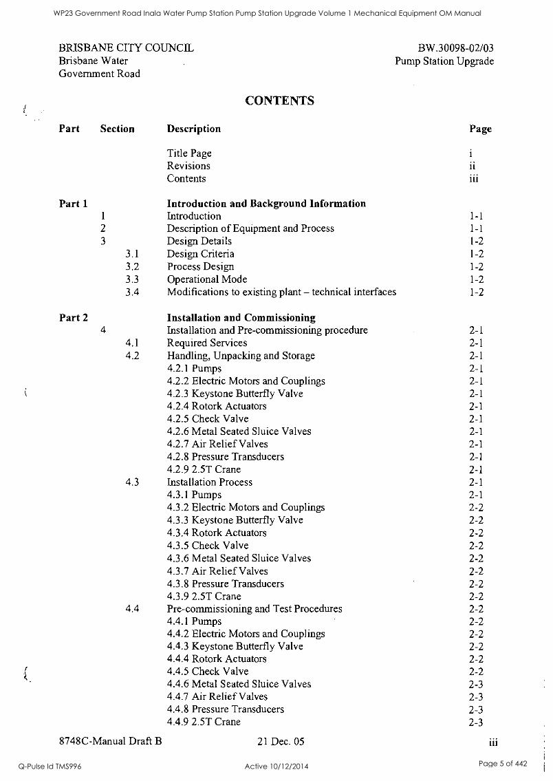
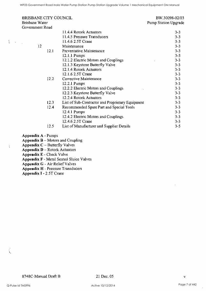
CONTENTS
BW.30098-02/03 Pump Station Upgrade
Part
Part 1
Section Description
Title Page Revisions Contents
Introduction and Background Information
Page
ii iii
1 Introduction 1-1
2 Description of Equipment and Process 1-1
3 Design Details 1-2 3.1 Design Criteria 1-2 3.2 Process Design 1-2 3.3 Operational Mode 1-2 3.4 Modifications to existing plant - technical interfaces 1-2
Part 2 Installation and Commissioning 4 Installation and Pre-commissioning procedure 2-1
4.1 Required Services 2-1 4.2 Handling, Unpacking and Storage 2-1
4.2.1 Pumps 2-1 4.2.2 Electric Motors and Couplings 2-1 4.2.3 Keystone Butterfly Valve 2-1 4.2.4 Rotork Actuators 2-1 4.2.5 Check Valve 2-1 4.2.6 Metal Seated Sluice Valves 2-1 4.2.7 Air Relief Valves 2-1 4.2.8 Pressure Transducers 2-1 4.2.9 2.5T Crane 2-1
4.3 Installation Process 2-1 4.3.1 Pumps 2-1 4.3.2 Electric Motors and Couplings 2-2 4.3.3 Keystone Butterfly Valve 2-2 4.3.4 Rotork Actuators 2-2 4.3.5 Check Valve 2-2 4.3.6 Metal Seated Sluice Valves 2-2 4.3.7 Air Relief Valves 2-2 4.3.8 Pressure Transducers 2-2 4.3.9 2.5T Crane 2-2
4.4 Pre-commissioning and Test Procedures 2-2 4.4.1 Pumps 2-2 4.4.2 Electric Motors and Couplings 2-2 4.4.3 Keystone Butterfly Valve 2-2 4.4.4 Rotork Actuators 2-2 4.4.5 Check Valve 2-2 4.4.6 Metal Seated Sluice Valves 2-3 4.4.7 Air Relief Valves 2-3 4.4.8 Pressure Transducers 2-3 4.4.9 2.5T Crane 2-3
8748C-Manual Draft B 21 Dec. 05 iii
WP23 Government Road Inala Water Pump Station Pump Station Upgrade Volume 1 Mechanical Equipment OM Manual
Q-Pulse Id TMS996 Active 10/12/2014 Page 5 of 442
BRISBANE Brisbane Water Government
CITY COUNCIL
Road
BW.30098-02/03 Pump Station Upgrade
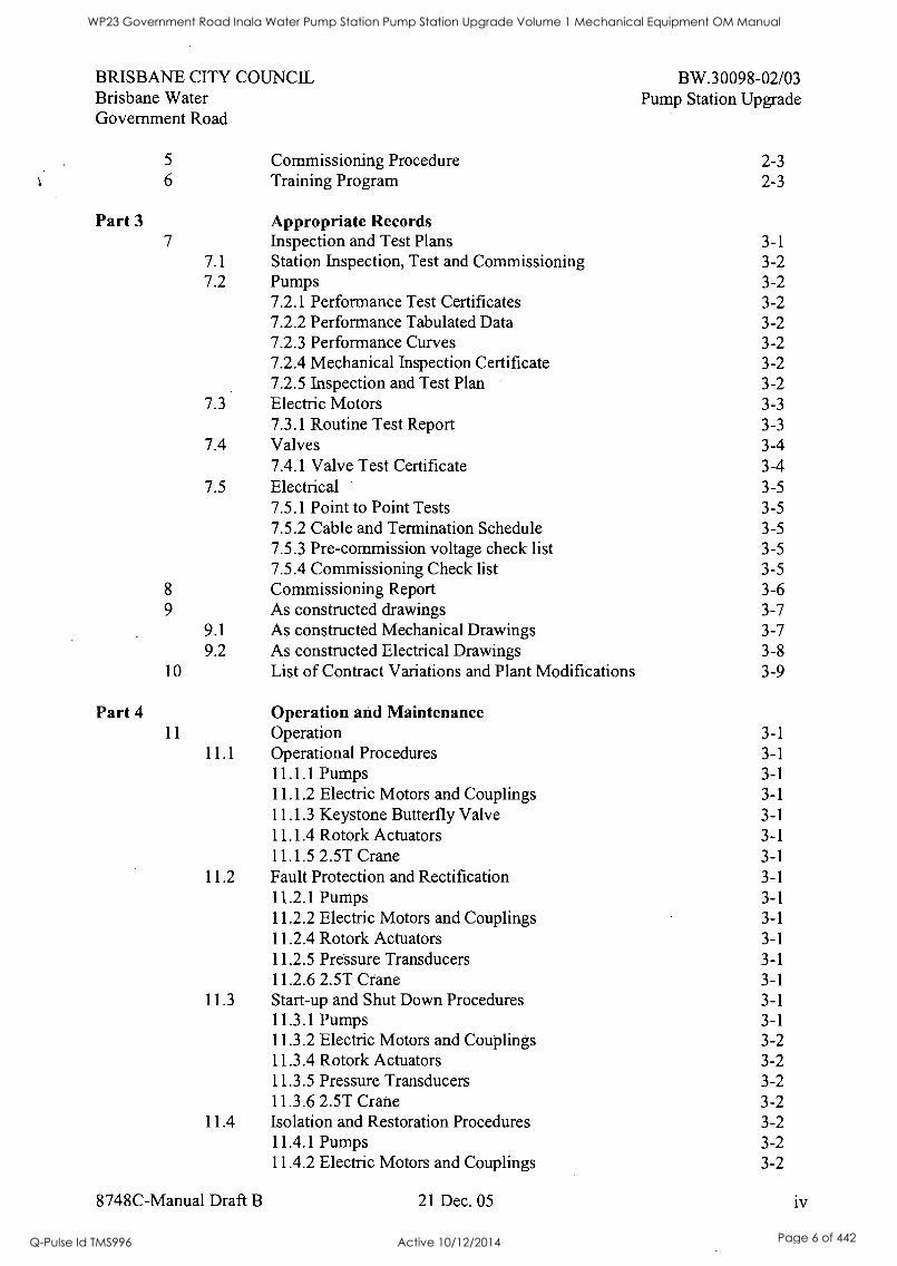
5 Commissioning Procedure 2-3 6 Training Program 2-3
Part 3 Appropriate Records 7 Inspection and Test Plans 3-1
7.1 Station Inspection, Test and Commissioning 3-2 7.2 Pumps 3-2
7.2.1 Performance Test Certificates 3-2 7.2.2 Performance Tabulated Data 3-2 7.2.3 Performance Curves 3-2 7.2.4 Mechanical Inspection Certificate 3-2 7.2.5 Inspection and Test Plan 3-2
7.3 Electric Motors 3-3 7.3.1 Routine Test Report 3-3
7.4 Valves 3-4 7.4.1 Valve Test Certificate 3-4
7.5 Electrical 3-5 7.5.1 Point to Point Tests 3-5 7.5.2 Cable and Termination Schedule 3-5 7.5.3 Pre-commission voltage check list 3-5 7.5.4 Commissioning Check list 3-5
8 Commissioning Report 3-6 9 As constructed drawings 3-7
9.1 As constructed Mechanical Drawings 3-7 9.2 As constructed Electrical Drawings 3-8
10 List of Contract Variations and Plant Modifications 3-9
Part 4 Operation and Maintenance 11 Operation 3-1
11.1 Operational Procedures 3-1 11.1.1 Pumps 3-1 11.1.2 Electric Motors and Couplings 3-1 11.1.3 Keystone Butterfly Valve 3-1 11.1.4 Rotork Actuators 3-1 11.1.5 2.5T Crane 3-1
11.2 Fault Protection and Rectification 3-1 11.2.1 Pumps 3-1 11.2.2 Electric Motors and Couplings 3-1 11.2.4 Rotork Actuators 3-1 11.2.5 Pressure Transducers 3-1 11.2.6 2.5T Crane 3-1
11.3 Start-up and Shut Down Procedures 3-1 11.3.1 Pumps 3-1 11.3.2 Electric Motors and Couplings 3-2 11.3.4 Rotork Actuators 3-2 11.3.5 Pressure Transducers 3-2 11.3.6 2.5T Crane 3-2
11.4 Isolation and Restoration Procedures 3-2 11.4.1 Pumps 3-2 11.4.2 Electric Motors and Couplings 3-2
8748C-Manual Draft B 21 Dec. 05 iv
WP23 Government Road Inala Water Pump Station Pump Station Upgrade Volume 1 Mechanical Equipment OM Manual
Q-Pulse Id TMS996 Active 10/12/2014 Page 6 of 442
BRISBANE CITY COUNCIL Brisbane Water Government Road
BW.30098-02/03 Pump Station Upgrade
11.4.4 Rotork Actuators 3-3 11.4.5 Pressure Transducers 3-3 11.4.6 2.5T Crane 3-3
12 Maintenance 3-3 12.1 Preventative Maintenance 3-3
12.1.1 Pumps 3-3 12.1.2 Electric Motors and Couplings 3-3 12.1.3 Keystone Butterfly Valve 3-3 12.1.4 Rotork Actuators 3-3 12.1.6 2.5T Crane 3-3
12.2 Corrective Maintenance 3-3 12.2.1 Pumps 3-3 12.2.2 Electric Motors and Couplings 3-3 12.2.3 Keystone Butterfly Valve 3-3 12.2.4 Rotork Actuators 3-3
12.3 List of Sub-Contractor and Proprietary Equipment 3-3 12.4 Recommended Spare Part and Special Tools 3-3
12.4.1 Pumps 3-3 12.4.2 Electric Motors and Couplings 3-3 12.4.6 2.5T Crane 3-3
12.5 List of Manufacturer and Supplier Details 3-5
Appendix A - Pumps Appendix B - Motors and Coupling Appendix C - Butterfly Valves Appendix D - Rotork Actuators Appendix E - Check Valve Appendix F - Metal Seated Sluice Valves Appendix G - Air Relief Valves Appendix H - Pressure Transducers Appendix I - 2.5T Crane
8748C-Manual Draft B 21 Dec. 05
WP23 Government Road Inala Water Pump Station Pump Station Upgrade Volume 1 Mechanical Equipment OM Manual
Q-Pulse Id TMS996 Active 10/12/2014 Page 7 of 442

II
I
WP23 Government Road Inala Water Pump Station Pump Station Upgrade Volume 1 Mechanical Equipment OM Manual
Q-Pulse Id TMS996 Active 10/12/2014 Page 8 of 442

0
I I
WP23 Government Road Inala Water Pump Station Pump Station Upgrade Volume 1 Mechanical Equipment OM Manual
Q-Pulse Id TMS996 Active 10/12/2014 Page 9 of 442

BRISBANE CITY COUNCIL Brisbane Water Government Road
Part 1 Introduction and Background Information
1 Introduction
BW.30098-02/03 Pump Station Upgrade
These instructions contain information for the installation, operation and maintenance of your mechanical equipment supplied by Style Industries.
When properly installed and maintained, this equipment will provide trouble free operation for a long period of time. These instructions are issued as a guide to correct procedures to be followed, and must be carried out to maximise the effectiveness and life of the equipment.
For replacement equipment, spare parts or service, please contact'our office and quote the equipment details and Style Industries Job No 8748C.
Telephone: 07 3710 5200 Fax: 07 32791828 Email: pumps(&stvleindustries.com.au
Delivery Address: 7 Forge Close Sumner Park QLD 4074
Postal Address: PO Box 3081 Darra QLD 4076
2 Description of Equipment and Process
Works to be completed under this contract comprise of supply, delivery, installation, testing and commissioning and maintenance within the defects liability period of a new upgraded water pump station Government Rd.
The requirements of the project are as follows: Demolish and remove all existing pipe work, pumps and switchboard within the pump station Supply all pipe work and fittings Supply and install two variable speed pump sets Supply and install necessary valves Civil works including raising valve pit lids and excavations for new pipe work. New switchboard and electrical installation.
The new pump station consists of two vertical split case pumpsets, mild steel manifolds and pipework, valves, gauges, concrete works and electrical switchboards including a variable speed drive unit for each pump.
The operation of this pump station will be remote, and the functional requirements and description do not form part of this contract.
8748C-Manual Draft B 21 Dec. 05 1-1
WP23 Government Road Inala Water Pump Station Pump Station Upgrade Volume 1 Mechanical Equipment OM Manual
Q-Pulse Id TMS996 Active 10/12/2014 Page 10 of 442

BRISBANE CITY COUNCIL Brisbane Water Government Road
3 Design Details-
3.1 Design Criteria
3.2 Process Design
3.3 Operational Mode
3.4 Modifications to existing plant - technical interfaces
8748C-Manual Draft B
BW.30098-02/03 Pump Station Upgrade
21 Dec. 05 1-2
WP23 Government Road Inala Water Pump Station Pump Station Upgrade Volume 1 Mechanical Equipment OM Manual
Q-Pulse Id TMS996 Active 10/12/2014 Page 11 of 442

S 0
I 1
WP23 Government Road Inala Water Pump Station Pump Station Upgrade Volume 1 Mechanical Equipment OM Manual
Q-Pulse Id TMS996 Active 10/12/2014 Page 12 of 442

$
I 1
I I S
6
WP23 Government Road Inala Water Pump Station Pump Station Upgrade Volume 1 Mechanical Equipment OM Manual
Q-Pulse Id TMS996 Active 10/12/2014 Page 13 of 442
BRISBANE CITY COUNCIL Brisbane Water Government Road
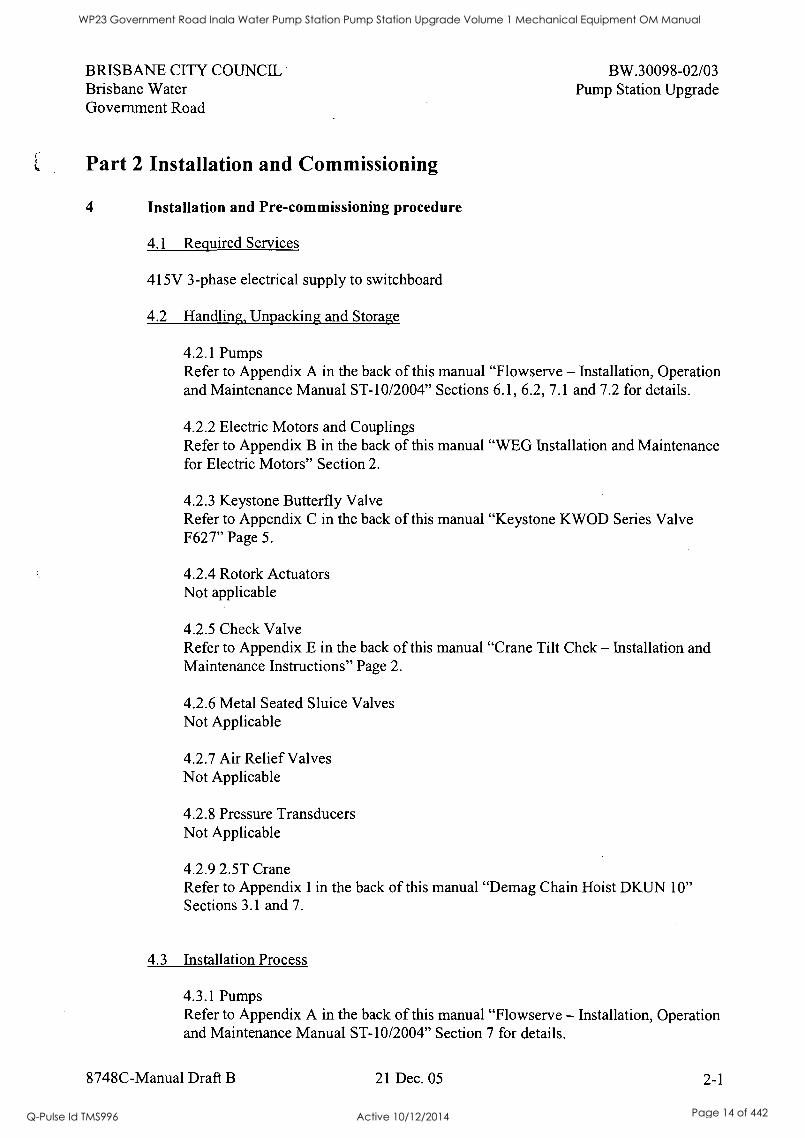
Part 2 Installation and Commissioning
4 Installation and Pre-commissioning procedure
4.1 Required Services
415V 3-phase electrical supply to switchboard
4.2 Handling, Unpacking and Storage
BW.30098-02/03 Pump Station Upgrade
4.2.1 Pumps Refer to Appendix A in the back of this manual "Flowserve - Installation, Operation and Maintenance Manual ST-10/2004" Sections 6.1, 6.2, 7.1 and 7.2 for details.
4.2.2 Electric Motors and Couplings Refer to Appendix B in the back of this manual "WEG Installation and Maintenance for Electric Motors" Section 2.
4.2.3 Keystone Butterfly Valve Refer to Appendix C in the back of this manual "Keystone KWOD Series Valve F627" Page 5.
4.2.4 Rotork Actuators Not applicable
4.2.5 Check Valve Refer to Appendix E in the back of this manual "Crane Tilt Chek - Installation and Maintenance Instructions" Page 2.
4.2.6 Metal Seated Sluice Valves Not Applicable
4.2.7 Air Relief Valves Not Applicable
4.2.8 Pressure Transducers Not Applicable
4.2.9 2.5T Crane Refer to Appendix I in the back of this manual "Demag Chain Hoist DKUN 10" Sections 3.1 and 7.
4.3 Installation Process
4.3.1 Pumps Refer to Appendix A in the back of this manual "Flowserve - Installation, Operation and Maintenance Manual ST-10/2004" Section 7 for details.
8748C-Manual Draft B 21 Dec. 05 2-1
WP23 Government Road Inala Water Pump Station Pump Station Upgrade Volume 1 Mechanical Equipment OM Manual
Q-Pulse Id TMS996 Active 10/12/2014 Page 14 of 442
BRISBANE CITY COUNCIL Brisbane Water Government Road
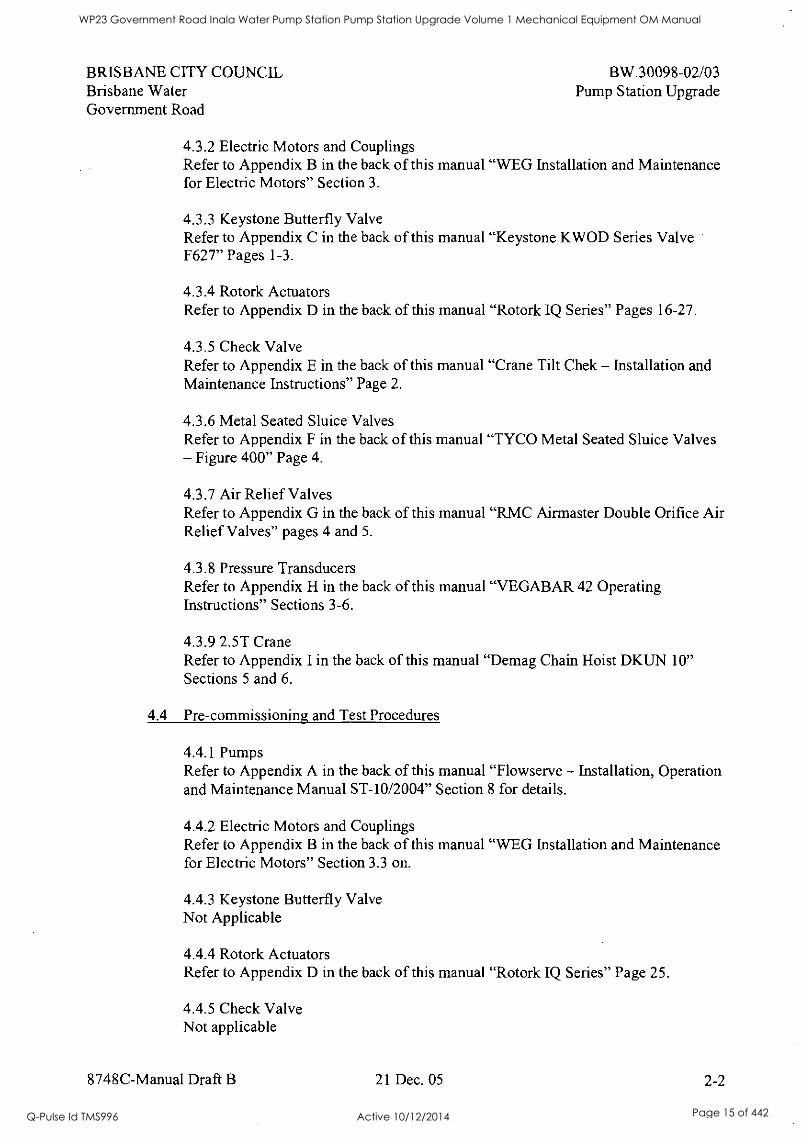
BW.30098-02103 Pump Station Upgrade
4.3.2 Electric Motors and Couplings Refer to Appendix B in the back of this manual "WEG Installation and Maintenance for Electric Motors" Section 3.
4.3.3 Keystone Butterfly Valve Refer to Appendix C in the back of this manual "Keystone KWOD Series Valve F627" Pages 1-3.
4.3.4 Rotork Actuators Refer to Appendix D in the back of this manual "Rotork IQ Series" Pages 16-27.
4.3.5 Check Valve Refer to Appendix E in the back of this manual "Crane Tilt Chek - Installation and Maintenance Instructions" Page 2.
4.3.6 Metal Seated Sluice Valves Refer to Appendix F in the back of this manual "TYCO Metal Seated Sluice Valves - Figure 400" Page 4.
4.3.7 Air Relief Valves Refer to Appendix G in the back of this manual "RMC Airmaster Double Orifice Air Relief Valves" pages 4 and 5.
4.3.8 Pressure Transducers Refer to Appendix H in the back of this manual "VEGABAR 42 Operating Instructions" Sections 3-6.
4.3.9 2.5T Crane Refer to Appendix I in the back of this manual "Demag Chain Hoist DKUN 10" Sections 5 and 6.
4.4 Pre-commissioning and Test Procedures
4.4.1 Pumps Refer to Appendix A in the back of this and Maintenance Manual ST-10/2004"
4.4.2 Electric Motors and Couplings Refer to Appendix B in the back of this for Electric Motors" Section 3.3 on.
4.4.3 Keystone Butterfly Valve Not Applicable
manual "Flowserve - Installation, Operation Section 8 for details.
manual "WEG Installation and Maintenance
4.4.4 Rotork Actuators Refer to Appendix D in the back of this manual "Rotork IQ Series" Page 25.
4.4.5 Check Valve Not applicable
8748C-Manual Draft B 21 Dec. 05 2-2
WP23 Government Road Inala Water Pump Station Pump Station Upgrade Volume 1 Mechanical Equipment OM Manual
Q-Pulse Id TMS996 Active 10/12/2014 Page 15 of 442
BRISBANE CITY COUNCIL Brisbane Water Government Road
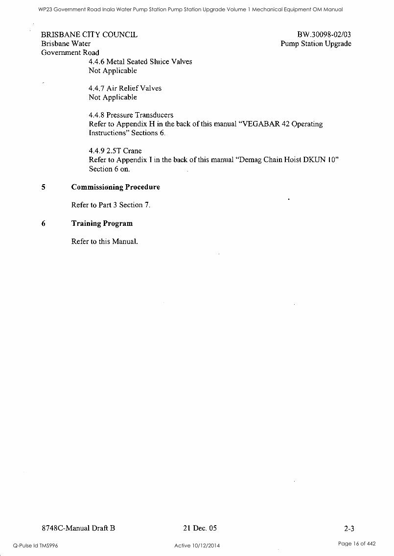
4.4.6 Metal Seated Sluice Valves Not Applicable
4.4.7 Air Relief Valves Not Applicable
BW.30098-02/03 Pump Station Upgrade
4.4.8 Pressure Transducers Refer to Appendix H in the back of this manual "VEGABAR 42 Operating Instructions" Sections 6.
4.4.9 2.5T Crane Refer to Appendix I in the back of this manual "Demag Chain Hoist DKUN 10" Section 6 on.
5 Commissioning Procedure
Refer to Part 3 Section 7.
6 Training Program
Refer to this Manual.
8748C-Manual Draft B 21 Dec. 05 2-3
WP23 Government Road Inala Water Pump Station Pump Station Upgrade Volume 1 Mechanical Equipment OM Manual
Q-Pulse Id TMS996 Active 10/12/2014 Page 16 of 442

WP23 Government Road Inala Water Pump Station Pump Station Upgrade Volume 1 Mechanical Equipment OM Manual
Q-Pulse Id TMS996 Active 10/12/2014 Page 17 of 442

WP23 Government Road Inala Water Pump Station Pump Station Upgrade Volume 1 Mechanical Equipment OM Manual
Q-Pulse Id TMS996 Active 10/12/2014 Page 18 of 442

BRISBANE CITY COUNCIL Brisbane Water Government Road
Part 3 Appropriate Records
7 Inspection and Test Plans
7.1 Station Inspection, Test and Commissioning
8748C-Manual Draft B
BW.30098-02/03 Pump Station Upgrade
21 Dec. 05 3-1
WP23 Government Road Inala Water Pump Station Pump Station Upgrade Volume 1 Mechanical Equipment OM Manual
Q-Pulse Id TMS996 Active 10/12/2014 Page 19 of 442

WP23 Government Road Inala Water Pump Station Pump Station Upgrade Volume 1 Mechanical Equipment OM Manual
Q-Pulse Id TMS996 Active 10/12/2014 Page 20 of 442
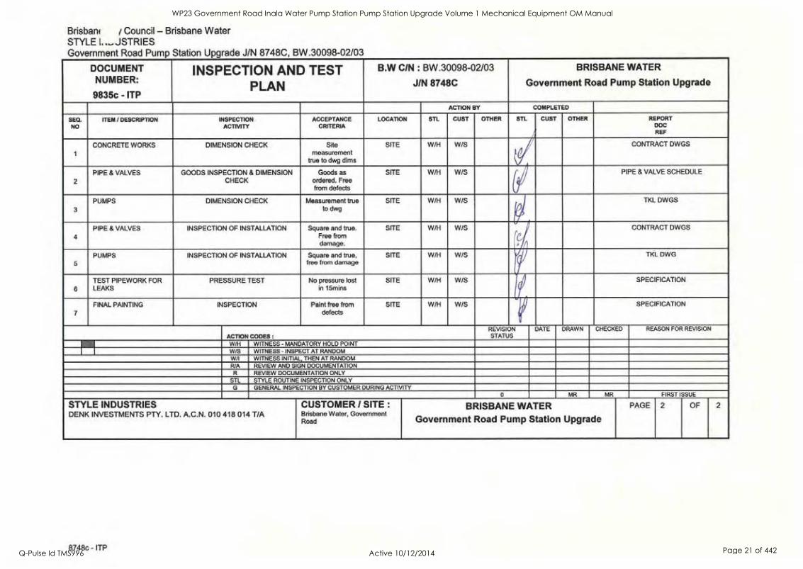
Station Upgrade J/N 8748C, BW.30098-02/03
DOCUMENT INSPECTION AND TEST BW C/N : BW.30098-02/03 BRISBANE WATER NUMBER:
PLAN J/N 8748C Government Road Pump Station Upgrade 9835c - ITP
ACTION BY COMPLETED
SEQ. ITEM / DESCRIPTION INSPECTION ACCEPTANCE LOCATION STL CUST OTHER STL CUST OTHER REPORT NO ACTIVITY CRITERIA DOC
REF
true to dwg dims measurement
CONCRETE WORKS DIMENSION CHECK Site SITE W/H W/S CONTRACT DWGS
2 CHECK ordered. Free from defects
PIPE & VALVES GOODS INSPECTION & DIMENSION Goods as SITE W/H W/S PIPE & VALVE SCHEDULE
3 to dwg
P1
PUMPS DIMENSION CHECK Measurement true SITE W/H W/S TKL DWGS
PIPE & VALVES INSPECTION OF INSTALLATION Square and true. SITE W/H W/S CONTRACT DWGS
4 Free from r damage.
PUMPS INSPECTION OF INSTALLATION Square and true, SITE W/H W/S TKL DWG
5 free from damage
TEST PIPEWORK FOR PRESSURE TEST No pressure lost SITE W/H W/S SPECIFICATION
e SPECIFICATION
6 LEAKS in 15mins I
7 defects FINAL PAINTING INSPECTION Paint free from SITE W/H W/S
REVISION DATE DRAWN CHECKED REASON FOR REVISION ACTION CODES : STATUS
W/H WITNESS - MANDATORY HOLD POINT W/S WITNESS - INSPECT AT RANDOM W/I WITNESS INITIAL, THEN AT RANDOM R/A REVIEW AND SIGN DOCUMENTATION
R REVIEW DOCUMENTATION ONLY STL STYLE ROUTINE INSPECTION ONLY
G GENERAL INSPECTION BY CUSTOMER DURING ACTIVITY 0 MR MR FIRST ISSUE
STYLE INDUSTRIES CUSTOMER / SITE : BRISBANE WATER PAGE 2 OF 2
DENK INVESTMENTS PTY. LTD. A.C.N. 010 418 014 T/A Brisbane Water, Government Road Government Road Pump Station Upgrade
Brisban( Council - Brisbane Water STYLE1....,JSTRIES Government Road Pump
8748c - ITP
WP23 Government Road Inala Water Pump Station Pump Station Upgrade Volume 1 Mechanical Equipment OM Manual
Q-Pulse Id TMS996 Active 10/12/2014 Page 21 of 442
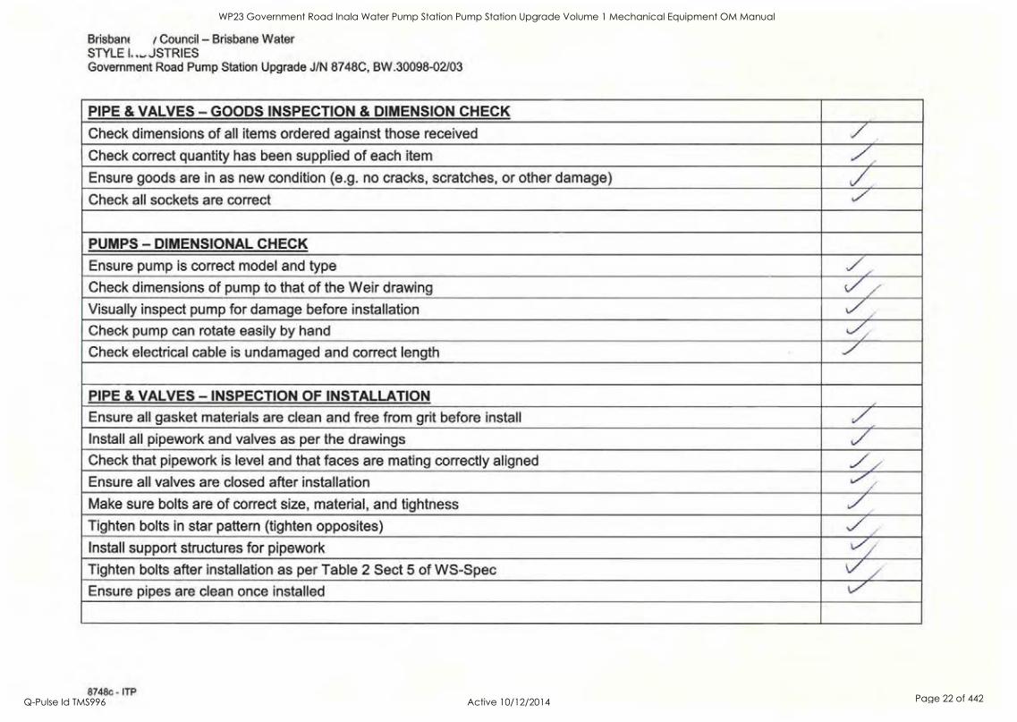
Brisban( Council - Brisbane Water STYLE I.._JSTRIES Government Road Pump Station Upgrade J/N 8748C, BW.30098-02/03
PIPE & VALVES - GOODS INSPECTION & DIMENSION CHECK
Check dimensions of all items ordered against those received
Check correct quantity has been supplied of each item
Ensure goods are in as new condition (e.g. no cracks, scratches, or other damage) / Check all sockets are correct
PUMPS - DIMENSIONAL CHECK
Ensure pump is correct model and type
Check dimensions of pump to that of the Weir drawing ..// Visually inspect pump for damage before installation L/z Check pump can rotate easily by hand L/ Check electrical cable is undamaged and correct length ../
PIPE & VALVES - INSPECTION OF INSTALLATION
Ensure all gasket materials are clean and free from grit before install ../ Install all pipework and valves as per the drawings / Check that pipework is level and that faces are mating correctly aligned
Ensure all valves are closed after installation
Make sure bolts are of correct size, material, and tightness
Tighten bolts in star pattern (tighten opposites)
Install support structures for pipework t/ Tighten bolts after installation as per Table 2 Sect 5 of WS-Spec
Ensure pipes are clean once installed LV
8748c - ITP
WP23 Government Road Inala Water Pump Station Pump Station Upgrade Volume 1 Mechanical Equipment OM Manual
Q-Pulse Id TMS996 Active 10/12/2014 Page 22 of 442
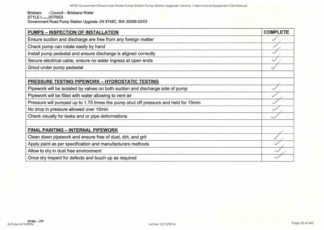
Brisban( ( Council Brisbane Water STYLE 1.-JSTRIES Government Road Pump Station Upgrade J/N 8748C, BW.30098-02/03
PUMPS - INSPECTION OF INSTALLATION COMPLETE
Ensure suction and discharge are free from any foreign matter / Check pump can rotate easily by hand Y Install pump pedestal and ensure discharge is aligned correctly
Secure electrical cable, ensure no water ingress at open ends
Grout under pump pedestal / PRESSURE TESTING PIPEWORK - HYDROSTATIC TESTING
Pipework will be isolated by valves on both suction and discharge side of pump
Pipework will be filled with water allowing to vent air
Pressure will pumped up to 1.75 times the pump shut off pressure and held for 15min
No drop in pressure allowed over 15min
Check visually for leaks and or pipe deformations ,./ FINAL PAINTING - INTERNAL PIPEWORK
Clean down pipework and ensure free of dust, dirt, and grit
Apply paint as per specification and manufacturers methods
Allow to dry in dust free environment
Once dry inspect for defects and touch up as required ,...7
8748c - ITP
WP23 Government Road Inala Water Pump Station Pump Station Upgrade Volume 1 Mechanical Equipment OM Manual
Q-Pulse Id TMS996 Active 10/12/2014 Page 23 of 442
BRISBANE CITY COUNCIL Brisbane Water Government Road
7.2 Pumps 7.2.1 Performance Test Certificates 7.2.2 Performance Tabulated Data 7.2.3 Performance Curves 7.2.4 Mechanical Inspection Certificate 7.2.5 Inspection and Test Plan
8748C-Manual Draft B
BW.30098-02/03 Pump Station Upgrade
21 Dec. 05 3-2
WP23 Government Road Inala Water Pump Station Pump Station Upgrade Volume 1 Mechanical Equipment OM Manual
Q-Pulse Id TMS996 Active 10/12/2014 Page 24 of 442
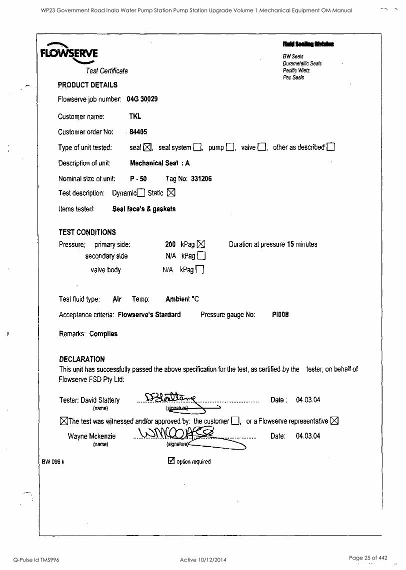
Rd imam Edda Flit:AA/SERVE BW Seals
Durarnefallic Seals
Test Certificate Pacific Met Pac Seals
PRODUCT DETAILS
Flowserve job number: 04G 30,029
Customer name: TKL
Customer order No: 84405
Type of unit tested: seal [0, seal system , pump , valve ID, other as described
Description of unit: Mechanical Seal : A
Nominal size of unit: P - 50 Tag No: 331206
Test description: Dynamic Static E]
Items tested: Seal face's & gaskets
TEST CONDITIONS
Pressure; primary side: 200 kPag
secondary side N/A kPag
valve body N/A kPag
Duration at pressure 15 minutes
Test fluid type: Air Temp: Ambient °C
Acceptance criteria: Flowserve's Stardard Pressure gauge No: PI008
Remarks: Complies
DECLARATION
This unit has successfully passed the above specification for the test, as certified by the tester, on behalf of
Flowserve FSD Pty Ltd:
Tester: David Slattery (name)
Date : 04.03.04
The test was witnessed and/or approved by: the customer , or a Flowserve representative
Wayne Mckenzie \)(\ Date: 04.03.04 (name) (signature
BW 096 k El option required
WP23 Government Road Inala Water Pump Station Pump Station Upgrade Volume 1 Mechanical Equipment OM Manual
Q-Pulse Id TMS996 Active 10/12/2014 Page 25 of 442
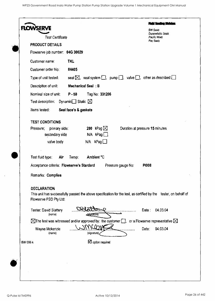
FLOWSERVE
Test Certificate
PRODUCT DETAILS
Flowserve job number: 04G 30029
Mil tans MOM
BW Seals Duramefallic Seals Pacific Wiefz
Pac Seals
Customer name: TKL
Customer order No: 84405
Type of unit tested: seal Z, seal system , pump , valve , other as described
Description of unit: Mechanical Seal : B
Nominal size of unit: P - 50 Tag No: 331206
Test description: Dynamics Static
Items tested: Seal face's & gaskets
TEST CONDITIONS
Pressure; primary side: 200 kPag
secondary side NIA kPag
valve body N/A kPag
Duration at pressure 15 minutes
Test fluid type: Air Temp: Ambient °C
Acceptance criteria: Flowserve's Stardard Pressure gauge No: PI008
Remarks: Complies
DECLARATION
This unit has successfully passed the above specification for the test, as certified by the tester, on behalf of
Flowserve FSD Pty Ltd:
Tester: David Slattery (name)
Date : 04.03.04
The test was witnessed and/or approved by: the customer , or a Flowserve representative [Z]
Wayne Mckenzie Date: 04.03.04 (name) (signature)
BW 096 k 121 option required
WP23 Government Road Inala Water Pump Station Pump Station Upgrade Volume 1 Mechanical Equipment OM Manual
Q-Pulse Id TMS996 Active 10/12/2014 Page 26 of 442

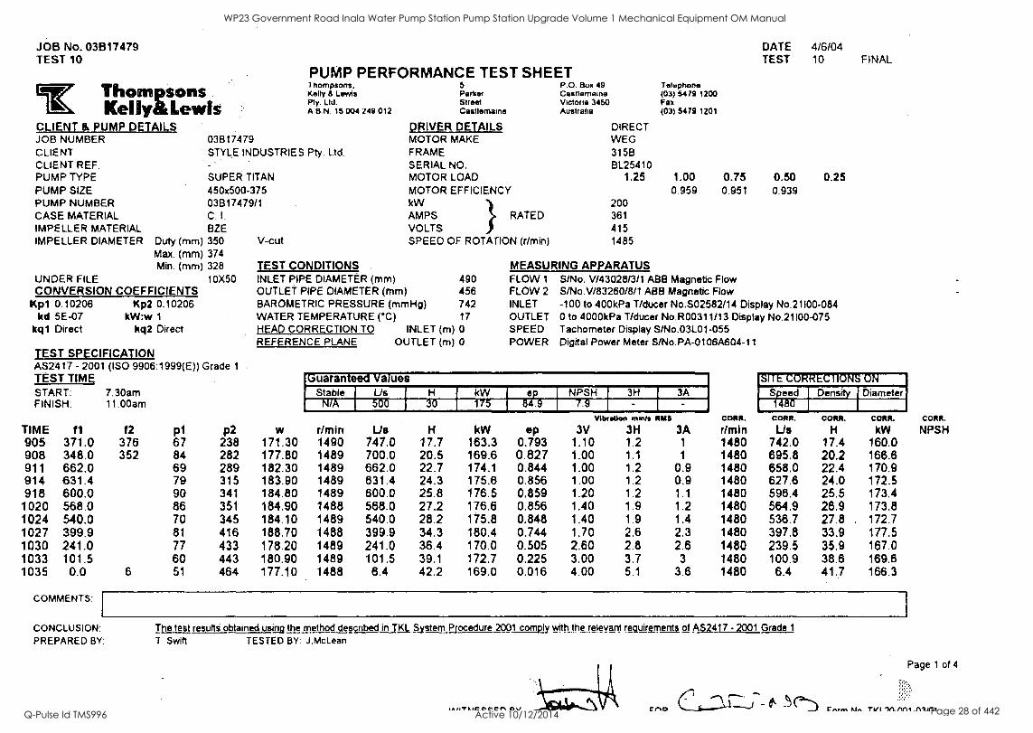
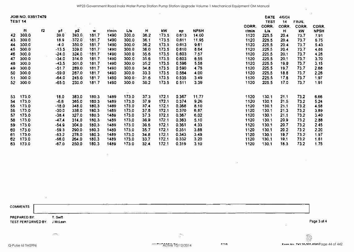
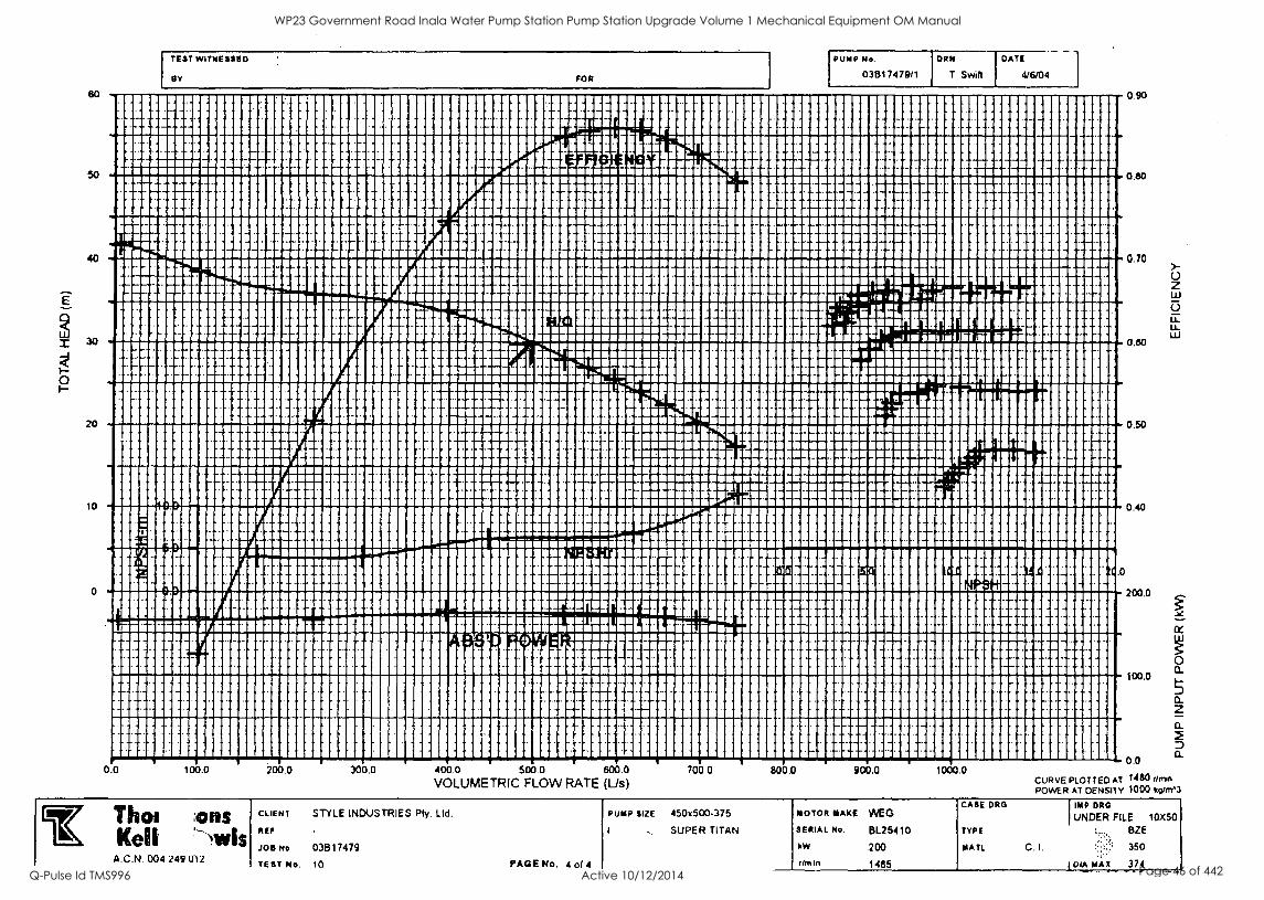
JOB No. 03817479 TEST 9
Thompsons Kelly&Letvls
CLIENT & PUMP DETAILS JOB NUMBER CLIENT CLIENT REF. PUMP TYPE PUMP SIZE PUMP NUMBER CASE MATERIAL IMPELLER MATERIAL IMPELLER DIAMETER
PUMP PERFORMANCE Thompson', Kelly Al Levels Pty. Ltd. A.B.N. 15 004 249 012
03817479 STYLE INDUSTRIES Pty. Ltd.
SUPER TITAN 450x500-375 03B17479/1 C. I.
BZE Duty (mm) 350 Max. (mm) 374 Min. (mm) 328
UNDER FILE CONVERSION COEFFICIENTS
KM 0.10206 Kp2 0.10206 kd 5E-07 kW:w 1
kq1 Direct kq2 Direct
10X50
TEST SPECIFICATION AS2417 - 2001 (ISO 9906:1999(E)) Grade 1
TEST TIME START: FINISH:
TIME f1
7.30am 11.00am
f2 pl p2 905 371.0 378 67 238 908 348.0 352 84 282 911 662.0 69 289 914 631.4 79 315 918 600.0 90 341 1020 568.0 86 351 1024 540.0 70 345 1027 399.9 81 416 1030 241.0 77 433 1033 101.5 60 443 1035 0.0 6 51 464
COMMENTS:
CONCLUSION: PREPARED BY:
V-cut
TEST SHEET P.O. Box 49 Castiamairto Victoria 3450 Auslrelia
S Parker Strout Castlemaine
DRIVER DETAILS MOTOR MAKE FRAME SERIAL NO. MOTOR LOAD MOTOR EFFICIENCY kW AMPS I RATED VOLTS SPEED OF ROTATION (r/min)
DATE 4/6/04 TEST 9 FINAL
Telephone (03) 5479 1200 Fax (03) 54 79 1201
DIRECT WEG 315B BL25410
1.25 1.00 0.75 0.50 0.25 0.959 0.951 0.939
200 361 415 1485
TEST CONDITIONS MEASURING APPARATUS INLET PIPE DIAMETER (mm) 490 FLOW I S/No. V/43028/3/1 ABB Magnetic Flow OUTLET PIPE DIAMETER (mm) 456 FLOW 2 S/No.V183260/8/1 ABB Magnetic Flow BAROMETRIC PRESSURE (mmHg) 742 INLET -100 to 400kPa T/ducer No.S02582/14 Display No.21100-084 WATER TEMPERATURE (°C) 17 OUTLET 0 to 4000kPa T/ducer No.R00311/13 Display No.21100-075 HEAD CORRECTION TO INLET (m) 0 SPEED Tachometer Display S/No.03L01-055 REFERENCE PLANE OUTLET (m) 0 POWER Digital Power Meter S/No.PA-0106A604-11
w 171.30 177.80
Guaranteed values
CORR.
r/mIn 1480 1480
SITE CORRECTIONS ON
CORR.
NPSH
Stable Us H NPSH I 3H 3A Sti4e8e0d Density Diameter N/A 600 25 168.9 87.1 9.2
r/mln 1490 1489
Lis 747.0 700.0
H 17.7 20.5
kW 163.3 169.6
ep 0.793 0.827
Vlb Mon muds RAN
3V 3H 3A 1.10 1.2 1
1.00 1.1 1
CORR.
Lis 742.0 695.8
CORR.
H 17.4 20.2
CORR.
kW 160.0 166.6
182.30 1489 662.0 22.7 174.1 0.844 1.00 1.2 0.9 1480 858.0 22.4 170.9 183.90 1489 631.4 24.3 175.6 0.856 1.00 1.2 0.9 1480 627.6 24.0 172.5 184.80 1489 600.0 25.8 176.5 0.859 1.20 1.2 1.1 1480 596.4 25.5 173.4 184.90 1488 568.0 27.2 178.6 0.856 1.40 1.9 1.2 1480 564.9 26.9 173.8 184.10 1489 540.0 28.2 175.8 0.848 1.40 1.9 1.4 1480 536.7 27.8 172.7 188.70 1488 399.9 34.3 180.4 0.744 1.70 2.8 2.3 1480 397.8 33.9 177.5 178.20 1489 241.0 36.4 170.0 0.505 2.60 2.8 2.6 1480 239.5 35.9 167.0 180.90 1489 101.5 39.1 172.7 0.225 3.00 3.7 3 1480 100.9 38.6 169.6 177.10 1488 6.4 42.2 169.0 0.016 4.00 5.1 3.6 1480 6.4 41.7 168.3
The test results obtained using the method described in TKL System Procedure 2001 comply with the relevant requirements of AS2417 - 2001 Grade 1
T. Swill TESTED BY: J.McLean
Page 1 of 4
WP23 Government Road Inala Water Pump Station Pump Station Upgrade Volume 1 Mechanical Equipment OM Manual
Q-Pulse Id TMS996 Active 10/12/2014 Page 27 of 442
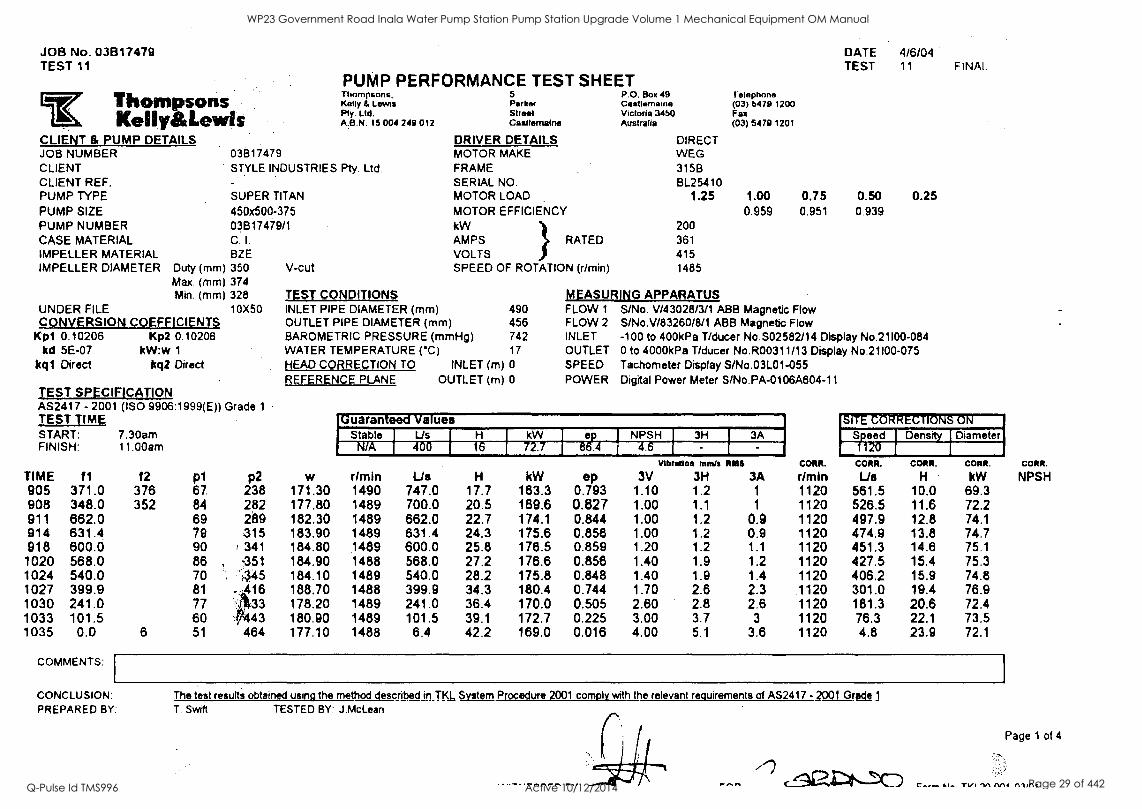
JOB No. 03B17479 DATE 4/6/04 TEST 10 TEST 10 FINAL
PUMP PERFORMANCE TEST SHEET r:TThompsons
Kelly&Lewis CLIENT & PUMP DETAILS JOB NUMBER CLIENT CLIENT REF. PUMP TYPE PUMP SIZE PUMP NUMBER CASE MATERIAL IMPELLER MATERIAL IMPELLER DIAMETER
1 hompsons. 5 P.O. Box 49 Telephone Kelly IL Lewis Parke/ Cestlemaine (03) 5479 1200 Pty. Ltd. Street Victoria 3450 Fax A B.N. 15 004 249 012 Castlamalne Australia (03) 5479 1201
03817479 STYLE INDUSTRIES Pty. Ltd.
SUPER TITAN 450x500-375 03817479/1 C. I.
BZE Duty (mm) 350 V-cut Max. (mm) 374 Min. (mm) 328
UNDER FILE 10X50 CONVERSION COEFFICIENTS
Kpl 0.10206 kd 5E-07
kql Direct
Kp2 0.10206 kW:w 1
kq2 Direct
TEST SPECIFICATION AS2417 - 2001 (ISO 9906:1999(E)) Grade 1
TEST TIMk START: FINISH:
TIME fl
7.30am 11.00am
f2 p1 p2 905 371.0 376 67 238 908 348.0 352 84 282 911 662.0 69 289 914 631.4 79 315 918 600.0 90 341 1020 568.0 86 351 1024 540.0 70 345 1027 399.9 81 416 1030 241.0 77 433 1033 101.5 60 443 1035 0.0 6 51 464
COMMENTS:
DRIVER DETAILS MOTOR MAKE FRAME SERIAL NO. MOTOR LOAD MOTOR EFFICIENCY kW AMPS I RATED VOLTS SPEED OF ROTATION (r/min)
DIRECT WEG 315B BL25410
1.25 1.00 0.75 0.50 0.25 0.959 0.951 0.939
200 361
415 1485
TEST CONDITIONS MEASURING APPARATUS INLET PIPE DIAMETER (mm) 490 FLOW 1 S/No. V/43028/3/1 ABB Magnetic Flow OUTLET PIPE DIAMETER (mm) 456 FLOW 2 S/No.V/83260/8/1 ABB Magnetic Flow BAROMETRIC PRESSURE (mmHg) 742 INLET -100 to 400kPa T/ducer No.S02582/14 Display No.21100-084 WATER TEMPERATURE (°C) 17 OUTLET 0 to 4000kPa T/ducer No.R00311/13 Display No.21100-075 HEAD CORRECTION TO INLET (m) 0 SPEED Tachometer Display S/No.03L01-055 REFERENCE PLANE OUTLET (m) 0 POWER Digital Power Meter S/No.PA-0108A604-11
SITE CORRECTIONS ON
Speed Density Diameter 1480
Guaranteed Values Stable Us H -- kW ' ep NPSH 3H 3A
N/A 500 30 175 84.9 7.9
w rlmin US H kW ep Vlb Won mmts RMS
3V 3H 3A CORR.
r/min CORR.
Lis CORR.
H CORR. CORR.
kW NPSH 171.30 1490 747.0 17.7 163.3 0.793 1.10 1.2 1 1480 742.0 17.4 160.0 177.80 1489 700,0 20.5 169.6 0.827 1.00 1.1 1 1480 695.8 20.2 166.6 182.30 1489 662.0 22.7 174.1 0.844 1.00 1.2 0.9 1480 658.0 22.4 170.9 183.90 1489 831.4 24.3 175.6 0.856 1.00 1.2 0.9 1480 627.6 24.0 172.5 184.80 1489 800.0 25.8 176.5 0.859 1.20 1.2 1.1 1480 598.4 25.5 173.4 184.90 1488 568.0 27.2 176.6 0.856 1.40 1.9 1.2 1480 584.9 26.9 173.8 184.10 1489 540.0 28.2 175.8 0.848 1.40 1.9 1.4 1480 536.7 27.8 172.7 188.70 1488 399.9 34.3 180.4 0.744 1.70 2.6 2.3 1480 397.8 33.9 177.5 178.20 1489 241.0 36.4 170.0 0.505 2.60 2.8 2.6 1480 239.5 35.9 167.0 180.90 1489 101.5 39.1 172.7 0.225 3.00 3.7 3 1480 100.9 38.6 169.6 177.10 1488 6.4 42.2 169.0 0.016 4.00 5.1 3.6 1480 6.4 41.7 166.3
CONCLUSION: PREPARED BY:
The test results obtained using the method described in TKL System Procedure 2001 comply with the relevant reguirg_ments of AS2417 - 2001 Grade 1
T. Swirl TESTED BY: J.McLean
tA/11.kleOCCI\ OS/ crra C'm
Page 1 of 4
Cosrnet Al" TVI 111,(1111 .111/A1
WP23 Government Road Inala Water Pump Station Pump Station Upgrade Volume 1 Mechanical Equipment OM Manual
Q-Pulse Id TMS996 Active 10/12/2014 Page 28 of 442
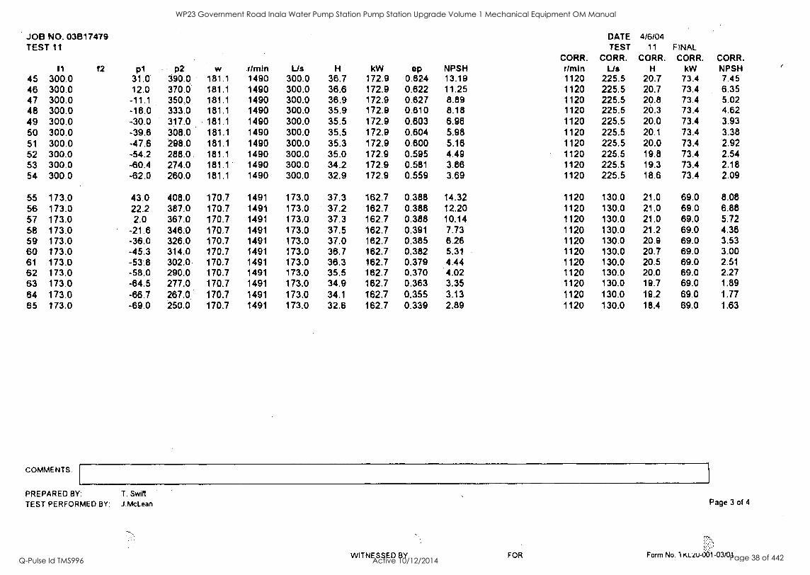
JOB No. 03B17479 TEST 11
Thom sons kellyatLewis
CLIENT & PUMP DETAILS JOB NUMBER CLIENT CLIENT REF. PUMP TYPE PUMP SIZE PUMP NUMBER CASE MATERIAL IMPELLER MATERIAL IMPELLER DIAMETER
03617479 STYLE INDUSTRIES
SUPER TITAN
450x500-375 03817479/1 C. I.
BZE Duty (mm) 350 V-cut Max (mm) 374 Min. (mm) 328
10X50 UNDER FILE CONVERSION COEFFICIENTS
KO 0.10206 Kp2 0.10206 Ica 5E-07 kW:w 1
kql Direct kq2 Direct
TEST SPECIFICATION AS2417 - 2001 (ISO 9906:1999(E)) Grade 1
TEST TIME START: 7.30am FINISH: 11.00am
TIME 11
905 371.0 908 348.0 911 662.0 914 631.4 918 600.0 1020 568.0 1024 540.0 1027 399.9 1030 241.0 1033 101.5 1035 0.0
COMMENTS:
f2 376 352
p1 67 84 69 79 90 86 70 81 77 60
6 51
p2 238 282 289 315
i 341 351 '445
171,33 41443
464
PUMP PERFORMANCE TEST SHEET Thompsons, Kelly & Lewis Pty. LW. A.B.N. 15 004 249 012
Pty. Ltd.
5 Parker Street Caattematne
DRIVER DETAILS MOTOR MAKE FRAME SERIAL NO. MOTOR LOAD MOTOR EFFICIENCY kW AMPS I RATED VOLTS SPEED OF ROTATION (r/min)
TEST CONDITIONS INLET PIPE DIAMETER (mm) 490 OUTLET PIPE DIAMETER (mm) 456 BAROMETRIC PRESSURE (mmHg) 742 WATER TEMPERATURE (*C) 17
HEAD CORRECTION TO INLET (m) 0
REFERENCE PLANE OUTLET (m) 0
P.O. Box 48 Castiemaine Victoria 3450 Australia
DIRECT WEG 315B BL25410
1.25
200 361 415 1485
MEASURING APPARATUS FLOW 1
FLOW 2
INLET OUTLET SPEED POWER
DATE 4/6/04 TEST 11 FINAL
Telephone (03) 5479 1200 Fax (03) 5479 1201
1.00 0.75 0.50 0.25 0.959 0.951 0.939
S/No. V/43028/3/1 ABB Magnetic Flow S/No.V/83260/8/1 ABB Magnetic Flow -100 to 400kPa T/ducer No.S02582/14 Display No.21100-084 0 to 4000kPa T/ducer No.R00311/13 Display No.21100-075 Tachometer Display S/No.03L01-055 .
Digital Power Meter S/No.PA-0106A604-11
w
Guaranteed Values
CORR.
rimin
SITE CORRECTIONS ON
CORR.
NPSH
Stable Us H kW NPSH 3H 3A Speed Density Diameter NIA 400 I 16 72.7 813P. 4 4.6 1120
1
Vlb mien mmis RN&
rrmin Us H kW op 3V 3H 3A CORR. CORR. CORR.
Us H kW 171.30 1490 747.0 17.7 183.3 0.793 1.10 1.2 1 1120 561.5 10.0 69.3 177.80 1489 700.0 20.5 169.6 0.827 1.00 1.1 1 1120 526.5 11.6 72.2 182.30 1489 662.0 22.7 174.1 0.844 1.00 1.2 0.9 1120 497.9 12.8 74.1 183.90 1489 631.4 24.3 175.6 0.856 1.00 1.2 0.9 1120 474.9 13.8 74.7 184.80 1489 600.0 25.8 176.5 0.859 1.20 1.2 1.1 1120 451.3 14.6 75.1 184.90 1488 568.0 27.2 178.6 0.856 1.40 1.9 1.2 1120 427.5 15.4 75.3 184.10 1489 540.0 28.2 175.8 0.848 1.40 1.9 1.4 1120 406.2 15.9 74.8 188.70 1488 399.9 34.3 180.4 0.744 1.70 2.6 2.3 1120 301.0 19.4 76.9 178.20 1489 241.0 36.4 170.0 0.505 2.60 2.8 2.6 1120 181.3 20.6 72.4 180.90 1489 101.5 39.1 172.7 0.225 3.00 3.7 3 1120 76.3 22.1 73.5 177.10 1488 6.4 42.2 169.0 0.016 4.00 5.1 3.6 1120 4.8 23.9 72.1
CONCLUSION: PREPARED BY:
The test results obtained using the method described in TN= System Procedure 2001 comply with the relevant requirements of AS2417 -2001 Grgel T. Swift TESTED BY: J.McLean
Page 1 of 4
TI/I 'IA MI (11/f11
WP23 Government Road Inala Water Pump Station Pump Station Upgrade Volume 1 Mechanical Equipment OM Manual
Q-Pulse Id TMS996 Active 10/12/2014 Page 29 of 442

JOB No. 03B17479 TEST 12
Thompsons KellyiatLewis
CLIENT & PUMP DETAILS JOB NUMBER CLIENT CLIENT REF. PUMP TYPE PUMP SIZE PUMP NUMBER CASE MATERIAL IMPELLER MATERIAL IMPELLER DIAMETER
PUMP PbriFORMANCE TEST SHEET thompsona, Kelly a Lewis Pty. Ltd. A.B.N. 15 004 249 012
03817479 STYLE INDUSTRIES Pty. Ltd.
SUPER TITAN 450x500-375 03817479/2 C. I.
BZE Duty (mm) 350 Max. (mm) 374 Min. (mm) 328
10X50 UNDER FILE CONVERSION COEFFICIENTS
Kp1 0.10206 Kp2 0.10206 kd 5E-07 kW:w 1
kql Direct kq2 Direct
TEST SPECIFICATION AS2417 - 2001 (ISO 9906:1999(E)) Grade 1
TEST TIME START: 1.15pm FINISH: 3.45pm
TIME 11
1405 370.0 1410 698.0 1413 860.2 1416 630.0 1419 800.3 1422 571.0 1425 539.8 1428 393.8 1431 239.2 1434 101.0 1437 9.6
COMMENTS:
CONCLUSION: PREPARED BY:
f2 p1 376 74
76 81 85 76 56 75 79 82 63 60
p2 240 272 297 318 324 317 348 414 438 450 471
V-cut
5 Parker Street Castlemaine
DRIVER DETAILS MOTOR MAKE FRAME SERIAL NO. MOTOR LOAD MOTOR EFFICIENCY kW AMPS I RATED VOLTS SPEED OF ROTATION (r /min)
P.O. Box 49 Castlemaine Victoria 3450 Australia
DATE 4/6/04 TEST 12 FINAL
Telephone (03) 5479 1200 Fax (03) 5479 1201
DIRECT WEG 315B BL23548
1.25 1.00 0.75 0.50 0.25 0.959 0.951 0.939
200 361
415 1485
TEST CONDITIONS MEASURING APPARATUS INLET PIPE DIAMETER (mm) 490 FLOW 1 S/No. V/43028/3/1 ABB Magnetic Flow OUTLET PIPE DIAMETER (mm) 456 FLOW 2 S/No.V/83260/8/1 ABB Magnetic Flow BAROMETRIC PRESSURE (mmHg) 742 INLET -100 to 400kPa T/ducer No.S02582/14 Display No.21100-084 WATER TEMPERATURE (°C) 17 OUTLET 0 to 4000kPa T/ducer No.R00311/13 Display No.21100-075 HEAD CORRECTION TO INLET (m) 0 SPEED Tachometer Display S/No.03L01-055 REFERENCE PLANE OUTLET (m) 0 POWER Digital Power Meter S/No.PA-0108A604-11
w CORK.
r/min CORR.
NPSH
'Guaranteed Values SI1E CORREC11ONS ON Stable Us H kW NPSH 3H 3A Speed Density Diameter
N/A 600 25 168.9 87.1 9.2 1480 Vlb felon mmis OAS
r/mln Us H kW ep 3V 3H 3A CORR. CORR. CORR.
Us H kW 167.40 1490 746.0 17.2 159.5 0.789 1.00 1.2 1 1480 741.0 17.0 156.3 174.30 1489 698.0 20.3 166.2 0.835 1.00 1.2 1480 693.8 20.0 163.2 177.80 1490 660.2 22.3 169.6 0.849 1.00 1.3 1 1480 655.8 22.0 166.3 180.30 1489 630.0 24.0 172.1 0.880 1.20 1.2 1.2 1480 626.2 23.7 169.0 181.30 1490 600.3 25.5 173.1 0.867 1.20 1.1 1 1480 596.3 25.2 169.6 181.80 1490 571.0 26.8 173.8 0.863 1.10 1.3 1.1 1480 567.2 26.4 170.1 181.40 1489 539.8 28.0 173.2 0.855 1.40 1.5 1.3 1480 536.5 27.7 170.1 188.70 1489 393.8 34.3 178.4 0.741 1.70 2.4 1.8 1480 391.4 33.9 175.2 177.40 1489 239.2 36.4 169.3 0.504 2.10 2.5 2.3 1480 237.8 35.9 166.2 182.50 1489 101.0 39.5 174.3 0.224 3.30 3.2 3 1480 100.4 39.0 171.1 178.70 1490 9.6 41.9 170.5 0.023 4.30 4.5 3.7 1480 9.5 41.4 167.1
The test results obtained using the method described in TKL System Procedure 2001 comply with the relevant requirements of AS2417 - 2001 Grade 1
T. Swift TESTED BY: J.McLean
WITNESSED BY FOR C Cm
Page 1 of 4
Form No. TKL20-001-03/01
WP23 Government Road Inala Water Pump Station Pump Station Upgrade Volume 1 Mechanical Equipment OM Manual
Q-Pulse Id TMS996 Active 10/12/2014 Page 30 of 442

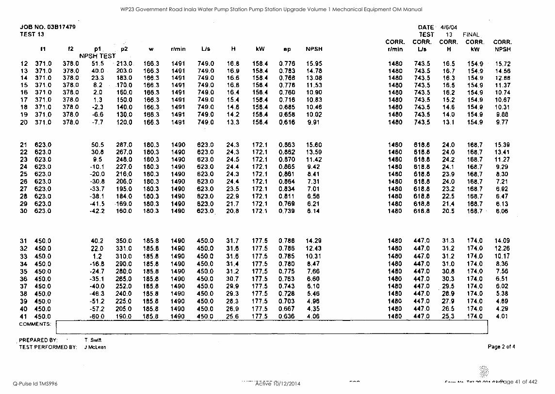
JOB No. 031317479 TEST 13
Thorn sons Kelly& Lewis
CLIENT & PUMP DETAILS JOB NUMBER CLIENT CLIENT REF. PUMP TYPE PUMP SIZE PUMP NUMBER CASE MATERIAL IMPELLER MATERIAL IMPELLER DIAMETER Duty
PUMP PERFORMANCE I hompsons, Kelly & Lewis Pty. Ltd. A.B.N. 15 004 249 012
03817479 STYLE INDUSTRIES Pty
SUPER TITAN 450x500-375 03817470/2 C. I.
BZE
(mm) 350 V-cut Max. (mm) 374
(mm) 328
UNDER FILE 10X50 CONVERSION COEFFICIENTS
Kp1 0.10206 Kp2 0.10206 kd 5E-07 kW:w 1
kq1 Direct kq2 Direct
TEST SPECIFICATION AS2417 - 2001 (ISO 9906:1999(E)) Grade 1
TEST TIME START: 1.15pm FINISH: 3.45pm
TIME 11
1405 370.0 1410 698.0 1413 660.2 1418 630.0 1419 600.3 1422 571.0 1425 539.8 1428 393.8 1431 239.2 1434 101.0 1437 9.6
COMMENTS:
CONCLUSION: PREPARED BY:
12 p1 378 74
76 81 85 76 56 75 79 82 63 60
p2 240 272 297 318 324 317 348 414 438 450 471
Ltd.
TEST SHEET 5 Parker Street Ceatlemaine
DRIVER DETAILS MOTOR MAKE FRAME SERIAL NO. MOTOR LOAD MOTOR EFFICIENCY kW AMPS RATED VOLTS SPEED OF ROTATION (r/min)
P.O Box 19 Caatternaina Victoria 3450 Australia
DATE 4/6/04 TEST 13 FINAL
Telephone (03) 5479 1200 Fax (03) 5479 1201
DIRECT WEG 315B BL23548
1.25 1.00 0.75 0.50 0.25 0.959 0.951 0.939
200 361
415 1485
TEST CONDITIONS MEASURING APPARATUS INLET PIPE DIAMETER (mm) 490 FLOW 1 S/No. V/43028/3/1 ABB Magnetic Flow OUTLET PIPE DIAMETER (mm) 456 FLOW 2 S/No.V/83260/8/1 ABB Magnetic Flow BAROMETRIC PRESSURE (mmHg) 742 INLET -100 to 400kPa T/ducer No.S02582/14 Display No.21100-084 WATER TEMPERATURE (°C) 17 OUTLET 0 to 4000kPa T/ducer No.R00311/13 Display No.21100-075 HEAD CORRECTION TO INLET (m) 0 SPEED Tachometer Display S/No.03L01-055 REFERENCE PLANE OUTLET (m) 0 POWER Digital Power Meter S/No.PA-0106A604-11
w
'Guaranteed Values
CORR.
r/min
SI I h CORRECTION'S ON
CO*. il
NPSH
Stable Us kW NPSH 3H 3A Speed Density Diameter N/A 500 30 175 84.9 7.9 1480
Vibration mmIs R1AS
drnIn Us H kW ep 3V 3H 3A CORR. CORR. CORR.
Us H kW 167.40 1490 748.0 17.2 159.5 0.789 1.00 1.2 1 1480 741.0 17.0 156.3 174.30 1489 898.0 20.3 166.2 0.835 1.00 1.2 1 1480 693.8 20.0 163.2 177.80 1490 660.2 22.3 169.6 0.849 1.00 1.3 1 1480 655.8 22.0 166.3 180.30 1489 830,0 24.0 172.1 0.860 1.20 1.2 1.2 1480 626.2 23.7 169.0 181.30 1490 600,3 25.5 173.1 0.867 1.20 1.1 1 1480 596.3 25.2 169.6 181.80 1490 571.0 26.8 173.6 0.883 1.10 1.3 1.1 1480 567.2 26.4 170.1 181.40 1489 539.8 28.0 173.2 0.855 1.40 1.5 1.3 1480 536.5 27.7 170.1 186.70 1489 393.8 34.3 178.4 0.741 1.70 2.4 1.8 1480 391.4 33.9 175.2 177.40 1489 239.2 36.4 169.3 0.504 2.10 2.5 2.3 1480 237.8 35.9 166.2 182.50 1489 101.0 39.5 174.3 0.224 3.30 3.2 3 1480 100.4 39.0 171.1 178.70 1490 9.6 41.9 170.5 0.023 4.30 4.5 3.7 1480 9.5 41.4 167.1
The test results obtained using the methp described in TKL System Procedure 2001 comply with the relevant requirements of AS2417 - 2001 Grade 1
T. Swift TESTED BY: J.McLean
(I _car, iNa_szen
Page 1 of 4
Till 'IA AM /11//11
WP23 Government Road Inala Water Pump Station Pump Station Upgrade Volume 1 Mechanical Equipment OM Manual
Q-Pulse Id TMS996 Active 10/12/2014 Page 31 of 442
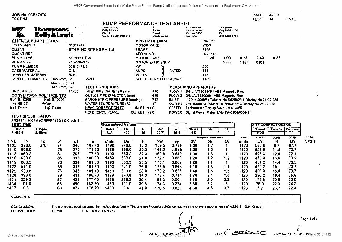
JOB No. 03B17479 TEST 14
Thortopsons Kelly Lewis
CLIENT 8 PUMP DETAILS JOB NUMBER CLIENT CLIENT REF. PUMP 'TYPE PUMP SIZE PUMP NUMBER CASE MATERIAL IMPELLER MATERIAL
03817479 STYLE INDUSTRIES
SUPER TITAN 450x500-375 03E117479/2 C. I.
BZE IMPELLER DIAMETER Duty (mm) 350
Max. (mm) 374 Min. (mm) 328
UNDER FILE 10X50 CONVERSION COEFFICIENTS
Kpi 0.10206 Kp2 0.10206 kd 5E-07 kW:w I
kq1 Direct kq2 Direct
TEST SPECIFICATION AS2417 - 2001 (ISO 9906:1999(E)) Grade 1
TEST TIME START: 1.15pm FINISH: 3.45pm
TIME f1 1405 370.0 1410 698.0 1413 660.2 1416 630.0 1419 600.3 1422 571.0 1425 539.8 1428 393.8 1431 239.2 1434 101.0 1437 9.6
COMMENTS:
CONCLUSION: PREPARED BY:
f2 376
V-cut
PUMP PERFORMANCE TEST SHEET rhompsons,
Kelly & Lewis Pty. Ltd. A.B.N. 15 004 249 012
Pty. Ltd.
5 Parker Street Castlemaine
P.O. Box 49 Casnemaine Victoria 3450 Australia
leleprione (03) 5479 1200 Fax (03) 5479 1201
DATE 4/6/04 TEST 14 FINAL
DRIVER DETAILS DIRECT WEG 3158 BL23548
1.25
200 361
415 1485
1.00 0.959
0.75 0.951
0.50 0.939
0.25
MOTOR MAKE FRAME SERIAL NO. MOTOR LOAD MOTOR EFFICIENCY kW AMPS I RATED VOLTS SPEED OF ROTATION (r/min)
TEST CONDITIONS MEASURING APPARATUS INLET PIPE DIAMETER (mm) 490 FLOW 1 S/No. V/43028/3/1 ABB Magnetic Flow OUTLET PIPE DIAMETER (mm) 456 FLOW 2 S/No.V/83260/8/1 ABB Magnetic Flow BAROMETRIC PRESSURE (mmHg) 742 INLET -100 to 400kPa T/ducer No.S02582/14 Display No.21100-084 WATER TEMPERATURE (°C) 17 OUTLET 0 to 4000kPa T/ducer No.R00311/13 Display No.21100-075 HEAD CORRECTION TO INLET (m) 0 SPEED Tachometer Display S/No.03L01-055 REFERENCE PLANE OUTLET (m) 0 POWER Digital Power Meter S/No.PA-0108A604-11
p1 p2 w
Guaranteed Values
CORR.
r!min
1177617RECTR713777-
CORR.
NPSH
Stable Lis 1 H kW e NPSH 3H 3A Speed Density Diameter N/A 400 I 16 72.7 4.6 1120
I
r/mIn Lis H kW ep Vibration mmls WAS
3V 3H 3A CORR.
Lis CORR.
H CORR.
kW 74 240 167.40 1490 746.0 17.2 159.5 0.789 1.00 1.2 1 1120 560.8 9.7 67.7 76 272 174.30 1489 698.0 20.3 166.2 0.835 1.00 1.2 1 1120 525.0 11.5 70.7 81 297 177.80 1490 660.2 22.3 169.6 0.849 1.00 1.3 1 1120 496.3 12.6 72.1 85 318 180.30 1489 630.0 24.0 172.1 0.860 1.20 1.2 1.2 1120 473.9 13.6 73.2 76 324 181.30 1490 600.3 25.5 173.1 0.867 1.20 1.1 1 1120 451.2 14.4 73.5 56 317 181.80 1490 571.0 26.8 173.6 0.863 1.10 1.3 1.1 1120 429.2 15.1 73.7 75 348 181.40 1489 539.8 28.0 173.2 0.855 1.40 1.5 1.3 1120 406.0 15.8 73.7 79 414 186.70 1489 393.8 34.3 178.4 0.741 1.70 2.4 1.8 1120 296.2 19.4 75.9 82 438 177.40 1489 239.2 36.4 169.3 0.504 2.10 2.5 2.3 1120 179.9 20.6 72.0 63 450 182.50 1489 101.0 39.5 174.3 0.224 3.30 3.2 3 1120 76.0 22.3 74.2 60 471 178.70 1490 9.6 41.9 170.5 0.023 4.30 4.5 3.7 1120 7.2 23.7 72.4
The test results obtained using the method described in TKL System Procedure 2001 comply with the relevant requirements of AS2417 - 2001 Grade 1
T. Swift TESTED BY: J.McLean
VVITNFSRF11 RV FOR
Page 1 of 4
Form No. D(1_20-661-03/01
WP23 Government Road Inala Water Pump Station Pump Station Upgrade Volume 1 Mechanical Equipment OM Manual
Q-Pulse Id TMS996 Active 10/12/2014 Page 32 of 442

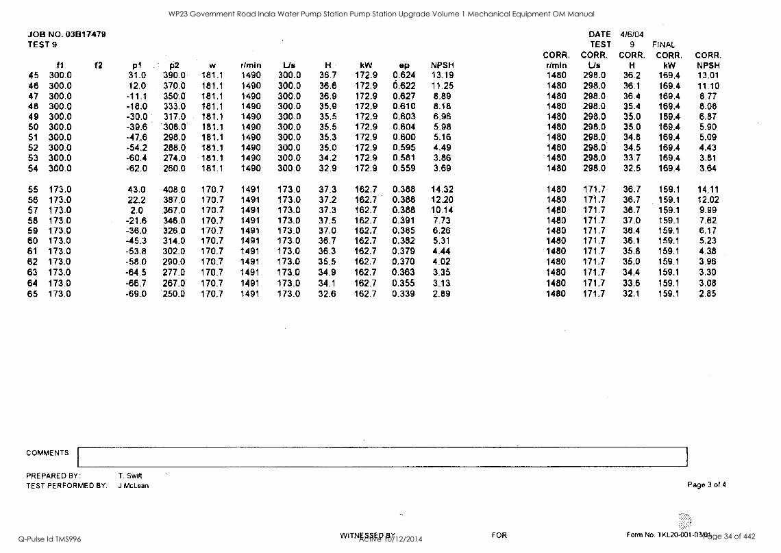
JOB NO. 031317479 TEST 9
11 f2 p1 p2 NPSH TEST
w r/rnin Lis H kW ep NPSH CORR. rimin
DATE TEST
CORR. Us
4/6/04 9
CORR. H
FINAL CORR.
kW CORR. NPSH
12 370.0 380.0 45.0 208.0 170.7 1491 750.0 16.9 162.7 0.764 15.29 1480 744.5 16.7 159.1 15.07 13 370.0 380.0 32.0 198.0 170.7 1491 750.0 17.2 182.7 0.777 13.97 1480 744.5 17.0 159.1 13.76 14 370.0 380.0 21.4 188.0 170.7 1491 750.0 17.3 182.7 0.780 12.88 1480 744.5 17.0 159.1 12.69 15 370.0 380.0 11.7 177.0 170.7 1491 750.0 17.1 162.7 0.774 11.89 1480 744.5 16.9 159.1 11.72 16 370.0 380.0 8.4 165.0 170.7 1491 750.0 16.3 162.7 0.734 11.56 1480 744.5 18.0 159.1 11.39 17 370.0 380.0 4.7 155.0 170.7 1491 750.0 15.6 162.7 0.705 11.18 1480 744.5 15.4 159.1 11.02 18 370.0 380.0 -0.5 145.0 170.7 1491 750.0 15.1 162.7 0.683 10.65 1480 744.5 14.9 159.1 10.49 19 370.0 380.0 -3.7 134.0 170.7 1491 750.0 14.3 162.7 0.647 10.32 1480 744.5 14.1 159.1 10.17 20 370.0 380.0 -7.4 122.0 170.7 1491 750.0 13.5 162.7 0.609 9.94 1480 744.5 13.3 159.1 9.80 21 370.0 380.0 -9.5 112.0 170.7 1491 750.0 12.7 162.7 0.572 9.73 1480 744.5 12.5 159.1 9.59
22 624.0 48.0 286.0 183.6 1490 624.0 24.5 175.4 0.853 15.35 1480 619.8 24.1 171.8 15.14 23 624.0 37.0 274.0 183.6 1490 624.0 24.4 175.4 0.850 14.23 1480 619.8 24.0 171.8 14.04 24 624.0 24.4 264.0 183.6 1490 824.0 24.6 175.4 0.859 12.94 1480 619.8 24.3 171.8 12.77 25 624.0 14.2 253.0 183.6 1490 824.0 24.6 175.4 0.856 11.90 1480 619.8 24.2 171.8 11.74 26 624.0 2.0 244.0 183.6 1490 824.0 24.9 175.4 0.868 10.66 1480 619.8 24.6 171.8 10.51 27 624.0 -13.0 231.0 183.6 1490 624.0 25.1 175.4 0.875 9.12 1480 819.8 24.8 171.8 9.00 28 624.0 -17.4 222.0 183.6 1490 824.0 24.6 175.4 0.858 8.68 1480 819.8 24.3 171.8 8.56 29 624.0 -23.3 211.0 183.6 1490 824.0 24.1 175.4 0.840 8.07 1480 819.8 23.8 171.8 7.97 30 624.0 -33.5 201.0 183.6 1490 624.0 24.1 175.4 0.841 7.03 1480 619.8 23.8 171.8 8.94 31 624.0 -38.3 185.0 183.6 1490 824.0 23.0 175.4 0.801 6.54 1480 619.8 22.7 171.8 6.46 32 624:0 -41.5 175.0 183.6 1490 624.0 22.3 175.4 0.777 6.22 1480 619.8 22.0 171.8 6.13 33 624.0 -42.6 165.0 183.6 1490 624.0 21.4 175.4 0.745 6.10 1480 619.8 21.1 171.8 6.02
34 449.8 35.3 348.0 188.0 1490 449.8 32.0 179.7 0.785 13.79 1480 448.8 31.6 176.1 13.60 35 449.8 23.6 336.0 188.0 1490 449.8 32.0 179.7 0.784 12.59 1480 446.8 31.6 176.1 12.42 36 449.8 13.0 325.0 188.0 1490 449.8 31.9 179.7 0.783 11.51 1480 446.8 31.5 176.1 11.36 37 449.8 2.8 315.0 188.0 1490 449.8 32.0 179.7 0.784 10.47 1480 446.8 31.5 176.1 10.33 38 449.8 -7.3 303.0 188.0 1490 449.8 31.8 179.7 0.779 9.44 1480 446.8 31.3 176.1 9.31 39 449.8 -19.3 292.0 188.0 1490 449.8 31.9 179.7 0.782 8.21 1480 446.8 31.4 176.1 8.10 40 449.8 -28.1 282.0 188.0 1490 449.8 31.7 179.7 0.779 7.32 1480 446.8 31.3 176.1 7.22 41 449.8 -36.7 287.0 188.0 1490 449.8 31.1 179.7 0.783 6.44 1480 446.8 30.7 176.1 8.35 42 449.8 -42.4 257.0 188.0 1490 449.8 30.7 179.7 0.752 5.88 1480 446.8 30.2 176.1 5.78 43 449.8 -49.4 240.0 188.0 1490 449.8 29.6 179.7 0.727 5.14 1480 446.8 29.2 176.1 5.07 44 449.8 -54.0 221.0 188.0 1490 449.8 28.2 179.7 0.691 4.67 1480 446.8 27.8 176.1 4.61 COMMENTS:
PREPARED BY: T. Swift
TEST PERFORMED BY: J.McLean
UVITNIPARLII RY Fnia
Page 2 of 4
Form No TKI 20-001-03/01
WP23 Government Road Inala Water Pump Station Pump Station Upgrade Volume 1 Mechanical Equipment OM Manual
Q-Pulse Id TMS996 Active 10/12/2014 Page 33 of 442
JOB NO. 03B17479 TEST 9
f1 f2 p1 p2 w r/min Lis H kW ep NPSH CORR. r/min
DATE TEST
CORR. Us
4/6/04 9
CORR. H
FINAL CORR.
kW CORR. NPSH
45 300.0 31.0 390.0 181.1 1490 300.0 36.7 172.9 0.624 13.19 1480 298.0 36.2 169.4 13.01 46 300.0 12.0 370.0 181.1 1490 300.0 36.6 172.9 0.622 11.25 1480 298.0 36.1 169.4 11.10 47 300.0 -11.1 350.0 181.1 1490 300.0 36.9 172.9 0.627 8.89 1480 298.0 36.4 169.4 8.77 48 300.0 -18.0 333.0 181.1 1490 300.0 35.9 172.9 0.610 8.18 1480 298.0 35.4 169.4 8.08 49 300.0 -30.0 317.0 181.1 1490 300.0 35.5 172.9 0.603 6.96 1480 298.0 35.0 169.4 6.87 50 300.0 -39.6 308.0 181.1 1490 300.0 35.5 172.9 0.604 5.98 1480 298.0 35.0 189.4 5.90 51 300.0 -47.6 298.0 181.1 1490 300.0 35.3 172.9 0.600 5.16 1480 298.0 34.8 169.4 5.09 52 300.0 -54.2 288.0 181.1 1490 300.0 35.0 172.9 0.595 4.49 1480 298.0 34.5 189.4 4.43 53 300.0 -60.4 274.0 181.1 1490 300.0 34.2 172.9 0.581 3.86 1480 298.0 33.7 169.4 3.81 54 300.0 -62.0 260.0 181.1 1490 300.0 32.9 172.9 0.559 3.69 1480 298.0 32.5 169.4 3.64
55 173.0 43.0 408.0 170.7 1491 173.0 37.3 162.7 0.388 14.32 1480 171.7 36.7 159.1 14.11 56 173.0 22.2 387.0 170.7 1491 173.0 37.2 162.7 0.388 12.20 1480 171.7 36.7 159.1 12.02 57 173.0 2.0 .367.0 170.7 1491 173.0 37.3 162.7 0.388 10.14 1480 171.7 36.7 159.1 9.99 58 173.0 -21.6 346.0 170.7 1491 173.0 37.5 162.7 0.391 7.73 1480 171.7 37.0 159.1 7.62 59 173.0 -36.0 326.0 170.7. 1491 173.0 37.0 162.7 0.385 6.26 1480 171.7 38.4 159.1 6.17 80 173.0 -45.3 314.0 170.7 1491 173.0 36.7 162.7 0.382 5.31 1480 171.7 36.1 159.1 5.23 61 173.0 -53.8 302.0 170.7 1491 173.0 36.3 162.7 0.379 4.44 1480 171.7 35.8 159.1 4.38 62 173.0 -58.0 290.0 170.7 1491 173.0 35.5 162.7 0.370 4.02 1480 171.7 35.0 159.1 3.96 63 173.0 -64.5 277.0 170.7 1491 173.0 34.9 162.7 0.363 3.35 1480 171.7 34.4 159.1 3.30 64 173.0 -66.7 267.0 170.7 1491 173.0 34.1 162.7 0.355 3.13 1480 171.7 33.6 159.1 3.08 65 173.0 -69.0 250.0 170.7 1491 173.0 32.6 162.7 0.339 2.89 1480 171.7 32.1 159.1 2.85
COMMENTS.
PREPARED BY: T. Swift
TEST PERFORMED BY: J McLean
WITNESSED BY FOR
Page 3 of 4
Form No. TKL20-001-03/01
WP23 Government Road Inala Water Pump Station Pump Station Upgrade Volume 1 Mechanical Equipment OM Manual
Q-Pulse Id TMS996 Active 10/12/2014 Page 34 of 442

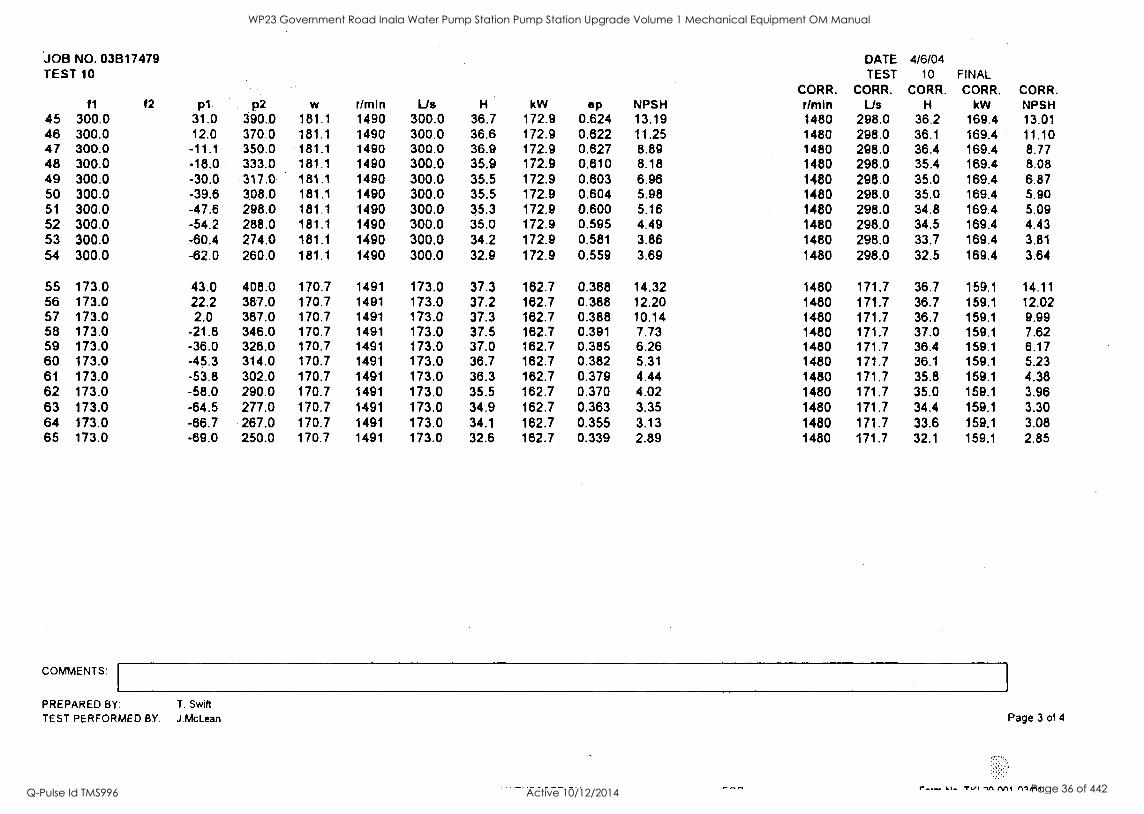
JOB NO. 03817479 TEST 10
f2 p1 p2 NPSH TEST.
w r /min Vs H kW ep NPSH CORR. rimin
DATE TEST
CORR. Lis
4/6/04 10
CORR. H
FINAL, CORR.
kW CORR. NPSH
12 370.0 380.0 45.0 208.0 170.7 1491 750.0 16.9 162.7 0.764 15.29 1480 744.5 16.7 159.1 15.07 13 370.0 380.0 32.0. 198.0 170.7 1491 750.0 17.2 162.7 0.777 13.97 1480 744.5 17.0 159.1 13.76 14 370.0 380.0 21.4 188.0 170.7 1491 750.0 17.3 162.7 0.780 12.88 1480 744.5 17.0 159.1 12.69 15 370.0 380.0 11.7 177.0 170.7 1491 750.0 17.1 162.7 0.774 11.89 1480 744.5 16.9 159.1 11.72 16 370.0 380.0 8.4 165.0 170.7 1491 750.0 16.3 162.7 0.734 11.56 1480 744.5 18.0 159.1 11.39 17 370.0 380.0 4.7 155.0 170.7 1491 750.0 15.6 162.7 0.705 11.18 1480 744.5 15.4 159.1 11.02 18 370.0 380.0 -0.5 145.0 170.7 1491 750.0 15.1 162.7 0.683 10.65 1480 744.5 14.9 159.1 10.49 19 370.0 380.0 -3.7 134.0 170.7 1491 750.0 14.3 162.7 0.647 10.32 1480 744.5 14.1 159.1 10.17 20 370.0 380.0 -7.4 122.0 170.7 1491 750.0 13.5 162.7 0.609 9.94 1480 744.5 13.3 159.1 9.80 21 370.0 380.0 -9.5 112.0 170.7 1491 750.0 12.7 162.7 0.572 9.73 1480 744.5 12.5 159.1 9.59
22 624.0 48.0 286.0 183.6 1490 624.0 24.5 175.4 0.853 15.35 1480 619.8 24.1 171.8 15.14 23 624.0 37.0 274.0 183.6 1490 624.0 24.4 175.4 0.850 14.23 1480 619.8 24.0 171.8 14.04 24 624.0 24.4 264.0 183.6 1490 624.0 24.6 175.4 0.859 12.94 1480 619.8 24.3 171.8 12.77 25 624.0 14.2 253.0 183.6 1490 624.0 24.6 175.4 0.856 11.90 1480 619.8 24.2 171.8 11.74 26 624.0 2.0 244.0 183.6 1490. 624.0 24.9 175.4 0.868 10.66 1480 619.8 24.6 171.8 10.51 27 624.0 -13.0 231.0 183.6 1490 624.0 25.1 175.4 0.875 9.12 1480 619.8 24.8 171.8 9.00 28 624.0 -17.4 222.0 183.8 1490 624.0 24.6 175.4 0.858 8.68 1480 619.8 24.3 171.8 8.56 29 624.0 -23.3 211.0 183.6 1490 624.0 24.1 175.4 0.840 8.07 1480 619.8 23.8 171.8 7.97 30 624.0 -33.5 201.0 183.8 1490 624.0 24.1 175.4 0.841 7.03 1480 619.8 23.8 171.8 6.94 31 624.0 -38.3 185.0 183.8 1490 624.0 23.0 175.4 0.801 6.54 1480 619.8 22.7 171.8 6.46 32 624.0 -41.5 175.0 183.6 1490 624.0 22.3 175.4 0.777 6.22 1480 619.8 22.0 171.8 6.13 33 624.0 -42.8 185.0 183.6 1490 624.0 21.4 175.4 0.745 8.10 1480 619.8 21.1 171.8 8.02
34 449.8 35.3 348.0 188.0 1490 449.8 32.0 179.7 0.785 13.79 1480 446.8 31.6 176.1 13.60 35 449.8 23.6 338.0 188.0 1490 449.8 32.0 179.7 0.784 12.59 1480 446.8 31.6 176.1 12.42 36 449.8 13.0 325.0 188.0 1490 449.8 31.9 179.7 0.783 11.51 1480 446.8 31.5 178.1 11.36 37 449.8 2.8 315.0 188.0 1490 449.8 32.0 179.7 0.784 10.47 1480 446.8 31.5 178.1 10.33 38 449.8 -7.3 303.0 188.0 1490 449.8 31.8 179.7 0.779 9.44 1480 446.8 31.3 178.1 9.31 39 449.8 -19.3 292.0 188.0 1490 449.8 31.9 179.7 0.782 8.21 1480 446.8 31.4 178.1 8.10 40 449.8 -28.1 282.0 188.0 1490 449.8 31.7 179.7 0.779 7.32 1480 446.8 31.3 176.1 7.22 41 449.8 -36.7 267.0 188.0 1490 449.8 31.1 179.7 0.763 6.44 1480 446.8 30.7 176.1 6.35 42 449.8 -42.4 257.0 188.0 1490 449.8 30.7 179.7 0.752 5.86 1480 446.8 30.2 176.1 5.78 43 449.8 -49.4 240.0 188.0 1490 449.8 29.6 179.7 0.727 5.14 1480 446.8 29.2 176.1 5.07 44 449.8 -54.0 221.0 188.0 1490 449.8 28.2 179.7 0.691 4.67 1480 446.8 27.8 176.1 4.61 COMMENTS:
PREPARED BY: T. Swift
TEST PERFORMED BY: J.McLean
A41-rLirneers GV Ce,0
Page 2 of 4
7fl.fitIl
WP23 Government Road Inala Water Pump Station Pump Station Upgrade Volume 1 Mechanical Equipment OM Manual
Q-Pulse Id TMS996 Active 10/12/2014 Page 35 of 442
JOB NO. 03B17479 TEST 10
fl f2 p1 p2 w r/min Us H kW ep NPSH CORR. r/min
DATE TEST
CORR. Us
4/6/04 10
CORR. H
FINAL CORR.
kW CORR. NPSH
45 300.0 31.0 390.0 181.1 1490 300.0 36.7 172.9 0.624 13.19 1480 298.0 36.2 169.4 13.01 46 300.0 12.0 370.0 181.1 1490 300.0 36.6 172.9 0.622 11.25 1480 298.0 36.1 169.4 11.10 47 300.0 -11.1 350.0 181.1 1490 300.0 36.9 172.9 0.627 8.89 1480 298.0 36.4 169.4 8.77 48 300.0 -18.0 333.0 181.1 1490 300.0 35.9 172.9 0.810 8.18 1480 298.0 35.4 169.4 8.08 49 300.0 -30.0 317.0 181.1 1490 300.0 35.5 172.9 0.603 6.96 1480 298.0 35.0 169.4 6.87 50 300.0 -39.6 308.0 181.1 1490 300.0 35.5 172.9 0.604 5.98 1480 298.0 35.0 169.4 5.90 51 300.0 -47.6 298.0 181.1 1490 300.0 35.3 172.9 0.600 5.16 1480 298.0 34.8 169.4 5.09 52 300.0 -54.2 288.0 181.1 1490 300.0 35.0 172.9 0.595 4.49 1480 298.0 34.5 169.4 4.43 53 300.0 -60.4 274.0 181.1 1490 300.0 34.2 172.9 0.581 3.86 1480 298.0 33.7 169.4 3.81 54 300.0 -62.0 260.0 181.1 1490 300.0 32.9 172.9 0.559 3.69 1480 298.0 32.5 169.4 3.64
55 173.0 43.0 408.0 170.7 1491 173.0 37.3 162.7 0.388 14.32 1480 171.7 36.7 159.1 14.11 56 173.0 22.2 387.0 170.7 1491 173.0 37.2 182.7 0.388 12.20 1480 171.7 36.7 159.1 12.02 57 173.0 2.0 387.0 170.7 1491 173.0 37.3 182.7 0.388 10.14 1480 171.7 36.7 159.1 9.99 58 173.0 -21.6 346.0 170.7 1491 173.0 37.5 182.7 0.391 7.73 1480 171.7 37.0 159.1 7.62 59 173.0 -36.0 328.0 170.7 1491 173.0 37.0 182.7 0.385 6.26 1480 171.7 36.4 159.1 6.17 60 173.0 -45.3 314.0 170.7 1491 173.0 38.7 182.7 0.382 5.31 1480 171.7 36.1 159.1 5.23 61 173.0 -53.8 302.0 170.7 1491 173.0 36.3 162.7 0.379 4.44 1480 171.7 35.8 159.1 4.38 62 173.0 -58.0 290.0 170.7 1491 173.0 35.5 162.7 0.370 4.02 1480 171.7 35.0 159.1 3.96 63 173.0 -64.5 277.0 170.7 1491 173.0 34.9 162.7 0.363 3.35 1480 171.7 34.4 159.1 3.30 64 173.0 -86.7 267.0 170.7 1491 173.0 34.1 182.7 0.355 3.13 1480 171.7 33.6 159.1 3.08 65 173.0 -69.0 250.0 170.7 1491 173.0 32.6 162.7 0.339 2.89 1480 171.7 32.1 159.1 2.85
COMMENTS:
PREPARED BY: T. Swift
TEST PERFORMED BY: J.McLean Page 3 of 4
r T1/I .1A Ar14 1111/11
WP23 Government Road Inala Water Pump Station Pump Station Upgrade Volume 1 Mechanical Equipment OM Manual
Q-Pulse Id TMS996 Active 10/12/2014 Page 36 of 442
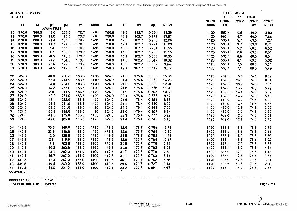
JOB NO. 03B17479 TEST 11
f1 f2 p1 p2 NPSH TEST
w rimin Lie H kW ep NPSH CORR. dmin
DATE TEST
CORR. Lie
4/6/04 11
CORR. H
FINAL CORR.
kW CORR. NPSH
12 370.0 380.0 45.0 208.0 170.7 1491 750.0 16.9 162.7 0.764 15.29 1120 563.4 9.5 69.0 8.63 13 370.0 380.0 32.0 198.0 170.7 1491 750.0 17.2 162.7 0.777 13.97 1120 563.4 9.7 69.0 7.88 14 370.0 380.0 21.4 188.0 170.7 1491 750.0 17.3 162.7 0.780 12.88 1120 563.4 9.7 69.0 7.27 15 370.0 380.0 11.7 177.0 170.7 1491 750.0 17.1 182.7 0.774 11.89 1120 563.4 9.7 69.0 6.71 16 370.0 380.0 8.4 165.0 170.7 1491 750.0 16.3 162.7 0.734 11.56 1120 563.4 9.2 69.0 6.52 17 370.0 380.0 4.7 155.0 170.7 1491 750.0 15.6 162.7 0.705 11.18 1120 563.4 8.8 69.0 6.31 18 370.0 380.0 -0.5 145.0 170.7 1491 750.0 15.1 162.7 0.683 10.65 1120 563.4 8.5 69.0 6.01 19 370.0 380.0 -3.7 134.0 170.7 1491 750.0 14.3 162.7 0.647 10.32 1120 563.4 8.1 69.0 5.82 20 370.0 380.0 -7.4 122.0 170.7 1491 750.0 13.5 162.7 0.609 9.94 1120 563.4 7.6 69.0 5.61 21 370.0 380.0 -9.5 112.0 170.7 1491 750.0 12.7 162.7 0.572 9.73 1120 563.4 7.1 69.0 5.49
22 624.0 48.0 286.0 183.6 1490 624.0 24.5 175.4 0.853 15.35 1120 469.0 13.8 74.5 8.67 23 624.0 37.0 274.0 183.6 1490 624.0 24.4 175.4 0.850 14.23 1120 469.0 13.8 74.5 8.04 24 624.0 24.4 264.0 183.6 1490 624.0 24.6 175.4 0.859 12.94 1120 469.0 13.9 74.5 7.31 25 624.0 14.2 253.0 183.6 1490 624.0 24.6 175.4 0.856 11.90 1120 469.0 13.9 74.5 6.72 26 624.0 2.0 244.0 183.6 1490 624.0 24.9 175.4 0.868 10.66 1120 469.0 14.1 74.5 6.02 27 624.0 -13.0 231.0 183.6 1490 624.0 25.1 175.4 0.875 9.12 1120 469.0 14.2 74.5 5.16 28 624.0 -17.4 222.0 183.6 1490 624.0 24.6 175.4 0.858 8.88 1120 469.0 13.9 74.5 4.90 29 624.0 -23.3 211.0 183.6 1490 624.0 24.1 175.4 0.840 8.07 1120 469.0 13.6 74.5 4.56 30 624.0 -33.5 201.0 183.6 1490 624.0 24.1 175.4 0.841 7.03 1120 469.0 13.6 74.5 3.97 31 624.0 -38.3 185.0 183.8 1490 624.0 23.0 175.4 0.801 6.54 1120 469.0 13.0 74.5 3.70 32 624.0 -41.5 175.0 183.8 1490 624.0 22.3 175.4 0.777 6.22 1120 469.0 12.6 74.5 3.51 33 624.0 -42.6 165.0 183.6 1490 624.0 21.4 175.4 0.745 6.10 1120 469.0 12.1 74.5 3.45
34 449.8 35.3 348.0 188.0 1490 449.8 32.0 179.7 0.785 13.79 1120 338.1 18.1 76.3 7.79 35 449.8 23.6 336.0 188.0 1490 449.8 32.0 179.7 0.784 12.59 1120 338.1 18.1 76.3 7.11 36 449.8 13.0 325.0 188.0 1490 449.8 31.9 179.7 0.783 11.51 1120 338.1 18.0 76.3 6.50 37 449.8 2.8 315.0 188.0 1490 449.8 32.0 179.7 0.784 10.47 1120 338.1 18.1 76.3 5.92 38 449.8 -7.3 303.0 188.0 1490 449.8 31.8 179.7 0.779 9.44 1120 338.1 17.9 76.3 5.33 39 449.8 -19.3 292.0 188.0 1490 449.8 31.9 179.7 0.782 8.21 1120 338.1 18.0 76.3 4.64 40 449.8 -28.1 282.0 188.0 1490 449.8 31.7 179.7 0.779 7.32 1120 338.1 17.9 76.3 4.13 41 449.8 -36.7 267.0 188.0 1490 449.8 31.1 179.7 0.763 8.44 1120 338.1 17.6 76.3 3.64 42 449.8 -42.4 257.0 188.0 1490 449.8 30.7 179.7 0.752 5.86 1120 338.1 17.3 76.3 3.31 43 449.8 -49.4 240.0 188.0 1490 449.8 29.6 179.7 0.727 5.14 1120 338.1 16.7 76.3 2.90 44 449.8 -54.0 221.0 188.0 1490 449.8 28.2 179.7 0.691 4.67 1120 338.1 15.9 76.3 2.64 COMMENTS:
PREPARED BY: T. Swift
TEST PERFORMED BY: McLean
VVITNP SSP n RY FOR
Page 2 of 4
Form No. 'I KL20-001 -03/01
WP23 Government Road Inala Water Pump Station Pump Station Upgrade Volume 1 Mechanical Equipment OM Manual
Q-Pulse Id TMS996 Active 10/12/2014 Page 37 of 442
JOB NO. 03B17479 TEST 11
11 f2 p1 p2 w r/min Us H kW ep NPSH CORR. r/min
DATE TEST
CORR. Us
4/6/04 11
CORR. H
FINAL CORR.
kW CORR. NPSH
45 300.0 31.0 390.0 181.1 1490 300.0 36.7 172.9 0.824 13.19 1120 225.5 20.7 73.4 7.45 46 300.0 12.0 370.0 181.1 1490 300.0 38.6 172.9 0.622 11.25 1120 225.5 20.7 73.4 6.35 47 300.0 -11.1 350.0 181.1 1490 300.0 36.9 172.9 0.627 8.89 1120 225.5 20.8 73.4 5.02 48 300.0 -18.0 333.0 181.1 1490 300.0 35.9 172.9 0.810 8.18 1120 225.5 20.3 73.4 4.62 49 300.0 -30.0 317.0 181.1 1490 300.0 35.5 172.9 0.603 6.96 1120 225.5 20.0 73.4 3.93 50 300.0 -39.6 308.0 181.1 1490 300.0 35.5 172.9 0.604 5.98 1120 225.5 20.1 73.4 3.38 51 300.0 -47.6 298.0 181.1 1490 300.0 35.3 172.9 0.600 5.16 1120 225.5 20.0 73.4 2.92 52 300.0 -54.2 288.0. 181.1 1490 300.0 35.0 172.9 0.595 4.49 1120 225.5 19.8 73.4 2.54 53 300.0 -60.4 274.0 181.1 1490 300.0 34.2 172.9 0.581 3.86 1120 225.5 19.3 73.4 2.18 54 300.0 -62.0 260.0 181.1 1490 300.0 32.9 172.9 0.559 3.69 1120 225.5 18.6 73.4 2.09
55 173.0 43.0 408.0 170.7 1491 173.0 37.3 162.7 0.388 14.32 1120 130.0 21.0 69.0 8.08 56 173.0 22.2 387.0 170.7 1491 173.0 37.2 162.7 0.388 12.20 1120 130.0 21.0 69.0 6.88 57 173.0 2.0 367.0 170.7 1491 173.0 37.3 162.7 0.388 10.14 1120 130.0 21.0 69.0 5.72 58 173.0 -21.6 346:0 170.7 1491 173.0 37.5 162.7 0.391 7.73 1120 130.0 21.2 69.0 4.36 59 173.0 -36.0 326.0 170.7 1491 173.0 37.0 162.7 0.385 6.26 1120 130.0 20.9 69.0 3.53 60 173.0 -45.3 314.0 170.7 1491 173.0 36.7 162.7 0.382 5.31 1120 130.0 20.7 69.0 3.00 61 173.0 -53.8 302.0 170.7 1491 173.0 36.3 162.7 0.379 4.44 1120 130.0 20.5 69.0 2.51 62 173.0 -58.0 290.0 170.7 1491 173.0 35.5 182.7 0.370 4.02 1120 130.0 20.0 69.0 2.27 63 173.0 -64.5 277.0 170.7 1491 173.0 34.9 162.7 0.363 3.35 1120 130.0 19.7 69.0 1.89 64 173.0 -66.7 267.0 170.7 1491 173.0 34.1 162.7 0.355 3.13 1120 130.0 19.2 69.0 1.77 65 173.0 -69.0 250.0 170.7 1491 173.0 32.6 162.7 0.339 2.89 1120 130.0 18.4 69.0 1.63
COMMENTS:
PREPARED BY: T. Swift
TEST PERFORMED BY: J.McLean
WITNESSED BY FOR
Page 3 of 4
Form No.1 isLzu-jot -03/01
WP23 Government Road Inala Water Pump Station Pump Station Upgrade Volume 1 Mechanical Equipment OM Manual
Q-Pulse Id TMS996 Active 10/12/2014 Page 38 of 442
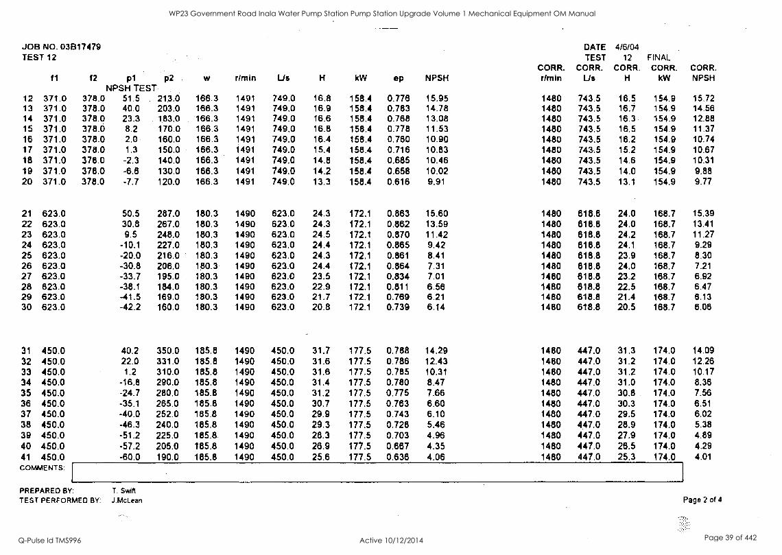
JOB NO. 03B17479 TEST 12
f1 f2 p1 p2 NPSH TEST
w rlmin Us H kW ep NPSH CORR. Om in
DATE TEST
CORR. Us
4/6/04 12
CORR. H
FINAL CORR.
kW CORR. NPSH
12 371.0 378.0 51.5 213.0 166.3 1491 749.0 16.8 158.4 0.778 15.95 1480 743.5 16.5 154.9 15.72 13 371.0 378.0 40.0 203.0 166.3 1491 749.0 16.9 158.4 0.783 14.78 1480 743.5 16.7 154.9 14.56 14 371.0 378.0 23.3 183.0 166.3 1491 749.0 16.6 158.4 0.768 13.08 1480 743.5 16.3 154.9 12.88 15 371.0 378.0 8.2 170.0 166.3 1491 749.0 16.8 158.4 0.778 11.53 1480 743.5 16.5 154.9 11.37 16 371.0 378.0 2.0 160.0 166.3 1491 749.0 16.4 158.4 0.760 10.90 1480 743.5 16.2 154.9 10.74 17 371.0 378.0 1.3 150.0 166.3 1491 749.0 15.4 158.4 0.716 10.83 1480 743.5 15.2 154.9 10.67 18 371.0 378.0 -2.3 140.0 166.3 1491 749.0 14.8 158.4 0.685 10.46 1480 743.5 14.6 154.9 10.31 19 371.0 378.0 -6.8 130.0 166.3 1491 749.0 14.2 158.4 0.658 10.02 1480 743.5 14.0 154.9 9.88 20 371.0 378.0 -7.7 120.0 166.3 1491 749.0 13.3 158.4 0.616 9.91 1480 743.5 13.1 154.9 9.77
21 623.0 50.5 287.0 180.3 1490 623.0 24.3 172.1 0.863 15.60 1480 818.8 24.0 168.7 15.39 22 623.0 30.8 267.0 180.3 1490 623.0 24.3 172.1 0.862 13.59 1480 818.8 24.0 168.7 13.41 23 623.0 9.5 248.0 180.3 1490 623.0 24.5 172.1 0.870 11.42 1480 818.8 24.2 168.7 11.27 24 623.0 -10.1 227.0 180.3 1490 623.0 24.4 172.1 0.865 9.42 1480 818.8 24.1 168.7 9.29 25 623.0 -20.0 216.0 180.3 1490 623.0 24.3 172.1 0.861 8.41 1480 818.8 23.9 168.7 8.30 26 623.0 -30.8 206.0 180.3 1490 623.0 24.4 172.1 0.864 7.31 1480 618.8 24.0 168.7 7.21 27 623.0 -33.7 195.0 180.3 1490 623.0 23.5 172.1 0.834 7.01 1480 818.8 23.2 168.7 6.92 28 623.0 -38.1 184.0 180.3 1490 623.0 22.9 172.1 0.811 6.58 1480 618.8 22.5 168.7 6.47 29 623.0 -41.5 169.0 180.3 1490 623.0 21.7 172.1 0.769 6.21 1480 818.8 21.4 168.7 8.13 30 623.0 -42.2 160.0 180.3 1490 623.0 20.8 172.1 0.739 6.14 1480 618.8 20.5 168.7 8.06
31 450.0 40.2 350.0 185.8 1490 450.0 31.7 177.5 0.788 14.29 1480 447.0 31.3 174.0 14.09 32 450.0 22.0 331.0 185.8 1490 450.0 31.6 177.5 0.786 12.43 1480 447.0 31.2 174.0 12.26 33 450.0 1.2 310.0 185.8 1490 450.0 31.6 177.5 0.785 10.31 1480 447.0 31.2 174.0 10.17 34 450.0 -16.8 290.0 185.8 1490 450.0 31.4 177.5 0.780 8.47 1480 447.0 31.0 174.0 8.36 35 450.0 -24.7 280.0 185.8 1490 450.0 31.2 177.5 0.775 7.66 1480 447.0 30.8 174.0 7.56 36 450.0 -35.1 265.0 185.8 1490 450.0 30.7 177.5 0.783 6.60 1480 447.0 30.3 174.0 6.51 37 450.0 -40.0 252.0 185.8 1490 450.0 29.9 177.5 0.743 6.10 1480 447.0 29.5 174.0 6.02 38 450.0 -46.3 240.0 185.8 1490 450.0 29.3 177.5 0.728 5.46 1480 447.0 28.9 174.0 5.38 39 450.0 -51.2 225.0 185.8 1490 450.0 28.3 177.5 0.703 4.96 1480 447.0 27.9 174.0 4.89 40 450.0 57.2 205.0 185.8 1490 450.0 26.9 177.5 0.687 4.35 1480 447.0 28.5 174.0 4.29 41 450.0 -60.0 190.0 185.8 1490 450.0 25.6 177.5 0.636 4.06 1480 447.0 25.3 174.0 4.01 COMMENTS:
PREPARED BY: T. Swift
TEST PERFORMED BY: J.McLean Page 2 of 4
WP23 Government Road Inala Water Pump Station Pump Station Upgrade Volume 1 Mechanical Equipment OM Manual
Q-Pulse Id TMS996 Active 10/12/2014 Page 39 of 442
JOB NO. 03B17479 TEST 12
f1 f2 p1 p2 w r/min Us H kW op NPSH CORR. Amin
DATE TEST
CORR. Us
4/6/04 12
CORR. H
FINAL CORR.
kW CORR. NPSH
42 300.0 39.0 393.0. 181.7 1490 300.0 36.2 173.5 0.613 14.00 1480 298.0 35.7 170.0 13.81 43 300.0 18.9 372.0 181.7 1490 300.0 36.1 173.5 0.611 11.95 1480 298.0 35.6 170.0 11.79 44 300.0 -4.0 350.0 181.7 1490 300.0 36.2 173.5 0.813 9.61 1480 298.0 35.7 170.0 9.49 45 300.0 -13.5 339.0 181.7 1490 300.0 38.0 173.5 0.810 8.64 1480 298.0 35.5 170.0 8.53 46 300.0 -24.0 324.0 181.7 1490 300.0 35.6 173.5 0.603 7.57 1480 298.0 35.1 170.0 7.47 47 300.0 -34.0 314.0 181.7 1490 300.0 35.6 173.5 0.603 6.55 1480 298.0 35.1 170.0 6.46 48 300.0 -43.5 301.0 181.7 1490 300.0 35.2 173.5 0.596 5.58 1480 298.0 34.7 170.0 5.51 49 300.0 -51.7 289.0 181.7 1490 300.0 34.8 173.5 0.590 4.75 1480 298.0 34.3 170.0 4.68 50 300.0 -59.0 287.0 181.7 1490 300.0 33.3 173.5 0.584 4.00 1480 298.0 32.9 170.0 3.95 51 300.0 -64.0 245.0 181.7 1490 300.0 31.6 173.5 0.535 3.49 1480 298.0 31.2 170.0 3.44 52 300.0 -65.0 230.0 181.7 1490 300.0 30.2 173.5 0.511 3.39 1480 298.0 29.7 170.0 3.34
53 173.0 18.0 383.0 180.3 1489 173.0 37.3 172.1 0.367 11.77 1480 172.0 36.8 169.0 11.63 54 173.0 -6.6 385.0 180.3 1489 173.0 37.9 172.1 0.374 9.26 1480 172.0 37.5 189.0 9.15 55 173.0 -18.0 348.0 180.3 1489 173.0 37.4 172.1 0.368 8.10 1480 172.0 36.9 169.0 8.00 56 173.0 -30.0 338.0 180.3 1489 173.0 37.6 172.1 0.370 6.87 1480 172.0 37.1 169.0 6.79 57 173.0 -38.4 327.0 180.3 1489 173.0 37.3 172.1 0.367 6.02 1480 172.0 36.9 169.0. 5.94 58 173.0 -47.4 314.0 180.3 1489 173.0 38.9 172.1 0.363 5.10 1480 172.0 38.5 169.0 5.04 59 173.0 -54.9 304.0 180.3 1489 173.0 38.6 172.1 0.361 4.33 1480 172.0 38.2 169.0 4.28 60 173.0 -59.3 290.0 180.3 1489 173.0 35.7 172.1 0.351 3.88 1480 172.0 35.2 169.0 3.84 61 173.0 -63.2 278.0 180.3 1489 173.0 34.8 172.1 0.343 3.49 1480 172.0 34.4 169.0 3.44 62 173.0 -66.0 264.0 180.3 1489 173.0 33.7 172.1 0.332 3.20 1480 172.0 33.3 169.0 3.16 63 173.0 -67.0 250.0 180.3 1489 173.0 32.4 172.1 0.319 3.10 1480 172.0 32.0 169.0 3.06
COMMENTS:
PREPARED BY: T. Swift
TEST PERFORMED BY: J.McLean Page 3 of 4
VulTAICCCrIlfZIV FrA Form No TKL20:601-03/01
WP23 Government Road Inala Water Pump Station Pump Station Upgrade Volume 1 Mechanical Equipment OM Manual
Q-Pulse Id TMS996 Active 10/12/2014 Page 40 of 442
JOB NO. 03B17479 TEST 13
f1 f2 p1 p2 NPSH TEST
w rlmin Us H kW ep NPSH CORR. timin
DATE TEST
CORR. Us
4/6/04 13
CORR. H
FINAL CORR.
kW CORR. NPSH
12 371.0 378.0 51.5 213.0 166.3 1491 749.0 16.8 158.4 0.776 15.95 1480 743.5 16.5 154.9 15.72 13 371.0 378.0 40.0 203.0 166.3 1491 749.0 16.9 158.4 0.783 14.78 1480 743.5 16.7 154.9 14.56 14 371.0 378.0 23.3 183.0 168.3 1491 749.0 16.6 158.4 0.768 13.08 1480 743.5 16.3 154.9 12.88 15 371.0 378.0 8.2 170.0 166.3 1491 749.0 16.8 158.4 0.778 11.53 1480 743.5 16.5 154.9 11.37 16 371.0 378.0 2.0 160.0 166.3 1491 749.0 16.4 158.4 0.760 10.90 1480 743.5 16.2 154.9 10.74 17 371.0 378.0 1.3 150.0 168.3 1491 749.0 15.4 158.4 0.718 10.83 1480 743.5 15.2 154.9 10.67 18 371.0 378.0 -2.3 140.0 166.3 1491 749.0 14.8 158.4 0.685 10.46 1480 743.5 14.6 154.9 10.31 19 371.0 378.0 -6.6 130.0 166.3 1491 749.0 14.2 158.4 0.658 10.02 1480 743.5 14.0 154.9 9.88 20 371.0 378.0 -7.7 120.0 186.3 1491 749.0 13.3 158.4 0.616 9.91 1480 743.5 13.1 154.9 9.77
21 623.0 50.5 287.0 180.3 1490 623.0 24.3 172.1 0.863 15.60 1480 818.8 24.0 168.7 15.39 22 623.0 30.8 267.0 180.3 1490 623.0 24.3 172.1 0.862 13.59 1480 818.8 24.0 168.7 13.41 23 623.0 9.5 248.0 180.3 1490 623.0 24.5 172.1 0.870 11.42 1480 818.8 24.2 168.7 11.27 24 623.0 -10.1 227.0 180.3 1490 623.0 24.4 172.1 0.865 9.42 1480 618.8 24.1 168.7 9.29 25 623.0 -20.0 216.0 180.3 1490 623.0 24.3 172.1 0.861 8.41 1480 618.8 23.9 168.7 8.30 26 623.0 -30.8 206.0 180.3 1490 623.0 24.4 172.1 0.864 7.31 1480 618.8 24.0 168.7 7.21 27 623.0 -33.7 195.0 180.3 1490 623.0 23.5 172.1 0.834 7.01 1480 618.8 23.2 168.7 6.92 28 623.0 -38.1 184.0 180.3 1490 823.0 22.9 172.1 0.811 6.58 1480 618.8 22.5 168.7 6.47 29 623.0 -41.5 169.0 180.3 1490 623.0 21.7 172.1 0.769 6.21 1480 618.8 21.4 188.7 6.13 30 623.0 -42.2 160.0 180.3 1490 623.0. 20.8 172.1 0.739 6.14 1480 618.8 20.5 168.7 6.06
31 450.0 40.2 350.0 185.8 1490 450.0 31.7 177.5 0.788 14.29 1480 447.0 31.3 174.0 14.09 32 450.0 22.0 331.0 185.8 1490 450.0 31.6 177.5 0.786 12.43 1480 447.0 31.2 174.0 12.26 33 450.0 1.2 310.0 185.8 1490 450.0 31.8 177.5 0.785 10.31 1480 447.0 31.2 174.0 10.17 34 450.0 -16.8 290.0 185.8 1490 450.0 31.4 177.5 0.780 8.47 1480 447.0 31.0 174.0 8.36 35 450.0 -24.7 280.0 185.8 1490 450.0 31.2 177.5 0.775 7.66 1480 447.0 30.8 174.0 7.56 36 450.0 -35.1 285.0 185.8 1490 450.0 30.7 177.5 0.763 6.60 1480 447.0 30.3 174.0 6.51 37 450.0 -40.0 252.0 185.8 1490 450.0 29.9 177.5 0.743 6.10 1480 447.0 29.5 174.0 6.02 38 450.0 -46.3 240.0 185.8 1490 450.0 29.3 177.5 0.728 5.46 14B0 447.0 28.9 174.0 5.38 39 450.0 -51.2 225.0 185.8 1490 450.0 28.3 177.5 0.703 4.96 1480 447.0 27.9 174.0 4.89 40 450.0 -57.2 205.0 185.8 1490 450.0 26.9 177.5 0.667 4,35 1480 447.0 26.5 174.0 4.29 41 450.0 -60.0 190.0 185.8 1490 450.0 25.6 177.5 0.636 4.06 1480 447.0 25.3 174.0 4.01 COMMENTS:
PREPARED BY: ' T. Swift
TEST PERFORMED BY: J.McLean Page 2 of 4
4#-. 7,1 "'A rIfl /12#14
WP23 Government Road Inala Water Pump Station Pump Station Upgrade Volume 1 Mechanical Equipment OM Manual
Q-Pulse Id TMS996 Active 10/12/2014 Page 41 of 442
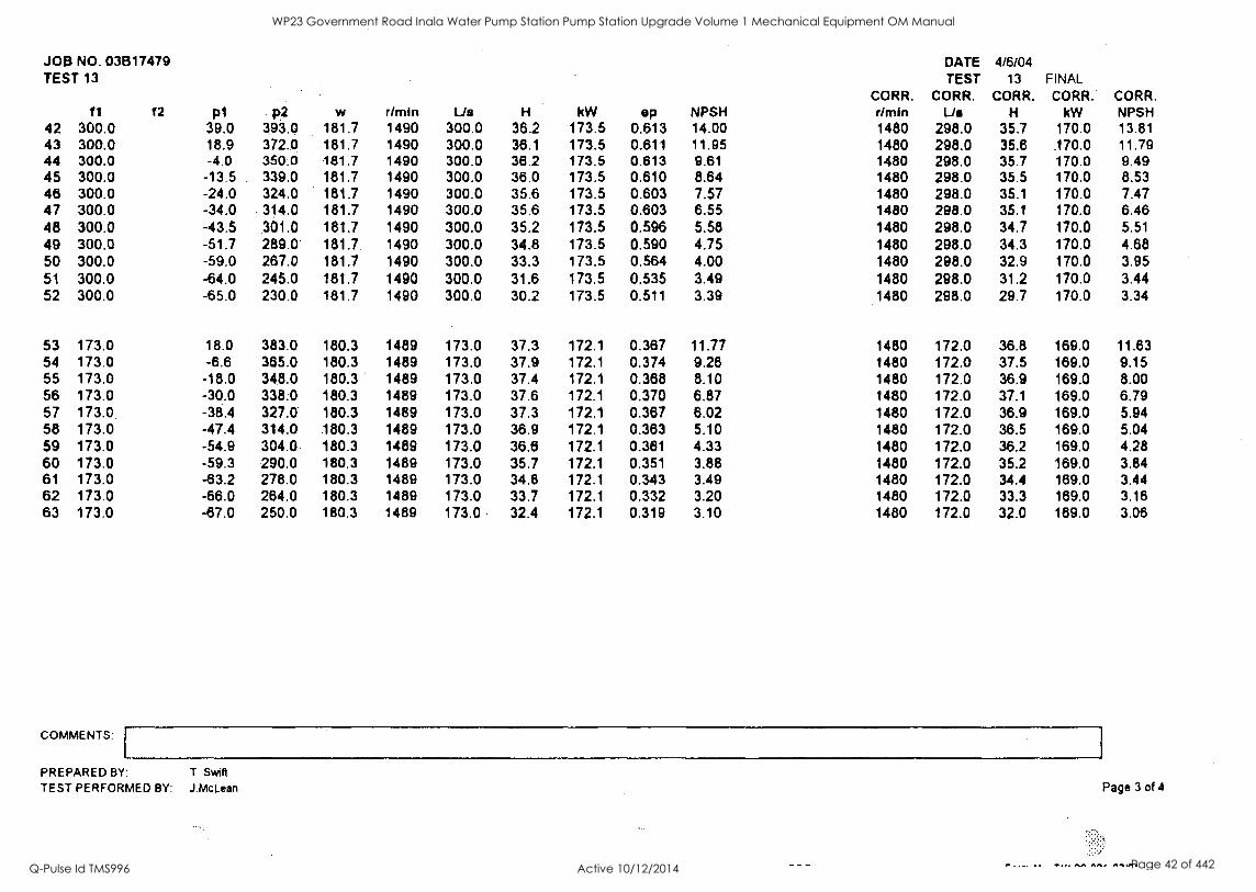
JOB NO. 03817479 TEST 13
11 t2 p1 p2 w r/min Us H kW op NPSH CORR. r/mIn
DATE TEST
CORR. Us
4/6/04 13
CORR. H
FINAL CORR.
kW CORR. NPSH
42 300.0 39.0 393.0 181.7 1490 300.0 36.2 173.5 0.613 14.00 1480 298.0 35.7 170.0 13.81 43 300.0 18.9 372.0 181.7 1490 300.0 36.1 173.5 0.611 11.95 1480 298.0 35.8 .170.0 11.79 44 300.0 -4.0 350.0 181.7 1490 300.0 38.2 173.5 0.613 9.61 1480 298.0 35.7 170.0 9.49 45 300.0 -13.5 339.0 181.7 1490 300.0 36.0 173.5 0.610 8.64 1480 298.0 35.5 170.0 8.53 46 300.0 -24.0 324.0 181.7 1490 300.0 35.6 173.5 0.603 7.57 1480 298.0 35.1 170.0 7.47 47 300.0 -34.0 314.0 181.7 1490 300.0 35.6 173.5 0.603 6.55 1480 298.0 35.1 170.0 6.46 48 300.0 -43.5 301.0 181.7 1490 300.0 35.2 173.5 0.596 5.58 1480 298.0 34.7 170.0 5.51 49 300.0 -51.7 289.0 181.7. 1490 300.0 34.8 173.5 0.590 4.75 1480 298.0 34.3 170.0 4.68 50 300.0 -59.0 267.0 181.7 1490 300.0 33.3 173.5 0.564 4.00 1480 298.0 32.9 170.0 3.95 51 300.0 -64.0 245.0 181.7 1490 300.0 31.6 173.5 0.535 3.49 1480 298.0 31.2 170.0 3.44 52 300.0 -65.0 230.0 181.7 1490 300.0 30.2 173.5 0.511 3.39 1480 298.0 29.7 170.0 3.34
53 173.0 18.0 383.0 180.3 1489 173.0 37.3 172.1 0.367 11.77 1480 172.0 36.8 169.0 11.83 54 173.0 -6.6 365.0 180.3 1489 173.0 37.9 172.1 0.374 9.26 1480 172.0 37.5 169.0 9.15 55 173.0 -18.0 348.0 180.3 1489 173.0 37.4 172.1 0.368 8.10 1480 172.0 36.9 169.0 8.00 56 173.0 -30.0 338.0 180.3 1489 173.0 37.6 172.1 0.370 6.87 1480 172.0 37.1 169.0 6.79 57 173.0 -38.4 327.0 180.3 1489 173.0 37.3 172.1 0.387 6.02 1480 172.0 36.9 169.0 5.94 58 173.0 -47.4 314.0 180.3 1489 173.0 36.9 172.1 0.383 5.10 1480 172.0 36.5 169.0 5.04 59 173.0 -54.9 304.0 180.3 1489 173.0 36.8 172.1 0.381 4.33 1480 172.0 36.2 169.0 4.28 60 173.0 -59.3 290.0 180.3 1489 173.0 35.7 172.1 0.351 3.88 1480 172.0 35.2 169.0 3.84 61 173.0 -63.2 278.0 180.3 1489 173.0 34.8 172.1 0.343 3.49 1480 172.0 34.4 189.0 3.44 62 173,0 -66.0 264.0 180.3 1489 173.0 33.7 172.1 0.332 3.20 1480 172.0 33.3 169.0 3.16 63 173.0 -67.0 250.0 180.3 1489 173.0 32.4 172.1 0.319 3.10 1480 172.0 32.0 189.0 3.06
COMMENTS:
PREPARED BY: T. Swift
TEST PERFORMED BY: J.Mclean Page 3 of 4
. _.... 4_ Tat, ISIS PIP IP
WP23 Government Road Inala Water Pump Station Pump Station Upgrade Volume 1 Mechanical Equipment OM Manual
Q-Pulse Id TMS996 Active 10/12/2014 Page 42 of 442
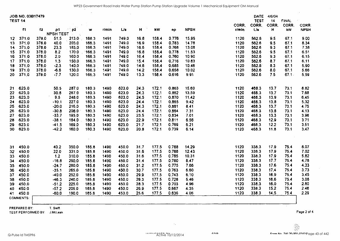
JOB NO. 03E117479 TEST 14
11 f2 p1 p2 NPSH TEST
w rlmin Us H kW ep NPSH CORR. dmin
DATE TEST
CORR. Us
4/6/04 14 FINAL
CORR. CORR. H kW
CORR. NPSH
12 371.0 378.0 51.5 213.0 186.3 1491 749.0 16.8 158.4 0.776 15.95 1120 562.8 9.5 67.1 9.00 13 371.0 378.0 40.0 203.0 188.3 1491 749.0 16.9 158.4 0.783 14.78 1120 562.6 9.5 67.1 8.34 14 371.0 378.0 23.3 183.0 166.3 1491 749.0 16.6 158.4 0.768 13.08 1120 562.6 9.3 67.1 7.38 15 371.0 378.0 8.2 170.0 166.3 1491 749.0 16.8 158.4 0.778 11.53 1120 562.6 9.5 67.1 6.51 16 371.0 378.0 2.0 160.0 166.3 1491 749.0 16.4 158.4 0.760 10.90 1120 562.6 9.3 67.1 6.15 17 371.0 378.0 1.3 150.0 166.3 1491 749.0 15.4 158.4 0.716 10.83 1120 562.8 8.7 67.1 6.11 18 371.0 378.0 -2.3 140.0 166.3 1491 749.0 14.8 158.4 0.685 10.48 1120 562.6 8.3 67.1 5.90 19 371.0 378.0 -6.8 130.0 166.3 1491 749.0 14.2 158.4 0.658 10.02 1120 562.6 8.0 67.1 5.66 20 371.0 378.0 -7.7 120.0 166.3 1491 749.0 13.3 158.4 0.616 9.91 1120 562.6 7.5 67.1 5.59
21 623.0 50.5 287.0 180.3 1490 623.0 24.3 172.1 0.863 15.60 1120 488.3 13.7 73.1 8.82 22 623.0 30.8 287.0 180.3 1490 623.0 24.3 172.1 0.882 13.59 1120 488.3 13.7 73.1 7.68 23 623.0 9.5 248.0 180.3 1490 623.0 24.5 172.1 0.870 11.42 1120 488.3 13.9 73.1 6.45 24 623.0 -10.1 227.0 180.3 1490 623.0 24.4 172.1 0.865 9.42 1120 488.3 13.8 73.1 5.32 25 623.0 -20.0 216.0 180.3 1490 623.0 24.3 172.1 0.881 8.41 1120 488.3 13.7 73.1 4.75 26 623.0 -30.8 206.0 180.3 1490 623.0 24.4 172.1 0.864 7.31 1120 468.3 13.8 73.1 4.13 27 623.0 -33.7 195.0 180.3 1490 623.0 23.5 172.1 0.834 7.01 1120 488.3 13.3 73.1 3.96 28 623.0 -38.1 184.0 180.3 1490 623.0 22.9 172.1 0.811 6.56 1120 468.3 12.9 73.1 3.71 29 623.0 -41.5 189.0 180.3 1490 623.0 21.7 172.1 0.769 6.21 1120 468.3 12.2 73.1 3.51 30 623.0 -42.2 160.0 180.3 1490 623.0 20.8 172.1 0.739 6.14 1120 468.3 11.8 73.1 3.47
31 450.0 40.2 350.0 185.8 1490 450.0 31.7 177.5 0.788 14.29 1120 338.3 17.9 75.4 8.07 32 450.0 22.0 331.0 185.8 1490 450.0 31.6 177.5 0.788 12.43 1120 338.3 17.9 75.4 7.02 33 450.0 1.2 310.0 185.8 1490 450.0 31.6 177.5 0.785 10.31 1120 338.3 17.9 75.4 5.82 34 450.0 -16.8 290.0 185.8 1490 450.0 31.4 177.5 0.780 8.47 1120 338.3 17.7 75.4 4.78 35 450.0 -24.7 280.0 185.8 1490 450.0 31.2 177.5 0.775 7.66 1120 338.3 17.6 75.4 4.33 36 450.0 -35.1 265.0 185.8 1490 450.0 30.7 177.5 0.763 6.60 1120 338.3 17.4 75.4 3.73 37 450.0 -40.0 252.0 185.8 1490 450.0 29.9 177.5 0.743 6.10 1120 338.3 18.9 75.4 3.45 38 450.0 -46.3 240.0 185.8 1490 450.0 29.3 177.5 0.728 5.46 1120 338.3 18.6 75.4 3.08 39 450.0 -51.2 225.0 185.8 1490 450.0 28.3 177.5 0.703 4.96 1120 338.3 18.0 75.4 2.80 40 450.0 -57.2 205.0 185.8 1490 450.0 26.9 177.5 0.667 4.35 1120 338.3 15.2 75.4 2.46 41 450.0 -60.0 190.0 185.8 1490 450.0 25.6 177.5 0.636 4.06 1120 338.3 14.5 75.4 2.29 COMMENTS:
PREPARED BY: T. Swift
TEST PERFORMED BY: J.McLean
ce.c)
Page 2 of 4
Costann T 7n1-M4 ./117(1
WP23 Government Road Inala Water Pump Station Pump Station Upgrade Volume 1 Mechanical Equipment OM Manual
Q-Pulse Id TMS996 Active 10/12/2014 Page 43 of 442
JOB NO. 03B17479 TEST 14
f1 f2 p1 p2 w r/min Us H kW ep NPSH CORR. Mein
DATE TEST
CORR. Us
4/6/04 14
CORR. H
FINAL CORR.
kW CORR. NPSH
42 300.0 39.0 393.0. 181.7 1490 300.0 38.2 173.5 0.613 14.00 1120 225.5 20.4 73.7 7.91 43 300.0 18.9 372.0 181.7 1490 300.0 36.1 173.5 0.611 11.95 1120 225.5 20.4 73.7 6.75 44 300.0 -4.0 350.0 181.7 1490 300.0 36.2 173.5 0.613 9.61 1120 225.5 20.4 73.7 5.43 45 300.0 -13.5 339.0 181.7 1490 300.0 36.0 173.5 0.810 8.84 1120 225.5 20.4 73.7 4.88 46 300.0 -24.0 324.0 181.7 1490 300.0 35.6 173.5 0.603 7.57 1120 225.5 20.1 73.7 4.28 47 300.0 -34.0 314.0 181.7 1490 300.0 35.6 173.5 0.803 6.55 1120 225.5 20.1 73.7 3.70 48 300.0 -43.5 301.0 181.7 1490 300.0 35.2 173.5 0.596 5.58 1120 225.5 19.9 73.7 3.15 49 300.0 -51.7 289.0 181.7 1490 300.0 34.8 173.5 0.590 4.75 1120 225.5 19.7 73.7 2.68 50 300.0 -59.0 287.0 181.7 1490 300.0 33.3 173.5 0.584 4.00 1120 225.5 18.8 73.7 2.26 51 300.0 -64.0 245.0 181.7 1490 300.0 31.6 173.5 0.535 3.49 1120 225.5 17.8 73.7 1.97 52 300.0 -65.0 230.0 181.7 1490 300.0 30.2 173.5 0.511 3.39 1120 225.5 17.0 73.7 1.91
53 173.0 18.0 383.0 180.3 1489 173.0 37.3 172.1 0.367 11.77 1120 130.1 21.1 73.2 6.66 54 173.0 -6.6 365.0 180.3 1489 173.0 37.9 172.1 0.374 9.26 1120 130.1 21.5 73.2 5.24 55 173.0 -18.0 348.0 180.3 1489 173.0 37.4 172.1 0.388 8.10 1120 130.1 21.1 73.2 4.58 56 173.0 -30.0 338.0 180.3 1489 173.0 37.6 172.1 0.370 6.87 1120 130.1 21.3 73.2 3.89 57 173.0 -38.4 327.0 180.3 1489 173.0 37.3 172.1 0.367 6.02 1120 130.1 21.1 73.2 3.40 58 173.0 -47.4 314.0 180.3 1489 173.0 36.9 172.1 0.363 5.10 1120 130.1 20.9 73.2 2.88 59 173.0 -54.9 304.0 180.3 1489 173.0 36.6 172.1 0.361 4.33 1120 130.1 20.7 73.2 2.45 60 173.0 -59.3 290.0 180.3 1489 173.0 35.7 172.1 0.351 3.88 1120 130.1 20.2 73.2 2.20 61 173.0 -63.2 278.0 180.3 1489 173.0 34.8 172.1 0.343 3.49 1120 130.1 19.7 73.2 1.97 62 173.0 -66.0 264.0 180.3 1489 173.0 33.7 172.1 0.332 3.20 1120 130.1 19.1 73.2 1.81
63 173.0 -67.0 250.0 180.3 1489 173.0 32.4 172.1 0.319 3.10 1120 130.1 18.3 73.2 1.75
COMMENTS:
PREPARED BY: T. Swift
TEST PERFORMED BY: J.McLean
cno
Page 3 of 4
c.,,,,, tin TILI -111/C1 1
WP23 Government Road Inala Water Pump Station Pump Station Upgrade Volume 1 Mechanical Equipment OM Manual
Q-Pulse Id TMS996 Active 10/12/2014 Page 44 of 442
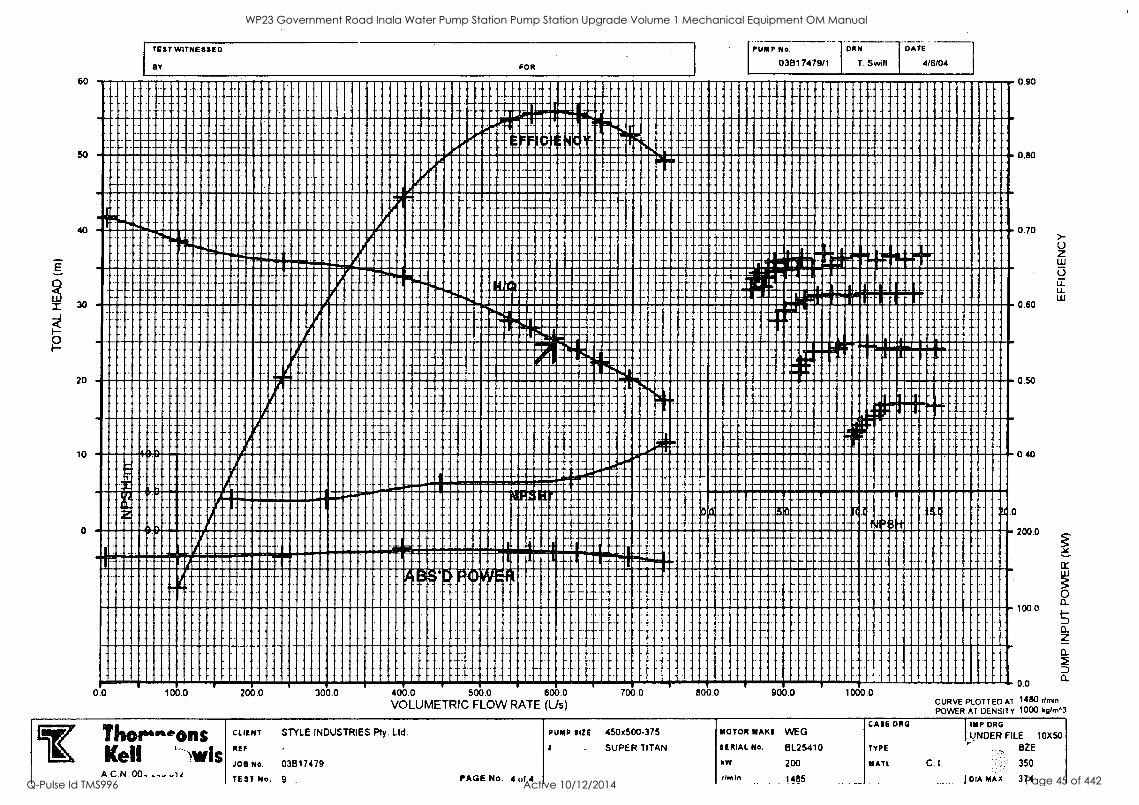
111111111111111111111119 111111111111111111111iiiiiilliilgj 11
11111111111111111161111111!: ' 11111111111111111111111111 111111111111111111;;;;11111::
4° F111"""1111111""11"1"1"1"""""11161110111111111111100101110P19k0 11111111iiiiiik1111 111111111
HIMME1011111111,1111111111111dminvormoupoomoorro """119141 -"MIIIIPP1111:111111111111111 I 11 1 In. MI1 1111111111111111F' MUM
11111111111111111111111911IIIIIIIMIPMUONfiklitSR1111111001111110p9M11111
11111111111111"111111111111111MINIPIIMMIN101111111111109mnimmoloo
11111111111111111/1111111111111111111111111111111111111111111111111
411""1"1"111"111111111111111111111111111Kidthilim00il ".....111111011
111111111111111111111111111111111111"111111111111!11"191112111111111111 mIlm 111111111111111111111111111111
1111111111.1 el
1111111111111 111111111 II I 11111111111111111111111 ""I "111111111111111111111111111111111111111111 1111111I 11111
P111111111ii1111"1"111""1111111111111111111111111111111111111
"gal 111111"111"111""1""1""1" " 1"111111111111111111111111111111111111111111111
20
0
0.0 100.0 200.0 300.0 400.0 500.0 600.0 VOLUMETRIC FLOW RATE (L/s)
Oa
700.0 800.0
450x500-375 PUMP SIZE
SUPER TITAN
900.0
MOTOR MAKI
SERIAL No.
kW
rim In
WEG
BL25410
200
1485
1000.0
CASE DAG
TYPE
tl ATL C
0.70
0.60
0.50
0.40
0
200.0
100.0
0.0
CURVE PLOT TED Al 1480 amen
POWER AT DENSIl Y 1000 kiiimn
IMP DRG
UNDER FILE 10X50
BZE
350
I DIA MAX 374
WP23 Government Road Inala Water Pump Station Pump Station Upgrade Volume 1 Mechanical Equipment OM Manual
Q-Pulse Id TMS996 Active 10/12/2014 Page 45 of 442
ommoopiomoomm moo ommumilimilminom womompoloom mum moloolimmoommoom
oimmilmongiumumiii mmoommumllowillom 1111111111111111111101141111111111111
I1l1111:'NIIIIIIIIII 1111111111111111151111111111111111111
1111111111111111111111111111111111111
!!!!!!!!!TEVIII""m""' 11111111111111111111101i111111100
11111111111111111111111111111111111111
1111111111111 111111111111111111111111
PUMP No.
03617479n
111111111111IMPIN11111111111111111111111111111101111111111111111111111
111111Mlidebilinill01111111111111111111111111111billim
1101111110111111111111ffillii11111111111111111101111111111111111111111111
111101111111110111011111111111111110MEMINIIIIIMMIIIIIIIII
111111111111111111111111111111111111110n01!!!!!!!1111111110
111111111::1111N111110111111111111EigiP!RIPIPM11111111111
111111151111;ititilliii1111111111111111iiiiiiiiiiii1111111111111
iiiiiiiiiIIIIIiiihMEN111111111111110111Eilhibliiiiiiii11111111
11111111111111111111111111111111111111111111111111111111111
1111111111111111111MEHMENdidmilliii1111111111111111
1111011111FPIIIIIMMINIIII11111111111111111111111111111111111111111
1111111iiiiiiiii111110111111111111:1111111111111111111M111111111111
limmomigivilliiiMIIIMIIIII111111111111111111111111111111111
.1."1 iii ouniimourn: iiiiiiiiikamommommolo 1
imillommomillimmollogionommommol1111 nimmimmummommemoomiloommoomomou
I
0.70
0.60
0.50
0.40
0200.0
100.0
0.0
a.
a_
WP23 Government Road Inala Water Pump Station Pump Station Upgrade Volume 1 Mechanical Equipment OM Manual
Q-Pulse Id TMS996 Active 10/12/2014 Page 46 of 442
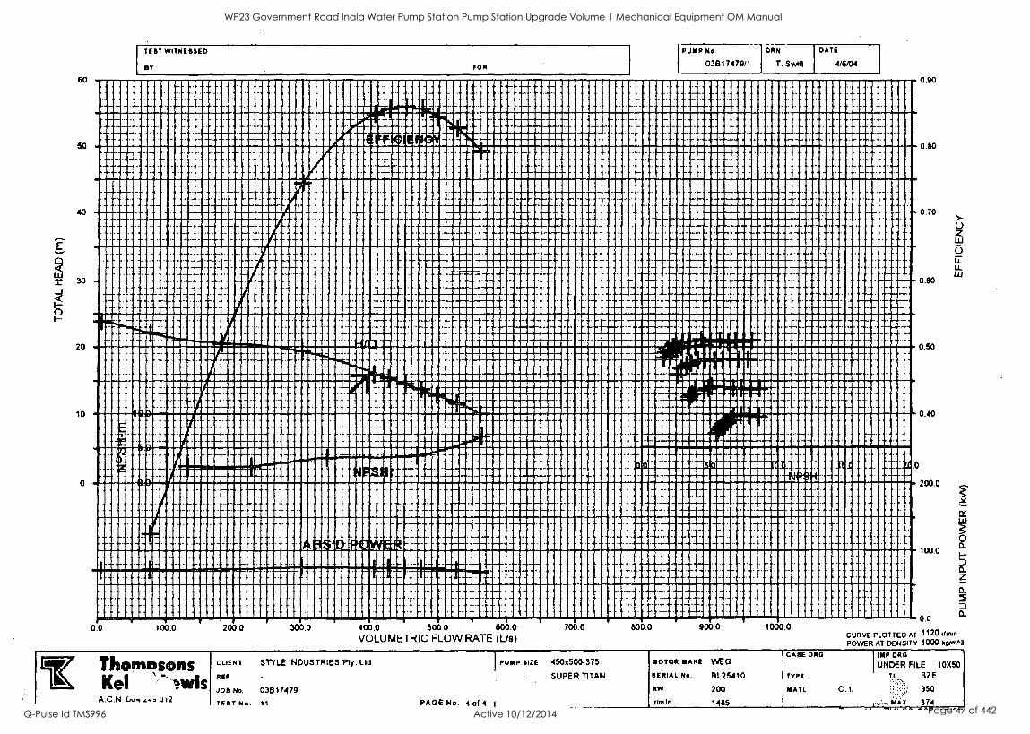
E
O
Hounioloollimmll quimmompoloporiummommommmummiquirommillimu " rgglimplimmilloommillumbooloommum
Holommollopoo mmiliiiiiimiiiilloommummummuipoolloommll room110111111001111111110011110111111EFEE11111111111111111111116111111111111111
1111111111111110111E111111111111111111111111111110111111111111111111111111111NIME1111111111
0011111111111111111111111111111111111111111111011111111000111111111111111111111111101111111E111111111011
1111111111111111111111111111111111M1111111011111111111111111111111111111111111111111101011111111111011
11119IIIIIINIM1111110011111.110111111111111111POINIMINWPWRIME11111111111
1111111111111MINNIIINEMPTIMPHIMPIN1111110111bilie;:g111111111111111111111111111
050 20
mmuormnmilmoloomminomilionillonstlloommoimm
I
2000
illmommoommonymommilmourdmiummummillminimmoin miciiisimmernivitorworiiimummoolliollordiummilomillooloimmo offillommullommillimiiiiiiirdommommommimmimmilloomommo
30
10
0.60
0.40
0.0 100.0 200.0 300.0 400.0 500.0 600.0 VOLUMETRIC FLOW RATE (Us)
Thonsz±sons Kel lurk
A.C.N. U12
CLIENT STYLE INDUSTRIES Ply. Lid.
RED
JOB No. 03B17479
TEST No 11
1
PUMP SIZE
PAGE No. 4 of 4 I
.0
100.0
0.0 700.0 600.0 900.0 1000.0
CURVE PLOTTED AT 1120 limn POWER AT DENSITY 1000 kp/m"3
450x500-375 MOTOR MAKE WEG CASE ORG
UNDER FILE DE FILE 10X50
SUPER TITAN SERIAL No. BL25410 TYPE TL BZE
kW
rim In
200
1485
MATL C. I. 350
MAX 371
WP23 Government Road Inala Water Pump Station Pump Station Upgrade Volume 1 Mechanical Equipment OM Manual
Q-Pulse Id TMS996 Active 10/12/2014 Page 47 of 442
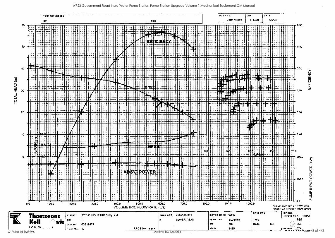
TEST WITNESSED
'1/41.F.P. Pc'
0.0 1 ob 0 200.0 300.0 400.0 500.0 600.0
VOLUMETRIC FLOW RATE (Lis)
O
I SI
PUMP No.
031317479/2
.... --T.
MOTOR MANE WEGI
SERIAL NIL 8L23548 kW 200
rhoiln 1485
T. Swift 4/6/04
0.70
200.0
100.0
X00 CURVE PLOTTED A r 1480 drown
POWER Al DENSITY 1000 kg/m"3
CASE DEG IMP DEG
UNDER FILE 10X50 TYPE BZE
NATL C. I. 350
u 1.1.1 X 374
WP23 Government Road Inala Water Pump Station Pump Station Upgrade Volume 1 Mechanical Equipment OM Manual
Q-Pulse Id TMS996 Active 10/12/2014 Page 48 of 442
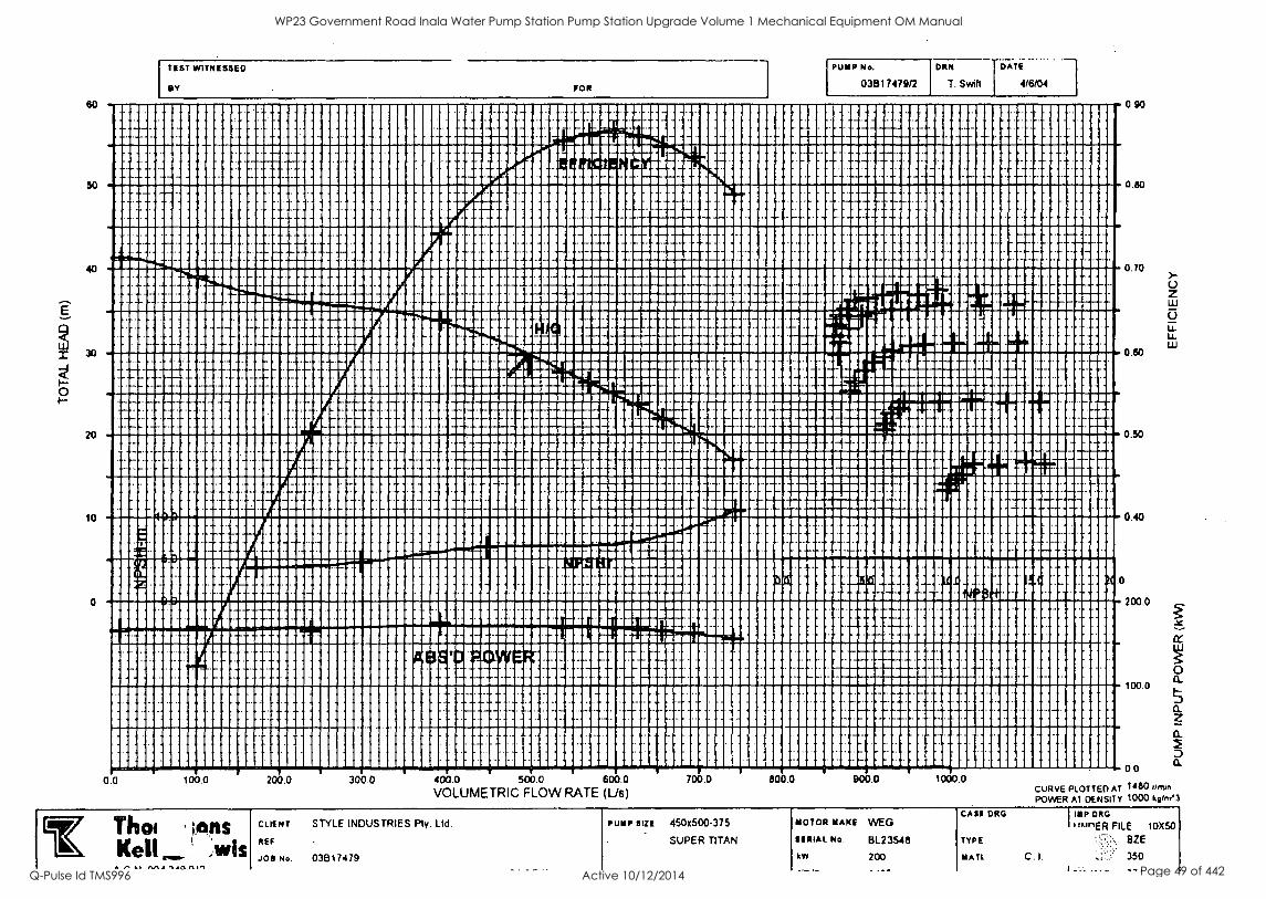
E
0 I-
20
10
TEST WITNESSED
BY FOR
PUMP No.
03E117479/2
DiitN
T. Swift
DATE
4/6/04
a ......
H
... - ..... ^
-A-
77' ;.
-
14
4 4, --A
. - . - 1 D
b.0
o. .
A9 S 'ID POWER '
4- 4-- 44 - 4
n i z . . . tEr : : I - NP
0.0
I 1
100.0 200.0
I
300.0
. . .
0 L -7
400.0 500.0 600 700.0
VOLUMETRIC FLOW RATE (Us)
..
. ....... - , , ...
800.0 A t -
900.0 1000.0
0 90
0.80
0.70
0.80
0.50
0.40
0
200.0
100.0
0.0
SC
0 a.
0_
0_ 2
CURVE PLOTTED AT "ISO timln POWER Al DENSITY 1000 ksemn
CrThoi ans Kell ,wis
/'-A1 IV141 '1.441011"1
CLIENT STYLE INDUSTRIES Ply. Ltd.
REF
JOB No. 03817479
rum. slit 450x500-375
SUPER TITAN
MOTOR MAKE WEG
SERIAL No. 8L23548
kW 200
CASE DRG I imp CMG
'IunER FILE 10XSO
TYPE : BZE
YATL C. I. 350
WP23 Government Road Inala Water Pump Station Pump Station Upgrade Volume 1 Mechanical Equipment OM Manual
Q-Pulse Id TMS996 Active 10/12/2014 Page 49 of 442
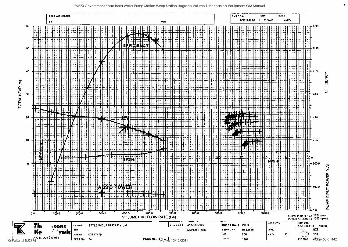
0
" 111111111111111111111111111111111101!!!!!!111111111111111111111111111111111111111111111111011111111 " 111111111111111111111111111111111MENIIIMMENIMENIMINE1111111111111111111
111111111111111111111111111 1111111111111111111111111011111111111111111111111111111111111111111111111111111111111
11111111111111111111111111111i1M11111111111111111111111111101111111111111m11011111111111111111111111111111111
11111111111111111111011511111111111111111111111101111111111111111011111MONE1111111111111111
110111111111111111111111111111111111111111111111111111M101111111111111111111111111111011111111111011110
1111111111111111111M1111111111111111111EMMEIMMIN10111111111111111111111111111111111H111111
11111120MINIIIIII11111111111111011111011111111111111111111111111FM011111111111111111111111
11111111111E111011111WIRIPPINNIMMIMMUNIMIIIIIIIIIii.'f11111111111111111111111111
1111111111M111111111111111111111hiliiiiENNEM11111111111111111Ciiiiiiiiiiiiiiiiii10111111
P1111111111111111111111111111111111111011111111M110111111111111111111111111111111A111111111111111110111111
111111111E111111111iiiiiiiiiiffiiiiiii011111111111111111111111111111111M111111:111M1111111111111:
111101111111111111111111111111111111111111111111111111111111111111111111111111111111111111111111111111111111111111111
m"wilm"'""'"'""'"4"*"'!'11111111111111111111111111111111111111111111111111111111111111111
111111111111111111111111111101110011111111111111111101111111111111111111111111111111011111111111111111111111
40 0.70
0
20
10
0
0.0 100.0 200.0 300.0 400.0 500.0 600.0 VOLUMETRIC FLOW RATE (Us)
Thi mons Ke 'ewis
A.C.N. '004 "249.012
CLIENT STYLE INDUSTRIES Pty. Ltd.
REF
JOE No. 03B17479
TOT Mn IA
IPUMP SIZE
PAGE No. of A I
0.80
.0
0.50
0.40
200.0
100.0
0.0 700.0 800.0 900.0 1000.0
CASE DRGI
CURVE POWER
PLOTTED AT AT DENSITY
1120 Own 1000 ko/m.3
450x500-375 MOTOR MAKE VVEG
SUPER TITAN SERIAL No.
kw
8L.23548
200
TYPE
MAIL. C. I.
mT.l, BZE
350
dm In 1485 101A MAX 374
WP23 Government Road Inala Water Pump Station Pump Station Upgrade Volume 1 Mechanical Equipment OM Manual
Q-Pulse Id TMS996 Active 10/12/2014 Page 50 of 442
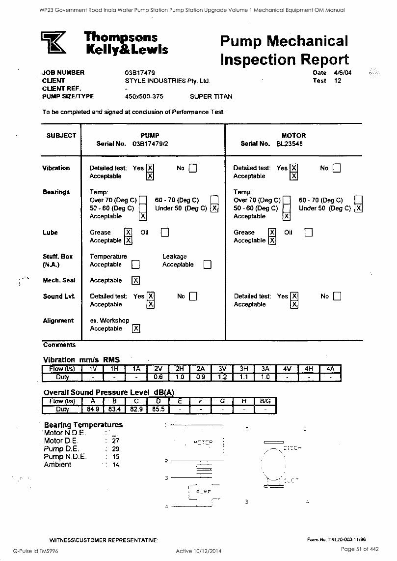
Thompsons Kel Iy& Lewis
JOB NUMBER CLIENT CLIENT REF. PUMP SIZE/TYPE
031317479 STYLE INDUSTRIES Pty. Ltd.
Pump Mechanical Inspection Report
450)(500-375 SUPER TITAN
To be completed and signed at conclusion of Performance Test.
Date 4/6/04 Test 12
SUBJECT PUMP Serial No. 03B17479/2
Vibration
Bearings
Detailed test Yes Acceptable
Temp: Over 70 (Deg C) 50 - 60 (Deg C) Acceptable X
No
60 - 70 (Deg C) Under 50 (Deg C)
Lobe Grease El Oil
Acceptable
Stuff. Box Temperature Leakage (NA) Acceptable [1:1 Acceptable
Mech. Seal Acceptable
Sound Lvi. Detailed test Yes No
Acceptable X
Alignment ex. Workshop Acceptable
Comments
Vibration mm/s RMS
MOTOR Serial No. BL23548
Detailed test: Yes Acceptable
No
Temp: Over 70 (Deg C) 60 - 70 (Deg C) SO - 60 (Deg C) Under 50 (Deg C) Acceptable X
Grease Oil Acceptable X
Detailed test: Yes Acceptable a
No
Flow (Us) [ 1V 1 1H I 1A I 2V I 2H
2A I 3V I 3H I 3A 4V I 4H 4A
Duty I 0.6 I 1.0 0.9 I 1.2 I 1.1 1 1.0 - I I
Overall Sound Pressure Level dB(A) Flow (Ifs) iAleici I E 1 F I G I. H 1 B/G
Duty I 84.9 1 83.4 I 82.91 85.5 I -1-1-1-i Bearing Temperatures Motor N.D.E. :
Motor D.E. :
Pump D.E. : 29 Pump N.D.E. : 15
Ambient : 14
3
P 'MP
rs--- - -
WITNESS1CUSTOMER REPRESENTATIVE: Form No. TKL20-003-11/96
WP23 Government Road Inala Water Pump Station Pump Station Upgrade Volume 1 Mechanical Equipment OM Manual
Q-Pulse Id TMS996 Active 10/12/2014 Page 51 of 442
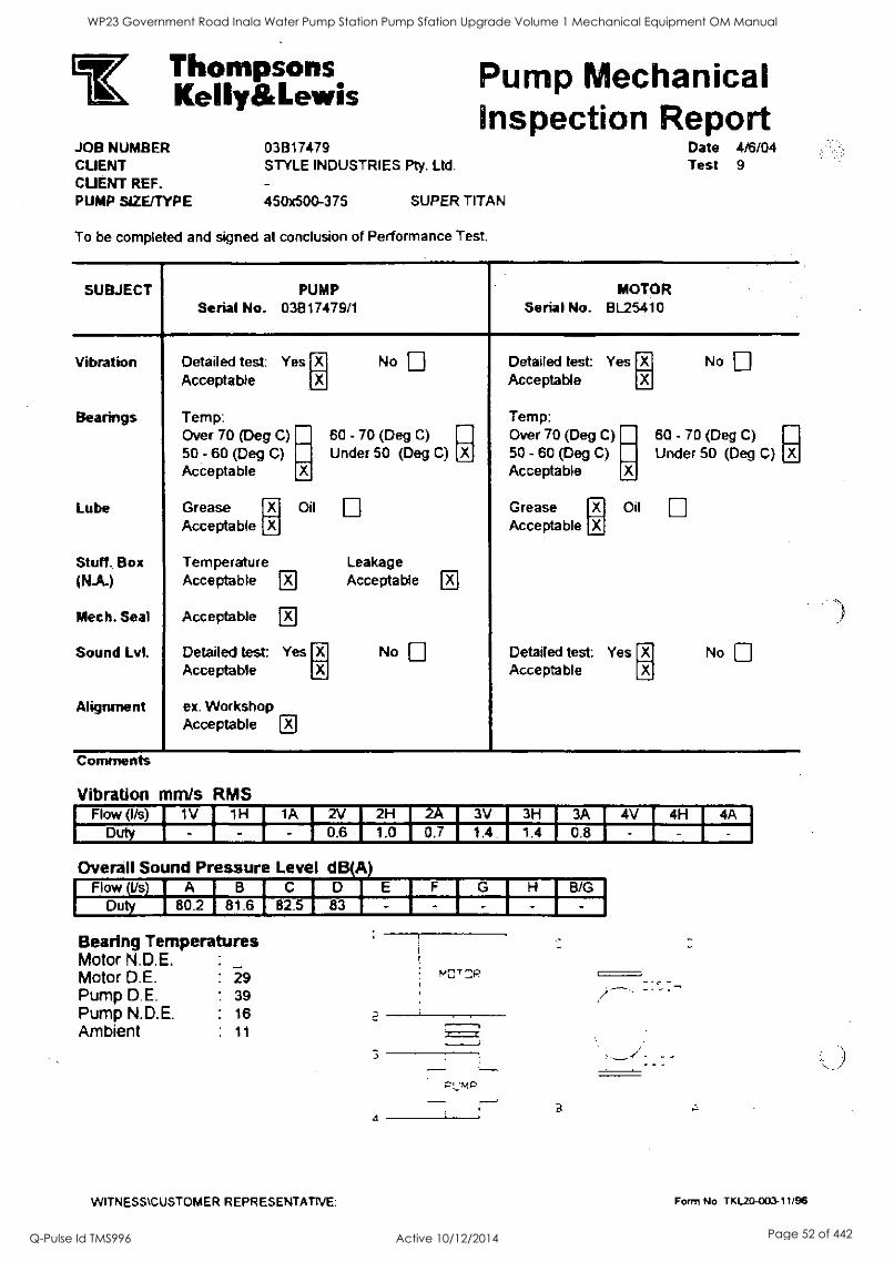
Thompsons Kelly&Lewis
JOB NUMBER 03817479 CUENT CUENT REF. PUMP SIZE/TYPE 450x500-375
STYLE INDUSTRIES Pty. Ltd.
Pump Mechanical Inspection Report
SUPER TITAN
To be completed and signed at conclusion of Performance Test.
Date 4/6/04 Test 9
SUBJECT PUMP Serial No. 03E317479/1
MOTOR Serial No. BL25410
Vibration
Bearings
Lube
Stuff. Box (NA)
Mech. Seal
Sound Lvl.
Alignment
Detailed test: Yes Acceptable
Temp: Over 70 (Deg C) 50 - 60 (Deg C) Acceptable
Grease Acceptable
x
Temperature Acceptable
Acceptable
El
El
No
60 - 70 (Deg C)
Under 50 (Deg C)
Oil
Detailed test: Yes Acceptable
ex. Workshop Acceptable El
X
Leakage Acceptable
No
111
a
Detailed test: Yes Acceptable
Temp: Over 70 (Deg C) 50 - 60 (Deg C) Acceptable
Grease Acceptable
x x
7 x
x
No
60 - 70 (Deg C)
Under 50 (Deg C)
Oil
Detailed test: Yes Acceptable a
No El
Comments
Vibration mm/s RMS Flow (I/s) 1 1V I 1H 1 1A 1 2V I 2H I 2A 1 3V 1 3H 1 3A 4V I 4H 1 4A
Duty 1 0.6 . I 1.0 1 0.7 1 1.4 . I 1.410.8
Overall Sound Pressure Level d A Flow(l/ s) IA B 1I CI D 1 E IGI F I H B/G
Duty 1 80.2 1 81.6 I 82.5 1 83 1 - -
I
Bearing Temperatures Motor N.D.E. Motor D.E. Pump D.E. Pump N.D.E. Ambient
.
:
:
:
29 39 16 11
NC' :
2 j==z
3
4
WITNESS \CUSTOMER REPRESENTATNE:
B
Form No. TKL20-003-11/96
WP23 Government Road Inala Water Pump Station Pump Station Upgrade Volume 1 Mechanical Equipment OM Manual
Q-Pulse Id TMS996 Active 10/12/2014 Page 52 of 442
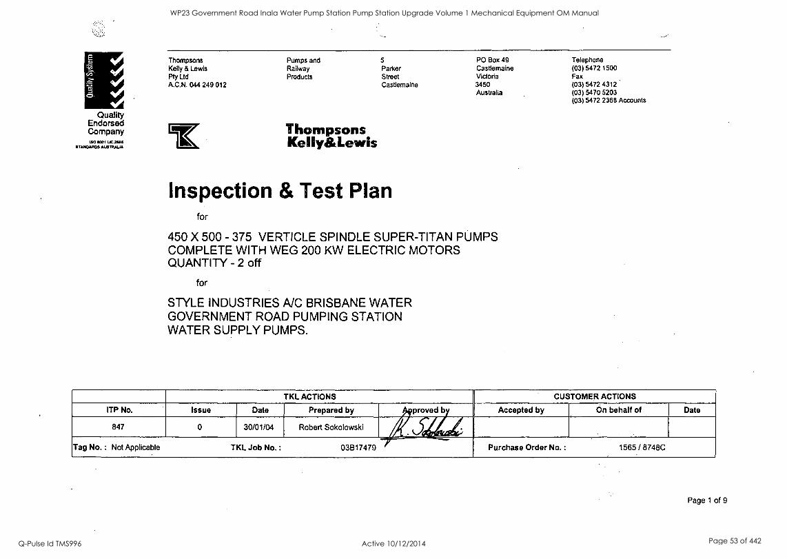
Quality Endorsed. Company ISO 111001 MINIS
STANDARDS AUSTRALIA
Thompsons Pumps and 5 PO Box 49 Telephone Kelly & Lewis Railway Parker Castlemaine (03) 5472 1500 Pty Ltd Products Street Victoria Fax A.C.N. 044 249 012 Castlemaine 3450 (03) 5472 4312
Australia (03) 5470 5203 (03) 5472 2368 Accounts
Thompsons KellyiltLewis
Inspection & Test Plan for
450 X 500 - 375 VERTICLE SPINDLE SUPER-TITAN PUMPS COMPLETE WITH WEG 200 KW ELECTRIC MOTORS QUANTITY - 2 off
for
STYLE INDUSTRIES A/C BRISBANE WATER GOVERNMENT ROAD PUMPING STATION WATER SUPPLY PUMPS.
TKL ACTIONS CUSTOMER ACTIONS
ITP No. Issue Date Prepared by proved b Accepted by On behalf of Date
847 0 30/01/04 Robert Sokolowski s ...4. c ..--
/
Tag No. : Not Applicable TKL Job No. : 03B17479 Purchase Order No. : 1565 / 8748C
Page 1 of 9
WP23 Government Road Inala Water Pump Station Pump Station Upgrade Volume 1 Mechanical Equipment OM Manual
Q-Pulse Id TMS996 Active 10/12/2014 Page 53 of 442
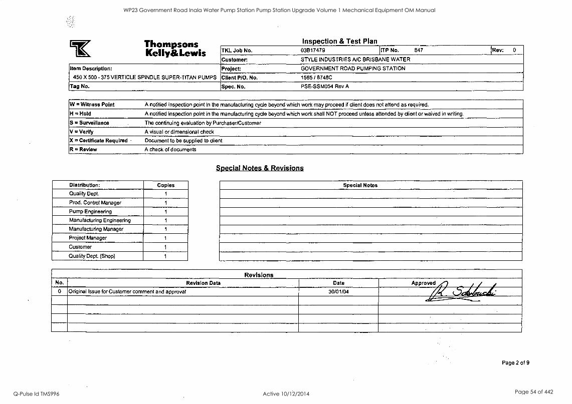
0%11.11110911 coins Inspection & Test Plan . lik ................. KellyEtALewis TKL Job No. 03B17479 ITP No. 847 Rev: 0
Customer: STYLE INDUSTRIES A/C BRISBANE WATER
Item Description:
450 X 500 - 375 VERTICLE SPINDLE SUPER-TITAN PUMPS
Project: GOVERNMENT ROAD PUMPING STATION
Client P/O. No. 1565 / 8748C
Tag No. Spec. No. PSE-SSM054 Rev A
W = Witness Point A notified inspection point in the manufacturing cycle beyond which work may proceed if client does not attend as required.
H = Hold A notified inspection point in the manufacturing cycle beyond which work shall NOT proceed unless attended by client or waived in writing.
S 12 Surveillance The continuing evaluation by Purchaser/Customer
V = Verify A visual or dimensional check
X = Certificate Required Document to be supplied to client
R = Review A check of documents
Distribution: Copies
Quality Dept. 1
Prod. Control Manager 1
Pump Engineering 1
Manufacturing Engineering 1
Manufacturing Manager 1
Project Manager 1
Customer 1
Quality Dept (Shop) 1
Special Notes & Revisions
Special Notes
Revisions No. Revision Data Date Approved
0 Original Issue for Customer comment and approval 30/01/04 6 , Page 2 of 9
WP23 Government Road Inala Water Pump Station Pump Station Upgrade Volume 1 Mechanical Equipment OM Manual
Q-Pulse Id TMS996 Active 10/12/2014 Page 54 of 442
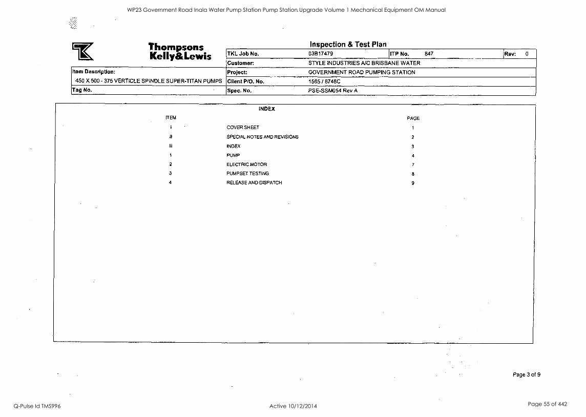
TisanareirseAIRIC Inspection & Test Plan
-1E Kelly& Lewis TKL Job No. 03B17479 ITP No. 847 Rev: 0
Customer: STYLE INDUSTRIES NC BRISBANE WATER
Item Description:
450 X 500 - 375 VERTICLE SPINDLE SUPER-TITAN PUMPS
Project: GOVERNMENT ROAD PUMPING STATION
Client P/O. No. 1565 / 8748C
Tag No. Spec. No. PSE-SSM054 Rev A
ITEM
i
H
iii
1
2
3
4
INDEX
COVER SHEET
SPECIAL NOTES AND REVISIONS
INDEX
PUMP
ELECTRIC MOTOR
PUMPSET TESTING
RELEASE AND DISPATCH
PAGE
1
2
3
4
7
8
9
Page 3 of 9
WP23 Government Road Inala Water Pump Station Pump Station Upgrade Volume 1 Mechanical Equipment OM Manual
Q-Pulse Id TMS996 Active 10/12/2014 Page 55 of 442
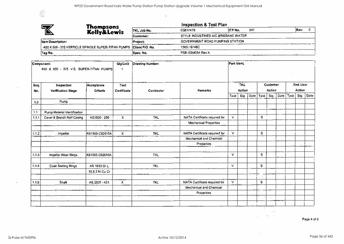
Inspection & Test Plan
LIM , ,,,I.mibizoiptim Kelly&Lewis TKL Job No. 03817479 ITP No. 847 Rev: 0
Customer: STYLE INDUSTRIES A/C BRISBANE WATER
Item Description:
450 X 500 - 375 VERTICLE SPINDLE SUPER-TITAN PUMPS
Project: GOVERNMENT ROAD PUMPING STATION
Client P/O. No. 1565 / 8748C
Tag No. Spec. No. PSE-SSM054 Rev A
Component:
450 X 500 - 375 V.S. SUPER-TITAN PUMPS
City/Unit
1
Drawing Number: Part !dent
Seq.
No.
Inspection
Verification Stage
Acceptance
Criteria
Test
Certificate Contractor Remarks
TKL
Action
Customer
Action
End User
Action
Task Sig. Date Task Sig. Date Task Sig. Date
1.0 Pump
1.1 Pump Material Identification
1.1.1 Cover & Branch Half Casing AS1830 - 250 X TKL NATA Certificate required for V S
Mechanical Properties
1.1.2 Impeller AS1565 C92610A X TKL NATA Certificate required for V
Mechanical and Chemical
Properties
1.1.3 Impeller Wear Rings AS1565 C92610A TKL V S
1.1.4 Case Sealing Rings AS 1833 Gr L TKL V S
15.6.3 Ni Cu Cr
1.1.5 Shaft AS 2837 - 431 X TKL NATA Certificate required for V S
Mechanical and Chemical
Properties
Page 4 of 9
WP23 Government Road Inala Water Pump Station Pump Station Upgrade Volume 1 Mechanical Equipment OM Manual
Q-Pulse Id TMS996 Active 10/12/2014 Page 56 of 442
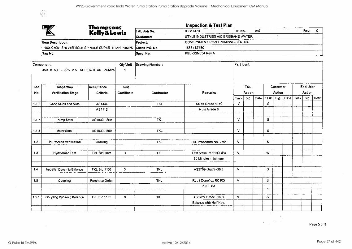
Irk A left Met/ILE% Ir. Ins ection & Test Plan Thor' KellyatLewis TKL Job No. 03B17479 ITP No. 847 [Rev: 0
Customer: STYLE INDUSTRIES NC BRISBANE WATER
Item Description: Project: GOVERNMENT ROAD PUMPING STATION
450 X 500 - 375 VERTICLE SPINDLE SUPER-TITAN PUMPS Client P/O. No. 1565 / 8748C
Tag No. Spec. No. PSE-SSM054 Rev A
Component:
450 X 500 - 375 V.S. SUPER-TITAN PUMPS
Qty/Unit
1
Drawing Number: Part Ident.
Seq.
No.
Inspection
Verification Stage
Acceptance
Criteria
Test
Certificate Contractor Remarks
TKL
Action
Customer
Action
End User
Action
Task Sig. Date Task Sig. Date Task Sig. Date
1.1.6 Case Studs and Nuts AS1444 TKL Studs Grade 4140 V S
AS1112 Nuts Grade 8
1.1.7 Pump Stool AS1830 - 200 TKL V S
1.1.8 Motor Stool AS1830 - 200 TKL V S
1.2 In-Process Verification Drawing TKL TKL Procedure No. 2501 V S
1.3 Hydrostatic Test TKL Std 3021 X TKL Test pressure 2100 kPa V W
30 Minutes minimum
1.4 Impeller Dynamic Balance TKL Std 1105 X TKL AS3709 Grade G6.3 V S
1.5 Coupling Purchase Order TKL Rathi Coneflex RC105 V S.
P.O. TBA
1.5.1 Coupling Dynamic Balance TKL Std 1105 X TKL AS3709 Grade G6.3 V S
Balance with Half Key.
Page 5 of 9
WP23 Government Road Inala Water Pump Station Pump Station Upgrade Volume 1 Mechanical Equipment OM Manual
Q-Pulse Id TMS996 Active 10/12/2014 Page 57 of 442
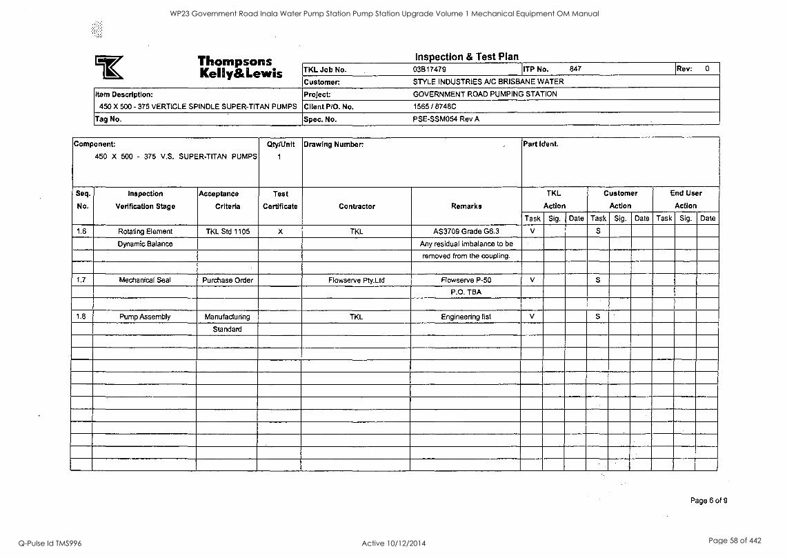
SOS Mil. AM OS r. Inspection & Test Plan ........ra...a Kelly&Lewis TKL Job No. 03817479 ITP No. 847 Rev: 0
Customer. STYLE INDUSTRIES A/C BRISBANE WATER
Item Description:
450 X 500 - 375 VERTICLE SPINDLE SUPER-TITAN PUMPS
Project: GOVERNMENT ROAD PUMPING STATION
Client P/O. No. 1565 / 8748C
Tag No. Spec. No. PSE-SSM054 Rev A
Component:
450 X 500 - 375 V.S. SUPER-TITAN PUMPS
City/Unit
1
Drawing Number . Part Ident.
Seq.
No.
Inspection
Verification Stage
Acceptance
Criteria
Test
Certificate Contractor Remarks
TKL
Action
Customer
Action
End User
Action
Task Sig. Date Task Sig. Date Task Sig. Date
1.6 Rotating Element TKL Std 1105 X TKL AS3709 Grade G6.3 V S
Dynamic Balance Any residual imbalance to be
removed from the coupling.
1.7 Mechanical Seal Purchase Order Flowserve Pty.Ltd Flowserve P-50 V
P.O. TBA
1.8 Pump Assembly Manufacturing TKL Engineering list V S
Standard
Page 6 of 9
WP23 Government Road Inala Water Pump Station Pump Station Upgrade Volume 1 Mechanical Equipment OM Manual
Q-Pulse Id TMS996 Active 10/12/2014 Page 58 of 442
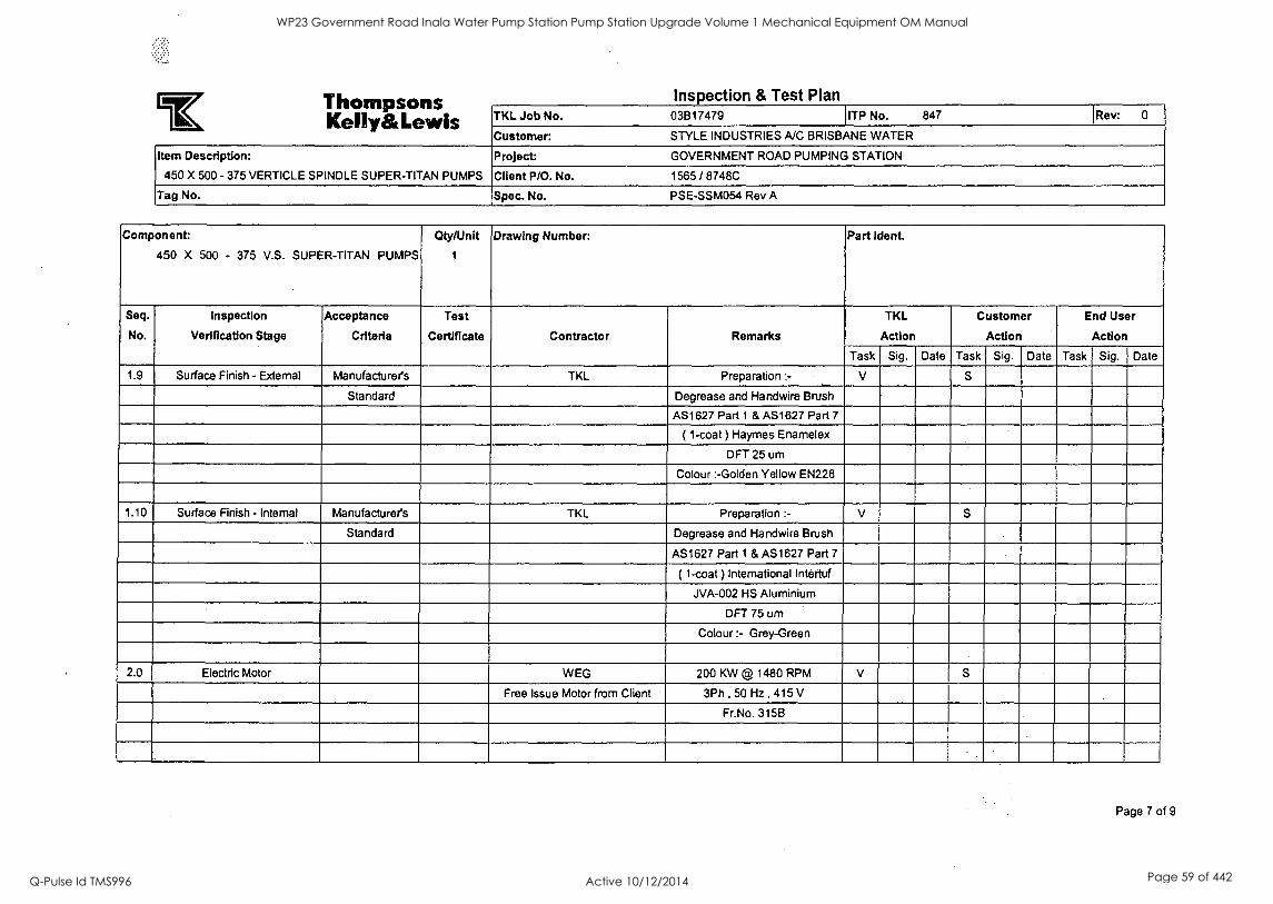
Thom DM MICA Da Inspection & Test Plan
IFIL mumemMireiVOI,.eiP
Kelly&Lewis TKL Job No. 03B17479 ITP No. 847 'Rev: 0
Customer: STYLE INDUSTRIES A/C BRISBANE WATER
Item Description:
450 X 500 - 375 VERTICLE SPINDLE SUPER-TITAN PUMPS
Project: GOVERNMENT ROAD PUMPING STATION
Client P/O. No. 1565 / 8748C
Tag No. Spec. No. PSE-SSM054 Rev A
Component:
450 X 500 - 375 V.S. SUPER-TITAN PUMPS
Qty/Unit
1
Drawing Number: Part Idea
Seq.
No.
Inspection
Verification Stage
Acceptance
Criteria
Test
Certificate Contractor Remarks
TKL
Action
Customer
Action
End User
Action
Task Sig. Date Task Sig. Date Task Sig. Date
1.9 Surface Finish - External Manufacturers TKL Preparation :- V S
Standard Degrease and Handwire Brush
AS1627 Part 1 & AS1627 Part 7
( 1-coat ) Haymes Enamelex
OFT 25 urn
Colour :-Golden Yellow EN228
1.10 Surface Finish - Internal Manufacturers TKL Preparation :- V S
Standard Degrease and Handwire Brush
AS1627 Part 1 & AS1627 Part 7
( 1-coat ) International Intertuf
JVA-002 HS Aluminium
OFT 75 urn
Colour :- Grey-Green
2.0 Electric Motor WEG 200 KW @ 1480 RPM V S
Free Issue Motor from Client 3Ph , 50 Hz , 415 V
Fr.No. 315B
Page 7 of 9
WP23 Government Road Inala Water Pump Station Pump Station Upgrade Volume 1 Mechanical Equipment OM Manual
Q-Pulse Id TMS996 Active 10/12/2014 Page 59 of 442

TIAIM% rieR%11% C Inspection & Test Plan
1L, Kelly&Lewis TKL Job No. 03517479 ITP No. 847 Rev: 0
Customer: STYLE INDUSTRIES A/C BRISBANE WATER
Item Description:
450 X 500 - 375 VERTICLE SPINDLE SUPER-TITAN PUMPS
Project: GOVERNMENT ROAD PUMPING STATION
Client P/O. No. 1565 / 8748C
Tag No. Spec. No. PSE-SSM054 Rev A
Component:
450 X 500 - 375 V.S. SUPER-TITAN PUMPS
Qty/Unit
1
Drawing Number: Part Went.
Seq.
No.
Inspection
Verification Stage
Acceptance
Criteria
Test
Certificate Contractor Remarks
TKL
Action
Customer
Action
End User
Action
Task Sig. Date Task Sig. Date Task Sig. Date
2.1 Pressure Guage ( Suction) Purchase Order X Blackwoods Floyd:- SBSS150120MHD R S
3/8" BSP 50070-0033 Calibration Certificate Required
2.2 Pressure Guage ( Suction) Purchase Order X Blackwoods Floyd:- SBSS15060MHD R S
3/8" BSP B0070-0033 Calibration Certificate Required
3.0 Pumpset Testing
3.1 Performance AS 2417 - 2001 X TKL NPSH test required. V W
Grade 1 Customer to approve test results
prior to pumpset dispatch.
3.2 Noise AS 1217.7 X TKL (A) Weighted Sound Power V W
Level 84 dB(A) Maximum
(total pump & motor)
3.3 Vibration AS 2625 Part 3 X TKL 5.1 mm/sec (r.m.s.) on test V W
3.6 mm/sec (r.m.s.)
Page 8 of 9
WP23 Government Road Inala Water Pump Station Pump Station Upgrade Volume 1 Mechanical Equipment OM Manual
Q-Pulse Id TMS996 Active 10/12/2014 Page 60 of 442
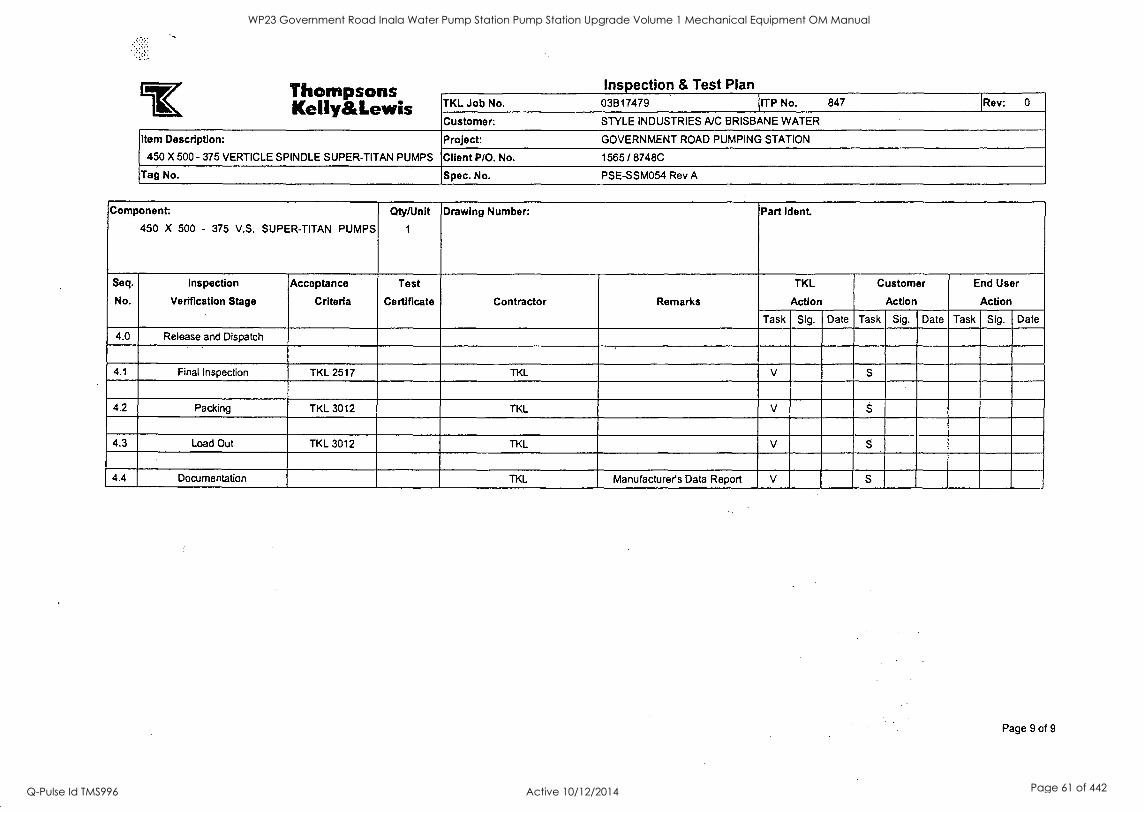
Tile VIPS riteesrae Inspection & Test Plan usAirmeovarwarmai
Kelly&Lewis TKL Job No. 03817479 ITP No. 847 Rev: 0
Customer: STYLE INDUSTRIES A/C BRISBANE WATER
Item Description:
450 X 500 - 375 VERTICLE SPINDLE SUPER-TITAN PUMPS
Project: GOVERNMENT ROAD PUMPING STATION
Client P/O. No. 1565 / 8748C
Tag No. Spec. No. PSE-SSM054 Rev A
Component:
450 X 500 - 375 V.S. SUPER-TITAN PUMPS
Qty/Unit
1
Drawing Number: Part Idea
Seq.
No.
Inspection
Verification Stage
Acceptance
Criteria
Test
Certificate Contractor Remarks
TKL
Action
Customer
Action
End User
Action
Task Sig. Date Task Sig. Date Task Sig. Date
4.0 Release and Dispatch
4.1 Final Inspection TKL 2517 TKL V S
4.2 Packing TKL 3012 TKL V S
4.3 Load Out TKL 3012 TKL V
4.4 Documentation TKL Manufacturer's Data Report V S
Page 9 of 9
WP23 Government Road Inala Water Pump Station Pump Station Upgrade Volume 1 Mechanical Equipment OM Manual
Q-Pulse Id TMS996 Active 10/12/2014 Page 61 of 442

WP23 Government Road Inala Water Pump Station Pump Station Upgrade Volume 1 Mechanical Equipment OM Manual
Q-Pulse Id TMS996 Active 10/12/2014 Page 62 of 442
BRISBANE CITY COUNCIL Brisbane Water Government Road
7.3 Electric Motors 7.3.1 Routine Test Report
8748C-Manual Draft B
BW.30098-02/03 Pump Station Upgrade
21 Dec. 05 3-3
WP23 Government Road Inala Water Pump Station Pump Station Upgrade Volume 1 Mechanical Equipment OM Manual
Q-Pulse Id TMS996 Active 10/12/2014 Page 63 of 442
Routine Test Report Three-Phase Induction Motors
N°: BL23548
Date: 08/17/2005
Customer : WEG AUSTRALIA PTY LTDA Order : 000000961601 Assembly : V1 Approximate weight : 1372 kg
IDENTIFICATION
Model : 315B 23012004 Item : 020849030 Ins. Class : H Frequency : 50 Hz Design : N Service Factor : 1
Full Speed : 1485 rpm Time rating : S1 Enclosure : IP 55 Power : 200 kW Power Factor 100%: 0,81 Voltage : 415 V Eff. - 75% Current : 361 A Eff. - 100% II/In D.T. (K) : 80
TESTS
Resistance Measurement
Resistance : 0,01262 Ohms Ambient Temp. : 30,90 °C Connection : Delta
No Load Test
Voltage : 415 V Frequency : 50 Hz Current : 151,69 A Losses : 6130,00 W
Locked Rotor Test
Voltage : 415 V Frequency : 50 Hz Current : 2228,07 A Power : 535,26 KW
TI/Tn : 1,75 Full load torque(Tn) : 130,18 mkgf (1 mkgf or mkp = 9.813 Nm)
High Voltage Test 1,83 kV for : 60 Seconds
Insulation Resistance Test
Resistance : 1500,0 MOhms Ambient Temperature : 30,90 °C
Notes
Thermistor resistance type PT100 : 117.1 , 117.1 , 117.3 ohms
Space heater : 200/240 V 130/188 W : 313.2 ohms
Thermistor resistance type PTC : 185.7 ohms
Premium Efficiency
E3007367
40 '
Gilberto da Silva Flores
Approved/Laboratory: WEG Approved/Witness: CUSTOMER
WP23 Government Road Inala Water Pump Station Pump Station Upgrade Volume 1 Mechanical Equipment OM Manual
Q-Pulse Id TMS996 Active 10/12/2014 Page 64 of 442
Routine Test Report Three-Phase Induction Motors
N°: BL25410
Date: 08/17/2005
Customer : WEG AUSTRALIA PTY LTDA Order : 000000961601 Assembly : V1 Approximate weight : 1372 kg
IDENTIFICATION
Model : 315B 26012004 Item : 020849030 Ins. Class : H Frequency : 50 Hz Design : N Service Factor : 1
Full Speed : 1485 rpm Time rating : S1 Enclosure : IP 55 Power : 200 kW Power Factor 100%: 0,81 Voltage : 415 V Eff. - 75% Current : 361 A Eff. - 100% II/In D.T. (K) : 80
TESTS
Resistance Measurement
Resistance : 0,01247 Ohms Ambient Temp. : 26,60 °C Connection : Delta
No Load Test
Voltage : 415 V Frequency : 50 Hz Current : 158,40 A Losses : 5949,00 W
Locked Rotor Test
Voltage : 415 V Frequency : 50 Hz Current : 1823,10 A Power : 576,71 KW
Tl/Tn : 1,74 Full load torque(Tn) : 130,18 mkgf (1 mkgf or mkp = 9.813 Nm)
High Voltage Test 1,83 kV for : 60 Seconds
Insulation Resistance Test
Resistance : 500,0 MOhms Ambient Temperature : 28,50 °C
Notes
Thermistor resistance type PT100 : 114.5 , 114.6 , 114.3 ohms.
Space heater : 200/240 V 130/188 W : 307.6 ohms.
Thermistor resistance type PTC : 188.4 ohms.
Premium Efficiency
E3007367
Evaldo Hencke
,
Alt ,
Approved/Witness: CUSTOMER
..... .
Approved/Laboratory: WEG
WP23 Government Road Inala Water Pump Station Pump Station Upgrade Volume 1 Mechanical Equipment OM Manual
Q-Pulse Id TMS996 Active 10/12/2014 Page 65 of 442

BRISBANE CITY COUNCIL Brisbane Water Government Road
7.4 Valves 7.4.1 Valve Test Certificate
8748C-Manual Draft B
BW.30098-02/03 Pump Station Upgrade
21 Dec. 05 3-4
WP23 Government Road Inala Water Pump Station Pump Station Upgrade Volume 1 Mechanical Equipment OM Manual
Q-Pulse Id TMS996 Active 10/12/2014 Page 66 of 442

- WP23 Government Road Inala Water Pump Station Pump Station Upgrade Volume 1 Mechanical Equipment OM Manual
Q-Pulse Id TMS996 Active 10/12/2014 Page 67 of 442
tilCa Flow Control
Ireirstone nufacturing
Date
Order No.
Contract No.
Sales Order No
Tyco Flow Control Pacific Pty Ltd ABN 83 000 922 690
17 Leadership Way Wangara WA 6065 P.O. Box 12 78 Wangara WA 6947
Phone: (08) 9302 8888 Fax: (08) 9302 8877 (Admin)
(08) 9302 8844 (Mining)
(08) 9302 8855 (Water)
Web: www.tycotlowcontroLbom.au
VALVE TEST CERTIFICATE
STYLE ENGINEERING
P.O. BOX 3081
DARRA QLD 4076
Manufacturing Order No.
: 3 June 2004
: 1480/8748C
: Q06215
Qty Size Description Serial No. Testing Pressures: Metres tlen1/1:Pa/PAI-
Body Disc/ Shaft
Seal
3 600 F627-16 DDH3 ACD
c/w F427 K40-S5, ROTORK 1Q12 EA Q06215/1-3 1760
2 100 F631-16 D1P1 ACD
c/w F427 BAF - 150 GEAR OP. Q06215/4-5 1760
2 100 F631-16 DEPT ACD
c/w F427 BAF - 150 GEAR OP. Q06215/6-7 1760
This is to certify that the above valves have passed the tests indicated.
Signed
Signed FOR KEYSTONE PACIFIC PTY LIMITED
T o t a
TKMWALM/5/00
WP23 Government Road Inala Water Pump Station Pump Station Upgrade Volume 1 Mechanical Equipment OM Manual
Q-Pulse Id TMS996 Active 10/12/2014 Page 68 of 442
BRISBANE CITY COUNCIL Brisbane Water Government Road
7.5 Electrical 7.5.1 Point to Point Tests 7.5.2 Cable and Termination Schedule 7.5.3 Pre-commission voltage check list 7.5.4 Commissioning Check list
8748C-Manual Draft B
BW.30098-02/03 Pump Station Upgrade
21 Dec. 05 3-5
WP23 Government Road Inala Water Pump Station Pump Station Upgrade Volume 1 Mechanical Equipment OM Manual
Q-Pulse Id TMS996 Active 10/12/2014 Page 69 of 442

Halmac Servk, Point to point test Project: Goer, LAO luenp S7;9/(0^.. Job Number: I?' *c
Description Between And Wire No. With In Continuity Tested By Date
3/4 ,
C:9 --)e3 -7LC - I lilcz_. ,,e rcl P /1- ce 6 0 /%1 .2_.-z_t_ P it - 07 c., U
o
p ii - 0 id I
BC1-- Oq 001 .-/ 0 1. i, 1901- /1 1, ( i 1.: Psi- /2_ t ,
Did - o o 1, e, 0 14. - 0 1 ti , , ,,
,t) 144 - 01 ,, -' (
/7 i<i. - 03 1.1
P t ,
)21/, - Ori- t r ,
CO - 1-7 -P LC - i micc /T4 a/2 - e 0 it 0 .
e
(, 19 /Z..- 01 6k r
0 tz, - 01. r1 i ,
,
,
P / ._- es-s 3 ;7;2 - /C.-
I t
, ,
,
pa... - i v 9- , .1 I I
Piz. - C6 t . rr.
Oil_ - 01 I. 1 r r
0 vz._ --09 i
t
,T) C 1 i - 03 ,. r '1 r 7:)i - 61.4- .r If
i
(4
9 P / - 0'} t / r ' r
r I : , i . _0 -19 i - PLC._ - I. iii? - *04- t)4' ai k , ,
il 11, - 0 6 - ti / 1.1 i.-7 - 0 1- *'
I. I ... . .
4 i.i_ - e11..+- 14 ,1 14 1 1..- 0 if- - .. AO 1 - QC -fs t, ,, .48 i - DO- . A
1 of 3
Pb26.07-8 Issue 10
WP23 Government Road Inala Water Pump Station Pump Station Upgrade Volume 1 Mechanical Equipment OM Manual
Q-Pulse Id TMS996 Active 10/12/2014 Page 70 of 442
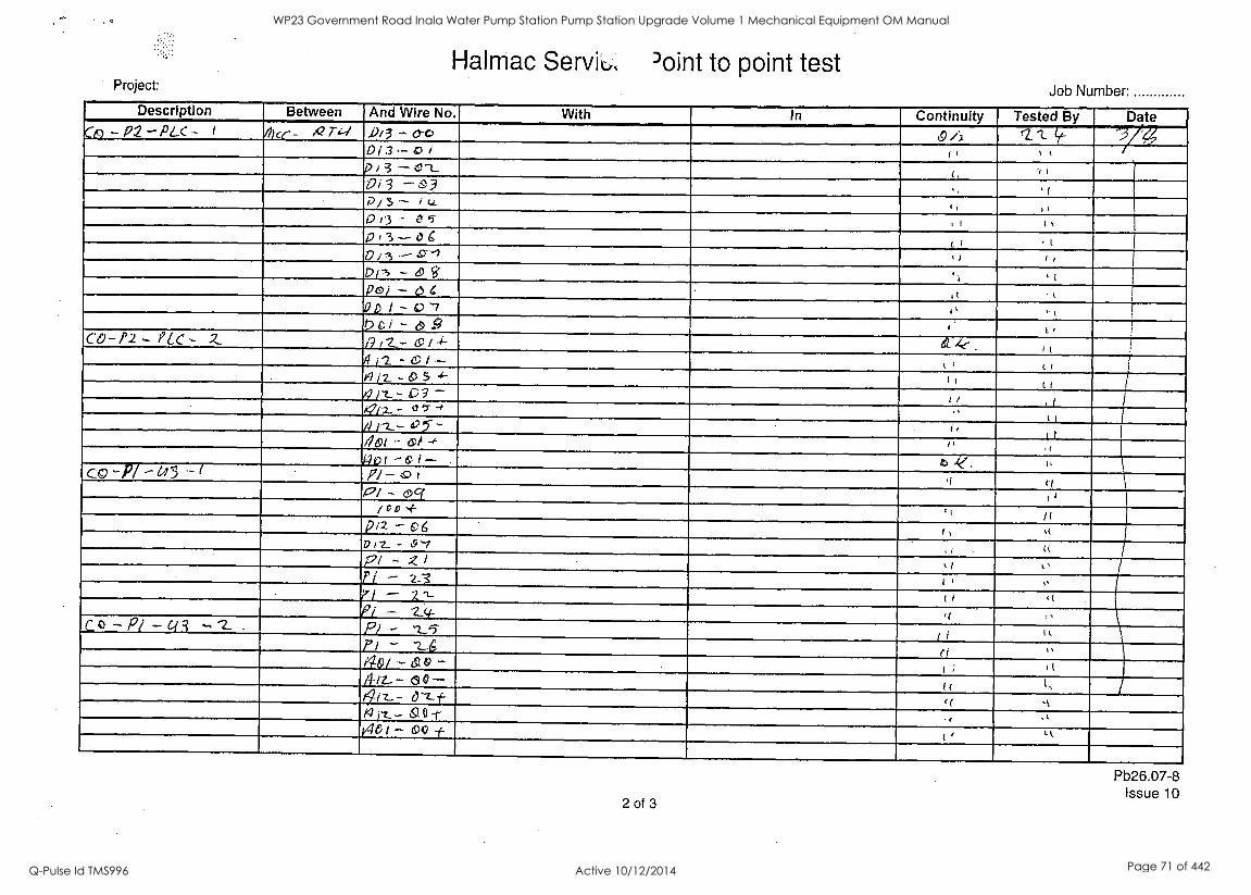
Halmac Serviu, Point to point test Project: Job Number:
Description Between And Wire No. With in Continuity Tested By Date :/4 Co - P2 - PLC - i ilke- - /42 74-1 j)/3 - CYC' 19 /J. c2." irc Di3 -0/ r, , t
p i 3 - CZ_ -4 (
0/3 -6'3 D ; 3 - Li 1, , 0 0 - 05 p ; - o6 Li ,l 0 i3 - '°.....1 41 4 1
Dri, -49 t i
0 e I - e 9 L CO-P2- PLC- Z a 11.._- Lc / .1-- 4. 4, ( t
el I2 - a) I .- L ;
wit -6)54- (1 (I ( pz...- 03-
r i ,../.2- - l' t- -f "
,
i
/V r2.-- C5- - 1
I
/9m( - sli ,;! i
q l'i 1
Ir2/ - 69 c{ i 1
/cm -r , !
12/2 - e 6 i , ,t I? 12._ - 0'1 u PI - 2I \ i l' ii - 2_3 I ! , ri - 21 ( , ;(
ei Co -Pr -c]3 c;13 - -2-- . Pi - '2_5 ri Ii.
PI - '2_6 ei 40/ -610 - 1(
/1-ii-- 00- « t, /91z-- a-Z--f- lf 't
146 i - CC ± II t%
2 of 3
Pb26.07-8 Issue 10
WP23 Government Road Inala Water Pump Station Pump Station Upgrade Volume 1 Mechanical Equipment OM Manual
Q-Pulse Id TMS996 Active 10/12/2014 Page 71 of 442
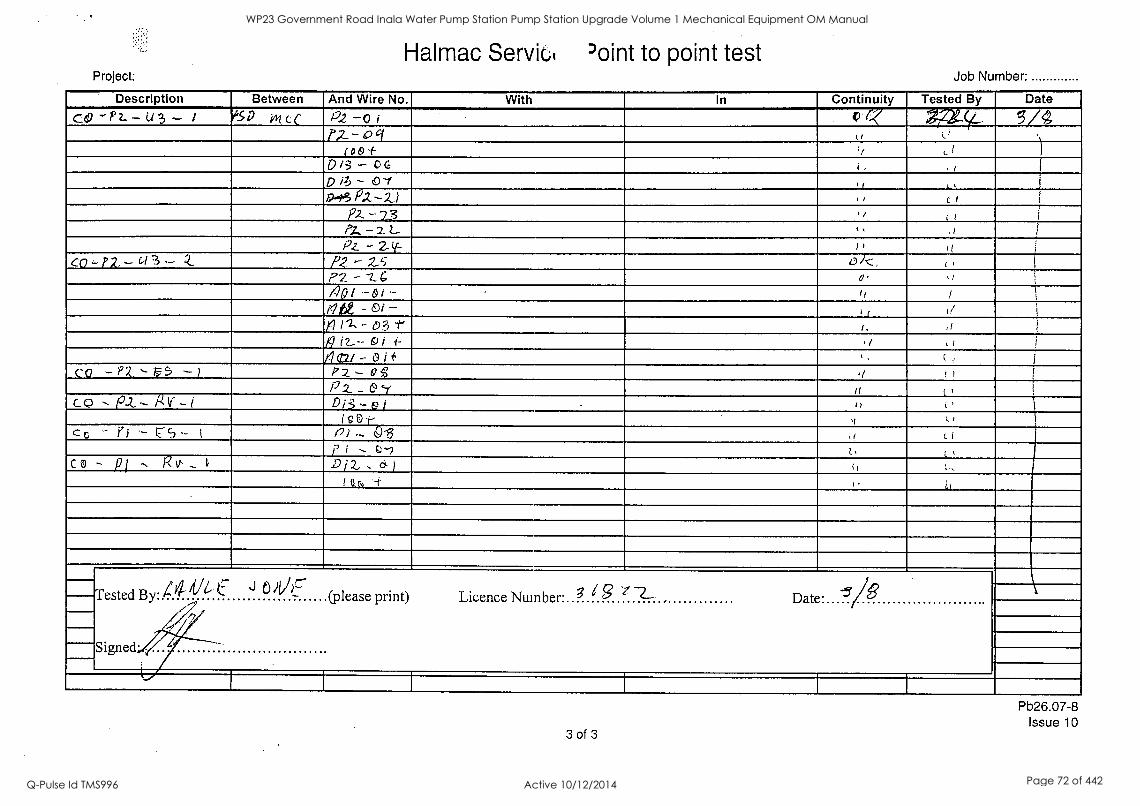
Halmac Servict 'oint to point test Project: Job Number:
Description Between And Wire No. With In Continuity Tested By Date
cep -Pz.. -CA 3 - t 617 im cc P.z -0 i p.q gi2X-4t 0
5/4 i>2..- 0 et ,,
(00+ ,, ,/ ) 0(3- 0 6 i , . I I
p ib - 0-1 3, , ,
9-6 P.2.-2.1 , , el 3
,
)2,-- 73 ,1 i /
P.7... - 2. L_ , , ,i P.z. -2 ((- I 1 II
CO ' P2. -C't 3 - Q PZ - 2-5 OA:: c 3
P2 - -2_. 6 o, 71p1 .-oi.- I,
p 7 t d e - &( - , ,
,n r2. - 03 lfr I, ,1
p i2--- 6) i i- ,/ 4w - o i i I ( ,
co -PZ- ..- 5 -) Pz - 0g ,,) ! )
P z _ & -7, t ( t' C-0 --- PIZ --- g V. - 1 . 0 ; - el ,, U ,
'vet-- I
CC - ri - P3-- l p91._ 013 , (
___P Da .. 6 1
t ci , C 0 - pi , 12v- ... 1,
Tested By. 4 4- Vt. -.,
A Signed.
j ) I I - (please print) Licence Number. 3 i 3 ' R---- , Date. -5 g
I
Pb26.07-8 Issue 10
3 of 3
WP23 Government Road Inala Water Pump Station Pump Station Upgrade Volume 1 Mechanical Equipment OM Manual
Q-Pulse Id TMS996 Active 10/12/2014 Page 72 of 442
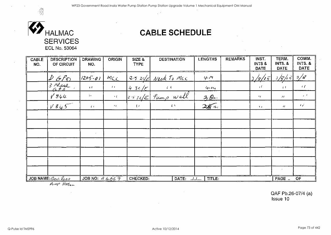
HALMAC SERVICES ECL No. 53064
CABLE SCHEDULE
CABLE NO.
DESCRIPTION OF CIRCUIT
DRAWING NO.
ORIGIN SIZE & TYPE
DESTINATION LENGTHS REMARKS INST. INTS & DATE
TERM. INTS. & DATE
COMM. INTS. & DATE
J> 6f' iZo5 -e9/ ' '2-'1 2 4 7 4(te4 rc, //7C: C v-Pt 3/9/; ;;-- We 1 5/A7
5' P/GUL L.
JOB NAME: 60(../: 70,9,2 JOB NO: A 4,- 6 6 9' CHECKED: I DATE: ../../.... I TITLE: I PAGE .. OF iovrw' STjJloi-
QAF Pb.26-07/4 (a) Issue 10
WP23 Government Road Inala Water Pump Station Pump Station Upgrade Volume 1 Mechanical Equipment OM Manual
Q-Pulse Id TMS996 Active 10/12/2014 Page 73 of 442
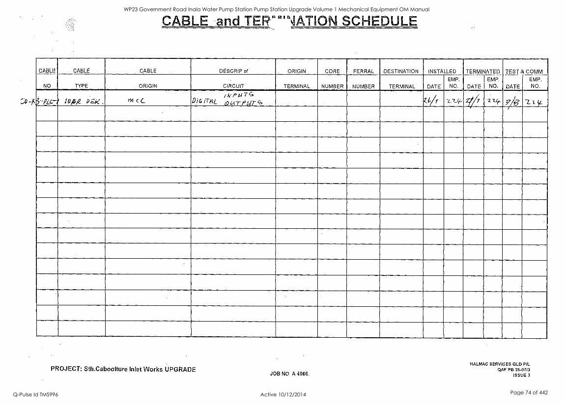
CABLE and TEir'NATION SCHEDULE
_CABLB _
NO
CABLE CABLE DESCRIP of ORIGIN CORE FERRAL DESTINATION INSTALLED TERMINATED
EMP.
NO.
TE.§:r
DATE
& cqmm_ EMP, NO, TYPE ORIGIN CIRCUIT TERMINAL NUMBER NUMBER TERMINAL DATE
EMP. NO. DATE
5;' - PLC..-/ Idylg Pi - - . , : k . Pm c C. A/PaiTc..
D i 6 %In L 0 wr P TI
C., Z.V7 -cz_11.- 2777 -2-4,_ g .2_1
PROJECT: Sth.Caboolture Inlet Works UPGRADE JOB NO A 4066.
HALMAC SERVICES QLD P/L QAF PB 26-07/3
ISSUE 3
WP23 Government Road Inala Water Pump Station Pump Station Upgrade Volume 1 Mechanical Equipment OM Manual
Q-Pulse Id TMS996 Active 10/12/2014 Page 74 of 442
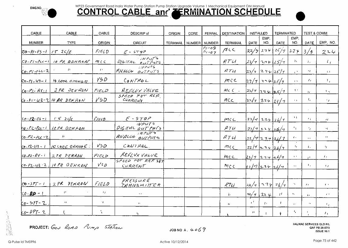
CONTROL CABLE an r° RN NATION SCHEDULE
CABLE CABLE CABLE DESCRIP of ORIGIN CORE FERRAL DESTINATION INSTALLED TERMINATED TEST & COMM
NUMBER TYPE ORIGIN CIRCUIT TERMINAL NUMBER NUMBER TERMINAL DATE
EMP. NO. DATE
EMP.
NO. DATE EMP. NO.
e- - /2/ -69 711 c_ (.. X2--/, 2'2 2 i y-77 2-2 }4 3/ 2z. Le:
Co .- r l --?Lc- i , PA: A Jr-- ve /-4. c /V. 41 ( C..
iiV P cli-1. /2/6 i r /9 i._ 0 Ai. ,--3 :4 n; . R r 64 -2----i-t. .457-r " i , i /
Cori t-p L-C- - Z. if friA014-66- 0 a T p c., T 5 A? ril .1/7 '2-'7 S- 201 .( I..,
Co.- Pf -Le3 - i it C-6-74._ t9r-rarirct-r Y.90 co A/7 ,_,e, 1_. M C c 2.277 -z- -, 9- y. , /q - /7 I , I, f,
co-PI- A? r- i 2 Pk pre aDA) r-)E74.,0 )4.Z E/16 ,/ //IL:ye ipi c c . 2z/7 1-t. c.-.. t .
t, t ,,
Cc ... P - Lig -1_ IQ 'fa p Es : Ao A) 1/;D SP4Ft.z. A ht?"7- 1 e C r- .
cw A RI-- r AN MCC_ 241 2:2. It
.1,1,71
2. i-/ .9 (, ' i
c c4 - pZ- Es - ) I . c 2c Fa r-cD 6- -STEP /41c (._ 2 2/-1 'L.-7-+. 2 6/t , 1
cc - r-:.--Pa- 1 ( 0 Pie 0 ,7,te lAelu, ,
//vnur 0 iG /p-N_ a;,...0--par-5 /27 cit 2711 1 7-1- 5- 7 .rg'7 t 1
'/ ./
fo-P-Z -Pex -2 li i il(PC/7- 5 0 A/14 W6- 0 up-74)T c) R T t'i z_rf 'I "Z- (-0- 2.4/ '7
:-..0 -0,-G/3 - I lc c_ °RE: 0 gg)u6:. C .. V5 0 C.,Div 7 -124Qt. _ 07C C
,;-2
22 & 1-.Z (r- 2_4/7 ,, if
co-P2-2Y- i -.z r,e P rkgem r-/ 1:7Li> AlZ(Ix 1/1,2 4.-v c hicc
mc c
D./7 22.E 1
is.2t1.-2--z-y-
21/-/
.2..v-7 ' '
f'
i
r ,
r, '- a - 1,2 ..i43 , 1 : is P, 0 IF RA 44.1 / 1 1) 51'Eri, Par" Rcir: s Er-
Ca iZA), )..--Air
09-5r)-- I z ?tie "PFfr<k9/1/ 17/F40 per.S.5 m R k.-
7-4-0 i 1 N 4 wi l rrZ l'. 47-c) z,,./-, -x. -2.
i '2 t /cf '`
/ , (
CO - SP - I i f
1 ( I, 1-z /% '221_ y- l f t. , ,
' 'e- 91Y- 2 . ,, ., ,, h
1
r l t, 1 ,. ., ,,
k
if i it
1,
, 1 ,
PROJECT: Co JOB NO A. 0G
HALMAC SERVICES OLD PR.
OAF PB 26-07/3 ISSUE 10.1
WP23 Government Road Inala Water Pump Station Pump Station Upgrade Volume 1 Mechanical Equipment OM Manual
Q-Pulse Id TMS996 Active 10/12/2014 Page 75 of 442
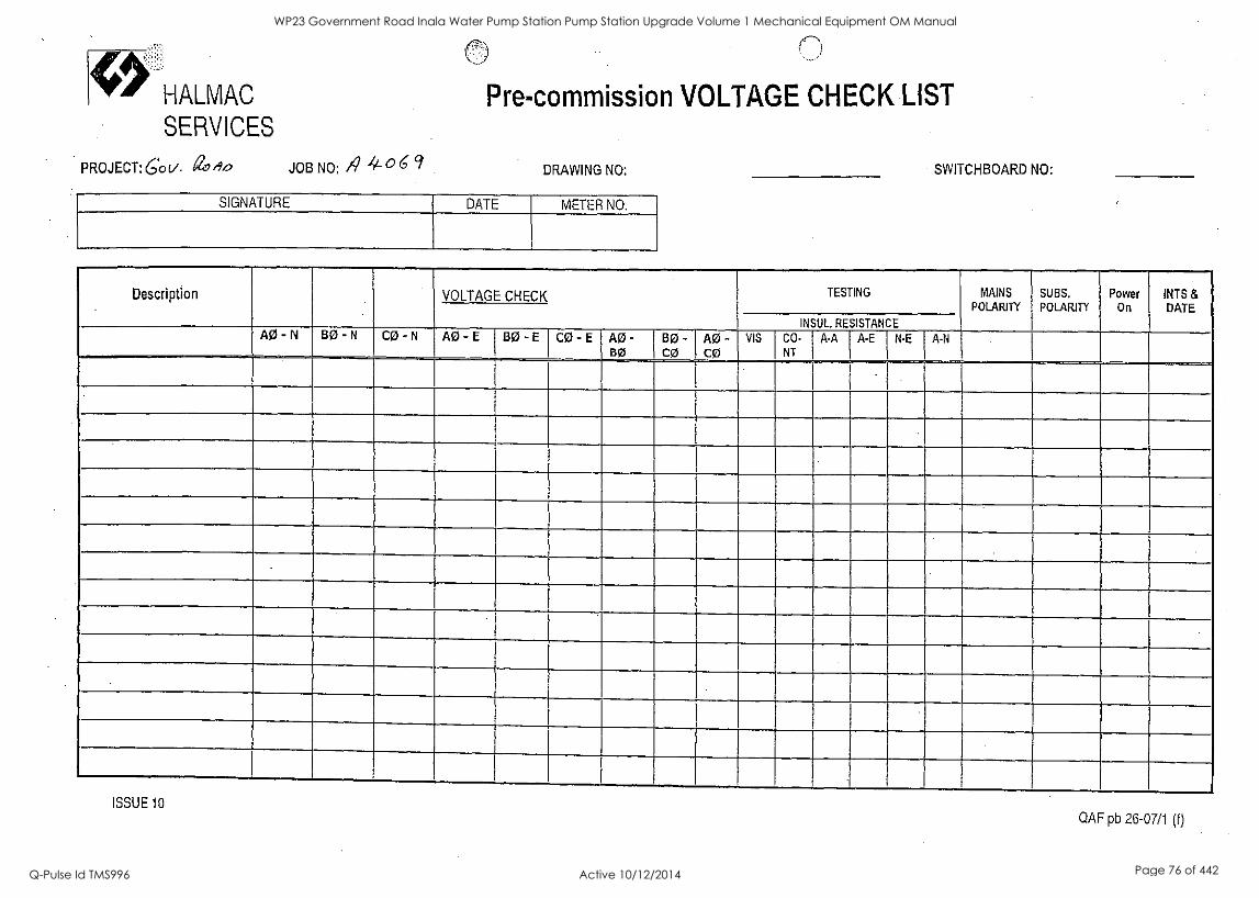
HALMAC
SERVICES
PROJECT:60V. avel, JOB NO: 4 4. ° 6 c'
Pre-commission VOLTAGE CHECK LIST
DRAWING NO:
SIGNATURE DATE METER NO.
SWITCHBOARD NO:
Description VOLTAGE CHECK TESTING MAINS POLARITY
SUBS.
POLARITY Power
On INTS & DATE
INSUL. RESISTANCE AO - N BO - N CO - N AO - E BO - E CO - E AO-
BO BO- CO
AO- CO
VIS CO-
NT
A-A A-E N-E A-N
ISSUE 10 QAF pb 26-07/1 (f)
WP23 Government Road Inala Water Pump Station Pump Station Upgrade Volume 1 Mechanical Equipment OM Manual
Q-Pulse Id TMS996 Active 10/12/2014 Page 76 of 442
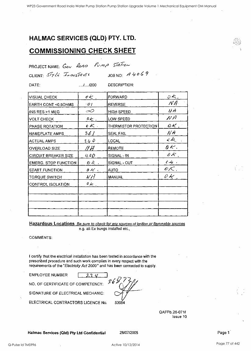
HALMAC SERVICES (QLD) PTY. LTD.
COMMISSIONING CHECK SHEET
PROJECT NAME: Gov 41,90 /24./,en $1;97,70..,
CLIENT: -S1Y/fi- JOB NO: 4 4
..../..../200 DESCRIPTION: DATE:
VISUAL CHECK 0.. FORWARD 0 ,
EARTH CONT <0.50HMS 0 ) REVERSE
INS RES >1 MEG :_-2.0 HIGH SPEED AM
VOLT CHECK C., LOW SPEED N lel
PHASE ROTATION 0 K - THERMISTOR PROTECTION 0 kl ,
NAMEPLATE AMPS 3 e / SEAL FAIL NA ACTUAL AMPS 3 ii. 0 LOCAL ,
OVERLOAD SIZE N4 REMOTE d) de-,
CIRCUIT BREAKER SIZE 4-- 00 SIGNAL - IN e./?"
EMERG. STOP FUNCTION 0 1< . SIGNAL - OUT ,r .4..
START FUNCTION 61 iie AUTO 0/C .
TORQUE SWITCH A/hi MANUAL 0 .1
CONTROL ISOLATION 0,&
Hazardous Locations Be sure to check for any sources of ignition or flammable sources e.g. all Ex bungs installed etc.,
COMMENTS:
I certify that the electrical installation has been tested in accordance with the prescribed procedure and such work complies in every respect with the requirements of the 'Electricity Act 2000° and has been connected to supply.
EMPLOYEE NUMBER 2,2 tf 1
NO. OF CERTIFICATE OF COMPETENCY:
SIGNATURE OF ELECTRICAL MECHANIC:
ELECTRICAL CONTRACTORS LICENCE No. 53064
QAFPb.26-071f Issue 10
Halmac Services (Qld) Pty Ltd Confidential 28/07/2005 Page 1
WP23 Government Road Inala Water Pump Station Pump Station Upgrade Volume 1 Mechanical Equipment OM Manual
Q-Pulse Id TMS996 Active 10/12/2014 Page 77 of 442

HALMAC SERVICES (QLD) PTY. LTD.
COMMISSIONING CHECK SHEET
PROJECT NAME: COL, a9,90 /2".V 5 770^'
CLIENT: 31/21i JOB NO: '4
DESCRIPTION: DATE:
VISUAL CHECK 4,1 K . FORWARD /1 /A
EARTH CONT <0.50HMS Ot REVERSE /1/1 INS RES >1 MEG <--:-. HIGH SPEED t)
VOLT CHECK 0 & . LOW SPEED 1 /
PHASE ROTATION 0 K THERMISTOR PROTECTION e ,1
NAMEPLATE AMPS 3 6 I SEAL FAIL i-- ACTUAL AMPS ____9 4 4 -0 LOCAL 13
OVERLOAD SIZE 41/4) REMOTE to ,V
CIRCUIT BREAKER SIZE .1,4 6 0 SIGNAL - IN 0 ,4
EMERG. STOP FUNCTION b X. SIGNAL - OUT 0 4.-z_
START FUNCTION C di. AUTO 0 -IC ,
TORQUE SWITCH ,17//q MANUAL
CONTROL ISOLATION c /e
Hazardous Locations Be sure to check for any sources of ignition or flammable sources e.g. all Ex bungs installed etc.,
COMMENTS:
I certify that the electrical installation has been tested in accordance with the prescribed procedure and such work complies in every respect with the requirements of the 'Electricity Act 2000° and has been connected to supply.
EMPLOYEE NUMBER zzy- NO. OF CERTIFICATE OF COMPETENCY: 3 ig '7 -2-
SIGNATURE OF ELECTRICAL MECHANIC:
ELECTRICAL CONTRACTORS LICENCE No. 53064
QAFPb.26-071f Issue 10
Halmac Services (Qld) Pty Ltd Confidential 28/07/2005 Page 1
WP23 Government Road Inala Water Pump Station Pump Station Upgrade Volume 1 Mechanical Equipment OM Manual
Q-Pulse Id TMS996 Active 10/12/2014 Page 78 of 442
BRISBANE CITY COUNCIL Brisbane Water Government Road
8 Commissioning Report
Overleaf
8748C-Manual Draft B
BW.30098-02/03 Pump Station Upgrade
21 Dec. 05 3-5
WP23 Government Road Inala Water Pump Station Pump Station Upgrade Volume 1 Mechanical Equipment OM Manual
Q-Pulse Id TMS996 Active 10/12/2014 Page 79 of 442
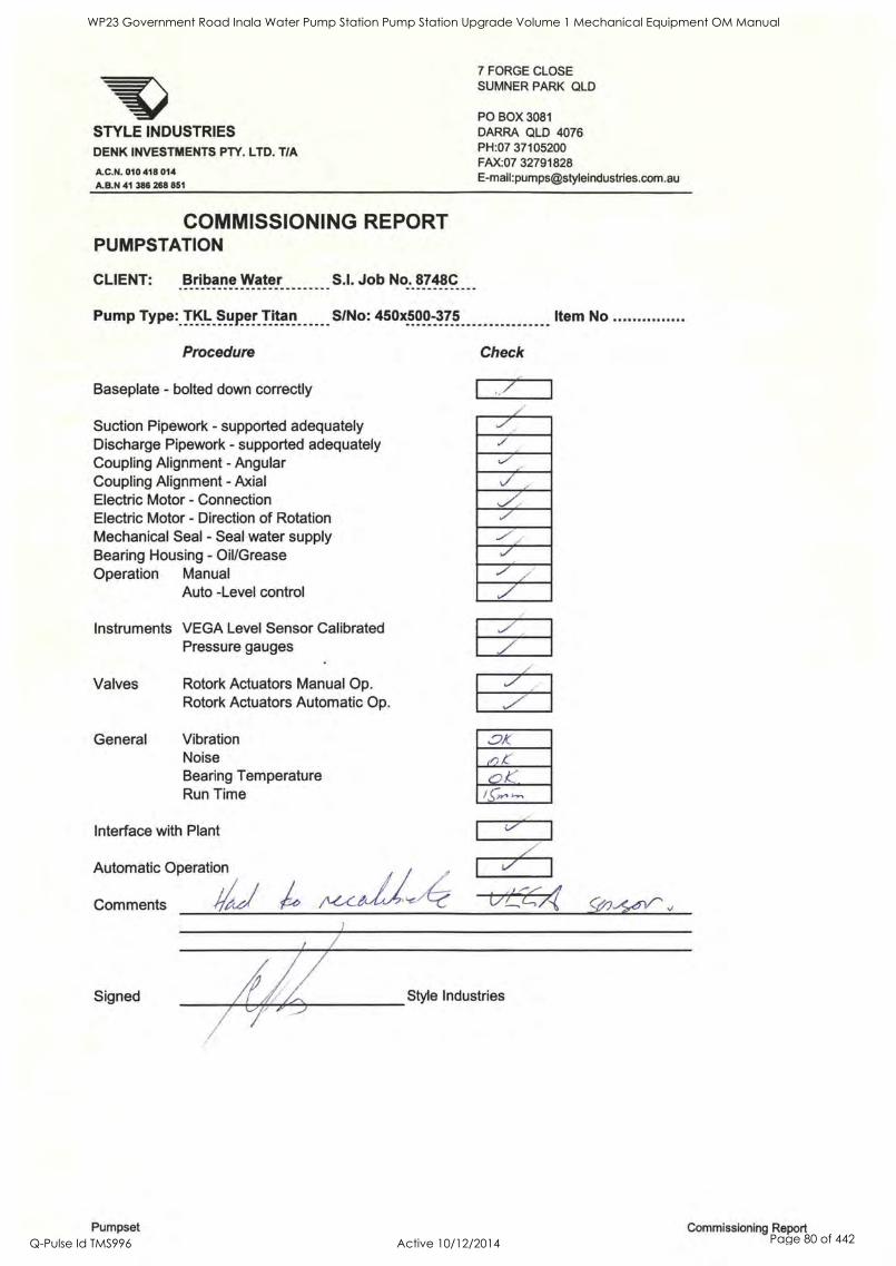
STYLE INDUSTRIES DENK INVESTMENTS PTY. LTD. T/A
A.C.N. 010 418 014
A.B.N 41 386 268 851
7 FORGE CLOSE SUMNER PARK QLD
PO BOX 3081 DARRA QLD 4076 PH:07 37105200 FAX:07 32791828 E-mail:[email protected]
COMMISSIONING REPORT PUMPSTATION
CLIENT: Bribane Water S.I. Job No. 8748C
Pump Type: TKL Super Titan S/No: 450x500-375
Procedure
Baseplate - bolted down correctly
Suction Pipework - supported adequately Discharge Pipework - supported adequately Coupling Alignment - Angular Coupling Alignment - Axial Electric Motor - Connection Electric Motor - Direction of Rotation Mechanical Seal - Seal water supply Bearing Housing - Oil/Grease Operation Manual
Auto -Level control
Instruments VEGA Level Sensor Calibrated Pressure gauges
Valves
General
Rotork Actuators Manual Op. Rotork Actuators Automatic Op.
Vibration Noise Bearing Temperature Run Time
Interface with Plant
Automatic Operation
Comments 4/41 45
Signed
Check
V
../
.7"
1=1
Item No
Style Industries
Pumpset Commissioning Report
WP23 Government Road Inala Water Pump Station Pump Station Upgrade Volume 1 Mechanical Equipment OM Manual
Q-Pulse Id TMS996 Active 10/12/2014 Page 80 of 442

WP23 Government Road Inala Water Pump Station Pump Station Upgrade Volume 1 Mechanical Equipment OM Manual
Q-Pulse Id TMS996 Active 10/12/2014 Page 81 of 442
BRISBANE CITY COUNCIL Brisbane Water Government Road
9 As constructed drawings
9.1 As constructed Mechanical Drawings
Overleaf
8748C-Manual Draft B
BW.30098-02/03 Pump Station Upgrade
21 Dec. 05 3-6
WP23 Government Road Inala Water Pump Station Pump Station Upgrade Volume 1 Mechanical Equipment OM Manual
Q-Pulse Id TMS996 Active 10/12/2014 Page 82 of 442

WP23 Government Road Inala Water Pump Station Pump Station Upgrade Volume 1 Mechanical Equipment OM Manual
Q-Pulse Id TMS996 Active 10/12/2014 Page 83 of 442
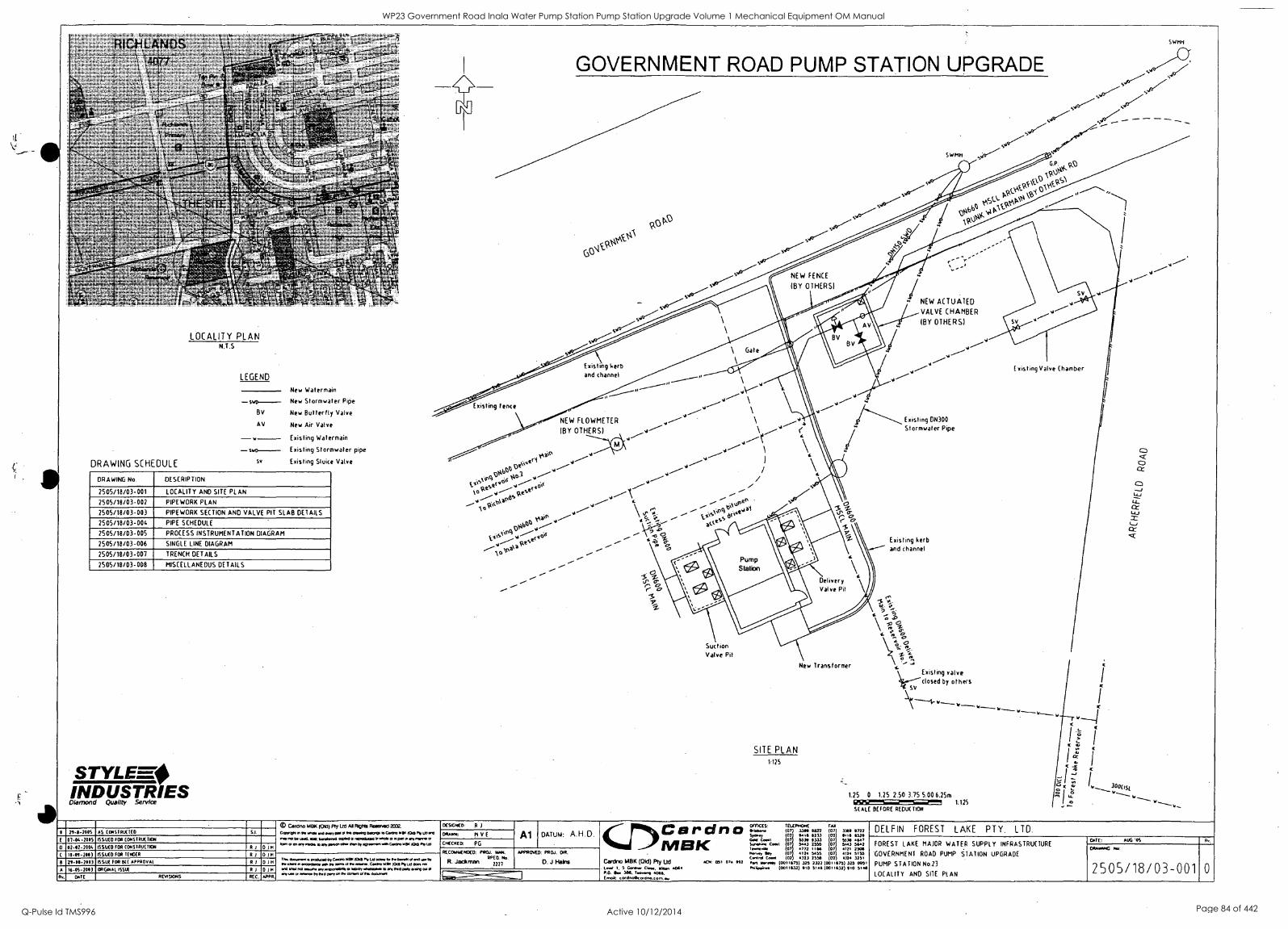
- .. .. - . v,400,0 -
,; 4 '" '
, ',' -.1
... srt.L7A ,.... .,...71..s.,
, , ....,--
s 07,.......0 -.'' efxix
- fo' . ,
3
LOCALITY PLAN N.T.S
LEGEND
- swo--- By
AV
DRAWING SCHEDULE
STYLE-=.0
so
INDUSTRIES Quality
TRIES
21-0.200S AS CONSTRUCTED
0 - - 20 S 5503(0 FOR CONSTRUCTION
0 02-00-2004 ISSUED FOR CONSTRUCTION R I 0)66 10-01-200) ISSUED 000 1E05ER RI 0 /
Z1-1/I200) ISSUE FOR DEC APPROVAL 111
A 16-0S-2011 OREONAl ISSUE R I 101
arc
orT
New Watermain
New Stormwater Pipe
New Butterfly Valve
New Air Valve
Existing Watermain
Existing Stormwater pipe
Existing Sluice Valve
DRAWING No. DESCRIPTION
2505/18/03-001 LOCALITY AND SITE PLAN
2505/18/03-002 PIPE WORK PLAN
2505/18/03-003 PIPE WORK SECTION AND VALVE PIT SLAB DETAILS
2505/18/03-004 PIPE SCHEDULE
2505/18/03-005 PROCESS INSTRUMENTATION DIAGRAM
2505/18/03-006 SINGLE LINE DIAGRAM
2505/18/03-007 TRENCH DETAILS
2505/18/03-008 MISCELLANEOUS DETAILS
acwsiovis RECr_
GOVERNMENT ROAD PUMP STATION UPGRADE
SJ
SWMH
/ SWMH
000 N\SCV
PckL.NAt'iki'
\E1,0 00.40
Gp
liki0c, Nei
051,Y4,0
\V( 014.RS1
V
NEW FENCE
(BY OTHERS)
SJ
NEW ACTUATED
VALVE CHAMBER
(BY OTHERS)
Existing kerb and channel
Existing fence
.°1.4e1 k.,,stseVricg
octe 9.5/0 if4S
laSbt'
1PbtA
siese
A0 \c,0
NEW FLOWMETER
(BY OTHERS)
Ptltl
ooke r,
41 .40131
Existing DN300
Stormwater Pipe
Existing kerb and channel
Suction Valve Pit
SITE PLAN 1125
New Transformer valve
closed by others
1.25 0 1.25 2.50 3.75 5,00 6.25m 1:125
SCALE BEFORE REDUCTION
Existing Valve Chamber
V
Car0/10 MOO KAM Fly 110 AIR/alit ROOMPACI 37(12.
Cc, 0219 now woo me 66, ow 0 1114 09.0 541.91004A. M 1016M 13795 ma, 190 Ow Led. 400 banal.. inAda Anal in.. a II ArilneynAA 1.410en y..0y 11517 A n a , Ow MA ty Noma 551f 0311K 100 691.
ocsxmcm R )
01106. E
APPR.
AL amonere 4410.0 DA. oleo 00101A3 a... tone to nocaora M1. warsaw.w.0 a9n, SO 100 69 LA Wes ro
A 17.9 70 MINA. 11, 0 Md901 lAancoas .A.C1 pAI .00 AAA. IA At an al IN anon SK dow.
CHEERED: PG
Al DATUM: A.H.D.
RECONY1NOE0, PROJ. NAN. RPEO.
R. Jackman
APPROVED: PROJ. PR.
O. J Mains
CJI)Cardrao NII3K
Cardno MBK (Old) Ply Ud I.- 1. 5 0aer Cleo, 000, 4099 P.O. OA 506. Toe*, 4066. (044: c0.7604190d..torn.A.
Al, 051 074 992
VMS: TELEPHONE FAX 5A4.9.. (07 3360 9622 (07 3369 9222 Sow, 02 Hi Ili 11233 02 91113 6529 G. Co. 07 5539 9333 07 55311 94.7 SonehA4 C911 07 5993 2576 07 5143 54.2 1 AnAjo 0) 4772 1166 07 4/21 25011 Arory NA 07 4124 5455 (07 4124 5155 Cont. 19. 102 9323 2550 102 9170 3251 5. N.A. (0071e75) 321 2322 (00111375) 325 0951 Aix.AA 100119171 910 5101(0011633) 110 51.6
DELFIN FOREST LAKE PTY. LTD.
FOREST LAKE MAJOR WATER SUPPLY INFRASTRUCTURE
GOVERNMENT ROAD PUMP STATION UPGRADE
PUMP STATION No.23
LOCALITY AND SITE PLAN
DATE: AUG 'OS
diNPAPIO No:
2505/18/03-001 0
WP23 Government Road Inala Water Pump Station Pump Station Upgrade Volume 1 Mechanical Equipment OM Manual
Q-Pulse Id TMS996 Active 10/12/2014 Page 84 of 442

ii
WP23 Government Road Inala Water Pump Station Pump Station Upgrade Volume 1 Mechanical Equipment OM Manual
Q-Pulse Id TMS996 Active 10/12/2014 Page 85 of 442
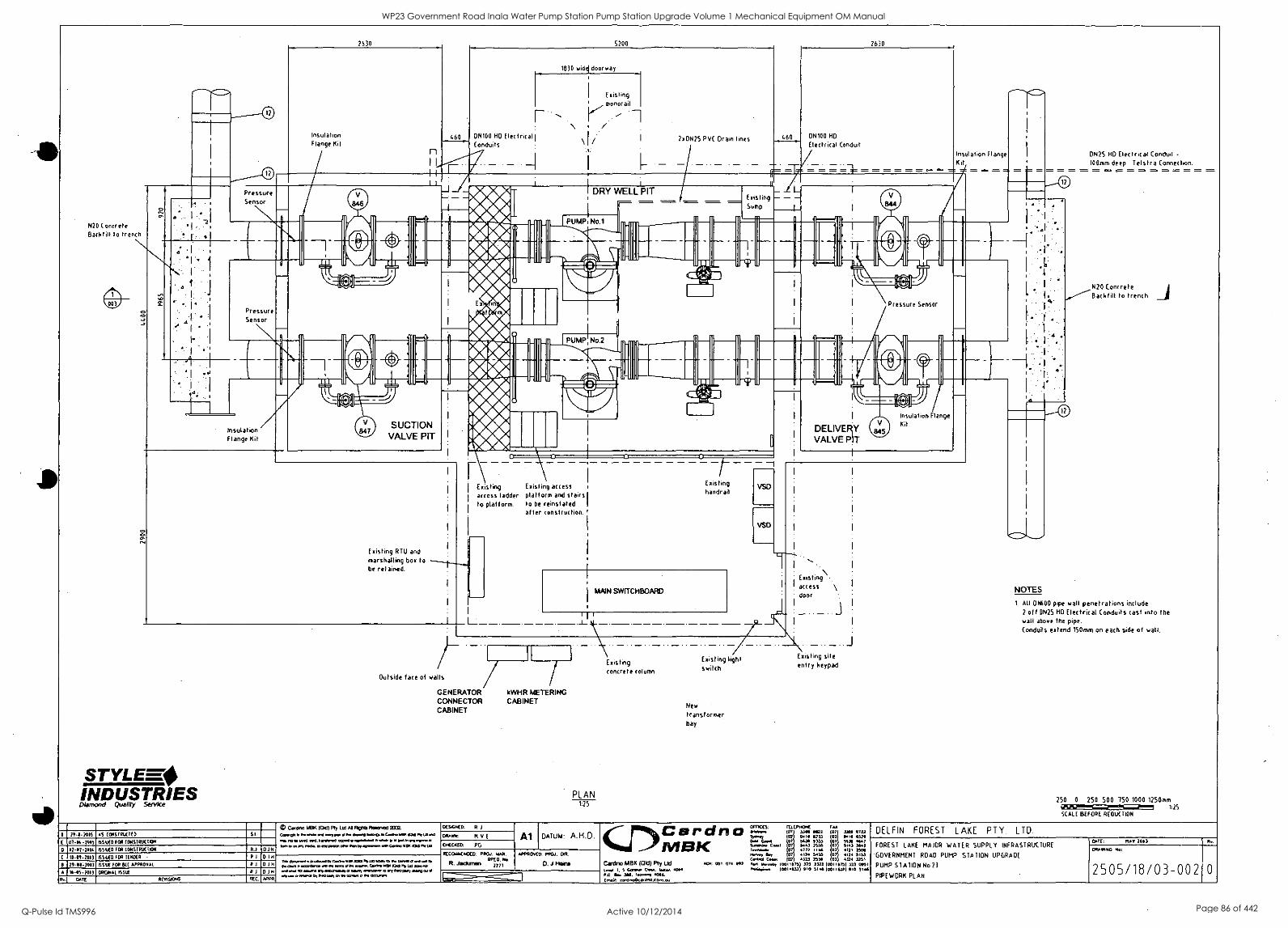
2630 5200 2630
Insulation Flange Kit
2x0N25 PV( Drain lines ON100 HD
Electrical Conduit
Insulation Flange Kit
DNZS HD Electrical Conduit -
100rom deep. Telstra Connection.
Pressure Sensor
DRY WELL PIT Existing Sump
N20 Concrete Backtill to trench
1
Pressure Sensor Pressure Sensor
Insulation Flange Kit
SUCTION VALVE PIT
Existing access ladder to platform.
Existing access platform and stairs to be reinstated after construction.
Existing handrail
Existing RTU and marshalling box to be retained.
MAIN SWITCHBOARD
Existing access door
Outside face of walls
GENERATOR CONNECTOR CABINET
STYLEF-4 INDUSTRIES Diamond
kWHR METERING CABINET
PLAN 1:25
Existing concrete column
Existing light switch
New
transformer bay
Existing site entry keypad
_J
N20 Concrete Backfill to trench
NOTES
1. All DN600 pipe wall penetrations include 2 off EIN25 HD Electrical Conduits cast into the wall above the pipe. Conduits extend 150mm on each side of wall.
250 0 250 500 750 1000 1250mm GiSISinaT!!!E=3 1:75
SCALE BEFORE REDUCTION
li CarcIno 510K (06:1) Fty Ltd Al /Vas liesenecl 2102.
c00011.1..... 1. Po O.. Illeftro n Coe. WO 10o On of ens
vow no C.Y.O. W. Inn.. coon o non.*O...NO MOM n 400ron44
DES4040: R
11-11.2015 AS CONSTRUCTED S i MOM: M v 01-01.- /CIS I55LI(0 fOR CONSIRLICTKIN
0ECXECA PG 01-07-1004 1551.40 fDR CONSTRUCTION R.1
boo .05 4.15. o ON mon eon 11.1 bp ',won .10 Go. 0011 10011310
REC06114/000: PROJ. WAN. RPEO.
R. Jackman . 222-1
10-01-1013 1551.40 000 1(11010 D 1I1 tin donowl A postool proOna SRi I P'v ISb yb Cm. e oaten ne
P. own I. owe.. on 14 woo 41 to ann.. CanOo 01/11100 7171.0 down. IS agiauma ,ongarnulaby CI 1.111y oftIvo 10 My ..0 Wyo.° totl
nay o *moo by nol goo en to Call. S fte Owns.
20-10:200) 155 IA 000 SU APPROVAL 1 010 A 16-05-1013 ORGNIAL 15514 R 010
OxTE RENI570ort5 REC. *PPR
Al DATUM: A.H.D.
APPROVED: PROJ. OR.
D. J Hans
(r)Cardno MBK
Canino MBK (Old) Pty lid Lon 1 5 Coofose Woo 4014
0.. 300. Noon, 4046. CHAR: cHono0c<0.0.09%.(29
404 CHI 074 902
DIMES: TELEPHONE FAX (07 3340 10172 07 3300 1723
504477 02 0.1 1233 02 9.10 4571 Gobi Caw 07 36.90 0333 0 5336 4447
C.Asi 07 5403 2313 07 5443 5442 07 *772 HI4 07 472I 1.v, Bey 07 *124 3655 07 4124 5103 C.. C.A. 102 4323 2558 02 4374 1251
4423 Mont. 100110751 325 2322 (001175) 373 0951 (001%321 010 3114 (00111371 910 5144
DELFIN FOREST LAKE PTY. LTD.
FOREST LAKE MAJOR WATER SUPPLY INFRASTRUCTURE
GOVERNMENT ROAD PUMP STATION UPGRADE
PUMP STATION No 23
PIPE WORK PLAN
CATE: riA0 760)
ORA:HNC No:
2505/18/03-002 0
WP23 Government Road Inala Water Pump Station Pump Station Upgrade Volume 1 Mechanical Equipment OM Manual
Q-Pulse Id TMS996 Active 10/12/2014 Page 86 of 442
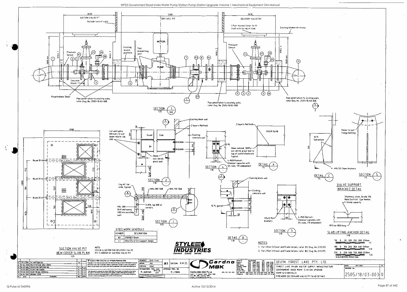
2630
SUCTION VALVE PIT
Outside lace of walls
5200
I DRY WELL PIT
2630
Pressure Sensor
Concrete Plinth
Polyethylene Sheet Pipe penetration to existing walls, refer Dwg. No. 2505/18/03-008
r- I- F - - - -10 1 0 1
I
1 e 1
Nr i .6. 1
i irii l
11
i..
- Beam 81 (-Et 7-=---=-1 - - ,_ I- I
I
I
ill
I
-
I I
I I
I
I
I
I
_ - - Beam B14.-
I - - Beam B1 4.
.
03
- "- J- - I e 1
r i 1
1 I L
_ L 1
I
I
I
I
738 I
I f-
I
J I
01 L
SUCTION VALVE PIT
NEW COVER SLAB PLAN F25
Existing access platform
Tied
dismantling joint.
Cut and splice N16 bars to suit beam rebate. lap 600.
10
ll
M 0
SECTION 125
DELIVERY VALVE PIT
3 Part Access Cover to lit flush with to top of slab Existing bitumen driveway
Pressure Sensor
Existing block wall
2 layers Mallhoid
Existing concrete wall
20mm
non-shrink grout pad
Cog alt. bar ends, typical.
71',
SECTION
N16-200 TIB N16-150 TIB
N16 300
Drill and epoxy 200 into existing wall
3-N16, lap 600 at corners
STEELWORK SCHEDULE
SECTION 1:25
MEMBER DESCRIPTION
81 25OUB31 Beam
Ll 125x125x12 EA Support Angle
NOTE:
COVER SLAB FOR THE DELIVERY VALVE PIT IS MIRROR OF SUCTION VALVE PIT
00@ $08 Pipe penetration to existing walls, refer Dwg. No. 2505/18/03-008
2 PL
SECTION 1:10
STYLEEO INDUSTRIES Diamond Quality Service
2 layers Malthoi
Pipe penetration to existing walls, refer Dwg. No. 2505/18/03-008
a a 10mm nominal, lOMPa
non shrink grout bed to top of walls/steelwork. Typical.
4-M20 Ramset- Chemset capsules with SS rods, 170 embedment
Existing block wall
12 PL gusset
Existing concrete wall
13502 PL
brackets
SECTION 1:10
16 PL
Galvanised
L
Holes to suit flange bolting
4- 016 SS Chem Anchors
4-M20 Ramset- Chemsel capsules with SS rods, 170 embedment
NOTES:
1. For 3 Part CI Cover and Frame details, refer BCC Dwg. No. 2/13.373.
2. For 2 Part CI Cover and Frame details, ref er 13(C Dwg. No. 2/13.371.
VALVE SUPPORT
BRACKET DETAIL
Stainless steel, Grade 316,
Reid Swif tlif t Eye Anchor, 5 tonne capacity
R12 bar 850 long
SLAB LIFTING ANCHOR DETAIL
50 0 50 100 150 200 250mm 12GEWSPS1 1.5
100 0 100 200 300 400 500mm 125132Si 170
250 0 250 SOO 750 1000 1250mm 1:56/1 1:25 SCALE BEFORE REDUCTION
21-11-701S AS (ONSTRUEIED
07.04.7005 POLYETHYLENE SHEET ACOED
0242.2004 ISSUED FOR CONSTRUE MN RI D H
10.4400) ISSUED FOR TENDER R1 01H
OD Canino 1413K (Oki) Fly 170 Al Fitho ReeRval 7002.
0,014 IP as a ay a 017 1144474044a oCrm.7447500 1477 110
ante I. a, 444300..000 bia taPay F al o 410441 n nr ale cr. a Pa to a par a M N anal to Cab 0201o1 Pty
0t510740: FIVE / (AU MAIM JAS
CNECNEO: A De( Al DATUM: A.H.D.
D 20-00.7003 ISSUE FOR DEC APPROvAt R I 19
A 14-05-2003 ORIGINAL ISSUE R I 0 1 1.1
047E 0005l0 05 REC. APPR
0ea9.4 aka bp Cara RIK 024 (NIA say to Pm tab d C v9. ty, 14 r sacra a Or 144444 saw Cao 4140 toe PNLPHLHL fl 09N any 4ny mama, ban *ma to a a 00? 0 RAP a 44 ama by a ay en re ban or F 07.9.4
REC044341100. 0R(1.1. INN. RP( O. Mc
R. Jackman " APPROVED: PROJ. DR.
D. J Hairs
(r)Cardno Mak
C.ardno MBK (Old) Ply Ltd 1, 5 Caw Ca. 442144 4004
A.O. M. 3114. ?ban 4066. Drool: corOnolker0..4abut
407: 031 074 *02
OFTKES: TELEPHONE FAX 090.. (0 ) 3300 Na 107 3340 0723 7a0, 02 9414 0233 03 4414 4521 CPI CA* 07 MN 11113 07 5515 4447 5..ar Cat 07 5443 2555 07 5443 5442
4772 1114 07 4771 2504 144.44, ils, 07 4124 5455 07 4174 5155 C4040 Ceast 1 (02 4333 2554 102 4374 3251 44,1 31444441 (401 ion) 325 2322 1 03111751 )25 0051 P44a. (0011532) 110 5144 (001,132) 110 51413
DELFIN FOREST LAKE PTY. LTD.
FOREST LAKE MAJOR WATER SUPPLY INFRASTRUCTURE
GOVERNMENT ROAD PUMP STATION UPGRADE
PUMP STATION No.23
PIPEWORK SECTION AND VALVE PIT SLAB DETAILS
0o7t 907 2007
01405740
2505/18/03-003
WP23 Government Road Inala Water Pump Station Pump Station Upgrade Volume 1 Mechanical Equipment OM Manual
Q-Pulse Id TMS996 Active 10/12/2014 Page 87 of 442
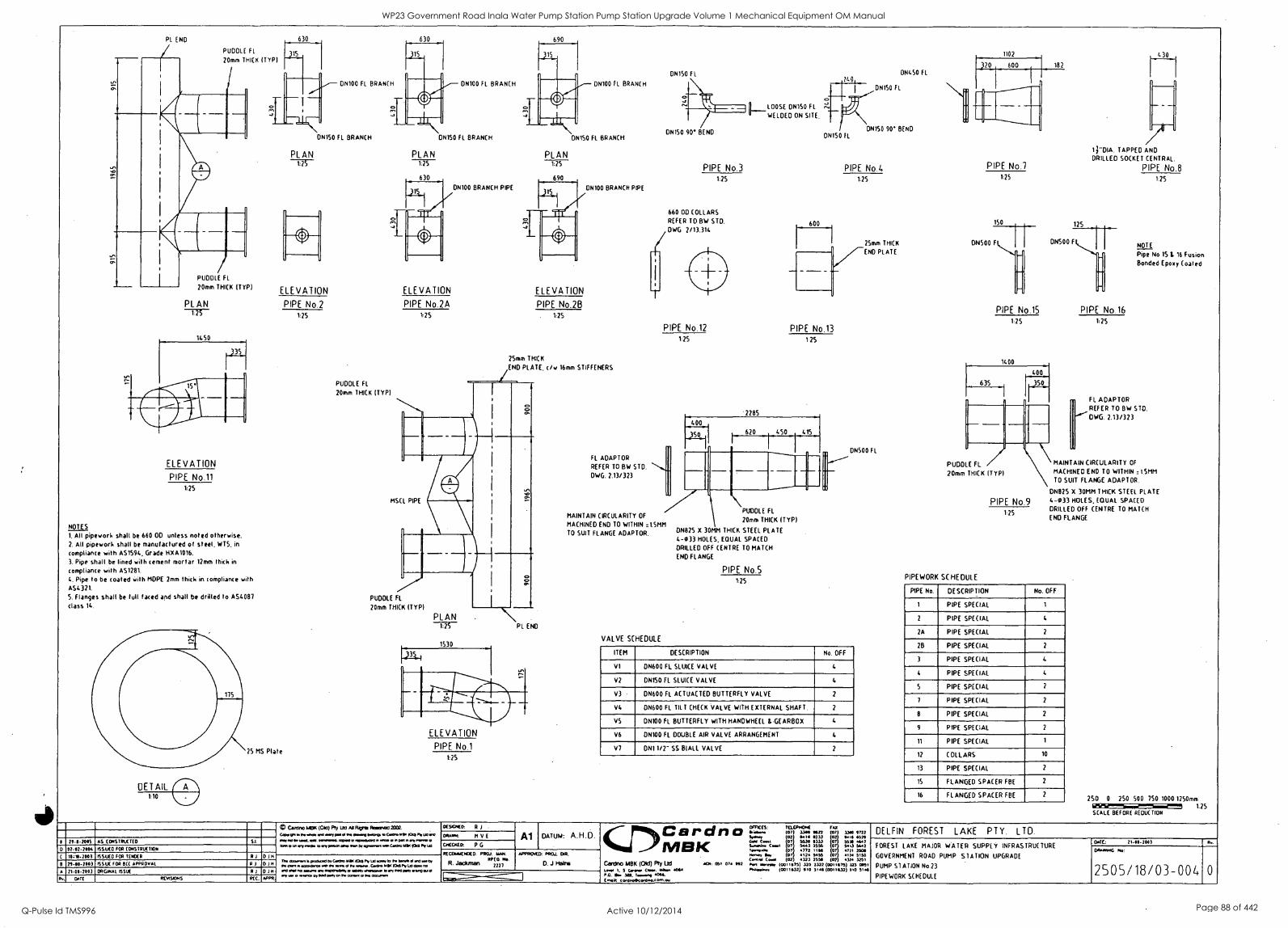
PL END
PUDDLE FL
20mm THICK ITYPI
PUDDLE FL
20mm THICK (TYP)
PLAN
ELEVATION
PIPE No.11 L25
NOTES
1, All pipework shall be 660 OD unless noted otherwise. 2. All pipework shall be manufactured of steel. WTS, in
compliance with AS1594, Grade HXA1016.
3. Pipe shall be lined with cement mortar 12mm thick in
compliance with AS1281.
4. Pipe to be coated wills MDPE 2mm thick in compliance with
AS4 321.
S. Flanges shall be full faced and shall be drilled to AS4087
class 14.
630 630
0N150 FL BRANCH
PLAN -775-
ELEVATION
PIPE No.2 1:75
25 MS Plate
PLAN
DN100 Fl. BRANCH
0N150 fl BRANCH
DN100 BRANCH PIPE
PUDDLE FL
20mm THICK ITYPI
ELEVATION
PIPE No.2A V25
PLAN
DN100 FL BRANCH
ONISO FL BRANCH
ELEVATION
PIPE No.28 . 115
ON100 BRANCH PIPE
25mm THICK
END PLATE, c/w 16mm STIFFENERS
MSCL PIPE
PUDDLE FL
20mm THICK ITYPI
PLAN PL END
ELEVATION
PIPE No.1 1:25
Caldno Wel< Pb 1.10 Ai Nona ReReneci ZOL woe a .. 0a oi *woo swop. Coo,o .9' Pe
77-11-7003 AS CONSTRUCTED sl. oar m a goat veneend. =owl o n000s000 47..00 0 rel
0 07.17 -1001 1551.1(0 FOR (CAISTRUET011 Woo moo... slorriootoano veep sperm* men C0042111.410421,041
10,1*-1003 ISSUED FOR TENDER R 114
71-01-7003 ISSUE FOR DC( APPROVAL 0104 Tr. moven Is poloc.094 Ce.00 MIK 030 re 14 acme, lo re Ione 44 .1964 re 014.4 n.ma.a 11411, re ems 0 re 4141ne. C.40. 1.0. 0341 Mr Ur One iv
A 71-01-7003 ORDINAL ISSUE R 0111 00 ow no loon. 0147040001 1.444 .vaneewe 0.17 .440 I.0 4n/ ow 0 woo 9,9043 meg 0+47 coon 0 re dearer.
DATE REVI9ONS RtC. PPPR.
FL ADAPTOR
REFER TO BW STD.
DWG. 2.13/323
MAINTAIN CIRCULARITY OF
MACHINED END TO WITHIN .1.5MM TO SUIT FLANGE ADAPTOR.
DN150 FL
EILOOSE OF1150 FL
ONISO 90' BEND
PIPE No .3
1:25
660 OD COLLARS
REFER TO BW STD.
DWG 2/13.314
PIPE No 12
1:25
2285
WELDED ON SITE
740,
ON150 IL
ON450 FL
DNISO FL
DNTSO 90' BEND
PIPE No .4 1:25
PIPE No 13
125
400
620 4S0
VALVE SCHEDULE
PUDDLE FL
20mm THICK IT YP)
ON825 X 30MM THICK STEEL PLATE 4-033 HOLES. EQUAL SPACED
DRILLED OFF CENTRE TO MATCH
END FLANGE
PIPE No .5 1:25
25mm THICK
END PLATE
DM500 FL
ITEM DESCRIPTION No. OFF
VI DN600 FL SLUICE VALVE 4
V7 DNISO FL SLUICE VALVE 4
V3 DN600 FL ACTUACTED BUTTERFLY VALVE 1
VI. DN600 FL TILT (HECK VALVE WITH EXTERNAL SHAFT. 2
VS DN100 FL BUTTERFLY WITH HANDWHEEL tGEARBOX 4
V6 DN100 FL DOUBLE AIR VALVE ARRANGEMENT I.
VT DN1 1/2- SS BIALL VALVE 2
1102 430
600
PIPE No.7 1.25
150
liON500 F
PIPE No.15 1:25
182
125
1 j"DIA. TAPPED AND DRILLED SOCKET CENTRAL.
PIPE No.8 1:25
DN500 F
PUDDLE FL
20mm THICK ITYPI
PIPE No .9 1:25
PIPE WORK SCHEDULE
PIPE No.16 1:25
NOTE
Pipe No 15 1. 16 Fusion Bonded Epoxy Coated
FL ADAPTOR REFER TO BW STD.
DWG. 2.13/323
MAINTAIN CIRCULARITY OF
MACHINED END TO WITHIN .15MM TO SUIT FLANGE ADAPTOR.
ON825 X 30MM THICK STEEL PLATE 4-033 HOLES, EQUAL SPACED
DRILLED OFF CENTRE TO MATCH
END FLANGE
PIPE No. DESCRIPTION No. OFF
1 PIPE SPECIAL 1
2 PIPE SPECIAL 4
2A PIPE SPECIAL 2
2B PIPE SPECIAL 2
3 PIPE SPECIAL 4
4 PIPE SPECIAL 4
5 PIPE SPECIAL 2
7 PIPE SPECIAL 2
8 PIPE SPECIAL 2
9 PIPE SPECIAL 2
11 PIPE SPECIAL 1
12 COLLARS 10
13 PIPE SPECIAL 2
15 FLANGED SPACER FBE 2
16 FLANGED SPACER FOE 2 250 0 250 500 150 1000 1250mm
1.25 SCALE BEFORE REDUCTION
ots4Ko R I MAIM. H V E
ustcxto P G
Al DATUM: A.H.D.
RECORREENDED: POW. pm. RPEO.
R. Jackman yny
APPROVED: PAW, OR.
D. J mains
CarC>9D1® I V lek
Cantno MEW (Old) Pty ltd 1..40 1, 5 004 C444. Won 40144 P.O. 14 oza (4,44: C0rdeo044707n0..0.n.see
101: 051 074 1192
OfTICCS: FELLPHONC !Ai 64464444 107 3309 9622 (07 1346 9723 Er.., 07 018 all 02 9419 6529 Gehl Cora 07 6331I 2556 5539 4647 544024.4 Cow. 07 5641 2556 07 5443 StA7 room.. 07 A773 I100 0 ./)4 Keno, floy 0 4124 5456 07 41)4 5153 C4400 Core. 102 432.1 2556 (172 4324 3251 404 1444114 (00116751 125 2322 (0011675) 135 501, 11.... (1:011.32) OM 5.11 (ODIUM) 140 510
DELFIN FOREST LAKE PTY. LTD.
FOREST LAKE MAJOR WATER SUPPLY INFRASTRUCTURE
GOVERNMENT ROAD PUMP STATION UPGRADE
PUMP STATION No.23
PIPE WORK SCHEDULE
DOE 21-81-7103
124144.141G No:
2505/18/03-004
WP23 Government Road Inala Water Pump Station Pump Station Upgrade Volume 1 Mechanical Equipment OM Manual
Q-Pulse Id TMS996 Active 10/12/2014 Page 88 of 442
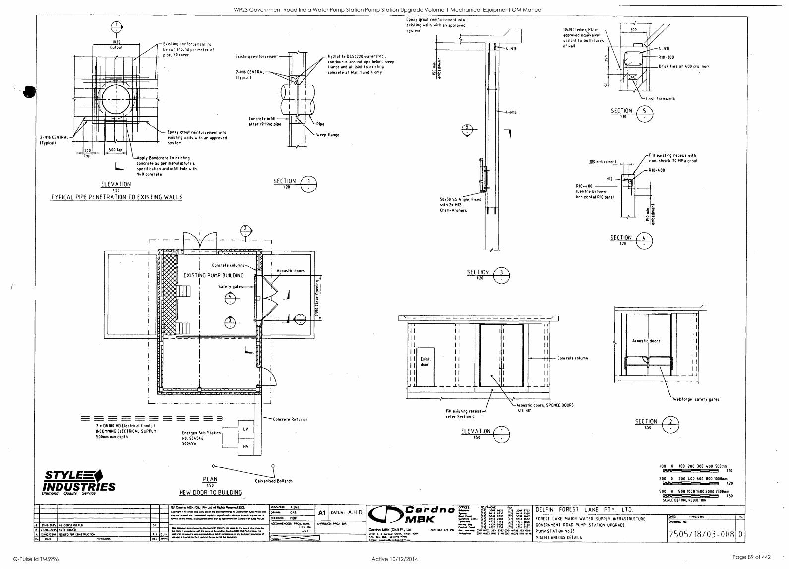
2-N16 CENTRAL
ITypicall
1035
Cutout
200 Typ
500 lap
Existing reinforcement to be cut around perimeter of pipe, SO cover
Epoxy grout reinforcement into existing walls with an approved system
pply Bondcrete to existing concrete as per manufacture's specification and infill hole with N40 concrete
ELEVATION 1:20
TYPICAL PIPE PENETRATION TO EXISTING WALLS
Existing reinforcement
2-N16 CENTRAL
IT ypicall
Concrete inlill after fitting pipe
Hydrotite D5S0220 waterstop continuous around pipe behind weep
flange and at joint to existing concrete at Wall 1 and 4 only
Weep flange
I 0 1 II.V4 i 1 114 OI.4 ti
j 4 i W . Kw !WV
LI Voo
.. LI ii ...to 0 IV^
I to" .4.4.. ovvi / ...... I ow,
r....4 1 3333
1
1 I
Concrete columns
1
EXISTING PUMP BUILDING 1
I
I
/ Acoustic doors
Safety
I I I I gales
th M.
11 .
0 I I ll
oth W
3 2 x DN100 HD Electrical Conduit INCOMMING ELECTRICAL SUPPLY
500mm min depth
STYLEE-74 INDUSTRIES Diamond Quality Service
Energex Sub Station NO. SC4546
500kVa
L V
NV
PLAN 1.50
NEW DOOR TO BUILDING
----Concrete Retainer
Galvanised Bollards
Epoxy grout reinforcement into existing walls with an approved system
C
4-N16
-N16
50.50 SS Angle, Fixed with 2x M12
(hem-Anchors
11 II
II
II
II II II II II 11
I I
Il II II II
.J
Exist. door
II
II I I
II
II
11 I
II I
II I
L \ _I
A A
10.10 Fleme,v.PU or
approved equivalent sealant to both faces of wall
4-N16
R10-200
Brick ties at 400 crs. nom
Lost formwork
SECTION 1.10
100 embedment
R10 -400 (Centre between horizontal R10 bars)
Fill existing recess with non-shrink 70 MPa grout
R10-400
Concrete column
Acoustic doors, SPENCE DOORS
Fill existing recess, 'SIC 38'
refer Section
ELEVATION 150
E 3=1
E
SECTION 150
'Webforge safety gates
100 0 100 200 300 400 500mm IRSESTSMT7 110
200 0 200 400 600 800 1000mm
SOO 0 500 1000 1500
1:20
200D 2500mm 1:50
SCALE BEFORE REDUCTION
79.8.2005 AS CONSIRIX1f 0 Si .
C.arcino (04:1) Ply Lid Al Rights Aseened 2002.
.wry meta ftwolphoksce [mow 943 roar Pv.. 9,81 89960 0 .0000.9 41.96 0 9 PeP P
Nemo N we. .9110941n COM lbw lb 404.19.1 eon 09070 Mee 100 P9116
ocSbc$CO: A.DeC
DRAWN: GF8
OttictO, MOP
Al DATUM: A.H.D. i Cardno 07.04.2005 ROTE 400(0
A 12/02/7004 5WD (124tEORSIKK1109/ DIM Dolt RNSORS RIC. APPR
Tr. 4199..... escos441,090.4 101,9. 6444, Se Pm Pm. d 94. 99 0411 n 69.0904 =NI N laws b r. el., Cabby KW PO N lb 401499
191554.4 ma eau.. ley brobabbial. S ...by *MM. lb WI 000 pony ably OA OP
any 0 Ire by bad pm, an Y. _39901.. bebbonba
RCC06165ENDED. P9(1./. MM. 99E0. me.
APP4001:3/ PROD. MBK
Cerdno MBK (Old) Ply Ltd Iv. I. 5 Gs... CA.. Salon 4044 P.O. N. 344 144.999 4084. Genoa.. cer090099.99o.e9..N
OFTICtS, TI:LEP19349( fAX (07 1344 9422 (07 UM 6711 01 8414 8113 01 6414 45711
0441 C.. 07 5339 9133 07 5534 4647 Sum.. Coal 0 5443 2556 07 5413 5442 744.94.64 07 4712 1166 07 47/1 NOS New, Om 07 4124 5435 07 4114 5135 C44110 04.0 (02 4323 2558 (02 4314 MI 1
ACPc. 051 074 912 Par, 4 nay (0011675) 325 1323 (00116751 32s MO (6011631) 910 5144 (00111532) 110 5144
DELFIN FOREST LAKE PTY. LTD.
FOREST LAKE MAJOR WATER SUPPLY INFRASTRUCTURE
GOVERNMENT ROAD PUMP STATION UPGRADE
PUMP STATION No23
MISCELLANEOUS DETAILS
oaf: 11/ 42/ MC Rs,
OAMPPIG
2505/18/03-008
WP23 Government Road Inala Water Pump Station Pump Station Upgrade Volume 1 Mechanical Equipment OM Manual
Q-Pulse Id TMS996 Active 10/12/2014 Page 89 of 442
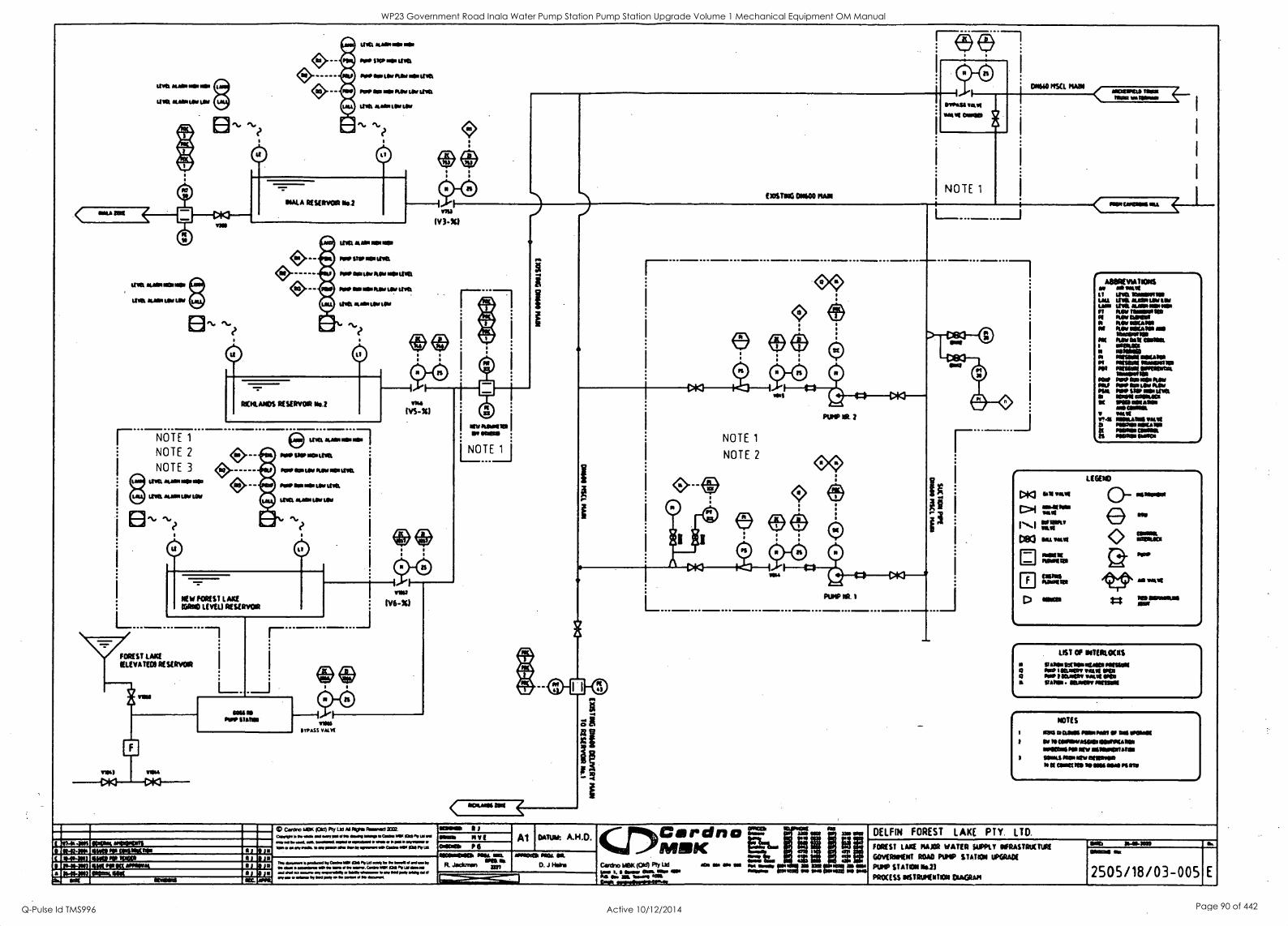
avel ALMA MN lulu
II Kt NAM Lfiee ter
RM
im wow op Na'
MP MP NW LIM
POOP Oa UN NW RN WM
POW Me NW her Low UM
LIM Wan Ow Les
C.)
BIALA RESERVOIR Ibol
ilea WIN mammal
LIN' Nam Ur IN
NOTE
NOTE 2
NOTE 3
Welt
LPN mom NO oNo
NON VIN ter
L...
LEM AIM PM real
IMP SRO RN the
PIO OM MN NW MN
Me ON INN Room UNL
MR Nose Ur IM
EXISTING 011100 MAST
RICHLANDS RESERVOIR 16.2
IV6-70
FOREST MST LAVA ELEVATED, RE SIRVON
aiS BYPASS VALVE
Cardno 1113K KIM Pty lb MND0 Floorm11002. C.010. be gm vb. ad am NO NI allmOu MM. 1
to test =KW...4 egobel waaal %NM ma C... INK al IV
nr ebooraM ID peeled ly Cads WM IMO IN NI Vr..r.r d w 41
N D Owl szoodlons 1.0 11 Gabe WM 10,11 NIA =3........../....P.111k 10111,ftleow 1. w.q.ryr0 try maws by MO Noy a.* palm/ I* *awe
1
1
1
1
1
49 l (i)
NOUNS INI
roam moo Nave Or
I NOTE 1
01160 NUL ISM
NOTE 1
NOTE 2
PUMP AL 2
L
eassa R) mom NV i Al DATUM A.H.D. comas P 6
CDC a r d n a MIRK m..,*.k.......... ~Me Ma Oa Ma
R. Jackman up la D. J limb's cambia Lex caw) PlY Lid &Da NG Oft ON
Pri I. . MN/ OM WM OP 1:3MENEe2MMINJ .. OM 0L 1..16 Ma
eVik WINO
MCIIIIPIDA Meg MIN walrus)
MwSaRMtru
ADORIVIATIONS ow minus tau It WM IRINNIRNR
trie ANN ted Wm ON ANN lonen n Na' Nowoos Ns N her POW
MANS N/
Na' socana
lansonso RIN 11611 NEM.
I =MIN nooNsID
N Now setno PI MUM Illsolf111111111 *e NN? INNISKRa
rie lauseNNI NNUNRIMIN
Oel N? RO+ Na' Nit MP SNP olps Ink
MIN eNINSOI IN INN mamas sr am&
gram Irmo isoNANN NNW ID MOM s
toe NN CONNt IS NUNN area
MRS 011116111
sem
LIST OP NIERLIXOS
ROAN INNIMANI NOM P iva 'MAW MN 0110
1 sawn wave rem RAM Ntaldr MINN
NOTES
comas NM Pan M MN MINN Or PO CONINNION SIONCINN MUM NO 11111111111111AM
OWLS Kai onemsao N Nam:cm Nowa INN PS Oft
DELFR4 FOREST LAKE PTY. LTD.
FOREST LAYS MAJOR WATER SUPPLY IFRASTRUETIRIE
GOVERMENT ROAR PUMP STATION UPGRADE
PUMP STATION Ns23
PROCESS NSTRUMINTION CIAMPI
OBb 1/1140-11,1
2505/18/03-005
WP23 Government Road Inala Water Pump Station Pump Station Upgrade Volume 1 Mechanical Equipment OM Manual
Q-Pulse Id TMS996 Active 10/12/2014 Page 90 of 442
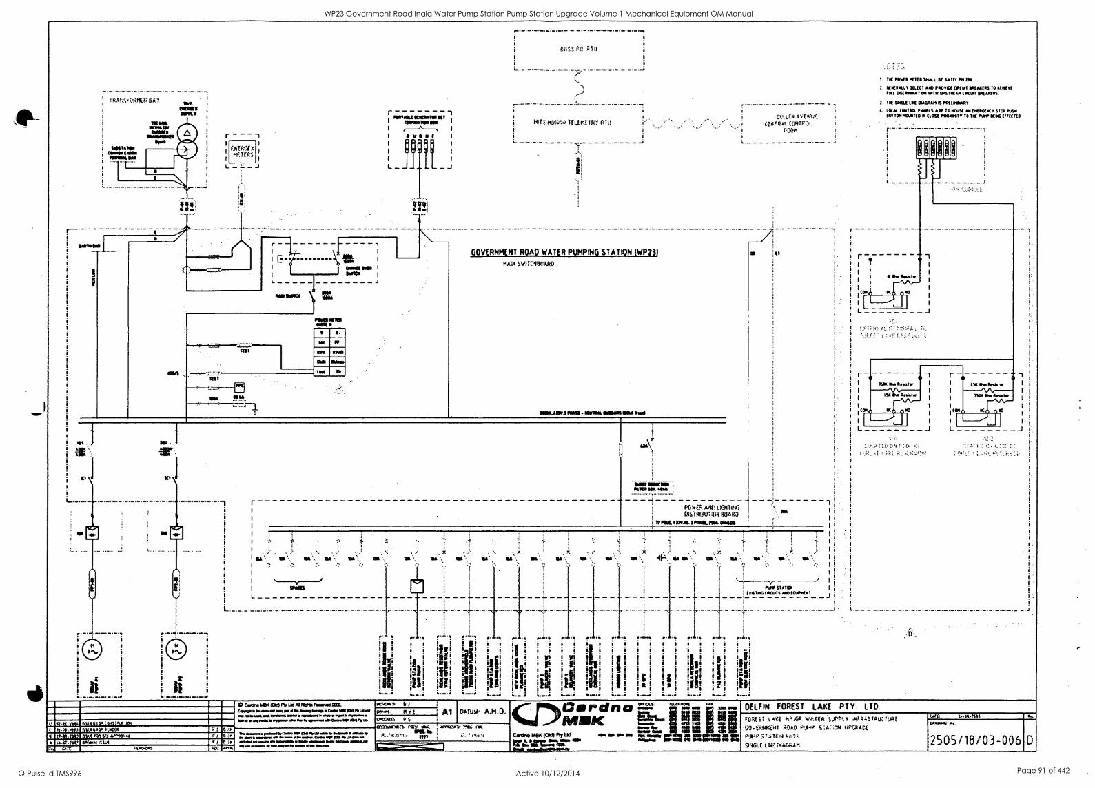
NAO4FeRIXF
r - - - 1
I
fig r I
TEAS
L - J
r -1
I 1-ii, I
I E liS I
I taws we I
I weal 1
L J
IIKT ANA
NI1
HITS L1W !3
GOVERNMENT ROAD WATER PUMPING STATION IWP23I MAN sw!rt: neon
111&M.) N..11 MAMA AMA OKI fool
' R.O?:.i0O mall.1110 I,S.Sloslz11( 1.-toolef 1t1%$$ Ho IS-4184.1 A.uot $vt oo£
o To-14.10, aoCwoot
CA ITITALLOAS
11$111 011111111111
OINK Gill GOA
i CUtatz 4'4E044 i
i CENTa.ot. Cf..047P:LIL i
PU01,1 i
i
II
r
L
POWS Millet-UK CIS 1Ii ROARa
sas. sor.aL max rm. omen
sla N. 11:4,, N. N.\ ail
. I
ATIO STATISM
OXISINZOKUTS mob EKIPKNI
!..1. i
1 Ir. .. .. Ir. ..
I ir1 ,....so
!I ! o 1 i i i gi
!ii ! i I itri -III 1 1 1 1 1 , , 1 1 1 1 1 1 1.-1
1 i s
lig! i !
ilia i
Jig. gi i .. , , , lr! ! w! ! ! ! ! ! ! ! !1! !ill ! ! V! ijii I a 1 Is I p fill 1st i sir !:: f ! :III 11! !,... ! Iti ! ! ! ! I ! ! ! ! ! ! ! ! ! ! 1 1
i ill ro o
iv lb "! ! e ai 4F
! I! !" . ii . ! i! !I ! !g! !g! ! ! ill: eir 1 1 t 1 1 1 121 121 1 1 121 ilii L.--; L.--; L....; :....:
0 Caodno (OK Ply Ud NI Rote Florned 2COL ociaoo, ti ,. t ...Wm o w & w i d . " e e p l o ousas Ia. P. Om da NV owe& 71 Agoom Ida Cala= WO pole,/ Ill OKOTOL
Al oArtok
TN* oinadmm I 100 NINNY/ Is Ow 1 Odom* Ow 1 la maws 11.1= SVU. coomIsoo as 1.'1110E6. mei dull &NUM ." NOW." 0 %Oft limo mg New* MOO I
moo ift 1101 pm* ammo OHM Is*
AMOLOTOOIS. SON LoN. 111111.1111
ALLKVAT.
limmen===nsill
Cri)Co rdna MIRK row low
Canino 1,1131C Mid) Ply Lld sot or NI Ooll N. ems, Kw us KIN 5NlI NIX soHO I. Wow Odk mom ON logos. op Se KO NSIl so KO PM Goo NAM
Omits emogokootmapoosi
r
icon
1.1
TT( KKR OILIER SMALL K SATE( POI PO
T. CAKIIALL V Ulf( T ATO PO0o0( (*CLOT OK AKITS TO ACIWYI MAL DIUMPINTATIOT MTN UPS TIM AM (WW1 IIKAKIS.
SOW LK DIAGRAM IS PKUTOTARY
A. LOCAL (NOR PANELS AK TO TKOS( AM (KOOKY STOP NSA ITUTTON MMHG II (LOS/ P5010111 TO 114 PLOW KING MUTED
11
Onislor
Li J
I
I I
I
I j
ISM Oho Roister LSO Ow AnisTr I I
I
LSO Or Rodsfor SIAM Oho Moist."
, (On K0950 (COI
I
I
L
S
!
I
_I I
JL-
DELFIN FOREST LAKE PTY. LTD.
FiMil LAO HAW SUPPLY iOV4Or:TRUt rug.S 0Mr ROM) KO5' 41:COO 117GRAD1
P;k4P V.11401 tir.rs SNCik 1.130. 3A.101
botO; T$.354$$$
ONTOKI
2505/18/03-006 D
WP23 Government Road Inala Water Pump Station Pump Station Upgrade Volume 1 Mechanical Equipment OM Manual
Q-Pulse Id TMS996 Active 10/12/2014 Page 91 of 442
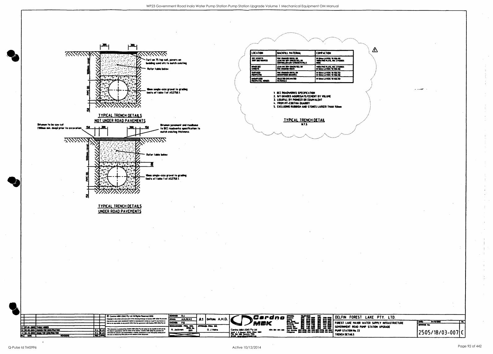
&hw to be saw tut (190as mea deep) prier is escoaticet
TYPICAL TRENCH DETAILS
NOT UNDER ROAD PAVEMENT$ Sibisso parfeastt and memo to BCC roadworks egewireelisa Is eytta issistiso thithoess
' W//,' t/Y //////,:Z
Refer IAN Wow
NOWIPICIMAPAN=IL
TYPICAL TRENCH DETAILS
UNDER ROAD PAVEMENT
les sinte- site gravel It wean was et Mkt 1 et AS1191.1
..........
LOCATION ISAMU NATfaut (WALTON
ow SSZYSIS -Ma ISM Nu OWNS 65011.1111 Ur sa WY CISAIMIJIM OlsteLISLOw 110004 041
o Mr LAMS Ye tia te vasslos kap. mu S MUD Me
aim ott MOUS
LW la Oa alaila. a Iso Mlle Om
labia Rakes' SNIAINS 414 ulna. IS ISS MI
WNW misatms
mg Mae Meg OS ottemes or pa
is Mr LAMAS Ye NI le a efts 14111 a MAO INAllaia AISIPstel. seek
IPUISSACassa WOW slam mall MISR NO
1 ICC ROADWORKS SPECIFICATION
1. GRADED AGGREGATE/CENDIT oft vomit UOIJftL BY PIONEER CO EQUIVALENT
1. FEN NT-COOTNA OUARRY
S EXCLUOING RUBBISH AND STOWS LARDER THAN 'Seas
TYPICAL TRENCH DEUR, T.S
........ -
t 4141144 taw ma 4141ta Otet PP CIESNIvtual
A 36-4401 gnat (Matt' 14 OM
at
C Canino P 101d) Ply LYS A1111104 1414141 cv,v, NM. eel am, 00 washy Wag. 0 __IN owl *Net I NOM owW 6.W i NO 1.= ...oda w r y pow Ow Oll 01010al 11:63 PI la
MOM Al solo mom PA
Al CATUH: A.H.O.
IS .1.40 IV Uil Edgy liwarr W wok
e j " 104*, yhmsore 1 gay 1.: my um *a I or MO pat y Ow swami I *sawn
aaalltaa .141 NM. aaftek Nal Oa .
Jactunsn ra, AL 0. J Hoke
Car)Cardna MIRK Rs- ....., ......, canine max (Old) Pty Ltd se so s est ass mussy = ire I. s 40. ems. ow a. 110.
04 SW al 4.041 .14 _444 sower
ti
S
()ELFIN FOREST LAKE PTY. LTD.
FOREST LAKE NAAR WATER SUPPLY INFRASTRUCTURE
GOVERMENT ROAD Pt STATION UPGRADE
PULP STATION Ns. 13
TRENCH DETAILS
011411 a.
2505/18/03-007
WP23 Government Road Inala Water Pump Station Pump Station Upgrade Volume 1 Mechanical Equipment OM Manual
Q-Pulse Id TMS996 Active 10/12/2014 Page 92 of 442
BRISBANE CITY COUNCIL Brisbane Water Government Road
9.2 As constructed Electrical Drawings
Overleaf
8748C-Manual Draft B
BW.30098-02/03 Pump Station Upgrade
21 Dec. 05 3-7
WP23 Government Road Inala Water Pump Station Pump Station Upgrade Volume 1 Mechanical Equipment OM Manual
Q-Pulse Id TMS996 Active 10/12/2014 Page 93 of 442
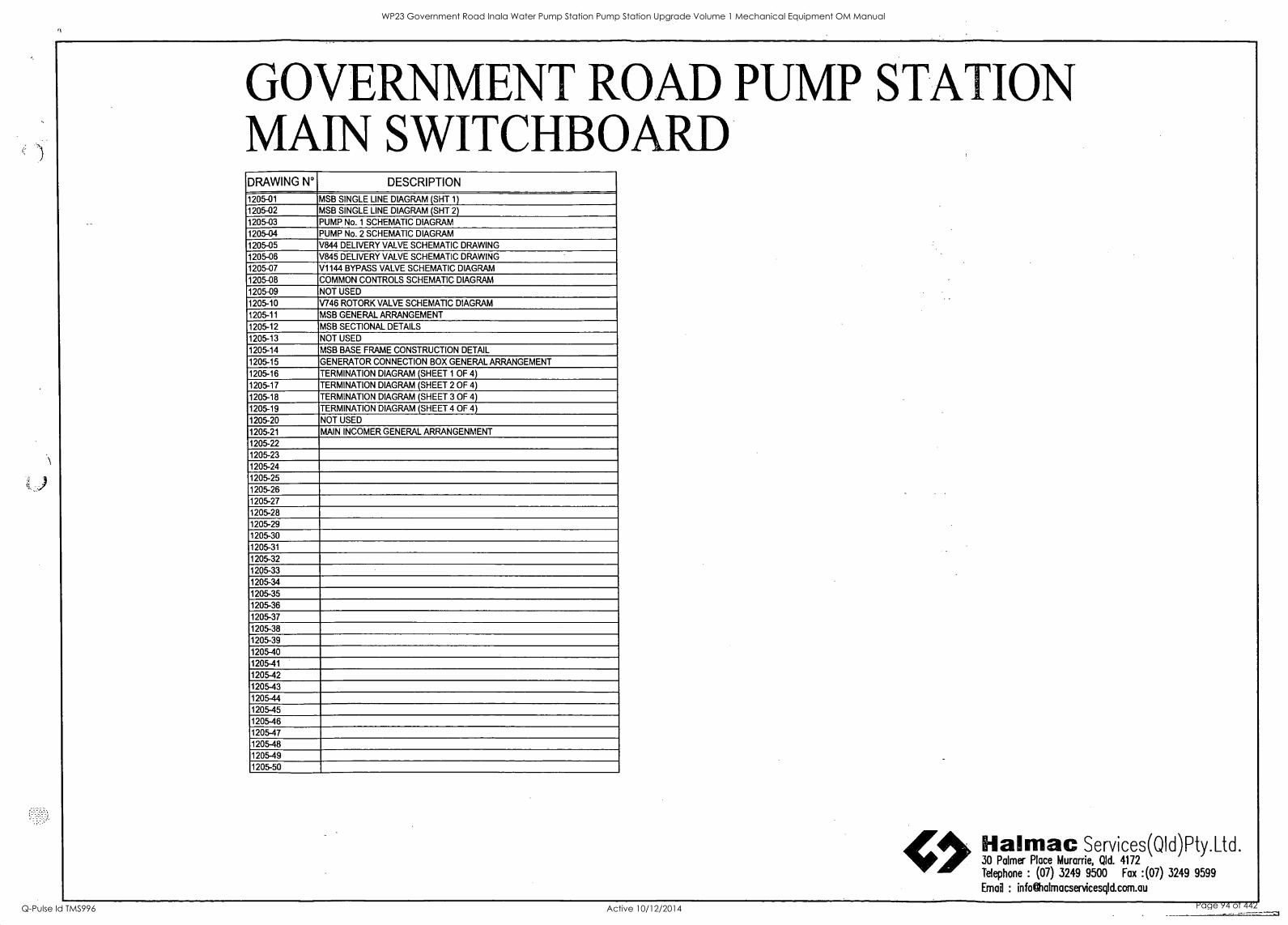
GOVERNMENT ROAD PUMP STATION MAIN SWITCHBOARD DRAWING N° DESCRIPTION
1205-01 MSB SINGLE LINE DIAGRAM (SHT 1)
1205-02 MSB SINGLE LINE DIAGRAM (SHT 2)
1205-03 PUMP No. 1 SCHEMATIC DIAGRAM
1205-04 PUMP No. 2 SCHEMATIC DIAGRAM
1205-05 V844 DELIVERY VALVE SCHEMATIC DRAWING
1205-06 V845 DELIVERY VALVE SCHEMATIC DRAWING
1205-07 V1144 BYPASS VALVE SCHEMATIC DIAGRAM
1205-08 COMMON CONTROLS SCHEMATIC DIAGRAM
1205-09 NOT USED
1205-10 V746 ROTORK VALVE SCHEMATIC DIAGRAM
1205-11 MSB GENERAL ARRANGEMENT
1205-12 MSB SECTIONAL DETAILS
1205-13 NOT USED
1205-14 MSB BASE FRAME CONSTRUCTION DETAIL
1205-15 GENERATOR CONNECTION BOX GENERAL ARRANGEMENT
1205-16 TERMINATION DIAGRAM (SHEET 1 OF 4)
1205-17 TERMINATION DIAGRAM (SHEET 2 OF 4)
1205-18 TERMINATION DIAGRAM (SHEET 3 OF 4)
1205-19 TERMINATION DIAGRAM (SHEET 4 OF 4)
1205-20 NOT USED
1205-21 MAIN INCOMER GENERAL ARRANGENMENT
1205-22 1205-23 1205-24 1205-25 1205-26 1205-27 1205-28 1205-29 1205-30 1205-31
1205-32
1205-33
1205-34
1205-35
1205-36
1205-37
1205-38
1205-39
1205-40
1205-41
1205-42
1205-43
1205-44
1205-45
1205-46 1205-47
1205-48
1205-49 1205-50
erAtti. Halmac Services(Q1d)Ptyltd. 30 Palmer Place Murarrie, Old. 4172 - Telephone : (07) 3249 9500 Fax :(07) 3249 9599
Email : infolitalmacservicesqld.com.au
1
WP23 Government Road Inala Water Pump Station Pump Station Upgrade Volume 1 Mechanical Equipment OM Manual
Q-Pulse Id TMS996 Active 10/12/2014 Page 94 of 442
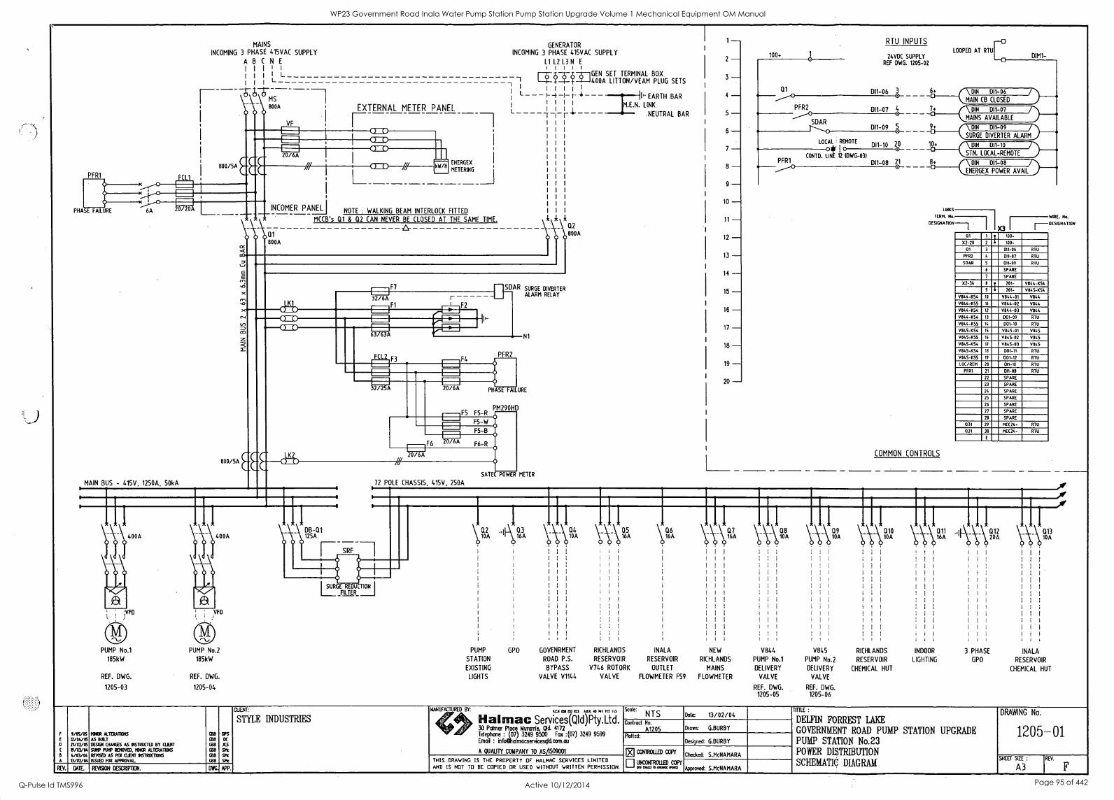
PFR1 FC 1
MAINS
INCOMING 3 PHASE 415VAC SUPPLY
ABCNE 11111 III! L I I I
E'T
800/5A
GENERATOR INCOMING 3 PHASE 415VAC SUPPLY
L1 L2 L3 N E
I I I I I
-A-1GEN SET TERMINAL BOX -1400A LITTON/VEAM PLUG SETS
800A
VF
EXTERNAL METER PANEL
PHASE FAILURE 6A 20/20A
ENERGEX
METERING
I
INCOMER PANEL I NOTE : WALKING BEAM INTERLOCK FITTED
MCCB's Q1 & Q2 CAN NEVER BE CLOSED AT THE SAME TIME.
-A- 01 600A
1 1 -t-4
V 800A
E
LK1 x---CDD kr) ,-CDD
800 /SA EEC
1F7 32/6A
F2
LK2 COD
63/63A
FCL2 F3
.--I I
SDAR SURGE DIVERTER
F4
32/25A 20/6A
PFR2
ALARM RELAY
N1
PHASE FAILURE
P F5 F5-R
M290HD
F5-W
F5-B
F6 20/6A F6-R
PUMP No.1
185kW
REF. DWG.
400A
VFD
PUMP No.2
185kW
REF. DWG.
125A
1-- SRF
20/6A
72 POLE CHASSIS, 415V, 250A O
SATEC POWER METER
II' EARTH BAR
IM.E.N. LINK
NEUTRAL BAR
SURGE REDUCTION
FILTER
C12
A 10
PUMP
STATION
EXISTING
LIGHTS
Q3 16A \M %IA VA 1165A
i
i I
GPO GOVENRMENT
ROAD P.S.
BYPASS
VALVE V1144
RICHLANDS
RESERVOIR
V746 ROTORK
VALVE
\06 16A
INALA
RESERVOIR
OUTLET
FLOWMETER F59
1205-03 1205-04
A
9/05/05 2/04/05 21/02/05 19/03/04 4/03/04 13/02/04
MINOR ALTERATIONS
AS BOAT
DEMI OWES AS INSTRUCTED BY (LENT AMP MVP REMOVED. MINOR ALTERATIONS
REVISED AS PER 0.IENT IN6TRUC71015
ISSUED FOR APPROVAL.
GM GM GM
1Z8 C/98
IPS DC
SPIc
5111
SPIc
CLIENT:
STYLE INDUSTRIES
MANUFACTURED BY: ALIT cam est 223 ABA 40 741 712 113
Halmac Services(QId)Pty.Ltd. 30 Palmer Place Hurarrie, Old. 4172 Telephone : (07) 3249 9500 Fax :(07) 3249 9599 Envoi : infoftalmocservicesgIcLcom-ou
A OUAUTY COMPANY TO AS/1509001
Scale: NTS
Control No.
A1205 Plotted:
=ROLLED COPY
UNCONTROLLED 03Pf ox n xxx xxe
THIS DRAWING IS THE PROPERTY OF HALHAC SERVICES LIMITED AND IS NOT TO BE COPIED OR USED WITHOUT WRITTEN PERMISSION. REV. DATE REVISION DESCRIPTION. DWG. APP.
1- 2- 3- 4
5
6- 7- 8- 9-
10 - 11 - 12 - 13 - 14 -- 15 - 16 - 17
18 - 19 - 20 -
100.
01
PFR2
SOAR
PFR1
LOCAL REMOTE
0 CONTD. LINE 12 IDWG-031
RTU INPUTS
24VDC SUPPLY REF DWG. 1205-02
DI1-06 3
DI1-07 4
DI1-09 5 0
DI1-10 20
011 -08 21
LOOPED AT RTUr 0 DIM1-
\ DIN 011 -06 MAN CB CLOSED
\ DIN DI1-07
MAINS AVAILABLE
_(4__(\ DIN DI1-09
SURGE DIVERTER ALARM
10+ DIN DI1-10
STN. LOCAL-REMOTE 0 \ DIN D11-08
ENERGEX POWER AVAIL
LINKS
TERM. No. WIRE. No.
DESIGNATION
X.3 I
1-DESIGNATION
COMMON CONTROLS
NEW
RICHLANDS
MAINS
FLOWMETER
V844
PUMP No.1
DELIVERY
VALVE
REF. DWG. 1205-05
V845
PUMP No.2
DELIVERY
VALVE
REF. DWG. 1205-06
RICHLANDS
RESERVOIR
CHEMICAL HUT
INDOOR
LIGHTING
01 1 ? 100.
X2-20 2 4 100.
01 3 011-06 RTU
PFR2 4 D11-07 RTU
SOAR 5 011-09 RTU
6 SPARE
7 SPARE
22-34 8 ? 201- V844454 9 4 201- 9845-454
V844-054 10 V844-01 V844
9844-455 11 9844-02 V844
V844-454 12 11844-03 V844
V844 -K54 13 D01-09 RTU
9844-455 14 001-10 RTU
0045-454 15 V845-01 V845
V845-455 16 V845-02 V845
V845-1(54 17 V845-03 V845
V845-1(54 18 D01-11 RTU
V845-K55 19 D01-12 RTU
LOC/REM 20 011-10 RTU
PFR1 21 D11-08 RTU
22 SPARE
23 SPARE
24 SPARE
25 SPARE
26 SPARE
27 SPARE
28 SPARE
031 29 M(424. RTU
031 30 MC(24- RTU
E
I \ C112 013 20A 10A
,
3 PHASE
GPO
1
INALA
RESERVOIR
CHEMICAL HUT
-0 0
Date: 13/02/04
Drown: G.BURBY
Designed: G.BURBY
Checked: S.McNAMARA
Approved: S.McNAMARA
TITTLE :
DELFIN FORREST LAKE
GOVERNMENT ROAD PUMP STATION UPGRADE PUMP STATION No.23 POWER DISTRIBUTION
SCHEMATIC DIAGRAM
DRAWING No.
1205-01
SHEET SIZE : REV.
A3
WP23 Government Road Inala Water Pump Station Pump Station Upgrade Volume 1 Mechanical Equipment OM Manual
Q-Pulse Id TMS996 Active 10/12/2014 Page 95 of 442
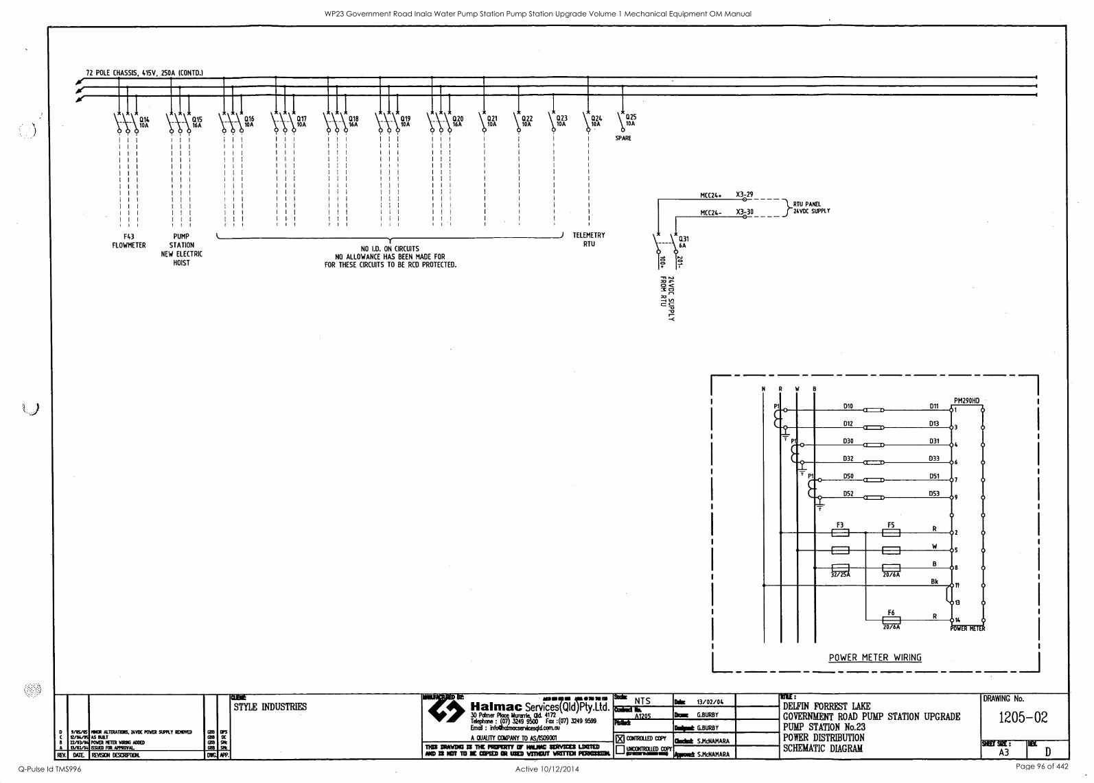
72 POLE CHASSIS, 415V. 250A (CONTD.)
F43
FLOWMETER
PUMP
STATION
NEW ELECTRIC
HOIST
* I 10A
\;\_\ Ii161,1%3 017
_1 \\\ Q 6A20 \a21 \ a22 10A 10A %A 23
(124 10A
NO I.D. ON CIRCUITS
NO ALLOWANCE HAS BEEN MADE FOR
FOR THESE CIRCUITS TO BE RCD PROTECTED.
TELEMETRY
RTU
1225 10A
SPARE
MCC24+ X3-29 } L RTU PANE
MCC24- X3-30 24VDC SUPPLY
L_
F3
D10 =D D12 C=D D30
D32 CE=D
D50 =D D52
PM290HD D11 01 0
D13 03
04
06
07
09 0
0
2
5 0
8 0
11 0
13 0
0 OWER METER
D31
D33
D51
1353
F5
cJ 31:4 f;A:1
Bk
F6
20/6A
POWER METER WIRING
amit gt eessesso moms= STYLE INDUSTRIES Halmac Services(Q1d)Pty.Ltd. rli0 30 Pdmer Ham Ikedrk CM. 4172
Tdechasef:ocralnatlresql00 Rot :(07) 3249 9599 Emelt : cl.com.au
D 11/05/05 MICA ALT:RADOM 24VDC POWER AMY RDIOVED GAS CPS
A/DV% AS RULE GB8 DC A QUALITY CCUPANY TO AMS09001
A
22/03/114 13/02/14
POWER mrn:e wseme MUD ISSUED FOR APPROVAL
GB3
GB3
At nos DRAWDO IS NE PROPERTY Of MAW SERVICEIt UNITED
REV. 1E REVISION DESDIP1101L D APP. AND IS NOT 10 X 0311ED Ot USED MOOT VET= PERNACZENI
Sake NTS
bind b. A1205
That
Ode 13/02/04 11ThE :
DELFIN FORREST LAKE
GOVERNMENT ROAD PUMP STATION UPGRADE PUMP STATION No.23 POWER DISTRIBUTION
SCHEMATIC DIAGRAM
0Paie G.BURBY
Wow& G.BURBY
[83 all
kilicm ctIED Avast Sit-NAMARA
OWN! =mum S.Md1AMARA
DRAWING No.
1205-02
SOT SIM :
A3
WP23 Government Road Inala Water Pump Station Pump Station Upgrade Volume 1 Mechanical Equipment OM Manual
Q-Pulse Id TMS996 Active 10/12/2014 Page 96 of 442
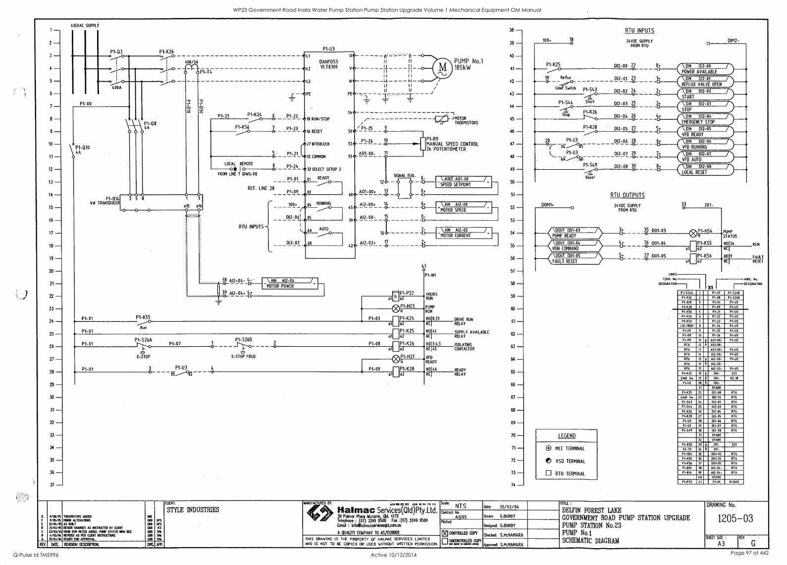
1- 2- 3- 4- 5-
415VAC SUPPLY
P1-03 P1-K26 ,,f,"
P1-T4
400/5A
CI*
P1-08 4A
12 - 13 - 14 - 15 - 16 - 17 - 18 - 19 -- 20 - 21 - 22 - 23 - 24 - 25 - 26 - 27 - 28 - 29 - 30 - 31 - 32 - 33 - 34 - 35 - 36 - 37 -
P1 -B14 kW TRANSDUCER
P1-01
P1-01
P1 -K55
Run
P1-21 PI-K24 6 0
P1 -K56 7
LOCAL REMOTE
0 FROM LINE 7 IDWG-011
REF. LINE 28
RTU INPUTS
38 Al2-04- 4-
39 AI2-04+ 4+
P1-U3
-.L1
-012
_11---oPE
DANFOSS VLT8300
P1-22 18 RUN/STOP
P1-23 -016 RESET
21 INTERLOCK
P1-21 L12 COMMON
P1-24 -11D 32 SELECT SETUP 2
P1-01 01 READY
P1-09 4,02
100. O4 ,RUNNING
012-061 05 -I 1
1,06A AUTO
012-07 4,6B
PE
54
50
53
55
60
l'r -ft II II
__ I I I I
1 1 1 I
I I II 14 -I-1
I I I I /
II II /
/- / / P1-25
P1-26
A01-00-
12
A01-00. 13
SIGNAL 1501. 0-
0+ 0
PUMP No.1 185kW
-I MOTOR
THERMISTORS
P1 -R9 MANUAL SPEED CONTROL 2k POTENTIOMETER
\ AOUT A01-00
SPEED SETPOINT
38 - 39 - 40 - 41
42
43
44 - 45
46
47 - 48
49 - 50 - 51-
45
Al2-00- 15
-0-
0-
/_ Al2-00+ 14 0+
*MOTOR SPEED 52
\ AIN Al2-00
39 0
h 161
42
\ AIN Al2-04 MOTOR POWER
AI2-02+ 17 -0-
P1-P22 G1E102
ifflplp P1-H23 4,008
P1-03 - P1 -K24
_26_1\ AIN Al2-02
MOTOR CURRENT
2+
41 0
P1-N1
al a2
P1-1(25 a a2
P1-08 EIP1-1(26 01 a2
09\ip P1-H27 Nalt, G
P1-09 P1 -K28 (OLIO
P1-01
P1-01
Pl-S26A
clo E-STOP
P1-07
3 P1 -U3 0- of
P1-S26B
f5 E-STOP FIELD
HOURS RUN
PUMP RUN
NO 8,23
NC
NO141
NC
NO 3.4.5 NC 45
VFD READY
NO 46
NC
DRIVE RUN RELAY
SUPPLY AVAILABLE RELAY
ISOLATING CONTACTOR
READY RELAY
53 - 54 - 55
56
57 - 58 - 59 - 60 - 61-
62 - 63 - 64 - 65 - 66 - 67 - 68 - 69 - 70 - 71-
72 - 73 - 74 -
100+ 18
P1-K25
19 Reflux
Limit Switch P1-543 O
Start P1-S44
20 Pt -U3 1312-06 28
(-- -0- 6+ \ DIN DI2-06 I) VFD RUNNING
PI-U3 DR-07 29 -0- 711. (\ DIN DI2-07
VFD AUTO
Pl-549 DI2-08 30 8+ \ DIN 012-08
LOCAL RESET Reset
RTU INPUTS
24VDC SUPPLY FROM RTU
0 D1M2-
012 -00 22
23 I+ \ DI
REFN
D12-01
LUX VALVE OPEN
0.__. 0- 0+ r \DIN DI2-00 / )
DI2-01
POWER AVAILABLE
DI2-02 204 240.(\ DIN 012-02 0__., DI2-03 205
STOP
012-03 0___. P1-1(26
DI2-04 26 4+ \ DIN 012-04 I) EMERGENCY STOP
P_____1-K208 D12-05 207 _56. \ DIN 012-05
VFD READY /)
DOM1+ 0
RTU OUTPUTS
24VDC SUPPLY FROM RTU
(\ DOUT 001-03 />__3d_ PUMP READY
(\ DOUT D01-04 / )_ci_+ RUN COMMAND
(\DOUT D01-05 /58_ FAULT RESET
LEGEND
® MCC TERMINAL
1 VSD TERMINAL
RTU TERMINAL
35 001-03
36 001-04 0
37 D01-05
33 201-
a I PI-H54 PUMP R STATUS
P1-K55 No124 RUN a2 NC
P1-1(56 No 9
ai a2 NC
FAULT RESET
LINKS
TERM. No. WIRE. No.
DESIGNATION I -DESIGNATION
P1 -S26A 1 P107 P1-S2613
P1-1(26 2 P1-08 P1-S26E1
P1-010 3 P1 -01 P1 -U3
P1-128 4 P1-09 P1-03
P1-1(56 5 P1 -21 PI-U3
P1-1(24 6 P1 -22 PI-U3
P1-1(56 7 P1 -23 P1-33
LOC/REM 8 P1-24 PI-U3
P1-89 9 P1 -25 P1-93
P1-69 10 P1 -26 PI-U3
PI-R9 11 t A01-00- P1-03
RTU 12 0 A01 -00- RTU 13 A01-00. PI-U3
RTU 14 AI2-00. P1-63
RIO 15 ? Al2 -00- P1-1/3
RTU 16 6 612-00-
RIO 17 612-02. PI-U3
P1-1(25 18 100 031
Limit Sv 19 100 02-18
PI-U3 20 100.
21 SPARE
P1-1(25 22 012-00 RTU
Limit Sto 23 012-01 RTU
P1-543 24 DI2-02 MU P1-544 25 012-03 RTU
PI-K26 26 017 -OS RTU
P1-1(28 27 DI2-05 RTU
P1-03 28 012-06 RTU
PI-U3 29 012-07 RTU
P1-549 30 012-08 RTU
31 SPARE
32 SPARE
P1-1(55 33 t 201- 031
X2-33 34 0 201-
P1-H54 35 1301-03 RTU
P1-1(55 36 001-04 RTU
P1-1(56 37 1301-05 RTU
P1-E114 38 AI2-04- RTU
P1-614 39 Al2-04. RTU
40 SPARE
P1-P22 41 P1-01 N-BAR
CLIENT:
STYLE INDUSTRIES 6 0/03/05 MIEl895TORS AIMED CMC
9/05/05 MMOR ALTERADONS BBB OPS
12/04/05 2V02/05
AS BUILT
DESIGN CHANGES AS INSTRUCTED BY CLEW GOB
GB8
OPS
AS 21103/04 HOUR 0491 METER ADDED. PUMP STATUS HOW RED GBB SM(
B 4/03/04 REVSED AS PER WENT 01STRIX7KI4S SMe
A 13/02/04 ISSUIT FOR APPROVAL GBB SHE
REV. DATE REVISION DESCRIPTION. APP.
MANUFACTURED BY: how we est 123 AIR .o 711 712 113
Hallman Services(QId)Pty.Ltd. 30 Palmer Place Murarrie, Old. 4172 Telephone : (07) 3249 95W Fax :(07) 3249 9599 Erna] : infodudmacservicesqld.can.au
A DUALITY COMPANY TO AMS09001
scalc NTS Date: 13/02/04
Contract No.
A1205 Drown: G.BURBY
Molted: Designed: G.BURBY
THIS DRAWING IS THE PROPERTY OF HALMAC SERVICES LIMITED AND IS NOT TO BE COPIED OR USED WITHOUT WRITTEN PERMISSION.
El corfrairo COPY
UNCONTROLLED COPY Pon .1:13 MN. tffial3
Checked: S.McNAMARA
Approved: S.McNAMARA
TITTLE :
DELFIN FOREST LAKE
GOVERNMENT ROAD PUMP STATION UPGRADE PUMP STATION No.23 PUMP No.1
SCHEMATIC DIAGRAM
DRAWING No.
1205-03
SHEET SIZE :
A3 REV.
WP23 Government Road Inala Water Pump Station Pump Station Upgrade Volume 1 Mechanical Equipment OM Manual
Q-Pulse Id TMS996 Active 10/12/2014 Page 97 of 442
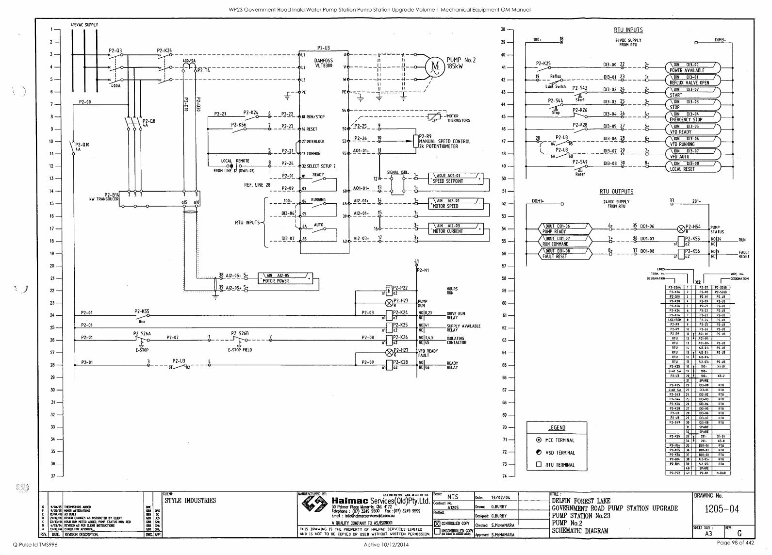
1- 2- 3- 4- 5- 6- 7- 8- 9-
10 - 11 - 12 - 13 - 14 - 15 - 16 - 17 - 18 - 19 - 20 - 21 - 22 - 23 - 24 - 25 - 26 - 27 - 28 -- 29 - 30 - 31 - 32 - 33 - 34 - 35 - 36 - 37 -
415VAC SUPPLY
P2-00
P2-Q3 )c
K
ep.-K
P2-K26
P2-Q10 4A
P2-B14 kW TRANSDUCER
P2-01
\V\ \P22 -Q8
6 4
0 0
400/5A
0 0P2-T4
P2-21 P2-K24 6
P2-K56 7 0
LOCAL REMOTE
10 (0 FROM LINE 12 (DWG-031
2 5 8
P2-01
P2-K55
Run
a 5 a16 0
8 0
REF. LINE 28
RTU INPUTS
P2-U3
-e L1
DANFOSS
-012 VLT8300
-0L3
PE
54 P2-22
-018 RUN/STOP
II
LF
II
/
P2-23 / -0
P2-25 16 RESET 50
A27 INTERLOCK 53
P2-21 '012 COMMON 55
P2-24 -032 SELECT SETUP 2
P2-01 01 READY
P2-09 03
100+ 04 RUNNING
013-0-I 6 05 e
c 6A AUTO
013-07 e6B
60
45
39
42
38 5- Al2-05- 0 -0- 38 Al2-05+ 5+
\ AIN Al2-05 MOTOR POWER
P2-26
A01-01-
SIGNAL ISOL. 16 I \ AOUT A01-01
13
12
1+
SPEED SETPOINT
i, A01-01+
-0- 0
PUMP No.2 185kW
1 J MOTOR
THERMISTORS
P2-R9 MANUAL SPEED CONTROL 2k POTENTIOMETER
38 - 39 - 40 - 41
42
43
44 - 45
46
47
48 - 49 - 50 - 51 --
Al2-01+ 14 1+ I \ AIN Al2-01 -0- +MOTOR SPEED
52
Al2-01- 15 1-
16I 3- -0- Al2-03+ 107
-- 3+
-
P2-01
P2-01
P2-526A
E-STOP
P2-07
3 P2-U3 0-
P2-S26B
E-STOP FIELD
V/03/05 INERILISTORS ADDED ONC
CUNT:
STYLE INDUSTRIES
9/05/05 MINOR ALTERATIONS 08 aps T2/04/05 AS BUILT rx 21/02/05 DESIGN CHANCES AS OISTRUCTED BY CLIENT x5 12/01/04 HOUR RUN METER ADDED, PUMP STATUS NOW RED EBB sow
B 4/03/04 REVISED AS PER QIENT 067RUCTI66 013 Slt A 13/02/64 tSSUED FOR APPROVAL. RIB At
REV. DATE REVISON DESCRIPTION. APP.
P2-P22 at' a2
Awl\ P2-H23 \ON
P2-03 -P2-K24 al 02
IP2-K25 a11___a2
P2-08 nP2-K26 a1 a2
®P2 -H27 G
P2-09 1-IP2-K28 a1 a2
\ AIN Al2-03
MOTOR CURRENT
/
41 0 P2-N1
PUMP RUN
NO 8,23
NC
NOI41SUPPLY AVAILABLE NC RELAY
NO 3,4.5 NC 45
VFD READY FAULT
NO
46
HOURS RUN
DRIVE RUN RELAY
ISOLATING CONTACTOR
READY RELAY
53 - 54 - 55
56
57 - 58 - 59 - 60
61 - 62 - 83 - 84
65 - 66 - 67 -- 68 - 69 - 70 - 71 - 72 - 73 - 74 -
RTU INPUTS
100+ 18 24VOC SUPPLY FROM RTU
P2-K25
/ID 19 Reflux
Limif Switch
DIM3-
013-00 22 0
0+ \ DIN 013-00 / POWER AVAILABLE
013-01 23 -0- 1+ \ DIN DI3-01
REFLUX VALVE OPEN 0-----..
013-02 24 O
2+ \ DIN 013-02
START 0__.
013-03 25 O
t<\DIN STOP
013-03 /)___,
P2426 01344 26 4+ DIN DI3-04 /.>___.
EMERGENCY STOP
DI3-05 27 O
5+ \ DIN 013-05 j VFD READY
DI3-06 28 -0- 6+ DIN 013-06 /}...._. VFD RUNNING
DI3-07 29 -0- 7+ \ DIN 013-07
VFD AUTO /:)____.
P2-549 DI3-08 30 Jr°----C'- 8+ \ DIN 013-08
LOCAL RESET {LOCAL
P2-S43
Start P2-S44
Stop
P2-1(28 O
20 P2-U3
P2-U3
DOM1+ O
RTU OUTPUTS
24VDC SUPPLY FROM RTU
. CDOUT 001-06 />__64_
PUMP READY
. K\DOUT 001-07 07+_
RUN COMMAND
. (\BOUT 001-08 J88_
FAULT RESET
LEGEND
0 MCC TERMINAL
VSD TERMINAL
RTU TERMINAL
35 001-06
36 001-07 0
37 001-08
33 201-
P2 -H54
a
I P2455 a2 I a2 al
LINKS
TERM. No.
DESIGNATION
X2
PUMP STATUS
NO124
NC
NO19
NC
RUN
FAULT RESET
WIRE. No.
DESIGNATION
P2-526A 1 P2 07 P2-5268 P2-026 2 P2-08 P2-S2613
P2-010 3 P2-01 P2-U3
P2-1(70 4 P2-09 P2-U3 P2-056 5 P2-21 P2-113
P2-424 6 P2-22 P2-U3
P2-056 7 P2-23 P2-03
L0( /REM 8 P2-24 P2-113
P2-R9 9 P2-25 P2-03
P2-R9 10 P2-26 P2-03
P2-09 11 T A01-01- P2-03
RTU 12 i A01-01-
RTU 13 A01-01. P2-03
RTU 14 Al2-01. P2-U3
RTU 15 ? Al2-01- P2-03
RTU 16 4 412-01-
RID 17 Al2-03. P2-03
P2-025 18 100. X1-19
Limit Sw 19 100.
P2-03 20 100. X3-2
21 SPARE
P2-025 22 013-00 RTU
Limit Sw 23 013-01 RTU
P2-543 24 013-02 RTU
P2-544 25 DI3-03 RTU
P2-426 26 1313-04 RTU
P2-028 27 013-05 RTU
P2-U3 28 013-06 RTU
P2-03 29 013-01 RTU
P2-549 30 013-08 RTU
31 SPARE
32 SPARE
P2-455 33 7 201- X1-34
34 4 201- X3-8
P2-1454 35 1301-06 RTU
P2-455 36 001-07 RTU
P2-056 37 D01-08 RTU
P2-614 38 Al2-05- RTU
P2 -814 39 412-05. RTU
40 SPARE
P2-P22 41 P2-N1 N-BAR
MANUFACTURED BY: ALI OM 852 SD ABA 40 141 712 III
Hal mac Services(QId)Pty.Ltd. 30 Palmer Place klurarie, OW. 4172 Telephone : (07) 3249 9500 Fax :(07) 3249 9599 Final : infoeficdmacserkesqld.com.au
A OUAUTY COMPANY TO AS/1509001
Scar NTS Date: 13/02/04 Contract No.
A1205 Drown: G.BURBY
Plotted Designed: G.BURBY
THIS DRAWING IS THE PROPERTY OF HALMAC SERVICES LIMITED AND IS NOT TO BE COPIED OR USED WITHOUT WRITTEN PERMISSION.
CONIRCUIED COPY
UNCONTROUID con O0 TSUI WOO= WM)
Checked: S.McNAMARA
Approved: S.McNAMARA
TIME :
DELFIN FOREST LAKE GOVERNMENT ROAD PUMP STATION UPGRADE PUMP STATION No.23 PUMP No.2 SCHEMATIC DIAGRAM
DRAWING No.
1205-04
SHEET SIZE :
A3 REV.
G
WP23 Government Road Inala Water Pump Station Pump Station Upgrade Volume 1 Mechanical Equipment OM Manual
Q-Pulse Id TMS996 Active 10/12/2014 Page 98 of 442
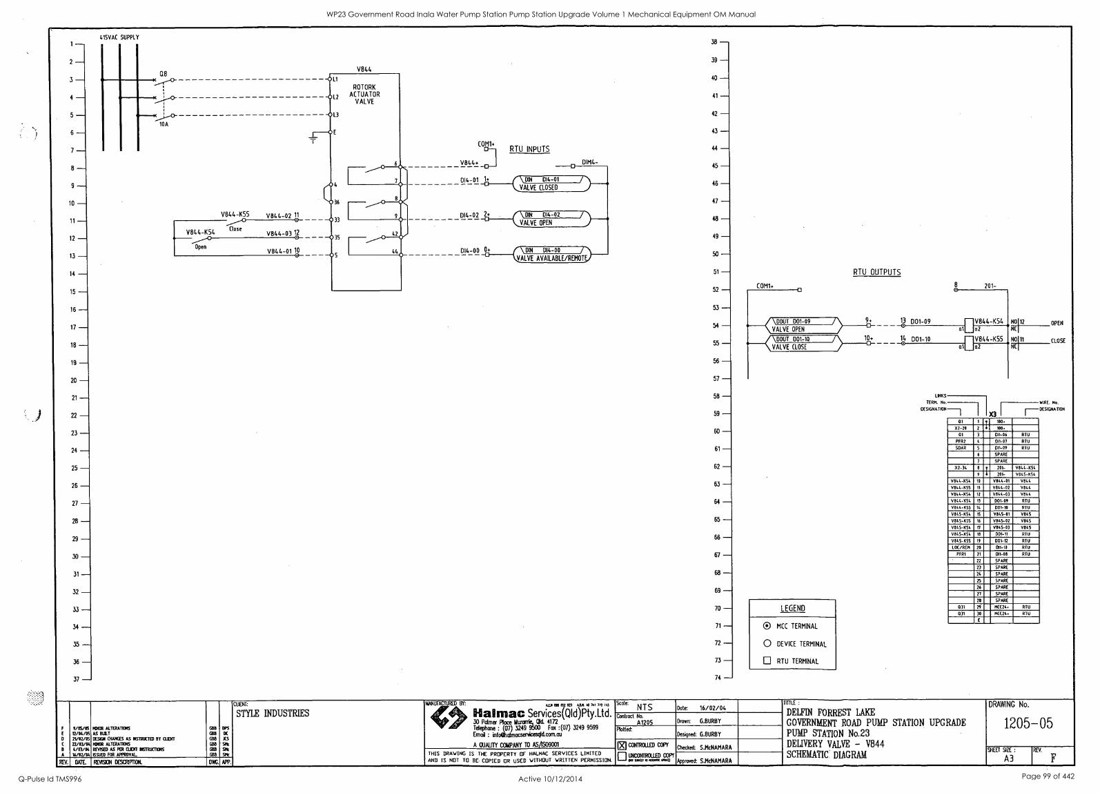
415VAC SUPPLY 1- 2 -
Q8 3 - 4 - 5 -
10A
6 - 7 - 8 - g
10 - V844-K55 V844-02 11 11-
V844-K54 Close
V844-03 12 12 - 13 - Open
V846-01 10 0
14 - 15 - 16 - 17 - 18 - 19 - 20 - 21 - 22 ---
23
24 - 25 - 26 - 27 - 28 - 29 - 30 - 31
32 - 33 - 34
35 - 36 - 37 -
V844
38 - 39 -- 40
41 - 42 - 43 -
COM1+ RTU INPUTS 44 -
V844+ DIM4- 45 0
DI4-01 1+ DIN 46 -
VALVE CLOSED
47 - DI4-02 2.
48 - 411_1\-4----/VE OPEN
49 - 014-00 0+ 004
50 - VALVE AVAILABLE/REMOTV
51 - 52 - 53 ----
54 - 55 - 56 - 57 - 58 - 59 - 60 - 61 - 62 - 63 - 64
65 - 66 - 67 - 68 - 69 - 70 - 71 - 72 - 73 - 74 -
COM1+ ci
/\000i D01-09
VALVE OPEN
\DOUT 001-10
VALVE CLOSE
LEGEND
0 MCC TERMINAL
0 DEVICE TERMINAL
LI RTU TERMINAL
RTU OUTPUTS
13 D01-09
14 001-10
201-
a
V844-K54 N0112 OPEN a2 NCI
V844-K55 NO 11 CLOSE a2 NC
LINKS
TERM. No.
OESIGNATION
X3
WIRE. No.
r--DESIGNATION
01 1 y 100.
X2-20 2 4 100.
01 3 DII-06 RIO
PFR2 4 DI1-07 RTU
SDAR 5 DI1-09 RTU
6 SPARE
7 SPARE
X2-34 8 y 201- V844-K54
9 4 201- V845-054
V844-KS'. 10 V844-01 VIN. 4
V844-K55 11 9844-02 V8/4 V844-K54 12 9844-03 V844
V844-K54 13 001-09 RTU
V844-COO 14 001-10 RTU
V845-K54 15 V845-01 V845
V845-K55 16 V845-02 9845
vats-ksi. 17 9845-03 V845
V845-K54 18 D01-11 RTU
V845-K55 19 001-12 RTU
LOC/REM 20 011-10 RR,
PFRI 21 011-08 RTU
22 SPARE
23 SPARE
24 SPARE
25 SPARE
26 SPARE
27 SPARE
28 SPARE
031 29 MCC24. RTU
031 30 M((24- RTU
E
F
C
B
0/05/05 12/04/05 2V02/05 V./03/04. 4/03/04 16/02/04
MNOR ALTERAT1016
AS BOLT
DE0101 CHANGES AS IISIRUCTED BY CLINT MINOR ALTERATIONS
REVSED AS PER OXNT INARUCTXVIS
ISSUED FOR APPROVAL
GBH
GIB 0010
EBB
1018
EBB
LIPS
DC
IS
Sit At
At REV. DAIL REVISION DESCRIFOON. D. APP.
CUNT:
STYLE INDUSTRIES
MANUFACTINED BY:
if 0.29 03402 ID VA 40 701 111 113
Halftime Services(Q1d)Pty.Ltd 30 Palmer Place Mmark_Old. 4172 Telephone : (07) 3249 9500 Fax :(07) 3249 9599
Email : infoCurlmocsenricesgld.com.au
A QUALITY COMPANY TO ASAS09001
Scale: NTS Dote: 16/02/04
Contract No.
A1205 Dm= G.BURBY
Plotted: Designed: G.BURBY
THIS DRAWING IS THE PROPERTY OF HALMAC SERVICES LIMITED AND IS NOT TO BE COPIED OR USED WITHOUT WRITTEN PERMISSION.
EicoxrRcuni con'
uNcommus con, RXCI Aint.as map
Checked: S.McNAMARA
Approved: S.McNAMARA
TWILL:
DELFIN FORREST LAKE
GOVERNMENT ROAD PUMP STATION UPGRADE
PUMP STATION No.23 DELIVERY VALVE - V844 SCHEMATIC DIAGRAM
DRAWING No.
1205-05
SHEET SIZE:
A3
WP23 Government Road Inala Water Pump Station Pump Station Upgrade Volume 1 Mechanical Equipment OM Manual
Q-Pulse Id TMS996 Active 10/12/2014 Page 99 of 442
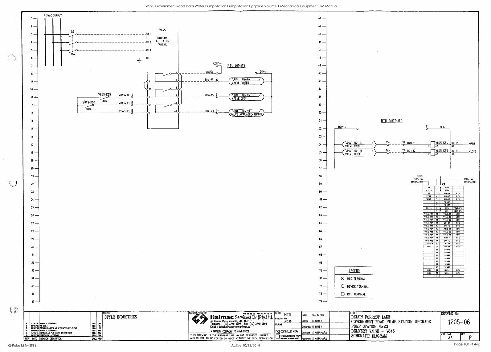
1
2
3
415VAC SUPPLY
Q9
4 KPID- 5
10A
6
7
8
9
10
11- V845-K55 V845-02 16
12 V845-K54
Close V845-03 17 9
Open V845-01 15
13
14
15
16
17
18
19
20
21
22
23
24
25
26
27
28
29
30
31
32
33
34
35
36
37
V845
COM1+
V845+
014-04 4d
RTU INPUTS
38 - 39 - 40 - 41-
42 -- 43 - 44 - 45 - 46 - 47 - 48 - 49 - 50 - 51-
52
53 - 64
55 - 56 - 57 - 58 - 59 -- 60 - 61 - 62 - 63 - 64 - 65 - 66 - 67 - 68 _ 69 - 70 - 71 - 72 - 73 - 74 -
DOM1+
DIM4- o
01(-714 014-04
014-05 5+
VALVE CLOSED
\ DIN DI4-05
014-03
VALVE OPEN
DI4 -03 / VALVE AVAILABLE /REMOTE
DOUT D01-11
VALVE OPEN
DOUT D01-12
VALVE CLOSE
LEGEND
® MCC TERMINAL
0 DEVICE TERMINAL
RTU TERMINAL
RTU OUTPUTS
11+
12+
LINKS
TERM. No.
CIESIGNATION-
N0112
NC
NO111
NC
at 1 100.
52-20 2 6 100.
01 3 011-06 RTU
PHU 4 011 -01 RTU
SOAR 5 011-09 RTU
6 SPARE
1 SPARE
X2-34 8 p 201- V844-K54
9 6 201- V845 -K54
V844-K54 10 V844-01 V844
VE144 .K55 II V844-02 V844
1844-454 12 1844-03 V844
V844-1154 13 001-09 RTU
V844-1(55 14 D01-10 RTU
0845-454 15 1845-01 V845
V845-455 16 V845-02 V845
V845-K54 ri V845-03 V845
1845-454 18 001-11 RTU
V845-K55 19 001-12 RTU
LOC/REM 20 DI1-10 RTU
PER1 21 011-08 RTU
22 SPARE
23 SPARE
24 SPARE
25 SPARE
26 SPARE
27 SPARE
28 SPARE
031 29 MCC24. RTU
031 30 MCC24- RTU
E
OPEN
CLOSE
WIRE. No.
DESIGNATION
A
9 /BS/OS 12/04/6 21/02/05 II/03/04 4/03/04 t4/02/04
MINOR ALTERATIONS
AS BULL DESIG1 CHANGES AS INSTRUCTED BY CUNT MINOR ALTERATIONS
REVISED AS PER CLEW INSTRUCTIONS
ESUED FOR APPROVAL
GB8
GB8
Ci18
BBB
BUS
GOB
TIPS
DC
KS SMc
Stic SKr
REV. DATE. REVISION DESCRIPTION. D. APP.
CUENT:
STYLE INDUSTRIES
MANUFACTURED BY: 486 ON OW ID ABA 40 741 712 113
Services(QId)Pty.Ltd. 30 Palmer Place MurwrikAld. 4172 Telephone : (07) 3249 9500 Fax :(07) 3249 9599 Email : infoChalmacsenicesqlicom.co
A QUALITY COMPANY TO ASAS09001
Scale: NTS Dote: 16/02/04
Contract No.
A1205 Drawn: G.BURBY
Plotted: Designed: G.BURBY
THIS DRAWING IS THE PROPERTY OF HALMAC SERVICES LIMITED AND IS NOT TO BE COPIED OR USED WITHOUT WRITTEN PERMISSION.
CON1ROLIED CCP(
uricorirRow:o COP( Tmo MOM WOO
Checked: S.McNAMARA
Approved: S.McNAMARA
TITTLE :
DELFIN FORREST LAKE
GOVERNMENT ROAD PUMP STATION UPGRADE PUMP STATION No.23 DELIVERY VALVE - V845 SCHEMATIC DIAGRAM
DRAWING No.
1205-06
SHEET SIZE :
A3 REV.
WP23 Government Road Inala Water Pump Station Pump Station Upgrade Volume 1 Mechanical Equipment OM Manual
Q-Pulse Id TMS996 Active 10/12/2014 Page 100 of 442
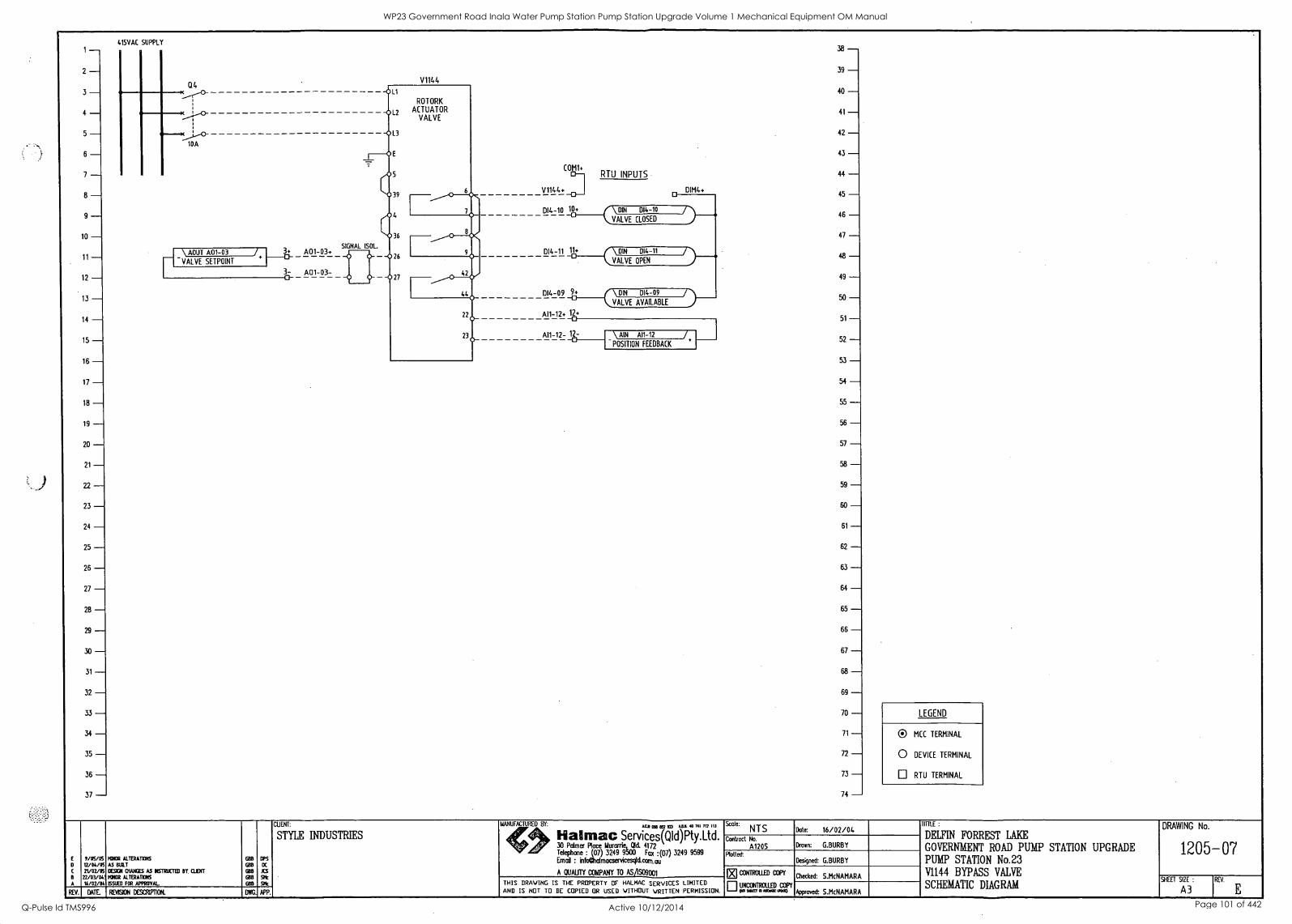
1 - 2 - 3 - 4 - 5 - 6 - 7 - -
9 - 10 - 11 - 12 - 13 - 14 - 15 - 16 - 17 - 18 - 19 - 20 - 21 - 22 - 23 - 24 - 25 - 26 - 27 - 28 - 29 - 30 - 31 - 32 - 33 - 34 - 35 - 36 - 37 -
415VAC SUPPLY
04
10A
TI\ ADUT A01-03 VALVE SETPOINT
/.
V1144
SIGNAL LSOL. 3+ A01-03+ - 3- A01-03- 0
COM1+
V1144+
RTU INPUTS
DIM4+
DI4-10 10+ DIN 014-10
VALVE CLOSED
DI4-11 11+ \ DIN 014-11
VALVE OPEN
014-09 _01 \ DIN 014-09
VALVE AVAILABLE
A11-12+ 12+ 0
A11-12- 12- -0- \ AIN A11-12 / POSITION FEEDBACK
38 - 39 - 40 - 41 - 42 - 43 - 44 - 45 - 46 - 47 - 48
49 -- 50 - 51 -- 52 - 53 - 54 - 55 - 56 - 57 - 58 ---
59 ---
60 ---
61 ---
62 ---
63 ---
64 ---
65 ---
66 - 67 ---
68 ---
69 - 70 - 71 - 72 - 73 - 74 -
LEGEND
0 MCC TERMINAL
0 DEVICE TERMINAL
LI RTU TERMINAL
VOS/OS MatOR ALTERATIONS BUD OPS
D IS/IA/OS AS BULT BUD DC
C 21/02/05 DEMI OWES As DESTRUCTED DT. WENT BUD xS n/03/042 IVOR AITERATXOS BUD Stic
A 16/02/04 ISSUED FO APPROVAL BUD SHE
REV. DATE REVISION COCRIVIION. D. APP.
CUENT:
STYLE INDUSTRIES
MANUFACTURED BY: AEA CM &SIM all 40 NI 712 113
Halmac Services(QId)Pty.Ltd. 30 Palmer Place Muranie, Old. 4172 Telephone : (07) 3249 9500 Fox :(07) 3249 9599 Email : infoalalmacservicesql&com.au
A OUAUTY COMPANY TO ASA09001
Scale: NTS Date: 16/02/04
Contract No.
A1205 Drawn: G.BURBY
Plotteok Designed: G.BURBY
THIS DRAWING IS THE PROPERTY OF HALMAC SERVICES LIMITED AND IS NOT TO BE COPIED OR USED WITHOUT WRITTEN PERMISSION.
CONTROLLED COPY
ri UNCONTROLLED COPY pa sour o ma= WM)
Checked: S.McNAMARA
Approved: S.McNAMARA
TOLE :
DELFIN FORREST LAKE
GOVERNMENT ROAD PUMP STATION UPGRADE PUMP STATION No.23 V1144 BYPASS VALVE
SCHEMATIC DIAGRAM
DRAWING No.
1205-07
SHEET SIZE :
A3 REV.
E
WP23 Government Road Inala Water Pump Station Pump Station Upgrade Volume 1 Mechanical Equipment OM Manual
Q-Pulse Id TMS996 Active 10/12/2014 Page 101 of 442
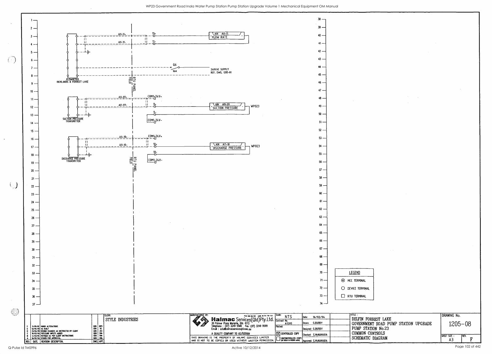
1 - 2 - 3 - 4 - 5 - 6 - 7 - 8 - 9 -
10 - 11 - 12 - 13 -
20 - 21 - 22 - 23 - 24 - 25 -- 26 - 27 - 28 - 29 - 30 - 31 -- 32 - 33 - 34 - 35 - 36 - 37 -
FLOWMETER RICHLANDS & FORREST LAKE
A11,11+
--A-
SUCTION PRESSURE TRANSMITTER
II 11
-Y--
T-
A11-09-
-A- 11
I I
- Y
DISCHARGE PRESSURE TRANSMITTER
A11-10-
11+
WP023
WP023
38 - 39 - 40 - 41 - 42 - 43 - 44 - 45 - 46 - 47 - 48 - 49 - 50 - 51 - 52 - 53
54 - 55 - 56 - 57 - 58 - 59 - 60 ---
61 ---
62 - 63 ---
64 - 65 ---
66 - 67 ---
68 ---
69 - 70 - 71 - 72 - 73 - 74 -
\ AIN A11-11 A-
I I
10_1 11-
'FLOW RATE
COM1+24V+ A- -0
I
II 9+
Q6
240VAC SUPPLY
REF. DWG. 1205-01 16A
\ AIN A11-09
9-
SUCTION PRESSURE
COM1-24V-
COM1+24V+ A- -0 I I
II 10+ \ AIN A11-10
10-
DISCHARGE PRESSURE
E0M1-24V-
LEGEND
® MCC TERMINAL
0 DEVICE TERMINAL
o RTU TERMINAL
0
e
A
0/05/05 22/04/05 21/02/05 0/03/04 4/03/04 20/02/04
REY. DATE
MGR ALTERATIONS
AS BULT
DE901 OWIGES AS INSTRUCTED BY WENT
PRESSURE IfUTS ADM REVISED AS PER CLIENT ONTRUCTITINS
ISSIXD FOR APPROVAL
GBB
008 CBS
GB8
ORB
coo
OPS
rx XS SMc
SMc
SPE
CUENT:
STYLE INDUSTRIES ACJI 1332 223 ABA 40 741 712 117
al mac Services(QId)Pty.Ltd. 30 Palmer Place Iturwri., Oa 4172 Telephone : (07) 3249 9500 Fax :(07) 3249 9599 Email : infoehalmacsenicesgld.c0m.au
A QUALITY COMPANY TO AS/1509001
Scale: NTS
Contract No.
A1205 Rotted:
CONTROLLED COF'Y
THIS DRAWING IS THE PROPERTY OF HALMAC SERVICES LIMITED AND IS NOT TO BE COPIED OR USED WITHOUT WRITTEN PERMISSION. El L749107 ID QOM 20.311:1PY
REVISION DESCRIPTION. APP.
Date: 16/02/04
Drawn: G.BURBY
Designed: G.BURBY
Checked: S.McNAMARA
*roved: S.McNAMARA
PULE
DELFIN FORREST LAKE
GOVERNMENT ROAD PUMP STATION UPGRADE PUMP STATION No.23 COMMON CONTROLS
SCHEMATIC DIAGRAM
DRAWING No.
1205-08
SHEET SIZE:
A3 RE' F
WP23 Government Road Inala Water Pump Station Pump Station Upgrade Volume 1 Mechanical Equipment OM Manual
Q-Pulse Id TMS996 Active 10/12/2014 Page 102 of 442
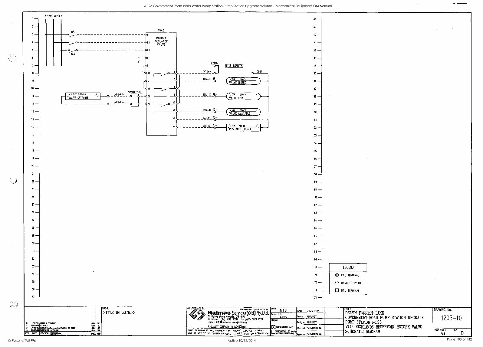
2
3
4
5
6
7
8
9
10
11
12
13
14
15
16
17
18
19
20
21
22
23
24
25
26
27
28
29
30
31
32
33
34
35
36
37
415VAC SUPPLY
as
)c)- 10A
V746
SIGNAL ISOL. \ AOUT A01-04 /. I A01-04. 'VALVE SETPOINT
A01-04- a
CUENT:
STYLE INDUSTRIES
0 4/05/05 IVOR ALfERAMS GOB GIPS
t2/04/OS AS BULT 03B DC
B 21/02/05 DESIGN CHANGES AS 06TRUCTED BY OJDff ORB JCS
22/03/04 ISSUED FOR APPROVAL. ORB SIB
REV. DATE REVISION DESCRIP11014 DWG. APP.
COM1+
V746+
DI4-13 13+
014-14 14+
014-12 12+
A11-13+ 1k
A11-13- lar
RTU INPUTS
DIM4-
DIN DI4-13
VALVE CLOSED
DIN 014-14
VALVE OPEN
\ AIN A11-13
POSITION FEEDBACK
42 - 43 ---
44 ---
45 ---
46
47 - 48 ---
49 ---
50 ---
51
52 - 53 ---
54 ---
55 ---
56 ---
57 ---
58 ---
59 ---
60 ---
61
62 - 63
64 ---
65 - 66 ---
67 ---
68 ---
69 - 70 ---
71
72
73 - 74 -
LEGEND
O MCC TERMINAL
O DEVICE TERMINAL
RTU TERMINAL
MANUFACTURED BY: Attl a52 fzI ASA 40 741 M 113
itialynac Services(QId)Pty.Ltd. 30 Palmer Place N Olt 4172 Telephone one : (07) 3249 9 ax :(07) 3249 9599 Erna : infochairnacservicescg.conLau
A GUAM COMPANY TO AS/1S09001
Scale NTS Dote: 22/03/04 Contract No.
A1205 Drawn: G.BURBY
Plotted: Designed: G.BURBY
CONTROLLED COPY Checked: S.McNAMARA
THIS DRAWING IS THE PROPERTY OF HALMAC SERVICES LIMITED uricarrootio AND IS NOT TO BE COPIED OR USED WITHOUT WRITTEN PERMISSION. "'"a' Approve& S.McNAMARA
TITTLE:
DELFIN FORREST LAKE
GOVERNMENT ROAD PUMP STATION UPGRADE PUMP STATION No.23 V746 RICHLANDS RESERVOIR ROTORK VALVE
SCHEMATIC DIAGRAM
DRAWING No.
1205-10
SHEET SIZE :
A3 REV.
WP23 Government Road Inala Water Pump Station Pump Station Upgrade Volume 1 Mechanical Equipment OM Manual
Q-Pulse Id TMS996 Active 10/12/2014 Page 103 of 442

WP23 Government Road Inala Water Pump Station Pump Station Upgrade Volume 1 Mechanical Equipment OM Manual
Q-Pulse Id TMS996 Active 10/12/2014 Page 104 of 442
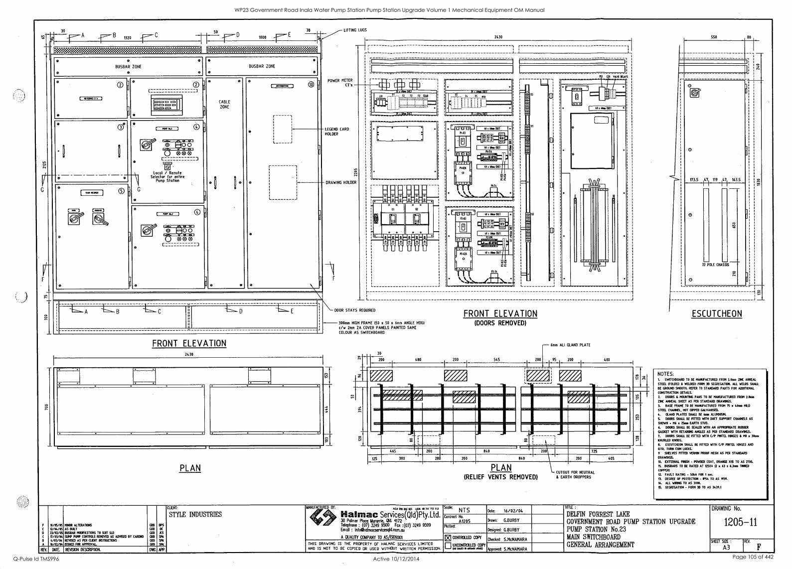
u
. f-- A -- 8 1320 -r- C
D 1000
KM:Kannii:Ken§:KOKSIOK:Keig::::*::::::MOK li:K:KOICK:KOMMKOS:KVSKOK:E*::"
:..
et 0 0
BUSBAR ZONE
0 0 0
0 0
BUSBAR ZONE
0 0
ll
0 0 I ® C 3
0 0
(ABLE ZONE
1
( asmeonn j
r -1
I I
aZTM:DM
o
=on. o 1=0 0 =1 pg= =
O e 0 [ rap MA 3
0
7,-.711.021.-M. 0 0 L J
9.-,...-aK,m.a 000 C 3 r----1 ES..1
Local / Remote
r -1
Selector for entire Pump Station e 1) 0
° e [ ..cows ] ®
] 0 0
L J
0 0 ( 6 62 ) e 0
0
VFNMEr.71-M.1= 7.20 0
0
0
:1.:Mi:10,111111, V
0 0 0 C 3
ul r-
e
I.
Ir.
J
;1
1"1110.---- A 1--. B .1==.- D
J1.
FRONT ELEVATION 2430
LIFTING LUGS
POWER METER
CT's
EGEND CARD
OLDER
RAWING HOLDER
PLAN
F
2430
L J
DOOR STAYS REQUIRED
300mm HIGH FRAME 150 x 50 x 6mm ANGLE HOG/
c/w 2mm ZA COVER PANELS PAINTED SAME
COLOUR AS SWITCHBOARD
30
200 480 200
FRONT ELEVATION (DOORS REMOVED)
545 200
- 6mm ALI GLAND PLATE
95 200 480
(._
465 200 840
125 380 28 200 840
PLAN (RELIEF VENTS REMOVED)
'Dm
0
173.5 47 119 47 163.5
0
72 POLE CHASSIS
0 I
ESCUTCHEON
NOTES: L SWITCHBOARD TO BE MANUFACTURED FROM 2.06a ZINC ANNEAL
STEEL (FOLDED & WELDED( FORM 35 SEGREGATION. ALL WELDS SHALL
BE GROUND 9930711. REFER TO STANDARD PARTS FOR ADOttIONAL
CONSTRUCTION DETAE.S.
2. DOORS L MOWING PANS TO BE MANUFACTURED FROM Mon DK ANNEAL SHEET AS PER STANDARD DRAWINGS.
3. BASE FRAME TO BE MANUFACTURED FROM 75 x 401ra PAD
STEEL CHM4YEL, HOT UPPED GALVANISED.
4. GLAND PLATES SHALL BE taa ALUMINIUM.
S. DOORS SHALL BE FITTED WITH DUCT SUPPORT CHANNELS AS
SHOWN 916 Eats EARTH STUD.
6. DOORS SHALL BE SEALED WITH AN APPROPRIATE RUBBER
GASKET WITH RETAINING ANGLES AS PER STAMM DRAWINGS.
7. DOORS SHALL BE FITTED WITH C/P PATEL HINGES & 1911 a 30moi
KNURLED KNOBS.
0. ESCUTCHEON SHALL BE FITTED WITH C/P PATEL HINGES AND
°III. TURN COIN LOCKS.
9 SHELVES FITTED VERMIN PROOF MESH AS PER STANDARD 200 725
200 405 DRAWINGS.
10. EXTERNAL RASH - POWDER COAT. ORANGE XS TO AS 2700.
It BUSBARS TO BE RATED AT T2.50A (2 x 63 x 4.3ara TAXED
CUTOUT FOR NEUTRAL COPPER)
Q. FAULT RATING - 50kA FOR 1 sec. EARTH DROPPERS S. DEGREE OF PROTECTION - PS4 TO AS 1939.
14. ALL WIRING TO AS 3000.
S. SEGREGATION - FORM 3B TO AS 3439.1
CUENT:
STYLE INDUSTRIES
10/05/05 MINOR ALTERATIONS G813 BPS
12/04/05 AS KILT GBEI DC
0 23/02/05 BUSBAR MODIRCSTIONS TO SUIT AD GEM JCS
17/03/64 4/03/04
SUMP PUMP CONTROLS REMOVED AS ADVSED BY CARDNO
REVISED AS PER CLINT INSTRUCTANS
GIB GBI3
At Ak
A 14/02/04 ISM FOR APPROVAL GBB Sit
REV. DATE BENISON DESCRIPTION. DWG. APP.
MANUFACTURED BY: 025 Kum UK 0 741 712 113
Services(QId)Pty.Ltd. 30 Palmer Place Mamie., Old. 4172 Telephone : (07) 3249 9500 Fax :(07) 3249 9599 Erna : infoOlcdmacservicesqld.com.au
A QUAUlY COMPANY TO ASAS09001
Scale: NTS Dote: 16/02/04
Contract No.
A1205 Drawn: G.BURBY
Plotted: Designed: G.BURBY
THIS DRAWING IS THE PROPERTY OF HALMAC SERVICES LIMITED AND IS NOT TO BE COPIED OR USED WITHOUT WRITTEN PERMISSION.
MCONTROLLED COPY
EIUNCONIROUED copy 00 MD 10 006.
Checked: S.McNAMARA
Approved S.McNAMARA
TITTLE :
DELFIN FORREST LAKE
GOVERNMENT ROAD PUMP STATION UPGRADE
PUMP STATION No.23 MAIN SWITCHBOARD
GENERAL ARRANGEMENT
DRAWING No.
1205-11
SHEET SIZE :
A3 REV.
WP23 Government Road Inala Water Pump Station Pump Station Upgrade Volume 1 Mechanical Equipment OM Manual
Q-Pulse Id TMS996 Active 10/12/2014 Page 105 of 442

49
100 398 126
SECTION A-A
150 450 100
313
III
317 260
SECTION B-B
123
244 113 113 194
320
SECTION C-C
SECTION F-F
R
Oa
320
624
SECTION D-D
56
rr 70
15 260
SECTION G-G
0
A
0/04/05 73/02/05 T7/03/04 16/02/04
AS BUILT
BUSBAR MOCIFICATIORS TO SUIT AD MINOR COKTRUCTIDEAL GIARGES
ISSUED FOR APPROVAL
COB
CiBB
COB
GBB
DC
JCS
SMe
Si
WENT:
STYLE INDUSTRIES
MANUFACTURED BY: 4C.11 050 i32 1123 Mt .o 741 712 113
Ifil almac Services(QId)Pty.Ltd. 30 Palmer Place Mamie, Old. 44 4172 Ma Telephone : (07) 3249 9500 Fax :(07) 3249 9599 EMOB : infoCalmacservicesqlicorkau
A QUALITY COMPANY TO AS/1939001
THIS BRAVING IS THE PROPERTY CIF HALMAC SERVICES LIMITED AND IS NOT TO BE COPIED OR USED WITHOUT WRITTEN PERMISSION. REV. DATE. RDASION DESCRIPTION. DWG. APP.
VENT BOX
320
SECTION E-E
3, 104 49 398
REMOVABLE TOP
COVER
126
PERFORATED ZED BRACKETS
J,
TYPICAL TOP SECTION
Scale: NTS Date: 16/02/04
Contract No.
A1205 Drawn: G.BURBY
Plotted. Designed: G.BURBY
MC01411211111 COPY
UNCONTROLLED COPY an9aalloimosuta0
Checked: S.McNAMARA
Approved:
TIME :
DELFIN FORREST LAKE
GOVERNMENT ROAD PUMP STATION UPGRADE PUMP STATION No.23 MAIN SWITCHBOARD
SECTIONAL DETAILS
DRAWING No.
1205-12
SHEET SIZE :
A3 REV.
WP23 Government Road Inala Water Pump Station Pump Station Upgrade Volume 1 Mechanical Equipment OM Manual
Q-Pulse Id TMS996 Active 10/12/2014 Page 106 of 442
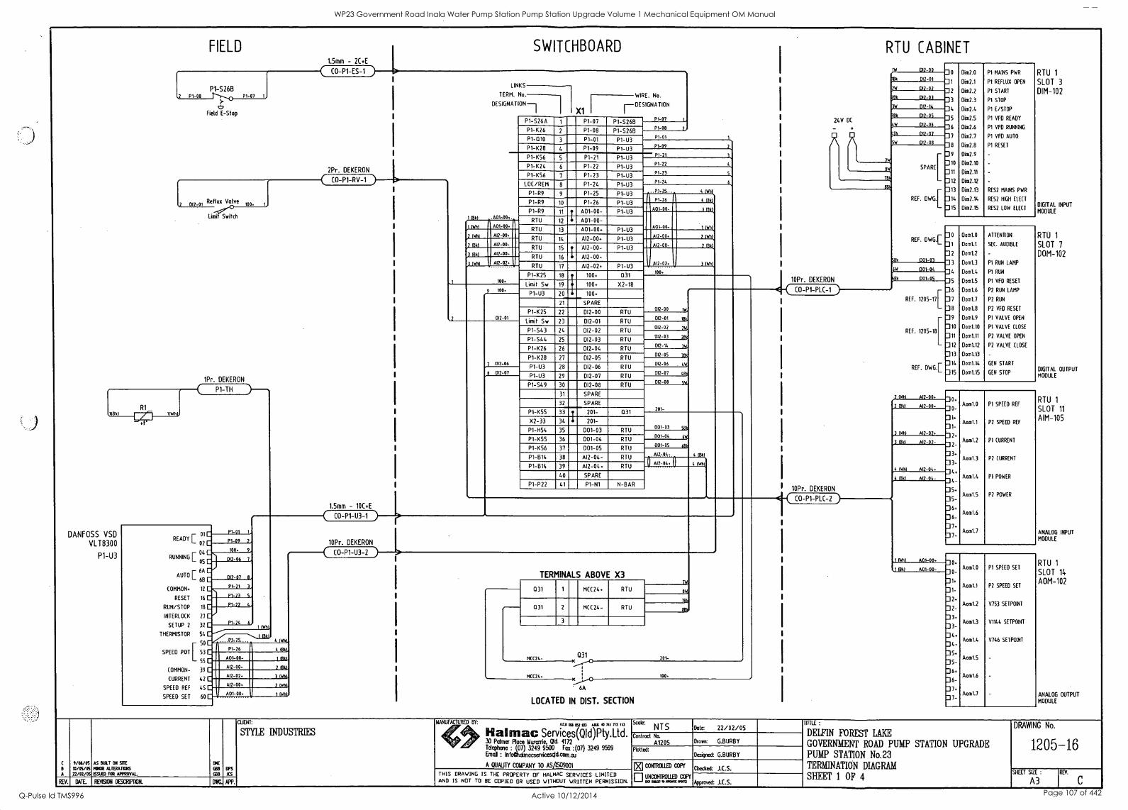
FIELD
P1-S26B
c!) Field E-Stop
2 Reflux Valve
100.
Limit Switch
DANFOSS VSD VLTE3 30 0
P1-U3
1Pr. DEKERON
P1 -TH
READY
RUNNING
AUTO
01
02
04
05
6A
6B
COMMON. 12
RESET 16
RUN/STOP 18
INTERLOCK 27
SETUP 2 32
THERMISTOR 54
r 50
SPEED POT 53
55
COMMON- 39
CURRENT 42
SPEED REF 45
SPEED SET 60
At2-02.
PAL
1 BO,
1.5mm - 2C+E
CO-P1-ES-1
SWITCHBOARD
2Pr. DEKERON
CO-P1-RV-1 )
4 (WM.
4 0361,
1 113k1,
2 Mkt.
3 INK
2 (Wh),
1 ROI
10Pr. DEKERON
CO-P1-U3-2
I OM
I IWhl
,2 0341
1841
) MAI
LINKS
TERM. No.
DES1GNAT ON-7
A.01-.007.
001-00.
Al2-00.
Al2-00-
012-00-
Al2-02.
100.
100
012-01
012-06
X1
WIRE. No.
[-DESIGNATION
P1 -S26A P1-07 P1 -S26B P1-1(26 2 P1-08 P1-S268 P1-010 3 P1-01 P1-U3
P1-K28 4 P1-09 P1 -U3
P1 -K56 5 P1-21 P1-U3
P1-1(24 6 P1-22 P1-U3
P1-1(56 7 P1-23 P1-U3
LOC/REM 8 P1-24 P1-U3
P1 -R9 9 P1-25 P1 -U3
P1-R9 10 P1-26 P1 -U3
P1-R9 11 tr A01-00- P1 -U3
RTU 12 A01 -00- RTU . 13 A01-00+ . P1-U3
RTU 14 AI2-00. P1-U3
RTU 15 T Al2 -00- P1 -U3
16 4 AI2-00- RTU
RTU 17 AI2-02. P1-U3
PI-K25 18 100. Q31
19 100+ X2-18 Limit Sw
P1-U3 20 100.
21 SPARE
P1-1(25 22 012-00 RTU
Limit Sw 23 012-01 RTU
P1 -S43 24 012-02 RTU
P1 -S44 25 012-03 RTU
P1-1(26 26 012-04 RTU
P1-1(28 27 012-05 RTU
P1-U3 28 DI2-06 RTU
P14.13 29 DI2-07 RTU
P1-S49 30 012-08 RTU
31 SPARE
32 SPARE
P1-1(55 33 t 201- Q31
X2-33 34 201 -
P1-H54 35 D01-03 RTU
P1-K55 36 001-04 RTU
P1 -K56 37 001-05 RTU
P1-514 38 Al2-04- RTU
PI-B14 39 Al2-04. RTU
40 SPARE
P1-P22 41 P1-N1 N-BAR
P1-07
P1 -08 2
P1 -01
P1-09
21 3
PI-22 4
P1 -23
PI-24
.
P1 -26
001-00-
4 IWhk.
4 (Bki
001-00.
012-00.
012-00-
tAl2-02.
100.
I 03 t
ttok
z IWnt
2 03kt
3 IWhi
012-00 114
012-01 16
012-02 Elt
012-03 28
012 -14 3
012-05 3B
DI2-06 4(1
012-07 46
012-08 5S4
201-
D01-03 sn
D01-04 6
001-05
.Al2.4147.
a012-04.
60k
4 (Bk
SAW
TERMINALS ABOVE X3
031 1 MCC24+ RTU
Q31 2 MCC24- RTU
3
MCC24-
MCC24.
Q31 ),ro
61A
LOCATED IN DIST. SECTION
01<
113
201-
100
24V DC
RR
10Pr. DEKERON
CO-P1-PLC-1 )
I 10Pr. DEKERON
Et{ CO-P1 PLC 2
RTU CABINET
YI4 D12-00
186 012 -01
jW 012-02
204 DI2-03
012-14
086 012 -0S
OW 012 -06
Bk 0(2 -07
5W 012-08
SPARE[
REF. DWG.[
REF. DWG.[
Bk D01-03
DO1s04
0 Dim2.0 P1 MAINS PWR
1 Dim2.1 P1 REFLUX OPEN
2 Dim2.2 P1 START
3 Dim2.3 P1 STOP
4 Dim2.4 PI E/STOP
5 Dim2.5 P1 VFD READY
6 Dim2.6 P1 VFD RUNNING
7 Dim2.7 P1 VFD AUTO
8 Dim2.8 P1 RESET
9 Oim2.9 -
10 Dim2.10 -
11 Dim2.11 -
12 Dim2.12 -
13 Dim2.13 RES2 MAINS PWR
14 Dim2.14 RES2 HIGH ELECT
15 Oim2.15 RES2 LOW ELECT
Bk D01 -0i
REF. 1205-17[
REF. 1205-18 [
2 WM
REF. DWG.[
Al2-00
0
1
2
Dom1.0
Dom1.1
Dom1.2
ATTENTION
SEC. AUDIBLE
-
3 Dom1.3 P1 RUN LAMP
4 Dom1.4 P1 RUN
5 Dom1.5 P1 VFD RESET
6 Dom1.6 P2 RUN LAMP
7 Dom1.7 P2 RUN
8 Dom1.13 P2 VFD RESET
9 Dom1.9 PI VALVE OPEN
10 Dom1.10 PI VALVE CLOSE
11 Dom1.11 P2 VALVE OPEN
12 Dom1.12 P2 VALVE CLOSE
13 Dom1.13 -
14 Dom1.14 GEN START
15 Dom1.15 GEN STOP
Aom1.0 PI SPEED REF 0
1.
1- Aom1.1 P2 SPEED REF
Aom1.2 P1 CURRENT 22 -
3
3- Aom1.3 P2 CURRENT
4. Aom1.4 P1 POWER
4-
5+
5- Aom1.5 P2 POWER
6+ Aom1.6
6-
7 Aom1.7
-
Aom1.0 P1 SPEED SET 0-
1+ Aom1.1 P1 SPEED SET
1-
2 Aom1.2 V753 SETPOINT
2-
3. Aom1.3 V1144 SETPOINT
- 3
Aom1.4 V746 SETPOINT 44. -
5. Aom1.5 -
5-
6. Aom1.6 -
II 6-
7. Aom1.7 -
-
RTU 1
SLOT 3
DIM -102
DIGITAL INPUT
MODULE
RTU 1
SLOT 7
DOM-10 2
DIGITAL OUTPUT MODULE
RTU 1
SLOT 11
AIM-105
ANALOG INPUT
MODULE
RTU 1
SLOT 14
A0M-10 2
ANALOG OUTPUT MODULE
A
9/43/05 I0/05/05 22/02/05
AS BUILT ON 9TE POOR ALTERATICKS
ISSUED FOR APPROVAL
OlIC
GBB
GOB
IPS KS
REV. DA1E. REM ON DESCRIPDON. DWG. APP.
()ANT:
STYLE INDUSTRIES
MANUFACTURED BY: &4A 063 052 923 ALI 40 741 712 113
lialmac Services(QId)Pty.Ltd. 30 Palmer Place Murarrie, Old. 4172 Telephone : (07) 3249 9500 Fax :(07) 3249 9599 Email : infoetalmacsenicescacan.au
A QUAUTY COMPANY TO ASASO9001
Scale: NTS Dote: 22/02/05
Contract No.
A1205 Drown: G.BURBY
Plotted: Designed: G.BURBY
THIS DRAWING IS THE PROPERTY OF HALMAC SERVICES LIMITED AND IS NOT TO BE COPIED OR USED WITHOUT WRITTEN PERMISSION.
CONTROLLED COPY
uNcotirRoun) COPY cal= w moos woo
Checked: J.C.S.
Approved: J.C.S.
TITTLE :
DELFIN FOREST LAKE
GOVERNMENT ROAD PUMP STATION UPGRADE PUMP STATION No.23 TERMINATION DIAGRAM
SHEET 1 OF 4
DRAWING No.
1205-16
SHEET SIZE :
A3 REV.
C
WP23 Government Road Inala Water Pump Station Pump Station Upgrade Volume 1 Mechanical Equipment OM Manual
Q-Pulse Id TMS996 Active 10/12/2014 Page 107 of 442
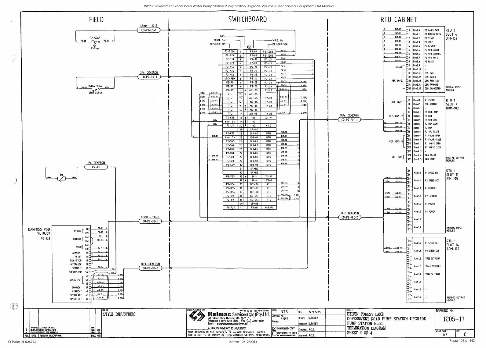
FIELD
P2-S26B 2 P2 -08 P2 -07 1
t2 E-Stop
2 Reflux Valve
11Md 1(WhL
DANFOSS VSD VLT830 0
P2-U3
limit Switch .
1Pr. DEKERON
P2-TH
READY
RUNNING
AUTO
01
02
04
05
6A
6B
COMMON. 12
RESET 16
RUN/STOP 18
INTERLOCK 27
SETUP 2 32
THERMISTOR 54
r 50
SPEED POT 53
55
COMMON- 39
CURRENT 42
SPEED REF 45
SPEED SET 60
P2 -01 1
1.5mm - 2C+E
CO-P2-ES-1
SWITCHBOARD
P2-09 2
100. 9
013-06 7
DD -07 8
P2-21 3
P2-23 5
1.5mm - 10C+E
C0- P2 -U3 -1
1 OM
1
3 INN
(841
) Mk/
3 INN
LINKS
TERM. No.
DESIGNAT ON-1
601-01.
Al2-01.
Al2-01-
612-01-
Al2-03.
100.
100.
013-M
013-06
WIRE. No.
nDESIGNATION
P2 -S26A P2-07 P2-S26B
P2-K26 2 P2-08 P2-S26B
P2-Q10 3 P2-01 P2-U3
P2-K28 4 P2-09 P2-U3
P2-K56 5 P2-21 P2-U3
P2-K24 6 P2-22 P2-U3
P2-K56 7 P2-23 P2-U3
LOC/REM 8 P2-24 P2-U3
P2-R9 9 P2-25 P2-U3
P2-R9 10 P2-26 P2-U3
P2-R9 11 I, A01-01- P2-U3
I RTU 12 A01 -01-
RTU 13 A01-01. P2-U3
14 Al2-01. RTU P2-U3
RTU 15 T Al2-01- P2-U3
RTU 16 I Al2 -01-
RTU 17 Al2-03. P2-U3
P2-1(25 18 100+ X1-19
19 t 100+ Limit Sw
20 1 100+ X3-2 P2-U3
21 SPARE
P2-K25 22 DI3-00 RTU
Limit Sw 23 013-01 RTU
P2-S43 24 013-02 RTU
P2-544 25 013-03 RTU
P2-K26 26 DI3-04 RTU
P2-1(28 27 DI3-05 RTU
P2-U3 28 013-06 RTU
P2-U3 29 013-07 RTU
P2-549 30 013-08. RTU
31 SPARE
32 SPARE
P2-1(55 33 .1. 201- X1-34
34. 4 201- X3-8
P2-H54 35 D01-06 RTU
P2-K55 36- D01-07 RTU
P2-1(56 37 D01-08 RTU
P2-B14 38 Al2-05- RTU
P2-B14 39 Al2-05+ RTU
40 SPARE
P2-P22 41 P2-N1 N-BAR
P2-07
P2-08 2
P2-01
P2-09
P2-21
P2-22
P2-23
P2-74
P2-26
A01-01
Al2-03.
DO-00
013 -01
013 -02
00-03
013-14
013-05
D1306
013-07
013-08
001-06
001-07
001-08
A
Al2-05.
10Pr. DEKERON
CO-P2-U3-2
RTU CABINET
4 14111,.
4 Mkt
1 PAL
2 (Wilk
2BBit
3 146111,
3
10Pr. DEKERON
DO-00 RTU 1
SLOT 4
DIM-102
DIGITAL INPUT MODULE
RTU 1
SLOT 7
DOM-10 2
DIGITAL OUTPUT MODULE
RTU 1
SLOT 11
AIM-105
ANALOG INPUT MODULE
RTU 1
SLOT 14
AM-102
ANALOG OUTPUT MODULE
0
1
2
3
4
5
6
7
8
9 io
11
12
13
14
15
Dim3.0
Dim3.1
Dim3.2
Dim3.3
Dim3.4
Dim3.5
Dim3.6
Dim3.7
Dim3.8
Dim3.9
Dim3.10
Dim3.11
Dim3.12
Dim3.13
Dim3.14
Dim3.15
P2 MAINS PWR
P2 REFLUX OPEN
P2 START
P1 STOP
P2 E/STOP
P2 VFD READY
P2 VFD RUNNING
P2 VFD AUTO
P2 RESET
GEN. FAIL
GEN. FAULT
GEN. FUEL LOW
GEN. RUNNING
GEN. CONNECTED
013-01
013-02
013-03
013-14
013-05
013-06
013-07
013-08
SPARE[
REF. DWG. [
REF. DWG.
REF. 1205-17[
10 001-06
0
1
2
3
4
5
6
8
9
10
11
12
13
14
15
Dom1.0
Dom1.1
Clom1.2
Dom1.3
Dom1.4
Dom1.5
Dom1.6
Donal
Dom1.8
Dom1.9
Dom1.10
Dom1.11
Dom1.12
Dom1.13
Dom1.14
Dom1.15
ATTENTION
SEC. AUDIBLE
P1 RUN LAMP
P1 RUN
P1 VFD RESET
P2 RUN LAMP
P2 RUN
P2 VFD RESET
P1 VALVE OPEN
P1 VALVE CLOSE
P2 VALVE OPEN
P2 VALVE CLOSE
GEN START
GEN STOP
3
4
6
L
10
11
1L
C0 -P2-PLC-1 )
10Pr. DEKERON
11 D01-07
12 001-08
REF. 1205-18 [
REF. DWG.E
2 1101 Al2-01 0-
1.
1
2
3+
3
4
4-
6+
6-
7-
Aom1.0
Aomtl
Aoml.2
Aom1.3
Aom1.4
Aom1.5
Aomt6
Aom1.7
P1 SPEED REF
P2 SPEED REF
P1 CURRENT
P2 CURRENT
P1 POWER
P2 POWER
Old Al2 -01
INN Al2-03.
3 11341 612 -03
4 WM Al2-05.
(1311 Al2-05-
1 INN A01-01.
CO-P2-PLC-2 )
ft.
0
1
1-
2+
2
3+
3-
4
4-
5
5-
6+
6
7
Aom1.0
Aom1.1
Aom1.2
Aom1.3
Aom1.4
Aom1.5
Aomt6
Aomt7
P1 SPEED SET
P2 SPEED SET
V753 SETPOINT
V1144 SETPOINT
V746 SETPOINT
1 (841 A01-01-
CLIENT:
STYLE INDUSTRIES
9/0/6/05 AS BUTT ON SITE aNC
10/05/05 MINOR ALTERATIONS GBH OPS
A 72/02/05 ISSUED FOR APPROVAL GBB JCS
REV. DATE REVISION DESCRIPTION. DWG. APP.
MANUFACTURED BY: AtA 093 OM 922 ABA 44 711 711 113
II al "mac Services(Q1d)Pty.Ltd. 30 Palmer Place Iturarrie, Old 4172 Telephone : (07) 3249 9500 Fox :(07) 3249 9599 Emo : infoftalmacservtesql&can.au
A QUALITY COMPANY TO AS/1S09001
Scale: NTS Date: 22/02/05
Contract No.
A1205 Drown: G.BURBY
Plotted: Designed: G.BURBY
THIS DRAWING IS THE PROPERTY OF HALMAC SERVICES LIMITED AND IS NOT TO BE COPIED OR USED VITHOUT WRITTEN PERMISSION.
[E] corrRom COPY
EI UNCONTROLLED trom3
COW oa 10.100Z
Checked: J.CS.
Approved: J.E.S.
TITTLE :
DELFIN FOREST LAKE
GOVERNMENT ROAD PUMP STATION UPGRADE
PUMP STATION No.23 TERMINATION DIAGRAM
SHEET 2 OF 4
DRAWING No.
1205-17
SHEET SIZE :
A3 REV.
C
WP23 Government Road Inala Water Pump Station Pump Station Upgrade Volume 1 Mechanical Equipment OM Manual
Q-Pulse Id TMS996 Active 10/12/2014 Page 108 of 442
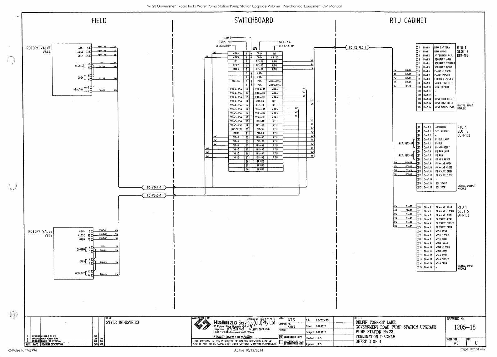
ROTORK VALVE V844
ROTORK VALVE V845
COM. 5 C
CLOSE 33 C
OPEN 35 C
CLOSED r 6
L 7
FIELD
V844-01 6W
V844-02 SW
V844 -03 5B
100 1W
014 -01 2
OPEN[ 9C
HEALTHY [ 42 C 44 C
014 -02
014-00
COM. 5 C
CLOSE 33 C
OPEN 35 C
CLOSED
OPEN
6
7
4W,
V845-01 6
V845-02 SW
V845-03 5B
100.
014 -04 2
014-05 3W
HEALTHY 12 L 44 C 014 -0 4W
CO-V844-1
111.
CO-V845-1
SWITCHBOARD
LINKS
DESIGNAT 1 1
DESIGNATION
TERM. No. WIRE. No.
1W
W
W
4W
3W
2
3W
V844 ,r 100. 01
V845 100. X2-20 Q1 3 DI1-06 RTU
PFR2 4 DI1-07 RTU
SOAR 5 011-09 RTU
6
I 200.
200.
X2-34 8 t 201- V844-K54
9 4 201- V845-K54
V844-K54 10 V844-01 V844
V844-K55 11 V844-02 V844
V844-K54 12 V844 -03 V844
V844-K54 13 D01-09 RTU
V844-K55 14 D01-10 RTU
V845-K54 15 V845-01 V845
V845-K55 16 V845-02 V845
V845-K54 17 V845-03 V845
V845-K54 18 001-11 RTU
V845-K55 19 D01-12 RTU
LOC/REM 20 D11-10 RTU
PFR1 21 D11-08 RTU
V844 22 014-00 RTU
V844 23 014-01 RTU
V844 24 014-02 RTU
V845 25 D14-03 RTU
V845 26 014-04 RTU
V845 27 DI4-05 RTU
28 SPARE
29 SPARE
30 SPARE
1W
113
28
6W
SW
50
441,
48
6W
SW
SB
5W
58
3W
2W
6W
68
7W
76
8W
88,
CO-X3-PLC-1
RTU CABINET
1W DI1-06
1B DI1-07
.114
28
011-08
DI1-09
3W 011-10
4W
REF. 1205-17
REF. 1205-18
001-09
0
1
2
3
5
6
7
8
9
10
11
12
13
14
15
Dim1.0
Dim1.1
Dim1.2
Dim1.3
Dim1.4
Dim1.5
Dim1.6
Dim1.7
Dim1.8
Dim1.9
Dim1.10
Dim1.11
Dim1.12
Oim1.13
Dim1.14
Dim1.15
RTU BATTERY
RTU MAINS
ATTENTION A(K.
SECURITY ARM
SECURITY TAMPER
SECURITY DOOR
MAINS CLOSED
MAINS POWER
ENERGEX POWER
SURGE DIVERTER
STN. REMOTE
RES1 HIGH ELECT
RES1 LOW ELECT
RES1 MAINS PWR
66 001-10
5W
58
D01-11
DO1 12
6W 014-00
68 014 -01
7W 014-02
78 014-03
8 D14-04
88 014-05
0
1
2
3
4
S
6
7
8
9
10
11
12
13
14
15
Dom1.0
Dom1.1
Dom1.2
Dom1.3
Dom1.4
Dom1.5
Dom1.6
Dom1.7
Dom1.8
Dom1.9
Dom1.10
Dom1.11
Dom1.12
Dom1.13
Dom1.14
Dom1.15
ATTENTION
SEC. AUDIBLE
P1 RUN LAMP
P1 RUN
P1 VFD RESET
P2 RUN LAMP
P2 RUN
P2 VFD RESET
PI VALVE OPEN
P1 VALVE CLOSE
P2 VALVE OPEN
P2 VALVE CLOSE
GEN START
GEN STOP
0
1
2
3
4
5
6
7
8
9
10
11
12
13
14
15
Dim4.0
Oim4.1
Dim4.2
Dim4.3
Dim4.4
Oim4.5
Dim4.6
Dim4.7
Dim4.8
Dim4.9
Dim4.10
Dim4.11
Dim4.12
Dim4.13
Oim4.14
Oim4.15
P1 VALVE AVAIL
PI VALVE CLOSED
PI VALVE OPEN
P2 VALVE AVAIL
P2 VALVE CLOSED
P2 VALVE OPEN
V753 AVAIL
V753 CLOSED
V753 OPEN
V1144 AVAIL
V1144 CLOSED
V1144 OPEN
V746 AVAIL
V746 CLOSED
V746 OPEN
RTU 1
SLOT 2
DIM-102
DIGITAL INPUT
MODULE
RTU 1
SLOT 7
DOM-102
DIGITAL OUTPUT MODULE
RTU 1
SLOT 5
DIM-102
DIGITAL INPUT MODULE
A
19/011/05
10/05/05 22/02/05
AS BOLT ON SITE
MINOR ALTERATD6 SAND FOR APPROVAL
BOB
as
GBB
CIPS
XS
REV. DATE REVISION DESCRIPTION. DWG. APP.
CLIENT:
STYLE INDUSTRIES ail an (GT al MIA 40 741 712 113
Hal mac Services(Q1d)Pty.Ltd. 30 Pcdmer Place Murarrie, Cid. 4172 Telephone (07) 3249 9500 Fax :(07) 3249 9599 Erna/ : infoalaimacservicesqld.com.au
A QUALITY COMPANY TO ASASO9C01
Scale: NTS Dote: 22/02/05
Contrail No.
A1205 Drawn: G.BURBY
Plotted: Designed: G.BURBY
THIS DRAWING IS THE PROPERTY OF HALMAC SERVICES LIMITED AND IS NOT TO BE COPIED OR USED WITHOUT WRITTEN PERMISSION.
DK] CONTROLLED con
0 UNCONTROLLED eon Ba faCI P SVaX wog
Checked: J.C.S.
Approved: J.C.S.
TITTLE :
DELFIN FORREST LAKE
GOVERNMENT ROAD PUMP STATION UPGRADE PUMP STATION No.23 TERMINATION DIAGRAM
SHEET 3 OF 4
DRAWING No.
1205-18
SHEET SIZE : REV.
A3
WP23 Government Road Inala Water Pump Station Pump Station Upgrade Volume 1 Mechanical Equipment OM Manual
Q-Pulse Id TMS996 Active 10/12/2014 Page 109 of 442
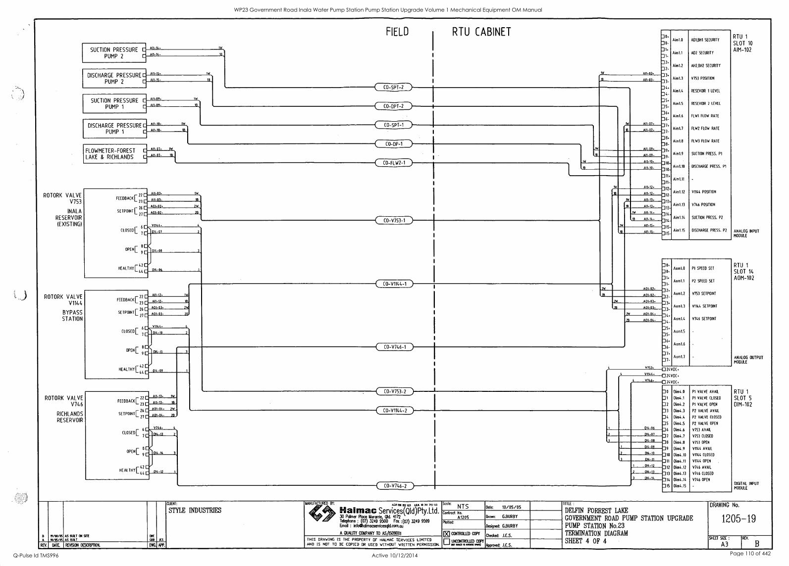
SUCTION PRESSURE C
PUMP 2
A11-11.
A11-14-
DISCHARGE PRESSURE
PUMP 2
A11-15.
A11-15-
ROTORK VALVE V7 5 3
INALA RESERVOIR
(EXISTING)
ROTORK VALVE V1144
BYPASS STATION
SUCTION PRESSURE C
PUMP 1
A11-09.
A11-09-
DISCHARGE PRESSURE E
PUMP 1
A11-10.
ROTORK VALVE V746
RICHLANDS RESERVOIR
FLOWMETER-FOREST C An-01.
LAKE & RICHLANDS E., A11-07- 113
FEEDBACK
SETPOINT
CLOSED
OPEN
HEAL THY
22 C
23 C
26 C
27C
6
All -03.
A11-03-
601-02
A01-02-
FIELD RTU CABINET
18
1W
18
1W
CO-SPT-2
18 CO
1W
-DPI -2
) 18
CO-SpT-1
( ) CO-DP-1
)
1W
CO-FLW2-1
18
2W
78
V1144.
C
9C
4
44 C
014 -07
014 -08
014-06
FEEDBACK
SETPOINT
CLOSED
22 C
23 C
26 C
27 C
6
A11-12.
A11-12- 113
A01-03. 2
A01-03- 28,
V1144.
7C
OPEN[ 9
HEALTHY 42
DI4 -10
014 -11
CO-V753-1 )
C-C-1/1144-1
44 C 014 -09
FEEDBACK
SETPOINT
CLOSED
OPEN
22 C
23 C
26 C
27C
6
A11-13. 1W
A11-13- 18
A01 -04. 2W
601 -04- 28
V746
7C
HEALTHYr 42 L 44 C
DI4 -13
014-14
014 -12
CO-V746-1 )
AI1-03.
RTU 1
SLOT 10
AIM-102
ANALOG INPUT MODULE
RTU 1
SLOT 14
AOM-10 2
ANALOG OUTPUT MODULE
0
0-
1.
1-
2.
3
4
4
5-
6.
6-
7
8
8
9
9-
10
10
11.
11-
12
12-
13
13-
14.
14
15.
15
Aim1.0
Aim1.1
Aim1.2
Aim1.3
Aim1.4
Aim1.5
Aim1.6
Aim1.7
Aim1.8
Aim1.9
Aim1.10
Aim1.11
Aim1.12
Aim1.13
Aim1.14
Aim1.15
601.801 SECURITY
AD2 SECURITY
A111,8H2 SECURITY
V753 POSITION
RESEVOIR 1 LEVEL
RESEVOIR 2 LEVEL
FLW1 FLOW RATE
FLW2 FLOW RATE
FLW3 FLOW RATE
SUCTION PRESS. P1
DISCHARGE PRESS. P1
V1144 POSITION
V746 POSITION
SUCTION PRESS. P2
DISCHARGE PRESS. P2
All- 0 3-
A11-07
All 07-
A11-09
1W
All -09-
All-10.
18 A11-10
A11-12. 1W
All -12-
1W
A11-13
18 A11-13-
1W A11-14
18 All-14
A11-15
IB All -15-
A01-0
0-
1
1
2.
4
5
5-
6.
6-
7.
7-
Aom1.0
Aoml.T
Aom1.2
Aom1.3
Aom1.4
Aom1.5
Aom1.6
Aom1.7
P1 SPEED SET
P2 SPEED SET
V753 SETPOINT
V1144 SETPOINT
V746 SETPOINT
A01-0 2 -
2W A01-0 3.
28 A01-0 3 -
A01-04.
A01-04-
V753.
V1144.
V746
CO-V753-2 )
CO-V1144-2 )
CO-V746-2
[32
014-06
DI4-07
D14-08
014-09
014 - 10
014-11
014-12
2 014-13
3 014-14
24 VDC.
24 VDC.
0 24 VDC.
0
1
2
3
4
5
6
7
8
9
10
11
12
13
14
15
Dim4.0
Dim4.1
Dim4.2
Dim4.3
Dim4.4
Dim4.5
Dim4.6
Dim4.7
Dim4.8
Dim4.9
Dim4.10
Dim4.11
Dim4.12
Dim4.13
Dim4.14
Dim4.15
P1 VALVE AVAIL
P1 VALVE CLOSED
P1 VALVE OPEN
P2 VALVE AVAIL
P2 VALVE CLOSED
P2 VALVE OPEN
V753 AVAIL
V753 CLOSED
V753 OPEN
V1144 AVAIL
V1144 CLOSED
V1144 OPEN
V746 AVAIL
V746 CLOSED
V746 OPEN
RTU 1
SLOT 5
DIM-102
DIGITAL INPUT MODULE
CUENT:
STYLE INDUSTRIES
B 19/03/05 AS BUILT ON SITE arc
A 10/05/05 AS BUILT li08 JCS
REV. DATE REVISION DESCRIFIDON. DWG. APP.
MANUFACTURED BY: ACM C23 a52 123 MU( 40 741 7T3 113
30 Patrner Place Murarrie, Old. 4172
Hal mac Services(QId)Pty.Ltd. Telephcce : (07) 3249 9500 Fax :(07) 3249 9599 Ernoi : infAxilmocservicesgld.com.ou
A QUALITY COMPANY TO AS/1509001
THIS DRAWING IS THE PROPERTY OF HALMAC SERVICES LIMITED AND IS NOT TO BE COPIED OR USED WITHOUT WRITTEN PERMISSION.
Scale: NTS Date 10/05/05
Control No.
A1205 Drown: G.BURBY
Rotted: Designed: G.BURBY
El CONTROLLED COPY
ElUNCONTROLLED COPY
sewn o Amocmo
Checked: J.C.S.
Approved: J.E.S.
TITTLE :
DELFIN FORREST LAKE
GOVERNMENT ROAD PUMP STATION UPGRADE PUMP STATION No.23 TERMINATION DIAGRAM
SHEET 4 OF 4
DRAWING No.
1205-19
SHEET SIZE :
A3 REV.
WP23 Government Road Inala Water Pump Station Pump Station Upgrade Volume 1 Mechanical Equipment OM Manual
Q-Pulse Id TMS996 Active 10/12/2014 Page 110 of 442
BRISBANE CITY COUNCIL Brisbane Water Government Road
10 List of Contract Variations and Plant Modifications
BW.30098-02/03 Pump Station Upgrade
VAR 1 1/07/2004 Amendments to Pipework
VAR 2 1/07/2004 Stiffening Plates VAR 3 16/07/2004 Delay - CPI increase Items 11-16
Delay - Item 17
Delay - CPI increase Items 18
Delay - Electrical Items 21-26 Delay - Storage & Packing Delay - Freight & Cranage Delay - Maintenance Costs Delay - Project Administration
VAR 4 17/02/2005 Switchboard Modification VAR 5 5/05/2005 Boss Rd. Security
VAR 6 5/05/2005 Electric Travel on Crane
VAR 7 19/05/2005 Manifold Mods
VAR 8 25/05/2005 Modification to Mono rail
VAR 9 27/05/05 Cut out of pump station floor VAR 10 27/05/05 Sewer Diversion
VAR 11.1 27/05/05 Upgrade of Existing Transformer- Electrical Relocation VAR 11.2 27/05/05 Upgrade of Existing Transformer- Culvert & Civil
VAR 12 27/05/05 Modification to Discharge Valve pit wall
VAR 13 27/05/05 Modification to I-beam structure under concrete lid
VAR 14 16/06/05 Spacer Pipe Spools
VAR 15 26/08/05 Alternate Ladder Arrangements VAR 16 25/08/05 Alternate Valve Pit Lid Arrangement
8748C-Manual Draft B 21 Dec. 05 3-8
WP23 Government Road Inala Water Pump Station Pump Station Upgrade Volume 1 Mechanical Equipment OM Manual
Q-Pulse Id TMS996 Active 10/12/2014 Page 111 of 442

I
II
II
WP23 Government Road Inala Water Pump Station Pump Station Upgrade Volume 1 Mechanical Equipment OM Manual
Q-Pulse Id TMS996 Active 10/12/2014 Page 112 of 442

e
I I
I
WP23 Government Road Inala Water Pump Station Pump Station Upgrade Volume 1 Mechanical Equipment OM Manual
Q-Pulse Id TMS996 Active 10/12/2014 Page 113 of 442
BRISBANE CITY COUNCIL Brisbane Water Government Road
Part 4 Operation and Maintenance
11 Operation
11.1 Operational Procedures
BW.30098-02/03 Pump Station Upgrade
11.1.1 Pumps Refer to Appendix A in the back of this manual "Flowserve - Installation, Operation and Maintenance Manual ST-10/2004" Section 8-10 for details.
11.1.2 Electric Motors and Couplings Refer to Appendix B in the back of this manual "WEG Installation and Maintenance for Electric Motors" Section 3.
11.1.3 Keystone Butterfly Valve Refer to Appendix C in the back of this manual "Keystone KWOD Series Valve F627" Page 3.
11.1.4 Rotork Actuators Refer to Appendix D in the back of this manual "Rotork IQ Series" Section 4.
11.1.5 2.5T Crane Refer to Appendix I in the back of this manual "Demag Chain Hoist DKUN 10" Sections 3-9.
11.2 Fault Protection and Rectification
11.2.1 Pumps Refer to Appendix A in the back of this manual "Flowserve - Installation, Operation and Maintenance Manual ST-10/2004" Section 12 and 18 for details.
11.2.2 Electric Motors and Couplings Refer to Appendix B in the back of this manual "WEG Installation and Maintenance for Electric Motors" Section 5.
11.2.4 Rotork Actuators Refer to Appendix D in the back of this manual "Rotork IQ Series" Section 6.
11.2.5 Pressure Transducers Refer to Appendix H in the back of this manual "VEGABAR 42 Operating Instructions" Section 7.
11.2.6 2.5T Crane Refer to Appendix I in the back of this manual "Demag Chain Hoist DKUN 10" Section 8.
11.3 Start-up and Shut Down Procedures
8748C-Manual Draft B 21 Dec. 05 4-1
WP23 Government Road Inala Water Pump Station Pump Station Upgrade Volume 1 Mechanical Equipment OM Manual
Q-Pulse Id TMS996 Active 10/12/2014 Page 114 of 442
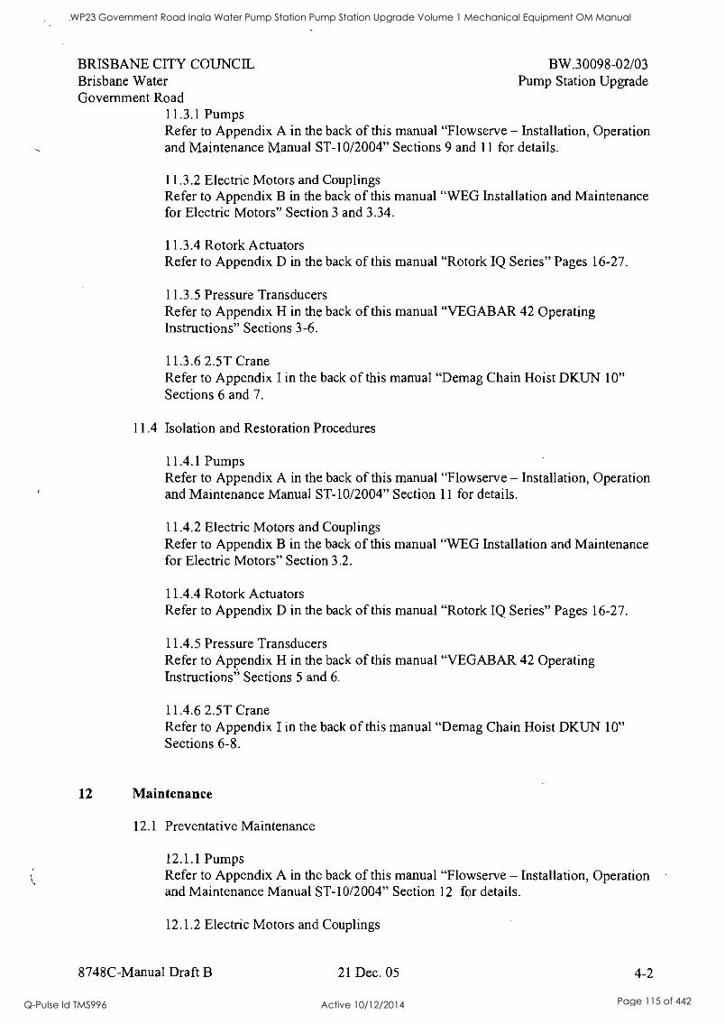
BRISBANE CITY COUNCIL BW.30098-02/03 Brisbane Water Pump Station Upgrade Government Road
11.3.1 Pumps Refer to Appendix A in the back of this manual "Flowserve - Installation, Operation and Maintenance Manual ST-10/2004" Sections 9 and 11 for details.
11.3.2 Electric Motors and Couplings Refer to Appendix B in the back of this manual "WEG Installation and Maintenance for Electric Motors" Section 3 and 3.34.
11.3.4 Rotork Actuators Refer to Appendix D in the back of this manual "Rotork IQ Series" Pages 16-27.
11.3.5 Pressure Transducers Refer to Appendix H in the back of this manual "VEGABAR 42 Operating Instructions" Sections 3-6.
11.3.6 2.5T Crane Refer to Appendix I in the back of this manual "Demag Chain Hoist DKUN 10" Sections 6 and 7.
11.4 Isolation and Restoration Procedures
11.4.1 Pumps Refer to Appendix A in the back of this manual "Flowserve - Installation, Operation and Maintenance Manual ST-10/2004" Section 11 for details.
11.4.2 Electric Motors and Couplings Refer to Appendix B in the back of this manual "WEG Installation and Maintenance for Electric Motors" Section 3.2.
11.4.4 Rotork Actuators Refer to Appendix D in the back of this manual "Rotork IQ Series" Pages 16-27.
11.4.5 Pressure Transducers Refer to Appendix H in the back of this manual "VEGABAR 42 Operating Instructions" Sections 5 and 6.
11.4.6 2.5T Crane Refer to Appendix I in the back of this manual "Demag Chain Hoist DKUN 10" Sections 6-8.
12 Maintenance
12.1 Preventative Maintenance
12.1.1 Pumps Refer to Appendix A in the back of this manual "Flowserve - Installation, Operation and Maintenance Manual ST-10/2004" Section 12 for details.
12.1.2 Electric Motors and Couplings
8748C-Manual Draft B 21 Dec. 05 4-2
WP23 Government Road Inala Water Pump Station Pump Station Upgrade Volume 1 Mechanical Equipment OM Manual
Q-Pulse Id TMS996 Active 10/12/2014 Page 115 of 442
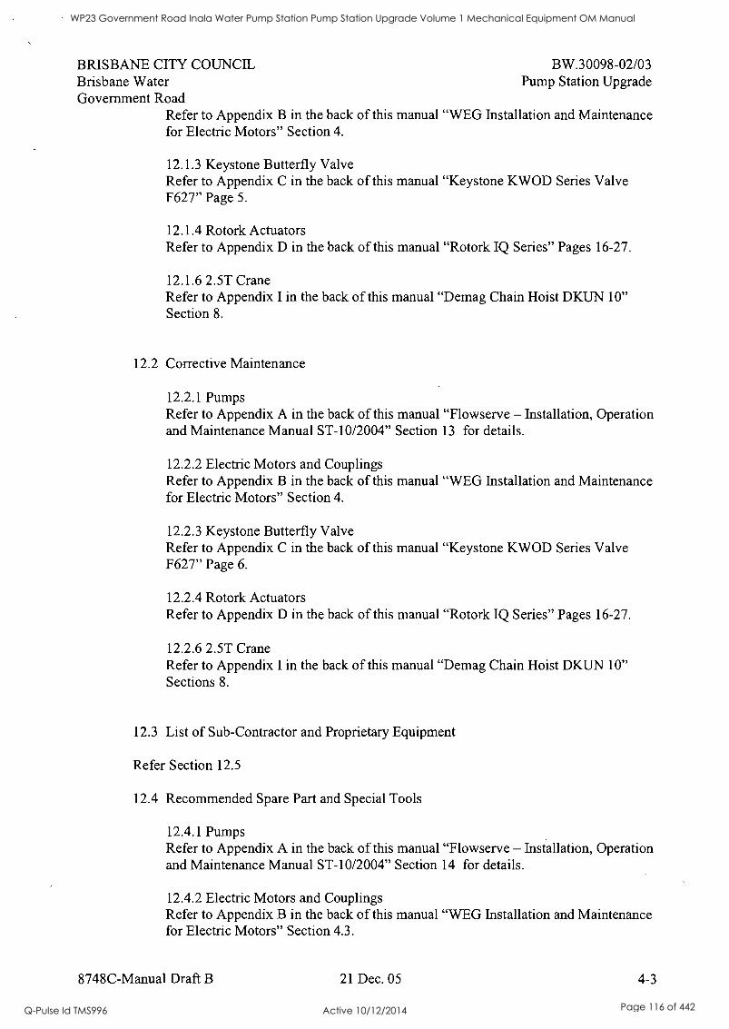
BRISBANE CITY COUNCIL BW.30098-02/03 Brisbane Water Pump Station Upgrade Government Road
Refer to Appendix B in the back of this manual "WEG Installation and Maintenance for Electric Motors" Section 4.
12.1.3 Keystone Butterfly Valve Refer to Appendix C in the back of this manual "Keystone KWOD Series Valve F627" Page 5.
12.1.4 Rotork Actuators Refer to Appendix D in the back of this manual "Rotork IQ Series" Pages 16-27.
12.1.6 2.5T Crane Refer to Appendix I in the back of this manual "Demag Chain Hoist DKUN 10" Section 8.
12.2 Corrective Maintenance
12.2.1 Pumps Refer to Appendix A in the back of this manual "Flowserve - Installation, Operation and Maintenance Manual ST-10/2004" Section 13 for details.
12.2.2 Electric Motors and Couplings Refer to Appendix B in the back of this manual "WEG Installation and Maintenance for Electric Motors" Section 4.
12.2.3 Keystone Butterfly Valve Refer to Appendix C in the back of this manual "Keystone KWOD Series Valve F627" Page 6.
12.2.4 Rotork Actuators Refer to Appendix D in the back of this manual "Rotork IQ Series" Pages 16-27.
12.2.6 2.5T Crane Refer to Appendix I in the back of this manual "Demag Chain Hoist DKUN 10" Sections 8.
12.3 List of Sub-Contractor and Proprietary Equipment
Refer Section 12.5
12.4 Recommended Spare Part and Special Tools
12.4.1 Pumps Refer to Appendix A in the back of this manual "Flowserve - Installation, Operation and Maintenance Manual ST-10/2004" Section 14 for details.
12.4.2 Electric Motors and Couplings Refer to Appendix B in the back of this manual "WEG Installation and Maintenance for Electric Motors" Section 4.3.
8748C-Manual Draft B 21 Dec. 05 4-3
WP23 Government Road Inala Water Pump Station Pump Station Upgrade Volume 1 Mechanical Equipment OM Manual
Q-Pulse Id TMS996 Active 10/12/2014 Page 116 of 442

BRISBANE CITY COUNCIL BW.30098-02/03 Brisbane Water Pump Station Upgrade Government Road
12.4.6 2.5T Crane Refer to Appendix 1 in the back of this manual "Demag Chain Hoist DKUN 10" Section 8.
8748C-Manual Draft B 21 Dec. 05 4-4
WP23 Government Road Inala Water Pump Station Pump Station Upgrade Volume 1 Mechanical Equipment OM Manual
Q-Pulse Id TMS996 Active 10/12/2014 Page 117 of 442
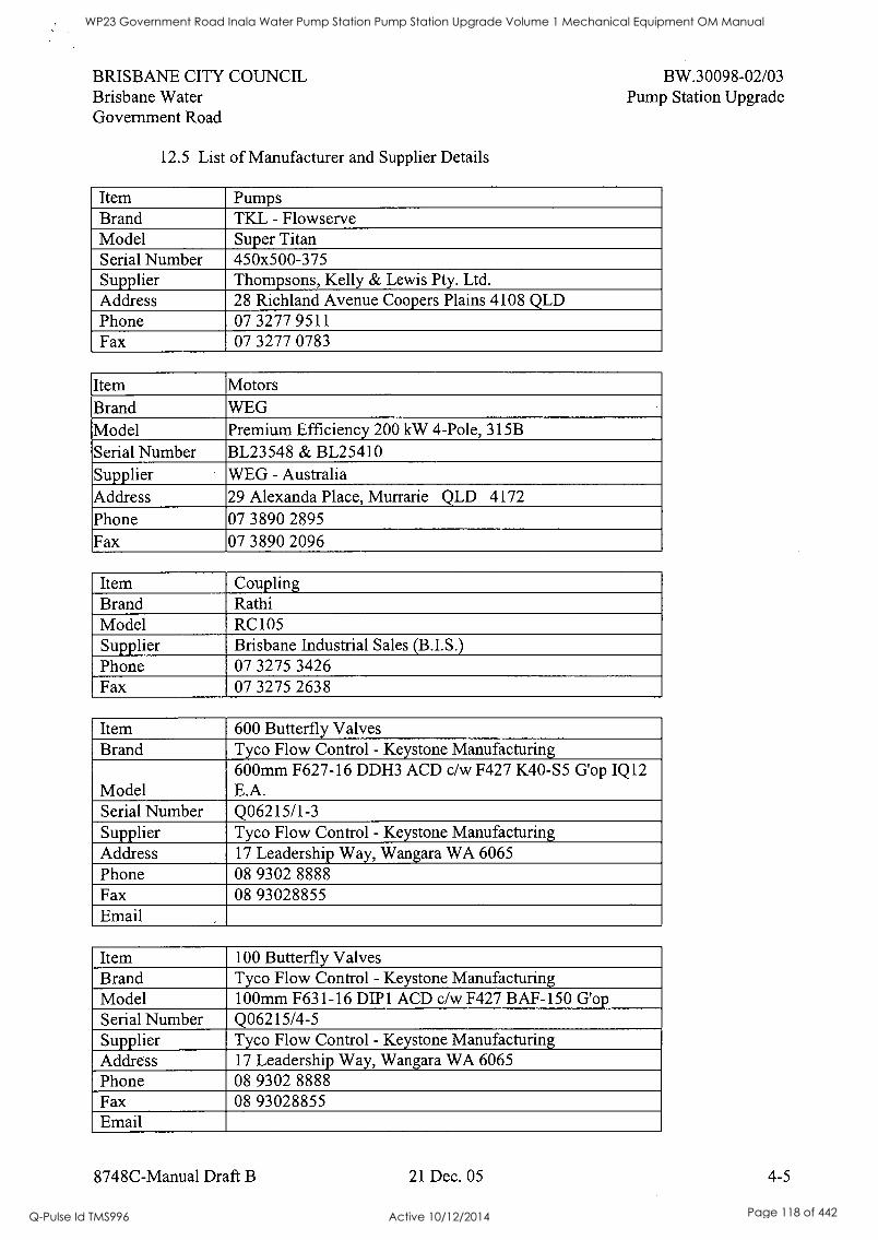
BRISBANE CITY COUNCIL Brisbane Water Government Road
12.5 List of Manufacturer and Supplier Details
BW.30098-02/03 Pump Station Upgrade
Item Pumps Brand TKL - Flowserve Model Super Titan Serial Number 450x500-375 Supplier Thompsons, Kelly & Lewis Pty. Ltd. Address 28 Richland Avenue Coopers Plains 4108 QLD Phone 07 3277 9511 Fax : 07 3277 0783
Item Motors Brand WEG Model Premium Efficiency 200 kW 4-Pole, 315B Serial Number BL23548 & BL25410 Supplier WEG - Australia Address 29 Alexanda Place, Murrarie QLD 4172
Phone 07 3890 2895 Fax 07 3890 2096
Item Coupling Brand Rathi Model RC105 Supplier Brisbane Industrial Sales (B.I.S.) Phone 07 3275 3426 Fax 07 3275 2638
Item 600 Butterfly Valves Brand Tyco Flow Control - Keystone Manufacturing
Model 600mm F627-16 DDH3 ACD c/w F427 K40-S5 G'op IQ12 E.A.
Serial Number Q06215/1-3 Supplier Tyco Flow Control - Keystone Manufacturing Address 17 Leadership Way, Wangara WA 6065 Phone 08 9302 8888 Fax 08 93028855 Email
Item 100 Butterfly Valves Brand Tyco Flow Control - Keystone Manufacturing Model 100mm F631-16 DIP1 ACD c/w F427 BAF-150 G'op Serial Number Q06215/4-5 Supplier Tyco Flow Control - Keystone Manufacturing Address 17 Leadership Way, Wangara WA 6065 Phone 08 9302 8888 Fax 08 93028855 Email
8748C-Manual Draft B 21 Dec. 05 4-5
WP23 Government Road Inala Water Pump Station Pump Station Upgrade Volume 1 Mechanical Equipment OM Manual
Q-Pulse Id TMS996 Active 10/12/2014 Page 118 of 442
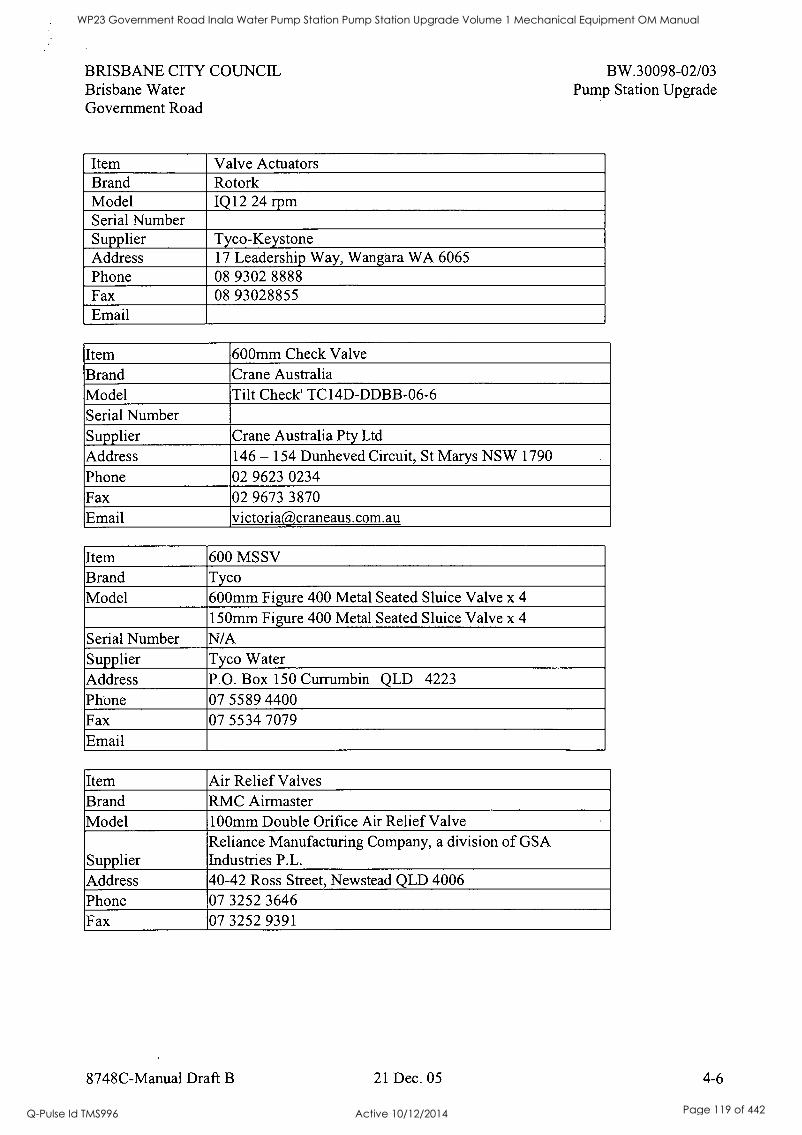
BRISBANE CITY COUNCIL Brisbane Water Government Road
BW.30098-02/03 Pump Station Upgrade
Item Valve Actuators Brand Rotork Model IQ12 24 rpm Serial Number Supplier Tyco-Keystone Address 17 Leadership Way, Wangara WA 6065 Phone 08 9302 8888 Fax 08 93028855 Email
Item 600mm Check Valve Brand Crane Australia Model Tilt Check' TC14D-DDBB-06-6 Serial Number Supplier Crane Australia Pty Ltd
Address 146 - 154 Dunheved Circuit, St Marys NSW 1790
Phone 02 9623 0234 Fax 02 9673 3870 Email victoriacraneaus.com.au
Item 600 MSSV Brand Tyco Model 600mm Figure 400 Metal Seated Sluice Valve x 4
150mm Figure 400 Metal Seated Sluice Valve x 4
Serial Number N/A Supplier Tyco Water Address P.O. Box 150 Currumbin QLD 4223
Phone 07 5589 4400 Fax 07 5534 7079 Email
Item Air Relief Valves Brand RMC Airmaster Model 100mm Double Orifice Air Relief Valve
Supplier Reliance Manufacturing Company, a division of GSA Industries P.L.
Address 40-42 Ross Street, Newstead QLD 4006 Phone 07 3252 3646 Fax 07 3252 9391
8748C-Manual Draft B 21 Dec. 05 4-6
WP23 Government Road Inala Water Pump Station Pump Station Upgrade Volume 1 Mechanical Equipment OM Manual
Q-Pulse Id TMS996 Active 10/12/2014 Page 119 of 442

BRISBANE CITY COUNCIL Brisbane Water Government Road
BW.30098-02/03 Pump Station Upgrade
Item Pressure Transducer Brand Vega Model Vegabar 42, BR42.XXGP1SZX Supplier Invoice No. 611404 Supplier Vega Australia Address P.O.Box 3272 Kirrawee DC, Kirrawee NSW 2232 Phone 02 9542 6662 Fax 02 9542 6665 Setpoint 4-20 mA equates to 0-1000 kPa
8748C-Manual Draft B 21 Dec. 05 4-7
WP23 Government Road Inala Water Pump Station Pump Station Upgrade Volume 1 Mechanical Equipment OM Manual
Q-Pulse Id TMS996 Active 10/12/2014 Page 120 of 442

Qt.
S
5
6050-07 A4 / 10 Tab Divider
RC! IJIIII0110111151
Made in Indonesia
WP23 Government Road Inala Water Pump Station Pump Station Upgrade Volume 1 Mechanical Equipment OM Manual
Q-Pulse Id TMS996 Active 10/12/2014 Page 121 of 442

I I
8
e
0
1
WP23 Government Road Inala Water Pump Station Pump Station Upgrade Volume 1 Mechanical Equipment OM Manual
Q-Pulse Id TMS996 Active 10/12/2014 Page 122 of 442
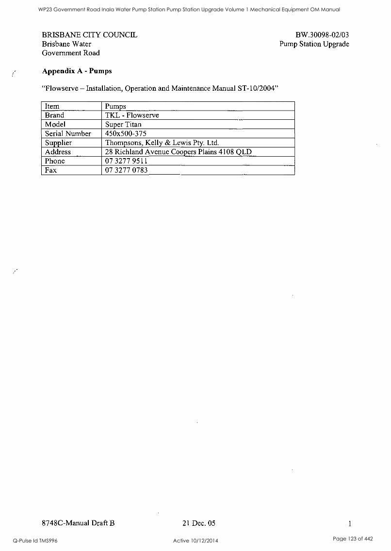
BRISBANE CITY COUNCIL Brisbane Water Government Road
Appendix A - Pumps
"Flowserve - Installation, Operation and Maintenance Manual ST-10/2004"
BW.30098-02/03 Pump Station Upgrade
Item Pumps Brand TKL - Flowserve Model Super Titan Serial Number 450x500-375 Supplier Thompsons, Kelly & Lewis Pty. Ltd. Address 28 Richland Avenue Coopers Plains 4108 QLD Phone 07 3277 9511 Fax 07 3277 0783
8748C-Manual Draft B 21 Dec. 05 1
WP23 Government Road Inala Water Pump Station Pump Station Upgrade Volume 1 Mechanical Equipment OM Manual
Q-Pulse Id TMS996 Active 10/12/2014 Page 123 of 442

WP23 Government Road Inala Water Pump Station Pump Station Upgrade Volume 1 Mechanical Equipment OM Manual
Q-Pulse Id TMS996 Active 10/12/2014 Page 124 of 442
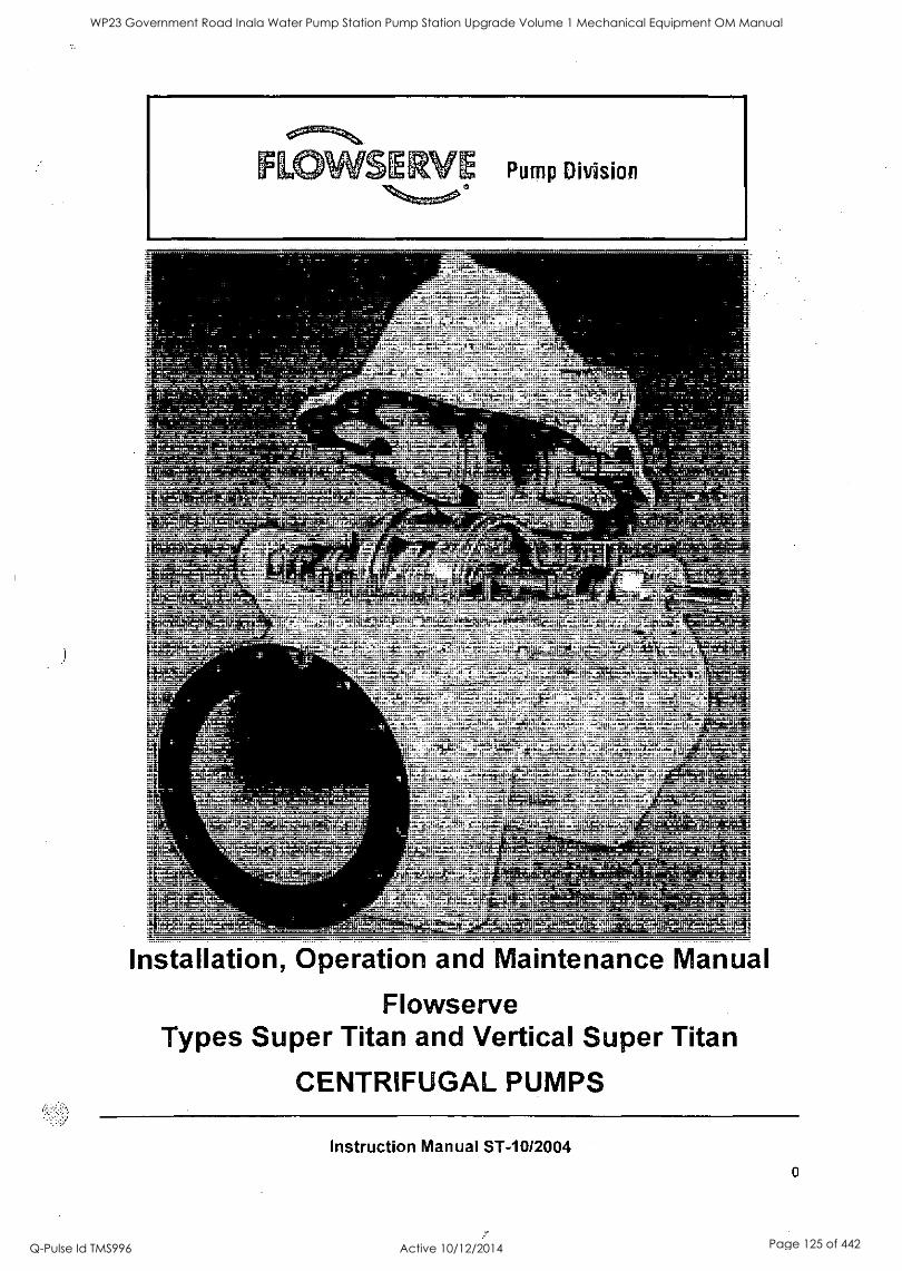
Installation, Operation and Maintenance Manual
Flowserve Types Super Titan and Vertical Super Titan
CENTRIFUGAL PUMPS
Instruction Manual ST-10/2004
WP23 Government Road Inala Water Pump Station Pump Station Upgrade Volume 1 Mechanical Equipment OM Manual
Q-Pulse Id TMS996 Active 10/12/2014 Page 125 of 442
INTRODUCTION
Flowserve Flowserve Pump Department Australia is the countries premier designer, manufacturer and supplier of centrifugal and positive displacement pumps and railway products. FPD is committed to providing a premium level of quality products and services to its customers. The Company's Quality Management System complies with. International Standard AS/NZS ISO 9001:2000 and is implemented in each manufacturing plant, service centre and sales office. The main pump manufacturing and design facility is located in Castlemaine Victoria, with sales offices and distributors located throughout Australia and New Zealand. FPD Australia have service centres in Melbourne, Sydney, Brisbane, Perth, Wollongong, Traralgon and Christchurch New Zealand.
Flowserve designs and manufactures pumps for all industries, and also manufactures under licence and supplies the well known brand names of: FLOWSERVE, Ingersoll Dresser Pumps, Ingersoll-Rand, Worthington, Pacific, Pleuger, Jeumont-Schneider Pumps, Giles & Gaskin and Pegson. For more than 100 years FPD have been prominent in the field of pumping equipment. The markets serviced include water, sewage, power, mining, oil and gas, petro-chemical, hydrocarbon, building services, agricultural and general industries.
The company has developed its market share as a result of its commitment to continuous quality improvement and the performance of its after sales service. For product enquiries, technical assistance or general information, please contact the office nearest to you.
Copyright All rights reserved. No part of this manual may be produced, stored in a retrieval system or transmitted in any form or by any means without prior permission of Flowserve Pump Division.
Disclaimer Flowserve products are manufactured under stringent quality control and quality assurance programmes. The company is certified to AS/NZS ISO 9001:2000 for design, manufacturing and installation. Flowserve is certified by the Australian Department of Defence as an accredited supplier. Flowserve quality replacement parts have been designed and tested for specific applications to ensure the safe and efficient performance of your equipment is retained when put into use. The use of non-genuine parts and accessories sourced from other vendors may affect the performance and safety features of Flowserve products. Any damage or failure caused where non-genuine parts are installed and/or selected incorrectly, will not be covered by Flowserve's warranty. Modification or removal of genuine components may impair the safety and reliability of Flowserve products in
their use.
1
WP23 Government Road Inala Water Pump Station Pump Station Upgrade Volume 1 Mechanical Equipment OM Manual
Q-Pulse Id TMS996 Active 10/12/2014 Page 126 of 442
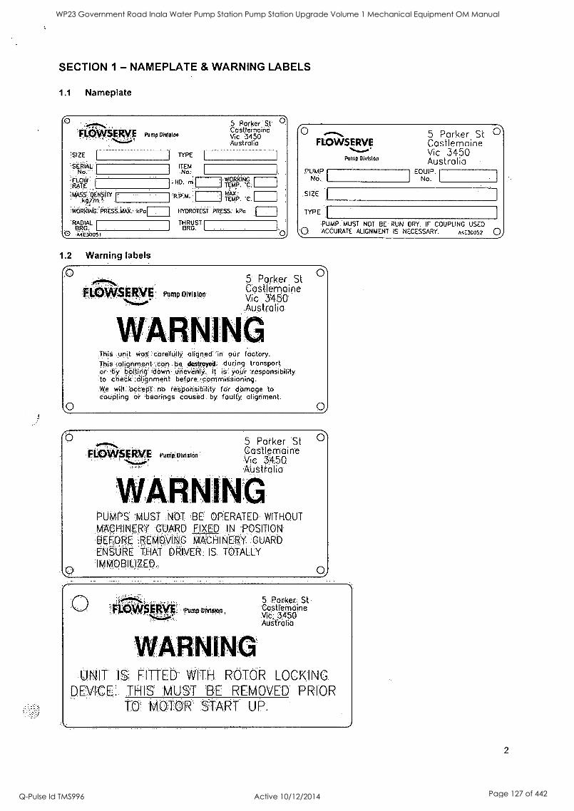
SECTION 1 - NAMEPLATE & WARNING LABELS
1.1 Nameplate
F1.,-9Etts,0 Pump Division
:SIZE ,r I
TYPE
SERIAL ITEM No:
FLOW ,RATE
.MASS' DENSITY
,WORKING PRESS.MAX.-kPo
RADIAL BRO.- 0 .A4E30091
.5. Parker 'St'
.CciStlemaine Vi.0 3450 Australia
,..WORkING HO. rn: T
RPM
.E MAX:
c bl -
TEMP. 'CI
HYOROTEST PRESS. kPo
THRUST ORG.
1.2 Warning labels
0 FLOWSERVE
Pump Olvfslon
PUMP No.
SIZE I
TYPE
5 Parker St Castlemaine Vic 3450 Australia
EQUIP. No.
PUMP. MUST NOT BE RUN DRY. IF COUPLING USED 0 ACCURATE ALIGNMENT IS NECESSARY. A4E30052 0
0 FLQWSERVE Pump Division
5 Parker St Castlemaine Vic 3450 Australia
This ,unit was: .carefUlly aligned in oUr factory. This Kolignmerit-can be deStroyed: during, transport or by bolting down unevenly It is responsibility to cheCk:::ciligrirrieht aefore ;:darrirniSSiOhing.
We will bCdePL no responsibility for damage to coupling 'or 'bearings caUsed by faulty, alignment.
0 FL4:3WSEitVE Pump:Olulslon
5 Parker St Castlemaine Vic 34.50
.AU Stro li
VVARNING PUMPS MUST NOT BE OPERATED WITHOUT
MACHINERY :GUARD FIXED IN POSITION:
BEFORE REMOVING MACHINERY GUARD
ENSURE THAT DRIVER: IS 'TOTALLY.
IMMOBILIZED.
0 'FLOWS ERVE Pump UMs1oi,
........
WARNING
.5 Porker. St 'COtIOndine.
3450 Australia
UNIT 15: FITTER WITH ROTOR LOCKING. DEVICE THIS MUST :13::E '.REMOVED. PRIOR
1\: TO M0TDR. START UP P.
2
WP23 Government Road Inala Water Pump Station Pump Station Upgrade Volume 1 Mechanical Equipment OM Manual
Q-Pulse Id TMS996 Active 10/12/2014 Page 127 of 442
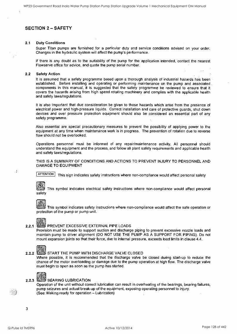
SECTION 2 - SAFETY
2.1 Duty Conditions Super Titan pumps are furnished for a particular duty and service conditions advised on your order. Changes in the hydraulic system will affect the pump's performance.
If there is any doubt as to the suitability of the pump for the application intended, contact the nearest Flowserve office for advice, and quote the pump serial number.
2.2 Safety Action It is assumed that a safety programme based upon a thorough analysis of industrial hazards has been established. Before installing and operating or performing maintenance on the pump and associated components in this manual, it is suggested that the safety programme be reviewed to ensure that it covers the hazards arising from high speed rotating machinery and complies with the applicable health and safety laws/regulations.
It is also important that due consideration be given to those hazards which arise from the presence of electrical power and high-pressure liquids. Correct installation and care of protective guards, shut down devices and over pressure protection equipment should also be considered an essential part of any safety programme.
Also essential are special precautionary measures to prevent the possibility of applying power to the equipment at any time when maintenance work is in progress. The prevention of rotation due to reverse flow should not be overlooked.
Operations personnel must be informed of any repair/maintenance activity. All personnel should understand the equipment and the process, and follow all plant safety requirements and applicable health and safety laws/regulations.
THIS IS A SUMMARY OF CONDITIONS AND ACTIONS TO PREVENT INJURY TO PERSONNEL AND DAMAGE TO EQUIPMENT
ATTENTION This sign indicates safety instructions where non-compliance would affect personal safety
This symbol indicates electrical safety instructions where non-compliance would affect personal safety
' This symbol indicates safety instructions where non-compliance would affect the safe operation or protection of the pump or pump unit.
2.2.1 PREVENT EXCESSIVE EXTERNAL PIPE LOADS Provision must be made to support suction and discharge piping to prevent excessive nozzle loads and maintain pump to driver alignment (DO NOT USE THE PUMP AS A SUPPORT FOR PIPING). Do not mount expansion joints so that their force, due to internal pressure, exceeds load limits in clause 4.4.
2.2.2 START THE PUMP WITH DISCHARGE VALVE CLOSED Where possible, it is recommended that the discharge valve be closed during start-up to reduce the chance of the motor overloading or damage due to the pump operation at high flow. The discharge valve must begin to open as soon as the pump has started.
n2.2.3 BEARING LUBRICATION Operation of the unit without correct lubrication can result in overheating of the bearings, bearing failures, pump seizures and actual break-up of the equipment, exposing operating personnel to injury. (See: Making ready for operation - Lubrication)
3
WP23 Government Road Inala Water Pump Station Pump Station Upgrade Volume 1 Mechanical Equipment OM Manual
Q-Pulse Id TMS996 Active 10/12/2014 Page 128 of 442

2.2.4 NEVER RUN THE PUMP DRY Before starting the pump, the casing and suction line must be completely filled with the liquid being pumped. The rotating parts depend on this liquid for lubrication and the pump will seize if operated without liquid.
2.2.5 INLET VALVES TO BE FULLY OPEN WHEN PUMP IS RUNNING Running the pump at zero flow or below the recommended minimum flow continuously will cause damage to the impeller, shaft, seal, sealing rings and bearings within a short time.
2.2.6 DO NOT RUN THE PUMP AT ABNORMALLY HIGH OR LOW FLOW RATES Operating at a flow rate higher than normal or at a flow rate with no backpressure on the pump may overload the motor and will cause cavitation. Low flow rates (25% of BEP) may cause a reduction in pump/bearing life, overheating of the pump, instability and cavitation/vibration. When operating for some time at a reduced capacity, a bypass line must be provided to prevent the liquid in the pump from becoming hot enough to vaporise.
2.2.7 t. NEVER DO MAINTENANCE WORK WHILST THE UNIT IS OPERATIONAL Operations personnel must be informed of any repair/maintenance activity. All personnel should understand the equipment and the process, and follow all plant safety requirements and applicable health and safety laws/regulations.
2.2.8 ' DO NOT OVERTIGHTEN PACKED GLANDS Packed glands must never be tightened to a point where leakage from the packing is stopped. A small amount of leakage is required for lubrication of the packing. Shutting off leakage flow from the packing will result in burnt packing, scored shaft sleeves and possible rotor seizure.
2.2.9 ATTENTION NEVER APPLY HEAT TO REMOVE IMPELLER
2.2.10
Trapped fluid, lubricant or vapour could cause an explosion.
ATTENTION HANDLING PUMP OR COMPONENTS Make sure that any equipment used to lift the pump or any of its components is capable of supporting the weights encountered in accordance with local regulations and that all parts are correctly rigged before attempting to lift. Many precision parts have sharp corners and the wearing of appropriate safety gloves and equipment is required when handling these components.
2.2.11 ATTENTION BEFORE DISMANTLING THE PUMP, ISOLATE THE DRIVER AND PIPEWORK, AND DRAIN THE PUMP Before attempting to disassemble the pump, the pump must be isolated from the system, by the closing of suction and discharge system valves and draining of liquid. The appropriate safety precautions should be taken where the pumped fluids are hazardous.
2.2.12 ATTENTION THERMAL SHOCK Rapid changes in the temperature of the liquid within the pump can cause thermal shock, which is can result in damage or breakage of components. Thermal shock should be avoided, particularly so where the material of the pump is not resistant to such loading.
2.2.13 ATTENTION HOT (and cold) PARTS If hot or freezing components or auxiliary heating supplies can present a danger to operators, they must be shielded to avoid accidental contact. If complete protection is not possible, machine access must be limited to maintenance staff only. Note: drive motors and bearings may be hot.
IF THE TEMPERATURE IS GREATER THAN 80°C (175°F) OR BELOW 5°C (20°F), A VISUAL WARNING INDICATOR SUCH AS A WARNING PLATE MUST BE PLACED CLEARLY ON THE EQUIPMENT.
4
WP23 Government Road Inala Water Pump Station Pump Station Upgrade Volume 1 Mechanical Equipment OM Manual
Q-Pulse Id TMS996 Active 10/12/2014 Page 129 of 442
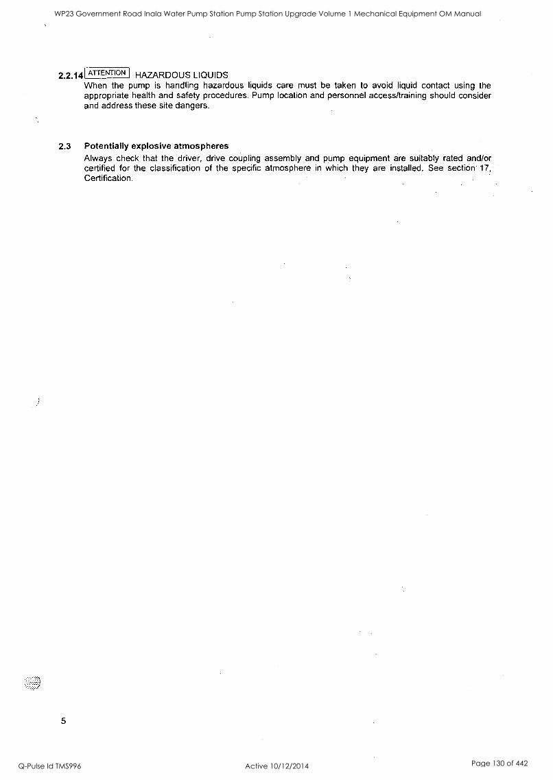
3
2.2.14 ATTENTION HAZARDOUS LIQUIDS When the pump is handling hazardous liquids care must be taken to avoid liquid contact using the appropriate health and safety procedures. Pump location and personnel access/training should consider and address these site dangers.
2.3 Potentially explosive atmospheres Always check that the driver, drive coupling assembly and pump equipment are suitably rated and/or certified for the classification of the specific atmosphere in which they are installed. See section 17, Certification.
5
WP23 Government Road Inala Water Pump Station Pump Station Upgrade Volume 1 Mechanical Equipment OM Manual
Q-Pulse Id TMS996 Active 10/12/2014 Page 130 of 442
SECTION 3 - CONTENTS PAGE
INTRODUCTION 1
SECTION 1 - NAMEPLATE & WARNING LABELS 2
1.1 Nameplate 2
1.2 Warning labels 2
SECTION 2 - SAFETY 3
2.1 Duty Conditions 3
2.2 Safety Action 3
2.3 Potentially explosive atmospheres 5
SECTION 3 - CONTENTS 6
SECTION 4 - PUMP TECHNICAL DATA 9
4.1 Performance 9
4.2 Noise Level 9
4.3 Pressure Limits 10
4.4 Flange Loads 10
4.5 Pump lubricant data 11
4.6 Recommended bolting and screw torques 11
4.7 Temperature limitations 11
4.8 Pump and impeller data 12
SECTION 5 - PRODUCT DESCRIPTION 12
5.1 General 12
5.2 Pump Casing 13
5.3 Impeller 13
5.4 Shaft 13
5.5 Bearing housings 13
5.6 Pump bearings and lubrication 13
5.7 Stuffing box (Seal housing) 13
5.8 Shaft Seal 13
5.9 Driver 13
5.10 Accessories 13
6
WP23 Government Road Inala Water Pump Station Pump Station Upgrade Volume 1 Mechanical Equipment OM Manual
Q-Pulse Id TMS996 Active 10/12/2014 Page 131 of 442
SECTION 6 - STORAGE 14
6.1 Storage - General
6.2 Storage - Long term
SECTION 7 - INSTALLATION 14
14
14
7.1 Unpacking and inspection 14
7.2 Handling 15
7.3 Location 15
7.4 Foundation 15
7.5 Grouting 16
7.6 Alignment of couplings 16
7.8 Pipe work connections 17
7.9 Final piping check 18
7.10 Auxiliary piping 18
SECTION 8 - MAKING READY FOR OPERATION 19
8.1 Lubrication 19
8.2 Pre-operation check list 19
SECTION 9 - STARTING THE PUMP 19
SECTION 10 - RUNNING 20
10.1 Pumps fitted with packed glands 20
10.2 Pumps fitted with mechanical seals 20
10.3 Stop/start frequency 20
SECTION 11 - STOPPING AND SHUTDOWN 20
SECTION 12 - PREVENTATIVE MAINTENANCE AND SERVICING 20
12.1 Maintenance schedule 20
12.2 Routine inspection (daily/weekly) 21
12.3 Periodic inspection (6 monthly) 21
12.4 Lubrication data 21
12.5 Gland packing 21
12.6 Mechanical seals 21
SECTION 13 - DISMANTLING 21
7
WP23 Government Road Inala Water Pump Station Pump Station Upgrade Volume 1 Mechanical Equipment OM Manual
Q-Pulse Id TMS996 Active 10/12/2014 Page 132 of 442
13.1 Dismantling 21
13.2 Examination of parts 23
13.3 Assembly 24
SECTION 14 - SPARE PARTS 26
SECTION 15 - GENERAL ARRANGEMENT DRAWING 27
SECTION 16 - SUPPLEMENTARY INSTRUCTION MANUALS 27
SECTION 17 - CERTIFICATION 27
SECTION 18 - OPERATING DIFFICULTIES 28
SECTION 19 - TYPICAL SECTIONAL ARRANGEMENT DRAWING AND PARTS LISTS 29
19.1 Sectional Drawings - Super Titan (Inboard bearing housings) 29
19.2 Sectional Drawings - Vertical Spindle Super Titan 29
19.3 Sectional Drawings - Mechanical Seal Assembly (Optional) 30
19.4 Sectional Drawings - Outboard Bearing Housings 30
19.5 Parts List 30
8
WP23 Government Road Inala Water Pump Station Pump Station Upgrade Volume 1 Mechanical Equipment OM Manual
Q-Pulse Id TMS996 Active 10/12/2014 Page 133 of 442
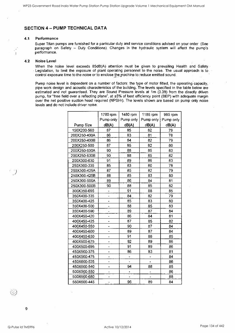
SECTION 4 - PUMP TECHNICAL DATA
4.1 Performance Super Titan pumps are furnished for a particular duty and service conditions advised on your order (See paragraph on Safety - Duty Conditions). Changes in the hydraulic system will affect the pump's performance.
4.2 Noise Level When the noise level exceeds 85dB(A) attention must be given to prevailing Health and Safety. Legislation, to limit the exposure of plant operating personnel to the noise. The usual approach is to control exposure time to the noise or to enclose thernachino to reduce emitted sound.
Pump noise level is dependent on a number of factors: the type of motor fitted, the operating capacity, pipe work design and acoustic characteristics of the building. The levels specified in the table below are estimated and not guaranteed. They are Sound Pressure levels at 1m (3.3ft) from the directly driven pump, for "free field over a reflecting plane", at ±5% of best efficiency point (BEP) with adequate margin over the net positive suction head required (NPSHr). The levels shown are based on pump only noise levels and do not include driver noise.
Pump Size
1780 rpm
Pump only
dB(A)
1480 rpm
Pump only
dB(A)
1185 rpm Pump only
dB(A)
985 rpm Pump only
dB(A) 150X200-560 87 85 82 79
200X250-400A 86 83 81 78
200X250-400B 86 84 82 79
200X250-500 87 85 82 80
200X250-630A 90 88 85 83
200X250-630B 90 88 85 82
200X300-630 91 89 86 83
250X300-335 85 83 80 78
250X300-425A 87 85 82 79
250X300-425B 88 85 83 80
250X300-500A 89 86 84 81
250X300-500B 90 88 85 82
300X350-695 - 91 88 85
350X400-335 - 84 82 79
350X400-425 - 85 83 80
350X400-500 - 88 85 83
350X400-590 - 89 87 84
400X450-420 - 86 84 81
400X450-425 - 87 85 82
400X450-550 - 90 87 84
400X450-600 - 89 87 84
400X450-630 - 91 88 85
400X500-675 - 92 89 86
400X500-695 - 91 89 86 450X500-375 - 86 83 81
450X500-475 - - - 84
450X600-525 - - - 86 450X600-540 - 94 88 85
500X500-550 - - - 86
500X600-680 - - - 88
550X600-445 - 96 89 84
9
WP23 Government Road Inala Water Pump Station Pump Station Upgrade Volume 1 Mechanical Equipment OM Manual
Q-Pulse Id TMS996 Active 10/12/2014 Page 134 of 442
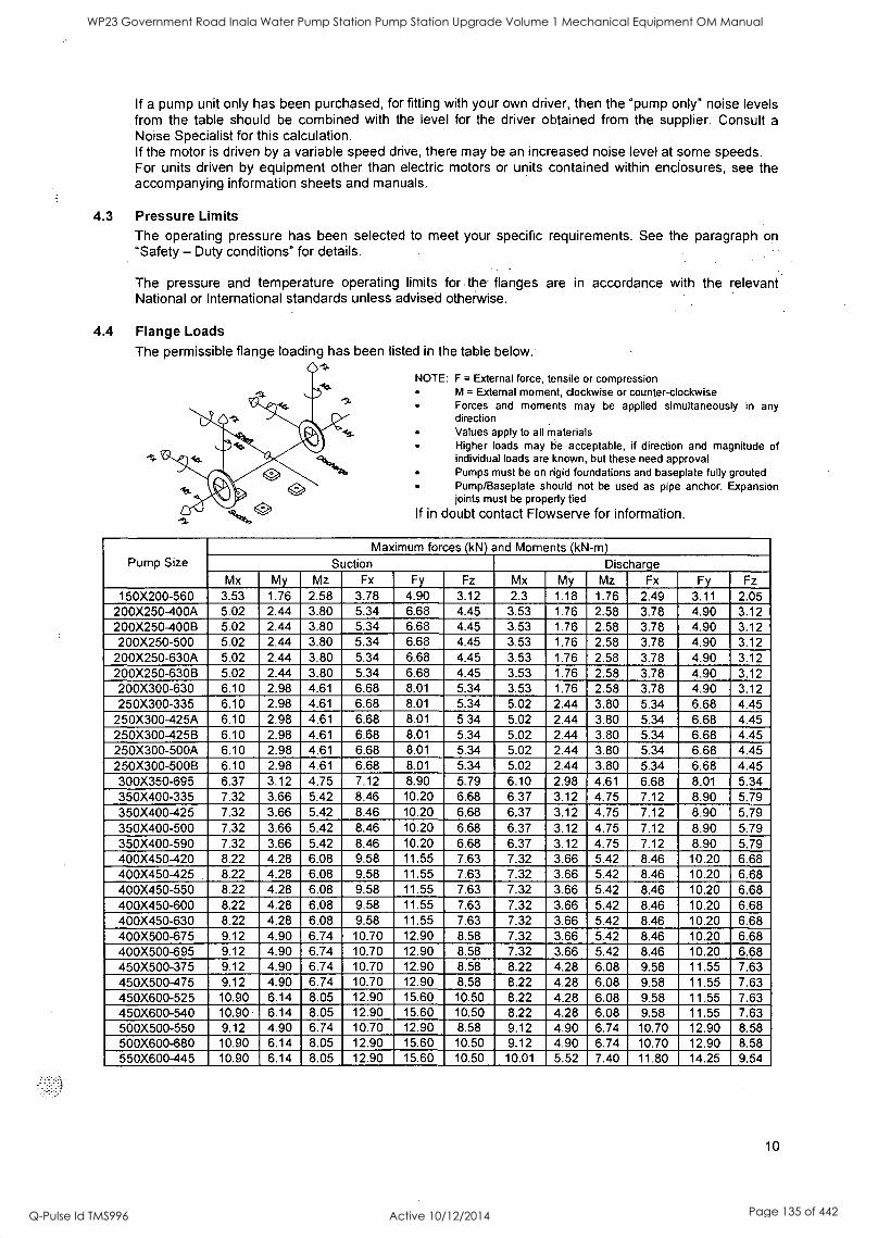
If a pump unit only has been purchased, for fitting with your own driver, then the "pump only" noise levels from the table should be combined with the level for the driver obtained from the supplier. Consult a
Noise Specialist for this calculation. If the motor is driven by a variable speed drive, there may be an increased noise level at some speeds. For units driven by equipment other than electric motors or units contained within enclosures, see the accompanying information sheets and manuals.
4.3 Pressure Limits The operating pressure has been selected to meet your specific requirements. See the paragraph on "Safety - Duty conditions" for details.
The pressure and temperature operating limits for the flanges are in accordance with the relevant National or International standards unless advised otherwise.
4A Flange Loads
The permissible flange loading has been listed in the table below.
NOTE: F = External force, tensile or compression M = External moment, clockwise or counter-clockwise Forces and moments may be applied simultaneously in any direction Values apply to all materials Higher loads may be acceptable, if direction and magnitude of individual loads are known, but these need approval Pumps must be on rigid foundations and baseplate fully grouted Pump/Baseplate should not be used as pipe anchor. Expansion joints must be properly tied
If in doubt contact Flowserve for information.
Pump Size Maximum forces (kN) and Moments (kN-m)
Suction Discharge Mx My Mz Fx Fy Fz Mx My Mz Fx Fy Fz
150X200-560 3.53 1.76 2.58 3.78 4.90 3.12 2.3 1.18 1.76 2.49 3.11 2.05 200X250-400A 5.02 2.44 3.80 5.34 6.68 4.45 3.53 1.76 2.58 3.78 4.90 3.12 200X250-400B 5.02 2.44 3.80 5.34 6.68 4.45 3.53 1.76 2.58 3.78 4.90 3.12 200X250-500 5.02 2.44 3.80 5.34 6.68 4.45 3.53 1.76 2.58 3.78 4.90 3.12
200X250-630A 5.02 2.44 3.80 5.34 6.68 4.45 3.53 1.76 2.58 3.78 4.90 3.12 200X250-630B 5.02 2.44 3.80 5.34 6.68 4.45 3.53 1.76 2.58 3.78 4.90 3.12 200X300-630 6.10 2.98 4.61 6.68 8.01 5.34 3.53 1.76 2.58 3.78 4.90 3.12 250X300-335 6.10 2.98 4.61 6.68 8.01 5.34 5.02 2.44 3.80 5.34 6.68 4.45
250X300-425A 6.10 2.98 4.61 6.68 8.01 5.34 5.02 2.44 3.80 5.34 6.68 4.45 250X300-425B 6.10 2.98 4.61 6.68 8.01 5.34 5.02 2.44 3.80 5.34 6.68 4.45 250X300-500A 6.10 2.98 4.61 6.68 8.01 5.34 5.02 2.44 3.80 5.34 6.68 4.45 250X300-500B 6.10 2.98 4.61 6.68 8.01 5.34 5.02 2.44 3.80 5.34 6.68 4.45 300X350-695 6.37 3.12 4.75 7.12 8.90 5.79 6.10 2.98 4.61 6.68 8.01 5.34 350X400-335 7.32 3.66 5.42 8.46 10.20 6.68 6.37 3.12 4.75 7.12 8.90 5.79 350X400-425 7.32 3.66 5.42 8.46 10.20 6.68 6.37 3.12 4.75 7.12 8.90 5.79 350X400-500 7.32 3.66 5.42 8.46 10.20 6.68 6.37 3.12 4.75 7.12 8.90 5.79 350X400-590 7.32 3.66 5.42 8.46 10.20 6.68 6.37 3.12 4.75 7.12 8.90 5.79 400X450-420 8.22 4.28 6.08 9.58 11.55 7.63 7.32 3.66 5.42 8.46 10.20 6.68 400X450-425 8.22 4.28 6.08 9.58 11.55 7.63 7.32 3.66 5.42 8.46 10.20 6.68 400X450-550 8.22 4.28 6.08 9.58 11.55 7.63 7.32 3.66 5.42 8.46 10.20 6.68 400X450-600 8.22 4.28 6.08 9.58 11.55 7.63 7.32 3.66 5.42 8.46 10.20 6.68 400X450-630 8.22 4.28 6.08 9.58 11.55 7.63 7.32 3.66 5.42 8.46 10.20 6.68 400X500-675 9.12 4.90 6.74 10.70 12.90 8.58 7.32 3.66 5.42 8.46 10.20 6.68 400X500-695 9.12 4.90 6.74 10.70 12.90 8.58 7.32 3.66 5.42 8.46 10.20 6.68 450X500-375 9.12 4.90 6.74 10.70 12.90 8.58 8.22 4.28 6.08 9.58 11.55 7.63 450X500-475 9.12 4.90 6.74 10.70 12.90 8.58 8.22 4.28 6.08 9.58 11.55 7.63 450X600-525 10.90 6.14 8.05 12.90 15.60 10.50 8.22 4.28 6.08 9.58 11.55 7.63 450X600-540 10.90 6.14 8.05 12.90 15.60 10.50 8.22 4.28 6.08 9.58 11.55 7.63 500X500-550 9.12 4.90 6.74 10.70 12.90 8.58 9.12 4.90 6.74 10.70 12.90 8.58 500X600-680 10.90 6.14 8.05 12.90 15.60 10.50 9.12 4.90 6.74 10.70 12.90 8.58 550X600-445 10.90 6.14 8.05 12.90 15.60 10.50 10.01 5.52 7.40 11.80 14.25 9.54
10
WP23 Government Road Inala Water Pump Station Pump Station Upgrade Volume 1 Mechanical Equipment OM Manual
Q-Pulse Id TMS996 Active 10/12/2014 Page 135 of 442
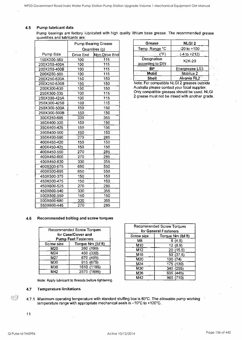
4.5 Pump lubricant data
Pump bearings are factory lubricated with high quality lithium base grease. The recommended grease quantities and lubricants are:
Pump Size
Pump Bearing Grease
Quantities (g)
Drive End Non-Drive End 150)(200-560 100 115
200X250-400A 100 115 200X250-400B 100 115 200X250-500 100 115
200X250-630A 150 150 200X250-630B 150 150 200X300-630 150 150 250X300-335 100 115
250X300-425A 100 115
250X300-425B 100 115 250X300-500A 150 150 250X300-500B 150 150 300X350-695 330 355 350X400-335 150 150 350X400-425 150 150
350X400-500 150 150 350X400-590 270 285 400X450-420 150 150 400X450-425 150 150 400X450-550 270 285 400X450-600 270 285 400X450-630 330 355 400X500-675 650 550 400X500-695 650 550 450X500-375 150 150 450X500-475 150 150 450X600-525 270 285 450X600-540 330 355 500X500-550 150 150 500X600-680 330 355 550X600-445 270 285
4.6 Recommended bolting and screw torques
Recommended Screw Torques for Case/Cover and
Pump Feet Fasteners Screw size Torque Nm (lbf ft)
M20 260 (190) M24 450 (330) M27 670 (495) M30 915 (675) M36 1610 (1185) M42 2570 (1895)
Note: Apply lubricant to threads before tightening.
4.7 Temperature limitations
4.7.1 Maximum operating temperature with standard stuffing box is 80°C. The allowable pump working
Grease NLGI 2
Temp. Range °C -20 to +100
(°F) (-4 to +212) Designation
according to DIN K2K-20
BP Energrease LS3 Mobil Mobilux 2
Shell Alvania RL2 Note: For compatible NLGI 2 greases outside Australia please contact your local supplier. Only compatible greases should be used. NLGI 2 grease must not be mixed with another grade.
Recommended Screw Torques for General Fasteners
Screw size Torque Nm (lbf ft) M8 6 (4.5) M10 12 (8.9) M12 20 (15.5) M16 50 (37.5) M20 100 (74) M24 175 (130) M30 345 (255) M36 605 (445) M42 965 (710)
temperature range with appropriate mechanical seals is -10°C to +120°C.
11
WP23 Government Road Inala Water Pump Station Pump Station Upgrade Volume 1 Mechanical Equipment OM Manual
Q-Pulse Id TMS996 Active 10/12/2014 Page 136 of 442
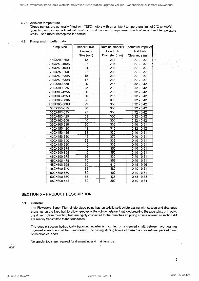
4.7.2 Ambient temperature These pumps are generally fitted with TEFC motors with an ambient temperature limit of 0°C to +40°C. Specific pumps may be fitted with motors to suit the client's requirements with other ambient temperature limits - see motor nameplate for details.
4.8 Pump and impeller data
Pump Size Impeller min.
Passage Size (mm)
Nominal Impeller Seal Hub
Diameter (mm)
Diametral Impeller Seal Hub
Clearance (mm)
150X200-560 12 212 0.27 - 0.37 200X250-400A 27 236 0.27 - 0.37 200X250-400B 24 236 0.27 - 0.37 200X250-500 27 236 0.27 - 0.37
200X250-630A 18 212 0.27 - 0.37 200X250-630B 17 212 0.27 - 0.37 200X300-630 26 265 0.32 - 0.42 250X300-335 22 265 0.32 - 0.42
250X300-425A 36 265 0.32 - 0.42 250X300-425B 36 265 0.32 - 0.42 250X300-500A 25 300 0.32 - 0.42 250X300-500B 29 300 0.32 - 0.42 300X350-695 30 300 0.32 - 0.42 350X400-335 27 300 0.32 - 0.42 350X400-425 53 300 0.32 - 0.42 350X400-500 40 300 0.32 - 0.42 350X400-590 30 335 0.40 - 0.51 400X450-420 48 315 0.32 - 0.42 400X450-425 31 335 0.40 - 0.51
400X450-550 45 375 0.40 - 0.51
400X450-600 38 335 0.40 - 0.51 400X450-630 40 335 0.40 - 0.51
400X500-675 40 355 0.40 - 0.51 400X500-695 45 355 0.40 - 0.51 450X500-375 36 335 0.40 - 0.51
450X500-475 70 355 0.40 - 0.51
450X600-525 90 410 0.45 - 0.56 450X600-540 35 380 0.40 - 0.51
500X500-550 80 400 0.40 - 0.51
500X600-680 65 435 0.48 - 0.58 550X600-445 80 390 0.40 - 0.51
SECTION 5 - PRODUCT DESCRIPTION
5.1 General
The Flowserve Super Titan single stage pump has an axially split volute casing with suction and discharge branches on the fixed half to allow removal of the rotating element without breaking the pipe joints or moving the driver. Case mounting feet are rigidly connected to the branches so piping strains allowed in section 4.4 are readily transmitted to the foundation.
The double suction hydraulically balanced impeller is mounted on a sleeved shaft, between two bearings mounted at each end of the pump casing. The casing stuffing boxes can use the conventional packed gland or mechanical seals.
No special tools are required for dismantling and maintenance.
12
WP23 Government Road Inala Water Pump Station Pump Station Upgrade Volume 1 Mechanical Equipment OM Manual
Q-Pulse Id TMS996 Active 10/12/2014 Page 137 of 442
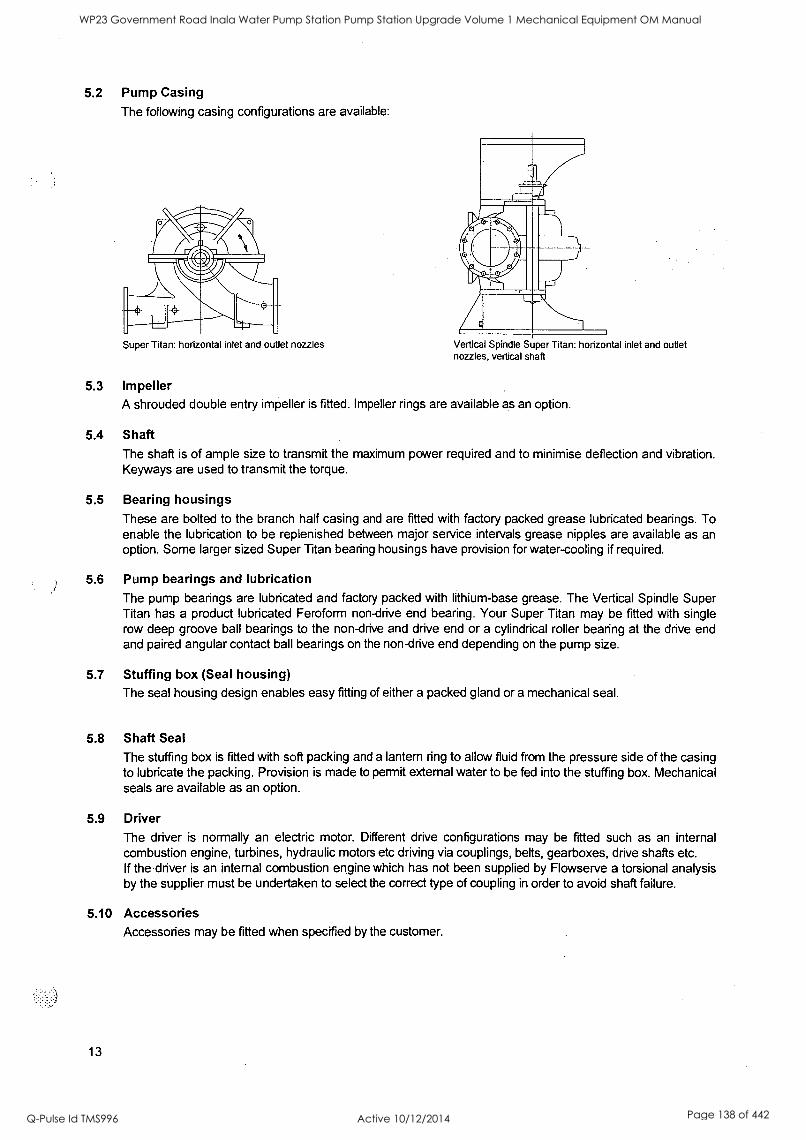
5.2 Pump Casing
The following casing configurations are available:
Super Titan: horizontal inlet and outlet nozzles Vertical Spindle Super Titan: horizontal inlet and outlet nozzles, vertical shaft
5.3 Impeller A shrouded double entry impeller is fitted. Impeller rings are available as an option.
5.4 Shaft The shaft is of ample size to transmit the maximum power required and to minimise deflection and vibration. Keyways are used to transmit the torque.
5.5 Bearing housings These are bolted to the branch half casing and are fitted with factory packed grease lubricated bearings. To enable the lubrication to be replenished between major service intervals grease nipples are available as an option. Some larger sized Super Titan bearing housings have provision for water-cooling if required.
5.6 Pump bearings and lubrication The pump bearings are lubricated and factory packed with lithium-base grease. The Vertical Spindle Super Titan has a product lubricated Feroform non-drive end bearing. Your Super Titan may be fitted with single row deep groove ball bearings to the non-drive and drive end or a cylindrical roller bearing at the drive end and paired angular contact ball bearings on the non-drive end depending on the pump size.
5.7 Stuffing box (Seal housing) The seal housing design enables easy fitting of either a packed gland or a mechanical seal.
5.8 Shaft Seal
The stuffing box is fitted with soft packing and a lantern ring to allow fluid from the pressure side of the casing to lubricate the packing. Provision is made to permit external water to be fed into the stuffing box. Mechanical seals are available as an option.
5.9 Driver The driver is normally an electric motor. Different drive configurations may be fitted such as an internal combustion engine, turbines, hydraulic motors etc driving via couplings, belts, gearboxes, drive shafts etc. If the driver is an internal combustion engine which has not been supplied by Flowserve a torsional analysis by the supplier must be undertaken to select the correct type of coupling in order to avoid shaft failure.
5.10 Accessories Accessories may be fitted when specified by the customer.
13
WP23 Government Road Inala Water Pump Station Pump Station Upgrade Volume 1 Mechanical Equipment OM Manual
Q-Pulse Id TMS996 Active 10/12/2014 Page 138 of 442
SECTION 6 - STORAGE
6.1 Storage - General
If the equipment is not to be used immediately, the pump, motor and its associated parts should be stored in
a clean dry location free from vibration on solid supports. Renew any area where protective coatings may have been rubbed off. Chipped or damaged paintwork should also be repaired using a suitable coating. Leave piping connection covers in place to keep dirt and other foreign material out of pump casing and motor terminal box.
The pump and motor shafts should be rotated at least once each week to prevent brinelling of the bearings and the sticking of the seal faces if fitted. Shaft locking devices may be removed to enable rotation, however it is strongly recommended that they be replaced after rotating the shaft.
If fitted, motor heaters should be turned on during any storage period. The motor winding resistance must be measured prior to start-up. If the measured motor winding resistance is below 1 MO, suitable heaters must be used to dry the motor windings. Finally it is recommended to cover the pump unit with a tarpaulin or suitable storage cover to protect from site contaminants. The pump may be stored using this procedure for up to 12 months.
WARNING: Exposure to vibration will cause damage to the bearings through brinelling.
[ L/
...:,. WARNING: The motor winding resistance should be measured prior to initial start-up.
6.2 Storage - Long term
This procedure should be used in conjunction with the information provided in "6.1 General storage". For long-term storage (periods over 12 months), it is preferable that both the pump and motor be shrink-wrapped ensuring all pump flanges, pipe fittings and motor ducts are covered preventing foreign material from entering the units. Prior to wrapping, bags of Silica Gel may be placed in the pump branches and at the motor air vents to prevent moisture build-up. Shaft ends and bearing housings should be left uncovered so that the shaft may be rotated "as above" and the bearing housing covers removed for lubricant change.
Lubricants must be replaced every 12 months or prior to installation to prevent bearing damage due to
moisture build-up in the lubrication. Remove all bearing housing covers and with a clean cloth wipe all
grease from the housing where possible. Using the correct grade of grease repack the bearings with similar quantity as removed. The bearing housing cover may then be replaced.
It is also recommended that mechanical seals kept in storage for periods greater than 24 months be removed and returned to Flowserve for component inspection.
Warranty for the pumps will normally be for 12 months. Extension of this period can only be achieved with the prior agreement of Flowserve and would necessitate inspection, prior to putting the pump into service.
SECTION 7 - INSTALLATION
7.1 Unpacking and inspection When the pump is received it should be inspected for damage. The delivery advice note should also be checked. Any shortage or damage must be reported to the carrier and Flowserve immediately.
Renew any area where protective coatings may have been rubbed off. Chipped or damaged paintwork should also be repaired using a suitable coating. Contact Flowserve for advice if required.
Covers over pump openings and pipefittings should be checked for looseness and/or damage. A visual inspection of any components where this may have occurred is required. Any dirt or moisture should be removed and the covers should be refitted securely as required.
14
WP23 Government Road Inala Water Pump Station Pump Station Upgrade Volume 1 Mechanical Equipment OM Manual
Q-Pulse Id TMS996 Active 10/12/2014 Page 139 of 442
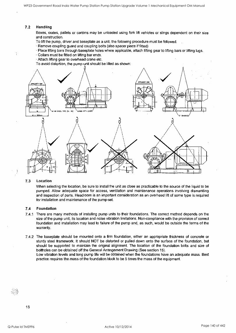
7.2 Handling Boxes, crates, pallets or cartons may be unloaded using fork lift vehicles or slings dependent on their size and construction. To lift the pump, driver and baseplate as a unit, the following procedure must be followed.
Remove coupling guard and coupling bolts (also spacer piece if fitted) Place lifting bars through baseplate holes where applicable, attach lifting gear to lifting bars or lifting lugs. Collars must be fitted on lifting bar ends. Attach lifting gear to overhead crane etc.
To avoid distortion, the pump unit should be lifted as shown:
40 OD MEI PIPE (Gr. XS) SUNGS WITH LOOPS
7.3 Location When selecting the location, be sure to install the unit as close as practicable to the source of the liquid to be pumped. Allow adequate space for access, ventilation and maintenance operations involving dismantling and inspection of parts. Headroom is an important consideration as an overhead lift of some type is required for installation and maintenance of the pump-set.
7.4 Foundation
7.4.1 There are many methods of installing pump units to their foundations. The correct method depends on the size of the pump unit, its location and noise vibration limitations. Non-compliance with the provision of correct foundation and installation may lead to failure of the pump and, as such, would be outside the terms of the warranty.
7.4.2 The baseplate should be mounted onto a firm foundation, either an appropriate thickness of concrete or sturdy steel framework. It should NOT be distorted or pulled down onto the surface of the foundation, but should be supported to maintain the original alignment. The location of the foundation bolts and size of boltholes can be obtained off the General Arrangement Drawing (See section 15).
Low vibration levels and long pump life will be obtained when the foundations have an adequate mass. Best practice requires the mass of the foundation block to be 5 times the mass of the equipment.
15
WP23 Government Road Inala Water Pump Station Pump Station Upgrade Volume 1 Mechanical Equipment OM Manual
Q-Pulse Id TMS996 Active 10/12/2014 Page 140 of 442
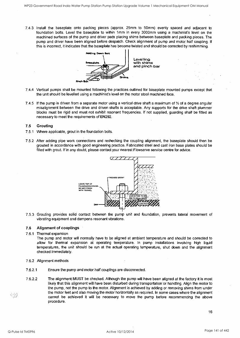
7.4.3 Install the baseplate onto packing pieces (approx. 25mm to 50mm) evenly spaced and adjacent to foundation bolts. Level the baseplate to within 1mm in every 3000mm using a machinist's level on the machined surfaces of the pump and driver pads placing shims between baseplate and packing pieces. The pump and driver have been aligned before despatch. Check alignment of pump and motor half coupling. If
this is incorrect, it indicates that the baseplate has become twisted and should be corrected by reshimming.
Levelling with shims and pinch bar
7.4.4 Vertical pumps shall be mounted following the practices outlined for baseplate mounted pumps except that the unit should be levelled using a machinist's level on the motor stool machined face.
7.4.5 If the pump is driven from a separate motor using a vertical drive shaft a maximum of 1/2 of a degree angular misalignment between the drive and driven shafts is acceptable. Any supports for the drive shaft plummer blocks must be rigid and must not exhibit resonant frequencies. If not supplied, guarding shall be fitted as necessary to meet the requirements of EN292.
7.5 Grouting 7.5.1 Where applicable, grout in the foundation bolts.
7.5.2 After adding pipe work connections and rechecking the coupling alignment, the baseplate should then be grouted in accordance with good engineering practice. Fabricated steel and cast iron base plates should be filled with grout. If in any doubt, please contact your nearest Flowserve service centre for advice.
LEAVE TOP OF FOUNDATION ROUGH. DO NOT FINISH WITH TROWEL
IA I WI I
WA IA
rri
I GROUTING TO B
25 TO 50mm DEE
FINISHED GROUT
7.5.3 Grouting provides solid contact between the pump unit and foundation, prevents lateral movement of vibrating equipment and dampens resonant vibrations.
7.6 Alignment of couplings 7.6.1 Thermal expansion
The pump and motor will normally have to be aligned at ambient temperature and should be corrected to allow for thermal expansion at operating temperature. In pump installations involving high liquid temperatures, the unit should be run at the actual operating temperature, shut down and the alignment checked immediately.
7.6.2 Alignment methods
7.6.2.1 Ensure the pump and motor half couplings are disconnected.
7.6.2.2 The alignment MUST be checked. Although the pump will have been aligned at the factory it is most likely that this alignment will have been disturbed during transportation or handling. Align the motor to the pump, not the pump to the motor. Alignment is achieved by adding or removing shims from under the motor feet and also moving the motor horizontally as required. In some cases where the alignment cannot be achieved it will be necessary to move the pump before recommencing the above procedure.
16
WP23 Government Road Inala Water Pump Station Pump Station Upgrade Volume 1 Mechanical Equipment OM Manual
Q-Pulse Id TMS996 Active 10/12/2014 Page 141 of 442

7.6.2.3 For couplings with narrow flanges, use a dial indicator gauge as shown. The alignment values are maxima for continuous service.
0 to 0.1mm TIR
0 to 0.05mm TIR
7.6.2.4 Permissible misalignment limits at working temperature: Parallel alignment within 0.1mm TIR Angular alignment within 0.05mm TIR
7.6.2.5 Face gaps may be measured between the machined faces using feeler gauges, measuring wedge, callipers or suitable micrometer.
7.6.2.6 When the electric motor has sleeve bearings it is necessary to ensure that the motor is aligned to run on its magnetic centreline. Refer to the motor manual for details.
7.7 Electrical connections 7.7.1 Electrical connections should be made by a qualified electrician in accordance with the relevant local,
national and international regulations.
It is important to be aware of the EUROPEAN DIRECTIVE on electromagnetic compatibility when wiring up and installing equipment on site. Attention must be paid to ensure that the techniques used during wiring/installation do not increase electromagnetic emissions or decrease the electromagnetic immunity of the equipment, wiring or any connected devices. If in any doubt contact Flowserve for advice.
7.7.2 The motor must be wired up in accordance with the motor manufacturer's instructions (normally supplied within the terminal box) including any temperature, earth leakage, current and other protective devices as appropriate. The identification nameplate should be checked to ensure the power supply is
appropriate.
7.7.3 ATTENTION A device to provide emergency stopping shall be fitted.
7.7.4 WARNING: Check required direction of rotation before connecting the motor to the pump. Ensure that the motor over power protection device is set 5% above the maximum power that the pump unit is expected to absorb.
7.8 Pipe work connections 7.8.1 Protective covers are fitted to the pipe connections to prevent foreign bodies entering during transportation
and installation. Ensure that these covers are removed from the pump before connecting any pipes.
7.8.2 Maximum forces and moments allowed on the pump flanges vary with the pump size and type and are shown in section 4.4. To minimise these forces and moments that may cause misalignment, hot bearings, worn couplings, vibration and the possible failure of the pump casing, the following points should be strictly followed: Prevent excessive external pipe load. Never draw piping into place by applying force to pump flange connections. Do not mount expansion joints so that their force, due to internal pressure, acts on the pump flange.
7.8.3 The inlet pipe should be one or two sizes larger than the pump inlet bore and pipe bends should be as large a radius as possible. On suction lift the piping should be inclined up towards the pump inlet with long eccentric taper pipes incorporated to prevent air locks. On positive suction, the inlet piping must have a
constant fall towards the pump.
17
WP23 Government Road Inala Water Pump Station Pump Station Upgrade Volume 1 Mechanical Equipment OM Manual
Q-Pulse Id TMS996 Active 10/12/2014 Page 142 of 442
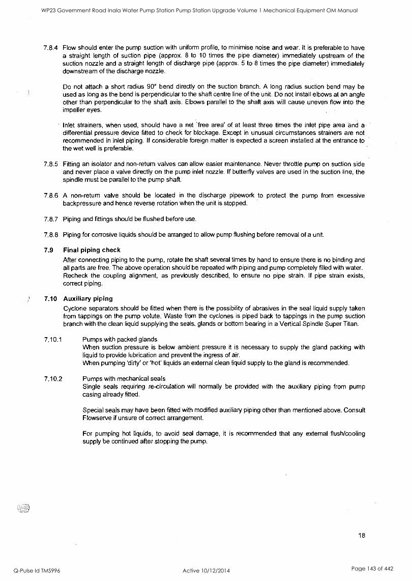
7.8.4 Flow should enter the pump suction with uniform profile, to minimise noise and wear. It is preferable to have a straight length of suction pipe (approx. 8 to 10 times the pipe diameter) immediately upstream of the suction nozzle and a straight length of discharge pipe (approx. 5 to 8 times the pipe diameter) immediately downstream of the discharge nozzle.
Do not attach a short radius 90° bend directly on the suction branch. A long radius suction bend may be used as long as the bend is perpendicular to the shaft centre line of the unit. Do not install elbows at an angle other than perpendicular to the shaft axis. Elbows parallel to the shaft axis will cause uneven flow into the impeller eyes.
Inlet strainers, when used, should have a net 'free area' of at least three times the inlet pipe area and a differential pressure device fitted to check for blockage. Except in unusual circumstances strainers are not recommended in inlet piping. If considerable foreign matter is expected a screen installed at the entrance to the wet well is preferable.
7.8.5 Fitting an isolator and non-return valves can allow easier maintenance. Never throttle pump on suction side and never place a valve directly on the pump inlet nozzle. If butterfly valves are used in the suction line, the spindle must be parallel to the pump shaft.
7.8.6 A non-return valve should be located in the discharge pipework to protect the pump from excessive backpressure and hence reverse rotation when the unit is stopped.
7.8.7 Piping and fittings should be flushed before use.
7.8.8 Piping for corrosive liquids should be arranged to allow pump flushing before removal of a unit.
7.9 Final piping check After connecting piping to the pump, rotate the shaft several times by hand to ensure there is no binding and all parts are free. The above operation should be repeated with piping and pump completely filled with water. Recheck the coupling alignment, as previously described, to ensure no pipe strain. If pipe strain exists, correct piping.
7.10 Auxiliary piping
Cyclone separators should be fitted when there is the possibility of abrasives in the seal liquid supply taken from tappings on the pump volute. Waste from the cyclones is piped back to tappings in the pump suction branch with the clean liquid supplying the seals, glands or bottom bearing in a Vertical Spindle Super Titan.
7.10.1 Pumps with packed glands When suction pressure is below ambient pressure it is necessary to supply the gland packing with liquid to provide lubrication and prevent the ingress of air.
When pumping 'dirty' or 'hot' liquids an external clean liquid supply to the gland is recommended.
7.10.2 Pumps with mechanical seals Single seals requiring re-circulation will normally be provided with the auxiliary piping from pump casing already fitted.
Special seals may have been fitted with modified auxiliary piping other than mentioned above. Consult Flowserve if unsure of correct arrangement.
For pumping hot liquids, to avoid seal damage, it is recommended that any external flush/cooling supply be continued after stopping the pump.
18
WP23 Government Road Inala Water Pump Station Pump Station Upgrade Volume 1 Mechanical Equipment OM Manual
Q-Pulse Id TMS996 Active 10/12/2014 Page 143 of 442

WP23 Government Road Inala Water Pump Station Pump Station Upgrade Volume 1 Mechanical Equipment OM Manual
Q-Pulse Id TMS996 Active 10/12/2014 Page 144 of 442
SECTION 8 - MAKING READY FOR OPERATION
8.1 Lubrication 8.1.1 Pump bearings are factory lubricated with high quality lithium base grease. Normal intervals between
grease changes are 4000 operating hours or 12 months period. See 'Section 4.5' for product information.
8.1.2 Your pump bearings are supplied pre-greased. Check motor manual for its lubrication details.
8.1.3 Other drivers and gearboxes, if appropriate, should be lubricated in accordance with their manuals.
8.1.4 The Vertical Spindle Super Titan has a Feroform non-drive end bearing which is in most cases product lubricated from a tapping in the pump volute. In this case no further lubrication will be required. There may be requirements for an external clean supply to the bearing, in particular supply pressure or the commencement of lubrication supply before pump start-up. This should be checked against the order.
8.2 Pre-operation check list
Pre-Operation Check List Checked by Date
8.2.1 With pump uncoupled start the driver to ensure correct direction of rotation. 8.2.2 Check alignment of pipework, valves and motor pump assembly.
Alignment shall be such that joints can be bolted without placing any
stress on the pipework or pump.
8.2.3 Check all fasteners for tightness. 8.2.4 Visually inspect footing for cracks etc.
8.2.5 Examine motor shims to ensure that any vibration during operation will
Not cause them to dislodge.
8 2 6 Check that all electrical, hydraulic, sealant and lubrication systems ... (as applicable) are connected and operational.
8.2.7 Check pump and motor for lubrication.
8 2 8 ATTENTION I Ensure all terminal boxes and guards are in place.
8.2.9 Check all valves and fittings to ensure that they are installed to allow flow in the intended direction.
8.2.10 4,'- I ',., 12.. Prime the Ensure that pump. the pump casing and all pipe work are
completely filled with liquid. Vent valves must be closed after priming. 8.2.11 Ensure pump/driver-coupling alignment is within the limits specified in 7.6.2.4. 8.2.12 Ensure flushing and/or cooling/heating liquid supplies are turned ON.
8.2.13 Check all pipe work, seals, casing joints and fittings for leaks.
SECTION 9 - STARTING THE PUMP
9.1 Ensure flushing and/or cooling/heating liquid supplies are turned ON before starting pump. Before initial start-up or start-up after a prolonged period without operation the rotating element should be turned by hand to ensure it rotates freely.
9.2 CLOSE the outlet valve where applicable.
9.3 OPEN all inlet valves.
9.4 Prime the pump ATTENTION Ensure all vent connections are closed before starting.
9.5 Start motor and open discharge valve.
9.6 Check outlet pressure and flow.
9.7 If NO pressure, or LOW pressure, STOP the pump. Refer to Operating difficulties chart (Section 19) for fault diagnosis.
19
WP23 Government Road Inala Water Pump Station Pump Station Upgrade Volume 1 Mechanical Equipment OM Manual
Q-Pulse Id TMS996 Active 10/12/2014 Page 145 of 442
9.8 Do not run the pump with the outlet valve closed for a period longer than 30 seconds.
9.9 Check the pump unit for vibration or overheating. If the vibration and/or temperature are excessive STOP the pump. Refer to Operating difficulties chart (Section 19) for fault diagnosis.
SECTION 10 - RUNNING
Vent the pump to enable all trapped air to escape taking due care with hot or hazardous liquids. Under normal operating conditions, after the pump has been fully primed and vented, it should be unnecessary to re-vent the pump.
10.1 Pumps fitted with packed glands 10.1.1 If the pump has a packed gland there must be some leakage from the gland. Gland nuts should
initially be finger-tight only. Leakage should take place soon after the stuffing box is pressurised. If no leakage takes place the packing will begin to overheat. If overheating takes place the pump should be stopped and allowed to cool before being re- started. When the pump is re-started, check to ensure leakage is taking place at the packed gland.
10.1.2 If hot liquids are being pumped it may be necessary to slacken the gland nuts to achieve adequate leakage.
10.1.3 The pump should be run for ten minutes with steady leakage and the gland nuts tightened by 60 degrees at a time until the leakage is reduced to an acceptable level, normally 30 to 120 drops per minute. Bedding in of the packing may take another 15 minutes.
10.2 Pumps fitted with mechanical seals 10.2.1 Mechanical seals require no adjustment. Any slight initial leakage will appear to stop when the seal
is run in. Seals will always have a slight leakage in operation to lubricate the seal faces.
10.2.2 Before pumping dirty liquids it is advisable, if possible, to run the pump in using clean liquid to safeguard the seal face.
1 kaT
10.2.3 External supply flush or quench should be started before the pump is run and allowed to flow for a period after the pump has stopped.
10.3 Stop/start frequency Consult driver manual for maximum number of starts per hour. STANDBY PUMPS SHOULD BE RUN ALTERNATELY.
SECTION 11 - STOPPING AND SHUTDOWN
11.1 Close the outlet valve, but ensure that the pump runs in this condition for no more than a few seconds.
11.2 Stop the pump. 11.3 Switch off flushing and/or cooling/heating liquid supplies at a time appropriate to the process.
Az; v 11.4 For prolonged shutdowns and especially when ambient temperatures are likely to drop below freezing point close the suction valve, drain the pump and any cooling and flushing arrangements.
SECTION 12 - PREVENTATIVE MAINTENANCE AND SERVICING
12.1 Maintenance schedule Our specialist service personnel can help with preventative maintenance records and provide condition monitoring for temperature and vibration to identify the onset of potential problems if required. This schedule is a recommendation only and is intended to be amended by site experience of the prevailing conditions. It outlines recommendations for the pump only and must be supplemented by schedules for other equipment on the package.
20
WP23 Government Road Inala Water Pump Station Pump Station Upgrade Volume 1 Mechanical Equipment OM Manual
Q-Pulse Id TMS996 Active 10/12/2014 Page 146 of 442

WP23 Government Road Inala Water Pump Station Pump Station Upgrade Volume 1 Mechanical Equipment OM Manual
Q-Pulse Id TMS996 Active 10/12/2014 Page 147 of 442
12.2 Routine inspection (daily/weekly) The following checks should be made and the appropriate action taken to remedy any deviations:
Check operating behaviour. Ensure performance, noise, vibration and bearing temperatures are normal. Check that there are no abnormal fluid or lubricant leaks (static and dynamic seals) and that any sealant systems (if fitted) are full and operating normally. Check that shaft seal leaks are within acceptable limits. Check running hours since last change of grease; Change grease if required. Check any auxiliary supplies e.g. heating/cooling (if fitted) are functioning correctly. Refer to the manuals of any associated equipment for routine checks needed.
12.3 Periodic inspection (6 monthly) Check foundation bolts for security of attachment and corrosion. The coupling should be checked for correct alignment and worn driving elements. Check all paint or protective coatings. Check all cable glands for tightness Refer to the manuals of any associated equipment for periodic checks needed.
12.4 Lubrication data
12.4.1 Grease lubricated bearings
Normal intervals between grease changes are 4000 operating hours or 12 months period. The characteristics of the installation and severity of service will determine the frequency of lubrication change. See Section 4.5 - Pump lubricant data.
An excess of lubricant will cause the operating temperature to rise rapidly, particularly when the bearings are running at high speeds. As a general rule, therefore, only the bearing should be completely filled, whilst the free space in the housing should be partly filled (to between 30 and 50 %) with grease.
ATTENTION WARNING: Never mix greases containing different bases, thickeners or additives.
12.5 Gland packing The stuffing box split gland can be completely removed for re-packing as required. The stuffing box is supplied with a lantern ring to enable a clean or pressurised flush to the centre of the packing. The gland should be adjusted to ensure adequate flow is achieved from the stuffing box.
12.6 Mechanical seals When leakage becomes unacceptable the seal will need to be replaced or repaired.
SECTION 13 - DISMANTLING
13.1 Dismantling Cleanliness is extremely important and care must be taken to prevent any foreign material from entering the pump or its components.
177 AL4 WARNING:
Refer to Safety section before dismantling the pump.
ATTENTION Before dismantling the pump for overhaul, ensure genuine Flowserve replacement parts are available.
Refer to section drawing for part numbers and identification.
WP23 Government Road Inala Water Pump Station Pump Station Upgrade Volume 1 Mechanical Equipment OM Manual
Q-Pulse Id TMS996 Active 10/12/2014 Page 148 of 442
13.1.4 Rotating element
Remove coupling guard and disconnect the coupling halves. Drain pump casing. Remove any auxiliary piping and equipment if applicable. If fitted, mechanical seal setting tabs should be locked in place. Remove casing dowels, bearing housing dowels & fasteners and gland or mechanical seal fasteners. Vertical Spindle Super Titans require the non-drive end bearing cover, motor & motor stool to be removed. Unscrew and remove nuts above split flange on cover half casing. Crack casing joint flange using the forcing off screws provided. Remove cover half casing using lifting lugs or eyebolts taking care not to damage the gasket material. Place cover half casing clear of working area taking care of machined face. Using soft rope slings, take out complete rotor unit taking care not to damage the rotating parts and place onto two support blocks.
13.1.5 Removal of bearing housing and bearing (Inboard bearing housings)
Note: The bearing housings, bearings and shaft seals can be removed without removal of the cover half casing if desired, however the drive end will require removal of either a spacer coupling or the motor to gain access. Note: Vertical Spindle Super Titans will require packers to be placed under the non-drive shaft end to prevent movement of the rotating element, and the motor removed. See section 13.1.7 - Product lubricated bearing. If a mechanical seal is fitted, the setting tabs must be locked in and the sleeve grubscrews loosened. See section 13.1.9 - Shaft seal - Mechanical seal. On pump drive end, remove pump half coupling and shaft key from shaft end. Note: Vertical Spindle Super Titans are fitted with a split ring on the shaft end. To remove, loosen coupling grub screw, slide coupling down shaft and withdraw split ring. The coupling, shaft key and V-ring may now be removed. Remove bearing cover setscrews and bearing cover. Unscrew bearing locknut(s) using a hook wrench by turning in the direction of rotation looking at shaft end. Withdraw bearing housing complete with bearing and collar. Remove the inboard V-ring and water thrower (packed gland only) The bearing may be removed from the housing using a standard puller. Note the size, type and orientation of the bearings. Bearings must not be re-used.
13.1.6 Removal of bearing housing and bearing (Outboard bearing housings)
See Section 19.4 Sectional Drawings - Outboard bearing housing Note: The bearing housings, bearings and shaft seals can be removed without removal of the cover half casing if desired, however the drive end will require removal of either a spacer coupling or the motor to gain access. Note: Vertical Spindle Super Titans will require packers to be placed under the non-drive shaft end to prevent movement of the rotating element, and the motor removed. See section 13.1.7 - Product lubricated bearing. If a mechanical seal is fitted, the setting tabs must be locked in and the sleeve grubscrews loosened. See section 13.1.9 - Shaft seal - Mechanical seal. On pump drive end, remove pump half coupling and shaft key from shaft end. Note: Vertical Spindle Super Titans are fitted with a split ring on the shaft end. To remove, loosen coupling grub screw, slide coupling down shaft and withdraw split ring. The coupling, shaft key and V-ring may now be removed. Remove bearing cover setscrews. Support bearing housing by overhead crane. Tap the housing off the bearing/shaft assembly with a soft face hammer. Remove bearing locknuts (if fitted)
22
WP23 Government Road Inala Water Pump Station Pump Station Upgrade Volume 1 Mechanical Equipment OM Manual
Q-Pulse Id TMS996 Active 10/12/2014 Page 149 of 442
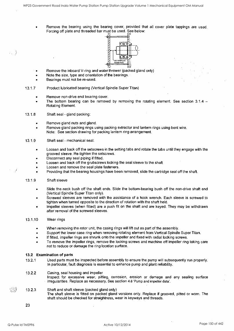
Remove the bearing using the bearing cover, provided that all cover plate tappings are used. Forcing off plate and threaded bar must be used. See below:
Remove the inboard V-ring and water thrower (packed gland only) Note the size, type and orientation of the bearings. Bearings must not be re-used.
13.1.7 Product lubricated bearing (Vertical Spindle Super Titan)
Remove non-drive end bearing cover. The bottom bearing can be removed by removing the rotating element. See section 3.1.4 Rotating Element.
13.1.8 Shaft seal - gland packing:
Remove gland nuts and gland. Remove gland packing rings using packing extractor and lantern rings using bent wire. Note: See section drawing for packing lantern ring arrangement.
13.1.9 Shaft seal - mechanical seal:
Loosen and back off the setscrews in the setting tabs and rotate the tabs until they engage with the grooved sleeve. Re-tighten the setscrews. Disconnect any seal piping if fitted. Loosen and back off the grubscrews locking the seal sleeve to the shaft Loosen and remove the seal plate fasteners. Providing that the bearing housings have been removed, slide the cartridge seal off the shaft.
13.1.9 Shaft sleeve
Slide the neck bush off the shaft ends. Slide the bottom-bearing bush off the non-drive shaft end (Vertical Spindle Super Titan only). Screwed sleeves are removed with the assistance of a hook wrench. Each sleeve is screwed to tighten when turned opposite to the direction of rotation with the shaft held. Impeller sleeves (when fitted) are a push fit on the shaft and are keyed. They may be withdrawn after removal of the screwed sleeves.
13.1.10 Wear rings
When removing the rotor unit, the casing rings will lift out as part of the assembly. Support the lower case ring when removing rotating element from Vertical Spindle Super Titan. If fitted, impeller rings are shrunk onto the impeller and fixed with radial locking screws. To remove the impeller rings, remove the locking screws and machine off impeller ring taking care not to reduce or damage the ring location surface.
13.2 Examination of parts
13.2.1 Used parts must be inspected before assembly to ensure the pump will subsequently run properly. In particular, fault diagnosis is essential to enhance pump and plant reliability.
13.2.2 Casing, seal housing and impeller Inspect for excessive wear, pitting, corrosion, erosion or damage and any sealing surface irregularities. Replace as necessary. See section 4.8 'Pump and impeller data'.
13.2.3 Shaft and shaft sleeve (packed gland only) The shaft sleeve is fitted on packed gland versions only. Replace if grooved, pitted or worn. The shaft should be checked for straightness, wear in keyways and threads.
23
WP23 Government Road Inala Water Pump Station Pump Station Upgrade Volume 1 Mechanical Equipment OM Manual
Q-Pulse Id TMS996 Active 10/12/2014 Page 150 of 442
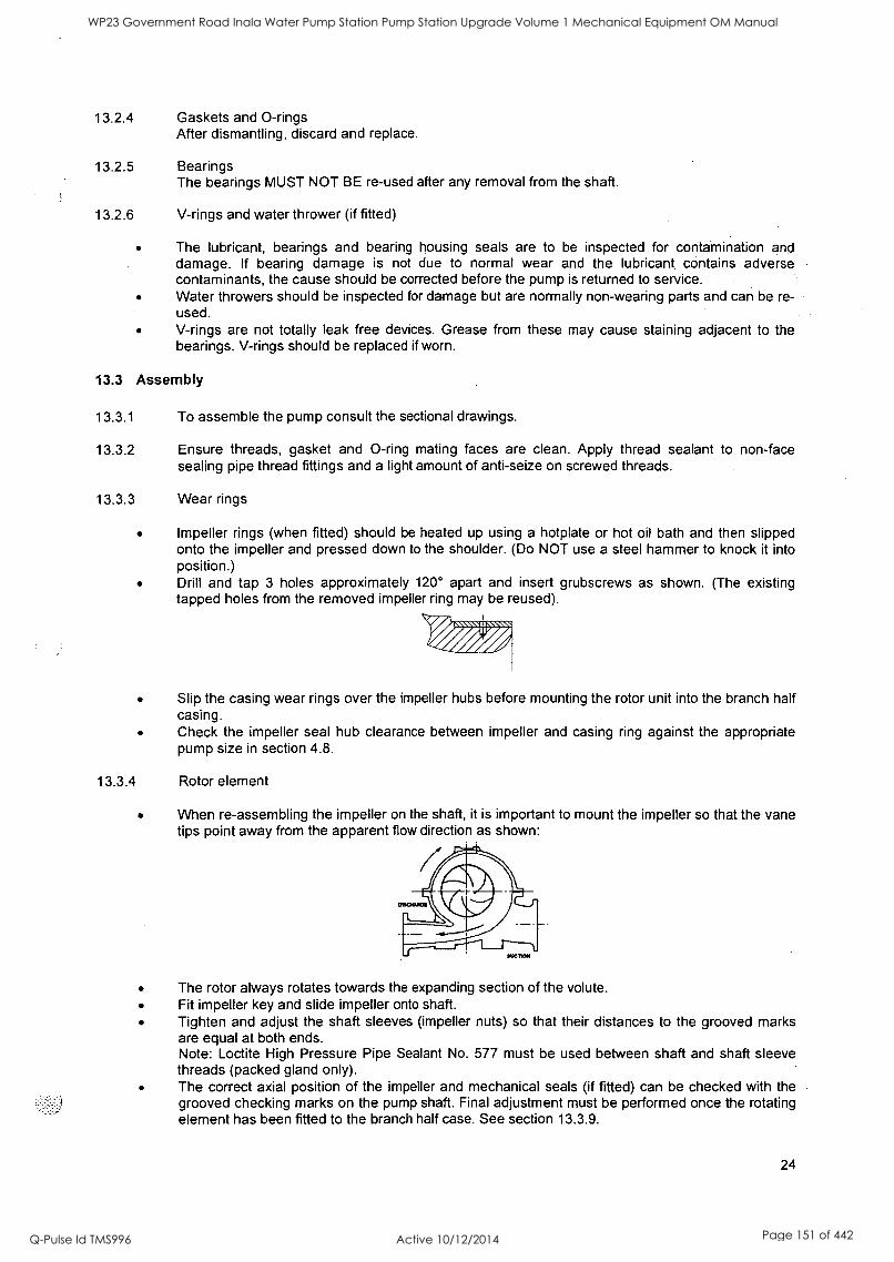
13.2.4 Gaskets and 0-rings After dismantling, discard and replace.
13.2.5 Bearings The bearings MUST NOT BE re-used after any removal from the shaft.
13.2.6 V-rings and water thrower (if fitted)
The lubricant, bearings and bearing housing seals are to be inspected for contamination and damage. If bearing damage is not due to normal wear and the lubricant contains adverse contaminants, the cause should be corrected before the pump is returned to service. Water throwers should be inspected for damage but are normally non-wearing parts and can be re- used. V-rings are not totally leak free devices. Grease from these may cause staining adjacent to the bearings. V-rings should be replaced if worn.
13.3 Assembly
13.3.1 To assemble the pump consult the sectional drawings.
13.3.2 Ensure threads, gasket and 0-ring mating faces are clean. Apply thread sealant to non-face sealing pipe thread fittings and a light amount of anti-seize on screwed threads.
13.3.3 Wear rings
Impeller rings (when fitted) should be heated up using a hotplate or hot oil bath and then slipped onto the impeller and pressed down to the shoulder. (Do NOT use a steel hammer to knock it into position.) Drill and tap 3 holes approximately 120° apart and insert grubscrews as shown. (The existing tapped holes from the removed impeller ring may be reused).
Slip the casing wear rings over the impeller hubs before mounting the rotor unit into the branch half casing. Check the impeller seal hub clearance between impeller and casing ring against the appropriate pump size in section 4.8.
13.3.4 Rotor element
When re-assembling the impeller on the shaft, it is important to mount the impeller so that the vane tips point away from the apparent flow direction as shown:
The rotor always rotates towards the expanding section of the volute. Fit impeller key and slide impeller onto shaft. Tighten and adjust the shaft sleeves (impeller nuts) so that their distances to the grooved marks are equal at both ends. Note: Loctite High Pressure Pipe Sealant No. 577 must be used between shaft and shaft sleeve threads (packed gland only). The correct axial position of the impeller and mechanical seals (if fitted) can be checked with the grooved checking marks on the pump shaft. Final adjustment must be performed once the rotating element has been fitted to the branch half case. See section 13.3.9.
24
WP23 Government Road Inala Water Pump Station Pump Station Upgrade Volume 1 Mechanical Equipment OM Manual
Q-Pulse Id TMS996 Active 10/12/2014 Page 151 of 442
Lock the shaft sleeves (impeller nuts) in place using a hook spanner (Remember, shaft sleeves (impeller nuts) tighten in the opposite direction to the impeller rotation. Check runout on sleeves and impeller hubs should not exceed 0.05mm. Slide the neck bush over shaft sleeve (impeller nut) and lantern ring over shaft (if packed gland). Fit mechanical seals (if fitted) and bearing housings as described.
13.3.5 Shaft seal - stuffing box
Slide lantern ring on to shaft. The split gland may be fitted after the packing has been fitted to stuffing box.
13.3.6 Shaft seal - mechanical seal
Using a light amount of lubrication to aid with assembly fit the mechanical seal sleeve 0-ring over the pump shaft and slide the 0-ring up to the impeller nut. Slide mechanical seal over the shaft and locate shaft sleeve grub screws over grooved section of pump shaft (See section drawing). Do not tighten at this stage.
13.3.7 Bearings and housings (Inboard bearing housings)
Fully pack bearing and fit in housing. Pack housing with appropriate NLGI 2 grade and quantity of grease. An excess of lubricant will cause the operating temperature to rise rapidly, particularly when the bearings are running at high speeds. As a general rule, therefore, only the bearing should be completely filled, whilst the free space in the housing should be partly filled (to between 30 and 50 %) with grease. See Section 4.5 - Pump Lubricant data. Mount the water thrower (if fitted) and V-ring seal onto the shaft and slide the bearing housing complete with new bearing and collar over the shaft. Fit bearing locking nut(s) and tighten in the opposite direction from rotation. Fit bearing cover and tighten bearing cover setscrews. Fit bearing housing fasteners and dowels and tighten. Care should be taken to ensure the rotating element travels through 360° rotation without rubbing. Fit outboard V-ring seal. The sealing surface of the V-ring must not be covered with grease. Push V-ring gently up to the back edge of the bearing cover as shown below, otherwise it may run hot!
13.3.8 Bearings and housings (Outboard bearing housing type)
Mount the water thrower (if fitted), V-ring seal, bearing cover and spacer ring onto the shaft. Bearing arrangements using a pair of angular contact bearings should be mounted back to back as shown:
The bearing must be heated between 100 and 120°C with an induction heater then placed on the pump shaft. Hold bearing against spacer ring until cool to prevent drawback. Fit bearing locking nut(s) and tighten in the opposite direction from rotation. Pack bearing and housing with appropriate NLGI 2 grade and quantity of grease. As a general guide, the spaces between the bearing bodies and covers should be no more than two thirds filled with grease. DO NOT OVER GREASE BEARING. Fit bearing housing to shaft/bearing assembly. Fit bearing cover and tighten bearing cover setscrews. The sealing surface of the V-ring must not be covered with grease. Push V-ring gently up to the back edge of the bearing cover as shown below, otherwise it may run hot!
25
WP23 Government Road Inala Water Pump Station Pump Station Upgrade Volume 1 Mechanical Equipment OM Manual
Q-Pulse Id TMS996 Active 10/12/2014 Page 152 of 442
13.3.9 Casing gasket & rotating element
The gasket must be cut from asbestos-free sheet material of 0.8 + 0.1/-0.05mm (1/32") thickness, by following the actual inner casing contour of the branch half casing. Flowserve recommend Klinger Sil C-4400. Special care must be exercised at the bores of the casing rings and stuffing box housing. The gasket must be accurately cut and fit flush with these bores. To prevent leakage at the stuffing box face (mechanical seal only) the gasket must be accurately cut and fit flush with these faces. Position gasket carefully onto the cleaned surface of the branch half casing. Push gasket flush against face of stuffing box housing and secure gasket locally using adhesive paste. As the rotating element is refitted to the casing, care should be taken that the sealing ring and neck bush tongues are correctly located in the casing grooves, and that their anti-rotation grub screws are pressed down in the branch half casing. Fit bearing housing fasteners and dowels and tighten to correct torque value. Care should be taken to ensure the rotating element travels through 360° rotation without rubbing. See Section 4.8 for impeller case ring clearances. The impeller must be centralised between the case rings using the shaft sleeves (nuts) to adjust. Place cover half casing onto pump, ensuring dowels and gaskets make correct alignment. Fit dowels and cover half casing flange nuts/screws and tighten to correct torque value. See section 4.6. Ensure that the rotating element travels through 360° of rotation.
13.3.10 Stuffing box assembly - soft packing
The gland must be packed as shown on the sectional arrangement drawing. The end of each packing ring must not be butted together, but leave a small gap to allow for lubrication and expansion during running. Insert inner two rings of packing between the neck bush and the lantern ring with both gaps at 12 o'clock (inline with gland flush). To aid assembly, these should be fitted to the branch half case before the cover is fitted. Fit the third ring of packing with the gap at 3 o'clock, the fourth ring with the gap at 9 o'clock and the fifth ring with the gap at 6 o'clock. Packing should be initially adjusted with finger tight tension on the gland nuts. Final adjusting to be made after initial starting as described in 10.1.3. Connect flush line.
13.3.11 Stuffing box assembly - mechanical seal
Ensure that the case gasket is flush to the face of the stuffing box. If the gasket is below the stuffing box face, the seal plate will leak. Locate seal plate against gland face and tighten. Tighten shaft sleeve grub screws. Loosen and back off the setscrews in the setting tabs and rotate the tabs until they disengage with the grooved sleeve. Tighten the setscrews. Connect any auxiliary piping.
SECTION 14 - SPARE PARTS
14.1 Ordering of spares Flowserve keep records of all pumps that have been supplied. When ordering spares the following information should be quoted.
(1) Pump serial and service number(s). (2) Pump type & size. (3) Part name. (4) Part number. (5) Number of parts required.
14.2 Pump Details The pump size and serial number are shown on the pump nameplate.
26
WP23 Government Road Inala Water Pump Station Pump Station Upgrade Volume 1 Mechanical Equipment OM Manual
Q-Pulse Id TMS996 Active 10/12/2014 Page 153 of 442
14.3 Genuine Parts To ensure continued satisfactory operation, replacement parts to the original design specification should be obtained from Flowserve. Any change to the original design specification (modification or use of a
non-standard part) will invalidate the pumps safety certification.
14.4 Recommended spares For start up purposes: 1 - complete set of gland packing 2 - shaft sleeves 1 - set of gaskets and seals (Optional: 2 - mechanical seals)
For 2 years operation: 1 - set of bearings (line and thrust) 2 - sets of gland packing 2 - shaft sleeves 2 - sets of gaskets and seals 2 - casing sealing rings (Optional: 2 - mechanical seals
2 - impeller wear rings)
For 4 years operation: 1 - set of bearings (line and thrust) 2 - sets of gland packing 2 - shaft sleeves 2 - sets of gaskets and seals 2 - casing wear rings 1 - complete set of mechanical seals and gaskets (Optional: 2 - mechanical seals
2 - impeller wear rings)
14.5 Storage of spares Spares should be stored in a clean dry area away from vibration. Inspection and re-treatment of metallic surfaces (if necessary) with preservative is recommended at 6 monthly intervals.
SECTION 15 - GENERAL ARRANGEMENT DRAWING The typical general arrangement drawing and any specific drawings required by the Contract will be sent to the Purchaser separately. If required these should be obtained from the Purchaser and retained with this manual.
SECTION 16 - SUPPLEMENTARY INSTRUCTION MANUALS See also the supplementary instruction manuals supplied with this manual e.g. for electric motors, controllers, engines, gearboxes, sealant systems etc.
SECTION 17 - CERTIFICATION Any certificates e.g. materials, hydraulic tests, conformities, performance test curves etc as determined by the contract requirements, will be sent to the Purchaser separately. If required, copies of these should be obtained from the Purchaser for retention with this manual.
27
WP23 Government Road Inala Water Pump Station Pump Station Upgrade Volume 1 Mechanical Equipment OM Manual
Q-Pulse Id TMS996 Active 10/12/2014 Page 154 of 442
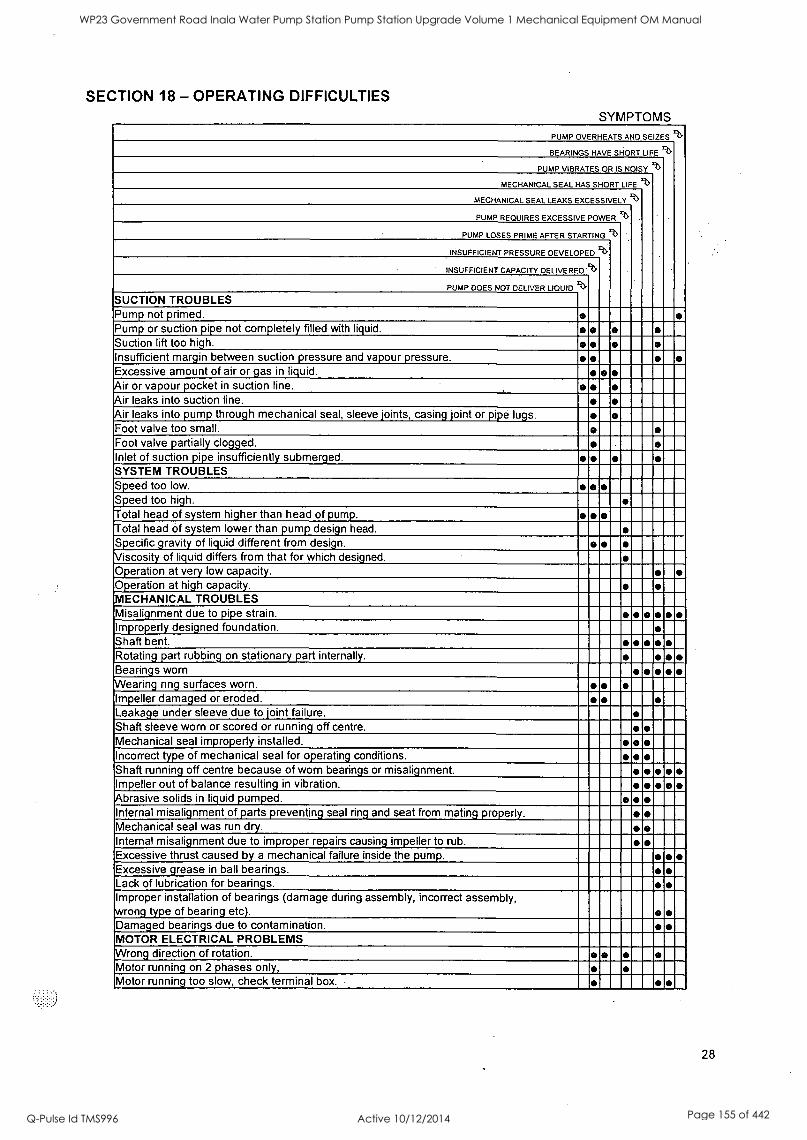
SECTION 18 - OPERATING DIFFICULTIES SYMPTOMS
PUMP OVERHEATS AND SEIZES %
BEARINGS HAVE SHORT LIFE %
PUMP VIBRATES OR IS NOISY %
MECHANICAL SEAL HAS SHORT LIFE 9>
MECHANICAL SEAL LEAKS EXCESSIVELY a>
PUMP REQUIRES EXCESSIVE POWER %
PUMP LOSES PRIME AFTER STARTING e>
INSUFFICIENT PRESSURE DEVELOPED %
INSUFFICIENT CAPACITY DELIVERED '%
PUMP DOES NOT DELIVER MOD % SUCTION TROUBLES Pump not primed. Pump or suction pipe not completely filled with liquid. Suction lift too high. Insufficient margin between suction pressure and vapourpressure. Excessive amount of air or gas in liquid. Air or vapour pocket in suction line. Air leaks into suction line. Air leaks into pump through mechanical seal, sleeve joints, casing joint or pipe lugs. Foot valve too small. Foot valve partially clogged. Inlet of suction pipe insufficiently submerged. SYSTEM TROUBLES Speed too low. Speed too high. Total head of system higher than head of pump. Total head of system lower than pump design head. Specific gravity of liquid different from design. Viscosity of liquid differs from that for which designed. Operation at very low capacity. Operation at high capacity. MECHANICAL TROUBLES Misalignment due to pipe strain. Improperly designed foundation. Shaft bent. Rotating part rubbing on stationary part internally. Bearings worn Wearing ring surfaces worn. Impeller damaged or eroded. Leakage under sleeve due to joint failure. Shaft sleeve worn or scored or running off centre. Mechanical seal improperly installed. Incorrect type of mechanical seal for operating conditions. Shaft running off centre because of worn bearings or misalignment. o Impeller out of balance resulting in vibration. Abrasive solids in liquid pumped. Internal misalignment of parts preventing seal ring and seat from mating properly. Mechanical seal was run dry. Internal misalignment due to improper repairs causing impeller to rub. Excessive thrust caused by a mechanical failure inside the pump. Excessive grease in ball bearings. Lack of lubrication for bearings. Improper installation of bearings (damage during assembly, incorrect assembly, wrong type of bearing etc). Damaged bearings due to contamination. MOTOR ELECTRICAL PROBLEMS Wrong direction of rotation. Motor running on 2 phases only, Motor running too slow, check terminal box.
28
WP23 Government Road Inala Water Pump Station Pump Station Upgrade Volume 1 Mechanical Equipment OM Manual
Q-Pulse Id TMS996 Active 10/12/2014 Page 155 of 442
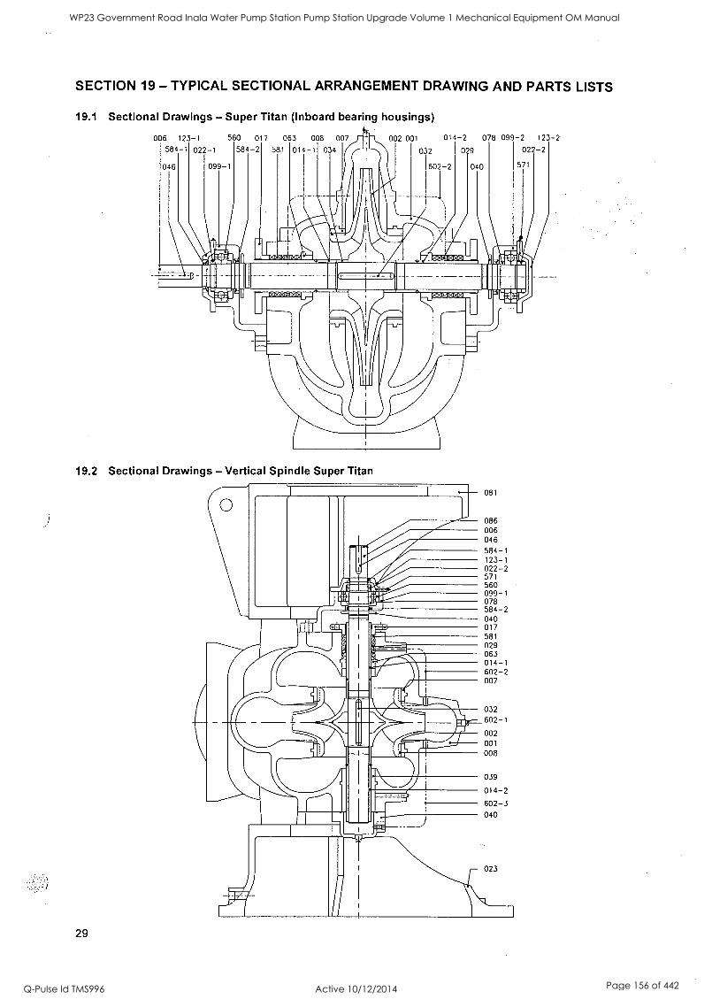
SECTION 19 - TYPICAL SECTIONAL ARRANGEMENT DRAWING AND PARTS LISTS
19.1 Sectional Drawings - Super Titan (Inboard bearing housings)
006 123-1 560 017 063 008 007
584-1 022-1 584-2 581 014-1 034
046 099-1
002 001
032
014-2 078 099-2 123-2
029 022-2
602-2 040 571
MID 101111 1WaD
19.2 Sectional Drawings - Vertical Spindle Super Titan
29
081
086 006
046
584-1 123-1 022-2 571 560 099-1 078 584-2 040 017 581
029 063 014-1 602-2 007
032
602-1
002
001
008
039
014-2
602-3
040
023
WP23 Government Road Inala Water Pump Station Pump Station Upgrade Volume 1 Mechanical Equipment OM Manual
Q-Pulse Id TMS996 Active 10/12/2014 Page 156 of 442
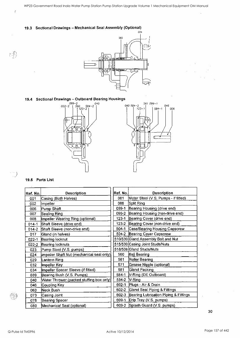
19.3 Sectional Drawings - Mechanical Seal Assembly (Optional) 024
19.4 Sectional Drawings - Outboard Bearing Housings 099-2 040 561 099-1
022-2 560 584-2 040 584-2 046 123-2 123-1 584-1 006
19.5 Parts List
Ref. No. Description 001 Casing (Both Halves)
002 Impeller 006 Pump Shaft 007 Sealing Ring
008 Impeller Wearing Ring (optional)
014-1 Shaft Sleeve (drive end)
014-2 Shaft Sleeve (non-drive end)
017 Gland (in halves)
022-1 Bearing locknut
022-2 Bearing locknuts
023 Pump Stool (V.S. pumps)
024 Impeller Shaft Nut (mechanical seal only)
029 Lantern Ring
032 Impeller Key 034 Impeller Spacer Sleeve (if fitted)
039 Bearing Bush (V.S. Pumps)
040 Water Thrower (packed stuffing box only)
046 Coupling Key
063 Neck Bush
073 Casing Joint
078 Bearing Spacer
080 Mechanical Seal (optional)
Ref. No. Description 081 Motor Stool (V.S. Pumps - if fitted) 086 Split Ring
099-1 Bearing Housing (drive end) 099-2 Bearing Housing (non-drive end) 123-1 Bearing Cover (drive end) 123-2 Bearing Cover (non-drive end) 504-1 Case/Bearing Housing Capscrew 504-2 Bearing Cover Capscrew
510/530 Gland Assembly Bolt and Nut 515/530 Casing Joint Studs/Nuts 518/538 Gland Studs/Nuts
560 Ball Bearing 561 Roller Bearing 571 Grease Nipple (optional) 581 Gland Packing
584-1 V-Ring (DE Outboard) 584-2 V-Ring 602-1 Plugs - Air & Drain
602-2 Gland Seal Piping & Fittings 602-3 Bearing Lubrication Piping & Fittings 609-1 Drip Tray (V.S. pumps)
609-2 Splash Guard (V.S. pumps)
30
WP23 Government Road Inala Water Pump Station Pump Station Upgrade Volume 1 Mechanical Equipment OM Manual
Q-Pulse Id TMS996 Active 10/12/2014 Page 157 of 442
Thompsons, Kelly & Lewis Pty. Ltd A.C.N. 044 249 012
26 Faigh Street Mulgrave Victoria 3170 Australia
Telephone +61 3 9562 0744 Fax +61 3 9562 2816
Visit our web site at: www.tkl.com.au or www.flowserve.com
For further information, sales, service or technical support, consult your telephone directory for your nearest sales office or distributor.
Sales Offices: Worldwide as well as AUSTRALIA Sydney, Melbourne, Brisbane, Perth NEW ZEALAND Auckland Christchurch
31
Your local FPD representative:
To find your local FPD representative, please use the locator system "Contact Us" found at:
www.tkl.com.au or www.flowserve.com
WP23 Government Road Inala Water Pump Station Pump Station Upgrade Volume 1 Mechanical Equipment OM Manual
Q-Pulse Id TMS996 Active 10/12/2014 Page 158 of 442

s
WP23 Government Road Inala Water Pump Station Pump Station Upgrade Volume 1 Mechanical Equipment OM Manual
Q-Pulse Id TMS996 Active 10/12/2014 Page 159 of 442
WP23 Government Road Inala Water Pump Station Pump Station Upgrade Volume 1 Mechanical Equipment OM Manual
Q-Pulse Id TMS996 Active 10/12/2014 Page 160 of 442
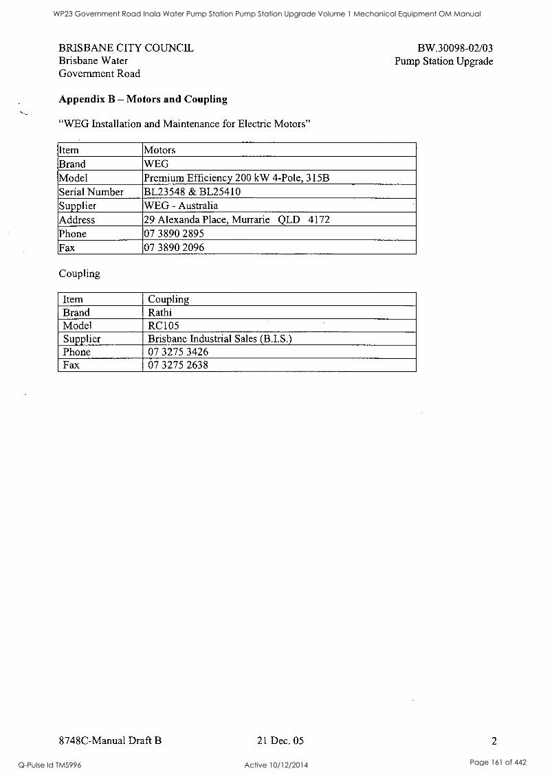
BRISBANE CITY COUNCIL Brisbane Water Government Road
Appendix B - Motors and Coupling
"WEG Installation and Maintenance for Electric Motors"
BW.30098-02/03 Pump Station Upgrade
Item Motors Brand WEG Model Premium Efficiency 200 kW 4-Pole, 315B Serial Number BL23548 & BL25410 Supplier WEG - Australia Address 29 Alexanda Place, Murrarie QLD 4172 Phone 07 3890 2895 Fax 07 3890 2096
Coupling
Item Coupling Brand Rathi Model RC105 Supplier Brisbane Industrial Sales (B.I.S.) Phone 07 3275 3426 Fax 07 3275 2638
8748C-Manual Draft B 21 Dec. 05 2
WP23 Government Road Inala Water Pump Station Pump Station Upgrade Volume 1 Mechanical Equipment OM Manual
Q-Pulse Id TMS996 Active 10/12/2014 Page 161 of 442

WP23 Government Road Inala Water Pump Station Pump Station Upgrade Volume 1 Mechanical Equipment OM Manual
Q-Pulse Id TMS996 Active 10/12/2014 Page 162 of 442
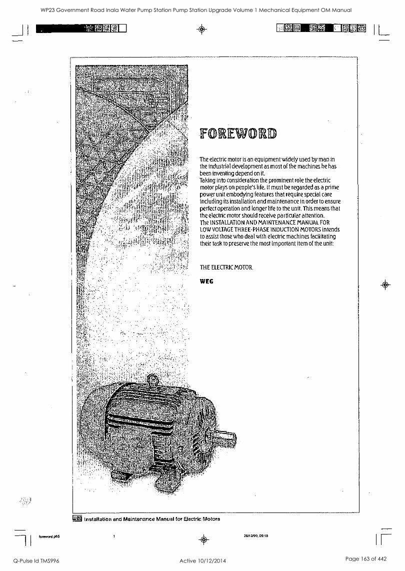
_J I
MEM .05 II 1 L
foreword.p65
The electric motor is an equipment widely used by man in the industrial development as most of the machines he has
been inventing depend on it. Taking into consideration the prominent role the electric motor plays on people's life, it must be regarded as a prime power unit embodying features that require special care including its installation and maintenance in order to ensure perfect operation and longer life to the unit. This means that the electric motor should receive particular attention. The INSTALLATION AND MAINTENANCE MANUAL FOR
LOW VOLTAGE THREE-PHASE INDUCTION MOTORS intends to assist those who deal with electric machines facilitating their task to preserve the most important item of the unit:
THE ELECTRIC MOTOR.
Wig Installation and Maintenance Manual for Electric Motors
Ci 26/12/99, 09:18
WP23 Government Road Inala Water Pump Station Pump Station Upgrade Volume 1 Mechanical Equipment OM Manual
Q-Pulse Id TMS996 Active 10/12/2014 Page 163 of 442
_JI I PI 21111E , x,. r rr ft!'
TABLE OF CONTENTS 1 - INTRODUCTION 1-03 2 BASIC INSTRUCTIONS 1-03 2.1 - General Instructions 1-03 2.2 - Delivery 1-03 2.3 - Storage 1-03
3 - INSTALLATION 1-04 3.1 - Mechanical Aspects 1-04 3.1.1 - Foundation 1-04 3.1.2 - Types of bases 1-04 3.1.3 - Alignment 1-04
3.1.4 - Coupling 1-05 3.2 - Electrical Aspects 1-09
3.2.1 - Power Supply System 1-09 3.2.2 - Starting of Electric Motors 1-09 3.2.3 - Motor Protection 1-10 3.3 - Start-up 1-11 3.3.1 - Preliminary Inspection 1-11 3.3.2 - The First Start-up 1-11 3.3.3 - Operation 1-12 3.3.4 - Stopping 1-12
4 - MAINTENANCE 1-15 4.1 - Cleanliness 1-15 4.2 - Lubrication 1-15 4.2.1- Lubrication Intervals 1-15 4.2.2 - Quality and Quantity of Grease 1-15 4.2.3 - Lubrication Instructions 1-15 4.2.4 - Replacement of Bearings 1-15 4.3 - Miscellaneous Recommendations 1-16
5 - ABNORMAL SITUATIONS DURING OPERATION 1-20 5.1 - Analysis of some abnormal situations and possible causes on electric motors 1-20
loreworc1.06 2
Installation and Maintenance Manual for Electric Motors Pkg-
26/12/99, 09:18
IL WP23 Government Road Inala Water Pump Station Pump Station Upgrade Volume 1 Mechanical Equipment OM Manual
Q-Pulse Id TMS996 Active 10/12/2014 Page 164 of 442
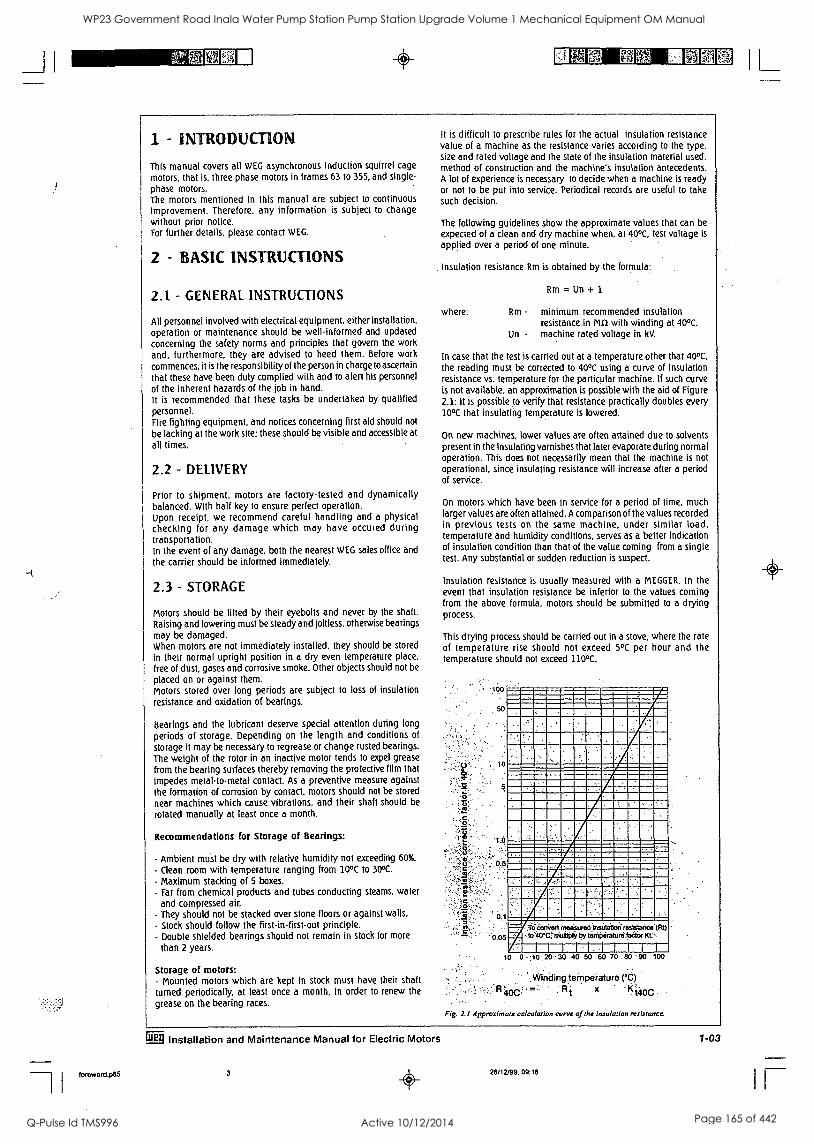
foreword.p85
1 - INTRODUCTION
This manual covers all WEG asynchronous induction squirrel cage
motors, that is. three phase motors in frames 63 to 355, and single-
phase motors. The motors mentioned in this manual are subject to continuous improvement. Therefore. any information is subject to change without prior notice. For further details, please contact WEG.
2 - BASIC INSTRUCTIONS
2.1 - GENERAL INSTRUCTIONS
All personnel involved with electrical equipment, either installation, operation or maintenance should be well-informed and updated concerning the safety norms and principles that govern the work and, furthermore, they are advised to heed them. Before work commences, it is the responsibility of the person in charge to ascertain
that these have been duly complied with and to alert his personnel
of the inherent hazards of the job in hand. It is recommended that these tasks be undertaken by qualified personnel. Fire fighting equipment, and notices concerning first aid should not
be lacking at the work site: these should be visible and accessible at
all times.
2.2 - DELIVERY
Prior to shipment, motors are factory-tested and dynamically balanced. With half key to ensure perfect operation. Upon receipt, we recommend careful handling and a physical checking for any damage which may have occured during transportation. In the event of any damage, both the nearest WEG sales office and
the carrier should be informed immediately.
2.3 - STORAGE
Motors should be lifted by their eyebolts and never by the shaft.
Raising and lowering must be steady and joltless, otherwise bearings may be damaged. When motors are not immediately installed, they should be stored
In their normal upright position in a dry even temperature place.
free of dust, gases and corrosive smoke. Other objects should not be
placed on or against them. Motors stored over long periods are subject to loss of insulation resistance and oxidation of bearings.
Bearings and the lubricant deserve special attention during long
periods of storage. Depending on the length and conditions of
storage it may be necessary to regrease or change rusted bearings.
The weight of the rotor in an inactive motor tends to expel grease
from the bearing surfaces thereby removing the protective film that
impedes metal-to-metal contact. As a preventive measure against the formation of corrosion by contact, motors should not be stored
near machines which cause vibrations, and their shaft should be
rotated manually at least once a month.
Recommendations for Storage of Bearings:
- Ambient must be dry with relative humidity not exceeding 60%.
- Clean room with temperature ranging from 10°C to 30°C.
- Maximum stacking of 5 boxes. - Far from chemical products and tubes conducting steams, water
and compressed air.
- They should not be stacked over stone floors or against walls. - Stock should follow the first-in-first-out principle. - Double shielded bearings should not remain in stock for more
than 2 years.
Storage of motors: - Mounted motors which are kept in stock must have their shaft
turned periodically, at least once a month, in order to renew the
grease on the bearing races.
It is difficult to prescribe rules for the actual insulation resistance value of a machine as the resistance varies according to the type, size and rated voltage and the state of the insulation material used, method of construction and the machine's insulation antecedents. A lot of experience is necessary to decide when a machine is ready or not to be put into service. Periodical records are useful to take such decision.
The following guidelines show the approximate values that can be
expected of a clean and dry machine when, at 40°C, test voltage is
applied over a period of one minute.
. InSulation resistance Rm is obtained .by the formula:
where:
Rm = 11n + 1
Rm - minimum recommended insulation resistance.in MCI with winding at 40°C.
Un - machine rated voltage in kV.
In case that the test is carried out at a temperature other that 40°C,
the reading must be corrected to 40°C using a curve of insulation resistance vs. temperature for the particular machine. If such curve is not available, an approximation is possible with the aid of Figure 2.1: it is possible to verify that resistance practically doubles every 10°C that insulating temperature is lowered.
On new machines, lower values are often attained due to solvents present in the insulating varnishes that later evaporate during normal operation. This does not necessarily mean that the machine is not operational, since insulating resistance will increase after a period of service.
On motors which have been in service for a period of time, much larger values are often attained. A comparison of the values recorded in previous tests on the same machine, under similar load, temperature and humidity conditions, serves as a better indication of insulation condition than that of the value coming from a single test. Any substantial or sudden reduction is suspect.
Insulation resistance is usually measured with a MEGGER. In the event that insulation resistance be inferior to the values coming from the above formula, motors should be submitted to a drying process.
This drying process should be carried out in a stove, where the rate of temperature rise should not exceed 5°C per hour and the temperature should not exceed 110°C.
c. .
0
-10
0
.5
0.1
MINOINIIMI=MEMMOMIMMIM111 OF
MNIMMI111011.1/1==
1101111,41 MIIIMMIIIMIIMM11111MMI
'0.05 To .iornieri measuredlliucila6o iesisisce tRI)
A to 40t;"rso86Oli.liy teraOiirahinifaetar. Kt: :
10 . ,;10.. 20'. 30 40 50 60 70 80 90 100
'Winiiingternperature (°C)
Rt
Fig. 2.1 Approximate calculation curve of the insulation resistance.
Installation and Maintenance Manual for Electric Motors
3 0 28/12/99, 09:18
1-03
I L WP23 Government Road Inala Water Pump Station Pump Station Upgrade Volume 1 Mechanical Equipment OM Manual
Q-Pulse Id TMS996 Active 10/12/2014 Page 165 of 442
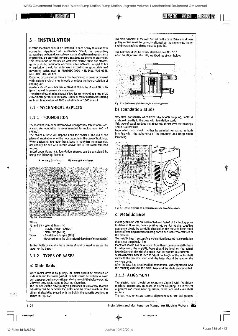
0
3 - INSTALLATION
Electric machines should be installed in such a way to allow easy access for inspection and maintenance. Should the surrounding atmosphere be humid, corrosive or containing flammable substance or particles, it is essential to ensure an adequate degree of protection. The installation of motors on ambients where there are steams. gases or dusts. flammable or combustible materials, subject to fire or explosion, should be undertaken according to appropriate and governing codes, such as ABNTAEC 7914, NBR 5418, VDE 0165, NEC-ART. 500. UL-674. Under no circumstances motors can be enclosed in boxes or covered with materials which may impede or reduce the free circulation of cooling air. Machines fitted with external ventilation should be at least 50cm far from the wall to permit air movement. The place of installation should allow for air renewal at a rate of 20 cubic meter per minute for each 100kW of motor output considering ambient temperature of 40°C and altitude of 1000 m.a.s.l.
3.1 - MECHANICAL ASPECTS
3.1.1 - FOUNDATION
The motor base must be level and as far as possible free of vibrations. A concrete foundation is recommended for motors over 100 HP
(75kW). The choice of base will depend upon the nature of the soil at the place of installation or of the floor capacity in the case of buildings. When designing the motor base, keep in mind that the motor may ocasionally be run at a torque above that of the rated full load torque. Based upon Figure 3.1. foundation stresses can be calculated by using the following formula:
Fl = 0.5.g.G - 4 Tmax F2 = 0.5.g.G + 4 Tmax A A
Fig. 3.1 - Base Stresses
Where: Fl and F2 - Lateral Stress (N)
9
Tmax A
- Gravity Force (9.8m/s2) - Motor Weight (kg) - Breakdown torque (Nm) - Obtained from the dimensional drawing of the motor(m)
Sunken bolts or metallic base plates should be used to secure the motor to the base.
3.1.2 - TYPES OF BASES
a) Slide Rails
When motor drive is by pulleys the motor should be mounted on slide rails and the lower part of the belt should be pulling to avoid belt sleppage during operation and also to avoid the belts to operate sidewise causing damage to bearing shoulders. The rail nearest the drive pulley is positioned in such a way that the adjusting bolt be between the motor and the driven machine. The other rail should be placed with the bolt in the opposite position, as
shown in Fig. 3.2.
The motor is bolted to the rails and set on the base. Drive and driven pulley centers must be correctly aligned on the same way, motor and driven machine shafts must be parallel.
The belt should not be overly stretched, see Fig. 3.10. After the alignment. the rails are fixed, as shown below:
Fig. 3.1 - Positioning of slide rails for motor alignment
b) Foundation Studs
Very often, particularly when drive is by flexible coupling, motor is anchored directly to the base with foundation studs. This type of coupling does not allow any thrust over the bearings and it is of low cost. Foundation studs should neither be painted nor rusted as both interfere with the adherence of the concrete, and bring about loosening.
Fig. 3.3 - Motor mounted on a concrete base with foundation studs.
c) Metallic Base
Motor-generator sets are assembled and tested at the factory prior to delivery. However, before putting into service at site, coupling alignment should be carefully checked as the metallic base could have suffered displacement during transit due to internal stresses of the material. The metallic base is susceptible to distortion if secured to a foundation that is not completely flat. Machines should not be removed from their common metallic base for alignment; the metallic base should be level on the actual foundation with the aid of a spirit level (or similar instrument). When a metallic base is used to adjust the height of the motor shaft end with the machine shaft end, the latter should be level on the concrete base. After the base has been levelled, foundation, studs tightened, and the coupling checked, the metal base and the studs are cemented.
3.1.3- ALIGNMENT
The electric motor should be accurately aligned with the driven machine, particularly in cases of direct coupling. An incorrect alignment can cause bearing failure, vibrations and even shaft rupture. The best way to ensure correct alignment is to use dial gauges
1-04 Installation and Maintenance Manual for Electric Motors Li§
foroword.p65 4 26/12199, 09:19
IL WP23 Government Road Inala Water Pump Station Pump Station Upgrade Volume 1 Mechanical Equipment OM Manual
Q-Pulse Id TMS996 Active 10/12/2014 Page 166 of 442
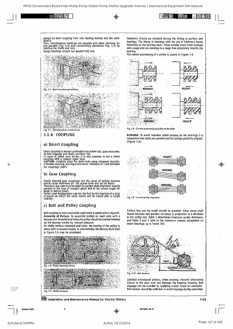
foreword.p65
1
placed on each coupling half, one reading radially and the other axially. Thus, simultaneous readings are possible and allow checking for any parallel (Fig. 3.4) and concentricity deviations (Fig. 3.5) by rotating the shafts one turn. Gauge readings should not exceed 0.05 mm.
Fig. 3.4 - Deviation from parallelism
e4, Fig. 3.5 - Deviation from concentricity
3,1.4- COUPLING
a) Direct Coupling
Direct coupling is always preferable due to low cost, space economy, no belt slippage and lower accident risk. In cases of speed ratio drives, it is also common to use a direct coupling with a reducer (gear box). CAUTION: Carefully align the shaft ends using, whenever feasible, a flexible coupling, leaving a minimum tolerance of 3 mm between the couplings (GAP).
b) Gear Coupling
Poorly aligned gear couplings are the cause of jerking motions which cause vibrations on the actual drive and on the motor. Therefore, due care must be taken for perfect shaft alignment: exactly parallel in the case of straight gears and at the correct angle for bevel or helical gears. Perfect gear engagement can be checked by the insertion of a strip of paper on which the teeth marks will be traced after a single rotation.
c) Belt and Pulley Coupling
Belt coupling is most commonly used when a speed ratio is required. Assembly of Pulleys: To assemble pulleys on shaft ends with a
keyway and threaded end holes the pulley should be inserted halfway up the keyway merely by manual pressure. On shafts without threaded end holes, the heating of the pulley to
about 80°C is recommended, or alternatively, the devices illustrated in Figure 3.6 may be employed.
Hammers should be avoided during the fitting of pulleys and bearings. The fitting of bearings with the aid of hammers leaves blemishes on the bearing races. These initially small flaws increase with usage and can develop to a stage that completely impairs the bearing. The correct positioning of a pulley is shown in Figure 3.8.
WRONG
s As 1 I I
7.19
Fic)NG-:
,RIGHT
Fig. 3.8 - Correct positioning of pulley on the shaft.
RIGHT
RUNNING: To avoid needless radial stresses on the bearings it is
imperative that shafts are parallel and the pulleys perfectly aligned. (Figure 3.9).
Fig. 3.9 - Correct pulley alignment
Pulleys that are too small should be avoided; these cause shaft flexion because belt traction increases in proportion to a decrease in the pulley size. Table 1 determines minimum pulley diameters, and Table 2 and 3 refer to the maximum stresses acceptable on motor bearings up to frame 355.
Fig. 3.6 - Pulley mounting device
Fig. 3.10 - Belt tensions
Laterally misaligned pulleys, when running, transmit alternating knocks to the rotor and can damage the bearing housing. Belt slippage can be avoided by applying a resin (rosin for example). Belt tension should be sufficient to avoid slippage during operation.
Installation and Maintenance Manual for Electric Motors 1-05
5 26/12/99, 09:19
IL WP23 Government Road Inala Water Pump Station Pump Station Upgrade Volume 1 Mechanical Equipment OM Manual
Q-Pulse Id TMS996 Active 10/12/2014 Page 167 of 442
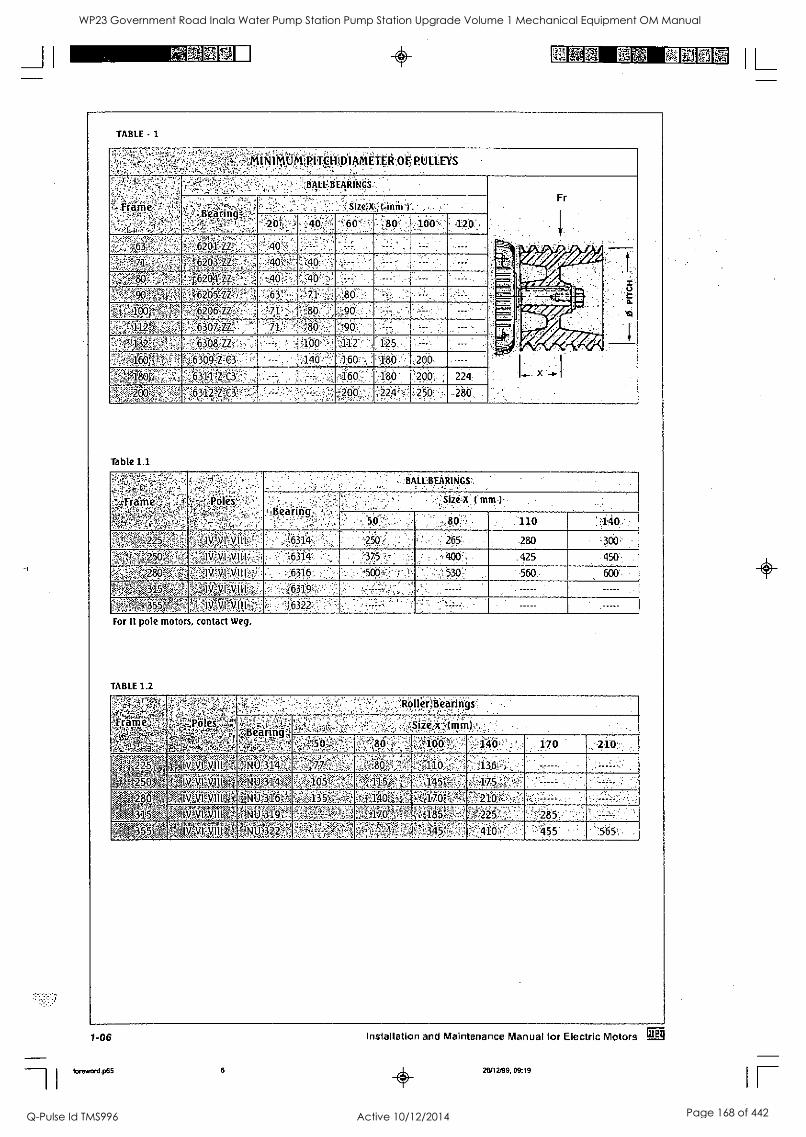
TABLE - 1
iNI".1s:IUKtitT,ttitpliwAtItR9F:PUI:1::EYS -- ,........-.,.. -.. 7..2 ''.s.ii. :-.:, - -2 . ..
.:-..7,..r:.!..',4,1:,..,1,,
1.....,,;;-:.-.-,
-, ,,.,..
*r..i*.:',1-',--, ,..,...-...e-. ,... . ... . BALL-.BEARINGS
Fr - ,4,
-.-..,.
: :. ..= . .a .
: ',:::-.;-. ! .. . .. ..- Sizg-)u(4bn) .. .y.. .:'::.. '.... " i .: .
":60''...""...' . - - .......-
,
.. ,--A0'.... . .. ..- -...,
.
-...100:',... ... s 420' .. .
6201ZZ 40 - . : ,. . - ..,'.:-.-.-...:,. ,,, ....,.-,.. traitei Y At: OM A ... Aga.
71.;;;a`/.a.A*0,*.i-.T:-:it....c..". 40 40 ....:::::!.:',,- ' ' : E-- : . ' --- .. . --- -
,f.
I
'',.,566-&-TR.'T.:"..-;'7.3:541:',,.:241621iirit-;.';',:: .i....-.40,;.-",:;'.;;-.40.-:;), .. :T.7: - --- ---7 --- - - ,
5 . 1..
Isi
I.
....M.1"061A,N.0 i'....1,-.'/?`..i, ' ,..*,6y.t.;;;:.;.?..,14,..,.: ',...Acri':-:
:;?Z`trl :.....t:m !..:-,....-;.?6y04i,....:f. ...,..i.r <..,.:80 ..:: ...v........,.; ....K. 4,.....ra:..,: .,..4.,,...,, , ....,:::- .... ..,. , . ...... ..
, ,,.).. .
.:__ ,
'. --,. .,
.
... 1
[L , '.;...::,--4,:iimf;',.:,,3.....6ofz 71 ' . . '-,90'..- ' ; '77' 7.-. - . --- - .
41 i100 112-. *i":r-'2:1,:f3'§i'"4,-Z',.P,":;:.:4^,%S6g=i2.,.. 1 5 .
,666-sd-9-.z:6-.._:: :. , - __-_ , ,-,: 140 - .:-460 ' .380 -..- :200- .---
. --. x _.. ,:..-.....?,.4.,:.i.... v.:, .- ....,..,... .
160. .. . ,..' -".. . - --- --, .. .
--.,..-Al. ..'- .
-180 , 200. ,
224:
.-- .200 ''...' :ris1.4r.,,,,v.;,,,:z.k.;-:-...:,?2, ;.-...,; ....f.,....?,,, , .. t . .....
-',-.24.--,Z..1., ' - 286. .. '
Table 1.1
';'',1*.F.
Frame ,
.
... ' " '. ' . BALL BEARINGS-.
.'.,,8earin0.i
.. . ..:., . :!. Size x - f mm 1
. . . . .. .
- .:-..,. 80'7! - .. .... , . . 110 .
. .
: -.140... :.
'W,f,,t-..&;;;,.-.' '
''..liAll'ig11-;='?". .';J:,..,,, '';'' :.... '6ii41.:: ,:!,,,,- - , - - : - '. '250-, ::
- . -..., ,...-; :., ' ..- : 265.. . . , ..280 :,300 -
4 - .i.,. 1Mi.I.:.1 : .:"..'.46314'.... . :' . : ...31,5,-.. ; .' . :., gip..., .
. 425 450..
4ti280'1:1-r&' --117,i'Vf.i.VIII 6316 - .,--- ,.. ' '-n- ;y.:-',!'.. - :.,,.. 530 560.. 600 val,iz:64.3, 5,1,:',... iv.:4vt ..-f.-4,:............,.:,,,6A1§;;.,...,
;:;F:1;,..i.;144;;:t:.....:-,6;;., '^1,- --, ' ,,
,.. - ....". :. '...,..,:-.:::-.. ' .', - " , ,';. '"... .
-
',:0,,4- 5r5INZ g:Sii-fiViNtifA ;, 6322 ;''.,::-'":;
.i. :,
., - . . . ' ' ;
: :.:
',:- ' , ----'7 -
For 11 pole motors, contact Weg.
TABLE 1.2
...F.."--.. Frarn
i',....... 7,k,'.?
0 g.:ti
",":*:,-.4 b?-g::..-1.-f,
'...'" ',.:'..- . 11bIlii:B.Baiiiigt, .
',34_4f"-'2.'j......'i...a; Zikbearing4
..."-q.i3;Z:.:;-.;;;,s',1.,:-.-k?z!...,,,ri,:i...--
`-k:f.'...-.:;--,,, -, ;';',,:',.:-,,gik..4C.".014.TIW'.-..; ...- . - .
,--:...`::'':";: 2.:: ::....,. ''.:;.....:,.._-: . '; :. ibl...,:-..',
... ,
.:.:..i.t..,.80':'.: ,,..... -......,...,..., ..;:4`,1004,1';..-:;.: ...,,,-:- .-.
"i..:r140':" .-.. '.. : ... . ... .... , 170 . -.2i0:.:
. . .
i5.0:k
_,..3f,...;..4,.,..r:
.,-;:1::.'i:i.;/-;/.,..4.::.:,.,Ns.-
..e,,,,n :..,-..- .....,,,,F,.......
.,,,,-11.0:. ,..- ' ,..
...- .--,...y..= :- 1.36' ;:" - ' ..,... . ... ....
,-4,4X,:;',:];j:.!:!,:',.- ,:.'' , -
, , ,
.... ,.. :. Ifiz ini=VIIIT 016414t3 adg,--:',..ta --
,I.,'Hkg.,:-i!,.f.1,N..4i6.-;i:0.,
4.,a8V014 io..:11,.5 :lit niK1.1909.1fita LatIblikh '.:435.;-'4-1,,w ,.fi, .
.F.,140,-.;.?f?.: ;;P.1.' ...S,.,to:.
..,-.....rr.F.0:q...=, ;.: A;,.,- --';:... :". .:.. .1:0.,,.,.....,.., .',*:: , . .- , . ....:::'.:-,..'..-::
06;10:411110, giqijk,-.400- fAlt=e4:jk di.0hli'..f* .vi:,48'.;,-u.,, :q:43L.:.:-.j:.:: . ':::::;.'285',:.. ' .' '
faVitt rtifiFRif'" FlaiP 11,,,=,,=--:',,,,-,..',.. ,:,
-4.,,:,...;.::,.; '..-:?..-;
,i.::.:.M,,,,;.--,., ...:-.y -.,...r.,..,:
,.,-.110,,..., .,.,.--
..'155 ..... . .:,
.565'
1-06
foreword.p65
Installation and Maintenance Manual for Electric Motors Pig
28/12/99, 09:19
IL
IF
WP23 Government Road Inala Water Pump Station Pump Station Upgrade Volume 1 Mechanical Equipment OM Manual
Q-Pulse Id TMS996 Active 10/12/2014 Page 168 of 442
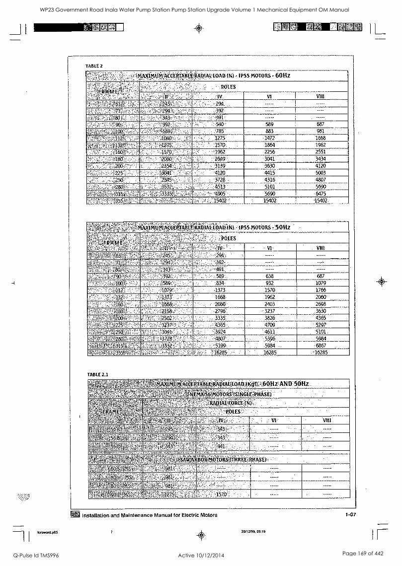
-II toreword.p65
4 ilminmaran, Immo
TABLE 2
MAXil'AIP:TA(CtirefifitiliAblAULOADIN) -1P55 MOTORS - 60Hz ..--?R.',..;-;:%';),:.1-::-. : '_ -- , - - . '-' .. , --,-,,c..,,t-?..-':: 7r...'-. .
Si. A. ,
. :t ., ..' .2'.: ,'. :' "!. '-. - .- ',POLES
.....,.
::iv . VI VIII
6"3 g .::: '- V;:;.!;;;J' ,..1,':"'10',."1:' : .:. .... - .,:.?94:
_ -;;;`..;71.-... - ,,,-:,::,:-- ...94:fi:-.,.:1--,;i,:...:;;,-7- '2,-,:,-- 2392." . ----
:.3',§05":...; . :::a.',:c.- '. 3I3 -:-.,:l.'2.-. , .,:. i.: . '.491 X... .. ., ,'....,-. ...,:' .192.::.';' ' " : 540- 589 687
' , f-:'.589 ": ',-- 785 883 981
..:.'..-a0''', ..2 ; :-:'.".,..' .';109'.f..: 1275. 1472 .1668
lIgg..,..'...i''. ..:Mg.:. . ' -: 42751 ..; . ' 1570, 1864 1962.
;..:"..5S.- , ' ,, 1:570. , '1962 2256 2551
:',..s1N '.',: ' ' .2060, ' 2619... .3041 3134
i:20.0.;,,-2 .' c. :2354-2 : I. ,, ' 3139 3630 4120
. ,' ,-': :::''..:r.:'=225. ' 30(11.' . .- 4120 . 4415 .5003
.....; .
.4 . -. -$28a....=-:-.,:.. . ; - ' . 3532.... '
3728 .
, :-4513 .
4316 5101
4807
5690 .."-,.i4.7..,?.'....''..., .:S..315.:0!-;;F:.'.::-.:;:::.,.iif .',..;435.,,i ,- ',/. '' :', . -'4905 , 5690 ' 6475
';'... .,:..'''..:'2:::2,;... : , ',-. ' , 15402
IKUKACCEPTAMIRADIAL.LOAD(H).: le 55.-MOTORS '.7:5 0Hz -
F. W
, POLES
:--.'..'':;:.7`;`;f:j,-;.;.., 7:',.. '''':.:::.: . IV . - . - *VI . . VIII
..-.?-1;q2.-W...::;',W.O3O: A::::S"::.04,24:',.. .:..: - 294 .
::...., .,..-.. .....-..a,...-,:,.., 7 :::!::, ; ..:. '' 294":.'-. ' . '-392'. '. -----
;"' .':-ii.:4F.2....80),;-...., . :1 4.'.;;::::.; 343'', ' , .. " . 491, . -
.:. ; ';;;;5'.."?-4;'90,. -.2..'',-,,..; - :., 392. '' 1 ' 589., ' 638 687
':;,:'-'ir-g: ' ;..490.,;!. .. :: ' '589='..`r:' - ; ..'.. : :834. 932. 1079
V:''..r.,..r." . . .-4,4 . '.1079!; ' ' ,.1373. 1570 1766
.1373 ; ' 1668. 1962 2060
'..:::',.....iP'.:...;';',;!74601:. 1668 .; ' ' , . .:2060 - 2403 2698
WP....:.-:';i08(15'....: .. '..'..:,. -" 2158: -. . .;.. . '...2796:1 . 3237 .3630
42.00;e.:-. -".2', ": .2502 , - 3335, . 3826 4365
fW,:tat,25-:::,!":7-',:.? 3237 ' . ; 4365' 4709 . 5297
' ...;' rs-1.5".0 gi;,i.:,...:,.NT....:,...30.4.1 --,..3.94 -, 4611 ' .5101 .
:284:a,'".i(.1R :t ...;.lii'.':',..372V.: ' ' '-';'- .....'''.4807'..12,_____-_,LL. ..:: 5396 5984
',..`0'l :'.353-2',1, : 7, . 5 .:-:5199: . -. .. . ,. .5984 .. . .6867 ----'40A?:.1,-.355W..-W7: '....:; =:;." ' 1' ":" 1 - ....;:,..'..:s::-/..: 16285.1.-.. . . 16285 . 16285
TABLE 2.1
1
,=,60HzIAND - - ik44 :-Ottz 44, ''...147.5.-.:-.i..,..2....-:'*W.'.4,.,-,,,,,,,:,,,,4,+.....,...,..:4:.,,........ ......,...1. . .- , . . . -... - . . .
'Y2qci,.:gi.i.!,.....li'4:yt.s;VM:74:5,.-x:,-,,.-r,,:z.tigt,-::.;;*,v,,pv,z-;.:..,,,,......:,,,,i ,,,
,. (SINGLE PHASE)
...
(.,,,,:;.'-'.1:::,f,::j,f-lq,-.V.::.;..:'A$?;-,:::P;;;.4:::'5,4-7,;jiikiiiifier.( N) .
%irOki-: .1::,: :.".-:.-0.0L ES .. ' .
;i;-14,tc.C4.t.0).liZ.4.'gF...i.:=74' ....;'''''.' ' ' - ' : l z . ' j W - r ' : : VI. VIII
,,., : ...,:::::,-...AF.,..,,,,,,,.,t-,,,A,z '-..4;;:,,..;
.p.,....., ......,,...:::,,,.:-.,:,: ..... :. . '
::- - '''. , :- . ....-...
.....-.., , v ..... ..4c...,. ;.., w4-,?..,A.e-...,g,,,*,,s.-,A-ri-k-;,,-.!
,,w..47 ',. ..., , 343 ,
,,,,,,,,,,,,..k , '''.- 1-514,4:.s4it:'.,:,, :::::,..,;-:.sr. ....'&(.4.-.:;',..4...
tiiivrk.;,,,?qi0; ,..:6;:qi;;;:.;.Y.1..-,.:7:,,, ,,': *.,.;.%.%:::6,6!'i.:.:
,.;,:,., -:. ,.. 441 .- -
'........<: *, ,. .: ' .
.
l--::Y,,g;if1:A4:kkj ,tiji jr401",o...ItiqtHREE-.M:i A'S. t)', '::q-k '80 H.MS .'-,rf->i"i7..:-,::::?.:981P.' . - . '!. , -
._.. MS :ift:''*g,-,4.4t -.. -. '":.:- , ...''.-.:.-1:-:.- .r.-.. .
...,......,,--47,-a-,,o;.,,,,,,,;:-;;;Ao ,-;x4-..:,...,-, ;..., ::.....rojz,....f.;;,, ..- p,1 ...-....4.; . ..,-, c7n:: .... , ' , . ' .1:J/V
grg Installation and Maintenance Manual for Electric Motors
7 0 26/12199. 09:19
1-07
IL WP23 Government Road Inala Water Pump Station Pump Station Upgrade Volume 1 Mechanical Equipment OM Manual
Q-Pulse Id TMS996 Active 10/12/2014 Page 169 of 442

4
Concerning ODP NEMA 48 & 56 fractional motors, these have the - Bearings: Ball following features: - Standards: NEMA MG-1
- Voltage: Single phase: 110/220V - Rotor: Squirrel cage Three phase: 220/380V - Protection: Open drip proof - Frequency: 60Hz and 50Hz - Insulation: Class "B" (130°C) - IEC 34 - Cooling system: intern& For more information referring to motor features, please contact
WEG.
TABLE 3
a 5 I ft iUMACCEPTABIIVAXIALIOAD ) - 60 Hz
" , TOTAEMENCLOSED.FAN,COOLEMMOTORS.- 1 P 55,
- 50100M0.0NTINGONFit-UkAtiON . '. ''
1...
,,, ' 42,---
I Fai .-Fa1
Fa2, .. 4' Fla2
A
.x.'''
N rYw
Aii
'If 11
2 *0:7,0tk:,0
t '1'.1
. . ,.
-,,..,.
:,,,
\
4p , ,...' .
a
..
u265^ X
ti343q
VP-
!:,412.,.
VIII. lt. 265
IV
343
.
'VI.
412
VIII .
;..7a:0.4, f3YAV POS toga ;53 0., , i;149,1, .. . II NT '1:2 4M0 ' .?; ; -5?0 ' '353 481 5591' !638
MOM' MO .1".:.01% :f0591 40 t,.:t4:747'i itt6:04i {'755'^ 4{844 OM glw -,-,,-.,,5 '.. 608' ' . 481: '618 ,7. 26 '": "..:1fi24: '
9,9:0 :Agit golo mg .rftg, i msg att -.922; ,A?z`A '! 706 '785' -'461. 628 '715:: -'';873! .
f TOTIAV' ', ON .795aY9034 687, --2AY5 ,4111281 4275 432 s .., .,834., :: 638- 873 ! -1069...'.1207- -.144 4; ;: ii11.1:q 11972 f18.28J, p1..,973.: '2227 ',424"' c)20 ; :'.1:187,:::11.1§ 1540L. 4:874 2139 ,132 .1., {1151314118 , '570:`, 1422: ;4982? c2364 ;26.59 ' IOCi ''....1010' .;'.1207; -1364 :13:05' "1825: 2178 .2453
::-t1260I ...,,,,97-i 16fAss; .,, 1884. Rig 2040 8746 ;.::3178 . j..3620- g952 1383. :,::1560 1884 1795 2482:. .2855 :: :3335,
,180.a ,g_X"! :2178; ,,..m ::g AT .' ..-; s ;WA 0 Ft:',416%-.1, , 1825'.:1'19.91 :.2315 3375 3806 "4565 .1668 "2 X2659 .3041,:: 4,129
: 41:4::*9A1;555? ;. 1197 ::: 052.9. j:2040: ,.24.22 -26542. 3483 :4277. 4983
.',14983'A - ',It'. 009' -'69§5': '4983' -'5278 V5150..!
t6290' %=6985
5i.:6653: ',3:682.8
,3....'. 3121-
144 4169'
'97.";;;.61:;?2, ",4876" ,' 5651
','3'3". ' 4454 ''.'
3129,1 - 4169
5297
.4876. '-'6082 . 5651 -.- 3895i; ;5180't :760.51-.16828; .1.645-1
:?§Q.If4. ;35Pat i5904r *7,9 7.4i MI5 47x, 0964:2 r;Y707k3; f:798 tc:25:4 4424 : :?.:.,5307; i[f6239= 2541' , 4424. '5307 -r,6239r
Am ram. t00:6322; mtii jo;;I:y 16641p614;1579, -O208; i 3 4 .::::4838- 1579..: 3208 3924' ,:.4836
055'..*::`.-30,0: .825:9:11'A331.81P32"99,:i 9112 ,..;g825,9'A :i:2338 .82.99 tl:"4:5 1:E ;':;-20191:. -irp,'2 443; !i,:2659 451i': e2109 :'-2443 :2659
5 -.' . -' ' ' ,,, ' ,IMArli!..cAPTA1141NNIAII-P.AP:5!"1\1 ,-f 'Hz,
..; '' -'q .04 PV.4E:N c1(.0 P3.Fikt1S.0,KEPMIPT 0 MNI P 5 5- ''.--SilTioi101 terWiilt:?&iiitit tRATio'N
..1X i
'ta2 a . # :.:(F. -6a2 -.,-,-
'
.
.
4:Fa1
,P
'..1' Fa2.'.. Fat ,
yi1.2.%) .,...:inz ,,-..i.viir i?.3..
ZAC:.@ .
,.,,,,A1: ..-
..5
5-5
, .,...;
411,11P, 41. .- ,' 1,- 11.' IV' -' yr . Aim I.
OM 001: Mig 4ii1 a z:, .r. RR§ ON ,fil.4;:t.7::, gso 601 .,, ,-.. 294. . ;392 441''';
:' I 3 T43 riF30 'om :59.0 iNIOI '''s 4 agog !ay. ,,,_ '' ':,::-.51 9 ..: .-. 510- 589` .,',677%
t80g 3:700 Mcyti 589.1 Igo 491 ̀ z A X785, 1. 3r:, 4814 .,,;.647,, :]1.1 I '. ":::657 ' 765 :' 873 .-
§"gia.004011 .§N 784M C.70 6r EC :-, k;4414 '4618 ti7,46 ..834::::,:,491....'667 824 '':::,922
l'00 PO StIO Iffigt KV:01'FM Klq.k ;q4.,::P A611 '00 , "765 - ::,'883 ;677 1128.:.:1275':-
-1982 `'2:266- A1:40410 ii911A §14±7,$.7, W54...A :4275, 21 7.I.2 71 4.0,91 :'2154:;; %PAM, F'87:V-: A. 1256 . 42Q7.': :. 16.28.
- 132 om ifito 001,4*.,l-OW OW 140.15 48 5 1275 ; 442,: :1383:: .:1933 2305.. 2600:-
0941t2,,,51 446 :14991 22.,,90. i5;2104: tpot i....:34:il i:.3AW :119 fl ./" ,,. ;1658 i. =11991 ::. : -1903`;2629` 3021 :3552:
)280. MR. '2105, Er.049'i .g9:.84.1 .''':'.'1,t':;''':, i3144;. !Ai% 1i.W15; 0A7'.."k;: 1933:" ;2109` .-. ..3581 4032 . ::4630,
:?.9.Pi i 10 61 i2i.5S5...t f28i5 4317S .3316`` 437,,5 K5;189 $.-.. c . 5 166 --: 0 5-2619, .;', 281.5? :3889 4532:- :5278- 22:61 424 45592'4 f18.5.23! F.:74,19:74 ll'i 4592:', ',8373 ;'7,401 A.:35 2i: 647; ,w :i;5611 . ;:844. 5', ': 3532 1719. 561 r, 6445
',?Ott#:;46. go. 6:Azdv i?' -:. A 549444 t6...aygi 7230 wc- s" 15160 ;:300:4',, 3316.. ' 5160; '.,5984;..
Op, i5,973; osori 7505 18466 .:,.3973.:. i:005 mg 4,:gc 4688:j 4,881F,", :::.5621`.:, ;?6612 2688 !.4689 5621 "6612
315, #00. rs*. RPO f$796,4 X3630 .
55886, F400; 27966A 1668 x3404',"4159 :51:21 1668::.' :3404 4159 ' . 512r 3554-1,31076] i602; 17;7(791 '8:7904 OSO:Oi T.66321 '..747z7,91: '0790 :(481 it. ,;: li) .c.'2815. 481 - 2237: .!2590, 2815:
1-08 Installation and Maintenance Manual for Electric Motors Er]
foroword.p65 8 26/12/99, 09:19
IL
WP23 Government Road Inala Water Pump Station Pump Station Upgrade Volume 1 Mechanical Equipment OM Manual
Q-Pulse Id TMS996 Active 10/12/2014 Page 170 of 442
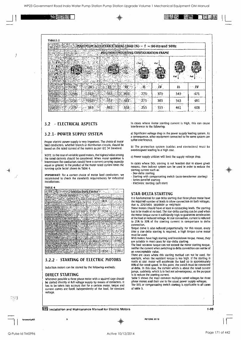
_J 1
%E IL
foreword p85
TABLE3.1
gal Mli MACCEPJYABtEWCIAkILPAP =160 livand 50Hz
POSIP0`1:10.01tITING'it-OfiFIGURATIONIIRAME
IV II: ,JV
27-5 373 343 -471.
275 363 343 461
255 353 441 608
3.2 - ELECTRICAL ASPECTS
1.2.1- POWER SUPPLY SYSTEM
Proper electric power supply is very important. The choice of motor
feed conductors, whether branch or distribution circuits, should be
based on the rated current of the motors as per IEC 34 Standard.
NOTE: In the case of variable speed motors, the highest value among the rated currents should be considered. When motor operation is
intermittent the conductors should have a current carrying capacity equal or greater, to the product of the motor rated current times the
running cycle factor shown in Table 4.
IMPORTANT: For a correct choice of motor feed conductors, we
recommend to check the standards requirements for industrial installations.
TABLE 4
;30:1O670,i Continiioiis
Srt4(valve--:,:-.....
Ac.,,m,,k...:b...,1, etc
1.o-:<1-4:::Y operation,: contact,. .operatiort..) Mrrtgffgri*'-'Ia'WiV otermitteAlondloy tbuildingelevatdrs,y "'
rrips ibndgesFetc.-1)
kriKi enod19,1
imilinimmohinesAria MataaVAltetniT'. Vanable
3.2.2 - STARTING OF ELECTRIC MOTORS
Induction motors can be started by the following methods:
DIRECT STARTING Whenever possible a three phase motor with a squirrel cage should be started directly at full voltage supply by means of contactors. It
has to be taken into account that for a certain motor, torque and current curves are fixed, independently of the load, for constant voltage.
In cases where motor starting current is high, this can cause interference to the following:
a) Significant voltage drop in the power supply feeding system. As
a consequence, other equipment connected to the same system can suffer interference.
b) The protection system (cables and contactors) must be overdesigned leading to a high cost.
c) Power supply utilities will limit the supply voltage drop.
In cases where DOL starting is not feasible due to above given reasons, then indirect system can be used in order to reduce the starting current such as: - Star-delta starting - Starting with compensating switch (auto-transformer starting) - Series-parallel starting - Electronic starting (soft-start)
STAR-DELTA STARTING It is fundamental for star-delta starting that three phase motor have the required number of leads to allow connection on both voltages, that is, 220/380V, 380/660V or 440/760V. These motors should have at least 6 connecting leads. The starting has to be made at no load. The star-delta starting can be used when the motor torque curve is sufficiently high to guarantee acceleration of the load at reduced voltage. At star connection, current is reduced to 25% to 30% of the starting current in comparison to delta connection. Torque curve is also reduced proportionally. For this reason, every time a star-delta starting is required, a high torque curve motor must be used. WEG motors have high starting and breakdown torque. Hence, they are suitable in most cases for star-delta starting. The load resistant torque can not exceed the motor starting torque, neither the current when switching to delta connection can not be of
an unacceptable value. There are cases where this starting method can not be used. For
example, when the resistant torque is too high. If the starting is
made at star, motor will accelerate the load up to approximately 85% of the rated speed. In this point, the switch must be connected at delta. In this case, the current which is about the rated current jumps, suddenly, which is in fact not advantageous, as the purpose is to reduce the starting current. Table 5 shows the most common multiple rated voltages for three phase motors and their use to the usual power supply voltages. The DOL or compensating switch starting is applicable to all cases
of table 5.
Erg Installation and Maintenance Manual for Electric Motors
9 26/12/99: 09:19
1-09
IF
WP23 Government Road Inala Water Pump Station Pump Station Upgrade Volume 1 Mechanical Equipment OM Manual
Q-Pulse Id TMS996 Active 10/12/2014 Page 171 of 442
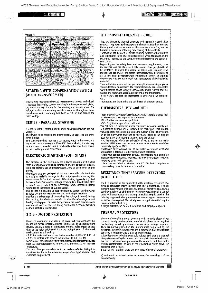
_J I
';ZiFillEi 4- mie M L
TABLE 5
`No -rural c. PnOe h reiip as e motors', i0419f i t .
, design
1 Operation jyoltage
di,deltas starting
,,,,,..,.,:,:x.,..:::.a...r
21:v/380 3 V
..
.' W4i5k-4,..'t'it - 9/400/2304,460)14;32,20Y/R3OV
.t..440Y/77,,,601A .... ,
i380V/:6:6 ,.:;,,
220/380/ :fr
, =',
STARTING WITH COMPENSATING SWITCH
(AUTO-TRANSFORMER)
This starting method can be used to start motors hooked to the load. It reduces the starting current avoiding in this way overload giving the motor enough torque for the starting and acceleration. The
voltage in the compensating switch is reduced through an auto-
transformer which normally has TAPS of 50, 65 and 80% of the
rated voltage.
SERIES - PARALLEL STARTING
For series-parallel starting, motor must allow reconnection for two voltages: The lowest to be equal to the power supply voltage and the other twice higher. This starting method requires 9 connecting leads in the motor, and the most common voltage is 220/440V, that is, during the starting, motor is series connected until it reaches the rated speed and then it is switched to parallel connection.
ELECTRONIC STARTING (SOFT START)
The advance of the electronics has allowed creation of the solid state starting switch which is composed of a set of pairs of tiristors (SCR) (or combination of tiristors/diodes), one on each motor output borne. The trigger angle of each pair of tiristors is controlled electronically to apply a variable voltage to the motor terminals during the acceleration. At the final moment of the starting, typically adjusted between 2 and 30 seconds, voltage reaches its full load value after a smooth acceleration or an increasing ramp, instead of being submitted to increasing or sudden jumps. Due to that it is possible to keep the starting current (in the power supply) close to the rated current and with slight variation. Besides the advantage of controlling the voltage (current) during the starting, the electronic switch has also the advantage of not
having moving parts or those that generate arc, as it happens with mechanical switches. This is a strong point of the electronic switches as their useful life is extended.
123 - MOTOR PROTECTION
Motors in continuous use should be protected from overloads by means of a device incorporated into the motor, or by an independent device, usually a fixed or adjustable thermal relay equal or less
than to the value originated from the multiplication of the rated feed current at full load by: - 1.25 for motors with a service factor equal or superior to 1.15: or - 1.15 for motors with service factor equal to 1.0 (IEC 34)
Some motors are optionally fitted with overheating protective devices such as thermoresistances, thermistors. thermostats or thermal protectors. The type of temperature detector to be used are selected taking into consideration the motor insulation temperature, type of motor and customer requirement
THERMOSTAT (THERMAL PROBE)
They are bimetallic thermal detectors with normally closed silver contacts. They open as the temperature increases and then return to the original position as soon as the -temperature acting on the bimetallic decreases, allowing new closing of the contacts. Thermostats can be used for alarm, tripping systems Or both (alarm and tripping) of three phase electric motors when requested by. the -
customer. Thermostats are series connected directly to the contactor coil circuit. Depending on the safety level and customer requirement, three thermostats (one per phase) or six thermostats (two per phase) can be installed. In order to operate as alarm and tripping (two thermostats per phase), the alarm thermostats must be suitable to act at the motor predetermined temperature, while the tripping thermostats must act at the maximum temperature of the insulating material. Thermostats are also used on special applications of single phase motors. On these applications, the thermostat can be series connected with the motor power supply as long as the motor current does not exceed the maximum acceptable current of the thermostat. If this occurs, connect the thermostat in series with the contactor coil. Thermostats are installed in the coil heads of different phases.
THERMISTORS (PTC and NTC)
These are semi-conductor heat detectors which sharply change their resistance upon reading a set temperature. PTC - Positive temperature coeficient. NTC - Negative temperature coeficient. The PTC type is a thermistor whose resistance increases sharply to a
temperature defined value specified for each type. This sudden variation of the resistance interrupts the current in the PTC by acting an outlet relay which switches off the main circuit. It can also be used for alarm and tripping systems (two per phase). NTC thermistors, which act adversity of PTC's, are not normally used on WEG motors as the control electronic circuits available commonly apply to PTC's. Thermistors have reduced size, do not suffer mechanical wear and act quicker in relation to other temperature detectors. Fitted with control electronic circuits, thermistors give complete protection for overheating. overload, sub or overvoltages or frequent reversing or on - off operations. It is a low cost device, similar to a PT-100, but it requires a
commanding relay for alarm or operation.
RESISTANCE TEMPERATURE DL LCTORS (RTD) PT-100
The RTD operates on the principle that the electrical resistance of a
metallic conductor varies linearly with the temperature, It is an element usually made of copper, platinum or nickel which allows a
continuous follow up of the motor heating process through a control panel of high precision and acting sensibility. Highly used in the industry in general where temperature measuring and automation techniques are required. Also widely used on applications that require irregular intermittent duty. A single detector can be used for alarm and tripping purposes.
THERMAL PROTECTORS
These are bimetallic thermal detectors with normally closed silver contacts. Mainly used as protection of single phase motors against overheating caused by overloads, locked rotor, voltage drop. etc. They are normally fitted in the motors when requested by the customer. The basic components are a bimetallic disc. two flexible contacts, a resistance and a pair of fixed contacts. It is series connected with the supply voltage and, due to a thermal dissipation caused by the current pass through its internal resistance, the disc is deformed enough to open the contacts, and then motor feeding is interrupted. As soon as the temperature comes down, the protector should react. Based on the resetting, there are two types of thermal protectors:
a) Automatic overload protector where the resetting is done automatically.
1-10 Installation and Maintenance Manual for Electric Motors Pin
foreword.p65 10 26/12/99, 09.19
WP23 Government Road Inala Water Pump Station Pump Station Upgrade Volume 1 Mechanical Equipment OM Manual
Q-Pulse Id TMS996 Active 10/12/2014 Page 172 of 442
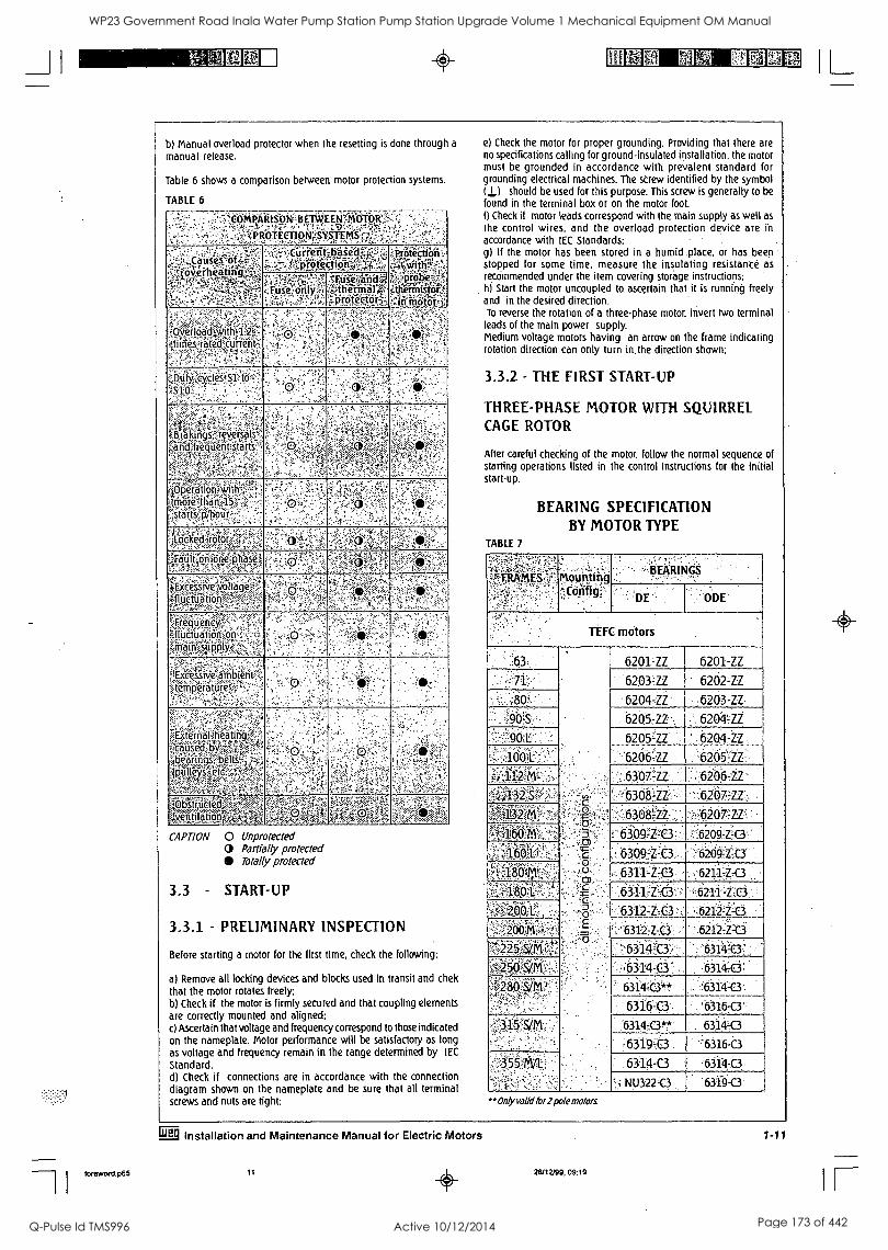
b) Manual overload protector when the resetting is done through a
manual release.
Table 6 shows a comparison between motor protection systems.
TABLE 6
COMPARISON BETWEEN
likbfiCtiON'SY',iii
Causes of eiheat n
rienf-kase protect:Log'
-tiaiiiii. 10,,ro
Yx . re
,, efin'istorf: ',;f:ii'iraltif'i.;
Fuse only. .
Fuse d ;thermal 1#041Okt
eflOadEwit . .
-,fliffi,s--8fgfi' rcurrent
:, D f9:;zeycles ; s] . to.
s -
:
,
Orakingsfeyersa ;,arkfltieriiietit?Sfar
,.- A "
.,!..-.,..K.-.1..: 1......-a-
,0peration1,wi ,,,,i,;., $more4nan-1. ,stariss,p/hour
.-,. cocked ,-:rbtoro,F;: -
"Fault on:one, ' p a.' 3 ,, ,
Excessive ....-.:--ti.--;
iv9ltage .--..-
glitlairgifon
Frequency3 1.11qctuation o
r4 , -
EiCessive:aitib ambient ; ,,,,.--...,,,.. temperatures:,
. ,
. .
terrialiheatin causedby ,,,,,,.-,
laciTiiiii s belts 3011 s.
-Obstr,-1-iete -, 4entiaton ',.t,,, ,,,,
*. s-.,
,
.r-
CAPTION 0 Unprotected (D Partially protected
Totally protected
3.3 - START-UP
3.3.1 - PRELIMINARY INSPECTION
Before starting a motor for the first time, check the following:
a) Remove all locking devices and blocks used in transit and chek that the motor rotates freely; b) Check if the motor is firmly secured and that coupling elements are correctly mounted and aligned; c) Ascertain that voltage and frequency correspond to those indicated on the nameplate. Motor performance will be satisfactory as long as voltage and frequency remain in the range determined by lEC
Standard. d) Check if connections are in accordance with the connection diagram shown on the nameplate and be sure that all terminal screws and nuts are tight;
e) Check the motor for proper grounding. Providing that there are no specifications calling for ground-insulated installation, the motor must be grounded in accordance with prevalent standard for grounding electrical machines. The screw identified by the symbol (I) ) should be used for this purpose. This screw is generally to be found in the terminal box or on the motor foot. f) Check if motor leads correspond with the main supply as well as the control wires, and the overload protection device are in accordance with IEC Standards; g) If the motor has been stored in a humid place. or has been stopped for some time. measure the insulating resistance as recommended under the item covering storage instructions: hi Start the motor uncoupled to ascertain that it is running freely and in the desired direction. To reverse the rotation of a three-phase motor, invert two terminal
leads of the main power supply. Medium voltage motors having an arrow on the frame indicating rotation direction can only turn in the direction shown;
3.3.2 - THE FIRST START-UP
THREE-PHASE MOTOR WITH SQUIRREL CAGE ROTOR
After careful checking of the motor, follow the normal sequence of starting operations listed in the control instructions for the initial start-up.
BEARING SPECIFICATION BY MOTOR TYPE
TABLE 7
FRAMES' .- '=,' ' '
MoMounting ..,,
.°311g'''
,, BEARINGS' If- --
: :DE `ODE:
TEFL motors
.63
:,,2 : ....c2:
! 5. 0 "-.
88,
3
r -
6201-U 6201-ZZ
.71' 6203 -U 6202 -ZZ
. 80' 6204,ZZ 6203-ZZ
.90 ;$ 6205:1Z , 6204ZZ
90 I.:- 6205qZ__ . '62064Z
_: 6204:ZZ_______
62054Z: -100:1:: .
. . .. :
.112. 63074Z ,.62064Z"
Qi11-4§ 6368 .zz, ,:6267;qz:. - 6308 .4z ;.,:6207 ;zzi..
'!--63b§2;t3 :'.6`266;z,o ,
. :: 6.09 .t.C3 .'6209:it3'' ' ',, 1- .. 6311LtC3 '6211-Z-C3
.:: 68iiq:e3 ,S2ii -z-c3 ..,.,
,;-:-6312-C.3 -..
-'6312-z-0.
,62124,C3
' 621-2,Z:C3 ,.,>. s
:j,,'. .....:-.-6 14c3, 6314b:, . -..,6.ji...=k3 6314-;d:
::::4*,?§/M - ' 6314:b4'..! :r631;4-.1
'6316=0'. 6316-.c3
'315' S/M . :6314 C3**' 6314L0
6319.C3 '6316-b
355 ma : 6314-0 614-.0 '- i NU322,C.3 6319-0
"" Only valid for 2 pole motors
Eg Installation and Maintenance Manual for Electric Motors
bmword.06 26/12/99, 09:19
IL WP23 Government Road Inala Water Pump Station Pump Station Upgrade Volume 1 Mechanical Equipment OM Manual
Q-Pulse Id TMS996 Active 10/12/2014 Page 173 of 442

WP23 Government Road Inala Water Pump Station Pump Station Upgrade Volume 1 Mechanical Equipment OM Manual
Q-Pulse Id TMS996 Active 10/12/2014 Page 174 of 442
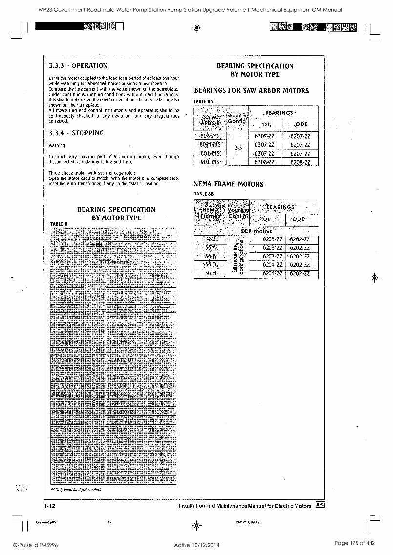
0
3.33 - OPERATION
Drive the motor coupled to the load for a period of at least one hour while watching for abnormal noises or signs of overheating. Compare the line current with the value shown on the nameplate. Under continuous running conditions without load fluctuations, this should not exceed the rated current times the service factor, also shown on the nameplate. All measuring and control instruments and apparatus should be
continuously checked for any deviation and any irregularities corrected.
3.3.4 - STOPPING
Warning:
To touch any moving part of a running motor, even though disconnected, is a danger to life and limb.
Three-phase motor with squirrel cage rotor: Open the stator circuits switch. With the motor at a complete stop, reset the auto-transformer, if any, to the "start" position.
BEARING SPECIFICATION BY MOTOR TYPE
TABLE 8
,-, ,
FRAMES Mounting on
;BEARINGS, ' ' :.--(z,-,F;
Feiiricilev,-,
143Tw', , ,
.§a Ott- - ,
L 182,T ,
6206 ,:-.,
X6307 0
P.; ......,
-r
8= . 0.7 , .. 4 .4,
8- 7z 6207 IZ
25,4 6309
,t-gFaair}g, ,..,,,,1,.
A . 99.,. 1
..o, i-
9,
g§gfhgTh; , ',.4v z
v. :6311- C3 6211 ' C3
41.0,7610/41, 43).AT-at 13 x.,t.ww1",,,,rx-,, c, 12400# A . - - 2,,,I,M,,,:4-,- sn .....-.< ,,,
6312 C3 ''N,..,...., ,
gij2"71VtliC.I1 AI ,. V ,
Vii Vin ''t'''..: 1:3:14 '''''. g MEWA-.,
= ,-ti,.4 .4.--,
6314 ,. et, ,,,..,,,..;1.:, '-'
4 0,1 ti 4 '16.-Alit 6iger ,,:,, .-,.
46.5ZS: ' ...........,,k,,,,, Mt6.310' t ..,,,,
''. 14 V.4r'''''Ai<3, 'T.3 444q7,4,A 1,,,..,?
7-- , ,-
',§3167, '.!) 6316 .
'411.§ '' -'...I 41 .-K.,t c
6314, C3t,' "1 k.,),..,'
6 i i-
',445 445 , , 6i6 ,... '.f',' - 4
fig414A- : . - 46314
,..i.p. ,,,,, :.' .
:. :
,e., E.3" 6316A3k.r.i.
Mktril ' 450.,..10-t-' - ''''' , 1 3 :.:'':- ,,,,, 5°PZ.,5c/2 I- , .6, 3 191 I ,
:86r- 631 4
,. 87ecr: ,....: , N(5 k ''' 4.,,,,,::. :,7 te. r6319 C3
Only mid for 2 pole motors.
BEARING SPECIFICATION BY MOTOR TYPE
BEARINGS FOR SAW ARBOR MOTORS
TABLE 8A
ARBOR
.. II
BEARINGS
-PP g., DE, ODE'
80 S .,''M 6307;E ,6267-ZZ
:80iM M S 6307-E 6207-E :801MS7 6307-E 6207-ZZ
:9042MS- 6308-E 6208-ZZ
NEMA FRAME MOTORS
TABLE 8B
,j 1S4:.IN
-4 1 641 say fir' ̂ t
WO Dtirig , '. 0 Ph: § ":
% ' .
,.
X'APINO§''
,
P;.riiiitis' 488":,: '
,.g. ;2f-,
:§::,,g,, i
?:Icp:.
"7-6..8 .
6203 -ZZ . ' ,'62021Z'
56*: ,.603zz, 6202 7zz
56 t,, : 6203-E '.-6202LE
56 1?:: 6204 -ZZ 6202 -ZZ
'.'56:1-I, - 6204'E. 6202-ZZ
1-12
foreword.p65 12
Installation and Maintenance Manual for Electric Motors Ed
26/12/99, 09:19
IL
WP23 Government Road Inala Water Pump Station Pump Station Upgrade Volume 1 Mechanical Equipment OM Manual
Q-Pulse Id TMS996 Active 10/12/2014 Page 175 of 442
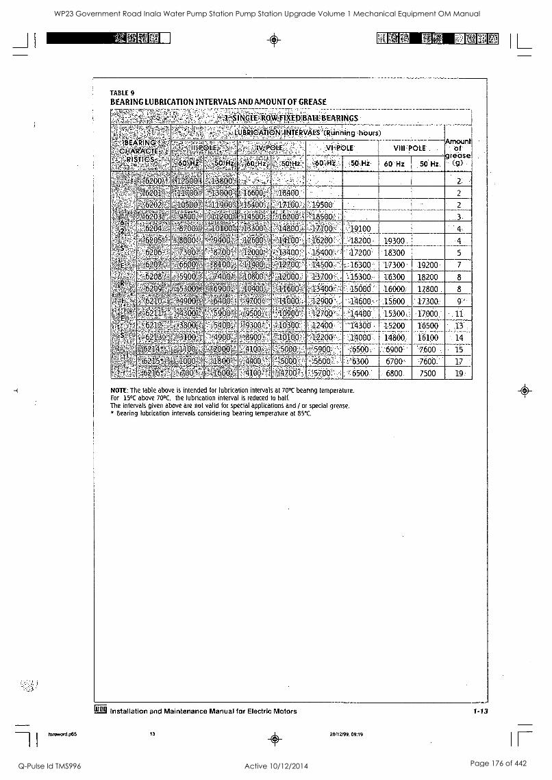
forewoni.p65
TABLE 9
BEARING LUBRICATION INTERVALS AND AMOUNT OF GREASE
',.ydf; .;, q
1::4 'S I NGLE-ROWEIXEDBALUBEARINGS
BE.?!2111G
- 040 I STI.S-
"h s7? LUBRICATION INTERVALS ,hours) Amount
: Of g tease -. (9)
e ,,,; -!..1, WOK' .
7:iw_-, ! -
.... ' 1P01F :
VIII POLE
:=4 ' V l-iz:, .
4. z:' .
, . .
:...:CO 0iHi :.. :50. Hi, 60 111 :50' Hz
, 62Q0" " 1
, bI4 , p ,
?-., 1700 A 16600 M*41:10:, 2
6202; 00.1§506: 2
62032 s 0 ?:.. t'^11200. fi,1 4500 ""1 200."?:: '-!-185001 li 3 x,pm ''S
:-,,,: w, 004
'eW .Tt.*,:V. .010M
;;":4",i.kilt, 41330CW ,14800 -', 17100 4:9100 4.
2 e '''
-126
..
'14100'>, O'z'
:Wf,:lf,Y, -.
,:1540U '
18200 19300
!- 47200: 18300
4
5
- .;, 1 w Z' ''' ' ,,, , 4.0046300 17300 19200. 7
8F X5900 aiW400,, , 12000 :,100,-.:::,. V15300:- 16300 18200 8
v..-J 5300 f06900V:A04001 13400' 15. 00, 6 :. :16001 17800 8
.. :4909ff , . .
-.:j29.00%,-.,-, ';446.00:,-,15.600. .:17300,
'A `',:'1-1.
,... '3
7, ,> ;.
oir, , A27,0014400 - . , . 15300 .. , .
17000:: ' 11
as z ::-.*.
, 621 '''i ....,r.,
,.':
...,
i,':',1:(i3W :
1) ,
?::12400::
'42200y,:.
'14300. i . 15200';
14000 : 14800
16500
16100
- 13
14
*;. 's , . ,, 's.'' - I.'6500 U '.: . ,690 '7600 ' 15
, ::.A. , ''''-57 , , .
''E6600;: . ,
--':'6300 6700' -7600, 17
,..-
,--v, fao ,,, ,'4700 5700` ..6500: 6800 7500 19
NOTE: The table above is intended for lubrication intervals at 70°C bearing temperature. For 15°C above 70°C, the lubrication interval is reduced to half. The intervals given above are not valid for special applications and / or special grease. * Bearing lubrication intervals considering bearing temperature at 85°C.
Olg Installation and Maintenance Manual for Electric Motors
13 0 26/12/99, 09:19
1 -13
IL
IF
WP23 Government Road Inala Water Pump Station Pump Station Upgrade Volume 1 Mechanical Equipment OM Manual
Q-Pulse Id TMS996 Active 10/12/2014 Page 176 of 442
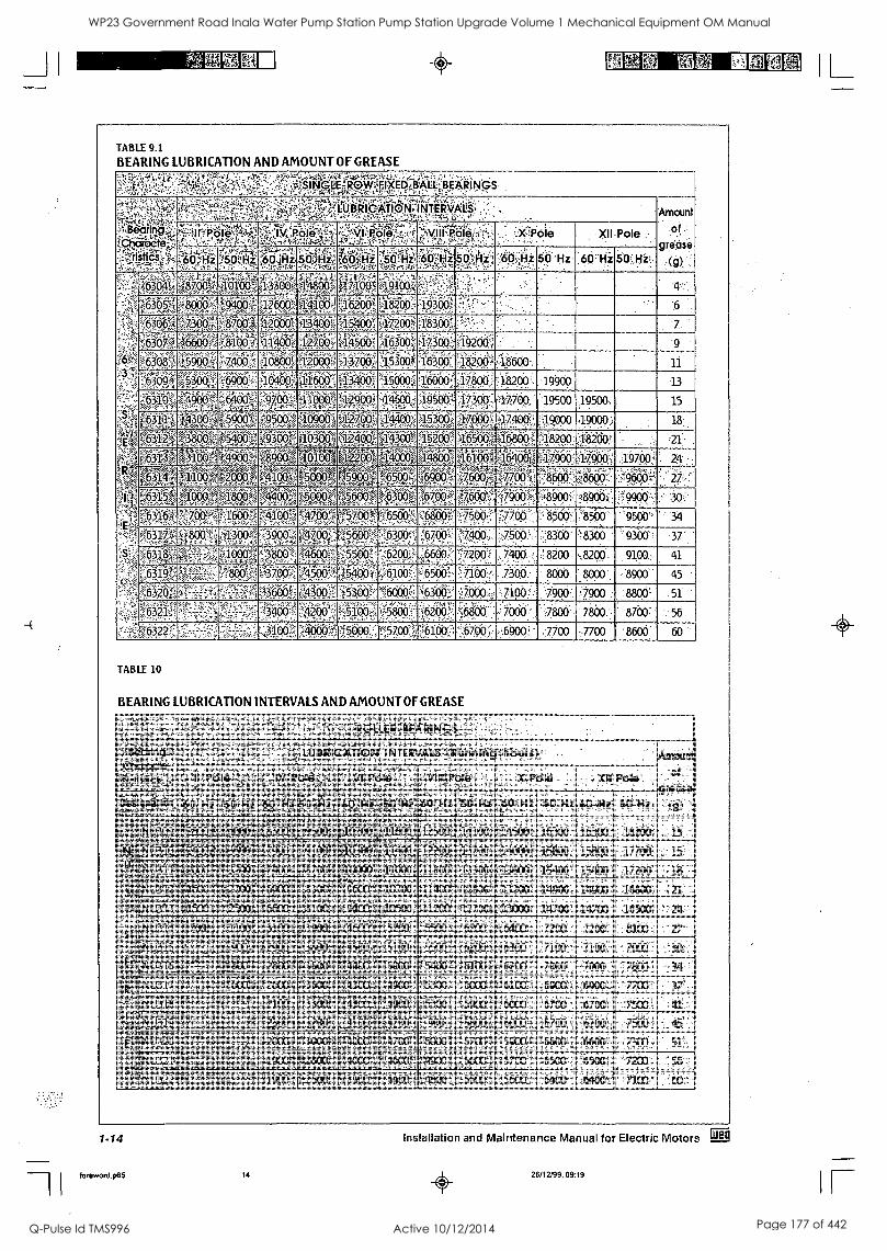
_Ji
TABLE 9.1
BEARING LUBRICATION AND AMOUNT OF GREASE ',...;::k..,-.1-filiAc....:,,,,-,.,,s-3-;,:,,,, .:....1..,_.. :.:...,.:-:-".::::- - , - .
'Pit I N GLE,ROW.,;6xEDallAit:',: ' ,,l'iVA'. vt,',;',,i.'i-,.,,,N5'.. , t ,,,` -.P.:,-: .' '
BEARINGS' , '
ch
,,, LUBRICATION? NTERVALS.,
f ...,:.,,:z::..i,"rq-,e,,,:.:.-::t5,,, ,:."--,k7-,z.::,-.- Amount
Of :
grease (g),
n '' ...,, e
Ii iio ., Pole' Pote :. sviiiP00,:.:: cpoie Xii Pole
s 6s. ','",Hi.,:e.0,r:14 fioitix solitz:2 1 71. ;;,;So1-ii ;"6 .Hz 0,.r.ttz.- .;
i 6p..,HZ .,
50 ' Hz . ,60 Hz 0; ..11I-
.,...:.POi 'b, :;; 4, 912-c;9 131'..,.3..,:i0:410g 194r7,, a
0:(Wii ; , ";. %-Ti V6493:i1' 410Ci16* ;182 19300 , 0.,, 7 - ;:a00405Wi0 .. 1-'840: - 7
9 6A30 . .
'i 927,00 44500$ :10369,147:00 '19200.
A r 5900 .'z,
-,:v.,,
t1:2PQ0J-?13700.! ...?. :,...-.,,, .. , -
..153091 ,,,- .: ,
16.300 18200 ,.
:18600 . 11
;'
6309#" '6900 '414600 43490. '15000 16990. 17800 :18200 19900
6310 '4900 6400 , 9700 ^11000' 12900' -....,.. --,,,, ::. 30: : 7 17700 19500 19500.
INIMIVPilt 00:1 9500 101:00:1 oggogip .153opi ': 17400 19000 '1.9000; . 18
,E..Rgif:I40)ZiI:.03t4 2 i103001 Rigfft 1 1300 4 A001 0800 1 00: ';J 8200 ' ,21: .
,i..."'a...41 firiM ,4900 '. Stgi 40100 tig.?0.Q. 44009 k1(1,891:4 l',.181.90 :,...... ::: 900 19700 24
r637.41 Firotil -,...;'',,,, --;:-;,:,,,::',:-,,,,,-':',,.,,-1:1':',:L.:-,-.,.--..,..,..-:
ITA ! 01,0i5it gall 59,c,x), 04,A ro:00 '''" " ,::,r , --. ---1, 4' . .. ' ',9660
.,...
27
%631:5g 000 ,,,,,,,,P+,. ' i' A4, 00tg -..A. V::1..,5,,-.4
'0001A ,r,--P41,...:
i%5600 -,,,,,,. , %....%
;"'','.
' ' V ' ' ,
'1: 8900: 990() 30 .4
E 1'.11 p4700 5" ''''..i ., ,,.. -'''' !.'Ff.500
.,.: 7700 8560 .. 8500 ' '9500' 34
e6.3 , 4300 '?. el , ,.:'";,...100,. 7500 8300 8300 .:- 9300 37'
X6318' ..- ,1000 4600 ' . ',":6"200,:- ,,,... ., -7200 -
7400- 8200 - 8200 ,
9100, ,
41
,;;6319 ,. 800 3700 Niiicilf,.E .
7:46100 ';',:i65 . 7100 7300.- 8000. ' 8000 8900.
5744i - - ?i A .:53 .:6000': 300,? ;'.000 7100.' 7900,, "790. 0 : :8800- .51
632 ,
",17,; 51004, ..5800.- ,6200 :", 7800 ' 7800. 8700 56
tOW -''-' : 31 00 -1' 5700 ; Z6100',.;',16700i: 6900 -7700 17700 '8600
TABLE 10
BEARING LUBRICATION INTERVALS AND AMOUNT OF GREASE
..-.. s', , 1Xv.,,,..± il.." ILE ritARI N G, s:".:
,!-.,. ,.
Amount
. of
grease (g) -
?..-Afsp
;.r d,,,,i,f2,..1,,
0 -A,,4...1,,,,.--,v,-4:-:::.,k,","-.:-2,"-,:.,-.7.-.5;,.. ,..... : .
LUBRICATION' 1NTERVALS?:(RiMplii4::hauig):,'
sfts'. -
fr.,e0le:,...., ''',':',"; ','
:Role so ',..
IPole'.,- . .. ,..
X.TOlii : Xli. Pole '
..,,se,siq-.-4:4.,. .-ir Des Flatten' Z1.1U-4.::.,:::!:r.:;i:-
,kiz:I50,::Hz3. , .:.-.
,
,...,:,....-..
' -%7-,., 41z.5,0t1Hzs; -- ..vi
,
y.,0.,,,.
-'".%:.',
;Hz, .,,,,...,j,.;
24, ;i5,02,,Hz: 4,...,.. .., i Hz' 60 -,H1 =50 . Hz ,60..Hz 50 Hz:
t'5....,--00Aw-r, niN0)9v,(.?.......4
ov - flQQ9 8300 ,.,-.
. ,I,, p'
,,,, ,19,,,,,,i 61.91P93011.40
e,4.v.,:,; ,.., ','.., .,.
,,, . ,,,, .
.1.51 : ,I,
, , !---
,
; 16300 .
[16300 18200 . 13 :
N'it ('''t0,- Y4, -
In h4010
40;;.-11/Ye,
03 ..
fe7 -,,,,,,',;,--,.
403991 r'',<..',''-:-..'',':,'
4J401 42. .?0) 43700 ';:
15800 ' 15800 , . , 17700 15
. ,.''..,. [N_
' '
3.2.661 - ' '
. .. Ved.i.31,
. .;,.--; SOW
. ..--.":,..-:. .ii0O(A
:-.,c,;::. aliopi.43S50
.
..
15400 i 1.5400, .:,17200 ; 18 __KIA,!-k400- .?4c,K,,,..,,c,,:,- W.i..",,
iNU31,4 60d F.i'f;33MW,
27001 A'50.,
0900 ,..ili.
'..1.830:0 i....."..';:r..,,.;;..,..;t:"...,.....,,,..,
10700 41.400 ,,e..,..,, 5428W 1-: 44900' 14900 ::: ,1 6860 21.
0
x`8275 aft r. .:
NV31-3,- ,,,....-r...,.. 25091
t..li..',.-s,A.,-1...,
nopu); iri: oi , 10549,,.
,.. : , .327001, 13000 14700. 14700
1
16500 1 '..2C-- .,1-,,,,x.,v,/
, ,,.. q,4 AA":
iV311?,7 %k A ,'.."MI,i;>,`',
01QQA 0990gl8QP, ',C'-'M
".i -,'
r,. - 7200 7200'. , I
. 8100 1 - 27 ' -,,,,,,',...44,..1, Ass; `.1....WW.....*.'
Nt./315' -: - - , ,,,,M,,W,
t:.§9.9.Z ,i,,..,";
Vik99 ,.:"-.',:
0199,1 -.;.''.. ..".;*4
f5,5,99P 1 6300 IN. .7 '' 7900 30 ..
ki.;:10:31:7;
At-A
Ni-:q:i ,, ---.4 t .. --,;: g*c -.400,, , 61001, 6200 5: opo - 7000 .';:'7800 . 34 '...
. .4 _,,,
,.. 4:-.,,,.....,.. 45,p914.
....:.,,-.0x.-,;,,.,-.----i,,,:::,- ,A3oot :;.,.,,,49.09:..;-:
,,,,...,- .,.0!.:".),:i.. 6000
., .' -6100 6900 ','
:. ,. ;:6900 ''7700- 37
an'81 F4 5`t 0:-i,,-,4 4','filiii.- 01:66-$. 4300 4900 ,',i:StiiiY ?i(:96,5. .'6000 - 6700 i ,Wkia . 7500 41
N)319 ,,, 0,-.&..,
I:
3200 1.
......
, .gf
Pi...i......,?470E.0g
t ...,.....y..
- 900 ...,:,...;.,
5800.: :,..- -56000 , .
6711 .
6700 - 7500
.- 7300
' 45 '
51 , . 8E
4:1,'.','''',-ffiol- gi 0 ;'::!.'. II7--' - 0:06*,..,..1r40b0_.gtk91 tO00 1 5700 5900 ,.1 6600..6600
--'k.*:;,..,-,.
.M3Rfltar livA lOgglgOil ,,,, 7,-*00g -' 1 6500 ''7200 56
,riA''''''75,14M-21.40Z4,,,,, "4--r,--i1::::.4.,.;%"fe:',
Ai bri,,c,,,,,,--,-
:a=!7YY-.i - ::::,,,,; ' . - 6400 i 6400 : 7100 -
1-14
foreword.p65 14
Installation and Maintenance Manual for Electric Motors
0 26/12/99, 09:19
IL
IF
WP23 Government Road Inala Water Pump Station Pump Station Upgrade Volume 1 Mechanical Equipment OM Manual
Q-Pulse Id TMS996 Active 10/12/2014 Page 177 of 442
Fari MN FNMA 1E1E4 I JI
foreword.p65
4 - MAINTENANCE
A well-designed maintenance program for electric motors, when correctly used, can be summed up as: periodical inspection of insulation levels, temperature rise, wear, bearing lubrication at the occasional checking of fan air flow. Inspection cycles depend upon the type of motor and the conditions under which it operates.
4.1 - CLEANLINESS
Motors should be kept clean, free of dust, debris and oil. Soft brushes or clean cotton rags should be used for cleaning. A jet of compressed air should be used to remove non-abrasive dust from the fan cover and any accumulated grime from the fan and cooling fins. Terminal boxes fitted to motors with IP-55 protection should be
cleaned: their terminals should be free of oxidation, in perfect mechanical condition, and all unused space dust-free. Motors with 1P(W) 55 protection are recommended for use under unfavourable ambient conditions.
4.2 - LUBRICATION
Motors made up to frame 160 are not fitted with grease fitting, while larger frames up to frame 200 this device is optional. For frame 225 to 355 grease fitting is supplied as standard. Proper Lubrication extends bearing life. Lubrication Maintenance Includes:
a) Attention to the overall state of the bearings: b) Cleaning and lubrication: c) Careful inspection of the bearings.
Bearing temperature control is also part of routine maintenance. The temperature of bearings lubricated with suitable grease as recommended under item 4.2.2 should not exceed 70°C.
Constant temperature control is possible with the aid of external thermometers or by embedded thermal elements. WEG motors are normally equipped with grease lubricated ball or roller bearings. Bearings should be lubricated to avoid the metallic contact of the moving parts, and also for protection against corrosion and wear. Lubricant properties deteriorate in the course of time and mechanical operation and, furthermore, all lubricants are subject to contamination under working conditions. For this reason, lubricants must be renewed and any lubricant consumed needs replacing from time to time.
4.2.1 - LUBRICATION INTERVALS
To apply correct amount of grease is an important aspect for a good lubrication. Relubrication must be made based on the relubrication intervals Table. However, when a motor is fitted with a lubrication instructions plate, these instructions must be followed. For an efficient initial bearing lubrication, the motor manual or the Lubrication Table must be followed. If this information is not available, the bearing must be greased up to its half (only the empty space between the moving parts). When performing these tasks, care and cleanliness are recommended in order to avoid penetration of dust into the bearings.
4.2.2 - QUALITY AND QUANTITY OF GREASE
Correct lubrication is important! Grease must be applied correctly and in sufficient quantity as both insufficient or excessive greasing are harmful. Excessive greasing causes overheating brought about by the greater resistance caused on the rotating parts and, in particular, by the compacting of the lubricant and its eventual loss of lubricating qualities. This can cause seepage with the grease penetrating the motor and dripping on the coils or other motor components. A lithium based grease is commonly used for the lubrication of electric motor bearings as it has_good mechanical stability, insoluble in water.
Greases for standard motors
Type;. ;SUpPlier .Frame
Unirex Esso 160M/L to 355M/L
.AKianid,113 :Shell Other. Frames
Greases for special feature motors
1 nie,. .Temp: ('C)
-Al i,Shia'LZ3 (-3016 135)
-::iii\ILRO(1,12. ( -30 to.165)
BG 20: - . (-45-:to18:0)
. ..
This grease should never be mixed with different base greases. More details about the greases mentioned above can be obtained at an authorized service agent or you can contact WEG directly.
42.3. LUBRICATION INSTRUCTIONS
- Inject about half the estimated amount of grease and run the motor at full speed for approximately a minute: switch off the motor and inject the remaining grease. The injection of all the grease with the motor at rest could cause penetration of a portion of the lubricant through the internal seal of the bearing case and hence into the motor. Nipples must be clean prior to introduction of grease to avoid entry of any alien bodies into the bearing. For lubricating, use only a manual grease gun.
BEARING LUBRICATION STEPS
1. Clean the area around the grease nipples with clean cotton fabric.
2. With the motor running, add grease with a manual grease gun until the quantity of grease recommended in Tables 9 or 10 has been applied.
3. Allow the motor to run long enough to eject all excess of grease.
4.2.4 - REPLACEMENT OF BEARINGS
The opening of a motor to replace a bearing should only be carried out by qualified personnel. Damage to the core after the removal of the bearing cover is avoided by filling the gap between the rotor and the stator with stiff paper of a proper thickness. Providing suitable tooling is employed, disassembly of a bearing is not difficult (Bearing Extractor). The extractor grips should be applied to the sidewall of the inner ring to the stripped, or to an adjacent part.
Fig. 4.1 - Bearing Extractor
To ensure perfect functioning and no injury to the bearing parts, it is essential that the assembly be undertaken under conditions of
Erg Installation and Maintenance Manual for Electric Motors
15 26/12/99, 09:19
1-15
IL WP23 Government Road Inala Water Pump Station Pump Station Upgrade Volume 1 Mechanical Equipment OM Manual
Q-Pulse Id TMS996 Active 10/12/2014 Page 178 of 442
4 -
complete cleanliness and by competent personnel. New bearings should not be removed from their packages until the moment of assembly. Prior to fitting a new bearing, ascertain that the shaft has no rough edges or signs of hammering. During assembly bearings cannot be subjected to direct blows. The aid used to press or strike the bearing should be applied to the inner ring. Protect all machined parts against oxidation by applying a coating of vaseline or oil immediately after cleaning.
STRIPPING OF WINDINGS - This step requires great care to avoid knocking and/or denting of enclosure joints and, when removing the sealing compound from the terminal box, damage or cracking of the frame.
IMPREGNATION - Protect all frame threads by using appropriate bolts, and terminal box support fitting with a non-adhesive varnish (ISO 287 - ISOLAS1L).
Protective varnish on machined parts should be removed soon after treating with impregnation varnish. This operation should be carried out manually without using tools.
ASSEMBLY - Inspect all parts for defects, such as cracks, joint incrustations, damaged threads and other potential problems. Assemble using a rubber headed mallet and a bronze bushing after ascertaining that all parts are perfect by fitted. Bolts should be positioned with corresponding spring washers and evenly tightened.
TESTING - Rotate the shaft by hand while examining for any drag problems on covers or fastening rings.
MOUNTING THE TERMINAL BOX - Prior to fitting the terminal box all cable outled on the frame should be sealed with a self estinguishible sponge compound (1st layer) and on Explosion Proof Motors an Epoxy resin (ISO 340) mixed with ground quartz (2nd layer).
Drying time for this mixture is two hours during which the frame should not be handled and cable outlets should be upwards. When dry, see that the outlets and areas around the cables are perfectly sealed. Mount the terminal box and paint the motor.
4.3- MISCELLANEOUS RECOMMENDATIONS
Any damaged parts (cracks, pittings in machined surfaces, defective threads) must be replaced and under no circumstances should attempt be made to recover them.
- Upon reassembling explosion proof motors IP(W) 55, the replacement of all seals is mandatory.
SINGLE PHASE MOTORS
SINGLE PHASE ASYNCHRONOUS INDUCTION MOTORS:
ADVANTAGES: WEG single phase motors, totally enclosed fan cooled (degree of protection IP55) are highly resistant to bad weather, any external contamination and action and penetration of rodents, and they offer more additional advantages in relation to standard motors. The capacitors start and run-supply superior power factor and high efficiency, offering significant energy saving. The energy saving obtained by using this new single phase motors can be calculated comparing the efficiency and power factor curves in order to know the investment payback. These motors are built with an efficient starting method. The centrifugal switch mounted on a ridig base is fitted with special steel helicoidal springs, resistant to fatigue, driven by counter-weights designed in such a way to ensure the closing and opening under minimum and maximum established speeds.
FRACTIONAL MOTORS
FRACTIONAL ODP NEMA 48 AND 56 MOTORS:
SINGLE PHASE: Built with high starting torque which are suitable for heavy loads. They are supplied with starting capacitor.
APPLICATIONS: Compressors, pumps, industrial air conditioning equipment, general machines and tooling, other industrial and commercial components requiring high starting torque.
THREE PHASE: Designed with torque suitable to drive industrial machines as well as optimized breakdown torques to operate under instantaneous overload conditions.
APPLICATIONS: Compressors, pumps, fans. chippers and general use machines powered by three phase network and continuous duty.
THREE PHASE ODP FRACTIONAL MOTOR "JET PUMP"
This type of motor can be used where three phase power supply is applicable. It has high starting torque, and breakdown torque approximately 3 times the rated current.
FRACTIONAL ODP "JET PUMP" MOTOR -
START CAPACITOR
It is a single phase motor designed with a main winding and a
capacitor series connected with the auxiliary winding. The centrifugal switch disconnects the auxiliary winding when motor reaches about 80% of the synchronous speed. Then the motor operates continuously with the main winding. The start capacitor motors present high torques. The starting torque varies between 200 and 350% of the rated torque, and the breakdown torque between 200% and 300% of the rated torque. Based on these features, this type of motor is recommended for heavy starting load and it is used for the range of output up to 3HP (2.2kW).
APPLICATIONS: Water pumping systems by jet pumps, commercial and industrial pumps, domestic use pumps. centrifugal pumps and hydraulic pumps.
FRACTIONAL ODP MOTOR "JET PUMP PLUS" - SPLIT PHASE
It is a single phase motor built with two windings: main and starting auxiliary. The centrifugal switch disconnects the auxiliary winding when the motor reaches about 70% of the synchronous speed. Then the motor operates continuously with the main winding. The let Pump Plus - Split Phase" has moderated torques. The starting torque varies between 150% and 200% of the rated torque, and the breakdown torque between 200% and 300% of the rated torque. It is a type of motor recommended for applications that require few starts and low starting torque.
These are the mechanical characteristics for this line of motors: Squirrel cage rotor Ball bearings 1045 steel shaft or stainless steel (optional) Feet and thermal protector (optional)
- CCW rotation direction - Voltages:single-phase: 110V. 220V or 110/220V
split-phase: without capacitor Standard painting is Red Oxid Primer.
- Degree of Protection is 1P21.
1-16
forewocd.p65 16
Installation and Maintenance Manual for Electric Motors -5--rg
26/12/99. 09:19
WP23 Government Road Inala Water Pump Station Pump Station Upgrade Volume 1 Mechanical Equipment OM Manual
Q-Pulse Id TMS996 Active 10/12/2014 Page 179 of 442
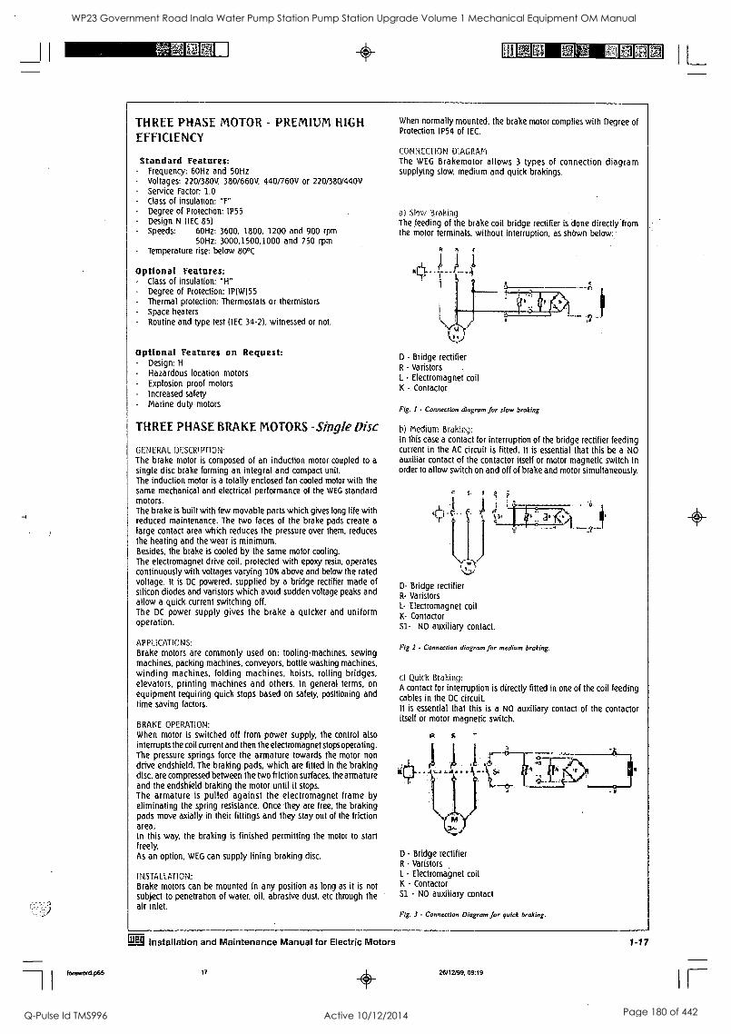
_11 0 IL
THREE PHASE MOTOR - PREMIUM HIGH EFFICIENCY
Standard Features: Frequency: 60Hz and 50Hz Voltages: 220/380V, 380/660V, 440/760V or 220/380/440V Service Factor: 1.0 Class of insulation: "F" Degree of Protection: IP55 Design N (IEC 85) Speeds: 60Hz: 3600, 1800. 1200 and 900 rpm
50Hz: 3000,1500,1000 and 750 rpm Temperature rise: below 80°C
Optional Features: - Class of insulation: "H" - Degree of Protection: IP(W)55
Thermal protection: Thermostats or thermistors - Space heaters - Routine and type test (IEC 34-2), witnessed or not.
Optional Features on Request: - Design: H
- Hazardous location motors - Explosion proof motors - Increased safety - Marine duty motors
THREE PHASE BRAKE MOTORS -Single Disc
GENERAL. DESCRIPTION:
The brake motor is composed of an induction motor coupled to a
single disc brake forming an integral and compact unit. The induction motor is a totally enclosed fan cooled motor with the same mechanical and electrical performance of the WEG standard motors. The brake is built with few movable parts which gives long life with reduced maintenance. The two faces of the brake pads create a
large contact area which reduces the pressure over them, reduces the heating and the wear is minimum. Besides, the brake is cooled by the same motor cooling. The electromagnet drive coil, protected with epoxy resin, operates continuously with voltages varying 10% above and below the rated voltage. It is DC powered, supplied by a bridge rectifier made of silicon diodes and varistors which avoid sudden voltage peaks and allow a quick current switching off. The DC power supply gives the brake a quicker and uniform operation.
APPLICATIONS:
Brake motors are commonly used on: tooling-machines. sewing machines. packing machines, conveyors, bottle washing machines, winding machines, folding machines, hoists, rolling bridges, elevators, printing machines and others. In general terms, on
equipment requiring quick stops based on safety, positioning and time saving factors.
BRAKE OPERATION: When motor is switched off from power supply, the control also interrupts the coil current and then the electromagnet stops operating. The pressure springs force the armature towards the motor non drive endshield. The braking pads, which are fitted in the braking disc, are compressed between the two friction surfaces, the armature and the endshield braking the motor until it stops. The armature is pulled against the electromagnet frame by eliminating the spring resistance. Once they are free, the braking pads move axially in their fittings and they stay out of the friction area. In this way, the braking is finished permitting the motor to start freely. As an option, WEG can supply lining braking disc.
INSTALLATION: Brake motors can be mounted in any position as long as it is not subject to penetration of water, oil, abrasive dust. etc through the air inlet.
When normally mounted. the brake motor complies with Degree of Protection IP54 of IEC.
CONNECTION DIAGRAM The WEG Brakemotor allows 3 types of connection diagram supplying slow, medium and quick brakings.
a) Slow Braking The feeding of the brake coil bridge rectifier is done directly from the motor terminals, without interruption, as shOwn below:
It r
D - Bridge rectifier R - Varistors ,
L - Electromagnet coil K - Contactor
Fig. I - Connection diagram for slot., braking
h) Medium Braking: In this case a contact for interruption of the bridge rectifier feeding current in the AC circuit is fitted. It is essential that this be a NO auxiliar contact of the contactor itself or motor magnetic switch in order to allow switch on and off of brake and motor simultaneously.
D- Bridge rectifier R- Varistors L- Electromagnet coil K- Contactor Sl- NO auxiliary contact.
Fig 1 - Connection diagram for medium braking.
c) Quick Braking: A contact for interruption is directly fitted in one of the coil feeding cables in the DC circuit. It is essential that this is a NO auxiliary contact of the contactor itself or motor magnetic switch.
S
D - Bridge rectifier R - Varistors 1. - Electromagnet coil K - Contactor S1 - NO auxiliary contact
Fig. 3 - Connection Diagram for quick braking.
grg Installation and Maintenance Manual for Electric Motors
foreword.p65 17 26/12/99, 09:19
1 -17
IF
WP23 Government Road Inala Water Pump Station Pump Station Upgrade Volume 1 Mechanical Equipment OM Manual
Q-Pulse Id TMS996 Active 10/12/2014 Page 180 of 442
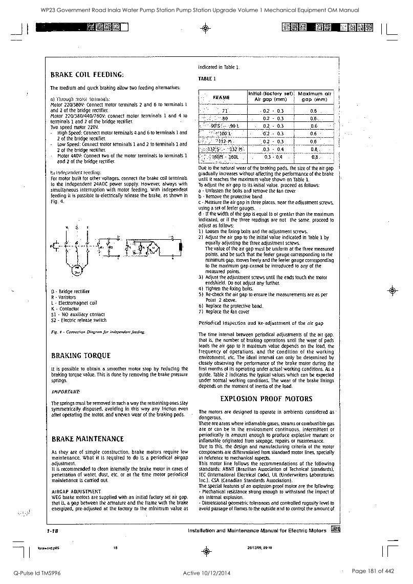
MMEI NM SIMM
BRAKE COIL FEEDING:
The medium and quick braking allow two feeding alternatives:
aj Through motor terminals: Motor 220/380V: Connect motor terminals 2 and 6 to terminals 1
and 2 of the bridge rectifier. Motor 220/380/440/760V: connect motor terminals 1 and 4 to
terminals 1 and 2 of the bridge rectifier. Two speed motor 220V.
High Speed: Connect motor terminals 4 and 6 to terminals 1 and
2 of the bridge rectifier. - Low Speed: Connect motor terminals 1 and 2 to terminals 1 and
2 of the bridge rectifier. - Motor 440V: Connect two of the motor terminals to terminals 1
and 2 of the bridge rectifier.
Independent Feeding: For motor built for other voltages, connect the brake coil terminals to the independent 24ADC power supply. However, always with simultaneous interruption with motor feeding. With independent feeding it is possible to electrically release the brake, as shown in
Fig. 4.
D - Bridge rectifier R - Varistors L - Electromagnet coil K - Contactor S1 - NO auxiliary contact S2 - Electric release switch
Fig. 4 - Connection Diagram for independent feeding.
BRAKING TORQUE
It is possible to obtain a smoother motor stop by reducing the braking torque value. This is done by removing the brake pressure
springs.
IMPORTANT:
The springs must be removed in such a way the remaining ones stay
symmetrically disposed, avoiding in this way any friction even after operating the motor, and uneven wear of the braking pads.
BRAKE MAINTENANCE
As they are of simple construction, brake motors require low maintenance. What it is required to do is a periodical airgap adjustment. It is recommended to clean internally the brake motor in cases of penetration of water, dust, etc. or at the time motor periodical maintenance is carried out.
AI RGAP ADJUSTMENT WEG brake motors are supplied with an initial factory set air gap, that is, a gap between the armature and the frame with the brake energized, pre-adjusted at the factory to the minimum value as
indicated in Table 1.
TABLE 1
FRAME Initial (factory set)
Alr gala (inm) Maximurri 'air
gap (alm)
, 71 . 0.2 - 0.3 0:6
s .80 0:2* - 0.3
-:90',:S',:,.! ,90.1. 0.2. - 0.3 ;0.6
':,100 i -'0:2- - 0:3 0.6
:1.12.M - 0.2 - 0.3 0.6
:.1 2','S,,,,- 152.P.,I .0;3 - 0.4 0.8
0M. -, 1601. 0,3 -'0 :4 0.8
Due to the natural wear of the braking pads. the size of the air gap gradually increases without affecting the performance of the brake until it reaches the maximum value shown on Table 1. To adjust the air gap to its initial value, proceed as follows: a - Unfasten the bolts and remove the fan cover b - Remove the protective band c - Measure the air gap in three places, near the adjustment screws, using a set of feeler gauges. d - If the width of the gap is equal to or greater than the maximum indicated, or if the three readings are not the same, proceed to adjust as follows: 1) Loosen the fixing bolts and the adjustment screws. 2) Adjust the air gap to the initial value indicated in Table 1 by
equally adjusting the three adjustment screws. The value of the air gap must be uniform at the three measured points, and be such that the feeler gauge corresponding to the minimum gap, moves freely and the feeler gauge corresponding to the maximum gap cannot be introduced to any of the measured points.
3) Adjust the adjustment screws until the ends touch the motor endshield. Do not adjust any further.
4) Tighten the fixing bolts. 5) Re-check the air gap to ensure the measurements are as per
Point 2 above. 6) Replace the protective band. 7) Replace the fan cover
Periodical Inspection and Re. adjustment of the air gap
The time interval between periodical adjustments of the air gap, that is. the number of braking operations until the wear of pads leads the air gap to it maximum value depends on the load, the frequency of operations, and the condition of the working environment, etc. The ideal interval can only be determined by closely observing the performance of the brake motor during the first months of its operating under actual working conditions. As a
guide. Table 2 indicates the typical values which can be expected under normal working conditions. The wear of the brake linings depends on the moment of inertia of the load.
EXPLOSION PROOF MOTORS
The motors are designed to operate in ambients considered as dangerous. These are areas where inflamable gases, steams or combustible gas are or can be in the environment continuous, intermittent or periodically in amount enough to produce explosive mixture or inflamable originated from seepage, repairs or maintenance. Due to this, the design and manufacturing criteria of the motor components are differentiated from standard motor lines, specially in reference to mechanical aspects. This motor line follows the recommendations of the following standards: ABNT (Brazilian Association of Technical Standards). IEC (International Electrical Code), UL (Underwriters Laboratories Inc.), CSA (Canadian Standards Association). The special features of an explosion proof motor are the following: - Mechanical resistance strong enough to withstand the impact of an internal explosion. - Dimensional geometric tolerances and controlled rugosity level to
avoid passage of flames to the outside and to control the amount of
1-18 Installation and Maintenance Manual for Electric Motors grg
7 foreword.p85 18 26/12199,09:19
IL
()
IF
WP23 Government Road Inala Water Pump Station Pump Station Upgrade Volume 1 Mechanical Equipment OM Manual
Q-Pulse Id TMS996 Active 10/12/2014 Page 181 of 442
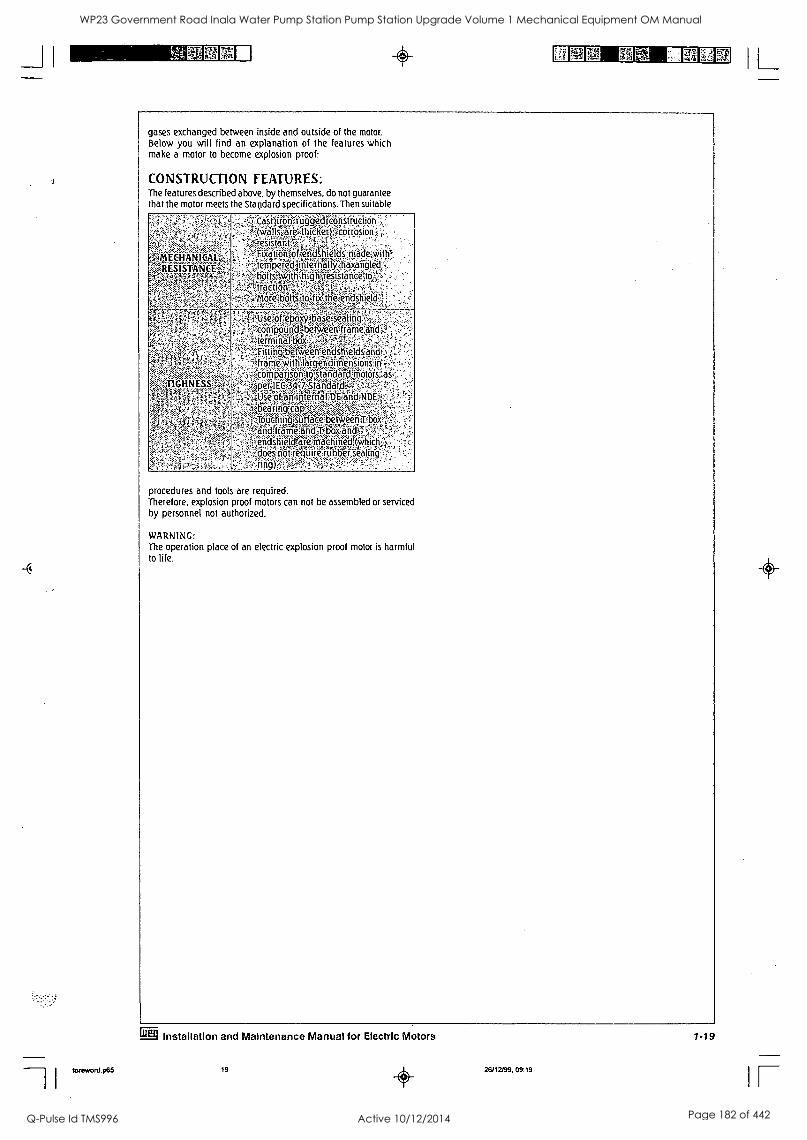
gases exchanged between inside and outside of the motor. Below you will find an explanation of the features which make a motor to become explosion proof:
CONSTRUCTION FEATURES: The features described above, by themselves, do not guarantee that the motor meets the Standard specifications. Then suitable
.,,,,, *mEGHANIGAt- ?..i'S,,,,..-.....,,,,,,,,,x..
,,,RESISTANEE
CasnironauggeticoriStructicin:... (w,allstfare.thicker)::corrcisionl; ,-..: ,
rgiggiiT:,,,t?..: ,...,. ..........
mationlotietidshilds'irriade:WO'- temperedlinternallyerazangle. pltswit ,, ig tresistanceAo ,,....i,.....- ,-
raction", ,,.- >, --,.--14, ,,-. w. oretboltsitotfixtheferi stile
N??..,,.-:.:z,,,,,,,:.
,,,
,,,...,:-,
TIGHNES
5;;;t:',
, ., ,,,:,:.:::,2:- ' setot>epqxpoas,,ceiseaim,
compound ,,t. between,frameand terMrnal:bo'''x
,1: - ' ittingthe eenencistrieldcan ,.-:,:-.- rameWithIlargervdtmensions)n',,
tomparison4ostandard,motors;.a -.p.er,Ilerl.,34.-.7s,SfandaldT.rl';
,-, ,,,,,,:,,,?,r.,:,,,,,,,?.vt:s sesoftmintemal)D,ElandiNDB
bearing,:carP .
,..:,,,,,,..., ..-,,,,,s .
ouchingtsurfdceabetCVeen; ,,,, r 33......2WX.14,,,,, 1 ' richframeiandT-box:an t-
tirdshreldtafeimachifiedt(Whic .,,:,,,8,,,,,..r.,,;,,,. does'ilotrequile,rubberwaltn ring) fr..v...,,,,:1:g -::,:;-,,,
. - ,
procedures and tools are required. Therefore, explosion proof motors can not be assembled or serviced by personnel not authorized.
WARNING: The operation place of an electric explosion proof motor is harmful to life.
gf Installation and Maintenance Manual for Electric Motors
foreword.p65 19 26/12/99, 09:19
1-19
IL WP23 Government Road Inala Water Pump Station Pump Station Upgrade Volume 1 Mechanical Equipment OM Manual
Q-Pulse Id TMS996 Active 10/12/2014 Page 182 of 442
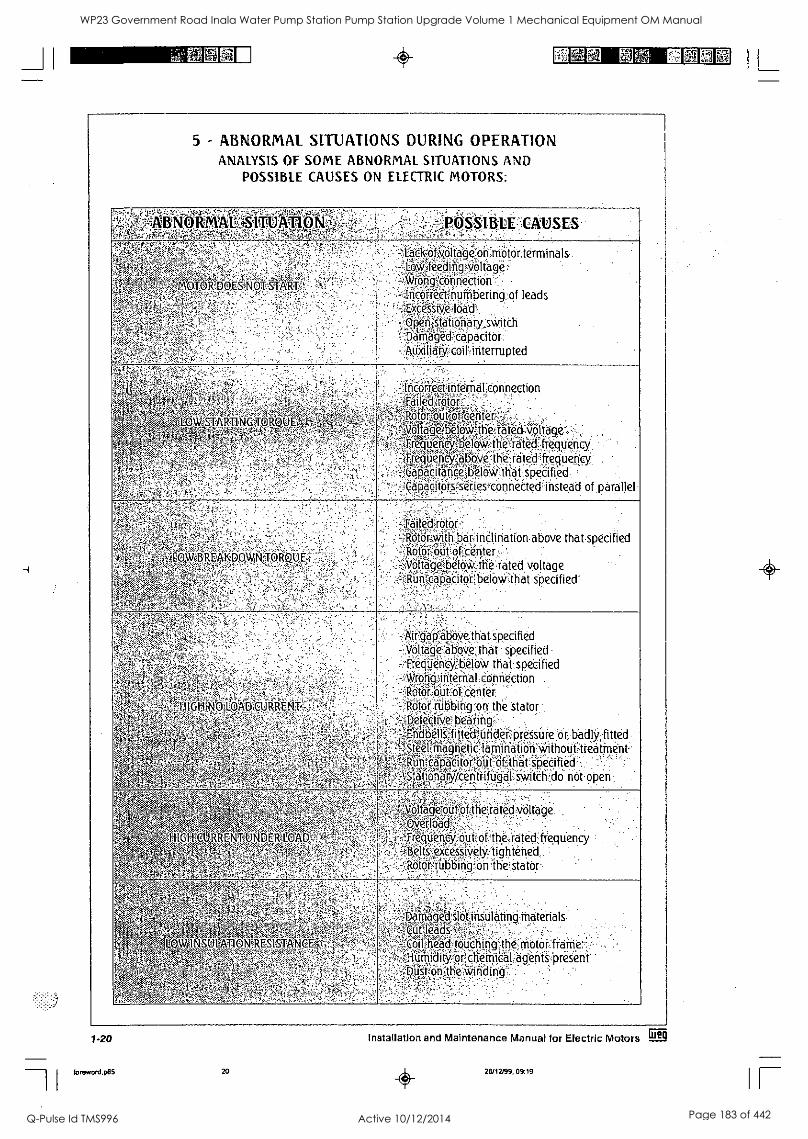
_JI um
5 - ABNORMAL SITUATIONS DURING OPERATION ANALYSIS OF SOME ABNORMAL SITUATIONS AND
POSSIBLE CAUSES ON ELECTRIC MOTORS:
....;.: -,..v..,p.'?,,.... ..:,,,,,,,,,:a.,..0;-..;,,;-,,,,z-z4.'-: 4 'ABNORMAL '1:: 1 1 ' -
,,,,A,
. ,. POSSIBLE -'CAUSES
,, .,.
DOES NOT ST=T °Im:.F02p. -,,.:':.
. - .
. . .
.
. .
, %
-
. '
.
-Latk60,6ttage"ohnOtQrtrminals :-...:,;;k-i . ,' X:, ., , :
1.0k4feeding*ltaget' - AVrOn4cConneetion
.-lncogtegnumbefing:of leads .- r - --:,,: - load
-100nisttioriaiyswiteh .,..,4.},-,A..0-;
,,parnaged-OpacitOr. . ......
:Atikiliaryz,coit,interrupted
,,-.A.1, ,.. .
:.-. , ...
,:-. ''''
.. . , ,-,-
' .:',. 1 , . tRikSTAR4AWA U.E t''':- ; 14 " ' i,-,,:- ,' .r,:...w., ,,4, .--'
,..
-5, -kr.
. . ' ,
'
i''
-
-
,
:
,
,-.friC6rteCtintetnaltonnection :- ' --.5.-fi:-... -F,:-.,:-,,,,.....,,, .::
,ailedtrotori2,,,:, .: -
,:,404,*.-?,--v,1+,' , RotoRout,oficenter,
,,,-,K,.:-,---&---1--,,,--- -- -c ,
oltagetelow4he?.rAted-voltage' .-,4w.,,..,.',:,..;--i;-.-3,---
- ' . ' JequencydpeloWlherated4teguency FfequengAboyethe-.tatedfrequency '
-.--!EapacitancelbelbVth6t- specified -.CaPacitOrs'SerteS4'ConneCted instead of parallel
, - . .
Lq.WREAKD0W fMAQt),E, : . .,- ..., .. ..,
'',,,, $4. ,-,
0- 4
-0.:,.., '''''
.
'
,
.
:
-Tail(ct:rOtor -.-totOr4ittrbaiineliriation above that specified = Rififig;o0of center ' .
ltagetelo, the,rated voltage Run capacitor below that specified
',. -,::::-,,,',' ,..
. .
..."- -,' - ..
,.. .
1,,,. ,-,-..
.., --. - -II , , ,
Hil-1NOLOAbCURREi\iT -,,,,,,,,--s,
- "-:,z,,i. 4.- :,.-,:
, ,-
-4:144.;:l. :,
,
:--,
.
'
. . .
-.'f.kirgap4bovetnat specified -.11Olthe::abbvethat specified -:fteifitienCij.?:berow that specified < . ... 2 AvionT,ititernal connection -12.6tOr,Obt:Of center
Otot,itibbitg.en the stator efeetiVe',Peating,- ndbellsffitteiPtitider;pres$iire or badlS,'fitted ee4magneticlaMination*thout treatment,
Run i capaeltoroufbf that specified ationaiWtentrifii01 switch do not open
.:, ...-<.,: ::: .,, ,
,,%,.. ---, - -,1 ,-,E,,,e,..4.., ,..,.. --,-,- ,
.< . ,-,4*-- ... ,,
"' HIGWEIJRRENTMNDER-16
- ,
o ta eioutof.the rated voltage ertba , -: ;' '
:
regikii-cy;:obVotthe.rated frequency , . ,...
,Belts excessively - tightened - -',.ItOtOr fubbiriOitiliestatbr
V -
-":-
*5 4.-..x.
. ''. ':11'...'":40:A. '' % ,...,
h.ATI - - 1 OWINSIgONPHESIST, AN 5
.,: `v. 4---i' - ,-,,,- r2 ' -,.
,,z-,.., ,,,,,,, f
...
-"Ntriaged-slcit insulating materials 'Plia-iii:::::;,-.-::: , i -.. - :
' '
")--,,,,,,, ,:',;i.:---.:-,...:- .. . .
head earktOuChingr..the motor fraMe. ,"r.,':,,:?. r";,. .i. ... . WitY or chemical agents present '
Dust ....
' :-... ." "
120
foreword.p65 20
Installation and Maintenance Manual for Electric Motors ag
26/12/99, 09:19
IL
0
IF
WP23 Government Road Inala Water Pump Station Pump Station Upgrade Volume 1 Mechanical Equipment OM Manual
Q-Pulse Id TMS996 Active 10/12/2014 Page 183 of 442
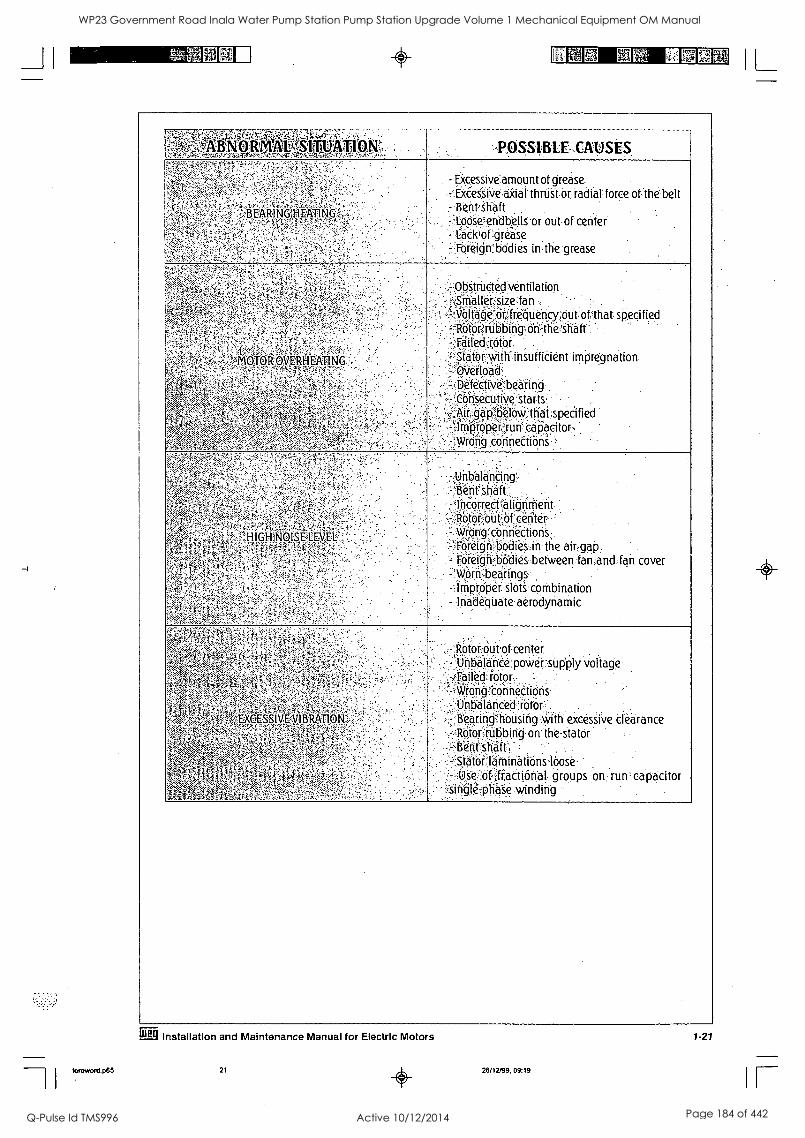
for. eword.p65
72*.f 1,14. 0-eZ. tfalf4 III IIEEE SE r51 IL
_t.vir:67,-A.'i;:4T2Ita.--:,:,; M,31, Lk.SIV , -, .., ,POSS1BLE.CAUSES
.-'s.
...,
.,..; .
EARINOHEATING A 4-,
.
.
'..
-
- Excessive amount of grease - Excessive axial thrust or radial force of the belt
Bent shaft 2 Loosendbells or out of center
Lcick'of grease - Foreign bodies in the grease
"'..
.
710l2PVEtZgAligG:.-
_
. :
Obstructed ventilation Smaller size fan - -
..:Nolidgedr!,frequency;out, of that specified Rotor rubbing on-the's116ft Failed rotor
- iator.:with insufficient impregnation ,
OVertodd.:: . , .
Defective bearing . ,
Consecutive e-Starts , --
Air;'.6-,bselbvi:ttrai specified ArnOtoper.?futi- cdP:acitorr, Wrong connections '
.,.::..
-,-
'
,
GiiiKpisEitiV
4, :A.- :
.
.
'
. .
- ,- UnbaldnCing Bent shaft Incorrect alignment '
1fOtO',,,bitziit c'6rifei-: Wrong connections -,-- , -. ,
:Fdreigf-; bodies in the air gap = FOreigh.:bodiesbetween,fan:and:fan cover
bearings -Iriiptdper.6-.4.combination - Inadequate aerodynamic
V.:
<
04.,,,,I.,
k;fscw
.1,,,,
:,,
'''',.
.....,
....,....,.... ..,
. ,.. EXGESS1VE ....
.i.k.
....
.
. .
:.
Rotor out of center - Unbalance power supply voltage
Failecf rotor Wrong connections
.
Unidldficed :r. o tor i. th-excessi. excessive clearance Bearing b sing w' aran c e
Ofor-rubbirig on the stator ..
tient shaft ^ .
Stator laminations loose - Use of fractional groups on run capacitor single
Erg Installation and Maintenance Manual for Electric Motors
21 26/12/99, 09:19
1-21
IF
WP23 Government Road Inala Water Pump Station Pump Station Upgrade Volume 1 Mechanical Equipment OM Manual
Q-Pulse Id TMS996 Active 10/12/2014 Page 184 of 442
Lv, a, mil Ti4 EN3
e.,C:;.,t";cikiii:Iff,...ibii,Stiiit:0001of,t:fe,elec!ffic'-ruotor:i Although the high quality A.,Islertseji,yearsfoftefrel,,atitif-44 v:rhetv'th motor
, r -- , -
sirvtce:il_ints;eantiaelorirectiveNpreventivelorlureritatNei,...'
part
t,,.,e;,,rp;pmentRus,puyolWg;gfe:citu,qEiSatorio,larealr.edi-Origtafii.iirfqifi-'fatile!,kriciW,hOwdeveloDed
legtir411.fV4ted'> ssermIcg:.,.cuTty'".gl h e,M."' h ole mo tot operating life '' `'' afdgfakgrllYToca Ie Inem o r &10
foreword.p65 22
Installation and Maintenance Manual for Electric Motors gig
26/12199, 09:19
IL
IF
WP23 Government Road Inala Water Pump Station Pump Station Upgrade Volume 1 Mechanical Equipment OM Manual
Q-Pulse Id TMS996 Active 10/12/2014 Page 185 of 442
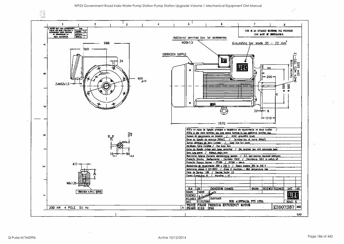
2 3 4 6 7 8
AL
CO
w
A WM OA WM IllOW1100 PIEWOF0 SERA PIN1000 A 01/0:0600 0E63E DCGDA10
NOIMM/i riEG MOTORES
be PAW* NCX14.1.
116PKIAL
2xM63x1.5
600 p12
Addlionol terminal box lot ocessories
1420x1.5
VIBRATION NIPPLE
1H15 15 AN UPDAILD REVISCel, DIE PREVIOUS
ONE MUM BE feRECAROELL
Groundina 1.r leods .35 - 70 mm2
1570
210
3 0
0
Mfrs no canto de focito prinei;o1 o nontioncio de cqueciresnb ro 02110 =dor / PTO's In the nolo torte/nal box and tome toreete In the cddltbnd hem)* box
Novo de edneomenlo Ao troseIro / N.D.E. oroundro hush
Cdoo do km& do coxoto 355NA., / letniro/ box of Nome Std)A/L 3conso dellotoro de ferry hoed° / Gone ion Ion caw YorModol Polo furoAdo / fon Coil on
raw de Eagan agog com box ronorwel / Old termIno1 beet with %ennoble bone
Sc,' fury down / Yfttoul drdn hole
Rolomento Es** Dionkint abdrtomonle nolo* / D,E. boll beorino innoloted eletriooly Proleceo Tbm1w Dediooroordo - TomIstoy lbsirolototo 1350 to odIdt on 1:holocao Ronk° Mire - MOD / PIM - *on Radttrict dr AnAmsbtordo 200 o 240 V / Baca hobos 21:0 to 240 V
loolornento doso, H IDI=OCK) / Claw H ineulatIon - BON temovoluto nee
Foto, de San.? 140 / Sox,* foctor 1,0
Porno Cortslrutv VI j Wooing - VI
200 kW 4 POLE 50 Hz IA
RIM LOC GINEEfliNG CHANCES DRAM REVVED liflEASED DATE IND
DRANK TIVOS Jon+ RIVIDWD #4.141,t- Itax4ED ,,,S'"" Cusladin
TEO AINTRAIIA PTY LTDA DAIE 17/12/2003 SCALE:
THREE PHASE PREMIUM EFFICIENCY MOTOR FRAME 3l6B IP65 E300731371 ME
CAD
WP23 Government Road Inala Water Pump Station Pump Station Upgrade Volume 1 Mechanical Equipment OM Manual
Q-Pulse Id TMS996 Active 10/12/2014 Page 186 of 442

WP23 Government Road Inala Water Pump Station Pump Station Upgrade Volume 1 Mechanical Equipment OM Manual
Q-Pulse Id TMS996 Active 10/12/2014 Page 187 of 442

II
I
WP23 Government Road Inala Water Pump Station Pump Station Upgrade Volume 1 Mechanical Equipment OM Manual
Q-Pulse Id TMS996 Active 10/12/2014 Page 188 of 442
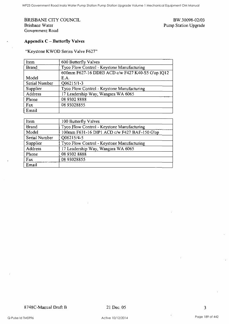
BRISBANE CITY COUNCIL Brisbane Water Government Road
Appendix C - Butterfly Valves
"Keystone KWOD Series Valve F627"
BW.30098-02/03 Pump Station Upgrade
Item 600 Butterfly Valves Brand Tyco Flow Control - Keystone Manufacturing
Model 600mm F627-16 DDH3 ACD c/w F427 K40-S5 G'op IQ12 E.A.
Serial Number Q06215/1-3 Supplier Tyco Flow Control - Keystone Manufacturing Address 17 Leadership Way, Wangara WA 6065 Phone 08 9302 8888 Fax 08 93028855 Email
Item 100 Butterfly Valves Brand Tyco Flow Control - Keystone Manufacturing Model 100mm F631-16 DIP1 ACD c/w F427 BAF-150 G'op Serial Number Q06215/4-5 Supplier Tyco Flow Control - Keystone Manufacturing Address 17 Leadership Way, Wangara WA 6065 Phone 08 9302 8888 Fax 08 93028855 Email
8748C-Manual Draft B 21 Dec. 05 3
WP23 Government Road Inala Water Pump Station Pump Station Upgrade Volume 1 Mechanical Equipment OM Manual
Q-Pulse Id TMS996 Active 10/12/2014 Page 189 of 442
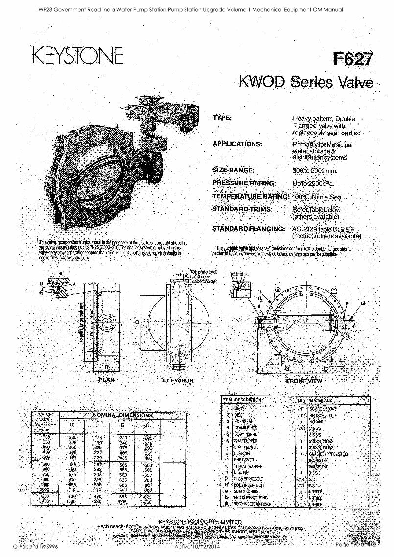
This.v abee. igoOrpo:OteS a bn igpe'seal in the periphery of the disc to ensure tight Shut off G.i..riuiiessUra ratings tip tOPN?5'(2500 k Pa) The sealing system enployed in this vaive gives Iowerooerati q tolOties than ail ether light shut off designS Tim results in economies in valve attuabon7
TYPE:
F627 KVVOD Series Valve
Heavy:pattern, Double Flanged valve with
: replaceable seal on disc
APPLICATIONS: Phenafily for Municipal Water storage & :distribution systems
300 to-2000 mm SIZE RANGE:
PRESSURERATING: to 2600kPa.;
TEMPERATURE RATING: 100°C Nitrile Seal
STANDARD TRIMS: Refer Table below (others available)
STANDARD FLANGING; AS. 2120-able pi:E &F (metric,) (others available)
The standard valve fro to faced conform to the double flanged short pattern in eS5155, however, other fa to face dimensions can be supp!ied.
s
TPP Plate and
11011"
matower
LEVATION ,
. .'VAL'E :SIZE
'NOly1, BORE mm.,
., ' " - NOMINAL DIMENSIONS . -- .
. .
C D
.. .
.
G . Q
.
300,: 350 400 450
,5Ô
280 325 360 -
375 410
'170 ' 19,0
216 222 229
310 340
375 405 435
- '200 ' 248 .293- 351
; 407
.
600 700 750 800 60 ..
3000 ,
. ,
' 485 490 575 610 655
.710
267 292 305 318 580 -
4i0
505 565 600 635
..8e5 7.60
503 606 657 708 815 888
.
....7'
1200 " 1 400- ,
.,
. -4:00 . 1600
. ..
470 "
, 63 0'
6 86 1005,
'1 075 1268
'
.130.141".YIEIY
ITEM DESCRIPTION !DIY', 'MATERIALS
'1'
2 :'
'3
4 '
5
6
7
8
9
10
11
12
0 14 -
15
BOI:141' , .
DISC .
ENERSEAL
CLAMP RINGS;
'BODY INE'EFil.
'6/lift LIPPER:
SHAFT OWET1 ,
BEARING
END OOVER :
THRUST WASHER
DISCR!N
CLP,IAF4IINO6OLT .
BODY. iNSERT BOLT '
SHAFT ORING
E NO 0001=0. P.; isiG
BODY INSERT '0113:NG
1 ''!,
1' '
1
VAll
'
1
4 '.'
I .
I
3
vah : VAR
4 '
2 :
I
sP::180R50q-7 So....1RON 500,7
NITRILE ,
ai65/6 .
316,9/S
316 57, 43151S '
316 VS.-43PM ',
'p:ACLER/pTFE / STEEL
,Iiibki8fEtl. ,
304 SIStNP
316S/S
s.s
.S13
NITRLE .... : ,
N1111LE
.NITRIE
!IKEYSI.O.NE.Nsergib-OtY. LIMITED 174EAD OFFICE .i's(): ".BOX 517,'N6W#Ai.i41.,-.:Aus,triAw#-RooivE (044)2,...,7066 TELEX- A4(24195 FAX' 190).21 8135
SALES Diliplgy5F.i.AcrwmEKcsofp!;,o,clATCD 71.:iftOUGI-i0 UT ALISTR;NL
1S.gis10.*(0^-ifves1:10 cie;19:pr or specifiCaliorivhot,Knolide
WP23 Government Road Inala Water Pump Station Pump Station Upgrade Volume 1 Mechanical Equipment OM Manual
Q-Pulse Id TMS996 Active 10/12/2014 Page 190 of 442
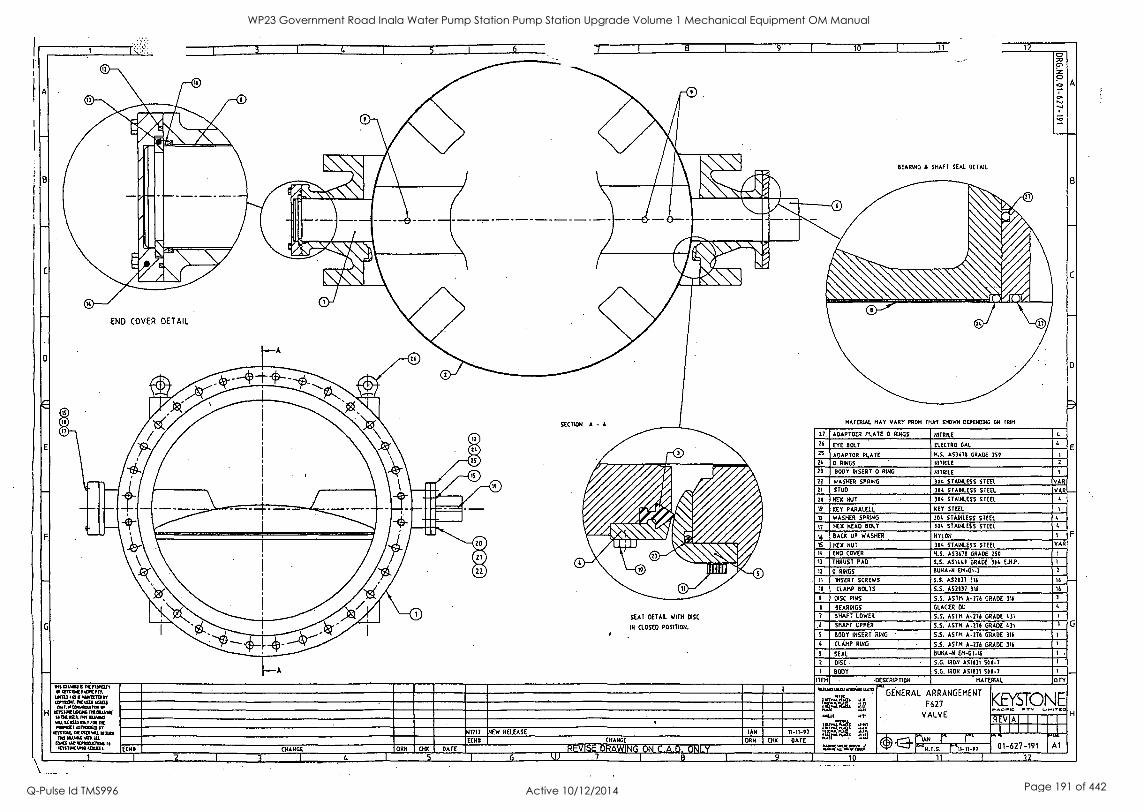
B
C
0
E
4 5 1 6 7 8 L 9 10 11
BEARING 1 SHAFT SEAL DETAIL
12
END COVER DETAIL
SECTION A - A
SEAT DETAIL WITH DISC
IN CLOSED POSITION.
RMGNOW0 IV MOW, 6,17Y1mmtpAcrcni.
116110403 ma= Tr arntoit DC IISOI MAITS rut ottoexuama
H ICTSIFILDCK MOIAVIf m MIRA MO UAW/ YU It CUD MY not DC moratit Lonalan
CYPDK. Kula Al OW Rd 64.4,64 NADI RI
(MS uR 001¢1.1Cresd artIEN WM =M.
01717 NEW RELEASE
ECHO CHANGE
REVISE7DRAWINGION C.A.D. ONLY
IAN
DON (MX DATE
1
ECNI1 [RANGE DRN 00C DATE
5 w
MATERIAL HAY VARY FROM THAT SHOWN OEPERIDIRG ON MIN
27 ADAPTOER PLATE 0 RINGS RIME 26 EYE ISLE ELECTOR GAL
2S ADAPTOR PLATE H.S. 153111 GRADE 250 24 0 RINGS NITRILE
23 Boor INSERT 0 RING INTRILE
22 WASHER SPRING 30t STAINLESS STEEL VAR 21 STUD MA STAINLESS STEEL VAR
26 HEX NUT NIL STAINLESS STEEL
19 KEY PARALELL KEY STEEL
WASHER SPRING 304 STAINLESS STEEL
17 HEX READ BOLT 704 STAINLESS STEEL
16 BACK UP WASHER NYLON
IS HEX NUT 304 STAINLESS STEEL VAR
14 END COVER M.S. 103675 GRADE 750
13 THRUST PAD S.S. AS18.41 GRADE SON E.N.P.
12 0 RINGS BONA -N Em-07-2
11 INSERT SCREWS S.S. A52037 30 16
76 CLAMP BOLTS 5.5. AS2137 310 16
DISC PINS 5.5. AVM 1-776 GRADE 116
BEARINGS GLACIER DU
7 SHAFT LOWER 5.5. ASTM 1276 GRADE 1.31
6 SHAFT UPPER S.S. ASTM A -776 GRADE Lb BOOT INSERT RING 5.S. ASTM A-276 GRADE 30
CLAMP RING ASTM A-276 GRADE 316
SEAL BONA -N EM-01-16
DISC S.G. IRON A51131 5IO-7
BODY S.G. IRON AS1031 500-7 ITEM DESCRIPTIDN MATERIAL ore
GENERAL ARRANGEMENT
F627
VALVE
KEYSTONE REV A
IAN d
.1.5. 11-1147 01-627-191 Al
10 11 I 12
WP23 Government Road Inala Water Pump Station Pump Station Upgrade Volume 1 Mechanical Equipment OM Manual
Q-Pulse Id TMS996 Active 10/12/2014 Page 191 of 442
KEYSTONE
Equipment Description
F627 Valve
The figure 627 is designed primarily for water distribution systerns.
The valve incorporates a seal on the periphery of the disc to ensure tight shut off. This seal seats against a stainless steel body insert. The sealing ring,
retaining ring and body insert are field replaceable and are fixed in position by
stainless steel set screws.
The disc of Ductile Iron is supported by stainless steel stub shafts. The shafts are designed to withstand twisting under specified conditions. The shafts
rotate on fibre wound resin self lubricating bearings. The upper bearing is
protected from ingress of foreign matter by '0' rings.
A thrust bearing is supplied located in the lower shaft bore.
Eyebolts have been supplied (2 each) for hoisting.
Operator
In each case a quarter turn Keystone 'K' series gear operator is close coupled to
the valve.
Keystone Pacific Ltd 17 Leadership Way, WANGARA WA 6065 - Ph. (08) 9302 8888 - Fax. (08) 9302 8877
WP23 Government Road Inala Water Pump Station Pump Station Upgrade Volume 1 Mechanical Equipment OM Manual
Q-Pulse Id TMS996 Active 10/12/2014 Page 192 of 442
f%11, NNW < EYSTO N E
PRINCIPLES OF OPERATION
The F627 is a quarter turn operation butterfly valve. In each case a worm/quadrant and spur type gearbox is fitted.
Clockwise input of the hand wheel will provide close action.
A lockable plate is fitted behind on the input shaft to allow the valve to be locked in any position.
OPERATING INSTRUCTIONS as applicable
Checks Before Starting
Visually inspect valve bore for foreign matter and remove any dirt or dust particles.
Fit handwheels to gearbox input shafts
Open and close valve to insure free movement
Manually actuated valves can be immediately put into service. No other checks are required
Keystone Pacific Ltd 17 Leadership Way, WANGARA WA 6065 - Ph. (08) 9302 8888 - Fax. (08) 9302 8877
WP23 Government Road Inala Water Pump Station Pump Station Upgrade Volume 1 Mechanical Equipment OM Manual
Q-Pulse Id TMS996 Active 10/12/2014 Page 193 of 442
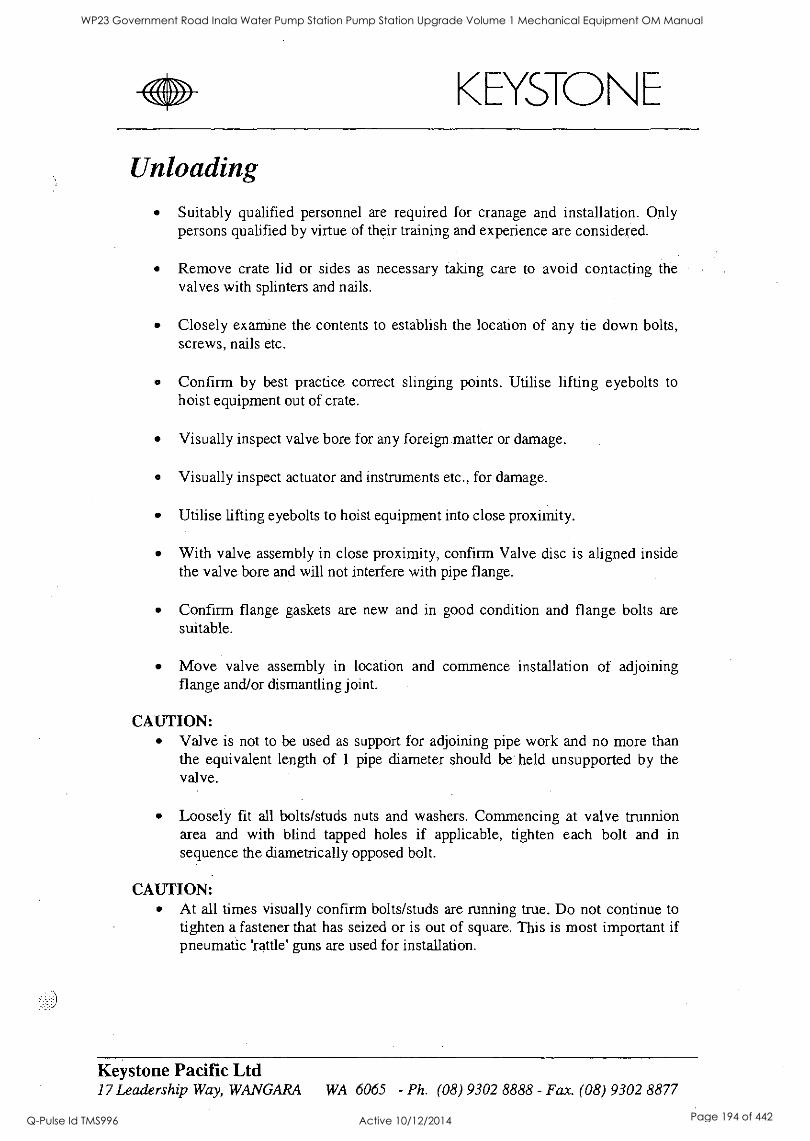
WIW KEYSTONE
Unloading Suitably qualified personnel are required for cranage and installation. Only persons qualified by virtue of their training and experience are considered.
Remove crate lid or sides as necessary taking care to avoid contacting the valves with splinters and nails.
Closely examine the contents to establish the location of any tie down bolts, screws, nails etc.
Confirm by best practice correct slinging points. Utilise lifting eyebolts to hoist equipment out of crate.
Visually inspect valve bore for any foreign matter or damage.
Visually inspect actuator and instruments etc., for damage.
Utilise lifting eyebolts to hoist equipment into close proximity.
With valve assembly in close proximity, confirm Valve disc is aligned inside the valve bore and will not interfere with pipe flange.
Confirm flange gaskets are new and in good condition and flange bolts are suitable.
Move valve assembly in location and commence installation of adjoining flange and/or dismantling joint.
CAUTION: Valve is not to be used as support for adjoining pipe work and no more than the equivalent length of 1 pipe diameter should be held unsupported by the valve.
Loosely fit all bolts/studs nuts and washers. Commencing at valve trunnion area and with blind tapped holes if applicable, tighten each bolt and in sequence the diametrically opposed bolt.
CAUTION: At all times visually confirm bolts/studs are running true. Do not continue to tighten a fastener that has seized or is out of square. This is most important if pneumatic 'rattle' guns are used for installation.
Keystone Pacific Ltd 17 Leadership Way, WANGARA WA 6065 - Ph. (08) 9302 8888 - Fax. (08) 9302 8877
WP23 Government Road Inala Water Pump Station Pump Station Upgrade Volume 1 Mechanical Equipment OM Manual
Q-Pulse Id TMS996 Active 10/12/2014 Page 194 of 442
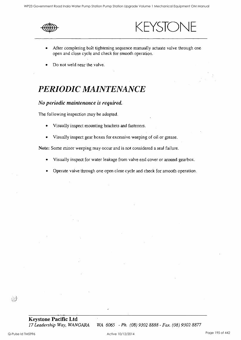
Zfil\N WV' KEYSTONE
After completing bolt tightening sequence manually actuate valve through one open and close cycle and check for smooth operation.
Do not weld near the valve.
PERIODIC MAINTENANCE
No periodic maintenance is required.
The following inspection may be adopted.
Visually inspect mounting brackets and fasteners.
Visually inspect gear boxes for excessive weeping of oil or grease.
Note: Some minor weeping may occur and is not considered a seal failure.
Visually inspect for water leakage from valve end cover or around gearbox.
Operate valve through one open close cycle and check for smooth operation.
Keystone Pacific Ltd 17 Leadership Way, WANGARA WA 6065 - Ph. (08) 9302 8888 - Fax. (08) 9302 8877
WP23 Government Road Inala Water Pump Station Pump Station Upgrade Volume 1 Mechanical Equipment OM Manual
Q-Pulse Id TMS996 Active 10/12/2014 Page 195 of 442
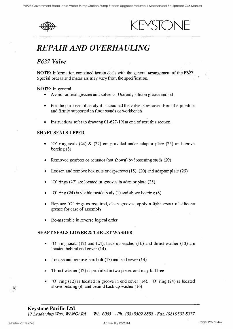
KEYSTONE
REPAIR AND OVERHAULING
F627 Valve
NOTE: Information contained herein deals with the general arrangement of the F627. Special orders and materials may vary from the specification.
NOTE: In general Avoid mineral greases and solvents. Use only silicon grease and oil.
For the purposes of safety it is assumed the valve is removed from the pipeline and firmly supported in floor stands or workbench.
Instructions refer to drawing 01-627-191at end of text this section.
SHAFT SEALS UPPER
'0' ring seals (24) & (27) are provided under adaptor plate (25) and above bearing (8)
Removed gearbox or actuator (not shown) by loosening studs (20)
Loosen and remove hex nuts or capscrews (15), (20) and adaptor plate (25)
'0' rings (27) are located in grooves in adaptor plate (25).
'0' ring (24) is visible inside body (1) and above bearing (8)
Replace '0' rings as required, clean grooves, apply a light smear of silicone grease for ease of assembly
Re-assemble in reverse logical order
SHAFT SEALS LOWER & THRUST WASHER
'0' ring seals (12) and (24), back up washer (16) and thrust washer (13) are located behind end cover (14).
Loosen and remove hex bolt (15) and end cover (14)
Thrust washer (13) is provided in two pieces and may fall free
'0' ring (12) is located in groove in end cover (14). '0' ring (24) is located above bearing (8) and behind back up washer (16)
Keystone Pacific Ltd 17 Leadership Way, WANGARA WA 6065 - Ph. (08) 9302 8888 - Fax. (08) 9302 8877
WP23 Government Road Inala Water Pump Station Pump Station Upgrade Volume 1 Mechanical Equipment OM Manual
Q-Pulse Id TMS996 Active 10/12/2014 Page 196 of 442
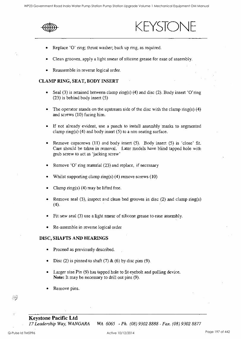
< EYSTO N E
Replace '0' ring; thrust washer; back up ring, as required.
Clean grooves, apply a light smear of silicone grease for ease of assembly.
Reassemble in reverse logical order.
CLAMP RING, SEAT, BODY INSERT
Seal (3) is retained between clamp ring(s) (4) and disc (2). Body insert 'O'ring (23) is behind body insert (5)
The operator stands on the upstream side of the disc with the clamp ring(s) (4) and screws (10) facing him.
If not already evident, use a punch to install assembly marks to segmented clamp ring(s) (4) and body insert (5) to a non seating surface.
Remove capscrews (11) and body insert (5). Body insert (5) is 'close' fit. Care should be taken in removal. Later models have blind tapped hole with grub screw to act as 'jacking screw'
Remove '0' ring material (23) and replace, if necessary
Whilst supporting clamp ring(s) (4) remove screws (10)
Clamp ring(s) (4) may be lifted free.
Remove seal (3), inspect and clean bed grooves in disc (2) and clamp ring(s) (4).
Fit new seal (3) use a light smear of silicone grease to ease assembly.
Re-assemble in reverse logical order
DISC, SHAFTS AND BEARINGS
Proceed as previously described.
Disc (2) is pinned to shaft (7) & (6) by disc pins (9).
Larger size Pin (9) has tapped hole to fit eyebolt and pulling device. Note: It may be necessary to drill out pins (9).
Remove pins.
Keystone Pacific Ltd 17 Leadership Way, WANGARA WA 6065 - Ph. (08) 9302 8888 - Fax. (08) 9302 8877
WP23 Government Road Inala Water Pump Station Pump Station Upgrade Volume 1 Mechanical Equipment OM Manual
Q-Pulse Id TMS996 Active 10/12/2014 Page 197 of 442
'WA, EYSTO E
Disc (2) has provision for lifting eyebolts. Locate visually and confirm thread size. Usually M12 / M16 / M20. Secure lifting device to disc and support disc weight.
Some versions have tapped hole in shafts (6) & (7) to fit pulling device. If not evident an eyebolt must be fitted by welding.
Fit pulling device and remove shafts from disc. Disc can now be lifted free. Caution: Do not allow disc to 'swing' and knock against valve bore.
Bearings (8) can be inspected inside upper and lower shaft bores. Check for damage and replace.
Reassemble in reverse logical order.
F427 `1(' SERIES GEAR OPERATORS
The Keystone F427 X' series gear operators are grease filled for life and require no routine maintenance.
The following dis-assembly procedure is provided for reference.
NOTE: The F427 'K' series operator is available with plain worm/quadrant, flanged input, spur/worm quadrant operator.
The following procedure assumes actuator removal and gearbox removed from valve.
Drawing at end of text this section.
F427 SPURBOX
Remove the four outer set screws (21) and cover (4). The pinion shaft (7) remains captive in cover (4). It is retained by spur (5) and cover (20). Remove the remaining two set screws (21) and pinion shaft (7) will be free of cover (4) and spur end cover (20).
The interior of spurbox may now be examined.
Spur gear (5) is a "slip on" fit to main gearbox shaft (not shown) and may be pulled free. Should spur gear (5) be unmovable, two tapped holes M10 are provided to fit a pulling tool.
Remove spur fasteners (17) and spur box housing (3).
Keystone Pacific Ltd 17 Leadership Way, WANGARA WA 6065 - Ph. (08) 9302 8888 - Fax. (08) 9302 8877
WP23 Government Road Inala Water Pump Station Pump Station Upgrade Volume 1 Mechanical Equipment OM Manual
Q-Pulse Id TMS996 Active 10/12/2014 Page 198 of 442
1%11 w11%, KEYSTONE
F427 'K' GEARBOX
Removal position indicator where fitted
Remove fasteners (23) and cover (not shown)
The interior of the main box showing worm (9) and quadrant (8) can be examined.
Remove sellock pins (18). To aid in the removal of sellok pins, two grub screws have been fitted into base of body (1) Those grub screws are in direct alignment with the sellok pins, and allow the pins to be driven clear.
Input shaft (not shown) can be pulled free from worm (9) and bearings (11) through body (1).
Remove segment gear (8) from body (1)
Remove worm gear (9) and bearings (11) from body (1).
Check all components for wear or damage and replace, as required (spares availability subject to confirmation).
Re-assemble in reverse logical order.
Re-pack with grease Shell Alvania EP Rd or equivalent.
Replace gaskets or sealant compound, such as, Loctite (TM) gasket eliminator.
Keystone Pacific Ltd 17 Leadership Way, WANGARA WA 6065 - Ph. (08) 9302 8888 - Fax. (08) 9302 8877
WP23 Government Road Inala Water Pump Station Pump Station Upgrade Volume 1 Mechanical Equipment OM Manual
Q-Pulse Id TMS996 Active 10/12/2014 Page 199 of 442
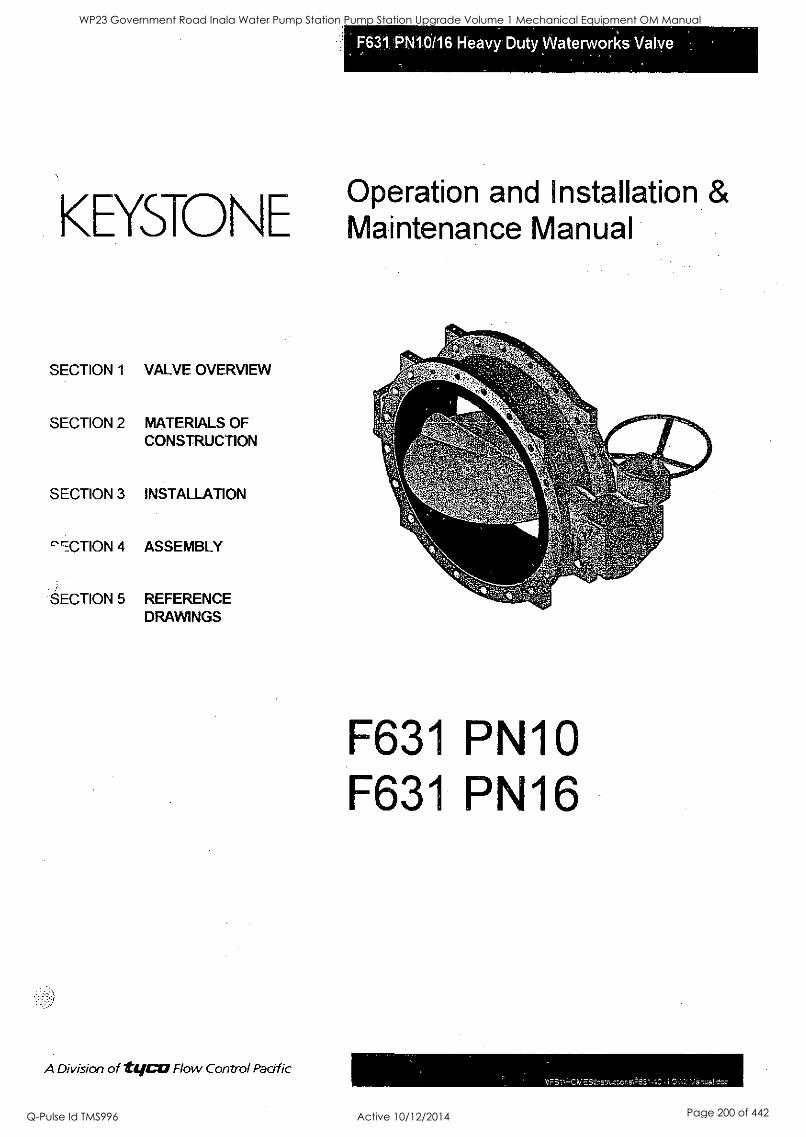
EYSTO N E Operation and Installation & Maintenance Manual
SECTION 1 VALVE OVERVIEW
SECTION 2 MATERIALS OF CONSTRUCTION
SECTION 3 INSTALLATION
`'ACTION 4 ASSEMBLY
SECTION 5 REFERENCE DRAWINGS
A Division of Vico Flow Control Pacific
F631 PN10 F631 PN16
WP23 Government Road Inala Water Pump Station Pump Station Upgrade Volume 1 Mechanical Equipment OM Manual
Q-Pulse Id TMS996 Active 10/12/2014 Page 200 of 442
Valve Overview
Range minal bores - 100, 150, 200, 250, 300, 350, 400, 450, 500, 600, 700, 750, 800, 900, 1000, 1050 and 1200.
Flange Standard The valve is designed to accommodate a wide range of flange drillings and consequently the diameter and thickness of the flange will not exactly comply to a specific flange standard. eg An AS 2129 table 'D' drilling pattern may have the flange outside diameter and flange thickness of an ANSI 150 so the true description is "drilled in accordance with Each size valve flange has been designed to have the maximum outside diameter and maximum thickness of the nominated flange standards i.e. worst case.
Flange Standards Standard Rating AS2129 Table C
Table D Table E
Table F
JIS B2210 PN10
DIN 2501-Part 1/
BS 4504-Section 3.2
:e to Face is, standard valve will have a face to face in accordance with BS 5155 short and ISO 5752 table 4.
o clarify, some specifications shall reference the face to face as ISO 5752 short, ISO 5752 table 4 short, ISO 5752 series 13 or BS 5155 - all these are identical references. The only sizes of the re-designed valves which do not comply are 750 N/B and 1050 N/B which are non-standard size in accordance with ISO 5752 and therefore are based on historical information ie F627.
Overall Dimensions
Refer to Reference Drawings
01-631-142 100-250mm F631 PN10/16 01-631-145 300-500mm F631 PN10/16 01-631-154 600-1200mm F631 PN10 01-631-139 600-1200mm F631 PN16
Seat Design The F631 seat design meets the requirements of seat replaceability but also solves the problem of internal protection of the valve body as the seat encapsulates the wetted area. The seat is of a moulded construction which fits easily into the body, covering the entire interior of the valve body and extending onto the grooved flange faces. The seat has a peripheral band which seats in a bed-groove in the body to hold the seat securely in place when the disc is closing and attempting to displace the seating surface. In the shut-off position, the disc seals on the crown surface of the disc by means of interference fit with the liner. Due to compression by the disc, the bed-groove feature of the seat minimises tension or pull on the liner; consequently there is a minimum of displacement as the polymer is being pushed to the corner of the bed-groove adjacent to the direction of the disc closing. Under compression the seat forms a positive seal between the flats on the seat and the disc hub referred to as the primary seal therefore preventing leakage at the shaft. In
t.irittion the valve has a secondary shaft seal by means of a dynamic 0-ring encapsulated in a stainless steel ring which is located on outer of the seat.
A Division of tIliCtrl Flow Control Pacific
WP23 Government Road Inala Water Pump Station Pump Station Upgrade Volume 1 Mechanical Equipment OM Manual
Q-Pulse Id TMS996 Active 10/12/2014 Page 201 of 442
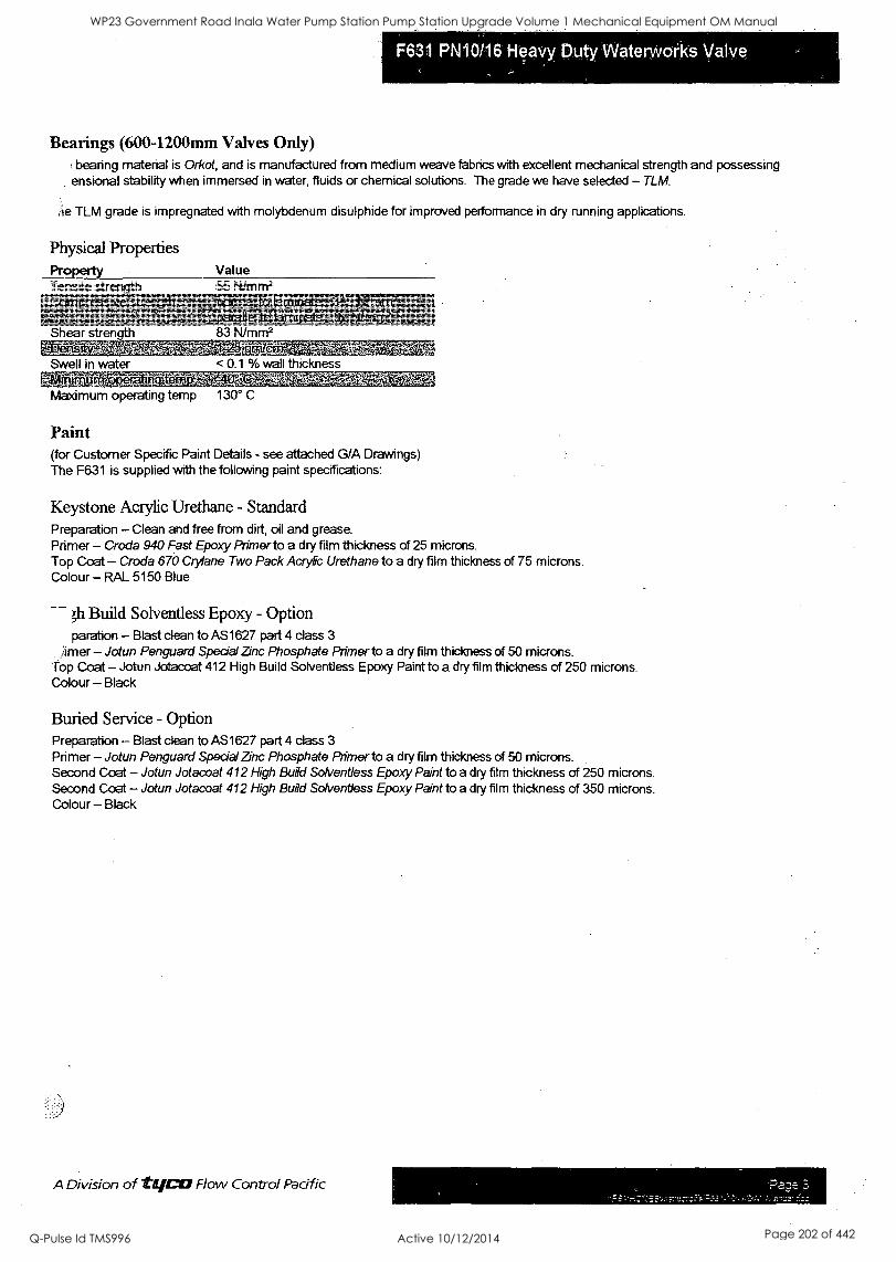
Bearings (600-1200mm Valves Only) bearing material is Orkot, and is manufactured from medium weave fabrics with excellent mechanical strength and possessing
ensional stability when immersed in water, fluids or chemical solutions. The grade we have selected - TLM.
e TLM grade is impregnated with molybdenum disulphide for improved performance in dry running applications.
Physical Properties Property Tensile strength
Shear strength AM-WEAWNEZIV
Swell in water
83 N/mm2 MERMARtg&ka
< 0.1 % wall thickness
Maximum operating temp 130° C
Paint (for Customer Specific Paint Details - see attached G/A Drawings) The F631 is supplied with the following paint specifications:
Keystone Acrylic Urethane - Standard Preparation - Clean and free from dirt, oil and grease. Primer -Grade 940 Fast Epoxy Primer to a dry film thickness of 25 microns. Top Coat - Croda 670 Crylane Two Pack Acrylic Urethane to a dry film thickness of 75 microns. Colour -RAL 5150 Blue
;11 Build Solventless Epoxy - Option paration - Blast clean to AS1627 part 4 class 3
Amer - Jotun Penguard Special Zinc Phosphate Primer to a dry film thickness of 50 microns. Top Coat - Jotun Jotacoat 412 High Build Solventless Epoxy Paint to a dry film thickness of 250 microns. Colour - Black
Buried Service - Option Preparation - Blast clean to AS1627 part 4 class 3
Primer - Jotun Penguard Special Zinc Phosphate Primer to a dry film thickness of 50 microns. Second Coat - Jotun Jotacoat 412 High Build Solventless Epoxy Paint to a dry film thickness of 250 microns. Second Coat - Jotun Jotacoat 412 High Build Solventless Epoxy Paint to a dry film thickness of 350 microns. Colour - Black
A Division of Lycra Flow Control Pacific
WP23 Government Road Inala Water Pump Station Pump Station Upgrade Volume 1 Mechanical Equipment OM Manual
Q-Pulse Id TMS996 Active 10/12/2014 Page 202 of 442
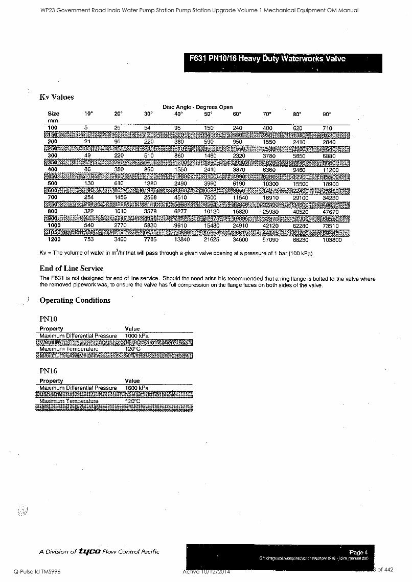
F631 PN10/16 Heavy Duty Waterworks Valve
Kv Values Disc Angle - Degrees Open
Size mm
10° 20° 30° 40° 50° 60°
100 5 25 54 95 150 240 450 200. 21 9
2s0 r 33 1,55
300 40 220 05
86 110
490 254 294
290 380 490
a 17o ,_ 0 380 590 950
340 - 1550 510 860 1460 2320 660 1200-- -18 - V '
860 1550 2410 3870
4 1980 -31L00 -:
1380 2490 3960
70° 80° 90°
400 95fyywtv16 1550
620 710
700 1156
ffir 1298 800 1610 3578
KO* 2249 'a:J*11488
1000 2770 5830
Rit6.4 1200 753 3460
L9,88,
2568 4510 311'
4
540
536:3 -
8, 9610
6055 10380 7785 13840
6190
1-4,11.2:1
2410 2840 2580 3960 3780 4820
10300 1.4273- 18910
11065k_ 7500 11540 8564 13840 ; 22490;° 10120 15820 25930 12975 19895 32 870
24910 42120 263,156 4:1'10
34600 57090
15480
21625
5850 6880 86'00
9460 11200
1556G'-A 15500 18900
29100
40520
54R.P. 62280 73510
,1704cio
88230 103800
34230 :411,4,0:%5
47670
Kv The volume of water in m3/hr that will pass through a given valve opening at a pressure of 1 bar (100 kPa)
End of Line Service The F631 is not designed for end of line service. Should the need arise it is recommended that a ring flange is bolted to the valve where the removed pipework was, to ensure the valve has full compression on the flange faces on both sides of the valve.
Operating Conditions
PN10 Property Maximum Differential Pressure
Maximum Temperature EggergirTvoisktWEETEW
PN16 Property
Value 1000 kPa
HObigiirog[_)n6ru, 120'C
[TVS
Value Maximum Differential Pressure 1600 kPa
latgatioirevogii- Maximum Temerature 120°C MaXiftifinitFloW,Yelee" 541rpigLy"
A Division of IWO Flow Control Pacific Page 4 GAtfcmfgkwatenvorknnstructions \1631pn10-16 - i.o m. manual doc
WP23 Government Road Inala Water Pump Station Pump Station Upgrade Volume 1 Mechanical Equipment OM Manual
Q-Pulse Id TMS996 Active 10/12/2014 Page 203 of 442
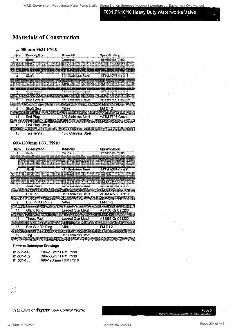
Materials of Construction
71 -500mm F631 PN10 .am Description Material
1 Body Cast Iron , 6tWe
Specification AS1830 Gr T260
Shaft 316 Stainless Steel ASTM A276 Gr 316
ASTM A276 Gr 316
Nitrile EM-D1-2 s';41.1141
f.
11 End Plug 316 Stainless Steel ASTM F593 Group 2
13 End Plug Circli
--MiStWleMaff& `1`-, ' ' ,'-
15 Tag Rivets
600-1200mm F631 PN10 item
1
94
Description Body
18.8 Stainless Steel
Material Cast Iron
Shaft 431
Specification
O kniA:.-N414.:. '479:A' tet*Broaze. vp?,,v 6t
Mt
Stainless Steel
AS1830 Gr T260 XOY7.4
ASTM A276 Gr 431
Seat Insert 316 Stainless Steel ASTM A276 Gr 316
IAMWAIM- 4MiNTWif Disc Pin 316 Stainless Steel ASTM A276 Gr 316
4:5J 40.4.21;
Disc Pin'O' Rings Nitrile EM-D1-2
1 Gland Ring rr;:r.g.2.
Leaded Gun Metal ,c1RW-_,LALtir
AS1565 Gr C93200
13 Thrust Pad Leaded Gun Metal AS1565 Gr C93200 -610M1_ 314-c ALM'
15 End Ca '0' Ring
17 Tag
Nitrile EM-D1-2
316 Stainless Steel WillcitW4-fr,e-tte.StraMttiO,111_,MiT
Refer to Reference Drawings
01-631-143 01-631-152 01-631-155
100-250mm F631 PN10 300-500mm F631 PN10 600-1200mm F631 PN10
A Division of t(jCU Flow Control Pacific
S
Page 5 c: C I.0 .M3'1;:3!.:
WP23 Government Road Inala Water Pump Station Pump Station Upgrade Volume 1 Mechanical Equipment OM Manual
Q-Pulse Id TMS996 Active 10/12/2014 Page 204 of 442
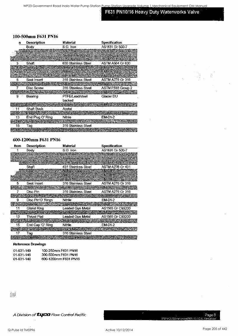
I II I
F631 PN10/16 Heavy Duty Waterworks Valve
:
S8
n o
kts. 'en 1 tr. --
11`' Art°44P1 4411.1t4' a c,vy '"WVVD
-xft 44" ' * An, ."-
-res.
gas !,!_
r. Z..
'41B,POW:WiNiaal.W.Hire40...W.6fe 7 I -
e 3TA,0Ags &
.1.- - I
-ffn
"`"0 t rt, 1+ 4 ritr4r -e I
: 8
' --Agautitrawalmiggwgtf
111 1111 '
"
-44444.
tr. -
yr` -
r:
'-Nc-17. °
r -
r. Z.. ; °T.O. gARSOitit-W
I -
-AIS"TgmeeK-eL LO' eiNV. - 11
.g.141-T$Tifft r AI' nfirit.L,TablTh-WAVIC "Al5S.MONSI ° :4 -
-f". 40,07.ri,,,MMX; AirMIELV:tra* - 11
-1414W.FA'* tt.
11,:;g41WIEW.,1-%1_1=085, tzqtetqlriWtNaNtt," . I -
I 11
1 11
1 I 11
111
VC
Os. / I
I
Page 6
WP23 Government Road Inala Water Pump Station Pump Station Upgrade Volume 1 Mechanical Equipment OM Manual
Q-Pulse Id TMS996 Active 10/12/2014 Page 205 of 442
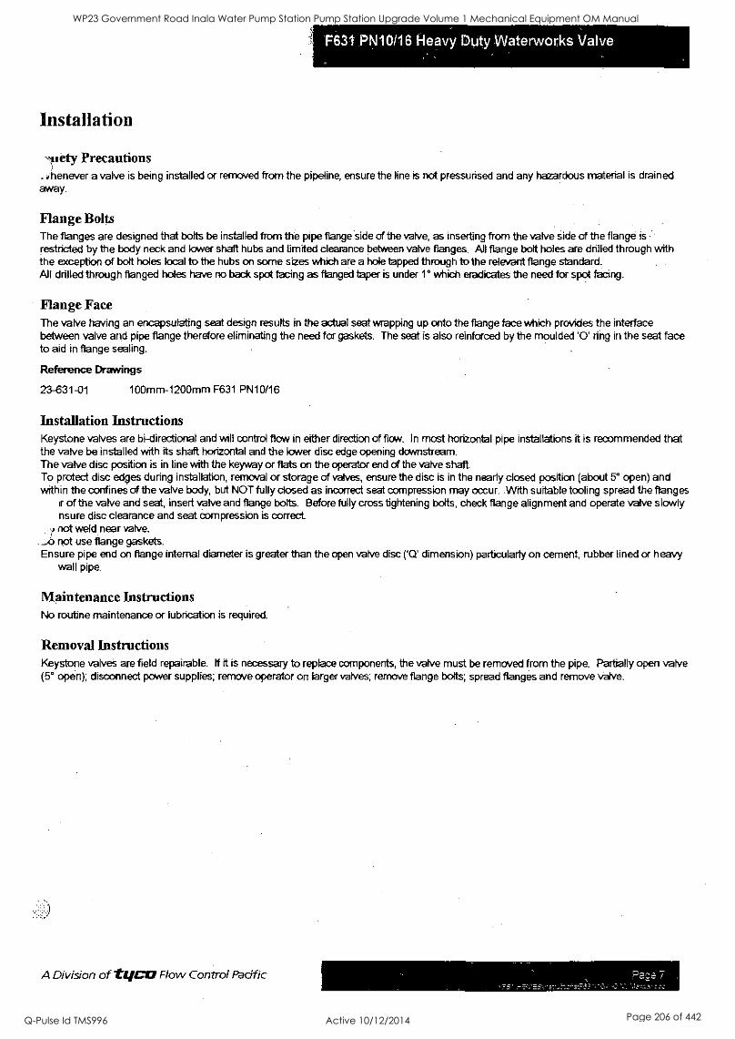
Installation
--,suety Precautions . rhenever a valve is being installed or removed from the pipeline, ensure the line is not pressurised and any hazardous material is drained away.
Flange Bolts The flanges are designed that bolts be installed from the pipe flange side of the valve, as inserting from the valve side of the flange is restricted by the body neck and lower shaft hubs and limited clearance between valve flanges. All flange bolt holes are drilled through with the exception of bolt holes local to the hubs on some sizes which are a hole tapped through to the relevant flange standard. All drilled through flanged holes have no back spot facing as flanged taper is under 1° which eradicates the need for spot facing.
Flange Face The valve having an encapsulating seat design results in the actual seat wrapping up onto the flange face which provides the interface between valve and pipe flange therefore eliminating the need for gaskets. The seat is also reinforced by the moulded '0' ring in the seat face to aid in flange sealing.
Reference Drawings
23-631-01 100mm-1200mm F631 PN10/16
Installation Instructions Keystone valves are bi-directional and will control flow in either direction of flow. In most horizontal pipe installations it is recommended that the valve be installed with its shaft horizontal and the lower disc edge opening downstream. The valve disc position is in line with the keyway or flats on the operator end of the valve shaft. To protect disc edges during installation, removal or storage of valves, ensure the disc is in the nearly closed position (about 5° open) and within the confines of the valve body, but NOT fully closed as incorrect seat compression may occur. With suitable tooling spread the flanges
it of the valve and seat, insert valve and flange bolts_ Before fully cross tightening bolts, check flange alignment and operate valve slowly nsure disc clearance and seat compression is correct.
v not weld near valve. not use flange gaskets.
Ensure pipe end on flange internal diameter is greater than the open valve disc ('Q' dimension) particularly on cement, rubber lined or heavy wall pipe.
Maintenance Instructions No routine maintenance or lubrication is required.
Removal Instructions Keystone valves are field repairable. if it is necessary to replace components, the valve must be removed from the pipe. Partially open valve (5° open); disconnect power supplies; remove operator on larger valves; remove flange bolts; spread flanges and remove valve.
A Division of two Flow Control Pacific
WP23 Government Road Inala Water Pump Station Pump Station Upgrade Volume 1 Mechanical Equipment OM Manual
Q-Pulse Id TMS996 Active 10/12/2014 Page 206 of 442
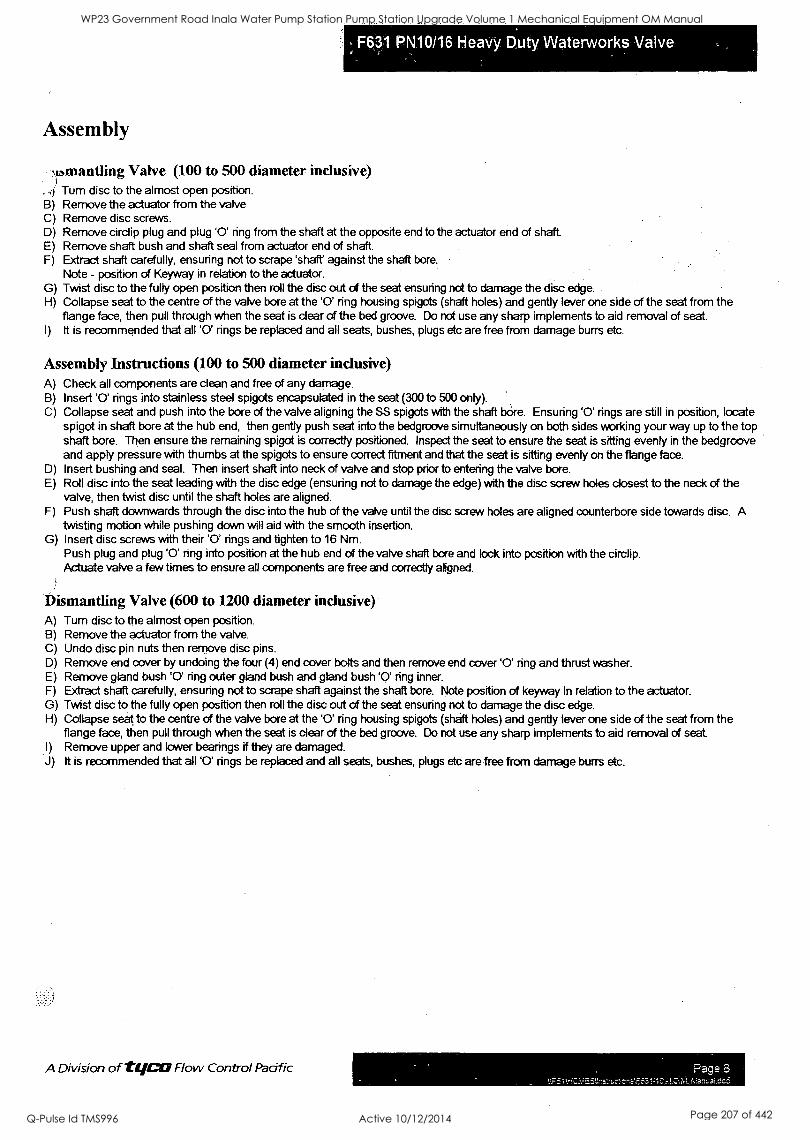
Assembly
SIbmantling Valve (100 to 500 diameter inclusive) . - Turn disc to the almost open position. B) Remove the actuator from the valve C) Remove disc screws. D) Remove cirdip plug and plug '0' ring from the shaft at the opposite end to the actuator end of shaft E) Remove shaft bush and shaft seal from actuator end of shaft. F) Extract shaft carefully, ensuring not to scrape 'shaft' against the shaft bore.
Note - position of Keyway in relation to the actuator. G) Twist disc to the fully open position then roll the disc out of the seat ensuring not to damage the disc edge. H) Collapse seat to the centre of the valve bore at the '0' ring housing spigots (shaft holes) and gently lever one side of the seat from the
flange face, then pull through when the seat is dear of the bed groove. Do not use any sharp implements to aid removal of seat. I) it is recommended that all '0' rings be replaced and all seats, bushes, plugs etc are free from damage burrs etc.
Assembly Instructions (100 to 500 diameter inclusive) A) Check all components are clean and free of any damage. B) Insert '0' rings into stainless steel spigots encapsulated in the seat (300 to 500 only). C) Collapse seat and push into the bore of the valve aligning the SS spigots with the shaft bore. Ensuring '0' rings are still in position, locate
spigot in shaft bore at the hub end, then gently push seat into the bedgroove simultaneously on both sides working your way up to the top shaft bore. Then ensure the remaining spigot is correctly positioned. Inspect the seat to ensure the seat is sitting evenly in the bedgroove and apply pressure with thumbs at the spigots to ensure correct fitment and that the seat is sitting evenly on the flange face.
D) Insert bushing and seal. Then insert shaft into neck of valve and stop prior to entering the valve bore. E) Roll disc into the seat leading with the disc edge (ensuring not to damage the edge) with the disc screw holes closest to the neck of the
valve, then twist disc until the shaft holes are aligned. F) Push shaft downwards through the disc into the hub of the valve until the disc screw holes are aligned counterbore side towards disc. A
twisting motion while pushing down will aid with the smooth insertion. G) Insert disc screws with their '0' rings and tighten to 16 Nm.
Push plug and plug '0' ring into position at the hub end of the valve shaft bore and lock into position with the circlip. Actuate valve a few times to ensure all components are free and correctly aligned.
Dismantling Valve (600 to 1200 diameter inclusive) A) Turn disc to the almost open position. B) Remove the actuator from the valve. C) Undo disc pin nuts then remove disc pins. D) Remove end cover by undoing the four (4) end cover bolts and then remove end cover '0' ring and thrust washer. E) Remove gland bush '0' ring outer gland bush and gland bush '0' ring inner. F) Extract shaft carefully, ensuring not to scrape shaft against the shaft bore. Note position of keyway in relation to the actuator. G) Twist disc to the fully open position then roll the disc out of the seat ensuring not to damage the disc edge. H) Collapse seat to the centre of the valve bore at the '0' ring housing spigots (shaft holes) and gently lever one side of the seat from the
flange face, then pull through when the seat is clear of the bed groove. Do not use any sharp implements to aid removal of seat. I) Remove upper and lower bearings if they are damaged. J) It is recommended that all '0' rings be replaced and all seats, bushes, plugs etc are free from damage burrs etc.
A Division of 111/C:13 Flow Control Pacific
WP23 Government Road Inala Water Pump Station Pump Station Upgrade Volume 1 Mechanical Equipment OM Manual
Q-Pulse Id TMS996 Active 10/12/2014 Page 207 of 442
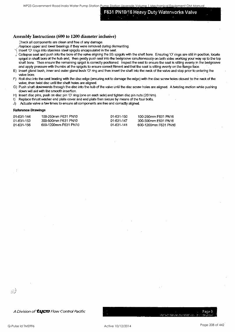
Assembly Instructions (600 to 1200 diameter inclusive) heck all components are dean and free of any damage.
.Replace upper and lower bearings if they were removed during dismantling. Insert '0' rings into stainless steel spigots encapsulated in the seat Collapse seat and push into the bore of the valve aligning the SS spigots with the shaft bore. Ensuring '0' rings are still in position, locate spigot in shaft bore at the hub end, then gently push seat into the bedgroove simultaneously on both sides working your way up to the top shaft bore. Then ensure the remaining spigot is correctly positioned. Inspect the seat to ensure the seat is sitting evenly in the bedgroove and apply pressure with thumbs at the spigots to ensure correct fitment and that the seat is sitting evenly on the flange face.
E) Insert gland bush, inner and outer gland bush '0' ring and then insert the shaft into the neck of the valve and stop prior to entering the valve bore.
F) Roll disc into the seat leading with the disc edge (ensuring not to damage the edge) with the disc screw holes closest to the neck of the valve, then twist disc until the shaft holes are aligned.
G) Push shaft downwards through the disc into the hub of the valve until the disc screw holes are aligned. A twisting motion while pushing down will aid with the smooth insertion.
H) Insert disc pins, push on disc pin '0' ring (one on each side) and tighten disc pin nuts' (20 Nm). I) Replace thrust washer end plate cover and end plate then secure by means of the four bolts. J) Actuate valve a few times to ensure all components are free and correctly aligned.
Reference Drawings
01-631-144 100-250mm F631 PN10 01-631-150 100-250mm F631 PN16 01-631-153 300-500mm F631 PN10 01-631-147 300-500mm F631 PN16 01-631-156 600-1200mm F631 PN10 01-631-141 600-1200mm F631 PN16
A Division of VICO Flow Control Pacific Pace
WP23 Government Road Inala Water Pump Station Pump Station Upgrade Volume 1 Mechanical Equipment OM Manual
Q-Pulse Id TMS996 Active 10/12/2014 Page 208 of 442
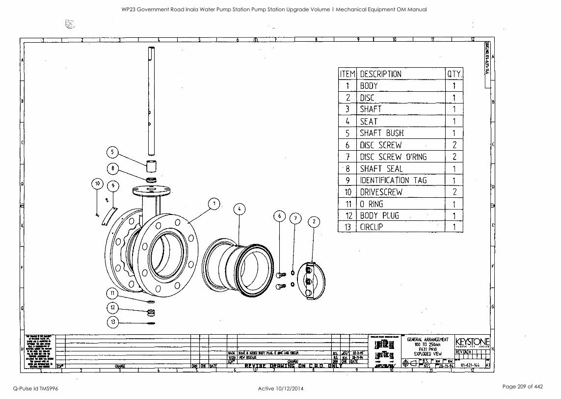
11 12
D
H
ITEM DESCRIPTION QTY.
1 BODY 1
2 DISC 1
3 SHAFT 1
4 SEAT 1
5 SHAFT BUSH 1
6 DISC SCREW 2
7 DISC SCREW O'RING 2
8 SHAFT SEAL 1
9 IDENTIFICATION TAG 1
10 DRIVESCREW 2
11 0 RING 1
12 BODY PLUG 1
13 CIRCLIP 1
1013f SSUE 6 MID FM MX. 061E MB Mal,.
57"
RE1E4SC
t: Ii. 1.."1111111111111irta6;1:14 GT II:
MIMS Ir 117E11191_,.
:1111 1:111
72-2-95
111111111.10 =WA
t
I 2
GENERAL ARRANGEMENT
100 TO 250mm F631 MO
EXPLODED VIEW REV, I M
S'PlVrinTr----.14.8-111-61:
1
01-631-144
KEYSTONE
Al
C
F
fi
WP23 Government Road Inala Water Pump Station Pump Station Upgrade Volume 1 Mechanical Equipment OM Manual
Q-Pulse Id TMS996 Active 10/12/2014 Page 209 of 442
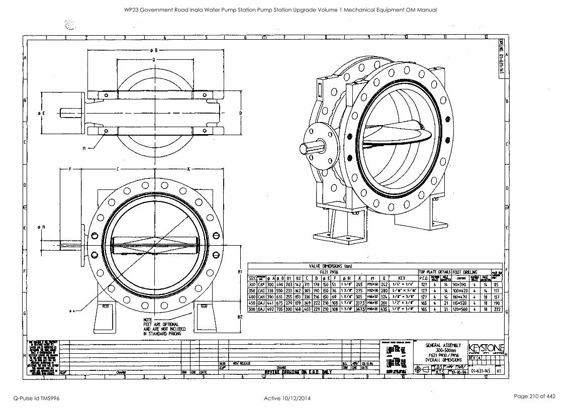
A
B
C
0
E
E
F
H
1 I 2 1 3 I 4 1 5 I 6 m 7
se
011
OM( 2 I 3
NOTE
FEET ARE OPTIONAL
AND ARE NOT NCLLIDED
IN STANDARD PRICING
COI 01( DAR
1
9 1 10 1 11 I 12
VALVE 0klENS1ONS fmml
F631 PN16 Me PLATE OVALS FOOT DRILLING zip Ma S12E"="43Aci1B 61 82 C 0 43E F of1 K M a KEY p.m or osz. axes wr an
300 CAF 300 490 203 142 311 178 150 51 11/r 245 P112"30 242 1/4- x l/4 121 4 14 90x390 4 14 85
350 CAG 338 550 233 142 305 190 150 76 1 3/r 275 r1W00 280 5/36 x s/le 127 4 14 100x420 4 14 117
400 CAN 390 610 255 150 336 216 150 69 1 sir 305 n16x3S 324 3/r x 3/r 127 4 14 110x470 4 18 157
450 OM 441 675 279 159 369 222 210 108 I //r 3375 rtsx35 381 1/2" x 3/r 165 4 21 115420 4 18 190
500 CIAJ 492 735 300 168 403 229 210 108 I //r 3675 IsNoos 435 t/r x i/r i65 4 21 120460 4 18 222
% WM ACM EEO
.1110011 MIN Wm.. Ma GENERAL ASSEttLY ifati .300-50fti
F631 PNIO/Ft116, OVERALL Dt104513N5
.5, .01' -01/ -10-91
9 1 10 L 12
83. 4103-n-91 awe 01( OAR
1 6
IOW ale
tiffit 811211.111i 10E-
KEYSTONE L01311111
01-631-145 Al
A
B
C
0
E
F
WP23 Government Road Inala Water Pump Station Pump Station Upgrade Volume 1 Mechanical Equipment OM Manual
Q-Pulse Id TMS996 Active 10/12/2014 Page 210 of 442
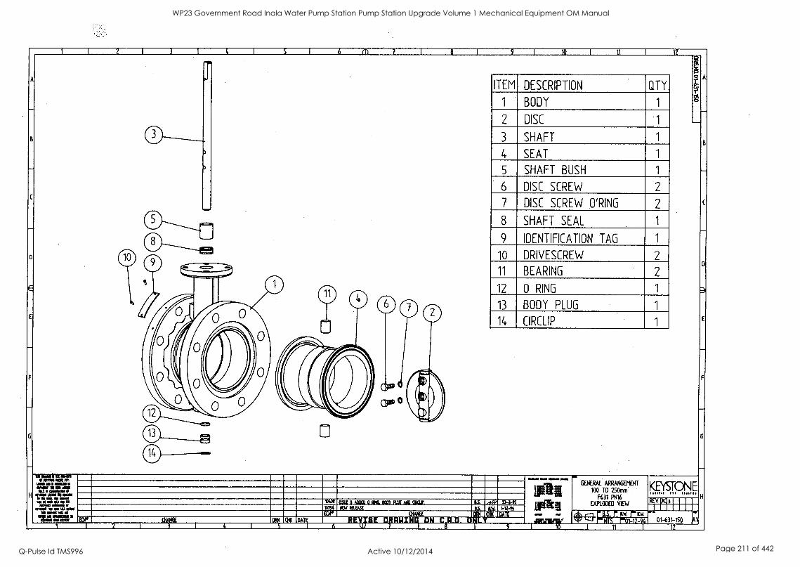
11 I 12
B 0 -
ITEM DESCRIPTION QTY.
1 BODY
2 DISC
3 SHAFT 1 B
C
E
4 SEAT 1
5 SHAFT BUSH 1
6 DISC SCREW 2
7 DISC SCREW O'RING 2
411 O
8 SHAFT SEAL
9 IDENTIFICATION TAG 1
10 DRIVESCREW 2 0 - .==. 11 BEARING 2 0
11 12 0 RING 1 i 0
0 13 BODY PLUG 1
0
( "), 1
0 14 CIRCLIP 1
410
411)
0
0
0
-Z"
0 (CCH 41) G
- MUM NM Pt
MO 0 111111=111 ......,- 1111110111111141
mazz.: r iings.
WWII MO IIIMM NM
g arakii
_mil;
GENroTr2strENT F631 PN16
EXPLODED VIEW
KEYSIPN E
H 551.1 8,f/RD 0 Plf. DX/ FUG MD CRar. ritiriz_vos
I. 4f-E3-uN'SYSr. 1120i1-r;r4 01-631-150 A ,, if :I rSallt II:I% yr.,- _co .... ,iammkie jak-1:11 1
WP23 Government Road Inala Water Pump Station Pump Station Upgrade Volume 1 Mechanical Equipment OM Manual
Q-Pulse Id TMS996 Active 10/12/2014 Page 211 of 442
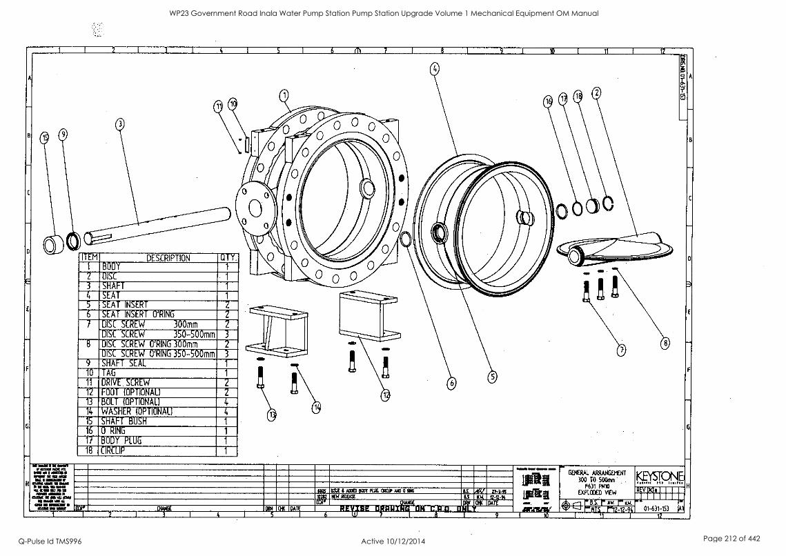
DESCRIPTION
SHAFT
SEAT INSERT
SEAT INSERT O'RING
DISC SCREW 300mm DISC SCREW 350-500mm DISC SCREW O'RING 300mm DISC SCREW O'RING 350-500mm SHAFT SEAL
DRIVE SCREW
FOOT (OPTIONAL)
BOLT (OPTIONAL)
WASHER (OPTIONAL)
SHAFT BUSH
0 RING
BODY PLUG
CIRCLIP
11(6 ISSLE 11 ACCED port PU.b. mar NO I) MI6
GENERAL300 TARRANGEtlENTO 500mm igys,rp F631 PN10
EXPLODED VIEW REVN6 .1 I I
1 *el P6r-r-7T-S.11 01-631-153
WP23 Government Road Inala Water Pump Station Pump Station Upgrade Volume 1 Mechanical Equipment OM Manual
Q-Pulse Id TMS996 Active 10/12/2014 Page 212 of 442
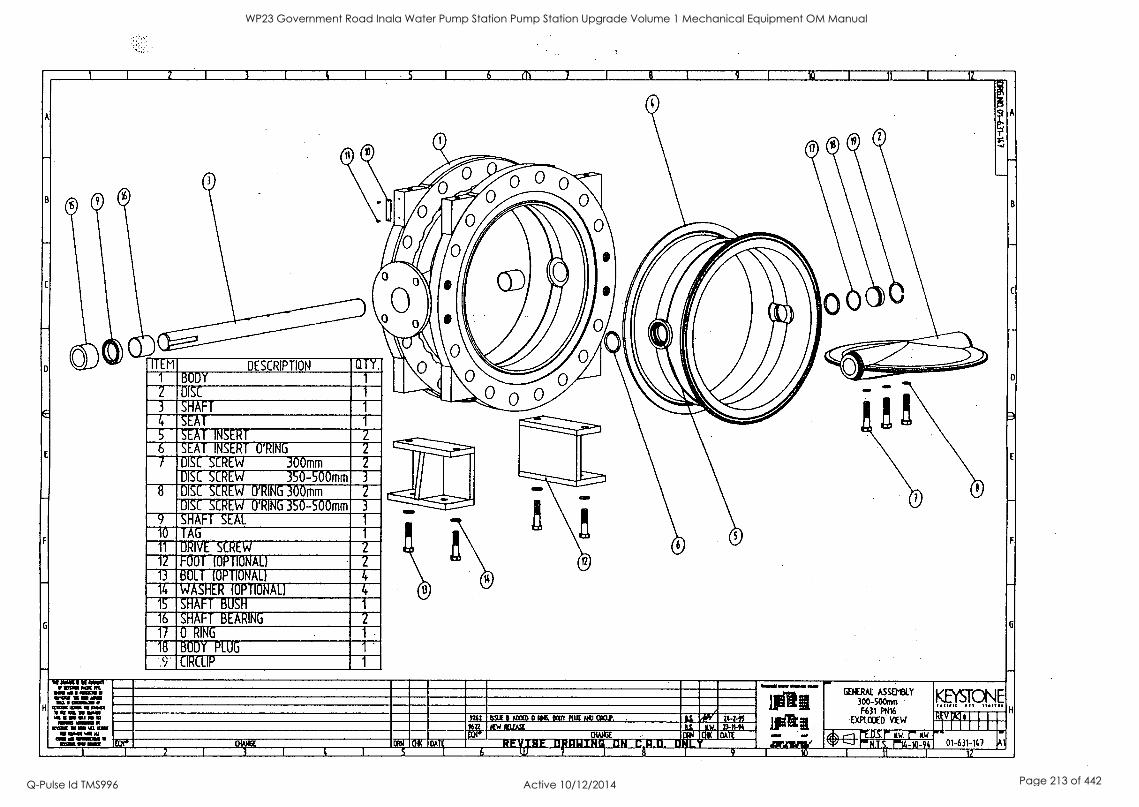
. 11 i 12
A 0
0 e H -
B 0 0 0 0
0 - 0
0
v 41/4\
0
0
CID
°All"
0
l
Ot IN )
-
0 -
C
41.'----------- --mIlliIIIIIM
- ITEM DESCRIPTION QTY. N 0 1 BODY 1 1
IIIIIQI
_
0 -
0 0 2 DISC 1
3 SHAFT 1 ......
4 SEAT 1 P. ! iD
5 SEAT INSERT 2 sows
E
la- 6 SEAT INSERT O'RING 2
....SIP011
Diiii.....i 7 DISC SCREW 300mm 2
D1SC SCREW 350-500mm 3
8 DISC SCREW O'RING 300mm 2 . 0 0 _ DISC SCREW O'RING 350-500mm 3 ---
9 SHAFT SEAL 1
0 F 0 0 '
0 -
6
10 TAG 1
11 DRIV E SCREW 2
12 FOOT (OPTIONAL) 2
13 BOLT (OPTIONAL) 4
14 WASHER (OPTIONAL) 4
15 SHAFT BUSH 1
16 SHAFT BEARING 2
17 0 RING 1 .
18 BODY PLUG 1 .
9 CIRCLIP 1 ..-
1111 MIMI i W NOM
MO al I MOO IN WINN! IN NM WIN at II CliMail
H 111111011Wil .111111l1 MIN RIM= 110/111 UIL 1.11041..,u
ME MI IMMO r071111011111:11
inswOmemr,
1St § Lvak
,_ , ,
GEttRAI. ASS813LY ,, 30°_,,,,
F631 PM%
EXPLCOED V IEW
KEYSTONE
gp 0 ISSUE II a OK KM PUX NO aCUP, ..,....
/ . niltifEl 111.11 e 47.....tindmi KW
01-631-147 ..."
11 I : I, Ilr :1' ' 4:14111; :1411:11111:1111 1111:11111 vi omen _ _
WP23 Government Road Inala Water Pump Station Pump Station Upgrade Volume 1 Mechanical Equipment OM Manual
Q-Pulse Id TMS996 Active 10/12/2014 Page 213 of 442
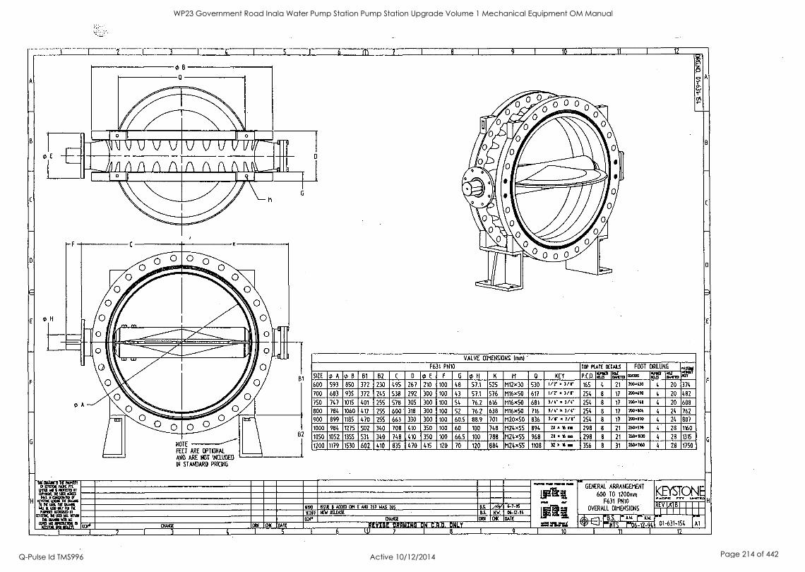
0H
NOTE
FEET ARE OPTIONAL
AND ARE NOT INCLUDED
IN STANDARD PRICING
VALVE DIMENSIONS Imm) -
F631 PN10 TOP PLATE onus FOOT DRILLING
SIZE 0 A0B B1 B2 C D 0 E F G O H K M a KEY P.C.D. rur raw cums AV renm PuT
600 593 850 372 230 495 267 210 100 48 57.1 525 M12x30 530 In- . m8' 165 4 21 200430 4 20 374
700 683 935 372 245 538 292 300 100 43 57.1 576 M16x50 617 lir . 3/8' 254 8 17 200490 4 20 482
750 747 1015 401 255 578 305 300 100 54 76.2 616 M16x50 681 3/6' 1/6* 254 8 17 7c0,q64 4 20 608
800 784 1060 417 255 600 318 300 100 52 76.2 638 M16x50 716 3/4* x 7/4" 254 8 17 200404 4 24 762
900 899 1185 470 255 663 330 300 100 60.5 88.9 701 M20x50 836 7/r x 7/1' 254 8 17 200490 4 24 807
1000 984 1275 502 340 708 410 350 100 60 100 748 M24x55 894 zs I6 ma 298 8 21 zbamo 4 28 1160
1050 1052 1355 531 340 748 410 350 100 66.5 100 788 M24x55 968 21 Is an 298 8 21 260111332 4 28 1315
1200 1179 1530 602 410 835 470 415 120 70 120 884 M24x55 1108 32.140 356 8 31 200"60 4 28 1750
B
11
C
1,*
0
NH 8190 TM B AWED OM 6 AM 267 WAS 765
BS. NW.
6-7-95
06-2-94 10769 NEW RELEASE
EER DV Oil DATE
I 2
FY 016 BATE
L 91
MOW. OM OMAR SOD GENERAL ARRANGEMENT
600 TO 1200mm F631 PNIO
OVERALL DIMENSIONS
F
KEYSTON ACIPIC TY liMrft
4frif] 1A111111321
U 01-631-154 I Al
12
WP23 Government Road Inala Water Pump Station Pump Station Upgrade Volume 1 Mechanical Equipment OM Manual
Q-Pulse Id TMS996 Active 10/12/2014 Page 214 of 442
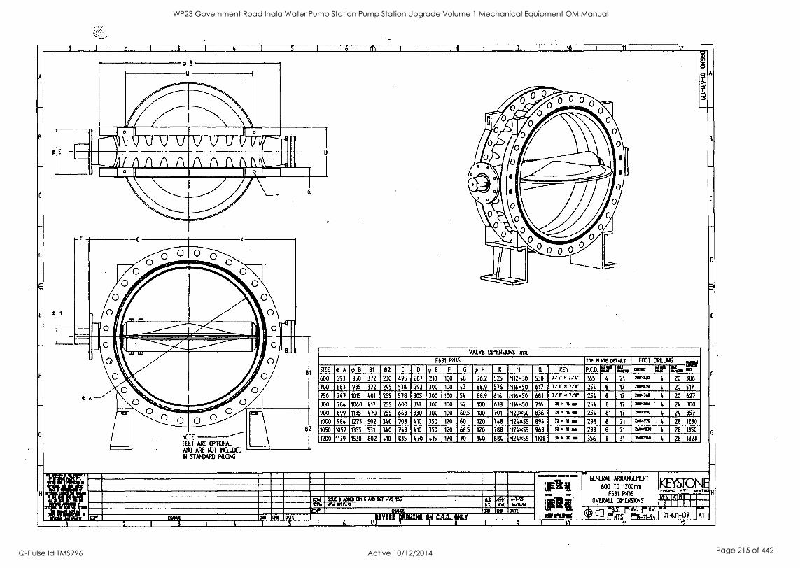
NOTE
FEET ARE OPTIONAL
AND ARE NOT INCLUDED
IN STANDARD PRICING
VALVE CelENSIONS {mm)
F631 P1116 TCP Fun riEras FOOT £$ J1
SIZE of., A cb B B1 B2 C D it E F G ce H K II Q KEY P.C.D. illi rogi COM Ir.: I ear. tar
600 593 850 372 230 495 267 210 100 48 76.2 575 t112x30 530 1/4 3/4' 165 4 21 2c043* 4 20 386
700 683 935 372 245 538 292 300 100 43 88.9 576 1116x50 617 7/r 7ir 254 8 17 2°).4%) 4 20 517
750 747 1015 401 255 528 305 300 100 54 88.9 616 t116x50 681 Fir .' 7/r 254 8 17 20061 4 20 627
600 784 1060 417 255 600 318 300 100 52 100 638 1116x50 716 21** 254 8 17 2c00664 4 24 800
900 899 1185 470 255 663 330 300 100 605 100 701 1120x50 836 zl 16. 254 8 17 ?wow 4 24 857
1000 984 1275 502 340 708 410 350 120 60 120 748 1124x55 894 n.1110 298 8 21 266.976 4 28 1230
1050 1052 1355 531 340 748 410 350 120 665 120 788 I124x55 968 n 10 298 8 21 260.1230 4 28 1350
1200 1179 1530 602 410 835 470 415 170 70 884 M24x55 1108 )6 20 am 356 8 31 28 1828
In4 011f7ks.COF On 6 MO 267 WAS US &i XV 4-7-41 *Di MEW 4W. 1441-44
We OW& OK DAN
GENERAL
TO
AWAN5ENEWT KEySTONE 600 1200mm
F631 Pt416 t OVERALL ga 5927F CtIENS1ONS
swami SE-PINTS F-14-11-91 01-631-139 Al t2
WP23 Government Road Inala Water Pump Station Pump Station Upgrade Volume 1 Mechanical Equipment OM Manual
Q-Pulse Id TMS996 Active 10/12/2014 Page 215 of 442
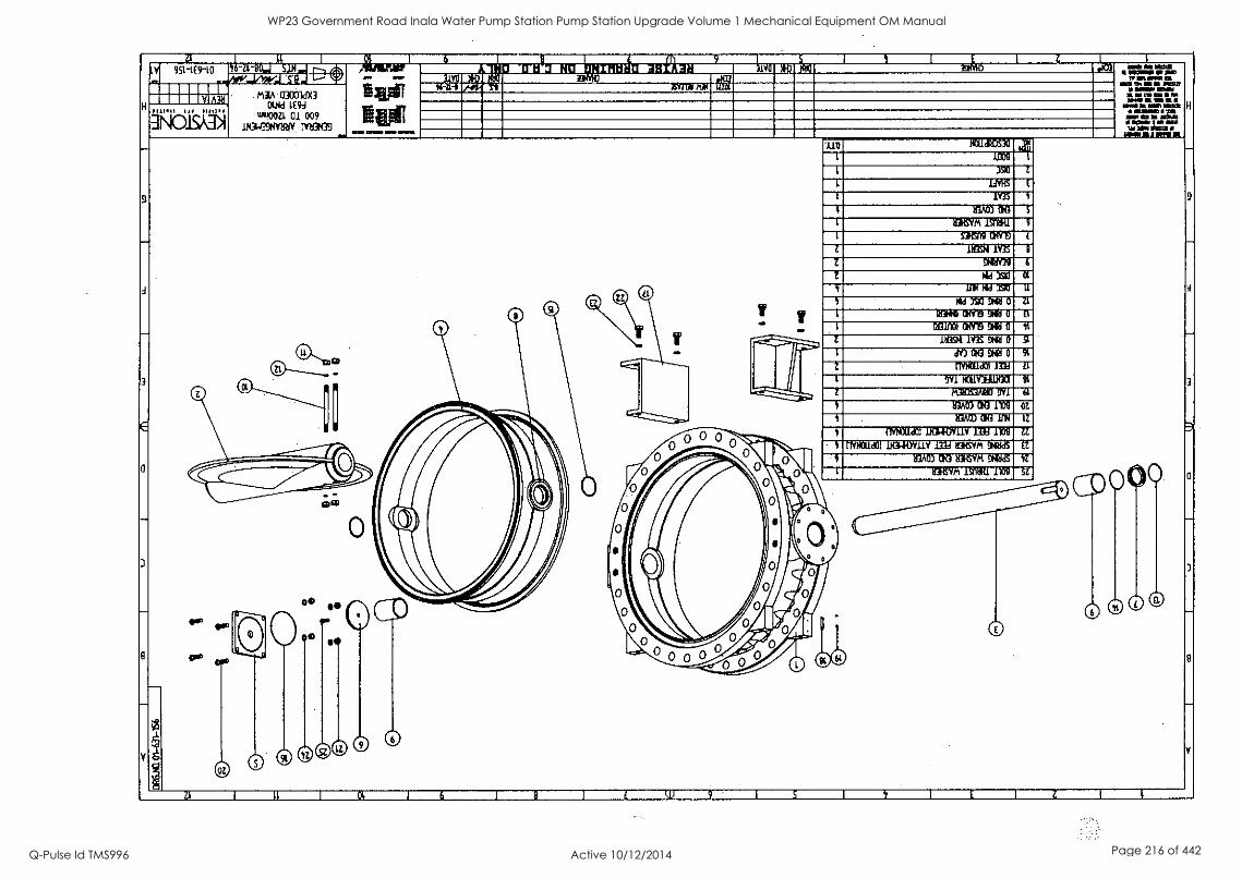
Z1 11 I 6 9-
1 I I Z la ty 951-1(9-10 11-71-80.1 SDI IP I.'s.' e-, likffinlerri inia3 HU 9 Igthii- -IMO- AD E93 -1
_zolivo 411 owe losna . IMMO IF MID
TIMM MEI MI Sim D 0 ,... ....,
Ea* NUE
r."090:1~..I IND 03001dX3
OKI 1E94
WWOOZ1 01 009
sdilialY0 EY731 KIN a MEM III II MIL021
II WNW MIN 1111/1111611011% WM 11111111111
wow a sr mat H 111111111101111 1111
NW MS III IMMO 11111011N I fIN NMI IMMIIIIIIISIZI NM All/MA
V A.3,11
H Ili /13" INOISADI -IN-
--.
9
_
4
- Cif T
'AID 0011d1DS30
9
-
A
3
1 1009
1 371 1
1 11VIAS E
1 1Y3S 1
1 113A03 Cla S
1 931isvm I5MH1 9
1 M 09 EINV19 L
Z MN 1Y3S 9
Z 9119Y39 G
/11e1 XXI 01
t 11P1 NM 371 11
NIA 373 NS 0 11
1 MO 014119 9ffi 0 B
11131110) CINTE 9H111 0 11
Z 19321 1Y3S 9N91 0 St
1 dV3 CS3 9991 0 91
3
Z nvraian 1331 LT
l 9V1 10.111Allal 40
Z R31OS3/0113 9111 61
1f3A03 ClIG 1110 02
S 03A03 OR MN 12
1 1110311/0 1111111011V 1334 ira zi
\
rlYNCl/d01 Dationty mi atm %WAS EL
113A03 OKI 213KSV11 DMUS 41Z
0 1 113HSVM 150001 1100 SZ 0
3
-
9
.-.-
Y
OZ
,. . GM
k.... } / o
0j\ II*
0
6 / :
--
3
-
9
Y
Z1, I 11 I 01 I 6 I 9 I t W 9 I S I t I E I Z I 1
WP23 Government Road Inala Water Pump Station Pump Station Upgrade Volume 1 Mechanical Equipment OM Manual
Q-Pulse Id TMS996 Active 10/12/2014 Page 216 of 442
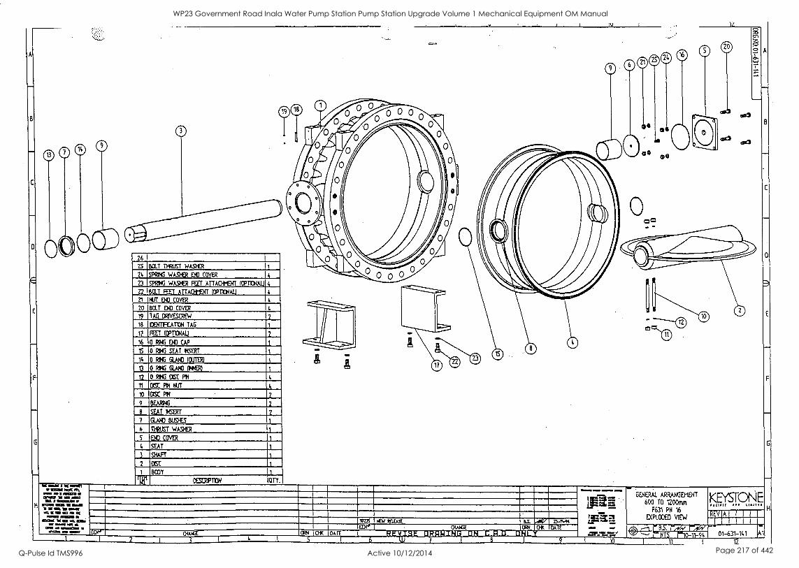
IV
1 I m
0
S
26 I
25
24
22
21
20
19
BOLT TPRUST wASKR
SPRING.WA_SER EN) COVER
SPRING wAS1fR RIT ATTACHMDTT ICPT1ONAL) 4
6CLT FAT ATTACHIENT IOPTICHAIJ
NM ET COVER
BOLT COVER
TAD DRIVESCREW 2
18 ICENTFCAT1ON TAG 1
17 FEET. (CPT1CNAIJ
16 0 RNG EN) CAP
2
1S 0 RING SEAT !CERT
it
13
12
11
10
9
7
6
5
0 RAG GUS) ICUTER)
0 RING GLAND INNER/
0 RHG ()MC PH
DISC PON NTT
DSC PH
BEAM%
SEAT MORT
GLAND BUSES
II-RUST WASHER
,p83 COVER
A SEAT
3 -SHAFT
2 CC 1
CES041110N
2
2
2
H
I
I
I
IOUs 1 WW MUSE B-C. 'AV D-r1.94 Mt. I OiAAGE CAN CH( DATE
U I CrK I DATE
6 lU 7 1 8 1 9
GENERAL ARRANGEMENT KEYSTONE 600 TO 1200mm IsC01( et o
F631 PH 16 A I I
EYKODED VIEW 1 I
REV
r-,04c."1 wrs n0-11-9, 01-631-141
I 12
Al
WP23 Government Road Inala Water Pump Station Pump Station Upgrade Volume 1 Mechanical Equipment OM Manual
Q-Pulse Id TMS996 Active 10/12/2014 Page 217 of 442
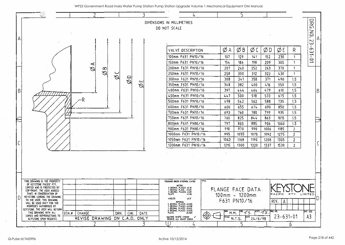
A
B
C
D
2 3
DIMENSIONS IN MILLIMETRES
DO NOT SCALE
VALVE DESCRIPTION 0 A 0 B 0 C 0 D 0 E R
100mm F631 PN10/16 107 129 141 152 230 1
150mm F631 PN10/16 154 186 198 209 305 1
200mm F631 PN10/16 207 240 252 263 370 1
250mm F631 PN10/16 258 300 312 323 430 1
300mm F631 PN10/16 308 341 358 371 490 1.5
350mm F631 PN10/16 348 382 400 416 550 1.5
400mm F631 PN10/16 397 444 464 479 610 1.5
450mm F631 PN10/16 447 500 518 533 675 1.5
500mm F631 PN10/16 498 542 562 588 735 1.5
600mm F631 PN10/16 600 655 674 690 850 1.5
700mm F631 PN10/16 693 760 780 799 935 1.5
750mm F631 PN10/16 760 825 844 863 1015 1.5
800mm F631 PN10/16 797 865 885 906 1060 1.5
900mm F631 PN10/16 910 970 990 1006 1185
1000mm F631 PN10/16 995 1055 1075 1092 1275 2
1050mm F631 PN10/16 1063 1168 1190 1208 1355 2
1200mm F631 PN10/16 1215 1300 1320 1337 1530 2
A
THIS DRAWING IS THE PROPERTY
OF KEYSTONE PACIFIC PTY.
LIMITED AND IS PROTECTED BY
COPYRIGHT. THE USER AGREES
THAT, IN CONSIDERATION OF
KEYSTONE LENDING THE DRAWING
TO THE USER, THIS DRAWING
WILL BE USED ONLY FOR THE
PURPOSES AUTHORISED BY
KEYSTONE. THE USER WILL RETURN
THIS DRAWING WITH ALL
COPIES AND REPRODUCTIONS TO
KEYSTONE UPON REQUEST.
ECN.# CHANGE DRN. CHK. DATE
REVISE DRAWING ON C A.D. ONLY
TOLERANCE LNLESS OTHERWISE STATED
METRIC 2 DECIMAL PLACES 0.10 1 DECIMAL PLACE t0.25 0 DECIMAL PLACES 11.00 PLATE ±2.00
ANGLES :CI.S'
IMPERIAL 3 DECIMAL PLACES :0.005 2 DECIMAL PLACES :0.010
1 DECIMAL PLACES :0.015 0 DECIMAL PLACES :0.030 PLATE 10.060
MACHINE WHERE SHOWN REMOVE ALL SHARP EDGES
TITLE
FLANGE FACE DATA 100mm - 1200mm
F631 PN10/16
KEYSTONE PACIF C PTY LIMITED
REV.
DRN.
M.M. APPD.
SCALE N.T.S. DATE 24/6/98
DAG NO
23-631-01 SHE. 92E
A3
1 2 3 5 6
B
C
WP23 Government Road Inala Water Pump Station Pump Station Upgrade Volume 1 Mechanical Equipment OM Manual
Q-Pulse Id TMS996 Active 10/12/2014 Page 218 of 442
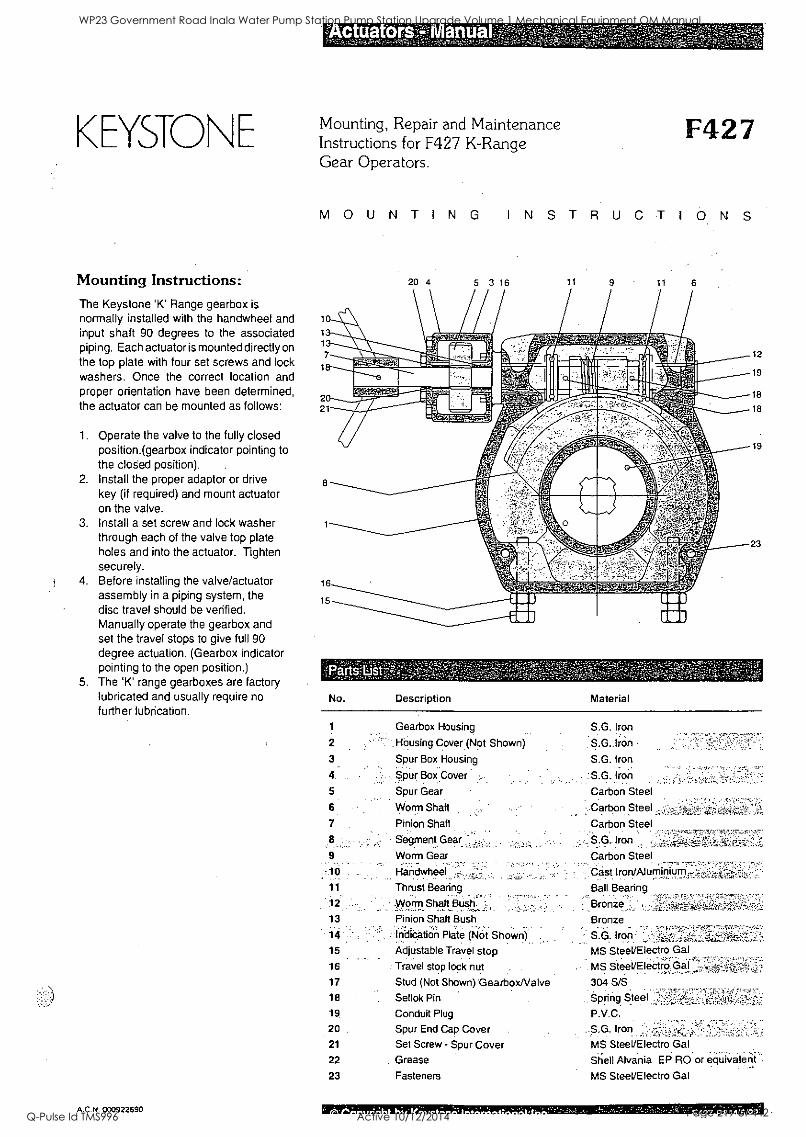
KEYSTO N E
Mounting Instructions: The Keystone 'K' Range gearbox is
normally installed with the handwheel and input shaft 90 degrees to the associated piping. Each actuator is mounted directly on
the top plate with four set screws and lock washers. Once the correct location and proper orientation have been determined, the actuator can be mounted as follows:
1. Operate the valve to the fully closed position.(gearbox indicator pointing to the closed position). .
2. Install the proper adaptor or drive key (if required) and mount actuator on the valve.
3. Install a set screw and lock washer through each of the valve top plate holes and into the actuator. Tighten securely.
4. Before installing the valve/actuator assembly in a piping system, the disc travel should be verified. Manually operate the gearbox and set the travel stops to give full 90 degree actuation. (Gearbox indicator pointing to the open position.)
5. The 'K' range gearboxes are factory lubricated and usually require no further lubrication.
A.C.N. 000922690
ctuat ';;Fixit,
Mounting, Repair and Maintenance Instructions for F427 K-Range Gear Operators.
F427
MOUNTING INSTRUCTIONS
20 4 5 3 16 11 9 11
12
19
18
18
19
23
No. Description Material
1 Gearbox Housing S.G. Iron
2 Housing Cover (Not Shown) S.G. Iron
3 Spur Box Housing S.G. Iron
4 Spur Box Cover S.G. Iron
5 Spur Gear Carbon Steel
6 Worm Shaft Carbon Steel
7 Pinion Shaft Carbon Steel
Segment Gear .2 S.G. Iron
9 Worm Gear Carbon Steel
10 Handwheel Cast Iron/Aluminium -
11 Thrust Bearing Ball Bearing
12 .Worm Shaft Bush Bronze
13 Pinion Shaft Bush Bronze
14 Indic.ation Plate (Not Shown) S.G. Iron , . .. .,-
15 Adjustable Travel stop MS SteeVElectro Gal
16 Travel stop lock nut MS SteeVElectro Gal
17 Stud (Not Shown) Gearbox/Valve 304 S/S.
18 Sellok Pin Spring Steel
19 Conduit Plug P.V.C.
20 Spur End Cap Cover S.G. Iron ...,..,
21 Set Screw - Spur Cover MS SteeVElectro Gal ,.
22 Grease Shell Alvania EP RO or equivalent
23 Fasteners MS SteeVElectro Gal
WP23 Government Road Inala Water Pump Station Pump Station Upgrade Volume 1 Mechanical Equipment OM Manual
Q-Pulse Id TMS996 Active 10/12/2014 Page 219 of 442
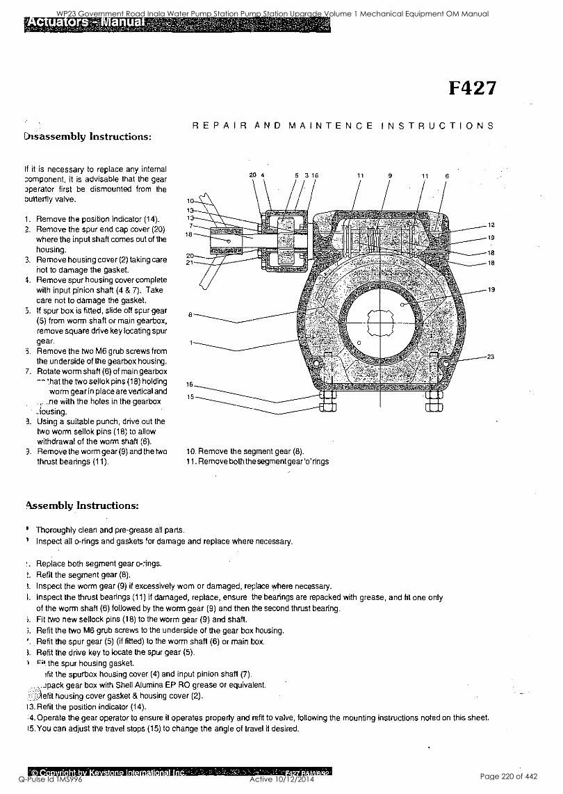
ua n
Disassembly Instructions:
If it is necessary to replace any internal component, it is advisable that the gear operator first be dismounted from the butterfly valve.
1. Remove the position indicator (14).
2. Remove the spur end cap cover (20) where the input shaft comes out of the housing.
3. Remove housing cover (2) taking care not to damage the gasket.
4. Remove spur housing cover complete with input pinion shaft (4 & 7). Take care not to damage the gasket.
5. If spur box is fitted, slide off spur gear (5) from worm shaft or main gearbox, remove square drive key locating spur gear.
3. Remove the two M6 grub screws from the underside of the gearbox housing.
7. Rotate worm shaft (6) of main gearbox -'hat the two sellok pins (18) holding
worm gear in place are vertical and I...ne with the holes in the gearbox
.dousing. 3. Using a suitable punch, drive out the
two worm sellok pins (18) to allow withdrawal of the worm shaft (6).
3. Remove the worm gear (9) and the two thrust bearings (11).
Assembly Instructions:
F427
REPAIR AND MAINTENCE INSTRUCTIONS
20 4 5 3 16 1.1 9 11
10. Remove the segment gear (8).
11. Remove both the segment gear `o' rings
Thoroughly clean and pre-grease all parts.
Inspect all o-rings and gaskets for damage and replace where necessary.
12
19
18
18
19
23
!. Replace both segment gear o-rings.
!. Refit the segment gear (8).
3. Inspect the worm gear (9) if excessively wom or damaged, replace where necessary.
3. Inspect the thrust bearings (11) if damaged, replace, ensure the bearings are repacked with grease, and fit one only of the worm shaft (6) followed by the worm gear (9) and then the second thrust bearing.
i. Fit two new sellock pins (18) to the worm gear (9) and shaft.
i. Refit the two M6 grub screws to the underside of the gear box housing.
'. Refit the spur gear (5) (if fitted) to the worm shaft (6) or main box.
3. Refit the drive key to locate the spur gear (5). it the spur housing gasket.
:fit the spurbox housing cover (4) and input pinion shaft (7).
,..:pack gear box with Shell Alumina EP RO grease or equivalent.
housing cover gasket & housing cover (2).
13. Refit the position indicator (14).
14. Operate the gear operator to ensure it operates properly and refit to valve, following the mounting instructions noted on this sheet.
15. You can adjust the travel stops (15) to change the angle of travel if desired.
I t.
WP23 Government Road Inala Water Pump Station Pump Station Upgrade Volume 1 Mechanical Equipment OM Manual
Q-Pulse Id TMS996 Active 10/12/2014 Page 220 of 442
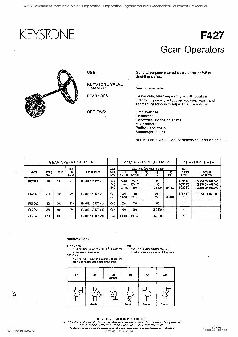
KEYSTONE F427 Gear Operators
USE: General purpose manual operator for on/off or throttling duties.
KEYSTONE VALVE RANGE: See reverse side.
FEATURES:
OPTIONS:
Heavy duty, weatherproof type with position indicator, grease packed, self-locking, worm and segment gearing with adjustable travelstops.
Limit switches Chainwheel Handwheel extension shafts Floor stands Padlock and chain Submerged duties
NOTE: See reverse side for dimensions and weights.
GEAR OPERATOR DATA VALVE SELECTION DATA ADAPTION DATA
Model Rating Nm
Ratio
Turns to
Close
Part Number Valve
Stem
Code
Valve, Size and Figure Number Stem Adaptor Regd.
Adaptor Part Number
F. 1,2,990
Fig.
129,239
Fig.
100
Fig.
153
Fig.
632
F427BAF 170 24:1 6 398.819.020.427.A11 BAB BAC
BAD
50-80
100
125-150
50-80 100-125
150
80
100
125-150 350-800
BOSS FB BOSS FC BOSS FD
102.254.020.099.000 102.254.040.099.000 102.254.060.099.000
F427CAF 680 30:1 71/2 398.819.120.427.A11 CAE
CAF
200
250-300
200
250-300
200
250 900-1200 BOSS FE
Nil 102.254.080.099.030
F427CAG 1350 50:1 121/2 398.819.140.427.A13 CAG 350 350 300 Nil
F427CAH 1350 50:1 121/2 398.819.160.427.A16 CAH 400 400 350-400 Nil
F427DAJ 2700 80:1 20 398.819.180.427.A18 DAJ 450-500 450 -500 450-600 Nil
ORIENTATIONS:
STANDARD = B3 Position (input shaft @ 90° to pipeline) = Clockwise cloies valve
OPTIONAL = 81 Position (input shaft parallel to pipeline) providing handwheel clears pipe/flanges
FOR = A 1 /A2 Position (mirror reverse) Clockwise opening - consult Keystone
B1 B2 B3 Standard
B4 Al A2
El
V A, 01/
II Special
i_.. o.
Special Specal
Ili Wi ill
Special
KEYSTONE PACIFIC PTY. LIMITED HEAD OFFICE: P.O. BOX 517 NOWRA 2541, AUSTRALIA PHONE (04.4) 21 7066. TELEX: AA24195. FAX: (044) 21 8135
SALES DIVISIONS AND WAREHOUSES LOCATED THROUGHOUT AUSTRALIA Keystone reserves the right to discontinue or change product designs or specifications without notice. F427/6/95
WP23 Government Road Inala Water Pump Station Pump Station Upgrade Volume 1 Mechanical Equipment OM Manual
Q-Pulse Id TMS996 Active 10/12/2014 Page 221 of 442
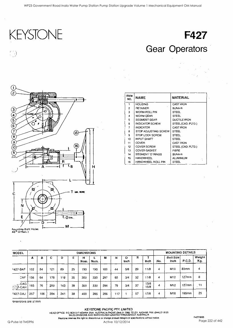
KEYSTONE
0 0 ii;414:;
FAM rt
11-A M . 6 .
0 0
15
0 sap- "...frigA:...w 1 I'7"11.1 -41W.A.1.1.. mom
E11111=,,,, I--- A ---1-1-113
16
T BoRE
4ounting Bolt Holes 450 Offset
M
F427 Gear Operators
ITEM NO. NAME MATERIAL
1 HOUSING CAST IRON
2 RETAINER BUNA-N
3 WORM. ROLL PIN STEEL
4 WORM GEAR STEEL
5 SEGMENT GEAR DUCTILE IRON
6 INDICATOR SCREW STEEL (CAD. PLTD.) 7 INDICATOR CAST IRON
8 STOP ADJUSTING SCREW STEEL
9 STOP LOCK SCREW STEEL 10 INPUT SHAFT STEEL 11 COVER CAST IRON
12 COVER SCREW STEEL (CAD. PLTD.)
13 COVER GASKET FIBRE
14 SEGMENT '0' RINGS BUNA-N
15 HANDWHEEL ALUMINIUM
16 HANDWHEEL ROLL PIN STEEL
MODEL DIMENSIONS MOUNTING DETAILS
A B C D E H
Nom. L
Nom. M N 0
Inch R T
Inch No. Bolt Size
Inch P.C.D. Weight
Kg.
=427-BAF 102 54 121 89 25 150 190 160 44 5/8 29 11/8 4 M10 83mm 4
CAF 156 64 178 118 35 300 330 297 65 3/4 32 11/8 4 M12 127mm 8
--.) -CAH 165 76 200 143 38 300 330 284 79 3/4 37 15/8
13/8 4 M12 127mm 11
:427-DAJ 257 106 284 241 38 450 285 256 117 1 57 17/8 4 M16 165mm 25
limensions are ±1mm.
KEYSTONE PACIFIC PTY. LIMITED HEAD OFFICE: PO. BOX 517 NOWRA 2541, AUSTRALIA PHONE (04.4) 21 7066. TELEX: AA24195. FAX: (044) 21 8135
SALES DIVISIONS AND WAREHOUSES LOCATED THROUGHOUT AUSTRALIA
Keystone reserves the right to discontinue or change product designs or specifications without notice. F427/6/95
WP23 Government Road Inala Water Pump Station Pump Station Upgrade Volume 1 Mechanical Equipment OM Manual
Q-Pulse Id TMS996 Active 10/12/2014 Page 222 of 442

Q
WP23 Government Road Inala Water Pump Station Pump Station Upgrade Volume 1 Mechanical Equipment OM Manual
Q-Pulse Id TMS996 Active 10/12/2014 Page 223 of 442
1
S
WP23 Government Road Inala Water Pump Station Pump Station Upgrade Volume 1 Mechanical Equipment OM Manual
Q-Pulse Id TMS996 Active 10/12/2014 Page 224 of 442
BRISBANE CITY COUNCIL Brisbane Water Government Road
Appendix D - Rotork Actuators
"Rotork IQ Series"
BW.30098-02/03 Pump Station Upgrade
Item Valve Actuators Brand Rotork Model IQ12 24 rpm Serial Number Supplier Tyco-Keystone Address 17 Leadership Way, Wangara WA 6065 Phone 08 9302 8888 Fax 08 93028855 Email
8748C-Manual Draft B 21 Dec. 05 4
WP23 Government Road Inala Water Pump Station Pump Station Upgrade Volume 1 Mechanical Equipment OM Manual
Q-Pulse Id TMS996 Active 10/12/2014 Page 225 of 442

a new generation of intelligent, non-intrusive 3-phase electric valve actuators
publication E110E issue 03/01
WP23 Government Road Inala Water Pump Station Pump Station Upgrade Volume 1 Mechanical Equipment OM Manual
Q-Pulse Id TMS996 Active 10/12/2014 Page 226 of 442
0
Rotork Actuation
World leaders in valve control
In the 40 years since the company was founded, Rotork
Actuation has become a byword for excellence in the field of valve, sluice gate and damper actuation products for the oil, gas, power, water and waste treatment industries
- worldwide.
We owe our success to an uncompromising focus on
quality at every stage - and at every level - of Rotork's
operations.
From initial site survey, specification and design, through to materials, manufacturing and testing processes,
installation, commissioning and after-sales service we
accept nothing but the best.
At the heart of the company is an exceptional workforce -
the highly trained, forward-thinking engineers, technicians
and support staff who each have a crucial role to play in
maintaining Rotork's unrivalled reputation for innovation,
reliability and first class customer support.
Rotork. Established leaders in actuation technology.
Contents
Features of the IQ
Reliability
Intelligent actuation
Protection
Applications
Intelligent communication
Communication systems
Construction
Second stage gearboxes
Actuator specification
Performance summary
5
6
7
8
10
12
14
15
16
Rotork Controls Ltd, Bath. UK
Rotork Controls Inc. Rochester, USA
WP23 Government Road Inala Water Pump Station Pump Station Upgrade Volume 1 Mechanical Equipment OM Manual
Q-Pulse Id TMS996 Active 10/12/2014 Page 227 of 442
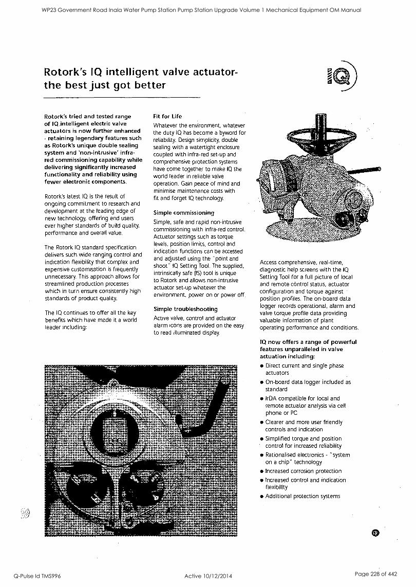
Rotork's IQ intelligent valve actuator- the best just got better
Rotork's tried and tested range of IQ intelligent electric valve actuators is now further enhanced - retaining legendary features such as Rotork's unique double sealing system and 'non-intrusive' infra- red commissioning capability while delivering significantly increased functionality and reliability using fewer electronic components.
Rotork's latest IQ is the result of ongoing commitment to research and
development at the leading edge of new technology, offering end users ever higher standards of build quality, performance and overall value.
The Rotork IQ standard specification delivers such wide ranging control and indication flexibility that complex and expensive customisation is frequently unnecessary. This approach allows for streamlined production processes
which in turn ensure consistently high
standards of product quality.
The IQ continues to offer all the key
benefits which have made it a world leader including:
Fit for Life
Whatever the environment, whatever the duty IQ has become a byword for reliability. Design simplicity, double sealing with a watertight enclosure coupled with infra-red set-up and
comprehensive protection systems
have come together to make IQ the world leader in reliable valve
operation. Gain peace of mind and minimise maintenance costs with fit and forget IQ technology.
Simple commissioning
Simple, safe and rapid non-intrusive commissioning with infra-red control. Actuator settings such as torque levels, position limits, control and indication functions can be accessed
and adjusted using the "point and shoot" IQ Setting Tool. The supplied, intrinsically safe (IS) tool is unique to Rotork and allows non-intrusive actuator set-up whatever the environment, power on or power off.
Simple troubleshooting Active valve, control and actuator alarm icons are provided on the easy
to read illuminated display.
Access comprehensive, real-time, diagnostic help screens with the IQ
Setting Tool for a full picture of local and remote control status, actuator configuration and torque against position profiles. The on-board data logger records operational, alarm and valve torque profile data providing valuable information of plant operating performance and conditions.
IQ now offers a range of powerful features unparalleled in valve actuation including:
Direct current and single phase actuators
On-board data logger included as
standard
IrDA compatible for local and remote actuator.analysis via cell phone or PC
Clearer and more user friendly controls and indication
Simplified torque and position control for increased reliability
Rationalised electronics - "system on a chip" technology
Increased corrosion protection
Increased control and indication flexibility
Additional protection systems
WP23 Government Road Inala Water Pump Station Pump Station Upgrade Volume 1 Mechanical Equipment OM Manual
Q-Pulse Id TMS996 Active 10/12/2014 Page 228 of 442
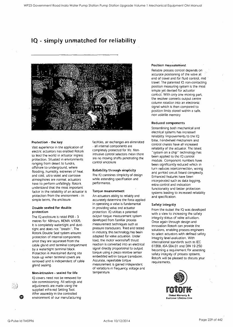
IQ - simply unmatched for reliability
Protection - the .key
Vast experience in the application of electric actuators has enabled Rotork to lead the world in actuator ingress
protection. Situated in environments ranging from desert to tundra, offshore to underground, where flooding, humidity, extremes of heat and cold, ultra violet and corrosive atmospheres are normal, actuators have to perform unfailingly. Rotork understand that the most important factor in the reliability of an actuator is
protection from the environment - in
simple terms, the enclosure.
Double sealed for double protection The IQ enclosure is rated IP68 - 3
metres for 48hours, NEMA 4/4X/6. It is completely watertight and dust-
tight and does not "breath". The
Rotork Double Seal system ensures protection of internal components since they are separated from the cable gland and terminal compartment by a watertight terminal block. Protection is maintained during site
hook-up when terminal covers are
removed and is independent of cable gland sealing.
Non-intrusive - sealed for life IQ covers need not be removed for site commissioning. All settings and adjustments are made using the supplied infra-red Setting Tool.
After assembly in the controlled environment of our manufacturing
facilities, air exchanges are eliminated - all internal components are
completely protected for life. Non- intrusive control selectors mean there are no moving shafts penetrating the control enclosure.
Reliability through simplicity The IQ combines simplicity of design while extending specification and performance.
Torque measurement An actuators ability to reliably and accurately determine the force applied in operating a valve is fundamental in providing valve and actuator protection. IQ utilises a patented output torque measurement system developed from familiar process
measurement techniques such as
pressure transducers. Tried and tested in industry, this technology has been adapted for valve actuation. Under load, the motor wormshaft thrust reaction is converted into an electrical signal directly proportional to output torque using a piezo resistive sensor embedded within torque transducer. Accurate, repeatable torque measurement is gained independent of variations in frequency, voltage and temperature.
Position measurement
Reliable process control depends on accurate positioning of the valve at end of travel and for fluid control, mid travel. The patented IQ non-contacting position measuring system is the most simple yet devised for actuator control. With only one moving part, the resolver converts output centre column rotation into an electronic signal which is then compared to position limits stored within a safe, non volatile memory
Reduced components
Streamlining both mechanical and electrical systems has increased reliability. Improvements to the IQ
base, handwheel mechanism and control chassis have all increased reliability of the actuator. The latest "system on a chip" technology has been applied to the IQ control module. Component numbers have been significantly reduced which in
turn reduces interconnection, wiring and printed circuit board complexity. Enhanced features have been incorporated such as data logging, extra control and indication functionality and better protection systems leading to increased reliability and specification.
Safety integrity From the outset the IQ was developed with a view to increasing the safety integrity status of valve actuation. Once again through design and innovation Rotork can provide the solutions, enabling process engineers to select actuators with defined safety integrity level evaluation. With international standards such as IEC
61508, ISA-S84.01 and DIN 19 250 becoming a requirement for assessing safety integrity of process systems, Rotork will be pleased to discuss your requirements.
rotcDrof Global Warranty &
Customer lifetime Care
WP23 Government Road Inala Water Pump Station Pump Station Upgrade Volume 1 Mechanical Equipment OM Manual
Q-Pulse Id TMS996 Active 10/12/2014 Page 229 of 442
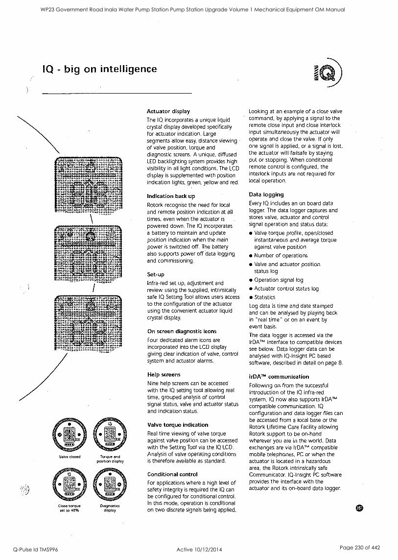
IQ - big on intelligence
Valve closed Torque and position display
Close torque set to 40%
Diagnostics display
Actuator display
The IQ incorporates a unique liquid crystal display developed specifically for actuator indication. Large
segments allow easy, distance viewing of valve position, torque and diagnostic screens. A unique, diffused LED backlighting system provides high visibility in all light conditions. The LCD
display is supplemented with position indication lights, green, yellow and red.
Indication back up
Rotork recognise the need for local
and remote position indication at all
times, even when the actuator is
powered down. The IQ incorporates a battery to maintain and update position indication when the main power is switched off. The battery also supports power off data logging and commissioning.
Set-up
Infra-red set up, adjustment and
review using the supplied, intrinsically safe IQ Setting Tool allows users access
to the configuration of the actuator using the convenient actuator liquid crystal display.
On screen diagnostic icons
Four dedicated alarm icons are
incorporated into the LCD display giving clear indication of valve, control system and actuator alarms.
Help screens
Nine help screens can be accessed
with the IQ setting tool allowing real
time, grouped analysis of control signal status, valve and actuator status and indication status.
Valve torque indication
Real time viewing of valve torque against valve position can be accessed with the Setting Tool via the IQ LCD.
Analysis of valve operating conditions is therefore available as standard.
Conditional control
For applications where a high level of safety integrity is required the IQ can be configured for conditional control. In this mode, operation is conditional on two discrete signals being applied.
Looking at an example of a close valve
command, by applying a signal to the remote close input and close interlock input simultaneously the actuator will operate and close the valve. If only one signal is applied, or a signal is lost, the actuator will failsafe by staying put or stopping. When conditional remote control is configured, the interlock inputs are not required for local operation.
Data logging Every IQ includes an on board data logger. The data logger captures and stores valve, actuator and control signal operation and status data:
Valve torque profile, open/closed instantaneous and average torque against valve position
Number of operations
Valve and actuator position status log
Operation signal log
Actuator control status log
Statistics
Log data is time and date stamped and can be analysed by playing back in "real time" or on an event by
event basis.
The data logger is accessed via the IrDATm interface to compatible devices see below. Data logger data can be
analysed with IQ-Insight PC based
software, described in detail on page 8.
IrDATm communication
Following on from the successful introduction of the IQ infra-red system, IQ now also supports IrDATM
compatible communication. IQ
configuration and data logger files can be accessed from a local base or the Rotork Lifetime Care Facility allowing Rotork support to be on-hand wherever you are in the world. Data exchanges are via IrDATM compatible mobile telephones, PC or when the actuator is located in a hazardous area, the Rotork intrinsically safe Communicator. IQ-Insight PC software provides the interface with the actuator and its on-board data logger.
WP23 Government Road Inala Water Pump Station Pump Station Upgrade Volume 1 Mechanical Equipment OM Manual
Q-Pulse Id TMS996 Active 10/12/2014 Page 230 of 442

I - ,
^ 9 . -
. , I I ID g I
.1 I g
I - I
, ^ " '
=
g
" w'
I
-
I I i
- -
" .70
"-
Z1,.'`...4.;;;;6., 4.:::Uf "=1..t.,
"1*
- 9
I
I g
- - ,
II -
-
`ss g -
8 9' I .
1/
- -
. 9 .11
' " " ' ,
,g ,
-
-
I -
I . g
WP23 Government Road Inala Water Pump Station Pump Station Upgrade Volume 1 Mechanical Equipment OM Manual
Q-Pulse Id TMS996 Active 10/12/2014 Page 231 of 442
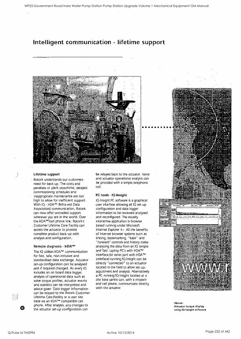
Intelligent communication - lifetime support
Lifetime support
Rotork understands our customers need for back up. The costs and penalties of plant downtime, delayed commissioning schedules and inappropriate maintenance are too high to allow for inefficient support. With IQ - IrDATM^ (Infra-red Data Association) communication, Rotork can now offer unrivalled support wherever you are in the world. Over the IrDATm/cell phone link, Rotork's .Customer Lifetime Care Facility can access the actuator to provide complete product back up with analysis and configuration.
Remote diagnosis - IrDAITM
The IQ utilises IrDATm communication for fast, safe, non-intrusive and standardised data exchange. Actuator set-up configuration can be analysed and if required changed. As every IQ
includes an on board data logger, analysis of operational data such as
valve torque profiles, actuator events and statistics can be interpreted and advice given. Data logger information can be relayed to the Rotork Customer Lifetime Care Facility or a user site base via an IrDATM compatible cell phone. After analysis, any changes to the actuator set-up configuration can
be relayed back to the actuator. Valve and actuator operational analysis can be provided with a simple telephone call.
PC tools - IQ-Insight
IQ-Insight PC software is a graphical user interface allowing all IQ set-up configuration and data logger information to be reviewed analysed and reconfigured. The visually interactive application is browser based running under Microsoft Internet Explorer 4+. All the benefits of Internet browser systems such as
linking, bookmarking, "back" and "forward" controls and history make analysing the data from an IQ simple and fast. Laptop PC's with IrDAT" interface (or serial port with IrDATM
interface) running IQ-Insight can be
directly "connected" to an actuator located in the field to allow set-up, adjustment and analysis. Alternatively a PC running IQ-Insight located at a
site base centre can, with a modem and cell phone, communicate directly with the actuator.
Above: Actuator torque display using IQ-Insight software
WP23 Government Road Inala Water Pump Station Pump Station Upgrade Volume 1 Mechanical Equipment OM Manual
Q-Pulse Id TMS996 Active 10/12/2014 Page 232 of 442
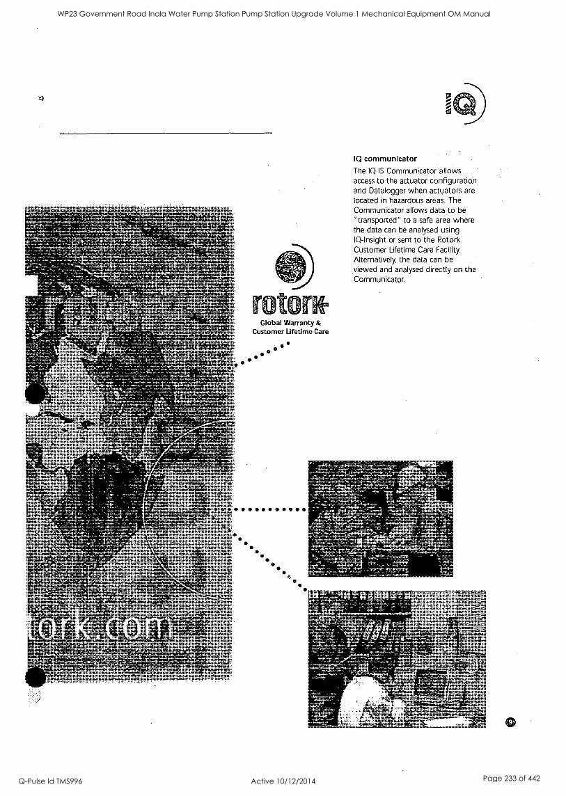
;#644C. tz
r
o
o o
o
Global Warranty & Customer Lifetime Care
0
IQ communicator
The IQ IS Communicator allows access to the actuator configuration and Datalogger when actuators are located in hazardous areas. The Communicator allows data to be
"transported" to a safe area where the data can be analysed using IQ-Insight or sent to the Rotork Customer Lifetime Care Facility. Alternatively, the data can be viewed and analysed directly on the Communicator.
WP23 Government Road Inala Water Pump Station Pump Station Upgrade Volume 1 Mechanical Equipment OM Manual
Q-Pulse Id TMS996 Active 10/12/2014 Page 233 of 442
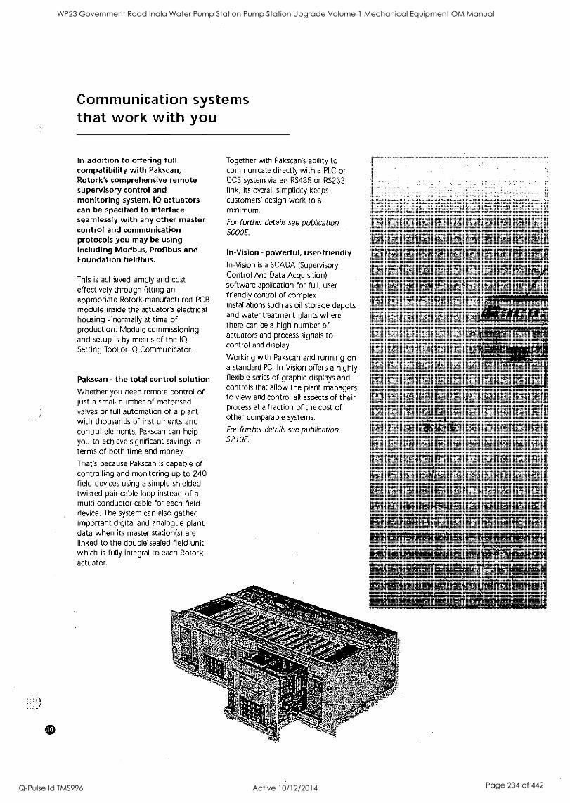
Communication systems that work with you
In addition to offering full compatibility with Pakscan, Rotork's comprehensive remote supervisory control and monitoring system, 10 actuators can be specified to interface seamlessly with any other master control and communication protocols you may be using including Modbus, Profibus and Foundation fieldbus.
This is achieved simply and cost effectively through fitting an appropriate Rotork-manufactured PCB
module inside the actuator's electrical housing - normally at time of production. Module commissioning and setup is by means of the IQ
Setting Tool or IQ Communicator.
Pakscan - the total control solution Whether you need remote control of just a small number of motorised valves or full automation of a plant with thousands of instruments and control elements, Pakscan can help you to achieve significant savings in
terms of both time and money.
That's because Pakscan is capable of controlling and monitoring up to 240 field devices using a simple shielded, twisted pair cable loop instead of a
multi conductor cable for each field device. The system can also gather. important digital and analogue plant data when its master station(s) are linked to the double sealed field unit which is fully integral to each Rotork actuator.
Together with Pakscan's ability to communicate directly with a PLC or DCS system via an RS485 or RS232 link, its overall simplicity keeps customers' design work to a
minimum.
For further details see publication S000E.
In-Vision - powerful, user-friendly In-Vision is a SCADA (Supervisory Control And Data Acquisition) software application for full, user friendly control of complex installations such as oil storage depots and water treatment plants where there can be a high number of actuators and process signals to control and display.
Working with Pakscan and running on a standard PC, In-Vision offers a highly flexible series of graphic displays and controls that allow the plant managers to view and control all aspects of their process at a fraction of the cost of other comparable systems.
For further details see publication S270E.
WP23 Government Road Inala Water Pump Station Pump Station Upgrade Volume 1 Mechanical Equipment OM Manual
Q-Pulse Id TMS996 Active 10/12/2014 Page 234 of 442
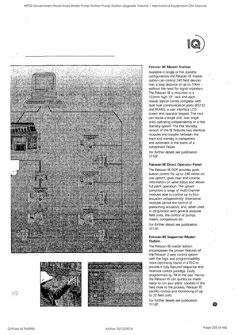
Pakscan IIE Master Station
Available in single or hot standby configurations the Pakscan IIE master, station can control 240 field devices over a loop distance of up to 20km -
without the need for signal repeaters. The Pakscan IIE is mounted in a
133mm high 19" rack and each master station comes complete with dual host communication ports (RS232 and RS485), a user interface LCD
screen and operator keypad. The rack can house a single unit, two single units operating independently or a Hot Standby system. The Hot Standby version of the IIE features two identical modules and transfer between the main and standby is transparent and automatic in the event of a
component failure.
For further details see publication S11 OE.
Pakscan IIE Direct Operator Panel
The Pakscan IIE DOP provides push- button control for up to 240 valves on One system, gives clear and concise information on valve status and allows full plant operation. The system comprises a range of multi-channel modules able to control up to four actuators independently. Alternative modules permit the control of positioning actuators, and, when used in conjunction with general purpose field units, the control of pumps, mixers, compressors etc.
For further details see publication S111E.
Pakscan IIS Sequencer Master Station
The Pakscan IIS master station encompasses the proven features of the Pakscan 2 wire control system with the logic and programmability .
more commonly found in a PLC to provide a fully featured sequence and interlock control package. Easily
programmed by Till in the box' menus the Pakscan IIS can quickly be made ready to run your plant. Located in the field close to the process, Pakscan IIS
permits control and monitoring of up to 32 field units.
For further details see publication S112E.
WP23 Government Road Inala Water Pump Station Pump Station Upgrade Volume 1 Mechanical Equipment OM Manual
Q-Pulse Id TMS996 Active 10/12/2014 Page 235 of 442
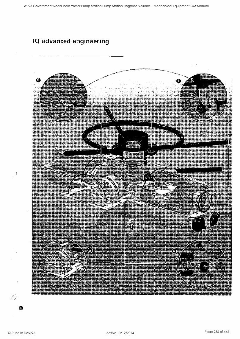
6
as
1
S
' ;27,74 k".` "'"6214 FAP. -GtaT
Y ̂ 11S.:4,"' eetkil4r
;if:Wet: , 5
-3.Z1 xte,
te,
12
WP23 Government Road Inala Water Pump Station Pump Station Upgrade Volume 1 Mechanical Equipment OM Manual
Q-Pulse Id TMS996 Active 10/12/2014 Page 236 of 442

1 Hand operation
Direct drive handwheel (or
independently geared handwheel on larger sizes) to provide reliable emergency manual operation in the event of a power supply failure. With low speed padlockable* hand/auto clutch for safe operation even when the motor is running.
Note: power operation always has
preference unless hand/auto lever is
purposely locked into 'hand drive'. Lost motion 'hammerblow' effect is
provided with both direct and independently geared handwheels.
2 Infra red settings
All actuator settings and diagnostics are made through the sealed
indication window. It is not necessary
to remove electrical covers exposing the integral controls on site.
3 Local controls
Local controls and padlockable* Local/Stop/Remote selector switch operate internal reed switches, avoiding penetrating shafts which would have to be sealed to prevent moisture ingress.
4 Position control
Hall effect magnetic pulse system
accurately measures and controls the stroke of the actuator without using gears and switches.
5 Terminal compartment
Separately sealed terminal compartment ensures the integrity of the electrical equipment even when the terminal cover is removed during site wiring.
6 Motor and drive Motor shaft and worm shaft separate to facilitate actuator speed change.. Low inertia high torque motor. The motor produces peak torque rapidly after starting but with very little overrun when de-energized. The winding thermostat provides accurate temperature sensing independent of ambient temperature conditions to optimize the motor's thermal capacity. The motor drive includes a lost motion 'hammerblow' to assist in unseating tightly shut valves.
Single worm and wheel drive running in an oil bath for maximum life with ambient temperature tolerance.
7 Thrust base
Thrust base for type 'A' couplings lubricated for life and detachable, up to size IQ35, to allow actuator removal without disturbing the valve position. On sizes IQ40 and above the thrust base is an integral part of the gearcase assembly.
Easily removable drive bushing for machining to suit valve stem for convenient valve adaptation.
'Suitable for 5rnm 'A inch padlock
WP23 Government Road Inala Water Pump Station Pump Station Upgrade Volume 1 Mechanical Equipment OM Manual
Q-Pulse Id TMS996 Active 10/12/2014 Page 237 of 442
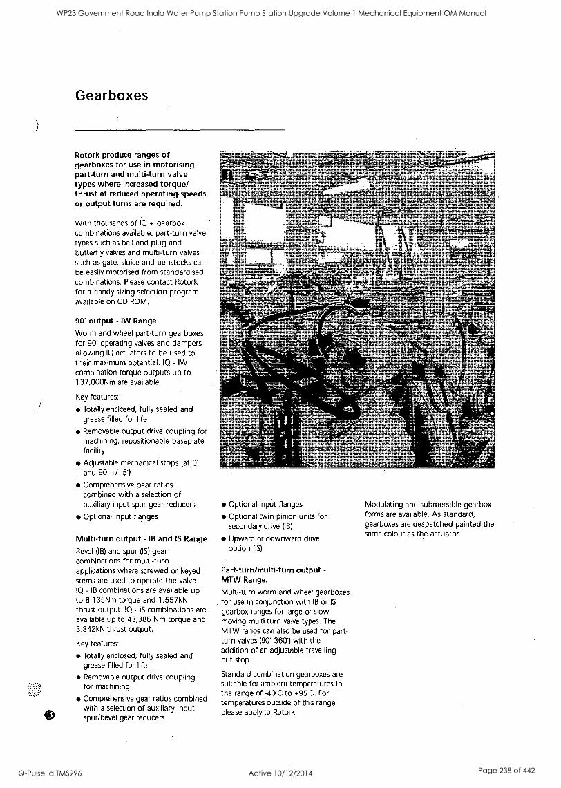
Gearboxes
Rotork produce ranges of gearboxes for use in motorising part-turn and multi-turn valve types where increased torque/ thrust at reduced operating speeds or output turns are required.
With thousands of IQ + gearbox combinations available, part-turn valve types such as ball and plug and butterfly valves and multi-turn valves such as gate, sluice and penstocks can
be easily motorised from standardised combinations. Please contact Rotork for a handy sizing selection program available on CD ROM.
90' output - IW Range
Worm and wheel part-turn gearboxes for 90' operating valves and dampers allowing IQ actuators to be used to their maximum potential. IQ - IW combination torque outputs up to 137,000Nm are available.
Key features:
Totally enclosed, fully sealed and grease filled for life
Removable output drive coupling for machining, repositionable baseplate facility
Adjustable mechanical stops (at 0' and 90* +/- 5)
Comprehensive gear ratios combined with a selection of auxiliary input spur gear reducers
Optional input flanges
Multi-turn output - IB and IS Range
Bevel (IB) and spur (IS) gear combinations for multi-turn applications where screwed or keyed stems are used to operate the valve. IQ - IB combinations are available up to 8,135Nm torque and 1,557kN thrust output. IQ - IS combinations are
available up to 43,386 Nm torque and 3,342kN thrust output.
Key features:
Totally enclosed, fully sealed and grease filled for life
Removable output drive coupling for machining
Comprehensive gear ratios combined with a selection of auxiliary input spur/bevel gear reducers
Optional input flanges
Optional twin pinion units for secondary drive (IB)
Upward or downward drive option (IS)
Part-turn/multi-turn output -
MTVV Range.
Multi-turn worm and wheel gearboxes for use in conjunction with IB or IS
gearbox ranges for large or slow moving multi turn valve types. The MTW range can also be used for part- turn valves (90' -360) with the addition of an adjustable travelling nut stop.
Standard combination gearboxes are suitable for ambient temperatures in
the range of -40C to +95"C. For
temperatures outside of this range please apply to Rotork.
Modulating and submersible gearbox forms are available. As standard, gearboxes are despatched painted the same colour as the actuator.
WP23 Government Road Inala Water Pump Station Pump Station Upgrade Volume 1 Mechanical Equipment OM Manual
Q-Pulse Id TMS996 Active 10/12/2014 Page 238 of 442

Actuator specification - contents
The following pages contain details
on performance and specification for the Rotork IQ range of actuators.
Please use the contents table below
to help access the information you
require.
1 Performance summary p16
2 Actuator Drive Couplings p 18
3 Introduction p20
4 Mechanical p20
4.1 Enclosure p20
4.2 Valve/actuator interface p21
4.3 Handwheel p21
4.4 Lubricant p21
4.5 Finish p21
5 Electrical p22
5.1 Power supplies p22
5.2 Control p22
5.3 Indication, monitoring and
data logging p23
5.4 Fieldbus system control p24
5.5 Protection p24
5.6 Actuator set-up p25
6 Actuator Components p25
6.1 Motor p25
6.2 Power module p25
6.3 Control module p25
6.4 Torque and position control p25
6.5 Conduit entries, terminals
and wiring p26
7 Design Specification p26
7.1 Design life p26
7.2 Frequency of operation p26
7.3 Operating temperature p26
7.4 Vibration p26
7.5 Safety integrity p26
7.6 Noise p26
WP23 Government Road Inala Water Pump Station Pump Station Upgrade Volume 1 Mechanical Equipment OM Manual
Q-Pulse Id TMS996 Active 10/12/2014 Page 239 of 442
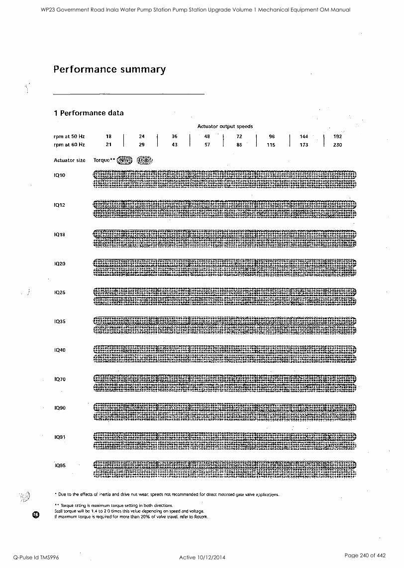
Performance summary
1 Performance data
rpm at 50 Hz
rpm at 60 Hz
Actuator output speeds
18 24 36 48
21 29 43 57
Actuator size Torque"
IQ10
IQ12
IQ18
IQ20
IQ25
IQ35
1040
IQ70
IQ90
IQ91
IQ95
:F:01bb
72 96 144 192
86 I 115 173 I 230
ree,1.7,R;R-61
1,1,-
Due to the effects of inertia and drive nut wear, speeds not recommended for direct mounted gate valve applications.
Torque rating is maximum torque setting in both directions. Stall torque will be 1.4 to 2.0 times this value depending on speed and voltage. If maximum torque is required for more than 20% of valve travel, refer to Rotork.
WP23 Government Road Inala Water Pump Station Pump Station Upgrade Volume 1 Mechanical Equipment OM Manual
Q-Pulse Id TMS996 Active 10/12/2014 Page 240 of 442
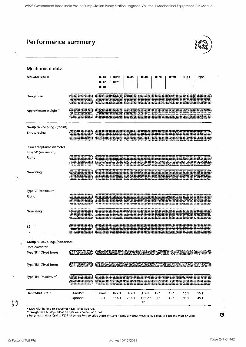
Performance summary
Mechanical data
Actuator size r>
Flange size
Approximate weight"
Group 'A couplings (thrust)
Thrust rating
Stem acceptance diameter
Type 'A (maximum)
Rising
Non-rising
Type 'Z' (maximum)
Rising
Non-rising
Z3
IQ10
IQ12
IQ18
IQ20
IQ25
IQ35 IQ40 1Q70 1Q90 1Q91
FA 1G ,FA25v,AfFA25',' FAFA Alt
IQ95
k!F3,o-
*1/4Ti6v-
qty
er_701,EFLI 33,R756,1 COITOOMFOoT .6rYNTOI. NIA:0;411M.00 4,114Z:gt.4..1
Group 'B' couplings (non-thrust)
Bore diameter
Type 'B1' (fixed bore)
Type 'B3' (fixed bore)
Type 'B4' (maximum)
r7577AF LL3 liA
Handwheel ratio Standard
Optional
Direct Direct
12:1 13.5:1
Direct
22.5:1
Direct Direct 15:1
15:1 or 30:1
30:1
15:1 15:1 15:1
45:1 30:1 45:1
IQ90 with B3 and B4 couplings have flange size F25. Weight will be dependent on optional equipment fitted.
t For actuator sizes IQ10 to IQ35 when required to drive shafts or stems having any axial movement, a type 'A' coupling must be used.
WP23 Government Road Inala Water Pump Station Pump Station Upgrade Volume 1 Mechanical Equipment OM Manual
Q-Pulse Id TMS996 Active 10/12/2014 Page 241 of 442
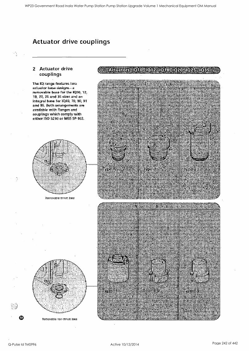
0
Actuator drive couplings
2 Actuator drive couplings
The IQ range features two actuator base designs - a
removable base for the IQ10, 12, 18, 20, 25 and 35 sizes and an integral base for IQ40, 70, 90, 91
and 95. Both arrangements are available with flanges and couplings which comply with either ISO 5210 or MSS SP-102.
Removable thrust base
Removable nonthrust base
ctuators.
WP23 Government Road Inala Water Pump Station Pump Station Upgrade Volume 1 Mechanical Equipment OM Manual
Q-Pulse Id TMS996 Active 10/12/2014 Page 242 of 442
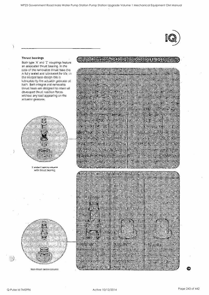
Thrust bearings
Both type 'A' and 'Z' couplings feature an associated thrust bearing. In the case of the removable thrust base this is fully sealed and lubricated for life; in
the integral base design this is
lubricated by the actuator gearcase oil bath. Both integral and removable thrust bases are designed to retain all
developed thrust reaction forces without any load appearing on the actuator gearcase.
Actuator
Standard centre column with thrust bearing
Non-thrust centre column
WP23 Government Road Inala Water Pump Station Pump Station Upgrade Volume 1 Mechanical Equipment OM Manual
Q-Pulse Id TMS996 Active 10/12/2014 Page 243 of 442

Standard specification
3 Introduction
IQ actuators are self contained units for local and remote
electrical operation of valves. Comprising an electric motor,
reduction gearing, reversing starter with local controls, turns
and torque limitation with electronic logic controls and
monitoring facilities, all housed in a double-sealed
watertight enclosure to IP68 3 metres-48 hours, NEMA 4,
4X and 6.
All torque and turns settings and configuration of the
indication contacts are effected using the non-intrusive,
hand held infra-red, IQ Setting Tool, which is included with each order.
The following specification covers standard features and
available optional features. Options selected must be
specified with enquiry.
4 Mechanical 4.1 Enclosure and ambient
temperatures
All IQ actuator hazardous and non- hazardous area enclosures are built to a watertight standard. Through the use of non-intrusive commissioning and site adjustment using the supplied infra-red IQ Setting Tool, the hermetic, factory-sealed enclosure protects internal components for life as covers never need removing. The terminal compartment is sealed from other areas by the Rotork double seal, maintaining watertight integrity even during site connection.
Actuators are available with the following enclosure types for which the ambient working temperature ranges are stated. Where option temperatures are indicated, changes to some actuator components are required and therefore the temperature requirement must be specified. Hazardous area approvals for other country standards are
available, please apply to Rotork.
The IQ is built in accordance with the following standards:
WT: Standard watertight, IEC 60529 (1989-11), IP68 3 metres/48 hours, NEMA 4, 4X and 6.
Temperature -30'C to +70"C (-22"F to +158'F). *Option -40'C to +70C (-40T to +158T).
CENELEC EExd IIB:
CENELEC Norm EN50014 and EN50018 for EExd IIBT4.
Temperature.-20C to +70"C (-4"F to +158'F). *Option -30C to +70C (-22T to +158T). *Option -40C to +70"C (-40'F to +158T).
CENELEC EExd IIC:
CENELEC Norm EN50014 and En50018 for EExd IICT4. Temperature -20'C to +70"C (-4T to +158'F).
WP23 Government Road Inala Water Pump Station Pump Station Upgrade Volume 1 Mechanical Equipment OM Manual
Q-Pulse Id TMS996 Active 10/12/2014 Page 244 of 442

WP23 Government Road Inala Water Pump Station Pump Station Upgrade Volume 1 Mechanical Equipment OM Manual
Q-Pulse Id TMS996 Active 10/12/2014 Page 245 of 442
CENELEC EExde IIB:
CENELEC Norm EN50014 and EN50019 for EExde IIBT4.
Temperature -20'C to +70C (-4T to +158T). *Option -30C to +70'C (-22T to +158'F). *Option -40"C to +70"C
(-40"F to +158"F).
CENELEC EExde IIC:
CENELEC Norm EN50014 and
EN50019 for EExde IICT4.
Temperature -20"C to +70"C
(-4"F to +158'F).
FM: Factory Mutual - Explosionproof Class 1, Div 1, Groups C, D, E, F, G
hazardous areas to NEC Article 500. Temperature -30'C to +60"C
(-22'F to +140'F). *Option -40"C to +60C (-40'F to +140T). * Alternative for Group B hazardous area. Temperatures as for Groups C &
D.
CSA WT: Canadian Standard Association - Watertight Wiring and components complying with CSA Enclosure 4 and 4X.
Temperature -30'C to +70"C
(-22'F to +158'F). *Option -40'C to +70'C (-40'F to +158T).
CSA EP: Canadian Standard Association - Explosionproof Class 1, Division 1, Groups C & D
hazardous areas.
Temperature -30'C to +40C (-22T to +104'F), *Option -40C to +40'C (-40T to +104'F).
4.2 Valve/actuator interface
The range of IQ actuators is available with mounting base and output drive couplings conforming to international standard ISO 5210 or USA standard MSS SP-102 (see Publications E140-1E through E147E for dimensions). Applications for which the various types of couplings have been designed are outlined as follows and the appropriate data concerning stem acceptance diameters are given in the table on page 17.
4.3 Handwheel
Handwheels are provided to allow manual operation of the valve during electrical power interruption.'
1Q10 - IQ40 Direct acting top mounted handwheel. Option: side
mounted geared handwheels.
IQ70 - 1Q95 Side mounted geared handwheel. Option: alternative gear ratios.
During electric operation of the actuator the handwheel is
mechanically disengaged from the drive. To engage handwheel operation, the hand/auto selection lever is depressed and released after which handwheel operation remains
selected. When electrical operation takes place, the actuator will automatically return to motor drive
without lever or handwheel kick- back. The hand /auto selection lever
incorporates a facility for locking in
the hand or auto positions using a
6mm diameter hasp padlock (not supplied by Rotork), preventing engagement of motor drive (locked in
hand) or engagement of handwheel drive (locked in auto). Emergency disengagement of motor drive can be
selected by depressing and holding the lever during electric operation.
4.4 Lubrication
IQ actuators are factory filled for life with premium quality gear oil, specified as SAE80/90 EP grade, available world-wide from lubricant suppliers. Oil lubrication out-performs grease over the 1Q standard temperature range -30C to +70C, with none of the problems associated
with grease such as separation and tunneling. Rotork have used this same grade of lubricating oil for 40
years. .
Lubrication options
Food grade lubricant: IQ actuators may be supplied with the gearcase filled with Hydra Lube GB Heavy food grade lubricant. This
lubricant is a synthetic non-aromatic hydrocarbon mixture with PTFE and other additives. It does not contain chlorinated solvents. Grease used in
assembly arid thrust bearings is Hydra
Lube WIG Medium-NLGI-123.
Extreme temperature service: Where actuator service requires operation outside of the standard -30C to +70C alternative lubricants are available, please apply to Rotork.
4.5 Finish
Actuators up to size IQ30 are finished in polyester powder coating, colour silver grey. Actuators size IQ40 and above are finished in air-dried urethane reinforced synthetic alkyd resin colour, silver grey. For full specification of paint finish see
publication E151E.
Finish options
Colour: Other colours may be specified, please apply to Rotork
Offshore: 2 pack epoxy coatings are
available for extreme environmental conditions, please apply to Rotork.
WP23 Government Road Inala Water Pump Station Pump Station Upgrade Volume 1 Mechanical Equipment OM Manual
Q-Pulse Id TMS996 Active 10/12/2014 Page 246 of 442
Standard specification
5 Electrical 5:1 Power supplies
IQ Actuators are suitable for operation with the following standard three phase, three wire nominal power supplies:
50Hz -
220, 240, 380, 400, 415, 440, 460, 500, 525, 550, 660 and 690 volts
60Hz -
208, 220, 230, 240, 380, 440, 460,
480, 575, and 600 volts
The required nominal operating voltage must be specified at time of order.
Actuator performance is guaranteed with a voltage tolerance +1-10% and frequency tolerance +/-5Hz. Actuators are capable of starting and running up to speed with a maximum 15% volt drop.
Uninterruptable power supplies
Standard actuators can be operated on UPS systems providing the above- specified tolerances are not exceeded and waveforms, harmonics, spikes etc.
adhere to recognised supply standards such as EN50160. For more information refer to publication El 30E.
Power supply options
IQ single phase: Available for standard nominal 50Hz voltage: 110, 220, 240 +1-10% and 60Hz voltage 110, 220, 230 4-10%. Refer to publication El 30E for motor performance data.
Non-standard voltages: Actuators can be supplied to operate on power supply voltages other than those quoted above. Please apply to Rotork.
Non standard tolerances: Where voltage and/or frequency variations may be experienced outside those quoted above, or where operation under large volt drop conditions may be required please apply to Rotork.
5.2 Control
Local control
Non-intrusive selectors are provided on the actuator electrical control cover, one for Local/Stop/Remote selection, pad-lockable in each position, and the other for Open/ Close control. Controls may be
rotated to suit actuator orientation.
Local control may be selected to operate using the supplied 10 Setting Tool. The Setting Tool incorporates dedicated open, stop and close buttons and will operate over a
nominal distance of 0.75 metres from the display window.
Local control option Vandal Resistant: Selectors removed, indication window with removable cover, control of local, stop and remote selection and local open and closed control is via
the supplied IQ setting tool.
Remote control
There are six control inputs for remote control:
Open, closed, stop/maintain.
Emergency shut down (ESD).
Open interlock and closed interlock.
Control can be connected for maintained or push to run, (inching) control. ESD signals must be derived from a stayput contact. For more information refer to publication E120E.
Control inputs are opto-isolated interfaces with a surge immunity of 2kV. Control is positive switching negative earth, internally fed from the actuator 24V DC customer supply or from external supplies within the ranges 20-60V AC or DC or 60-120V AC.
ESD can be configured off, active high or active low, to close or open the valve, with or without automatic motor thermostat bypass*. ESD will override any local or remote signals that may be active. If required ESD
can be configured to override local stop, interlocks or the optional interrupter timer. The ESD input operates from a separate common allowing isolation between the ESD
control system and operational control systems.
'Bypassing the motor thermostat will invalidate hazardous area certification.
WP23 Government Road Inala Water Pump Station Pump Station Upgrade Volume 1 Mechanical Equipment OM Manual
Q-Pulse Id TMS996 Active 10/12/2014 Page 247 of 442
Remote control can be configured so that the open signal and open interlock (or closed signal and closed interlock) can be combined to form a
remote open (or closed) signal that can detect single faults. When configured, interlocks will not be
active during local control.
For more information refer to publication El 20E.
Remote control options
Negative switching: For remote control systems where the negative pole of the remote control circuit supply is switched.
External control circuit supplies: For control with supplies in the range 60 - 125V DC and 230V AC an
alternative control circuit option is
available.
Analogue Proportional Control: The Rotork Folomatic proportional controller enables the actuator to automatically position a valve in
proportion to an analogue current, voltage or potentiometric signal. Signal ranges: 0-5, 0-10, 0-20 or 4-
20mA. 0-5, 0 L10 or 0-20V.
Positioning can take place over the whole valve stroke or if required, a
set portion of stroke. By incorporating a remote manual/remote auto control selector in the control scheme, proportional control can be over- ridden allowing standard remote control operation to take place when manual intervention is required (see
above). The Folomatic can be
configured to failsafe stayput, open or closed on loss of analogue signal.
Hydraulic shock/surge protection: Where the operating time of the valve must be increased to prevent hydraulic shock or water hammer, or to prevent surges, the Rotork Interrupter Timer option can be
included. Pulsed operation with independently adjustable on and off time periods in the range 1-99 seconds can be selected to operate over any portion of the closing or opening valve stroke, effectively
reducing valve speed. On/Off time period range may be extended when configuration is carried out with the IQ-Insight PC tool. The interrupter timer is active for both local and remote control.
5.3 Indication, monitoring and data logging
Local
A back-lit liquid crystal display gives digital indication from fully open to fully closed in 1% increments. Three LED's coloured red, green and yellow for indication of open, close and intermediate positions respectively are also provided. The display includes four icons for rapid diagnosis of valve alarm, actuator alarm, control system alarm and actuator battery status.
With the supplied IQ Setting Tool,
actuator torque plus position can be displayed allowing the valve torque against position to be monitored in
real time. Help screen diagnosis is
available for monitoring valve, actuator and control system status. The local display can be rotated to suit actuator orientation. LED colours can be reversed. Please specify with order.
Remote
Four latching volt free contacts, S1,
S2, S3 and S4 are provided each independently configurable using the supplied IQ Setting Tool to signal one of the following:
Valve Position: fully open, fully closed or intermediate positions (0-99% open).
Status: Valve opening, closing, moving (continuous or pulsing signal), local stop selected, local selected, remote selected, open or close interlock active, ESD active.
Valve Alarms: Motor tripped on torque in mid travel, motor tripped on torque going open, going closed, pre-set torque exceeded, valve jammed, actuator being operated by handwheel.
Actuator alarms: Lost phase, customer 24V DC (120V AC) supply lost, battery low, internal failure detected, thermostat tripped.
Each contact can be configured to either 'normally open' or 'normally closed' and rated at 5mA to 5A, 120V AC, 30V DC.
WP23 Government Road Inala Water Pump Station Pump Station Upgrade Volume 1 Mechanical Equipment OM Manual
Q-Pulse Id TMS996 Active 10/12/2014 Page 248 of 442
Standard specification
Monitor relay
An independent relay with a volt-free changeover contact for monitoring actuator electrical availability. Contact rating 5mA to 5A, 120V AC, 30V DC. The relay can be configured to de-energise under any one, or combination, of the following conditions:
Loss of one or more of the power supply phases.
Loss of control circuit supply.
Local control selected.
Local stop selected.
Motor thermostat tripped.
Data logger
The on board data logger allows infra-red, IrDA( (Infra-Red Data
Association) standard, download of historical actuator/valve performance data to PC or via an IrDA compatible mobile telephone to a local base or the Rotork Lifetime Care Facility. For
hazardous areas the intrinsically safe
Rotork Communicator tool is
available. Rotork IQ-Insight PC
software allows data logger information of operational events and statistics all time and date stamped plus valve torque/position profiles, both last operation and historical trends, all to be analyzed.
For more information please refer to publication E111E.
Indication options
Remote analogue position indication: The Current Position Transmitter (CPT)
provides a contact-less internally fed 4-20mA analogue signal proportional to valve position, selectable for minimum signal corresponding to fully closed or fully open position with automatic zero and span setting. An externally powered version of the CPT is also available.
Remote analogue torque indication
The Current Torque Transmitter (CTT)
provides an internally fed 4-20mA analogue signal proportional to actuator output torque 0-100% rated.
Extra indication contacts
The extra indication contacts module provides an additional four change- over contacts; S5, S6, S7 and S8.
Each contact is latching, volt free and rated at 5mA to 5A; 120V AC, 30V. DC. The extra indication contact functions are independently configurable in the same way as the standard contacts using the supplied IQ Setting Tool. The extra indication contact functions available are shown below:
Valve position Fully open, fully closed or intermediate positions (0-99% open)
Status Valve opening, closing, moving (continuous or pulsing signal), local stop selected, local selected, remote selected, open or close interlock active, ESD active
Valve alarms Motor tripped on torque in mid travel, motor tripped on torque going open, going closed, pre-set torque exceeded, valve jammed, actuator being operated by handwheel
Actuator alarms Lost phase, customer 24V DC
(120V AC) supply lost, battery low, internal failure detected, thermostat tripped
5.4 Fieldbus system control
Pakscan
An internally mounted Pakscan field unit for remote control and status indication over a fault tolerant two- wire serial link. Loop distances of up to 20 km without repeaters and host communications using Modbus protocol. System variables programmable over the infra-red'data link. For more information please refer to publication S000E.
Modbus Single or dual Modbus modules may be included in the IQ actuator to provide fieldbus communications of all the actuator control functions and feedback data. The fieldbus uses an
RS485 data highway and the communications protocol used is
Modbus RTU. System variables such as unit address and data baud rate are programmable over the infra-red data link. For more information please refer to publication E121E.
Profibus
A Profibus DP interface module is
available to allow the actuator to be
integrated into a Profibus network. Full compatibility with EN 50170 is
provided and the Profibus network allows full actuator control and feedback of data to the host. For
more information please refer to publication S113E.
Foundation Fieldbus
An IEC 1158-2 compliant Foundation interface module allows the actuator to be connected to a Foundation network. The device has link scheduler capability as well as digital and analogue function block capability. Foundation Fieldbus actuators can communicate directly between themselves without the need of a host supervisory system.
5.5 Protection
The IQ control system incorporates the following valve, actuator and control protection:
Obstructed valve (torque trip) protection.
Lost phase protection plus automatic Phase rotation correction by
Syncrophase.
Jammed valve protection.
Motor thermostat protection.
Internal fault protection - ASTD
(automatic self test & diagnosis).
Actuator control circuit supply protection.
Instantaneous reversal protection.
Control signal fault protection (configurable).
WP23 Government Road Inala Water Pump Station Pump Station Upgrade Volume 1 Mechanical Equipment OM Manual
Q-Pulse Id TMS996 Active 10/12/2014 Page 249 of 442
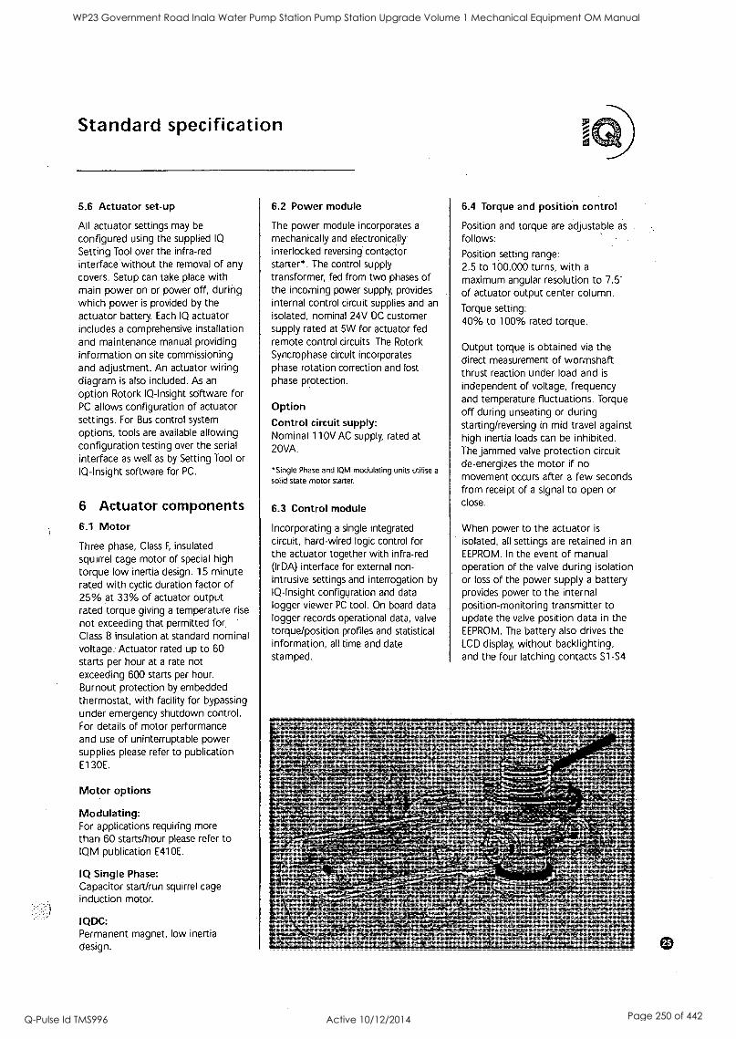
Standard specification
5.6 Actuator set-up
All actuator settings may be
configured using the supplied IQ
Setting Tool over the infra-red interface without the removal of any covers. Setup can take place with main power on or power off, during which power is provided by the actuator battery. Each IQ actuator includes a comprehensive installation and maintenance manual providing information on site commissioning and adjustment. An actuator wiring diagram is also included. As an
option Rotork IQ-Insight software for PC allows configuration of actuator settings. For Bus control system options, tools are available allowing configuration testing over the serial interface as well as by Setting Tool or IQ-Insight software for PC.
6 Actuator components 6.1 Motor
Three phase, Class F, insulated squirrel cage motor of special high torque low inertia design. 15 minute rated with cyclic duration factor of 25% at 33% of actuator output rated torque giving a temperature rise
not exceeding that permitted for Class B insulation at standard nominal voltage: Actuator rated up to 60 starts per hour at a rate not exceeding 600 starts per hour. Burnout protection by embedded thermostat, with facility for bypassing under emergency shutdown control. For details of motor performance and use of uninterruptable power supplies please refer to publication E130E.
Motor options
Modulating: For applications requiring more than 60 starts/hour please refer to IQM publication E410E.
IQ Single Phase: Capacitor start/run squirrel cage induction motor.
IQDC: Permanent magnet, low inertia design.
6.2 Power module
The power module incorporates a
mechanically and electronically interlocked reversing contactor starter*. The control supply transformer, fed from two phases of the incoming power supply, provides internal control circuit supplies and an isolated, nominal 24V DC customer supply rated at 5W for actuator fed remote control circuits. The Rotork Syncrophase circuit incorporates phase rotation correction and lost phase protection.
Option Control circuit supply: Nominal 110V AC supply, rated at 20VA.
'Single Phase and IQM modulating units utilise a
solid state motor starter.
6.3 Control module
Incorporating a single integrated circuit, hard-wired logic control for the actuator together with infra-red (IrDA) interface for external non- intrusive settings and interrogation by IQ-Insight configuration and data logger viewer PC tool. On board data logger records operational data, valve torque/position profiles and statistical information, all time and date stamped.
6.4 Torque and position control
Position and torque are adjustable as
follows:
Position setting range: 2.5 to 100,000 turns, with a
maximum angular resolution to 7.5' of actuator output center column.
Torque setting: 40% to 100% rated torque.
Output torque is obtained via the `direct measurement of wormshaft thrust reaction under load and is
independent of voltage, frequency and temperature fluctuations. Torque off during unseating or during starting/reversing in mid travel against high inertia loads can be inhibited. The jammed valve protection circuit de-energizes the motor if no movement occurs after a few seconds from receipt of a signal to open or close.
When power to the actuator is
isolated, all settings are retained in an
EEPROM. In the event of manual operation of the valve during isolation or loss of the power supply a battery provides power to the internal position-monitoring transmitter to update the valve position data in the EEPROM. The battery also drives the LCD display, without backlighting, and the four latching contacts S1-54
WP23 Government Road Inala Water Pump Station Pump Station Upgrade Volume 1 Mechanical Equipment OM Manual
Q-Pulse Id TMS996 Active 10/12/2014 Page 250 of 442
Standard specification
while the power to the actuator is
not available. Based on a typical application the minimum battery life is 5 years. Infra-red setting is also available with main power off.
6.5 Conduit entries, terminals and wiring
Three threaded conduit entries are
provided tapped: 1 x 11/2 and 2 x 1" ASA NPT.
Unless otherwise specified, actuator will be dispatched with adapters: 1 x
M40 and 2 x M25 metric to BS3643, "Ex" certified or as an alternative, 1 x PG29 and 2 x PG16.
It is the responsibility of the installer to ensure the appropriate cable/ conduit adapters and blanking plugs are fitted, in order to maintain hazardous area certification and ingress protection levels. Certified adapters and blanking plugs are available as optional extras.
Conduit entry options
If specified with order, a fourth conduit entry can be provided tapped 1" ASA NPT with adapter to M25 or as an alternative PG16.
Separately sealed compartment containing segregated metric thread M5 power and M4 control terminals. Terminal screws and washers are supplied with the actuator. The terminal box cover carries a terminal identification code card. An Installation and Maintenance manual (E170E2) and wiring diagram are enclosed with each actuator.
Jig built harnesses of individually numbered stranded conductors, tropical grade PVC insulated, connect internal components to the sealed terminal block. All internal control connections to the printed circuit boards are via plugs and sockets.
7 Design specifiCation 7.1 Design life
For isolating duty, torque ratings of actuators are based on a minimum maintenance free life of 10,000 open/close/open cycles with rated seating torque at stroke end and an
average of 1/3 rated seating torque during stroke: For modulating duty during stroke please refer to IQM Range, publication E410E.
Life tests
Standard IQ life test is based on 10,000 open/close/open cycles
(500,000 output turns) with maximum seating torque at stroke end and an average of 1/3 max. seating torque during stroke. Actuators are stalled against a solid object 25 times to prove durability.
7.2 Frequency of operation
IQ actuators are suitable for valve duty up to 60 starts per hour.
IQM Modulating service: up to 1200 starts per hour.
IQ Single Phase: up to 60 starts per hour.
IQDC: up to 60 starts per hour.
7.3 Operating temperature
Actuators are suitable for operation for ambient temperatures in the range -30C to +70'C. Please note -
Hazardous area certification defines the temperature operating range to maintain certification. Refer to 4.1.
For temperatures outside this range please apply to Rotork.
7.4 Vibration
Standard IQ Range actuators are
suitable for applications where vibration severity does not exceed the following:
Plant induced: Where the cumulative level of all vibration within the frequency range of 10 to 1000Hz is
less than lg rms.
Shock: 5g peak acceleration:
Seismic: Frequency range 1 to 50Hz, 2g acceleration if it is to operate during and after the event. 5g if it is
only required to maintain structural integrity.
Where excessive plant induced vibration is anticipated, mounting the actuator remote from the valve and
driving via extension shafting incorporating vibration absorbing couplings may provide a satisfactory solution.
7.5 Safety integrity
Electromjgnetic compatibility directive (EMC) Actuators conform to the requirements of the European Economic Community EMC Directive 89/336/EEC as amended by 92/31/EEC. Contact Rotork for a copy of our Declaration of Conformity.
Low voltage directive (LV) Actuators conform to the requirements of the European Economic Community Low Voltage Directive 73/23/EEC amended by 93/68/EEC by the application of EN
60204-1 1993. Contact Rotork for a
copy of our Declaration of Conformity.
Machinery directive Actuators follow the provision of the Machinery Directive (89/392/EEC) as
amended by 91/368/EEC and 93/44/EEC.
The I0 must not be put into service until the equipment into which it is
being incorporated has been declared to be in conformity with the provisions of the European Community Machinery Directive (89/392/EEC) 91/368/EEC and 93/44/EEC. Contact Rotork for a copy of our Declaration of Incorporation.
7.6 Noise
Independent tests have shown that at lm generated noise did not exceed 61db(A).
WP23 Government Road Inala Water Pump Station Pump Station Upgrade Volume 1 Mechanical Equipment OM Manual
Q-Pulse Id TMS996 Active 10/12/2014 Page 251 of 442
WP23 Government Road Inala Water Pump Station Pump Station Upgrade Volume 1 Mechanical Equipment OM Manual
Q-Pulse Id TMS996 Active 10/12/2014 Page 252 of 442
r t rof UK head office Rotork Controls Limited telephone Bath 01225 733200 telefax 01225 333467 email [email protected]
A full listing of our worldwide sales and service network is available on our website at www.rotork.com
USA head office Rotork Controls Inc
telephone Rochester (716) 328 1550 telefax (716) 328 5848 email [email protected]
As part of a process or on-going product development, Rotork reserves the right to amend and change specifications without prior notice.
Published data may be subject to change.
For the very latest version release, visit our website at www.rotork.com
Rota. Corset* Ltd. barn
30),
Pow. Conc. Rodosur. USA
The name Rotork is a registered trademark. .Rotork recognizes all registered trademarks. Published and produced In the UK by
Rotork Controls Limited.
WP23 Government Road Inala Water Pump Station Pump Station Upgrade Volume 1 Mechanical Equipment OM Manual
Q-Pulse Id TMS996 Active 10/12/2014 Page 253 of 442

WP23 Government Road Inala Water Pump Station Pump Station Upgrade Volume 1 Mechanical Equipment OM Manual
Q-Pulse Id TMS996 Active 10/12/2014 Page 254 of 442

761 351 230
DISC ROTATION
TO OPEN VALVE
30 265
DIME RES
ISO
ItANDWHE EL
DIAMETER 300oA
HAND Ef VF8
0160 TAP
CONDUIT ENTRIES
2 x 112S TAP
MOUT ENTRIES
INTORK ELECTRIC ACTUATOR MODEL,1012 24RPM 41SVAC
K-RANGE ISO F10 ADAPTOR
KEYSTONE GEAR OP,
F427040 -55 RATIO: 350.1
117 TURNS TO CLOSE
FLANGE DRILLING SEE FLANGE DRILLING DETAILS
BODY: 0 A 500-7 DISC: 0 AS1031 GRADE 500-7 SHAFT: H AS2037 Grade 431
LINER: 3 NITRILE RUBBER
BEARINGS: GLACIER DU
DISC PINS: 316 STAINLESS STEEL
13' RINGS: RITRILE
FLANGE DRILLING DETAILS
AS2129 TABLE CEA
4 HOLES H27 DRILL AND TAP
12 HOLES 030 EQU/SPACED
OFF CENTRES ON 756 P.C.D.
PAINT DETAILS
OIL ABRASIVE BLAST TO AS1627 PART 4 CLASS 3.
1ST COATI AlTUN PENGUARD SPECIAL (ZINC PHOSPHATE
EPDXY PRIMER) TO A MINIMUM DRY FILM
THICKNESS OF 50 MICRONS.
2ND COAT.
BLACK JOTACOAT 412 IHIGH BUILD SOLVENTLESS
EPDXY) TO A DRY FILM THICKNESS OF 300 MICRONS.
AD COAT: BLACK JOTACOAT 612 (HIGH BUILD SOLVENTLESS
EPDXY) TO A TOTAL DRY FILM THICKNESS OF
550 MICRONS.
JESTING SPECIFICATION
SEAL PRESSURE, 1760 kP a
WORKING PRESSURE: 1600 kPo
DRAWING /40M
DRAWN TO AS1100.101-1992
onront. STYLE ENGINEERING I SALES CIOX14 006215
mum once 14110/3741C I 3 606006 II. 00621 /ITO 006715/3
INS mina K nt noun, IP MO nth/ Canal MR KT LIP AL IS MILTED IT VAMP. nt/ WO MAU MI.R CalaCOUTIta Matta:Ira PC =VW T. Re IA0,116 01.1110
tt VSlA MT INK Karam =Kamm 17(0. MCA WEL 16=1 PR NAPO MM ALL
1a1a1 aro 110ataialkas IC Kant
1RD.IlalItS MN. MID GENERAL ARRANGEMENT
600mm F627 F427 K40-55 GEAR OP.
ROTORK IQ12 ELECTRIC ACT
'NPR, Peek Perla,
REV A
P2165 REV A NEW RELEASE T.M.N. OS/05/04
ECN CHANGE (HK DATE r 01 627 246 Al ECN CHANGE DON (NO DATE REVISE DRAWING ON C.A.D. ONLY 1:4 05/0S/04
3 5 W 7 8 l 9 10 11 I 12
WP23 Government Road Inala Water Pump Station Pump Station Upgrade Volume 1 Mechanical Equipment OM Manual
Q-Pulse Id TMS996 Active 10/12/2014 Page 255 of 442
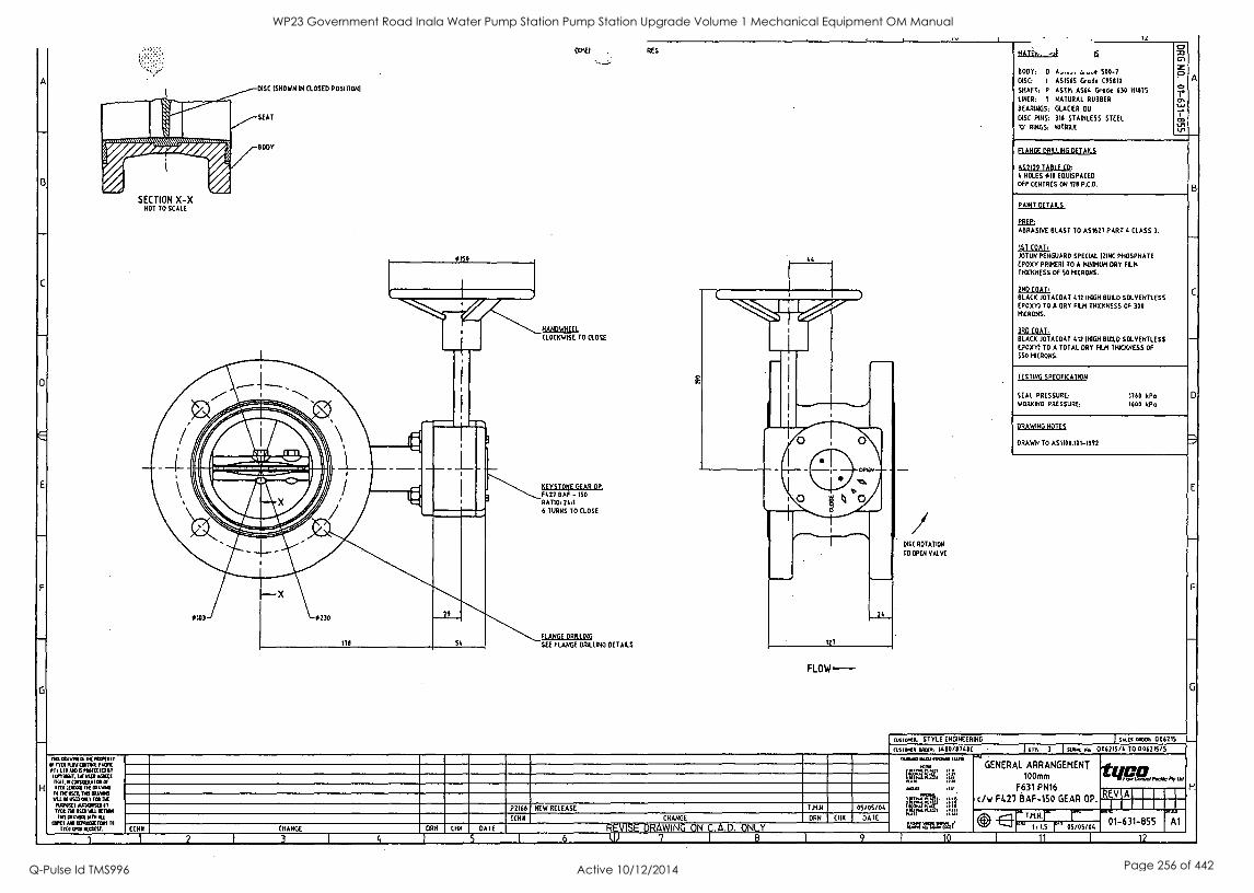
7/on/ET ,y Arel.r/Vir
SECTION X-X NOT TO SCALE
DISC (SHOWN 04 CLOSED POSITION'
SEAT
BODY
IC
021E1 RES
8610.a.LEL CLOCKWISE TO CLOSE
bEYSTONE GEAR OP. F427 OAF - ISO
RATIO, 244 6 TURNS TO CLOSE
FLANGE DRILLING
SEE FLANGE DRILLING DETAILS
0
1
127
0
24
FLOW ---
MATEh,
BODY: 0 90-7 DISC: I ASI565 Grad. C951110
SHAFT: P ASTIR A564 Grade 630 141015
LINER: 1 NATURAL RUBBER
BEARINGS: GLACIER DU
DISC PINS: 316 STAINLESS STEEL
V RINGS: NITRILE
O
2 A 0 Ar
1.J1 4/1
FLANGE DRILLING DETAILS
A52129 TABLE CO,
I. HOLES 010 EOUISPACED
OFF CENTRES ON 170 P.C.D.
PAINT DETAILS
PREP:
ABRASIVE BLAST TO AS1627 PART CLASS 3.
1ST COAL JOTUN PENGUARD SPECIAL (ZINC PHOSPHATE EPDXY PRIMER, TO A MINIMUM DRY FILM
THICKNESS OF 50 MICRONS.
2ND COAT,
BLACK JOTACOAT 412 NIGH BUILD SOLVENTLESS EPDXY) TO A DRY FILM THICKNESS OF 300 MICRONS.
)RD COAT:
BLACK JOTACOAT 412 IHIGH BUILD SOLVENTLESS
EPDXYI TO A TOTAL DRY FILM THICKNESS OF
EGO MICRONS.
TESTING SPECIFICATION
SEAL PRESSURE 1760 kPo WORKING PRESSURE: 1600 kPa
DRAWING NOTES
DRAWN TO AS1100.101-1992
DISC ROTATION
TO OPEN VALVE
COS TWA, STYLE ENGINEERING I :ALES alaxa, 006215
Mit/Kt aorta, 1410/8741C I arr, 3 I stem 006215/4 TO 006215/5 n6talw0a Of1401.011/
If MA RSV COMM PACK Pl TO MOM MAIMED IT (1.19317. TYE VSEll AG MS MI. II COMMA EOM Cf I YEA IMO TIN
II 11[MI. 114S IMMO WU It WA OMIT UR lit
PUVOSES =OMR IT I CL na 0111 VAS KIWI
ENS PAM MTh ALA
OAKS A91mECIXIWS II SRN ROM%
P2166 NEW RELEASE
ECNII CHANGE
T.H.N.
DRN
05/05/04 CHK DATE
ECNII CHANGE ORN CI DATE
1 2 1 3 1 4 5 I 6 R ISE DRAWING ON C.A.D. ONLY
GENERAL ARRANGEMENT 100 mm
F631 PN16
c/w F427 BAF-150 GEAR OP.
/is N2.1 E r-
°M 11 1.5 r 05/05/04
REV Al
01 631 855 Al
12
B
G
H
WP23 Government Road Inala Water Pump Station Pump Station Upgrade Volume 1 Mechanical Equipment OM Manual
Q-Pulse Id TMS996 Active 10/12/2014 Page 256 of 442

1
s
WP23 Government Road Inala Water Pump Station Pump Station Upgrade Volume 1 Mechanical Equipment OM Manual
Q-Pulse Id TMS996 Active 10/12/2014 Page 257 of 442
1
WP23 Government Road Inala Water Pump Station Pump Station Upgrade Volume 1 Mechanical Equipment OM Manual
Q-Pulse Id TMS996 Active 10/12/2014 Page 258 of 442

BRISBANE CITY COUNCIL Brisbane Water Government Road
Appendix E - Check Valve
"Crane Tilt Chek - Installation and Maintenance Instructions".
BW.30098-02/03 Pump Station Upgrade
Item 600mm Check Valve Brand Crane Australia Model Tilt Check' TC14D-DDBB-06-6 Serial Number Supplier Crane Australia Pty Ltd
Address 146 - 154 Dunheved Circuit, St Marys NSW 1790
Phone 02 9623 0234
Fax 02 9673 3870
Email victoria craneaus.com.au
8748C-Manual Draft B 21 Dec. 05 5
WP23 Government Road Inala Water Pump Station Pump Station Upgrade Volume 1 Mechanical Equipment OM Manual
Q-Pulse Id TMS996 Active 10/12/2014 Page 259 of 442
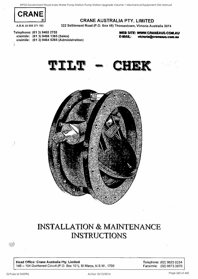
CRANE A.B.N. 24 000 371 193
Telephone: (61 3) icsimile: (61 3) icsimile: (61 3)
CRANE AUSTRALIA PTY. LIMITED 322 Settlement Road (P.O. Box 48) Thomastown, Victoria Australia 3074
9465 2755 9466 1365 (Sales) 9464 5266 (Administration)
WEB SITE: WWW,CRANEAUS.COKAU EMAIL; victorioacrotteous.comate
TILT CHEK
C
I =
r
r 1.4 ,
1.r44*, 4
"14
., ..F'c 0,.V.('- .
-i-z,P':-It4flp
5--..ti
INSTALLATION & MAINTENANCE INSTRUCTIONS
Head Office: Crane Australia Pty. Limited Telephone: (02) 9623 0234 146 - 154 Dunheved Circuit (P.O. Box 101), St Marys, N.S.W., 1790 Facsimile: (02) 9673 3870
WP23 Government Road Inala Water Pump Station Pump Station Upgrade Volume 1 Mechanical Equipment OM Manual
Q-Pulse Id TMS996 Active 10/12/2014 Page 260 of 442

WP23 Government Road Inala Water Pump Station Pump Station Upgrade Volume 1 Mechanical Equipment OM Manual
Q-Pulse Id TMS996 Active 10/12/2014 Page 261 of 442
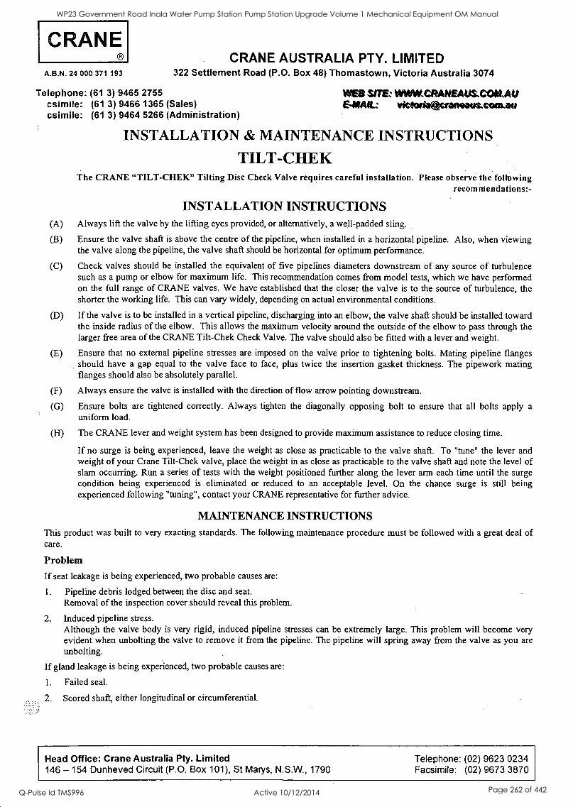
CRANE A.B.N. 24 000 371 193
Telephone: (61 3) csimile: (61 3) csimile: (61 3)
CRANE AUSTRALIA PTY. LIMITED 322 Settlement Road (P.O. Box 48) Thomastown, Victoria Australia 3074
9465 2755 WEB SIM WWW,CRANEAUS,COKAU 9466 1365 (Sales) &NAIL victoriageraneaus.comatm 9464 5266 (Administration)
INSTALLATION & MAINTENANCE INSTRUCTIONS
TILT-CHEK The CRANE "TILT-CHEK" Tilting Disc Check Valve requires careful installation. Please observe the following
recom mendations:-
INSTALLATION INSTRUCTIONS (A) Always lift the valve by the lifting eyes provided, or alternatively, a well-padded sling.
(B) Ensure the valve shaft is above the centre of the pipeline, when installed in a horizontal pipeline. Also, when viewing the valve along the pipeline, the valve shaft should be horizontal for optimum performance.
(C) Check valves should be installed the equivalent of five pipelines diameters downstream of any source of turbulence such as a pump or elbow for maximum life. This recommendation comes from model tests, which we have performed on the full range of CRANE valves. We have established that the closer the valve is to the source of turbulence, the shorter the working life. This can vary widely, depending on actual environmental conditions.
(D) If the valve is to be installed in a vertical pipeline, discharging into an elbow, the valve shaft should be installed toward the inside radius of the elbow. This allows the maximum velocity around the outside of the elbow to pass through the larger free area of the CRANE Tilt-Chek Check Valve. The valve should also be fitted with a lever and weight.
(E) Ensure that no external pipeline stresses are imposed on the valve prior to tightening bolts. Mating pipeline flanges should have a gap equal to the valve face to face, plus twice the insertion gasket thickness. The pipework mating flanges should also be absolutely parallel.
(F) Always ensure the valve is installed with the direction of flow arrow pointing downstream.
(G) Ensure bolts are tightened correctly. Always tighten the diagonally opposing bolt to ensure that all bolts apply a uniform load.
(H) The CRANE lever and weight system has been designed to provide maximum assistance to reduce closing time.
If no surge is being experienced, leave the weight as close as practicable to the valve shaft. To "tune" the lever and weight of your Crane Tilt-Chek valve, place the weight in as close as practicable to the valve shaft and note the level of slam occurring. Run a series of tests with the weight positioned further along the lever arm each time until the surge condition being experienced is eliminated or reduced to an acceptable level. On the chance surge is still being experienced following "tuning", contact your CRANE representative for further advice.
MAINTENANCE INSTRUCTIONS
This product was built to very exacting standards. The following maintenance procedure must be followed with a great deal of care.
Problem
If seat leakage is being experienced, two probable causes are:
1. Pipeline debris lodged between the disc and seat. Removal of the inspection cover should reveal this problem.
2. Induced pipeline stress. Although the valve body is very rigid, induced pipeline stresses can be extremely large. This problem will become very evident when unbolting the valve to remove it from the pipeline. The pipeline will spring away from the valve as you are unbolting.
If gland leakage is being experienced, two probable causes are:
1. Failed seal.
2. Scored shaft, either longitudinal or circumferential.
Head Office: Crane Australia Pty. Limited Telephone: (02) 9623 0234 146 - 154 Dunheved Circuit (P.O. Box 101), St Marys, N.S.W., 1790 Facsimile: (02) 9673 3870
WP23 Government Road Inala Water Pump Station Pump Station Upgrade Volume 1 Mechanical Equipment OM Manual
Q-Pulse Id TMS996 Active 10/12/2014 Page 262 of 442
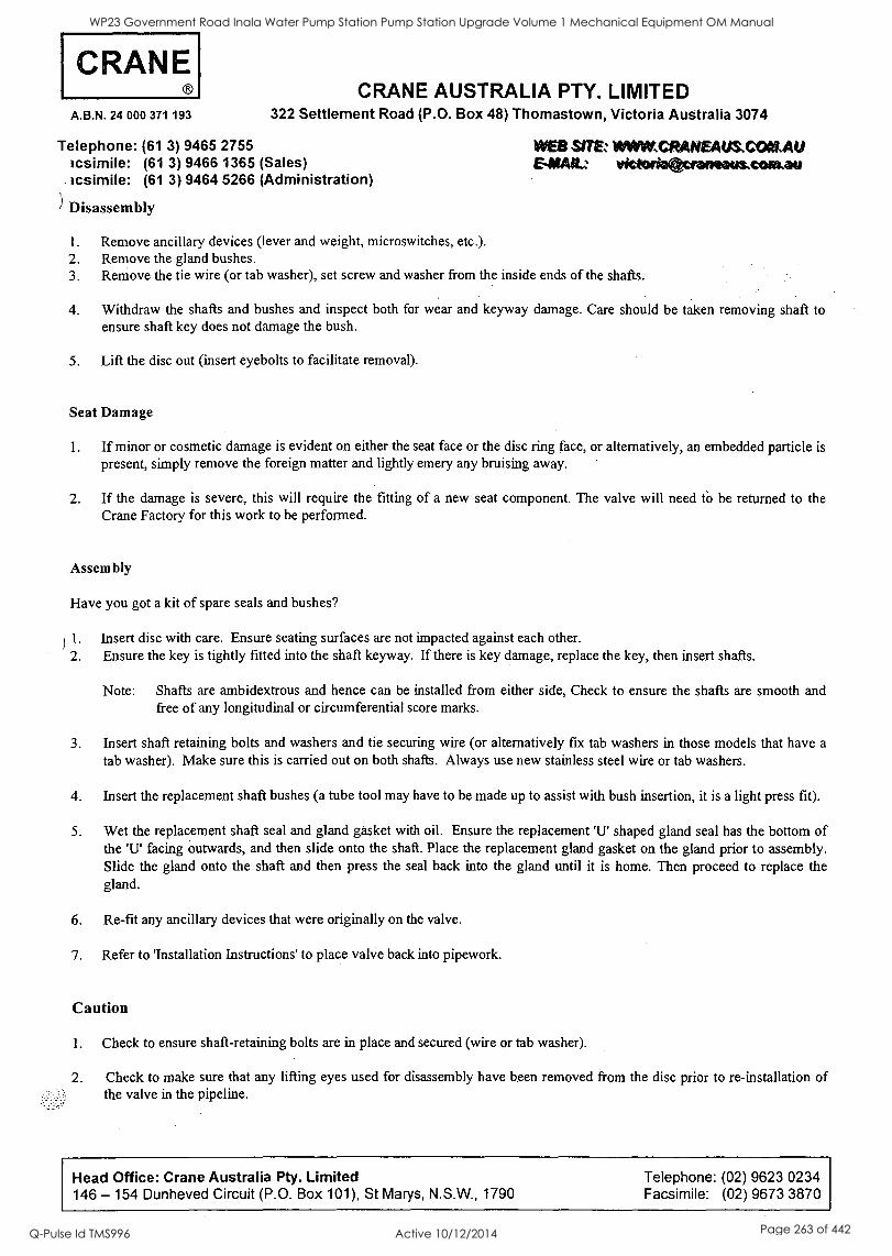
CRANE A.B.N. 24 000 371 193
CRANE AUSTRALIA PTY. LIMITED 322 Settlement Road (P.O. Box 48) Thomastown, Victoria Australia 3074
Telephone: (61 3) 9465 2755 Icsimile: (61 3) 9466 1365 (Sales) tcsimile: (61 3) 9464 5266 (Administration)
) Disassembly
WEB SITEz WWWCRANEAUS,CONLAU SNAIL. victeiattereneays.cowau
1. Remove ancillary devices (lever and weight, microswitches, etc.). 2. Remove the gland bushes. 3. Remove the tie wire (or tab washer), set screw and washer from the inside ends of the shafts.
4. Withdraw the shafts and bushes and inspect both for wear and keyway damage. Care should be taken removing shaft to ensure shaft key does not damage the bush.
5. Lift the disc out (insert eyebolts to facilitate removal).
Seat Damage
1. If minor or cosmetic damage is evident on either the seat face or the disc ring face, or alternatively, an embedded particle is present, simply remove the foreign matter and lightly emery any bruising away.
2. If the damage is severe, this will require the fitting of a new seat component. The valve will need to be returned to the Crane Factory for this work to be performed.
Assembly
Have you got a kit of spare seals and bushes?
11. Insert disc with care. Ensure seating surfaces are not impacted against each other. 2. Ensure the key is tightly fitted into the shaft keyway. If there is key damage, replace the key, then insert shafts.
Note: Shafts are ambidextrous and hence can be installed from either side, Check to ensure the shafts are smooth and free of any longitudinal or circumferential score marks.
3. Insert shaft retaining bolts and washers and tie securing wire (or alternatively fix tab washers in those models that have a
tab washer). Make sure this is carried out on both shafts. Always use new stainless steel wire or tab washers.
4. Insert the replacement shaft bushes (a tube tool may have to be made up to assist with bush insertion, it is a light press fit).
5. Wet the replacement shaft seal and gland gasket with oil. Ensure the replacement `U' shaped gland seal has the bottom of the 'U' facing outwards, and then slide onto the shaft. Place the replacement gland gasket on the gland prior to assembly. Slide the gland onto the shaft and then press the seal back into the gland until it is home. Then proceed to replace the gland.
6. Re-fit any ancillary devices that were originally on the valve.
7. Refer to 'Installation Instructions' to place valve back into pipework.
Caution
1. Check to ensure shaft-retaining bolts are in place and secured (wire or tab washer).
2. Check to make sure that any lifting eyes used for disassembly have been removed from the disc prior to re-installation of the valve in the pipeline.
Head Office: Crane Australia Pty. Limited Telephone: (02) 9623 0234 146 - 154 Dunheved Circuit (P.O. Box 101), St Marys, N.S.W., 1790 Facsimile: (02) 9673 3870
WP23 Government Road Inala Water Pump Station Pump Station Upgrade Volume 1 Mechanical Equipment OM Manual
Q-Pulse Id TMS996 Active 10/12/2014 Page 263 of 442
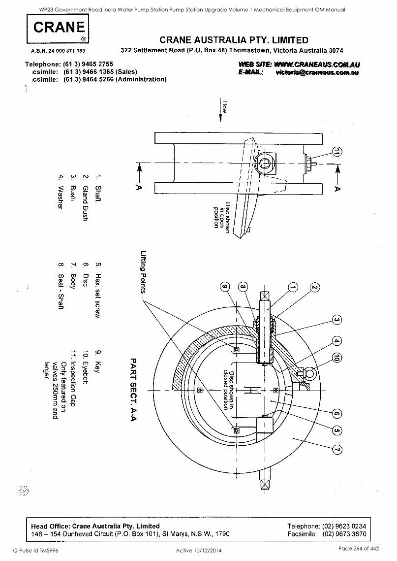
CRANE A.B.N. 24 000 371 193
Telephone: (61 3) icsimile: (61 3) icsimile: (61 3)
CRANE AUSTRALIA PTY. LIMITED 322 Settlement Road (P.O. Box 48) Thomastown, Victoria Australia 3074
9465 2755 9466 1365 (Sales) 9464 5266 (Administration)
!:0 9' 5-n
co q O
(-)
O m CD
0
CD
CD
WEB SIT& WAWCRANEAUS,COALAU E4SAILz victorivecreneousconkau
Head Office: Crane Australia Pty. Limited 146 - 154 Dunheved Circuit (P.O. Box 101), St Marys, N.S.W., 1790
Telephone: (02) 9623 0234
Facsimile: (02) 9673 3870
WP23 Government Road Inala Water Pump Station Pump Station Upgrade Volume 1 Mechanical Equipment OM Manual
Q-Pulse Id TMS996 Active 10/12/2014 Page 264 of 442
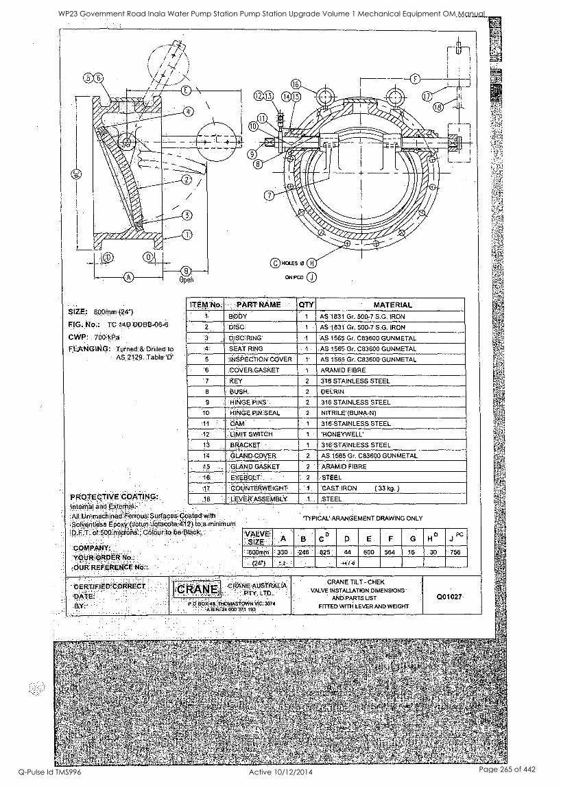
SIZE: 00.ipm 241")
TC:141?DDBIM6-6
CANF!: 700:wp
FLANGING: Turned ;& Drilled to AS;2129'. Table.
PROTEcTIVE :COATING:; Internal and External -
Au Un-machined Ferrous Surfaces " "
. . .
Coated with
!D.F.T. of 500 microha., Colour to be Black. - .
. YOURORDER OUR REFERENCE No.:
ITEM No PART NAME CITY' MATERIAL
1 BODY 1 AS 1831 Gr. 500-7 S.G. IRON
' 2 DISC 1 AS 1831 Gr. 500-7 S.G. IRON
3 : DISC RING 1 r AS 1565 Gr. C83600 GUNMETAL
4. SEAT RING 1 AS 1565 Gr. C83600 GUNMETAL
5 1NSOECTION, COVER t AS 1565 Gr. C83600 GUNMETAL
6 COVER GASKET 1 ARAMID FIBRE
7 KEY 2 316 STAINLESS STEEL
8 BUSH. 2 DELRIN
9 , -HINGE' OIN 2 316 STAINLESS STEEL
10 HINoPIN 'SEAL 2 NITRILE (BUNA-N)
11 : *4 1 316 STAINLESS STEEL
12' 'LIMIT SWITCH 1 'HONEYWELL'
13 BRACKET 1 316 STAINLESS STEEL
14 : GLAND COVER 2 AS 1565 Gr. C83600 GUNMETAL
15 GLAND GASKET 2 ARAMID FIBRE
16. EYEBO,LI. '. 2 STEEL
17 COUNTERWEIGHT 1 CAST IRON ( 33 kg. )
18' : LEVER ASSEMBLY 1 STEEL
'TYPICAL' ARANGEMENT DRAWING ONLY
!VALVE.: '
:
.
: a: ri G0 GHJ D PC
60Orliiii: , 33.0 246' 825. : 44 600 564 16 30 756
(24?). .
CERTIFIED5:CPRREPT : . :: :
DATE: 6,`(:
CRAME :COANEvAUSTRALIA; PTY. LTD.
: :
P.0 p9X48, THOWL,N.STOWN VIC. 3074 k1314:;24 WO 373 193
CRANE TILT - CHEK VALVE INSTALLATION DIMENSIONS
AND PARTS UST
FITTED WITH LEVER AND WEIGHT
001027
iS
4
WP23 Government Road Inala Water Pump Station Pump Station Upgrade Volume 1 Mechanical Equipment OM Manual
Q-Pulse Id TMS996 Active 10/12/2014 Page 265 of 442

II
I
s
1
WP23 Government Road Inala Water Pump Station Pump Station Upgrade Volume 1 Mechanical Equipment OM Manual
Q-Pulse Id TMS996 Active 10/12/2014 Page 266 of 442

0
1
S
WP23 Government Road Inala Water Pump Station Pump Station Upgrade Volume 1 Mechanical Equipment OM Manual
Q-Pulse Id TMS996 Active 10/12/2014 Page 267 of 442

BRISBANE CITY COUNCIL Brisbane Water Government Road
Appendix F - Metal Seated Sluice Valves
"TYCO Metal Seated Sluice Valves - Figure 400"
BW.30098-02/03 Pump Station Upgrade
Item 600 MSSV Brand Tyco Model 600mm Figure 400 Metal Seated Sluice Valve x 4
150mm Figure 400 Metal Seated Sluice Valve x 4
Serial Number N/A Supplier Tyco Water Address P.O. Box 150 Currumbin QLD 4223 Phone 07 5589 4400 Fax 07 5534 7079 Email
8748C-Manual Draft B 21 Dec. 05 6
WP23 Government Road Inala Water Pump Station Pump Station Upgrade Volume 1 Mechanical Equipment OM Manual
Q-Pulse Id TMS996 Active 10/12/2014 Page 268 of 442
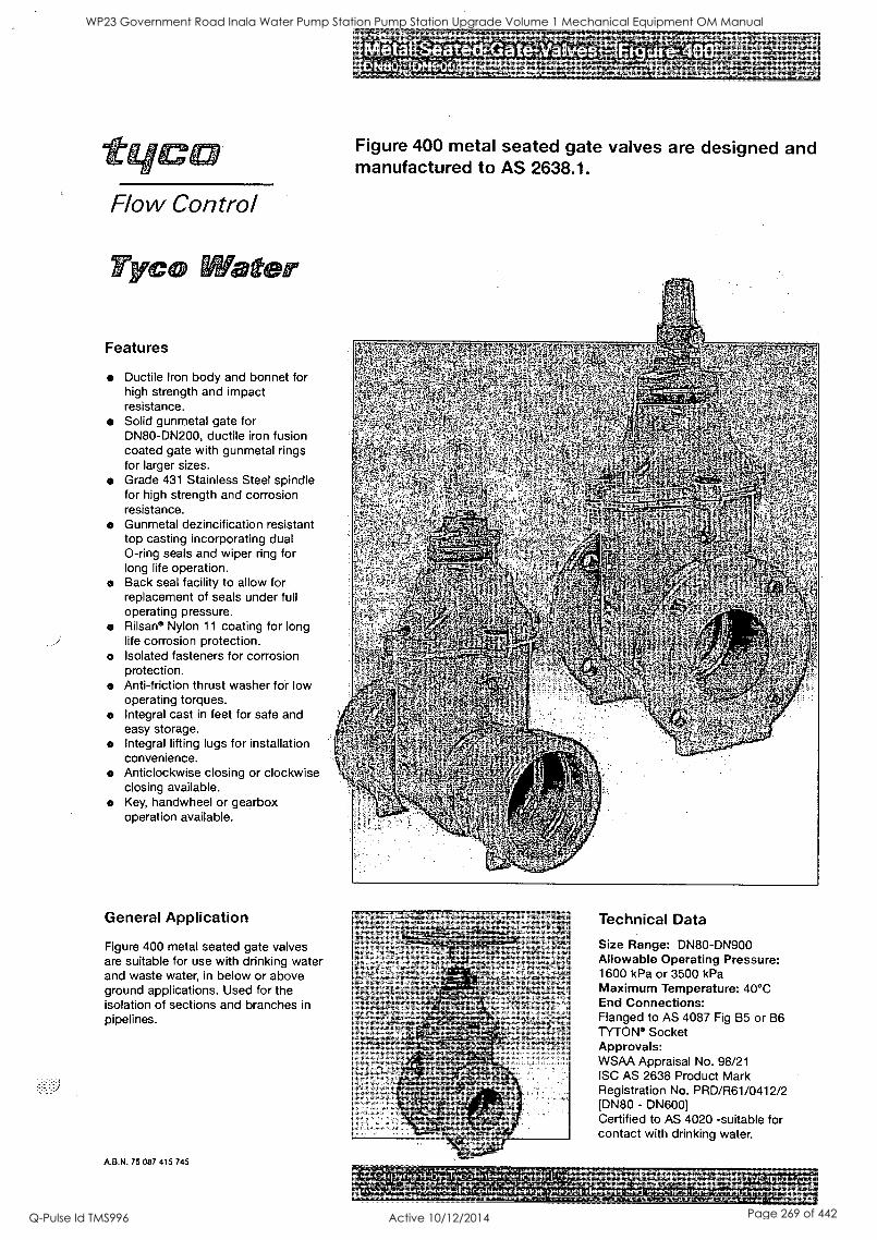
Flow Control
lyc titter
Features
Ductile Iron body and bonnet for high strength and impact resistance. Solid gunmetal gate for DN80-DN200, ductile iron fusion coated gate with gunmetal rings for larger sizes. Grade 431 Stainless Steel spindle for high strength and corrosion resistance.
o Gunmetal dezincification resistant top casting incorporating dual 0-ring seals and wiper ring for long life operation.
o Back seal facility to allow for replacement of seals under full operating pressure. Rilsan Nylon 11 coating for long life corrosion protection.
o Isolated fasteners for corrosion protection. Anti-friction thrust washer for low operating torques.
o Integral cast in feet for safe and easy storage.
o Integral lifting lugs for installation convenience. Anticlockwise closing or clockwise closing available. Key, handwheel or gearbox operation available.
General Application
Figure 400 metal seated gate valves are suitable for use with drinking water and waste water, in below or above ground applications. Used for the isolation of sections and branches in pipelines.
A.B.N. 75 087 415 745
Dar'iv.i.pjalt$9,a
809N900
Figure 400 metal seated gate valves are designed and manufactured to AS 2638.1.
Technical Data
Size Range: DN80-DN900 Allowable Operating Pressure: 1600 kPa or 3500 kPa Maximum Temperature: 40°C End Connections: Flanged to AS 4087 Fig B5 or B6 TYTON Socket Approvals: WSAA Appraisal No. 98/21 ISC AS 2638 Product Mark Registration No. PRD/R61/0412/2 [DN80 - DN600] Certified to AS 4020 -suitable for contact with drinking water.
erirwgnwrycsirrigmargago-irin; ky.5aNaterganyes.ine2Uoichamproduct design and
tiTWS400/11/03. specifications without; notice.
WP23 Government Road Inala Water Pump Station Pump Station Upgrade Volume 1 Mechanical Equipment OM Manual
Q-Pulse Id TMS996 Active 10/12/2014 Page 269 of 442
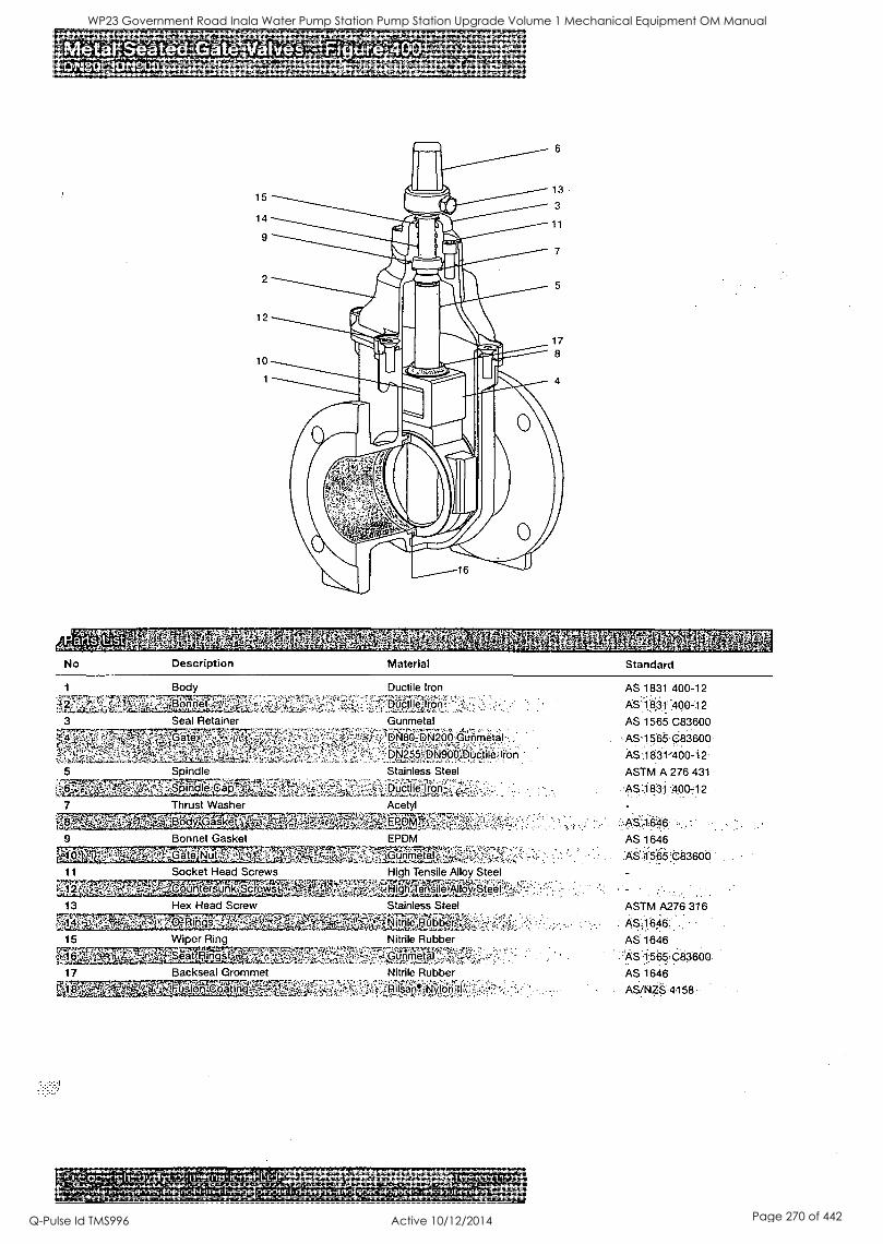
Pieta! Seated Valves' 19N80 DN900
15
14
9
12
10
No Description
g $.1 1
Material
rjk
r.orinr,.V
Standard
Body
Seal Retainer
Ductile Iron
DOrptilelront ; '
Gunmetal
DN80,-:DN200 GUnrneta)-
DN255=DN900`,MCtilezlion
5 Spindle Stainless Steel .
... .
Ductilelron-J.-4..,,-- : . _
7 Thrust Washer Acetyl
' . -7.4,7,,,.,,...g.w;4*-Ar'''''FiF,::.,Y.,7::74-54.":,:.':-."1'
9 Bonnet Gasket EPDM
ate. N utLi.?- "' G u n metal- , .11r277,:.s.'TYP1-742:7TZ,7411..^,, ,
,".1 ' ` 7 "
AS 1831 400-12
AS 1-1:031: I40012 AS 1565 C83600
AS 1565 C83600
AS ii 831400-1 2
ASTM A 276 431
)?6,11831 400-12
AS 1 6.46
AS 1646
AS45i5 C83600 11 Socket Head Screws High Tensile Alloy Steel
Ey....,.., ,,,,4: . . . r-..:,,,,,s.,,,,,e . .:,,,,,,,,,..,,,,.i.;0,.......,,,,,,_,,A.,,,,,:-.2g,,,,s,;,,,4.4...,),L-Aptg.,,,,-;;Qn12,m,IPPIIPf,v.19Y.S.RMI-5:fv,-.
-:', ;:' 1 :. ';' ' :;.- -' . ..
.. . . .
13 Hex Head Screw Stainless Steel ASTM A276 316
1.6`.&1..tat0.1:4 ; AS 1646 ,
15 Wiper Ring Nitrile Rubber
retal 17 Backseal Grommet Nitrile Rubber
4147M...77.FMR"fn "
14..:::r,i$4.1'. 1711.1,SPilttkN1,99j1?;:,;1"+;"7.:-':-
.?'..fv 'A* -r.J' Artvarne.mvviaq,, ,,,,..T1NS400/11/03,
kTycolWaterlreserves,Oeirightltorchangeiproductdesignslandtspecifications,wIthoutmotice. .
nOPEff,11,111.1,11,rtda.ti Pta..4.11.1`..... Or fx"tr*IIrs.a...,9,4',riOr+OPik,traeliPktF,*,4*,..01.,
AS 1646
.''AS.1.565,683600
AS 1646
AS/NS 4158:
WP23 Government Road Inala Water Pump Station Pump Station Upgrade Volume 1 Mechanical Equipment OM Manual
Q-Pulse Id TMS996 Active 10/12/2014 Page 270 of 442
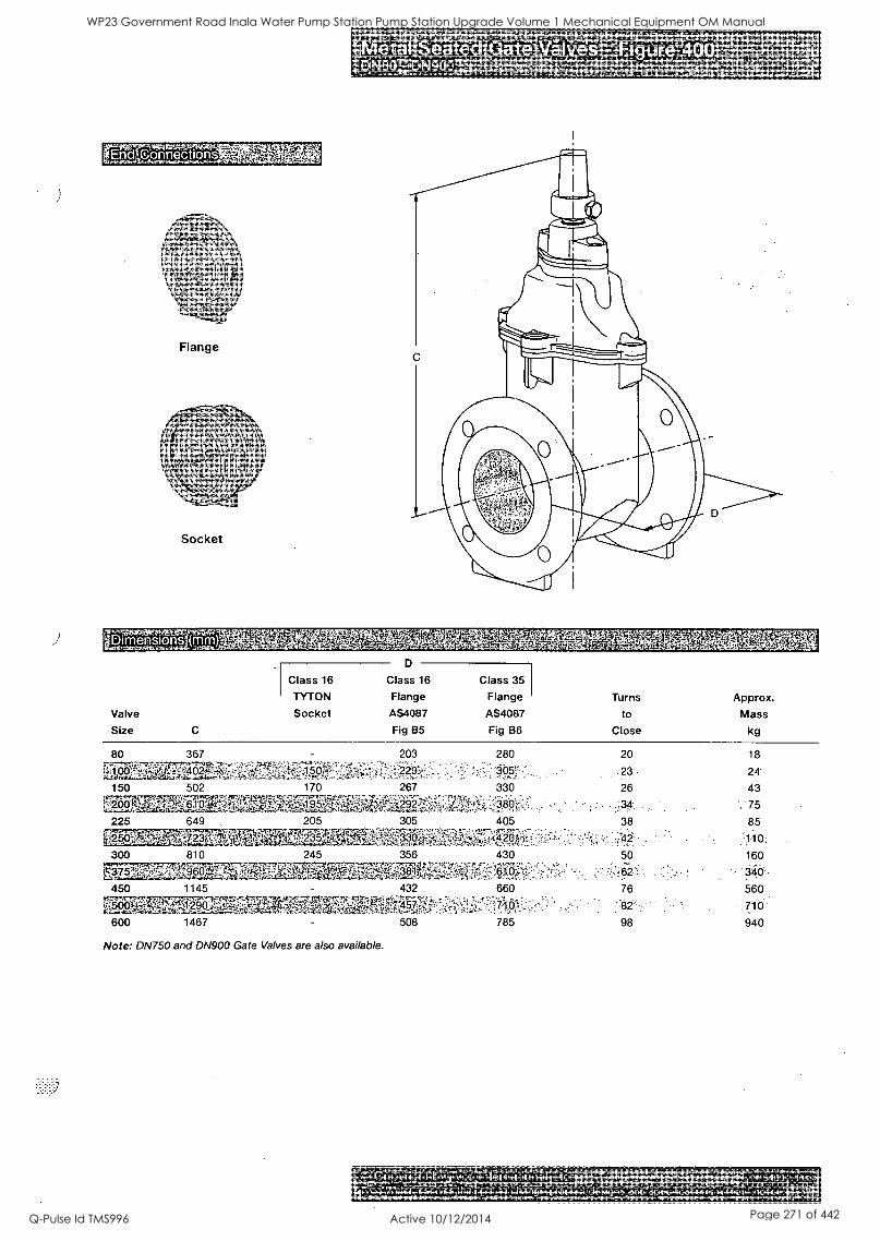
CEr7C16VATEMTS .10,.41tleeftasv
Flange
Socket
Metal Sq ated GateValves. ,-1Eibiref 0 DN 0 i5N -9 -rp6s.tun.m. r.siox
",,VOISrat:74 tkintat9M02,
Class 16
D
Class 16 Class 35
TYTON Flange Flange Turns Approx. Valve Socket AS4087 AS4087 to Mass
Size C Fig B5 Fig B6 Close kg
80 'PA p 1 00
150 502 . i7097 0 10
225 649
krsgik4.74,147R3r'
367
300 810
450 1145
L
170
205
600 1467
245
Note: DN750 and DN900 Gate Valves are also available.
203 280 20 18
.23 24'
267 330 26 43
75 305 405 38 85
.11 0;
356 430 50 160
.346 432 660 76 560
710 508 785 98 940
res oi:417 i VWCZ) i 1-kTyconater reseives'theinglittto,changeiprodixt designs and'tpecificaLions.lithottnoLiczit rAts,....Yra4k.vat 1.4,41:koa4v4,13whaa*A 4- Winrrzn , .414,
WP23 Government Road Inala Water Pump Station Pump Station Upgrade Volume 1 Mechanical Equipment OM Manual
Q-Pulse Id TMS996 Active 10/12/2014 Page 271 of 442
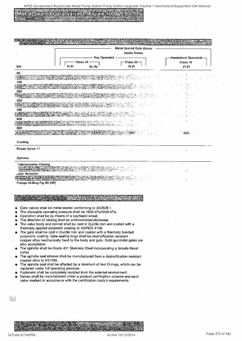
:tvtallablezRange ,f4 oaas
DN
Metal Seated Gate Valves
Inside Screw
Key Operated Class 16 r- Class 35--1
FI-Fl Sc-Sc FI-Fl
Class 16
FI-Fl
80 "4.71,1,4X1
150 TR
225
r*2
300 t,
450
600
450k 900
wrA-.5P.:.szwr.4
Coating
FI
:600
Rilsan Nylon 11
Options
-,nticlockwise Closing Iockw'iseCl'o5iriga ; t,4 -» =a;
,,iear Actuator e,
Flange Drilling Fig B6 (HP)
-467-afor-fiss.=. .Recommended Specification
^ - rta.4.15,..54.1.7,10o
o Gate valves shall be metal seated conforming to AS2638.1. o The allowable operating pressure shall be 1600 kPa/3500 kPa.
Operation shall be by means of a key/hand wheel. o The direction of closing shall be anticlockwise/clockwise.
The valve body and bonnet shall be cast in Ductile Iron and coated with a thermally applied polymeric coating to AS/NZS 4158. The gate shall be cast in Ductile Iron and coated with a thermally bonded polymeric coating. Gate sealing rings shall be dezincification resistant copper alloy mechanically fixed to the body and gate. Solid gunmetal gates are also acceptable. The spindle shall be Grade 431 Stainless Steel incorporating a failsafe thrust collar. The spindle seal retainer shall be manufactured from a dezincification resistant copper alloy to AS1565. The spindle seal shall be affected by a minimum of two 0-rings, which can be replaced under full operating pressure.
o Fasteners shall be completely isolated from the external environment. Valves shall be manufactured under a product certification scheme and each valve marked in accordance with the certification body's requirements.
?(C)It;opyrighVbyhTycoInternational!Lltd. to, TWS400/11/03V
Tyco jilferevmesvwilmrItitrzciangstp,roducldetigristand specifications withouttnot Jr.w.Tow.L.,-.1isfas2u....,0q404443iVrtra.
44,
WP23 Government Road Inala Water Pump Station Pump Station Upgrade Volume 1 Mechanical Equipment OM Manual
Q-Pulse Id TMS996 Active 10/12/2014 Page 272 of 442
-two Flow Control
Tyco Water
PIPELINE COMPONENTS PRODUCT BULLETIN
Resilient Seated Gate Valves
Tyco Water is pleased to announce its range of resilient seated gate valves has now been extended to DN600.
Resilient seated gate valves are manufactured to AS 2638.2.
When Standards Australia WS/22 Committee first met to discuss the inclusion of resilient seated valves into the AS2638 Standard it found that various international standards included predominantly prescriptive details for resilient seated valves but were lacking in inclusion of satisfactory type tests to verify performance.
Clearly this was of some concern to Committee members as they were seeking assurance that the various valve designs were adequate for satisfactory performance over extended periods. Of particular importance was the requirement to prove that neither the rubber coating on the gate nor the polymeric coating on the inside of the body would be abraded during operation of the valve under pressure. There was also a need to demonstrate that the valve components were of sufficient strength to withstand anticipated operating conditions.
The 1991 version of AS2638 was published with similar content to that of the International Standards, however it was agreed that work would be carried out to establish performance tests for inclusion in future revisions of the Standard.
Tyco Water undertook an active role, working with Sydney Water, to develop a series of Type Tests to demonstrate performance for each particular valve design. These tests were incorporated into Sydney Water specifications as they were developed, and culminated in inclusion of the tests into the 1999 version of AS2638.
Clearly the design and performance characteristics of resilient seated gate valves have evolved over many years. Tyco Water has been actively involved in a continual product improvement programme and its resilient seated gate valve design is now world class. The Type Test regime specified in AS2638-1999 has been satisfied for each size of Tyco Water gate valve from DN80 - DN600, as evidenced by the product schedule attachment to the AS2638 Standards Mark licence.
Specifiers may wish to verify that other manufacturer's gate valves have similarly demonstrated conformance to the AS2638-1999 Type Test regimes for their particular product range. This can be verified by sighting the manufacturers AS2638-1999 Standards Mark product schedule.
Issued: 1st July 2002.
Issue No: 01
: I
WP23 Government Road Inala Water Pump Station Pump Station Upgrade Volume 1 Mechanical Equipment OM Manual
Q-Pulse Id TMS996 Active 10/12/2014 Page 273 of 442
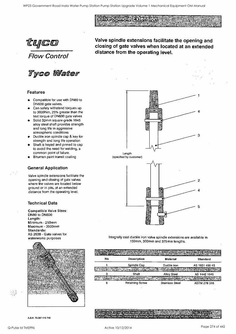
Flow Control
Tyc ater
Features
Compatible for use with DN80 to DN600 gate valves. Can safely withstand torques up to 3000Nm, 25% greater than the test torque of DN600 gate valves Solid 32mm square grade 1045 alloy steel shaft provides strength and long life in aggressive atmospheric conditions Ductile iron spindle cap & key for strength and long life operation Shaft is keyed and pinned to cap to avoid the need for welding, a common point of failure.
at Bitumen paint transit coating
General Application
Valve spindle extensions facilitate the opening and closing of gate valves where the valves are located below ground or in pits, at an extended distance from the operating level.
Technical Data
Compatible Valve Sizes: DN80 to DN600 Length: Minimum - 250mm Maximum - 3500mm Standards: AS 2638 - Gate valves for waterworks purposes
A.B.N. 75 087 415 745
Valve spindle extensions facilitate the opening and closing of gate valves when located at an extended distance from the operating level.
Length (specified by customer)
Integrally cast ductile iron valve spindle extensions are available in 150mm, 300mm and 375mm lengths.
grtsplist No Description Material Standard
.
Spindle Cap Ductile Iron AS 1831 400-15
Y irgfr,--Ve14.;:fAS iti31;400t15,-A 3 Shaft Alloy Steel AS 1442 1045
5 Retaining Screw Stainless Steel ASTM 276 316
AP,AV.."lrktaalvWV't:Mgr"0"."N",7"-"ta"'ZA" LCo py n g hOpyiTycoilntematioriallLtd. TWP.,CES/03104, it.
_TycoiWat_Aelleseizes,th 'ejightitoyd'hangtpiothicl de.signsandspecilications,mithout,notice
WP23 Government Road Inala Water Pump Station Pump Station Upgrade Volume 1 Mechanical Equipment OM Manual
Q-Pulse Id TMS996 Active 10/12/2014 Page 274 of 442

I
II
1
I I
WP23 Government Road Inala Water Pump Station Pump Station Upgrade Volume 1 Mechanical Equipment OM Manual
Q-Pulse Id TMS996 Active 10/12/2014 Page 275 of 442
II
8
I 0
1
WP23 Government Road Inala Water Pump Station Pump Station Upgrade Volume 1 Mechanical Equipment OM Manual
Q-Pulse Id TMS996 Active 10/12/2014 Page 276 of 442
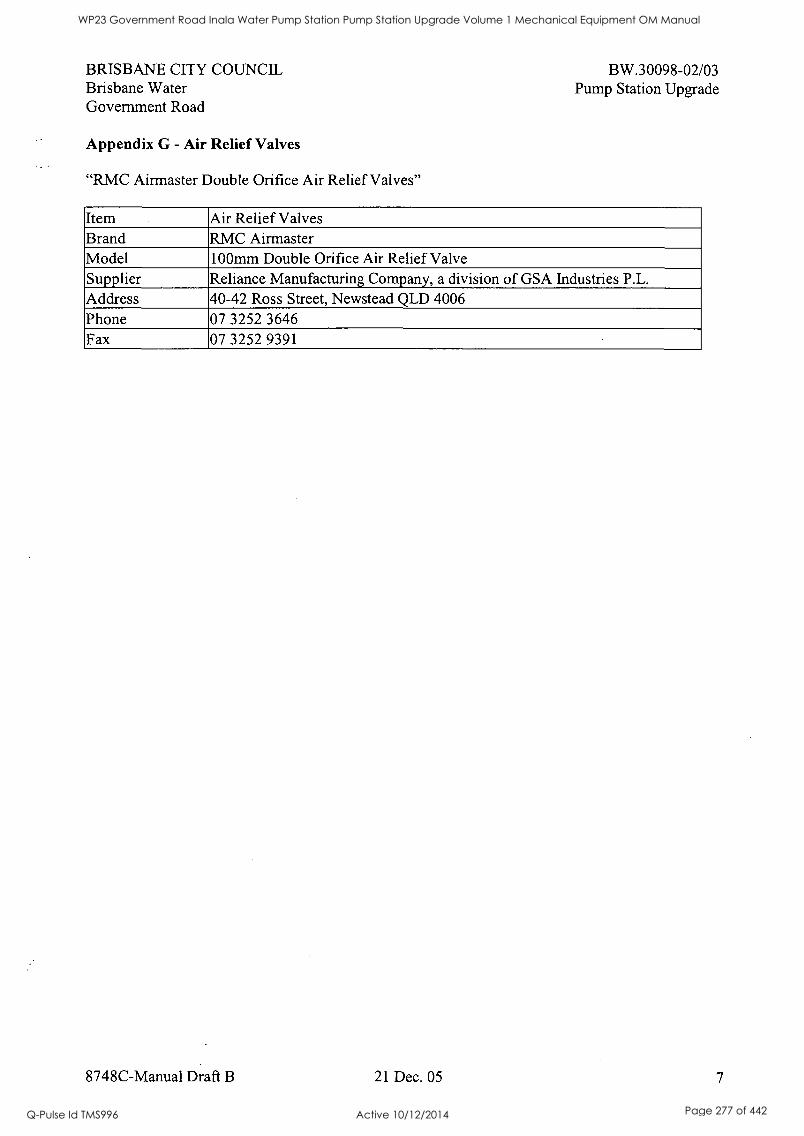
BRISBANE CITY COUNCIL Brisbane Water Government Road
Appendix G - Air Relief Valves
"RMC Airmaster Double Orifice Air Relief Valves"
BW.30098-02/03 Pump Station Upgrade
Item Air Relief Valves Brand RMC Airmaster Model 100mm Double Orifice Air Relief Valve Supplier Reliance Manufacturing Company, a division of GSA Industries P.L. Address 40-42 Ross Street, Newstead QLD 4006 Phone 07 3252 3646 Fax 07 3252 9391
8748C-Manual Draft B 21 Dec. 05 7
WP23 Government Road Inala Water Pump Station Pump Station Upgrade Volume 1 Mechanical Equipment OM Manual
Q-Pulse Id TMS996 Active 10/12/2014 Page 277 of 442
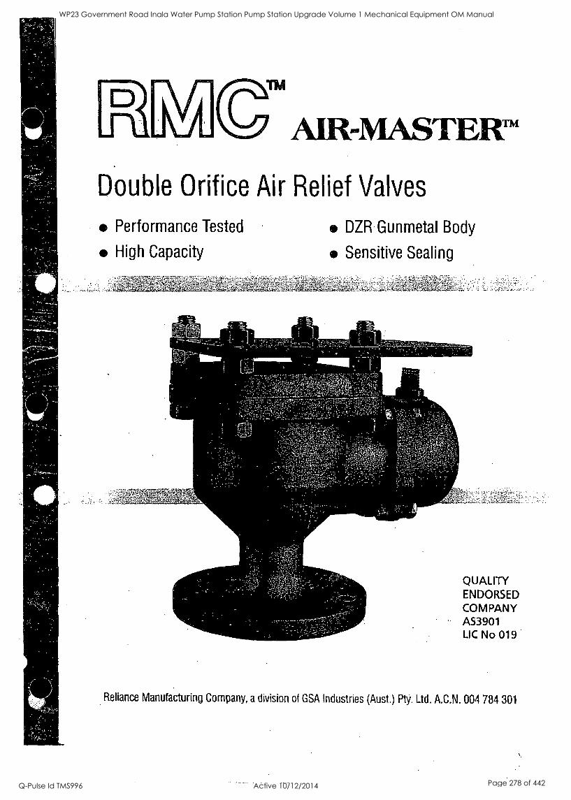
AIR-MASTER-II
Double Orifice Air Relief Valves
Performance Tested
High Capacity
DZR Gunmetal Body
Sensitive Sealing
QUALITY ENDORSED COMPANY AS3901 LIC No 019
Reliance Manufacturing Company, a division of GSA Industries (Aust.) Pty. Ltd. A.C.N. 004 784 301
WP23 Government Road Inala Water Pump Station Pump Station Upgrade Volume 1 Mechanical Equipment OM Manual
Q-Pulse Id TMS996 Active 10/12/2014 Page 278 of 442

WP23 Government Road Inala Water Pump Station Pump Station Upgrade Volume 1 Mechanical Equipment OM Manual
Q-Pulse Id TMS996 Active 10/12/2014 Page 279 of 442
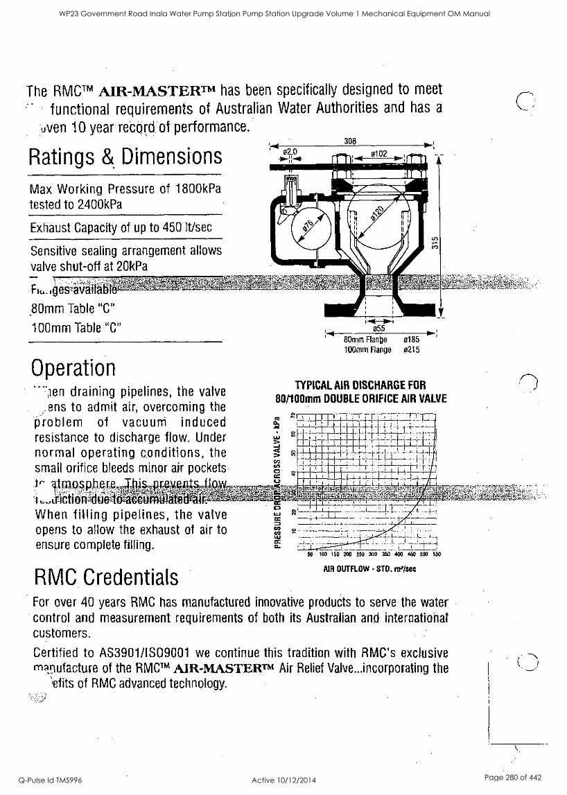
The RMCTM AIR-MASTERTm has been specifically designed to meet
functional requirements of Australian Water Authorities and has a
:,oven 10 year retord of performance.
Ratings & Dimensions
Max Working Pressure of 1800kPa tested to 2400kPa
Exhaust Capacity of up to 450 It/sec
Sensitive sealing arrangement allows
valve shut-off at 20kPa
Ij 02.0
308
1111: 0102 IIIII
U) c)
80mm Table "C"
100mm Table "C"
Operation -711en draining pipelines, the valve
ens to admit air, overcoming the problem of vacuum induced resistance to discharge flow. Under normal operating conditions, the small orifice bleeds minor air pockets
tr atmos..phere j434§A -ree*AlltA4,,
When filling pipelines, the valve opens to allow the exhaust of air to ensure complete filling.
RMC Credentials For over 40 years RMC has manufactured innovative products to serve the water control and measurement requirements of both its Australian and international customers.
Certified to AS3901/IS09001 we continue this tradition with RMC's exclusive m9,nufacture of the RMCTM MR-MASTERTm Air Relief Valve...incorporating the
iefits of RMC advanced technology.
055 ;
80mm Flange 0185
100mm Flange 0215
TYPICAL AIR DISCHARGE FOR
80/100mm DOUBLE ORIFICE AIR VALVE
E. ,..0 LT. 4-4 i : ..;___;
...,
01_ . i I-1 -li. I - -- --- I 4_4..4 ,i_..
ct
cn cn 71,- ; 1.- 1-1----- - i-1- ::
o 1 . : - 7 ..1_4_ ; , _ill- r ".
_i i 1-1 1
C-1
:',...1t;
Li 1
60 100 150 200 250 300 350 400 450 500 550
AIR OUTFLOW - STD. mi /sec
M
WP23 Government Road Inala Water Pump Station Pump Station Upgrade Volume 1 Mechanical Equipment OM Manual
Q-Pulse Id TMS996 Active 10/12/2014 Page 280 of 442

WP23 Government Road Inala Water Pump Station Pump Station Upgrade Volume 1 Mechanical Equipment OM Manual
Q-Pulse Id TMS996 Active 10/12/2014 Page 281 of 442
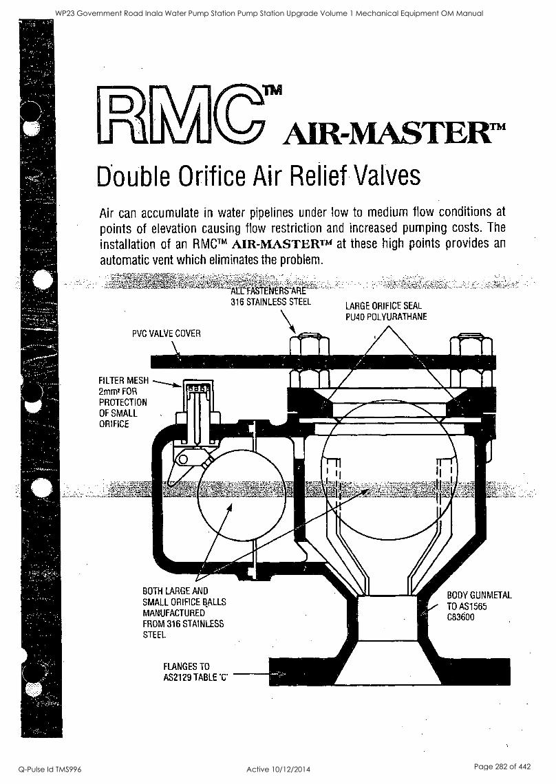
AIR - MASTER Double Orifice Air Relief Valves
Air can accumulate in water pipelines under low to medium flow conditions at
points of elevation causing flow restriction and increased pumping costs. The
installation of an RMCTM AIR-MASTERn4 at these high points provides an
automatic vent which eliminates the problem.
PVC VALVE COVER
trFASTENERS'ARE 316 STAINLESS STEEL
LARGE ORIFICE SEAL
PU40 POLYURATHANE
FILTER MESH ......1b.. 2mm2 FOR
PROTECTION
OF SMALL ORIFICE
BOTH LARGE AND
SMALL ORIFICE BALLS
MANUFACTURED
FROM 316 STAINLESS STEEL
FLANGES TO
AS2129 TABLE 'C'
BODY GUNMETAL
TO AS1565 C83600
WP23 Government Road Inala Water Pump Station Pump Station Upgrade Volume 1 Mechanical Equipment OM Manual
Q-Pulse Id TMS996 Active 10/12/2014 Page 282 of 442
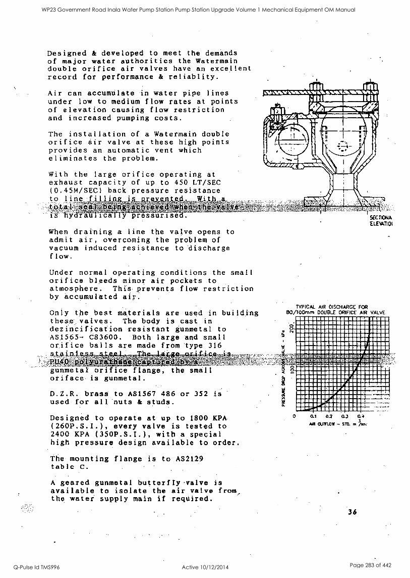
Designed & developed to meet the demands of major water authorities the Watermain double orifice air valves have an excellent record for performance & reliablity.
Air can accumulate in water pipe lines under low to medium flow rates at points of elevation causing flow restriction and increased pumping costs.
The installation of a Watermain double orifice air valve at these high points provides an automatic vent which eliminates the problem.
With the large orifice operating at
exhaust capacity of up to 450 LT/SEC (0.45M/SEC) back pressure resistance to line filling is .prexen e ith A__
ifiWriltifil 4 w118n She VViatk, -.AMV
ydraiiIitgliy pressurised.-
When draining a line the valve opens to
admit air, overcoming the problem of vacuum induced resistance to discharge flow.
Under normal operating conditions the small orifice bleeds minor air pockets to atmosphere. This prevents flow restriction by accumulated air.
Only the best materials are used in building these valves. The body is .cast in dezincification resistant gunmetal to AS1565- 083600. Both large and small orifice balls are made from type 316 :§A401RAAA4A,F41-Tm0f*ORIK40;
TAr,47,,y,..,maa.,4:w..p;zg,,fiasz..-;lwz;t
gunmetal Orifice flange, the small oriface is gunmetal.
D.Z.R. brass to AS1567 486 or 352 is used for all nuts & studs.
Designed to operate at up to 1800 KPA.
(260P.S.I.), every valve is tested to 2400 KPA (350P.S.I.), with a special high pressure design available to order.
The mounting flange is to AS2129 table C.
A geared gunmetal butterfly. valve is
available to isolate the air valve from the water supply main if required.
um onl
kfil Nitibidgma-.04 elimepaloftmmagariaaamml . , !lep7.4 e i
ION tAMNR.ItIAMINNFLWIMWW1110111WIAR
Int
< ss
;;TIONA ELEATI 01
TYPICAL AIR D SCHARGE FOR B0/10Ornm DOUBLE ORIFICE MR VALVE
0 0 N
1111111111111111111111111MISIO BIIIRMIN MEM 1111111111111111M1111111111 NOW IIEN 1111111111 11 11I1 10101IMONIMONIMOLOINNO EGEMEDGM69113621151121MISHOWIEM1130 INCIQUISSIJIMILICIEMIEWAIBIAM
111111111.1111111111111111111111./ MINIM OAII ENS F ININ MOINEONSIIMINY MIM11010 COUMMMIII 8 11111 K/ inIell 111167.1.111 1111
0 0.1 0.2 0.3 0.4
AA CUTFLOW - sm. in /10,
36
WP23 Government Road Inala Water Pump Station Pump Station Upgrade Volume 1 Mechanical Equipment OM Manual
Q-Pulse Id TMS996 Active 10/12/2014 Page 283 of 442
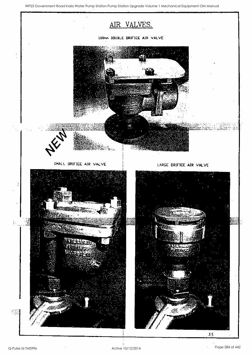
AIR VALVES.
100met DOUBLE ORIFICE AIR VALVE
SMALL ORIFICE AIR VALVE
4j1
F Yet.
.e'
L.
eigitfai 1.0'.5"OtCog
-
?D' 4+,104-t.
; ,
LARGE ORIFICE AIR VALVE
^
4
--
35
WP23 Government Road Inala Water Pump Station Pump Station Upgrade Volume 1 Mechanical Equipment OM Manual
Q-Pulse Id TMS996 Active 10/12/2014 Page 284 of 442
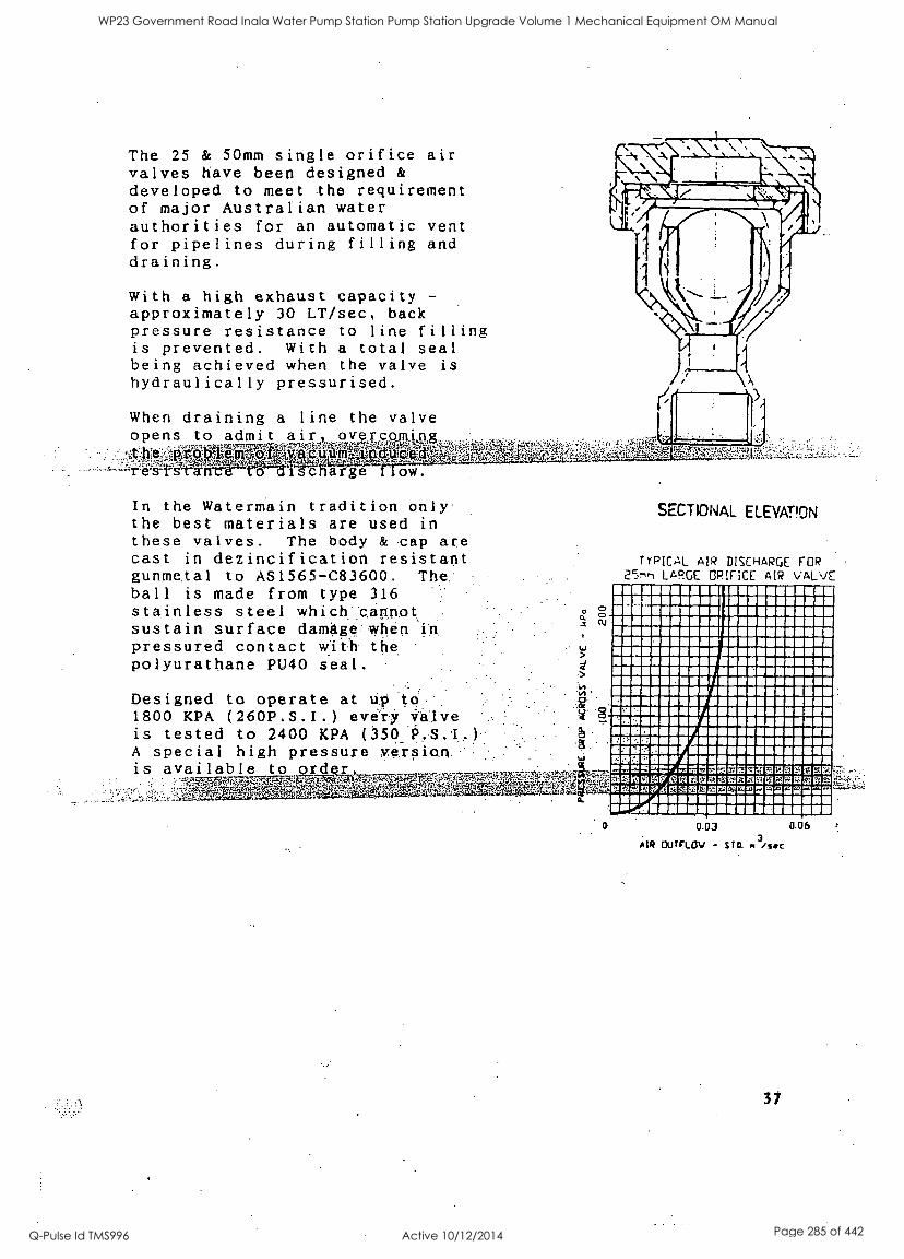
The 25 & 50mm single orifice air valves have been designed &
developed to meet the requirement of major Australian water authorities for an automatic vent for pipelines during filling and draining.
with a high exhaust capacity -
approximately 30 LT/sec, back pressure resistance to line filling is prevented. With a total seal being achieved when the valve is
hydraulically pressurised.
When draining a line the valve opens to admit air, pwcaptisi t ivelggyAalisnr say res to dignarge ow.
In the Watermain tradition only the best materials are used in these valves. The body & cap are cast in dezincification resistant gunmetal to AS1565-C83600. The: ball is made from type 316 stainless steel which'.cannot., sustain surface damage:when in.
pressured contact with the polyurathane PU40 seal.
Designed to operate at up to 1800 KPA (260P.S.I.) every is tested to 2400 KPA (3500,S.1. A special high pressure versioh is available to or
ItkyyligERWinalerveivor' ve-
SECTIONAL ELEVATION
TYPICAL AIR DISCHARGE FOR 25nri LARGE ORIFICE AIR VALVE
MOMSOMMMIMAROMOMMOMMEM RIMMIMMOMMOMINIMMONOMOM MERWOOMASIMOMMOOMMEMOS
MIMMOMMISMOMMOMMINMO MOMMOOMMIONMOMMOMOMOMO EMMOMMOMMWMOSOMMOMEM IIVOMMEM IONMMEMEMMOMMON 11111mOSUMMMEMIXOXIIMOMMMO 111111111MOVOMMAMMOMMOMMOSO IMMMNIUMMOOMMOMMOMM OMMMOMOMOMAIMMOOMMOMOMM MINOMMEMOMNIMMWOMMEMMMOM MEMEMIIMIWOMOMOMMOMMOM MIIMMOMOMMASOOMMOOMM nomnimirmmisummomom maimmommfAmmilmomum SINUOMMIWEEMMOMMOMMOM numme sAmmumummomom MREVMW,MITOMMEMESOMMOOMM MOMMMFOMOQMO MMMOOOMUOM mmempAmmatommumcomwmauww mmwgmmmmumamsmmammw Ilw".miummiummuminnumms
0.03 0.06
AIR OuTFLOv - STD. r /see
31
WP23 Government Road Inala Water Pump Station Pump Station Upgrade Volume 1 Mechanical Equipment OM Manual
Q-Pulse Id TMS996 Active 10/12/2014 Page 285 of 442

S
WP23 Government Road Inala Water Pump Station Pump Station Upgrade Volume 1 Mechanical Equipment OM Manual
Q-Pulse Id TMS996 Active 10/12/2014 Page 286 of 442

WP23 Government Road Inala Water Pump Station Pump Station Upgrade Volume 1 Mechanical Equipment OM Manual
Q-Pulse Id TMS996 Active 10/12/2014 Page 287 of 442
BRISBANE CITY COUNCIL Brisbane Water Government Road
Appendix H - Pressure Transducers
"VEGABAR 42 Operating Instructions"
BW.30098-02/03 Pump Station Upgrade
Item Pressure Transducer Brand Vega Model Vegabar 42, BR42.XXGP1SZX Supplier Invoice No. 611404 Supplier Vega Australia Address P.O.Box 3272 Kirrawee DC, Kirrawee NSW 2232 Phone 02 9542 6662 Fax 02 9542 6665 Setpoint 4-20 mA equates to 0-1000 kPa
8748C-Manual Draft B 21 Dec. 05 8
WP23 Government Road Inala Water Pump Station Pump Station Upgrade Volume 1 Mechanical Equipment OM Manual
Q-Pulse Id TMS996 Active 10/12/2014 Page 288 of 442
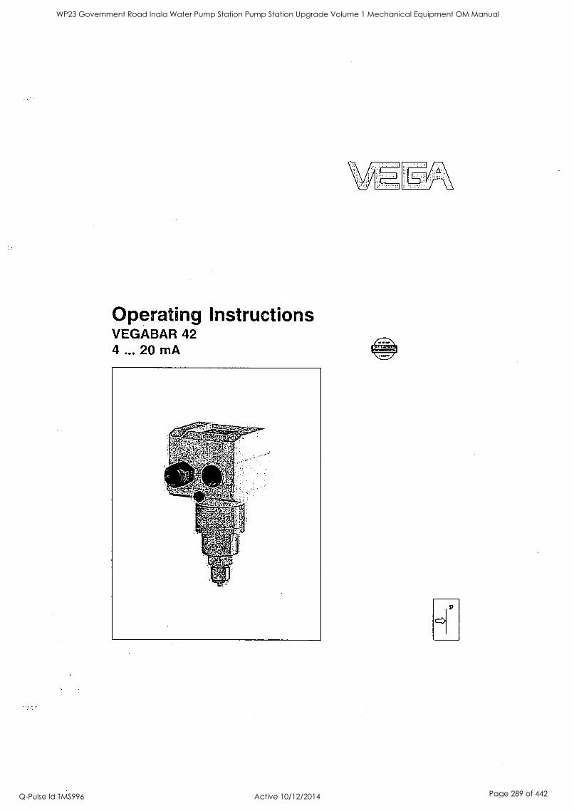
Operating Instructions VEGABAR 42 4 ... 20 mA
WP23 Government Road Inala Water Pump Station Pump Station Upgrade Volume 1 Mechanical Equipment OM Manual
Q-Pulse Id TMS996 Active 10/12/2014 Page 289 of 442
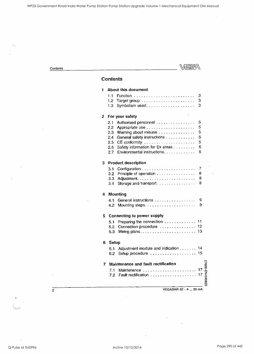
Contents
Contents
1 About this document 1.1 Function 3
1.2 Target group 3
1.3 Symbolism used 3
2 For your safety
2.1 Authorised personnel 5
2.2 Appropriate use 5
2.3 Warning about misuse 5
2.4 General safety instructions 5
2.5 CE conformity 5
2.6 Safety information for Ex areas 6
2.7 Environmental instructions 6
3 Product description 3.1 Configuration 7
3.2 Principle of operation 8
3.3 Adjustment 8
3.4 Storage and transport 8
4 Mounting 4.1 General instructions 9
4.2 Mounting steps 9
5 Connecting to power supply
5.1 Preparing the connection 11
5.2 Connection procedure 12
5.3 Wiring plans 13
6 Setup
6.1 Adjustment module and indication 14
6.2 Setup procedure 15
7 Maintenance and fault rectification 03
7.1 Maintenance 17 CI'
7.2 Fault rectification 17z
2 VEGABAR 42 - 4 ... 20 mA
WP23 Government Road Inala Water Pump Station Pump Station Upgrade Volume 1 Mechanical Equipment OM Manual
Q-Pulse Id TMS996 Active 10/12/2014 Page 290 of 442
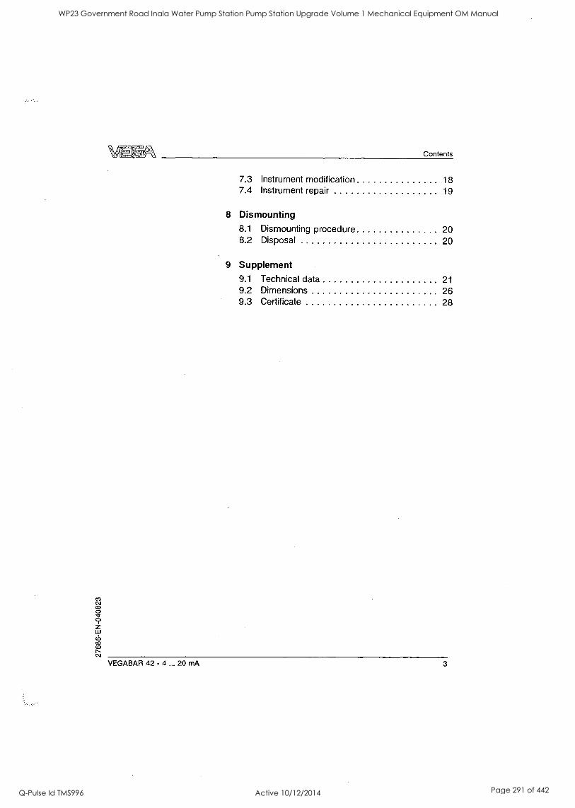
Contents
7.3 Instrument modification 18 7.4 Instrument repair 19
8 Dismounting 8.1 Dismounting procedure 20 8.2 Disposal 20
9 Supplement 9.1 Technical data 21 9.2 Dimensions 26 9.3 Certificate 28
VEGABAR 42 - 4 ... 20 mA 3
WP23 Government Road Inala Water Pump Station Pump Station Upgrade Volume 1 Mechanical Equipment OM Manual
Q-Pulse Id TMS996 Active 10/12/2014 Page 291 of 442
About this document
1
A
1 About this document
1.1 Function
This operating instructions manual has all the informa- tion you need for quick setup and safe operation of VEGABAR 42. Please read this manual before you start setup.
1.2 Target group
This operating instructions manual is directed to trained personnel. The contents of this manual should be made available to these personnel and put into practice by them.
1.3 Symbolism used
Information, tip, note This symbol indicates helpful additional information.
Caution, warning, danger This symbol informs you of a dangerous situation that could occur. Ignoring this cautionary note can impair the person and/or the instrument.
Ex applications This symbol indicates special instructions for Ex ap- plications.
List The dot set in front indicates a list with no implied sequence.
--> Action This arrow indicates a single action.
4 VEGABAR 42 - 4 ... 20 mA
WP23 Government Road Inala Water Pump Station Pump Station Upgrade Volume 1 Mechanical Equipment OM Manual
Q-Pulse Id TMS996 Active 10/12/2014 Page 292 of 442
About this document
1 Sequence Numbers set in front indicate successive steps in a procedure.
VEGABAR 42 - 4 ... 20 mA 5
WP23 Government Road Inala Water Pump Station Pump Station Upgrade Volume 1 Mechanical Equipment OM Manual
Q-Pulse Id TMS996 Active 10/12/2014 Page 293 of 442
For your safety
2 For your safety
2.1 Authorised personnel
All operations described in this operating instructions manual must be carried out only by trained and authorised specialist personnel. For safety and warranty reasons, any internal work on the instruments must be carried out only by VEGA personnel.
2.2 Appropriate use
VEGABAR 42 is a pressure transmitter for measurement of gauge pressure, absolute pressure and vacuum.
2.3 Warning about misuse
Inappropriate or incorrect use of the instrument can give rise to application-specific hazards, e.g. vessel overfill or damage to system components through incorrect mounting or adjustment.
2.4 General safety instructions
VEGABAR 42 is a high-tech instrument requiring the strict observance of standard regulations and guideli- nes. The user must take note of the safety instructions in
this operating instructions manual, the country-specific installation standards (e.g. the VDE regulations in
Germany) as well as all prevailing safety regulations and accident prevention rules.
2.5 CE conformity
VEGABAR 42 is in CE conformity with EMC (89/336/ EWG), fulfils the Namur recommendation NE 21 and is in CE conformity with NSR (73/23/EWG).
Conformity has been judged acc. to the following standards:
6 VEGABAR 42 - 4 ... 20 mA
WP23 Government Road Inala Water Pump Station Pump Station Upgrade Volume 1 Mechanical Equipment OM Manual
Q-Pulse Id TMS996 Active 10/12/2014 Page 294 of 442

For your safety
EMC: - Emission EN 61326: 1997 (class B) - Susceptibility EN 61326: 1997/A1: 1998
NSR: EN 61010-1: 2001.
In addition, VEGABAR 42 is subject to the pressure device guideline (97/23/EG) without CE marking.
The max. permissible pressure is 200 bar.
2.6 Safety information for Ex areas
Please note the Ex-specific safety information for installation and operation in Ex areas. These safety instructions are part of the operating instructions manual and come with the Ex-approved instruments.
2.7 Environmental instructions
Protection of the environment is one of our most important duties. That is why we have introduced an environment management system with the goal of continuously improving company environmental protec- tion. The environment management system is certified acc. to DIN EN ISO 14001.
Please help us fulfil this obligation by observing the environmental instructions in this manual:
Chapter "Storage and transport" Chapter "Disposal"
VEGABAR 42 - 4 ... 20 mA 7
WP23 Government Road Inala Water Pump Station Pump Station Upgrade Volume 1 Mechanical Equipment OM Manual
Q-Pulse Id TMS996 Active 10/12/2014 Page 295 of 442
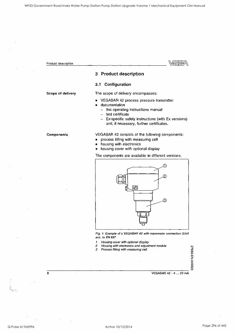
Product description
Scope of delivery
Components
3 Product description
3.1 Configuration
The scope of delivery encompasses:
VEGABAR 42 process pressure transmitter documentation - this operating instructions manual - test certificate - Ex-specific safety instructions (with Ex versions)
and, if necessary, further certificates.
VEGABAR 42 consists of the following components: process fitting with measuring cell housing with electronics housing cover with optional display
The components are available in different versions.
Fig. 1: Example of a VEGABAR 42 with manometer connection GY2A
acc. to EN 837
1 Housing cover with optional display 2 Housing with electronics and adjustment module 3 Process fitting with measuring cell
8 VEGABAR 42 - 4 ... 20 mA
WP23 Government Road Inala Water Pump Station Pump Station Upgrade Volume 1 Mechanical Equipment OM Manual
Q-Pulse Id TMS996 Active 10/12/2014 Page 296 of 442
Product description
Area of application
Physical principle
3.2 Principle of operation
VEGABAR 42 is a pressure transmitter for measurement of gauge pressure, absolute pressure or vacuum. Measured products are gases, vapours and liquids.
Sensor element is the CERTEC measuring cell with rugged ceramic diaphragm. The process pressure causes a capacitance change in the measuring cell via the ceramic diaphragm. This change is converted into an appropriate output signal and outputted as measured value.
Power supply Two-wire electronics 4 ... 20 mA/HART for power supply and measured value transmission on the same cable.
Packaging
Storage and transport temperature
The power supply range can differ depending on the instrument version. The exact range is stated in the Technical data in the Supplement.
3.3 Adjustment
VEGABAR 42 4 ... 20 mA can be adjusted with the following adjustment media:
integrated adjustment.
3.4 Storage and transport
Your instrument was protected by packaging during transport. Its capacity to handle normal loads during transport is assured by a test acc. to EN 24180.
The packaging of standard instruments consists of environment-friendly, recyclable cardboard. For special versions PE foam or PE foil is also used. Dispose of the packaging material via specialised recycling companies.
Storage and transport temperature see Supplement, Technical data, Ambient conditions Relative humidity 20 ... 85 %
VEGABAR 42 - 4 ... 20 mA 9
WP23 Government Road Inala Water Pump Station Pump Station Upgrade Volume 1 Mechanical Equipment OM Manual
Q-Pulse Id TMS996 Active 10/12/2014 Page 297 of 442

Mounting
Installation position
Moisture
Welding the socket
4 Mounting
4.1 General instructions
VEGABAR 42 functions in any installation position It is
mounted acc. to the same regulations like a manometer (DIN EN 839-2). The housing can be rotated by 330° without the use of any tools.
Information: We recommend using lock fittings or siphons from the line of VEGA accessories.
Use the recommended cable (see chapter "Connecting to power supply ") and tighten the cable entry.
You can give your VEGABAR 42 additional protection against moisture penetration by leading the connection cable downward in front of the cable entry. Rain and condensation water can thus drain off. This applies mainly to mounting outdoors, in areas where moisture is
expected (e.g. by cleaning processes) or on cooled or heated vessels.
Fig. 2: Measures against moisture penetration
4.2 Mounting steps N3
To mount VEGABAR 42, a welded socket is necessary. in Use components of the VEGA accessory program:
O 03
10 VEGABAR 42 - 4 ... 20 mA
WP23 Government Road Inala Water Pump Station Pump Station Upgrade Volume 1 Mechanical Equipment OM Manual
Q-Pulse Id TMS996 Active 10/12/2014 Page 298 of 442
Mounting
Welded socket G1/2A, article no. 2.7783 Manometer welding tube G1/2A, article no. 2.24462 or 2.19990.
Note the applicable welding standards (segment welding procedure) when welding the socket.
Sealing/Screwing in Use the appropriate seal:
Process fitting GV: Tesnit 6.2x17.5x1, article no. 2.14815, seal on the nipple Process fitting GP: Klingersil 21x30x2, article no. 2.5056, seal on the hexagon
- or - Seal the thread with teflon, hemp or a similar resistant seal material:
Process fitting GN
---> Screw VEGABAR 42 into the welded socket. Tighten the hexagon screw on the process fitting with SW 27 (spanner width 27 mm).
VEGABAR 42 - 4 ... 20 mA 11
WP23 Government Road Inala Water Pump Station Pump Station Upgrade Volume 1 Mechanical Equipment OM Manual
Q-Pulse Id TMS996 Active 10/12/2014 Page 299 of 442
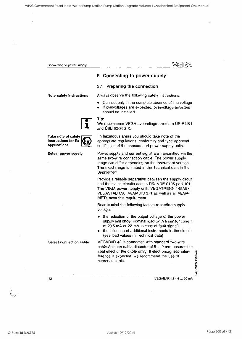
Connecting to power supply VLF
5 Connecting to power supply
5.1 Preparing the connection
Note safety instructions Always observe the following safety instructions:
Connect only in the complete absence of line voltage If overvoltages are expected, overvoltage arresters should be installed.
Take note of safety instructions for Ex applications
1
Select power supply
Select connection cable
Tip: We recommend VEGA overvoltage arresters OS-F-LB-1 and USB 62-36G.X.
In hazardous areas you should take note of the appropriate regulations, conformity and type approval certificates of the sensors and power supply units.
Power supply and current signal are transmitted via the same two-wire connection cable. The power supply range can differ depending on the instrument version. The exact range is stated in the Technical data in the Supplement.
Provide a reliable separation between the supply circuit and the mains circuits acc. to DIN VDE 0106 part 101. The VEGA power supply units VEGATRENN 149AEx, VEGASTAB 690, VEGADIS 371 as well as all VEGA- METs meet this requirement.
Bear in mind the following factors regarding supply voltage:
the reduction of the output voltage of the power supply unit under nominal load (with a sensor current of 20.5 mA or 22 mA in case of fault signal) the influence of additional instruments in the circuit (see load values in Technical data)
VEGABAR 42 is connected with standard two-wire cable.An outer cable diameter of 5 ... 9 mm ensures the seal effect of the cable entry. If electromagnetic inter- ference is expected, we recommend the use of screened cable.
12 VEGABAR 42 - 4 ... 20 mA
WP23 Government Road Inala Water Pump Station Pump Station Upgrade Volume 1 Mechanical Equipment OM Manual
Q-Pulse Id TMS996 Active 10/12/2014 Page 300 of 442
Connecting to power supply
Cable screening and grounding
Select connection cable for Ex appli- cations
Connect the cable screen on both ends to ground potential. In the sensor, the screen must be connected directly to the internal ground terminal. The ground terminal outside on the housing must be connected to the potential equalisation (low impedance).
If potential equalisation currents are expected, the connection on the evaluation side must be made via a ceramic capacitor (e.g. 1 nF, 1500 V). The low frequency potential equalisation currents are thus sup- pressed, but the protective effect against high frequency interference signals remains.
Take note of the corresponding installation regulations for Ex applications. In particular, make sure that no potential equalisation current flow over the cable screen. In case of grounding on both sides this can be achieved by the use of a capacitor or a separate potential equalisation.
5.2 Connection procedure
Proceed as follows:
1 Unscrew the housing cover
2 Loosen compression nut of the cable entry
3 Remove approx. 10 cm of the cable mantle, strip approx. 1 cm insulation
4 Insert the cable into the sensor through the cable entry
5 Loosen the screws of the terminals
6 Insert the wire ends into the open terminals according to the wiring plan
7 Tighten the screws of the terminals
8 Check the hold of the wires in the terminals by lightly pulling on them
9 Tighten the compression nut of the cable entry, the seal ring must completely encircle the cable
VEGABAR 42 - 4 ... 20 mA 13
WP23 Government Road Inala Water Pump Station Pump Station Upgrade Volume 1 Mechanical Equipment OM Manual
Q-Pulse Id TMS996 Active 10/12/2014 Page 301 of 442
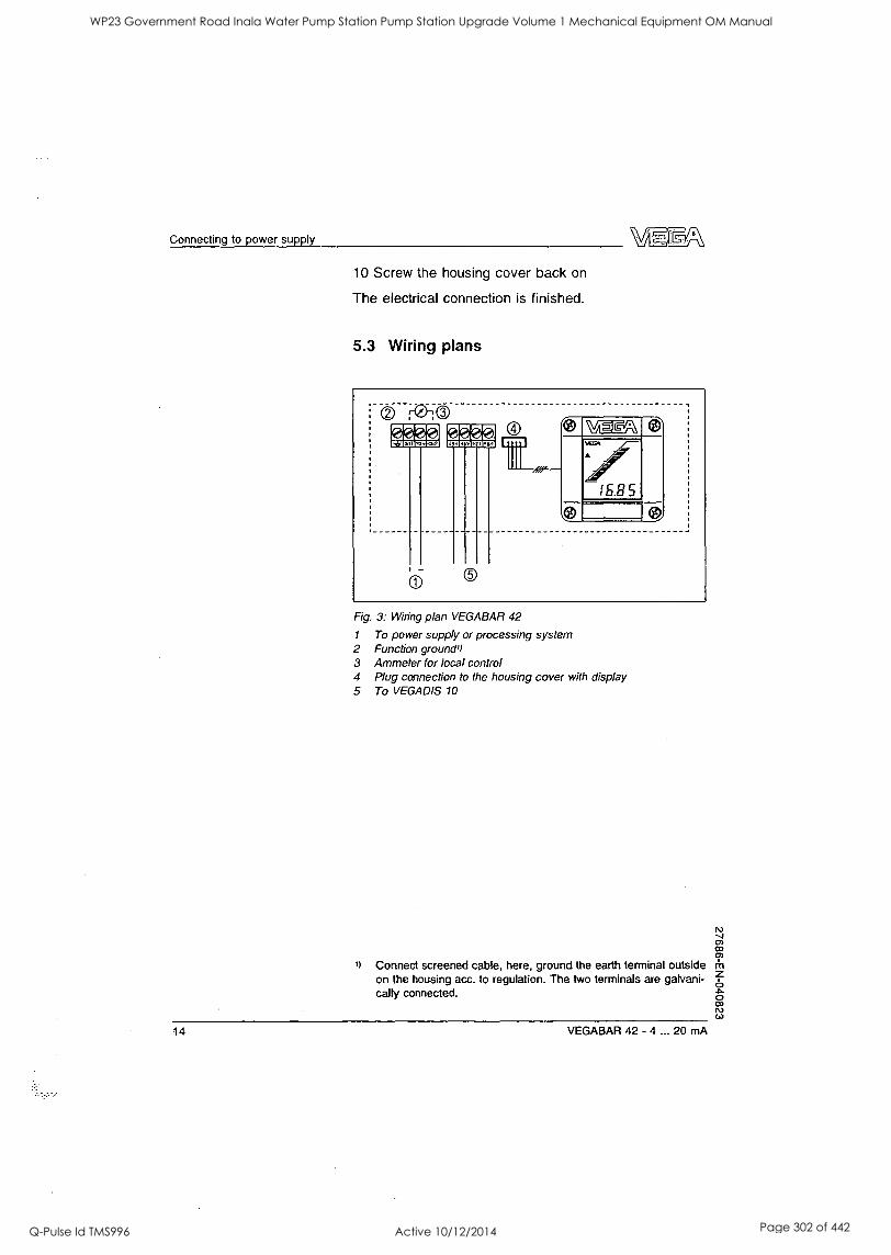
Connecting to power supply
10 Screw the housing cover back on
The electrical connection is finished.
5.3 Wiring plans
Fig. 3: Wiring plan VEGABAR 42
1 To power supply or processing system 2 Function grounds) 3 Ammeter for local control 4 Plug connection to the housing cover with display 5 To VEGADIS 10
1) Connect screened cable, here, ground the earth terminal outside on the housing acc. to regulation. The two terminals are galvani- cally connected.
14 VEGABAR 42 - 4 ... 20 mA
WP23 Government Road Inala Water Pump Station Pump Station Upgrade Volume 1 Mechanical Equipment OM Manual
Q-Pulse Id TMS996 Active 10/12/2014 Page 302 of 442
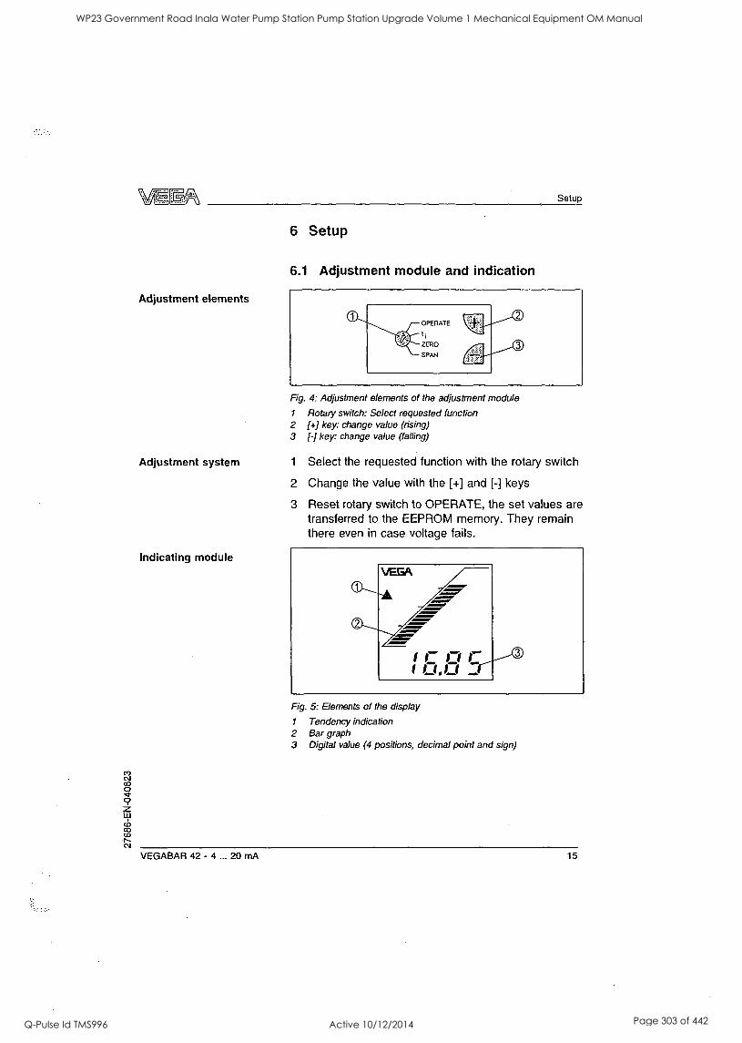
Setup
Adjustment elements
Adjustment system
Indicating module
6 Setup
6.1 Adjustment module and indication
Fig. 4: Adjustment elements of the adjustment module
1 Rotary switch: Select requested function 2 [+] key: change value (rising) 3 1-] key: change value (falling)
1 Select the requested function with the rotary switch
2 Change the value with the [+] and [-] keys
3 Reset rotary switch to OPERATE, the set values are transferred to the EEPROM memory. They remain there even in case voltage fails.
Fig. 5: Elements of the display
1 Tendency indication 2 Bar graph 3 Digital value (4 positions, decimal point and sign)
VEGABAR 42 - 4 ... 20 mA 15
WP23 Government Road Inala Water Pump Station Pump Station Upgrade Volume 1 Mechanical Equipment OM Manual
Q-Pulse Id TMS996 Active 10/12/2014 Page 303 of 442
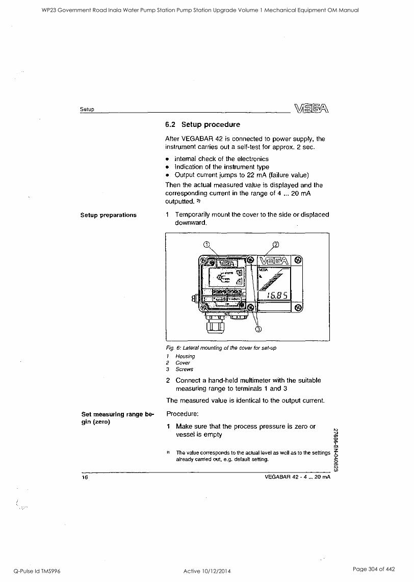
Setup
Setup preparations
6.2 Setup procedure
After VEGABAR 42 is connected to power supply, the instrument carries out a self-test for approx. 2 sec.
o internal check of the electronics Indication of the instrument type Output current jumps to 22 mA (failure value)
Then the actual measured value is displayed and the corresponding current in the range of 4 ... 20 mA outputted. 2)
1 Temporarily mount the cover to the side or displaced downward.
Fig. 6: Lateral mounting of the cover for set-up
l Housing 2 Cover 3 Screws
2 Connect a hand-held multimeter with the suitable measuring range to terminals 1 and 3
The measured value is identical to the output current.
Set measuring range be- Procedure: gin (zero)
1 Make sure that the process pressure is zero or vessel is empty
rV J 02
Ti 2) The value corresponds to the actual level as well as to the settings f,
already carried out, e.g. default setting. o .p,
0) IV CO
16 VEGABAR 42 - 4 ... 20 mA
WP23 Government Road Inala Water Pump Station Pump Station Upgrade Volume 1 Mechanical Equipment OM Manual
Q-Pulse Id TMS996 Active 10/12/2014 Page 304 of 442
Setup
2 Set the rotary switch to "zero"
3 Push the [+] and [-] keys simultaneously3)
The current jumps to 4 mA, the "zero" setting is finished.
Adjustment of measuring Procedure: range end (span)
1
1 Make sure that the process pressure is at maximum or vessel is full
2 Set rotary switch to "span"
3 Push the [+] and [-] keys simultaneously4)
The current jumps to 20 mA, the "span" setting is finished.
Information: A modification of "zero" also shifts the "span". The measuring span remains unchanged.
Adjustment of the integra- Procedure: tion time (ti)
1 Set rotary switch to "ti"
2 10 timess) Push the [-] key
3 For every 1 sec integration time require& Push the [+] key once
3)
4)
5)
6)
As an alternative to pushing the keys simultaneously, it is also possible to adjust the current by pressing the [+] and [-] keys individually. Adjustment ranges: zero = -20 ... +95 % of the no- minal range; span = 3,3 ... +120 % of the nominal range.Push As an alternative to pushing the keys simultaneously, it is also possible to adjust the current by pressing the [+] and [-] keys individually. Adjustment ranges: zero = -20 ... +95 % of the no- minal range; span = 3,3 ... +120 % of the nominal range.Push This ensures ti = 0 sec. In this interval, the output current reaches 63 % of the height in
case of a jump of the process pressure, adjustment range 0 to 10 sec.
VEGABAR 42 - 4 ... 20 mA 17
WP23 Government Road Inala Water Pump Station Pump Station Upgrade Volume 1 Mechanical Equipment OM Manual
Q-Pulse Id TMS996 Active 10/12/2014 Page 305 of 442
Maintenance and fault rectification
Failure reasons
Fault rectification
7 Maintenance and fault rectification
7.1 Maintenance
When used as directed in normal operation, VEGABAR 42 is completely maintenance-free.
7.2 Fault rectification
VEGABAR 42 offers maximium reliability. Nevertheless, it is possible that failures occur during operation. These can have the following reasons, e.g.:
Sensor Process Power supply Signal processing.
The first measure is checking the output signal. In many cases, the reasons can be determined in this way and faults can be rectified.
24 hour service hotline Should these measures not be successful, please call in
urgent matters the VEGA service hotline under the phone number +49 1805 858550.
The hotline is available to you on 7 days a week round- the-clock. Since we offer this service world-wide, the support is only available in the English language. The service is free of charge, only the standard telephone costs will be charged.
Checking the 4 ... 20 mA Connect a hand-held multimeter with a suitable measu- signal ring range ace. to the wiring plan.
? 4 ... 20 mA signal is not stable
Pressure fluctuations
-) Set integration time via the adjustment insert
no atmospheric pressure compensation
-4 check the pressure compensation in the housing and clean the filter element, if necessary
18 VEGABAR 42 - 4 ... 20 mA
WP23 Government Road Inala Water Pump Station Pump Station Upgrade Volume 1 Mechanical Equipment OM Manual
Q-Pulse Id TMS996 Active 10/12/2014 Page 306 of 442
Maintenance and fault rectification
Insert/remove display
1
? 4 ... 20 mA signal missing
incorrect connection to power supply
4 check connection acc. to chapter "Connection procedure" and correct, if necessary, abc. to chapter "Wiring plans"
no power supply
4 check cables for line break, repair, if necessary
power supply too low or load resistance too high
4 check and adapt, if necessary
? Current signal greater than 22 mA or less than 3.6 mA
electronics module or measuring cell defective
--> exchange instrument or return it for repair
In Ex applications, the regulations for the wiring of intrinsically safe circuits must be observed.
7.3 instrument modification
The display (special cover) can be inserted or removed VEGABAR 42 at any time. An interruption of the power supply is not necessary.
Procedure:
1 Loosen the screws of the housing cover, remove the cover
2 Connect plug connector of the display to VEGABAR 42
3 Place the adjustment module in the requested position on the housing
Note: For positions displaced by 90° are selectable.
4 Fasten the screws of the housing cover
VEGABAR 42 - 4 ... 20 mA 19
WP23 Government Road Inala Water Pump Station Pump Station Upgrade Volume 1 Mechanical Equipment OM Manual
Q-Pulse Id TMS996 Active 10/12/2014 Page 307 of 442
Maintenance and fault rectification
Removal is carried out in reverse order.
7.4 Instrument repair
If it is necessary to repair VEGABAR 42 please proceed as follows:
You can download a return form (23 KB) from our Internet homepage www.vega.com under "Services >
Downloads > Forms and Certificates > Repair form.
By doing this you help us carry out the repair quickly and without having to call for additional information.
Print and fill out one form per instrument Clean the instrument and pack it damage-proof Attach the completed form and possibly also a safety data sheet to the instrument Send the instrument to the respective address of your agency. In Germany to the VEGA headquarters in Schiltach.
20 VEGABAR 42 - 4 ... 20 mA
WP23 Government Road Inala Water Pump Station Pump Station Upgrade Volume 1 Mechanical Equipment OM Manual
Q-Pulse Id TMS996 Active 10/12/2014 Page 308 of 442
Dismounting
8 Dismounting
8.1 Dismounting procedure
Take note of chapters "Mounting" and "Connecting to power supply" and carry out the listed steps in reverse order.
8.2 Disposal
VEGABAR 42 consists of materials which can be recycled by specialised recycling companies. We have purposely designed the electronic modules to be easily separable. Mark the instrument as scrap and dispose of it according to government regulations (electronic scrap ordinance, ...)
Materials: see Technical data
If you cannot dispose of the instrument properly, please contact us about disposal methods or return.
VEGABAR 42 - 4 ... 20 mA 21
WP23 Government Road Inala Water Pump Station Pump Station Upgrade Volume 1 Mechanical Equipment OM Manual
Q-Pulse Id TMS996 Active 10/12/2014 Page 309 of 442
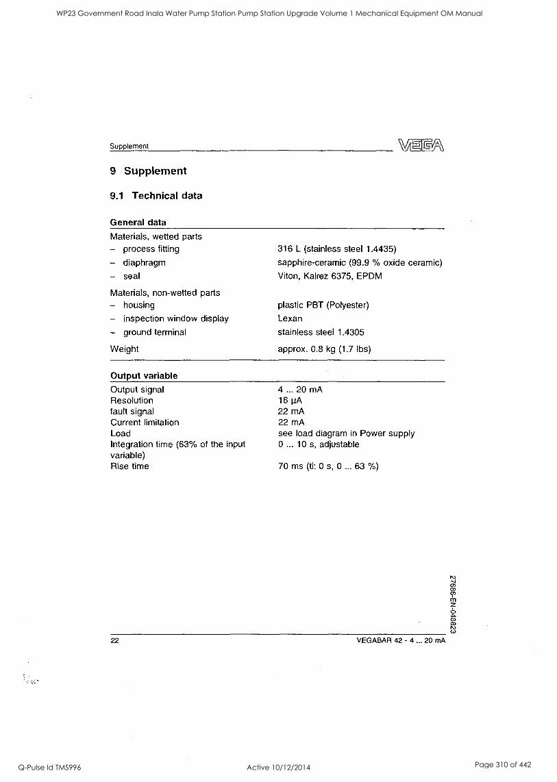
Supplement
9 Supplement
9.1 Technical data
General data
Materials, wetted parts - process fitting
- diaphragm
- seal
Materials, non-wetted parts
- housing
- inspection window display
- ground terminal
Weight
316 L (stainless steel 1.4435)
sapphire-ceramic (99.9 % oxide ceramic)
Viton, Kalrez 6375, EPDM
plastic PBT (Polyester)
Lexan
stainless steel 1.4305
approx. 0.8 kg (1.7 lbs)
Output variable Output signal Resolution fault signal Current limitation Load Integration time (63% of the input variable) Rise time
4 ... 20 mA 16 jiA 22 mA 22 mA see load diagram in Power supply 0 ... 10 s, adjustable
70 ms (ti: 0 s, 0 ... 63 %)
22 VEGABAR 42 - 4 ... 20 mA
WP23 Government Road Inala Water Pump Station Pump Station Upgrade Volume 1 Mechanical Equipment OM Manual
Q-Pulse Id TMS996 Active 10/12/2014 Page 310 of 442
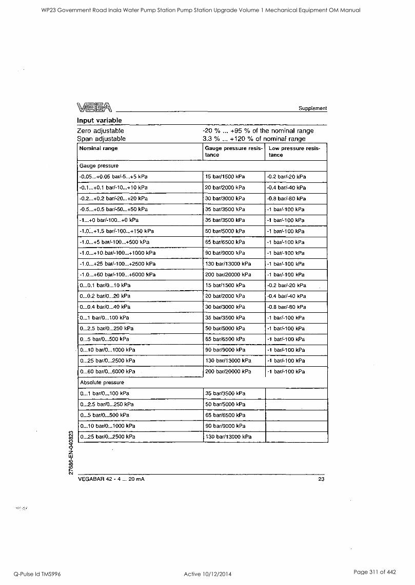
Supplement
Input variable Zero adjustable Span adjustable
-20 % ... +95 % of the nominal range 3.3 % ... +120 % of nominal range
Nominal range Gauge pressure resis- tance
Low pressure resis- tance
Gauge pressure
-0.05...+0.05 bar/-5...+5 kPa 15 bar/1500 kPa -0.2 bar/-20 kPa
-0.1...+0.1 bar/-10...+10 kPa 20 bar/2000 kPa -0.4 bar/-40 kPa
-0.2...+0.2 bar/-20...+20 kPa 30 bar/3000 kPa -0.8 bar/-80 kPa
-0.5...+0.5 bar/-50...+50 kPa 35 bar/3500 kPa -1 bar/-100 kPa
-1...+0 bar/-100...+0 kPa 35 bar/3500 kPa -1 bar/-100 kPa
-1.0...+1.5 bar/-100...+150 kPa 50 bar/5000 kPa -1 bar/-100 kPa
-1.0...+5 bar/-100...+500 kPa 65 bar/6500 kPa -1 bar/-100 kPa
-1.0...+10 bar/-100...+1000 kPa 90 bar/9000 kPa -1 bar/-100 kPa
-1.0...+25 bar/-100...+2500 kPa 130 bar/13000 kPa -1 bar/-100 kPa
-1.0...+60 bar/-100...+6000 kPa 200 bar/20000 kPa -1 bar/-100 kPa
0...0.1 bar/0...10 kPa 15 bar/1500 kPa -0.2 bar/-20 kPa
0...0.2 bar/0...20 kPa 20 bar/2000 kPa -0.4 bar/-40 kPa
0...0.4 bar/0...40 kPa 30 bar/3000 kPa -0.8 bar/-80 kPa
0...1 bar/0...100 kPa 35 bar/3500 kPa -1 bar/-100 kPa
0...2.5 bar/0...250 kPa 50 bar/5000 kPa -1 bar/-100 kPa
0...5 bar/0...500 kPa 65 bar/6500 kPa -1 bar/-100 kPa
0...10 bar/0...1000 kPa 90 bar/9000 kPa -1 bar/-100 kPa
0...25 bar/0...2500 kPa 130 bar/13000 kPa -1 bar/-100 kPa
0...60 bar/0...6000 kPa 200 bar/20000 kPa -1 bar/ -100 kPa
Absolute pressure
0...1 bar/0...100 kPa 35 bar/3500 kPa
0...2.5 bar/0...250 kPa 50 bar/5000 kPa
0...5 bar/0...500 kPa 65 bar/6500 kPa
0...10 bar/0...1000 kPa 90 bar/9000 kPa
0...25 bar/0...2500 kPa 130 bar/13000 kPa
VEGABAR 42 - 4 ... 20 mA 23
WP23 Government Road Inala Water Pump Station Pump Station Upgrade Volume 1 Mechanical Equipment OM Manual
Q-Pulse Id TMS996 Active 10/12/2014 Page 311 of 442
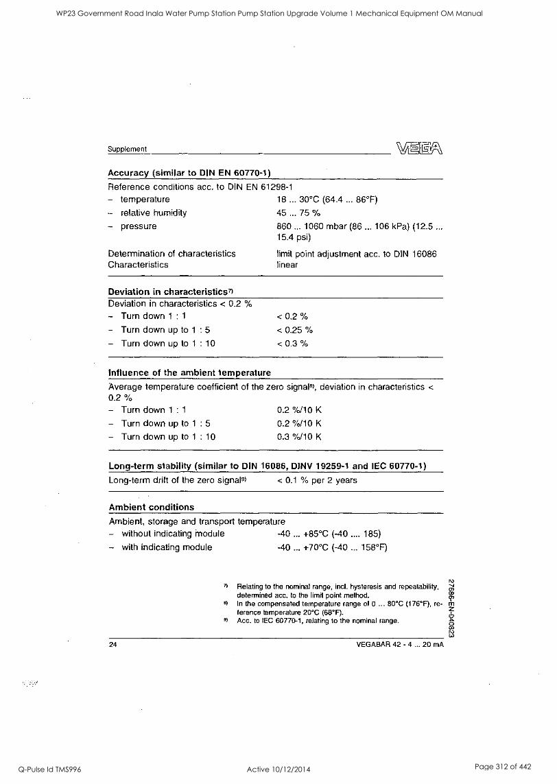
Supplement
Accuracy (similar to DIN EN 60770-1)
Reference conditions acc. to DIN EN 61298-1
- temperature 18 ... 30°C (64.4 ... 86°F)
- relative humidity 45 ... 75 %
- pressure
Determination of characteristics Characteristics
860 ... 1060 mbar (86 ... 106 kPa) (12.5 ...
15.4 psi)
limit point adjustment acc. to DIN 16086 linear
Deviation in characteristicsn Deviation in characteristics < 0.2 %
- Turn down 1 : 1
- Turn down up to 1 : 5
- Turn down up to 1 : 10
< 0.2 %
< 0.25 %
< 0.3 %
Influence of the ambient temperature
Average temperature coefficient of the zero signal8), deviation in characteristics <
0.2 %
- Turn down 1 : 1 0.2 %/10 K
- Turn down up to 1 : 5 0.2 %/10 K
- Turn down up to 1 : 10 0.3 %/10 K
Long-term stability (similar to DIN 16086, DINV 19259-1 and IEC 60770-1)
Long-term drift of the zero signals) < 0.1 % per 2 years
Ambient conditions Ambient, storage and transport temperature - without indicating module -40 ... +85°C (-40 .... 185)
- with indicating module -40 ... +70°C (-40 ... 158°F)
8)
9)
Relating to the nominal range, incl. hysteresis and repeatability, determined acc. to the limit point method. In the compensated temperature range of 0 ... 80°C (176°F), re- ference temperature 20°C (68°F). Acc. to IEC 60770-1, relating to the nominal range.
24 VEGABAR 42 - 4 ... 20 mA
WP23 Government Road Inala Water Pump Station Pump Station Upgrade Volume 1 Mechanical Equipment OM Manual
Q-Pulse Id TMS996 Active 10/12/2014 Page 312 of 442
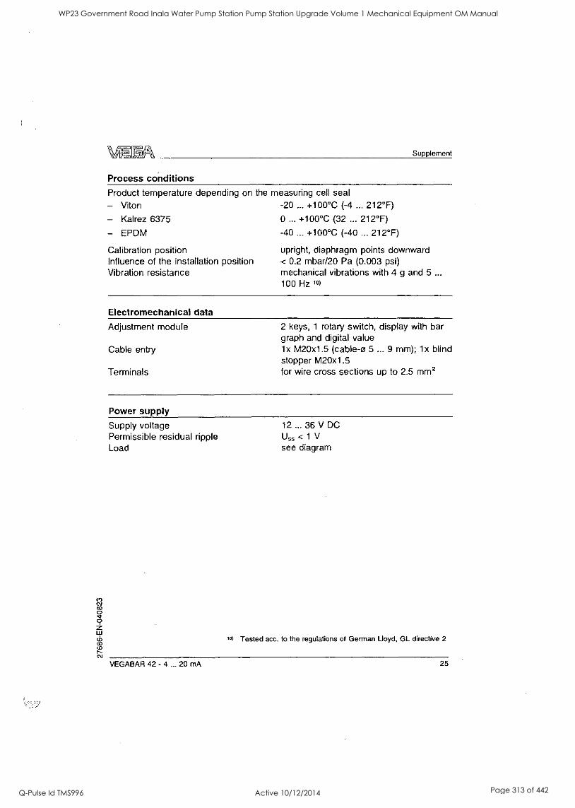
Supplement
Process conditions Product temperature depending on the measuring cell seal
- Viton -20 ... +100°C (-4 ... 212°F)
- Kalrez 6375 0 ... +100°C (32 ... 212°F)
- EPDM -40 ... +100°C (-40 ... 212°F)
Calibration position upright, diaphragm points downward Influence of the installation position < 0.2 mbar/20 Pa (0.003 psi) Vibration resistance mechanical vibrations with 4 g and 5 ...
100 Hz 10)
Electromechanical data
Adjustment module 2 keys, 1 rotary switch, display with bar graph and digital value
Cable entry lx M20x1.5 (cable-o 5 ... 9 mm); lx blind stopper M20x1.5
Terminals for wire cross sections up to 2.5 mm2
Power supply Supply voltage 12 ... 36 V DC Permissible residual ripple Uss < 1 V Load see diagram
10) Tested acc. to the regulations of German Lloyd, GL directive 2
VEGABAR 42 - 4 ... 20 mA 25
WP23 Government Road Inala Water Pump Station Pump Station Upgrade Volume 1 Mechanical Equipment OM Manual
Q-Pulse Id TMS996 Active 10/12/2014 Page 313 of 442
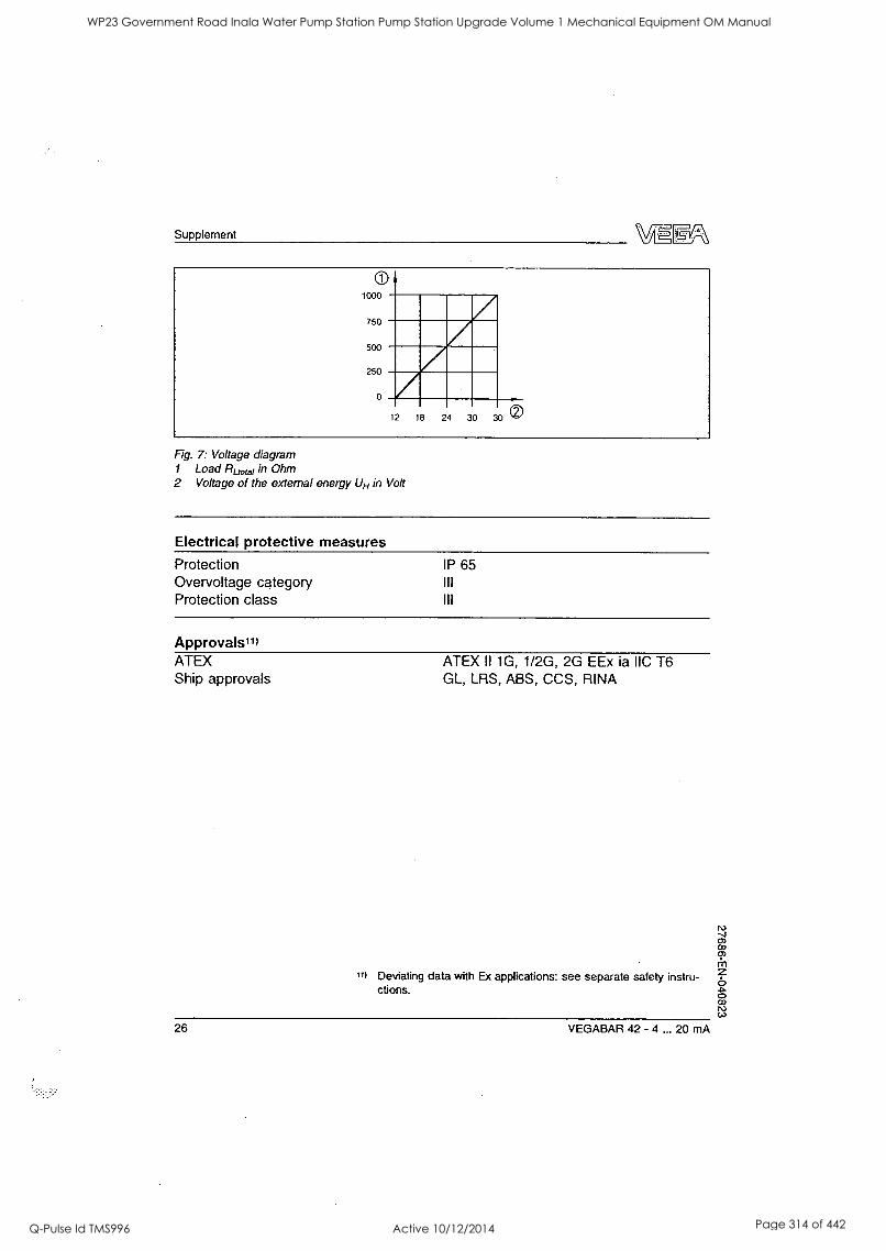
Supplement
1000
750
500
250
0
12 18 24 30 30
Fig. 7: Voltage diagram 1 Load Riot., in Ohm 2 Voltage of the external energy UH in Volt
Electrical protective measures
Protection IP 65 Overvoltage category Ill Protection class III
Approvals11) ATEX Ship approvals
11)
ATEX II 1G, 1/2G, 2G EEx is IIC T6 GL, LRS, ABS, CCS, RINA
Deviating data with Ex applications: see separate safety instru- ctions.
26 VEGABAR 42 - 4 ... 20 mA
WP23 Government Road Inala Water Pump Station Pump Station Upgrade Volume 1 Mechanical Equipment OM Manual
Q-Pulse Id TMS996 Active 10/12/2014 Page 314 of 442
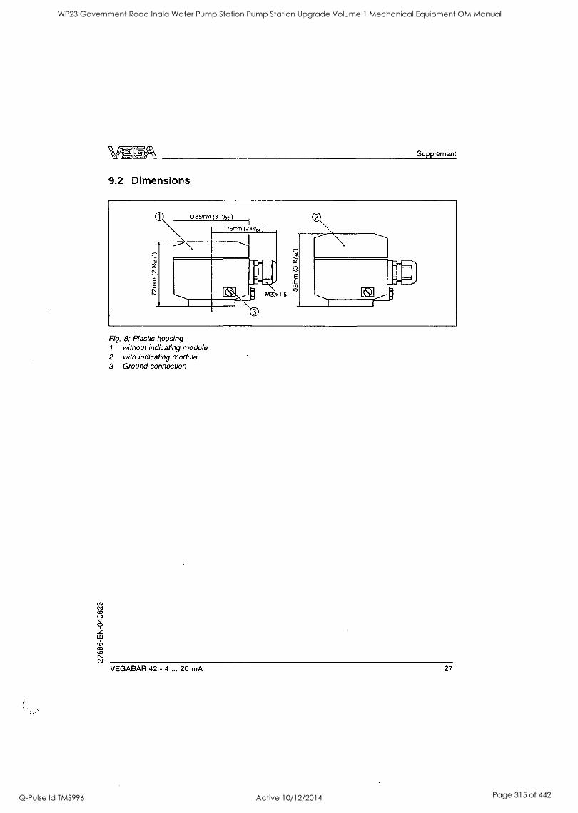
Supplement
9.2 Dimensions
Fig. 8: Plastic housing 1 without indicating module 2 with indicating module 3 Ground connection
VEGABAR 42 - 4 ... 20 mA 27
WP23 Government Road Inala Water Pump Station Pump Station Upgrade Volume 1 Mechanical Equipment OM Manual
Q-Pulse Id TMS996 Active 10/12/2014 Page 315 of 442
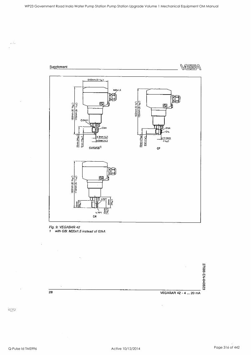
Supplement
Fig. 9: VEGABAR 42 1 with GB: M20x1.5 instead of GY2A
28 VEGABAR 42 - 4 ... 20 mA
WP23 Government Road Inala Water Pump Station Pump Station Upgrade Volume 1 Mechanical Equipment OM Manual
Q-Pulse Id TMS996 Active 10/12/2014 Page 316 of 442

WP23 Government Road Inala Water Pump Station Pump Station Upgrade Volume 1 Mechanical Equipment OM Manual
Q-Pulse Id TMS996 Active 10/12/2014 Page 317 of 442
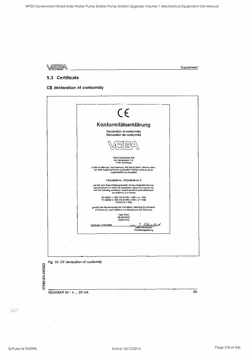
Supplement
9.3 Certificate
CE declaration of conformity
CE Konformitatserklarung
Declaration of conformity Declaration de contormite
I /-
VEGA Grieshaber KG Am Hohensteln 113
77761 Schtltach
erkleri in alleiniger Verantwortung, dab das Produle / dedare under our sole responsibility that our product / declare sous sa scule
responsabilite qua t9 produft
VEGABAR 4x, VEGABAR 4x H
auf das slch diese Erklaning beziele, mit den folgenden Norman Glpect:ristirnml / to which this declaration relates is in conformity with the following standards / auquol se More gene declaration
est conform° aux nouns
EN 50081 -1:1992: EN 61326-1:1997 / A1:1998 EN 50082-2:1995: EN 61326-1:1997 / A1:1998
EN 61010-1:1993
geM50 den Bestimmungen der RichtlInien / following the provision of Directives / conformement aux dispositions des Directives
73/23 EWG 89/336 EWG 93/68 EWG
Schitach, 13.03.2000 npa Jo68t Fehrenbach
Entwicklungsleitung
Fig. 10: CE declaration of conformity
VEGABAR 42 - 4 ... 20 mA 29
WP23 Government Road Inala Water Pump Station Pump Station Upgrade Volume 1 Mechanical Equipment OM Manual
Q-Pulse Id TMS996 Active 10/12/2014 Page 318 of 442
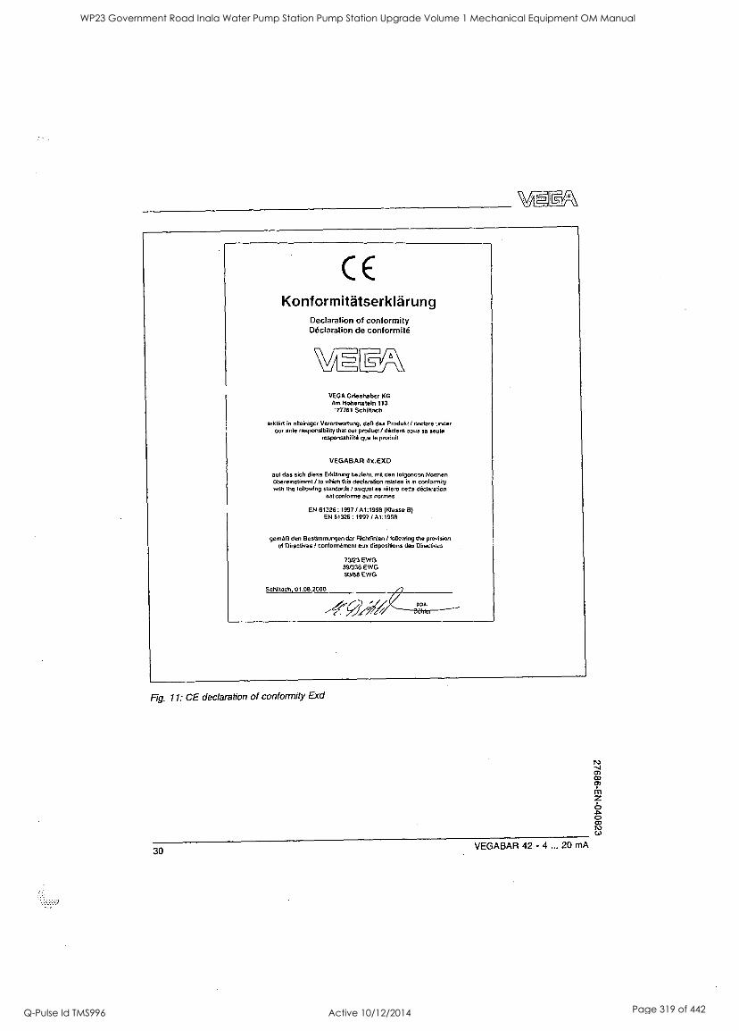
CE Konformitatserklarung
Declaration of conformity Declaration de conformity
WJE7611A\
VEGA Grieshaber KG Am Hohensteln 113
'77761 Schigach
orklart in alleinigcr Verantwortung, dal) dos Produkt I declare under our sole responsibility that our product / declare 3005 3a seule
resporisabitrto quo le produit
VEGABAR 4x.EXD
auf das rich diese ErklArung tezleht, mit den lolgendm Normen ObereInstimmt / to which this declaration relates is in conformity will, the following standards / august se triter° cello declaration
est CallOrIlle our norrnes
EN 61326: 1997 / A1:1998 (Klasse B) EN 61326: 1997 /A1:1998
gemA13 den Bestimmungen der RichiGnien / following the provision ol Directives f contonnement aux dispositions des Directives
73/23 EWG 89/336 EWG 93768 EWG
01.08.2000 /7
Fig. 11: CE declaration of conformity Exd
30 VEGABAR 42 - 4 ... 20 mA
WP23 Government Road Inala Water Pump Station Pump Station Upgrade Volume 1 Mechanical Equipment OM Manual
Q-Pulse Id TMS996 Active 10/12/2014 Page 319 of 442
27686-EN-040823
Ca
WP23 Government Road Inala Water Pump Station Pump Station Upgrade Volume 1 Mechanical Equipment OM Manual
Q-Pulse Id TMS996 Active 10/12/2014 Page 320 of 442
VEGA Grieshaber KG Am Hohenstein 113 77761 Schiltach Germany Phone +49 7836 50-0 Fax +49 7836 50-201 E-mail: [email protected] www.vega.com
ISO 9001
rAQ CIE II*
WP23 Government Road Inala Water Pump Station Pump Station Upgrade Volume 1 Mechanical Equipment OM Manual
Q-Pulse Id TMS996 Active 10/12/2014 Page 321 of 442
BRISBANE CITY COUNCIL Brisbane Water Government Road
Appendix I - 2.5T Crane
"Demag Chain Hoist DKUN 10"
8748C-Manual Draft B
BW.30098-02/03 Pump Station Upgrade
21 Dec. 05 9
WP23 Government Road Inala Water Pump Station Pump Station Upgrade Volume 1 Mechanical Equipment OM Manual
Q-Pulse Id TMS996 Active 10/12/2014 Page 322 of 442

9
I
8
e
s
WP23 Government Road Inala Water Pump Station Pump Station Upgrade Volume 1 Mechanical Equipment OM Manual
Q-Pulse Id TMS996 Active 10/12/2014 Page 323 of 442
S
WP23 Government Road Inala Water Pump Station Pump Station Upgrade Volume 1 Mechanical Equipment OM Manual
Q-Pulse Id TMS996 Active 10/12/2014 Page 324 of 442
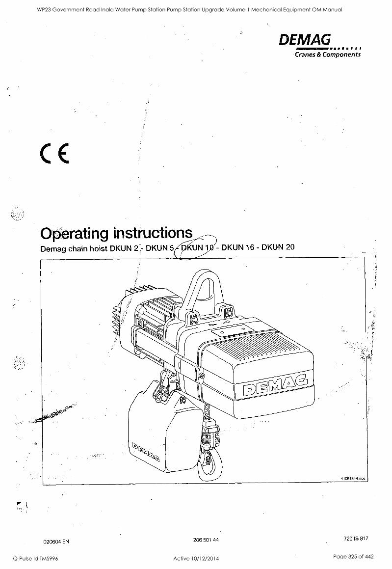
DEMAG
E
()Orating instructions Demag chain hoist DKUN 2 DKUN DKUN 16- DKUN 20
Cranes & Components
WP23 Government Road Inala Water Pump Station Pump Station Upgrade Volume 1 Mechanical Equipment OM Manual
Q-Pulse Id TMS996 Active 10/12/2014 Page 325 of 442
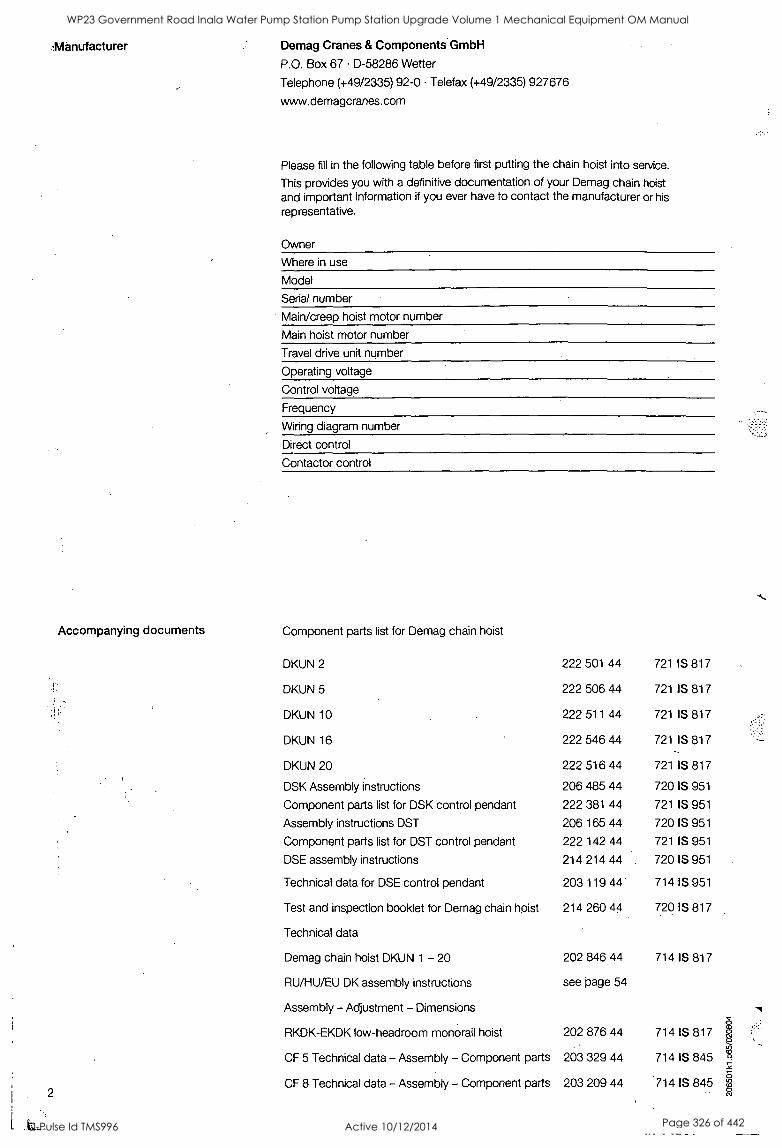
-Manufacturer Demag Cranes & Components GmbH
P.O. Box 67 D-58286 Wetter
Telephone (+49/2335) 92-0 Telefax (+49/2335) 927676
www.demagcranes.com
Please fill in the following table before first putting the chain hoist into service.
This provides you with a definitive documentation of your Demag chain hoist and important information if you ever have to contact the manufacturer or his representative.
Owner
Where in use
Model
Serial number
Main/creep hoist motor number
Main hoist motor number
Travel drive unit number
Operating voltage
Control voltage
Frequency
Wiring diagram number
Direct control
Contactor control
Accompanying documents Component parts list for Demag chain hoist
DKUN 2 222 501 44 721 IS 817
DKUN 5 222 506 44 721 IS 817
DKUN 10 222 511 44 721 IS 817
DKUN 16 222 546 44 721 IS 817
DKUN 20 222 516 44 721 IS 817
DSK Assembly instructions 206 485 44 720 IS 951
Component parts list for DSK control pendant 222 381 44 721 IS 951
Assembly instructions DST 206 165 44 720 IS 951
Component parts list for DST control pendant 222 142 44 721 IS 951
DSE assembly instructions 214 214 44 720 IS 951
Technical data for DSE control pendant 203 119 44 714 IS 951
Test and inspection booklet for Demag chain hpist 214 260 44 720 IS 817
Technical data
Demag chain hoist DKUN 1 - 20 202 846 44 714 IS 817
RU/HU/EU DK assembly instructions see page 54
Assembly - Adjustment - Dimensions
RKDK-EKDK low-headroom monorail hoist 202 876 44 714 IS 817
CF 5 Technical data - Assembly - Component parts 203 329 44 714 IS 845
CF 8 Technical data - Assembly - Component parts 203 209 44 714 IS 845 2
WP23 Government Road Inala Water Pump Station Pump Station Upgrade Volume 1 Mechanical Equipment OM Manual
Q-Pulse Id TMS996 Active 10/12/2014 Page 326 of 442
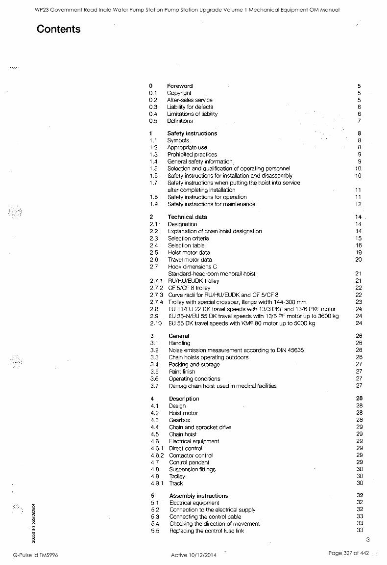
Contents
0 Foreword 5 0.1 Copyright 5 0.2 After-sales service 5 0.3 Liability for defects 6
0.4 Limitations of liability 6 0.5 Definitions 7
1 Safety instructions 8
1.1 Symbols 8 1.2 Appropriate use 8 1.3 Prohibited practices 9
1.4 General safety information 9
1.5 Selection and qualification of operating personnel 10
1.6 Safety instructions for installation and disassembly 10
1.7 Safety instructions when putting the hoist into service after completing installation 11
1.8 Safety instructions for operation 11
1.9 Safety instructions for maintenance 12
2 Technical data 14 2.1 Designation 14
2.2 Explanation of chain hoist designation 14
2.3 Selection criteria 15
2.4 Selection table 16
2.5 Hoist motor data 19 2.6 Travel motor data 20 2.7 Hook dimensions C
Standard-headroom monorail hoist 21
2.7.1 RU/HU/EUDK trolley 21
2.7.2 CF 5/CF 8 trolley 22 2.7.3 Curve radii for RU/HU/EUDK and CF 5/CF 8 22 2.7.4 Trolley with special crossbar, flange width 144-300 mm 23 2.8 EU 11/EU 22 DK travel speeds with 13/3 PKF and 13/6 PKF motor 24 2.9 EU 36-N/EU 55 DK travel speeds with 13/6 PF motor up to 3600 kg 24 2.10 EU 55 DK travel speeds with KMF 80 motor up to 5000 kg 24
3 General 26 3.1 Handling 26 3.2 Noise emission measurement according to DIN 45635 26 3.3 Chain hoists operating outdoors 26 3.4 Packing and storage 27
3.5 Paint finish 27 3.6 Operating conditions 27
3.7 Demag chain hoist used in medical facilities 27
4 Description 28 4.1 Design 28
4.2 Hoist motor 28 4.3 Gearbox 28 4.4 Chain and sprocket drive 29 4.5 Chain hoist 29 4.6 Electrical equipment 29 4.6.1 Direct control 29 4.6.2 Contactor control 29 4.7 Control pendant 29 4.8 Suspension fittings 30 4.9 Trolley 30 4.9.1 Track 30
5 Assembly instructions 32 5.1 Electrical equipment 32 5.2 Connection to the electrical supply 32
5.3 Connecting the control cable 33 5.4 Checking the direction of movement 33
.
0 5.5 Replacing the control fuse link 33
0 3
WP23 Government Road Inala Water Pump Station Pump Station Upgrade Volume 1 Mechanical Equipment OM Manual
Q-Pulse Id TMS996 Active 10/12/2014 Page 327 of 442
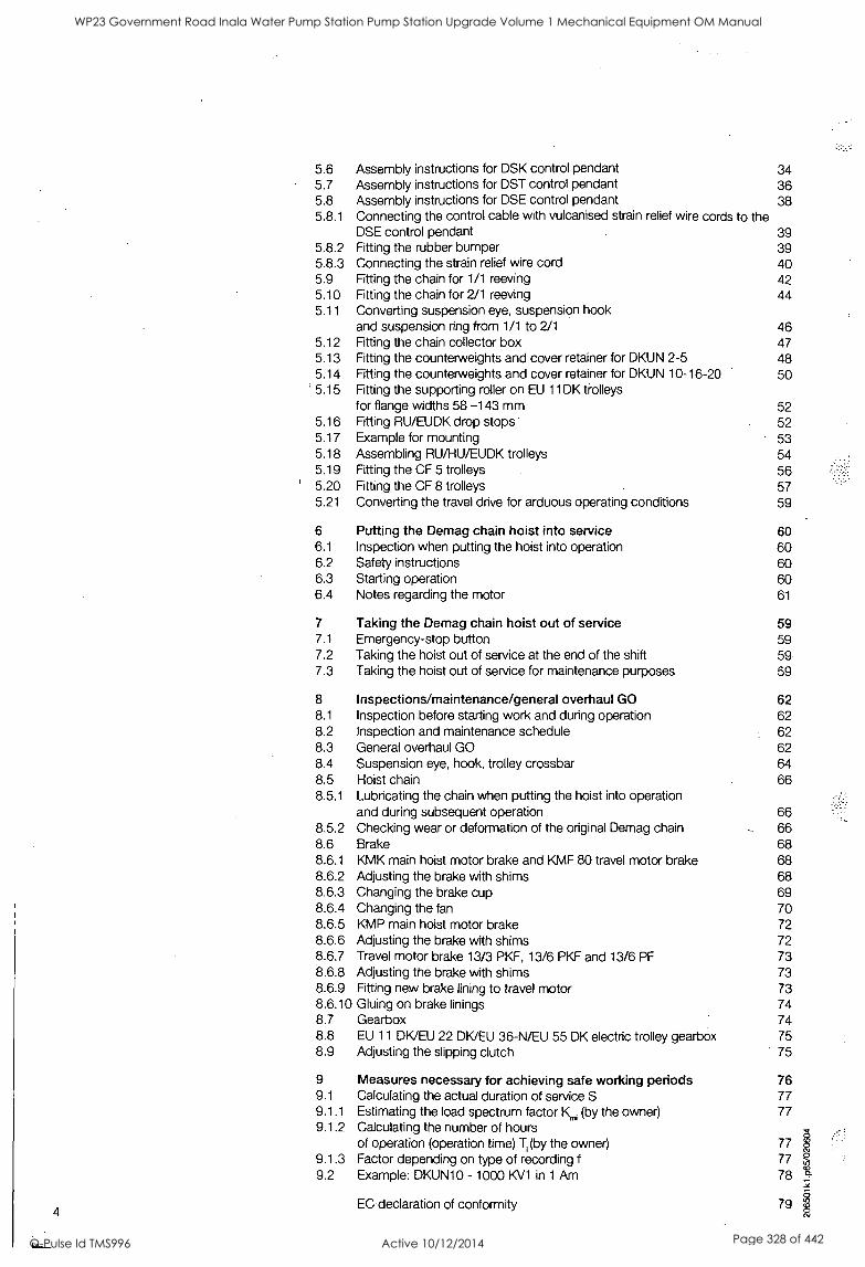
4
5.6 Assembly instructions for DSK control pendant 34 5.7 Assembly instructions for DST control pendant 36 5.8 Assembly instructions for DSE control pendant 38 5.8.1 Connecting the control cable with vulcanised strain relief wire cords to the
DSE control pendant 39 5.8.2 Fitting the rubber bumper 39 5.8.3 Connecting the strain relief wire cord 40 5.9 Fitting the chain for 1/1 reeving 42 5.10 Fitting the chain for 2/1 reeving 44 5.11 Converting suspension eye, suspension hook
and suspension ring from 1/1 to 2/1 46 5.12 Fitting the chain collector box 47 5.13 Fitting the counterweights and cover retainer for DKUN 2-5 48
_ 5.14 Fitting the counterweights and cover retainer for DKUN 10-16-20 50 5.15 Fitting the supporting roller on EU 11DK trolleys
for flange widths 58 -143 mm 52 5.16 Fitting RU/EUDK drop stops 52 5.17 Example for mounting 53 5.18 Assembling RU/HU/EUDK trolleys 54 5.19 Fitting the CF 5 trolleys 56 5.20 Fitting the CF 8 trolleys 57 5.21 Converting the travel drive for arduous operating conditions 59
6 Putting the Demag chain hoist into service 60 6.1 Inspection when putting the hoist into operation 60 6.2 Safety instructions 60 6.3 Starting operation 60 6.4 Notes regarding the motor 61
7 Taking the Demag chain hoist out of service 59 7.1 Emergency-stop button 59 7.2 Taking the hoist out of service at the end of the shift 59 7.3 Taking the hoist out of service for maintenance purposes 59
8 Inspections/maintenance/general overhaul GO 62 8.1 Inspection before starting work and during operation 62 8.2 Inspection and maintenance schedule 62 8.3 General overhaul GO 62 8.4 Suspension eye, hook, trolley crossbar 64 8.5 Hoist chain 66 8.5.1 Lubricating the chain when putting the hoist into operation
and during subsequent operation 66 8.5.2 Checking wear or deformation of the original Demag chain 66 8.6 Brake 68 8.6.1 KMK main hoist motor brake and KMF 80 travel motor brake 68 8.6.2 Adjusting the brake with shims 68 8.6.3 Changing the brake cup 69 8.6.4 Changing the fan 70 8.6.5 KMP main hoist motor brake 72 8.6.6 Adjusting the brake with shims 72 8.6.7 Travel motor brake 13/3 PKF, 13/6 PKF and 13/6 PF 73 8.6.8 Adjusting the brake with shims 73 8.6.9 Fitting new brake lining to travel motor 73 8.6.10 Gluing on brake linings 74 8.7 Gearbox 74 8.8 EU 11 DK/EU 22 DK/EU 36-N/EU 55 DK electric trolley gearbox 75 8.9 Adjusting the slipping clutch 75
9 Measures necessary for achieving safe working periods 76 9.1 Calculating the actual duration of service S 77 9.1.1 Estimating the load spectrum factor Km (by the owner) 77 9.1.2 Calculating the number of hours
of operation (operation time) T, (by the owner) 77 I 9.1.3 Factor depending on type of recording f 77 9.2 Example: DKUN10 - 1000 KV1 in 1 Am 78
EC declaration of conformity 79 8
WP23 Government Road Inala Water Pump Station Pump Station Upgrade Volume 1 Mechanical Equipment OM Manual
Q-Pulse Id TMS996 Active 10/12/2014 Page 328 of 442
0 Foreword
CE
0.1 Copyright
0.2 After-sales service
You have purchased a Demag product. This chain hoist was manufactured in accordance with German and European standards and regulations, e.g. EC Machinery Directive 98/37/EC, and state-of- the-art engineering principles.
Demag electric chain hoists are of modular design.
The main assemblies include:
the gearbox
the hoist motor
the integrated electrics
the chain drive mechanism
the control pendant
These operating instructions are designed to provide the operator with appropriate instructions for safe and correct operation and to facilitate maintenance.
Every individual given the task of transporting, installing, commissioning, operating, maintaining and repairing our chain hoists and additional equipment must have read and understood
the operating instructions
the safety regulations and
safety instructions in the individual chapters and sections.
The operating instructions must be available to the operating personnel at all times in
order to prevent operating errors and to ensure smooth and trouble-free operation of our products.
These operating instructions must be treated confidentially. They should only be used by authorized personnel. They may only be entrusted or made available to third parties with the prior written consent of Demag. All documents are protected within the sense of copyright law.
No part of this documentation may be reproduced, utilized or transmitted without specific prior consent. Infringements are an offence resulting in obligatory compensa- tory damages.
All industrial rights reserved.
Our after-sales service will provide you with all technical information on Demag products and their systematic application.
Should you have any questions regarding our products, please refer to one of our after-sales service stations, the relevant representative or to our main office.
Kindly quote the serial or order number (see test and inspection booklet, chain hoist data plate) in any correspondence or for spare part orders.
Specifying this data ensures that you receive the correct information or the required spare parts.
The relevant after-sales service station of Demag is specified for example on the back page of the test and inspection booklet.
5
WP23 Government Road Inala Water Pump Station Pump Station Upgrade Volume 1 Mechanical Equipment OM Manual
Q-Pulse Id TMS996 Active 10/12/2014 Page 329 of 442
0.3 Liability for defects
0.4 Limitations of liability
6
These operating instructions must be read carefully before installing and putting chain hoists into operation.
We assume no liability for damage and malfunctions resulting from failure to comply with the operating instructions.
Any liability claims for defects must be made by quoting the order number immedi- ately on detecting the defect.
Liability claims for defects are void in the event of
inappropriate use,
faulty devices or equipment connected or attached to the chain hoist which are not part of our scope of supplies and services,
use of non-genuine spare parts and accessories,
refurbishment or modification of the chain hoist unleSs approved in writing by Demag.
Wearing parts are not subject to liability for defects.
All technical information, data and instructions for operation contained in these oper- ating instructions were up-to-date on going to print and are compiled on the basis of our experience and to the best of our knowledge.
We reserve the right to incorporate technical modifications within the scope of further development of the hoist units which are the subject of these operating instructions. The information, illustrations and descriptions contained in these operating instruc- tions are therefore only intended for information purposes.
The descriptions and illustrations contained in this documentation do not necessarily correspond to the scope of delivery or any subsequent spare part delivery, either; the drawings and illustrations are not to scale.
Only documentation belonging to the actual order is valid.
We assume no liability for defects, damage and malfunctions caused as a result of operating errors, noncompliance with these operating instructions or omitted and/or inappropriate repairs and maintenance.
We expressly point out that only Demag spare parts and accessories approved by us may be used. Accordingly, this also applies to other manufacturers' parts supplied by us.
For safety reasons, the fitting and use of spare parts or accessories which have not been approved and unauthorized modification and conversion of the hoist unit are not permitted; we assume no liability for defects or damages resulting therefrom.
With the exclusion of any further claims, our liability for defects and other liability obli- gations for any defects pertaining to the products supplied or faults in the documen- tation delivered or any negligence on our part are exclusively based on the stipulati- ons of the original contract. Any further claims, in particular any and all claims for damages, are excluded with the exception of legal claims in accordance with product liability legislation.
WP23 Government Road Inala Water Pump Station Pump Station Upgrade Volume 1 Mechanical Equipment OM Manual
Q-Pulse Id TMS996 Active 10/12/2014 Page 330 of 442
0.5 Definitions Owner
Owners (employer, company) are defined as persons who own chain hoists and who use them appropriately or allow them to be operated by suitable and instructed persons.
Operating personnel
Operating personnel are defined as persons entrusted by the owner of the chain hoist with operation and/or transportation of the equipment.
Specialist personnel
Specialist personnel are defined as persons assigned by the owner to carry out spe- cial tasks such as installation, setting-up, maintenance and fault elimination.
Qualified electrician
Qualified electricians are defined as persons, who, owing to their technical training, knowledge and experience of electrical installations as well as knowledge of the rele- vant standards and regulations, are able to assess the tasks given to them and iden- tify and eliminate potential hazards.
Trained person
Trained persons are defined as persons who have been instructed and trained for the tasks assigned to them and on the possible hazards resulting from incorrect handling and who have been informed about the required protective devices, protective meas- ures, relevant regulations, codes of practice, accident prevention regulations and operating conditions and who have proven their qualifications.
Experienced technician
Experienced technicians are defined as persons, who, owing to their technical train- ing and experience, have sufficient knowledge of chain hoists and are familiar with the relevant national industrial safety regulations, codes of practice, accident preven- tion regulations, directives and generally accepted engineering standards enabling them to judge the safe operating condition of chain hoistts.
Qualified electricians are defined as persons who, owing to their technical training, knowledge and experience of electrical installations as well as knowledge of the rele- vant standards, codes of practice and regulations, are able to assess the tasks given to them and to identify and eliminate potential hazards.
Assigned expert engineer (in the Federal Republic of Germany according to BGV D8 § 23 (VBG 8), for determining the S.W.P.)
An assigned expert engineer is defined as an experienced technician specifically assigned by the manufacturer to determine the remaining duration of service (service life) of serial hoists and for carrying out general overhauls of chain hoists (S.W.P. = safe working period).
Authorized expert engineer (according to BGV D6 § 28 (VBG 9))
In addition to the expert engineers of the Technical Supervisory and Inspection Board, an authorized expert engineer for the inspection of chain hoists is defined as an expert engineer authorized by the Industrial Employers' Mutual Insurance Association.
Chain hoists
Chain hoists are systems used for lifting and moving loads, such as cranes, crabs and travelling hoist units, rail systems.
VBG (BGV D8) = German Industrial Employers' Mutual Insurance Association responsible for the prevention of accidents
WP23 Government Road Inala Water Pump Station Pump Station Upgrade Volume 1 Mechanical Equipment OM Manual
Q-Pulse Id TMS996 Active 10/12/2014 Page 331 of 442
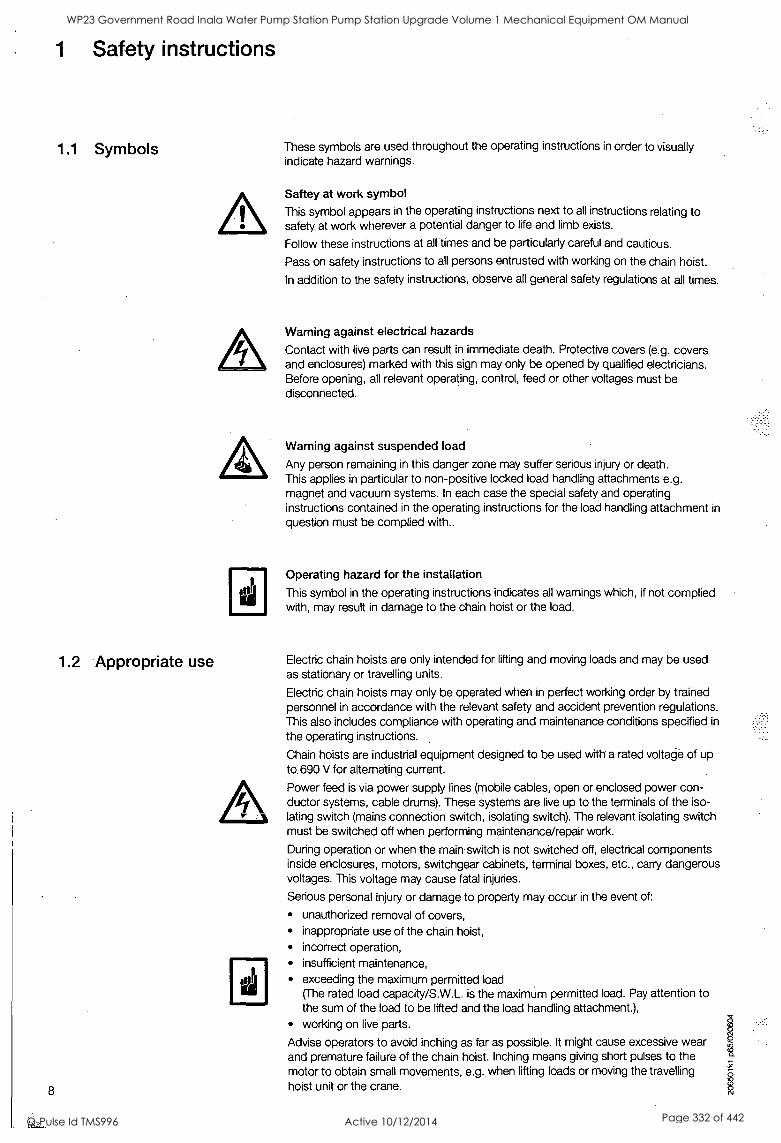
1 Safety instructions
1.1 Symbols
1.2 Appropriate use
8
These symbols are used throughout the operating instructions in order to visually indicate hazard warnings.
Saftey at work symbol
This symbol appears in the operating instructions next to all instructions relating to safety at work wherever a potential danger to life and limb exists.
Follow these instructions at all times and be particularly careful and cautious.
Pass on safety instructions to all persons entrusted with working on the chain hoist.
In addition to the safety instructions, observe all general safety regulations at all times.
Warning against electrical hazards
Contact with live parts can result in immediate death. Protective covers (e.g. covers and enclosures) marked with this sign may only be opened by qualified electricians. Before opening, all relevant operating, control, feed or other voltages must be disconnected.
Warning against suspended load
Any person remaining in this danger zone may suffer serious injury or death. This applies in particular to non-positive locked load handling attachments e.g. magnet and vacuum systems. In each case the special safety and operating instructions contained in the operating instructions for the load handling attachment in
question must be complied with..
Operating hazard for the installation
This symbol in the operating instructions indicates all warnings which, if not complied with, may result in damage to the chain hoist or the load.
Electric chain hoists are only intended for lifting and moving loads and may be used as stationary or travelling units.
Electric chain hoists may only be operated when in perfect working order by trained personnel in accordance with the relevant safety and accident prevention regulations. This also includes compliance with operating and maintenance conditions specified in
the operating instructions.
Chain hoists are industrial equipment designed to be used with a rated voltage of up to. 690 V for alternating current.
Power feed is via power supply lines (mobile cables, open or enclosed power con- ductor systems, cable drums). These systems are live up to the terminals of the iso- lating switch (mains connection switch, isolating switch). The relevant isolating switch must be switched off when performing maintenance/repair work.
During operation or when the main switch is not switched off, electrical components inside enclosures, motors, switchgear cabinets, terminal boxes, etc., carry dangerous voltages. This voltage may cause fatal injuries.
Serious personal injury or damage to property may occur in the event of:
unauthorized removal of covers, inappropriate use of the chain hoist, incorrect operation, insufficient maintenance, exceeding the maximum permitted load (The rated load capacity/S.W.L. is the maximum permitted load. Pay attention to the sum of the load to be lifted and the load handling attachment.), working on live parts.
Advise operators to avoid inching as far as possible. It might cause excessive wear and premature failure of the chain hoist. Inching means giving short pulses to the motor to obtain small movements, e.g. when lifting loads or moving the travelling
hoist unit or the crane.
WP23 Government Road Inala Water Pump Station Pump Station Upgrade Volume 1 Mechanical Equipment OM Manual
Q-Pulse Id TMS996 Active 10/12/2014 Page 332 of 442
1.3 Prohibited practices
1.4 - General safety information
Certain work and practices are prohibited when using the chain hoist as they may involve danger to life and limb and result in lasting damage to the chain hoist, e.g.:
Unsafe load handling (e.g. swinging the load).
Do not handle suspended loads above persons.
Do not pull or drag suspended loads at an angle.
Do not pull free fixed or obstructed loads with the chain hoist.
Do not exceed the maximum permitted load and permitted load dimensions.
Do not leave suspended loads unsupervised.
Do not allow the chain to run over-edges.
Do not use the chain as a load bearing sling.
Always move the chain hoist with push travel trolley by pulling on the load, bottom block or load hook assembly - never pull on the control pendant.
Do not allow loads to drop when the chain is in a slack condition.
Do not subject the control pendant to inappropriate mechanical loads.
Transporting persons, unless lifting devices are specifically approved for transport- ing persons, is not permitted.
Do not tamper with or manipulate electrical equipment.
Chain hoists must be suspended in such a way that they do not collide with stationary equipment and structures, e.g. when slewing jib cranes are slewed.
Persons under the influence of drugs, alcohol or medicines which affect reactions must not install, operate, put into service, maintain, repair or disassemble chain hoists.
Any conversions and modifications to the installation require the written consent of Demag.
Work on electrical equipment of chain hoists may only be carried out by qualified electricians in accordance with electrical regulations. In the event of malfunctions, chain hoist operation must be stopped, the hoist switched off and the relevant main switches locked immediately. Defects must be rectified immediately.
National accident prevention regulations and codes of practice and general safety regulations must be observed when operating our products. Important information and instructions are marked by corresponding symbols. Follow these instructions and/or safety regulations in order to avoid accidents and damage. The operating instructions must be kept available at the place where the chain hoist is in use at all
times. They include significant aspects and appropriate excerpts from the relevant guidelines, standards and regulations. The owner must instruct his personnel appro- priately.
Any failure to comply with the safety instructions stated in these operating instruc- tions can result in death or personal injury.
Observe general statutory and other obligatory regulations relating to accident pre- vention and environmental protection and basic health and safety requirements in
addition to those included in these operating instructions. Such requirements may also relate, for example, to the handling of hazardous materials or the provision/wear- ing of personal protection equipment. Comply with these regulations and general accident prevention regulations relevant for the place at which the chain hoist is used and follow the instructions therein when working with the chain hoist. The chain hoist may still constitute a danger to life and limb if it is not installed, operated, maintained or used appropriately by personnel which have not been trained or specially instruct- ed. The operating instructions must, if required, be supplemented by the owner with instructions and information (e.g. factory regulations) relating to organization of work, working procedures, operating personnel, etc. Supervising and reporting obligations as well as special operating conditions must also be taken into consideration.
Personnel assigned to working with the chain hoist must have read and understood the operating instructions and, in particular, the chapter on safety information.
All activities relating to chain hoists which are not described in these operating in- structions may only be carried out by specialist personnel specifically trained for the particular chain hoist.
The owner must ensure that personnel work in a safety and hazard-conscious manner in compliance with the operating instructions.
9
WP23 Government Road Inala Water Pump Station Pump Station Upgrade Volume 1 Mechanical Equipment OM Manual
Q-Pulse Id TMS996 Active 10/12/2014 Page 333 of 442
1.5 Selection and qualifi- cation of operating personnel
1.6 Safety instructions for installation and disassembly
10
The owner must ensure that the chain hoist is only operated when in proper working order and that all relevant safety requirements and regulations are complied with. Chain hoists must be taken out of service immediately if functional defects or irregu- larities are detected. In the event of a stoppage .(e.g. if defects regarding safe and reliable operation are detected, in emergency-situations, in the event of operating malfunctions, for repairs and maintenance purposes, if damage is detected or after finishing work), the operator/experienced technician must carry out all prescribed safety measures (e.g. for cranes operating outdoors, ensure wind drift safety catch is fitted) or observe that they are automatically carried out. Personal protective clothing must be worn as necessary or as required by regulations. Personnel must not wear loose clothing, jewellery including rings or long hair loose. Injury may occur, for exam- ple, by being caught or drawn into the mechanism. All safety and hazard information and recommendations on the chain hoist, at access points and mains connection switches must be maintained in complete and legible condition. Inching (i.e. giving short pulses to the motor) must always be avoided. Emergency limit stop devices (e.g. slipping clutch or emergency limit switch) must not be approached in normal operation. Modifications, additions to and conversions of the chain hoist which may impair safety in any way must not be carried out without the consent of Demag. This also applies to the installation and adjustment of safety devices as well as for performing welds on load bearing parts. Safety devices must not be rendered inoperative. Only genuine Demag spare parts may be used. Observe prescribed deadlines or those specified in the operating instructions for routine checks/inspections.
For independent operation or maintenance of the chain hoist, the owner may only employ persons
who are at least 18 years of age,
who are mentally and physically suitable,
who have been instructed in the operation or maintenance of the chain hoist and have proven their qualification to the owner in this respect (in addition to theoreti- cal training, instruction also includes sufficient practical operating experience as well as acquiring the ability to identify defects which are a hazard to safe opera- tion),
who can be expected to carry out the work assigned to them reliably.
The owner must assign operating and maintenance personnel to their relevant tasks.
Installation and disassembly work may only be performed by experienced technicians.
Installation and disassembly work must be coordinated by the person carrying out the work and the owner within the scope of their responsibility.
The working and danger zone must be made safe.
The installation must be isolated in accordance with the relevant electrical regulations.
Customer-specific regulations must be observed.
Only appropriate, tested and calibrated tools and equipment may be used.
The electrode holder and earth must be connected to the same assembly when welding work is carried out. If the current flow is returned via protective conduc- tors, screening elements or anti-friction bearings, serious damage may be caused to these or other components.
WP23 Government Road Inala Water Pump Station Pump Station Upgrade Volume 1 Mechanical Equipment OM Manual
Q-Pulse Id TMS996 Active 10/12/2014 Page 334 of 442
1.7 Safety instructions when first putting the hoist into service after completing installation
1.8 Safety instructions for operation
The working and danger area must be made safe.
First check that the voltage and frequency specified on the data plates match the owner's mains power supply.
All clearance dimensions and safety distances (see approval drawing) must be checked before putting the hoist into service.
When putting the hoist unit into service, it may be necessary to perfOrm work in
the danger zone.
In the course of putting the hoist unit into service, it may be necessary to tempo- rarily render safety devices or features inoperative.
It must be ensured that only trained personnel are employed for putting the hoist unit into service.
The operator must check the function of the brakes and emergency limit stop devices before starting work. All instructions and measures described in the operating instructions with regard to safe operation and items concerning general safety and accident prevention which have to be observed before, during and after putting into service must be strictly complied with. Any failure to comply can lead to accidents resulting in fatalities. Chain hoists must be taken out of service immediately or not put into operation if any defects relating to operating safety and reliability are detected. Safety devices must not be rendered inoperative or modified in contradiction to their intended use. Only operate chain hoists when all protective devices and safety-relevant equipment, e.g. movable protective devices and emergency-stop devices, are fitted and fully functioning. Anybody who identifies an immediate danger of personal injury must actuate the emergency-stop button without delay. This also applies in the case of damage occurring to parts of the installation and equipment which makes immediate stoppage necessary. After an "emergency-stop", the operator must not switch on and restart the chain hoist until an experienced technician is satisfied that the cause which led to actuation of this function has been rectified and that continued operation of the installation constitutes no further hazard. Chain hoists must be switched off immediately in the event of the following faults:
In the event of damage to electrical devices and cables as well as parts of the insulation.
In the event of brake and safety device failure.
The chain hoist is provided with a slipping clutch as overload protection.
In the event of overload, the following situations may occur:
1. The load is not lifted, the slipping clutch responds.
2. The load is lifted, however, after switching off the lifting motion, the load slowly moves downwards. In this case, the load must be immediately deposited by actuating the control switch.
Malfunction: The slipping clutch must be readjusted or overload has occured.
Before switching on/putting into operation of the chain hoist it must be ensured that nobody is endangered by operation of the hoist. If the operator notices persons who may be exposed to a risk to health or personal safety by operation of the chain hoist, he must suspend operation immediately and may not resume operation again until the persons are outside the danger zone. Before putting the chain hoist into operation, the operator must be satisfied that the installation is in safe and correct operating condition. Work on chain hoists may only be carried out when instructions to this effect have been issued, when operation and function of the chain hoist have been explained and when the working and danger zone has been made safe. Cooling devices, such as ventilation openings, may not be rendered permanently inoperative (e.g. covered or closed).
Special local conditions or special applications can lead to situations which were not known when this chapter was written. In such cases, special safety measures must be implemented by the owner.
11
WP23 Government Road Inala Water Pump Station Pump Station Upgrade Volume 1 Mechanical Equipment OM Manual
Q-Pulse Id TMS996 Active 10/12/2014 Page 335 of 442
1.9 Safety instructions for maintenance
12
L
Maintenance measures are defined as regular maintenance, inspection and repair work.
Mechanical and electrical repairs and maintenance work may.only.be carried out by appropriately trained: personnel (experienced technicians).
Adjustment, maintenance and inspection activities and inspection deadlines including specifications concerning replacement of parts/assemblies prescribed in the operat- ing instructions must be observed.
Ensure that all electrical components are de-energized before commencing work on electrical installations and devices. When all work on the chain hoist has been com- pleted, operation of the chain hoist must not resume until the owner has given ap- proval to this effect.
Unauthorized persons must be prohibited from carrying out work on machinery or parts of the chain hoist. Before starting all repair and maintenance work, the chain hoist must be switched off, taken out of operation and secured (switches must be locked) against accidental or unauthorized putting into operation (restarting).
It must be ensured that
the chain hoist is switched off and checked that it is de-energized and, in special cases, isolated,
moving parts are stationary and stopped,
moving parts cannot start moving while maintenance work is being performed,
the power supply cannot be accidentally restored as long as the hoist unit has been taken out of service for maintenance and repair purposes.
Ensure that operating and auxiliary materials as well as spare parts are disposed of in a safe and environmentally sound way.
Instructions for repair work in the course of operation
The danger zone must be marked off with red/white safety chains or safety tape and indicated with warning signs.
In each individual case, the owner or the person specified by him must check whether the relevant work may be carried out in the course of operation without risk of personal injury owing to the particular local conditions.
To avoid injury, only use calibrated and appropriate tools and auxiliary materials for maintenance, inspection and repair purposes.
If there is a risk of objects falling, the danger zone must be made safe.
Maintain a sufficient safety distance to rotating parts to prevent clothing, parts of the body or hair becoming entangled.
Avoid naked flames, extreme heat and sparks in the vicinity of cleaning agents and flammable parts or parts liable to deformation (e.g. wood, plastic parts, oil, grease) as well as in electrical installations - noncompliance may result in fire hazard. Harmful gases may evolve or insulation may be damaged.
Additional instructions for repair work on electrical equipment
Only use genuine fuse links with specified amperage and tripping characteristics. Defective fuse links must not be repaired or bridged and must only be replaced by fuse links of the same type. Switch off the chain hoist immediately in the event of electrical power supply malfunctions. Work on the electronic and electrical compo- nents or equipment may only be carried out by qualified electricians. If inspection, maintenance and repair work is to be carried out on parts of chain hoists, these must - if prescribed by regulations - be isolated. First verify the safe isolation of the parts from the supply before commencing work. The electrical equipment of the chain hoist must be inspected and checked at regular intervals. Defects, such as loose connec- tions, damaged cables and worn contactors must be rectified immediately.
WP23 Government Road Inala Water Pump Station Pump Station Upgrade Volume 1 Mechanical Equipment OM Manual
Q-Pulse Id TMS996 Active 10/12/2014 Page 336 of 442
Since it is possible that after a longer period of operation the switching points of re- lays (time,. frequency, monitoring relays) change due to ageing of the components, the relay switching points in circuits relevant to safety must be checked at regular intervals.
Electrical equipment must be replaced as a preventive measure on reaching the limit of its theoretical duration of service (service life).
If work has to be carried out on live parts, a second person must be available in order to actuate the emergency-stop button or mains connection switch/isolating switch for voltage disconnection in an emergency.
The second person must be familiar with resuscitation measures. Only use insulated tools... Before disconnecting and connecting electrical plug-and-socket connections, always disconnect them from the supply (this does not apply to mains connections, provided they do not represent a dangerous contact voltage in the sense of the safety regulations).
13
WP23 Government Road Inala Water Pump Station Pump Station Upgrade Volume 1 Mechanical Equipment OM Manual
Q-Pulse Id TMS996 Active 10/12/2014 Page 337 of 442
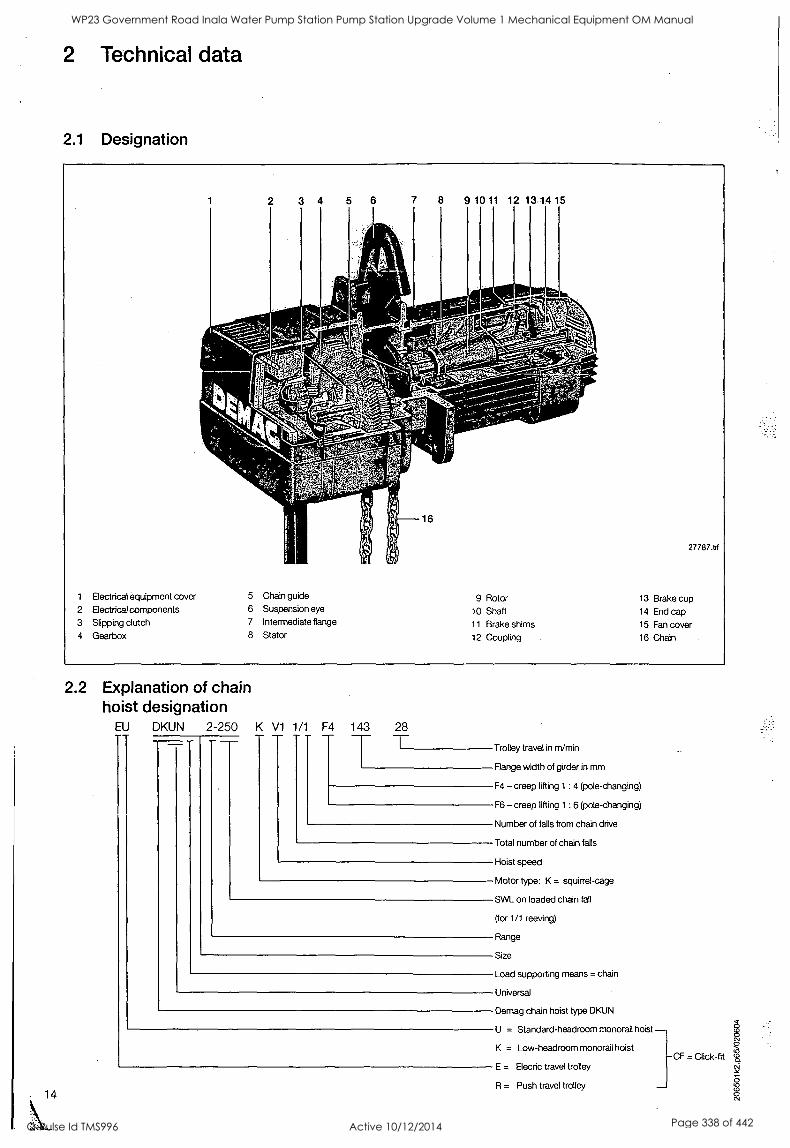
2 Technical data
2.1 Designation
3 4 5 6 7 8 9 10 11 12 13 14 15
27787.tif
1 Electrical equipment cover 5 Chain guide 9 Rotor 13 Brake cup 2 Electrical components 6 Suspension eye 10 Shaft 14 End cap 3 Slipping clutch 7 Intermediate flange 11 Brake shims 15 Fan cover 4 Gearbox 8 Stator 12 Coupling 16 Chain
2.2 Explanation of chain hoist designation
EU DKUN 2-250 K V1 1/1 F4 143
14
28
Trolley travel in m/min
Flange width of girder in mm
F4 creep lifting 1 : 4 (pole-changing)
F6 creep lifting 1 : 6 (pole-changing)
Number of falls from chain drive
Total number of chain falls
Hoist speed
Motor type: K = squirrel-cage
SWL on loaded chain fall
(for 1/1 reeving)
Range
Size
Load supporting means = chain
Universal
Demag chain hoist type DKUN
U = Standard-headroom monorail hoist - K = Low-headroom monorail hoist
-CF = Click-fit E - Elecric travel trolley
R = Push travel trolley
WP23 Government Road Inala Water Pump Station Pump Station Upgrade Volume 1 Mechanical Equipment OM Manual
Q-Pulse Id TMS996 Active 10/12/2014 Page 338 of 442
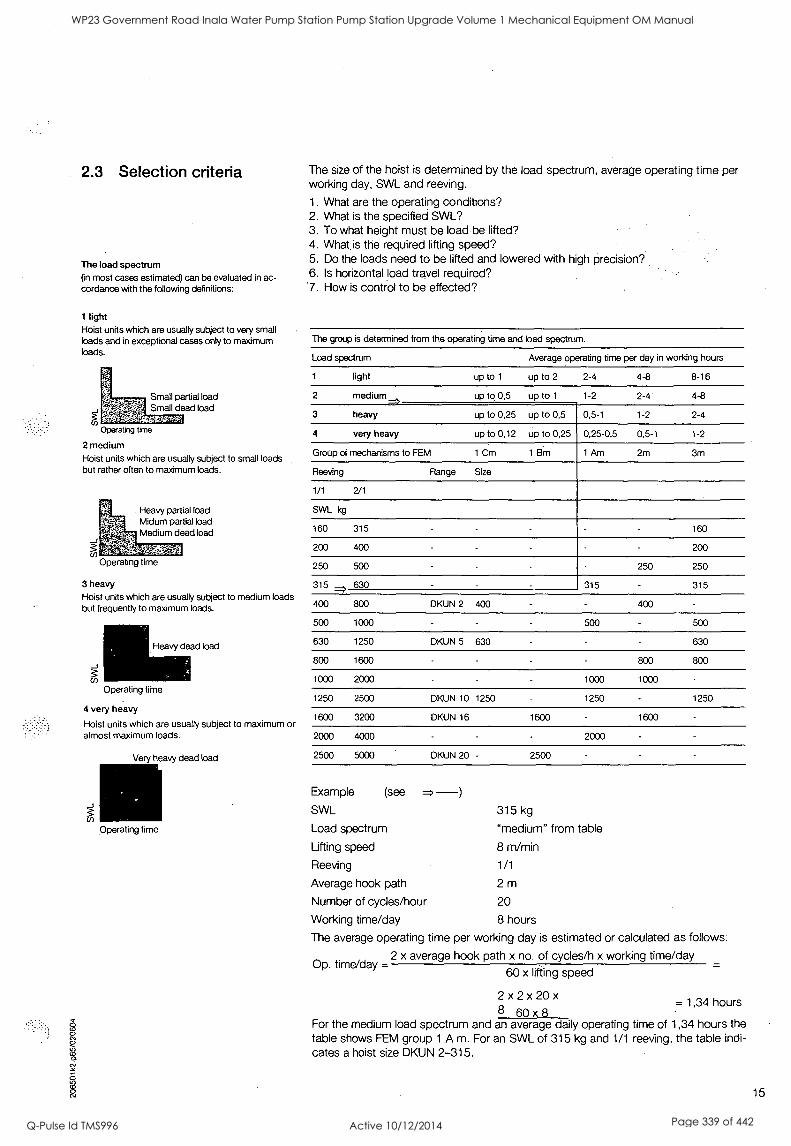
2.3 Selection criteria
The load spectrum (in most cases estimated) can be evaluated in ac- cordance with the following definitions:
1 light Hoist units which are usually subject to very small loads and in exceptional cases only to maximum loads.
Small partial load Small dead load
Operating time
2 medium Hoist units which are usually subject to small loads but rather often to maximum loads.
. Heavy partial load Midum partial load Medium dead load
Operating time
3 heavy
Hoist units which are usually subject to medium loads but frequently to maximum loads.
Heavy dead load
Operating time
4 very heavy
Hoist units which are usually subject to maximum or almost maximum loads.
Pin
Very heavy dead load
Operating time
The size of the hoist is determined by the load spectrum, average operating time per working day, SWL and reeving.
1. What are the operating conditions? 2. What is the specified SWL? 3. To.what height must be load be lifted? 4. What is the required lifting speed? 5. Do the loads need to be lifted and lowered with high precision? 6. Is horizontal load travel required? '7. How is control to be effected?
The group is determined from the operating time and load spectrum.
Load spectrum Average operating time per day in working hours
1 light up to 1 up to 2 2-4 4-8 8-16
2 medium up to 0,5 up to 1 1-2 2-4 4-8
3 heavy up to 0,25 up to 0,5 0,5-1 1-2 2-4
4 very heavy up to 0,12 up to 0,25 0,25-0,5 0,5-1 1-2
Group of mechanisms to FEM 1 Cm 1 Bm 1 Am 2m 3m
Reeving Range Size
1/1 2/1
SWL kg
160 315 - - - 160
200 400 - - - - 200
250 500 - - - 250 250
315 -, 630 - 315 - 315
400 800 DKUN 2 400 400
500 1000 500 500
630 1250 DKUN 5 630 630
800 1600 800 800
1000 2000 1000 1000
1250 2500 DKUN 10 1250 1250 1250
1600 3200 DKUN 16 1600 1600
2000 4000 2000
2500 5000 DKUN 20 - 2500
Example (see = -) SWL
Load spectrum
Lifting speed
Reeving
Average hook path
Number of cycles/hour
Working time/day
315 kg
"medium" from table
8 m/min
1/1
2m 20
8 hours
The average operating time per working day is estimated or calculated as follows:
Op. time/day = 2 x average hook path x no. of cycles/h x working time/day
60 x lifting speed
2 x2 x20 x = 1,34 hours
8 60 x 8 For the medium load spectrum and an average daily operating time of 1,34 hours the table shows FEM group 1 A m. For an SWL of 315 kg and 1/1 reeving, the table indi- cates a hoist size DKUN 2-315.
15
WP23 Government Road Inala Water Pump Station Pump Station Upgrade Volume 1 Mechanical Equipment OM Manual
Q-Pulse Id TMS996 Active 10/12/2014 Page 339 of 442
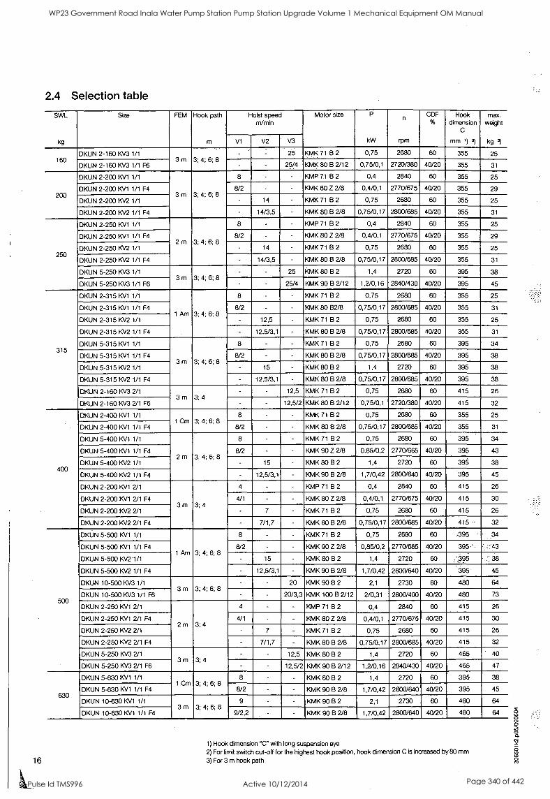
16
2.4 Selection table
SWL
kg
Size. FEM Hook path
m
Hoist speed m/min
Motor size P
kW
n
rpm
CDF %
Hook dimension
C
mm 1) 2)
max. weight
kg 3) V1 V2 V3
160 DKUN 2-16010/3 1/1
3m 3; 4; 6; 8 - 25 KMK 71 B 2 0,75 2680 60 355 25
DKUN 2-160 KV3 1/1 F6 - - 25/4 KMK 80 B 2/12 0,75/0,1 2720/380 40/20 355 31
200
DKUN 2-20010/1 1/1
3 m 3; 4; 6; 8
8 - - KMP 71 B 2 0,4 2840 60 355 25
DKUN 2-200 KV1 1/1 F4 8/2 - - KMK 80 Z 2/8 0,4/0,1 2770/675 40/20 355 29
DKUN 2-20010/2 1/1 - 14 - KMK 71 B 2 0,75 2680 60 355 25
DKUN 2-200 10/2 1/1 F4 - 14/3,5 KMK 80 B 2/8 0,75/0,17 2800/685 40/20 355 31
250
DKUN 2-250 10/1 1/1
2m 3; 4; 6; 8
8 - - KMP 71 B 2 0,4 2840 60 355 25
DKUN 2-250 10/1 1/1 F4 8/2 - - KMK 80 Z 2/8 0,4/0,1 2770/675 40/20 355 29
DKUN 2-250 10/2 1/1 - 14 - KMK 71 B 2 0,75 2680 60 355 25
DKUN 2-250 10/2 1/1 F4 - 14/3,5 - KMK 80 B 2/8 0,75/0,17 2800/685 40/20 355 31
DKUN 5-250 10/3 1/1 3m 3; 4; 6; 8
- - 25 KMK 80 B 2 1,4 2720 60 395 38
DKUN 5-25010/3 1/1 F6 - - 25/4 KMK 90 B 2/12 1,2/0,16 2840/430 40/20 395 45
315
DKUN 2-315 KV1 1/1
1 Am 3; 4; 6; 8
8 - KMK 71 B 2 0,75 2680 60 355 25
DKUN 2-315 KV1 1/1 F4 8/2 - - KMK 80 B2/8 0,75/0,17 2800/685 40/20 355 31
DKUN 2-315 KV2 1/1 - 12,5 - KMK 71 B 2 0,75 2680 60 355 25
DKUN 2-315 KV2 1/1 F4 - 12,5/3,1 - KMK 80 8 2/8 0,75/0,17 2800/685 40/20 355 31
DKUN 5-315 KV1 1/1
3m 3; 4; 6; 8
8 - - KMK 71 B 2 0,75 2680 60 395 34
DKUN 5-31510/1 1/1 F4 8/2 - - KMK 80 B 2/8 0,75/0,17 2800/685 40/20 395 38
DKUN 5-315 KV2 1/1 - 15 - KMK 80132 1,4 2720 60 395 38
DKUN 5-31510/2 1/1 F4 - 12,5/3,1 - KMK 80 B 2/8 0,75/0,17 2800/685 40/20 395 38
DKUN 2-16010/3 2/1 3m 3;4
- - 12,5 KMK 71 B 2 0,75 2680 60 415 26
DKUN 2-16010/3 2/1 F6 - - 12,5/2 KMK 80 B 2/12 0,75/0,1 2720/380 40/20 415 32
400
DKUN 2-400 KV1 1/1 1 Cm 3; 4; 6; 8
8 - - KMK 71 B 2 0,75 2680 60 355 25
DKUN 2-400 KV1 1/1 F4 8/2 - - KMK 8013 2/8 0,75/0,17 2800/685 40/20 355 31
DKUN 5-400 KV1 1/1
2m 3; 4; 6; 8
8 - - KMK 71 B 2 0,75 2680 60 395 34
DKUN 5-40010/1 1/1 F4 8/2 - - KMK 90 Z 2/8 0,85/0,2 2770/665 40/20 395 43
DKUN 5-40010/2 1/1 - 15 KMK 80 B 2 1,4 2720 60 395 38
DKUN 5-400 KV2 1/1 F4 - 12,5/3,1 - KMK 90 B 2/8 1,7/0,42 2800/640 40/20 395 45
DKUN 2-20010/1 2/1
3 m 3; 4
4 - KMP 71 B 2 0,4 2840 60 415 26
DKUN 2-200 KV1 2/1 F4 4/1 - - KMK 80 Z 2/8 0,4/0,1 2770/675 40/20 415 30
DKUN 2-200 KV2 2/1 - 7 - KMK 71 B 2 0,75 2680 60 415 26
DKUN 2-200 KV2 2/1 F4 - 7/1,7 - KMK 80 B 2/8 0,75/0,17 2800/685 40/20 415 32
500
DKUN 5-500 10/1 1/1
'I Am 3; 4; 6; 8
8 - - KMK 71 B 2 0,75 2680 60 ,395 , 34
DKUN 5-50010/1 1/1 F4 8/2 - - KMK 90 Z 2/8 0,85/0,2 2770/665 40/20 395.' -
DKUN 5-500 KV2 1/1 - 15 - KMK 80 B 2 1,4 2720 60 .' 395 .
DKUN 5-5001N2 1/1 F4 - 12,5/3,1 - KMK 90 B 2/8 1,7/0,42 2800/640 40/20 395 45
OKUN 10-50010/3 1/1 3m 3; 4; 6; 8
- - 20 KMK 90 B 2 2,1 2730 60 480 64
DKUN 10-500 KV3 1/1 F6 - 20/3,3 KMK 100 13 2/12 2/0,31 2800/400 40/20 480 73
DKUN 2-250 10/1 2/1
2m 3;4
4 - - KMP 71 B 2 0,4 2840 60 415 26
DKUN 2-25010/1 2/1 F4 4/1 - KMK 80 Z 2/8 0,4/0,1 2770/675 40/20 415 30
OKUN 2-250 KV2 2/1 - 7 KMK 71 B 2 0,75 2680 60 415 26
DKUN 2-25010/2 2/1 F4 - 7/1,7 - KMK 80 B 2/8 0,75/0,17 2800/685 40/20 415 32
DKUN 5-250 KV3 2/1 3m 3;4
- - 12,5 KMK 80 B 2 1,4 2720 60 465 40
DKUN 5-250 KV3 2/1 F6 - - 12,5/2 KMK 90 B 2/12 1,2/0,16 2840/430 40/20 465 47
630
DKUN 5-630 KV1 1/1 1 Cm 3; 4; 6; 8
8 - - KMK 8013 2 1,4 2720 60 395 38
DKUN 5-630 KV1 1/1 F4 8/2 - - KMK 90 B 2/8 1,7/0,42 2800/640 40/20 395 45
DKUN 10-630 KV1 1/1 3m 3; 4; 6; 8
9 - - KMK 90 B 2 2,1 2730 60 480 64
DKUN 10-630 KV1 1/1 F4 9/2,2 - - KMK 90 B 2/8 1,7/0,42 2800/640 40/20 480
1) Hook dimension "C" with long suspension eye
2) For limit switch cut-off for the highest hook position, hook dimension C is increased by 80 mm
3) For 3 m hook path
WP23 Government Road Inala Water Pump Station Pump Station Upgrade Volume 1 Mechanical Equipment OM Manual
Q-Pulse Id TMS996 Active 10/12/2014 Page 340 of 442
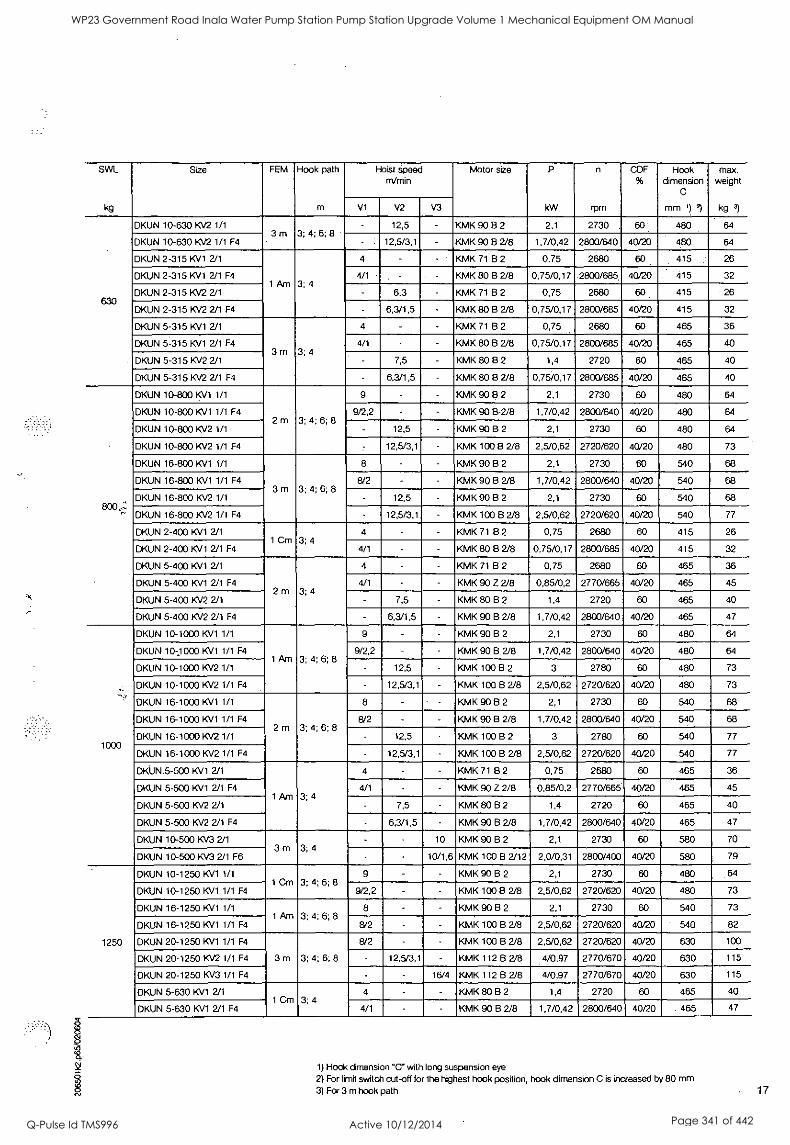
O
Nd
SWL
kg
Size FEM Hook path Hoist speed m/min
Motor size P
kW
n
rpm
CDF %
Hook dimension
C
mm 1) 2)
max. weight
kg 3) m V1 V2 V3
630
DKUN 10-630 KV2 1/1 3m
- 12,5 - KMK 90 B 2 2,1 2730 . 64
OKUN 10-630 KV2 1/1 F4 3; 4; 6; 8
12,5/3,1 - KMK 90 B 2/8 1,7/0,42 2800/640 40/20 480 64
DKUN 2-315 KV1 2/1
1 Am 3; 4
4 - KMK 71 B 2 0,75 2680 60 415 26
DKUN 2-315 KV1 2/1 F4 4/1 - KMK 80 B 2/8 0,75/0,17 2800/685. 40/20 . '415 32
DKUN 2-315 KV2 2/1 6,3 - KMK 71 B 2 0,75 2680 60 415 26
DKUN 2-315 KV2 2/1 F4 - 6,3/1,5 - KMK 80 El 2/8 0,75/0,17 2800/685 40/20 415 32
DKUN 5-315 KV1 2/1
3m 3;4
4 - - KMK 71 B 2 0,75 2680 60 465 36
DKUN 5-315 KV1 2/1 F4 4/1 - KMK 80 82/8 0,75/0,17 2800/685 40/20 465 40
DKUN 5-315 KV2 2/1 - 7,5 - KMK 80 B 2 1,4 2720 60 465 40
DKUN 5-315 KV2 2/1 F4 - 6,3/1,5 KMK 80 B 2/8 0,75/0,17 2800/685 40/20 465 40
800...=.: "
DKUN 10-800 I<\/1 1/1
2m 3; 4; 6; 8
9 - - KMK 90 a 2 2,1 2730 60 480 64
DKUN 10-800 )(VS 1/1 F4 9/2,2 - KMK 90 B2/8 1,7/0,42 2800/640 40/20 480 64
DKUN 10-800 KV2 1/1 - 12,5 KMK 90 B 2 2,1 2730 60 480 64
DKUN 10-800 KV2 1/1 F4 - 12,5/3,1 KMK 100 13 2/8 2,5/0,62 2720/620 40/20 480 73
DKUN 16-800 KV1 1/1
3m 3; 4; 6; 8
8 - KMK 90 8 2 2,1 2730 60 540 68
DKUN 16-800 KV1 1/1 F4 8/2 - KMK 90 B 2/8 1,7/0,42 2800/640 40/20 540 68
DKUN 16-800 KV2 1/1 - 12,5 - KMK 90 B 2 2,1 2730 60 540 68
DKUN 16-800 K/2 1/1 F4 - 12,5/3,1 KMK 100 B 2/8 2,5/0,62 2720/620 40/20 540 77
DKUN 2-400 KV1 2/1 1 Cm 3; 4
4 - - KMK 71 B 2 0,75 2680 60 415 26
DKUN 2-400 KV1 2/1 F4 4/1 - - KMK 80 B 2/8 0,75/0,17 2800/685 40/20 415 32
DKUN 5-400 KV1 2/1
2m 3;4
4 - - KMK 71 B 2 0,75 2680 60 465 36
DKUN 5-400 KV1 2/1 F4 4/1 - KMK 90 Z 2/8 0,85/0,2 2770/665 40/20 465 45
DKUN 5-400 KV2 2/1 7,5 - KMK 80 B 2 1,4 2720 60 465 40
DKUN 5-400 KV2 2/1 F4 6,3/1,5 - KMK 90 B 2/8 1,7/0,42 2800/640 40/20 465 47
1000
DKUN 10-1000 KV1 1/1
1 Arn 3; 4; 6; 8
9 KMK 90 B 2 2,1 2730 60 480 64
DKUN 10;1000 K\/1 1/1 F4 9/2,2 - KMK 90 B 2/8 1,7/0,42 2800/640 40/20 480 64
DKUN 10-1000 KV2 1/1 12,5 - KMK 100 B 2 3 2780 60 480 73
DKUN 10-1000 KV2 1/1 F4 - 12,5/3,1 - KMK 100 B 2/8 2,5/0,62 2720/620 40/20 480 73
DKUN 16-1000 KV1 1/1
2m 3; 4; 6; 8
8 - KMK 90 8 2 2,1 2730 60 540 68
DKUN 16-1000 KV1 1/1 F4 8/2 - - KMK 90 B 2/8 1,7/0,42 2800/640 40/20 540 68
DKUN 16-1000 KV2 1/1 - 12,5 KMK 100 B 2 3 2780 60 540 77
DKUN 16-1000 KV2 1/1 F4 - 12,5/3,1 - KMK 100 13 2/8 2,5/0,62 2720/620 40/20 540 77
DKUN.5-500 KV1 2/1
1 Am 3; 4
4 - - KMK 71 B 2 0,75 2680 60 465 36
DKUN 5-500 KV1 2/1 F4 4/i KMK 90 Z 2/8 0,85/0,2 2770/665 40/20 465 45
DKUN 5-500 KV2 2/1 - 7,5 - KMK 80 B 2 1,4 2720 60 465 40
DKUN 5-500 KV2 2/1 F4 6,3/1,5 - KMK 90 B 2/8 1,7/0,42 2800/640 40/20 465 47
DKUN 10-500 KV3 2/1 3m 3;4
10 KMK 90 8 2 2,1 2730 60 580 70
DKUN 10-500 KV3 2/1 F6 - 10/1,6 KMK 100 Ei 2/12 2,0/0,31 2800/400 40/20 580 79
1250
DKUN 10-1250 KV1 1/1 1 Cm 3; 4; 6; 8
9 - - KMK 90 B 2 2,1 2730 60 480 .64
DKUN 10-1250 KV1 1/1 F4 9/2,2 - - KMK 10013 2/8 2,5/0,62 2720/620 40/20 480 73
DKUN 16-1250 KV1 1/1 1 Am 3; 4; 6; 8
8 - - KMK 90 B 2 2,1 2730 60 540 73
DKUN 16-1250 KV1 1/1 F4 8/2 - - KMK 100 8 2/8 2,5/0,62 2720/620 40/20 ' 540 82
DKUN 20-1250 KV1 1/1 F4
3 m 3; 4; 6; 8
8/2 - - KMK 100 El 2/8 2,5/0,62 2720/620 40/20 630 100
DKUN 20-1250 KV2 1/1 F4 - 12,5/3,1 - KMK 112 B 2/8 4/0,97 2770/670 40/20 630 115
DKUN 20-1250 KV3 1/1 F4 - - 16/4 KMK 112 B 2/8 4/0,97 2770/670 40/20 630 115
DKUN 5-630 KV1 2/1 3; 4
4 - - KMK 80 B 2 1,4 2720 60 465 40
DKUN 5-630 KV1 2/1 F4 1 Cm
4/1 - - KMK 90 B 2/8 1,7/0,42 2800/640 40/20 . 465 47
1) Hook dimension "C" with long suspension eye
2) For limit switch cut-off for the highest hook position, hook dimension C is increased by 80 mm
3) For 3 m hook path 17
WP23 Government Road Inala Water Pump Station Pump Station Upgrade Volume 1 Mechanical Equipment OM Manual
Q-Pulse Id TMS996 Active 10/12/2014 Page 341 of 442
SWL
kg
Size FEM Hook path
m
Hoist speed m/min
Motor size P
kW
n
rpm
CDF %
Hook dimension
C
mm 1) 2)
max. weight
kg 3) V1 V2 V3
1600
DKUN 16-1600 10/1 1/1 1 Bm 3; 4; 6; 8
8 - KMK 100 B 2 3,0 2780 60 540 82
DKUN 16-160010/1 1/1 F4 8/2 - KMK 100 B 2/8 2,5/0,62 2720/620 40/20 540 82
DKUN 20-1600 KV1 1/1 F4 2m 3; 4; 6; 8
8/2 - KMK 100 B 2/8 2,5/0,62 2720/620 40/20 630 100
DKUN 20-160010/2 1/1 F4 - 12,5/3,1 - KMK 11213 2/8 4/0,97 2770/670 40/20 630 115
DKUN 10-800 KV1 2/1
2m 3;4
4,5 - - KMK 90 B 2 2,1 2730 60 580 70
DKUN 10-800 10/1 2/1 F4 4,5/1,1 - KMK 90 B 2/8 1,7/0,42 2800/640 40/20 580 70
DKUN 10-80010/2 2/1 6,3 KMK 90 B 2 2,1 2730 60 580 70
DKUN 10-800 10/2 2/1 F4 - 6,3/1,5 KMK 10013 2/8 2,5/0,62 2720/620 40/20 580 79
DKUN 16-80010/1 2/1
3m 3;4
4 - KMK 90 B 2 2,1 2730 60 640 76
DKUN 16-800 KV1 2/1 F4 4/1 KMK 90 B 2/8 1,7/0,42 2800/640 40/20 640 76
DKUN 16-800 KV2 2/1 6,3 - KMK 90 13 2 2,1 2730 60 640 76
DKUN 16-800 10/2 2/1 F4 - 6,3/1,5 KMK 100 B 2/8 2,5/0,62 2720/620 40/20 640 82
2000
DKUN 20-200010/1 1/1 F4 1 Am 3; 4; 6; 8 8/2 - KMK 112 B 2/8 4/0,97 2770/670 40/20 630 115
DKUN 10-1000 KV1 2/1
1 Am 3; 4
4,5 - - KMK 90 B 2 2,1 2730 60 580 70
DKUN 10-100010/1 2/1 F4 4,5/1,1 - KMK 90 B 2/8 1,7/0,42 2800/640 40/20 580 70
DKUN 10-100010/2 2/1 - 6,3 KMK 100 B 2 3,0 2780 60 580 79
DKUN 10-1000 10/2 2/1 F4 - 6,3/1,5 - KMK 100 B 2/8 2,5/0,62 2720/620 40/20 580 79
DKUN 16-1000 10/1 2/1
2m 3;4
4 - - KMK 90 B 2 2,1 2730 60 640 76
DKUN 16-100010/1 2/1 F4 4/1 - KMK 90 B 2/8 1,7/0,42 2800/640 40/20 640 76
DKUN 16-1000 10/2 2/1 - 6,3 - KMK 100 13 2 3,0 2780 60 640 85
DKUN 16-100010/2 2/1 F4 6,3/1,5 KMK 100 13 2/8 2,5/0,62 2720/620 40/20 640 85
2500
DKUN 20-2500 10/1 1/1 F4 1 Bm 3, 4, 6, 8 8/2 KMK 112 B 2/8 4/0,97 2770/670 40/20 630 115
DKUN 10-1250 10/1 2/1 1 Cm 3; 4
4,5 - KMK 90 B 2 2,1 2730 60 580 70
DKUN 10-125010/1 2/1 F4 4,5/1,1 - - KMK 100 B 2/8 2,5/0,62 2720/620 40/20 580 79
DKUN 16-1250 KV1 2/1 1 Am 3; 4
4 - KMK 9013 2 2,1 2730 60 640 76
DKUN 16-125010/1 2/1 F4 4/1 - KMK 100 B 2/8 2,5/0,62 2720/620 40/20 640 85
DKUN 20-1250 KV1 2/1 F4
3 m 3; 4
4/1 KMK 10013 2/8 2,5/0,62 2720/620 40/20 755 106
DKUN 20-1250 10/2 2/1 F4 6,3/1,5 - KMK 112 B 2/8 4/0,97 2770/670 40/20 755 121
DKUN 20-1250 /0/3 2/1 F4 - - 8/2 KMK 112 13 2/8 4/0,97 2770/670 40/20 755 121
3200
DKUN 16-160010/1 2/1 1 Bm 3;4
4 - - KMK 100 8 2 3,0 2780 60 640 85
DKUN 16-1600 KV1 2/1 F4 4/1 - KMK 100 B 2/8 2,5/0,62 2720/620 40/20 640 85
DKUN 20-1600 10/1 2/1 F4 2m 3;4
4/1 - KMK 10013 2/8 2,5/0,62 2720/620 40/20 755 106
DKUN 20-1600 KV2 2/1 F4 - 6,3/1,5 KMK 112 B 2/8 4/0,97 2770/670 40/20 755 121
4000 DKUN 20-2000 KM 2/1 F4 1 Am 3; 4 4/1 - - KMK 112 B 2/8 4/0,97 2770/670 40/20 755 121
5000 DKUN 20-2500 10/1 2/1 F4 1 Bm 3; 4 4/1 - - KMK 112 13 2/8 4/0,97 2770/670 40/20 755 121
1) Hook dimension 'C" with long suspension eye 2) For limit switch cut-off for the highest hook position, hook dimension C is increased by 80 mm 3) For 3 m hook path
18
WP23 Government Road Inala Water Pump Station Pump Station Upgrade Volume 1 Mechanical Equipment OM Manual
Q-Pulse Id TMS996 Active 10/12/2014 Page 342 of 442
2.5 Hoist motor data
Main/creep lifting F4 Required supply cable conductor cross sections and fuse links
Size
KMK
Group of
mech- anisms to FEM
P
kW
CDF % n
rpm
Starts/h Rated current IN and starting current IA for 50 Hz cos cos
230 V 400V 500 V 9 N 9 A
I N (A) I A (A) I N (A) I A (A) I N (A) I A (A)
80 Z 2/8 0,4/ 40/ 2770/ 120/ 2,6 9,1 1,5 5,3 1,1 3,8 0,80 0,84 0,1 20 675 240 2,6 3,8 1,5 2,2 1,1 1,6 0,62 0,84
80 B 2/8 0,75/ 0,17
40/ 20
2800/ 685
120/ 240
3,8 3,8
15,5 5,5
2,2 2,2
9,0 3,2
1,6 1,6
6,5 2,3
0,80 0,57
0,90 0,86
1 Cm 0,85/ 40/ 2770/ 120/ 4,6 20 2,6 11,6 1,9 8,4 0,81 0,79 90 Z 2/8
1 Bm 0,2 20 665 240 2,7 5,1 1,6 3,0 1,1 2,1 0,59 0,77 1 Am
90 B 2/8 2 m 1,7/ 40/ 2800/ 120/ 7,7 35 4,4 20 3,2 14,4 0,90 0,82
3m 0,42 20 640 240 4,4 8,6 2,5 5,0 1,8 3,6 0,60 0,75
100 B 2/8 2,5/ 0,62
40/ 20
2720/ 620
120/ 240
11,9 5,8
49 11,9
6,9 3,4
29 6,9
4,9 2,4
21
4,9 0,86 0,65
0,79 0,72
112 B 2/8 4/ 40/ 2770/ 120/ 19,2 91 11,1 53 8 38 0,82 0,68 0,97 20 670 240 11,9 24 6,9 13,7 4,9 9,9 0,50 0,68
Size
KMK.
Group of
mech- anisms to FEN1
Mains connection delay fuse for 50 Hz 1) Supply lines for 5% voltage drop A U and starting current IA for 50 Hz 2)
230 V 400 V 500 V 230 V (A U 11,5 V) 400 V (A U 20 V) 500 V (A U 25 V)
A- A A mm2 m mm2 m mm2 m
80 Z 2/8
1 Cm 1 Bm 1 Am
2m 3 m
6 6 6 1,5 73 1,5 100 1,5 100
80 B 2/8 6 6 6 1,5 42 1,5 100 1,5 100
90 Z 2/8 10 6 6 1,5 35 1,5 100 1,5 100
90 B 2/8 16 10 6 2,5 28 1,5 59 1,5 100
100 6 2/8 16 16 10 2,5 23 1,5 42 1,5 77
112 B 2/8 35 20 16 2,5 16 1,5 30 1,5 47
Main/creep lifting F6
Size
KMK
Group of
anisms anisms
to FEM
P
kW
CDF % n
rpm
Starts/h Rated current IN and starting current IA bei 50 Hz cos
9 N
cos
9 A 230 V 400V 500 V
I N (A) I A (A) I N (A) I A (A) I N (A) I A (A)
80 B 2/12
3 m
0,75/ 0,1
40/ 20
2720/ 380
120/ 240
3,7 3,7
15,0 4,8
2,1
2,1
9,0 2,7
1,5 1,5
6,5 2,0
0,84 0,73
0,87 0,77
90 13 1,2/
0,16 40/ 20
2840/ 430
120/ 240
6,4 5,7
35 6,9
3,7 3,3
20 4,0
2,7 2,4
14,4 2,9
0,75 0,59
0,85 0,79
100 B 2/12 2,0/ 0,31
40/ 20
2800/ 400
120/ 240
9,9 6,0
49 10
5,7 3,5
29 5,8
4,1
2,5 20 4,2
0,81
0,53 0,79 0,64
Size
KMK
Group of
mech- anisms to FEM
Mains connection delay fuse for 50 Hz 1) Supply lines for 5% voltage drop A U and starting current I A for 50 Hz 2)
230 V 400 V 500 V 230 V (,A U 11,5 V) 400 V (A U 20 V) 500 V (A U 25 V)
A A A mm2 m mm2 m mm2 m
80 B 2/12
3 m
6 6 6 1,5 41 1,5 100 1,5 100
90 B 2/12 16 10 6 2,5 31 1,5 57 1,5 99
100 B 2/12 16 16 10 2,5 24 1,5 42 1,5 77
1) Fuse links also apply in conjunction with a cross travel motor.
2) The lengths of the supply lines are calculated on the basis of an earth-loop impedance of 200 mi2.
19
WP23 Government Road Inala Water Pump Station Pump Station Upgrade Volume 1 Mechanical Equipment OM Manual
Q-Pulse Id TMS996 Active 10/12/2014 Page 343 of 442
20
Main hoist
Size Group of
mech- anisms to FEM
P
kW
CDF % n
rpm
Starts/h Rated current I N and starting current I A for 50 Hz cos
9 N
cos
9 A 230 V 400V 500 V
I N (A) I A (A) I N (A) I A (A) IN (A) I A (A)
KMP 71 B 2
1 Cm 1 Bm 1 Am 2m 3 m
0,40 60 2840 360 3,7 16,4 2,1 9,5 1,5 6,8 0,52 0,74
KMK 71 B 2 0,75 60 2680 360 4,2 16,4 2,4 9,5 1,8 6,8 0,75 0,74
KMK 80 B 2 1,4 60 2720 360 7,3 33 4,2 19 3,0 13,7 0,80 0,82
KMK 906 2 2,1 60 2730 360 9,9 46 5,7 26 4,1 19 0,81 0,83
KMK 100 B 2 3,0 60 2780 360 14,6 77 8,4 44 6,1 32 0,78 0,78
Size G rou p of
mech- anisms to FEM
Mains connection delay fuse for 50 Hz 1) Supply lines for 5% voltage drop a U and starting current IA for 50 Hz 2)
230 V 400 V . 500 V 230 V (11 U 11,5 V) 400 V (A U 20 V) 500 V (A U 25 V)
A A A mm2 m mm2 m mm2 m
KMP 71 B 2
1 Cm 1 Bm 1 Am 2m 3 m
6 6 6 1,5 46 1,5 100 1,5 100
KMK 71 B 2 6 6 6 1,5 46 1,5 100 1,5 100
KMK 80 B 2 16 10 6 2,5 34 1,5 62 1,5 100
KMK 90 B 2 16 10 10 2,5 24 1,5 45 1,5 77
KMK 100 B 2 20 16 10 2,5 15 1,5 28 1,5 48
2.6 Travel motor data EU standard-headroom monorail hoist
EK low-headroom monorail hoist
Size P
kW
CDF % n
rpm
Rated current IN and starting current IA at 50 Hz cos
9 N
cos
9 A 230 V 400V 500 V
I N (A) I A (A) I N (A) I A (A) I N (A) I A (A)
13/3 PKF 2 0,2 40 2890 1,1 5,7 0,63 3,3 0,46 2,4 0,73 0,74
13/3 PKF 4 0,14 40 1390 0,77 2,6 0,44 1,5 0,32 1,1 0,76 0,74
13/3 ;in PKF R n,nc 40 710 0,95 2,2 0,55 1,3 0,4 0,91 0,48 0,7
13/6 PF 2 0,3 40 2840 1,5 8,8 0,85 5 0,68 4 0,78 0,8
13/6 PF 4 0,2 40 1320 1,1 3 0,62 1,7 0,49 1,4 0,86 0,88
13/6 PF 8 0,1 40 710 1,6 3,7 0,95 2,1 0,68 1,5 0,50 0,72
13/6 PKF 8/2 13/6 PF 8/2
0,07/ 0,27
40 680/ 2900
1,3/ 1,8
2,6/ 8,6
0,74/ 1,1
1,5/ 5,0
0,53/ 0,76
1,1/ 3,6
0,57/ 0,71
0,86 0,86
13/6 PKF 12/4 13/6 PF 12/4
0,05/ 0,17
20/ 40
450/ 1440
2,2/ 1,8
2,8/ 6,2
1,3/ 1,1
1,6/ 3,6
0,91/ 0,76
1,2/ 2,8
0,66/ 0,55
0,82/ 0,86
KMF 80 A 2 0,65 40 2570 3,0 9,6 1,7 5,5 1,4 4,4 0,93 0,84
KMF 80 A 4 0,32 40 1350 1,7 5,5 0,95 3,1 0,76 2,5 0,74 0,82
KMF 80 A 8/2 0,13/ 0,5
40 630/ 2710
2,0/ 2,5
3,3/ 9,9
1,1/ 1,4
1,9/ 5,7
0,91/ 1,1
1,5/ 4,6
0,71/ 0,88
0,84/ 0,84
1) Fuse links also apply in conjunction with a cross travel motor.
2) The lengths of the supply lines are calculated on the basis of an earth-loop impedance of 200 ma
WP23 Government Road Inala Water Pump Station Pump Station Upgrade Volume 1 Mechanical Equipment OM Manual
Q-Pulse Id TMS996 Active 10/12/2014 Page 344 of 442
2.7 Hook dimensions C
Standard-headroom monorail hoist
1) Pay attention to flange thickness 2) Trolley crossbar with adjusting rings
2.7.1 RUDK/HUDK/EUDK trolley
Hook dimension C from girder running surface For trolley assembly instructions see sections 5.18. Trolley size max. SWL
kg
Flange width
mm
Size Hook dim. C C2
Reeving Chain collector box size
1/1 2/1 1 2 3 4 5
RU 3 OK 450 50-90
DKUN 2 -160-200 410 470 445 505 555
- - DKUN 2 -250-315-400 410
DKUN5 -250-315 450 470 530 575
RU 6 DK 700 58-300
DKUN 2 -250-315 460 460 520 565
-
-
DKUN 5 -250-315 510 485 545 590
DKUN 5 -400-500-630 440
58-300 1) DKUN 10 -500 535 - - - 680 800 -.0
RU 11 DK
850 58-300 DKUN 2 -400 460 460 520 565
-
1350
58-143 DKUN 5 -400-500-630
510 485 545 590
144-300 505 480 540 585
58-143 1) DKUN 10 -500-630
535 635
-
680 800
144-300 1) 530 675 795
58-143 1) DKUN 10 -800-1000-1250
535 680 800
144 -3001) 530 675 795
RU 22 DK 2600 82-300
DKUN 10 -500-630-800-1000-1250 545 645
-
690 810 DKUN 16 -800-1000-1250 595 695
DKUN 16 -1600 595
DKUN 20 -1250-1600-2000 685 785 905 985
RU 36-N 2) 3600 90-300
DKUN 16 -800-1000-1250-1600 610 710
- -
705 825 -
DKUN 20 -2500 700 - 800 920 1000
DKUN 20 -1250-1600 - 825
RU 55 DK 5500 106-186
DKUN 20 -1250-1600-2000-2500 705 830 805 925 1005
187-300 700 825 800 920 1000
EU 11/HU 11 DK
850 58-300 DKUN 2 -160-200-250-315-400 400 460 460 520 565
-
1350
58-143 DKUN 5 -250-315-400-500-630
440 510 485 545 590
144-300 435 505 480 540 585
58-143 1) DKUN 10 -500-630
535 635
_ _
680 800
144-300 1) 530 630 675 795
58-143 1) DKUN 10 -800-1000-1250
535 -
680 800
144 -3001) 530 675 795
EU 22/I1U 22 DK 2600 82-300
DKUN 10 -500-630-800-1000-1250 545 645
-
690 810 - DKUN 16 -800-1000-1250 595 695
DKUN 16 -1600 595
DKUN 20 -1250-1600-2000 685 785 905 985
EU 36-N 2) 3600 90-300
DKUN 16 -800-1000-1250-1600 610 710
- - -
705 825 -
DKUN 20 -2500 700 -
800 920 1000 DKUN 20 -1250-1600 - 825
EU 55 DK 5500 106-186
DKUN 20 -1250-1600-2000-2500 705 830
-
805 925 1005
187-300 700 825 800 920 1000 21
WP23 Government Road Inala Water Pump Station Pump Station Upgrade Volume 1 Mechanical Equipment OM Manual
Q-Pulse Id TMS996 Active 10/12/2014 Page 345 of 442
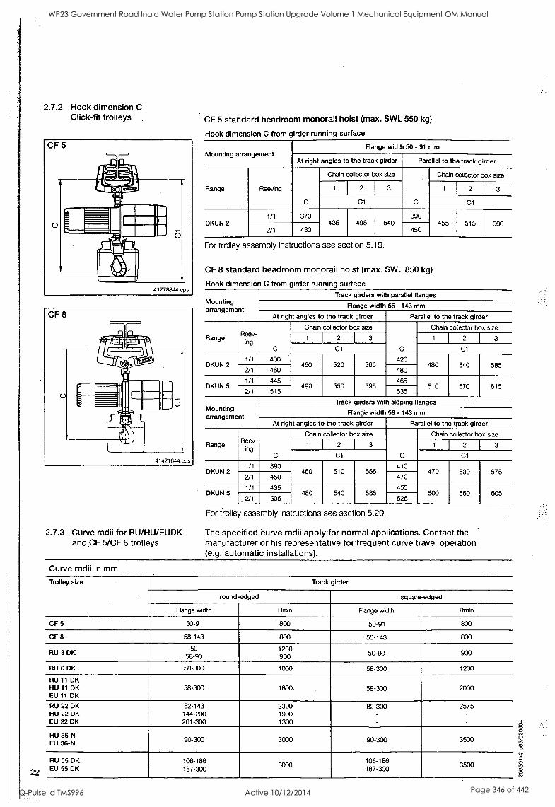
22
2.7.2 Hook dimension C Click-fit trolleys
2.7.3 Curve radii for RU/HU/EUDK and CF 5/CF 8 trolleys
CF 5 standard headroom monorail hoist (max. SWL 550 kg)
Hook dimension C from girder running surface
Mounting arrangement Flange width 50 - 91 mm
At right angles to the track girder Parallel to the track girder
Range Reeving
C
Chain collector box size
C
Chain collector box size
1 2 3 1 2 3
Cl Cl
DKUN 2 1/1 370
435 495 540 390
455 515 560 2/1 430 450
For trolley assembly instructions see section 5.19.
CF 8 standard headroom monorail hoist (max. SWL 850 kg)
Hook dimension C from girder running surface
Mounting arrangement
Track girders with parallel flanges
Flange width 55 - 143 mm
At right angles to the track girder Parallel to the track girder
Range R eev- Ring
C
Chain collector box size
C
Chain collector box size
1 2 3 1 2 3
Cl Cl
DKUN 2 1/1 400
460 520 565 420
480 540 585 2/1 460 480
DKUN 5 1/1 445
490 550 595 465
510 570 615 2/1 515 535
Mounting arrangement
Track girders with sloping flanges
Flange width 58 - 143 mm
At right angles to the track girder Parallel to the track girder
Range R e
inev- g C
Chain collector box size
C
Chain collector box size
1 2 3 1 2 3
C1 Cl
DKUN 2 1/1 390
450 510 555 410
470 530 575 2/1 450 470
DKUN 5 1/1 435
480 540 585 455
500 560 605 2/1 505 525
For trolley assembly instructions see section 5.20.
The specified curve radii apply for normal applications. Contact the -
manufacturer or his representative for frequent curve travel operation (e.g. automatic installations).
Curve radii in mm
Trolley size Track girder
round-edged square-edged
Range width Rmin Range width Rmin
CF 5 50-91 800 50-91 800
CF 8 58-143 800 55-143 800
RU 3 DK 50
58-90 1200 900 50-90 900
RU 6 DK 58-300 1000 58-300 1200
RU 11 DK HU 11 DK EU 11 DK
58-300 1800 58-300 2000
RU 22 DK HU 22 DK EU 22 DK
82-143 144-200 201-300
2300 1900 1300
82-300 -
2575
-
RU 36-N EU 36-N 90-300 3000 90-300 3500
RU 55 DK EU 55 DK
106-186 187-300
3000 106-186 187-300
3500
WP23 Government Road Inala Water Pump Station Pump Station Upgrade Volume 1 Mechanical Equipment OM Manual
Q-Pulse Id TMS996 Active 10/12/2014 Page 346 of 442
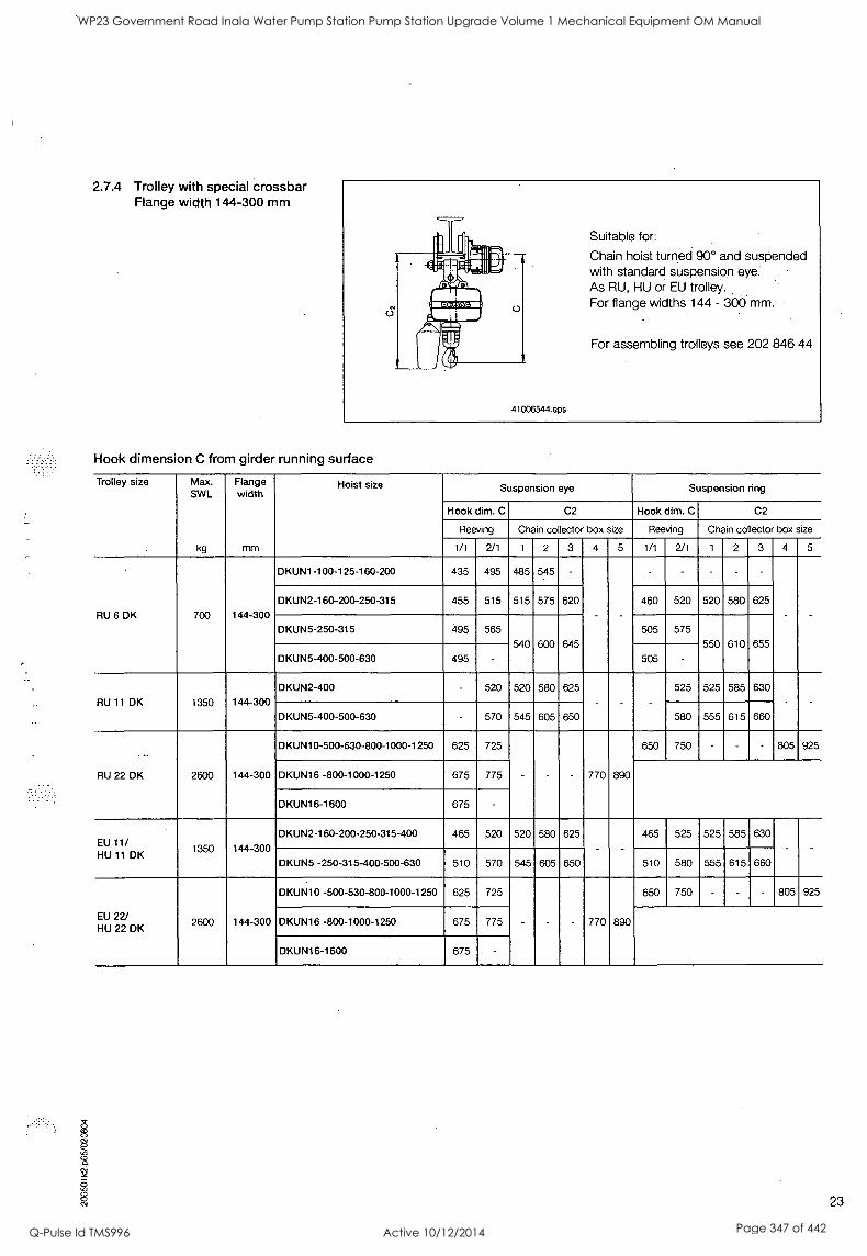
2.7.4 Trolley with special crossbar Flange width 144-300 mm
41006544.eps
Suitable for:
Chain hoist turned 90° and suspended with standard suspension eye. As RU, HU or EU trolley. For flange widths 144 - 300 mm.
For assembling trolleys see 202 846 44
Hook dimension C from girder running surface
Trolley size Max. SWL
kg
Flange width
mm
Hoist size Suspension eye Suspension ring
Hook dim. C C2 Hook dim. C C2
Reeving Chain collecto box size Reeving Chain co lector box size
1/1 2/1 1 2 3 4 5 1/1 2/1 1 2 3 4 5
RU 6 DK 700 144-300
DKUN1-100-125-160-200 435 495 485 545 -
- - - -
DKUN2-160-200-250-315 455 515 515 575 620 460 520 520 580 625
DKUN5-250-315 495 565
540 600 645
505 575
550 610 655
DKUN5-400-500-630 495 505 -
RU 11 DK 1350 144-300
DKUN2-400 520 520 580 625
- -
525 525 585 630
DKUN5-400-500-630 - 570 545 605 650 580 555 615 660
...
RU 22 DK 2600 144-300
DKUN10-500-630-800-1000-1250 625 725
- - 770 890
650 750 - - - 805 925
DKUN16 -800-1000-1250 675 775
DKUN16-1600 675 -
EU 11/ HU 11 DK
1350 144-300
DKUN2-160-200-250-315-400 465 520 520 580 625 465 525 525 585 630
-
DKUN5 -250-315-400-500-630 510 570 545 605 650 510 580 555 615 660
EU 22/ HU 22 DK
2600 144-300
DKUN10 -500-530-800-1000-1250 625 725
- - 770 890
650 750 - - - 805 925
DKUN16 -800-1000-1250 675 775
DKUN16-1600 675 -
23
WP23 Government Road Inala Water Pump Station Pump Station Upgrade Volume 1 Mechanical Equipment OM Manual
Q-Pulse Id TMS996 Active 10/12/2014 Page 347 of 442
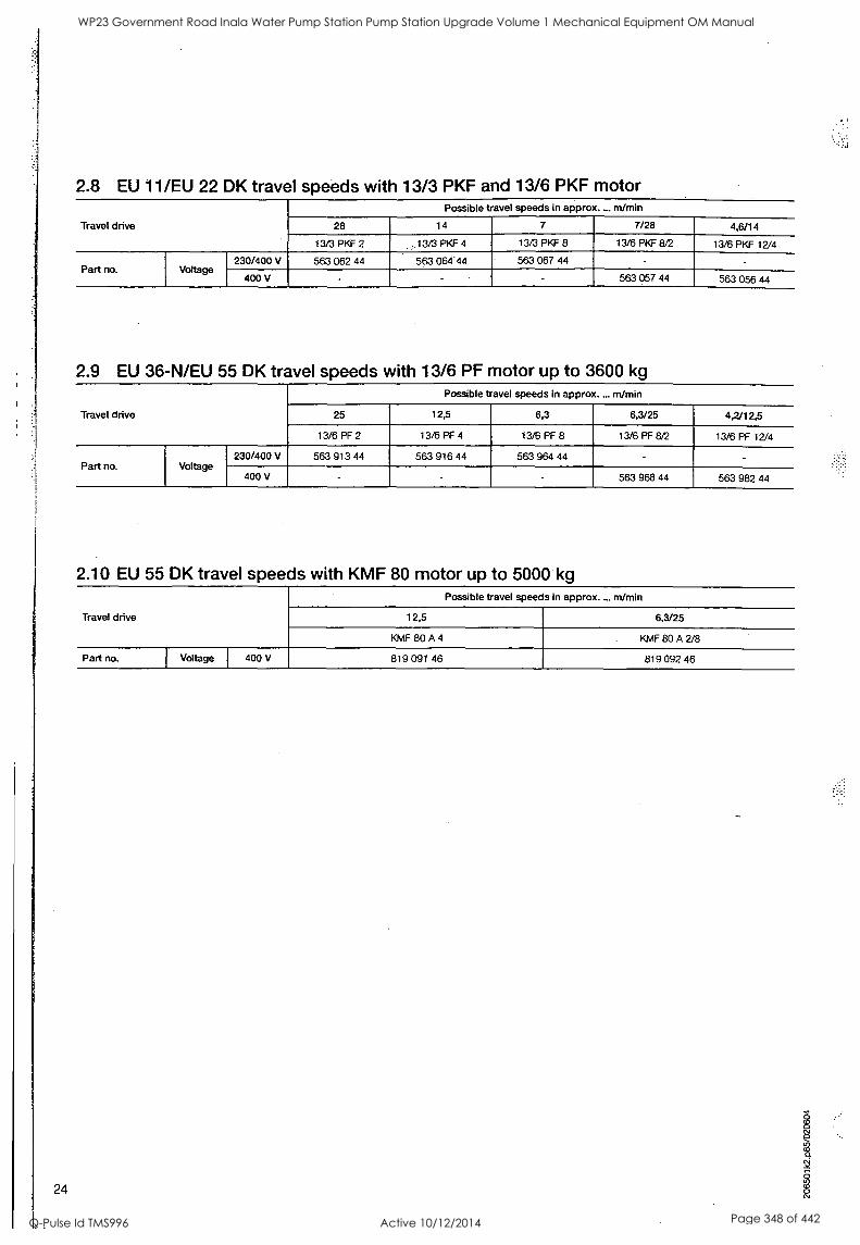
2.8 EU 11/EU 22 DK travel speeds with 13/3 PKF and 13/6 PKF motor
Travel drive
Possible travel speeds in approx... m/min
28 14 7 7/28 4,6/14
13/3 PiT 2 ,.13/3 PKF 4 13/3 PIGF 8 13/6 PKF 8/2 13/6 PKF 12/4
Part no. Voltage 230/400 V 563 062 44 563 064:44 563 067 44
400 V 563 057 44 563 056 44
2.9 EU 36-N/EU 55 DK travel speeds with 13/6 PF motor up to 3600 kg
Travel drive
Possible travel speeds in approx.... m/min
25 12,5 6,3 6,3/25 4,2/12,5
13/6 PF 2 13/6 PF 4 13/6 PF 8 13/6 PF 8/2 13/6 PF 12/4
Part no. Voltage 230/400 V 563 913 44 563 916 44 563 964 44
400 V 563 968 44 563 982 44
2.10 EU 55 DK travel speeds with KMF 80 motor up to 5000 kg
Travel drive
Possible travel speeds in approx.... m/min
12,5 6,3/25
KMF 80 A 4 KMF 80 A 2/8
Part no. I Voltage 400 V 819 091 46 819 092 46
24
WP23 Government Road Inala Water Pump Station Pump Station Upgrade Volume 1 Mechanical Equipment OM Manual
Q-Pulse Id TMS996 Active 10/12/2014 Page 348 of 442

O
25
WP23 Government Road Inala Water Pump Station Pump Station Upgrade Volume 1 Mechanical Equipment OM Manual
Q-Pulse Id TMS996 Active 10/12/2014 Page 349 of 442
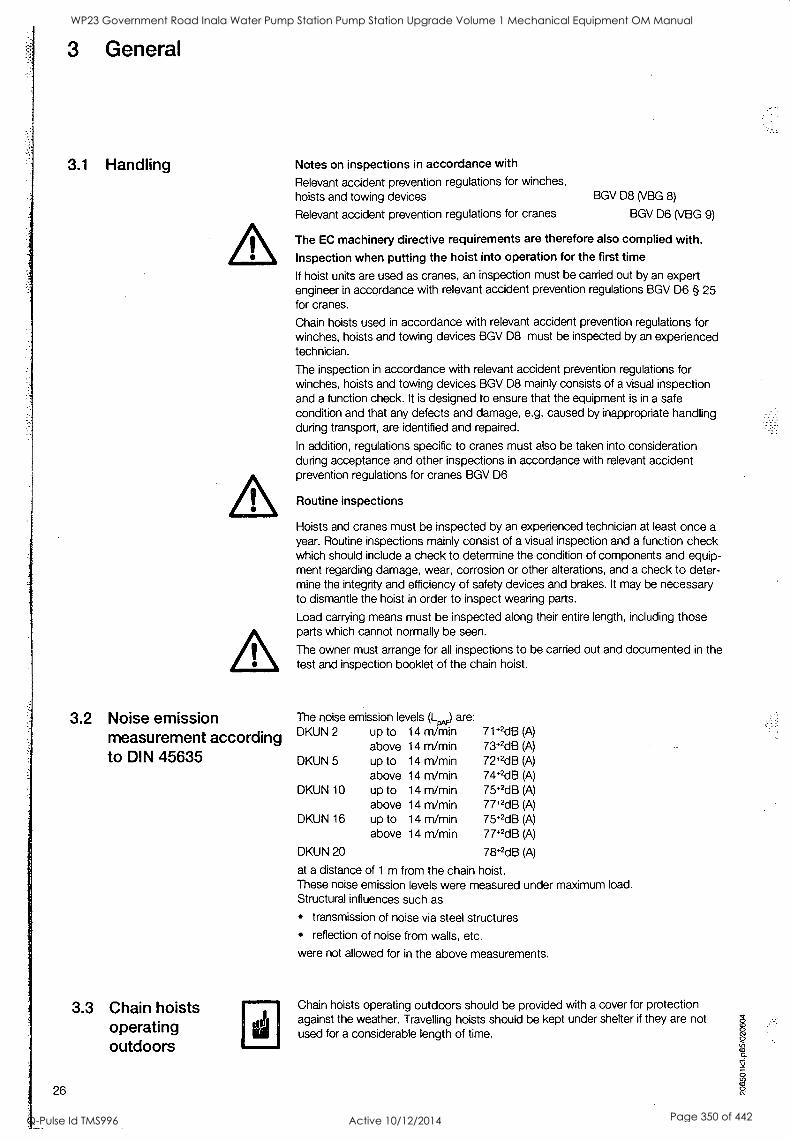
3 General
3.1 Handling Notes on inspections in accordance with
Relevant accident prevention regulations for winches, hoists and towing devices
3.2 Noise emission measurement according to DIN 45635
3.3 Chain hoists operating outdoors
26
BGV D8 (VBG 8)
Relevant accident prevention regulations for cranes BGV D6 (VBG 9)
The EC machinery directive requirements are therefore also complied with. Inspection when putting the hoist into operation for the first time
If hoist units are used as cranes, an inspection must be carried out by an expert engineer in accordance with relevant accident prevention regulations BGV D6 § 25 for cranes.
Chain hoists used in accordance with relevant accident prevention regulations for winches, hoists and towing devices BGV D8 must be inspected by an experienced technician.
The inspection in accordance with relevant accident prevention regulations for winches, hoists and towing devices BGV D8 mainly consists of a visual inspection and a function check. It is designed to ensure that the equipment is in a safe condition and that any defects and damage, e.g. caused by inappropriate handling during transport, are identified and repaired.
In addition, regulations specific to cranes must also be taken into consideration during acceptance and other inspections in accordance with relevant accident prevention regulations for cranes BGV D6
Routine inspections
Hoists and cranes must be inspected by an experienced technician at least once a
year. Routine inspections mainly consist of a visual inspection and a function check which should include a check to determine the condition of components and equip- ment regarding damage, wear, corrosion or other alterations, and a check to deter- mine the integrity and efficiency of safety devices and brakes. It may be necessary to dismantle the hoist in order to inspect wearing parts.
Load carrying means must be inspected along their entire length, including those parts which cannot normally be seen.
The owner must arrange for all inspections to be carried out and documented in the test and inspection booklet of the chain hoist.
The noise emission levels (L ) are: DKUN 2 up to 14 m min 71*2dB (A)
above 14 m/min 73 *2dB (A)
DKUN 5 up to 14 m/min 72+2dB (A)
above 14 m/min 74+2dB (A)
DKUN 10 up to 14 m/min 75+2dB (A)
above 14 m/min 77+2dB (A)
DKUN 16 up to 14 m/min 75+2dB (A)
above 14 m/min 77+2dB (A)
DKUN 20 78+2dB (A)
at a distance of 1 m from the chain hoist. These noise emission levels were measured under maximum load. Structural influences such as
transmission of noise via steel structures
reflection of noise from walls, etc.
were not allowed for in the above measurements.
Chain hoists operating outdoors should be provided with a cover for protection against the weather. Travelling hoists should be kept under shelter if they are not used for a considerable length of time.
WP23 Government Road Inala Water Pump Station Pump Station Upgrade Volume 1 Mechanical Equipment OM Manual
Q-Pulse Id TMS996 Active 10/12/2014 Page 350 of 442
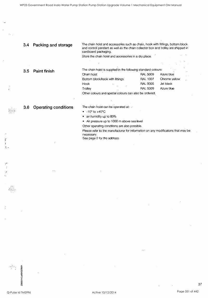
3.4 Packing and storage The chain hoist and accessories such as chain, hook with fittings, bottom block and control pendant as well as the chain collector box and trolley are shipped in
cardboard packaging.
Store the chain hoist and accessories in a dry place.
3.5 Paint finish The chain hoist is supplied in the following standard colours:
Chain hoist RAL 5009 Azure blue
Bottom block/hook with fittings RAL 1007 Chrome yellow
Hook RAL 9005 Jet black
Trolley RAL 5009 Azure blue
Other colours and special colours can also be ordered.
3.6 Operating conditions The chain hoist can be operated at: .
-10° to +40°C
air humidity up to 80%
Air pressure up to 1000 m above sea level
Other operating conditions are also possible.
Please refer to the manufacturer for information on any modifications that may be necessary. See page 2 for the address.
27
WP23 Government Road Inala Water Pump Station Pump Station Upgrade Volume 1 Mechanical Equipment OM Manual
Q-Pulse Id TMS996 Active 10/12/2014 Page 351 of 442
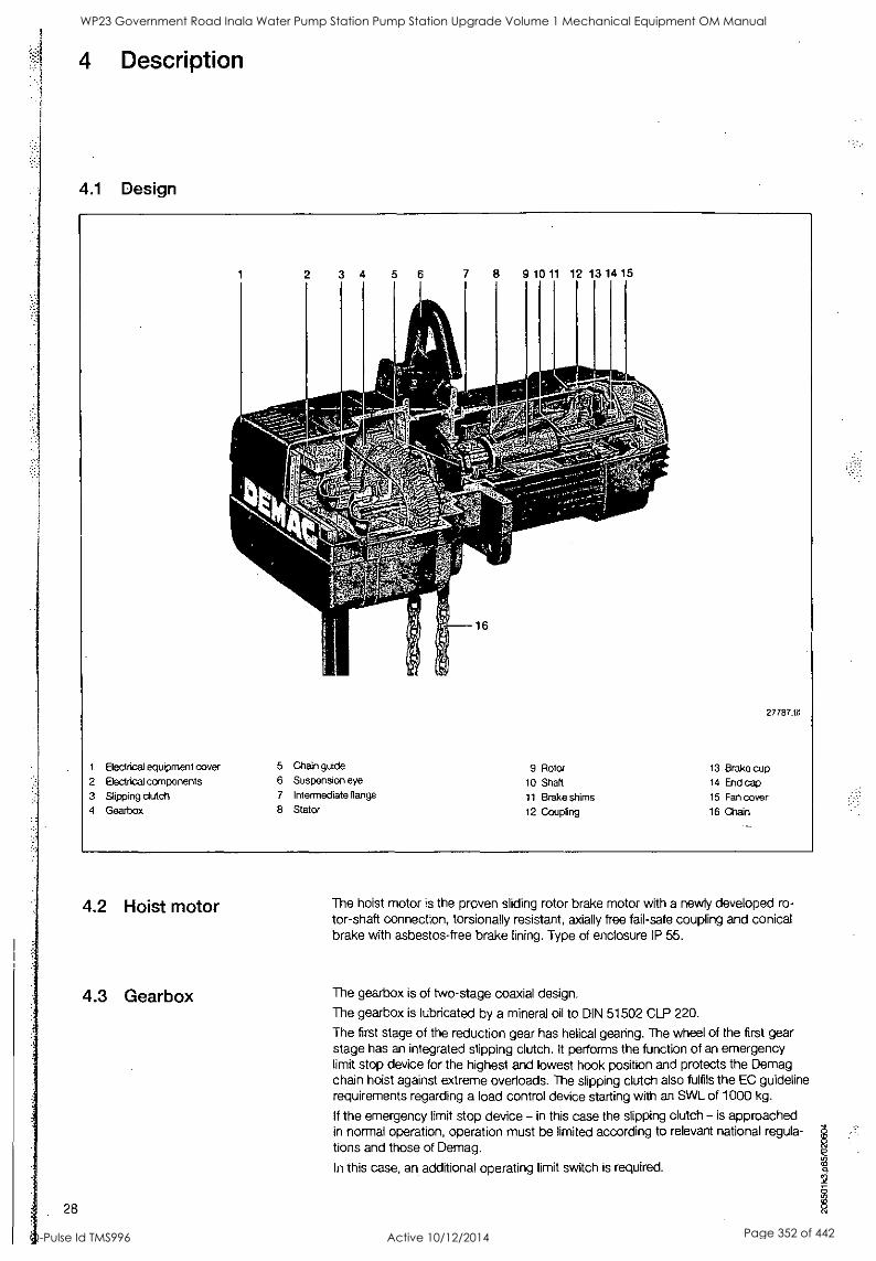
4 Description
4.1 Design
2 3 4 6 7 9 10 11 12 13 14 15
27787.W
1 Electrical equipment cover 5 Chain guide 9 Rotor 13 Brake cup 2 Electrical components 6 Suspension eye 10 Shaft 14 End cap 3 Slipping dutch 7 Intermediate flange 11 Brake shims 15 Fan cover 4 Gearbox 8 Stator 12 Coupling 16 Chain
4.2 Hoist motor
4.3 Gearbox
28
The hoist motor is the proven sliding rotor brake motor with a newly developed ro- tor-shaft connection, torsionally resistant, axially free fail-safe coupling and conical brake with asbestos-free brake lining. Type of enclosure IP 55.
The gearbox is of two-stage coaxial design.
The gearbox is lubricated by a mineral oil to DIN 51502 CLP 220.
The first stage of the reduction gear has helical gearing. The wheel of the first gear stage has an integrated slipping clutch. It performs the function of an emergency limit stop device for the highest and lowest hook position and protects the Demag chain hoist against extreme overloads. The slipping clutch also fulfils the EC guideline requirements regarding a load control device starting with an SWL of 1000 kg.
If the emergency limit stop device - in this case the slipping clutch - is approached in normal operation, operation must be limited according to relevant national regula- tions and those of Demag.
In this case, an additional operating limit switch is required.
WP23 Government Road Inala Water Pump Station Pump Station Upgrade Volume 1 Mechanical Equipment OM Manual
Q-Pulse Id TMS996 Active 10/12/2014 Page 352 of 442
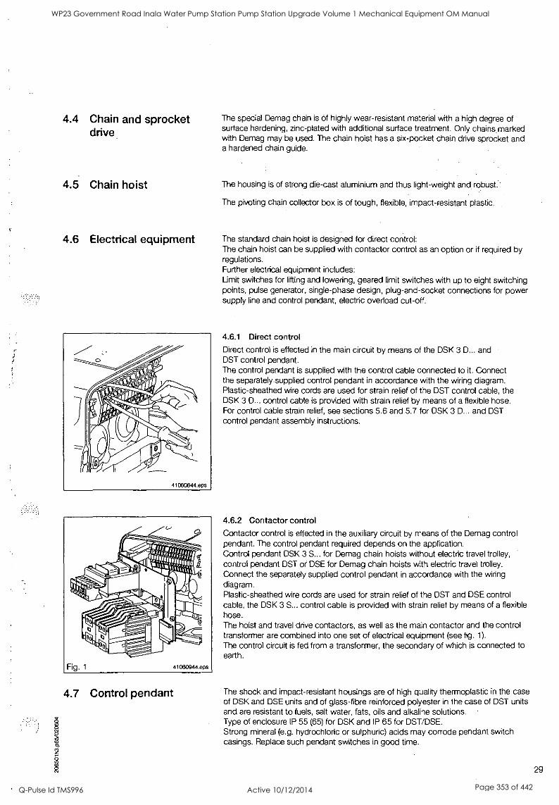
4.4 Chain and sprocket drive
The special Demag chain is of highly wear-resistant material with a high degree of surface hardening, zinc-plated with additional surface treatment. Only chains marked with Demag may be used. The chain hoist has a six-pocket chain drive sprocket and a hardened chain guide.
4.5 Chain hoist The housing is of strong die-cast aluminium and thus light-weight and robust.
The pivoting chain collector box is of tough, flexible, impact-resistant plastic.
4.6 Electrical equipment
4.7 Control pendant
The standard chain hoist is designed for direct control: The chain hoist can be supplied with contactor control as an option or if required by regulations. Further electrical equipment includes: Limit switches for lifting and lowering, geared limit switches with up to eight switching points, pulse generator, single-phase design, plug-and-socket connections for power supply line and control pendant, electric overload cut-off.
4.6.1 Direct control
Direct control is effected in the main circuit by means of the DSK 3 D... and DST control pendant. The control pendant is supplied with the control cable connected to it. Connect the separately supplied control pendant in accordance with the wiring diagram. Plastic-sheathed wire cords are used for strain relief of the DST control cable, the DSK 3 D... control cable is provided with strain relief by means of a flexible hose. For control cable strain relief, see sections 5.6 and 5.7 for DSK 3 D... and DST control pendant assembly instructions.
4.6.2 Contactor control
Contactor control is effected in the auxiliary circuit by means of the Demag control pendant. The control pendant required depends on the application. Control pendant DSK 3 S... for Demag chain hoists without electric travel trolley, control pendant DST or DSE for Demag chain hoists with electric travel trolley. Connect the separately supplied control pendant in accordance with the wiring diagram. Plastic-sheathed wire cords are used for strain relief of the DST and DSE control cable, the DSK 3 S... control cable is provided with strain relief by means of a flexible hose. The hoist and travel drive contactors, as well as the main contactor and the control transformer are combined into one set of electrical equipment (see fig. 1).
The control circuit is fed from a transformer, the secondary of which is connected to earth.
The shock and impact-resistant housings are of high quality thermoplastic in the case of DSK and DSE units and of glass-fibre reinforced polyester in the case of DST units and are resistant to fuels, salt water, fats, oils and alkaline solutions. Type of enclosure IP 55 (65) for DSK and IP 65 for DST/DSE.
o Strong mineral (e.g. hydrochloric or sulphuric) acids may corrode pendant switch casings. Replace such pendant switches in good time.
2
29
WP23 Government Road Inala Water Pump Station Pump Station Upgrade Volume 1 Mechanical Equipment OM Manual
Q-Pulse Id TMS996 Active 10/12/2014 Page 353 of 442
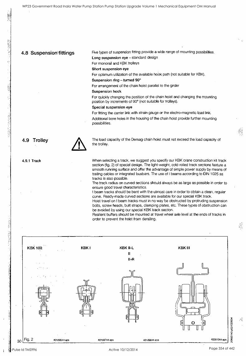
4.8 Suspension fittings
4.9 Trolley
4.9.1 Track
Five types of suspension fitting provide a wide range of mounting possibilities.
Long suspension eye - standard design
For monorail and KBK trolleys
Short suspension eye
For optimum utilization of the available hosok path (not suitable for KBK).
Suspension ring -turned 90°
For arrangement of the chain hoist parallel to the girder
Suspension hook
For quickly changing the position of the chain hoist and changing the mounting position by increments of 90° (not suitable for trolleys).
Special suspension eye
For fitting the carrier link with strain gauge or the electro-magnetic load link.
Additional bore holes in the housing of the chain hoist provide further mounting possibilities.
The load capacity of the Demag chain hoist must not exceed the load capacity of the trolley.
When selecting a track, we suggest you specify our KBK crane construction kit track section (fig. 2) of special design. The light-weight, cold-rolled track sections feature a smooth running surface and offer the advantage of simple power supply by means of trailing cables or integrated busbars. The use of I beams according to DIN 1025 as
tracks is also possible. The track radius on curved sections should always be as large as possible in order to ensure good travel characteristics. I beam tracks should be bent with the utmost care in order to obtain a clean, regular curve. Ready-made curved sections are available for our special KBK track. Hoist travel on I beam tracks must in no way be obstructed by protruding suspension bolts, screw heads, butt straps, clamping plates, etc. These types of obstruction can be avoided by using our special KBK track section. Resilient buffers should be mounted at travel wheel axle level at the ends of tracks in
order to prevent the hoist from derailing.
30
WP23 Government Road Inala Water Pump Station Pump Station Upgrade Volume 1 Mechanical Equipment OM Manual
Q-Pulse Id TMS996 Active 10/12/2014 Page 354 of 442
.206501k3.p65/020604
WP23 Government Road Inala Water Pump Station Pump Station Upgrade Volume 1 Mechanical Equipment OM Manual
Q-Pulse Id TMS996 Active 10/12/2014 Page 355 of 442
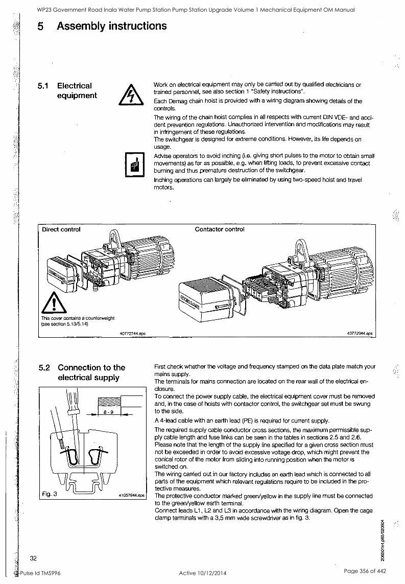
5 Assembly instructions
5.1 Electrical equipment
Work on electrical equipment may only be carried out by qualified electricians or trained personnel, see also section 1 "Safety instructions".
Each Demag chain hoist is provided with a wiring diagram showing details of the controls.
The wiring of the chain hoist complies in all respects with current DIN VDE- and acci- dent prevention regulations. Unauthorized intervention and modifications may result in infringement of these regulations. The switchgear is designed for extreme conditions. However, its life depends on usage.
Advise operators to avoid inching (i.e. giving short pulses to the motor to obtain small movements) as far as possible, e.g. when lifting loads, to prevent excessive contact burning and thus premature destruction of the switchgear.
Inching operations can largely be eliminated by using two-speed hoist and travel motors.
Direct control Contactor control
This cover contains a counterweight (see section 5.13/5.14)
40772744.eps 40772944.eps
5.2 Connection to the electrical supply
8 - 9
Fig. 3 41057944.eps
32
First check whether the voltage and frequency stamped on the data plate match your mains supply. The terminals for mains connection are located on the rear wall of the electrical en- closure. To connect the power supply cable, the electrical equipment cover must be removed and, in the case of hoists with contactor control, the switchgear set must be swung to the side.
A 4-lead cable with an earth lead (PE) is required for current supply.
The required supply cable conductor cross sections, the maximum permissible sup- ply cable length and fuse links can be seen in the tables in sections 2.5 and 2.6. Please note that the length of the supply line specified for a given cross section must not be exceeded in order to avoid excessive voltage drop, which might prevent the conical rotor of the motor from sliding into running position when the motor is switched on. The wiring carried out in our factory includes an earth lead which is connected to all parts of the equipment which relevant regulations require to be included in the pro- tective measures. The protective conductor marked green/yellow in the supply line must be connected to the green/yellow earth terminal. Connect leads L1, L2 and L3 in accordance with the wiring diagram. Open the cage clamp terminals with a 3,5 mm wide screwdriver as in fig. 3.
WP23 Government Road Inala Water Pump Station Pump Station Upgrade Volume 1 Mechanical Equipment OM Manual
Q-Pulse Id TMS996 Active 10/12/2014 Page 356 of 442
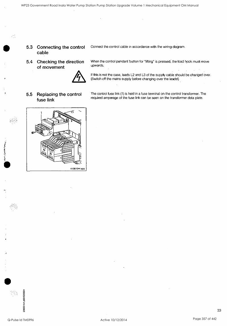
5.3 Connecting the control cable
5.4 Checking the direction of movement
5.5 Replacing the control fuse link
Connect the control cable in accordance with the wiring diagram.
When the control pendant button for "lifting" is pressed, the load hook must move upwards.
If this is not the case, leads L2 and L3 of the supply cable should be changed over. (Switch off the mains supply before changing over the leads!)
The control fuse link (1) is held in a fuse terminal on the control transformer. The required amperage of the fuse link can be seen on the transformer data plate.
33
WP23 Government Road Inala Water Pump Station Pump Station Upgrade Volume 1 Mechanical Equipment OM Manual
Q-Pulse Id TMS996 Active 10/12/2014 Page 357 of 442
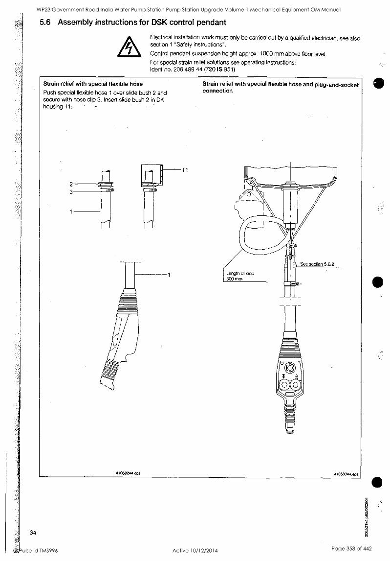
5.6 Assembly instructions for DSK control pendant
Electrical installation work must only be carried out by a qualified electrician, see also section 1 "Safety instructions".
Control pendant suspension height approx. 1000 mm above floor level.
For special strain relief solutions see operating instructions: (dent no. 206 489 44 (720 IS 951)
Strain relief with special flexible hose
Push special flexible hose 1 over slide bush 2 and secure with hose clip 3. Insert slide bush 2 in DK hoUSing 11
Strain relief with special flexible hose and plug-and-socket connection
11
See section 5.6.2
Length of loop 500 mm
41058244.eps 41058344.eps
34
WP23 Government Road Inala Water Pump Station Pump Station Upgrade Volume 1 Mechanical Equipment OM Manual
Q-Pulse Id TMS996 Active 10/12/2014 Page 358 of 442
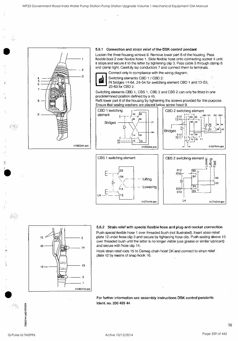
5.6.1 Connection and strain relief of the DSK control pendant Loosen the three housing screws 9. Remove lower part 8 of the housing. Pass flexible boot 2 over flexible hose 1. Slide flexible hose onto connecting socket 4 until it stops and secure it to the latter by tightening clip 3. Pass cable 5 through clamp 6
and clamp tight. Carefully lay conductors 7 and connect them to terminals.
Connect only in compliance with the wiring diagram.
Switching elements CBD 1 / CBD 2: Fit bridges 14-64, 24-54 for switching element CBD 1 and 13-53, 23-63 for CBD 2.
Switching elements CBD 1, CBS 1, CBD 2 and CBS 2 can only be fitted in one predetermined position defined by a rib. Refit lower part 8 of the housing by tightening the screws provided for this purpose. Ensure that sealing washers are placed below screw head 9.
CBD 1 switching element
l54 164 Bridges
(14 124
13- 1\123 13-
VI
WI
41059044.eps
CBS 1 switching element
L4
53
54 ---: Lifting
- Lowering
41274144 eps
CBD 2 switching element ElvEr,__)_6_3)....53i
64
112122
Bridges ,
012:
2v1 2W1
14 24
LL_ 13 j 23 I I I
12 ! 41057644.eps
CBS 2 switching element a, rn 3 -g tn. 0 J Li_
Eerfl,_ J5_3711 012
: 54
4' 4-
44
, ) 43 24 1
I
" 012 23 I L4 41274244.epS
5.6.2 Strain relief with special flexible hose and plug-and-socket connection
Push special flexible hose 1 over threaded bush (not illustrated). Insert strain relief plate 12 under hose clip 3 and secure by tightening hose clip. Push sealing sleeve 13
over threaded bush until the latter is no longer visible (use grease or similar lubricant) and secure with hose clip 14.
Hook strain relief rods 15 to Demag chain hoist DK and connect to strain relief plate 12 by means of snap hook 16.
For further information see assembly instructions DSK control pendants
Ident. no. 206 485 44
35
WP23 Government Road Inala Water Pump Station Pump Station Upgrade Volume 1 Mechanical Equipment OM Manual
Q-Pulse Id TMS996 Active 10/12/2014 Page 359 of 442
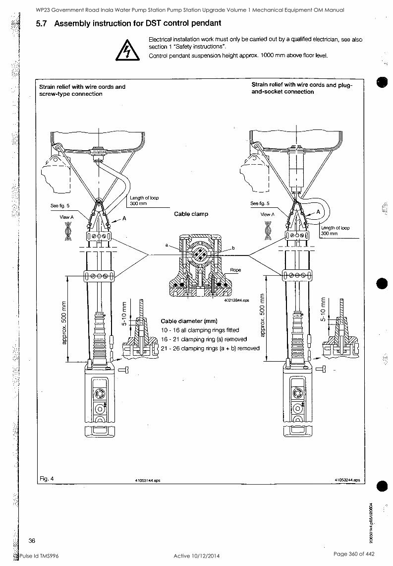
5.7 Assembly instruction for DST control pendant
Electrical installation work must only be carried out by a qualified electrician, see also section 1 "Safety instructions".
Control pendant suspension height approx. 1000 mm above floor level.
Strain relief with wire cords and screw-type connection
Strain relief with wire cords and plug- and-socket connection
Length of loop 300 mm See fig. 5
Fig. 4
View A Cable clamp View A
®
Length of loop 300 mm
Rope
E E O O
0 a a
40212844.eps
Cable diameter (mm)
10 - 16 all clamping rings fitted
16 - 21 clamping ring (a) removed
21 - 26 clamping rings (a + b) removed
E E O O
0 a a
E E O
41053144.eps 41053244.eps
36
WP23 Government Road Inala Water Pump Station Pump Station Upgrade Volume 1 Mechanical Equipment OM Manual
Q-Pulse Id TMS996 Active 10/12/2014 Page 360 of 442

Control pendant with sleeve protecting against kinking 18.
Strain relief by wire cords; see figs. 4 and 5.
Loosen the 4 or 6 housing screws 8. Remove lower part 7 of the housing. By tightening the two screws securing cap 12 to upper part 13 of the housing, press sleeve protecting against kinking 18 against the housing. Cut off sleeve prbtecting against kinking 18 as required for the relevant cable diameter (see markings on sleeve). Pass cable 2 through sleeve 18 and clamp 4 (small opening for-cables of 10-20 mm diameter and wide opening for cables of 20-26 mm diameter) and clamp the cable by tightening the screws. Tighten clip 19 on sleeve 18. This ensures that the cable inlet is water-tight. Carefully bunch conductors 5 behind clip 6 and connect them to terminals as required.
sig Connect only in compliance with the wiring diagram.
Only use bridges 33-34, 43-44 for switching element SED 1ZD and 11-22, 21-12 for switching element SED 2ZD. Remove bridges 34-62 and 44-52 on switching element SED 2ZD for lifting/lowering. Double switching elements SED 10 and SED 2D can only be fitted in one predetermined position defined by pin 14. Fit lower part 7 of the housing by tightening screws 8. Ensure that sealing washers are placed below screw heads 8.
SED 1ZD switching element
2 22
L2 - --
12 22:1311"
33
Bridges
41059144.eps
Strain relief by means of wire cords
Hook strain relief rods 32 to Demag chain hoist DK. Thread strain relief cords 33 through loops of strain relief rods 32 and insert in slots of retaining plates 34 (part no. 864 662 44) in the shape of an "S" (see fig. 5).
For further information see assembly instructions DST control pendants
Went. no. 206 165 44
37
WP23 Government Road Inala Water Pump Station Pump Station Upgrade Volume 1 Mechanical Equipment OM Manual
Q-Pulse Id TMS996 Active 10/12/2014 Page 361 of 442
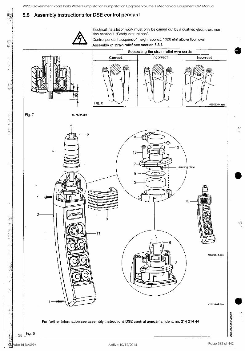
38
5.8 Assembly instructions for DSE control pendant
Electrical installation work must only be carried out by a qualified electrician, see also section 1 "Safety instructions".
Control pendant suspension height approx. 1000 mm above floor level.
Assembly of strain relief see section 5.8.3
Fig. 7
Fig. 6
41775244.eps
Separating the strain relief wire cords
Correct. Incorrect Incorrect
Centring plate
For further information see assembly instructions DSE control pendants, ident. no. 214 214 44
40989544.eps
41775444.eps
WP23 Government Road Inala Water Pump Station Pump Station Upgrade Volume 1 Mechanical Equipment OM Manual
Q-Pulse Id TMS996 Active 10/12/2014 Page 362 of 442
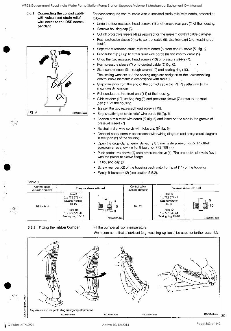
5.8.1 Connecting the control cable with vulcanised strain relief wire cords to the DSE control pendant
Table 1
For connecting the control cable with vulcanised strain relief wire cords, proceed as follows:
Undo the four recessed head screws (1) and remove rear part (2) of the housing.
Remove housing cap (3).
Cut off protective sleeve (4) as required for the relevant control cable diameter.
Push protective sleeve (4) onto control cable (5). Use lubricant (e.g. washing-up liquid).
Separate vulcanised strain relief wire cords (6) from control cable (5) (fig. 8).
Push tube clip (8) up to strain relief wire cords (6) and control cable (5).
Undo the two recessed head screws (13) of pressure sleeve (7).
Push pressure sleeve (7) onto control cable (5) (fig. 6).
Slide control cable (5) through washer (9) and sealing ring (10).
The sealing washers and the sealing rings are assigned to the corresponding control cable diameter in accordance with table 1..
Strip insulation from. the end of the control cable (fig. 7). Pay attention to the mounting dimensions!
Pull conductors into front part (11) of the housing.
Slide washer (10), sealing ring (9) and pressure sleeve (7) down to the front part (11) of the housing.
Tighten the two recessed head screws (13).
Strip sheathing of strain relief wire cords (6) (fig. 6).
Shorten strain relief wire cords (6) (fig. 6) and insert on the side in the groove of pressure sleeve (7)
Fix strain relief wire cords with tube clip (8) (fig. 6).
Connect conductors in accordance with wiring diagram and assignment diagram in rear part (2) of the housing.
Open the cage clamp terminals with a 3,5 mm wide screwdriver or an offset screwdriver as shown in fig. 9 (part no. 772 798 44).
Push protective sleeve (4) onto pressure sleeve (7). The protective sleeve is flush with the pressure sleeve flange.
Fit housing cap (3).
Screw rear part (2) of the housing back onto front part (11) of the housing.
Finally fit bumper (12) (see section 5.8.2).
Control cable outside diameter
Pressure sleeve with seal Control cable
outside diameter Pressure sleeve with seal
.
10,5 - 14,5
Item 9 2 x 772 576 44 Sealing washer
10-15 q
:_ti:
q
42029544.eps
9
10
9
15 - 20
Item 9 1 x 772 574 44 Sealing washer
15-20 q I
I
.
41800144.eps
9 q
01
Item 10 1 x 772 575 44
Sealing ring 10-15
Item 10 1 x 772 546 44
Sealing ring 15-20
5.8.2 Fitting the rubber bumper Fit the bumper at room temperature.
We recommend that a lubricant (e.g. washing-up liquid) be used for further assembly.
Pay attention to the protruding emergency-stop button.
42324844.eps 42330744.eps 42325844.eps 42324944.eps 39
WP23 Government Road Inala Water Pump Station Pump Station Upgrade Volume 1 Mechanical Equipment OM Manual
Q-Pulse Id TMS996 Active 10/12/2014 Page 363 of 442
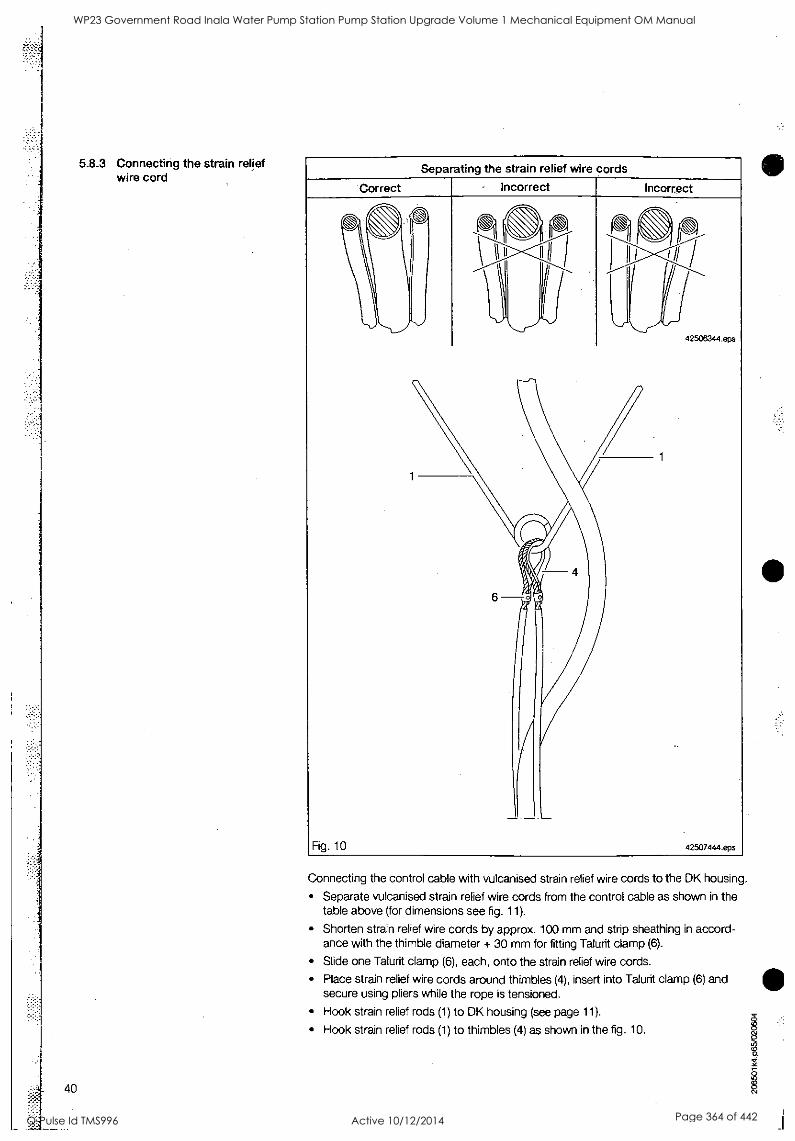
5.8.3 Connecting the strain relief wire cord
Separating the strain relief wire cords
Incorrect
Fig. 10
1
42506344.eps
42507444.eps
Connecting the control cable with vulcanised strain relief wire cords to the DK housing.
Separate vulcanised strain relief wire cords from the control cable as shown in the table above (for dimensions see fig. 11).
Shorten strain relief wire cords by approx. 100 mm and strip sheathing in accord- ance with the thimble diameter + 30 mm for fitting Talurit clamp (6).
Slide one Talurit clamp (6), each, onto the strain relief wire cords.
Place strain relief wire cords around thimbles (4), insert into Talurit clamp (6) and secure using pliers while the rope is tensioned.
Hook strain relief rods (1) to DK housing (see page 11).
Hook strain relief rods (1) to thimbles (4) as shown in the fig. 10.
O
40
WP23 Government Road Inala Water Pump Station Pump Station Upgrade Volume 1 Mechanical Equipment OM Manual
Q-Pulse Id TMS996 Active 10/12/2014 Page 364 of 442
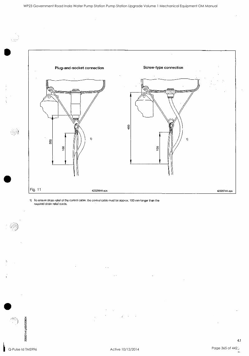
g )
Fig. 11
Plug-and-socket connection Screw-type connection
1) 1)
42325644.eps 42325744.eps
1) To ensure strain relief of the control cable, the control cable must be approx. 100 mm longer than the required strain relief cords.
WP23 Government Road Inala Water Pump Station Pump Station Upgrade Volume 1 Mechanical Equipment OM Manual
Q-Pulse Id TMS996 Active 10/12/2014 Page 365 of 442
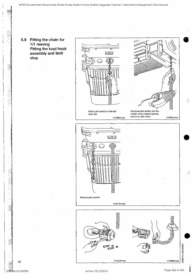
5.9 Fitting the chain for 1/1 reeving Fitting the load hook assembly and limit stop
42
0 0
Attach pilot section to the last chain link.
41056844.eps
Introduce pilot section into the middle cross-shaped opening and run in with motor. 41056944.eps
1
WP23 Government Road Inala Water Pump Station Pump Station Upgrade Volume 1 Mechanical Equipment OM Manual
Q-Pulse Id TMS996 Active 10/12/2014 Page 366 of 442
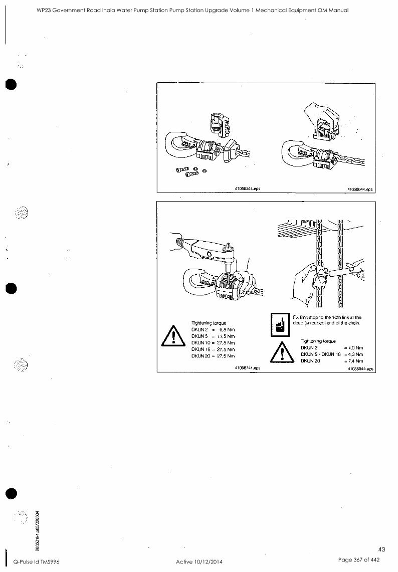
Tightening torque DKUN 2 = 6,8 Nm DKUN 5 = 11,5 Nm
DKUN 10 = 27,5 Nm DKUN 16 = 27,5 Nm
DKUN 20 = 27,5 Nm
41058744.eps
Fix limit stop to the 10th ink at the dead (unloaded) end of the chain.
Tightening torque
DKUN 2 = 4,0 Nm
DKUN 5 - DKUN 16 = 4,3 Nm
DKUN 20 = 7,4 Nm
41058844.eps
43
WP23 Government Road Inala Water Pump Station Pump Station Upgrade Volume 1 Mechanical Equipment OM Manual
Q-Pulse Id TMS996 Active 10/12/2014 Page 367 of 442
44
5.10 Fitting the chain for 211 reeving Fitting the bottom block and limit stop
Remove bolt
41055844.eps
Fit chain anchorage to last chain link
41055944.eps
Press chain anchorage halves together and fit into chain guide base plate
Tightening torque
DKUN 2 = 10,4 Nm
DKUN 5 = 25 Nm
DKUN 10 = 55 Nm
DKUN 16 = 55 Nm
DKUN 20 = 79 Nm
Refit base plate and tighten bolts to specified tightening torque.
41056144.eps
Attach pilot section to last chain link
41056244.eps
Introduce pilot section into the middle cross- shaped opening and run in with motor
41056344.eps
s
WP23 Government Road Inala Water Pump Station Pump Station Upgrade Volume 1 Mechanical Equipment OM Manual
Q-Pulse Id TMS996 Active 10/12/2014 Page 368 of 442
41056444.eps
Align the chain by lifting and turning the chain anchorage.
The chain is correctly aligned when the chain links are not twisted.
41056544.eps 41057144.eps
Tightening torque
DKUN 2 = 11,5 Nm
DKUN 5 = 27,5 Nm DKUN 10 = 55 Nm
DKUN 16 = 55 Nm
DKUN 20 = 55 Nm
41057244.eps 41057344.eps
Fx imit stop to the 10th link at the dead (unloaded) end of the chain
Tightening torque
DKUN 2 = 4,0 Nm
DKUN 5 - DKUN 16 = 4,3 Nm
DKUN 20 = 7,4 Nm
41057444.eps
WP23 Government Road Inala Water Pump Station Pump Station Upgrade Volume 1 Mechanical Equipment OM Manual
Q-Pulse Id TMS996 Active 10/12/2014 Page 369 of 442
46
5.11 Converting suspension eye, suspension hook and suspension ring from 1/1 to 2/1 reeving
Suspension hook DKUN 2- DKUN 5- DKUN 10
Suspension ring turned 90° DKUN 2- DKUN 5- DKUN 10
WP23 Government Road Inala Water Pump Station Pump Station Upgrade Volume 1 Mechanical Equipment OM Manual
Q-Pulse Id TMS996 Active 10/12/2014 Page 370 of 442
5.12 Fitting the chain collector box
47
WP23 Government Road Inala Water Pump Station Pump Station Upgrade Volume 1 Mechanical Equipment OM Manual
Q-Pulse Id TMS996 Active 10/12/2014 Page 371 of 442
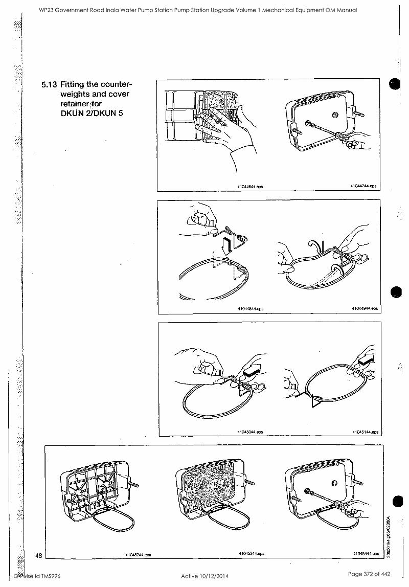
5.13 Fitting the counter- weights and cover retainerfor DKUN 2/DKUN 5
48
WP23 Government Road Inala Water Pump Station Pump Station Upgrade Volume 1 Mechanical Equipment OM Manual
Q-Pulse Id TMS996 Active 10/12/2014 Page 372 of 442
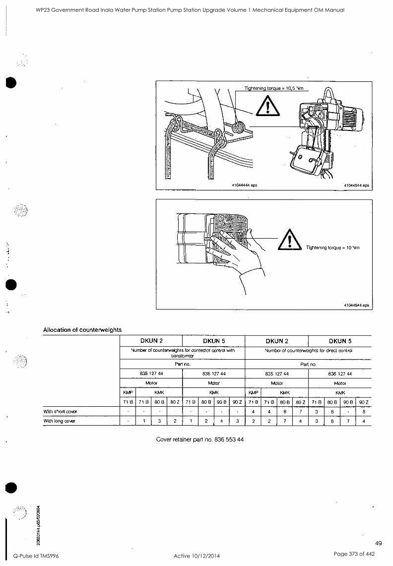
S
Allocation of counterweights
DKUN 2 DKUN 5 DKUN 2 DKUN 5
Number of counterweights for contactor control with transformer
Number of counterweights for direct control
Part no. Part no.
835 127 44 836 127 44 835 127 44 836 127 44
Motor Motor Motor Motor
KMP KMK KMK KMP KMK KMK
71 B 71 B 80 B 80 Z 71 B 80 B 90 B 90 Z 71 B 71 B BO B 80 Z 71 B 80 B 90 B 90 Z
With short cover 4 4 8 7 3 6 8
With long cover 1 3 2 1 2 4 3 2 2 7 4 3 6 7 4
Cover retainer part no. 836 553 44
49
WP23 Government Road Inala Water Pump Station Pump Station Upgrade Volume 1 Mechanical Equipment OM Manual
Q-Pulse Id TMS996 Active 10/12/2014 Page 373 of 442
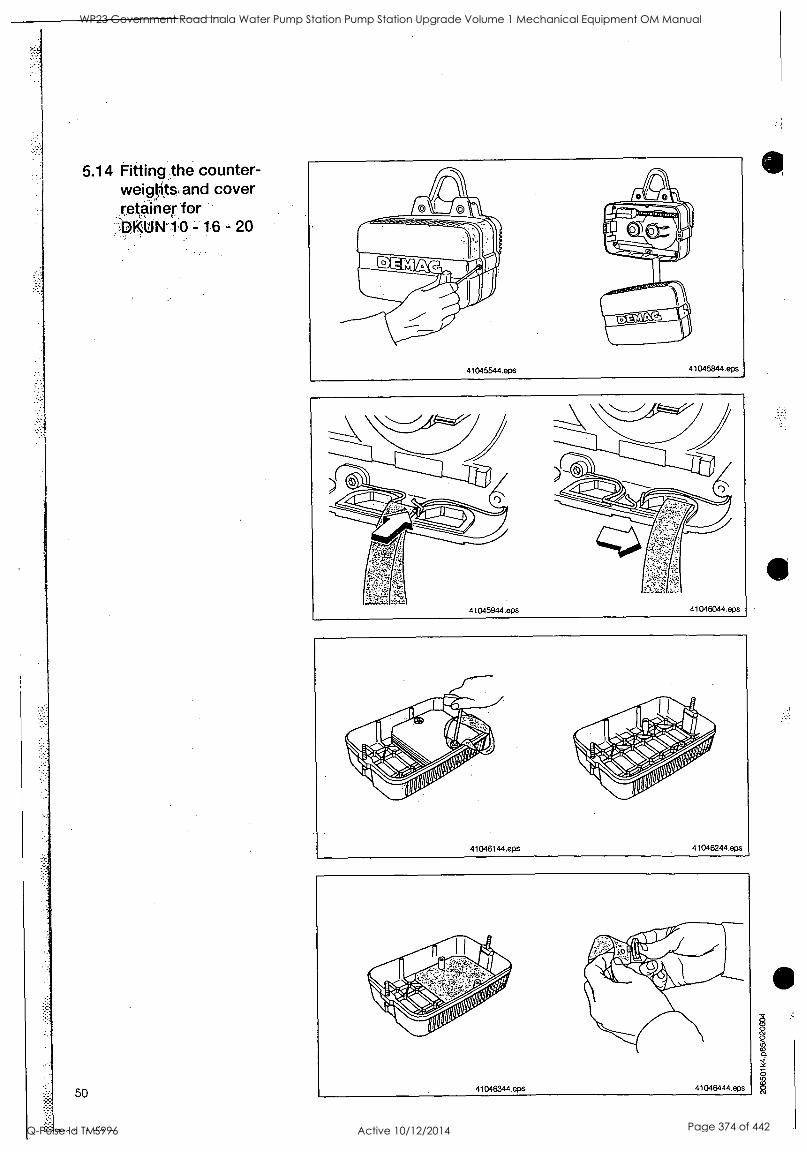
5.14 Fitting the counter- weights and cover retainer for PPM' 10 - 16 - 20
50
WP23 Government Road Inala Water Pump Station Pump Station Upgrade Volume 1 Mechanical Equipment OM Manual
Q-Pulse Id TMS996 Active 10/12/2014 Page 374 of 442
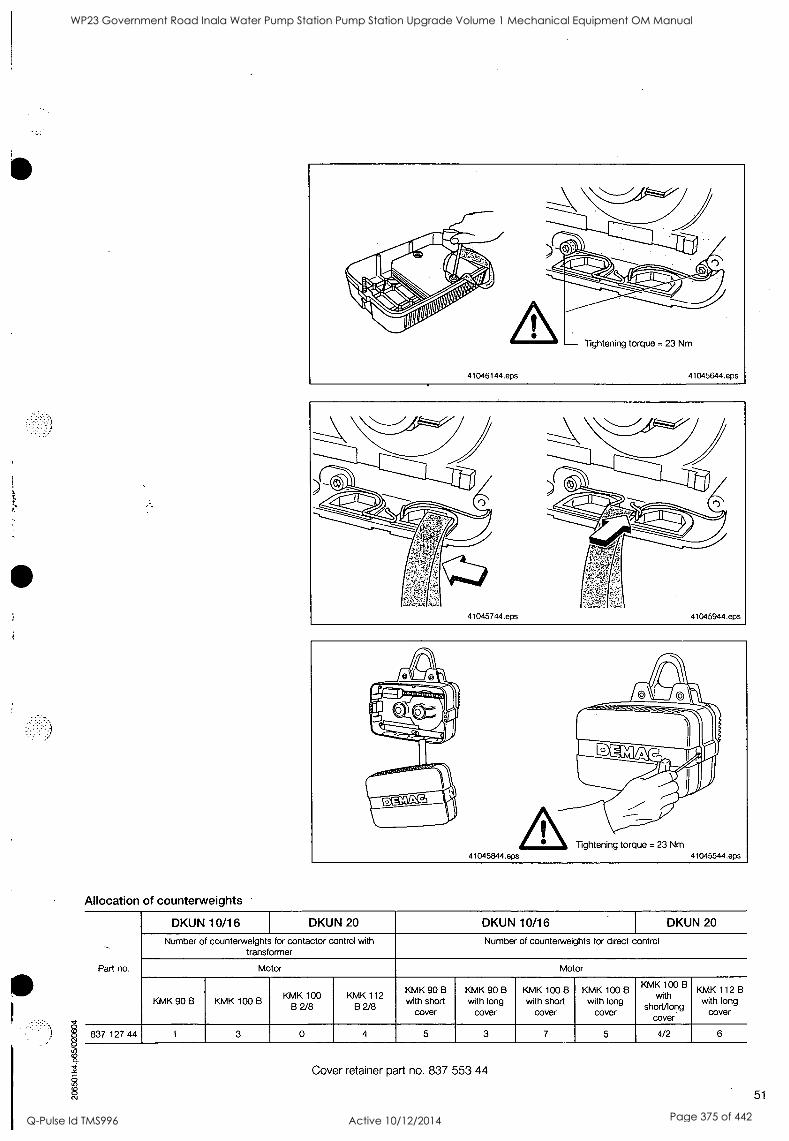
Allocation of counterweights
Tightening torque = 23 Nm 41045544.eps
Part no.
DKUN 10/16 DKUN 20 DKUN 10/16 DKUN 20
Number of counterweights for contactor control with transformer
Number of counterweights for direct control
Motor Motor
KMK 90 B KMK 100 B KMK 100
B 2/8 KMK 112
B 2/8
KMK 90 B with short
cover
KMK 90 B
with long cover
KMK 100 B
with short cover
KMK 100 B with long
cover
KMK 100 B with
short/long cover
KMK 112 B with long
cover
837 127 44 1 3 0 4 5 3 7 5 4/2 6
Cover retainer part no. 837 553 44
51
WP23 Government Road Inala Water Pump Station Pump Station Upgrade Volume 1 Mechanical Equipment OM Manual
Q-Pulse Id TMS996 Active 10/12/2014 Page 375 of 442
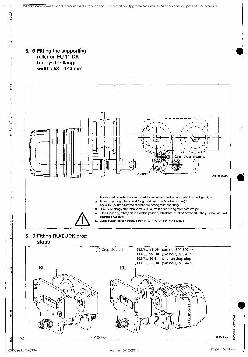
52
5.15 Fitting the supporting roller on, EU 11 DK trolleys for flange widths 58 -143 mm
H
r ------------ -
I 1, - \ /
4,r(
11111IIIIP"
0.5mm Adjust clearance
0
M A10Nm 20654844.eps
1. Position trolley on the track so that all 4 travel wheels are in contact with the running surface.
2. Press supporting roller against flange and secure with locking screw (1).
Adjust to 0,5 mm clearance between supporting roller and flange.
3. Run trolley along entire track to make sure that the supporting roller does not jam.
4. If the supporting roller jams in a certain position, adjustment must be corrected in this position (required clearance: 0,5 mm)
5. Subsequently tighten locking screw (1) with 10 Nm tightening torque.
5.16 Fitting RU/EUDK drop stops
0 Drop stop set
41175544.eps
EU
RU/EU 11 DK RU/EU 22 DK RU/EU 36N
1 RU/EU 55 DK
part no. 839 697 44 part no. 839 698 44 Cast-on drop stop part no. 839 699 44
41175644.eps
WP23 Government Road Inala Water Pump Station Pump Station Upgrade Volume 1 Mechanical Equipment OM Manual
Q-Pulse Id TMS996 Active 10/12/2014 Page 376 of 442
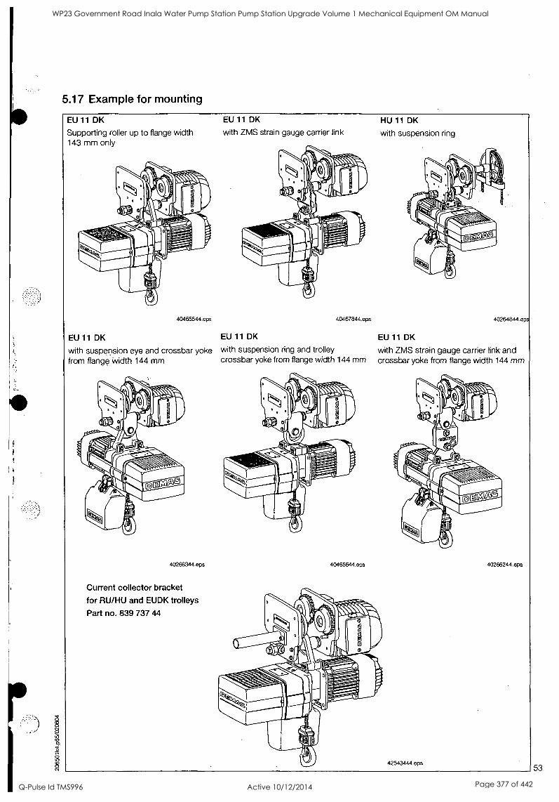
5.17 Example for mounting
EU 11 DK
Supporting roller up to flange width 143 mm only
40465544.eps
EU 11 DK
with ZMS strain gauge carrier link
40467844.eps
EU 11 DK EU 11 DK
with suspension eye and crossbar yoke with suspension ring and trolley from flange Width 144 mm crossbar yoke from flange width 144 mm
40266344.eps
Current collector bracket
for RU/HU and EUDK trolleys
Part no. 839 737 44
40465644.eps
HU 11 DK
with suspension ring
40264844.eps
EU 11 DK
with ZMS strain gauge carrier link and crossbar yoke from flange width 144 mm
42543444.eps
40266244.eps
53
WP23 Government Road Inala Water Pump Station Pump Station Upgrade Volume 1 Mechanical Equipment OM Manual
Q-Pulse Id TMS996 Active 10/12/2014 Page 377 of 442
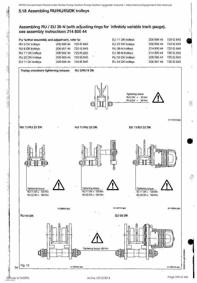
5.18 Assembling RU/HU/EUDK trolleys
Assembling RU / EU 36-N (with adjusting rings for infinitely variable track gauge), see assembly instructions 214 800 44
For further assembly and adjustment, refer to: EU 11 DK trolleys 206 604 44 720 IS 845
RU 3 DK trolleys 206 600 44 720 IS 845 EU 22 DK trolleys 206 605 44 720 IS 845
RU 6 DK trolleys 206 601 44 720 IS 845 RU 36-N trolleys 214 800 44 720 IS 845
RU 11 DK trolleys 206 602 44 720..6,845 EU 36-N trolleys 214 800 44 720 IS 845
RU 22 DK trolleys 206 603 44 720 IS=845 RU 55 DK trolleys 206 580 44 720 IS 845
EU 11 DK trolleys 206 604 44 720 IS 845 EU 55 DK trolleys 206 581 44 720 IS 845
Trolley crossbars tightening torques RU 3/RU 6 DK
RU 11/RU 22 DK
Tightening torque
RU 11 DK = 120 Nm
RU 22 DK = 160 Nm
41268844.eps
RU 55 DK
Fig. 12
Tightening torque
RU 3 DK = 50 Nm
RU 6 DK = 80 Nm
HU 11/HU 22 DK
Tightening torque
HU 11 DK = 120 Nm
HU 22 DK = 160 Nm
41140744.epS
EU 55 DK
Tightening torque 160 Nm
41195444.eps
41141044.eps
EU 11/EU 22 DK
Tightening torque
EU 11 DK = 120 Nm
EU 22 DK= 160 Nm
41140944.eps
41195744.eps
WP23 Government Road Inala Water Pump Station Pump Station Upgrade Volume 1 Mechanical Equipment OM Manual
Q-Pulse Id TMS996 Active 10/12/2014 Page 378 of 442
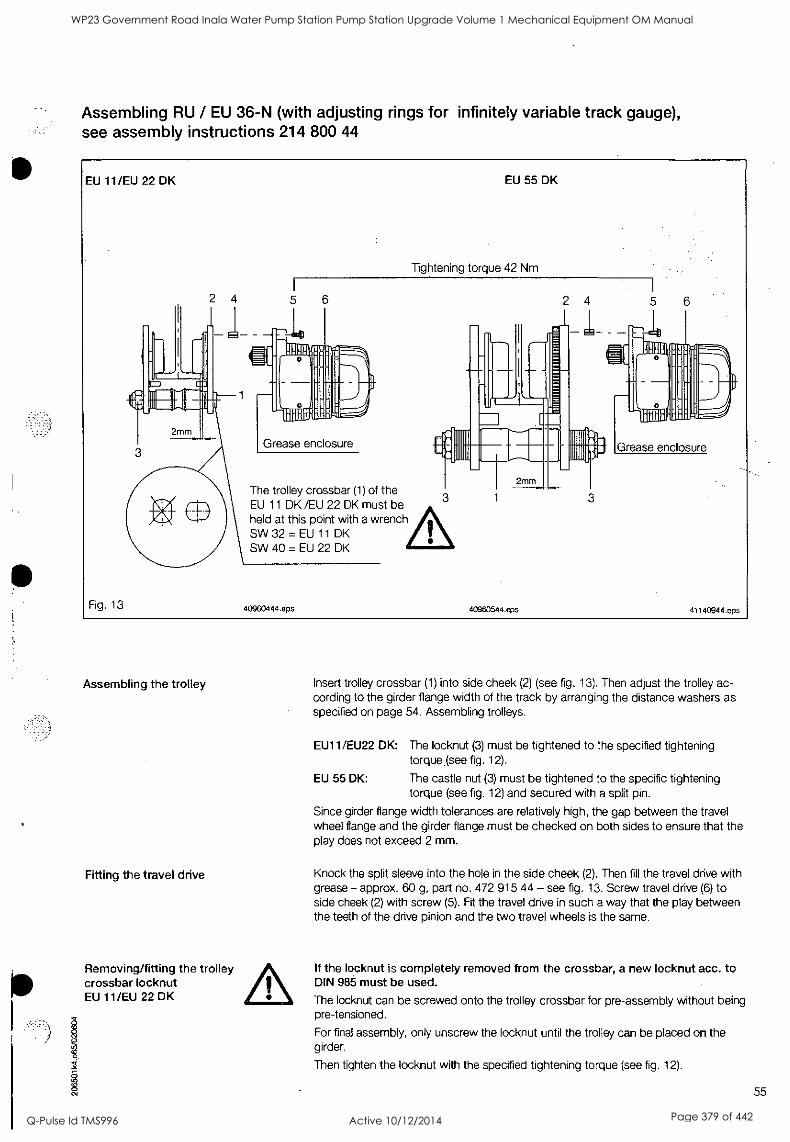
Assembling RU / EU 36-N (with adjusting rings for infinitely variable track gauge), see assembly instructions 214 800 44
EU 11/EU 22 DK
Fig. 13
2 4
EU 55 DK
Tightening torque 42 Nm
The trolley crossbar (1) of the EU 11 DK /EU 22 DK must be held at this point with a wrench SW 32 = EU 11 DK SW 40 = EU 22 DK
40960444.eps
2 4
1111111111 no 11,11111111111mm
2mm
40960544.eps
5
'1
IL RIR
VIM
Grease enclosure
41140944.eps
Assembling the trolley
Fitting the travel drive
Removing/fitting the trolley crossbar locknut EU 11/EU 22 DK
O
Insert trolley crossbar (1) into side cheek (2) (see fig. 13). Then adjust the trolley ac- cording to the girder flange width of the track by arranging the distance washers as specified on page 54. Assembling trolleys.
EU11/EU22 DK: The locknut (3) must be tightened to the specified tightening torque (see fig. 12).
EU 55 DK: The castle nut (3) must be tightened to the specific tightening torque (see fig. 12) and secured with a split pin.
Since girder flange width tolerances are relatively high, the gap between the travel wheel flange and the girder flange must be checked on both sides to ensure that the play does not exceed 2 mm.
Knock the split sleeve into the hole in the side cheek (2). Then fill the travel drive with grease - approx. 60 g, part no. 472 915 44 - see fig. 13. Screw travel drive (6) to side cheek (2) with screw (5). Fit the travel drive in such a way that the play between the teeth of the drive pinion and the two travel wheels is the same.
If the locknut is completely removed from the crossbar, a new locknut acc. to DIN 98 must be used.
The locknut can be screwed onto the trolley crossbar for pre-assembly without being pre-tensioned.
For final assembly, only unscrew the locknut until the trolley can be placed on the girder.
Then tighten the locknut with the specified tightening torque (see fig. 12).
cO, 55
WP23 Government Road Inala Water Pump Station Pump Station Upgrade Volume 1 Mechanical Equipment OM Manual
Q-Pulse Id TMS996 Active 10/12/2014 Page 379 of 442

5.19 Fitting the CF 5 trolleys
56
Locking element 1. Unlock locking element (see figure).
2. Open trolley.
41779144.eps 41779244.eps
41779344.eps
Locking element
41779444.eps
1. Place trolley travel roller on girder flange.
2. Close trolley.
When the trolley is fitted, the locking element must be clearly heared to lock into place. The knob used to unlock the trolley must be fully pushed into the locking element.
The trolley guide rollers come into con- tact with the girder when a load is sus- pended.
WP23 Government Road Inala Water Pump Station Pump Station Upgrade Volume 1 Mechanical Equipment OM Manual
Q-Pulse Id TMS996 Active 10/12/2014 Page 380 of 442
5.20 Fitting the CF 8 trolleys
Pay attention to girder type!
Fitting the trolleys
Locking element
41414844.eps
1. Unlock locking element (see figure).
2. Open trolley.
41414944.eps
1. Place trolley travel roller on girder flange.
2. Close trolley.
41415044.eps
Knob
Locking element
41651744.eps
When the trolley is fitted, the locking element must be clearly heared to lock into place. The knob used to unlock the trolley must be fully pushed into the locking element.
The trolley guide rollers come into contact with the girder when a load is suspended.
41415144.eps 57
WP23 Government Road Inala Water Pump Station Pump Station Upgrade Volume 1 Mechanical Equipment OM Manual
Q-Pulse Id TMS996 Active 10/12/2014 Page 381 of 442
Examples for mounting CF 5 trolleys
DK - at right angles to track girder
41778044.eps
DK - parallel to track girder
41778144.eps
Current collector bracket Part no 840 085 44
270
41778244.eps
Examples for mounting CF 8 trolleys
DK - at right angles to track girder
41420444.eps
DK - parallel to track girder Current collector bracket Part no. 840 055 44
41420344.eps 41651544.eps
1
WP23 Government Road Inala Water Pump Station Pump Station Upgrade Volume 1 Mechanical Equipment OM Manual
Q-Pulse Id TMS996 Active 10/12/2014 Page 382 of 442
5.21 Converting the travel drive for arduous operating conditions
Conversion to IP 55
To convert, proceed as follows:
1. Seal centring collar (2) using Loctite 573.
2. Replace standard rotor assembly (3) with a new one with weather-proof braking surface.
3. Fit motor seal (6) between motor end cap and stator.
4. Place sealing ring (5) under cover (4).
5. Replace twist-type cable entry glands and plugs by cable entry bushes with gland nuts and screw plugs with sealing rings (7).
6. Stamp IP 55 and all other relevant data on blank rating plate (1) and fit this plate instead of the existing one. Replace all twist-type cable entry glands and plugs of the electrical equipment casing by cable entry bushes with gland nuts and screw plugs with sealing rings.
59
WP23 Government Road Inala Water Pump Station Pump Station Upgrade Volume 1 Mechanical Equipment OM Manual
Q-Pulse Id TMS996 Active 10/12/2014 Page 383 of 442
6 Putting the Demag chain hoist into service
6.1 Inspection when putting the hoist into operation
6.2 Safety instructions
6.3 Starting operation
60
When determining the hook path/lifting height, make sure that when in the lowest hook position, the load hook or bottom block is lying on the floor (limit stop at the dead end of the chain should not touch the chain guide base plate).
41C61144.eps
When putting the hoist into operation for the first time, the inspections in accordance with section 8.3, table 2 must be carried out.
All fitting and assembly work must be completed in accordance with the operating instructions and the hoist chain must be greased.
Operation with defective or damaged chains results in a high risk of accident for persons and the chain hoist and is therefore prohibited.
Any change or modification which prejudices safety must be reported to the nearest person responsible immediately. Unauthorized repairs are not permitted.
See section 8.1
WP23 Government Road Inala Water Pump Station Pump Station Upgrade Volume 1 Mechanical Equipment OM Manual
Q-Pulse Id TMS996 Active 10/12/2014 Page 384 of 442
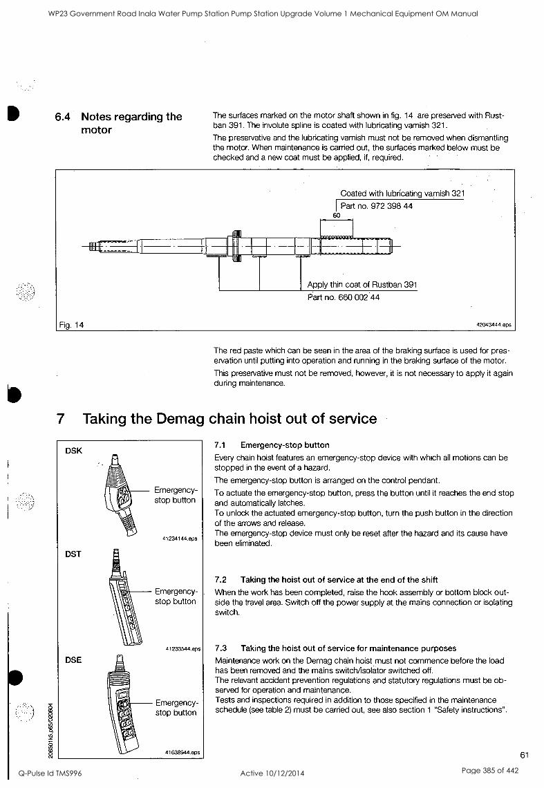
S
6.4 Notes regarding the motor
The surfaces marked on the motor shaft shown in fig. 14 are preserved with Rust- ban 391. The involute spline is coated with lubricating varnish 321.
The preservative and the lubricating varnish must not be removed when dismantling the motor. When maintenance is carried out, the surfaces marked below must be checked and a new coat must be applied, if, required.
Fig. 14
Coated with lubricating varnish 321
Part no. 972 398 44 60
Apply thin coat of Rustban 391
Part no. 660 002 44
42043444.eps
The red paste which can be seen in the area of the braking surface is used for pres- ervation until putting into operation and running in the braking surface of the motor.
This preservative must not be removed, however, it is not necessary to apply it again during maintenance.
7 Taking the Demag chain hoist out of service
DSK
DST
DSE
Emergency- stop button
41234144.eps
Emergency- stop button
41233544.eps
Emergency- stop button
41638944.eps
7.1 Emergency-stop button
Every chain hoist features an emergency-stop device with which all motions can be stopped in the event of a hazard.
The emergency-stop button is arranged on the control pendant.
To actuate the emergency-stop button, press the button until it reaches the end stop and automatically latches. To unlock the actuated emergency-stop button, turn the push button in the direction of the arrows and release. The emergency-stop device must only be reset after the hazard and its cause have been eliminated.
7.2 Taking the hoist out of service at the end of the shift
When the work has been completed, raise the hook assembly or bottom block out- side the travel area. Switch off the power supply at the mains connection or isolating switch.
7.3 Taking the hoist out of service for maintenance purposes
Maintenance work on the Demag chain hoist must not commence before the load has been removed and the mains switch/isolator switched off. The relevant accident prevention regulations and statutory regulations must be ob- served for operation and maintenance. Tests and inspections required in addition to those specified in the maintenance schedule (see table 2) must be carried out, see also section 1 "Safety instructions".
61
WP23 Government Road Inala Water Pump Station Pump Station Upgrade Volume 1 Mechanical Equipment OM Manual
Q-Pulse Id TMS996 Active 10/12/2014 Page 385 of 442
8 Inspections/maintenance/general overhaul GO
8.1 Inspection before starting work and during operation
8.2 Inspection and maintenance schedule
8.3 General overhaul GO
62
The operator must carry out inspections in accordance with table 2 before starting work. Chain hoists must be taken out of service immediately or not put into opera- tion if any defects.relating, to operating safety and reliability are detected.
Such ,defects are e.g.:
brake and safety device failure,
damage to the chain,
unusual noise in the gearbox, etc.
The specified inspection and maintenance intervals (table 2) apply to normal chain hoist service conditions. If routine maintenance reveals that the intervals are too long or too short, they should be adapted to the specific operating conditions. For repairs, only use genuine Demag parts (see component parts list).
The use of spare parts not approved by Demag renders any liability and guarantee claims void.
The theoretical duration of service D (hours at full load h) depends on the Group of Mechanisms classification of the chain hoist (see section 9, table 4).
Upon expiration of 90 % of the theoretical duration of service - if the chain hoists are correctly classified after 8 to 10 years - the owner must arrange for a general over- haul GO to be carried out. A general overhaul must be carried out on reaching the theoretical duration of service at the latest. During the general overhaul the following parts must be replaced in addition to the checks and work specified in the inspection and maintenance schedule (see table 2).
Gearing
Gearbox bearings
Motor shaft
Motor bearings
Connection elements
Gear oil
The small parts (screws, washers ...) to be replaced during maintenance and assem- bly work are not listed separately.
The general overhaul carried out by the manufacturer or an authorized specialist company fulfills the conditioh for continued operation of the chain hoist. Thus the relevant accident preVention regulations and the UVV /BGV D8 (VBG 8) are complied with.
Further utilization is approved when an expert engineer has entered the conditions for further utilization into the test and inspection booklet. The completion of the general overhaul must be confirmed in the test and inspection booklet and a further period of utilization in accordance with FEM 9.755 must be entered.
The general overhaul may be carried out by expert engineers of Demag or an authorized specialist company.
WP23 Government Road Inala Water Pump Station Pump Station Upgrade Volume 1 Mechanical Equipment OM Manual
Q-Pulse Id TMS996 Active 10/12/2014 Page 386 of 442
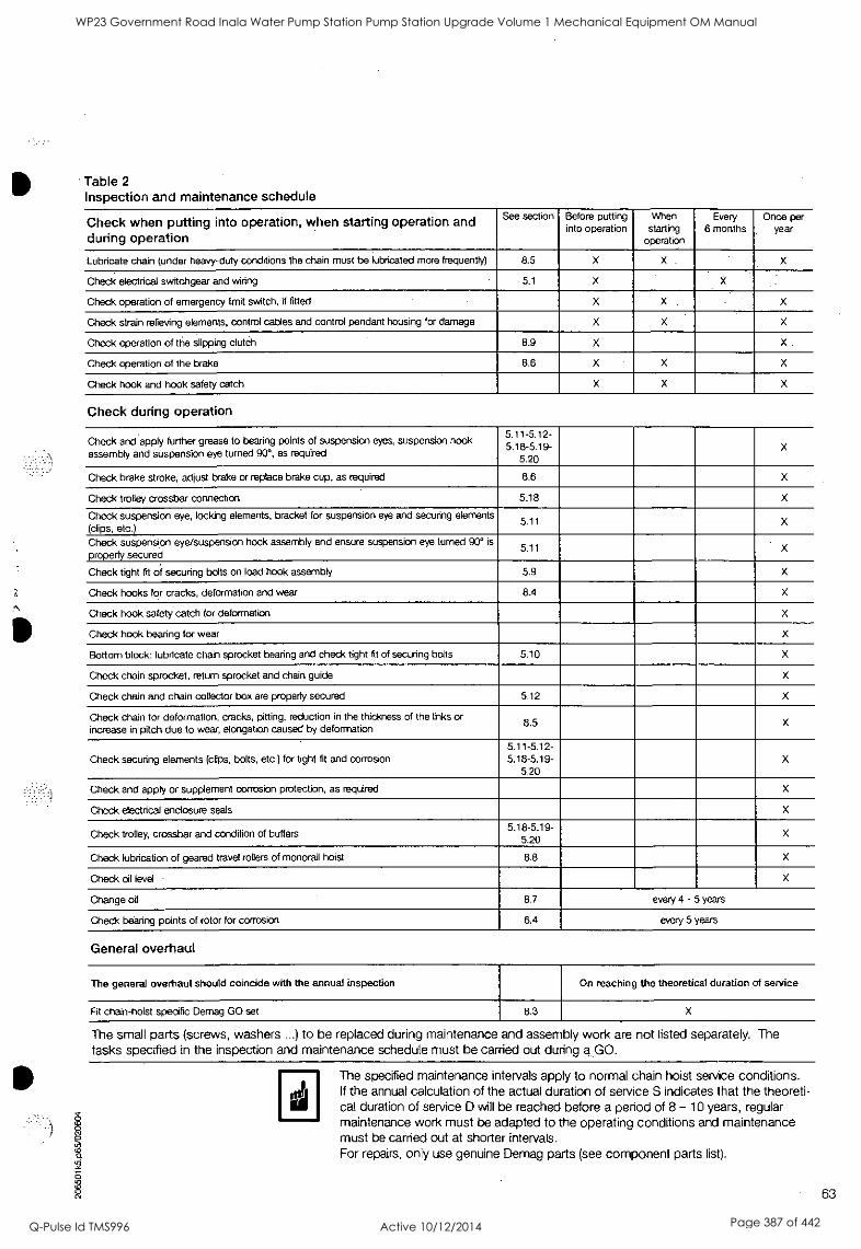
Table 2 Inspection and maintenance schedule
Check when putting into operation, when starting operation and during operation
See section Before putting into operation
When starting
operation
Every 6 months
Once per year
Lubricate chain (under heavy-duty conditions the chain must be lubricated more frequently) 8.5 X X - X
Check electrical switchgear and wiring 5.1 X
Check operation of emergency limit switch, if fitted X X X
Check strain relieving elements, control cables and control pendant housing for damage X X -x
Check operation of the slipping clutch 8.9 X X
Check operation of the brake 8.6 X X X
Check hook and hook safety catch X X X
Check during operation
Check and apply further grease to bearing points of suspension eyes, suspension hook assembly and suspension eye turned 90°, as required
5.11-5.12- 19 5.15.20 - X
Check brake stroke, adjust brake or replace brake cup, as required 8.6 X
Check trolley crossbar connection 5.18 X
Check suspension eye, locking elements, bracket for suspension eye and securing elements (clips, etc.)
5.11 X
Check suspension eye/suspension hook assembly and ensure suspension eye turned 90° is
properly secured 5.11
Check tight fit of securing bolts on load hook assembly 5.9 X
Check hooks for cracks, deformation and wear 8.4 X
Check hook safety catch for deformation X
Check hook bearing for wear X
Bottom block: lubricate chain sprocket bearing and check tight fit of securing bolts 5.10 X
Check chain sprocket, return sprocket and chain guide X
Check chain and chain collector box are property secured 5.12 X
Check chain for deformation, cracks, pitting, reduction in the thickness of the links or increase in pitch due to wear, elongation caused by deformation
8.5 X
Check securing elements (clips, bolts, etc.) for tight fit and corrosion 5.11-5.12 -
5.18 -5.19- 5.20
X
Check and apply or supplement corrosion protection, as required X
Check electrical enclosure seals x
Check trolley, crossbar and condition of buffers 5. 19- 18-5.
5.20 X
Check lubrication of geared travel rollers of monorail hoist 8.8 X
Check oil level x
Change oil 8.7 every 4 - 5 years
Check bearing points of rotor for corrosion 6.4 every 5 years
General overhaul
The general overhaul should coincide with the annual inspection On reaching the theoretical duration of service
Fit chain-hoist specific Demag GO set 8.3 X
The small parts (screws, washers ...) to be replaced during maintenance and assembly work are not listed separately. The tasks specified in the inspection and maintenance schedule must be carried out during a. GO.
The specified maintenance intervals apply to normal chain hoist service conditions. If the annual calculation of the actual duration of service S indicates that the theoreti- cal duration of service D will be reached before a period of 8 - 10 years, regular maintenance work must be adapted to the operating conditions and maintenance must be carried out at shorter intervals. For repairs, only use genuine Demag parts (see component parts list).
63
WP23 Government Road Inala Water Pump Station Pump Station Upgrade Volume 1 Mechanical Equipment OM Manual
Q-Pulse Id TMS996 Active 10/12/2014 Page 387 of 442
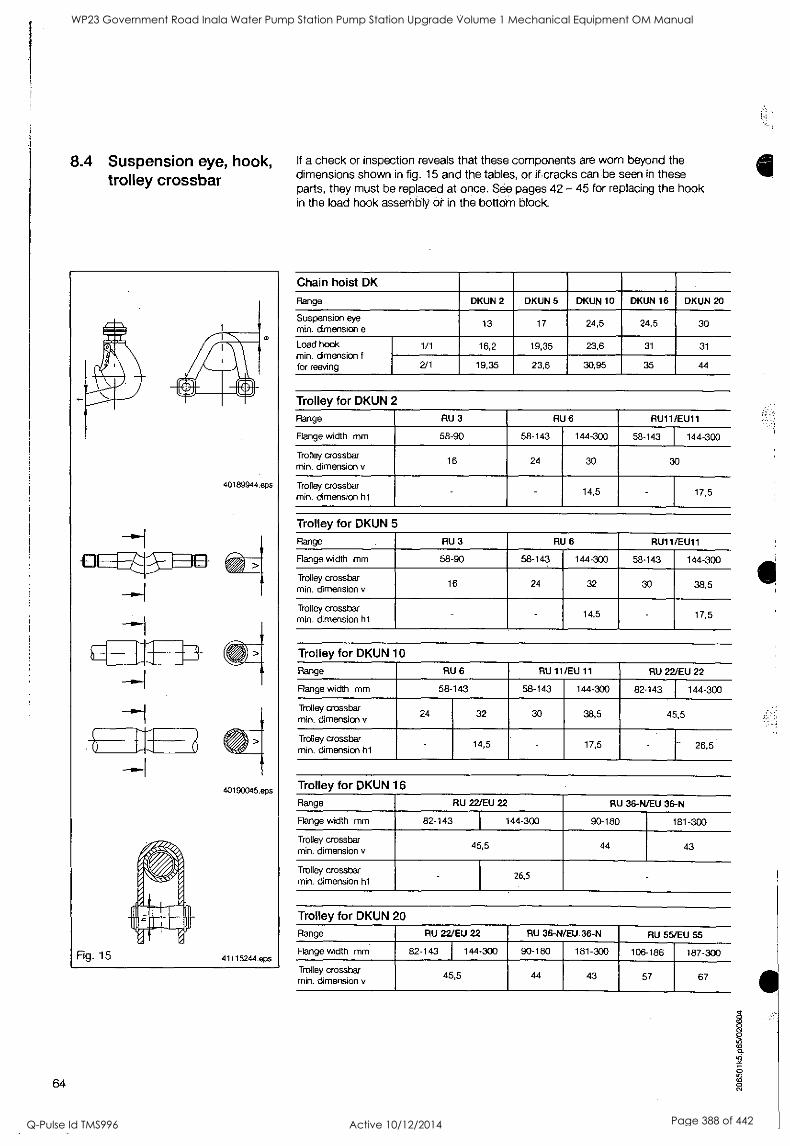
8.4 Suspension eye, hook, trolley crossbar
I
Fig. 15
0
40189944.eps
1-7L4
40190045.eps
41115244.eps
64
If a check or inspection reveals that these components are worn beyond the dimensions shown in fig. 15 and the tables, or if cracks can be seen in these parts, they must be replaced at once. See pages 42 - 45 for replacing the hook in the load hook assembly or in the bottom block.
Chain hoist DK
Range DKUN 2 DKUN 5 DKUN 10 DKUN 16 DKUN 20
Suspension eye
min. dimension e 13 17 24,5 24,5 30
Load hook min. dimension f
for reeving
1/1 16,2 19,35 23,6 31 31
2/1 19,35 23,6 30,95 35 44
Trolley for DKUN 2
Range RU 3 RU 6 RU11/EU11
Flange width mm 58-90 58-143 144-300 58-143 144-300
Trolley crossbar min. dimension v
16 24 30 30
Trolley crossbar min. dimension h1
- 14,5 - 17,5
Trolley for DKUN 5
Range RU 3 RU 6 RU11/EU11
Flange width mm 58-90 58-143 144-300 58-143 144-300
Trolley crossbar min. dimension v
16 24 32 30 38,5
Trolley crossbar min. dimension h1
- 14,5 - 17,5
Trolley for DKUN 10
Range RU 6 RU 11/EU 11 RU 22/EU 22
Flange width mm 58 143 58-143 144-300 82-143 144-300
Trolley crossbar min. dimension v
24 32 30 38,5 45,5
Trolley crossbar min. dimension h1
- 14,5 - 17,5 - 26,5
Trolley for DKUN 16
Range RU 22/EU 22 RU 36 -N/EU 36-N
Flange width mm 82-143 I 144-300 90-180 181-300
Trolley crossbar min. dimension v
45,5 44 43
Trolley crossbar min. dimension h1
- 26,5
Trolley for DKUN 20
Range RU 22/EU 22 RU 36-N/EU 36-N RU 5 U 55
Range width mm 82-143 144-300 90-180 181-300 106-186 187-300
Trolley crossbar min. dimension v
45,5 44 43 57 67
WP23 Government Road Inala Water Pump Station Pump Station Upgrade Volume 1 Mechanical Equipment OM Manual
Q-Pulse Id TMS996 Active 10/12/2014 Page 388 of 442

0090ZAS9d l0990
a
WP23 Government Road Inala Water Pump Station Pump Station Upgrade Volume 1 Mechanical Equipment OM Manual
Q-Pulse Id TMS996 Active 10/12/2014 Page 389 of 442
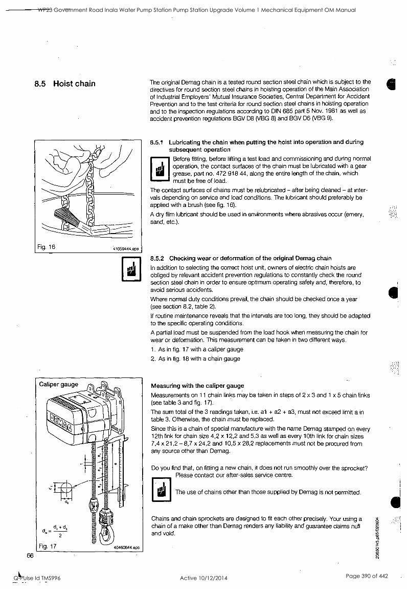
66
1.
8.5 Hoist chain
Caliper gauge
The original Demag chain is a tested round section steel chain which is subject to the directives for round section steel chains in hoisting operation of the Main Association of Industrial Employers' Mutual Insurance Societies, Central Department for Accident Prevention and to the test criteria for round section steel chains in hoisting operation and to the inspection regulations according to DIN 685 part 5 Nov. 1981 as well as accident prevention regulations BGV D8 (VBG 8) and BGV D6 (VBG 9).
8.5.1 Lubricating the chain when putting the hoist into operation and during subsequent operation
Before fitting, before lifting a test load and commissioning and during normal operation, the contact surfaces of the chain must be lubricated with a gear grease, part no. 472 918 44, along the entire length of the chain, which must be free of load.
The contact surfaces of chains must be relubricated - after being cleaned - at inter- vals depending on service and load conditions. The lubricant should preferably be applied with a brush (see fig. 16).
A dry film lubricant should be used in environments where abrasives occur (emery, sand, etc.).
8.5.2 Checking wear or deformation of the original Demag chain
In addition to selecting the correct hoist unit, owners of electric chain hoists are obliged by relevant accident prevention regulations to constantly check the round section steel chain in order to ensure optimum operating safety and, therefore, to avoid serious accidents.
Where normal duty conditions prevail, the chain should be checked once a year (see section 8.2, table 2).
if routine maintenance reveals that the intervals are too long, they should be adapted to the specific operating conditions.
A partial load must be suspended from the load hook when measuring the chain for wear or deformation. This measurement can be taken in two different ways.
1. As in fig. 17 with a caliper gauge
2. As in fig. 18 with a chain gauge
Measuring with the caliper gauge
Measurements on 11 chain links may be taken in steps of 2 x 3 and 1 x 5 chain links (see table 3 and fig. 17).
The sum total of the 3 readings taken, i.e. al + a2 + a3, must not exceed limit a in table 3. Otherwise, the chain must be replaced.
Since this is a chain of special manufacture with the name Demag stamped on every 12th link for chain size 4,2 x 12,2 and 5,3 as well as every 10th link for chain sizes 7,4 x 21,2 - 8,7 x 24,2 and 10,5 x 28,2 replacements must not be procured from any source other than Demag.
Do you find that, on fitting a new chain, it does not run smoothly over the sprocket? Please contact our after-sales service centre.
The use of chains other than those supplied by Demag is not permitted.
Chains and chain sprockets are designed to fit each other precisely. Your using a chain of a make other than Demag renders any liability and guarantee claims null and void.
WP23 Government Road Inala Water Pump Station Pump Station Upgrade Volume 1 Mechanical Equipment OM Manual
Q-Pulse Id TMS996 Active 10/12/2014 Page 390 of 442
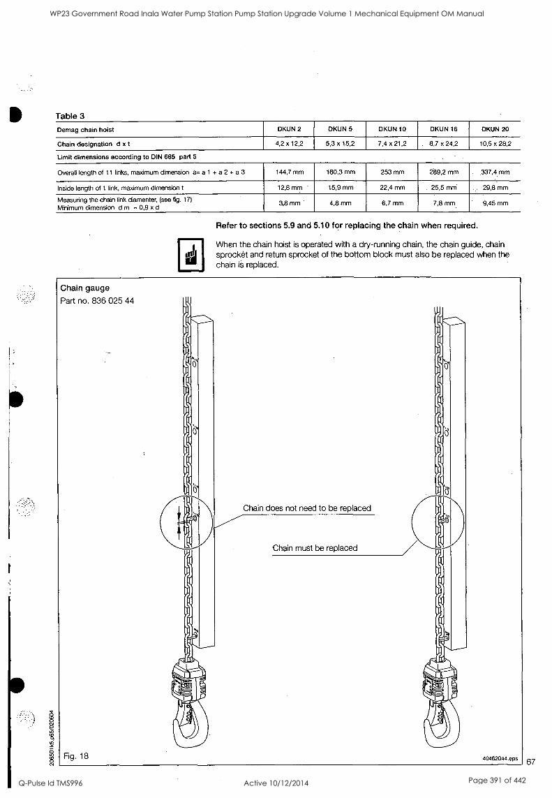
Table 3
Demag chain hoist DKUN 2 DKUN 5 DKUN 10 DKUN 16 DKUN 20
Chain designation d x t 4,2 x 12,2 5,3 x 15,2 7,4 x 21,2 8,7 x 24,2 10,5 x 28,2
Limit dimensions according to DIN 685 part 5
Overall length of 11 finks, maximum dimension as a 1 + a 2 + a 3 144,7 mm 180,3 mm 253 mm 289,2 mm 337,4 mm
Inside length of 1 link, maximum dimension t 12,8 mm - 15,9 mm 22,4 mm 25,5 mm . 29,8 mm
Measuring the chain link diamenter, (see fig. 17)
Minimum dimension d m = 0,9 x d 3,8 mm 4,8 mm 6,7 mm 7,8 mm 9,45 mm
inJ
Refer to sections 5.9 and 5.10 for replacing the chain when required.
When the chain hoist is operated with a dry-running chain, the chain guide, chain sprocket and return sprocket of the bottom block must also be replaced when the chain is replaced.
Chain gauge
Part no. 836 025 44
Fig. 18
Chain does not need to be replaced
Chain must be replaced
40462044.eps 67
WP23 Government Road Inala Water Pump Station Pump Station Upgrade Volume 1 Mechanical Equipment OM Manual
Q-Pulse Id TMS996 Active 10/12/2014 Page 391 of 442
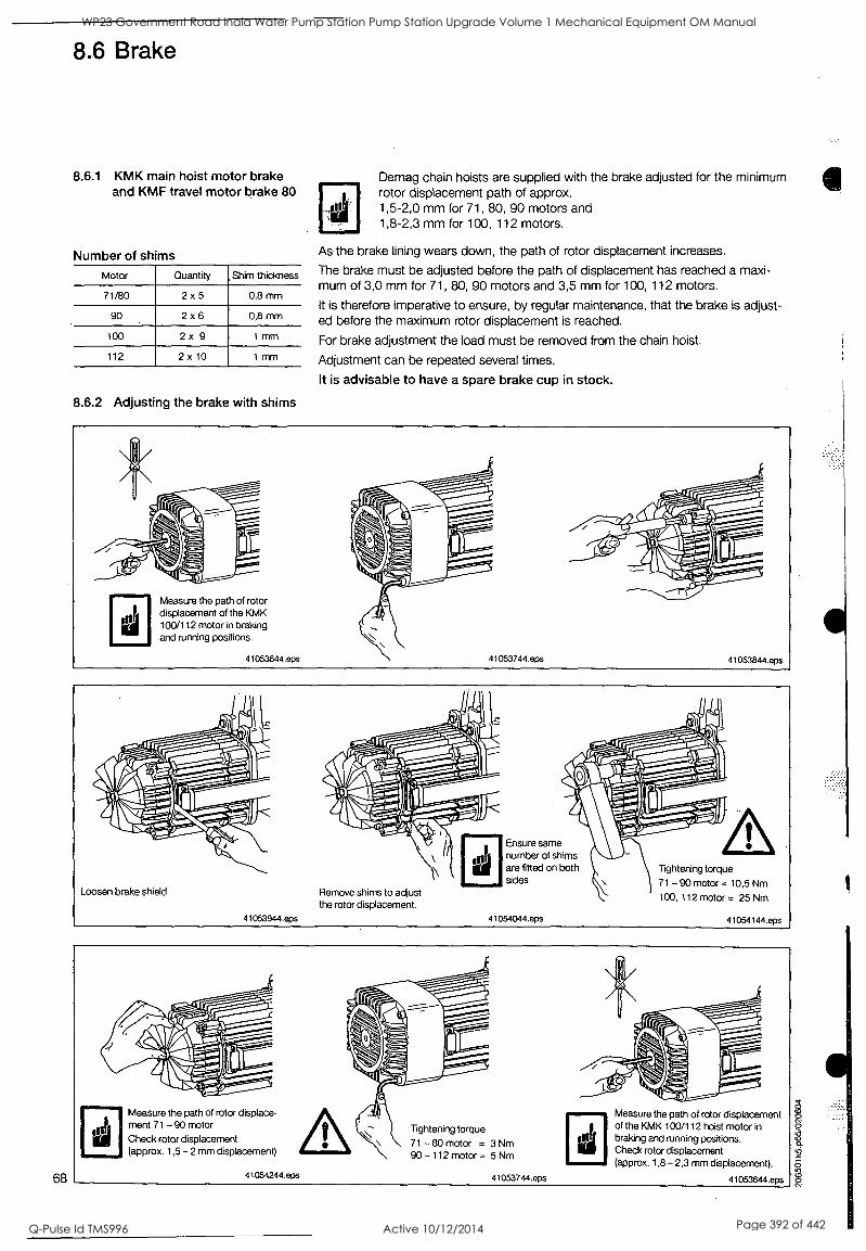
68
8.6 Brake
8.6.1 KMK main hoist motor brake and KMF travel motor brake 80
Number of shims
Motor Quantity Shim thickness
71/80 2 x 5 0,8 mm
90 2 x 6 0,8 mm
100 2 x 9 1 mm
112 2 x 10 1 mm
8.6.2 Adjusting the brake with shims
Demag chain hoists are supplied with the brake adjusted for the minimum rotor displacement path of approx. 1,5-2,0 mm for 71, 80, 90 motors and 1,8-2,3 mm for 100, 112 motors.
As the brake lining wears down, the path of rotor displacement increases.
The brake must be adjusted before the path of displacement has reached a maxi- mum of 3,0 mm for 71, 80, 90 motors and 3,5 mm for 100, 112 motors.
It is therefore imperative to ensure, by regular maintenance, that the brake is adjust- ed before the maximum rotor displacement is reached.
For brake adjustment the load must be removed from the chain hoist.
Adjustment can be repeated several times.
It is advisable to have a spare brake cup in stock.
Measure the path of rotor displacement of the KMK 100/112 motor in braking and running positions.
41053644.eps 41053844.eps
Loosen brake shield
41053944.eps
Remove shims to adjust the rotor displacement.
Ensure same number of shims are fitted on both sides
41054044.eps
Tightening torque 71 - 90 motor e 10,5 Nm 100, 112 motor = 25 Nm
41054144.eps
Measure the path of rotor displace- ment 71 - 90 motor
Check rotor displacement (approx. 1,5 -2 mm displacement)
41054244.eps
Tightening torque
71 -80 motor = 3 Nm 90 -112 motor = 5 Nm
InJ
Measure the path of rotor displacement of the KMK 100/112 hoist motor in braking and running positions. Check rotor displacement (approx. 1,8 - 2,3 mm displacement).
41053744.eps 41053644.eps
WP23 Government Road Inala Water Pump Station Pump Station Upgrade Volume 1 Mechanical Equipment OM Manual
Q-Pulse Id TMS996 Active 10/12/2014 Page 392 of 442
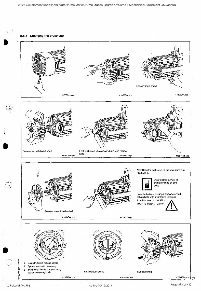
8.6.3 Changing the brake cup
Remove fan with brake shield
41054344.eps
Lock brake cup using a screwdriver and remove bolts
41054444.eps 41054544.eps
Remove fan with brake shield
41054644.eps 41054744.eps
After fitting the brake cup, fit the new shims sup- plied with it.
Ensure same number of shims are fitted on both sides.
Lock the brake cup using a screwdriver and tighten bolts with a tightening torque of
71 - 90 motor = 10,5 Nm
100, 112 motor = 25 Nm
1 Guide for brake release stirrup
2 Splines to assist in assembly
3 Ensure that fan clips are correctly seated in bearing bush
41054844.eps
1 Brake release stirrup
41054944,eps
Fit brake shield
41055044.eps 69
WP23 Government Road Inala Water Pump Station Pump Station Upgrade Volume 1 Mechanical Equipment OM Manual
Q-Pulse Id TMS996 Active 10/12/2014 Page 393 of 442
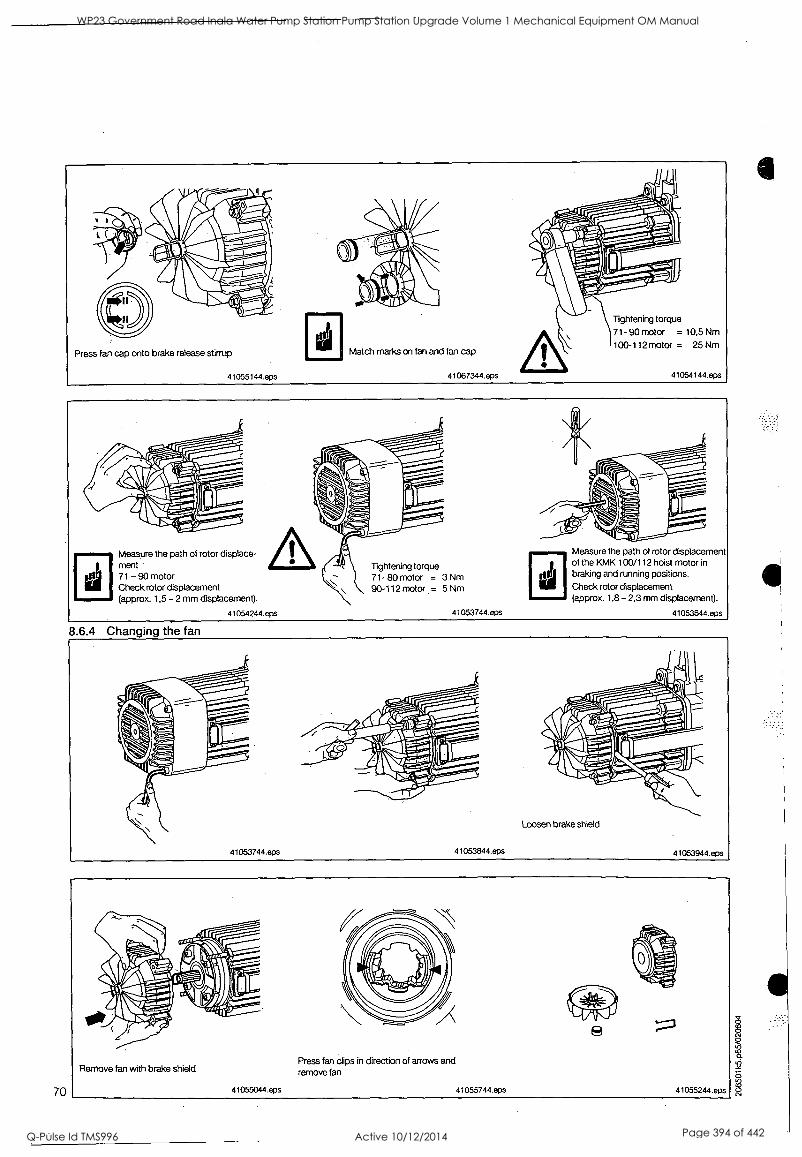
Press fan cap onto brake release stirrup
41055144.eps
Match marks on fan and fan cap
41067344.eps
Tightening torque
71- 90 motor = 10,5 Nm
100-112 motor = 25 Nm
41054144.eps
70
Measure the path of rotor displace- ment 71 -90 motor Check rotor displacement (approx. 1,5 -2 mm displacement).
41054244.eps
Tightening torque 71- 80 motor = 3 Nm 90-112 motor = 5 Nm
41053744.eps
Measure the path of rotor displacement of the KMK 100/112 hoist motor in
braking and running positions.
Check rotor displacement (approx. 1,8 - 2,3 mm displacement).
41053644.eps
8.6.4 Changing the fan
Remove fan with brake shield
41055044.epS
Press fan clips in direction of arrows and remove fan
41055744.eps 41055244.eps
cv cv 0
WP23 Government Road Inala Water Pump Station Pump Station Upgrade Volume 1 Mechanical Equipment OM Manual
Q-Pulse Id TMS996 Active 10/12/2014 Page 394 of 442
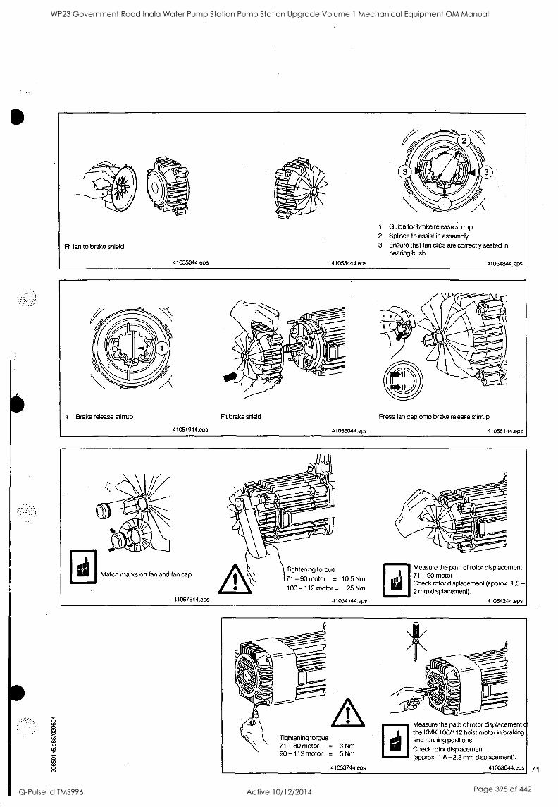
Fit fan to brake shield
41055344.eps 41055444.eps
1 Guide for brake release stirrup 2 Splines to assist in assembly
3 Ensure that fan clips are correctly seated in bearing bush
41054844.eps
1 Brake release stirrup
41054944.eps
Fit brake shield
41055044.eps
Press fan cap onto brake release stirrup
41055144.eps
Match marks on fan and fan cap
41067344.eps
Tightening torque
71 - 90 motor = 10,5 Nm
100 -112 motor = 25 Nm
Measure the path of rotor displacement 71 - 90 motor Check rotor displacement (approx. 1,5 2 mm displacement).
41054144.eps
-
41054244.eps
lightening torque 71 - 80 motor = 3 Nm 90 -112 motor = 5 Nm
41053744.eps
Measure the path of rotor displacement cf the KMK 100/112 hoist motor in braking and running positions.
Check rotor displacement (approx. 1,8 2,3 mm displacement).
41053644.eps 71
WP23 Government Road Inala Water Pump Station Pump Station Upgrade Volume 1 Mechanical Equipment OM Manual
Q-Pulse Id TMS996 Active 10/12/2014 Page 395 of 442
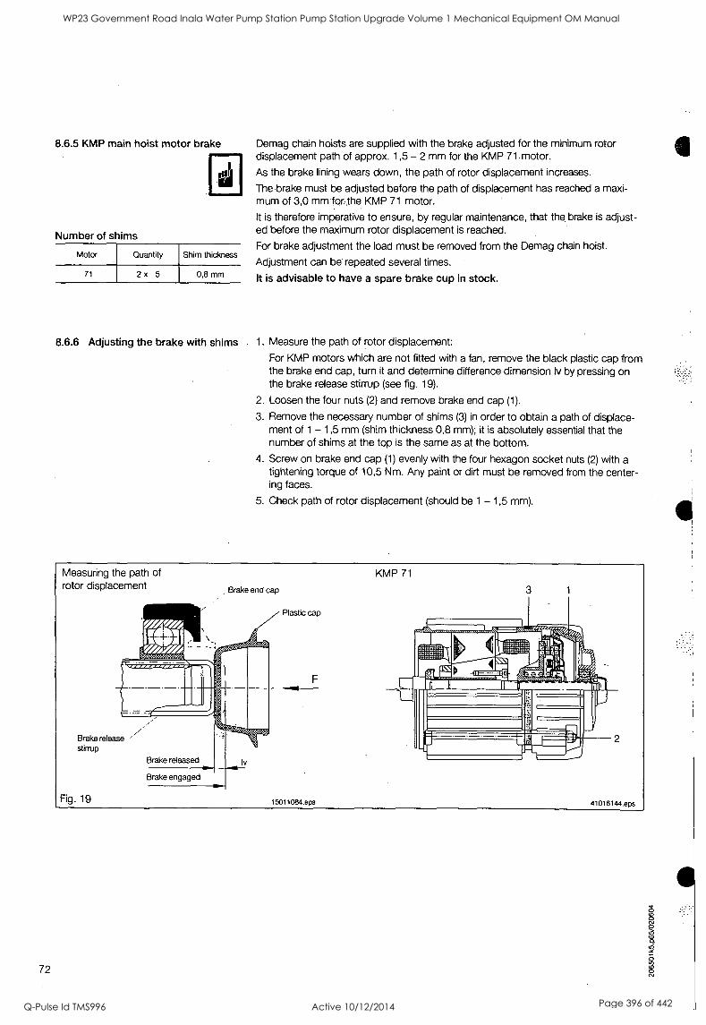
8.6.5 KMP main hoist motor brake
Number of shims
Motor Quantity Shim thickness
71 2x 5 0,8 mm
Demag chain hoists are supplied with the brake adjusted for the minimum rotor displacement path of approx. 1,5 -2 mm for the KMP 71 motor.
As the brake lining wears down, the path of rotor displacement increases.
The brake must be adjusted before the path of displacement has reached a maxi- mum of 3,0 mmfor-the KMP 71 motor.
It is therefore imperative to ensure, by regular maintenance, that the brake is adjust- ed before the maximum rotor displacement is reached.
For brake adjustment the load must be removed from the Demag chain hoist.
Adjustment can be repeated several times.
It is advisable to have a spare brake cup in stock.
8.6.6 Adjusting the brake with shims 1. Measure the path of rotor displacement:
For KMP motors which are not fitted with a fan, remove the black plastic cap from the brake end cap, turn it and determine difference dimension lv by pressing on the brake release stirrup (see fig. 19).
2. Loosen the four nuts (2) and remove brake end cap (1).
3. Remove the necessary number of shims (3) in order to obtain a path of displace- ment of 1 - 1,5 mm (shim thickness 0,8 mm); it is absolutely essential that the number of shims at the top is the same as at the bottom.
4. Screw on brake end cap (1) evenly with the four hexagon socket nuts (2) with a tightening torque of 10,5 Nm. Any paint or dirt must be removed from the center- ing faces.
5. Check path of rotor displacement (should be 1 - 1,5 mm).
Measuring the path of rotor displacement Brake end cap
Brake release stirrup
Fig. 19
Plastic cap
F
15011084.epS
KMP 71
41016144.eps
72
WP23 Government Road Inala Water Pump Station Pump Station Upgrade Volume 1 Mechanical Equipment OM Manual
Q-Pulse Id TMS996 Active 10/12/2014 Page 396 of 442
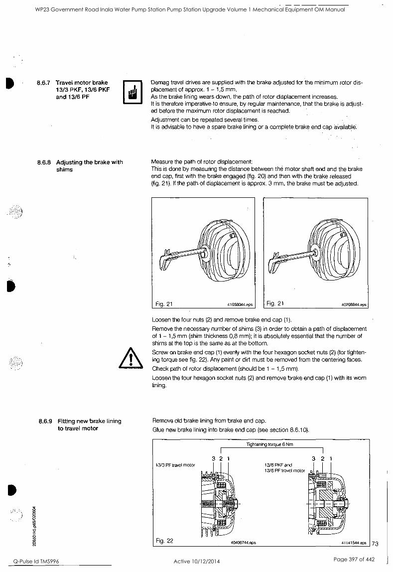
8.6.7 Travel motor brake 13/3 PKF, 13/6 PKF and 13/6 PF
8.6.8 Adjusting the brake with shims
Demag travel drives are supplied with the brake adjusted for the minimum rotor dis- placement of approx. 1 - 1,5 mm. As the brake lining wears down, the path of rotor displacement increases. It is therefore imperative to ensure, by regular maintenance, that the brake is adjust- ed before the maximum rotor displacement is reached.
Adjustment can be repeated several times. It is advisable to have a spare brake lining or a complete brake end cap available.
Measure the path of rotor displacement: This is done by measuring the distance between the motor shaft end and the brake end cap, first with the brake engaged (fig. 20) and then with the brake released (fig. 21). If the path of displacement is approx. 3 mm, the brake must be adjusted.
Loosen the four nuts (2) and remove brake end cap (1).
Remove the necessary number of shims (3) in order to obtain a path of displacement of 1 - 1,5 mm (shim thickness 0,8 mm); it is absolutely essential that the number of shims at the top is the same as at the bottom.
Screw on brake end cap (1) evenly with the four hexagon socket nuts (2) (for tighten- ing torque see fig. 22). Any paint or dirt must be removed from the centering faces.
Check path of rotor displacement (should be 1 - 1,5 mm).
Loosen the four hexagon socket nuts (2) and remove brake end cap (1) with its worn lining.
8.6.9 Fitting new brake lining Remove old brake lining from brake end cap. to travel motor Glue new brake lining into brake end cap (see section 8.6.10).
13/3 PF travel motor
Fig. 22
Tightening torque 6 Nm
3 2 1
40406744.eps
13/6 PKF and 13/6 PF travel motor
3 2 1
41141544.eps 73
WP23 Government Road Inala Water Pump Station Pump Station Upgrade Volume 1 Mechanical Equipment OM Manual
Q-Pulse Id TMS996 Active 10/12/2014 Page 397 of 442
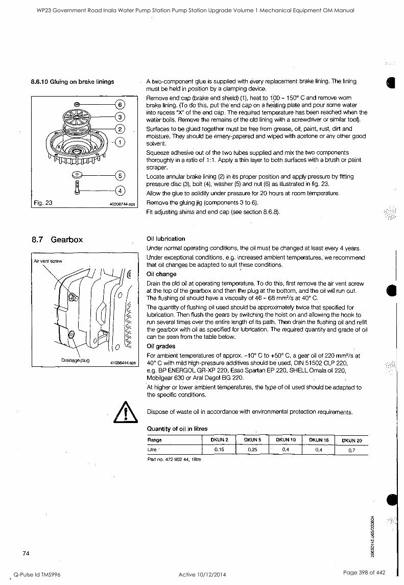
8.6.10 Gluing on brake linings
8.7 Gearbox
O
74
A two-component glue is supplied with every replacement brake lining. The lining must be held in position by a clamping device.
Remove end cap (brake end shield) (1), heat. to 100 -150° C and remove worn brake lining. (To do this, put the end cap on a heating plate and pour some water into recess "X" of the end cap. The required temperature has been reached when the water boils. Remove the remains of the old lining with a screwdriver or similar tool).
Surfaces to be glued together must be free from grease, oil, paint, rust, dirt and moisture. They should be emery-papered and wiped with acetone or any other good solvent.
Squeeze adhesive out of the two tubes supplied and mix the two components thoroughly in a ratio of 1:1. Apply a thin layer to both surfaces with a brush or paint scraper.
Locate annular brake lining (2) in its proper position and apply pressure by fitting pressure disc (3), bolt (4), washer (5) and nut (6) as illustrated in fig. 23.
Allow the glue to solidify under pressure for 20 hours at room temperature.
Remove the gluing jig (components 3 to 6).
Fit adjusting shims and end cap (see section 8.6.8).
Oil lubrication
Under normal operating conditions, the oil must be changed at least every 4 years.
Under exceptional conditions, e.g. increased ambient temperatures, we recommend that oil changes be adapted to suit these conditions.
Oil change
Drain the old oil at operating temperature. To do this, first remove the air vent screw at the top of the gearbox and then the plug at the bottom, and the oil will run out. The flushing oil should have a viscosity of 46 - 68 mm2/s at 40° C.
The quantity of flushing oil used should be approximately twice that specified for lubrication. Then flush the gears by switching the hoist on and allowing the hook to run several times over the entire length of its path. Then drain the flushing oil and refill the gearbox with oil as specified for lubrication. The required quantity and grade of oil
can be seen from the table below.
Oil grades
For ambient temperatures of approx. -10° C to +50° C, a gear oil of 220 mm2/s at 40° C with mild high-pressure additives should be used, DIN 51502 CLP 220, e.g. BP ENERGOL GR-XP 220, Esso Spartan EP.220, SHELL Omala oil 220, Mobilgear 630 or Aral Degol BG 220.
At higher or lower ambient temperatures, the type of oil used should be adapted to the specific conditions.
Dispose of waste oil in accordance with environmental protection requirements.
Quantity of oil in litres
Range DKUN 2 DKUN 5 DKUN 10 DKUN 16 DKUN 20
Litre
Part no. 472 902 44, llitre
0,15 0,25 0,4 0,4 0,7
WP23 Government Road Inala Water Pump Station Pump Station Upgrade Volume 1 Mechanical Equipment OM Manual
Q-Pulse Id TMS996 Active 10/12/2014 Page 398 of 442
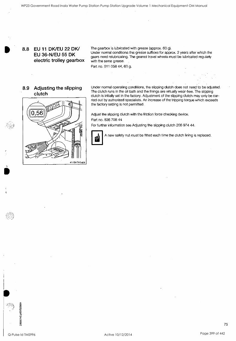
ui
8.8 EU 11 DK/EU 22 DK/ EU 36-N/EU 55 DK electric trolley gearbox
8.9 Adjusting the slipping clutch
The gearbox is lubricated with grease (approx. 60 g).
Under normal conditions this grease suffices for approx. 2 years after which the gears need relubricating. The geared travel wheels must be lubricated regularly with the same grease.
Part no. 011 058 44, 60 g.
Under normal operating conditions, the slipping clutch does not need to be adjusted. The clutch runs in the oil bath and the linings are virtually wear-free. The slipping clutch is initially set in the factory. Adjustment of the slipping clutch may only be car- ried out by authorized specialists. An increase of the tripping torque which exceeds the factory setting is not permitted.
Adjust the slipping clutch with the friction force checking device.
Part no. 836 708 44
For further information see Adjusting the slipping clutch 206 974 44.
A new safety nut must be fitted each time the clutch lining is replaced.
75
WP23 Government Road Inala Water Pump Station Pump Station Upgrade Volume 1 Mechanical Equipment OM Manual
Q-Pulse Id TMS996 Active 10/12/2014 Page 399 of 442
9 Measures necessary for achieving safe working periods
The safety and health provisions of EC directive 98/37/EC make it a legal requirement to eliminate special hazards which may be caused by, for example, fatigue and ageing. This requirement is also reflected in relevant accident prevention regulations and codes of practice, such as the 3rd supplement to UW/BGV D8 (VBG 8) of 1.4.1996 in Germany. This requirement obliges the owner of serial hoist units to de- termine the actual duration of service of the hoist unit on the basis of the operating hours, load spectra and/or recording factors. This is based on FEM 9.755/06.1993 'Measures for achieving safe working periods for powered serial hoist units (S:W.P.)". The objective of this rule is to determine measures for achieving safe working periods over the entire duration of service, although, according to the state-of-the-art, the hoist units are designed for specific periods of operation. .
Premature failure cannot, however, be ruled out.
The following items have been taken from FEM rule 9.755 with reference to the elec- tric chain hoist:
1. The actual duration of service determined on the basis of operating time and load must be documented at least once per year.
2. The operating time T, (number of operating hours) can be estimated or read .on an elapsed time indicator.
3. The load kn, (load spectrum) must be estimated.
4. The value determined for operating time Ti using an elapsed time indicator must be multiplied by the type of recording factor f = 1,1.
5. The value determined for the estimated operating hours and load spectrum must be multiplied by the type of recording factor f = 1,2.
6. The actual duration of service S is calculated as: S = kmi xTx f 7. A general overhaul must be carried out on reaching the theoretical duration of
service.
8. All checks and inspections and the general overhaul must be arranged by the owner of the hoist unit.
A general overhaul is defined as:
Inspection of the machinery for the purpose of detecting all defective components and/or components and parts close to failure and the replacement of all such components and parts. Following a general overhaul, the machinery is in a condition similar to that of the same machinery in new condition as far as the principle of operation and performance values are concemed.
For electric chain hoists classified according to FEM 9.511, the following theoretical durations of service apply (converted into full load hours):
Table 4:
1Cm 1Bm 1Am 2m 3m
[h] 200 400 800 1600 3200
The actual duration of service is considerably increased if the hoist unit is only operated with partial load. For a chain hoist operated on average with half load, for example, this results in an 8-fold increase in the actual duration of service, with operation at one quarter of the full load, a 64-fold increase.
76
WP23 Government Road Inala Water Pump Station Pump Station Upgrade Volume 1 Mechanical Equipment OM Manual
Q-Pulse Id TMS996 Active 10/12/2014 Page 400 of 442
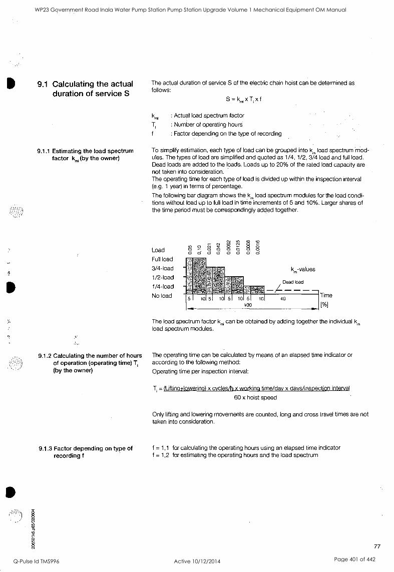
9.1 Calculating the actual duration of service S
9.1.1 Estimating the load spectrum factor km, (by the owner)
9.1.2 Calculating the number of hours of operation (operating time) Ti
(by the owner)
The actual duration of service S of the electric chain hoist can be determined as follows:
S=kmixTixf
km, : Actual load spectrum factor
: Number of operating hours
: Factor depending on the type of recording
To simplify estimation, each type of load can be grouped into km load spectrum mod- ules. The types of load are simplified and quoted as 1/4, 1/2, 3/4 load and full load. Dead loads are added to the loads. Loads up to 20% of the rated load capacity are not taken into consideration. The operating time for each type of load is divided up within the inspection interval (e.g. 1 year) in terms of percentage.
The following bar diagram shows the km load spectrum modules for the load condi- tions without load up to full load in time increments of 5 and 10%. Larger shares of the time period must be correspondingly added together.
Load
Full load
3/4-load
1/2-load
1/4-load
No load
0 0 0
N Ca
0 8 0 0 o
co
0
CO
8 0
10 5 10 5 10 5 10 40
100
Time
[Vol
The load spectrum factor km, can be obtained by adding together the individual km
load spectrum modules.
The operating time can be calculated by means of an elapsed time indicator or according to the following method:
Operating time per inspection interval:
=1Lifting+lowering) x cvcles/h x working time/day x days/inspection interval
60 x hoist speed
Only lifting and lowering movements are counted, long and cross travel times are not taken into consideration.
9.1.3 Factor depending on type of f = 1,1 for calculating the operating hours using an elapsed time indicator recording f f = 1,2 for estimating the operating hours and the load spectrum
77
WP23 Government Road Inala Water Pump Station Pump Station Upgrade Volume 1 Mechanical Equipment OM Manual
Q-Pulse Id TMS996 Active 10/12/2014 Page 401 of 442
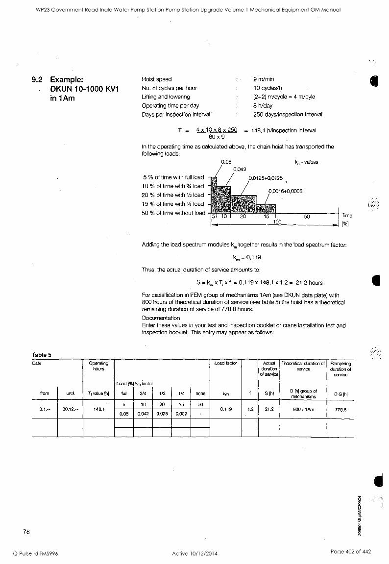
9.2 Example: DKUN 10-1000 KV1
in 1Am
Table 5
Hoist speed
No. of cycles per hour
Lifting and lowering
Operating time per day
Days per inspection interval
9 m/min
10 cycles/h
(2+2) m/cycle = 4 m/cyle
8 h/day
250 days/inspection interval
T. = 4 x 10 x 8 x 250 = 148,1 h/inspection interval 60 x 9
In the operating time as calculated above, the chain hoist has transported the following loads:
5 % of time with full load
10 % of time with 3/4 load
20 % of time with 1/2 load
15 % of time with 1/4 load
50 % of time without load Time
[%]
Adding the load spectrum modules km together results in the load spectrum factor:
kmi = 0,119
Thus, the actual duration of service amounts to:
S = kmi x x f = 0,119 x 148,1 x 1,2 = 21,2 hours
For classification in FEM group of mechanisms lAm (see DKUN data plate) with 800 hours of theoretical duration of service (see table 5) the hoist has a theoretical remaining duration of service of 778,8 hours.
Documentation Enter these values in your test and inspection booklet or crane installation test and inspection booklet. This entry may appear as follows:
Date
from until
Operating hours
Ti value pi]
Load (%
full
km factor
3/4 1/2 1/4 none
Load factor
km; f
Actual duration
of service
s I/
Theoretical duration of service
D (11 group of mechanisms
Remaining duration of
service
D-S [11)
3.1.-- 30.12.-- 148,1 5 10 20 15 50
0,119 1,2 21,2 800 / 1Arn 778,8 0,05 0,042 0,025 0,002 -
78
WP23 Government Road Inala Water Pump Station Pump Station Upgrade Volume 1 Mechanical Equipment OM Manual
Q-Pulse Id TMS996 Active 10/12/2014 Page 402 of 442
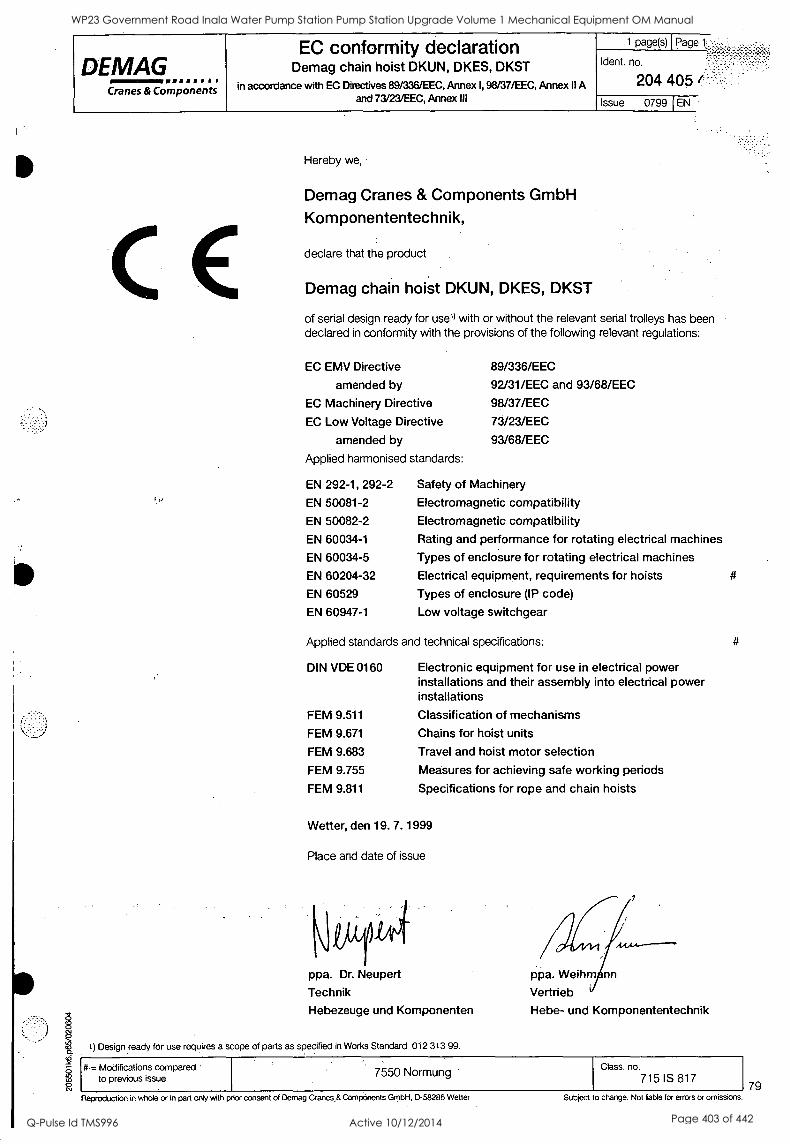
DEMAG 8=111111/ Cranes & Components
EC conformity declaration Demag chain hoist DKUN, DKES, DKST
in accordance with EC Directives 89/336/EEC, Annex I, 98/37/EEC, Annex II A and 73/23/EEC, Annex III
1 page(s)
dent. no.
204 405 t::
Page
Issue 0799 I EN
10 Hereby we,
0 Csl
CE Demag Cranes & Components GmbH
Komponententechnik,
declare that the product
Demag chain hoist DKUN, DKES, DKST
of serial design ready for use') with or without the relevant serial trolleys has been declared in conformity with the provisions of the following relevant regulations:
EC EMV Directive 89/336/EEC
amended by 92/31/EEC and 93/68/EEC
EC Machinery Directive 98/37/EEC
EC Low Voltage Directive 73/23/EEC
amended by 93/68/EEC
Applied harmonised standards:
EN 292-1, 292-2
EN 50081-2
EN 50082-2
EN 60034-1
EN 60034-5
EN 60204-32
EN 60529
EN 60947-1
Safety of Machinery
Electromagnetic compatibility Electromagnetic compatibility Rating and performance for rotating electrical machines
Types of enclosure for rotating electrical machines
Electrical equipment, requirements for hoists
Types of enclosure (IP code)
Low voltage switchgear
Applied standards and technical specifications:
DIN VDE 0160
FEM 9.511
FEM 9.671
FEM 9.683
FEM 9.755
FEM 9.811
Electronic equipment for use in electrical power installations and their assembly into electrical power installations
Classification of mechanisms
Chains for hoist units
Travel and hoist motor selection
Measures for achieving safe working periods
Specifications for rope and chain hoists
Wetter, den 19. 7. 1999
Place and date of issue
ppa. Dr. Neupert
Technik
Hebezeuge und Komponenten
1) Design ready for use requires a scope of parts as specified in Works Standard 012 313 99.
ppa. Weihm nn
Vertrieb
Hebe- und Komponententechnik
#.= Modifications compared to previous issue 7550 Normung Class. no.
715 IS 817
Reproduction in whole or in part only with prior consent of Demag Cranes,& Components GmbH, D-58286 Wetter Subject o change. Not liable for errors or omissions. 79
WP23 Government Road Inala Water Pump Station Pump Station Upgrade Volume 1 Mechanical Equipment OM Manual
Q-Pulse Id TMS996 Active 10/12/2014 Page 403 of 442
Reproduction in whole or in part only with prior consent of Dernag Cranes & Components GmbH, 0-58286 Wetter
-
0
J
C
:Slabject to change. Not liable for errors or omissions.
WP23 Government Road Inala Water Pump Station Pump Station Upgrade Volume 1 Mechanical Equipment OM Manual
Q-Pulse Id TMS996 Active 10/12/2014 Page 404 of 442
Component parts Demag chain hoist DKUN 2
180702 EN/DE
DEMAG =111111== MM
Cranes & Components
222 501 44 721 IS 817
WP23 Government Road Inala Water Pump Station Pump Station Upgrade Volume 1 Mechanical Equipment OM Manual
Q-Pulse Id TMS996 Active 10/12/2014 Page 405 of 442
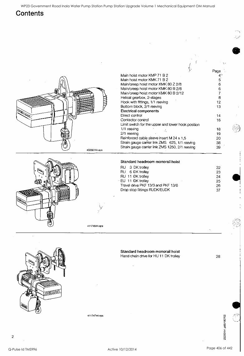
Contents
41174644.eps
Main hoist motor KMP 71 B 2
Main hoist motor KMK 71 B 2
Main/creep hoist motor KMK 80 Z 2/8 Main/creep hoist motor KMK 80 B 2/8 Main/creep hoist motor KMK 80 B 2/12 Helical gearbox, 2-stages
Page, 4', 5
6 6 7
8 Hook with fittings, 1/1 reeving 12 Bottom block, 2/1 reeving 13 Electrical components Direct control 14 Contactor control 16 Limit switch for the upper and lower hook position 1/1 reeving 18 2/1 reeving 19 Reinforced cable sleeve insert M 24 x 1,5 20 Strain gauge carrier link ZMS 625, 1/1 reeving 38 Strain gauge carrier link ZMS 1250, 2/1 reeving 39
Standard headroom monorail hoist
RU 3 DK trolley 22 RU 6 DK trolley 23 RU 11 DK trolley 24 EU 11 DK trolley 25 Travel drive PKF 13/3 and PKF 13/6 26 Drop stop fittings RUDK/EUDK 37
2
41174744.eps
Standard headroom monorail hoist Hand chain drive for HU 11 DK trolley 28
WP23 Government Road Inala Water Pump Station Pump Station Upgrade Volume 1 Mechanical Equipment OM Manual
Q-Pulse Id TMS996 Active 10/12/2014 Page 406 of 442
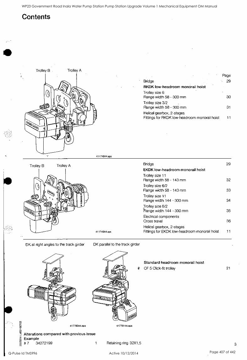
0 8
Alterations compared with previous issue E Example
# 7 34272199
Contents
Trolley B Trolley A
41174844.eps
Page
Bridge 29
RKDK low-headroom monorail hoist
Trolley size 6 Flange width 58 - 300 mm 30
Trolley size 3/2 Flange width 58 - 300 mm 31
Helical gearbox, 2-stages Fittings for RKDK low-headroom monorail hoist 11
Trolley B Trolley A
41 174944.eps
Bridge 29
EKDK low-headroom monorail hoist
Trolley size 11
Flange width 58 - 143 mm 32
Trolley size 6/2 Flange width 58 - 143 mm 33
Trolley size 11
Flange width 144 - 300 mm 34
Trolley size 6/2 Flange width 144 - 300 mm 35
Electrical components Cross travel 36
Helical gearbox, 2-stages Fittings for EKDK low-headroom monorail hoist 11
DK at right angles to the track girder
41778044.eps
DK parallel to the track girder
41778144.eps
Standard headroom monorail hoist
# CF 5 Click-fit trolley 21
1 Retaining ring 32X1,5 3
WP23 Government Road Inala Water Pump Station Pump Station Upgrade Volume 1 Mechanical Equipment OM Manual
Q-Pulse Id TMS996 Active 10/12/2014 Page 407 of 442
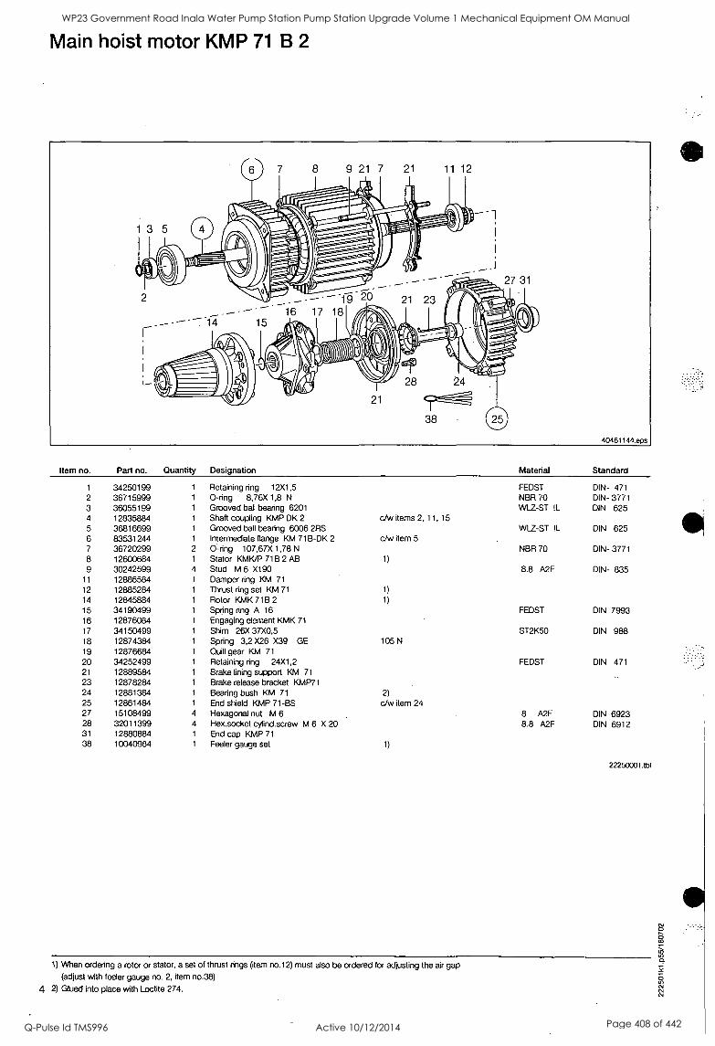
Main hoist motor KMP 71 B 2
Item no. Part no. Quantity Designation Material Standard
1 34250199 1 Retaining ring 12X1,5 FEDST DIN- 471 2 36715999 1 0-ring 8,76X 1,8 N NBR 70 DIN- 3771 3 36055199 1 Grooved ball bearing 6201 WLZ-ST !L DIN 625 4 12835884 1 Shaft coupling KMP DK 2 c/w items 2, 11, 15 5 36816699 1 Grooved ball bearing 6006 2RS WLZ-ST !L DIN 625 6 83531244 1 Intermediate flange KM 71B-DK 2 c/w item 5 7 36720299 2 0-ring 107,67X 1,78 N NBR 70 DIN- 3771 8 12600684 1 Stator KMK/P 71B 2 AB 1)
9 30242599 4 Stud M 6 X190 8.8 A2F DIN- 835 11 12886584 1 Damper ring KM 71
12 12885284 1 Thrust ring set KM 71 1)
14 12845884 1 Rotor KMK 71B 2 1)
15 34190499 1 Spring ring A 16 FEDST DIN 7993 16 12876084 1 Engaging element KMK 71
17 34150499 1 Shim 26X 37X0,5 ST2K50 DIN 988 18 12874384 1 Spring 3,2 X26 X39 GE 105 N
19 12876684 1 Quill gear KM 71
20 34252499 1 Retaining ring 24X1,2 FEDST DIN 471 21 12889584 1 Brake lining support KM 71
23 12878284 1 Brake release bracket KMP71 24 12881384 1 Bearing bush KM 71 2)
25 12861484 1 End shield KMP 71-BS c/w item 24 27 15108499 4 Hexagonal nut M 6 8 A2F DIN 6923 28 32011399 4 Hex.socket cylind.screw M 6 X 20 8.8 A2F DIN 6912 31 12880884 1 End cap KMP 71
38 10040984 1 Feeler gauge set 1)
22250001.tbl
1) When ordering a rotor or stator, a set of thrust rings (item no.12) must also be ordered for adjusting the air gap
(adjust with feeler gauge no. 2, item no.38)
4 2) Glued into place with Loctite 274.
WP23 Government Road Inala Water Pump Station Pump Station Upgrade Volume 1 Mechanical Equipment OM Manual
Q-Pulse Id TMS996 Active 10/12/2014 Page 408 of 442
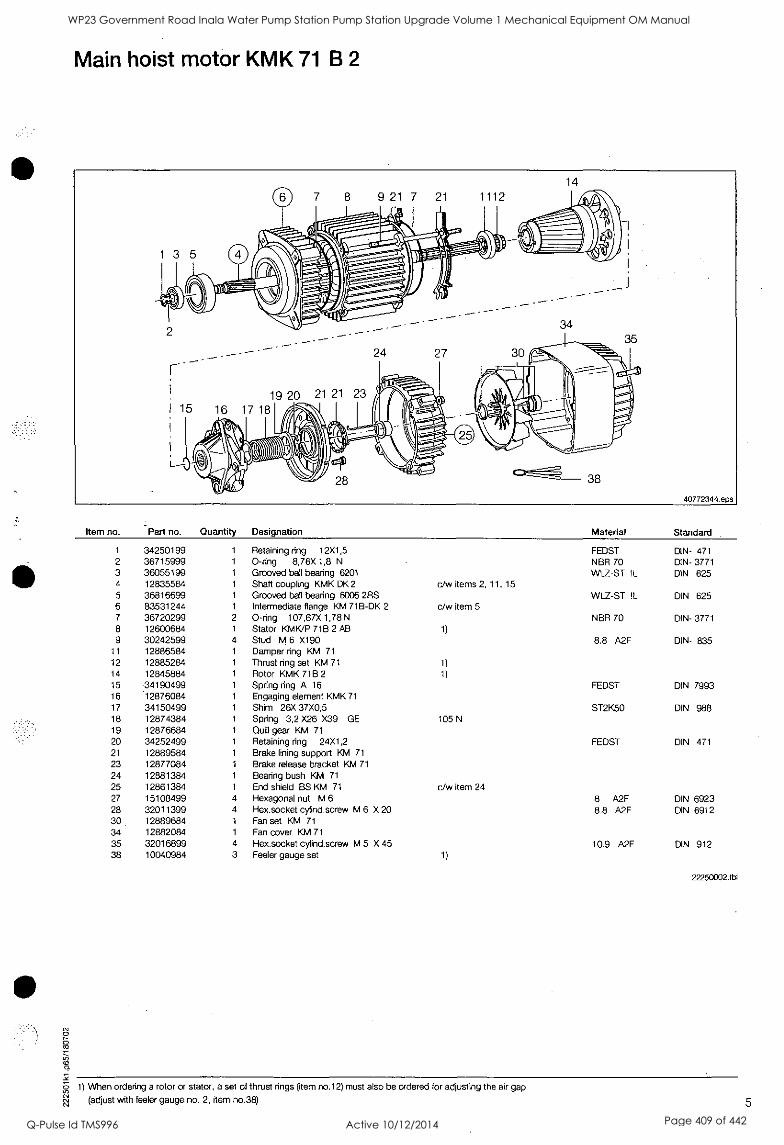
c
Main hoist motor KMK 71 B 2
Item no. Part no. Quantity Designation Material Standard
1 34250199 1 Retaining ring 12X1,5 FEDST DIN- 471 2 36715999 1 0-ring 8,76X 1,8 N NBR 70 DIN- 3771 3 36055199 1 Grooved ball bearing 6201 W12-ST DIN 625 4 12835584 1 Shaft coupling KMK DK 2 c/w items 2, 11, 15 5 36816699 1 Grooved bat bearing 6006 2RS WLZ-ST !L DIN 625 6 83531244 1 Intermediate flange KM 71B-DK 2 c/w item 5 7 36720299 2 0-ring 107,67X 1,78 N NBR 70 DIN- 3771 8 12600684 1 Stator KMK/P 71B 2 AB 1)
9 30242599 4 Stud M 6 X190 8.8 A2F DIN- 835 11 12886584 1 Damper ring KM 71
12 12885284 1 Thrust ring set KM 71 1)
14 12845884 1 Rotor KMK 71B 2 1)
15 -34190499 1 Spring ring A 16 FEDST DIN 7993 16 12876084 1 Engaging element KMK 71
17 34150499 1 Shim 26X 37X0,5 ST2K50 DIN 988 18 12874384 1 Spring 3,2 X26 X39 GE 105 N
19 12876684 1 Quill gear KM 71
20 34252499 1 Retaining ring 24X1,2 FEDST DIN 471 21 12889584 1 Brake lining support KM 71
23 12877084 1 Brake release bracket KM 71
24 12881384 1 Bearing bush KM 71
25 12861384 1 End shield BS KM 71 c/w item 24 27 15108499 4 Hexagonal nut M 6 8 A2F DIN 6923 28 32011399 4 Hex.socket cylind.screw M 6 X 20 8.8 A2F DIN 6912 30 12889684 1 Fan set KM 71
34 12882084 1 Fan cover KM 71
35 32016899 4 Hex.socket cylind.screw M 5 X 45 10.9 A2F DIN 912 38 10040984 3 Feeler gauge set 1)
22250002.tbl
0 1) When ordering a rotor or stator, a set of thrust rings (item no.12) must also be ordered for adjusting the air gap
RI (adjust with feeler gauge no. 2, item no.38) 5
WP23 Government Road Inala Water Pump Station Pump Station Upgrade Volume 1 Mechanical Equipment OM Manual
Q-Pulse Id TMS996 Active 10/12/2014 Page 409 of 442
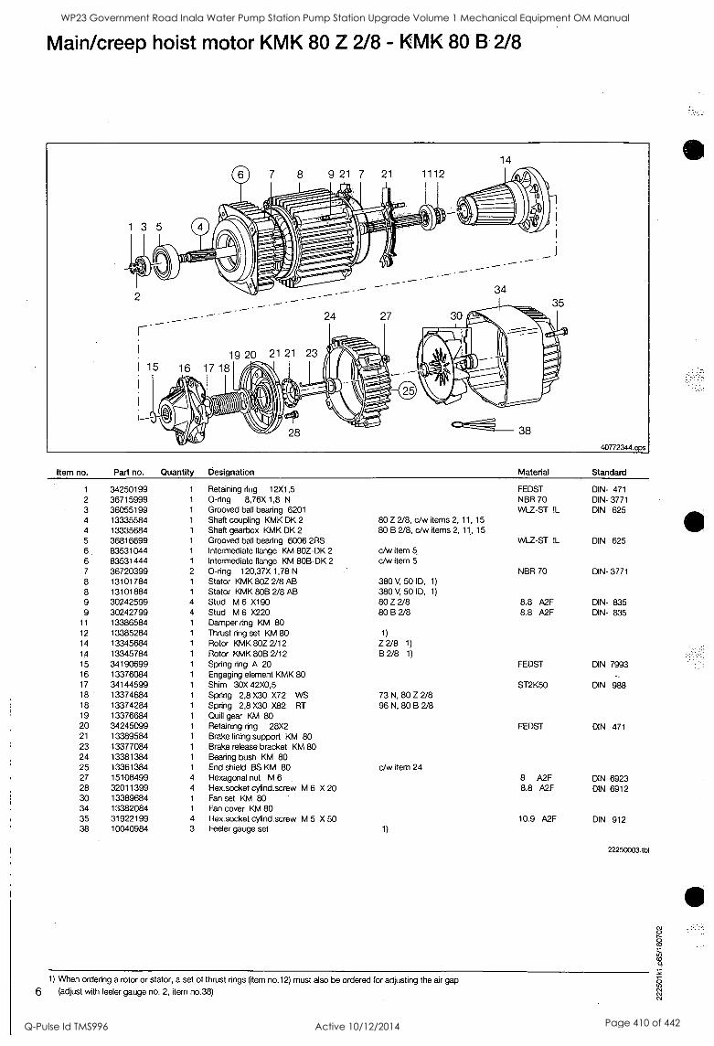
Main/creep hoist motor KMK 80 Z 2/8 - KMK 80 B 2/8
Item no. Part no. Quantity Designation
1 34250199 1 Retaining ring 12X1,5 2 36715999 1 0-ring 8,76X 1,8 N
3 36055199 1 Grooved ball bearing 6201 4 13335584 1 Shaft coupling KMK DK 2
4 13335684 1 Shaft gearbox KMK DK 2
5 36816699 1 Grooved ball bearing 6006 2RS 6 83531044 1 Intermediate flange KM 80Z-DK 2
6 83531444 1 Intermediate flange KM 80B-DK 2
7 36720399 2 0-ring 120,37X 1,78 N
8 13101784 1 Stator KMK 80Z 2/8 AB 8 13101884 1 Stator KMK 808 2/8 AB 9 30242599 4 Stud M 6 X190 9 30242799 4 Stud M 6 X220
11 13386584 1 Damper ring KM 80 12 13385284 1 Thrust ring set KM 80 14 13345684 1 Rotor KMK 80Z 2/12 14 13345784 1 Rotor KMK 80B 2/12 15 34190699 1 Spring ring A 20 16 13376084 1 Engaging element KMK 80 17 34144599 1 Shim 30X 42X0,5 18 13374684 1 Spring 2,8 X30 X72 WS 18 13374284 1 Spring 2,8 X30 X82 RT 19 13376684 1 Quill gear KM 80 20 34245099 1 Retaining ring 28X2 21 13389584 1 Brake lining support KM 80 23 13377084 1 Brake release bracket KM 80 24 13381384 1 Bearing bush KM 80 25 13361384 1 End shield BS KM 80 27 15108499 4 Hexagonal nut M 6 28 32011399 4 Hex.socket cylind.screw M 6 X 20 30 13389684 1 Fan set KM 80 34 13382084 1 Fan cover KM 80 35 31922199 4 Hex.socket cylind.screw M 5 X 50 38 10040984 3 Feeler gauge set
Material Standard
80 Z 2/8, c/w items 2, 11, 15
80 B 2/8, c/w items 2, 11, 15
c/w item 5,
c/w item 5
380 V, 50 ID, 1)
380 V, 50 ID, 1)
80 Z 2/8 80 B 2/8
1)
Z 2/8 1)
B 2/8 1)
73 N, 80 Z 2/8 96 N, 80 B 2/8
c/w tern 24
1)
FEDST DIN- 471 NBR 70 DIN- 3771 WLZ-ST IL DIN 625
WLZ-ST !L DIN 625
NBR 70 DIN- 3771
8.8 A2F DIN- 835 8.8 A2F DIN- 835
FEDST DIN 7993
ST2K50 DIN 988
FEDST DIN 471
8 A2F DIN 6923 8.8 A2F DIN 6912
10.9 A2F DIN 912
22250003.tbl
1) When ordering a rotor or stator, a set of thrust rings (tern no.12) must also be ordered for adjusting the air gap
6 (adjust with feeler gauge no. 2, item no.38)
WP23 Government Road Inala Water Pump Station Pump Station Upgrade Volume 1 Mechanical Equipment OM Manual
Q-Pulse Id TMS996 Active 10/12/2014 Page 410 of 442
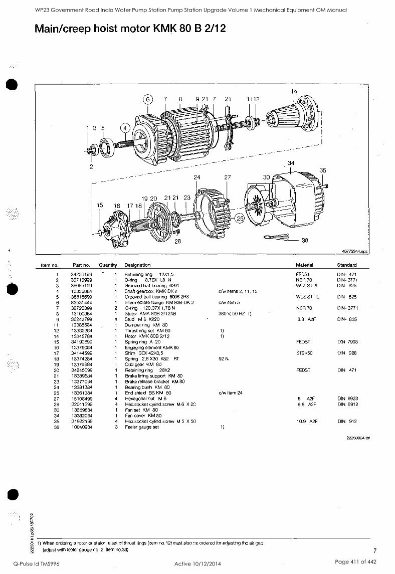
csi O
co O
a) 0
Main/creep hoist motor KMK 80 B 2/12
Item no. Part no. Quantity Designation Material Standard
1 34250199 1 Retaining ring 12X1,5 FEDST DIN- 471
2 36715999 1 0-ring 8,76X 1,8 N NBR 70 DIN- 3771 3 36055199 1 Grooved ball bearing 6201 WLZ-ST IL DIN 625 4 13335684 1 Shaft gearbox KMK DK 2 c/w items 2, 11, 15
5 36816699 1 Grooved ball bearing 6006 2RS WLZ-ST !L DIN 625 6 83531444 1 Intermediate flange KM 80B-DK 2 c/w item 5 7 36720399 2 0-ring 120,37X 1,78 N NBR 70 DIN- 3771 8 13100384 1 Stator KMK 80B 2/12AB 380 V, 50 HZ 1)
9 30242799 4 Stud M 6 X220 8.8 A2F DIN- 835 11 13386584 1 Damper ring KM 80 12 13385284 1 Thrust ring set KM 80 1)
14 13345784 1 Rotor KMK 80B 2/12 1)
15 34190699 1 Spring ring A 20 FEDST DIN 7993 16 13376084 1 Engaging element KMK 80 17 34144599 1 Shim 30X 42X0,5 ST2K50 DIN 988 18 13374284 1 Spring 2,8 X30 X82 RT 92 N
19 13376684 1 Quill gear KM 80 20 34245099 1 Retaining ring 28X2 FEDST DIN 471
21 13389584 1 Brake lining support KM 80
23 13377084 1 Brake release bracket KM 80 24 13381384 1 Bearing bush KM 80 25 13361384 1 End shield BS KM 80 c/w item 24
27 15108499 4 Hexagonal nut M 6 8 A2F DIN 6923 28 32011399 4 Hex.socket cylind.screw M 6 X 20 8.8 A2F DIN 6912 30 13389684 1 Fan set KM 80 34 13382084 1 Fan cover KM 80 35 31922199 4 Hex.socket cylind.screw M 5 X 50 10.9 A2F DIN 912 38 10040984 3 Feeler gauge set 1)
22250004.tbi
G 1) When ordering a rotor or stator, a set of thrust rings (item no.12) must also be ordered for adjusting the air gap
N,cc (adjust with feeler gauge no. 2, item no.38) 7
WP23 Government Road Inala Water Pump Station Pump Station Upgrade Volume 1 Mechanical Equipment OM Manual
Q-Pulse Id TMS996 Active 10/12/2014 Page 411 of 442
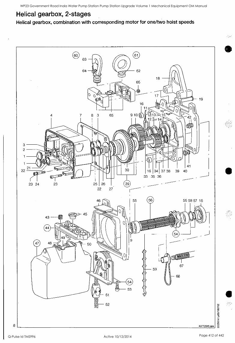
Helical gearbox, 2-stages Helical gearbox, combination with corresponding motor for one/two hoist speeds
3
2
22 41
16 34 137 38 39 40
33 35 36
23 24 23
40772045.eps
WP23 Government Road Inala Water Pump Station Pump Station Upgrade Volume 1 Mechanical Equipment OM Manual
Q-Pulse Id TMS996 Active 10/12/2014 Page 412 of 442
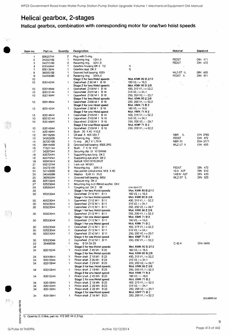
Helical gearbox, 2-stages Helical gearbox, combination with corresponding motor for one/two hoist speeds
Item no. Part no. Quantity Designation Material Standard
1 83625744 2 Plug with 0-ring 2 34250199 1 Retaining ring 12X1,5 FEDST DIN- 471
3 34272199 2 Retaining ring 32X1,5 FEDST DIN. 472 4 83510444 1 Gearbox housing DK 2 T.2 1)
7 83513944 1 Gearbox seal DK 2 1)
8 36055199 1 Grooved ball bearing 6201 WLZ-ST !L . DIN 625 9 34253099 2 Retaining ring 30X1,5 FEDST IL DIN 47.1
10 Stage 2 for two Hoist speeds 'Mot. KMK 80 B 2/12 10 83514244 1 Gearwheel Z 86 M 1 B 18 160 V3, i = 16,5
Stage 2 for two Hoist speeds Mot. KMK 80 B 2/8 10 83514644 1 Gearwheel Z109 M 1 B 18 400, 315 V1, i = 52,2 10 83515144 1 Gearwheel Z103 M 1 B 18 315 V2, i = 34,1
10 83514844 1 Gearwheel Z100 M 1 8 18 250, 200 V2, i = 29,7 Stage 2 for two Hoist speeds Mot. KMK 80 Z 2/8
10 83514644 1 Gearwheel Z109 M 1 8 18 250, 200 V1, i = 52,2 Stage 2 for one Hoist speed Mot. KMK 71 B 2
10 83514244 1 Gearwheel Z 86 M 1 8 18 160 V3, i = 16,5 Stage 2 for one Hoist speed Mot. KMK 71 B 2
10 83514644 1 Gearwheel Z109 M 1 B 18 400, 315 V1, i = 52,2 10 83515144 1 Gearwheel Z103 M 1 B 18 315 V2, i = 34,1
10 83514844 1 Gearwheel Z100 M 1 B 18 250, 200 V2, i = 29,7 Stage 2 for one Hoist speed Mot. KMP 71 B 2
10 83514644 1 Gearwheel Z109 M 1 B 18 250, 200 V1, i = 52,2 11 83514944 1 Bush 30 X 40 X10,5 12 36716299 1 Oil seal A 40X 55X 7 NBR !L DIN 3760
13 34265299 1 Retaining ring 55X2 FEDST DIN 472 14 36720199 1 0-ring 26,7 X 1,78 N NBR 70 DIN- 3771
15 36816699 2 Grooved ball bearing 6006 2RS WLZ-ST !L DIN 625 16 71521144 2 Bush 7 X 12 X10 17 34287544 2 Securing clip SL 10 SXN08
18 83570444 1 Supporting eye long DK 2
18 83570244 1 Supporting eye short DK 2
19 83561644 2 Setbolt 10H11X76,5NUT 21 83513744 1 Lock nut M15X1 22 34272199 2 Retaining ring 32X1,5 FEDST DIN 472 23 32143699 6 Hex.socket cylind.screw M 6 X 40 10.9 A2F DIN 912 24 34045599 ' 1 Washer 6,4X 11 X1,6 140HV A2F DIN 433 25 36050299 1 Grooved ball bearing 6002 WLZ-ST !L DIN 625
26 83513844 1 Pressure ring DK 2
27 83523644 1 Mounting ring and dished washer DK2
29 83526044 1 Coupling set DK 2 XX c/w item 21
30 Stage 1 for two Hoist speeds Mot. KMK 80 B 2/12 30 83523044 1 Gearwheel Z112 M 1 B 11 160 V3, i = 16,5
Stage 1 for two Hoist speeds Mot. KMK 80 B 2/8 30 83523044 1 Gearwheel Z112 M 1 B 11 400, 315 V1, i = 52,2 30 83523044 1 Gearwheel Z112 M 1 B 11 315 V2, i = 34,1
30 83523044 1 Gearwheel Z112 M 1 B 11 250, 200 V2, i = 29,7 Stage 1 for two Hoist speeds Mot. KMK 80 Z 2/8
30 83523044 1 Gearwheel Z112 M 1 B 11 250, 200 V1, i = 52,2 Stage 1 for one Hoist speed Mot. KMK 71 B 2
30 83523044 1 Gearwheel Z112 M 1 B 11 160 V3, i = 16,5 Stage 1 for one Hoist speed Mot. KMK 71 B 2
30 83523044 1 Gearwheel Z112 M 1 B 11 400, 315 V1, i = 52,2
30 83523044 1 Gearwheel Z112 M 1 13 11 315 V2, i= 34,1
30 83523044 1 Gearwheel Z112 M 1 8 11 250, 200 V2, i = 29,7 Stage 1 for one Hoist speed Mot. KMP 71 B 2
30 83523044 1 Gearwheel Z112 M 1 8 11 250, 200 V1, i = 52,2 33 35488599 1 Key B 5X 5X 29 C 45 K DIN- 6885
34 Stage 2 for two Hoist speeds Mot. KMK 80 B 2/12 34 83515244 1 Pinion shaft Z 45 M1 13 23 160 V3, i = 16,5
Stage 2 for two Hoist speeds Mot. KMK 80 B 2/8 34 83515644 1 Pinion shaft Z 18 M1 B 23 400, 315 V1, i = 52,2 34 83515044 1 315 V2, i= 34,1 Pinion shaft. Z 26 M1 B 23 34 83515844 1 Pinion shaft Z 29 M1 B 23 250, 200 V2, i = 29,7
Stage 2 for two Hoist speeds Mot. KMK 80 Z 2/8 34 83515644 1 Pinion shaft Z 18 M1 B 23 250, 200 V1, i = 52,2
Stage 2 for one Hoist speed Mot. KMK 71 B 2
34 83515244 1 Pinion shaft Z 45 M1 B 23 160 V3, i = 16,5 Stage 2 for one Hoist speed Mot. KMK 71 B 2
34 83515644 1 Pinion shaft Z 18 M1 B 23 400, 315 V1, i = 52,2 34 83515044 1 Pinion shaft Z 26 M1 B 23 315 V2, i = 34,1
34 83515844 1 Pinion shaft Z 29 M1 B 23 250, 200 V2, i = 29,7 Stage 2 for one Hoist speed Mot. KMP 71 B 2
34 83515644 1 Pinion shaft Z 18 M1 B 23 250, 200 V1, i = 52,2 22250005.tbi
O O
0 --
1) Quantity 0,15 litre, part no. 472 902 44 (1,0 kg).
cv cv 9
WP23 Government Road Inala Water Pump Station Pump Station Upgrade Volume 1 Mechanical Equipment OM Manual
Q-Pulse Id TMS996 Active 10/12/2014 Page 413 of 442
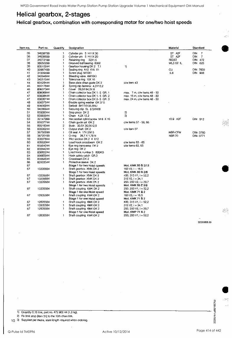
Helical gearbox, 2-stages Helical gearbox, combination with corresponding motor for one/two hoist speeds
Item no. Part no. Quantity Designation
35 34638799 1 Cylinder pin 5 H11X 36 36 34638699 2 Cylinder pin 5 H11X 20 37 34272199 1 Retaining ring 32X1,5 38 36050299 1 Grooved ball bearing 6002 39 83510244 1 Gearbox housing DK 2 T.1
40 33987499 1 Sealing ring A10 X16 X1 41 31339499 1 Screw plug M10X1 42 34264844 1 Bleeding valve AM10X1 43 34251544 1 Tolerance ring 10X 10 44 83529444 1 Base plate chain guide DK 2
45 83517844 2 Spring clip fastener 4,2X12,2 46 83607344 1 Cover 39.5X 64,5X 8 47 83606844 1 Chain collector box DK 1- 5 GR. 1
47 83608444 1 Chain collector box DK 1- 5 GR. 2 47 83606744 1 Chain collector box DK 2- 5 GR. 3 48 83607544 1 Double spring washer DK 2/ 5 49 83606944 1 Setbolt 8H11X135,5NU 50 34286944 1 Securing clip SL 8 SXN08 51 83508344 1 Stop piece DK 2
52 83569944 1 Chain 4,2X 12,2 53 32147999 4 Hex.socket cylind.screw M 6 X 16 54 83537744 1 Chain guide set DK 2 55 83516344 2 Bush 30,5X 36,5X12,9 56 83536244 1 Output shaft DK 2 57 36750599 1 Oil seal A 17X 25X 5 58 36720199 1 0-ring 26,7 X 1,78 N
59 83507844 1 Pilot section DK 2 4 X12 60 83562044 1 Load hook crossbeam DK 2 61 83564044 1 Eye ring transverse DK 2
62 83564244 1 Eye ring DK 2
63 83665244 1 Load hook number 3 800KG 64 83665944 1 Hook safety catch GR.3 65 83562544 1 Crossbeam DK 2
66 83503544 1 Protective sleeve DK 2
67 Stage 1 for two Hoist speeds 67 13335684 1 Shaft gearbox KMK DK 2
Stage 1 for two Hoist speeds 67 13335684 1 Shaft gearbox KMK DK 2
67 13335684 1 Shaft gearbox KMK DK 2
67 13335684 1 Shaft gearbox KMK DK 2
Stage 1 for two Hoist speeds 67 13335584 1 Shaft coupling KMK DK 2
Stage 1 for one Hoist speed 67 12835584 1 Shaft coupling KMK DK 2
Stage 1 for one Hoist speed 67 12835584 1 Shaft coupling KMK DK 2
67 12835584 1 Shaft coupling KMK DK 2
67 12835584 1 Shaft coupling KMK DK 2
Stage 1 for one Hoist speed 67 12835584 1 Shaft coupling KMK DK 2
Material Standard
ST A2F DIN 7
ST A2F DIN 7
FEDST DIN 472 WLZ-ST IL DIN 625
1)
CU DIN 7603 5.8 DIN 908
c/w item 43
max. 7 m, c/w items 48 - 50 max. 15 m, c/w items 48 - 50 max. 24 m, c/w items 48 - 50
2)
3)
10.9 A2F DIN 912 c/w items 57 - 59, 66
c/w item 57 NBR-CFW DIN- 3760 NBR 70 DIN- 3771
c/w items 63 - 65 c/w items 62, 65
Mot. KMK 80 B 2/12 160 V3, i = 16,5 Mot. KMK 80 B 2/8 400, 315 V1, i = 52,2 315 V2, i = 34,1
250, 200 V2, i = 29,7 Mot. KMK 80 Z 2/8 250, 200 V1, i = 52,2 Mot. KMK 71 B 2
160 V3, i = 16,5 Mot. KMK 71 B 2
400, 315 V1, i = 52,2 315 V2, i = 34,1
250, 200 V2, i = 29,7 Mot. KMP 71 B 2
250, 200 V1, i = 52,2
22250005.tbl
1) Quantity 0,15 litre, part no. 472 902 44 (1,0 kg).
2) Fix limit stop (item 51) to the loth chain link.
10 3) Supplied per metre, state length required when ordering.
WP23 Government Road Inala Water Pump Station Pump Station Upgrade Volume 1 Mechanical Equipment OM Manual
Q-Pulse Id TMS996 Active 10/12/2014 Page 414 of 442
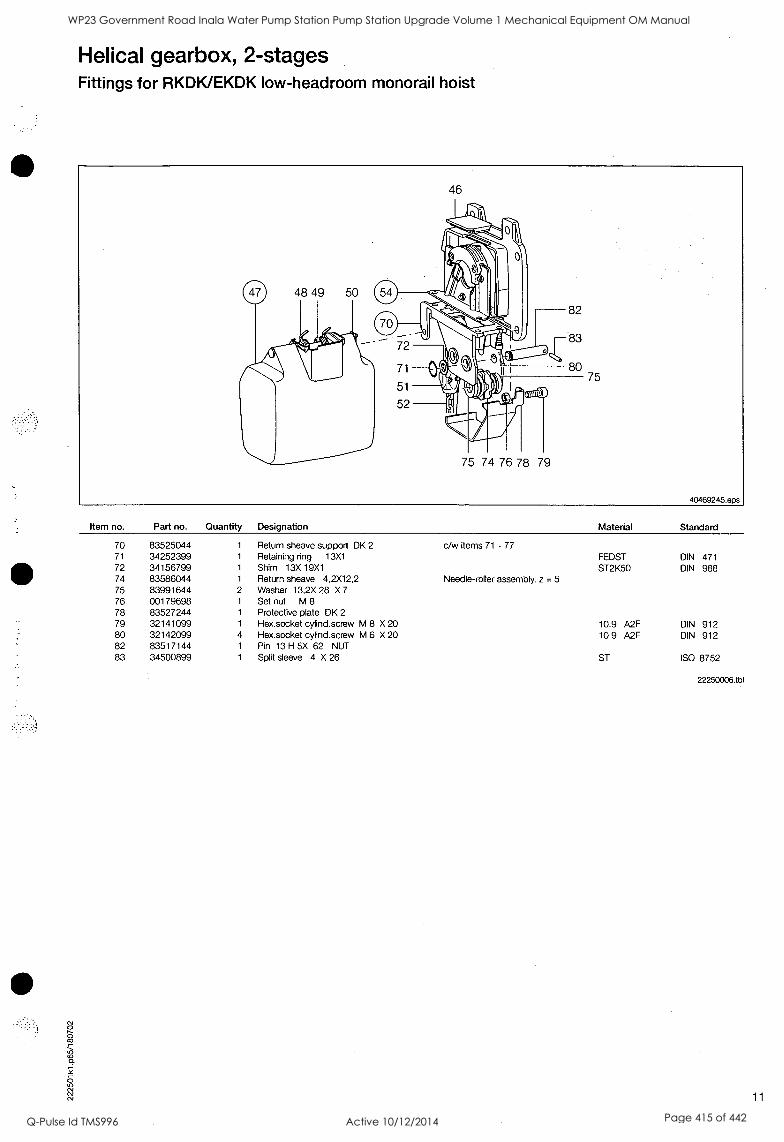
Helical gearbox, 2-stages Fittings for RKDK/EKDK low-headroom monorail hoist
Item no. Part no. Quantity Designation Material Standard
70 83525044 1 Return sheave support DK 2 c/w items 71 - 77 71 34252399 1 Retaining ring 13X1 FEDST DIN 471 72 34156799 1 Shim 13X 19X1 ST2K50 DIN 988 74 83586044 1 Return sheave 4,2X12,2 Needle-roller assembly, z = 5 75 83991644 2 Washer 13,2X 28 X 7
76 00179698 1 Set nut M 8
78 83527244 1 Protective plate DK 2
79 32141099 1 Hex.socket cylind.screw M 8 X 20 10.9 A2F DIN 912 80 32142099 4 Hex.socket cylind.screw M 6 X 20 10.9 A2F DIN 912 82 83517144 1 Pin 13 H 5X 62 NUT 83 34500899 1 Split sleeve 4 X 26 ST ISO 8752
22250006.tb1
11
WP23 Government Road Inala Water Pump Station Pump Station Upgrade Volume 1 Mechanical Equipment OM Manual
Q-Pulse Id TMS996 Active 10/12/2014 Page 415 of 442
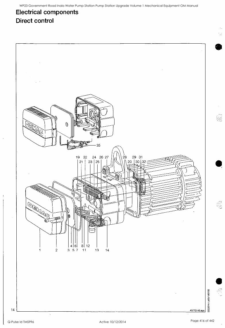
14
Electrical components Direct control
19 22 24 26 27 28 29 31
21 23 25
46 8 12
2 357 11 13 14
40772145.eps
WP23 Government Road Inala Water Pump Station Pump Station Upgrade Volume 1 Mechanical Equipment OM Manual
Q-Pulse Id TMS996 Active 10/12/2014 Page 416 of 442
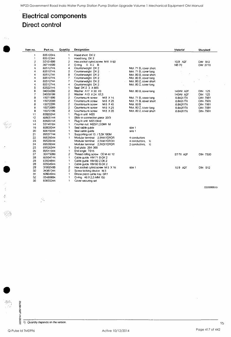
Electrical components Direct control
Item no. Part no. Quantity Designation Material Standard
1 83512044 1 Hood short DK 2
1 83512344 1 Hood long DK 2
2 32151699 2 Hex.socket cylind.screw M 6 X 60 10.9 A2F DIN 912 3 36714599 2 0-ring 5 X 2 B NB 70 DIN 3770 4 83512744 4 Counterweight DK 2 Mot. 71 B, cover short 4 83512744 2 Counterweight DK 2 Mot. 71 B, cover long 4 83512744 8 Counterweight DK 2 Mot. 80 B, cover short 4 83512744 7 Counterweight DK 2 Mot. 80 B, cover long 4 83512744 7 Counterweight DK 2 Mot. 80 Z, cover short 4 83512744 4 Counterweight DK 2 Mot. 80 Z, cover long 5 83522144 1 Seal DK 2 3 X 665 6 34054299 2 Washer Al 7 X 30 X3 Mot. 80 B, cover long 140HV A2F DIN 125 7 34059199 2 Washer A13 X 24 X2,5 140HV A2F DIN 125 8 15071999 2 Countersunk screw M 8 X 14 Mot. 71 B, cover long 8.8A2F/TX DIN- 7991 8 15072099 2 Countersunk screw M 8 X 25 Mot. 71 B, cover short 8.8A2F/TX DIN- 7991 8 15072299 2 Countersunk screw M 8 X 45 Mot. 80 B 8.8A2F/TX DIN- 7991 8 15072099 2 Countersunk screw M 8 X 25 Mot. 80 Z, cover long 8.8A2F/TX DIN- 7991 8 15072199 2 Countersunk screw M 8 X 35 Mot. 80 Z, cover short 8.8A2F/TX DIN- 7991
11 83620244 1 Plug-in unit M20 12 83605144 1 Slide-in connection piece 20/3 13 83620144 1 Plug-in unit M25 Blind 14 53746184 1 Counter nut M25X1,5 EMV M 19 83605044 1 Seal cable guide size 1
20 83615044 1 Seal cable guide size 1
21 89537744 1 Supporting rail 15 / 5,5X 180M 22 89539544 1 Modular terminal 2,5X4X1DRDR 4 conductors 23 89528444 Modular terminal 2,5X4X1DRDR 4 conductors, 1)
24 89528344 Modular terminal 2,5X2X1DRDR 2 conductors, 1)
25 .89528544 1 End plate 264-368 26 89541944 1 End angle TS15 27 32475099 2 Thread rolling screw CE M 4X 12 ST-TX A2F DIN- 7500 28 83504744 1 Cable guide KM 71 B-DK 2
28 83504844 1 Cable guide KM 80 Z-DK 2
28 83504944 1 Cable guide KM 80 B-DK 2
29 31892499 2 Hex.socket cylind.screw M 5 X 16 size 1 10.9 A2F DIN 912 30 34387344 2 Screw locking device M 5
31 83604944 1 Elbow piece cable tray GR1
32 05480684 1 0-ring 46 X 2,5 MM 150 35 83655344 1 Cover securing set
csi O
co O
Fe; O
O
cv 1) Quantity depends on the version.
22250009.tbl
15
WP23 Government Road Inala Water Pump Station Pump Station Upgrade Volume 1 Mechanical Equipment OM Manual
Q-Pulse Id TMS996 Active 10/12/2014 Page 417 of 442
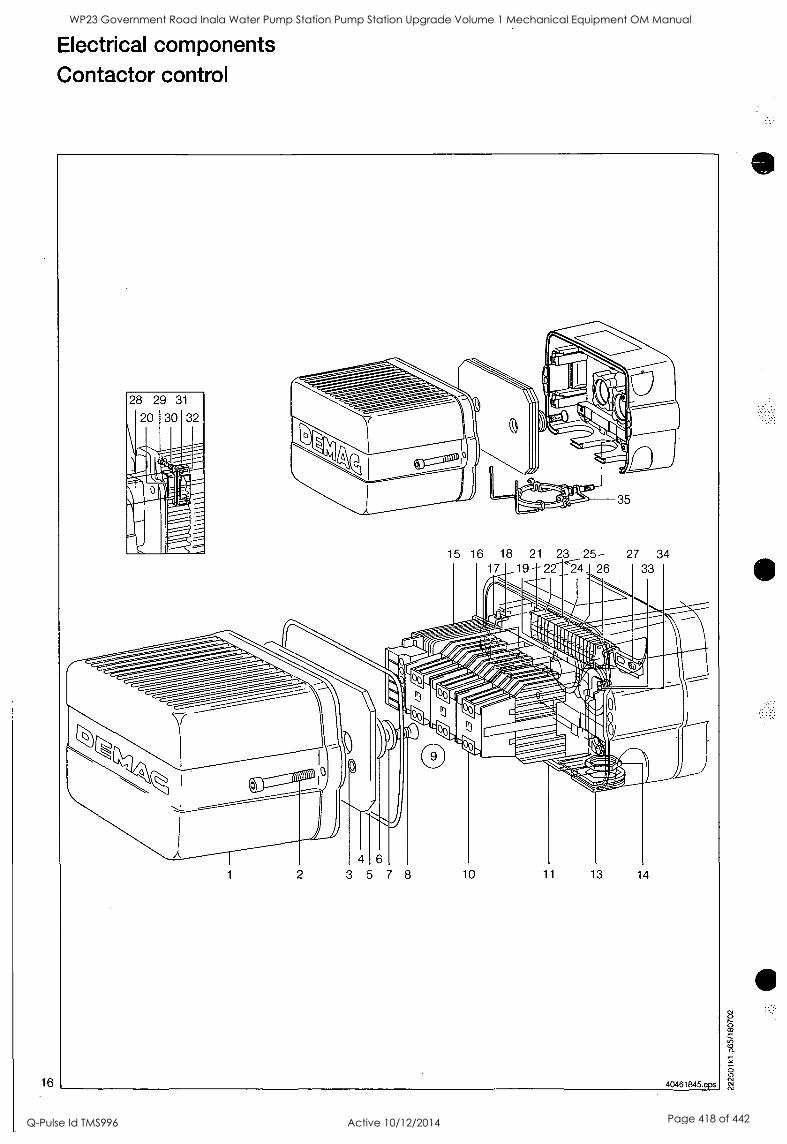
16
Electrical components Contactor control
15 16 18 21 23 25- 27 34 17 19 -- 22 24 26 33
WP23 Government Road Inala Water Pump Station Pump Station Upgrade Volume 1 Mechanical Equipment OM Manual
Q-Pulse Id TMS996 Active 10/12/2014 Page 418 of 442
Electrical components Contactor control
Item no. Part no. Quantity Designation Material Standard
1 83512344 1 Hood long DK 2
2 32151699 2 Hex.socket cylind.screw M 6 X 60 10.9 A2F DIN 912 3 36714599 2 0-ring 5 X 2 B NB 70 DIN 3770 4 83512744 1 Counterweight DK 2 Mot. 71 B
4 83512744 3 Counterweight DK 2 Mot. 80 B 4 83512744 2 Counterweight DK 2 Mot. 80 Z 5 83522144 1 Seal DK 2 3 X 665 6 34054299 2 Washer A17 X 30 X3 Mot. 71 B, 80 B 140HV A2F DIN 125 7 34059199 2 Washer A13 X 24 X2,5 140HV A2F DIN 125 8 15071999 2 Countersunk screw M 8 X 14 Mot. 71 B, 80 Z 8.8A2F/TX DIN- 7991. 8 15072099 2 Countersunk screw M 8 X 25 Mot. 80 B 8.8A2F/TX DIN- 7991 9 Switchgear set 3-Phase Design c/w items 10, 15 - 18, 2 0 -26 9 38025546 1 Switchgear set 220-500V5OHZ VDE Main hoisting, 1), 2)
9 38026146 1 Switchgear set 380/220V50HZ VDE Main hoisting, 1)
9 38026646 1 Switchgear set 380/220V50HZ VDE Main hoisting, 1), 3)
9 38025646 1 Switchgear set 220-500V5OHZ VDE Main/creep hoisting, 1), 2)
9 38026246 1 Switchgear set 380/220V50HZ VDE Main/creep hoisting, 1)
9 38026746 1 Switchgear set 380/220V50HZ VDE Main/creep hoisting, 1) , 3)
9 38025746 1 Switchgear set 220-500V50HZ VDE Main hoisting + cross tra vel, 1), 2)
9 38026346 1 Switchgear set 380/220V50HZ VDE Main hoisting + cross Ira vel, 1)
9 38026846 1 Switchgear set 380 /220V50HZ VDE Main hoisting + cross Ira vel, 1), 3)
9 38025846 1 Switchgear set 220-500V50HZ VDE Main/creep hoisting + c ross travel, 1), 2)
9 38026446 1 Switchgear set 380/220V50HZ VDE Main/creep hoisting + c ross travel, 1)
9 38025946 1 Switchgear set 220-500V50HZ VDE Main hoisting + cross tra vel, 2 speeds, 1:4, 1), 2)
9 38026546 1 Switchgear set 380/220V50HZ VDE Main hoisting + cross tra vel, 2 speeds, 1:4, 1)
9 38026046 1 Switchgear set 220-500V5OHZ VDE Main/creep hoisting + c ross travel, 2 speeds, 1), 2)
10 87535244 2 Contactor DSW 3TF8133 42V50HZ 1 NC 10 87535044 2 Contactor DSW 3TF8133 230/220V50HZ 1 NC 10 J87536244 1 Contactor DSUB 111 42V50HZ 1 NO + 1 NC 10 87536044 1 Contactor DSUB 111 230/220V50HZ 1 NO + 1 NC 10 87548744 1 Contactor DSKR 110 42V5OHZ 1 NO 10 87545544 1 Contactor DSKR 110 230/220V50HZ 1 NO 11 83620244 2 Plug-in unit M20 13 83620144 1 Plug-in unit M25 Blind 14 53746184 1 Counter nut M25X1,5 EMV M
15 89553944 1 Control transformer 36VA400/ 42V 50/60 ID
15 89569944 1 Control transformer 36VA400/230V 50/60 ID
16 89543044 1 Plate transformer 17 83512244 1 Mounting plate DK 2
18 34280444 1 Clamping plate 4X1.5X11.2 19 83605044 1 Seal cable guide size 1
20 83615044 1 Seal cable guide size 1
21 89537744 1 Supporting rail 15 / 5,5X 180M 22 %:89539544 1 Modular terminal 2,5X4X1DRDR 4 conductors 23 '1:89528444 Modular terminal 2,5X4X1DRDR 4 conductors, 4)
24 89528344 Modular terminal 2,5X2X1DRDR 2 conductors, 4)
25 89528544 1 End plate 264-368 26 89541944 1 End angle TS15 27 32475099 2 Thread rolling screw CE M 4X 12 ST-D( A2F DIN- 7500 28 83504744 1 Cable guide KM 71 B-DK 2
28 83504844 1 Cable guide KM 80 Z-DK 2
28 83504944 1 Cable guide KM 80 B-DK 2
29 31892499 2 Hex.socket cylind.screw M 5 X 16 10.9 A2F DIN 912 30 34387344 2 Screw locking device M 5
31 83604944 1 Elbow piece cable tray GR1
32 05480684 1 0-ring 46 X 2,5 MM 150
33 31953499 2 Hex.socket cylind.screw M 4 X 10 10.9 DIN 912 34 34043599 2 Washer 3,7X 7 X1,0 VULKANFIBE DIN- 433 35 83655344 1 Cover securing set
22250010 bl
O
1) State operating and control voltage when ordering.
'; 2) Without control transformer.
3) With crane switch.
c;), c 4) Quantity depends on the version. 17
WP23 Government Road Inala Water Pump Station Pump Station Upgrade Volume 1 Mechanical Equipment OM Manual
Q-Pulse Id TMS996 Active 10/12/2014 Page 419 of 442
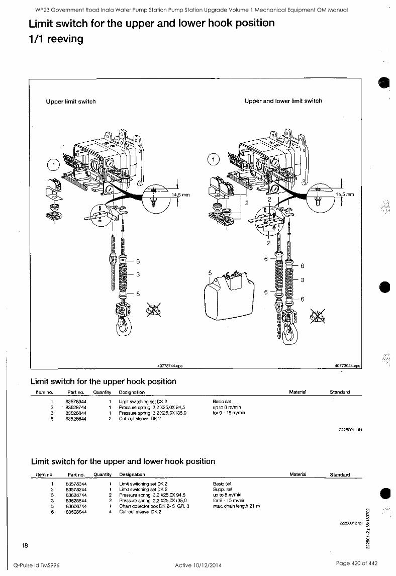
Limit switch for the upper and lower hook position
1/1 reeving
Limit switch for the upper hook position Item no. Part no. Quantity Designation
1 83578344 1 Limit switching set DK 2 Basic set 3 83628744 1 Pressure spring 3,2 X25,0X 94,5 up to 8 m/min 3 83628844 1 Pressure spring 3,2 X25,0X135,0 for 9 - 15 m/min 6 83528644 2 Cut-out sleeve DK 2
Limit switch for the upper and lower hook position
Item no. Part no. Quantity Designation
1 83578344 1 Limit switching set DK 2
2 83578244 1 Limit switching set DK 2
3 83628744 2 Pressure spring 3,2 X25,0X 94,5 3 83628844 2 Pressure spring 3,2 X25,0X135,0 3 83606744 1 Chain collector box DK 2- 5 GR. 3 6 83528644 4 Cut-out sleeve DK 2
18
Material Standard
22250011.tbl
Material Standard
Basic set Supp. set up to 8 m/min for 9 - 15 m/min max. chain length 21 m
22250012.tbt
WP23 Government Road Inala Water Pump Station Pump Station Upgrade Volume 1 Mechanical Equipment OM Manual
Q-Pulse Id TMS996 Active 10/12/2014 Page 420 of 442
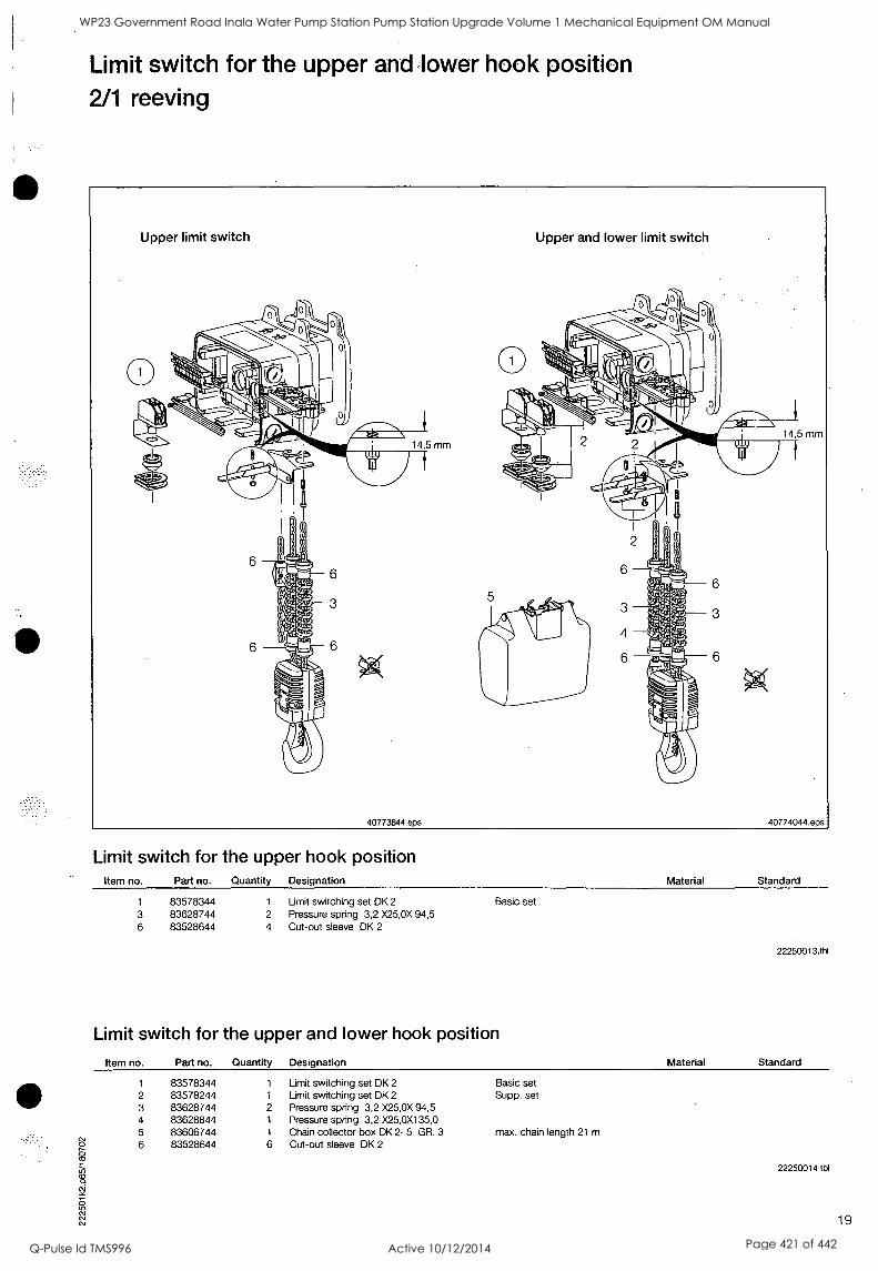
Limit switch for the upper and lower hook position 2/1 reeving
Limit switch for the upper hook position Item no. Part no. Quantity Designation Material Standard
1 83578344 1 Limit switching set DK 2 Basic set 3 83628744 2 Pressure spring 3,2 X25,0X 94,5 6 83528644 4 Cut-out sleeve DK 2
Limit switch for the upper and lower hook position
Item no. Part no. Quantity Designation
1 83578344 1 Limit switching set DK 2
2 83578244 1 Limit switching set DK 2
3 83628744 2 Pressure spring 3,2 X25,0X 94,5 4 83628844 1 Pressure spring 3,2 X25,0X135,0 5 83606744 1 Chain collector box DK 2- 5 GR. 3
6 83528644 6 Cut-out sleeve DK 2
Basic set Supp. set
max. chain length 21 m
22250013.tbl
Material Standard
22250014 tbl
19
WP23 Government Road Inala Water Pump Station Pump Station Upgrade Volume 1 Mechanical Equipment OM Manual
Q-Pulse Id TMS996 Active 10/12/2014 Page 421 of 442
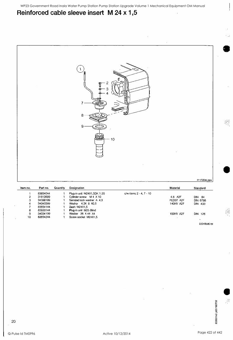
Reinforced cable sleeve insert M 24 x 1,5
Item no. Part no. Quantity Designation Material Standard
1 83654044 1 Plug-in unit M24X1,5DK 1-20 c,/w items 2 - 4, 7 - 10 2 31813699 1 Cylinder screw M 4 X 10 4.8 A2F DIN 84 3 34398199 1 Serrated lock washer A 4,3 FEDST A2F DIN 6798 4 34040399 1 Washer 4,3X 8 X0,5 140HV A2F DIN 433 7 83654144 1 Bush M24X1,5 8 83620144 1 Plug-in unit M25 Blind 9 34034199 1 Washer 26 X 44 X4 100HV A2F DIN 126
10 83654244 1 Screw socket M24X1,5
22249506.tbl
20
WP23 Government Road Inala Water Pump Station Pump Station Upgrade Volume 1 Mechanical Equipment OM Manual
Q-Pulse Id TMS996 Active 10/12/2014 Page 422 of 442
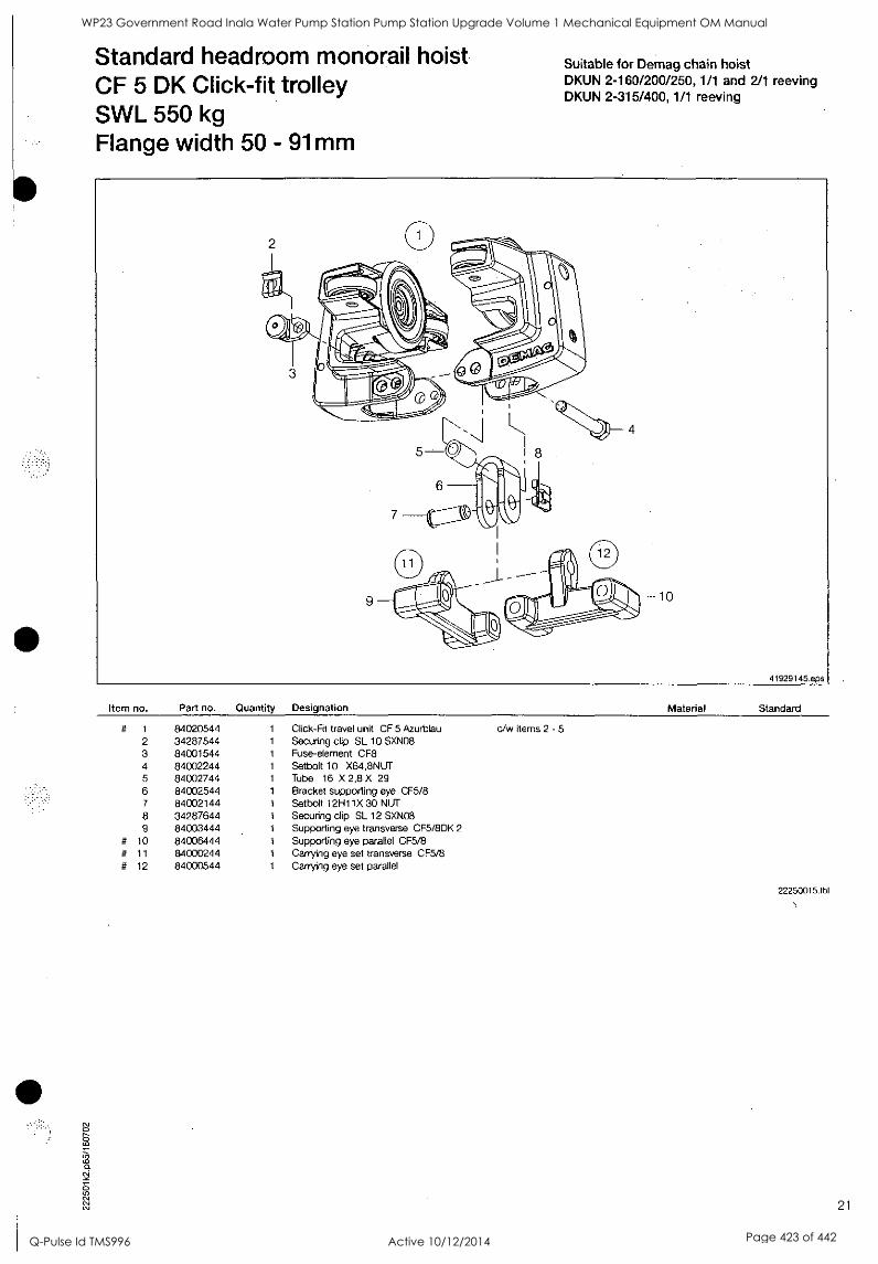
Standard headroom monorail hoist CF 5 DK Click-fit trolley SWL 550 kg Flange width 50 - 91mm
Suitable for Demag chain hoist DKUN 2-160/200/250, 1/1 and 2/1 reeving DKUN 2-315/400, 1/1 reeving
Item no. Part no. Quantity Designation Material Standard
# 1 84020544 1 Click-Fit travel unit CF 5 Azurblau c/w items 2 - 5 2 34287544 1 Securing clip SL 10 SXN08 3 84001544 1 Fuse-element CF8 4 84002244 1 Setbolt 10 X64,8NUT 5 84002744 1 Tube 16 X 2,8 X 29 6 84002544 1 Bracket supporting eye CF5/8 7 84002144 1 Setbolt 12H11X 30 NUT 8 34287644 1 Securing clip SL 12 SXN08 9 84003444 1 Supporting eye transverse CF5/8DK 2
# 10 84006444 1 Supporting eye parallel CF5/8 # 11 84000244 1 Carrying eye set transverse CF5/8 # 12 84000544 1 Carrying eye set parallel
22250015.tbi
21
WP23 Government Road Inala Water Pump Station Pump Station Upgrade Volume 1 Mechanical Equipment OM Manual
Q-Pulse Id TMS996 Active 10/12/2014 Page 423 of 442
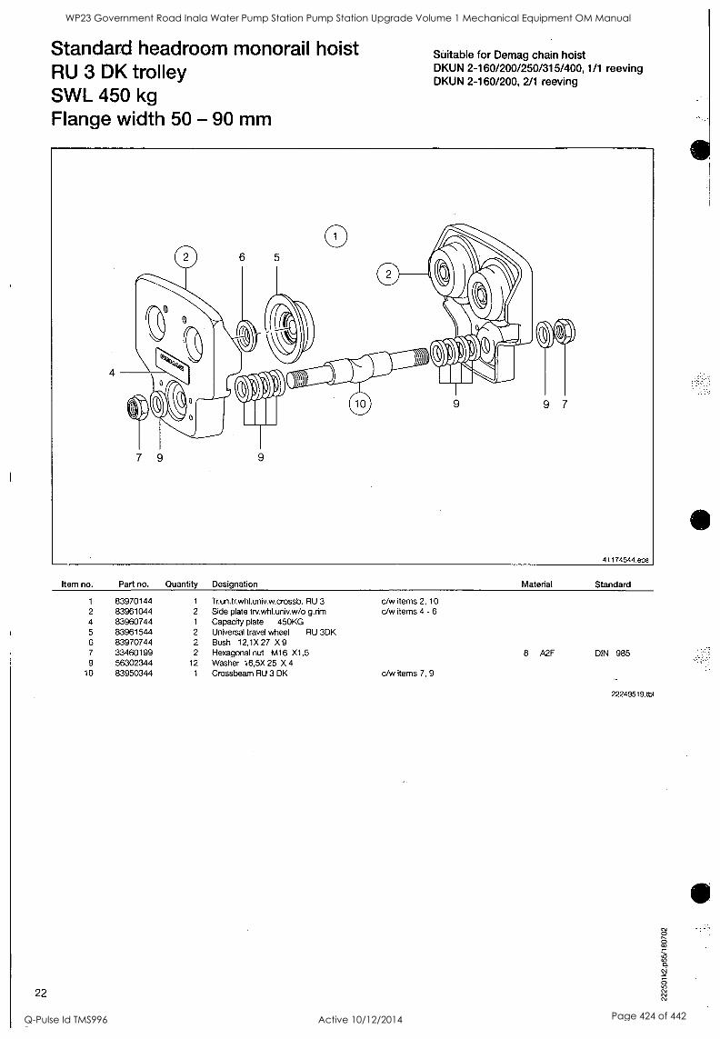
Standard headroom monorail hoist RU 3 DK trolley SWL 450 kg Flange width 50 - 90 mm
Suitable for Demag chain hoist DKUN 2-160/200/250/315/400, 1/1 reeving DKUN 2-160/200, 2/1 reeving
Item no. Part no. Quantity Designation Material Standard
1 83970144 1 Tr.un.tr.whl.univ.w.crossb. RU 3 c/w items 2, 10 2 83961044 2 Side plate trv.whl.univ.w /o g.rim c/w items 4 - 6 4 83960744 1 Capacity plate 450KG 5 83961544 2 Universal travel wheel RU 3DK 6 83970744 2 Bush 12,1X27 X9 7 33460199 2 Hexagonal nut M16 X1,5 8 A2F DIN 985 9 56302344 12 Washer 16,5X 25 X 4
10 83950344 1 Crossbeam RU 3 DK c/w items 7, 9
22249519.tbl
22
WP23 Government Road Inala Water Pump Station Pump Station Upgrade Volume 1 Mechanical Equipment OM Manual
Q-Pulse Id TMS996 Active 10/12/2014 Page 424 of 442
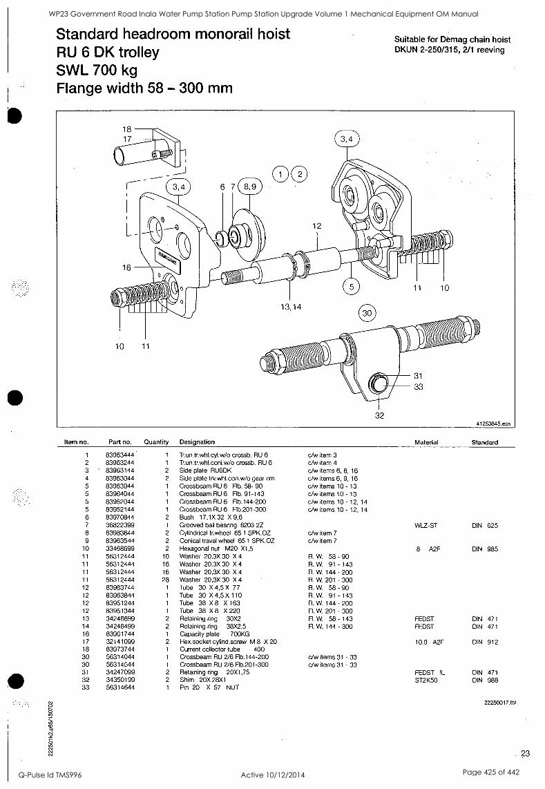
S
Standard headroom monorail hoist RU 6 DK trolley SWL 700 kg Flange width 58 - 300 mm
Suitable for Demag chain hoist DKUN 2-250/315, 2/1 reeving
10 11
13,14
11 10
0011 -00, 32
31
33
41253845.eps
Item no. Part no. Quantity
1 83963444 1
2 83963244 1
3 83963144 2
4 83963044 2
5 83963944 1
5 83964044 1
5 83952044 1
5 83952144 1
6 83970844 2
7 36822399 1
8 83983644 2
9 83963544 2
10 33468699 2
11 56312444 10
11 56312444 16
11 56312444 16 11 56312444 28 12 83963744 1
12 83963844 1
12 83951244 1
12 83951344 1
13 34248699 2
14 34248499 2
16 83961744 1
17 32141099 2
18 83973744 1
30 56314044 1
30 56314544 1
31 34247099 2
32 34350199 2
33 56314644 1
Designation Material Standard
Trun.trwhl.cyl.w/o crossb. RU 6 Tr.un.tr.whl.coni.w/o crossb. RU 6 Side plate RU6DK Side plate trv.whl.con.w/o gear rim Crossbeam RU 6 Flb. 58- 90 Crossbeam RU 6 Flb. 91-143 Crossbeam RU 6 Flb.144-200 Crossbeam RU 6 Rb.201-300 Bush 17,1X32 X9,6 Grooved ball bearing 6203 2Z Cylindrical tr.wheel 65 1 SPK.OZ Conical travel wheel 65 1 SPK.OZ Hexagonal nut M20 X1,5
c/w item 3
c/w item 4
c/w items 6, 8, 16
c/w items 6, 9, 16 c/w items 10 - 13
c/w items 10 - 13
c/w items 10 - 12, 14 c/w items 10 - 12, 14
c/w item 7
c/w item 7
WLZ-ST
8 A2F
DIN 625
DIN 985 Washer 20,3X 30 X 4 FL W. 58 - 90 Washer 20,3X 30 X 4 Fl. W. 91 - 143 Washer 20,3X 30 X 4 FL W. 144 - 200 Washer 20,3X 30 X 4 Fl. W. 201 - 300 Tube 30 X 4,5 X 77 Fl. W. 58 - 90 Tube 30 X 4,5 X 110 Fl. W. 91 - 143 Tube 38 X 8 X 163 Fl. W. 144 - 200 Tube 38 X 8 X 220 R. W. 201 - 300 Retaining ring 30X2 Fl. W. 58 - 143 FEDST DIN Retaining ring 38X2,5 Fl. W. 144 - 300 FEDST DIN Capacity plate 700KG Hex.socket cylind.screw M 8 X 20 10.9 A2F DIN Current collector tube 400 Crossbeam RU 2/6 Flb.144 -200 Crossbeam RU 2/6 Rb.201-300
c/w items 31 - 33 c/w items 31 - 33
Retaining ring 20X1,75 FEDST !L DIN Shim 20X 28X1 ST2K50 DIN Pin 20 X 57 NUT
471 471
912
471 988
22250017.tbl
23
WP23 Government Road Inala Water Pump Station Pump Station Upgrade Volume 1 Mechanical Equipment OM Manual
Q-Pulse Id TMS996 Active 10/12/2014 Page 425 of 442
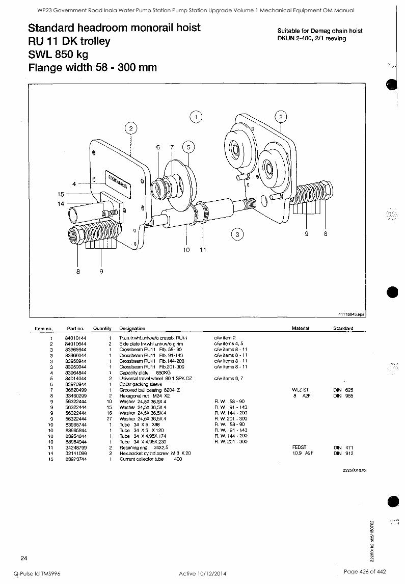
Standard headroom monorail hoist RU 11 DK trolley SWL 850 kg Flange width 58 - 300 mm
Suitable for Demag chain hoist DKUN 2-400, 2/1 reeving
Item no. Part no. Quantity
1 84010144 1
2 84010644 2
3 83965944 1
3 83966044 1
3 83958944 1
3 83959044 1
4 83964844 1
5 84014044 2
6 83970944 1
7 36820499 1
8 33460299 2
9 56322444 10
9 56322444 15 9 56322444 16
9 56322444 27 10 83965744 1
10 83965844 1
10 83954844 1
10 83954944 1
11 34248799 2
14 32141099 2
15 83973744 1
24
Designation Material Standard
Trun.trwhLuniv.w/o crossb. RU11
Side plate tiv.whl.univ.w/o grim Crossbeam RU11 Flb. 58- 90 Crossbeam RU11 Flb. 91-143 Crossbeam RU11 Rb.144-200 Crossbeam RU11 Flb.201-300 Capacity plate 850KG Universal travel wheel 80 1 SPK.OZ Collar packing sleeve Grooved ball bearing 6204 Z
c/w item 2
c/w items 4, 5
c/w items 8 - 11
c/w items 8 - 11
c/w items 8 - 11
c/w items 8 - 11
c/w items 6, 7
Hexagonal nut M24 X2 Washer 24,5X 36,5X 4 R. W. 58 - 90 Washer 24,5X 36,5X 4 Fl. W. 91 - 143 Washer 24,5X 36,5X 4 FL W. 144 - 200 Washer 24,5X 36,5X 4 R. W. 201 - 300 Tube 34 X 5 X88 Fl. W. 58 - 90 Tube 34 X 5 X 120 Fl. W. 91 - 143 Tube 34 X 4,95X 174 R. W. 144 - 200 Tube 34 X 4,95X 230 R. W. 201 - 300 Retaining ring 34X2,5 Hex.socket cylind.screw M 8 X 20 Current collector tube 400
WLZ-ST 8 A2F
FEDST 10.9 A2F
DIN 625 DIN 985
DIN 471 DIN 912
22250018.tbl
WP23 Government Road Inala Water Pump Station Pump Station Upgrade Volume 1 Mechanical Equipment OM Manual
Q-Pulse Id TMS996 Active 10/12/2014 Page 426 of 442
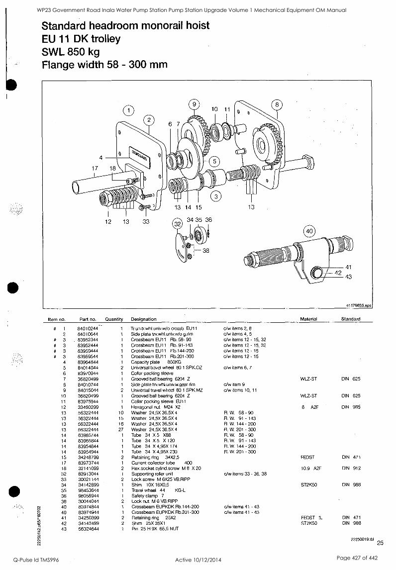
Standard headroom monorail hoist EU 11 DK trolley SWL 850 kg Flange width 58 - 300 mm
0
4
17 18
0
I I I I I I I I I I I I I I I I I I I I I I I L t 1
TOISVII- ,0101111
12 13 33
0 10 11 0 6 7 ,
poritiolv, 13 14 15 13
$30/01 4i*)
I
41
43
41179655. eps
Item no. Part no. Quantity Designation
# 1 84010244." 1 Tr.un.tr.whl.univ.w/o crossb. EU11
2 84010644 1 Side plate trv.whl.univ.w /o g.rim
# 3 83952344 1 Crossbeam EU11 Flb. 58- 90 # 3 83952444 1 Crossbeam EU11 Flb. 91-143 # 3 83959444 1 Crossbeam EU11 Flb.144-200 # 3 83959544 1 Crossbeam EU11 Flb.201-300
4 83964844 1 Capacity plate 850KG 5 84014044 2 Universal travel wheel 80 1 SPK.OZ 6 83970944 1 Collar packing sleeve 7 36820499 1 Grooved ball bearing 6204 Z
8 84010744 1 Side plate trv.whl.univ.w.gear rim 9 84015044 2 Universal travel wheel 80 1 SPK.MZ
10 36820499 1 Grooved ball bearing 6204 Z 11 83975944 1 Collar packing sleeve EU11
12 33460299 1 Hexagonal nut M24 X2
13 56322444 10 Washer 24,5X 36,5X 4
13 56322444 15 Washer 24,5X 36,5X 4
13 56322444 16 Washer 24,5X 36,5X 4
13 56322444 27 Washer 24,5X 36,5X 4
14 83965744 1 Tube 34 X 5 X88 14 83965844 1 Tube 34 X 5 X 120
14 83954844 1 Tube 34 X 4,95X 174
14 83954944 1 Tube 34 X 4,95X 230 15 34248799 2 Retaining ring 34X2,5 17 83973744 1 Current collector tube 400 18 32141099 2 Hex.socket cylind.screw M 8 X 20 32 83913044 1 Supporting roller unit 33 30021144 2 Lock screw M 6X25 VB.RIPP 34 34142899 1 Shim 10X 16X0,5 35 98453644 1 Travel wheel 44 KG-L 36 98058944 1 Safety clamp 7
38 30044044 2 Lock nut M 6 VB.RIPP 40 83974844 1 Crossbeam EUPKDK Rb.144-200 40 83974944 1 Crossbeam EUPKDK Flb.201-300 41 34250399 2 Retaining ring 25X2 42 34142499 2 Shim 25X 35X1 43 56324644 1 Pin 25 H 9X 65,5 NUT
Material Standard
c/w items 2, 8 c/w items 4, 5
cJw items 12 - 15, 32 c/w items 12 - 15
,
32 c/w items 12 - 15
c/w items 12 - 15
c/w items 6, 7
c/w item 9 c/w items 10, 11
WLZ-ST DIN 625
WLZ-ST DIN 625
8 A2F DIN 985 Fl. W. 58 - 90 Fl. W. 91 - 143 R. W. 144 - 200 Fl. W. 201 - 300 R. W. 58 - 90 R. W. 91 - 143 R. W. 144 - 200 R. W. 201 - 300
FEDST DIN 471
10.9 A2F DIN 912 c/w items 33 - 36, 38
c/w items 41 - 43 c/w items 41 - 43
ST2K50 DIN 988
FEDST IL DIN 471
ST2K50 DIN 988
22250019.tbl 25
WP23 Government Road Inala Water Pump Station Pump Station Upgrade Volume 1 Mechanical Equipment OM Manual
Q-Pulse Id TMS996 Active 10/12/2014 Page 427 of 442
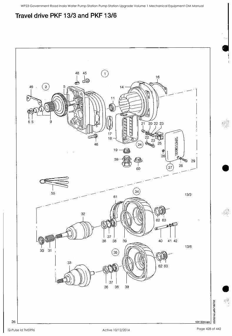
26
Travel drive PKF 13/3 and PKF 13/6
WP23 Government Road Inala Water Pump Station Pump Station Upgrade Volume 1 Mechanical Equipment OM Manual
Q-Pulse Id TMS996 Active 10/12/2014 Page 428 of 442
O O
Travel drive PKF 13/3 and PKF 13/6
Item no. Part no. Quantity Designation Material Standard
1
1
1
1
1
2
5
56306744 56306444 56306244 56305644 56305744 56307044 56377844
1
1
1
1
1
1
2
Motor 7M 13/3PKF8 AB Motor 14M 13/3PKF4 AB Motor 28M 13/3PKF2 AB Motor 4,6/14M 13/6PKF AB Motor 7/28M 13/6PKF8-2AB End shield PKF M5 Washer 15D12X 26 X 2
c/w items 2,12-14,16,24,25,30-32,34,40-42, 220-400 V, 50 ID c/w items 2,12-14,16,24,25,30-32,34,40-42, 220-400 V, 50 ID c/w items 2,12-14,16,24,25,30-32,34,40-42, 220-400 V, 50 ID
c/w items 2,12-14,16,24,25,30,31,33,35,40-42, 380-400 V, 50 ID
c/w items 2,12-14,16,24,25,30,31,33,35,40-42, 380-400 V, 50 ID c/w items 5, 6, 9, 11
6 34251599 1 Retaining ring 15X1 FEDST DIN 471
9 56307344 1 Cluster gear Z103M1 Z18M2 11 36050399 1 Grooved ball bearing 6003 FE.-30+110 DIN- 625 14 56010644 1 Stator F 13/ 3P2K AB 220/380 V, 50 ID, 230/400 V, 50 ID, 1)
14 56371444 1 Stator F 13/ 3PF4 AB 220/380 V, 50 ID, 230/400 V, 50 ID, 1)
14 56371744 1 Stator F 13/ 3PF8 AB 220/380 V, 50 ID, 230/400 V, 50 ID, 1)
14 56372544 1 Stator F 13/ 6PF8/2AB 380/400 V, 50 ID, 1)
14 56370144 1 Stator F 13/6PF12/4AB 380/400 V, 50 ID, 1)
16 56025444 14 Segment 13/3P 13/6 P
17 56368944 1 Seal terminal box lower part 18 56369044 1 Terminal box lower part M25X1,5 19 79494644 1 Twist.cab.entr.gland M25 ZU/ 9-16 K
20 44016499 1 Rat plug 6,3-0,8/2X 21 37437999 1 Tubular rivet A6 X0,4 X10 1.4301 DIN- 7340 22 34360599 2 Serrated lock washer A 5,3 FEDST A2F DIN 6798 23 31817999 2 Cylinder screw M 5 X 20 4.8 A2F DIN 84 24 56368544 1 Terminal board 13 KF-PKF c/w items 17 - 23, 27
25 50577344 1 Terminal strip 4X 4,8 STST 1 speed 25 50577444 1 Terminal strip 6X 4,8 STST 2 speeds 26 34043599 2 Washer 3,7X 7 X1,0 VULKANFIBE DIN- 433 27 56368744 1 Terminal box cover EU c/w items 26, 28, 29 28 34387244 2 Screw locking device M 4
29 31816699 2 Cylinder screw M 4 X 16 4.8 A2F DIN 84 30 56022544 1 Pressure ring 7,3 13/3P 13/6 P 1)
30 56022644 1 Pressure ring 7,6 13/3P 13/6 P 1)
30 56022744 1 Pressure ring 7,9 13/3P 13/6 P 1)
30 56022844 1 Pressure ring 8,2 13/3P 13/6 P 1)
31 56379344 1 Pressure spring 1,8 X25,8X 84 30 N
32 56379144 1 Rotor 13/ 3PKF 1), 3)
32 56379244 1 Rotor 13/ 3PKF 1)
33 56304744 1 Rotor 13/ 6PF 8-2 1), 3)
33 56304844 1 Rotor 13/ 6PF 8-2 1)
34 56024044 1 End shield B 13/ 3P c/w items 36 - 39, 63 35 56305544 1 End shield B13/ 6PF8-2 c/w items 36 - 39, 63 36 56024544 1 Oil seal 17 X 35X 5 37 34263599 1 Retaining ring 35X1,5 FEDST DIN 472 38 36050399 1 Grooved ball bearing 6003 FE.-30+110 DIN- 625 39 56029044 1 Brake lining PK 1 ASBFR 2)
40 60063544 4 Stud M 5 X 54X 62 13/3 P
40 60063844 4 Stud M 5 X 79X 87 13/6 P
41 34380599 4 Lock washer 5 A FEDST A2F DIN 127 42 60065444 4 Nut with hexagon socket M 5
45 30021744 1 Lock screw M 8X20 VB.RIPP 46 30022044 3 Lock screw M 8X30 VB.RIPP 48 34575899 1 Split sleeve 11 X 12 ST IS0-13337 49 58136944 1 Seal travel drive PK 55 10092644 1 Feeler gauge 0,30X3X250 1)
55 10092744 1 Feeler gauge 0,35X3X300 1)
59 79495944 2 Screw conn. compl. M25X1,5 RD K 3)
60 79499144 1 Screw plug M25X1,5 3)
61 60077444 1 Profiled joint 13P 3)
62 60087599 1 Sealing ring thr.con. PG21 K 3) PE DIN 46320 63 60070644 1 Screw plug PG21 K
01105844 1 Grease KPF2K-30 DG67B
22249524.tbI
1) When ordering a rotor or stator, a set of thrust rings (Rem no. 30) must
'7.5, also be ordered for adjusting the air gap
&I, (adjust with feeler gauge no. 2, item no. 55)
2) With gluing device. 3) For service in arduous conditions.
27
WP23 Government Road Inala Water Pump Station Pump Station Upgrade Volume 1 Mechanical Equipment OM Manual
Q-Pulse Id TMS996 Active 10/12/2014 Page 429 of 442
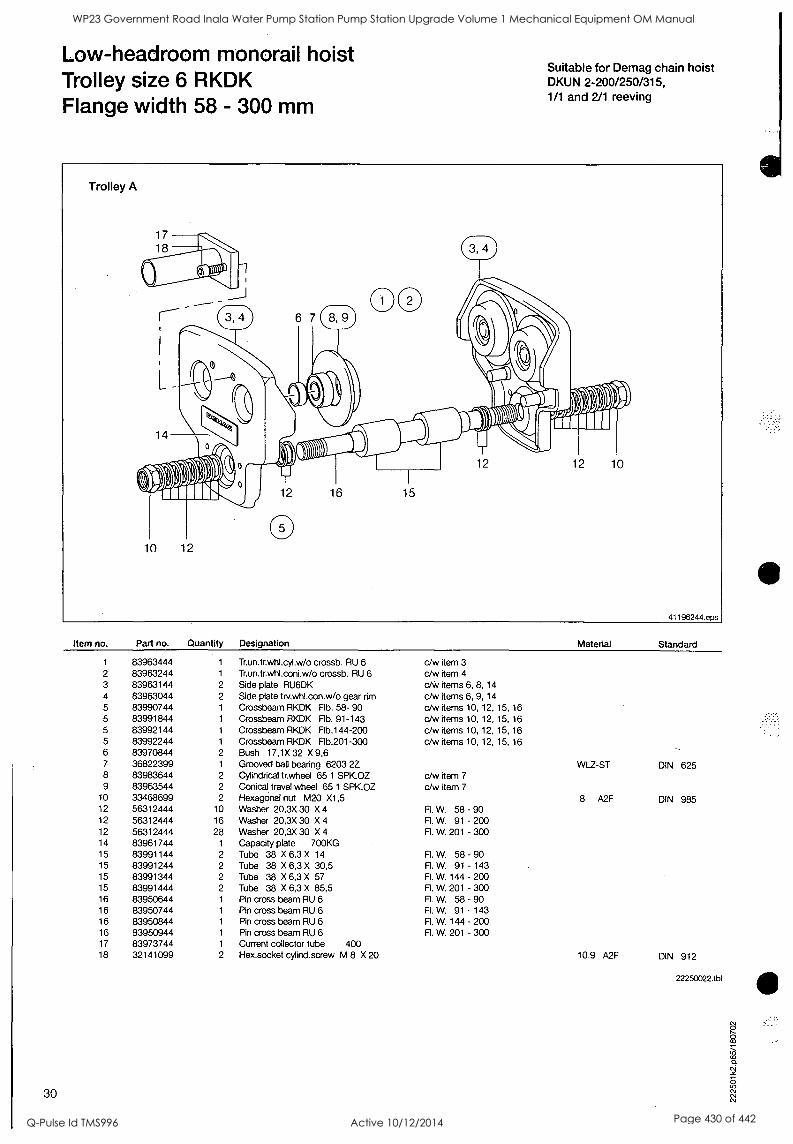
Low-headroom monorail hoist Trolley size 6 RKDK Flange width 58 - 300 mm
Suitable for Demag chain hoist DKUN 2-200/250/315, 1/1 and 2/1 reeving
INMA 0161Ifiar
12 12 10
Item no. Part no. Quantity Designation
1 83963444 1 Trun.trwhl.cyl.w/o crossb. RU 6 2 83963244 1 Tr.un.tr.whl.coni.w/o crossb. RU 6
3 83963144 2 Side plate RU6DK 4 83963044 2 Side plate trv.whl.con.w/o gear rim 5 83990744 1 Crossbeam RKDK Fib. 58- 90 5 83991844 1 Crossbeam RKDK Flb. 91-143 5 83992144 1 Crossbeam RKDK Flb.144-200 5 83992244 1 Crossbeam RKDK Flb.201-300 6 83970844 2 Bush 17,1X 32 X 9,6 7 36822399 1 Grooved ball bearing 6203 22 8 83983644 2 Cylindrical tr.wheel 65 1 SPKOZ 9 83963544 2 Conical travel wheel 65 1 SPK.OZ
10 33468699 2 Hexagonal nut M20 X1,5 12 56312444 10 Washer 20,3X 30 X 4 12 56312444 16 Washer 20,3X 30 X 4
12 56312444 28 Washer 20,3X 30 X 4
14 83961744 1 Capacity plate 700KG 15 83991144 2 Tube 38 X 6,3 X 14
15 83991244 2 Tube 38 X 6,3 X 30,5 15 83991344 2 Tube 38 X 6,3 X 57 15 83991444 2 Tube 38 X 6,3 X 85,5 16 83950644 1 Pin cross beam RU 6 16 83950744 1 Pin cross beam RU 6 16 83950844 1 Pin cross beam RU 6 16 83950944 1 Pin cross beam RU 6 17 83973744 1 Current collector tube 400 18 32141099 2 Hex.socket cylind.screw M 8 X 20
30
Material Standard
c/w item 3 c/w item 4
cAv items 6, 8, 14
c/w items 6, 9, 14
c/w items 10, 12, 15, 16
c/w items 10, 12, 15, 16
c/w items 10, 12, 15, 16 c/w items 10, 12, 15, 16
c/w item 7
c/w item 7
R. W. 58 - 90 Fl. W. 91 - 200 Fl. W. 201 - 300
R. W. 58 - 90 R. W. 91 - 143 R. W. 144 - 200 R. W. 201 - 300 FL W. 58 - 90 Fl. W. 91 - 143 Fl. W. 144 - 200 R. W. 201 - 300
WIZ -ST DIN 625
8 A2F DIN 985
10.9 A2F DIN 912
22250022.tbl
WP23 Government Road Inala Water Pump Station Pump Station Upgrade Volume 1 Mechanical Equipment OM Manual
Q-Pulse Id TMS996 Active 10/12/2014 Page 430 of 442
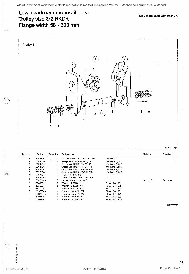
Low-headroom monorail hoist Trolley size 3/2 RKDK Flange width 58 - 300 mm
Only to be used with trolley A
Item no. Part no. Quantity
1 83982044 1
2 83980444 2
3 83981244 1
3 83981344 1
3 83981444 1
3 83981544 1
4 83970744 1
5 83961544 1
6 33460199 2
8 56302344 12 8 56302344 18 8 56302344 30 9 83980844 1
9 83980944 1
9 83981044 1
9 83981144 1
Designation Material Standard
Tr.un.tr.whl.univ.w /o crossb. RU 3/2 c/w item 2
Side plate trv.whl.univ.w/o grim c/w items 4, 5 Crossbeam RKDK Flb. 58- 90 c/w items 6, 8, 9
Crossbeam RKDK Flb. 91-143 c/w items 6, 8, 9 Crossbeam RKDK Flb.144-200 c/w items 6, 8, 9 Crossbeam RKDK Fib.201-300 c/w items 6, 8, 9
Bush 12,1X 27 X 9 Universal travel wheel RU 3DK Hexagonal nut M16 X1,5 Washer 16,5X 25 X 4
Washer 16,5X 25 X 4
Fl. W. 58 Fl. W. 91
8 A2F DIN 985 - 90 - 200
Washer 16,5X 25 X 4 R. W. 201 - 300 Pin cross beam RU 3/ 2 Fl. W. 58 - 90 Pin cross beam RU 3/ 2 R. W. 91 - 143 Pin cross beam RU 3/ 2 R. W. 144 - 200 Pin cross beam RU 3/ 2 Fl. W. 201 - 300
22250023.tbl
31
WP23 Government Road Inala Water Pump Station Pump Station Upgrade Volume 1 Mechanical Equipment OM Manual
Q-Pulse Id TMS996 Active 10/12/2014 Page 431 of 442
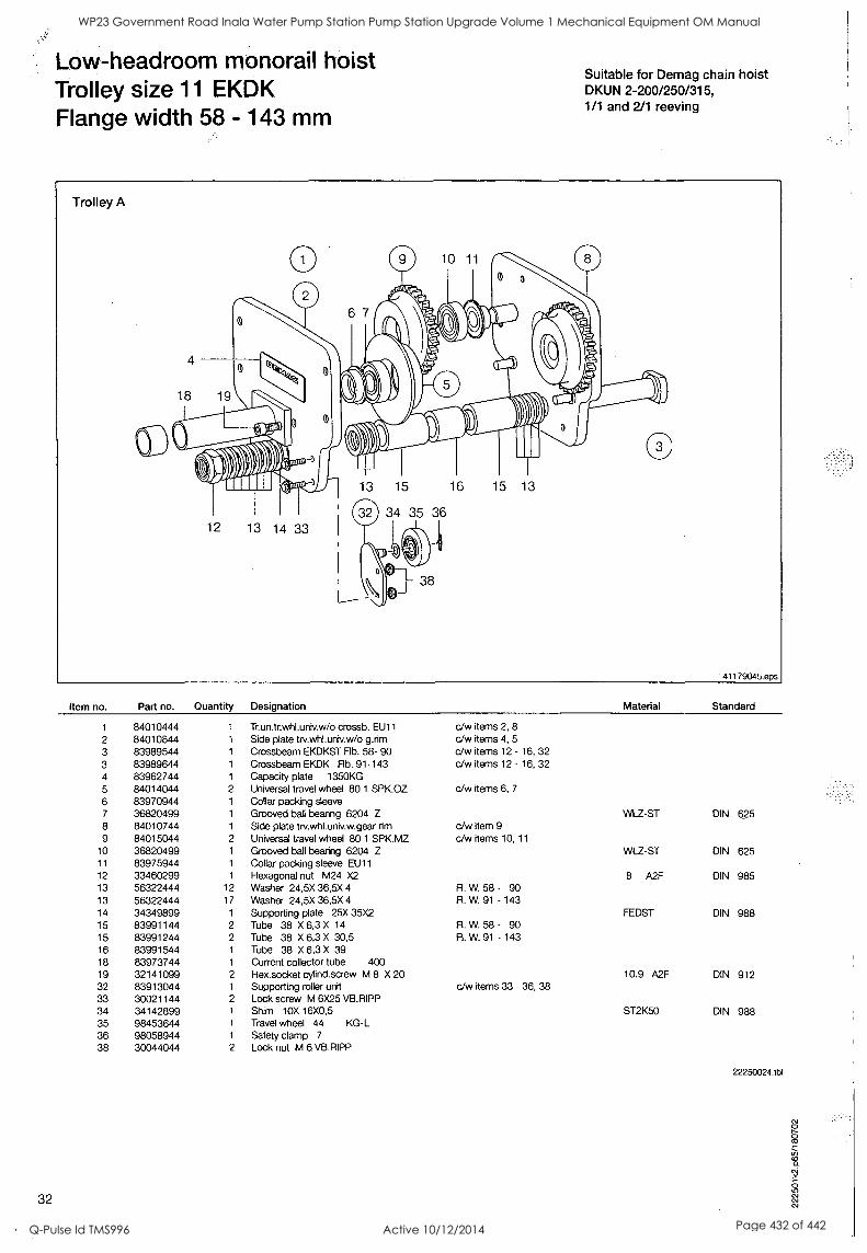
Low-headroom monorail hoist Trolley size 11 EKDK Flange width 58 - 143 mm
Suitable for Demag chain hoist DKUN 2-200/250/315, 1/1 and 2/1 reeving
Item no. Part no. Quantity Designation
1 84010444 1 Trun.tr.whLuniv.w/o crossb. EU11
2 84010844 1 Side plate trv.whl.univ.w/o grim 3 83989544 1 Crossbeam EKDKST Flb. 58- 90 3 83989644 1 Crossbeam EKDK Flb. 91-143 4 83962744 1 Capacity plate 1350KG 5 84014044 2 Universal travel wheel 80 1 SPK.OZ 6 83970944 1 Collar packing sleeve 7 36820499 1 Grooved ball bearing 6204 Z
8 84010744 1 Side plate trv.whl.univ.w.gear rim 9 84015044 2 Universal travel wheel 80 1 SPK.MZ
10 36820499 1 Grooved ball bearing 6204 Z 11 83975944 1 Collar packing sleeve EU11 12 33460299 1 Hexagonal nut M24 X2 13 56322444 12 Washer 24,5X 36,5X 4 13 56322444 17 Washer 24,5X 36,5X 4
14 34349899 1 Supporting plate 25X 35X2 15 83991144 2 Tube 38 X 6,3 X 14
15 83991244 2 Tube 38 X 6,3 X 30,5 16 83991544 1 Tube 38 X 6,3 X 39 18 83973744 1 Current collector tube 400 19 32141099 2 Hex.socket cylind.screw M 8 X 20 32 83913044 1 Supporting roller unit 33 30021144 2 Lock screw M 6X25 VB.RIPP 34 34142899 1 Shim 10X 16X0,5 35 98453644 1 Travel wheel 44 KG-L 36 98058944 1 Safety clamp 7
38 30044044 2 Lock nut M 6 VB.RIPP
32
Material Standard
c/w items 2, 8
c/w items 4, 5
c/w items 12 - 16, 32 c/w items 12 - 16, 32
c/w items 6, 7
c/w item 9
c/w items 10, 11
Fl. W. 58 - 90 R. W. 91 - 143
Fl. W. 58 - 90 Fl. W. 91 - 143
c/w items 33 - 36, 38
WLZ-ST DIN 625
WLZ-ST DIN 625
8 A2F DIN 985
FEDST DIN 988
10.9 A2F DIN 912
ST2K50 DIN 988
22250024.tbl
WP23 Government Road Inala Water Pump Station Pump Station Upgrade Volume 1 Mechanical Equipment OM Manual
Q-Pulse Id TMS996 Active 10/12/2014 Page 432 of 442
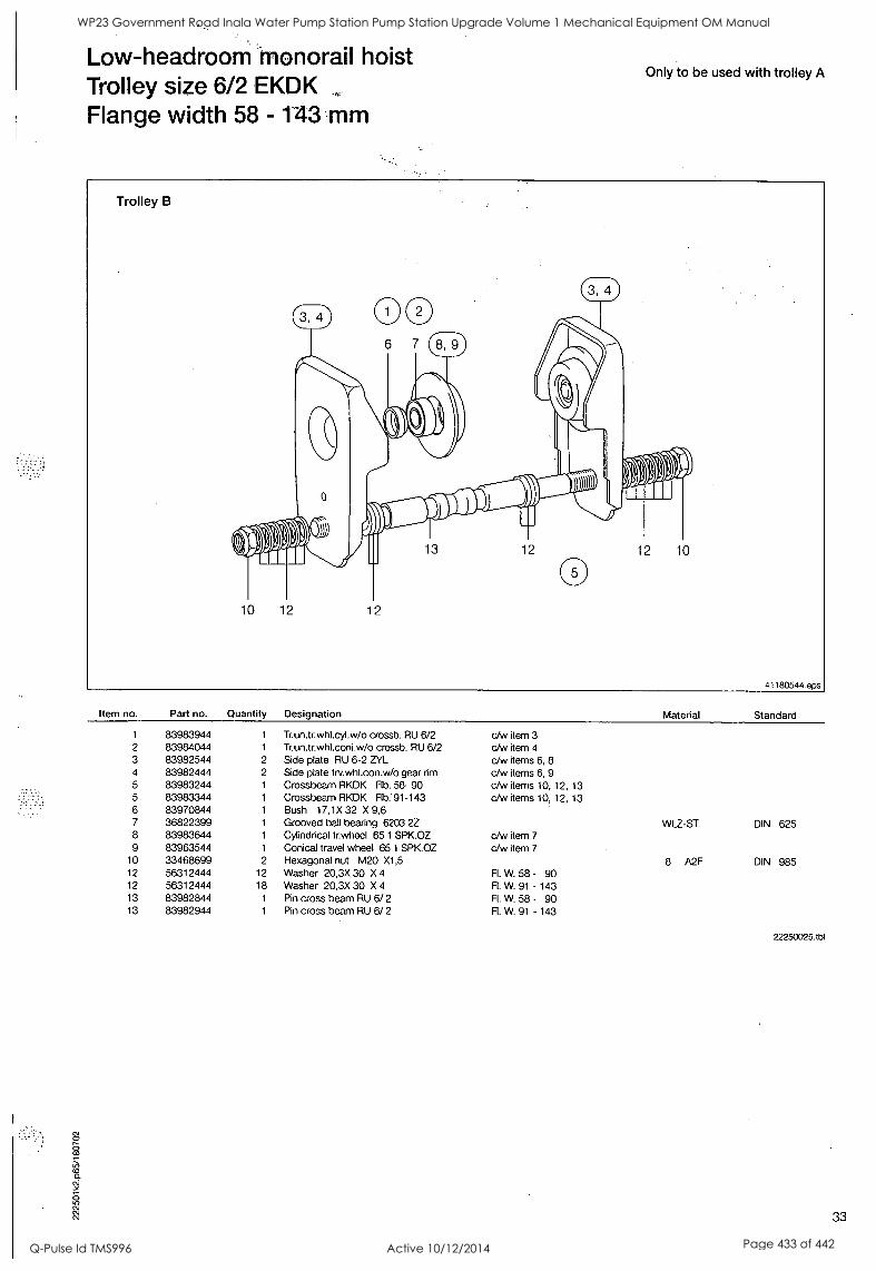
Low-headroom monorail hoist Trolley size 6/2 EKDK Flange width 58 - 143 mm
Only to be used with trolley A
Item no. Part no. Quantity Designation
1 83983944 1 Tr.un.tr.whl.cyl.w/o crossb. RU 6/2 2 83984044 1 Tr.un.tr.whl.coni.w /o crossb. RU 6/2 3 83982544 2 Side plate RU 6-2 ZYL 4 83982444 2 Side plate trv.whl.con.w/o gear rim
5 83983244 1 Crossbeam RKDK Flb. 58- 90 5 83983344 1 Crossbeam RKDK Flb: 91-143 6 83970844 1 Bush 17,1X 32 X 9,6 7 36822399 1 Grooved ball bearing 6203 2Z 8 83983644 1 Cylindrical tr.wheel 65 1 SPK.OZ 9 83963544 1 Conical travel wheel 65 1 SPK.OZ
10 33468699 2 Hexagonal nut M20 X1,5 12 56312444 12 Washer 20,3X 30 X 4
12 56312444 18 Washer 20,3X 30 X 4
13 83982844 1 Pin cross beam RU 6/ 2
13 83982944 1 Pin cross beam RU 6/ 2
Material Standard
c/w item 3 c/w item 4
c/w items 6, 8 c/w items 6, 9 c/w items 10, 12, 13 c/w items 10, 12, 13
c/w item 7
c/w item 7
Fl. W. 58 - 90 R. W. 91 - 143 Fl. W. 58 - 90 R. W. 91 - 143
WLZ-ST DIN 625
8 A2F DIN 985
22250025.tbl
33
WP23 Government Road Inala Water Pump Station Pump Station Upgrade Volume 1 Mechanical Equipment OM Manual
Q-Pulse Id TMS996 Active 10/12/2014 Page 433 of 442
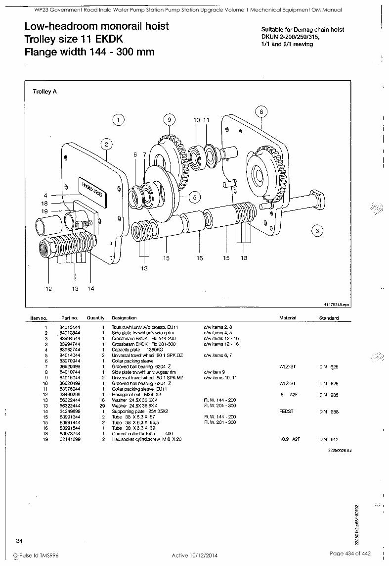
Low-headroom monorail hoist Trolley size 11 EKDK Flange width 144 - 300 mm
Suitable for Demag chain hoist DKUN 2-200/250/315, 1/1 and 2/1 reeving
Trolley A
4
18
19
0
12. 13 14
10 11
6 7
la 0
I I I I
15 16 15 13
0
13
0
41179245.eps
Item no. Part no. Quantity Designation
1 84010444 1 Trun.tr.whl.univ.w/o crossb. EU11
2 84010844 1 Side plate trv.whl.univ.w/o grim 3 83994644 1 Crossbeam EKDK Flb.144-200 3 83994744 1 Crossbeam EKDK Flb.201-300 4 83962744 1 Capacity plate 1350KG 5 84014044 2 Universal travel wheel 801 SPK.OZ 6 83970944 1 Collar packing sleeve 7 36820499 1 Grooved ball bearing 6204 Z
8 84010744 1 Side plate trv.whluniv.w.gear rim
9 84015044 2 Universal travel wheel 80 1 SPK.MZ 10 36820499 1 Grooved ball bearing 6204 Z 11 83975944 1 Collar packing sleeve EU11 12 33460299 1 Hexagonal nut M24 X2 13 56322444 18 Washer 24,5X 36,5X 4
13 56322444 29 Washer 24,5X 36,5X 4 14 34349899 1 Supporting plate 25X 35X2 15 83991344 2 Tube 38 X 6,3 X 57 15 83991444 2 Tube 38 X 6,3 X 85,5 16 83991544 1 Tube 38 X 6,3 X 39 18 83973744 1 Current collector tube 400 19 32141099 2 Hex.socket cylind.screw M 8 X 20
34
Material Standard
c/w items 2, 8
c/w items 4, 5
c/w items 12 - 16 c/w items 12 - 16
c/w items 6, 7
c/w item 9 c/w items 10, 11
Fl. W. 144 - 200 Fl. W. 201 - 300
A. W. 144 - 200 FL W. 201 - 300
WLZ-ST DIN 625
WLZ-ST DIN 625
8 A2F DIN 985
FEDST DIN 988
10.9 A2F DIN 912
22250026.tbl
WP23 Government Road Inala Water Pump Station Pump Station Upgrade Volume 1 Mechanical Equipment OM Manual
Q-Pulse Id TMS996 Active 10/12/2014 Page 434 of 442
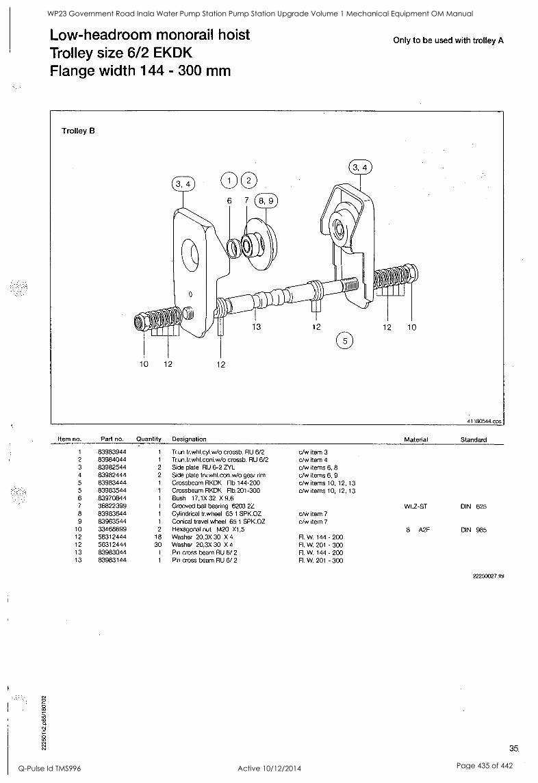
Low-headroom monorail hoist Trolley size 6/2 EKDK Flange width 144 - 300 mm
Only to be used with trolley A
Item no. Part no. Quantity Designation
1 83983944 1 Tr.un.tr.whicyl.w/o crossb. RU 6/2 2 83984044 1 Tr.un.tr.whl.coni.w/o crossb. RU 6/2 3 83982544 2 Side plate RU 6-2 ZYL 4 83982444 2 Side plate trv.whl.con.w /o gear rim 5 83983444 1 Crossbeam RKDK Flb.144-200 5 83983544 1 Crossbeam RKDK Flb.201-300 6 83970844 1 Bush 17,1X32 X9,6 7 36822399 1 Grooved ball bearing 6203 2Z 8 83983644 1 Cylindrical tr.wheel 65 1 SPK.OZ 9 83963544 1 Conical travel wheel 65 1 SPK.OZ
10 33468699 2 Hexagonal nut M20 X1,5 12 56312444 18 Washer 20,3X 30 X 4
12 56312444 30 Washer 20,3X 30 X 4
13 83983044 1 Pin cross beam RU 6/ 2
13 83983144 1 Pin cross beam RU 6/ 2
Material Standard
c/w item 3 c/w item 4
c/w items 6, 8 c/w items 6, 9 c/w items 10, 12, 13 c/w items 10, 12, 13
c/Vy item 7
c/w item 7
R. W. 144 - 200 Fl. W. 201 - 300 R. W. 144 - 200 R. W. 201 - 300
WLZ-ST DIN 625
8 A2F DIN 985
22250027.tbl
35.
WP23 Government Road Inala Water Pump Station Pump Station Upgrade Volume 1 Mechanical Equipment OM Manual
Q-Pulse Id TMS996 Active 10/12/2014 Page 435 of 442
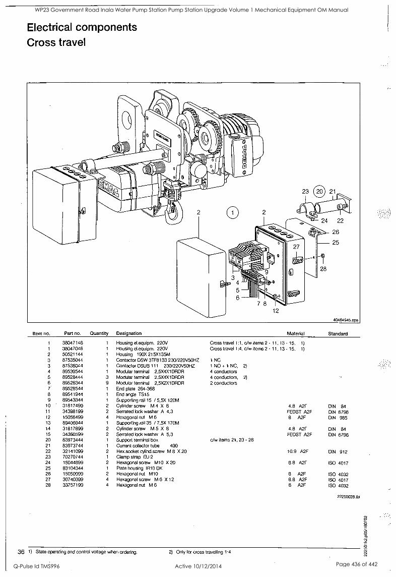
Electrical components Cross travel
Item no. Part no. Quantity Designation Material Standard
1 38047146 1 Housing el.equipm. 220V Cross travel 1:1, c/w items 2 - 11, 13 - 15, 1)
1 38047046 1 Housing el.equipm. 220V Cross travel 1:4, c/w items 2 - 11, 13 - 15, 1)
2 50521144 1 Housing 190X 215X135M 3 87535044 1 Contactor DSW 3TF8133 230/220V5OHZ 1 NC
3 87536044 1 Contactor DSUB 111 230/220V50HZ 1 NO + 1 NC, 2)
4 89539544 1 Modular terminal 2,5X4X1DRDR 4 conductors 5 89528444 3 Modular terminal 2,5X4X1DRDR 4 conductors, 2)
6 89528344 9 Modular terminal 2,5X2X1DRDR 2 conductors 7 89528544 1 End plate 264-368 8 89541944 1 End angle TS15 9 89543344 1 Supporting rail 15 / 5,5X 120M
10 31817499 2 Cylinder screw M 4 X 8 4.8 A2F DIN 84 11 34398199 2 Serrated lock washer A 4,3 FEDST A2F DIN 6798 12 15056499 4 Hexagonal nut M 6 8 A2F DIN 985 13 89406944 1 Supporting rail 35 / 7,5X 170M 14 31817899 2 Cylinder screw M 5 X 8 4.8 A2F DIN 84 15 34360599 2 Serrated lock washer A 5,3 FEDST A2F DIN 6798 20 83973444 1 Support terminal box c/w items 21, 23 - 28 21 83973744 1 Current collector tube 400 22 32141099 2 Hex.socket cylind.screw M 8 X 20 10.9 A2F DIN 912 23 70270744 1 Clamp strap EU 2
24 15044899 2 Hexagonal screw M10 X 20 8.8 A2F ISO 4017 25 83104344 1 Plate housing IR10 DK 26 15050999 2 Hexagonal nut M10 8 A2F ISO 4032 27 30740399 4 Hexagonal screw M 6 X 12 8.8 A2F ISO 4017 28 33757199 4 Hexagonal nut M 6 8 A2F ISO 4032
22250028.tbl
36 1) State operating and control voltage when ordering. 2) Only for cross travelling 1:4.
WP23 Government Road Inala Water Pump Station Pump Station Upgrade Volume 1 Mechanical Equipment OM Manual
Q-Pulse Id TMS996 Active 10/12/2014 Page 436 of 442
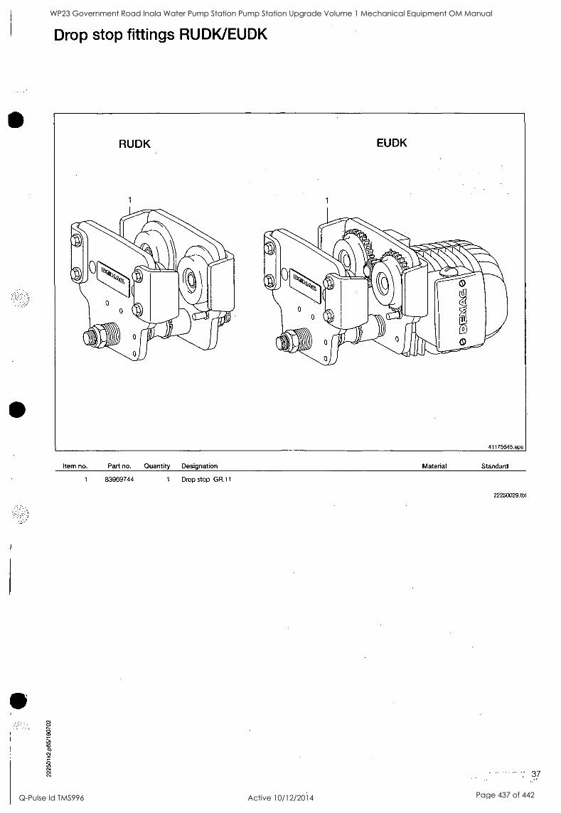
Drop stop fittings RUDK/EUDK
Item no. Part no. Quantity Designation Material Standard
1 83969744 1 Drop stop GR.11
22250029.tb1
37
WP23 Government Road Inala Water Pump Station Pump Station Upgrade Volume 1 Mechanical Equipment OM Manual
Q-Pulse Id TMS996 Active 10/12/2014 Page 437 of 442
Strain gauge carrier link ZMS 625.
1/1 reeving
Item no. Part no. Quantity Designation Material Standard
1 83561344 1 Strain gauge can. link 0,625T 2 59309244 1 Setbolt 16H 9X44,5Boh 3 34145899 3 Shim 17X 24X1 4 34307644 1 Double spring plug 2,25X 34 5 83560544 1 Eye DK 2-ZMS 625 6 49139044 1 Strain gauge cam link 0,625T
c/w items 2 - 6
ST2K50 DIN 988
22250030.tb1
WP23 Government Road Inala Water Pump Station Pump Station Upgrade Volume 1 Mechanical Equipment OM Manual
Q-Pulse Id TMS996 Active 10/12/2014 Page 438 of 442
Strain gauge carrier link ZMS 1250
2/1 reeving
Item no. Part no. Quantity Designation
1 83561044 1 Strain gauge cam link 1,25 T 2 82863844 1 Se tbolt 20H 9X 56 Soh 3 34350199 3 Shim 20X 28X1
4 34306844 1 Double spring plug 2,8 X 41
5 83561244 1 Eye DK 2/ZMS1250 6 49139144 1 Strain gauge cam. link 1,25 T
c/w items 2 - 6
Material
ST2K50
Standard
DIN 988
22250031Abl
WP23 Government Road Inala Water Pump Station Pump Station Upgrade Volume 1 Mechanical Equipment OM Manual
Q-Pulse Id TMS996 Active 10/12/2014 Page 439 of 442
DeM4g4r.anes & Components
:7POStfabti167 -0-58286 Wetter !Teli)fpAo ti; 49/2335) 92-0 - Telefax (+49/2335) 927676 Intern'etlittO/Www;ctematic.com
:4ilitOkikiiktion'in'WhOle or in part only with prior consent of Oemag Cranes & Components, 0-58286 Wetter Not liable for errors or omissions. Subject to change.
I
WP23 Government Road Inala Water Pump Station Pump Station Upgrade Volume 1 Mechanical Equipment OM Manual
Q-Pulse Id TMS996 Active 10/12/2014 Page 440 of 442
0
A
11111111 11111 1111 111
BRISBANE WATER
ZTo: Networks - Mechanical Supervisor Date: 6/2/06 Projects Branch
Attn: Mark Cowper
< CC:
TC Beime Centre Level 1, 315 Brunswick Street Mall Fortitude Valley Qld 4006 GPO Box 1434 IX From: Andrew Wiles Brisbane Qld 4001
e: 07 3403 0270 Re: Government Rd Pump Stn Fa
Phoncsimile:
07 3403 0205
0 0 & M Manuals Email: pm2bw©brisbane.q1d.gov.au Internet: www.brisbane.q1d.gov.au
Mark
Please review the enclosed Operational and Maintenance Manual (known as Volume 1
Equipment) that has been submitted by Cardno for the Government Road Pump Station Upgrade project, on behalf of Delfin.
Mechanical
I would appreciate comments and the manual are returned by Monday 13 February.
Regards
Andrew Wiles
WP23 Government Road Inala Water Pump Station Pump Station Upgrade Volume 1 Mechanical Equipment OM Manual
Q-Pulse Id TMS996 Active 10/12/2014 Page 441 of 442
2.
1!
4" . , 7. -1:4,-,.",:.'4, 7. 7:
1
S. p.
FA
!,1
WP23 Government Road Inala Water Pump Station Pump Station Upgrade Volume 1 Mechanical Equipment OM Manual
Q-Pulse Id TMS996 Active 10/12/2014 Page 442 of 442