Embed Size (px)
Citation preview
International Journal of Emerging Engineering Research and Technology
Volume 2, Issue 7, October 2014, PP 199-210
ISSN 2349-4395 (Print) & ISSN 2349-4409 (Online)
©IJEERT www.ijeert.org 199
Investigation of Piezoelectric Vibro Impact Energy System
Georgi Petkov1, Todor Todorov
2, Rumen Nikolov
3
1Eng. Faculty of Industrial Technology, Technical University of Sofia, Sofia, Bulgaria
2Faculty of Industrial Technology, Technical University of Sofia, Sofia, Bulgaria
3Faculty of Mechanical Engineering, Technical University of Sofia, Sofia, Bulgaria
[email protected], [email protected], [email protected]
Abstract: The paper deals with theoretical and experimental investigation of vibroimpact energy harvester.
This harvester consists of two parallel piezoelectric discs disposed into cylindrical case. The design of the
harvester allows the gap between the discs to be varied. The case of the energy harvester is driven by a
vibrational shaker. As a result of case motion a sphere moves between the discs and impacting onto a disk
surface produce electric energy. The laws of sphere motion and impact energy are determined theoretically and
the obtained results are proven by experiments. The aim of the paper is by the optimal dimensions, mass
parameters, piezoelectric and elastic properties of the harvester to be determined in order the maximum energy
to be produced
Keywords: vibroimpact energy harvester, vibrational energy harvester, shock energy harvester, MEMS
1. INTRODUCTION
Vibrational shock energy harvesters are micro electro-mechanical systems (MEMS), which generate
electrical power from impacts. The source of the vibrational energy necessary for the impacts is
derived from unutilized vibrations of the surrounding environment.
A good approximation of a traditional harvester is the mass – spring – damper system with limiting
motion edges. Such a design has a typical behaviour of clipping the resonance peak in the frequency
sweeps due to imposed motion limit [7],[18].[21]. The jump phenomenon also occurs in higher
frequencies for the side of the clipped peak. With increasing the amplitude of the vibrations from the
external source the power output from the device reaches a saturation point, at least to a given
approximation [1],[2],[11],[12],[13].
The power output saturation is a negative consequence from the imposed restriction on the motion
[14][16]. Whether or not the impacts are totally elastic is irrelevant for the power output when the
vibrations are sinusoidal and the device is subjected to its resonant frequency [3],[17],[20]. The goal
of the article is to examine the characteristics of an impact energy harvester for sinusoidal type
vibrations and to determine the conditions for optimal performance concerning the maximum of
energy yield.
2. PROBLEM DEFINITION
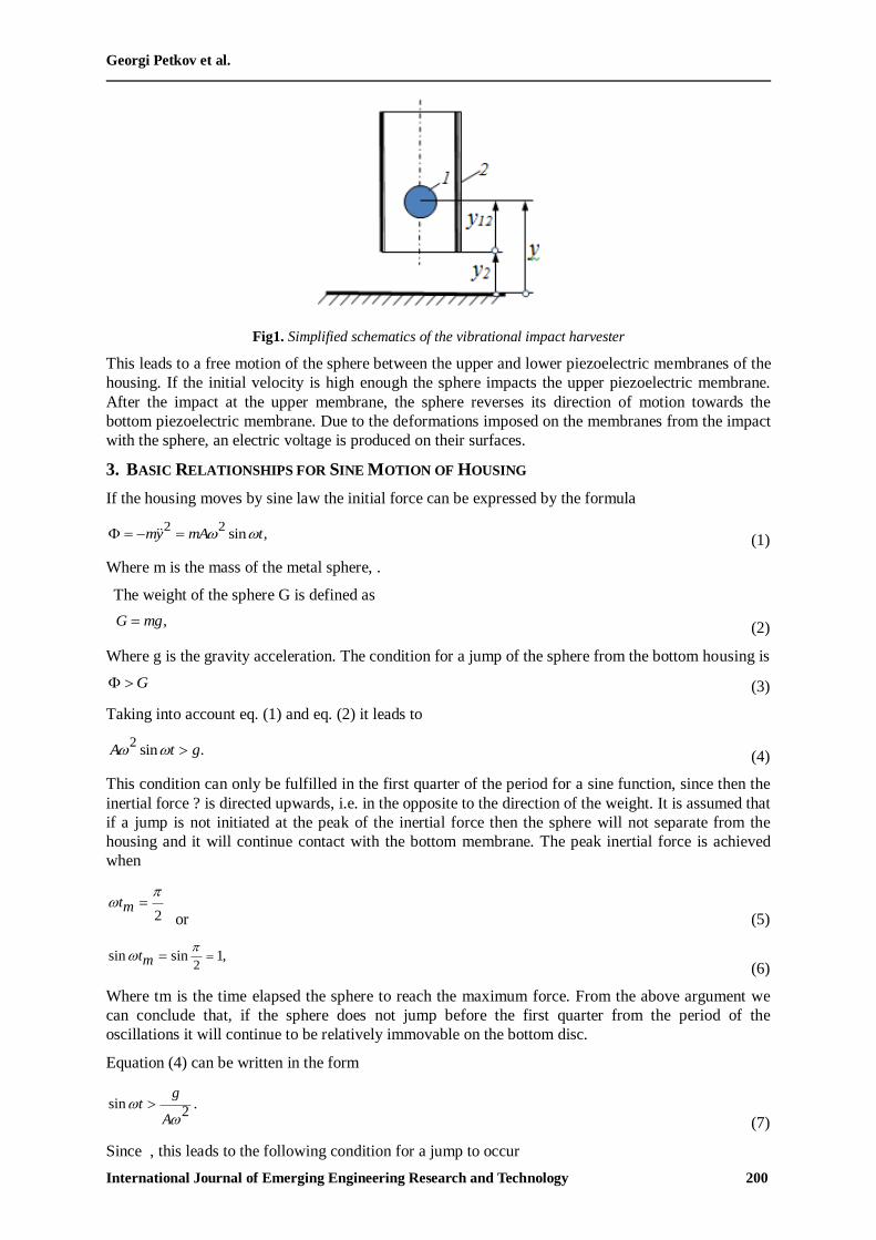
Simplified schematic of the vibrational impact harvester is shown in Figure 1. A metal sphere 1 with
radius r located inside a cylindrical housing is moving freely between the housing`s membranes. The
membranes are the mechanical end stops limiting the sphere`s motion. These membranes are made of
elastic brass substrate and thin piezoelectric layer of PZT disposed at the brass substrate. The housing
undergoes periodic oscillations. Its position with respect to the fixed reference system is denoted as
y2. The relative position of the material sphere center with respect to the housing base is denoted as
y12. The instant absolute position of the sphere with respect to the fixed base is denoted as y. The
periodic motion of the housing is assumed to be a sine law of the type, where is the amplitude, is
the angular frequency, and is the time.
In the initial position the sphere lies at the bottom membrane until the inertial force overcomes the
weight of the sphere. At the instant of separation of the sphere from the bottom membrane there is no
relative motion between the sphere and housing i.e. y=y2 and y12=0. When the inertial forces
overcome the weight of the sphere a jump occurs.
Georgi Petkov et al.
International Journal of Emerging Engineering Research and Technology 200
Fig1. Simplified schematics of the vibrational impact harvester
This leads to a free motion of the sphere between the upper and lower piezoelectric membranes of the
housing. If the initial velocity is high enough the sphere impacts the upper piezoelectric membrane.
After the impact at the upper membrane, the sphere reverses its direction of motion towards the
bottom piezoelectric membrane. Due to the deformations imposed on the membranes from the impact
with the sphere, an electric voltage is produced on their surfaces.
3. BASIC RELATIONSHIPS FOR SINE MOTION OF HOUSING
If the housing moves by sine law the initial force can be expressed by the formula
2 2sin ,my mA t
(1)
Where m is the mass of the metal sphere, .
The weight of the sphere G is defined as
,G mg (2)
Where g is the gravity acceleration. The condition for a jump of the sphere from the bottom housing is
G (3)
Taking into account eq. (1) and eq. (2) it leads to
2sin .A t g (4)
This condition can only be fulfilled in the first quarter of the period for a sine function, since then the
inertial force ? is directed upwards, i.e. in the opposite to the direction of the weight. It is assumed that
if a jump is not initiated at the peak of the inertial force then the sphere will not separate from the
housing and it will continue contact with the bottom membrane. The peak inertial force is achieved
when
2tm
or (5)
2sin sin 1,tm
(6)
Where tm is the time elapsed the sphere to reach the maximum force. From the above argument we
can conclude that, if the sphere does not jump before the first quarter from the period of the
oscillations it will continue to be relatively immovable on the bottom disc.
Equation (4) can be written in the form
sin .2
gt
A
(7)
Since , this leads to the following condition for a jump to occur
Investigation of Piezoelectric Vibro Impact Energy System
International Journal of Emerging Engineering Research and Technology 201
1.2
g
A
(8)
It is not possible for a relative displacement of the sphere to occur, if the product of the amplitude and
the square of the frequency is less than the gravitational acceleration.
Equation (7) can be rewritten in the form
2sin
gA
t
(9)
Taking into account that the maximum value of is 1, this leads to a restriction on the peak amplitude
for the vibrations on the housing
.2
gAm
(10)
This is the minimal amplitude, under which a jump from the bottom will not occur for a given angular
velocity.
Let assume that the housing vibrate with amplitude mA A . In this case, in accordance with equation
(4) the jump has to appear at instant time 0t , 004
t
following from the expression
0
1arcsin .
2
gt
A
(11)
If the membrane deformations during this moment are ignored the sphere separates from the bottom
membrane with initial velocity
0cos .
0v A t
(12)
The initial absolute displacement of the sphere is
sin .0 0
y A t (13)
If it is assumed, that the sphere moves in vacuum than the differential equation describing its motion
takes the simple form
.my mg (14)
Taking into account the initial conditions (12) and (13) the solution of differential equation (14) is
found in the form
1 12 2
cos sin cos .0 0 0 0 0 02 2
y gt A t gt t A t gt A t t (15)
Taking in account equation (11) it can be written
2 4
cos 1,0 2 2
g At
A g
(16)
Taking in account equation (10) and on substituting equation (16) in 15 it follows that
1 12 2 2 2 2 2.
0 0 02 2y gt А А gt t A gt t А Аm m m (17)
In order to have a sufficient high kinetic energy it is reasonable to take vibrations which have a
relatively high amplitude А, many times surpassing the minimal required value of Am. This
assumption can simplified the equation (17) in the form
Georgi Petkov et al.
International Journal of Emerging Engineering Research and Technology 202
1 12 2
- .0 0 02 2
y gt А gt t A gt А tm (18)
The relative displacement of the sphere with reference to the housing in accordance with Figure 1 is
described by
.12 2
y y y (19)
Or
1 12 2
- - sin .12 0 0 02 2
y gt А gt t A gt А t А tm (20)
The condition for impact on the upper membrane is
112,ty r d (21)
Where d is the distance between the bottom and upper membranes, t1 is the moment when the impact
occurs.
On applying Taylor series and after simple transformations, we get
1 53 3
sin6
t t t O t (22)
1 1 12 2 3 3
.12 0 0 02 2 6
y gt А gt t A gt А t А t A tm (23)
1 1 12 2 3 2
0.1 0 1 0 0 1 12 2 6
gt А gt t A gt А t А t A t r dm (24)
If it is assumed that 3
sin t t O t
then
2
1 0 0t t d r A t Am
g
(25)
In this moment the sphere impacts the upper membrane with speed
( )sin .
12 1 0 1I
v gt gt А t (26)
Equation (26) is derived by differentiating equation (20) and on substituting t with 1t .
According to the elementary impact theory, in an infinitely small amount of time the sphere velocity
changes direction and reduces its value
( )sin .
12 12 1 0 1II I
v kv kgt kgt kА t (27)
Where k is the restitution coefficient which depends on the impacting materials. To exhibit a
velocity reversal the following relation must apply
( )sin 0
12 1 0 1II
v kgt kgt kА t (28)
sin 01 0 1
Аt t t
g
(29)
If conditions (28), (29) are not satisfied, the sphere will continue to move with the upper membrane
until condition (29) is satisfied.
Investigation of Piezoelectric Vibro Impact Energy System
International Journal of Emerging Engineering Research and Technology 203
4. RESULTS AND DISCUSSION
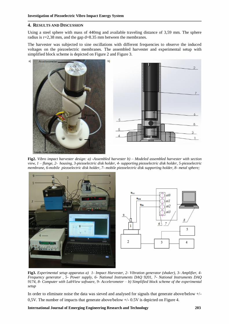
Using a steel sphere with mass of 440mg and available traveling distance of 3,59 mm. The sphere
radius is r=2,38 mm, and the gap d=8.35 mm between the membranes.
The harvester was subjected to sine oscillations with different frequencies to observe the induced voltages on the piezoelectric membranes. The assembled harvester and experimental setup with
simplified block scheme is depicted on Figure 2 and Figure 3.
Fig2. Vibro impact harvester design: a) -Assembled harvester b) – Modeled assembled harvester with section
view, 1 – flange, 2- housing, 3-piezoelectric disk holder, 4- supporting piezoelectric disk holder, 5-piezoelectric
membrane, 6-mobile piezoelectric disk holder, 7- mobile piezoelectric disk supporting holder, 8- metal sphere;
Fig3. Experimental setup apparatus a) 1- Impact Harvester, 2- Vibration generator (shaker), 3- Amplifier, 4-
Frequency generator , 5- Power supply, 6- National Instruments DAQ 9201, 7- National Instruments DAQ
9174, 8- Computer with LabView software, 9- Accelerometer – b) Simplified block scheme of the experimental
setup
In order to eliminate noise the data was sieved and analysed for signals that generate above/below +/-
0,5V. The number of impacts that generate above/below +/- 0.5V is depicted on Figure 4.
Georgi Petkov et al.
International Journal of Emerging Engineering Research and Technology 204
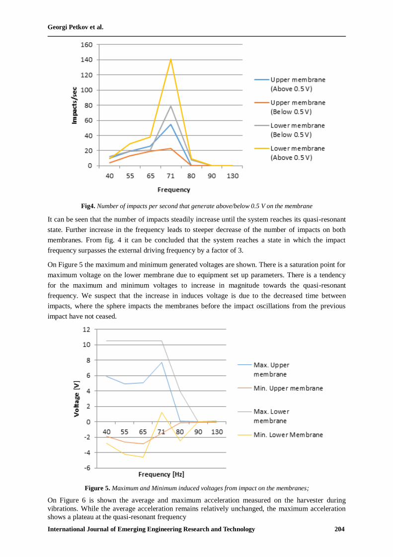
Fig4. Number of impacts per second that generate above/below 0.5 V on the membrane
It can be seen that the number of impacts steadily increase until the system reaches its quasi-resonant
state. Further increase in the frequency leads to steeper decrease of the number of impacts on both
membranes. From fig. 4 it can be concluded that the system reaches a state in which the impact
frequency surpasses the external driving frequency by a factor of 3.
On Figure 5 the maximum and minimum generated voltages are shown. There is a saturation point for
maximum voltage on the lower membrane due to equipment set up parameters. There is a tendency
for the maximum and minimum voltages to increase in magnitude towards the quasi-resonant
frequency. We suspect that the increase in induces voltage is due to the decreased time between
impacts, where the sphere impacts the membranes before the impact oscillations from the previous
impact have not ceased.
Figure 5. Maximum and Minimum induced voltages from impact on the membranes;
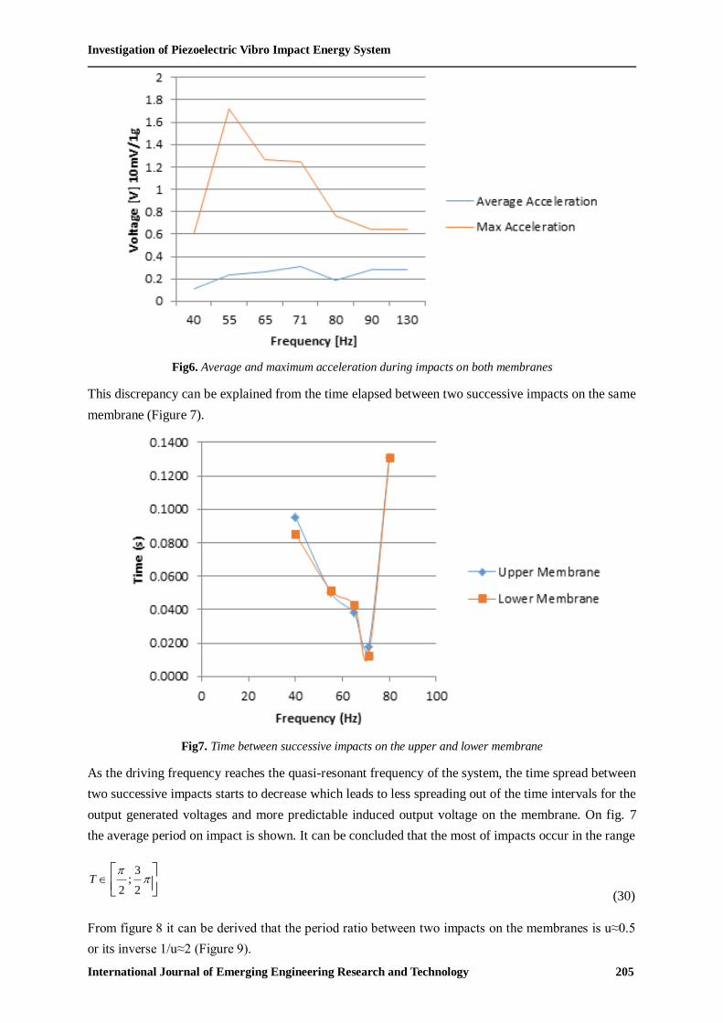
On Figure 6 is shown the average and maximum acceleration measured on the harvester during
vibrations. While the average acceleration remains relatively unchanged, the maximum acceleration shows a plateau at the quasi-resonant frequency
Investigation of Piezoelectric Vibro Impact Energy System
International Journal of Emerging Engineering Research and Technology 205
Fig6. Average and maximum acceleration during impacts on both membranes
This discrepancy can be explained from the time elapsed between two successive impacts on the same
membrane (Figure 7).
Fig7. Time between successive impacts on the upper and lower membrane
As the driving frequency reaches the quasi-resonant frequency of the system, the time spread between
two successive impacts starts to decrease which leads to less spreading out of the time intervals for the
output generated voltages and more predictable induced output voltage on the membrane. On fig. 7
the average period on impact is shown. It can be concluded that the most of impacts occur in the range
3;
2 2T
(30)
From figure 8 it can be derived that the period ratio between two impacts on the membranes is u≈0.5
or its inverse 1/u≈2 (Figure 9).
Georgi Petkov et al.
International Journal of Emerging Engineering Research and Technology 206
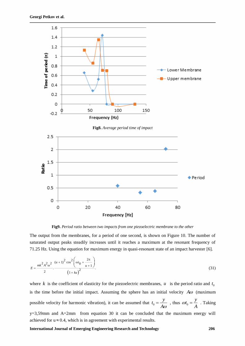
Fig8. Average period time of impact
Fig9. Period ratio between two impacts from one piezoelectric membrane to the other
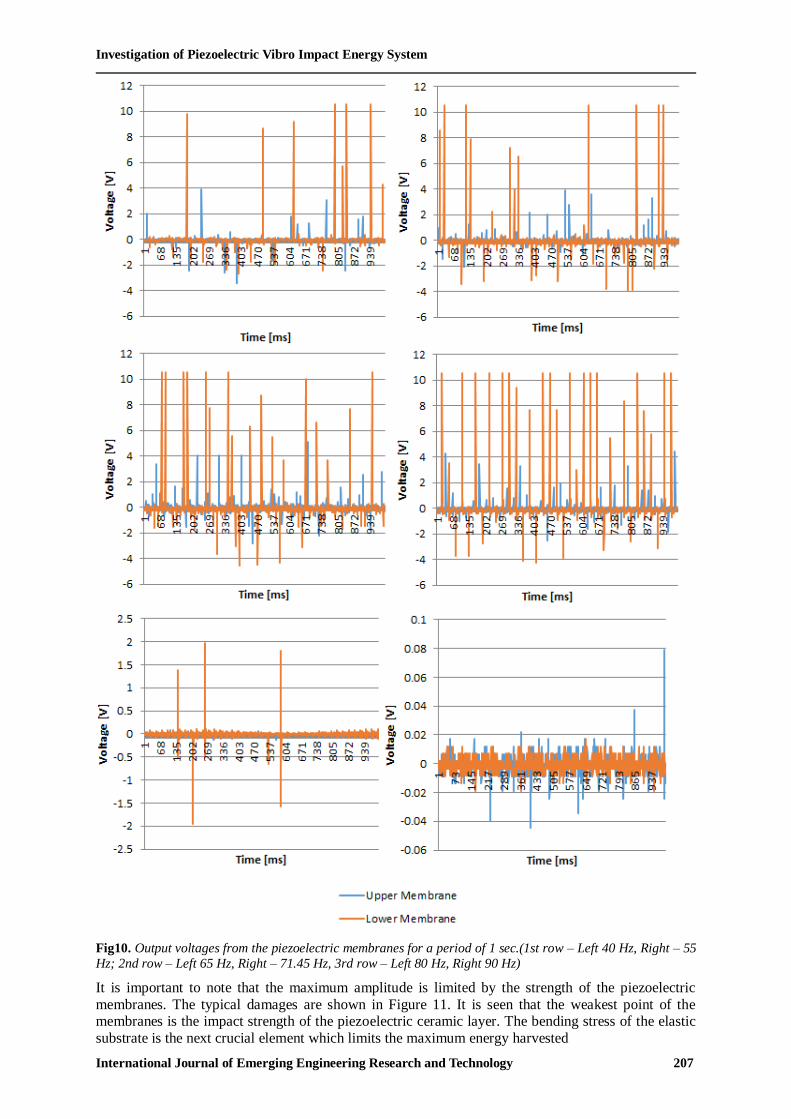
The output from the membranes, for a period of one second, is shown on Figure 10. The number of
saturated output peaks steadily increases until it reaches a maximum at the resonant frequency of
71.25 Hz. Using the equation for maximum energy in quasi-resonant state of an impact harvester [6].
22 2( 1) cos2 2 2 0
1. .
22 1
u tmk A u
E
ku
(31)
where k is the coefficient of elasticity for the piezoelectric membranes, u is the period ratio and 0t
is the time before the initial impact. Assuming the sphere has an initial velocity A (maximum
possible velocity for harmonic vibration), it can be assumed that 0
yt
A , thus 0
yt
A . Taking
y=3,59mm and A=2mm from equation 30 it can be concluded that the maximum energy will
achieved for u 0.4, which is in agreement with experimental results.
Investigation of Piezoelectric Vibro Impact Energy System
International Journal of Emerging Engineering Research and Technology 207
Fig10. Output voltages from the piezoelectric membranes for a period of 1 sec.(1st row – Left 40 Hz, Right – 55
Hz; 2nd row – Left 65 Hz, Right – 71.45 Hz, 3rd row – Left 80 Hz, Right 90 Hz)
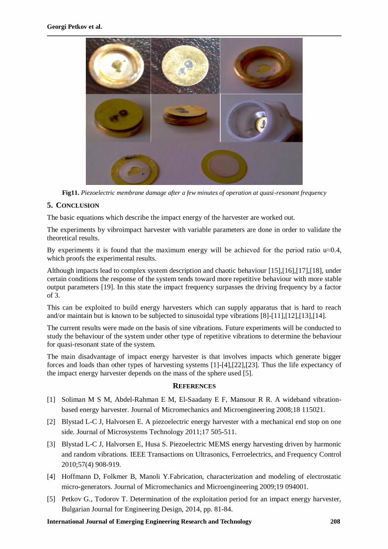
It is important to note that the maximum amplitude is limited by the strength of the piezoelectric
membranes. The typical damages are shown in Figure 11. It is seen that the weakest point of the membranes is the impact strength of the piezoelectric ceramic layer. The bending stress of the elastic
substrate is the next crucial element which limits the maximum energy harvested
Georgi Petkov et al.
International Journal of Emerging Engineering Research and Technology 208
Fig11. Piezoelectric membrane damage after a few minutes of operation at quasi-resonant frequency
5. CONCLUSION
The basic equations which describe the impact energy of the harvester are worked out.
The experiments by vibroimpact harvester with variable parameters are done in order to validate the
theoretical results.
By experiments it is found that the maximum energy will be achieved for the period ratio u≈0.4,
which proofs the experimental results.
Although impacts lead to complex system description and chaotic behaviour [15],[16],[17],[18], under
certain conditions the response of the system tends toward more repetitive behaviour with more stable output parameters [19]. In this state the impact frequency surpasses the driving frequency by a factor
of 3.
This can be exploited to build energy harvesters which can supply apparatus that is hard to reach and/or maintain but is known to be subjected to sinusoidal type vibrations [8]-[11],[12],[13],[14].
The current results were made on the basis of sine vibrations. Future experiments will be conducted to
study the behaviour of the system under other type of repetitive vibrations to determine the behaviour for quasi-resonant state of the system.
The main disadvantage of impact energy harvester is that involves impacts which generate bigger
forces and loads than other types of harvesting systems [1]-[4],[22],[23]. Thus the life expectancy of
the impact energy harvester depends on the mass of the sphere used [5].
REFERENCES
[1] Soliman M S M, Abdel-Rahman E M, El-Saadany E F, Mansour R R. A wideband vibration-
based energy harvester. Journal of Micromechanics and Microengineering 2008;18 115021.
[2] Blystad L-C J, Halvorsen E. A piezoelectric energy harvester with a mechanical end stop on one
side. Journal of Microsystems Technology 2011;17 505-511.
[3] Blystad L-C J, Halvorsen E, Husa S. Piezoelectric MEMS energy harvesting driven by harmonic
and random vibrations. IEEE Transactions on Ultrasonics, Ferroelectrics, and Frequency Control
2010;57(4) 908-919.
[4] Hoffmann D, Folkmer B, Manoli Y.Fabrication, characterization and modeling of electrostatic
micro-generators. Journal of Micromechanics and Microengineering 2009;19 094001.
[5] Petkov G., Todorov T. Determination of the exploitation period for an impact energy harvester,
Bulgarian Journal for Engineering Design, 2014, pp. 81-84.
Investigation of Piezoelectric Vibro Impact Energy System
International Journal of Emerging Engineering Research and Technology 209
[6] Petkov G., Todorov T. Determination of steady state conditions of micro vibro-impact energy
harvester, Technical Science Conference, Varna – 2011, (Machines and Mechanisms), ISSN
0861-9727), pp.92-95
[7] Blystad L-C J, Halvorsen E, Husa S. Piezoelectric MEMS energy harvesting driven by harmonic
and random vibrations. IEEE Transactions on Ultrasonics, Ferroelectrics, and Frequency Control
2010;57(4) 908-919.
[8] Roundy S, Wright P K, Rabaey J. A study of low level vibrations as a power source for wireless
sensor nodes. Computer Communications 2003;26 1131-1144.
[9] Z.L. Wang, R.S. Yang, J. Zhou, Y. Qin, C. Xu, Y.F. Hu, S. Xu, Lateral nanowire/nanobelt based
nanogenerators, piezotronics and piezo-phototronics. Mater. Sci. Eng., R 70, 320–329, (2010)
[10] R.S. Yang, Y. Qin, C. Li, L.M. Dai, Z.L. Wang, Characteristics of output voltage and current of
integrated nanogenerators. Appl. Phys. Lett. 94, 022905 (2009)
[11] J. Liu, P. Fei, J. Zhou, R. Tummala, Z.L. Wang, Toward high output-power nanogenerator. Appl.
Phys. Lett. 92, 173105 (2008)
[12] M. Ferrari, et al.,”Piezoelectric multifrequency energy converter for power harvesting in
autonomous microsystems,” sensors and Actuators A: Physical, vol. 142, pp. 329-335,2008.
[13] J. Rastegar, et al., „Piezoelectric-based power sources for harvesting energy from platforms with
low frequency vibrations,” in Proc. SPIE, 2006.
[14] H.Vocca, et al., “Kinetic energy harvesting,” Physical Review Letters, vol. 102, 2009.
[15] F.Cottone, et al., “Nonlinear energy harvesting,” Physical Review Letters, vol.102, 2009.
[16] L. Gammaitoni, et al., “Nonlinear oscillators for vibration energy harvesting,” Applied Physics
Letters, vol.94, pp.164102-164102-3,2009.
[17] B. Ando, et al., “Nonlinear mechanism in MEMS devices for energy harvesting applications,”
Journal of Micromechanics and Microengineering, vol. 20, p. 125020, 2010.
[18] D.A. Barton, et al., “Energy harvesting from vibrations with a nonlinear oscillator,” Journal of
vibration and acoustics, vol. 132, 2010.
[19] X.Wu, et al., „A frequency adjustable vibration energy harvester,” Proceedings of PowerMEMS,
pp.245-248, 2008.
[20] S.Meninger, et al.,”Vibration-to-electric energy conversion,” Very Large Scale Integration
(VLSI) Systems, IEEE Transactions on, vol. 9, pp. 64-76, 2001
[21] C.B. Williams and R.B. Yates, “Analysis of A Micro-electric Generator For Microsystems,”
Solid-State Sensors and Actuators, 1995 and Eurosensors IX. Transducers‟ 95. The 8th
International Conference on, vol. 1, 1995.
[22] G. Sebald, et al.,”Experimental Duffing oscillator for broadband piezoelectric energy
harvesting,” Smart materials and structures, vol.20, p.102001, 2001.
[23] S. Roundy and Y. Zhang, “Toward self-tuning adaptive vibration-based microgenerators,” in
Proc. SPIE, 2004, pp.373-384.
Georgi Petkov et al.
International Journal of Emerging Engineering Research and Technology 210
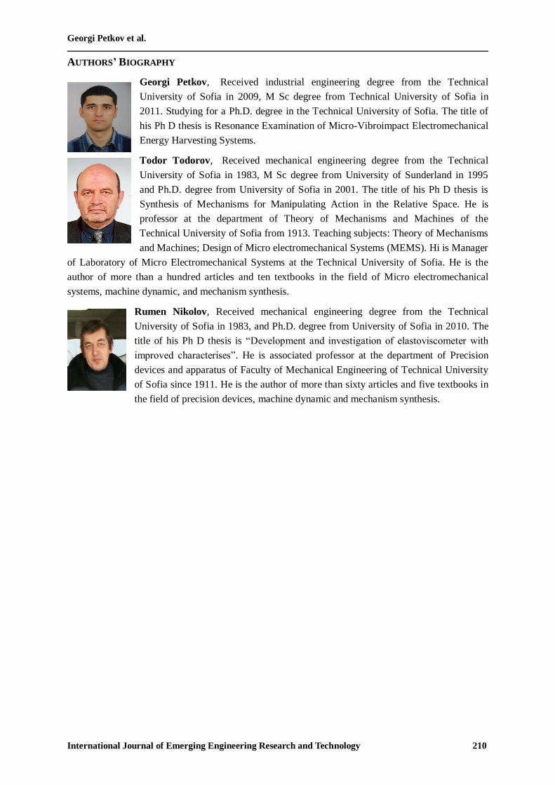
AUTHORS’ BIOGRAPHY
Georgi Petkov, Received industrial engineering degree from the Technical
University of Sofia in 2009, M Sc degree from Technical University of Sofia in
2011. Studying for a Ph.D. degree in the Technical University of Sofia. The title of
his Ph D thesis is Resonance Examination of Micro-Vibroimpact Electromechanical
Energy Harvesting Systems.
Todor Todorov, Received mechanical engineering degree from the Technical
University of Sofia in 1983, M Sc degree from University of Sunderland in 1995
and Ph.D. degree from University of Sofia in 2001. The title of his Ph D thesis is
Synthesis of Mechanisms for Manipulating Action in the Relative Space. He is
professor at the department of Theory of Mechanisms and Machines of the
Technical University of Sofia from 1913. Teaching subjects: Theory of Mechanisms
and Machines; Design of Micro electromechanical Systems (MEMS). Hi is Manager
of Laboratory of Micro Electromechanical Systems at the Technical University of Sofia. He is the
author of more than a hundred articles and ten textbooks in the field of Micro electromechanical
systems, machine dynamic, and mechanism synthesis.
Rumen Nikolov, Received mechanical engineering degree from the Technical
University of Sofia in 1983, and Ph.D. degree from University of Sofia in 2010. The
title of his Ph D thesis is “Development and investigation of elastoviscometer with
improved characterises”. He is associated professor at the department of Precision
devices and apparatus of Faculty of Mechanical Engineering of Technical University
of Sofia since 1911. He is the author of more than sixty articles and five textbooks in
the field of precision devices, machine dynamic and mechanism synthesis.


