Embed Size (px)
Citation preview

This article was downloaded by:[CDL Journals Account][CDL Journals Account]
On: 12 July 2007Access Details: [subscription number 780222585]Publisher: Taylor & FrancisInforma Ltd Registered in England and Wales Registered Number: 1072954Registered office: Mortimer House, 37-41 Mortimer Street, London W1T 3JH, UK
Mechanics Based Design ofStructures and MachinesAn International JournalPublication details, including instructions for authors and subscription information:http://www.informaworld.com/smpp/title~content=t713639027
Periodic Motions, Bifurcation, and Hysteresis of theVibro-Impact System
Online Publication Date: 01 April 2007To cite this Article: Cheng, Jianlian and Xu, Hui , (2007) 'Periodic Motions,Bifurcation, and Hysteresis of the Vibro-Impact System ', Mechanics Based Designof Structures and Machines, 35:2, 179 - 203To link to this article: DOI: 10.1080/15397730701291404URL: http://dx.doi.org/10.1080/15397730701291404
PLEASE SCROLL DOWN FOR ARTICLE
Full terms and conditions of use: http://www.informaworld.com/terms-and-conditions-of-access.pdf
This article maybe used for research, teaching and private study purposes. Any substantial or systematic reproduction,re-distribution, re-selling, loan or sub-licensing, systematic supply or distribution in any form to anyone is expresslyforbidden.
The publisher does not give any warranty express or implied or make any representation that the contents will becomplete or accurate or up to date. The accuracy of any instructions, formulae and drug doses should beindependently verified with primary sources. The publisher shall not be liable for any loss, actions, claims, proceedings,demand or costs or damages whatsoever or howsoever caused arising directly or indirectly in connection with orarising out of the use of this material.
© Taylor and Francis 2007
Dow
nloa
ded
By:
[CD
L Jo
urna
ls A
ccou
nt] A
t: 21
:55
12 J
uly
2007
Mechanics Based Design of Structures and Machines, 35: 179–203, 2007Copyright © Taylor & Francis Group, LLCISSN 1539-7734 print/1539-7742 onlineDOI: 10.1080/15397730701291404
Periodic Motions, Bifurcation, and Hysteresisof the Vibro-Impact System#
Jianlian ChengDepartment of Mechanical Engineering, Construction Machinery School,
Chang’an University, Xi’an, P.R. China
Hui XuDepartment of Engineering Mechanics/MOE Key Laboratory for Strength andVibration, School of Aerospace, Xi’an Jiaotong University, Xi’an, P.R. China
Abstract: Stability periodic motions, saddle-node, grazing and periodicdoubling bifurcation conditions for the single-degree-of-freedom impactoscillator are determined analytically and numerically. The regions for suchcondition are developed in parameter space. The Poincaré map of the systemis established. The period-1 impact motion of the system and its stability arestudied by analytical methods, and the physical origin of hysteresis is foundas function of the drive amplitude. To understand the rich dynamical behaviorof the system, some numerical methods are applied. The phase portraits ofvarious period-1 orbits are exhibited in phase plane. The grazing bifurcation,period doubling bifurcation and periodic motions are illustrated at the Poincarésurface defined at constant drive phase as function of the drive amplitude. Usinganalytical results, the dependence of hysteretic region is determined in parameterspace. In particular, for fixed value of coefficient of restitution (R) and viscousdamping (�), the hysteretic region, in the amplitude-frequency (A− �) space,increases with increasing A and with increasing � above resonant frequency.The effect of increasing damping (increasing � or decreasing R) decreases thearea of hysteretic region of in A− � space.
Keywords: Bifurcation; Hysteresis; Periodic motions; Poincaré map; Stability;Vibro-impact system.
Received October 24, 2006; Accepted December 13, 2006#Communicated by S. Sinha.Correspondence: Jianlian Cheng, Department of Mechanical Engineering,
Construction Machinery School, Chang’an University, Xi’an, 710064 P.R.China; E-mail: [email protected]
Dow
nloa
ded
By:
[CD
L Jo
urna
ls A
ccou
nt] A
t: 21
:55
12 J
uly
2007
180 Cheng and Xu
1. INTRODUCTION
The vibro-systems with clearance or gap between the moving partsare frequently encountered in a large number of diverse engineeringfields. Repeated impact, i.e., vibro-impact, usually occurs whenever thecomponents of a vibrating system collide with a rigid obstacle or witheach other. Impacts give rise to discontinuity and strong nonlinearity,so the vibro-impact systems can exhibit very rich and complicateddynamic behaviors and it is a good testing bench for nonlinear theories.Some numerical and experimental results were obtained, but analyticalprediction need to be further developed. Some researches, includingglobal bifurcations, singularity, high-codimension bifurcation, and quasi-periodic impacts, were developed for the vibro-impact systems (Coneand Zadoks, 1995; Ivanov, 1993, 1996; Nordmark, 1991; Peterka, 1996;Peterka and Vcacik, 1992; Whiston, 1987). A single-degree-of-freedomimpact oscillator model has been widely used for the last few decadesas a first approximation to understanding the behavior of machinesused in pile driving, compacting, crushing, riveting, rock drilling, impactprinting, and hand-held percussion machine, and so on (Babitsky, 1998;Bapat, 1998; Tatara and Moriwaki, 1992). Other complex periodic,period doubling and chaotic motions were extensively studied recentlyusing theoretical and numerical simulation approaches (Chatterjee andMallik, 1996; Han et al., 1995; Luo, 2002, 2004; Luo and Xie, 2001; Xieand Ding, 2005). Simulation approaches are computational exhaustive instudy of periodic motions, especially when system is lightly damped andstops are elastic.
In the past decades, the vibro-impact systems have becomeincreasingly important in engineering and other applied science. Thereare many concrete problems in mechanics where effects resulting fromnonsmooth phenomena have to be taken into account. Peterka (1978)investigated the different types of the conditions of existence of themotion of two mass nonlinear systems. Subsequently, and gave ashort explanation of the laws of a simple mechanical impact system,to elucidate the transition to chaotic motion and to illustrate theperiodic and chaotic motions of more complicated systems in 1992(Peterka and Vcacik, 1992). Bapat et al. (1983), Bapat and Sankar(1985) studied the periodic motion of an impact pair experimentally.The symmetrical periodic motion was observed, and the unsymmetricalperiodic motion was treated as a part of the symmetrical periodicmotion. Shaw and Holmes (1983a) investigated the periodic motion ofthe impact damper and singularity of the Poincaré mapping of theimpact system. Shaw (1985) researched the subharmonic motion andlocal bifurcation, the chaotic motion and global bifurcation throughthe Poincaré mapping of the impact system. Whiston (1987) analyzedthe global dynamics of an impact oscillator with one single side
Dow
nloa
ded
By:
[CD
L Jo
urna
ls A
ccou
nt] A
t: 21
:55
12 J
uly
2007
Bifurcation and Hysteresis of the Vibro-Impact System 181
impact. The singularity structure of the Poincaré mapping of the impactsystems was investigated. Nordmark (1991) investigated the nonperiodicmotion caused by the grazing bifurcation. Rega et al. (1991) studiedperiodic and chaotic motions of an unsymmetrical oscillator in nonlinearstructural dynamics. Budd and Dux (1994) presented an approach todetermine in the initial data sets for the chatters in impact oscillators.Han et al. (1995) presented analytical approach to determine period-k motion, stability and bifurcation conditions of impact oscillatorswith one-side constraint and two-side constraints. Budd and Lee (1996)investigated double impact orbits of the periodically forced impactsoscillator analytically and numerically, but only numerical simulationswere presented. In addition, Bishop et al. (1998) presented how topredict period-1 impacts in a driven beam, and used control to maintainperiod-1 motion during the or wind-down operation of an impactingdriven beam. Hogan and Homer (1999) applied the graph theory toinvestigate the piecewise smooth dynamical system. This description isa qualitative description and it is very difficult to complete quantitativeanalysis.
Recently, theories of dynamical systems have been successfullyapplied to explain and predict new and complex behaviors of nonsmoothsystems. Luo (2002), Luo and Chen (2005) researched the stabilityand bifurcation for the unsymmetrical, periodic motion of a horizontalimpact oscillator under a periodic excitation through four mappingsbased on two switch-planes relative to discontinuities. Wen (2001)investigated onset of degenerate Hopf bifurcation of a vibro-impactoscillator. Luo (2004) considered a two-degree-of-freedom vibro-impactsystem with a single rigid stop, and investigated some nontypicalroutes to chaos via period-doubling bifurcations of periodic motionswith one impact. Ding et al. (2004) examined the interaction effectsbetween Hopf and period-doubling bifurcation in vibro-impact system.Souza and Caldas (2004) applied a model based algorithm for thecalculation of the spectrum of the Lyapunov exponents of attractorsof mechanical systems with impacts. Jiang et al. (2005) considers theuse of numerically constructed invariant manifolds to determine theresponse of nonlinear vibratory systems that are subjected to harmonicexcitation.
In this paper, analytical solutions, stability, and bifurcations forsymmetrical and unsymmetrical period-1 motions of impact oscillatorswill be investigated. Various numerical investigations are performed tounderstand the rich dynamical response of our model vibration impactsystems by introducing the Poincaré surfaces. The hysteretic behaviorsinvolving impacting and non-impacting periodic orbits are analyzed, anddepend on all the system parameters. The relaxation of the impact modelby a three linear restoring force is an approximation of the reality forthe instantaneous Newton restitution law.
Dow
nloa
ded
By:
[CD
L Jo
urna
ls A
ccou
nt] A
t: 21
:55
12 J
uly
2007
182 Cheng and Xu
2. MODELING ANALYSIS AND PERIODIC MOTIONS
2.1. Modeling Analysis and Hysteresis
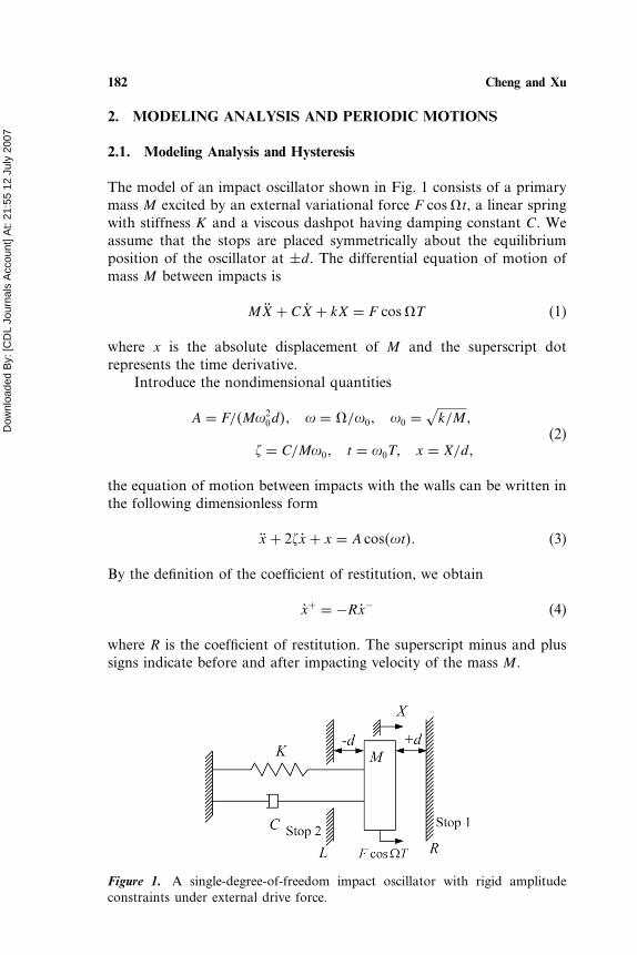
The model of an impact oscillator shown in Fig. 1 consists of a primarymass M excited by an external variational force F cos�t, a linear springwith stiffness K and a viscous dashpot having damping constant C. Weassume that the stops are placed symmetrically about the equilibriumposition of the oscillator at ±d. The differential equation of motion ofmass M between impacts is
MX + CX + kX = F cos�T (1)
where x is the absolute displacement of M and the superscript dotrepresents the time derivative.
Introduce the nondimensional quantities
A = F/�M�20d�� � = �/�0� �0 =
√k/M�
(2)� = C/M�0� t = �0T� x = X/d�
the equation of motion between impacts with the walls can be written inthe following dimensionless form
x + 2�x + x = A cos��t�� (3)
By the definition of the coefficient of restitution, we obtain
x+ = −Rx− (4)
where R is the coefficient of restitution. The superscript minus and plussigns indicate before and after impacting velocity of the mass M .
Figure 1. A single-degree-of-freedom impact oscillator with rigid amplitudeconstraints under external drive force.
Dow
nloa
ded
By:
[CD
L Jo
urna
ls A
ccou
nt] A
t: 21
:55
12 J
uly
2007
Bifurcation and Hysteresis of the Vibro-Impact System 183
We are interested in studying complex dynamical behavior caused bythe impacts with the walls. Therefore, the motion of the above oscillatoris limited by two stationary stops symmetrically placed at x= ± 1.Because of the time scaling used, the natural frequency is 1 rad/s, and� = 1 implies that the system is critically damped. In this paper, we onlyconsider the underdamped case, i.e., � < 1.
Equation (3) describes a non-autonomous second order system,but the system can equivalently be described as a three-dimensionalautonomous first order coupled differential equations as
x
y
�
=
y
−2�x − x + A cos���
�
� for − 1 < x < 1� (5)
where � denotes the phase of the drive and is defined as � = �� mod2�.We defined the three-dimensional phase space of the impact systemby �x� x� �� ∈ R2 × C where −1 ≤ x ≤ 1, −� < x < +�. This three-dimensional flow phase space can be reduced to a two-dimensionalPoincaré map. Consider the three Poincaré sections �, L, and R,where
� = ��x� x� �� �� = �0�−1 ≤ x ≤ 1� x ∈ �−��+����
L = ��x� x� �� � x = −1� � ∈ C� x ∈ �−��+���� (6)
R = ��x� x� �� � x = 1� � ∈ C� x ∈ �−��+����
Based on these three surfaces, three mappings are defined P1 � →�, the map where the position and velocity are sampled at somefixed drive phase, and the other two impact mappings P2 L → L
and P3 R → R where the phase and velocity are sampled at impactwith the left wall or the right wall, respectively. In general, a periodic ntrajectory of the Poincaré map defined by � will show n points whilethe same trajectory could impact the left wall p times and the right wallq times, where n� p� q are all different numbers. In particular, it is noteven necessary for impacts to take place on one wall or either of thewalls. Thus, we can characterize periodic motions of the impact systemby the symbol n–p–q, where p and q is the number of impacts occurringrespectively at the left wall and right wall, and n is the number of theforcing cycles (Ivanov, 1993; Peterka and Vcacik, 1992). The orbit will bedenoted as an Pnpq orbit. If part of an orbit of an impact system is justtouching a wall with zero velocity, then it is said to be a grazing orbit(Whiston, 1992).
In the following, the results of numerical experiment provide themotivation and background to analytical analysis that will be done inthe subsequent section. Based on the numerical integration of the system
Dow
nloa
ded
By:
[CD
L Jo
urna
ls A
ccou
nt] A
t: 21
:55
12 J
uly
2007
184 Cheng and Xu
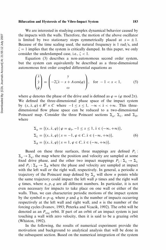
Figure 2. The graph shows the position of the oscillator at the Poincaré section,taken as amplitude A is varied when the drive phase of force is equal to 2. Thearrow pointing upward indicates the transition from P100 orbit to stable P111
orbit. (a) Symmetric clearance ±1; (b) Asymmetric clearance +1 and −1�5.
described by Eq. (5) for system parameters set at � = 0�035 and R = 0�7,considering the frequency set at � = 1�9 and 2.3, the bifurcation graph isplotted for the system using the drive amplitude as the scan parameter.The numerical result is shown in Fig. 2, (a) expressing the symmetricclearance, (b) expressing the asymmetric clearance. In Fig. 2(a), the curveA–B–C is the stable asymptotic state P100 of the Poincaré map when Ais incremented from 0.0 to 2.615 at � = 1�9. On increasing in the valueof A ≈ 2�61, the system goes through grazing bifurcation and jumps tothe already existing impacting period-1 orbit. On decreasing A from 2.62,the system follows the P111 orbit-a different route compared to when Awas being increased. In the proximity of A = 0�4 at � = 1�9, the P111
solution disappears and the system settles down to P100 solution. At� = 2�3, the grazing bifurcation point arise in the value of A ≈ 4�33,and the P111 solution disappears and the system settles down to P100
solution in the proximity A ≈ 0�65. Thus, the system shows hysteresis.The results in Fig. 2(b) are similar to ones in Fig. 2(a), but comparingthe results between two figures, the hysteresis of asymmetric clearance ismore severe than that of symmetric clearance in same drive frequency.
2.2. Periodic Motions and Stability on Symmetric Walls
2.2.1. Existence of the Period-1 Orbit
Based on the forgoing Eq. (3), the general solution between impacts isgiven by
x = A0e−�t cos
(√1− �2t + �0
)+ Acos��t + ��√
�1− �2�2 + 4�2�2(7)
Dow
nloa
ded
By:
[CD
L Jo
urna
ls A
ccou
nt] A
t: 21
:55
12 J
uly
2007
Bifurcation and Hysteresis of the Vibro-Impact System 185
where A0 and �0 are determined by the initial condition, andtan��� = −2��/�1− �2�. In Eq. (7), the first term is the transientterm and the second term is a steady state solution, i.e., as t→�,A0e
−�t cos�√1− �2t + �0� → 0, and the solution reduces to x =
A cos��t+��√�1−�2�2+4�2�2
. If A < Aa, the initial condition will approach to the
non-impact solution, where
Aa =√�1− �2�2 + 4�2�2 (8)
If A = Aa, the system will have a grazing impact with the wall, locatedto x = ±1.
To determine the condition for the existence of the symmetricperiod-1 orbit, P111, we assume that the oscillator is at left wall at timet = t0 and the velocity is positive (moving away from the wall). Thus, thesolution can be written
−1 = A0e−�t0 cos���+ A
cos��t0 + ��√�1− �2�2 + 4�2�2
(9)
v�t0� = −A0e−�t0(� cos���+
√1− �2 sin���
)− A�sin��t0 + ��√
�1− �2�2 + 4�2�2
(10)
where � = √1− �2t0 + �0. If the orbit period is T = 2/�, the oscillator
is at the left wall at t = t0 and at right wall at t = t0 + /�. The otherconstraint on the system is
x�t0 + /�� = 1 (11)
Substituting Eq. (7) into Eq. (11), and simultaneously Eq. (9)generate
tan��� = e�/� + cos(√
1− �2/�)
sin(√
1− �2/�) (12)
Based on the trait of the symmetric orbit, the ratio of the outgoingvelocity to the incoming velocity is related by the coefficient of restitutionR. Thus, there is
Rv�t0 + /�� = v�t0� (13)
Substituting Eq. (10) into Eq. (13), we can obtain
v�t0� = −A0e−�t0S (14)
Dow
nloa
ded
By:
[CD
L Jo
urna
ls A
ccou
nt] A
t: 21
:55
12 J
uly
2007
186 Cheng and Xu
where
S =(�+ C
√1− �2
)(1− Re−�/� cos���
)− Re−�/� sin���(√
1− �2 − C�)
√1+ C2�1+ R�
�
� = √1− �2
�� C = tan����
Comparing Eq. (14) and Eq. (10), leads to
A0 =−�� sin��t0 + ��e�t0
√1+ C2
�+ C√1− �2 − S
√1+ C2
(15)
where � = A/√�1− �2�2 + 4�2�2. Using Eq. (15) into Eq. (9) yields
��� sin��t0 + ��− cos��t0 + ��� = 1 (16)
where � = �/(�+ C
√1− �2 − S
√1+ C2
). Transforming Eq. (16),
become
�2�1+ �2� cos2��t0 + ��+ 2� cos��t0 + ��+ 1− �2�2 = 0 (17)
The solvability condition for Eq. (17) is
A√1+ �2√
�1− �2�2 + 4�2�2≥ 1 (18)
Thus, the condition as in Eq. (18) determines the existence of thesymmetric period-1 orbit with one collision at each wall per cycle. Forgiven value of � and R in Eq. (18), with the equality sign, we get the valueof A ≡ Ac.
Ac =√�1− �2�2 + 4�2�2√
1+ �2(19)
Thus, Eqs. (8) and (19) give the range of values of A for the periodicorbit P111 and non-impacting solutions coexist. As mentioned before,the physically important repercussion of this type of solution set isthat the system exhibits hysteresis. For Fig. 2 shown, the system jumpsto the impacting solution at A = 2�615 and the control parameter A mustbe reduced to 0.40 before the system jumps to back to non-impactingsolution. This trait is important for the view point of real engineeringapplication where the operation of the system involves vibration withclearance, or repeated impact of tube-to-support impact in case of heatexchanger tubes (Bedout et al., 1999). A sudden catastrophic jump from
Dow
nloa
ded
By:
[CD
L Jo
urna
ls A
ccou
nt] A
t: 21
:55
12 J
uly
2007
Bifurcation and Hysteresis of the Vibro-Impact System 187
safe non-impacting solution to undesired impacting solution would callfor a very large change in the system parameter to get the system backto the non-impacting solution.
Using a similar analysis method as above, the existent condition ofthe period-1 impact orbit P110 (or P101� which collides with the left (orthe right) wall during one drive cycle can be obtained. The result is thesame as Eq. (19).
2.2.2. Stability Analysis
To the system stability, it is necessary that the derivations of theJacobian of the local mapping in the neighborhood of a track areconsidered in the phase space. Equation (5) is written in the standardform as follows:
x
y
�
=
y
F�x� y� ��
�
� (20)
where F is the acceleration function that is periodic. For the singleimpact system, F = −2�y − x + A cos��t�. The Poincaré section is takenby sampling the states variables once every cycle, when the drive phaseis zero � modulo 2. Let un = �xn� yn� be the value of the state variableat the nth crossing of the Poincaré section taken at a particular phaseof the driving function modulo 2. The state at (n+ 1)th crossing un+1
is uniquely determined by the state at nth crossing un since the systemis deterministic. The two-dimensional Poincaré map G can be given atsuccessive iterative crossing as
un+1 = G�un� (21)
A mapping between successive impacts from a constant phase plane �1
to another such plane �2 for the system can be analytically expressedsince the system is linear. The linearized form can be written as(
�x
�y
)=(
0 1
−1 2�
)(�x
�y
)� (22)
where �( )s are the deviations form the trajectory. The solution forEq. (22) is given by (
�x�t�
�y�t�
)= P�t� t0�
(�x�t0�
�y�t0�
)� (23)
where
P�t� t0� =e−��t−t0�
r
(� sin���+ r cos��� sin���
− sin��� r cos���− � sin���
)� (24)
Dow
nloa
ded
By:
[CD
L Jo
urna
ls A
ccou
nt] A
t: 21
:55
12 J
uly
2007
188 Cheng and Xu
where r = √1− �2, and � = r�t − t0�. Thus, the local mapping P:
�1 →�2 , defined near a track starting at �x�1� y�1� and reaching�x�2� y�2� with no impacts in between the phase plane, is given by Eq. (24)with �t− t0� = ��2 − �1�/�.
In following, a general expression for the Jacobian of the localPoincaré map is driven for the collision of a mass with a moving barrier.Assume that the track u�t� = �xf �t�� yf �t�� collides with the moving wallat time t∗. Then, xf �t∗� = xb�t
∗�, where xf �t∗� and xb�t∗� are the position
of mass and barrier at the impact time, respectively. We consider theperturbed motion of the trajectory. A point that collides with the movingwall can be represented by
u−� = u−
f + �u−f
u+� = u+
f + �u+f
}� (25)
where u−� and u+
� present a point before and after collision. The Jacobianof impact map will relate �u+
f and �u−f by the expression
�u+f = Q�u−
f � (26)
The mass collide with the moving wall at time t∗ + �t when x−� �t∗ + �t� =
xb�t∗ + �t�. Expanding the flow in phase space by the Taylor series, yield
(to first order in �t�
x−� �t∗ + �t� = xf �t
∗�+ �x−f �t∗�+ y−f �t
∗��t(27)
xb�t∗ + �t� = xb�t
∗�+ vb�t∗��t
where y−f �t∗� is the velocity of the mass just before collision and vb is the
velocity of the moving wall. Based on the foregoing condition, we canobtain
�t = − �x−f �t∗�
y−f �t∗�− vb�t∗�
(28)
Suppose that the impact time is neglected, the displacement of the pointafter colliding with the moving wall at same time is given as
x+� �t∗ + �t� = xf �t
∗�+ �x+f �t∗�+ y+f �t
∗��t = xb�t∗�+ vb�t
∗��t (29)
�t = − �x+f �t∗�
y+f �t∗�− vb�t∗�
(30)
From Eqs. (28) and (30), we can obtain
�x+f �t∗� = y+f �t
∗�− vb�t∗�
y−f �t∗�− vb�t∗��x−f �t
∗� = −R�x−f �t∗� (31)
Dow
nloa
ded
By:
[CD
L Jo
urna
ls A
ccou
nt] A
t: 21
:55
12 J
uly
2007
Bifurcation and Hysteresis of the Vibro-Impact System 189
where the impact velocity law is v+r �t∗� = −Rv−r �t
∗�,v+r �t∗� = y+f �t
∗�−vb�t
∗�, v−r �t∗� = y−f �t
∗�− vb�t∗�, v+r �t
∗� and v−r �t∗� are the relative velocity
between the mass and the moving wall after the collision and before thecollision.
Considering the perturbing relative velocity, obtains
v−�r�t∗ + �t� = y−f �t
∗�+ F−�xf � y−f � t
∗��t + �y−f �t∗�− vb�t
∗�− vb�t∗��t
v+�r�t∗ + �t� = y+f �t
∗�+ F+�xf � y+f � t
∗��t + �y+f �t∗�− vb�t
∗�− vb�t∗��t
(32)
Using the velocity impact law v+�r�t∗ + �t� = −Rv−�r�t
∗ + �t� intoEq. (31) and simplifying, we obtain
�y+f �t∗� = �−F+ − RF− + �1+ R�vb�t
∗���t − R�y+f �t∗� (33)
Substituting Eq. (27) into Eq. (32) yields
�y+f �t∗� = �F+ + RF− − �1+ R�vb�t
∗���x−f �t
∗�
v−r �t∗�− R�y+f �t
∗� (34)
Combining Eqs. (31) and (34), the Jacobian of the local Poincarémaps at moving impact surface can be given. The Q matrix for a movingwall is given by
Q =(
−R 0F++RF−−�1+R�vb
v−r−R
)t=t∗
(35)
where vb is the acceleration of moving wall. For the stationary wall bysetting vb = 0 and v−r = y−f , the Q-matrix become
Q =( −R 0
F++RF−y−f
−R
)t=t∗
(36)
A Poincaré map can locally be constructed out of the combinationof Q and P mappings. Thus, assuming that the track makes one collisionwith the wall on the right and one with the wall on the left in one cycle,when the drive phase is equal to modulo 2, the Poincaré map for thelinearized dynamics will be given by
M = Pl •Ql • · · · • Pr •Qr︸ ︷︷ ︸�p+q�th-impacts
(37)
where subscript l and r present the collision with the left wall and withthe right one. It should be noted that the determinant of Q is equal
Dow
nloa
ded
By:
[CD
L Jo
urna
ls A
ccou
nt] A
t: 21
:55
12 J
uly
2007
190 Cheng and Xu
to R2. Thus, each collision, locally, contracts the volume in phase spaceby a factor of R2 (R ≤ 1). But because of 1/y−f singularity in one of theelements of in one of the elements of Q the phase space will undergoa large stretching and compression for the case of low velocity impacts.If the eigenvalues of the matrix P lie inside the unit circle, then thesystem has a stable periodic solution with period 2/�. If one of twoeigenvalues is −1 and the other one is in interval (−1, 1), the perioddoubling bifurcation (or the saddle-node bifurcation of the second kind)occurs. When the larger one of two eigenvalues is +1 and the other oneis in interval (–1, 1), the saddle-node bifurcation of the first kind takesplace. If none of the eigenvalues lie on the unit circle or inside it, thesystem becomes unstable.
3. NUMERICAL SIMULATION AND BEHAVIORS ANALYSIS
The vibro-impact system can exhibit the rich dynamical behaviors viavarious numerical methods. We present the phase space portraits ofvarious period-1 orbits that the system approaches to for differentsettings of the system parameters. The local transitions between variousstable states are discussed, as one of the system parameter is changed.Using foregoing results and from bifurcation theory, the nature ofthe transition between different stable states is exhibited. Vibro-impactsystems go through grazing bifurcation in addition to other localbifurcations that are also found in smooth dynamical systems. Thephenomenon of hysteresis is discussed and observed within the lowamplitude region. At the same time, we give the detail of the calculationof the Lyapunov spectra for impact systems and explain the numericalalgorithm to track unstable periodic orbits through the parameter space.
In the numerical simulations, the fourth order Runge-Kutta methodis applied to numerically integrate the model equations forward in time.Collision, for the case of the impact oscillator with two stationarywalls placed to at ±1 symmetrically about the equilibrium point ofthe oscillator, is detected when the absolute value of the position ofthe oscillator is greater than 1. Once the collision is detected, the lastintegration step is discarded and the system is integrated forward withhalf the integration time step. This is done repeatedly while observingwhich side of the wall the system lies after each integration step.The system is integrated forward (or backward) in time depending onwhether the system mass is located before (or beyond) the wall withthe time step being halved each time the wall is crossed and the timeis reversed. This is done until the time of collision is detected withinan accuracy of 10−6 of the origin integration time step. After thedetection of the collision time within the predetermined accuracy, theinitial conditions are reset at the wall using the velocity impact law.
Dow
nloa
ded
By:
[CD
L Jo
urna
ls A
ccou
nt] A
t: 21
:55
12 J
uly
2007
Bifurcation and Hysteresis of the Vibro-Impact System 191
3.1. Bifurcation Analysis
To show the transitions between various stable states as a functionof drive amplitude A, the bifurcation plots are shown at the Poincarésurface defined at constant drive phase. The bifurcation plot was madein the following manner. The drive amplitude was initially set to 6.0 andthe initial condition for the position and velocity were set to 0.9 and–1.1 (a point on the chaotic attractor). The position and velocity of theoscillator was recorded every time the phase of the drive force equaled2 mod 2. With each decremented of A, the initial conditions were setto the last values produced in the previous step. This was repeated untilthe value of A = 0�0 was reached. The points obtained in this mannerare plotted. This method of plotting bifurcation diagram does not showother coexisting stable attractors. In Fig. 4, the only other coexistingstable attractors, for A < 6�0, are traced by scanning drive amplitudeforward from 0.0 to 6.0. The initial conditions are the last valuesproduced in the previous step by the foregoing method. The plot showsonly the points that are not obtained while A was scanned backward.
To handily marking the point of transition, we adopt some acronymas follows. The points where a saddle-node bifurcation occur is labeledSN1 and SN2, the point labeled SB denotes the symmetry breakingbifurcation, the points labeled PD denote a period doubling bifurcationand the points labeled GB1, GB2, and GB3 mark the point where agrazing bifurcation occurs. Figure 4 shows four different kinds of local
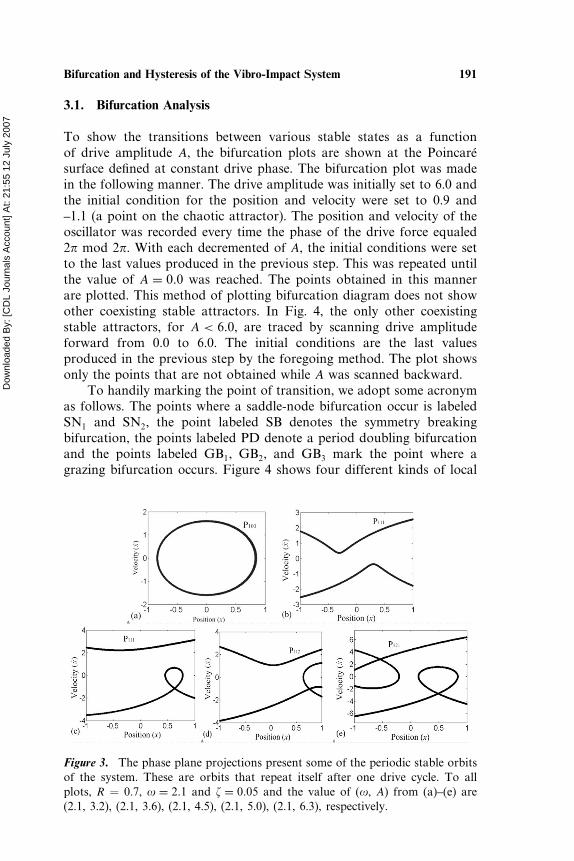
Figure 3. The phase plane projections present some of the periodic stable orbitsof the system. These are orbits that repeat itself after one drive cycle. To allplots, R = 0.7, � = 2�1 and � = 0�05 and the value of (�, A) from (a)–(e) are(2.1, 3.2), (2.1, 3.6), (2.1, 4.5), (2.1, 5.0), (2.1, 6.3), respectively.
Dow
nloa
ded
By:
[CD
L Jo
urna
ls A
ccou
nt] A
t: 21
:55
12 J
uly
2007
192 Cheng and Xu
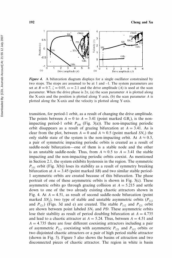
Figure 4. A bifurcation diagram displays for a single oscillator constrained bytwo stops. The stops are assumed to be at 1 and –1. The system parameters areset at R = 0�7, � = 0�05, � = 2�1 and the drive amplitude (A) is used at the scanparameter. When the drive phase is 2, (a) the scan parameter A is plotted alongthe X-axis and the position is plotted along Y-axis, (b) the scan parameter A isplotted along the X-axis and the velocity is plotted along Y-axis.
transition, for period-1 orbit, as a result of changing the drive amplitude.The points between A = 0 to A = 3�41 (point marked GB1), is the non-impacting period-1 orbit P100 (Fig. 3(a)). The non-impacting periodicorbit disappears as a result of grazing bifurcation at A = 3�41. As isclear from the plot, between A = 0 and A ≈ 0�5 (point marked SN1� theonly stable state of the system is the non-impacting orbit. At A ≈ 0�5,a pair of symmetric impacting periodic orbits is created as a result ofsaddle-node bifurcation—one of them is a stable node and the otheris an unstable saddle-node. Thus, from A ≈ 0�5 to A = 3�41 the stableimpacting and the non-impacting periodic orbits coexist. As mentionedin Section 2.1, the system exhibits hysteresis in the region. The symmetricP111 orbit (Fig. 3(b)) loses its stability as a result of symmetry breakingbifurcation at A = 3�45 (point marked SB) and two similar stable period-1 asymmetric orbits are created because of this bifurcation. The phaseportrait of one of these asymmetric orbits is shown in Fig. 3(c). Theseasymmetric orbits go through grazing collision at A = 5�215 and settledown to one of the two already existing chaotic attractors shown inFig. 4. At A = 4�51, as result of second saddle-node bifurcation (pointmarked SN2), two type of stable and unstable asymmetric orbits (P112
and P121� (Figs. 3d and e) are created. The stable P112 and P121 orbitare shown between point labeled SN2 and PD. These asymmetric orbitslose their stability as result of period doubling bifurcation at A = 4�735and lead to a chaotic attractor at A = 5�24. Thus, between A = 4�51 andA = 4�735 there are four different coexisting attractors including a pairof asymmetric P111 coexisting with asymmetric P121 and P112 orbits ortwo disjointed chaotic attractors or a pair of high period stable attractor(shown in Fig. 5). Figure 5 also shows the basins of attraction and twodisconnected pieces of chaotic attractor. The region in white is basin
Dow
nloa
ded
By:
[CD
L Jo
urna
ls A
ccou
nt] A
t: 21
:55
12 J
uly
2007
Bifurcation and Hysteresis of the Vibro-Impact System 193
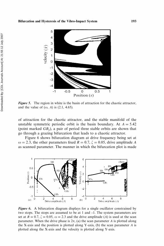
Figure 5. The region in white is the basin of attraction for the chaotic attractor,and the value of (�, A) is (2.1, 4.65).
of attraction for the chaotic attractor, and the stable manifold of theunstable symmetric periodic orbit is the basin boundary. At A = 5�42(point marked GB2), a pair of period three stable orbits are shown thatgo through a grazing bifurcation that leads to a chaotic attractor.
Figure 6 shows bifurcation diagram at drive frequency being set at� = 2�3, the other parameters fixed R = 0�7, � = 0�05, drive amplitude Aas scanned parameter. The manner in which the bifurcation plot is made
Figure 6. A bifurcation diagram displays for a single oscillator constrained bytwo stops. The stops are assumed to be at 1 and –1. The system parameters areset at R = 0�7, � = 0�05, � = 2�3 and the drive amplitude (A) is used at the scanparameter. When the drive phase is 2, (a) the scan parameter A is plotted alongthe X-axis and the position is plotted along Y-axis, (b) the scan parameter A isplotted along the X-axis and the velocity is plotted along Y-axis.
Dow
nloa
ded
By:
[CD
L Jo
urna
ls A
ccou
nt] A
t: 21
:55
12 J
uly
2007
194 Cheng and Xu
is same as that of Fig. 4. To contrast between Figs. 4 and 6, we canfind that the value of all bifurcation points increase along the X-axis inhigh frequency than in low one, but the configuration of bifurcation isidentical. In Fig. 6, the stable P121 and P112 orbit between points labeledSN2 and PD and period doubling bifurcation orbit become more obviousthan ones in Fig. 4.
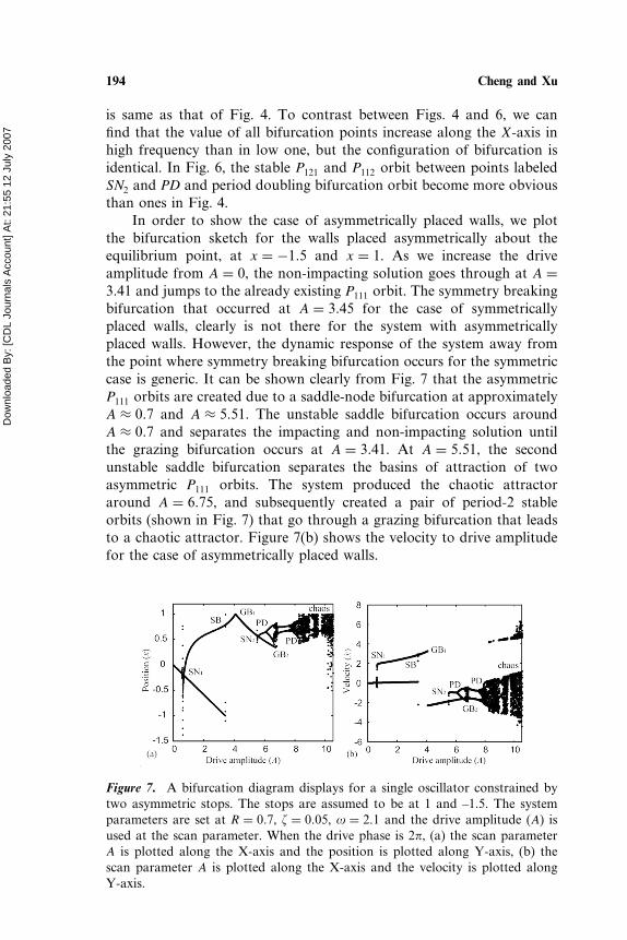
In order to show the case of asymmetrically placed walls, we plotthe bifurcation sketch for the walls placed asymmetrically about theequilibrium point, at x = −1�5 and x = 1. As we increase the driveamplitude from A = 0, the non-impacting solution goes through at A =3�41 and jumps to the already existing P111 orbit. The symmetry breakingbifurcation that occurred at A = 3�45 for the case of symmetricallyplaced walls, clearly is not there for the system with asymmetricallyplaced walls. However, the dynamic response of the system away fromthe point where symmetry breaking bifurcation occurs for the symmetriccase is generic. It can be shown clearly from Fig. 7 that the asymmetricP111 orbits are created due to a saddle-node bifurcation at approximatelyA ≈ 0�7 and A ≈ 5�51. The unstable saddle bifurcation occurs aroundA ≈ 0�7 and separates the impacting and non-impacting solution untilthe grazing bifurcation occurs at A = 3�41. At A = 5�51, the secondunstable saddle bifurcation separates the basins of attraction of twoasymmetric P111 orbits. The system produced the chaotic attractoraround A = 6�75, and subsequently created a pair of period-2 stableorbits (shown in Fig. 7) that go through a grazing bifurcation that leadsto a chaotic attractor. Figure 7(b) shows the velocity to drive amplitudefor the case of asymmetrically placed walls.
Figure 7. A bifurcation diagram displays for a single oscillator constrained bytwo asymmetric stops. The stops are assumed to be at 1 and –1.5. The systemparameters are set at R = 0�7, � = 0�05, � = 2�1 and the drive amplitude (A) isused at the scan parameter. When the drive phase is 2, (a) the scan parameterA is plotted along the X-axis and the position is plotted along Y-axis, (b) thescan parameter A is plotted along the X-axis and the velocity is plotted alongY-axis.
Dow
nloa
ded
By:
[CD
L Jo
urna
ls A
ccou
nt] A
t: 21
:55
12 J
uly
2007
Bifurcation and Hysteresis of the Vibro-Impact System 195
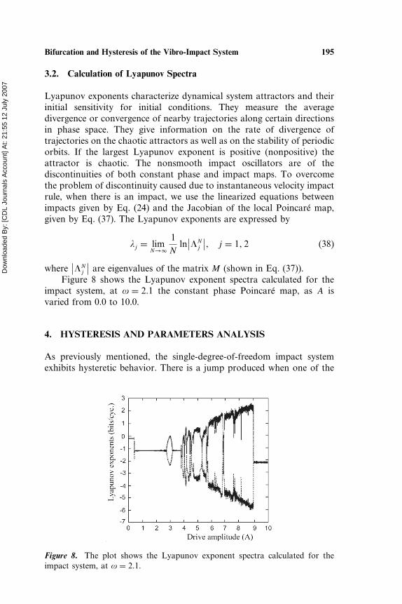
3.2. Calculation of Lyapunov Spectra
Lyapunov exponents characterize dynamical system attractors and theirinitial sensitivity for initial conditions. They measure the averagedivergence or convergence of nearby trajectories along certain directionsin phase space. They give information on the rate of divergence oftrajectories on the chaotic attractors as well as on the stability of periodicorbits. If the largest Lyapunov exponent is positive (nonpositive) theattractor is chaotic. The nonsmooth impact oscillators are of thediscontinuities of both constant phase and impact maps. To overcomethe problem of discontinuity caused due to instantaneous velocity impactrule, when there is an impact, we use the linearized equations betweenimpacts given by Eq. (24) and the Jacobian of the local Poincaré map,given by Eq. (37). The Lyapunov exponents are expressed by
�j = limN→�
1N
ln∣∣�N
j
∣∣� j = 1� 2 (38)
where∣∣�N
j
∣∣ are eigenvalues of the matrix M (shown in Eq. (37)).Figure 8 shows the Lyapunov exponent spectra calculated for the
impact system, at � = 2�1 the constant phase Poincaré map, as A isvaried from 0.0 to 10.0.
4. HYSTERESIS AND PARAMETERS ANALYSIS
As previously mentioned, the single-degree-of-freedom impact systemexhibits hysteretic behavior. There is a jump produced when one of the
Figure 8. The plot shows the Lyapunov exponent spectra calculated for theimpact system, at � = 2�1.
Dow
nloa
ded
By:
[CD
L Jo
urna
ls A
ccou
nt] A
t: 21
:55
12 J
uly
2007
196 Cheng and Xu
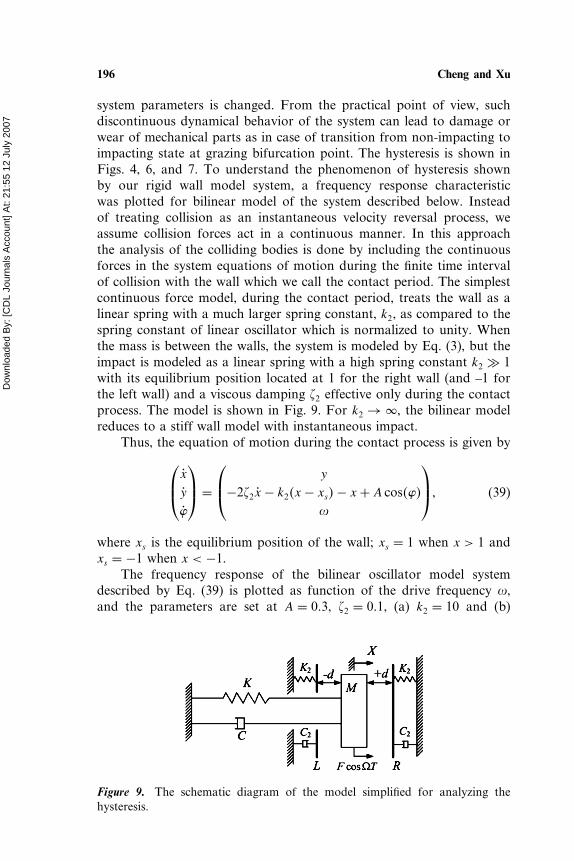
system parameters is changed. From the practical point of view, suchdiscontinuous dynamical behavior of the system can lead to damage orwear of mechanical parts as in case of transition from non-impacting toimpacting state at grazing bifurcation point. The hysteresis is shown inFigs. 4, 6, and 7. To understand the phenomenon of hysteresis shownby our rigid wall model system, a frequency response characteristicwas plotted for bilinear model of the system described below. Insteadof treating collision as an instantaneous velocity reversal process, weassume collision forces act in a continuous manner. In this approachthe analysis of the colliding bodies is done by including the continuousforces in the system equations of motion during the finite time intervalof collision with the wall which we call the contact period. The simplestcontinuous force model, during the contact period, treats the wall as alinear spring with a much larger spring constant, k2, as compared to thespring constant of linear oscillator which is normalized to unity. Whenthe mass is between the walls, the system is modeled by Eq. (3), but theimpact is modeled as a linear spring with a high spring constant k2 � 1with its equilibrium position located at 1 for the right wall (and –1 forthe left wall) and a viscous damping �2 effective only during the contactprocess. The model is shown in Fig. 9. For k2 → �, the bilinear modelreduces to a stiff wall model with instantaneous impact.
Thus, the equation of motion during the contact process is given byx
y
�
=
y
−2�2x − k2�x − xs�− x + A cos����
� (39)
where xs is the equilibrium position of the wall; xs = 1 when x > 1 andxs = −1 when x < −1.
The frequency response of the bilinear oscillator model systemdescribed by Eq. (39) is plotted as function of the drive frequency �,and the parameters are set at A = 0�3, �2 = 0�1, (a) k2 = 10 and (b)
Figure 9. The schematic diagram of the model simplified for analyzing thehysteresis.
Dow
nloa
ded
By:
[CD
L Jo
urna
ls A
ccou
nt] A
t: 21
:55
12 J
uly
2007
Bifurcation and Hysteresis of the Vibro-Impact System 197
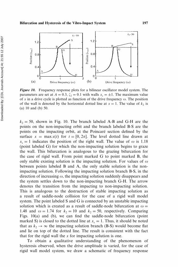
Figure 10. Frequency response plots for a bilinear oscillator model system. Theparameters are set at A = 0�3, �2 = 0�1 with walls xs = ±1. The maximum valueof x in a drive cycle is plotted as function of the drive frequency �. The positionof the wall is denoted by the horizontal dotted line at x = 1. The value of k2 is(a) 10 and (b) 50.
k2 = 50, shown in Fig. 10. The branch labeled A-B and G-H are thepoints on the non-impacting orbit and the branch labeled B-S are thepoints on the impacting orbit, at the Poincaré section defined by thesurface x = maxx�t� for t = �0� 2�. The level dotted line drawn atxs = 1 indicates the position of the right wall. The value of � is 1.18(point labeled G) for which the non-impacting solution begins to grazethe wall. This bifurcation is analogous to the grazing bifurcation forthe case of rigid wall. From point marked G to point marked B, theonly stable existing solution is the impacting solution. For values of �between points labeled B and A, the only stable solution is the non-impacting solution. Following the impacting solution branch B-S, in thedirection of increasing �, the impacting solution suddenly disappears andthe system settles down to the non-impacting branch G-H. The arrowdenotes the transition from the impacting to non-impacting solution.This is analogous to the destruction of stable impacting solution asa result of saddle-node collision for the case of a rigid wall modelsystem. The point labeled S and G is connected by an unstable impactingsolution which is created as a result of saddle-node bifurcation at � =1�48 and � = 1�74 for k2 = 10 and k2 = 50, respectively. ComparingFigs. 10(a) and (b), we can find the saddle-node bifurcation (pointmarked S) is closed to the dotted line at xs = 1. Thus, it should be notedthat as k2 → � the impacting solution branch (B-S) would become flatand lie on top of the dotted line. The result is consistent with the factthat for the rigid wall the x for impacting solution is one.
To obtain a qualitative understanding of the phenomenon ofhysteresis observed, when the drive amplitude is varied, for the case ofrigid wall model system, we draw a schematic of frequency response

Dow
nloa
ded
By:
[CD
L Jo
urna
ls A
ccou
nt] A
t: 21
:55
12 J
uly
2007
198 Cheng and Xu
Figure 11. A schematic of frequency response plot for a bilinear model systemdescribed by Eq. (36) for four different values of the drive amplitude, whereA1 < A2 < A3 < A4. The solid line plots represent the stable states of the systemand dashed line curve denote the unstable states. The horizontal dotted linerepresent the position of right wall at x = 1. The maximum value of thedisplacement of the oscillator in each drive cycle is plot against the value of thedrive frequency (�) for that cycle.
plots, for the case of bilinear model, for different values of the driveamplitude. Figure 11 shows the frequency response plot for four differentvalues of the drive amplitude, where A1 < A2 < A3 < A4. The positionof the right wall is shown as a horizontal dotted line. The solid curvesrepresent the stable orbits and the unstable solutions are denoted indashed lines. For fixed value of the drive frequency such as � = �1,the line shows the changes in the dynamical response of the system asthe amplitude is increased from A1 to A4 (points labeled P1, P2, P3, P4�
in Fig. 11. For the amplitude A1 at point P1 increasing to A2 at pointP2, the system is still at the non-impacting solution. As the amplitudeis increased to A3 the system just begins to graze with the wall (pointlabeled G) and jumps to the impacting solution represented as point P3.The line � = �2 denotes the effect of decreasing the amplitude from A4
to A1 corresponding to the jump from the impacting solution to the non-impacting solution. The system impacting orbit is destroyed at the pointS as a result of collision between stable and unstable impacting solutionand jumps to the non-impacting solution.
Through simplified the bilinear model system analysis, the systemtakes place the jump from the impacting solution to the non-impactingsolution at fixed frequency via altering the amplitude. The results aresame as ones of the model system in Fig. 1. We can find that the
Dow
nloa
ded
By:
[CD
L Jo
urna
ls A
ccou
nt] A
t: 21
:55
12 J
uly
2007
Bifurcation and Hysteresis of the Vibro-Impact System 199
model system applying the coefficient of restitution can be simplified thebilinear model system, and the time of impact can be considered.
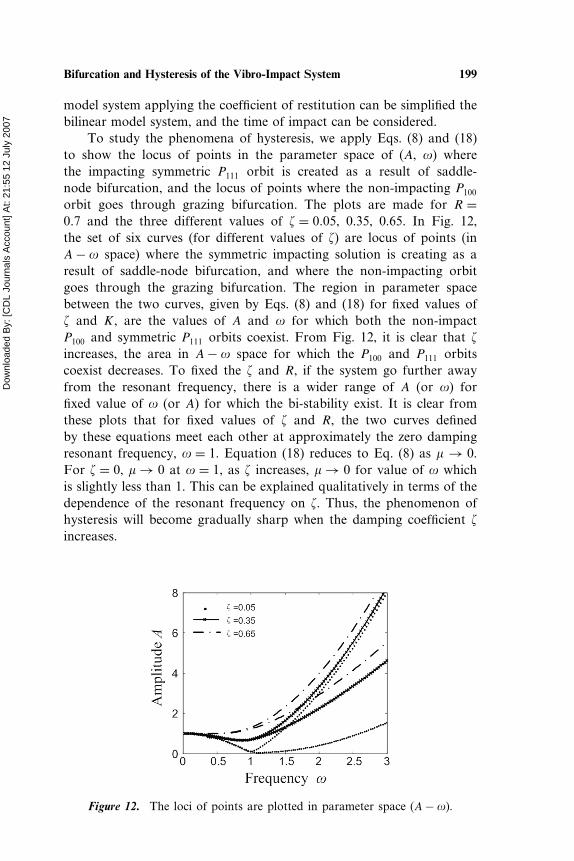
To study the phenomena of hysteresis, we apply Eqs. (8) and (18)to show the locus of points in the parameter space of (A, �) wherethe impacting symmetric P111 orbit is created as a result of saddle-node bifurcation, and the locus of points where the non-impacting P100
orbit goes through grazing bifurcation. The plots are made for R =0�7 and the three different values of � = 0�05, 0.35, 0.65. In Fig. 12,the set of six curves (for different values of �) are locus of points (inA− � space) where the symmetric impacting solution is creating as aresult of saddle-node bifurcation, and where the non-impacting orbitgoes through the grazing bifurcation. The region in parameter spacebetween the two curves, given by Eqs. (8) and (18) for fixed values of� and K, are the values of A and � for which both the non-impactP100 and symmetric P111 orbits coexist. From Fig. 12, it is clear that �
increases, the area in A− � space for which the P100 and P111 orbitscoexist decreases. To fixed the � and R, if the system go further awayfrom the resonant frequency, there is a wider range of A (or �) forfixed value of � (or A) for which the bi-stability exist. It is clear fromthese plots that for fixed values of � and R, the two curves definedby these equations meet each other at approximately the zero dampingresonant frequency, � = 1. Equation (18) reduces to Eq. (8) as � → 0.For � = 0, � → 0 at � = 1, as � increases, � → 0 for value of � whichis slightly less than 1. This can be explained qualitatively in terms of thedependence of the resonant frequency on �. Thus, the phenomenon ofhysteresis will become gradually sharp when the damping coefficient �
increases.
Figure 12. The loci of points are plotted in parameter space (A− �).
Dow
nloa
ded
By:
[CD
L Jo
urna
ls A
ccou
nt] A
t: 21
:55
12 J
uly
2007
200 Cheng and Xu
5. CONCLUSION
In this paper, the dynamical behaviors of the single-degree-of-freedomvibro-impact system are investigated in detail. We established thecorresponding Poincaré map section via the model analyzing and thephenomenon of hysteresis is observed by projected the position ofoscillator on the Poincaré section as a function of the drive amplitudeA. If the model system is provided with the stable priod-1 orbit, thecondition Eq. (18) must be satisfied via the model analytically analyzed.If the parameters meet the condition (18), the P111 and P100 orbitsare likely to coexist. We consider the derivation of the Jacobian ofthe local mapping in the neighborhood of a trajectory in the phasespace. This is necessary for local stability analysis of trajectories. ThePoincaré map for the linearized dynamics is obtained. The variousnumerical methods and the results of numerical simulation are applied tounderstand the rich dynamical behaviors. Some of the periodic attractorsof the system are exhibited by the phase plane projection. The transitionbetween various stable states is shown as function of drive amplitude.We show the bifurcation diagram at the Poincaré surface defined atconstant drive phase and observe various bifurcation behaviors of thesystem. The hysteresis observed at low drive amplitude can be of highpractical importance. Based on qualitative analysis, we can understandthe physical origin of hysteresis reported for the case of low amplitudevalues in terms of the similar hysteretic behavior of a driven nonlinearoscillator with a stiff spring. Using analytical results, the dependenceof hysteretic region in parameter space can be applied on other systemparameters. In particular, for fixed values of � and R, in A− � space, thehysteretic region is increased with increasing A and increasing � aboveresonant frequency. The effect of increasing damping ratio will decreasethe area of the hysteretic region in A− � space.
ACKNOWLEDGMENT
The authors gratefully acknowledge the support by the National NatureScience Foundation of China (No. 10372076).
REFERENCES
Babitsky, V. I. (1998). Hand-held percussion machine as discrete non-linear converter. Journal of Sound and Vibration 214:165–182.
Bapat, C. N. (1998). Periodic motion of an impact oscillator. Journal ofSound and Vibration 209:43–60.
Dow
nloa
ded
By:
[CD
L Jo
urna
ls A
ccou
nt] A
t: 21
:55
12 J
uly
2007
Bifurcation and Hysteresis of the Vibro-Impact System 201
Bapat, C. N., Sankar, S. (1985). Single unit impact damper in free andforced vibrations. Journal of Sound and Vibration 99:85–94.
Bapat, C. N., Popplewell, N., Mclachlan, K. (1983). Stable periodicmotion of an impact pair. Journal of Sound and Vibration87:19–40.
Bedout, J. M., Francheck, M. A., Bajaj, A. K. (1999). Robust controlof chaotic vibrations for impacting heat exchanger tubes in crossflow.Journal of Sound and Vibration 227:183–204.
Bishop, S. R., Wagg, D. J., Xu, D. (1998). Use of control to maintainperiod-1 motion during wind-up or wind-down operations of animpacting driven beam. Chaos, Solitions and Fractals 9:261–269.
Budd, C. J., Dux, F. (1994). Chattering and related behavior in impactoscillator. Philosophical Transactions of the Royal Society of LondonA 347:365–389.
Budd, C. J., Lee, A. G. (1996). Double impact orbits of periodicallyforced impact oscillator. Proceeding of the Royal Society London A452:2719–2750.
Chatterjee, S., Mallik, A. K. (1996). Bifurcations and chaos inautonomous self-excited oscillators with impact damping. Journal ofSound and Vibration 191:539–562.
Cone, K. M., Zadoks, R. I. (1995). The effect of frequency and clearancevariations on single-degree-of-freedom impact oscillators. Journal ofSound and Vibration 188:660–683.
Ding, W. C., Xie, J. H., Sun, Q. G. (2004). Interaction of Hopf andperiod doubling bifurcations of a vibro-impact system. Journal ofSound and Vibration 275:27–45.
Han, R. P. S., Luo, A. C. J., Deng, W. (1995). Chaotic motion of ahorizontal impact pair. Journal of Sound and Vibration 181:231–250.
Hogan, S. J., Homer, M. E. (1999). Graph theory and piecewisesmooth dynamical systems of arbitrary dimension. Chaos, Solitonsand Fractals 10:1869–1880.
Ivanov, A. P. (1993). Stabilization of an impact oscillator neargrazing incidence owing to resonance. Journal of Sound Vibration162:562–565.
Ivanov, A. P. (1996). Bifurcation in impact systems. Chaos, Solitons andFractals 7:1615–1634.
Jiang, D., Pierre, C., Shaw, S. W. (2005). Nonlinear normal modes forvibratory systems under harmonic excitation. Journal of Sound andVibration 288:791–812.
Luo, A. C. J. (2002). An unsymmetrical motion in a horizontal impactoscillator. ASME Journal of Vibration and Acoustics 124:420–426.
Luo, G. W. (2004a). Period-doubling bifurcations and routes tochaos of the vibratory systems contacting stops. Physics Letters A323:210–217.
Dow
nloa
ded
By:
[CD
L Jo
urna
ls A
ccou
nt] A
t: 21
:55
12 J
uly
2007
202 Cheng and Xu
Luo, A. C. J. (2004b). Periodic-doubling induced chaotic motion inthe LR model of a horizontal impact oscillator. Chaos, Solitons andFractals 19:823–839.
Luo, G. W., Xie, J. H. (2001). Bifurcations and chaos in a system withimpacts. Physica D 148:183–200.
Luo, A. C. J., Chen, L. D. (2005). Periodic motions and grazing in aharmonically forced, piecewise, linear oscillator with impacts. Chaos,Solitons and Fractals 24:567–578.
Han, R. P. S., Luo, A. C. J., Deng, W. (1995). Chaotic motion of ahorizontal impact pair. Journal of Sound and Vibration 181:231–250.
Hogan, S. J., Homer, M. E. (1999). Graph theory and piecewisesmooth dynamical systems of arbitrary dimension. Chaos, Solitonsand Fractals 10:1869–1880.
Nordmark, A. B. (1991). Non-periodic motion caused by grazingincidence in an impact oscillator. Journal of Sound and Vibration145:279–297.
Peterka, F. (1978). Existence and stability of self-excited vibrations withimpacts. Mechanism and Machine Theory 13:75–83.
Peterka, F. (1996). Bifurcation and transition phenomena in an impactoscillator. Chaos, Solitons and Fractals 7:1635–1647.
Peterka, F., Vcacik, J. (1992). Transition to chaotic motion in mechanicalsystems with impacts. Journal of Sound and Vibration 154:95–115.
Rega, G., Benedettini, F., Salvatori, A. (1991). Periodic and chaoticmotions of an unsymmetrical oscillator in nonlinear structuraldynamics. Chaos, Solitons and Fractals 1:39–54.
Shaw, S. W. (1985). Dynamics of harmonically excited systems havingrigid amplitude constraints. Part I-subharmonic motions and localbifurcations. Part II-subharmonic motions and local bifurcations.ASME Journal of Applied Mechanics 52:453–464.
Shaw, S. W., Holmes, P. J. (1983a). A periodically forced piecewise linearoscillator. Journal of Sound and Vibration 90:129–155.
Shaw, S. W., Holmes, P. J. (1983b). A periodically forced impactoscillator with large dissipation. ASME Journal of Applied Mechanics50:849–857.
Shaw, S. W., Holmes, P. J. (1983c). Periodically forced linear oscillatorwith impacts: chaos and long-peiod motions. Physical Review Letters51:623–626.
Souza, S. L. T., Caldas, I. L. (2004). Calculation of Lyapunov exponentsin system with impacts. Chaos, Solitons and Fractals 19:569–579.
Tatara, Y., Moriwaki, N. (1992). Study of impact of equivalent twobodies (coefficient of restitution of spheres of brass, lead, glassporcelain and agate and the material properties). Bulletin of the JapanSociety of Mechanical Engineers 25:631–637.
Dow
nloa
ded
By:
[CD
L Jo
urna
ls A
ccou
nt] A
t: 21
:55
12 J
uly
2007
Bifurcation and Hysteresis of the Vibro-Impact System 203
Wen, G. L. (2001). Codimension-2 hopf bifurcation of a two-degree-of-freedom vibro-impact system. Journal of Sound and Vibration242:475–485.
Whiston, G. S. (1987). Global dynamic of a vibro-impacting linearoscillator. Journal of Sound and Vibration 118:395–429.
Whiston, G. S. (1992). Singularities in vibro-impact dynamics. Journalof Sound and Vibration 152:427–460.
Xie, J H., Ding, W. C. (2005). Hopf-hopf bifurcation and invarianttorus T 2 of a vibro-impact system. International Journal of Non-linearMechanics 40:531–543.


