Embed Size (px)
Citation preview
Impedance matching for improving piezoelectric energy harvesting systems
Junrui Liang and Wei-Hsin Liao*
Smart Materials and Structures Laboratory, Department of Mechanical and Automation Engineering The Chinese University of Hong Kong, Shatin, N. T., Hong Kong, China
ABSTRACT
In a piezoelectric energy harvesting (PEH) system, the dynamics of the device as well as the energy flow within the system vary with different harvesting interface circuits connected. Meanwhile, the impedance matching theory is regarded as theoretical base for harvesting power enhancement, and hopefully could provide guidance for harvesting interface optimization. Most previous literatures on impedance matching for PEH started their analyses by assuming that the harvesting interface, which is nonlinear in nature, can be equalized to resistive load, or linear load whose impedance value can be arbitrarily set, so that the output impedance of the piezoelectric structure can surely be matched. Yet, after investigating the equivalent impedances of the existing harvesting interfaces, including standard energy harvesting (SEH), parallel synchronized switching harvesting on inductor (P-SSHI), and series synchronized switching harvesting on inductor (S-SSHI), we found that, their ranges are in fact limited. Therefore, to optimize the harvesting power, constrained matching instead of free matching should be adopted. In addition, we also clarify some confusing points in the previous literatures on impedance matching for energy harvesting. With the understanding on energy flow within piezoelectric devices, we know that only a portion of the extracted energy is able to be harvested, while the other is dissipated throughout the harvesting process. So even the extracted power from the source is maximized by matching the impedance; there is no guarantee that harvesting power is surely improved. The harvesting power also depends on the ratio between harvested energy and dissipated energy. These two issues discussed in this paper are crucial to improve the harvesting power and efficiency in piezoelectric energy harvesting systems.
Keywords: Piezoelectric, energy harvesting, equivalent impedance, impedance matching
1. INTRODUCTION Ambient energy harvesting provides the possibility that ambient energy in different forms (e.g., solar, thermal, wind, mechanical) is converted (usually into electrical energy), captured and stored. During the last few years, accompanying with the development on low power integrated circuits (ICs) and distributed wireless sensor networks (WSNs), researchers investigated how to better harvest the ambient energy. It is possible that someday the power units in different sensor nodes, which are mostly batteries nowadays, are able to be replaced by certain energy harvesting devices. With the self-powered nature, the sensor nodes can endure longer lifetime, become more flexible on installation, and eventually achieve higher autonomy.
Mechanical movement or vibration can be found everywhere in our daily life. It is one of the promising ambient sources to be explored [1]. Piezoelectric materials, as one of the important and commonly used electromechanical transducers, can be utilized to harvest energy from mechanical vibration sources. In terms of the complexity of the mechanical part, the piezoelectric harvester is the simplest compared to the electromagnetic and electrostatic ones; therefore, it is more welcome in small scale systems [2].
Figure 1 shows the configuration of a base excited piezoelectric energy harvesting (PEH) device. The main mechanical structure is a base excited cantilever; while the primary electrical circuit is a standard energy harvesting (SEH) interface. With its electromechanical coupling characteristic, the piezoelectric transducer links the mechanical and electrical parts in this system. The cantilever vibrates in response to the base excitation. Because of the vibration, alternating strain is produced in the piezoelectric element, which induces a periodic charge movement across the element. Different shunt circuits designed for different treatments are connected to the electrodes of the piezoelectric element to extract energy
* Corresponding author: Tel: (852) 2609 8341; Fax: (852) 2603 6002; E-mail: [email protected]
Active and Passive Smart Structures and Integrated Systems 2010, edited by Mehrdad N. Ghasemi-Nejhad, Proc. of SPIE Vol. 7643, 76430K · © 2010 SPIE · CCC code: 0277-786X/10/$18 · doi: 10.1117/12.847524
Proc. of SPIE Vol. 7643 76430K-1
Downloaded from SPIE Digital Library on 03 May 2010 to 137.189.101.43. Terms of Use: http://spiedl.org/terms

from the vibrating mechanical structure. The simplest shunt circuit is a resistor directly connected to the piezoelectric element, which is called resistive shunt damping (RSD). The extracted energy is directly dissipated in RSD; therefore this treatment is mostly utilized for vibration suppression. For PEH, as far as the target applications are low power electronics, which are usually powered by DC voltage source, an AC-DC conversion is necessary. SEH, as shown in Figure 1, is the most standard rectification interface. Besides, based on the capacitive nature of piezoelectric elements, more sophisticated semi-passive interface circuits were proposed to increase the harvesting capability, e.g., the parallel synchronized switching harvesting on inductor (P-SSHI) and the series synchronized switching harvesting on inductor (S-SSHI). It was claimed that the harvesting power can increase several hundred percents by implementing P-SSHI or S-SSHI compared to SEH [3].
The harvesting power improvement by modifying the interface circuit is significant. Yet, several questions are still open: Given a specific excitation applied to a specific structure, what is the maximum harvesting power? Is there any interface circuit can make this maximum power?
Several literatures discussed the limitation of the harvesting power by analyzing the ideal work cycle of the electrical parts. Y. Liu et al. proposed the so called active PEH, with which they claimed that the harvested power can be increased arbitrarily high without the limitation on power electronics efficiency [4]. Y.-P. Liu et al. reached a similar point, but they called their method as velocity-controlled PEH [5]. Earlier than those, W. Q. Liu et al. provided a similar analysis on the ideal work cycle [6]; but differently, they regarded the maximum parameters of a piezoelectric element, e.g., maximum strain, maximum field, maximum surface charge density and maximum stress, as the limitation of the electromechanical conversion. There are two common problems in these analyses. 1) These analyses have not considered the reaction of their treatments to the dynamics of the mechanical part. In real situation, as the extracted energy increases, the damping effect increases too, the vibration magnitude therefore is suppressed. Eventually some of the increase on extracted energy will be canceled out. 2) It is not true that the larger the area enclosed by the work cycle, the higher the harvesting power. The enclosed area corresponds to the extracted energy in one cycle, which should be subdivided into harvested portion and dissipated portion. Liang and Liao investigated the energy relation within a PEH device [7]. Without considering the mechanical dynamics and the energy flow in the system, the discussions on the limitation of harvesting power would be misleading.
A preferred investigation on the maximum harvesting power should take both the overall dynamics and the energy flow into account. The impedance matching is the most well known theory for load power optimization. It has been employed to investigate the maximum harvesting power issue [8]-[10]; nevertheless, three factors are ambiguous in their studies:
1) The definition of the impedance or equivalent impedance of a nonlinear PEH interface circuit. 2) The attainable ranges of the equivalent impedance of the electrical part under different interface circuits. 3) The objective of utilizing impedance matching theory in PEH.
In addition, there were also conflicts in utilizing the matching theory for power optimization in electromagnetic energy harvesting [11]. Concerning all the above-mentioned three issues, this paper proposes an investigation for clarification.
2. IMPEDANCE MODELING Nowadays, both the modeling techniques for pure mechanical structures and pure electrical circuits are of many options. Take the PEH device shown in Figure 1 for example. Its mechanical part is a cantilever beam, which has multiple vibration modes. The structural dynamics can be analyzed with either closed-form or numerical solution to the partial
Figure 1. A base excited PEH device.
Proc. of SPIE Vol. 7643 76430K-2
Downloaded from SPIE Digital Library on 03 May 2010 to 137.189.101.43. Terms of Use: http://spiedl.org/terms

differential equations (PDEs). Its electrical part is a conventional rectifier circuit, which is nonlinear in nature. The circuit waveforms can be obtained with piecewise circuit equations or circuit simulation software. Yet, when the two domains are bridged by the piezoelectric transducer, the situation becomes complicated. The dynamics of the whole electromechanical device would be hardly modeled accurately with these existing methods. The characteristics of multiple vibration modes on mechanical part and nonlinearity on electrical part obstruct the integration of their models. Up to now, nearly all studies emphasizing on the mechanical part adopted simplified electrical models, e.g., [12], [13]; while studies emphasizing on the electrical part adopted simplified mechanical models, e.g., [3], [14]. The majority of researches focused on either mechanical or electrical parts, but not both.
On the other hand, energy flow and impedance matching have been considered from the system level. To utilize the impedance matching, the first problem is: what are the impedances of different parts or components in the system? The equivalent circuit of the linear mechanical part is well established. With the mechanical to electrical analogy, each mode can be equivalently represented by a RLC path in the electrical domain. The corresponding resistance, inductance, and capacitance values can be obtained by experimental identification [15], analytical method [16], or numerical analysis [17]. Nevertheless, for the electrical part, in most literatures, the nonlinear interface circuit was taken as an equivalent resistance, i.e., impedance without imaginary part [9], [10]. On the other hand, Brufau-Penella and Puig-Vidal regarded it as complex impedance [8]. They proposed the complex conjugate impedance matching, rather than resistive impedance matching. However, they did the matching with a resistor and an inductor, whose values are able to be arbitrarily chosen, instead of considering the equivalent impedance of a real harvesting interface circuit. To determine the equivalent impedance of the electrical part is one of the keys in this paper.
2.1 Equivalent impedance in the mechanical part
Figure 2 gives the single degree-of-freedom (SDOF) schematic representation of the PEH device shown in Figure 1, where M, D, K, and Kp represent the first mode equivalent mass, mechanical damping (dissipation), substrate stiffness, piezoelectric short circuit stiffness, respectively; Cp is piezoelectric clamped capacitance; vp is the voltage across the piezoelectric element, and ip is the current flowing through the element; x = z - y is the relative displacement; αe is the force-voltage factor of the piezoelectric element.
The dynamics of the SDOF representation can be described by the following equations
( ) ( ) ( ) ( ) ( ) ( )( ) ( ) ( )⎪⎩
⎪⎨⎧
−=
−=++++
tvCtxtityMtvtxKKtxDtxM
ppep
pep
&&
&&&&&
α
α (1)
The schematic representation shows not only the simplified mechanical configuration and electrical connection of the device, but also the equivalent model of the piezoelectric element illustrating the coupling mechanism. Taking the Fourier transform of (1) and rearranging it, we have
( ) ( ) ( )
( ) ( ) ( )⎪⎩
⎪⎨
⎧
+=
=+⎟⎟⎠
⎞⎜⎜⎝
⎛++
ωωωω
ωωωω
ω
jVCjjIjI
jVjVjICj
RLj
pppeq
eqpeq1
(2)
Figure 2. SDOF schematic representation of a base excited PEH device.
Proc. of SPIE Vol. 7643 76430K-3
Downloaded from SPIE Digital Library on 03 May 2010 to 137.189.101.43. Terms of Use: http://spiedl.org/terms
where ω is the excitation frequency; and
( ) ( )tyMtve
eq &&α
−= , ( ) ( )txti eeq &α= , 2e
MLα
= , 2e
DRα
= , p
e
KKC
+=
2α , (3)
denote the equivalent voltage source, current, inductance, resistance, and capacitance, which corresponds to the base excitation, velocity, mass, damping, and stiffness in mechanical domain, respectively.
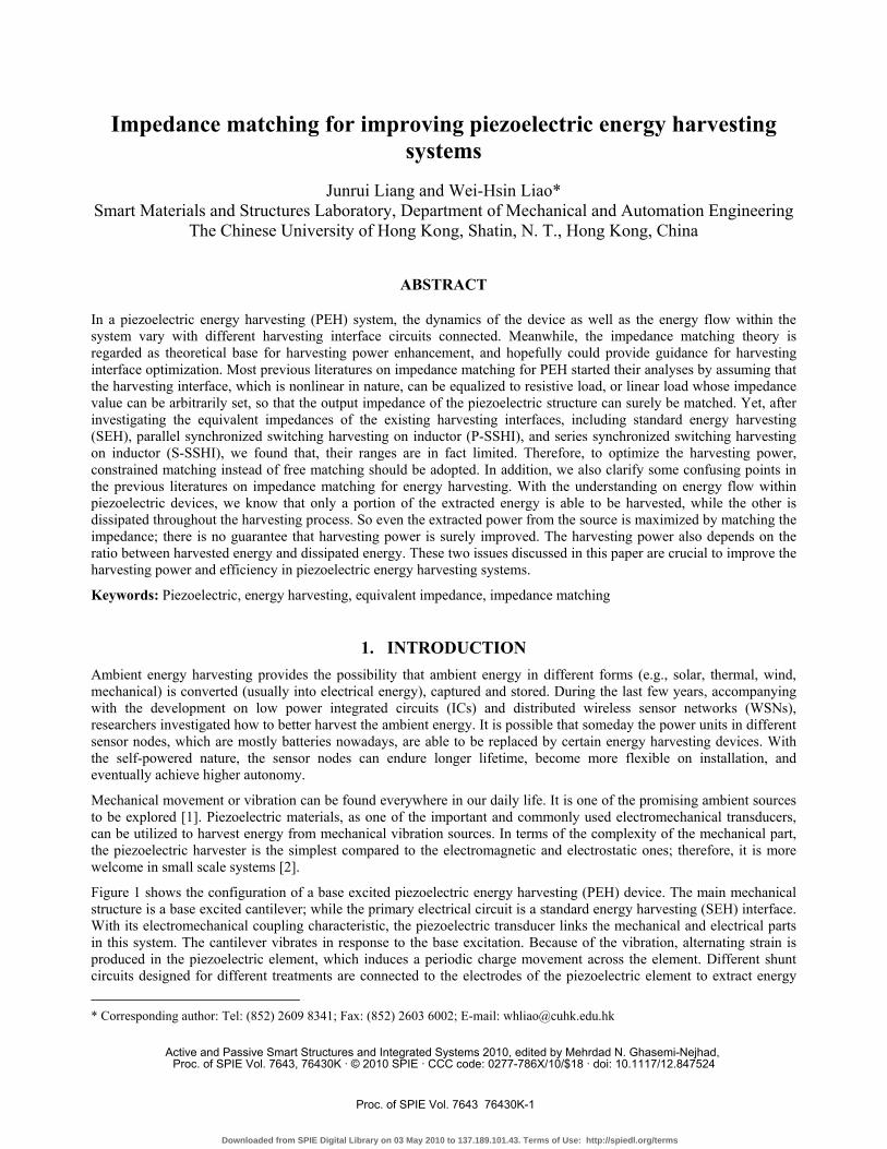
Two connection relations can be obtained from (2). With the voltage relation given by the first equation, the voltage source veq, L, R, C, and Cp are connected in series; while with the current relation given by the second equation, Cp and the SEH circuit are connected in parallel. With both the expressions on equivalent impedances in mechanical part and their connection relations, Figure 3 illustrates the equivalent circuit of the PEH device. In this figure, the electrical part, which is composed of Cp and the SEH interface circuit in parallel, is represented by an equivalent impedance, Zelec,.
2.2 Equivalent impedance of the electrical part
In section 2.1, the electrical part of the PEH device was denoted as Zelec. Yet, as we know, in circuit analysis, the concept of impedance is usually used for linear AC circuits to show the magnitude and phase relations between voltage and current. So strictly speaking, for all the AC to DC harvesting interfaces, even the simplest SEH, their behaviors cannot be completely shown by the concept of impedance. Simplification is made based on the assumption that the influence of higher-order harmonics produced by the harvesting circuit to the system is much smaller than that of the fundamental component. With this assumption, two simplified conditions are obtained.
1) The equivalent current ieq can be regarded as perfect sine wave. 2) Only the fundamental component of vp, which is denoted as vp,F, has an effect on the dynamic of the system.
Taking SEH for instance,
( ) ( )tItieq ωsin0= (4)
where I0 is the magnitude of the ieq (t). The voltage across the piezoelectric element can be described by the following piecewise equation:
( )
( )[ ]
( )[ ]
⎪⎪⎪⎪
⎩
⎪⎪⎪⎪
⎨
⎧
<≤+−
+<≤−−
<≤
<≤−−
=
;
;
πωθπ
θπωπωω
πωθ
θωωω
2,
;,cos1
,
;0,cos1
0
0
tV
ttCIV
tV
tVtCI
tv
rect
prect
rect
rectp
p
(5)
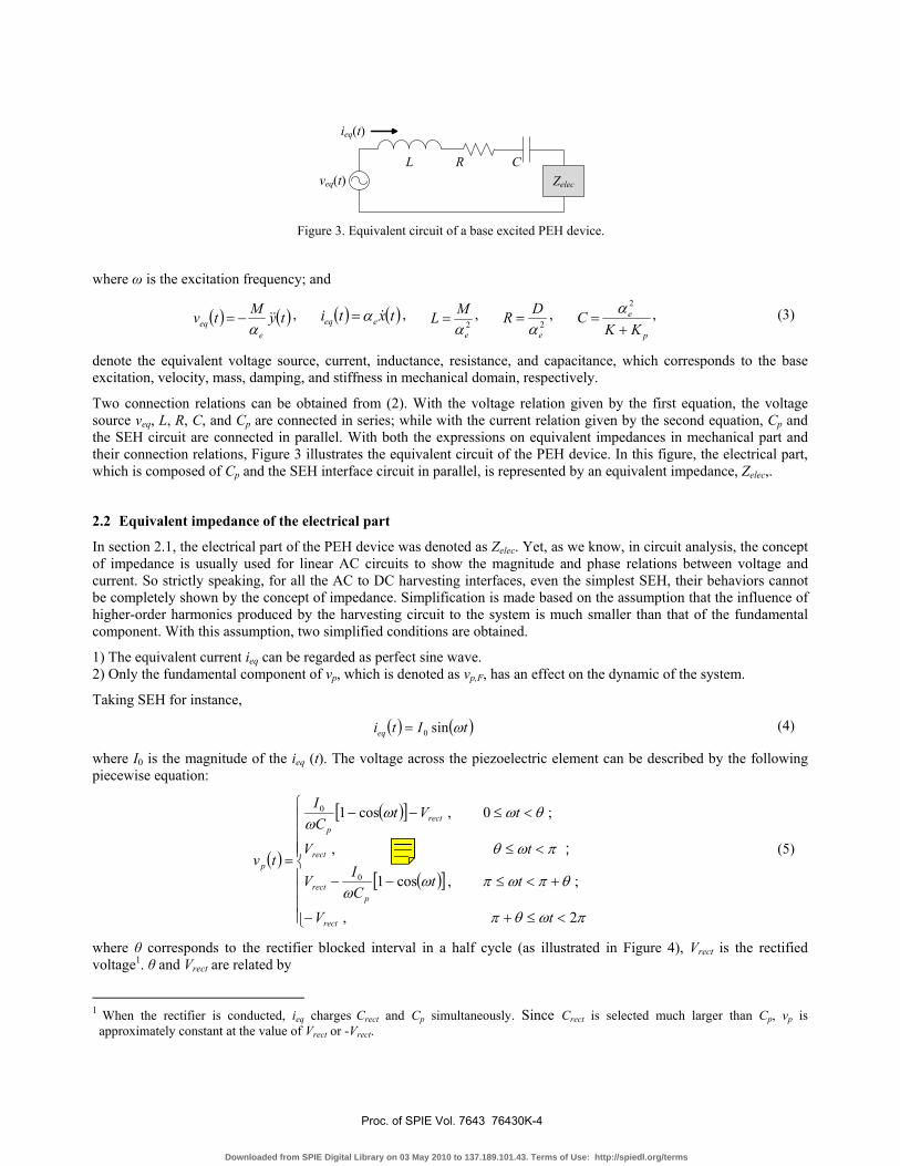
where θ corresponds to the rectifier blocked interval in a half cycle (as illustrated in Figure 4), Vrect is the rectified voltage1. θ and Vrect are related by
1 When the rectifier is conducted, ieq charges Crect and Cp simultaneously. Since Crect is selected much larger than Cp, vp is approximately constant at the value of Vrect or -Vrect.
L R C
ieq(t)
veq(t) Zelec
Figure 3. Equivalent circuit of a base excited PEH device.
Proc. of SPIE Vol. 7643 76430K-4
Downloaded from SPIE Digital Library on 03 May 2010 to 137.189.101.43. Terms of Use: http://spiedl.org/terms
rectV~21cos −=θ . (6)
rectV~ is the non-dimensional rectified voltage defined as
0
~I
CVV prect
rect
ω= . (7)
The rectified voltage Vrect is the sum of Vstore (the voltage across Crect) and VF (the forward voltage drop of the bridge rectifier). According to (5), the expression on the fundamental component of vp is obtained as
( ) ( )[ ] ( ) ( ) ttC
Itvp
Fp ωθωθθπω
sinsin2cos22sin2
20, +−= (8)
Figure 4 shows the waveforms of ip, vp, and vp,F under a certain Vrect in one vibration cycle. The equivalent impedance of the electrical part is obtained with the Fourier transform of (4) and (8)
( ) ( )( ) ( )[ ]θθθθ
πωωω
ω −+== cossinsin1 2, jCjI
jVjZ
peq
Fpelec
(9)
When the excitation frequency ω is fixed, Zelec is independent of the voltage source, but merely depends on θ. The equivalent impedances with other harvesting interface circuits can also be obtained with this method.
3. RANGE OF EQUIVALENT IMPEDANCE The ranges of the electrical equivalent impedance with four different interface circuits, i.e. SEH, RSD, P-SSHI, and S-SSHI, will be compared and discussed in this section. The interface circuits of RSD, P-SSHI, and S-SSHI are shown in Figure 5.
Figure 4. Characteristic voltage and current waveforms in SEH.
Crect Rload
sw
Li
Crect Rload
sw Li
(a) (b) (c)
Figure 5. Circuit topologies of RSD, P-SSHI, and S-SSHI. (a) RSD. (b) P-SSHI. (c) S-SSHI.
Proc. of SPIE Vol. 7643 76430K-5
Downloaded from SPIE Digital Library on 03 May 2010 to 137.189.101.43. Terms of Use: http://spiedl.org/terms
In linear RSD, the electrical part is composed of Cp and RRSD connected in parallel. Its impedance is
( ) ⎟⎟⎠
⎞⎜⎜⎝
⎛+
−+
= 2
2
2 111
ρρ
ρρ
ωω j
CjZ
pelec
, (10)
where
RSDpRCωρ = (11)
is the non-dimensional shunt resistance in RSD.
The SSHI interface circuit is constructed by adding a synchronized switching path to the SEH one. By carrying out the switching actions once the displacement x reaches its extreme values, it intervenes in the transduction process in a semi-passive way, so as to increase the harvesting power. The detailed principles and advantages of P-SSHI and S-SSHI have been investigated [3], [7], [14]. With the same method, the equivalent impedance of the electrical part in SEH, the P-SSHI and S-SSHI interfaces can also be studied. In P-SSHI, the equivalent impedance of the electrical part is obtained as
( ) ( ) ⎥⎦
⎤⎢⎣
⎡⎟⎠⎞
⎜⎝⎛ −+⎟⎟
⎠
⎞⎜⎜⎝
⎛+−
+−= θθθ
γθ
πωω 2sin
21cos1
14cos11 j
CjZ
pelec
. (12)
Different from SEH, in P-SSHI, θ and Vrect are related by
( ) rectV~11cos γθ +−= . (13)
In S-SSHI, the equivalent impedance is obtained as
( ) ( ) ⎥⎦
⎤⎢⎣
⎡−−
+−
= jVC
jZ rectp
elec~1
1141
γγ
πωω . (14)
In (12) - (14), γ is the voltage inversion factor in every switching action, which was defined in [7].
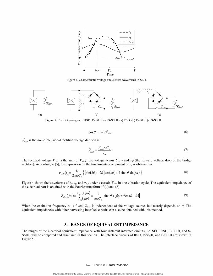
According to (9), (10), (12), and (14), Figure 6 shows the electrical part equivalent impedance of the four interface circuits on the normalized complex impedance plane. Only points on the corresponding curve are attainable for a certain interface circuit. Therefore, the range is constrained, rather than able to be arbitrarily set.
Comparisons between SEH and RSD have been made [7], [9], [10], [19]. It has been shown that the performances of SEH and RSD are different; the ratio between their maximum extractable powers is 2/π. From Figure 6, the impedance ranges of SEH and RSD are not overlapped except for the points corresponding to short and open circuits; therefore, their responses to the same excitation are again shown to be different. The real component of the equivalent impedance is related to the load power. In a general matching case, it is not necessary that the larger the real component, the more power delivered. But in a low coupling system, the equivalent source resistance, e.g., R in Figure 3, is much larger than the real component of Zelec. In this condition, the larger the real component, the more the power delivered to the electrical part. Therefore, the maximum extractable power of RSD is larger than SEH. Both P-SSHI and S-SSHI can greatly
Figure 6. Available impedance ranges of four interface circuits.
Proc. of SPIE Vol. 7643 76430K-6
Downloaded from SPIE Digital Library on 03 May 2010 to 137.189.101.43. Terms of Use: http://spiedl.org/terms
increase the real component of the equivalent impedance (the smaller the inversion factor γ, the larger the increase on the real component); therefore, the extracted power can be increased by P-SSHI and S-SSHI.
4. IMPEDANCE MATCHING The equivalent impedances of both the mechanical and electrical parts were obtained; further investigation on how to utilize the impedance matching to improve the harvesting power will be carried out.
4.1 Objective of impedance matching in energy harvesting
The objective of impedance matching for a general system is to maximize the power that delivered to the load. But in the energy harvesting system, the objective is vague. Various researchers have made conflicting claims [11]. The reason is attributed to the ambiguous understanding on the concept of load in energy harvesting. In a conventional system, load consumes all the power that is extracted from the system. Whereas, in a harvesting system, the concern is how much energy is scavenged rather than consumed. The harvested energy is only one portion of the extracted energy. Clarification on energy flow is crucial towards straightening out the objective of impedance matching in energy harvesting.
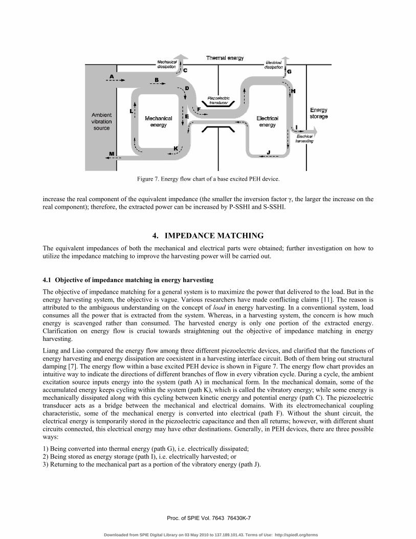
Liang and Liao compared the energy flow among three different piezoelectric devices, and clarified that the functions of energy harvesting and energy dissipation are coexistent in a harvesting interface circuit. Both of them bring out structural damping [7]. The energy flow within a base excited PEH device is shown in Figure 7. The energy flow chart provides an intuitive way to indicate the directions of different branches of flow in every vibration cycle. During a cycle, the ambient excitation source inputs energy into the system (path A) in mechanical form. In the mechanical domain, some of the accumulated energy keeps cycling within the system (path K), which is called the vibratory energy; while some energy is mechanically dissipated along with this cycling between kinetic energy and potential energy (path C). The piezoelectric transducer acts as a bridge between the mechanical and electrical domains. With its electromechanical coupling characteristic, some of the mechanical energy is converted into electrical (path F). Without the shunt circuit, the electrical energy is temporarily stored in the piezoelectric capacitance and then all returns; however, with different shunt circuits connected, this electrical energy may have other destinations. Generally, in PEH devices, there are three possible ways:
1) Being converted into thermal energy (path G), i.e. electrically dissipated; 2) Being stored as energy storage (path I), i.e. electrically harvested; or 3) Returning to the mechanical part as a portion of the vibratory energy (path J).
Figure 7. Energy flow chart of a base excited PEH device.
Proc. of SPIE Vol. 7643 76430K-7
Downloaded from SPIE Digital Library on 03 May 2010 to 137.189.101.43. Terms of Use: http://spiedl.org/terms
EISCLC9I b
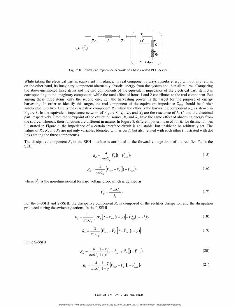
While taking the electrical part as equivalent impedance, its real component always absorbs energy without any return; on the other hand, its imaginary component alternately absorbs energy from the system and then all returns. Comparing the above-mentioned three items and the two components of the equivalent impedance of the electrical part, item 3 is corresponding to the imaginary component; while the total effect of items 1 and 2 contributes to the real component. But among these three items, only the second one, i.e., the harvesting power, is the target for the purpose of energy harvesting. In order to identify this target, the real component of the equivalent impedance Zelec should be further subdivided into two. One is the dissipative component Rd, while the other is the harvesting component Rh, as shown in Figure 8. In the equivalent impedance network of Figure 8, XL, XC, and XE are the reactance of L, C, and the electrical part, respectively. From the viewpoint of the excitation source, Rd and Rh have the same effect of absorbing energy from the source; whereas, their functions are different in nature. In Figure 8, different pattern is used for Rh for distinction. As illustrated in Figure 6, the impedance of a certain interface circuit is adjustable, but unable to be arbitrarily set. The values of Rd, Rh and XE are not only variables (denoted with arrows), but also related with each other (illustrated with dot links among the three components).
The dissipative component Rd in the SEH interface is attributed to the forward voltage drop of the rectifier VF. In the SEH
( )rectFp
d VVC
R ~1~4−=
πω, (15)
( )( )rectFrectp
h VVVC
R ~1~~4−−=
πω. (16)
where FV~ is the non-dimensional forward voltage drop, which is defined as
0
~I
CVV pF
F
ω= . (17)
For the P-SSHI and S-SSHI, the dissipative component Rd is composed of the rectifier dissipation and the dissipation produced during the switching actions. In the P-SSHI
( )[ ] ( ) 22 1~1~2~21 γγπω
−++−= rectrectFp
d VVVC
R , (18)
( ) ( )[ ]γπω
+−−= 1~2~~2rectFrect
ph VVV
CR . (19)
In the S-SSHI
( )( )rectFrectp
d VVVC
R ~1~~1114
−+−+−
=γγ
πω, (20)
( )( )rectFrectp
h VVVC
R ~1~~114
−−+−
=γγ
πω. (21)
Figure 8. Equivalent impedance network of a base excited PEH device.
Proc. of SPIE Vol. 7643 76430K-8
Downloaded from SPIE Digital Library on 03 May 2010 to 137.189.101.43. Terms of Use: http://spiedl.org/terms
4.2 Constrained impedance matching
Based on the energy flow in a PEH system, the harvesting power is obtained as:
2 2
2 2 22 2 ( ) ( )eq eqh h
hL C E d hsys
V VR RPX X X R R RZ
= =+ + + + +
(22)
where Veq is the magnitude of the equivalent voltage source, which is constant for the base excited case; Zsys denotes the total input impedance of the system, from the view of veq.
For a general case of impedance matching, the maximum Ph can be achieved under the condition that
2 2( ) ( )h d L C E sys hR R R X X X Z R= + + + + = − (23)
However, for a practical harvesting device, the condition provided by (23) is hardly satisfied. Due to the low coupling coefficient, the magnitudes of XL, XC, and R are usually much larger than that of Zelec. On the other hand, even some advanced interface circuits, e.g., P-SSHI and S-SSHI, can enlarge the magnitude of Zelec; its magnitude is still limited, and the range of Zelec is constrained on the corresponding curve.
Therefore, in harvesting power optimization, a constrained matching, instead of free matching, should be used, i.e.,
max , s. t. the constraints on , , and h d h EP R R X . (24)
In this PEH study, Ph is the most direct index for harvesting power optimization. It can be expressed as functions of some tunable parameters in a harvesting interface circuit. In all the three interfaces of SEH, P-SSHI, and S-SSHI, the tunable ranges are limited (only one tunable parameter). The non-dimensional rectified voltage rectV~ is the most representative tunable parameter within these three interface circuits.
5. EXPERIMENTS Experiments are carried out with a base excited piezoelectric energy harvester for three cases. In each case, one of the interface circuits among SEH, P-SSHI, and S-SSHI is connected to the piezoelectric cantilever. The harvesting power is theoretically obtained as functions of rectV~ . The actual harvesting power is experimentally measured for comparison.
Figure 9. Experimental setup.
Proc. of SPIE Vol. 7643 76430K-9
Downloaded from SPIE Digital Library on 03 May 2010 to 137.189.101.43. Terms of Use: http://spiedl.org/terms

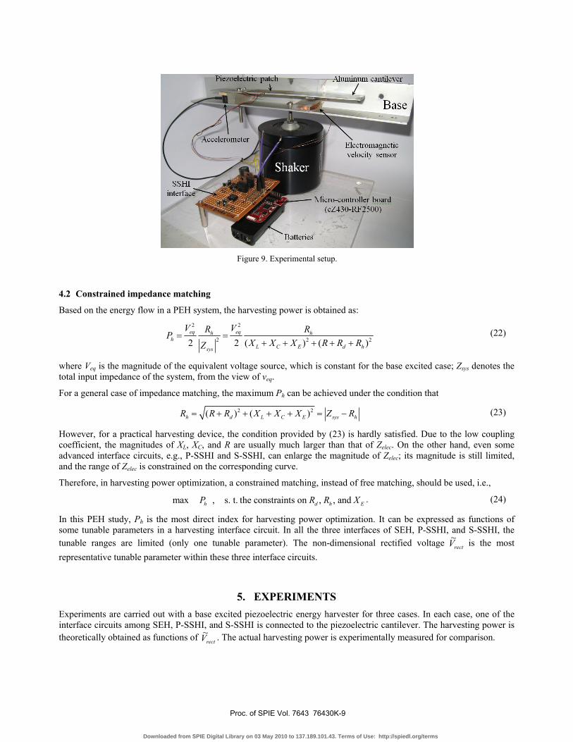
5.1 Experimental setup
Figure 9 shows the experimental setup. The main mechanical structure is an aluminum cantilever, whose excitation is from a shaker (4810, B & K). A piezoceramic patch of 49mm x 24mm x 0.508mm (T120-A4E-602, Piezo System, Inc.) is bonded near the fixed end. An accelerometer (4501, B & K) is installed at the fixed end to track the base acceleration. For the purpose of synchronization in both P-SSHI and S-SSHI, an electromagnetic sensor is employed to sense the relative velocity between the cantilever beam and the base. The permanent magnet acts as proof mass at the same time. It can lower the vibration frequency and increase the displacement of the free end. The output voltage from the coil, which is proportional to the end velocity, is then input to a micro-controller unit (eZ430-RF2500, Texas Instrument). In the circuitry part, the micro-controller is coded to firstly analyze the velocity signal, and then generate switching command to drive the MOSFET switch to perform synchronized switching actions. Table 1 gives the parameters of the experimental setup, including mechanical structure and interface circuit.
The equivalent impedance of the mechanical part is obtained with experimental identification. Without excitation applied and shunt circuit connected, the internal impedance of the piezoelectric structure can be derived from Figure 3. It was also known as the Van Dyke’s model [15]. The internal impedance is measured with an impedance analyzer (4294A, Agilent). Based on the Van Dyke’s model, the component values are obtained by fitting the experimental waveforms. The values are also listed in Table 1.
5.2 Results
Given a 42 Hz and 10 m/s2 (in RMS) harmonic base excitation, the harvesting power Ph under different rectV~ is studied both theoretically and experimentally. In experiments, different DC load resistors Rload are connected one after another to stabilize the Vstore at different levels. The corresponding experimental Ph is obtained with
load
storeh R
VP2
= . (25)
As for the measurement of rectV~ , Vrect is the sum of Vstore and VF (1.0 V for the bridge rectifier we used), but I0 changes under different Vrect. It is better to take the rectifier blocked interval θ/ω as the direct measured parameter in SEH and P-SSHI, then obtain rectV~ with (6) and (13). For S-SSHI, there is no conduction angle θ, but I0/(ωCp) can be directly measured from the waveform.
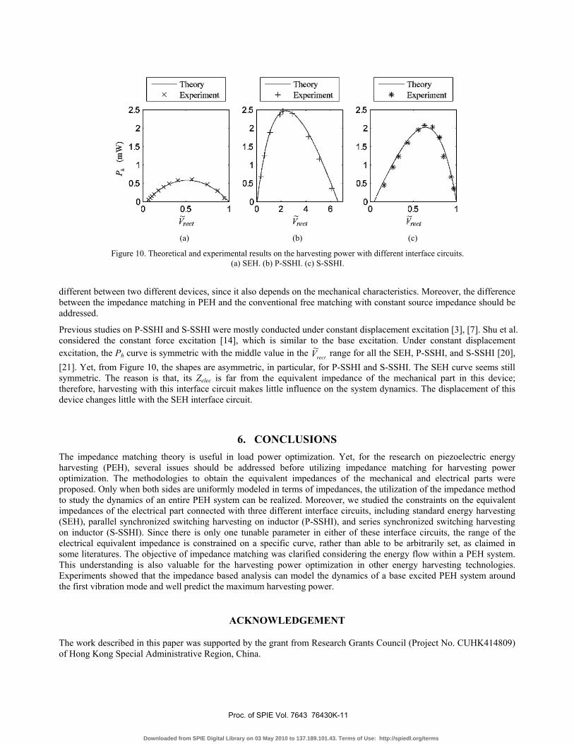
The theoretical and experimental results on the harvesting power are shown in Figure 10 for comparison. The theoretical results match the experimental data very well. The P-SSHI provides the maximum harvestable power among the three cases. For this specific based excited PEH device, the improvement of implementing P-SSHI and S-SSHI, compared to SEH, is about 500% and 400%, respectively. The improvement in implementing these two interfaces, yet, might be
Table 1. Parameters of the experimental setup.
Parameter Value αe 4.75*10-4 N/V f0 42.76 Hz sw MOSFET (IRL510)
Rectifier DB104 (VF = 1.0V) γ - 0.7 Li 47 mH
Crect 1, 10, 22 μF Cp 34.69 nF L 31 kH C 448 pF R 1 MΩ
Proc. of SPIE Vol. 7643 76430K-10
Downloaded from SPIE Digital Library on 03 May 2010 to 137.189.101.43. Terms of Use: http://spiedl.org/terms
different between two different devices, since it also depends on the mechanical characteristics. Moreover, the difference between the impedance matching in PEH and the conventional free matching with constant source impedance should be addressed.
Previous studies on P-SSHI and S-SSHI were mostly conducted under constant displacement excitation [3], [7]. Shu et al. considered the constant force excitation [14], which is similar to the base excitation. Under constant displacement excitation, the Ph curve is symmetric with the middle value in the rectV~ range for all the SEH, P-SSHI, and S-SSHI [20], [21]. Yet, from Figure 10, the shapes are asymmetric, in particular, for P-SSHI and S-SSHI. The SEH curve seems still symmetric. The reason is that, its Zelec is far from the equivalent impedance of the mechanical part in this device; therefore, harvesting with this interface circuit makes little influence on the system dynamics. The displacement of this device changes little with the SEH interface circuit.
6. CONCLUSIONS The impedance matching theory is useful in load power optimization. Yet, for the research on piezoelectric energy harvesting (PEH), several issues should be addressed before utilizing impedance matching for harvesting power optimization. The methodologies to obtain the equivalent impedances of the mechanical and electrical parts were proposed. Only when both sides are uniformly modeled in terms of impedances, the utilization of the impedance method to study the dynamics of an entire PEH system can be realized. Moreover, we studied the constraints on the equivalent impedances of the electrical part connected with three different interface circuits, including standard energy harvesting (SEH), parallel synchronized switching harvesting on inductor (P-SSHI), and series synchronized switching harvesting on inductor (S-SSHI). Since there is only one tunable parameter in either of these interface circuits, the range of the electrical equivalent impedance is constrained on a specific curve, rather than able to be arbitrarily set, as claimed in some literatures. The objective of impedance matching was clarified considering the energy flow within a PEH system. This understanding is also valuable for the harvesting power optimization in other energy harvesting technologies. Experiments showed that the impedance based analysis can model the dynamics of a base excited PEH system around the first vibration mode and well predict the maximum harvesting power.
ACKNOWLEDGEMENT
The work described in this paper was supported by the grant from Research Grants Council (Project No. CUHK414809) of Hong Kong Special Administrative Region, China.
(a) (b) (c)
Figure 10. Theoretical and experimental results on the harvesting power with different interface circuits. (a) SEH. (b) P-SSHI. (c) S-SSHI.
Proc. of SPIE Vol. 7643 76430K-11
Downloaded from SPIE Digital Library on 03 May 2010 to 137.189.101.43. Terms of Use: http://spiedl.org/terms

REFERENCES
[1] Anton, S. R. and Sodano, H. A., “A review of power harvesting using piezoelectric materials (2003-2006),” Smart Materials and Structures, 16(3), R1-R21 (2007).
[2] Beeby, S., Tudor, M. and White, N., “Energy harvesting vibration sources for microsystems applications,” Measurement Science and Technology, 17(12), R175-R195 (2006).
[3] Lefeuvre, E., Badel, A., Richard, C., Petit, L. and Guyomar, D., “A comparison between several vibration-powered piezoelectric generators for standalone systems,” Sensors and Actuators A: Physical, 126(2), 405–416 (2006).
[4] Liu, Y., Tian, G., Wang, Y., Lin, J., Zhang, Q. and Hofmann, H. F., “Active piezoelectric energy harvesting: general principle and experimental demonstration,” Journal of Intelligent Material Systems and Structures, 20, 575-585 (2009).
[5] Liu, Y.-P., Vasic, D., Costa, F., Wu, W.-J. and Lee, C. K., “Velocity-controlled piezoelectric switching energy harvesting device,” International Conference on Renewable Energies and Power Quality ICREPQ (2009).
[6] Liu, W. Q., Feng, Z. H., He, J. and Liu, R. B., “Maximum mechanical energy harvesting strategy for a piezoelement,” Smart Materials and Structures, 16, 2130-2136 (2007).
[7] Liang, J. R. and Liao, W. H. “Piezoelectric energy harvesting and dissipation on structural damping,” Journal of Intelligent Material Systems and Structures, 20, 515-527 (2009).
[8] Brufau-Penella, J. and Puig-Vidal, M. “Piezoelectric energy harvesting improvement with complex conjugate impedance matching,” Journal of Intelligent Material Systems and Structures, 20, 597-608 (2009).
[9] Kim, H., Priya, S., Stephanou, H. and Uchino, K. “Consideration of impedance matching techniques for efficient piezoelectric energy harvesting,” IEEE Transactions on Ultrasonics, Ferroelectrics and Frequency Control, 54, 1851-1859 (2007).
[10] Kong, N., Ha, D. S., Erturk, A. and Inman, D. J. “Resistive impedance matching circuit for piezoelectric energy harvesting,” Journal of Intelligent Material Systems and Structures (OnlineFirst), 1045389X09357971 (2010).
[11] Stephen, N. “On energy harvesting from ambient vibration,” Journal of Sound and Vibration, 293, 409-425 (2006). [12] Erturk, A. and Inman, D. “On mechanical modeling of cantilevered piezoelectric vibration energy harvesters,”
Journal of Intelligent Material Systems and Structures, 19, 1311-1325 (2008). [13] Zhu, M., Worthington, E. and Njuguna, J. “Analyses of power output of piezoelectric energy-harvesting devices
directly connected to a load resistor using a coupled piezoelectric-circuit finite element method,” IEEE Transactions on Ultrasonics, Ferroelectrics and Frequency Control, 56, 1309-1317 (2009).
[14] Shu, Y. C., Lien, I. C., and Wu, W. J. “An improved analysis of the SSHI interface in piezoelectric energy harvesting,” Smart Materials and Structures, 16, 2253-2264 (2007).
[15] Guan, M. J. and Liao, W. H. “On the equivalent circuit models of piezoelectric ceramics,” Ferroelectrics, 386, 77-87 (2009).
[16] Elvin, N. G. and Elvin, A. A. “A general equivalent circuit model for piezoelectric generators,” Journal of Intelligent Material Systems and Structures, 20, 3-9 (2009).
[17] Yang, Y. and Tang, L. “Equivalent circuit modeling of piezoelectric energy harvesters,” Journal of Intelligent Material Systems and Structures, 20, 2223-2235 (2009).
[18] Priya, S. and Inman, D. J., Energy Harvesting Technologies, Spring, Chapter 4 (2009). [19] Lesieutre, G. A., Ottman, G. K. and Hofmann, H. F. “Damping as a result of piezoelectric energy harvesting,”
Journal of Sound and Vibration, 269, 991-1001 (2004). [20] Badel, A., Benayad, A., Lefeuvre, E., Lebrun, L., Richard, C. and Guyomar, D. “Single crystals and nonlinear
process for outstanding vibration-powered electrical generators,” IEEE Transactions on Ultrasonics, Ferroelectrics and Frequency Control 53, 673-684 (2006).
[21] Liang, J. R. and Liao, W. H. “On the energy flow in piezoelectric energy harvesting with SSHI interface,” Proceedings of the 19th International Conference on Adaptive Structures and Technologies, Ascona, Switzerland (2008).
Proc. of SPIE Vol. 7643 76430K-12
Downloaded from SPIE Digital Library on 03 May 2010 to 137.189.101.43. Terms of Use: http://spiedl.org/terms


