Embed Size (px)
Citation preview
AM
HRRPKe
AMBTHe
MFRTHe
Mtasirafst�
1
toranfeutnsd
ats
Jmdn
J
Downlo
rchitectures of Translational Parallelechanism for MEMS Fabrication
agay BambergerAFAEL-Advanced Defense Systems Ltd.,obotics Laboratory-Technion,.O. Box 5218,far Hasidim 20400, Israel
-mail: [email protected]
lon Wolfem. ASMEiorobotics and Biomechanics Lab,echnion,aifa 32000, Israel
-mail: [email protected]
oshe Shohamellow ASMEobotics Laboratory,echnion,aifa 32000, Israel
-mail: [email protected]
anufacturing techniques, especially in the microscale, determinehe type of joints, links, and actuators available for the designer,nd as a result, the possible kinematic architectures of the de-igned mechanism. This paper discusses the design constraintsmposed by current microelectromechanical system (MEMS) fab-ication techniques, and how they affect the feasible kinematicrchitectures of microrobots. In particular, three degree-of-reedom translational mechanisms are investigated, and all pos-ible nonoverconstrained kinematic architectures under limita-ions imposed by MEMS fabrication techniques are derived.DOI: 10.1115/1.2936933�
IntroductionMicroelectromechanical system �MEMS� is a relatively new
echnology, enabling fabrication of miniature mechanical devicesn silicon wafers. Most fabrication methods are based on lithog-aphy, which produces two-dimensional shapes by layer etchingnd deposition. Consequently, MEMS devices usually have a pla-ar geometry, making it difficult to construct mechanisms that areully three dimensional. The hinge design presented in Ref. �1�nabled, for the first time, the production of spatial mechanismssing surface micromachining. The hinge element is fabricated inhe substrate plane, but it is free to rotate out of the plane. Con-ecting several of these hinges in a kinematical chain results in atructure that can be lifted off the plane, thus yielding a three-imensional mechanism.
The components that constitute mechanisms are links, joints,nd actuators. When dealing with microsystems, the fabricationechniques are of utmost importance for the mechanism designersince not all of the components can be realized by MEMS tech-
Contributed by the Mechanisms and Robotics Committee for publication in theOURNAL OF MECHANICAL DESIGN. Manuscript received September 9, 2007; finalanuscript received March 26, 2008; published online July 11, 2008. Review con-
ucted by Larry L. Howell. Paper presented at the 12th World Congress in Mecha-
ism and Machine Science �IftoMM� 2007.ournal of Mechanical Design Copyright © 20
aded 11 Jul 2008 to 132.68.247.8. Redistribution subject to ASME
nology, which is the leading manufacturing technique for milimet-ric and submilimetric scale. Hence, manufacturing technology de-termines what types of links, joints, and actuators are at thedesigner disposal, which in turn affects the feasible kinematicarchitectures.
Universal joints and spherical joints, having two and three de-grees of freedom �DOFs� respectively, are very rare and hard tomanufacture using the current MEMS fabrication techniques. Onthe other hand, a simple revolute joint, whose axis is parallel tothe substrate plane, is possible. This kind of joint enables a verylarge angle of revolution, even greater than 180 deg �1�.
Electrostatic actuation �2� is a very common method, based ontechniques derived from integrated circuit fabrication. Although avariety of geometries of electrostatic actuators have been devel-oped, the linear design is the most commonly used, enabling rela-tively large displacements. This type of actuator can also be de-signed to enable bidirectional translation. Most actuatorsdeveloped in MEMS are built on the silicon substrate and theirstators are not raised above that plane. Therefore, it is preferableto use this common design to produce actuators that are linear andare located at the base of the mechanism. The architecture de-scribed in Ref. �3� is not suitable for MEMS fabrication, since theactuators do not lie in the same plane.
In Ref. �2�, a translational three DOF MEMS mechanism wasconstructed using few simple revolute and compliant joints. Themechanism architecture is very simple, yielding simple inverseand direct kinematic solutions. One major advantage of this de-sign is that the moving platform can be lifted off the plane by itsown actuators. However, in order for the platform to have a rea-sonable workspace, the actuators need to have long stroke. Also,the compliant joints suffer from internal stresses that cause reac-tion forces applied on the actuators, even when the mechanism isin its natural position.
Another very important aspect of MEMS manufacturing isclearance at the joints, which are about only one order of magni-tude less than the links themselves. This opens a whole new re-search field—large clearance mechanisms, which has been treatedin a separate paper �4� and is omitted in the present discussion.
In this paper, we present a systematic way for designing archi-tectures of large clearance mechanisms with applications to mi-croparallel mechanisms. Our approach takes into account consid-erations related to MEMS fabrication limitations, as well asconstraint singularities of limited DOF mechanisms. We denotethis approach as MEMS kinematics since it comprises both MEMSconstraints and fundamental kinematic rules in mechanism design.We start with a systematic search for a translational parallelmechanism that is suitable for MEMS fabrication techniques, i.e.,consists of only revolute hinges, whose axes lie in the substrateplane during manufacturing, and linear actuators, which are lo-cated at the base. Then, we suggest two types of architectures,where one of them features topologically identical limbs. Forthose types, some kinematical analyses are presented, ending withnumerical examples.
2 Possible Architectures of Three DOF MechanismsA limited DOF parallel mechanism, which is capable of less
than six DOF, may suffer from constraint singularity, in which theplatform gains extra uncontrollable motion �5–10�. When consid-ering the singularity of a limited DOF mechanism, it is importantto develop the full Jacobian matrix, which consists of two subma-trices �5�: the Jacobian of actuations JA and the Jacobian of con-straints JC. This full Jacobian matrix is needed to determine thedirect kinematic singularities, while another Jacobian matrix ishelpful in detecting the inverse kinematic singularities, which aresimilar to those of a serial mechanism �11�. Reference �12� givesa comprehensive study to obtain all possible singularities, by con-sidering all joint velocities, including the passive ones.
In a nonredundant robotic mechanism, the number of actuators
is equal to the number of endeffector’s DOF. When each limbAUGUST 2008, Vol. 130 / 084502-108 by ASME
license or copyright; see http://www.asme.org/terms/Terms_Use.cfm
ct
sl
wbnti+�ntT
oasispecq
Dpwtsdl
3
tlchif
0
Downlo
onsists of one actuator at the base, this is the number of limbshat connect the base and the platform �13�.
For trivial nongeometrically dependent joints, and not overcon-trained mechanism, the mobility of a mechanism can be calcu-ated by the well-known Grübler formula �14–16�:
M = ��n − j − 1� + �i=1
j
f i �1�
here �=6 for spatial mechanisms, n denotes the number of rigidodies, j the number of joints �both active and passive�, and f i theumber of DOF in each joint. Usually f i equals 1 in MEMS, dueo the manufacturing constraints. Denote nl as the number of linksn each of the three limbs, such that n=2+�l=1
3 nl and j=�l=13 �nl
1�. Substituting M =3 for a three DOF mechanism yields
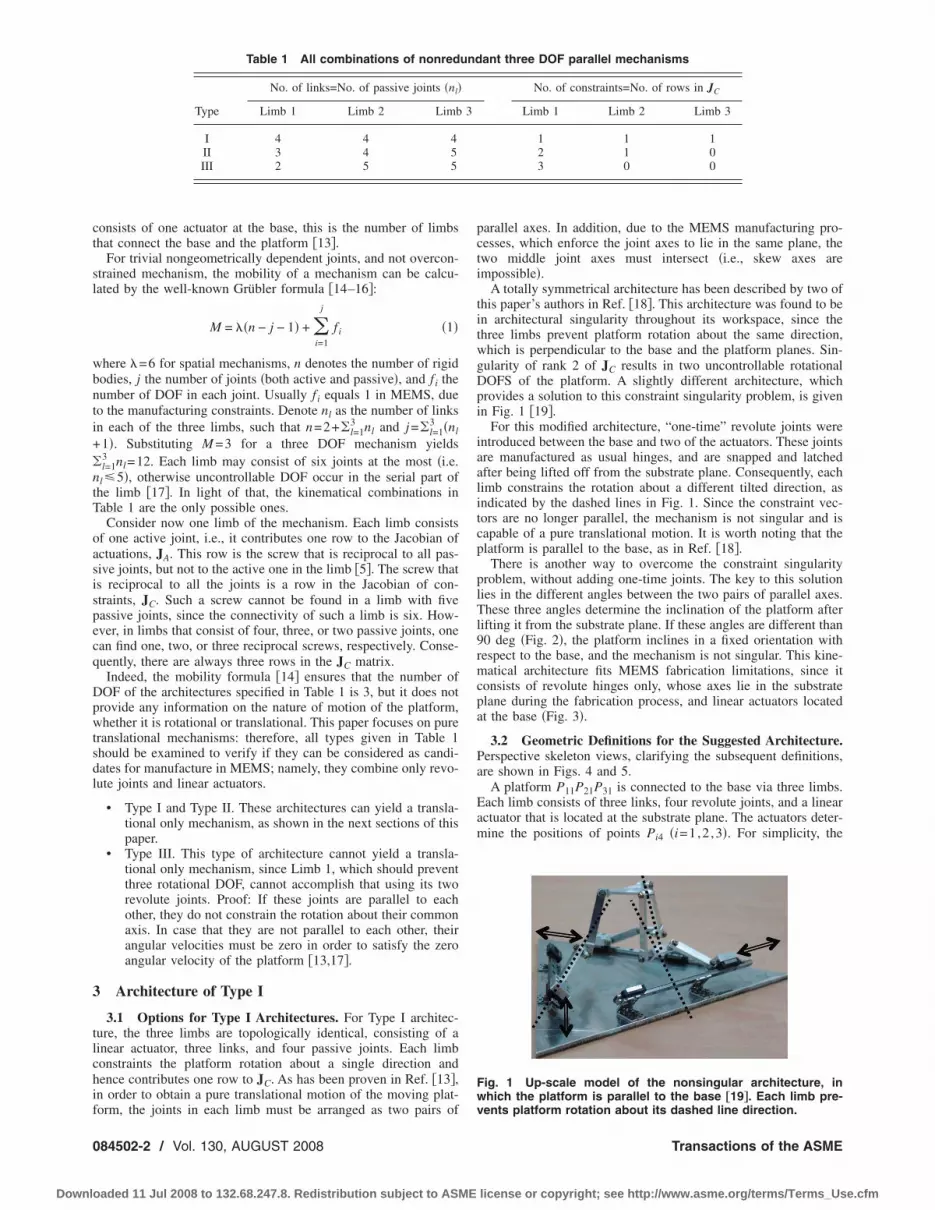
l=13 nl=12. Each limb may consist of six joints at the most �i.e.l�5�, otherwise uncontrollable DOF occur in the serial part ofhe limb �17�. In light of that, the kinematical combinations inable 1 are the only possible ones.Consider now one limb of the mechanism. Each limb consists
f one active joint, i.e., it contributes one row to the Jacobian ofctuations, JA. This row is the screw that is reciprocal to all pas-ive joints, but not to the active one in the limb �5�. The screw thats reciprocal to all the joints is a row in the Jacobian of con-traints, JC. Such a screw cannot be found in a limb with fiveassive joints, since the connectivity of such a limb is six. How-ver, in limbs that consist of four, three, or two passive joints, onean find one, two, or three reciprocal screws, respectively. Conse-uently, there are always three rows in the JC matrix.Indeed, the mobility formula �14� ensures that the number of
OF of the architectures specified in Table 1 is 3, but it does notrovide any information on the nature of motion of the platform,hether it is rotational or translational. This paper focuses on pure
ranslational mechanisms: therefore, all types given in Table 1hould be examined to verify if they can be considered as candi-ates for manufacture in MEMS; namely, they combine only revo-ute joints and linear actuators.
• Type I and Type II. These architectures can yield a transla-tional only mechanism, as shown in the next sections of thispaper.
• Type III. This type of architecture cannot yield a transla-tional only mechanism, since Limb 1, which should preventthree rotational DOF, cannot accomplish that using its tworevolute joints. Proof: If these joints are parallel to eachother, they do not constrain the rotation about their commonaxis. In case that they are not parallel to each other, theirangular velocities must be zero in order to satisfy the zeroangular velocity of the platform �13,17�.
Architecture of Type I
3.1 Options for Type I Architectures. For Type I architec-ure, the three limbs are topologically identical, consisting of ainear actuator, three links, and four passive joints. Each limbonstraints the platform rotation about a single direction andence contributes one row to JC. As has been proven in Ref. �13�,n order to obtain a pure translational motion of the moving plat-
Table 1 All combinations of nonred
Type
No. of links=No. of passive joints �nl�
Limb 1 Limb 2 Limb
I 4 4 4II 3 4 5III 2 5 5
orm, the joints in each limb must be arranged as two pairs of
84502-2 / Vol. 130, AUGUST 2008
aded 11 Jul 2008 to 132.68.247.8. Redistribution subject to ASME
parallel axes. In addition, due to the MEMS manufacturing pro-cesses, which enforce the joint axes to lie in the same plane, thetwo middle joint axes must intersect �i.e., skew axes areimpossible�.
A totally symmetrical architecture has been described by two ofthis paper’s authors in Ref. �18�. This architecture was found to bein architectural singularity throughout its workspace, since thethree limbs prevent platform rotation about the same direction,which is perpendicular to the base and the platform planes. Sin-gularity of rank 2 of JC results in two uncontrollable rotationalDOFS of the platform. A slightly different architecture, whichprovides a solution to this constraint singularity problem, is givenin Fig. 1 �19�.
For this modified architecture, “one-time” revolute joints wereintroduced between the base and two of the actuators. These jointsare manufactured as usual hinges, and are snapped and latchedafter being lifted off from the substrate plane. Consequently, eachlimb constrains the rotation about a different tilted direction, asindicated by the dashed lines in Fig. 1. Since the constraint vec-tors are no longer parallel, the mechanism is not singular and iscapable of a pure translational motion. It is worth noting that theplatform is parallel to the base, as in Ref. �18�.
There is another way to overcome the constraint singularityproblem, without adding one-time joints. The key to this solutionlies in the different angles between the two pairs of parallel axes.These three angles determine the inclination of the platform afterlifting it from the substrate plane. If these angles are different than90 deg �Fig. 2�, the platform inclines in a fixed orientation withrespect to the base, and the mechanism is not singular. This kine-matical architecture fits MEMS fabrication limitations, since itconsists of revolute hinges only, whose axes lie in the substrateplane during the fabrication process, and linear actuators locatedat the base �Fig. 3�.
3.2 Geometric Definitions for the Suggested Architecture.Perspective skeleton views, clarifying the subsequent definitions,are shown in Figs. 4 and 5.
A platform P11P21P31 is connected to the base via three limbs.Each limb consists of three links, four revolute joints, and a linearactuator that is located at the substrate plane. The actuators deter-mine the positions of points Pi4 �i=1,2 ,3�. For simplicity, the
ant three DOF parallel mechanisms
No. of constraints=No. of rows in JC
Limb 1 Limb 2 Limb 3
1 1 12 1 03 0 0
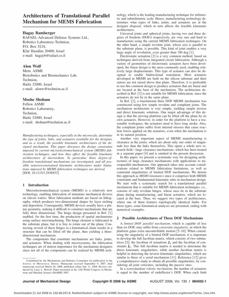
Fig. 1 Up-scale model of the nonsingular architecture, inwhich the platform is parallel to the base †19‡. Each limb pre-
und
3
vents platform rotation about its dashed line direction.
Transactions of the ASME
license or copyright; see http://www.asme.org/terms/Terms_Use.cfm

pdgpPt
J
Downlo
assive joints at points Pi4 are chosen to be perpendicular to theirection of motion of the actuator. According to the guidelinesiven in Ref. �13�, the axes of the joints at points Pi1 and Pi2 arearallel to each other, and so are the joint axes at points Pi3 andi4. These directions are denoted by ui1, ui2, ui3, and ui4, respec-
ively. MEMS manufacturing processes force the link Pi2Pi3 to be
Fig. 2 Three DOF translational parallel mechanism
Fig. 3 Links and joints in a manufacturing configuration
Fig. 4 Perspective view on the kinematical architecture
Fig. 5 The platform and one of the limbs
ournal of Mechanical Design
aded 11 Jul 2008 to 132.68.247.8. Redistribution subject to ASME
planar, so, without loss of generality, it can be assumed that theaxes ui2 and ui3 meet at point Pi3. The angle between these axes isdenoted by �i2.
Denote by O the origin of the coordinate system n1-n2-n3, lo-cated on the substrate plane, where n3 is perpendicular to thisplane. The distances from point O to the actuators’ lines of motionare indicated by l0. The origin of the platform coordinate system,p1-p2-p3, is indicated by P, which is the geometric center of theequilateral triangle P11P21P31. Note that this coordinate system isin general not parallel to n1-n2-n3, yet it maintains a fixed orien-tation. The distances from P to Pi1 are denoted by r. The lengthsof links Pi1Pi2, Pi2Pi3, and Pi3Pi4 are li1, li2, and li3, respectively.The positions of points Pi4 are indicated by ai and are measuredfrom the fixed points Oi, defined as the projections of point O onthe actuators’ lines of motions.
3.3 Inverse Kinematics. The goal of the inverse kinematicssolution is to find the positions of the actuators when the pose�position and orientation� of the moving platform is given. Itshould be noted that the algorithm is executed under the assump-tion of no joint clearance, which might be way off on the MEMSrelative scale �4�.
The position of the moving platform is given by a vector to itscenter P:
OrP = xn1 + yn2 + zn3 �2�
and the platform orientation, which is constant, is given by theorientation matrix CP as
�p1
p2
p3� = �C11
P C12P C13
P
C21P C22
P C23P
C31P C32
P C33P � · �n1
n2
n3� �3�
The inverse kinematics solution �20� is calculated separately foreach of the three limbs �i=1,2 ,3�. �i1 is the pitch angle of the linkPi1Pi2 �Fig. 5�, so that the vector from the center of the platformto Pi3 is given as
OrPi3 = xn1 + yn2 + zn3 + �rc�i + li1 cos �i1c�i − li2s�i�p1
+ �rs�i + li1 cos �i1s�i + li2c�i�p2 − li1 sin �i1p3 �4�
where the angle �i is constant and given as �1=0 deg, �2=120 deg, �3=240 deg, and c�i=cos �i and s�i=sin �i. Giventhat, an equation for solving �i1 can be obtained:
OrPi3 · �c�in1 + s�in2� = l0 �5�
since Pi3 lies in the plane indicated in Fig. 5, whose distance fromO is l0. Note that �i defines also the angle of the actuator line ofmotion with respect to the fixed vector n1 �Fig. 4�.
Two solutions are given by
�i1 = 2 tan−1� ki2 � ki12 + ki2
2 − ki32
ki3 − ki1 �6�
where
ki1 = li1�c2�iC11P + s�ic�i�C21
P + C12P � + s2�iC22
P �
ki2 = li1�c�iC31P + s�iC32
P ��7�
ki3 = r�c2�iC11P + s�ic�i�C21
P + C12P � + s2�iC22
P � + li2�c2�iC21P
+ s�ic�i�C22P − C11
P � − s2�iC12P � + xc�i + ys�i − l0
The two solutions present two assembly modes in which the linkPi1Pi2 is located either above the platform �Pi1rPi2 ·p3�0�, or be-low it �Pi1rPi2 ·p3�0�. Using Eq. �4� and the Pythagorean theo-rem, the travel of the actuator ai can be found by
O Pi3 2 O Pi3 2
ai = r · �c�in2 − s�in1� � li3 − � r · n3� �8�AUGUST 2008, Vol. 130 / 084502-3
license or copyright; see http://www.asme.org/terms/Terms_Use.cfm

aosstaf
sf4al
Jtot
w
as
oa9
rbalimaDm
0
Downlo
Each of the actuators has two solutions; one represents an acutengle between the actuator and the adjacent link, whereas thether represents an obtuse one. Since there are less then fourolutions �21�, switching between these assembly modes is pos-ible only while passing through a singular configuration in whichhe actuator is perpendicular to its adjacent link. Therefore, if thengles were acute at the beginning of the motion, the positive signor the square root of Eq. �8� should be used.
We conclude that each limb has four solutions, for the twoolutions of Eqs. �6� and �8�. A total of 64 solutions can be foundor the inverse kinematics problem of the mechanism given in Fig.. Indeed, this is a large number of solutions, but by applying theforementioned algorithm to distinguish between the possible so-utions, the correct solution can be easily obtained.
3.4 Design Criteria: The Angles Between the Middle Linkoints „�i2… and the Platform Orientation. The angles �i2 be-ween the joints axes of the middle link determine the platformrientation once lifted from the substrate plane. The relation be-
ween these axes is simplyThe ith limb can resist an external torque that is applied about
84502-4 / Vol. 130, AUGUST 2008
aded 11 Jul 2008 to 132.68.247.8. Redistribution subject to ASME
ui2 · ui3 = cos �i2 �9�where
ui1 = ui2 = s�ip1 − c�ip2
�10�ui3 = ui4 = c�in1 + s�in2
Using the definition of the orientation matrix given in Eq. �3�yields
c�12 = − C21P
c�22 =1
4�3C12
P − C21P + 3�C22
P − C11P �� �11�
c�32 =1
4�3C12
P − C21P + 3�C11
P − C22P ��
where c�ij =cos �ij.For design purposes, when the orientation matrix is known, the
calculation of �i2 is straightforward. On the other hand, findingthe orientation matrix for a known set of angles �i2 is more com-
plicated. Applying the quaternion formula yieldsCP = �k5 − k1 k2 + k3 s12k4 − 2k4
2
− 2k2k3 + 2k1k5
k2 − k3 k5 + k1 s22k4 − 2k42
+ 2k2k3 − 2k1k5
s32k4 − 2k42
+ 2k2k3 + 2k1k5s42k4 − 2k4
2
− 2k2k3 − 2k1k5
1 − 2k4
� �12�
here
k1 = �c�22 − c�32�/3, k4 = k12 + k2
2
k2 = �c�22 + c�32 − 2c�12�/3, k5 = � �k4 − 1�2 − k32 �13�
k3 = �c�12 + c�22 + c�32�/3, s1,s2,s3,s4 = � 1
nd the following equations are used to determine the signs of s2,3, and s4:
C21P = C13
P C32P − C12
P C33P
C22P = C11
P C33P − C13
P C31P �14�
C23P = C12
P C31P − C11
P C32P
It follows from Eq. �13� that there are four solutions for therientation matrix CP. It is worth noting that in case that the threengles �i2 are equal to �, the platform is rotated about n3 by0°−� or 90° +�, and this configuration is singular.
3.5 Full Jacobian Matrix. There might be singular configu-ations between the actuations and the constraint parts of the Jaco-ian matrix or among one of those parts �5,6�. Therefore, to detectll the singularities, the full 66 Jacobian matrix must be calcu-ated. Referring to the rows of the Jacobian matrix as the govern-ng lines of the mechanism enables an elegant way for solving the
ore general singularities. We refer the reader to Ref. �5�, wheresystematic method for forming the Jacobian matrix of limitedOF parallel mechanisms is given. The following is an imple-entation of Ref. �5� for our given structure.
the direction perpendicular to its passive joints �13,19�. This di-rection is indicated in Fig. 5 by the unit vector wi2:
wi2 =ui2 ui3
sin �i2�15�
Hence, one screw, which is reciprocal to all the joints’ screws of alimb, can be identified. This reciprocal screw, denoted as $̂r,1,i, isan infinite pitch screw pointing in the direction of wi2:
$̂r,1,iT = �013 wi2
T � �16�
One additional screw, $̂r,2,i, which is reciprocal to all the pas-sive joint screws of the ith limb can be identified. This reciprocalscrew is the intersecting line between two planes: one that con-tains the vectors ui1 and ui2, and one that contains ui3 and ui4�Fig. 5�. The direction of this line is
hi = � Pi1rPi2
l1 ui2 � Pi3rPi4
l3 ui3 �17�
Since point Pi3 lies in both planes, the intersecting line must passthrough it, therefore $̂r,2,i is given by:
$̂r,2,iT = �hi
T �OrPi3 hi�T� �18�
This screw is a row in the Jacobian of actuations.
The full Jacobian matrix is given byTransactions of the ASME
license or copyright; see http://www.asme.org/terms/Terms_Use.cfm

TT
4
Ts
tmtjthaAcpcdcfpjatt�j
Pa
EolLcfialPu
Fj
J
Downlo
J = �h1
T �OrP13 h1�T
h2T �OrP23 h2�T
h3T �OrP33 h3�T
0 0 0 w12T
0 0 0 w22T
0 0 0 w32T
� �19�
This Jacobian matrix has similar components as it describesype I architecture mechanisms, which consists of identical limbs.he next section deals with nontopologically identical limbs.
Architecture of Type II
4.1 Description. Type II architecture, which is described inable 1, can yield a translational only mechanism, e.g., as de-cribed in Fig. 6.
The three axes of the passive joints of Limb 1 must be parallelo each other �17�, so as to constrain the platform rotational move-
ents about the two perpendicular directions. Referring to Fig. 6,he vector u1 denotes the direction of these joints axes. Theseoints allow the platform to move in a plane normal to u1; hence,he linear actuator has to generate motion parallel to u1. Limb 2as to prevent platform rotation about u1. This can be achieved byrranging the four joints of Limb 2 as two pairs of parallel joints.s explained in Ref. �13�, such an arrangement causes Limb 2 to
onstrain the platform from rotating about the direction that iserpendicular to all of its four joints. Hence, the platform is fullyonstrained, i.e., pure translational, if this direction is not perpen-icular to u1, or, preferably, if it is parallel to u1. Limb 3 does notontribute to JC, and its role is to transfer the actuation forcesrom the base to the platform. Transferring these forces would beossible if a screw, that is reciprocal to all the limb’s five passiveoints, is identified. One of the possibilities to achieve this is byrranging three adjacent axes to meet at one point, while the otherwo axes meet at another point, so that the screw that connectshese two points is, indeed, reciprocal to all five passive joints22�. Evidently, this screw must not be perpendicular to the activeoint, so they are not reciprocal to each other.
4.2 Geometric Definitions for the Suggested Architecture.erspective skeleton views, clarifying the subsequent definitions,re shown in Figs. 6 and 7.
A platform P11P21P31 is connected to the base via three limbs.ach of the limbs is connected to a linear actuator that is locatedn the substrate plane. Limb 1 consists of two links, whoseengths are l11 and l12, and three joints, whose axes are parallel.imb 2’s structure is identical to that of the limbs of Type I ar-hitecture, as described in the previous section. Limb 3 consists ofve revolute joints and four links, which are shown in Fig. 7. Thexes of the joints are denoted by u3j �j=1, . . ,5�, and the linkengths are l3j �j=1, . . ,4�. The unit vector v3j points from P3j to
3�j+1� and, without loss of generality, is perpendicular to u3j. The
ig. 6 Type II architecture, with three, four, and five passiveoints in each limb
nit vector w3j is perpendicular to the link plane, where w3j
ournal of Mechanical Design
aded 11 Jul 2008 to 132.68.247.8. Redistribution subject to ASME
=u3j v3j. The constant angle between u3j and u3�j+1�, which isdetermined while manufacturing, is denoted by �3j, and thechangeable angle between two adjacent link planes is �3j. Forsimplicity, the passive joint at point P35 is chosen to be perpen-dicular to the direction of actuator motion.
In order to ensure that the axes u31 and u32 meet in one point�denoted as P36�, it is required that
�31 � 0 deg �20�
while ensuring that the axes u33, u34, and u35 meet in one point�denoted as P37� requires that
l33
s�33=
l34
t�34, �33 � 0 deg, �34 � 0 deg �21�
where s�ij =sin �ij and t�ij =tan �ij.
4.3 Inverse Kinematics. The platform position is given inEq. �2�, while its orientation matrix is given in Eq. �3�. It is worthnoting that the orientation matrix is not arbitrary, since the axis u1is parallel to the line of action of the corresponding actuator,meaning
u1 = c�1p2 − s�1p1 = c�1n2 − s�1n1 �22�Finding the travel of the first actuator is trivial,
a1 = OrP11 · u1 �23�
The algorithm for calculating the second actuator travel is identi-cal to that of Type I mechanism limbs, which was presented inSec. 3.3, Eqs. �4�–�8�. As for the third limb, when the platformposition and orientation are known, one can find the position ofpoint P36, using Eqs. �2� and �10�:
OrP36 = OrP + r�cos �3p1 + sin �3p2� −l31
t�31u31 �24�
The distance from P37 to P36 is fixed and known, since both pointsare located at the plane of the link P32P33:
�P37rP36� =�l32 −l33s�32
t�332
+ � l31
s�31−
l33c�32
t�332
�25�
Point P37 is located also at the substrate plane, in a fixed andknown distance from the actuator line of action:
OrP37 = �l0 −l34
s�34�c�3n1 + s�3n2� + a3�c�3n2 − s�3n1�
�26�
Equating �P37rP36� from Eq. �25� to the difference between Equa-tions �24� and �26� yields a quadratic equation in a3, which itssolutions are:
a3 = k32 � k322 − k31 �27�
Fig. 7 Typical link of Limb 3 of Type II architecture
where
AUGUST 2008, Vol. 130 / 084502-5
license or copyright; see http://www.asme.org/terms/Terms_Use.cfm
laip
a
w
wms
Of
w
Sia
a
0
Downlo
k31 = �OrP36�2 − �P37rP36�2 + �l0 −l34
s�342
− 2�l0 −l34
s�34
�c�3OrP36 · n1 + s�3
OrP36 · n2��28�
k32 = c�3OrP36 · n2 − s�3
OrP36 · n1
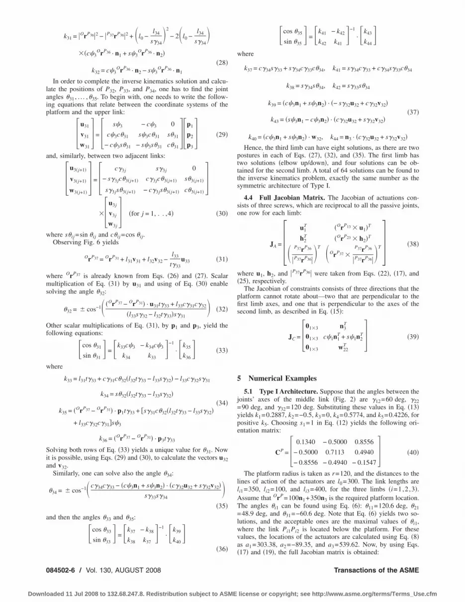
In order to complete the inverse kinematics solution and calcu-ate the positions of P32, P33, and P34, one has to find the jointngles �31, . . . ,�35. To begin with, one needs to write the follow-ng equations that relate between the coordinate systems of thelatform and the upper link:
�u31
v31
w31� = � s�3 − c�3 0
c�3c�31 s�3c�31 s�31
− c�3s�31 − s�3s�31 c�31��p1
p2
p3� �29�
nd, similarly, between two adjacent links:
�u3�j+1�
v3�j+1�
w3�j+1�� = � c�3j s�3j 0
− s�3jc�3�j+1� c�3jc�3�j+1� s�3�j+1�
s�3js�3�j+1� − c�3js�3�j+1� c�3�j+1��
�u3j
v3j
w3j� �for j = 1, . . ,4� �30�
here s�ij =sin �ij and c�ij =cos �ij.Observing Fig. 6 yields
OrP37 = OrP31 + l31v31 + l32v32 −l33
t�33u33 �31�
here OrP37 is already known from Eqs. �26� and �27�. Scalarultiplication of Eq. �31� by u31 and using of Eq. �30� enable
olving the angle �32:
�32 = � cos−1� �OrP37 − OrP31� · u31t�33 + l33c�31c�32
�l33s�32 − l32t�33�s�31 �32�
ther scalar multiplications of Eq. �31�, by p1 and p3, yield theollowing equations:
�cos �31
sin �31 = �k33c�3 − k34c�3
k34 k33 −1
· �k35
k36 �33�
here
k33 = l31t�33 + c�31c�32�l32t�33 − l33s�32� − l33c�32s�31
k34 = s�32�l32t�33 − l33s�32��34�
k35 = �OrP37 − OrP31� · p1t�33 + �s�31c�32�l32t�33 − l33s�32�
+ l33c�32c�31�s�3
k36 = �OrP37 − OrP31� · p3t�33
olving both rows of Eq. �33� yields a unique value for �31. Nowt is possible, using Eqs. �29� and �30�, to calculate the vectors u32nd v32.
Similarly, one can solve also the angle �34:
�34 = � cos−1� c�34c�33 − �c�3n1 + s�3n2� · �c�32u32 + s�32v32�s�33s�34
�35�
nd then the angles �33 and �35:
�cos �33
sin �33 = �k37 − k38
k38 k37 −1
· �k39
k40
�36�
84502-6 / Vol. 130, AUGUST 2008
aded 11 Jul 2008 to 132.68.247.8. Redistribution subject to ASME
�cos �35
sin �35 = �k41 − k42
k42 k41 −1
· �k43
k44
where
k37 = c�34s�33 + s�34c�33c�34, k41 = s�34c�33 + c�34s�33c�34
k38 = s�34s�34, k42 = s�33s�34
k39 = �c�3n1 + s�3n2� · �− s�32u32 + c�32v32��37�
k43 = �s�3n1 − c�3n2� · �c�32u32 + s�32v32�
k40 = �c�3n1 + s�3n2� · w32, k44 = n3 · �c�32u32 + s�32v32�Hence, the third limb can have eight solutions, as there are two
postures in each of Eqs. �27�, �32�, and �35�. The first limb hastwo solutions �elbow up/down�, and four solutions can be ob-tained for the second limb. A total of 64 solutions can be found tothe inverse kinematics problem, exactly the same number as thesymmetric architecture of Type I.
4.4 Full Jacobian Matrix. The Jacobian of actuations con-sists of three screws, which are reciprocal to all the passive joints,one row for each limb:
JA = �u1
T
h2T
�OrP13 u1�T
�OrP23 h2�T
� P37rP36
�P37rP36�T �OrP37
P37rP36
�P37rP36�T � �38�
where u1, h2, and �P37rP36� were taken from Eqs. �22�, �17�, and�25�, respectively.
The Jacobian of constraints consists of three directions that theplatform cannot rotate about—two that are perpendicular to thefirst limb axes, and one that is perpendicular to the axes of thesecond limb, as described in Eq. �15�:
JC = �013 n3T
013 c�1n1T + s�1n2
T
013 w22T � �39�
5 Numerical Examples
5.1 Type I Architecture. Suppose that the angles between thejoints’ axes of the middle link �Fig. 2� are �12=60 deg, �22=90 deg, and �32=120 deg. Substituting these values in Eq. �13�yields k1=0.2887, k2=−0.5, k3=0, k4=0.5774, and k5=0.4226, forpositive k5. Choosing s1=1 in Eq. �12� yields the following ori-entation matrix:
CP = � 0.1340 − 0.5000 0.8556
− 0.5000 0.7113 0.4940
− 0.8556 − 0.4940 − 0.1547� �40�
The platform radius is taken as r=120, and the distances to thelines of action of the actuators are l0=300. The link lengths areli1=350, li2=100, and li3=400, for the three limbs �i=1,2 ,3�.Assume that OrP=100n1+350n3 is the required platform location.The angles �i1 can be found using Eq. �6�: �11=120.6 deg, �21=48.9 deg, and �31=−60.6 deg. Note that Eq. �6� yields two so-lutions, and the acceptable ones are the maximal values of �i1,where the link Pi1Pi2 is located below the platform. For thesevalues, the locations of the actuators are calculated using Eq. �8�as a1=303.38, a2=−89.35, and a3=539.62. Now, by using Eqs.
�17� and �19�, the full Jacobian matrix is obtained:Transactions of the ASME
license or copyright; see http://www.asme.org/terms/Terms_Use.cfm

m�cpl
�o
Llls
=−dtt−��wo�
Tp
6
cmlflaalwnd
J
Downlo
J = �− 0.8320 − 0.0748 0.5456 165.53 − 493.41 184.74
0.1872 0.7061 0.5503 36.58 − 35.66 33.31
0.1597 0.8628 0.0778 − 114.65 17.75 38.62
0 0 0 0 − 0.5704 0.8214
0 0 0 − 0.8556 − 0.4940 − 0.1547
0 0 0 − 0.4940 0.2852 0.8214
� �41�
The Jacobian matrix consists of the governing lines of theechanism, and the linear complex that is closest to these lines
23� is �0 0 0−0.5702 0.4168 −0.7079�. The pitch of this linearomplex is infinite, meaning that the instantaneous motion of thelatform is indeed translational, and the mechanism is not singu-ar.
5.2 Type II Architecture. To withstand the condition in Eq.22�, assume that the platform inclines by 40 deg about n2, so therientation matrix is
CP = �0.7660 0 − 0.6428
0 1 0
0.6428 0 0.7660� �42�
et the platform location and the lengths of the second limb’sinks be same as in the previous example. The third limb’s linkengths are taken as l31=180, l32=140, l33=200, and l34=145.09,o Eq. �21� is obeyed.
Substituting in Eqs. �23� and �8� gives the actuators travels a10 and a2=451.53. Substituting in Eq. �17� yields h2=0.7989n10.3009n2+0.4450n3. As for the third limb, Eq. �25� yields theistance �P37rP36�=360.36, and Eq. �27� yields two solutions forhe actuator travel: a3=82.48 or a3=538.96. For the first solution,he difference between Eqs. �24� and �26� is P37rP36=131.49n1228.72n2+245.47n3. The joint angles are calculated using Eqs.
32�–�37�: �31=−71.63 deg, �32=−68.90 deg, �33=128.71 deg,34=−65.76 deg, and �35=103.26 deg, where the negative valuesere chosen for �32 and �34, arbitrarily. The third limb contributesne row to the Jacobian matrix, which can be found using Eqs.38� and �39�:
J = �0 1 0 0 0 300
0.7989 − 0.3009 0.4450 160.323 324.558 − 68.361
0.3649 − 0.6347 0.6812 − 2.5425 − 63.407 − 57.720
0 0 0 0 0 1
0 0 0 1 0 0
0 0 0 0.4846 0.2798 0.8288
��43�
he linear complex is �0 0 0 0.6240 −0.1030 −0.7745�, and itsitch is infinite, as expected.
Summary and ConclusionsTwo architectures of translational parallel mechanisms that
omply with MEMS fabrication limitations were suggested. Theechanisms are comprised of three linear actuators and 12 revo-
ute joints that are fabricated within the substrate plane. Only aew combinations of joint arrangements are possible, if pure trans-ational motion is desired. The kinematical requirements include,mong others, the avoidance of constraint singularities that aressociated with limited DOF parallel mechanisms. All the singu-arities were found by examining the full Jacobian matrix, whichas calculated by identifying the governing lines of the mecha-ism. It was shown that these architectures are indeed functional,
espite the severe limitations forced by current MEMS fabricationournal of Mechanical Design
aded 11 Jul 2008 to 132.68.247.8. Redistribution subject to ASME
techniques. These limitations may be changed when new micro-manufacturing technologies are introduced, and consequently, in-crease the number of feasible architectures.
A methodical approach for designing architectures of transla-tional microparallel mechanisms was developed. The approach isdenoted as MEMS kinematics, where both MEMS fabricationlimitations and kinematical considerations were taken intoconsideration.
Realization of the present microrobot still faces some majorobstacles: hinge reliability, during fabrication and operation, cancause low yield, especially due to the large number of hingesincluded in the mechanism. Raising the device from its planarfabrication pose is also a challenge. Clearances at the joints canreduce the positional accuracy of the moving platform to a degreethat it is not useable, as was discussed in a previous investigation�4�. These obstacles are a challenge in all currently realized mi-cromechanisms and are subjects for further investigation.
References�1� Pister, K. S. J., Judy, M. W., Burgett, S. R., and Fearing, R. S., 1992, “Micro-
Fabricated Hinges,” Sens. Actuators, A, 33�3�, pp. 249–256.�2� Fan, L., Wu, M. C., Choquette, K. D., and Crawford, M. H., 1997, “Self-
Assembled Microactuated XYZ Stages for Optical Scanning and Alignment,”Proceedings of International Solid State Sensors and Actuators Conference(Transducers’97), Chicago, IL, pp. 319–322.
�3� Chablat, D., and Wenger, P., 2003, “Architecture Optimization of a 3-DOFTranslational Parallel Mechanism for Machining Applications, the Or-thoglide,” IEEE Trans. Rob. Autom., 19�3�, pp. 403–410.
�4� Bamberger, H., Shoham, M., and Wolf, A., 2006, “Kinematics of Micro PlanarParallel Robot Comprising Large Joint Clearances,” Advances in Robot Kine-matics (ARK), Springer, Ljubljana, Slovenia, pp. 75–84.
�5� Joshi, S. A., and Tsai, L.-W., 2002, “Jacobian Analysis of Limited-DOF Par-allel Manipulators,” ASME J. Mech. Des., 124, pp. 254–258.
�6� Zlatanov, D., Bonev, I. A., and Gosselin, C. M., 2002, “Constraint Singulari-ties of Parallel Mechanisms,” IEEE International Conference on Robotics andAutomation (ICRA), Washington, DC, pp. 496–502.
�7� Kim, D., and Chung, W. K., 2003, “Kinematic Condition Analysis of Three-DOF Pure Translational Parallel Manipulators,” ASME J. Mech. Des., 125,pp. 323–331.
�8� Hao, F., and McCarthy, J. M., 1998, “Conditions for Line-Based Singularitiesin Spatial Platform Manipulators,” J. Rob. Syst., 15�1�, pp. 43–55.
�9� Fang, Y., and Tsai, L.-W., 2004, “Structure Synthesis of a Class of 3-DOFRotational Parallel Manipulators,” IEEE Trans. Rob. Autom., 20�1�, pp. 117–121.
�10� Zoppi, M., Bruzzone, L. E., Molfino, R. M., and Michelini, R. C., 2003,“Constraint Singularities of Force Transmission in Nonredundant Parallel Ro-bots With Less Than Six Degrees of Freedom,” ASME J. Mech. Des., 125, pp.557–563.
�11� Gosselin, C., and Angeles, J., 1990, “Singularity Analysis of Closed-LoopKinematic Chains,” IEEE Trans. Rob. Autom., 6�3�, pp. 281–290.
�12� Zlatanov, D., Fenton, R. G., and Benhabib, B., 1998, “Identification and Clas-sification of the Singular Configurations of Mechanisms,” Mech. Mach.Theory, 33�6�, pp. 743–760.
�13� Carricato, M., and Parenti-Castelli, V., 2003, “A Family of 3-DOF Transla-tional Parallel Manipulators,” ASME J. Mech. Des., 125, pp. 302–307.
�14� Grübler, M., 1917, Getriebelehre, Springer-Verlag, Berlin.�15� Rico Martinez, J. M., and Ravani, B., 2003, “On Mobility Analysis of Link-
ages using Group Theory,” ASME J. Mech. Des., 125, pp. 70–80.�16� Gogu, G., 2005, “Mobility of Mechanisms: A Critical Review,” Mech. Mach.
Theory, 40�9�, pp. 1068–1097.�17� Carricato, M., and Parenti-Castelli, V., 2004, “On the Topological and Geo-
metrical Synthesis and Classification of Translational Parallel Mechanisms,”Proceedings of the 11th World Congress in Mechanisms and Machine Science,Tianjin, China.
�18� Bamberger, H., and Shoham, M., 2004, “Kinematic Structure of a Parallel
Robot for MEMS Fabrication,” On Advances in Robot Kinematics (ARK),AUGUST 2008, Vol. 130 / 084502-7
license or copyright; see http://www.asme.org/terms/Terms_Use.cfm
0
Downlo
Kluwer Academic, Sestri-Levante, Italy, pp. 113–122.�19� Bamberger, H., Wolf, A., and Shoham, M., 2005, “Identification of Micro
Parallel Robot’s Singularity Using Line Geometry,” The 30th Israeli Confer-ence on Mechanical Engineering, Tel-Aviv, Israel.
�20� Carricato, M., and Parenti-Castelli, V., 2003, “Position Analysis of a NewFamily of 3-DOF Translational Parallel Manipulators,” ASME J. Mech. Des.,125, pp. 316–322.
�21� Innocenti, C., and Parenti-Castelli, V., March 1998, “Singularity-Free Evolu-
84502-8 / Vol. 130, AUGUST 2008
aded 11 Jul 2008 to 132.68.247.8. Redistribution subject to ASME
tion from One Configuration to Another in Serial and Fully-Parallel Manipu-lators,” ASME J. Mech. Des., 120, pp. 73–79.
�22� Di-Gregorio, R., and Parenti-Castelli, V., 2006, “Parallel Mechanisms for KneeOrthoses with Selective Recovery Action,” On Advances in Robot Kinematics(ARK), Kluwer Academic, Ljubljana, Slovenia, pp. 167–176.
�23� Wolf, A., and Shoham, M., 2003, “Investigation of Parallel Manipulators Us-ing Linear Complex Approximation,” ASME J. Mech. Des., 125�3�, pp. 564–572.
Transactions of the ASME
license or copyright; see http://www.asme.org/terms/Terms_Use.cfm


