Embed Size (px)
Citation preview
Journal of Applied Geophysics 65 (2008) 30–38
Contents lists available at ScienceDirect
Journal of Applied Geophysics
j ourna l homepage: www.e lsev ie r.com/ locate / jappgeo
An approach to construct the weathering profile in a hilly granitic terrain based onelectrical imaging
P.H. Giao a,⁎, A. Weller b,1, D.H. Hien a, K. Adisornsupawat a
a Geosystem Exploration and Petroleum Geoengineering Program, Asian Institute of Technology; PO BOX 4, Klong Luang, Pathumthani, 12120, Thailandb Institute of Geophysics, Clausthal University of Technology, Germany
⁎ Corresponding author. Tel.: +66 2 524 5529; fax: +6E-mail addresses: [email protected] (P.H. Giao), Andrea
(A. Weller).
0926-9851/$ – see front matter © 2008 Elsevier B.V. Aldoi:10.1016/j.jappgeo.2008.03.004
A B S T R A C T
A R T I C L E I N F OArticle history:
For investigation of a granit Received 15 January 2007Accepted 14 March 2008Keywords:Electrical imagingTopographic correctionSite investigationHilly terrainWeathered granites
ic hillside at the Kata Noi beach in Phuket, Thailand, a common geotechnical siteinvestigation might not be suitable because it is difficult to bring a drilling rig to make the boreholes on thehillside. As an alternative electrical imaging (EI) survey was proposed. The main issues addressed in thisstudy are how to find the boundary between the weathered and unweathered granites in a graduallychanging resistivity pseudo-section and how to assess the effect of hillside topography and the type ofelectrode array in locating such a boundary. To solve these problems an approach was adopted, including(i) selection of a suitable EI array in the field; (ii) data analysis with topographical correction; and (iii) theincorporation of a conceptual weathering profile in EI data interpretation. As a result, a geological–geoelectrical model was constructed for the weathering profile of granitic rocks at the study site, which canbe applied for investigation of similar hilly terrains in Southern Thailand.
© 2008 Elsevier B.V. All rights reserved.
1. Introduction
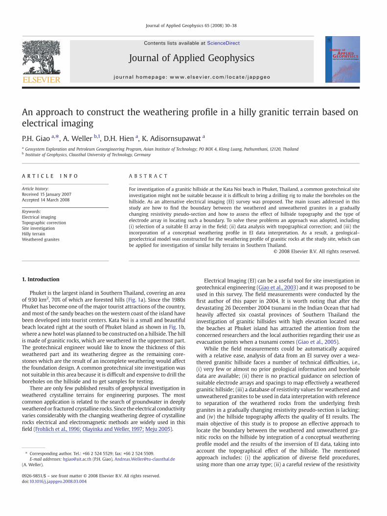
Phuket is the largest island in Southern Thailand, covering an areaof 930 km2, 70% of which are forested hills (Fig. 1a). Since the 1980sPhuket has become one of the major tourist attractions of the country,and most of the sandy beaches on the western coast of the island havebeen developed into tourist centers. Kata Noi is a small and beautifulbeach located right at the south of Phuket Island as shown in Fig. 1b,where a new hotel was planned to be constructed on a hillside. The hillis made of granitic rocks, which are weathered in the uppermost part.The geotechnical engineer would like to know the thickness of thisweathered part and its weathering degree as the remaining core-stones which are the result of an incomplete weathering would affectthe foundation design. A common geotechnical site investigation wasnot suitable in this area because it is difficult and expensive to drill theboreholes on the hillside and to get samples for testing.
There are only few published results of geophysical investigation inweathered crystalline terrains for engineering purposes. The mostcommon application is related to the search of groundwater in deeplyweathered or fractured crystalline rocks. Since the electrical conductivityvaries considerably with the changing weathering degree of crystallinerocks electrical and electromagnetic methods are widely used in thisfield (Frohlich et al., 1996; Olayinka andWeller, 1997; Meju 2005).
6 2 524 [email protected]
l rights reserved.
Electrical Imaging (EI) can be a useful tool for site investigation ingeotechnical engineering (Giao et al., 2003) and it was proposed to beused in this survey. The field measurements were conducted by thefirst author of this paper in 2004. It is worth noting that after thedevastating 26 December 2004 tsunami in the Indian Ocean that hadheavily affected six coastal provinces of Southern Thailand theinvestigation of granitic hillsides with high elevation located nearthe beaches at Phuket island has attracted the attention from theconcerned researchers and the local authorities regarding their use asevacuation points when a tsunami comes (Giao et al., 2005).
While the field measurements could be automatically acquiredwith a relative ease, analysis of data from an EI survey over a wea-thered granitic hillside faces a number of technical difficulties, i.e.,(i) very few or almost no prior geological information and boreholedata are available; (ii) there is no practical guidance on selection ofsuitable electrode arrays and spacings to map effectively a weatheredgranitic hillside; (iii) a database of resistivity values for weathered andunweathered granites to be used in data interpretationwith referenceto separation of the weathered rocks from the underlying freshgranites in a gradually changing resistivity pseudo-section is lacking;and (iv) the hillside topography affects the quality of EI results. Themain objective of this study is to propose an effective approach tolocate the boundary between the weathered and unweathered gra-nitic rocks on the hillside by integration of a conceptual weatheringprofile model and the results of the inversion of EI data, taking intoaccount the topographical effect of the hillside. The mentionedapproach includes: (i) the application of diverse field procedures,using more than one array type; (ii) a careful review of the resistivity
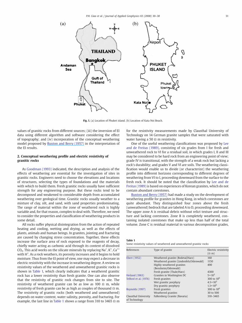
Fig. 1. (a) Location of Phuket island. (b) Location of Kata Noi Beach.
Table 1Some resistivity values of weathered and unweathered granitic rocks
References Type of granite Electric resistivity(Ω m)
Ebert (1952) Weathered granite (Bodetal/Harz) 160Weathered granite (Lindenfels/Odenwald) 1150Highly weathered granites(Bensheim/Odenwald)
490
Fresh granite (Thale/Harz) 4300Heiland (1963) Granites in Washington DC 5×10³
Telford et al. (1976) Fresh granites 300 to 106
Wet granitic porphyry 4.5×10³
Dry granitic porphyry 1.3×10⁶
Reynolds (1997) Fresh granites 300 to 106
Weathered granites 30 to 500Clausthal Universityof Technology
Falkenberg Granite (Bavaria) 310–3465
31P.H. Giao et al. / Journal of Applied Geophysics 65 (2008) 30–38
values of granitic rocks from different sources; (iii) the inversion of EIdata using different algorithm and software considering the effectof topography; and (iv) incorporation of the conceptual weatheringmodel proposed by Ruxton and Berry (1957) in the interpretation ofthe EI results.
2. Conceptual weathering profile and electric resistivity ofgranitic rocks
As Goodman (1993) indicated, the description and analysis of theeffects of weathering are essential for the investigation of sites ingranitic rocks. Engineers need to choose the elevations and locationsof structures, selecting the types of foundations and the materialswith which to build them. Fresh granitic rocks usually have sufficientstrength for any engineering purpose. But these rocks tend to bedecomposed and weakened to considerable depth from accumulatedweathering over geological time. Granitic rocks usually weather to amixture of clay, silt, and sand, with sand properties predominating.The range of material within the zone of weathered rock is highlyvariable and, for that reason, complex to deal with. Therefore, we needto consider the properties and classification of weathering products insome detail.
All rocks suffer physical disintegration from the action of repeatedheating and cooling, wetting and drying, as well as the effects ofplants, animals and human beings. In granites, jointing and fracturingare caused by changing stress concentration. Together, these effectsincrease the surface area of rock exposed to the reagents of decay,chiefly water acting as carbonic acid through its content of dissolvedCO2. This acid works on the silicate minerals by replacing Na+, K+, Ca++
with H+. As a rockweathers, its porosity increases and it begins to holdmoisture. Thus from the EI point of view, onemay expect a decrease inelectric resistivity with the increase inweathering degree. A review onresistivity values of the weathered and unweathered granitic rocks isshown in Table 1, which clearly indicates that a weathered graniticrock has a lower resistivity than fresh granite. One can also observethat the resistivity of granitic rock changes from site to site. Theresistivity of weathered granite can be as low as 100 Ω m, whileresistivity of fresh granite can be as high as couples of thousand Ω m.The resistivity of granitic rocks (both weathered and unweathered)depends on water content, water salinity, porosity, and fracturing. Forexample, the last line in Table 1 shows a range from 310 to 3465 Ω m
for the resistivity measurements made by Clausthal University ofTechnology on 14 German granite samples that were saturated withwater having a 50 Ω m resistivity.
One of the useful weathering classifications was proposed by Leeand de Freitas (1989), consisting of six grades from I for fresh andunweathered rock to VI for a residual soil, in which grades I, II and IIImay be considered to be hard rock from an engineering point of view;grade IV is transitional, with the strength of a weak rock but lacking arock's durability; and grades V and VI are soils. The weathering classi-fication would enable us to divide (or characterize) the weatheringprofile into different horizons corresponding to different degrees ofweathering from VI to I, proceeding downward from the surface to thefresh rock. It should be noted that the classification by Lee and deFreitas (1989) is based on experiences of Korean granites, which do notcontain abundant corestones.
Ruxton and Berry (1957) had made a study on the development ofweathering profile for granites in Hong Kong, in which corestones arequite abundant. They distinguished four zones above the fresh(unweathered) bedrock that are labeled A to D, proceeding downward.The upper zone A is residual debris without relict texture and struc-ture and lacking corestones. Zone B is completely weathered, con-taining isolated corestones that make up less than half of the totalvolume. Zone C is residual material in various decomposition grades,
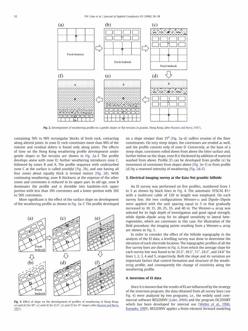
Fig. 2. Development of weathering profile on a gentle slopes or flat terrains in granite, Hong Kong (after Ruxton and Berry, 1957).
32 P.H. Giao et al. / Journal of Applied Geophysics 65 (2008) 30–38
containing 50% to 90% rectangular blocks of fresh rock, contactingalong altered joints. In zone D, rock constitutes more than 90% of thevolume and residual debris is found only along joints. The effectsof time on the Hong Kong weathering profile development undergentle slopes or flat terrains are shown in Fig. 2a–f. The profiledevelops anew with zone D; further weathering introduces zone C,followed by zones B and A. The profile sequence with undisturbedzone C at the surface is called youthful (Fig. 2b), and one having allfour zones about equally thick is termed mature (Fig. 2d). Withcontinuing weathering, zone B thickness at the expense of the otherzones and corestones is reduced in its upper part. In old age, zone Bdominates the profile and is divisible into kaolinite-rich upperportion with less than 10% corestones and a lower portion with 10%to 50% corestones.
More significant is the effect of the surface slope on developmentof the weathering profile as shown in Fig. 3a–f. The profile developed
Fig. 3. Effect of slope on the development of profiles of weathering in Hong Kong:(a) and (b) for 30°, (c) and (d) for 22.5°, (e) and (f) for 15° slopes (after Ruxton and Berry,1957).
on a slope steeper than 150 (Fig. 3a–d) suffers erosion of the finerconstituents. On very steep slopes, the corestones are eroded as well,and the profile consists only of zone D. Conversely, at the base of asteep slope, corestones rolled down from above the litter surface and,further below on the slope, zone B is thickened by addition of materialwashed from above. Profile (f) can be developed from profile (e) bymovement of corestones from slopes above (Fig. 3e–f) or from profile(d) by a renewed intensity of weathering (Fig. 2d–f).
3. Electrical imaging survey at the Kata Noi granitic hillside
An EI survey was performed on five profiles, numbered from 1to 5 as shown by black lines in Fig. 4. The automatic SYSCAL R1+with a multicore cable of 120 m length was employed. On eachsurvey line, the two configurations Wenner-α and Dipole–Dipolewere applied with the unit spacing equal to 5 m that graduallyincreased to 10, 15, 20, 25, 35, and 40 m. The Wenner-α array wasselected for its high depth of investigation and good signal strength,while dipole–dipole array for its alleged sensitivity to lateral hete-rogeneities, which are corestones in this case. For illustration of thefield procedure, the imaging points resulting from a Wenner-α arrayare shown in Fig. 5.
In order to consider the effect of the hillside topography in theanalysis of the EI data, a levelling survey was done to determine theelevation of each electrode location. The topographic profiles of all thefive survey lines are shown in Fig. 6, fromwhich the average slope foreach survey line was found to be 25.5°, 10.5°, 7.1°, 24.5°, and 24.6° forlines 1, 2, 3, 4 and 5, respectively. Both the slope and its variation areimportant factors that control formation and structure of the weath-ering profile, and consequently the change of resistivity along theweathering profile.
4. Inversion of EI data
Since it is known that the results of EI are influenced by the strategyof the inversion program, the data obtained from all survey lines (seeFig. 4) were analyzed by two programs, i.e., the widely used com-mercial software RES2DINV (Loke, 2004) and the program DC2DSIRTwhich has been developed for internal use (Weller et al., 1996;Kampke, 1999). RES2DINV applies a finite-element forward modeling
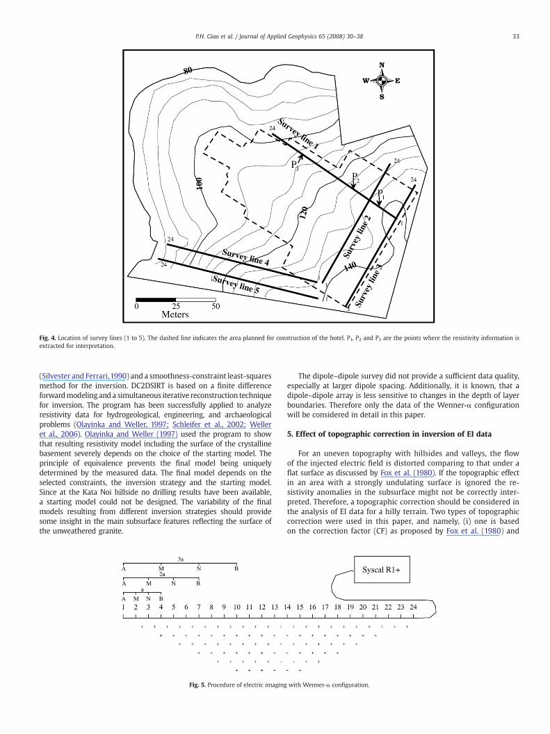
Fig. 4. Location of survey lines (1 to 5). The dashed line indicates the area planned for construction of the hotel. P1, P2 and P3 are the points where the resistivity information isextracted for interpretation.
33P.H. Giao et al. / Journal of Applied Geophysics 65 (2008) 30–38
(Silvester and Ferrari,1990) and a smoothness-constraint least-squaresmethod for the inversion. DC2DSIRT is based on a finite differenceforwardmodelingand a simultaneous iterative reconstruction techniquefor inversion. The program has been successfully applied to analyzeresistivity data for hydrogeological, engineering, and archaeologicalproblems (Olayinka and Weller, 1997; Schleifer et al., 2002; Welleret al., 2006). Olayinka and Weller (1997) used the program to showthat resulting resistivity model including the surface of the crystallinebasement severely depends on the choice of the starting model. Theprinciple of equivalence prevents the final model being uniquelydetermined by the measured data. The final model depends on theselected constraints, the inversion strategy and the starting model.Since at the Kata Noi hillside no drilling results have been available,a starting model could not be designed. The variability of the finalmodels resulting from different inversion strategies should providesome insight in the main subsurface features reflecting the surface ofthe unweathered granite.
Fig. 5. Procedure of electric imaging
The dipole–dipole survey did not provide a sufficient data quality,especially at larger dipole spacing. Additionally, it is known, that adipole–dipole array is less sensitive to changes in the depth of layerboundaries. Therefore only the data of the Wenner-α configurationwill be considered in detail in this paper.
5. Effect of topographic correction in inversion of EI data
For an uneven topography with hillsides and valleys, the flowof the injected electric field is distorted comparing to that under aflat surface as discussed by Fox et al. (1980). If the topographic effectin an area with a strongly undulating surface is ignored the re-sistivity anomalies in the subsurface might not be correctly inter-preted. Therefore, a topographic correction should be considered inthe analysis of EI data for a hilly terrain. Two types of topographiccorrection were used in this paper, and namely, (i) one is basedon the correction factor (CF) as proposed by Fox et al. (1980) and
with Wenner-α configuration.
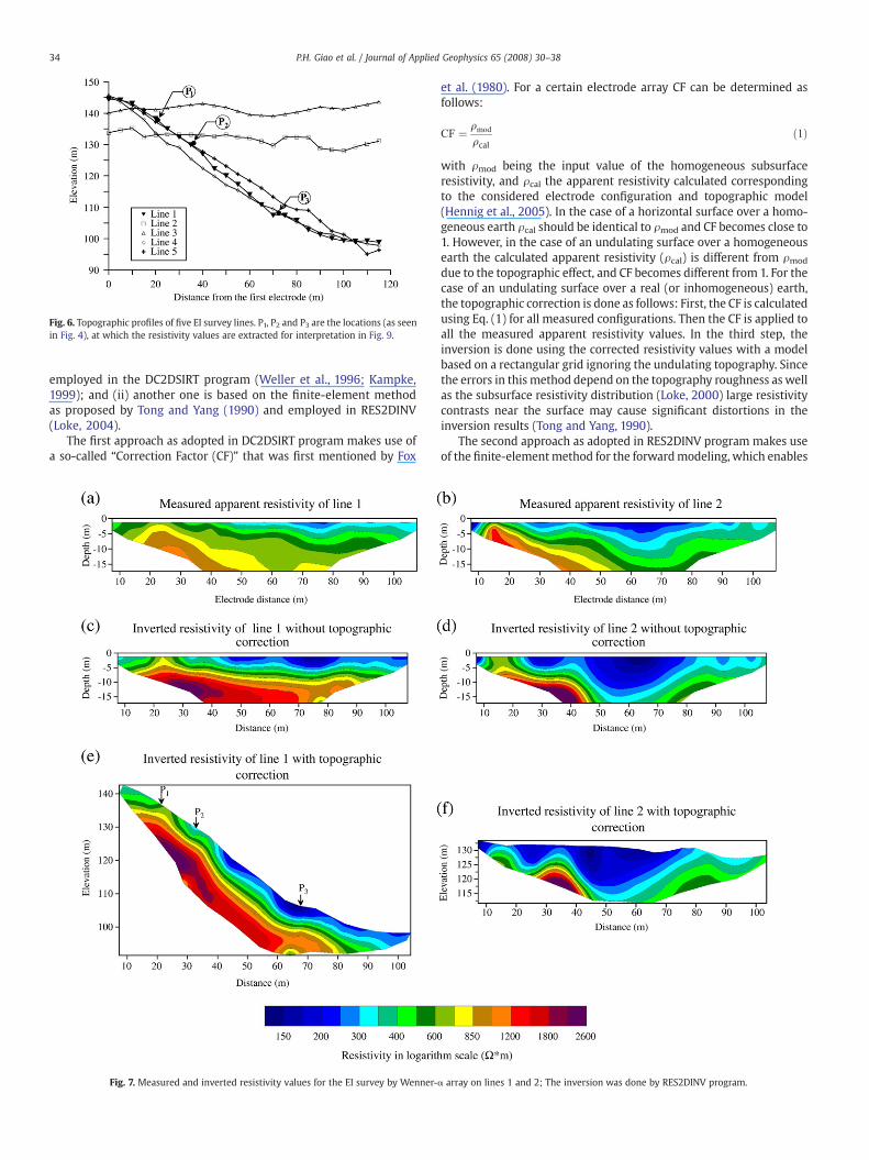
Fig. 6. Topographic profiles of five EI survey lines. P1, P2 and P3 are the locations (as seenin Fig. 4), at which the resistivity values are extracted for interpretation in Fig. 9.
34 P.H. Giao et al. / Journal of Applied Geophysics 65 (2008) 30–38
employed in the DC2DSIRT program (Weller et al., 1996; Kampke,1999); and (ii) another one is based on the finite-element methodas proposed by Tong and Yang (1990) and employed in RES2DINV(Loke, 2004).
The first approach as adopted in DC2DSIRT program makes use ofa so-called “Correction Factor (CF)” that was first mentioned by Fox
Fig. 7. Measured and inverted resistivity values for the EI survey by Wenner-
et al. (1980). For a certain electrode array CF can be determined asfollows:
CF ¼ qmod
qcalð1Þ
with ρmod being the input value of the homogeneous subsurfaceresistivity, and ρcal the apparent resistivity calculated correspondingto the considered electrode configuration and topographic model(Hennig et al., 2005). In the case of a horizontal surface over a homo-geneous earth ρcal should be identical to ρmod and CF becomes close to1. However, in the case of an undulating surface over a homogeneousearth the calculated apparent resistivity (ρcal) is different from ρmod
due to the topographic effect, and CF becomes different from 1. For thecase of an undulating surface over a real (or inhomogeneous) earth,the topographic correction is done as follows: First, the CF is calculatedusing Eq. (1) for all measured configurations. Then the CF is applied toall the measured apparent resistivity values. In the third step, theinversion is done using the corrected resistivity values with a modelbased on a rectangular grid ignoring the undulating topography. Sincethe errors in this method depend on the topography roughness as wellas the subsurface resistivity distribution (Loke, 2000) large resistivitycontrasts near the surface may cause significant distortions in theinversion results (Tong and Yang, 1990).
The second approach as adopted in RES2DINV program makes useof the finite-elementmethod for the forwardmodeling, which enables
α array on lines 1 and 2; The inversion was done by RES2DINV program.
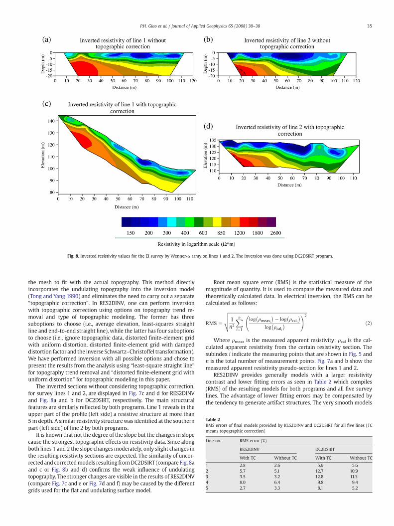
Fig. 8. Inverted resistivity values for the EI survey by Wenner-α array on lines 1 and 2. The inversion was done using DC2DSIRT program.
Table 2RMS errors of final models provided by RES2DINV and DC2DSIRT for all five lines (TCmeans topographic correction)
Line no. RMS error (%)
RES2DINV DC2DSIRT
With TC Without TC With TC Without TC
1 2.8 2.6 5.9 5.62 5.7 5.1 12.7 10.93 3.5 3.2 12.8 11.34 8.0 6.4 9.8 9.45 2.7 3.3 8.1 5.2
35P.H. Giao et al. / Journal of Applied Geophysics 65 (2008) 30–38
the mesh to fit with the actual topography. This method directlyincorporates the undulating topography into the inversion model(Tong and Yang 1990) and eliminates the need to carry out a separate“topographic correction”. In RES2DINV, one can perform inversionwith topographic correction using options on topography trend re-moval and type of topographic modeling. The former has threesuboptions to choose (i.e., average elevation, least-squares straightline and end-to-end straight line), while the latter has four suboptionsto choose (i.e., ignore topographic data, distorted finite-element gridwith uniform distortion, distorted finite-element grid with dampeddistortion factor and the inverse Schwartz–Christoffel transformation).We have performed inversion with all possible options and chose topresent the results from the analysis using “least-square straight line”for topography trend removal and “distorted finite-element grid withuniform distortion” for topographic modeling in this paper.
The inverted sections without considering topographic correction,for survey lines 1 and 2, are displayed in Fig. 7c and d for RES2DINVand Fig. 8a and b for DC2DSIRT, respectively. The main structuralfeatures are similarly reflected by both programs. Line 1 reveals in theupper part of the profile (left side) a resistive structure at more than5mdepth. A similar resistivity structurewas identified at the southernpart (left side) of line 2 by both programs.
It is known that not the degree of the slope but the changes in slopecause the strongest topographic effects on resistivity data. Since alongboth lines 1 and 2 the slope changesmoderately, only slight changes inthe resulting resistivity sections are expected. The similarity of uncor-rected and correctedmodels resulting fromDC2DSIRT (compare Fig. 8aand c or Fig. 8b and d) confirms the weak influence of undulatingtopography. The stronger changes are visible in the results of RES2DINV(compare Fig. 7c and e or Fig. 7d and f) may be caused by the differentgrids used for the flat and undulating surface model.
Root mean square error (RMS) is the statistical measure of themagnitude of quantity. It is used to compare the measured data andtheoretically calculated data. In electrical inversion, the RMS can becalculated as follows:
RMS ¼
ffiffiffiffiffiffiffiffiffiffiffiffiffiffiffiffiffiffiffiffiffiffiffiffiffiffiffiffiffiffiffiffiffiffiffiffiffiffiffiffiffiffiffiffiffiffiffiffiffiffiffiffiffiffiffiffiffiffiffiffiffiffiffiffiffiffiffiffiffiffiffi1n2
Xni¼1
log qmeasi
� �� log qcali� �
log qcali� �
!2vuut ð2Þ
Where ρmeas is the measured apparent resistivity; ρcal is the cal-culated apparent resistivity from the certain resistivity section. Thesubindex i indicate the measuring points that are shown in Fig. 5 andn is the total number of measurement points. Fig. 7a and b show themeasured apparent resistivity pseudo-section for lines 1 and 2.
RES2DINV provides generally models with a larger resistivitycontrast and lower fitting errors as seen in Table 2 which compiles(RMS) of the resulting models for both programs and all five surveylines. The advantage of lower fitting errors may be compensated bythe tendency to generate artifact structures. The very smooth models
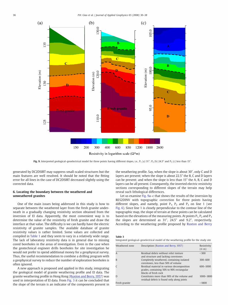
Fig. 9. Interpreted geological–geoelectrical model for three points having different slopes, i.e., P1 (a) 31°; P2 (b) 24.5° and P3 (c) less than 15°.
Table 3Integrated geological–geoelectrical model of the weathering profile for the study site
Weathered zone Description (Ruxton and Berry, 1957) Resistivity(Ω m)
A Residual debris without relict textureand structure and lacking corestones
b300
B Completely weathered, containing isolatedcorestones, less than 50% of volume
300–600
C Residual material in various decompositiongrades, containing 50% to 90% rectangularblocks of fresh rock
600–1000
D Constitutes more than 90% of the volume andresidual debris is found only along joints
1000–1800
Fresh granite N1800
36 P.H. Giao et al. / Journal of Applied Geophysics 65 (2008) 30–38
generated by DC2DSIRT may suppress small-scaled structures but themain features are well resolved. It should be noted that the fittingerror for all lines in the case of DC2DSIRT decreased slightly using thecorrected data.
6. Locating the boundary between the weathered andunweathered granites
One of the main issues being addressed in this study is how toseparate between the weathered layer from the fresh granite under-neath in a gradually changing resistivity section obtained from theinversion of EI data. Apparently, the most convenient way is todetermine the value of the resistivity of fresh granite and draw theinterface at that value. The difficulty is we can hardly have the electricresistivity of granite samples. The available database of graniteresistivity values is rather limited. Some values are collected andcompiled in Table 1 and they seem to vary in a relatively wide range.The lack of laboratory resistivity data is in general due to missingcored boreholes in the areas of investigation. Even in the case whenthe geotechnical engineer drills boreholes for site investigation hewould not prefer to spend additional money for a geophysical survey.Thus, the useful recommendation to combine a drilling program witha geophysical survey to reduce the number of exploration boreholes isoften ignored.
A new approach is proposed and applied in this study, integratingthe geological model of granite weathering profile and EI data. Thegranite weathering profile in Hong Kong (Ruxton and Berry, 1957) wasused in interpretation of EI data. From Fig. 3 it can be concluded thatthe slope of the terrain is an indicator of the components present in
the weathering profile. Say, when the slope is about 30°, only C and Dlayers are present; when the slope is about 22.5° the B, C and D layerscan be present; and when the slope is less than 15° the A, B, C and Dlayers can be all present. Consequently, the inverted electric resistivitysections corresponding to different slopes of the terrain may helpreveal such lithological differences.
Let us examine Fig. 9a–c that shows the results of the inversion byRES2DINV with topographic correction for three points havingdifferent slopes, and namely, point P1, P2 and P3 on line 1 (seeFig. 6). Since line 1 is closely perpendicular to the contour line of thetopographic map, the slope of terrain at these points can be calculatedbased on the elevations of themeasuring points. At points P1, P2 and P3the slopes are determined as 31°, 24.5° and 9.2°, respectively.According to the weathering profile proposed by Ruxton and Berry
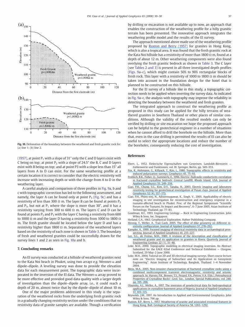
Fig. 10. Delineation of the boundary between the weathered and fresh granitic rock for:(a) line 1; (b) line 2.
37P.H. Giao et al. / Journal of Applied Geophysics 65 (2008) 30–38
(1957), at point P1 with a slope of 31° only the C and D layers exist withC being on top; at point P2 with a slope of 24.5° the B, C and D layersexist with B being on top; and at point P3 with a slope less than 15° alllayers from A to D can exist. For the same weathering profile at acertain location it is correct to consider that the electric resistivity willincrease with increasing depth or with the change from A to D in theweathering layer.
A careful analysis and comparison of three profiles in Fig. 9a, b andc with topographic correction has led to the following assessment, andnamely, the layer A can be found only at point P3 (Fig. 9c) and has aresistivity of less than 300 Ω m. The layer B can be found at points P2and P3, but not at P1 where the slope is more than 30°, and it has aresistivity varying from 300 to 600 Ω m. The layers C and D can befound at points P2 and P3 with the layer C having a resistivity from 600to 1000 Ω m and the layer D having a resistivity from 1000 to 1800 Ωm. The fresh granite should be located below the layer D and has aresistivity higher than 1800 Ω m. Separation of the weathered layersbased on the resistivity of each zone is shown in Table 3. The boundaryof fresh and weathered granites could be successfully drawn for thesurvey lines 1 and 2 as seen in Fig. 10a and b.
7. Concluding remarks
An EI surveywas conducted at a hillside of weathered granites nextto the Kata Noi beach in Phuket, using two arrays e.g. Wenner-α anddipole–dipole. A leveling survey was done to provide the elevationdata for each measurement point. The topographic data were incor-porated in the inversion of the EI data. The Wenner-α array proved tobe more effective and provided good data quality with a larger depthof investigation than the dipole–dipole array, i.e., it could reach adepth of 20 m, almost twice that by the dipole–dipole of about 10 m.
One of the major problems addressed in this study is the sepa-ration of the weathered rocks from the underlying fresh granitic rockin a gradually changing resistivity section under the conditions that noresistivity data of granite samples are available. Though a verification
by drilling or excavation is not available up to now, an approach thatenables the construction of the weathering profile for a hilly graniticterrain has been presented. The innovative approach integrates theweathering profile model and the results of the EI survey.
The approachmentioned abovemade use of theweathering profileproposed by Ruxton and Berry (1957) for granites in Hong Kong,which is also a tropical area. It was found that the fresh granitic rock atthe Kata Noi hillside has a resistivity of more than 1800Ωm, found at adepth of about 12 m. Other weathering components were also foundoverlying the fresh granitic bedrock as shown in Table 3. The C layer(see Tables 2 and 3) is present in all three investigated depth profiles(Figs. 9a–c), which might contain 50% to 90% rectangular blocks offresh rock. This layer with a resistivity of 1000 to 1800 Ω m should betaken into account in the foundation design for the hotel that isplanned to be constructed on this hillside.
For the EI survey of a hillside like in this study, a topographic cor-rection needs to be applied when inverting the survey data. As indicatedin Fig. 9a–c, the analysis with topography may improve the reliability indetecting the boundary between the weathered and fresh granites.
The integrated approach to construct the weathering profile asproposed in this study can be applied for the hilly terrains of wea-thered granites in Southern Thailand or other places of similar con-ditions. Although the validity of the resulted models can only beverified by drilling or site excavation we hope the proposed approachcan be helpful to the geotechnical engineer in a number of situationswhen he cannot afford to drill the borehole on the hillside. More thanthat, even in the case drilling is permitted the results of EI can also beuseful to select the appropriate locations and reduce the number ofthe boreholes, consequently reducing the cost of investigation.
References
Ebert, L., 1952. Elektrische Eigenschaften von Gesteinen. Landoldt-Börnstein —
Zahlenwerte und Funktionen, vol. III. Springer, Berlin, pp. 349–353.Fox, R., Hohmann, G., Killpack, T., Rjio, L., 1980. Topographic effects in resistivity and
induced polarization surveys. Geophysics 45, 75–93.Frohlich, R.K., Fisher, J.J., Summerly, E., 1996. Electric–hydraulic conductivity correlation
in fractured crystalline bedrock: Central Landfill, Rhode Island, USA. Journal ofApplied Geophysics 35, 249–259.
Giao, P.H., Chung, S.G., Kim, D.Y., Tanaka, H., 2003. Electric imaging and laboratoryresistivity testing for geotechnical investigation of Pusan clays. Journal of AppliedGeophysics 52 (4), 157–175.
Giao, P.H., Phien-wej, N., Adisornsupawat, K., Singh, V., 2005. Applicability of electricimaging in site investigation for reconstruction and emergency response in atsunami-affected beach in Phuket. Proc. of the Regional Symposium “ScientificForum on the Tsunami, Its Impact and Recovery”, 6–7 June 2005. Asian Institute ofTechnology, Thailand, pp. 77–83.
Goodman, R.E., 1993. Engineering Geology — Rock in Engineering Construction. JohnWiley & Sons, Inc, Singapore.
Heiland, C.A., 1963. Geophysical Exploration. Hafner Publishing Company.Hennig, T., Weller, A., Tran Canh, 2005. The effect of dike geometry on different re-
sistivity configuration. Journal of Applied Geophysics 57, 278–292.Kampke, A., 1999. Focused imaging of electrical resistivity data in archaeological pros-
pecting. Journal of Applied Geophysics 41, 215–227.Lee, S.G., de Freitas, M.H., 1989. A revision of the description and classification of
weathered granite and its application to granites in Korea. Quarterly Journal ofEngineering Geology 22 (1), 31–48.
Loke, M.H., 2000. Topographic modeling in electrical imaging inversion. An AbstractSubmitted for the EAGE 62nd Conference and Technical Exhibition — Glasgow,Scotland, 29 May–2 June 2000.
Loke, M.H., 2004. Tutorial on 2D and 3D electrical imaging surveys. Short course lecturenote on “Electric Imaging of Subsurface and Its Application in GeosystemEngineering”. Asian Institute of Technology, Bangkok, Thailand. 1–4 November2004.
Meju, M.A., 2005. Non-invasive characterisation of fractured crystalline rocks using acombined multicomponent transient electromagnetic, resistivity and seismicapproach. In: Harvey, P.K., Brewer, T.S., Pezard, P.A., Petrov, V.A. (Eds.), PetrophysicalProperties of Crystalline Rocks’. Geol. Soc., London, Special Publications, vol. 240,pp. 195–206.
Olayinka, A.I., Weller, A., 1997. The inversion of geoelectrical data for hydrogeologicalapplications in crystalline basement areas of Nigeria. Journal of Applied Geophysics37, 103–115.
Reynolds, J.M., 1997. An Introduction to Applied and Environmental Geophysics. JohnWiley & Sons. 796 pp.
Ruxton, B.P., Berry, L., 1957. Weathering of granite and associated erosional features inHong Kong. Bull. Geological Society of America 58, 1263–1292.

38 P.H. Giao et al. / Journal of Applied Geophysics 65 (2008) 30–38
Schleifer, N., Weller, A., Schneider, S., Junge, A., 2002. Investigation of a Bronze Ageplankway by spectral induced polarisation. Archaeological Prospection 9, 243–253.
Silvester, P.P., Ferrari, R.L., 1990. Finite Elements for Electrical Engineers, 2nd Ed.Cambridge University Press.
Tong, L., Yang, C., 1990. Incorporation of topography into 2-D resistivity inversion.Geophysics, 55, 354–361.
Telford, W.M., Geldart, L.P., Sheriff, R.E., Keys, D.A., 1976. Applied Geophysics. CambridgeUniversity Press, Cambridge.
Weller, A., Seichter, M., Kampke, A., 1996. Induced-polarization modelling using com-plex electrical conductivities. Geophysical Journal International 127, 387–398.
Weller, A., Tran Canh, Breede, K., Nguyen, T.V., 2006. Multi-electrode measurements atThai Binh dikes. Near Surface Geophysics 4, 135–143.