Embed Size (px)
Citation preview

Innovative bridge foundation for hilly regions
Autor(en): Mishra, Deena Nath
Objekttyp: Article
Zeitschrift: IABSE reports = Rapports AIPC = IVBH Berichte
Band (Jahr): 80 (1999)
Persistenter Link: http://doi.org/10.5169/seals-60789
PDF erstellt am: 12.08.2022
NutzungsbedingungenDie ETH-Bibliothek ist Anbieterin der digitalisierten Zeitschriften. Sie besitzt keine Urheberrechte anden Inhalten der Zeitschriften. Die Rechte liegen in der Regel bei den Herausgebern.Die auf der Plattform e-periodica veröffentlichten Dokumente stehen für nicht-kommerzielle Zwecke inLehre und Forschung sowie für die private Nutzung frei zur Verfügung. Einzelne Dateien oderAusdrucke aus diesem Angebot können zusammen mit diesen Nutzungsbedingungen und denkorrekten Herkunftsbezeichnungen weitergegeben werden.Das Veröffentlichen von Bildern in Print- und Online-Publikationen ist nur mit vorheriger Genehmigungder Rechteinhaber erlaubt. Die systematische Speicherung von Teilen des elektronischen Angebotsauf anderen Servern bedarf ebenfalls des schriftlichen Einverständnisses der Rechteinhaber.
HaftungsausschlussAlle Angaben erfolgen ohne Gewähr für Vollständigkeit oder Richtigkeit. Es wird keine Haftungübernommen für Schäden durch die Verwendung von Informationen aus diesem Online-Angebot oderdurch das Fehlen von Informationen. Dies gilt auch für Inhalte Dritter, die über dieses Angebotzugänglich sind.
Ein Dienst der ETH-BibliothekETH Zürich, Rämistrasse 101, 8092 Zürich, Schweiz, www.library.ethz.ch
http://www.e-periodica.ch

427
INNOVATIVE BRIDGE FOUNDATION FOR HILLY REGIONS
The CIDF system is a combination of a group of Auger Bored Compaction Under-reamed Piles
(ABCUP) of small length with grid beams and top slab supported on soil may be used as an innovativefoundation system for bridges in eastern provinces .of India. However this paper deals with analysis of the
foundation and provides some useful data required for design in the field.
IntroductionThe innovative design of combined intermediate depth foundation (CIDF) system is derived from
the stilt root system of plants. In present era of development demand of energy is increasing day by day
resulting in effort requirement for the digging of more and more oil wells, presently we are looking lornorth-east provinces of the country for the natural source of enetgy. These provinces are mostly surrounded
by the hills. For the transportation of oil and gases piplines are used and for crossing the deep gorges cable
bridges are frequently used. However this paper is devoted to the analysis of suitable bridge foundation
especially for these regions.
The Bridge FoundationA modified structural form comprising of conventional under-reamed piles (ABCUP) combined
with grillage cap for transferring the load of bridge particularly at the banks of stream. As we know the
deep gorges and valleys are tire common feature of hills. The CIDF system seem to be very suitable where
load transferring is not possible at the shallow depth level and anchoring is required. The essential
requirements in the design of a foundation are
i. The total settlement of tire structureii. Differential settlement along with other design capabilities.
To limit settlements it is necessary to transfer the load of the structure to the soil stratum of sufficient
strength and to spread the load over a sufficiently latge area of the stratum to minimise bearing pressure.
However, if the soil of adequate strength is not available immeiately below the bridge support CIDF system
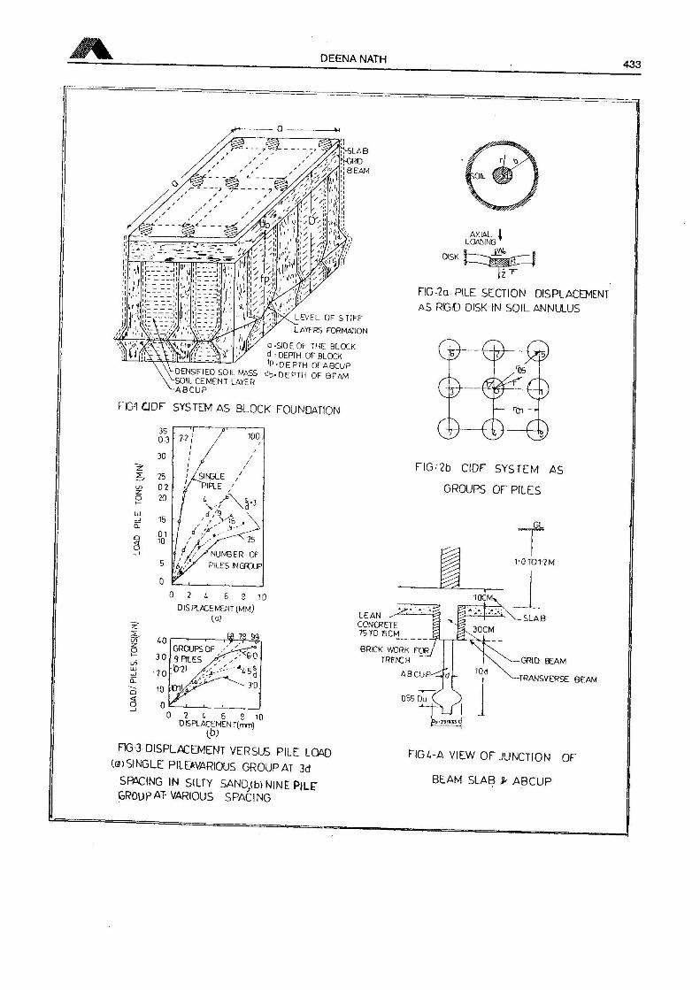
(Fig. 1 and Fig.4) may be used to transmit the load.
The range of the allow able skin friction for auger Bored Compaction Under-reamed Pile (ABCIT)varies between 180 to 300 kN/m2 (Brandl 1988) where in ordinary under-reamed pile maximum value ofskin friction is only 110 kN/m2. still more allowable values of the skin friction are expected but for the
design purposes these values are suggested for evaluating the effectiveness of CIDF system.
* Dr. Deena Nath Mishra is a senior faculty member and reputed structural engineer of Civil EngineeringDeptt., M.M.M. Engineering College Gorakhpur- 273010 India.Address for Communication.Dr. D.N. Mishra. Shwetambari Outer West load Suiaj Kund A.V. Colony,Gorakhpur-273015 Te. 91-551-250435, Fax 91-551-334157
Summary
» DEENA NATH
The ABCUP

428 INNOVATIVE BRIDGE FOUNDATION FOR HILLY REGIONS
Foundation and Natural Root SystemTo extend the correlation and draw useful inference between natural plant root system and the man
made foundation system, overall study of various rott system, particularly the modified form are logical.
Similar to foundation the ma|or function of root is to anchor the plant and resist load due to weight, wind
and so on. Functional comparison of foundation and root further reflect similarity lit mechanism of load
transfer m both the cases lriction and by bearing resistance.
Skin FrictionApart from vertical load transmitted to soil mass by skin friction at side faces of capping beam it
also transmit the load in bearing for design purpose of well foundation, the values of skin friction as
recommended by Terzaghi and Peek (2) given in fable-1 may be used for load transfer contribution
Table - 1
Reconunended Skin Friction
Type of soil Density Skin FrictionkN/m3 kN/m3
Silt & soft clav 130 7.25-30
Very stiff clay 143 50-200
Loose Sand 151 10
Medium Dense sand 181 15
Dense Sand 212 50-100
Dense gravel 212 50-100
Assumption
Following assumptions are made for composite block analysis.
1. the depth of the block is consideied equal to the sum of depth of beam and the length of pile.
2. The total axial lond carrying capacity of the block is equal to the sum of resistance offered by the all
four sides of the foundation block due to allowable skin friction and allowable bearing offered at
the face of the block. (Fig. 1
3. Due to confinement and densification of soil the block, coefficient k, improves so that it is morerealistic to assume improved of the skin fnction for calculation of sides resistance of the block.
4. The combined structuie of slab and beam will jointly behave like a rigid cap
5 The soil contained within the penpheially circumscribing all the piles behave like a solid compositeconfined mass
DEENA NATH 429
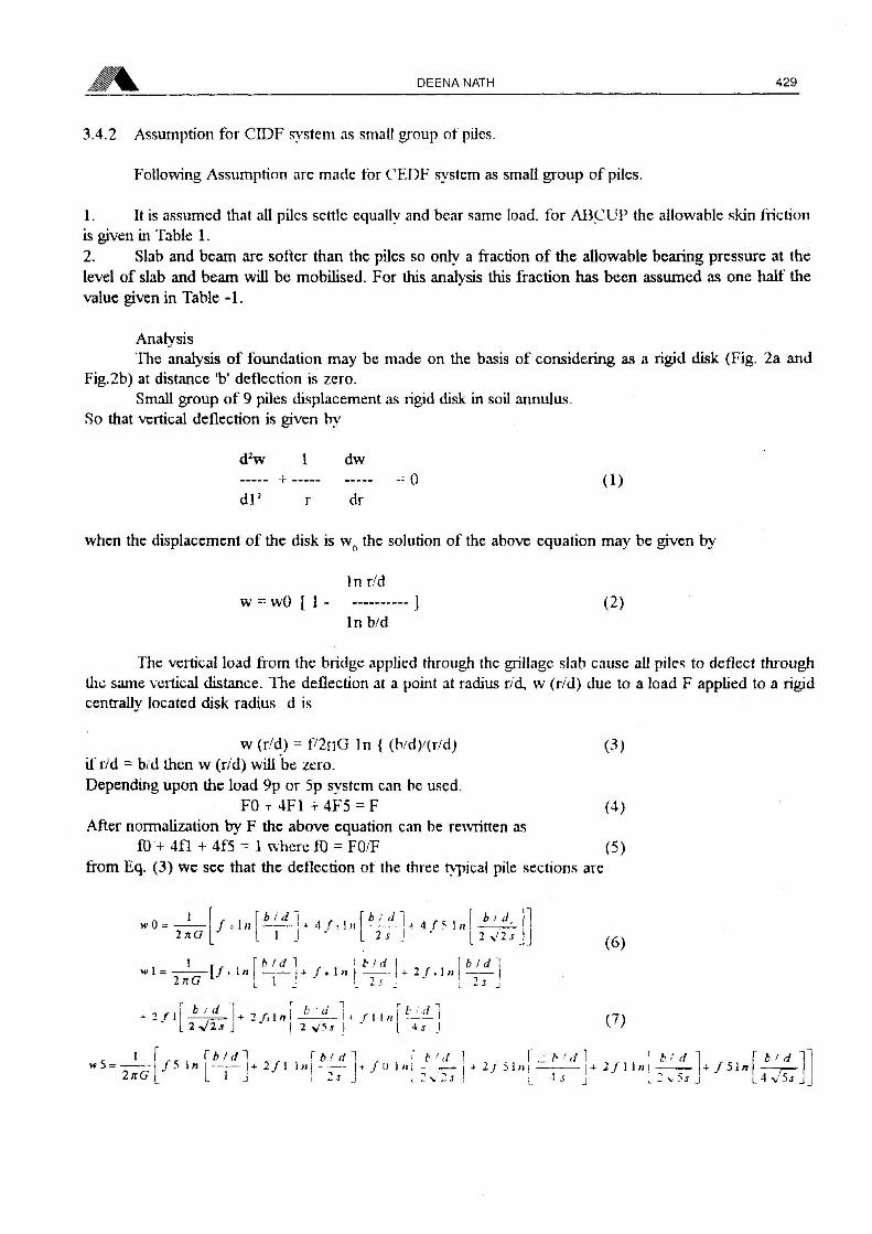
3.4.2 Assumption for CIDF system as small group of piles.
Following Assumption are made for CEDF system as small group of piles.
1. It is assumed that all piles settle equally and bear same load, for ABCUP the allowable skin frictionis given in Table 1.
2. Slab and beam are solter than the piles so only a fraction of the allowable bearing pressure at the
level of slab and beam will be mobilised. For this analysis this fraction has been assumed as one half the
value given in Table -1.
AnalysisThe analysis of foundation may be made on the basis of considering as a rigid disk (Fig. 2a and
Fig.2b) at distance 'b' deflection is zero.Small group of 9 piles displacement as rigid disk in soil annulus.
So that vertical deflection is given by
d2w 1 dw+ --o (1)
dl2 r dr
when the displacement of the disk is w0 the solution of the above equation may be given by
1 n r/d
w wO [1 ] (2)In b/d
The vertical load from the bridge applied through the grillage slab cause all piles to deflect throughthe same vertical distance. The deflection at a point at radius r/d, vv (r/d) due to a load F applied to a rigidcentrally located disk radius d is
w (r/d) l72nG In { (b/d)/(r/d) (3)if r/d b/d then w (r/d) will be zero.Depending upon the load 9p or 5p system can be used.
FO -r 4F1 + 4F5 F (4)After normalization by F the above equation can be rewritten as
ID + 4fl + 4f5*~ 1 where ft) FO/F (5)from Eq. (3) we see that the deflection ol the three typical pile sections are
»02 nO / o 1 Ii f tuL j. 4 /", 1 « f i 4 f 5 ] n
L i j i is jb 1 J.
2 v'TJ
1 r £ i \b Id \
iïâ-V I —J- /•1 » -TTI-Î/.1»!
(6)
+ : r 11b 'I + 2 r, l n I JuL 11 /-11 ;i I l-—iL i
L 2 V2.I J"
I 2 v'SJ J I 4J J
<1 I" / C
^ b! d^ f ',i 1 r.z /',/! ^ \ b! d 1 r \ b t d ~\
"s —/5 In —— 1+2/1 Inj — | + /U In I T-— I + 2j 3ln| |+ +/1 ln| -—|+ /51n r—2/rCrj^ Llj \ j. s j » \ „ j J; l - v j l4v5j j

430 INNOVATIVE BRIDGE FOUNDATION FOR HILLY REGIONS
But since these dellection must all be the same we can writewO - wl 0 (9)
and wO - w5 1 0 (10)
The eq. (9) and Eq. (10) can be writcn as
10 in 2s + fl in (2/s) + 13 In (5/4) - 0 (11)and lOin 2 2s -+ 11 In 5 + f5 In ((2)/5] 0 (12)
from Eqs. (5). (11) and (12) one can get fO. fl and f5 for the value of s selected. When a solution is
obtained, the dimensionless displacement w' 2 H GW/T of the pile disk group can be find out by the use
of equation (5) and (6) or (7).
The subgrade reaction coefficient for each pile is computed by dividing the dimensionless force in
the pile by displacement w' thus
Ki 2nGfi/w' (13)However the coeflicent K for a solitary pile can be written
K' 2nG/ln(b/d) (14)The ratio of the individual reaction coefficient can be obtained
Ki /K - fi Av' 1 n (h'd) (15)The relevant values are given in Table 2.
Table - 2
Displacement. Forces and Relative Stiffness in a 9p system
GroupDisplacementEfficiency
Spacing kn ko k, k>
Diameters, FO Fl F5 w' or — — —S k k k k
2 -0.0298 0.0721 0.1854 2.2274 0.195 -0.0524 0.1266 0.32563 -0.0024 0.0820 0.1686 1.8822 0.231 -0.0051 0.1705 0.35044 0.0116 0.0864 0.1607 1.6338 0.266 0.277 0.2069 0.38485 0.0203 0.0890 0.1560 1.4399 0.302 0.0551 0.2417 0.42376 0.0264 0.0907 0.1527 1.2810 0.339 0.0806 0.2770 0.46638 0.0345 0.0929 0.1484 1.0294 0.422 0.1312 0.3697 0.564110 0.0417 0.0973 0.1423 0.8439 0.515 0.1932 0.4510 0.6596
Allowable Ixtad Carrying Capacity of CI I) F System(a) Block Foundation (Fig. 1)
P |Fs + FbJ - - weight of the blockWhere Fs and Fb are average allowable Fictional resistance and allowable bearing resistance at Depth T)'and P is the load carry ing capacity
DEENA NATH 431
(b)Clüh system as a small group ol piles.
P - Pp t Pb Ps (17)
Where Pp Pb and Ps are the load coined b\ the ABCUP, beam and tlie slab individually (Fig 4)
However the load earning capacity ol the foundation may be computed bv the use of Eq (16) and
hq (17) and the lower one will be treated as the load carrying capacity of the foundation the load settlement
and other values regarding load, spacing and diameter of ABCUP are shown m fig 3, Fig 6 and Fig 7
Conclusion
Following are the mam conclusions
1 If pile spacing is up to tliree tunes of the diameter thecentral pile will not be effective so that the
minimum spacing of ABCUP should be 4d
2 When the spacing of ABCftp is moie the load carrying capacity of individual pile group will be
moie so that the whole system, will canv moie load Although, due to interaction effect of pile to
pile average load earning capacity of individual pile m system will be lessei than single pile But mthe CIDF system contnbution ol end cap elleel ol densification, confinement will also come intothe picture resulting m moie load îriying capacity of the system
3 1 he confining effect in loose soil is moie than lhat of the denser soil
1 I oid cam mg capacity must be y enfied with field tests of minimum 2% of total number of ABCUPused
References
1 Brandl 11 1 he interaction between soil and groups of small diameter bored piles' Vanmpe (ed)1988 balUma ISBN 90619118146 (U k)
2 Nath D. Study ol combined Inlcimcdiatc depth foundation system AME dissertation UORRoorkee (1993)
3 Nath D and Nay ak < r C C ID! system as an innovative foundation CE & CR March 1995
4 Nayak OC and sondhi 1 Combined uell shell pile foundation as innovative deep foundationIndian Geotechmcal Jouranl (17(2) 1987
3 / lcnkicwic/, O C the finite element method m uigincumg Seicncc Me Giaw I fill I ondon - 1971

432 INNOVATIVE BRIDGE FOUNDATION FOR HILLY REGIONS
FlG-5 LOAD SETTLEMENT CHARACTERISTIC 5
OF PILE COMBINED WITH CAP AFTER
POLOUS AND DEVISatat.WZ)
2UJ
£
SPACING OF 200nrn DIAMETER.xk? ABCUP ;
SPACING OF 150mmOIAME!ERABCUP SPACNG OF250mmOlMETER ABCUP SPACING OF 300mmDIMETER ABI
FIG-6 spacing v? capacity ofcidf system
t%a.
DIMETER OF ABCUP INmm OfMETER OF »6CUP INmm DIMETER OFABCUP INmm
F167 DIAMETER OFABCUP Vs CAPACITY OFCIDF SYSTEM AT VARIOUS
SPACINGS OFABCUP
DEENA NATH 433
LEVEL OF STIFFLAYFRS FORMATION
a-SIDE OF THE BLOCKd - DEPTH OF BLOCK
v^-DEPTH 0FA8CUP
OENSIFIEO SOIL MASS Jb* DEPTH OF BEAMSOIL CEMENT LAYER
'-ABCUP
FG-1 CJDF SYSTEM AS BLOCK FOUNDATION
0 2 £ 6 S 10DISPLACEMENT (MM)
la?
78 99
AXIAL 1
LOALING
DISK
FIG-2a pile SECTION DISPLACEMENTAS RGID DISK IN SOIL ANNULUS
©©©>— TJ» —
©—©—©FIG-2b CIDF SYSTEM AS
GROUPS OF PÎL ES
1-OTOT2M
BRICK WORK FORTRENCH
AB CUP
0 7 4 6 S 10D IS PL ACEMEN T(_mm)
F1G-3 DISPLACEMENT VERSUS PILE LOAD(O)SINGLE PILE*VARIOUS GROUPAT 3d
SPACING IN SILTY SAND(b) NINE PILE"GROUPAT-VARIOUS SPACING
GRID BEAM
-TRANSVERSE BEAM
FIG4-A VIEW OF JUNCTION OF
BEAM SLAB p ABCUP

Leere SeiteBlank pagePage vide


![l'armorial Wijnbergen [suite et fin] - E-Periodica](https://img.dokumen.tips/doc/110x75/63343fbff59f4bbe810a897a/larmorial-wijnbergen-suite-et-fin-e-periodica.jpg)