Embed Size (px)
Citation preview
Outstanding composite structures for buildings
Autor(en): Hanswille, Gerhard
Objekttyp: Article
Zeitschrift: IABSE reports = Rapports AIPC = IVBH Berichte
Band (Jahr): 999 (1997)
Persistenter Link: http://doi.org/10.5169/seals-949
PDF erstellt am: 23.07.2022
NutzungsbedingungenDie ETH-Bibliothek ist Anbieterin der digitalisierten Zeitschriften. Sie besitzt keine Urheberrechte anden Inhalten der Zeitschriften. Die Rechte liegen in der Regel bei den Herausgebern.Die auf der Plattform e-periodica veröffentlichten Dokumente stehen für nicht-kommerzielle Zwecke inLehre und Forschung sowie für die private Nutzung frei zur Verfügung. Einzelne Dateien oderAusdrucke aus diesem Angebot können zusammen mit diesen Nutzungsbedingungen und denkorrekten Herkunftsbezeichnungen weitergegeben werden.Das Veröffentlichen von Bildern in Print- und Online-Publikationen ist nur mit vorheriger Genehmigungder Rechteinhaber erlaubt. Die systematische Speicherung von Teilen des elektronischen Angebotsauf anderen Servern bedarf ebenfalls des schriftlichen Einverständnisses der Rechteinhaber.
HaftungsausschlussAlle Angaben erfolgen ohne Gewähr für Vollständigkeit oder Richtigkeit. Es wird keine Haftungübernommen für Schäden durch die Verwendung von Informationen aus diesem Online-Angebot oderdurch das Fehlen von Informationen. Dies gilt auch für Inhalte Dritter, die über dieses Angebotzugänglich sind.
Ein Dienst der ETH-BibliothekETH Zürich, Rämistrasse 101, 8092 Zürich, Schweiz, www.library.ethz.ch
http://www.e-periodica.ch
41
Outstanding Composite Structures for Buildings
Gerhard HANSWILLEUniv.-Prof. Dr.-Ing.University of WuppertalWuppertal, Germany
G. Hanswille, born 1951, civil eng. Universityof Bochum, involved in composite bridge and
building design for many years and partner ofHRA consulting engineers in Bochum. Since1992 Professor and head of the Institute forsteel and composite structures at the Universityof Wuppertal. Member of the project teamEC4-2 and chairman of the working group forcomposite structures of the German StandardInstitution.
Summary
The paper gives an overview of the development of composite structures for buildings inGermany in recent years. The background and advantage of partially concrete encased
columns and girders is demonstrated with three buildings for the car industry, an officebuilding and the extension of the airport in Hannover. Furthermore two impressive high risebuildings in Düsseldorf and Frankfurt will be presented.
1 Introduction
Comparing the development of composite structures for buildings in Europe it is obvious thatin contrast with neighbouring countries, in Germany the technology with partially concreteencased members has been favoured over the last twenty years. The paper will show the
advantages of this technology for some typical examples of outstanding composite structuresfor industrial and office buildings.
2 Buildings for the Car Industry
2.1 General
Industrial buildings for the car industry require a high flexibility because the technicalequipment must be converted frequently during the design life. The Figures 1 to 3 show threetypical buildings for the car industry built between 1982 and 1992. These buildingsdemonstrate the development of composite structures from the conventional type to the moderntechnology of concrete encased beams and columns with significant advantages, regarding fireresistance as well as durability and last but not least economic benefit.
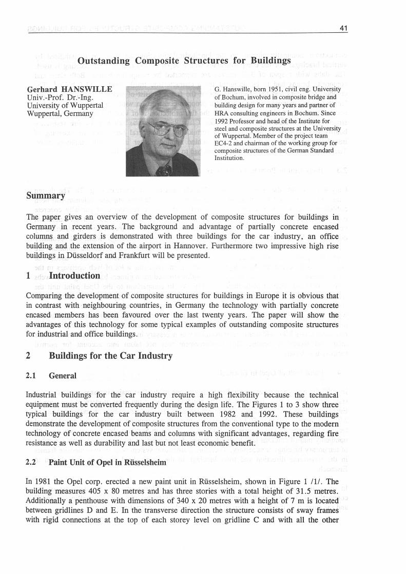
2.2 Paint Unit of Opel in Rüsselsheim
In 1981 the Opel corp. erected a new paint unit in Rüsselsheim, shown in Figure 1 III. Thebuilding measures 405 x 80 metres and has three stories with a total height of 31.5 metres.Additionally a penthouse with dimensions of 340 x 20 metres with a height of 7 m is locatedbetween gridlines D and E. In the transverse direction the structure consists of sway frameswith rigid connections at the top of each storey level on gridline C and with all the other
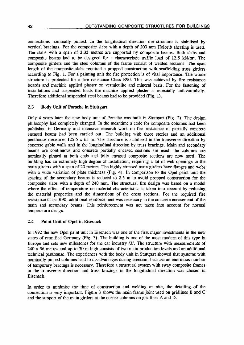
42 OUTSTANDING COMPOSITE STRUCTURES FOR BUILDINGS
connections nominally pinned. In the longitudinal direction the structure is stabilised byvertical bracings. For the composite slabs with a depth of 200 mm Holorib sheeting is used.The slabs with a span of 3.33 metres are supported by composite beams. Both slabs and
composite beams had to be designed for a characteristic traffic load of 12,5 kN/m2. Thecomposite girders and the steel columns of the frame consist of welded sections The spanlength of the composite slabs required a propped construction with scaffolding truss girdersaccording to Fig. 1. For a painting unit the fire protection is of vital importance. The wholestructure is protected for a fire resistance Class R90. This was achieved by fire resistanceboards and machine applied plaster on vermiculite and mineral basis. For the fastening ofinstallations and suspended loads the machine applied plaster is especially unfavourabely.Therefore additional suspended steel beams had to be provided (Fig. 1).
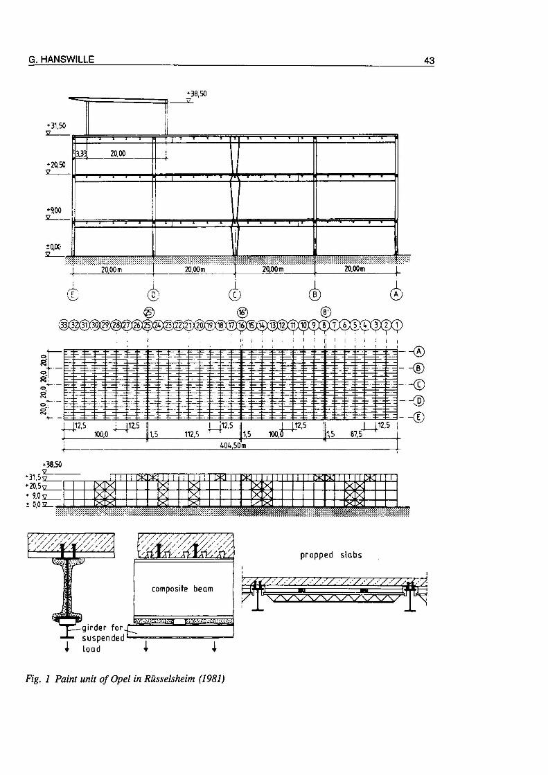
2.3 Body Unit of Porsche in Stuttgart
Only 4 years later the new body unit of Porsche was built in Stuttgart (Fig. 2). The designphilosophy had completely changed. In the meantime a code for composite columns had been
published in Germany and intensive research work on fire resistance of partially concreteencased beams had been carried out. The building with three stories and an additionalpenthouse measures 125.5 x 65 m. The structure is stabilised in the transverse direction byconcrete gable walls and in the longitudinal direction by truss bracings. Main and secondarybeams are continuous and concrete partially encased sections are used; the columns are
nominally pinned at both ends and fully encased composite sections are now used. The
building has an extremely high degree of installation, requiring a lot of web openings in themain girders with a span of 20 metres. The highly stressed main girders have flanges and webswith a wide variation of plate thickness (Fig. 4). In comparison to the Opel paint unit the
spacing of the secondary beams is reduced to 2.5 m to avoid propped construction for the
composite slabs with a depth of 240 mm. The structural fire design was based on a modelwhere the effect of temperature on material characteristics is taken into account by reducingthe material properties and the dimensions of the cross sections. For the required fireresistance Class R90, additional reinforcement was necessary in the concrete encasement of the
main and secondary beams. This reinforcement was not taken into account for normal
temperature design.
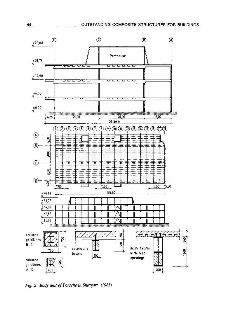
2.4 Paint Unit of Opel in Eisenach
In 1992 the new Opel paint unit in Eisenach was one of the first major investments in the newstates of reunified Germany (Fig. 3). The building is one of the most modern of this type inEurope and sets new milestones for the car industry 131. The structure with measurements of240 x 56 metres and up to 30 m high consists of two main production levels and an additionaltechnical penthouse. The experiences with the body unit in Stuttgart showed that systems withnominally pinned columns lead to disadvantages during erection, because an enormous numberof temporary bracings is necessary. Therefore a structural system with sway composite frames
in the transverse direction and truss bracings in the longitudinal direction was chosen inEisenach.
In order to minimise the time of construction and welding on site, the detailing of the
connection is very important. Figure 3 shows the main frame joint used on gridlines B and Cand the support of the main girders at the corner columns on gridlines A and D.
G. HANSWILLE 43
3150
n v1
20,50
—1 1 1 1—*— "
m 2000—+
1
iii i i |i
9,00v
' | i i i i1
0,00
"1
J 20,00 m 2000m 20,00m 20,00m j
(£ <£> (i) (i)
® ©v33X3^3lY30Y29Y28)(27Y26X25ÂY23Y22Y2lY20Xl9Yl8XÏ7Yl6Y^1^1?)(l2XÎÎYÎÔX9Yi^X6X5Y4X3X2Yl]
112.5 I 1112.5 « 1112,5 || J 112 5
100,0 ^ j 1,5 112 S ^ 1.5 100.IJ P 87,5
404,50m
38,50
"31 5sz_20 5y_* 90s_
002_
mil 111 lap 11111 r*T*11 injPTTT7
* ;r w.,
' //'VW//'/,
-girder forsuspended
I loQd 4
propped slabs
Fig. 1 Paint unit of Opel in Rüsselsheim (1981)
44 OUTSTANDING COMPOSITE STRUCTURES FOR BUILDINGS
29,88 9 9
21,75
14,90
6,85
J U LJ L1
Penthouse
in
±0,002
I26,00 JQ4Q t 12,00 J.
56,26 m
0 (p (p Ç) (p (p (8) (9) (10) (i) (B) (Ip (£) (15) (JS)
7,50: '5,50
29,88 125.50 m
21,75
6,85V
0,00
i —n/ " '1
A fl i1 V
i on in II
nï II III IAA H
columns
gndlinesB, C
700
XZZZZäZZZÄI
secondarybeams
columns
gr idlinesA ,0 ' 400 I
"n
m
Wr7/r\
150
I
main beams
with web
openings
I
1 §
S
400
Fig. 2 Body unit of Porsche in Stuttgart (1985)
G. HANSWILLE 45
®4~
B) ©54,00 ;
18,00 J 16,00
30,60_SL
18,00
D) 's> -
'&S&
+ 20,00
>8,90
•PENTHOUSE -3
\/yyzz/*yy///.?\ ^
[ 1180 secondarybeam
®~o1Ocd
®-o-Oao
cd
^+30,60
„20,00
(p (|) (|) © (p (8) (p®Jppd6) ^ ^ dpTT1Z0C^12,0| „
mmm12,0j
X Xr* î^s
/\
giidlinesA and D
level 8,90 |gg
frame jointgridlinesB and C
level +8,90
Fig. 3 Paint unit of Opel in Eisenach (1992)
46 OUTSTANDING COMPOSITE STRUCTURES FOR BUILDINGS
The depth of the columns changes at each storey level, and the supporting reactions of themain girders are introduced into the columns by end plates. The bending moments aretransferred into the columns by reinforcement and contact plates at the top flange and bycontact in combination with welded plates at the bottom flange. In comparison with the paintunit in Rüsselsheim, the composite columns had the advantage of increasing the horizontalstiffness of the frame significantly. To avoid the high costs for the formwork of completelyconcrete encased sections, partially encased sections are used for the columns. Additionallythis has the advantage that new installations can be fixed at the free steel flanges withoutdifficulties. In Germany it was the first time that a mixed system with composite columns,composite girders and steel trusses was designed as a composite sway frame. The design ofthis type of framing is not covered by Eurocode 4 and the national German codes. In a firsttrial calculation an elastic calculation was carried out with an effective cracked stiffness for thecolumns. The effect of cracking of concrete in the main girders was taken into account byreducing the stiffness at internal supports to the stiffness of the steel section consisting ofstructural steel and reinforcement. Effects of creep and shrinkage were taken into account byuse of different modular ratios for permanent actions, shrinkage and hyperstatic effects
developing in time. For the standard frames the second order effects lead to an increase ofbending moments up to 25%, which is significantly lower than the second order effects of thesteel frame of Opel Rüsselsheim. In a second step, a non-linear calculation was carried out forcritical load arrangements, taking into account cracking of concrete and tension stiffeningeffects. These calculations have shown that the simplified method gives safe results.
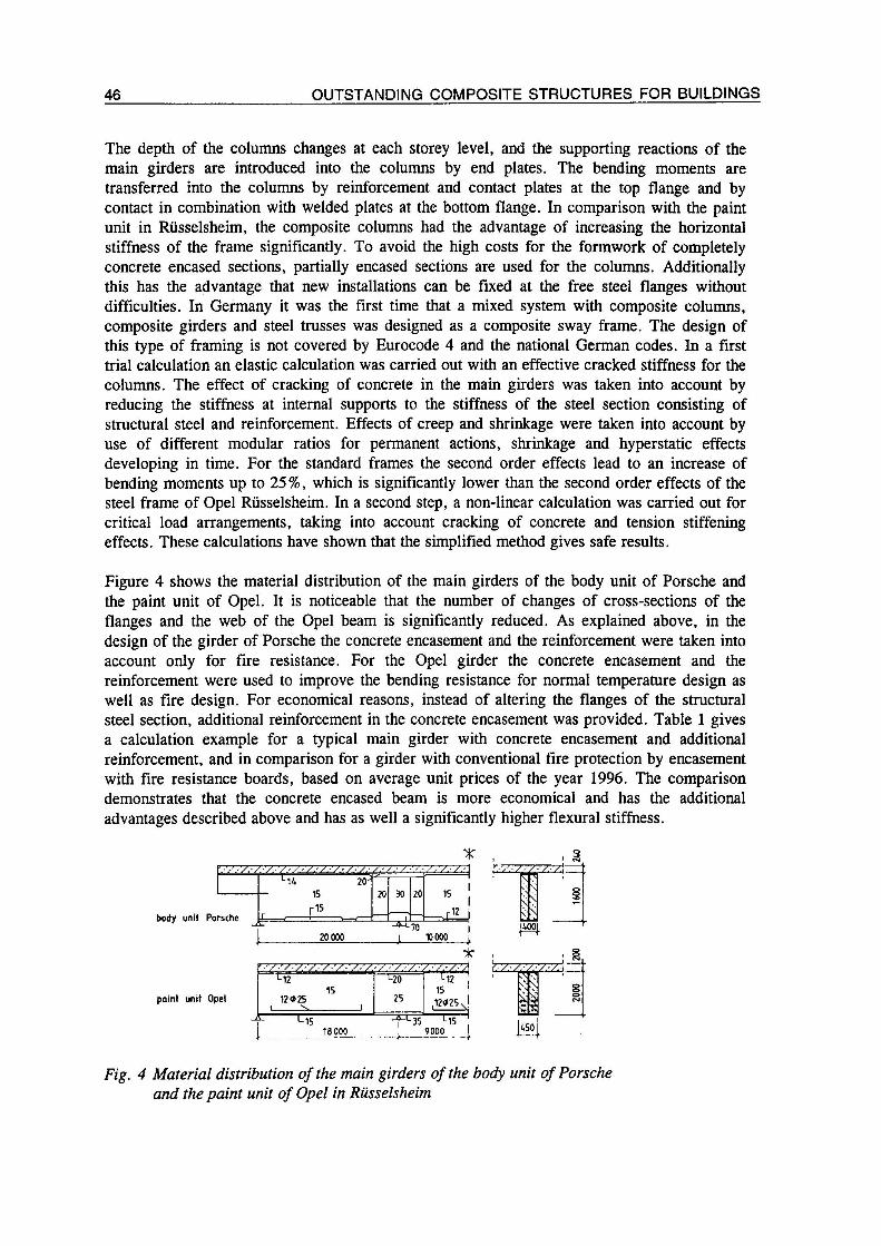
Figure 4 shows the material distribution of the main girders of the body unit of Porsche and
the paint unit of Opel. It is noticeable that the number of changes of cross-sections of the
flanges and the web of the Opel beam is significantly reduced. As explained above, in the
design of the girder of Porsche the concrete encasement and the reinforcement were taken intoaccount only for fire resistance. For the Opel girder the concrete encasement and thereinforcement were used to improve the bending resistance for normal temperature design as
well as fire design. For economical reasons, instead of altering the flanges of the structuralsteel section, additional reinforcement in the concrete encasement was provided. Table 1 givesa calculation example for a typical main girder with concrete encasement and additionalreinforcement, and in comparison for a girder with conventional fire protection by encasementwith fire resistance boards, based on average unit prices of the year 1996. The comparisondemonstrates that the concrete encased beam is more economical and has the additional
advantages described above and has as well a significantly higher flexural stiffness.
body unit Porsche
paint unit Opel
20 000^-70
10000
*T:
M215
12*251 'S 1
L20
25
L12
151
,12*25nI
L L1518000
-fL35>. —
Li59000
0 \$
1 h
uso
Fig. 4 Material distribution of the main girders of the body unit of Porsche
and the paint unit of Opel in Rüsselsheim
G. HANSWILLE 47
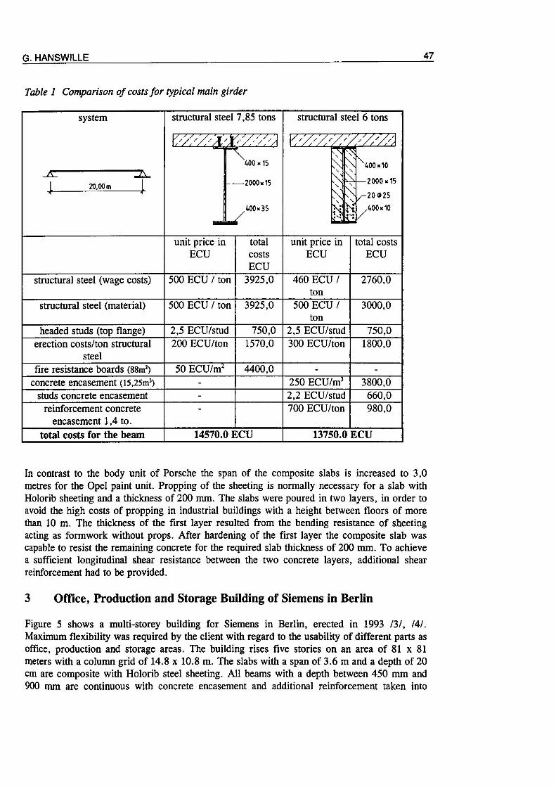
Table 1 Comparison of costs for typical main girder
In contrast to the body unit of Porsche the span of the composite slabs is increased to 3,0metres for the Opel paint unit. Propping of the sheeting is normally necessary for a slab withHolorib sheeting and a thickness of 200 mm. The slabs were poured in two layers, in order toavoid the high costs of propping in industrial buildings with a height between floors of morethan 10 m. The thickness of the first layer resulted from the bending resistance of sheetingacting as formwork without props. After hardening of the first layer the composite slab wascapable to resist the remaining concrete for the required slab thickness of 200 mm. To achievea sufficient longitudinal shear resistance between the two concrete layers, additional shearreinforcement had to be provided.
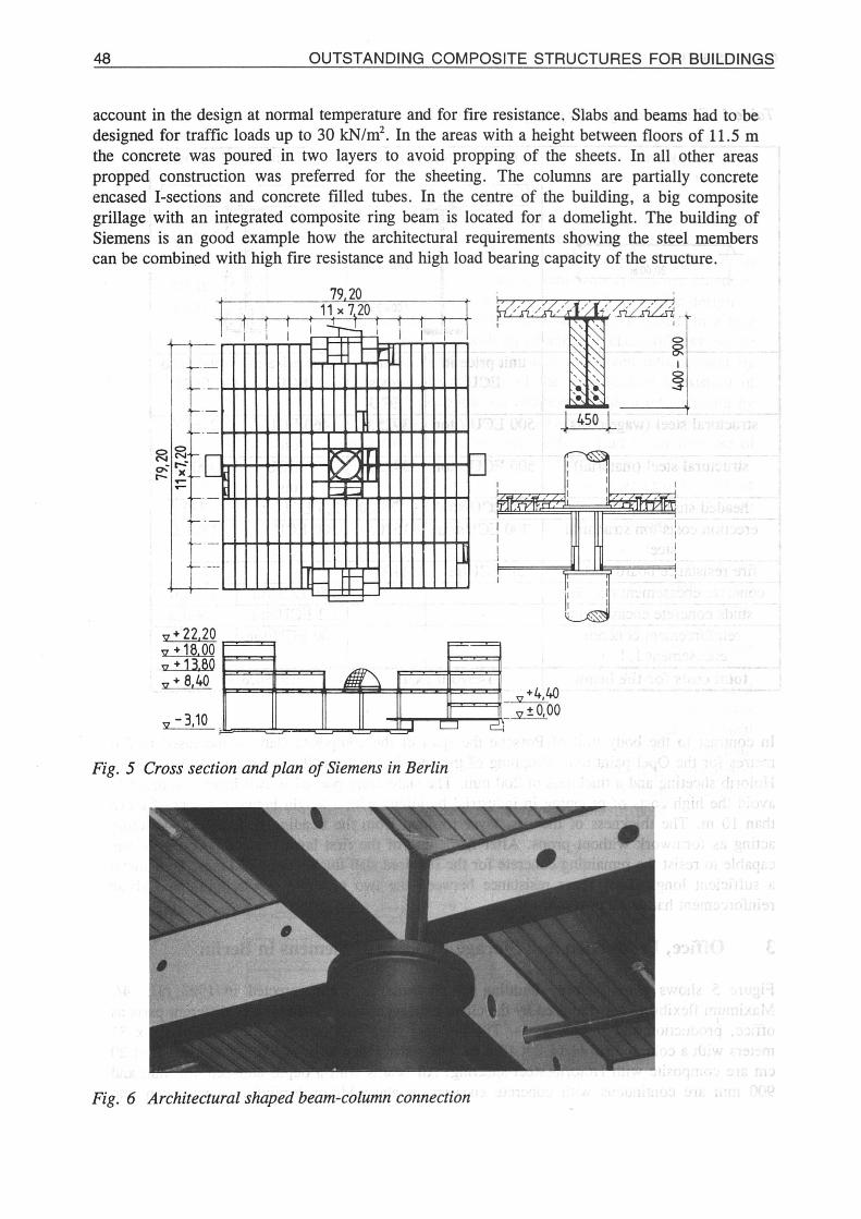
3 Office, Production and Storage Building of Siemens in Berlin
Figure 5 shows a multi-storey building for Siemens in Berlin, erected in 1993 /3/, /4/.Maximum flexibility was required by the client with regard to the usability of different parts as
office, production and storage areas. The building rises five stories on an area of 81 x 81
meters with a column grid of 14.8 x 10.8 m. The slabs with a span of 3.6 m and a depth of 20cm are composite with Holorib steel sheeting. All beams with a depth between 450 mm and900 mm are continuous with concrete encasement and additional reinforcement taken into
48 OUTSTANDING COMPOSITE STRUCTURES FOR BUILDINGS
account in the design at normal temperature and for fire resistance. Slabs and beams had to be
designed for traffic loads up to 30 kN/m2. In the areas with a height between floors of 11.5 mthe concrete was poured in two layers to avoid propping of the sheets. In all other areas
propped construction was preferred for the sheeting. The columns are partially concreteencased I-sections and concrete filled tubes. In the centre of the building, a big compositegrillage with an integrated composite ring beam is located for a domelight. The building ofSiemens is an good example how the architectural requirements showing the steel members
can be combined with high fire resistance and high load bearing capacity of the structure.
79,20
8
t t ti i I
11 x 7.20
i- 22,20>18.00•13.80
8,40
,-3,10
0
M
1
1 '-J / /
Sj
i
mKilMESS.
I
1
1
1
i
1
1
i •=———
i!I '
i
4,40
"S",±0,00
Fig. 5 Cross section and plan of Siemens in Berlin
Fig. 6 Architectural shaped beam-column connection
G. HANSWILLE 49
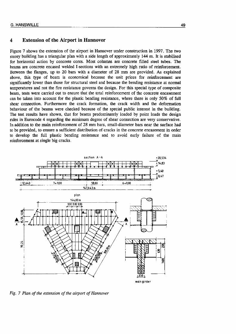
4 Extension of the Airport in Hannover
Figure 7 shows the extension of the airport in Hannover under construction in 1997. The twostorey building has a triangular plan with a side length of approximately 144 m. It is stabilisedfor horizontal action by concrete cores. Most columns are concrete filled steel tubes. Thebeams are concrete encased welded I-sections with an extremely high ratio of reinforcement.Between the flanges, up to 20 bars with a diameter of 28 mm are provided. As explainedabove, this type of beam is economical because the unit prices for reinforcement are
significantly lower than those for structural steel and because the bending resistance at normal
temperatures and not the fire resistance governs the design. For this special type of compositebeam, tests were carried out to ensure that the total reinforcement of the concrete encasementcan be taken into account for the plastic bending resistance, where there is only 50% of fullshear connection. Furthermore the crack formation, the crack width and the deformationbehaviour of the beams were checked because of the special public interest in the building.The test results have shown, that for beams predominately loaded by point loads the designrules in Eurocode 4 regarding the minimum degree of shear connection are very conservative.In addition to the main reinforcement of 28 mm bars, small-diameter bars near the surface had
to be provided, to ensure a sufficient distribution of cracks in the concrete encasement in orderto develop the full plastic bending resistance and to avoid early failure of the mainreinforcement at single big cracks.
section A-A
147,643 m
plan
144,00m
mvmain girder
Fig. 7 Plan of the extension of the airport of Hannover
50 OUTSTANDING COMPOSITE STRUCTURES FOR BUILDINGS
5 High-rise Buildings
5.1 General
In 1997 two very interesting building projects will be finished in Düsseldorf and Frankfurt.The Stadttor (Towngate) in Düsseldorf 151 and the Commerzbank tower in Frankfurt 161. Bothhigh rise buildings use a large variety of different composite members with sophisticated load-bearing structures.
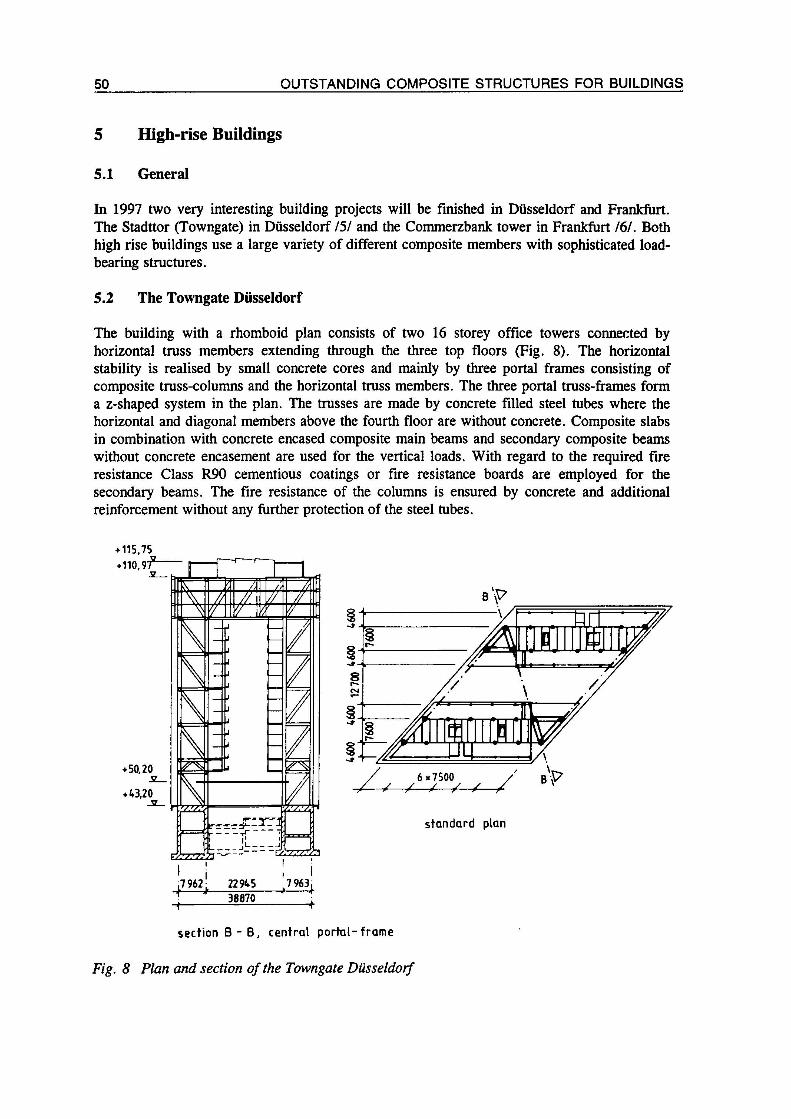
5.2 The Towngate Düsseldorf
The building with a rhomboid plan consists of two 16 storey office towers connected byhorizontal truss members extending through the three top floors (Fig. 8). The horizontalstability is realised by small concrete cores and mainly by three portal frames consisting ofcomposite truss-columns and the horizontal truss members. The three portal truss-frames forma z-shaped system in the plan. The trusses are made by concrete filled steel tubes where the
horizontal and diagonal members above the fourth floor are without concrete. Composite slabsin combination with concrete encased composite main beams and secondary composite beams
without concrete encasement are used for the vertical loads. With regard to the required fireresistance Class R90 cementious coatings or fire resistance boards are employed for the
secondary beams. The fire resistance of the columns is ensured by concrete and additionalreinforcement without any further protection of the steel tubes.
115,75
Fig. 8 Plan and section of the Towngate Düsseldorf
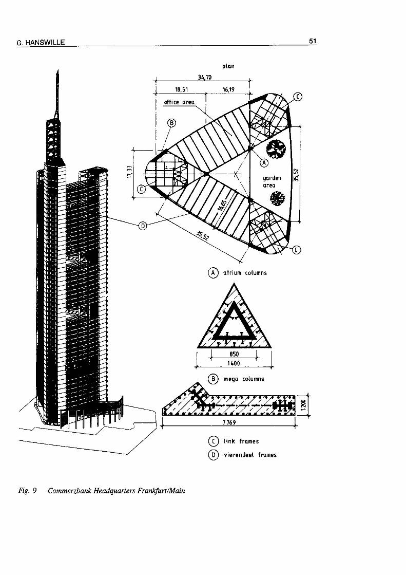
Fig. 9 Commerzbank Headquarters Frankfurt/Main
52 OUTSTANDING COMPOSITE STRUCTURES FOR BUILDINGS
5.3 Commerzbank Headquarters in Frankfurt /Main
The new building of the Commerzbank is the most interesting project in Germany at the
present time. With a overall height of 298.74 m, including antenna, 63 floors and an effectivearea of 52700 m2, the building will give room for 2400 employees of the Commerzbank. The
plan of the building has the shape of an equilateral triangle with rounded corners and slightlycurved sides with length of approximately 60 m (see Fig. 9). Three cores at the corners,ending at different heights, contain stair cases, elevators, adjoining corridors and theinstallation for the building. The cores are connected by office areas where the standard floorsconsist of two office areas. The third side is kept free over 4 storeys and contains a gardenarea. This standard floor plan is turned by 120 degree every four storeys. For the horizontalloads, a three dimensional structure (consisting of the mega-columns connected by link frames,the vierendeel frames located in the facade, and the composite slab floors) forms a tube, whichis fixed in the foundation. All other columns inside the cores and the atrium columns are
nominally pinned at both ends and do not contribute to the horizontal stability of the building.The composite floors consist of Super-Holorib sheeting in combination with light weightconcrete with a density class of 20. In the office area composite beams with welded sectionsand large web openings span between the atrium beams to the outside vierendeel steel frames.Within the cores mixed systems with steel and composite beams are used. The required fireresistance Class R120 for the beams was achieved by fire resistance boards. The atriumcolumns are designed as composite columns with an inner and outer equilateral-triangle steel
section with steel grades S460 and S355. Composite action is achieved by headed stud shear
connectors. Because this type of section is not covered by Eurocode 4, an elasto-plastic designhad to be carried out. The design for fire resistance is based on a reduced effective sectionwith decreased material properties. The mega columns in the edges of the plan consist of fullyconcrete encased steel trusses forming a composite column together with concrete and
additional reinforcement. All other columns are designed as steel members.
References
III Muess, H.: Anwendung der Verbundbauweise am Beispiel der neuen Opel-Lackiererei in Rüsselsheim, Der Stahlbau, Heft 3, 1982
121 Jost, E., Hanswille, G., Heddrich, R. Muess, H., Williams, D.A.: Die neue OpelLackiererei in feuerbeständiger Verbundbauweise, Der Stahlbau, Heft 8, 1992
131 Kurz, W.: A new composite Building in Berlin, Engineering FoundationConferences Composite Construction III, Irsee 1996
/4/ Eichhorn, H., Kühn, B., Muess, H.: Der Neubau der Siemens AG Verkehrstechnik inBerlin Treptow, Der Stahlbau 65, 1996
151 Lange, J.: The Düsseldorfer Stadttor - A 20 storey office Building in CompositeConstruction, Engineering Foundation Conferences Composite Construction HI,Irsee 1996
161 Ladberg, W.: Commerzbank-Hochhaus Frankfurt/Main, Planung, Fertigung und
Montage der Stahlkonstruktion, Der Stahlbau, Heft 10, 1996