Embed Size (px)
Citation preview
Long span steel bridges in Japan
Autor(en): Ito, Manabu
Objekttyp: Article
Zeitschrift: IABSE reports = Rapports AIPC = IVBH Berichte
Band (Jahr): 64 (1991)
Persistenter Link: http://doi.org/10.5169/seals-49343
PDF erstellt am: 27.07.2022
NutzungsbedingungenDie ETH-Bibliothek ist Anbieterin der digitalisierten Zeitschriften. Sie besitzt keine Urheberrechte anden Inhalten der Zeitschriften. Die Rechte liegen in der Regel bei den Herausgebern.Die auf der Plattform e-periodica veröffentlichten Dokumente stehen für nicht-kommerzielle Zwecke inLehre und Forschung sowie für die private Nutzung frei zur Verfügung. Einzelne Dateien oderAusdrucke aus diesem Angebot können zusammen mit diesen Nutzungsbedingungen und denkorrekten Herkunftsbezeichnungen weitergegeben werden.Das Veröffentlichen von Bildern in Print- und Online-Publikationen ist nur mit vorheriger Genehmigungder Rechteinhaber erlaubt. Die systematische Speicherung von Teilen des elektronischen Angebotsauf anderen Servern bedarf ebenfalls des schriftlichen Einverständnisses der Rechteinhaber.
HaftungsausschlussAlle Angaben erfolgen ohne Gewähr für Vollständigkeit oder Richtigkeit. Es wird keine Haftungübernommen für Schäden durch die Verwendung von Informationen aus diesem Online-Angebot oderdurch das Fehlen von Informationen. Dies gilt auch für Inhalte Dritter, die über dieses Angebotzugänglich sind.
Ein Dienst der ETH-BibliothekETH Zürich, Rämistrasse 101, 8092 Zürich, Schweiz, www.library.ethz.ch
http://www.e-periodica.ch

405
Long Span Steel Bridges in Japan
Ponts métalliques de grande portée au Japon
Weitgespannte Stahlbrücken in Japan
Manabu ITO
Prof. Dr.
Saitama UniversityUrawa, Japan
M. Ito, born in 1930, has beenengaged in teaching andresearch on bridges andstructurai dynamics. Retiredfrom the University of Tokyowith the title of ProfessorEmeritus in 1991, he hasmoved to Saitama University.He has also been involved in
many cable-supported bridgeprojects and, in IABSE, is a
member of the ExecutiveCommittee.
SUMMARYThe state-of-the-art in long span cable-supported steel bridges in Japan is presented, withemphasis on their design and construction features. After giving an overall review, special mention
is made of two very large bridges under construction: the Akashi Straits Bridge of thesuspension type, and the Tatara Bridge of the cable-stayed type, both of which will respectivelyhave the world's longest spans when completed.
RESUME
L'état de l'art au Japon des ponts métalliques de grande portée, suspendus ou haubanés, estprésenté, en insistant sur les particularités de conception et de construction. Après une présentation
générale, deux ponts très importants en cours de construction sont examinés en détail:le pont suspendu du détroit d'Akashi et le pont haubané de Tatara qui, dans leur genre, serontles plus longs au monde une fois terminés.
ZUSAMMENFASSUNGEs wird über den japanischen Stand der Technik bei abgehängten Stahlbrücken anhand vonBesonderheiten in Entwurf und Ausführung berichtet. Nach einem allgemeinen Überblick werden
zwei sehr lange, zur Zeit im Bau stehende Brücken, beschrieben: die Hängebrücke über dieAkashi Straits und die Tatara-Schrägseilbrücke, beide einst die weitest gespannten Brückenihrer Art in der Welt.

406 LONG SPAN STEEL BRIDGES IN JAPAN
1. INTRODUCTION
Steel structures are extensively used in Japan as compared with other countries. This isbecause the structures have to withstand severe earthquakes, and the densely populateddistricts where many bridges have to be built are usually on soft ground. In additionsteel is readily available at a reasonable price. Consumption of structural steels forbridge superstructures has reached 0.8 million tonnes per annum over the past two years.
Apart from these local situations, it goes without saying that steel structures areadvantageous for long spans. Japan consists of four major islands and many other smallislands. With the development of vigorous socio-economic activities, the improvementof transportation networks has been promoted. From these geographical and socialcircumstances, many long span bridge projects to cross straits and river mouths in urbanareas, or sometimes to connect areas of reclaimed land in the coastal cities, have beenundertaken. When very long span length is required, the lead has been taken by cable-supported bridges, namely suspension or cable-stayed types.
The present paper describes the state-of-the-art of these Japanese cable-supported bridgesfocusing on the interaction between design and construction technology in theirsuperstructures, with particular reference to two of the most spectacular bridge projectsof the respective types mentioned above. Construction of these two bridges has alreadystarted.
2. JAPANESE CABLE-SUPPORTED BRIDGES
Including medium and short spans, the construction of cable-supported bridges in Japanhas been very vigorous over the past few years. The number of Japanese cable-stayedbridges amounts to approximately one third of the world total [1], while that ofsuspension bridges including those under construction may be more than half of theworld total for the past decade. Tables 1 and 2 list major or noteworthy cable-supportedsteel bridges in Japan. Almost all of these bridges have been or are being built in the lastquarter of this century.
2.1 Suspension bridges
Although fairly numerous, Japanese suspension bridges built before 1950's were allsmall, providing footway or narrow road crossings in mountainous regions, or spanningrather short distances. The start of the modern suspension bridge period was marked bythe completion of the Wakato Bridge, with a center span of 367m, in 1962. The KanmonBridge completed in 1972 and listed at the top of Table 1 was the first really deserving tobe called a long span suspension bridge. Since then, several long span suspensionbridges have been built or are under construction, most of which are associated with theHonshu-Shikoku linking project.
Some features of these modern Japanese suspension bridges are as follows:(a) More than half of these bridgés are of the truss-stiffened type. Except for those builtbefore 1985, however, this is due to unavoidable design constraints. Five suspensionbridges in Table 1 are of the double-deck type and the Akashi Straits Bridge described in

MANABU ITO 407
more detail later has very long span length. Nowadays, suspension bridges with a boxsection stiffening girder are not unusual in Japan.
Table 1 Major suspension bridges in Japan (as of 1991)name max. year remarks
span(m)
Kanmon 712 1973 truss-stiffenedIn-no-shima 770 1983 truss-stiffenedOhnaruto 876 1985 truss-stiffened, designed for highway+railwayOhshima 560 1988 twin-trapezoidal box girderShimotsui 940 1988 continuous double-deck truss (highway+railway)North Bisan 990 1988 continuous double-deck truss (highway+railway)South Bisan 1100 1988 continuous double-deck truss (highway+railway)Tokyo Port 570 * double-deck trussHakucho 720 * streamlined box girder, snowy districtKurushima I 600 #* ^
Kurushima II 1020 ** I- box section, three 3-span bridges linked with
Kurushima in 1030 ** J two shared anchoragesAkashi 1990 * truss-stiffened
note: * under construction, ** started construction
(b) The three suspension bridges of the Seto Bridge project carry both highway andrailway traffic. Innovative design and fabrication techniques to cope with heavy andhigh-speed train loading on such long span suspension bridges will be referred to in thefollowing chapters.(c) Except for the Shimotsui Seto Bridge in which the air spinning method was employedbecause of the adoption of a tunnel anchorage at the north end in order to reduce theenvironmental intrusion, all of the other long span suspension bridges in Table 1 are, orwill be, built using prefabricated parallel wire strand cables. Although both cableerection techniques mentioned above originated in the United States of America,remarkable development of their technology has been achieved in Japan[2].
2.2 Cable-staved bridges
Historically, Japan probably has the earliest modern cable-stayed bridges outside thesphere of German technology. The first steel and prestressed concrete bridges of this typein Japan were built in 1960 and 1963 respectively, though the latter was of only 40mspan. In the light of not only the number as mentioned earlier but also the scale of steelbridges, Japan seems most active now in cable-stayed bridge construction. Five bridgesunder construction in Table 2 have longer span lengths than any exisiting cable-stayedbridges in the world.
Some comments on these long span cable-stayed bridges in Japan are given in thefollowing:(a) The types of steel girder are all based on substantially similar concepts: namely, atruss structure for double-deck bridges and a shallow box girder with orthotropic steeldeck for single-deck highway bridges.(b) Use of the multi-cable system has prevailed as with bridges of this type overseas.

408 LONG SPAN STEEL BRIDGES IN JAPAN
(c) The Iwakuro Island Bridge and the Hitsuishi Island Bridge of the Seto Bridge Projectare designed for a four-lane motorway on the upper deck and two double-track railwayson the lower deck.(d) The Katsushika Harp Bridge of the Metropolitan Express Highway is the first curved,cable-stayed bridge in the world. Because the continuous four spans are considerablyunsymmetric, the two towers have quite different heights.
Table 2 Major cable-stayed steel bridges in Japan (as of 1991)
name max. year remarksspan(m)
Yamato River 355 1982 trapezoidal box girder, very skewMeikoh-West 405 1985 hexagonal box with fairingKatsushika 220 1987 spirally curved, box girder with fairingTokachi 250 1988 twin box, R/C tower, snowy districtIwakuro Is. 420 1988 1I double deck truss (highway & railway),Hitsuishi Is. 420 1988 Jl standing in lineYokohama Bay 460 1989 double-deck truss with shallow box upper chordTempozan 350 1990 flat hexagonal box with splitter plateEast Kobe 485 * double deck trussIkuchi 490 * twin hexagonal box, P/C girder in side spansTsurumi 510 * streamlined box girderMeikoh-Central 590 ** trapezoidal box girderMeikoh-East 410 ** trapezoidal box girderTatara 890 ** streamlined box girder, P/C girder in side spans
note: * under construction, ** started construction
(e) In the cases of the Meikoh West Bridge and the Tsurumi Bridge respectively, twosimilar bridges will stand side by side in the future. The feasibility of constructingclosely adjacent foundations, and the aerodynamic interference between two parallelbridge decks were investigated. The cables of the Tsurumi Bridge are in a single-plane foraesthetic reasons, despite the long span of 510m.(f) The Ikuchi Bridge is the first cable-stayed bridge with a hybrid girder in Japan. Itsmain span of 490m is a steel girder, while the continuously extended side spans areprestressed concrete structures. The Tatara Bridge will have a similar structure.(g) Until a few years ago, Japanese cable-stayed bridges with prestressed concrete girdershad small or medium spans. Presently, however, several bridges of this type having amain span length of around 250m have been realized.
Other notable features of Japanese cable-supported bridges are described in the followingchapters.
3. SPECIFIC FEATURES IN DESIGN
3.1 Effects of earthquakes and wind
Earthquakes and strong winds are frequently the dominant actions in designing longspan bridges in Japan. Generally speaking, earthquakes govern the proportioning ofsubstructures and towers, while wind effects affect the design of superstructures,

MANABU ITO 409
including the towers of cable-supported bridges. Dynamic analysis or checking is nowthe prevailing procedure in the design of these structures[3].
Since the girders of modern cable-stayed bridge are mostly continuous over two or morespans, selection of supporting conditions is rather adaptable owing to the existence of thestay cables and flexible towers. Recently prevailing in Japanese bridges has been elasticconstraint in the longitudinal direction by connecting the girder and the tower, or theabutment, with steel bars, layered plate springs, shear-type rubber, or links, in order tocontrol seismic forces applied to the substructures and optimize the sectional forces dueto not only seismic but also temperature effects. Considerations of multiple-supportexcitations and long-period components of earthquake waves are made in some of thevery long span bridges.
Design wind speeds for the bridges in Tables 1 and 2 are quite high (between about 50 to75 m/s at deck level), and the critical wind speed for divergent response predicted fromwind tunnel tests is required to be above 1.2 times these design wind speeds.Accordingly, many of the long span bridges, sometimes even steel continuous girderbridges, are provided with means for suppressing wind-induced vibrations [4]. The firstchoice is to select an aerodynamically stable cross section and, if necessary, fairings, flapsand other aerodynamic appendages are attached. With the growth of scale of structuresthese days, the use of various dampers for towers, girders and cables has also increased.In particular, towers free-standing during the construction stage often have tuned massdampers or tuned liquid dampers installed.
3.2 Structures for rail traffic
Three suspension bridges of 1,000m span class and two cable-stayed bridges of 420mmain span carry both road and rail traffic in the Seto Bridge. In order to satisfy the safetyand serviceability of train operation on such flexible structures as cable-supportedbridges, as well as the durability of the structure subject to repeated heavy loading,various new techniques were developed. Firstly, an innovative track structure systemwas placed between the tracks on the stiffening truss and those on the fixed abutment.This system aims at allowing for expansion and contraction, as well as inclination changedue to live loading, which occur at the end of the stiffening truss. A set of the systemsconsists of four small girders having different functions. Secondly, fatigue design forhigh strength steels used in the stiffening truss was established on the basis of large scalefatigue tests, and careful controls on welding procedure were carried out as described in4.1. Finally, the dynamic magnification due to high speed running of trains was takeninto consideration by the appropriate impact factor specified in the design codes.
3.3 Aesthetic considerations
Although the design of Japanese infrastructure has generally been governed by safety,function and economy, visual aspects have increasingly attracted the concern ofengineers over the past two decades. In cable-supported bridges, this has normallycentered on the design of towers and anchorage abutments. The use of curved elements
appears to be one of the developing trends, even though it is often accompanied by someincrease of fabrication or construction costs. In the case of the massive concrete blocks forsuspension bridge anchorages, the main surfaces have been formed from small

410 LONG SPAN STEEL BRIDGES IN JAPAN
subsurfaces with taper, which also aims at preventing radar hindrance to the navigationof ships around the structure.
3.4 Cables
Selection of cable materials, composition, formation and protection against corrosion isrelated to both construction techniques and maintenance. It is reported elsewhere in thissymposium [5] that the newly developed high-strength cable wire could improve the
design and erection process of the Akashi Straits Bridge. The erection of the main cablesof other Japanese suspension bridges was already mentioned in 2.1.
As far as the stay cables of long span cable-stayed bridges are concerned, the multi-cablesystem using sheathed parallel wire strand has been a world-wide trend over recentyears. For protection from corrosion, grouting cables within polyethylene casings hasbeen prevailing practice, but a process for bonding the casing directly to the wire strandhas also been developed quite recently. Although this polyethylene tube has beenavailable only in black, an additional outer coating in coloured resin has now become ofpractical use. Another recent feature of this polyethylene tube is a notched surfaceadopted in the East Kobe Bridge, in order to suppress wind-induced vibrations of the
stay cables.
4. SOME TOPICS ON FABRICATION AND ERECTION
4.1 Welding of railway truss girders
In the case of truss girders carrying combined highway and railway loads, very carefulfabrication is required to ensure the fatigue strength. The fabrication specifications for theSeto Bridge project were established on the basis of fatigue test results and fracturemechanics analysis. With respect to the corner weld joints of box chord members, thepermissible sizes of blowhole were specified according to the ratio of design stress rangeto allowable stress range. Acceptable toe profiles in particular acute angles and undercutwere also determined from the fatigue requirements for each joint. An inspection systemto detect small blowholes at the root of groove welding was developed. Defects inwelding were recorded with regard to size and location simultaneously, and theserecords are used practically for maintenance inspection.
4.2 Large block erection by floating crane
One of the most outstanding features of Japanese steel bridge construction is veryfrequent use and development of large block erection. Generally speaking, this methodcan be adopted only at sites where an area of open and deep water is availabe.
The advantages of the method are shortening of construction period, reduction of labor atthe site, better and easier quality control of erection, increasing safety by reducing workat high positions, and lower erection cost as a result of the first two merits. It goeswithout saying, however, that there are some restrictions and points of attention inadopting this method. The restrictions may be associated with compromises withnavigational traffic and fisheries, and caused by rapid water flow. Careful structuralanalysis during erection and a prudent erection scheme are required. Cost saving is not

IV MANABU ITO 411
always attained because of additional facilities and temporary or local reinforcement ofthe structure during erection.
Although there are several different techniques within the large block erection method,the most prevalent in Japanese steel bridges built over straits, water channels and rivermouths, is the use of floating cranes. The number of large floating cranes with liftingcapacities of 3000 tonf or more is now six, and the biggest has a maximum lifting capacityof 4100 tonf, a reach of 51.7m and a lifting height of 123.5m. The maximum erectionweight of one structural block ever experienced is 6160 tonf, which was the complete sidespan of the Hitsuishi Island Bridge (Fig. 1). In this case, two floating cranes withcapacities of 3500 tonf and 3000 tonf respectively, were used together. This method hasbeen used not only for girders and trusses, but also for vertically standing blocks such as
bridge piers and towers (Fig. 2).
Fig. 1 Large block erection:side span of the IwakuroIsland Bridge (courtesy ofthe Honshu-ShikokuBridge Authority)
Fig. 2 Large block erection:tower of the Ikuchi Bridge(courtesy of the Honshu-Shikoku Bridge Authority)

412 LONG SPAN STEEL BRIDGES IN JAPAN
5. THE AKASHI STRAITS BRIDGE
5.1 Outline of the project
The Akashi Straits Bridge is a three-span suspension bridge connecting the west end ofKobe city and Awaji Island. It is the bridge on one of the three routes to link Honshu(main island of Japan) and Shikoku, together with the Ohnaruto Bridge which is alreadyopen for traffic between Awaji Island and Shikoku. Construction work on thefoundations of the Akashi Straits Bridge was started in 1988 by the Honshu-ShikokuBridge Authority, and the expected period of construction is about ten years.
The work features the world's longest span bridge with a center span of 1990m and side
spans of 960m each. Fig. 3 shows a general view of the bridge. Span lengths were fixed inorder to minimize the total costs of superstructures and substructures, and to meet therequirements of the international navigation channel. The clear height above water of65m is sufficient to permit passage of the world's largest vessels. The bridge will carry sixlanes of heavy duty highway traffic.
5.2 Environmental conditions
The climate of this area is normally moderate, but several strong typhoons have passednear the bridge site in the past. The reference design wind speed for 10 minutes averageat 10m above sea level was fixed at 46 m/s for a return period of 150 years, on the basis ofstatistical analysis and wind tunnel tests with a topographic model.
Although the frequency of severe earthquakes is not large in this area as compared withother areas in Japan, an earthquake with magnitude of 8 to 8.5 may be anticipated off thePacific coast at a distance of about 200 kilometers from the site. Considering thissituation, the maximum horizontal acceleration at the bearing bed rock is specified as 180
gals in aseismic design.
The bridge site is a part of the inland sea, but tidal currents in this strait are quite rapid. Amaximum current speed of 4.0 m/s was taken into consideration.
5.3 Substructures
The main tower foundations are being constructed by the "laying-down caisson" method,the process of which is as illustrated in Fig. 4. In contrast with the rectangular box sectionused in the Seto Bridge project, steel cylindrical caissons with double walls were used inthe Akashi Straits Bridge, in consideration of the severe marine conditions at the site andease of caisson handling. The larger caisson measures 80m in diameter and 65m inheight. The total height of this tower foundation will be 70m. Special underwaterconcrete will be placed inside the caisson using a concrete plant vessel. The vertical forceapplied at the base of tower foundations is about 0.6 million tonf each, about one fifth ofwhich is transmitted from the tower.
Each of the anchorages must resist a pull from the cables of about 120 thousand tonf.Since the bearing layer of the north anchorage is about 60m deep from the groundsurface, the underground continuous wall method was adopted for this foundation, the

MANABU ITO 413

414 LONG SPAN STEEL BRIDGES IN JAPAN
underwater blasting
clamshell dredging
Ïlevelling base rock
Ïsteel caissonfabrication
steel caisson laying-down
IItow-in
aggregate filling
r~mortar injection
Iconcrete placement above sea level
Fig.4 Process of the "laying-down"caisson method
size of which is 85m in diameter and75.5m in height. Concrete will be placedinside the wall. On the other hand, thesouth anchorage is built on a sloping butshallow granite layer. In this case, theopen excavation method using retainingwalls is to be adopted.
5.4 Superstructure
The material and design for the maincables will be discussed in a partnerpaper in this symposium [5]. The maintowers supporting these cables haveheights of 297.2m above mean waterlevel. The cellular steel tower shaftsstanding vertically have a constantwidth of 6.6m in the tower plane and a
varying width of 14.8m to 10.0m in thedirection of the bridge axis. The erectionof tower blocks will be executed using a
climbing crane. The largest block fabricated
at the shop will weigh 460 tonf. In constructing such a tall structure, very carefulaccuracy control is required as shown in Table 3. In order to plane the large componentsof tower blocks, the fabricators have equipped with a large facing machine usingnumerical control.
Table 3 Permissible accuracy in tower constructionverticality 1/10,000degree of metal touch : main plate (rib) above 50 (25)% within 0.04mmmaximum opening 0.20mm
The design of the stiffening girder was dominated by wind effects because a critical windspeed of 78m/s or more is required for divergent oscillations. Although a variety of boxgirder alternatives had been proposed [6], a conventional stiffening truss, to which a
vertical stabilizer may be attached, was finally adopted in the light of aerodynamicstability, economy and erection problems. Considerable quantities of high strength steels
(up to 80 kgf/mm2 class) will be used for the stiffening truss. The height and width ofthe cross section of truss girder are 14m and 35.3m respectively. As far as theaerodynamic stability is concerned, very tall towers are also susceptible to windexcitation. Various aerodynamic measures have been tested in wind tunnels, but theinstallation of some mechanical dampers is anticipated.
6. THE TATARA BRIDGE
6.1 Outline of the project
The Tatara Bridge is also one of the Honshu-Shikoku linking bridges to connect Ikuchi-jima and Ohmishima on the most western route. The main span of 890m will be the
MANABU I TO 415
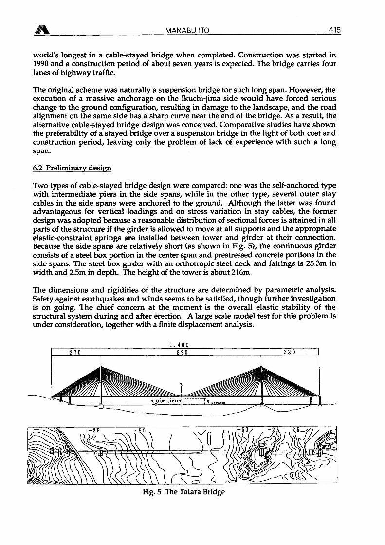
world's longest in a cable-stayed bridge when completed. Construction was started in1990 and a construction period of about seven years is expected. The bridge carries fourlanes of highway traffic.
The original scheme was naturally a suspension bridge for such long span. However, theexecution of a massive anchorage on the Ikuchi-jima side would have forced seriouschange to the ground configuration, resulting in damage to the landscape, and the roadalignment on the same side has a sharp curve near the end of the bridge. As a result, thealternative cable-stayed bridge design was conceived. Comparative studies have shownthe preferability of a stayed bridge over a suspension bridge in the light of both cost andconstruction period, leaving only the problem of lack of experience with such a longspan.
6.2 Preliminary design
Two types of cable-stayed bridge design were compared: one was the self-anchored typewith intermediate piers in the side spans, while in the other type, several outer staycables in the side spans were anchored to the ground. Although the latter was foundadvantageous for vertical loadings and on stress variation in stay cables, the formerdesign was adopted because a reasonable distribution of sectional forces is attained in allparts of the structure if the girder is allowed to move at all supports and the appropriateelastic-constraint springs are installed between tower and girder at their connection.Because the side spans are relatively short (as shown in Fig. 5), the continuous girderconsists of a steel box portion in the center span and prestressed concrete portions in theside spans. The steel box girder with an orthotropic steel deck and fairings is 25.3m inwidth and 2.5m in depth. The height of the tower is about 216m.
The dimensions and rigidities of the structure are determined by parametric analysis.Safety against earthquakes and winds seems to be satisfied, though further investigationis on going. The chief concern at the moment is the overall elastic stability of thestructural system during and after erection. A large scale model test for this problem isunder consideration, together with a finite displacement analysis.
Fig. 5 The Tatara Bridge

416 LONG SPAN STEEL BRIDGES IN JAPAN
7. ADDITIONAL REMARKS
Generally speaking, it is expected that these long span bridges will achieve longerlifetimes in view of the large investments made. Additionally it is noted that betterquality and higher accuracy are required in the building of these larger structures. Tosatisfy these requirements, a cooperative system throughout design, fabrication anderection should be established, in particular for large scale steel structures.
As reported in this paper, Japanese bridge-building technology seems now to be leadingthe world. Nevertheless, there are problems, such as a decrease in the number of youngand skilled manual workers in the industry, and a solution to this problem is now beingsought through labour-saving, automation, as well as simplification and standardizationof the fabrication and erection of works.
Finally, acknowledgements are made to Mr A. R. Burden and Miss R. Enomoto for theirhelp in preparing this manuscript.
REFERENCES
[1] BURDEN, A. R., Japanese cable-stayed bridge design, paper submitted to Proc. Inst.Civ. Engrs, London.
[2] BIRDSALL, B., Footnotes to suspension bridge history prior to 1950 with somerambling recollections of a cable construction engineer, Paper at 1st Intl. OlegKerensky Memorial Conf. (London), June 1988.
[3] ITO, M., Design practices of Japanese steel cable-stayed bridge against wind andearthquake effects, Proc. Intl. Conf. Cable-Stayed Bridges (AIT), November 1987.
[4] ITO, M., Measures against wind-induced vibrations of bridges, Proc. StructuresCong. *87 (ASCE), August 1987.
[5] ENDO, T. et al., Development and investigation of high-strength galvanized wire, tobe submitted to IABSE Symposium (Leningrad), September 1991.
[6] OHASHI, M. et al., Considerations for wind effects on a 1,990m -main spansuspension bridge, Cong. Rep. of 13th Congress of IABSE (Helsinki), June 1988.


![l'armorial Wijnbergen [suite et fin] - E-Periodica](https://img.dokumen.tips/doc/110x75/63343fbff59f4bbe810a897a/larmorial-wijnbergen-suite-et-fin-e-periodica.jpg)


