Embed Size (px)
Citation preview

6-1
6. SEEPAGE THROUGH DAMS
6.1 TYPES OF DAMS
The type of earth or earth and rockfill dam that is constructed at a particular location is
usually dictated by the local availability of appropriate materials such as quarried rock, gravel,
sand, silt or clay. A homogeneous dam (Fig. 6.1) is one that is composed almost entirely of the
one material which is usually relatively impervious. With this type of dam it is necessary to
incorporate some type of downstream pervious drain with appropriately placed filters in order to
control the seepage water. This is to prevent the occurrence of a “piping” failure by the internal
erosion of the finer particles of the earthfill.
If there exists a plentiful supply of rockfill, a thin core dam (Fig. 6.2) could be
constructed. The rockfill could be rolled by means of compaction equipment or dumped from
trucks. Impervious cores having widths of 15% to 20% of the water head usually perform
satisfactorily if adequately designed and constructed filter layers are incorporated. When a wide
range of construction materials is available within the vicinity of the damsite, a zoned earth and
rockfill dam (Fig. 6.3) incorporating all of these materials may be built.
The term “rockfill dam” is usually restricted to a dam composed almost entirely of
rockfill. The water barrier may consist of an upstream membrane of metal, concrete, asphalt or
earthfill or there may be no water barrier at all.
6.2 SEEPAGE THROUGH A HOMOGENEOUS EARTH DAM
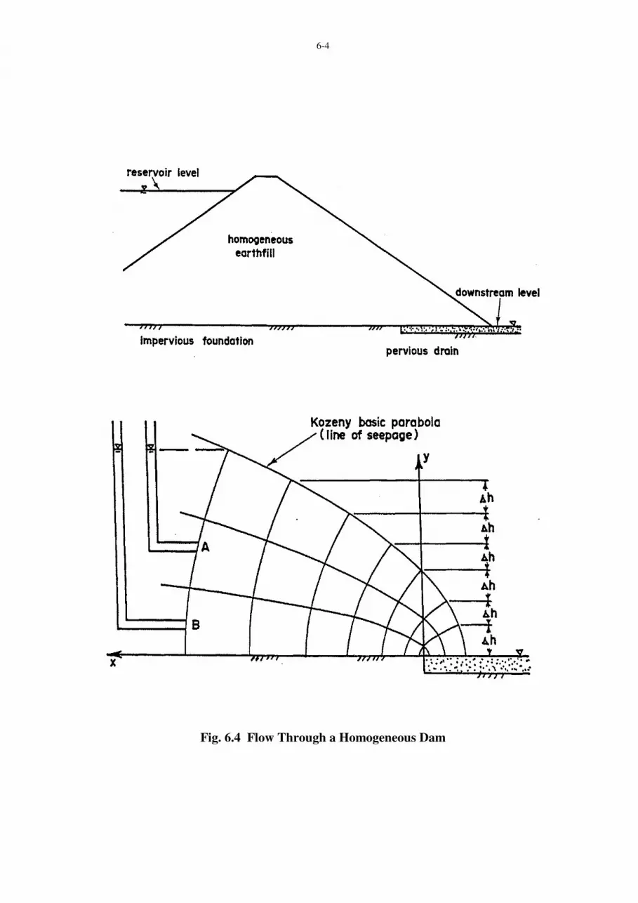
It is considered to be poor design practice to permit the water, which will inevitably seep
through the homogeneous earth fill, to discharge along the downstream face of the dam. This may
be avoided by provision of a drain on the downstream side of the dam, such as the one shown in
Fig. 6.4. This pervious drain should extend sufficiently far in the upstream direction to ensure that
the flow net is entirely contained within the homogeneous earth fill section.
For a horizontal discharge face forming the boundary between the earth fill and the
pervious drain, Kozeny (see Casagrande (1937)) has produced an exact solution for that portion of
the flow net in the vicinity of the drain. This solution is given by the flow lines and equipotential
lines, which form a net of confocal parabolas in the lower portion of Fig. 6.4. The focus of these
parabolas is located at the upstream end of the pervious drain. In this case the line of seepage,
which is the

6-2
Fig. 6.1 Homogeneous Dam with a Chimney Drain
Fig. 6.2 Thin Core Dam
Fig. 6.3 Zoned Earth and Rockfill Dam

6-3
uppermost flow line is referred to as the Kozeny basic parabola. Since the line of seepage is a line
of atmospheric pressure (that is, the pressure head is zero), changes in total head and elevation
head along this line are identical. This means that there must be equal vertical intercepts between
the points of intersection of the line of seepage with successive equipotential lines as illustrated in
the sketch. If stand-pipes (piezometers) are placed at points along a particular equipotential line
such as points A and B in Fig. 6.4, the water will rise in each of these stand-pipes until it reaches a
level coincident with the point of intersection of the line of seepage with that particular
equipotential line. This characteristic provides a convenient technique for the determination of
the pressure head or pore water pressure at any point within the flow net.
The equation for the line of seepage is given by the following expression
x = y2 - yo
2
2yo (1.1)
where y = yo at the point of intersection of the line of seepage with the y axis.
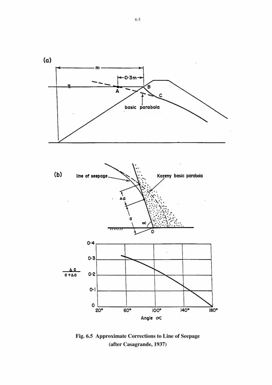
In the upstream region of the flow net through the homogeneous earth fill the net of
confocal parabolas will not be maintained but must alter in shape in order to satisfy the upstream
boundary conditions. A convenient correction for the line of seepage at the upstream end has been
proposed by Casagrande (1937). This correction is illustrated in Fig. 6.5 (a). With this technique
the basic parabola through point A is first located. At point B the flow line must intersect the
upstream slope of the dam which is an equipotential line, at right angles. The upstream portion of
the line of seepage is drawn from point B to join in gradually with the basic parabola at point C.
When the discharge face is not horizontal as illustrated in Fig. 6.5 (b) the Kozeny basic
parabola (with focus at point 0) no longer gives an accurate representation of the line of seepage in
the vicinity of the discharge face. By means of a number of graphical solutions Casagrande has
prepared a series of corrections to the basic parabola in terms of the slope of the discharge face as
represented by the angle α. These corrections are illustrated graphically in Figure 6.5 (b).
EXAMPLE
For the zoned earth dam illustrated in Fig. 6.6 determine:
(a) the rate of seepage discharge per unit width of dam through the earth fill,
(b) the pore water pressure at point P,
(c) The pore water pressure at point R.
The permeability of the earth fill is 0.15 µm/sec.
6-4
Fig. 6.4 Flow Through a Homogeneous Dam
6-5
Fig. 6.5 Approximate Corrections to Line of Seepage
(after Casagrande, 1937)
6-6
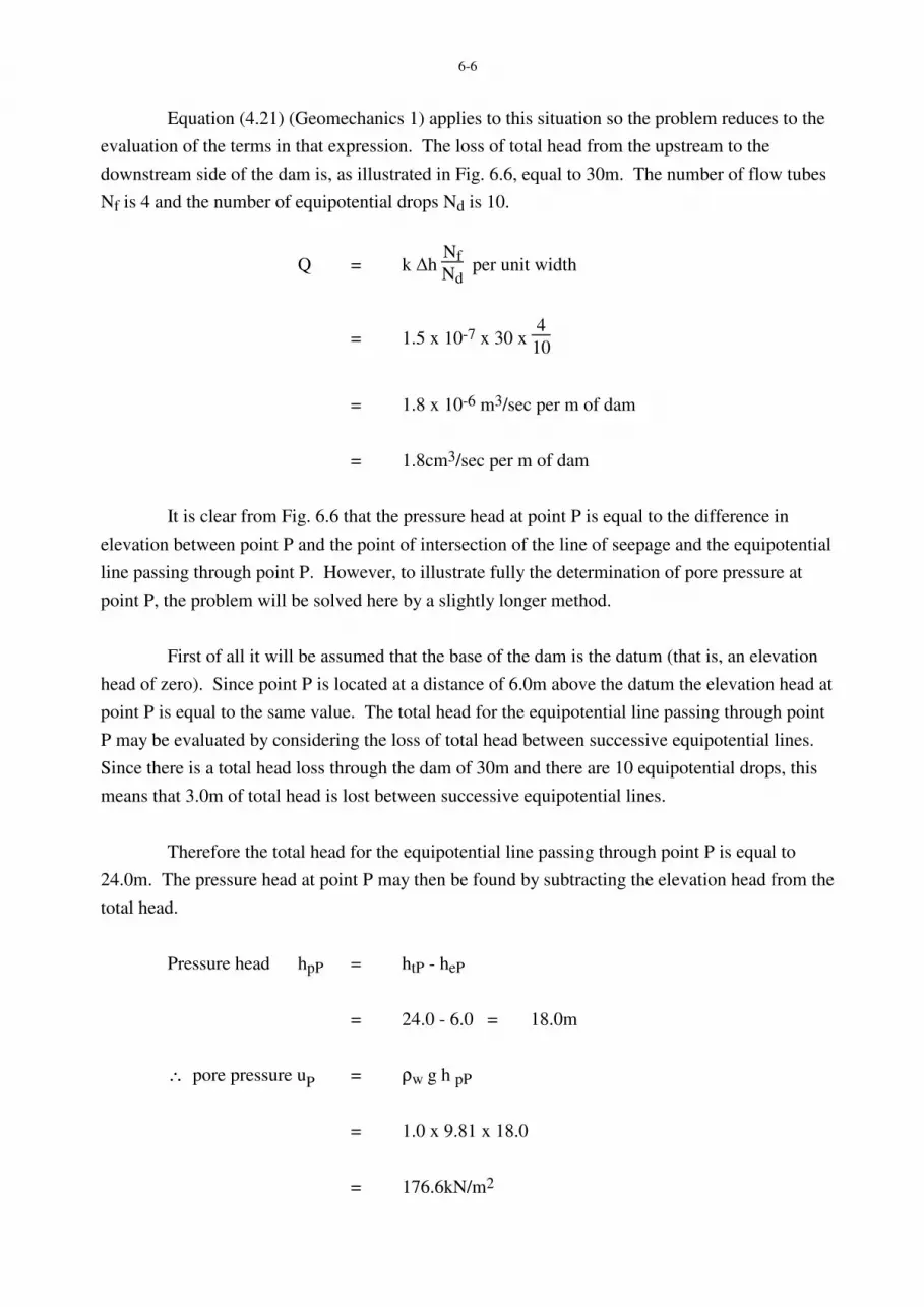
Equation (4.21) (Geomechanics 1) applies to this situation so the problem reduces to the
evaluation of the terms in that expression. The loss of total head from the upstream to the
downstream side of the dam is, as illustrated in Fig. 6.6, equal to 30m. The number of flow tubes
Nf is 4 and the number of equipotential drops Nd is 10.
Q = k ∆h Nf
Nd per unit width
= 1.5 x 10-7 x 30 x 4
10
= 1.8 x 10⁻⁶ m3/sec per m of dam
= 1.8cm3/sec per m of dam
It is clear from Fig. 6.6 that the pressure head at point P is equal to the difference in
elevation between point P and the point of intersection of the line of seepage and the equipotential
line passing through point P. However, to illustrate fully the determination of pore pressure at
point P, the problem will be solved here by a slightly longer method.
First of all it will be assumed that the base of the dam is the datum (that is, an elevation
head of zero). Since point P is located at a distance of 6.0m above the datum the elevation head at
point P is equal to the same value. The total head for the equipotential line passing through point
P may be evaluated by considering the loss of total head between successive equipotential lines.
Since there is a total head loss through the dam of 30m and there are 10 equipotential drops, this
means that 3.0m of total head is lost between successive equipotential lines.
Therefore the total head for the equipotential line passing through point P is equal to
24.0m. The pressure head at point P may then be found by subtracting the elevation head from the
total head.
Pressure head hpP = htP - heP
= 24.0 - 6.0 = 18.0m
∴ pore pressure uP = ρw g h pP
= 1.0 x 9.81 x 18.0
= 176.6kN/m2
6-7
Fig. 6.6
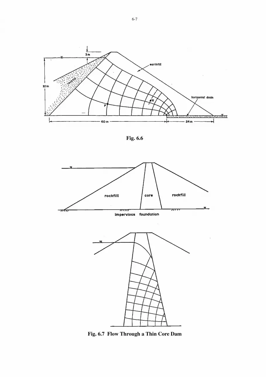
Fig. 6.7 Flow Through a Thin Core Dam

6-8
For the determination of the pore pressure at point R a similar procedure is followed to
that described above. In this case, however, an equipotential line has not passed through point R
in the drawn flow net. It is therefore necessary to interpolate an equipotential line and this is
shown by the dashed line in Fig. 6.6. Now following the same procedure as previously described.
Pressure head hpR = htR - heR
= 13.5 - 8.0
= 5.5m
∴ pore pressure uR = ρw g h pR
= 1.0 x 9.81 x 5.5
= 54.0kN/m2
6.3 SEEPAGE THROUGH THIN CORE DAMS
A thin core dam is illustrated in Fig. 6.7 in which the core or impervious soil zone is
flanked on either side by a zone of rockfill. In many cases the permeability of the rockfill is in
orders of magnitude greater than that of the relatively impervious core. In such cases the presence
of the rockfill zones may be ignored for purposes of drawing a flow net. The upstream rockfill
may be considered as an extension of the reservoir and the downstream rockfill may be considered
as non-existent. The downstream slope of the core now becomes the discharge face for seepage
passing through the core. It should be noted that the downstream slope of the core is neither a
flow line nor an equipotential line. Because the distance in which the total head is dissipated is
small in the case of a thin core dam compared with that for a homogeneous dam the total head
gradient is greater and the velocity of flow of the water is greater. With the greater velocity of
flow there is a greatly increased risk of washing out the fine particles of soil from the core into the
interstices of the rockfill on the downstream side of the dam. This action, if permitted to continue,
could ultimately lead to a piping failure through the core of the dam. In order to reduce the
probability of this occurring, it is necessary to place a transition zone or zones of material known
as filters between the core and the rockfill on the downstream side of the dam. The design of
these filters is discussed in section 6.7.
When a rapid drawdown occurs, that is, when a reservoir level is reduced relatively
quickly, water which is inside the core of the dam near the upstream slope will tend to flow in an
upstream direction. This means that it is also necessary to place filter zones between the rockfill
on the upstream side of the dam and the core to remove the possibility of erosion of the fine
particles of soil from the core of the dam.

6-9
6.4 FLOW THROUGH ANISOTROPIC MATERIAL
In all of the preceding discussion relating to seepage, it has been assumed that the flow
region is isotropic, that is, the permeability is equal in all directions. In naturally occurring strata
as well as in earth dams the horizontal and vertical permeabilities are often not equal. The
Laplace equation as expressed by equation (6.3) and for which the flow net is a graphical solution
applies only to isotropic material. This means that in anisotropic materials (in which the
horizontal and vertical permeabilities are unequal) flow nets of the type sketched in Fig. 6.6
cannot be drawn. Fortunately a simple transformation may be made to the natural flow region in
order to obtain an equivalent isotropic flow region within which the flow net may be sketched.
This may be demonstrated by starting with the Laplace equation for anisotropic material
kxδ2h
δx2+kyδ2h
δy2=0 (6.1)
If a new dimension X is defined by
X = x (ky/kx)1/2
(6.2)
then δ2h
δX2 + δ2h
δy2 = 0 (6.3)
which is the Laplace equation for isotropic material.
This indicates that if the x dimensions are transformed to X according to equation (6.2)
an isotropic region is obtained within which the flow net may be drawn. In this transformation the
x dimensions are varied and the y dimensions are kept constant. Alternatively the transformation
could be carried out in the y direction in which case the x dimensions would be maintained
constant.
This process of transformation is illustrated in Fig. 6.8. In this example the permeability
kx is greater than the permeability ky. This means that the transformed section is smaller than the
natural section in the x direction. For one dimensional flow from left to right the flow net has
been sketched in the isotropic transformed section in the Figure. In this flow net the flow lines
and equipotential lines have been drawn to form a square pattern. If this flow net is transferred
back into the natural section, it is seen that the square pattern is not maintained and the shapes
now become rectangular.
In order to calculate the rate of seepage flow Q per unit width, equation (5.21)
(Geomechanics 1) may be used. Since there are now two permeabilities (kx and ky) it may not be
immediately apparent which value of the permeability should be used for k in equation (5.21).
The value of the permeability to be used in conjunction with the transformed section to calculate
the rate of seepage flow may be developed as follows:

6-10
Fig. 6.8 Transformation for Anisotropic Conditions
Fig. 6.9 Effect of Anisotropy on Seepage Through an Earth Dam

6-11
From the natural section (anisotropic)
Q = vxy per unit width
= kx δh
δx y
From the transformed section (isotropic)
Q = k δh
δX y per unit width
where k is the coefficient of permeability to be used with the transformed section
Q = k δh
δx δx
δX y
= k δh
δx (
kx
ky)1/2
y
These two values of Q (calculated from the natural and transformed sections) must be
equal.
∴ kx δh
δx y = k
δh
δx (
kx
ky)1/2
y
∴ k = (kx ky)1/2
(6.4)
The effect of anisotropy on the seepage flow through the earth dam section is illustrated
in Fig. 6.9. This figure indicates that the greater the degree of anisotropy, that is, the greater the
magnitude of the ratio of the horizontal to vertical permeability the more distorted the flow net
becomes when it is redrawn on the natural dam section. The figure also indicates that the greater
the degree of anisotropy the closer the line of seepage moves towards the downstream slop of the
dam.

6-12
EXAMPLE
For the dam section sketched in Fig. 6.9 calculate the rate of seepage flow per unit width
for cases where the ratio of horizontal permeability to vertical permeability is one, four and nine.
The reservoir depth H is 70m and the vertical permeability kv is equal to 10-6m/sec.
For kh = hv
Q = kH Nf
Nd per unit width
= 10-6 x 70 x 2.7
7.5
= 2.6 x 10⁻⁵ m3/sec per m
For kh = 4 kv
Q = (kh kv)1/2
H Nf
Nd per unit width
= 2 x 10-6 x 70 x 4.3
8.0
= 7.5 x 10⁻⁵ m3/sec per m
For kh = 9 kv
Q = (kh kv)1/2
H Nf
Nd per unit width
= 3 x 10-6 x 70 x 5.5
7.8
= 14.8 x 10⁻⁵ m3/sec per m
This demonstrates that the rate of seepage flow increases as the degree of anisotropy
increases.

6-13
6.5 BOUNDARY CONDITIONS
Casagrande (1937) has demonstrated that special conditions sometimes prevail when the
line of seepage intercepts a boundary either at entrance or discharge points or at the boundary line
between two different soils. A summary of these conditions is illustrated in Fig. 6.10.
When seepage takes place across a boundary between two different soils a process very
similar to that of the refraction of light takes place. The relationship between the angles of
incidence and refraction may be determined from a knowledge of the permeabilities of the two
soils. Referring to Fig. 6.11 the flow in soil (1) approaches the boundary between soil (1) and soil
(2) with an angle of incidence equal to α1. The angle of refraction is α2.
In order to satisfy continuity the rate of seepage flow q along the flow tube in soil (1)
must be identical to the rate of seepage flow in the extension of this flow tube in soil (2).
q = k i A (5.5)
= k1 ∆h
b a = k2
∆h
d c per unit width
∴ b/a
d/c =
k1k2
That is tan α1tan α2
= 21 /( kk ) (6.5)
Equation (6.5) enables the sketching of the flow net to be continued in soil (2). It will be
noted from Fig. 6.11 that the gradient of total head changes following flow across such a
boundary. Further, the shape of the flow net will alter if the equipotential lines are drawn with
equal total head drops between successive lines.
In other words, if the flow net in soil (1) is drawn with the pattern of flow lines and
equipotential lines forming squares, the flow net in soil (2) will no longer be made up of square
shapes. Instead, the flow net will be made up of rectangular shapes with the ratio of the two sides
being equal to the ratio between the two permeabilities, k1/k2.

6-14
Fig. 6.10 Various Boundary Conditions for the Line of Seepage
(after Casagrande, 1937)
Fig. 6.11 Seepage Across a Boundary Between Two Soils

6-15
EXAMPLE
Fig. 6.12 represents a portion of a flownet in the vicinity of a vertical boundary ACB
separating two isotropic soils - soil (1) and soil (2). The flownet has been drawn using square
shapes with point C at the corner of a square on each side of the boundary. The scale of the whole
figure may be determined from the 2m size square in soil (1). The seepage flow (q) through each
flow tube is 4 x 10⁻⁷ m3/sec/m. If the permeability for soil (1) is 10-4 cm/sec., determine:
(a) the permeability in soil (2), and
(b) The difference in pressure head between points D and E.
(a) Since the inclinations of the equipotential lines to the horizontal are given the angles of
incidence (α1) and refraction (α2) may be evaluated.
α1 = 25˚ and α2 = 5˚
From equation (6.5)
k1/k2 = tan α1/tan α2 = 5.32
∴ k2 = 0.19 x 10⁻⁴ cm/sec
(b) For the flow through one of the flow tubes in soil (1), let ∆h1 be the total head loss
between successive equipotential lines.
q = k1 i1 A1
= 10-4 x 10⁻² x (∆h1/2) x 2 x 1
= 4 x 10⁻⁷ m3/sec/m, as given
∆ h1 = 0.4m
size of the square in soil (2) = 2 cos 5˚/cos 25˚ = 2.2m.
For flow through the flow tube in soil (2)
q = 4 x 10-7 = k2 i2 A2
= 0.19 x 10-4 x 10-2 x (∆h2/2.2) x 2.2 x 1

6-16
Fig. 6.12
Fig. 6.13 Underseepage Control Measures

6-17
∴ ∆h2 = 2.13 m = total head loss per square
By scaling, the change in elevation head from point D to point E is
∆he = 0.45m
The change in total head from point D to point E is
∆ht = 2 x (0.4) + 3 x (2.13)
= 7.19m
∴ Change in pressure head from point D to point E is
∆hp = 7.19 - 0.45
= 6.74m
6.6 UNDERSEEPAGE BENEATH DAMS
When dams are constructed on pervious strata, seepage may take place through these
strata as well as through the body of the dam. In some cases the permeabilities of the strata are so
large that considerable loss of water will take place by means of seepage through the strata
beneath the dam unless positive means are taken during the design and construction stages of the
dam to reduce this loss.
Some of the techniques which have been used to reduce the quantity of seepage through
underlying pervious strata are illustrated in Fig. 6.13. Fig. 6.13 (a) illustrates a positive cut-off
where the seepage through the pervious stratum may be almost entirely eliminated. This cut-off
usually consists of compacted earth fill and is often a continuation of the impervious core of the
dam. This technique has been found to be quite successful in situations where the thickness of the
pervious stratum is relatively small. In some cases, cut-offs made of concrete or sheet steel piling
have been used with mixed success. The major disadvantage of a concrete cut-off is it
susceptibility to cracking and one disadvantage associated with the sheet steel piling is the
possible leaks which may result from opening of the interlocks between the piling. A discussion
of the characteristics of various cut-off methods has been given by Sherard et al (1963).
Fig. 6.13 (b) illustrates the method of reducing seepage through a fissured rock
foundation material. When dams are built on rock foundations, grouting is very widely used, but
the successful application of this technique has not always been clearly demonstrated.

6-18
It is normally accepted that several rows of grout must be used for this technique to be
successful. Grout curtains were successfully used in the case of the Karl Terzaghi dam (originally
named Mission dam) in British Columbia (Terzaghi and Lacroix, 1964). With this dam five rows
of grout up to 150m in depth were used. Four of these grout curtains were of clay-cement and the
remaining grout curtain was made of chemical grout. When this technique as well as other cut-off
methods are successful not only is the quantity of seepage through the foundation reduced, but the
pore water pressures beneath the downstream of the dam are also reduced.
In cases where a pervious stratum is too deep for the application of a compacted cut-off
which was illustrated in Fig. 6.13 (a), a slurry trench may be more appropriate. This is illustrated
in Fig. 6.13 (c). During excavation, the trench is usually kept filled with some type of clay slurry.
The clay used in the slurry must be sufficiently fine that it will remain in suspension to provide
support for the sides of the trench during excavation. After excavation the trench is backfilled
with soil to form a firm impervious barrier.
In cases where the pervious stratum is very deep the application of an upstream clay
blanket (illustrated in Fig. 6.13 (d)) may provide an economical means of reducing the seepage
through this pervious stratum beneath the dam. With this technique the distance over which
seepage water must travel is increased. This means that the hydraulic gradient is decreased and in
turn the rate of seepage flow will be decreased. Relief wells are often used in conjunction with
upstream clay blankets in order to ensure that pore pressures beneath the toe of the dam do not
become too large. This procedure is commonly used with levees (Turnbull and Mansur, 1961).
6.7 FILTER REQUIREMENTS
As mentioned in section 1.3, in cases where water is seeping from a fine grained soil into
a course grained soil it is necessary to ensure that the finer particles of the fine grained soil will
not be washed into the pores of the coarse grained soil. Otherwise such behaviour may ultimately
lead to failure of the dam through piping. A number of earth dams have failed through piping (for
example, see Aitchison and Wood (1965), Justin (1936)). Further, a significant percentage of
earth dam failures could be described as seepage failures. (Sherard et al, 1963).
Filters which are used to overcome this problem must in fact be designed to satisfy two
conflicting requirements. Firstly, the pore spaces in the coarse grained soil must be sufficiently
small to prevent particles being washed into them. Secondly, the pore spaces in the filter material
must be large enough to enable seeping water to escape freely without the build up of high pore
water pressures.
From the results of a number of laboratory experiments Bertram (1940) demonstrated the
validity of the following criteria for filter design.

6-19
( )( )soilofD
filterofD
85
15 < 4 to 5 < ( )( )soilofD
filterofD
15
15 (6.6)
where D15, for example, refers to the grain size corresponding to the 15% finer point on the grain
size distribution curve. This is illustrated in Fig. 6.14. The first portion of equation (6.6) is
intended to satisfy the first criterion mentioned above and the second portion of equation (6.6) is
intended to satisfy the second criterion.
Since Bertram completed his work many more investigations have been carried out into
filter requirements. In particular, the United States Bureau of Reclamation has carried on
extensive experimentation with filter materials. Their most recently stated criteria are given in
Table 6.1
The symbols used in Table 6.1 are illustrated in Fig. 6.14. After design of the filter to
protect the soil in accordance with the criteria above the filter material itself must be protected
according to the same filter requirements. Some examples of filter design to prevent piping have
been described by Cedergren (1977) and by Sherard et al (1963).
TABLE 6.1
REQUIREMENTS FOR FILTER MATERIALS
(After U.S. Bureau of Reclamation, 1974)
Character of Filter Materials
Ratio R50
Ratio R15
Uniform grain-size distribution
(Uniformity Coefficient = 3 to 4)
5 to 10
-
Well graded to poorly graded
(non-uniform); subrounded grains
12 to 58
12 to 40
Well graded to poorly graded
(non-uniform); angular particles
9 to 30
6 to 18
R50 = D50 of filter material
D50 of material to be protected R15 =
D15 of filter material
D15 of material to be protected

6-20
Fig. 6.14
Fig. 6.15

6-21
EXAMPLE
It has been proposed to place Zone A material immediately adjacent to Zone B material
in a zoned earth and rockfill dam. The ranges of materials available for Zones A and B are
illustrated by the grain size curves in Fig. 6.15. Comment critically upon the proposal and by
making appropriate calculations evaluate the desirability of providing an intermediate transition
zone.
For Zone B material, uniformity coefficient
= 25/10 = 2.5 approx.
This corresponds to a uniform grain size distribution, and from Table 6.1, R50 should have a
magnitude of 5 to 10.
In this case
R50 = D50 of material B
D50 of material A =
20
0.2 = 100
which is far too large. The gap between materials A and B is also too large on the basis of the old
filter rules, equation (6.6).
Consequently an intermediate transition zone is needed. Try a material with D50 of
around 2mm. Then
D50 of material B
D50 of transition =
20
2 = 10 O.K.
D50 of transition
D50 of material A =
2
20 = 10 O.K.
It appears that the transition material will satisfy the filter rules in Table 6.1 but it may be
noted that the old filter rules (Equation (6.6)) are not fully satisfied. To satisfy the old rules two
transition zones are needed (say with D50 values of about 4mm and 0.8mm respectively), but in
this case the new filter rules (Table 6.1) are not fully satisfied.
Choose a single intermediate transition zone with D50 of around 2mm and with a grain
size distribution curve roughly parallel to those for materials A and B.

6-22
6.8 STABILITY OF DAMS
The dam and its foundation should be designed against failure by overtopping, slope
instability, excessive foundation movement, piping and wave action. Analysis of the stability of
slopes is discussed later in the course. Consideration of conditions which may lead to instability
should be made for all likely combinations of seepage conditions, reservoir and tailwater levels,
both during and after construction. In particular, three conditions should be examined:
(a) The Construction Condition
The critical conditions to be analysed are at the completion of embankment construction
and after initial filling with the reservoir water at the most critical levels; and at any
intermediate stage of construction which may prove to be critical. Construction pore
pressures may be estimated from observation of pore pressure in previously constructed
similar embankments, or from results from one dimensional consolidation tests, or
triaxial testing.
(b) The Steady Seepage Condition
For zoned and homogeneous types of dams the conditions to be considered for the steady
seepage analysis (generally of the downstream face) are:
• Steady seepage pore pressures fully developed as a result of the reservoir storing
water over a long wet period.
• The combination of headwater and tailwater levels that is found to be most critical.
The determination of flow nets for the steady seepage condition has been discussed
earlier in this Chapter.
(c) The Drawdown Condition
Fluctuations in reservoir level may cause the stability of the upstream face to become
critical due to the removal of the water support. When the reservoir is drawn down, pore
pressures in the dam are reduced in two ways. There is an immediate elastic effect due to
the removal of all or part of the water load and there is a slower dissipation of pore
pressure due to drainage.

6-23
6.9 OTHER DESIGN CONSIDERATIONS
The upstream face of the dam should be protected against wave action and the
downstream face should be protected against erosive action of wind and rain and the lower part
against water or wave action if appropriate. Steel mesh or a heavy rock toe should be provided to
stabilize the downstream toe if water is likely to pass through the rockfill during construction.
In addition to providing insurance against overtopping of the embankment by waves
caused by severe storms, freeboard should be sufficient to prevent seepage through an earth core
which has become loosened by frost action or which has cracked due to drying out. Drying out is
of particular importance for a dam located in a hot, dry climate, when the core is composed of clay
soil. Camber should be provided above the design crest height to ensure that freeboard will not be
diminished by foundation and embankment settlement.
Consideration should be given to the installation of instruments to provide the basic data
by means of which the performance of a dam can be assessed continuously during construction
and service. This data is also of great value for future dam designs. The following types of
instrumentation should be considered:
(a) Hydraulic of electric piezometers for measurement of construction and seepage pore
pressure;
(b) Vertical settlement devices in the form of telescoping tubes for earthfill or hydrostatic
gauges for earthfull or rockfill;
(c) Devices for measuring horizontal movements of earthfill and rockfill;
(d) Surface settlement points to measure deformations of the structure in three dimensions;
(e) Gauges for measuring total stress within the dam.

6-24
REFERENCES
Aitchison, G.D., and Wood, C.C., (1965) “Some Interactions of Compaction, Permeability and
Post-Construction Deflocculation Affecting the Probability of Piping Failure in Small Earth
Dams.” Proc. 6th Int. Conf. Soil Mechanics and Found. Eng., Vol 2, pp. 442-6.
Bertram, G.E., (1940), “An Experimental Investigation of Protective Filters”, Pub. of Graduate
School of Eng., Harvard University, No. 267.
Casagrande, A., “Seepage through Dams” Jnl. New England Water Works Assn., Vol. 51, No. 2,
June 1937, also published in “Contributions to Soil Mechanics, 1925 - 1940”, Boston Society of
Civil Engineers, pp. 295 - 336, 1940.
Cedergren, H.R., (1977) “Seepage, Drainage and Flow Nets”, John Wiley and Sons, New York,
534 pp.
Justin, J.D., (1936), “Earth Dam Projects”, John Wiley and Sons, New York.
Moore, P.J., (1970) “Some Aspects of the Use of Stability Analyses in Earth Dam Design”, Proc.
Tenth Congress on Large Dams, Montreal, pp. 151-167.
Sherard, J.L., Woodward, R.J., Gizienski, S.F. and Clevenger, W.A., (1963), “Earth and Earth-
Rock Dams”, John Wiley and Sons, New York.
Terzaghi, K. and Lacroix, Y., (1964) “Mission Dam - An Earth and Rockfill Dam on a Highly
Compressible Foundation”, Geotechnique, 14, pp. 14-50.
Turnbull, W.J. and Mansur, C.I., (1961) “Investigation of Underseepage - Mississippi River
Levees”, Trans. ASCE, Vol. 126, Part I, pp. 1429-1539.
U.S. Bureau of Reclamation, (1974) “Earth manual,” U.S. Dept. of the Interior, 810 pp.