Embed Size (px)
Citation preview
Planning Inspectorate Scheme Ref: TR010041 Application Document Ref: TR010041/APP/6.1
A1 in Northumberland: Morpeth to Ellingham
6.1 Environmental Statement
[Scheme Name] [Scheme Number TR100xx]
1.3 Introduction to the Application APFP Regulation 5(2)(q)
Planning Act 2008
Infrastructure Planning (Applications: Prescribed Forms and Procedure)
Regulations 2009
Volume [x]
[Month/year]
APFP Regulation 5(2)(a)
Planning Act 2008
Infrastructure Planning (Applications: Prescribed Forms and Procedure) Regulations 2009
June 2020
A1 in Northumberland: Morpeth to Ellingham
Scheme Number: TR010041
6.1 Environmental Statement Appendix 2.3 Culvert Construction
Methodology
Planning Inspectorate Scheme Ref: TR010041 Application Document Ref: TR010041/APP/6.1
A1 in Northumberland: Morpeth to Ellingham
6.1 Environmental Statement
Infrastructure Planning
Planning Act 2008
The Infrastructure Planning (Applications: Prescribed Forms and
Procedure) Regulations 2009
The A1 in Northumberland: Morpeth to Ellingham Development Consent Order 20[xx]
Environmental Statement
Regulation Reference: APFP Regulation 5(2)(a)
Planning Inspectorate Scheme Reference
TR010041
Application Document Reference TR010041/APP/6.1
Author: A1 in Northumberland: Morpeth to Ellingham Project Team, Highways England
Version Date Status of Version
Rev 0 June 2020 Application Issue
Planning Inspectorate Scheme Ref: TR010041 Application Document Ref: TR010041/APP/6.1
A1 in Northumberland: Morpeth to Ellingham
6.1 Environmental Statement
Culvert Construction Methodology
A1 in Northumberland: Morpeth to Ellingham
Part A: Morpeth to Felton
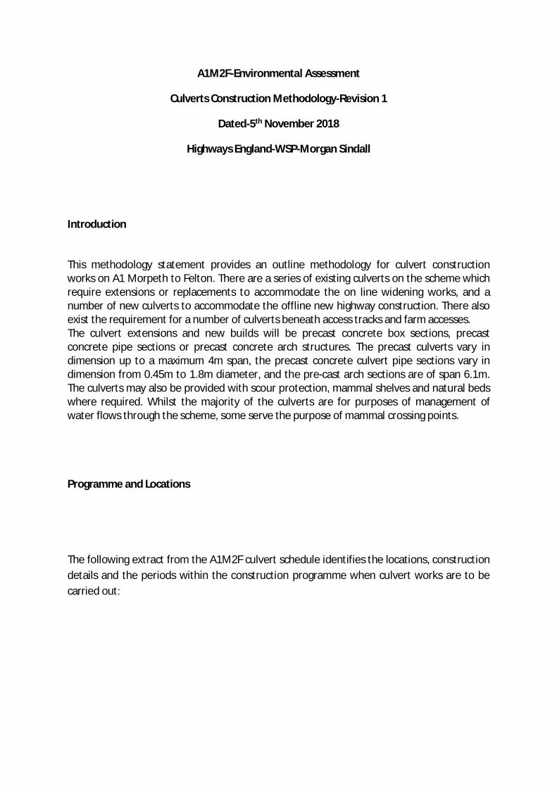
A1M2F-Environmental Assessment
Culverts Construction Methodology-Revision 1
Dated-5th November 2018
Highways England-WSP-Morgan Sindall
Introduction
This methodology statement provides an outline methodology for culvert constructionworks on A1 Morpeth to Felton. There are a series of existing culverts on the scheme whichrequire extensions or replacements to accommodate the on line widening works, and anumber of new culverts to accommodate the offline new highway construction. There alsoexist the requirement for a number of culverts beneath access tracks and farm accesses.The culvert extensions and new builds will be precast concrete box sections, precastconcrete pipe sections or precast concrete arch structures. The precast culverts vary indimension up to a maximum 4m span, the precast concrete culvert pipe sections vary indimension from 0.45m to 1.8m diameter, and the pre-cast arch sections are of span 6.1m.The culverts may also be provided with scour protection, mammal shelves and natural bedswhere required. Whilst the majority of the culverts are for purposes of management ofwater flows through the scheme, some serve the purpose of mammal crossing points.
Programme and Locations
The following extract from the A1M2F culvert schedule identifies the locations, constructiondetails and the periods within the construction programme when culvert works are to becarried out:
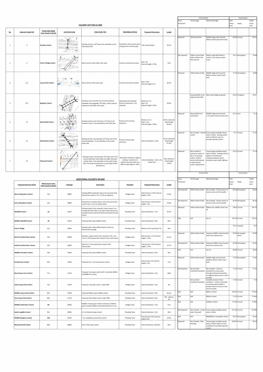
Change Issue to ReviewScour Fish Passage Mammal Passage Inlet Outlet
Protection Invert level
Shape Invert level
No. Hydraulic Model RefSTRUCTURE NAME
(from South to North)LOCATION PLAN STRUCTURE TYPE PREFERRED OPTION Proposed Dimensions Length
1 3 Paradise Culvert Existing structure, 200 skew to be extended on the inlet (west) side.
Demolition and reconstruction using precast concrete pipe.
1.8m internal diam. 32.7m
Required 150 natural bed Wildlife ledge with top level 950mm above pipe invert level
83.69 Circular 83.51
2 4 Priest's Bridge Culvert New structure with 4.00m clear span. Precast concrete box culvert.Span: 4m Internal height: 3.75m
53m
Not required 100mm natural bed within 250mm low flow channel
500mm wide Shelf fixed to culvert 1.31m above culvert invert
79.17 Rectangular 79.08
3 6.2 Causey Park Culvert New structure 3.0m clear span. Precast concrete box culvert.Span: 3.0m Internal height:2.1m
36.2m
Required 150mm Natural bed Wildlife ledge with top level 950mm above culvert invert level
77.16 Rectangular 76.89
4 10.1 Burgham CulvertExisting in-situ concrete arch structure without headwalls and wingwalls, 300 skew, 3.45m internal headroom and 4.85m clear span.
Wing walls and headwall hence an extension is not required.
Remain as it is:Span: 5mInternal height: 3.45m
30.6m
Existing baffles to be replaced with GMS
New mamal ledge proposed 54.31 (irregular) 54.31
5 12 Bockenfield Culvert Existing masonry arch structure, 140 skew, 6.1m maximum span. To be extended on the inlet side.
Precast arch concrete extension.
Remain as it is:Span: 6.1m Internal height: 2.49m
34.4m extension (total length
64.4m)
Required Natural Bed to be maintained
Wildlife ledge with top level 1.7m above channel invert level
51.11 Arch 51.1
6 14 Glenshotton CulvertExisting circular concrete pipe, 350 skew and 1.22m internal diameter. To be extended on the outlet (east) side.
Precast concrete pipe extension.
Internal diameter: 1.35m 23.3m extension
(total length 47.6m)
Required Not included - existing culvert
Free passage available except when in flood - Existing culvert with insufficient cover to provide separate culvert
57.7 Circular 57.53
7 16 Parkwood Culvert
Existing circular concrete pipe, 350 skew and 1.22m internal diameter (inlet side) and 0.88m diameter (outlet side). To be extended on the outlet (east)
side. The outlet incorporates a second pipe 0.30m diameter (?)
New deep manhole to replace existing + extension of
downstream pipe with new 900mm pipe (approx. 20m)
Internal diameter: Inlet 1.2m, outlet 0.9m.
20m extension (total length
145m)
Required Not included in upstream section as this is an existing culvert. 150mm natural bed allowed in downstream culvert replacement.
Free passage available except when in flood - Existing culvert is adjacent to Parkwood subway/underpass which provides access under highway
39.15 Circular 37.74
Scour Fish Passage Mammal Passage Inlet Outlet
Proposed Structure NameWatercourse name
(from South to North)Chainage Description Discipline Proposed Dimensions Length
Protection Invert level
Shape Invert level
West Cotting Burn Culvert 1.4 10800Existing 450mm diameter pipe to be removed. New precast box culvert 2.7m x 1.25m to replace it.
Bridges teamInternal span: 2.70m Internal height: 1.25m
12.8m
Not Required 250mm Natural Bed Not included - Private means of access so low risk of casualty
85.64 Rectangular 85.64
East Cotting Burn Culvert 1.5 10800Removal of 2 existing culverts. One new precast box culvert 3.0m x 1.2m to replace them.
Bridges teamInternal span: 3.0m Internal height: 1.2m
12.8m Not Required 200mm Natural Bed Not included - Private means of
access so low risk of casualty85.49 Rectangular 85.49
Shieldhill Culvert 1A 11815
Existing culvert to be removed. (Leave culvert in to manage the flow). New 1.2m pipe culvert (and scour protection) then switch the flow and remove the old culvert.
Flooding Team Internal diameter: 1.2m 43.4m
Required 150mm Natural bed 600mm dia. wildlife culvert see 1b
104.4 Circular 103.77
Wildlife Shieldhill Culvert 1B 11810 Proposed 0.6m pipe wildlife culvert. Flooding Team Internal diameter: 0.6m 40m
N/A N/A See 1a 105.29 Circular 105.16
Priest's Bridge 4.1 14020Existing culvert. New baffles fixed to culvert to improve fish passage.
Flooding Team Masonry Arch spanning 3.7m 34m
79.11 Irregular 78.7
North Fenrother Burn Culvert 5.2 15000Existing 5.1 pipe culvert to be removed. 2 No. new 1.5m x 1.25m precast box culverts to be constructed.
Bridges teamInternal span: 1.5m Internal height: 1.25m
33.1m
Required 250mm Natural Bed Separate wildlife culvert located away from watercourse
87.69 Rectangular (twin)
87.69
South Fenrother Burn Culvert 5.3 14900New 3m x 1.75m precast box culvert to be constructed.
Bridges teamInternal span: 3.0m Internal height: 1.75m
52.7m Not Required 250mm Natural Bed Separate wildlife culvert located
away from watercourse87.69 Rectangular 87.56
Wildlife Fenrother Culvert 5.4 14930 Proposed 0.6m pipe wildlife culvert. Flooding Team Internal diameter: 0.6m 36m
N/A N/A see 5.3 89.98 Circular 90.49
Earsdon Burn Culvert 6.3 17000 Proposed 3m x 2.1m precast box culvert. Bridges teamInternal span: 3m Internal height: 2.1m
11m
Required 150mm Natural bed Wildlife ledge with top level 1000mm above culvert invert level
77.87 Rectangular 77.87
New Houses Farm Culvert 7.1 17150Proposed 1.6m pipe culvert with 2 manholes @49m and @98m for access.
Bridges team Internal diameter: 1.6m 148m
Not Required Not included - insufficient baseflow
Not included - Culvert is provided to convey water through earthworks therefore no highway above and no risk of casualty
77.42 Circular 77.31
Little Causey Park Culvert 7.2 17440 Proposed 1.6m pipe culvert under PMA Bridges team Internal diameter: 1.6m 9m
Not included - insufficient baseflow
Available except in flood conditions - culvert is provided to convey water beneath a private means of access so low risk of casualty
77.85 Circular 77.8
Wildlife Causey Park Culvert 8.1 17660 Proposed 600mm pipe wildlife culvert. Flooding Team Internal diameter: 0.6m 46.4mN/A N/A 600mm culvert 78.367 Circular 77.619
Tiny Causey Park Culvert 8.2 17720 Proposed 0.6m piped culvert under PMA Flooding Team Internal diameter: 0.6m TBC - Approx.
6m
N/A N/A 600mm culvert 77.16 Circular 77.063
Wildlife Eshott Burn Culvert 8A 18300Wildlife crossing point. Need a minimum 1500mm pipe to enable wildlife and preferably bats to cross.
Bridges team Internal diameter: 1.5m 51m
N/A N/A 1500mm culvert 77.103 Circular 77.385
South Longdike Culvert 9.1 19090 A 1.2m diameter pipe culvert. Flooding Team Internal diameter: 1.2m 39mNot Required Not included - surface
water flow pathFree passage available except when in flood
67.136 Circular 67.096
Wildlife Burgham Culvert 10A 19520 1 no. Amphibian precast box culvert Flooding TeamInternal span 0.9m Internal height 0.6m
19.8mN/A N/A 900x600mm rectangular culvert 56.57 Rectangular 55.93
Blackwood Hall Culvert 13.1 20880 3 No. 0.45m pipe culvert. Flooding Team Internal diameter: 3x0.45m 56m
Required Not included - field drainage
Free passage available except when in flood. Depth of cover insufficient to provide separate culvert
60.487 Circular 60.19
ADDITIONAL CULVERTS ON M2F
CULVERT LIST FOR A1 M2F
Environment Construction
Environment Construction
Online Culvert Extensions Methodology-Pipes
It will be advisable to carry out the extension works whilst the flows through the culvert are divertedto an alternative route. This may be an adjacent culvert, pipe or drainage channel. If this is notpossible, a temporary sump shall be excavated on the upstream end of the existing culvert, and withthe culvert dammed, a 6 inch pump will divert the flow through the culvert by means of a 6 inch pipesuspended above the culvert floor.
Culvert extension works may now proceed free of flowing water-It must be noted that in times offlood, the temporary pumping arrangement may need to be suspended and flows allowed to againflow through the culvert, suspending construction works for this period.
The culvert bed shall be excavated to formation level and a layer of blinding concrete placed.
The pipe sections shall be lifted into place with a large tracked excavator and the pipe sectionspulled together ensuring the proprietary seals between the units is in place. The installation shall becarried out sequentially, ensuring correct vertical and horizontal alignment is maintained. Oncompletion of the pipe installation, the external faces shall be waterproofed and concrete protectionplaced where detailed. They will then be backfilled and compacted with 6N granular material. Thewing walls will then be constructed in in situ concrete, following which waterproofing and backfillingof these walls may proceed. The rip rap /scour protection, to the approaches and departures of theculvert shall then be installed and levelled to the required profiles. Any natural beds and mammalshelves will be placed through the culvert
The watercourse may then be diverted through the new culvert, allowing road construction anddemolition activities to proceed.
Online Culvert Extensions Methodology-Precast Arch sections
It will be advisable to carry out the extension works whilst the flows through the culvert are divertedto an alternative route. This may be an adjacent culvert, pipe or drainage channel. If this is notpossible, a temporary sump shall be excavated on the upstream end of the existing culvert, and withthe culvert dammed, a 6 inch pump will divert the flow through the culvert by means of a 6 inch pipesuspended above the culvert floor.
Culvert extension works may now proceed free of flowing water-It must be noted that in times offlood, the temporary pumping arrangement may need to be suspended and flows allowed to againflow through the culvert, suspending construction works for this period.
The culvert bed shall be excavated to formation level and a concrete ground beams to support thearch sections placed...
The arch sections shall be lifted into place with a large tracked excavator or mobile crane and thesections pulled together ensuring the proprietary seals between the units are in place. Theinstallation shall be carried out sequentially, ensuring correct vertical and horizontal alignment ismaintained. On completion of the arch installation, the external faces shall be waterproofed andconcrete protection placed where detailed. They will then be backfilled and compacted with 6Ngranular material. The wing walls will then be constructed in in situ concrete, following which
waterproofing and backfilling of these walls may proceed. The rip rap /scour protection, to theapproaches and departures of the culvert shall then be installed and levelled to the requiredprofiles. Any natural beds and mammal shelves will be placed through the culvert
The watercourse may then be diverted through the new culvert, allowing road construction andactivities to proceed.
Offline New Culvert Construction Methodology-Precast Concrete Box sections
Prior to commencement of the works, the flow of the open burn channel shall be diverted to analignment approx. 10m North or South from the route of the proposed culvert construction into apreformed open channel to allow the works to be carried out free of flowing water.
The culvert bed shall be excavated to formation level and a layer of blinding concrete placed.Following this, a sand screed shall be placed to the underside of precast culvert section level.
The culvert sections shall be lifted into place with a mobile crane or large tracked excavator and thesections pulled together ensuring the proprietary seals between the units is in place. The installationshall be carried out sequentially, ensuring correct vertical and horizontal alignment is maintained.On completion of the culvert unit installation, the external faces shall be waterproofed and concreteprotection placed where detailed. They will then be backfilled and compacted with 6N granularmaterial. The wing walls will then be constructed in in situ concrete, following which waterproofingand backfilling of these walls may proceed. The rip rap/scour protection to the approaches anddepartures of the culvert shall then be installed and levelled to the required profiles. Final naturalbed installation and any mammal shelf installation required will complete the works.
The watercourse may then be diverted through the new culvert and the temporary open coursebackfilled with suitable material, allowing road construction and demolition activities to commence.
Offline New Culvert Construction Methodology-Pipe sections
Prior to commencement of the works, the flow of the open burn channel shall be diverted to analignment approx. 10m North or South from the route of the proposed culvert construction into apreformed open channel to allow the works to be carried out free of flowing water.
The culvert bed shall be excavated to formation level and a layer of blinding concrete or pipebedding placed.
The pipe sections shall be lifted into place with a large tracked excavator and the sections pulledtogether ensuring the proprietary seals between the units is in place. The installation shall be carriedout sequentially, ensuring correct vertical and horizontal alignment is maintained. On completion ofthe pipe unit installation, the external faces shall be waterproofed and concrete protection placedwhere detailed. They will then be backfilled and compacted with 6N granular material. The wingwalls will then be constructed in in situ concrete, following which waterproofing and backfilling of

these walls may proceed. Any rip rap/scour protection to the approaches and departures of theculvert shall then be installed and levelled to the required profiles. Final natural bed installation willcomplete the works.
The watercourse may then be diverted through the new culvert and the temporary open coursebackfilled with suitable material, allowing road construction and any demolition activities tocommence.

Planning Inspectorate Scheme Ref: TR010041 Application Document Ref: TR010041/APP/6.1
A1 in Northumberland: Morpeth to Ellingham
6.1 Environmental Statement
Culvert Construction Methodology
A1 in Northumberland: Morpeth to Ellingham
Part B: Alnwick to Ellingham
A1A2E-Environmental Assessment
Culverts Construction Methodology-Rev 1
Dated-9th December 2019
Highways England-WSP-Morgan Sindall
Introduction This methodology statement provides an outline methodology for culvert construction works
on A1 in Northumberland: Alnwick to Ellingham. There are a series of existing culverts on the Scheme which require extensions or replacements to accommodate the online widening works, and the installation of a new culvert.
The culvert extensions and new builds will be either precast concrete box sections or precast concrete pipe sections. The precast culverts vary in dimension up to a maximum 3m span whilst the precast concrete culvert pipe sections vary in dimension from 0.6m to 1.2m diameter. The culverts may also be provided with scour protection and natural beds where required and also the installation of wing walls at outlet and inlet.
Locations and Culvert Forms
The following extract from the A1A2E culvert schedule identifies the locations, construction
types and details of the proposed culverts on A1 in Northumberland: Alnwick to Ellingham:
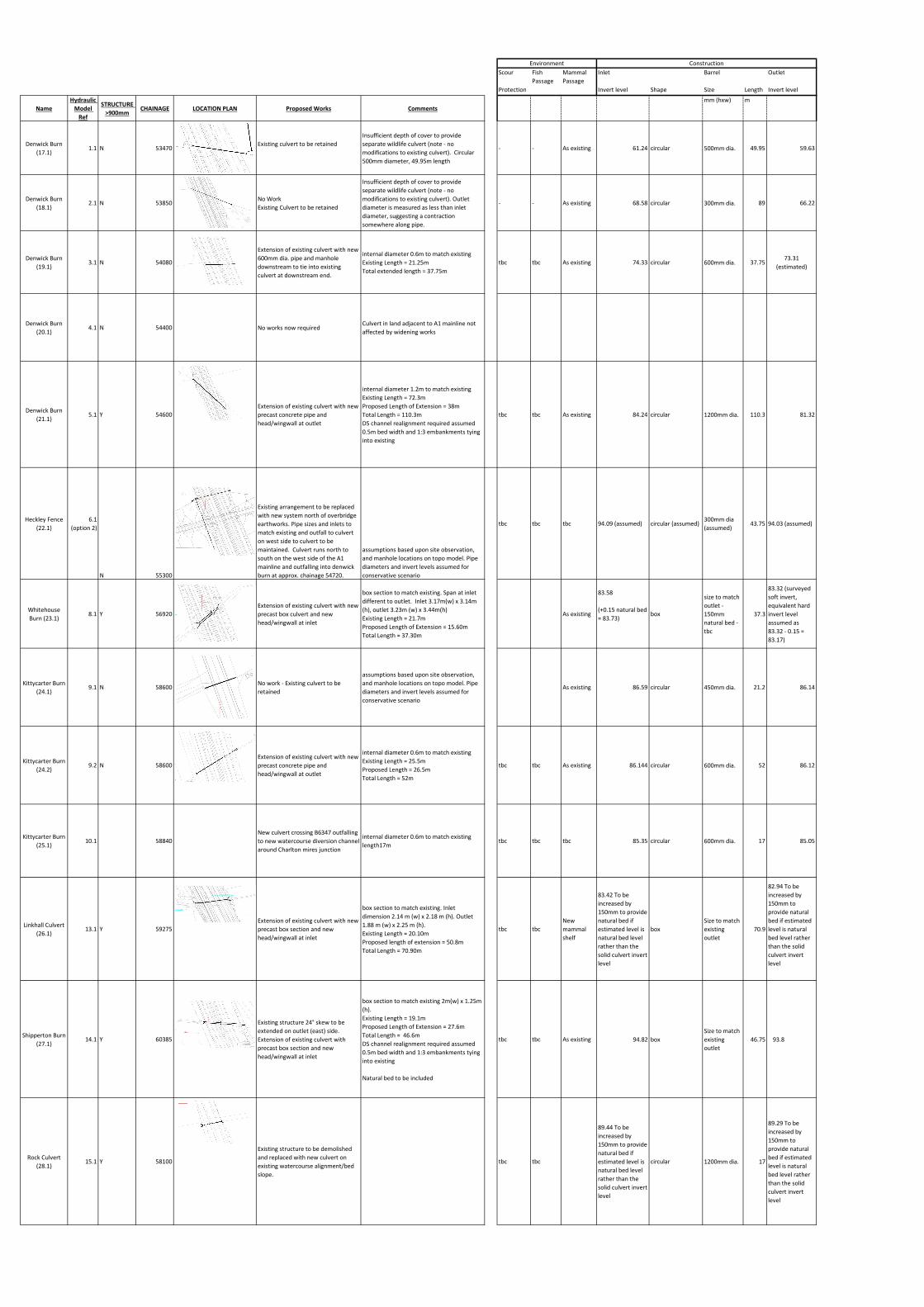
Scour Fish Passage
Mammal Passage
Inlet Barrel Outlet
Protection Invert level Shape Size Length Invert level
NameHydraulic
Model Ref
STRUCTURE >900mm
CHAINAGE LOCATION PLAN Proposed Works Commentsmm (hxw) m
Denwick Burn (17.1)
1.1 N 53470Existing culvert to be retained
Insufficient depth of cover to provide separate wildlife culvert (note - no modifications to existing culvert). Circular 500mm diameter, 49.95m length
- - As existing 61.24 circular 500mm dia. 49.95 59.63
Denwick Burn (18.1)
2.1 N 53850No WorkExisting Culvert to be retained
Insufficient depth of cover to provide separate wildlife culvert (note - no modifications to existing culvert). Outlet diameter is measured as less than inlet diameter, suggesting a contraction somewhere along pipe.
- - As existing 68.58 circular 300mm dia. 89 66.22
Denwick Burn (19.1)
3.1 N 54080
Extension of existing culvert with new 600mm dia. pipe and manhole downstream to tie into existing culvert at downstream end.
internal diameter 0.6m to match existingExisting Length = 21.25mTotal extended length = 37.75m
tbc tbc As existing 74.33 circular 600mm dia. 37.7573.31
(estimated)
Denwick Burn (20.1)
4.1 N 54400 No works now requiredCulvert in land adjacent to A1 mainline not affected by widening works
Denwick Burn (21.1)
5.1 Y 54600Extension of existing culvert with new precast concrete pipe and head/wingwall at outlet
internal diameter 1.2m to match existingExisting Length = 72.3mProposed Length of Extension = 38mTotal Length = 110.3mDS channel realignment required assumed 0.5m bed width and 1:3 embankments tying into existing
tbc tbc As existing 84.24 circular 1200mm dia. 110.3 81.32
Heckley Fence (22.1)
6.1 (option 2)
N 55300
Existing arrangement to be replaced with new system north of overbridge earthworks. Pipe sizes and inlets to match existing and outfall to culvert on west side to culvert to be maintained. Culvert runs north to south on the west side of the A1 mainline and outfalling into denwick burn at approx. chainage 54720.
assumptions based upon site observation, and manhole locations on topo model. Pipe diameters and invert levels assumed for conservative scenario
tbc tbc tbc 94.09 (assumed) circular (assumed)300mm dia (assumed)
43.75 94.03 (assumed)
Whitehouse Burn (23.1)
8.1 Y 56920Extension of existing culvert with new precast box culvert and new head/wingwall at inlet
box section to match existing. Span at inlet different to outlet. Inlet 3.17m(w) x 3.14m (h), outlet 3.23m (w) x 3.44m(h)Existing Length = 21.7mProposed Length of Extension = 15.60mTotal Length = 37.30m
As existing
83.58
(+0.15 natural bed = 83.73)
box
size to match outlet - 150mm natural bed - tbc
37.3
83.32 (surveyed soft invert, equivalent hard invert level assumed as 83.32 - 0.15 = 83.17)
Kittycarter Burn (24.1)
9.1 N 58600No work - Existing culvert to be retained
assumptions based upon site observation, and manhole locations on topo model. Pipe diameters and invert levels assumed for conservative scenario
As existing 86.59 circular 450mm dia. 21.2 86.14
Kittycarter Burn (24.2)
9.2 N 58600Extension of existing culvert with new precast concrete pipe and head/wingwall at outlet
internal diameter 0.6m to match existingExisting Length = 25.5mProposed Length = 26.5mTotal Length = 52m
tbc tbc As existing 86.144 circular 600mm dia. 52 86.12
Kittycarter Burn (25.1)
10.1 58840New culvert crossing B6347 outfalling to new watercourse diversion channel around Charlton mires junction
internal diameter 0.6m to match existing length17m
tbc tbc tbc 85.35 circular 600mm dia. 17 85.05
Linkhall Culvert (26.1)
13.1 Y 59275Extension of existing culvert with new precast box section and new head/wingwall at inlet
box section to match existing. Inlet dimension 2.14 m (w) x 2.18 m (h). Outlet 1.88 m (w) x 2.25 m (h).Existing Length = 20.10mProposed length of extension = 50.8mTotal Length = 70.90m
tbc tbcNew mammal shelf
83.42 To be increased by 150mm to provide natural bed if estimated level is natural bed level rather than the solid culvert invert level
boxSize to match existing outlet
70.9
82.94 To be increased by 150mm to provide natural bed if estimated level is natural bed level rather than the solid culvert invert level
Shipperton Burn (27.1)
14.1 Y 60385
Existing structure 24° skew to be extended on outlet (east) side. Extension of existing culvert with precast box section and new head/wingwall at inlet
box section to match existing 2m(w) x 1.25m (h). Existing Length = 19.1mProposed Length of Extension = 27.6mTotal Length = 46.6mDS channel realignment required assumed 0.5m bed width and 1:3 embankments tying into existing
Natural bed to be included
tbc tbc As existing 94.82 boxSize to match existing outlet
46.75 93.8
Rock Culvert (28.1)
15.1 Y 58100
Existing structure to be demolished and replaced with new culvert on existing watercourse alignment/bed slope.
tbc tbc
89.44 To be increased by 150mm to provide natural bed if estimated level is natural bed level rather than the solid culvert invert level
circular 1200mm dia. 17
89.29 To be increased by 150mm to provide natural bed if estimated level is natural bed level rather than the solid culvert invert level
Environment Construction
Online Culvert Extensions Methodology-Pipes
It will be advisable to carry out the extension works whilst the flows through the culvert are diverted
to an alternative route. This may be an adjacent culvert, pipe or drainage channel. If this is not
possible, a temporary sump shall be excavated on the upstream end of the existing culvert, and with
the culvert dammed, a 6 inch pump will divert the flow through the culvert by means of a 6 inch pipe
suspended above the culvert floor.
Culvert extension works may now proceed free of flowing water-It must be noted that in times of
flood, the temporary pumping arrangement may need to be suspended and flows allowed to again
flow through the culvert, suspending construction works for this period.
The culvert bed shall be excavated to formation level and a layer of blinding concrete placed.
The pipe sections shall be lifted into place with a large tracked excavator and the pipe sections pulled
together ensuring the proprietary seals between the units is in place. The installation shall be carried
out sequentially, ensuring correct vertical and horizontal alignment is maintained. On completion of
the pipe installation, the external faces shall be waterproofed and concrete protection placed where
detailed. They will then be backfilled and compacted with 6N granular material. The wing walls will
then be constructed in in situ concrete, following which waterproofing and backfilling of these walls
may proceed. The rip rap /scour protection, to the approaches and departures of the culvert shall then
be installed and levelled to the required profiles. Any natural beds will be placed through the culvert
The watercourse may then be diverted through the new culvert, allowing road construction and
demolition activities to proceed.
Online Culvert Extension Methodology-Precast Concrete Box sections
It will be advisable to carry out the extension works whilst the flows through the culvert are diverted
to an alternative route. This may be an adjacent culvert, pipe or drainage channel. If this is not
possible, a temporary sump shall be excavated on the upstream end of the existing culvert, and with
the culvert dammed, a 6 inch pump will divert the flow through the culvert by means of a 6 inch pipe
suspended above the culvert floor.
Culvert extension works may now proceed free of flowing water-It must be noted that in times of
flood, the temporary pumping arrangement may need to be suspended and flows allowed to again
flow through the culvert, suspending construction works for this period.
The culvert bed shall be excavated to formation level and a layer of blinding concrete placed. Following
this, a sand screed shall be placed to the underside of precast culvert section level.
The culvert sections shall be lifted into place with a mobile crane or large tracked excavator and the
sections pulled together ensuring the proprietary seals between the units is in place. The installation
shall be carried out sequentially, ensuring correct vertical and horizontal alignment is maintained. On
completion of the culvert unit installation, the external faces shall be waterproofed and concrete
protection placed where detailed. They will then be backfilled and compacted with 6N granular
material. The wing walls will then be constructed in in situ concrete, following which waterproofing
and backfilling of these walls may proceed. The rip rap/scour protection to the approaches and
departures of the culvert shall then be installed and levelled to the required profiles. Final natural bed
installation required will complete the works.
The watercourse may then be diverted through the new culvert and the temporary open course
backfilled with suitable material, allowing road construction and demolition activities to commence.
New Culvert Construction Methodology-Pipe sections
Prior to commencement of the works, the flow of the open burn channel shall be diverted to an
alignment approx. 10m north or south from the route of the proposed culvert construction into a
preformed open channel to allow the works to be carried out free of flowing water.
The culvert bed shall be excavated to formation level and a layer of blinding concrete or pipe bedding
placed.
The pipe sections shall be lifted into place with a large tracked excavator and the sections pulled
together ensuring the proprietary seals between the units is in place. The installation shall be carried
out sequentially, ensuring correct vertical and horizontal alignment is maintained. On completion of
the pipe unit installation, the external faces shall be waterproofed and concrete protection placed
where detailed. They will then be backfilled and compacted with 6N granular material. The wing walls
will then be constructed in in situ concrete, following which waterproofing and backfilling of these
walls may proceed. Any rip rap/scour protection to the approaches and departures of the culvert shall
then be installed and levelled to the required profiles. Final natural bed installation will complete the
works.
The watercourse may then be diverted through the new culvert and the temporary open course
backfilled with suitable material, allowing road construction and any demolition activities to
commence.

Planning Inspectorate Scheme Ref: TR010041 Application Document Ref: TR010041/APP/6.1
A1 in Northumberland: Morpeth to Ellingham
6.1 Environmental Statement
© Crown copyright 2020. You may re-use this information (not including logos) free of charge in any format or medium, under the terms of the Open Government Licence. To view this licence: visit www.nationalarchives.gov.uk /doc/open-government-licence/ write to the Information Policy Team, The National Archives, Kew, London TW9 4DU, or email [email protected]. This document is also available on our website at www.gov.uk /highways If you have any enquiries about this document [email protected] or call 0300 470 4580*. *Calls to 03 numbers cost no more than a national rate call to an 01 or 02 number and must count towards any inclusive minutes in the same way as 01 and 02 calls. These rules apply to calls from any type of line including mobile, BT, other fixed line or payphone. Calls may be recorded or monitored. Registered office Bridge House, 1 Walnut Tree Close, Guildford GU1 4LZ Highways England Company Limited registered in England and Wales number 09346363