Embed Size (px)
Citation preview
~I Hili n~IIIIIIII1II!11111111111P895-220950
CULVERT REPAIR PRACTICES MANUAL. VOLUME 2(APPENDICES)
SMITH (WILBUR) ASSOCIATES, FALLS CHURCH, VA
MAY 95
U.S. DEPARTMENT OF CO'VIMERCENational Technical Information Service
:I111111111111
Publication No. FHWA-RD·95·089May 1995
Culvert RepairPractices ManualVolume II
u.s Department of Transportation
Federal Highway Administration
Research and DevelopmentTurner-Fairbank Highway Research Center6300 Georgetown PikeMcLean, Virginia 22101·2296
PB95-220950
ftiWEW(JRQ,
The ("I. rert ' ,){.ir I ',wtic(" M,/II",.' Wus design~d to supplement the ( .drcrt Inspectio/1 IHanua!devdopec' 1y the Fedcr." Highway Administration in 19H6, The ('/111'('1'1 Repair I'mctic('\ \fail/wIprovides a n"nr:,chum or rehahilitation techniques to he used when inspel"lio/1S show the needto repair, -",Ivcrt. Volumc I consists of the text. Volumc II prcsents Appendixes.
Culverts, ilL' :l,lvcJncnls, arc' gcncrally c1assificd into two groups: rigid ,1Ild flexihle. Concrete istypil~ally U',l'C) In rigid culvcrh: sleel ami aluminum arc primary materi,tls that comprisl~ Ikxihlc:;y:;I":IU:i. ·loc('u. ft#~fJi/'-J'hl,o~'e"'lUI/uti' pHl'liJes.. reliourec-tmt~m-on-alt-etliverttypes;the materials used in their fahrication, and the construction methods used in thcit placement. ItOullilll'S the CIUSl~S of common ddelioration prohlems and methods ror maintcnance and repair.It OIls!] II1cludes .l!lIidance for duidin!', \\hether a culvert should be rcp,lircd or rcplalcd,
This manual is cll-signcd ror a h\(1ad audience, Rccogni/ing that some statcs assi1!n responsibilitvof culvel t repair t() mamtc'nanCl' departJll\.'nts whilL' cllhers assign il 10 hriuge sections or ntherdepartmcnts, the <Iuthurs h<l\'l: deSigned the l11anu<ll lor all design, construction, and mainll'llann'slall whn arc Ill\nlvnl in the i.'(ll1slrurlinl1 nl culverts, Those respnllsihlc lor the dcsigll anuengil1L'Crin!! olne\\ lUis L'llS rna\' ids! I lind the inlurmatHHl useful.
'ha lcs J, ~emrnnsr Clm, Ollirc nr Enginc'cring andIlighway Operations Research and Devc]opment
NOTICE
ThiS docun1l'nt IS dissl'minatnl under tlw spol1snrship "I' the Departmenl nl Transportation in Ihcintcrl'st nf JnlnllllalHHl n,'halH!l', I h,' I nited Slatl's (;Cl\'l'rnmcnt assumes nn liahility lor its('Cln1L'111s Cll lISl' Ihell'l)!. I'his Il'Pllll d',les not l'.lllstitutl' a st<llllbrd, spl~rilil'alinl1, 11I rl'glll<ltinll,
TIll' UlIllC'l1lS "llhis lcpnrl Il'I'h.'l'1 thl' \'i,'wS 111 the ilUtlllllS, \\ho an' respnnslhil' fur the lads and,ICCUr<ll'V nf Ihe cht,. prc'selltnl hell'lll. Thl: ('(Ill lel1 Is dCI nnt Ilcl'l'ssanl" leflcct the olliual polinnlthe Ikpartll1eflt 01 Tr;lJ1Spnrt<ltlon,
TIll' t 'flited Stall's (;O\C'lllllll'nl dOL'S 110t cllllllrsl' products Clf llIill1ulaelurers, 'I ralk amimaI1ULI,'tlltl'ls' IliIl11<'S appl'.I1 111 this IqHHt lllll\' hn,IIISl' the'\' .Ill' l'ollsidnnll'ss,'ntial In thenh!l'l t III Ihe dOl'lJl1ll'lll.
1. Report No.
FHWA-RD-95-0891111111111111111111111111111111111111111111
PB9S-220950
Technical Documentation Page3. ~ecipient's Catalog No.
5. Report Date
May 19954. Title and Subtitle
CULVERT REPAIR PRACTICES MANUAL: VOLUME I I
(APPENDIXES)
7. Authods)
Craig A. Ballinger and Patricia G. Drake9. Performing Organizatio'l Name and Address
Wilbur Smith Associates, BTML Division2921 Telestar CourtFalls Church, VA 2204212. Sponsoring Agency Name and Address
Oftke of Engineering and Highway Operations R&DFederal Highway Administration, HNR-206300 Georgetown PikeMcLean, VA 22101-2296
15. Supplementary Notes
FHWA Program Manager-Kevin Black, HNG-23This study was funded under the Nation Pooled Fund Study Program
I~~...,.--------,-------6. Performing Organization Code
8. Performing Organization Report No.
10. 'Nork Unit No. (TRAIS)
11. Contract or Grant No.
DTFH61-88-C-OOOI513. Type of Report and Period Covered
Final Report
14. Sponsoring Agency Code
16. Abstract
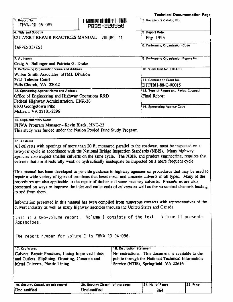
All culverts with openings of more than 20 ft, measured parallel to the roadway, must be inspected on atwo-yC'ar cycle in accordance with the National Bridge Inspection Standards (NBIS). Many highwayagencies also inspect smaller culverts on the same cycle. The NBIS, and prudent engineering, requires thatculverts that are structurally weak or hydraulically inadequate be inspected on a more frequent cycle.
This manual has been developed to provide guidance to highway agencies on procedures that may be used torepair a wide variety of types of problems that beset metal and concrete culverts of all types. Many of theprocedures are also applicable to the repair of timber and stone masonry culverts. ProcC(iures are alsopresented on ways to improve the inlet and outlet ends of culverts as well as the streambed channels leadingto and from them.
Information presented in this manual has been compiled from numer(\us contacts with representatives of theculvert industry as well as many highway agencies throu~h the United States and Canada.
7his is a two-volume report. Volume I consists of the text. V0lume II presentsAppendixes.
The report n.'rnber for volume I is FHWA-RD-94-096.
17. Key Words
Culvert, Repair Practices, Lining Improved Inletsand Outlets, Sliplining, Grouting, Concrete andMetal Culverts, Plastic Lining
18. Distribution Statement
No restrictions. This document is available to thepublic through the National Technical InformationService (NTIS), Springfield, VA 22616
354 L--__---'
19. Security Clas.if. (of this report)
Unclusified20. Security Cla.sif. (of this page)
Unclusified21. No. of Page. 22. Price
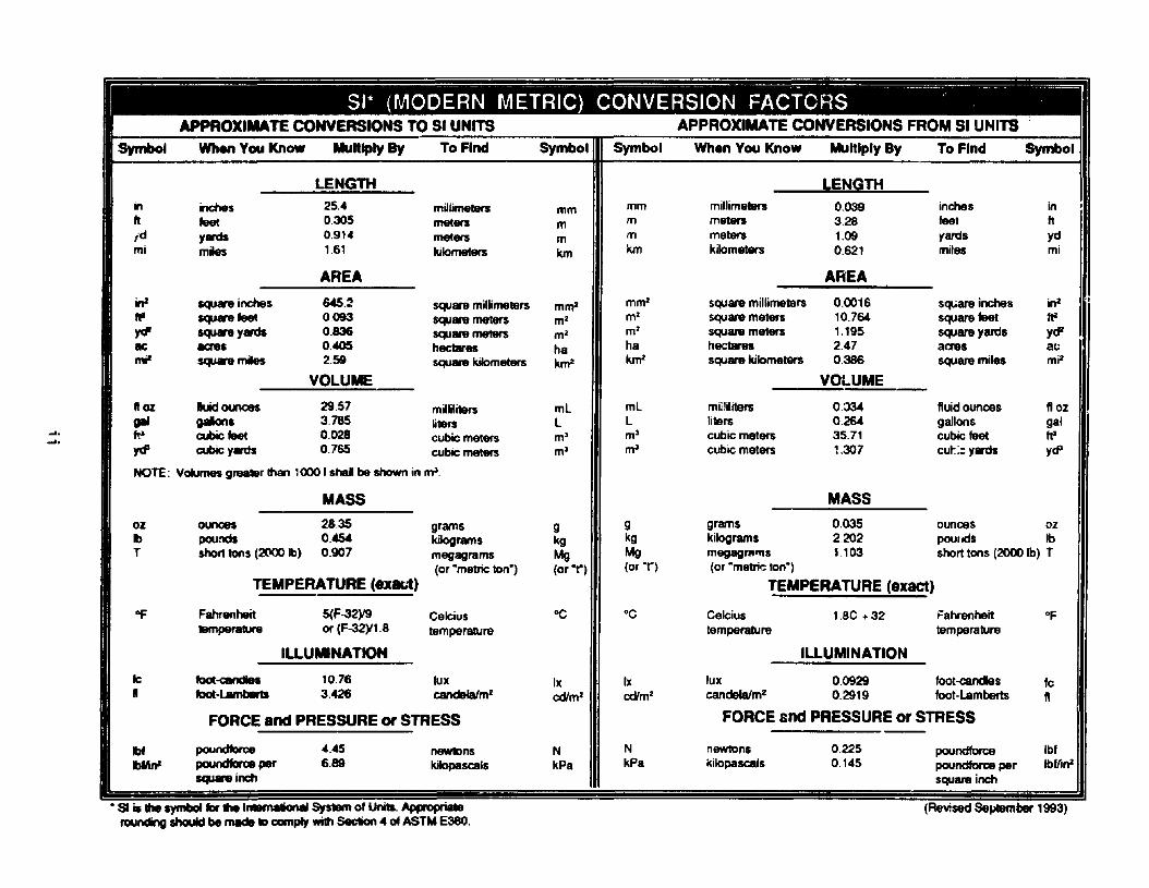
'.. .~ •APPROXIMATE CONVERSIONS TO SI UNITS APPROXIMATE CONVERSIONS FROM SI UNITS
Symbol When You Know Multiply 8y To Find Symbol Symbol When You Know Multiply 8y To Find Symbol
LENGTH LENGTHin inches 25.4 millimellBn; mm mm millimeters 0.039 inches infr teet 0.305 meters m m meters 3.28 feet ft
i d 1ards 0.914 meters m m meters 1.09 yards ydmi miles 1.61 kilometers km km kilometers 0.621 miles mi
AREA AREA
in' squlninches 645.2 squln millimeters mnr mm2 square millimeters 0.0016 Sql,Oare inches in2
• squlnteet 0093 squlnmeters m2 m2 square meters 10.764 square feet 112~ lqUlnyards 0.836 square meters m2 m2 square meters 1.195 square 1ard& yrPBe acres 0.0405 hectares ha ha hectare& 2.47 acres somi' squlnmiles 2.59 square kilometers kfn2 kfn2 square kilometers 0.386 square miles mil
VOLUME VOLUME
loz luidounces 29.57 milliliters ml mL milliliters 0.J34 fluidounces f10z
pi gallons 3.785 liters l l liters 0.264 gallons gal-I. I It- cubic teet 0.028 cubic meters mJ m3 cubic meters 35.71 cubic feet It'.....
'fd' cubic yards 0.765 cubic meters mJ mJ cubic meters 1.307 cul:;~ yards ydJ
NOTE: Vca.mes grealBr lhan 1000 I shal be shown in mJ.
MASS MASS
02 ounces 28.35 grams g g grams 0.035 ounces ozIb pounds 0.45<1 kilograms kg kg kilograms 2.202 pOUllds IbT &hotI tons (2000 Ib) 0.907 megagrams Mg Mg megagl'Rrns 1.103 short tons (2000 Ib) T
(or -metric ton") (or -t") (or-n (or -metric ton-)
TEMPERATURE (ex&1) TEMPERATURE (exact)
"F Fahrenheit 5(F-32)19 Celcius "C °C Celcius 1.8e +32 Fahrenheit oflBmperature or (F-32)11.8 temperature temperature temperature
ILLUMINATION ILLUMINATION
fc foot-e:andles 10.76 lux Ix Ix lux 0.0929 loot-candles Ie• foot-l.M1b8ft1 3.426 candefalm2cd'm' cd'm2 candela/m2 0.2919 loot-lamberti fl
FORCE and PRESSURE or STRESS FORCE and PRESSURE or STRESS
Ibt ~ 4.45 newtons N N newtons 0.225 poundforce IbfIbfIW pouncIaroe per 6.89 kiIopascals kPa kPa kilopascals 0.145 poundforce per IbfJinJ
squa'8 inch square inch--- 51 • the symboIlDr .. InBnaIiclnaI s,s..... of Uni1s. Appopl ia1e (Revised SeJitember 1993)
raunding should be made II) ccmply with Section 4 of ASTM E380.
VOLUME I
TABLE OF CONTENTS
PAGE
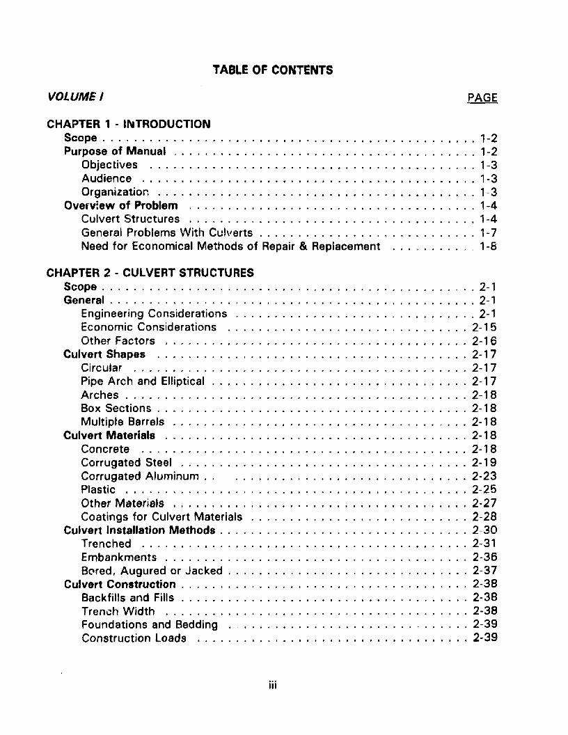
CHAPTER 1 - II\ITRODUCTIONScope 1-2Purpose of Manual . . . . . . . . . . . . . . . . . . . . . . . . . . . . . . . . . . . . . . . 1-2
Objectives 1-3Audience 1-3Organization . . . . . . . . . . . . . . . . 1-3
OV8rv:ew of Problem 1-4Culvert Structures 1-4General Problems VVith Culverts 1-7Need for Economical Methods of Repair & Replacement _ 1-8
CHAPTER 2 - CULVERT STRUCTURESScope 2-1General 2-1
Engineering Considerations 2-1Economic Considerations 2-15Other Factors 2-16
Culvert Shapes 2-17Circular 2-17Pipe Arch and Elliptical 2-17Arches 2-18Box Sections 2-18Multiple Barrels cl ••• 2-18
Culvert Materials 2-18Concrete 2-18Corrugated Steel 2-19Corrugated Aluminum.. . 2-23Plastic 2-25Other Materials 2-27Coatings for Culvert Materials 2-28
Culvert Installation Methods 2-30Trenched 2-31Embankments 2-36BNed, Augured or Jacked 2-37
Culvert Construction 2-38Backfills and Fills 2-38Trench Width 2-38Foundations and Bedding 2-39Construction Loads 2-39
iii
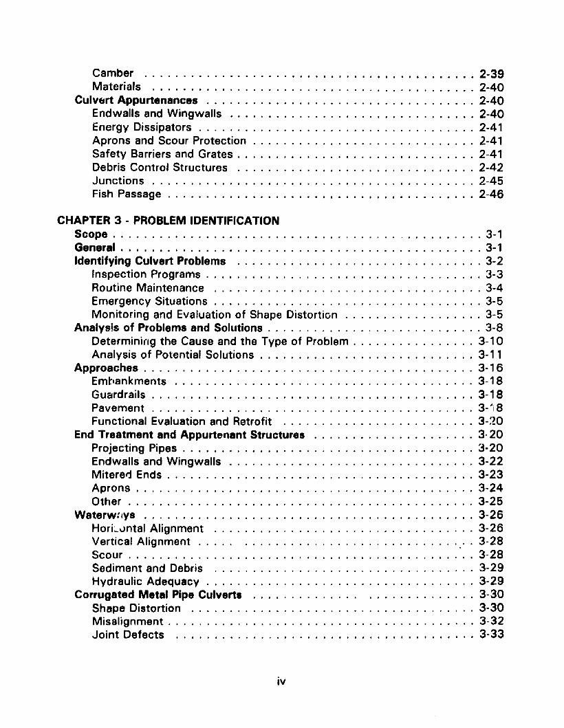
Camber 2-39Materials 2-40
Culv&rt Appurtenances 2-40Endwalls and Wingwalls 2-40Energy Dissipators 2-41Aprons and Scour Protection . . . . . . . . . . . . . . . . . . . . . . . . . . . . . 2-41Safety Barriers and Grates 2-41Debris Control Structures 2-42Junctions 2-45Fish Passage . . . . . . . . . . . . . . . . . . . . . . . . . . . . . . . . . . . . . . . . 2-46
CHAPTER 3 - PROBLEM IDENTIFICATIONScope . . . . . . . . . . . . . . . . . . . . . . . . . . . . . . . . . . . . . , . . . . . . . . . . 3-1General . . . . . . . . . . . . . . . . . . . . . . . . . . . . . . . . . . . . . . . . . . . . . . . 3-1Identifying Culvert Problems 3-2
Inspection Programs 3-3Routine Maintenance 3-4Emergency Situations 3-5Monitoring and Evaluation of Shape Distortion 3-5
Analysis of Problems and Solutions . . . . . . . . . . . . . . . . . . . . . . . . . . . . 3-8Determining the Cause and the Type of Problem 3-10Analysis of Potential Solutions . . . . . . . . . . . . . . . . . . . . . . . . . . . . 3-11
Approaches . . . . . . . . . . . . . . . . . . . . . . . . . . . . . . . . . . . . . . . . . . . 3-1 6Embankments .. . . . . . . . . . . . . . . . . . . . . . . . . . . . . . . . . . . . . . 3-1 8Gu&rdrails 3-18Pavement . . . . . . . . . . . . . . . . . . . . . . . . . . . . . . . . . . . . . . . . . . 3-"1 8Functional Evaluation and Retrofit 3-:Z0
End Treatment and Appurtenant Structures 3· 20Projecting Pipes 3·20Endwalls and Wingwalls 3-22Mitered Ends 3-23Aprons 3-24Other 3-25
Waterw:JVs 3-26HorL.vntal Alignment 3-26Vertical Alignment . . . .. . 3-28Scour 3-28Sediment and Debris 3-29Hydraulic Adequacy 3-29
Corrugated Metal Pipe Culverts 3-30Shape Distortion 3-30Misalignment 3-32Joint Defects 3-33
iv
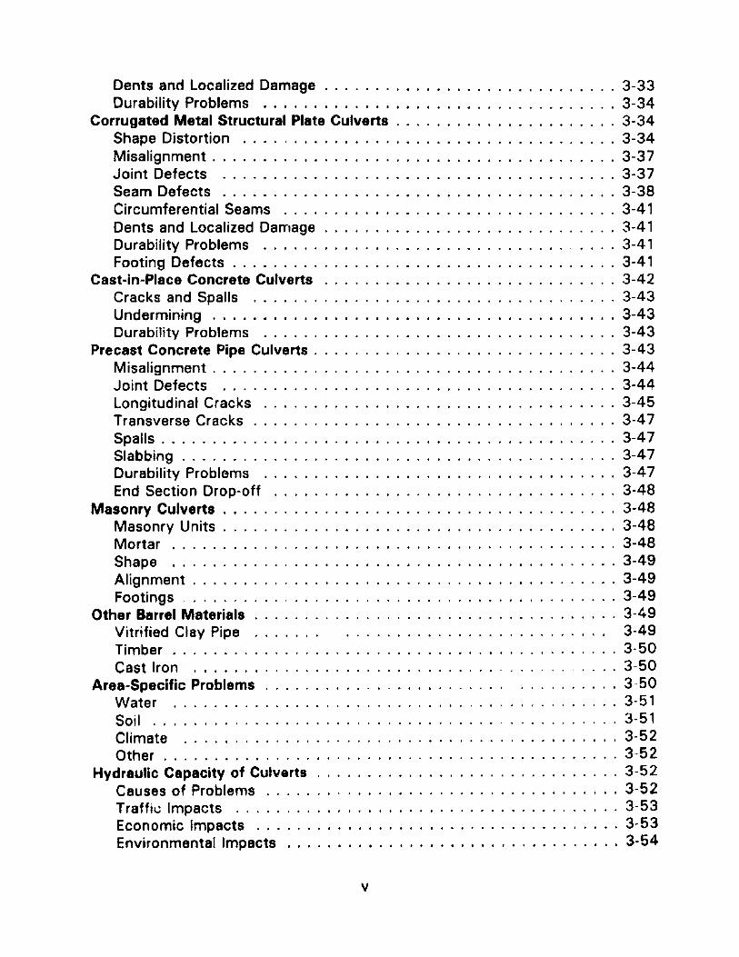
Dents and Localized Damage . . . . . . . . . . . . . . . . . . . . . . . . . . . . . 3-33Durability Problems 3-34
Corrugated Metal Structural Plate Culverts 3-34Shape Distortion ....,................................ 3-34Misalignment. . . . . . . . . . . . . . . . . . . . . . . . . . . . . . . . . . . . . . . . 3-37Joint Defects 3-37Seam Defects . . . . . . . . . . . . 3-38Circumferential Seams 3-41Dents and Localized Damage . . . . . . . . . . . . . . . . . . . . . . . . . . . . . 3-41Durability Problems " 3-41Footing Defects . . . . . . . . . . . . . . . . . . . . . . . . . . . . . . . . . . . . . . 3-41
Cast-in-Place Concrete Culverts . . . . . . . . . . . . . . . . . . . . . . . . 3-42Cracks and Spalls 3-43Undermining .. . . . . . . . . . . . . . . . . . . . . . . . . . . . . . . . . . . . . . . 3-43Durability Problems 3-43
Precast Concrete Pipe Culverts 3-43Misalignment . . . . . . . . . . . . . . . . . . . . . . . . . . . . . . . . . . . . . . . . 3-44Joint Defects 3-44Longitudinal Cracks 3-45Transverse Cracks 3-47Spalls . . . . . . . . . . . . . . . . . . . . . . . . . . . . . . . . . . . . . . . . . . . . . 3-47Slabbing . . . . . . . . . . . . . . . . . . . . . . . . . . . . . . . . . . . . . . . . . . . 3-47Durability Problems 3-47End Section Drop-off 3-48
Masonry Culverts . . . . . . . . . . . . . . . . . . . . . . . . . . . . . . . . . . . . . . . 3-48Masonry Units . . . . . . . . . . . . . . . . . . . . . . . . . . . . . . . . . . . . . . . 3-48Mortar . . . . . . . . . . . . . . . . . . . . . . . . . . . . . . . . . . . . . . . . . . . . 3-48Shape 3-49Alignment . . . . . . . . . . . . . . . . . . . . . . . . . . . . . . . . . . . . . . . . . . 3-49Footings 3-49
Other Barrel Materials . . . . . . . . . . . . . . . . . . . . . . . . . . . . . . . . . . . . 3-49Vitrified Clay Pipe 3-49Timber 3-50Cast Iron ,...... . 3-50
Area-Specific Problems . . . . . . . . . . . . . . . . . . . . . . ., 3- 50Water , 3-51Soil 3-51Climate 3-52Other 3-52
Hydraulic Capacity of Culverts 3-52Causes of Problems 3-52Traff,~ Impacts 3-53Economic Impacts 3-53Environmental Impacts 3-54
v
Fish Passage 3-58Beaver Control 3-61
CHAPTER 4 - CULVERT MAINTENANCEScope 4-1General . . . . . . . . . . . . . . . . . . . . . . . . . . . . . . . . . . . . . . . . . . . . . . . 4- 1Benefits of Regular and Preventative Maintenance . . . . . . . . . . . . . . . . . . 4- 2
Costs 4-3Legallmplications 4-4Culvert Inspection Programs 4-6
Maintenance Procedures . . . . . . . . . . . . . . . . . . . . . . . . . . . . . . . . . . . 4- 7Debris Removal 4-8Flushing/Sediment Removal 4-8Thawing 4-9Ditch Cleaning and Repair . . . . . . . . . . . . . . . . . . . . . . . . . . . . . . . . 4-9Streambed Maintenance 4-9Vegetation Control 4-11
CHAPTER 5 - END TREATMENT AND OTHER APPURTENANT STRUCTUREREPAIRS AND RETROFIT IMPROVEMENTS
Scope 5-1General . . . . . . . . . . . . . . . . . . . . . . . . . . . . . . . . . . . . . . . . . . . . . . . 5-1Erosion Control 5- 2
Backfilling . . . . . . . . . . . . . . . . . . . . . . . . . . . . . . . . . . . . . . . . . . . 5-4Slope Stabilization 5-5Block Retaining Wall Systems 5-9Ditches 5-22
Scour Holes and Streambed 5-22Riprap 5-24Gabions 5-24Energy Dissipators 5-24Aprons 5-28Streambed Paving 5-28End Sections 5-29
Headwalls, Endwalls and Wingwalls 5-29Replacement 5-31Partial Replacement and Patching 5-31Retrofit of Endwalls and Wingwalls 5-31Jacketing of Concrete or Masonry Endwalls and Wingwalls 5-33Underpinning of Concrete Footings 5-34Repointing of Masonry 5-34Tying Arch for Support of Masonry Endwalls and Wingwalls 5-35Repairs Using Steel Sheeting . . . . . . . . . . . . . . . . . . . . . . . . . . . . . 5- 35
vi
Repairs Using Gabions 5-35Repairs Usir.~ Shol-.;rete 5-36
Other Repairs and Retrofit Improvements 5-37Piping 5-37Safety Considerations 5-38Fish Passage Devices - . 5-39Beaver Control Devices 5-50
CHAPTER 6 - CULVERT BARREL REPAIR AND REHABILITATION PROCEDURESScope 6-1General . . . . . . . . . . . . . . . . . . . . . . . . . . . . . . . . . . . . . . . . . . . . . . . 6-1Precast Reinftn ced Concrete Culverts 6-2
Joint Defects 6-2Longitudinal and Transverse Cracks 6-6Spall Repair . . . . . . . . . . . . . . . . . . . . . . . . . . . . . . . . . . . . . . . . . . 6-7Slabbing Repairs 6-7Invert Deterioration 6-8Crown Deterioration 6-9
Cast-in-Place Barrels 6-9Joint Defects 6-10Cracks and Spalls 6-11Underpinning Footings 6-11Invert Repair 6-12
Corrugated Metal Pipes and Pipe Arches 6-1 3Joint Defects 6-14Invert Durability Repairs 6-1 5Shape Distortions 6-1 6
Corrugated Metal Structural Plate . . . . . . . . . . . . . . . . . . . . . . . . . . . . 6-18Seam Defects 6-1 8Joint Defects 6-19Invert DurabIlity . . . . . . . . . . . . . . . . . . . . . . . . . . . . . . . . . . . . . . 6-1 9Shape Distortion 6-20
Corrugated Metal Arches and Boxes 6-20Underpinning Footings 6-21Streambed ;lepair 6-21Shape Di::;tortiol's 6··21
General r. " Jarrel Rphabilitation 6-22Sliplinll, 6-23Inversion Lining 6-29Cement Mortar lining . . . . . . . . . . .. . 6-33Other Techniques 6-35
Repairs to Other Barrel Materials 6-37Masonrv I •••• I ••• f ••••••••••••••••••••• 6-37Vitrified Clay 6-37
vii
Wood 6-38Cast Iron 6-38Plastic 6-38
CHAPTER 7 - CULVERT REPLACEMENTScope 7-1General . . . . . . . . . . . . . . . . . . . . . . . . . . . . . . . . . . . . . . . . . . . . . . . 7-1Repair Versus Replacement 7-1
Condition of Existing Structures 7-2Current and Future Requirements . . . . . . .. . 7-6Construction Costs and Economic Analysis 7-8Other Considerations 7-23Comparison of Alternatives 7-24
Replacement Systems 7-28Design Considerations 7-28Traditional Materials/Past Performance 7-29Recent Innovations in Materials, Products, and Procedures 7-29Construction Methods 7-38
Conclusion 7-45
VOLUME 1/
APPENDIXES
A. Standard Sizes and Geometric Data for Pipe
ASTM Standards . . . . . . . . . . . . . . . . . . . . . . . . . . . . . . . . . . . . . A-1
Handling Weight of Corrugated Steel Pipe. A-7
Sizes and Layout Details - Corrugated Steel Plate Arches. . . . . . . . .. A-9
Sizes and Layout Details - Structural Plate Steel . . . . . . . . . . . . . .. A-10
Representative Sizes of Structural Plate Steel Arches A-13
Layout Details - Corrugated Steel Box Culverts . . . . . . . . . . . . . . .. A-1 5
Sizes and Layout Details - Corrugated Steel Long Span . . . . . . . . A-1 7
Aluminum Helical Pipe Availability, Weight and Fill Height TableHS-20 Loading A-22
Geometric Data· Aluminum .
viii
A-23
Con/Span Culvert Systems - Short & Long Span Sizes. . . . . . . . . .. A-37
Plastic Pipe
B. Repair and Retrofit Procedures
A-38
B-1 Debris Removal 8-1
B-2 Sediment Removal B-3
B··3 Thawing Frozen Culverts B-5
B-4 Cleaning and Repairing Lined Citches B-l0
B-5 Mechanical Cleaning and Repair of Unlined Ditches . . .. B-13
B-6 Vegetative Streambank Stabilization '" . . . . . . . B-17
B-7 Selection and Use of Erosion Control Geotextiles . 6- 25
B-8 Use of Loffelstein BIJck to Prevent Streambank Erosion. 8-35
B-9
B-10
8-1 '1
8-12
8-13
B-14
8 .. 15
8-16
8-17
Assembling and Installing Gabions .,
Repair of Timber Structures .
Shotcrete/Gunite Paving, Lining, and Repair .
Stormwater Conveyance Channels (Ditches)
Installing Riprap .
Repair and Replacement of Apron/Cutoff Wall ..
Strearnbt1d Paving .
Replacement of Concrete Wing walls and Endwalls
Repair of Bljsical/y Sound Endwalls and Wingwalls
B-39
8-49
B-52
8-58
8-63
8-68
B-70
872
B-74
B-1B Repairing Severely Deterjorat~d or Collapsed Wingwallsand Endwalls B-77
B-19 Concrete Jacket Repairs for Endwalls and Vylin~walls. " B-81
ix
B-20 Underpinning . . . . . . . . . . . . . . . . . . . . . . . . . . . . . , . B-83
B-21 Repainting Masonry B-87
B-22 Installing Safety End Treatments 8-90
8-23 Facilitating Fish Passage 8-95
8-24 Installing Beaver Control Devices 8-101
8-25 Repairing Cracks in Concrete , B-106
8-26 Sealing Culvert Joints 8-111
B-27
8-28
Preventing End Section Dropoff of PrecastConcrete Culverts .
Patching Concrete
8-116
8-121
8-29 Invert Paving 8-123
8-30 Grouting Voids Behind and Under Culverts 8-135
8-31 Cathodically Protecting Metal Culverts 8-138
8-32 Steel Armor Plating and Reinforcing Inverts . 8-142
8-33 Measuring and Evaluating Culvert Distortion 8-148
8-34 Repair at a Distorted Section 8-152
8 ·35 Timber Bracing of Culverts 8-160
8-36 Rerounding/Reshaping Ccrrugated Metal Culverts ..... 8-162
8-37 Repairing and Strengthening Crowns of Culverts 8-165
8-38 Repairing Corrugated Metal Structural Plate SAams .... 8-167
B-39 Sliplining Culverts 8-174
8-40 Grouting Sliplined Culverts . . . . . . . . . . . . . . . . . . . . . 8-186
x
B-41 Repair of Masonry Walls B-192
B-42 Ja<..king Concrete Pipe . B-194
C. Specifications and Design Procedures
1
2
Specification Guide for Erosion . . . . . . . . . . . . . . . . . .. C-1Control Geotextiles
Riprap Design in Channels . . . . . . . . . . . . . . . . . . . . .. C-6
D. Sources of Information and Assistance
Pipe & Culvert Producer Associations
Materials Related Organizations .
User Organizations ;~ Associations
Producers & Materials Supplier~
0-1
0-2
0-3
0-3
Service Companies, Specializing in Certain Materials & Processes.. 0-6
E. Annotated Bibliography E-1
XI
Figure 1.1
Figure 2.1
Figure 2.2
LIST OF FIGURES
CHAPTER 1
Culvert failures may be both hazardous and costly , 1-1
CHAPTER 2
Drainage area served by a culvert . . . . . . . . . . . . . . . . . .. 2-2
Factors affecting culvert discharge , " 2-3
Figure 2.3 Typical culvert section under inlet control .. 2-4
Figure 2.4 Typical culvert section under outlet control 2-6
Figure 2.5
Figure 2.6
AASHTO live load spacing for highway structures , ...
Surface contact area for single dual wheel.
... 2-7
... 2-8
Figure 2.7 Distribution of livp. load (single dual wheel) fordepth of cover H , , , 2-8
Figure 2.8
Figure 2.9
Deflection of flexible culverts
Formula for ring compression
. , 2-9
2-10
Figure 2.10 Concrete thrust beam used as a longitudinal stiffener 2-11
Figure 2.11
Figure 2.12
Figure 2.13
Figure 2.14
Zones of tension and compression in rigid pipes ....
Trench installation. Friction on trench sides reducesthe size of the column of fill carried by the pipe. .., ....
The corrosion process , ..
Corrugated steel culvert with invert perforation
2-11
2-12
2-14
2-15
Figure 2. '15
Figure 2.16
Common corrugation patterns (not to scale) , , , 2-22
Fiberglass-reinforced pipe. . 2-26
xii
Figure 2.17
Figure 2.18
Figure 2.19
Figure 2.20
FigLJre 2.21
Figure 2.22
Figure 2.23
Figure 2.24
Figure 3.1
Figure 3.2
Figure 3.3
Figure 3.4
Figure 3.5
Figure 3.6
Figure 3.7
Figure 3.8
Figure 3.9
Trench installation. . 2-32
Wide trench installation 2-32
Subtrench installation in a wide trench 2-33
Transverse or circumferential cracks 2-34
Correlation of bedding and supporting strengthfor rigid pipe 2-35
Essential features of various types ofinstallation 2-36
Typical jacking installation 2-37
Camber allows for settlement of a culvert undera high fill 2-40
CHAPTER 3
General elements of inspection 3-3
Analysis of problems and solutions. Overall process 3-9
Process for identifying problems . . . . . . . . . . . . . . . . . . . . 3-10
Process for analysis of potential solutions 3-12
Pavement failure due to inadequate compactionof material quality adjacent to flexible pipe 3-19
Pavement failure due to inadequate compaction of materialquality adjacent to rigid pipe 3-19
Suggested limits for sk.ews to embankments unlessthe embankment is warped for support orfull headwalls are provided 3-24
Settlement and invert distortion of pipe arches 3-32
Surface indications of infiltration 3-33
Figure 3.10 Arch deflection during installation
XIII
3-36
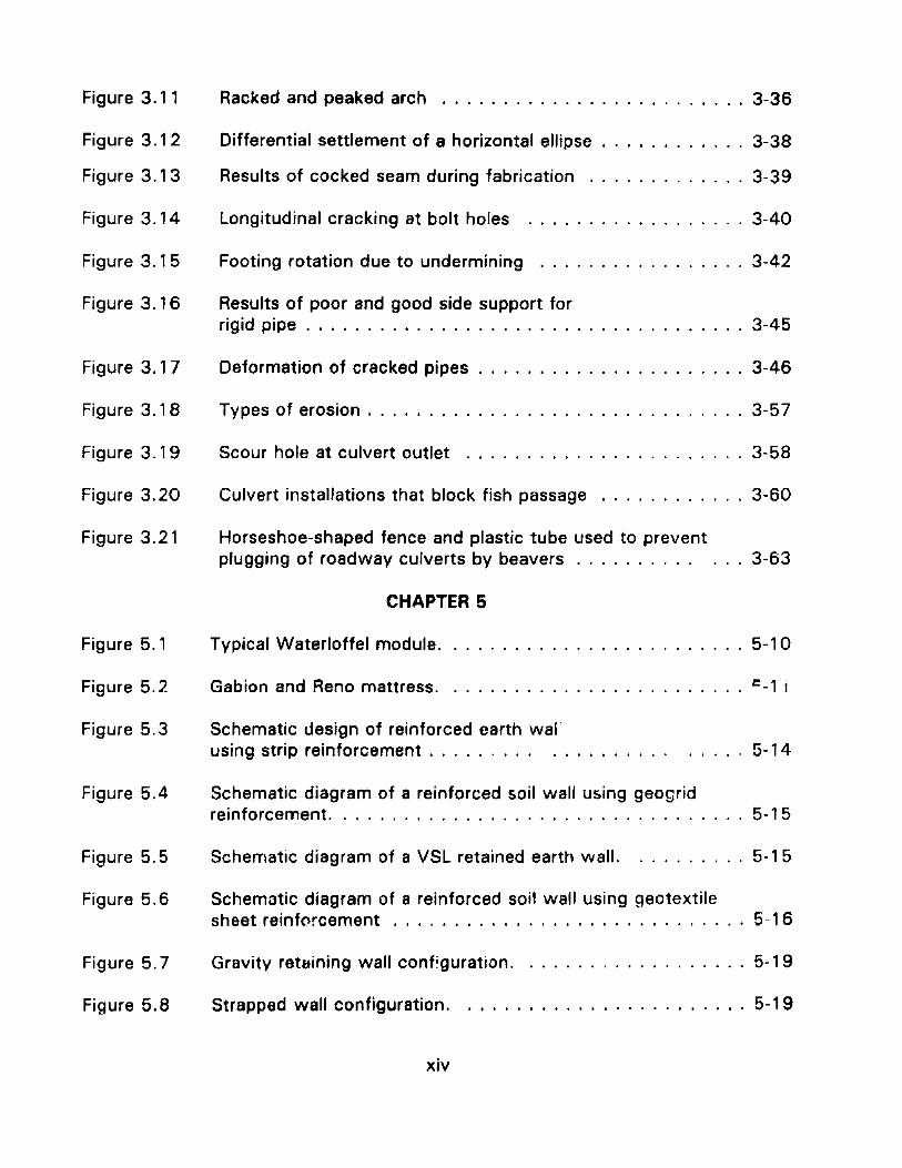
Figure 3.11
Figure 3.12
Figure 3.13
Figure 3.14
Figure 3.15
Figure 3.16
Figure 3.17
Figure 3.18
Figure 3.19
Figure 3.20
Racked and peaked arch 3-36
Differential settlement of a horizontal ellipse 3-38
Results of cocked seam during fabrication 3-39
Longitudinal cracking at bolt holes 3-40
Footing rotation due to undermining 3-42
Results of poor and good side support forrigid pipe . . . . . . . . . . . . . . . . . . . . . . . . . . . . . . . . . . . . 3-45
Deformation of cracked pipes 3-46
Types of erosion 3-57
Scour hole at culvert outlet 3-58
Culvert installations that block fish passage 3-60
Figure 3.21
Figure 5.1
Figure 5.2
Horseshoe-shaped fence and plastic tube used to preventplugging of roadway culverts by beavers .
CHAPTER 5
Typical Waterloffel module.
Gabion and Reno mattress.
3-63
5-10
r: -1 i
Figure 5.3
Figure 5.4
Figure 5.5
Figure 5.6
Figure 5.7
Schematic design of reinforced earth walusing strip reinforcement . . . . . . . .. . . . 5- 14
Schematic diagram of a reinforced soil wall using geogridreinforcement. . . . . . . . . . . . . . . . . . . . . . . . . . . . . . . 5- 15
Schematic diagram 01 a VSL retained earth wall. 5-15
Schematic diagram of a reinforced soil wall using geotextilesheet reinfC'rcement 5-1 6
Gravity retaining wall conf~guration. . 5-19
Figure 5.8 Strapped wall configuration.
xiv
5-19
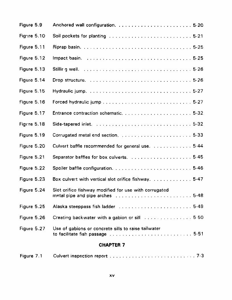
Figure 5.9 Anchored wall configuration 5-20
Fig'lre 5.10 Soil pockets for planting 5-21
Figure 5. i 1 Riprap basin , , 5-25
Figure 5.12 Impact basin. . ,., 5-25
Figure 5.13 Stillir 9 well. 5-26
Figure 5.14
Figure 5.15
Drop structure.
Hydraulic jump.
5-26
5-27
Figure 5.16 Forced hydraulic jump 5-27
Figure 5.17 Entrance contraction schematic , , , 5-32
Figl're 5.18 Side-tapered inlet. . , , 5-32
Figure 5.19 Corrugated metal end section , 5-33
Figure 5.20 Culvert baffle recommended for general use. . 5-44
Figure 5.21 Separator baffles for box culverts. . 5-45
Figure 5.22 Spoiler baffle configuration 5-46
Figure 5.23 Box culvert with vertical slot orifice fishway. . 5-47
Figure 5.24 Slot orifice tishway modified for use with corrugatedmp.tal pipe and pipe arches .,." , 5-48
Figure 5.25 Alaska steeppass fish ladder 5-49
Figure 5.26 Creating backwater with a gabion or sill 5-50
Figure 5.27 Use of gabions or concrete sills to raise tailwaterto facilitate fish passage . , , .. , , .. 5-51
CHAPTER 7
Figure 7,1 Culvert inspection report 7-3
xv
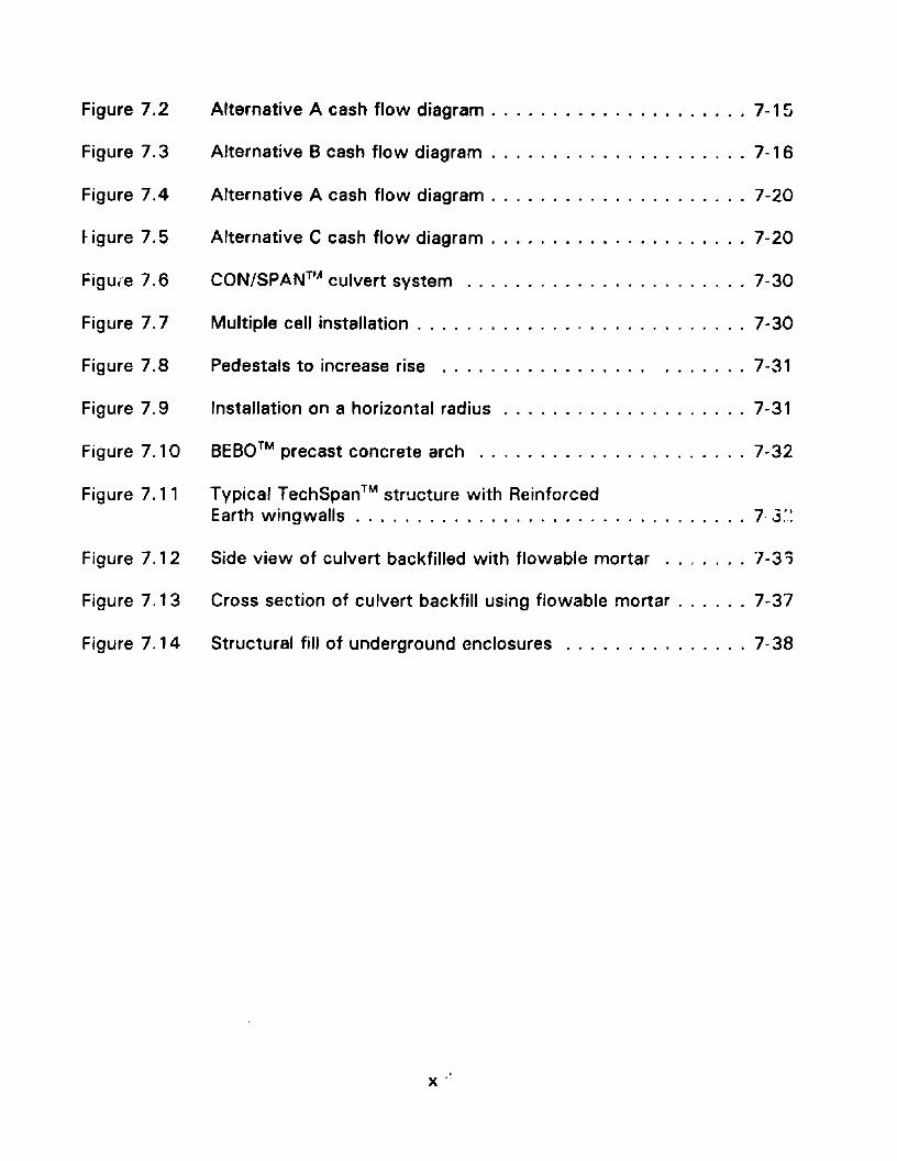
Figure 7.2
Figure 7.3
Figure 7.4
~igure 7.5
Figure 7.6
Figure 7.7
Alternative A cash flow diagram 7-1 Z
Alternative B cash flow diagram 7-16
Alternative A cash flow diagram 7-20
Alternative C cash flow diagram 7-20
CON/SP.4NTlIl culvert system 7-30
Multiple cell installation 7-30
Figure 7.8 Pedestals to increase rise . 7-31
Figure 7.9 Installation on a horizontal radius 7-31
Figure 7. 10 BEBO™ precast concrete arch 7-32
Figure 7.11 Typical TechSpan™ structure with ReinforcedEarth wingwalls 7· 3:.~
Figure 7. , 2 Side view of culvert backfilled with flowable mortar .. , .... 7-3?
Figure 7.13 Cross section of culvert backfill using flowable mortar 7-37
Figure 7.14 Structural fill of underground enclosures 7· 38
x .~
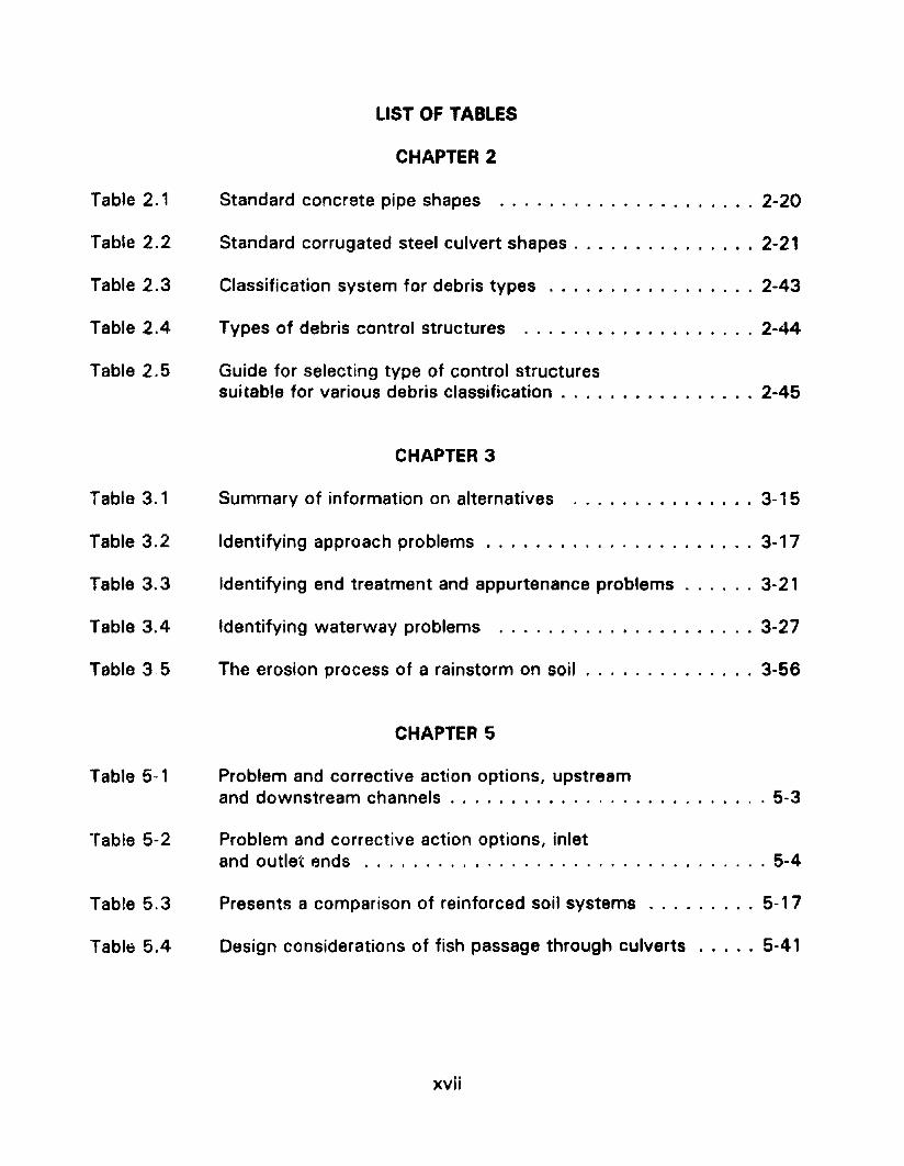
Table 2.1
Table 2.2
Table 2.3
Table 2.4
Table 2.5
LIST OF TABLES
CHAPTER 2
Standard concrete pipe shapes 2-20
Standard corrugated steel culvert shapes 2-21
Classification system for debris types 2-43
Types of debris control structures 2-44
Guide for selecting type of control structuressuitable for various debris classification 2-45
CHAPTER 3
Table 3.1 Summary of information on alternatives 3-15
Table 3.2
Table 3.3
Table 3.4
Table 35
Table 5-1
Table 5-2
Table 5.3
Table 5.4
Identifying approach problems 3-17
Identifying end treatment and appurtenance problems 3-21
Identifying waterway problems 3-27
The erosion process of a rainstorm on soil 3-56
CHAPTER 5
Problem and corrective action options, upstreamand downstream channels 5-3
Problem and corrective action options, inletand outlet ends 5-4
Presents a comparison of reinforced soil systems . . . . . . . . . 5-1 7
Design considerations of fish passage through culverts ..... 5-41
xvii
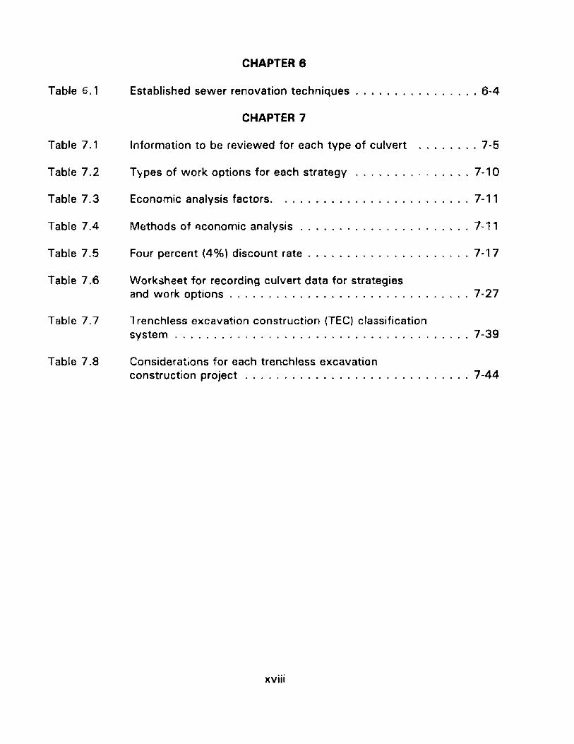
Table 6.1
Table 7.1
Table 7.2
Table 7.3
Table 7.4
Table 7.5
Table 7.6
CHAPTER 8
Established sewer renovation techniques 6-4
CHAPTER 7
Information to be reviewed for each type of culvert 7-5
Types of work options for each strategy 7-10
Economic analysis factors. . 7-11
Methods of ~conomic analysis 7-11
Four percent (4%) discount rate. . . . . . . . . . . . . . . . . . .. 7-17
\Nork~heet for recording culvert data for strategiesand work options 7-27
Table 7.7 1renchless excavation construction (TEC) classificationsystem . 7-39
Table 7.8 Considerations for each trenchless excavationconstruction project 7-44
xviii
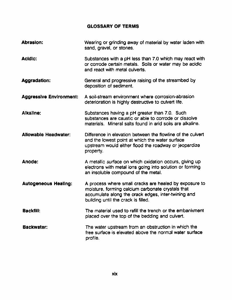
GLOSSARY OF TERMS
Abrasion: Wearing or grinding away of material by water laden withsand, gravel, or stones.
Acidic: Substances with a pH less than 7.0 which may react withor corrode certain metals. Soils or water may be acidicand react with metal culverts.
Aggradation: General and progressive raising of the streambed bydeposition of sediment.
Aggressive Environment: A soil-stream environment where corrosion-abrasiondeterioration is highly destructive to culvert life.
Alkaline: Substances having a pH greater than 7.0. Suchsubstances are caustic or able to corrode or dissolvematerials. Mineral salts found in arid soils are alkaline.
Allowable Headwater: Difference in elevation between the flowline of the culvertand the lowest point at which the water surfaceupstream would either flood the roadway or jeopardizeproperty.
Anode: A metallic surface on which oxidation occurs, giving upelectrons with metal ions going into solution or formingan insoluble compound of the metal.
Autogeneous Healing: A process where small cracks are healed by exposure tomoisture, forming calcium carbonate crystals thataccumulate along the crack edges, inter-twining andbuilding until the crack is filled.
Backfill: The material used to refill the trench or the embankmentplaced over the top of the bedding and culvert.
Backwater: The water upstream from an obstruction in which thefree surface is elevated above the normal water surfaceprofile.
xix
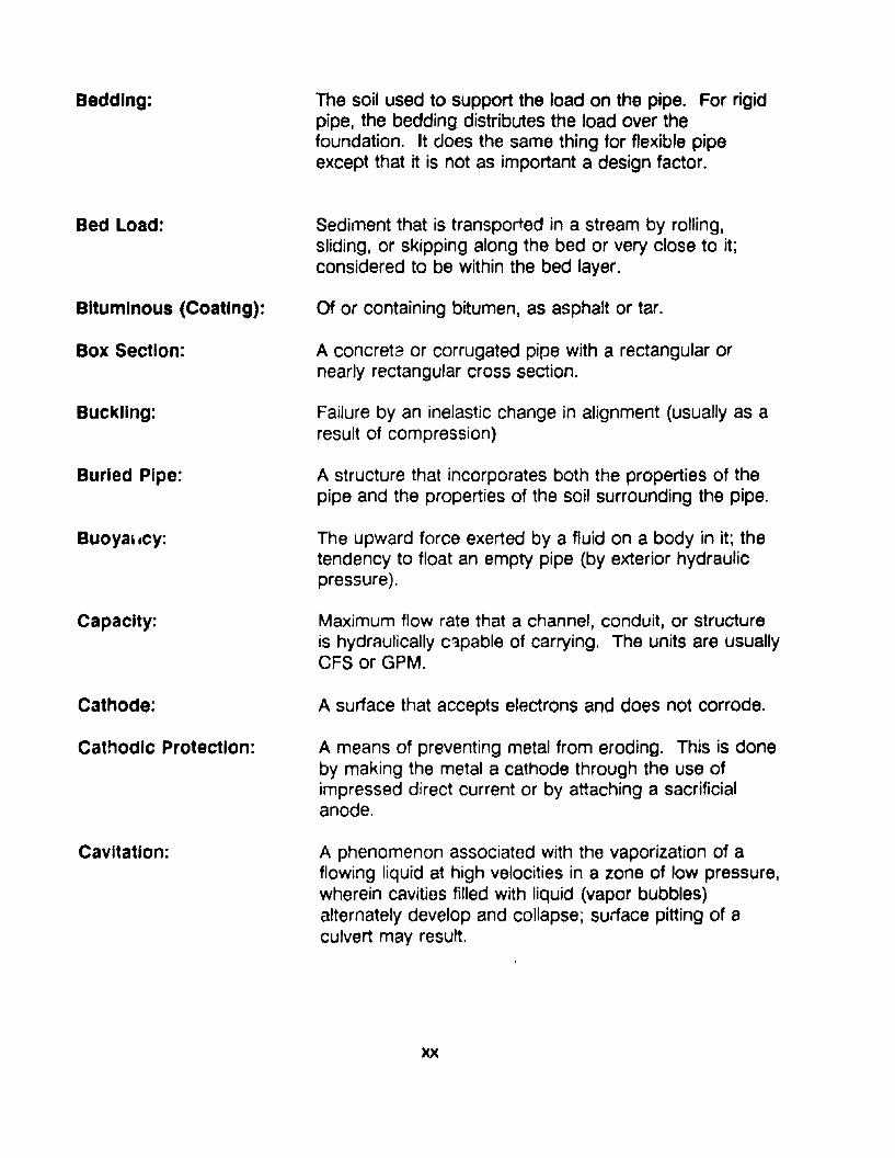
Bedding:
Bed Load:
Bituminous (Coating):
Box Section:
Buckling:
Burled Pipe:
Buoyal.cv:
Capacity:
Cathode:
Cathodic Protection:
Cavitation:
The soil used to support the load on the pipe. For rigidpipe, the bedding distributes the load over thefoundation. It does the same thing for flexible pipeexcept that it is not as important a design factor.
Sediment that is transported in a stream by rolling,sliding, or skipping along the bed or very close to it;considered to be within the bed layer.
Of or containing bitumen, as asphalt or tar.
A concrete or corrugated pipe with a rectangular ornearly rectangular cross section.
Failure by an inelastic change in alignment (usually as aresult of compression)
A structure that incorporates both the properties of thepipe and the properties of the soil surrounding the pipe.
The upward force exerted by a fluid on a body in it; thetendency to float an empty pipe (by exterior hydraulicpressure).
Maximum flow rate that a channel, conduit, or structureis hydraulically c~pable of carrying. The units are usuallyCFS or GPM.
A surface that accepts electrons and does not corrode.
A means of preventing metal from eroding. This is doneby making the metal a cathode through the use ofimpressed direct current or by attaching a sacrificialanode.
A phenomenon associated with the vaporization of aflowing liqUid at high velocities in a zone of low pressure,wherein cavities filled with liquid (vapor bubbles)alternately develop and collapse; surface pitting of aculvert may result.
xx
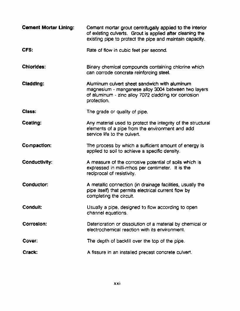
Cement Mortar Unlng:
CFS:
Chlorides:
Cladding:
Class:
Coating:
Compaction:
Conductivity:
Conductor:
Conduit:
Corrosion:
Cover;
Crack:
Cement mortar grout centrifugally applied to the interiorof existing culverts. Grout is applied after cleaning theexisting pipe to protect the pipe and maintain capacity.
Rate of flow in cubic feet per second.
Binary chemical compounds containing chlorine whichcan corrode concrete reinforcing steel.
Aluminum culvert sheet sandwich with aluminummagnesium - manganese alloy 3004 between two layersof aluminum - zinc alloy 7072 cladding lor corrosionprotection.
The grade or quality of pipe.
Any material used to protect the integrity of the structuralelements of a pipe from the environment and addservice life to the culvert.
The process by which a sufficient amount of energy isapplied to soil to achieve a specific density.
A measure of the corrosive potential of soils which isexpressed in milli-mhos per centimeter. It is thereciprocal of resistivity.
A metallic connection (in drainage facilities, usually thepipe itself) that permits electrical current flow bycompleting the circuit.
Usually a pipe, designed to flow according to openchannel equations.
Deterioration or dissolution of a material by chemical orelectrochemical reaction with its environment.
The depth of backfill over the top of the pipe.
A fissure in an installed precast concrete culvert
xxi
Critical Depth:
Critical Flow:
Crown:
Culvert:
Debris:
Deflection:
Degradation:
Discharge (0):
Drainage:
Drop Inlet:
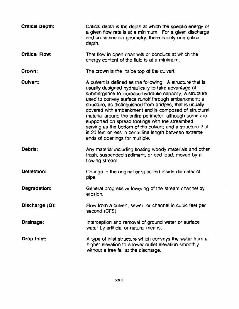
Critical depth is the depth at which the specific energy ofa given flow rate is at a minimum. For a given dischargeand cross-section ge'Jmetry, there is only one criticaldepth.
That flow in open channels or conduits at which theenergy content of the fluid is at a minimum.
The crown is the inside top of the culvert.
A culvert is defined as the following: A structure that isusually designed hydraulically to take advantage ofsubmergence to increase hydraulic capacity; a structureused to convey surface runoff through embankment; astructure, as distinguished from bridges, that is usuallycovered with embankment and is comf:'osed of structuralmaterial around the entire perimeter. although some aresupported on spread footings with the streambedserving as the bottom of the culvert; and a structure thatis 20 feet or less in centerline length between extremeends of openings for multiple.
Any material including floating woody materials and othertrash, suspended sediment, or bed load, moved by afloWing stream.
Change in the original or specified inside diameter ofpipe.
General progressive lowering of the stream channel byerosion.
Flow from a culvert. sewer. or channel in cubic feet persecond (CFS).
Interception and removal of ground water or suriacewater by artificial or natural means.
A type of inlet structure which conveys the water from ahigher elevation to a lower outlet elevation smoothlywithout a free fall at the discharge.
xxii
Durability:
Electrolyte:
Embankment:
End Section:
Energy DlsSlpator:
Energy Gradient:
Energy Grade Line:
Erosion (Culvert):
Erosion (Stream):
Female End of Pipe(bell, locket, groove,modified groove):
fish Passage:
Flexible Pipe:
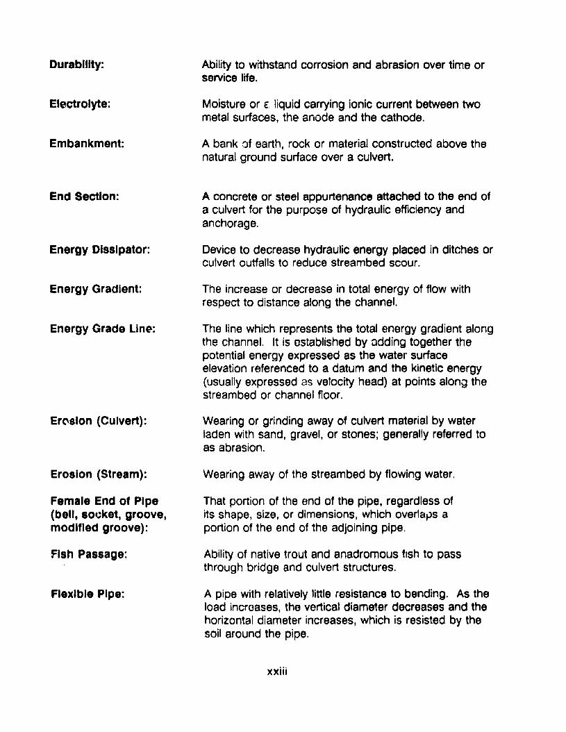
Ability to withstand corrosion and abrasion over time orservice life.
Moisture or E. liquid carrying ionic current between twometal surfaces, the anode and the cathode.
A bank of earth, rock or material constructed above thenatural ground surface over a culvert.
A concrete or steel appurtenance attached to the end ofa culvert for the purpose of hydraulic efficiency andanchorage.
Device to decrease hydraulic energy placed in ditches orculvert outfalls to reduce streambed scour.
The increase or decrease in total energy of flow withrespect to distance along the channel.
The line which represents the total energy gradient alongthe channel. It is ostablished by adding together thepotential energy expressed as the water surfaceelevation referenced to a datum and the kinetic energy(usually expressed as velocity head) at points along thestreambed or channel floor.
Wearing or grinding away of culvert material by waterladen with sand, gravel, or stones; generally referred toas abrasion.
Wearing away of the streambed by flowing water.
That portion of the end of the pipe, regardless ofits shape, size, or dimensions, which overlaps aportion of the end of the adjoining pipe.
Ability of native trout and anadromous fish to passthrough bridge and culvert structures.
A pipe with relatively little resistance to bending. As theload incroases, the vertical diameter decreases and thehorizontal diameter increases, which is resisted by thesoil around the pipe.
xxiii
Flood Frequency:
Flow Une:
Foundation:
Free Outlet:
Gltlvanlzlng:
Gauge:
GPM:
Grade:
Gradient:
Groundwater:
Hairline Cracks:
Holidays:
Haunches:
Head (StatiC):
Headloss:
Headwall:
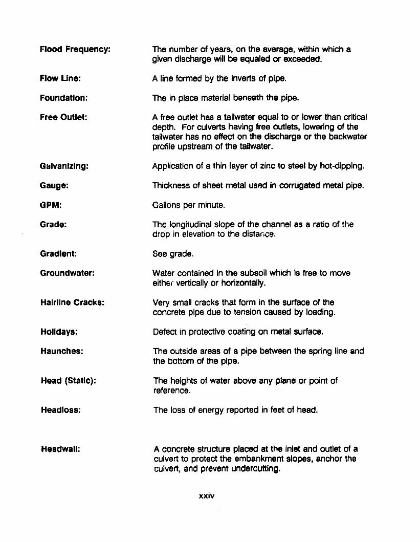
The number of years, on the average, within which agiven discharge will be equaled or exceeded.
A line formed by the inverts of pipe.
The in place material beneath the pipe.
A free outlet has a tailwater equal to or lower than criticaldepth. For culverts having free outlets, lowering of thetailwater has no effect on the discharge or the backwaterprofile upstream of the tailwater.
Application of a thin layer of zinc to steel by hot-dipping.
Thickness of sheet metal used in corrugated metal pipe.
Gailons per minute.
The longitudinal slope of the channel as a ratio of thedrop in elevation to the distance.
See grade.
Water contained in the subsoil which is free to moveeithe.' vertically or horizontally.
Very small cracks that form in the surface of theconcrete pipe due to tension caused by loading,
Defect in protective coating on metal surface.
The outside areas of a pipe between the spring line andthe bottom of the pipe.
The heights of water above any plane or point ofreference.
The loss of energy reported in feet of head.
A concrete structure placed at the Inlet and outlet of aculvert to protect the embankment slopes, anchor theculvert, and prevent undercutting.
xxiv
Headwater:
Hydraulics:
Hydraulic Gradellne:
Hydraulic Jump:
Hydraulic Radius:
Hydrology:
Improved Inlet:
Impingement:
Insertion Renewal:
Inversion Unlng:
Invert:
Joint:
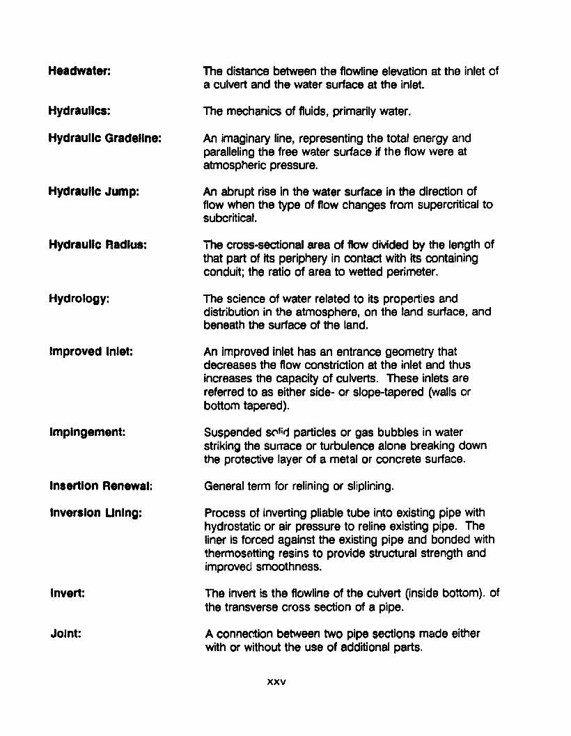
The distance between the flowline elevation at the inlet ofa culvert and the water surface at the inlet.
The mechanics of fluids, primarily water.
An imaginary line, representing the total energy andparalleling the free water surface if the flow were atatmospheric pressure.
An abrupt rise in the water surface in the direction offlow when the type of flow changes from supercritical tosubcritical.
The cross-sectional area of flow divided by the length ofthat part of its periphery in contact with its containingconduit; the ratio of area to wetted perimeter.
The science of water related to its properties anddistribution in the atmosphere, on the land surface, andbeneath the surface of the land.
An improved inlet has an entrance geometry thatdecreases the flow constriction at the inlet and thusincreases the capacity of culverts. These inlets arereferred to as either side- or slope-tapered (walls orbottom tapered).
Suspended S("llitj particles or gas bubbles in waterstriking the sunace or turbulence alone breaking downthe protective layer of a metsl or concrete surface.
General term for relining or sliplining.
Process of inverting pliable tube into existing pipe withhydrostatic or air pressure to reline existing pipe. Theliner is forced against the existing pipe and bonded withthermosatting resins to provide structural strength andimproved smoothness.
The invert is the flowline of the culvert (inside bottom). ofthe transverse cross section of a pipe.
A connection between two pipe sections made eitherwith or without the use of additional parts.
xxv
Unk Pipe Unlng:
Long Span CUlverts:
Male End of Pipe(Spigot, Tongue,Modified Tongue):
Manning's Equation:
Metal Corrosion:
Minor Head Losses:
Normal Flow:
O-Ring Gasket:
Outfall:
Outlet:
Method of pulling a short, folded pipe line segment tothe damaged point in an existing pipe and jacking thesegment into place.
Culverts that are designed on structural aspects ratherthan hydraulic considerations. Usually constructed ofstructural plate which exceed defined sizes for pipes,pipe arches, or arches or may be special shapes thatinvolve a long radius of curvature in the crown or sideplates.
That portion of the end of the pipe, regardless ofits shape or dimensions, which is overlapped by aportion of the end of the adjoining pipe.
An equation for the empirical relationship used tocalculate the barrel friction loss in culvert design.
An electrical process involving an electrolyte (moisture),an anod~ (the metallic surface where oxidation occurs),a cathode «(he metallic surface that accepts electronsand does not corrode), and a conductor (the metal pipeitself).
Head lost through transitions such as entrances, outlets,obstructions, and bends.
Normal flow occurs in a channel reach when thedischarge, velocity and depth of flow do not changethroughout the reach. The water surface profile andchannel bottom slope will be parallel. This type of flowwill exist in a culvert operating on a steep slope providedthe culvert is sufficiently long.A solid gasket of circular cross section. Used in jointconnections.
In hydraulics, the discharge end of drains or sewers.Also referred to as outlet.
See Outfall.
xxvi
Oxidation-Reductionpotential:
Perforation:
pH Value:
Pipe:
Pipe Diameter:
Piping:
Polyethylene Pipe:
Polymer Coating:
Ponding:
Prestressed Concrete:
Used as a primary indicator of anaerobic bacterialcorrosion which occurs in wet, poorly drained soils atthe soil-metal interface. Iron in aerated water in thepresence of sulfate-reducing bacteria corrodes at anaccelerated ratd. Also known as the "redox potential."
Complete penetration of metal culvert that generallyoccurs in the invert.
The log of the reciprocal of the hydrogen ionconcentration of a solution. A pH value of 7.0 is neutral;values of less than 7.0 are acid; values of more than 7.0are alkaline.
A tube or conduit.
The inside diameter of a pipe.
A process of subsurface erosion in which surface runoffflows along the outside of a CulVBrt and with sufficienthydraulic gradient erodes and carries away soil aroundor beneath tho culvert.
Plastic pipe manufactured from polymerized ethylene incorrugated or smooth configurations of various1imensions.
Pr0tective coatings o~ plastic polymer resins with othermaterials.
Water back up in a channel or ditch as the result of ael'lvert of inadequate capacity or design to permit theVI/ater to flow unrestricted.
Con:..r~l.e that is continually under a compressive stressthat is created when the steel reinforcing bars, wires, orcables are h~ld in a stretched condition during placingof the plastic concrete and until the concrete hashardened. The pull on the reinforcing steel is thenreleased prOViding additional strength.
Reinforced Concrete Pipe: A concrete pipe designed with reinforcement as acomposite structure.
xxvii
Rigid Pipe:
Rip Rap:
A pipe with a high resistance to bending
Rough stone of various sizes placed compactly orirregularly to prevent scour by water or debris.
Roughness Coefficient (n): A factor in the Kutter, Manning, and other flow formulasrepresenting the effen of channel (or conduit) roughnessupon energy losses in flowing water. It is based oneither hydraulic test results or calculated usingtheoretical relationships.
Resistivity (Soli):
Runoff:
Sacrificial Coating:
Sacrificial Thickness:
Scour (Outlet):
Seepage:
Shotcrete Unlng:
Skew (Skew Angle):
An electrical measurement in ohm-em, which is one ofthe factors for estimating the corrosivity of a given soil tometals.
That part of precipitation carried off from the area uponwhich it falls.
A coating over the base material to provide protection tothe base mRterial. Examples include galvanizing on steeland cladding on aluminum.
Additional pipe thickness provided for extra service life ofthe culvert in an aggressive environment.
Degradation of the channel at the culvert outlet as aresult of erosive velocities.
The escape of water through the soil, or water flowingfrom a fairly large area of soil instead of from one spot,as in the case of a spring.
Application of pneumatically applied cement plaster orconcrete to an in place structure to increase structuralstrength and improve the surface smoothness.
The acute angle formed by the intersection of the linenormal to the centerline of the road with the centerline ofa culvert or other structure.
xxviii
Slabbing:
Slide:
Sllpllnlng:
Slope:
Spelter:
Spalllng (Culvert):
Springline:
Structural Plate:
Submerged Inlet:
Submerged Outlet:
Sulfates:
Suspended Load:
Radial tension failure of concrete pipe resulting from thetendency of curved reinforcing steel or cage tostraighten out under load. It is characterized by largeslabs of concrete "peeling" away from the sides of thepipe.
Movement of a part of the earth (embankment) underthe force of gravity.
The process of placing a smaller diameter pipe in alarger diameter existing pipe to improve the culvertstructure and repair leaks. The annular space betweenthe pipes is usually filled with grout.
Steep slope occurs where the critical depth is greaterthan the normal depth. Mild slope occurs where criticaldepth is less than normal depth.
Zinc slabs or plates.
The separation of surface concrete due to fractures inthe concrete parallel or slightly inclined to the surface ofthe concrete.
The points on the internal surface of the transversecross section of a pipe intersected by the line ofmaximum horizontal dimension; or in box sections, themid-height of the internal vertical wall.
Plates of structural steel used to fabricate IElrge culvertstructures such as arches elr boxes.
A submerged inlet occurs where the headwater isgreater than 1.20.
A submerged outlet occurs where the tailwater elevationis higher than the crown of It Ie culvert.
Chemical compounds containing SO found in alkalinesoils that cause concrete detArioretidh.
Sediment that is supported by the upward comt~~"ents
of the turbulent currents in a stream.
xxix
Tallwater Depth:
velocity Head:
Wall (Concrete Pipe):
Watercourse:
Watersht}d:
Weir:
W\Jtted Perimeter:
The depth of water just downstream from a structure.
For water moving at a given velocity, the equivalent headthrough which it would have to fall by gravity to acquirethe same velocity.
The structural element composed of concrete orconcrete and reinforcing steel between the inside andoutside of a concrete pipe.
A channel in which a flow oi water occurs, eithercontinuously or intermittentlY, with some degree ofregularity.
Region or area contributing to the supply of a stream orlake, drainage area, drainage basin, or catchment area.
A man made barrier in an open channel over whichwater flows. It is used to measure the quantity of flow.
The length of the wetted contact between the water andthe containirig conduit measured at right angles to theconduit.
xxx
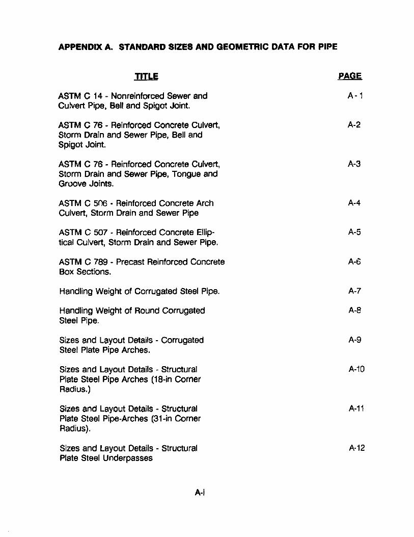
APPENDIX A. STANDARD SIZES AND GEOMETRIC DATA FOR PIPE
TITLE
ASTM C 14 - Nonreinforced Sewer andCulvert Pipe. Bell and Spigot Joint.
ASTM C 76 - Reinforced Concrete Culvert,Storm Drain and Sewer Pipe, Bell andSpigot Joint.
ASTM C 76 - Reinforced Concrete Culvert,Storm Drain and Sewer Pipe, Tongue andGroove Joints.
ASTM C 506 - Reinforced Concrete ArchCulvert, Storm Drain and Sewer Pipe
ASTM C 507 - Reinforced Concrete Elliptical Culvert, Storm Drain and Sewer Pipe.
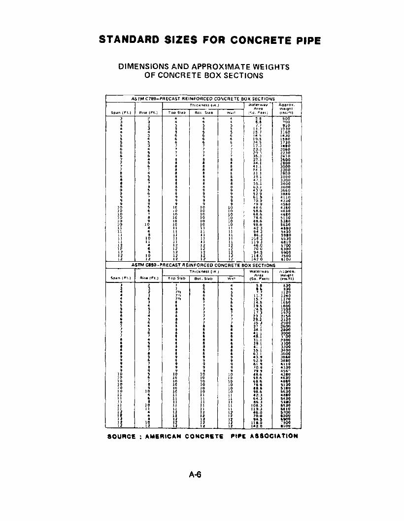
ASTM C 789 - Precast Reinforced ConcreteBox Sections.
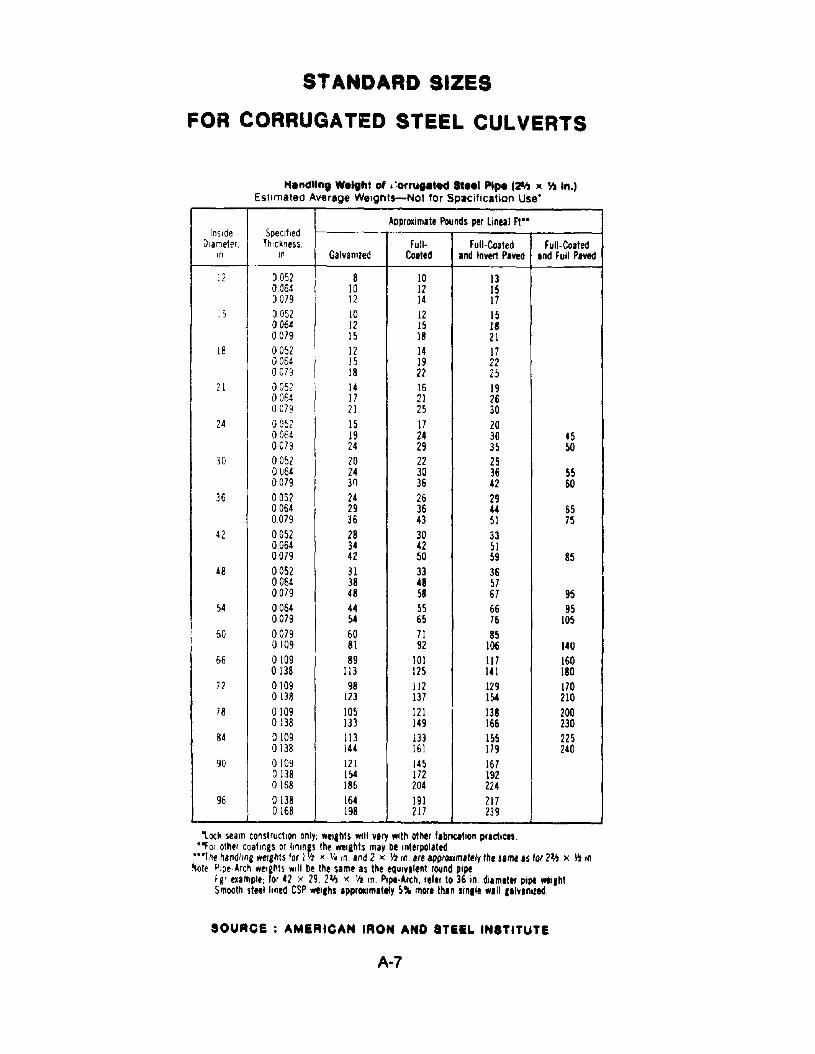
Handling Weight of Corrugated Steel Pipe.
Handling Weight of Round CorrugatedSteel Pipe,
Sizes and Layout Details - CorrugatedSteel Plate Pipe Arches.
Sizes and Layout Details - StructuralPlate Steel Pipe Arches (18-in CornerRadiUS.)
Sizes and Layout Details - StructuralPlate Steel Pipe-Arches (31-in CornerRadius).
Sizes and Layout Details - StructuralPlate Steel Underpasses
A-I
PAGE
A-1
A-2
A-3
A-4
A-5
A-6
A-7
A-8
A-9
A-10
A-11
A·12
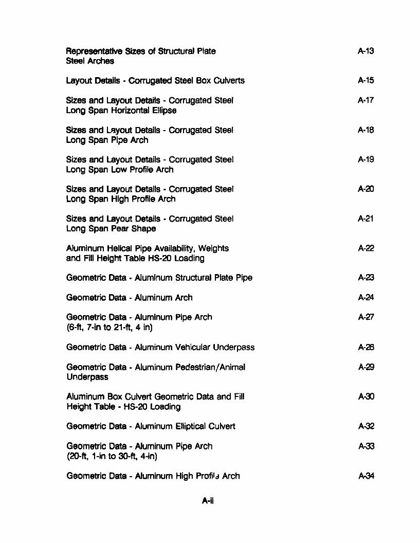
Representative Sizes of Structural PlateSteel Arches
Layout DetaIls - Corrugated Steel Box Culverts
Sizes and Layout Details - Corrugated SteelLong Span Horizontal Ellipse
Sizes and LAyout Details - Corrugated SteelLong Span Pipe Arch
Sizes and Layout Details - Corrugated SteelLong Span Low Profile Arch
Sizes and Layout Details - Corrugated SteelLong Span High Profile Arch
Sizes and Layout Details - Corrugated SteelLong Span Pear Shape
Aluminum Helical Pipe Availability, Weightsand Fill Height Table HS-20 Loading
Geometric Data - Aluminum Structural Plate Pipe
Geometric Data - Aluminum Arch
Geometric Data - Aluminum Pipe Arch(6-ft, 7-in to 21-ft, 4 in)
Geometric Data - Aluminum Vehicular Underpass
Geometric Data - Aluminum Pedestrian/AnimalUnderpass
Aluminum Box Culvert Geometric Data and FillHeight Table - HS-20 Loading
Geometric Data - Aluminum Elliptical Culvert
Geometric Data - Aluminum Pipe Arch(20-ft, 1-in to 3D-ft, 4-in)
Geometric Data - Aluminum High Profil" Arch
A-Ii
A-13
A-15
A-17
A-18
A-19
A-2l
A-21
A-22
A-23
A-24
A-V
A-28
A-23
A-OO
A-32
A-33
A-34
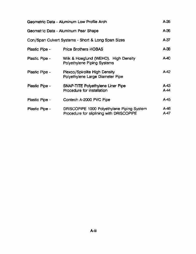
Geometric Data - Aluminum Low Profile Arch
Geometl'ic Data - Aluminum Pear Shape
Con/Span Culvert Systems - Short & Long Span Sizes
A-35
A~7
Plastic Pipe -
Plastic Pipe -
Plastic Pipe -
Plastic Pipe -
Plastic Pipe -
Plastic Pipe -
Price Brothers HOBAS
Wiik & Hoeglund (WEHO). High DensityPolyethylene Piping Systems
Plexco/Spirolite High DensityPolyethylene Large Diameter Pipe
SNAP-TITE Polyethylene Liner PipeProcedure for installation
Contech A-2000 PVC Pipe
DRISCOPIPE 1000 Polyethylene Piping SystemProcedure for sliplining with DRISCOPIPE
A-40
A-42
A-43AM
A45
A-46A-47
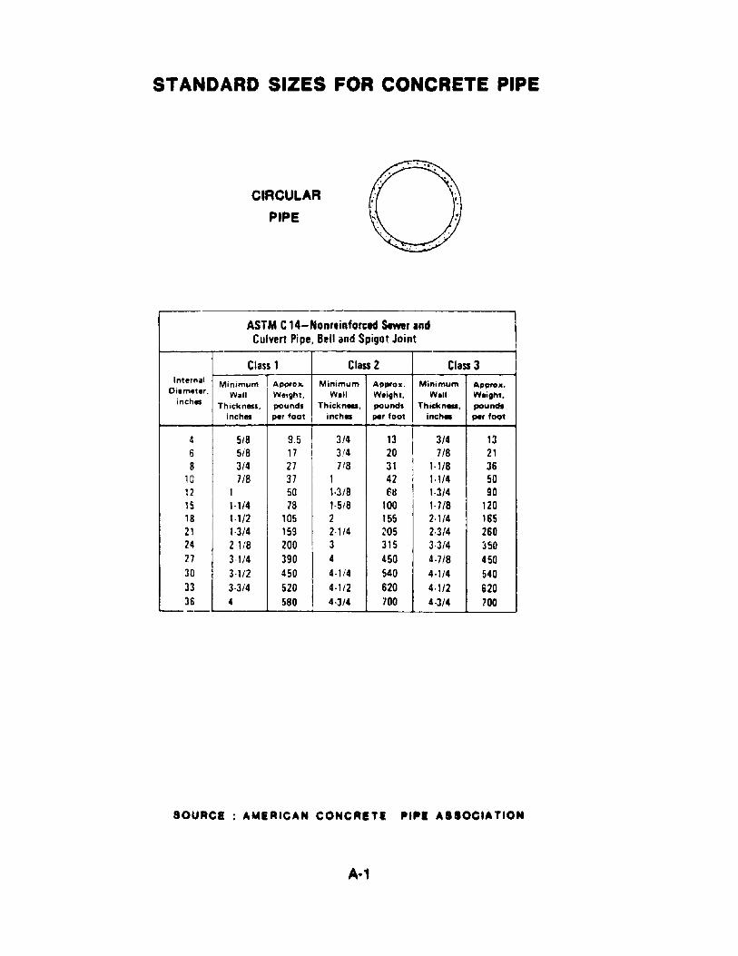
STANDARD SIZES FOR CONCRETE PIPE
CIRCULAR
PIPE
ASTM C14-Nonreinforced Sewer IndCulvert Pipe, Bell and Spigot Joint
Class 1 Class 2 Class 3Internal Minimum Appro,," Minimum Appro •. Minimum Approx.
Oiametar. Wall Weight. W.II Waight. W.II Waight.inchlllS Thickn,,". pounds Thickn_. pounds Thiekn_. poundt
inchlllS per foot inch. per foot inch. per foot
4 5/8 9.5 3/4 13 3/4 136 5/8 17 3/4 20 7/8 218 3/4 27 7/8 31 1-1/8 36
10 7/8 37 1 42 1·1/4 5012 1 50 1-3/8 ell 1·3/4 9015 1·1/4 78 1-5/8 100 1·7/8 12018 1·1/2 105 2 155 2·1/4 16521 1·3/4 159 2·1/4 205 2·3/4 26024 2·1/8 200 3 315 3·3/4 ~50
27 3-1/4 390 4 450 4·718 45030 3-1/2 450 4·1/4 540 4·1/4 54033 3·3/4 520 4·1/2 620 4·1/2 62036 4 580 4·3/4 700 4·3/4 700
'-
SOURCE AMERICAN CONCRETI. PIPI ASSOCIATION
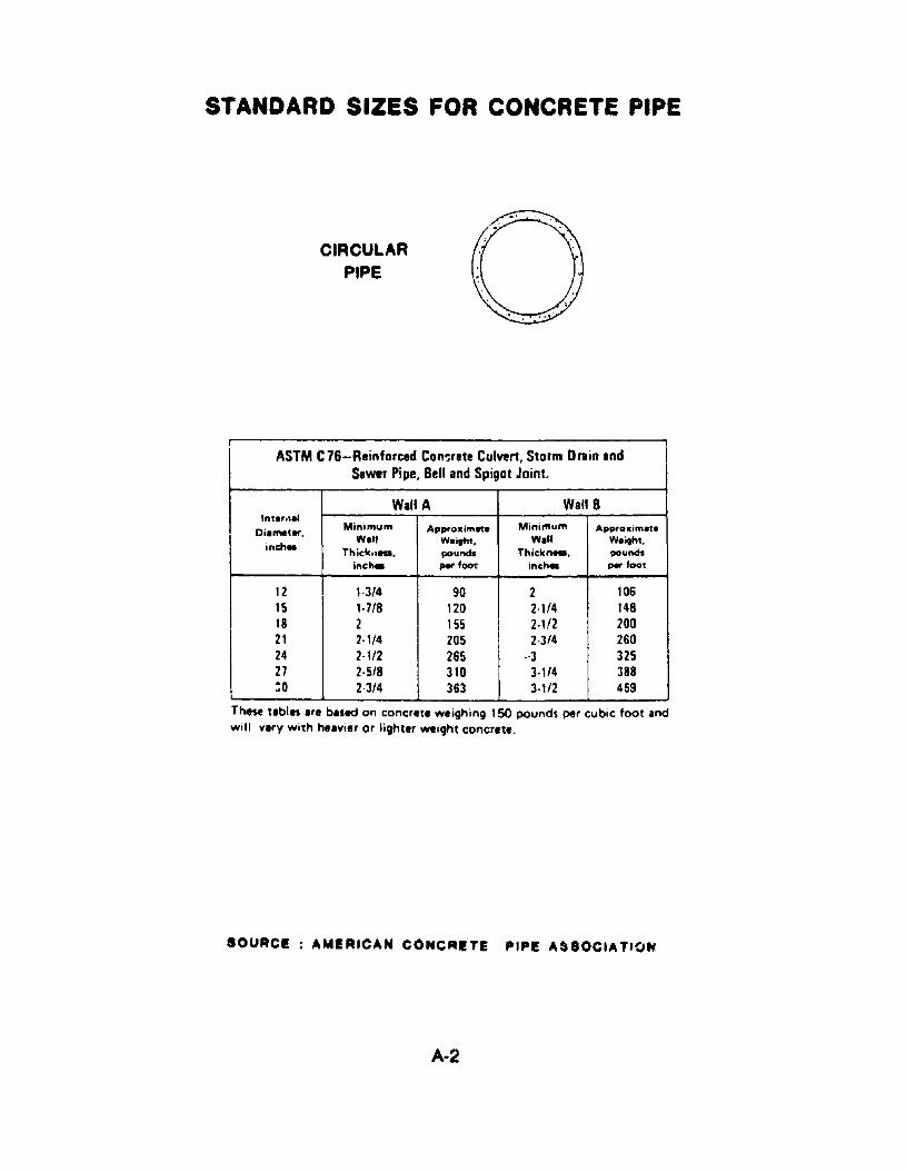
STANDARD SIZES FOR CONCRETE PIPE
CIRCULARPIPE
ASTM C76-Reinforced Con~rete Culvert, Storm Ol1lin IndSewer Pipe, Bell Ind Spigot Joint.
Wall A Wall BInt.",al
Minimum MinimumDiameter. Approllimfta App,ollim~.
WI" Weitht. Wall Weitht.inch. Thick._. pound. Thickn_. pound.
inc"- par foot inc"- par f_t
12 1·3/4 90 2 10615 1·7/8 120 2·1/4 14818 2 155 2·112 20021 2·1/4 205 2·3/4 26024 2·112 265 -3 32527 2·5/8 310 3·1/4 388:0 2·3/4 363 3·1/2 459
These t.bles Ire b.sed on concrete weighing 150 pounds per cubic foot andwill vary with h..vier or lighter weiqht coner.te.
SOURCE AMERICAN CONCRETE PIPE A&80CIA TfON
A-2
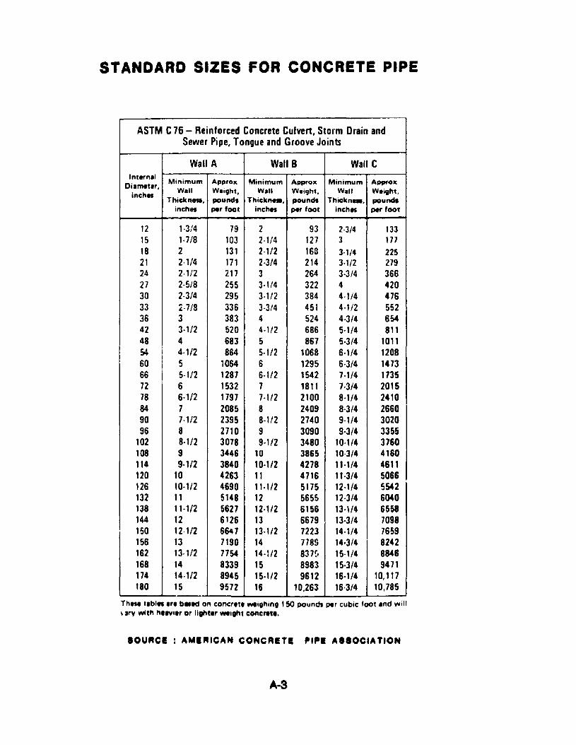
STANDARD SIZES FOR CONCRETE PIPE
ASTM C76 - Reinforced Concrete Culvert, Storm Drain andSewer Pipe, Tongue and Groove Joints
Wall A Wall B Wall CInternal
Minimum Approx Minimum Approx Minimum Appt'oxDiameter,
inchesWall Weight, Wall Weight. Wall Weight,
Thickn... povnd, Thick"... pound, Thick"... poundsinches per foot inches per foot inch. per foot
12 1·3/4 79 2 93 2·3/4 13315 1·7/8 103 2·1/4 127 3 17118 2 131 2·1/2 168 3·1/4 22521 2·1/4 171 2·3/4 214 3·1/2 27924 2·112 217 3 264 3·3/4 36627 2·5/8 255 3·1/4 322 4 42030 2·3/4 295 3·1/2 384 4·1/4 47633 Z·718 336 3·3/4 451 4·1/2 55236 3 383 4 524 4·3/4 65442 3·1/2 520 4·112 686 5·1/4 81148 4 683 5 867 5·3/4 101154 4·112 864 5-1/2 1068 6-1/4 120860 5 1064 6 1295 6·3/4 147366 5·1/2 1287 6·1/2 1542 7·1/4 173572 6 1532 7 1811 1·3/4 201578 6·112 1197 1·1/2 2100 8·1/4 241084 7 2085 8 2409 8·3/4 266090 7·1/2 2395 8·1/2 2740 9·1/4 302096 8 2710 9 3090 9·3/4 3355
102 8·1/2 3078 9-1/2 3480 10·1/4 3760108 9 3446 10 3865 10·3/4 4160114 9·1/2 3840 10·1/2 4278 11-1/4 4611120 10 4263 11 4716 11·3/4 5066126 10·1/2 4690 11·1/2 5175 12·1/4 5542132 11 5148 12 5655 12·3/4 6040138 11·1/2 5627 12·1/2 6156 13·\/4 6558144 12 6126 13 6679 13·3/4 7098150 12·1/2 6647 13·1/2 7223 14·1/4 7659156 13 7190 14 7189 14·3/4 8242162 13·1/2 7754 14·1/2 837r, 15·1/4 8846168 14 8339 15 8983 15·3/4 9471174 14·1/2 8945 15·1/2 9612 16·1/4 10,117180 15 9572 16 10.263 16·3/4 10,185
These tlbl.. Irl b.1d on concrlt. weighing 150 pOund. per cubic foot Ind WIll
\ Jry with helVier or lighter weight concrete.
SOURCE: AMERICAN CONCRETE lit I lit. ASSOCIATION
A·3
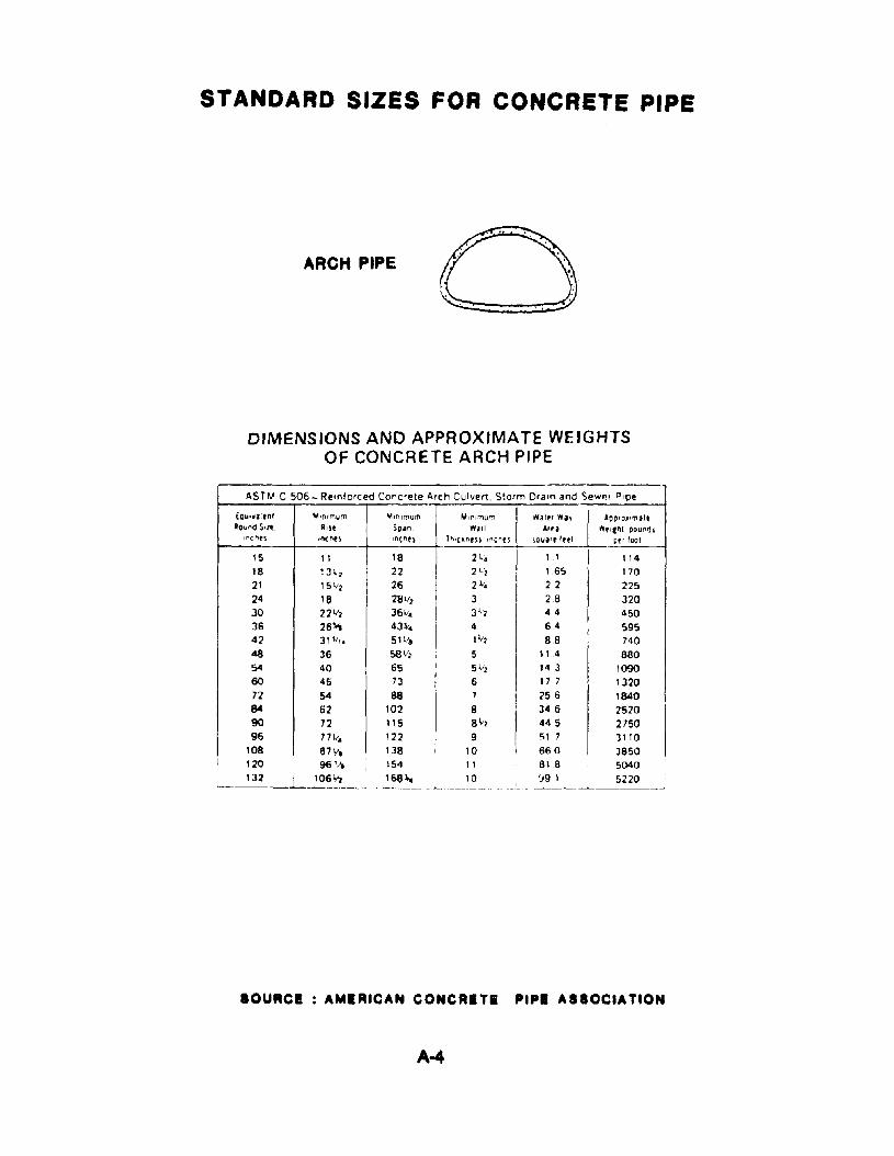
STANDARD SIZES FOR CONCRETE PIPE
ARCH PIPE
DIMENSIONS AND APPROXIMATE WEIGHTSOF CONCRETE ARCH PIPE
ASTM C 506 - ReInforced Concrete Arch Culvert. Storm Drain and Sew", P'Qe
[(Ju,w'l~nl ~mlmum ~InIlT'Um I ",,",",U'" I >Vat., >v~oP,o","al'RounO S,~ AIU Soan >Vall A", wtt"Ir'l1 POUflfh
lncnu Inches IO(~es hltc.nt~s In-tnes SQUi'f Ittl per foot
15 11 18 21.. I 11 I 11418 131" 22 2 ~, 165 17021 1511, 26
I
2"'. 22 22524 18 281/7 3 28 32030 221(2 3611_ 31,2 4 4 45036 26~ 43"'_ 4 6.4 59542 31'/" 511/8 1 \1, 88 74048 36 581/2 5 11 .4 88054 40 65 51.'2 14 3 109060 45 73 6 17 7 131072 54 88 7 256 184084 62 102 8 346 252090 72 115 8\12 445 U5096 771(_ 122 9 51 7 3110
108 871ft 138 10 I 660 3850I I 20 96 ''-' 154 11
~~_L_~~~ ... 2-&8~~ . ~~ __. ,_ ..81 8 5040'.191 5220
IOURCI AMIRICAN CONCRlfl PIPI AI'OCIATION
A-4
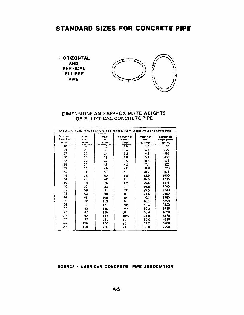
STANDARD SIZES FOR CONCRETE PIPI
HORIZONTALAND
VfRTICALELLIPSE
PIPE
.•..... \.' .. . ' . ' .. " .' .
• eo'
. '.. .. .
DIMENSIONS AND APPROXIMATE WEIGHTSOF ELLIPTICAL CONCRETE PIPE
AS TM C 507 - Re;;,forced Concrete Elliptical Culvert. Storm Drain and Sewer Pipe
EQuivalent Minor M'lor M,n,mumWl1I Wllt',WIY All" ..""."Round Stir "'". ""S Th,ckness. Are,. Wtllhl. ,.....,Inches I"ChotS Inthes Inches saulr, '"I -,101'
18 14 23 2¥. 1.8 19524 19 30 311. 3.3 30027 22 34 3'f.l 4.1 36530 24 38 3¥. 5.1 43033 27 42 3¥. 6.3 47536 29 45 4112 7.4 62539 32 49
I4¥. 8.8 720
42 34 53 5 10.2 81548 38 60 5liz 12.9 100054 43 68 6 16.6 123560 48 76 6liz 20.5 147566 53 83 7 24.8 174572 58 91 7liz 29.5 204078 63 98 B 34.6 235('184 68 106 811z I 40.1 268090 72 113 9 46.1 305096 77 121 9 liz 52.4 3420
102 82 12& 9¥. 59.2 3725108 87 136 10 66.4 4050114 92 143 1oliz 74.0 "70120 97 151 11 82.0 4930132 106 166 12 99.2 5900144 116 180 13 118.6 7000
SOUACE AMERICAN CONCRITE PIPI ASIOCIATION
A·5
STANDARD SIZES FOR CONCRETE PIPE
DIMENSIONS AND APPROXIMATE WEIGHTSOF CONCRETE BOX SECTIONS
ASTM C789-PRECAST REINFORCED CONCRETE BOX SECTIONSTh.cj,(neu (_n.) Waterway Agpro.ll..
Area wel9MSpan (Ft.) Rise (Ft.) Top 51'b 80t. $1'0 W.II (SQ. Feet) (IDS/HI
3 2 4 I 4 • 5.8 6003 3 4 4 • 6.8 7004 2 ~ ~ ~ 7.7 9104 3 5 I 5 5 11.7 10304 4 5 I 5 5 15.7 11605 3 6 6 6 •
145 14305 4 6 6 6 19.5 15805 5 6 6 6 24.5 17306 3 7 7 7 17.3 18806 4 7 7 7 23.3 20606 5 7 7 7 29.l 22306 6 7 7 7 35.3 24107 4 8 a 8 21.1 26007 5 8 8 8 34.1 26007 6 8 8 8 41.1 30007 7 8 8 8 J 81 32008 4 a a 6 311 28008 5 8 8 8 391 30008 6 8 8 8 .71 32008 7 8 8 8 55.1 34008 8 8 8 8 63.1 36009 5 '3 9 '3 439 3660 I9 6 9 9 9 52.9 38809 , 9 9 9 619 41109 8 9 9 9 70.9 43309 9 9 9 9 799 4560
10 5 10 10 10 48.6 438010 6 ,0 10 10 58.6 463010 7 10 10 10 68.6 488010 8 10 10 10 78.6 513010 9 10 10 10 88.6 538010 10 10 10 10 98.6 563011 4 11 11 11 42.3 4811011 6 11 11 11 64.3 543011 8 II 11 11 86.3 591011 10 11 11 11 1(,8.3 651011 11 11 11 11 119.3 681012 4 12 12 12 46.0 570012 6 12 12 .2 70.0 630012 8 12 12 12 94.5 690012 10 12 12 12 118.0 750012 12 12 12 12 142.0 8100
ASTM C850-PRECAST REINFORCeD CONCRETE BOX SeCTIONSTtHcknl" (in.) W.terw• ., A'::":litO •.
Area We l 9"tSpan (Ft.) R". (Fq Top S~ab Bot. SI.b W.,II (SQ. Feet) (Ibt/I ll
3 2 7 6 4 5.8 8303 3 7 I> 4 8.6 9104 2 7V, 6 5 7.7 1\204 3 7 1f, 6 5 11.7 12404 4 7V, 6 5 15.7 13705 3 7 6 14.5 16505 4 7 6 19.5 18005 5 7 6 .:'4.5 1950II 3 7 7 17.3 1970II 4 7 7 233 2150II ~ 7 7 29.3 23206 6 1 7 353 25001 4 8 8 27.1 26001 5 8 8 34.1 28001 6 8 8 411 30001 7 8 8 48.1 1"008 4 8 8 31.1 7.008 5 8 8 391 JIOO• 6 8 8 4; .1 3200• 7 8 8 551 3400• 8 8 8 63.1 36009 5 9 9 43,9 36609 6 9 9 9 52.9 3880'3 7 '3 9 '3 61.9 4110'3 8 9 9 9 70.9 4UO'3 9 9 9 9 799 456"
10 5 10 10 10 486 438010 6 10 10 10 58.6 461010 7 10 \0 \0 686 .81010 8 10 \0 10 78.6 51)010 9 10 10 10 88.6 538010 10 10 10 10 98.6 SUOII 4 II 11 II 42,3 4810II 6 11 \1 II 64.3 543011 • II 11 1\ 86.3 598011 10 II 11 11 1083 653011 11 II 11 11 119,3 681012 4 12 12 12 46,0 5700It • U 12 IZ 70,0 630012 • 12 12 IZ 94.5 ..0012 10 IZ 12 IZ 111.0 750012 12 U 12 IZ 142,0 1100
SOURCE AMERICAN CONCRETE PIP! ASSOCIATION
A-6
STANDARD SIZES
FOR CORRUGATED STEEL CULVERTS
Hendllng Weight of I ~orrug.ted 8tHI PIpe (2'13 )( '>'lIn.)Estimated Average Welgrtts-Not for SP3cification Use'
Approximate Pounds per Lineal Ft"Inside Specified
Diameter. ThICkness. Full- Full-Coated Full-CoatedIn In Galvanized Coated .nd Invert P.ved and Full Paved
12 0052 8 10 130064 10 12 150079 12 14 17
15 0052 10 12 150064 12 15 180079 15 18 21
18 0052 12 14 170064 15 19 220079 18 22 25
21 J052 14 16 190064 17 21 260079 21 25 30
24 0052 15 17 200064 19 24 30 450079 24 29 35 50
30 0052 20 22 25olJ64 24 30 36 550079 3CJ 36 42 60
36 0052 24 26 290064 29 36 44 650079 36 43 51 75
42 0052 28 30 330064 34 42 510079 42 50 59 85
48 0052 31 33 360064 38 48 570079 48 58 67 9S
54 0064 44 55 66 950079 54 65 76 105I
71 85I 60 0079 60I 0109 81 92 106 14066 0109 89 101 117 160
0138 113 125 141 18072 0109 98 112 129 170
0138 123 137 154 21078 0109 105 121 138 200
0138 133 149 166 23084 0109 113 in ISS 225
0.138 144 161 179 24090 0109 121 145 167
0138 154 172 1920168 186 204 224
I96 0138 164 191 2170168 198 217 239
'tock seam construction only; welghls Will vary With other labncallo" practices."'for other coattngs or h"lnf,S the weights may be ,"terpolated
'''The handltng weights 'or 1Vt x 11. In and 2 x 112 In are approximately Ihe same as lor 2~ x If2 InNote ~lpe·Arch welghls will be Ihe s.me as Ihe equlv,lent round Pipe
fir example; lor 42 )( 29. 2'-'1 )( '" I" Plpe-AICh. ,efer to 36 in. di.met8f pipe _IhtSmooth sleel lined CSP wellhs approlum.tlty 5'- more Ihan sinlle w,lI 1,Iv,nlled
SOURCE: AMERICAN IRON AND STEEL IN8TITUTE
A·7
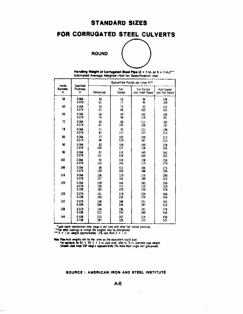
STANDARD SIZES
FOR CORRUGATED STEEL CULVERTS
ROUND
HlndIIng weight of COrrupled 81... PIpe (3 )( 1 In. or 5 '" 1 In-l""Estimated Average wetghtt-Not for Specification Use
Appr~lmate Pounds per lineal Ft--Inside Specified
Dilmeter. Thickness, Full- Full-Co'ted Full-Coatedin. in. GalvaniZed Coated and Invert Paved and Full Paved
54 0.064 SO C6 84 1380079 61 77 95 149
60 0064 55 73 93 1530079 67 86 105 165
I66 OD64 60 80 102 168
0079 74 94 116 1@\72 0.064 66 88 III 183
0.079 81 102 126 1977a 0.064 71 Cl5 \2\ \98
0.079 87 II! 137 21414 0.064 I 77 102 130 2\3
O.OiQ I 94 119 147 m90 0064 I 82 109 140 228
I0079 100 127 158 246
I96 0.064 87 116 \49 242
0079 10; 136 169 262102 0064 93 124 158 258
I0.079 114 145 \79 279
101 0064 98 131 166 273
I0079 120 153 188 295
II4 0064 10.4 139 176 289I 0.079 127 162 199 312I 120 0.064 109 146 \83 296I 0.079 134 171 210 329i 0.109 la3 220 259 378, 126 0.079 141 179 220 346I 0.109 195 233 274 400I 132 0079 148 188 231 363
0109 20.4 244 287 419I 13a 0079 154 196 241 379I 0.109 213 m 300 438
I 144 0.109 223 267 314 4580.138 m 326 373 m
•Loc_ sum construction only; wetl~ (s will vary .wth other la~' 'cation prachces... for atIItr COitinls or IininlS the", ailhts may be interpolated-- 5 )( I in. _Ihs IpprI:Ilimltely 12% less th~n 3 x I In .
....: ",,..Arch weilMs will be the ..ame as the equivllent round pipe.f...mplt: for 81 x 59. 3 ,( I In. pipe 3rch. reler to 72·In. diarreter pipe wetlhlSInolIIIt .tIII lined CSP -It S IpprgIlmltety 5% more thin sinlle wall aalvanlzed.
SOURCE: AMERICAN IRON AND STEEL INSTITUTE
A-B
STANDARD SIZES
FOR CORRUGATED STEEL CULVERTS
r~--+'~~,?.-+_...... £
! 8
,_--=-~~_.I 'J_,- Span--------I
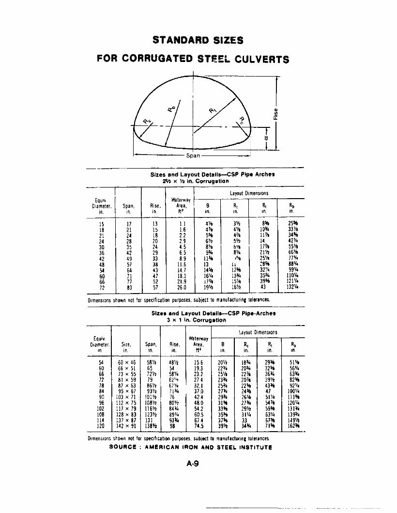
Sizes and Layout Detalls-CSP Pipe Arches~ )( 112 in. Corrugation
layout DimensionsEQUIv. Waterway
Diameter, Span, Rise, Area, B Rc Rt Rbin, In. 10. ft' in. 10, 10. in.
IS 17 13 1.1 4Va 3'12 8~ 25~
18 21 I) 1.6 47/, 4Ya 10:1(. 33V,21 24 18 22 5~ 471a I J71a 34~
24 28 20 2.9 6'12 5'12 14 42V.30 35 24 4.5 8Va b'l, J77." 55'/a36 42 29 6.5 9:1(. 8'1. 21'12 66Va42 49 33 8.9 11:v. l'li 25'1a 77'1.48 57 38 11.6 13 11 ~8~ 88Y.54 64 43 14.7 14~ 12:v. 32'/. 99'1.60 71 47 18.1 16V. 1331. 35:1(. 110'1.66 77 52 21.9 17¥a 15'1, 39:v. 121'1.72 83 57 26.0 19'12 16'12 43 l32Y.
DimenSions shown not for specification purposes, subject to manufacturing tolerances.
Sizes and Layout Detalls-CSP Pipe-Arches3 )( 1 In. Corrugation
layout DimensionsEQuiv. Waterway
Diameter. Size, Span, Rise, Area, B Rc Rt Rbin. in. in. In. ft l in. in in. in.
54 60 x 46 58V2 481f2 156 20'12 18:1(. 29:v. 5J1/a60 66 x 51 65 54 19.3 22¥. 20¥. 32~ 56V.66 73 x 55 72'12 58'1. 232 2SVa 22~, 36:1(. 63¥.72 81 x 59 79 621/, 274 23:1(. 2071a 39'12 82~
78 87 x 63 86V2 67'1.,
32.1 25¥. 22~ 43:v. 92'1.84 95 x 67 93V2 71:1(. 37.0 27¥. 24:v. 47 190'1.90 103 x 71 !OIY2 76 42.4 29¥. 26'4 SlY. 111~
96 112 x 75 108'12 801f2 480 31~ 27¥. 547/a 120'/.102 117 x 79 116112 8H. 54.2 33~ 291f2 59:v. 13l¥.108 128 x 83 123'12 89'1. 60.5 35~ 31 'I. 63Y. 139¥.114 137 x 87 131 93:V. 674 37~ 33 67:v. 149'12120 142 x 91 1381f2 98 74,5 39", 34:1(. 71~ 162:v.
--DimenSIOns shown not for specification purposes. subJect to manufactunnc tolerances
SOURCE: AMERICAN IRON AND STEEL INSTITUTE
A-9
STANDARD SIZES
FOR CORRUGATED STEEL CULVERTS
f----__ Span------i
r
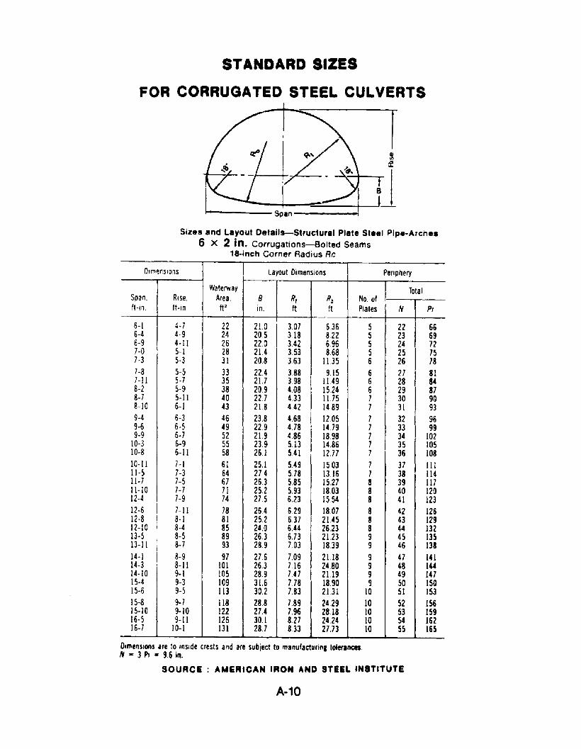
Sizes and Layout Details-Structural Plate Steel Pipe-Arch••
6 X 2 in. Corrugations-Bolted Seams18-inch Corner Radius Rr.
Dlm~rSlons Layout Dimensions Periphery
Waterway TotalSpan. Rise. Area. 8 R, Rb No. ofIHn. ft-In ft· in. It It Plates N Pi
6-1 4-7 22 210
I3.07 6.36 5 22 66
6-4 4-9 24 20.5 3.18 8.22 5 23 696-9 4-11 26 no 142 6.96 5 24 727-0 5-1 28 214 3.53 8.68 5 25 757-3 5-3 31 20.8 363 11.35 6 26 787-8 5-5 33 22.4 3.88 9.15 6 27 817-11 5-7 35 21.7 3.98 11.49 6 28 848-2 5-9 38 209 4.08
I15.24 6 29 87
8-7 5-11 40 227 433 1175 7 30 908-10 6-1 43 218 442 1489 7 31 939-4 6-3 46 23.8 4.68 I 12.05 7 32 969-6 6-5 49 229 478 I 14.79 7 33 999-9 6-7 52 21.9 486
I18.98 7 34 102
10-3 6-9 55 23.9 5.13 14.86 7 35 10510-8 6-11 58 26.1 541 12.77 7 36 10810-11 7-1 61 25.1 5.49 15.03 7 37 III11-5 7-3 64 27.4 578 1316 7 38 11411-7 7-5 67 263 5.85 15.27 8 39 11711-10 7-7 71 25.2 5.93 18.03 8 40 12012-4 7-9 74 27.5 6.23 15.54 8 41 12312-6 I 7-11 78 264 629 1807 8 42 12612-8 I 8-1 81 252 637 2145 8 43 12912-10 8-4 85 24.0 6.44 26.23 8 44 13213-5
I8-5 89 263 6.73 2123 9 45 135
13-11 i 8-7 93 289 7.03 1839 9 46 13814-1 I 8-9 97 276 7.09 2U8 9 47 14114-3 8-11 101 263 716 24.80 9 48 14414-10 9-1 105 28.9 7.47 21.19 9 49 14715-4 9-3 109 31.6 7.78 18.90 9 50 ISO15-6 9-5 113 30.2 783 2131 10 51 15315-8 9-7 118 28.8 789 2429 10 52 ISO15-10 9-10 122 27.4 7.96 28.18 10 53 15916-5 9-11 126 30.1 8.27 24.24 10 54 16216-7 10-1 131 287 833 27.73 10 55 165
Dimensions are to inside crests and are subJect to rnanufacturinl tolerances.N = 3 Pi = 9.6 in.
SOURCE: AMERICAN IRON AND STEEL INSTITUTE
A-10
8TANDARD SIZES
FOR CORRUGATED STEEL CULVERTS
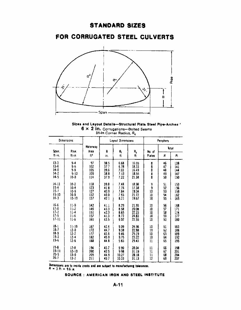
Sizes and Layout Details-Structural Plat. Steel Pipe-Arches"6 X 2 in. Corrugations-Bolted Seams
31-1" Corner Radius. Rc
Dimensions Layout Dimensions Periphery
waterway TotalSpan. Rise. Area. S Rt Rb No. ofIt-in. It-in 1t2 in. It ft Plates N Pi
13-3 9-4 97 38.5 6.68 16.05 8 46 13813-6 9-6 102 377 6.78 18.33 8 47 14114-0 9-8 105 39.6 7.03 16.49 8 48 lU14-2 9·10 109 388 7.13 18.55 8 49 14714-5 10-0 114 379 7.22 21.38 8 50 150
14-11 10-2 118 398 7.48 18.98 9 51 15315-4 10-4 123 41.8 776 17.38 9 52 15615-7 10-6 127 40.9 7.84 19,34 10 53 15915-10 10-8 132 40.0 7.93 21.72 10 54 16216-3 10-10 137 421 8.21 1967 10 S5 165
16-6 11-0 142 411 8.29 21.93 10 56 16817-0 11-2 146 43.3 8.58 20.08 10 57 17117-2 11-4 151 42.3 8.65 22.23 10 58 17417-5 11-6 157 41.3 8.73 24.83 10 59 17117-11 11-& 161 43.5 9.02 22.55 10 60 180
18-1 11-10 167 42.4 9.09 24.98 10 6: 18318-7 12-0 172 44.7 9.38 22.88 10 62 18618-9 12-2 177 43.6 9.46 25.19 10 6., 18919-3 12-4 182 45.9 9.75 2122 10 64 19219-6 12-6 188 44.8 9.83 25.43 11 65 195
19-8 12-8 194 43.7 9.90 28.04 11 66 19819-11 12-10 200 42.5 9.98 3119 11 67 20120-5 13-0 205 44.9 10.27 28.18 11 68 20420-7 13-2 211 43.7 10,33 3113 12 69 207
Dimensions are to inside crests and Itl subject to mlnuflCtunnl toltrances.N - 3 Pi - 9.6 ill.
SOURCE: AMERICAN IRON AND STEEL IN8TITUTE
A-11
STANDARD SIZES
FOR CORRUGATED STEEL CULVERTS
I!,..-------span--------I
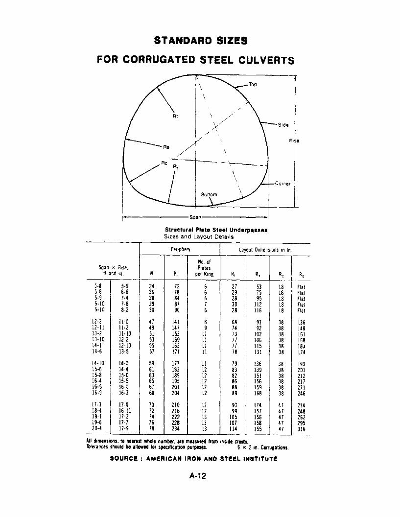
Structural Plate Steel UnderpusesSizes and Layout DetaIls
Corner
Periphery Layout Dimensions in In.
No. of ISpan x ~Ise, Plates
IIt and m. N PI per Ring Rl Rs R( Rb
3-8 5-9 24 72 6 27 53 18 ! Flat5-8 6-6 26 78 6 29 75 18 I Flat5-9 7-4 28 84 6 28 95 18 Flat5-10 7-8 29 87 7 30 112 18 Flat5-10 8-2 30 90 6 28 116 18 Flat
12-2 11-0 47 141 8 68 93 38 13612-11 11-2 49 147 9 74 92 38 14813-2 11-10 51 153 11 73 102 38 16113-10 12-2 53 159 II 77 106 38 16814-1 12-10 55 165 II 77 115 38 18J14-6 13-5 57 171 11 78 131 38 174
14-10 14-0 59 177 11 79 136 38 19315-6 14-4 61 183 12 83 139 38 20115-8 15-0 63 189 12 82 151 38 21216-4 15-5 65 195 12 86 156 38 21716-5 16-0 67 201 12 88 159 38 27116-9 16-3 68 204 12 89 168 38 246
17-3 17-0 70 210 12 90 m 47 21418-4 16-11 72 216 12 99 157 47 24819-1 17-2 74 222 13 105 156 47 26219-6 17-7 76 228 13 107 158 47 29520-4 17-9 78 234 13 114 155 47 316
All dimensions. to nearest whole number. are measured from Inside crests.Toieri"ces should be allowed fOf specification purllClStS. 6 )( 2 in. Corfulalions.
SOURCE: AMERICAN IRON AND STEEL INSTITUTE
A-12
STANDARD SIZES
FOR CORRUGATED STEEL CULVERTS
I--------- Span -------.a-_~
I
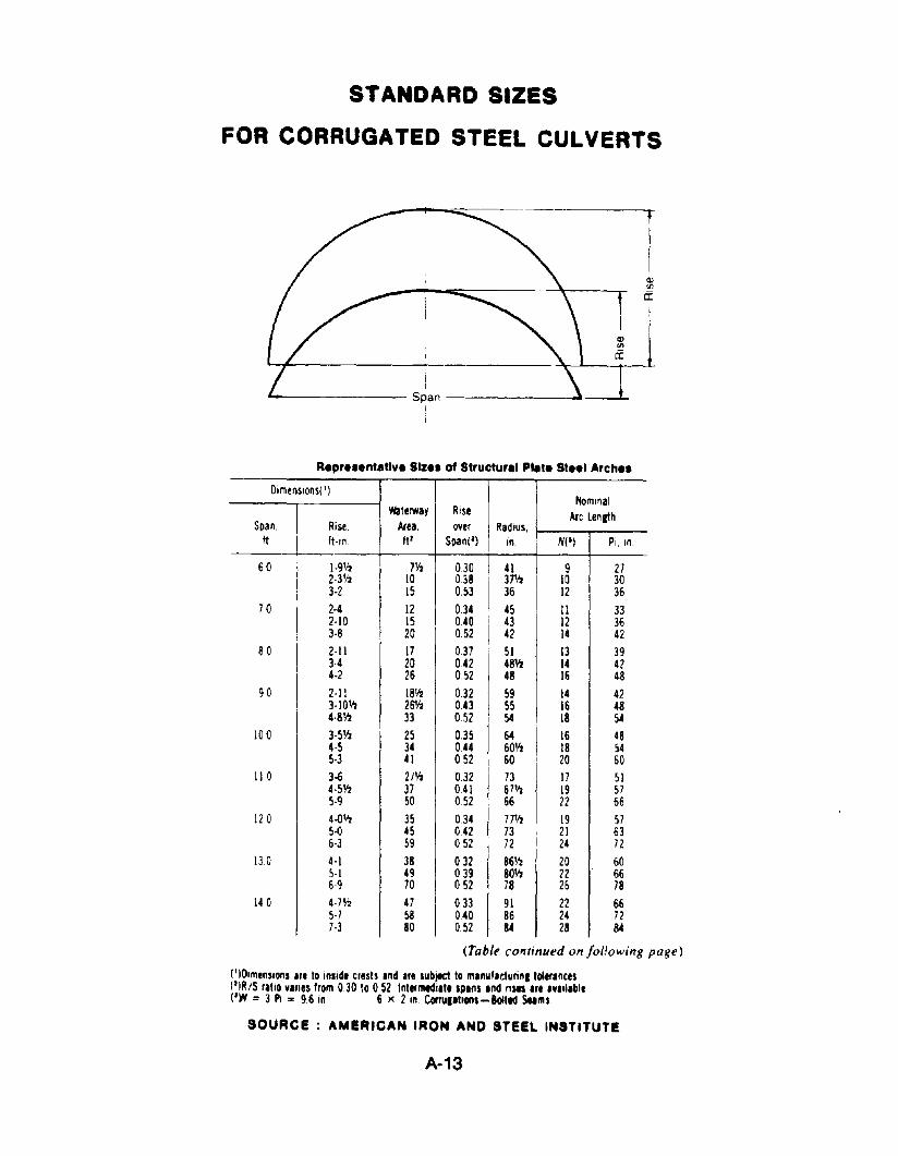
A.pr•••ntltivi Size. of Structur.' Pllt. Stili Arch••
Dimenslons( '1Nominal
Waterway Rise Arc LengthSpan, Rise, Area. over Radius.
ft ft-In tjl Span(l) in. N(I) Pi. In
60 1·9112 7112 030 41 9 272-3112 10 038 371,', 10 303-2 15 0.53 36 12 36
70 2-4 12 0.34 45 11 332·10 15 040 43 12 363-8 20 0.52 42 14 42
80 2·11 17 0.37 51 13 39H 20 042 48112 14 424-2 26 052 48 16 48
90 2-11 18112 0.32 59 14 423·10112 261,', 043 55 16 484·8lfl 33 052 54 18 54
100 3-5112 25 035 64 16 484-5 34 044 60',', 18 545-3 41 052 60 20 60
110 3-6 2Jlfl 0.32 73 17 514·5112 37 041 67Y2 19 575·9 50 052 66 22 66
12 a 4·{)112 35 034 77112 19 575-0 45 042 73 21 636-3 59 052 72 24 72
130 4-1 38 032 86112 20 605-1 49 039 80112 22 666-9 70 052 78 26 78
140 4·71f2 47 033 91 22 665-7 sa 040 86 24 727-3 80 052 a.- 28 a.-
(Table continued on fol!owing page)
(' lOlmenslons Ire to inSIde crests Ind Ire subJ'Cf to mlnut.cturinlloler.nces(')RIS rillo vines from 030 to 052 Intermtdill. sPins Ind nSIS 'r. IV'II,bl.(IW :: 3 PI '"' 96 in 6 )( 2 In CorrulltlOlls-BoItId seams
SOURCE: AMERICAN IRON AND STeEL INSTITUTE
A-13
STANDARD SIZES
FOR CORRUGATED STEEL CULVERTSARCH
TI1-
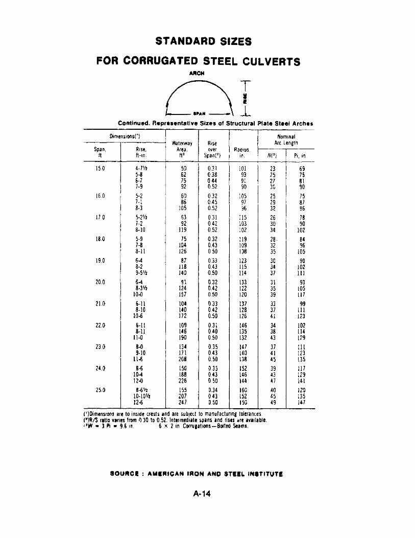
Continued. Aepresentatlve Sizes of Structural Plate St••, Arches
Dimenslons(') NomlOalWaterway Rise Arc Length
Span, Rise, Area, over Radius,It It-IO tt 2 Span(2) In. N(') Pi, 10.
15.0 4- 7112 50 031 101 23 695-8 62 0.38 93 25 756-7 75 0.44 91 27 817·9 92 052 90 30 90
16.0 5-2 60 032 105 25 757-I 86 045 97 29 878-3 105 052 ~6 32 96
170 5·2112 63 031 115 26 787-2 92 042 103 30 908·10 119 052 102 34 102
18.0 5-9 75 032 119 28 847-8 104 043 109 32 968-11 126 050 108 35 105
19.0 6-4 87 033 123 30 908-2 118 043 IlS 34 1029-5112 140 0.50 114 37 III
20.0 6-4 91 032 133 31 938-31/2 124 0.42 122 35 105
10-0 157 050 120 39 117
21.0 6-11 104 033 137 33 998-10 140 042 128 37 III
10-6 172 0.50 126 41 123
22.0 6-11 109 0.31 146 34 1028-11 146 0.40 135 38 114
ll-o 190 0.50 132 43 129
230 8-0 134 0.35 147 37 III9-10 171 043 140 41 123
11-6 208 0.50 138 45 13524.0 8-6 150 035 152 39 117
10-4 188 043 146 43 12912-0 226 050 144 47 141
25.0 8-6 '12 155 034 160 40 12010·10112 207 043 152 45 13512-6 247 050 150 49 147
(')Dimensions are to inside crests and are subJect to manulacturtng tolerances.(')1VS rltio vlries from f)JO to 0.52. Intermediate spans and rises .re available('W • 3 Pi • 96 in. 6 x 2 in. Corrugations-Bolted Seams.
SOURCE: AMERICAN IRON AND STEEL INSTITUTE
A·14
81ANDAl~D SIZES
FOR CORRUGATED STEEL CULVERTS
-~-~-------
AreaIII
Span,It·,n
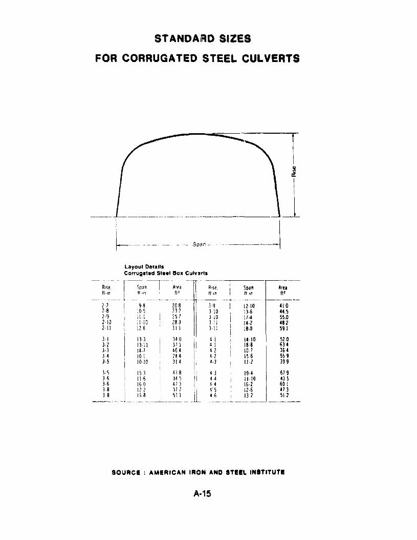
393103103·113·11
Rise.It In
13-313·1114·710 I10·10
12·10 41013·6 44511-4 55014·2 48218·0 591
340 41 14·10 52037 1 41 18·8 634404 4·2 10·7 364
1?84 42 15·6 559I 314 4·3 11·2 399I
153 I 4'J8 43 19·4 679116 I 345 44 11·\0 435
:n.J .EL..1L tL .. ~__~J .__. .~~_1_
]-53 63·63838
Layout DetailsCorrugated Steel BOll Culverts
--RI~-e.-I~'an-.-T--';~'a-
ft·ln i fl·,n I ftI--- .t-._ .. __...~--_.
2 7 : 98 20828 ~ 105 2322·9 II I 2512·10 1110 2832·11 12 6 31 I
]-1
3·2]·3343-5
SOURCE: AMERICAN IRON AND STIlL INSTITUTI
A·15
STANDARD SIZES
FOR CORRUGATED STEEL CULVERTS
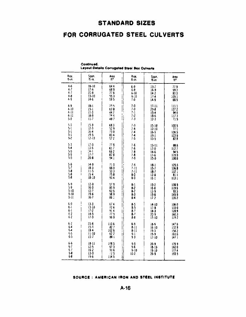
Continued.L.yout D.t.... Corrug.ted St... 10. Culv.rt.
Rise. Soan. Area Rise, Sllan, Areaft'ln ft-in. ftl ft·ln. ft·in. ftl
4-6 16-10 644 6-9 1'3-7 7794-7 17-6 68.9 , 6-9 16-9 9934-7 20·8 776 6-10 14-2 8334-8 1]·10 553 6-10 17-4 10514·9 IH 59.5 7.{J 14-9 889
4·9 18·1 nr, I 7·0 17-11 11114·10 15·1 638 7·0 20·8 12724·11 11·0 447 , 7-1
I15·4 946
4·11 18·9 7A 4 7-2 18·6 11735·0 11· 7 487 7·] 12·3 71.5
5-0 15-9 683 7·] 15·10 100 55-1 12·3 529 7-4 12·10 7715-1 16·4 730 7-4 16·5 106.55-1 19-5 834 7·4 19·1 12365-2 12-10 572 7·5 IH 82.8
5-3 17-0 77 8 7-6 13·11 8865-4 13-6 617 7·6 17·0 llV5-5 14-1 662 7·8 14-6 ~55-5 17·7 828 7·8 17·6 11905-5 20-8 941 7-9 15-0 100.6
5·6 14·9 71 a 7·9 18·1 125.55·7 18·3 880 7-II 15·7 10685-8 11-5 533 7-11 18·7 13Z15-8 15-4 758 8·0 12·8 8U5-8 18-10 934 8-0 16-1 lI3.l
5-9 \2·a 57 9 8·\ 19·2 13895·9 16·0 809 8·2 16-8 11965·10 12·7 626 8·2 13-9 9335·10 19·6 989 8·3 19-8 14595-11 16·7 861 8·4 17 2 1262
6-0 13-3 67 4 8-5 14·10 10606-1 13·10 724 8·5 17 ·8 13306-1 j 7·2 914 8-7 18·) 13996-2 14·5 775 8·7 20-9 16036-2 17-9 969 8·8 15-10 1192
6-2 20-8 \\0 6 8·9 18-9 14706-4 15-n 827 8-11 16-10 13296-4 18·4 1026 8-11 19-) 1542Ii·S 11-10 622 9·1 IH 161 G6·5 15· 7 881 9-) 17·10 147 I
6·6 18-11 1(185 9-5 20·9 17696-7 12·5 673 9·6 18·\0 16206-7 16·2 936 9·10 19-10 17746-8 \3-0 72 5 10·2 20-9 19356-8 19·6 1145
SOURCE: AMIRICAN IRON AND STilL INSTITUTE
A-16
STANDARD SIZES
FOR CORRUGATED STEEL CULVERTS
~----Sp.n----~
Long Sp.n Horlzont.1 IlIIp•• Size••nd Layout De'.II,
PeriphtIY Inside Radius
Top or ITotalBottom Side I
Spin, Rise, Area, Top SideIt-In. ft-In. Itl .¥ I'i N Pi N Pi Rid. In. Rad. In
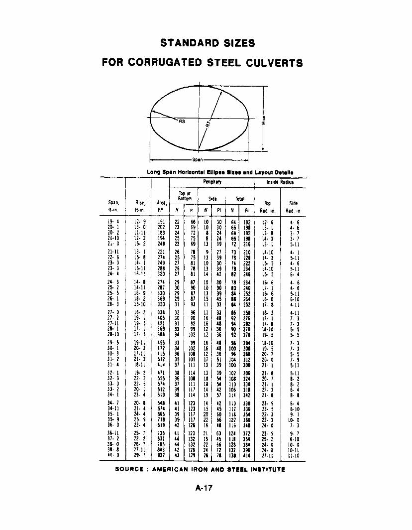
i9· 4 12- 9 191 22 66 10 30 64 192 12- 6 4- 620· 1 13- 0 202 23 S~ 10 30 66 198 13- 1 4· 620· 2 11-11 183 24 72 8 24 64 192 13- 8 3· 720·10 12· 2 190' 25 75 8 24 66 198 14- 3 3· 72;- 0 IS· 2 248 23 69 13 39 72 216 13- 1 5·1121-11 13- 1 221 26 78 9 27 70 210 14·10 4· 122- 6 15- 8 274 25 75 13 39 76 228 14- 3 5-1123· 0 14. 1 249 27 81 10 30 74 222 1S· 5 4· 623· 3 15-11 288 26 78 13 39 78 234 14-10 ~·1124- 4 1~_1 ~ 320 27 81 14 42 82 246 1S· 5 6· 424· 6 14- 8 274 29 87 10 30 78 234 16· 6 4- 625- 2 14-11 287 30 90 10 30 80 240 17- 1 4- 625- 5 16- 9 330 29 87 13 39 84 252 16· 6 5·1126· 1 18· 2 369 29 87 15 45 88 2&4 16- 6 6·1026· 3 15·10 320 31 93 11 33 84 252 17- 8 4-1127· 0 16· 2 334 32 96 11 33 86 251 18· 3 4-1127· 2 19· 1 405 30 90 16 48 92 276 17. 1 7· 327·11 19- 5 421 31 92 16 48 ,. 282 17- 8 7· 328· 1 17· 1 369 33 99 12 36 90 270 18-10 5- 528-10 17· 5 384 34 102 12 36 92 276 19- 5 5· 529· 5 19-11 455 33 99 16 48 98 294 18·10 7· 330· 1 20- 2 472 34 102 16 48 100 300 19- 5 7- 330· 3 17-11 415 36 108 12 36 96 211 20- 7 5- 531· 2 21- 2 512 35 lOS 17 51 104 312 20· 0 7- 931- 4 18·11 U 37 111 13 39 100 300 21- 1 5-1132- I 19- 2 471 31 114 13 39 102 306 21- 8 5-1132· 3 22- 2 555 36 108 18 54 108 324 20- 7 8- 233- 0 22- 5 574 37 111 18 54 110 330 21· I 8- 233- 2 20- 1 512 39 117 14 42 106 318 27- 3 6- 434- 1 23- 4 619 38 114 19 57 114 342 21- 8 8- 834- 7 20- 8 548 41 123 14 42 110 330 23- 5 6· 434-11 21- 4 574 41 123 15 45 112 336 23· 5 6-1035- 1 24- 4 665 39 1I7 20 60 118 354 22· 3 9- 135- 9 25- 9 718 39 117 22 66 122 366 22- 3 10- 036- 0 22- 4 619 42 126 16 48 116 348 24· 0 7- 336-11 25- 7 735 41 123 21 63 124 37Z 23- 5 9- 737- 2 22- 2 631 44 132 IS 4S 118 354 25- 2 6-1038- 0 26- 7 785 44 132 22 66 128 384 24· 0 10- 038- 8 27-11 843 42 126 24 72 132 396 24· 0 10·1140- 0 29· 7 927 43 129 26 7' III 414 21·11 11-10.
SOURCE: AMERICAN IRON AND STilL INITITUTI
A-17
STANDARD SIZES
FOR CORRUGATED STEEL CULVERTS
f-------span---.I-r
B
1
Long Span Pipe Arch Sizes and Layout Details
Periphery InSIde Radius---.--.-
, Total Top Bottom TotalSpan, ~ Rise, Area, No B. e, RI , R1•ft-In I ft-,n ft l Plates I N Pi N Pi N Pi In In In In
to \ J4----
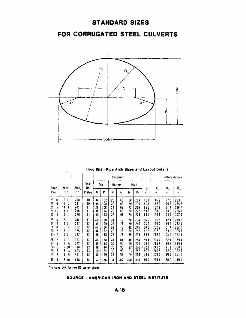
20- 0 13-11 218 102 20 60 68 204 628 1462 inS 223620- 6 :4- 3 23: 10 36 108 20 60 70 210 614 1523 1247 2S5721- 5 14- 6 243 II 36 108 22 66 72 216 653 1628 1314 236 72111 14-1\ 256 II 38 114 22 66 74 222 637 1689 1335 268122-5 15- 3 270 II 40 120 22 66 76 228 62.1 1746 1355 307 123- 4 I S- 7 284 II 40 120 24 72 78 234 662 1855 1424 280224· 2 I S- 11 297 12 40 120 26 78 80 240 707 1962 149 7 262 I24- 8 16- 2 312 12 42 126 26 78 82 246 688 2022 1514 292225- 2 16- 7 326 12 44 132 26 78 84 252 669 2079 153 2 328625- 7 16-11 342 12 46 138 26 78 86 258 648 2113 1550 ] 733
26- 7 17- 3 357 12 46 138 28 84 88 264 694 n47 162 1 339427- 6 17 - 6 372 12 46 138 30 90 90 270 742 2358 1696 315828- 0 17-10 388 12 48 144 30 90 92 276 721 2415 III 1 350228- 5 18- 3 405 13 50 150 30 90 Q' 282 699 2468 1727 3923•29- 4 18- 6 421 13 50 150 32 96 ~6 288 748 2582 1802 361.130- 4 18-10 438 14 52 156 34 102 100 300 800 2694 11182 3391
''1cludes 14" lor two 1t7 corner pl.tn.
SQURel ; AMIRtCAN tRON AND STilL INITITUTI
A·18
RC
STANDARD SIZES
FOR CORRUGATED STEEL CULVERTS
!-----M.lllmumSp.n-----!
!-----BottomSpan---...-i
Lonw "'n Low ProfII. Arch ~'I end Llyout Ottelll
Periphery Inside Rldiu~
Mil Bottom Toll' lip Side \)tl'Spin, Spin, RiM, Are.; Top Sid.I
It-in. It·in. ft·in. Itl N Pi N Pi N Pi r.d. in. r.d. in.
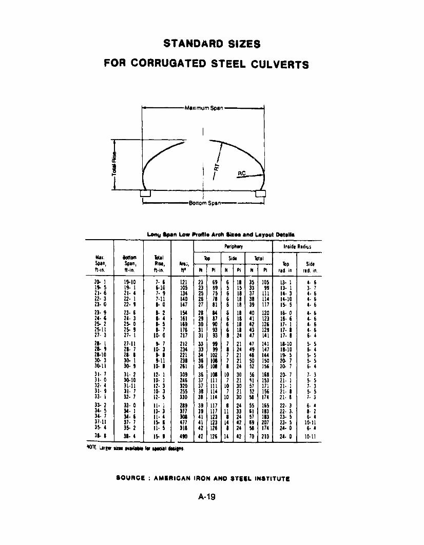
20- 1 19-10 7- 6 121 23 69 6 11 35 105 13· I 4· 619- 5 19- I 6-10 105 23 69 5 15 33 99 13· 1 3- 721· 6 21· 4 7· 9 134 25 75 6 11 37 III 14· 3 4- 622· 3 22· 1 7-11 140 26 71 6 11 31 114 14·10 4- 623· 0 22· 9 I· 0 147 27 11 6 18 39 117 15· 5 4· 623· 9 23· 6 I· 2 154 21 .. S 18 40 120 16- (l 4· 624. 6 24· 3 8-4 161 I 29 87 6 18 41 123 16· 6 4- 62> 2 2> 0 8- 5 169 ! 30 90 6 18 42 126 17· 1 4- 62>11 2> 9 I· 7 176 . 31 93 6 II 43 129 17· 8 4- 627· 3 27· 1 10. 0 217
131 93 8 24 47 141 17· 8 6- 4
21· 1 27·11 • 7 212 33 99 7 21 47 141 11·10 5· 528- 9 28· 7 10. 3 234 33 99 1 24 4' 147 11·10 6· 421·10 21· I •• 221 34 102 7 21 41 144 1. 5 S- 530. 3 30. 1 9-11 231 36 101 7 21 50 150 20· 7 5· 530.11 30. 9 10. • 261 36 101 8 24 52 156 20· 7 6· 431- 7 31· 2 12· 1 309 36 101 10 30 56 168 20· 7 7· 331· 0 30.10 to. 1 246 37 III 7 21 51 153 21· I 5· 532· 4 31·11 12· 3 320 37 III 10 30 57 171 21· 1 7· 331- 9 31· 7 10. 3 255 38 114 7 21 52 156 21- 8 5· 533· 1 32· 7 12· 5 330 38 114 10 30 51 174 21· 8 7· 333· 2 33· 0 11· 1 289 39 117 I 24 55 165 22· 3 6· 434· 5 J4. I 13· 3 377 39 117 11 33 61 113 22· 3. I· 234· 7 J4. 6 11· 4 301 41 123 • 24 57 113 23- 5 6· 437·11 37· 7 1> & 477 41 123 14 42 69 207 23· 5 10·113S- 4 3> 2 11- 5 311 42 126 • 24 51 174 24· 0 6· 438- 1 31· 4 1> 9 490 42 126 14 42 70 210 24· 0 10·11
SOURCE: AMERICAN IRON AND S'fEIL INSTITUTI
A·19
STANDARD SIZES
FOR CORRUGATED STEEL CULVERTS
i""'1.------ MaXi<T\ur" Soar'------1
/...------801:0,..., P'se -------,
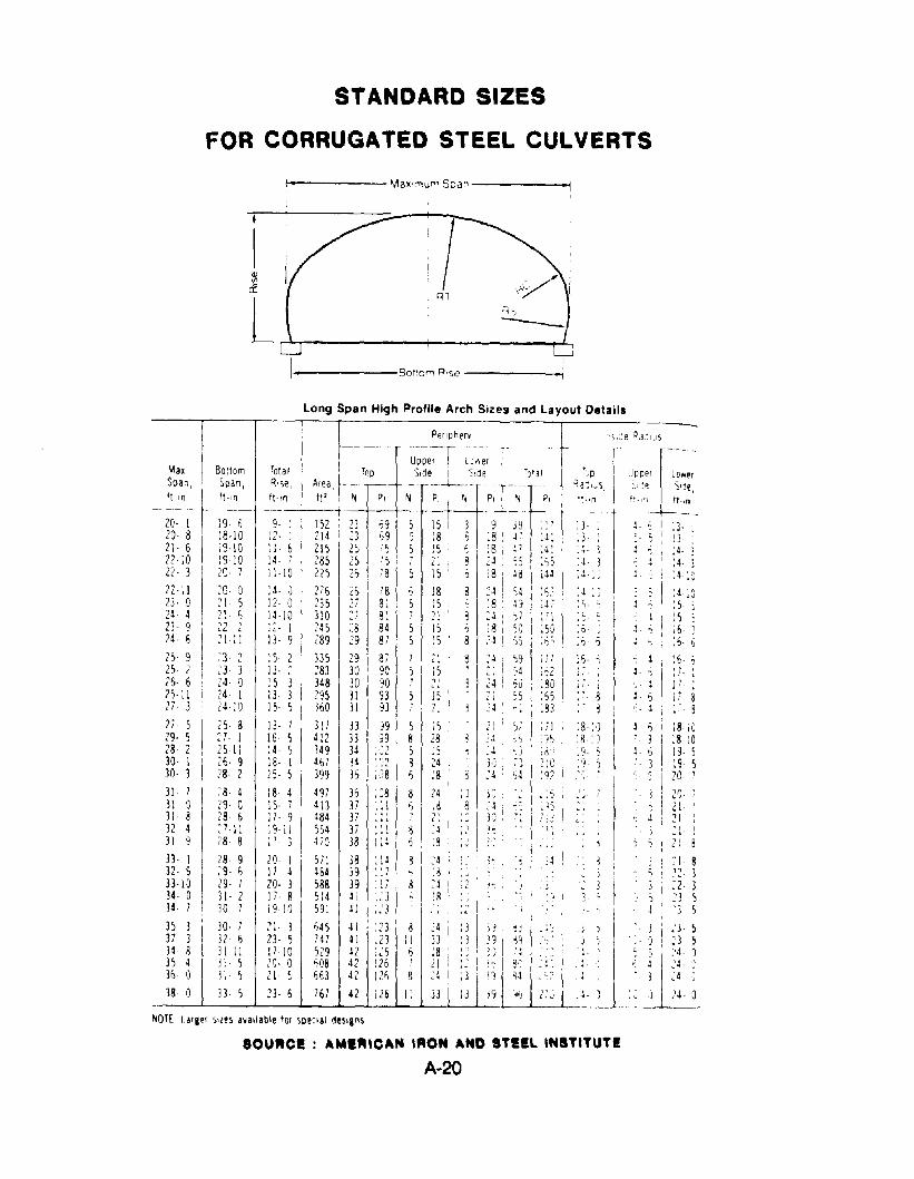
Long Span High Profile Arch Sizes and Layout Details
j )
,• 1 !• J
'oJ' I
. ~ ~.
1.4 1
.4,,(i,';
I _, __ ~fflohe", _ r ' '-I,ce RadiUS,r---- UDper l:.-.er - -----
I 'op Side S'de • f 'J'31 r,;p Upper L3werArea r---~-~- -- ~!-j -- RaclJs, ~I~~, )Ije,
I. ft" I' N P, N ...~_ 'j PI':: -h~ t!~~ H"l thn+---I 152 • 23 ~9 5 15 3 9 ]9 I:' i3- 4- ~ I i3-I 214 i 23 59 ~ 18 I 5 :S r :4::3 i 1]
I m ~~ :~ i nI ~ 2~ ~~ I ~~; :~: i : } i \~: im 26, 78 5 15 ~ :8 ~8 i ;44 :4 " ~ ': 4-: J
276 26 I 78 S 18 8 24 q' :S: :4 iJ '" I :4;)235 ?7 81 5:5 :8 j~ I :47 ',~, j" :So 5310 ;'7 81 ; 21 ~ 24 ) I 1'1 :(" I ~ I : 5-245 28 34 5 !5 i , ;3 I 50 ;50 :5- J I ~ : ,6· J289 29 87 5 :5 i 3 24 i 5) :,~' I _~- 6 ~ -:; :6- 6
I 335 29 87 7 21 i 8 24 ')9 :6- ~ 4 I :6-?! 283 30 I 90 ) I i 5 j , " 54 :~Z I :7 J : :-
m i~ I ~~ ~ IH\ 3 fi I~ :~~, !: 8 l ~ I i; 8J60 31 ~3 3 24 "j I i 93. ., 3 .:. 4 i • ' 8
317 33 :J9 51; ~ I 2i I 57 .1 : il I :8-:J I 4- 6 I i8- iO412 3J 99 I 8 28 ' 24 "5·]5 :8:) '3 18iO349 34 'J2 5!.5 I 1 24 '~'J III' .9- 5 4 6 19- 5467 34 J2 9 24 i Jl] I ") nc .'J ~ 3 :9· 5399 36 I 18 6 ;8! ~ 24 64 :02 .,' '5 20- 1
497 361 i:8 8 24::J JJI
": .:6413 37' :11 6 \ ,8 3 '4 ,J,)484 37 11 , 21: C,'\ ); I I "3554 37 :11 9 24 1:2 ,,:. ., 'l'
47S 38 I :4 6 :8 -.. I .. '571 38 114 9 24 .. !. 1 I ;4484 j 9 : \7 ~ :9 . "588 39 i I; ~ 24 ;2 ..514 41 U " 18 '1
591 41 1:.'3 l' i< .,
645 41 1: 23 8 24 ;3 ;! .. .:')747 41 l2J II 33 :3529 42 126 6 :8 '608 42 126 21 ,"663 42 126 e 24 :3
767 42126 1133 13
20 117 420- 317 8i 9 10
21 323- 517 1020- aZ1· 5
236
25· 8"7- 125 1126- 928- 2
: 8- 429- C28- 6"7 -il28- 8
28- 929- 629- 731- 230 7
30- 732 - 6311131 5JI 5
33 - 5
27 - 529- 528- 230- I30- 3
] I 73\ Q] 1 832 43I 9
33- I32 - 633-1034- a34 735 3 I
37 3 I34 8
35 4 II36 Q
38- 0
',1 ax Bottom 'otalSpan, i Span, Rise,
_;~~_+<~ _f:-_,n
20- 8 I 18-10 12-2\- 6 ;9-\ 0 11· 82Z10 I 19-10 14- i22-3 20-7 ll1022-\\ 20- 0 14- ,)23·021-512-024- 4 2: 5 14-1023- 9 22- 2 12- 124-~ 2111 13-9
25 9 n 2 15 225-223] 13-'26- 6 24- 0 15]25-11 24- I l3-]17 3 2410 15- 5
13- 716- 514- 518- I15- 518 415- 717 919- i I)' )
SOURce: AMERICAN I"ON AND STleL INSTITUTe
A·2Q
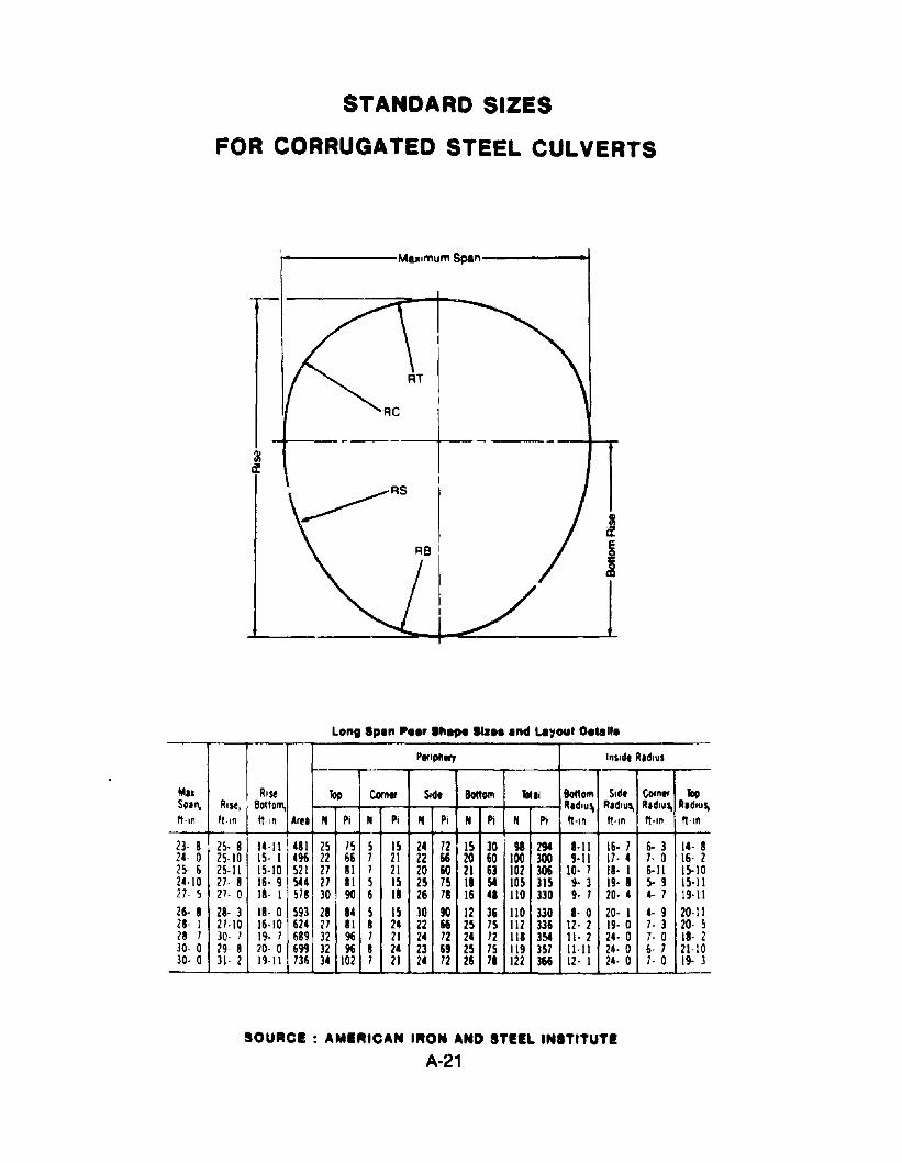
STANDARD SIZES
FOR CORRUGATED STEEL CULVERTS
t------MaximumSpan-----~
IIIif
j
Lon, 'pen P.er Ih.,. 1Ia•• end LtI~out 0.,.11.PlrlpII.., InSld. R.dlus
-
M.l Rise Too Comer Sid. Bottom Tot.1 8oItom Sid. Comer TopSp.n, R,se, Bottom, R.dlus. R.dlus. R.dlus. R.dlus.ft·ln It-In ft·1n Arel N Pi N Pi N Pi N Pi N Pi ft·,n ft·,n ft-In ft·'"
23· 8 25· 8 14·11 481 25 /5 5 15 24 12 15 30 98 294 8·11 16· / 6· 3 1.· 824- 0 25-10 15· 1 496 22 66 1 21 22 66 20 60 100 300 9·11 17· • 7· 0 16· 225- 6 25-11 15-10 521 21 81 7 21 20 60 21 63 102 306 10- 1 18· I 6·11 15·102.·\0 27· 8 16· 9 5U 21 II 5 15 25 75 II 54 105 m ~. 3 19· I 5· 9 15·1121- 5 2/· 0 18· 1 S78 30 90 6 18 26 78 16 •• 110 330 9· 7 20· • 4· 1 19·1126· 8 28· 3 18- 0 m 21 U 5 IS 30 90 12 36 110 330 I· 0 20- I 4- 9 20·1128· I 2/·10 16·10 624 27 81 8 2. 22 66 25 75 112 336 12· 2 19· 0 7· 3 20- 528· 7 30- 7 19· 7 689 32 96 / 21 2. 72 2. 72 118 354 11· 2 24· 0 7- 0 II· 230· 0 29- 8 20· 0 699 32 96 I 2. 23 69 25 7S 119 3S7 !l·11 24· 0 6· 7 21·1030- 0 31· 2 19·11 m 3. 102 7 21 2. 72 26 71 122 366 12· I 2.- 0 7· 0 19- 3
SOURCE : AMERICAN I..ON AND STEIL INSTITUTE
A·21
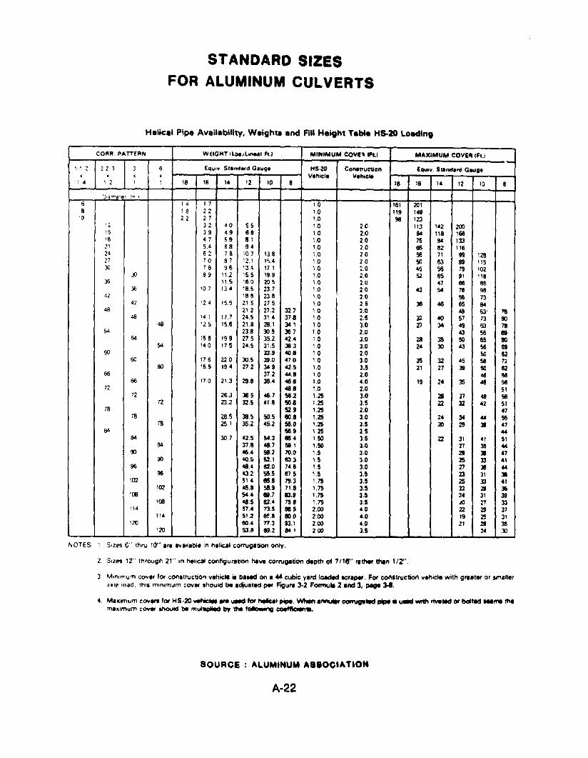
STANDARD SIZESFOR ALUMINUM CULVERTS
Helical Pipe Availability, Weigh" and Fill Height T.a. H5-20 Loading
CORR. PATTERN WEIGHT ILbs.lLi...., Ft.I MINIMUM COVE:- .h.1 MAXIMUM COIIEIlIFI.I
1·1 2 2 2 3 3 6 Equlv SI.,.,d.rd G.ug. HS·20 CO"'.lruction Equiv. SUllul.rd G.uge. . • . lI.hicl• lI.hiele14 1 2 1 ~ 18 16 14 12 10 8
"16 14 12 10 8
J,ame!er '!" J
6 I 4 1 7 10 161 2018 18 22 10 119 149
10 22 27 10 98 12312 32 40 55 1.0 20 113 142 20015 3.9 49 68 10 2.0 94 I" 166\8 47 59 81 1.0 2.0 75 94 13321 5.4 68 94 10 20 116 82 11624 62 78 107 138 1.0 20 56 71 99 12827 70 87 12.1 1~.4 10 20 so 63 89 11530 78 96 134 171 10 ~.O 4',; 56 79 102
30 89 11,2 155 199 10 2.0 52 65 91 118)6 11.5 160 205 1.0 20 47 66 85
)6 '07 134 185 23.7 10 20 «3 54 76 !j842 186 238 1.0 2.0 56 73
42 124 155 215 275 10 2.5 36 46 55 8448 212 272 32.7 1.0 2.0 All 63' 78
48 14 1 17.7 245 314 378 10 2.5 32 40 57 73 9048 125 156 218 28.1 341 1.0 3.0 XI 34 49 63 78
54 238 305 367 10 2.0 43 56 11954 158 199 275 352 42.4 10 3.0 28 35 50 65 80
54 140 175 24.5 31.5 38.3 10 3.0 24 30 «3 56 6950 33.9 40.8 10 2.0 50 62
50 176 220 30.5 39.0 470 10 3.0 25 32 45 58 n60 155 194 272 349 42.5 1.0 3.5 21 27 J9 so 62
66 372 44.8 1.0 2.0 4$ se66 170 213 298 38.4 411.11 1.0 4.0 19 24 35 411 58
72 018.8 1.0 2.0 5172 263 365 46.7 se.2 1.25 3.0 211 37 48 58n 23.2 32.5 41.8 SO.• 1.25 3.5 22 32 42 51
78 52.9 1.25 2.0 4778 285 39.5 SO.5 eo.' 1.25 3.0 24 34 44 56
78 251 35.2 45.2 5ll.O 1.25 3.5 2Il 29 38 47BA 58.9 125 2.5 44
84 307 42.5 54.3 66.4 1.50 3.5 22 31 41 5184 378 48.7 58.1 I.SO 3.0 27 3S 44
90 46.4 58.2 70.0 1.5 30 29 31 4790 405 S2.1 83.3 1.5 3.0 2S 33 41
96 484 82.0 74.8 1.5 3.0 27 31 4496 432 56.5 875 1.5 3.5 23 31 31
102 514 8158 79.3 175 35 2S 33 41102 46.8 58.9 71.8 1.75 3.5 22 29 3ll
HJl 544 88.7 83.' 175 Hi 24 31 39HJl 48.5 82.4 758 175 3.S .LO 27 33
114 !S74 73.5 •.5 2.00 40 22 29 37114 512 &f.B 80.0 2.00 4.0 19 25 31
120 804 n3 93.1 2.00 40 21 28 J5120 5J.1I 1192 841 200 3.5 2' 30
NOTES 1 S'Zes 6" thru 10" arll avatiabl. in heli~l corrugation only.
2 SiZes 12" through 21'" in helical configuration have corrugation depth of 7/18" rather then lIZ'.
3 M,nimum cover lor construction vehicle is baNd on I ... cubic yard loaded ICraper. For con.truclion v.hicle with gr.ater or small.ra.le load. thIS mIn,mum COIIllr should be .dju.ted pet' Figur. 3·2 Formule 2 and 3. pege 3-1.
4. Mumum COlI.... 101 ...5·20 uehic_ ... uetd fof helIcaI~.When annuli' COl'nlgle.d pipe ia uaecl with rMe.d or bolted ...".lhamaximum cOYer should be mul1iplieO by me following coeffIden•.
SOURCE ALUMINUM ASSOC.ATIOM
A·22
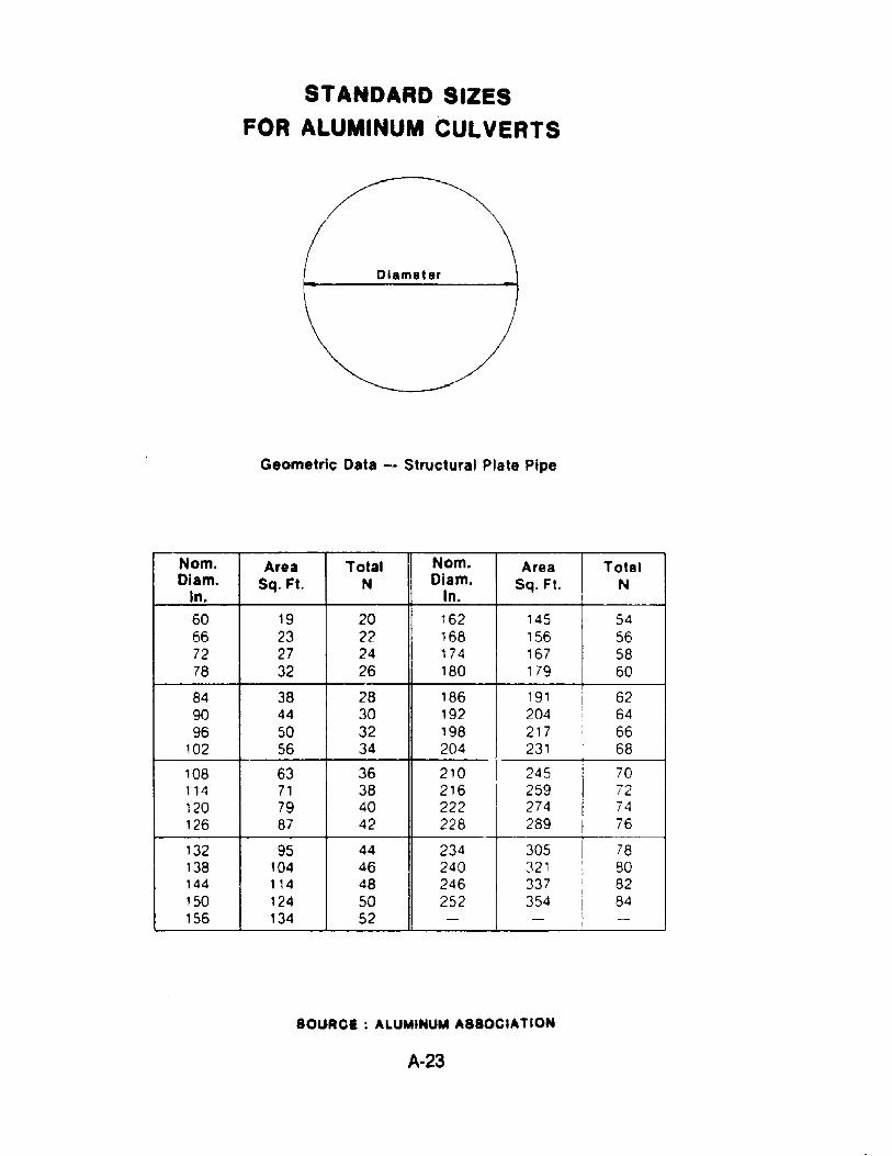
STANDARD SIZES
FOR ALUMINUM CULVERTS
Diameter
Geometric Data - Structural Plate Pipe
Nom. Area Total Nom. Area TotalDiam. Sq.Ft. N Oiam. Sq.Ft. N
In. In.60 19 20 162 145 5466 23 22 168 156 5672 27 24 174 167 5878 32 26 180 179 60
84 38 28 186 191 6290 44 30 192 204 6496 50 32 198 217 66
102 56 34 204 231 68
108 63 36 210 1 245 70114 71 38 216 259 72120 79 40 222 274 74126 87 42 228 289 76
132 95 44 234 305 78138 104 46 240 321 80144 114 48 246 337 82150 124 50
I252 354 84
156 134 52 - - -
SOURCE: ALUMINUM ASSOCIATION
A-23
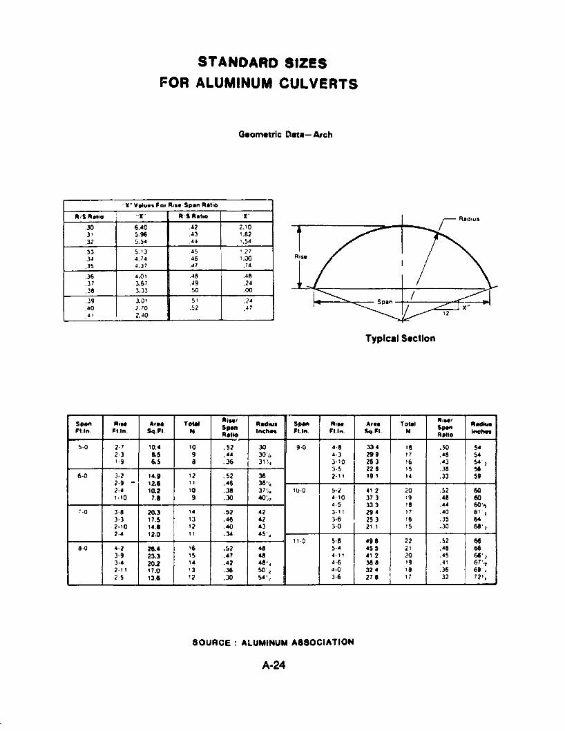
STANDARD SIZES
FOR ALUMINUM CULVERTS
Geometric Oet.- Arch
"X" V.lu•• For A••• ,S"." A.ho
A'S A.I,o I "X" A,S R.ho 'X"
.30 6.•0 .~2 2.l0
.3 I 5.96 .~3 1.82
.32 !I. !I. .~4 1.!l4
,33 !I. '3 .45 ' .27.34 4.74 .46 '.00.35 4.37 .47 ,74
.36 4.01 .48 .48
.37 3.67 49 .24
.38 3.33 !l0 .00
.39 3.01 .!lI .24
.40 2.70 .52 47
4' 2.40
S"an RiM Ar•• TotM AiM' R"iul Span RiM A,•• Tolal Ri.1I Aectlu.FU". FI.I". Sq.Fl. N
SpanInch.. FI.I". FI.I". Sq.Fl. N $"." Inc:hnR.tIO A.llo
!I·O 2· 7 10.• '0 . 52 30 9·0 4·8 33 • 18 .50 54
2·3 1.5 9 .'" 30'/, 4·3 299 17 .48 5•1·9 6.5 a .36 31 !( .. 3·10 2& 3 16 .•3 54"1
3·5 228 15 .J8 5t6·0 3·2 14.' 12 .52 36 2·1 I 19 I I. .33 59
2·9 . 12.& 11 .46 36'1,2·. 10.2 10 .38 37'1, 1()·0 !I·2 ., 2 20 .52 601.10 1.• 9 .30 .0>, 4· 10 313 '9 .48 60
4·5 333 18 .44 60''1~·O 3·8 20.3 1. .52 .2 3· " 29. 17 .40 61' 1
3·3 11.5 13 .46 .2 3·6 253 16 .35 642·10 U .• 12 .40 .3 3·0 21 I 15 .30 68' 1
2·. 12.0 11 .34 45 ,11·0 5·8 .U 22 .52 6e
8·0 .·2 28.• '6 .52 .a 5·. .55 2' .48 6e3-9 23.3 '5 .47 48 .-11 ., 2 20 .45 68' 13·. 20.2
,. .42 48', 4·6 3e8 19 .4' 67''1
2·" 17.0 13 .36 50'l 4·0 32. 18 .36 69' ,2·5 13.1 12 .30 54' I 3·6 218 17 .32 72' ,
SOURCE AlUMINUM ASSOCIATION
A·24
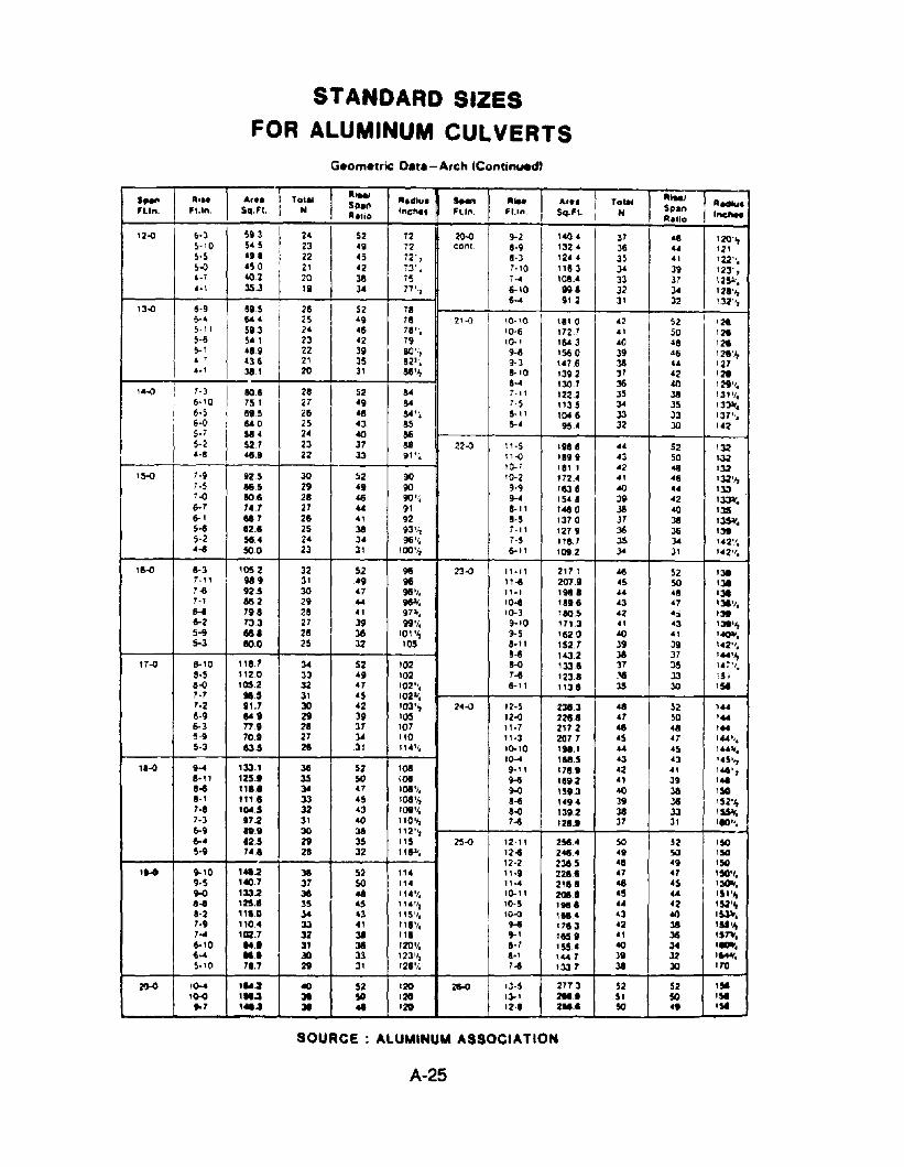
STANDARD SIZESFOR ALUMINUM CULVERTS
Geometric 08t.-Arch IContinued)
SI*' ,,'.. A,•• Tol., IhM!lII.dlu. s_ Ill.. A,.. I Tol.l IIIIMJ
15118.. 5118..
,,_,'L'... ".In. $q.Fl. N Inc"•• Ftln. 'Un. $q.f\. H '-Allio A.tto
12'() &-3 5i 3 24 I 52 72 2O-<l I 9-2 \40 4 31
I&6 \20'"
~-'O ~4 5 23 49 72 cone. 8·9 \324 J6 44 12\s-s 4' I 22 43 72' , 8-3 1244 35 4' 'U".5-<1 450 2' 42 7J' • 7·10 1163 J4 39 123',4·7 402 20 38 7$ 7-4 \08.4 33 37 125't.4·\ 35.3 19 ~ 17'·, 6·10 agl 32 34 12.·...
I 6·.. 9\ 2 31 32 132'1,13-<1 6·9 615 26 52 11
I&-4 644 25 49 18 2' .() 10"0 1110 42 I 52 12415-11 51J 24 46 TIlle 10·6 172.7 4' 50 '215·6 ~1 23 42 79 1().' 164 3 40 48 12415-' 4.1 22 39 80',", 9-11 156 0 39 46 1:le'1,4 ' 436 21 35 &2". 1·3 \47.6 3& u 1274·\ 31.1 20 3' M'I, 8-10 1312 37 '2 128
I8·4 130.7 36 40 '291
,.
'4~ 7·3 60.6 28 52 S4 7-11 1222 35 Ja '31'/.6-10 751 27 '9 S4 7·5 "35 J4 35 13~.6·5 615 21i 46 8.4'. &-11 104 Ii J3 33 '37',.6·0 lot 0 25 '3 as 6-' 95.' 32 JO "25·1 514 24 40 86$-2 52.7 23 37 &8 22'() 11·5 1988 4' 52 1324-8 41.9 22 33 91 ','. 11-<1 1899 43 50 1.)2
1().7 181 1 42 48 132'5-0 7·9 925 30 52 go 10-2 172.' 4' 46 132'1,
7·5 MS 29 49 go g.g 1153 Ii 40 4. 1337.(J 606 28 46 90 1't 9-' 1548 31 42 lJ3'1'.6-7 7.7 27 44 91 8·11 1480 J8 40 1]56-' 887 28 41 92 &·5 1370 37 JI I~.5·8 82.1 25 JI 93'/, 7-11 1279 36 36 1~
5·2 sa. 24 34 96'1, 7·5 118.7 JS 3. 142'/.'-3 SOO 23 31 100'/, 6-11 1012 J4 31 '.2'/.
,~ 8-3 105 2 32 52 96 23-<1 11·11 2171 415 52 l]e
7· " M9 31 '9 96 11-3 2079 '5 SO '387·-6 925 30 '7 9I t
/. "., lM.1 .. '1 1317·' 1M! 2 29 44 98'f. '0-3 1816 43 47 131',.H 79. 28 41 9710'. 1().3 160.5 42 4:; I~
6-2 733 27 39 99'1. 9-10 171.3 41 43 1~''''5·9 881 26 36 101'" 9-S 162.0 40 41 1~.5-3 eo.O 25 32 105 8-11 IS2.T 39 39 '.21
'.
8-3 143.2 JI 37 ,''''",17--0 8-10 "'.T 34 52 102 8--0 1338 37 35 1.1'/.
8·5 1120 33 49 102 7-3 123.1 :-a 33 I!.8-0 105.2 32 47 102". 6-11 1138 3S JO IS'7·7 915 31 45 102".7·2 II.T 30 '2 103'" 24-0 12·5 238.3 41 52 14046·9 loti 29 39 105 12-0 2211.8 .7 SO ''''6-3 77.1 21 31 107 11·7 2172 41 41 ''''5-9 TOI 27 34 110 11·3 20T 7 45 47 'UI/.5·3 13.5 28 31 11.'/. '(),'O 191.1 ... 45 '"1;.
10-4 118.5 43 43 1.5'~
'.~9-4 133.1 38 52 108 9'" 171.1 42 41 146',11-11 125.' ~ SO '.08 9-6 1119.2 41 39 ''-11-3 1'" 301 41 1081
/. 9-0 1513 40 38 1SO11·1 11111 J3 4S 108'1, 8-3 14!J4 39 36 152'1,7·8 ICW.S 32 43 tog l /. 1-<1 1312 38 33 1~.7-3 17 -2 31 40 fl 0 'I, 7-3 121.1 37 31 'lOll.6-9 ".1 30 J8 112'~
&-4 12.5 29 35 '15 25--0 12·11 258.• SO 52 'SO5·1 7'8 28 32 118.11. '2~ 241.• 41 SO 150
12·2 236.5 41 49 150(11M 9-10
'
4t1l J8 52 ". "'i 221111 .7 47 ISO'/.9·5 140.7 37 SO I" 11-4 2188 46 '5 1:lC11or.9-0 '33-2 J8 .. 11"'/. 10-11 2018 45 .. 151'ol,8-1 125.• 35 • 5 ,'.'/~ 10·5 I •.• 4. 42 15,2'",1·2 "'.0 J4 43 115'/. ,<HI 11M!. 43 40 1~.
7·' 110.• 33 ., 118'1. 9-3 178.3 42 38 1$$....7-4 1OZ.7 32 38 1" 9-1 11S1 41 36 '57\'.&-10 .U 31 J8 120'/. 1·7 ISS. 40 34 11llIl'.~-4 ... JO 33 123'~ 8-1 , ... 7 31 32 11044'.5·10 71.7 2t 31 121'/. 7~ 1331 JI 30 170
20-0 ,()-4 1".2 «l 52 '20 26-0 '3·5 277 3 52 52 IS'1M
'''~ 31 SO 120 13-1 2M.' S. SO 'S'.7 1....1 31 .. 120 '2" 2M.' SO 4' lSi
SOURCE ALUMINUM ASSOCIATION
A-25
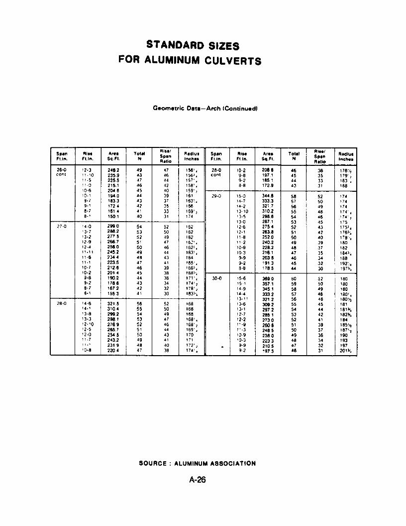
STANDAAD SIZESFOR ALUMINUM CULVERTS
Geometric Oete-Arch (Continued)
Sp.n AI•• ~". Totll Rilll R.dlu. Spin Aill ~r.. Tot.1 AlillA'dlu.
Fl.'n, FUn, Sq.FI. NSpin
'nch•• FUn. FUn. Sq.Ft. N Sp.n'nch••R.tlo A.llo
26·0 12·3 2482 49 47 156' , 28·0 10-2 2018 46 36 176'1,coni 11-10 2359 43 46 1563 , cont 9-8 197.1 45 35 179"1
11·5 2255 .$7 44 157' , 9-2 1851 44 33 183' ,1 ~ -0 215.1 46 42 158' , 8-8 172.9 43 31 18810-6 204 8 45 40 159' 110·1 1~0 44 39 161 29-0 15-0 344.8 58 52 1749·7 1833 43 37 163', 14-7 333.3 57 50 1749-1 1724 42 35 166 14·2 3217 56 49 1748-7 181 4 41 33 169',
I13·10 3102 55 48 174' ,
8-1 1501 40 31 174 '3·5 2988 54 46 .174 "13-0 287.1 53 45 175
2i-O 14-0 2990 54 52 162 12-6 275 .. 52 43 1i53'13-7 2882 53 50 162 12·1 2638 51 42 1763/,
13-2 277 5 52 49 162 11-8 2520 50 40 1i8".12-9 2667 51 47 16:' • 11-2 240.2 49 39 18012·4 2560 50 46 162', 10-9 228.2 48 37 18211·11 2452 49 44 163' , 10-3 21e.l 47 35 184'.,11·6 ;>344 48 43 164 9·9 2038 46 34 18811-1 2235 47 .II '65' , 9-2 191.3 45 32 192'"10-7 2128 46 39 '663., 8-8 1785 44 30 ~ 97 3/,10-2 2014 45 38 168",9-8 190.2 44 36 17 l' , 30-0 15·6 38~0 60 52 1809·2 1788 43 34 174' 1 '5 .. 1 357.1 59 50 1808·7 1672 42 32 178' 2 14-9 345.1 58 49 1808·1 1553 41 30 1833/, 14·4 333.2 57 48 180' ,
13. 1 1 321.2 56 46 I80 'It28-0 14·6 3215 56 52 168 13-6 3ot.2 55 45 181
14·1 3104 55 50 168 13·1 2972 54 44 18131.13-8 299.2 54 49 168 12-7 285.1 53 42 18211.13·3 2881 53 47 168' , 12·2 2730 52 41 18412-10 2769 52 46 168' 1 11-9 2608 51 39 185'1,12-5 285.7 51 44 169' • 11·3 2485 50 37 187':/12·0 2545 50 43 170 10-9 2360 49 36 19011-7 243.2 49 41 171 10-3 223.3 48 34 1931'.' 2319 48 40 172' 'Z . 9'9 2105 47 32 19710·8 2204 47 38 174' , 9-2 1973 46 31 201 11,
SOURCE ALUMINUM ASSOCIATION
A-26
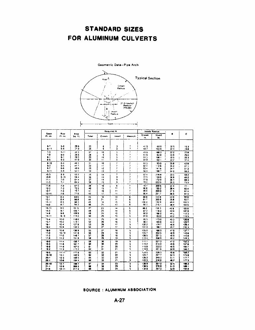
STANDARD SIZES
FOR ALUMINUM CULVERTS
Geometric Data-Pipe Arclt
iIS
i I!""-..(,1
Typical Section
'----.----So."-------~
J' '0 I' 7 Ii 7 ,I 6J J I 9J a J56 I <2 I32 l' 7 7 644 "26 352 '71J3 '2 ,I.' 'I 65< "'6 J<7 5'33< '3 7 , 66< 1587 3<2 553
c
., 5 I 699 J25 '53<37 1029 J2< '91
Crown In....rtIn. In.
'I J I, ' I <56 II 1183 I 322 I, 23 I5 , 516 531 338 290I, 5 I' 53 3 '08 , 33 5 33 3
5 , 5<9 ISO' 1332 37<
'09
'0
"
j Crown II Tole'
296J' 93< 336 I393"9
"5., ,<99527
I "',,,.I Sq, Fl
5·15·9
6·<6·56·66,5
IA.,.....,"
I
i"'0~3
9-7~"
'.J'·911-'I,S
Sp.nFI.·ln
1·2 830 C3 " I '] I 6 SIS "J6 <20 I 1311·< 1568 .. 2' " 6 8" 3008 ]S8 '371·5 '103 <S '5 'S 6 100< '320 160 '03]8·7 "2 <8 2' '] 8 90] 2'5' l" 10<5
7·2 675 J9 1ft I 9 I 7 '57 309S 30' 177'7·3 705 00 IS I" 7 908 '552 38' 13<,. -s 73 7 .4 t 16 11 I 7 90 5 200 0 37 S 87 ..7·6 710 <2 17 " , 90< 2S17 365 I ,,]
')-'')-''3·11"-0
6·96·'07·07·'
5S 551 <6' <6' <
3S '" 7 I' 6" I 2785 33 5 I 5' 236 '3 II 9 I' 775 1396 368 dS237 ,< 9 , 778 '720 36' 61338 '5 9 , '5 2 222 a 35 3 73 3
').11... ],.-.,..,, 9·5 ! 'a' 5 " 21 I' .. I 5 86 2 '59] <28 I '03',., IDS' 08 2< ,. 5 872 1783 <20 '0709-8 1099 <9 2< '5 5 909 '682 ..... "239-10 1'.2 so 25 'S S 91 a 18,30 432 It'S
,!t-< '0-0 I "86 5' 25 '6 5 955 17]0 <5J '201'~7 10-2 jl t,?) 1 52 26 16 S 96" 1896 .... 123-, .. , '0·< 1278 53 28 17 5 '002 1797 <66 '292' .... 10·6 1313 54 27 17 5 1010 1961 '507 '323
'''I 10·8 I '369 ~5 27 18 ~ 1050 I '58] "9 ']77"-0 '0·10 "'8 5& 28 18 5 1051 2025 169 "01"·3 II-ll "6' 57 29 '6 5 lOIS 22'. <59 U]."., 11·2 '5' 8 sa 29 '9 5 110< 20.9 <.2 '<93,e-o ".< '567 59 30 '9 5 ,,, • 2273 <72 '52]'11-, "., '6' , 110 30 20 5 1152 2'52 <98 1578'''' 11·1 '67 ° " ]' 20 ~ llS I 2]] 3 46 5 '110''.l 11·9 1722 82 ]' 21 5 119' 22'S 50' '682
r---';';"-":--+-"-"''':''-'--!----''':-'''"'8'--1-'':8':]--I--:]=2--t---:-2=-,---t-. 75--+--=-,,0-:5--t-:2::J9:-:-J-+--:<,:-:-.-+-----:'~69:-:-2-1
'.'0 '2·' '82 9 64 32 22 5 12< / 22/ / 52] 11.'~, '2·3 '"5 8S 33 22 S 'lSl l<S3 SI' 1177
1-..:~:;....7-_!-':.::1~..;......-!-.:..:":::.~.-_+_68~-+-:3::-5-_t--:l::-'-_t--75--jr_"7'_=1l:_':-+-:;]:;-'0;-1:-+--:"::-:1_+---:-:"=7-:5:--1~'o ,z·/ '"' " ,. 23 S 'JOo lS'l SlS ,.Z1',' 'l·' lOS' .. )5 n S 'JOS lTO' "1 '"I2'" '1." l"l II 35 2' S ,,.1 lS/l U9 ,,.1
SOURCE ALUMINUM ASSOCIATION
A-27
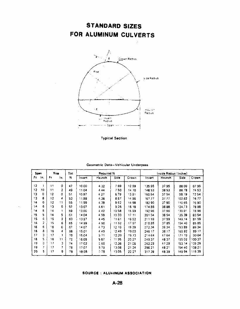
STANDARD SIZES
FOR ALUMINUM CULVERTS
, f
/
<
t-l:i'u I1 Crl
Rad'uS
In"enRadIuS
----Spar>
Typical Section
Geometric Data- Vehicular Underpass
S~n Rise Tot Requlled N InSIde Radius (IncheslFt In, Ft In. N Invert Haunch Sid. Crown Invert Hllunch Sid. Crown
12 1 11 0 47 1000 4.32 7.69 1299 13595 3795 8800 67.9512 10 11 2 49 1104 444 7 50 14.10 14853 3853 8678 745313 0 12 0 51 1097 4 27 879 13.91 16054 3754 98.19 725413 8 12 4 53 11.98 436 867 1496 16777 3777 102.62 767714 0 12 11 55 1199 439 962 1498 18290 3790 11065 769011\ 6 13 5 57 13.07 461 926 1618 1748B 3888 124,73 788814 8 14 1 59 1300 442 1058 1599 19296 3796 13001 78.9615 5 14 5 61 1404 459 1033 17 11 20154 3854 13539 835415 6 15 2 63 1397 445 1161 1692 21159 3759 149.14 815916 2 1'5 6 65 1499 450 1152 1797 21685 3785 15440 858516 6 16 0 67 1407 4 73 1210 1929 27234 3934 15389 893416 8 16 4 68 1501 449 1249 1903 246 17 3817 16082 89171'1 3 17 1 70 15.04 571 1220 19.13 21464 4764 171 19 906418 S 16 11 72 16.09 S 87 l' 95 2027 24937 4837 15502 1003719 0 17 3 74 17 02 : 60 12,36 2106 26229 4729 153 14 1052919 7 17 7 76 1707 579 1306 21 24 29621 4821 15446 1082120 5 11 9 78 1808 ~'78 '3 OS 22 27 31739 4839 14994 11539
SOURce : AlU~lINUM ASSOCIATION
A-28
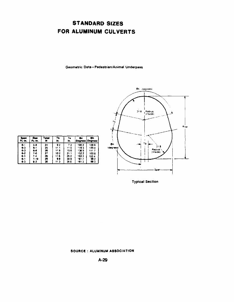
STANDARD SIZES
FOR ALUMINUM CULVERTS
Geometric Data-Pedestrian/Animal Underpass
€Ie loeg,eesl
...... "'" T.... ~ TI ec 8h'l·llI. 'l·lII. N III. In. Det- DeF-
1-1 5-' 24 112 72 1002 12991-3 6-1 2S " I 110 "93 '2041-3 54 26 116 '56 '36 5 ," 71-2 7~ 27 '02 21 I 1522 10396-3 7-. 21 III 252 153 3 IOJ •1-1 7·10 2t 18 JO, ,el7 9921-3 1·2 JO 113 350 ,e, 3 993
------- Span--..
Typical Section
SOURce: ALUMINUM ASSOCIATION
A-29
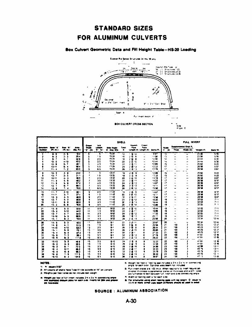
STANDARD SIZES
FOR ALUMINUM CULVERTS
lox Culvert Geometric De,. end FIll Height Tebe.-H8-20 lo8dlng
1-,.....11 Iota Strvctuf'M 2_ 1f"N'\l ]I onty,-'
.'#
'" 50ll'l A
.Oll CULVEIIT CliO'S SECTION
--'"II.L 'ULL INVIIIT.- ..., H- e_ ...........,... ,,,- ........ ........ - -. - -- T.... ...... ..... _.- ......... ' ...•...1 .",".1 "e" 111I "D" ,~. .....~.•to. N ~","'''flL'''''''NI .....".. .. ,. INI n .... _.INI ".....tJ" .....',.., a· • 2· • ~! • 5 ~
:~~:,. , ~ l' - HI '3 - 1301 PI
2 •• 2 3- 3 2U 5 , ~ '5 ,~ 5 - .,~ '3 - - 2301 ~ II3 •• 1 .. , 32. , n '~2' 'I 2@ ~ - '200 ,. - - 2' .. 5 .)D
• 'D· 0 '.'0 002 S 35 '~·2' 20 2'~ '0 - 12u '. - - 2' .. 5)D, '0· a So 1 '" ~ ·~'~2' n ~ '! " - '2" I~ - - 2H2 112
• '0·" ••• !II' ~ B 'H' 10 2 ~ '2 - '3 13 " - ,,~ lSI1 " ... 1. 2 ISO ~ es ,~ 2' 21 2 ~'3 - 1J'1 11 - - 21 " 51'-- -- -- - - _.--a '0· 2 2- a 230 1 ~ '3-31 'I 2@ I - '2" "
- - 2$12 122
• '0. 1 3· 5 ]1 , , ,, 13-33 'I 2@ ~ - '3 l3 '5 - - 2512 11210 'O·" .. ] :lU 1 n '3-33 20 2 (i> '0 - '311 " - - "" II'
" ".. ,. 0 "2 I JS ':1-33 22 2 li \I - '. 2211 - - 21 " In
'2 ". I ,.. ,72 1 IS '3-33 2' 2 :§1 '2 - ~. I' " - - "" I"':I '2· , •• 1 ... 1 B '3-33 :It ,~ '3 - ,~ " " - - 2. " 1$',. '2· , 1.• 110 1 .5 '3-33 21 2 ~ '. - '5" 11 - - 2a !II H'-----'5 ". 7 2,'0 211 , °~ ,','2 15 2~ ~ - US1 " - - ,,~ IIIla n." :I. , 37. , , 5 "U 20 2 <! 10 - ,~ ,;
" - - 21 !II 61111 12· 3 .. , ... • 25 ''''2 .'2 2:J " - '5~ l/ - - "51 '"" '2. 1 5· 2 M' , 35 \1"2 2' 2 :t '2 - '100 '. - - 3202 ,,," 12." •. ° ... , .~ "·'2 2f 2.~ '3 - '... ,~ - - 3202 '\I
20 IS· 3 •• • "' • B ",'2 " 2 ~ '. - 'I" ,~ - - 1202 , ,2' ':I. 0 :1·0 »a " os "'2 20 2 :t 10 - " .. ,~ - - 3202 IIIU IS· • :1.'0 "2 " , 5 "'2 n 2:'f n - 'I" " - - 1202 '\I
n IS· I t· 7 "a " n .61 2' 2 ~ '2 - "» " - - 3202 '\IU ':1.10 '-, ..a " 35 .. 52 21 , '1 •J - 23' , II - - 3202 '\I
25 u· , .·2 '" " • 5..52 2. 2 <§ '. - 23~ 20 - - 3334 '214
3334.
It ,.. , :I. :I 100 ' , 01 ..' 22 21-1,w , 1 - 2211 20 - - '21421 ,.. I .. , IU , :I , S ..' 2. 211 a 8 2S ,. 2' '00 1 .023 , 2 ~7
21 "·'0 "'0 au ' .3 n ..' 18 2" I 8 21 .. 2' '00 2 '02J '21121 'S- , ... " , '3 J5 .., 11 , ., '0 5 :It" 2' 'OIl 1 .023 " 173D 'S- • .. S .72 ' :I • S .. ' 30 'J '§ I" 8 2' )J 2' '00 2 .0 23 '2 I':I' ,... ,. 3 "' 13 H ..' J2 1 " • 2 8 2"1 22 'OIl 2 " ., '211J2 ,... .. 0 '" a '3 15 .. ' 3' 2 \i 'J 5 2522 22 '00 2 .' It '2 tI------ --~ -- _. --- - ~ -
JJ "·'0 Jol ... 'S os "'0 2' 1~ • 8 3222 22 '00 2 .'" ' 2 "~ '.. ° .. , ItS 'S , S 1-'0 14 2. t I :13" 22 '00 2 .t It '2 "JI ,.. 2 .. 1 713 " 21 "'0 2• 2. '0 • )I" 2J '00 2 .2,. ') I'31 ,a· • ..,; au " :II a,o 30 2. \I • 3533 2.3 'OIl 3 ,PS l' "37 , •. I ••• 11.3 'S .~ "'0 32 2. '2 • 151• a '00 1 'S 'S IJ q
:II ,... ,.. '" , " 15 '''0 )' 2. '3 ,. 3122 2J '00 3 'S 75 ') ,:II ''''0 •. :I '211 " 15 "'0 :II 2. " • 31" 2f '00 3 ., I) '3 lJ
NOTa:'I ."'- .......".Z. .... C,....I of ....... .,... ',De IV ,.... ovt.,ete., ,•. ott ,en''''':II -1"""' IlIOI "".... .-01 " •.,_ DOl' -0'"
" "'",'001 O"ull ,_ ,ncl_ 3"l • J ... _to"' ......_......_ ....'.._... 1_...._..---SI WI'O"''''' loot 0' 1001,no PttCIlf'l(lwOtl • 3'" .3 ...... If''l eon"-CI,"O
InOl1 '01 tlCft ,.Ot, 00110ftl,1 •••• ..".. nOI ,nClu'"
II 'ull In.." 011'" I'. 100 '''Ie' W...." fMCt_ons to In.." "",,,Ire act11'1'0"1' ''',cllne.. ,uPpltmen'l' Oil'" of ''''CIl,,-,. Ift(II w'G'PI "tI..,.f' ',,'"'11\eO to bOlt bet"",, tu" ,n...., .~ I'. connectlftQ a"OI'
7'1 "'Wild'" 01 100llnt Nd " lor MCP'l l,eM• ... "_-...__... _ ..", .......,,D _'0:11"'''_ .. I1.,... te_
SOUACI ALUMINUM ASSOCIATION
A-30
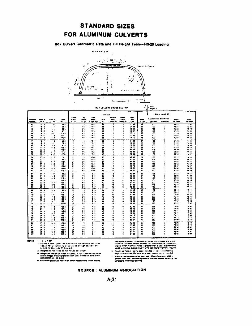
STANDARD SIZES
FOR ALUMINUM CULVERTS
Boll Culvert Geometric De.. end Fill Height T."-H5-20 Loedlng
J~
'J~
'J'I
'. 00'.'""12'.12,.",
'. 00'.'"'1122' .' ."5"
' .' .' .I' 87"17,,",,"'.51,,",••t1,' IiIS 11
I""l' H
.......... '..........~.. ' ..l
, 'S'10II~
100100
'"110-~----~
1MIZI100100100lOO110
100100lOOlOGlOOlOO
)0
l'
"J'11II11IIIIJl11lJII30
"30
"303011I~
l~
IIIIIIIIII
_.............."I .._~.t"",' (N' ' __AM, • ....- 1"1
, .1...... ,.
"541 16 '0 )3~ ~5
'45' 18 ,0).4" 2~
"~4 30 '0 '0 )122 2t"~)2 '0 )817 21•• Sc' ). ~ 2 ' a }1 '1 21.• ~. l& 'J '0 PM 2•,.~. 18 ,. '0 1100 2'- ---_.__._-------=:.:=-.-+-='2.' 11 8 11 )0&" 21,]., 30 9 '2 Jl22 21'2" )2 '0 '2 )1" 21'1")4 '1 1100 II'241 l& '2 '2 ~U1 29'2" 11 ') '2 ~." 19'2 .7 !I?- ~ '_'__2!E- )0
'0,'0 )0 8 '. 4' M 19'0-'0 )2 9 '. S222 2'910-40 ).4 '0 " \.4" 2t'0·'0 )I 'I ,. ~S)J JO'0"0 11 12 '. ,,'a )0'0,6(1 ao '3 '. !I 22 l~
'0,40 t2 '. '. !le" )'8·)2 )2 ~ '. ~ ...)2 )4 10 '. U!lt',)2 )I " " ~12
IU 11 '2 '. ~'7'12 &0 ') " S7"• 32 '2 '. 14 S1!11131 &. 'S '. WOO,,~ )4 '0 1212.n)l ,.~..8H 11 '2 '. \7YIl§ 10 'J ,. YOO
'-2' '2 '. " ,."'2S &. .~ " W"82S 41 'e '. S'1)
• '. )t '0 '. U!II• " M 11 'f! \122.', 40 '1 " "'"41' '2 1] II 'Ill'" •• 1. il \I"",, 41 'S " 1022• '. &I '4 'I tol'_._--~---_.__ . __ .
21')1 'f! \4"2 I' .0 '2 '. sty~ " '2 'J 'I 8022~Il .. '. " 60171 II .. 'S 'I " '.2" &I 'e " ,1Y
lOX CULVEIlT CIIOSS SECTION
SHELL.... ""W"CII C,................ "t4. Itt.. "'.1. __
'"""" IIlfil lit l.,.,....'.. ' L..... ' ..l '"
l'-4 '2JdO "" 2~
'9 ' '9·,
J>~::==~~~~
'.."....o IIU
, ,
to 11) '0 ~••., '8 '1 • 1 (1)
'2 'a, , ~ 4 U ~
.3 "·0 6' 'H'« '9~ &I~ ~"9
•, "'0 1 I 'n'.. 2'0. ) 8! "28
.7 '9AI I' ,•• '9 9'0 2'0'
" 10 e'2 20·'0U 21 1
:l4 10 ,$$ 10'!II 20,' I'1 2'))I 2' 8!t " '010 22 I
., ~
'7 , ~
'1 l!l'1 )!Jq .!/,, 1 ~ 511 8 ~
• 2 &3 ~ '9 ~
• " '13 '9 ' 55 e 936 \9 2566 '092 \. 35~) ,no .t 'S8 1 ", 2 '9 5!llitO 1~7,,-8-t_-,'9_ e~
• e '3' 2' 55 ) 1192 2' , 56' ·~s 2' 256 '0 12'21 2' J 5" 1)902' otiS'!I 'YO 21 5~9 1 "ll 11 B---~--- ._----'1 l" .,, 13823 5
II t· \0 5. 10' 0 2) \ 5U 22' •• "" 23 25.. 22 ) ') , 35' 2) ] 5II 22 • .' 153 1 11 , 5• 221 1'0 "1' 1) 55II 13 0 9 I -""='---te--.:.ll=- BIt II 9 I • 9H II ~
.. 13 0 • "3' n "'0 2).2 ttl 132' 11 25
" n .. '. '!IO' n ] 571 Il • • • ," 1 M , ,'1 Il • " 'It , .., B" 13 '0 '0' 201 0 ~ 65't 1. 0 $ 1~ :I 21 S'I 14' • '2' 5 21 , 517 2' , ' ''' 2' 2' 5'. 2' • 2 'II 2 11 ) ," I' ,., , '.~ 1 21 • ~III " • , lOll I' B" I' 10.' 2.nO 2' "--_ .._--- ----U 1~ 1 I 1 1220 It SU l~ '1 '0 'U 2 2't ' !I.. ~] '1112' 19 2'• ~, • , 'UI 19 H• ", ., IOU 19 ,~., " ~ '0 I III 1 19 B
............... 1III.... ~.
........ ,'Ill'll 1'1 It'll 114"'1
-OTIS: 11 ~ • '12'11 .,.1 thetll "... T,,.,v f,1I1 Ow'I'de 0"1' Iotf"! "",,"(1'1 'I'ICI (.'0.1'\
floe ttl 'I· Of (tAt". 'or ,Uuet""1 10 1'"0''9'''~ tNt .' (tf"Ie'I'I''''' 'Of ,"vctv'"!' ",'out""31 -IMI", 'aot ItltM dO "01 ,!'Ie',," Do!t .t·...'til ~t.., ,... of '\II' ,n.." ,~IWIM' )"IIJI '. !;OfIfl«:li"O anGie........... c......,. "... '" Neft .... I"".,.". t. 10 fit w.""..._....,..-II ......t~ .._ ate ... tWI ..... ,...,..... t, ,,...,.., .....,.
-«I1'lonll lfttell""•• h'OO'~111pll". 01 !'IIC'~" ''''elI .'ClI"I"IM If' '",,,,,,.... 10 lIOn .,..." 'WII '1'1,,'1 I'" t'de tOt'l"fiCt,"OIt'll" t'fhet'\ 11':1("'''' " t' .,••,., ''''en. lID ......eme"'.1eM"" ",'I'" ,.. ..ec" "1\1 '1'lt c........" '''tC'''''' '""I'M
II -9"'''' '001 0' lao"~•••"CIYdet )"t I h ''I CO"'~"'"~I' 101 .Ie" .,M 00t10"1' .,1, "","' ."Vf'll It "ot ·,.CIYdt(J
1) ...... of..- I 11K" ~'''.U~' IItlM ,t..... tMfl ,. "' .,11 ...............111"1 '''4-'---
SOURce ALUMINUM ASSOCIATION
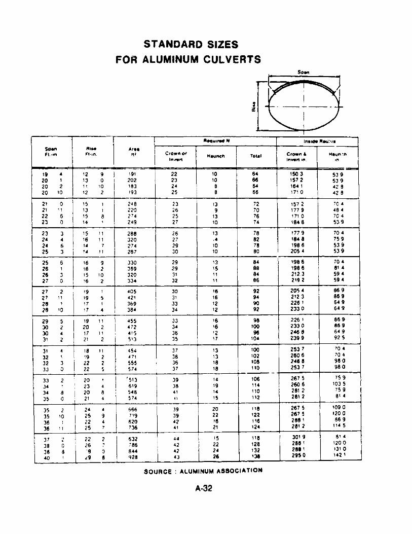
STANDARD SIZES
FOR ALUMINUM CULVERTS
J_I rrrsr=
•~, "'"'\1
• -~ - ---- - --- - -t-i
"- II1
'-""1'" N I"••IM .....:•••
S"en '"'' Ar••Ft.·'" Ft·,,,_ tt' Cro." or H8"MII TOt8' Crow" • H.""_~,,
1",,.t1 1"...t1 '", I"19 4 12 9
I191 22 10 64
:=ISO 3 539
20 I 13 0 202 23 10 66 1512 53920 2 11 '0 '83 24 8 64 164 I 42820 '0 12 2 I '93 25 8 66 1710 42 8
2' 0 15 , 248 I 23\
13 72 1572 70421
"'3 , 220 26 I 9 70 177 9 484
22 6 '5 8 274 2S 13 76 1710 70 423 0 14 I 249 2'T 10 14 1848 539
23 3 '5"
288 26 13 78 177 9 70424 4 16 11 320 27 ,4 82 1848 75924 6 14 7 274 29 10 78 1986 S3925 3 14 11 287 30 10 80 2054 539
25 6 16 9 330 29 13 84 1986 70426 I '8 2 369 29 IS 88 1986 81 426 J '5 '0 320 31 II 84 2123 59427 0 16 2 334 32 II 86 2192 594
27 2 '9 I 405 30 16 92 20S 4 86927 " '9 5 421 31 16 94 2123 86928 , 17 I 3&9 33 12 !IO 226 I 64928 '0 '7 4 384 )4 12 92 2330 649
29 5I
'9 " 455 33 16 98 2261 86930 2 20 2 472 34 16 100 2330 86930 .. 17 11
I 4'5 36 '2 96 2468 64931 2 21 2 513 35 17 104 2399 925
31 4 18 It
I45" 37 13 100 2537 '04
32 I 19 2 471 38 '3 102 2606 704
32 3 22 2 555 36 18 108 2468 980
33 0 22 S S74 37 18 "0 2537 98010---1 1
-33 2 20 , 'S13 39 14 106 2675 75934 I I I
23 4 I 6'9 38 '9 "4 260 6 1035
34 8 I 20 8 I 548
\
4' 14 110 2812. 759
35 0 I21 .. 574 " 15 112 2812 814
35 2.
\
24 4 666 .J 39 20 tl8 2675 1090
35 '0 25 9 7\9 39 22 122 2615 1200
36 , 22 4 620 42 16 116 288 I 869
36" ! 25 7 736 41 Z, 124 2812 1145
I
37 2 I 22 2. 532 44 t5 118 3019 81 4
38 0 LL; i86 42 22 128 2881 '200
38 8 8U 42 24 132 281 I 1)10
40 , ..9 8 '.J28 43 26 131 2950 142 ,
SOURCE ALUMINUM ASSOCIATION
A·32
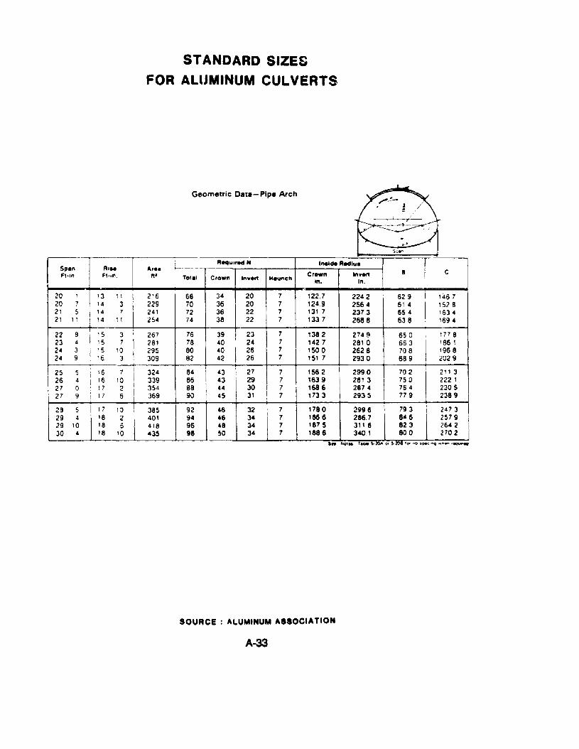
STANDARD SIZESFOR ALUMINUM CULVERTS
~Geometric Data- Pipe Arch
;"-~• I
= ,
R:~.~, .-/Sea'"
RequIred H Inllde Redlu. ISp.n R,.. Ar••B CFt·,n Ft·,n. n' Total Crown Invert Haunch
Cr_n Invert
IIn. In.
20 1 13 1I 216 68 34 20 7 122.7 2242 629 I 146720 7 14 3
I229 70 36 20 7 1249 2564 61 4
I1528
21 5 I 14 7 241 72 36 22 7 13t .7 2373I
654 163421 11 : 14 I I 254 74 38 22 7 1337 2688 538 1694
22 8
I15 3 267 76 39 23 7 1382 274 ~ 650
I177 8
23 4 15 7 281 78 40 24 7 1427 2810 663 '86124 3 15 10 295 80 40 26 7 ISO 0 2628 708 196 824 9 I 16 J 309 82 42 26 7 151 7 2930 689 2029
25 5 i 16 7 324 84I
43 27 7 1562 2990 702 211 326 4 I 16 10 339 86 43 29 7 1639 2813 750 222 I27 0 17 2 354 88 44 30 7 1686 2874 764 230527 9 I 17 5 369 90 45 31 7 1733 2935 779 2389
28 5
I
17 10 385 92 46 32 7 1780 :2996 793 247329 4 18 2 401 94 46 34 7 186 6 2867 846 257929 10 18 6 418 96 48 34 7 1875 3116 823 264230 4 18 10 435 98 50 34 7 1886 3401 800 2702
I " ," "
SOURCE: ALUMINUM ASSOCIATION
A-33
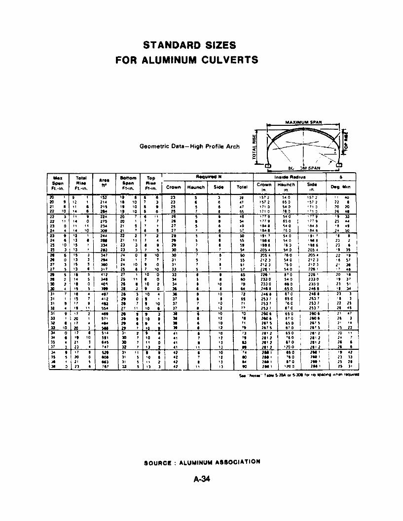
STANDARD SIZES
FOR ALUMINUM CULVERTS
II
)l, SPAN
MAXIMUM SPAN
'"!Qa:...<l..o..
Geometric Data- High Profile Arch
,. ••.... Tol.' A,.. Bonom Top,
Aequ'rM N 'na.. AMiua &
SP8n RI.. ft' SP8n Ai.. Crown H.unetl SicMFl.-in. Fl.-in. F'·in. Fl·in. Crown H.unch SicM To'.' in.
Deg. ",n.In. In.
20 • 9 I 'S2 '9 8 8 8 23 5 3 39 .57 .. 5.0 , 57 2"
0()
20 9 ,~ I 214 '8 10 7 ) 23 8 8 H '572 850 , 57 2 22 •21 8 II • 215 ,.'0 8 • 25 5 8 .7 .7. 0 5.0 '7, 0 70 20
22 '0 '4 8 2.. '. '0 • 5 25 7 • 55 .71 0 780 '7, 0 28 4822 3 II • 224 20 7 8 " 24 5 5 •• '719 540 '
71 9 I '9 3322 " '4 0 275 20 , 7 7 2. 8 • ~ '719 650 ' 1~ 9
I25 .4
23 0 " ., 2~ 21 5 7 I 27 5 8 .9 '&0 • 540 ' 8.8 '. ••24 4 '4 .0 309 2' 7 • 5 27 7 • 57 11'•• '60 '... 2' ~
23 9 '2 ,2" 22 2 7 2 28 5 8 50 ". 7 5.0 ! ' 9' 1 '. •24 6 '3 • 2.. 2' " 7 4 2t 5 • S5 '9' 8 5.0 '9' 6 2J 2 ,
25 10 15 ,J~ 23 3 I • 2t 7 I 5. 1918 I 760
,'916 n 8
25 J '3 , 213 23 3 7 5 30 5 7 ~ 205 • 540 I 205 • '9 )5
21 6 '5 3 347 24 0 8 '0 30 7 I 60 205. 780 I 2054 I 22 '.21 0 '3 ) 2t4 24 • 7 7 3' $ 7 55 2'23 540 I 2' 2 J
I'.57
27 ) '$ $ 3tlO 24 '0 , 0 3. 7 8 6' 2'23 '60 I 2'2 J 2' 3127 $ I) 8 JI7 25 I 7 '0 33 5 7 57 228 • 540 221 ,
" '821 5 '8 5 412 27 , '0 0 33 8 • 85 221 , .70 221 ' : 20 '.21 2 14 $ 34. 25 11 • 0 ~ $ I • 60 233 0 $40 2330 19 )730 2 '8 0 olt'\ 28 • '0 2 34 8 '0 70 2330 880 2330
I23 5'
30 4 '5 5 )It 2. 2 , 0 31 8 8 64 2.. 8 850 2.. 8 '8 3431 7
I18 • "7 2. 5 '0 4 31 8 '0 72 24' 8 870
I248. I 23 )
3', '5 7 4'2 2t 0 , , J1 8 8 65 l537 150 2537 '. )
)' 8 t7 • '83 21 7 , 10 37 7 '0 71 2537 'II 0 2537I
22 l5)2 • "
11 5$4 27 11 '0 8 37 8 '2 " 2537 870 2537 28 '53' , 17 2 ... 21 t , 3 31 8 '0 70 2150 I 150 2150 I 2'
.,J3 • 20 1 571 21 , 10 • 31 8 '2 '8 2150 , 870 I 2150 I , 26 3)2 • t7 • ... 2t • • 4 Jt I '0 71 2175 150 I. 21' 5 I 2' '.33 '0 M 3 Ya ,. 7 '0
, 31 • '2 " 21175.' 0
, 211' 5 25 2J34 0 17 8 514 3' 2 , 8 ., I '0 73 21' 2 650 ! 2.' 2 20 "34 • ., '0 5tl Jll 7 '0 • •• , .2 " 28' .. '10 28' 2 i 2'
,15 4 2' ) "5 Jll , tl 0 41 8 13 IJ 28' .. 870
I "8' .. I21 I
3' ) 23 • 747 )2 , I) .. 4. " ') " 28' 2 '200 21' 2 28 •34 ,
"9 m 31 tl , • 42 • '0
,.2'" 850 211 1 I ., '2
15 5 20 0 101 3' 5 1O • '2 7 ' .. 10 2" , '10 211 ,
\
13 J3JI • 21 5 113 3' 5 " 2 ... • , J '4 "II' I' 0 211 , 25 21]I 0 21 6 '.' 33 $ '3 ) 42 11 , 3 90 2'" '20 0 211' 15 31
SOURCE ALUMINUM ASSOCIATION
A·34
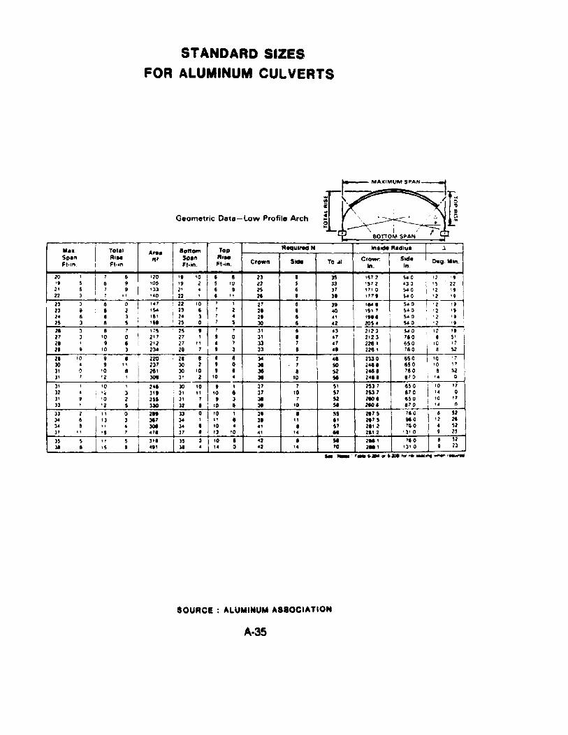
STANDARD SIZESFOR ALUMINUM CULVERTS
Geometric Data-Low Profile Arch
r=:; MAXIMUMSPAN~
:::r\~ ~/~...;i~' .~....~ ~o ~---; ·L~ ~ \ I /.cp' 8011'0""" SPAN t -¢
Sid. ! [)eg. Min.In. I
M••.So.nFI-,n. I
TOI.IRi..Fl-ln
A...It'
ToORi..Ft·in. Crown
Aequlrea"
To ..I
Il'lIICM "Ieslul I
~ ~ I ~ : I :~~ !;; '~ :'~ ~~ : ~~ :E ~ I ~ ~ i:~ 4~~I22 J , " "0 I 22 , '" 21 , JI , 11 , S' 0 ' 2 '9
r--:2=3---0=--t-I--:,---o~-r-I--:'-:'~1---"'-2==2;--:'-::0-t"";1;---:,-1-""":2::1=--+--'=---+--=3-='--+--":",,:-:-=-,-+-';S':'~O:---r-,-=-,2 , II
23 9.' 2 i '54 !22~ I 1 2 21 • .00 "'1 S'O :'2 \92' 8 , J ," • J 1. 2' • .. 'M' 54 0 ,'2 ' II25 J • S I '8' I 25 0 , 5 JO • d 205 • 54 0 12 19
21 0 • 1 "5 25 'I' 1 Jl • .3 2123 I 540 '2 'II21 J '0 0 I 2'1 27 1 '0 31 I H 2'23 '10 '5'21 I " I I 212 21 11 • 1 33 1 '1 221 I 650 i '0 "21 9 '0 ) 23' 26 1 ,) J3 I ., 221 , 11 0 • 52
21 '0 : 9 • 220 21 I ,. ]a 1 " 2330 650 i '0
~ ~ .~ '~, I ~~~ :,~ : ~ : ~ : ~::: ~:g ~,'~r-..:)-'---' '..:2 .........;3OI..:..:._-+....:.J_'_ .....;2-1_'0__ • :Ie lD ~ 2'" ,10 ..
)' I '0 , 2.. JO 10 t 1 )1 1 51 2531 '50 I '0)2 • I. 'e J II, 3" )1 11 10. )1 '0 57 253 1 110 I If)' 9 I '0 2 2U )1 1 'J 31 7 SZ 2101 850 I ',~)3 , '2 5 J30 )2 I 10' 31 10 51 210. '10 •
J3 2 I, , 0 i 211 J3 0 '0 1 ~ I ~5 2175 l' 0 I' ,
)' • 'J 3 ':MI1 ]a 1 II I :MI " .' 2175 910 '23' • " • I 30t ]a I 10'" • 57 211 2 1.0 •)1 " '5 'i 411 31 • 13 '0 ., If .. 2112 13.0 9
"o'1/)
5221522J
311 35 ) 10 1'2 I 51 2.. , "0 ,." JI' " 0 '2 '. 70 2M 1 'J' 0 9
S22).. _ r_ _ __
SOURCE ALUMINUM ASSOCIATION
A-35
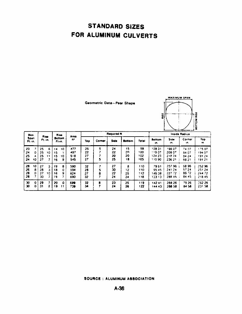
STANDARD SIZESFOR ALUMINUM CULVERTS
MAXIMUM SPAN
Geometric Data-Pear Shape V I
'",,,
WI f------ h!!!IIIIit ,ac
~ /~C>t:
, 0III
..... Ail. AequirlCl N Inl'CS. AId,uISp.n Ai.. 8onom A".Fl.-in. Ft.-in. Fl·in. tI' Top Comer Side Ionom TOla' Bottom SiCS' Co,n., Top
,n. •n. ,n . ,n
23 7 25 6 '4 10 477 25 5 2. IS 98 10831 19807 7407 '750724 0 25 10 IS I 497 22 7 22 2r) 100 "907 20807 8407 , 940725 4 25 II 15 10 518 27 7 20 20 102 12423 21 El <4 8424 , 91 2424 10 27 7 16 9 545 27 5 25 18 lOS 11090 23621 6921 19121
28 10 27 3 19 8 590 32 7 27 8 110 7961 25796 I 6896 2529626 8 28 3 18 0 594 28 5 30 12 110 9545 241 24 5724 251 2428 0 27 10 16 9 624 27 8 22 25 112 14638 227 72 I 8672 244 7228 7 30 7 19 7 690 32 7 24 2. 118 13313 28845 I 8445 21845
JO 0 29 7 20 0 699 32 8 23 25 119 14241 28826 7926 26226JO 0 31 2 19 11 731 34 7 24 26 122 14443 288 58 8.58 231 58
SOURCE: ALUMINUM ASSOCIATION
A-38
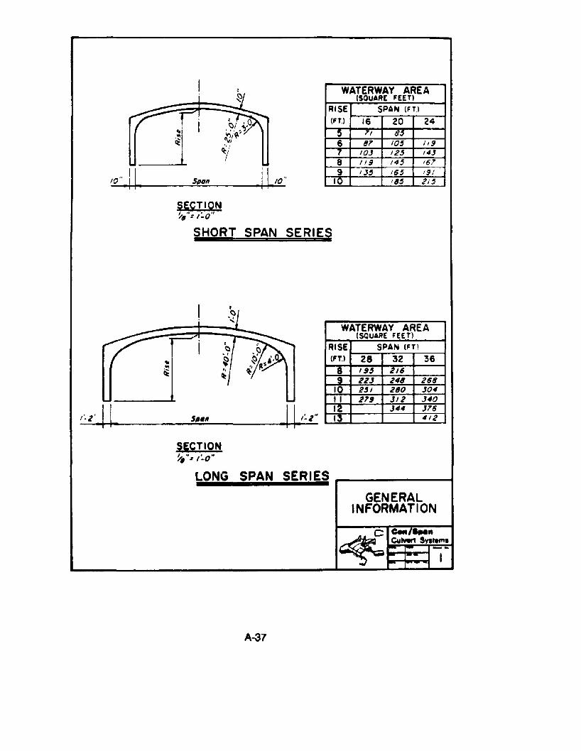
I : WATERWAY AREAi ~ (SQUARE FEET)
RISE SPAN (FTlr l
~; I .~/ .~.O(FT) 16 20 24
~:V/~' 5 71 8''. , 6 8' 10' 1/9
~I 7 10,3 12' /4.1
8 119 /4' /6,7
I' Jk· 9 IJ' 16' 191
4 Span 10 18' 21'
SECTION~,"= 1'-0"
SHORT SPAN SERI~
I .~jiWATERWAY AREA
,.....- . (SQUARE FEE Tl
I ;~RISE SPAN (FT)
• (FT.! 28 32 36...I, ~" 8 I" 2/6it ~ 9 22.1 246 268
10 2'1 280 J04
- II 279 JI2 ,340
~ .~12 J44 J'6
S""" 13 412
SECTION~'''I ''.0''
LONG SPAN SERIESGENERAL
INFORMATION
~e-,.....C41hIert !h rem.--- -- I
A-37
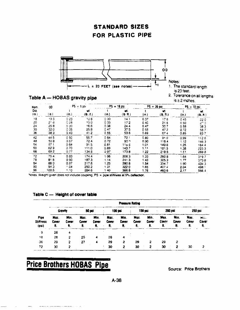
STANDARD SIZESFOR PLASTIC PIPE
Table A - HOBAS gravity pipe
n+1+-++------~}~)~------_+_ 00
, ("======'=+. -.I~·----l :: 20 FEET (s•• notes) -----1 t 1. The standard length
IS 20 feet.2. Tolerance on all lengths
is ± 2 inGhes.-~-
PS =72 pSiI WI.
(in.) lib.,".)~--------~
045 220050 2-:'::059 383072 5870.85 83.7
0.99 1126112 14631.25 , 84.4138 22331 :1 2698
164 31971.71 3738190 4343204 498.12.17 5664
Nom. 00 PS =9 ~Sln PS =18 psi PS =36 psiOia I WI I WI. I WI.(in.) (in.) (in,) IIb,flt.) (in.) (lb.:f1.) lin.) (lb. 'fl.)
18 195 023 106 030 141 0.37 17620 210 026 130 033 172 0.40 21624 258 0 30 18.6 0.38 24.4 0.47 30730 320 035 25.8 047 375 058 47236 383 043 41.2 055 53,6 069 67.4
42 44.5 050 55.7 064 72.1 0.80 91048 508 057 72.4 0.72 93 <1 0.90 118.454 571 064 915 081 1Hi;; 101 149660 629 070 1110 0.89 143.7 1,11 181566 692 on 134.5 097 173.8 122 2196
72 754 083 174.4 1.06 206.3 1.33 260.878 816 090 1873 114 2413 143 305.384 88 a 0.97 2176 123 280.8 154 3[>4790 94,3 1.04 2502 131 3220 165 407.496 100.6 110 284.6 140 366.8 i 176 4636
Notes 'Weight gillen does not Include coupling; PS = Pipe stiffness at 5% deflection.
Table C - HeIght of cover table
PrIau,. RlUntI
Gravity 50 pal 100 pal 150 pli 200pli 250 psi
Pipe Mil. Min. Mil. Min. Mu. Min. Mil. Min. Mil. Min. Mil. ftoii,; .Stiffness Cover Cover eonr Covtf ecmr ecmr CoY.r Cover C~r Cover CoYer Cov.r
(psil ft. ft. ft. ft. ft. ft. ft. n. II. II. ft. It.-_.---._---------------
9 28 4
18 28 2 25 4 28 4
36 29 2 27 4 29 2 29 2 29 272 30 2 30 2 30 2 30 2 30 2
_.~--_ .._-._---"
Price Brothers HOBAS Pie!.Source: Price Brothers
A-38
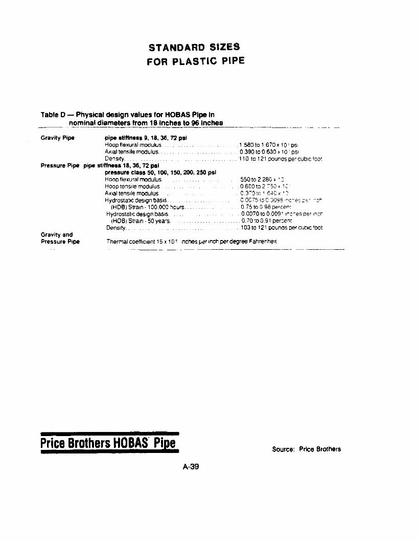
STANDARD SIZESFOR PLASTIC PIPE
Table 0 - Physical design values for HOBAS Pipe Innominal diameters from 18 Inches to 96 Inches
Gravity Pipe pipe stiffness 9,18,36, 72 psiHoop flexural modulus ..AXial ten!llle modulus.Density .
Presllure Pipe pipe stiffness 18, 36, 72 psipressure class SO, 100, 150, 200, 250 psiHoop flexural modulus. . .Hoop te~slle modulus..AXial tenSile modulusHydrostatic design basIs.
(HOB) Strain - 100.000 ;,oursHydrostattc design basIs ..
(HDB) Strain - 50 years.Density ...
. . 158010 1.670 x 10 C pSI0.390 to 0.630 x 10' pSI110 to 121 pounds per cubic foot
. 550 to 2280 x 100600t02 750. ~ CeTa te 1 6~C x ' ~
.0 Oe75 to o J098 l'1c:-es p,,' ~c~
o 75 to 098 percen :
00070 to 00091 Inc,..es per Incr. .... 0.70100.91 percent
.. 103 to 121 pounos per cubic footGravity andPressure Pipe Thermal coeHlclent 16 x 10 ~ Inches ~r Inch per degree Fahrenhel1
Price Brothers HOBAS' Pie!.
A-39
Source: Price Brothers
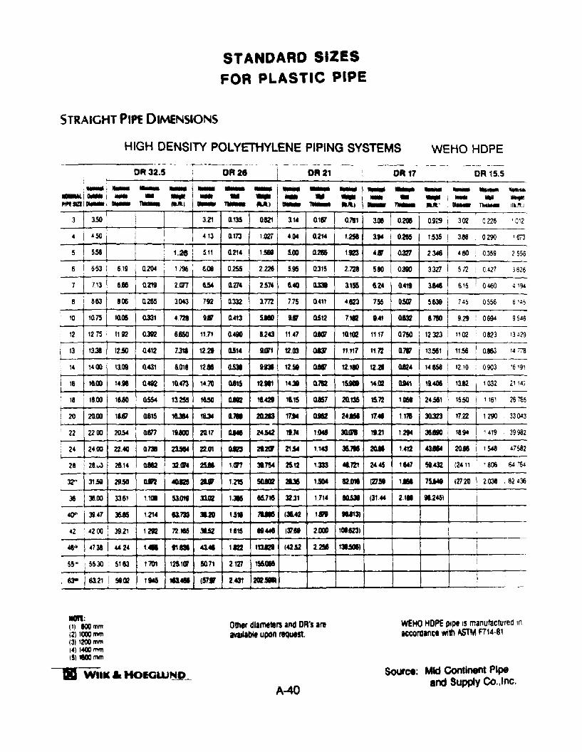
STANDARD SIZESFOR PLASTIC PIPE
STRAIGHT PIPE DIMENSIONS
HIGH DENSITY POLYETHYLENE PIPING SYSTEMS WEHO HOPE
DR 32.5 DR 28 DR 21 DR 17 DR 15.5
' ............. -- .... ... -- - - .... -1- .... ... ' .... -- .....~i ... i ... • ... - • ... - • ..... 1- • ... i ... .. .......""f1lZ!1 .... 1 .... --- ....1 ....., Tw.. UI ... -- UI ... ~ U.' 01.- ~ 11.. 11I1
j
3 3.50 3.21 0.135 0.&21 3.1. 0.187 0.1&1 3.011 O.~ O.9i~ I 302 0226 ' 012
iE I I 413 0.173 1,027 4()t 11214 1.251 3.14 0.• 1535 i 388 0290 '6i3I I
I i ~2348 I: 1.2e i 5.11 0.214 1,581 5.00 0.2t15 1123 4.11 Q327 480 , 0,359 2556
+--6 I 653 i 619 0.204 1196
,6.08 0.255 2226 5.95 I 0.315 2.721 5.10 Q390 3327 i 5,72 I 0427 3626! I
7 713 6.66 0.219 2<117 6.54 (m4 2.574 6.40 ll33I 3.155 6.24 0.419 3.848 6,15 i 0460 4 '94
6I
663 I 8~ 0.265 3.043 792 0.332 3.772 7.75 0.411 4823 755 OS' 5,639 i 745 0556 6 '~5I
10 '0.75 10.011 0.331 4128 g.l/ 0.413 5.110 1117 0512 7112 9.4' 0.132 8.780 921 ! 0694 9546
12 1275 1192 Q3lI2 8650 11,71 0.490 8.243 11.47 0.1CI7 10.102 1117 0.750 12323 ! 1102 0823 13 J29
~ 13.31 12.50 0.412 7.318 12.29 05'4 9.Wt 12.03 Q& 11.117 1172 0.717 13~1 1156 i 0.863 14 :'78I
I
14851 I, 14 1400 13.09 0.431 8.018 12. Q53lI 1.931 12.51 Q8lI7 12.1. lUI QJ24 1210 0903 '6 '91:
! 16 le-OO 14,. 0.482 10.473 14.70 0115 1Uel 14" 0.1&2 15.101 14.02 U41 1140S 13.82 I ' 032 2' 14;I
1800 16.80 0.5504 13.255 t8.5O a..l 11421 18.15 QJ57 20.135 15.72 1IlH 24.561 I 15.50 2676518 ! 1161
I 20 20.00 11.81 0.615 1UM 18.3' Cl'll 20.. 17... 0J52 2•• 17.... 1171 JO.323 1722 I 1290 ' 33043
22 2200 20.54 rUJl7 11.800 20.17 OM 24.542 19.7' 1IMI 3Cun 19.21 1294 31.180 18.94 I 1419 39982
24 2400 22.40 0.731 21514 22.0' Q.Il3 21.2CF 21Jot 1.143 35". 20.11 1.412 43.114 20.. I 1548 47582
28 12t...l 26.14 QJS2 32.0'4 25.11 'an 31,754 a12 '333 .721 24.45 1667 SI.432 (24 'I ! 1806 64764
32'" 31.58 29.50 Q.fI2 4QI25 .. '215 5U02 2l3I 1.!eM ami (Z7!t I. 75M t27201 2038 . 82436
36 i 36.00 lute 32.31 IQ53lI 2.'. 11.2451I
3361 not S101I 33.02 I.- 1.714 (31.. I
qt i 39.47 36.IIi 1.21' lI3.733 31.. 1.511 ,.. (35.42 ,. 1U131 I42 4200 1, 3921 1212 7'Zte6 3IJ2 1815 Ill.... (~. 2000 101.1231 i
I
48" i 4738 442. ,. .,. 43.. '" "3.121 (~.52 2.258 131.501l I55," 55.30 I 5163 1701 la,er !lO.71 2.127 156.. :
i
63.21 I I
83"' Sl02 1165 "'. (57. 2,431_.
I
1ICm:(1) 800mm12) l000mm(3)I200mm(4)14OOmm(5lamm
-. WIIK.HoIGW~_
Other diameters arld DR's areMIlablt upon request.
A-40
WEHO HOPE pipe IS manufactured ,naccordance with ASTM F714·8'
Source: Mid Contlnent Pipeand Supply Co,"lnc.
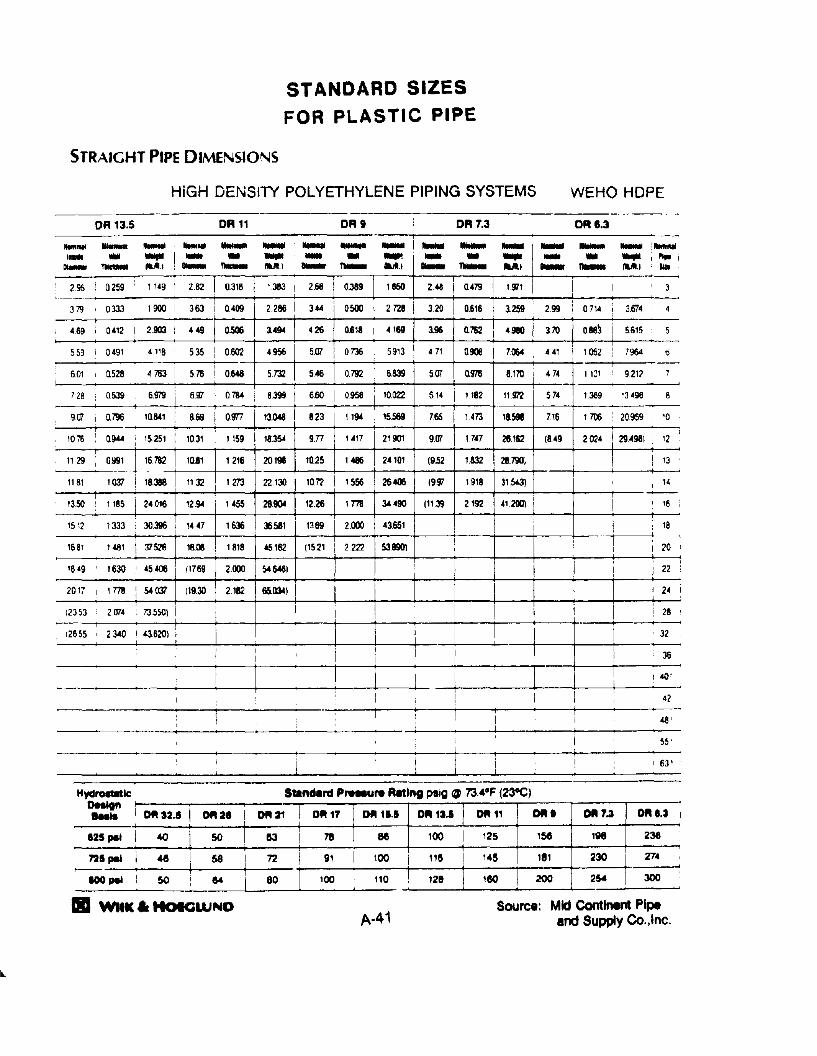
STANDARD SIZES
FOR PLASTIC PIPE
STRAIGHT PIPE DIMENSIONS
HiGH DENSllY POLYETHYLENE PIPING SYSTEMS WEHO HOPE
.....DRe.3
...... 1 .....
DR 7.3DRtDR 11DR 13.5
ItIIItt .. ... 1-- .. WIllI to::. .. ... .. .... -- .. .... 1 ,... iDI.- ~ 1IlJ1I.1 , .... "*- 1IlJ1I.1 "*- au.1 .... ~ M.I i ..... "*- U.I IlII
295,
0.259 I 1'49 I 2.82 I 0.3'8 1383 \ 2.68 0.389 1650 248 I 0.479 U71 I : , 3
1900 i 2.286 I 344I
0500 27'28,
379 0.333 I I 363 0409 320 0.616 3.259 299 I 0714 I 3.674 41 I I ~
469 i 0.412 2.903 I 449 0.506 3.494 426 0.618 4169 3.96 0.1&2 4.980 370 0.88~ i 5.615 5
559 0491 4118 535 I 0602 4956 507 I 0.736 i 5913 471 0908 7064 1 441 I 1052 : 7964 0I ,
4.783 II I
601 , 0.528 I 57'6 I 0648 5732 546 0.792 6839 507 0.97'6 8.170 474 llJ' 9217 7I I I I
I !728 0639 I 6979 i 6.97 0784 8399 I 660 0958 10.022 5.14 I 1182 llWZ 574 1369 '3498 8,
907 I 0.796 i 10.841 I 8.69 o.m 13.048 I 823 1194 15.569 7.65 1473 18.598 716 1706 20969 I '0I
2024 i 294981 II
1076 0944 I 15251 1031 1159 18.354 9.n 1417 21901 907 1747 28.162 (849 12
, 'I 29 I 0.Y91 I 16782 10.61 1216 20198 10.25 1486 24101 (9.52 1.832 28.790. I ! '3
1181 1037,
18.388 '132 1273 22130 107'2 I 1556 26406 (997 1918 31.543) 14i I I
1185 I 24016I --1350 12.94 1455 28.904 1226 1.778 34490 (1139 2192 412'JO) I I '6
1512 , 333 i 30396 I 1447 1636 36581 1359 12000 43.651 I i I 18I :
'681 I 1481 I 37526 16.011 1.818 45162 (1521 2.222 53.8901 I ,20I I I
II ~
'849 1630 45406 (1769 2000 54 60'61 , : 22
2017 I 1778 I 54037 (19:W 2182 65l13ot) I I I 24 Ii
12353 2(]74 73550) I i ! I I I ! I I i 28I
12655 2340 I 436201 : I . 32
I i ,
-=--=--=======:-=-=-~~_--+--+--_---+--4.---j-:,=~-:~4:'! I i 42
48'
55 .
I 63'
OH6gn0-.32.5 I ! DR 17 D1111U D1111U I DIll 11 0'" DIll 7.3 DAI.3... DA2e I 0-.21 I
I I r-; --;
125 pel i ~J
SO I 7'8 Be 100 I 125 156 lV8 236I I 1
725 pel i 46 I 58 I 72 I 91 I 100 i 1181
145 181 230 I 274 I
I I ,-- ,,
I I100 pel I SO ! 64 I 80 '00 , 110 128 180 200 2~ 300I I! .
Hyd~lc\
11II Will(. HOIGWND Source: Mid Continent Pipeand Supply Co.,lne.
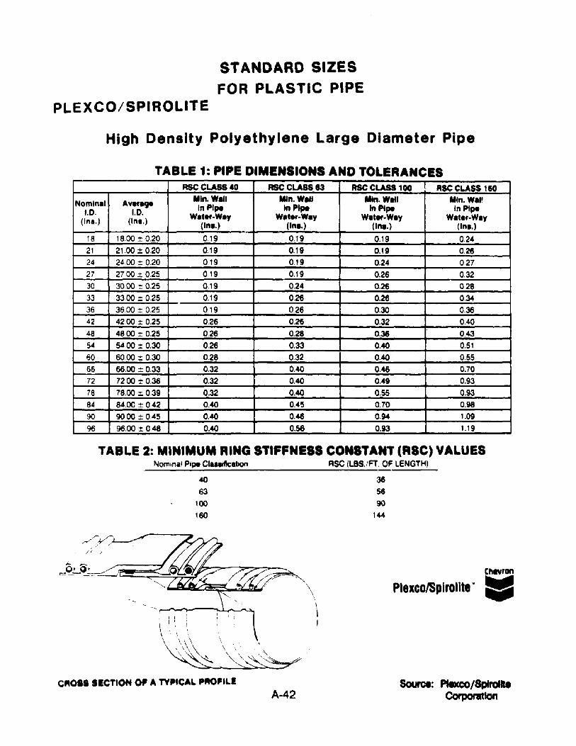
STANDARD SIZES
FOR PLASTIC PIPEPLEXCO/SPIROLITE
High Density Polyethylene Large Diameter Pipe
TABLE 1: PIPE DIMENSIONS AND TOLERANCESRSCCLASS40 ASC CLASS 83 RSC CLASS 100 RSC CLASS 160
Nomin.1 Average Min. Will Mln.•1I1 MIn. Watl Mln.W.I'1.0. 1.0. In Pipe In Pipe In Pipe In Pipe
(In•. ) (Inl.) W.ter.W.y W.t..--W.y W.t...·W.y W.ter-W.y(Inl.) (Inl.) (Inl.) (Inl.)
18 18oo:t: 020 0.19 0.19 0.19 0.2421 21.oo:!: 0.20 0.19 0.19 0.19 0.2624 2400 ~ 020 0.19 0.19 0.24 0.2727 2700:t: 0.25 0.19 0,19 0.26 0.3230 3000 1: 025 0.19 0.24 0.26 0.2833 33.oo:t: 025 0.19 0,26 0.26 0.3436 36oo:t: 025 0.19 0.26 0.30 0.3642 42.00 i: 0,25 0.26 0.26 0.32 0.4048 4800 :t 0.25 0.26 0.28 0.36 0.4354 5400 i: 0.30 0,26 0.33 0.40 0,51
60 60.00 :t 0.30 0.28 0.32 0.40 0.55
66 66,00:t: 0.33 0,32 0,40 0.46 0.7072 7200 ± 0,36 0,32 0.40 0.49 0.9378 78.oo:t: 0,39 0.32 0.40 0.55 0.9384 8400 ± 042 0.40 0.45 0.70 0.98
90 9000 ± 0,45 0,40 0.46 0.94 1.0996 96.00 1: 048 0.40 0.56 0.93 1.19
TABLE 2: MINIMUM RING STIFFNESS CONSTANT (RIC) VALUESNominal Pipe CIUII&.bon RSC fLBS./FT. OF LENGTHl
40 3663 56
100 ~
1~ 1«
CROSS SECTION 0' A TYPICAL PfIO'ILEA-42
Cftftron
Plexco/Splrolite" liJ
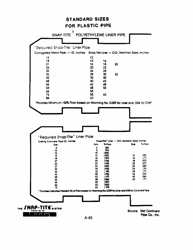
STANDARD SIZESFOR PLASTIC PIPE
R..,,-__S_N_A..P-TITE - POLYETHYLENE UNER PIPE J
. Required Snap-lite· Liner PipeCorrugated Metal Pipe; - 1.0.; inches Snap-lite Uner - 0.0.; Nominal Sizes, Inches
15 1218 14 1621 16 18 2024 20 2230 24 2836 28 30 3242 36 4048 40 4254 42 4860 48 5566 5572 55 6384 63
•Provides Minimum 100'lt Flow based on Manning No. 0.009 for Uner and .024 'or CMP
• Required Snap-lite· liner Pipehlllln; Concrete Pipe LO.; Inchel Snap-nte. Uner - o.O~ NomInOI SIzes. Inches
SiZe SIz~ ... Flow Slze"t" Flow
8 6 (~
10 8 (93)12 10 (105)15 13 (102) 12 (90118 16 (101) 14 (71)~ ~ ~ ~ ~24 22 (110) 20 (87)27 24 (101) 22 (80)30 28 (115) 24 (76)36 J2 ( 91) 28 (71)42 .eo (116) 36 (92)
" 42 ( 971 40 (861~ 41 (1CM) 42 (71)60 55 (107)66 63 (103)n 63 l~
• ProYldellndlcClted Peteent l1't1 01 Flow baled on MannIng No. QClD9fof lJNrand.011Uor Concrete Pipe
THI INAp·TITI I'YITIM""_'1o'W ..
A-43
1-Source: Mid Continent
Pipe Co,. Inc.
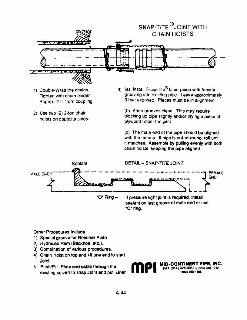
". r.
SNAP.TITE@JOINT WITHCHAIN HOISTS
1) Double-Wrap the chains.Tighten with chain binder.Approx. 2 ft. from coupling.
2) Use two (2) 2·ton chainhoists on opposite sides.
3) (a) Install Snap-T1te® Liner piece with femalegrooving into existing pipe. Leave approximately3 feet exposed. Pieces must be in alignment.
(b) Keep grooves clean. This may requireblocking up pipe slightly and/or laying a piece ofplywood under the joint.
(c) The male end of the pipe should be alignedwith the female. If pipe is out-ot-round, roll untilit matches. Assemble by pulling evenly with bothchain hoists, keeping the pipe aligned.
Sealant DETAIL - SNAP-TITE JOINT
MALEEN{D ~- -~-- -::~,-- - -;::~::-l---JF~~ALE_ ~........ . St'" _~_________ ~ L __
"0· Ring - It pressure tight joint is required, installsealant on last groove of male end or use"0· ring.
Other Procedures Inchlde:1) Special groove for Retainer Plate2) Hydraulic Ram (Backhoe, Gtc.).3) Combination of vanoul procedures.4) Chain Hoist on top and 11ft one end to start
Joint.~) Push/PIIII Plate and cable through the
existing culvert to snap Joint and pull Uner.
A-44
mPI MID-CONTINENT PIPE, INC.FAX (31") 328-3313. (314134-1212
(100)"'306

STANDARD SIZES
FOR PLASTIC PIPE
A·2000 p'"C PIPE DETAILS
SECTION PROPERTIES
SIZE INSIDE ! OlITSlDE , AREA C IDIAMETER i DIAMETER i (I.2/fOOl) (10.
4/10.1
4' 3.9S" i 4.29" .658 I .\OS" .(0)21
6'I 5.88" i 6.41" .842 ! .163' .00:170I Igo ,
7$""I
8.59" 1.142I , .7Zt' .0017510" I 9.84' 10.78" 1.176 i .m" 00334IU'
I
11.72' U.8O" 1..591 .330" .00568IS 14.34' 15.66' : 1.884 I .4OS" .01040
I
iIS" 17.5S" 19.1S I 2.503 .493" .01860I
MECHANICAL PROPERTIES··(CELL CLASS 124548 PVC RESIN)
INITIAL 5O\'E.Ul
MINIMUM TENSILI: MINIMUM MODUWS MIN1MlJM mNSILI: MINIMUM MODULtJS
S'l'UHGTH OfEIASTICm STltENG11I OF ElASTICITY7,000 PSI m,n"X) PSI 3,700 PSl 140,000 PSI
~~I~~1911!1~U'!P~ ,.~• •- --.....~ ~I. • -.: ..~._CONSTRUCTION PRODUCTS INC.
A-45
Source: Contech Co,'structlonProducts. If"'~.
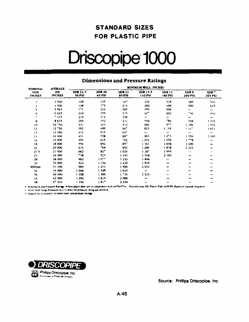
STANDARD SIZES
FOR PLASTIC PIPE
Driscopipe'1000Dimensions and Pressure Ratings
SOMINAL AVERAGE MI~rMUM WALL. INCHES
SIZE 00 SOil ~1.S SOil ~6 SOil 21 SOil I S.S SOR II SOR9 SOR '"INCHES INCHES SO PSI 6S PSI SO PSI IIOPSI 160 PSI 200 PSI 2M PSI
3 ~oo 108 IB 16- 226 .\18 389 ~oo
~ ~ 500 138 1-3 21~ 290 ~09 ~oo 6~3
~ SSM '-I 21~ 2M ~S9 S066 6625 2~0 ~5S 315 ~r 602 -~6 '1~6
- 125 219 r .. B9!l 86lS 2M B2 ~ II SS6 -84 9"8 I !H
10 10 -50 BI 413 512 694 9-- I 194 I ~~6
12 12 -50 392 ~90 6()- 823 I 1S9 1 ~ I- I Hli
13 \ ~ 386 411 SIS 63-
I~ .4000 431 "38 06- 903 lr3 1 ""6 11)00
16 16000 ..92 61S -62 I 032 I iSS I --8
IS 18000 SS" 692 SS" 1 161 1 636 2 00020 20000 61S '"69 9S2 1290 1818 2 H221 S 21 SOO 662 82'" 1024 I J8'" 19""H 24 000 '"38 9!3 llH I S48 2 18228 28000 862 10-- I H3 1806W .30000 923 I 154 I 429 19B
800mm 31496 969 I 211 I SOO 20323-1 3i 000 10..6 1 30" 1619~6 36000 I 108 I 38" I -14 2313H "2000 I 292 , 61" 200048 .... 244 14'14 181'" 2HO
• DlmrntWn In'll Pfnl"r~ " ....... ' "'M1'~ Ipphcabl.. an '" ('omphancr ..nh ASTM , ..... 'Olyflhylnw "£1 "UII( '1~'SD.·'.II_don OUIIICI< Doomt'tr
• 'hon Ttrm \urRf 'r""urn to 1 ~ umn tM pt'C'MUfC' nuna lilt aUowrd• Inqulrt tor a\ allabll"\ ot OIMr ,lift and pt'f'IWn rII...
Source: Phnllpi Drtscoplpe, Inc.
A-46
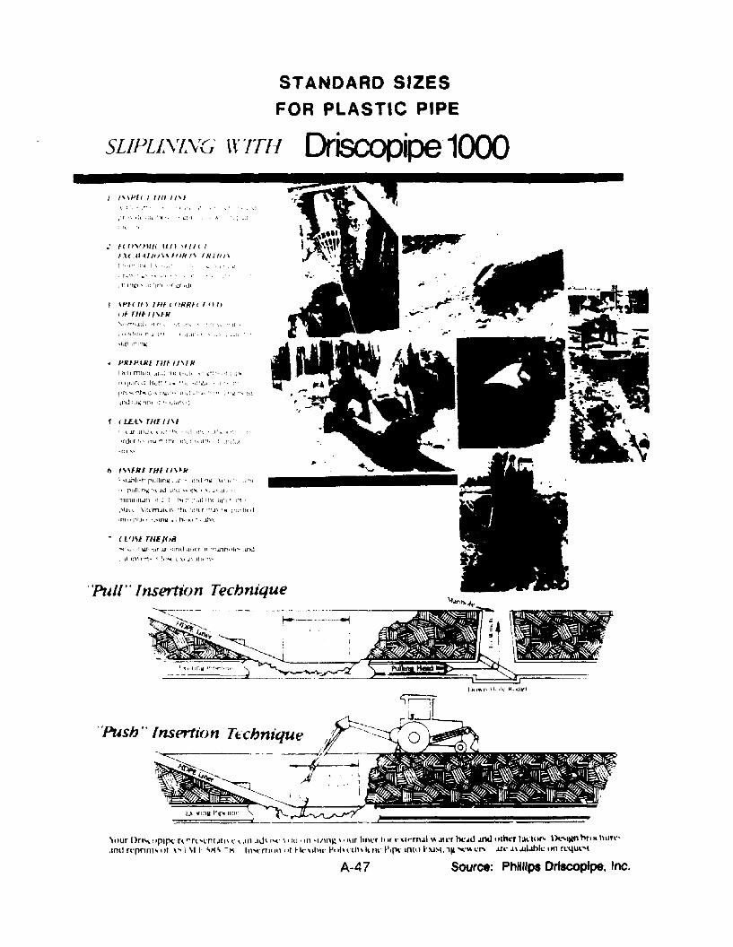
STANDARD SIZES
FOR PLASTIC PIPE
- (I flU TlIEJ{)iJ
l :1 J.f .IP,J ~ ,-.lp 'II( Id 11\', •. t'" 1 ,,,
'rlkr 1,' :n .... f1 :~11 I!ll, r ;\ 11:1" .!",\;,.(
"'I
'\. <,rr' lJ ((" ~! (~ <
• Hhl'll- 'f' j
• 'it ' ·.~:·l
jr',I"::I,I\
·Irl\\:"o,;'
, T1.lJllr.:l' !I~ 'lilt 'r,:,r!tll
1\1/'1' / 1/" 1/\1\ I
IPH If I /111' flRRI' I fI f)
flI rlfl / "IR
I h'll nl1011, .tl:d 'lit L~t.rlt ·i~·:·" 'i' ;i"-
flqtdr,d Ih,l1 ·~I"" "11 "!'\lJl "I",
1"':n........ :;t1l( ,: i\ n"'::l ~" ~r:\ ~ .' '..I' '~ 'i",,: ',\..:. "\ ,d
IIld !.lw, 'jJlt ,1 r~\j\W\'1
...... 1; ,r~, ·... T lI' 'til".! dl'l'[ .I( rll,JJ1r,. >i~'" ,u,J
jf In\t-n .. ( I. ''''l. ,\, J\ .ltl' -q ..
• PRIPVU 11/1 JI"R
I> IHfRl THfl"'R\"'I.iMh ... h rl,iJH'~ .It-· n'd '-II.!. \n.j,' 1:'lt
!., rullln'llt t't .Ill UhJ '10 'f"" \ \, J\ ,j!" ·f'
'lllflHIHifTl II ~ i :Ilt:· ;'l,i: :tll dIll' ;'f,'
l'IJ.. , \!I,'m..iILil ,tll 'llltr "1J\ ' .... l'w.f)td
1m, ,pIJI t \.,mw, J, ,tl' ''''1 r ..l.hh
: HfI'fll//< IJlI "II' I1 \(II~/lI)\1 ffiR /\ fH/II'\
SLIPLL\ZVG \\' lTI-f
"Pull" Insertion Tecbnique
",ur Dn'l' 'pipe: n'''n 'l'ntJII\ l' l JI1 ,Ill- .-c' \, ". "11 '1IIn" \, IlIr hnl'r "'r c',wmal '" alt'r h<:ad Jnd "Ilkr tal'IlI'" \).....llln hr... hUfl~',mlJ rt'pnnt' ,,' '''I \1 I, '\/'1'\ -/'I In'l'nHlIl \1' H.-"bk PIII"',I1l 1",1<' P,p<' 1010 hu~I, 114 .... '" 0;'" .Lro; JI .ulahlo; lin rl:4Ul"l
A-47 Source: PhHIIPI Drtscoplpe, Inc.
SECTION
8-1
APPENDIX B. REPAIR AND RETROFIT PROCEDURES
TITLE
Procedure for Debris Removal .
PAGE
8-1
8-2
8-3
8-4
8-5
8-6
B-7
Procedures for Sediment Removal . . . . . . . . . . . . . . . . . . " 8-3
Procedures for Thawing Frozen Culverts 8-5
Procedure for Cleaning and Repairinglined Ditches B-10
Procedure for Mechanical Cleaning andRepair of Unlined Ditches 8-13
Procedures for Vegetative StreambankStabilization " . . . . . . . . . . . . . . . . . . . . . . . . . . .. .... 8-17
Procedures for Selection and Use ofErosion Control Geotextiles . . . . . . . . . . . . . . . . . . . . . . .. 8-25
8-'3 Procedures for Use of LoffelsteinBlock to Prevent Streambank Erosion 8-35
8-9
8-10
B-11
B-12
8-13
8-14
8-15
Procedures for Assembling and InstallingGabions 8-39
Procedures for Repair of TimberStructures 8-49
Procedures for Shotcrete/Gunite Paving,lining. and Repair B-52
Procedures for Stormwater ConveyanceChannels (DitchesJ . . . . . . . . . . . . . . . . . . • . . . . . . . . • .. 8-58
Procedures for Installing Riprap . . . . . . . . . . . . . . . . . . . .. 8-63
Procedure for Repair and Replacementof Apron/Cutoff Wall. . . . . . . . . . . . . . . . . . . . . . . . . . . .. 8-68
Procedures for Streambed Paving . . . . . . . . . . . . . . . . . .. 8-70
B-1
B-16
B-17
8-18
B-19
8-20
B-21
8-22
B-23
B-24
B-25
B-26
B-27
8-28
B-29
B-30
8-31
B-32
8-33
Procedure for Replacement of ConcreteWingwalls and Endwalls 8-72
Procedure for Repair of Basically SoundEndwalls and Wingwalls 8-74
Procedure for Repairing Severely Deterioratedor Collapsed Wingwalls and Endwalls 8-77
Procedure for Concrete Jacket Repairs forEndwalls and Wingwalls 8-81
Procedures for Underpinning . . . . . . . . . . . . . . . . . . . . . .. 8-83
Procedure for Repointing Ma:50nry . . . . . . . . . . . . . . . . . .. 8-87
Procedure for Installing Safety End Treatments . . . . . . . . .. 8-90
Procedures for Facilitating Fish Passage B-95
Procedures for Installing Beaver Control Devices B-101
Procedures for Repairing Cracks in Concrete . . . . . . . . .. B-106
Pmcedures for Sealing Culvert Joints . . . . . . . . . . . . . . .. 8-111
Procedures for Preventing End Section Dropoffof Precast Concrete Culverts . . . . . . . . . . . . . . . . . . . . .. 8-116
Procedures for Patching Concrete 8-121
Procedure for Invert Paving . . . . . . . . . . . . . . . . . . . . . .. 8-123
Procedures for Grouting 'Joids 8ehindand Under Culverts 8-135
Procedures for Cathodically ProtectingMetal Culverts 8-138
Procedures for Steel Armor Plating andReinforcing Invert'S . . . . . . . . . . . . . . . . . . . . . . . . . . . .. 8-142
Procedures for Measuring and EvaluatingCulvert Distortion > • • • • • •• B- ~ 48
B-II
8-34
8-35
8-37
8-38
8-39
8-40
8-41
8-42
Procedurer-; for Repair at a DistortedSection , . . . . . . . . . . . . . . . . . . . . . . . . . . . .. 8-152
Procedures for Timber Bracing of Culvert~, . . . . . . . . . . .. 8-160
Procedures for Rerounding/Reshaping CorrugatedMetal Culverts 8-162
Procedures for Repairing and StrengtheningCrowns of Culverts . . . . . . . . . . . . . . . . . . . . . . . . . . . .. B-165
Procedures for Repairing Corrugated MetalStructural Plate Seams 8-167
Procedures for Sliplining Culverts . . . . . . , . . . . . . . . . . ., 8-174
Procedures for Grouting Sliplined Culverts 8-186
Procedures for Repair of Masonry Walls . . . . . . . . . . . . .. 8-192
Procedures for .Jacking Concrete Pipe . . . . . . . . . . . . . .. 8-194
B-III
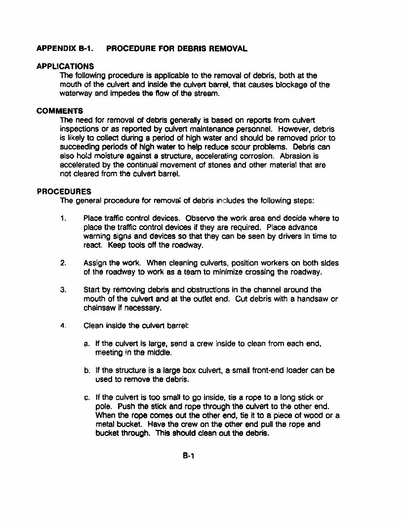
APPENDIX B·1. PROCEDURE FOR DEBRIS REMOVAL
APPLICATIONSThe following procedure is applicable to the removal of debris, both at themouth of the culvert and inside the culvert barrel, that causes blockage of thewaterway and impedes the flow of the stream.
COMMENTSThe need for removal of debris generally is based on reports from culvertinspections or as reported by culvert maintenance personnel. However, debrisis likely to collect during a period of high water and should be removed prior tosucceeding periods of high water to help reduce scour problems. Debris canalso hold moisture against a structure, accelerating corrosion. Abrasion isaccelerated by the continual movement of stones and other material that arenot cleared from the culvert barrel.
PROCEDURESThe general procedure for remova; of debris includes the following steps:
1. Place traffic control devices. Observe the work area and decide where toplace the traffic control devices if they are required. Place advancewarning signd and devices so that they can be seen by drivers in time toreact. Keep tools off the roadway.
2. Assign the work. When cleaning culverts, position workers on both sidesof the roadway to work as a team to minimize crossing the roadway.
3. Start by removing debris and obstructions in the channel around themouth of the culvert and at the outlet end. Cut debris with a handsaw orchainsaw if necessary.
4. Clean inside the culvert barrel:
a. If the culvert is large, send a crew inside to clean from each end,meeting in the middle.
b. If the structure is a large box culvert, a small front-end loader can beused to remove the debris.
c. If the culvert is too small to go inside, tie a rope to a long stick orpole. Push the stick and rope through the culvert to the other end.When the rope comes out the other end, tie it to a piece of wood or ametal bucket. Have the crew on the other end pull the rope andbucket through. This should clean out the debris.
B-1
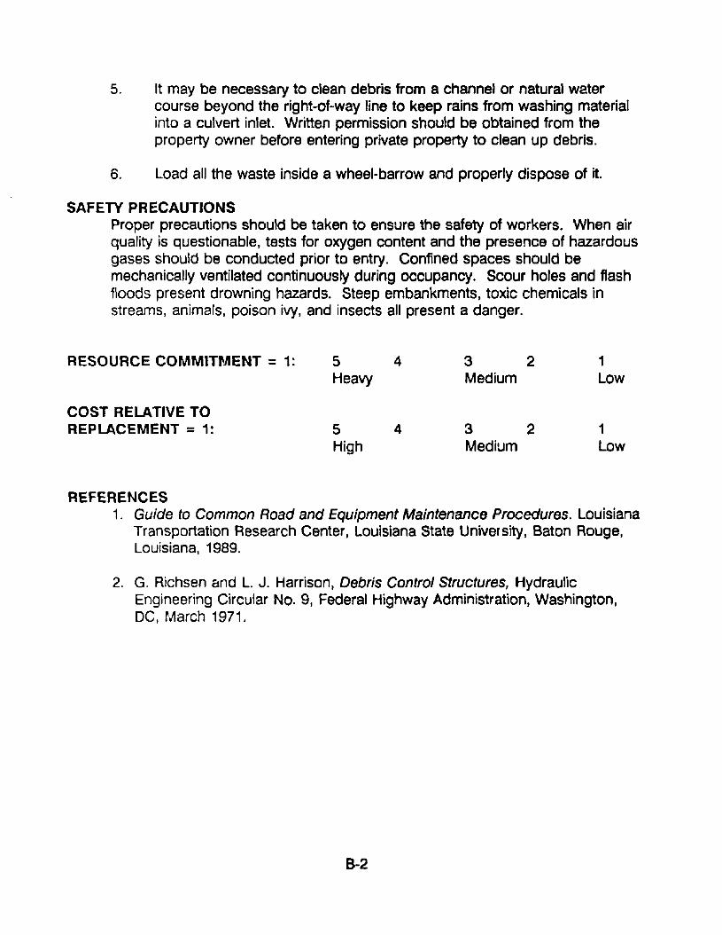
5. It may be necessary to clean debris from a channel or natural watercourse beyond the right-of-way line to keep rains from washing materialinto a culvert inlet. Written permission should be obtained from theproperty owner before entering private property to clean up debris.
6. Load all the waste inside a wheel-barrow and properly dispose of it.
SAFETY PRECAUTIONSProper precautions should be taken to ensure the safety of workers. When airquality is questionable, tests for oxygen content and the presence of hazardousgases should be conducted prior to entry. Confined spaces should bemechanically ventilated continuously during occupancy. Scour holes and flashfloods present drowning hazards. Steep embankments, toxic chemicals instreams, animals, poison ivy, and insects all present a danger.
RESOURCE COMMITMENT = 1: 5 4 3 2 1Heavy Medium Low
COST RELATIVE TOREPLACEMENT = 1: 5 4 3 2 1
High Medium Low
REFERENCES1. Guide to Common Road and Equipment Maintenance Procedures. Louisiana
Transportation Research Center, Louisiana State University, Baton Rouge,Louisiana, 1989.
2. G. Richsen and L. J. Harrison, Debris Control Structures, HydraulicEngineering Circular No.9, Federal Highway Administration, Washington,DC, March 1971.
B-2
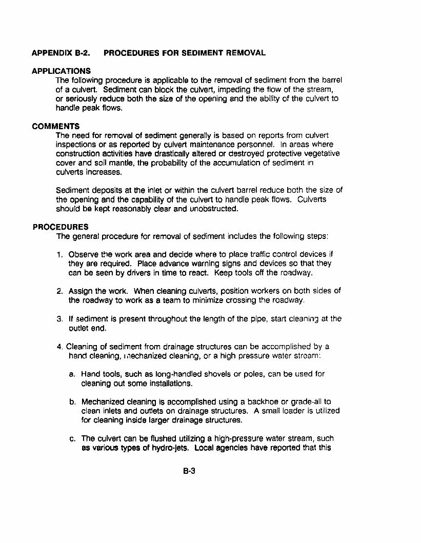
APPENDIX B·2. PROCEDURES FOR SEDIMENT REMOVAL
APPLICATIONSThe following procedure is applicable to the removal of sediment from the barrelof a culvert. Sediment can block the culvert, impeding the flow of the stream,or seriously reduce both the size of the opening and the ability of the culvert tohandle peak flows.
COMMENTSThe need for removal of sediment generally is based on reports from culvertinspections or as reported by culvert maintenance personnel. In areas whereconstruction activities have drastically altered or destroyed protective vegetativecover and soil mantle, the probability of the accumulation of sediment inculverts increases.
Sediment deposits at the inlet or within the culvert barrel reduce both the size ofthe opening and the capability of the culvert to handle peak flows. Culvertsshould be kept reasonably clear and unobstructed.
PROCEDURESThe general procedure for removal of sediment includes the following steps:
1. Observe t!1e work area and decide where to place traffic control devices ifthey are required. Place advance warning signs and devices so that theycan be seen by drivers in time to react. Keep tools off the r08dway.
2. Assign the work. When cleaning culverts, position workers on both sides ofthe roadway to work as a team to minimize crossing the roadway.
3. If sediment is present throughout the length of the pipe, start cleaning at theoutlet end.
4. Cleaning of sediment from drainage structures can be accomplished by ahand cleaning, 1,1echanized cleaning, or a high pressure water stream:
a. Hand tools, such as long-handled shovels or poles, can be used forcleaning out some installations.
b. Mechanized cleaning is accomplished using a backhoe or grade-all toclean inlets and outlets on drainage structures. A small loader is utilizedfor cleaning inside larger drainage structures.
c. The culvert can be flushed utilizing a high-pressure water stream, suchas various types of hydro-jets. Local agencies have reported that this
B-3
system has increased their production significantly. Occasionally, whenthis piece of equipment is not available to an agency, the fire departmentis requested to flush out a blockage in the culvert. It is possible that alocal agency can rent such a unit or share equipment with anotherjurisdiction on a once- or twice-a-year basis when this work is done.
Adequate measures shourd be taken to protect the drainageway andprevent stream siltation or increased turbidity when culverts arahydraulicarly cleaned.
SAFETY PRECAUTIONSProper precautions should be taken to ensure the safety of workers. When airquality is questionable, tests for oxygen content and the presence of hazardousgases should be conducted prior to entry. Confined spaces should bemechanically ventilated continuously during occupancy. S~our holes and flashfloods present drowning hazards. Steep embankment~, toxic chemicals instreams, animals, poison ivy, and insects all present a danger.
RESOURCE COMMITMENT =1: 5 4 3 2 1Heavy Medium Low
COST RELATIVE TOREPLACEMENT =1: 5 4 3 2 1
High Medium Low
8-4
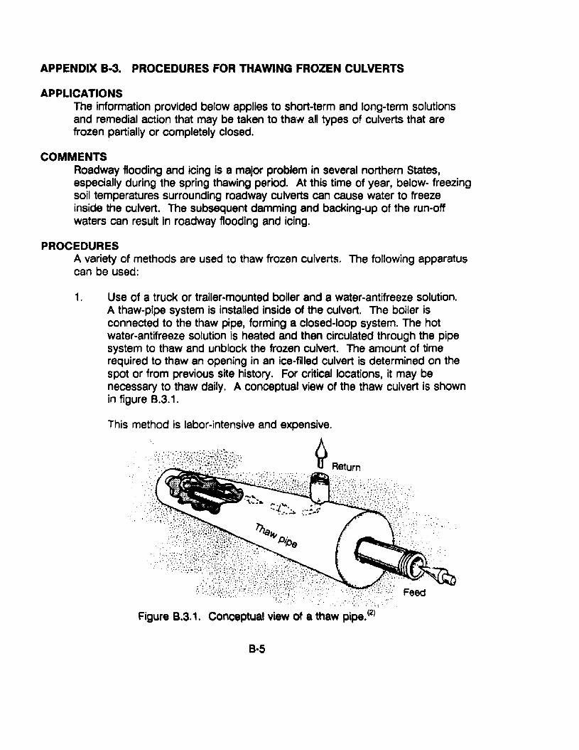
APPENDIX B·3. PROCEDURES FOR THAWING FROZEN CULVERTS
APPLICATIONSThe information provided below applies to short-term and long-term solutionsand remedial action that may be taken to thaw all types of culverts that arefrozen partially or completely closed.
COMMENTSRoadway flooding and icing is a major problem in several northern States,especially during the spring thawing period. At this time of year, below- freezingsoil temperatures surrounding roadway culverts can cause water to freezeinside the culvert. The subsequent damming and backing-up of the run-offwaters can result in roadway flooding and icing.
PROCEDURESA variety of methods are used to thaw frozen culverts. The following apparatuscan be used:
1. Use of a truck or trailer-mounted boiler and a water-antifreeze solution.A thaw-pipe system is installed inside of the culvert. The boiler isconnected to the thaw pipe, forming a closed-loop system. The hotwater-antifreeze solution is heated and then circulated through the pipesystem to thaw and unblock the frozen culvert. The amount of timerequired to thaw an opening in an ice-filled culvert is determined on thespot or from previous site history. For critical locations, it may benecessary to thaw daily. A conceptual view of the thaw culvert is shownin figure B.3.1.
This method is labor-intensive and expensive.
~ Return
."..... , ..',. ".
" "
Figure 8.3.1. Conceptual view of a thaw pipe.(2)
B-5
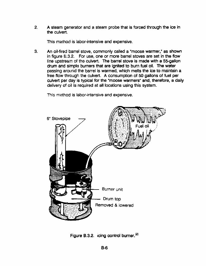
2. A steam generator and a steam probe that is forced through the ice inthe culvert.
This method is labor-intensive and expensive.
3. An oil-fired barrel stove, commonly called a "moose warmer," as shownin figure 8.3.2. For use, one or more barrel stoves are set in the flowline upstream of the culvert. The barrel stove is made with a 55-gallondrum and simpll3 burners that are ignited to burn fuel oil. The waterpassing around the barrel is warmed, which melts the ice to maintain afree flow through the culvert. A consumption of 50 gallons of fuel perculvert per day is typical for the "moose warmers" and, therefore, a dailydelivery of oil is required at all locations using this system.
This method is labor-intensive and expensive.
6" Stovepipe
Burner unit
Drum top
Removed & lowered
Figure 8.3.2. icing control burner. (2)
8-8
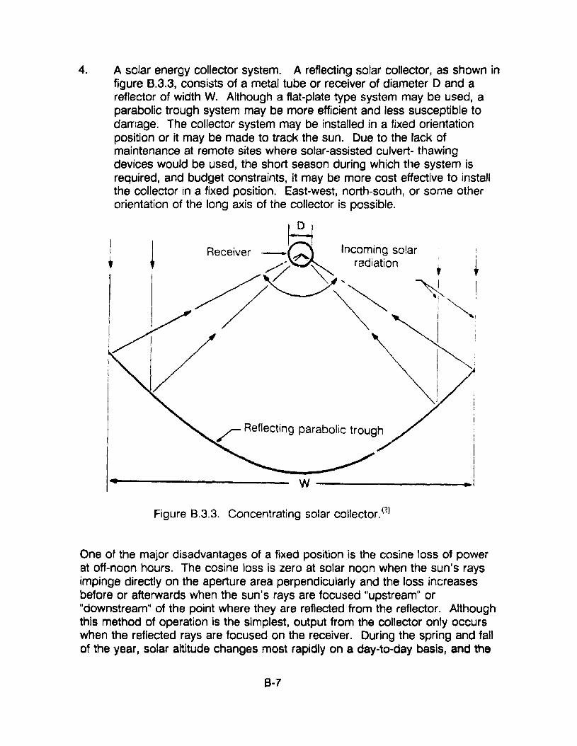
4. A solar energy collector system. A reflecting solar collector, as shown infigure B.3.3, consists of a metal tube or receiver of diameter D and areflector of width W. Although a flat-plate type system may be used, aparabolic trough system may be more efficient and less susceptible todamage. The collector system may be installed in a fixed orientationposition or it may be made to track the sun. Due to the lack ofmaintenance at remote sites where solar-assisted culvert- thawingdevices would be used, the short season during which the system isrequired, and budget constraints, it may be more cost effective to installthe collector in a fixed position. East-west, north-south, or some otherorientation of the long axis of the collector is possible.
~Receiver _~ Incom.in~ solar i
~~ radiatIon , t
~'CY~ T~!'\ I I
, I
~!// Reflecting parabolic trougy I
!I
W .1
Figure 8.3.3. Concentrating solar collector. (2)
One of the major disadvantages of a fixed position is the cosine loss of powerat off-noon hours. The cosine loss is zero at solar noon when the sun's raysimpinge directly on the aperture area perpendicularly and the loss increasesbefore or afterwards when the sun's rays are focused "upstream" or"downstream" of the point where they are reflected from the reflector. Althoughthis method of operation is the simplest, output from the collector only occurswhen the reflected rays are focused on the receiver. During the spring and fallof the year, solar altitude changes most rapidly on a day-ta-day basis, and the
B-7
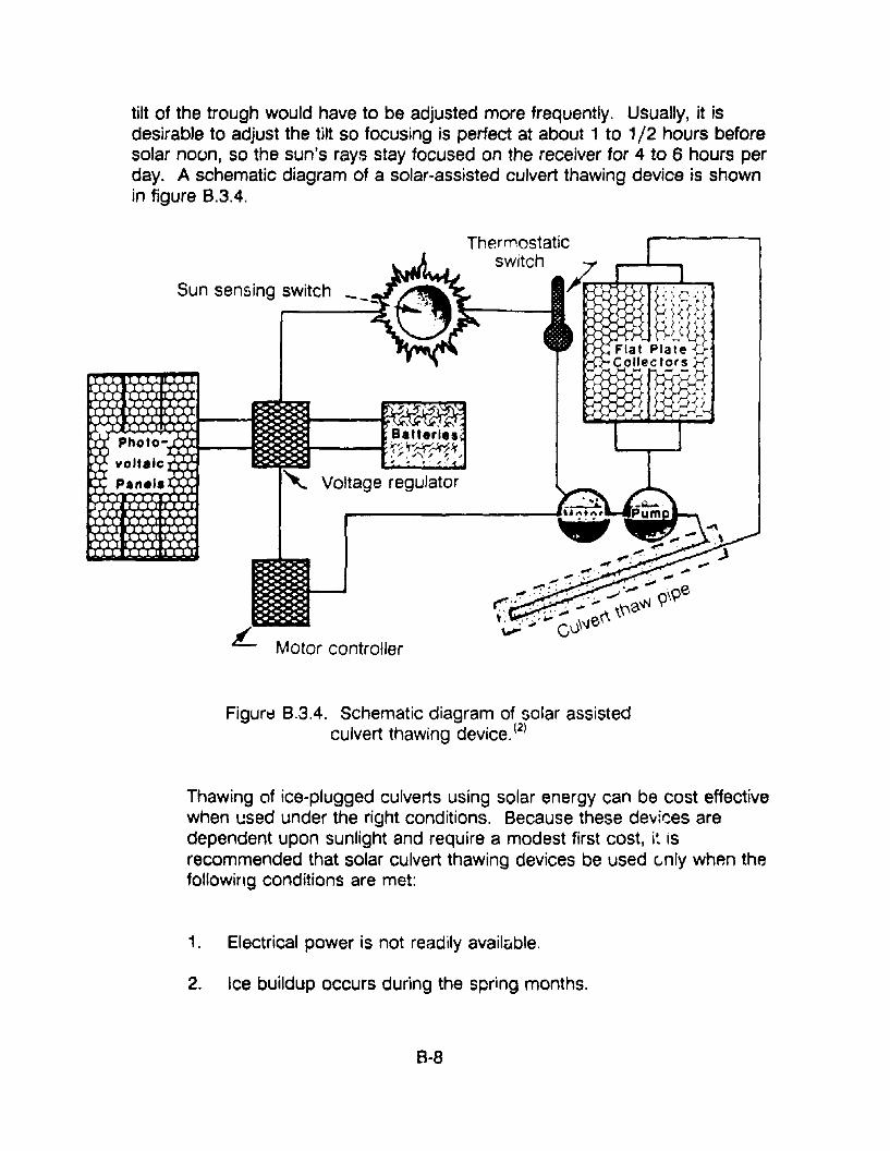
tilt of the trough would have to be adjusted more frequently. Usually, it isdesirable to adjust the tilt so focusing is perfect at about 1 to 1/2 hours beforesolar noon, so the sun's rays stay focused on the receiver for 4 to 6 hours perday. A schematic diagram of a solar-assisted culvert thawing device is shownin figure 8.3.4.
Sun sensing switch
Batteries·~"(::f;~>r,, I ~ ,/
'" Voltage regulator
£... Motor controller
Figurt:l 8.3.4. Schematic diagram of solar assistedculvert thawing device. (2
)
Thawing of ice-plugged culverts using solar energy can be cost effectivewhen used under the right conditions. Because these devices aredependent upon sunlight and require a modest first cost, i~ isrecommended that solar culvert thawing devices be used c.nly whp.n thefollowing conditions are met:
1. Electrical power is not readily available.
2. Ice buildup occurs during the spring months.
8-8
3. Repeated thawing of the culvert is required.
4. The horizon is sufficiently low to allow exposure to sunlight.
SAFETY PRECAUTIONSThe potential of problems and injury relating to the process of thawingfrozen culverts should be recognized and avoided. Improper use and/oraccidents with high-pressure hot antifreeze-water solutions and fuel-oilfired heating systems can cause serious injury.
RESOURCE COMMITMENT =*: 5 4 3 2 1Heavy Medium Low
COST RELATIVE TOREPLACEMENT = *: 5 4 3 2 1
High Medium Low
*Varies according to procedure selected.
REFERENCES1. John P. Zarling and Fred A. Miller, Solar Assisted Thawing Device - Phase
I, UniversIty of Alaska, Fairbanks, Alaska, November 1981.
2. John P. Zarling and Douglas H. Murray, Solar Assisted Thawing Device Phase II, Alaska DOT Report AK-RD-83-36, University of Fairbanks,Al3ska, May 1983.
8-9
APPENDIX 8-4. PROCEDURE FOR CLEANING AND REPAIRINGLINED DITCHES
APPLICATIONSThis procedure applies to the cleaning of lined ditches.
COMMENTSWater creates many serious problems for all types of roads. Water that doesnot drain properly from paved roads will accumulate in the base and subgrade.This accumulation weakens the base and causes critical surface defects suchas potholes and area cracKing. Such surface defects, in turn, cause furtherdeterioration of the road and can create safety hazards for traffic. Poor surfacedrainage on unpaved roads can cause potholes, soft spots, ruts, andcorrugations. '!'Jater saturation can even weaken the adjacent embankment.Clogged drainage structures contribute to water saturation problems. Regularditch maintenance will help prevent these problems and more expensive roadrepairs.
The best time to inspect ditches is before and after the rainy season. Examineditches before the rainy season to make sure they are in good condition andthat water will be able to flow freely through them, Examine ditches after therainy season in order to schedUle cleaning to remove accumulated sedimentand debris.
The equipment needed to perform this maintenance function includes a dumptruck to haul the hand tools and crew t~ the work site. Hand tools neededinclude rakes, hoes, shovels, J:'ick axes, grass-cutting tools, a stringline, rope,bucket, a pole, a hand tamper, paint, and a wheelbarrow.
Cleaning lined ditches by hand is the best method because it will not damagethe ditch lining. Hand cleaning is easy to schedule and perform because nomaterial or heavy equipment is required. Cleaning drainage structures by handalso allows time to completely inspect the area for damage and possible tutureprub,!ems. A gradall may be required where the amount of sediment isexcessive.
PROCEDURESSeveral iactors contribute to correctly performed, long-Iastirlg maintenancework. They are prv;:,~r planning by a supervisor, proper on-site supervision,and use of a skilled, conscientious work crew. Unless all of these factors areconsidt'red, the worh may be poorly done and will probably have to berepeated.
8-10

The following :'1formation covers each work step in detail. Equipment and handtools also will be (;~·:~red.
1. Place traffic control devices if required. The goal is to keep thedisruption of traffic flow to a minimum while furnishing the maximumsafety for the crew and the motoring public. Place advance warningsigns and traffic control devices. Position f1aggers at appropriatepositions if required. Keep tools off the roadway.
2. Assign the work. Distribute the work in a way that will reduce the need tocross the road. Instruct the crew to move forward as a unit with eachworker cleaning the area in front of him.
3. Remove and dispos~ of all debris and obstructions, working fromdownstream up. Use shovels to move rocks, trash, and earth to theshoulder of the road. Load the waste material into a wheel barrow. Donot leave it near any drainage structure. Keep the roadway shouldersclean. If waste material cannot be disposed of nearby, load it onto adump truck and carry it to a predetermined disposal site.
When working on masonry or stonelined ditches, remove all vegetationsuch as grass, plants, and shrubs. Their roots can break up the ditchlining and block the flow of water.
4. Inspect for damage. Check the flow to see that there are no high or lowspots. Check the ditch lining to see if there are any broken pieces ofconcrete or missing sections of masonry. If a rTl13j0r defect is locatedthat cannot be repaired by the crew, mark the spot so that it is visiblefrom the road. Use paint. Report the defect to the supervisor so thatrepairs can be scheduled.
5. Make minor repairs. Replace and compact backfill behind lined ditches ifit is eroded.
6. Clean thp work site. Rem()ve all waste material from the shoulders.Inspect, clean, and load all hand tools. Remove traffic control devices byloading them in reverse order of their placement.
SAFETY PRECAUTIONSAs with all maintenance operations, safety is of prime importance. Theappropriate personai protection equipment and/or clothing should be worn orused. This would include a hard hat, gloves, heavy high-top shoes or workbeots, and a safety vest.
8-11
RESOURCE COMMITMENT =1: 5 4 3 2 1Heavy Medium Low
COST RELATIVE TOREPLACEMENT = 1: 5 4 3 2 1
High Medium Low
REFERENCES1. Guide to Common Road and Equipment Maintenance Procedures,
Louisiana Transportation Research Center, Louisiana State UniversityBaton Rouge, Louisiana, 1989.
8-12
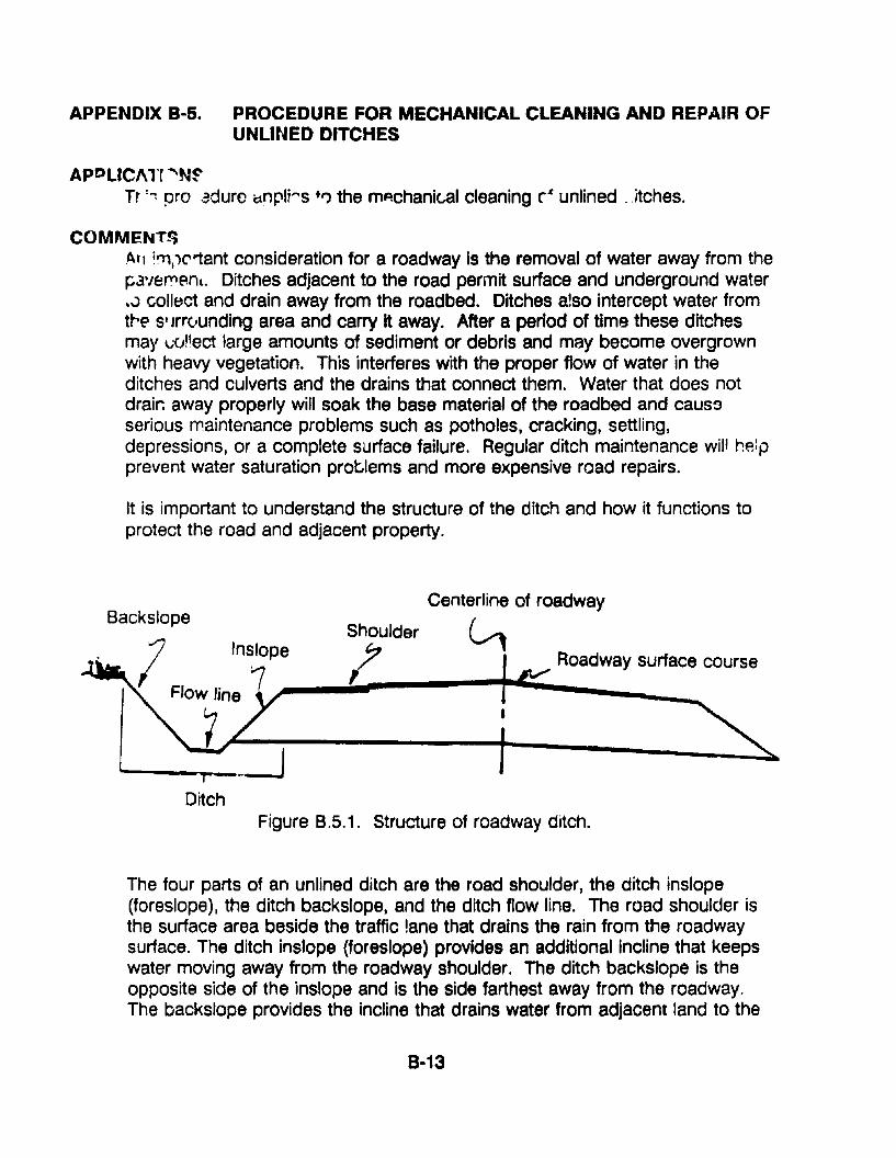
APPENDIX B-5. PROCEDURE FOR MECHANICAL CLEANING AND REPAIR OFUNLINED DITCHES
ApPLlCJ\l'r ....N~Tr '~ pro .3durc Cinpli"s +1') the m~chani(,al cleaning c· unlined ,.Jtches.
COMMEt-4l'!;Atl ;"'.1('1:ant consideration for a roadway is the removal of water away from thepa',ernenL. Ditches adjacent to the road permit surface and underground water•.:> collect and drain away from the roadbed. Ditches also intercept water fromtrea S' Jrrvunding area and carry it away. After a period of time these ditchesmay lJCJ!'ect large amounts of sediment or debris and may become overgrownwith heavy vegetation. This interferes with the proper flow of water in theditches and culverts and the drains that connect them. Water that does notdrair. away properly will soak the base material of the roadbed and caussserious maintenance problems such as potholes, cracking, settling,depressions, or a complete surface failure. Regular ditch maintenance will helpprevent water saturation problems and more expensive road repairs.
It is important to understand the structure of the ditch and how it functions toprotect the road and adjacent property.
Centerline of roadwayBackslope ( _
Shoulder '-'1I Inslope ; Roadway surface course
Flow line ~--"~----"'I""-----.....__{
DitchFigure B.5.1. Structure of roadway ditch.
The four parts of an unlined ditch are the road shoulder, the ditch inslope(foreslope), the ditch backslope. and the ditch flow line. The road shoulder isthe surface area beside the traffic lane that drains the rain from the roadwaysurface. The ditch inslope (foreslope) provides an additional incline that keepswater moving away from the roadway shoulder. The ditch backslope is theopposite side of the inslope and is the side farthest away from the roadway.The backslope provides the incline that drains water from adjacent land to the
8-13
bottom of the ditch. The bottom of the ditch is called the ditch flow line. Theflow line allows water deposited in the ditch to flow smoothly along the ditch tooutlets. All four parts of a ditch work together to drain water away from theroadway.
Mechanical ditch cleaning can be done with a motor grader or a machineshovel. The type of equipment used depends on the condition of the ditch andthe availability of the equipment.
Use a motor grader If the following conditions are met:
The ground adjacent to the ditch is solid enough to support heavyequipment.
The ditch inslope and backslope are sloped gradually enough to allowthe motor grader easy access.
The ditch is long.
The ditch is not interrupted by drain pipes or culverts.
Use a machine shovel if the following conditions are met:
If there is excessive water causing the slopes to be too soft to supportheavy equipment.
If the inslope and backslope are too steep for easy access.
When tile ditch is frequently interrupted by drain pipes or culverts.
PROCEDURESPlan the job well in advance. Make a thorough visual inspection of the worksite. Determine if the ground is firm enough to support heavy equipment.Decide what the grade of the inslope and backslope should be. Locate c'J'vertspipes and outfall ditches.
Consider the type and capability of the equipment. Cleaning procedures mayv~ry according to equipment capabilities.
D.-:cide how and where to dispose of the material that will be removed from theditch. If the waste material is spread on the adjacent right-ot-way, it should beplaced beyo~d the beginning of the backslope to avoid being washed back intothe ditch.
B-14
The following are general guidelines for the mechanical cleaning of unlinedditches:
1. Place traffic control devices to keep the disruption of the traffic flow to aminimum while furnishing maximum safety for the crew and the motoringpublic. Place advance warning signs and traffic control devices. Positionflaggers at appropriate positions if circumstances require.
2. Clean the ditch, working from downstream up.
If using a motor grader:
a. Make a preliminary pass with the motor grader to clear outvegetation.
b. Clean the inslope. Position the motor grader blade so that itsedge touches the bottom of the ditch at the flow line. Be sure theblade is set to the proper predetermined grade. Move forward tocut along the flow line to remove mud, silt, and other accumulateddebris from the bottom of the ditch.
c. Clean the backslope. Position the motor grader over the inslopewith the opposite edge of the blade now touching the ditchbottom. This cut redefines the ditch shape on the backslope sideand establishes the flow line at the bottom of the ditch.
If using a machine shovel:
a. Be sure the excavator is on firm ground before reaching down intothe ditch to remove debris.
b. Load excess material directly into a dump truck.
c. Take care in reestablishing the ditch flow line.
3. Clean the adjacent culvert inlets, outlets, and outfall ditches. Clean byhand. Cut down the heavy vegetation and plant growth. Shovel th~accumulated debris away from the ditch, making sure the material willnot wash back in. Clean all the outfall ditches that connect to the mainditch. Clean culverts or pipes that drain water from the main ditch.
Clear all pipe openings but maintain the proper contour and shape of theditch at culvert inlets and outlets, as well as the proper flow path.
8-15
4. Properly dispose of unwanted material.
5. Clean the work site and the road surface of unwanted material.
6. Inspect the finished job. Check the ditch flow line. Be sure the flow lineis uniform with no low or high spots. Check the ditch contour for smoothslopes and unobstructed outfall ditches, culverts, and pipes.
7. Remove the equipment from the work site.
SAFETY PRECAUTIONSAs with all maintenance operations, safety is of prime importance. Theappropriate personal protection equipme:1t and/or clothing should be worn orused. This would include a hard hat, gloves, heavy high-top shoes or workboots, and a safety vest.
RESOURCE COMMITMENT = 1:
COST RELATIVE TOREPLACEMENT = 1:
5 4Heavy
5 4High
3 2Medium
3 2Medium
1Low
1Low
REFERENCES1. Guide to Common Road and EqUipment Maintenance Procedures,
Louisiana Transportation Research Center, Louisiana State University,Baton Rouge, Louisiana, 1989.
8-16
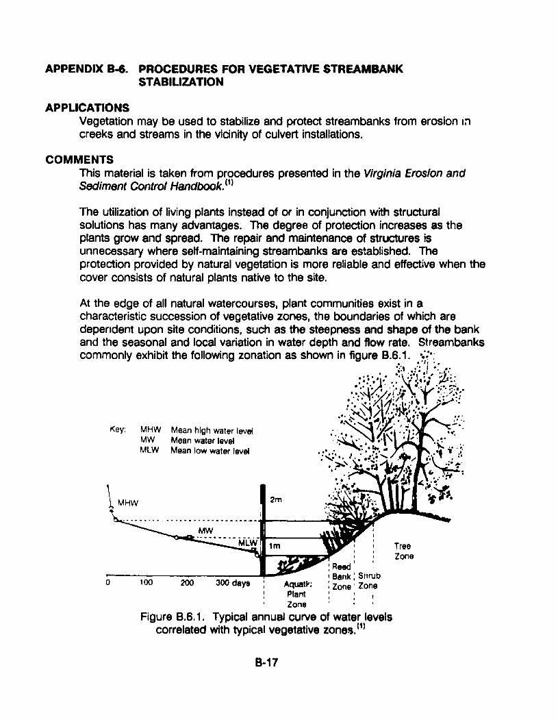
APPENDIX 8-6. PROCEDURES FOR VEGETATIVE STREAM8ANKSTABILIZATION
APPLICATIONSVegetation may be used to stabilize and protect streambanks from erosion increeks and streams in the vicinity of culvert installations.
COMMENTSThis material is taken from procedures presented in the Virginia Erosion andSediment Control Handbook. (1)
The utilization of living plants instead of or in conjunction with structuralsolutions has many advantages. The degree of protection increases as theplants grow and spread. The repair and maintenance of structures isunnecessary where self-maintaining streambanks are established. Theprotection provided by natural vegetation is more reliable and effective when thecover consists of natural plants native to the site.
TreeZone
2m
..•.• -- .• MClii 1m
200
III
I Reed I
; Bank; StmJb300 days : Aquatl'; : Zone' Zone
: p~~: t
, Zone' I
Figure 8.6.1. Typical annual curve of water levelscorrelated with typical vegetative zones. (1)
100
MHW Mean high water levelMW Mean water levelMLW Mean low water level
Key:
_, .z--~
o
At the edge of all natural watercourses, plant communities exist in acharacteristic succession of vegetative zones, the boundaries of which aredependent upon site conditions, such as the steepness and shape of the bankand the seasonal and local variation in water depth and flow rate. Streambankscommonly exhibit the following zonation as shown in figure 8.6.1. .::.:
• • ., I '.-to, ,'. I .. ..• .-' ,-••• , ;h'o•.. ~... ·X~\" ~ ;..' :....] .. ",'. :-~...... ;~
o ·.~~'~/il··l 'r :~.:;;::~.•:' :ti'XI~;I1;~~l~';\. ..;~::.. \ 1 \ ·l4 ~I ••
"."~'/%"'" ,~;.; . ....,.~...'i... " .. :':;'... '. .~ ..' : ,~
."~\". ..\, .,. .t~··.,.~..... ....... ....
••::.;..~. '. I . •:.;,.:;.~... ,; •.•.~.·f~.:~· ~'. • 'r.~ . .;--:.• ' • • • .)\" f ~... . ,1f····f"::,...," :;l ~"-1~~•••• to ..
to .; I, ~ ....
"0" II}"'" -.'.:.: ~,,'...............~
... _--_ .... _--_ ..._-~---------~~
8-17
1. Aquatic plant zone - This zone is permanently sUbmerged. The roots ofplants, such as water lilies, reduce the water's flow rate by friction andhelp bind the soil. These plants further protect the channel from erosionbecause the water flow tends to flatten them against the banks and bedof the stream.
2. Reed-bank zone - The lower part of this zone is normally submergedabout half the year. Plants, such as rushes, cattails, and reed grasses,grow in this area. Their roots bind the soil and the growth slows the flowrate of the water by friction.
3. Shrub zone - This zone is flooded only during periods of high water. It isinhabited by trees and shrubs with a high regenerative capacity. Theseplants also hold the soil with their roots ar Id slow the water by friction.The shrubs protect tree trunks from damage caused by breaking ice andhelp to prevent the formation of strong eddies around large trees duringflood flows. Shrub zone vegetation is particularly beneficial along theimpact bank of a stream meander, where maximum scour tends tooccur.
4. Trev~ - This zone is flooded only during periods of very high water.These trees hold soil in place with their root system.
The aquatic plant zone is difficult to implant and establish artificially; however, ittends to become established naturally when the reed·bank vegetation ispresent. The tree zone is least significant in terms of protecting banks.Therefore, guidelines will be presented only for the reed-bank and shrub zones.These guidelines do not apply in tidal waterways.
PROCEDURES1. ~tablishing rae'" ,Jank protection: Local agencies, the U.S. Forest
Service, or local U.S. Corps of Engineers Offices should bf.'l contacted toobtain the types of native plants that thrive in this lone. The fourfollowing common plants are considered suit ble:
Common Reed (Phragmites communis)
Great Bulrush (Scirpus lacustris)
Reed Canary Grass (Phalaris arundinacae)
Common Cattail (Typha latifolia)
B-18
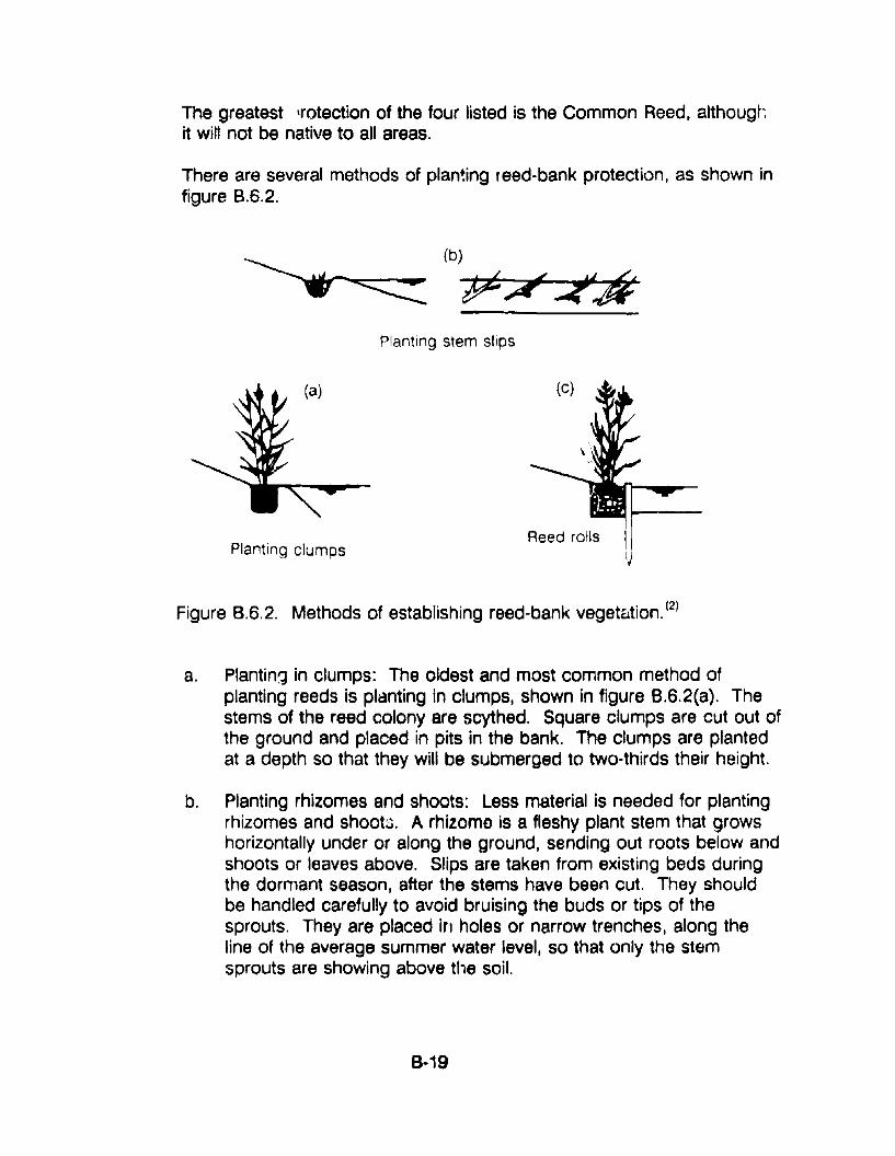
The greatest lrotection of the four listed is the Common Reed. althougr.it will not be native to alt areas.
There are several methods of plan~ing reed-bank protection, as shown infigure B.6.2.
(b)
tp~~<
Planting clumps
Planting stem slips
Reed rolls Ilj
Figure B.6.2. Methods of establishing reed-bank vegetation. (2)
a. PlantinIJ in clumps: The oldest and most common method ofplanting reeds is pldnting in clumps, shown in figure 8.6.2(a). Thestems of the reed colony are scythed. Square clumps are cut out ofthe ground and placed in pits in the bank. The clumps are plantedat a depth so that they will be submerged to two-thirds their height.
b. Planting rhizomes and shoots: Less material is needed for plantingrhizomes and shoots. A rhizome is a fleshy plant stem that growshorizontally under or along the ground, sending out roots below andshoots or leaves above. Slips are taken from existing beds duringthe dormant season, after the stems have been cut. They shouldbe handled carefully to avoid bruising the buds or tips of thesprouts. They are placed in holes or narrow trenches, along theline of the average summer water level, so that only the stemsprouts are showing above the soil.
8·19
c. Planting sten' slips: It is also possible to plant stem slips alongslow-moving streams, as shown in figure 8.6.2 (b). Usually, threeslips 'are se'. In a pit 12 to 20 inches deep. The pits should belocated ora foot apart.
d. Reed rolls: The fastest and most effective method of establishinfjreed-bank vegetation is the use of reed rolls, as shown in figure8.6.2 (c), in which the protection of the bank is, at first, ensured byplacement of structural materials. A trench 18 inches wide is dugbehind a row of stakes. Wire netting, such as 1/2-inch hardwarecloth, is stretched from both sides of the trench between uprightplanks. Onto this netting is dumped fill material, such as coarsegravel, sad, or soil and other organic material. This material is thencovered by reed clumps until the two edges of the wire netting canjust be held together by wire. The upper edges of the roll should beno more than two inches above the level of the water. Finally, theplanks are taken out, and any gaps along the sides of the roll arefilled in with earth. This method provides greater protection from thepossibility of a heavy flow washing away the vegetative materialsbefore they have a chance to become established.
e. Seeding: Some grasses can be sown on very damp bank soilprovided that the seeded surface is not covered by water for sixmonths after sowing. Cool-season grass should not be seeded inthe summer.
f. Vegetation and stone facings: Reed-bank vegetation can beplanted in conjunction with riprap or other stone facing. Clumps,rhizomes, or shoots can be planted in the crevices or gaps alongthe line of the average summer water level.
2. Establishing shrub zone vegetation: Stands of full-grown trees are oflittle use for protecting streambanks apart from binding the soil with theirroots. Shrubwood prOVides much better protection. Plants should beused that are well adapted to the stream and site conditions. Methods ofestablishing shrub zone vegetation is s:lown in figure 8.6.3.
n Seeding and sodding: If the streambed is small and a goodseedbed can be prepared, grasses can be used alone to stabilizethe streambed. Seeding mixtures should be selected andoperations performed according to local specifications. An erosionblanket, such as jute netting or excelsior blankets, should beinstalled according to norrnally accepted specifications for thelocality. Sad can also be placed in areas where grass is suitable.
8·20
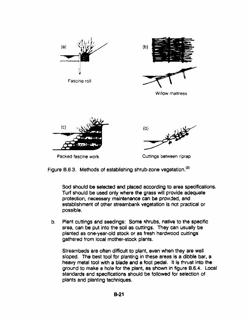
(a)
Fascine roll
Packed fascine work
(b)
Willow mattress
Cuttings between riprap
Figure B.6.3. Methods of establishing shrub-zone vegetation. (2)
Sad should be selected and placed according to area specifications.Turf should be used only where the grass will provide adequateprotection, necessary maintenance can be provljed, andestablishment of other streambank vegetation is not practical orpossible.
b. Plant cuttings and seedings: Some ~hrubs, native to the specificarea, can be put into the soil as cuttings. They can usually beplanted as one-year-old stock or as fresh hardwood cuttingsgathered from local mother-stock plants.
Streambeds are often difficult to plant, even when they are wellsloped. The best tool for planting in these areas Is a dibble bar, aheavy metal tool with a blade and a foot pedal. It is thrust into theground to make a hole for the plant, as shown In figure 8.6.4. localstandards and specifications should be followed for selection ofplants and planting techniques.
8-21
c. Fascine rolls: Fascine rulls ara bundles of brushwood or sticks,without branches if possible, that are filled with coarse gravel andrubble and wired tightly around the outside. They are 4 to 20 yardslong and 4 to 16 inches in diameter. They are set against the bankso that the parts that are to take root touch the ground above thewater level and are able to get sufficient moisture. Covering withearth improves the contact with the ground and retards the loss ofmoisture from the wood. Fascine rolls are illustrated in figureB.6.3.(a).
d. Willow mattresses: The d'3gree of stream-bank protection can beincreased by using willow mattresses, if willow is available, orpacked fascine work. Willow mattresses consist of four-to-eightinch-thick layers of growing branches set perpendicular to thedirection of the current or sloping downstream, with the broad endof the branches oriented downstream. The branches are heldtogether with interweaving wire at intervals of 24 to 32 inches, asshown in figure B.6.3.{b). The whole mattress structure should becovered with two to ten inches of earth or fine gravel.
e. Packed fascine work: Packed fascine work, as illustrated in figureB.6.3.{c), consists essentially of layars of branches laid one acrossthe other to a depth of 8 to 12 inches and covered with fascine rolls.The spaces between the fascine rolls are filled with gravel, stones,and soil so that no gaps remain and a layer of soil 8 to 12 inches isadded on top. Packed fascine work is particularly suitable forrepairing large breaches in the banks of streams with high waterlevels.
f. Combination with stone facing: In many places, the bank is notadequately protected until the roots are fully developed, andtemporary protection must be provided by inanimate materials. Onemethod is the planting of woody plants in the crevices of stonefacing as shown in figure B.6.3.{d).
8·22
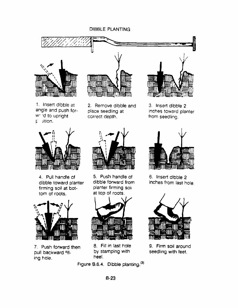
DIBBLE PLANTING
1. Insert dibble atangle and push forw"d to upright~ ;ition.
2. Remove dibble andplace seedling atcorrect depth.
3. Insert dibble 2inches toward planterfrom seedling.
6. Insert dibble 2inches from last hole.
9. Firm soil aroundseedling with feet.
5. Push handle ofdibble forward fromplanter firming soitat top of roots.
,8. Fill in last holeby stamping withheel.
Figure 8.6.4. Dibble planting. (3)
4. Pull handle ofdibble toward planterfirming soil at bottom of roots.
7. Push forward thenpull backward fill-ing hole.
8-23
SAFETY PRECAUTIONS
Streambanks are always vulnerable to new damage. Repairs are neededperiodically. Banks should be checked after every high-water event is over.Gaps in the vegetative cover should be repaired at once with new plants andmulched if necessary'. Fresh cuttings from other plants on the bank can beused, or they can be taken from mother-stock plantings if they are available.Trees that are established on the bank should be removed at once.
RESOURCE COMMITMENT ~ 3:
COST RELATIVE TOREPLACEMENT = 1:
5 4Heavy
5 4High
3 2Medium
3 2Medill:n
1Low
1Low
REfERENCES1. Virginia Erosion and Sediment Control Handbook, Virginia Department of
Conservation and Historic Resources, Division of Soil and WaterConservation, Richmond, V,rginia, 1980.
2. P. Seibert Importance of Natural Vegetation for the Protection of theBanks of Streams, Rivers, and Canals in Freshwater, pp. 35-67, Councilof Europe, New York, 1968.
3. A Guide for Vegetating Surface-Mined Lands for Wildlife in EasternKentucky and West Virginia, U.S. Department of the Interior, Fish andWildlife Service.
8·24
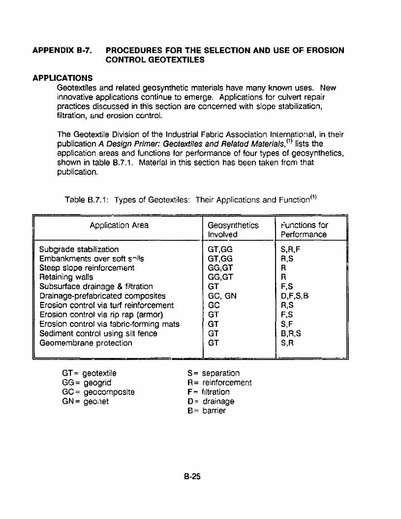
APPENDIX B-7. PROCEDURES FOR THE SELECTION AND USE OF EROSIONCONTROL GEOTEXTILES
APPLICATIONSGeotextiles and related geosynthetic materials have many known uses. Newinnovative applications contil1ue to emerge. Applications for culvert repairpractices discussed in this section are concerned with slope stabilization,filtration, and erosion control.
The Geotextile Division of the Industrial Fabric Association International, in theirpublication A Design Primer: Geotextiles and Related Materials, (1) lists theapplication areas and functions for performance of four types of geosynthetics,shown in table B.7.1. Material in this section has been taken from thatpublication.
Table B.7.1: Types of Geotextiles: Their Applications and Function(1)
Application Area Geosynthetics functions forInvolved Performance
Subgrade stabilization GT,GG S,R,FEmbankments over soft s~ils GT,GG R,SSteep slope reinforcement GG,GT ARetaining walls GG,GT RSubsurface drainage & filtration GT F,SDrainage-prefabricated composites Ge, GN D,F,S,BErosion control via turf reinforcement GC R,SErosion control via rip rap (armor) GT F,SErosion control via fabric-forming mats GT S,FSediment control using silt fence GT B,A,SGeomembrane protection GT S,R
GT = geotextileGG= geogridGC = geocompositeGN= geo;1et
S= separationR= reinforcementF::: filtrationD= drainageEJ:= barrier
8-25
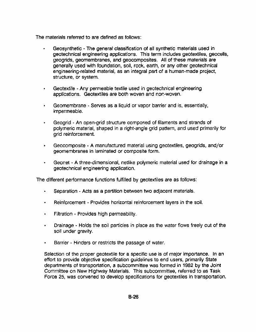
The materials referred to are defined as follows:
Geosynthetic - The general classification of all synthetic materials used ingeotechnical engineering applications. This term includes geotextiles, geocells,geogrids, geomembranes, and geocomposites. All of these materials aregenerally used with foundation, soil, rock, earth, or any other geotechnicalengineering-related material, as an integral part of a human-made project,structure, or system.
Geotextile - Any permeable textile used in geotechnical engineeringapplications. Geotextiles are both woven and non-woven.
Geomembrane - Serves as a liquid or vapor barrier and is, essentially,impermeable.
Geogrid - An open-grid structure compoRed of filaments and strands ofpolymeric material, shaped in a right-angle grid pattern, and used primarily forgrid reinforcement.
Geocomposite - A manufactured materia! using geotextiles, geogrids, and/orgeomembranes in laminated or composite form.
Geor~et - A three-dimensional, netlike polymeric material used for drainage in ageotechnical engineering application.
The different performance functions fulfilled by geotextiles are as follows:
Separation - Acts as a partition between two adjacent materials.
• Reinforcement - Provides horizontal reinforcement layers in the soil.
Filtration - Provides high permeability.
• Drainage - Holds the soil particles in place as the water flows freely out of thesoil under gravity.
Barrier - Hinders or restricts the passage of water.
Selection of the proper geotextile for a specific use is of major importance. In aneffort to provide objective specification guidelin~s to end users, primarily Statedepartments of transportation, a subcommittee was formed in 1982 by the JointCommittee on New Highway Materials. This subcommittee, referred to as TaskForce 25, was convened to develop specifications for geotextiles in transportation.
8-26
The Joint Committee is made up of representatives from the American Associationof State Highway and Transportation Officials (AASHTO), the Associated GeneralContractors of America (AGC), and the American Road and TransportationBuilders' Association (ARTBA).
Approved specification guides have been developed for the following fiveapplications:
• Paving fabric;
• Silt fence;
• Drainage geotextiles;
• Erosion corltrol geotextiles; and
• Sepal ation geotextiles.
This publication, referred to as TS25(2), is available from the PublicationsDepartment of AASHTO.
PROCEDURES1. Geotextiles Used for Turf Reinforcement
Geotextiles are used to stabilize the soil while plant growth is established. Themat allows the roots and stems to grow through.
Description- Polymer erosion control mat linings are three-dimensionalsystems that can be used to establish a reinforced v(jgetative surface - "turf"on streambanks, slopes, and in channels and ditches. The mat has aoequateporosity to retain soil while allowing roots anr' stems lO arow th:"('\ugh. Themat entangles with the root and stem networK of vp-getation to gre3tly enhRnceits resistance to sheet, gully, and rill er05lon. The system is fle.IClble, canconform to irregular surfaces, and can prevent undermining. Top soil covermay be used to enhance temporary erosion protection and early veQetativegrowth. Specific applicatiun areas include the following:
• Slope protection;
• Channel banks;
• Roadside ditches;
B-27
• Conveying ditches; and
• Storm channels.
Turf reinforcement systems almost defy a simple physical description. Someof the variations are listed below.
• Entangled webbings of a three-dimensional structure;
• Open cells of a three-dimensional structure;
• Heavy woven fabrics consisting of thick filament fibers; and
• Various vegetative and non-vegetative filler materials within an open netting.
Installation- Turf-reinforcement systems are easily installed. However, thefollowing are some of the precautions that shou!d be taken when installinggeotextiles. Manufacturer's literature is a good source of more detailedprocedures.
• Slopes are covered with roll lengths going up and down the slope, Le., nohorizontal joints are permitted and vertical joints are shingled down stream.
• Ditch and channel bottoms are lined with longitudinal lengths. Jointsperpendicular to water flow are shingled downstream with a 3-ft overlap.
• The edges of rolls are usually overlapped by 2 to 4 inches and suitablystaked so as not to move with respect to one another. A minimum stakespacir.g of 5-ft is recommended at each edge.
• A geotextile filter should be placed beneath the turf reinforcement in areas ofhighly erodible soils. The matting is often bonded to the geotextile. If not, itmust be secured by proper use of stakes.
• A soil or wood chip infill is often IJsed with turf reinforcement for stability andseeding purposes.
• The upper and lower ellds of turf reinforcement must be designed againstundermining. Anchor trAnch details are shown in figure 8.7.1.
• Material shall be placed loosely to allow contact with the soil. It must .QQJ bestretched.
8·28
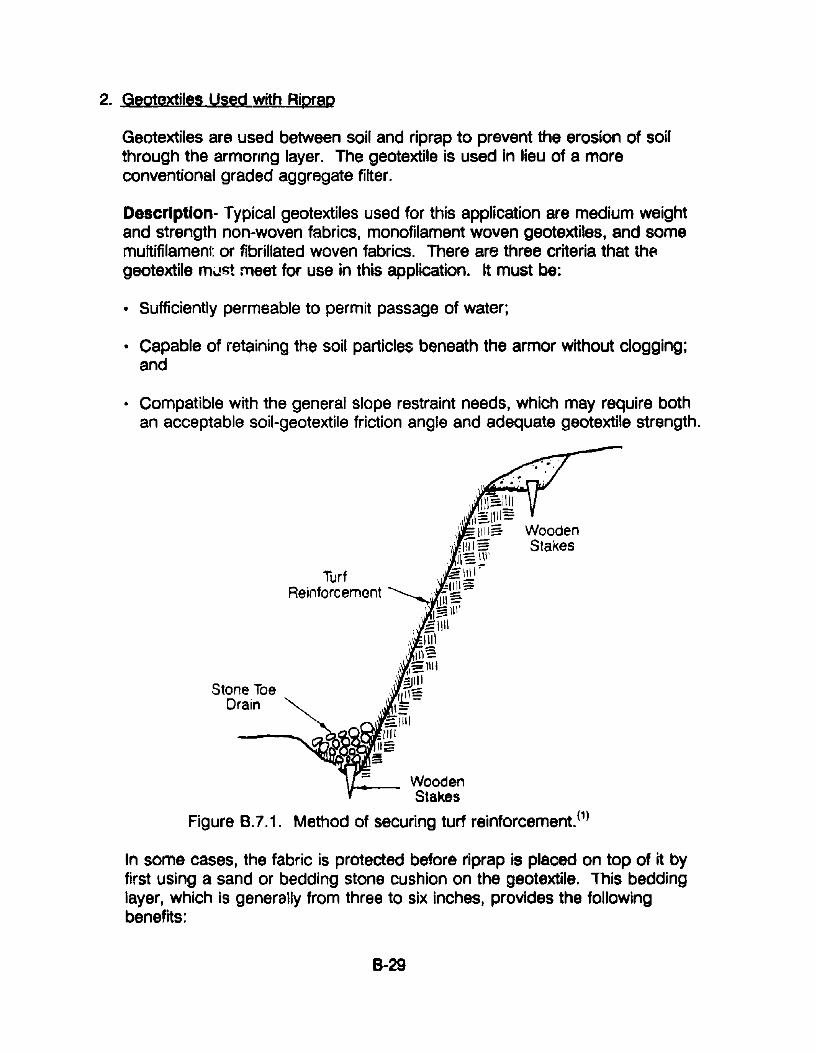
2. Geotextiles Used with Riprap
Geotextiles are used between soil and riprap to prevent the erosion of soilthrough the armoflng layer. The geotextile is used in lieu of a moreconventional graded aggregate filter.
Descrlptlon- Typical geotextiles used for this application are medium weightand strength non-woven fabrics, monofilament woven geotextiles, and somemultifilament or fibrillated woven fabrics. There are three criteria that thegeotextile m\.!st meet for use in this application. It must be:
• Sufficiently permeable to permit passage of water;
• Capable of retaining the soil particles beneath the armor without clogging;and
• Compatible with the general slope restraint needs, which may require bothan acceptable soil-geotextile friction angle and adequate geotextile strength.
TurfReinforcemont
11---- WoodenStakes
Figure B.7.1. Method of securing turf reinforcement. (1)
In some cases, the fabric is protected before riprap is placed on top of it byfirst using a sand or bedding stone cushion on the geotextile. This beddinglayer, which is generally from three to six inches, provides the followingbenefits:
8-29
• Protects the geotextile during placement of the riprap;
• Provides an intimate contact between the geotextile and underlying soil;
• Provides protection against ultraviolet rays; and
• Protects against vandalism.
There are three design elements to be considered in using a geotextile. First,it must be adequate as a filter, which is a three-part problem. It must beadequate for flow, soil retention, and long-term clogging prevention. Second,since the gravitational force of the rock riprap may be partially transferred tothe geotextile, an estimate of tensile strength is necessary. Third, thegeotextile must be able to survive the in~taJlation stresses.
Installation - The formation of holes and the loss of tensile strength may resultfrom dropping large stones on an exposed geotextile. Therefore, if height ofdrop cannot be controlled, either geotextiles with height-survivability propertiesmust be specified or a bedding layer must be placed above the fabric.
Specific construction criteria should be followed for placing geotextiles betweenthe soil layer and riprap:
1. Slopes steeper than 2.5 to 1 should not be used without laboratory testingto confirm stable soil-fabric friction angles.
2. Slopes should be graded to provide a smooth, fairly level surface. Thefabric should be laid with the machine direction of the fabric placedparallel to the slope. Folds and wrinkles of the fabric should be avoided.
3. Adjacent rolls should be shingle-overlapped 12 inches in the down-slopeor down-stream direction or should be seamed. Overlapped seams maybe secured using metal pins as necessary.
The Corp of Engineers specifies steel securing pins, nominally 3/16inches in diameter, 18 inches long, pointed at one end and fitted with 1.5inch diameter washers at the other end for use in securing fabrics in firmsoils. The pin spacing is a function of the slope with the followingspacings recommended:
8-30
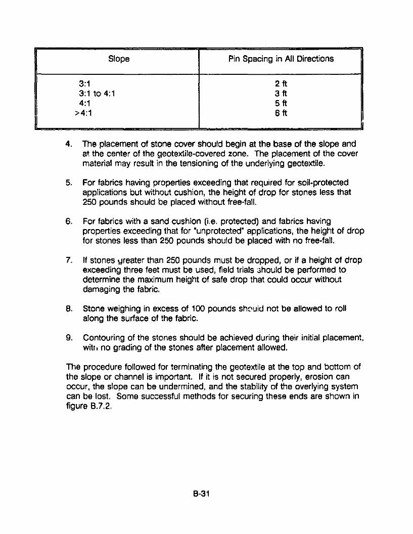
Slope Pin Spacing in All Directions
3:1 2ft3:1 to 4:1 3ft4:1 5ft
>4:1 6ft
4. The placement of stone cover should begin at the base of the slope andat the center of the geotextile-covered zone. The placement of the covermaterial may result in the tensioning of the underlying geotextile.
5. For fabrics having properties exceeding that required for soil-protectedapplications but without cushion, the height of drop for stones less that250 pounds should be placed without free-fall.
6. For fabrics with a sand cushion (Le. protected) and fabrics havingproperties exceeding that for "unprotected" applications, the height of dropfor stones less than 250 pounds should be placed with no free-fall.
7. If stones ~reater than 250 pounds must be dropped, or if a height of dropexceeding three feet must be used, field trials 3hould be performed todetermine the maximum height of safe drop that could occur withoutdamaging the fabric.
8. Stone weighing in excess of 100 pounds shC'uid not be allowed to rollalong the surface of the fabric.
9. Contouring of the stones should be achieved during their initial placement,witf. no grading of the stones after placement allowed.
The procedure followed for terminating the geotextile at the top and bottom ofthe slope or channel is important. If it is not secured properly, erosion canoccur, the slope can be undermined, and the stability of the overlying systemcan be lost. Some successful methods for securing these ends are shown infigure 8.7.2.
8-31
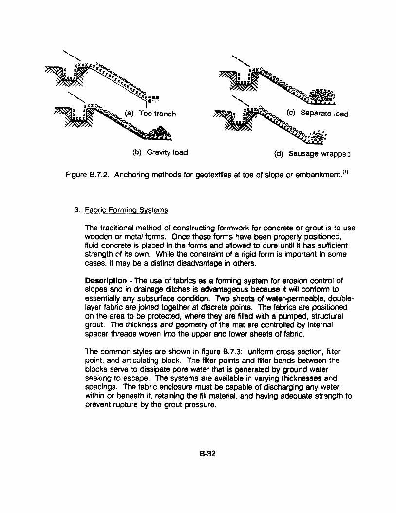
(b) Gravity load (d) Sausage wrapped
Figure 8.7.2. Anchoring methods for geotextiles at toe of slope or embankment.(1)
3. fabric Forming Systems
The traditional method of constructing formwork for concrete or grout is to usewooden or metal forms. Once these forms have been properly positioned,fluid concrete is placed in the forms and allowed to cure until it has sufficientstrength C'f its own. While the constraint of a rigid form is important in somecases, it may be a distinct disadvantage in others.
Description - The use of fabrics as a forming system for erosion control ofslopes and in drainage ditches is advantageous because it will conform toessentially any subsurface condition. Two sheets of water-permeable, doublelayer fabric are joined together at discrete points. The fabrics are positionedon the area to be protected, where they are filled with a pumped, structuralgrout. The thickness and geometry of the mat are ccntrolled by Internalspacer threads woven Into the upper and lower sheets of fabric.
The common styles are shown in figure 8.7.3: uniform cross section, filterpoint, and articulating block. The filter points and filter bands between theblocks serve to dissipate pore water that is generated by ground waterseeking to escape. The systems are available in varying thicknesses andspacings. The fabric enclosure must be capable of discharging any waterNithin or beneath it, retaining the fill material, and having adequate str9ngth toprevent rupture by the grout pressure.
8-32
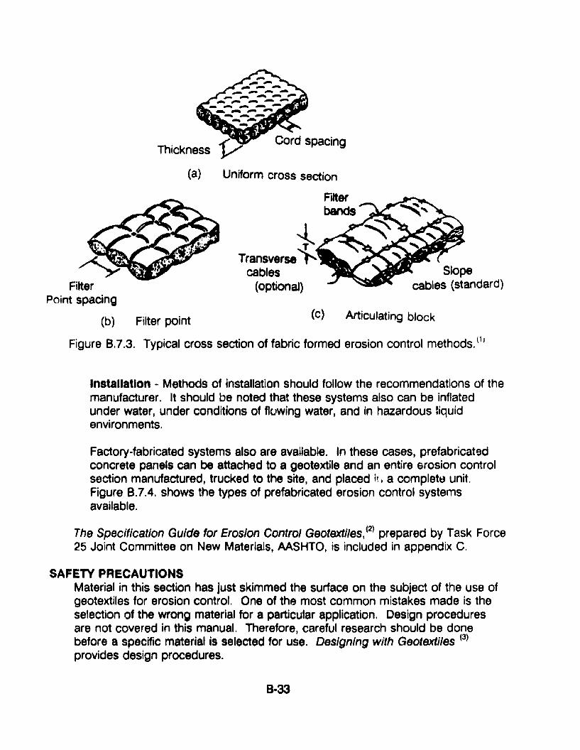
Thickness
(a) Uniform cross section
Slopecables (standard)
Articulating block(c)
iTransverse'l'
cables(optionaJ)
(b) Filter point
Figure 8.7.3. Typical cross section of fabric formed erosion control methods. (II
Installation - Methods of installation should follow the recommendations of themanufacturer. It should be noted that these systems also can be inflatedunder water, under conditions of flowing water, and in hazardous liquidenvironments.
Factory-fabricated systems also are available. In these cases, prefabricatedconcrete panels can be attached to a geotextile and an entire erosion controlsection manufactured, trucked to the site, and placed h, a complete unit.Figure 8.7.4. shows the types of prefabricated erosion control systemsavailable.
The Specification Guide for Erosion Control Geotextiles, (2) prepared by Task Force25 Joint Committee on New Materials, AASHTO, is included in appendix C.
SAFETY PRECAUTIONSMaterial in this section has just skimmed the surface on the subject of the use ofgeotextiles for erosion control. One of the most common mistakes made is theselection of the wrong material for a particular application. Design proceduresare not covered in this manual. Therefore, careful research should be donebefore a specific material is selected for use. Designing with Geotextlles (3)
provides design procedures.
8-33
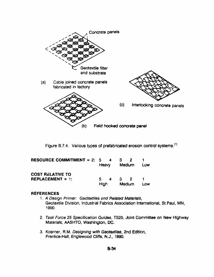
Field hooked concrete panel
(c) Interlocking concrete panels
Concrete panels
Geotextile filterand substrate
".... ""~-......_ .......... "" ~--_ ~........< ""><~O.c:--...~~~IQIII;,.........
..... ~~--.. .. ,/~-..;1'~~CooooI.....
........... ~-"----....~-
........... .....
(a) Cable joined concrete panelsfabricated in factory
Figure B.7.4. Various types of prefabricated erosion control systemsYl
RESOURCE COMMITMENT = 2: 5 4 3 2 1Heavy Medium low
COST ReLATIVE TOREPLACEMENT = 1: 5 4 3 2 1
High Medium low
REFERENCES1. A Design Primer: Geotextifes ~md Related Materials,
Geotextile Division, Industrial Fabrics Association International, St.Paul, MN,1990.
2. Task Force 25 Specification Guides, TS25, Joint Committee on New HighwayMaterials, AASHTO, Washington, DC.
3. Koerner, A.M. Designing with Geotextlles, 2nd Edition,Prentice-Hall, Englewood Cliffs, N.J., 1990.
8 ..34
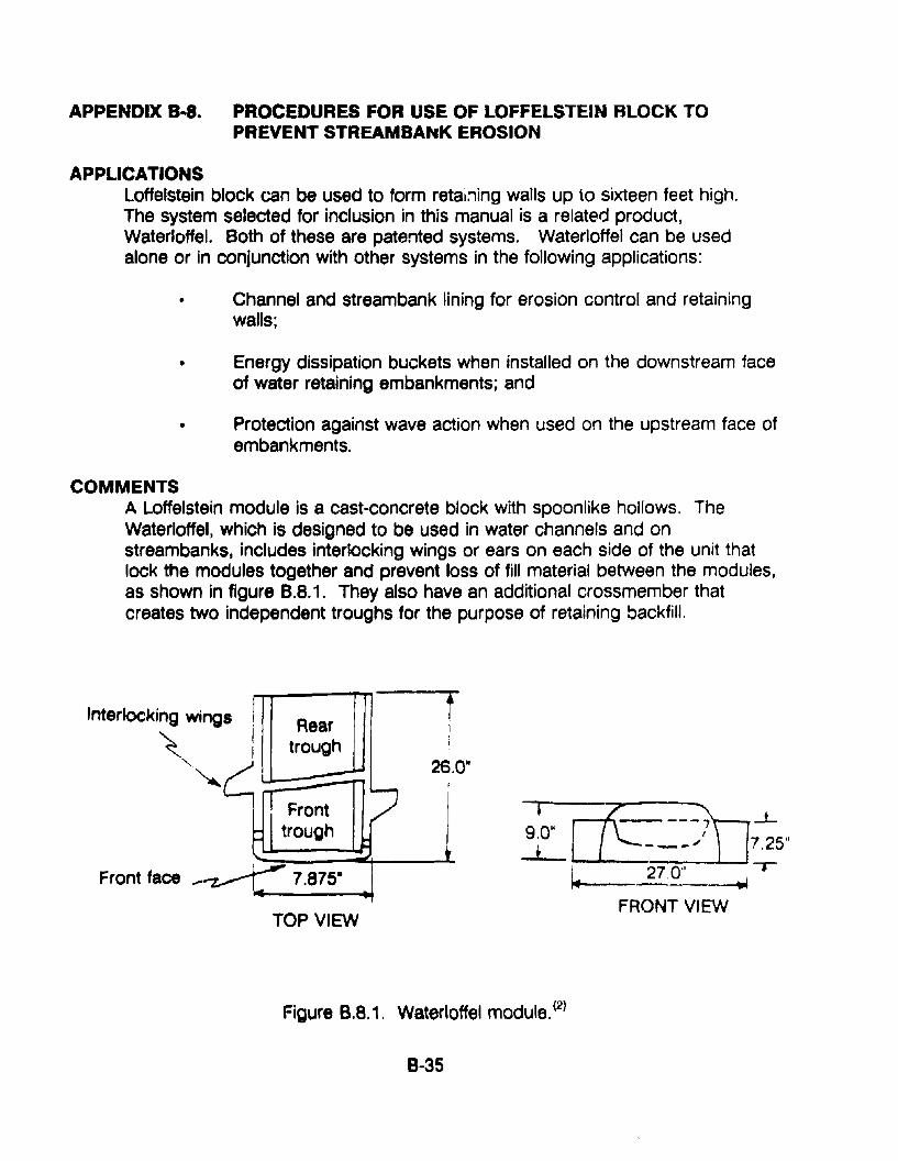
APPENDIX B-8. PROCEDURES FOR USE OF LOFFELSTEIN BLOCK TOPREVENT STREAMBAttK EROSION
APPLICATIONSLoffelstein block can be used to form retai:1ing walls up to sixteen feet high.The system selected for inclusion in this manual is a related product,Waterloffel. Both of these are patented systems. Waterloffel can be usedalone or in conjunction with other systems in the following applications:
• Channel and streambank lining for erosion control and retainingwalls;
• Energy dissipation buckets when installed on the downstream faceof water retaining embankments; and
• Protection against wave action when used on the upstream face ofembankments.
COMMENTSA Loffelstein module is a cast-concrete block with spoonlike hollows. TheWaterloffel, which is designed to be used in water channels and onstreambanks, includes interlocking wings or ears on each side of the unit thatlock the modules together and prevent loss of fill material between the modules,as shown in figure B.8.1. They also have an additional crossmember thatcreates two independent troughs for the purpose of retaining backfill.
Interlocking wings
~""-.~
Front face
Reartrough
Fronttrough
TOP VIEW
I ~ JJ----7 ....L~~ - __~ 7.25"
~ 27,0" ~ -r
FRONT VIEW
Figure 6.8.1. Waterloffel module. (2)
8-35
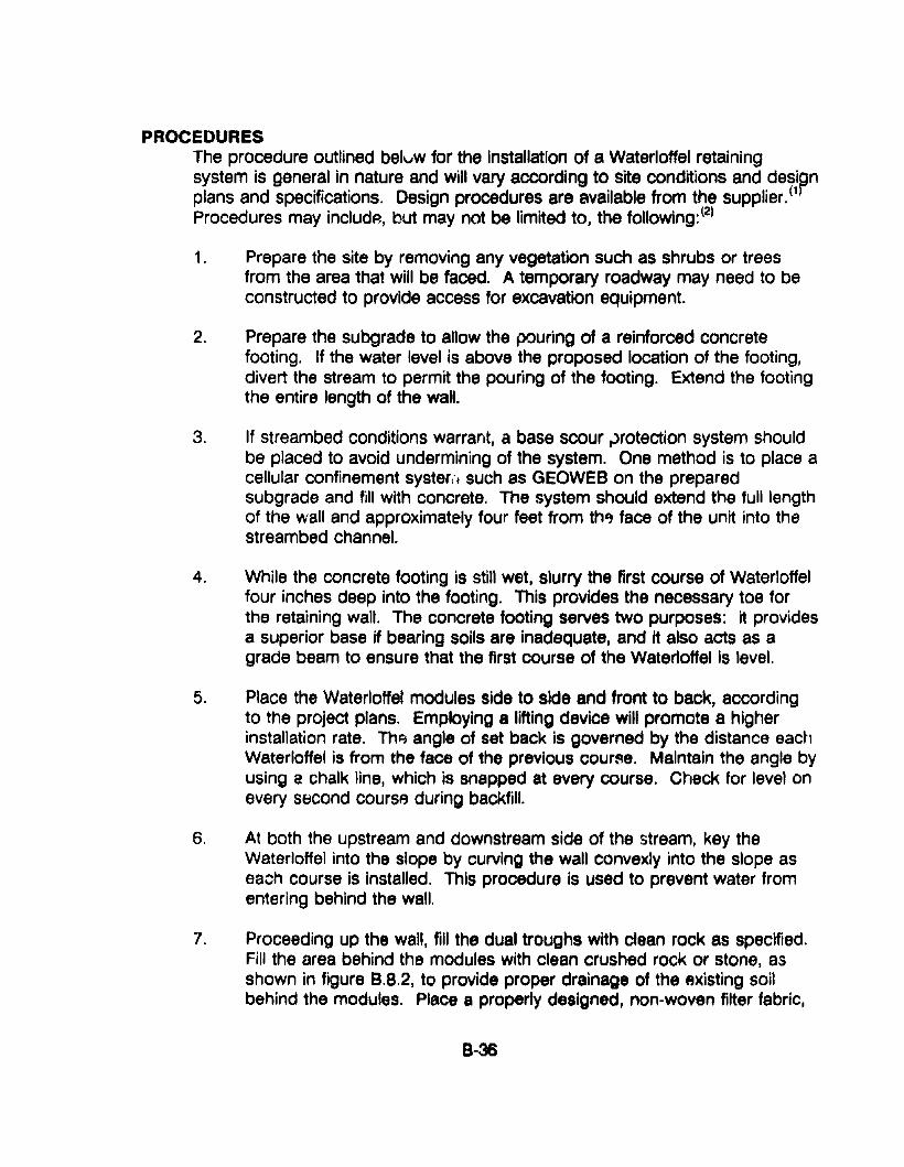
PROCEDURESThe procedure outlined belvw for the installation of a Waterloffel retainingsystem is general in nature and will vary according to site conditions and deSi?nplans and specifications. Design procedures are available from the supplier. (1
Procedures may includA, but may not be limited to, the following:(2)
1. Prepare the site by removing any vegetation such as shrubs or treesfrom the area that will be faced. A temporary roadway may need to beconstructed to provide access for excavation equipment.
2. Prepare the subgrade to allow the pouring of a reinforced concretefooting. If the water level is above the proposed location of the footing,divert the stream to permit the pouring of the footing. Extend the footingthe entire length of the wall.
3. If streambed conditions warrant, a base scour ,.>rotection system shouldbe placed to avoid undermining of the system. One method is to place acellular confinement syster,', such as GEOWEB on the preparedsubgrade and fill with concrete. The system should extend the full lengthof the wall and approximately four feet from th') face of the unit into thestreambed channel.
4. While the concrete footing is still wet, slurry the first course of Waterloffelfour inches deep into the footing. This provides the necessary toe forthe retaining wall. The concrete footing serves two purposes: it providesa superior base if bearing soils are inadequate, and it also acts as agrade beam to ensure that the first course of the Waterloffel is level.
5. Place the Waterloffel modules side to side and front to back, accordingto the project plans. Employing a lifting device will promote a higherinstallation rate. Thl? angle of set back is governed by the distance eachWaterloffel is from the face of the previous course. Maintain the angle byusing e chalk line, which is snapped at every course. Check for level onevery second course during backfill.
6. At both the upstream and downstream side of the stream, key theWaterloffel into the slope by curving the wall convexly into the slope aseach course is installed. This procedure is used to prevent water fromentering behind the wall.
7. Proceeding up the wall, fill the dual troughs with clean rock as specified.Fill the area behind the modules with clean crushed rock or stone, asshown in figure 8.8.2, to provide proper drainage of the eXisting soilbehind the modules. Place a properly designed, non-woven filter fabric,
B-36
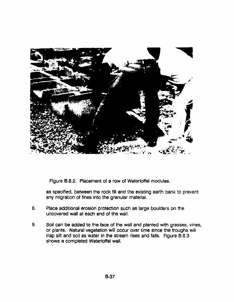
Figure B.8.2. Placement of a row of Waterloffel modules.
as specified, between the rock fill and the existing earth bank to preventany migration of fines into the granular material.
8. Place additional erosion protection such as large boulders on theuncovered wall at each end of the wall.
9. Soil can be added to the face of the wall and planted with grasses, vines,or plants. Natural vegetation will occur over time since the troughs willtrap silt and soil as water in the stream rises and falls. Figure B.8.3shows a completed Waterloffel wall.
B-37
RESOURCE COMMITMENT = 4:
COST RELATIVE TOREPLACEMENT = 2:
5 4Heavy
5 4High
3 2Medium
3 2Medium
1Low
1Low
REFERENCES1. Robert B. Rodgers, Loffe/stein Retaining Wall Design Manua/, Seagren
Industries, Inc., St. Louis, MO.
2. "Waterloffel," Loffe/stein Retaining Walls, Seagren Industries, Inc., St.Louis, MO.
8-38
APPENDIX B-9. PROCEDURES FOR ASSEMBLING AND INSTALLINGGABIONS
APPLICATIONSGabions may be used to extend wingwalls and armor slopes against erosion.They also may be used as velocity attenuators.
COMMENTSThe u&e of gabions may be a simple and effective technique for stabilizingslopes against movement and erosion; protecting culvert headwalls, endwalls,and wingwalls from scour and undermining; and protecting streambeds againsterosion due to high velocity water flow. They may be particularly effectivewhere there is fast-moving water and riprap of the size or quality required is notavailable.
There are two >,pes of gabion revetment designs that are distinguished by theshape and plac Jment of the gabion: mattress and block. In the mattressdesign, the individual wire baskets are placed end-to-end and side-to-side toform a continuous mattress layer on a prepared bed or bank. The individualbaskets are attached to each other and anchored to the base material. Thewire baskets forming the mattress generally have a depth dimension that ismuch smaller than the width or length.
The block design is formed by stacking individual gabion blocks in a steppedfashion. Block gabions are typically rectangular or trapezoidal in shape andgenerally equadimensional. Design and construction information is availablefrom manufacturer's literature.
Gabions may be cut or bent to form shapes to fit culv~rt appurtenances. Thecut or bent edges of the mesh must be fastened securely to another part of th~structure.
1. Supply and Delivery
Gabions are supplied folded flat and packed in bundles. For easein handling, the number of gabions per bundle generally variesaccording to the size of the gabions. The lacing wire is supplied incoils.
2. Stone
Order only hard durable stone of the currect size range.
8-39
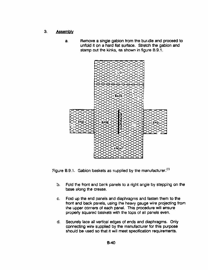
3. Assembly
a. Remove a single gabion from the buridle and proceed tounfold it on a hard flat surface. Stretch the gabion andstamp out the kinks, l:3S shown in figure 8.9.1.
Figure 8.9.1. Gabion baskets as supplied by the manufacturer. (1)
b. Fold the front and back panels to a right angle by stepping on thebase along the crease.
c. Fold up the end panels and diaphragms and fasten them to thefront and back panels, using the heavy gauge wire project,ng fromthe upper corners of each panel. This procedure will ensureproperly squared baskets with the tops of all panels even.
d. Securely lace all vertical edges of ends and diaphragms. Onlyconnecting wire supplied by the manufacturer for this purposeshould be IJsed so that it will meet specification requirements.
8-40
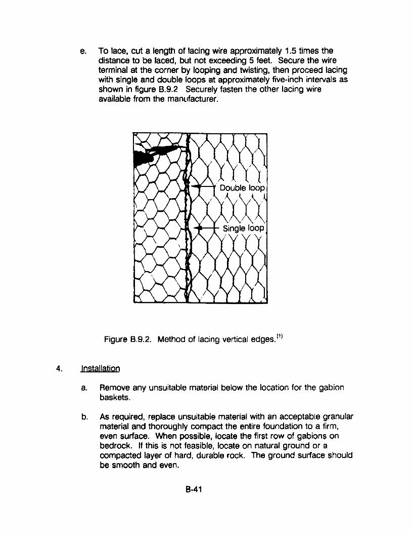
e. To lace, cut a length of lacing wire approximately 1.5 times thedistance to be laced, but not exceeding 5 feet. Secure the wireterminal at the corner by looping and twisting, then proceed lacingwith single and double loops at approximately five-inch intervals asshown in figure 8.9.2 Securely fasten the other lacing wireavailable from the manufacturer.
Figure 8.9.2. Method of lacing vertical edges. (1)
4. Installation
a. Remove any unsuitable material below the location for the gabionbaskets.
b. As required, replace unsuitable material with an acceptable granularmaterial and thoroughly compact the entire foundation to a firm,even surface. When possible, locate the first row of gabions onbedrock. If this is not feasible, locate on natural ground or acompacted layer of hard, durable rock. The ground surface shouldbe smooth and even.
8-41
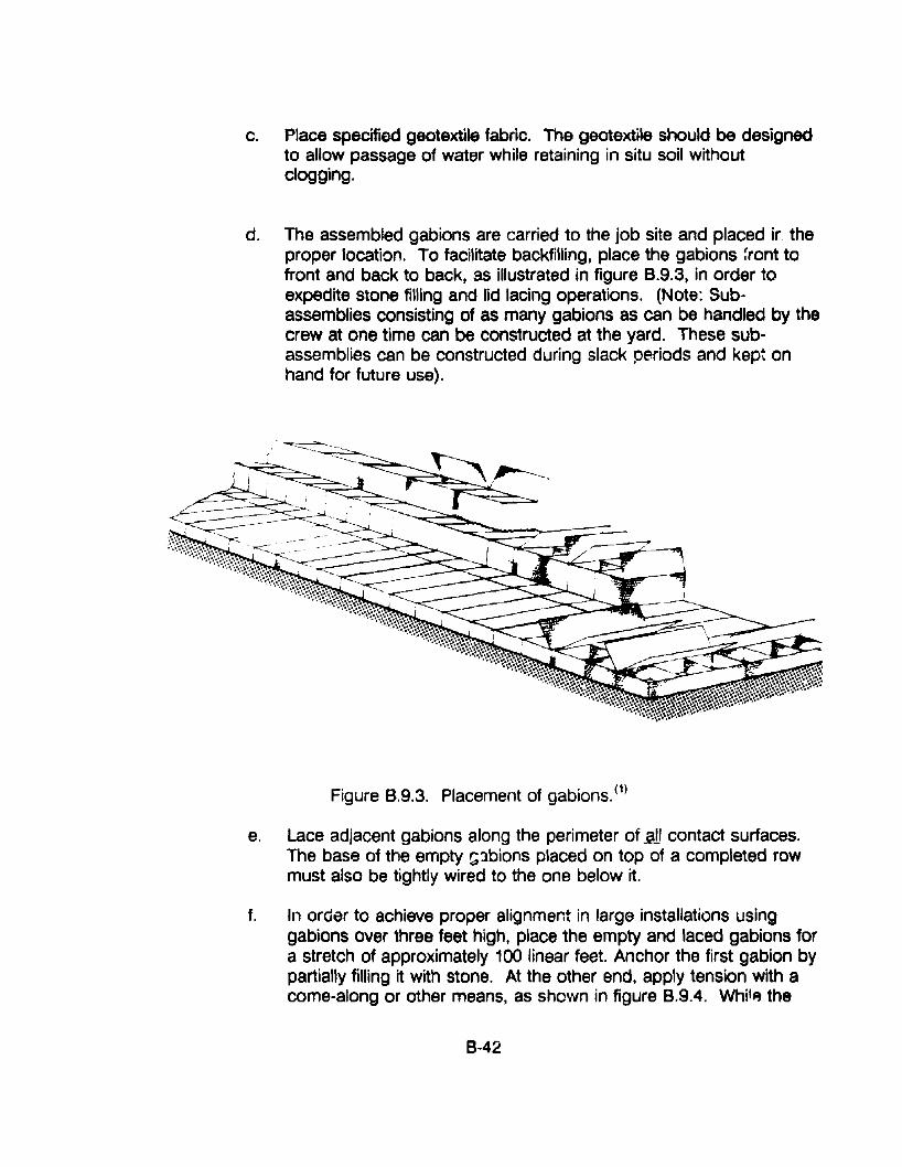
c. Place specified geotextile fabric. The geotextile should be designedto allow passage of water while retaining in situ soil withoutclogging.
d. The assembled gabions are carried to the job site and placed ir. theproper location. To facilitate backfilling, place the gabions front tofront and back to back, as illustrated in figure B.9.3, in order toexpedite stone filling and lid lacing operations. (Note: Subassemblies consisting of as many gabions as can be handled by thecrew at one time can be constructed at the yard. These subassemblies can be constructed during slack periods and kept onhand for future use).
Figure B.9.3. Placement of gabions. (1)
e. Lace adjacent gabions along the perimeter of.2ll contact surfaces.The base of the empty G3bions placed on top of a completed rowmust also be tightly wired to the one below it.
f. In order to achieve proper alignment in large installations usinggabions over three feet high, place the empty and laced gabions fora stretch of approximately 100 linear feet. Anchor the first gabion bypartially filling it with stone. At the other end, apply tension with acome-along or other means, as shown in figure 8.9.4. Whjl~ the
8-42
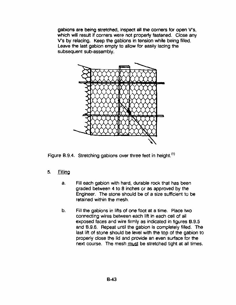
gabions are being stretched, inspect all the corners for open V's,which will result if corners were not p:operly fastened. Close anyV's by relacing. Keep the gabions in tension while being filled.Leave the last gabion empty to allow for easily lacing thesubsequent sUb-assembly.
Figure 8.9.4. Stretching gabions over three feet in height. (1)
5. Filling
a. Fill each gabion with hard, durable rock that has beengraded between 4 to 8 inches or as approved by theEngineer. The stone should be of a size sufficient to beretained within the mesh.
b. Fill the gabions in lifts of one foot at a time. Place twoconnecting wires between each lift in each cell of allexposed faces and wire firmly as indicated in figures B.9.5and B.9.6. Repeat until the gabion is completely filled. Thelast lift of stone should be level with the top of the gabion toproperly close the lid and provide an even surface for thenext course. The mesh .must be stretched tight at all times.
B-43
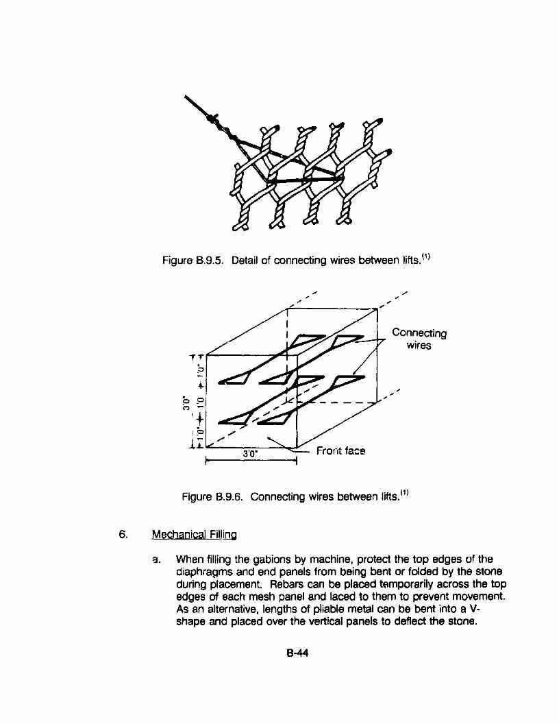
Figure B.9.S. Detail of connecting wires between lifts. (1)
~~~~Z-4"T Connectingwires
T T ,.-.----~lllGo__1"
;,
9 9C") ....,+
1 91:L~- ~.-Y
~
Figure B.9.6. Connecting wires between lifts. (1)
6. Mechanical Filling
a. When filling the gabions by machine, protect the top edges of thediaphragms and end panels from being bent or folded by the stoneduring placement. Rebars can be placed temporarily across the topedges of each mesh panel and laced to them to prevent movement.As an alternative, lengths of pliable metal can be bent into a Vshape and placed over the vertical panels to deflect the stone.
B--44
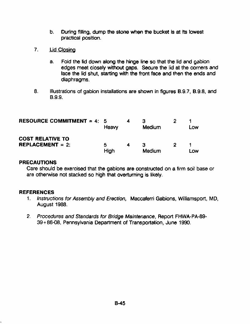
b. During filJing, dump the stone when the bucket is at its lowestpractical position.
7. Lid Closing
a. Fold the lid down along the hinge line so that the lid and gabionedges meet closely without gaps. Secure the lid at the corners andlace the lid shut, starting with the front face and then the ends anddiaphragms.
8. Illustrations of gabion installations are shown in figures B.9.7, B.9.8, andB.9.9.
RESOURCE COMMITMENT =4: 5 4 3 2 1Heavy Medium Low
COST RELATIVE TOREPLACEMENT =2: 5 4 3 2 1
High Medium Low
PRECAUTIONSCare should be exercised that the gabions are constructed on a firm soil base orare otherwise not stacked so high that overturning is likely.
REFERENCES1. Instructions for Assembly and Erection, Maccaferri Gabions, Williamsport, MD,
August 1988.
2. Procedures and Standards for Bridge Maintenance, Report FHWA-PA-8939 +86-08, Pennsylvania Department of Transportation, June 1990.
8-45
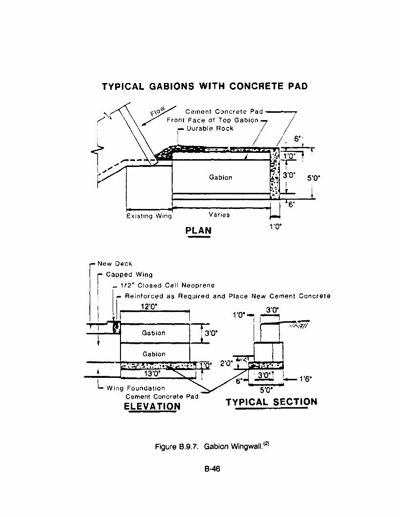
TYPICAL GABIONS WITH CONCRETE PAD
Existing Wing Varies
PLAN 1'OM
, .'.'3'0·~ I~ -1'6·
5'0·
TYPICAL SECTIONELEVATION
New Deck
Capped Wing
,.. 1f2 u Closed Cell Neoprene
I ~ Reinforced as Required and Place New Cement Concrete
12'0· , •II , 1'0·- ~
-i-~""'II'1I------~' I' I ",,'$'/1Gabion ~'O' . i-i ........
Figure B.9.7. Gabion Wingwall.(2)
B-46
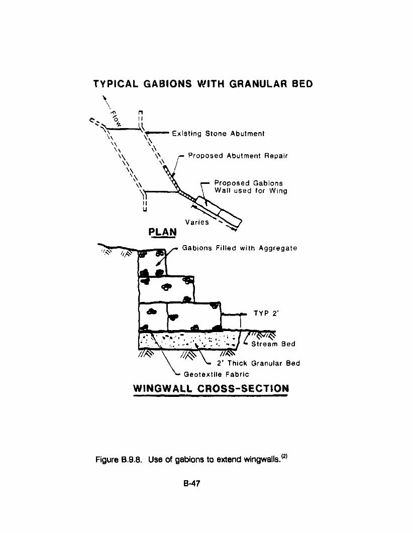
TYPICAL GABIONS WITH GRANULAR BED
Existing Stone Abutment
rProposed Abutment Repair
Proposed GabionsWall used for Wing
PLAN
Gabions Filled with Aggregate
TYP 2'
/.2' Thick Granular Bed
Geotextile Fabric
WINGWALL CROSS-SECTION
Figure B.9.8. Use of gabions to extend wingwalls. (2)
8-47
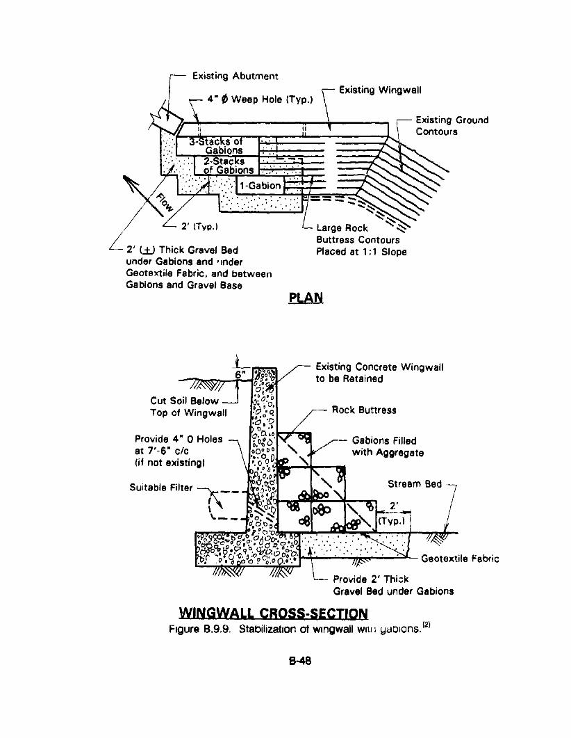
Existing Abutment
4" tJ Weep Hole (Typ.)
II
.......• • f" I toO···
. . .... ~ ", .' . ..:.' •. ··"0.
" '.
2' (Typ.)
L 2' (jJ Thick Gravel Bedunder Gabions and 'InderGeotextile Fabric, and betweenGabions and Gravel Base
Existing Wingwall
Existing GroundContours
=.= == --- ..........-"~~~
Large Rock ""~Buttress ContoursPlaced at 1: 1 Slope
Stream Bed --
- Gabions Filledwith Aggregate
Rock Buttress
Existing Concrete Wingwallto be Retained
'a..,..;~.:-.:-_oi-~;"'~"-- Geotextile Fabric
- Provide 2' Thi.::kGravel Bed under Gabions
Cut Soil BelowTop of Wingwall
Provide 4" 0 Holesat 7'-6" clc(if not existing)
Suitabla Filte,~__
\.--
Figure B.9.9. Stabilization of wlngwall Will I yaOlons. (2)
8-48
APPENDIX B·10. PROCEDURES FOR REPAIR OF TIMBER STRUCTURES
APPLICATIONSThe procedures described below apply to the repair of both timber culverts andtimber retaining walls.
COMMENTSDouglas fir and southern long leaf yellow pine are the most common speciesused in heavy timber construction. These same types of timber should be usedfor repair of timber structures. When treated Douglas fir is to be used, coastalDouglas fir should be specified since it accepts preservative treatment betterthan inland varieties.
Three materials are commonly used to protect timber and all are applied underpressure. The three are creosote, pentachlorophenol, and copper chromiumarsenate (CCA). The empty cell process is generally specified since it leaves apreservative coating on the internal surface of the cells, but it does not leave aheavy residue of preservative on the outer surface of the timber. This fact issignificant because all of the materials used for preservative treatment are toxic.
Galvanized hardware should be used for repair of all permanent structures.Ordinary hardware can be used for temporary structures such as scaffolding,however.
PROCEDURES1. Repairing Damage From RQt
a. Determine the extent of the damage or deterioration. This is usually doneby sounding in the case of rot.
b. Determine whether tlimporary supports will be required when damaged ordeteriorated wood is removed.
c. When repairing timber damaged by rot, determine whether Qr nQt toreplace the entire piece of timber or remove only the rotten portion.
d. When it is not reasonable tQ replace the entire member, all timbershowing visible signs of decay should be removed plus two additionalfeet in the direction of the grain.
e. Install a splice between the existing timber and the new timber.
f. Remove all sawdust and chips from the work site.
B~9
g. Since the presence of unnecessary moisture is the most common rootcause of timber decay, eliminate moisture-retaining debris from all timbersurfaces.
2. Repairing Damage by Overload
a. When timber has been damaged by overload rather than rot, repair canbe made by adding a sister member, which is a new member addedadjacent to the similar existing one.
b. Since the presence of rut·causing fungi is not always visible on damagedtimber, the sister mem~.ar usua!ly should be isolated from the existingmember by heavy roofing or similar material.
3. Genera-!
a. The installation of sheet metal caps to help control deterioration on timberends has been a common practice. In most cases, however, thispractice accelerates deterioration instead of reducing it by acting as afunnel directing water into the timber and retaining moisture.Consequently, t~e use of such CCtpS should be avoided.
b. A minimum number of cuts and holes should be made in treated timber.The cuts and holes that have to be made should be thoroughly swabbedwith protective material. Pentachlorophenol is a convenient material touse for this purpose.
c. Timber is strong in boti, tension and compression but is relatively weak inhorizontal shear. As a result, satisfactory connections between memberscarrying heavy loads can be difficult to obtain where th~ loads must betransferred by hardware rather than by direct timber-to-timber contact. Inthese instances the use cf shear transfer devices, such as a spirt ringconnector, should be used,
SAFETY PRECAUTIONSAll of the materials used for iJreservative treatment are toxic. Therefore,appropriate gloves and othe' SUitable protective items should always be wornwhen handling treated timbel'.
RESOURCE COMMITMENT = 1: 5 4 3 2 1Heavy Medium Low
COST RELATIVE TOREPLACEMENT = 1: 5 4 3 2 1
High Medium Low
REFERENCES1. M.e. Rissel, and J.P. Taylor, Procedures and Standards for Bridge
Maintenance, Research Project as-Q8. Pennsylvania Department ofTransportation, Harrisburg, PA, June 1990.
B-51
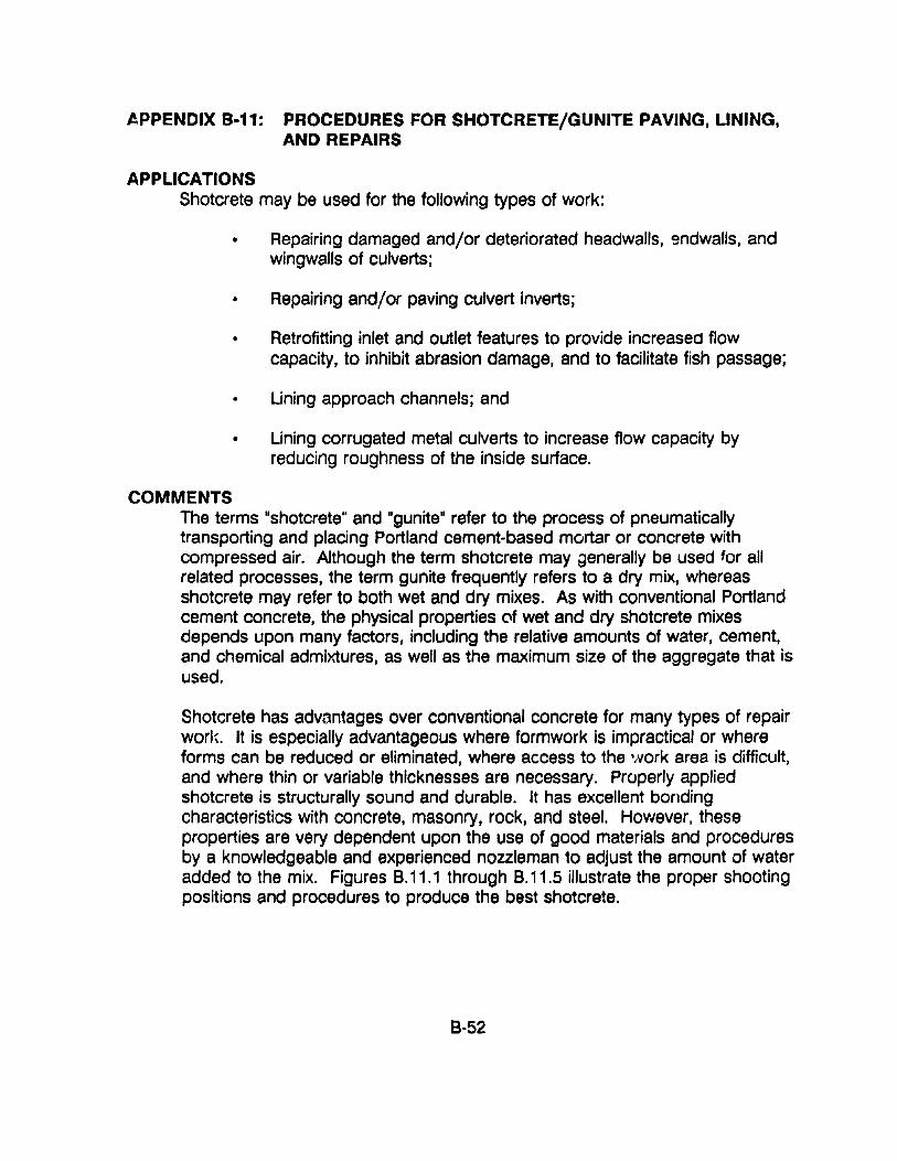
APPENDIX 9·11: PROCEDURES FOR SHOTCRETE/GUNITE PAVING, LINING,AND REPAIRS
APPLICATIONSShotcrete may be used for the following types of work:
• Repairing damaged and/or deteriorated headwalls, 9ndwalls, andwingwalls of culverts;
• Repairing and/or paving culvert inverts;
• Retrofitting inlet and outlet features to provide increasea flowcapacity, to inhibit abrasion damage, and to facilitate fish passage;
• Lining approach channels; and
• Lining corrugated metal culverts to increase flow capacity byreducing roughness of the inside surface.
COMMENTSThe terms "shotcrete" and "gunite" refer to the process of pneumaticallytransporting and placing Portland cement-based mortar or concrete withcompressed air. Although the term shotcrete may generally be used for allrelated processes, the term gunite frequently refers to a dry mix, whereasshotcrete may refer to both wet and dry mixes. As with conventional Portlandcement concrete, the physical properties of wet and dry shotcrete mixesdepends upon many factors, including the relative amounts of water, cement,and chemical admixtures, as well as the maximum size of the aggregate that isused.
Shotcrete has advantages over conventional concrete for many types of repairworl~. It is especially advantageous where formwork is impractical or whereforms can be reduced or eliminated, where access to the work area is difficult,and where thin or variable thicknesses are necessary. Properly appliedshotcrete is structurally sound and durable. It has excellent bondingcharacteristics with concrete, masonry, rock, and steel. However, theseproperties are very dependent upon the use of good materials and proceduresby a knowledgeable and experienced nozzleman to adjust the amount of wateradded to the mix. Figures B.11.1 through B. 11.5 illustrate the proper shootingpositions and procedures to produce the best shotcrete.
8-52
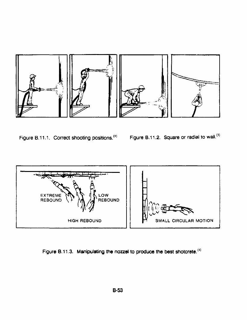
I
I,
I ~~~t:::l~ , ~,.., -=-=;- )
'\~',I
Figure 8.11.1. Correct shooting positions. (1)
LOWREBOUND
HIGH REBOUND
Figure 8.11.2. Square or radial to wall. (1)
1'(\1"\lll~::~",,,,v \\WI ~
SMALL CIRCULAR MOTION
Figure 8.11.3. Manipulating the nozzel to produce the best shotcrete. (1)
8·53
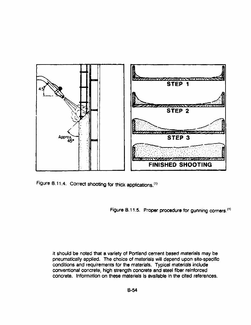
, ,;..
L,ojilj swnatZw'tS$ZZ .1"~STEP 1
~ Ai~:.. ..:: .. . . ...;s-:,aFP2&'pii'SSSSS Y2Z???TB';i j',',{f
STEP 2
Figure 8.11.4. Correct shooting for thick applications. (1)
Figure 8.11.5. Proper procedure for gunning corners. (1)
It should be noted that a variety of Portland cement based materials may bepneumatically applied. The choice of materials will depend upon site-specificconditions and requirements for the materials. Typical materials includeconventional concrete, high strength concrete and steel fiber reinforcedconcrete. Information on these materials Is available in the cited references.
6·54
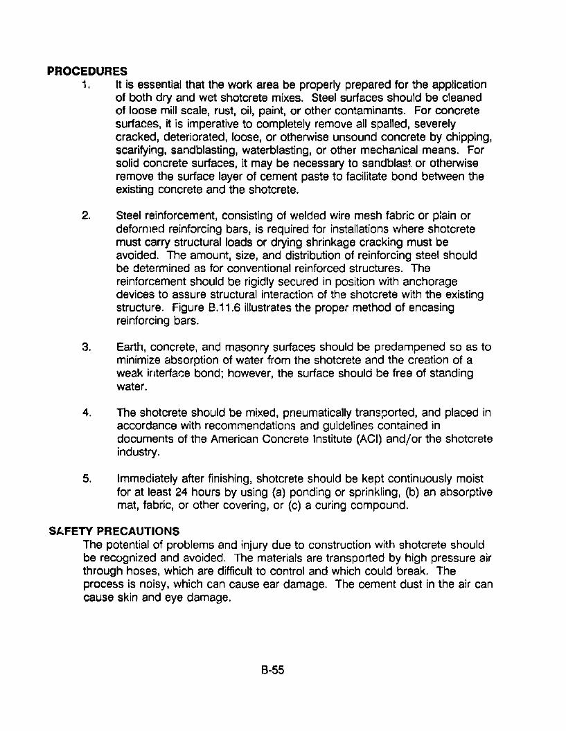
PROCEDURES1. It is essential that the work area be properly prepared for the application
of both dry and wet shotcrete mixes. Steel surfaces should be cleanedof loose mill scale, rust, oil, paint, or other contaminants. For concretesurfaces, it is imperative to completely remove all spalled, severelycracked, deteriorated, loose, or otherwise unsound concrete by chipping,scarifying, sandblasting, waterblasting, or other mechanical means. Forsolid concrete surfaces, it may be necessary to sandblast or otherwiseremove the surface layer of cement paste to facilitate bond between theexisting concrete and the shotcrete.
2. Steel reinforcement, consisting of welded wire mesh fabric or p:ain ordeformed reinforcing bars, is required for installations where shotcretemust carry structural loads or drying shrinkage cracking must beavoided. The amount, size, and distribution of reinforcing steel shouldbe determined as for conventional reinforced structures. Thereinforcement should be rigidly secured in position with anchoragedevices to assure structural interaction of the shotcrete with the existingstructure. Figure 8.11.6 illustrates the proper method of encasingreinforcing bars.
3. Earth, concrete, and masonry surfaces should be predampened so as tominimize absorption of water from the shotcrete and the creation of aweak interface bond; however, the surface should be free of standingwater.
4. The shotcrete should be mixed, pneumatically transported, and placed inaccordance with recommendations and guidelines contained indocuments of the American Concrete Institute (ACI) and/or the shotcreteindustry.
5. Immediately after finishing, shotcrete should be kept continuously moistfor at least 24 hours by using (a) ponding or sprinkling, (b) an absorptivemat, fabric, or other covering, or (c) a curing compound.
SAFETY PRECAUTIONSThe potential of problems and injury due to construction with shotcrete shouldbe recognized and avoided. The materials are transported by high pressure airthrough hoses, which are difficult to control and which could break. TheproceSis is noisy, which can cause ear damage. The cement dust in the air cancause skin and eye damage.
8-55
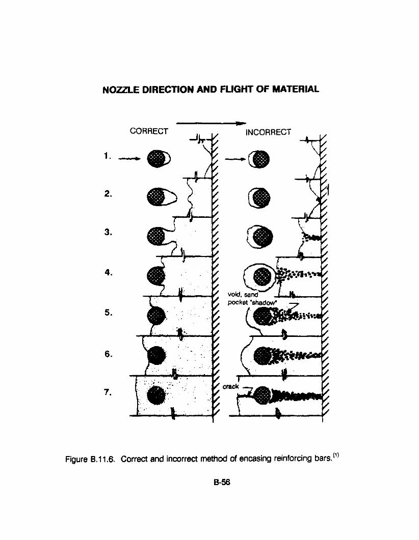
NOZZLE DIRECTION AND FUGHT OF MATERIAL
1.
2.
3.
4.
5.
6.
7.
CORRECT
, ,. '.'.....•..: ...... :.::~'. ... . . ~~ '.
:.. :. ...".
..INCORRECT
Figure 8.11.6. Correct and incorrect method of encasing reinforcing bars. (1)
8-56
RESOURCE COMMITMENT = 2:
COST RELATIVE TOREPLACEMENT = 2:
5 4Heavy
5 4High
3 2Medium
3 2Medium
1Low
1Low
REFERENCES1. "Guide to Shotcrete. 1I (ACI SaBA-gO), ACI Manual of Concrete Practice,
American Concrete Institute, 1990.
2. "Specification for Materials, Proportioning, and Application of Shotcrete," (ACI506.2-77), ACI Manual of Concrete Practice, American Concrete Institute,Revised 1983.
~. "State-of-the-Art Report on Fiber Reinforced Shotc~cte,1I (ACI 506.1 R-84 ), ACIManual of Concrete Practice, American Concrete Institute, 1984.
4. "Guide to Certification of Shotcrete Nozzlemen." ACI Manual of ConcretePractice, American Concrete Institute, 1982.
5. "Rehabilitation of Corrugated Steel Pipe and Pipe Lines of Other Materials."Drainage Technology Bulletin, National Steel Pipe Institute, September 1988.
8-57
APPENDIX 8·12. PROCEDURES FOR STORMWATER CONVEYANCECHANNELS (DITCHES)
APPLICATIONSThis section is generally applicable to man-made channels, including roadsideditches and paved flumes, and intermittent natural channels that are modified toaccommodate increased flows generated by stormwater runoff. This practice isnot applicable to major, continuous flowing natural streams.
COMMENTSA stormwater conveyance channel is a permanent, designed waterway, shapedand lined with the appropriate vegetation or structural material to safely conveyexcess stormwater runoff. The purpose of such a channel is to provide for thedisposal of concentrated surface runoff water without damage from erosion.
The desigl" of a channel cross-section and lining is based primarily upon thevolume and ve'~clty of flow expected in the channel. If conditions areappropriate, grass or riprap channels are generally preferred over concrete.While co.lcrete channels are efficient and easy to maintain, they remove waterso quickly that channel erosion and flooding may result downstream. Grass orriprap channels reduce this problem by more nearly duplicating a naturalsystem.
Other factors ·such as land availability, compatibility with land use and thesurrounding environment, maintenance requirements, and outlet conditionsmust also be considered when selecting a cross-section and lining. Cross·sections may be one of the following:
Vee-Shaped ditches are generally used where the quantity of water is relativelysmall, such as along roadways. A grass or sod lining is sufficient wherevelocities are low. For steeper slopes, a concrete or bituminous lining may beappropriate. A vee-shaped ditch is more erosion prone than parabolic ortrapezoidal-shaped ditches. It is, therefore, only recommended for smalldischarges on mild slopes.
Parabolic channels are often used where the quantity of water to be handled isgreater and where space is available for a wide, shallow channel with lowvelocity flow. Riprap should be used where high velocities are expected. Acombination of grass and riprap is useful where there is continuous low flow ina channel.
Trapezoidal channels are often used where the quantity of water to be handledis large and conditions require that it be carried at a relatively high velocity.Trapezoidal ditches are generally lined with concrete or riprap.
B·58
Outlet conditions for all channels shoul'i be considered, particularly at thetransition from a man-made lining such as concrete to a vegetative lining.Appropriate measures must be taken to dissipate the energy of flow to preventscour of the receiving channel.
PROCEDURESCapacity
Unless otherwise specified by local and State drainage criteria, design channelcapacity and erosion protection for a 2-year frequency storm. If propertydamage from channel flooding is problematic, design capacity for a 1a-yearfrequency storm.
Velocity
Design channels so that the velocity of flow expected from a 2-year frequencystorm does nct exceed the permissible velocity for the type of lining used.
Grass-lined channels - Permissible velocities for grass-lined channels isshown in table 8.12.1 below. However, local specifications should beused for selecting the appropriate grass for the area.
Riprap-Iined channels - Riprap linings can be designed to withstand mostflow velocities by choosing a stable stone size. The procedure forselecting a stable stone size can be found in appendix B, section B.13,Riprap.
Concrete-lined channel - Velocity is usually not a limiting factor in thedesign of concrete-lined channels. However, flow velocity at the outlet ofthe paved section must not exceed the permissible velocity of thereceiving channel.
Cross Section
Channel cross-sections may be \/ee-shaped, parabolic, or trapezoidal. The topwidth of parabolic and vee-shaped, grass-lined channels should not exceed 30feet. The bottom width of trapezoidal, grass-lined channels should not exceed15 feet unless multiple or divided waterways, a riprap center or other means areprovided to control meandering of low flows.
Channel linings
Grass - The type of grass chosen must be appropriate for site
B·59
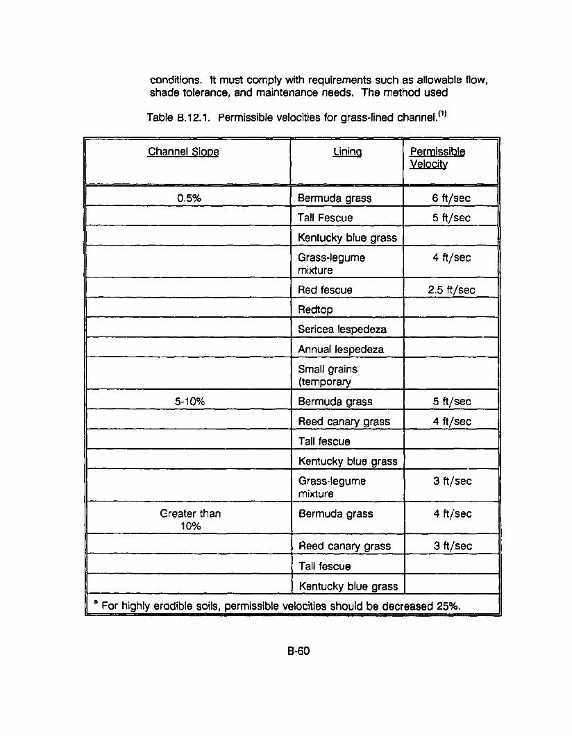
conditions. It must comply with requirements such as allowable flow,shade tolerance, and maintenance needs. The method used
Table B.12.1. Permissible velocities for grass-lined channel. (1)
Channel Slope Lining PermissibleVelocity
0.5% Bermuda grass 6 ft/sec
Tall Fescue 5 ft/sec
Kentucky blue grass
Grass-legume 4 ft/secmixture
Red fescue 2.5 ft/sec
Redtop
Sericea lespedeza
Annual lespedeza
Small grains(temporary
5-10% Bermuda grass 5 ft/sec
Reed canary grass 4 ft/sec
Tall fescue
Kentucky blue grass
Grass-legume 3 ft/secmixture
Greater than Bermuda grass 4 ft/sec10%
Reed canary grass 3 ft/sec
Tall fescue
Kentucky blue grass
a For highly erodible soils, permissible velocities should be decreased 25%.
B-60
to establish grass in the ditch or channel generally depends upon the slope, allowablevelocity, the erosion-resistance of the soils, and whether or not the majority of thedrainage can be diverted away from the channel during germination to permit growthand establishment. Some methods available for grass establishment are:
.. Seeding with straw mulch and tack coat.
.. Sprigging with Bermuda grass.
.. Sodding.
Geotextiles: Polymer erosion control mat linings that arethree·dimensional systems used to establish a reinforcedsystem used to establish a reinforced vegetative surface.Additional information can be found in appendix B, section7: Geotextiles, Turf Reinforcement.
.. Erosion control blankets such as those made from woodexcelsior combined with a photo-degradable plastic mesh.High-velocity erosion control blankets are also available.
Riprap-Iined channels - Riprap should be installed in accordance withappendix B, section 13, Riprap, or as specified by local or stateregulations.
Concrete-lined channels - Concrete-lined channels should be at least 4inches thick and meet applicable local and state criteria.
Shotcrete-lined channels - Shotcrete is particularly cost effective whereformwork is impractical or where forms can be reduced or eliminated,access to work is difficult or thin layers of variable thicknesses arerequired. The physical properties of sound shotcrete are comparable orsuperior to conventional concrete having the same composition.
Patented erosion control systems used to line channels. An example ofthis type of lining is TRI.lOCK(2), a flexible, permeable erosion controlsystem of precast concrete blocks made up of two components, a "lockblock" and a "key block," installed over a specially designed plastic filterfabric. This system is normally installed in dry conditions by handplacing on the overlying filter fabric. For underwater applications, it canalso be supplied on pre-assembled mats.
8-61
SAFETY PRECAUTIONSSafety precautions related to the placement of Shotcrete should be observed.These problems are outlined in Appendix 8, Section 11: Procedures forShotcrete/Gunite Paving, Uning, and Repairs(3).
RESOURCE COMMITMENT =4:
COST RELATIVE TOREPLACEMENT = 2:
5 4Heavy
5 4High
3 2Medium
3 2Medium
1Low
1Low
REFERENCES1. Virginia Erosion c:."u Seaiment Control Handbook, Second Edition.
Virginia Department of Conservation and Historic Resources, Division ofSoil and Water Conservation, Richmond, VA, 1980.
2. TRI-LOCK Erosion Control System Specifications," American ExcelsiorCompany, Arlington, TX.
3. "Guide to Shotcrete." (ACI S06R-90), ACI Iv'anual of Concrete Practice,American Concrete Institute, 1990.
8-62
APPENDIX 8-13. PROCEDURES FOR INSTALLING RIPRAP
APPLICATIONSRiprap can be installed on soil-water interfaces where the soil conditions, waterturbulence and velocity, or expected vegetative cover are such that the soil mayerode under design flow conditions. Riprap may be used, as appropriate, atstormdrain outlets, on channel banks or bottoms, around culvert appurtenancesto prevent erosion and scour, in roadside ditches, and along the toe of slopes.The purposes fulfilled by the placement of riprap are as follo'iv's:
• To protect the soil surface from the erosive forces of concentrated runoff;
• To slow the velocity of concentrated runoff while enhancing the potentialfor infiltration;
• To stabilize slopes with seepage problems and/or non-cohesive soils;and
• To stabilize streambeds and streambanks exposed to increased velocityand turbulence at culvert inlets and outlets.
COMMENTSThere are se\'p;"u; types of riprap that are considered to be permanent flexiblelinings. These types are described as follows:
• Rock riprap - Rock riprap is dumped in place on a filter blanket orprepared slope to form a well-graded mass with a minimum of voids.Rocks should be hard, durable, preferably angular in shape, and freefrom overburden, shale, and organic material. It should be noted thathand-placed riprap is considered to be a rigid lining since it cannotaccommodate even minor movement of the surface it protects.
• Gravel riprap - Gravel riprap consists of coarse gravel or crushed rockplaced on filter blankets or on a prepared slope to form a well-gradedmass with a minimum of voids. The material is composed of tough,durable, gravel-sized particles and should be free from organic matter.
• Wire-enclosed riprap - Wire-enclosed riprap, usually known as gabions, ismanufactured from a rectangular container made of steel wire, woven ina uniform pattern and reinforced on the corners and edges with he9vierwire. The containers are filled with stone, connected together, andanchored to the channel side slope. Stones must be well graded anddurable. Wire-enclosed riprap is typically used when high quality rock
8-63
riprap is either not available or not large enough to be stable. Furtherinformation can be found in appendix B, section 9, Gabions.
Methods discussed below refer to dumped rock riprap only.
Rlprap Peslgn In ChannelsA design method for riprap in channels is included in appendix C, entitled "RiprapDesign in Channels." The method is adoptt3d from H'Jdraulic EngineeringCircular No. 15(1) of the Federal Highway Adminis~ration and the simplifiedmethod included in the Virginia Erosion and Set1ill~3ntControl Handbook. (2)
However, local specification for riprap design Sh0Uld be followed.
Riprap used with erosion control geotextiles - To prevent the erosion of soilthrough the armoring layer of riprap, geotextiles are used between the soil andthe riprap. The geotextile is used in lieu of a conventional graded aggregatefilter. In this application, riprap is placed over the geotextile to protect thestreambed and streambanks.
Two key criteria must be met for this application of geotextiles. First, thegeotextile must have sufficient permeability to permit the passage of water, thusrelieving hydrostatic pressure behind the armor layer. Second, the geotextilemust be capable of retaining the soil particles under the armor. The specificationfor the geotextile is included in appendix C, and is entitled ''Task Force 25Specification Guide for Erosion Control Geotextiles."(3)
PROCEDURES1. Riprap and Geotextile placement for Streambank/Streambed Protection
a. if a portion of the streambed is to be lined, construct a sandbagcofferdam to an elevation above the water level or divert the stream usingtp.mporary pipes.
b. Install sediment control devices.
c. Prepare foundation by removing unsuitable material, sediment,vegetation, and debris.
d. Backfill with suitable mE\terlal if required.
e. Select appropriate geotextile as specified in ''Task Force 25 SpecificationGuide for Erosion Control Geotextiles,"(3) Included in appendix C.
f. Place the geotextile as described in appendix B, section 7, Geotextiles:Part 2 • "Geotextiles Used with Riprap. II
8-64
g. Place the geotextile so that it will not stretch or tear excessively.
h. Anchor the terminal ends by using the key trenches or aprons at thecrest and toe of the slope as described in (f) above.
i. Overlap successive geotextile sheets in such a manner that the upstreamsheet is placed over the downstream sheet and/or upslope overdownslope. In underwater application, place the geotextile and riprap thesame day. Begin the riprap placement at the toe and proceed up theslope.
j. Overlap seams a minir 12 inches except when placed underwaterwhere the overlap shall i ninimum of three feet. Secure with anchorpins, 15 inches long, placed every three feet along the overlap.
k. Riprap and heavy stone filling should not be dropped onto the geotexti!efror a height to exceed one foot. Slope protection and smaller sizes ofstone filling should not be dropped from a height exceeding three feet.For large stones (12 inches or greater), a 4-inch layer of gravel may benecessary to prevent damage to the cloth.
I. Placement of stones should follow immediatp.ly after placement of thefilter. The riprap should be placed so that it produces a dense wellgraded mass of stone with a minimum of voids. It should be placed toits full thickness in one operation, not in layers. The riprap should not beplaced by dumping into chutes or similar methods that are likely to causesegregating of the stone sizes.
m. Remove sediment control devices.
2. Riprap and Geotextile placement to Provide Scour ProteQ!iQ.o
NOTE: This construction to be done in the dry condition only.
a. Construct a sandbag cofferdam to an elevation above the water level ordivert the stream using temporary pipes.
b. Install a sediment control device.
c. Probe the scour hole to determine its approximate siLeo Removesediment, unsuitable material and debris from the scour hole.
d. Excavate the scour hole to a minimum of 3 feet wide and 3 feet deep tothe natural streambed material.
8-65
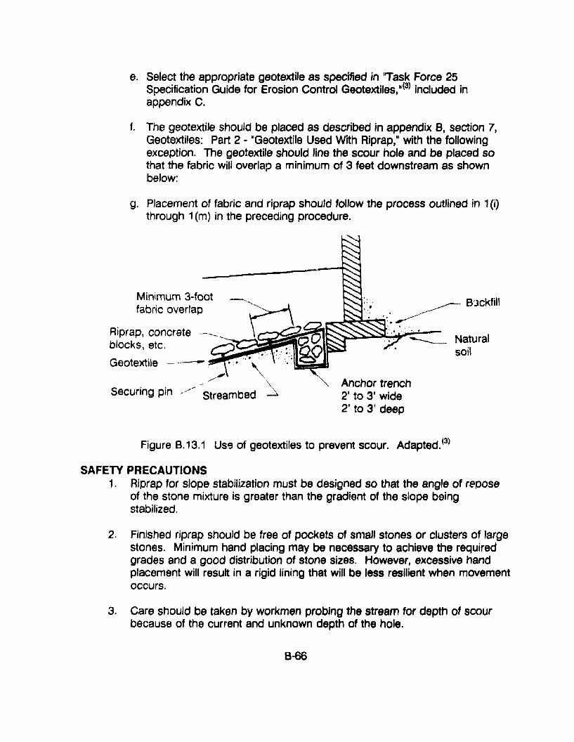
e. Select the appropriate geotextiJe as specified in "Task Force 25Specification Guide for Erosion Control GeotextiJes,"(3) included inappendix C.
f. The geotextile should be placed as described in appendix B, section 7,Geotextiles: Part 2 - "GeotextiJe Used With Riprap," with the followingexception. The geotextile should line the scour hole and be placed sothat the fabric will overlap a minimum of 3 feet downstream as shownbelow:
g. Placement of fabric and riprap should follow the process outlined in 1(i)through 1(m) in the preceding procedure.
Minimum 3-footfabric overlap
Aiprap, concrete ______
:.~. ~ B'lckfill
__~~'~'::::l':.---
;:Z;*,J~ Natural
soil
Anchor trench2' to 3' wide2' to 3' deep
Figure B.13.1 Use of geotextiles to prevent scour. Adapted. (3)
SAFETY PRECAUTIONS1. Riprap for slope stabilization must be designed so that the angle of repose
of the stone mixture is greater than the gradient of the slope beingstabilized.
2. Finished riprap should be free of pockets of small stones or clusters of largestones. Minimum hand placing may be necessary to achieve the requiredgrades and a good distribution of stone sizes. However, excessive handplacement will result in a rigid lining that will be less resilient when movementoccurs.
3. Care should be taken by workmen probing the stream for depth of scourbecause of the current and unknown depth of the hole.
8-66
RESOURCE COMMITMENT = 2: 5 4 3 2 1Heavy Medium Low
COST RELATIVE TOREPLACEMENT = 2: 5 4 3 2 1
High Medium Low
REFERENCES1. Design of Roadside Channels with Flexible Linings, Hydraulic
Engineering Circular No. 15, FHWA-IP-87-7. US Department ofTransportation, Federal Highway Administration, McLean, Virginia, April1988.
2. Virginia Erosion and Sediment Control Handbook, Virginia Department ofConservatior'l and Historic Resources, Division of Soil and WaterConservation, Richmond, Virginia, 1980.
3. Task Force 25 Specification Guides, T825 , Joint Committee on NewHighway Materials, AASHTO, Washington, DC, 1989.
8-67
APPENDIX 8·14. PROCEDURE FOR REPAIR AND REPLACEMENT OFAPRON/CUTOFF WALL
APPLICATIONSThis procedure is applicable to the repair and repiacement of all or portions ofexisting culvert concrete or masonry aprons and cutoff walls.
COMMENTSAprons and cutoff walls help to protect the slopes and channel bed from scour.Undermining is one of the major causes of failure of the aprons. If caughtearly, voids below can be filled and cutoff walls added as necessary to preventfurther undermining. Care should be exercised to maintain the flow of waterover aprons so as not to restrict fish passage.
Pr-lOCEDURES1. Install sediment control devices.
2. Construct sluices or other devices to divert stream and to protect freshlyplaced concrete from flowing water.
3. Remove deteriorated masonry or concrete.
4. Excavate unsuitable material. The apron should not protrude above thenormal streambed elevation.
5. Place and compact base material.
6. Drill holes and set dowels with non-shrink grout or approved adhesive.
7. Construct formwork. Aprons should extend at least one pipe diameterupstream.
8. Place reinforcing steel.
9. Place concrete. Just prior to placing concrete, apply epoxy bonding agentto all existing concrete that is to come into contact with new concrete.
10. Remove formwork.
11. Remove sluices and sediment control devices.
12. Grade streambed.
B-68
RESOURCE COMMITMENT = 2: 5 4 3 2 1Heavy Medium Low
COST RELATIVE TOREPLACEMENT = 2: 5 4 3 2 1
High Medium Low
REFERENCES1. Martin C. Rissel, John P. Taylor,and Robert J. Vollmer, Procedures and
Standards for Bridge Maintenance, Final Report, Research Project 86-08,Pennsylvania Department of Transportation, June 1990.
8-69
APPENDIX B·15. PROCEDURES FOR STREAMBED PAVING
APPLICATIONSThe following procedure applies to the paving or repair of paving in streambedsadjacent to highway culverts.
COMMENTSAlthough streambed paving is not desirable, it is occasionally necessary as apermanent solution to a longstanding problem of erosion or to provide capacitywhere space for a larger ditch is limited. This is particularly true when moretraditional forms of erosion control, such as riprap, gabions, or various types ofenergy dissipators, 8re not effective. Streambed paving may be essential to protectthe footings of arch culverts.
The scheduling of this type of work should be based on need, as indicated byinspections and/or changes in stream flow or conditions that increase the potentialfor scour problems. The work can be most efficiently performed during periodsof low water, which are most likely to occur during late summer or early fall.
PROCEDURESPaving or repair of paved streambeds should be performed in accordance withplans, specifications, and procedures that are established for each specific project.The work area includes the entire width and breadth of existing streambed areC'sor areas indicated on the plans for new streambed paving. In addition, sufficientadditional space is needed to allow for required excavation and for the constructionof sluices or other means to conduct water through the structure and to protectthe work area and freshly placed concrete from flowing water during the pavingoperation.
When protective material, such as riprap, is excavated to gain access to the work,it should be replaced in conformance with existing standards and procedures orprocedures established for this specific project.
The work procedure shall include, but is not limited to, the following:
1, Install sediment control de'/ices.
2. Excavate unsuitable material and dispose of properly,
3, 63Ck.fill with suitable material.
4. Place and compact base material.
5. Drill holes and install dowels.
6. Erect formwork.
7. Place reinforcing steel.
8. Place Class A concrete 6" thick to dimensions shown on plans.
9. Saw 3/16" x 2" joints as soon as practical after placement
10. Tool edges to 1/4" radius.
11. Place preformed joint filler.
12. Remove sediment control devices.
PRECAUTIONSSpecial precautions and permits may be required for general construction instreams that are inhabited or used by fizh and wildlife, pariicularly with regard to:
Placement of Portland cement concreteSediment3tion and/or erosion of ~oHs
RESOURCE COMMITMENT = 2:
COST RELATIVE TOREPLACEMENT = 2:
5 4Heavy
5 4High
3 2Medium
3 2Medium
1Low
1Low
REFERENCES1. Richard E. Weyers and Richard M. McClure, A Collection of Attempted
Maintenance Force Remedial Bridge Work, Report FHWA/AP-84/003,Pennsylvania Department of Transportation, September 1983.
8-71
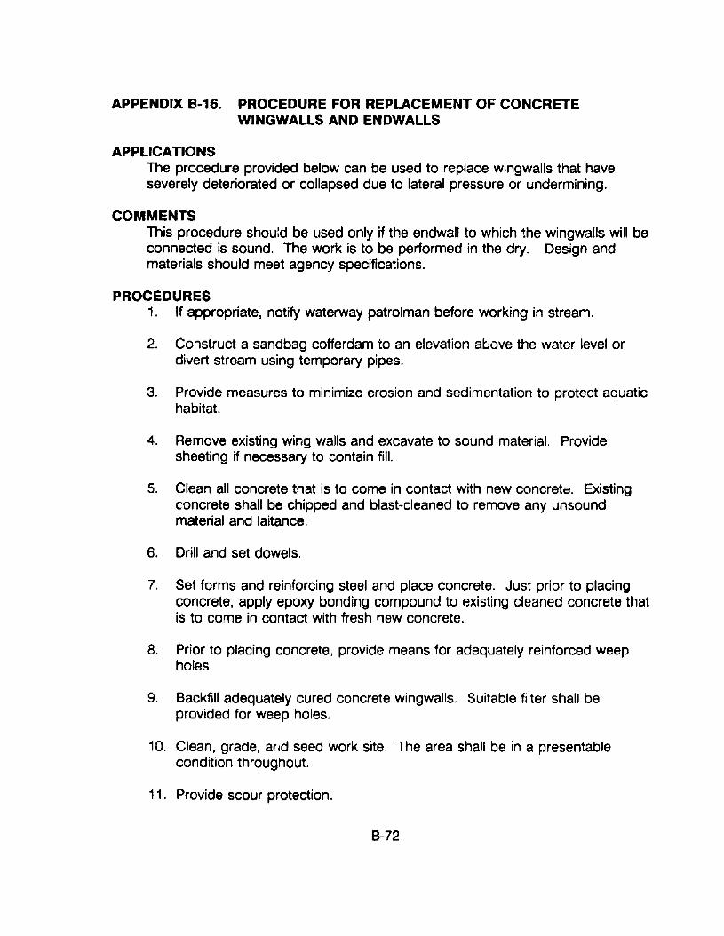
APPENDIX 8·16. PROCEDURE FOR REPLACEMENT OF CONCRETEWINGWALLS AND ENDWALLS
APPLICATIONSThe procedure provided below can be used to replace wingwalls that haveseverely deteriorated or collapsed due to lateral pressure or undermining.
COMMENTSThis procedure should be used only if the endwall to which the wingwalls will beconnected is sound. The work is to be performed in the dry. Design andmaterials should meet agency specifications.
PROCEDURES1. If appropriate, notify waterway patrolman before working in stream.
2. Construct a sandbag cofferdam to an elevation above the water level ordivert stream using temporary pipes.
3. Provide measures to minimize erosion and sedimentation to protect aquatichabitat.
4. Remove existing wing walls and excavate to sound material. Providesheeting if necessary to contain fill.
5. Clean all concrete that is to come in contact with new concret~. Existingconcrete shall be chipped and blast-cleaned to remove any unsoundmaterial and laitance.
6. Drill and set dowels.
7. Set forms and reinforcing steel and place concrete. Just prior to placingconcrete, apply epoxy bonding compound to existing cleaned concrete thatis to come in contact with fresh new concrete.
8. Prior to placing concrete, provide means for adequately reinforced weepholes.
9. Backfill adequately cured concrete wingwalls. Suitable filter shall beprovided for weep holes.
10. Clean, grade. and seed work site. The area shall be in a presentablecondition throughout.
11. Provide scour protection.
B-72
RESOURCE COMMITMENT =3: 5 4 3 2 1Heavy Medium Low
COST RELATIVE TOREPLACEMENT =3 : 5 4 3 2 1
High Medium Lvw
REFERENCES1. Martin C. Rissel, John P. Taylor, and Robert J. Vollmer, Procedures and
Standards for Bridge Maintenance, Final Report, Research Project SS-Q8.Pennsylvania Department of Transportation, June 1990.
8-73
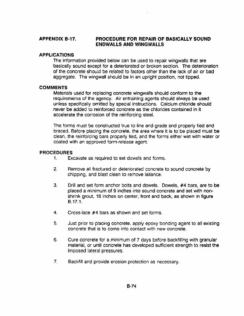
APPENDIX B-17. PROCEDURE FOR REPAIR OF BASICALLY SOUNDENDWALLS AND WINGWALLS
APPLICATIONSThe information provided below can be used to repair wingwalls that 9rebasically sound except for a deteriorated or broken section. The deteriorationof the concrete should be related to factors other than the lack of air or badaggregate. The wingwall should be in an upright position, not tipped.
COMMENTSMaterials used for replacing concrete wingwalls should conform to therequirements of the agency. Air entraining agents should always be usedunless specifically omitted by special instructions. Calcium chloride shouldnever be added to reinforced concrete as the chlorides contained in itaccelerate the corrosion of the reinforcing steel.
The forms must be constructed true to line and grade and properly tied andbraced. Before placing the concrete, the area where it is to be placed must beclean, the reinforcing bars properly tied, and the forms either wet with water orcoated with an approved form-release agent.
PROCEDURES1. Excavate as required to set dowels and forms.
2. Remove all fractured or deteriorated concrete to sound concrete bychipping, and blast clean to remove laitance.
3. Drill and set form anchor bolts and dowels. Dowels, ·#4 bars, are to beplaced a minimum of 9 inches into sound concrete and set with nonshrink grout, 18 inches on center, front and back, as shown in figureB.17.1.
4. Cross-lace #4 bars as shown and set forms.
5. Just prior to placing concrete, apply epoxy bonding agent to all existingconcrete that is to come into contact with new concrete.
6. Cure concrete for a minimum of 7 days before backfilling with granularmaterial, or until concrete has developed sufficient strength to resist theimposed lateral pressures.
7. Backfill and provide erosion protection as necessary.
8·74
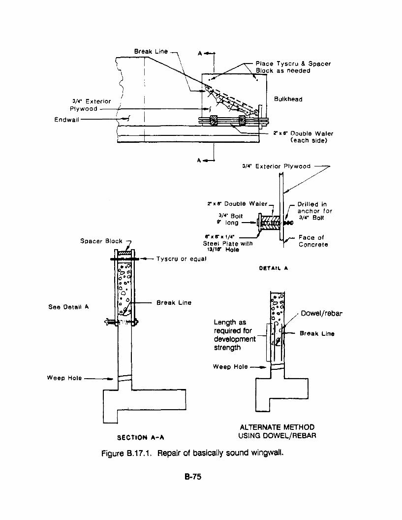
Bulkhead
'Z' II 8" Double Waler(each side)
3/4· Exterior Plywood
Place Tyscru & Spacerr-~""""__-.....B;.;.IO;;;.;Ck as needed
AJ
3/." ExteriorPlywood ---I---+------~-
Endwall ----+-O-i
Break Line
Face ofConcrete
. Dowel/rebar
rDrilled inanchor for3/." Bolt
DETAIL A
Length asrequired fordevelopmentstrength
Break Line
8"x8" x,/." _~Steel Plate with
'3/'1" Hole
~-....-- Tyscru or eQual
See Detail A
Weep Hole -- _
SECTION A-A
ALTERNATE METHODUSING DOWEL/REBAR
Figure B.17.1. Repair of basically sound wingwall.
8-75
RESOURCE COMMITMENT = 2: 5 4 3 2 1Heavy Medium Low
COST RELATIVE TOREPLACEMENT = 2: 5 4 3 2 1
High Meu;um Low
REFERENCES1. Martin C. Rissel, John P. Taylor, and Robert J. Vollmer, Procedures and
Standards for Bridge Maintenance, Final Report, Research Project 86-08.Pennsylvania Department of Transportation, June 1990.
8-76
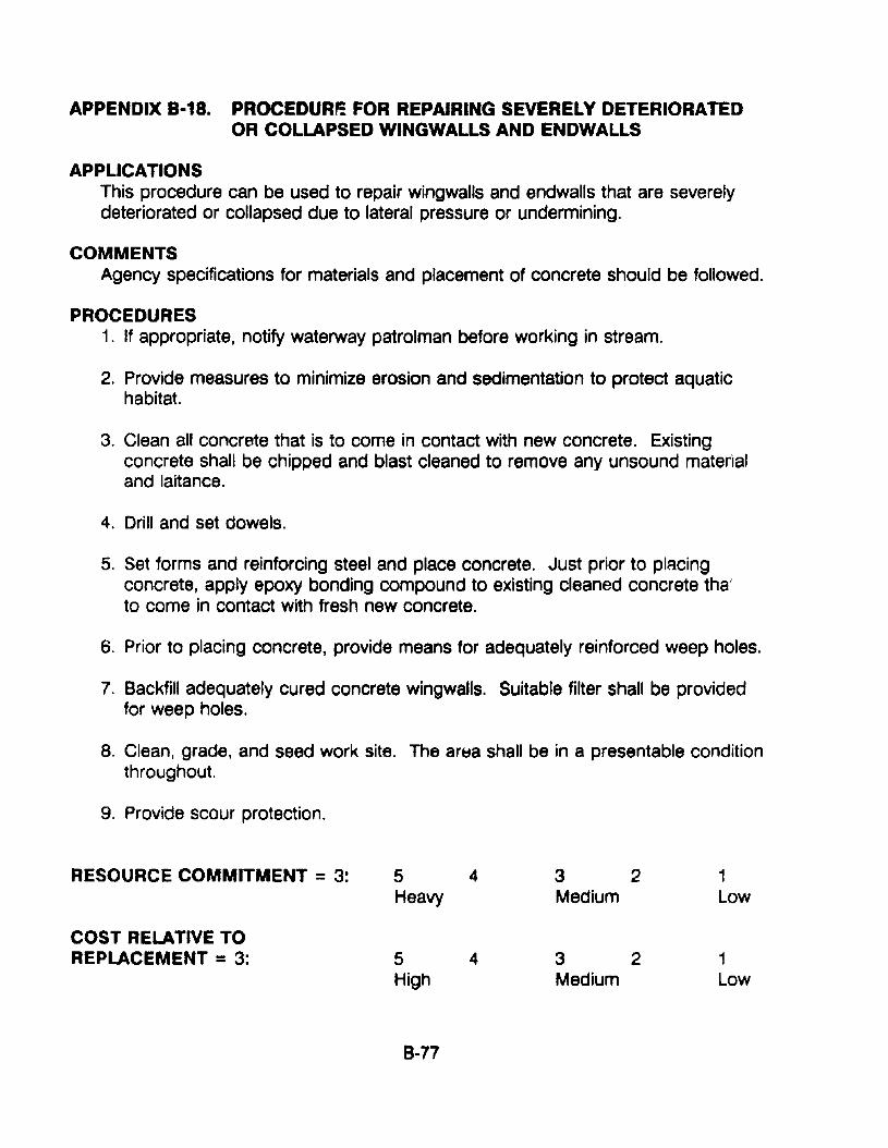
APPENDIX B·18. PROCEDURr: FOR REPAIRING SEVERELY DETERIORATEDOR COLLAPSED WINGWALLS AND ENDWALLS
APPLICATIONSThis procedure can be used to repair wingwalls and endwalls that are severelydeteriorated or collapsed due to lateral pressure or undermining.
COMMENTSAgency specifications for materials and placement of concrete should be followed.
PROCEDURES1. If appropriate, notify waterway patrolman before working in stream.
2. Provide measures to minimize erosion and sedimentation to protect aquatichabitat.
3. Clean all concrete that is to come in contact with new concrete. Existingconcrete shall be chipped and blast cleaned to remove any unsound materialand laitance.
4. Drill and set dowels.
5. Set forms and reinforcing steel and place concrete. Just prior to placingconcrete, apply epoxy bonding compound to existing cleaned concrete thaJ
to come in contact with fresh new concrete.
6. Prior to placing concrete, provide means for adequately reinforced weep holes.
7. Backfill adequately cured concrete wingwalls. Suitable filter shall be providedfor weep holes.
8. Clean, grade, and seed work site. The art:ta shall be in a presentable conditionthroughout.
9. Provide scour protection.
RESOURCE COMMITMENT =3: 5 4 3 2 1Heavy Medium Low
COST RELATIVE TOREPLACEMENT =3: 5 4 3 2 1
High Medium Low
B-77
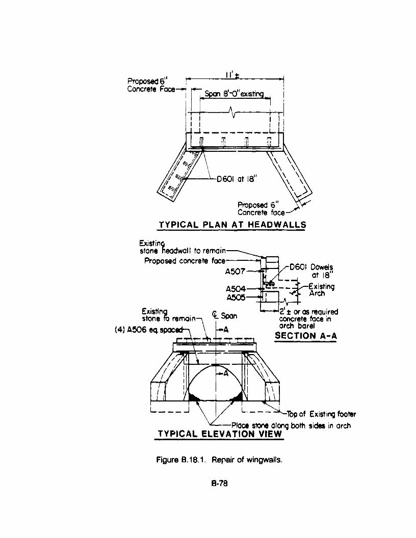
1
~~-J---D601 at ISII
\ \\ \
\ \, ,\ ,)v
Proposed 6 11
Concrete face~TYPICAL PLAN AT HEADWALLS
" j II'~Proposed 6 ..Concrete Face r: 8ea' 81-011 'ti11" exs ~l
I I ~ IiI I I I I~ L I
m in
0601 Dowelsat 18
11
ExistingArch
t:t: or as reQuiredconcrete face inarch barel
SECTION A-A
Top of Existing footer-Place stone along both sid. in arch
TYPICAL ELEVATION VIEW
Existinc:,stone headwall to remain
Proposed concrete face -\A507~=r---.
A504-~:::.:
A505
~t~~e"~ remain, l Span
(4) A506 eq.spoc -~t~_ .....
Figure 8.18.1. Repair of wingwalls.
8-78
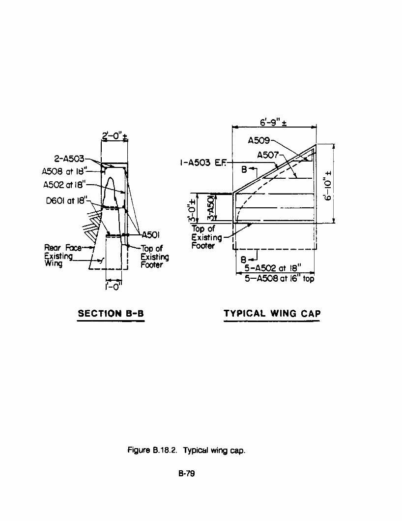
6'_g" ±
11-0'
+f
jO
r~~- ---- -J, I
If-+----l
I-A503 E.F.-+---""'\.
~~---I.A501
Top ofExistingFooter
Rear Face---,E~ isting Lat'Wing ..: _
2-A503A508 at I~I-'---Iof
A502 at ISII
0601 at IS"
SECTION a-a TYPICAL WING CAP-
Figure 8.18.2. Typic&1 wing cap.
8-79
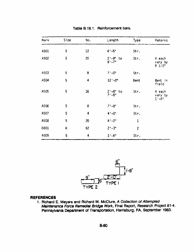
Table 8.18.1. Reinforcement bars.
Mark Size No. Length Type Remarks
ASOI 5 12 6'':5'' Str.
A502 5 20 2' -9'1 to St r. 4 each6'_7" vary by
9 1/2"
AS03 5 8 7'-0" Str.
AS04 5 4 12 1 -0" Bent Bent infield
A505 5 16 2' -8" to Str. 4 each7'-8" vary by
1'-8"
A506 5 8 71-8" St r.
A507 5 4 4' -0" Str.
A50a 5 20 4' -2" 1
0601 6 62 2'-3" 2
A509 5 4 1'~6" St r' •
REFERENCES1. Richard E. Weyers and Richard M. McClure, A Collection of Attempted
Maintenance Force Remedial Bridge Work, Final Report, Research Project 81-4.Pennsylvania Department of Transportation, Harrisburg, PA, september 1983.
B-8O
APPENDIX 8·19. PROCEDURE FOR CONCRETE JACKET REPAIRS FORENDWALLS AND WINGWALLS
APPLICATIONSThis procedure can be used to repair the deteriorated face of concrete endwallsor wingwalls when the deterioration of the concrete is not related to lack of airin the concrete, inferior to inadequate aggregate, or another progressiveconcrete deterioration problem.
COMMENTSAgency specifications for materials and placement of concrete should befollowed. Endwalls and wingwalls should be jacketed only when the existingmaterial is deemed sound.
PROCEDURES1. Remove deteriorated concrete and laitance by chipping and blast
cleaning.
2. Drill and set tyscrus and lagstuds.
3. Set reinforcing steel and forms.
4. Just prior to placing concrete, apply epoxy bonding agent.
5. Place cement concrete, cure, remove forms, and provide erosion controlas shown in figure 8.19.1.
RESOURCE COMMITMENT = 1: 5 4 3 2 1Heavy Medium Low
COST RELATIVE TOREPLACEMENT = 1: 5 4 3 2 1
High Medium Low
REFERENCES1. Martin C. Rissel, John P. Taylor, and Robert J. Vollmer, Procedures and
Standards for Bridge Maintenance, Final Report, Research Project 86-08Pennsylvania Department of Transportation, June 1990.
8-81
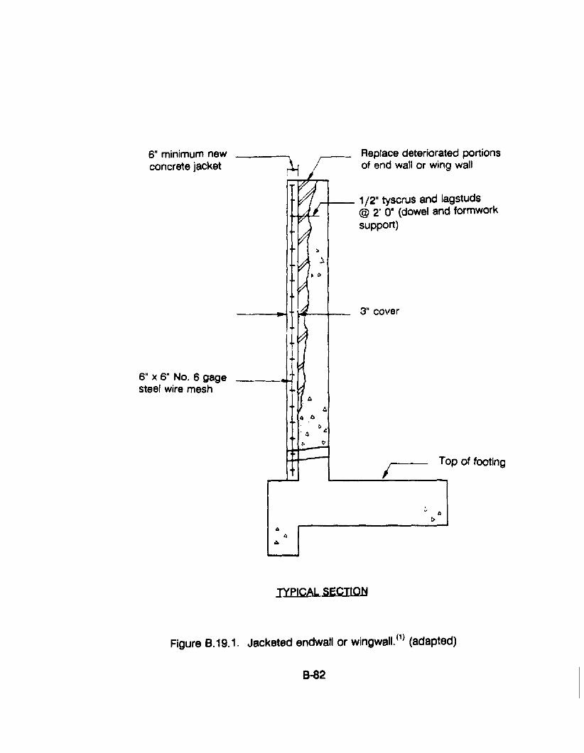
Replace deteriorated portionsof end wall or wing wall
6" minimum newconcrete jacket ;i, I
~J~/J"""""-- 1/2" tyscrus and Jagstuds
," , @ 2' O· (dowel and formworktI" \ support)~~
6" X 6" No. 6 gagesteel wire mesh
3" cover
lYPICAl SECTION
ITop of footing
Figure 8.19.1. Jacketed endwall or wingwall. (1) (adapted)
8-82
APPENDIX 9-20. PROCEDURES FOR UNDERPINNING
APPLICATIONSThe following procedures have application to underpinning portions of hydraulicstructures including footings, wingwalls, and the upstream end of culverts.
COMMENTSUnderpinning is the process of increasing the support for structures that havedeteriorating or inadequate soil support. The cause may be scour and erosionof soil from under the structural footings or the structure may have beenconstructed without adequate soil support. Although several concepts may beused for reinstating or increasing the structural support by underpinning, themost appropriate will depend on the site conditions and the type of repair orretrofit work that must be accomplished.
PROCEDURESSeveral concepts and methods may be used for underpinning portions ofhydraulic structures depending upon the nature and severity of the problems.The following are general guidelines that may be used as the basis for the workto be done.
1. General Procedure
a. Construct a sandbag cofferdam to an elevation above the waterlevel or divert stream using temporary pipes.
b. Clean all exposed concrete of marine growth and remove loose ordeteriorated concrete.
c. Excavate to a depth of two feet below the bottom of the scour oras directed by the engineer as shown in figure 8.20.1.
d. Drill required dowel holes, set and install dowels, set additionalreinforcing, and place and anchor forms.
e. Place and consolidate the concrete, making sure that the scourarea is completely filled.
f. Remove forms and (as necessary) protect against continuedstreambed erosion with gabions or stone riprap. Where thescoured-out material is fine-grained, a properly designed filtershould be placed prior to placing the riprap.
8-83
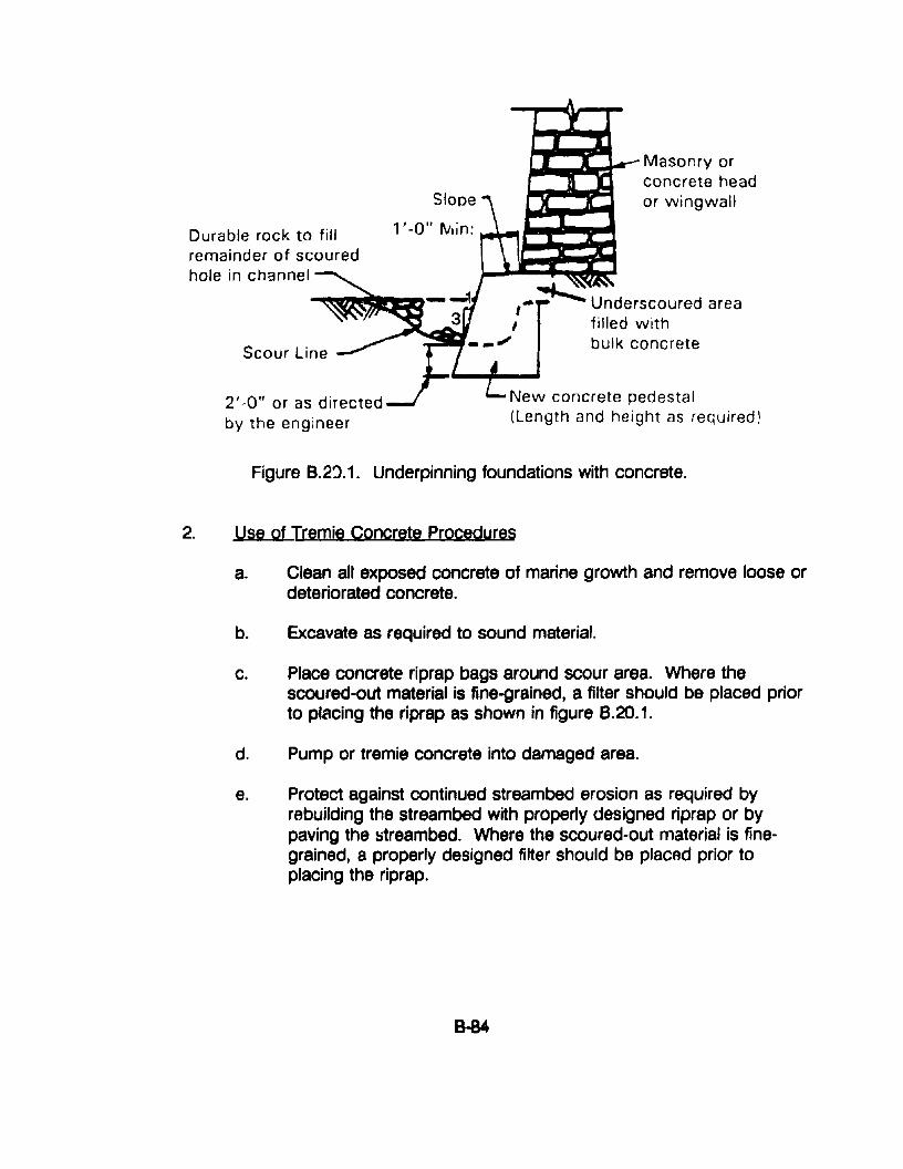
Durable rock to fillremainder of scouredhole in channel
2' -0" or as directedby the engineer
Masonry orconcrete heador wingwall
l'-0" rvlin: ~~jt:C::::I=
I-~ Underscoured area, filled with
- -" bulk concrete
New concrete pedestal(Length and height as required!
Figure B.2~.1. Underpinning foundations with concrete.
2. Use Qf Tremie CQncrete PrQcedures
a. Clean all exposed concrete Qf marine grQwth and remQve IQQse Qrdeteriorated concrete.
b. Excavate as required tQ sound material.
c. Place concrete riprap bags arQund SCQur area. Where thescoured-Qut material is fine-grained, a filter should be placed priortQ placing the riprap as shown in figure 8.20.1.
d. Pump or tremie concrete into damaged area.
e. Protect against continued streambed erQsiQn as required byrebuilding the streambed with properly designed riprap or bypaving the streambed. Where the scoured-Qut material is finegrained, a properly designed filter should be placed prior toplacing the riprap.
B-84
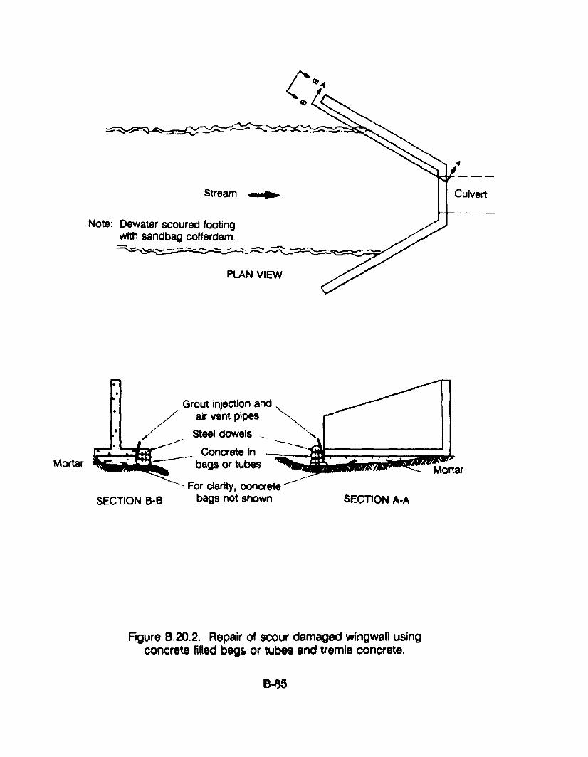
~ --.-.-..... .........,.-.~._.
Stream •
Note: Dewater scoured footingwith sandbag cofferdam.
.~-_ ......_~
PLAN VIEW
Mortar
SECTION A-A
•.•
Grout injection and~
/
air vent pipes
Steel dowels __
-----Concrete in ---"'IIG:JiI--------...J
~......i--....- bags or tubes
----- For clarity, concrete--SECTION B-B bags not shown
Mortar
Figure 8.20.2. Repair of scour damaged wingwall usingconcrete filled bags, or tubes and tremie concrete.
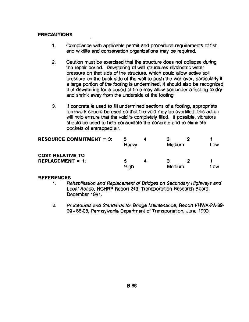
PRECAUTIONS
1. Compliance with applicable permit and procedural requirements of fishand wildlife and conservation organizations may be required.
2. Caution must be exercised that the structure does not collapse duringthe repair period. Dewatering of wall structures eliminates waterpressure on that side of the structure, which could allow active soilpressure on the back side of the wall to push the wall over, particularly ifa large portion of the footing is undermined. It should also be recognizedthat dewatering for a period of time may allow soil under a footing to dryand shrink away from the underside of the footing.
3. If concrete is used to fill undermined sections of a footing, appropriateformwork should be used so that the void may be overfilled; this actionwill help ensure that the void :s completely filled. If possible, vibratorsshould be used to help consolidate the concrete and to eliminatepockets of entrapped air.
RESOURCE COMMITMENT = 3:
COST RELATIVE TOREPLACEMENT = 1:
5 4Heavy
5 4High
3 2Medium
3 2Medium
1Low
1Low
REFERENCES1. Rehabilitation and Replacement of Bridges on Secondary Highways and
Local Roads, NCHRP Report 243, Transportation Research Board,December 1981.
2. Procedures and Standards for Bridge Maintenance, Report FHWA-PA-8939+86-08, Pennsylvania Department of Transportation, June 1990.
8-86
APPENDIX 8-21: PROCEDURE FOR REPOINTING MASONRY
APPLICATIONSThe following guidelines and procedures apply to repointing or remortaringmasonry walls and culverts.
COMMENTSMasonry walls and culverts of laid-up stone or brick are subject to having themortar joints eroded by the effects of mortar deterioration, freeze-thaw cycles,and channel flow. Replacing the mortar. repointing. is necessary to maintainstructural integrity. Repointing by this procedure should be attempted onlyabove the water line. Therefore, accomplishment during periods of low water isrecommended to gain maximum access.
Repointing masonry should be performed in accordance with plans.specifications. and procedures that are established for each specific project.The work area may include the entire length of an existing masonry culvert oronly portions of it. It may also include the construction of sluices, or othermeans to conduct water through the structure. to protect the work area andfreshly placed concrete mortar from flowing water during and after therepointing operation.
When protective material. such as riprap, is excavated to gain access to thework, it should be replaced in conformance with existing standards andprocedures or procedures established for this specific project.
PROCEDURES1. Tnoroughly clean masonry joints of all loose and unsound mortar and
foreign material. Deteriorated mortar may be removed by hand or powertools. Surfaces to be mortared should be cleaned with high pressurewater. air-blasting. or sand-blasting, as appropriate and necessary.
2. Saturate the joint surfaces with clean water before applying mortar.
3. Pressure grout all voids between masonry units with mortar, making thesurface of the mortar flush with the adjacent face of the structure, asshown in figure B.21.1.
4. Cure all new mortar with wet burlap or clear curing compound.
5. Clean the face of the masonry structure.
If used. pressure grouting should be performed by experienced pressure-gunoperators.
B-87
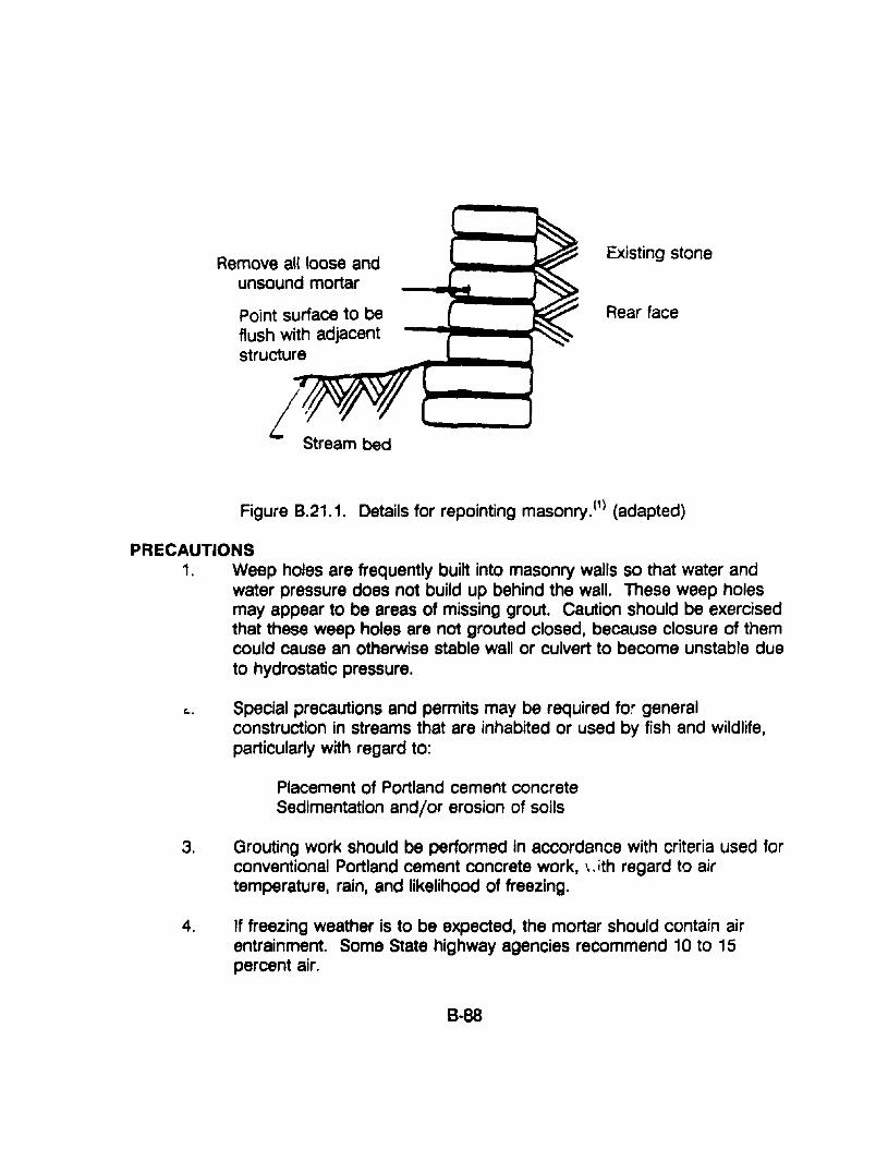
Remove all loose andunsound mortar
Point surface to beflush with adjacent
struetur:e~__..,.,.....,~-r"__-;
Stream bed
Existing stone
Rear face
Figure B.21.1. Details for repointing masonry. (1) (adapted)
PRECAUTIONS1. Weep holes are frequently built into masonry walls so that water and
water pressure does not build up behind the wall. These weep holesmay appear to be areas of missing grout. Caution should be exercisedthat these weep holes are not grouted closed, because closure of themcould cause an otherwise stable wall or culvert to become unstable dueto hydrostatic pressure.
l:.. Special precautions and permits may be required for generalconstruction in streams that are inhabited or used by fish and wildlife,particularly with regard to:
Placement of Portland cement concreteSedimentation and/or erosion of soils
3. Grouting work should be performed in accordance with criteria used forconventional Portland cement concrete work, '.. ith regard to airtemperature, rain, and likelihood of freezing.
4. If freezing weather is to be expected, the mortar should contain airentrainment. Some State highway agencies recommend 10 to 15percent air.
8-88
RESOURCE COMMITMENT = 1: 5 4 3 2 1Heavy Medium Low
COST RELATIVE TOREPLACEMENT = 1: 5 4 3 2 1
High Medium Low
REFERENCES1. Richard E. Weyers and Richard E. McClure, A Collection of Attempted
Maintenance Force Remedial Bridge Work, Report FHWA/PA-84/003,Pennsylvania Department of Transportation.
2. Procedures and Standards tor Bridge Maintenance, Report FHWA-PA-8939 + 86-08, Pennsylvania Department of Transportation, June 1990.
3. Specification for Concrete Masonry Construction, AC1531.1-76, AmericanConcrete Institute, Revised 1983.
4. Standard Specification for Grout for Masonry, ASTM C-476.
5. Standard Specification for Aggregates for Masonry Grout, ASTM C-270
6. Standard Specification for Mortar for Unit Masonry, ASTM C-2l0.
7. Standard Specification for Aggregate for Masonry Mortar, ASTM C-144.
APPENDIX 8·22. PROCEDURE FOR INSTALLING SAFETY END TREATMENTS
APPLICATIONSThe following procedure is applicable to single structures and end treatments widerthan 36 inches. These structures can be made traversable for passenger-sizedvehicles by using bar grates or pipes to reduce the clear opening width.
COMMENTSTypically, culvert inlets and outlets consist of concrete headwalls and wingwalls forlarger structures and beveled end sections for the smaller pipes. These types ofdesigns may represent an obstacle to motorists who run off the road byintroducing a fixed object protruding into an otherwise traversable embankment oran opening into which a vehicle can drop, causin~ an abrupt stop. Threealternatives can be used to minimize these hazards: ( ,2)
Use a traversable design;• Extend the structure so that it is less likely to be hit; and• Shield the structure.
This procedure will focus on the first option. The AASHTO Road Design Guidedirects that single structures and end treatments wider than 36 inches can bemade traversable for passenger vehicles by installing bar grates or pipes spacedon 3D-inch centers to reduce the clear width opening. Crash tests have shownthat passenger vehicles can cross grated culverts and sections on slopes as steepas 3: 1, at speeds as low as 20 miles per hour when steel pipes spaced on 3O-inchcenters are used.
However, safety treatments must be hydraulically efficient. The AASHTO ModelDrainage Manual states that culverts greater than 30 inches in diameter shall be:
"safety treated with a grate if the consequences of cloggingand causing a potential flooding hazard is less than thehazard of vehicles impacting an unprotected end. If a grateis used. an open area shall be provided between the bars of1.5 to 3.0 times the area of the culvert entrance."
The AASHTO Road Design Guide stresses that, to maintain hydraulic efficiency,bar grates may be applied to flared wingwalls. flared end sections, or to endsections that are la~ger in size than the main barrel. The bottom line is that ifsignificant hydraulic capacity or clogging problems could result. the designershould consider shielding the structure.
8-90
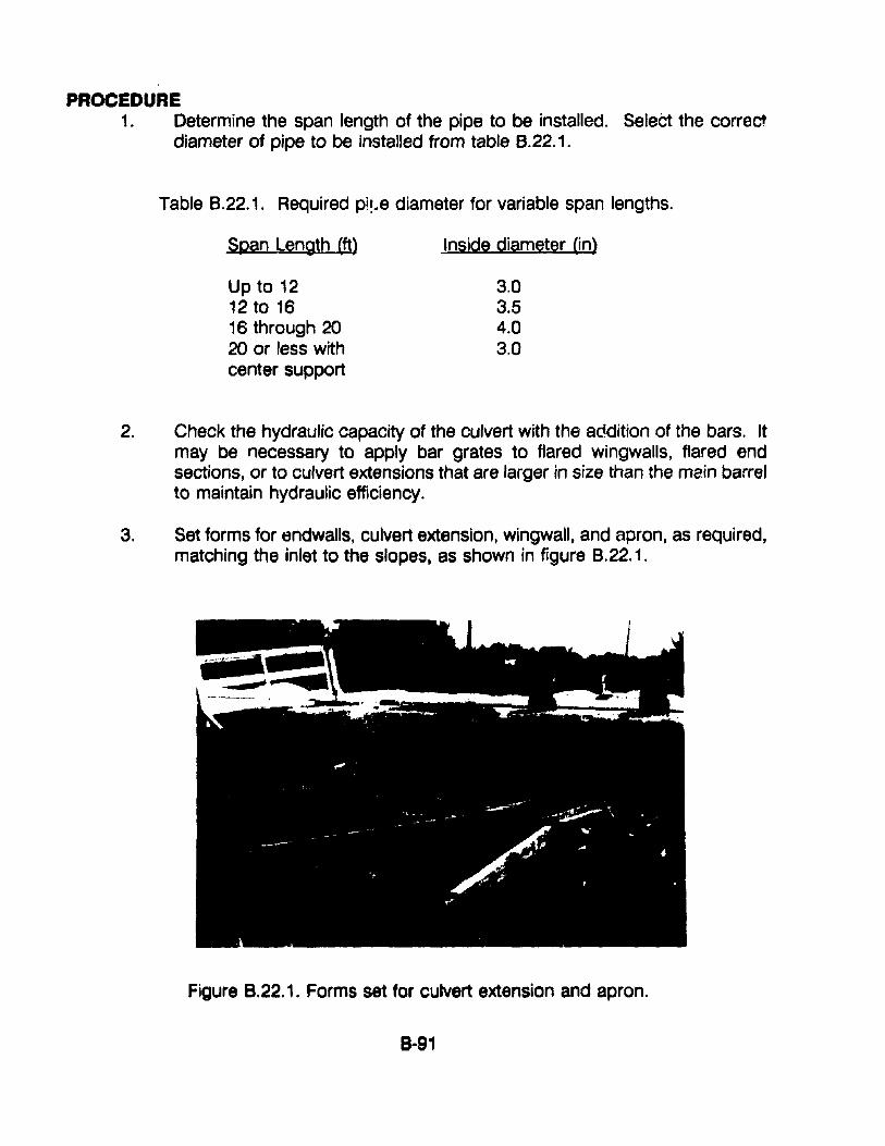
PROCEDURE1. Determine the span length of the pipe to be installed. Select the correct
diameter of pipe to be installed from table 8.22.1.
Table 8.22.1. Required pi!..e diameter for variable span lengths.
Span Length (tt)
Up to 1212 to 1616 through 2020 or less withcenter support
Inside diameter (in)
3.03.54.03.0
2. Check the hydraulic capacity of the culvert with the addition of the bars. Itmay be necessary to apply bar grates to flared wingwalls, flared endsections, or to culvert extensions that are larger in size than the main barrelto maintain hydraulic efficiency.
3. Set forms for endwalls, culvert extension, wingwall, and apron, as required,matching the inlet to the slopes. as shown in figure 8.22.1.
Figure 8.22.1. Forms set for culvert extension and apron.
8·91
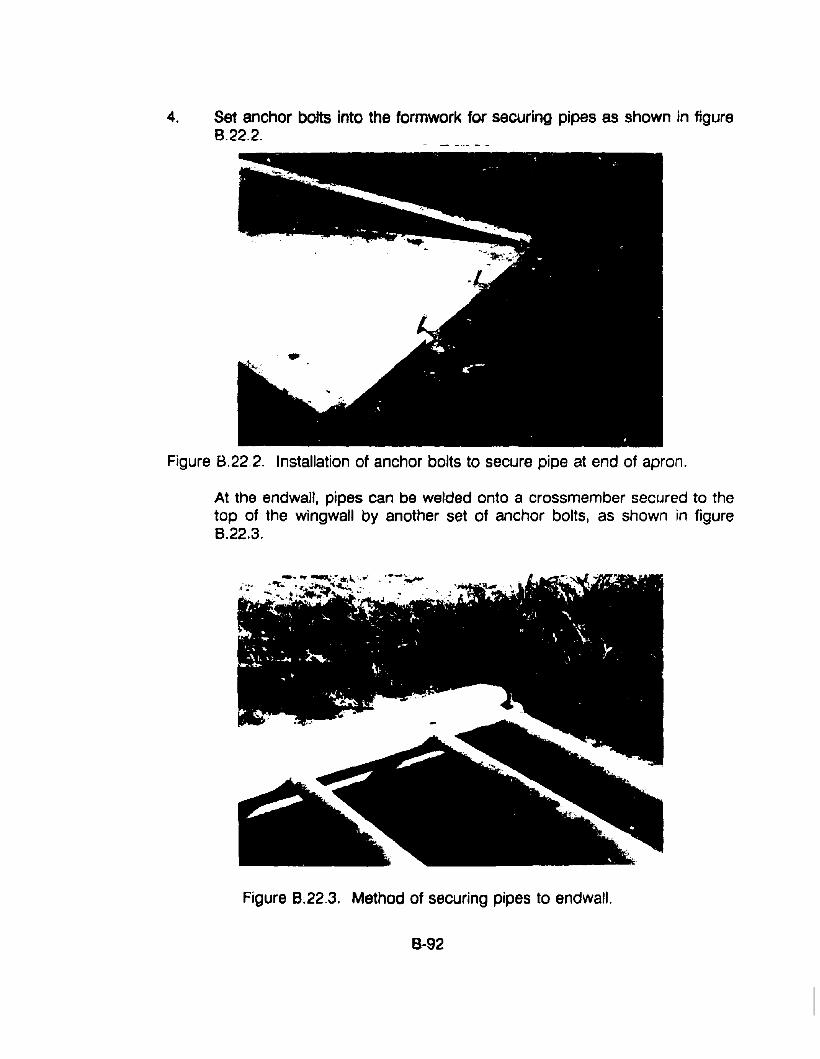
4. Set anchor bolts into the formwork for securing pipes as shown in figure8.22.2.
Figure 8.22.2. Installation of anchor bolts to secure pipe at end of apron.
At the endwall, pipes can be welded onto a crossmember secured to thetop of the wingwall by another set of anchor bolts, as shown in figure8.22.3.
Figure 8.22.3. Method of securing pipes to endwall.
8-92
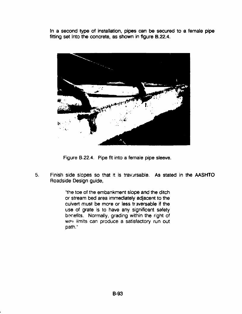
In a second type of installation, pipes can be secured to a female pipefitting set into the concrete, as shown in figure 8.22.4.
;.~. '.
I,.
Figure 8.22.4. Pipe fit into a female pipe sleeve.
5. Finish side slopes so that it is travJrsable. As stated in the AASHTORoadside Design guide,
"the toe of the embankment slope and the ditchor stream bed area immediately adjacent to theculvert must be more or less tr lversable if theuse of grate is to have any significant safetyb~r.efits. Normally, grading within the right ofWfl': limits can produce a satisfactory run outpath."
8-93
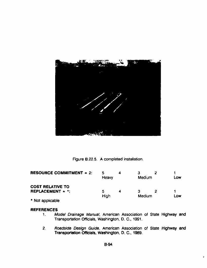
Figure 8.22.5. A completed installation.
RESOURCE COMMITMENT = 2: 5 4 3 2 1Heavy Medium Low
COST RELATIVE TOREPLACEMENT = *: 5 4 3 2 1
High Medium Lowif Not applicable
REFERENCES1. Model Drainage Manual, American Association of State Highway and
Transportation Officials, Washington, D. C., 1991.
2. Roadside Design GUide, American Association of State Highway andTransportation Officials, Washington, D. C., 1989.
8-94
APPENDIX 8-23: PROCEDURES FOR FACILITATING FISH PASSAGE
APPLICATIONSThe following information applies to the design of new culverts as well as to theretrofitting of existing culverts to facilitate fish passage.
COMMENTSCulverts and other drainage structures represent 8 variety of potential obstaclesto fish passage. The two most common of these problems are excessive watervelocities through the culvert or vertical barriers that are too high for fish toovercome. Perching, which is the tendency of a stream to develop a falls orcascade at a culvert outlet due to the eros!')n of the stream channel downstreamfrom a culvert, is commonplace.
Other problems may include:
• Depth of water in the culvert at high, moderate, or low flows;
• The coincidence of desigr. flows with seasonal time of fish migration;
• The size and species of fish passing through the culvert;
• The velocity of water over a given length of structure in relation to theswimming capabilities of the fish; and
• Icing and debris problems.
In addition to the conditions in existing culverts that presently block or hinder fishpassage, there are literally millions of culverts approaching the end of their usefullife. If the structure is presently only marginal for fish passage, repair orretrofitting of these structures can further block the remaining ftsh runs.
PRO'~EDURES
In this section, general guidelines are given for both the installation of newculverts and for retrofitting existing culverts to improve fish passage. theseguidelines are discussed in more detail in Fish Passage Through Culverts,(1)prepe'red by the U.S. Department of Agriculture Forest Services for the FederalHighway Administration.
1. .General Culvert Installation Guidelines for Effective Fish Passage
a. Culverts should be designed and installed to keep the velocity of thewater passing through the pipe equal to the predicted stream velocity atdesign flows.
8-95
b. The culvert should maintain the natural gradient of the stream in order toavoid turbulenC''l and scour However, if the gradient of the stream issteep, resting peols Sh0Uld be provided.
c. Bottomless arch culverts or partially buried pipes are preferred overround pipes, especially if:
• The culvert is over 100 feet in length;
• Threatened or endangered species of fish reside in the stream; or
• The natural stream gradient is steep enough that velocities causedownstream erosion or scour at the culvert outlet.
The most desirable culvert bottom is one consisting of the naturalstreambed or native materials.
d. Corrugated mstal culverts generally reduce velocities and allow juvenilefish to utilize the corrugations as resting areas as they migrate.
e. Where fish passage is critical, pipe having the largest corrugationspossible can be used to reduce velocities and provide a resting place:
• 6 x 2 inch for steel structural plate;
• 9 x 2 1/2 inch for aluminum structural plate; and
• 5 x 1 inch for corrugated metal pipe.
f. The water depth for effective fish passage should be not less than sixinches for resident trout and at least twelve inches for adult anadromousfish.
g. The use of concrete aprons at culvert openings is not recommended.The lower roughness coefficient and steeper gradient of the apronincrease the velocity of the outlet. Depth of fiow can also be a problemwith concrete aprons.
h. The alignment and location of the culvert are important to effective fishpassage because sudden changes in stream flow direction can causeturbulence resulting in scour and erosion of the streambank, andundermining of culvert inlets or outlets. Ideally, a stream channel shouldhave 100 feet of straight alignment above and below the culvert.
8·96
i. Construction of cutoff walls attached to the bottom of the culvert andextending perpendicular to the streambed can prevent the underminingof culverts.
j. In streams with critical migratory fish needs, an outlet pool with tailwatercontrol should be designed and constructed at the downstream end ofthe culvert. The length and width of the outlet pool should be twice thediameter of the culvert (20) and the bottom elevation of the pool shouldbe at least two feet below the invert elevation of the culvert outlet.
2. General Guidelines for Retrofitting Culverts for Impr,:>ved Fish Pas3age
The need for any of these devices should be determined by a biologist anddesigned by an engineer.
a. Addition of baffles - Although the addition of baffles to a culvert shouldonly be considered as a last resort, baffles can be advantageous in thefollowing respects:
• A baffle system can produce a pocket of low velocity water in the culvertwhere fish can momentarily rest during high flows.
• When culverts have been placed in streams with steep gradients,velocities passing through the culvert may exceed the maximum velocityallowable for fish passage. Adding baffles may be necessary to reducethe velocity.
• The addition of baffles will change the operation of a culvert from inlet tooutlet control. Those originally operating under outlet control willcontinue to do so.
• In addition to the value of baffles in controlling velocity, tr3y increasewater depth in the pipe to provide fish passage during low flow periods.
• A culvert with a steep gradier;t can be converted into a series of pools, ineffect, creating a modified fist' ladder.
The disadvantages of adding baffles include the following:
• Baffles can significantly reduce the hydraulic efficiency of a culvert;
• The design life of baffles is typically substantially less than the culvertitself. They require periodic maintenance and can significantly reduce thelife expectancy of the culvert.
8-97
• Corrugated metal pipes and pipe arches are designed as flexiblestructures. Unless the baffle system is equally flexible, the system willhave a higher potential for structural failure than the pipe itself.
• Metal baffles are normally bolted onto the culvert floor using metal platesfor added strength. Simply bolting the baffle to the culvert floor isinadequate. It usually pulls loose during flood flows.
• A minimum culvert diameter of five feet is required in round metal culvertsto provide a four foot wide space for baffle installation. Culverts that areless than five feet in diameter should generally not be equipped withbaffles.
• The addition of baffles may not always be cost effective. Both installationand maintenan~e expenses should be considered before retrofitting astructure with baffles.
b. Raising the tailwater to overcome perchin.g - An insurmountable barrieroften is presented to migrating fish when the outlet of the culvert is so farabove the tailwater elevation that fish cannot enter the culvert outlet.Solutions may include the following:
• A perching proolem can be corrected by installing one or a series oflow head dams below the culvert outfall. These dams can consist ofgabions, concrete sills, logs, or handplaced rock. If the culvert barrieris excessive, it may be necessary to install several of these dams toraise the tailwater to within one foot of the pipe.
• Low head dams also can provide a resting pool for fish before theyentel the culvert.
• The backwater also reduces the velocity at the culvert outlet.
• The restinSJ pool acts as an energy dissipator and provides atransition zone between the culvert and the natural chal"neldownstream.
• By creating a backwater with these dams, adequate water depth ismaintained in the culvert. However, since back water decreasesculvert capacity, care must be taken to ensure that the culvert willpass peak flows.
c. Overcoming inlet dram - Deposition of natural streambed material ormaterial from adjacent embankments at the culvert inlet can result in
B-98
supercritical flow conditions, creating a hydraulic jump within theculvert. Although fish may have progressed through the culvert to theinlet, the turbulence and increased velocity may make it impossibie toproceed for some species. One publication that may be helpful inavoiding inlet drops is Design of Depressed Inlet CUlvert. AlaskaDepartment of Transportation and Public Facilities. (2)
d. Debris control - Debris control is important to fish migration becausedebris partially blocking the culvert inlet can cause an increase invelocity that certain species cannot overcome. Chapter 5 of thismanual discusses debris control structures. Additional information isalso available in Hydraulic Engineering Circular (HEC} No.9, DebrisControl Structures. Federal Highway Administration. ( )
Additional helpful literature on fish passage is listed in the references.
PRECAUTIONSCompliance with applicable permit and procedural requirements of fish andwildlife and conservation organizations may apply to construction and retrofitwork in fishery waters.
RESOURCE COMMITMENT = *: 5 4 3 2 1Heavy Medium low
COST RELATIVE TOREPLACEMENT = *: 5 4 3 2 1
High Medium l.ow
*Varies according to type procedure selected.
REFERENCES1. Calvin O. Ba"er and Frank E. Votapka, Fish Passage Through Culverts,
Report No. FHWA-FL-90-006, Federal Highway Administration,Washington, DC, November 1990.
2. Mark C. Jordan and Robert F. Carlson, Design of Depressed InletCulverts, Department of Transportation and Public Facilities, Fairbanks,AK, June 1987.
3. G. Reiksen and L.J. Harrison, Debris Control Structures, HydraUlicEngineering Circular No.9, Federal Highway ,a,dministration, Marcy 1971.
8·99
4. V. Blevins and R. Carlson, Retrofit Design of Drainage Structures forImproved Fish Passage: Literature Review, Report AK-RD-89-02,University of Alaska, Institute for Northern Engineering, AlaskaDepartment of Transportation and Public Facilities, June 1988.
5. Fish Migration and Fish Passage· A Practical Guide to Solving FishPassage Problems, Report EM-7100-12, U.S. Department of Agriculture,Forest Service, Revised June 1980.
6. D. Kane and P. Wellen, A Hydraulic Evaluation of Fish Passage ThroughRoadway Culverts in Alaska, Report AK-RD-85-24 and 24A, University ofAlaska, Institute for Northern Engineering, Alaska Department ofTransportation and Public Facilities, August 1985.
7. Roadway Drainage Guide for Installing Culverts to A..;commodate Fish,Alaska Region Report Number 42, U.S. Department of Agriculture, ForestService.
B·1oo
APPENDIX 8·24: PROCEDURES FOR INSTAWNG BEAVER CONTROL DEVICES
APPLICATIONSThe following methods are applicable to the installation of appurtenances toprevent beavers from plugging culvert inlets.
COMMENTSThe easiest way for a beaver to construct a dam in a waterway is to plug aculvert inlet. The result is often a washed-out roadway. Because of thepersistent problem and the cost of keeping culverts clear. the San DimasEquipment Development Center of the U.S. Forest Service tested and evaluatedthe following methods of beaver control in the Ottawa National Forest in northernMichigan. Each approach is based on two traits characteristic of beavers:
1. They normally do not try to plug a culvert if the araa to be plugged is muchgreater than the culvert opening itself.
2. They usually will not try to plug an opening through which water flowsvertically upward.
PROCEDURESThe four structural methods presented below include (1) the perforated pipemethod, (2) the perforated culvert method, (3) the downspout method, and (4)the baffle method.
1. The Perforated Pipe MetbQd: The theory behind this method is that.although the beaver may build a dam in the culvert entrance. water can stillflow through the perforations and out the pipe downstream of the dam. Thebeaver may plug some of the perforations but usually not all. This typeinstallation is illustrated in figure B.24.1.
a. Place a piece of perforated pipe with one end inside the culvert inlet anathe other end extending upstream, well beyond the culvert entrance.
b. Install a cap or plug on the upstream end of the perforated pipe.
c. To allow for a larger volume of water flow. more than one pipe may beused or A "Y" or "T" section In the pipe upstream of the culvert so thatextra arms of perforated pipe can be installed.
d. The pipe or pipes can rest on the bottom of the culvert interior. However.it should be supported above the bottom of the stream. A stake or a
B·101
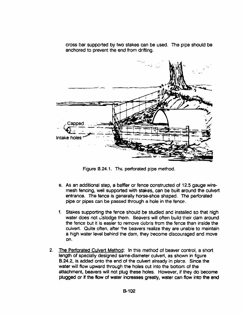
- -\"L '-~_
cross bar supported by two stakes can be used. The pipe should beanchored to prevent the end from drifting.
Figure B.24.1. The; perforated pipe method.
e. As an additional step, a baffler or fence constructed of 12.5 gauge wiremesh fencing, well supported with stakes, can be built around the culvertentrance. The fence is generally horse-shoe shaped. The perforatedpipe or pipes can be passed through a hole in the fencE'.
f. Stakes supporting the fence should be studied and installed so that highwater does not ~lslodge them. Beavers will often build their dam aroundthe fence but it is easier to remove dobris from the fence than inside theculvert. Quite often, after ~hp, beavers realize they are unable to maintaina high water level behind the dam, they become discouraged and moveon.
2. The perforated Culvert Method: In this method of beaver control, a shortlength of specially designed same-diameter culvert, as shown in figure8.24.2, is added onto the end of the culvert already in plar:e. Since thewater will flow upward through the holes cut into the bottom of theattachment, beavers will not plug these holes. However, if they do becomeplugged or if the flow of water increases greatly, water can flow into the end
8-102
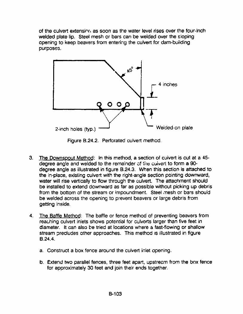
of the culvert extensinr. as soon as the water level rises over the four-inchwelded plate lip. Steel mesh or bars can be welded over the slopingopening to keep beavers from entering the culvert for dam-buildingpurposes.
2-inch holes (typ.)
L 4 inches
Welded-on plate
Figure 8.24.2. Perforated culvert method.
3. The Downspoyt Method: In this method, a section of cuivert is cut at a 45degree angle and welded to the remainder cf the cuivert to form a 90degree angle as illustrated in figure 8.24.3. When this section is attached tothe in-place, existing culvert with the right-angle section pointing downward,water will rise vertically to flow through the culvert. The attachment shouldbe installed to extend downward as far as possible without picking up debrisfrom the bottom of the stream or impoundment. Steel mesh or bars shouldbe welded across the opening to prevent beavers or large debris fromgetting inside.
4. The Baffle MethQd: The baffle or fence method of preventing beavers fromreat;hing culvert inlets shows potential for culverts larger than five feet indiameter. It can also be tried at locations where a fast-flowing or shallowstream precludes other approaches. This method is illustrated in figureB.24.4.
a. Construct a box fence around the culvert inlet opening.
b. Extend two parallel fences, three feet apart, upstream from the box fencefor approximately 30 feet and join their ends together.
8-103
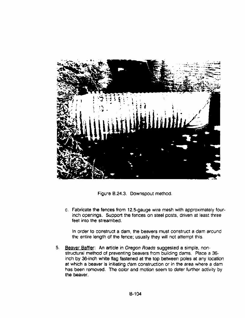
Figute B.24.3. Downspout method.
c. Fabricate the fences from 12.5-gauge wire mesh with approximately fourinch openings. Support the fences on steel posts, driven at least threefeet into the streambed.
In order to construct a dam, the beavers must construct a dam aroundthe: entire length of the fence; usually they will not attempt this.
5. Beaver Baffler: An article in Oregon Roads suggested a simple, nonstructural method of preventing beavers from building dams. Place a 36inch by 36-inch white flag fastened at the top between poles at any locationat which a beaver is initiating cam construction or in the area where a damhas been removed. The color and motion seem to deter further activity bythe beaver.
B-104
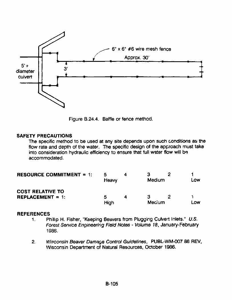
5'+diameterculvert
3'
6" X 6" #6 wire mesh fence
Approx.30'
Figure B.24.4. Baffle or fence method.
SAFETY PRECAUTIONSThe specific method to be used at any site depends upon such c.onditions Sf) theflow rate and depth of the water. The specific design of the ap~roach must takeinto consideration hydraulic efficiency to ensure that full w9ter flow will b~accommodated.
RESOURCE COMMITMENT = 1: 5 4 3 2 1Heavy Medium Low
COST RELAT~VE TOREPLACEMENT = 1: 5 4 3 2 1
High Mec;ium Low
REFERENCES1. Ptlillip H. Fisher, "Keeping Beavers from Plugging Culvert Inlets." U.S.
Forest Service Engineering Field Notes - Volume 18, January-February1986.
2. Wi~consin Beaver DamlJ~e Control Guidelines, PUBL-WM-Q0786 REV,\AJisconsin Department of Natural Resources, October 1986.
8-105
APPENDIX 8-25: PROCEDURES FOR REPAIRING CRACKS IN CONCRETE
APPLICATIONSThe following discussion applies to the repair of cracks in Portland cementconcrete.
COMMENTSThe procedures and materials that should be used for repairing cracks inPortland cement concrete will frequently depend upon the cause of the c~~ck,
its location, and the environment surrounding it. Shrinkage cracks may be qtlitenarrow and shallow and have little influence on the structural behavior, whereaswider and deeper cracks may have been caused by structural loading and maysignify more serious effects on structural load carrying capacity. Both types ofcracks may have an influence on long term durability of the structure.
With regard to procedures for repairing cracks in concrete culverts, there isalways an overall requirement that cracks be clean and preferably dry beforethey a.re repaired. Obviously, it may be diffic'..lIt to meet both of these criteria forcracks in culverts. The cracks will generally be old by the time they are found,and if they are wide enough, they may be full of sand or dirt. In addition, theymay be continuously wet from water from either the inside or the outside of theculvert. Thus, generally some work will be needed to prepare the crack for therepair material.
There is a choice of materials that may be used to repair cracks. The materialsgenerally may be c3tegorized as either flexible crack fillers or rigid materials thatare more permanent that may create a structural repair. The latter groupincludes both Portland cement-based mortar and structural adhesives includingepoxy systems that may be filled with aggregate or a powder or unfilled.
The general opinion of many practitioners is that cracks that are movingbecause of movement in the structure should be repaired with a flexible sealingtype material, whereas stationary cracks may be filled with a rigid material. Thisis not an absolute rule, but it does highlight the need to determine whether thecrack is moving. For most concrete culvf;::rts it may be assumed that the crackis moving, especially since there is a close relationship between soil pressuresand the resistance (and strength) of a concrete culvert; anC'! the soil pressuresthat may hFlV(i caused cracking will continue to be exerted on the culvert.Under sr. lie Situations the condition may have stabilized. Thus, there is arationale that the structure is probably still moving and it should be filled with aflexible material. However, there is also another principle in soil·structurebehavior that if conditions are allowed to continue they will become worse, asthe soil pressures will continue to deform the structure until collapse O\.."Curs.From that standpoint it may be best to try to strengthen or stabilize the
B-106

structure so that it can resist the increasing soil pressures, in this case byeffecting a structural repair on the more serious cracks. This will require fillingthe cracks with a rigid material. If tensile, flexure of shear forces will occur itmay be nece~sary to use a structural adhesive. Some of these materials maybe installed in wet or submerged cracks.
PROCEDURES1. Installation of a Flexible Sealant
The following is a general procedure for fiBing a crack with a flexiblesealant. The manufacturers of such sealants will have more specificrecommendations for their particular materials if the highway agency hasnot established such procedures.
a. Clean the surface of the concrete.
b. Route a groove into the surface of the crack, so that it will serveas a reservoir for the sealant.
c. Clean concrete dust and debris out of the crack by sand-blasting,air-water jet, or both.
d. Fill the crack with the sealant by pressure injection or troweling. Iftroweling is to be done a bond breaker should be first applied tothe surface of the concrete on both sides of the crack so that thesealant will not have a wide width at the top of the crack.
e. Scrape excess sealant off the concrete surface, so that thesurface will be smooth. (For some types of cracks it may bedesirable to trowel a shallow depression in the surface of thesealant.)
2. Installation of a Portland Cement Mortar or GroutWide cracks may be repaired by filling with portland cement grout, asfollows:
a. Clean the surface of the concrete.
b. Install built-up seats and grout nipples at intervals along andastride the crack to provide a pressure tight contact with theinjection apparatus.
c. Seal the crack between the grout nipples, with a cement paint,sealant, or grout.
8-107
d. Flush the crack to clean it and to test the seal.
e. Grout the crack. The grout mixture may contain cement andwater or cement plus sand plus water, depending on the width ofthe crack. However, the water-cement ratio should be kept as lowas possible to provide maximum strength and low shrinkage. Thegrout may include a water reducer or other admixtures to improvethe properties of the grout.
3. Repair by Injection of Epoxy AdhesiveThe following is from guidelines of the Pennsylvania DOT.
Equipmenta. Type - The equipment used to meter and mix the two injection
adhesive components and inject the mixed adhesive into the crackshall be portable, positive displacement type pumps with interlockto provide positive "atio control of exact proportions of the twocomponents at the nozzle. The pumps shall be electric or airpowered and shall provide in-line metering and mixing.
b. Discharge Pressure - The injection equipment shall have automaticpressure control capable of discharging the mixed adhesive at anypreset pressure up to 200 psi plus/minus 5 psi and shall beequipped with a manual pressure control override.
c. Ratio Tolerance - The equipment shall have capability ofmaintaining the volume ratio for the injection adhesive prescribedby the manufacturer of the adhesive with a tolerance of plus orminus 5 percent by volume at any discharge pressure up to 200psi.
d. Automatic Shut-Off Control - The injection equipment shall beequipped with sensors on both the component A and B reservoirsthat will automatically stop the machine when only one componentis being pumped to the mixing head.
Preparationa. Surfaces adjacent to cracks or other areas of application shall be
cleaned of dirt, dust, grease, oil, efflorescence or other foreignmatter detrimental to bond of epoxy injection surface seal system.Acids and corrosives shall not be permitted for cleaning.
b. Entry ports shall be provided along the crack at intervals of notless thl'in the thickness of the concrete at that location.
8·108
d.
Surface seal material shall be applied to the face of the crackbetween the entry ports. For thrOl.: ...h cracks, surface seal shall be~pr'ied to ~"tl1 face~ if pose-ible.
~nOLgh tin Ie hJr the surface s6al material to gain adequatestrength shall pass before proceeding with the injection.
=POX>, injectiona. Injection of epoxy adhesive shall begin at lower entry port and
continue until there is an appearance of epoxy adhesive at thenext entry port adjacent to the entry port being pumped.
b. When epoxy adhesive travel is indicated by appearance at thenext adjacent port, injection shall be discontinued on the entry portbeing pumped, and epoxy injection shall be transferred to the nextadjacent port where epoxy adhesive appeared.
c. Perform epoxy adhesive injection continuously until cracks arecompletely filled.
d. If port to port travel of epoxy adhesive is not indicated, the workshall immediately be stopped and the engineer notified.
Finishinga. When cra~ks are completely filled, epoxy adhesive shall be cured
~or sufficient time to allow removal of surface seal without anydraining or runback of epoxy materia! from cracks.
b. Surface seal material and injection adhesive runs or spiils shall beremoved from concrete surfaces.
c. The lace of the crack shall be finished flush to the adjacentconcrete showing no indentations or protrusions caused by theplacement of entry ports.
8·109
RESOURCE COMMITMENT • 2: 5 4 3 2 1Heavy Medium Low
COST RELATIVE TOREPLACEMENT = *: 5 4 3 2 1
High Medium Low
• Varies according to procedure selected.
REFERENCES1. ·Causes. Evaluation. and Repair of Cracks in Concrete Structures," (ACI
224.1 R-84) ACI MIO'J.aI at Concrete Practice, American ConcreteInstitute, 1989.
2. Guiding documents are available from the following companies:8. Master BUildings (Formerly Adhesive Engineering)b. Sika Chemical Company
8-110
APPENDIX 8-26. PROCEDURES FOR SEAUNG CULVERT JOINTS
APPUCATIONSThe following applies to sealing the joints of corrugated metal and precastconcrete culverts. Although the methods are used more commonly for metal(flexible) culverts, they may be used for the others, with some adaptation.
COMMENTSCorrugated metal pipe and pipe arch as well as precast concrete culverts aresubjected to a variety of external loads and changing soil conditions that maycause the circumferential joints to open. When this occurs infiltration andexfiltration frequently develop and cause a progressively worsening condition.Open joints lead to loss of the embankment material and creation of voids in theembankment surrounding and supporting the culvert. Uneven soil pressuresmay cause distortion of metal culverts and cracking and settlement of precastconcrete culvert, with possible collapse of both types.
The amount and complexity of remedial action will depend upon the siteconditions, the type of culvert, and the level and severity of the deterioration.Site conditions include such factors as location, height of fill over the culvert andinfiltration from water under a considerable hydraulic head pressure. Thesolution to the problem generally involves installation of an expansion ring thatbridges and closes the open joint and pressure grouting to fill voids in the soilbehind the joint. The closure ring may have to :arry structural loads, externalnydraulic pressure, or both. The following describes techniques for the use oftwo types of closure rings. Information on grouts and grouting techniques isprovided in appendix B, section 11.
PROCEDURES1. Steel Expansion Ring Gaskets
Several types of corrugated steel expansion rings are available for repair ofculvert joints from inside of the culvert, as shown in figure B.25.1
a. The type and width of band to be used is determined based on theamount of separation and the misalignment at the joint. For example, acorrugated band would be selected if there were no, or very little,misalignment.
b. Based on the type and width of band selected, a gasket that will properlyseal the joint is determined,i.e., an O-ring type could be used with acorrugated band; a strip type with other types of bands where minormisalignment is determined; and a mastic type with a flat band wheremisalignment is greater. Strip gaskets should be wider than the band.
8-111
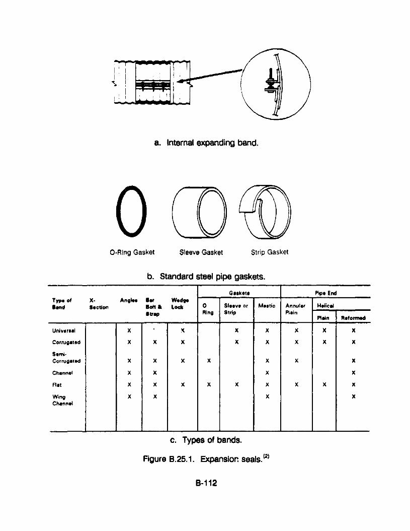
8. Internal expanding band.
O-Ring Gasket Sleeve Gasket Strip Gasket
b. Standard steel pipe gaskets.-
G.,k.t' Pip. EndType of x- An,le. .., w.dgelend Section Bott • Lock 0 SllIve or Ma.tic Annuler Helic..
'tr., Ring Strip PleinPlein A.formed
Uni"er••1 X :< X X X X X
Co,rugated X X X X X X X X
Semi·Corrugated X X X X X X X
Channel X X X )(
A't X X X X X X X X X
Wing X X X XChan"el
c. Types of bands.
Figure 8.25.1. Expansior. seals. (2)
B-112
c. Fabricate band(s) using 2 sections that conform to the existing pipeshape. Each section should conform as nearly as possible to 1/2 of thecross-section of the pipe, with the maximum being equal to the perimeterof the 2 sections. Shorter than 1/2 cross-section may be desirable if thetwo pieces are to be bolted together prior to pla,:ement at the joint. Sizeand location of angles are determined by design, space reqUired forhardware (nuts and washers), and space required to facilitate installation.The size of the bolt sh~uld be 3/4 inch minimum. It may be necessaryto specify larger diameter bolts for some installations.
d. The peripheral area of the pipe where the band is to be placed must becleaned and prepared. Dirt and debris should be removed. Localizeddents and distortions should be smoothed out by hammering with heatapplied as necessary to help in the straightening. All fins, burrs, andother imperfections in the pipe should be ground to a smooth surface.
e. Install the band with gasket either with the two sections bolted togetheror as single units. The bottom half should be installed first. On largerpipes, the top half may require temporary support prior to bolting thesectinns together. If a strip gasket is used, the lap should be as close tothe top a~ pract!cal. On pipe arches, it may be necessary to weld thebottom section to the pipe due to the possibility of buckling at the invertwhen the bolts are tightened.
f. Tighten the bolts evenly until a tight fit is realized. A tight fit may bedetermined by the distortion of the gasket or band-to-pipe contact.Caution: observe invert area of band for buckling.
g. Seal the edges of the band with a mastic.
SAFETY PRECAUTIONSIf galvanized metal is used for the band, removal of the galvanizing isreauired prior to welding clip angles. Caution should be exercised whenst"' ')p or field welding is performed on galvanized metals. Fumes can betoxic. The welder should wear a mask in case all galvanizing has not beenremoved.
2. AMEX-10/WEKO-SEAL™ Internal Joint Sealiog System
The Miller Pipeline Corporation has developed s proprietary system for therepair of water, wastewater, gas, and other type: vf pipelines made ofreinforced concrete, cast iron, ductile iron, steel, cement lined, and unlinedpipe. It has also been used by several highway agencies to repair precastand corrugated metal culverts. It has been used on pipelines from 14 to 208
8-113
inches in diame~er. The standard seal can span a 4-1/2 inch gap and thedouble-wide seal can span a 9 inch wide gap. A particular advantage is thatit can withstand a high external pressure, at least up to 100 feet of head. Itmay be used for a wide variety of shapes, including circular, oval, arch, andeven box-shaped pipes and culverts.
This joint sealing system is comprised of a Ethylene Propylene DieneMonomer (EPDM) rubber seal into which stainless steel strips are set. Theseal is resistant to weather, chemicals and bacteria. Installation of the sealinvolves expansion of the ring with a hydraulic jack and locking off the ringby inserting metal wedges between the ends of the stainless steel bands. Amore detailed description of the installation procedure is as follows:
a. The culvert should be cleaned, at least in the area of the joints to besealed. Generally this can be done with hand tools.
b. Gaps in the joints must be cleared of dust and debris and filled flush withthe internal surface of the culvert with a quick setting mortar or grout.
c. The area of the culvert on both sides of the joint, where the "lip seals"make contact with the culvert, must be prepared to a ftnish that will allowthe "lip seals" to bed consistently, so as to provide a permanent seal.
d. Immediately prior to fitting the seal, the area must be cleaned and coatedwith a joint lubricant.
e. The seal is then placed in position, Jjarallel to the joint gap.
f. Two stainless steel-radiused shims are placed under the wedge area ingrooves in the rubber seal and the stainless steel bands are install'3d inthe grooves.
g. A hydraulic jack expander is then attached and used to eXp[~nlj thestainless steel bands and the rubber gasket against the inside of theculvert. After the gasket ring is expanded the wedgd shims are setbetweGn the ends of the bands and the expander is retracted.
RESOURCE COMMITMENT =2: 5 4 3 2 1Heavy Medium Low
COST RELATIVE TOREPLACEMENT = 1: 5 4 3 2 1
High Medium Low
8-114
SPECIFICATIONS
No specifi~ specifications apply directly to this type of work. Standardspecifications should be used for bands, gaskets, clip angles and hardware.Size of angles and bolts should be in accordance with AASHTO designstandards.
REFERENCES,. Drainage Technology Bulletin, National Corrugated Steel Pipe
Association, September 1988.
2. Handbook of Steel Drainage and Highway Construction Products,American Iron & Steel Institute, Washington, D.C.
3. Miller Pipeline Corporation (address provided in Appendix D).
8·115
APPENDIX 8·27. PROCEDURES '~OR PREVENTING END SECTION DROPOFFOF PRECAST C.')NCRETE CULVERTS
APPLICATIONSThe following procedure ma)' be used to prevent the dropoff of the end sectionsof precast concrete culverts, primarily due to erosion of the embankment aroundthem.
COMMENTSThe problem of end section dropoff is primarily caused by erosion of the soilembankment from under the entrance or exit ends of the culvert. With a loss ofsoil support from under the end sections and continued soil pressure beingapplied by the embankment above, the only possible result is that the endsections begin to rotate and slide into the scour hole since the sections of theprecast concrete culvert are not attached to one another.
The following are three concepts that may be used to connect sections togetherto prevent end section dropoff.
PROCEDURES1. Use Qf Concrete pipe Ties
The North Dakota State Highway Department uses concrete pipe ties fQrrT.ost new installatiQns to prevent end-section dropoff of reinforcedconcrete pipe and for repair projects where an end sectiQn(s) hasseparated from the other sections.
Figure 8.27.1 illustrates four methods by which concrete pipe ties can befastened to concrete end sections to secure them to the remaining pipe:(1) an adjustable tie, which consists of a coupler welded to the bolt; (2)an eye-bolt tie in which the tie is threaded through a welded eye tosecure the sections; (3) a welded pipe tie where the two bolts arewelded together as shown in detail A; and the U-Bolt tie in which the tiebolt is connected into the one end of each concrete section withoutusing a joint.
Figure B.27.2 shows the placement of the holes in the concrete pipe.Table 8.27. '1 prQvides the size of the bolts required for pipe sizes from 12inches to 132 inches. The notes shown are those that were included inNorth n~;'ota Highway Department plans for such a project.
2. J.b.t. yt ;;ileel Reinforcing Bars
Somo highway agencies have been installing steel reinforcing bars
B·116

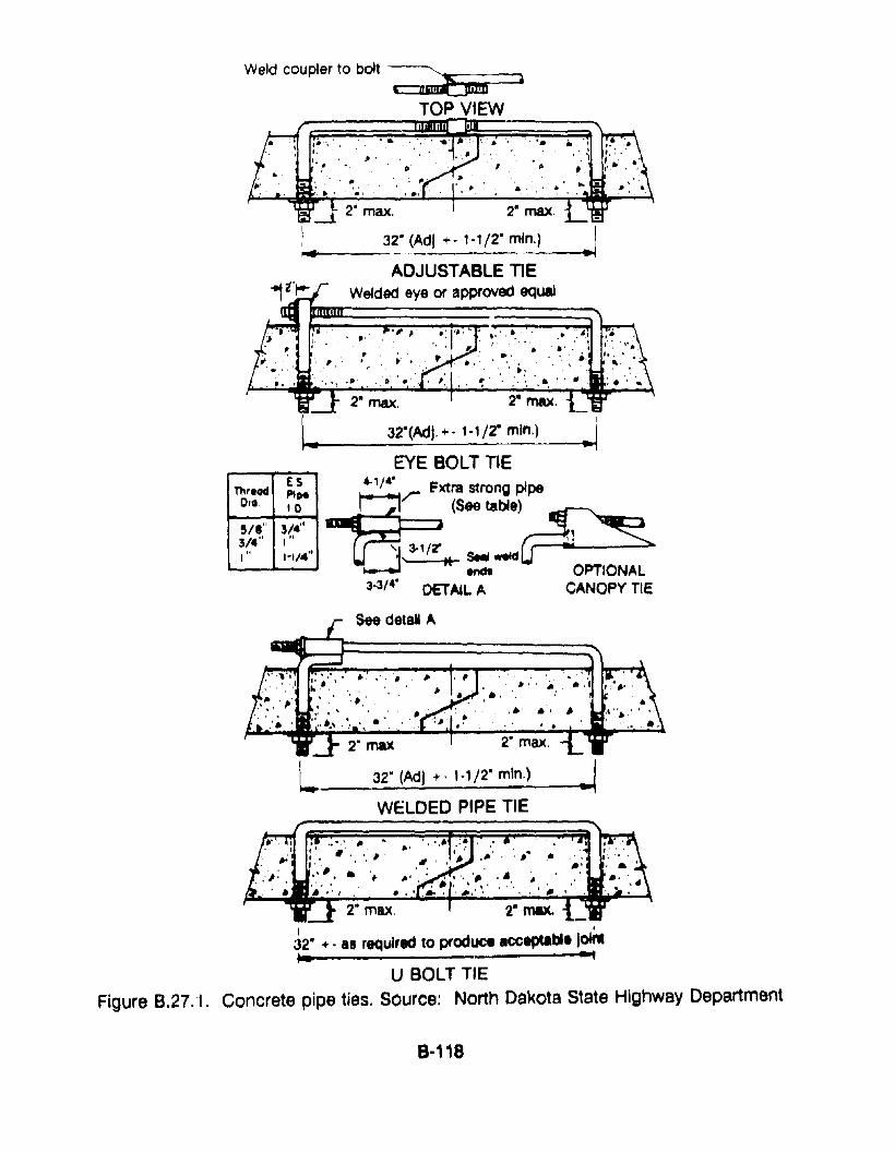
I
~
,..2" max.
32"(AdI. +. 1-1/2" min.)
..
32" (Adl +, 1-1/2" min.) jADJUSTABLE TIE
Welded eye or approved equal
, .
2" max.
. ~, ..".
.;- ~ •'1'•. " . a· .. '. ",: I. :~'. ' .•.•.,. ,:•.'
.' . t', ,.. • . ' .. ,.:'., .. ', \ •.
,., ... ,'. ~ .. ;. ", ',., ...
Weld coupler to bolt~ ).
TOP VIEW-------
ThtlltdESPI~
DIQ 10
5/'" 3/4"3/4" I"
I" "1/4"
EYE BOLT TIE"'/4"~/ Fxtra strong pipe
~(See ta~e)~I~
U 3-1 /'r ~ -~" " SNl.-dendt OPTIONAL
3-3/4• DETAIL. A CANOPY TIE
See detaN A
..2" max.2" max
L 32" (Adl +. 1-1/2" min.) I-~----'-1
WELDED PIPE TIE
2" max. 2" max..I I
32" +- 18 required to produce acceptable I~'- ~
U BOLT TIEFigure B.27. '1. Concrete pipe ties. Source: North Dakota State Highway Department
8-118
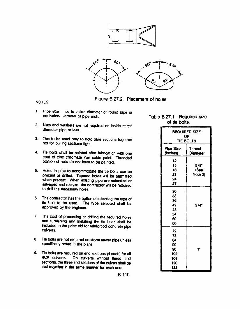
o·_-! c_ 6~ I O.
NOTES:Figure 8.27.2. Placement of holes.
1. Pipe size ,ed is Inside diameter of round pipe orequivalen. -.jlameter of pipe arch.
2. Nuts and washers are not required on Inside tit ~1·diameter pipe or less.
3. Ties to I)e used only to hold pipe sections togethernot for pulling sections tight.
4. Tie bolts shall be painted after fabrication with onecoat of zinc chromate Iron oxide paint. Threadedportion of rods do not have to be painted.
5. Holes In pipe to accommodate the tie bolts can beprecast or drilled. Tapered holes will be permittedwhen precast. When existing pipe are extended orsalvaged and relayed, the contractor will be requiredto drill the necessary holes.
6. The contractor has the option of selecting the type oftie bolt tu be used. The type selected shall beapproved by the engineer.
7. The cost of precastlng or drilling the required holesand furnishing and Instalilng the tie bolts shall beincluded In the price bid for reinforced concrete pipeculverts.
8. Tie bolts are not rer,ulred on storm sewer pipe unlessspecifically noted In the plans.
9. Tie bolts are required on end sections (4 each) for allRep CUlverts. On culverts without flared endsections, the three end sections of the culvert shall betied together In the same manner for each end.
8-119
Table 8.27.1. Required sizeof tie bolts.
REQUIRED SIZEOF
TIE BOLTS
Pipe Size Thread(Inches) Diameter
1215 5/8-18 (See21 Note 2)2427
30333842 3/4-4654eo66
7278849096 1-102108120132
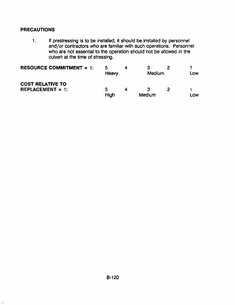
PRECAUTIONS
1. If prestressing is to be installed, it should be installed by personneland/or contractors who are familiar with such operations. Personnelwho are not essential to the operation should not be allowed in theculvert at the time of stressing.
RESOURCE COMMITMENT = 1:
COST RELATIVE TOREPLACEMENT = 1:
5 4Heavy
5 4High
8-120
3 2Medium
3 2Medium
1Low
1Low
APPENDIX 8·28. PROCEDURES FOR PATCHING CONCRETE
APPLICATIONSThe following procedure may be used to patch spalled, delaminated and brokenareas of Portland cement concrete.
COMMENTSAlthough there are many materials that may be used for patching concrete, theoverriding principle for such repairs is that it be done carefully and with goodworkmanship. The cracked, spalled, or otherwise deteriorated area to berepaired must be properly prepared, good materials must be used, and the workmust be properly protected until the materials have gained sufficient strength andother physical properties to withstand the expected environmental and loadingconditions. The alternative to this produces a patch that will not endure and thepatching work will be a total waste of time and money. Moreover, loss of thepatch may create worsening or additional problems that will certainly requireeven more time, material, and funding to correct. Depending upon the siteconditions, even well prepared and installed patches may not last very long, andit should be an established practice to periodically inspect critical patches toensure that the structure is performing adequately.
The material that normally provides the most permanent patch for Portlandcement concrete is Portland cement concrete. The closer the physicalproperties of the patch are to the existing material, the better. It is important tominimize shrinkage of the patching material. This may be done by using a lowwater/cement ratio material. A water reducing admixture may also be used.Inclusion of a latex additive to the concrete or mortar will also reduce the amountof water required for workability and also reduce the permeability of the patchmaterial. Other performance-proven additives can be used to reduce settingtirne and to increase strength.
Proper curing is important for all concrets work and especially important forpatching. Thin patche& present a particularly difficult problem because they dryout quickly. The existing concrete will tend to absorb the moisture in thepatching material. If exposed to the sun or wind, moisture is lost even morerapidly. If possible, patches should be covered with moist burlap.
The following provides some guidance for patching portland cement concrete.
PROCEDURES1. The first step is to determine the exact boundaries of the distressed
concrete. Delaminated areas may be detected by tapping with a hammer orsteel rod, with a hollow sound being produced in the delaminated area.
8-121
2.
4.
5.
6.
Remove delaminated and/or broken concrete from the distressed area. Forsome areas or structures it may be desirable to make a 3/4 inch deepsawcut around the area to be patched. For delaminated and spalled areas.the edge of the repair should be extended 12 to 18 inches into goodconcrete to be ensure that all cracked concrete is removed. Deterioratedconcrete may be removed with power-driven hand tools. If used. pneumatichammers should not be heavier than a nominal 30 pounds. A 15 poundchipping hammer may be useful. particularly around reinforcing bars. Caremust be taken to not apply heavy vibrations to reinforcing bars, to preventbreaking bond with the concrete.
The repair area should then be air - or sand-blast cleaned to removal alldust and debris. Do not use water to clean the area.
Apply a cement or cement-latex grout or an epoxy resin to the sides andbottom of the area to be repaired.
Plnce the patching material in the distressed area, in accordance with State,ACI or the manufacturer's guidelines. The material should be placed beforethe bonding layer (step 4) begins to set up. The patch material should thenbe struck off. finished. and edged as required.
The patch area should then be covered with wet burlap or a moisture barrierand allowed to cure without disturbance.
RESOURCE COMMITMENT = 1: 5 4 3 2 1Heavy Medium low
COST RELAliVE TOREPLACEMENT = 1: 5 4 3 2 1
High Medium low
8-122
APPENDIX B·2S. PROCEDURES FOR INVERT PAVING
APPLICATIONSInvert paving may be installed in all types of culverts; however, different methodsmay be used for anchoring the concrete paving to the existing culvert.
COMMENTSIt may be appropriate or necessary to concrete pave the invert of culverts thathave deteriorated because of corrosion and/or abrasion. Paving will alsoimprove the flow characteristics and provide increased durability against furtherdeterioration.
A variety of materials and techniques may be used, depending upon the natureof the existing problems and the type of culvert that must be rehabilitated. Invertpaving may be done with conventional Portland cement concrete, steel fiberreinforced concrete, or high strength concrete as well as latex modified or lowslump concretes of the type used for bridge deck overlays. As with the latter, itis also very important that the remaining invert and previous paving or protectivelayers be properly cleaned and prepared for placement of the invert paving. Inareas where acid water will deteriorate concrete, the surface may be coated withan epoxy resin or a polymer concrete.
It should be recognized that paving to restore a severely deteriorated :. wert is astructural repair. At the least the cross sectional area of the lost metal (of acorrugated metal culvert) should probably be replaced so that the culvert willhave structural strength to resist lateral thrust loading. Determination of the sizeand number of reinforcing bars used to reinforce the paving should giveconsideration to the lateral (hoop) stiffness of the culvert and the restoration ofthat stiffness.
As an alternative, instead of restoring the ring stiffnp.s:s of thE:J culvert bvreinforcing the concrete paving, the Ohio DOT has welded new invt1rt plates overthe deteriorated areas and done field paving ~ ;th minimal steel.
It should also be noted that although steel fiber reinforced concrete has excellenttoughness and durability against impact-related damage, it is not particularlyresistant to sand related abrasion loss of concrete. Moreover, use of short steelfibers should not be considered to provide adequata structural reinforcement inlieu of deformed bars or wire mesh.
Additional information on the design and application of shotcrete and gunite isprovided in appendix B, section 11.
8-123
PROCEDURESThere are several procedures and guidelines that may be used fe r paving theinverts of metal and concrete culverts. These procedures can be used equallywell for both metal and reinforced concrete, with certain modifications.
1. The following guidelines have been abstracted from the National CorrugatedSteel Pipe Association's Drainage Technology Bulletin on "Rehabilitation ofCorrugated Steel Pipe and Pipe Unes of Other Materials" dated September,1988(3T.
a. The bottom 25 percent of the inside circumference for round pipe, thebottom 30 percent of the inside periphery for pipe-arch spans of 10 feet3 inches and shorter and the bottom 35 percent of the inside peripheryfor pipe-arch spans longer than 10 feet 3 inches shall be paved unlessotherwise specified by the engineer. Details of this procedure are shownin figure 8.29.1.
b. The minimum coverage over corrugations shall be 4 inches.
c. The contractor shall schedule and conduct his diversion of wateroperations prior to and during the placement of pavement in a mannersatisfactory to the engineer;
d. When pavement is placed, the surfaces to be in contact with concreteshall be clean and dry to the satisfaction of the engineer.
e. The pavement shall be reinforced with steel fabric reinforcement meetingthe ~pecification requirements of Federal Specification FP·85, Section 709- Reinforcing Steel and Wire Rope. The reinforcement shall be placedtwo in~hes above the crests of corrugations and securely fastened bywelding or tying to studs or angles previously welded to the structure.Studs or angles are to be spaced two feet on center longitudinally andtransversely. The reinforcement shall be placed ~o provide a four-inchminimum clearance from the edges of concrete and shall be lapped sixinches minimurn. Unless otherwise shown on the plans, Ute steel fabricreinforcement shall consist of No. 6 gauge wire at six inch centerstransversely and longitudinally.
f. The pavement shall be finished to a smooth surface acceptable to theengineer. Within 18 hours after completion of finishing, the surface shallbe protected by either an approved curing cover or an approvedmembrane curing compound applied at a minimum rate of one gallon per150 square feet. However, any concrete in the invert that would beexposed to sunlight shall be protected by one of the above methods
8-124
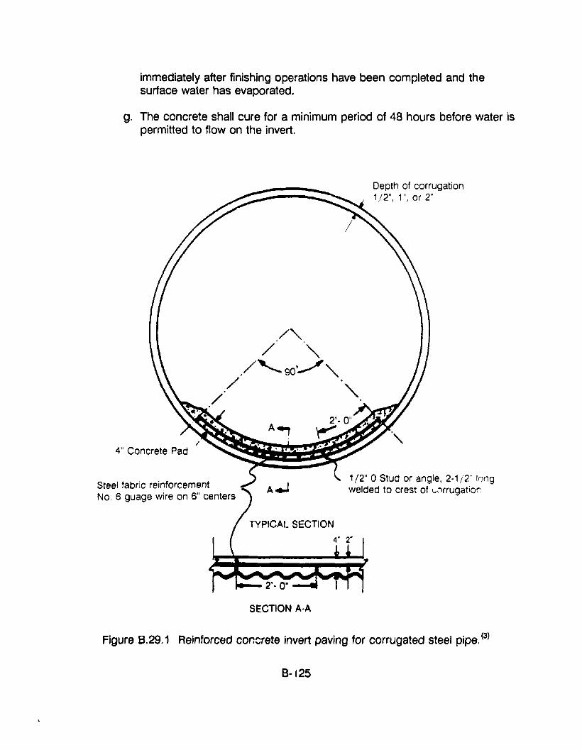
immediately after finishing operations have been completed and thesurface water has evaporated.
g. The concrete shall cure for a minimum period of 48 hours before water ispermitted to flow on the invert.
4" Concrete Pad
Steel fabric reinforcementNO.6 guage wire on 6" centers
TYPICAL SECTION
SECTION A·A
Depth of corrugation1/2", 1", or 2"
1/2" 0 Stud or angle, 2·1/2" Ir)l19welded to crest of L.,"lrrugation
Figure 8.29.1 Reinforced concrete invert paving for corrugated steel pipe. (3)
8-125
2. The following is an alternate specification (to the above) for in-placeinstallation of a concrete invert. It covers two Ohio Department ofTransportation projects that were undertaken in 1988. These guidelineshave been abstracted from the National Steel Pipe Association's Q,rainageTechnology Bulletin on "Rehabilitation of Corrugated Steel Pipe and PipeLines of Other Materials" dated September, 1988. Details of this procedureare shown in figures B.29.2 and 8.29.3.
ITEM: SPECIAL SURFACE PREPARATION OF CULVERT INVERTThis item shall consist of preparing the culvert by removing all debris, dirt,and any other material that might be present.
This item shall also include tack welding of all wire reinforcing mesh to thecorrugations of the pipe. This tack welding shall be performed as shown onthe plans and as directed by the engineer to hold the mesh in place duringpouring of the concrete.
ITEM: 503 COFFERDAMS, CRIBS AND SHEETINGThis item shall consist of furnishing all labor, material and equipmentnecessary to dewater the culverts for the performance of this work. All otherdrainage flow shall be maintained at all times while the work to the pertinentculvert is in progress. All materials and devices placed in the stream toregulate or divert flow shall be removed at the conclusion of the work.
ITEM: 602 CONCRETE MASONRY INVERT REPAIR, AS PER PLANThis item shall consist of all labor, material and equipment necessary to fillall voids found to be present below the bottom of the existing steel pipe.
These areas shall be filled with Ciass C Concrete (using the followingmixture) up to the bottom of the pipu. Note: The maximum size of coarseaggregate is to be #8 limestone.
Fine AggregateCoarse Aggregate (#8 Max. Stone)Total Aggregate/cu.yd.CementWaterIcement ratio (maximum)
8·126
1440lbs1410lbs2850lbs600 Ibs0.5
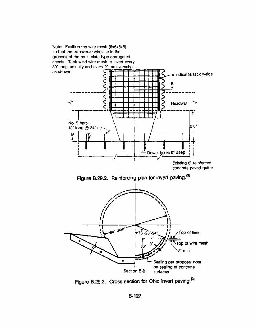
Note: Position the wire mesh (6X6x8x8)so that the transverse wires lie in thegrooves of the multi-plate type corrugatedsheets. Tack weld wire mesh to invert every
30" longitudinally and every 2" tr.::ani=s:iv=e;;rs=eli:Y~'~~:::;::+:lm-jas shown. .. x indicates tack welds
- ..---------B•
---------~
Headwall
N:7~~:~----,;>\"~,,-~.-,-'-. -7'-~1.------
1
-- -510',
18" long @ 24" cc "-
I I~" (~ ILrf-r :4! D~~h~d_e_s_s_"_d_ee_p~:l
Existing 6" reinforcedconcrete paved gutter
Figure 8.29.2. Reinforcing plan for invert paving.(3)
Sealing per proposal noteon sealing of concretesurfaces
~ /173 -23'-54" ~~op of liner
3" .I'/;'~p of wire mesh
;,;( 2' min.
-...,' .....~,
""""\\\,,It
Section B-B
Figure 8.29.3. Cross section for Ohio invert paving. (3)
8-127

This item shall also include removal of any unsuitablA rnaterial in these voidareas, as directed by the engineer. These void areas shall be filled withconcrete prior to placing the concrete invert paving. Portions of the culvertplates should be removed as necessary to facilitate complete filling of thevoids.
The quantity shown on this item is an estimated amount. The actualquantity placed will be determined by the erlgineer.
ITEM: 602 CONCRETE MASONRY, INVERT PAVING, AS PER PLANThis item shall consist of furnishing and placing the concrete invert pavingas shlJwn on the plans. The contractor shall have the option of placing thisconcrete in a conventional manner using the mix specified above for invertrepair or using pneumatically-placed mortar. In either case, the surface ofthe invert paving shall conform to the radius of the existing pipe as shownon the plans. The concrete shall conform to the radius of the existing pipeas shown on the plans. The concrete shall be finished as per section511.17 (not included herein).
If pneumatically placed mortar is used, the work shall be performed inaccordance with the requirements of item 502 (not included herein) inconstruction and materials specifications book except the wire mesh asshown on the plans will be used in lieu of wire fabric.
This item shall also include the additional material and labor to construct sixinch reinforced concrete paved apron at the pipe inlet.
The apron, as shown, transitions the circular invert paving to the existing sixinch reinforced concrete riprap and is butted and doweled into the existingsaid riprap at the Inlet end.
The wire mesh and reinforcing steel furnished and placed as shown on theplans are also included in the unit price bid for this item.
ITEM: SPECIAL SEALING CONCRETE SURFACESThe surface of the Class C concrete invert paving shall be treated withmaterial specified in the proposal note.
All of these methods described previously herein require a completeinspection and evaluation of the existing pipe to determine the best choice.With CSP (c')rrugated steel pipe), rehabilitation often requires merelyproviding a new wear surface in the invert. Typically, structural repair isunnecessary. However, if the pipe is structurally deficient, this does not rule
8·128
out rehabilitation. Repair methods can be utilized and the structuresrestored to structural adequacy and then normal rehabilitation proceduresperformed. Even with 25% metal loss, which occurs long after perforation,structural factors of safety are reduced only 25%. When originally built, CSPstorm sewers often provide factors of safety of 4 to 8, far in excess of thatrequired for prudent design.
3. The US Army, Corps of Engineers used the following specification (in 1973)to restore the invert of a three-cell reinforced concrete box culvert that had asevere abrasion problem and loss of concrete due to rocks and other debristhat passed through the culvert. This procedure involves paving the invertwith steel fiber reinforced concrete. The restored invert has functioned in asatisfactory manner for 18 years, with little damage due to abrasion.
.IDeei Fibrous Reinforced Concrete. A steel fibrous conclete overlay, 1-1/2inch minimum thickness, shall be applied to the invert of the existing culvert,to level and recondition the existing surface. The fibrous concrete shall becomposed of 3/B-inch coarse aggregate (pea gravel), fine aggregate,portland cement, wire fibers, water and admixtures as directed. The fibrousconcrete shall be batched, charged, mixed, transported, placed and curedas directed by tile Contracting Officer's representative. The Contractor shallperfvrm a full scale trial batching, charging and mixing test, one cubic yardin size, to determine the proper proportioning rates for the steel fiber.Quality control tests and test specimens shall be made from the trial batchmaterial. No separate payment will be made for the proportioning, batching,charging and mixing the trial batch, however, the Government may elect tocast test specimens of the wasted fibrous concrete. Truck mixers shall notbe batched over approximately 50 percent of their rated capacity or 3 cubicyards, whichever is smaller. Except as modified herein and below, fibrousconcrete shall be batched and mixed in accordance with ASTM C94.
a. The fine and coarse aggregates shall be weighed in t! ,e usual manner.
b. When all the aggregates are in the mixer, approximately 80 percent ofthe mixing water shall be added to the rotating mixer.
c. The steel fibers shall be added to the fine and coarse aggregate andwflter mixture at the mixer at a near continuous rate. The wire shall bepassed through a 2-1/2 to 3-inch vibrating screen; either by handdumping from boxes or by batching through a hopper in such a mannerthat clumps of fibers are not introduced into the mix.
d. All the cement shall be batched and charged into the mixer.
8·129
e. Remaining water shall be added prior to transporting to the job site.
f. The fibrous concrete mixture shall pass through a 2-inch screen prior toentering the conveying vehicle for the placement.
Fiber Reinf~rcemer~. The contractor shall furnish ferrous wire reinforcingfibers of either round, flat or deformed section. The fibers shall have one ofthe following dimensions:
Round
Flat
Deformed
SectionInch
0.016
0.01 x 0.0200.01 x 0.022
0.016 round0.010 x 0.020
x
xx
x
lengthInch
1
11
1
The wire f:bers shall have a minimum tensile strength of approximately90,000 psi and may be brass plated. The wire fibers shall be proportionedat approximately 220 pounds per cubic yard. Separate payment will bemade for wire reinforcing fibers used in the repair work.
Cleaning aDct..CQncrete Remoyal.ThEl Contractor shall clean the entire interior surface (to be repaired) witheither high-pressure water jet and/or wet sandblasting in accordance withthe requirements specified herein.
Drilling and Grouting Anchor Bars. The new fibrQus concrete shall beanchored to the existing structure by means of steel reinforcing barsinstalled in locatiQns and as shown on the drawings. These bars shall bestraight and hooked Qn one end and shall be fabricated as Indicated on thedrawings. Anchor bars shall be placed tQ extend to depths as indicated onthe drawings. The diameter of each anchor bar hole shall be not less than1·1/2 times the diameter or greatest transverse dimension of the anchor barspecified for that hole. Holes for anchor bars shall be drilled at the anglesshown on the drawings. Bars shall be of proper length so that the outerends will have the coverage of concrete shown on the drawings. Drill holesshall be cleaned with compressed air immediately before the bars aregrouted. Anchor bars shall be cleaned of all traces of sludge, oil, rust, orother objectionable matter before grouting is accomplished. The holes shallbe filled with plain grout, following wt"Jch the bars shall be forced into place
8-130
and vibrated or rapped until the entire surface of the embedded portion is inintimate contact with the grout. Subsequent movement of the bars shall beprevented, and any bars found to be loose after the grout has set shall beproperly reset at the expense of the Contractor. Bars shall be grouted atleast 36 hours prior to placing the fibrous concrete.
4. An alternate to the above, for culvert inverts that are subject to severeabrasion damage is to pave them with high strength concrete. It has beenfound that the toughness of Portland Cement concrete is proportional to thecompressive strength. The State of Colorado has had good succoss withpaving inverts with concrete that has a 28-day compressive strength in therange of 8,000 psi. Guidelines for the design, production and use of highstrength concrete have been developed by ACI Committee 363 on HighStrength Concrete.
5. For culverts that are located in areas that have acidic water passing throughthem it may be necessary to protect the concrete surface against acidattack. At least on3 State highway agency coats the surface with a polymertype material, such as an epoxy sealer or a polymer concrete (a mixture of aresin and sand). Such materials are routinely used by many highwayagencies to protect bridge decks and structural concrete against corrosiondue to deicing or seawater salt. It should be noted that the concrete surfacemust be dry for application of most of these materials.
Gunlte Repair and Paving of a Corrugated Metal Pipe Arch Culvert In Maryland
.Qbi~: Strengthen corrugated structural plate pipe arch culvert
frocedure: Install sandbag check dam and plastic pipe to channel drainage waterthrough the culvert. Dewater 2-ft·deep hole under 15 to 20 feet of corroded out invert.Install steel reinforcing bars across invert and attach them (ty welding) to the existinqmetal culvert, at just below the springline of the arch. Fill the hole below the invert withgunite (dry-miX), to just below the reinforcing bars. Apply gunite to pave thE' invert.
8·131
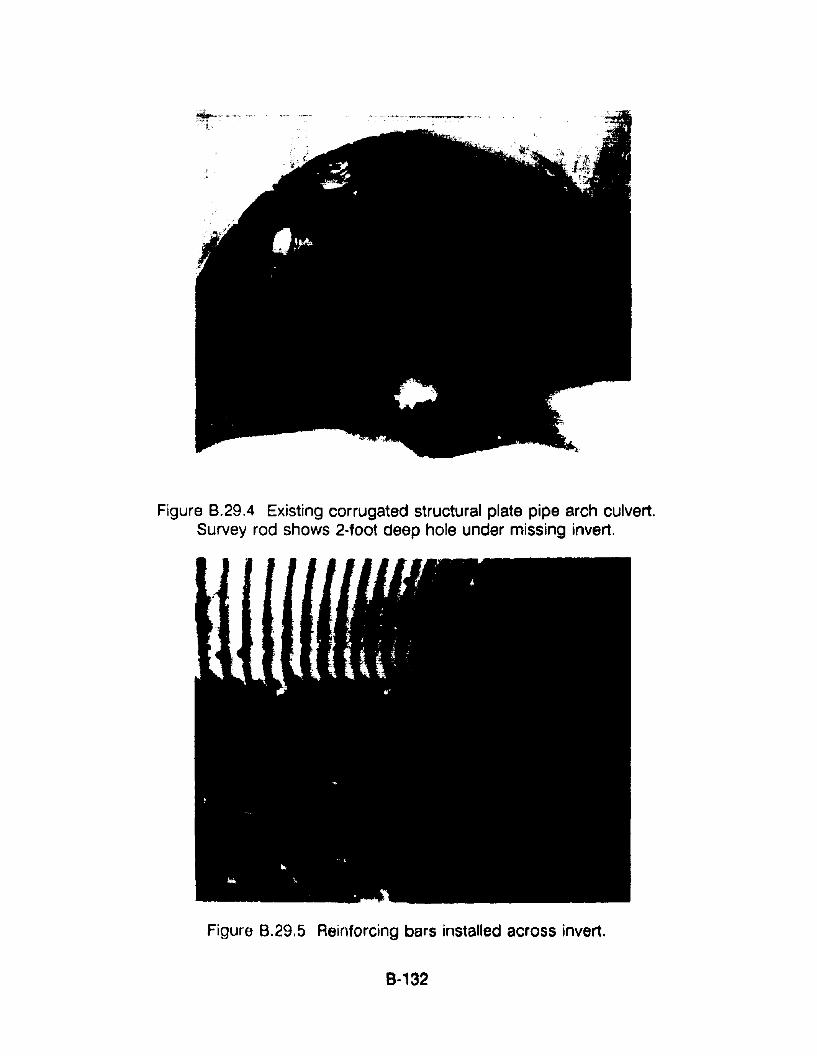
Figure 8.29.4 Existing corrugated structural plate pipe arch culvert.Survey rod shows 2-foot deep hole under missing invert.
Figure 8.29,5 Reinforcing bars installed across invert.
8·132
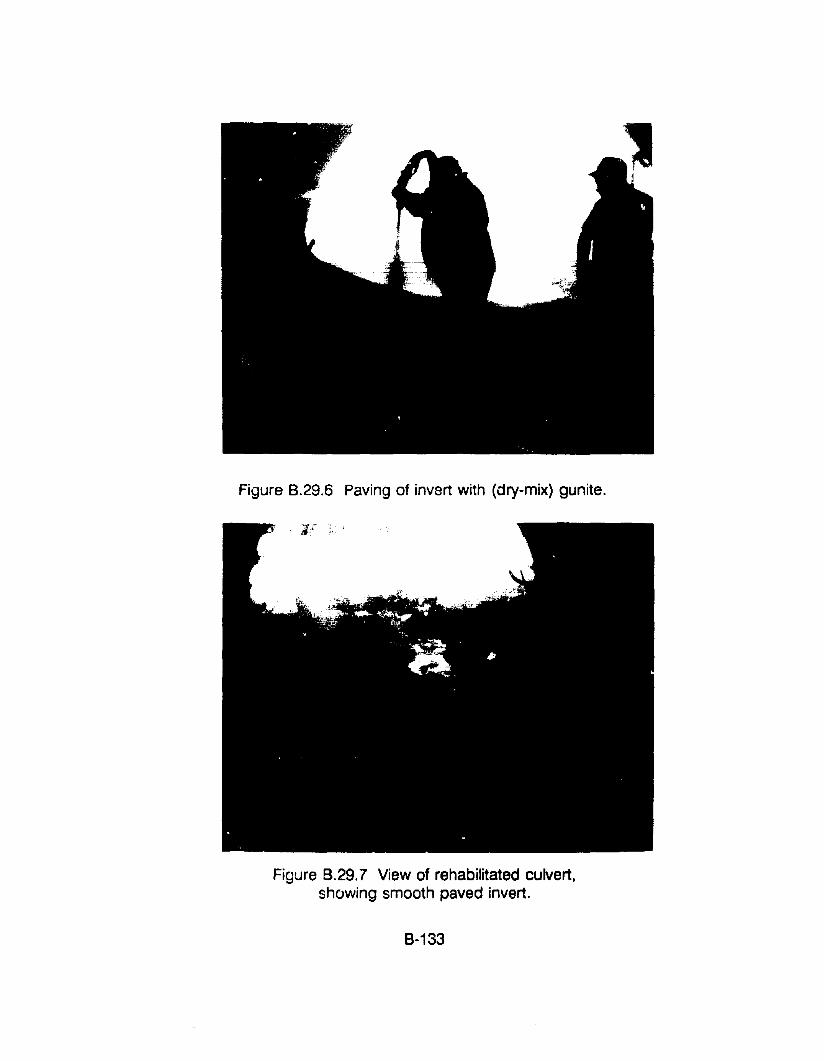
Figure 8.29.6 Paving of invert with (dry-mix) gunite.
Figure 8.29.7 View of rehabilitated culvert,showing smooth paved invert.
8-133
RESOURCE COMMITMENT =3: 5 4 3 2 1Heavy Medium Low
COST RELATIVE TOREPLACEMENT = 2: 5 4 3 2 1
High Medium Low
REFERENCES1. "Guide for Specifying, Mixing, Placing, and Finishing Steel Fiber
Reinforced Concrete," (ACI 544.3R-84/88), ACI Manual of ConcretePractice, American Concrete Institute, 1989.
2. "Guide of the Use of Polymers in Concrete," (ACI 548.1 R-86), ACI Manualof Concrete Practice, American Concrete Institute, 1989.
3. "Rehabilitation of Corrugated Steel Pipe and Pipe Unes of OtherMaterials," Drainage Technology Bulletin, National Corrugated Steel PipeAssociation, September 1988.
4. "Specification for Materials, Proportioning, and Application of Shotcrete."(ACI 506.2-77/83), ACI Manual of Concrete Practice, American ConcreteInstitute, 1989.
5. "State-of-the-Art Report on Fiber Reinforced Concrete," (ACI 544.1 R-82/86), ACI Manual of Concrete Practice, American Concrete Institute, 1989.
6. "State-of-the-Art Report on hLJer Reinforced Shotcrete." (ACI 506.1 R-84),ACI Manual of Concrete Practice .. American Concrete Institute, 1984.
7. "State-of-the-Art Report on High-Strength Concrete," (ACI 363R-84), ACIManu81 of Concrete Practice, Am9rican Concrete Institute, 1989.
8-134
APPENDIX B·30. PROCEDURES FOR GROUTING VOIDS BEHIND AND UNDERCULVERTS
APPLICATIONSThe following discussion deals with the materials and procedures that may beused to grout voids behind and under culverts.
COMMENTSDuring the 1980's there have been substantial advances in the development ofgrouts and grouting techniques. Much of this advancement is the result of theneed for improved techniques for grouting underground construction, machinerybases, and segmental prestressed concrete and cable-stayed bridges. It hasbeen well established that the primary objective of grouting is to completely fillthe required space with a material that will not shrink segregate, or otherwisecreate additional pr"blems.
Critical reviews of previous grouting jobs have led to the development and use ofspecial admixtures for Portland cement based grouts and mortars, and chemicaland foaming grouts that foam and expand when they come in contact withwater. In general, for culvert repair work Portiand cement based grouts, withand without special admixtures, are adequate and much less expensive than thefoaming and chemical grouts that are used to set machinery and to resist highexternal and internal fluid pressures.
The primary objective of completely filling the void can be accomplished byadequately studying site conditions and properly planning and executing thegrouting operation. The principal problem to be avoided in entrapment of air orwater in the void to be filled with grout. The procedure to he used for groutingmust recognize this potential problem and provision must be made for air orwater to be vented out of the void as grout is pumped into the void. Dependingon the location of the void to be filled, the grout may be installed with a pressurepumping system or it may merely flow in by gravity.
Normally voids under corroded or undermined inverts may be filled by a gravityflow method. Voids behind the sides of culverts that are caused by piping orexfiltration will have to be pressure grouted to ensure that the void is pr,:>perlyfilled. However, for certain situations where the void can be accurately located, itmay be possible to fill side voids by gravity feed from the roadway surfact'~.
8-135
PROCEDURES
There are basically three procedures for grouting:
1. Gravity Flow from AbQve thy VQidThis cQncept involves merely pouring the grout irto the void from aboveit. It is assumed that the fluid grQut will cQmpletely fill the void withQutentrapping air and that any water in the VQid will be displaced as theheavier-than-water grQut displaces it.
Although this technique may work fQr a water-filled VQid, the grQut willprobably be dispersed in the water with the result that the VQid will nQt beproperly grouted. It is much preferr~,d that aly water in the VQid bepumped Qut priQr tQ grQuting.
2. Grouting Through a Tremie Pipe or TubeFor this gravity feed concept the grout is introduced into the void bypouring it into a tremie tube, so that grout fills the VQid from the bottomwith an upward flow Qf the grout. The procedure may be warranted forSQme site conditions where there is a potential prQblem of entrapment ofair in the gr0ut.
3. Pressure GroutingThis concept will normally be used to fili voids behind the sides ofculverts. If the void is behind an open joint, it will be necessary to sealthe interiQr slJrface Qf the joint, nQrmally with a concrete mortar, or a jQintsealing system, such as thQse described in appendix B, section 25.
The most effective procedure for grouting will then invQlve installation ofgrout tu~es at the bottom and the top of the joint or void. The grout isthen pumped into the IQwer tube. Air or water will, at first, flow out of theupper tube, then a watery grout will flow out, and finally a pure grout willflow out of the upper tube. At this point it may be considered that thevoid is properly filled.
PRECAUTIONS1. The grouting procedures should be designed so that air Qr water is not
trapped in the void.
2. The grQuting pressure sbould be monitored to prevent bursting of linesand/or displac~mentof the culvert walls if a blockage develops in thegrout lines.
8-136
RESOURCE COMMITMENT =2: 5 4 3 2 1Heavy Medium Low
COST RELATIVE TOREPLACEMENT = 1: 5 4 3 2 1
High Medium Low
REFERENCES1. ':.4 Professional's Handbook on Grouting Concrete Repair and
Waterproofing, II Five Star Products, Inc.
2. "How to Grout," L & M Construction Chemicals, Inc., 14851 Calhoun Ad.,Omaha, Nebraska 68152.
3. "Grouting Slip Liners: The New Inside Story: by L. Lee, Civil Engineering,September 1990.
4. 3M Company, Contractor Products Department, St. Paul, Minnesota.
8-137
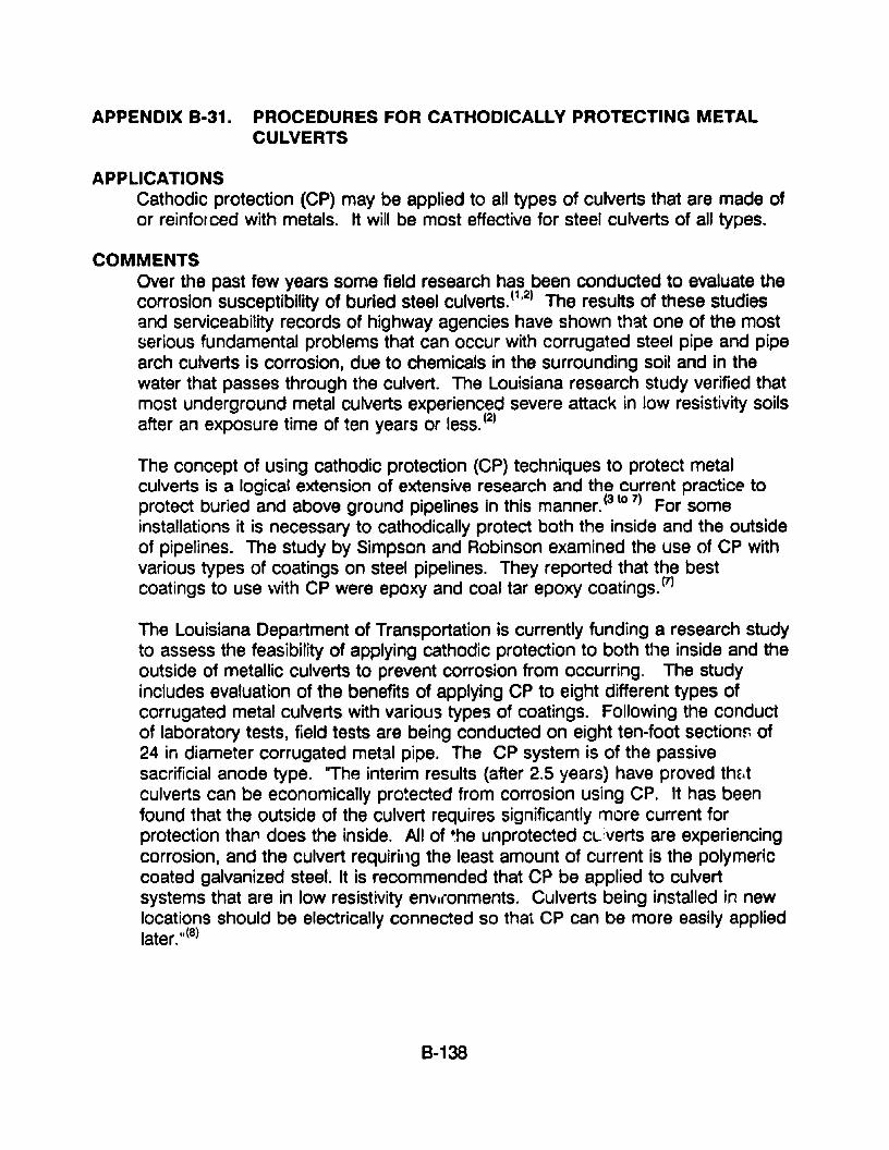
APPENDIX 8·31. PROCEDURES FOR CATHODICALLY PROTECTING METALCULVERTS
APPLICATIONSCathodic protection (CP) may be applied to all types of culverts that are made ofor reinforced with metals. It will be most effective for steel culverts of all types.
COMMENTSOver the past few years some field research has been conducted to evaluate thecorrosion susceptibility of buried steel culverts. (1,2) The results of these studiesand serviceability records of highway agencies have shown that one of the mostserious fundamental problems that can occur with corrugated steel pipe and pipearch culverts is corrosion, due to chemicals in the surrounding soil and in thewater that passes through the culvert. The Louisiana research study verified thatmost underground metal culverts experienced severe attack in low resistivity soilsafter an exposure time of ten years or less. (2)
The concept of using cathodic protection (CP) techniques to protect metalculverts is a logical extension of extensive research and the current practic~ toprotect buried and above ground pipelines in this manner.(3to 7) For someinstallations it is necessary to cathodically protect both the inside and the outsideof pipelines. The study by Simpson and Robinson examined the use of CP withvarious types of coatings on steel pipelines. They reported that the bestcoatings to use with CP were epoxy and coal tar epoxy coatings. (7)
The Louisiana Department of Transportation is currently funding a research studyto assess the feasibility of applying cathodic protection to both tile inside and theoutside of metallic culverts to prevent corrosion from occurring. The studyincludes evaluation of the benefits of applying CP to eight different t~pes ofcorrugated metal culverts with various types of coatings. Following the conductof laboratory tests, field tests are being conducted on eight ten-foot sectionr. of24 in diameter corrugated metal pipe. The CP system is of the passivesacrificial anode type. 'The interim results (after 2.5 years) have proved the,tculverts can be economically pro~ected from corrosion using CPo It has beenfound that the outside of the culvert requires significantly more current forprotection tha,., does the inside. All of the unprotected CLverts are experiencingcorrosion, and the culvert requiring the least amount of current is the polymericcoated galvanized steel. It is recommended that CP be applied to culvertsystems that are in low resistivity envl(onments. Culverts being installed in newlocations should be electrically connected so that CP can be more easily appliedlater. 11(8)
8-138
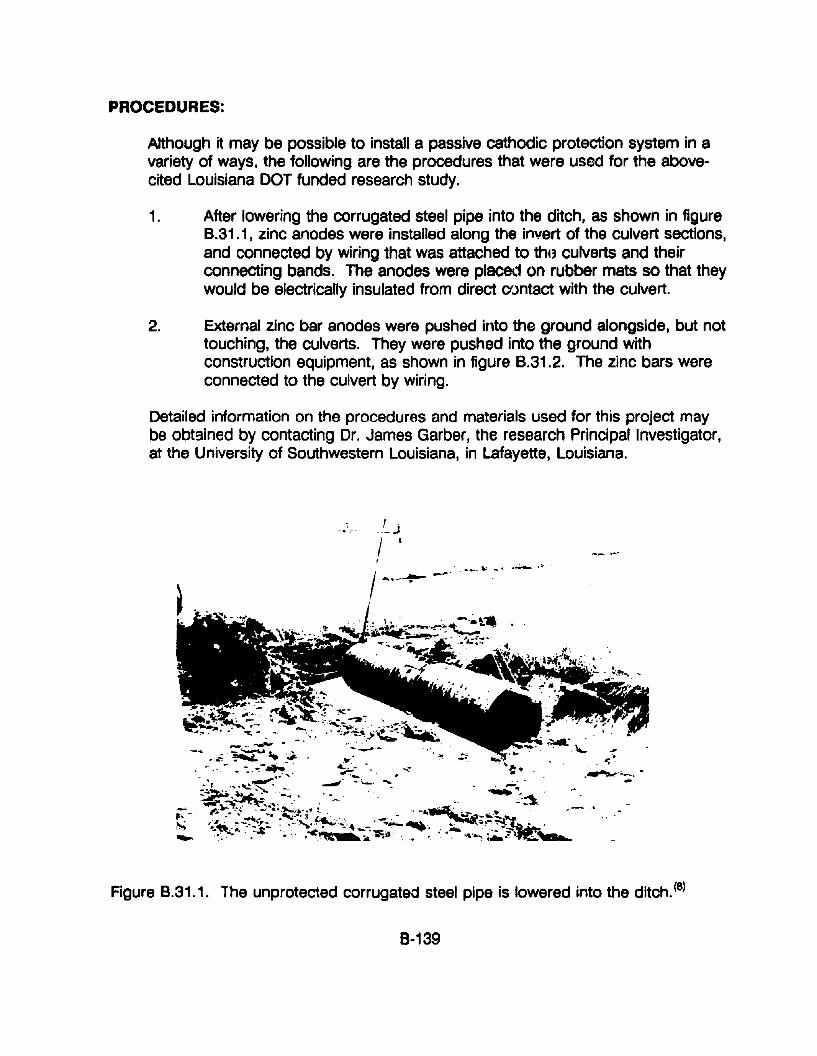
PROCEDURES:
Although it may be possible to install a passive cathodic protection system in avariety of ways. the following are the procedures that were used for the abovecited Louisiana DOT funded research study.
1. After lowering the corrugated steel pipe into the ditch. as shown in figure8.31.1, zinc anodes were installed along the invert of the culvert sections,and connected by wiring that was attached to the, culverts and theirconnecting bands. The anodes were placed on rubber mats so that theywould be electrically insulated from direct CfJntact with the culvert.
2. External zinc bar anodes were pushed into the ground alongside, but nottouching, the culverts. They were pushed into the ground withconstruction equipment, as shown in figure 8.31.2. The zinc bars wereconnected to the culvert by wiring.
Detailed information on the procedures and materials used for this project maybe obtained by contacting Dr. James Garber, the research Principal Investigator,at the University of Southwestern Louisiana, in Lafayette, Louisiana.
,,~ .J.
I 'I
I- -~..._. to' .' .--..>
~.-~ .
Figure 8.31.1. The unprotected corrugated steel pipe is lowered into the ditch. (8)
8-139
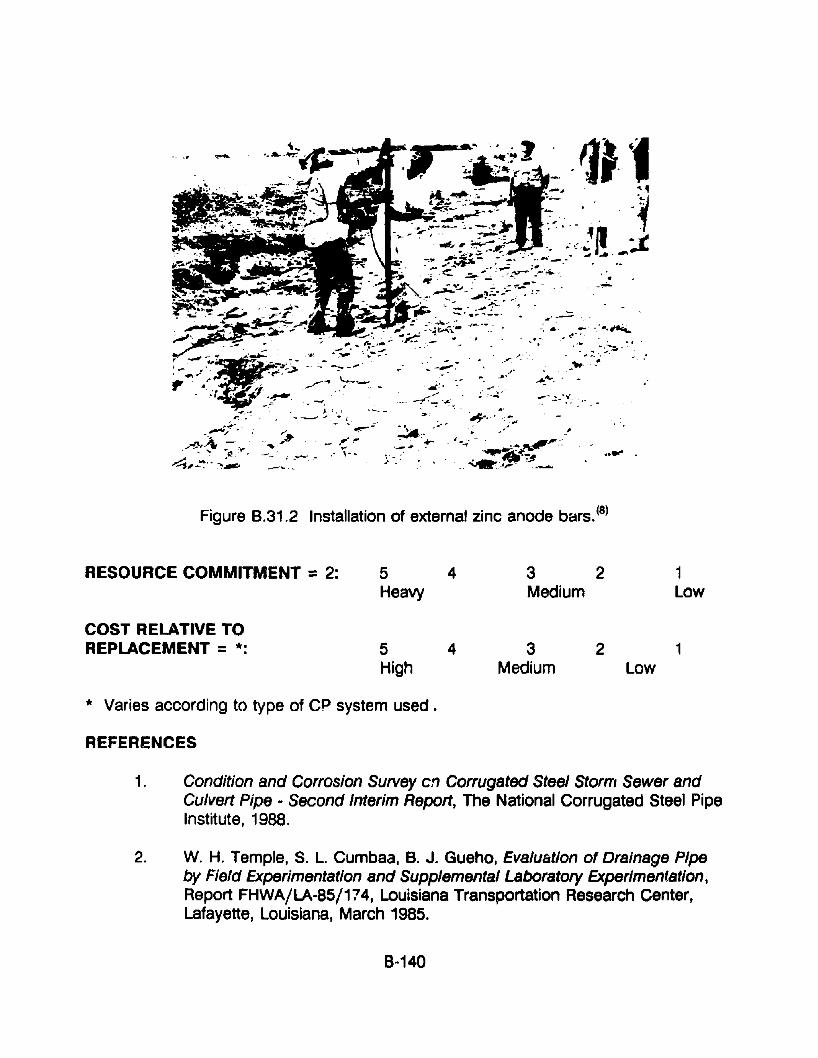
1"; .. ' ;
..~~-'..,~,~ ~:.,.'
~..... ~'"
...;:;,-~.-.~~
..... ---......' ,J' _-.-. i...~::
--" :#' . - .~ ...--- : ~~.- .. ,- '" ..-.-
Figure B.31.2 Installation of external zinc anode bars. (8)
RESOURCE COMMITMENT =2: 5 4Heavy
3 2Medium
1Low
COST RELATIVE TOREPLACEMENT = *: 5
High4 3
Medium2 1
Low
* Varies according to type of CP system used.
REFERENCES
1. Condition and Corrosion Survey en Corrugated Steel Storm Sewer andCulvert Pipe - Second Interim Report, The National Corrugated Steel PipeInstitute, 1988.
2. W. H. Temple, S. L. Cumbaa, B. J. Gueho, Evaluation of Drainage Pipeby Field Experimentation and Supplemental Laboratory Experimentation,Report FHWA/LA-85/174, Louisiana Transportation Research Center,Lafayette, Louisiana, March 1985.
8-140
3. Control of External Corrosion on Underground or Submerged MetallicPiping Systems, Standard RP-Q1-69, National Association of CorrosionEngineers (NACE), Houston, Texas
4. F. Q. Jensen and R. D. Tems, Internal Cathodic Protection of CementLined Steel Pipes, NACE Corrosion 88, Paper 25, St. Louis, Missouri,1988.
5. R. E. Groover and M. H. Peterson, "Cathodic Protection of InternalSurfaces of Pipes Containing Sea Water, II Materials Performance,November 1984.
6. W. B. MacKay and L. R. Grace, Cathodic Protection of Pipeline Internals,Proceedings of the 4th International Congress on Marine Corrosion andFouling, Antibes, 1976.
7. V. P. Simpson and R. C. Robinson, Experimental Studies Relate Effect ofCat!70dic Protection with Certain Generic Coating systems, OfffhoreTechnology Conference, 1980.
8. J. D. Garber, J. H. Lin and L. G. Smith, Feasibility of Applying CathodicProtection to Underground Culverts (Interim Report), Report FHWA/LA91/238, Louisiana Department of Transportation & Development, BatonRouge, Louisiana, June 1991.
8-141
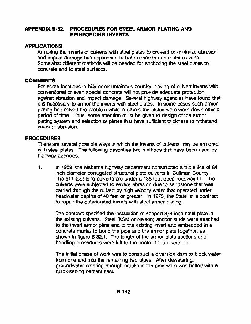
APPENDIX 8-32. PROCEDURES FOR STEEL ARMOR PLATING ANDREINFORCING INVERTS
APPLICATIONSArmoring the inverts of culverts with steel plates to prevent or minimize abrasionand impact damage has application to both concrete and metal culverts.Somewhat different methods will be needed for anchoring the steel plates toconcrete and to steel surfaces.
COMMENTSFor seme locations in hilly or mountainous country. paving of culvert inverts withconventional or even special concrete will not provide adequate protectionagainst abrasion and impact damage. Several highway agencies have found thatit is neces:3ary to armor the inverts with steel plates. In some cases such armorplating ha'3 solved the problem while in others the plates were worn down after aperiod of time. Thus. some attention must be given to design of the armorplating system and selection of plates that have sufficient thickness to withstandyears of abrasion.
PROCEDURESThere are several possible ways in which the inverts of culverts may be armoredwith steel plates. The following describes two methods that have been L'sed byhighway agencies.
1. In 1952. the Alabama highway department constructed a triple Une of 84inch diameter corrugated structural plate culverts in Cullman County.The 517 foot long culverts are under a 135 foot deep roadway fill. Theculverts were subjected to severe abrasion due to sandstone that wascarried through the culvert by high velocity water that operated underheadwater depths of 40 feet or greater. In 1973, the State let a contractto repair the deteriorated inverts with steel armor plating.
The contract specified the installation of shaped 3/8 inch steel plate inthe existing culverts. Steel (KSM or Nelson) anchor studs were attachedto the invert armor plate and to the existing invert and embedded in aconcrete mortal' to bond the pipe and the armor plate together, asshown in figure 8.32.1. The length of the armor plate sections andhandling procedures were left to the contractor's discretion.
The initial phase of work was to construct a diversion dam to block waterfrom one and into the remaining two pipes. After dewatering,groundwater entering through cracks in the pipe walls was halted with aquick-setting cement seal.
8-142
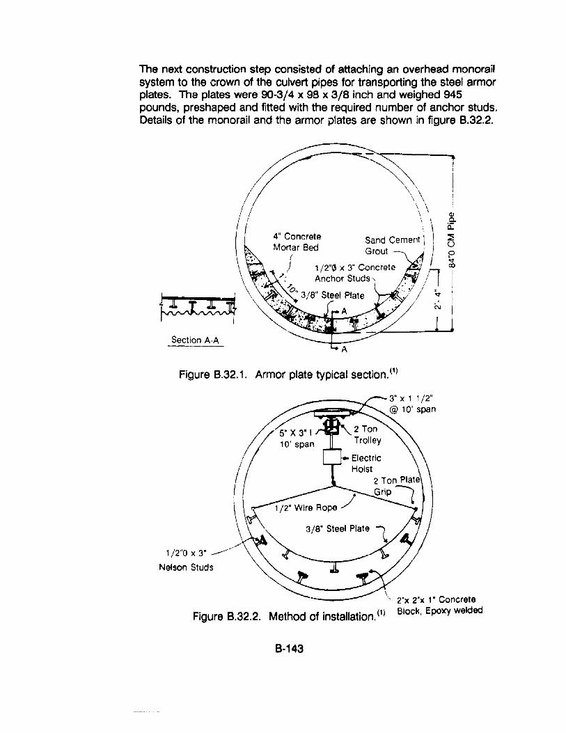
The next construction step consisted of attaching an overhead monorailsystem to the crown of the culvert pipes for transporting the steel armorplates. The plates were 90-3/4 x 98 x 3/8 inch and weighed 945pounds, preshaped and fitted with the required number of anchor studs.Details of the monorail and the armor plates are shown in figure B.32.2.
Section A-A
Figure B.32.1. Armor plate typical section. (1)
,,/
1/2"0 x 3" -----
Nelson Studs
," 2"x 2"x 1" Concrete
Figure 8.32.2. Method of Installation. (1) Block, Epoxy welded
8-143
After all water was removed from the culvert, anchor studs were weldedto the invert of the existing culvert. Concrete spacer blocks were thenattached to the heads of the studs in the invert with an epoxy adhesive.
Initially the next step was to place the concrete mortar bed and to lowerthe steel armor plates into it. This procedure was found to beunsatisfactory because vibration of the plates and the mortar to removevoids in the mortar caused movement of the plates and problems withtheir alignment.
Tho procedure was modified so that a group of three plates was set,tack-welded together and braced before placement of the concrete. Theconcrete bedding was then placed and vibrated to remove air voids.
After allowing the concrete to cure for seven days the braces wereremoved and the plates were welded together. Gaps between the plates,whic: I were caused by variations in alignment and profile, were closed bywelding on strips of armor plate.
The edges of the unfinished concrete were then coated with an epoxyand a sand-cement grout was applied to provide a uniform finish.
The contractor was required to regalvanize damaged areas of the crownafter removal of the monorail system.
Inspection of the culvert after nine years of service indicated satisfactoryperformance, with no adverse wear. Armor plating the inverts of thetriple-line culvert was accomplished at a small fraction of the possiblecost for replacement of the culvert.
Additional information on this project is provided in Reference No.2,below.
2. In the early 1970's the Colorado highway department had severe rockabrasion problems with a ten year old 15OO-100t long reinforced concretebox culvert under a large interstate highway intersection, near Golden,Colorado. The approach streambed was steep and large and mediumsize boulders were carried by stormwater and snowmelt. The culvertwas constructe ~ on fairly steep grade and the inlet walls and invertnarrowed from 20 foot square to 10 foot square while droppingapproximately 8 foot, to ensure a high velocity flow that would keep rockand sediment from building up inside of the culvert. The highwaydepartment had tried many methods of reinforcing the concrete againstabrasion, with little success, since construction of the culvert In the 1960'~"
8-144
The final solution was to "pave" the approach and a portion of the invertinside of the culvert with 2-inch-thick steel plates, as follows:
a. The curved descending invert of the box culvert was first pavedwith concrete to the desired shape.
b. Two-inch-thick steel plates were then positioned across the invert.
c. Holes were then drilled (through holes in the plates) through theunderlaying concrete and then into bedrock.
d. The plates were then anchored to bedrock with bolts that were setinto an epoxy resin.
Details of this installation are shown in figures 8.32.3 and B.32.4. It maybe seen from figure B.32.4 that some wear of the steel plates hasoccurred over the past 20 years.
3. For corrugated steel culverts, some highway agencies have installed adouble thickness of multiplate sections in the invert or have installedmultiplate sections in the invert of circular and arch culverts. This mustbe securely fastened to the primary culvert to prevent movement anddeterioration of the underlaying plate materials.
4. The Oregon highway department has reinforced the inverts of reinforcedconcrete box culverts with steel grid bridge decking and old railroad rails,to protect the inverts from impact and abrasion damage. The inverts ofculverts that have been reinforced in this manner have performed verywell, since they were installed about ~jx years (\90.
8-145
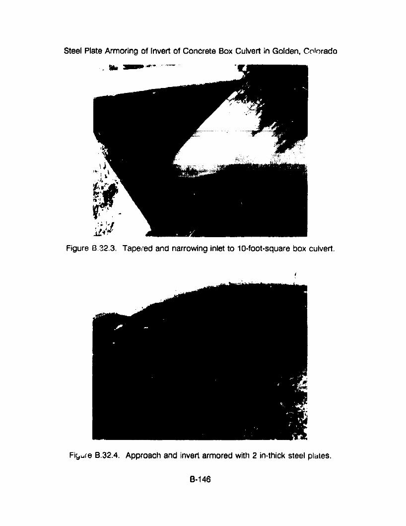
Steel Plate Armoring of Invert of Concrete Box Culvert in Golden, CC'kxado
.' 11,."'/~i ,..L....... ,
Figure 8.32.3. Tapel"ed and narrowing inlet to 10-foot-square box culvert.
Fi~ure B.32.4. Approach and invert armored with 2 in-thick steel plates.
8-146
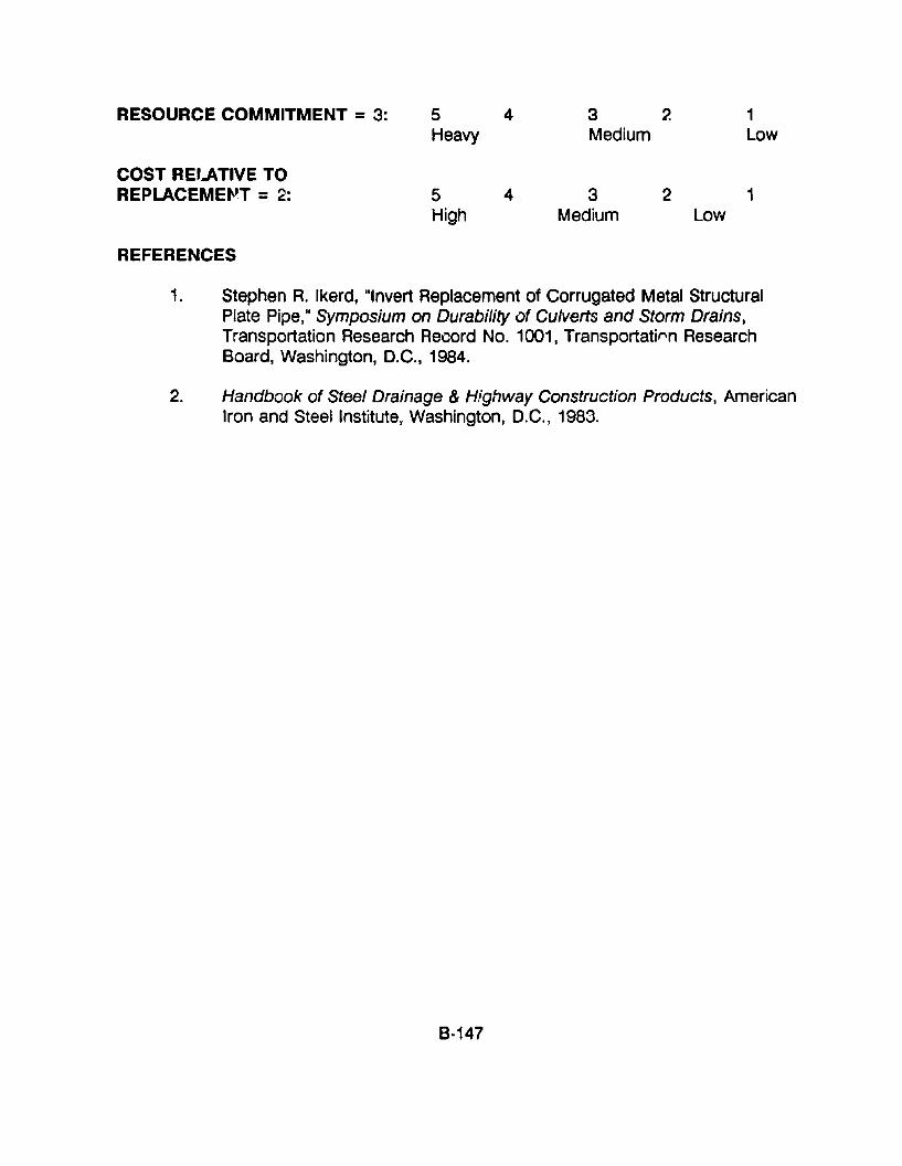
RESOURCE COMMITMENT = 3: 5 4 3 2 1Heavy Medium Low
COST REI-4TIVE TOREPLACEMEfJT = 2: 5 4 3 2 1
High Medium Low
REFERENCES
1. Stephen R. Ikerd, "Invert Replacement of Corrugated Metal StructuralPlate Pipe," Symposium on Durability of Culverts and Storm Drains,Transportation Research Record No. 1001, Transportati('\n ResearchBoard, Washington, D.C., 1984.
2. Handbook of Steel Drainage & Highway Construction Products, AmericanIron and Steel Institute, Washington, D.C., 1983.
B-147
APPENDIX 8-33: PROCEDURES FOR MEASURING AND EVALUATINGCULVERT DISTORTION
APPLICATIONSThe following techniques may be used to measure, monitor, and evaluatedistortion of culverts, and other types of structures.
COMMENTSHighway culverts, as with any other type of structure, are never built in perfectaccordance with the plans, or perfectly symmetrically. Moreover, corrugatedmetal culverts are considered to be flexible structures by the nature of theirconstruction materials as well as their close interaction with pressures applied bythe supporting soils and highway vehicle loads. It is well established thatcorrugated metal culverts will bend and change their shape during theirconstruction, because of uneven compaction of the supporting soil. Because ofcreep-type redistribution of forces in the soil, such structures may deform andotherwise seek a position of equilibrium for some time after construction iscompleted. During the service life of a culvert, the support provided by thesurrounding soil may also change, due to environmental conditions, erosion atthe ends of the culvert, and problems due to infiltration, exfiltration and piping.Thus, the shape of a corrugated metal culvert may not be symmetrical for eitherthe entire length or the culvert or individual sections of it.
With regard to the above, it is important to determine whether the culvert isstable in its distorted shape or whether it is continuing to become distorted, andif it is, the rate at which it is distorting. It is quite common to have at least somesymmetrical or unsymmetrical distortion in corrugated metal culverts. It is alsocommon that the culvert is stable in that distorted shape; that is, it is notcontinuing to distort. If this is the case, then corrective action is not necessary.On the other hand, if it is distorting, determination of the rate of distortion willgive th~ agency an idea of how rapidly corrective action may be necessary.
I he following are techniques that may be used to measure tt Ie interior shape ora culvert. If they are used twice or more, it is possible to determine whether theirshape is changing and at what rate.
It is extremely important that well identifiable and permanent locations be chosenas measurement points, and their location must be carefully documented. so thatthey may be repeatedly used over a long period of time. It is safest to usejoints, seams, or bolts that may be easily identified in the future. For criticallocations it may be a good practice to use more points than the minimumnumber necessary so that if one or more points are lost, the entire section willnot be lost. The number of measurement points that are used will depend uponthe size and condition of the culvert.
8-148
PROCEDURES1. Conventional Survey Techniques
Many highway agencies use traditional survey equipment and techniquesto measure the shape of a culvert. The advantages and disadvantagesof this approach are:
Advantages:
• The equipment is available and State and contractor personnel areproficient in using it; and
• It is relatively inexpensive to use.
Disadvantages:
• It is time consuming and somewhat difficult to determine exactchanges in shape;
• It is difficult to obtain measurements inside of a culvert, due tolighting conditions; and
• Work can be dangerous, particularly if the culvert has aconsiderable water flow.
2. ''Total Station" Survey Techniques
An alternative to conventional surveying is to use the new electronic 'otalstation" survey equipment. This type of system uses a new type ofsurvey "transit" that has an electronic data storage adapter that is usedto record all survey "readings." The survey procedure normally involvesthe instrument person sighting on a mirrored target. The instrumentrecords the distance and angle to the target. The precision or accuracyof the readings is a function of the quality and features of the instrument.First-, second-, and third-order survey accuracy is available. SeveralState highway agencies routinely use such equipment, which is marketedby several companies. The following are advantages and disadvantagesof this concept:
Advantages:
• The data pack from the survey instrument can be returned to theoffice, for "dump" and analysis of the data. The data can betransferred into a number of computer systems for analysis and
8·149
plotting of cross sections of the culvert and determination of itsshape at any cross section. Graphics packages can be used toplot three-dimensional views of the structure.
• Although an instrument person is needed for the first survey, thatperson may establish permanent targets by attaching mirrortargets to the points of interest. Thereafter, the entire survey maybe done by one person, the instrument person. (A second personshould be present, for safety reasons if nothing else).
• This concept and equipment may be used to record survey datanot only on the culvert but also its entrance and exit features fromthe beginning of construction.
• By starting the survey with the establishment of bench marksoutside of the culvert, it is possible to determine not only whetherthe culvert shape is distorting but alse whether the slope andelevation of the entire culvert is changing, although that may beunlikely.
• Procurement of such equipment for this purpose rr,ay help justify itfor use on other critical types of surveys.
Disadvantages:
• The survey equipment cost is in the range of $8;000.
• The equipment may not be readily available to many district. andresidency-level offices of most highway agencies.
3. PhQtogrammetric TechniQu~
The Ontario Mini~3try of Transportation has developed a concept formeasuring the shape of culverts that uses close-range photogrammetryequipment. The principles Qf close-range photogrammetry are similar tothe traditional aerial photogrammetry, with three significant differences.
a. A very special 35mm camera is used, rather than the traditionallarge negative type camera used from aircraft.
b. Picture pairs may be taken from almost any vantage point on theground.
B-150
c. Survey information is obtained by digitizing large size prints of thepictures, for example, 8 x 10 inch size prints.
Conduct of the survey is similar to the procedures described for 'otalstation" type surveys; setup during the first survey involves setting mirrortargets on the points of interest. Thereafter, surveys may be taken by asingle person. Advantages and disadvantages of this concept are:
Advantages:
• The equipment is quite versatile.
• Data from the digitized photographs can be handled by computer,for analysis, plotting, and determination of changes in shape.
• The technique may be used for long culverts, with flowing water,by taking photographs from a raft floating through the culvert.
Disadvantages:
• The equipment is very expensive and somewhat fragile.
• The personnel needed must be very highly trained.
RESOURCE COMMITMENT =2: 5 4 3 2 1Heavy Medium Low
COST RELATIVE TOREPLACEMENT =2: 5 4 3 2 1
High Medium Low
REFERENCES1. Ontario Ministry of Transportation, Research and Development Branch,
1201 Wilson Avenue, Downsview, Ontario M3M 1J8. (Telephone. (416)235-4674).
2. Leica Canada, Inc., 513 McNicoll Avenue, Willowdale, Ontario M2H 2C9.(Telephone: (416) 497-2460)
3. Leica, Inc., 2 Inverness Drive East, Suite 106-108, Englewood, Colorado80112.
B-151
APPENDIX 8 ..34. PROCEDURES FOR REPAIR AT A DISTORTED SECTION
APPLICATIONSThe followinQ describes repair techniques that may be made at distorted sectionsof culverts. Although these deal mainly with corrugated metal type culverts theseprocedures may also be used for culverts made with other types of materials.
COMMENTSCo;-rugated metal pipe and pipe arch as well as precast concrete culverts aresubjected to a variety of external loads and changing soil conditions that maycause localized distortion and cracking after installation. It has been found thatthe uneven soil pressures that cause such distortion seldom stabilize and, in fact,related problems normally become worse. Total collapse is possible. If thedistortion and cracking is an isolated condition in a culvert that is otherwise infairly good condition, it may be possible to repair that section without disturbingthe remaining section of the culvert. Although the following procedures willsomewhat constrict the culvert opening, the influence of the reduction in the areawill depend upon many site-specific details.
The amount and complexity of remedial action will depend upon the siteconditions, the type of culvert, and the level and severity of the distortion. Siteconditions include such factors as location, height of fill over the culvert, andwhether infiltration is from water under a considerable hydraulic head pressure.The solution to the problem generally involves installation of an expansion ringthat bridges and closes the open joint and pressure grouting to fill voids in thesoil behind the joint. The closure ring may have to carry structural loads andexternal hydraulic pressure. The following describes several techniques andtypes of repairs that may be used. Information on grouts and groutingtechniques is provided in appendix B, section 29.
PROCEDURES1. Strengthening With a Tunnel Liner Plate Ring
Several State and Canadian Government highway agoncies routinely usetunnel liner plate to repair distorted culverts. Steel liner plates are curvedand rigid. They are made with either two or four flanges that are used tobolt the sections together. If the culvert is only moderately deformed itmay be practical to install and grout one or more complete rings of linerplate to strengthen the deformed section, by the following procedure.
a. Install the bottom liner plates in the invert of the culvert bysupporting the plate on steel chairs that are welded to the culvertand connecting them with anchor bolts. A gap of 6 to 8 inchesshould be provided, for grouting.
8-152
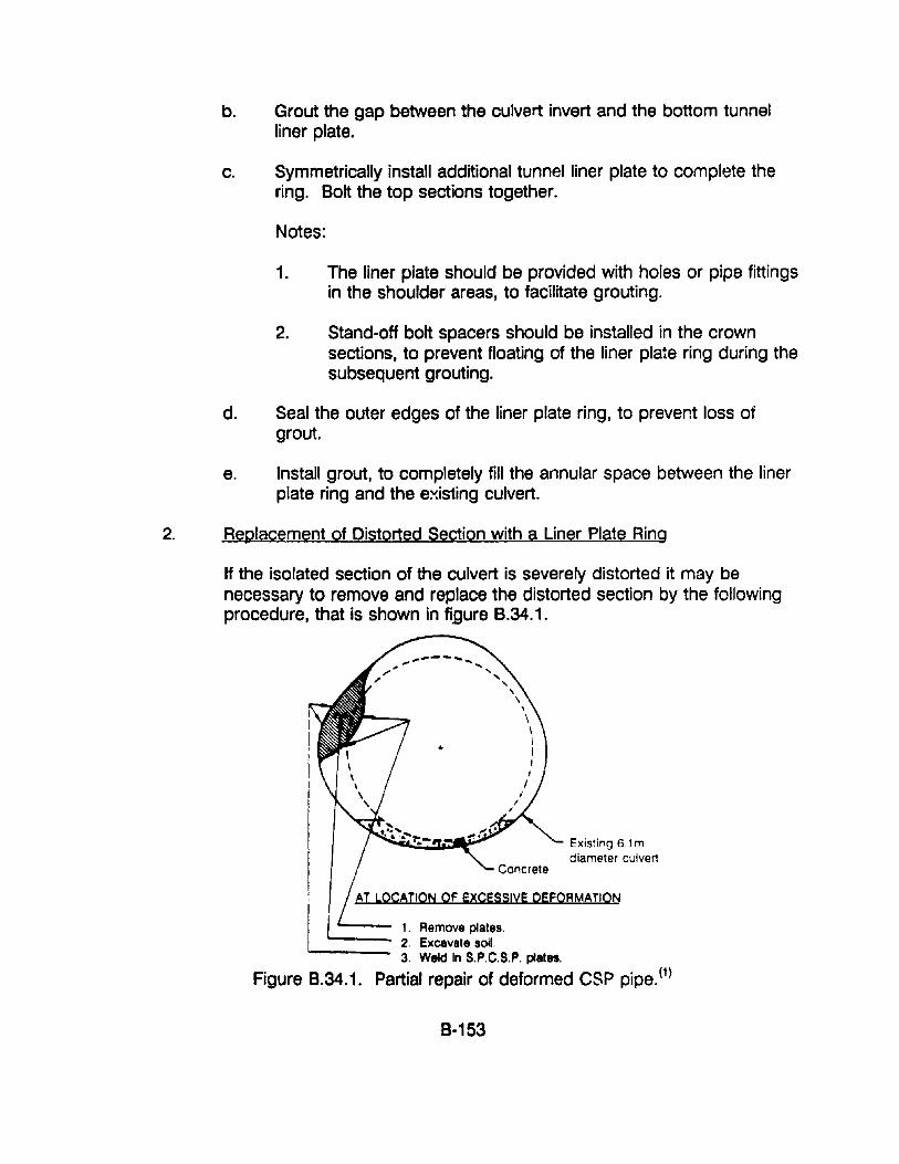
b. Grout the gap between the culvert invert and the bottom tunnelliner plate.
c. Symmetrically install additional tunnel liner plate to complete thering. Bolt the top sections together.
Notes:
1. The liner plate should be provided with holes or pipe fittingsin the shoulder areas, to facilitate grouting.
2. Stand-off bolt spacers should be installed in the crownsections, to prevent floating of the liner plate ring during thesubsequent grouting.
d. Seal the outer edges of the liner plate ring, to prevent loss ofgrout.
e. Install grout, to completely fill the annular space between the linerplate ring and the existing culvert.
2. Replacement of Distorted Section with a Liner Plate Ring
If the isolated section of the culvert is severely distorted it may benecessary to remove and replace the distorted section by the followingprocedure, that is shown in figure B.34.1.
Existing 6.1 mdiameter culvert
AT LOCATION Of EXCESSIYE DEFORMATION
---- 1. Remove plates."'---- 2. Excavate soil.
3. Weld In S.P.C.S.P. plates.
Figure B.34.1. Partial repair of deformed CSP pipe. (1)
B-153
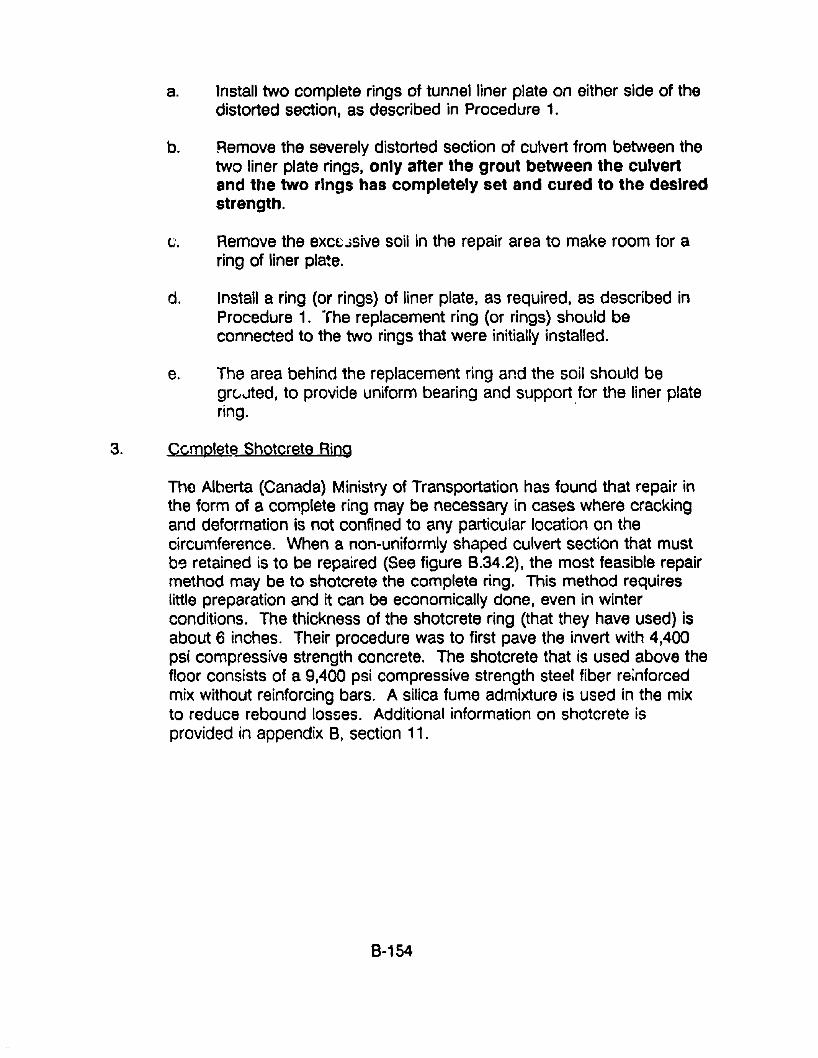
a. Install two complete rings of tunnel liner plate on either side of thedistorted section, as described in Procedure 1.
b. Remove the severely distorted section of culvert from between thetwo liner plate rings, only after the grout between the CUlvertand the two rings has completely set and cured to the desiredstrength.
tJ, Remove the excl:Jsive soil in the repair area to make room for aring of liner pla~e.
d. Install a ring (or rings) of liner plate, as required, as described inProcedure 1. "fhe replacement ring (or rings) should beconnected to the two rings that were initially installed.
e. The area behind the replacement ring and the soil should begrCJ.Jted, to provide uniform bearing and support ,for the liner platering.
3. Ccmplete Shotcrete Ring
The Alberta (Canada) Ministry of Transportation has found that repair inthe form of a complete ring may be necessary in cases where crackingand deformation is not confined to any particular location on thecircumference. When a non-uniformly shaped culvert section that mustb9 retained is to be repaired (See figure B.34.2), the most feasible repairmethod may be to shotcrete the complete ring. This method requireslittle preparation and it can be economically done, even in winterconditions. The thickness of the shotcrete ring (that they have used) isabout 6 inches. Their procedure was to first pave the invert with 4,400psi compressive strength concrete. The shotcrete that is used above thefloor consists of a 9,400 psi compressive strength steel fiber reinforcedmix without reinforcing bars. A silica fume admixture is used in the mixto reduce rebound losses. Additional information on shotcrete isprovided in appendix B, section 11.
8-154
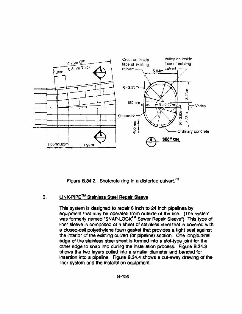
Varies
Ordinary concrete
SECTION
Valley on insideface of existing
5.84m culvert 7
150mm
Crest on insideface of eXistingculvert
9.75fT' OF6.3fT'fT' Thick
1.83m __--'-f
W~7'92=-----m_JShotcrete
--i--+--+---,---l----ri---L---l EE -r--"""O--f-:--<:'/
Figure 8.34.2. Shotcrete ring in a distorted culvert. (1)
3. LINK-PIPe™ Stainless Steel Repair Sleeve
This system is designed to repair 6 inch to 24 inch pipelines byequipment that may be operated from outside of the line. (The systemwas formerly named ''SNAP-LOCK™ Sewer Repair Sleeve") This type ofliner sleeve is comprised of a sheet of stainless steel that is covered witha closed-cell polyethylene foam gasket that provides a tight seal againstthe interior of the existing culvert (or pipeline) section. One longitudinaledge of the stainless steel sheet is formed into a slot-type joint for theother edge to snap into during the installation process. Figure 8.34.3shows the two layers coiled into a smaller diameter and banded forinsertion into a pipeline. Figure 8.34.4 shows a cut-away drawing of theliner system and the installation equipment.
8-155
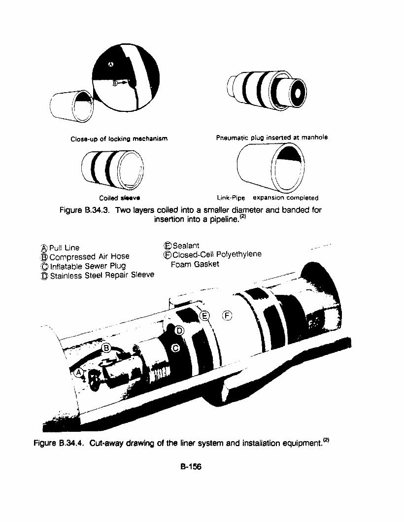
Close-up of locking mechanism
Coiled sleeve
Pneumatic plug inserted at manhole
link-Pipe expansion completed
Figure B.34.3. Two layers coiled into a smaller diameter and banded forinsertion into a pipeline. (2)
lY Pull lineIBJ Compressed Air Hose© Inflatable Sewer Plug:g Stainless Steel Repair Sleeve
®Sealant(f)Closed-Cell Polyethylene
Foam Gasket
-----
Figure 8.34.4. Cut-away drawing of the liner system and installation equipment. (2)
8-156
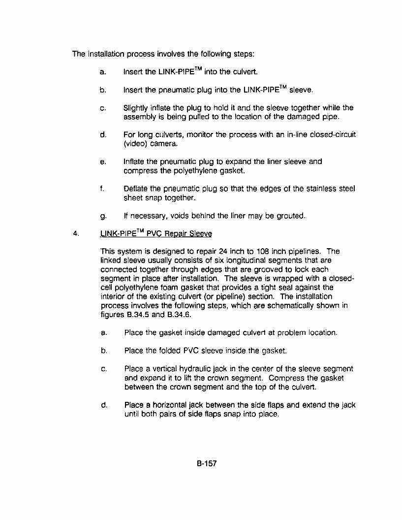
The installation process involves the following steps:
a. Insert the L1NK_PIPE™ into the culvert.
b. Insert the pneumatic plug into the L1NK_PIPE™ sleeve.
c. Slightly inflate the plug to hold it and the sleeve together while theassembly is being pUlled to the location of the damaged pipe.
d. For long clJlverts, monitor the process with an in-line closed-circuit(video) camera.
e. Inflate the pneumatic plug to expand the liner sleeve andcompress the polyethylene gasket.
f. Deflate the pneumatic plug so that the edges of the stainless steelsheet snap together.
g. If necessary, voids behind the liner may be grouted.
4. _LINK-PIPE™ PVC Repair Sleeve
This system is designed to repair 24 inch to 108 inch pipelines. Thelinked sleeve usually consists of six longitudinal segments that areconnected together through edges that are grooved to lock eachsegment in place after installation. The sleeve is wrapped with a closedcell polyethylene foam gasket that provides a tight seal against theinterior of the existing culvert (or pipeline) section. The installationprocess involves the following steps, which are schematically shown infigures 8.34.5 and 8.34.6.
a. Place the gasket inside damaged culvert at problem location.
b. Place the folded PVC sleeve inside the gasket.
c. Place a vertical hydraulic jack in the center of the sleeve segmentand expand it to lift the crown segment. Compress the gasketbetween the crown segment and the top of the culvert.
d. Place a horizontal jack between the side flaps and extend the jackuntil both pairs of side flaps snap into place.
8-157
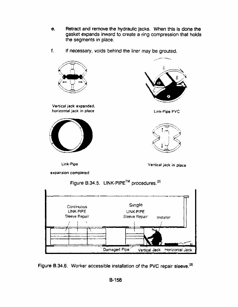
e. Retract and remove the hydraulic jacks. When this is done thegasket expands inward to create a ring compression that holdsthe segments in place.
f. If necessary, voids behind the liner may be grouted.
/~!
Vertical jack expanded,horizontal jack in place Link-Pipe PVC
Link-Pipe Vertical jack in place
expansion completed
Figure 8.34.5. L1NK-PIPE™ procedures. (2)
Installer
Singl~
LINK-PIPESleeve Repair
ContinuousLINK-PIPE
Sleeve RepairI
I
•• ,.........-;;", ••••••••••••• t""' •• ~~ ~ ....Damaged Pipe Vertical Jack Horizontal Jack
Figure 8.34.6. Worker accessible installation of the PVC repair sleeve. (2)
8·158
RESOURCE COMMITMENT = 1:
COST RELATIVE TOREPLACEMENT = 1:
REFERENCES
5 4Heavy
5 4Heavy
3 2Medium
3 2Medium
1Low
1Low
1. Jay G. Ramotar, Culvert Seam Failures and Repairs, Alberta Ministry ofTransportation, Alberta, Canada, 1986.
2. Unk-Pipe Technologies Inc., Remote Stainless Steel Repair Sleeve andWorker-Accessible PVC Repair Sleeve, Ontario, Canada.
3. Drainage Technology Bulletin, National Corrugated Steel PipeAssociation, September 1988.
4. Handbook" of Steel Drainage and Highway Construction Products,American Iron & Steel Institute, Washington, D.C.
8·159
APPENDIX B·35: PROCEDURES FOR TIMBER BRACING OF CULVERTS
APPLICATIONSTimber bracing has application to all types of culverts, but the most commonusage is for metal, timber and stone masonry culverts.
COMMENTSOne of the most effective procedures for ensuring that ?n excessively deformedculvert will not suddenly collapse is to install temporary G~nJ(s or braces in theculvert.
The main disadvantage of installing braces inside a culvert is that they will tendto constrict or disrupt the smooth flow of water through the culvert. Of particularconcern should be the fact that the braces may snag debris that is carried by thewater and create a wall that may totally block the culvert. The hydraulic forcesthat are created by such a blockage may subsequently break or dislodge thebracing and cause a catastrophic collapse of the culvert, perhaps during theheight of a storm. The blockage of the culvert can also cause flood waters toovertop the roadway.
Thus, braces should be inst&lIed only when they are essential to preventcollapse. If they are used, they should be designed to minimize the space theytake up, but at the same time be sufficiently strong to resist all but the strongesthydraulic forces.
It should be noted that the use of timber bracing is a temporary solutior that isintended to prevent further deterioration and/or collapse of A culvert. The culvsrtshould be inspected regularly while the bracing is in place. A permanent repairshould be designed and undertaken as soon as possible.
PROCEDURES:The basic procedure is to install vertical bracos between the crown and the invertthroughout the entire section of the culvert that has excessive deflection. Timbersills should be placed below and above the brar.es, so that the support loads willbe spread out along the length of the sills and not be point loads at the ends ofthe braces. The butt Joints of the top and bottom sills should be staggered, sothat they do not occur at the same location in the culvert.
The braces should be structurally designed to carry, with an adequate margin ofsafety, the weight of the volume of soil that is statically proportioned to them byassuming the propped cross-section to act as a two-span continuous beam.
The spacing of the braces will depend upon the soil forces to be resisted andupon the type of brace used. Braces are normally installed at 3· to 5·100t
8·160
spacing. The sills above and below the braces should be long enough to hold atleast two braces.
A variety of types of braces may be used. The most ~ommon may be 8 inch x 8inch timbers. Another common type of brace is the hollow tubular steel bracethat is frequently used in construction formwork. The advantage of the lattertype of brace is that the end of the tubular section has a threaded coup!ing thatpermits easy adjustment of the length and the application of at least some force,to take up any slack space in the bracing system.
If the sides of the culvert are alinstall horizontal braces, which &
ssively distorted, it may be necessary tobe attached to the vertical braces.
RESOURCE COrMITMENT = 2: 5 4 3 2 1Heavy Medium Low
COST RELATIVE TOREPLACEMENT = 2: 5 4 3 2 1
High Medium Low
REFERENCES
8-161
APPENDIX 8·36. PROCEDURES FOR REROUNDING/RESHAPINGCORRUGATED METAL CULVERTS
APPLICATIONSThe following methodology may be used for rerounding or reshaping distortedcorrugated metal pipe and pipe arch culverts.
COMMENTSAlthough it may be technically possible to adjust or reround deformed corrugatedmetal pipe and pipe arch, it may not be practical. The overall condition of theculvert should be assessed, as well as the soil-structure conditions that eithercaused or allowed the deformation to occur. The type and size of the culvert aswell as the type, location, and de~ree of deformation will also have a directbearing on whether it is practical to try to reround the culvert. For example,symmetrical deflection of the crown may be indicative of problems with supportof the bottom of the culvert or insufficient backfill over the top of the culvert.Unsymmetrical deformation of the top of the culvert may be the result of loss ofsoil support on one side of the bottom or improper compaction of the backfill onone side of the culvert. Thus, the conditions that caused the deformation mustbe assessed and the rehabilitation plan must include not only rerounding theculvert but also correcting the underlying problem.
There are basically two approaches for reshaping deformed corrugated metalculverts. One is through a combination of work from the outside and from theinside of the culvert, and the other is to work entirely from the inside of theculvert.
PROCEDURES:1. Work from the Outside and the Inside of the Culvert
The basic concept for this approach is to remove the backfill from abovethe culvert, reshape the culvert from the inside, and replace the backfill,as described in appendix B~37 in the procedure for repairing andstrengthening the crown of culverts. This approach would be u~ed whenit was determined that depth of the backfill above the culvert wassufficiently shallow that the most economical procedure would be toremove the overburden rather than to work entirely from the inside of theculvert.
The primary difference for this procedure is that the deformed sections ofthe culvert would not be removed, but rather moved into their properposition through the use of portable hydraulic jacks after the outerbackfill material has been removed. The following are some points thatshould be considered in planning this operation.
R~162
a. Working around jacking systems has a certain amount of risk, andprecautions should be taken to minimize the risk to personnelduring the operation. Particular attention should be given toplacement and orientation of the jacks so that they, and/ortimbers that they are reacting against, will not buckle out ofposition when force is applied.
b. Spreader beams should be installed under the hydraulic jacks andat point where the load is being applied to distribute the load sothat a more-or-Iess unifonn load is applied without causing localbending of the culvert at the point of load. It may be appropriateto place a section of similar corrugated metal between the existingculvert and the applied load to reinforce the corrugations.
c. It may be necessary to over-bend (over-correct) the distortion, sothat when the jacking load is removed the culvert will rebound intothe proper position. It should not be expected that propercompaction of the backfill (by itself) will resist the elastic reboundof the culvert as it will attempt to return to its distorted shape.
d. Depending upon the location of the distortion and the cause of it,it may be appropriate to install a cast-in-place concrete slab abovethe reshaped culvert, as described in appendix 8-37: Procedurefor Repairing and Strengthening the Crown of Culverts.
2. Work from the Inside of the Culvert
When the depth of the culvert is too deep to economically remove thebackfill from above it, it may be possible to reshape a corrugated metalculvert by working entirely from the inside of the culvert. Although thismay seem to be an extreme situation, such conditions may occur: forexample, for a long culvert under an interstate highway intersection,where (1) only a small portion of the culvert is affected; and (2) the sizeof the culvert is only marginally adequate and a reduction in the flowcapacity would further reduce the hydraulic capacity of the culvert. Theobjective of this rehabilitation effort is to restore the cross-sectional areaand flow characteristics. As noted above, consideration must also begiven to correcting the problem that caused the deformation. Theprocedure will include the following steps:
a. Remove the indented or distorted section of the culvert with acutting torch. Care must be given to protect the workmen fromthe fumes created by cutting a galvanized coating. It may benecessary to temporarily strengthen the culvert sections adjacent
8-163
to the section to be removed by installing tunnel lining segments,as described in the appendix B-34: Procedures for Repair atDistorted Sections. The difference here is that when the repairwork is completed, the internal shape and area of the culvert willbe restored.
b. Remove the backfill material that was behind the distorted section.Consideration should be given to the need to remove aconsiderable amount of material, so that when the void issubsequently grouted, the volume and shape of the grout will notonly fill the void but will also provide additional strength anddistribution of future soil loads to and around the culvert withoutcreating future distortion.
c. Replace the removed and reshaped section, or a new section ofsimilar culvert material, by welding.
d. If necessary, install an internal expanding band of similar culvertmaterial to strengthen the joint between the existing and thereshaped culvert sections, as mentioned in the appendix B-26:Procedure for Sealing Culvert Joints.
e. Pressure grout the voids behind the formerly distorted section aswell as behind sections that created voids as they were removedto restore the symmetrical shape of the culvert. Information ongrouting is provided in appendix B-30: Procedures for GroutingVoids Behind and Under Culverts.
Note: Special attention should be given to the location of groutports and ventilation ports that will permit proper installation of thegrout and venting of air as the grout is installed.
RESOURCE COMMITMENT =4: 5 4 3 2 1Heavy Medium Low
COST RELATIVE TOREPLACEMENT =3: 5 4 3 2 1
High Medium Low
REFERENCES
B-164
APPENDIX 8·37. PROCEDURES FOR REPAIRING AND STRENGTHENING THECROWN OF CULVERTS
APPLICATIONSThe following procedures have application to all types of culverts that haveproblems that are primarily located at the crown.
COMMENTSMany types of culverts may sustain damage in their crown section that is dueprimarily to the depth of cover being too shallow to adequately support anddistribute vehicle live loads. The result may be cracking, spalling, and distortionof concrete culverts, and distortion and tearing at bolt holes of metal culverts.
If the depth of cover is shallow and the amount of distress of the culvert is notexcessive, it may be possible to repair and strengthen the existing culvert. Thecost effectiveness of the following procedure will depend upon the size, type andlocation of the culvert. The procedure involves removal of the soil cover, repairof the damage to the culvert, and installation of a concrete slab around andabove the upper portion of the culvert. The addition of a composite-reinforcedconcrete slab not only repairs the damaged culvert crown, but it may alsoovercome the problem of too shallow a depth of cover.
PROCEDURES:1. Remove the backfill material from above and around the upper portion of
the culvert.
2. Repair the damaged portion of the existing culvert. This may include:
a. Removal and replacement of the damaged upper portions of metalculverts with similar material that is securely fastened into position.It may be necessary to cut out bent and/or distorted sections ofcircular or oval CMP. Care should be taken to properly positionthe replacement sections of metal plate so that tearing at boltholes will not occur at a later date.
As indicated in appendix 8-38: Procedure for RepairingCorrugated Metal Structural Plate Seams, the replacement sectionshould be assembled so that the bolts nearest the visible edge areon the crests of the corrugations rather than in the valleys.
b. Removal of damaged sections of concrete pipe and replacementof the damaged section with cast-in-place concrete. If possible,the existing cage of steel reinforcing should not be cut.
B-165
3. Install shear studs (Tor metal culverts) or bolts (for concrete culverts) toensure composite action between the culvert and the subsequentlyplaced concrete.
4. Install reinforcing steel above the culvert to reinforce the cast-in-placeconcrete.
5. Install and finish cast-in-place concrete eround the upper portion andabove the culvert.
6. Replace the backfill above the culvert with proper compaction.
RESOURCE COMMITMENT = 2: 5 4 3 2 1Heavy Medium Low
COST RELATIVE TOREPLACEMENT = 2: 5 4 3 2 1
High Medium Low
REFERENCES
8·166
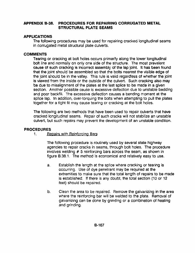
APPENDIX B-38. PROCEDURES FOR REPAIRING CORRUGATED METALSTRUCTURAL PLATE SEAMS
APPLICATIONSThe following procedures may be used for repairing cracked longitudinal seamsin corrugated metal structural plate culverts.
COMMENTSTearing or cracking at bolt holes occurs primarily along the lower longitudinalbolt line and normally on only one side of the structure. The most prevalentcause of such cracking is incorrect assembly of the lap joint. It has been foundthat the joint should be assembled so that the bolts nearest the visible edge ofthe joint s~lOuld be in the valley. This rule is valid regardless of whether the jointis viewed from the inside or the outside of the culvert. Such cracking also maybe due to misalignment of the plates at the last splice to be made in a givensection. Another possible cause is excessive deflection due to unstable beddingand poor backfill. The excessive deflection causes a bending moment at thesplice lap. In addition, over-torquing the bolts when attempting to pull the platestogether for a tight fit may cause tearing or cracking at the bolt holes.
The following are two methods that have been used to repair culverts that havecracked longitudinal seams. Repair of such cracks will not stabilize an unstableculvert, but such repairs may prevent the development of an unstable condition.
PROCEDURES1. Repairs with Reinforcing Bars
The following procedure is routinely used by several state highwayagencies to repair cracks in seams, through bolt holes. The procedureinvolves welding # 5 reinforcing bars across the seam, as shown infigure B.38.1. The method is economical and relatively easy to use.
a. Establish the length at the splice where cracking or tearing isoccurring. Use of dye penetrant may be required at theextremities to make sure that the total length of repairs to be madeis established. If there is any doubt, the total section (10 or 12feet) should be repaired.
b. Clean the area to be repaired. Remove the galvanizing in the areawhere the reinforcing bar will be welded to the plate. Removal ofgalvanizing can be done by grinding or a combination of heatingand grinding.
8-167
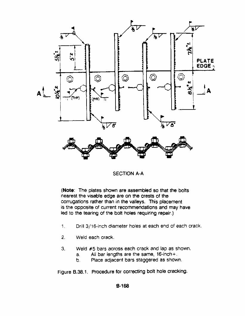
J_-
~ fr~ Jiv/ ...
···rr ~~
~ .~ \() PLATE
L EDGE;
© © @ @ ..At. ,.... ~ ~
~ <0 ~A- ~
SECTION A-A
(Note: The plates shown are assembled so that the boltsnearest the visable edge are on the crests of thecorrugations rather than in the valleys. This placementis the opposite of current recommendations and may haveled to the tearing of the bolt holes requiring repair.)
1. Drill 3/16~inch diameter holes at each end of each crack.
2. Weld each crack.
3. Weld #5 bars across each crack and lap as shown.a. All bar lengths are the same, 16-inch +.b. Place adjacent bars staggered as shown.
Figure 8.38.1. Procedure for correcting bolt hole cracking.
8-168
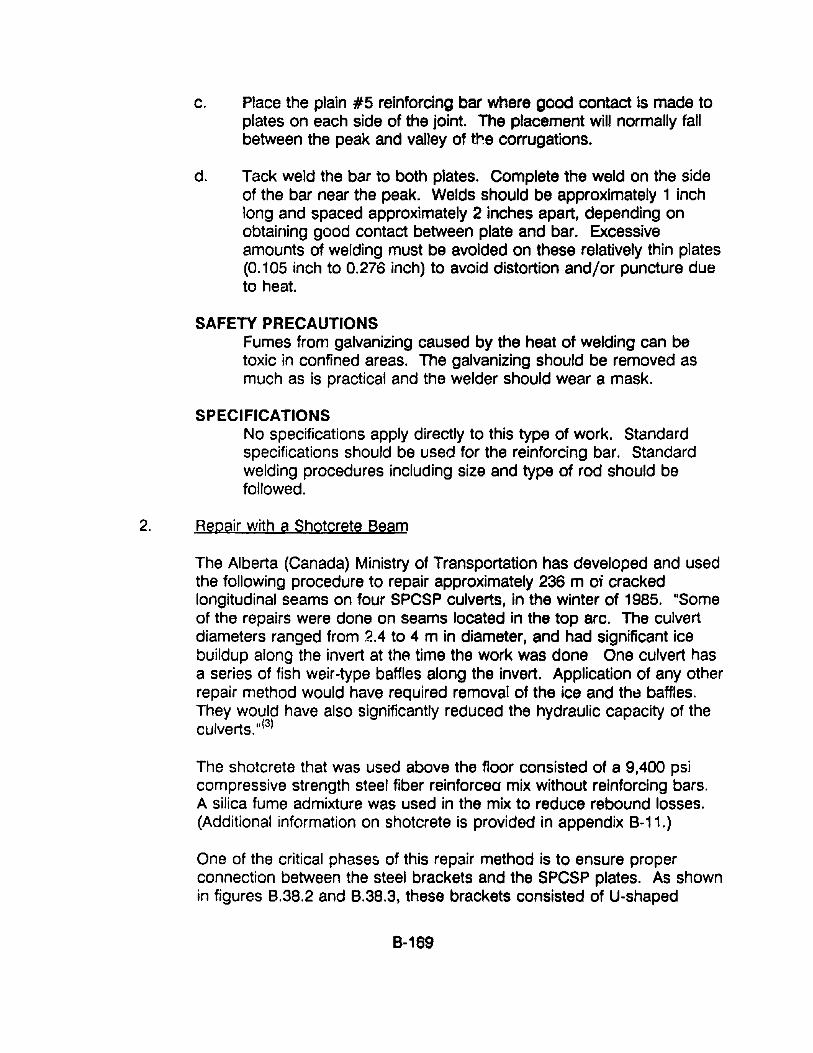
c. Place the plain #5 reinforcing bar where good contact is made toplates on each side of the joint. The placement will normally fallbetween the peak and valley of tre corrugations.
d. Tack weld the bar to both plates. Complete the weld on the sideof the bar near the peak. Welds should be approximately 1 inchlong and spaced approximately 2 inches apart, depending onobtaining good contact between plate and bar. Excessiveamounts of welding must be avoided on these relatively thin plates(0.105 inch to 0.276 inch) to avoid distortion and/or puncture dueto heat.
SAFETY PRECAUTIONSFumes from galvanizing caused by the heat of welding can betoxic in confined areas. The galvanizing should be removed asmuch as is practical and the welder should wear a mask.
SPECIFICATIONSNo specifications apply directly to this type of work. Standardspecifications should be used for the reinforcing bar. Standardwelding procedures including size and type of rod should befollowed.
2. Repair with a Shotcrete Beam
The Alberta (Canada) Ministry of Transportation has developed and usedthe following procedure to repair approximately 236 m oj crackedlongitudinal seams on four SPCSP culverts, in the winter of 1985. "Someof the repairs were done on seams located in the top arc. The culvertdiameters ranged from 2.4 to 4 m in diameter, and had significant icebuildup along the invert at thA time the work was done One culvert hasa series of fish weir-type baffles along the invert. Application of any otherrepair method would have required removal of the ice and th~ baffles.They would have also significantly reduced the hydraulic capacity of theculverts. 11(3)
The shotcrete that was used above the floor consisted of a 9,400 psicompressive strength steel fiber reinforcea mix without reinforcing bars.A silica fume admixture was used in the mix to reduce rebound losses.(Additional information on shotcrete is provided in appendix 8-11.)
One of the critical phases of this repair method is to ensure properconnection between the steel brackets and the SPCSP plates. As shownin figures B.38.2 and B.38.3, these brackets consisted of U-shaped
8-169
galvanized steel, 2.7 mm thick. They were attached to the SPCSP platesusing Hilti pins. The plate thickness ranges from 3 mm to 5 mm. Thevariation in plate thickness required careful selection of the Hilti pins,driving guns, and cartridges. Their recommendations, based onexperience, are:
PLATE THICKNESS HILTI GUN PINSCARTRIDGES4 mm4.3mm5.0mm
DX450DX650DX650
ENK 19S12ENP 3-21-L15ENP 3-21-L15
RedYellowRed
As shown in figure 8.38.2, the brackets were arranged in two differentways: one had the brackets pinned along the centerline of the insidecrest, and the other had the brackets pinned to the tangent portion of thecorrugations.
The first arrangement provides higher rigidity against the driving energyof the gun, which helps avoid loose connections on thinner plates.. Thesecond arrangement has the advantage of placing the Hilti pins in ashear mode rather than a Npulling-out" mode, which results in strongerconnections on all plate thicknesses providing the driving energy of thegun is properly adjusted.
Prior to shotcreting, the culvert sections with cracked seams werehoarded in 15 m lengths and heated using 2 or 3 propane heaters. TheSPCSP plates were lightly sandblasted to provide a textured roughsurface without removing the zinc coating. The plates were then washedwith an air-jet immediately before shotcreting. This was done in lengthsnot exceeding 5 m so as to minimize oxidation of the reinforcing steel.
The specified minimum hoarding temperature during the shotcretingoperation and the following 72 hours was 20°C. Since the work wasdone in winter conditions, the SPCSP plates heated up slower than therebars and anchors. Also, the temperature of the plates varied, with thetemperatures decreasing near the ice at the invert. The minimumspecified bond surface temperature was SaC. In order to maintain theminimum temperature of the shotcrete mix at 15°C during shooting, themixing water and the pre-bagged mix were also hoarded and heated witha propane heater.
8-170
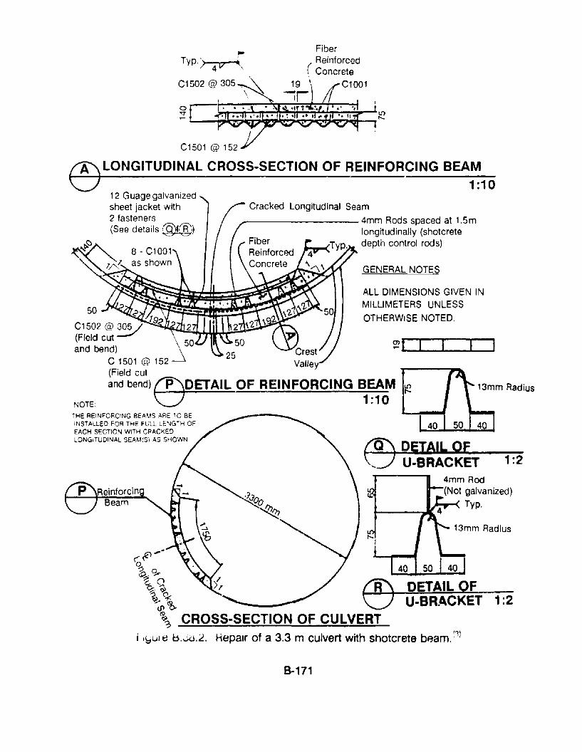
Fiber
(ReinforcedConcrete
19 \ C1001
~r
~
Typ. > 4 t7-(.
C1502 @,305~
o~ ~
~ L....._~~~~~~~~~"7'iIlr,1'-
C1501 @ 152
U.BRACKET 1:2
1:2
13mm Radius
DETAIL F
GENERAL NOTES
ALL DIMENSIONS GIVEN INMILLIMETERS UNLESS
OTHERWISE NOTED.
Cracked Longitudinal Seam
_-------- 4mm Rods spaced at 1.5mlongitudinally (shotcretedepth control rods)
~~,o., 0~. .,..'e.O9:.~
" (l~Ul\~? CROSS-SECTION OF CULVERT
I l\:,ul e b.Jd.2. Hepalr of a 3.3 m culvert with shotcrete bAam. (1)
50 ..~.._~-~~~~~:? 1 "j"C1502@ 31 --9<.....,I\'L'_/Mo,:;;~,.w...~__.(Field cut mcc::r=::c::Jand bend) 25 Crest -
C 1501 @ 152 Valley(Field cutand bend) ffiOETAIL OF REINFORCING BEAM ~o 1:10NOTE
THE REINFORCING BEAMS ARE TO BEINSTALLED FOR THE FljLL LENGTH OFEACH SECTION WITH CRACKE')LONGITUDINAL SEAM(S\ AS SHOWN
®LONGITUDINAL CROSS·SECTION OF REINFORCING BEAM1:10
12 Guage galvanizedsheet jacket with2 fasteners(See details !:§)@)
8-171
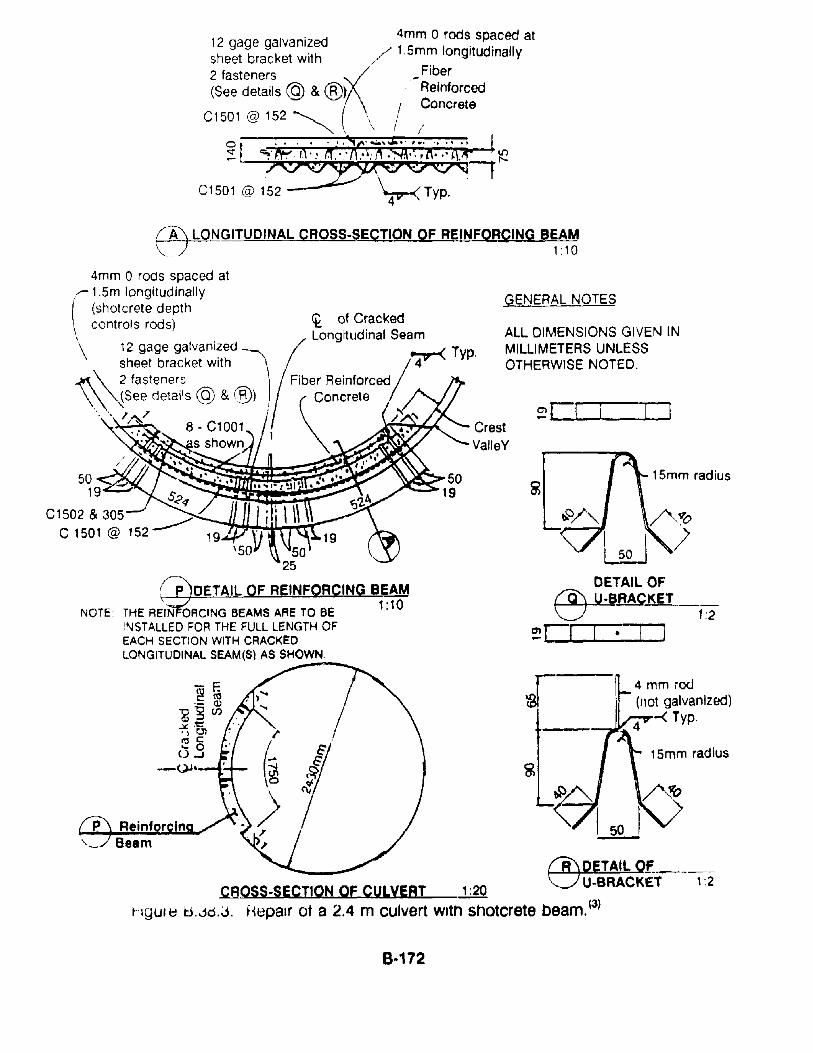
o ., . , .. , .:"c· .....~ ..· " .... ~:: ~·N?"·.·I1.··I1 ..(I'\~·i·,l\···t\.lt .t!?. .' . 0---r
C1501 @ 152 Typ.
)
15mm radius
DETAil OF~RAC",-,K"""ET-,-- __~- 1:2
~r:::o::::::o
ALL DIMENSIONS GIVEN INMILLIMETERS UNLESSOTHERWISE NOTED.
GENERAL NOTES
CrestValleY
5025
~DETAIL OF REINFORCING BEAM
THE REIN OACING BEAMS ARE TO BE 1:10
INSTALLED FOR THE FULL LENGTH OFEACH SECTION WITH CRACKEDLONGITUDINAL SEAM(Sl AS SHOWN,
NOTE
~NGITUOINAL CROSS-SECTION OF REINFQRQING B~~~
4mm 0 rOdS spaced at.--- 1.5m longitudinally( (shotcrete depth\ controls rods)
\ 12 gage galvanizedsheet bracket with ~
~\ 2 fasteners\\"'~See details @ & @) .
'. " 'A? 8 _C1001
...... II"-"",.....,.. ...• s shown
5019 S'?<1
C1502 & 305 ______C 1501 @ 152
4 mm rod(not galvanIzed)
~ ........ 4 -< Typ,
~DETAll Of. _CROSS-SECTION OF CULVERT 1:20 U-BRACKET 1:2
hgur ~ U,.jo.J. H~palr ot a 2.4 m culvert With shotcrete beam. (3)
8·172
A slurry coat was applied to the area receiving the shotcrete. Tworough coats of shotcrete were then applied, allowing 1 hour settime for each coat, to a maximum thickness of 100 mm to avoiddebonding. After about 1-1/2 hours of set time the finish coat wasapplied to establish the designed thickness and curvature.Thickness control was monitored by using three rows of depthgauges located at the top, middle and bottom of the beam and at1.5 m intervals along the longitudinal axis of the culvert. Thethickness was checked using a 4 m long straight edge.
RESOURCE COMMITMENT = 2:
COST RELATIVE TOREPLACEMENT = 2:
5 4Heavy
5 4High
3 2Medium
3 2Medium
1low
1Low
REFERENCES1. David C. Cowherd and Vlad G. Perba, "An Evaluation of Flexible Metal
Pipes." Bowser-Morner Associates, Inc., Dayton, Ohio.
2. "Handbook of Steel Drainage and Highway Construction Products."American Iron & Steel Institute, Washington, D.C., 1983
3. Jay G. Ramotar, "Culvert Seam Failures and Repairs," Alberta Ministry ofTransportation, 1986
4. "Hilti Fastening Systems," Hilti Fastening Systems, Inc., Tulsa, Oklahoma.
8-173
APPENDIX 8·39: PROCEDURES FOR SLlPLINING CULVERTS
APPLICATIONSThe technique of sliplining may be used to line almost all types of culverts withmany of the types and shapes of metal, concrete or plastic products that arecommonly used to construct culverts. In addition existing culverts may also belined with non-structural types of plastic pipe products.
COMMENTSAs noted in Chapter 6, one of the more effective ways to restore a culvert to afunctional condition is by sliplining the existing culvert with either conventional ornew types of prefabricated culvert products. In a sense, almost any type ofculvert can be sliplined with almost any kind of culvert material.
There are many technical details that must be worked out for the actualconstruction project, including: (1) how the liner sections will be moved intoplace in front of ,he culvert, (2) how the sections will be slid into the culvert, and(3) if and how structural interaction will be established between the liner and theexisting culvert. Although there are some procedures that are relatively simpleand straightforward, others are much more complex. In some cases it may bepossible to stipulate standard construction procedures while at other times theprocedures should be left open for contractor innovation, which may permit acontractor to use special equipment or techniques that may reduce the cost ofthe work.
With regard to innovative engineering and construction practices, it may beworthwhile to note that plastic pipe is somewhat flexible and it can be deformedto fit unusual culvert conditions and shapes. It has been reported that on oneproject in the State of Indiana, a section of 32 inch diameter Snap-TitaN wasdeform~d to fit into a 24 inch high pipe arch culvert. The process involvedplacing one 4 inch x 4 inch timber along the center of ths invert and anotherdirectly above it, under the centerline of the crown. Several portable hydraulicjacks were then used to push the two timbers apart, creating an oval crosssection to the plastic pipe. The oval-shaped plastic pipe was then rolled 90° andthen pushed into the pipe arch culvert. Multiple sections of the plastic liner pipewere similarly changed in shape and sUbsequently snapped together to form thecontinuous liner. The space between the culvert and the liner was later grouted,in accordance with procedures described appendix 8-40.
The following dt:5cribes the steps that are involved in s:iplining process andsome of the individual techniques that have been used for specific projects.InfmmC1tion on three slipli11in~ projects is provided at the end of this section.
8-174
PROCEDURES:
There are a wide variety of individual techniques that may be used to slipline aculvert. The choice of technique depends upon site-specific conditions and theselected sliplining material as well as the contractor's knowledge and experiencewith this type of work. The equipment that must, or can, be used for the work isalso a consideration. The following steps are normally required for the slipliningprocess:
Control water passing through the culvert - Water that is flowing, or could flow,through the culvert must be controlled or diverted so that the existing culvertmay be re~aired and/or relined. It is customary to construct a check-damacross the channel above the culvert and then install a pipe or pump system formoving the water through or around the culvert. This may also include diversionof sideslope channels and secondary check-dams to prevent surface runoff ofwater through the culvert during rainstorm periods. Examples of such controlfeatures are shown in figures 8.39.8 and 8.39.10.
Prepare culvert for sliplining - The culvert must be prepared for the slipliningoperation. This will usually include dewatering and doing at least a minimumamount of necessary repair work. The type and amount of preparation work willdepend upon the condition of the existing culvert, the type of slipliner to beinstalled and whether the space between the liner and the existing culvert will begrouted to provide structural interaction between the liner and tne existingculvert.
Construct guideway for sliplining - Consideration must be given to how the linersegments will be moved inside the culvert and whether they should be slid onsome sort of guideway system. It has been found that the variety of ways thatthese operations are done is a function of site conditions; the condition of theexisting culvert; the type, size, and weight of the liner sections; the clearancespace between the existing culvert and the line,'; the contractor's experience andinnovativeness; and the equipment available for the task.
Frequently pairs of wooden timbers are used to construct a "railway" that thesections may be slid on, This procedure may not be feasible if the invert of theexisting culvert is badly deteriorated and uneven. Another system that is alsofrequently useds to form up and cast a concrete slab down the centerline of theexisting invert. 1his has the dual function of repairing the invert and providing asmooth surface on which the liner sections may be slid. The surface of the"sidewalk" may be either flat or shaped to conform to the shape of the liner. Inaddition, the elevation of the "sidewalk" can be set to provide excellent gradecontrol for the liner and the final elevation of the relined culvert. For arch andsome oth3r types of culverts it may be possible and desirable to excavate e' 'd
8-175
lower the elevation of the invert or streambed so that the elevation of the invert ofthe liner will be the same as the original grade. Another method that has beenused for large precast concrete liner segments is to construct a railway withsurplus steel light-rail track. The liner sections are then lifted, rolled, and set intoplace with a special bogie vehicle that has flanged steel wheels.
It is also possible to establish gradelines inside the existing culvert with surveyset laser equipment that can be set to any desired slope. The laser beam isusually set at a convenient elevation above the invert. A survey rod, orequivalent, may then be used to check the grade of the liner sections by theoffset method.
Slipline liner segments intQ the culvert - The QVerall concept of this technique isto line the existing culvert with anQther (smaller) culvert product, by sliding thenew sections into the exist:. Ig culvert. This operation is commof'ly termed"launching." The complexity and difficulty Qf the launching operation is a functionof the type and size of the existing culvert and the product that is used for thenew lining. For example, lining a small concrete pipe culvert with a somewhatsmaller concrete or plastic sections is relatively simple and straightforward,whereas lining a large cQrrugated metal culvert that has a distorted and cQrrodedout invert with a somewhat smaller corrugated metal culvert may requireconsiderable planning and preparation work.
It should also be recognized that prefabricated metal and reinfcrced CQncreteculvert sections are designed to be lifted and set into place on a speciallyprepared base of compacted SQil or base course material. They are thenincQrporatod ir.to the roadway by compacting soil around them in a prescribedmanner. This procedure is not only not followed for sliplining, it is sUbstantiallydeviated from by the requirements imposed by the sliplining process.Specifically, sections are lifted and set down in front of the existing culvert andthey are then slid into and along the inside of the culvert until they reach theirfinal position.
Although there are several techniques that may he used t" install a slipllner, theyall involve either pushing or pulling the individual segments together and throughthe culvert. Frequently the sections are pulled into the culvert with a cable that isattached to a crane or a piece of construction equipment. Depending on siteconditions the cable may be pulled from the "far" end Qf the culvert or it may berun from the segment to the "far" end of the culvert, through a pulley block on astrongback frame and then back through the culvert and the liner to the "nearN
end of the culvert.
It should be noted that at some appropriate point in the process the linersegments must be connected together. When this operation is undertaken will
8·176
depend upon the type of liner to be used: for example:
• Precast concrete segments are connl=lcted together inside the culvert.• Corrugated metai segments are normally connected together outside of
the culvert.• Plastic liner segments may be snapped together inside or outside of the
culvert or they may be fuse/welded together outside of the culvert.
Grout or seal liner - Although the process of sliplining provides a new interiorsurface in the culvert, the liner will usually not be stable and resistant to hydraulicand structural loads until the annular space between the existing culvert and theliner is filled with some type of grout material. Grouting completes this type ofconstruction and re-establishes structural support and interaction between thesurrounding soil (including the existing culvert) and the new liner. In addition,grouting also helps retard corrosion of the existing culvert and it blocks furtherinfiltration through the wall of the existing culvert, if that has been occurring.Such infiltration may create voids in the soil adjacent to the culvert barrel,causing an undesirable distribution of soil pressures around the existing culvert.The worst-case scenario might be the eventual collapse of the existing culvertinto the ungrouted space, which may then lead to collapse of the liner and manyassociated problems at the level of the roadway surface.
The procedures and materials that are to be used for grouting the annuler spacebetween the outside of the liner and the inside of the existing culvert should becarefully considered with regard to the purpose and requirements for the grout.If the existing culvert is structurally weak and the liner is to carry significantstructural loads, then the filling (grout) must completely fill the space, withoutlarge voids or air pockets in the grout. If the existing culvert is structurally strongand the liner will only carry water and resist outward radial forces from the water,then it may be allowable for the grout to be a weaker material and to have somevoids. Incomplete filling resulting in voids will create uneven distribution offorces, which could cause future distress and damage to the culvert liner.
It is very impQrtant to recognize that the liner must be adequately blocked, Qr thegrQuting procedures must be selected tQ avoid displacement and damage to theliner during the grouting operatiQn, due to flotation. A considerable buoyantforce may be exerted on the lining by the fluid cement-based grQut; which tendsto float the liner to the top of the existing culvert This can raise the level of theinvert Qf the liner and possible cause structural damage to the liner. Althoughthe buoyant force is resisted by the weight of the liner units, there is still aconsiderable buoyant force that is proportionately larger with larger size culverts.For example, the buoyant force on a circular liner, in 150 pet concrete, isapproximately 1,900 pounds per lineal foot on a 4 ft oiameter liner and 8,600pounds per lineal foot on an 8 ft diameter liner. The use of non-uniform or
B-177
inadequate blocking may also cause point loading, bending and cracking of theliner. Since having a cold joint is not of concern, the grout may be placed inseveral small lifts to avoid flotation problems More detailed information on groutsand procedures for grouting sliplined culverts is provided in Chapter 6 and inappendix 8-35.
It must be recognized that some sort of end dam must be constructed at theends of the culvert to contain and resist fluid forces that will be exerted by thegrouting operation. This dam may De of a temporary type of construction or itmay be construction of new headwalls at the ends of the culvert.
It should also be noted that the Tennessee highway department, and possiblyother agencies, do not completely grout the annular space between the liner andthe existing culvert, especially when sliplining with a non-rigid plastic liner. Theirpractice is simply to seal this anl"'ular space at the upstream end of the culvertwith a non-shrinking, semi-flexible type of grout or a resin-impregnated type ofrope product that expands and completely fills the space.
9-178
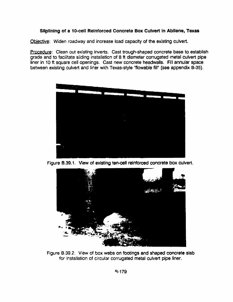
SlIpllnlng of a 10-cell Reinforced Concrete Box Culvert In Abilene, Texas
Objective: Widen roadway and increase load capacity of the existing culvert.
Procedure: Clean out existing inverts. Cast trough-shaped concrete base to establishgrade and to facilitate sliding installation of 8 ft diameter corrugated metal culvert pipeliner in 10ft square cell openings. Cast new concrete headwalls. Fill annular spacebetween existing culvert and liner with Texas-style "f1owable fill- (see appendix 8-35).
Figure 8.39.1. View of existing ten-cell reinforced concrete box culvert.
Figure 8.39.2. View of box webs on footings and shaped concrete slabfor installation of circular corrugated metal culvert pipe liner.
~-179
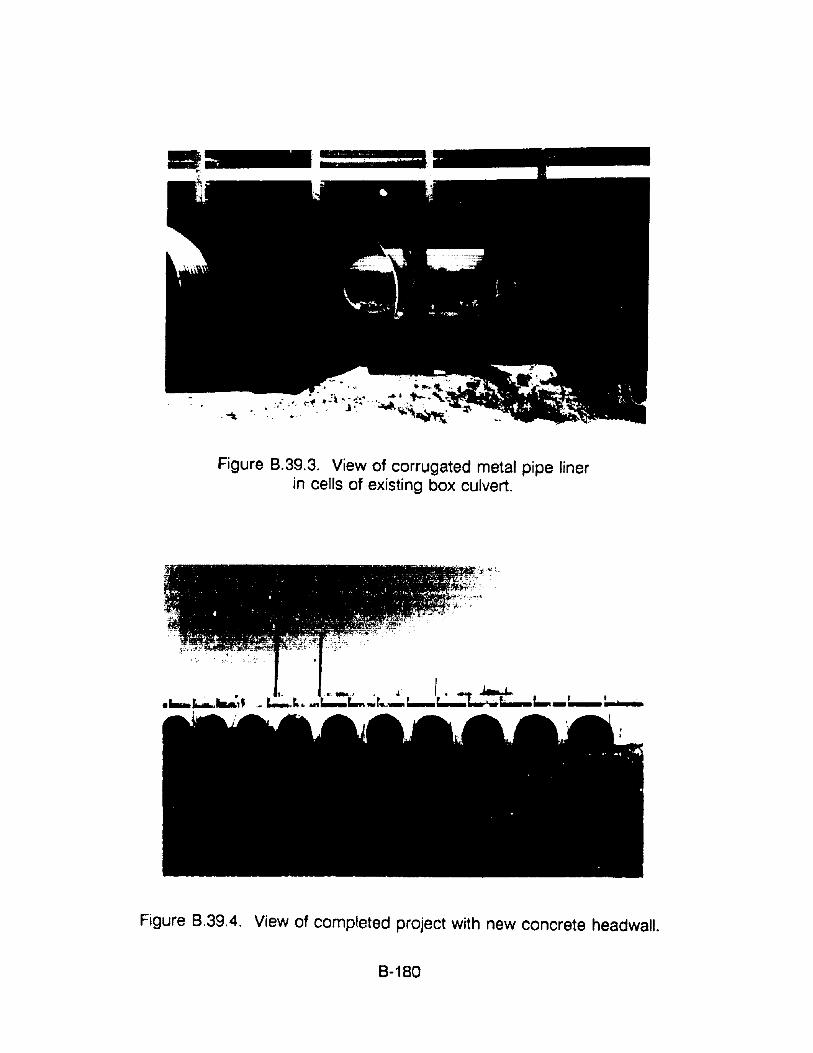
'. ...., ..- .' "I" ~'., ..... -1'- ..,~..
•• . J ~...,. • _ ••• "~--"' : •
.'" .., .. , "'.' ,), ..........:,~ ~
Figure 8.39.3. View of corrugated metal pipe linerin cells of existing box culvert.
•~ ...........:" _~ru ...~c:...,.;r.-~c.....I~~~tL _,-_,--:-",,-I
Figure 8.39.4. View of completed project with new concrete headwall.
8-180
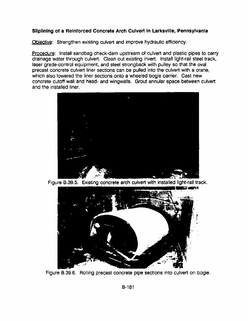
SlIpllnlng of a Reinforced Concrete Arch Culvert In Larksville, Pennsylvania
Objective: Strengthen existing culvert and improve hydraulic efficiency.
Procedure: Install sandbag check-dam upstream of culvert and plastic pipes to carrydrainage water through culvert. Clean out existing invert. Install light-rail steel track,laser grade-control equipment, and steel strongback with pulley so that the ovalprecast concrete culvert liner sections can be pulled into the culvert with a crane,which also lowered the liner sections onto a wheeled bogie carrier. Cast newconcrete cutoff wall and head- and wingwalls. Grout annular space between culvertand the installed liner.
Figure B.39.5. Existing concrete arch culvert with installed IightM rail track.~~._~.__.-n1t
Figure 8.39.6. Rolling precast concrete pipe sections into culvert on bogie.
8-181
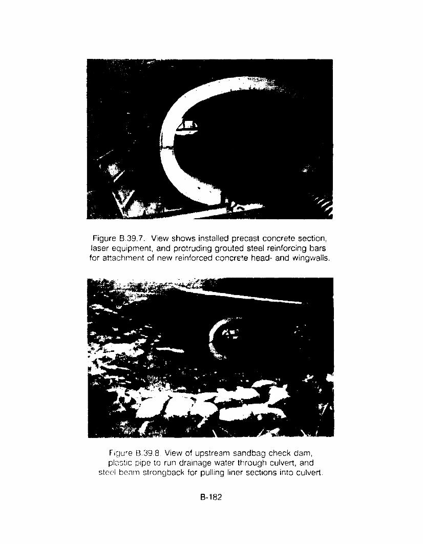
Figure 8.39.7. View shows installed precast concrete section,laser equipment, and protruding grouted steel reinforcing barsfor attachment of new reinforced concrE~e head- and wingwalis.
rigure 839.8. View of upstream sandbag check dam,plastiC pipe to run drainage water ttlrough culvert, and
steE~1 bezlIn strongback for pulling liner sections into culvert.
s- 182
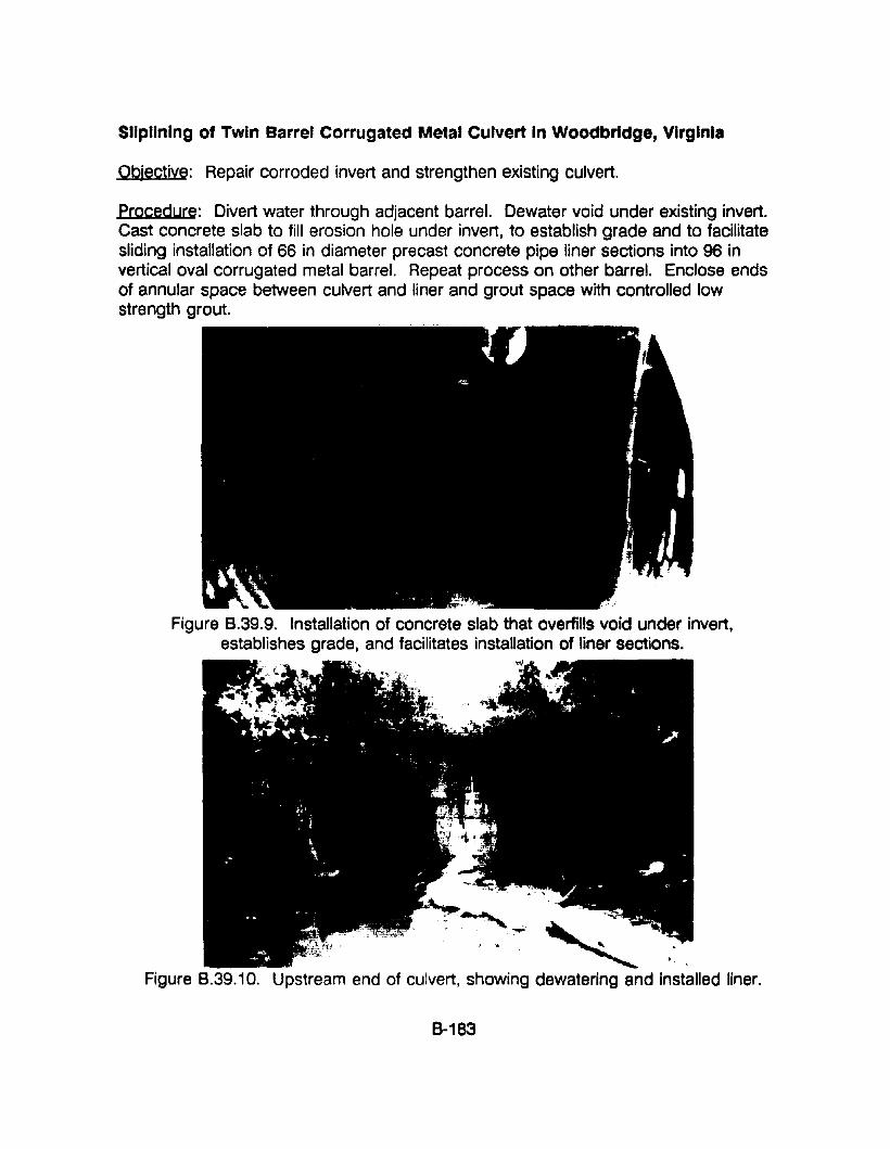
SlIpllnlng Of Twin Barrel Corrugated Metal Culvert In Woodbridge, Virginia
Objective: Repair corroded invert and strengthen existing culvert.
procedure: Divert water through adjacent barrel. Dewater void under existing invert.Cast concrete slab to fill erosion hole under invert, to establish grade and to facilitatesliding installation of 66 in diameter precast concrete pipe liner sections into 96 invertical oval corrugated metal barrel. Repeat process on other barrel. Enclose endsof annular space between culvert and liner and grout space with controlled lowstrength grout.
Figure 8.39.9. Installation of concrete slab that overfills void under invert,establishes grade, and facilitates installation of liner sections.
Figure 8.39.10. Upstream end of culvert, showing dewatering and installed liner.
8-183
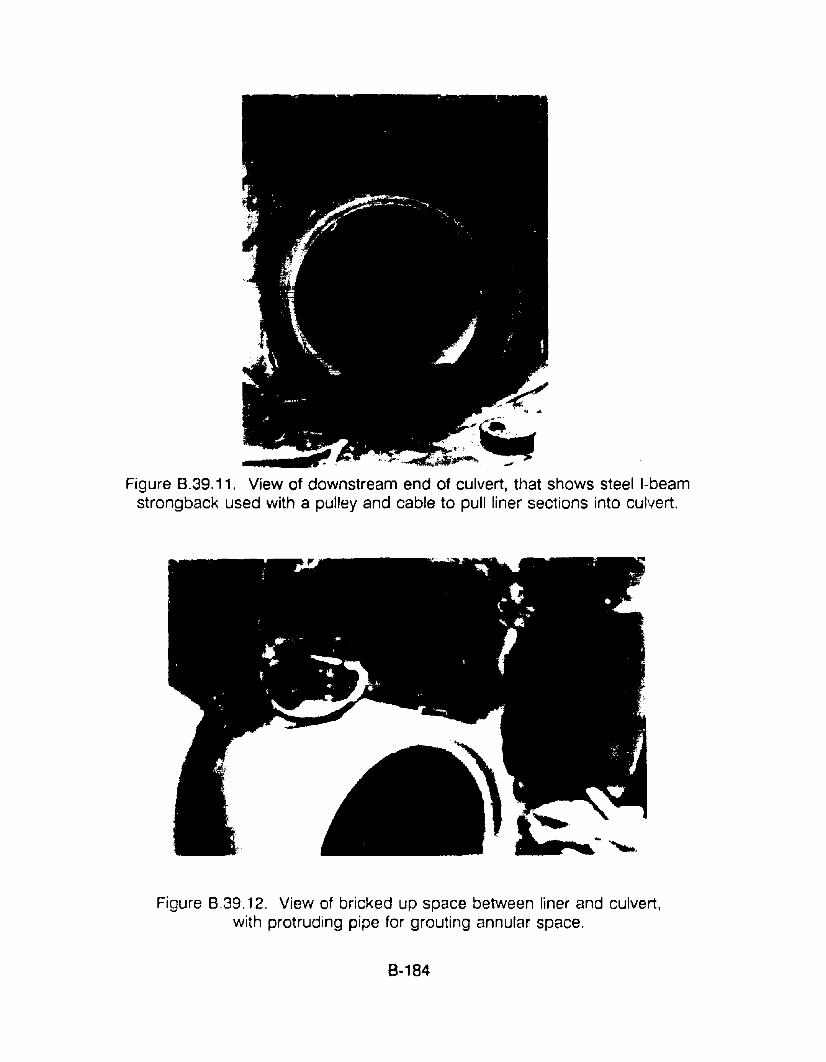
~ .. -~____CI".:"· , ,.,.,...... -
Figure 8.39.11. View of downstream end of culvert, tl1at shows steel I-beamstrongback used with a pulley and cable to pull liner sections into culvert.
Figure 8.39.12. View of bricked up space between liner and culvert,with protruding pipe for grouting annular space.
8-184
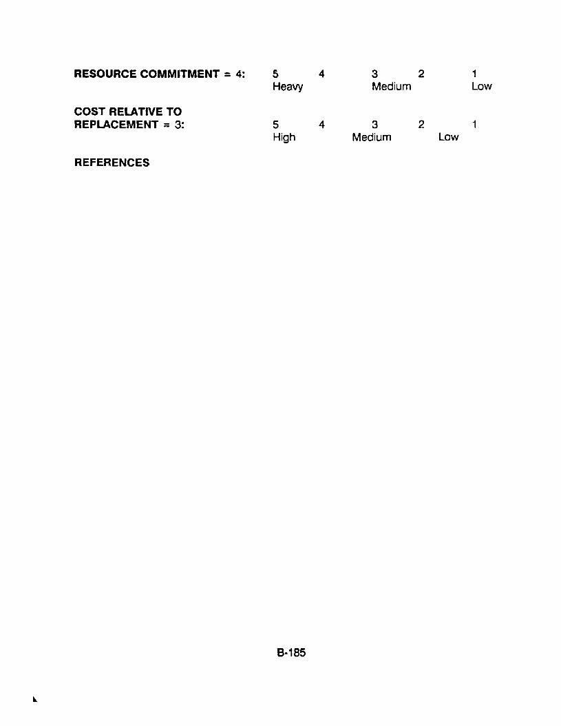
RESOURCE COMMITMENT =4: 5 4 3 2 1Heavy Medium Low
COST RELATIVE TOREPLACEMENT =3: 5 4 3 2 1
High Medium Low
REFERENCES
8·185
APPENDIX 8-40. PROCEDURES FOR GROUTING SLIPLINED CULVERTS
APPLICATIONSThe following deals with the materials and procedures that may be used to groutsliplined culverts: including (1) concrete inside of concrete, (2) corrugated steelinside of concrete, (3) concrete inside of corrugated steel, (4) corrugated steelinside of corrugated steel and (5) corrugated steel or concrete inside of eithermasonry or timber.
COMMENTSThe procedures and materials that are to be used for grouting the annular spacebetween the outside of rigid sliplined culvert liners and the inside of existingculverts should be carefully considered with regard to the purpose for filling andthe strength of the grout material that should be used. The grout may not needto have the strength of structural concrete but rather only the strength of wellcompacted soil. However, the strength-gain characteristics of the materialshould be established to fit the anticipated construction schedule and the timewhen the lined culvert will be returned to service. The types of materials that aretypically used range from Portland cement based mortar to a controlled lowstrength material (CLSM).
A CLSM is usualiy a mixture of cement, fly ash, fine sand, and water. A typicalmix may have three times more fly ash (a pozzolanic cementitious material) thancement. Hydration of the cement and slow hydration of the fly ash produces amaterial that may have a 28-day compressive strength of only 100 psi or 14,400psf, which is about six times stronger than many soils that have a strength in therange of only 2,500 psf. Lower strength CLSM mixes may be used. If a CLSMtype grout mix is to be used, particularly for the first time, it is recommended thattrial mixes be prepared to become familiar with the properties and procedures formixing and handling this type of material. Example mix designs, specifications,and test methods are provided in the following Specifications section for thisprocedure.
It should be recognized that the slipliner must be adequately blocked or thegrouting procedures must be selected to avoid displacement and/or damage tothe liner during the grouting operation due to flotation. A considerable buoyantforce is exerted on the lining by the fluid cement-based grout, which tends tofloat the liner to the top of the existing culvert. It mey be noted that the buoyantforce on a circular liner, in 150 pcf concrete, is approximately 1,900 pounds perlineal foot on a 4 ft. diameter liner and 8,600 pounds per lineal foot on an 8 ft.~iam9ter liner. Thus! these forces must be resisted either by blocking or bygrouting in stages so that the forces are effectively resisted by the weight of theliner. Although the buoyant force is resisted by the weight of the liner units,there is still a considerable buoyant force, which is proportionately larger with
8-186
larger size culverts. The use of non-uniform and inadequate blocking can easilycause point loading, bending, and cracking of the liner.
It has been reported that the heat of hydration of portland cement based groutsmay cause plastic liners to increase in length, by as much as four inches.
The National Corrugated Steel Pipe Association's "Drainage Technology Bulletin",dated September 1988, recommends that hold-down bolts be installed in theupper portion of corrugated steel liners. The hold-down devices may consist ofa 3/4-inch diameter nut welded on the outside of the CMP liner pipe with a 3/4inch diameter adjusting rod inserted. Typical spacing would be three sets on 10foot centers longitudinally, one at the top center-line and the other two, 40degrees to both sides. Other techniques have also been successfully used.
PROCEDURES
The first step of the grouting operation is to construct either a permanent ortemporary headwall at the ends of the culvert, to block the annular spacebetween the existing culvert and the liner. The space is then filled with thedesired material by a variety of methods, depending upon the type of groutbeing used and various aspects of the specific project. The following discussesfour of the most common techniques.
1. One method involves the installation of a t'3mporary pipe through one orboth of the end bulkheads along the top of the liner. Grout that is thenpumped to the end of the pipe free-falls around the liner. It is the intentthat the grout will flow completely under and around the liner and it willbe consolidated by the hydrostatic head of the fluid grout. The liner mayor may not be vibrated to facilitate consolidation of the grout. The pipe isslowly withdrawn so that grout may flow around the liner for the fulllength of the culvert. An alternate to t1lis method of placement, which isused by at least one State, is to pour the grout through holes that aredrilled through the roadway and the crown of the existing culvert.
The biggest drawback to this procedure is that there is minimal controlover placement of the grout and large voids could be created if the groutblocks up at some point. However, the grouts that are placed in thismanner usually have a very high slump and are essentially self-leveling.A high cement-factor grout is used if a high strength is required and aControlled Low Strength Material (CLSM) may be used if high strength isnot required.
2. One method involves the use of grout ports that are built into theprefabricated liner sections. The ports may be just the lifting holes in the
B-187
crown of precast concrete sections or holes that are cast or built in atvarious elevations around the circumference of concrete and metalculvert sections. Grout that is then p'Jmped through these ports free-fallsinto place around the liner.
3. Perhaps the most reliable way to place grout, to preclude the for-mationof voids, is to pressure grout from the bottom up. Grout is pressureinjected through low level ports along both sides of the culvert liner, untilit comes out of the ports at higher elevations. The grouting may bacontinued through the low level ports (after plugging the higher ports) orthe grout placement pipe/hose may be moved to tr:e higher level portsto minimize the ~ressure that is necessary to push grout uphill. Groutingis continued in this manner until the entire cavity is completely filled. Thisprocedure, which is commonly used to grout relatively small dIameterducts for post·~ensioned concrete construction, minimizes the tendenc:lfor grout to block up and create voids. This procedlJre is the mostpositive way of ensuring that the liner has good structural support.
4. A variation of the latter tecfmique is to grout in two cr three stsges tominirr.ize floatation forces on the liner. Under this procedure, the firststep is inject grout through ports in the lower quadrant of t!le units toencase the invert and no more than the lower half of the liner. Theprocedure is to inject grout through ports along one side of the culvertuntil it comes out of the same level ports along the oth~r side of theculvert, thereby ensuring that the entire area below the invert of the linerhas been grouted. The holes are then plugged and the grout ;s allowedto harden before subsequent grouting is initiated.
PRECAUTIONS1. The liner should be adequately blocked to prevent flotation and IJossible
displacemer.t and damage to the liner.
2. Ttle annular space between the existing culvert and the liner should becompletely filled, with no voids in the material.
3. The heat of hydration of portland cement based grouts may cause plasticpipe liners to increase in length by soveral inches.
4. The pressure should be monitored during pressure grouting to preventexcessive external pressure from collapsing the liner conduit.
8·188
SPECIFICATIONS1. Suggested Guide Specifications for Flowable FillTexas Aggregates and Concrete Association, November 28, 1989.
GENERALThis specification identifies the basic requirements for furnishing, mixing, andtransporting f10wable fill.
Flowable fill backfill material suitable for use as a structural backfill material,beneath building foundations, for filling utility trenches, excavations insidebuildings, abandoned pipes and tanks, (sliplined culverts) and all routinebackfilling. The material may also be used for placements in water.
MATERIALSMaterials shall conform to:
Cement ASTM C 150Fly Ash ASTM C 168, class C or Class FWater - ASTM C 94Admixtures - ASTM C 260 and/or C 494Fine Aggregate - Natural or ma:1ufactured sand, or a combinationthereof, free from injurious amounts of salt, alkali, vegetable matter orother objectionable ~laterial. It is intended that the fine aggregate be fineenough to stay in suspension in the mortar to the extent required forproper flow. The fine aggregate shall conform to the following gradation:
Sieve Size3/4 inchNo. 200
% Passing1000- 10
MIX DESIGNThe following is given as a typical mix design for a trial mix. Adjustments af the:'proportions may .,~ made to achieve proper solid suspension and optimumflowability. Admi,,+..Jres may be used if desired to improve the characteristics ofthe mix. The suggested quantities of dry materials per cubic yard are:
CementFly AshFine AggregateWater (approxi~ate)
100lbs300 Ibs
2600 Ibs70 gal
8-189
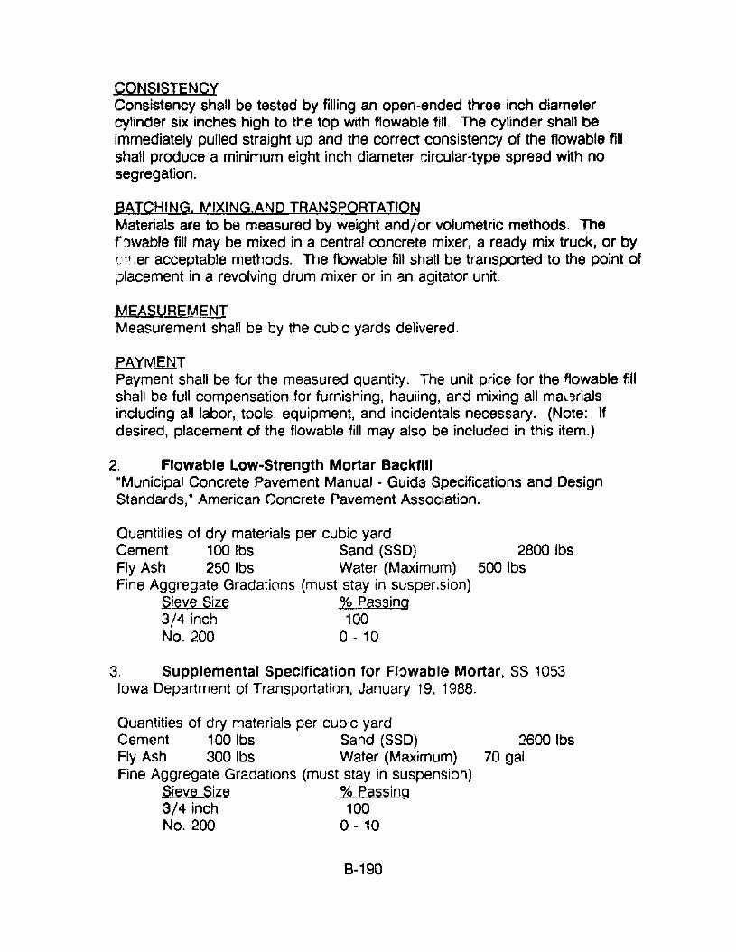
CONSISTENCYConsistency shall be tested by filling an open-ended three inch diametercylinder six inches high to the top with flowable fill. The cylinder shall beimmediately pulled straight up and the correct consistency of the f10wable fillshall produce a minimum eight inch diameter circular-type spread with nosegregation.
BATCHING. MIXING.AND TRANSPORTATIONMaterials are to be measured by weight and/or volumetric methods. Thef/)wable fill may be mixed in a central concrete mixer, a ready mix truck, or byc·tl.er acceptable methods. The flowable fill shall be transported to the point oftJ1acement in a revolving drum mixer or in 3n agitator unit.
MEASUREMENTMeasurement shall be by the cubic yards delivered.
PAYMENTPayment shall be fur the measured quantity. The unit price for the tJowable fillshall be full compensation for furnishing, hauiing, and mixing all ma'~ ~rials
including all labor, tools. equipment, and incidentals necessary. (Note: Ifdesired, placement of the flowable fill may also be included in this item.)
2. Flowable Low-Strength Mortar Backfill"Municipal Concrete Pavement Manual - Guide Specifications and DesignStandards, tI American Concrete Pavement Association.
Quantities of dry materials per cubic yardCement 100 Ibs Sand (SSO) 2800 IbsFly Ash 250 Ibs Water (Maximum) 500 IbsFine Aggregate Gradations (must stay in susper.sion)
.sieve Size % Passing3/4 inch 100No, 200 0 - 10
3. Supplemental Specification for FI~wable Mortar, 5S 1053Iowa Department of Transportation, January 19, 1988.
Quantities of dry matArials per cubic yardCement 100 Ibs Sand (SSO)Fly Ash 300 Ibs Water (Maximum)Fine Aggregate Gradations (must stay in suspension)
Sieve Size % Passing3/4 inch 100No. 200 0 - 10
8-190
~600 Ibs70 gal
RESOURCE COMMITMENT =3:
COST RELATIVE TOREPLACEMENT = 2:
5 4Heavy
5 4High
3 2Medium
3 2Medium
1Low
1Low
REFE~ENCES
1. "Drainage Technology Bulletin," National Corrugated Steel PipeAssociation, September 1988.
2. "Ready Mixed Flowable Fill," National Ready Mixed Concrete Association.
3. "Suggested Guide Specifications for Flowable Fill," Texas Aggregatesand Concrete Association, 1989.
B·191
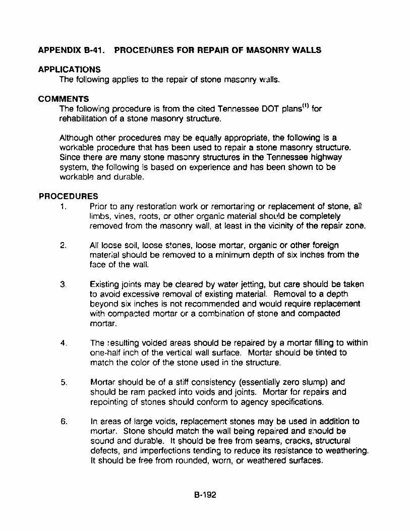
APPENDIX 8-41. PROCEnURES FOR REPAIR OF MASONRY WALLS
APPLICATIONSThe following applies to the repair of stone masonry walls.
COMMENTSThe following procedure is from the cited Tennessee DOT plans(1) forrehabilitation of a stone masonry structure.
Although other procedures may be equally appropriate, the following is aworkable procedure that has been used to repair a stone masonry structure.Since there are many stone masonry structures in the Tennessee highwaysystem, the following is based on experience and has been shown to beworkable and durable.
PROCEDURES1. Prior to any restoration work or remortaring or replacement of stone, all
limbs, vines, roots, or other organic material shol!ld be completelyremoved from the masonry wall, at least in the vicinity of the repair zona.
2. All loose soil, loose stones, loose mortar, organic or other foreignmaterial should be removed to a minimum depth of six inches from theface of the wall.
3. Existing joints may be cleared by water jetting, but care should be takento avoid excessive removal of existing material. Removal to a depthbeyond six inches is not recommended and would require replacementwith compacted mortar or a combination of stone and compactedmortar.
4. The ~esulting voided areas should be repaired by a mortar filling to withinone-half inch of the vertical wall surface. Mortar should be tinted tomatch the color of the stone used in the structure.
5. Mortar should be of a stiff consistency (essentially zero slump) andshould be ram packed into voids and joints. Mortar for repairs andrepainting of stones should conform to agency specifications.
6. In areas of large voids, replacement stones may be used in addition tomortar. Stone should match the wall being repaired and s;10uld besound and durable. It should be free from seams, cracks, structuraldefects, and imperfections tending to reduce its resistance to weathering.It should be free from rounded, worn, or weathered surfaces.
8-192
In general, stones should have a thickness of not less than six inches.Widths should not be less than 1-1/2 times their respective thicknesses.Lengths should not be less than 1-1/2 times their respective widths.
7. The masonry should be kept wet while repairs are being performed. Therepaired surfaces should be protected from the sun and kept wet for aperiod of three days after completion of the work. Mortaring should notbe performed in freezing weather. Any work damaged by frost should beremoved and repl3ced.
RESOURCE COMMITMENT = 1:
COST RELATIVE TOREPLACEMENT = 1:
5 4Heavy
5 4High
3 2Medium
3 2Medium
1Low
1Low
REFERENCES1. "Plans for Rehabilitation of Cowa(d Mill Road Bridge over Beaver creek,
Knox County, Tennessee DOT, 1989.
8-193
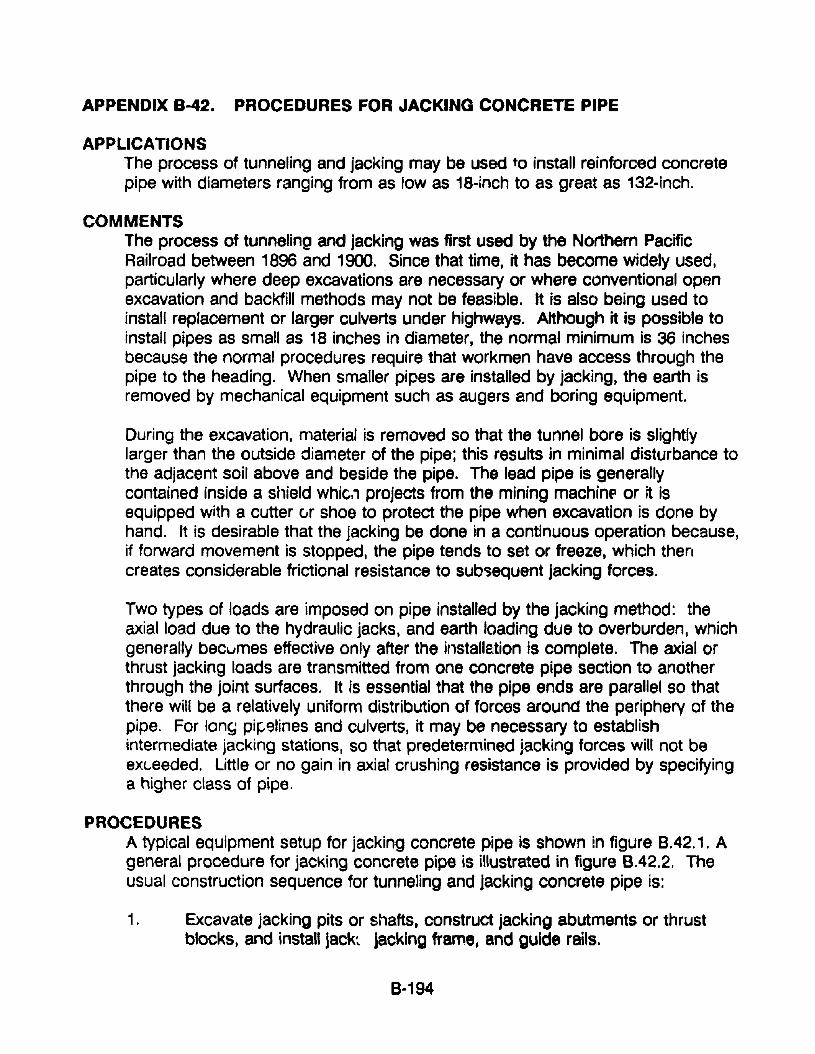
APPENDIX 8-42. PROCEDURES FOR JACKING CONCRETE PIPE
APPLICATIONSThe process of tunneling and jacking may be used to install reinforced concretepipe with diameters ranging from as low as 18-inch to as great as 132-inch.
COMMENTSThe process of tunneling and jacking was first used by the Northern PacificRailroad between 1896 and 1900. Since that time, it has become widely used,particularly where deep excavations are necessary or where conventional openexcavation and backfill methods may not be feasible. It is also being used toinstall replacement or larger culverts under highways. Although it is possible toinstall pipes as small as 18 inches in diameter, the normal minimum is 36 inchesbecause the normal procedures require that workmen have access through thepipe to the heading. When smaller pipes are installed by jacking, the earth isremoved by mechanical equipment such as augers and boring equipment.
During the excavation. material is removed so that the tunnel bore is slightlylarger than the outside diameter of the pipe; this results in minimal disturbance tothe adjacent soil above and beside the pipe. The lead pipe is generallycontained inside a shield whic" projects from the mining machinf or it isequipped with a cutter vr shoe to protect the pipe when excavation is done byhand. It is desirable that the jacking be done in a continuous operation because,if forward movement is stopped, the pipe tends to set or freeze, which thencreates considerable frictional resistance to subsequent jacking forces.
Two types of loads are imposed on pipe installed by the jacking method: theaxial load due to the hydraulic jacks, and earth loading due to overburden, whichgenerally becumes effective only after the installetion is complete. The axial orthrust jacking loads are transmitted from one concrete pipe section to anotherthrough the joint surfaces. It is essential that the pipe ends are parallel so thatthere will be a relatively uniform distribution of forces around the periphery of thepipe. For long pir;,'3lines and culverts, it may be necessary to establishintermediate jacking stations, so that predetermined jacking forces will not beexc..eeded. Little or no gain in axial crushing resistance is provided by specifyinga higher class of pipe.
PROCEDURESA typical equipment setup for jacking concrete pipe is shown in figure 8.42.1. Ageneral procedure for JacKing concrete pipe is illustrated in figure 8.42.2. Theusual construction sequence for tunneling and jacking concrete pipe is:
1. Excavate jacking pits or shafts, construct jacking abutments or thrustblocks, and install jack~ jacking frame, and guide rails.
8-194
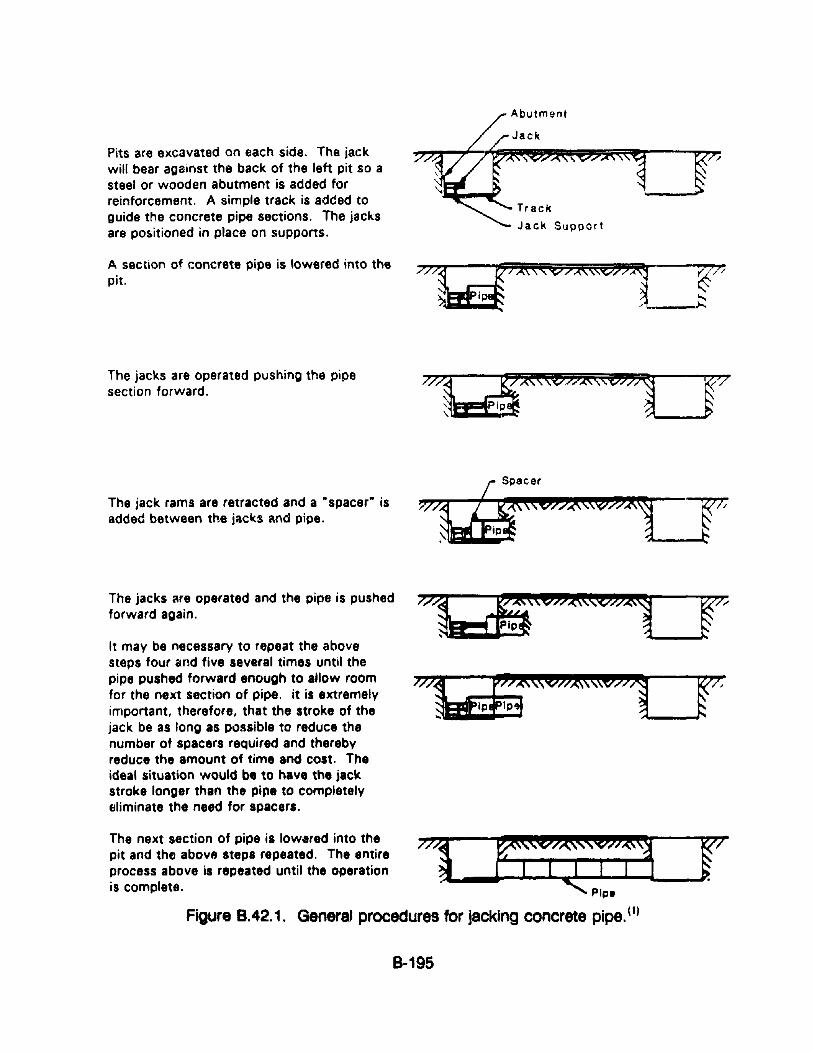
Pits are excavated on each side. The jackwill bear against the back of the left pit so asteel or wooden abutment is added forreinforcement. A simple track is added toguide the concrete pipe sections. The jacksare positioned in place on supports.
A section of concrete pipe is lowered into thepit.
The jacks are operated pushing the pipesection forward.
The jack rams are retracted and a •spacer· isadded between the jllcl(s ~nd pipe.
The jacks ..re operated and the pipe is pushedforward again.
It may be necessary to repeat the abovesteps four and five several times until thepipe pushed forward enough to allow roomfor the next section of pipe. it is extremelyimportant, therefore, that the stroke of thejack be as long as possible to reduce thenumber of spacers required and therebyreduce the amount of time and cost. Theideal situation would be to have the jackstroke longer than the pipe to completelyeliminate the need for spacers.
Abutment
Jack
Track
Jack Support
The next section of pipe is lowered into the 777~ ~ rpit and the abovB steps repeated. The entireprocess above is repeated until the operation •is complete. Pipe
Figure 8.42.1. General procedures for jacking concrete pipe. (1)
8-195
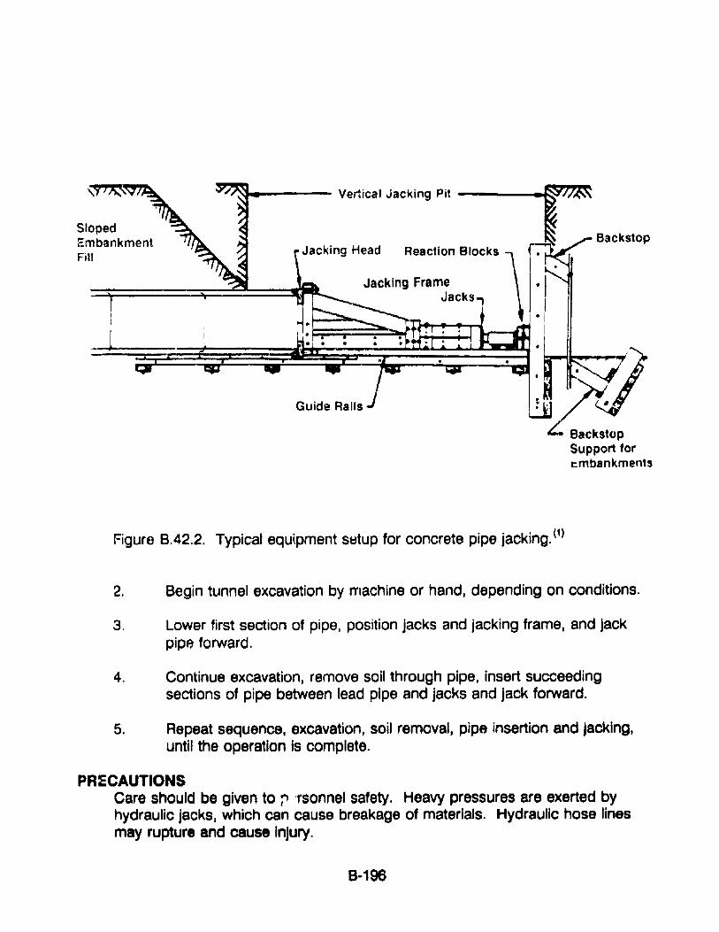
Sloped~mbankment
Fill
J
~------ Vertical Jacking Pit ----
Jacking Head
Guide Rails
Figure 8.42.2. Typical equipment st:'tup for concrete pipe jacking. (1)
2. Begin tunnel excavation by machine or hand, depending on conditions.
3. Lower first section of pipe, position jacks and jacking frame, and jackpipe forward.
4. Continue excavation, remove soil through pipe, insert succeedingsections of pipe between lead pipe and jacks and jack forward.
5. Repeat sequence, excavation, soil removal, pipe insertion and jacking,until the operation is complete.
PR:ECAUTIONSCare should be given to ;" 'rsonnel safety. Heavy pressures are exerted byhydraulic jacks, which can cause breakage of materials. Hydraulic hose linesmay rupture and cause InJury.
8-196
RESOURCE COMMITMENT =3: 5 4 3 2 1Heavy Medium Low
COST RELATIVE TOREPLACEMENT =3: 5 4 3 2 1
High Medium Low
REFERENCES1. Concrete Pipe Handbook, American Concrete Pipe Association, 1988.
2. "Design Data 13," American Concrete Pipe Association, July 1969.
8·197

SECTION
APPENDIX C. SPECIFICATIONS AND DESIGN PROCEDURES
PAGE
1
2
Specification Guide for ErosionControl Geotextiles
Riprap Design in Channels
C-1
C-6
APPENDIX C-1. SPECIFICATION GUIDE FOR EROSION CONTROLGEOTEXTILES
TASK FORCE 25 SPECIFICATION GUIDESJOINT COMMITTEE ON NEW MATERIALS, AASHTO
1. DESCRIPTION
1.1
2. MATERIALS
2.1
2.2
This work shall consist of furnishing and placing a geotextile forthe following drainage applications: cut and fill slope protection,protection of various small drainage structures and ditches, waveprotection for causeways and shoreline roadway embankments,and scour protection for structures such as bricge piers andabutments. The geotextile shall be designed to allow passage ofwater while retaining insitu soil without clogging. The quantities oferosion control geotextiles as shown on the plans may beincreased or decreased at the direction of the engineer based onconstruction procedures and actual site conditions that occurduring construction of the project. Such variations in quantity willnot be considered as alterations in the details of construction or achange in the character of the work.
Fibers used in the manufacture of geotextiles, and the threadsused in joining geotextiles by sewing, shall consist of long ch~in
synthetic polymers composed of at least 85% by weightpolyolefins, polyesters, or polyamides. They shall be formed intoa network such that the filaments or yarns retain dimenSionalstability relative to each other, including selvages. These materialsshall conform to the physical requirements of table 8.7.2.
Geotextile rolls shall be furnished with suitable wrapping forprotection against moisture and extended ultraviolet exposure priorto placement. Each roll shall be labeled or tagged to provideproduct identification sufficient for inventory and quality controlpurposes. Rolls shall be stored in a manner which protects themfrom the elements. If stored outdoors, they shall be elevated andprotected with a waterproof cover.
C-1
3. CONSTRUCTION REQUIREMENTS
3.1 Geotextile Exposure Following Placement. Exposure ofgeotextiles to the elements between laydown and cover shall be amaximum of fourteen (14) days to minimize damage r->otential.
3.2 _Erosion Control Placement. The geoiextile shall be placed andanchored on a smooth graded surface approved by the engineer.The geotextile shall be placed in such a manner that placement ofthe overlying materials will not excessively stretch or tear thefabric. Ancllo'ing of the terminal ends of the geotextile shall beaccomplish~d through the use of key trenches or aprons at thecrest and the toe of the slope (refer to figures B.7.5 throughB.7.8.).[NOTE: In certain applications to expedite construction,18·i:1ch long anchoring pins, pla~ed on 2 to 6 feet centers,depending on the slope of the covered area, have been usedsuccessfully. ]
3.2.1 Slope Protection Placement. Successive geotextile sheets shallbe overlapped in such a manner that the upst"eam sheet is placedover the downstream sheet and/or upslope over downslope. Inunderwater applications, the geotextile and required thickness ofbackfiil material shall be placed the same day. The backfillplacement shall begin at the toe and proceed up the slope.
Riprap and heavy stone filling shall not be dropped onto thegeotextile from a height of more than one feot. Siupe protectionand smaller sizes of stone filling shall not be dropped onto thegentextile from a height exceeding three feet. Any geotextiledamaged during placement shall be replaced as directed by theengineer at the Contractor's expense.
3.3 Seams. The geotextile shall be joined by either sewing oroverlapping. ~II seams shall be subject to the approval of theEngineer. Overlapped seams shall have a minimum overlap of 12inches except when placed under water where the overlap shall bea minimum of three feet.
3.4 Repair. A geotextile patch shall be placed over the damaged areaand extend three (3) feat beyond the perimeter of the tear ordamage.
C-2
4. METHOD OF MEASUREMENT
4.1 The geotextile shall be measured by the number of square yardscomputed from the payment lines shown on the plans or frompayment lines established in writing by the Engineer. Thisexcludes seam overlaps, but shall include geotextiles used in thecrest and the toe of slope treatments.
4.2 Slope preparation, excavation and backfill, bedding, and covermaterial are separate pay items.
5. BASIS OF PAYMENT
5.1 The accepted quanti~ies of geotextile shall be paid for at thecontract unit price per square yard in place.
5.2 Payment wili be made under:PAY ITEM PAY UNIT
Erosion C')ntrol Geotextile Square Yard
C-3
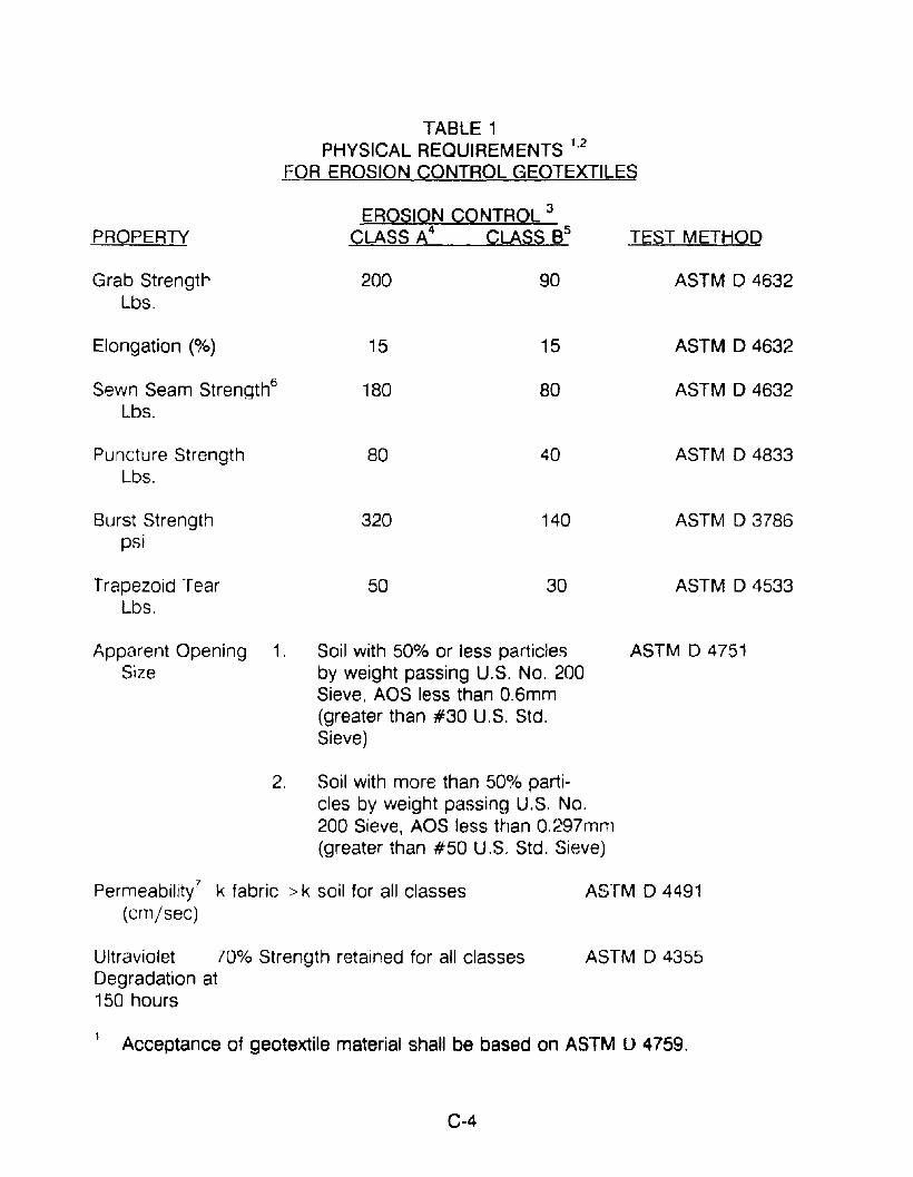
TEST METHODPROPERTY
TABLE 1PHYSICAL REQUIREMENTS 1,2
FOR EROSION CONTROL GEOTEXTILES
EROSION CONTROL 3
CLASS A4 CLASS 8 5
Grab StrengtrLbs.
Elongation (%)
Sewn Seam Strength6
Lbs.
Puncture StrengthLbs.
Burst Strengthpsi
Trapezoid TearLbs.
200
15
180
80
320
50
90
15
80
40
140
30
ASTM D 4632
ASTM D 4632
ASTM D 4632
ASTM D 4833
ASTM 03786
ASTM D 4533
Apparent Opening 1. Soil with 50% or less particlesSize by weight passing U.S. No. 200
Sieve, AOS less than O.6mm(greater than #30 U.S. Std.Sieve)
2. Soil with more than 50% parti-cles by weight passing U.S. No.200 Sieve, AOS less than O.297mm(greater than #50 U.S. Std. Sieve)
ASTM D 47.51
Permeability7 k fabric > k soil for all classes(em/sec)
Ultraviolet 70% Strength retained for all classesDegradation at150 hours
ASTM 04491
ASTM D 4355
1 Acceptance of geotextile material shall be based on ASTM U 4759.
C-4

2 Contracting agency may ,-~quire a letter from the supplier certifying that itsgeotextile meets specification requirements.
3 Minimum. Use value in weaker principal direction. All numerical values representminimum average roll value (Le., test results from any ampled roll in a lot shall meetor exceed the minimum values in the Table). Stated values are for non-critical,non-severe applications. Lots sampled according to ASTM 04354.
4CI8SS A Erosion Control applications are those where fabrics are used underc<.-~ , -!tions where installation stresses are more severe than Class 8 applications;Le., .:.-tone placement height should be less than 3 feet and stone weights shouldnot exceed 250 pounds.
5 Class 8 Erosion Control applications are those where fabric is used ,n structures orunder conditions where the fabric is protected by a sand cushion or by "zero dropheight" placement of stone.
6 Values apply to both field and manufactured seams.
7 A nominal coefficient of permeability may be determined by multiplying permittivityvalue by nominal thickness. The k value of the fabric shouid be greater than the kvalue of the soil.
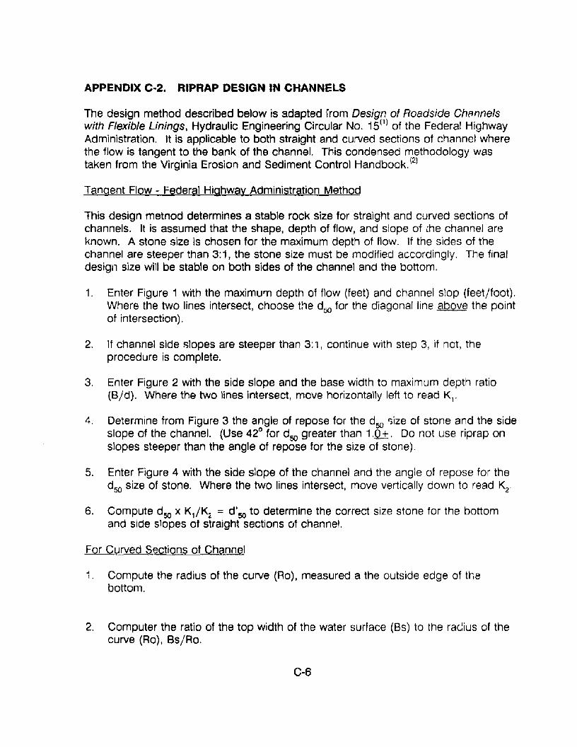
APPENDIX C-2. RIPRAP DESIGN IN CHANNELS
The design method described below is adapted irom Design of Roadside Channelswith Flexible Linings, Hydraulic Engineering Circular No. 15(1) of the Federal HighwayAdministration. It is applicable to both straight and curved sections of channel wherethe flow is tangent to the bank of the channel. This condensed methodology wastaken from the Virginia Erosion and Sediment Control Handbook. (2)
Tangent Flow - Federal Highway Administration Method
This design metnod determines a stable rock size for straight and curved sections ofchannels. It is assumed that the shape, depth of flow, and slope ofihe channel areknown. A stone size is chosen for the maximum depth of flow. If the sides of thechannel are steeper than 3:1, the stone size must be modified accordingly. The finaldesign size will be stable on both sides of the channel and the bottom.
1. Enter Figure 1 with the maximum depth of flow (feet) and channel slop (feet/foot).Where the two lines intersect, choose the d50 for the diagonal line above the pointof intersection).
2. If channel side slopes are steeper than 3:', continue with step 3, if not, theprocedure is complete.
3. Enter Figure 2 with the side slope and the base width to maximum depth ratio(B/d). Where the two lines intersect, move horizontally left to read K,.
4. Determine from Figure 3 the angle of repose for the d50 r;ize of stone and the sideslope of the channel. (Use 42° for d50 greater than 1.0+. Do not use riprap onslopes steeper than the angle of repose for the size of stone).
5. Enter Figure 4 with the side slope of the channel and the angle of repose for thed50 size of stone. Where the two lines intersect, move vertically down to read K2.
6. Compute d50 x K,/K2, = d'50 to determine the correct size stone for the bottomand side slopes of straight sections of channel.
For Curved Sections of Channel
1. Compute the radius of the curve (Ro), measured a the outside edge of thebottom.
2. Computer the ratio of the top width of the water surface (8s) to the racius of thecurve (Ro), Bs/Ro.
C-6
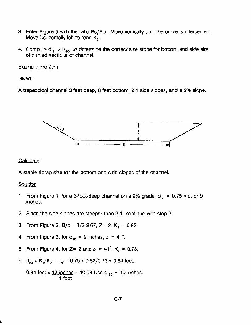
3. Enter Figure 5 with the ratio Bs/Ro. Move vertically until the curve is intersectedMove : .o:izontally left to read K3.
4. (')mpl .~.., d's x K5Or' t....l cic"er'"'1ine the correct: size stone hr botton..md side slolof r m. ad o:;ectic .s of channel.
Examp' ) ~rQij:e'"1
Given:
A trapezoidal channel 3 feet deep, 8 feet bottom, 2:1 side slopes, and a 2% slope.
Calcula..m;
A stable riprap si!e for the bottom and side slopes of the channel.
Solution
1. From Figure 1, for a 3·foot-deep channel on a 2% grade, d50 = O.75 I!El~~ or 9,inches.
2. Since the side slopes are steeper than 3: 1, continue with step 3.
3. From Figure 2, B/d= 8/32.67, Z= 2, K, = 0.82.
4. From Figure 3, for d50 = 9 inches, ¢ = 41°.
5. From Figure 4, for Z= 2 and ¢ =' 41°, K2 = 0.73.
6. d50 X K,/K2 = d50 = 0.75 x 0.82/0.73= 0.84 feet.
0.84 feet x 12 inches = 10.08 Use d' 50 = 10 inches.1 foot
C·7
Given:
The preceding channel has a cUNed section with a radius of 50 feet.
Calculate:
A stable riprap size for the bottom and side slopes of the cUNed section of channel.
Solution:
1. Ro = 50 feet
2. Bs/Ro = 20/50 :: 0.40
3. From Figure 5, for Bs/Ro :: 0.40, K3 = 1.1
4. d'sc X K3 = dsoc :: 0.84 x 1.1 :: 0.92 feet
0.92 feet x 12 inches = 11.0 inches1 foot
REFERENCE1. Design of Roadside Channels with Flexible Lining:;, Hydraulic Engineering
Circular No. 15, FHWA-IP-87-7. US Department of Transportation, FederalHighway Administration, McLean, Virpinia, April 1988.
2. Virginia Erosion and Sediment Control Handbook, Virginia Department ofConseNation and Historic Resources, Division of Soil and Water ConseNation,Richmond, VA, 1980.
3. Orainage Manual, Virginia Department of Highways and Transportation,Location and Design Division, Hydraulics Section, Richmond, VA, January1980.
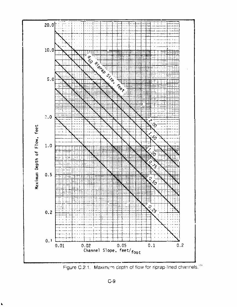
20.0~ :~ • •• .,., .•.. . 0-...-... .. .• ..~ •.-" '!---_--+--_ _••••••• ,. ••. •••• • ••• ~-. - t+tt -~~--r-~-~
..~,.....
Li..
~
o.c+>0-
~e::::le....)(
'"2:
2.0
1.0
0.5
0.2
O. 10.01 0.02 0.05
Channel Slope, feet/foot0.1 0.2
Figure C.2.1. MaxirnL''11 depth of flo'N for riprap·lined chAnnels. III
C-9
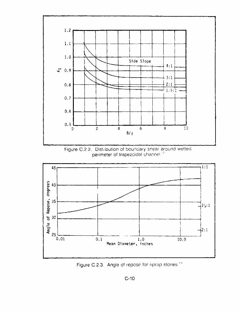
~
""~
-'--
Side Slope
!'...4: 1
I\.
~..........
t'--
~3: 1
-"--2: 1
1.5:1 -
-
--
1.2
1.1
1.0
- 0.9:..::
0.8
0.7
0.6
0.5o 2 4
Bid6 8 10
Figure C.2.2. Distilbution of boundary shear around wettedperimeter of trapezoidal channel ."
2: 1
1: 1
10.00.1 1.0Mean Diameter, inches
-----~
~
------V'" -
---. ._-
45
G>....l:1'c::
<C 250.01
cV 35VIoa.G>
0::
6 3C
Figure C.2.3. Angle of repose for nprap stones.13J
C-10
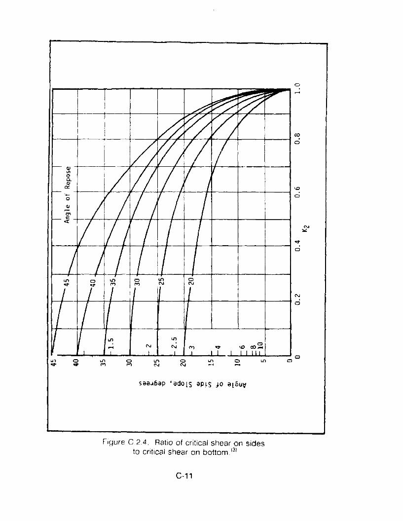
0r- ...:~~t??
I I d ~~vII
CO.--
I/Jv>vI /aI
I
~jr'/.-
'II IiV I1/
1.0I--- - - V;/ / 7 a'+- V
i / /~«I I / I I N
~
qo
,j II I a
/ / ,•
l.J'l 0l.J'l a l.J'l 0qo /qo M M N N
/ I I I 'I I N .I 1/ I 0
~ I l.J'l l.J'l. 0.... N N M qo ID co .....I I I I I I I I I I lJ I
0U) 0 l.J'l 0 l.J'l 0 l.J'l 0 1.0 a~ ~ M M N N .... -
saaJ6ap cadolS ap~s JO al5u~
Figure C.24. Ratio of critical shear on sidesto critical shear on bottomY'
C·'1
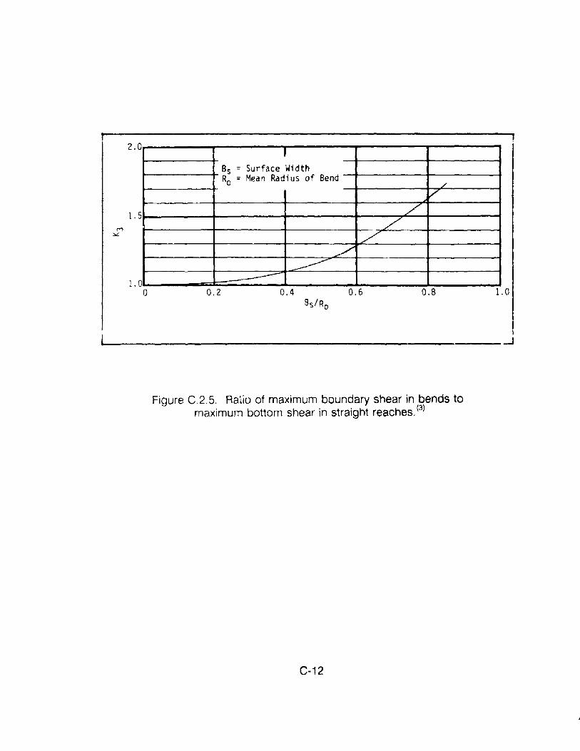
IBs = Surface WidthRo = Mean Radius of Bend
./
,/
;//
/.,/
--------
2.0
1.5
1.0o 0.2 0.4 0.6 0.8 1.0
Figure C.2.5. Ratio of maximum boundary shear in bends tomaximum bottom shear in straight reaches. (3)
C-12
APPENDIX D. f 'URCES OF INFORMATION AND ASSISTANCE
SECTION PAGE
Pipe & Culvert Producer Associations
Materials Related Organizations
User Organizations & Associations
Producer & Materials SuppliersConcrete (reinforced & prestressed)Metal (corrugated, etc.)Plastic (plain & reinforced)Lining systems
Service Companies, Specializing inCertain Materials & Processes
Grouting, Chemical and CementInspection and RepairShotcreteMaterials SuppliersErosion Control
0·1
0-1
0-2
0-30-30-40·-40-5
0-6
0-60-70-70-7O-g
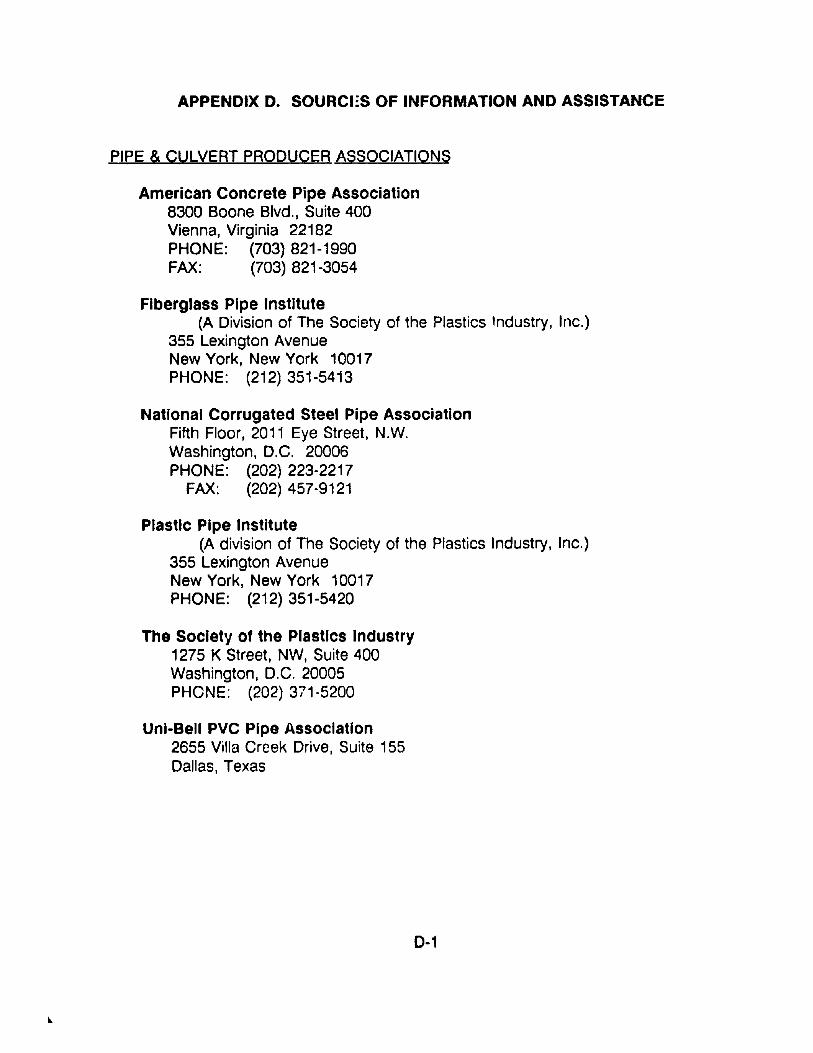
APPENDIX D. SOURCES OF INFORMATION AND ASSISTANCE
PIPE & CULVERT PRODUCER ASSOCIATIONS
American Concrete Pipe Association8300 Boone Blvd., Suite 400Vienna, Virginia 22182PHONE: (703) 821-1990FAX: (703) 821-3054
Fiberglass Pipe Institute(A Division of The Society of the Plastics Industry, Inc.)
355 Lexington AvenueNew York, New York 10017PHONE: (212) 351-5413
National Corrugated Steel Pipe AssociationFifth Floor, 2011 Eye Street, N.W.Washington, D.C. 20006PHONE: (202) 223-2217
FAX: (202) 457-9121
Plastic Pipe Institute(A division of The Society of the Plastics Industry, Inc.)
355 Lexington AvenueNew York, New York 10017PHONE: (212) 351-5420
The Society of the Plastics Industry1275 K Street, NW, Suite 400Washington, D.C. 20005PHONE: (202) 371-5200
Unl·Bell PVC Pipe Association2655 Villa Creek Drive, Suite 155Dallas, Texas
D-1

MATERIALS RELATED ORGANIZATIONS
American Concrete InstituteBox 19150, Redford StationDetroit, Michigan 48219PHONE: (31~) ::32-2600FAX: (313) 538-0655
American Institute for Steel Construction400 N. Michigan AvenueChicago, Illinois 60611PHONE: (312) 670-2400
American Iron & Steel Institute1133 15th Street, N.W.Washington, D.C. 20005PHONE: (202) 452-7100
American Society for Testing and Materials1916 Race StreetPhiladelphia, Pennsylvania 19103-1187PHONE: (215) 299-5400FAX: (215) 977-9679
International Association of Concrete Repair SpecialistsP.O. Box 17402Dulles International AirportWashington, D.C. 20041
National Ready Mix Concrete Association900 Spring StreetSilver Spring, Maryiand 20910PHONE: (301) 587·1400
Portland Cement Association5420 Old Orchard RoadSkokie, Illinois 60077PHONE: (708) 966-6200
Texas Aggregate & Concrete Association6633 Highway 290 East, Suite 100Austin, Texas 78723PHONE: (512) 451-5100
0·2
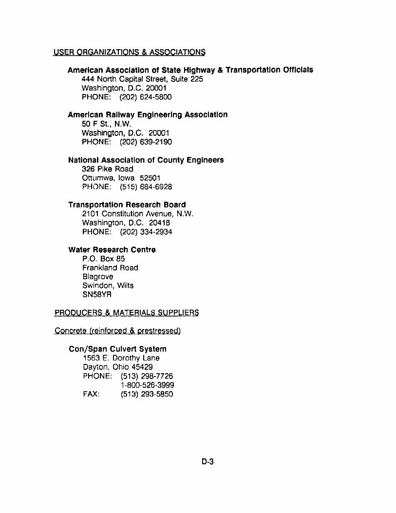
USER ORGANIZATIONS & ASSOCIATIONS
American Association of State Highway & Transportation Officials444 North Capital Street, Suite 225Washington, D.C. 20001PHONE: (202) 624-5800
American Railway Engineering Association50 F St., N.W.Washington, D.C. 20001PHONE: (202) 639-2190
National Association of County Engineers326 Pike RoadOttumwa, Iowa 52501PHONE: (515) 684-6928
Transportation Research Board2101 Constitution Avenue, N.W.Washington, D.C. 20418PHONE: (202) 334-2934
Water Research CentreP.O. Box 85Frankland RoadBlagroveSwindon, WiltsSN58YR
PRODUCERS & MATERIALS SUPPLlEf3.S
Concrete (reinforced & prestressed)
Con/Span Culvert System1563 E. Dorothy laneDayton, Ohio 45429PHONE: (513) 298-7726
1-800-526-3999FAX: (513) 293-5850
0-3
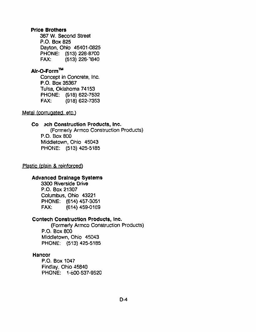
Price Brothers367 W. Second StreetP.O. Box 825Dayton, Ohio 45401-0825PHONE: (513) 226-8700FAX: (513) 226·1840
Air-a-FormTM
Concept in Concrete, Inc.P.O. Box 35367Tulsa, Oklahoma 74153PHONE: (918) 622-7532FAX: (918) 622-7353
Metal (corrugated. etc.)
Co ~ch Construction Products, Inc.(Formerly Armco Construction Products)
P.O. Box 800Middletown, Ohio 45043PHONE: (513) 425-5185
.Em.stic (plain & reinforced)
Advanced Drainage Systems3300 Riverside DriveP.O. Box 21307Columbus, Ohio 43221PHONE: (614) 457-3051FAX: (614) 459-0169
Contech Construction Products, Inc.(Formerly Armco Construction Products)
P.O. Box 800Middletown, Ohio 45043PHONE: (513) 425-5185
HancorP.O. Box 1047Findlay, Ohio 45840PHONE: 1-bOO-537-9520
0-4
Mid Continent Pipe (Snap-Tite & other P.E. Pipe products)P.O. Box 750Fenton, Missouri 63026 (near St. Louis)PHONES: (314) 349-1212
1-800-233-1305FAX: (314) 326-3313
PhillipS Drlscoplpe, Inc.P.O. Box 83-38662929 North Centre.' Expressway, Suite 100Richardson, Texas 75063PHONES: (214) 783-2666
1-800-527-0662FAX: (214) 783-261"'
Pl~xco /Splrolite1050 Busse High';vaySuite 200Bensenville, Illinois 60106PHONE: (708) 350-3700
Price Brothers367 W. Second StreetP.O. Box 825Dayton, Ohio 45401-0825PHONE: (513) 226-8700FAX: (513) 226-8840
Lining Systems
Innovative Process Corporation415 N. 16th StreetBillings, Montana 59101PHONE: (406) 248-1995FAX: (406) 248-2196
Insltuform East, Inc.3315 Democrat RoadP.O. Box 181071Memphis, TN 38118PHONE: (901) 363-2105FAX: (901) 365-3906
0-5
LINK-PIPE, Inc.27 West Beaver Creek, Unit 2Richmond Hill, Ontario, Canada L4B 1K4PHONE: (416) 886-0335FAX: (416) 886-7323
Miller Pipeline Corp.XPANDITP.O. Box 34141Indianapolis, Indiana 46234PHONE: (317) 293-0278FAX: (317) 293-8502
Pipe Liners, Inc.3421 N. Causeway Blvd., Suite 321Metairie, LA 70002PHONE: (504) 831-3568
SERVICE COMPANIES, SPECIALIZING IN CERTAIN MATERIALS & PROCESSES
Grouting, Chemical and Cement
Avianti International16920 Texas Avenue, Suite C-7Webster, Texas 77598PHONE: (713) 554-7541TLX: 287611-AVNTI-OKFAX: (713) 554-4498
GKN Hayward Baker, Inc.1875 Mayfield RoadOdenton, Maryland 21113PHONE: (301) 551·8200
Halliburton Services1415 Louisiana, Suite 2300Houston, Texas 77002PHONE: (713) 652-6073FAX: (713) 652-6066
0-6
HEITKAMP, Inc.99 Callender RoadP.O. Box 730Watertown, CT 06795PHONE: (203) 274-5468
u.s. Grout Corporation401 Stillson RoadFairfield, CT 06430PHONE: (203) 336-7900
Inspection and Repair
Aquatech, Inc.P.O. Box 1907Cleveland, Ohio 44106PHONE: (216) 231-1010
Shotcrete
General Gunite and Construction CompanyP.O. Box 2730Industrial ParkFlorence, Alabama 35630-2730PHONE: (205) 767-7076FAX: (205) 760-8009
United Gunite Construction Company, Inc.102 Weiland Avenue (Headquarters)Irvington, New Jersey 07111PHONE: (201) 371-4123FAX: ~201) 371·1737
Materials Suppliers
Five Star Products, Inc.425 Stillson RoadFairfield, CT 06430PHONE: (203) 336-7939
0-7
3M Contractor ProductsBUilding 223-4N-063M CenterSt. Paul, Minnesota 55144-1000PHONE: (612) 733-1140
W.R. GraceP.O. Box 30235Charleston, S.C. 29417PHONE: (803) 556-3573
GEOWEB (Geosystems) Retaining WallsPresto Products Company670 N. Perkins StreetP.O. Box 2399Appleton, WI 54913-2399PHONE: (800) 548-3424
Hifiker Walls (and Gabions)637 West Hurst BoulevardHurst, Texas 76053PHONE: (817) 268-1044
(800) 634-1913FAX: (817) 282-0694
Keystone Re(aining Wall Systems, Inc.7600 France Avenue SouthMinneapolis, Minnesota 55435PHONE: (612) 897-1040
(800) 747-8971FAX: (612) 897-3658
Mid-Atlantic Permacrlb10830 Guilford Road, Suite 310P.O. Box 238Annapolis Junction, Marylend 20701PHONE: (301) 490-0055FAX: (301) 776-1883
Maccaferrl Gablons, Inc.43A Governor lane BoulevardWilliamsport, Maryland 21795PHONE: (301) 223-6910FAX: (301) 223-6134
0-8
The Reinforced Earth Company2010 Corporate Ridge, Suite 1000McLean, Virginia 22102PHONE: (703) 821-1175FAX: (703) 821-1815
Erosion Control
TRI-LOCK Erosion Control SystemAmerican Excelsion CompanyP.O. Box 5067850 Avenue H EastArlington, Texas, 76011PHONE: (817) 640-1555FAX: (817) 649-7816
0-9
APPENDIX E. ANNOTATED BIBLIOGRAPHY
AASHTO Maintenance Manual. 1987. American Association of State Highway andTransportaton Offici9ls, Washington D.C., 1987.
The manual contains a chapter en drainage which briefly discussesculverts. However, it is very general but recommends cleaning and theremoval of obstructions.
Abt, S. R., J. F. Ruff, F. K. Doehring, and C. A. Donnell. "Ir.fluence ofCulvert Shape on Outlet Scour." Journal of Hydraulic Engineering,Vol. 113, No.3, ASCE, New York, N.Y., March 1987, pp. 393-400.
This paper reports on the results of investigation on scour holedimensions of square, arch and rectangular culvert shapes compared tocircular shape. Scour geometry at culvert outlets is u8ed to determine theneed for potential erosion protection.
ItAir-inflated forms speed Florida culverts." Roads & Bridges, November 1987,p.20.
Article discusses use of air-inflated form system from Concepts inConcrete Inc. on job in Florida for a privately funded road upgrade for ashopping center.
"Aluminum Culvert Replaces Bridge in Indiana." Better Roads, Vol. 57, No.6,June 1987, p. 56.
Article discusses use of corrugated aluminum box culverts for bridgereplacement in Blackford County, Indiana. Culvert installed was 25.5 feetwide x 12 feet high by 26 feet long and was fabricated at KaiserAluminum and Chemical Corporation's Mitchell, Indiana ,"'!rainage prodL.ctsplant.
Arnoult, James D. "Culvert Inspection Manual: Supplement to the BridgeInspector's Training Manual." Report No. FHWA-IP-86-2, FederalHighway Administration, McLean, VA, July 1986.
Manual provides guidelines for the inspection and evaluation of existingculverts. It is a stand alone supplement to the Bridge Inspector's TrainingManual.
E-1
Boadsgaard, Marinus and Punda Pai. "Sewer Line Rehabilitation WithoutExcavation." Public Works, Vol. 119, No.1 0, September 1988. p. 93.
Describes project in Clark County, Nevada, Sanitation District to repair 21/2 mile section of sewer line which deteriorated from sulfide corrosion.District investigated and selected INSITUFORM which had never beenpreviously used in Nevada.
Bealey. Mike, "Precast Concrete Pipe Durability: State of the Art." TRR 1001.TRB, Washington, D.C., 1984, p. 88.
The performance of precast concrete pipe is reviewed, andstate··of-the-art information concerning the durability of buried precastconcrete pipe is presented. The article concludes that service life ofprecast concrete pipe in most installation environments is virtuallyunlimited.
Beucler, Brian. "Pipe Rehabilitation on Skyline Drive, Shenandoah NationalPark." Experimental Projects Program Report, Office of HighwayOperations Demonstration Projects Division, FHWA, Washington, D.C.,undated report.
Paper discusses the rehabilitation of culverts on the Skyline Drive. Thereare hundreds of 50 year old damaged concrete and corrugated metalpipes underneath the roadway. The "Insituform" method of repair wasselected. The methods for comparing Insituform with pipe replacementare presented.
Blonska, Frank ed., "Condition and Corro~ion Survey on Corrugated Steel StormSewer and Culvert Pipe." Interim Report prepared for the NationalCorrugated Steel Pipe Association, Washington, D.C., February 1~87.
Reports on a detailed inspection and testing program sponsored byNCSPA to evaluate the long term performance of corrugated steel pipethroughout the U.S.
"Bridge Alert: Air-Inflated Form Ideal for Culverts." Better Roads, Vol. 57,No.5, May 1987, p. 40.
Article describes use of "Air-O-Form" which was developed for smallconcrete tanks and earth shelter homes and adopted by inventor, GeneHale, for arch bridges and utility structur~s.
E-2
..
"Bridge Alert: Innovative Techniques And Bridge Projects." Bener RQads,Vol. 57, No.5, May 1987, p. 37.
One section of article discusses use of precast concrete culvert for asmall bridge replacement. The arch box shape was developed andpatented by Lockwood, Jones and Beals for Con/Span Culvert Systems.First installation was in Butler County, Ohio.
Byrd, Gary and George Briggs. Street and Highway Maintenance Manual.American
Public Works Association, 1985, pp. 137-139.
Contains brief description of culvert maintenance. It recommendscleaning and debris removal and recommends different basic repairsdepending on conditions.
"Case History No.5, Culvert Relining Australia." Undated sectior. of Rib LocBrochure forwarded by Mr. A. J. Sutton, Rib Loc Group Limited, TheLevels, South Australia, Australia, November 15, 1988.
Briefly descr:bes use of Rib-Loc material as a "former" for the structuralrepair of a corrugated metal pipe under an Australian National Railwaysroadbed.
Chambers, R. E., T. J. McGrath and F. J. Heger. "Plastic Pipe for SubsurfaceDrainage of Transportation Facilities." National Cooperative HighwayResearch Program Bapon 225, TRB, WashinghJn, D.C., October 1980.
Report summarizes the results of a study of buried plastic pipe for thedrainaQe of tram;portation facilities. The report does not consider in detailbut mentions that PE gravity or force main sewer pipe may be appropriatefor storm drains and culverts, reinforced plastic mortar (RPM) pipe may beused for storm drains and culverts and large diameter corrugated PEtubing may be useful for small secondary culverts.
Clarkson, T. E. and J. C. Thomson. "Pipe Jacking: State of the Art in U.K.and Europe." Journal of Transportation Engineering, Vol. 109, No.1,American Society of Civil Engineers, New York, N.Y. Jan 1983,pp.57-72.
Article discusses the development of pipe and box jacking techniques inthe U.K. and Europe. A good description of pipe jacking equipment andprocedures is included. The different types of concrete pipe joints used inU.K., Germany and France are shown.
E-3
Cowherd, D. C., G. H. Degler. "Evaluation of Long-Span Corrugated MetalStructures." FHWA/OH-86/011, Ohio Department of Transportation,Columbus, Ohio, May 1986.
This report describes the field evalu€tion of 17 long-span corrugatedmetal structures which had span dimensions from 20 feet to 31 feet andrises from 7 feet 9 inches to. 19 feet 3 inches and lengths of 44 feet to148 feet. The evaluation also had as an objective the development of acomputer program to evaluate thesE' structures and then to analyze thestructure movement. The d~scriptions of the culverts and recommendedactions are good.
Crumpton, Carl F., Glen M. Koonty, and Barbara J. Smith. "For Want of Air, aDrainage System Was Nearly Lost." TRR 1001, TRB, Washington, D.C.,1984, p. 94.
The omission of air entrainment from a concrete pipe end section in 1972set up a chain of events that couid have been much more destructive.
"Culvert Design Systems." FHWA-TS-80-245, Wyoming State HighwayDepartment,
Hydraulics Section, U.S. Department of Transportation, Washington,D.C., December 1980.
Program documentation to hydraulically design a culvert or hydraulicallyreview an existing or proposed culvdrt size. Tht:! paper is highly technicaland may be somewhat obsolete.
"Culvert Maintenanr.e and Replacement." American Railway Bridge and 8uildingAssociation, Homewood, Illinois, 1982.
Brief descriptions of railroad culvert problems, repairs and replacements.
Drennon, Clarence B. "Pipe Jacking: State-of-the-Art." Journal of thec.Qnstruction Division, Vol. 105, No. C03, American Society of CivilEngineers, New York, N.Y., Sept. 1979, pp. 217-223.
Pipe jacking is a methC'd of producing tunnels by placement of a precastreinforced final liner irnmediately behind the excavation by pushing thelines in sections with hydral'!ic jacks from a shaft. It is used in the U.S.for circular tunnels frcm 54 inch to 122 inch. A very good, practicaldescri!,tion of pipe ja<;king.
E-4
Driver, F. T. and M. R. Olson. Demonstration of Sewer Relining by theInsituform Process. Northbrook. lIIinms. EPA-600/2-83-064, MunicipalEnvironmental Research Laboratory, Office of Research and Development,U.S. Environmental Protection Agency, Cincinnati, Ohio, October 1983.
Report was initiated to determine the effectiveness of a new process oflining sewers called Insituf~rm. Two test sections of sewer in need ofrehabilitation were lined to evaluate the effectiveness of the lines ineliminating infiltration and the effect on flow characteristics. The studydocuments the fact that the method is an effective process for eliminatinginfiltration from lines and improves the hydraulics and structural integrityof damaged conduits.
Duncan, Charles R. "Innovated Repair of a Large Failing Structural SteelPlate Pipe Arch Culvert." TRR 1001. TRB, Washington, D.C., 1984,p.98.
This paper discusses a project where a value-engineering team studiedalternatives to replacing a structural steel plate pipe arch culvert 14 feet x9 feet 8 inch x 260 feet long. The team's proposal consisted of rolling aslightly smaller asbestos-bonded asphalt-coated pipe through tt"e existingculvert and grouting between them.
Duncan, J. M., R. B. Seed and R. H. Drawsky. "Design of Corrugated Metal BoxCulverts." TRR 1O~ TRB, Wasllington, D.C., 1985, p. 33.
The procedure encompasses bending mements in the crown and haunchsections due to backfill and traffic loads, design of portland cementconcrete relieving slabs for conditions where cover depth is !=:everelyIimited, recommended load factors for design, and deflections in servicefor metal box culverts with spans as large as 26 ft.
Durability of Drainage Pipe. NCHRP Synthesis of Highway Practice 50/ TF:u.Washington, D.C., 1978.
This report deals with material durability or the ability of drainage pipe toendure corrosion and abrasion. It does not address structural durability.The report contains summaries of field and laboratory studies carried outin half of the states. It recommends that guidelines for selection of pipematerials should be developed or modified based on local conditions. Thereport gives descriptions of corrosion and abrasion, ranges of values andtheir effects on the various materials used in culverts. There are goodchapters on pipe protective measures, maintenance and repair of culverts,and service life estimation.
Etti-Williams, Jimmy L. "The Performance of Corrugated Metal Culvert Pipes."Report of Research Division, Oklahoma DOT, Oklahoma City, Oklahoma,June 1988.
Repo: t de~cribes work by ODOT research engineers to develop efficientano cost effective method of repairing deteriorated CMP. The methodsdiscussed are placing cement grouts in the perforated invert and placing apolythyelene inner liner.
Evans, Willis A. and Beryl Johnston. "Fish Migration and Fish Passage, APractical Guide to Solving Fish Passage Problems." USDA Forest Service,Washington, D.C., June 1972, revised June 1980.
This guide was prepared by members of the Region 5 staff (California) buthas a good general discussion of fish passage requirements findconsiderations. It contains a section on investigating new culverts,installing baffles in culverts, and inspection and correction of existingculverts.
Existing Sewer Eyaluation and Rehabilitation. ASCE Manuals and Reports onEngineering Practice No. 62, WPCF Manual on Practice No. FD-6,Prepared by a Joint Task Force of ASCE and WPCF, American Society ofCivil Engineers, New York, N.Y. and Water Pollution Control Federation,Washington, D.C., 1983.
This manual provides guidelines for the evaluation and rehabilitation ofsanitary sewer. The major emphasis of the manual is on infiltration andinflow reduction. It contains sections on pipeline rehabilitation andmaterials which are generally applicable to culverts.
A Guide to Standardized Highway Drainage Pj~1S. AASHTO-AGC-ARTBA JointCooperation Committee, Subcommittee on New Highway Materials, TaskForce, No. 13, Washington, D.C., Dec. 1986.
This guide presents drawings of currently available common drainageproducts.
E-6
Heummen, P. H. Van. "Half-Century Experience with Precast Reinforced-ConcreteBox Sections for Culverts and Storm Drains in the Netherlands."TAA 1001, TAB, Washington, D.C., 1984, p. 112.
Under varying aggressive conditions, there are tens of thousands ofculverts and other structures that make up a system of water control inthe Netherlands. Most of these culverts have been constructed in precastreinforced-concrete box sections. The real service life, even under severeconditions, amply meets the design service life.
Hill, James J. "Construction and Evaluation of Precast Concrete ArchStructures." TRR 1008, TRB, Washington, D.C., 1985, p. 94.
Information is given regarding the durability of concrete pipe used forculverts at acidic flow sites (pH less than 7.0) in the state of Ohio. Ingeneral, unprotected concrete pipe will provide adequate service life (50years or more) except at extremely acidic sites (pH less than 4.5).
Hill, James J. and Arunprakash M. Shirole. "Comparative Evaluation of PrecastConcrete Pipe-Arch and Arch Structures." TRR 1087, TRB, Washington,D.C., 1986, p. 32.
A comparative evaluation of precast concrete pipe-arch and archstructures constructed in Minnesota during the past 20 years ispresented. Comparative evaluation of features and problems associatedwith construction, maintenance, and repair of these structures isdiscussed.
Hirsch, Carl M. "Durability of Polymer-Coated Corrugated Steel Pipe."!RR 1001, TRB, Washington, D.C., 1984, p. 9.
Paper provides an overview of corrosion resistance and examines therecent development of polvmer coated corrugated steel pipe.
Hixon, C. Dwight. "Corrugated Steel Pipe, Cross Drain Culvert Repairs forProjects: Fl16(6), F116(7), S-717(1)5; Le Flore County." internalOklahoma DOT memo dated October 12, 1984.
Memo describes repair projects in the mountainous areas of easternOklahoma where conditions were difficult due to abrasion and erosion.Polyethylene (PE) plastic pipe with a cement grout backfill was selectedfor use. Conditions, materials including grout mix, and procedures aredescribed.
E·7
Hurd, John Owen. "Field Performance of Concrete and Corrugated Steel PipeCulverts and Bituminou$ Protection of Corrugated Steel Pipe Culverts."TRR 1001, TRB, Washington, D.C., 1984, p. 40.
Information is prov;ded regarding the durability of concrete pipe,galvanized corrugated steel pipe (6 x 2-in. and 2.67 x 0.5-in.corrugations), and bituminous protection (AASHTO M 190, Types A, B,and C) of corrugated steel pipe used for culverts in Ohio.
Hurd, John Owen. "Field Performance of Concrete Pipe Culverts at Acidic FlowSites in Ohio." TRR 1008, TRB, Washington, D.C., 1985, p. 195.
Construction and field evaluation is presented of the precast concretearch structures (BEBO of America) that have been constructed inMinnesota since 1980.
Hurd, John O. "Field Performance of Corrugated Polyethylene Pipe Culverts inOhio." TRR 1087, TRB, Washington, D.C., 1986. p. 1.
Total of 172 corrugated polyothylene pipe culverts 12 through 24 inchesin diameter and ranging in age from 0 to 4 years were inspected in Ohioin the summer of 1985. Data pertinent to structural performance anddurability of the culverts were collected at each site. No culvert showedany signs of wear even at sites with abrasive flow. The incidence oflarge maximum deflections or wall flattening and buckling, or both, wassigni'ficantly greater for 12- and 15-in. pipes than for 18- and 24-in. pipes.
Hurd, John Owen. "Field Performance of Protective Linings for Concrete andCorrugated Steel Pipe Culverts." TRR 1001, TRB, Washington, D.C.1984, p. 35.
Information is provided regarding the durabinty of protective linings forconcrete pipe i::md galvanized corrugated steel pipe used for culverts atcorrosive and abrasive sites in Ohio. AII1hree materials have providedsatisfactory protection of base pipe material at study sites, except forpolymeric coating at abrasive sites. The performance of other types ofless frequently used protective linings are briefly discussed.
E-8
Ikerd, Stephen R. "Invert Replacement of Corrugated Metal Structural PlatePipe." TRR 1001, TRB, Washington, D.C., 1984, p. 102.
The Alabama Highway Department chose to replace worn inverts of alarge diameter corrugated metal structural plate pipe with steel armorolating. The installation of these armor-plated inverts has significantlyincreased the useful service life of the existing pipe for a fra~tion of whatthe actual replacement cost would have been. The paper gives sketchesof contractors set-up.
"Installation or Replacement of Culverts." American Railway Bridge andBuilding Association, Homewood, Illinois, 1984.
A brief report of a committee of the ARBBA. This is a very generalreport. It mentions that open cut replacement is usually the preferredrepair method due to costs. Tunneling, boring and jacking arealternatives. Threading (sliplining) is also mentioned.
Jacobs, Kenneth M. "Culvert life Study." Technical Paper 74-1, MaineDepartment of Transportation, Augusta, Maine, January, 1974.
Various culvert types were samplec:i including reinforced concrete,bituminous coatAd and uncoated galvanized steel, aluminum, asbestoscement and vitrified clay. Parameters of the study were to determineculvert life expectanr.ies in Maine and the effect of environmentalconditions. Resistivity, pH of the water, and stream velocities weremeasured and other conditions noted.
Jacobs, Kenneth M. "Durability of Orair.age Structures." TRR 1001, TRB,Washington, D.C., 1984, p. 14.
The study evaluated various culvert materials and coatings for durability inMaine.
Katona, Michael G. and Adel Y. Ake, "Structural Design of Buried Culvertswith Slotted Joints." Journal of Structural Engineering, Vol. 113, No.1,American Society of Civil Engineers, New York, N.Y., June 1987,pp.44-60.
The results of this paper are more applicable to design of new orreplacement culverts.
E-9
Kinchen, Richard W. "Evaluation of the Durability of Metal Drainage Pipe."Transportation Research Record 762, TRB, Washington, D.C., 1980,p.25.
Preliminary results are presented of a 10-year field study undertaken inLouisiana to determine the ability of aluminum and galvanized-steelculverts to resist corrosion in moderate, acidic, and lowelectrical-resistivity environments. All of the test culverts appear toprovide satisfactory service life in moderate environments.
Koeper, John F., Lynn E. Osborn, "Collapsing 96-inch Sewer Commands FastCure." Public Works, Vol. 119, No. 12, November 1988 pp. 42-44.
Article discusses collapse of a 90 year old sanitary sewer line in St. Louis.High fiow rates in an 8 feet circular section and 7 feet by 9 feet eggshape section had eroded invert of the line. The invert was replaced withconcrete and then an inversion liner from Insituform was placed.
Koepf, A. H. and P. H. Ryan. "Abrasion Resistance Of Aluminum Culvert Based onLong-Term Field Performance." TRR 1087, TRB, Washington, D.C., 1986,p. 15.
In 1968 an initial study was reported on 229 aluminum culverts that hadbeen exposed to abrasion for 4 to 7 years. That study proposed a formof energy level for bed load materials and rated the abrasion performanceof aluminum culvert through a series of energy ratings. In 1984 and1985 the field experience of the originally reported culvert group averaged20 years of exposure to abrasion. This paper are presents the results ofth& 1984-1985 study.
Kohutek, T. L. and H. E. Ross Jr. "Safety Treatment of Roadside Culverts onlow Volume Roads." FHWATX-77-225-1, .B.e~rch Report 225-1, TexasTransportation Institute, College Station, Texas, March 1978.
This report describes a model recommended by AASHTO which was usedby the researchers to develop guidelines for safety treating culverts onlow volume roads (ADT < 20,000). The treatments considered wereextending the culvert end 30' from the traveled way, providing guardrailprotection, and providing grate protection.
E-10
Lisk, Ian. "Slip-lining and Concrete Put Pipe Into Action." Water/Engineeringand Management, Vol. 135, No. 10, October 1988, p.28.
Article describes rehabilitation of 24-inch cast iron water pipe by twomethods, sliplining a section with 20-inch polyethylene pipe and cementlining a longer section. Project set up was r.luch more difficult thanwould be required in culvert repairs.
Manual for Railway Engineering. Vol. 1. Roadway and Ballast. American RailwayEngineering Association, Chicago, Illinois, 1979.
"Jacking Culvert Pipe Through Fills," discussion of pipe jacking. Givesgeneral procedure, equipment, crew etc.
"Methods of Installing Culverts Inside Existing Culverts" discussessurveying ex.i'iting structure and allowable reduction in size. Existingpipes and arches usually lined with structures of same shape but smaller.Arches require adequate foundations.
McClellan, Thomas J. "Fish Passage Through Highway Culverts, A FieldEvaluation." U.S. DOT, FHWA Office of Engineering, 1970.
Report describes a study of 62 "in-service" culverts having provisions foranadromous and native fish in Oregon. The report contains descriptionsand pictures of the culverts with comments by wildlife biologists on theirfish passage effectiveness.
McCrea, Robert. "Lining Deteriorated Culvert Pipes on the Jones Valley Road."Report of District Engineer, Shasta-Trinity National Forests, undatetl.
This paper discusses the lining of deteriorated galvanized metal pipes inthe Shasta Lake Ranger District. Pipes varied from 18 to 38 inches indiameter and were degraded by hydrogen sulfide in the water. Slipliningwas used with corrugated polyethylene pipe, smooth-wall polyethylenepipe and Corban RPM. Paper describes procedure, grout, and economicanalysis used.
"'Mole' Speeds Tough Culvert Cleaning Job." Roads & Bridges, May 1987, p. 90.
Construction firm of T. J. Hall Inc. used remote controlled equipment towater-blast away hardened sediment.
E-11
Morris, G. E. and L. Bednar. "Comprehensive Evaluation of Aluminized Steel Type2 Pipe Field Performance." TRR 1001, TRB, Washington, D.C., 1984,p.49.
Results of 30-yeCifl\eld test:.. in 14 states, conducted by Armco onAluminized Steel Type 2 and galvanized steel culvert pipe. Theresults for aluminized steel indicated tolerance for substantially moresevere environmental conditions.
Normann, J~rome M., Robert J. Houghtalen and William J. Johnston. "HydraulicDesign of Highway Culverts." FHWA-IP-85-15, HDS No.5, Jerome M.Normann and Associates, Norfolk, VA, September 1985.
This manual, Hydraulic Design Series No.5, ic; a comprehensive culvertdesign publication. It contains information prp'v'iously contained inHydraulic Engineering Circular (HEC) Nos. 5, 10, and 13 with hydrologic,storage routing and special culvert design information
~atenaude, Robert. "Bacterial Corrosion of Steel Culvert Pipe in Wisconsin."TRR 1001, TRB, Washington, D.C., 1984, p. 66.
An ongoing project to inve!tigate culver~ corrosion in Wise- nsin hasindicated that anaerobic sulfate-reducing bacteria were a (;, .1tributingfact'r in the corrosion of galvanized steel culvert pipe at 31 percent ofthe culvert sites examined since 1972. In this paper field tests arediscussed and a description of the occurrences is givE;n.
"Pipeline Rehabilitation with Polyethylene Pipe." The Society of the PlasticsIndustry Inc., New York, N.Y., 1988.
This brochure is a chapter that is to be incorporated into a future ff!Handbook .o.LP.9.'yethylene Pipillll. The chapter describes designconsiderations (selecting liner diameter, wall thickness, analyzing flowcapacity, designing accesses and contract documents) and the slipliningprocedur0.
E-12
Pyskadlo. Robert M. and Wallace W. Renfrew. "Overview of Polymer Coatings forCorrugated Steel Pipe in New York. n TRR 1001. TRB, Washington, D.C.,1984, p. 21.
This paper discusses the use of polymer coatings on corrugated oiteelculverts which were first used in New York State in late 1977 and 1978on two sections of the Genesee Expre~sway in Livingston County.Although the evaluation is continuing, "(wo tentative findings arediscussed: stilling basins are an effective means of preventing early lossof polymer coating, and a roller-coated pipe is performing better than alaminated pipe at an aggressive site.
"Renewing Sewers with Polyolefin Pipe." Plastic Pipe Institute, New York, N.Y.,undated.
Describes general procedure for slip-lining existing sewer lines withpolyolefin pipes - polyethylene and polybutylene. Gives seven stepprocedure as well as formulas for flow capacity.
Renfrew, Wallace W. "Durability of Asphalt Coating and Paving on CorrugatedSteel Culverts in New York." TRR 1001, TRB, Washington, D.C., 1984,p.26.
This paper reports on 294 coated pipes with paved inverts which weresurveyed and measured. In New York State, paving has effectivelyprotected round pipe for 30 years and pipe-arches for at least 20 years.Beyond 30 years, paving is ineffective in protecting any corrugated steelpipe.
Ring, George W. "Culvert Durability: Where Are W"~7." TRA 1001, TAB,Washington, D.C., 1984, p. 'I.
Paper provides an excellent overview of the use of culverts in highwaydrainage and the advantages and disadvantages of different pipe types.There has been extensive use of culverts under highways for more than75 years. During that time "(he states have made more than 90 culvertperformance studies, Prediction of the probable service life of nil types ofculverts is still difficult.
E-13
"Roadway Drainage Guide for Installing Culverts to Accommodate Fish." A1.a..sk.aRegion Report Number 42, USDA Forest Service, September 1979.
Report discusses necessary conditions for fish passage. Slower« 1.5 cfs) stream velocity required in culverts.
Ross, Hayes E. Jr., T. J. Hirsch, Benito Jackson Jr., and Dean Sicking. "SafetyTreatment of Roadside Cross-Drainage Structures." Research Report280- 1, FHWAITX-82/37 + 280-1, Texas Transportation Institute, CollegeStation, Texas, March 1981.
The report describes research to develop traffic safe end treatments forcross-drainage structures that would not appreciably restrict water flows.
Ross, Hayes E. Jr., Dean Sicking, T. J. Hirsch, Harold D. Cooner, John F.Nixon, Samuel V. Fox, and C. P. Damon." Safety Treatment of RoadsideDrainag~ Structures." TRR 868, TRB, Washington, D.C., 1980, p. 1.
The purpose of the research was to develop traffic-safe end treatmentsfor cross-drainage and para!lel-drainage structures that would notappreciably restrict water flow.
Ruff, James F. and Steven R. Abt. "Evaluating Scour at Culvert Outlets."TRR 785, TRB, Washington, D.C., 1980, p. 37.
This paper describes an experimental study of scour at culvert outlets intwo uniform noncohesive soil materials. Empirical relationships fordescribing the scour-hole lengths, widths, depths, and volume of materialremoved were developed.
Selig, Ernest T. "Review of Specification for Corrugated Metal ConduitInstallations." TRR 1008.... TRB, Washington, D.C., 1985, p. 15.
This paper provides an overview of CMP specifications. The nationalspecifications for AASHTO cmd the American Iron and Steel Institute forblJried corrugated metal conduit~ for the past 15 years are reviewed.
E-14
Stavios, A. J. "Galvalume Corrugated Steel Pipe: A Performance Study."TRR 1001, TRB, Washington, D.C., 1984, p. 69.
Laboratory and field tests have been used to characterize the performanceof Galvalume corrugated steel pipe. After approximately 9 years, theGalvalume inverts and intermittently wet zones inside the pipe, whereservice is most severe, were overall in much better condition than thoseof comparable galvanized pipes.
"Status Report to Selected Projects Containing Experimental Features."UKTRP-86-29, Staff of Kentucky Transportation Research Program,University of Kentucky, Lexington, Kentucky, December 1986.
This report describes projects containing experimental features orinnovative concepts which were selected for long term monitoring.Projects described include: the performance of metal long-spanstructures, metal box culverts, and precast reinforced concrete boxculverts; performance of and loads on culverts; and performanceevaluation of corrugated polyethylene entrance pipe.
"Steel Drainage Pipes Get Plastic Retrofit." Roads and Bridg~, May 1986,adapted from a report by Curt Hayes, Research Division, Oklahoma DOT.
Article covers material in Hixon's memo with illustrations.
Summerson, T. J .. "Corrosion Resistance of Aluminum Drainage Products: TheFirst 25 Years." TRR 100" TRB, Washington D.C. 1984, p. 77.
A description is provided of laboratory and field evaluation proceduresused to evaluate the corrosion resistance of aluminum culverts, stormdrains, structural plates, and retaining walls. Results indicate that there isa qualitative relationship between corrosion resistance of aluminum andthe water and soil pH and resistivities. Good performance of unprotectedaluminum pipe was observed in the pH range of 4 to 9 and minimumresistivities greater than 500 ohm-cm.
E-15
Summerson, T. J. and R. J. Hogan. "Performance of Aluminum Riveted Culvert inCa:,fornia - 1978 Cooperative Caltrans-Kaiser Aluminum Survey."FHWA/ZCFT. 79/39, Kaiser Aluminum and Chemical Corporation,Pleasonton California, August 1979.
This report discusses monitoring of aluminum drainage pipe installations inCalifornia. While aluminum pipe was introduced in the U.S. in 1959,Caltrans did not approve their use in installations requiring a 25 or 50 yearservice life within the pH and resistivity ranges proposed by KaiserAluminum (pH 4 to 9 and resistivity> 500 ohm-em). The reportrecommends that Alclad 3004 pipe be accepted by Caltrans for use insidethe recommended limits.
Swar;son, H. N. and D. E. Donnelly. "Performance of Culvert Materials in VariousColorado Environments." FHWA-CO-77-7, CD04-P&R-77-7, ColoradoDivision of Highways, Denver, Co, Septembp~ 1977.
The report describes various soil and water environments in Colorado if'
which culvert pipe materials have been placed. Their performanceincluding laboratory tests on materials is described.
Temple, William H. "Evaluation of Metal Drainage Pipe Durability After TenYears." TRR 1087, TRB, Washington, D.C., 1986, p. 7.
This study represents an investigation of the comparative performance ofcoated and uncoated, corrugated, galvanized steel and aluminum drainagepipe in Louisiana. The highly corrosive environments in some areas of thestate make durability requirements of metal pipe as critical as strengthrequirements.
Tyrpak, Kenneth A. "Pipeline Rehabilitation Improves Water Flows." PublicWorks, Vol. 118, No. 12, December 1987, p. 39.
Describes project in Beachwood, Ohio to rehabilitate tuberculation fromiron deposits in unlined cast iron water pipes. Solution chosen was thePerkins process of cement mortar pipeline rehabilitation. Only a smallnumber of contractors in the U.S. are equipped to employ it, includingUtilicon Corp. of Cleveland.
E-16
Yedinak, Brian and Keith Highlands, "Insituform Pipe Rehabilitation."Report No. PA-85-034-84-103, Pennsylvania Department ofTransportation, Harrisburg, PA, April 1986.
This report covers the construction evaluation of a pipe rehabilitationproject where INSITUFORM was used. Although some minor problemsoccurred, the INSITUFORM pipe rehabilitation seems to have beensuccessful.
Young, W. T. "Evaluation of Highway Culvert Coating Performance."FHWA/RO-80/059, U.S. Dept. of Transportation, Washington, D.C., June1980.
The objective of this study was to evaluate the performance of coatingsfor highway culverts and to recommend methods of improving culvertservice life through improved coating systems and other means. Thestudy included a literature search and fip,ld investigations in nine states.
E-17
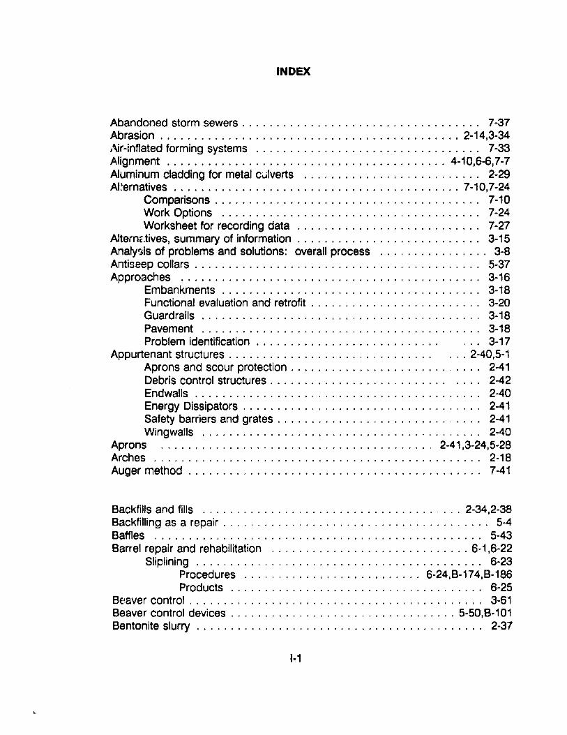
INDEX
Abandoned storm sewers . . . . . . . . . . . . . . . . . . . . . . . . . . . . . . . . . .. 7-37Abrasion 2-14,3-34Air-inflated forming systems 7-33Alignment . . . . . . . . . . . . . . . . . . . . . . . . . . . . . . . . . . . 4-10,6-6,7-7Aluminum cladding for metal culverts 2-29AI'~ernatives 7-10,7-24
Comparisons . . . . . . . . . . . . . . . . . . . . . . . . . . . . . . . . . . . . . .. 7-10Work Options 7-24Worksheet for recording data 7-27
AlternE:tives, summary of information. . . . . . . . . . . . . . . . . . . . . . . . . .. 3-15Analy13is of problems and solutions: overall process 3-8Antiseep collars . . . . . . . . . . . . . . . . . . . . . . . . . . . . . . . . . . . . . . . . .. 5-37Approaches 3-16
Embankments . . . . . . . . . . . . . . . . . . . . . . . . . . . . . . . . . . . . .. 3-18Functional evaluation and retrofit . . . . . . . . . . . . . . . . . . . . . . . .. 3-20Guardrails . . . . . . . . . . . . . . . . . . . . . . . . . . . . . . . . . . . . . . . .. 3-18Pavement 3-18Problem identification . . . . . . . . . . . . . . . . . . . . . . . . . . . 3-17
Appurtenant structures . . . . . . . . . . . . . . . . . . . . . . . . . . . . .. . .. 2-40,5-1Aprons and scour protection . . . . . . . . . . . . . . . . . . . . . . . . . . .. 2-41Debris control structures . . . . . . . . . . . . . . . . . . . . . . . . . . . . . .. 2-42Endwalls . . . . . . . . . . . . . . . . . . . . . . . . . . . . . . . . . . . . . . . . .. 2-40Energy Dissipators . . . . . . . . . . . . . . . . . . . . . . . . . . . . . . . . . .. 2-41Safety barriers and grates . . . . . . . . . . . . . . . . . . . . . . . . . . . . .. 2-41Wingwalls 2-40
Aprons 2-41,3-24,5-28Arches 2-18Auger method . . . . . . . . . . . . . . . . . . . . . . . . . . . . . . . . . . . . . . . . . .. 7-41
Backfills and fills 2-34,2-38Backfilling as a repair. . . . . . . . . . . . . . . . . . . . . . . . . . . . . . . . . . . . . .. 5-4Baffles 5-43Barrel repair and rehabilitation 6-1 ,6-22
Sliplining . . . . . . . . . . . . . . . . . . . . . . . . . . . . . . . . .. 6-23Procedures 6-24,B-174,B-186Products . . . . . . . . . . . . . . . . . . . . . . . . . . . . .. 6-25
BE.'aver control . . . . . . . . . . . . . . . . . . . . . . . . . . . . . . . . . . . . . . . . . .. 3-61Beaver control devices 5-50,8-101Bentonite slurry , 2-37
1-1
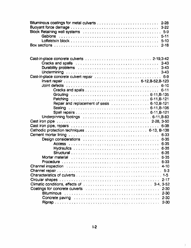
Bituminous coatings for metal culverts. . . . . . . . . . . . . . . . . . . . . . . . .. 2·28Buoyant force damage . . . . . . . . . . . . . . . . . . . . . . . . . . . . . . . . . . . .. 3-22Block Retaining wall systems ..............,.................. 5-9
Gabions 5-11Loffelstein block . . . . . . . . . . , . . . . . . . . . . . . . . . . . . . . . . . . .. 5-10
Box sections . . . . . . . . . . . . . . . . . . . . . . . . . . . . . . . . . . . . . . . . . . .. 2-18
Cast-in-place concrete culverts 2-19,3-42Cracks and spalls 3-43Durability problems 3-43Undermining ..............,........................ 3·43
Cast-in-place concrete culvert repair . . . . . . . . . . . . . . . . . . . . . . . . . . .. 6-9Invert repair 6-12,B·52,B-123Joint defects 6-10
Cracks and spalls . . . . . . . . . . . . . . . . . . . . . . . . . . . . . ',' 6-11Grouting 6-11,B-135Patching 6-11,8-121Repair and replacement of seals 6-10,8-121Sealing 6-11,8-106Spall repairs . . . . . . . . . . . . . . . . . . . . . . . . . . . . . . . 6-11,8·121
Underpinning footings 6·11,8-83Cast iron pipe . . . . . . . . . . . . . . . . . . . . . . . . . . . . . . . . . . . . . .. 2~28, 3·50Cast iron pipe, repairs . . . . . .. 6-38Cathodic protection techniques 6-13, 8-138Cement mortar lining .. . . . . . . . . . . . . . . . . . . . . . . . . . . . . . . . . . . " 6-33
Design considerations 6·35Access 6·35Hydraulics . . . . . . . . . . . . . . . . . . . . . . . . . . . . . . . . . . .. 6-35Structural . . . . . . . . . . . . . . . . . . . . . . . . . . . . . . . . . . . .. 6-35
Mortar material 6·35Procedure . . . . . . . . . . . . . . . . . . . . . . . . . . . . . . . . . . . . . . . " 6-33
Channel inspection 4-10Channel repair . . . . . . . . . . . . . . . . . . . . . . . . . . . . . . . . . . . . . . . . . . .. 5-3Characteristics of culverts . . . . . . . . . . . . . . . . . . . . . . . . . . . . . . . . . . . . 1·5Circular shapes . . . . . . . . . . . . . . . . . . . . . . . . . . . . . . . . . . . . . . . . .. 2-17Climatic conditions, effects of . . . . . . . . . . . . . . . . . . . . . . . . . . . . . 3-4, 3-52Coatings for concrete culverts 2-30
Bituminous 2-30Concrete paving 2-30Riprap . . . . . . . . . . . . . . . . . . . . . . . . . . . . . . . . . . . . . . . . . . .. 2·30
1·2
Coatings for metal culverts . . . . . . . . . . . . . . . . . . . . . . . . . . . . . . . . .. 2-28Aluminum cladding . . . . . . . . . . . . . . . . . . . . . . . . . . . . . . . . . .. 2-29Bituminous 2-28Concrete/mortar 2-29Galvanizing 2-29Polymer 2-29
Cocked and cusped seams 6-18Compaction method, trenchless construction method , 7-41Concrete . . . . . . . . . . . . . . . . . . . . . . . . . . . . . . . . . . . . . . . . . . . . . .. 2-18Concrete, cast-in-place 2-19,3-42Concrete/mortar coatings for metal culverts 2-29Concrete paving 5-22Concrete, precast 2-19, 3-43Concrete pipe
Cast-in-place , 2-19Prl9cast , 2-19Shapes . . . . . . . . . . . . . . . . . . . . . . . . . . . . . . . . . . . . . . . . . ., 2-20Sizes, range 2-20Uses, common 2-2U
Concrete pipe construction . . . . . . . . . . . . . . . . . . . . . . . . . . . . . . . . .. 2-38Backfills and fills 2-38Camber . . . . . . . . . . . . . . . . . . . . . . . . . . . . . . . . . . . . . . . . . .. 2-39Foundations and bedding . . . . . . . . . . . . . . . . . . . . . . . . . . . . .. 2-39loads 2-39Materials . . . . . . . . . . . . . . . . . . . . . . . . . . . . . . . . . . . . . . . . ., 2-40Trench width . . . . . . . . . . . . . . . . . . . . . . . . . . . . . . . . . . . . . ., 2-38Foundations and bedding. . . . . . . . . . . . . . . . . . . . . . . . . . . . .. 2-39
Condition assessment 7-2Construction methods to replace or add a culvert 7-38
Jacking 7-40,8-194Auger method 7-41Compaction method . . . . . . . . . . . . . . . . . . . . . . . . . . . .. 7-41Directional drilling method . . . . . . . . . . . . . . . . . . . . . . . ., 7-42FlowMole guidedrill method . . . . . . . . . . . . . . . . . . . . . . .. 7-43Micro-tunneling method 7-43Pipe ramming method 7-42Slurry horizontal rotary drilling (SRo) method 7-42Wat
. jetting method 7-42Trenching 7-40Tunneling 7-44
Controlled low-strength material (CLSM) 7-34Corrosion . . . . . . . . . 2-12,3-34Corrosion, prevention and repair 6-13,8-138
1-3
Corrugated aluminum 2-2380x sections .. . . . . . . . . . . . . . . . . . . . . . . . . . . . . . . . . . . . .. 2-24Long span 2-24Material . . . . . . . . . . . . . . . . . . . . . . . . . . . . . . . . . . . . . . . . . .. 2-24Pipe 2-24Shapes . . . . . . . . . . . . . . . . . . . . . . . . . . . . . . . . . . . . . . . . . ., 2-24Structural plate 2-24
Corrugated metal arches and boxes . . . . . . . . . . . . . . . . .. 6-20Shape distortions 6-21,8-152Streambed repair. . . . . . .. . 6-21,8-63,8-70,8-123Underpinning footings 6-21,8-83
Corrugated metal pipe culverts . . . . . . . . . . . . . . . . . . . . . . . . . . . . . .. 3-30Dents and localized damage . . . . . . . . . . . . . . . . . . . . . . . . . . ., 3-33Durability problems 3-34
Abrasion 3-34Corrosion 3-31
Joint defects 3-33Misalignment . . . . . . . . . . . . . . . . . . . . . . . . . . . . . . . . . . . . . .. 3-33Shape distortion . . . . . . . . . . . . . . . . . . . . . . . . . . . . . . . . . . . ., 3-30
Pipe arch. . . . . . . . . . . . . . . . . . . . . . . . . . . . . . . . . . . .. 3-31Round and elliptical 3-31
Corrugated Metal pipes and pipe arches, repair . . . . . . . . . . . . . . . . . .. 6·13Cathodic protection techniques 6-13,8-138Joint defects 6-14
Excavation and exterior repair . . . . . . . . . . . . . . . . . . . . .. 6-14Grouting 6-14,8-135Interior seals 6·15,8-111,8-135
Invert durability repairs . . . . . . . . . . . . . . . . . . . . . . . . . . , . . . ., 6-15Invert paving with concrete 6-15,8-52,8-123Pipe arch conversion to arch .. 6-16Steel armor plating . . . . . . . . . . . . . . . . . . . . . . . .. 6-16, 8-142
Shape distortion 6-16,8·152Excavation and backfilling . . . . . . . . . . . . . . . . . . . . . . . .. 6·17Rerounding 6-17,8-162Temporary bracing 6-17,8·160
Corrugated metal structural plate culverts ......................' 3-34Circumferential seams a-4 '1Dents and localized damage . . . . . . . . . . . . . . . . . . . . . . . . . . .. 3-41Durability problems 3-41Footing defects 3-41Joint defects 3-37Misalignment . . . . . . . . . . . . . . . . . . . . . . . . . . . . . . . . . . . . . .. 3-37
1-4
Shape distortion . . . . . . . . . . . . . . . . . . . . . . . . . . . . . . . . . . . .. 3-34Arches 3-3580xes '" 3-36Long span . . . . . . . . . . . . . . . . . . . . . . . . . . . . . . . . . . .. 3-37Pipe arch . . . . . . . . . . . . . . . . . . . . . . . . . . . . . . . . . . . .. 3-35Round and ellipitical . . . . . . . . . . . . . . . . . . . . . . . . . . . .. 3-34
Seam defects 3-3880lt tipping 3-40Cocked and cusped seams . . . . . . . . . . . . . . . . . . . . . . .. 3-39Loose fasteners . . . . . . . . . . . . . . . . . . . . . . . . . . . . . . .. 3-38Seam cracking . . . . . . . . . . . . . . . . . . . . . . . . . . . . . . . .. 3-40
Circumferential seams 3-41Cc,rrugatec.1 metal structural plate repairs . . . . . . . . . . . . . . . . . . . . . . .. 6-18
Seam defects 6-18Cocked and cusped seams . . . . . . . . . . . . . . . . . . . . . . ., 6-18Seam cracking 6-19,8-142,8-167
Joint defects 6-19,8-111Invert durability 6-19,8-52,8-123Shape distortion . . . . . . . . . . . . . . . . . . . . .. . 6-20,8-152
Corrugated steel . . . . . . . . . . . . . . .. 2-1980x sections . . . . . . . . . . . . . . . . . . . . . . . . . ., 2-23Long span . . . . . . . . . . . . . . . . . . . . . . . . . . . .. . . . . . . . . . . .. 2-23Material . . . . . . . . . . . . . . . . . . . . . . . . . . . . . . . . . . . . . . . . . .. 2-22Pipe 2-22Pipe arch 2-23Structural plate 2-23Shapes " 2-?1, 2-22Sizes , 2-21Uses, common 2-21
Corrugation patterns ....,................................. 2-22Corrugated metal . . . . . . . . . . . . . . . . . . . . , 2-22Structural plate 2-22
Cusped seams 6-18Cutoff wall . . . . . . . . . . . . . . . . . . . . . . . . . . . . . . . . . . . . . . . . . . . . .. 8-68Cracks, circumferential . . . . . . . . . . . . . . . . . . . . . . . . . . . . . . 3-45,6-2,B-1 06Cracks, longitudinal . . . . . . . . . . . . . . . . . . . . . . . . . . . . . . . . . . . . . .. 3-45Cracks, transverse . . . . . . . . . . . . . . . . . . . . . . . . . . . . . . . . . . . . . . .. 3-47Crown deterioration . . . . . . . . . . . . . . . . . . . . . . . . . . . . . . . . . . . . 6-9,8-165
Debris-control structures 2-42Selection, guide for 2-45Types of debris . . . . .. 2-43Types of debris control structures . . . . . . . . . . . . . . . . . . . . . . .. 2-44
1-5
Debris types 2-43Debris removal ..........................."............. 4-8,B-1Definition of culverts . . . . . . . . . . . . . . . . . . . . . . . . . . . . . . . . . . . . . . .. 1-5Deflection of flexible culverts . . . . . . . . . . . . . . . . . . . . . . . . . . . . . . . . .. 2-9Dents and localized damage " 3-33Differential settlement . . . . . . . . . . . . . . . . . . . . . . . . . . . . . . . . . . . . . ., 6-5Directional drilling method 7-42Distortion, monitoring and evaluation . . . . . . . . . . . . . . . , . . . . . . . . . . .. 3-5Ditches 3-25,5-22Ditch cleaning and repair 4-9,8-10,8-13Drainage ditches . . . . . . . . . . . . . . . . . . . . . . . . . . . . . . . . . . . . . . . " 8-58Drop structure . . . . . . . . . . . . . . . . . . . . . . . . . . . . . . . . . . . . . . . . . " 5-26Durability . . . . . . . . . . . . . . . . . . . . . . . . . . . . . . . . . . . . . .. 2-12, 3-47, 3-51
Earth reinforcement systems 5-12Grid reinforcement . . . . . . . . . . . . . . . . . . . . . . . . . . . . . . . . . " 5-14Sheet reinforcement . . . . . . . . . . . . . . . . . . . . . . . . . . . . . . . . " 5-16Soil nailing . . . . . . . . . . . . . . . . . . . . . . . . . . . . . . . . . . . . . . . " 5-16Strip reinforcement . . . . . . . . . . . . . . . . . . . . . . . . . . . . . . . . . " 5-13
Economic analysis 7-8,7-11Benefit-cost analysis " 7-22First-cost analysis 7-12Ufe-cycle costs 7-12
Economic considerations . . . . . . . . . . . . . . . . . . . . . . . . . . . . . . " 2-15Economic impacts . . . . . . . . . . . . . . . . . . . . . . . . . . . . . . . . . . . . . . .. 3-53Embankments . . . . . . . . . . . . . . . . . . . . . . . . . . . . . . . . . . . . . . . . . .. 3-18End section dropoff 3-48,6-6,8-116End sections, addition of 5-29,5-33,6-90End treatment and appurtenant structures 3-20,5-1,8-90
Buoyant force damage . . . . . . . . . . . . . . . . . . . . . . . . . . . . . . .. 3-22Piping . . . . . . . . . . . . . . . . . . . . . . . . . . . . . . . . . . . . . . . . . . .. 3-22Problem identification . . . . . . . . . . . . . . . . . . . . . . . . . . . . . . . .. 3-21Projecting pipes. . . . . . . . . . . . . . . . . . . . . . . . . . . . . . . . . . . .. 3-20
Endwalls . . . . . . . . . . . . . . . . . . . . . . . . . . . . . . . . . . . . . . .. 2-4f),3-22,5-29Endwalls, jacketing 5-33, 6-81Endwalls, partial replacement . . . . . . . . . . . . . . . . . . . . . . .. 5-31, 6-74Endwalls, repair . . . . . . . . . . . . . . . . . . . . . . . . . . . . . . . . . . . . . . 5-31, B-77Endwalls, replacement 5-31, 8-72Endwalls, retrofit 5-31Endwalls, underpinning 5-34, 6-83Environmental impacts . . . . . . . . . . . . . . . . . . . . . . . . . . . . . . . . . . . .. 3-54Emergency situations . . . . . . . . . . . . . . . . . . . . . . . . . . . . . . . . . . . . . .. 3-5Energy Dissipators . . . . . . . . . . . . . . . . . . . . . . . . . . . . . . . .. 2-41,3-25,5-24
I.e
Environmental factors . . . . . . . . . . . . . . . . . . . . . . . . . . . . . . . . . . . . .. 2-16Erosion . . . . . . . . . . . . . . . . . . . . . . . . . . . . . . . . . . . . . . . . . . . . . 3-54,3-56Erosion control 5-2Excavation and exterior repair . . . . . . . . . . . . . . . . . . . . . . . . . . . . '. . .. 6-14Excavation and backfilling . . . . . . . . . . . . . . . . . . . . . . . . . . . . . . . . . .. 6-17Exfiltration . . . . . . . . . . . . . . . . . . . . . . . . . . . . . . . . . . . . .. 3-44
Fiberglass reinforced plastic (FPR) composite pipe . . . . . . . . . . . . . . . .. 2-26Fiber reinforced polymer concrete (FRPC) . . . . . . . . . . . . . . . . . . . . . .. 2-27Fish ladders 5-46Fish passage . . . . . . . . . . . . . . . . . . . . . . . . . . . . . . . . . . . . . . .. 2-46, 3-58
Parameters 3-59Obstacles to fish passage . . . . . . . . . . . . . . . . . . . . . . . . . . . . .. 3-59Problems with modifications of culverts 3-61
Fish passage devices 5-39,B-95Baffles . . . . . . . . . . . . . . . . . . . . . . . . . . . . . . . . . . . . . . . . . . .. 5-43Fish ladders 5-46Resting pools < • • • • • • • • • • • • • • •• 5-49Slot orifice fishway . . . . . . . . . . . . . . . . . . . . . . . . . . . . . . . . . .. 5-47Spoiler baffles 5-45Steeppass fishway . . . . . . . . . . . . . . . . . . . . . . . . . . . . . . . . . .. 5-48
Flexible culvert behavior . . . . . . . . . . . . . . . . . . . . . . . . . . . . . . . . . . . .. 2-9Flooding . . . . . . . . . . . . . . . . . . . . . . . . . . . . . . . . . . . . . . . . . .. 3-53, 3-54Flowable fill . . . . . . . . . . . . . . . . . . . . . . . . . . . . . . . . . . . . . . . . . . . .. 7-35Flowable fly ash . . . . . . . . . . . . . . . . . . . . . . . . . . . . . . . . . . . . . . . . .. 7-36Flowable mortar . . . . . . . . . . . . . . . . . . . . . . . . . . . . . . . . . . . . . . . . .. 7-35FlowMole guiderail method . . . . . . . . . . . . . . . . . . . . . . . . . . . . . . . . .. 7-43Flushing 4-8Footings, underpinning 5-34, B-81Foundations and bedding . . . . . . . . . . . . . . . . . . . . . . . . . . . . . . . . . .. 2-39Functional evaluation . . . . . . . . . . . . . . . . . . . . . . . . . . . . . . . . . . . . .. 3-20
Gabions 5-11 ,5-24,B-39Gabions, repairs with . . . . . . . . . . . . . . . . . . . . . . . . . . . . . . . . . . 5-35, 8-39Galvanizing for metal culverts . . . . . . . . . . . . . . . . . . . . . . . . . . . . . . .. 2-29Geotechnical factors 2-16Geotextiles 5-7,B-25,C-1Grid reinforcement . . . . . . . . . . . . . . . . . . . . . . . . . . . . . . . . . . . . . . .. 5-14Grouting . . . . . . . . . . . . . . . . . . . . . . . . . . . . . . . . . .. 5-37,6-11,6-14,6-135Guardrails . . . . . . . . . . . . . . . . . . . . . . . . . . . . . . . . . . . . . . . . . . . . .. 3-18Gunite B-52
1-7
Headwalls . . . . . . . . . . . . . . . . . . . . . . . . . . . . . . . . . . . . . . . . . . . . .. 5-29Headwalls, underpinning 5-34, 8-83Horizontal alignment 3-26Hydraulic adequacy . . . . . . . . . . . . . . . . . . . . . . . . . . . . . . . . . .. 3-29, 3-52Hydraulic jump 5-27Hydraulic jump, forced . . . . . ,- 5-27Hydraulics . . . . . . . . . . . . . . . . . . . . . . . . . . . . . . . . . . . . . . . . . . . . . .. 2-3Hydrology . . . . . . . . . . . . . . . . . . . . . . . . . . . . . . . . . . . . . . . . . . . . . .. 2-1Hydrology changes 7-7
Impact basin . . . . . . . . . . . . . . . . . . . . . . . . . . . . . . . . . . . . . . . . . . " 5-25Infiltration 3-44Inlet control . . . . . . . . . . . . . . . . . . . . . . . . . . . . . . . . . . . . . . . . . . . . .. 2-3Inlet repair . . . . . . . . . . . . . . . . . . . . . . . . . . . . . . . . . . . . . . . . . . . . . .. 5·4Inspection of culverts , 3-3,4-6Installations methods . . . . . . . . . . . . . . . . . . . . . . . . . . . . . . . . . . . . .. 2-30
Augured ' . . . , . . . . . . . . . . . . . . .. 2-37Bored 2-37Embankments . . . . . . . . . . . . . . . . . . . . . . . . . . . . . . . . . . . . .. 2-36
Induced trench . . . . . . . . . . . . . . . . . . . . . . . . . . . . . . . .. 2-36Negative projection . . . . . . . . . . . . . . . . . . . . . . . . . . . . .. 2-36Positive projection 2-36
Jacked 2-37Trenched 2-31
Backfilling 2-34Bedding 2-33Bedding as related to supporting strength for rigid pipe . . .. 2-35
Interior seals . . . . . . . . . . . . . . . . . . . . . . . . . . . . . . . . . . . 6-15,B-111 ,8-135Inversion lining 6-29
Design considerations 6-32Materials and products . . . . . . . . . . . . . . . . . . . . . . . . . . . . . . .. 6-32Procedure . . . . . . . . . . . . . . . . . . . . . . . . . . . . . . . . . . . . . . . .. 6-30
Invert paving and repair 6-7,6-11,6-15,8-52,8-123
Jacking . . . . . . . . . . . . . . . . . . . . . . . . . . . . . . . . . . . . . . . . . .. 7·40, 8-194Joint defects 3-33,3-37, 3-44,6-2,6-14,6-19,8-111Joint sealing for minor repairs . . . . . . . . . . . . . . . . . . . . . . . . . . . . . 6-5,B-106Joints, repair and replacement of seals 6-10,8-121
1-8
Legal implications related to culvert maintenance . . . . . . . . . . . , . . . . . .. 4-4Loads 2-5
Live load . . . . . . . . . . . . . . . . . . . . . . . . . . . . . . . . . . . . . . . . . .. 2-7Dead loads . . . . . . . . . . . . . . . . . . . . . . . . . . . . . . . . . . . . . . . .. 2-7
Loffelstein block type systems .. . 5-10,8-35Longitudinal cracks 6-6Long span culverts 2-10,3-3"
Maintenance of culverts 2-16, 3-4,4-1Benefits . . . . . . . . . . . . . . . . . . . . . . . . . . . . . . . . . . . . . . . . . . .. 4-2Costs 4-3Legal implications 4-4Procedures . . . . . . . . . . . . . . . . . . . . . . . . . . . . . . . . . . . . . . . .. 4-8
Maintenance, preventive 7-8Maintenance, routine . . . . . . . . . . . . . . . . . . . . . . . . . . . . . . . . . . . . . .. 7-8Masonry culverts 2-27,3-48
Alignment 3-49Footings ..................,....................... 3-49Masonry units 3-48Mortar . . . . . . . . . . . . . . . . . . . . . . . . . . . . . . . . . . . . . . . . . . .. 3-48Shape 3-49
Masonry, repairs . . . . . . . . . . . . . . . . . . . . . . . . . . . . . . . . . . . . . . . .. 6-37Masonry, repointing .. . 5-34, B-87Materials . . . . . . . . . . . . . . . . . . . . . . . . . . . . . . . . . . . . . . . . . . . . . .. 2-18Micro-tunneling method of construction. . . . . . . . . . . . . . . . . . . . . . . .. 7-43Misalignment 3-32,3-37, 3-44Misalignment, relaying of sections . . . . . . . . . . . . . . . . . . . . . . . . . . . . .. 6-6Mitered ends . . . . . . . . . . . . . . . . . . . . . . . . . . . . . . . . . . . . . . . . . . .. 3-23Mortar 3-48Mortar and mastic for leakage 6-5Multiple barrels 2-18
Outlet control ...................................,........ 2-5Outlet repair 5-4Overburd3n . . . . . . . . . . . . . . . . . . . . . . . . . . . . . . . . . . . . . . . . . . . .. 2-37
Peak flow 3-30Partial flow 3-29Patching, concrete. . . . . . .. . 6-7,6-11,8-121Paving, invert 6-7,8-123Paving, streambed . . . . . . . . . . .. 5-28
1-9
Pavement ... . . . . . . . . . . . . . . . . . . . . . . . . . . . . . . . . . . . . . . . . . .. 3-18Pipe arch and elliptical . . . . . . . . . . . . . . . . . . . . . . . . . . . . . . . . . . . .. 2-17Piping . . . . . . . . . . . . . . . . . . . . . . . . . . . . . . . . . . . . . . . . . . . . . . 3-22,5-37Pipe ramming method of construction . . . . . . . . . . . . . . . . . . . . . . . . .. 7-42Plastic pipe . . . . . . . . . . . . . . . . . . . . . . . . . . . . . . . . . . . . . . . . . . . .. 2-25
Fiberglass . . . . . . . . . . . . . . . . . . . . . . . . . . . . . . . . . . . . . . . .. 2-26Fiber reinforced polymer concrete (FRPC) . .. 2-27Polyethylene (PE) . . . . . . . . . . . . . . . . . . . . . . . . . . . . . . . . . . .. 2-26Polyvinyl chloride (PVC) 2-25
Plastic pipe, repairs .... . . . . . . . . . . . . . . . . . . . . . . . . . . . . . . . . . .. 6·38Polymer coatings for metal culverts . . . . . . . . . . . . . . . . . . . . . . . . . . ,. 2-29Precast concrete pipe culverts 3-43, 6-2
Durability problems 3-47End section dropoff . . . . . . . . . . . . . . . . . . . . . . . . . . . . . . . . .. 3-48Joint defects 3-44
Cracks 3-44Exfiltration 3-44Infiltration. . . . . . . . . . . . . . . . . . . . . . . . . . . . . . . . . . . .. 3-44Separation . . . . . . . . . . . . . . . . . . . . . . . . . . . . . . . . . . .. 3-45
Longitudinal cracks 3-45Slabbing . . . . . . . . . . . . . . . . . . . . . . . . . . . . .. 3-47Spalls 3-47Transverse cracks 3-47
Precast reinforced concrete culverts, repair . . . . . . . . . . . . . . . . . . .. 6-3Joint defects 6-2
Cracking 6-2,8-106Mortar and mastic for leakage . . . . . . . . . . . . . . . . .. 6-5Structural adhesives . . . . . . . . . . .. 6-5
Differential settlement 6-5Joint sealing 6-5,8-106Steel bands and shotcrete 6-5,8-52,8-111
End section dropoff prevention 6-6,8-116Relaying of misaligned sections , 6-6
Longitudinal and transverse cracks 6-6Invert paving 6-7,8-123Patching 6-7,8-121Sealing 6-7,8-106Slabbing repair 6-7,8-121
Invert deterioration . . . . . . . . . . . . . . . . . . . . . . . . . . . . . . . . . . .. 6-8Concrete repair 6-8,8-52,8-123Flow neutralization basin . . . . . . . . . . . . . . . . . . . . . . . . . .. 6-8Spall repair 6-7,8-121
Crown deterioration 6-9,8-165
1-10
Precast culvert systems . . . . . . . . . . . . .. 7-30Problem identification . . . . . . . . . . . . . . . . . . . . . . . . . . . . . . . . . . . . . .. 3-1
General . . . . . . . . . . . . . . . . . . . . . . . . . . . . . . . . . . . . . . . . . . .. 3-1Erld treatment and appurtenance problems 3-21Waterway problems ..... . . . . . . . . . . . . . . . . . . . . . . . . " 3-27
Projecting pipes . . . . . . . . . . . . . . . . . . . . . . . . . . . . . . . . . . . . . . . . .. 3-20Precast concrete .. . . . . . . . . . . . . . . . . . . . . . . . . . . . . . . . . . . . . . " 2-19Problems
Analysis of problems ,.................... 3-9Analysis of solutions . . . . . . . . . . . . . . . . . . . . . . . . . . . . . . . . .. 3-11General . . . . . . . . . . . . . . . . . . . . . . . . . . . . . . . . . . . . . . . . . . .. 1-7Identification 3-10
Rehabilitation. . . . . . . . . . . . . . . . . . . . . . . . . . . . . . . . . . . . . . . . .. 7-4,7-8Reinforced soil systems . . . . . . . . . . . . . . . . . . . . . . . . . . 5-12,5-17Remaining service life . . . . . . . . . . . . . . . . . . . . . . . . . . . . . . . . . . . . . .. 7-4Repair actions . . . . . . . . . . . . . . . . . . . . . . . . . . . . . . . . . . . . . . ... " 3-13Repair versus replacement . . . . . . .. . . . . . . . . . . . . . . . . . . . . . . . . . .. 7-1Replacement . . . . . . . . . . . . . . . . . . . . . . . . . . . . . . . . . . . . . . . . . . . .. 7-9Replacement systems 7-28
Design considerations 7-28Recent innovations in materials, products, and procedures 7-29Traditional materials/past performance 7-29
Repointing 5-34, 8-87Rerounding 6-17,8-162Resting pools 5-49Rigid culvert behavior . . . . . . . . . . . . . . . . . . . . . . . . . . . . . . . . . . . . " 2-11Ring compression 2-10i~iprap 5-24, 8-63,C-6Riprap basin 5-25Route closure 3-54Rutole .. :.............................................. 5-8
Safety barriers and grates 2-41Safety factors 2-16,5-38,7-7Scour 3-28, 3-56,5-23Scour hole repair . . . . . . . . . . . . . . . . . . . . . . . . . . . . . . . . . . . . . . . .. 4-10Sealing 6-7,6-11 )8-106Seam defects, corrugated metal structural plate . . . . . . . . . . . . . . . . . .. 6-18
Cocked and cusped seams 6-18Seam cracking 6-19,8-142,8-167
Sedimentation 3-29,3-55
1-11
Sediment removal ,..................... 4-8,8-3Separation, joints . . . . . . . . . . . . . . . . . . . . . . . . . . . . . . . . . . . . . . . .. 3-45Separator baffles . . . . . . . . . . . . . . . . . . . . . . . . . . . . . . . . . . . . . . . " 5-45Service life, remaining 7-4Shapes, concrete pipe . . . . . . . . . . . . . . . . . . . . . . . . . . . . . . . . . . . .. 2-20Shape distortion
Corrugated metal pipe culverts '" . . . . . . . . . . . . . . . . . . . . . " 3-30Corrugated metal structural plate culverts 3-34
Shape distortion, monitoring and evaluating , 3-5Close-range photogrammetry procedure 3-7Conventional survey procedures . . . . . . . . . . . . . . . . . . . . . . . . ., 3-7Total station survey procedure 3-7
Shape distortion, repair 6-17,6-21,8-152Sheet reinforcement . . . . . . . . . . . . . . . . . . . . . . . . . . . . . . . . . . . . . " 5·16Shotcrete, repairs using 5-~6J6-5,8-52
Slabbing . . . . . . . . . . . . . . . . . . . . . . . . . . . . . . . . . . . . . . . . . . . . . .. 3-47Slabbing repairs 6-7,8-121Sliplining . . . . . . . . . . . . . . . . . . . . . . . . . . . . . . . . . . . . . . . . . . . . . .. 6-23
Design consiJerations 6-27Access 6-29Clearance 6-28Hydraulics .. . . . . . . . . . . . . . . . . . . . . . . . . . . . . . . . . .. 6-27Structural. . . . . . . . . . . . . . . . . . . . . . . . . . . . . . . . . . . .. 6-28
Procedures 6-24,8-174,8-186Products used for sliplining . . . . . . . . . . . . . . . . . . . . . . . . . . . .. 6-25
Corrugated metal . . . . . . . . . . . . . . . . . . . . . . . . . . . . . .. 6-25Fiberglass pipe 6-26Grout 6-26,8-186Plastic pipe 6-26Precast concrete 6-26
Slope stabilization 5-5Geotextiles 5-7Rubble 5-8Vegetation 5-5
Slurry horizontal rotary drilling (SRD) method . . . . . . . . . . . . . . . . . . . .. 7-42Soil, factor in durability , 3-51Solutions, analysis of . . . . . . . . . . . . . . . . . . . . . . . . . . . . . . . . . . .. . 3-11Spalls . . . . . . . . . . . . . . . . . . . . . . . . . . . . . . . . . . . . . . . . . . . . . . . ., 3-47Spall repair 6-7,6·11,8-121Spoiler baffles 5-46Steel armor plating . . . . . . . . . . . . . . . . . . . . . . . . . . . . . . . . . . . . . . ., 6-16Steel bands for repair . . . . . . . . . . . . . . . . . . . . . . . . . . . . . . . . . . 6-5, 8-111Steel, corrugated , 2-19Steel retaining walls . . . . . . . . . . . . . . . . . . . . . . . . . . . . . . . . . . . . . .. 5-20
1-12
Steel sheeting repairs . . . . . . . . . . . . . . . . . . . . . . . . . . . . . . . . . . . . .. 5-35Stilling well 5-26Streambed maintenance . . . . . . . . . . . . . . . . . . . . . . . . . . . . . . . . . . . .. 4-9Streambed paving . . . . . . . . . . . . . . . . . . . . . . . . . . . . . . . . . . .. 5-28Streambed repair 6-21,8-63,8-70,8-123Strip reinforcement 5-13Structural adhesives . . . . . . . . . . . . . . . . . . . . . . . . . . . . . . . . . . . . . . .. 6-5Stru(;tu~al 10E:lds . . . . . . . . . . . . . . . . . . . . . . . . . . . . . . . . . . . . . . . . . .. 2-5Struclure inventory and appraisal sheet (SI&A) for culvert inspection ..... 7-2Survey procedures for monitoring and evaluating shape distortion . . . . . .. 3-8
Conventional survey procedures . . . . . . . . . . . . . . . . . . . . . . . . .. 3-7Total station survey procedure 3-7Close-range photogrammetry procedure 3-7
Temporary brer'ing 6-17,8-160Th~wing frozen culverts , 4-9,8-5Timber 3-50Tirr'ber rp.taining walls 5-18Timber structures, repair of 8-49Traffic impacts 3-53,7-6Traffic maintenance and control 2-17Transverse ~racks . . . . . . . . . . . . . . . . . . . . . . . . . . . . . . . . . . . . . . . .. 6-6Trench installation, narrow 2-12Trenching .. . . . . . . . . . . . . . . . . . . . . . . . . . . . . . . . . . . . . . . . . . . .. 7-40Trenchless excavation 7-38Trench width . . . . . . . . . . . . . . . . . . . . . . . . . . . . . . . . . . . . . . . . . . .. 2-38Tunneling 7-44Tying arch . . . . . . . . . . . . . . . . . . . . . . . . . . . . . . . . . . . . . . . . . . . . .. 5-35
Underpinning, footings. . . . . . . . . . . . . . . . . . . . . . . . .. 5-34,6-11,6-21,8-83Underpinning, headwalls, endwalls, and wingwalls 5-34, B-83Upgrade to equal replacement 7-9
Vegetation control . . . . . . . . . . . . . . . . . . . . . . . . . . . . . . . . . . . . . . .. 4-11Vegetative streambank stabilization . . . . . . . . . . . . . . . . . . . . . . . . . . .. B-17Vertical alignment 3-28Vitrified clay pipe " 2-27, 3-49
Durability . . . . . . . . . . . . . . . . . . . . . . . . . . . . . . . . . . . . . . . . " 3-49Shape 3-43
Vitrified clay pipe, repairs .. . . . . . . . . . . . . . . . . . . . . . . . . . . . . . . . .. 6-37
1·13
Water, factor in durability .......,........................... 3-51Water jetting method of construction . . . . . . . . . . . . . . . . . . . . . . . . . ., 7-42Waterways 3-26
General . . . . . . . . . . . . . . . . . . . . . . . . . . . . . . . . . . . . . . . . . ., 3-26Horizontal alignment . . . . . . . . . . . . . . . . . . . . . . . . . . . . . . . . ., 3-26Hydraulic adequacy .... . . . . . . . . . . . . . . . . . . . . . . . . . . . . ., 3-29
Partial flow . . . . . . . . . . . . . . . . . . . . . . . . . . . . . . . . . . ., 3-29Peak flow 3-29
Problem identification . . . . . . . . . . . . . . . . . . . . . . . . . . . . . . . ., 3-27Sccur 3-28Sediment and debris 3-29Vertical alignment . . . . . . . . . . . . . . . . . . . . . . . . . . . . . . . . . . .. 3-28
Wingwalls . . .. 2-40, 3-22,5-29Wingwalls, jacketing 5-33,B-81Wingwalls, partial replacement 5-31, B-74Wingwalls, repair . . . . . . . . . . . . . . . . . . . . . . . . . . . . . . . . . . . . . 5-31, B-77Wingwalls, replacement 5-31, 8-72Wingwalls, retrofit 5-31Wingwalls, underpinning . . . . . . . . . . . . . . . . . . . . . . . . . . . . . . . . 5-34, B-83Wood (timber) . . . . . . . . . . . . . . . . . . . . . . . . . . . . . . . . . . . . . . . . 2-27,3-50Wood, repairs , 6-38
1-14