Embed Size (px)
Citation preview

OED Electronics Pty. Ltd.ABN 16 064 869 594
Phone (07) 3207 1023 Int. +61 7 3207 1023Fax (07) 3822 6102 E-Mail oed @ powerup.com.au
RTM 24102400 Baud Radio Data Modem
♦ For Tait ® 2010, 2015For Tait ® 2010, 2015For Tait ® 2010, 2015For Tait ® 2010, 2015and "Data" Radiosand "Data" Radiosand "Data" Radiosand "Data" Radios
♦ Fits into the OptionFits into the OptionFits into the OptionFits into the OptionSpace inside the radioSpace inside the radioSpace inside the radioSpace inside the radio
♦ 9 Pin RS232 "D" data9 Pin RS232 "D" data9 Pin RS232 "D" data9 Pin RS232 "D" dataconnectorconnectorconnectorconnector
OED Electronics has developed theRTM2410 data modem to provide much moreflexibility when implementing data modemsinto VHF/UHF radio systems using Tait ®radios.
The features built into this modem havebeen designed to ensure all functions are userconfigurable.
The RTM2410 uses the same modulationmethod as the RTM1200 and therefore retainsthe low Bit Error Rate but with greatlyimproved throughput.
Specifications:Baud Rate (Bits Per Second) 1200 or 2400
Data Buffer Size 260 Bytes
TX Stabilise Delay 50 - 500 mS
Repeater Key Up Delay 50 - 5000 mS
Anti Collision Delay 80 - 500 mS
Channel Select 24 Channels
RSSI reading (-130 to -70dBm) 0 - 200
Temperature reading 0 - 120 °C
Default shutdown temperature 65 °C
Features: Modem initialisation using AT Commands.
All delay times can be adjusted and havean accuracy of 1 mS.
Change the radio channel by using an ATCommand (24 channels on 2015).
Anti Collision to stop modems transmittingsimultaneously.
Voice Compatibility to coordinate Voiceand Data on the same radio system.
Repeater delay to enable repeaters to keyup while retaining the fastest turn aroundtime.
Radio over temperature protection.
The radio's temperature can be read fromthe modem.
RSSI (Received Signal Strength Indicator)value can be read from the modem.
DIP Switch settings can be used for fastinstallations that require no specialinitialisation.
Full compatibility with the RTM1200 andRTM2400 modems.
For further information contact: Qty 1 - 4 $ 296 + GSTOED Electronics Pty. Ltd. (Australia) Qty 5 - 19 $ 259 + GSTP.O. Box 3081 Birkdale QLD 4159 Qty 20 up $ 222 + GSTPhone (07) 3207 1023 Recommended Retail $370 + GST

__________________________________________________________________________________________________OED Electronics Pty. Ltd. (Oct-97) RTM-2410 Supplementary Information
RTM-2410 RECOMMENDED DEFAULT SETUP.
The RTM-2410 Modem has the capability to be accurately setup to maximise data transmission and timing.This is achieved by programming the S-Registers.
However in most situations timing and through put are not critical and the modem can be set to default valuesusing only the Dip Switches on the side of the modem card.
The following gives a list of recommended Dip Switch settings for both modes of operation. This will enable afast installation.
Mode 0 Settings (recommended):
Mode 0 is for use on equipment that has the ability to raise RTS (Request to Send) when ever it requires data totransmitted, and to lower RTS to stop transmission. This type of equipment is usually specifically designed foruse with Radio Telemetry for example DGPS Base Stations and special purpose data logging Microprocessorbased equipment.
Use this mode for DGPS base stations or other equipment that requires permanent transmission of data. Thistype of equipment must have RTS (Request to Send) raised at all times. If the equipment doesn't have RTSthen wire Pin 6 to Pin 7 of the 9 Pin "D" Connector at the RTM-2410 modem end.
Install the Modem card into the radio (Refer to the Installation section in the Manual).
Solder a piece of wire across the "MODE" pads on the solder side of the Modem.Go to Dip Switch Settings section below.
Mode 1 Settings:
Mode 1 is for use on equipment that permanently raises RTS (Request to Send) when ever the serial port isactive (usually all the time). PC's running standard off the shelf communications software will usually keep RTSactive all the time. Software such as Pro Comm, Terminal for Windows and Hyper Terminal for Win95 fall intothis category. The standard transfer protocols, X Modem, Z Modem, Kermit etc. can be used with Mode 1 totransfer data across the radio link.
This mode requires more time for transmission turnarounds, therefore it is recommended to use softwarewritten specifically for Radio Telemetry and to use the modem in Mode 0 if maximum performance is required.
Install the Modem card into the radio (Refer to the Installation section in the Manual).
Ensure the "MODE" pads on the solder side of the Modem, are not linked (open circuit).Set the Dip Switches as follows:
Dip Switch Settings:
1. Set Dip Switch 1 ON if the radio system has repeaters. Set to OFF if the radios communicate directly.
2. Set Dip Switch 2 OFF for 2400 Baud. Set Dip Switch 2 ON for 1200 Baud.
3. Set Dip Switch 3 OFF
4. Set Dip Switch 4 ON
5. Set Dip Switch 5 OFF
6. Set Dip Switch 7 ON
7. Set Dip Switch 6 and 8 OFF
Refer to the manual for correct deviation adjustment procedure.The modem should now be operational. If data is not getting through increase the TX Stabilise Delay using DipSwitches 6, 7 and 8. (Refer to the manual for settings).
__________________________________________________________________________________________________OED Electronics Pty. Ltd. (21-Aug-01) RTM-2410 B Operation Manual
RTM-2410 B V1.3
2400 BAUD RADIO MODEM
(FOR TAIT 2010, 2015 AND DATA RADIOS)
1. Specifications. ................................................................................................................ 2
2. Operation......................................................................................................................... 3
2.1 RTM-1200 Compatible Mode. (Mode Pads Linked) .......................................................................... 3
2.2 Mode 1 - Three Wire Mode. (Mode Pads Open) ................................................................................. 42.2.1 Mode 1 Normal Operation............................................................................................................ 42.2.2 Mode 1 with Anti Collision ON...................................................................................................... 42.2.3 Mode 1 with Repeater Delay ON. ................................................................................................ 5
2.3 Mode 0 - Hardware Handshake Mode. (Mode Pads Linked)............................................................ 52.3.1 Mode 0 Normal Operation............................................................................................................ 52.3.2 Mode 0 with Anti Collision ON...................................................................................................... 62.3.3 Mode 0 with Repeater Delay ON. ................................................................................................ 6
3. Dip Switch and Link Pad Settings. ................................................................................ 7
3.1 TX Stabilise Delay. (Dip Switch 6, 7 and 8)....................................................................................... 7
3.2 Baud Rate Select. (Dip Switch 2)....................................................................................................... 8
3.3 AT Commands ON / OFF. (Dip Switch 3) .......................................................................................... 8
3.4 Anti Collision ON / OFF. (Dip Switch 4)............................................................................................. 8
3.5 Voice Compatibility. (Dip Switch 5)................................................................................................... 9
3.6 Repeater Delay ON / OFF. (Dip Switch 1)........................................................................................ 12
3.7 Link Pads (solder side of RTM-2410) ............................................................................................... 12
3.8 Tait Data Radio Setup........................................................................................................................ 13
4. AT Commands............................................................................................................... 14
4.1 AT Command Requirements............................................................................................................. 14
4.2 AT Command String Format. ............................................................................................................ 14
4.3 AT Command List. ............................................................................................................................. 15
4.4 S Registers. ........................................................................................................................................ 17
5. Installation..................................................................................................................... 25
6. Adjustment. ................................................................................................................... 27
Table 1. RSSI value vs Signal Strength (dBm) .............................................................. 22Table 2. S Register Reference Table .............................................................................. 24
Manufactured by:OED Electronics Pty. Ltd.27 Paige CourtWellington Point QLD 4160AUSTRALIA.Phone (07) 3207 1023Fax (07) 3822 6102E-Mail [email protected]
© OED Electronics Pty. Ltd. (21-Aug-01) RTM-2410 B Operation Manual
Page 2 of 29
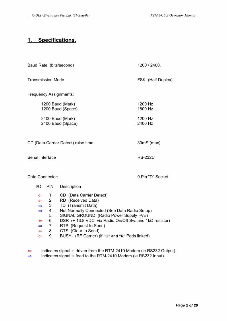
1. Specifications.
Baud Rate (bits/second) 1200 / 2400.
Transmission Mode FSK (Half Duplex)
Frequency Assignments:
1200 Baud (Mark) 1200 Hz1200 Baud (Space) 1800 Hz
2400 Baud (Mark) 1200 Hz2400 Baud (Space) 2400 Hz
CD (Data Carrier Detect) raise time. 30mS (max)
Serial Interface RS-232C
Data Connector: 9 Pin "D" Socket
I/O PIN Description
⇐ 1 CD (Data Carrier Detect)⇐ 2 RD (Received Data)⇒ 3 TD (Transmit Data)⇒ 4 Not Normally Connected (See Data Radio Setup)
5 SIGNAL GROUND (Radio Power Supply -VE)⇐ 6 DSR (+ 13.8 VDC via Radio On/Off Sw. and 1kΩ resistor)⇒ 7 RTS (Request to Send)⇐ 8 CTS (Clear to Send)⇐ 9 BUSY- (RF Carrier) (if "G" and "R" Pads linked)
⇐ Indicates signal is driven from the RTM-2410 Modem (ie RS232 Output).⇒ Indicates signal is feed to the RTM-2410 Modem (ie RS232 Input).

© OED Electronics Pty. Ltd. (21-Aug-01) RTM-2410 B Operation Manual
Page 3 of 29
2. Operation.
The RTM-2410 Modem Board is a semi-intelligent 2400 baud modem.
All Data Protocol, Error Detection and Error Recovery must be performed by the Customer'sData Equipment (DTE) connected to the modem.
The RTM-2410 modem will control all timing and radio functions to ensure the Radio Link isoperational before transmitting data. This eliminates the need for timing loops etc. in thecustomer's communication software normally required for Radio Modem operation.
The modem can be made to change channel on the radio by sending an AT command to themodem.
It also has a separate Voice Channel and Data Channel. At power on, the Data Channel will beselected. The modem will select the Voice Channel when the Microphone PTT button ispressed, then re-select the Data channel when it is released. The Channels can be set with anAT Command.
The RTM-2410 modem monitors the radio's temperature and drops CTS (Clear To Send) tostop the customer's data if the radio is too hot. The modem will continue to receive and voicetransmission (Mic PTT) remains operational. The temperature threshold can be set with an ATCommand.
The Radio's Temperature and RSSI (Received Signal Strength Indicator) value can also beread from the modem using an AT Command.
Three Modes are possible with the RTM-2410 modem. The MODE solder pads on the solderside of the modem PCB are either left open or linked with a piece of wire.
Data received from a transmitting radio is only valid when CD (Carrier Detect) is asserted.
2.1 RTM-1200 Compatible Mode. (Mode Pads Linked)
The RTM-2410 can be made compatible with the RTM-1200 modems.
The Mode pads must be linked and the modem Baud Rate (Dip Switch 2) must be set to 2400.
The RTM-2410 operates in Mode 0 (see 2.3 Mode 0 - Hardware Handshake Mode. (ModePads Linked)) however the data baud rate must be 1200 and the AT Commands must be sentat 2400,8,N,1.
No change to the RTM-1200 is necessary.
WARNING !!!
THIS MODEM BOARD IS NOT TO BE USED IN RADIOS THAT MAY BE REQUIRED
FOR EMERGENCY VOICE COMMUNICATION. THIS IS BECAUSE THE MODEM MAY
LOCK OUT VOICE COMMUNICATION WHEN IT IS SENDING DATA.

© OED Electronics Pty. Ltd. (21-Aug-01) RTM-2410 B Operation Manual
Page 4 of 29
2.2 Mode 1 - Three Wire Mode. (Mode Pads Open)
This Mode only operates with 8 Bit, No Parity, 1 Stop Bit format and at the selected BaudRate (see Baud Rate Select. (Dip Switch 2) Page 8).
When the RTM-2410 is set in Mode 1, the modem will initiate a transmission when data is sentto the modem from the customer's equipment. RTS (Request To Send) must be asserted by thecustomer's equipment for data to be recognised, however RTS can remain asserted at all times.The transmission will stop when the data buffer is empty.
No data should be sent to the modem until CTS (Clear To Send) is asserted by the modem.
2.2.1 Mode 1 Normal Operation. With RTS asserted by the customer's equipment and CTS asserted by the modem, data can besent to the modem and is stored in a 270 Byte buffer. If the buffer becomes full, the modem willdrop CTS to stop customer's data. It re-asserts CTS when the buffer empties. The modem keys the radio when the buffer contains customer data. The modem waits for the TX Stabilisation Time to expire. This allows the transmitter toachieve full power and the receiving radio to open the RF Mute and assert the CD (CarrierDetect). The modem then starts sending the Data to the receiving radio. Data can be sent to the modem while waiting for the TX Stabilise Time to expire. CTS isdropped if the buffer becomes full and asserted when it empties. The modem continues to transmit until the internal buffer is empty. Any AT Commands will beignored until the buffer is emptied (max 270 bytes). NOTE !!! An Idle (1 Byte of no activity on TD pin), will be treated as the end of the data packet. CTS will be dropped until the packet has been transmitted.
2.2.2 Mode 1 with Anti Collision ON. Collision Random Delay is added before Repeater Delay (if ON) and TX Stabilise Delay. When data is sent to the modem, the modem looks for a TX Collision (Busy + CD) caused byother radios transmitting at the same time. If there is a collision detected, the modem loads aRandom Delay Time (limits set by S53 and S54) and waits for this time to expire. At the end of the time the modem again tests for a TX Collision. If the collision is still present itrepeats the above Random Delay until the collision clears. If there was initially no collision or the collision has now cleared, the modem continues withnormal operation (see 2.2.1 Mode 1 Normal Operation.). Data can be sent to the modem while waiting for the Collision to clear. CTS is dropped if thebuffer becomes full. Continued….

© OED Electronics Pty. Ltd. (21-Aug-01) RTM-2410 B Operation Manual
Page 5 of 29
2.2.3 Mode 1 with Repeater Delay ON.
Repeater Delay is added after Collision Random Delay (if ON) and before TX Stabilise Delay. When RTS is seen, the modem looks for BUSY (RF Carrier). If BUSY is not active (channel notbusy) then the modem assumes the Repeater is not keyed. It keys the radio and waits for theRepeater Delay Time (S52) to expire before continuing with normal operation (see 2.2.1 Mode 1Normal Operation.). This allows the repeater to key up before sending data. If BUSY is active, then the repeater is assumed to be keyed and the modem does not wait forRepeater Delay Time. Repeater Delay Time is set by S52.
Data can be sent to the modem while waiting for the Delay to expire. CTS is dropped if thebuffer becomes full.
2.3 Mode 0 - Hardware Handshake Mode. (Mode Pads Linked)
This mode can operate with any Parity, Stop Bit or Data Bit format. However AT Commandsmust be sent with 8 Bit, No Parity, 1 Stop Bit format.
The modem can accept 1200 or 2400 Baud Data when set to 2400 Baud (see Baud RateSelect. (Dip Switch 2) Page 8).It can only accept 1200 Baud Data if set to 1200 Baud.
When the RTM-2410 is set in Mode 0, the modem will initiate a transmission when RTS(Request To Send) is asserted by the customers equipment. The transmission will stop whenRTS is dropped.
Data should not to be sent to the Modem when CTS is not active.
2.3.1 Mode 0 Normal Operation. When RTS is seen, the modem keys the radio to start transmission. CTS (Clear To Send) isasserted by the modem to indicate the customers equipment can start sending the Data. Theincoming data is stored in a buffer in the modem. The modem waits for the TX Stabilisation Time to expire. This allows the transmitter toachieve full power and the receiving radio to open the RF Mute and assert the CD (CarrierDetect). The modem then starts sending the Data to the receiving radio. When RTS is dropped by the customers equipment, the modem drops CTS but continues toreceive the next n Bytes (as specified by S51). This is to overcome double buffering in UARTs. The modem continues to transmit until the internal buffer is empty. Any AT Commands or re-asserting RTS will be ignored until the buffer is emptied (max 260 bytes), plus 20mS. Continued….

© OED Electronics Pty. Ltd. (21-Aug-01) RTM-2410 B Operation Manual
Page 6 of 29
2.3.2 Mode 0 with Anti Collision ON. Collision Random Delay is added before Repeater Delay (if ON) and TX Stabilise Delay. When RTS is seen, the modem looks for a TX Collision (Busy + CD) caused by other radiostransmitting at the same time. If there is a collision detected, the modem loads a Random DelayTime (limits set by S53 and S54) and waits for this time to expire. At the end of the time the modem again tests for a TX Collision. If the collision is still present itrepeats the above Random Delay until the collision clears. If there was initially no collision or the collision has now cleared, the modem continues withnormal operation (see 2.3.1 Mode 0 Normal Operation.). CTS is not asserted until the collision has cleared.
2.3.3 Mode 0 with Repeater Delay ON. Repeater Delay is added after Collision Random Delay (if ON) and before TX Stabilise Delay. When RTS is seen, the modem looks for BUSY (RF Carrier). If BUSY is not active (channel notbusy) then the modem assumes the Repeater is not keyed. It waits for the Repeater Delay Time(S52) to expire before continuing with normal operation (see 2.3.1 Mode 0 Normal Operation.).This allows the repeater to key up before sending data. CTS is not asserted until this delay has expired. If BUSY is active then the repeater is assumed to be keyed and the modem does not wait forRepeater Delay Time. The Repeater Delay Time is set by S52.
© OED Electronics Pty. Ltd. (21-Aug-01) RTM-2410 B Operation Manual
Page 7 of 29
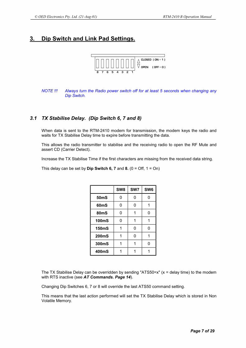
3. Dip Switch and Link Pad Settings.
9 8 7 6 5 4 3 2
DMPTFE!!)!PO!>!2!*
PQFO!!!!!)!PGG!>!1!*
NOTE !!! Always turn the Radio power switch off for at least 5 seconds when changing anyDip Switch.
3.1 TX Stabilise Delay. (Dip Switch 6, 7 and 8)
When data is sent to the RTM-2410 modem for transmission, the modem keys the radio andwaits for TX Stabilise Delay time to expire before transmitting the data.
This allows the radio transmitter to stabilise and the receiving radio to open the RF Mute andassert CD (Carrier Detect).
Increase the TX Stabilise Time if the first characters are missing from the received data string.
This delay can be set by Dip Switch 6, 7 and 8. (0 = Off, 1 = On)
SW8 SW7 SW6
50mS 0 0 0
60mS 0 0 1
80mS 0 1 0
100mS 0 1 1
150mS 1 0 0
200mS 1 0 1
300mS 1 1 0
400mS 1 1 1
The TX Stabilise Delay can be overridden by sending "ATS50=x" (x = delay time) to the modemwith RTS inactive (see AT Commands. Page 14).
Changing Dip Switches 6, 7 or 8 will override the last ATS50 command setting.
This means that the last action performed will set the TX Stabilise Delay which is stored in NonVolatile Memory.

© OED Electronics Pty. Ltd. (21-Aug-01) RTM-2410 B Operation Manual
Page 8 of 29
3.2 Baud Rate Select. (Dip Switch 2)
Dip Switch 2 OFF = 2400 BaudDip Switch 2 ON = 1200 Baud
The Baud rate Dip Switch can be overridden by sending "ATS57=1200" or "ATS57=2400" to themodem with RTS inactive (see AT Commands. Page 14).
Changing the Dip Switch will override the last AT command setting.
This means that the last action performed will set the Baud Rate which is stored in Non VolatileMemory.
3.3 AT Commands ON / OFF. (Dip Switch 3)
Dip Switch 3 OFF = AT Commands are ignored.Dip Switch 3 ON = AT Commands will be executed.
The AT Commands are similar to the Hayes™ Command Set. The Commands will only berecognised and executed if Dip Switch 3 is ON and RTS (Request To Send) is not assertedwhen the command is sent to the RTM-2410 modem.
Set this switch to OFF after initialising the modem at installation time, unless you intend to allowthe customer's equipment to use AT commands to alter the Modem settings.
Turning the switch off will ensure the initialised S Registers will not be accidentally altered.
NOTE !!! When the modem is in Mode 1 (MODE Pads open), RTS (Pin 7) must beconnected to DSR (Pin 6) when Dip Switch 3 is turned off.
3.4 Anti Collision ON / OFF. (Dip Switch 4)
Dip Switch 4 OFF = Anti Collision Disabled.Dip Switch 4 ON = Anti Collision Enabled.
The Anti Collision system in the modem is designed to delay transmission of data if two or moremodems try to transmit data at the same time. This is achieved by waiting for a Random DelayTime when a collision with another modem is detected. A collision is detected when CD (CarrierDetect) is active. At the end of the delay time the collision (CD) is again tested for.
If the collision is still present (ie the other modem is still transmitting) then a new Random Delaywill be started and the process repeated until the channel is free.
If there is no collision after the delay, the modem will start the TX sequence which will includethe Repeater Delay, if enabled (Dip Switch 1), and the TX Stabilise Delay. (Dip Switch 6, 7and 8)
A Random Delay is used instead of a fixed delay to separate the two modems that havecollided. In other words the modem with the shortest random time will transmit first, the othermodem will then detect a collision and restart its delay time.
The Random Timer has minimum and maximum time limits which can be set by using the ATcommands (see AT Commands. Page 14).
If Dip Switch 4 is Off, the collisions are ignored and the modem will transmit regardless.

© OED Electronics Pty. Ltd. (21-Aug-01) RTM-2410 B Operation Manual
Page 9 of 29
3.5 Voice Compatibility. (Dip Switch 5)
Dip Switch 5 OFF = Radio System used for Data Only.Dip Switch 5 ON = Radio System used for Voice and Data.
Set this Dip Switch to OFF if the Radio System does not have any Voice Communication andwill be used for Data Telemetry only. When OFF, voice will interfere with data and vice versa.
If the Radio System has Voice and Data traffic (eg Taxi's, Police, etc), then the data and voiceneed to be coordinated to minimise interference with each other and to stop data noise beingheard by the radio operators.
When this Dip Switch is turned On, the RTM-2410 modem will monitor the received audio. If thecustomer's data equipment wishes to transmit data, the modem will wait until the voicecommunication has finished before transmitting data (if in Mode 0, CTS will be held off).
If the operator presses the Mic PTT button while the modem is receiving data (CD active) ortransmitting data, then the modem will hold off the Mic TX until the data transfer has finished.
For this feature to work properly one of following methods needs to be adopted.
1. Small fleets with low data use on a leased channel:
Use this method if you lease a channel from the local repeater company and have a smallfleet that uses voice for primary communications. An example is a company that wishes tohave a lap top in their vehicles to generate invoices and do stock queries with the officecomputer but still uses voice to issue job information.
Link the pads marked "H" on the solder side of the RTM-2410. This will enable the modem tomute the radio when data is received. Occasionally there will be a short (60mS) tone at thebeginning of a data transfer due to the modems detection circuit. The tone is not annoying tothe vehicle drivers if the data transfer is kept to a minimum AND the data traffic is notfrequent (eg. Two data packets every minute). If the data transfer becomes annoying thenuse one of the other two Voice Compatibility methods below.
This is the cheapest method as no other changes need to be made however ALL FLEETVEHICLE RADIOS MUST BE FITTED WITH A MODEM TO MUTE THE DATA NOISE.
NOTE !!! Data Channel (S56) and Voice Channel (S57) registers MUST be programmedwith the same channel number.Any channel change must be done manually with the radio, not the AT Command.Also the Data CTCSS (S64) and Voice CTCSS (S65) regs. must be programmedwith "0"
2. High data use on a single leased or private channel (no channel changes):
This method will require the use of another CTCSS tone on the channel (frequency) that ispresently being used. CTCSS (Continuous Tone Controlled Sub-audible Signalling) isprogrammed into the radio and is a tone (< 300Hz) that is transmitted by the radio. Therepeater will transmit the same tone and only radios programmed with the tone will open themute and allow the audio to be heard. Every company using the channel has their ownindividual tone.
The modem makes use of two CTCSS tones, one for voice (existing tone) and another tonefor data. The second tone must be allocated to your company and could incur another fullrental fee from the repeater provider.
Continued …

© OED Electronics Pty. Ltd. (21-Aug-01) RTM-2410 B Operation Manual
Page 10 of 29
The radios will be programmed to recognise the Voice tone. When the modem transmitsdata the second tone is transmitted which will not be recognised by the radios and the audiowill be muted. The modem receive circuitry is connected to the radio before the CTCSSmuting so it will always receive data.
The modem sends different CTCSS tones by changing channel on the radio. The radio musthave two channels programmed into it with the same frequencies but different tones.
The Data Channel (S55) and Voice Channel (S56) in the modem, must be set up as per theexample in (S56) Voice Channel (see S Registers. Page 17)
NOTE !!! This method will only work where the customer has only one channel.
3. High data use on multiple leased or private channels:
This method uses the same principle as in Method 2 above.
The difference with this method is the modem will generate the transmit CTCSS tonesinstead of changing channel in the radio to change the tones. This requires a capacitor to beremoved from the radio control PCB and a wire soldered to the PCB.
This method will allow the operator to change channel on the radio if they use more than onechannel or have multiple repeaters over a large geographical area. This method is also moresuitable to customers who own their own repeater system.
The repeaters will need to have the capability of keying up when either Voice or Data CTCSStone is received. Each tone should be regenerated by the Repeater.
Tone regeneration MUST stop immediately when the transmitting vehicle radio stopstransmitting the tone.
The repeater should stay keyed up for at least 2 seconds after the last radio has stoppedtransmitting. There will be no tones transmitted from the repeaters during this tail period.
Install the CTCSS option loom into S1 of the RTM-2410 modem board. Locate and removeC604 4.7µF capacitor from the radio control board and solder the "C" wire to the + padwhere the capacitor was.
S13S14
S14 S13
"RTM-2410 B" PCB
T 2010/15 CONTROL PCB
DIP
POWERPLUG
"D" CONNECTORAND
AERIAL PLUG
S1ADJUST
DEVIATION
TX
TX CTCSS SIGNAL
0 1 C
S15
S15
C 604 4.7uFREMOVE
H

© OED Electronics Pty. Ltd. (21-Aug-01) RTM-2410 B Operation Manual
Page 11 of 29
Program ALL used channels in the Tait 2010/15 radio for the Voice CTCSS (RX only required).
Program S64 for the Data CTCSS tone # and program S65 for the Voice CTCSS tone # in theRTM-2410 modem (see S Registers. Page 17). Program the Number # into the S RegisterNOT the tone itself. (ie for 100Hz tone then S64=12). See table below.
It is recommended to use CTCSS tones above 150Hz as this will help to speed up unmutingand repeater keying.
# CTCSS Tone0 Off1 67.0 Hz2 71.9 Hz3 74.4 Hz4 77.0 Hz5 79.7 Hz6 82.5 Hz7 85.4 Hz8 88.5 Hz9 91.5 Hz10 94.8 Hz11 97.4 Hz12 100.0 Hz13 103.5 Hz14 107.2 Hz15 110.9 Hz16 114.8 Hz17 118.8 Hz18 123.0 Hz19 127.3 Hz20 131.8 Hz21 136.5 Hz22 141.3 Hz23 146.2 Hz24 151.4 Hz25 156.7 Hz26 162.2 Hz27 167.9 Hz28 173.8 Hz29 179.9 Hz30 186.2 Hz31 192.8 Hz32 203.5 Hz33 210.7 Hz34 218.1 Hz35 225.7 Hz36 233.6 Hz37 241.8 Hz38 250.3 Hz

© OED Electronics Pty. Ltd. (21-Aug-01) RTM-2410 B Operation Manual
Page 12 of 29
3.6 Repeater Delay ON / OFF. (Dip Switch 1)
Dip Switch 1 OFF = Repeater Delay Disabled.Dip Switch 1 ON = Repeater Delay Enabled.
The Repeater Delay system in the modem is designed to delay data transmission until theRepeater has keyed up. When the modem is ready to transmit it looks for BUSY (RF Carrier). If BUSY is not active(channel not busy) then the modem assumes the Repeater is not keyed. It keys the transmitterand waits for the Repeater Delay Time (set by S52) to expire. This allows the repeater to key up before sending data. If BUSY is active then the repeater is assumed to be keyed and the modem does not wait forRepeater Delay Time.
3.7 Link Pads (solder side of RTM-2410)
The Link Pads are situated on the solder side of the RTM-2410 Modem PCB.(see below).The pads can be linked with a piece of wire or solder across them.Do Not connect links that are not mentioned below (grey pads = do not use).
WARNING!!! Never connect all pads on the three pad groups. Connect the centrepad with only one of the outside pads.
BUSY Signal.
If pads G and R are linked, the BUSY- (RF Carrier) signal from the radio will appear on Pin 9 ofthe "D" connector as an RS232 level signal.
NOTE !!! Do Not connect Link Pads "G and R" when the modem is connected to a PersonalComputer as the BUSY (RF Carrier) can cause RI (Ring Indicator) interrupts in thePC every time the channel becomes busy.
S13S14
S14 S13
"RTM-2410 B" PCB
RADIO CONTROL PCB
DIP
"D" CONNECTORAND
AERIAL PLUG
B
Mode Pads
S15
S15E
A
C
G
FH
R
P
DK

© OED Electronics Pty. Ltd. (21-Aug-01) RTM-2410 B Operation Manual
Page 13 of 29
3.8 Tait Data Radio Setup
The RTM2410 Modem can be installed in the new Tait Data Radios. The data radios are fittedwith a blank front panel and therefore cannot be programmed through the Microphone socket.There is also no On/Off switch or speaker.
To enable the power on the Data Radio the "P" Link Pads must be shorted. Use a piece of wireto link the "P" pads. Solder the "K" Link Pads to enable the speaker audio.
The Radio can be programmed through the RTM2410 9 Pin "D" connector. Solder "D", "F" and"R" Link Pads.
DO NOT solder "G" Link Pads. Link pad "E" can be left shorted by the PCB track.
Make up a Programming Lead as shown below to program the radio using the Tait PGM2000program via the DB9 connector on the rear of the radio. Do Not use the Tait programming lead.
RADIO PROGRAMMING LEAD
1 5
6 9
SIG GNDSIG GNDSIG GNDSIG GND
TDTDTDTD
RDRDRDRD
5
9 6
DB9 (MALE)DB9 (MALE)DB9 (MALE)DB9 (MALE)TO MODEMTO MODEMTO MODEMTO MODEM
DB9 (FEMALE)DB9 (FEMALE)DB9 (FEMALE)DB9 (FEMALE)TO PC SERIAL PORTTO PC SERIAL PORTTO PC SERIAL PORTTO PC SERIAL PORT
VIEWED FROM SOLDER
SIDE OF CONNECTORS
4 23
WARNING!!! Ensure Pins 4 and 9 are not connected when the RTM2410 modem isconnected in normal use as a modem. DO NOT use a store purchasedserial cable as these have all pins connected. You will need make up acable with all but Pins 4 and 9 connected.
If Pins 4 and 9 are connected, the modem will not be able to changechannel or reset the radio.
S13S14
S14 S13
"RTM-2410 B" PCB
RADIO CONTROL PCB
DIP
"D" CONNECTORAND
AERIAL PLUG
B
Mode Pads
S15
S15E
A
C
G
FH
R
P
DK

© OED Electronics Pty. Ltd. (21-Aug-01) RTM-2410 B Operation Manual
Page 14 of 29
4. AT Commands.
4.1 AT Command Requirements.
AT Commands can be sent to the RTM-2410 modem to change parameters or read informationfrom the modem.
The commands must be sent to the modem with RTS (Request To Send) Not Active. This isdifferent to the standard Hayes™ commands and is a substitute for the Escape SequenceGuard Time and +++ characters, which are not required for the RTM-2410 modem.
ALWAYS allow at least 0.5 seconds of inactivity before sending any commands to the Modem.
The command must be sent at the Baud rate that was last selected by either an AT Commandor by the Dip Switches.
The commands must also be sent with coms set to 8 Data Bits, No Parity, 1 Start and 1 Stopbit. The echoed commands and messages will be in this format.
Lastly, Dip Switch 3 must be set to ON for the AT Commands to be recognised.
4.2 AT Command String Format.
ALWAYS allow at least 0.5 seconds of inactivity before sending any commands to the Modem.
The AT Commands are all ASCII characters and can have several commands in a string (30characters max.). The string must have AT before the commands and must end with a CR(Carriage Return) character. A CR is commonly a ^M in most communications programs.
Upon receiving a CR with RTS not active, the modem will search the received string until AT isseen. It then executes any valid command/s in the received string until it comes across the CR(Carriage Return).
If ANY command has invalid values in it (eg. S Registers that don't exist) the modem will returnan ASCII message: ERROR. The modem will still execute the valid commands in the string.
If ALL commands were valid then OK is returned.
Command strings can have any or no characters between commands.Eg. +++ AT S50=3S51=20 S53=1200S60? ^M
It is advisable to start the command string with +++ but this is not essential. No delay isrequired after the +++.
The command buffer in the RTM-2410 is cleared when RTS is asserted and all previously sentcommand bytes are lost. All commands are ignored if the modem is still transmitting data.
WAIT FOR 2 SECONDS AFTER A POWER UP BEFORE SENDINGANY COMMANDS OR INITIALISATION STRINGS TO THE MODEM.

© OED Electronics Pty. Ltd. (21-Aug-01) RTM-2410 B Operation Manual
Page 15 of 29
4.3 AT Command List.
AT Commands must be sent when RTS (Request To Send) is not active.ALWAYS allow at least 500mS of inactivity before sending any commands to the Modem.
Snn=xxxx Writes the value xxxx into the S Register nn.
Use this command to enter a new value into any of the S Registers.nn must be a valid S Register. xxxx must be ASCII characters 0-9.xxxx must be within the range for the S Register.Any incorrect command will return ERROR.
Example. ATS50=250 ^M Stores 250 into S Register #50
Snn? Returns the value in the S Register nn.
Use this command to read the value from any S Register. The returnedformat will be four ASCII digits (0-9).
Example. ATS50? ^M requests the contents of S Register #500250 is returned if S Register #50 contains 250
I0 Returns the ID and Version of the Modem. (eg RTM2410 V1.3).
Use this command to determine what features this modem has by readingthe Model and Version number.
Example. ATI0 ^M requests the Model and VersionRTM2410 V1.3 is returned for this modem
I1 Returns the state of the radio Busy signal. (ie. RF Carrier Detect).
Use this command to determine the state of the Busy signal in the radio.When this command is sent to the modem, a 1 (ASCII) will be returnedwhen there is an RF Carrier present (ie Busy active) and a 0 will be returnedwhen there is no RF Carrier. This is useful when detecting if repeaters arekeyed or not.
Example. ATI1 ^M requests the Busy status1 Busy Active (RF Carrier)0 Busy Not Active (No RF Carrier)
Continued …
© OED Electronics Pty. Ltd. (21-Aug-01) RTM-2410 B Operation Manual
Page 16 of 29
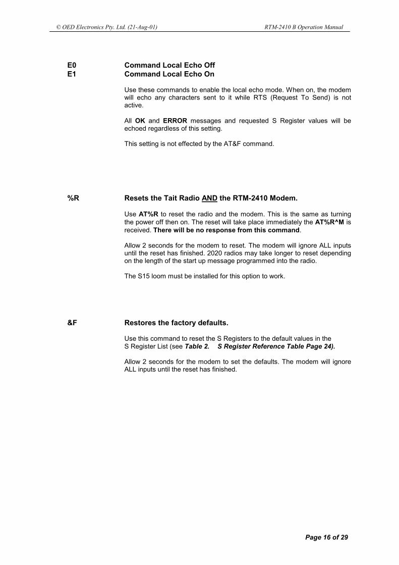
E0 Command Local Echo OffE1 Command Local Echo On
Use these commands to enable the local echo mode. When on, the modemwill echo any characters sent to it while RTS (Request To Send) is notactive.
All OK and ERROR messages and requested S Register values will beechoed regardless of this setting.
This setting is not effected by the AT&F command.
%R Resets the Tait Radio AND the RTM-2410 Modem.
Use AT%R to reset the radio and the modem. This is the same as turningthe power off then on. The reset will take place immediately the AT%R^M isreceived. There will be no response from this command.
Allow 2 seconds for the modem to reset. The modem will ignore ALL inputsuntil the reset has finished. 2020 radios may take longer to reset dependingon the length of the start up message programmed into the radio.
The S15 loom must be installed for this option to work.
&F Restores the factory defaults.
Use this command to reset the S Registers to the default values in theS Register List (see Table 2. S Register Reference Table Page 24).
Allow 2 seconds for the modem to set the defaults. The modem will ignoreALL inputs until the reset has finished.

© OED Electronics Pty. Ltd. (21-Aug-01) RTM-2410 B Operation Manual
Page 17 of 29
4.4 S Registers.
S Registers contain the modem's operating parameters. They are stored in Non Volatilememory and are not effected by power down. The last written S Register value will remaincurrent until a new value replaces it, or the AT&F command restores all the default values.
The S Registers are all Four (ASCII) Digits long. Sending more than four digits to an S Registerwill truncate all digits after the 4th digit.
For example a command to set S-Register #50 to a value of 80mS can be ATS50=80 orATS50=0080. Issuing ATS50=0000080 will result in a value of 0000 being stored in the S Reg.
Most S Registers have a minimum and maximum range. If a command is sent that tries to setan S Register outside the range, the S Register will retain its old value and the ERRORmessage will be returned.
The S Registers also have default factory values which will be set when you receive the modem.The values can be reset to these defaults using the AT&F command. Defaults listed with DipSw will be set according to the Dip Switch settings. (See 3 Dip Switch and Link Pad Settings.Page 7)
To set S Register #54 to 330, send +++ ATS54=330 ^MOK will be echoed back.
To read the contents of S Register #54, send +++ ATS54? ^M0330 will be echoed back followed by OK.
The +++ is optional but recommended.
(S50) TX Stabilisation Delay Time.
When data is sent to the RTM-2410 modem for transmission, the modem keys the radio andwaits for TX Stabilise Delay Time (mS) to expire before transmitting the data.
This allows the radio transmitter to stabilise and the receiving radio to open the RF mute andassert CD (Carrier Detect).
Increase the TX Stabilise Time if the first characters are missing from the received datastring.
This delay can also be set by Dip Switch 6, 7 and 8, which will set the default value.
Changing Dip Switches 6, 7 or 8 will override the last ATS50=xxxx command setting.
(S51) Bytes Received after RTS drops (Mode 0 only).
When the modem is in Mode 0 (RTS - TX Mode), the customer's data is sent to the modemwith RTS (Request To Sent) asserted by the customer's computer equipment.
Because most old style UARTs are double buffered, the RTS line is dropped before thecontents of the UART have been sent to the modem at the end of the customers data.
The value in S51 will make the modem continue to receive data for a number of bytes afterRTS is dropped. The bytes are considered to be 10 bit (1 Start, 8 Data, 1 Stop).
Increase this value by 1 byte at a time if the last bytes are missing from the end of a receivedstring.

© OED Electronics Pty. Ltd. (21-Aug-01) RTM-2410 B Operation Manual
Page 18 of 29
(S52) Repeater Delay Time.
Dip Switch 1 must be set to ON for this function to operate.
This function is used on radio systems with repeaters installed to increase the coverage.When a modem is ready to send data, it keys the transmitter. The repeater keys itself whenit detects the RF Carrier from the modem's radio. This then finally opens the mute andasserts CD (Carrier Detect) on the receiving radio.
The time for the transmitting radio and receiving radio to stabilise is already allowed for bythe TX Stabilise Delay Time (S50) however the repeater needs extra time to key up andstabilise.
This extra time can be added using the Repeater Delay Time. The time in S52 is added tothe TX Stabilise Delay Time.
However, repeaters will stay keyed up for a length of time after the transmitting radio stopstransmission. This is because there is usually a reply to the message shortly after.
If the repeater is already keyed when the modem is ready to transmit data, there is no needto add the Repeater Delay Time. The modem monitors BUSY (RF Carrier) and only addsthe Repeater Delay Time if the repeater is not keyed (ie BUSY not active).
(S53) Anti Collision Random Delay Lower Limit.
Refer to Anti Collision ON / OFF. (Dip Switch 4) for more details on this function.
This S Register sets the shortest Random Delay Time possible.
The value in this S Register MUST be LOWER than the value in S Register #54.
(S54) Anti Collision Random Delay Upper Limit.
Refer to Anti Collision ON / OFF. (Dip Switch 4) for more details on this function.
This S Register sets the longest Random Delay Time possible.
The value in this S Register MUST be HIGHER than the value in S Register #53.

© OED Electronics Pty. Ltd. (21-Aug-01) RTM-2410 B Operation Manual
Page 19 of 29
(S55) Data Channel (1 - 24).
This S Register contains the Radio Channel selected when modem data is beingtransmitted. This is also the channel selected for ALL radio reception (Data and Voice)
(S56) Voice Channel (0 - 24). (Set to '0' to inhibit ALL channel changing)
This S Register contains the Radio Channel selected when the Microphone PTT button ispressed. The Data Channel (S55) is re-selected when the Mic PTT is released.
This function is useful if voice and data are being sent on the one channel and the customerwishes the operator to hear only voice traffic without data/voice interference (see VoiceCompatibility. (Dip Switch 5) Page 9).
This can be achieved by programming the radio as per the diagram below.
Send the command string ATS55=1 S56=2 ^M to the RTM-2410 modem.Channel 1 is the Data Channel, Channel 2 is the Voice Channel.
The TX and RX frequency can be different (for repeaters), but the frequency entries in Ch.1MUST be the same as in Ch.2.
The CTCSS frequency can be any valid CTCSS Frequency. Do Not enter a TX CTCSS inCh.1 (Data Channel).
When voice is sent (Mic PTT), the modem selects Channel 2 and sends a CTCSS tone withthe transmission. This opens the Audio Mute on the receiving radio and allows the operatorto hear the voice message.
When Data is sent, Channel 1 is selected and no CTCSS tone is sent. The receiver Audiowill remain muted, but the data will get through to the RTM-2410 modem.
NOTE !!! The S15 ribbon connector or the 3 pin channel select loom (S1) must beinstalled. The Radio must be programmed for BCD Channels Enabled (Options)if S1 is used instead of S15.
© OED Electronics Pty. Ltd. (21-Aug-01) RTM-2410 B Operation Manual
Page 20 of 29
(S57) Baud Rate Select (1200 or 2400).
Send ATS57=1200 ^M to set the baud rate to 1200.Send ATS57=2400 ^M to set the baud rate to 2400.
The Baud Rate can also be set by Dip Switch 2, which will set the default value.
Changing Dip Switch 2 will override the last ATS57=xxxx command setting.
The Baud rate will be changed to the new value AFTER the OK message is returned.
(S58) TX Start Up Temperature (°C).
The modem monitors the radio's temperature and will shutdown transmission if the value inS Register #59 (see next description) is exceeded.
When the radio temperature drops below the value set in this S Register, the transmissionwill again start.
Radio data and voice reception and Microphone PTT are always active. Only TX Data will bestopped.
It is advised to use the Default value as this will ensure the radio will function correctly andstill be protected from over heating.
The value in this S Register MUST be 5°C BELOW the value stored in S Register #59.
(S59) TX Shut Down Temperature (°C).
The modem monitors the radio's temperature and will shutdown transmission if the value inthis S Register is exceeded.
When the radio temperature drops below the value set in S Register #58, the transmissionwill again start.
Reception and Microphone PTT are always active. Only Data will be stopped.
It is advised to use the Default value as this will ensure the radio will function correctly andstill be protected from over heating.
The value in this S Register MUST be 5°C ABOVE the value stored in S Register #58.
(S60) Radio Temperature (°C) (Resolution = 2°C).
The is a READ ONLY Register and returns the present Radio Temperature.
Example. ATS60? ^M requests the Radio Temperature.0036 is returned if the radio is at 36°C

© OED Electronics Pty. Ltd. (21-Aug-01) RTM-2410 B Operation Manual
Page 21 of 29
(S61) Radio RSSI (Received Signal Strength Indicator) Value.
The is a READ ONLY Register and returns the present Radio RSSI (Received SignalStrength Indicator) value. The RSSI value is always an even number (ie. 0, 2, 4 etc).
Example. ATS61? ^M requests the present RSSI value.0126 is returned if the signal strength is 126
See Table 1. RSSI value vs Signal Strength (dBm) . to equate the RSSI value to theReceived Signal Strength.
(S62) Radio RSSI Peak Average Value during last BUSY (RF Carrier) period.
The is a READ ONLY Register and returns the Peak (Maximum) Averaged RSSI valuewhile the BUSY (RF Carrier) was last active. This value is held until the next BUSY isdetected when it will be updated. Power down sets this value to "0000".
The RF Carrier must be present for at least 80mS to obtain an averaged reading and shouldbe present for as long as possible to obtain an accurate RSSI value.
Example. ATS62? ^M requests the last RSSI value.0180 is returned if the peak signal strength was 180
(S63) Radio RSSI Offset Adjustment Value.
The RSSI value changes dramatically between radio models and to a lesser extent betweenindividual radios. The RSSI curves (see Table 1. RSSI value vs Signal Strength(dBm) .) will always be followed however there will be an offset.
That is, at a signal input of -100 dBm one radio might read 94 RSSI, while another identicalradio might read 78 RSSI. The RSSI graph is based around -100 dBm = 100 (RSSI value).
To correct the difference between radios, the value in this S Register can have an offsetcorrection value written to it.
Calculate the offset by writing 50 into S63, then feed an unmodulated rf signal of -100dBm(2.24 µV PD) to the aerial socket, then read the RSSI value from S Reg S61.
Calculate OFFSET using the formula below.
OFFSET = (100 - RSSI) + 50
Write the OFFSET value to S63 (min OFFSET = 0, max OFFSET = 100)
Reading the RSSI (S61) should now show 100.
Example. ATS63=72 ^M writes 72 to the offset.
NOTE !!! The offset value written to S63 is not changed when the AT&F (Modem Reset)command is sent to the modem.

© OED Electronics Pty. Ltd. (21-Aug-01) RTM-2410 B Operation Manual
Page 22 of 29
Table 1. RSSI value vs Signal Strength (dBm) .
The graph show the different radio model RSSI reading variations. These results were obtained afterthe RSSI Offset was written to S Register (S63) to obtain an RSSI reading of 100 at a signal input of -100dBm (2.24 µV PD).
The RSSI value should always follow the curve however design changes made by Tait may alter thecurves below.
No signal will give a reading of between 0 and 20 which will be constantly changing due to noise.
RSSI vs SIGNAL STRENGTH (dBm)
0
50
100
150
200
250
-120 -110 -100 -90 -80 -70
dBm
RSSI
201020202040

© OED Electronics Pty. Ltd. (21-Aug-01) RTM-2410 B Operation Manual
Page 23 of 29
(S64) Data CTCSS Transmit Tone.
This S Register determines the CTCSS Tone transmitted when Data is being sent over theradio. Write the Number # to this register NOT the CTCSS tone frequency.
Example. ATS64 = 12 ^M sets the TX tone to 100 Hz.
See the table below for the corresponding CTCSS Number.See Voice Compatibility. (Dip Switch 5) Page 9 for more information.
(S65) Voice CTCSS Transmit Tone.
This S Register determines the CTCSS Tone transmitted when the microphone PTT ispressed and Voice is being sent over the radio. Write the Number # to this register NOT theCTCSS tone frequency.
Example. ATS65 = 25 ^M sets the TX tone to 156.7 Hz.
See the table below for the corresponding CTCSS Number.See Voice Compatibility. (Dip Switch 5) Page 9 for more information.
# CTCSS Tone0 Off1 67.0 Hz2 71.9 Hz3 74.4 Hz4 77.0 Hz5 79.7 Hz6 82.5 Hz7 85.4 Hz8 88.5 Hz9 91.5 Hz
10 94.8 Hz11 97.4 Hz12 100.0 Hz13 103.5 Hz14 107.2 Hz15 110.9 Hz16 114.8 Hz17 118.8 Hz18 123.0 Hz19 127.3 Hz20 131.8 Hz21 136.5 Hz22 141.3 Hz23 146.2 Hz24 151.4 Hz25 156.7 Hz26 162.2 Hz27 167.9 Hz28 173.8 Hz29 179.9 Hz30 186.2 Hz31 192.8 Hz32 203.5 Hz33 210.7 Hz34 218.1 Hz35 225.7 Hz36 233.6 Hz37 241.8 Hz38 250.3 Hz

© OED Electronics Pty. Ltd. (21-Aug-01) RTM-2410 B Operation Manual
Page 24 of 29
Table 2. S Register Reference Table
Reg Range Default Units Function
50 0 - 500 Dip Sw 0.001secs (mS) TX Stabilise Delay Time51 0 - 9 2 Bytes (10 bits) Bytes Received after RTS drops (Mode 0)52 50 - 5000 200 0.001secs (mS) Repeater Key Up Delay Time53 80 - 400 80 0.001secs (mS) Anti Collision Random Delay Lower Limit54 90 - 500 250 0.001secs (mS) Anti Collision Random Delay Upper Limit55 1 - 24 note 1 1 Channel No. Data Channel56 0 - 24 note 1,2 1 Channel No. Voice Channel57 1200 - 2400 Dip Sw Bits Per Second Baud Rate Select58 0 - 70 65 °Celsius TX Start Up Temperature Threshold59 40 - 99 70 °Celsius TX Shut Down Temperature Threshold60 Read Only °Celsius Radio Temperature61 Read Only 0 - 255 RSSI Present Value62 Read Only 0 - 255 Peak Average RSSI when last BUSY active63 0 - 100 50 (RSSI) RSSI Offset Adjustment value64 0 - 38 0 (Off) CTCSS # Data CTCSS Tone65 0 - 38 0 (Off) CTCSS # Voice CTCSS Tone67 Read Only 0 (Off) ASCII Last Reset Register (diagnostic use only)
Note 1. Only 4 channels (1 - 4) will be available when the modem is installed on older radios.The modem will accept channel numbers up to 24 but this will give undeterminedresults on 2010 radios.
Note 2. To stop the modem setting the radio Channel to 1 at power up set S56 = 0 (VoiceChannel). This will inhibit the Modem from changing Channel at any time. This is usedto allow the radio operator to select the Channel via the radio front panel buttons. Themodem will not change the radio from this channel.

© OED Electronics Pty. Ltd. (21-Aug-01) RTM-2410 B Operation Manual
Page 25 of 29
5. Installation.
The RTM-2410B Modem Board is designed for the Tait T2010, T2015 and "Data" Radios.
1. Disconnect all plugs from the radio and remove it from the cradle. Turn the radio over and undothe four screws on the bottom cover. Remove the top cover from the radio.
2. Undo the three screws securing the Radio Control PCB and fold the board back so thecomponent side is facing upwards.
3. Remove the blanking plug from the "D" connector hole in the back of the radio. This is locatedabove the aerial socket.
4. Locate and carefully remove R513 (PTT 0 Ω link) on the Radio Control Board. This is just belowS14. This must be done to ensure correct operation. See the next page for the T2000 radiocontrol board component locations. The board is viewed from the component side. Newerradios may already have R513 removed.
5. Plug the Channel Change ribbon cable assembly S15 on the RTM-2410 so the folded ribboncovers the RTM-2410 Microprocessor. (note the S15 plastic locating lug orientation.)
If the RTM-2410 Modem is replacing an RTM-2400 Modem in an older T2010/15, then theexisting white channel change plug can be plugged into P1 on the RTM-2410.
6. If the CTCSS option on the Modem is not required skip to step 7.
Remove C604 from the radio control board and solder the CTCSS wire on the 3 pin white plug(optional), (marked "C" on S1 of the RTM-2410 PCB), into the + pad of C604 on the radioboard.
Enable the CTCSS Reverse Tone feature in the Tait radio.
7. Plug the three connecting plugs to S13, S14 and S15 on the radio board. Ensure they areseated properly. Check the other plugs on the Radio Control board and ensure they are alsoseated properly.
8. It is advisable to screw the mounting screws into the chassis before mounting the PCBor alternately use an M3 thread tap. This will establish the threads without damaging thePCB.
Fold both boards back into position. Locate the 9 Pin modem "D" connector into the hole in theback of the radio and ensure both boards are laying flat with no obstructions under the boards.The flat ribbon cables may need to be shaped on the connecting plugs if they are obstructingthe PCB's.
9. Secure the boards in place with ALL three screws provided. When securing the RTM-2410board, align the "D" connector with the holes in the back panel before tightening the screws.Ensure the "D" connector is sitting flat against the back heatsink.
10. If the modem is fitted to Narrow Band equipment where a repeater will be used, the solder padson the RTM-2410 modem need to be changed. Use a sharp blade to carefully cut the shortingtracks on pad "A" and pad "C" then solder pad "B". This changes the TX audio path in the Taitradio.
11. Solder the Mode Pads if Mode 0 is required. Solder any Link Pads for the required options.Solder the "P" Link Pads if the modem is installed in a Data Radio.

© OED Electronics Pty. Ltd. (21-Aug-01) RTM-2410 B Operation Manual
Page 26 of 29
Tait T2010/2015 Control PCB (component side).
Carefully remove R513 with a small soldering iron. D500 can be left in place.

© OED Electronics Pty. Ltd. (21-Aug-01) RTM-2410 B Operation Manual
Page 27 of 29
6. Adjustment.
1. Ensure the Tait radio is programmed for the requirements of the customer. Disable the CTCSSbefore adjusting the modulation.
2. Connect the radio to a 13.8 VDC power source. DO NOT TURN THE POWER ON.
3. Connect a deviation meter and dummy load to the aerial socket.
4. Set the Dip Switches on the RTM-2410 to the customer's requirements.
5. Link Pin 2 to Pin 3 of the "D" connector. Turn the power on to the radio to start the modemtransmitting. (NOTE. Transmission will start 3 Seconds after power on.)
6. Adjust the blue TX pot on the end of the modem board for 3.0 kHz deviation ±±±± 0.1 kHz (WideBand) and 1.5 kHz deviation ±±±± 0.1 kHz (Narrow Band).
7. Set the radio's TX power to 3 watts min. 4 watts max. to avoid overheating the radio.
8. Ensure the TX carrier frequency is no more than ± 400Hz. Adjust the radio's TXO if necessary.
9. Turn the radio off and then on again if it times out. It will beep several times before timing outand halting transmission.
10. Remove the link on Pin 2 and 3 and test all required functions on the modem.
11. If all functions work, installation is now complete. Remove the power and re-assemble thecovers etc. Long screws may be required to secure a plug to the "D" connector.
12. If a repeater is to be used, set it to "Flat Audio Response" (10Hz - 3kHz) and make sure thereare no filters in the TX/RX audio paths (usually the CTCSS jumpers needs to be set but with theCTCSS tone turned off). Connect pin 2-3 on the RTM-2410 on the Tait radio to start ittransmitting, then set the repeater TX deviation to 3.0 kHz deviation (Wide Band) or 1.5 kHzdeviation (Narrow Band).
13. Contact OED Electronics if the modem is used on a narrow band repeater system. The repeaterwill probably require modems to be fitted to regenerate the data.
S13S14
S14 S13
RTM-2410 PCB
T2010/15 CONTROL PCB
DIP 3x MOUNTING SCREWS
POWERPLUG
"D" CONNECTORAND
AERIAL PLUG
S1ADJUST
DEVIATION
TX
TX CTCSS SIGNALCHANNEL
SELECT
BCD
0 1 C
S15
S15

© OED Electronics Pty. Ltd. (21-Aug-01) RTM-2410 B Operation Manual
Page 28 of 29
MODEM "AT" COMMANDPROGRAMMING CABLE.
NOT FOR PROGRAMMING THE RADIO
1 5
6 9
SIG GNDSIG GNDSIG GNDSIG GND
TDTDTDTD
RDRDRDRD
5 1
9 6
DB9 (MALE)DB9 (MALE)DB9 (MALE)DB9 (MALE)TO MODEMTO MODEMTO MODEMTO MODEM
DB9 (FEMALE)DB9 (FEMALE)DB9 (FEMALE)DB9 (FEMALE)TO PC SERIAL PORTTO PC SERIAL PORTTO PC SERIAL PORTTO PC SERIAL PORT
VIEWED FROM SOLDER
SIDE OF CONNECTORS
Make up this lead to connect the RTM2400 modem to a PC serial port. Use a program such asTerminal for Windows to send AT Commands to the modem. (see AT Commands. Page 14).
TRANSMITTER DEVIATION ADJUSTMENT TEST PLUG.
1 5
6 9
DB9 (MALE)DB9 (MALE)DB9 (MALE)DB9 (MALE)
VIEWED FROM SOLDER
SIDE OF CONNECTOR
Make up a DB9 male plug with Pin 2 and Pin 3 linked. Plug this into the RTM2410 connector to enablethe modem to transmit a tone used to adjust the deviation. (See Adjustment. Page 27)

© OED Electronics Pty. Ltd. (21-Aug-01) RTM-2410 B Operation Manual
Page 29 of 29
MODEM DB9 to DB25 CONNECTION DIAGRAM.
1 13
14 25
1 5
6 9
DSRDSRDSRDSR
RTSRTSRTSRTS
CTSCTSCTSCTS
SIG GNDSIG GNDSIG GNDSIG GND
TDTDTDTD
RDRDRDRD
CDCDCDCD
RTM-2410 DB9 Connector DB25 Connector
PIN PIN 1 -------------- CD (Modem Carrier Detect) ------------ 8 2 -------------- RD (Received Data) ---------------------- 3 3 -------------- TD (Transmit Data) ---------------------- 2 5 -------------- SIGNAL GROUND ------------------------ 7 6 -------------- DSR (Data Set Ready) ------------------ 6 7 -------------- RTS (Request to Send) ----------------- 4 8 -------------- CTS (Clear to Send) --------------------- 5
This is the cable wiring for connection to a DB25 connector on Data Terminal Equipment.
If the DTE has a DB9 connector, a standard DB9 to DB9 cable can be used. These can beobtained from most electronic retail shops or computer suppliers.
DB9 to DB25 cables are also available from the above shops.
WARNING!!! If a pre-made cable is purchased, DO NOT Link the "D, G, F and R" Pads on theRTM-2410 Modem board, unless Busy is required on the RI Pin (Ring Indicator).
DO NOT use a Null Modem cable or adaptor.