Embed Size (px)
Citation preview
Manual Supplement00809-0600-2410, Rev AA2017
Rosemount™ 2410 Tank Hub
Tokyo Keiso emulation instruction
Introduction . . . . . . . . . . . . . . . . . . . . . . . . . . . . . . . . . . . . . . . . . . . . . . . . . . . . . . . . . . . . . . . . . . . . . . . . . page 1Electrical installation . . . . . . . . . . . . . . . . . . . . . . . . . . . . . . . . . . . . . . . . . . . . . . . . . . . . . . . . . . . . . . . . . . page 6Configuration . . . . . . . . . . . . . . . . . . . . . . . . . . . . . . . . . . . . . . . . . . . . . . . . . . . . . . . . . . . . . . . . . . . . . . . . page 7Troubleshooting . . . . . . . . . . . . . . . . . . . . . . . . . . . . . . . . . . . . . . . . . . . . . . . . . . . . . . . . . . . . . . . . . . . . . . page 14Optional configuration and settings . . . . . . . . . . . . . . . . . . . . . . . . . . . . . . . . . . . . . . . . . . . . . . . . . . . . . page 15
1.0 Introduction
The purpose of this document is to provide guidelines on how to change from other manufacturer’s devices to Rosemount equipment by exchanging gauges. When a gauge is replaced with a Rosemount gauge, it is necessary to configure the Rosemount 2410 Tank Hub for emulation.
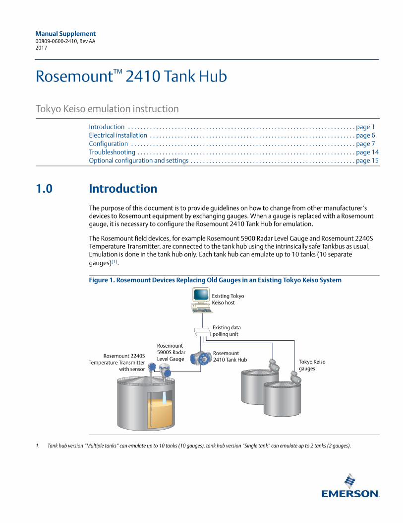
The Rosemount field devices, for example Rosemount 5900 Radar Level Gauge and Rosemount 2240S Temperature Transmitter, are connected to the tank hub using the intrinsically safe Tankbus as usual. Emulation is done in the tank hub only. Each tank hub can emulate up to 10 tanks (10 separate gauges)(1).
Figure 1. Rosemount Devices Replacing Old Gauges in an Existing Tokyo Keiso System
1. Tank hub version “Multiple tanks” can emulate up to 10 tanks (10 gauges), tank hub version “Single tank” can emulate up to 2 tanks (2 gauges).
Existing data polling unit
Existing Tokyo Keiso host
Tokyo Keiso gauges
Rosemount 2410 Tank Hub
Rosemount 2240STemperature Transmitter
with sensor
Rosemount 5900S Radar Level Gauge
Manual Supplement00809-0600-2410, Rev AA
Rosemount 2410 Tank Hub2017
1.1 Emulation capabilities
Emulation enables the ability to replace old devices in another vendor’s existing tank gauging system, with Rosemount devices. The Rosemount device will act just like the replaced gauge, using the other vendor’s protocol to communicate.
By using the other vendor’s field and control room communication protocol together with modern Rosemount tank gauging devices, the legacy system is modernized step-by-step. The legacy system can be upgraded while tanks are in operation and existing wiring can be re-used.
The tank hub can emulate replaced devices, acting as a slave.
Tank hub acting as slave
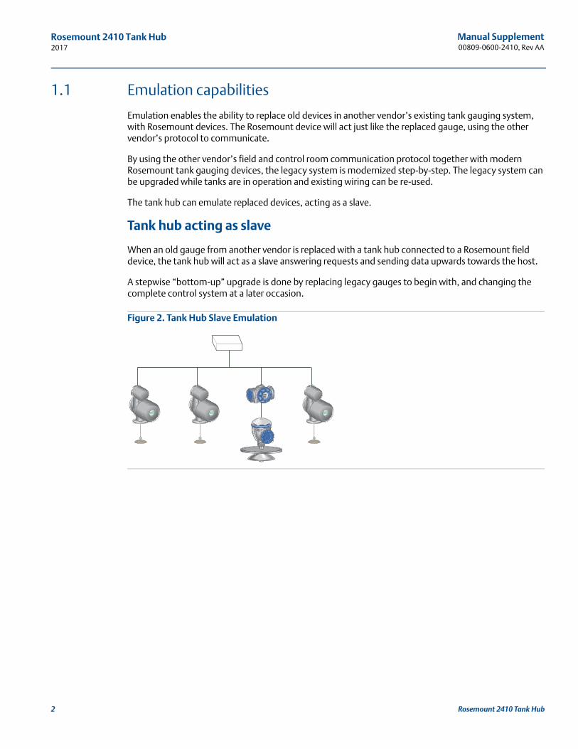
When an old gauge from another vendor is replaced with a tank hub connected to a Rosemount field device, the tank hub will act as a slave answering requests and sending data upwards towards the host.
A stepwise “bottom-up” upgrade is done by replacing legacy gauges to begin with, and changing the complete control system at a later occasion.
Figure 2. Tank Hub Slave Emulation
2 Rosemount 2410 Tank Hub
Manual Supplement 00809-0600-2410, Rev AA
Rosemount 2410 Tank Hub2017
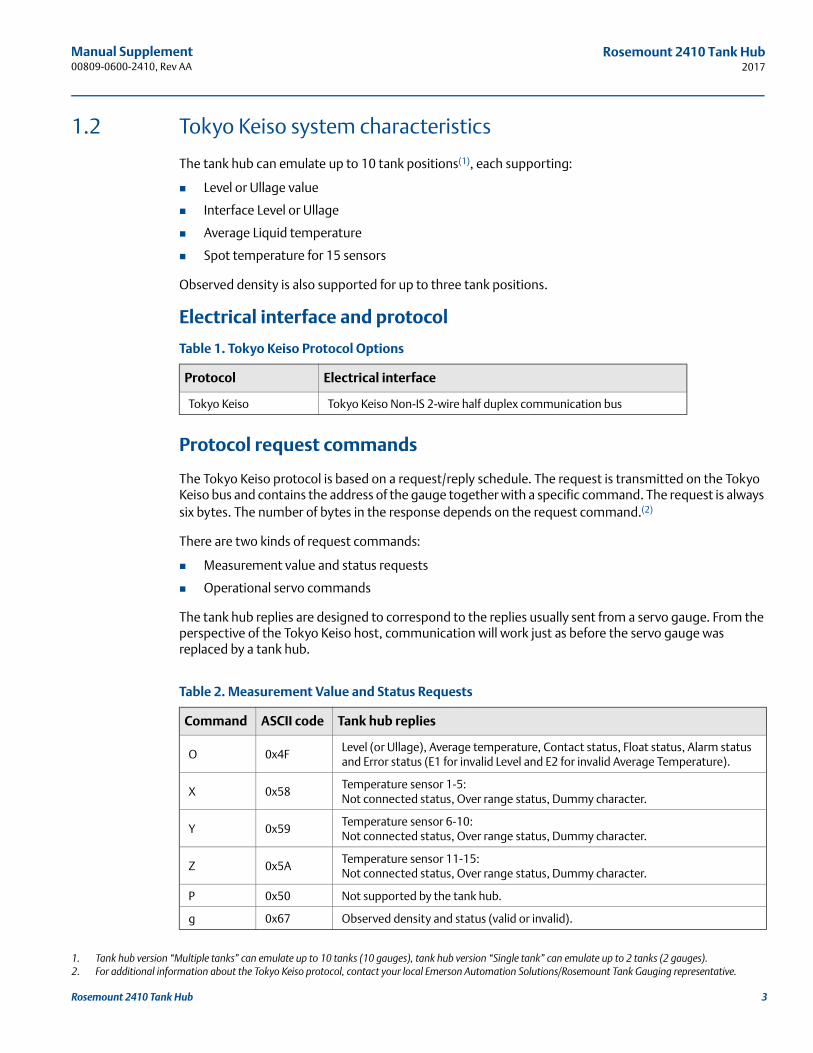
1.2 Tokyo Keiso system characteristics
The tank hub can emulate up to 10 tank positions(1), each supporting:
Level or Ullage value
Interface Level or Ullage
Average Liquid temperature
Spot temperature for 15 sensors
Observed density is also supported for up to three tank positions.
Electrical interface and protocol
Table 1. Tokyo Keiso Protocol Options
Protocol request commands
The Tokyo Keiso protocol is based on a request/reply schedule. The request is transmitted on the Tokyo Keiso bus and contains the address of the gauge together with a specific command. The request is always six bytes. The number of bytes in the response depends on the request command.(2)
There are two kinds of request commands:
Measurement value and status requests
Operational servo commands
The tank hub replies are designed to correspond to the replies usually sent from a servo gauge. From the perspective of the Tokyo Keiso host, communication will work just as before the servo gauge was replaced by a tank hub.
Table 2. Measurement Value and Status Requests
1. Tank hub version “Multiple tanks” can emulate up to 10 tanks (10 gauges), tank hub version “Single tank” can emulate up to 2 tanks (2 gauges).
Protocol Electrical interface
Tokyo Keiso Tokyo Keiso Non-IS 2-wire half duplex communication bus
2. For additional information about the Tokyo Keiso protocol, contact your local Emerson Automation Solutions/Rosemount Tank Gauging representative.
Command ASCII code Tank hub replies
O 0x4FLevel (or Ullage), Average temperature, Contact status, Float status, Alarm status and Error status (E1 for invalid Level and E2 for invalid Average Temperature).
X 0x58Temperature sensor 1-5:Not connected status, Over range status, Dummy character.
Y 0x59Temperature sensor 6-10:Not connected status, Over range status, Dummy character.
Z 0x5ATemperature sensor 11-15:Not connected status, Over range status, Dummy character.
P 0x50 Not supported by the tank hub.
g 0x67 Observed density and status (valid or invalid).
3Rosemount 2410 Tank Hub
Manual Supplement00809-0600-2410, Rev AA
Rosemount 2410 Tank Hub2017
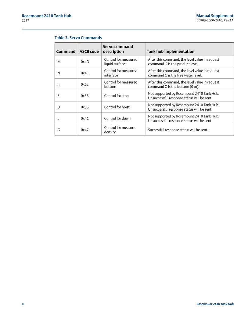
Table 3. Servo Commands
Command ASCII codeServo command description Tank hub implementation
M 0x4DControl for measured liquid surface
After this command, the level value in request command O is the product level.
N 0x4EControl for measured interface
After this command, the level value in request command O is the free water level.
n 0x6EControl for measured bottom
After this command, the level value in request command O is the bottom (0 m).
S 0x53 Control for stopNot supported by Rosemount 2410 Tank Hub. Unsuccessful response status will be sent.
U 0x55 Control for hoistNot supported by Rosemount 2410 Tank Hub. Unsuccessful response status will be sent.
L 0x4C Control for downNot supported by Rosemount 2410 Tank Hub. Unsuccessful response status will be sent.
G 0x47Control for measure density
Successful response status will be sent.
4 Rosemount 2410 Tank Hub
Manual Supplement 00809-0600-2410, Rev AA
Rosemount 2410 Tank Hub2017
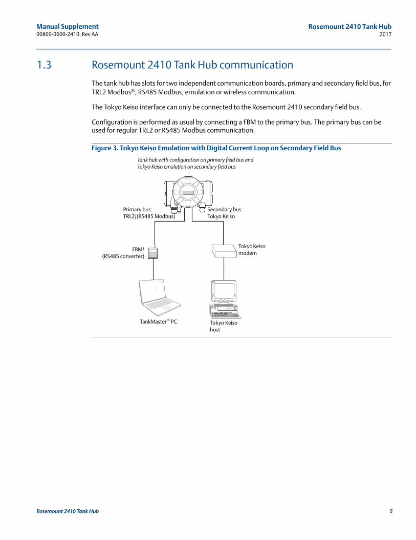
1.3 Rosemount 2410 Tank Hub communication
The tank hub has slots for two independent communication boards, primary and secondary field bus, for TRL2 Modbus®, RS485 Modbus, emulation or wireless communication.
The Tokyo Keiso interface can only be connected to the Rosemount 2410 secondary field bus.
Configuration is performed as usual by connecting a FBM to the primary bus. The primary bus can be used for regular TRL2 or RS485 Modbus communication.
Figure 3. Tokyo Keiso Emulation with Digital Current Loop on Secondary Field Bus
TankMaster™ PC
Primary bus:TRL2/(RS485 Modbus)
Secondary bus:Tokyo Keiso
FBM/(RS485 converter)
Tokyo Keiso modem
Tokyo Keiso host
Tank hub with configuration on primary field bus and Tokyo Keiso emulation on secondary field bus
5Rosemount 2410 Tank Hub
Manual Supplement00809-0600-2410, Rev AA
Rosemount 2410 Tank Hub2017
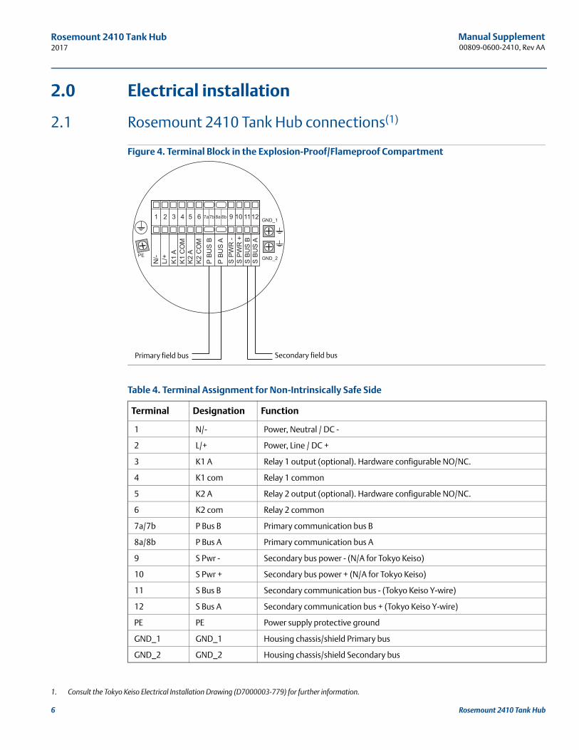
2.0 Electrical installation
2.1 Rosemount 2410 Tank Hub connections(1)
Figure 4. Terminal Block in the Explosion-Proof/Flameproof Compartment
Table 4. Terminal Assignment for Non-Intrinsically Safe Side
1. Consult the Tokyo Keiso Electrical Installation Drawing (D7000003-779) for further information.
Terminal Designation Function
1 N/- Power, Neutral / DC -
2 L/+ Power, Line / DC +
3 K1 A Relay 1 output (optional). Hardware configurable NO/NC.
4 K1 com Relay 1 common
5 K2 A Relay 2 output (optional). Hardware configurable NO/NC.
6 K2 com Relay 2 common
7a/7b P Bus B Primary communication bus B
8a/8b P Bus A Primary communication bus A
9 S Pwr - Secondary bus power - (N/A for Tokyo Keiso)
10 S Pwr + Secondary bus power + (N/A for Tokyo Keiso)
11 S Bus B Secondary communication bus - (Tokyo Keiso Y-wire)
12 S Bus A Secondary communication bus + (Tokyo Keiso Y-wire)
PE PE Power supply protective ground
GND_1 GND_1 Housing chassis/shield Primary bus
GND_2 GND_2 Housing chassis/shield Secondary bus
Secondary field busPrimary field bus
6 Rosemount 2410 Tank Hub
Manual Supplement 00809-0600-2410, Rev AA
Rosemount 2410 Tank Hub2017
3.0 Configuration
The Rosemount 2410 Tank Hub is configured by using the TankMaster WinSetup configuration program(1). WinSetup is a user-friendly software package that includes basic configuration options as well as advanced configuration and service functions.
Configuration of the Rosemount 2410 Tokyo Keiso emulation function can be performed with the WinSetup program using the FBM or a RS485 converter, depending on the tank hub configuration.
3.1 Set up Modbus communication protocol
This section describes how to configure the Modbus Master protocol channel for communication. To specify PC communication port and the standard communication parameters, do the following:
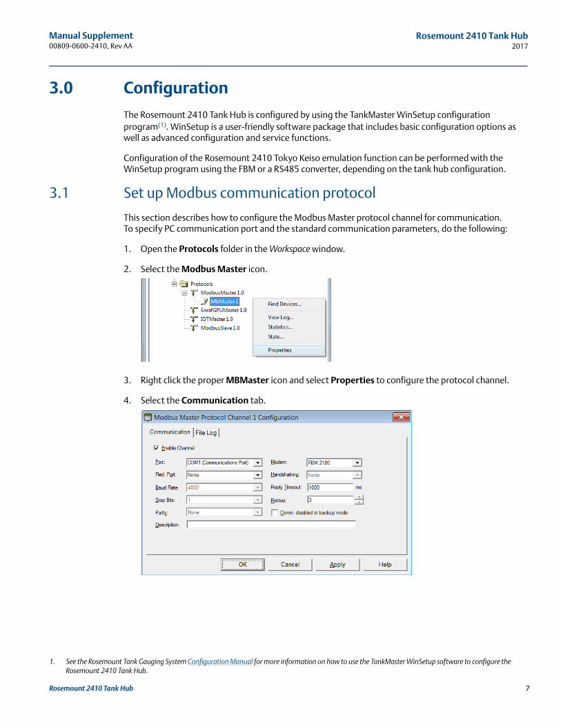
1. Open the Protocols folder in the Workspace window.
2. Select the Modbus Master icon.
3. Right click the proper MBMaster icon and select Properties to configure the protocol channel.
4. Select the Communication tab.
1. See the Rosemount Tank Gauging System Configuration Manual for more information on how to use the TankMaster WinSetup software to configure the Rosemount 2410 Tank Hub.
7Rosemount 2410 Tank Hub
Manual Supplement00809-0600-2410, Rev AA
Rosemount 2410 Tank Hub2017
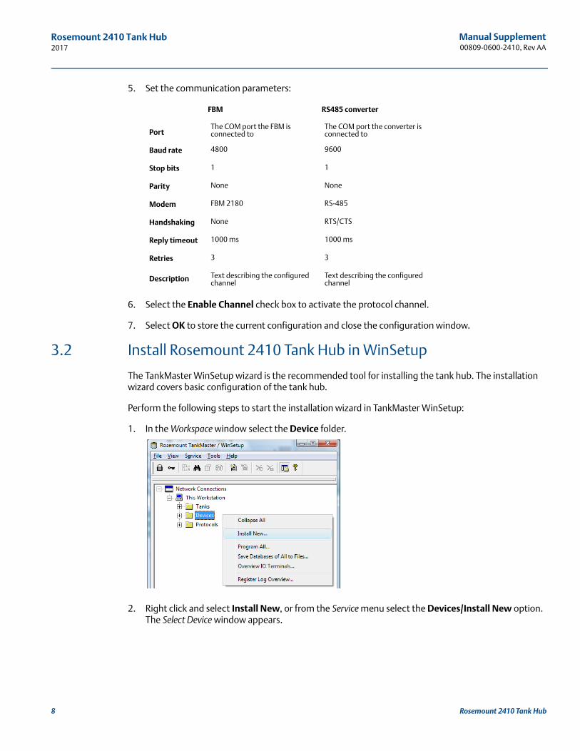
5. Set the communication parameters:
6. Select the Enable Channel check box to activate the protocol channel.
7. Select OK to store the current configuration and close the configuration window.
3.2 Install Rosemount 2410 Tank Hub in WinSetup
The TankMaster WinSetup wizard is the recommended tool for installing the tank hub. The installation wizard covers basic configuration of the tank hub.
Perform the following steps to start the installation wizard in TankMaster WinSetup:
1. In the Workspace window select the Device folder.
2. Right click and select Install New, or from the Service menu select the Devices/Install New option. The Select Device window appears.
FBM RS485 converter
PortThe COM port the FBM is connected to
The COM port the converter is connected to
Baud rate 4800 9600
Stop bits 1 1
Parity None None
Modem FBM 2180 RS-485
Handshaking None RTS/CTS
Reply timeout 1000 ms 1000 ms
Retries 3 3
Description Text describing the configured channel
Text describing the configured channel
8 Rosemount 2410 Tank Hub
Manual Supplement 00809-0600-2410, Rev AA
Rosemount 2410 Tank Hub2017
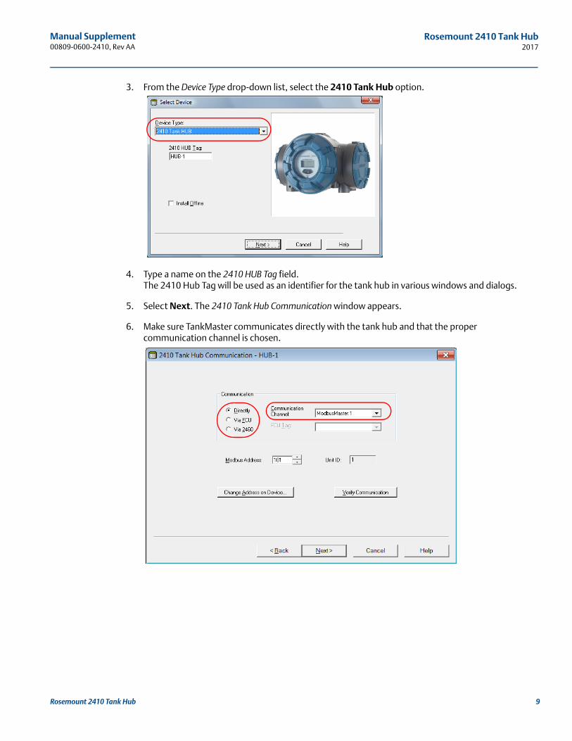
3. From the Device Type drop-down list, select the 2410 Tank Hub option.
4. Type a name on the 2410 HUB Tag field.The 2410 Hub Tag will be used as an identifier for the tank hub in various windows and dialogs.
5. Select Next. The 2410 Tank Hub Communication window appears.
6. Make sure TankMaster communicates directly with the tank hub and that the proper communication channel is chosen.
9Rosemount 2410 Tank Hub
Manual Supplement00809-0600-2410, Rev AA
Rosemount 2410 Tank Hub2017
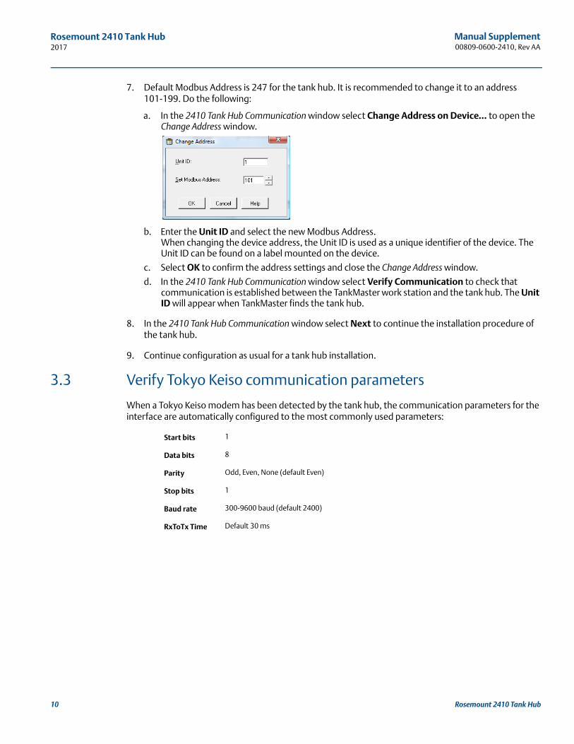
7. Default Modbus Address is 247 for the tank hub. It is recommended to change it to an address 101-199. Do the following:
a. In the 2410 Tank Hub Communication window select Change Address on Device... to open the Change Address window.
b. Enter the Unit ID and select the new Modbus Address. When changing the device address, the Unit ID is used as a unique identifier of the device. The Unit ID can be found on a label mounted on the device.
c. Select OK to confirm the address settings and close the Change Address window.
d. In the 2410 Tank Hub Communication window select Verify Communication to check that communication is established between the TankMaster work station and the tank hub. The Unit ID will appear when TankMaster finds the tank hub.
8. In the 2410 Tank Hub Communication window select Next to continue the installation procedure of the tank hub.
9. Continue configuration as usual for a tank hub installation.
3.3 Verify Tokyo Keiso communication parameters
When a Tokyo Keiso modem has been detected by the tank hub, the communication parameters for the interface are automatically configured to the most commonly used parameters:
Start bits 1
Data bits 8
Parity Odd, Even, None (default Even)
Stop bits 1
Baud rate 300-9600 baud (default 2400)
RxToTx Time Default 30 ms
10 Rosemount 2410 Tank Hub
Manual Supplement 00809-0600-2410, Rev AA
Rosemount 2410 Tank Hub2017
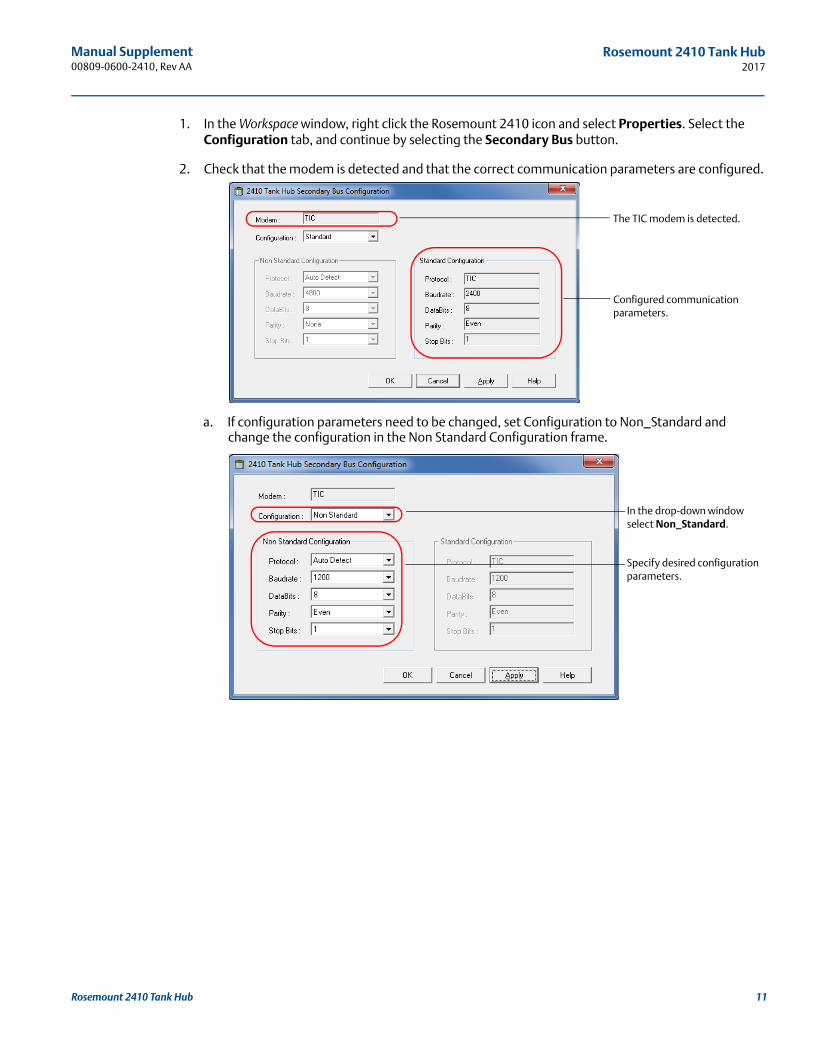
1. In the Workspace window, right click the Rosemount 2410 icon and select Properties. Select the Configuration tab, and continue by selecting the Secondary Bus button.
2. Check that the modem is detected and that the correct communication parameters are configured.
a. If configuration parameters need to be changed, set Configuration to Non_Standard and change the configuration in the Non Standard Configuration frame.
The TIC modem is detected.
Configured communication parameters.
In the drop-down window select Non_Standard.
Specify desired configuration parameters.
11Rosemount 2410 Tank Hub
Manual Supplement00809-0600-2410, Rev AA
Rosemount 2410 Tank Hub2017
3.4 Configure specific variables for Tokyo Keiso emulation
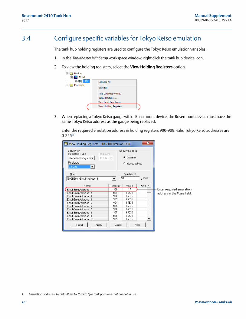
The tank hub holding registers are used to configure the Tokyo Keiso emulation variables.
1. In the TankMaster WinSetup workspace window, right click the tank hub device icon.
2. To view the holding registers, select the View Holding Registers option.
3. When replacing a Tokyo Keiso gauge with a Rosemount device, the Rosemount device must have the same Tokyo Keiso address as the gauge being replaced.
Enter the required emulation address in holding registers 900-909, valid Tokyo Keiso addresses are 0-255(1).
1. Emulation address is by default set to “65535” for tank positions that are not in use.
Enter required emulation address in the Value field.
12 Rosemount 2410 Tank Hub
Manual Supplement 00809-0600-2410, Rev AA
Rosemount 2410 Tank Hub2017
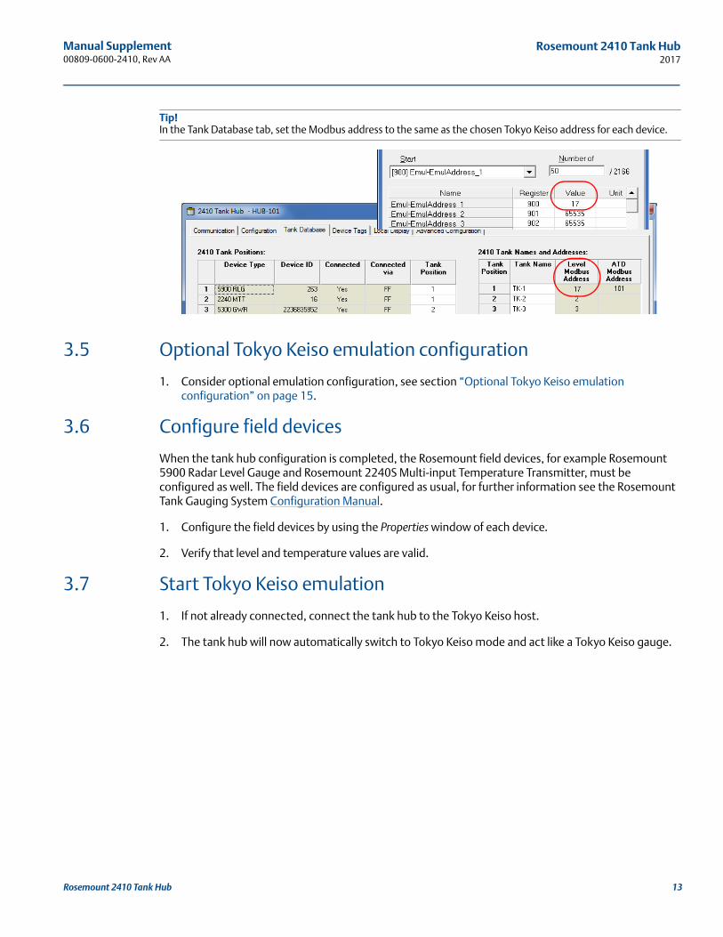
Tip!In the Tank Database tab, set the Modbus address to the same as the chosen Tokyo Keiso address for each device.
3.5 Optional Tokyo Keiso emulation configuration
1. Consider optional emulation configuration, see section “Optional Tokyo Keiso emulation configuration” on page 15.
3.6 Configure field devices
When the tank hub configuration is completed, the Rosemount field devices, for example Rosemount 5900 Radar Level Gauge and Rosemount 2240S Multi-input Temperature Transmitter, must be configured as well. The field devices are configured as usual, for further information see the Rosemount Tank Gauging System Configuration Manual.
1. Configure the field devices by using the Properties window of each device.
2. Verify that level and temperature values are valid.
3.7 Start Tokyo Keiso emulation
1. If not already connected, connect the tank hub to the Tokyo Keiso host.
2. The tank hub will now automatically switch to Tokyo Keiso mode and act like a Tokyo Keiso gauge.
13Rosemount 2410 Tank Hub
Manual Supplement00809-0600-2410, Rev AA
Rosemount 2410 Tank Hub2017
4.0 Troubleshooting
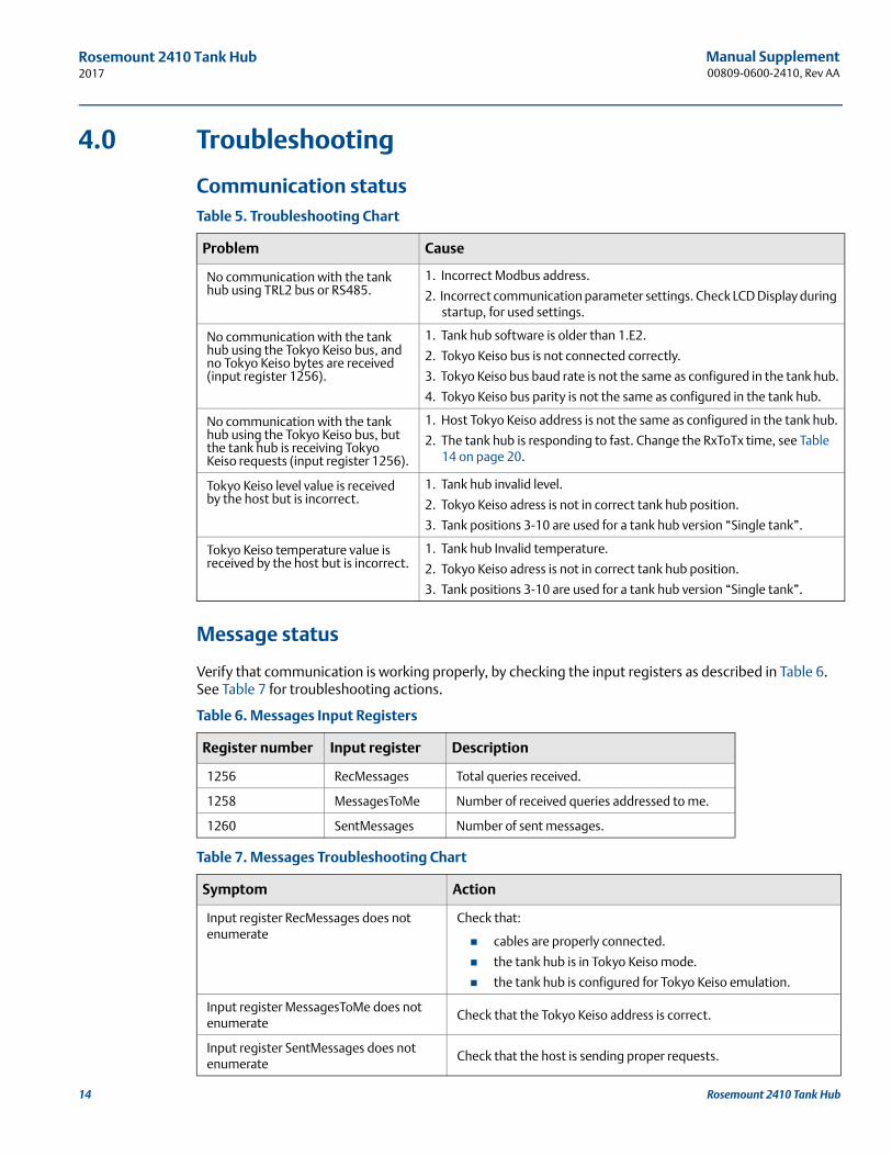
Communication statusTable 5. Troubleshooting Chart
Message status
Verify that communication is working properly, by checking the input registers as described in Table 6. See Table 7 for troubleshooting actions.
Table 6. Messages Input Registers
Table 7. Messages Troubleshooting Chart
Problem Cause
No communication with the tank hub using TRL2 bus or RS485.
1. Incorrect Modbus address.
2. Incorrect communication parameter settings. Check LCD Display during startup, for used settings.
No communication with the tank hub using the Tokyo Keiso bus, and no Tokyo Keiso bytes are received (input register 1256).
1. Tank hub software is older than 1.E2.
2. Tokyo Keiso bus is not connected correctly.
3. Tokyo Keiso bus baud rate is not the same as configured in the tank hub.
4. Tokyo Keiso bus parity is not the same as configured in the tank hub.
No communication with the tank hub using the Tokyo Keiso bus, but the tank hub is receiving Tokyo Keiso requests (input register 1256).
1. Host Tokyo Keiso address is not the same as configured in the tank hub.
2. The tank hub is responding to fast. Change the RxToTx time, see Table 14 on page 20.
Tokyo Keiso level value is received by the host but is incorrect.
1. Tank hub invalid level.
2. Tokyo Keiso adress is not in correct tank hub position.
3. Tank positions 3-10 are used for a tank hub version “Single tank”.
Tokyo Keiso temperature value is received by the host but is incorrect.
1. Tank hub Invalid temperature.
2. Tokyo Keiso adress is not in correct tank hub position.
3. Tank positions 3-10 are used for a tank hub version “Single tank”.
Register number Input register Description
1256 RecMessages Total queries received.
1258 MessagesToMe Number of received queries addressed to me.
1260 SentMessages Number of sent messages.
Symptom Action
Input register RecMessages does not enumerate
Check that:
cables are properly connected.
the tank hub is in Tokyo Keiso mode.
the tank hub is configured for Tokyo Keiso emulation.
Input register MessagesToMe does not enumerate
Check that the Tokyo Keiso address is correct.
Input register SentMessages does not enumerate
Check that the host is sending proper requests.
14 Rosemount 2410 Tank Hub
Manual Supplement 00809-0600-2410, Rev AA
Rosemount 2410 Tank Hub2017
5.0 Optional configuration and settings
5.1 Optional Tokyo Keiso emulation configuration
Engineering units
The tank hub automatically converts all measurement values to the correct engineering unit. No additional configuration is needed.
Gauge type
There are no gauge type settings for Tokyo Keiso emulation.
Invalid level measurements
The tank hub reply on the Tokyo Keiso host request command “O” for level can be customized if the level value is invalid.
Use holding register TIC_LevelErrorConfig (1201) to customize your reply configuration. See Table 8 on page 15 and Figure 5 on page 16. This configuration is applicable on all tank positions.
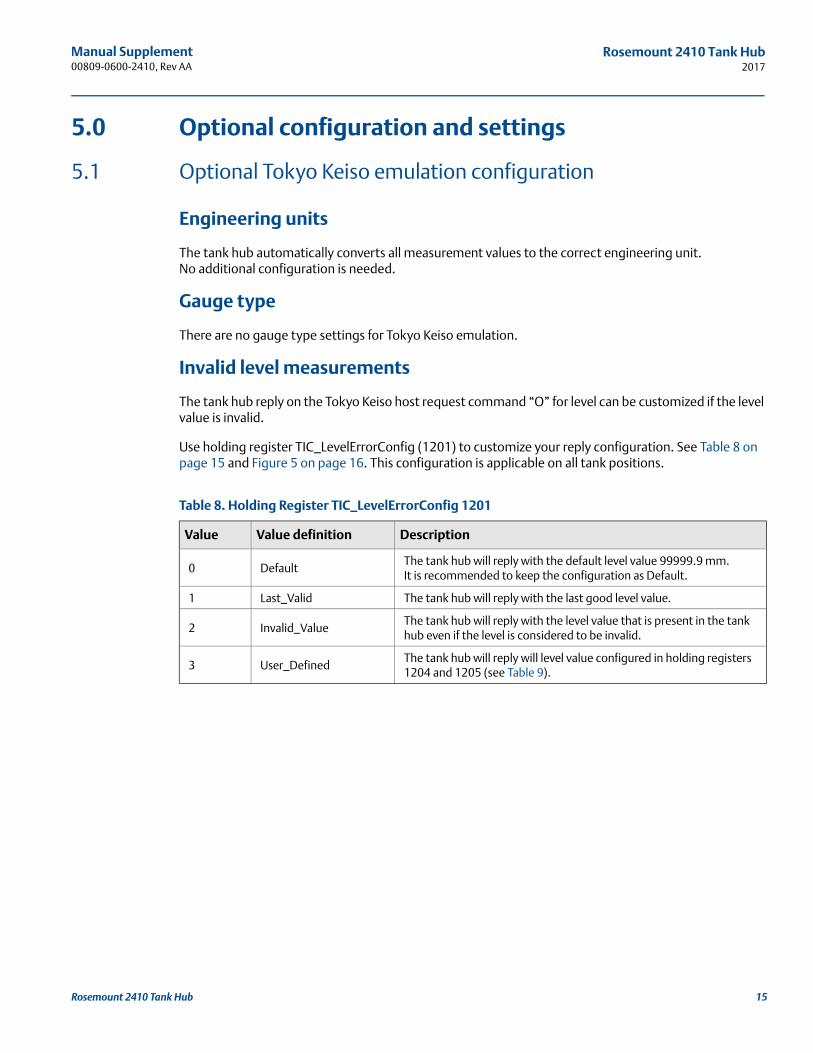
Table 8. Holding Register TIC_LevelErrorConfig 1201
Value Value definition Description
0 DefaultThe tank hub will reply with the default level value 99999.9 mm. It is recommended to keep the configuration as Default.
1 Last_Valid The tank hub will reply with the last good level value.
2 Invalid_ValueThe tank hub will reply with the level value that is present in the tank hub even if the level is considered to be invalid.
3 User_DefinedThe tank hub will reply will level value configured in holding registers 1204 and 1205 (see Table 9).
15Rosemount 2410 Tank Hub
Manual Supplement00809-0600-2410, Rev AA
Rosemount 2410 Tank Hub2017
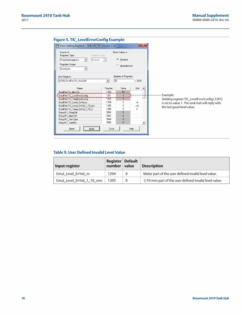
Figure 5. TIC_LevelErrorConfig Example
Table 9. User Defined Invalid Level Value
Input registerRegister number
Default value Description
Emul_Level_ErrVal_m 1204 0 Meter part of the user defined invalid level value.
Emul_Level_ErrVal_1_10_mm 1205 0 1/10 mm part of the user defined invalid level value.
Example: Holding register TIC_LevelErrorConfig (1201) is set to value 1. The tank hub will reply with the last good level value.
16 Rosemount 2410 Tank Hub
Manual Supplement 00809-0600-2410, Rev AA
Rosemount 2410 Tank Hub2017
Invalid temperature measurements
The tank hub reply on the Tokyo Keiso host request commands “O, X, Y and Z” for temperature can be customized if the temperature value is invalid.
Use holding register TIC_TempErrorConfig (1202) to customize your reply configuration. See Table 10 on page 17 and Figure 6 on page 17. This configuration is applicable on all tank positions.
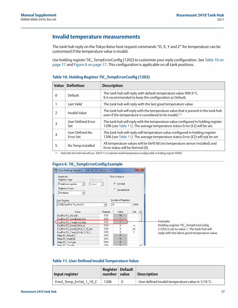
Table 10. Holding Register TIC_TempErrorConfig (1202)
Figure 6. TIC_TempErrorConfig Example
Table 11. User Defined Invalid Temperature Value
Value Definition Description
0 DefaultThe tank hub will reply with default temperature value 999.9 °C. It is recommended to keep the configuration as Default.
1 Last Valid The tank hub will reply with the last good temperature value.
2 Invalid ValueThe tank hub will reply with the temperature value that is present in the tank hub even if the temperature is considered to be invalid.(1)
1. Note that the tank hub will use -300.0 °C to indicate invalid temperature (configurable in holding register 6096).
3User Defined Error Set
The tank hub will reply with the temperature value configured in holding register 1206 (see Table 11). The average temperature status Error (E2) will be set.
4User Defined No Error Set
The tank hub will reply will temperature value configured in holding register 1206 (see Table 11). The average temperature status Error (E2) will not be set.
5 No Temp installedAll temperature values will be 0xF0 00 (no temperature sensor installed) and Error status will be Normal (0).
Input registerRegister number
Default value Description
Emul_Temp_ErrVal_1_10_C 1206 0 User defined invalid temperature value in 1/10 °C.
Example: Holding register TIC_TempErrorConfig (1202) is set to value 1. The tank hub will reply with the latest good temperature value.
17Rosemount 2410 Tank Hub
Manual Supplement00809-0600-2410, Rev AA
Rosemount 2410 Tank Hub2017
MiscControl
Use holding register 1200 (Tic_MiscControl) to set some optional configuration bits, see Table 12.
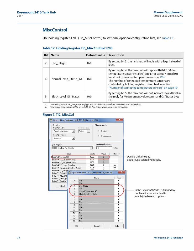
Table 12. Holding Register TIC_MiscControl 1200
Figure 7. TIC_MiscCtrl
Bit Name Default value Description
2 Use_Ullage 0x0By setting bit 2, the tank hub will reply with ullage instead of level.
4 Normal Temp_Status_ NC 0x0
By setting bit 4, the tank hub will reply with 0xF0 00 (No temperature sensor installed) and Error status Normal (0) for all not connected temperature sensors.(1)(2)
The number of connected temperature sensors are controlled by holding registers, described in section “Number of connected temperature sensors” on page 19.
1. The holding register TIC_TempErrorConfig (1202) should be set to Default, Invalid value or User Defined.2. The average temperature will be set to 0xF0 00 if no temperature sensors are connected.
5 Block_Level_E1_Status 0x0By setting bit 5, the tank hub will not indicate invalid level in the reply for Measurement value command O. (Status byte E1).
Double-click the grey background colored Value field.
In the Expanded Bitfield -1200 window, double-click the Value field to enable/disable each option.
18 Rosemount 2410 Tank Hub
Manual Supplement 00809-0600-2410, Rev AA
Rosemount 2410 Tank Hub2017
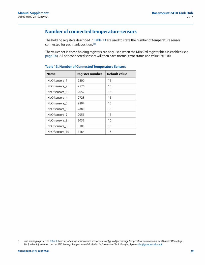
Number of connected temperature sensors
The holding registers described in Table 13 are used to state the number of temperature sensor connected for each tank position.(1)
The values set in these holding registers are only used when the MiscCtrl register bit 4 is enabled (see page 18). All not connected sensors will then have normal error status and value 0xF0 00.
Table 13. Number of Connected Temperature Sensors
1. The holding registers in Table 13 are set when the temperature sensors are configured for average temperature calculation in TankMaster WinSetup. For further information see the ATD Average Temperature Calculation in Rosemount Tank Gauging System Configuration Manual.
Name Register number Default value
NoOfsensors_1 2500 16
NoOfsensors_2 2576 16
NoOfsensors_3 2652 16
NoOfsensors_4 2728 16
NoOfsensors_5 2804 16
NoOfsensors_6 2880 16
NoOfsensors_7 2956 16
NoOfsensors_8 3032 16
NoOfsensors_9 3108 16
NoOfsensors_10 3184 16
19Rosemount 2410 Tank Hub
Manual Supplement00809-0600-2410, Rev AA
Rosemount 2410 Tank Hub2017
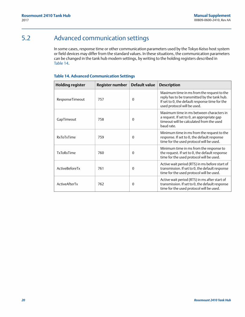
5.2 Advanced communication settings
In some cases, response time or other communication parameters used by the Tokyo Keiso host system or field devices may differ from the standard values. In these situations, the communication parameters can be changed in the tank hub modem settings, by writing to the holding registers described in Table 14.
Table 14. Advanced Communication Settings
Holding register Register number Default value Description
ResponseTimeout 757 0
Maximum time in ms from the request to the reply has to be transmitted by the tank hub. If set to 0, the default response time for the used protocol will be used.
GapTimeout 758 0
Maximum time in ms between characters in a request. If set to 0, an appropriate gap timeout will be calculated from the used baud rate.
RxToTxTime 759 0Minimum time in ms from the request to the response. If set to 0, the default response time for the used protocol will be used.
TxToRxTime 760 0Minimum time in ms from the response to the request. If set to 0, the default response time for the used protocol will be used.
ActiveBeforeTx 761 0Active wait period (RTS) in ms before start of transmission. If set to 0, the default response time for the used protocol will be used.
ActiveAfterTx 762 0Active wait period (RTS) in ms after start of transmission. If set to 0, the default response time for the used protocol will be used.
20 Rosemount 2410 Tank Hub

Manual Supplement 00809-0600-2410, Rev AA
Rosemount 2410 Tank Hub2017
21Rosemount 2410 Tank Hub
Manual Supplement00809-0600-2410, Rev AA
2017
Global Headquarters and Europe Regional Office Tank GaugingEmerson Automation SolutionsBox 150(Visiting address: Layoutvägen 1)SE-435 23 MölnlyckeSweden
+46 31 337 00 00+46 31 25 30 22 [email protected]
North America Regional OfficeTank GaugingEmerson Automation Solutions 6005 Rogerdale RoadMail Stop NC 136Houston, TX 77072, USA
+1 281 988 4000 or +1 800 722 [email protected]
Latin America Regional OfficeEmerson Automation Solutions 1300 Concord Terrace, Suite 400Sunrise, FL 33323, USA
+1 954 846 5030+1 954 846 [email protected]
Asia Pacific Regional OfficeEmerson Automation Solutions Asia Pacific Pte Ltd1 Pandan CrescentSingapore 128461
+65 6777 8211+65 6777 0947 [email protected]
Middle East and Africa Regional OfficeEmerson Automation Solutions Emerson FZE P.O. Box 17033Jebel Ali Free Zone - South 2Dubai, United Arab Emirates
+971 4 8118100+971 4 8865465 [email protected]
Linkedin.com/company/Emerson-Automation-Solutions
Twitter.com/Rosemount_News
Facebook.com/Rosemount
Youtube.com/user/RosemountMeasurement
Google.com/+RosemountMeasurement
Standard Terms and Conditions of Sale can be found on the Terms and Conditions of Sale page.The Emerson logo is a trademark and service mark of Emerson Electric Co.TankMaster, Rosemount and Rosemount logotype are trademarks of Emerson.Modbus is a registered trademark of Modicon Inc.All other marks are the property of their respective owners.© 2017 Emerson. All rights reserved.