Embed Size (px)
Citation preview

ĐẠI HỌC QUỐC GIA TP.HỒ CHÍ MINHTRƯỜNG ĐẠI HỌC BÁCH KHOA
KHOA ĐIỆN-ĐIỆN TỬ BỘ MÔN KỸ THUẬT ĐIỆN TỬ
11
ASIC CHIP AND IP CORE DESIGN
Chapter 1: Introduction to ASIC chip and IP design
1.1 ASIC and FPGA-based chip design flow 1.2 ASIC chip: analog versus digital 1.3 IP design

Bộ môn Kỹ Thuật Điện Tử
1.1 ASIC and FPGA-based chip design flow • Hardware design flow
2

Bộ môn Kỹ Thuật Điện Tử
Chip Design Flow
3

Bộ môn Kỹ Thuật Điện Tử
1.1 ASIC and FPGA-based chip design flow Feature ASIC design FPGA-based design
Language VHDL, Verilog, System C VHDL, Verilog, System CSimulator ModelSim, VCS ModelSim, VCSSynthesis -Synopsys
-Cadence-Mentor Graphic-Apollo, Astro, Daracula, DIVA, Ansoft, Synplify
-Atera: Quartus, Maxplus-Xilinx: Vivado, ISE-Lattice: Lattice Diamond(tools depended on FPGAvendors)
Advantage/disadvantages
-for massive products-optimized in area, timing, power.-Low cost solution in large quantities-slow to market
-for prototype products-not optimized in area, timing, power.-High cost solution in large quantities-fast to market
4

Bộ môn Kỹ Thuật Điện Tử
1.2 ASIC Chip Design Flow: Analog
5Source: http://www.vlsi.wpi.edu/cds/flow.html

Bộ môn Kỹ Thuật Điện Tử
Design Specification• “Specs” typically describe:
– Expected functionality– Technology– Maximum allowable delay times– Silicon area – Power dissipation
• As an example specs for a one-bit binary full adder circuit:– Technology: 0.8 um twin-well CMOS – Propagation delay of "sum" and "carry_out" signals < 1.2 ns (worst case) – Transition times of "sum" and "carry_out" signals <1.2 ns (worst case) – Circuit area < 1500 um^2 – Dynamic power dissipation (at VDD=5 V and fmax=20 MHz) < 1 mW
6

Bộ môn Kỹ Thuật Điện Tử
Schematic Capture• Schematic editors provide simple, intuitive means to draw, to
place and to connect individual components that make up your design
• The resulting schematics describe – main electrical properties of all components and their interconnections.– the power supply and ground connections– input and output signals
• Corresponding netlist is generated for later stages of the design
7
Bộ môn Kỹ Thuật Điện Tử
Symbol Creation• Each module can be assigned to a corresponding symbol• This step largely simplifies the schematic representation of
the overall system• Default symbol icon is a simple rectangular box with input and
output pins.
8

Bộ môn Kỹ Thuật Điện Tử
Simulation• Simulation is performed by Simulation tool• The initial simulation phase also serves to detect some
of the design errors– Missing connection– Unintended crossing of two signals
9
Bộ môn Kỹ Thuật Điện Tử
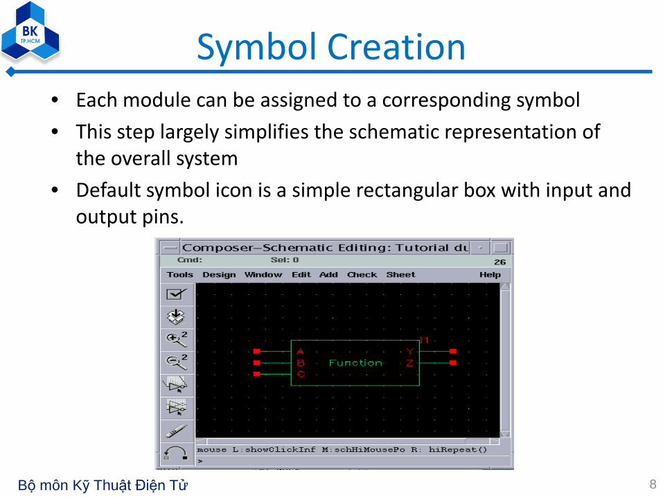
Mask Layout• The creation of the mask layout is one of the most important
steps in the full-custom• Physical layout design is very tightly linked to overall circuit
performance (area, speed and power dissipation)• The detailed mask layout of logic gates requires a very intensive
and time-consuming design effort.• The layout design must not violate any of the Layout Design
Rules
10

Bộ môn Kỹ Thuật Điện Tử
Design Rule Check (DRC)• The mask layout must conform to a complex set of design rules• Design Rule Checker, is used to detect any design rule violations• The designer must perform DRC, and make sure that all layout
errors are eventually removed
11

Bộ môn Kỹ Thuật Điện Tử
Design Rule Check (DRC)
12

Bộ môn Kỹ Thuật Điện Tử
Circuit Extraction• Circuit extraction is performed to create a detailed net-list for
the simulation tool.• The extracted net-list can provide a very accurate estimation of
the actual device dimensions and device parasitic• The extracted net-list file and parameters are subsequently used
in Layout-versus-Schematic comparison and in detailed transistor-level simulations
13

Bộ môn Kỹ Thuật Điện Tử
Layout Versus Schematic Check• Layout-versus-Schematic (LVS) Check
– compare the original network with the one extracted from the mask layout
– prove that the two networks are indeed equivalent
• A successful LVS will not guarantee that the extracted circuit will actually satisfy the performance requirements.
14

Bộ môn Kỹ Thuật Điện Tử
Post-Layout Simulation• The detailed simulation performed using the extracted net-list will provide a
clear assessment of the circuit speed, the influence of circuit parasitic, and any glitches.
• Note that a satisfactory result in post-layout simulation is still no guarantee for a completely successful product
• the actual performance of the chip can only be verified by testing the fabricated prototype
15

Bộ môn Kỹ Thuật Điện Tử
ASIC chip design flow: digital
16
Front-end
Back-end
Sign-off

Bộ môn Kỹ Thuật Điện Tử
ASIC chip design flow: digital
• Design Flow by Synopsys
17

Bộ môn Kỹ Thuật Điện Tử
Design Flow by Synopsys Design Compiler1. The input design files for Design Compiler are often written
using Verilog or VHDL. 2. Design Compiler uses technology libraries, synthetic or
DesignWare libraries, and symbol libraries to implement synthesis and to display synthesis results graphically.
3. During the synthesis process, Design Compiler translates the HDL description to components extracted from the generic technology (GTECH) library and DesignWare library. – The GTECH library consists of basic logic gates and flip-flops. – The DesignWare library contains more complex cells such as adders
and comparators.
18

Bộ môn Kỹ Thuật Điện Tử
Design Flow by Synopsys Design Compiler4. After translating the HDL description to gates, Design
Compiler optimizes and maps the design to a specific technology library, known as the target library.
5. After the design is optimized, test synthesis is performed to integrate test logic into a design during logic synthesis.
6. After test synthesis, the design is ready for the place and route tools, which place and interconnect cells in the design. Based on the physical routing, the designer can back-annotate the design with actual interconnect delays; Design Compiler can then resynthesize the design for more accurate timing analysis.
19

Bộ môn Kỹ Thuật Điện Tử
1.3 ASIC chip design flow: IP core
20
IP release environment
Release packaged IP core: (Tích hợp trong một thư viện phần mềm phát triển SoC (ví dụ SOPC builder); hướng dẫn sử dụng, hướng dẫn cách tích hợp
IPs trong SoC, những application có thể với IPs.
IP development environment
Customize IP core theo yêu cầu sử dụng của khách hàng và mô phỏng trong SoC :(GUI for Core Parameterization)
Documents :
(Specification, timing/ block diagram, datasheet, etc)
etcPackaged soft-IP :
(Encrypted Verilog files, installation scripts & manual )
Packaged soft-IP :
(evaluation netlist, evaluation C-model)
Packaged hard-IP
Specification :Customize, re-configurable & SoC
(Architecture, block & timing diagram)
Gate synthesis & verification :
Synthesis, gate-level simulation & debug (Netlist file)
Layout : Place & route, timing simulation & anal.
(GDSII file)
RTL design coding :Logic simulation & debug
(Verilog, VHDL files)
Specification group
Verification group
Physical design group
Soft IP
HardIP

Bộ môn Kỹ Thuật Điện Tử
Problems in SoC Era• Productivity gap• Time-to-market pressure• Increasing design complexity
– HW/SW co-development– System-level verification– Integration on various levels and areas of
expertise– Timing closure due to deep submicron
• Solution: Platform-based design with reusable IPs
21

Bộ môn Kỹ Thuật Điện Tử
Design for Reuse IPs• Design to maximize the flexibility
– configurable, parameterizable
• Design for use in multiple technologies– synthesis script with a variety of libraries– portable for new technologies
• Design with complete verification process– robust and verified
• Design verified to a high level of confidence– physical prototype, demo system
• Design with complete document set22
Bộ môn Kỹ Thuật Điện Tử
Parameterized IP Design• Why to parameterize IP?
– Provide flexibility in interface and functionality– Facilitate verification
• Parameterizable types– Logic/Constant functionality– Structural functionality
• Bit-width, depth of FIFO, regulation and selection of submodule
– Design process functionality (mainly in test bench)• Test events• Events report (what, when and where)• Automatic check event
– Others✱ (Hardware component Modeling, 1996)
23

Bộ môn Kỹ Thuật Điện Tử
IP Generator/Compiler• User specifies
– Power dissipation, code size, application performance, die size– Types, numbers and sizes of functional unit, including processor– User-defined instructions.
• Tool generates– RTL code, diagnostics and test reference bench– Synthesis, P&R scripts– Instruction set simulator, C/C++ compiler, assembler, linker, debugger,
profiler, initialization and self-test code
24

Bộ môn Kỹ Thuật Điện Tử
Logic/Constant Functionality• Logic Functionality
– Synthesizable codealways @(posedge clock) beginif (reset==`ResetLevel) begin…endelse begin…endend
25
• Constant Functionality– Synthesizable code
assign tRC_limit=(`RC_CYC > (`RCD_CYC + burst_len)) ?`RC_CYC - (`RCD_CYC + burst_len) : 0;
– For test benchalways #(`T_CLK/2) clock = ~clock;…initial begin#(`T_CLK) event_1;#(`T_CLK) event_2;…end

Bộ môn Kỹ Thuật Điện Tử
Reusable Design – Test Suite• Test events
– Automatically adjusted when IP design is changed– Partition test events to reduce redundant cases when test for all
allowable parameter sets at a time
• Debug mode– Test for the specific parameter set at a time– Test for all allowable parameter sets at a time– Test for the specific functionality– Step control after the specific time point
• • Display mode of automatic checking– display[0]: event current under test– display[1]: the time error occurs– display[2]: expected value and actual value
26

Bộ môn Kỹ Thuật Điện Tử
Reusable Design - Test Bench
• Use Global Connector to configure desired test• bench• – E.g.: bus topology of IEEE 1394
27

Bộ môn Kỹ Thuật Điện Tử
IP – Intellectual Property
28

Bộ môn Kỹ Thuật Điện Tử
Coding Guidelines for IP Design
• The coding guidelines provide the following recommendations:– Use simple constructs, basic types, and simple clocking schemes– Use a consistent coding style, consistent naming conventions, and a
consistent structure for processes and state machines– Use a regular partitioning scheme, with all module outputs registered
and with modules roughly of the same size– Make the RTL code easy to understand, by using comments, meaningful
names, and constants or parameters instead of hard-coded numbers
29

Bộ môn Kỹ Thuật Điện Tử
Basic Coding Practices
• The following guidelines address basic coding practices, focusing on lexical conventions and basic RTL constructs
• General Naming Conventions• Example 5-1 Using downto in port declarations
entity DW_addinc is generic(WIDTH : natural);port (A,B : in std_logic_vector(WIDTH-1 downto 0);CI : in std_logic;SUM : out std_logic_vector(WIDTH-1 downto 0);CO : out std_logic;
);end DW01_addinc;
30

Bộ môn Kỹ Thuật Điện Tử
General Naming Conventions
• Guideline – When possible, use the signal naming conventions listed in Table 5-1.
Signal naming conventions
Convention Use
*_r Output of a register (for example, count_r)
*_a Asynchronous signal (for example, addr_strobe_a)
*_pn Signal used in the nth phase (for example, enable_p2)
*_z Tristate internal signal
*_nxt Data before being registered into a register with the same name
31

Bộ môn Kỹ Thuật Điện Tử
Naming Convention for VITAL Support
• VITAL is a gate-level modeling standard for VHDL libraries and is described in IEEE Specification 1076.4
• Background – VITAL libraries can have two levels of compliance with the standard :
VITAL_Level0 and VITAL_Level1 – VITAL_Level1 is more rigorous and deals with the architecture of a library
cell– VITAL_Level0 is the interface specification that deals with the ports and
generics specifications in the entity section of VHDL library cell
• Rules– IEEE Specification 1076.4 addresses port naming conventions and
includes the following rules– These restrictions apply only to the top-level entity of a hard macro
32

Bộ môn Kỹ Thuật Điện Tử
Architecture Naming Conventions• Guideline – Use the VHDL architecture type listed in Table 5-2
Table 5-2 Architecture naming conventions
Architecture Naming Convention
synthesis ARCHITECTURE rtl OF my_syn_model ISor
model ARCHITECTURE str OF my_structural_design IS
Simulation ARCHITECTURE sim OF my_behave_model ISor
model ARCHITECTURE tb OF my_test_bench IS
33

Bộ môn Kỹ Thuật Điện Tử
Include Headers in Source Files
• Rule – Include a header at the top of every source file, including scripts. The header must contain:– Filename – Author– Description of function and list of key features of the nodule– Date the file was created – Modification history including date,name of modifier, and
description of the change
34

Bộ môn Kỹ Thuật Điện Tử
Examples
• Example 5-2 Header in an HDL source file -- This confidential and proprietary software may be used-- only as authorized by a licensing agreement from-- synopsys Inc.-- In the event of publication, the following notice is -- applicable:---- ( C ) COPYRIGHT 1996 SYNOPSYS INC.-- ALL RIGHTS RESERVED---- The entire notice above must be reproduced on all-- authorized copies.---- File : Dwpci_core.vhd-- Author : Jeff Hackett
35

Bộ môn Kỹ Thuật Điện Tử
Examples-- Date : 09/17/96-- version : 0.1-- Abstract : This file has the entity, architecture-- and configuration of the PCI 2.1-- MacroCell core module.-- The core module has the interface,-- config, initiator,-- and target top-level modules.-- Modification History:-- Date BY Version Change Descroption---------------------------------------------------- 9/17/96 JDH 0.1 Original-- 11/13/96 JDH Last pre-Atria changes -- 03/04/97 SKC Changes for ism_ad_en_ffd_n-- and tsm_date_ffd_n
36

Bộ môn Kỹ Thuật Điện Tử
Use Comments• Rule – Use comments appropriately to explain all processes,
functions, and declarations of types and subtypes.• Example 5-3 Comments for a subtype declaration-- Create subtype INTEGER_256 FOR built_in error-- checking of legal values.subtype INTEGER_256 is type integer range 0 to 255;
• Comments should be placed logically, near the code that they describe
• The key is to describe the intent behind the section of code
37

Bộ môn Kỹ Thuật Điện Tử
Keep Commands on Separate Lines
• Rule – Use a separate line for each HDL statement – Although both VHDL and Verilog allow more than one statement per
line, the code is more readable and maintainable if each statement or command is on a separate line.
38

Bộ môn Kỹ Thuật Điện Tử
Line Length
• Guideline – Keep the line length to 72 characters or less.
• Example: Continuing a line of HDL codehp_req <= (x0_hp_req or t0_hp_req or x1_hp_req ort1_hp_req or s0_hp_req or t2_hp_req or s1_hp_req or x2_hp_req or x3_hp_req orx4_hp_req or x5_hp_req orwd_hp_req and ea and pf_req nor iip2);
39

Bộ môn Kỹ Thuật Điện Tử
Indentation
• Rule – Use indentation to improve the readability of continued code lines and nested loops.
• Example: Indentation in a nested if loopif (bit_width(m+1) >= 2) then
for I in 2 to bit_width(m+1) loopspin_j := 0;for j in 1 to m loop
if j > spin_j thenif (matrix(m) (I-1) (j) /= wht) thenif (j=m) and (matrix(m) (I) (j) = wht) then
matrix(m) (I) (j) := j;elsefor k in j+1 to m loop
if (matrix(m) (I-1) (k) /= wht) thenmatrix(m) (I) (k) := j;spin_j := k ;exit;
end if;end loop -- k
end if;end if;
end if;end loop; -- j
end loop; -- I
end if;40

Bộ môn Kỹ Thuật Điện Tử
Do Not Use HDL Reserved Words
• Rule • Do not VHDL or Verilog reserved words for names of any
elements in your RTL source files.• Because macro designs must be translatable from VHDL to
Verilog and from Verilog to VHDL, • It is important not to use VHDL reserved words in Verilog
code, and not to use Verilog reserved words in VHDL code.
41

Bộ môn Kỹ Thuật Điện Tử
Port Ordering
• Rule – Declare ports in a logical order, and keep this order consistent throughout the design.
• Guideline – Declare one port per line, with a comment following it (preferably on the same line)
• Guideline – Declare the ports in the following order:– Input :
• Clocks, Resets, Enables, other control signals • Data and address lines
– Outputs:• Clocks, Resets, Enables, other control signals• Data
42

Bộ môn Kỹ Thuật Điện Tử
Examples• Example 5-6 Port ordering in entity definition
entity my_fir isgeneric (
DATA_WIDTH : positive;COEF_WIDTH : positive;ACC_WIDTH : positive;ORDER : positive;
) ;port (
-- control Inputs--
clk : in std_logic;rst_n : in std_logic;run : in std_logic;load : in std_logic;tc : in std_logic;
--Data Inputs
43
Bộ môn Kỹ Thuật Điện Tử
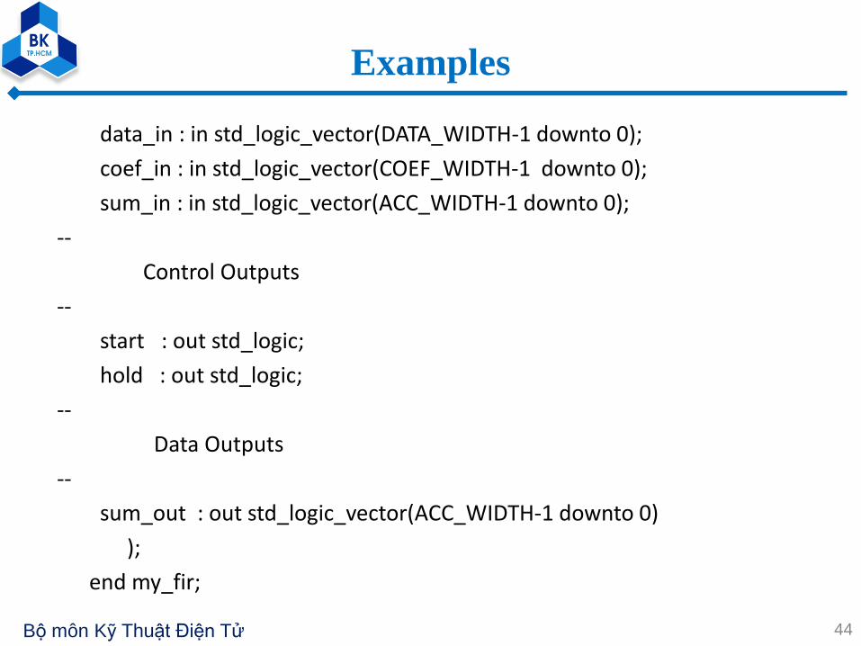
Examples
data_in : in std_logic_vector(DATA_WIDTH-1 downto 0);coef_in : in std_logic_vector(COEF_WIDTH-1 downto 0);sum_in : in std_logic_vector(ACC_WIDTH-1 downto 0);
--Control Outputs
--start : out std_logic;hold : out std_logic;
--Data Outputs
--sum_out : out std_logic_vector(ACC_WIDTH-1 downto 0)
);end my_fir;
44

Bộ môn Kỹ Thuật Điện Tử
Port Maps and Generic Maps• Rule – Always use explicit mapping for ports and generics,
using named association rather than positional association.• Example 5-7 Using named association for port mapping
-- instantiate my_addU_ADD: my_addgeneric map (width => WORDLENGTH)port map (a => in1,b => in2,ci => carry_in,
sum => sum,co => carry_out
);
45

Bộ môn Kỹ Thuật Điện Tử
Examples• Verilog :// instantiate my_addmy_add #(‘WORDLENGTH) U_ADD (
.a (in1 ) ,
.b (in2 ) ,
.ci (carry_in ) ,
.sum (sum ) ,
.co (carry_out ) );
46

Bộ môn Kỹ Thuật Điện Tử
VHDL Entity, Architecture, and Configuration Sections
• Guideline – Place entity, architecture, and configuration sections of your VHDL design in the same file.
• Example 5-8 Using pragmas to comment out VHDL configurations for synthesis
-- pragma translate_offconfiguration cfg_example_struc of example is
for strucuse example_gate;
end for;end cfg_example_struc;-- pragma translate_on
47

Bộ môn Kỹ Thuật Điện Tử
Use Functions
• Guideline – Use functions when possible, instead of repeating the same sections of code
• Example 5-9 Creating a reusable functionVHDL:
-- This function converts the incoming address to the-- corresponding relative address.
function convert_address(input_address, offset : integer)
return integer isbegin
-- … function body here…end; -- convert_address
48

Bộ môn Kỹ Thuật Điện Tử
Examples• Verilog:
// This function converts the incoming address to the // corresponding relative address.
function [‘BUS_WIDTH-1 : 0] convert_address;input input_address, offset;integer input_address, offset;
begin// …function body goes here…
endend function // convert_address
49

Bộ môn Kỹ Thuật Điện Tử
Use Loops and Arrays• Guideline – Use loops and arrays for improved readability of the source
code.• Example 5-10 Using loops to improve readability
shift_delay_loop: for I in 1 to (number_taps-1) loopdelay(I) := delay (I-1);
and loop shift_delay_loop;• Example 5-11 Register bank using an array
type reg_array is array(natural range <>) ofstd_logic_vector (REG_WIDTH-1 downto 0);
signal reg: reg_array (WORD_COUNT-1 downto 0);begin
REG_PROC:process (clk)begin if clk=‘1’ and clk’event thenif we=‘1’ then
reg(addr) <= data;end if;end if;
end process REG_PROC;data_out <= reg(addr);
50

Bộ môn Kỹ Thuật Điện Tử
Examples• Example 5-12 Using arrays for faster simulation
poor coding style:function my_xor (bbit : std_logic;
avec : td_logic_vector (x downto y) )return std_logic_vector is
variable cvec :std_logic_vector(avec’range-1 downto 0);
begin for i in avec’range loop -- bit-level for loop
cvec(I) := avec (I) xor bbit; -- bit-level xorend loop;return(cvec);
end;
51

Bộ môn Kỹ Thuật Điện Tử
ExamplesRecommended coding style:
function my_xor ( bbit : std_logic;evec : std_logic_vector (x downto y) )
return std_logic_vector isvariable cvec, temp :std_logic_vector(avec’range-1 downto 0);
begintemp := (others => bbit);cvec := avec xor temp;return (cvec);
end;
52

Bộ môn Kỹ Thuật Điện Tử
Use Meaningful Labels
• Rule – Label each process block with a meaningful name. This is very helpful for debug.
• Guideline –Label each process block <name>_PROC• Rule – Do not duplicate any signal, variable, or entity names.• Example 5-13 Meaningful process label
-- synchronize requests (hold for one clock).SYNC_PROC : process (req1, req2, rst, clk)
… process body here …
end process SYNC_PROC;
53

Bộ môn Kỹ Thuật Điện Tử
Rule (VHDL only) - Use only IEEE standard types.
--Create new 16-bit subtypesubtype WORD_TYPE is std_logic_vector (15 downto 0);
( Example 5-14 Creating a subtype from std_logic_vector )
Guideline (VHDL only)
- Use std_logic rather than std_ulogic.
- Likewise, use std_logic_vector rather than std_logic_vector.
You will create code that is technology-independent, compatible with various simulation tools, and easily translatable from VHDL to Verilog ( or from Verilog to VHDL).
Coding for PortabilityUse Only IEEE Standard Types
54

Bộ môn Kỹ Thuật Điện Tử
Continue Guideline (VHDL only)
- Be conservative in the number of subtypes you create.
: Using too many subtypes make the coder difficult to understand.
Guideline (VHDL only)
- Do not uese the type bit or bit_vector.
: Many simulators do not provide built-in arithmetic functions for
these types.
Use ieee.std_logic_arith.all;Signal a, b, c, d : std_logic_vector (y downto x);( Example 5-15 using built-in arithmetic functions for std_logic_vector )
55

Bộ môn Kỹ Thuật Điện Tử
Guideline (VHDL only)
- Do not use hard-coded numeric values in your design.
: As an exception, you can use the values 0 and 1 (but not in com-
bination, as in 1001).
( Example 5-16 using constants instead of hard-coded values )
Recommended coding style`define MY_BUS_SIZE 8wire [ ` MY_BUS_SIZE-1 : 0 ] my_in_bus;reg [ ` MY_BUS_SIZE-1 : 0 ] my_out_bus;
Poor coding stylewire [7 : 0 ] my_in_bus;reg [7 : 0 ] my_out_bus;
Do Not use Hard-Coded Numeric Values
56

Bộ môn Kỹ Thuật Điện Tử
Packages Guideline (VHDL only)
- Collect all parameter values and function definitions for a design
into a single separate file (a “package”) and name the file
DesignName_package.vhd.
Guideline (Verilog only)
- keep the `define statements for a design in a single separate file
and name the file DesignName_params.v.
Include Files
Packages & Include Files
57
Bộ môn Kỹ Thuật Điện Tử
− Although it is possible to embed dc_shell synthesis commands
directly in the source code, this practice is not recommended.
− Others who synthesize the code may not be aware of the hidden
commands, which may cause their synthesis scripts to produce
poor result.
Avoid Embedding dc_shell Scripts
58

Bộ môn Kỹ Thuật Điện Tử
Guideline
- Use the DesignWare Foundation Library to maintain technology
independence.
Guideline
- Avoid instantiating gates in the design.
- Gate-level designs are very hard to read, and thus difficult to
maintain and reuse.
- If technology-specific gates are used, then the design is not port-
able to other technologies.
Use Technology-independent Libraries
59

Bộ môn Kỹ Thuật Điện Tử
Guideline
- If you must use technology-specific gates, then isolate these gates
in a separate module.
Guideline – The GTECH library
- If you must instantiate a gate, use a technology-independent library such as the Synopsys generic technology library, GETCH.
Continue
60
Bộ môn Kỹ Thuật Điện Tử
Guideline (VHDL only)
- Do not use generate statements.
: There is no equivalent construct in Verilog.
Guideline (VHDL only)
- Do not use block constructs.
: There is no equivalent construct in Verilog.
Guideline (VHDL only)
- Do not use code to modify constant declarations.
: There is no equivalent capability in Verilog.
Coding For Translation (VHDL to Verilog)
61

Bộ môn Kỹ Thuật Điện Tử
Questions1. What are differences between ASIC and FPGA based
chip design?2. What are steps of ASIC design flow for analog chip?3. What are steps of ASIC design flow for digital chip?4. Explain about Layout-versus-Schematic (LVS) Check5. What is IP core?6. List the needed characteristics of IP core7. What are coding guidelines?
62

Bộ môn Kỹ Thuật Điện Tử
Assignment • Design an IP core, select one of the following list :
– Adder– Subtractor– Multiplier– Divider
• Configurable parameters– Width of input data– Reset level– Unsigned / signed number
• Required deliverable set– Behavior model– RTL code– Synthesis report– Testbench– Verification report
63