Embed Size (px)
Citation preview
CTU Presents
“All Coaxial Cables are not Created Equal”
Selection parameters while shopping the flea market
John Sluymer, VE3EJ
Value – The tradeoff between price and specifications.
Lowest price may not be the best choice. Highest price is likely also not be best choice. Somewhere in between usually lies a product
that meets the needs. One needs to define the requirements and
understand the specifications.
What is coaxial cable?
Coaxial cable or “Coax” is a type of cable that has an inner conductor surrounded by an insulating layer, surrounded by a tubular conducting shield. The term coaxial comes from the inner conductor and the outer shield sharing a geometric axis.
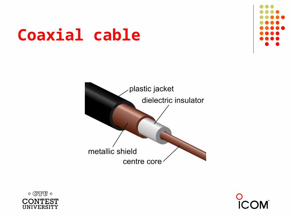
Coaxial cable
Applications
Coaxial cable is used as a transmission line for radio frequency (RF) signals. The primary use is in connecting transmitters and receivers with antennas or other RF components.
Main Parameters - electrical Shunt capacitance. Series inductance. Characteristic impedance. VSWR Voltage breakdown. Power handling. Loss / Attenuation - efficiency. Velocity factor. Phase stability. Shielding effectiveness. IMD products.
Physical parameters – variables
Length of the cable: h Outside diameter of inner conductor: d Inside diameter of outer conductor: D Dielectric constant of the dielectric insulator: Є Magnetic permeability of dielectric insulator: µ
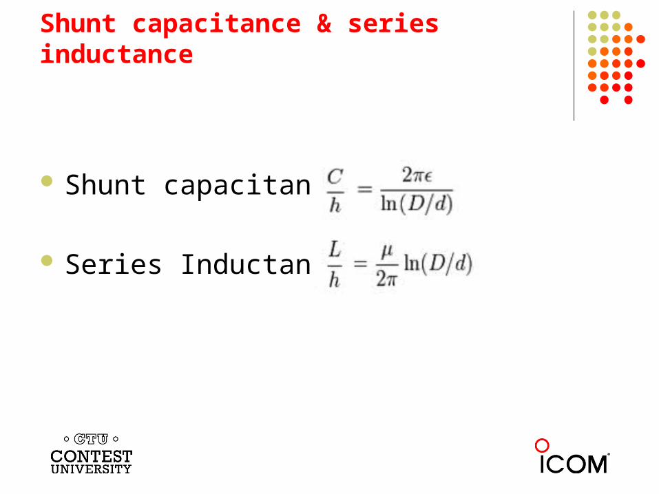
Shunt capacitance & series inductance
Shunt capacitance:
Series Inductance:
Characteristic Impedance
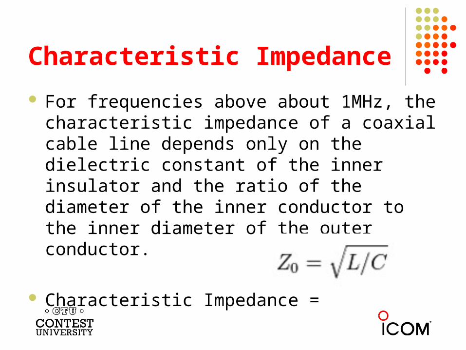
For frequencies above about 1MHz, the characteristic impedance of a coaxial cable line depends only on the dielectric constant of the inner insulator and the ratio of the diameter of the inner conductor to the inner diameter of the outer conductor.
Characteristic Impedance =
VSWR (Voltage Standing Wave Ratio)
VSWR is a function of how well the cable maintains its characteristic impedance (Zo) over its length.
Function of how well the geometry of the cable is maintained over its length.
Function of how consistent the dielectric material is maintained over its length.
Voltage Breakdown
Generally a function of:
Dielectric material Environmental conditions – Moisture or contaminants.
Often limited by choice of connectors. Instantaneous issue with possible carbon tracking =
permanent damage.
Power Handling
Limited by: Breakdown Voltage. Thermal dissipation capability of the cable.
Directly related to size of cable (surface area). Directly related to attenuation per unit length. Frequency dependant. Time rather than instantaneous problem. Specifications need to be de-rated for temperature and
VSWR.
Loss & Attenuation
Conductor losses Type of metal
Copper Aluminum Copper clad
Size – surface area of inner and outer. Skin effect at RF – currents travel on surface only.
Loss & Attenuation (cont …)
Dielectric losses
Type of material (In order of increasing loss)
Air (Nitrogen) with polyethylene spiral. HJ5-50 PTFE (Teflon). RG142 PF (polyethylene foam). RG6 PE (Polyethylene). – RG213
Power/Voltage/Efficiency tradoffs
Why are 50 Ohm cables in such common use? It’s a tradeoff between power, voltage and
attenuation. Bell Laboratories (1929) testing showed:
30 Ohms best for power handling. 60 Ohms best for voltage rating. 77 Ohms best for attenuation. 50 Ohms best overall compromise.
Velocity Factor The velocity factor (Vf) is the speed an electromagnetic wave
travels along a coax cable relative to the speed in a vacuum.
Vf is directly related to the dielectric material of the cable.
Denser dielectric material = lower Vf.
A cable with a lower Vf is physically shorter than a cable with a higher Vf for the same electrical length.
Important consideration for phased applications.
Phase stability
Length or phase variation with temperature.
Thermal expansion or contraction rates.
Important for phasing – especially as frequency rises.
Cable types should not be mixed for phased applications.
Shielding effectiveness
Signal leakage from cable to outside world. Signal ingress from outside world. (It’s a two way issue) Function of continuity and bonding of outer conductor. Solid (or corrugated copper) best. Braided shield percentage coverage is largest factor. Continuity at connectors very important.
IMD Products (Inter Modulation Distortion)
IMD is the generation of undesirable signals as a result of two or more desired signal mixing together through some medium.
IMD products occur when two or more signals cross a non linear junction and are rectified.
IMD products most often occur across ferromagnetic or oxidized surfaces.
Poor cable to connector or connector to connector connections are the most likely sources.
Connectors with greater surface areas are desired.
IMD Products (Inter Modulation Distortion) cont …
Properly soldered connections are essential. Proper connector torque is essential. Moisture free connections are essential. IMD issues very important in Multi transmitter.
environments – including SO2R. IMD issues can be the source of TVI or other
interference situations.
Main parameters - Mechanical
Conductor materials. Jacket material. Dielectric material. Air vs solid dielectric. Size. Weight. Bending radius. Crush strength.
Conductor Materials
Outer conductor Copper braid (Single or double) Aluminum braid (Single or double) Aluminum foil (Often with braid) Corrugated copper (annular or spiral) Corrugated aluminum (annular or spiral) Solid copper Solid aluminum
Conductor Material
Inner conductor material:
Braided copper. Solid copper wire. Solid copper heavy gauge. Hollow copper (straight) cylinder. Hollow copper spiral cylinder. Copper clad aluminum.
Jacket Material
Cable jacketing designed to protect from environmental factors – moisture, chemical, solar as well as abrasion.
Jacket materials: Polyvinyl-chloride EPDM Polyethylene Silicone rubber Polyurethane Natural rubber Teflon Bare – no jacket Neoprene
Fire retardant and plenum rated cables generally have blue or white jackets and are made of non-halogenated materials to reduce smoke and production of toxic gases.
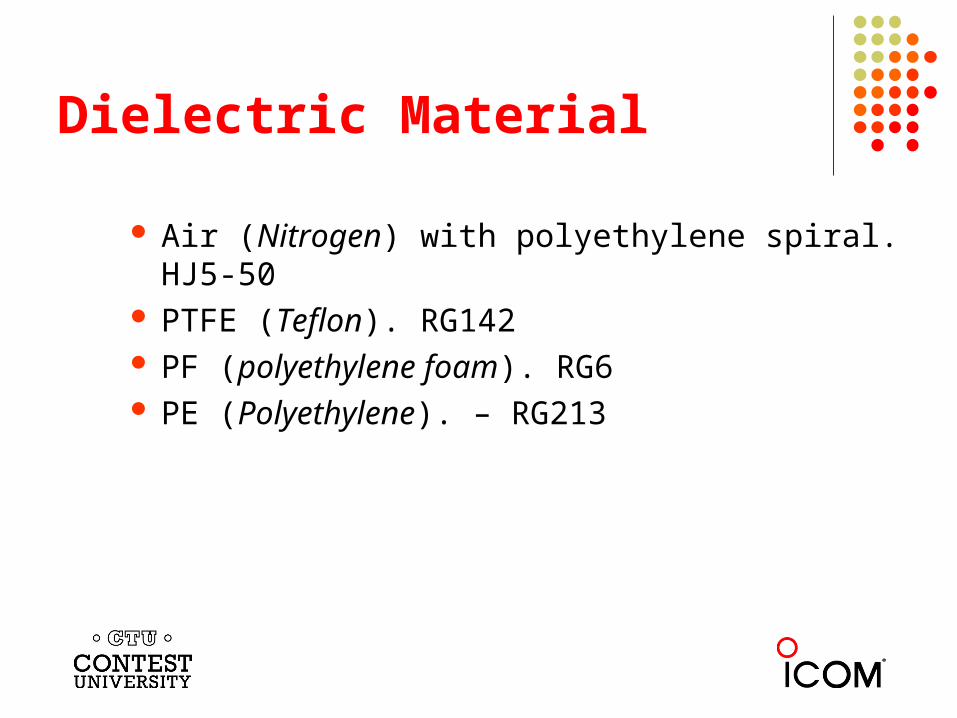
Dielectric Material
Air (Nitrogen) with polyethylene spiral. HJ5-50 PTFE (Teflon). RG142 PF (polyethylene foam). RG6 PE (Polyethylene). – RG213
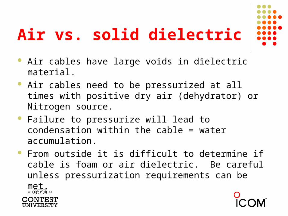
Air vs. solid dielectric
Air cables have large voids in dielectric material. Air cables need to be pressurized at all times with
positive dry air (dehydrator) or Nitrogen source. Failure to pressurize will lead to condensation within the
cable = water accumulation. From outside it is difficult to determine if cable is foam or
air dielectric. Be careful unless pressurization requirements can be met.
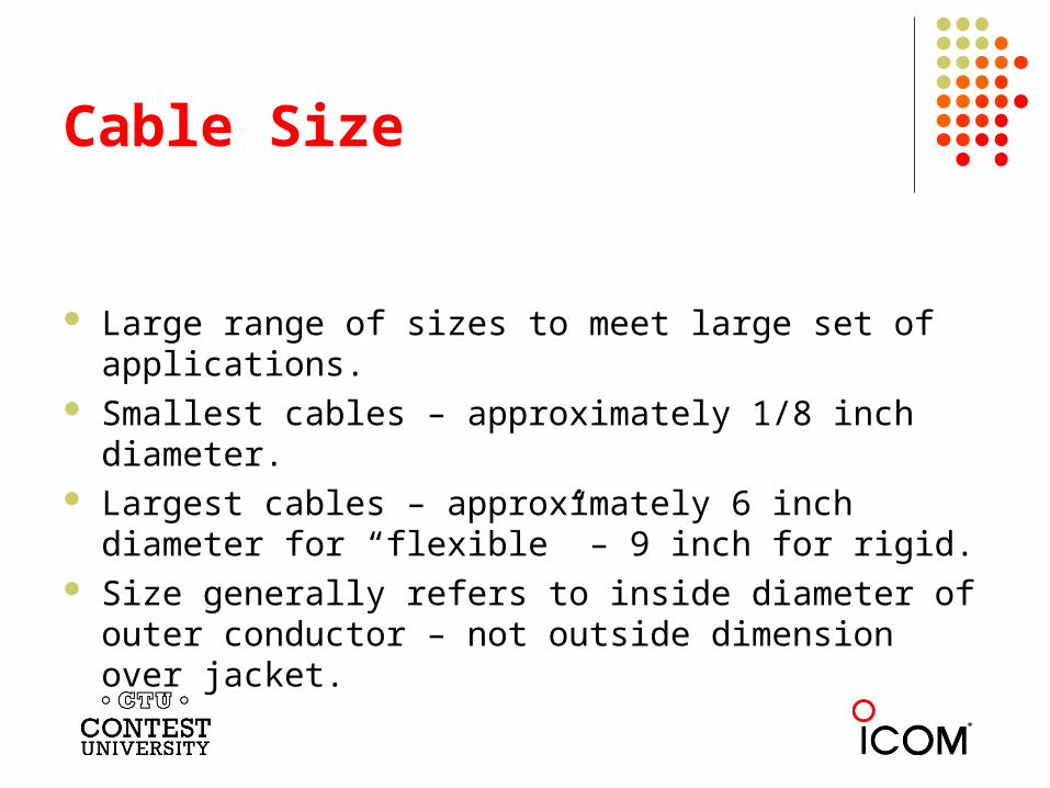
Cable Size
Large range of sizes to meet large set of applications. Smallest cables – approximately 1/8 inch diameter. Largest cables – approximately 6 inch diameter for
“flexible” – 9 inch for rigid. Size generally refers to inside diameter of outer
conductor – not outside dimension over jacket.
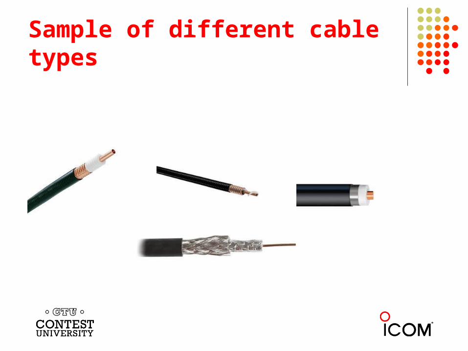
Sample of different cable types
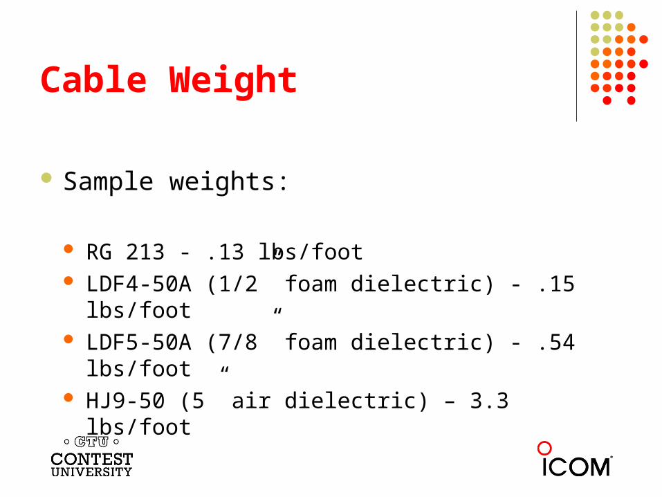
Cable Weight
Sample weights:
RG 213 - .13 lbs/foot LDF4-50A (1/2” foam dielectric) - .15 lbs/foot LDF5-50A (7/8” foam dielectric) - .54 lbs/foot HJ9-50 (5” air dielectric) – 3.3 lbs/foot
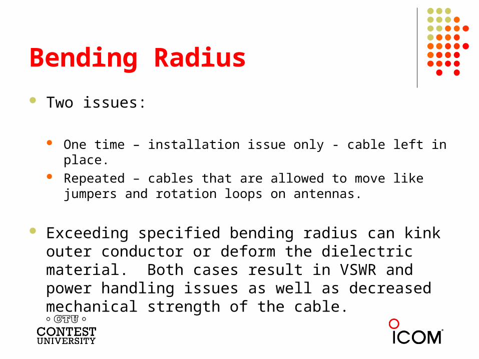
Bending Radius
Two issues:
One time – installation issue only - cable left in place. Repeated – cables that are allowed to move like jumpers and
rotation loops on antennas.
Exceeding specified bending radius can kink outer conductor or deform the dielectric material. Both cases result in VSWR and power handling issues as well as decreased mechanical strength of the cable.
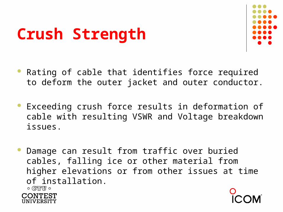
Crush Strength
Rating of cable that identifies force required to deform the outer jacket and outer conductor.
Exceeding crush force results in deformation of cable with resulting VSWR and Voltage breakdown issues.
Damage can result from traffic over buried cables, falling ice or other material from higher elevations or from other issues at time of installation.
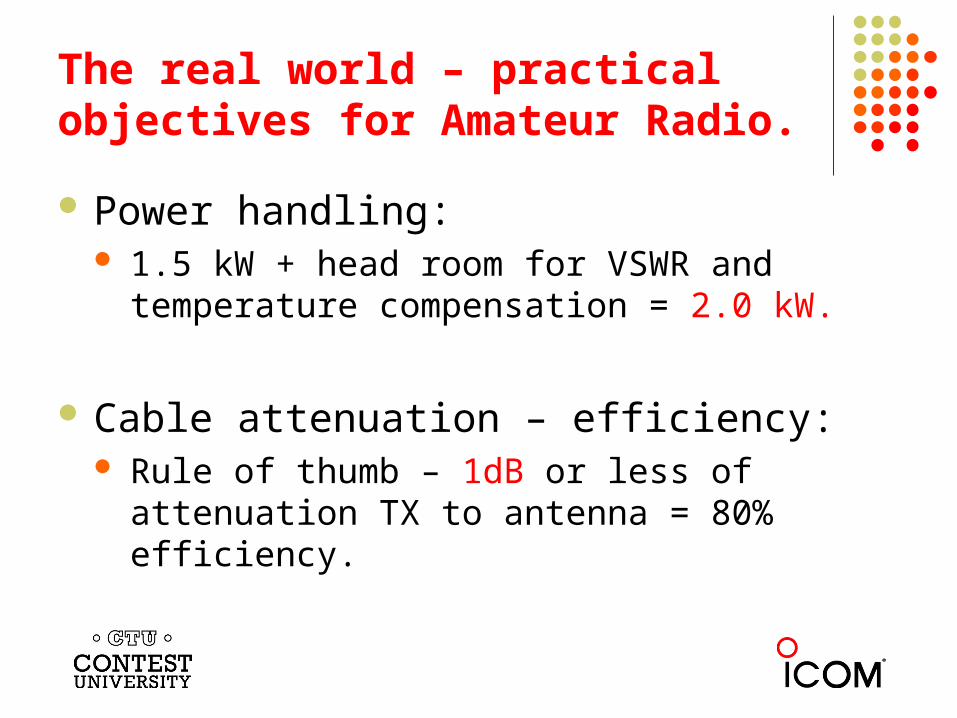
The real world – practical objectives for Amateur Radio.
Power handling: 1.5 kW + head room for VSWR and temperature
compensation = 2.0 kW.
Cable attenuation – efficiency: Rule of thumb – 1dB or less of attenuation TX to
antenna = 80% efficiency.
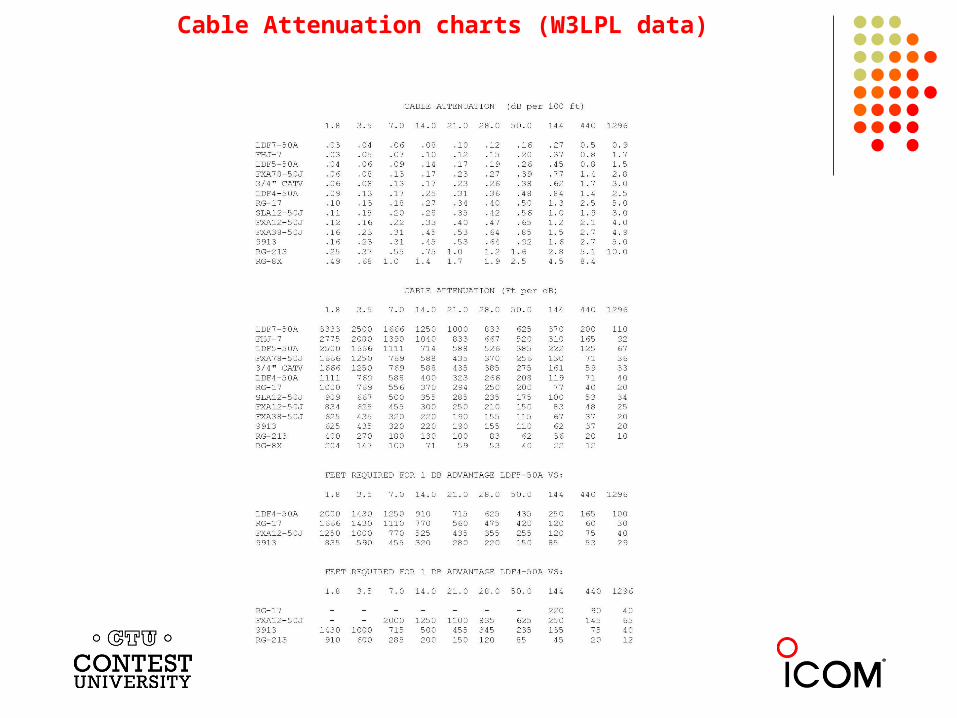
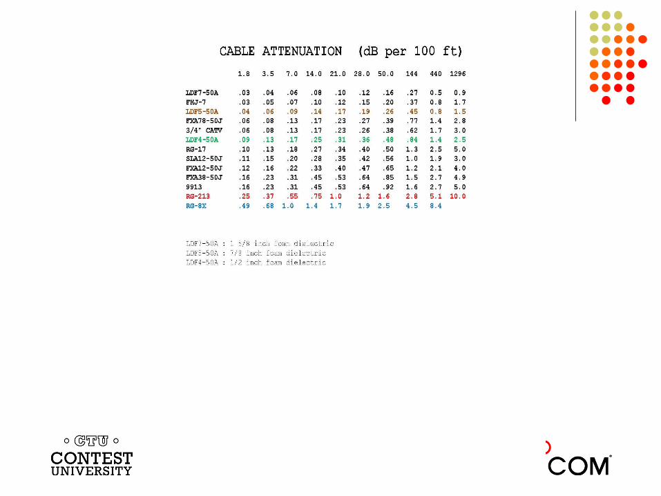
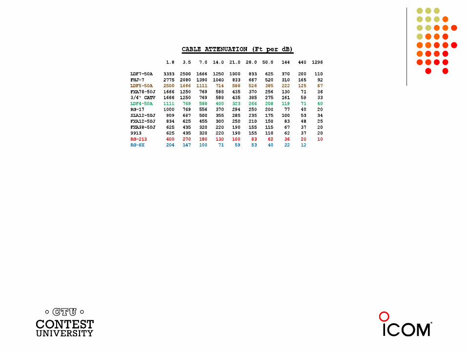
Cable Attenuation charts (W3LPL data)
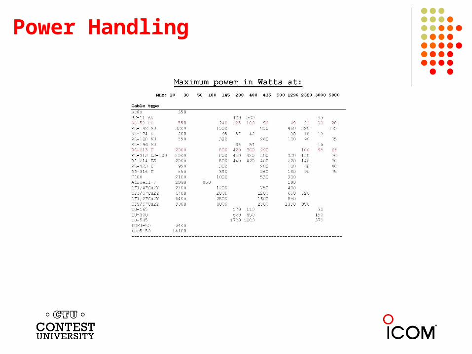
Power Handling
Cable size conclusions
For HF work, RG 213 type cables are adequate for 1.5 kW power levels.
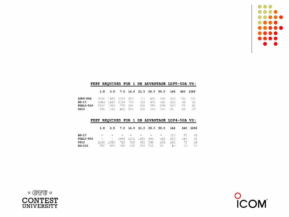
For HF work with cable runs up to 100 feet – RG213 type OK. For HF work with cable runs up to approximately 300 feet – 1/2 inch
LDF4 cable OK. For HF work and cable runs over 300 feet, 7/8 inch LDF5 or larger
cables should be considered. For all VHF and UHF work, nothing less than ½ inch cable should
be used even for short runs.
Connectors
Single biggest failure point in most RF systems. Installation issues Weatherproofing Connector type Connector series
Connector installation issues
Proper connector for cable type. Proper cut back dimensions. Use prep tools where available. Follow installation instructions. Keep all parts including cable clean and dry. For solder connections – lots of heat for short
time. Make sure solder flows to connector and cable.
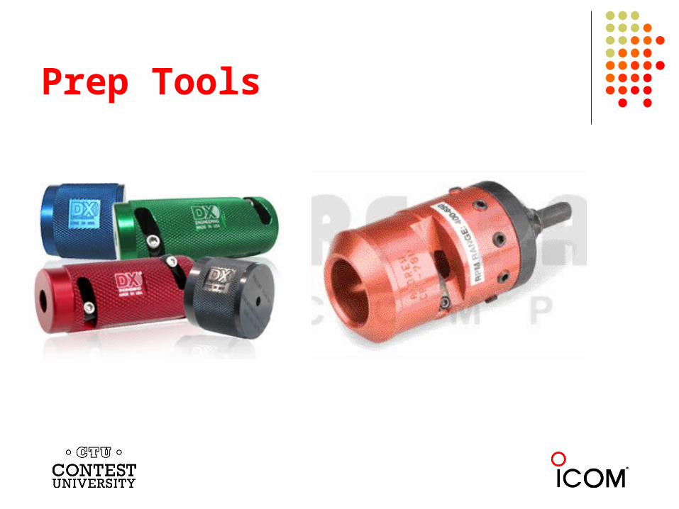
Prep Tools
Connector weatherproofing
Connections must stay dry. Use conformable rubber splicing tape like 3M type 130C
(or equiv) as weather seal. Protect from UV and hold in place using 3M type 88 vinyl
tape (or equiv). Cut – do not stretch final tape wrap. For large connectors use butyl rubber tape as gap filler
before taping. In hard to reach locations use UV rated heat shrink.
Connector types
Use proper connector for cable type. Be aware that there are different manufacturers of
various cable sizes and that connectors are not interchangeable. (exception MIL spec cables)
For a given manufacturer there are different generations of cable and connectors will not be interchangeable.
Avoid home made connectors. They are not long term solutions.
Connector Series
Choose the right connector series for the application. (Power rating, VSWR and impedance) UHF (PL 259 series) Type “N” 7/16 DIN BNC “F” series EIA Flanged connectors (7/8, 1 5/8, 3 1/8 etc…)
Avoid inter-series adaptors where possible. Avoid “cheap” Elbows and “Tees” – they have power
issues and can be sources for IMD.
Installation
Cable support. Cable hangers or Ty wraps – avoid tape. Use UV resistant Ty wraps – never use white
nylon. Hoisting grips for larger cables. Leave a little extra at the top. Drip loop at bottom.
Installation cont ….
Be careful not to nick cable jacket – source of water entry. Make sure no cable rub locations – future sources of water. Plan rotator loop – sufficient clearance and length. Ground kits – top, middle (for long runs), bottom and entry point to
radio room. Bury horizontal runs for cables so rated or use overhead centenary
wire for support. Do not bury connectors or splices. Bury below frost line. Weatherproof all connections.
Inspections and maintenance
Benchmark performance at time of installation. VSWR or swept VSWR – TDR + photograph installation.
Keep records. Regularly re-test – changes are signs of trouble. Physically inspect on regular interval. Photograph and compare pictures. Deal with the problems promptly – they rarely fix
themselves!
Bottom Line
Understand your needs and objectives. Understand the specifications for what you are proposing
to buy. View coax runs as systems – cable, connectors and
jumpers. It’s a series circuit and any single component failure is a system failure. All components are equally important.
Make sure the products meet or exceed your needs. Apply your best negotiating techniques to obtain best
value.
Thank you for your attention!
73, John, VE3EJ
Sources and credits
http://www.dxengineering.com/search/product-line/dx-engineering-coax-cable-stripping-tools/cable-prep-tool-type/drop-cutter
http://www.electronics-lab.com/blog/?p=18953 http://en.wikipedia.org/wiki/Coaxial_cable http://www.harbourind.com/images/stories/datasheets/Power_Handling.pdf http://www.k1ttt.net/technote/coaxloss.html#tables Frank Donavan, W3LPL