Embed Size (px)
Citation preview

Product Specification LPM Connector Family
DOCUMENT NUMBER: AS-000021
REV. A 7/1/2015
Product Specs: LPM Connector Family
AUTHOR: WM
Page 1 of 11
Product Specification - LPM Connector Family
OVERVIEW Developed for mobile devices and other space-constrained applications, the Neoconix LPM line of connectors feature exceptional X-Y-Z density with a simple, highly reliable screw-down fastening system. With an extremely short electrical path, these products can uniquely combine high speed signaling (>10Gbps) and significant power delivery (>10A) within one connector.
FEATURES High performance PCBeam™ connector technology
Ultra-low profile, 0.28mm connector thickness
High density 0.7424mm contact pitch
High current to >10A on some configurations
High speed to >10Gbps.
Meets PCIe3.0 & USB3.1 signal integrity requirements
Pick & place compatible standard hardware (pins & nut)
Additional customization options offered
Compliant with ROHS 2011/65/EU and IPC-4101B (halogen-free)
STANDARD PRODUCT FAMILY
P/N Rows Cols Pins
Length
(mm)
Width
(mm)
LPM-012A 3 8 12 9.9 3.6
LPM-016A 4 8 16 9.9 3.6
LPM-020A 4 9 20 10.7 3.6
LPM-024A 4 10 24 11.4 3.6
LPM-028A 4 11 28 12.2 3.6
LPM-032A 4 12 32 12.9 3.6
LPM-034A 5 10 34 11.4 4.3
LPM-036A 4 13 36 13.6 3.6
LPM-039A 5 11 39 12.2 4.3
LPM-040A 4 14 40 14.4 3.6
LPM-044A 5 12 44 12.9 4.3
LPM-049A 5 13 49 13.6 4.3
LPM-054A 7 10 54 11.4 5.8
LPM-056A 6 12 56 12.9 5.1
LPM-062A 6 13 62 13.6 5.1
LPM-068A 7 12 68 12.9 5.8
LPM-075A 7 13 75 13.6 5.8
LPM-080A 6 16 80 15.9 5.1
LPM-082A 7 14 82 14.4 5.8
12 columns x 5 rows
L = 12.9mm
W = 4.3mm
Example LPM-044A
PCBeam™ Interposer
PCB
FPC
Product Specification LPM Connector Family
DOCUMENT NUMBER: AS-000021
REV. A 7/1/2015
Product Specs: LPM Connector Family
AUTHOR: WM
Page 2 of 11
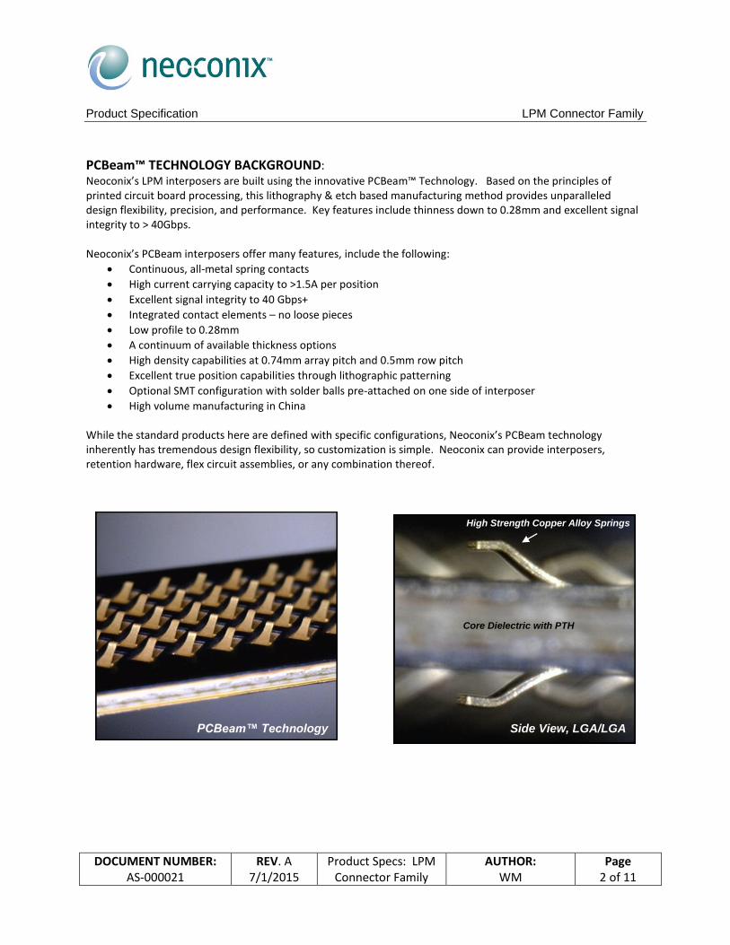
PCBeam™ TECHNOLOGY BACKGROUND: Neoconix’s LPM interposers are built using the innovative PCBeam™ Technology. Based on the principles of printed circuit board processing, this lithography & etch based manufacturing method provides unparalleled design flexibility, precision, and performance. Key features include thinness down to 0.28mm and excellent signal integrity to > 40Gbps. Neoconix’s PCBeam interposers offer many features, include the following:
Continuous, all-metal spring contacts
High current carrying capacity to >1.5A per position
Excellent signal integrity to 40 Gbps+
Integrated contact elements – no loose pieces
Low profile to 0.28mm
A continuum of available thickness options
High density capabilities at 0.74mm array pitch and 0.5mm row pitch
Excellent true position capabilities through lithographic patterning
Optional SMT configuration with solder balls pre-attached on one side of interposer
High volume manufacturing in China While the standard products here are defined with specific configurations, Neoconix’s PCBeam technology inherently has tremendous design flexibility, so customization is simple. Neoconix can provide interposers, retention hardware, flex circuit assemblies, or any combination thereof.
PCBeam™ Technology Side View, LGA/LGA
Low Profile
Flex-to-Board Assembly
Core Dielectric with PTH
High Strength Copper Alloy Springs
Product Specification LPM Connector Family
DOCUMENT NUMBER: AS-000021
REV. A 7/1/2015
Product Specs: LPM Connector Family
AUTHOR: WM
Page 3 of 11
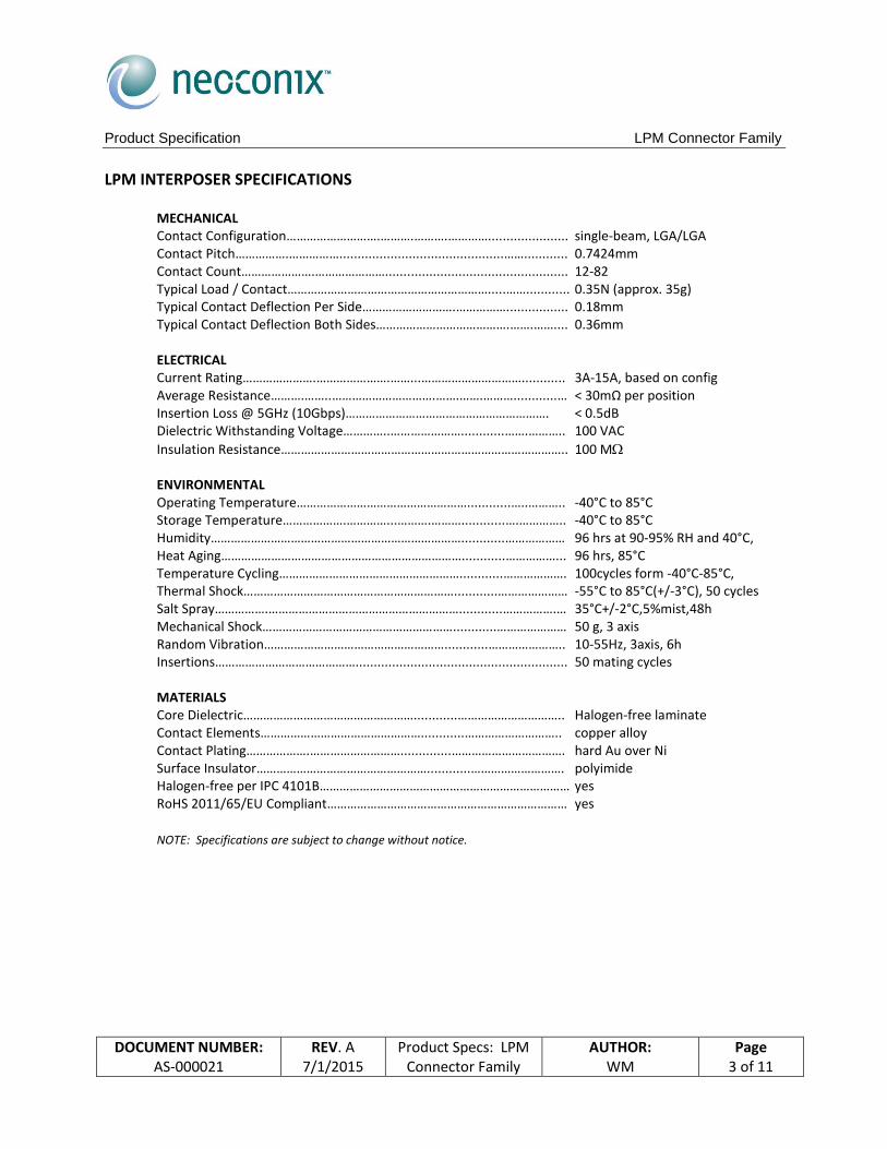
LPM INTERPOSER SPECIFICATIONS
MECHANICAL Contact Configuration……………………….……….……….…………...................... single-beam, LGA/LGA Contact Pitch…………….…………….............................................……............ 0.7424mm Contact Count………………….………………….................................................. 12-82 Typical Load / Contact…………………………………………………….....……............ 0.35N (approx. 35g) Typical Contact Deflection Per Side……………………….……………................. 0.18mm Typical Contact Deflection Both Sides………………………………….…….…….... 0.36mm ELECTRICAL Current Rating………………….………………….……...…………………………............ 3A-15A, based on config Average Resistance……….……..………………………….…….…….………............… < 30mΩ per position Insertion Loss @ 5GHz (10Gbps)……………………………………………………. < 0.5dB Dielectric Withstanding Voltage…………..…………………............…….……….. 100 VAC
Insulation Resistance………………………………………………………………………….. 100 M ENVIRONMENTAL Operating Temperature……………………………………………............…..……….. -40°C to 85°C Storage Temperature……………….…………...……….………............….………….. -40°C to 85°C Humidity…………………………………………………………………............……………… 96 hrs at 90-95% RH and 40°C, Heat Aging………………………………………………………………............……………... 96 hrs, 85°C Temperature Cycling………………………………………………............………………. 100cycles form -40°C-85°C, Thermal Shock………………………………………………………............………………… -55°C to 85°C(+/-3°C), 50 cycles Salt Spray…………….…………………………………………………............…………….… 35°C+/-2°C,5%mist,48h Mechanical Shock…………………………………………………............………………… 50 g, 3 axis Random Vibration………………………………………………............………………….. 10-55Hz, 3axis, 6h Insertions…………………………………….......................................................... 50 mating cycles MATERIALS Core Dielectric……………………………………………............………………………….. Halogen-free laminate Contact Elements…………………………………………............……………………….. copper alloy Contact Plating……………….………………………..............……………………………. hard Au over Ni Surface Insulator……………………………………………............………………………. polyimide Halogen-free per IPC 4101B………………………………………………………………… yes RoHS 2011/65/EU Compliant……………………………………………………………… yes
NOTE: Specifications are subject to change without notice.

Product Specification LPM Connector Family
DOCUMENT NUMBER: AS-000021
REV. A 7/1/2015
Product Specs: LPM Connector Family
AUTHOR: WM
Page 4 of 11
DIMENSIONAL INFORMATION – INTERPOSERS (Example = LPM-044A, 44-position)
Note: This example is for reference only. Please refer to the product drawing for the specific part number of interest.
Product Specification LPM Connector Family
DOCUMENT NUMBER: AS-000021
REV. A 7/1/2015
Product Specs: LPM Connector Family
AUTHOR: WM
Page 5 of 11
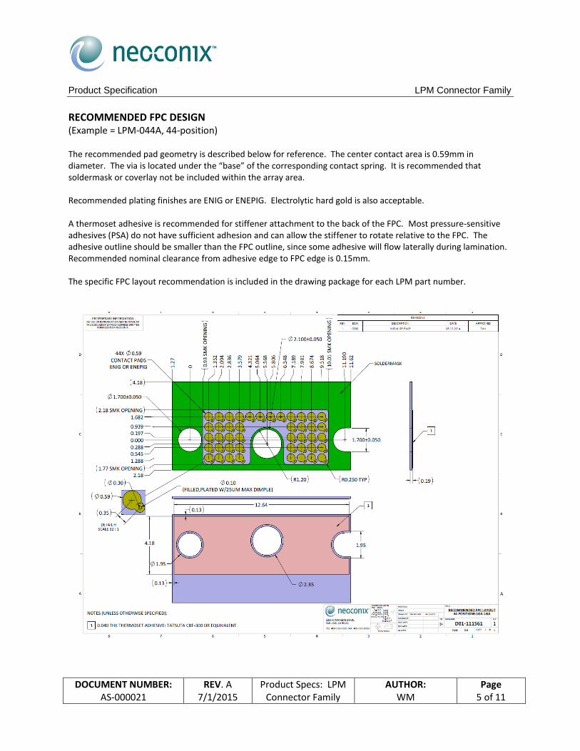
RECOMMENDED FPC DESIGN (Example = LPM-044A, 44-position) The recommended pad geometry is described below for reference. The center contact area is 0.59mm in diameter. The via is located under the “base” of the corresponding contact spring. It is recommended that soldermask or coverlay not be included within the array area. Recommended plating finishes are ENIG or ENEPIG. Electrolytic hard gold is also acceptable. A thermoset adhesive is recommended for stiffener attachment to the back of the FPC. Most pressure-sensitive adhesives (PSA) do not have sufficient adhesion and can allow the stiffener to rotate relative to the FPC. The adhesive outline should be smaller than the FPC outline, since some adhesive will flow laterally during lamination. Recommended nominal clearance from adhesive edge to FPC edge is 0.15mm. The specific FPC layout recommendation is included in the drawing package for each LPM part number.
Product Specification LPM Connector Family
DOCUMENT NUMBER: AS-000021
REV. A 7/1/2015
Product Specs: LPM Connector Family
AUTHOR: WM
Page 6 of 11
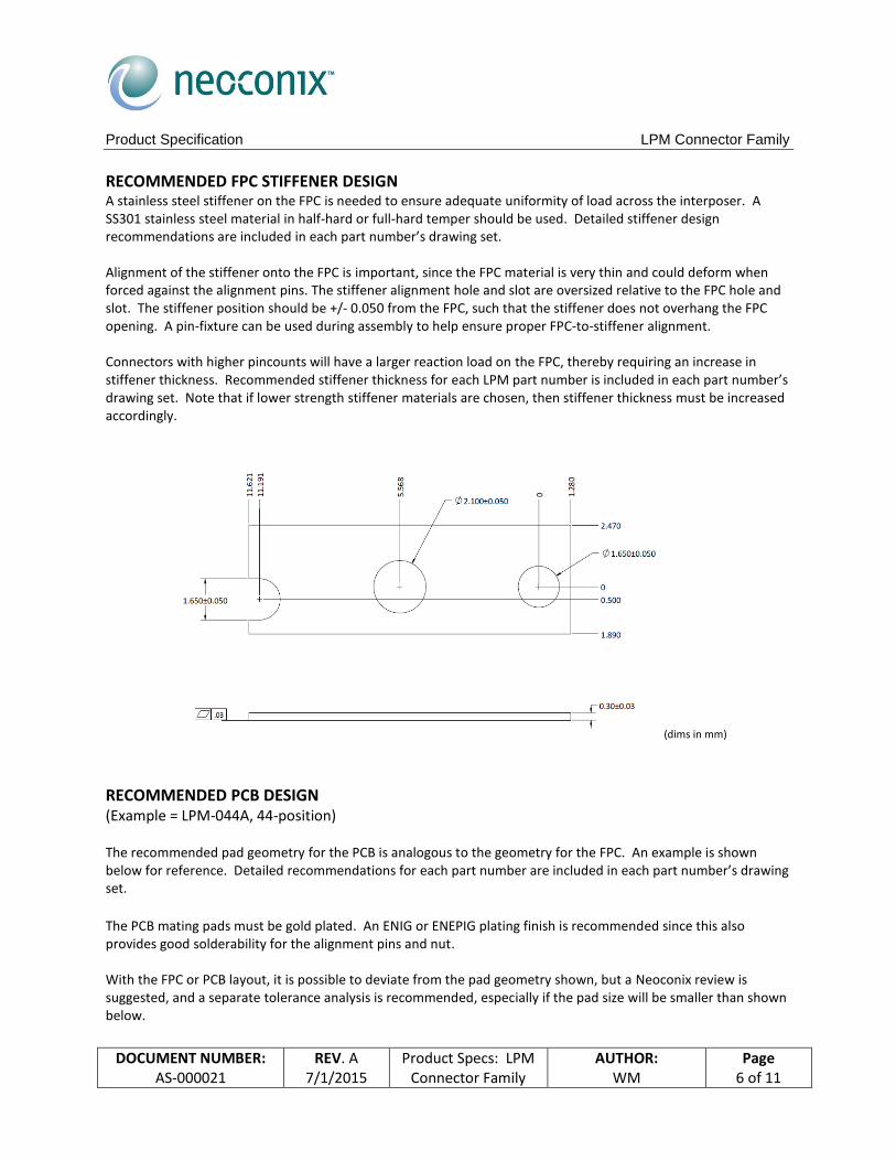
RECOMMENDED FPC STIFFENER DESIGN A stainless steel stiffener on the FPC is needed to ensure adequate uniformity of load across the interposer. A SS301 stainless steel material in half-hard or full-hard temper should be used. Detailed stiffener design recommendations are included in each part number’s drawing set. Alignment of the stiffener onto the FPC is important, since the FPC material is very thin and could deform when forced against the alignment pins. The stiffener alignment hole and slot are oversized relative to the FPC hole and slot. The stiffener position should be +/- 0.050 from the FPC, such that the stiffener does not overhang the FPC opening. A pin-fixture can be used during assembly to help ensure proper FPC-to-stiffener alignment. Connectors with higher pincounts will have a larger reaction load on the FPC, thereby requiring an increase in stiffener thickness. Recommended stiffener thickness for each LPM part number is included in each part number’s drawing set. Note that if lower strength stiffener materials are chosen, then stiffener thickness must be increased accordingly.
(dims in mm)
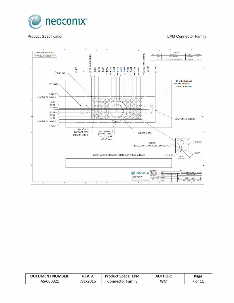
RECOMMENDED PCB DESIGN (Example = LPM-044A, 44-position) The recommended pad geometry for the PCB is analogous to the geometry for the FPC. An example is shown below for reference. Detailed recommendations for each part number are included in each part number’s drawing set.
The PCB mating pads must be gold plated. An ENIG or ENEPIG plating finish is recommended since this also provides good solderability for the alignment pins and nut. With the FPC or PCB layout, it is possible to deviate from the pad geometry shown, but a Neoconix review is suggested, and a separate tolerance analysis is recommended, especially if the pad size will be smaller than shown below.
Product Specification LPM Connector Family
DOCUMENT NUMBER: AS-000021
REV. A 7/1/2015
Product Specs: LPM Connector Family
AUTHOR: WM
Page 7 of 11
Product Specification LPM Connector Family
DOCUMENT NUMBER: AS-000021
REV. A 7/1/2015
Product Specs: LPM Connector Family
AUTHOR: WM
Page 8 of 11
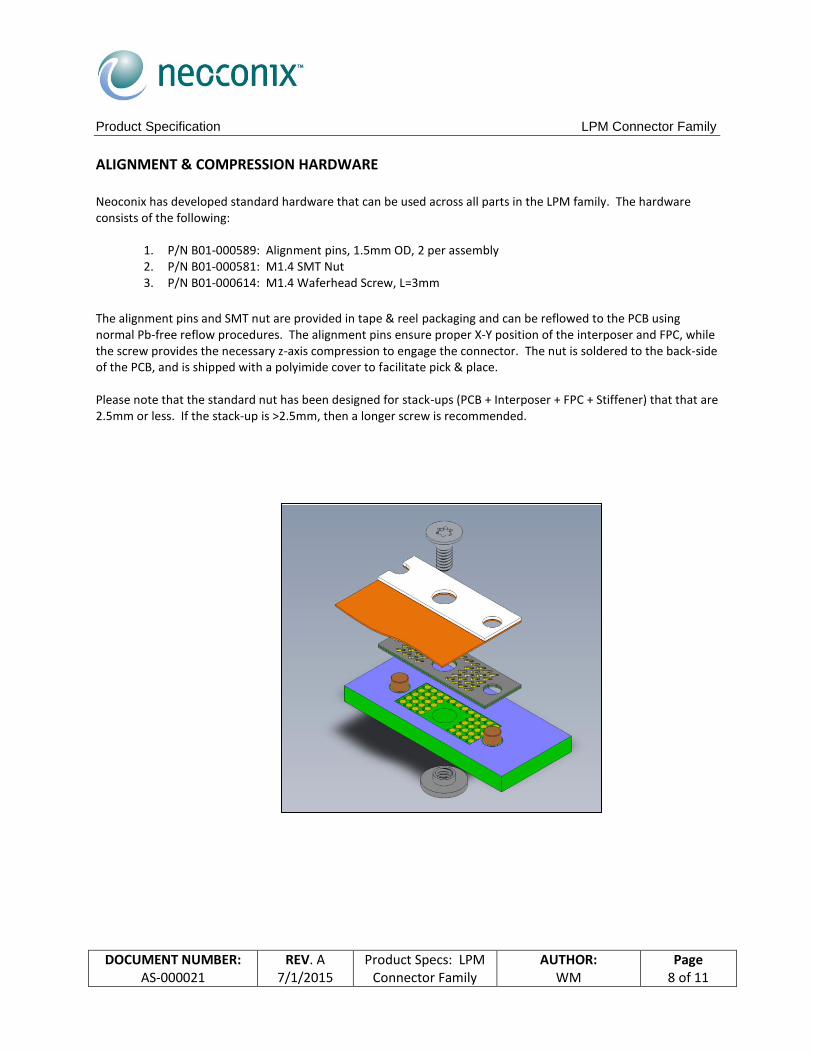
ALIGNMENT & COMPRESSION HARDWARE Neoconix has developed standard hardware that can be used across all parts in the LPM family. The hardware consists of the following:
1. P/N B01-000589: Alignment pins, 1.5mm OD, 2 per assembly 2. P/N B01-000581: M1.4 SMT Nut 3. P/N B01-000614: M1.4 Waferhead Screw, L=3mm
The alignment pins and SMT nut are provided in tape & reel packaging and can be reflowed to the PCB using normal Pb-free reflow procedures. The alignment pins ensure proper X-Y position of the interposer and FPC, while the screw provides the necessary z-axis compression to engage the connector. The nut is soldered to the back-side of the PCB, and is shipped with a polyimide cover to facilitate pick & place. Please note that the standard nut has been designed for stack-ups (PCB + Interposer + FPC + Stiffener) that that are 2.5mm or less. If the stack-up is >2.5mm, then a longer screw is recommended.

Product Specification LPM Connector Family
DOCUMENT NUMBER: AS-000021
REV. A 7/1/2015
Product Specs: LPM Connector Family
AUTHOR: WM
Page 9 of 11
ASSEMBLY INSTRUCTIONS The recommended assembly sequence is as follows:
1. Pre-assemble nut and dowel pins onto PCB using traditional lead-free reflow process (see example reflow profile below).
2. Pre-attach stiffener onto FPC using a conductive thermoset adhesive (TSA), such as Tatsuta CBF300 or similar.
3. Using reverse-action plastic tweezers, pick-up interposer from its center screw hole and place over dowel pins. Orient so the indicator on the interposer lines up with corresponding indicator on PCB.
4. Place the FPC over the dowel pins 5. Turn screw to engage connector. Recommended starting torque is 0.8 kg-cm. Some optimization testing
may be required for your specific assembly. Compression hardware can be custom designed when desired. Please ensure that the hardware solution provides sufficient rigidity assuming 0.4N of contact force is applied by each of the contact element positions. For example, an 80-position interposer would exert approximately 32N (or 7Lbs) of normal force.
PCBeam™ Interposer
SMT Dowel Pins (2X)
FPC w/Stiffener M1.4 Screw
PCB
M1.4 SMT Nut

Product Specification LPM Connector Family
DOCUMENT NUMBER: AS-000021
REV. A 7/1/2015
Product Specs: LPM Connector Family
AUTHOR: WM
Page 10 of 11
Recommended Solder Profile for SAC305 Solder.
HANDLING GUIDELINES
The use of latex gloves is recommended when handling interposers. As with any normal force connector, avoid touching contact tips and handle the product only by its edges.
Mating surfaces should be clean prior to assembly. Foreign contaminants can result in opens or shorts after assembly.
Interposer cleaning is not needed if the product is kept in original packaging. When necessary, cleaning can be employed with the use of compressed air. Direct the flow of air in the direction that the contact elements are pointing. Cleaning can also be performed with an ultrasonic bath of isopropyl alcohol (IPA). A 5 minute soak can be followed by a 10 minute bake at 65°C.
When not in use, please keep product stored in original packaging.
ORDERING INFO To obtain a quotation, please contact the Neoconix sales office at [email protected] or 408-530-9393. Please include the part number(s) of interest. Custom interposers and hardware are also available from Neoconix. Please contact the factory for more information. Corporate Headquarters: Asia Sales Neoconix, Inc. Unimicron Technology 2355-C Paragon Dr. Building A-D, Environment Protection Ind. Zone San Jose, CA 95131 USA Shayi Village, Shajing Town, Baoan District Shenzhen 518104, Guangdong, China (408) 530-9393 (phone) 86-755-27245188 (phone) (408) 530-9383 (fax) 86-755-27245990 (fax) http://www.neoconix.com http://www.unimicron.com/en/product26.htm [email protected] [email protected]

Product Specification LPM Connector Family
DOCUMENT NUMBER: AS-000021
REV. A 7/1/2015
Product Specs: LPM Connector Family
AUTHOR: WM
Page 11 of 11
REVISION HISTORY
Rev A 07/01/2015 Rev A Release