Embed Size (px)
Citation preview
Journal of Colloid and Interface Science 425 (2014) 143–151
Contents lists available at ScienceDirect
Journal of Colloid and Interface Science
www.elsevier .com/locate / jc is
Towards completely miscible PMMA nanocomposites reinforcedby shear-stiff, nano-mica
http://dx.doi.org/10.1016/j.jcis.2014.03.0400021-9797/� 2014 Elsevier Inc. All rights reserved.
⇑ Corresponding author. Fax: +49 921 552788.E-mail address: [email protected] (J. Breu).
Mazen Ziadeh a, Stephan Weiss b, Bianca Fischer c, Stephan Förster d, Volker Altstädt c, Axel H.E. Müller e,Josef Breu a,⇑a Lehrstuhl für Anorganische Chemie I, Universität Bayreuth, Universitätstrasse 30, 95440 Bayreuth, Germanyb Lehrstuhl für Makromolekulare Chemie II, Universität Bayreuth, Universitätstrasse 30, 95440 Bayreuth, Germanyc Lehrstuhl für Polymere Werkstoffe, Universität Bayreuth, Universitätstrasse 30, 95447 Bayreuth, Germanyd Lehrstuhl für Physikalische Chemie I, Universität Bayreuth, Universitätstrasse 30, 95440 Bayreuth, Germanye Institute of Organic Chemistry, Johannes Gutenberg University Mainz, 55099 Mainz, Germany
a r t i c l e i n f o
Article history:Received 18 October 2013Accepted 17 March 2014Available online 26 March 2014
Keywords:Nano-micaPMMA nanocompositesSI-ATRPColloidal stabilityNematic phaseNon-wetting
a b s t r a c t
Optimizing the reinforcement of polymers with nanoplatelets requires optimization of the aspect ratioand the moduli of the filler while providing a complete stress transfer. Employing a novel shear-stiff,nano-mica with large aspect ratio, we focus on maximizing the interfacial interaction between fillerand matrix. External surfaces of the nano-mica were selectively modified by a polycationic macro-initi-ator and two PMMA-polymer brushes of length below and above critical entanglement length, respec-tively, and the mechanical properties of the three PMMA nanocomposites were measured. Themultiple electrostatic anchoring groups of the macro-initiator not only provide reliable adhesion but atthe same time allow the variation of the degree of protonation providing a local match between thecharge densities of the clay surface and the adsorbed macro-initiator. PMMA coating of the nano-micavia surface initiated polymerization yielded long-term stable suspensions in THF that showed birefrin-gence of a nematic phase.
Solution blending of the PMMA coated nano-mica allows for dispersing single clay tactoids in the trans-lucent PMMA nanocomposites at 5 wt% clay loading as determined by transmission electron microscopy(TEM). Although significantly improved mechanical properties could be achieved as compared to nano-composites made with conventional clay fillers, the full potential – as expressed by Halpin–Tsai equa-tions – of the PMMA coated nano-mica can still not be completely utilized. This is attributed to thenon-wetting character of the densely packed PMMA brushes attached to planar nanoplatelets.
� 2014 Elsevier Inc. All rights reserved.
1. Introduction
Incorporation of two-dimensional nanomaterials, in particu-larly anisotropic platelet-like layered compounds such as layeredsilicates [1–3] and layered double hydroxides [4,5], paved theway for cutting-edge composite materials. The incorporation ofsuch nanomaterials into polymeric matrices created new and var-ious fields of nanotechnological applications; for instance superbgas barrier diffusion for packaging [6–8], flame retardancy throughintumescent-like behavior [9], and mechanical reinforcement weredescribed [10] for such polymer layered silicate nanocomposites(PLSN). Nevertheless, there are still fundamental challengeslimiting the progress in all areas which leave room for further
major improvements. These limitations range from the tendencyof such nanoparticles to aggregate in polymeric matrices [11],the dimensions and properties of the dispersed nanoparticles[1,12], and inefficient interface management between thedispersed nanoparticles and the matrix [13]. Over the years,natural montmorillonite (MMT), completely ion exchanged withalkylammonium cations, has emerged as the conventional nanofill-er. However, natural clays have major drawbacks such as theinherent small lateral extension (L) < 250 nm which limits theiraverage aspect ratios to typically less than 100. Furthermore,natural MMT suffers from heterogeneity in surface charge whichconsequently leads to non-uniform interlayer reactivity hamperingcontrol over the nanoplatelets stiffness. Moreover, amorphousmaterials like iron- and aluminum-oxihydroxides acting as bindersrender these fillers difficult to be disaggregated. Even more so to becompletely delaminated into individual silicate layers delivering

144 M. Ziadeh et al. / Journal of Colloid and Interface Science 425 (2014) 143–151
the maximum possible aspect ratio for a given platelet diameter[14–16]. The aspect ratio (a) is expressed by the lateral extension(L) of the platelet divided by its thickness h which is �1 nm for sin-gular 2:1 silicate layer. Furthermore, incomplete delamination ofclay tactoids in the polymer matrix has a detrimental effect onthe mechanical efficiency because the remaining interlayer spacesmay act as inner shear planes inducing failure when introducingshear stress [17].
The shear stiffness may however be increased by collapsing theinterlayer space producing mica-like platelets. In mica, the inter-layer space is bridged by non-hydrated potassium ions protrudinginto cavities of the 2:1 silicate layer on both sides of the interlayerspace. By adjusting the charge density to the hydration enthalpy ofdifferent interlayer cations, a synthetic fluorohectorite even allowsfor switching between a highly hydrated, shear-labile state withMg2+ as interlayer cations and a completely non-hydrated, non-swelling, mica-like, shear-stiff state with K+ as interlayer cations[18]. The shear stiffness is, in turn, related to the flexural rigidityof the reinforcing nanoplatelet, which increases with �h3 and thestrength of the interaction along the stacking direction [19]. There-fore, using a mica-like synthetic clay with high inner shear planestiffness, which allows high dispersion quality in the polymermatrix would be advantageous [18].
This synthetic layered silicate is characterized by an extraordi-nary lateral extension of typically 5–7 lm and layer chargehomogeneity. We have already reported that the incorporation ofsuch high aspect ratio, shear-stiff, nano-mica platelets by meltcompounding enhanced the mechanical properties of PMMA nano-composite significantly [10]. However, the exploitation of the fullpotential of this novel nanomaterial has been hindered by subop-timal dispersion in the polymeric matrix. We now report oncomposite materials with improved interfacial interactionbetween the nanoplatelets and matrix leading to a homogeneousdistribution of nanofiller.
It has already been reported that coating spherical iron oxidenanoparticles with a polymer brush layer provides perfect misci-bility in a polyethylene matrix [20]. Moreover, coating the externalbasal surfaces of the nanoplatelets with polymer brushes of thesame polarity as the matrix is expected to minimize surface ten-sion and to provide the largest possible stress transfer from matrixto nanoplatelets.
When a ‘grafting-from’ approach is taken for coating the nano-platelets with a polymer brush via living polymerization tech-niques such as atom transfer radical polymerization (ATRP), thelength of the brush may be controlled [21]. This allows checkingfor a possible further improvement of stress transfer for brusheslonger than the critical entanglement length.
In this line, MMT has been modified with molecular cationicATRP initiators to graft n-butyl acrylate (BA) and methyl methacry-late (MMA) from the clay surfaces [22,23]. While these molecularinitiators occupy both, internal and external surface, the novelnano-mica allows selective attachment of a polycationic macro-initiator (MIn+) to external surfaces. It is expected that the highershear stiffness of the modified nano-mica provides improved rein-forcement while the optimized interfacial interaction allows for abetter stress transfer in these novel PMMA nanocomposites ascompared to conventional MMT fillers.
2. Experimental and characterization methods
2.1. Materials and chemicals
The starting material for the preparation of the nanofiller is asynthetic Na-fluorohectorite with the chemical formula Na0.5
[Mg2.5Li0.5]Si4O10F2 and a CEC of 110 meq./100 g [24]. The aspect
ratio was tuned to an average of 500 by exfoliation of the highlyhydrated state, represented by the presence of Mg2+ cations inthe interlayer space, in a stirred media mill. Subsequent cation ex-change with K+ cations yields a collapsed non-swollen and shear-stiff, K-nano-mica with no intracrystalline reactivity [18,25].
2-Cyano-2-propyl benzodithioate (CPBT) (97%, Aldrich), 2-bromoisobutyryl bromide (98%, Alfa-Aesar), triethylamine (min.99%, Aldrich), 2-hydroxyethyl methacrylate (HEMA) (97% Aldrich)and N,N,N0,N00,N00-pentamethyldiethylenetriamine (PMDETA) (97%,Aldrich) were used as received without further purification. Ethyl2-bromoisobutyrate (EBiB) (99%, Aldrich) was used as free sacrificialinitiator. Azobisisobutyronitrile (AIBN) (98%, Aldrich) was used afterrecrystallization twice from methanol. Solvents such as Tetrahydro-furan (THF), Dimethyl sulfoxide (DMSO), Dimethylacetamide(DMAc) and anisole, all in p.a grade were purchased from Aldrichand used as received unless stated. Dichloromethane (p.a. Aldrich)was stored over molecular sieves (3 Å) to remove water traces.2-Dimethylaminoethyl methacrylate (DMAEMA) (98% Aldrich) andmethyl methacrylate (MMA) (99% Aldrich) were passed over a basicalumina column to remove stabilizer prior to polymerization.2-(2-Bromoisobutyryloxy)ethyl methacrylate (BIEM) was synthe-sized according to literature [26]. A commercial PMMA (PlexiglasPOQ62 supplied by Evonik Industries) was used as matrix. PMMAhas a molecular weight (Mw) of 73 kg/mol with a polydispersityindex of 1.63.
2.2. Synthesis of poly(2-(2-bromoisobutyryloxy) ethyl methacrylate)-stat-(2-(dimethylamino) ethyl methacrylate) (MIn+)
To a 100 ml round bottom flask, equipped with rubber septum,BIEM (1.7 g; 6.1 mmol), DMAEMA (6.7 g; 42.8 mmol), 2-Cyano-2-propyl benzodithioate (CPBT), (270 mg; 1.2 mmol), AIBN(100 mg; 0.6 mmol) and 40 ml of DMSO as solvent in addition to2 ml of anisole as internal standard were added. After threefreeze–pump–thaw cycles the reaction was placed into an oil bathat 70 �C for 4 h (Fig. S1) to reach a conversion of 54% as determinedby 1H NMR spectroscopy. The resulting polymer solution wascooled, exposed to air and dialysed against dioxane until no mono-mer related peaks at 5.8–6.4 ppm were detected by 1H NMR spec-troscopy. Mn = 9000 g/mol and Mw = 14000 g/mol was determinedvia SEC with DMAc as eluent and a DMAEMA calibration. 1H NMR(300 MHz, CDCl3, d in ppm): 4.4–4.1 (R–C(–CH3)–COO–CH2–CH2–OOC–C(CH3)2–Br), 4.0 (R–C(–CH3)–COO–CH2–CH2–N–(CH3)2), 2.6(R–C(–CH3)–COO–CH2–CH2–N–(CH3)2), 2.2 (R–C(–CH3)–COO–CH2–CH2–N–(CH3)2), 1.9 (R–C(–CH3)–COO–CH2–CH2–OOC–C(CH3)2–Br), 1.8 (R–C(–CH3)–COO–CH2–CH2–N–(CH3)2).
2.3. Organophilization and surface initiated (SI)-ATRP of PMMAbrushes
The external surface of K-nano-mica (10 g) was flocculated witha solution of MI (330 mg) in DI water at pH = 7.2. Subsequently, theflocculated hydrophobic nanoplatelets (MI/nano-mica) were cen-trifuged and redispersed in THF for few times. The grafting ofMMA was initiated from MI/nano-mica via a copper mediatedATRP in the presence of EBiB as a free sacrificial initiator. All exper-iments were performed under inert atmosphere in a conventionalrun procedure [21,27]; A dispersion of the MI/nano-mica (10 g;calculated 370 lmol of initiating sites) in 400 ml THF, MMA(164.5 g; 1.462 mol) and EBiB (19 mg; 97.5 lmol) were added toa flask and sealed with a rubber septum. The reaction mixturewas degassed three times by freeze–pump–thaw cycles and filledwith argon. In a separate flask a stock solution of PMDETA, Cu(I)Cland Cu(II)Cl2 (338 mg; 975 lmol, 115.8 mg; 1.17 mmol and39.2 mg; 292.5 lmol) in 20 ml anisole was degassed for 30 min un-der argon. Finally, 10 ml of the stock solution was introduced to the

M. Ziadeh et al. / Journal of Colloid and Interface Science 425 (2014) 143–151 145
reaction flask by a syringe. The reaction flask was immersed in anoil bath at 80 �C. Samples were withdrawn at various times tomonitor the reaction kinetics by determining the monomer con-version from the integration of the residual monomer peaks by1H NMR spectroscopy with anisole as an internal standard. Averagemolecular weights and molecular weight distribution were mea-sured by size exclusion chromatography (SEC) for the free polymerinitiated from the sacrificial initiator. The free polymer was recov-ered after passing over a basic alumina column to separate the claynanoplatelets. The reaction was stopped after 300 min by coolingand exposing to air. The same procedure was repeated and thereaction was stopped after 30 min for shorter PMMA brushes.The final hybrids of PMMA coated nano-mica were centrifugedand washed few times with THF to remove the free PMMA chainsand finally redispersed in THF.
2.4. Preparation of PMMA/nano-mica nanocomposites
A solution blending route was applied for optimum dispersion ofthe modified nano-mica in the matrix. Nano-mica suspension inTHF was mixed with a solution of PMMA in THF (5 wt% clay loading)and placed in an overhead shaker for 18 h for homogenization.Subsequently, the suspension was film casted and dried in an ovenunder vacuum at 90 �C for 18 h and at 140 �C for another 8 h. Thedried composite materials were cryo-grinded to fine powder priorto melt compounding. The compounding was done in a discontinu-ous counter rotating twin-screw micro-compounder (DSM Xplore,15 ml micro-compounder) at a temperature of 200 �C, a mixingspeed of 210 rpm and a mixing time of 3 min. The material wasadded batch wise to the running micro-compounder and duringeach cycle a batch of 11 g was processed. After extrusion, the meltwas injection-moulded with a microinjector (DSM Xplore 12 mlinjection moulding machine; melt temperature: 190 �C; mouldtemperature: 40 �C; injection pressure: 8 bar) into dumbbellspecimens (75 mm � 5 mm � 2 mm) for tensile testing.
2.5. Instrumentation and characterization
Determination of point of zero charge of the external basal sur-face was done using charge titration stability analyzer (Stabisizer�,Particle Metrix GmbH). Aqueous dispersion of K-nano-mica(30 mg) was titrated with MI solution (1 g/L) at different pH values.The transmittance absorption spectra were recorded on a NicoletFTIR 460 (Thermo Nicolet Corp.) using 64 scans at 4 cm�1 spectralresolution at room temperature. The specific surface area of afreeze-dried K-nano-mica sample was calculated from the N2
adsorption/desorption isotherms (Quantachrome Nova 2000e ana-lyzer) applying the Brunauer–Emmett–Teller (BET) equation. In thenon-swollen K-nano-mica, the interlamellar space is no longeraccessible and the CEC and BET values are attributed solely tothe external basal planes of the tactoids. Due to the high aspect ra-tio observed for the synthetic fluorohectorite, the contribution ofthe edges to the specific surface area can be safely ignored.
Monomer conversion was determined from the integration ofthe residual monomer peaks by 1H NMR spectroscopy with anisoleas an internal standard. The 1H NMR spectroscopy was performedon a Bruker Avance 300 spectrometer. Average molecular weightsand molecular weight distribution were measured by conventionalsize exclusion chromatography (SEC). Column set: 5 lm SDV� gel,102, 103, 104, and 105 Å, 30 cm each (PSS, Mainz). Detectors usedare refractive index (RI) and UV operated at 254 nm. The numberaverage (Mn) and weight average (Mw) molecular weights were cal-culated by using a calibration curve which was constructed usingPMMA with low dispersity as standard (PMMA standards series,PSS, Mainz). DMAc or THF was used as eluent at a flow rate of1 ml/min.
Thermal gravimetric analysis (TGA) was conducted on a MettlerTG 50/TA 3000 thermobalance. Samples were heated at a heatingrate of 20 K/min from 30 to 600 �C under oxidative atmosphere.The morphology of the surface was examined by scanning electronmicroscope (SEM) using a Zeiss EM 922 EFTEM (Carl Zeiss GmbH)with an acceleration voltage of 200 kV. The stability measurementswere performed in a LUMiFuge� 114 (LUM) with a variable rota-tion frequency of 300, 600, 900 rpm and different time intervalsof 200 s and 400, respectively. Clay suspensions (0.5 wt%) in THFand water were placed in tubes in horizontal positions on the discof the LUMiFuge�. During the horizontal rotation of this disc thetransparencies of the suspensions were measured in the area be-tween the menisci and the sediment. The mean transparency ofthe whole area was determined. The transparency was measuredin time intervals of 10 s while increasing rotation speed stepwise.The optical parameters transmittance, haze, and clarity of thePMMA/nano-mica composites were measured on a BYK Gardnerhaze-gard plus in accordance with ASTM D1003 ‘‘Standard TestMethod for Haze and Luminous Transmittance of Transparent Plas-tics’’. Transmission electron microscope (TEM) measurementswere carried out on a Zeiss CEM 902 EFTEM with an accelerationvoltage of 200 kV. Specimens were microtomed to obtain 30–50 nm thick pieces, which were placed on a lacey carbon coppergrid. Tensile modulus, tensile strength and elongation at breakwere measured using a Universal Tensile Tester according to ISO527 applying a strain rate of 1 mm/min. For each material at least6 samples were tested. The elongation was determined by a macro-displacement-transducer.
3. Results and discussion
3.1. Preparation of PMMA coated nano-mica nanofiller
3.1.1. Tailoring of high aspect ratio K-nano-micaAs previously shown [18], with synthetic Na-fluorohectorite the
subtle balance between layer charge and hydration enthalpy of dif-ferent interlayer cations allows for controlled transformation be-tween a highly hydrated and a non-hydrated state by simplecation exchange. This transition between hydration states cannotbe observed for natural MMT due to both heterogeneity of chargedensity and lower average layer charge. The highly hydrated andtherefore ‘shear-labile’ state, in which Mg2+ cations occupy theinterlayer space (basal spacing: d = 18.6 Å), enables an efficientexfoliation to increase the aspect ratio by applying shear forcesin a stirred media mill [25]. Subsequent cation exchange with K+
cations yields a collapsed non-swollen and shear-stiff, mica-likenanofiller (nano-mica, d = 9.9 Å) (Fig. 1a). A rough estimate of theaverage aspect ratio can be calculated using a previously intro-duced method which correlates the tactoid thickness as deter-mined by the Scherrer equation with the value of the totalspecific surface area [18]. Thus, by having a median particle sizedistribution, X50 = 6.4 lm as determined by static light scatteringand a large external specific surface area of 60 m2/g as obtainedvia N2 adsorption/desorption measurement applying the BET equa-tion, we can estimate an average aspect ratio of 500 for theK-nano-mica used here. This nanofiller combines the best of twoworlds, the stiffness of the mica sandwich and an aspect ratiosignificantly larger than what can be obtained with natural MMT.
3.1.2. Selective surface modificationThe pristine K-nano-mica obtained still carries hydrated inor-
ganic K+ on the outer surface. To transfer it into a hydrophobicpolymer matrix, its surface tension has to be lowered to improvethe matrix-filler interaction and to prevent aggregation of the filler.Any aggregation (see discussion below for details) will lower the

Fig. 1. (a) A schematic representation of tailoring high aspect ratio shear-stiff, K-nano-mica nanoplatelets after exfoliation and exchanging the interlayer cations and (b)selective modification of only the external basal surface using MIn+.
Fig. 2. Charge titration of K-nano-mica (30 mg in 10 ml DI water) with MIn+
solution (1 g/l) until point of zero charge as a function of pH, related to the degree ofprotonation (h): ( ) pH = 4.6; h = 100%, ( ) pH = 5.5; h = 75%, ( ) pH = 6.4; h = 50%and (j) pH = 7.2; h = 25%.
146 M. Ziadeh et al. / Journal of Colloid and Interface Science 425 (2014) 143–151
specific interface in the composite and such reduce the potentialimprovements of composite properties. A polycationic macro-initi-ator (MIn+) was employed for modification of the nano-mica. TheMIn+ consists of a statistical copolymer of DMAEMA and BIEM ina 3:1 ratio with an average degree of polymerization (DP) of 40units (Fig. S1). This polymeric modifier is unable to intercalate be-tween the silicate layers and the cation exchange is restricted toouter basal surfaces leaving the basal spacing unchanged. More-over, the multiple electrostatic anchoring by ammonium groupsincorporated in the backbone of the MIn+ allow for a more reliableadhesion to the nano-mica as compared to single charged molecu-lar anchoring groups. The successful modification was confirmedqualitatively by FT-IR (Fig. S2).
MIn+ not only is firmly anchored but at the same time the de-gree of protonation can be varied and by this the charge densityof the macro-initiator can be adjusted to the charge density ofthe clay surface. Furthermore, each MIn+ chain bears an averageof ten potential initiator groups for a surface-initiated (SI)-ATRP,subsequently enabling a controlled grafting of polymeric brushesfrom the surface of the modified nano-mica. The charge (n+) ofthe macro-initiator, MIn+, can be tuned by adjusting the pH andtherefore the degree of protonation of the amine groups of theDMAEMA. The influence of charge variation on the adsorbed poly-cationic MIn+ on the external basal surface of nano-mica and its ef-fect on stability has been investigated. The charged DMAEMAgroups can be anchored onto the surface by a cation exchange withthe K+ cations and the uncharged amine groups act as neutralspacer (Fig. 1b).
To attain different degrees of protonation of the amine functionof DMAEMA, the pH of the solution was adjusted using acetic acid[28]. The charge titration curves at different pH solutions with thesame amount of K-nano-mica are shown in Fig. 2. The amount ofMIn+ anchored on the external basal surface at the point of zerocharge as expected increases with decreasing degree of protonation.
Concomitantly with annihilation of the surface charge, themodification of K-nano-mica with Min+ leads to organophilizationof the clay altering its state from hydrophilic to hydrophobic andleading to flocculation of nanoplatelets in aqueous solution. Thequality of the dispersion in THF after organophilization with MIn+
is significantly influenced by the loading of MIn+. As a semi-quan-titative measurement of dispersion stability, forced sedimentationexperiments were performed applying a LUMiFuge� 114 (Fig. S3).The integrated transparency of a 0.5 wt% suspensions in THF ofK-nano-mica modified with MIn+ at pH = 7.2; h = 25% is signifi-cantly higher as compared to all other samples suggesting that thispacking density of MIn+ gives the most stable dispersion in
organophilic environments. Consequently, controlled polymeriza-tions were focused on the K-nano-mica modified with MIn+ atpH = 7.2 (h: 25%) and this material will be referred to as MI/nano-mica hereafter.
3.1.3. Surface initiated (SI)-ATRP of PMMA brushesThe grafting-from process of planar PMMA brushes was initi-
ated from the basal planes of the MI/nano-mica. The determinationof the molecular weight of grafted polymer was facilitated by anal-ysis of free chains formed in solution using a sacrificial-initiator.EBiB was used as initiator for free chains due to its structural sim-ilarity to the incorporated BIEM in the MIn+.
A good correlation between the molecular weights of theseloose polymer chains grown in solution and the molecular weightsof polymer brushes anchored to a surface has been shown before[29,30]. The ATRP technique allows the grafted chains to growslowly and simultaneously. Therefore, it is possible to obtainbrushes with narrow molecular weight distribution and polydis-persity. Table 1 lists the number and weight average molecularweights Mn and Mw of the free PMMA grown in solution deter-mined by SEC as a function of reaction time. The differences

Table 1Molecular weights of the free PMMA chains as a function of polymerization time in THF.
Time (min) Conv.a (%) DPa Mna (kg/mol) DPb Mn
b (kg/mol) Mwb (kg/mol) PDIb
10 1 36 3.5 84 8.4 10.0 1.220 2 72 7.2 100 10.0 13.0 1.330 4 120 12.0 150 15.0 17.0 1.160 5 143 14.3 190 19.0 23.0 1.2
120 7 203 20.3 310 31.0 36.0 1.2300 9 263 26.3 380 38.0 50.0 1.3
a Determined by 1H NMR spectroscopy.b Determined by SEC with THF as eluent and PMMA calibration.
Fig. 4. TGA measurements of (a) MI/nano-mica, (b) short PMMA coated nano-mica(DP 150) and of (c) long PMMA coated nano-mica (DP 380).
M. Ziadeh et al. / Journal of Colloid and Interface Science 425 (2014) 143–151 147
between theoretical and experimental values can be assigned to aninitiation efficiency of less than 100%.
The reaction shows a controlled character with polydispersityindex close to 1. Fig. 3 (left) shows the evaluation of ln[M]0/[M]vs. time where, polymerization rate slows down after 120 min.This indicates that the number of the initiating species remainsapproximately constant up to 120 min reaction time and thenstarts to decrease. Furthermore, by plotting the molecular weightvs. conversion as in Fig. 3 (right), a linear increase ascertainedthe controlled behavior of the reaction.
The amount of surface grafted PMMA was examined by TGA(Fig. 4). As expected, the PMMA coated nano-mica with longerpolymer chains showed a higher weight loss of organic material.Weight losses observed below 100 �C are assigned to remainingsolvent and are neglected in the calculation. MI/nano-mica wasfound to have 3.1% loss of volatile materials after heating to400 �C. The grafted PMMA coated nano-mica showed a weight lossof 13.0% and 32.5% for grafted PMMA chains with a DP of 150(short PMMA) and 380 (long PMMA), respectively.
The grafting density and initiation efficiency represented by thenumber of chains per nm2 can be calculated from the TGA and SECdata.
All calculations of grafting density were based on the followingformulas:
r ¼ MI � NA
SAð1Þ
r0 ¼ MP � NA
SAð2Þ
where r is the grafting density (initiator per nm2), r0 is the graftingdensity (chain per nm2), MI is molar amount of the initiating speciesper g of MI/nano-mica, MP is the molar amount of PMMA chains, NA
Fig. 3. ( ) Plots of ln[M]0/[Mt] vs. time for the solution polymerization of free PM
is the Avogadro constant and SA is the specific surface area of the K-nano-mica.
A grafting density of 0.30 ATRP initiator functions per nm2 wascalculated from (1). For the PMMA coated nano-mica calculations,(2) gave a grafting density of 0.087 and 0.086 chains per nm2 cor-responding to an initiation efficiency of 29% and 28% for DP 150and DP 380, respectively. The relatively low efficiency can beattributed to certain issues in the applied polymerization system:whereas, copper-complexes used as catalysts can adsorb/ion-ex-change onto the surface of the nanoplatelets. Indeed the PMMAcoated nano-micas have a deep blue color due to adsorbed catalyst
MA. ( ) evolution of molecular weight with conversion of MMA monomers.

Fig. 6. Dispersions (1 wt%) of unmodified K-nano-mica in water (left), MI/nano-mica in THF (middle) and PMMA coated nano-mica (DP 380) in THF (right).
Fig. 7. Integrated transparency of 0.5 wt% dispersions under time dependentcentrifugal forces of 300, 600 and 900 rpm; (j) MI/nano-mica in THF, ( ) PMMAcoated nano-micas in THF (DP 150), ( ) PMMA coated nano-micas in THF (DP 380)and ( ) unmodified K-nano-mica in water.
148 M. Ziadeh et al. / Journal of Colloid and Interface Science 425 (2014) 143–151
(Fig. 6) and thus, reduction of the concentration of free catalyst willslow down kinetics of the polymerization.
The morphological changes of external surfaces of the nano-mica before and after polymerization were analyzed using SEM.The K-nano-mica after exfoliation has a large lateral extensionand a smooth surface (Fig. 5a) when compared to the rough surfaceof MI/nano-mica (Fig. 5b). The grafted PMMA brushes gives arougher and coarse surface with pattern typical for collapsedPMMA chains in a dried state forming mushroom-like structures(Fig. 5c), as expected for the achieved high grafting density [31].
3.2. Dispersion quality and stability in solvents
3.2.1. Shear induced birefringenceTypically, particles in colloidal suspension are randomly ori-
ented. When anisotropy comes into play, like with K-nano-micananoplatelets of 500 aspect ratio, the particles might no longerbe able to move independently, in particular when objected tolamellar flows [32–34]. In Fig. 6 (left) a dispersion of unmodifiedK-nano-mica in water is compared to dispersions of MI/nano-micaand PMMA coated nano-mica in THF. As already mentioned theblue color of the latter is due to adsorbed/ion-exchanged copper-complexes used as a catalyst for ATRP.
A gentle movement of the containers induces a vivid birefrin-gence of a nematic phase in both unmodified K-nano-mica in waterand PMMA coated nano-mica (DP 380) in THF (Fig. 6 left and right).However, the dispersion of MI/nano-mica in THF (Fig. 6 middle) isnot stable enough to observe this birefringence. Stirring generatesa lamellar flow, causing the clay platelets to orient parallel in theshear field. Platelets in the stack can no longer rotate freely andthe distance of the platelets is fixed by lateral extension of theplatelets which is in the range of visible light allowing birefringenceto be observed with the naked eye. Observation and evidence ofoptical birefringence which demonstrates the existence of a liquidcrystalline order of the platelet-like particles has already been re-ported for aqueous smectite suspensions [34–36]. The nematicphase displays a threaded Schlieren pattern resulting from the ori-entation of individual particles with high aspect ratio [37]. Interest-ingly, the occurrence of birefringence seems to be a first opticalindication of the quality of dispersion as will be discussed next.
3.2.2. Stability of dispersionThe stability of the colloidal dispersions was investigated in a
semi-quantitative way by forced sedimentation experimentsapplying a LUMiFuge� 114. Fig. 7 compares the integrated trans-parency of unmodified K-nano-mica in an aqueous dispersion withMI/nano-mica and two PMMA coated nano-micas in THF.
The K-nano-mica suspension in water is highly hydrophilic andcarries a high negative surface potential resulting in the most
Fig. 5. SEM images of (a) exfoliated K-nano-mica, (b) surface morphology of MI/nano-mica and (c) surface of PMMA coated nano-mica (DP 380) indicating collapsed polymerchains (Arrows indicate clay fragments from the milling treatment).
M. Ziadeh et al. / Journal of Colloid and Interface Science 425 (2014) 143–151 149
stable suspension. Due to the large lateral dimension of platelets itstill sediments. All organophilized samples in THF are less stable ascompared to K-nano-mica in an aqueous dispersion. The fact thatTHF is a good solvent for PMMA explains the greatly enhanced sta-bility of the PMMA coated nano-mica which improves withincreasing chain length. DP 380 at low centrifugal forces(300 rpm) even matches the stability of K-nano-mica in an aque-ous dispersion. Please note that these two samples also are theones for which optical birefringence could be observed contraryto the less stable MI/nano-mica suspension in THF.
3.3. PMMA/nano-mica nanocomposites
3.3.1. Optical characteristicThe optical properties of PMMA/nano-mica nanocomposites at
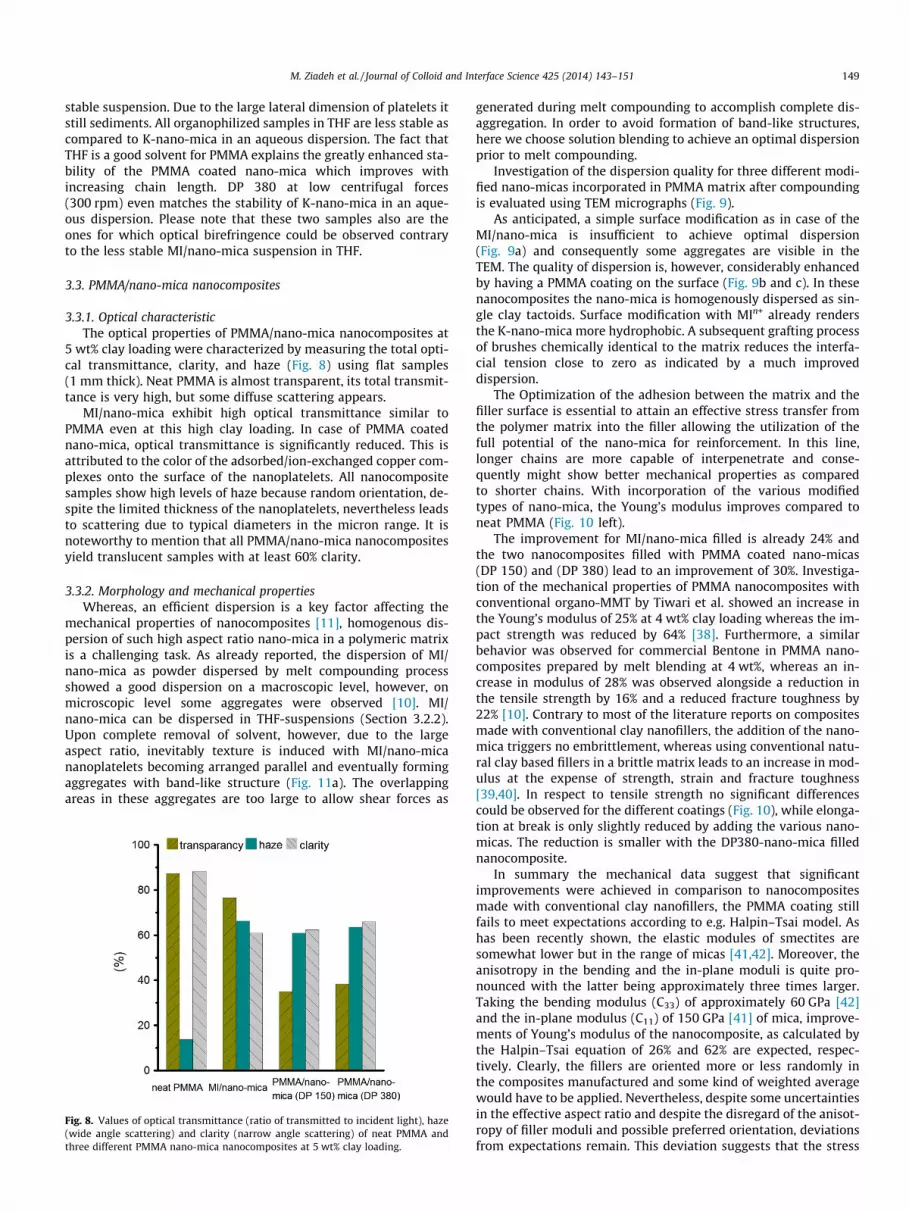
5 wt% clay loading were characterized by measuring the total opti-cal transmittance, clarity, and haze (Fig. 8) using flat samples(1 mm thick). Neat PMMA is almost transparent, its total transmit-tance is very high, but some diffuse scattering appears.
MI/nano-mica exhibit high optical transmittance similar toPMMA even at this high clay loading. In case of PMMA coatednano-mica, optical transmittance is significantly reduced. This isattributed to the color of the adsorbed/ion-exchanged copper com-plexes onto the surface of the nanoplatelets. All nanocompositesamples show high levels of haze because random orientation, de-spite the limited thickness of the nanoplatelets, nevertheless leadsto scattering due to typical diameters in the micron range. It isnoteworthy to mention that all PMMA/nano-mica nanocompositesyield translucent samples with at least 60% clarity.
3.3.2. Morphology and mechanical propertiesWhereas, an efficient dispersion is a key factor affecting the
mechanical properties of nanocomposites [11], homogenous dis-persion of such high aspect ratio nano-mica in a polymeric matrixis a challenging task. As already reported, the dispersion of MI/nano-mica as powder dispersed by melt compounding processshowed a good dispersion on a macroscopic level, however, onmicroscopic level some aggregates were observed [10]. MI/nano-mica can be dispersed in THF-suspensions (Section 3.2.2).Upon complete removal of solvent, however, due to the largeaspect ratio, inevitably texture is induced with MI/nano-micananoplatelets becoming arranged parallel and eventually formingaggregates with band-like structure (Fig. 11a). The overlappingareas in these aggregates are too large to allow shear forces as
Fig. 8. Values of optical transmittance (ratio of transmitted to incident light), haze(wide angle scattering) and clarity (narrow angle scattering) of neat PMMA andthree different PMMA nano-mica nanocomposites at 5 wt% clay loading.
generated during melt compounding to accomplish complete dis-aggregation. In order to avoid formation of band-like structures,here we choose solution blending to achieve an optimal dispersionprior to melt compounding.
Investigation of the dispersion quality for three different modi-fied nano-micas incorporated in PMMA matrix after compoundingis evaluated using TEM micrographs (Fig. 9).
As anticipated, a simple surface modification as in case of theMI/nano-mica is insufficient to achieve optimal dispersion(Fig. 9a) and consequently some aggregates are visible in theTEM. The quality of dispersion is, however, considerably enhancedby having a PMMA coating on the surface (Fig. 9b and c). In thesenanocomposites the nano-mica is homogenously dispersed as sin-gle clay tactoids. Surface modification with MIn+ already rendersthe K-nano-mica more hydrophobic. A subsequent grafting processof brushes chemically identical to the matrix reduces the interfa-cial tension close to zero as indicated by a much improveddispersion.
The Optimization of the adhesion between the matrix and thefiller surface is essential to attain an effective stress transfer fromthe polymer matrix into the filler allowing the utilization of thefull potential of the nano-mica for reinforcement. In this line,longer chains are more capable of interpenetrate and conse-quently might show better mechanical properties as comparedto shorter chains. With incorporation of the various modifiedtypes of nano-mica, the Young’s modulus improves compared toneat PMMA (Fig. 10 left).
The improvement for MI/nano-mica filled is already 24% andthe two nanocomposites filled with PMMA coated nano-micas(DP 150) and (DP 380) lead to an improvement of 30%. Investiga-tion of the mechanical properties of PMMA nanocomposites withconventional organo-MMT by Tiwari et al. showed an increase inthe Young’s modulus of 25% at 4 wt% clay loading whereas the im-pact strength was reduced by 64% [38]. Furthermore, a similarbehavior was observed for commercial Bentone in PMMA nano-composites prepared by melt blending at 4 wt%, whereas an in-crease in modulus of 28% was observed alongside a reduction inthe tensile strength by 16% and a reduced fracture toughness by22% [10]. Contrary to most of the literature reports on compositesmade with conventional clay nanofillers, the addition of the nano-mica triggers no embrittlement, whereas using conventional natu-ral clay based fillers in a brittle matrix leads to an increase in mod-ulus at the expense of strength, strain and fracture toughness[39,40]. In respect to tensile strength no significant differencescould be observed for the different coatings (Fig. 10), while elonga-tion at break is only slightly reduced by adding the various nano-micas. The reduction is smaller with the DP380-nano-mica fillednanocomposite.
In summary the mechanical data suggest that significantimprovements were achieved in comparison to nanocompositesmade with conventional clay nanofillers, the PMMA coating stillfails to meet expectations according to e.g. Halpin–Tsai model. Ashas been recently shown, the elastic modules of smectites aresomewhat lower but in the range of micas [41,42]. Moreover, theanisotropy in the bending and the in-plane moduli is quite pro-nounced with the latter being approximately three times larger.Taking the bending modulus (C33) of approximately 60 GPa [42]and the in-plane modulus (C11) of 150 GPa [41] of mica, improve-ments of Young’s modulus of the nanocomposite, as calculated bythe Halpin–Tsai equation of 26% and 62% are expected, respec-tively. Clearly, the fillers are oriented more or less randomly inthe composites manufactured and some kind of weighted averagewould have to be applied. Nevertheless, despite some uncertaintiesin the effective aspect ratio and despite the disregard of the anisot-ropy of filler moduli and possible preferred orientation, deviationsfrom expectations remain. This deviation suggests that the stress

Fig. 9. TEM micrographs of PMMA nanocomposite with incorporated (a) MI/nano-mica, (b) PMMA coated nano-mica (DP150), and (c) PMMA coated nano-mica (DP380) at5 wt% clay loading.
Fig. 10. (Left). ( ) Young’s modulus and (right). (j) tensile strength and ( ) elongation at break for neat PMMA and three different PMMA/nano-mica filled nanocomposites.
Fig. 11. Schematic representation showing (a) drying effect on tactoid resulting inband-like structure aggregates, (b) non-wetting character of platelet-like nanopar-ticles exhibiting heterogeneities in polymer length and grafting density and (c)wetting character of spherical nanoparticles having a high density of graftedpolymer brushes from the surface.
150 M. Ziadeh et al. / Journal of Colloid and Interface Science 425 (2014) 143–151
transfer from the matrix to the nanofiller might still be suboptimal,even for DP380 nano-mica filled nanocomposites.
This in turn might be related to the lack of chain interpenetra-tion (wetting) between the polymer matrix chains and the graftedpolymer brush chains of the DP380 nano-mica filler. For brushesattached to a flat clay surface, the packing density does not de-crease with distance from the surface as for spheres but stays con-stant (Fig. 11). With grafting densities of 0.086 chains per nm2 forDP 380 a rather dense packing with stretched chains is expected[43] that inhibits penetration of polymer chains into the matrix(Fig. 11b). The wettabilty of a brush layer depends on the polymersegment density at the periphery of the brush, which is determinedby the grafting density, but also by the degree of polymerization ofthe grafted polymer. Brushes consisting of long polymer chains, asin the present case (DP = 380, contour length ca. 100 nm) with aratio of contour length/grafting distance 10:1 are in the moder-ate-to-dense brush regime with a rather high segment density[44]. Fery et al. have for instance recently studied the influenceof different polymeric glassfiber coatings on the interfacial shearstrength of epoxy resin based composites [45]. They presented evi-dence that the grafting density is the most crucial parameter to at-tain high interfacial adhesion and they found the highestinterfacial shear strength for grafting densities below 0.05 chainsper nm2. The surface roughness seen in the SEM images (Fig. 5c)is induced by heterogeneities in the grafting density resulting fromnon-equilibrium structures of adsorbed MIn+. While these hetero-geneities trigger segment density variations at the periphery ofthe coating, this will not allow chain interdigitation needed forgood wetting.
This wetting behavior is quite different from spherical nanopar-ticles coated by polymer brushes that are wettable even at high

M. Ziadeh et al. / Journal of Colloid and Interface Science 425 (2014) 143–151 151
grafting density. This is because the density of brushes attached toa spherical particle declines quickly from a dense regime close tothe core towards a loose regime at the periphery of the brush layersegment (Fig. 11c). Even at high grafting density, there is a suffi-cient conformational freedom allowing to interpenetrate with thematrix polymer chains [46]. Therefore, such spherical nanoparti-cles exhibit a wetting character leading to completely misciblenanofiller.
4. Conclusion
Hydrophilic K-nano-mica can be rendered hydrophobic withoutsacrificing aspect ratio by aggregation by grafting PMMA brushesfrom external surfaces modified with a macro-initiator (MIn+).Moreover, for this synthetic clay, modification can be restrictedto the external basal plans while dehydrated K-ions crosslink inter-layers yielding shear-stiff nano-mica. Subsequently, (SI)-ATRP en-ables a controlled grafting of PMMA brushes propagated from themodified MI/nano-mica surface. For these PMMA coated nano-mi-cas, a vivid birefringence of a nematic phase may be observed withthe naked eye alongside a remarkable stability of suspensions inTHF. Solution blending yields well dispersed single tactoids inthe translucent PMMA nanocomposites. Although significantly im-proved mechanical properties could be achieved as compared tonanocomposites made with conventional clay fillers, the full po-tential, as expressed by Halpin–Tsai equations, of the PMMAcoated nano-mica can still not be utilized. This is attributed tothe non-wetting character of the densely packed PMMA brushesattached to planar nanoplatelets.
Acknowledgments
The authors would like to thank Lena Geiling for here help inthe compounding experiments and for SEM micrographs. Ziadeh,M. would like to thank Dr. Christian Kuttner for valuable discus-sion. The financial support from the ‘Deutsche Forschungsgemeins-chaft’ (Germany) in the frame of the Collaborative Research Centre(SFB) 840 is highly acknowledged.
Appendix A. Supplementary material
Supplementary data associated with this article can be found, inthe online version, at http://dx.doi.org/10.1016/j.jcis.2014.03.040.
References
[1] H. Fischer, Mater. Sci. Eng., C 23 (2003) 763–772.[2] P.C. LeBaron, Z. Wang, T.J. Pinnavaia, Appl. Clay Sci. 15 (1999) 11–29.[3] K. Tamura, S. Yokoyama, C.S. Pascua, H. Yamada, Chem. Mater. 20 (2008)
2242–2246.[4] L.A. Utracki, M. Sepehr, E. Boccaleri, Polym. Adv. Technol. 18 (2007) 1–37.[5] Q. Wang, X. Zhang, J. Zhu, Z. Guo, D. O’Hare, Chem. Commun. 48 (2012) 7450–
7452.[6] D.A. Kunz, J. Schmid, P. Feicht, J. Erath, A. Fery, J. Breu, ACS Nano 7 (2013)
4275–4280.
[7] K.S. Triantafyllidis, P.C. LeBaron, I. Park, T.J. Pinnavaia, Chem. Mater. 18 (2006)4393–4398.
[8] M.W. Möller, D.A. Kunz, T. Lunkenbein, S. Sommer, A. Nennemann, J. Breu, Adv.Mater. 24 (2012) 2142–2147.
[9] M.R. Schütz, H. Kalo, T. Lunkenbein, J. Breu, C.A. Wilkie, Polymer 52 (2011)3288–3294.
[10] B. Fischer, M. Ziadeh, A. Pfaff, J. Breu, V. Altstädt, Polymer 53 (2012) 3230–3237.
[11] R.A. Vaia, H.D. Wagner, Mater. Today 7 (2004) 32–37.[12] E. Manias, Nat. Mater. 6 (2007) 9–11.[13] M. Si, T. Araki, H. Ade, A.L.D. Kilcoyne, R. Fisher, J.C. Sokolov, M.H. Rafailovich,
Macromolecules 39 (2006) 4793–4801.[14] J. Breu, K.J. Range, E.E. Kohler, U. Wagner, Appl. Clay Sci. 8 (1993) 313–320.[15] H.M. Köster, Clay Miner. 31 (1996) 417–422.[16] K. Vogt, H.M. Köster, Clay Miner. 13 (1978) 25–43.[17] D.A. Brune, J. Bicerano, Polymer 43 (2002) 369–387.[18] M.W. Möller, U.A. Handge, D.A. Kunz, T. Lunkenbein, V. Altstädt, J. Breu, ACS
Nano 4 (2010) 717–724.[19] N. Sheng, M.C. Boyce, D.M. Parks, G.C. Rutledge, J.I. Abes, R.E. Cohen, Polymer
45 (2004) 487–506.[20] M. Bieligmeyer, S.M. Taheri, I. German, C. Boisson, C. Probst, W. Milius, V.
Altstädt, J. Breu, H.W. Schmidt, F. D’Agosto, S. Förster, J. Am. Chem. Soc. 134(2012) 18157–18160.
[21] K. Matyjaszewski, P.J. Miller, N. Shukla, B. Immaraporn, A. Gelman, B.B.Luokala, T.M. Siclovan, G. Kickelbick, T. Vallant, H. Hoffmann, T. Pakula,Macromolecules 32 (1999) 8716–8724.
[22] D. Lerari, S. Peeterbroeck, S. Benali, A. Benaboura, P. Dubois, J. Appl. Polym. Sci.121 (2011) 1355–1364.
[23] H. Zhao, S.D. Argoti, B.P. Farrell, D.A. Shipp, J. Polym. Sci. A Polym. Chem. 42(2004) 916–924.
[24] H. Kalo, M.W. Möller, M. Ziadeh, D. Dolejs, J. Breu, Appl. Clay Sci. 48 (2010) 39–45.
[25] M. Ziadeh, B. Chwalka, H. Kalo, M.R. Schütz, J. Breu, Clay Miner. 47 (2012) 341–353.
[26] Y. Cai, S.P. Armes, Macromolecules 38 (2004) 271–279.[27] H. Bottcher, M.L. Hallensleben, S. Nuß, H. Wurm, J. Bauer, P. Behrens, J. Mater.
Chem. 12 (2002) 1351–1354.[28] F.A. Plamper, M. Ruppel, A. Schmalz, O. Borisov, M. Ballauff, A.H.E. Müller,
Macromolecules 40 (2007) 8361–8366.[29] M. Ejaz, Y. Tsujii, T. Fukuda, Polymer 42 (2001) 6811–6815.[30] M. Husseman, E.E. Malmström, M. McNamara, M. Mate, D. Mecerreyes, D.G.
Benoit, J.L. Hedrick, P. Mansky, E. Huang, T.P. Russell, C.J. Hawker,Macromolecules 32 (1999) 1424–1431.
[31] T. Wu, K. Efimenko, P. Vlcek, V. Šubr, J. Genzer, Macromolecules 36 (2003)2448–2453.
[32] I. Langmuir, J. Chem. Phys 6 (1938) 873–896.[33] L. Onsager, Ann. N. Y. Acad. Sci. 51 (1949) 627–659.[34] E. DiMasi, J.O. Fossum, T. Gog, C. Venkataraman, Phys. Rev. 64 (2001).[35] H. Hemmen, N.I. Ringdal, E.N. De Azevedo, M. Engelsberg, E.L. Hansen, Y.
Méheust, J.O. Fossum, K.D. Knudsen, Langmuir 25 (2009) 12507–12515.[36] J.C. Gabriel, C. Sanchez, P. Davidson, J. Phys. Chem. 100 (1996) 11139–11143.[37] P. Davidson, J.C. Gabriel, Curr. Opin. Colloid Interface Sci. 9 (2005) 377–383.[38] R.R. Tiwari, U. Natarajan, Polym. Int. 57 (2008) 738–743.[39] P. Meneghetti, S. Qutubuddin, Thermochim. Acta 442 (2006) 74–77.[40] J.H. Liaw, T.Y. Hsueh, T.S. Tan, Y. Wang, S.M. Chiao, Polym. Int. 56 (2007) 1045–
1052.[41] D.A. Kunz, J. Erath, D. Kluge, H. Thurn, B. Putz, A. Fery, J. Breu, ACS Appl. Mater.
Interfaces 5 (2013) 5851–5855.[42] D.A. Kunz, E. Max, R. Weinkamer, T. Lunkenbein, J. Breu, A. Fery, Small 5 (2009)
1816–1820.[43] S. Yamamoto, M. Ejaz, Y. Tsujii, T. Fukuda, Macromolecules 33 (2000) 5608–
5612.[44] L.C.H. Moh, M.D. Losego, P.V. Braun, Langmuir 27 (2011) 3698–3702.[45] C. Kuttner, A. Hanisch, H. Schmalz, M. Eder, H. Schlaad, I. Burgert, A. Fery, ACS
Appl. Mater. Interfaces 5 (2013) 2469–2478.[46] S. Fischer, A. Salcher, A. Kornowski, H. Weller, S. Förster, Angew. Chem. Int. Ed.
50 (2011) 7811–7814.


