Embed Size (px)
Citation preview

Reduced Order Modeling Enables System Level Simulation of a MEMS Piezoelectric Energy Harvester with a Self-Supplied SSHI-Scheme
F. Sayed1, T. Aftab1, M. Eker2, D. Hohlfeld2, T. Bechtold1, J. G. Korvink1,3
1 Institute for Microsystems Engineering - IMTEK, Freiburg University, Germany 2 Reutlingen University, Reutlingen, Germany
3 Freiburg Institute of Advanced Studies - FRIAS, Freiburg University, Germany corresponding author: [email protected]
Abstract This paper proposes a novel modeling methodology
for MEMS-based piezoelectric vibration energy harvesting systems. The approach is based on coupling of the reduced order model and the power circuitry. A numerically accurate reduced order model of the harvester was connected to a synchronized switch harvesting on inductor scheme and optimized subsequently. The harvester output voltage was increased by 17% under open circuit condition.
1. Introduction Energy efficiency plays a vital role in human life,
where different techniques are used in order to harvest the energy from the surrounding environment. Energy harvesting systems make use of the wasted ambient energy such as temperature gradient, flowing water or vibration by converting them to electrical energy using different physical effects. This gives wireless microsystems the capability to act as a battery-free or independent power supplies. The vibration energy in rails, roads and machines can be harvested using the piezoelectric effect [1]. Each piezoelectric harvester system has two main sections: a transducer which is responsible for the energy conversion process (the mechanical deformation of the piezoelectric material is converted to electrical energy), and an electrical circuit to manage the electrical energy generated from the mechanical vibrations [2].
Since the mechanical power of the source is limited, the generated electrical power at the resonance frequency ranges between a few 10µW and a few mW. Increasing the conversion ability of the piezoelectric material can be achieved by increasing the piezoelectric output voltage, reducing the time shift between the speed and the voltage and increasing the electro-mechanical coupling coefficient. Changing the coupling coefficient depends on the material itself. Although, single crystals are recently investigated, they are not widely used in real applications due to their high cost, low conformability and fabrication processing complexity [3].
In order to obtain a DC-voltage supply, full-bridge or voltage-doubling rectifiers are commonly used. Their main disadvantage is the low power extraction efficiency. In order to improve the conversion ability different nonlinear synchronized switching approaches, which take advantage of the capacitive behavior of the piezoelectric material, have been investigated [3,4].
The main principle these switching techniques is to create an oscillating circuit by connecting the piezoelectric element to an inductor. This allows for shaping an additional piecewise voltage proportional to the velocity and larger than the original voltage [3]. This approach enhances the conversion process as it increases the generated output voltage and reduces the time shift between both the voltage and the speed-related current.
In the synchronized switch harvesting on inductor (SSHI) approach [2], an inductor is temporarily connected to the piezoelectric-element. This enables reversing the harvested voltage instead of discharging it every half cycle. The inductor can be connected in parallel, in which case the voltage inversion happens after the energy extraction process, or in series, where the voltage inversion and the energy extraction occur simultaneously [3,4]. This approach increases the converted energy compared to the standard case (using the bridge rectifier). Still, the efficiency increases only to a small amount due to the losses in the harvesting stages [4].
Another approach is the synchronous electric charge extraction (SECE), which extracts the electrostatic energy from the piezoelectric-element at its maximum value, then transforms it to electromagnetic energy in the inductor. After releasing the connection to the inductor, the stored energy in the inductor is transferred to a storage stage. In this case the harvested power will not depend on the electric load thanks to the decoupling between the extraction and the storage stages, but the extraction process can’t be controlled which limits the voltage increase process (no inversion is performed) [3]. More advanced approaches are developed by combining the previous two.
The main challenge in these methods is to synchronize the voltage inversion with the harvester motion, as this determines the energy transfer efficiency. Several recent publications present control circuits with relative high complexity and mandatory external power supply [5, 6]. Furthermore, in order to consider the interaction between the device and the circuitry all presented works use a lumped element description for the harvester. This representation is of limited accuracy and only applicable at the resonance frequency.
In this work we focus on multi-physical compact modeling using mathematical model order reduction

(MOR). This methodology maintains the accuracy of the original numerical model of the harvester while simultaneously reducing the transient simulation time by several orders of magnitude [7].
Our main goal is to build a system level model, which includes a highly accurate reduced order model connected to a simple control circuit for a self-supplied SSHI scheme. Besides harmonic signals the proposed modeling approach is also able to consider non-resonant excitation of the energy harvester and the co-simulation with the electrical circuit.
2. MEMS-based Piezoelectric Energy Harvester The MEMS based piezoelectric energy harvester
shown in Fig. 1, is composed of a micromachined mechanical resonator [1].
Figure 1: Schematic design of a piezoelectric energy
harvester based on clamped-guided beams and multiple mass segments [1].
The beam segments of the resonator integrate
capacitors with aluminum nitride as a piezoelectric material. The resonator amplifies the ambient vibration to a significant mass displacement. This causes deformation of the piezoelectric material which generates a surface charge and respectively a voltage across the capacitor electrodes of the piezoelectric element. Under oscillations a bridge rectifier can convert the sinusoidal voltage output of the harvesting capacitor to a DC current flowing into a capacitor as an energy storage component. The mechanical energy extracted from the harvester is thus stored as electrical energy.
Figure 2: Top view of fabricated piezoelectric MEMS
energy harvester with multiple masses and beams [1]. In this work, the vibration harvester consists of one
seismic mass and two trusses as shown in Fig. 1and
Fig. 2. The seismic mass is attached to the trusses via two mass beams while the two trusses are attached to the silicon substrate via four truss beams. The beams can be considered either as clamped-guided or clamped-free depending on the mode shape. This results in either tensile together with compressive stress (clamped-guided) or in one stress type only (clamped-free) at the top surface. in order to harvest energy from these two opposite types of stress two separated capacitors are fabricated on top of each of the six beams [8].
3. Finite Element Model and Numerical Results The commercial finite element simulator ANSYS
Workbench (V 14.5), is used to design a three dimensional geometry for the harvester. An element with three translational degrees of freedom using an anisotropic elasticity matrix and density as material parameters is used for the crystalline silicon part of the model. A solid element type with displacement and potential degrees of freedom is used to model the piezoelectric layer on the beams. The potential degrees of freedom are coupled on the top and the bottom surfaces of the piezoelectric material. This represents the conductive metal layers acting as electrical interfaces.
Figure 3: Model and mesh view of the piezoelectric
energy harvester. The mesh density was increased in the beam and
the piezoelectric patch sections in order to consider their relatively high compliance contribution as indicated in Fig. 3. A much bigger element size was applied to the more stiff segments (mass, truss and substrate). The total number of nodes amounts to 47.800. Depending on the attributed material each node features either three or four degrees of freedom so that the model dimension is around 145.000. The material properties of the piezoelectric layer were using an anisotropic stiffness matrix and appropriate piezoelectric stress and orthotropic permittivity coefficients. A fixed support boundary condition was applied to the bottom and outer facets of the silicon substrate. A damped modal analysis (stiffness coefficient = 4,5·10-7) yielded the resonance frequencies 1.966,2 Hz and 3.755,6 Hz for the modes shown in Fig. 4 and Fig. 5: These mode shape provide useful deformation to the piezoelectric patches. Other modes include rotational motion with asymmetric

strain distribution, thus canceling any electrical field generation.
Figure 4: Mode shape and strain distribution at
1.966,2 Hz. Mass and truss segments move in-phase. Beam segments can be considered as clamped-guided. The two piezoelectric-patches on one beam experience tensile and compressive strain respectively.
Figure 5: Mode shape and strain distribution at
3.755,6 Hz. Beam segments can be considered as clamped-free. Both piezoelectric- patches on one beam experience identical strain type.
4. Model Order Reduction Model order reduction refers to a number of
mathematical algorithms that transform large systems of ordinary differential equations, as those emerging from finite element models, into much smaller systems as the original one [9]. Fig. 6 shows schematically the usage of MOR within a process of deriving a system level model from the physical device model. The intermediate step is the device level, which is a high dimensional ordinary differential equation (ODE) system. We perform the first conversion of the physical to the device model via the finite element discretization. For our model, the governing equations are derived [10] from the principle of virtual work density.
∙ ∙ (1)
where u denotes displacement in [m], φ the electric potential in [V], F the mechanical force density in [N/m3], σ the charge density in [C/m] and δ a virtual quantity. The constitutive piezoelectric equations:
∙ ∙∙ ∙
(2)
where T is the stress tensor in [N/m2], S is the strain tensor in [m/m], E is the electric field in [V/m], D is the electric charge displacement in [C/m2], c is the
elastic stiffness tensor in [N/m2], e is the piezoelectric coupling tensor in [C/m2], and ε is the electric permittivity of the material in [F/m].
Figure 6: Model order reduction as a viable tool in
generation of compact models.
A finite element discretization of (1) and (2) under consideration of mechanical damping and the assumption of loss-free piezoelectric material, results in the following second order system of n + k (in total 145.517) equations:
1 1 11 12 11
221 22 22 2
X XM 0 D 0 K K B X. + . + . = . u
X0 0 0 0 K K BX X
1
1 2
2
Xy = C C .
X
(3)
where [M] is the structural mass matrix, [D] is the structural damping matrix, [K11] is the structural stiffness matrix, [K12] is the forward piezoelectric coupling matrix, [K21] is the reverse piezoelectric coupling matrix, [K22] is the dielectric conductivity matrix, X1 is the vector of size n of nodal displacements, X2 the vector of size k of nodal electrical potentials, u the concatenated vector of input forces and charges, [B1] and [B2] are scattering matrices that translate the input vector into domain forces, y is a concatenated vector of potentials and displacements which are to be observed and finally [C1] and [C2] are collecting matrices which collect some components of the state vector and translate them into system outputs.
We wish to reduce the system (3) in order to enable the co-simulation between the device and the power circuitry. The Arnoldi-based reduction technique, being well scalable and numerically very robust, is one of the most popular approaches for microsystems modeled by large-scale linear ODE systems of first and second order [11, 12]. Furthermore, this technique can be partly applied to the reduction of nonlinear models as well [13, 14]. An important aspect within a reduction process is the preservation of stability and passivity. In [15] it has been shown that the system matrices of the original model have to be positive-definite in order to preserve stability within the reduced order model. This is not the case with the piezoelectric system (3). In [16] the authors have transformed (3) into a first order system of 2n + k equations and have used a first order Arnoldi-based MOR preceded by some algebraic operations to preserve the stability and the passivity of the reduced model. In [8] we have used a more efficient second order Arnoldi-based MOR from [17] preceded by a Schur-complement type transformation (for preserving the stability) to construct a model of the same form as (3) but with solely 50 second order ODEs.
This methodology maintains the accuracy of the original numerical device model, while reducing the computation time for transient simulations by several orders of magnitude (Table 1). Fig. 7 shows a comparison of time domain results obtained from the full-scale model and the reduced order model of the harvester. This MOR is based on Arnoldi-algorithm, which matches the transfer functions of the full and reduced model. The expansion has been chosen at zero, thus preserving the system's frequency response in the low-frequency domain.
Table 1: Comparison of integration times and number of
equations between the full and the reduced model (3.1 GHz with 8 GB RAM)
full model reduced model
computation time (s) 6.269,0 4,71
model dimension 145.517 50
Figure 7: Transfer functions of the full and of the reduced
model near fundamental resonance frequency.
5. SSHI Circuit Implementation
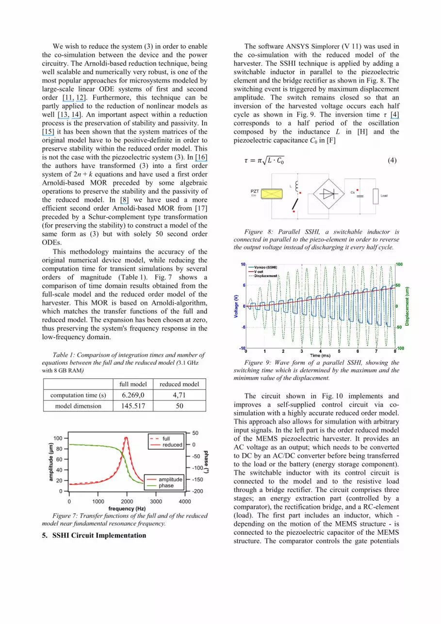
The software ANSYS Simplorer (V 11) was used in the co-simulation with the reduced model of the harvester. The SSHI technique is applied by adding a switchable inductor in parallel to the piezoelectric element and the bridge rectifier as shown in Fig. 8. The switching event is triggered by maximum displacement amplitude. The switch remains closed so that an inversion of the harvested voltage occurs each half cycle as shown in Fig. 9. The inversion time τ [4] corresponds to a half period of the oscillation composed by the inductance L in [H] and the piezoelectric capacitance C0 in [F]
∙ (4)
Figure 8: Parallel SSHI, a switchable inductor is
connected in parallel to the piezo-element in order to reverse the output voltage instead of discharging it every half cycle.
Figure 9: Wave form of a parallel SSHI, showing the
switching time which is determined by the maximum and the minimum value of the displacement.
The circuit shown in Fig. 10 implements and
improves a self-supplied control circuit via co-simulation with a highly accurate reduced order model. This approach also allows for simulation with arbitrary input signals. In the left part is the order reduced model of the MEMS piezoelectric harvester. It provides an AC voltage as an output; which needs to be converted to DC by an AC/DC converter before being transferred to the load or the battery (energy storage component). The switchable inductor with its control circuit is connected to the model and to the resistive load through a bridge rectifier. The circuit comprises three stages; an energy extraction part (controlled by a comparator), the rectification bridge, and a RC-element (load). The first part includes an inductor, which - depending on the motion of the MEMS structure - is connected to the piezoelectric capacitor of the MEMS structure. The comparator controls the gate potentials
100
80
60
40
20
0
am
plit
ud
e (
µm
)
40003000200010000frequency (Hz)
-200
-150
-100
-50
0
50
ph
as
e (°)
amplitude phase
full reduced

of the MOSFET-switches, which are connected to the inductor. The comparator consists of two MOSFET transistors biased by two self-charging capacitors from the harvester output voltage. The gate potential of one MOSFET is proportional to the derivative of the piezoelectric voltage resp. mass velocity.
Synchronization of switch activity with the harvester motion is essential, as it leads to optimum voltage inversion and thus determines the energy transfer efficiency.
6. Results and Discussion The reduced order model of the harvester is excited
at a frequency of 2kHz. The transient simulation results of the output voltage using the bridge rectifier alone and by connecting the SSHI circuit are presented in Fig. 11. The output voltage at open circuit increased from 3.7V to 4.5V.
Figure 11: Transient simulation of system-level response (left); detailed view on the voltage variation (right).
In the presented circuit the output voltage at
optimum resistive load of 5.6kΩ was 1.67V and the harvested power was 0.52mW. The power dissipation in each part of the circuit is summarized in Table. 2. Although the output voltage is increased by 17% the output power did not improve as presented in Fig. 12 (0.55mW using bridge rectifier), the efficiency is kept at 50% due to the electrical losses in the harvesting
stages and the mechanical re-injection losses. Where driving the harvester at the resonance frequency by a force with constant amplitude, results in vibration damping effect. This limits the input energy and thus the harvested energy, and affects the quality factor for the inversion oscillating network [3].
Figure 12: Power optimization of the device with load resistance.
Table 2: Power dissipation at various parts of the circuit.
comparator switch bridge rectifier load
1% 0% 29% 70% The SSHI-circuit in Fig. 10 was assembled and
connected to a piezoelectric harvester. The voltage supply to comparator was provided externally. The harvester was excited with sinusoidal acceleration of 0.3g at the harvester resonance frequency. The voltage across the piezo-element was observed together with a signal representing the harvester motion. Measured voltage characteristics are presented in Fig. 13. One identifies the voltage inversion events in the Vpiezo signal occurring between maximum mass deflection as a consequence of an oscillation process occurring at the piezoelectric capacitance and the inductor. In the present case maximum power is obtained at an optimum load resistance of 3.9 kΩ. Dissipation of
5
4
3
2
1
0
vo
lta
ge
(V
)
20151050
time (ms)
30.029.529.0
Vpiezo
Vout,SSHI
Vout
Figure 10: System-level schematic comprising the MOR representation of a high dimensional FEM; with mechanical port
(left) and electrical port (right), self-supplied comparator, switchable inductive branch for voltage inversion, full-bridge rectifier with flattening capacitor and resistive load (parallel-SSHI).
MultiphysicsMOR
pos1
pos2
p
m
F
Bridge rectifeirSwitching inductorSelf-supplied comparator
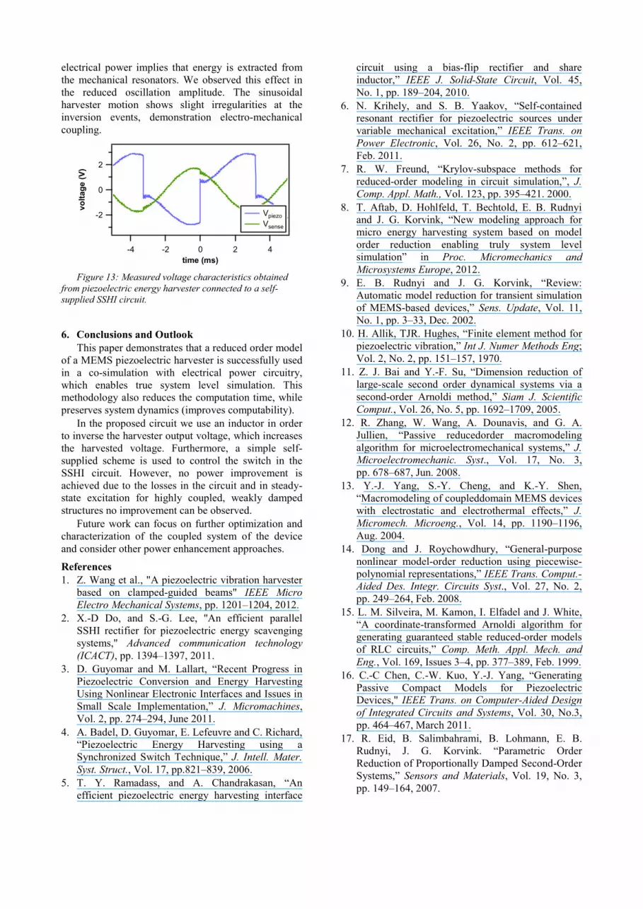
electrical power implies that energy is extracted from the mechanical resonators. We observed this effect in the reduced oscillation amplitude. The sinusoidal harvester motion shows slight irregularities at the inversion events, demonstration electro-mechanical coupling.
Figure 13: Measured voltage characteristics obtained from piezoelectric energy harvester connected to a self-supplied SSHI circuit.
6. Conclusions and Outlook This paper demonstrates that a reduced order model
of a MEMS piezoelectric harvester is successfully used in a co-simulation with electrical power circuitry, which enables true system level simulation. This methodology also reduces the computation time, while preserves system dynamics (improves computability).
In the proposed circuit we use an inductor in order to inverse the harvester output voltage, which increases the harvested voltage. Furthermore, a simple self-supplied scheme is used to control the switch in the SSHI circuit. However, no power improvement is achieved due to the losses in the circuit and in steady-state excitation for highly coupled, weakly damped structures no improvement can be observed.
Future work can focus on further optimization and characterization of the coupled system of the device and consider other power enhancement approaches.
References 1. Z. Wang et al., "A piezoelectric vibration harvester
based on clamped-guided beams" IEEE Micro Electro Mechanical Systems, pp. 1201–1204, 2012.
2. X.-D Do, and S.-G. Lee, ''An efficient parallel SSHI rectifier for piezoelectric energy scavenging systems,'' Advanced communication technology (ICACT), pp. 1394–1397, 2011.
3. D. Guyomar and M. Lallart, “Recent Progress in Piezoelectric Conversion and Energy Harvesting Using Nonlinear Electronic Interfaces and Issues in Small Scale Implementation,” J. Micromachines, Vol. 2, pp. 274–294, June 2011.
4. A. Badel, D. Guyomar, E. Lefeuvre and C. Richard, “Piezoelectric Energy Harvesting using a Synchronized Switch Technique,” J. Intell. Mater. Syst. Struct., Vol. 17, pp.821–839, 2006.
5. T. Y. Ramadass, and A. Chandrakasan, “An efficient piezoelectric energy harvesting interface
circuit using a bias-flip rectifier and share inductor,” IEEE J. Solid-State Circuit, Vol. 45, No. 1, pp. 189–204, 2010.
6. N. Krihely, and S. B. Yaakov, “Self-contained resonant rectifier for piezoelectric sources under variable mechanical excitation,” IEEE Trans. on Power Electronic, Vol. 26, No. 2, pp. 612–621, Feb. 2011.
7. R. W. Freund, “Krylov-subspace methods for reduced-order modeling in circuit simulation,”, J. Comp. Appl. Math., Vol. 123, pp. 395–421. 2000.
8. T. Aftab, D. Hohlfeld, T. Bechtold, E. B. Rudnyi and J. G. Korvink, “New modeling approach for micro energy harvesting system based on model order reduction enabling truly system level simulation” in Proc. Micromechanics and Microsystems Europe, 2012.
9. E. B. Rudnyi and J. G. Korvink, “Review: Automatic model reduction for transient simulation of MEMS-based devices,” Sens. Update, Vol. 11, No. 1, pp. 3–33, Dec. 2002.
10. H. Allik, TJR. Hughes, “Finite element method for piezoelectric vibration,” Int J. Numer Methods Eng; Vol. 2, No. 2, pp. 151–157, 1970.
11. Z. J. Bai and Y.-F. Su, “Dimension reduction of large-scale second order dynamical systems via a second-order Arnoldi method,” Siam J. Scientific Comput., Vol. 26, No. 5, pp. 1692–1709, 2005.
12. R. Zhang, W. Wang, A. Dounavis, and G. A. Jullien, “Passive reducedorder macromodeling algorithm for microelectromechanical systems,” J. Microelectromechanic. Syst., Vol. 17, No. 3, pp. 678–687, Jun. 2008.
13. Y.-J. Yang, S.-Y. Cheng, and K.-Y. Shen, “Macromodeling of coupleddomain MEMS devices with electrostatic and electrothermal effects,” J. Micromech. Microeng., Vol. 14, pp. 1190–1196, Aug. 2004.
14. Dong and J. Roychowdhury, “General-purpose nonlinear model-order reduction using piecewise-polynomial representations,” IEEE Trans. Comput.-Aided Des. Integr. Circuits Syst., Vol. 27, No. 2, pp. 249–264, Feb. 2008.
15. L. M. Silveira, M. Kamon, I. Elfadel and J. White, “A coordinate-transformed Arnoldi algorithm for generating guaranteed stable reduced-order models of RLC circuits,” Comp. Meth. Appl. Mech. and Eng., Vol. 169, Issues 3–4, pp. 377–389, Feb. 1999.
16. C.-C Chen, C.-W. Kuo, Y.-J. Yang, “Generating Passive Compact Models for Piezoelectric Devices," IEEE Trans. on Computer-Aided Design of Integrated Circuits and Systems, Vol. 30, No.3, pp. 464–467, March 2011.
17. R. Eid, B. Salimbahrami, B. Lohmann, E. B. Rudnyi, J. G. Korvink. “Parametric Order Reduction of Proportionally Damped Second-Order Systems,” Sensors and Materials, Vol. 19, No. 3, pp. 149–164, 2007.
-2
0
2
vo
ltag
e (
V)
-4 -2 0 2 4time (ms)
Vpiezo
Vsense