Embed Size (px)
Citation preview
Proceedings of the ASME 2014 International Design Engineering Technical Conferences &Computers and Information in Engineering Conference
IDETC/CIE 2014August 17-20, 2014, Buffalo, USA
DETC2014-35093
TEST AND VALIDATION OF A NONLINEAR ELECTROMAGNETIC ENERGYHARVESTER
Mohamed Bendame ∗
University of Waterloo
Dept. Systems Design
Waterloo, Ontario, Canada
Email: [email protected]
Eihab Abdel-Rahman
University of Waterloo
Dept. Systems Design
Waterloo, Ontario, Canada
Email: [email protected]
Mostafa Soliman
Electronics Research Institute
Dept. Energy Conversion and Power Electronics
Giza, Egypt
Email: [email protected]
ABSTRACT
Vibration energy harvesting is an alternative power source
for low power electronic devices. Earlier designs of vibration
energy harvesters (VEHs) utilized linear oscillators as the en-
ergy harvesting element to capture ambient vibrations and con-
vert them into electrical power. These harvesters were designed
to harvest energy within a narrow frequency band close to the
natural frequency of the oscillator. Even though these harvesters
are capable of generating mWatts of electrical power, a number
of challenges remain, such as low power density and limited op-
erational bandwidth. To overcome these limitations, researchers
turned their attention to nonlinear oscillators as a harvesting el-
ement. In this paper, we investigate a new type of nonlinear vi-
bration energy harvester that uses a double impact oscillator as
a harvesting element. A prototype of the harvester is analyzed
numerically and experimentally when aligned vertically. Results
show that the new architecture enhanced the output power as well
as the frequency bandwidth significantly. The new harvester is
capable of generating up to 250 mV and has a harvesting band-
width of about 8 Hz. The optimal load for 0.7 g input accelera-
tion is found to be 5.5Ω and the corresponding optimal power is
determined to be 8 mWatts.
∗Address all correspondence to this author.
INTRODUCTION
Energy harvesters extract energy from ambient sources and
convert it into electrical energy. While ambient energy sources
such as solar, thermal and wind have been used extensively in
a variety of applications, another source of energy that has at-
tracted the attention is ambient vibration energy. The attraction
of these new sources of energy is their capability to power wire-
less and micro-systems, thus replacing or complementing the use
of batteries [1]. While the idea of converting vibrations into elec-
trical power has been used before, advances in micro-electronics
have given it an added significance. Electromagnetic vibration
energy harvesters use mechanical oscillators and electromagnetic
transducers to harvest kinetic energy from ambient vibrations
and transform it into electrical energy [2]. A number of vibra-
tion energy harvesters (VEHs) have been proposed and some are
commercially available. Most of these works have focused on the
harvesting with a linear oscillator with harmonic excitation [3].
These Harvesters implement a single degree-of-freedom linear
spring-mass-damper, Figure (1), as the harvesting element. In
this setup, the seismic mass moves under the influence of base
excitation supported by a spring. The oscillator attains maxi-
mum velocity, and thus input kinetic energy, in a frequency band
around its natural frequency:
ω =
√
k
m, (1)
1 Copyright c© 2014 by ASME
where k is the linear stiffness of the spring and m is the effective
mass of the oscillator.
While these types of energy harvesters are capable of gener-
Generator ω (Hz) Accel
(ms−2)
m (g) Power
(µW)
[4] 52 0.589 0.66 45
[5] 99 6.85 2.96 4990
[6] 110 95.5 0.192 830
TABLE 1. Electromagnetic micro-power generators
FIGURE 1. Conventional VEHs
ating electrical energy with output power on the order of few
milli-Watts [4,7], their natural frequency must be tuned to match
the frequency of ambient vibrations. In fact these harvesters are
designed to harvest at a single frequency. However, in the vast
majority of cases ambient vibrations are distributed over a wide
spectrum of frequencies, with significant predominance of low
frequency components, and frequency tuning is not always pos-
sible due to geometrical and dynamic constraints [8]. It is there-
fore impractical to use traditional VEHs that have relatively high
center frequency (≥ 20Hz) to harvest low frequency (< 20Hz)vibrations. Some of the harvesters that have been proposed over
the years are listed in Table (1). We note the proposed harvesters
have high frequencies and low power densities. For example,
the VIBES harvester, which is electromagnetic, has a center fre-
quency of 52Hz and a maximum power of 48µ W . Due to these
limitations, there has been an interest in realizing low center fre-
quency, high power density, and wideband VEHs. To overcome
these limitations many researchers are following a different ap-
proach by exploiting the properties of nonlinear oscillators, and
within the past few years, however, dynamicists have begun to
demonstrate the efficacy of nonlinear systems to overcome mod-
ern challenges in vibratory energy harvesting [9]. For instance,
in [10], the author proposed a wideband MPG that utilized a
nonlinear oscillator by adding a one stopper within the stroke
of a cantilever beam. When the cantilever oscillates it engages
the stopper and hence increases its stiffness, a piecewise func-
tion was used to account for the change in the stiffness in the
system. In [11], the author discussed different ways of deliber-
ately introducing dynamic nonlinearities in energy harvesting de-
vices in order to improve their performance. Another energy har-
vester specifically designed to exhibit a nonlinear response was
described in [3]. In particular, the authors showed how magnetic
levitation could be used to extend device bandwidth through a
hardening frequency response. In this paper, we analyze a new
type of nonlinear VEH that uses a double-impact oscillator as its
harvesting element. Specifically, we study the response of the
vertically aligned configuration of the VEH experimentally and
numerically.
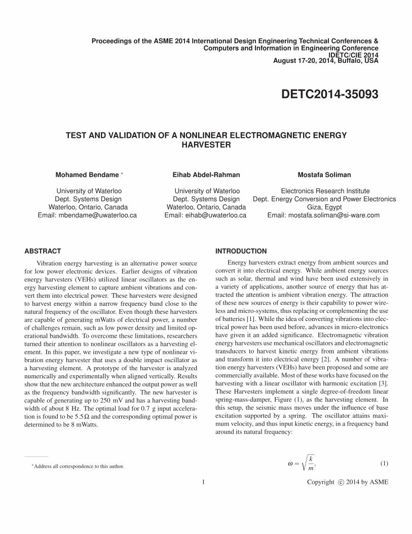
1 Vibration Energy HarvestersThe springless VEH consists of an electromagnetic trans-
ducer and a mechanical oscillator. The mechanical oscillator
used in this architecture is a double-impact oscillator as shown in
Figure 2. The inertial mass comprised of 4 magnets and a steel
cage, and is running freely along a linear guide. The magnets are
arranged with alternating polarities such that a closed magnetic
circuit exists with the magnetic flux passing through the coil. The
carriage moves along the linear guide carrying the assembly with
respect to the stationary concentric coil in response to base ex-
citations. The motion of the carriage induces a voltage V across
the coil terminals and proportional to the time rate of change of
the magnetic flux within the coil in accordance with Faraday’s
law of induction.
1.1 Electromagnetic Transduction
VEHs use electromagnetic transducers to transform kinetic
energy to electrical energy. The induced voltage across the coil
terminals is given;
V =dφ
dx
dx
dt= Bl
dx
dt, (2)
where φ is the total magnetic flux and x is the displacement of
the magnetic field with respect to the coil. From equation (2), we
note that the induced voltage V across the coil terminals depends
on the strength of the magnetic filed B, the length of the coil l,
and the relative velocity between the magnetic field and the coil.
2 Copyright c© 2014 by ASME
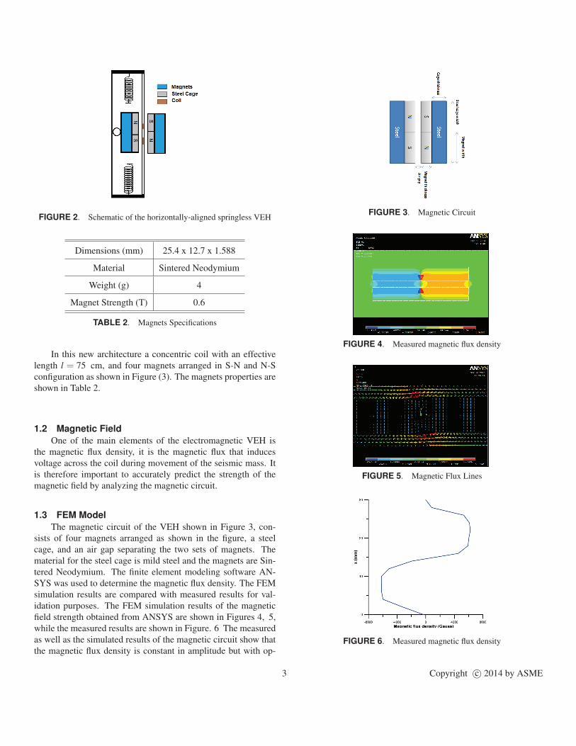
FIGURE 2. Schematic of the horizontally-aligned springless VEH
Dimensions (mm) 25.4 x 12.7 x 1.588
Material Sintered Neodymium
Weight (g) 4
Magnet Strength (T) 0.6
TABLE 2. Magnets Specifications
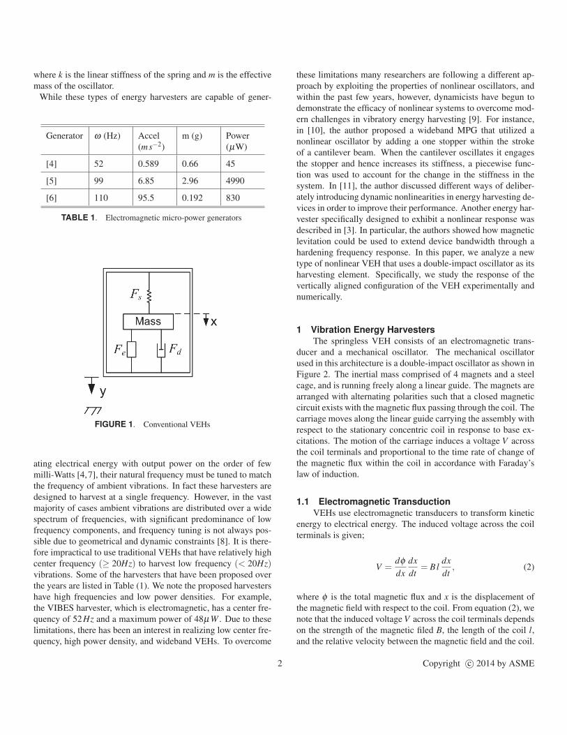
In this new architecture a concentric coil with an effective
length l = 75 cm, and four magnets arranged in S-N and N-S
configuration as shown in Figure (3). The magnets properties are
shown in Table 2.
1.2 Magnetic Field
One of the main elements of the electromagnetic VEH is
the magnetic flux density, it is the magnetic flux that induces
voltage across the coil during movement of the seismic mass. It
is therefore important to accurately predict the strength of the
magnetic field by analyzing the magnetic circuit.
1.3 FEM Model
The magnetic circuit of the VEH shown in Figure 3, con-
sists of four magnets arranged as shown in the figure, a steel
cage, and an air gap separating the two sets of magnets. The
material for the steel cage is mild steel and the magnets are Sin-
tered Neodymium. The finite element modeling software AN-
SYS was used to determine the magnetic flux density. The FEM
simulation results are compared with measured results for val-
idation purposes. The FEM simulation results of the magnetic
field strength obtained from ANSYS are shown in Figures 4, 5,
while the measured results are shown in Figure. 6 The measured
as well as the simulated results of the magnetic circuit show that
the magnetic flux density is constant in amplitude but with op-
FIGURE 3. Magnetic Circuit
FIGURE 4. Measured magnetic flux density
FIGURE 5. Magnetic Flux Lines
FIGURE 6. Measured magnetic flux density
3 Copyright c© 2014 by ASME
posite signs on each side of the magnetic circuit. This is due to
the fact that the polarities of the two sets of magnets are opposite
(S-N and N-S). This setup allows the induced voltage across the
coil to add up and hence maximize the harvested power.
1.4 Electrical Damping
The current passing through the coil creates a magnetic field
that opposes the field produced by the magnets. The interac-
tion between the two fields produces a force which opposes the
motions of the inertial mass. This interaction force is the electro-
magnetic damping defined as;
Fem = be x, (3)
The electrical power extracted from the mechanical oscillator is
given by;
Pem = Fem x = be x2, (4)
This power is dissipated in the parasitic coil resistance RC and
the load resistance RL. Equating the power dissipated in the coil
and load to that extracted from the oscillator gives
be x2 =V 2
RL +RC + jωL, (5)
where L is the coil inductance. Substituting equation (2) into
equation (5) we obtain the electromagnetic damping be as
be =1
RL +RC + jωL
(dφ
dx
)2
, (6)
Since the coil inductance is negligible and assuming that the coil
moves in a region of constant magnetic field, the electromagnetic
damping coefficient can be expressed as
be =(N Bl)2
RL +RC
, (7)
where B is the magnetic field intensity, N the number of turns
and l is the effective length of the coil. The electrical damping
for the prototype under test can be calculated using equation (7)
and the parameter values in Table (3).
1.5 Mechanical Damping
The frequency-response curve of the open-loop harvester is
used to determine the mechanical quality factor Qm of the VEH
Parameter Value
Magnetic Field: B (T) 0.67
Effective Coil Length: l (m) 0.75
Load Resistance: RL (Ω) ∞
Coil Resistance: RC (Ω) 2.4
TABLE 3. Electromagnetic Transducer Parameters
from the formula
Qm =f
∆ f, (8)
where f is the center frequency and ∆ f = f2 − f1, with f1 and
f2 the two half-power frequencies. The mechanical damping co-
efficient is then found as
bm =
√mk
Qm
, (9)
We can find the mechanical damping bm using equations (9, 8)
and the values of the systems parameters given in Table (4) as
bm = 0.9kg/s . The center frequency and half power bandwidth
were found from a frequency-sweep of the base acceleration of
the VEH at an amplitude of A = 0.03 g. The total damping of the
VEH is sum of mechanical damping and electromagnetic damp-
ing: b = be +bm.
Parameter Value
Mass: m (Kg) 0.11
Stiffness: k1 (N/m) 980
Center Frequency: f (Hz) 21.25
Damping: bm (kg/s) 0.9
TABLE 4. VEH Parameters
2 Model
In this section the mathematical model of the VEH is derived
and the shooting method for finding periodic orbits of the system
is described.
4 Copyright c© 2014 by ASME
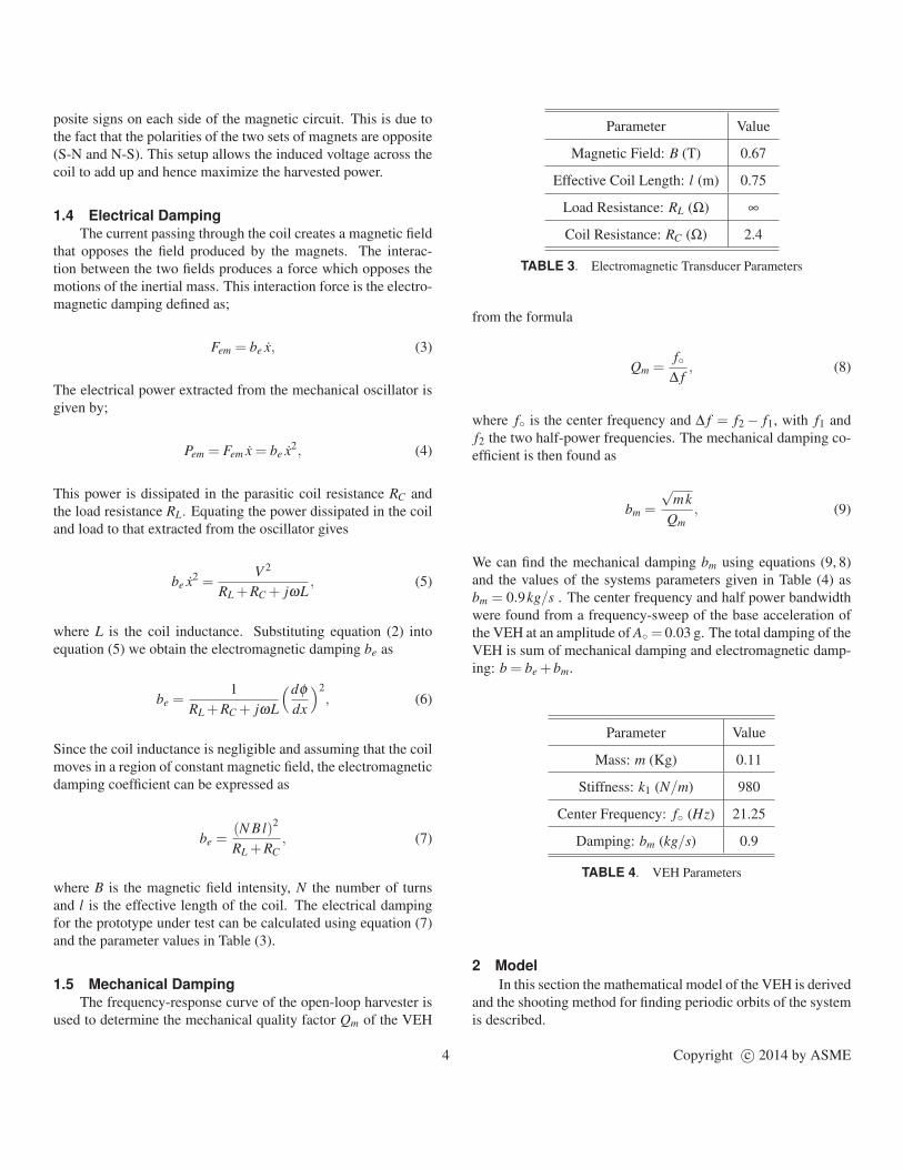
2.1 Equation of Motion
The vertical implementation of the VEH, is suitable for en-
vironments where motions are predominantly in the vertical di-
rection. The linear guide, aligned vertically, allows the carriage
to move freely along the rail. When the assembly vibrates due
to a base excitation y(t), the seismic mass moves with respect
to the housing producing a relative displacement x(t). The elec-
tromagnetic transducer “drains" some of the “apparent" kinetic
energy converting it to electric energy and acting as an electric
damper be on the relative velocity between the seismic mass and
the frame. The equation of motion of the vertically-aligned har-
vester can be written as:
mx =−(be +bm) x−F (x)− my, (10)
where x and y are the displacements of the seismic mass m and
frame, respectively, and F(x) is the restoring force. The VEH
harvests kinetic energy transmitted to it from the host vibrations
represented by the base acceleration
y = A cos(Ω t), (11)
where A and Ω are the amplitude and frequency of the external
excitation. Two identical springs are used as limiters on either
end of the linear guide. The origin of the coordinate system is
placed at the point where mass m rests on the lower spring. The
seismic mass m is assumed to be a point mass, as shown in Figure
7. The free distance along the rail (not occupied by the cage)
between the upper and lower uncompressed springs is denoted
xL. The uncompressed length of each spring is denoted xs and the
fully compressed length is denoted xc. The restoring force F(x)
FIGURE 7. Simplified schematic of the VEH
varies with the the position of the inertial mass m as it moves
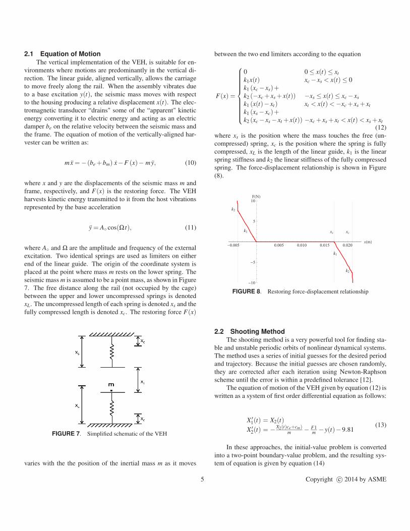
between the two end limiters according to the equation
F(x) =
0 0 ≤ x(t)≤ xt
k1x(t) xc − xs < x(t)≤ 0
k1 (xc − xs)+k2 (−xc + xs + x(t)) −xs ≤ x(t)≤ xc − xs
k1 (x(t)− xt) xt < x(t)<−xc + xs + xt
k1 (xs − xc)+k2 (xc − xs − xt + x(t)) −xc + xs + xt < x(t)< xs + xt
(12)
where xs is the position where the mass touches the free (un-
compressed) spring, xc is the position where the spring is fully
compressed, xL is the length of the linear guide, k1 is the linear
spring stiffness and k2 the linear stiffness of the fully compressed
spring. The force-displacement relationship is shown in Figure
(8).
k1
k2
k1
k2
xs xc
-0.005 0.005 0.010 0.015 0.020xHmL
-10
-5
5
10
FHNL
FIGURE 8. Restoring force-displacement relationship
2.2 Shooting Method
The shooting method is a very powerful tool for finding sta-
ble and unstable periodic orbits of nonlinear dynamical systems.
The method uses a series of initial guesses for the desired period
and trajectory. Because the initial guesses are chosen randomly,
they are corrected after each iteration using Newton-Raphson
scheme until the error is within a predefined tolerance [12].
The equation of motion of the VEH given by equation (12) is
written as a system of first order differential equation as follows:
X ′1(t) = X2(t)
X ′2(t) = −X2(t)ce+cm)
m− F1
m− y(t)−9.81
(13)
In these approaches, the initial-value problem is converted
into a two-point boundary-value problem, and the resulting sys-
tem of equation is given by equation (14)
5 Copyright c© 2014 by ASME
X ′1(t) = X2(t)
X ′2(t) =−X2(t)(ce+cm)
m− F1
m− y(t)−9.81
X ′3 =
ddt( ∂X1
∂η1) = ∂X2
∂η1
X ′4 =
ddt( ∂X1
∂η2) = ∂X2
∂η2
X ′5 =
ddt( ∂X2
∂η1) =−( ce+cm
m) ∂X2
∂η1− 1
m∂F1∂η1
X ′6 =
ddt( ∂X2
∂η2) =−( ce+cm
m) ∂X2
∂η2− 1
m∂F1∂η2
(14)
Initial guess values are needed to solve the system given by
equation (14), and one way to choose such guesses is to solve
the initial problem by long time integration and then pick the
guesses from the obtained orbit. In section (3), experimental and
numerical results obtained by solving the shooting model given
by equation (13) are presented. The results show the VEH’s the
frequency response for different amplitudes of base excitation.
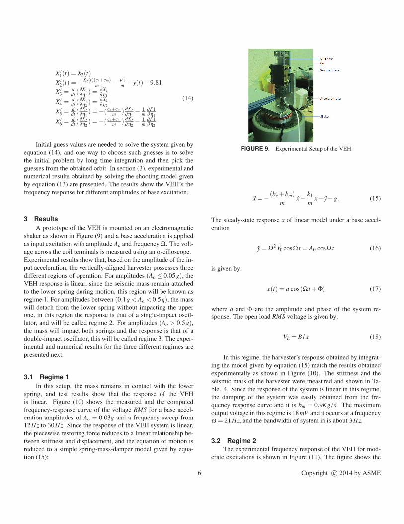
3 Results
A prototype of the VEH is mounted on an electromagnetic
shaker as shown in Figure (9) and a base acceleration is applied
as input excitation with amplitude Ao and frequency Ω. The volt-
age across the coil terminals is measured using an oscilloscope.
Experimental results show that, based on the amplitude of the in-
put acceleration, the vertically-aligned harvester possesses three
different regions of operation. For amplitudes (Ao ≤ 0.05g), the
VEH response is linear, since the seismic mass remain attached
to the lower spring during motion, this region will be known as
regime 1. For amplitudes between (0.1g < Ao < 0.5g), the mass
will detach from the lower spring without impacting the upper
one, in this region the response is that of a single-impact oscil-
lator, and will be called regime 2. For amplitudes (Ao > 0.5g),the mass will impact both springs and the response is that of a
double-impact oscillator, this will be called regime 3. The exper-
imental and numerical results for the three different regimes are
presented next.
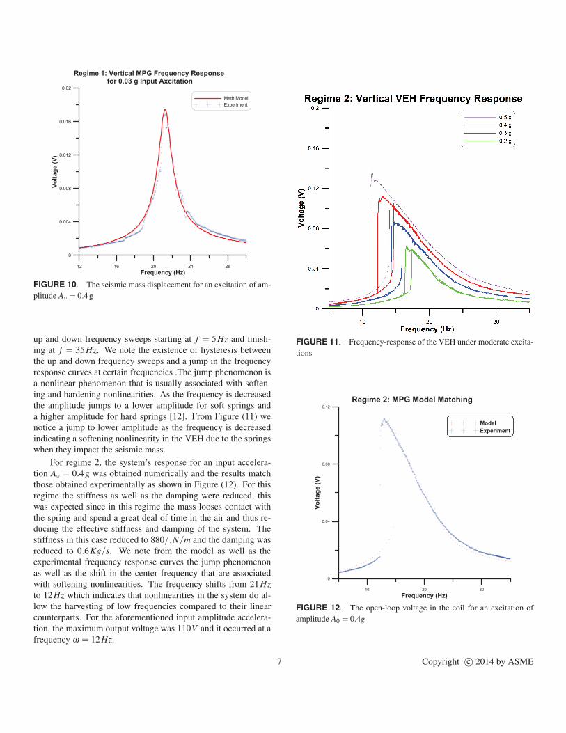
3.1 Regime 1
In this setup, the mass remains in contact with the lower
spring, and test results show that the response of the VEH
is linear. Figure (10) shows the measured and the computed
frequency-response curve of the voltage RMS for a base accel-
eration amplitudes of Ao = 0.03g and a frequency sweep from
12Hz to 30Hz. Since the response of the VEH system is linear,
the piecewise restoring force reduces to a linear relationship be-
tween stiffness and displacement, and the equation of motion is
reduced to a simple spring-mass-damper model given by equa-
tion (15):
FIGURE 9. Experimental Setup of the VEH
x =− (be +bm)
mx− k1
mx− y−g, (15)
The steady-state response x of linear model under a base accel-
eration
y = Ω2 Y0 cosΩ t = A0 cosΩ t (16)
is given by:
x(t) = a cos(Ω t +Φ) (17)
where a and Φ are the amplitude and phase of the system re-
sponse. The open load RMS voltage is given by:
VL = Bl x (18)
In this regime, the harvester’s response obtained by integrat-
ing the model given by equation (15) match the results obtained
experimentally as shown in Figure (10). The stiffness and the
seismic mass of the harvester were measured and shown in Ta-
ble. 4. Since the response of the system is linear in this regime,
the damping of the system was easily obtained from the fre-
quency response curve and it is bm = 0.9Kg/s. The maximum
output voltage in this regime is 18mV and it occurs at a frequency
ω = 21Hz, and the bandwidth of system in is about 3Hz.
3.2 Regime 2
The experimental frequency response of the VEH for mod-
erate excitations is shown in Figure (11). The figure shows the
6 Copyright c© 2014 by ASME
12 16 20 24 28
Frequency (Hz)
0
0.004
0.008
0.012
0.016
0.02
Vo
ltag
e (
V)
Math Model
Experiment
Regime 1: Vertical MPG Frequency Response for 0.03 g Input Axcitation
FIGURE 10. The seismic mass displacement for an excitation of am-
plitude A = 0.4g
up and down frequency sweeps starting at f = 5Hz and finish-
ing at f = 35Hz. We note the existence of hysteresis between
the up and down frequency sweeps and a jump in the frequency
response curves at certain frequencies .The jump phenomenon is
a nonlinear phenomenon that is usually associated with soften-
ing and hardening nonlinearities. As the frequency is decreased
the amplitude jumps to a lower amplitude for soft springs and
a higher amplitude for hard springs [12]. From Figure (11) we
notice a jump to lower amplitude as the frequency is decreased
indicating a softening nonlinearity in the VEH due to the springs
when they impact the seismic mass.
For regime 2, the system’s response for an input accelera-
tion A = 0.4g was obtained numerically and the results match
those obtained experimentally as shown in Figure (12). For this
regime the stiffness as well as the damping were reduced, this
was expected since in this regime the mass looses contact with
the spring and spend a great deal of time in the air and thus re-
ducing the effective stiffness and damping of the system. The
stiffness in this case reduced to 880/,N/m and the damping was
reduced to 0.6Kg/s. We note from the model as well as the
experimental frequency response curves the jump phenomenon
as well as the shift in the center frequency that are associated
with softening nonlinearities. The frequency shifts from 21Hz
to 12Hz which indicates that nonlinearities in the system do al-
low the harvesting of low frequencies compared to their linear
counterparts. For the aforementioned input amplitude accelera-
tion, the maximum output voltage was 110V and it occurred at a
frequency ω = 12Hz.
FIGURE 11. Frequency-response of the VEH under moderate excita-
tions
10 20 30
Frequency (Hz)
0
0.04
0.08
0.12
Vo
ltag
e (
V)
Model
Experiment
Regime 2: MPG Model Matching
FIGURE 12. The open-loop voltage in the coil for an excitation of
amplitude A0 = 0.4g
7 Copyright c© 2014 by ASME
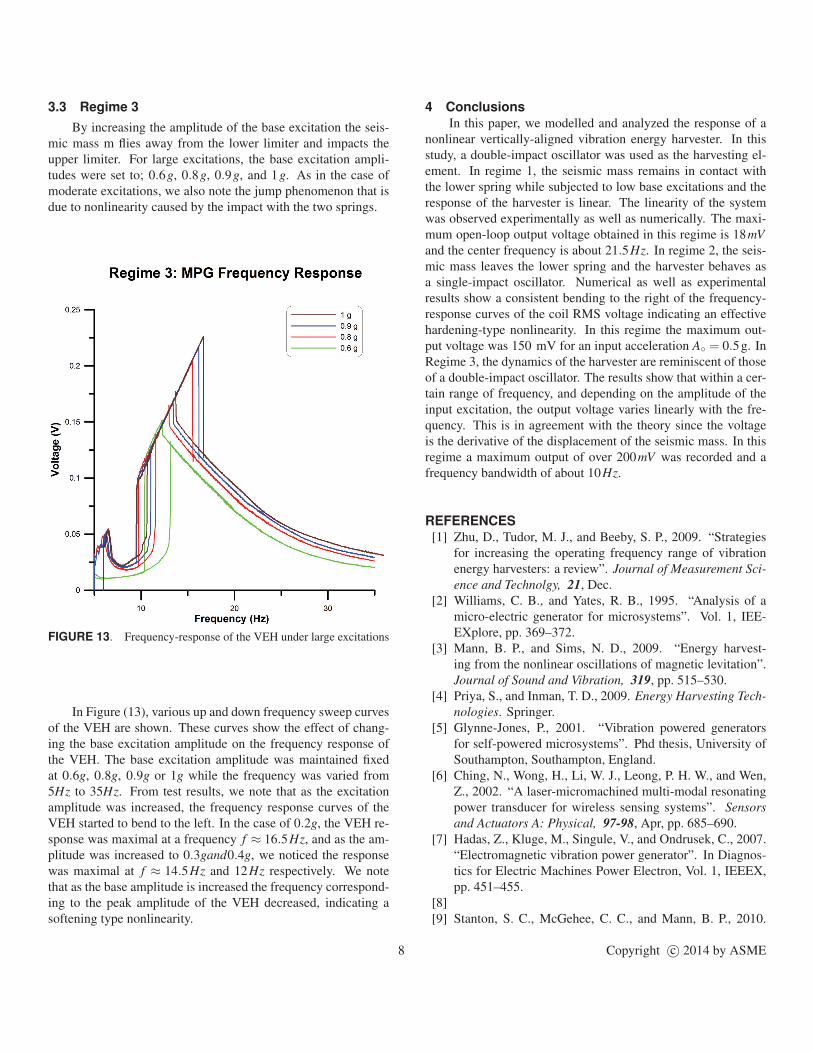
3.3 Regime 3
By increasing the amplitude of the base excitation the seis-
mic mass m flies away from the lower limiter and impacts the
upper limiter. For large excitations, the base excitation ampli-
tudes were set to; 0.6g, 0.8g, 0.9g, and 1g. As in the case of
moderate excitations, we also note the jump phenomenon that is
due to nonlinearity caused by the impact with the two springs.
FIGURE 13. Frequency-response of the VEH under large excitations
In Figure (13), various up and down frequency sweep curves
of the VEH are shown. These curves show the effect of chang-
ing the base excitation amplitude on the frequency response of
the VEH. The base excitation amplitude was maintained fixed
at 0.6g, 0.8g, 0.9g or 1g while the frequency was varied from
5Hz to 35Hz. From test results, we note that as the excitation
amplitude was increased, the frequency response curves of the
VEH started to bend to the left. In the case of 0.2g, the VEH re-
sponse was maximal at a frequency f ≈ 16.5Hz, and as the am-
plitude was increased to 0.3gand0.4g, we noticed the response
was maximal at f ≈ 14.5Hz and 12Hz respectively. We note
that as the base amplitude is increased the frequency correspond-
ing to the peak amplitude of the VEH decreased, indicating a
softening type nonlinearity.
4 Conclusions
In this paper, we modelled and analyzed the response of a
nonlinear vertically-aligned vibration energy harvester. In this
study, a double-impact oscillator was used as the harvesting el-
ement. In regime 1, the seismic mass remains in contact with
the lower spring while subjected to low base excitations and the
response of the harvester is linear. The linearity of the system
was observed experimentally as well as numerically. The maxi-
mum open-loop output voltage obtained in this regime is 18mV
and the center frequency is about 21.5Hz. In regime 2, the seis-
mic mass leaves the lower spring and the harvester behaves as
a single-impact oscillator. Numerical as well as experimental
results show a consistent bending to the right of the frequency-
response curves of the coil RMS voltage indicating an effective
hardening-type nonlinearity. In this regime the maximum out-
put voltage was 150 mV for an input acceleration A = 0.5g. In
Regime 3, the dynamics of the harvester are reminiscent of those
of a double-impact oscillator. The results show that within a cer-
tain range of frequency, and depending on the amplitude of the
input excitation, the output voltage varies linearly with the fre-
quency. This is in agreement with the theory since the voltage
is the derivative of the displacement of the seismic mass. In this
regime a maximum output of over 200mV was recorded and a
frequency bandwidth of about 10Hz.
REFERENCES
[1] Zhu, D., Tudor, M. J., and Beeby, S. P., 2009. “Strategies
for increasing the operating frequency range of vibration
energy harvesters: a review”. Journal of Measurement Sci-
ence and Technolgy, 21, Dec.
[2] Williams, C. B., and Yates, R. B., 1995. “Analysis of a
micro-electric generator for microsystems”. Vol. 1, IEE-
EXplore, pp. 369–372.
[3] Mann, B. P., and Sims, N. D., 2009. “Energy harvest-
ing from the nonlinear oscillations of magnetic levitation”.
Journal of Sound and Vibration, 319, pp. 515–530.
[4] Priya, S., and Inman, T. D., 2009. Energy Harvesting Tech-
nologies. Springer.
[5] Glynne-Jones, P., 2001. “Vibration powered generators
for self-powered microsystems”. Phd thesis, University of
Southampton, Southampton, England.
[6] Ching, N., Wong, H., Li, W. J., Leong, P. H. W., and Wen,
Z., 2002. “A laser-micromachined multi-modal resonating
power transducer for wireless sensing systems”. Sensors
and Actuators A: Physical, 97-98, Apr, pp. 685–690.
[7] Hadas, Z., Kluge, M., Singule, V., and Ondrusek, C., 2007.
“Electromagnetic vibration power generator”. In Diagnos-
tics for Electric Machines Power Electron, Vol. 1, IEEEX,
pp. 451–455.
[8]
[9] Stanton, S. C., McGehee, C. C., and Mann, B. P., 2010.
8 Copyright c© 2014 by ASME
“Nonlinear dynamics for broadband energy harvesting: In-
vestigation of a bistable piezoelectric inertial generator”.
Physica D: Nonlinear Phenomena, 239(10), May, pp. 640–
653.
[10] Soliman, M., Abdel-Rahman, E., El-Saadany, E. F., and
Mansour, R. R., 2009. “A Design Procedure for Wideband
Micropower Generators”. Journal of Microelectromechan-
ical Systems, 18(6), Dec, pp. 1288–1299.
[11] Green, L. P., 2012. “Nonlinear energy harvesting”. Phd
thesis, University of Sheffield, Sheffield, England, October.
[12] Nayfeh, A., and Mook, D., 1997. Nonlinear Oscillations.
John Wiley & Sons.
9 Copyright c© 2014 by ASME