Embed Size (px)
Citation preview
applied sciences
Article
A Flutter-Based Electromagnetic Wind EnergyHarvester: Theory and Experiments
Zhuang Lu 1,2,*, Quan Wen 1,3,*, Xianming He 1,2 and Zhiyu Wen 1,2,*1 Microsystem Research Center, College of Optoelectronic Engineering, Chongqing University,
Chongqing 400044, China; [email protected] Key Laboratory of Fundamental Science of Micro/Nano-Device and System Technology,
Chongqing University, Chongqing 400044, China3 Fraunhofer ENAS, Technologie-Campus 3, 09126 Chemnitz, Germany* Correspondence: [email protected] (Z.L.); [email protected] (Q.W.);
[email protected] (Z.W.)
Received: 11 October 2019; Accepted: 7 November 2019; Published: 11 November 2019
Abstract: Wind energy harvesting is a promising way to offer power supply to low-power electronicdevices. Miniature wind-induced vibration energy harvesters, which are currently being focused onby researchers in the field, offer the advantages of small volume and simple structure. In this article,an analytical model was proposed for the kinetic analysis of a flutter-based electromagnetic windenergy harvester. As a result, the critical wind speeds of energy harvesters with different magnetpositions were predicted. To experimentally verify the analytical predictions and investigate theoutput performance of the proposed energy harvester, a small wind tunnel was built. The criticalwind speeds measured by the experiment were found to be consistent with the predictions. Therefore,the proposed model can be used to predict the critical wind speed of a wind belt type energy harvester.The experimental results also show that placing the magnets near the middle of the membrane canresult in lower critical wind speed and higher output performance. The optimized wind energyharvester was found to generate maximum average power of 705 µW at a wind speed of 10 m/s,offering application prospects for the power supply of low-power electronic devices. This workcan serve as a reference for the structural design and theoretical analysis of a flutter-based windenergy harvester.
Keywords: flutter based wind energy harvester; analytical model; critical wind speed
1. Introduction
Low-power electronic devices, such as wireless sensor networks [1], portable electronics [2], andimplanted systems [3], have made great progress in recent years. Traditionally, batteries were employedas a primary power source for such devices; however, their limited life challenges the long-termoperation of devices, and their disposal poses environmental concerns [4,5]. Harvesting ambientenergy—Solar, vibration, and wind energy—and converting them to electric power is a prospectivesolution [6–9]. Among all of the energy sources, wind energy has attracted much attention over thepast decades due to its clean, renewable, and widespread existence. The conventional wind turbine hasdisadvantages of large volume, complicated structure, and high cost to power low-power electronicdevices [5,10]; researchers are, thus, keen to find simpler ways to harvest wind energy.
An energy harvester based on wind-induced vibration (WIV) offers simple mechanisms to harvestwind energy, such as vortex-induced vibration (VIV), flutter, etc. VIV [11,12] is a phenomenon whereinairflow interacts with the buff body, while the vortex sheds from the buff body; there is a period ofaerodynamic force being applied to the body and the structure behind it. If the vortex shedding
Appl. Sci. 2019, 9, 4823; doi:10.3390/app9224823 www.mdpi.com/journal/applsci
Appl. Sci. 2019, 9, 4823 2 of 14
frequency is close to the natural frequency of the elastic structure, a resonance phenomenon takesplace and the amplitude increases dramatically. Dai et al. [13] compared the output performance ofa piezoelectric energy harvester with different orientations of buff body; the results confirm that thevortex-induced aerodynamic force acts on both the buff body and the rear cantilever. Differing from VIV,flutter is a self-excited vibration phenomenon—The aerodynamic forces mainly come from the vibrationof the structure itself, which is possible when the total damping is negative. According to the numberof vibrational degrees of freedom, flutter can be divided into two forms: single-freedom flutter (alsoknown as galloping) [14–16] and bend-torsion coupled flutter [17,18]. Galloping is normally observedin lightweight prismatic structures (square, triangle, D-section, and so on). VIV and galloping mayoccur simultaneously. He et al. [19] investigated the performance of a piezoelectric energy harvesterby utilizing buff bodies with a different rectangular section; the results show the enhancement of windenergy harvesting on interaction between VIV and galloping. Bend-torsion coupled flutter usuallyoccurs in plate-like structures, such as membranes, flat plates, and airfoils. Li et al. [20] proposed theconcept of bionic tree, wherein hundreds of leaf-like piezoelectric energy harvesters show prospectsfor high-power applications.
When compared to piezoelectric energy harvesters, electromagnetic energy harvesters offer theadvantage of lower internal resistance, which results in a higher current. Frayne [21–23] invented aflutter-based electromagnetic wind energy harvester, known as the wind belt. The energy harvesterhad an extremely simple structure consisting of three parts: a doubly-clamped membrane, two piecesof magnets, and one or more coils. Frayne claimed that the energy harvester—With two dimensionsof 12 cm and 1 m—Could be used for the power supply of an island. Fei et al. [24] introduced theaerodynamic forces of the wind belt and designed a power management circuit for the energy harvester.Quy et al. [25] experimentally investigated the effects of axial tension, angle of attack, and position ofmagnets on critical wind speed, oscillating frequency, and output performance of the energy harvester.Aquino et al. [26,27] made a wind belt with a length of 0.5 m and simulated the wind field aroundbuildings; they also suggested the optimal installation location of the energy harvester. However,although a series of experiments have been conducted on the wind belt type energy harvester, ananalytical model to systematically analyze its behavior is missing.
In this paper, an analytical model for the wind belt type energy harvester is proposed. Modalanalysis of the model agrees well with that of the finite element simulation. The results of flutteranalysis indicate that flutter at low airflow speed mainly comes from the coupling of the first bendingand torsional modes. The calculated critical wind speed was consistent with previous empiricalformulae and the experimental results. The influence of the magnets’ positions was also investigated.The results suggest that by placing the magnets near the middle of the membrane, the performanceof the system could be further improved. The optimized wind energy harvester can generate amaximum average power of 705 µW at wind speed of 10 m/s., showcasing a promising future as apower supplier for low-power consumption devices. This work shows significance of the structuredesign and performance improvement of the flutter-based wind energy harvester.
2. Device Structure and Modal Analysis
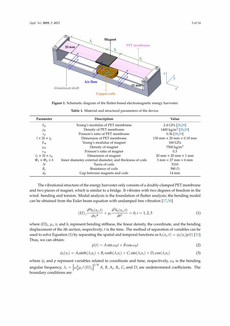
The structure of the proposed wind energy harvester is illustrated in Figure 1; it mainly consistsof four parts: a flexible polyethylene terephthalate (PET) membrane, two pieces of magnets, a setof copper coils, and an aluminum shell. The material and structural parameters of the wind energyharvester are given in Table 1. The PET membrane was doubly clamped by four screws. The N35NdFeB magnets were attached to the PET membrane, which were magnetized along the thicknessdirection. The coils were as close to the magnets as possible for higher voltage and electric power. Theoverall dimensions of the device are 142 mm × 30 mm × 25 mm. The wind direction is perpendicularto the axis of the PET membrane. When wind speed is higher than the flutter critical wind speed, thePET membrane combined with magnets oscillate with a large amplitude, and the energy harvestergenerates high electric power based on Faraday’s law of electromagnetic induction.
Appl. Sci. 2019, 9, 4823 3 of 14
Appl. Sci. 2019, 9, x FOR PEER REVIEW 3 of 14
Figure 1. Schematic diagram of the flutter-based electromagnetic energy harvester.
Table 1. Material and structural parameters of the device.
Parameter Description Value Ep Young’s modulus of PET membrane 2.4 GPa [28,29] ρp Density of PET membrane 1400 kg/m3 [28,29] νp Poisson’s ratio of PET membrane 0.36 [28,29]
l × 2b × tp Dimension of PET membrane 130 mm × 20 mm × 0.18 mm
Em Young’s modulus of magnet 160 GPa ρm Density of magnet 7500 kg/m3
νm Poisson’s ratio of magnet 0.3 l2 × 2b × tm Dimension of magnet 20 mm × 20 mm × 1 mm
Φ1 × Φ2 × h Inner diameter, external diameter, and thickness of coils
3 mm × 27 mm × 6 mm
N Turns of coils 5310 Rc Resistance of coils 580 Ω d0 Gap between magnets and coils 14 mm
The vibrational structure of the energy harvester only consists of a doubly-clamped PET membrane and two pieces of magnet, which is similar to a bridge. It vibrates with two degrees of freedom in the wind: bending and torsion. Modal analysis is the foundation of flutter analysis; the bending modal can be obtained from the Euler beam equation with undamped free vibration [17,30]
4 2
4 2
( , ) ( , )( ) + 0, 1, 2,3i i i ii i
i
h x t h x tEI i
x tμ∂ ∂
= =∂ ∂
(1)
where (EI)i, μi, xi and hi represent bending stiffness, the linear density, the coordinate, and the bending displacement of the ith section, respectively; t is the time. The method of separation of variables can be used to solve Equation (1) by separating the spatial and temporal functions as ( , ) ( ) ( )i i i ih x t x p tφ= [31]. Thus, we can obtain:
( ) sin cosh hp t A t B tω ω= + (2)
( ) sinh( ) cosh( ) sin( ) cos( )i i i i i i i i i i i i i ix A x B x C x D xφ λ λ λ λ= + + + (3)
where ϕi and p represent variables related to coordinate and time, respectively, ωh is the bending angular frequency, 1/42 /( )i h i iEIλ ω μ = A, B, Ai, Bi, Ci and Di are undetermined coefficients. The
boundary conditions are:
1(0) 0φ = , 1
1 1
1 0
( ) 0x
xx
φ
=
∂ =∂
, 3 3( ) 0lφ = , 3 3
3 3
3
( ) 0x l
xx
φ
=
∂ =∂
(4)
Figure 1. Schematic diagram of the flutter-based electromagnetic energy harvester.
Table 1. Material and structural parameters of the device.
Parameter Description Value
Ep Young’s modulus of PET membrane 2.4 GPa [28,29]ρp Density of PET membrane 1400 kg/m3 [28,29]νp Poisson’s ratio of PET membrane 0.36 [28,29]
l × 2b × tp Dimension of PET membrane 130 mm × 20 mm × 0.18 mmEm Young’s modulus of magnet 160 GPaρm Density of magnet 7500 kg/m3
νm Poisson’s ratio of magnet 0.3l2 × 2b × tm Dimension of magnet 20 mm × 20 mm × 1 mmΦ1 × Φ2 × h Inner diameter, external diameter, and thickness of coils 3 mm × 27 mm × 6 mm
N Turns of coils 5310Rc Resistance of coils 580 Ωd0 Gap between magnets and coils 14 mm
The vibrational structure of the energy harvester only consists of a doubly-clamped PET membraneand two pieces of magnet, which is similar to a bridge. It vibrates with two degrees of freedom in thewind: bending and torsion. Modal analysis is the foundation of flutter analysis; the bending modalcan be obtained from the Euler beam equation with undamped free vibration [17,30]
(EI) i∂4hi(xi, t)∂xi4
+ µi∂2hi(xi, t)
∂t2 = 0, i = 1, 2, 3 (1)
where (EI)i, µi, xi and hi represent bending stiffness, the linear density, the coordinate, and the bendingdisplacement of the ith section, respectively; t is the time. The method of separation of variables can beused to solve Equation (1) by separating the spatial and temporal functions as hi(xi, t) = φi(xi)p(t) [31].Thus, we can obtain:
p(t) = A sinωht + B cosωht (2)
φi(xi) = Aisinh(λixi) + Bi cosh(λixi) + Ci sin(λixi) + Di cos(λixi) (3)
where φi and p represent variables related to coordinate and time, respectively, ωh is the bending
angular frequency, λi =[ω2
hµi/(EI)i
]1/4A, B, Ai, Bi, Ci and Di are undetermined coefficients. The
boundary conditions are:
Appl. Sci. 2019, 9, 4823 4 of 14
φ1(0) = 0, ∂φ1(x1)∂x1
∣∣∣∣x1=0
= 0, φ3(l3) = 0, ∂φ3(x3)∂x3
∣∣∣∣x3=l3
= 0
φi(li) =φi+1(0) , ∂φi(xi)∂xi
∣∣∣∣xi=li
=∂φi+1(xi+1)
∂xi+1
∣∣∣∣xi+1=0
(EI)i∂2φi(xi)
∂xi2
∣∣∣∣∣xi=li
= (EI)i+1∂2φi+1(xi+1)
∂xi+12
∣∣∣∣∣xi+1=0
(EI)i∂3φi(xi)
∂xi3
∣∣∣∣∣xi=li
= (EI)i+1∂3φi+1(xi+1)
∂xi+13
∣∣∣∣∣xi+1=0
(4)
li is the length of each section. By substituting Equation (3) into the boundary conditions (4), andconsidering the orthogonal normalization condition (to obtain the bending vibration modes):
∑i
µi
∫ li
0φir(xi)φis(xi)dxi = δrs (5)
where r and s represent the rth and sth bending mode, respectively, δrs is the Kronecker delta (δrs = 0when r , s and δrs = 1 when r = s). We can obtain:
λi = λir, fhr =ωhr2π
=λir
2
2π
√(EI)iµi
, φi(xi) = φir(xi), p(t) = pr(t), r = 1, 2, · · · (6)
where fhr, φr, pr represents the rth bending natural frequency, the rth bending vibration mode, and therth bending modal, respectively. Bending displacement hi can be written as:
hi(xi, t) =∑
rφir(xi)pr(t) (7)
Similar to the bending modal, the torsional modal can be obtained from the following equation:
(EIω)i∂4αi(xi, t)∂xi4
− (GIt)i∂2αi(xi, t)∂xi2
+ (ρIm)i∂2αi(xi, t)
∂t2 = 0, i = 1, 2, 3 (8)
where (EIω)i, (GIt)i, (ρIm)i and αi represent the warping stiffness, the torsional stiffness, the moment ofinertial per unit length, and the twist angle of the ith section, respectively. Equation (8) can also besolved by separating variables as αi(xi, t) = ϕi(xi)q(t) [31], where:
q(t) = S sinωαt + T cosωαt (9)
ϕi(xi) = Sisinh(mixi) + Ti cosh(mixi) + Ui sin(nixi) + Vi cos(nixi) (10)
mi =
√4χi2 + ki2 + ki
2, ni =
√4χi2 + ki2 − ki
2, ki =
(GIt)i
(EIω)i(11)
where ϕi and q represent variables related to coordinate and time, respectively; ωα is the torsional
angular frequency, χi =√ω2α(EIω)i/(ρIm)i, S, T, Si, Ti, Ui, and Vi are undetermined coefficients. The
boundary conditions are:
ϕ1(0) = 0, ∂ϕ1(x1)∂x1
∣∣∣∣x1=0
= 0, ϕ3(l3) = 0, ∂ϕ3(x3)∂x3
∣∣∣∣x3=l3
= 0
ϕi(li) =ϕi+1(0) , ∂ϕi(xi)∂xi
∣∣∣∣xi=li
=∂ϕi+1(xi+1)
∂xi+1
∣∣∣∣xi+1=0
(GIt)i∂ϕi(xi)∂xi
∣∣∣∣xi=li
= (GIt)i+1∂ϕi+1(xi+1)
∂xi+1
∣∣∣∣xi+1=0
(EIω)i∂3ϕi(xi)
∂xi3
∣∣∣∣xi=li
= (EIω)i+1∂3ϕi+1(xi+1)
∂xi+13
∣∣∣∣xi+1=0
(12)
Appl. Sci. 2019, 9, 4823 5 of 14
By substituting Equation (10) into the boundary conditions (12), and considering the orthogonalnormalization condition (to obtain the torsional vibration modes):
∑i
(ρIm)i
∫ li
0ϕiu(xi)ϕiv(xi)dxi = δuv (13)
where u and v represent the uth and vth torsional mode, respectively; δuv is the Kronecker delta (δuv = 0when u , v and δuv = 1 when u = v). We can obtain:
χi = χiu, fαu = ωαu2π = χiu
2π
√(ρIm)i(EIω)i
, ϕi(xi) = ϕiu(xi), q(t) = qu(t),
u = 1, 2, · · ·(14)
where fαu, ϕu, qu represents the uth torsional natural frequency, the uth torsional vibration mode andthe uth torsional modal, respectively. The torsion angle αi can be written as:
αi(xi, t) =∑
uϕiu(xi)qu(t) (15)
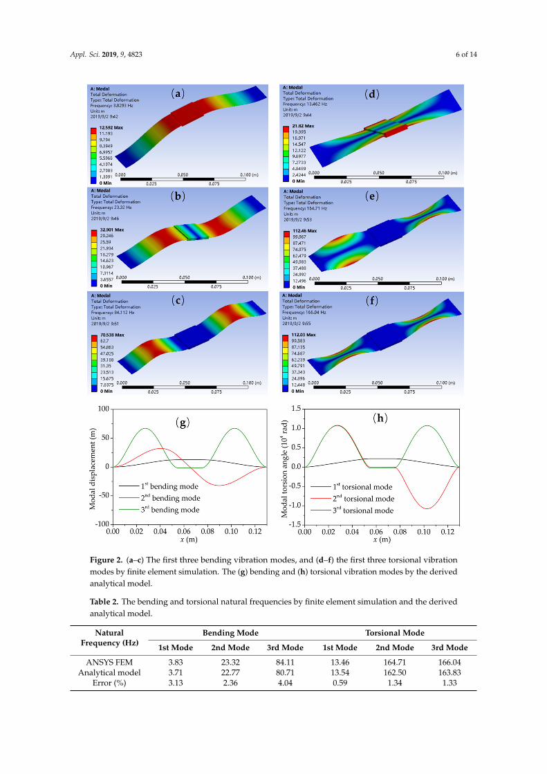
The modal of the structure can be obtained by finite element simulation as well, which has beenused for verification of modal analysis by the analytical model. Figure 2 and Table 2 show the firstthree bending and torsional vibration modes and the corresponding natural frequencies by finiteelement simulation (ANSYS workbench) and the derived analytical model, respectively (the magnetsare located in the middle of the PET membrane). We can see that the results of the derived analyticalmodel and the finite element simulation are consistent, which demonstrates that the derived analyticalmodel is reliable. The errors of natural frequencies between the analytical model and the finite elementresults are less than 5%. The errors mainly come from the constraint of the derived analytical model onthe freedom of vibration. In addition, the first and third bending and torsional vibration modes aresymmetric to the perpendicular bisector of magnets, and the second bending and torsional vibrationmodes are anti-symmetric around the midpoint of the magnets. Therefore, it is easy to produce coupledflutter due to similarity between the bending and torsional vibration modes of the same order. Thereis no coupling between the adjacent bending and torsional modes (refer to the definition of Λru inEquation (34)).
Appl. Sci. 2019, 9, 4823 6 of 14
Appl. Sci. 2019, 9, x FOR PEER REVIEW 6 of 14
Figure 2. (a–c) The first three bending vibration modes, and (d–f) the first three torsional vibration modes by finite element simulation. The (g) bending and (h) torsional vibration modes by the derived analytical model.
Table 2. The bending and torsional natural frequencies by finite element simulation and the derived analytical model.
Natural Frequency (Hz) Bending Mode Torsional Mode
1st Mode 2nd Mode 3rd Mode 1st Mode 2nd Mode 3rd Mode ANSYS FEM 3.83 23.32 84.11 13.46 164.71 166.04
Analytical model 3.71 22.77 80.71 13.54 162.50 163.83 Error (%) 3.13 2.36 4.04 0.59 1.34 1.33
Figure 2. (a–c) The first three bending vibration modes, and (d–f) the first three torsional vibrationmodes by finite element simulation. The (g) bending and (h) torsional vibration modes by the derivedanalytical model.
Table 2. The bending and torsional natural frequencies by finite element simulation and the derivedanalytical model.
NaturalFrequency (Hz)
Bending Mode Torsional Mode
1st Mode 2nd Mode 3rd Mode 1st Mode 2nd Mode 3rd Mode
ANSYS FEM 3.83 23.32 84.11 13.46 164.71 166.04Analytical model 3.71 22.77 80.71 13.54 162.50 163.83
Error (%) 3.13 2.36 4.04 0.59 1.34 1.33
Appl. Sci. 2019, 9, 4823 7 of 14
3. Flutter Analysis
The dynamical equations of the energy harvester in wind can be written as:
µi∂2hi(xi, t)
∂t2 + chi∂hi(xi, t)
∂t+ (EI)i
∂4hi(xi, t)∂xi4
= Li (16)
(ρIm)i∂2αi(xi, t)
∂t2 + cαi∂αi(xi, t)
∂t+ (EIω)i
∂4αi(xi, t)∂xi4
− (GIt)i∂2αi(xi, t)∂xi2
= Mi (17)
where chi and cαi represent the structural damping of bending and torsion of each section, respectively;Li and Mi are the aerodynamic lift force and torque per unit length, respectively [24].
Li = πρab−b
..hi − 2UC(k)
.hi − [1+C(k)]Ub
.αi − 2U2C(k)αi
(18)
Mi = πρab2
UC(k).hi −
b2
8..αi +
[−
12+
12
C(k)]Ub
.αi + U2C(k)αi
(19)
where ρa = 1.226 kg/m3 is the density of air (15 C), b is the half width of the PET membrane, U is thewind speed, k = ωb/U is the non-dimensional frequency, ω is the flutter angular frequency, and C(k) isTheodorsen’s circulation function [32,33]
C(k) = F(k) + iG(k) (20)
where [33]
F(k) = 1−0.165
1 +(
0.0455k
)2 −0.335
1 +(
0.3k
)2 , G(k) = −0.165× 0.0455
k
1 +(
0.0455k
)2 −0.335× 0.3
k
1 +(
0.3k
)2 (21)
For the dynamic equations to be valid throughout the time domain, the diverging rate andfrequency of both bending and torsion should be same; thus, we can assume:
pr(t) = Pre(δ+iω)t (22)
qu(t) = Que(δ+iω)t (23)
where δ is the diverging rate, ω is the angular frequency. By substituting Equations (7) and (15) into thedynamical equations, and considering the orthogonal normalization conditions (Equations (5) and (13)),we can obtain:
(ar + bri)pr(t) +∑
u(m + ni)Λruqu(t) = 0 (24)
∑r(p + qi)Λrupr(t) + (cu + dui)qu(t) = 0 (25)
where
ar =(δ2−ω2
)(1+πρab2Ar
)+ 2ζhrωhrδ+ 2πρabUF(k)δAr − 2πρabUG(k)ωAr +ω2
hr (26)
br = 2δω(1+πρab2Ar
)+ 2ζhrωhrω+ 2πρabUF(k)ωAr + 2πρabUG(k)δAr (27)
m = πρab2Uδ+ πρab2UF(k)δ+ 2πρabU2F(k) −πρab2UG(k)ω (28)
n = πρab2Uω+ πρab2UF(k)ω+ πρab2UG(k)δ+ 2πρabU2G(k) (29)
p = −πρab2UF(k)δ+ πρab2UG(k)ω (30)
Appl. Sci. 2019, 9, 4823 8 of 14
q = −πρab2UG(k)δ−πρab2UF(k)ω (31)
cu =(δ2−ω2
)(1 + πρab4
8 Bu
)+ 2ζαuωαuδ+
πρab3Uδ2 Bu −
πρab3UF(k)δ2 Bu
+πρab3UG(k)ω
2 Bu +ω2αu −πρab2U2F(k)Bu
(32)
du = 2ωδ(1 + πρab4
8 Bu
)−πρab3UG(k)δ
2 Bu + 2ζαuωαuω+πρab3Uω
2 Bu
−πρab3UF(k)ω
2 Bu −πρab2U2G(k)Bu
(33)
Ar =∑
i
∫ li
0φ2
ir(xi)dxi, Bu =∑
i
∫ li
0ϕ2
iu(xi)dxi, Λru =∑
i
∫ li
0φir(xi)ϕiu(xi)dxi (34)
where ζhr = chi/(2ωhrµi) and ζαu = cαi/[2ωαu(ρIm)i] are the structural damping ratio of bending andtorsion, respectively. Equations (24) and (25) can be written in a matrix form:
a1 + b1i 0 · · · (m + ni)Λ11 (m + ni)Λ12 · · ·
0 a2 + b2i · · · (m + ni)Λ21 (m + ni)Λ22 · · ·
......
. . . · · · · · ·. . .
(p + qi)Λ11 (p + qi)Λ21 · · · c1 + d1i 0 · · ·
(p + qi)Λ12 (p + qi)Λ22 · · · 0 c2 + d2i · · ·
......
. . ....
.... . .
p1(t)p2(t)
...q1(t)q2(t)
...
= 0 (35)
The condition that Equation (35) has non-zero solutions is the determinant if the coefficient iszero; the diverging rate and critical wind speed can be obtained accordingly.
As there is no magnet attached to the PET membrane, critical wind speed can also be obtained byempirical formulae proposed by Van der Put [34] and Selberg [35], respectively.
Ucr =
1 + (ωα1
ωh1− 0.5
)√0.72µrπρab3
ωh1b (36)
Ucr = 7.44b fα1
µr
ρa(2b)3
1− (fh1
fα1
)2
1/2
(37)
where r is the cross-section radius of gyration.For Equation (35), it is impossible to consider all of the bending and torsional modes. Figure 3a
shows the relationship between the diverging rate and the wind speed, when all the first three bendingand torsional modes are involved in the calculation (the magnets are located in the middle of the PETmembrane). The diverging rate judges whether the flutter occurs or not. When the diverging rate isnegative, the vibration is attenuated and no flutter occurs; when the diverging rate is positive, thevibration is divergent and the flutter takes place; when the diverging rate is zero, the correspondingwind speed is the critical wind speed. There are three curves corresponding to three sets of solutionsfor Equation (35). It indicates that the vibration of the energy harvester is divergent when wind speedis between 6.46 m/s and 9.39 m/s, and above 20.34 m/s, there will be large amplitudes when the flutterhappens. The critical wind speed is 6.46 m/s, which is the most important parameter of the flutter,and the flutter phenomenon can occur only when wind speed is higher than the critical wind speed.Figure 3b shows the relationship between the diverging rate and the wind speed, when the first, second,and third bending and torsional modes are involved in the calculation, respectively. The results aresimilar to the three curves in Figure 3a. Critical wind speed is 6.45 m/s when only the first bending andtorsional modes are considered. We can infer that the flutter at low wind speed is mainly caused bythe coupling of the first bending and torsional modes. The high order modes participate in the flutteras the wind speed increases and the state of motion of the wind belt is more chaotic.
Appl. Sci. 2019, 9, 4823 9 of 14
Appl. Sci. 2019, 9, x FOR PEER REVIEW 9 of 14
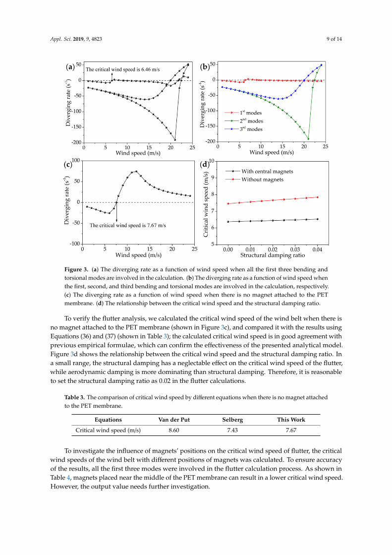
Figure 3. (a) The diverging rate as a function of wind speed when all the first three bending and torsional modes are involved in the calculation. (b) The diverging rate as a function of wind speed when the first, second, and third bending and torsional modes are involved in the calculation, respectively. (c) The diverging rate as a function of wind speed when there is no magnet attached to the PET membrane. (d) The relationship between the critical wind speed and the structural damping ratio.
To verify the flutter analysis, we calculated the critical wind speed of the wind belt when there is no magnet attached to the PET membrane (shown in Figure 3c), and compared it with the results using Equation (36) and Equation (37) (shown in Table 3); the calculated critical wind speed is in good agreement with previous empirical formulae, which can confirm the effectiveness of the presented analytical model. Figure 3d shows the relationship between the critical wind speed and the structural damping ratio. In a small range, the structural damping has a neglectable effect on the critical wind speed of the flutter, while aerodynamic damping is more dominating than structural damping. Therefore, it is reasonable to set the structural damping ratio as 0.02 in the flutter calculations.
Table 3. The comparison of critical wind speed by different equations when there is no magnet attached to the PET membrane.
Equations Van der Put Selberg This Work Critical wind speed (m/s) 8.60 7.43 7.67
To investigate the influence of magnets’ positions on the critical wind speed of flutter, the critical wind speeds of the wind belt with different positions of magnets was calculated. To ensure accuracy of the results, all the first three modes were involved in the flutter calculation process. As shown in Table 4, magnets placed near the middle of the PET membrane can result in a lower critical wind speed. However, the output value needs further investigation.
Figure 3. (a) The diverging rate as a function of wind speed when all the first three bending andtorsional modes are involved in the calculation. (b) The diverging rate as a function of wind speed whenthe first, second, and third bending and torsional modes are involved in the calculation, respectively.(c) The diverging rate as a function of wind speed when there is no magnet attached to the PETmembrane. (d) The relationship between the critical wind speed and the structural damping ratio.
To verify the flutter analysis, we calculated the critical wind speed of the wind belt when there isno magnet attached to the PET membrane (shown in Figure 3c), and compared it with the results usingEquations (36) and (37) (shown in Table 3); the calculated critical wind speed is in good agreement withprevious empirical formulae, which can confirm the effectiveness of the presented analytical model.Figure 3d shows the relationship between the critical wind speed and the structural damping ratio. Ina small range, the structural damping has a neglectable effect on the critical wind speed of the flutter,while aerodynamic damping is more dominating than structural damping. Therefore, it is reasonableto set the structural damping ratio as 0.02 in the flutter calculations.
Table 3. The comparison of critical wind speed by different equations when there is no magnet attachedto the PET membrane.
Equations Van der Put Selberg This Work
Critical wind speed (m/s) 8.60 7.43 7.67
To investigate the influence of magnets’ positions on the critical wind speed of flutter, the criticalwind speeds of the wind belt with different positions of magnets was calculated. To ensure accuracyof the results, all the first three modes were involved in the flutter calculation process. As shown inTable 4, magnets placed near the middle of the PET membrane can result in a lower critical wind speed.However, the output value needs further investigation.
Appl. Sci. 2019, 9, 4823 10 of 14
Table 4. Predictions of the critical wind speed of an energy harvester with different magnet positions.
Magnets Locations l1 = 55 mm l1 = 40 mm l1 = 25 mm l1 = 10 mm
Critical wind speed (m/s) 6.46 7.31 9.94 10.13
In fact, the vibration of the energy harvester is influenced by nonlinearity after the flutter takesplace. As a result, the flutter amplitude will not be divergent and flutter frequency changes with thebending amplitude. The dynamical equations can be rewritten as [17]:
µi∂2hi(xi, t)
∂t2 + chi∂hi(xi, t)
∂t+ (EI)i
∂4hi(xi, t)∂xi4
− Fi(t)∂2hi(xi, t)∂xi2
= Li (38)
(ρIm)i∂2αi(xi, t)
∂t2 + cαi∂αi(xi, t)
∂t+ (EIω)i
∂4αi(xi, t)∂xi4
− (GIt)i∂2αi(xi, t)∂xi2
−Fi(t)Imi
2btp
∂2αi(xi, t)∂xi2
= Mi (39)
where
Fi(t) =bEptp
li
∫ li
0
(∂hi(xi, t)∂xi
)2
dxi (40)
is the axial tension during vibration, which is the main source of nonlinearity. Imi is the polar momentof area. If flutter frequencies at different wind speeds are measured, bending and torsional amplitudescan be calculated according to Equations (38) and (39). Load voltage can be obtained by the followingequation:
U(t) =dΦ[h2(x2, t),α2(x2, t)]
dtRl
Rc + Rl(41)
where Φ is the magnetic flux, and Rl is load resistance.
4. Experimental Results
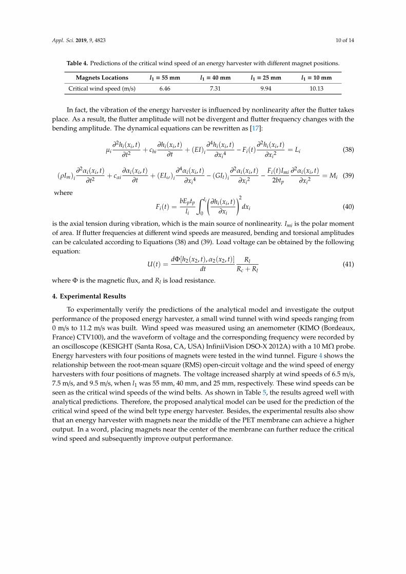
To experimentally verify the predictions of the analytical model and investigate the outputperformance of the proposed energy harvester, a small wind tunnel with wind speeds ranging from0 m/s to 11.2 m/s was built. Wind speed was measured using an anemometer (KIMO (Bordeaux,France) CTV100), and the waveform of voltage and the corresponding frequency were recorded byan oscilloscope (KESIGHT (Santa Rosa, CA, USA) InfiniiVision DSO-X 2012A) with a 10 MΩ probe.Energy harvesters with four positions of magnets were tested in the wind tunnel. Figure 4 shows therelationship between the root-mean square (RMS) open-circuit voltage and the wind speed of energyharvesters with four positions of magnets. The voltage increased sharply at wind speeds of 6.5 m/s,7.5 m/s, and 9.5 m/s, when l1 was 55 mm, 40 mm, and 25 mm, respectively. These wind speeds can beseen as the critical wind speeds of the wind belts. As shown in Table 5, the results agreed well withanalytical predictions. Therefore, the proposed analytical model can be used for the prediction of thecritical wind speed of the wind belt type energy harvester. Besides, the experimental results also showthat an energy harvester with magnets near the middle of the PET membrane can achieve a higheroutput. In a word, placing magnets near the center of the membrane can further reduce the criticalwind speed and subsequently improve output performance.
Appl. Sci. 2019, 9, 4823 11 of 14
Appl. Sci. 2019, 9, x FOR PEER REVIEW 11 of 14
Figure 4. The RMS open-circuit voltage of energy harvester with different magnets positions.
Table 5. Comparison of critical wind speed between the analytical predictions and the experimental results.
Critical Wind Speed (m/s) l1 = 55 mm l1 = 40 mm l1 = 25 mm Analytical model 6.46 7.31 9.94
Experimental results 6.5 7.5 9.5
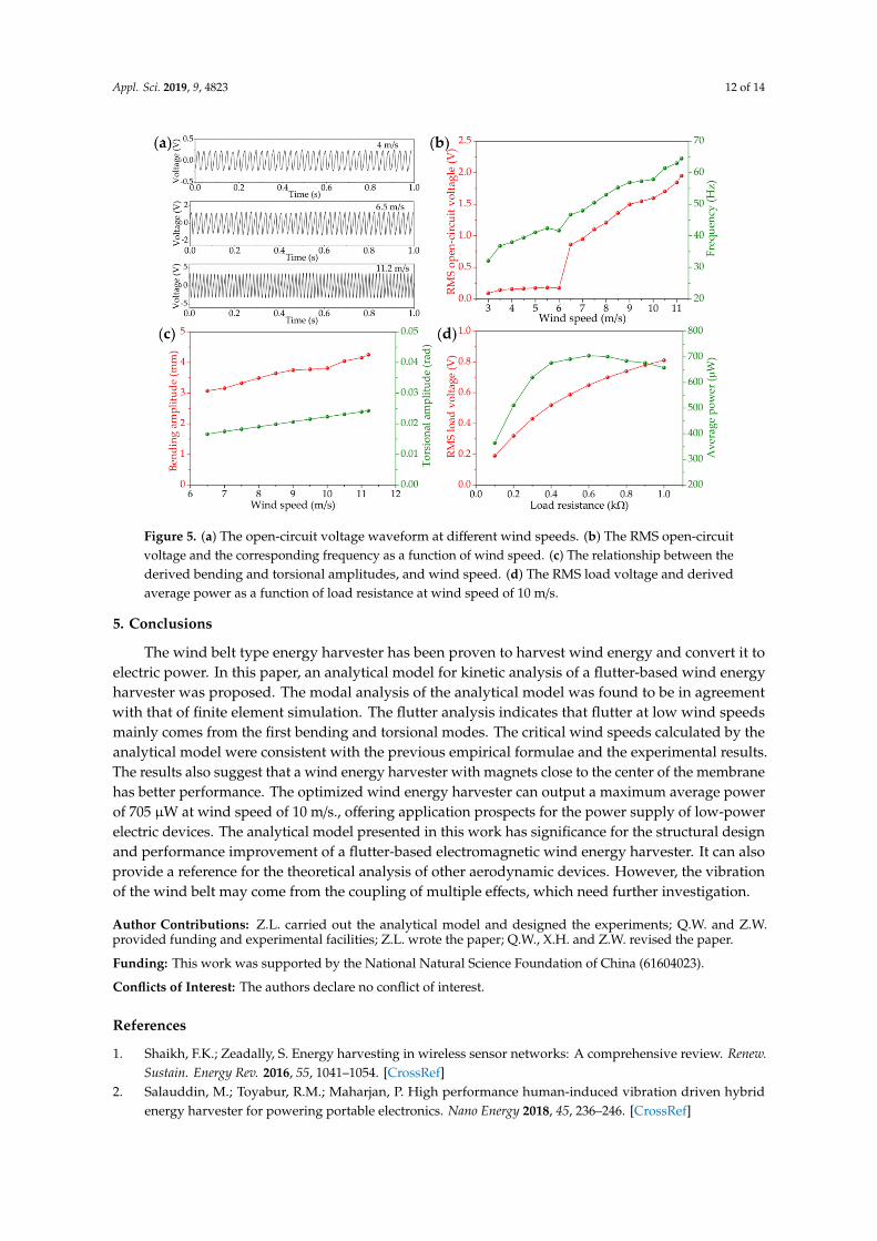
Since the energy harvester with central magnets has the lowest critical wind speed and considerable output performance, it was further investigated. Figure 5a shows the open-circuit voltage waveform at different wind speeds. The energy harvester can generate a steady output, indicating that it vibrated with constant amplitude. Figure 5b shows the RMS open-circuit voltage and the corresponding frequency at different wind speeds. When wind speed was below 3 m/s, there was no output, because the wind belt did not vibrate. When the wind speed reached 3 m/s, the wind belt vibrated with a small amplitude and the energy harvester was able to output small voltage. This phenomenon comes mainly from the asymmetry of the pre-stress along the y direction, so a torsional vibration with torsional axis deviating from the central axis could be observed. When the wind speed reached 6.5 m/s, violent vibration of the wind belt took place and the energy harvester was able to output an RMS voltage of 0.86 V. As the wind speed continues to increase, the voltage of the energy harvester increased approximately linearly; when the wind speed reached 11.2 m/s, the energy harvester generated an output voltage of 1.95 V. Meanwhile, the frequency of the voltage can be used to represent the flutter frequency of the wind belt. We can see that the flutter frequency increased with the wind speed, which was mainly due to enhancement of nonlinearity as the bending amplitude increased. Figure 5c shows the derived bending and torsional amplitudes at different wind speeds according to the nonlinear Equations (38) and (39). The bending and torsional amplitudes increased with the wind speed as well as the flutter frequency, which can explain why the voltage increased with wind speed. To obtain the maximum output power and the corresponding optimized load, the RMS voltage Urms with different load resistance was measured. Average power can be gained according to the equation 2 /ave rms lP U R= . Figure 5d shows the measured RMS load voltage and the derived average power as a function of load resistance; at wind speed of 10 m/s, the energy harvester can generate a maximum average power of 705 μW with an optimized load resistance of 600 Ω. The result highlights application prospects for the power supply of low-power electronic devices.
Figure 4. The RMS open-circuit voltage of energy harvester with different magnets positions.
Table 5. Comparison of critical wind speed between the analytical predictions and theexperimental results.
Critical Wind Speed (m/s) l1 = 55 mm l1 = 40 mm l1 = 25 mm
Analytical model 6.46 7.31 9.94Experimental results 6.5 7.5 9.5
Since the energy harvester with central magnets has the lowest critical wind speed and considerableoutput performance, it was further investigated. Figure 5a shows the open-circuit voltage waveform atdifferent wind speeds. The energy harvester can generate a steady output, indicating that it vibratedwith constant amplitude. Figure 5b shows the RMS open-circuit voltage and the correspondingfrequency at different wind speeds. When wind speed was below 3 m/s, there was no output, becausethe wind belt did not vibrate. When the wind speed reached 3 m/s, the wind belt vibrated with a smallamplitude and the energy harvester was able to output small voltage. This phenomenon comes mainlyfrom the asymmetry of the pre-stress along the y direction, so a torsional vibration with torsional axisdeviating from the central axis could be observed. When the wind speed reached 6.5 m/s, violentvibration of the wind belt took place and the energy harvester was able to output an RMS voltageof 0.86 V. As the wind speed continues to increase, the voltage of the energy harvester increasedapproximately linearly; when the wind speed reached 11.2 m/s, the energy harvester generated anoutput voltage of 1.95 V. Meanwhile, the frequency of the voltage can be used to represent the flutterfrequency of the wind belt. We can see that the flutter frequency increased with the wind speed, whichwas mainly due to enhancement of nonlinearity as the bending amplitude increased. Figure 5c showsthe derived bending and torsional amplitudes at different wind speeds according to the nonlinearEquations (38) and (39). The bending and torsional amplitudes increased with the wind speed as wellas the flutter frequency, which can explain why the voltage increased with wind speed. To obtain themaximum output power and the corresponding optimized load, the RMS voltage Urms with differentload resistance was measured. Average power can be gained according to the equation Pave = U2
rms/Rl.Figure 5d shows the measured RMS load voltage and the derived average power as a function of loadresistance; at wind speed of 10 m/s, the energy harvester can generate a maximum average power of705 µW with an optimized load resistance of 600 Ω. The result highlights application prospects for thepower supply of low-power electronic devices.
Appl. Sci. 2019, 9, 4823 12 of 14
Appl. Sci. 2019, 9, x FOR PEER REVIEW 12 of 14
Figure 5. (a) The open-circuit voltage waveform at different wind speeds. (b) The RMS open-circuit voltage and the corresponding frequency as a function of wind speed. (c) The relationship between the derived bending and torsional amplitudes, and wind speed. (d) The RMS load voltage and derived average power as a function of load resistance at wind speed of 10 m/s.
5. Conclusions The wind belt type energy harvester has been proven to harvest wind energy and convert it to
electric power. In this paper, an analytical model for kinetic analysis of a flutter-based wind energy harvester was proposed. The modal analysis of the analytical model was found to be in agreement with that of finite element simulation. The flutter analysis indicates that flutter at low wind speeds mainly comes from the first bending and torsional modes. The critical wind speeds calculated by the analytical model were consistent with the previous empirical formulae and the experimental results. The results also suggest that a wind energy harvester with magnets close to the center of the membrane has better performance. The optimized wind energy harvester can output a maximum average power of 705 μW at wind speed of 10 m/s., offering application prospects for the power supply of low-power electric devices. The analytical model presented in this work has significance for the structural design and performance improvement of a flutter-based electromagnetic wind energy harvester. It can also provide a reference for the theoretical analysis of other aerodynamic devices. However, the vibration of the wind belt may come from the coupling of multiple effects, which need further investigation.
Author Contributions: Z.L. carried out the analytical model and designed the experiments; Q.W. and Z.W. provided funding and experimental facilities; Z.L. wrote the paper; Q.W., X.H. and Z.W. revised the paper.
Funding: This work was supported by the National Natural Science Foundation of China (61604023).
Conflicts of Interest: The authors declare no conflict of interest.
Reference 1 Shaikh, F.K.; Zeadally, S. Energy harvesting in wireless sensor networks: A comprehensive review. Renew.
Sustain. Energy. Rev. 2016, 55, 1041–1054. 2 Salauddin, M.; Toyabur, R.M.; Maharjan, P. High performance human-induced vibration driven hybrid
energy harvester for powering portable electronics. Nano Energy. 2018, 45, 236–246. 3 Nasiri, A.; Zabalawi, S.A.; Jeutter, D.C. A linear permanent magnet generator for powering implanted
Figure 5. (a) The open-circuit voltage waveform at different wind speeds. (b) The RMS open-circuitvoltage and the corresponding frequency as a function of wind speed. (c) The relationship between thederived bending and torsional amplitudes, and wind speed. (d) The RMS load voltage and derivedaverage power as a function of load resistance at wind speed of 10 m/s.
5. Conclusions
The wind belt type energy harvester has been proven to harvest wind energy and convert it toelectric power. In this paper, an analytical model for kinetic analysis of a flutter-based wind energyharvester was proposed. The modal analysis of the analytical model was found to be in agreementwith that of finite element simulation. The flutter analysis indicates that flutter at low wind speedsmainly comes from the first bending and torsional modes. The critical wind speeds calculated by theanalytical model were consistent with the previous empirical formulae and the experimental results.The results also suggest that a wind energy harvester with magnets close to the center of the membranehas better performance. The optimized wind energy harvester can output a maximum average powerof 705 µW at wind speed of 10 m/s., offering application prospects for the power supply of low-powerelectric devices. The analytical model presented in this work has significance for the structural designand performance improvement of a flutter-based electromagnetic wind energy harvester. It can alsoprovide a reference for the theoretical analysis of other aerodynamic devices. However, the vibrationof the wind belt may come from the coupling of multiple effects, which need further investigation.
Author Contributions: Z.L. carried out the analytical model and designed the experiments; Q.W. and Z.W.provided funding and experimental facilities; Z.L. wrote the paper; Q.W., X.H. and Z.W. revised the paper.
Funding: This work was supported by the National Natural Science Foundation of China (61604023).
Conflicts of Interest: The authors declare no conflict of interest.
References
1. Shaikh, F.K.; Zeadally, S. Energy harvesting in wireless sensor networks: A comprehensive review. Renew.Sustain. Energy Rev. 2016, 55, 1041–1054. [CrossRef]
2. Salauddin, M.; Toyabur, R.M.; Maharjan, P. High performance human-induced vibration driven hybridenergy harvester for powering portable electronics. Nano Energy 2018, 45, 236–246. [CrossRef]
Appl. Sci. 2019, 9, 4823 13 of 14
3. Nasiri, A.; Zabalawi, S.A.; Jeutter, D.C. A linear permanent magnet generator for powering implantedelectronic devices. IEEE Trans. Power Electron. 2011, 26, 192–199. [CrossRef]
4. Tan, Y.S.; Dong, Y.; Wang, X.H. Review of MEMS electromagnetic vibration energy harvester.J. Microelectromech. Syst. 2016, 26, 1–16. [CrossRef]
5. Orrego, S.; Shoele, K.; Ruas, A.; Doran, K.; Cagiano, B.; Mittal, R.; Kang, S.H. Harvesting ambient windenergy with an inverted piezoelectric flag. Appl. Energy 2017, 194, 212–222. [CrossRef]
6. Bogue, R. Energy harvesting: A review of recent developments. Sens. Rev. 2015, 35, 1–5. [CrossRef]7. Liu, H.C.; Zhong, J.W.; Lee, C.K.; Lee, S.W.; Lin, L.W. A comprehensive review on piezoelectric energy
harvesting technology: Materials, mechanisms, and applications. Appl. Phys. Rev. 2018, 5, 041306. [CrossRef]8. Elahi, H.; Eugeni, M.; Caudenzi, P. A review on mechanisms for piezoelectric-based energy harvesters.
Energies 2018, 11, 1850. [CrossRef]9. Usharani, R.; Uma, G.; Ummpathy, M.; Choi, S. A novel piezoelectric energy harvester using a multi-stepped
beam with rectangular cavities. Appl. Sci. 2018, 8, 2091. [CrossRef]10. Mccarthy, J.M.; Watkins, S.; Deivasigamani, A.; John, S.J. Fluttering energy harvesters in the wind: A review.
J. Sound Vib. 2016, 361, 355–377. [CrossRef]11. Hu, Y.L.; Yang, B.; Chen, X.; Wang, X.L.; Liu, J.Q. Modeling and experimental study of a piezoelectric energy
harvester from vortex shedding-induced vibration. Energy Convers. Manag. 2018, 162, 145–158. [CrossRef]12. Kumar, S.K.; Bose, C.; Ali, S.F.; Sarkar, S.; Gupta, S. Investigations on a vortex induced vibration based energy
harvester. Appl. Phys. Lett. 2017, 111, 243903. [CrossRef]13. Dai, H.L.; Abdelkefi, A.; Yang, Y.; Wang, L. Orientation of bluff body for designing efficient energy harvesters
from vortex induced vibrations. Appl. Phys. Lett. 2016, 108, 053902. [CrossRef]14. Ewere, F.; Wang, G. Performance of galloping piezoelectric energy harvesters. J. Intell. Mater. Syst. Struct.
2014, 25, 1693–1704. [CrossRef]15. Hemon, P.; Amandolese, X.; Andrianne, T. Energy harvesting from galloping of prisms: A wind tunnel
experiment. J. Fluids Struct. 2017, 70, 390–402. [CrossRef]16. Li, X.T.; Lyu, Z.; Kou, J.Q.; Zhang, W.W. Mode competition in galloping of a square cylinder at low Reynolds
number. J. Fluid Mech. 2019, 867, 516–555. [CrossRef]17. Chen, Y.; Mu, X.J.; Wang, T.; Ren, W.W.; Yang, Y.; Wang, Z.L.; Sun, C.L.; Gu, A.Y.D. Flutter Phenomenon in
Flow Driven Energy Harvester—A Unified Theoretical Model for “Stiff” and “Flexible” Materials. Sci. Rep.2016, 6, 35180. [CrossRef] [PubMed]
18. Bao, C.Y.; Dai, Y.T.; Wang, P.; Tang, G.J. A piezoelectric energy harvesting scheme based on stall flutter ofairfoil section. Eur. J. Mech. B Fluids 2019, 75, 119–132. [CrossRef]
19. He, X.F.; Yang, X.K.; Jiang, S.L. Enhancement of wind energy harvesting by interaction between vortex-inducedvibration and galloping. Appl. Phys. Lett. 2018, 112, 033901. [CrossRef]
20. Li, S.G.; Lipson, H. Vertical-stalk flapping-leaf generator for wind energy harvesting. In Proceedingsof the Conference on Smart Materials, Adaptive Structures and Intelligent Systems, Oxnard, CA, USA,20–24 September 2009; 2, pp. 611–619. [CrossRef]
21. Available online: http://www.humdingerwind.com (accessed on 27 June 2019).22. Frayne, S.M. Fluid-Induced Energy Converter with Curved Parts. U.S. Patent 20080297119A1,
4 December 2008.23. Frayne, S.M. Generator Utilizing Fluid-Induced Oscillations. U.S. Patent 7,573,143, 11 August 2009.24. Fei, F.; Mai, J.D.; Li, W.J. A wind-flutter energy converter for powering wireless sensors. Sens. Actuators A
Phys. 2012, 173, 163–171. [CrossRef]25. Quy, V.D.; Sy, N.V.; Hung, D.T.; Huy, V.Q. Wind tunnel and initial field tests of a micro generator powered by
fluid-induced flutter. Energy Sustain. Dev. 2016, 33, 75–83.26. Aquino, A.I.; Calautit, J.K.; Hughes, B.R. A Study on the Wind-Induced Flutter Energy Harvester (WIFEH)
Integration into Buildings. Energy Procedia 2017, 142, 321–327. [CrossRef]27. Aquino, A.I.; Calautit, J.K.; Hughes, B.R. Integration of aero-elastic belt into the built environment for
low-energy wind harnessing: Current status and a case study. Energy Convers. Manag. 2017, 149, 830–850.[CrossRef]
28. Pan, C.T.; Liu, Z.H.; Chen, Y.C.; Liu, C.F. Design and fabrication of flexible piezo-microgenerator by depositingZnO thin films on PET substrates. Sens. Actuators A Phys. 2010, 159, 96–104. [CrossRef]
Appl. Sci. 2019, 9, 4823 14 of 14
29. Pan, C.T.; Liu, Z.H.; Chen, Y.C. Study of broad bandwidth vibrational energy harvesting system withoptimum thickness of PET substrate. Curr. Appl. Phys. 2012, 12, 684–696. [CrossRef]
30. Foong, F.M.; Thein, C.K.; Ooi, B.L.; Yurchenko, D. Increased power output of an electromagnetic vibrationenergy harvester through anti-phase resonance. Mech. Syst. Signal Process. 2019, 116, 129–145. [CrossRef]
31. He, X.M.; Wen, Q.; Lu, Z. A micro-electromechanical systems based vibration energy harvester withaluminum nitride piezoelectric thin film deposited by pulsed direct-current magnetron sputtering. Appl.Energy 2018, 228, 881–890. [CrossRef]
32. Theodorsen, T. General theory of aerodynamic instability and the mechanism of flutter. NACA Tech. Rep.1935, 496, 1–23.
33. Fung, Y.C. A Introduction to Theory of Aeroelasticity; Dover Publications: New York, NY, USA, 1993; pp. 214–215.34. Van der Put, M. Rigidity of Structures Against Aerodynamic Forces; IABSE: Zurich, Switzerland, 1976.35. Selberg, A.; Hjort-Hansen, E. The fate of flat plate aerodynamics in the world of bridge decks. In Proceedings
of the Theodorsen Colloquium, Trondheim, Norway, 1976; pp. 101–113.
© 2019 by the authors. Licensee MDPI, Basel, Switzerland. This article is an open accessarticle distributed under the terms and conditions of the Creative Commons Attribution(CC BY) license (http://creativecommons.org/licenses/by/4.0/).