Embed Size (px)
Citation preview
Electromagnetic Induction17
COMPREHENSIVE REVIEW
1. Magnetic flux
i) The dot product of magnetic field B
& the
area element dA
is called magnetic flux.
ii) The magnetic flux is denoted by . If B
be
the magnetic field through the area element
dA
. Then, the flux through the area is given
by :
d B dA
a) Unit for magnetic flux
The unit of magnetic flux is called weber.
It is abbreviated as Wb.
If B
is parallel to dA
. Then
0d B dA B(dA)cos0
This gives d B(dA)
If B = 1 tesla, dA = 1 square metre,
then d = 1 weber.
Thus, magnetic flux is said to be 1 weber if
a magnetic field of 1 tesla crosses through
1 square metre area, held perpendicular to
the magnetic field.
Mathematically : Wb = Tm2
Note. The area vector is taken perpendicular to
the surface. Therefore, area vector parallel to
the magnetic field vector means that the magnetic
field is perpendicular to the surface on which the
area lies.
b) Magnetic flux density
Magnetic flux is given by : d B(dA)
For B
parallel to dA
, we have
0d B(dA)cos0 B(dA)
Therefore, d
BdA
ELECTROMAGNETIC INDUCTION ( 196 )
That is, magnetic induction is equal to the
magnetic flux density. In other words,
magnetic field may be measured in terms
of the magnetic flux density.
From equation (i), we find :
Unit of Unit of d
BUnit of dA
Or2
WbT
m
That is tesla = weber per square metre.
2. Electromagnetic induction
When the magnetic flux linked with a circuit
changes, an emf is set up in the circuit. The
phenomenon is called electromagnetic induction.
a) Induced emf and current
When the magnetic flux linked with a circuit
changes, emf set up in the circuit is called
induced emf.
The current due to induced emf is called
induced current.
b) Faraday's laws of electromagnetic
induction
i) Whenever, the magnetic flux linked with a
circuit changes, induced emf is produced.
ii) The induced emf lasts as long as the change
in magnetic flux continues.
iii) The magnitude of induced emf (E) is directly
proportional to the rate of change in
magnetic flux.
Thus, if d be the change in magnetic
flux during the time dt, then :
dE
dt
Ord
E kdt
where k is the constant of proportionality.
DGT Group - Tuitions (Feed Concepts) XIth – XIIth | JEE | CET | NEET | Call : 9920154035 / 8169861448
DGT MH –CET 12th PHYSICS Study Material 1
DGT GROUP TUITIONS (FEED CONCEPTS) [MHT - CET] PHYSICS
ELECTROMAGNETIC INDUCTION ( 197 )
In SI, k = – 1, hence : d
Edt
It is called Faraday's flux rule.
Remarks. The negative sign indicates that the
induced emf opposes the change in magnetic
flux. In SI, the change in flux d is measured in
weber, dt in second and E in volt.
Hence volt = weber/second. Or Wb
Vs
3. Lenz's law
The Lenz'slaw explains the –VE sign in the
Faraday's flux rule d
E .dt
It states that the induced emf is such as to
oppose the cause that produces it.
4. Lenz's law is in accordance with the conser-
vation of' energy.
As the induced emf opposes the cause that
produces it. Therefore mechanical work need to
be done to continue the process. It is this
mechanical energy which is converted into
electrical energy, in accordance with the law of
conservation of energy.
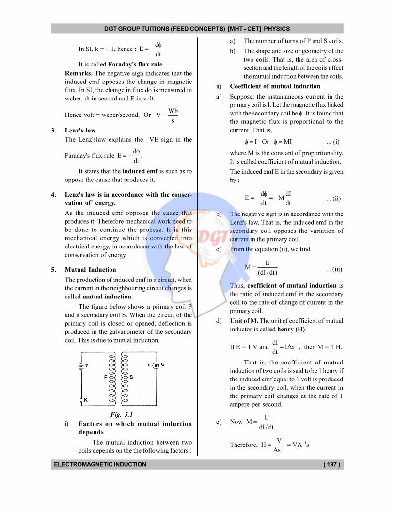
5. Mutual Induction
The production of induced emf in a circuit, when
the current in the neighbouring circuit changes is
called mutual induction.
The figure below shows a primary coil P
and a secondary coil S. When the circuit of the
primary coil is closed or opened, deflection is
produced in the galvanometer of the secondary
coil. This is due to mutual induction.
Fig. 5.1
i) Factors on which mutual induction
depends
The mutual induction between two
coils depends on the the following factors :
a) The number of turns of P and S coils.
b) The shape and size or geometry of the
two coils. That is, the area of cross-
section and the length of the coils affect
the mutual induction between the coils.
ii) Coefficient of mutual induction
a) Suppose, the instantaneous current in the
primary coil is I. Let the magnetic flux linked
with the secondary coil be . It is found that
the magnetic flux is proportional to the
current. That is,
I Or MI ... (i)
where M is the constant of proportionality.
It is called coefficient of mutual induction.
The induced emf E in the secondary is given
by :
d dIE M
dt dt
... (ii)
b) The negative sign is in accordance with the
Lenz's law. That is, the induced emf in the
secondary coil opposes the variation of
current in the primary coil.
c) From the equation (ii), we find
EM
(dI / dt) ... (iii)
Thus, coefficient of mutual induction is
the ratio of induced emf in the secondary
coil to the rate of change of current in the
primary coil.
d) Unit of M. The unit of coefficient of mutual
inductor is called henry (H).
If E = 1 V and 1dI
1As ,dt
then M = 1 H.
That is, the coefficient of mutual
induction of two coils is said to be 1 henry if
the induced emf equal to 1 volt is produced
in the secondary coil, when the current in
the primary coil changes at the rate of 1
ampere per second.
e) Now E
MdI / dt
Therefore, 1
1
VH VA s
As
DGT Group - Tuitions (Feed Concepts) XIth – XIIth | JEE | CET | NEET | Call : 9920154035 / 8169861448
DGT MH –CET 12th PHYSICS Study Material 2
DGT GROUP TUITIONS (FEED CONCEPTS) [MHT - CET] PHYSICS
ELECTROMAGNETIC INDUCTION ( 198 )
6. Self induction
The production of induced emf in a circuit, when
the current in the same circuit changes is called
self induction.
i) Factors on which self induction depends
The self induction in a circuit mainly
depends upon its geometry. For a solenoid it
is determined by the number of turns, area
of cross-section and the length of the
solenoid.
ii) Coefficient of self induction
a) Suppose, the instantaneous current in the
circuit is I. If the magnetic flux linked with
the solenoid is , then it is found that :
I Or LI ... (i)
where L is the constant of proportionality. It
is called coefficient of self induction.
The induced emf in the coil is given by :
d dIE L
dt dt
... (ii)
b) The negative sign is in accordance with the
Lenz's law. That is, the induced emf opposes
the variation of current in the coil.
c) From the equation (ii), we find :
EL
(dI / dt) ... (iii)
Then, coefficient of self induction is the
ratio of induced emf in the circuit to tlie rate
of change of the current in the circuit.
d) Unit of L. The unit of self induction is also
called henry (symbol H).
From equation (ii),
we find that if
1dI1 As ,
dt
E = 1 V, then L = 1 H.
That is, the coefficient of self induction of a
coil is said to be one henry if induced emf
equal to 1 volt is produced in the coil, when
the current in it changes at the rate of 1
ampere per second.
e) Also, as explained early,
H = VA–1 s.
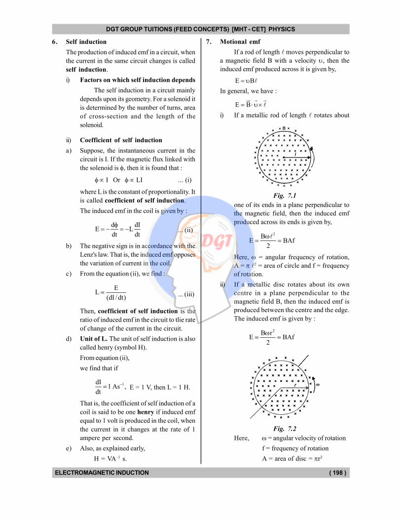
7. Motional emf
If a rod of length moves perpendicular to
a magnetic field B with a velocity , then the
induced emf produced across it is given by,
E B
In general, we have :
E B
i) If a metallic rod of length rotates about
Fig. 7.1
one of its ends in a plane perpendicular to
the magnetic field, then the induced emf
produced across its ends is given by,
2BE BAf
2
Here, = angular frequency of rotation,
A = 2 = area of circle and f = frequency
of rotation.
ii) If a metallic disc rotates about its own
centre in a plane perpendicular to the
magnetic field B, then the induced emf is
produced between the centre and the edge.
The induced emf is given by :
2B rE BAf
2
Fig. 7.2
Here, = angular velocity of rotation
f = frequency of rotation
A = area of disc = r2
DGT Group - Tuitions (Feed Concepts) XIth – XIIth | JEE | CET | NEET | Call : 9920154035 / 8169861448
DGT MH –CET 12th PHYSICS Study Material 3
DGT GROUP TUITIONS (FEED CONCEPTS) [MHT - CET] PHYSICS
ELECTROMAGNETIC INDUCTION ( 199 )
8. Eddy currents
In the year 1895, A.D., Focault discovered that if
a metallic plate is moved in a magnetic field,
induced current is set up in the plate. It flows in
closed loops within the plate. Such a current is
called eddy current. In accordance with the
Lenz's law, the induced current opposes the cause
that produces it.
If a current I is set up in a coil of inductance
L, then the magnetic field energy stored in it is
given by,
2
p
1U LI
2
9. Finding the direction of induced emf
The direction of induced emf can be found be
using the Lenz's law. That is, the induced emf is
such as to oppose the cause that produces it.
Below we discuss a number of such cases.
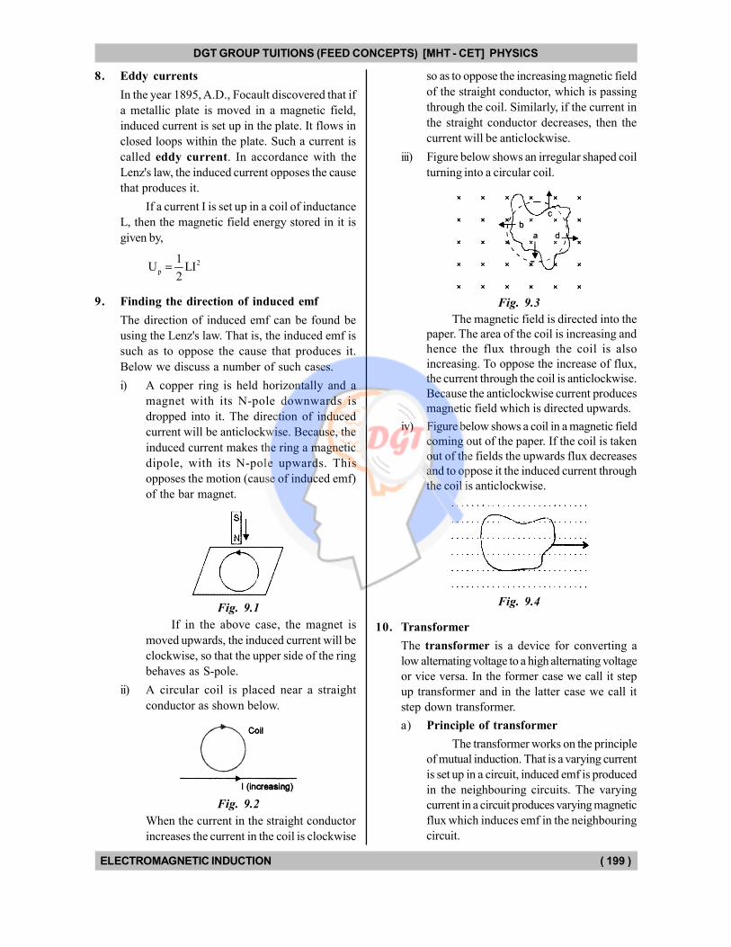
i) A copper ring is held horizontally and a
magnet with its N-pole downwards is
dropped into it. The direction of induced
current will be anticlockwise. Because, the
induced current makes the ring a magnetic
dipole, with its N-pole upwards. This
opposes the motion (cause of induced emf)
of the bar magnet.
Fig. 9.1
If in the above case, the magnet is
moved upwards, the induced current will be
clockwise, so that the upper side of the ring
behaves as S-pole.
ii) A circular coil is placed near a straight
conductor as shown below.
Fig. 9.2
When the current in the straight conductor
increases the current in the coil is clockwise
so as to oppose the increasing magnetic field
of the straight conductor, which is passing
through the coil. Similarly, if the current in
the straight conductor decreases, then the
current will be anticlockwise.
iii) Figure below shows an irregular shaped coil
turning into a circular coil.
Fig. 9.3
The magnetic field is directed into the
paper. The area of the coil is increasing and
hence the flux through the coil is also
increasing. To oppose the increase of flux,
the current through the coil is anticlockwise.
Because the anticlockwise current produces
magnetic field which is directed upwards.
iv) Figure below shows a coil in a magnetic field
coming out of the paper. If the coil is taken
out of the fields the upwards flux decreases
and to oppose it the induced current through
the coil is anticlockwise.
Fig. 9.4
10. Transformer
The transformer is a device for converting a
low alternating voltage to a high alternating voltage
or vice versa. In the former case we call it step
up transformer and in the latter case we call it
step down transformer.
a) Principle of transformer
The transformer works on the principle
of mutual induction. That is a varying current
is set up in a circuit, induced emf is produced
in the neighbouring circuits. The varying
current in a circuit produces varying magnetic
flux which induces emf in the neighbouring
circuit.
DGT Group - Tuitions (Feed Concepts) XIth – XIIth | JEE | CET | NEET | Call : 9920154035 / 8169861448
DGT MH –CET 12th PHYSICS Study Material 4
DGT GROUP TUITIONS (FEED CONCEPTS) [MHT - CET] PHYSICS
ELECTROMAGNETIC INDUCTION ( 200 )
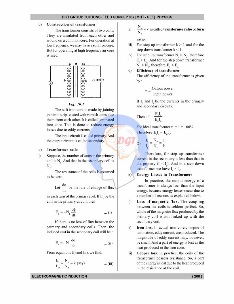
b) Construction of transformer
The transformer consists of two coils.
They are insulated from each other and
wound on a common core. For operation at
low frequency, we may have a soft iron core.
But for operating at high frequency air core
is used.
Fig. 10.1
The soft iron core is made by joining
thin iron strips coated with varnish to insulate
them from each other. It is called laminated
iron core. This is done to reduce energy
losses due to eddy currents.
The input circuit is called primary. And
the output circuit is called secondary.
c) Transformer ratio
i) Suppose, the number of turns in the primary
coil is Np. And that in the secondary coil is
Ns.
The resistance of the coils is assumed
to be zero.
Let d
dt
be the rate of change of flux
in each turn of the primary coil. If Ep be the
emf in the primary circuit, then
p p
dE N
dt
... (i)
If there is no loss of flux between the
primary and secondary coils. Then, the
induced emf in the secondary coil will be :
s p
dE N
dt
... (ii)
From equations (i) and (ii), we find,
s s
p p
E Nk (say)
E N ... (iii)
ii) s
p
Nk
N is called transformer ratio or turn
ratio.
iii) For step up transformer k > 1 and for the
step down transformer k < 1.
iv) For step up transformer Ns > N
p, therefore
Es > E
p. And for the step down transformer
Ns < N
p, therefore E
s < E
p.
d) Efficiency of transformer
The efficiency of the transformer is given
by :
Output power
Input power
If Ip and I
s be the currents in the primary
and secondary circuits.
Then : s s
p p
E I
E I
For ideal transformer = 1 = 100%.
Therefore EsI
s = E
pI
p.
Orps
p s
NI 1
I N k
Therefore, for step up transformer
current in the secondary is less than that in
the primary (Is< I
p). And in a step down
transformer we have Is > I
p.
e) Energy Losses in Transformers
In practice, the output energy of a
transformer is always less than the input
energy, because energy losses occur due to
a number of reasons as explained below.
i) Loss of magnetic flux. The coupling
between the coils is seldom perfect. So,
whole of the magnetic flux produced by the
primary coil is not linked up with the
secondary coil.
ii) Iron loss. In actual iron cores, inspite of
lamination, eddy current, are produced. The
magnitude of eddy current may, however,
be small. And a part of energy is lost as the
heat produced in the iron core.
iii) Copper loss. In practice, the coils of the
transformer possess resistance. So, a part
of the energy is lost due to the heat produced
in the resistance of the coil.
DGT Group - Tuitions (Feed Concepts) XIth – XIIth | JEE | CET | NEET | Call : 9920154035 / 8169861448
DGT MH –CET 12th PHYSICS Study Material 5
DGT GROUP TUITIONS (FEED CONCEPTS) [MHT - CET] PHYSICS
ELECTROMAGNETIC INDUCTION ( 201 )
iv) Hysteresis loss. The alternating current
in the coil takes the iron core through
complete cycle of magnetisation. So, energy
is lost due to hysteresis.
v) Humming losses. The alternating current
in the transformer may set its parts into
vibrations and sound may be produced. It is
called humming. Thus, a part of the energy
may be lost due to humming.
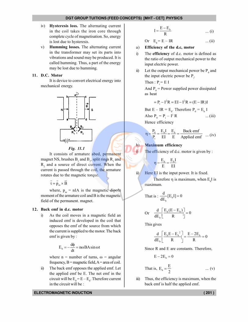
11. D.C. Motor
It is device to convert electrical energy into
mechanical energy.
Fig. 11.1
It consists of armature abed, permanent
magnet NS, brushes B1 and B
2, split rings R
1 and
R2 and a source of direct current. When the
current is passed through the coil, the armature
rotates due to the magnetic torque.
mp B
where, pm = nIA is the magnetic dipole
moment of the armature coil and B is the magnetic
field of the permanent. magnet.
12. Back emf in d.c. motor
i) As the coil moves in a magnetic field an
induced emf is developed in the coil that
opposes the emf of the source from which
the current is supplied to the motor. The back
emf is given by :
b
dE n BAsin t
dt
where n = number of turns, = angular
frequency, B = magnetic field, A = area of coil.
ii) The back emf opposes the applied emf. Let
the applied emf be E. The net emf in the
circuit will be E0 = E – E
b. Therefore current
in the circuit will be :
bE EI
R
... (i)
Or Eb = E – IR ... (ii)
a) Efficiency of the d.c, motor
i) The efficiency of d.c. motor is defined as
the ratio of output mechanical power to the
input electric power.
ii) Let the output mechanical power be P0 and
the input electric power be Pi.
Then : Pi = E I
And P0 = Power supplied power dissipated
as heat
2 2
iP I R EI I R (E IR)I
But E – IR = Eb. Therefore P
0 = E
b I
Also P0 = P
i – I2 R ... (iii)
Hence efficiency
0 b b
i
P E I E Back emf
P EI E Applied emf ... (iv)
b) Maximum efficiency
i) The efficiency of d.c. motor is given by :
b bE E I
E EI
ii) Here EI is the input power. It is fixed.
Therefore is maximum, when EbI is
maximum.
That is : b
b
d[E I] 0
dE
Orb b
b
E (E E )d0
dE R
This gives
2
b b b
b
E E E E 2Ed0
dE R R
Since R and E are constants. Therefore,
bE 2E 0
That is, b
EE
2 ... (v)
iii) Thus, the efficiency is maximum, when the
back emf is half the applied emf.
DGT Group - Tuitions (Feed Concepts) XIth – XIIth | JEE | CET | NEET | Call : 9920154035 / 8169861448
DGT MH –CET 12th PHYSICS Study Material 6
DGT GROUP TUITIONS (FEED CONCEPTS) [MHT - CET] PHYSICS
ELECTROMAGNETIC INDUCTION ( 202 )
13. A.C. Generator
The electric generator is a device for converting
mechanical energy into electric energy. If the
electric current produced varies in direction
alternatively, it is called alternating current or a.c.
generator.
a) Principle of a.c. generator
It is based on the principle of electromagnetic
induction. When the magnetic flux linked
with a circuit varies, induced e.m.f, is set up
in the circuit.
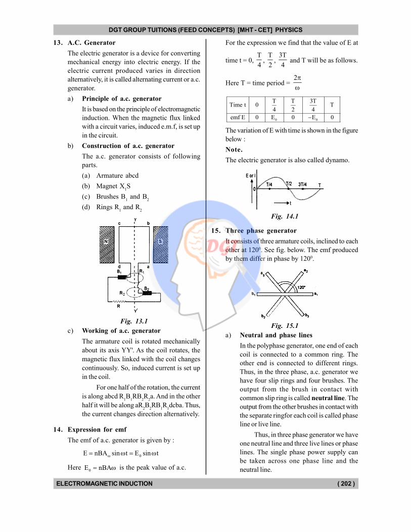
b) Construction of a.c. generator
The a.c. generator consists of following
parts.
(a) Armature abcd
(b) Magnet X1S
(c) Brushes B1 and B
2
(d) Rings R1 and R
2
Fig. 13.1
c) Working of a.c. generator
The armature coil is rotated mechanically
about its axis YY'. As the coil rotates, the
magnetic flux linked with the coil changes
continuously. So, induced current is set up
in the coil.
For one half of the rotation, the current
is along abcd R1B
1RB
2R
2a. And in the other
half it will be along aR2B
2RB
1R
1dcba. Thus,
the current changes direction alternatively.
14. Expression for emf
The emf of a.c. generator is given by :
0E nBA sin t E sin t
Here 0E nBA is the peak value of a.c.
For the expression we find that the value of E at
time t = 0, T
4,
T
2,
3T
4 and T will be as follows.
Here T = time period = 2
0 0
T T 3TTime t 0 T
4 2 4
emf E 0 E 0 E 0
The variation of E with time is shown in the figure
below :
Note.
The electric generator is also called dynamo.
Fig. 14.1
15. Three phase generator
It consists of three armature coils, inclined to each
other at 1200. See fig. below. The emf produced
by them differ in phase by 1200.
Fig. 15.1
a) Neutral and phase lines
In the polyphase generator, one end of each
coil is connected to a common ring. The
other end is connected to different rings.
Thus, in the three phase, a.c. generator we
have four slip rings and four brushes. The
output from the brush in contact with
common slip ring is called neutral line. The
output from the other brushes in contact with
the separate ringfor each coil is called phase
line or live line.
Thus, in three phase generator we have
one neutral line and three live lines or phase
lines. The single phase power supply can
be taken across one phase line and the
neutral line.
DGT Group - Tuitions (Feed Concepts) XIth – XIIth | JEE | CET | NEET | Call : 9920154035 / 8169861448
DGT MH –CET 12th PHYSICS Study Material 7
DGT GROUP TUITIONS (FEED CONCEPTS) [MHT - CET] PHYSICS
ELECTROMAGNETIC INDUCTION ( 203 )
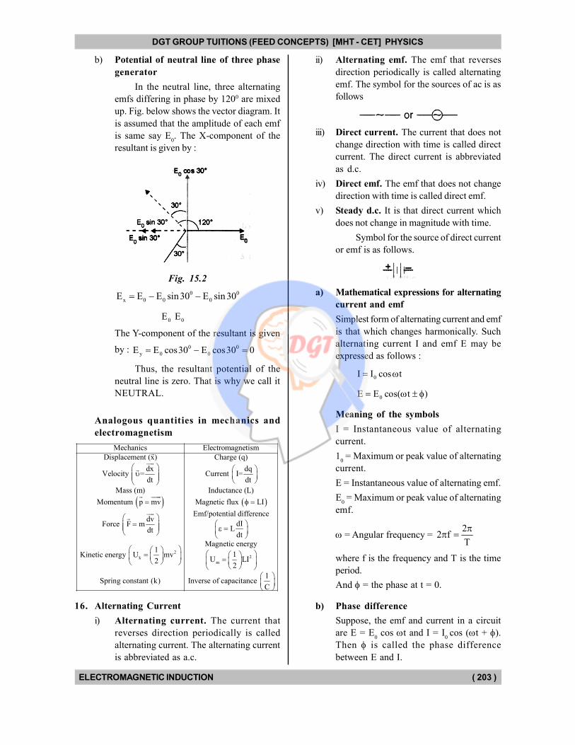
b) Potential of neutral line of three phase
generator
In the neutral line, three alternating
emfs differing in phase by 1200 are mixed
up. Fig. below shows the vector diagram. It
is assumed that the amplitude of each emf
is same say E0. The X-component of the
resultant is given by :
Fig. 15.2
0 0
x 0 0 0E E E sin30 E sin 30
0 0E E
The Y-component of the resultant is given
by : 0 0
y 0 0E E cos30 E cos30 0
Thus, the resultant potential of the
neutral line is zero. That is why we call it
NEUTRAL.
Analogous quantities in mechanics and
electromagnetism
Mechanics Electromagnetism
Displacement (x) Charge (q)
dx dqVelocity = Current I=
dt dt
Mass (m) Inductance (L)
Momentum p mv Magnetic flux LI
Emf/potential diffdv
Force F mdt
22k
m
erence
dIL
dt
Magnetic energy1
1Kinetic energy U mvU LI2
2
1Spring constant (k) Inverse of capacitance
C
16. Alternating Current
i) Alternating current. The current that
reverses direction periodically is called
alternating current. The alternating current
is abbreviated as a.c.
ii) Alternating emf. The emf that reverses
direction periodically is called alternating
emf. The symbol for the sources of ac is as
follows
iii) Direct current. The current that does not
change direction with time is called direct
current. The direct current is abbreviated
as d.c.
iv) Direct emf. The emf that does not change
direction with time is called direct emf.
v) Steady d.c. It is that direct current which
does not change in magnitude with time.
Symbol for the source of direct current
or emf is as follows.
a) Mathematical expressions for alternating
current and emf
Simplest form of alternating current and emf
is that which changes harmonically. Such
alternating current I and emf E may be
expressed as follows :
0I I cos t
0E E cos( t )
Meaning of the symbols
I = Instantaneous value of alternating
current.
10 = Maximum or peak value of alternating
current.
E = Instantaneous value of alternating emf.
E0 = Maximum or peak value of alternating
emf.
= Angular frequency = 2
2 fT
where f is the frequency and T is the time
period.
And = the phase at t = 0.
b) Phase difference
Suppose, the emf and current in a circuit
are E = E0 cos t and I = I
0 cos (t + ).
Then is called the phase difference
between E and I.
DGT Group - Tuitions (Feed Concepts) XIth – XIIth | JEE | CET | NEET | Call : 9920154035 / 8169861448
DGT MH –CET 12th PHYSICS Study Material 8
DGT GROUP TUITIONS (FEED CONCEPTS) [MHT - CET] PHYSICS
ELECTROMAGNETIC INDUCTION ( 204 )
If the sign with is +VB, then we
say that the current leads the emf by phase
angle .
If the sign with is –VE, then we say
that the current lags behind the emf by phase
angle .
c) Average value of alternating current is
that steady direct current which sends the
same charge through the circuit in halftime
T
2
period as is sent by the a.c. during the
same time.
It is given by : 0a 0
2II 63.66% of I
d) Average value of alternating emf is that
steady emf which sends same charge
through the circuit during half time period
T
2
as is sent by the alternating emf during
the same time.
It is given by :
0a 0
2EE 63.66% of E
e) The root mean square value of the
alternating current is defined as the steady
direct current that produces same heat in a
resistance, as is done by the alternating
current during one time period (T).
It may be denoted by Irms
. It is also
called effective value or virtual value of
the alternating current. The ammeter, when
connected in the circuit measures rms value
of a.c. Its value is given by,
0rms 0 0
II 0.7071 I 71.71% of I
2
f) The root mean square value of the
alternating emf is defined as that steady
direct emf which produces same heat in a
resistance as the alternating emf does in one
time period (T).
It may be denoted by Erms
. It is also
called effective value or virtual value of
alternating emf. The voltmeter connected
in an a.c. circuit measures Erms
.
Its value is given by :
0rms 0
EE 70.71% of E
2
g) In the pure resistance, the alternating
current and the corresponding alternating
emf are in phase.
That is if0I I cos t
Then0E E cos t
h) In pure inductance the alternating emf
leads the alternating current by /2.
That is if 0I I cos t
Then 0 0E E cos t E sin t
2
i) In the pure capacitance, the alternating
emf lags behind the alternating current
by /2.
That is if : 0I I cos t
Then 0 0E E cos t E sin t2
j) In the pure inductance (L), we have
0 0E I ( L)
Here L= XL is called inductive reactance.
Its unit is same as that of resistance (ohm).
k) In the pure capacitance (C), we have
00
iE
C
Here, C
1X
C
is called capacitive reactance.
Its unit is same as that of resistance (ohm).
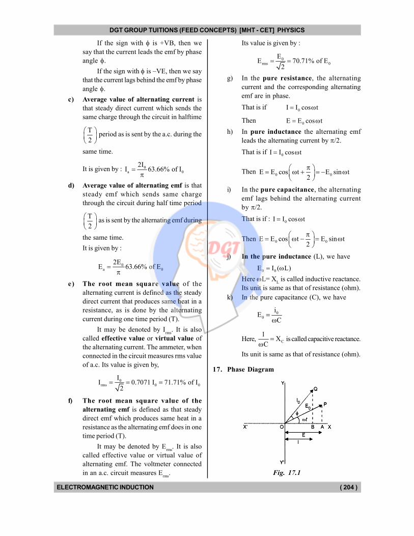
17. Phase Diagram
Fig. 17.1
DGT Group - Tuitions (Feed Concepts) XIth – XIIth | JEE | CET | NEET | Call : 9920154035 / 8169861448
DGT MH –CET 12th PHYSICS Study Material 9
DGT GROUP TUITIONS (FEED CONCEPTS) [MHT - CET] PHYSICS
ELECTROMAGNETIC INDUCTION ( 205 )
The graphical representation of the phase
relationship between two or more quantities is
called phase diagram.
Suppose, we wish to draw the phase diagram
for alternating current and alternating emf. Let :
0E E cos t & 0I I cos( t )
Then we draw two vectors OP and OQ as
shown in fig. 49.1. where OP = E0 and OQ = I
0
and POQ= .
The instantaneous values of current and emf
will be given by the projections of OQ and OP on
the X-axis. That is E = OA = E0 cos t and
I = OB = I0 cos (t + ), where t = XOP. It is
the phase angle for the emf.
Note. As the time passes, the vectors OP and
OQ rotate about O. Because the phase angle t
changes with time. Therefore they are also called
phasors.
Vector diagram. Since E0 and I
0 are represented
as vectors in the phase diagram. Therefore, the
phase diagram is also called vector diagram.
18. Phase diagrams for A.C.
Through pure resistance, pure inductance and
pure capacitances are shown below in the figures
50.1 (a), (b) and (c) respectively.
Fig. 18.1
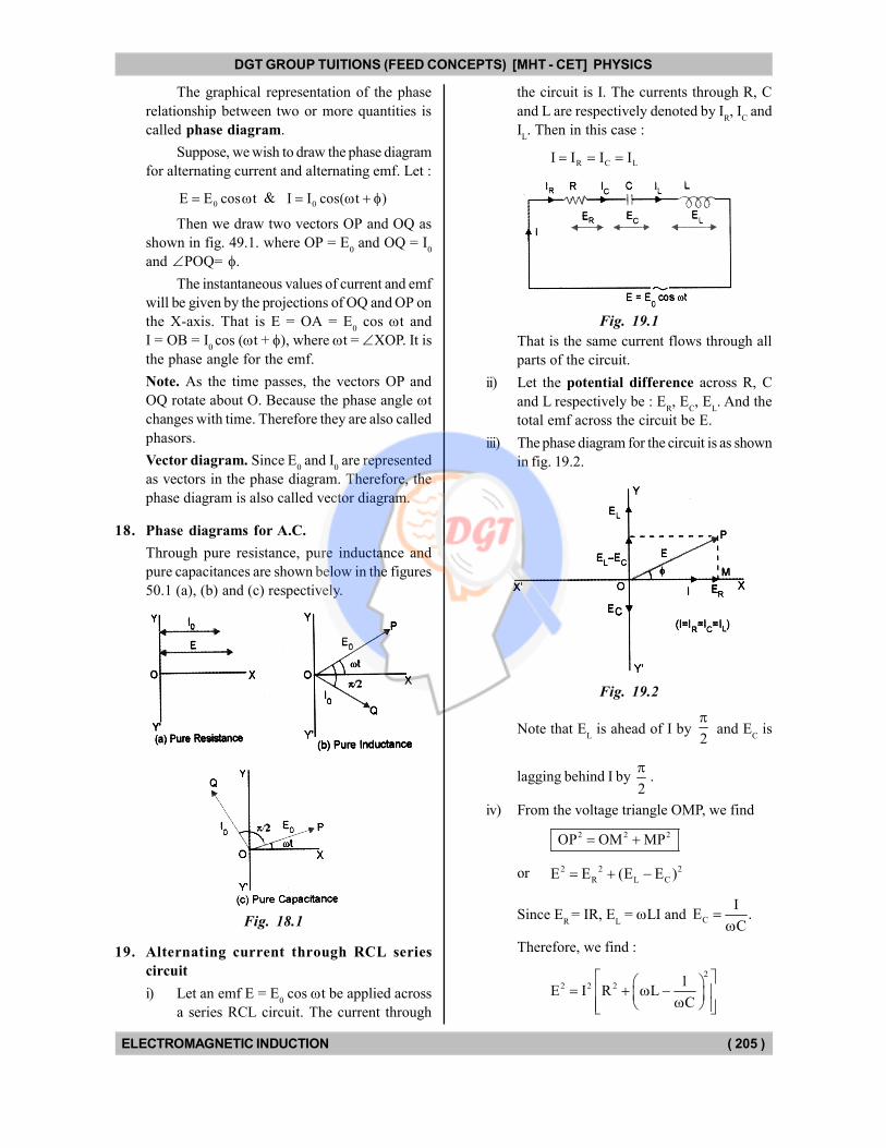
19. Alternating current through RCL series
circuit
i) Let an emf E = E0 cos t be applied across
a series RCL circuit. The current through
the circuit is I. The currents through R, C
and L are respectively denoted by IR, I
C and
IL. Then in this case :
R C LI I I I
Fig. 19.1
That is the same current flows through all
parts of the circuit.
ii) Let the potential difference across R, C
and L respectively be : ER, E
C, E
L. And the
total emf across the circuit be E.
iii) The phase diagram for the circuit is as shown
in fig. 19.2.
Fig. 19.2
Note that EL is ahead of I by
2
and E
C is
lagging behind I by 2
.
iv) From the voltage triangle OMP, we find
2 2 2OP OM MP
or 2 2 2
R L CE E (E E )
Since ER
= IR, EL = LI and C
IE .
C
Therefore, we find :
2
2 2 2 1E I R L
C
DGT Group - Tuitions (Feed Concepts) XIth – XIIth | JEE | CET | NEET | Call : 9920154035 / 8169861448
DGT MH –CET 12th PHYSICS Study Material 10
DGT GROUP TUITIONS (FEED CONCEPTS) [MHT - CET] PHYSICS
ELECTROMAGNETIC INDUCTION ( 206 )
or
1/ 22
2 1E I R L
C
Here
1/ 22
2E 1R L Z
I C
is called impedance of the circuit. It consists
of two parts, the resistance R and the
reactance
2
L C
1X (X X ) L
C
.
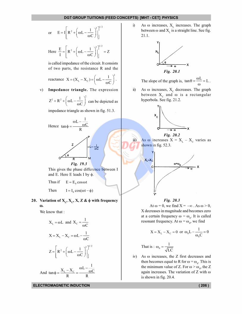
v) Impedance triangle. The expression
2
2 2 1Z R L
C
can be depicted as
impedance triangle as shown in fig. 51.3.
Hence
1L
CtanR
Fig. 19.3
This gives the phase difference between I
and E. Here E leads I by .
Thus if0E E cos t
Then0I I cos( t )
20. Variation of XL, X
C, X, Z & with frequency
.
We know that :
LX L and C
1X
C
L C
1X X X L
C
1/ 22
2 1Z R L
C
And L C
1L
X X CtanR R
i) As increases, XL increases. The graph
between and XL is a straight line. See fig.
21.1.
Fig. 20.1
The slope of the graph is, L
tan L
.
ii) As increases, XC decreases. The graph
between XC and is a rectangular
hyperbola. See fig. 21.2.
Fig. 20.2
iii) As increases X = XL – X
C varies as
shown in fig. 52.3.
Fig. 20.3
At = 0, we find X = . As > 0,
X decreases in magnitude and becomes zero
at a certain frequency = 0. It is called
resonant frequency. At = 0, we find
L CX X X 0 or 0
0
1L 0
C
That is : 0
1
LC
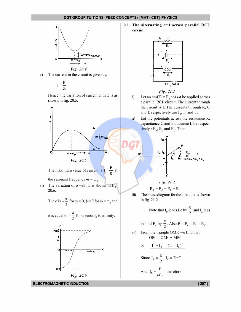
iv) As increases, the Z first decreases and
then becomes equal to R for = 0. This is
the minimum value of Z. For > 0, the Z
again increases. The variation of Z with is shown in fig. 20.4.
DGT Group - Tuitions (Feed Concepts) XIth – XIIth | JEE | CET | NEET | Call : 9920154035 / 8169861448
DGT MH –CET 12th PHYSICS Study Material 11
DGT GROUP TUITIONS (FEED CONCEPTS) [MHT - CET] PHYSICS
ELECTROMAGNETIC INDUCTION ( 207 )
Fig. 20.4
v) The current in the circuit is given by,
EI
Z
Hence, the variation of current with is as
shown in fig. 20.5.
Fig. 20.5
The maximum value of current is E
IR
at
the resonant frequency = 0.
vi) The variation of with is shown in fig.
20.6.
The is 2
for = 0, = 0 for =
0 and
it is equal to 2
for tending to infinity..
Fig. 20.6
21. The alternating emf across parallel RCL
circuit.
Fig. 21.1
i) Let an emf E = E0 cos t be applied across
a parallel RCL circuit. The current through
the circuit is I. The currents through R, C
and L respectively are IR, I
C and I
L.
ii) Let the potentials across the resistance R,
capacitance C and inductance L be respec-
tively : ER, E
C and E
L. Then
Fig. 21.2
R C LE E E E
iii) The phase diagram for the circuit is as shown
in fig. 21.2.
Note that IC leads Ee by
2
and I
L lags
behind EL by
2
. Also E = E
R = E
C = E
R.
iv) From the triangle OMP, we find that
OP2 = OM2 + MP2
or 2 2 2
R C LI I (I I )
Since R C
EI , I E C
R
And L
EI ,
L
therefore
DGT Group - Tuitions (Feed Concepts) XIth – XIIth | JEE | CET | NEET | Call : 9920154035 / 8169861448
DGT MH –CET 12th PHYSICS Study Material 12
DGT GROUP TUITIONS (FEED CONCEPTS) [MHT - CET] PHYSICS
ELECTROMAGNETIC INDUCTION ( 208 )
222
2
E EI E C
R L
or
2
2 2
2
1 1I E C
R L
or
1/ 22
2
1 1I E C
R L
Here
1/ 22
2
I 1 1 1C
E R L Z
where Z is the impedance of the circuit.
1Y,
Z where Y is called admittance of the
circuit.
v) Admittance triangle. The expression
2
2
2 2
1 1 1Y C
Z R L
can be depicted as admittance triangle as
shown in fig. 21.3.
Fig. 21.3
Hence
1C
Ltan1/ R
This gives the phase difference I and E.
Here I leads E by .
Thus, if0E E cos t
Then0I I cos( t )
22. Parallel resonance
i) The circuit is said to be in resonance when,
1C 0
L
or
0
1
LC
Thus, the resonance frequency is same both
for the series and parallel resonance.
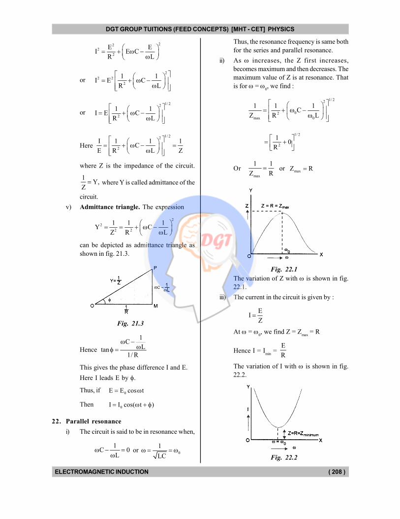
ii) As increases, the Z first increases,
becomes maximum and then decreases. The
maximum value of Z is at resonance. That
is for = 0, we find :
1/ 22
02
max 0
1 1 1C
Z R L
1/ 2
2
10
R
Ormax
1 1
Z R or
maxZ R
Fig. 22.1
The variation of Z with is shown in fig.
22.1.
iii) The current in the circuit is given by :
EI
Z
At = 0, we find Z = Z
max = R
Hence I = Imin
= E
R
The variation of I with is shown in fig.
22.2.
Fig. 22.2
DGT Group - Tuitions (Feed Concepts) XIth – XIIth | JEE | CET | NEET | Call : 9920154035 / 8169861448
DGT MH –CET 12th PHYSICS Study Material 13
DGT GROUP TUITIONS (FEED CONCEPTS) [MHT - CET] PHYSICS
ELECTROMAGNETIC INDUCTION ( 209 )
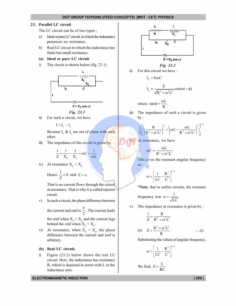
23. Parallel LC circuit
The LC circuit can be of two types ;
a) Ideal or pure LC circuit, in which the inductance
possesses no resistance.
b) Real LC circuit in which the inductance has
finite but small resistance.
(a) Ideal or pure LC circuit
i) The circuit is shown below (fig. 23.1)
Fig. 23.1
ii) For such a circuit, we have
C LI I I
Because IC & I
L are out of phase with each
other.
iii) The impedance of the circuit is given by,
C L
1 1 1 1C
Z X X L
iv) At resonance XL = X
C
Hence 1
0Z and Z .
That is no current flows through the circuit
at resonance. That is why it is called rejector
circuit.
v) In such a circuit, the phase difference between
the current and emf is 2
. The current leads
the emf when XC
> XL and the current lags
behind the emf when XC < X
L.
vi) At resonance, when XC = X
L, the phase
difference between the current and emf is
arbitrary.
(b) Real LC circuit.
i) Figure (23.2) below shows the real LC
circuit. Here, the inductance has resistance
R, which is depicted in series with L in the
inductance arm.
Fig. 23.2
ii) For this circuit we have :
CI E C
L2 2 2
EI cos( t )
R L
where L
tan .R
iii) The impedance of such a circuit is given
by :
1/ 22 2
2 2 2 2 2 2
1 R LC
Z R L R L
iv) At resonance, we have
2 2 2
LC
R L
This gives the resonant angular frequency
as :
1/ 22
2
1 R
LC L
*Note, that in earlier circuits, the resonant
frequency was 1
.LC
v) The impedance at resonance is given by :
2 2 2
1 R
Z R L
Or2 2 2R L
ZR
... (i)
Substituting the values of angular frequency.
1/ 22
2
1 R
LC L
We find, L
ZRC
DGT Group - Tuitions (Feed Concepts) XIth – XIIth | JEE | CET | NEET | Call : 9920154035 / 8169861448
DGT MH –CET 12th PHYSICS Study Material 14
DGT GROUP TUITIONS (FEED CONCEPTS) [MHT - CET] PHYSICS
ELECTROMAGNETIC INDUCTION ( 210 )
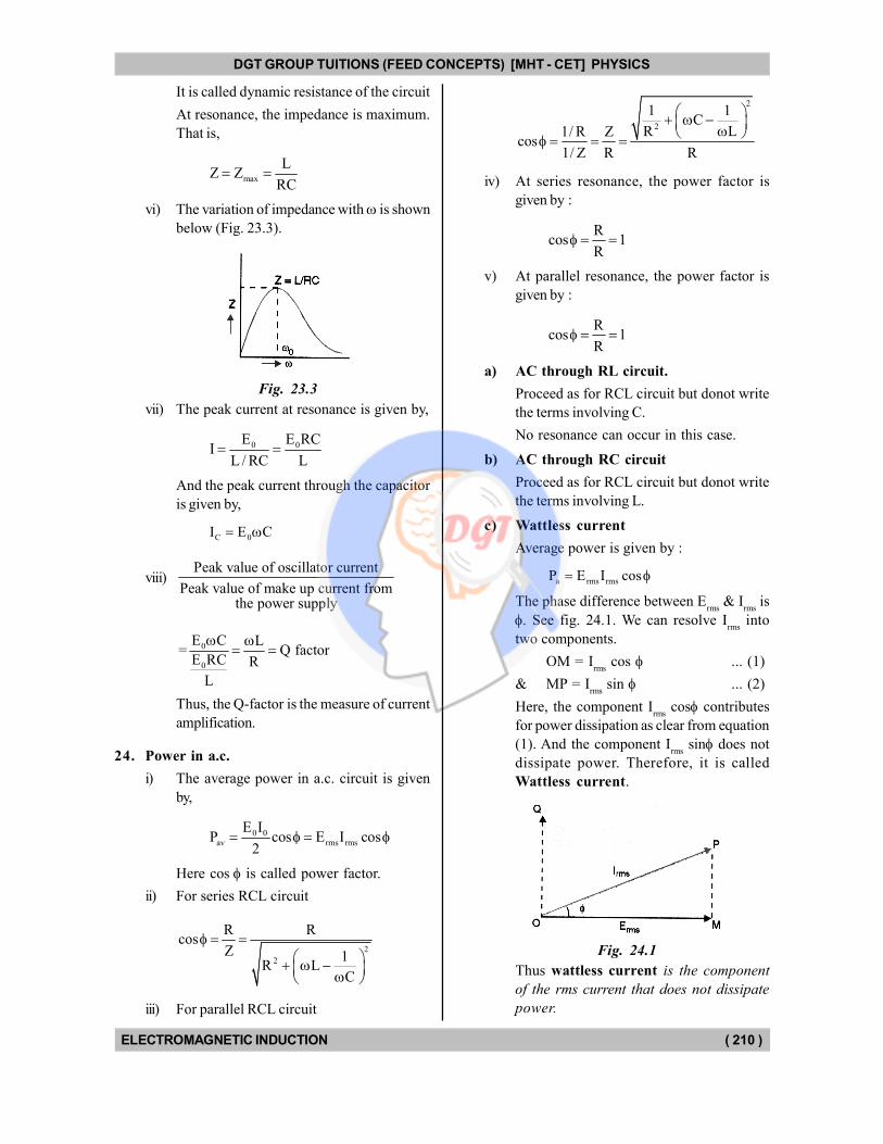
It is called dynamic resistance of the circuit
At resonance, the impedance is maximum.
That is,
max
LZ Z
RC
vi) The variation of impedance with is shown
below (Fig. 23.3).
Fig. 23.3
vii) The peak current at resonance is given by,
0 0E E RCI
L / RC L
And the peak current through the capacitor
is given by,
C 0I E C
viii)Peak value of oscillator current
Peak value of make up current fromthe power supply
0
0
E C L= Q factor
E RC R
L
Thus, the Q-factor is the measure of current
amplification.
24. Power in a.c.
i) The average power in a.c. circuit is given
by,
0 0av rms rms
E IP cos E I cos
2
Here cos is called power factor.
ii) For series RCL circuit
2
2
R Rcos
Z 1R L
C
iii) For parallel RCL circuit
2
2
1 1C
R L1/ R Zcos
1/ Z R R
iv) At series resonance, the power factor is
given by :
Rcos 1
R
v) At parallel resonance, the power factor is
given by :
Rcos 1
R
a) AC through RL circuit.
Proceed as for RCL circuit but donot write
the terms involving C.
No resonance can occur in this case.
b) AC through RC circuit
Proceed as for RCL circuit but donot write
the terms involving L.
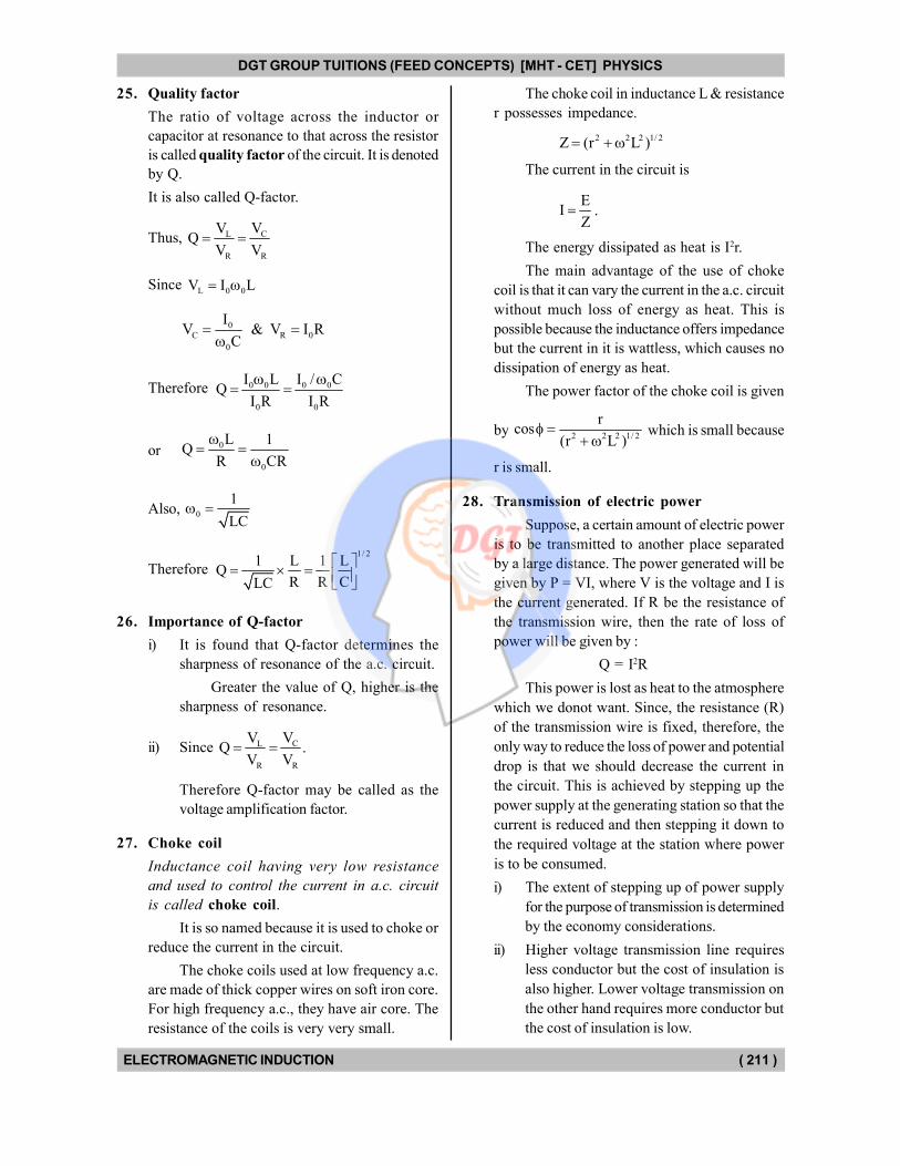
c) Wattless current
Average power is given by :
a rms rmsP E I cos
The phase difference between Erms
& Irms
is
. See fig. 24.1. We can resolve Irms
into
two components.
OM = Irms
cos ... (1)
& MP = Irms
sin ... (2)
Here, the component Irms
cos contributes
for power dissipation as clear from equation
(1). And the component Irms
sin does not
dissipate power. Therefore, it is called
Wattless current.
Fig. 24.1
Thus wattless current is the component
of the rms current that does not dissipate
power.
DGT Group - Tuitions (Feed Concepts) XIth – XIIth | JEE | CET | NEET | Call : 9920154035 / 8169861448
DGT MH –CET 12th PHYSICS Study Material 15
DGT GROUP TUITIONS (FEED CONCEPTS) [MHT - CET] PHYSICS
ELECTROMAGNETIC INDUCTION ( 211 )
25. Quality factor
The ratio of voltage across the inductor or
capacitor at resonance to that across the resistor
is called quality factor of the circuit. It is denoted
by Q.
It is also called Q-factor.
Thus, CL
R R
VVQ
V V
Since L 0 0V I L
0C R 0
0
IV & V I R
C
Therefore 0 0 0 0
0 0
I L I / CQ
I R I R
or0
0
L 1Q
R CR
Also, 0
1
LC
Therefore
1/ 21 L 1 L
QR R CLC
26. Importance of Q-factor
i) It is found that Q-factor determines the
sharpness of resonance of the a.c. circuit.
Greater the value of Q, higher is the
sharpness of resonance.
ii) Since CL
R R
VVQ .
V V
Therefore Q-factor may be called as the
voltage amplification factor.
27. Choke coil
Inductance coil having very low resistance
and used to control the current in a.c. circuit
is called choke coil.
It is so named because it is used to choke or
reduce the current in the circuit.
The choke coils used at low frequency a.c.
are made of thick copper wires on soft iron core.
For high frequency a.c., they have air core. The
resistance of the coils is very very small.
The choke coil in inductance L & resistance
r possesses impedance.
2 2 2 1/ 2Z (r L )
The current in the circuit is
EI
Z .
The energy dissipated as heat is I2r.
The main advantage of the use of choke
coil is that it can vary the current in the a.c. circuit
without much loss of energy as heat. This is
possible because the inductance offers impedance
but the current in it is wattless, which causes no
dissipation of energy as heat.
The power factor of the choke coil is given
by 2 2 2 1/ 2
rcos
(r L )
which is small because
r is small.
28. Transmission of electric power
Suppose, a certain amount of electric power
is to be transmitted to another place separated
by a large distance. The power generated will be
given by P = VI, where V is the voltage and I is
the current generated. If R be the resistance of
the transmission wire, then the rate of loss of
power will be given by :
Q = I2R
This power is lost as heat to the atmosphere
which we donot want. Since, the resistance (R)
of the transmission wire is fixed, therefore, the
only way to reduce the loss of power and potential
drop is that we should decrease the current in
the circuit. This is achieved by stepping up the
power supply at the generating station so that the
current is reduced and then stepping it down to
the required voltage at the station where power
is to be consumed.
i) The extent of stepping up of power supply
for the purpose of transmission is determined
by the economy considerations.
ii) Higher voltage transmission line requires
less conductor but the cost of insulation is
also higher. Lower voltage transmission on
the other hand requires more conductor but
the cost of insulation is low.
DGT Group - Tuitions (Feed Concepts) XIth – XIIth | JEE | CET | NEET | Call : 9920154035 / 8169861448
DGT MH –CET 12th PHYSICS Study Material 16
DGT GROUP TUITIONS (FEED CONCEPTS) [MHT - CET] PHYSICS
ELECTROMAGNETIC INDUCTION ( 212 )
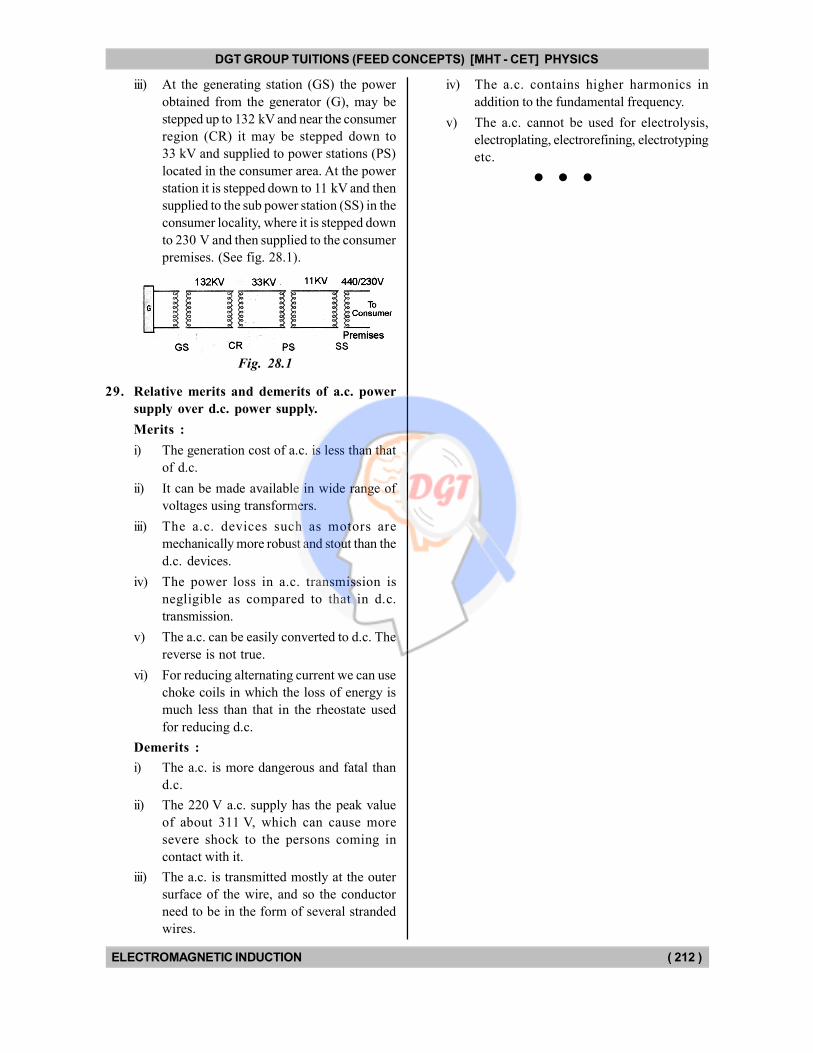
iii) At the generating station (GS) the power
obtained from the generator (G), may be
stepped up to 132 kV and near the consumer
region (CR) it may be stepped down to
33 kV and supplied to power stations (PS)
located in the consumer area. At the power
station it is stepped down to 11 kV and then
supplied to the sub power station (SS) in the
consumer locality, where it is stepped down
to 230 V and then supplied to the consumer
premises. (See fig. 28.1).
Fig. 28.1
29. Relative merits and demerits of a.c. power
supply over d.c. power supply.
Merits :
i) The generation cost of a.c. is less than that
of d.c.
ii) It can be made available in wide range of
voltages using transformers.
iii) The a.c. devices such as motors are
mechanically more robust and stout than the
d.c. devices.
iv) The power loss in a.c. transmission is
negligible as compared to that in d.c.
transmission.
v) The a.c. can be easily converted to d.c. The
reverse is not true.
vi) For reducing alternating current we can use
choke coils in which the loss of energy is
much less than that in the rheostate used
for reducing d.c.
Demerits :
i) The a.c. is more dangerous and fatal than
d.c.
ii) The 220 V a.c. supply has the peak value
of about 311 V, which can cause more
severe shock to the persons coming in
contact with it.
iii) The a.c. is transmitted mostly at the outer
surface of the wire, and so the conductor
need to be in the form of several stranded
wires.
iv) The a.c. contains higher harmonics in
addition to the fundamental frequency.
v) The a.c. cannot be used for electrolysis,
electroplating, electrorefining, electrotyping
etc.
DGT Group - Tuitions (Feed Concepts) XIth – XIIth | JEE | CET | NEET | Call : 9920154035 / 8169861448
DGT MH –CET 12th PHYSICS Study Material 17

DGT Group - Tuitions (Feed Concepts) XIth – XIIth | JEE | CET | NEET | Call : 9920154035 / 8169861448
DGT MH –CET 12th PHYSICS Study Material 18
DGT GROUP TUITIONS (FEED CONCEPTS) [MHT - CET] PHYSICS
ELECTROMAGNETIC INDUCTION ( 213 )
Magnetic Flux
1. The unit of magnetic flux in SI is :
a) weber b) gauss
c) oersted d) tesla
2. The unit of magnetic induction B in SI is :
a) weber b) gauss
c) oersted d) tesla
3. The magnetic flux through a coil is inversely
proportional to :
a) number of turns
b) area
c) magnetic field
d) none of the above
4. If the magnetic field is parallel to a surface, then
the magnetic flux through the surface is :
a) zero
b) small but not zero
c) infinite
d) large but not infinite
5. The magnetic flux () linked with a coil is related
to the number (n) of turns of the coil as :
a) 2n b) 2n
c) 1n d) n
6. The magnetic flux () linked with a coil is related
to the area (A) of the coil as :
a) 1/ 2A b) 1/ 2A
c) A d) 1A
7. A square loop of side b is rotating with angular
speed about one of the diagonals as axis. At
t = 0, the plane of the loop is perpendicular to the
magnetic field B. If the number of turns of the
loop be N, then what is the instantaneous flux
through the coil ?
a) BAN b) BAN sin t
c) BAN cos t d) BAN t
8. The length of a solenoid of radius 2.5 cm having
500 turns/cm is 0.5 m. A current of 1 ampere is
set up in the solenoid. What is the magnetic flux
through the coil ?
a) 1.5 Wb b) 2.0 Wb
c) 3 Wb d) 4 Wb
MULTIPLE CHOICE QUESTIONS
Electromagnetic Induction
9. Which one of the following scientists is NOT
connected with the electromagnetic induction ?
a) Faraday b) Lenz
c) Henry d) Ohm
10. Which of the following gives the direction of the
induction emf ?
a) Faraday's laws b) Lenz's law
c) Ampere's theorem
d) Biot Savart law
11. The expression for the induced emf contains a
negative sign d
dt
. What is the significance
of the negative sign ?
a) The induced emf is produced only when the
magnetic flux decreases
b) The induced emf opposes the changes in the
magnetic flux
c) The induced emf is opposite to the direction
of the flux
d) none of the above
12. Which of the following phenomena makes use of
electromagnetic induction ?
a) Charging a storage battery
b) Magnetising an iron piece with a bar magnet
c) Generation of hydroelectricity
d) Magnetising a soft iron piece by placing inside
a current carrying solenoid
13. A varying electric field generates :
a) emf b) electric current
c) magnetic field d) none of the above
14. Which of the following is based on the law of
conservation of energy ?
a) Lenz's law b) Faraday's law
c) Ampere's law d) Biot Savart law
15. The induced emf cannot be produced by :
a) moving a magnet near a circuit
b) moving a circuit near a magnet
c) changing the current in one circuit placed near
the other
d) maintaining large but constant current in a
circuit
DGT Group - Tuitions (Feed Concepts) XIth – XIIth | JEE | CET | NEET | Call : 9920154035 / 8169861448
DGT MH –CET 12th PHYSICS Study Material 19
DGT GROUP TUITIONS (FEED CONCEPTS) [MHT - CET] PHYSICS
ELECTROMAGNETIC INDUCTION ( 214 )
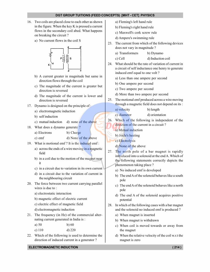
16. Two coils are placed close to each other as shown
in the figure. When the key K is pressed a current
flows in the secondary coil abed. What happens
on breaking the circuit ?
a) No current flows in the coil S
b) A current greater in magnitude but same in
direction flows through the coil
c) The magnitude of the current is greater but
direction is reversed
d) The magnitude of the current is lower and
direction is reversed
17. Dynamo is designed on the principle of :
a) electromagnetic induction
b) self induction
c) mutual induction d) none of the above
18. What does a dynamo generate ?
a) Electrons b) Charge
c) emf d) None of the above
19. What is motional emf ? It is the induced emf :
a) across the ends of a wire moving in a magnetic
field
b) in a coil due to the motion of the magnet near
it
c) in a circuit due to variation in its own current
d) in a circuit due to the variation of current in
the neighbouring circuit
20. The force between two current carrying parallel
wires is due to :
a) electrostatic interaction
b) magnetic effect of electric current
c) electric effect of magnetic field
d) electromagnetic induction
21. The frequency (in Hz) of the commercial alter-
nating current generated in India is :
a) 50 b) 60
c) 110 d) 220
22. Which of the following is used to determine the
direction of induced current in a generator ?
a) Fleming's left hand rule
b) Fleming's right hand rule
c) Maxwell's cork screw rule
d) Ampere's swimming rule
23. The current from which of the following devices
does not vary in magnitude ?
a) Transformers b) Dynamo
c) Cell d) Induction coil
24. What should be the rate of variation of current in
a circuit of self inductance one henry to generate
induced emf equal to one volt ?
a) Less than one ampere per second
b) One ampere per second
c) Two ampere per second
d) More than two ampere per second
25. The motional emf produced across a wire moving
through a magnetic field does not depend on its :
a) velocity b) length
c) diameter d) orientation
26. Which of the following is independent of the
direction of the current in a circuit ?
a) Mutual induction
b) Joule's heating
c) Electrolysis
d) None of the above
27. The north pole of a bar magnet is rapidly
introduced into a solenoid at the end A. Which of
the following statements correctly depicts the
phenomenon taking place ?
a) No induced emf is developed
b) The end A of the solenoid behaves like a south
pole
c) The end A of the solenoid behaves like a north
pole
d) The end A of the solenoid acquires positive
potential
28. In which of the following cases with a bar magnet
and the solenoid no induced emf is produced ?
a) When magnet is inserted
b) When magnet is withdrawn
c) When coil is moved towards or away from
the magnet
d) When the relative velocity of the coil w.r.t the
magnet is zero
DGT Group - Tuitions (Feed Concepts) XIth – XIIth | JEE | CET | NEET | Call : 9920154035 / 8169861448
DGT MH –CET 12th PHYSICS Study Material 20
DGT GROUP TUITIONS (FEED CONCEPTS) [MHT - CET] PHYSICS
ELECTROMAGNETIC INDUCTION ( 215 )
29. A copper rod moves parallel to the horizontal
direction. The induced emf developed across its
ends due to earths magnetic field will be maximum
at the :
a) equator b) latitude 300
c) latitude 600 d) poles
30. A copper rod is moved in a magnetic field. The
charge developed across its ends will be
proportional to :
a) magnetic flux
b) total change of magnetic flux
c)1
velocity of the rod
d)1
magnitude of the magnetic field
31. What determines the charge that flows through
a circuit due to the induced emf ?
a) The rate of change of magnetic flux
b) The total change in magnetic flux
c) The initial magnetic flux
d) The final magnetic flux
32. Which of the following is NOT the name of the
part of the a.c. generator ?
a) Armature b) Field magnet
c) Split ring commutator
d) Brushes
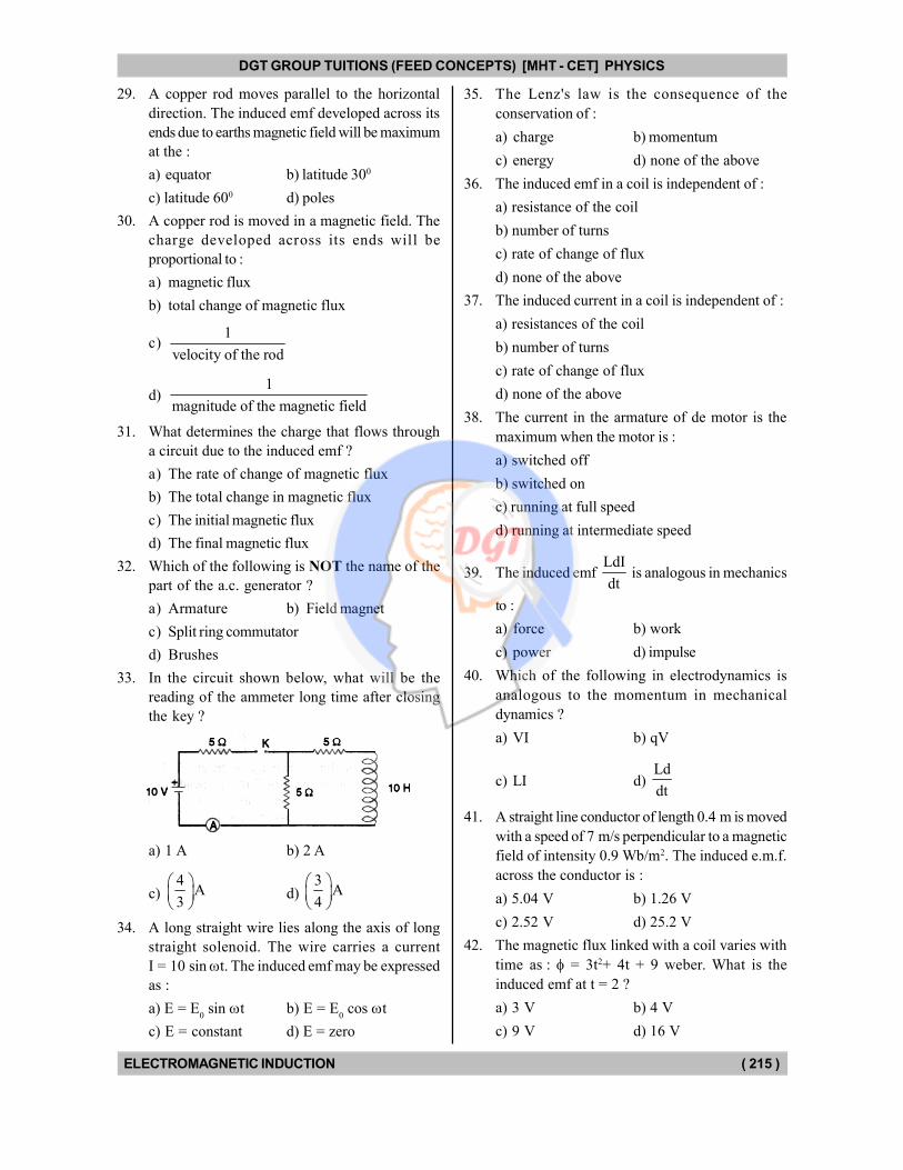
33. In the circuit shown below, what will be the
reading of the ammeter long time after closing
the key ?
a) 1 A b) 2 A
c) 4
A3
d) 3
A4
34. A long straight wire lies along the axis of long
straight solenoid. The wire carries a current
I = 10 sin t. The induced emf may be expressed
as :
a) E = E0 sin t b) E = E
0 cos t
c) E = constant d) E = zero
35. The Lenz's law is the consequence of the
conservation of :
a) charge b) momentum
c) energy d) none of the above
36. The induced emf in a coil is independent of :
a) resistance of the coil
b) number of turns
c) rate of change of flux
d) none of the above
37. The induced current in a coil is independent of :
a) resistances of the coil
b) number of turns
c) rate of change of flux
d) none of the above
38. The current in the armature of de motor is the
maximum when the motor is :
a) switched off
b) switched on
c) running at full speed
d) running at intermediate speed
39. The induced emf LdI
dt is analogous in mechanics
to :
a) force b) work
c) power d) impulse
40. Which of the following in electrodynamics is
analogous to the momentum in mechanical
dynamics ?
a) VI b) qV
c) LI d) Ld
dt
41. A straight line conductor of length 0.4 m is moved
with a speed of 7 m/s perpendicular to a magnetic
field of intensity 0.9 Wb/m2. The induced e.m.f.
across the conductor is :
a) 5.04 V b) 1.26 V
c) 2.52 V d) 25.2 V
42. The magnetic flux linked with a coil varies with
time as : = 3t2+ 4t + 9 weber. What is the
induced emf at t = 2 ?
a) 3 V b) 4 V
c) 9 V d) 16 V
DGT Group - Tuitions (Feed Concepts) XIth – XIIth | JEE | CET | NEET | Call : 9920154035 / 8169861448
DGT MH –CET 12th PHYSICS Study Material 21
DGT GROUP TUITIONS (FEED CONCEPTS) [MHT - CET] PHYSICS
ELECTROMAGNETIC INDUCTION ( 216 )
43. What voltage is developed across the axle of the
wheels of a train, when it moves with a speed of
72 kmh–1 ? The horizontal component of the
earth's magnetic field is 0.40 10–4 T and the
angle of dip is 300. The length of the axle is 1.5 m :
a) 0.2 mV b) 0.4 mV
c) 0.6 mV d) 0.8 mV
44. The current passing through a choke coil of 15
henry is decreasing at the rate of 0.2 ampere per
second. The e.m.f. developed across the coil :
a) 3 volt b) 7.5 volt
c) 15 volt d) 30 volt
45. The equation of A.C. is represented by
e = e0 sin t
In what time the e.m.f. will be half of its maximum
value starting from zero ?
a) T
4b) T
c) T
12d)
T
8
46. The induced emf in a coil rotating in a magnetic
field is maximum when the angle between the
plane of the coil and the direction of field is :
a) zero b) 4
c) 2
d) Some angle other that those mentioned above
47. A horizontal telegraph wire 0.5 kilometer long
runing east and west is a part of a circuit whose
resistance is 2.5 ohm. The wire falls to the ground
from a height of 5 metres. If g = 10.0 m/s2 and
B = 2 10–5 weber per meter2, then the current
induced in the circuit is :
a) 0.7 ampere b) 0.02 ampere
c) 0.01 ampere d) 0.04 ampere
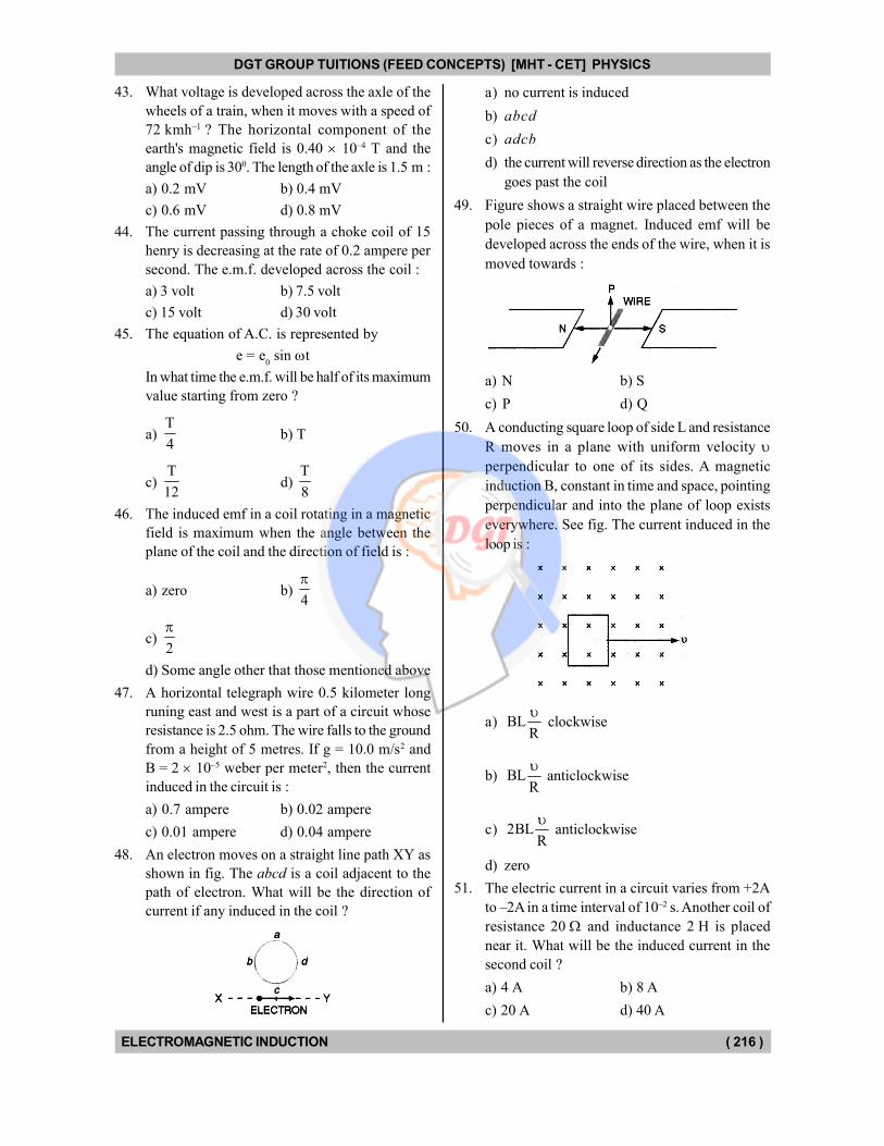
48. An electron moves on a straight line path XY as
shown in fig. The abcd is a coil adjacent to the
path of electron. What will be the direction of
current if any induced in the coil ?
a) no current is induced
b) abcd
c) adcb
d) the current will reverse direction as the electron
goes past the coil
49. Figure shows a straight wire placed between the
pole pieces of a magnet. Induced emf will be
developed across the ends of the wire, when it is
moved towards :
a) N b) S
c) P d) Q
50. A conducting square loop of side L and resistance
R moves in a plane with uniform velocity perpendicular to one of its sides. A magnetic
induction B, constant in time and space, pointing
perpendicular and into the plane of loop exists
everywhere. See fig. The current induced in the
loop is :
a) BLR
clockwise
b) BLR
anticlockwise
c) 2BLR
anticlockwise
d) zero
51. The electric current in a circuit varies from +2A
to –2A in a time interval of 10–2 s. Another coil of
resistance 20 and inductance 2 H is placed
near it. What will be the induced current in the
second coil ?
a) 4 A b) 8 A
c) 20 A d) 40 A
DGT Group - Tuitions (Feed Concepts) XIth – XIIth | JEE | CET | NEET | Call : 9920154035 / 8169861448
DGT MH –CET 12th PHYSICS Study Material 22
DGT GROUP TUITIONS (FEED CONCEPTS) [MHT - CET] PHYSICS
ELECTROMAGNETIC INDUCTION ( 217 )
52. The magnetic flux through a surface varies with
time as follows :
= 12t2 + 7t + 3
Here is in milliweber and t is in seconds. What
will be the induced emf at t = 5s ?
a) 338 mV b) 127 mV
c) 105 mV d) none of the above
53. The current in a coil changes from +10A to –2A
in 3 ms. What is the induced emf in the coil ?
The self inductance of the coil is 2 mH :
a) 8 V b) 4 V
c) 0.8 V d) 0.4 V
54. The distance between the ends of the wings of an
aeroplane is 20 m. The aeroplane is descending with
a speed of 20 m/s. If the horizontal component
of the earth's magnetic field be 0.5 Gs, then what
will be the induced emf across the wings ?
a) 40 mV b) 20 mV
c) 10 mV d) 5 mV
55. There is a window 50 cm 100 cm in a wall which
is parallel to the magnetic meridian. The resistance
of the window is 0.07 . What is the induced
charge when the window is opened through 900 ?
Given that horizontal component of earth's
magnetic field is 0.35 Gs :
a) 2.5 C b) 25 C
c) 250 C d) 2500 C
56. A square loop of 10 turns has each side 10 cm. It
rotates in a magnetic field of 0.25 T and the
maximum induced emf is 20 mV. What is the
angular speed of rotation ?
a) 4 rad/s b) 0.4 rad/s
c) 8 rad/s d) 0.8 rad/s
57. The resistance of the armature of a dc motor is
50 . A power supply of 200 V is connected
across it and the current through the armature is
2 A. What is back emf ?
a) 10 V b) 50 V
c) 100 V d) 150 V
58. The magnetic flux passing normally through a coil
is = 20 sin 5 t + t2 + 50t + 25 milliweber,
where t is in seconds. What will be the induced
emf at t = 1 s ?
a) 52 V b) 72 V
c) 100 V d) (100 + 50) V
59. A 2 m long metallic conductor is rotated about
one end in a vertical plane with angular speed
of 2.5 rad/s. If the horizontal component of
earth's magnetic field be 0.5 10–4 T, then what
is the potential difference across the ends of
the conductor ?
a) 100 V b) 150 V
c) 200 V d) 250 V
60. The current through a coil of self inductance 5 mH
rises uniformly from 0 to 1 ampere in 0.1 s. What
is the induced emf ?
a) 2.5 V b) 2.5 mV
c) 0.5 V d) 0.5 mV
61. A coil of 1000 turns and area 20 cm2 is placed in
a magnetic field of 1000
ampere turn/m. The
magnetic field makes angle 300 with the plane of
the coil. If the field is reduced to zero in 0.2 s,
then what is the induced emf set up in the coil ?
a) 16 mV b) 8 mV
c) 4 mV d) 2 mV
62. A magnetic field of 20 T is normal to a coil of
100 turns and area 10–2 m2. If the coil is removed
from the magnetic field in 2 ms, what is the induced
emf set up in the coil ?
a) 2 kV b) 5 kV
c) 7 kV d) 10 kV
63. A current of 5000 A is flowing at 220 V in the
primary coil of a transformer. The voltage across
the secondary is 11000 V and 10% power is lost.
What is the current through the secondary ?
a) 9 A b) 90 A
c) 900 A d) 9000 A
64. A cycle wheel with 64 spokes is rotatory at the
rate of 120 revolutions per second. A potential
difference of 10 V is produced between the axis
and the rim. What will be this potential difference,
it the number of spokes is reduced to 16 ?
a) 2.5 b) 5 V
c) 10 V d) 40 V
65. The varying electric field produces magnetic field.
This is known as :
a) Laplace's law b) Ampere's law
c) Maxwell's law d) Faraday's law
DGT Group - Tuitions (Feed Concepts) XIth – XIIth | JEE | CET | NEET | Call : 9920154035 / 8169861448
DGT MH –CET 12th PHYSICS Study Material 23

DGT GROUP TUITIONS (FEED CONCEPTS) [MHT - CET] PHYSICS
ELECTROMAGNETIC INDUCTION ( 218 )
Self Induction & Mutual Induction
66. Which of the following is not equal to henry ?
a) volt second
ampereb)
2volt second
coulomb
c)
2volt second
coulombd)
2
2
joule second
coulomb
67. Which of the following is NOT a factor to determine
the mutual inductance of the two coils ?
a) The number of turns of each coil
b) The shape of each coil
c) Current through each coil
d) Separation between the coils
68. Which of the following is NOT the function of
transformer ?
a) Transform magnetic energy into electric energy
b) Transfer electrical energy from one part of
the circuit to another
c) Step up or step down the voltage
d) Decrease or increase the alternating current
69. Which of the following instruments do not make
use of eddy currents ?
a) Electrical brakes b) Induction motor
c) Transformer
d) Dead beat galvanometer
70. Induction furnace makes use of :
a) self induction b) mutual induction
c) eddy currents d) none of the above
71. The transformer is devised on the principle of :
a) self induction b) mutual induction
c) eddy currents d) none of the above
72. The coil of the balistic galvanometer oscillates
due to :
a) self induction b) mutual induction
c) eddy currents d) none of the above
73. For perfect coupling of two coils of inductance
L1 and L
2, their mutual inductance M should be
given by :
a) 1 2M L L b) 1
2
LM
L
c) 1 2M L L d)
1/ 2
1
2
LM
L
74. The coupling coefficient of the perfectly coupled
coils is :
a) zero
b) 1
c) slightly more than 1
d) infinite
75. What is the minimum value of inductance that
can be obtained with the help of three inductances
of 2 H, 3 H and 6 H ?
a) 1
H6
b) 1
H3
c) 1 H d) 11 H
76. If the magnetic flux linked with a coil through
which a current of xA is set up, is y Wb, then the
coefficient of self-inductance of the coil is :
a) (x y) henry b) x
henryy
c) y
henryx
d) xy henry
77. When the number of turns of a coil is doubled, its
self inductance :
a) is doubled b) is halved
c) becomes one quarter
d) becomes four times
78. Eddy currents donot cause :
a) damping b) heating
c) sparking d) loss of energy
79. The role of inductance is equivalent to :
a) momentum b) force
c) energy d) inertia
80. In the dead beat galvanometer, the coil is wound
on a frame made of :
a) magnetic material
b) non magnetic material
c) good conductor d) bad conductor
81. What happens when a magnet is dropped into a
solenoid, whose two ends are connected to each
other. While crossing the loop, it will fall with
acceleration.
a) equal to g b) less than g
c) more than g
d) less than g above the coil and more than g
below it
DGT Group - Tuitions (Feed Concepts) XIth – XIIth | JEE | CET | NEET | Call : 9920154035 / 8169861448
DGT MH –CET 12th PHYSICS Study Material 24
DGT GROUP TUITIONS (FEED CONCEPTS) [MHT - CET] PHYSICS
ELECTROMAGNETIC INDUCTION ( 219 )
82. A coil is wound on a transformer of rectangular
cross-section. If all the linear dimensions of the
transformer are increased by a factor 2 and the
number of turns per unit length of the coil remains
unchanged, the self inductance of the coil will be
increased by a factor :
a) 16 b) 8
c) 4 d) 2
83. The induced emf of 2 V is generated when the
current in the circuit changes from 4 A to 5 A in
one millisecond. What is the self inductance of
the circuit ?
a) 8 H b) 10 H
c) 80 H d) none of the above
84. Two pure inductors each of inductance L are
connected in parallel but well separated from each
other. The equivalent inductance of the combination
is :
a) L
4b)
L
2
c) 2 L d) 4 L
85. What is the energy stored in a 50 mH inductor
carrying a current of 4 A ?
a) 0.4 J b) 0.2 J
c) 0.1 J d) 0.05 J
86. A transformer is used to light a 100 W and 110 V
lamp from a 220 V mains. If the main current is
0.5 A. The efficiency of the transformer is :
a) 11 % b) 50 %
c) 80 % d) 90 %
87. When the current changes from +2A to –2A in
0.05 second, an e.m.f. of 8 volt is induced in a
coil. The coefficient of self induction of the coil
is :
a) 0.1 H b) 0.2 H
c) 0.4 H d) 0.8 H
88. Two coils X and Y are placed in a circuit such
that a current changes by 3 ampere in coil X and
the magnetic flux changes of 1.2 weber occurs
in Y. The value of mutual inductance of the coils
is :
a) 0.2 henry b) 0.4 henry
c) 0.6 henry d) 3.6 henry
89. 1 henry =
a) weber + ampere b) weber + volt
c) weber ampere d) weber volt
90. The length of a solenoid is 20 cm, its area of cross-
section is 10 cm2, and the number of turns are
1000. Another coil of 500 turns is wound in the
middle. Their coefficient of mutual induction will
be nearest to :
a) / 2 b)
c) 2 d) 2
91. What is the energy stored in a coil of self inductance
2 H when a current of 10 A is set up through it ?
a) 10 J b) 50 J
c) 100 J d) 500 J
92. A step up transformer raises the voltage from
220 V to 11000 V. If the number of turns of the
secondary be 1000, what is the number of turns
of the primary ?
a) 2 b) 20
c) 200 d) 2000
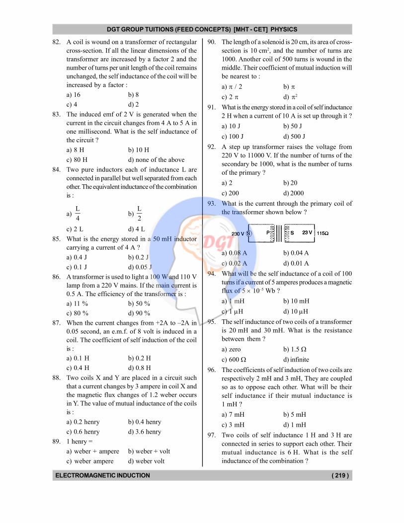
93. What is the current through the primary coil of
the transformer shown below ?
a) 0.08 A b) 0.04 A
c) 0.02 A d) 0.01 A
94. What will be the self inductance of a coil of 100
turns if a current of 5 amperes produces a magnetic
flux of 5 10–5 Wb ?
a) 1 mH b) 10 mH
c) 1 H d) 10 H
95. The self inductance of two coils of a transformer
is 20 mH and 30 mH. What is the resistance
between them ?
a) zero b) 1.5
c) 600 d) infinite
96. The coefficients of self induction of two coils are
respectively 2 mH and 3 mH, They are coupled
so as to oppose each other. What will be their
self inductance if their mutual inductance is
1 mH ?
a) 7 mH b) 5 mH
c) 3 mH d) 1 mH
97. Two coils of self inductance 1 H and 3 H are
connected in series to support each other. Their
mutual inductance is 6 H. What is the self
inductance of the combination ?
DGT Group - Tuitions (Feed Concepts) XIth – XIIth | JEE | CET | NEET | Call : 9920154035 / 8169861448
DGT MH –CET 12th PHYSICS Study Material 25
DGT GROUP TUITIONS (FEED CONCEPTS) [MHT - CET] PHYSICS
ELECTROMAGNETIC INDUCTION ( 220 )
a) 10 H b) 16 H
c) 26 H d) 40 H
98. What will be the self inductance of a coil of 200
turns in which a current of 2 A produces a
magnetic flux of 4 mWb ?
a) 0.1 H b) 0.2 H
c) 0.3 H d) 0.4 H
99. A circular coil of diameter 2 cm and 100 is placed
at the centre of a long solenoid redius 5 cm and
10 turns/cm. The mutual inductance of the two
coils will be nearest to :
a) 40 H b) 4 H
c) 40 mH d) 4 mH
100. The turn ratio of transformer is 5 and the
impedance of primary coil is 100 . What is the
impedance of the secondary coil ?
a) 500 b) 1000
c) 2500 d) 10000
101. Two coils each of self inductance L are connected
in parallel. If they are separated by a large
distance, then what will be the self inductance of
combination ?
a) L
4b)
L
2
c) L d) 2 L
102. The self inductance and resistance of a coil are
10 H and 40 respectively. Only applying a
potential difference of 200 V, what will be the
energy stored in it ?
a) 25 J b) 50 J
c) 75 J d) 125 J
103. Which of the following helps in the operation of
the choke coil ?
a) Self induction
b) Mutual inductance
c) Eddy currents
d) None of the above
104. Which of the following helps in raising the
efficiency transformer as a machine ?
a) Sinusoidal nature of ac
b) High voltage
c) Absence of moving parts
d) Absence of direct electrical connection of the
primary and the secondary coils
105. The transformer varies the output :
a) energy b) power
c) frequency d) current
106. The core of the transformer is laminated to :
a) produce eddy currents
b) reduce self induction
c) increase the efficiency
d) decrease the weight of the transformer
107. Which of the following does not cause loss of
energy in a transformer ?
a) Heating b) Eddy currents
c) Mechanical motion d) Hysteresis
108. The core of the transformer is laminated to avoid
loss of energy due to :
a) heating b) eddy current
c) flux leakage d) hysteresis
109. Iron core decreases the loss of energy due to :
a) heating b) eddy current
c) flux leakage d) hysteresis
110. Which of the following decreases the efficiency
of the transformer ?
a) Laminating the core
b) Use of iron core
c) Core made of material having narrow hysteresis
loop
d) None of the above
111. A choke coil should have :
a) high resistance low inductance
b) high resistance high inductance
c) low resistance high inductance
d) low resistance low inductance
112. Electromagnetic waves of wavelength 300 m are
to be received with a circuit having capacitance
2 F. What should be the self inductance of the
coil in the circuit ?
a) 12.67 H b) 12.67 mH
c) 12.67 H d) 12.67 nH
Alternating Current
113. What is the phase difference between the flux
linked with a coil rotating in a magnetic field and
the induced emf produced in it ?
a) 0 b) / 4
c) / 2 d)
DGT Group - Tuitions (Feed Concepts) XIth – XIIth | JEE | CET | NEET | Call : 9920154035 / 8169861448
DGT MH –CET 12th PHYSICS Study Material 26
DGT GROUP TUITIONS (FEED CONCEPTS) [MHT - CET] PHYSICS
ELECTROMAGNETIC INDUCTION ( 221 )
114. If R, C and L be the resistance, capacitance and
inductance in a circuit in which ac of frequency f
is set up, then which of the following has the
dimensions of R ?
a) f C b) f L
c) C
fd)
L
f
115. For long distance transmission, the ac is stepped
up because transmission at high voltage is :
a) faster b) economical
c) not damped d) not dangerous
116. Large value of which of the following does not
allow electrical oscillations in the LCR circuit.
a) Capacitance b) Inductance
c) Resistance d) Electromotive force
117. Which of the following is independent of the
frequency of ac ?
a) Resistance
b) Inductive reactance
c) Capacitive reactance
d) Impedance
118. Through which of the ae circuit elements both
the emf and current are in phase ?
a) Impedance
b) Inductive reactance
c) Capacitive reactance
d) Resistance
119. The current and emf through an inductance differ
in phase by :
a) 4
b)
2
c) 34
d)
120. The ae cannot be used for :
a) heating
b) lighting
c) electrolysis
d) generate mechanical energy
121. What is the average value of ac over a complete
cycle ?
a) zero b) 0I
2
c) 02 I
d) none of the above
122. Which of the following is zero in a watt-less
circuit ?
a) Inductance b) Capacitance
c) Resistance d) None of the above
123. For the current in LC circuit to be maximum, the
angular frequency should be related to L and C
as :
a) 2 LC b) 2 1
LC
c) LC d) 1
LC
124. What converts ac to dc ?
a) Transformer b) Generator
c) Rectifier d) None of the above
125. In an ac circuit, the current :
a) always leads the voltage
b) always lags behind the voltage
c) is always in phase with voltage
d) may lead or leg behind or be in phase with
voltage
126. A resistor, capacitor and inductor are connected
in series with a source of ac. Which of the following
is true ?
The current in resistor lags behind the :
a) current in capacitor
b) current in inductor
c) voltage across capacitor
d) voltage across inductor
127. The current in ae circuit will be wattless when :
a) inductance is zero
b) capacitance is zero
c) resistance is zero
d) capacitance = inductance
128. The hot wire instrument measures :
a) peak voltage b) average voltage
c) rms voltage d) none of the above
129. The instantaneous current in a circuit is
I 2 sin( t ) ampere.
What is the rms value of the current ?
DGT Group - Tuitions (Feed Concepts) XIth – XIIth | JEE | CET | NEET | Call : 9920154035 / 8169861448
DGT MH –CET 12th PHYSICS Study Material 27
DGT GROUP TUITIONS (FEED CONCEPTS) [MHT - CET] PHYSICS
ELECTROMAGNETIC INDUCTION ( 222 )
a) 2 A b) 2
c) 1 A d) 1
A2
130. If R, C and L denote resistance, capacitance and
inductance. Which of the following will NOT
have the dimensions of frequency ?
a) RL–1 b) R–1 C–1
c) L–1/2 C–1/2 d) RCL
131. What generates the restoring tendency in the LCR
oscillating circuit ?
a) Capacitor b) Inductor
c) Resistor d) Cell
132. For quick discharge of a capacitor through a
resistor, which of the following should be large ?
a) Capacitance b) Resistance
c) Both resistance and capacitance
d) Neither resistance nor capacitance
133. How does the current in an RC circuit vary when
the charge on the capacitor builds up ?
a) It increases linearly
b) It increases exponentially
c) It decreases linearly
d) It decreases exponentially
134. The alternating current in RCL series circuit is
maximum when :
a) XL = 0 b) X
C = 0
c) XL = X
Cd) 2 2
L CX X 1
135. Hot wire anuneters can measure :
a) only ac b) only dc
c) both ac and dc d) neither ac nor dc
136. In an ac circuit capacitive reactance = inductive
reactance. The phase difference between the
current and voltage will be :
a) zero b) 4
c) 2
d)
137. The frequency of ac is 50 Hz. How many times
in one second does the voltage in the circuit
becomes zero ?
a) 25 b) 50
c) 100 d) 150
138. Capacitive reactance of a capacitor varies directly
as :
a) capacitance b) frequency of ac
c) both capacitance and frequency of ac
d) none of the above
139. Why 220 V ac is more dangerous than 220 V dc ?
a) The dc attracts
b) Peak voltage for ac is much larger
c) The body offers less resistance to ac
d) Due to some other reason
140. An ac circuit contains a resistance R, capacitance
C and inductance L in series with a source of
emf = 0 sin (t + ). The current through the
circuit is maximum, when :
a) R L C b) 1
LC
c) 2 LC d) RLC
141. The choke coil of resistance R and inductance L
is connected across a battery of emf . The final
current in the choke depends on :
a) R and L b) L and
c) and R d) R, L and
142. What is the nature of graph between inductive
reactance and frequency of ac for series RCL
circuit ?
a) Straight line b) Parabola
c) Hyperbola d) Bell shaped
143. What is the nature of graph between impedance
and frequency of ac for series RCL circuit ?
a) Straight line b) Parabola
c) Hyperbola d) Bell shaped
144. What is the nature of graph between inductive
reactance and frequency of ac for series RCL
circuit ?
a) Straight line b) Parabola
c) Hyperbola d) Bell shaped
145. In a series RCL circuit the frequency of ac is
varied. At the resonant angular frequency 0, the
impedance of the circuit is :
a) R b) Less than 0L
c) More than 0L
d) Between 0L and
0
1
C
DGT Group - Tuitions (Feed Concepts) XIth – XIIth | JEE | CET | NEET | Call : 9920154035 / 8169861448
DGT MH –CET 12th PHYSICS Study Material 28
DGT GROUP TUITIONS (FEED CONCEPTS) [MHT - CET] PHYSICS
ELECTROMAGNETIC INDUCTION ( 223 )
146. In the above question what is the current in the
circuit, if applied emf be E ?
a) More than E
Rb) Less than
E
R
c) Equal to E
R
d) Depends on the values of L and C
147. A pure resistance R, pure capacitance C and pure
inductance L are connected in series and the
impedance of the circuit at resonance is Z0. If
they are connected in parallel to each other, the
maximum impedance at resonance will be :
a) Less than R
b) More than R
c) Equal to Z0
d) dependent on the values of C and L
148. The ohm second =
a) henry b) siemns
c) weber d) tesla
149. The impedance of a 10 ohm resistance to 50 Hz
ac is :
a) 500 b) 250
c) 50 d) 10
150. A 10 F capacitor is connected across a 200 V,
50 Hz ac supply. The peak current through the
circuit is :
a) 0.6 A b) 0.6 2 A
c) 0.6
A2
d) 0.6
2A
151. In a transformer the voltage is stepped up from
220 V to 440 V. If the current in the primary was
1.0 ampere, that in the secondary should be :
a) 0.5 A
b) between 0.5 and 1 A
c) 1 A
d) more than 1 A
152. A hot wire ammeter reads 10 A in an ac circuit.
The peak value of the current is :
a) 10 2 A b) 10
A2
c) 5 A d) 20
A
153. The impedance of a 10 microfarad capacitor for
50 Hz ac is :
a) 2 b) 20
c) 200 d) none of the above
154. The reading of ac voltmeter is 220 V. What is
the peak voltage ?
a) 200 V b) 220 V
c) 240 V d) none of the above
155. An inductance coil and capacitor are connected
in series and the current through the combination
is maximum for ac of frequency f. If they are
connected in parallel, at what frequency the
current through the combination is minimum ?
a) f b) f / 2
c) 2 f d) none of the above
156. In a RCL circuit capacitance is changed from C
to 2 C. For the resonant frequency to remain
unchanged, the inductance should be changed
from L to :
a) 4 L b) 2 L
c) L / 2 d) L / 4
157. In a series resonant circuit the ae voltages across
resistance R, inductance L and capacitance C
are 5 V, 10 V & 10 V respectively. The ae voltage
applied to the circuit will be :
a) 25 V b) 20 V
c) 10 V d) 5 V
158. A 1.0 mH inductance, a 10 F capacitance and a
5.0 ohm resistance are connected in series to an
a.c. source. It is found that the inductor and the
capacitor show equal reactances. The reactance
should be nearest to :
a) 100 ohm b) 32 ohm
c) 10 ohm d) 3.2 ohm
159. In a circuit resistance R, capacitance C, and
inductance L are in series with a sinusoidal power
source. If the voltage across R, C and L are 80 V,
10 V & 70 V respectively, then the voltage across
the source terminals will be :
a) 100 V b) 110 V
c) 140 V d) 160 V
160. The ratio of the mean value over half cycle to
the r.m.s. value of an A.C. is :
a) 2 : b) 2 2 :
c) 2 : d) 2 :1
DGT Group - Tuitions (Feed Concepts) XIth – XIIth | JEE | CET | NEET | Call : 9920154035 / 8169861448
DGT MH –CET 12th PHYSICS Study Material 29
DGT GROUP TUITIONS (FEED CONCEPTS) [MHT - CET] PHYSICS
ELECTROMAGNETIC INDUCTION ( 224 )
161. In a step-up transformer the turn ratio is 3 : 2.
A battery (e.m.f. 4.5 V) is connected across the
primary. The voltage developed in the secondary
would be :
a) 4.5 V b) 3.0 V
c) 1.5 V d) zero
162. A capacitor of capacitance 1 F and a resistor of
resistance 105 ohm are connected in series with
a battery of e.m.f. 100 volt and negligible internal
resistance. Then the time constant of the circuit
is :
a) 10–6 s b) 10–4 s
c) 10–1 s d) 1000 s
163. The ratio of induced emf in a coil of 50 turns and
area A oscillating at frequency 50 Hz to that in a
coil of 100 turns and same area oscillating at
frequency 100 Hz is :
a) 0.25 b) 0.50
c) 0.75 d) 1.00
164. A lamp of 220 V and 100 W is first connected in
dc circuit of 200 V and then in ae circuit of 200 V.
It will light brighter in :
a) dc circuit
b) ac circuit
c) none of the above
d) dc or ac circuit depending on the nature of
filament
165. In the series RCL circuit at resonance the applied
ac voltage is 220 V. The potential drop across
the inductance is 110 V, what is the potential drop
across the resistance ?
a) 110 V b) 110 2 V
c) 220 V d) 220 2 V
166. In the above question, what is the potential drop
across the capacitor ?
a) 110 V b) 110 2 V
c) 220 V d) 220 2 V
167. A capacitor of 5 F is charged to a potential
difference of 200 V. If it is discharged through
two resistors of 700 and 300 ohms, what is the
energy dissipated in each of the two resistors ?
a) 0.07 J, 0.03 J b) 0.03 J, 0.07 J
c) 0.7 J, 0.3 J d) 0.3 J, 0.7 J
168. In an RCL series circuit, the capacitance is made
four times. To keep the resonant frequency
unchanged, by how many times the inductance
be changed ?
a) 4 b) 2
c) 1
2d)
1
4
169. The inductance of a coil is 5 H. What is its
effective reactance in dc circuit ?
a) 0 b)
c) 5 W d) 0.2 W
170. A coil of 10 and 10 mH is connected in parallel
to a capacitor of 0.1 F. The impedance of the
circuit at resonance is :
a) 102 b) 103
c) 104 d) 106
171. In an ac circuit, the capacitive reactance equals
the inductive reactance. What is the phase
difference between the voltage and current ?
a) 0° b) 30°
c) 45° d) 60°
172. What will be the impedance of the circuit shown
below ?
a) 5 b) 10
c) 25 d) 75
173. What will be the impedance of the circuit shown
below ?
a) zero b) 1
c) 100 d)
174. In the above circuit, what is the current drawn
from the circuit ?
a) zero b) 1 A
c) 10 A d)
175. The alternating current is given by,
1 2I I cos t I sin t
What is the rms current in the circuit ?
DGT Group - Tuitions (Feed Concepts) XIth – XIIth | JEE | CET | NEET | Call : 9920154035 / 8169861448
DGT MH –CET 12th PHYSICS Study Material 30
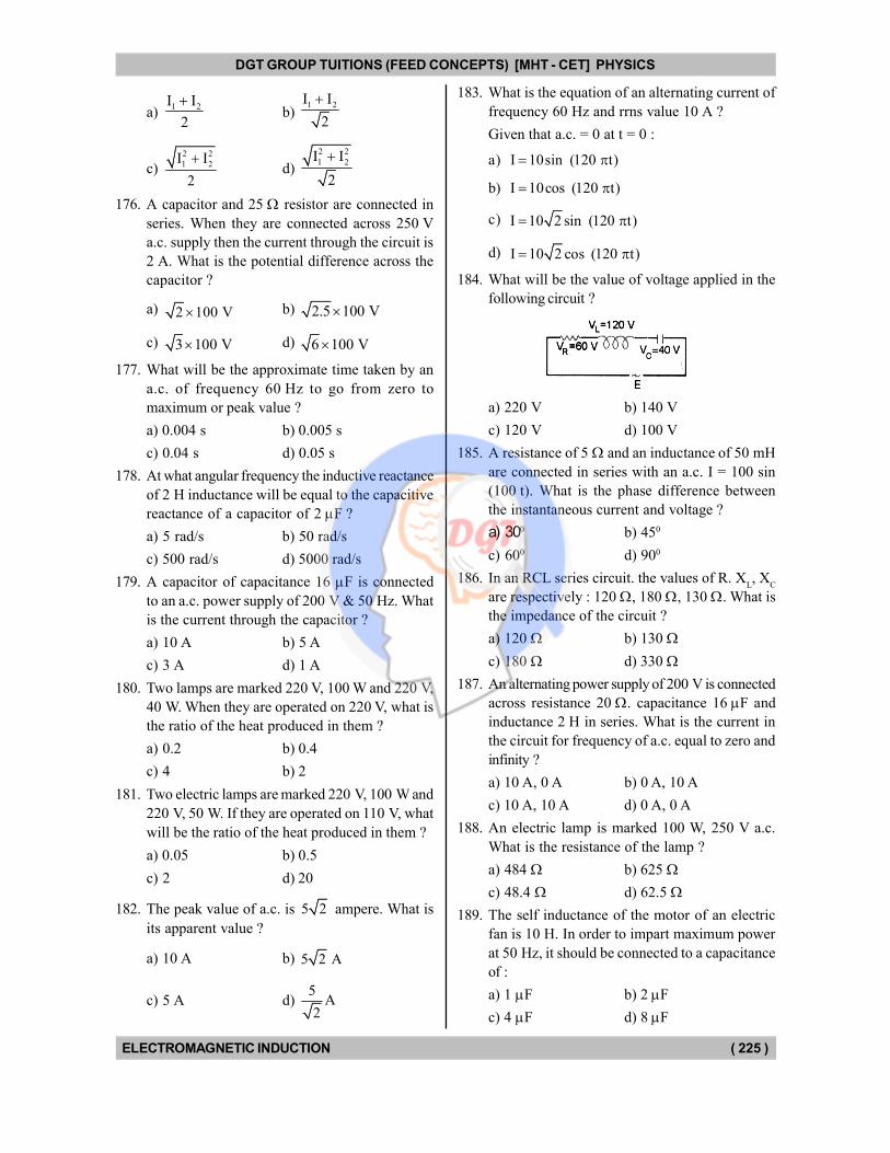
DGT GROUP TUITIONS (FEED CONCEPTS) [MHT - CET] PHYSICS
ELECTROMAGNETIC INDUCTION ( 225 )
a) 1 2I I
2
b)
1 2I I
2
c) 2 2
1 2I I
2
d)
2 2
1 2I I
2
176. A capacitor and 25 resistor are connected in
series. When they are connected across 250 V
a.c. supply then the current through the circuit is
2 A. What is the potential difference across the
capacitor ?
a) 2 100 V b) 2.5 100 V
c) 3 100 V d) 6 100 V
177. What will be the approximate time taken by an
a.c. of frequency 60 Hz to go from zero to
maximum or peak value ?
a) 0.004 s b) 0.005 s
c) 0.04 s d) 0.05 s
178. At what angular frequency the inductive reactance
of 2 H inductance will be equal to the capacitive
reactance of a capacitor of 2 F ?
a) 5 rad/s b) 50 rad/s
c) 500 rad/s d) 5000 rad/s
179. A capacitor of capacitance 16 F is connected
to an a.c. power supply of 200 V & 50 Hz. What
is the current through the capacitor ?
a) 10 A b) 5 A
c) 3 A d) 1 A
180. Two lamps are marked 220 V, 100 W and 220 V,
40 W. When they are operated on 220 V, what is
the ratio of the heat produced in them ?
a) 0.2 b) 0.4
c) 4 b) 2
181. Two electric lamps are marked 220 V, 100 W and
220 V, 50 W. If they are operated on 110 V, what
will be the ratio of the heat produced in them ?
a) 0.05 b) 0.5
c) 2 d) 20
182. The peak value of a.c. is 5 2 ampere. What is
its apparent value ?
a) 10 A b) 5 2 A
c) 5 A d) 5
A2
183. What is the equation of an alternating current of
frequency 60 Hz and rrns value 10 A ?
Given that a.c. = 0 at t = 0 :
a) I 10sin (120 t)
b) I 10cos (120 t)
c) I 10 2 sin (120 t)
d) I 10 2 cos (120 t)
184. What will be the value of voltage applied in the
following circuit ?
a) 220 V b) 140 V
c) 120 V d) 100 V
185. A resistance of 5 and an inductance of 50 mH
are connected in series with an a.c. I = 100 sin
(100 t). What is the phase difference between
the instantaneous current and voltage ?
a) 300 b) 450
c) 600 d) 900
186. In an RCL series circuit. the values of R. XL, X
C
are respectively : 120 , 180 , 130 . What is
the impedance of the circuit ?
a) 120 b) 130
c) 180 d) 330
187. An alternating power supply of 200 V is connected
across resistance 20 . capacitance 16 F and
inductance 2 H in series. What is the current in
the circuit for frequency of a.c. equal to zero and
infinity ?
a) 10 A, 0 A b) 0 A, 10 A
c) 10 A, 10 A d) 0 A, 0 A
188. An electric lamp is marked 100 W, 250 V a.c.
What is the resistance of the lamp ?
a) 484 b) 625
c) 48.4 d) 62.5
189. The self inductance of the motor of an electric
fan is 10 H. In order to impart maximum power
at 50 Hz, it should be connected to a capacitance
of :
a) 1 F b) 2 F
c) 4 F d) 8 F
DGT Group - Tuitions (Feed Concepts) XIth – XIIth | JEE | CET | NEET | Call : 9920154035 / 8169861448
DGT MH –CET 12th PHYSICS Study Material 31
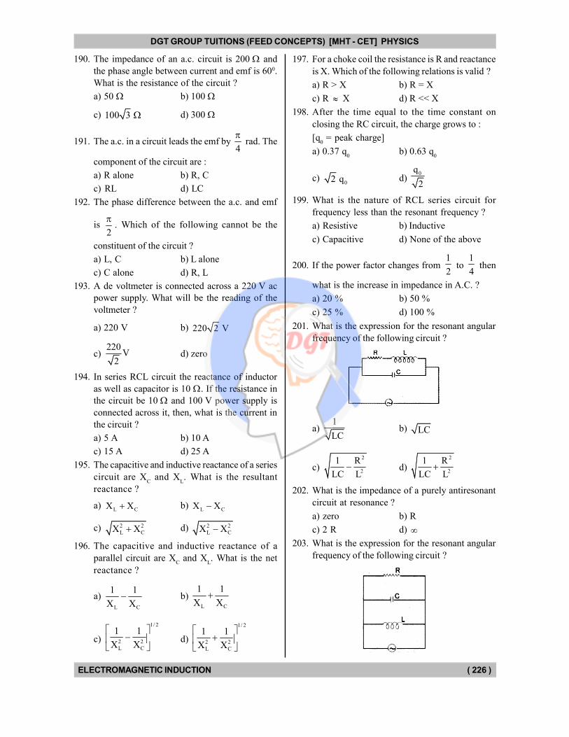
DGT GROUP TUITIONS (FEED CONCEPTS) [MHT - CET] PHYSICS
ELECTROMAGNETIC INDUCTION ( 226 )
190. The impedance of an a.c. circuit is 200 and
the phase angle between current and emf is 600.
What is the resistance of the circuit ?
a) 50 b) 100
c) 100 3 d) 300
191. The a.c. in a circuit leads the emf by 4
rad. The
component of the circuit are :
a) R alone b) R, C
c) RL d) LC
192. The phase difference between the a.c. and emf
is 2
. Which of the following cannot be the
constituent of the circuit ?
a) L, C b) L alone
c) C alone d) R, L
193. A de voltmeter is connected across a 220 V ac
power supply. What will be the reading of the
voltmeter ?
a) 220 V b) 220 2 V
c) 220
V2
d) zero
194. In series RCL circuit the reactance of inductor
as well as capacitor is 10 . If the resistance in
the circuit be 10 and 100 V power supply is
connected across it, then, what is the current in
the circuit ?
a) 5 A b) 10 A
c) 15 A d) 25 A
195. The capacitive and inductive reactance of a series
circuit are XC and X
L. What is the resultant
reactance ?
a) L CX X b)
L CX X
c) 2 2
L CX X d) 2 2
L CX X
196. The capacitive and inductive reactance of a
parallel circuit are XC and X
L. What is the net
reactance ?
a) L C
1 1
X X b)
L C
1 1
X X
c)
1/ 2
2 2
L C
1 1
X X
d)
1/ 2
2 2
L C
1 1
X X
197. For a choke coil the resistance is R and reactance
is X. Which of the following relations is valid ?
a) R > X b) R = X
c) R X d) R << X
198. After the time equal to the time constant on
closing the RC circuit, the charge grows to :
[q0 = peak charge]
a) 0.37 q0
b) 0.63 q0
c) 02 q d)
0q
2
199. What is the nature of RCL series circuit for
frequency less than the resonant frequency ?
a) Resistive b) Inductive
c) Capacitive d) None of the above
200. If the power factor changes from 1
2 to
1
4 then
what is the increase in impedance in A.C. ?
a) 20 % b) 50 %
c) 25 % d) 100 %
201. What is the expression for the resonant angular
frequency of the following circuit ?
a) 1
LCb) LC
c)
2
2
1 R
LC L d)
2
2
1 R
LC L
202. What is the impedance of a purely antiresonant
circuit at resonance ?
a) zero b) R
c) 2 R d) 203. What is the expression for the resonant angular
frequency of the following circuit ?
DGT Group - Tuitions (Feed Concepts) XIth – XIIth | JEE | CET | NEET | Call : 9920154035 / 8169861448
DGT MH –CET 12th PHYSICS Study Material 32
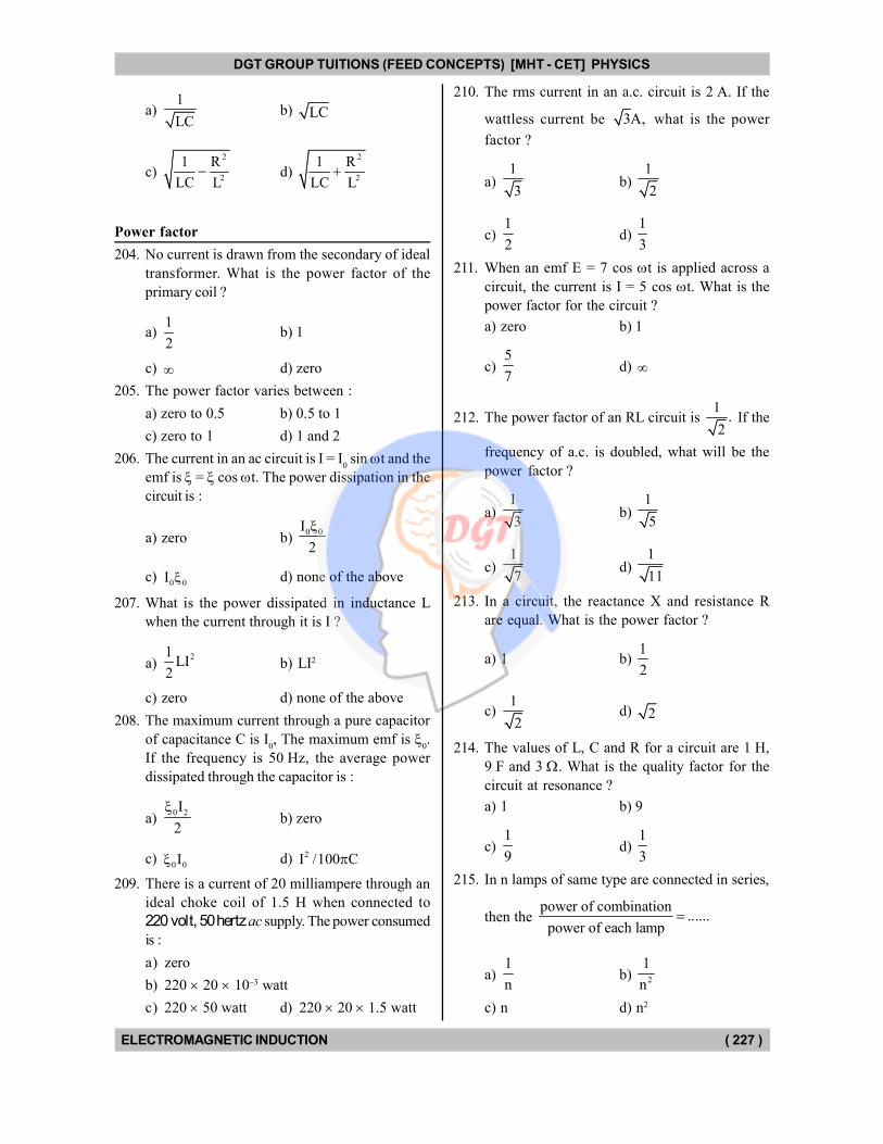
DGT GROUP TUITIONS (FEED CONCEPTS) [MHT - CET] PHYSICS
ELECTROMAGNETIC INDUCTION ( 227 )
a) 1
LCb) LC
c)
2
2
1 R
LC L d)
2
2
1 R
LC L
Power factor
204. No current is drawn from the secondary of ideal
transformer. What is the power factor of the
primary coil ?
a) 1
2b) 1
c) d) zero
205. The power factor varies between :
a) zero to 0.5 b) 0.5 to 1
c) zero to 1 d) 1 and 2
206. The current in an ac circuit is I = I0 sin t and the
emf is = cos t. The power dissipation in the
circuit is :
a) zero b) 0 0I
2
c) 0 0I d) none of the above
207. What is the power dissipated in inductance L
when the current through it is I ?
a) 21
LI2
b) LI2
c) zero d) none of the above
208. The maximum current through a pure capacitor
of capacitance C is I0, The maximum emf is
0.
If the frequency is 50 Hz, the average power
dissipated through the capacitor is :
a) 0 2I
2
b) zero
c) 0 0I d) 2I /100 C
209. There is a current of 20 milliampere through an
ideal choke coil of 1.5 H when connected to
220 volt, 50 hertz ac supply. The power consumed
is :
a) zero
b) 220 20 10–3 watt
c) 220 50 watt d) 220 20 1.5 watt
210. The rms current in an a.c. circuit is 2 A. If the
wattless current be 3A, what is the power
factor ?
a) 1
3b)
1
2
c) 1
2d)
1
3
211. When an emf E = 7 cos t is applied across a
circuit, the current is I = 5 cos t. What is the
power factor for the circuit ?
a) zero b) 1
c) 5
7d)
212. The power factor of an RL circuit is 1
.2
If the
frequency of a.c. is doubled, what will be the
power factor ?
a) 1
3b)
1
5
c) 1
7d)
1
11
213. In a circuit, the reactance X and resistance R
are equal. What is the power factor ?
a) 1 b) 1
2
c) 1
2d) 2
214. The values of L, C and R for a circuit are 1 H,
9 F and 3 . What is the quality factor for the
circuit at resonance ?
a) 1 b) 9
c) 1
9d)
1
3
215. In n lamps of same type are connected in series,
then the power of combination
......power of each lamp
a) 1
nb) 2
1
n
c) n d) n2
DGT Group - Tuitions (Feed Concepts) XIth – XIIth | JEE | CET | NEET | Call : 9920154035 / 8169861448
DGT MH –CET 12th PHYSICS Study Material 33
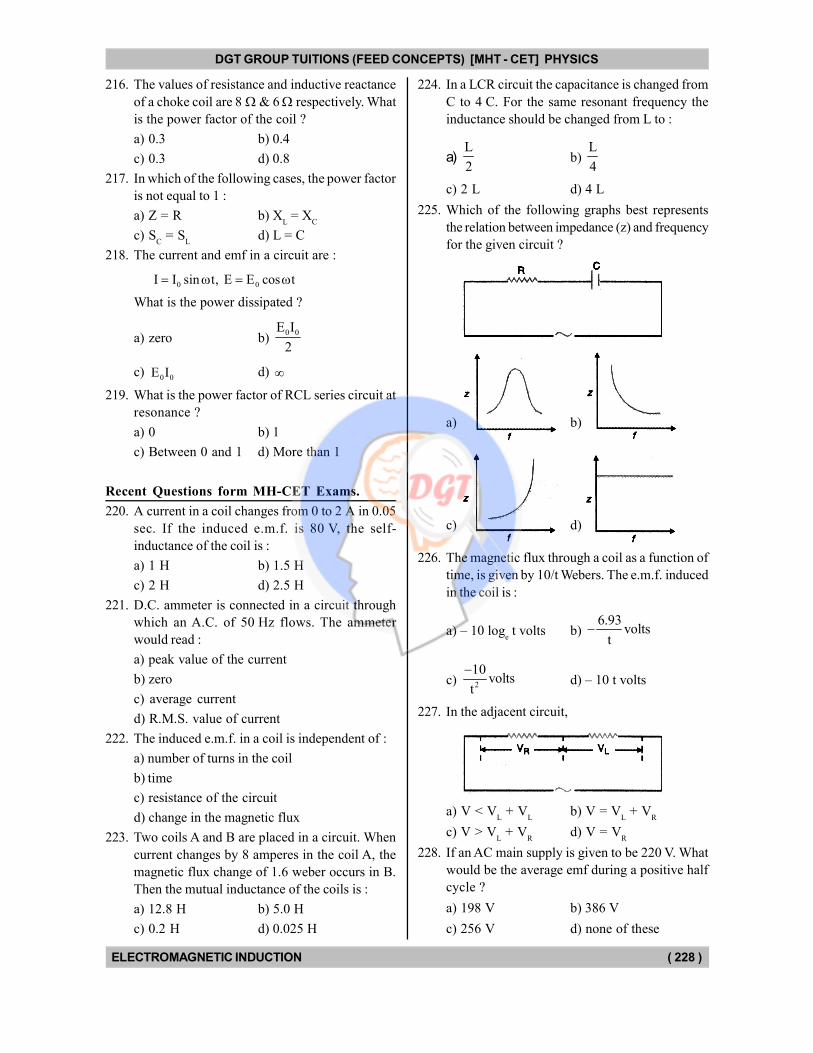
DGT GROUP TUITIONS (FEED CONCEPTS) [MHT - CET] PHYSICS
ELECTROMAGNETIC INDUCTION ( 228 )
216. The values of resistance and inductive reactance
of a choke coil are 8 & 6 respectively. What
is the power factor of the coil ?
a) 0.3 b) 0.4
c) 0.3 d) 0.8
217. In which of the following cases, the power factor
is not equal to 1 :
a) Z = R b) XL = X
C
c) SC = S
Ld) L = C
218. The current and emf in a circuit are :
0 0I I sin t, E E cos t
What is the power dissipated ?
a) zero b) 0 0E I
2
c) 0 0E I d)
219. What is the power factor of RCL series circuit at
resonance ?
a) 0 b) 1
c) Between 0 and 1 d) More than 1
Recent Questions form MH-CET Exams.
220. A current in a coil changes from 0 to 2 A in 0.05
sec. If the induced e.m.f. is 80 V, the self-
inductance of the coil is :
a) 1 H b) 1.5 H
c) 2 H d) 2.5 H
221. D.C. ammeter is connected in a circuit through
which an A.C. of 50 Hz flows. The ammeter
would read :
a) peak value of the current
b) zero
c) average current
d) R.M.S. value of current
222. The induced e.m.f. in a coil is independent of :
a) number of turns in the coil
b) time
c) resistance of the circuit
d) change in the magnetic flux
223. Two coils A and B are placed in a circuit. When
current changes by 8 amperes in the coil A, the
magnetic flux change of 1.6 weber occurs in B.
Then the mutual inductance of the coils is :
a) 12.8 H b) 5.0 H
c) 0.2 H d) 0.025 H
224. In a LCR circuit the capacitance is changed from
C to 4 C. For the same resonant frequency the
inductance should be changed from L to :
a) L
2b)
L
4
c) 2 L d) 4 L
225. Which of the following graphs best represents
the relation between impedance (z) and frequency
for the given circuit ?
a) b)
c) d)
226. The magnetic flux through a coil as a function of
time, is given by 10/t Webers. The e.m.f. induced
in the coil is :
a) – 10 loge t volts b)
6.93volts
t
c) 2
10volts
t
d) – 10 t volts
227. In the adjacent circuit,
a) V < VL + V
Lb) V = V
L + V
R
c) V > VL + V
Rd) V = V
R
228. If an AC main supply is given to be 220 V. What
would be the average emf during a positive half
cycle ?
a) 198 V b) 386 V
c) 256 V d) none of these
DGT Group - Tuitions (Feed Concepts) XIth – XIIth | JEE | CET | NEET | Call : 9920154035 / 8169861448
DGT MH –CET 12th PHYSICS Study Material 34
DGT GROUP TUITIONS (FEED CONCEPTS) [MHT - CET] PHYSICS
ELECTROMAGNETIC INDUCTION ( 229 )
229. The current in a coil of inductance 5 H decrease
at the rate of 2 A/s. The induced emf is :
a) 2 V b) 5 V
c) 10 V d) – 10 V
230. Resonance of a capacitor of capacitance C F
for A.C. frequency 100
Hz is 25 . The value
C is :
a) 50 F b) 25 F
c) 100 F d) 75 F
231. In a coil of area 20 cm2 & 10 turns with magnetic
field directed perpendicular to the plane changing
at the rate of 104 T/s. The resistance of the coil
is 20 . The current in the coil will be :
a) 10 A b) 20 A
c) 0.5 A d) 1.0 A
232. In an purely capacitive circuit current in capacitor?
a) leads e.m.f. by /2
b) lags e.m.f. by /2
c) both are in same phase
d) both are out of phase
233. If 1 = 5 Wb,
2 = 2 Wb, t = 2s. What is the
value of e.m.f. induced if number of turns is 100 ?
a) 50 volt b) 100 volt
c) 150 volt d) 200 volt
234. A helicopter rises vertically with a speed of
100 m/s. If helicopter has length 10 m and
horizontal component of earth's magnetic field is
5 10–3 Wb/m2, then the induced emf between
the tip of nose and tail of helicopter is :
a) 50 V b) 0.5 V
c) 5 V d) 25 V
235. The current which does not contribute to the
power consumed in an A.C. circuit is called :
a) non ideal current
b) wattless current
c) convectional current
d) inductance current
236. Induction coil is used to convert a small d.c.
voltage into :
a) a.c. voltage
b) sinusoidal voltage
c) high unidirectional and intermittent voltage
d) pulsating d.c. voltage
237. A metal disc of radius r rotates with an angular
velocity about an axis perpendicular to its plane
passing through its centre in a magnetic field of
induction B acting perpendicular to the plane of
the disc. The induced emf between rim and axis
of disc is :
a)
2BR
2
b)
2 2
2
2B R
c) 2B R d) 2B R 238. Resistor of 2 , inductor of 100 H and capacitor
of 400 pF are connected in series across a source
of erms
= 0.1 volt. At resonance voltage drop
across inductor is :
a) 25 volt b) 2.5 volt
c) 250 volt d) 20 volt
239. A wire of length 2.5 km is part of circuit of
resistance 35 orient along E-W direction falls
under gravity to group from, a height of 10 m then
current in the wire is :
[g = 9.8 m/s2 and BH = 2 cot 5 10–5 T]
a) 0.2 A b) 0.02 A
c) 0.04 A d) 2 A
240. Peak current is given Ip, in a resistive circuit of
resistance R. Average power over complete cycle
is :
a) 2
P
1I R
2b) 2
PI R
c)
2
PI Rcos
2 d) pI R cos
241. An inductor of 9 mH and capacitor of 10 F are
in series and XL = X
C. Calculate resonant
frequency.
a) 0.53 kHz b) 5.3 kHz
c) 0.53 Hz d) 5.3 Hz
242. A rod of length is rotated about one of its ends
with angular speed '' in magnetic field of '',
then, e.m.f. induced will be :
a)
2
2
b)
2
c)
2
2
d) 2
243. Henry is equivalent to :
a) Ampere/second b) Ampere second
c) Ohm/second d) Ohm second
DGT Group - Tuitions (Feed Concepts) XIth – XIIth | JEE | CET | NEET | Call : 9920154035 / 8169861448
DGT MH –CET 12th PHYSICS Study Material 35
DGT GROUP TUITIONS (FEED CONCEPTS) [MHT - CET] PHYSICS
ELECTROMAGNETIC INDUCTION ( 230 )
244. In the purely resistive AC. circuit :
a) current leads e.m.f. by a phase angle of radians
b) current leads e.m.f. by a phase angle of /2
radians
c) current and e.m.f. are in phase
d) current lags behind e.m.f. by a phase angle of
/2 radians
245. In LCR series circuit, at resonance, the power
facotor is :
a) zero b) 0.5
c) 1 d)
246. When a current of 2 A is passed through a coil of
100 turns flux associated with it is 5 10–5 Wb.
Find the self inductance of the coil :
a) 4 10–3 H b) 4 10–2 H
c) 2.5 10–3 H d) 10–3 H
247. Average power in the L-C-R circuit depends upon :
a) current
b) phase difference only
c) e.m.f.
d) current, e.m.f. and phase difference
248. A transformer is having 2100 turns in primary
and 4200 turns in secondary. An ac source of
120 V, 10 A is connected to its primary. The
secondary voltage and current are :
a) 240 V, 5 A b) 120 V, 10 A
c) 240 V, 10 A d) 120 V, 20 A
249. When the number of turns and length of a solenoid
are doubled keeping the area of cross section
same, the inductance becomes :
a) half b) zero
c) two times d) four times
250. If the current through the coil changes from +2 A
to –2 A in 0.05 sec and 8 V emf is developed in
the coil then the self inductance of the coil is :
a) 0.05 H b) 0.1 H
c) 0.2 H d) 0.4 H
251. An emf e 200 2 sin (100 t) volt is applied
across capacitor of capacitance 2 F then current
through capacitor is :
a) 4 mA b) 40 mA
c) 2 mA d) 3 mA
252. In LCR series circuit power factor at resonance
is :
a) less than one
b) greater than one
c) unity/one
d) can not be predicted
253. In series LCR circuit at resonance :
a) current is maximum and voltage is minimum
b) current is maximum and voltage is maximum
c) current is minimum and voltage is maximum
d) current is minimum and voltage is minimum
254. The self inductance of coil of 400 turns is 8 mH,
If current of 5 mA flows in it, then flux associated
with the coil is :
a) 0
4
b) 0
c) 0
100
d)
0
4
255. In LCR series circuit an ac emf of 2 volt and
frequency 50 Hz is applied across the combination.
If resistance is 4 , capacitance is 8 F and
inductance is 10–2 H then the voltage across
inductor will be :
a) 3
V5
b) 5
V3
c) 2
V3
d) 0.02 V
256. If 'N' is the number of turns in a circular coil then
the value of self inductance varies as :
a) N0 b) N
c) N2 d) N–2
257. In LCR series circuit, an alternating e.m.f. 'e' and
current 'i' are given by the equations
e 100sin(100t)volt,
i 100sin 100t mA.3
The average power dissipated in the circuit will
be :
a) 100 W b) 10 W
c) 5 W d) 2.5 W
DGT Group - Tuitions (Feed Concepts) XIth – XIIth | JEE | CET | NEET | Call : 9920154035 / 8169861448
DGT MH –CET 12th PHYSICS Study Material 36
DGT GROUP TUITIONS (FEED CONCEPTS) [MHT - CET] PHYSICS
ELECTROMAGNETIC INDUCTION ( 231 )
258. In electromagnetic wave, according to Maxwell,
changing electric field gives :
a) stationary magnetic field
b) conduction current
c) eddy current
d) displacement current
259. Same current is flowing in two a.c. circuits. First
contains only inductance and second contains only
capacitance. If frequency of a.c. is increased for
both, the current will :
a) increase in first circuit and decrease in second
b) increase in both circuits
c) decrease in both circuits
d) decrease in first circuit and increase in second
260. Two coils A and B have mutual inductance
2 10–2 henry. If the current in the primary is
i = 5 sin (10 t) then the maximum value of e.m.f.
induced in coil B is :
a) volt b) volt2
c) volt3
d) volt
4
DGT Group - Tuitions (Feed Concepts) XIth – XIIth | JEE | CET | NEET | Call : 9920154035 / 8169861448
DGT MH –CET 12th PHYSICS Study Material 37

DGT Group - Tuitions (Feed Concepts) XIth – XIIth | JEE | CET | NEET | Call : 9920154035 / 8169861448
DGT MH –CET 12th PHYSICS Study Material 38
DGT GROUP TUITIONS (FEED CONCEPTS) [MHT - CET] PHYSICS
ELECTROMAGNETIC INDUCTION ( 232 )
REVISION OUESTIONS
from Competitive Exams
1. In a coil of area 10 cm2 & 10 turns with magnetic
field directed perpendicular to the plane and is
changing at the rate of 108 gauss/second. The
resistance of the coil is 20 ohm. The current in
the coil will be :
a) 5 A b) 0.5 A
c) 0.05 A d) 5 108 A
2. The potential difference V across and the current
I flowing through an A.C. circuit are given by,
V = 5 cos t volt, I = 2 sin t ampere.
The power dissipated in the instrument is :
a) 0 watt b) 10 watt
c) 5 watt d) 2.5 watt
3. To reduce the loss of energy as heat due to eddy
currents, the soft iron core is laminated. The angle
between the plane of these sheets and the
magnetic induction should by :
a) zero b) 450
c) 600 d) 900
4. A coil is wound on a former of rectangular cross-
section. If all the linear dimensions of the former
are increased by a factor of 3 and the numbers
of turns per unit length remains the same, the
self-inductance increases by a factor of :
a) 3 b) 9
c) 27 d) 81
5. When the number of turns in a solenoid is doubled
without any change in the length of the solenoid,
its self-inductance will be :
a) Four times b) Doubled
c) Halved d) Squared
6. The average e.m.f. induced in a coil in which the
current changes from 2 ampere to 4 ampere in
0.05 second is 8 volt, what is the self inductance
of the coil ?
a) 0.1 henry b) 0.2 henry
c) 0.4 henry d) 0.8 henry
7. Using an A.C. voltmeter, the potential difference
in the elecrical line in a house is read to be
234 volt. If the line frequency is known to be
50 cycles per second, the equation for the line
voltage is :
a) V = 165 sin (100 t)
b) V = 331 sin (100 t)
c) V = 234 sin (100 t)
d) V = 440 sin (100 t)
8. A 20 volt A.C. is applied to a circuit consisting of
a resistance and a coil with a negligible resistance.
If the voltage across the resistance is 12 volt, the
voltage across the coil is :
a) 16 volt b) 10 volt
c) 8 volt d) 6 volt
9. With the decrease of current in the primary coil
from 2 ampere to zero value in 0.01 second, the
e.m.f. generated in the secondary coil is 1000
volt. The mutual inductance of the two coil is :
a) 1.25 henry b) 2.50 henry
c) 5.00 henry d) 10.00 henry
10. The peak value of an alternating e.m.f. E given
by E = E0 cos t is 10 volt and its frequency is
50 Hz. At a time t = 1
600s the instantaneous value
of the e.m.f. is :
a) 10 volt b) 5 3 volt
c) 5 volt d) 1 volt
11. In a region of uniform magnetic induction B = 10–2
tesla, a circular coil of radius 30 cm and resistance
2 ohm is rotated about an axis which is perpen-
dicular to the direction of B and which forms a
diameter of the coil. If the coil rotates at 200 rpm
the amplitude of the alternating current induced
in the coil is :
a) 4 2 mA b) 30 mA
c) 6 mA d) 200 mA
12. A generator produces a voltage that is given by
V = 240 sin 120 t volt where t is in seconds. The
frequency and rms voltage are :
a) 60 Hz and 240 volt
b) 19 Hz and 120 volt
c) 19 Hz and 170 volt
d) 754 Hz and 170 volt
13. When 100 volt D.C. is applied across a solenoid,
a current of 1.0 ampere flows in it. When 100
volt A.C. is applied across the same coil, the
current drops to 0.5 ampere. If the frequency of
A.C. source is 50 Hz the impedance & inductance
of the solenoid are :
DGT Group - Tuitions (Feed Concepts) XIth – XIIth | JEE | CET | NEET | Call : 9920154035 / 8169861448
DGT MH –CET 12th PHYSICS Study Material 39
DGT GROUP TUITIONS (FEED CONCEPTS) [MHT - CET] PHYSICS
ELECTROMAGNETIC INDUCTION ( 233 )
a) 200 ohm and 0.55 henry
b) 100 ohm and 0.86 henry
c) 200 ohm and 1.0 henry
d) 100 ohm and 0.93 henry
14. The current in a self inductance L = 40 mH is to
be increased uniformly from 1 A to 11 A in 4 milli
seconds. The induced e.m.f. produced in L during
this process will be :
a)100 volt b) 0.4 volt
c) 440 volt d) 40 volt
15. The frequency of a resonant LC combination
(L = 10 mH and C = 1.0 F) is :
a) 1.0 104 radian per second
b) 1.0 10–4 hertz
c) 1.0 10–4 radian per second
d) 1.0 104 hertz
16. When the current in a coil changes from 8 ampere
to 2 ampere in 3 10–2 seconds the e.m.f. induced
in the coil is 2 volt. The self-inductance of the
coil, in rnilli henry, is :
a) 1 b) 5
c) 20 d) 10
17. The number of turns in the primary and the
secondary of a transformer are 1000 and 3000
respectively. If 80 volt A.C. is applied to the
primary coil of the transformer, then the potential
difference per turn of the secondary coil would
be :
a) 240 volt b) 2400 volt
c) 0.24 volt d) 0.80 volt
18. In an A.C. circuit the potential V and the current
are given respectively by,
V = 100 sin (100 t) volt and
1= 100 sin 100t3
mA.
The power dissipation in the circuit will be :
a) 104 watt b) 10 watt
c) 2.5 watt d) 5 watt
19. An A.C. circuit using an inductor and a capacitor
in series has a maximum current. If L = 0.5 henry
and C = 8 F, then the angular frequency of A.C.
voltage will be :
a) 500 b) 5 105
c) 4000 d) 5000
20. An alternating voltage (in volts) = 200 2 sin 100t
is connected to one microfarad capacitor through
an ac ammeter. The reading of the ammeter shall
be :
a) 10 mA b) 20 mA
c) 40 mA d) 80 mA
21. A galvanometer is connected to the secondary
coil. The galvanometer shows an instantaneous
maximum deflection of 7 divisions when current
is started in the primary coil of the solenoid. Now
if the primary coil is rotated through 180·, then
the new instantaneous maximum deflection will
be :
a) 7 units b) 14 units
c) 0 units d) 21 units
22. A 40 electric heater is connected to a 200 V,
50 Hz mains supply. The peak value of electric
current flowing in the circuit is approximately :
a) 2.5 A b) 5.0 A
c) 7 A d) 10 A
23. Dimensions of self-inductance are :
a) M L T–2 A–2 b) M L2 T–1 A–2
c) M L2 T–2 A–2 d) M L2 T–2 A–1
24. If the number of turns per unit length of a coil of
solenoid is doubled, the self-inductance of the
solenoid will :
a) remain unchanged b) be halved
c) be doubled d) become four times
25. Energy in a current carrying coil is stored in the
form of :
a) electric field b) magnetic field
c) dielectric strength c) heat
26. A rectangular coil has 20 turns and area of cross-
section 25 sq cm has a resistance of 100 ohm. If
a magnetic field which is perpendicular to the
plane of the coil changes at a rate of 1000 tesla
per second, the current in the coil is :
a) 1.0 ampere b) 50 ampere
c) 0.5 ampere d) 5.0 ampere
27. The total charge, induced in a conducting loop
when it is moved in magnetic field, depends on :
a) the rate of change of magnetic flux
b) initial magnetic flux only
c) the total change in magnetic flux
d) final magnetic flux only
DGT Group - Tuitions (Feed Concepts) XIth – XIIth | JEE | CET | NEET | Call : 9920154035 / 8169861448
DGT MH –CET 12th PHYSICS Study Material 40
DGT GROUP TUITIONS (FEED CONCEPTS) [MHT - CET] PHYSICS
ELECTROMAGNETIC INDUCTION ( 234 )
28. A 100 millihenry coil carries a current of 1 ampere.
Energy stored in its magnetic field is :
a) 0.5 J b) 1 J
c) 0.05 J d) 0.1 J
29. A magnetic field of 2 10–2 tesla acts at right
angles to a coil of area 100 cm2 with 50 turns.
The average emf induced in the coil is 0.1 V when
it is removed from the field in time 't', The value
of 't' is :
a) 0.1 second b) 0.01 second
c) 1 second d) 20 second
30. An alternating potential V = V0 sin t is applied
across a circuit.
As a result the current 0I I sin t2
flows in it. The power consumed in the circuit
per cycle is :
a) zero b) 0.5 V0I
0
c) 0.707 V0I
0d) 1.414 V
0I
0
31. Faraday's laws are consequence of conservation
of :
a) Energy
b) Energy and magnetic field
c) Charge
d) Magnetic field
32. A moving conductor coil produces an induced emf.
This is in accordance with :
a) Lenz's law b) Faraday's laws
c) Coulomb's law d) Ampere's law
33. When the number of turns and the length of the
solenoid are doubled keeping the area of cross-
section same, the inductance :
a) remains the same b) is halved
c) is doubled d) becomes four times
34. What is the self-inductance of a coil which
produces 5 V when the current changes from 3
amperes to 2 amperes in one millisecond ?
a) 5000 henry b) 5 mili-henry
c) 50 henry d) 5 henry
35. The north pole of a long horizontal bar magnet is
being brought closer to a vertical conducting plane
along the perpendicular direction. The direction
of the induced current in the conducting plane
will be :
a) horizontal b) vertical
c) clockwise
d) anticlockwise
36. In general in an alternating current circuit :
a) the average value of current is zero
b) the average value of square of the current is
zero
c) average power dissipation is zero.
d) the phase difference between voltage and
current is zero
37. A 12 ohm resistor and a 0.21 henry inductor are
connected in series to an AC source operating at
20 volts, 50 cycle. The phase angle between the
current and the source voltage is :
a) 300 b) 400
c) 800 d) 900
38. An e.m.f. of 15 volt is applied in a circuit coil
containing 5 henry inductance and 10 ohm
resistance. The ratio of the currents at time t = and at t = 1 seconds is :
a)
1/ 2
1/ 2
e
e 1b)
2
2
e
e 1
c) 11 e d) e 1
39. In a noiseless transformer an alternating current
of 2 amperes is flowing in the primary coil. The
number of turns in the primary and secondary
coils are 100 and 20 respectively. The value of
the current in the secondary coil is :
a) 0.80 A b) 0.4 A
c) 5 A d) 10 A
40. If resistance of 100 and inductance of 0.5 henry
and capacitance of 10 10–6 F are connected in
series through 50 Hertz AC supply then impedence
is :
a) 1.8765 b) 18.76
c) 187.6 d) 101.3
41. In an A.C. circuit, the current is,
i 5sin 100t amp2
and the A.C. potential
is V = 200 sin (100 t) volt. Then the power con-
sumption is :
a) 20 watts b) 40 watts
c) 1000 watts d) 0 watts
DGT Group - Tuitions (Feed Concepts) XIth – XIIth | JEE | CET | NEET | Call : 9920154035 / 8169861448
DGT MH –CET 12th PHYSICS Study Material 41
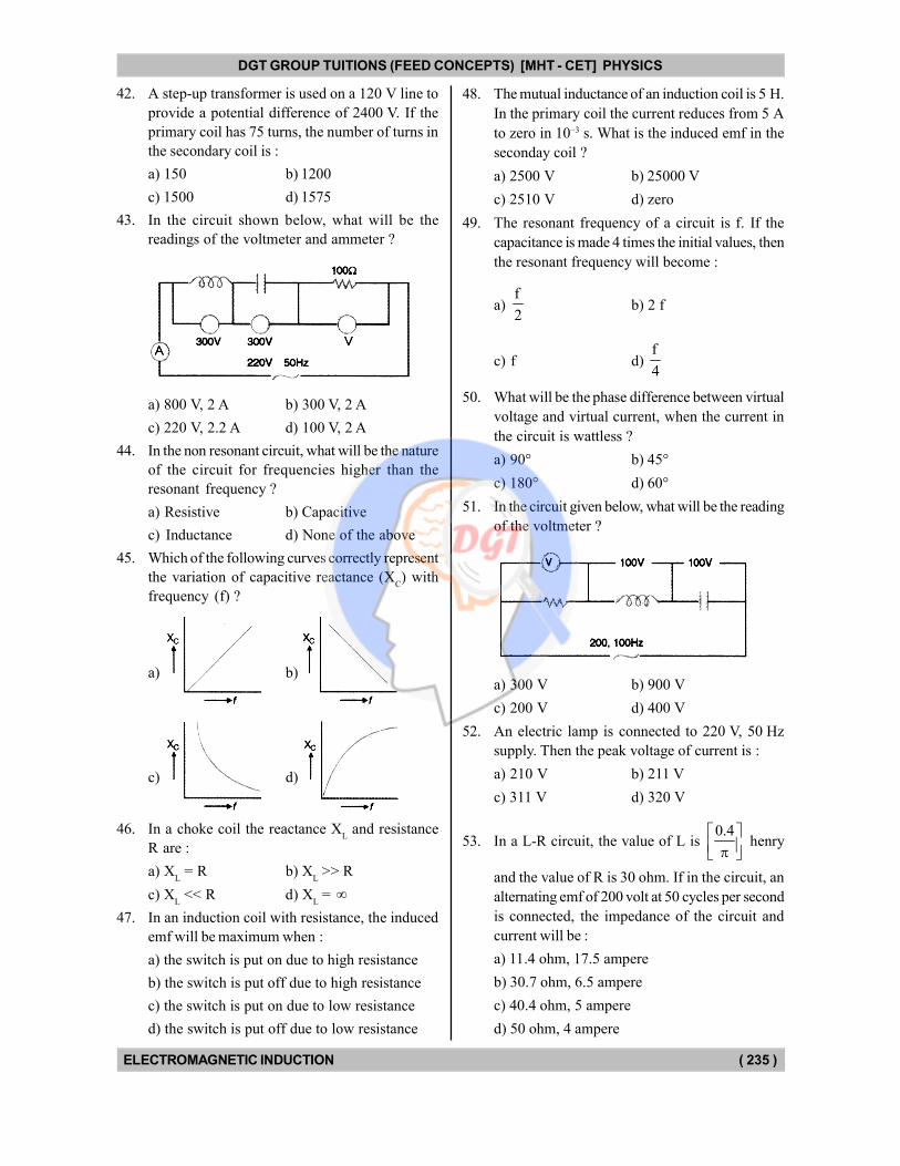
DGT GROUP TUITIONS (FEED CONCEPTS) [MHT - CET] PHYSICS
ELECTROMAGNETIC INDUCTION ( 235 )
42. A step-up transformer is used on a 120 V line to
provide a potential difference of 2400 V. If the
primary coil has 75 turns, the number of turns in
the secondary coil is :
a) 150 b) 1200
c) 1500 d) 1575
43. In the circuit shown below, what will be the
readings of the voltmeter and ammeter ?
a) 800 V, 2 A b) 300 V, 2 A
c) 220 V, 2.2 A d) 100 V, 2 A
44. In the non resonant circuit, what will be the nature
of the circuit for frequencies higher than the
resonant frequency ?
a) Resistive b) Capacitive
c) Inductance d) None of the above
45. Which of the following curves correctly represent
the variation of capacitive reactance (XC) with
frequency (f) ?
a) b)
c) d)
46. In a choke coil the reactance XL and resistance
R are :
a) XL = R b) X
L >> R
c) XL << R d) X
L =
47. In an induction coil with resistance, the induced
emf will be maximum when :
a) the switch is put on due to high resistance
b) the switch is put off due to high resistance
c) the switch is put on due to low resistance
d) the switch is put off due to low resistance
48. The mutual inductance of an induction coil is 5 H.
In the primary coil the current reduces from 5 A
to zero in 10–3 s. What is the induced emf in the
seconday coil ?
a) 2500 V b) 25000 V
c) 2510 V d) zero
49. The resonant frequency of a circuit is f. If the
capacitance is made 4 times the initial values, then
the resonant frequency will become :
a) f
2b) 2 f
c) f d) f
4
50. What will be the phase difference between virtual
voltage and virtual current, when the current in
the circuit is wattless ?
a) 90° b) 45°
c) 180° d) 60°
51. In the circuit given below, what will be the reading
of the voltmeter ?
a) 300 V b) 900 V
c) 200 V d) 400 V
52. An electric lamp is connected to 220 V, 50 Hz
supply. Then the peak voltage of current is :
a) 210 V b) 211 V
c) 311 V d) 320 V
53. In a L-R circuit, the value of L is 0.4
henry
and the value of R is 30 ohm. If in the circuit, an
alternating emf of 200 volt at 50 cycles per second
is connected, the impedance of the circuit and
current will be :
a) 11.4 ohm, 17.5 ampere
b) 30.7 ohm, 6.5 ampere
c) 40.4 ohm, 5 ampere
d) 50 ohm, 4 ampere
DGT Group - Tuitions (Feed Concepts) XIth – XIIth | JEE | CET | NEET | Call : 9920154035 / 8169861448
DGT MH –CET 12th PHYSICS Study Material 42
DGT GROUP TUITIONS (FEED CONCEPTS) [MHT - CET] PHYSICS
ELECTROMAGNETIC INDUCTION ( 236 )
54. In only inductance circuit the relation of phase
between current and voltage is :
a) Voltage is leading by /2
b) Current is leading by /2
c) Both are in same phase
c) The phase difference is
55. In a coil of self-induction 5 henry, the rate of the
change of current is 2 ampere per second, then
EMF induced in the coil is :
a) 10 V b) 0 V
c) 5 V d) – 5 V
56. In an ac circuit containing only capacitance the
current :
a) leads voltage by 1800
c) remains in phase with voltage
c) leads voltage by 900
d) legs voltage by 900
57. During a current change from 2 A to 4 A in 0.05
second, 8 V of emf is developed in a coil. The
coefficient of self-induction is :
a) 0.1 H b) 0.2 H
c) 0·4 H d) 0.8 H
58. In an ac circuit with voltage V and current I the
power dissipated is :
a) VI
b) 1
VI2
c) 1
VI2
d) depends on the phase between V and I
59. The primary winding of transformer has 500
turns whereas its secondary has 5000 turns. The
primary is connected to an a.c. supply of 20 V,
50 Hz. The secondary will have an output of :
a) 200 V, 50 Hz b) 2 V, 50 Hz
c) 200 V, 500 Hz d) 2 V, 5 Hz
60. The number of turns in the primary coil of a
transformer is 200 and the number of turns in the
secondary coil is 10. If 240 volts ac are applied
to the primary, the output from the secondary will
be :
a) 48 A b) 24 V
c) 12 V d) 6 V
61. A coil of copper having 1000 turns is placed in a
magnetic field (B = 4 10–5) perpendicular to its
axis. The cross-sectional area of the coil is
0.05 m2. If it turns through 1800 in 0.01 second,
then the EMF induced in the coil is :
a) 0.4 V b) 0.2 V
c) 0.04 V d) 4 V
62. Weber/m2 is equal to :
a) volt b) henry
c) tesla d) all the these
63. If the rotational velocity of a dynamo armature is
doubled, then the induced emf will :
a) become half
b) become double
c) become quadruple
d) remain unchanged
64. Which quantity is increased in step-down
transformer ?
a) Current b) Voltage
c) Power d) Frequency
65. In L-C-R series A.C. circuit, the phase angle
between current and voltage is :
a) Any angle between 0 and 2
b) 2
c)
d) Any angle between 0 and 2
66. The average power dissipation in a pure capacitor
in AC circuit is :
a) 21
CV2
b) CV2
c) 2 CV2 d) zero
67. In an A.C. circuit, a resistance of R ohm is
connected in series with an inductance L. If phase
angle between voltage and current be 45°, the
value of inductive reactance will be :
a) R
4b)
R
2
c) R
d) cannot be found with the given data
DGT Group - Tuitions (Feed Concepts) XIth – XIIth | JEE | CET | NEET | Call : 9920154035 / 8169861448
DGT MH –CET 12th PHYSICS Study Material 43
DGT GROUP TUITIONS (FEED CONCEPTS) [MHT - CET] PHYSICS
ELECTROMAGNETIC INDUCTION ( 237 )
68. In an L-R circuit, time constant is that time in
which current grows from zero to the value :
a) 0.63 I0
b) 0.50 I0
c) 0.37 I0
d) I0
[where I0 is the steady state current]
69. Quantity that remains unchanged in a transformer
is :
a) Voltage b) Current
c) Frequency d) None of these
70. The direction of induced current is such that it
opposes the very cause that has produced it. This
is the law of :
a) Lenz b) Faraday
c) Kirchhoff d) Fleming
71. A two meter wire is moving with a velocity of 1 m/s
perpendicular to a magnetic field of 0.5 Wb/m2.
The emf induced in it will be :
a) 0.5 volt b) 0.1 volt
c) I volt d) 2 volt
72. The north pole of a magnet is brought near a
metallic ring as shown in the figure. The direction
of induced current in the ring will be :
a) Anticlockwise
b) Clockwise
c) First anticlockwise and then clockwise
d) First clockwise and then anticlockwise
73. The expression for magnetic induction inside a
solenoid of length L, carrying a current I and
having N number of turns is :
a) 0 N
I4 L
b)
0 NLI
c) 0 NLI
4
d) 0
NI
L
74. A particle is moving in a uniform magnetic field,
then :
a) its momentum changes but total energy remains
the same
b) both momentum and total energy remain the
same
c) both change
d) total energy changes but momentum remains
same
75. A particle moving in a magnetic field has increase
in its velocity, then its radius of the circle :
a) decreases b) increases
c) remains the same d) becomes half
76. Two inductors each of inductance 'L' are joined
in parallel. What is the equivalent inductance ?
a) 2 L b) L
c) L
2d) zero
77. What is the coefficient of mutual inductance,
when the magnetic flux changes by 2 10–2 Wb,
and change in current is 0.01 A ?
a) 2 henry b) 3 henry
c) 1
2 henry d) zero
78. In an LCR series circuit, the capacitance is made
one-fourth, when in resonance. Then what should
be change, in inductance, so that the circuit remains
in resonance ?
a) 4 times b) 1
4 times
c) 8 times d) 2 times
79. A step-up transformer has transformation ratio
of 3 : 2. What is the voltage in secondary, if
voltage in primary is 30 V ?
a) 45 V b) 15 V
c) 90 V d) 300 V
80. A step-up transformer operates on a 230 V line
and supplies a load of 2 ampere. The ratio of the
primary and secondary winding is 1 : 25. The
current in the primary is :
a) 15 A b) 50 A
c) 25 A d) 12.5 A
81. Two coils have a mutual inductance 0.005 H.
The current changes in the first coil according
to equation I = I0 sin t where I
0 = 10 A and
= 100 radian/second. The maximum value
of e.m.f. in the second coil is :
a) 2 b) 5
c) d) 4
DGT Group - Tuitions (Feed Concepts) XIth – XIIth | JEE | CET | NEET | Call : 9920154035 / 8169861448
DGT MH –CET 12th PHYSICS Study Material 44
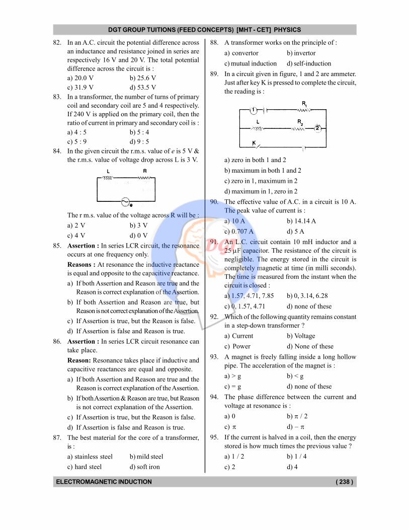
DGT GROUP TUITIONS (FEED CONCEPTS) [MHT - CET] PHYSICS
ELECTROMAGNETIC INDUCTION ( 238 )
82. In an A.C. circuit the potential difference across
an inductance and resistance joined in series are
respectively 16 V and 20 V. The total potential
difference across the circuit is :
a) 20.0 V b) 25.6 V
c) 31.9 V d) 53.5 V
83. In a transformer, the number of turns of primary
coil and secondary coil are 5 and 4 respectively.
If 240 V is applied on the primary coil, then the
ratio of current in primary and secondary coil is :
a) 4 : 5 b) 5 : 4
c) 5 : 9 d) 9 : 5
84. In the given circuit the r.m.s. value of e is 5 V &
the r.m.s. value of voltage drop across L is 3 V.
The r m.s. value of the voltage across R will be :
a) 2 V b) 3 V
c) 4 V d) 0 V
85. Assertion : In series LCR circuit, the resonance
occurs at one frequency only.
Reasons : At resonance the inductive reactance
is equal and opposite to the capacitive reactance.
a) If both Assertion and Reason are true and the
Reason is correct explanation of the Assertion.
b) If both Assertion and Reason are true, but
Reason is not correct explanation of the Assertion.
c) If Assertion is true, but the Reason is false.
d) If Assertion is false and Reason is true.
86. Assertion : In series LCR circuit resonance can
take place.
Reason: Resonance takes place if inductive and
capacitive reactances are equal and opposite.
a) If both Assertion and Reason are true and the
Reason is correct explanation of the Assertion.
b) If both Assertion & Reason are true, but Reason
is not correct explanation of the Assertion.
c) If Assertion is true, but the Reason is false.
d) If Assertion is false and Reason is true.
87. The best material for the core of a transformer,
is :
a) stainless steel b) mild steel
c) hard steel d) soft iron
88. A transformer works on the principle of :
a) convertor b) invertor
c) mutual induction d) self-induction
89. In a circuit given in figure, 1 and 2 are ammeter.
Just after key K is pressed to complete the circuit,
the reading is :
a) zero in both 1 and 2
b) maximum in both 1 and 2
c) zero in 1, maximum in 2
d) maximum in 1, zero in 2
90. The effective value of A.C. in a circuit is 10 A.
The peak value of current is :
a) 10 A b) 14.14 A
c) 0.707 A d) 5 A
91. An L.C. circuit contain 10 mH inductor and a
25 F capacitor. The resistance of the circuit is
negligible. The energy stored in the circuit is
completely magnetic at time (in milli seconds).
The time is measured from the instant when the
circuit is closed :
a) 1.57, 4.71, 7.85 b) 0, 3.14, 6.28
c) 0, 1.57, 4.71 d) none of these
92. Which of the following quantity remains constant
in a step-down transformer ?
a) Current b) Voltage
c) Power d) None of these
93. A magnet is freely falling inside a long hollow
pipe. The acceleration of the magnet is :
a) > g b) < g
c) = g d) none of these
94. The phase difference between the current and
voltage at resonance is :
a) 0 b) / 2
c) d) –
95. If the current is halved in a coil, then the energy
stored is how much times the previous value ?
a) 1 / 2 b) 1 / 4
c) 2 d) 4
DGT Group - Tuitions (Feed Concepts) XIth – XIIth | JEE | CET | NEET | Call : 9920154035 / 8169861448
DGT MH –CET 12th PHYSICS Study Material 45
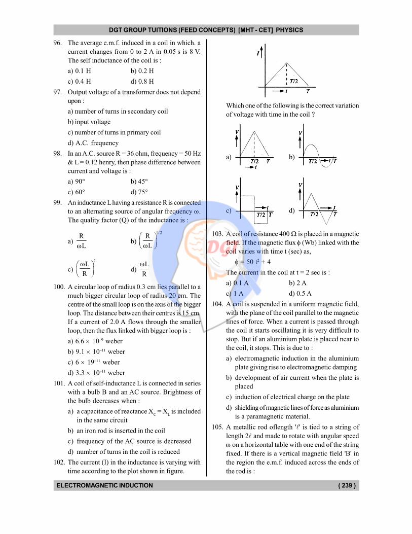
DGT GROUP TUITIONS (FEED CONCEPTS) [MHT - CET] PHYSICS
ELECTROMAGNETIC INDUCTION ( 239 )
96. The average e.m.f. induced in a coil in which. a
current changes from 0 to 2 A in 0.05 s is 8 V.
The self inductance of the coil is :
a) 0.1 H b) 0.2 H
c) 0.4 H d) 0.8 H
97. Output voltage of a transformer does not depend
upon :
a) number of turns in secondary coil
b) input voltage
c) number of turns in primary coil
d) A.C. frequency
98. In an A.C. source R = 36 ohm, frequency = 50 Hz
& L = 0.12 henry, then phase difference between
current and voltage is :
a) 90° b) 45°
c) 60° d) 75°
99. An inductance L having a resistance R is connected
to an alternating source of angular frequency .
The quality factor (Q) of the inductance is :
a) R
Lb)
1/ 2R
L
c)
2L
R
d) L
R
100. A circular loop of radius 0.3 cm lies parallel to a
much bigger circular loop of radius 20 cm. The
centre of the small loop is on the axis of the bigger
loop. The distance between their centres is 15 cm.
If a current of 2.0 A flows through the smaller
loop, then the flux linked with bigger loop is :
a) 6.6 10–9 weber
b) 9.1 10–11 weber
c) 6 19–11 weber
d) 3.3 10–11 weber
101. A coil of self-inductance L is connected in series
with a bulb B and an AC source. Brightness of
the bulb decreases when :
a) a capacitance of reactance XC = X
L is included
in the same circuit
b) an iron rod is inserted in the coil
c) frequency of the AC source is decreased
d) number of turns in the coil is reduced
102. The current (I) in the inductance is varying with
time according to the plot shown in figure.
Which one of the following is the correct variation
of voltage with time in the coil ?
a) b)
c) d)
103. A coil of resistance 400 is placed in a magnetic
field. If the magnetic flux (Wb) linked with the
coil varies with time t (sec) as,
= 50 t2 + 4
The current in the coil at t = 2 sec is :
a) 0.1 A b) 2 A
c) 1 A d) 0.5 A
104. A coil is suspended in a uniform magnetic field,
with the plane of the coil parallel to the magnetic
lines of force. When a current is passed through
the coil it starts oscillating it is very difficult to
stop. But if an aluminium plate is placed near to
the coil, it stops. This is due to :
a) electromagnetic induction in the aluminium
plate giving rise to electromagnetic damping
b) development of air current when the plate is
placed
c) induction of electrical charge on the plate
d) shielding of magnetic lines of force as aluminium
is a paramagnetic material.
105. A metallic rod oflength '' is tied to a string of
length 2 and made to rotate with angular speed
on a horizontal table with one end of the string
fixed. If there is a vertical magnetic field 'B' in
the region the e.m.f. induced across the ends of
the rod is :
DGT Group - Tuitions (Feed Concepts) XIth – XIIth | JEE | CET | NEET | Call : 9920154035 / 8169861448
DGT MH –CET 12th PHYSICS Study Material 46
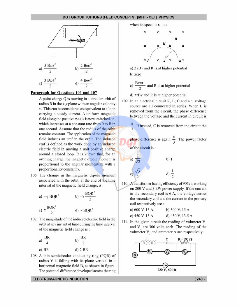
DGT GROUP TUITIONS (FEED CONCEPTS) [MHT - CET] PHYSICS
ELECTROMAGNETIC INDUCTION ( 240 )
a)
25 B
2
b)
22 B
2
c)
23 B
2
d)
24 B
2
Paragraph for Questions 106 and 107
A point charge Q is moving in a circular orbit of
radius R in the x-y plane with an angular velocity
. This can be considered as equivalent to a loop
carrying a steady current. A uniform magnetic
field along the positive z-axis is now switched on,
which increases at a constant rate from 0 to B in
one second. Assume that the radius of the orbit
remains constant. The application of the magnetic
field induces an emf in the orbit. The induced
emf is defined as the work done by an induced
electric field in moving a unit positive charge
around a closed loop. It is known that, for an
orbiting charge, the magnetic dipole moment is
proportional to the angular momentum with a
proportionality constant .
106. The change in the magnetic dipole moment
associated with the orbit, at the end of the time
interval of the magnetic field change, is :
a) 2 BQR b)
2BQR
2
c)
2BQR
2 d) 2 BQR
107. The magnitude of the induced electric field in the
orbit at any instant of time during the time interval
of the magnetic field change is :
a) BR
4b)
BR
2
c) BR d) 2 BR
108. A thin semicircular conducting ring (PQR) of
radius 'r' is falling with its plane vertical in a
horizontal magnetic field B, as shown in figure.
The potential difference developed across the ring
when its speed is , is :
a) 2 rBv and R is at higher potential
b) zero
c)
2Bv r
2
and R is at higher potential
d) rBv and R is at higher potential
109. In an electrical circuit R, L, C and a.c. voltage
source are all connected in series. When L is
removed from the circuit, the phase difference
between the voltage and the current in circuit is
.3
If instead, C is removed from the circuit the
phase difference is again .3
The power factor
of the circuit is :
a) 1
2b) 1
c) 3
2d)
1
2
110. A transformer having efficiency of 90% is working
on 200 V and 3 kW power supply. If the current
in the secondary coil is 6 A, the voltage across
the secondary coil and the current in the primary
coil respectively are :
a) 600 V, 15 A b) 300 V, 15 A
c) 450 V, 15 A d) 450 V, 13.5 A
111. In the given circuit the reading of voltmeter V1
and V2 are 300 volts each. The reading of the
voltmeter V3 and ammeter A are respectively :
DGT Group - Tuitions (Feed Concepts) XIth – XIIth | JEE | CET | NEET | Call : 9920154035 / 8169861448
DGT MH –CET 12th PHYSICS Study Material 47
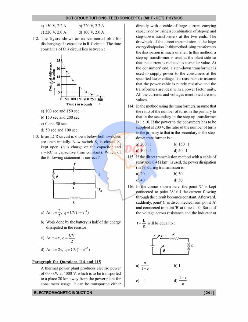
DGT GROUP TUITIONS (FEED CONCEPTS) [MHT - CET] PHYSICS
ELECTROMAGNETIC INDUCTION ( 241 )
a) 150 V, 2.2 A b) 220 V, 2.2 A
c) 220 V, 2.0 A d) 100 V, 2.0 A
112. The figure shows an experimental plot for
discharging of a capacitor in R-C circuit. The time
constant of this circuit lies between :
a) 100 sec and 150 sec
b) 150 sec and 200 sec
c) 0 and 50 sec
d) 50 sec and 100 sec
113. In an LCR circuit is shown below both switches
are open initially. Now switch S1 is closed, S
2
kept open. (q is charge on the capacitor and
= RC is capacitive time constant). Which of
the following statement is correct ?
a) At 1t , q CV(1 e )
2
b) Work done by the battery is half of the energy
dissipated in the resistor
c) At CV
t , q2
d) At 2t 2 , q CV(1 e )
Paragraph for Questions 114 and 115
A thermal power plant produces electric power
of 600 kW at 4000 V, which is to be transported
to a place 20 km away from the power plant for
consumers' usage. It can be transported either
directly with a cable of large current carrying
capacity or by using a combination of step-up and
step-down transformers at the two ends. The
drawback of the direct transmission is the large
energy dissipation. In this method using transformers
the dissipation is much smaller. In this method, a
step-up transformer is used at the plant side so
that the current is reduced to a smaller value. At
the consumers' end, a step-down transformer is
used to supply power to the consumers at the
specified lower voltage. It is reasonable to assume
that the power cable is purely resistive and the
transformers are ideal with a power factor unity.
All the currents and voltages mentioned are rms
values.
114. In the method using the transformers, assume that
the ratio of the number of turns in the primary to
that in the secondary in the step-up transformer
is 1 : 10. If the power to the consumers has to be
supplied at 200 V, the ratio of the number of turns
in the primary to that in the secondary in the step-
down transformer is :
a) 200 : 1 b) 150 : 1
c) 100 : 1 d) 50 : 1
115. If the direct transmission method with a cable of
resistance 0.4 km–1 is used, the power dissipation
(in %) during transmission is :
a) 20 b) 30
c) 40 d) 50
116. In the circuit shown here, the point 'C' is kept
connected to point 'A' till the current flowing
through the circuit becomes constant. Afterward,
suddenly, point' C' is disconnected from point 'A'
and connected to point 'B' at time t = 0. Ratio of
the voltage across resistance and the inductor at
Lt
R will be equal to :
a) e
1 eb) 1
c) – 1 d) 1 e
e
DGT Group - Tuitions (Feed Concepts) XIth – XIIth | JEE | CET | NEET | Call : 9920154035 / 8169861448
DGT MH –CET 12th PHYSICS Study Material 48
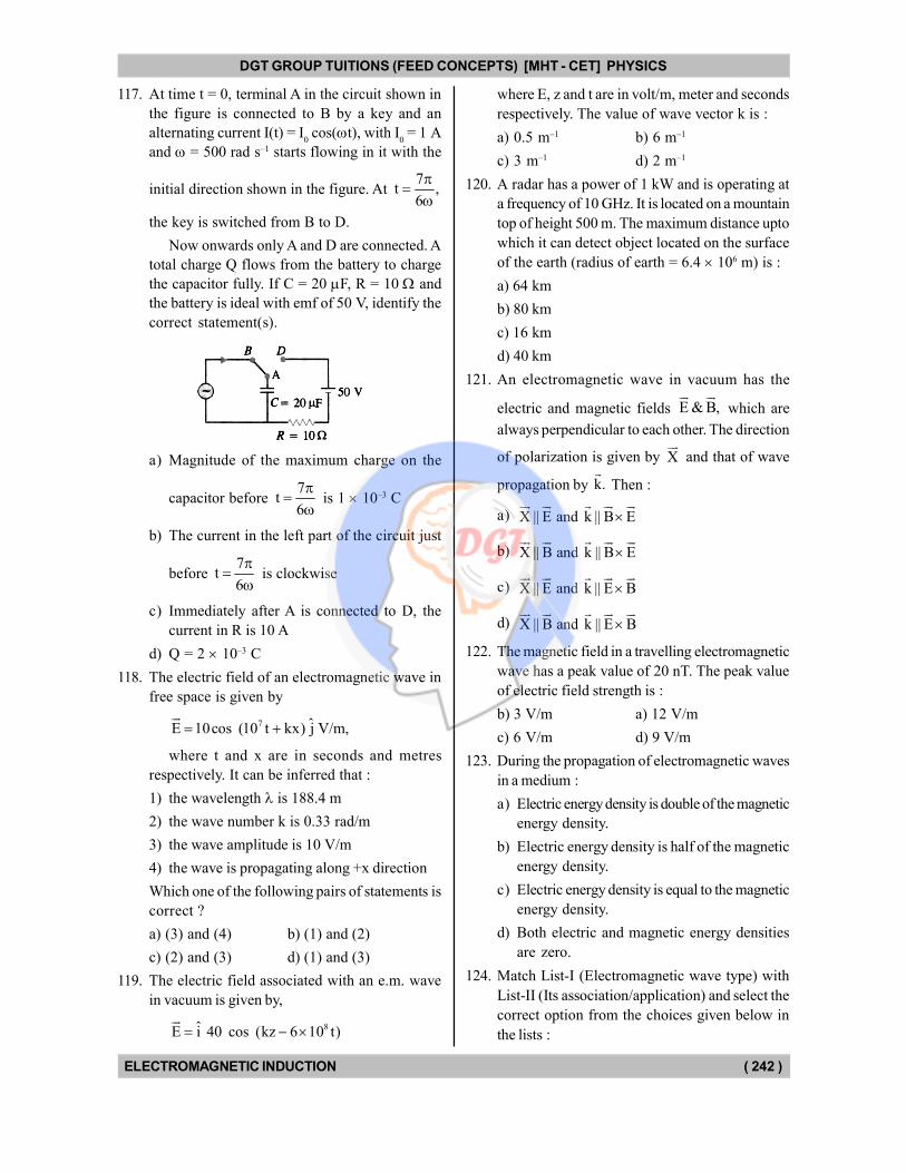
DGT GROUP TUITIONS (FEED CONCEPTS) [MHT - CET] PHYSICS
ELECTROMAGNETIC INDUCTION ( 242 )
117. At time t = 0, terminal A in the circuit shown in
the figure is connected to B by a key and an
alternating current I(t) = I0 cos(t), with I
0 = 1 A
and = 500 rad s–1 starts flowing in it with the
initial direction shown in the figure. At 7
t ,6
the key is switched from B to D.
Now onwards only A and D are connected. A
total charge Q flows from the battery to charge
the capacitor fully. If C = 20 F, R = 10 and
the battery is ideal with emf of 50 V, identify the
correct statement(s).
a) Magnitude of the maximum charge on the
capacitor before 7
t6
is 1 10–3 C
b) The current in the left part of the circuit just
before 7
t6
is clockwise
c) Immediately after A is connected to D, the
current in R is 10 A
d) Q = 2 10–3 C
118. The electric field of an electromagnetic wave in
free space is given by
7 ˆE 10cos (10 t kx) j V/m,
where t and x are in seconds and metres
respectively. It can be inferred that :
1) the wavelength is 188.4 m
2) the wave number k is 0.33 rad/m
3) the wave amplitude is 10 V/m
4) the wave is propagating along +x direction
Which one of the following pairs of statements is
correct ?
a) (3) and (4) b) (1) and (2)
c) (2) and (3) d) (1) and (3)
119. The electric field associated with an e.m. wave
in vacuum is given by,
8ˆE i 40 cos (kz 6 10 t)
where E, z and t are in volt/m, meter and seconds
respectively. The value of wave vector k is :
a) 0.5 m–1 b) 6 m–1
c) 3 m–1 d) 2 m–1
120. A radar has a power of 1 kW and is operating at
a frequency of 10 GHz. It is located on a mountain
top of height 500 m. The maximum distance upto
which it can detect object located on the surface
of the earth (radius of earth = 6.4 106 m) is :
a) 64 km
b) 80 km
c) 16 km
d) 40 km
121. An electromagnetic wave in vacuum has the
electric and magnetic fields E & B,
which are
always perpendicular to each other. The direction
of polarization is given by X
and that of wave
propagation by k.
Then :
a) X || E and k || B E
b) X || B and k || B E
c) X || E and k || E B
d) X || B and k || E B
122. The magnetic field in a travelling electromagnetic
wave has a peak value of 20 nT. The peak value
of electric field strength is :
b) 3 V/m a) 12 V/m
c) 6 V/m d) 9 V/m
123. During the propagation of electromagnetic waves
in a medium :
a) Electric energy density is double of the magnetic
energy density.
b) Electric energy density is half of the magnetic
energy density.
c) Electric energy density is equal to the magnetic
energy density.
d) Both electric and magnetic energy densities
are zero.
124. Match List-I (Electromagnetic wave type) with
List-II (Its association/application) and select the
correct option from the choices given below in
the lists :
DGT Group - Tuitions (Feed Concepts) XIth – XIIth | JEE | CET | NEET | Call : 9920154035 / 8169861448
DGT MH –CET 12th PHYSICS Study Material 49
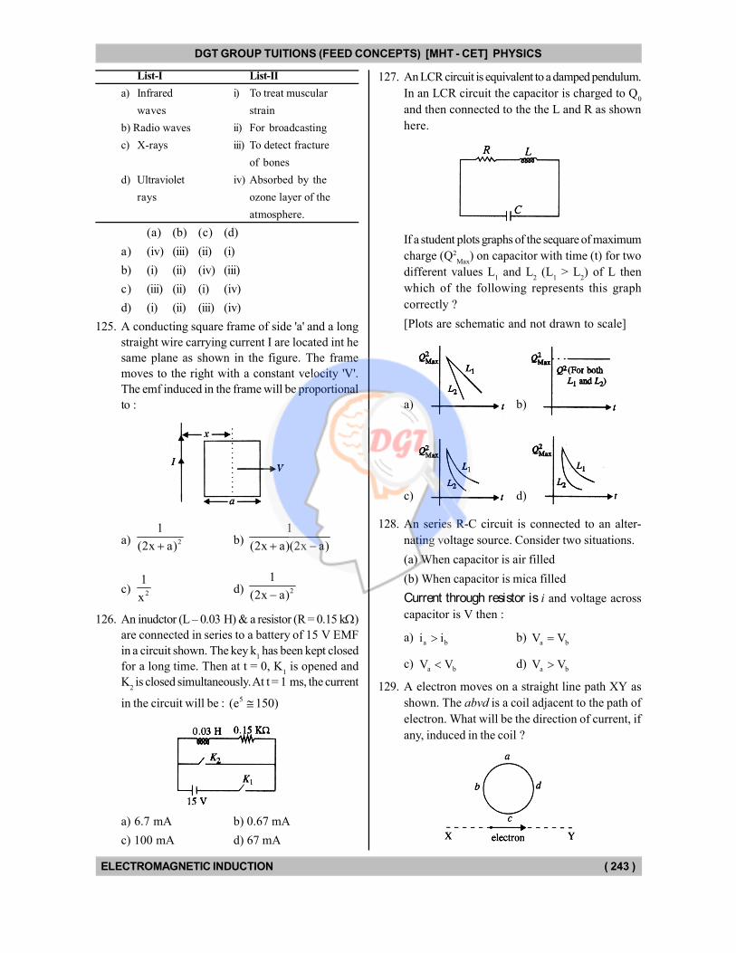
DGT GROUP TUITIONS (FEED CONCEPTS) [MHT - CET] PHYSICS
ELECTROMAGNETIC INDUCTION ( 243 )
List-I List-II
a) Infrared i) To treat muscular
waves strain
b) Radio waves ii) For broadcasting
c) X-rays iii) To detect fracture
of bones
d) Ultraviolet iv) Absorbed by the
rays ozone layer of the
atmosphere.
(a) (b) (c) (d)
a) (iv) (iii) (ii) (i)
b) (i) (ii) (iv) (iii)
c) (iii) (ii) (i) (iv)
d) (i) (ii) (iii) (iv)
125. A conducting square frame of side 'a' and a long
straight wire carrying current I are located int he
same plane as shown in the figure. The frame
moves to the right with a constant velocity 'V'.
The emf induced in the frame will be proportional
to :
a) 2
1
(2x a) b) 1
(2x a)(2x a)
c) 2
1
xd) 2
1
(2x a)
126. An inudctor (L – 0.03 H) & a resistor (R = 0.15 k)
are connected in series to a battery of 15 V EMF
in a circuit shown. The key k1 has been kept closed
for a long time. Then at t = 0, K1 is opened and
K2 is closed simultaneously. At t = 1 ms, the current
in the circuit will be : 5(e 150)
a) 6.7 mA b) 0.67 mA
c) 100 mA d) 67 mA
127. An LCR circuit is equivalent to a damped pendulum.
In an LCR circuit the capacitor is charged to Q0
and then connected to the the L and R as shown
here.
If a student plots graphs of the sequare of maximum
charge (Q2
Max) on capacitor with time (t) for two
different values L1 and L
2 (L
1 > L
2) of L then
which of the following represents this graph
correctly ?
[Plots are schematic and not drawn to scale]
a) b)
c) d)
128. An series R-C circuit is connected to an alter-
nating voltage source. Consider two situations.
(a) When capacitor is air filled
(b) When capacitor is mica filled
Current through resistor is i and voltage across
capacitor is V then :
a) a bi i b)
a bV V
c) a bV V d)
a bV V
129. A electron moves on a straight line path XY as
shown. The abvd is a coil adjacent to the path of
electron. What will be the direction of current, if
any, induced in the coil ?
DGT Group - Tuitions (Feed Concepts) XIth – XIIth | JEE | CET | NEET | Call : 9920154035 / 8169861448
DGT MH –CET 12th PHYSICS Study Material 50
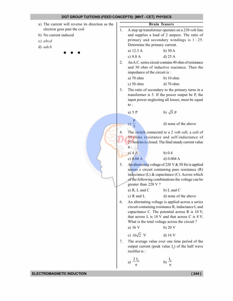
DGT GROUP TUITIONS (FEED CONCEPTS) [MHT - CET] PHYSICS
ELECTROMAGNETIC INDUCTION ( 244 )
a) The current will reverse its direction as the
electron goes past the coil
b) No current induced
c) abcd
d) adcb
Brain Teasers
1. A step up transformer operates on a 230 volt line
and supplies a load of 2 ampere. The ratio of
primary and secondary windings is 1 : 25.
Determine the primary current.
a) 12.5 A b) 50 A
c) 8.8 A d) 25 A
2. An A.C. series circuit contains 40 ohm of resistance
and 30 ohm of inductive reactance. Then the
impedance of the circuit is :
a) 70 ohm b) 10 ohm
c) 50 ohm d) 70 ohm
3. The ratio of secondary to the primary turns in a
transformer is 5. If the power output be P, the
input power neglecting all losses, must be equal
to :
a) 5 P b) 5 P
c) P
5d) none of the above
4. The switch connected to a 2 volt cell, a coil of
50 ohms resistance and self-inductance of
25 henries is closed. The final steady current value
is :
a) 4 A b) 0.4
c) 0.04 A d) 0.004 A
5. An alternating voltage of 220 V & 50 Hz is applied
across a circuit containing pure resistance (R)
inductance (L) & capacitance (C). Across which
of the following combinations the voltage can be
greater than 220 V ?
a) R, L and C b) L and C
c) R and L d) none of the above
6. An alternating voltage is applied across a series
circuit containing resistance R, inductance L and
capacitance C. The potential across R is 10 V,
that across L is 18 V and that across C is 8 V.
What is the total voltage across the circuit ?
a) 36 V b) 20 V
c) 10 2 V d) 16 V
7. The average value over one time period of the
output current (peak value I0) of the half wave
rectifier is :
a) 02 I
b)
0I
DGT Group - Tuitions (Feed Concepts) XIth – XIIth | JEE | CET | NEET | Call : 9920154035 / 8169861448
DGT MH –CET 12th PHYSICS Study Material 51
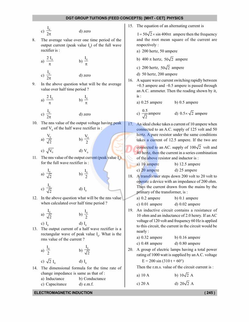
DGT GROUP TUITIONS (FEED CONCEPTS) [MHT - CET] PHYSICS
ELECTROMAGNETIC INDUCTION ( 245 )
c) 0I
2d) zero
8. The average value over one time period of the
output current (peak value I0) of the full wave
rectifier is :
a) 02 I
b)
0I
c) 0I
2d) zero
9. In the above question what will be the average
value over half time period ?
a) 02 I
b)
0I
c) 0I
2d) zero
10. The nns value of the output voltage having peak
emf V0 of the half wave rectifier is :
a) 0V
2b)
0V
2
c) 0V d) V
0
11. The nns value of the output current (peak value I0)
for the full wave rectifier is :
a) 0I
2b)
0I
2
c) 0I
2d) I
0
12. In the above question what will be the nns value
when calculated over half time period ?
a) 0I
2b)
0I
2
c) I0
d) I0
13. The output current of a half wave rectifier is a
rectangular wave of peak value I0. What is the
rms value of the current ?
a) 0I
2b)
0I
2
c) 02 I d) I
0
14. The dimensional formula for the time rate of
change impedance is same as that of :
a) Inductance b) Conductance
c) Capacitance d) e.m.f.
15. The equation of an alternating current is
I 50 2 sin 400 t ampere then the frequency
and the root mean square of the current are
respectively :
a) 200 hertz, 50 ampere
b) 400 hertz, 50 2 ampere
c) 200 hertz, 50 2 ampere
d) 50 hertz, 200 ampere
16. A square wave current switching rapidly between
+0.5 ampere and –0.5 ampere is passed through
an A.C. ammeter. Then the reading shown by it,
is :
a) 0.25 ampere b) 0.5 ampere
c) 0.5
ampere2
d) 0.5 2 ampere
17. An ideal choke takes a current of 10 ampere when
connected to an A.C. supply of 125 volt and 50
hertz. A pure resistor under the same conditions
takes a current of 12.5 ampere. If the two are
connected to an AC. supply of 100 2 volt and
40 hertz, then the current in a series combination
of the above resistor and inductor is :
a) 10 ampere b) 12.5 ampere
c) 20 ampere d) 25 ampere
18. A transformer steps down 200 volt to 20 volt to
operate a device with an impedance of 200 ohm.
Then the current drawn from the mains by the
primary of the transformer, is :
a) 0.2 ampere b) 0.1 ampere
c) 0.01 ampere d) 0.02 ampere
19. An inductive circuit contains a resistance of
10 ohm and an inductance of 2.0 henry. If an AC
voltage of 120 volt and frequency 60 Hz is applied
to this circuit, the current in the circuit would be
nearly :
a) 0.32 ampere b) 0.16 ampere
c) 0.48 ampere d) 0.80 ampere
20. A group of electric lamps having a total power
rating of 1000 watt is supplied by an A.C. voltage
E = 200 sin (310 t + 60°)
Then the r.m.s. value of the circuit current is :
a) 10 A b) 10 2 A
c) 20 A d) 20 2 A
DGT Group - Tuitions (Feed Concepts) XIth – XIIth | JEE | CET | NEET | Call : 9920154035 / 8169861448
DGT MH –CET 12th PHYSICS Study Material 52
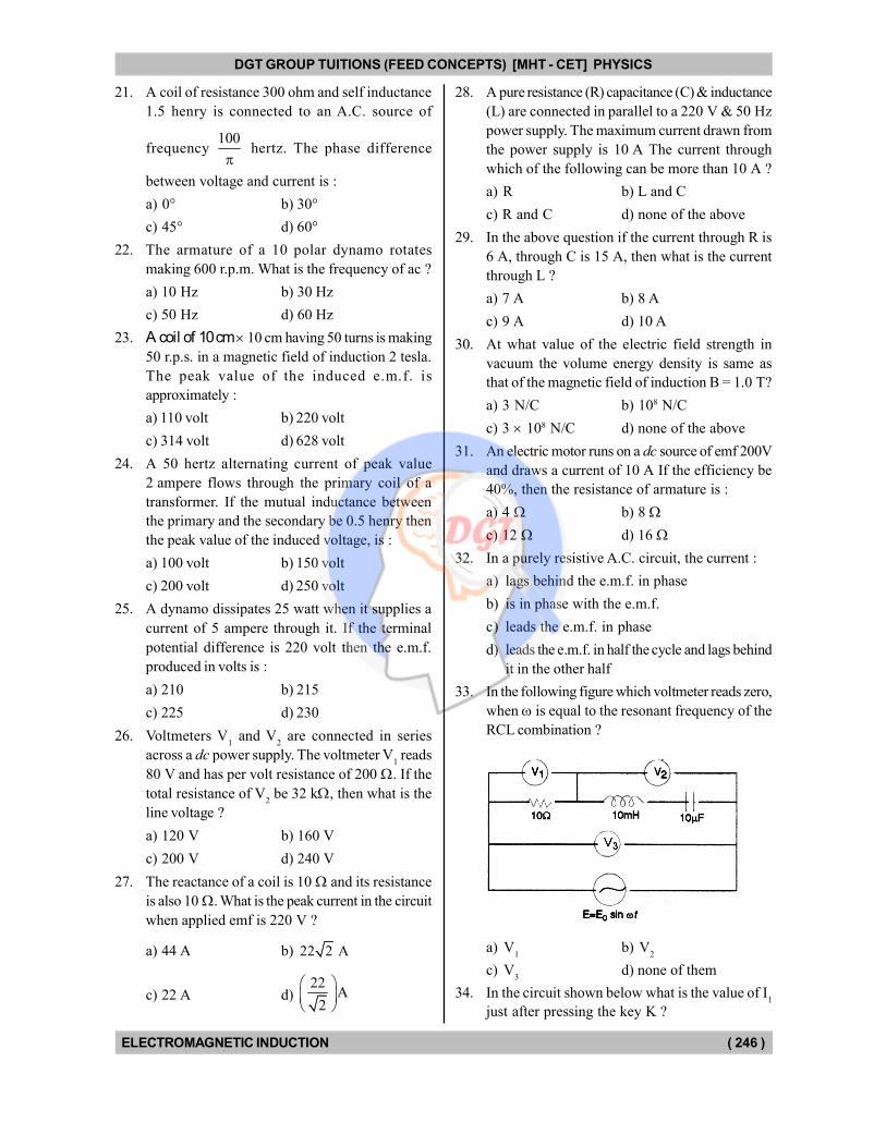
DGT GROUP TUITIONS (FEED CONCEPTS) [MHT - CET] PHYSICS
ELECTROMAGNETIC INDUCTION ( 246 )
21. A coil of resistance 300 ohm and self inductance
1.5 henry is connected to an A.C. source of
frequency 100
hertz. The phase difference
between voltage and current is :
a) 0° b) 30°
c) 45° d) 60°
22. The armature of a 10 polar dynamo rotates
making 600 r.p.m. What is the frequency of ac ?
a) 10 Hz b) 30 Hz
c) 50 Hz d) 60 Hz
23. A coil of 10 cm 10 cm having 50 turns is making
50 r.p.s. in a magnetic field of induction 2 tesla.
The peak value of the induced e.m.f. is
approximately :
a) 110 volt b) 220 volt
c) 314 volt d) 628 volt
24. A 50 hertz alternating current of peak value
2 ampere flows through the primary coil of a
transformer. If the mutual inductance between
the primary and the secondary be 0.5 henry then
the peak value of the induced voltage, is :
a) 100 volt b) 150 volt
c) 200 volt d) 250 volt
25. A dynamo dissipates 25 watt when it supplies a
current of 5 ampere through it. If the terminal
potential difference is 220 volt then the e.m.f.
produced in volts is :
a) 210 b) 215
c) 225 d) 230
26. Voltmeters V1 and V
2 are connected in series
across a dc power supply. The voltmeter V1 reads
80 V and has per volt resistance of 200 . If the
total resistance of V2 be 32 k, then what is the
line voltage ?
a) 120 V b) 160 V
c) 200 V d) 240 V
27. The reactance of a coil is 10 and its resistance
is also 10 . What is the peak current in the circuit
when applied emf is 220 V ?
a) 44 A b) 22 2 A
c) 22 A d) 22
A2
28. A pure resistance (R) capacitance (C) & inductance
(L) are connected in parallel to a 220 V & 50 Hz
power supply. The maximum current drawn from
the power supply is 10 A The current through
which of the following can be more than 10 A ?
a) R b) L and C
c) R and C d) none of the above
29. In the above question if the current through R is
6 A, through C is 15 A, then what is the current
through L ?
a) 7 A b) 8 A
c) 9 A d) 10 A
30. At what value of the electric field strength in
vacuum the volume energy density is same as
that of the magnetic field of induction B = 1.0 T?
a) 3 N/C b) 108 N/C
c) 3 108 N/C d) none of the above
31. An electric motor runs on a dc source of emf 200V
and draws a current of 10 A If the efficiency be
40%, then the resistance of armature is :
a) 4 b) 8
c) 12 d) 16
32. In a purely resistive A.C. circuit, the current :
a) lags behind the e.m.f. in phase
b) is in phase with the e.m.f.
c) leads the e.m.f. in phase
d) leads the e.m.f. in half the cycle and lags behind
it in the other half
33. In the following figure which voltmeter reads zero,
when is equal to the resonant frequency of the
RCL combination ?
a) V1
b) V2
c) V3
d) none of them
34. In the circuit shown below what is the value of I1
just after pressing the key K ?
DGT Group - Tuitions (Feed Concepts) XIth – XIIth | JEE | CET | NEET | Call : 9920154035 / 8169861448
DGT MH –CET 12th PHYSICS Study Material 53
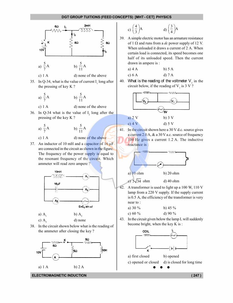
DGT GROUP TUITIONS (FEED CONCEPTS) [MHT - CET] PHYSICS
ELECTROMAGNETIC INDUCTION ( 247 )
a) 5
A7
b) 5
A11
c) 1 A d) none of the above
35. In Q-34, what is the value of current I1 long after
the pressing of key K ?
a) 5
A7
b) 5
A11
c) 1 A d) none of the above
36. In Q-34 what is the value of I2 long after the
pressing of the key K ?
a) 5
A7
b) 5
A11
c) 1 A d) none of the above
37. An inductor of 10 mH and a capacitor of 16 F
are connected in the circuit as shown in the figure.
The frequency of the power supply is equal to
the resonant frequency of the circuit. Which
ammeter will read zero ampere ?
a) A1
b) A2
c) A3
d) none
38. In the circuit shown below what is the reading of
the ammeter after closing the key ?
a) 1 A b) 2 A
c) 4
A3
d) 3
A4
39. A simple electric motor has an armature resistance
of 1 and runs from a dc power supply of 12 V.
When unloaded it draws a current of 2 A. When
certain load is connected, its speed becomes one
half of its unloaded speed. Then the current
drawn in ampere is :
a) 4 A b) 5 A
c) 6 A d) 7 A
40. What is the reading of the voltmeter V2 in the
circuit below, if the reading of V1 is 3 V ?
a) 2 V b) 3 V
c) 4 V d) 5 V
41. In the circuit shown here a 30 V d.c. source gives
a current 2.0 A, & a 30 V a.c. source of frequency
100 Hz gives a current 1.2 A. The inductive
reactance is :
a) 10 ohm b) 20 ohm
c) 5 34 ohm d) 40 ohm
42. A transformer is used to light up a 100 W, 110 V
lamp from a 220 V supply. If the supply current
is 0.5 A, the efficiency of the transformer is very
near to :
a) 30 % b) 45 %
c) 60 % d) 90 %
43. In the circuit given below the lamp L will suddenly
become bright, when the key K is :
a) first closed b) opened
c) opened or closed d) is closed for long time
DGT Group - Tuitions (Feed Concepts) XIth – XIIth | JEE | CET | NEET | Call : 9920154035 / 8169861448
DGT MH –CET 12th PHYSICS Study Material 54
DINESH [MHT - CET] PHYSICS
ELECTROMAGNETIC INDUCTION ( 248 )
Answer Key
MH Text Book Based MCQ's
01. (a)
02. (d)
03. (d)
04. (a)
05. (a)
06. (c)
07. (c)
08. (c)
09. (d)
10. (b)
11. (b)
12. (c)
13. (c)
14. (a)
15. (d)
16. (c)
17. (a)
18. (c)
19. (a)
20. (b)
21. (a)
22. (b)
23. (c)
24. (b)
25. (c)
26. (b)
27. (c)
28. (d)
29. (d)
30. (b)
31. (b)
32. (c)
33. (c)
34. (d)
35. (c)
36. (a)
37. (d)
38. (b)
39. (a)
40. (c)
41. (c)
42. (d)
43. (c)
44. (a)
45. (c)
46. (a)
47. (b)
48. (b)
49. (c)
50. (d)
51. (d)
52. (b)
53. (a)
54. (b)
55. (c)
56. (d)
57. (c)
58. (a)
59. (d)
60. (d)
61. (d)
62. (d)
63. (b)
64. (c)
65. (c)
66. (c)
67. (c)
68. (a)
69. (c)
70. (c)
71. (b)
72. (d)
73. (c)
74. (b)
75. (c)
76. (c)
77. (d)
78. (c)
79. (d)
80. (c)
81. (b)
82. (b)
83. (d)
84. (b)
85. (a)
86. (d)
87. (a)
88. (b)
89. (a)
90. (b)
91. (c)
92. (b)
93. (c)
94. (a)
95. (d)
96. (c)
97. (b)
98. (d)
99. (a)
100. (c)
101. (c)
102. (d)
103. (a)
104. (c)
105. (b)
106. (c)
107. (c)
108. (b)
109. (c)
110. (d)
111. (c)
112. (d)
113. (c)
114. (b)
115. (b)
116. (c)
117. (a)
118. (d)
119. (b)
120. (c)
121. (a)
122. (c)
123. (b)
124. (c)
125. (d)
126. (d)
127. (c)
128. (c)
129. (c)
130. (d)
131. (a)
132. (d)
133. (d)
134. (c)
135. (c)
136. (a)
137. (c)
138. (d)
139. (b)
140. (b)
141. (c)
142. (a)
143. (d)
144. (c)
145. (a)
146. (c)
147. (c)
148. (a)
149. (d)
150. (b)
151. (a)
152. (a)
153. (d)
154. (d)
155. (a)
156. (c)
157. (d)
158. (c)
159. (a)
160. (b)
161. (d)
162. (c)
163. (a)
164. (b)
165. (c)
166. (a)
167. (a)
168. (d)
169. (a)
170. (c)
171. (a)
172. (c)
173. (d)
174. (a)
175. (d)
176. (d)
177. (a)
178. (c)
179. (d)
180. (b)
181. (b)
182. (c)
183. (c)
184. (d)
185. (b)
186. (b)
187. (d)
188. (b)
189. (a)
190. (b)
191. (b)
192. (d)
193. (d)
194. (b)
195. (b)
196. (a)
197. (d)
198. (b)
199. (c)
200. (d)
201. (c)
202. (d)
203. (a)
204. (d)
205. (c)
206. (a)
207. (c)
208. (d)
209. (a)
210. (c)
211. (b)
212. (b)
213. (c)
214. (c)
215. (a)
216. (d)
217. (d)
218. (a)
219. (b)
220. (c)
221. (b)
222. (c)
223. (c)
224. (b)
225. (b)
226. (c)
227. (a)
228. (a)
229. (d)
230. (a)
231. (a)
232. (a)
233. (c)
234. (c)
235. (b)
236. (c)
237. (a)
238. (a)
239. (b)
240. (c)
241. (a)
242. (a)
243. (d)
244. (c)
245. (c)
246. (c)
247. (d)
248. (a)
249. (c)
250. (b)
251. (b)
252. (c)
253. (a)
254. (c)
255. (d)
256. (c)
257. (d)
258. (d)
259. (d)
260. (a)
DGT Group - Tuitions (Feed Concepts) XIth – XIIth | JEE | CET | NEET | Call : 9920154035 / 8169861448
DGT MH –CET 12th PHYSICS Study Material 55
DINESH [MHT - CET] PHYSICS
ELECTROMAGNETIC INDUCTION ( 249 )
Answer Key
REVISION QUESTIONS from Competitive Exams.
01. (a)
02. (a)
03. (a)
04. (c)
05. (a)
06. (b)
07. (b)
08. (a)
09. (c)
10. (b)
11. (c)
12. (c)
13. (a)
14. (a)
15. (a)
16. (d)
17. (d)
18. (c)
19. (a)
20. (b)
21. (b)
22. (c)
23. (c)
24. (d)
25. (b)
26. (c)
27. (c)
28. (c)
29. (a)
30. (a)
31. (a)
32. (b)
33. (c)
34. (b)
35. (d)
36. (a)
37. (c)
38. (b)
39. (d)
40. (c)
41. (d)
42. (c)
43. (c)
44. (c)
45. (c)
46. (c)
47. (b)
48. (d)
49. (a)
50. (c)
51. (a)
52. (c)
53. (d)
54. (a)
55. (a)
56. (c)
57. (b)
58. (d)
59. (a)
60. (c)
61. (a)
62. (c)
63. (b)
64. (a)
65. (a)
66. (d)
67. (c)
68. (a)
69. (c)
70. (a)
71. (c)
72. (a)
73. (d)
74. (a)
75. (b)
76. (c)
77. (a)
78. (a)
79. (a)
80. (b)
81. (b)
82. (b)
83. (a)
84. (c)
85. (a)
86. (a)
87. (d)
88. (c)
89. (b)
90. (b)
91. (b)
92. (c)
93. (b)
94. (a)
95. (b)
96. (b)
97. (d)
98. (c)
99. (d)
100. (b)
101. (b)
102. (c)
103. (d)
104. (a)
105. (a)
106. (b)
107. (b)
108. (a)
109. (b)
110. (c)
111. (b)
112. (a)
113. (d)
114. (a)
115. (b)
116. (c)
117. (c,d)
118. (d)
119. (d)
120. (b)
121. (c)
122. (c)
123. (c)
124. (d)
125. (b)
126. (b)
127. (c)
128. (d)
129. (a)
BRAIN TEASERS
01. (b)
02. (c)
03. (d)
04. (c)
05. (c)
06. (c)
07. (b)
08. (a)
09. (a)
10. (b)
11. (a)
12. (a)
13. (d)
14. (c)
15. (a)
16. (b)
17. (a)
18. (c)
19. (b)
20. (b)
21. (c)
22. (c)
23. (c)
24. (c)
25. (c)
26. (d)
27. (c)
28. (c)
29. (a)
30. (c)
31. (c)
32. (b)
33. (b)
34. (a)
35. (c)
36. (d)
37. (c)
38. (a)
39. (d)
40. (c)
41. (b)
42. (d)
43. (b)
DGT Group - Tuitions (Feed Concepts) XIth – XIIth | JEE | CET | NEET | Call : 9920154035 / 8169861448
DGT MH –CET 12th PHYSICS Study Material 56

DGT Group - Tuitions (Feed Concepts) XIth – XIIth | JEE | CET | NEET | Call : 9920154035 / 8169861448
DGT MH –CET 12th PHYSICS Study Material 57
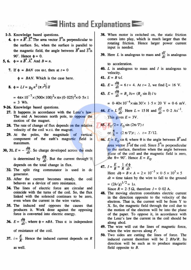
DGT Group - Tuitions (Feed Concepts) XIth – XIIth | JEE | CET | NEET | Call : 9920154035 / 8169861448
Hints & Solutions 58
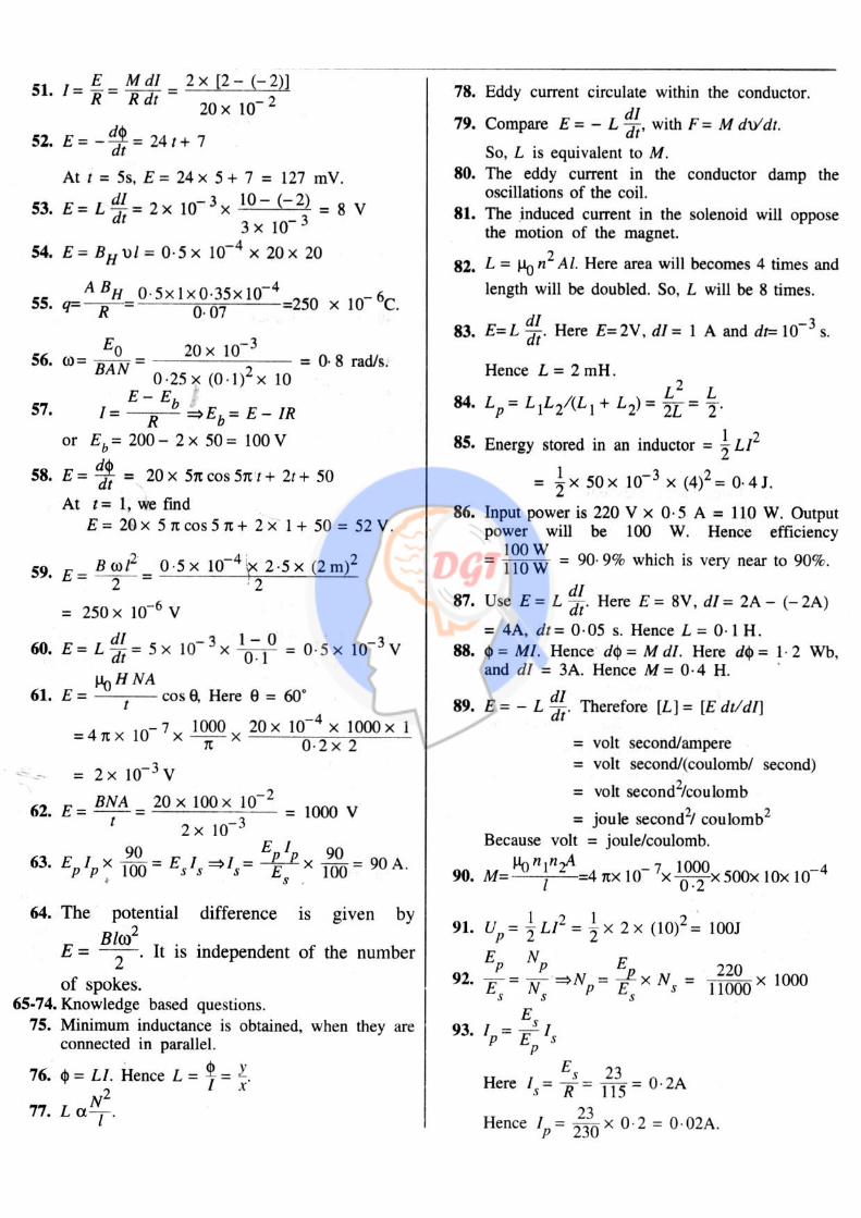
DGT Group - Tuitions (Feed Concepts) XIth – XIIth | JEE | CET | NEET | Call : 9920154035 / 8169861448
Hints & Solutions 59
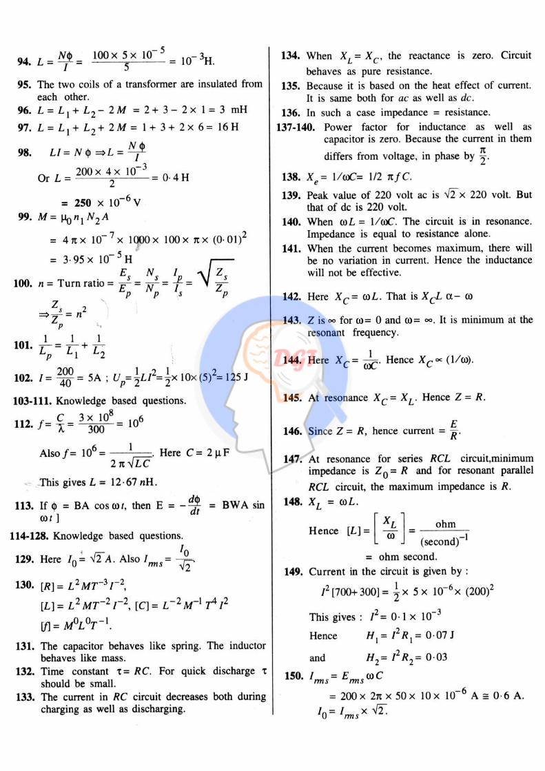
DGT Group - Tuitions (Feed Concepts) XIth – XIIth | JEE | CET | NEET | Call : 9920154035 / 8169861448
Hints & Solutions 60
DGT Group - Tuitions (Feed Concepts) XIth – XIIth | JEE | CET | NEET | Call : 9920154035 / 8169861448
Hints & Solutions 61
DGT Group - Tuitions (Feed Concepts) XIth – XIIth | JEE | CET | NEET | Call : 9920154035 / 8169861448
Hints & Solutions 62
DGT Group - Tuitions (Feed Concepts) XIth – XIIth | JEE | CET | NEET | Call : 9920154035 / 8169861448
Hints & Solutions 63
DGT Group - Tuitions (Feed Concepts) XIth – XIIth | JEE | CET | NEET | Call : 9920154035 / 8169861448
Hints & Solutions 64
DGT Group - Tuitions (Feed Concepts) XIth – XIIth | JEE | CET | NEET | Call : 9920154035 / 8169861448
Hints & Solutions 65
DGT Group - Tuitions (Feed Concepts) XIth – XIIth | JEE | CET | NEET | Call : 9920154035 / 8169861448
Hints & Solutions 66
DGT Group - Tuitions (Feed Concepts) XIth – XIIth | JEE | CET | NEET | Call : 9920154035 / 8169861448
Hints & Solutions 67
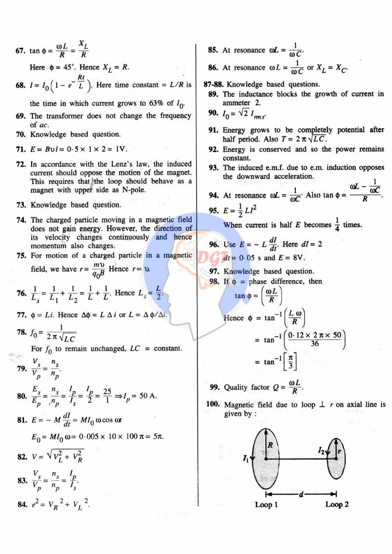
DGT Group - Tuitions (Feed Concepts) XIth – XIIth | JEE | CET | NEET | Call : 9920154035 / 8169861448
Hints & Solutions 68
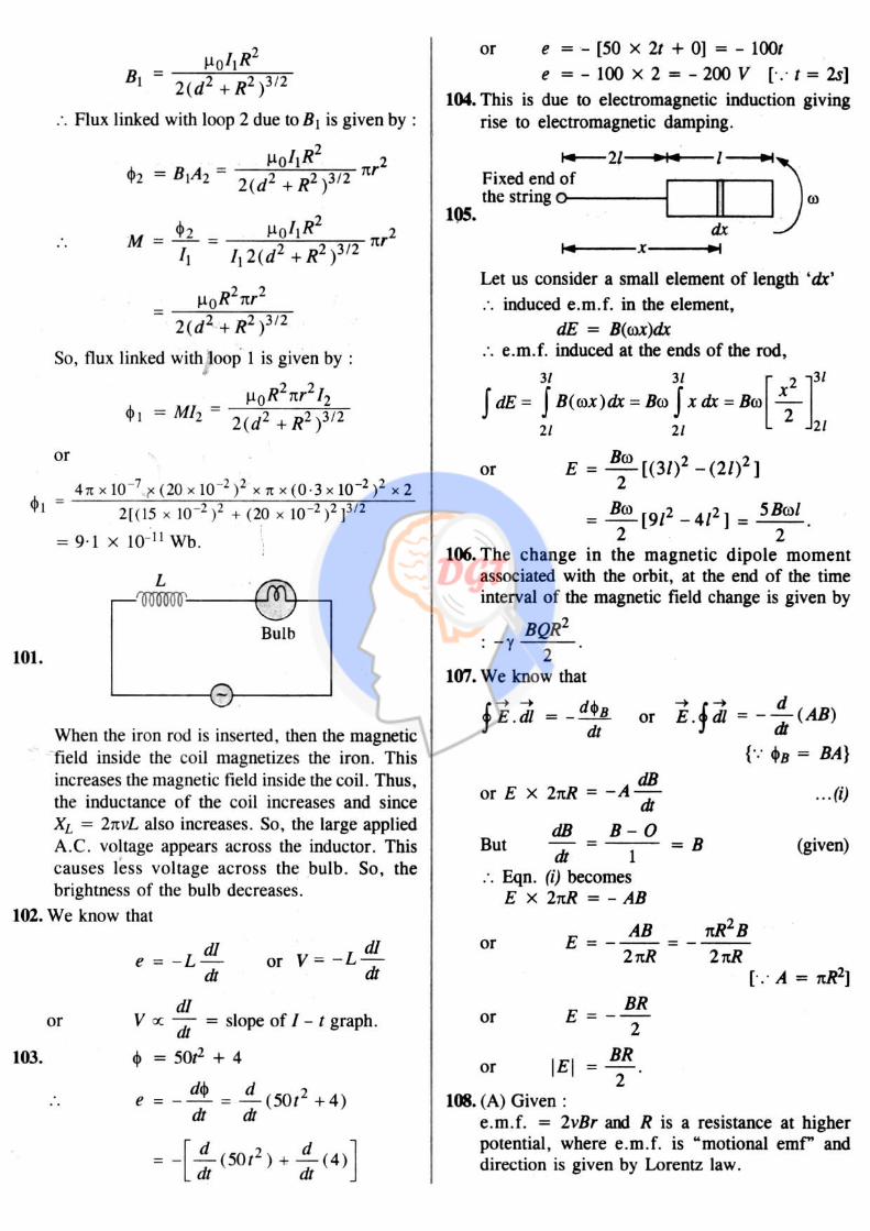
DGT Group - Tuitions (Feed Concepts) XIth – XIIth | JEE | CET | NEET | Call : 9920154035 / 8169861448
Hints & Solutions 69
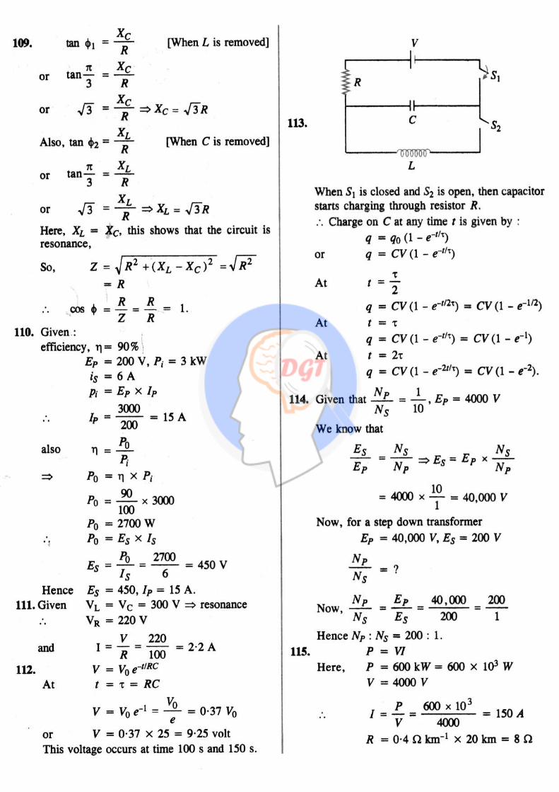
DGT Group - Tuitions (Feed Concepts) XIth – XIIth | JEE | CET | NEET | Call : 9920154035 / 8169861448
Hints & Solutions 70
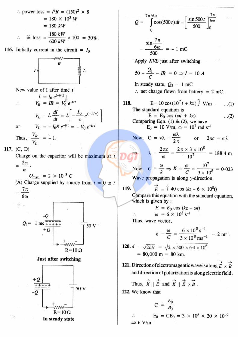
DGT Group - Tuitions (Feed Concepts) XIth – XIIth | JEE | CET | NEET | Call : 9920154035 / 8169861448
Hints & Solutions 71
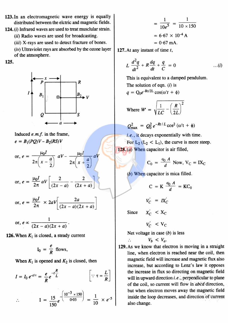
DGT Group - Tuitions (Feed Concepts) XIth – XIIth | JEE | CET | NEET | Call : 9920154035 / 8169861448
Hints & Solutions 72
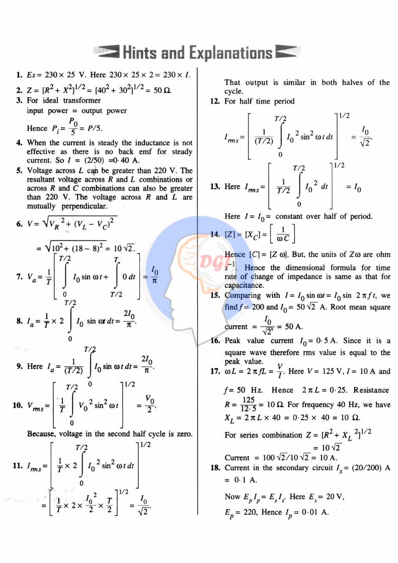
DGT Group - Tuitions (Feed Concepts) XIth – XIIth | JEE | CET | NEET | Call : 9920154035 / 8169861448
Hints & Solutions 73
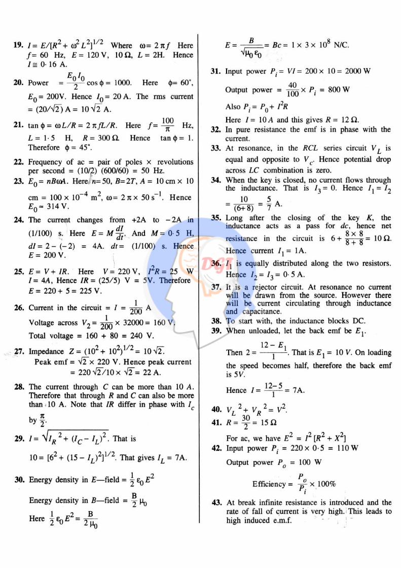
DGT Group - Tuitions (Feed Concepts) XIth – XIIth | JEE | CET | NEET | Call : 9920154035 / 8169861448
Hints & Solutions 74


