Embed Size (px)
Citation preview

·············································································
·······································
Sta
nd
ard
AC
Mo
tors
In
trod
uctio
n
Ind
uctio
nM
oto
rs
Revers
ible
M
oto
rs
Ele
ctro
m
ag
ne
tic
Bra
ke
Mo
tors
V
Serie
s
Clu
tch
&
Bra
ke
Mo
tors
Sy
nch
ron
ou
s
Mo
tors
L
ow
-Sp
ee
d
Sy
nch
ron
ou
s
Mo
tors
Watertig
ht,
Du
st-Resistan
t M
oto
rs
To
rqu
e
Mo
tors
R
igh
t-An
gle
Gearh
ead
s
Lin
ear
Head
s
Bra
ke P
ack
Accesso
ries
Insta
llatio
n
Page
Features and Types of Electromagnetic Brake Motors A-110 General Specifications A-115 World K Series [6 W∼90 W (1/125 HP∼1/8 HP)] A-116 BH Series [200 W (1/4 HP)] A-143
Standard AC Motors
Constant Speed Motors
Electromagnetic Brake Motors
Electromagnetic
Brake Motors
A-109

Sta
nd
ard
AC
Mo
tors
6 W
(1/1
25 H
P)
15 W
(1
/50 H
P)
25 W
(1/3
0 H
P)
40 W
(1/1
9 H
P)
60 W
(1/1
2 H
P)
90 W
(1/8
HP
) 20
0 W
(1
/4 H
P)
Features and Types of Electromagnetic Brake Motors
■Features of Electromagnetic Brake Motors ●Power Off Activated Type Electromagnetic Brake
Equipped An AC power off activated type electromagnetic brake is equipped
to allow the motor to stop instantaneously when the power is cut off,
while still holding the load in position.
●Ideal for Applications Required Load Holding This configuration is ideal for vertical applications in which the load
must be held.
■Types of Electromagnetic Brake Motors
●Extensive Lineup The World K Series and BH Series are available.
We have models with an output power range of 6 W (1/125 HP) to
200 W (1/4 HP), so that you can find one that meets your specific
application.
●Compatible with Gearheads or Linear Heads Combination with a gearhead allows the motor to reduce to a
required speed or generate higher torque.
Combination with a linear head allows the motor to convert rotation
to linear motion with great ease.
● RoHS-Compliant The World K Series and BH Series conform to the RoHS Directive
that prohibits the use of six chemical substances including lead and
cadmium.
Series Features, Lineup
World K Series
BH Series
●Conforms to Safety Standards All World K Series models have a built-in overheat protection device and conform to major safety standards.
● Applicable Standards UL/CSA Standards Certified under the China Compulsory Certification System (CCC System) CE Marking (Low Voltage Directive)
● Motor Overheat Protection Device Thermal protector, Impedance protected
●Global Voltage Specifications The World K Series supports the power supply voltages used in major countries. Motors meeting the local voltage standard are readily available in major countries in Europe, Asia and North America.
●The Motor Bearing Life is Twice as Long as a Conventional Type
A motor's life is determined by its bearing. We adopted high-performance bearing grease to lubricate this important component. As a result, the bearings of World K Series motors last twice as long as conventional bearings.
●Protective Earth Terminal on the Motor
Protective Earth Terminal
●Lineup
●Smallest Frame Size among 200 W (1/4 HP) Motors
These motors achieve a high output of 200 W (1/4 HP) with a frame size of 104 mm (4.09 in.).
●Hypoid Gear-Employed Right Angle Type is Available.
●“Combination Type” for Easy Installation With each combination type, the motor and gearhead come pre-assembled for easy installation into your equipment.
●Conforms to Safety Standards and Global Voltage Specifications
●Lineup Frame Size Output Power
Type
Voltage
□60 mm (□2.36 in.)∼□90 mm (□3.54 in.)
6 W∼90 W (1/125 HP∼1/8 HP)
Single-Phase 110/115 VAC Single-Phase 220/230 VAC Three-Phase 200/220/230 VAC
Frame Size Output Power
Voltage
□104 mm (□4.09 in.)
200 W (1/4 HP)
Right-Angle, Hollow Shaft Type,Right-Angle, Solid Shaft Type, Parallel Shaft Type, Round Shaft Type
Single-Phase 110/115 VAC Single-Phase 220/230 VAC Three-Phase 200/220/230 VAC
A-110 ORIENTAL MOTOR GENERAL CATALOG 2009/2010

■Features of Gearheads and Linear HeadsMotor ●Gearheads: Easy Speed Reduction and Torque Increase Pinion Shaft
Sta
nd
ard
AC
Mo
tors
In
trod
uctio
n
Ind
uctio
nM
oto
rs
Revers
ible
M
oto
rs
Ele
ctro
m
ag
ne
tic
Bra
ke
Mo
tors
V
Serie
s
Clu
tch
&
Bra
ke
Mo
tors
Sy
nch
ron
ou
s
Mo
tors
L
ow
-Sp
ee
d
Sy
nch
ron
ou
s
Mo
tors
Watertig
ht,
Du
st-Resistan
t M
oto
rs
To
rqu
e
Mo
tors
R
igh
t-An
gle
Gearh
ead
s
Lin
ear
Head
s
Bra
ke P
ack
Accesso
ries
Insta
llatio
n
Gearhead
Motor
Combination with a gearhead allows the motor to reduce to a
required speed or generate higher torque. Gearheads come in
various types including the long life, low noise gearhead and right
angle gearhead.
●Linear Heads: Convert Motor Rotation to Linear Motion Combination with a linear head allows the motor to convert rotation
Linear Head
to linear motion with great ease. Linear heads are available with a
square sectioned rack.
● RoHS-Compliant Gearheads and linear heads conform to the RoHS Directive that
prohibits the use of six chemical substances including lead and
cadmium.
Combine gearheads and linear heads with a pinion shaft type motor. ● Gearheads and linear heads are sold separately. ● BH Series comes with the gearhead pre-assembled.
■Types of Gearheads and Linear Heads Types Features
Long Life, Low Noise ●Long Rated Life of 10000 Hours GN-S Gearhead The GN-S gearhead achieves a long rated life of
10000 hours, twice the level of a conventional gearhead, by adopting a large, specially designed bearing and reinforced gears.
●Low Noise Design 30
5
0 25.0 40 63 100 160 250 400 630 1K 1.6K 2.5K 4K 6.3K 10K 16K
■: Long Life, Low Noise GN-S Gearhead 4IK25GN-AW2J/4GN120S
■: GN-K Gearhead (Conventional Model) 4IK25GN-A/4GN120K
[Measurement conditions] Load: 1.2 N•m Direction: Clockwise Measurement distance: 1 m (Measured in A-weighted sound pressure level)
31.5 50 80 125 200 315 500 800 1.25K 2K 3.15K 5K 8K 12.5K 20K
Frequency [Hz]
The GN-S gearhead generates less noise thanks to gears with a special shape and surface machining assembled with the use of advanced technology.
●Applicable Products 6 W (1/125 HP), 15 W (1/50 HP), 25 W (1/30 HP) or 40 W
Soun
d Pr
essu
re L
evel
[dB(
A)] 25
20
15
10 (1/19 HP) GN pinion motor
Long Life GE-S Gearhead
Right-Angle Gearhead ➜ Page A-239
Rack-and-Pinion Mechanism LS Linear Heads ➜ Page A-259
●Long Rated Life of 10000 Hours The GE-S gearhead achieves a long rated life of 10000 hours, twice the level of a conventional gearhead, by adopting a large, specially designed bearing and reinforced gears. ●The GE-S gearhead comes with a tapped hole at the tip of the shaft.
●Applicable Products 60 W (1/12 HP) or 90 W (1/8 HP) GE pinion motor
●Ideal Space-Saving Solution The gear shaft is positioned at right angles with the motor shaft, enabling space-saving.
●Applicable Products 25 W (1/30 HP), 40 W (1/19 HP), 60 W (1/12 HP) or 90 W (1/8 HP) pinion motor
●Hollow Shaft and Solid Shaft Types are Available
Select an appropriate type that suits your specific application. ●Solid shaft type of GE pinion gearhead comes with a tapped hole at
the tip of the shaft.
●Easy to Achieve Linear Motion A rack-and-pinion mechanism is combined with a reduction mechanism, which allows the motor to convert rotation to linear motion with great ease.
A-111

Sta
nd
ard
AC
Mo
tors
6 W
(1/1
25 H
P)
15 W
(1
/50 H
P)
25 W
(1/3
0 H
P)
40 W
(1/1
9 H
P)
60 W
(1/1
2 H
P)
90 W
(1/8
HP
) 20
0 W
(1
/4 H
P)
■Product Line of Electromagnetic Brake Motors
Series Voltage (VAC)
Motor Frame Size, Output Power
□60 mm (□2.36 in.)
□70 mm (□2.76 in.)
□80 mm (□3.15 in.)
□90 mm (□3.54 in.)
□104 mm (□4.09 in.)
6 W (1/125 HP)
15 W (1/50 HP)
25 W (1/30 HP)
40 W (1/19 HP)
60 W (1/12 HP)
90 W (1/8 HP)
200 W (1/4 HP)
World K Series
Single-Phase 110/115 ● ● ● ● ● ●
Single-Phase 220/230 ● ● ● ● ● ●
Three-Phase 200/220/230 ● ● ● ● ●
BH Series
Single-Phase 110/115 ●
Single-Phase 220/230 ●
Three-Phase 200/220/230 ●
■Product Line of Gearheads and Linear Heads ●Gearheads
Gearhead Applicable Motor Rated Life (hours)
Low Noise Type of Gearhead Type of Pinion Series Output Power Type of Pinion
Parallel Shaft
Long Life, Low Noise GN-S Gearhead
GN Type Pinion Shaft
World K Series 6 W∼40 W
(1/125 HP∼1/19 HP) GN Type
Pinion Shaft 10000 ●
GN-K Gearhead GN Type
Pinion Shaft World K Series
6 W∼40 W (1/125 HP∼1/19 HP)
GN Type Pinion Shaft
5000
Long Life GE-S Gearhead
GE Type Pinion Shaft
World K Series 60 W, 90 W
(1/12 HP, 1/8 HP) GE Type
Pinion Shaft 10000
Right-Angle Shaft
Hollow Shaft Gearhead
GN Type Pinion Shaft
World K Series 25 W, 40 W
(1/30 HP, 1/19 HP) GN Type
Pinion Shaft 5000
GE Type Pinion Shaft
World K Series 60 W, 90 W
(1/12 HP, 1/8 HP) GE Type
Pinion Shaft 5000
Solid Shaft Gearhead
GN Type Pinion Shaft
World K Series 25 W, 40 W
(1/30 HP, 1/19 HP) GN Type
Pinion Shaft 5000
GE Type Pinion Shaft
World K Series 60 W, 90 W
(1/12 HP, 1/8 HP) GE Type
Pinion Shaft 5000
●Linear Heads
Type of Linear Head Applicable Motor
Series Output Power Type of Pinion
6 W, 25 W GN Type Square Sectioned Rack LS Linear Head World K Series
(1/125 HP, 1/30 HP) Pinion Shaft
A-112 ORIENTAL MOTOR GENERAL CATALOG 2009/2010

■System Configuration
Electromagnetic Brake Motors
Motor (Pinion Shaft)
Capacitor (Included)
Capacitor Cap(Included)
Gearheads and Linear Heads (Sold separately)
Accessories (Sold separately)
Peripheral Equipment (Sold separately)
②Mounting Brackets (➜ Page A-288)
③Flexible Couplings (➜ Page A-292)
④CR Circuit for Surge Suppression (➜ Page A-302)
Hollow Shaft Type Solid Shaft Type
Parallel Shaft Gearheads (➜ Page A-111) Right-Angle Gearheads (➜ Page A-239) Linear Heads (➜ Page A-259)
①Brake Pack SB50W (➜ Page A-277)AC Power Supply
(Main power supply)
No. Product Name Overview Page ① Brake Pack Use this brake pack to stop the motor instantaneously, perform bi-directional operation, and more. A-277 ② Mounting Brackets Dedicated mounting bracket for the motor and gearhead. A-288 ③ Flexible Couplings Clamp type coupling that connects the motor or gearhead shaft to the driven shaft. A-292 ④ CR Circuit for Surge Suppression Used to protect relay and switch contacts (EPCR1201-2). A-302
●Example of System Configuration (Sold separately) (Sold separately)
Long Life, Low Noise Gearhead
4GN25SA
Electromagnetic Brake Motor (Pinion shaft)
4RK25GN-AW2MU SOL4U10
Mounting Bracket Flexible Coupling
MCL30F06F06 ●Both of gearheads and linear heads cannot be combined with round shaft type motors.
● The system configuration shown above is an example. Other combinations are available.
Sta
nd
ard
AC
Mo
tors
In
trod
uctio
n
Ind
uctio
nM
oto
rs
Revers
ible
M
oto
rs
Ele
ctro
m
ag
ne
tic
Bra
ke
Mo
tors
V
Serie
s
Clu
tch
&
Bra
ke
Mo
tors
Sy
nch
ron
ou
s
Mo
tors
L
ow
-Sp
ee
d
Sy
nch
ron
ou
s
Mo
tors
Watertig
ht,
Du
st-Resistan
t M
oto
rs
To
rqu
e
Mo
tors
R
igh
t-An
gle
Gearh
ead
s
Lin
ear
Head
s
Bra
ke P
ack
Accesso
ries
Insta
llatio
n
A-113

Sta
nd
ard
AC
Mo
tors
6 W
(1/1
25 H
P)
15 W
(1
/50 H
P)
25 W
(1/3
0 H
P)
40 W
(1/1
9 H
P)
60 W
(1/1
2 H
P)
90 W
(1/8
HP
) 20
0 W
(1
/4 H
P)
■Product Number Code ●World K Series
5 R K 40 GN - AW 2 M U ① ② ③ ④ ⑤ ⑥ ⑦ ⑧ ⑨
① Motor Frame Size 2: 60 mm (2.36 in.) 3: 70 mm (2.76 in.) 4: 80 mm (3.15 in.) 5: 90 mm (3.54 in.) ② Motor Type I: Induction Motor R: Reversible Motor ③ Series K: K Series ④ Output Power (W) (Example) 40: 40 W (1/19 HP) ⑤ Motor Shaft Type, Type of Pinion A: Round Shaft GN: GN Type Pinion Shaft GE: GE Type Pinion Shaft ⑥ Power Supply Voltage AW: Single-Phase 110/115 VAC CW: Single-Phase 220/230 VAC SW: Three-Phase 200/220/230 VAC ⑦ 2: RoHS-Compliant ⑧ M: Power Off Activated Type Electromagnetic Brake ⑨ Included Capacitor U: For Single-Phase 110/115 VAC E: For Single-Phase 220/230 VAC Blank: Three-Phase Type
●The U and E at the end of the model name indicate that the unit includes a capacitor. These letters are not listed on the motor nameplate. When the motor is approved under various safety standards, the model name on the nameplate is the approved model name. ➜ Page G-11 (Example) Model: 5RK40GN-AW2MU ➜ Motor nameplate and product approved under various safety standards: 5RK40GN-AW2M
●Gearhead
5 GN 50 SA ① ② ③ ④
① Gearhead Frame Size 2: 60 mm (2.36 in.) 3: 70 mm (2.76 in.) 4: 80 mm (3.15 in.) 5: 90 mm (3.54 in.) ② Type of Pinion GN: GN Type Pinion GE: GE Type Pinion ③ Gear Ratio (Example) 50: Gear Ratio of 50:1 10X denotes the decimal gearhead of gear ratio 10:1
GN Type Pinion SA: Long Life, Low Noise GN-S Gearhead, RoHS-Compliant KA: GN-K Gearhead, RoHS-Compliant RH: Right-Angle, Hollow Shaft Gearhead, RoHS-Compliant RAA: Right-Angle, Solid Shaft Gearhead, RoHS-Compliant
④ GE Type Pinion SA: Long Life GE-S Gearhead, RoHS-Compliant
RH: Right-Angle, Hollow Shaft Gearhead, RoHS-Compliant RAA: Right-Angle, Solid Shaft Gearhead, RoHS-Compliant
●BH Series
BH I 6 2 F M T - 100 RH ① ② ③ ④ ⑤ ⑥ ⑦ ⑧ ⑨
①
②
③
④
⑤
Series Motor Type Motor Frame Size Output Power (W) Power Supply Voltage
BH: BH Series I: Induction Motor 6: 104 mm (4.09 in.) (Example) 2: 200 W (1/4 HP) F: Single-Phase 110/115 VAC E: Single-Phase 220/230 VAC S: Three-Phase 200/220/230 VAC
⑥ M: Power Off Activated Type Electromagnetic Brake ⑦ T: Terminal Box Type ⑧ Gear Ratio, Motor Shaft Type A: Round Shaft Type Number: Gear Ratio of Combination Type
Type of Gearhead RH: Right-Angle, Hollow Shaft Type RA: Right-Angle, Solid Shaft Type Blank: Parallel Shaft Type ⑨
(Combination type only)
A-114 ORIENTAL MOTOR GENERAL CATALOG 2009/2010

■General Specifications
●World K Series Item Specifications
Insulation Resistance
Dielectric Strength
Temperature Rise
Insulation Class
Overheat Protection
Ambient Temperature
Ambient Humidity
Degree of Protection
100 MΩ or more when 500 VDC megger is applied between the windings and the case after rated motor operation under normal ambient temperature and humidity.
Sufficient to withstand 1.5 kVAC at 50 Hz or 60 Hz applied between the windings and the case for 1 minute after rated motor operation under normal ambient temperature and humidity.
Temperature rise of windings are 80˚C (144˚F) or less measured by the resistance change method after rated operation under normal ambient temperature and humidity with connecting a gearhead or equivalent heat radiation plate✽. [Three-phase type: 70˚C (126˚F) or less]
Class B [130˚C (266˚F)]
6 W (1/125 HP) type has impedance protection.All others have built-in thermal protector (automatic return type) Open: 130±5˚C (266±9˚F), Close: 82±15˚C (179.6±27˚F)
Single-phase 110/115 VAC, Single-phase 220/230 VAC, Three-phase 220/230 VAC: −10∼+40˚C (+14∼+104˚F) (non-freezing)Three-phase 200 VAC: −10∼+50˚C (+14∼+122˚F) (non-freezing)
85% or less (non-condensing)
6 W (1/125 HP), 15 W (1/50 HP), 25 W (1/30 HP), 40 W (1/19 HP) Type: IP2060 W (1/12 HP), 90 W (1/8 HP) Type: IP40
Sta
nd
ard
AC
Mo
tors
In
trod
uctio
n
Ind
uctio
nM
oto
rs
Revers
ible
M
oto
rs
Ele
ctro
m
ag
ne
tic
Bra
ke
Mo
tors
V
Serie
s
Clu
tch
&
Bra
ke
Mo
tors
Sy
nch
ron
ou
s
Mo
tors
L
ow
-Sp
ee
d
Sy
nch
ron
ou
s
Mo
tors
Watertig
ht,
Du
st-Resistan
t M
oto
rs
To
rqu
e
Mo
tors
R
igh
t-An
gle
Gearh
ead
s
Lin
ear
Head
s
Bra
ke P
ack
Accesso
ries
Insta
llatio
n
✽ Heat radiation plate (Material: Aluminum)
6 W (1/125 HP) Type 115×115 (4.53×4.53) 15 W (1/50 HP) Type 125×125 (4.92×4.92) 25 W (1/30 HP) Type 135×135 (5.31×5.31) 5 (0.20) 40 W (1/19 HP) Type 165×165 (6.50×6.50) 60 W (1/12 HP), 90 W (1/8 HP) Type 200×200 (7.87×7.87)
Motor Type Size: mm (in.) Thickness: mm (in.)
●BH Series Item Specifications
Insulation Resistance
Dielectric Strength
Temperature Rise
Insulation Class Overheat Protection
Ambient Temperature
Ambient Humidity Degree of Protection
100 MΩ or more when 500 VDC megger is applied between the windings and the case after rated operation under normal ambient temperature and humidity.
Sufficient to withstand 1.5 kVAC at 50 Hz or 60 Hz applied between the windings and the case for 1 minute after rated operation under normal ambient temperature and humidity.
Temperature rise of windings are 70˚C (126˚F) or less measured by the resistance change method after rated operation under normal ambient temperature and humidity with connecting a gearhead or equivalent heat radiation plate✽ .
Class B [130˚C (266˚F)] Built-in thermal protector (automatic return type) Open: 150±5˚C (302±9˚F), Close: 96±15˚C (204.8±27˚F)
Single-phase 110/115 VAC, Single-phase 220/230 VAC, Three-phase 220/230 VAC: −10∼+40˚C (+14∼+104˚F) (non-freezing) Three-phase 200 VAC: −10∼+50˚C (+14∼+122˚F) (non-freezing)
85% or less (non-condensing) IP54 (excluding the installation surface of the round shaft type)
✽ Heat radiation plate: 230×230 mm (9.06×9.06 in.), Thickness: 5 mm (0.20 in.) (Material: Aluminum)
A-115

Sta
nd
ard
AC
Mo
tors
6 W
(1/1
25 H
P)
15 W
(1
/50 H
P)
25 W
(1/3
0 H
P)
40 W
(1/1
9 H
P)
60 W
(1/1
2 H
P)
90 W
(1/8
HP
) 20
0 W
(1
/4 H
P)
Power Off Activated Type Electromagnetic Brake Motors
6 W (1/125 HP) Frame Size: □60 mm (□2.36 in.)
(Gearhead sold separately)
■Specifications●Motor ● This type of motor does not contain a built-in friction brake mechanism.
Model Rating Output Power
Voltage Frequency Current Starting Torque
Rated Torque Rated Speed Capacitor
Pinion Shaft Type Round Shaft Type W HP VAC Hz A
mN·m oz-in
mN·m oz-in r/min μF
2RK6GN-AW2MU 2RK6A-AW2MU 30 minutes
6 1/125
Single-Phase 110 60
0.235 45 6.3
41 5.8
1450 3.5Single-Phase 115 0.242
2RK6GN-CW2ME 2RK6A-CW2ME 30 minutes
6 1/125
Single-Phase 220 50 0.107
50 7.1
49 6.9
1150
0.8 60 0.109
45 6.3
41 5.8
1450
Single-Phase 230 50 0.112
50 7.1
49 6.9
1200
60 0.113 45 6.3
41 5.8
1450
2IK6GN-SW2M 2IK6A-SW2M Continuous 6
1/125
Three-Phase 200 50 0.081
49 6.9
49 6.9
1200
–60 0.072 41 5.8
41 5.8
1400
Three-Phase 220 60
0.076 41 5.8
41 5.8
1500Three-Phase 230 0.079
The● U and E at the end of the model name indicate that the unit includes a capacitor. These letters are not listed on the motor nameplate. When the motor is approved under various safety standards, the model name on the nameplate is the approved model name. ➜ Page G-11 Details of safety standards● ➜ Page G-2 Details of RoHS Directive● ➜ Page G-38
: Impedance protected
Electromagnetic Brake (Power Off Activated Type) ●Voltage Frequency Current Input Holding Brake Torque
Motor Model mN·m VAC Hz A W oz-in
2RK6GN-AW2MU Single-Phase 110 60 0.03 3
30 4.22RK6A-AW2MU Single-Phase 115
50
0.02 3 30 4.2
2RK6GN-CW2ME Single-Phase 220
60 2RK6A-CW2ME 50
Single-Phase 230 60 50
0.02 3 30 4.2
2IK6GN-SW2M Single-Phase 200
60 2IK6A-SW2M Single-Phase 220
60Single-Phase 230
■Product Line●Motor
Model Pinion Shaft Type Round Shaft Type
2RK6GN-AW2MU 2RK6A-AW2MU 2RK6GN-CW2ME 2RK6A-CW2ME 2IK6GN-SW2M 2IK6A-SW2M
Motor, Capacitor✽, Capacitor Cap✽, Operating Manual ✽Only for single-phase motors
The following items are included in each product.
A-116 ORIENTAL MOTOR GENERAL CATALOG 2009/2010 Features A-110 / System Configuration A-113 / Specifications A-116

●Parallel Shaft Gearhead (Sold separately) Gearhead Type Gearhead Model Gear Ratio
3, 3.6, 5, 6, 7.5, 9, 12.5, Parallel Long Life, Low Noise 2GN□SA 15, 18, 25, 30, 36, 50, 60, Shaft GN-S Gearhead 75, 90, 100, 120, 150, 180
2GN10XS (Decimal Gearhead)
●Enter the gear ratio in the box (□) within the model name.
Gearhead, Mounting Screws, Operating Manual The following items are included in each product.
●Following gearheads are also available. For details, please refer to website (http://www.orientalmotor.com/) or contact the nearest Oriental Motor sales office.
Gearhead Type Gearhead Model Gear Ratio
Parallel Shaft GN-K Gearhead
2GN□KA 3∼180 2GN10XK (Decimal Gearhead)
●Enter the gear ratio in the box (□) within the model name.
■Gearmotor – Torque Table ● Gearheads and decimal gearheads are sold separately.
● Enter the gear ratio in the box (□) within the gearhead model name.
● A colored background ( ) indicates gear shaft rotation in the same direction as the motor shaft, while the others rotate in the opposite
direction.
● The speed is calculated by dividing the motor's synchronous speed (50 Hz: 1500 r/min, 60 Hz: 1800 r/min) by the gear ratio.
The actual speed is 2∼20% less than the displayed value, depending on the load.
● To reduce the speed beyond the gear ratio in the table, attach a decimal gearhead (gear ratio 10:1) between the gearhead and the motor.
In that case, the permissible torque is 3 N·m (26 lb-in).
◇50 Hz Unit = Upper values: N·m/Lower values: lb-in
Model Speed r/min
500 416 300 250 200 166 120 100 83 60 50 41 30 25 20 16 15 12.5 10 8.3
Motor/ Gearhead
Gear Ratio 3 3.6 5 6 7.5 9 12.5 15 18 25 30 36 50 60 75 90 100 120 150 180
2RK6GN-CW2ME 2IK6GN-SW2M 2GN□SA 0.12
1.06 0.14 1.23
0.20 1.77
0.24 2.1
0.30 2.6
0.36 3.1
0.50 4.4
0.60 5.3
0.71 6.2
0.89 7.8
1.1 9.7
1.3 11.5
1.6 14.1
1.9 16.8
2.4 21
2.9 25
3 26
3 26
3 26
3 26
◇60 Hz Unit = Upper values: N·m/Lower values: lb-in
Sta
nd
ard
AC
Mo
tors
In
trod
uctio
n
Ind
uctio
nM
oto
rs
Revers
ible
M
oto
rs
Ele
ctro
m
ag
ne
tic
Bra
ke
Mo
tors
V
Serie
s
Clu
tch
&
Bra
ke
Mo
tors
Sy
nch
ron
ou
s
Mo
tors
L
ow
-Sp
ee
d
Sy
nch
ron
ou
s
Mo
tors
Watertig
ht,
Du
st-Resistan
t M
oto
rs
To
rqu
e
Mo
tors
R
igh
t-An
gle
Gearh
ead
s
Lin
ear
Head
s
Bra
ke P
ack
Accesso
ries
Insta
llatio
n
Model Speed r/min
600 500 360 300 240 200 144 120 100 72 60 50 36 30 24 20 18 15 12 10
Motor/ Gearhead
Gear Ratio 3 3.6 5 6 7.5 9 12.5 15 18 25 30 36 50 60 75 90 100 120 150 180
2RK6GN-AW2MU 2RK6GN-CW2ME 2IK6GN-SW2M
2GN□SA 0.10 0.88
0.12 1.06
0.17 1.50
0.20 1.77
0.25 2.2
0.30 2.6
0.42 3.7
0.50 4.4
0.60 5.3
0.75 6.6
0.90 7.9
1.1 9.7
1.4 12.3
1.6 14.1
2.0 17.7
2.4 21
2.7 23
3 26
3 26
3 26
Permissible Overhung Load and Permissible Thrust Load■
Motor (Round shaft type) ➜ Page A-16
Gearhead ➜ Page A-16
Permissible Load Inertia J of Gearhead■
➜ Page A-17
Product Line A-116 / Characteristics A-118 / Dimensions A-118 / Connection Diagrams A-119 A-117

■Starting and Braking Characteristics (Reference Values)
●Single-Phase Motor ●Three-Phase Motor Ti
me
[ms]
200
Single-Phase 50 Hz Single-Phase 60 Hz
0 0.025 0.05 0.075 0.1
100
Braking Time
Starting Time
Overrun
200
4 1004 Tim
e [m
s]
Sta
nd
ard
AC
Mo
tors
6 W
(1/1
25 H
P)
15 W
(1
/50 H
P)
25 W
(1/3
0 H
P)
40 W
(1/1
9 H
P)
60 W
(1/1
2 H
P)
90 W
(1/8
HP
) 20
0 W
(1
/4 H
P)
Over
run
[Rot
atio
ns]
Three-Phase 50 Hz Three-Phase 60 Hz
Braking Time
Starting Time
Overrun
150 150
Over
run
[Rot
atio
ns]
55
33
50 5022
11
00 0 0.025 0.05 0.075 0.1
[×10−4 kg·m2] [×10−4 kg·m2]
0 0.1 0.2 0.3 0.4 0.5 0.6 0 0.1 0.2 0.3 0.4 0.5 0.6 Load Inertia J [oz-in2] Load Inertia J [oz-in2]
■Dimensions Unit = mm (in.)
● Mounting screws are included with gearheads. Dimensions for mounting screws ➜ Page A-310
◇Motor/Gearhead Mass: Motor 0.9 kg (1.98 lb.)
Motor Model Gearhead Model Gear Ratio L DXF
303∼18 A462AU2RK6GN-AW2MU Gearhead 0.4 kg (0.88 lb.) (1.18)
ϕ7.937−0.0150 2RK6GN-CW2ME 2GN□SA
402IK6GN-SW2M 25∼180 A462BU
ϕ24
(ϕ0.
94)
10 ( 0
.39)
7.43
7 ( 0
.293
)
12.7 (0.50)
115 (4.53) 7
(0.28)
L 32 (1.26) 5
(0.20)
ϕ60
(ϕ2.
36)
60 ( 2
.36)
ϕ0.3125−0.0006 (5/16")
4×ϕ4.5 (ϕ0.177) Thru
2 Break Leads 300 mm (12 in.) Length UL Style 3266, AWG22
3 Motor Leads 300 mm (12 in.) Length UL Style 3271, AWG20
0 (1.57)
●Enter the gear ratio in the box (□) within the model name.
5 (0.20)
70±0.5
(2.76±0.02)
22.5°
Protective Earth Terminal M4
15.5
( 0.6
1)
21.5 (0.85)
60 (2.36)
max. Protective Earth Terminal M4
Detail Drawing of Protective Earth Terminal
◇Shaft Section of Round Shaft Type ◇Decimal Gearhead The motor’s dimensions (excluding the shaft section) are the same Can be connected to GN pinion shaft type.
as those of the pinion shaft types. 2GN10XS Mass: 0.9 kg (1.98 lb.) Mass: 0.2 kg (0.44 lb.)
A463 A003
24 ϕ6−00.012 (ϕ0.2362−0.0005
0 ) 38.5 (1.51)
26 (1.02)
12.5 (0.49)
2 (0.08)
70±0.5
(2.76±0.02)
□60
( □2.
36)
( ϕ2.
1260
−0.
0012
) 0
ϕ54
−0.
030
0
2 (0.08)
(0.94)
22.5°
70±0.5 (2.76±0.02)
□60
( □2.
36)
Protective Earth Terminal M4
5 (0.20) max.4×ϕ4.5 (ϕ0.177) Thru
ϕ54−0.030 (ϕ2.1260−0.0012)00
A-118 ORIENTAL MOTOR GENERAL CATALOG 2009/2010
4×ϕ4.5 (ϕ0.177) Thru
Features A-110 / System Configuration A-113 / Specifications A-116

◇Capacitor ◇Capacitor Dimensions Unit = mm (in.)
(Included with single-phase motors) A
ϕ4.3 (ϕ0.169)
20 (0.79)
B +10
( 0.3
9)
B4.
5 ( 0
.18)
Model Pinion Shaft Type Round Shaft Type
Capacitor Model
A B C Mass g (oz.)
Capacitor Cap
CH35FAUL2 31 (1.22)
17 (0.67)
27 (1.06)
22 (0.78)
Included CH08BFAUL 31
(1.22) 17
(0.67) 27
(1.06) 23
(0.81)
2RK6GN-AW2MU 2RK6A-AW2MU
2RK6GN-CW2ME 2RK6A-CW2ME
C 4
( 0.1
6)
10
( 0.3
9)
6 (0.24)AMP#187
■Connection Diagrams ● The direction of motor rotation is as viewed from the shaft end of the motor. CW represents the clockwise direction, while CCW represents the
counterclockwise direction.
● Connection diagrams are also valid for the equivalent round shaft type.
2RK6GN-AW2MU 2RK6GN-CW2ME
2IK6GN-SW2M
SW1 operates both motor and electromagnetic brake action. The electromagnetic brake will be released and the motor will rotate when SW1 is switched simultaneously to ON. When SW1 is switched simultaneously to OFF, the motor stops immediately with the electromagnetic brake and holds the load.
If you wish to release the brake while the motor is stopped, apply voltage between the two brake lead wires (orange).
Rotation Direction To rotate the motor in a clockwise (CW) direction, turn SW2 to CW. To rotate the motor in a counterclockwise (CCW) direction, turn SW2 to CCW.
Sing
le-P
hase
Mot
orTh
ree-
Phas
e M
otor
Switch No.
SW1 SW2
Specifications Note
Switched Simultaneously –
SW1 operates both motor and electromagnetic brake action. The electromagnetic brake will be released and the motor will rotate when SW1 is switched simultaneously to ON. When SW1 is switched simultaneously to OFF, the motor stops immediately with the electromagnetic brake and holds the load.
If you wish to release the brake while the motor is stopped, apply voltage between the two brake lead wires (orange).
Rotation Direction To change the rotation direction, change any two connections between L1(R), L2(S) and L3(T).
Switch No.
SW1
Specifications
250 VAC 1.5 A minimum (Inductive Load)
Note
Switched Simultaneously
Red
White
Black
Orange
Orange
Capacitor
Electromagnetic Brake
SW1 ON
R0 C0
R0 C0
ON
SW2 CCW CW
L
N
R0 C0
PEMotor
CCW CW
CW
White
RedL1(R)
L2(S)
L3(T) Black
Orange
Orange Electromagnetic
Brake SW1
R0 C0
R0 C0
R0 C0
PEMotor
125 VAC 3 A minimum (Inductive Load)
250 VAC 1.5 A minimum (Inductive Load)
Single-Phase 110/115 VAC Input
Single-Phase 220/230 VAC Input
PE: Protective Earth ●R0 and C0 indicate CR circuit for surge suppression. [R0 = 5∼200 Ω, C0 = 0.1∼0.2 μF, 200 WV (400 WV)]
EPCR1201-2 (CR circuit) is available as an accessory. ➜ Page A-302 ●How to connect a capacitor ➜ Page A-313
Linear Head, Accessories and Peripheral Equipment
AccessoriesLinear Motion Instantaneous Stop Linear Heads Brake Pack
➜ Page A-287➜ Page A-259 ➜ Page A-277
Product Line A-116 / Characteristics A-118 / Dimensions A-118 / Connection Diagrams A-119 A-119
Sta
nd
ard
AC
Mo
tors
In
trod
uctio
n
Ind
uctio
nM
oto
rs
Revers
ible
M
oto
rs
Ele
ctro
m
ag
ne
tic
Bra
ke
Mo
tors
V
Serie
s
Clu
tch
&
Bra
ke
Mo
tors
Sy
nch
ron
ou
s
Mo
tors
L
ow
-Sp
ee
d
Sy
nch
ron
ou
s
Mo
tors
Watertig
ht,
Du
st-Resistan
t M
oto
rs
To
rqu
e
Mo
tors
R
igh
t-An
gle
Gearh
ead
s
Lin
ear
Head
s
Bra
ke P
ack
Accesso
ries
Insta
llatio
n

Power Off Activated Type Electromagnetic Brake Motors
15 W (1/50 HP) Frame Size: □70 mm (□2.76 in.)
(Gearhead sold separately)
■Specifications ●Motor ● This type of motor does not contain a built-in friction brake mechanism.
Model Rating Output Power
Voltage Frequency Current Starting Torque
Rated Torque Rated Speed Capacitor
Pinion Shaft Type Round Shaft Type W HP VAC Hz A
mN·m oz-in
mN·m oz-in r/min μF
3RK15GN-AW2MU 3RK15A-AW2MU 30 minutes
15 1/50
Single-Phase 110 60
0.42 100 14.2
105 14.9
1450 6.0Single-Phase 115 0.41
3RK15GN-CW2ME 3RK15A-CW2ME 30 minutes
15 1/50
Single-Phase 220 50 0.18
100 14.2
125 17.7
1200
1.5 60 0.20
105 14.9
1450
Single-Phase 230 50 0.19
100 14.2
125 17.7
1200
60 0.20 105 14.9
1450
●The U and E at the end of the model name indicate that the unit includes a capacitor. These letters are not listed on the motor nameplate. When the motor is approved under various safety standards, the model name on the nameplate is the approved model name. ➜ Page G-11
●Details of safety standards ➜ Page G-2 ●Details of RoHS Directive ➜ Page G-38
: Contains a built-in thermal protector (automatic return type). If a motor overheats for any reason, the thermal protector is activated and the motor is stopped. (The power supply to the electromagnetic brake is kept and the brake is released.) When the motor temperature drops, the thermal protector closes and the motor restarts. Be sure to turn the motor power off before inspecting.
●Electromagnetic Brake (Power Off Activated Type) Voltage Frequency Current Input Holding Brake Torque
Motor Model mN·m VAC Hz A W oz-in
3RK15GN-AW2MU Single-Phase 110 60 0.09 7
80 11.33RK15A-AW2MU Single-Phase 115
50
0.05 7 80
11.3 3RK15GN-CW2ME
Single-Phase 220 60
3RK15A-CW2ME Single-Phase 230
50 60
■Product Line ●Motor
Model Pinion Shaft Type Round Shaft Type
3RK15GN-AW2MU 3RK15A-AW2MU 3RK15GN-CW2ME 3RK15A-CW2ME
Motor, Capacitor, Capacitor Cap, Operating Manual The following items are included in each product.
●Parallel Shaft Gearhead (Sold separately) Gearhead Type Gearhead Model Gear Ratio
Parallel Shaft
Long Life, Low Noise GN-S Gearhead
3GN□SA 3, 3.6, 5, 6, 7.5, 9, 12.5,
15, 18, 25, 30, 36, 50, 60, 75, 90, 100, 120, 150, 180
3GN10XS (Decimal Gearhead)
●Enter the gear ratio in the box (□) within the model name.
Gearhead, Mounting Screws, Operating Manual The following items are included in each product.
●Following gearheads are also available. For details, please refer to website (http://www.orientalmotor.com/) or contact the nearest Oriental Motor sales office.
Gearhead Type Gearhead Model Gear Ratio 3GN□KA 3∼180Parallel
Shaft GN-K Gearhead 3GN10XK (Decimal Gearhead)
Sta
nd
ard
AC
Mo
tors
6 W
(1/1
25 H
P)
15 W
25 W
40 W
60 W
90 W
20
0 W
(1
/50 H
P)
(1/3
0 H
P)
(1/1
9 H
P)
(1/1
2 H
P)
(1/8
HP
) (1
/4 H
P)
●Enter the gear ratio in the box (□) within the model name.
A-120 ORIENTAL MOTOR GENERAL CATALOG 2009/2010 Features A-110 / System Configuration A-113 / Specifications A-120

■Gearmotor – Torque Table ● Gearheads and decimal gearheads are sold separately.
● Enter the gear ratio in the box (□) within the gearhead model name.
● A colored background ( ) indicates gear shaft rotation in the same direction as the motor shaft, while the others rotate in the opposite
direction.
● The speed is calculated by dividing the motor's synchronous speed (50 Hz: 1500 r/min, 60 Hz: 1800 r/min) by the gear ratio.
The actual speed is 2∼20% less than the displayed value, depending on the load.
● To reduce the speed beyond the gear ratio in the table, attach a decimal gearhead (gear ratio 10:1) between the gearhead and the motor.
In that case, the permissible torque is 5 N·m (44 lb-in).
◇50 Hz Unit = Upper values: N·m/Lower values: lb-in
Model Speed r/min
500 416 300 250 200 166 120 100 83 60 50 41 30 25 20 16 15 12.5 10 8.3
Motor/ Gearhead
Gear Ratio 3 3.6 5 6 7.5 9 12.5 15 18 25 30 36 50 60 75 90 100 120 150 180
3RK15GN-CW2ME 3GN□SA 0.30 2.6
0.36 3.1
0.51 4.5
0.61 5.3
0.76 6.7
0.91 8.0
1.3 11.5
1.5 13.2
1.8 15.9
2.3 20
2.7 23
3.3 29
4.1 36
5 44
5 44
5 44
5 44
5 44
5 44
5 44
◇60 Hz Unit = Upper values: N·m/Lower values: lb-in
Model Speed r/min
600 500 360 300 240 200 144 120 100 72 60 50 36 30 24 20 18 15 12 10
Motor/ Gearhead
Gear Ratio 3 3.6 5 6 7.5 9 12.5 15 18 25 30 36 50 60 75 90 100 120 150 180
3RK15GN-AW2MU 3RK15GN-CW2ME 3GN□SA 0.26
2.3 0.31 2.7
0.43 3.8
0.51 4.5
0.64 5.6
0.77 6.8
1.1 9.7
1.3 11.5
1.5 13.2
1.9 16.8
2.3 20
2.8 24
3.5 30
4.2 37
5 44
5 44
5 44
5 44
5 44
5 44
■Permissible Overhung Load and Permissible Thrust Load Motor (Round shaft type) ➜ Page A-16
Gearhead ➜ Page A-16
■Permissible Load Inertia J of Gearhead ➜ Page A-17
■Starting and Braking Characteristics (Reference values)
200
0.05 0.1 0.15 0.2
4 100
150
Tim
e [m
s]
0
Single-Phase 50 Hz
Single-Phase 60 Hz
Braking Time
Starting Time
Overrun
Over
run
[Rot
atio
ns]
5
3
2 50
1
[×10−4 kg·m2]
0 0.2 0.4 0.6 0.8 1.0 1.2 Load Inertia J [oz-in2]
Product Line A-120 / Characteristics A-121 / Dimensions A-122 / Connection Diagrams A-123 A-121
Sta
nd
ard
AC
Mo
tors
In
trod
uctio
n
Ind
uctio
nM
oto
rs
Revers
ible
M
oto
rs
Ele
ctro
m
ag
ne
tic
Bra
ke
Mo
tors
V
Serie
s
Clu
tch
&
Bra
ke
Mo
tors
Sy
nch
ron
ou
s
Mo
tors
L
ow
-Sp
ee
d
Sy
nch
ron
ou
s
Mo
tors
Watertig
ht,
Du
st-Resistan
t M
oto
rs
To
rqu
e
Mo
tors
R
igh
t-An
gle
Gearh
ead
s
Lin
ear
Head
s
Bra
ke P
ack
Accesso
ries
Insta
llatio
n
0

■Dimensions Unit = mm (in.)
● Mounting screws are included with gearheads. Dimensions for mounting screws ➜ Page A-310
◇Motor/Gearhead Mass: Motor 1.3 kg (2.9 lb.)
Motor Model Gearhead Model Gear Ratio L DXF
Gearhead 0.55 kg (1.21 lb.) 323∼18 A464AU
(1.26)
Sta
nd
ard
AC
Mo
tors
6 W
(1/1
25 H
P)
15 W
(1
/50 H
P)
25 W
(1/3
0 H
P)
40 W
(1/1
9 H
P)
60 W
(1/1
2 H
P)
90 W
(1/8
HP
) 20
0 W
(1
/4 H
P)
ϕ70
( ϕ2.
76)
3RK15GN-AW2MU 3GN□SA3RK15GN-CW2ME 4225∼180 A464BU(1.65)
12.7 (0.50)
8.82
5 ( 0
.347
)
15 ( 0
.59)
ϕ
30
(ϕ1.
18)
32 (1.26)L120 (4.72) 7
(0.28) 5
(0.20) 70 (2.76)
70 ( 2
.76)
22.5°
ϕ9.525−0.015
ϕ0.3750−0.0006 (3/8") 0
0
4×ϕ5.5 (ϕ0.217) Thru 5 (0.20) max.
82±0.5
(3.23±0.02)
2 Break Leads 300 mm (12 in.) Length UL Style 3266, AWG22
3 Motor Leads 300 mm (12 in.) Length UL Style 3271, AWG20
Protective Earth Terminal M4
Enter the gear ratio in the box (● □) within the model name.
16.5
( 0.6
5)
21.5 (0.85)
Detail Drawing of Protective Earth Terminal
Protective Earth Terminal M4
◇Shaft Section of Round Shaft Type ◇Decimal Gearhead The motor’s dimensions (excluding the shaft section) are the same Can be connected to GN pinion shaft type.
as those of the pinion shaft types. 3GN10XS Mass: 1.3 kg (2.9 lb.) Mass: 0.3 kg (0.66 lb.)
A465 A009
2 (0.08)
32 (1.26)
82±0.5 (3.23±0.02)
□70
( □2.
76)
22.5˚
5 (0.20) max.
Protective Earth Terminal M4
4×ϕ5.5 (ϕ0.217) Thru
ϕ6−
0.01
2 ( ϕ
0.23
62−
0.00
05)
00
ϕ64
−0.
030
( ϕ2.
5197
−0.
0012
) 0
0
43 (1.69)
30 (1.18)
13 (0.51)
2 (0.08)
82±0.5
(3.23±0.02)
□70
( □2.
76)
( ϕ2.
5197
−0.
0012
) 0
ϕ64
−0.
030
0
4×ϕ5.5 (ϕ0.217) Thru
◇Capacitor (Included) ◇Capacitor Dimensions Unit = mm (in.)
ϕ4.3 (ϕ0.169)
20 (0.79)
A
C
B +10
( 0.3
9)
B4.
5 ( 0
.18)
4
( 0.1
6)
10
( 0.3
9)
6 (0.24)AMP#187
Model Capacitor Model
A B C Mass g (oz.)
Capacitor Cap Pinion Shaft Type Round Shaft Type
3RK15GN-AW2MU 3RK15A-AW2MU CH60CFAUL2 38 (1.50)
21 (0.83)
31 (1.22)
35 (1.24)
Included 3RK15GN-CW2ME 3RK15A-CW2ME CH15BFAUL 38
(1.50) 21
(0.83) 31
(1.22) 37
(1.31)
A-122 ORIENTAL MOTOR GENERAL CATALOG 2009/2010 Features A-110 / System Configuration A-113 / Specifications A-120

■Connection Diagrams● The direction of motor rotation is as viewed from the shaft end of the motor. CW represents the clockwise direction, while CCW represents the
counterclockwise direction.
● Connection diagrams are also valid for the equivalent round shaft type.
3RK15GN-AW2MU 3RK15GN-CW2ME
SW1 operates both motor and electromagnetic brake action. The electromagnetic brake will be released and the motor will rotate when SW1 is switched simultaneously to ON. When SW1 is switched simultaneously to OFF, the motor stops immediately with the electromagnetic brake and holds the load.
If you wish to release the brake while the motor is stopped, apply voltage between the two brake lead wires (orange).
Rotation Direction To rotate the motor in a clockwise (CW) direction, turn SW2 to CW. To rotate the motor in a counterclockwise (CCW) direction, turn SW2 to CCW.
Switch No.
SW1 SW2
Specifications Note
Switched Simultaneously –
125 VAC 3 A minimum (Inductive Load)
250 VAC 1.5 A minimum (Inductive Load)
Single-Phase 110/115 VAC Input
Single-Phase 220/230 VAC Input
SW1 ON
R0 C0
R0 C0
ON
SW2 CCW CW
L
N
R0 C0
PE
CCW CW
Red
White
Black
Orange
Orange
Capacitor
Electromagnetic Brake
Motor
PE: Protective Earth R● 0 and C0 indicate CR circuit for surge suppression. [R0 = 5∼200 Ω, C0 = 0.1∼0.2 μF, 200 WV (400 WV)] EPCR1201-2 (CR circuit) is available as an accessory. ➜ Page A-302 How to connect a capacitor● ➜ Page A-313
Accessories and Peripheral Equipment
Instantaneous Stop Brake Pack
Accessories
➜ Page A-277 ➜ Page A-287
Sta
nd
ard
AC
Mo
tors
In
trod
uctio
n
Ind
uctio
nM
oto
rs
Revers
ible
M
oto
rs
Ele
ctro
m
ag
ne
tic
Bra
ke
Mo
tors
V
Serie
s
Clu
tch
&
Bra
ke
Mo
tors
Sy
nch
ron
ou
s
Mo
tors
L
ow
-Sp
ee
d
Sy
nch
ron
ou
s
Mo
tors
Watertig
ht,
Du
st-Resistan
t M
oto
rs
To
rqu
e
Mo
tors
R
igh
t-An
gle
Gearh
ead
s
Lin
ear
Head
s
Bra
ke P
ack
Accesso
ries
Insta
llatio
n
Product Line A-120 / Characteristics A-121 / Dimensions A-122 / Connection Diagrams A-123 A-123

Sta
nd
ard
AC
Mo
tors
6 W
(1/1
25 H
P)
15 W
(1
/50 H
P)
25 W
(1/3
0 H
P)
40 W
(1/1
9 H
P)
60 W
(1/1
2 H
P)
90 W
(1/8
HP
) 20
0 W
(1
/4 H
P)
Power Off Activated Type Electromagnetic Brake Motors
25 W (1/30 HP) Frame Size: □80 mm (□3.15 in.)
(Gearhead sold separately)
■Specifications
●Motor ● This type of motor does not contain a built-in friction brake mechanism.
Model Rating Output Power
Voltage Frequency Current Starting Torque
Rated Torque Rated Speed Capacitor
Pinion Shaft Type Round Shaft Type W HP VAC Hz A
mN·m oz-in
mN·m oz-in r/min μF
4RK25GN-AW2MU 4RK25A-AW2MU 30 minutes
25 1/30
Single-Phase 110 60 0.54
140 19.8
170 24
1450 8.0Single-Phase 115
4RK25GN-CW2ME 4RK25A-CW2ME 30 minutes
25 1/30
Single-Phase 220 60 0.28 140 19.8
170 24
1450
2.0 Single-Phase 230
50 0.25 160 22
205 29
1200
60 0.28 140 19.8
170 24
1450
4IK25GN-SW2M 4IK25A-SW2M Continuous 25
1/30
Three-Phase 200 50 0.23
240 34
190 26
1300
–60 0.21 160 22
160 22
1550
Three-Phase 220 60
0.20 160 22
150 21
1600Three-Phase 230 0.21
●The U and E at the end of the model name indicate that the unit includes a capacitor. These letters are not listed on the motor nameplate. When the motor is approved under various safety standards, the model name on the nameplate is the approved model name. ➜ Page G-11
●Details of safety standards ➜ Page G-2 ●Details of RoHS Directive ➜ Page G-38
: Contains a built-in thermal protector (automatic return type). If a motor overheats for any reason, the thermal protector is activated and the motor is stopped.(The power supply to the electromagnetic brake is kept and the brake is released.) When the motor temperature drops, the thermal protector closes and the motor restarts. Be sure to turn the motor power off before inspecting.
●Electromagnetic Brake (Power Off Activated Type) Voltage Frequency Current Input Holding Brake Torque
Motor Model mN·m VAC Hz A W oz-in
4RK25GN-AW2MU Single-Phase 110 60 0.09 6
100 14.24RK25A-AW2MU Single-Phase 115
4RK25GN-CW2ME 4RK25A-CW2ME
Single-Phase 220 60 0.05 7
100 14.2Single-Phase 230
50 60 50
0.05 7 100 14.2
4IK25GN-SW2M Single-Phase 200
60 4IK25A-SW2M Single-Phase 220
60 Single-Phase 230
■Product Line
●Motor Model
Pinion Shaft Type Round Shaft Type 4RK25GN-AW2MU 4RK25A-AW2MU 4RK25GN-CW2ME 4RK25A-CW2ME 4IK25GN-SW2M 4IK25A-SW2M
Motor, Capacitor✽, Capacitor Cap✽, Operating Manual ✽Only for single-phase motors
The following items are included in each product.
A-124 ORIENTAL MOTOR GENERAL CATALOG 2009/2010 Features A-110 / System Configuration A-113 / Specifications A-124

●Parallel Shaft Gearhead/Right-Angle Gearhead
Gearhead Type Gearhead Model Gear Ratio
(Sold separately)
ParallelShaft
Right-AngleShaft
ParallelShaft
Long Life, Low NoiseGN-S Gearhead
Hollow ShaftSolid Shaft
Long Life, Low NoiseGN-S Gearhead
●Following gearheads are also available. For details, please refer to website (http://www.orientalmotor.com/) or contact the nearest Oriental Motor sales office.
Gearhead Type Gearhead Model Gear Ratio 4GN□KA 3∼180Parallel 4GN□SA 3, 3.6, 5, 6, 7.5, 9, 12.5, 15, Shaft GN-K Gearhead 4GN10XK (Decimal Gearhead)
18, 25, 30, 36, 50, 60, 75, 90,4GN□RH 100, 120, 150, 180 ●Enter the gear ratio in the box (□) within the model name. 4GN□RAA
4GN10XS (Decimal Gearhead)
●Enter the gear ratio in the box (□) within the model name.
The following items are included in each product. ●Parallel Shaft Gearhead
Gearhead, Mounting Screws, Operating Manual●Hollow Shaft Gearhead
Gearhead, Mounting Screws, Parallel Key, Safety Cover (with screws), Gasket, Operating Manual ●Solid Shaft Gearhead
Gearhead, Mounting Screws, Gasket, Operating Manual
■Gearmotor – Torque Table ● Gearheads and decimal gearheads are sold separately.
● Enter the gear ratio in the box (□) within the gearhead model name.
● A colored background ( ) indicates gear shaft rotation in the same direction as the motor shaft, while the others rotate in the opposite
direction.
● The speed is calculated by dividing the motor's synchronous speed (50 Hz: 1500 r/min, 60 Hz: 1800 r/min) by the gear ratio.
The actual speed is 2∼20% less than the displayed value, depending on the load.
● To reduce the speed beyond the gear ratio in the table, attach a decimal gearhead (gear ratio 10:1) between the gearhead and the motor.
In that case, the permissible torque is 8 N·m (70 lb-in). When a gearhead of 25:1∼36:1 is connected, the value for permissible torque is
6 N·m (53 lb-in).
◇50 Hz Unit = Upper values: N·m/Lower values: lb-in
Model Speed r/min
500 416 300 250 200 166 120 100 83 60 50 41 30 25 20 16 15 12.5 10 8.3
Motor/ Gearhead
Gear Ratio 3 3.6 5 6 7.5 9 12.5 15 18 25 30 36 50 60 75 90 100 120 150 180
4RK25GN-CW2ME 4GN□SA 0.50 4.4
0.60 5.3
0.83 7.3
1.0 8.8
1.2 10.6
1.5 13.2
2.1 18.5
2.5 22
3.0 26
3.7 32
4.5 39
5.4 47
6.8 60
8 70
8 70
8 70
8 70
8 70
8 70
8 70
4IK25GN-SW2M 4GN□SA 0.46 4.0
0.55 4.8
0.77 6.8
0.92 8.1
1.2 10.6
1.4 12.3
1.9 16.8
2.3 20
2.8 24
3.5 30
4.2 37
5.0 44
6.3 55
7.5 66
8 70
8 70
8 70
8 70
8 70
8 70
◇60 Hz Unit = Upper values: N·m/Lower values: lb-in
Model Speed r/min
600 500 360 300 240 200 144 120 100 72 60 50 36 30 24 20 18 15 12 10
Motor/ Gearhead
Gear Ratio 3 3.6 5 6 7.5 9 12.5 15 18 25 30 36 50 60 75 90 100 120 150 180
4RK25GN-AW2MU 4RK25GN-CW2ME 4GN□SA 0.41
3.6 0.50 4.4
0.69 6.1
0.83 7.3
1.0 8.8
1.2 10.6
1.7 15.0
2.1 18.5
2.5 22
3.1 27
3.7 32
4.5 39
5.6 49
6.7 59
8 70
8 70
8 70
8 70
8 70
8 70
4IK25GN-SW2M (200 VAC)
4GN□SA 0.39 3.4
0.47 4.1
0.65 5.7
0.78 6.9
0.97 8.5
1.2 10.6
1.6 14.1
1.9 16.8
2.3 20
2.9 25
3.5 30
4.2 37
5.3 46
6.3 55
7.9 69
8 70
8 70
8 70
8 70
8 70
4IK25GN-SW2M (220/230 VAC)
4GN□SA 0.36 3.1
0.44 3.8
0.61 5.3
0.73 6.4
0.91 8.0
1.1 9.7
1.5 13.2
1.8 15.9
2.2 19.4
2.7 23
3.3 29
3.9 34
5.0 44
5.9 52
7.4 65
8 70
8 70
8 70
8 70
8 70
■Gearmotor – Torque Table When Right-Angle Gearhead is Attached ➜ Page A-250
■Permissible Overhung Load and Permissible Thrust Load Motor (Round shaft type) ➜ Page A-16
Gearhead ➜ Page A-16
■Permissible Load Inertia J of Gearhead ➜ Page A-17
Sta
nd
ard
AC
Mo
tors
In
trod
uctio
n
Ind
uctio
nM
oto
rs
Revers
ible
M
oto
rs
Ele
ctro
m
ag
ne
tic
Bra
ke
Mo
tors
V
Serie
s
Clu
tch
&
Bra
ke
Mo
tors
Sy
nch
ron
ou
s
Mo
tors
L
ow
-Sp
ee
d
Sy
nch
ron
ou
s
Mo
tors
Watertig
ht,
Du
st-Resistan
t M
oto
rs
To
rqu
e
Mo
tors
R
igh
t-An
gle
Gearh
ead
s
Lin
ear
Head
s
Bra
ke P
ack
Accesso
ries
Insta
llatio
n
Product Line A-124 / Characteristics A-126 / Dimensions A-126 / Connection Diagrams A-127 A-125

■Starting and Braking Characteristics (Reference values) ●Single-Phase Motor ●Three-Phase Motor
200
Sta
nd
ard
AC
Mo
tors
6 W
(1/1
25 H
P)
15 W
(1
/50 H
P)
25 W
(1/3
0 H
P)
40 W
(1/1
9 H
P)
60 W
(1/1
2 H
P)
90 W
(1/8
HP
) 20
0 W
(1
/4 H
P)
4
Over
run
[Rot
atio
ns]
Tim
e [m
s]
0 0.1 0.2 0.3 0.4
Single-Phase 50 Hz Single-Phase 60 Hz
100
200
Braking Time
Starting Time
Overrun
150150
Three-Phase 50 Hz Three-Phase 60 Hz
Braking Time
Starting Time
Overrun
Over
run
[Rot
atio
ns]
55
Tim
e [m
s]
4 100
33
2 50502
1 1
00 0 0.1 0.2 0.3 0.4
[×10−4 kg·m2][×10−4 kg·m2]
0 0.4 0.8 1.2 1.6 2.0 2.4 0 0.4 0.8 1.2 1.6 2.0 2.4 Load Inertia J [oz-in2]
Load Inertia J [oz-in2]
■Dimensions Unit = mm (in.)
● Mounting screws are included with gearheads. Dimensions for mounting screws ➜ Page A-310
◇Motor/Gearhead Mass: Motor 2.0 kg (4.4 lb.)
Motor Model Gearhead Model Gear Ratio L DXF
323∼18 A466AU4RK25GN-AW2MU Gearhead 0.65 kg (1.43 lb.) (1.26)4RK25GN-CW2ME 4GN□SA
12.7 (0.50) 8.
825
( 0.3
47)
15 ( 0
.59)
32 (1.26)
L130 (5.12)
ϕ79
(ϕ3.
11)
7 (0.28)
6 (0.24)
80 (3.15)
80 ( 3
.15)
94±0.5
(3.70±0.02)
5 (0.20) max.
22.5° 4×ϕ5.5 (ϕ0.217) Thru
ϕ9.525−0.015
ϕ0.3750−0.0006 (3/8") 0
0
ϕ34
(ϕ
1.34
)
2 Brake Leads 300 mm (12 in.) Length UL Style 3266, AWG22
3 Motor Leads 300 mm (12 in.) Length UL Style 3271, AWG20
Protective Earth Terminal M4
4IK25GN-SW2M 25∼180 42.5 (1.67)
A466BU
Enter the gear ratio in the box (● □) within the model name.
16.5
( 0.6
5)
21.5 (0.85)
Detail Drawing of Protective Earth Terminal
Protective Earth Terminal M4
Shaft Section of Round Shaft Type ◇ Decimal Gearhead◇The motor’s dimensions (excluding the shaft section) are the same Can be connected to GN pinion shaft type.
as those of the pinion shaft types. 4GN10XS
Mass: 2.0 kg (4.4 lb.) Mass: 0.4 kg (0.88 lb.)
A467 A013
32 ϕ8−00.015 (ϕ0.3150−
00.0006) 45.5 (1.79)
32 (1.26)
13.5 (0.53)
2 (0.08)
□80
( □3.
15)
94±0.5
(3.70±0.02)
ϕ73
−0.
030
( ϕ2.
8740
−0.
0012
) 0
0
(1.26)
94±0.5 (3.70±0.02)
25 (0.98)
7 ( 0
.28)
□80
( □3.
15)
22.5°
5 (0.20) max.
Protective Earth Terminal M4
ϕ73−0.030 (ϕ2.8740−0.0012)002 (0.08)
4×ϕ5.5 (ϕ0.217) Thru
4×ϕ5.5 (ϕ0.217) Thru
Features A-110 / System Configuration A-113 / Specifications A-124A-126 ORIENTAL MOTOR GENERAL CATALOG 2009/2010

◇Capacitor ◇Capacitor Dimensions Unit = mm (in.)
(Included with single-phase motors) Model Pinion Shaft Type Round Shaft Type
Capacitor Model
A B C Mass g (oz.)
Capacitor Cap
CH80CFAUL2 48 (1.89)
21 (0.83)
31 (1.22)
41 (1.45)
Included CH20BFAUL 48
(1.89) 19
(0.75) 29
(1.14) 36
(1.27)
A
ϕ4.3 (ϕ0.169)
20 (0.79)
B +10
( 0.3
9)
B4.
5 ( 0
.18)
4RK25GN-AW2MU 4RK25A-AW2MU
4RK25GN-CW2ME 4RK25A-CW2ME
C 4
( 0.1
6)
10
( 0.3
9)
6 (0.24)AMP#187
■Connection Diagrams ● The direction of motor rotation is as viewed from the shaft end of the motor. CW represents the clockwise direction, while CCW represents the
counterclockwise direction.
● Connection diagrams are also valid for the equivalent round shaft type.
4RK25GN-AW2MU 4RK25GN-CW2ME
4IK25GN-SW2M
Sing
le-P
hase
Mot
orTh
ree-
Phas
e M
otor
SW1 ON
R0 C0
R0 C0
ON
SW2 CCW CW
L
N
R0 C0
PE
CCW CW
CW
L1(R)
L2(S)
L3(T)
SW1
R0 C0
R0 C0
R0 C0
PE
SW1 operates both motor and electromagnetic brake action. The electromagnetic brake will be released and the motor will rotate when SW1 is switched simultaneously to ON. When SW1 is switched simultaneously to OFF, the motor stops immediately with the electromagnetic brake and holds the load.
If you wish to release the brake while the motor is stopped, apply voltage between the two brake lead wires (orange).
Rotation Direction To rotate the motor in a clockwise (CW) direction, turn SW2 to CW. To rotate the motor in a counterclockwise (CCW) direction, turn SW2 to CCW.
Switch No.
SW1 SW2
Specifications Note
Switched Simultaneously –
125 VAC 3 A minimum (Inductive Load)
250 VAC 1.5 A minimum (Inductive Load)
Single-Phase 110/115 VAC Input
Single-Phase 220/230 VAC Input
SW1 operates both motor and electromagnetic brake action. The electromagnetic brake will be released and the motor will rotate when SW1 is switched simultaneously to ON. When SW1 is switched simultaneously to OFF, the motor stops immediately with the electromagnetic brake and holds the load.
If you wish to release the brake while the motor is stopped, apply voltage between the two brake lead wires (orange).
Rotation Direction To change the rotation direction, change any two connections between L1(R), L2(S) and L3(T).
Switch No.
SW1
Specifications
250 VAC 1.5 A minimum (Inductive Load)
Note
Switched Simultaneously
Red
White
Black
Orange
Orange
Capacitor
Electromagnetic Brake
Motor
White
Red
Black
Orange
Orange Electromagnetic
Brake
Motor
PE: Protective Earth ●R0 and C0 indicate CR circuit for surge suppression. [R0 = 5∼200 Ω, C0 = 0.1∼0.2 μF, 200 WV (400 WV)]
EPCR1201-2 (CR circuit) is available as an accessory. ➜ Page A-302 ●How to connect a capacitor ➜ Page A-313
Gearhead, Linear Head, Accessories and Peripheral Equipment
AccessoriesInstantaneous StopLinear MotionSpace-Saving Right-Angle Gearheads Linear Heads Brake Pack
➜ Page A-287➜ Page A-277➜ Page A-259➜ Page A-239
Sta
nd
ard
AC
Mo
tors
In
trod
uctio
n
Ind
uctio
nM
oto
rs
Revers
ible
M
oto
rs
Ele
ctro
m
ag
ne
tic
Bra
ke
Mo
tors
V
Serie
s
Clu
tch
&
Bra
ke
Mo
tors
Sy
nch
ron
ou
s
Mo
tors
L
ow
-Sp
ee
d
Sy
nch
ron
ou
s
Mo
tors
Watertig
ht,
Du
st-Resistan
t M
oto
rs
To
rqu
e
Mo
tors
R
igh
t-An
gle
Gearh
ead
s
Lin
ear
Head
s
Bra
ke P
ack
Accesso
ries
Insta
llatio
n
Product Line A-124 / Characteristics A-126 / Dimensions A-126 / Connection Diagrams A-127 A-127

Sta
nd
ard
AC
Mo
tors
6 W
(1/1
25 H
P)
15 W
(1
/50 H
P)
25 W
(1/3
0 H
P)
40 W
(1/1
9 H
P)
60 W
(1/1
2 H
P)
90 W
(1/8
HP
) 20
0 W
(1
/4 H
P)
Power Off Activated Type Electromagnetic Brake Motors
40 W (1/19 HP) Frame Size: □90 mm (□3.54 in.)
(Gearhead sold separately)
■Specifications
●Motor ● This type of motor does not contain a built-in friction brake mechanism.
Model Rating Output Power
Voltage Frequency Current Starting Torque
Rated Torque Rated Speed Capacitor
Pinion Shaft Type Round Shaft Type W HP VAC Hz A
mN·m oz-in
mN·m oz-in r/min μF
5RK40GN-AW2MU 5RK40A-AW2MU 30 minutes
40 1/19
Single-Phase 110 60 0.81
260 36
270 38
1450 12Single-Phase 115
5RK40GN-CW2ME 5RK40A-CW2ME 30 minutes
40 1/19
Single-Phase 220 60 0.43 260 36
260 36
1500
3.5 Single-Phase 230
50 0.38 270 38
315 44
1250
60 0.43 260 36
260 36
1500
5IK40GN-SW2M 5IK40A-SW2M Continuous 40
1/19
Three-Phase 200 50 0.32
400 56
300 42
1300
–60 0.30 260 36
260 36
1550
Three-Phase 220 60
0.30 260 36
260 36
1600Three-Phase 230 0.31
●The U and E at the end of the model name indicate that the unit includes a capacitor. These letters are not listed on the motor nameplate. When the motor is approved under various safety standards, the model name on the nameplate is the approved model name. ➜ Page G-11
●Details of safety standards ➜ Page G-2 ●Details of RoHS Directive ➜ Page G-38
: Contains a built-in thermal protector (automatic return type). If a motor overheats for any reason, the thermal protector is activated and the motor is stopped.(The power supply to the electromagnetic brake is kept and the brake is released.) When the motor temperature drops, the thermal protector closes and the motor restarts. Be sure to turn the motor power off before inspecting.
●Electromagnetic Brake (Power Off Activated Type)
Motor Model
5RK40GN-AW2MU 5RK40A-AW2MU
5RK40GN-CW2ME 5RK40A-CW2ME
5IK40GN-SW2M 5IK40A-SW2M
Voltage
VAC Single-Phase 110
Frequency
Hz
60
Current
A
0.09
Input
W
6
Holding Brake Torque
mN·m oz-in
200 28Single-Phase 115
Single-Phase 220 60 0.05 7
200 28Single-Phase 230
Single-Phase 200
50 60 50
0.05 7 200 28
60 Single-Phase 220
60 Single-Phase 230
A-128 ORIENTAL MOTOR GENERAL CATALOG 2009/2010 Features A-110 / System Configuration A-113 / Specifications A-128

■Product Line
Model Pinion Shaft Type Round Shaft Type Gearhead Type Gearhead Model Gear Ratio
●Motor
5RK40GN-AW2MU 5RK40GN-CW2ME 5IK40GN-SW2M
●Parallel Shaft Gearhead/Right-Angle Gearhead (Sold separately)
Sta
nd
ard
AC
Mo
tors
In
trod
uctio
n
Ind
uctio
nM
oto
rs
Revers
ible
M
oto
rs
Ele
ctro
m
ag
ne
tic
Bra
ke
Mo
tors
V
Serie
s
Clu
tch
&
Bra
ke
Mo
tors
Sy
nch
ron
ou
s
Mo
tors
L
ow
-Sp
ee
d
Sy
nch
ron
ou
s
Mo
tors
Watertig
ht,
Du
st-Resistan
t M
oto
rs
To
rqu
e
Mo
tors
R
igh
t-An
gle
Gearh
ead
s
Lin
ear
Head
s
Bra
ke P
ack
Accesso
ries
Insta
llatio
n
5RK40A-AW2MU Parallel 5RK40A-CW2ME Shaft 5IK40A-SW2M Right-Angle
Motor, Capacitor✽, Capacitor Cap✽, Operating Manual ✽Only for single-phase motors
The following items are included in each product. Shaft
Parallel Shaft
Long Life, Low NoiseGN-S Gearhead
Hollow ShaftSolid Shaft
Long Life, Low NoiseGN-S Gearhead
5GN□SA 3, 3.6, 5, 6, 7.5, 9, 12.5, 15, 18, 25, 30, 36, 50, 60, 75, 90,
5GN□RH 100, 120, 150, 180 5GN□RAA
5GN10XS (Decimal Gearhead)
●Enter the gear ratio in the box (□) within the model name.
Parallel Shaft Gearhead● Gearhead, Mounting Screws, Operating Manual Hollow Shaft Gearhead● Gearhead, Mounting Screws, Parallel Key, Safety Cover (with screws), Gasket, Operating Manual Solid Shaft Gearhead● Gearhead, Mounting Screws, Gasket, Operating Manual
The following items are included in each product.
●Following gearheads are also available. For details, please refer to website (http://www.orientalmotor.com/) or contact the nearest Oriental Motor sales office.
5GN□KA 3∼180Parallel Shaft GN-K Gearhead 5GN10XK (Decimal Gearhead)
Gearhead Type Gearhead Model Gear Ratio
●Enter the gear ratio in the box (□) within the model name.
■Gearmotor – Torque Table ● Gearheads and decimal gearheads are sold separately.
● Enter the gear ratio in the box (□) within the gearhead model name.
● A colored background ( ) indicates gear shaft rotation in the same direction as the motor shaft, while the others rotate in the opposite
direction.
● The speed is calculated by dividing the motor's synchronous speed (50 Hz: 1500 r/min, 60 Hz: 1800 r/min) by the gear ratio.
The actual speed is 2∼20% less than the displayed value, depending on the load.
● To reduce the speed beyond the gear ratio in the table, attach a decimal gearhead (gear ratio 10:1) between the gearhead and the motor.
In that case, the permissible torque is 10 N·m (88 lb-in).
◇50 Hz Unit = Upper values: N·m/Lower values: lb-in
Model Speed r/min
500 416 300 250 200 166 120 100 83 60 50 41 30 25 20 16 15 12.5 10 8.3
Motor/ Gearhead
Gear Ratio 3 3.6 5 6 7.5 9 12.5 15 18 25 30 36 50 60 75 90 100 120 150 180
5RK40GN-CW2ME 5GN□SA 0.77 6.8
0.92 8.1
1.3 11.5
1.5 13.2
1.9 16.8
2.3 20
3.2 28
3.8 33
4.6 40
5.7 50
6.9 61
8.3 73
10 88
10 88
10 88
10 88
10 88
10 88
10 88
10 88
5IK40GN-SW2M 5GN□SA 0.73 6.4
0.87 7.6
1.2 10.6
1.5 13.2
1.8 15.9
2.2 19.4
3.0 26
3.6 31
4.4 38
5.5 48
6.6 58
7.9 69
9.9 87
10 88
10 88
10 88
10 88
10 88
10 88
10 88
◇60 Hz Unit = Upper values: N·m/Lower values: lb-in
Model Speed r/min
600 500 360 300 240 200 144 120 100 72 60 50 36 30 24 20 18 15 12 10
Motor/ Gearhead
Gear Ratio 3 3.6 5 6 7.5 9 12.5 15 18 25 30 36 50 60 75 90 100 120 150 180
5RK40GN-AW2MU 5GN□SA 0.66 5.8
0.79 6.9
1.1 9.7
1.3 11.5
1.6 14.1
2.0 17.7
2.7 23
3.3 29
3.9 34
4.9 43
5.9 52
7.1 62
8.9 78
10 88
10 88
10 88
10 88
10 88
10 88
10 88
5RK40GN-CW2ME 5IK40GN-SW2M 5GN□SA 0.63
5.5 0.76 6.7
1.1 9.7
1.3 11.5
1.6 14.1
1.9 16.8
2.6 23
3.2 28
3.8 33
4.7 41
5.7 50
6.8 60
8.6 76
10 88
10 88
10 88
10 88
10 88
10 88
10 88
Product Line A-129 / Characteristics A-130 / Dimensions A-130 / Connection Diagrams A-132 A-129

Sta
nd
ard
AC
Mo
tors
6 W
(1/1
25 H
P)
15 W
(1
/50 H
P)
25 W
(1/3
0 H
P)
40 W
(1/1
9 H
P)
60 W
(1/1
2 H
P)
90 W
(1/8
HP
) 20
0 W
(1
/4 H
P)
Over
run
[Rot
atio
ns]
■Gearmotor – Torque Table When Right-Angle Gearhead is Attached ➜ Page A-250
■Permissible Overhung Load and Permissible Thrust Load Motor (Round shaft type) ➜ Page A-16
Gearhead ➜ Page A-16
■Permissible Load Inertia J of Gearhead ➜ Page A-17
■Starting and Braking Characteristics (Reference values) ●Three-Phase Motor Single-Phase Motor●
Braking Time
Starting Time
Overrun
4 100
Single-Phase 50 Hz Single-Phase 60 Hz
TT
hree-Phase 50 Hz hree-Phase 60 Hz
Braking Time
Starting Time
Overrun
250 250
200 200
Over
run
[Rot
atio
ns]
Tim
e [m
s] 150
Tim
e [m
s] 150
5 5
4
3 3
100
5022 50
1 1
0 0 0.25 0.5 0.75 1 0 0 0.25 0.5 0.75 1
[×10−4 kg·m2] [×10−4 kg·m2]
0 1 2 3 4 5 6 0 1 2 3 4 5 6 Load Inertia J [oz-in2] Load Inertia J [oz-in2]
■Dimensions Unit = mm (in.)
● Mounting screws are included with gearheads. Dimensions for mounting screws ➜ Page A-310
◇Motor/Gearhead Mass: Motor 2.8 kg (6.2 lb.) 423∼18 A468AU5RK40GN-AW2MU
5RK40GN-CW2ME 5GN□SA 605IK40GN-SW2M 25∼180 A468BU
(2.36)
Motor Model Gearhead Model Gear Ratio L DXF
●Enter the gear ratio in the box (□) within the model name.
ϕ12.7−0.0180
Gearhead 1.5 kg (3.3 lb.) (1.65)
11.4
( 0.4
5)
18 ( 0
.71)
ϕ
36
(ϕ1.
42)
19 (0.75)
32 (1.26)L148 (5.83)
ϕ89
( ϕ3.
50)
90 (3.54)
90 ( 3
.54)
5 (0.20) max.
22.5°
7.5 (0.30)
4 (0.16)
ϕ0.5000−0.0007 (1/2")0
4×ϕ6.5 (ϕ0.256) Thru
104±0.5
(4.09±0.02)
2 Brake Leads 300 mm (12 in.) Length
3 Motor Leads 300 mm (12 in.) Length UL Style 3271, AWG20
Protective Earth Terminal M4
16.5
( 0.6
5)
21.5 (0.85)
Detail Drawing of Protective Earth Terminal
Protective Earth Terminal M4
UL Style 3266, AWG22
A-130 ORIENTAL MOTOR GENERAL CATALOG 2009/2010 Features A-110 / System Configuration A-113 / Specifications A-128

◇Shaft Section of Round Shaft Type ◇Decimal Gearhead The motor’s dimensions (excluding the shaft section) are the same Can be connected to GN pinion shaft type.
as those of the pinion shaft types. 5GN10XS Mass: 2.8 kg (6.2 lb.) Mass: 0.6 kg (1.32 lb.)
A022A469
55 (2.17)
2 (0.08)
37 (1.46)
30 (1.18)
9 ( 0
.35)
104±0.5 (4.09±0.02)
□90
( □3.
54)
22.5°
5 (0.20) max.
Protective Earth Terminal M4
4×ϕ6.5 (ϕ0.256) Thru
ϕ10
−0.
015
( ϕ0.
3937
−0.
0006
) 0
0
ϕ83
−0.
035
( ϕ3.
2677
−0.
0014
) 0
0
37 (1.46)
18 (0.71)
2 (0.08)
□90
( □3.
54)
104±0.5
(4.09±0.02)
4×ϕ6.5 (ϕ0.256) Thru
ϕ83
−0.
035
( ϕ3.
2677
−0.
0014
) 0
0
◇Capacitor (Included with single-phase motors)
ϕ4.3 (ϕ0.169)
20 (0.79)
A
C
B +10
( 0.3
9)
B4.
5 ( 0
.18)
4
( 0.1
6)
10
( 0.3
9)
6 (0.24)AMP#187
◇Capacitor Dimensions Unit = mm (in.)
Model Pinion Shaft Type Round Shaft Type
Capacitor Model
A B C Mass g (oz.)
Capacitor Cap
CH120CFAUL2 58 (2.28)
22 (0.87)
35 (1.38)
60 (2.1)
Included CH35BFAUL 58
(2.28) 22
(0.87) 35
(1.38) 59
(2.1)
5RK40GN-AW2MU 5RK40A-AW2MU
5RK40GN-CW2ME 5RK40A-CW2ME
Sta
nd
ard
AC
Mo
tors
In
trod
uctio
n
Ind
uctio
nM
oto
rs
Revers
ible
M
oto
rs
Ele
ctro
m
ag
ne
tic
Bra
ke
Mo
tors
V
Serie
s
Clu
tch
&
Bra
ke
Mo
tors
Sy
nch
ron
ou
s
Mo
tors
L
ow
-Sp
ee
d
Sy
nch
ron
ou
s
Mo
tors
Watertig
ht,
Du
st-Resistan
t M
oto
rs
To
rqu
e
Mo
tors
R
igh
t-An
gle
Gearh
ead
s
Lin
ear
He
ad
s
Bra
ke P
ack
Ac
ce
ss
orie
s
Ins
talla
tion
Product Line A-129 / Characteristics A-130 / Dimensions A-130 / Connection Diagrams A-132 A-131

Sta
nd
ard
AC
Mo
tors
6 W
(1/1
25 H
P)
15 W
(1
/50 H
P)
25 W
(1/3
0 H
P)
40 W
(1/1
9 H
P)
60 W
(1/1
2 H
P)
90 W
(1/8
HP
) 20
0 W
(1
/4 H
P)
■Connection Diagrams ● The direction of motor rotation is as viewed from the shaft end of the motor. CW represents the clockwise direction, while CCW represents the
counterclockwise direction.
● Connection diagrams are also valid for the equivalent round shaft type.
5RK40GN-AW2MU 5RK40GN-CW2ME
5IK40GN-SW2M
Sing
le-P
hase
Mot
orTh
ree-
Phas
e M
otor
SW1 ON
R0 C0
R0 C0
ON
SW2 CCW CW
L
N
R0 C0
PE
CCW CW
CW
L1(R)
L2(S)
L3(T)
SW1
R0 C0
R0 C0
R0 C0
PE
SW1 operates both motor and electromagnetic brake action. The electromagnetic brake will be released and the motor will rotate when SW1 is switched simultaneously to ON. When SW1 is switched simultaneously to OFF, the motor stops immediately with the electromagnetic brake and holds the load.
If you wish to release the brake while the motor is stopped, apply voltage between the two brake lead wires (orange).
Rotation Direction To rotate the motor in a clockwise (CW) direction, turn SW2 to CW. To rotate the motor in a counterclockwise (CCW) direction, turn SW2 to CCW.
Switch No.
SW1 SW2
Specifications Note
Switched Simultaneously –
125 VAC 5 A minimum (Inductive Load)
250 VAC 5 A minimum (Inductive Load)
Single-Phase 110/115 VAC Input
Single-Phase 220/230 VAC Input
SW1 operates both motor and electromagnetic brake action. The electromagnetic brake will be released and the motor will rotate when SW1 is switched simultaneously to ON. When SW1 is switched simultaneously to OFF, the motor stops immediately with the electromagnetic brake and holds the load.
If you wish to release the brake while the motor is stopped, apply voltage between the two brake lead wires (orange).
Rotation Direction To change the rotation direction, change any two connections between L1(R), L2(S) and L3(T).
Switch No.
SW1
Specifications
250 VAC 5 A minimum (Inductive Load)
Note
Switched Simultaneously
Red
White
Black
Orange
Orange
Capacitor
Electromagnetic Brake
Motor
White
Red
Black
Orange
Orange Electromagnetic
Brake
Motor
PE: Protective Earth ●R0 and C0 indicate CR circuit for surge suppression. [R0 = 5∼200 Ω, C0 = 0.1∼0.2 μF, 200 WV (400 WV)]
EPCR1201-2 (CR circuit) is available as an accessory. ➜ Page A-302 ●How to connect a capacitor ➜ Page A-313
Gearhead, Accessories and Peripheral Equipment
AccessoriesInstantaneous Stop Brake Pack
Space-Saving Right-Angle Gearheads ➜ Page A-239 ➜ Page A-277 ➜ Page A-287
A-132 ORIENTAL MOTOR GENERAL CATALOG 2009/2010 Features A-110 / System Configuration A-113 / Specifications A-128

Power Off Activated Type Electromagnetic Brake Motors
60 W (1/12 HP) Frame Size: □90 mm (□3.54 in.)
(Gearhead sold separately)
■Specifications
●Motor ● This type of motor does not contain a built-in friction brake mechanism.
Model Rating Output Power
Voltage Frequency Current Starting Torque
Rated Torque Rated Speed Capacitor
Pinion Shaft Type Round Shaft Type W HP VAC Hz A
mN·m oz-in
mN·m oz-in r/min μF
5RK60GE-AW2MU 5RK60A-AW2MU 30 minutes
60 1/12
Single-Phase 110 60 1.24
380 53
405 57
1450 20Single-Phase 115
5RK60GE-CW2ME 5RK60A-CW2ME 30 minutes
60 1/12
Single-Phase 220 60 0.61 380 53
405 57
1450
5.0 Single-Phase 230
50 0.59 470 66
490 69
1200
60 0.61 380 53
405 57
1450
5IK60GE-SW2M 5IK60A-SW2M Continuous 60
1/12
Three-Phase 200 50 0.50
600 85
450 63
1300
–60 0.43 500 71
380 53
1550
Three-Phase 220 60
0.45 500 71
380 53
1600Three-Phase 230 0.46
●The U and E at the end of the model name indicate that the unit includes a capacitor. These letters are not listed on the motor nameplate. When the motor is approved under various safety standards, the model name on the nameplate is the approved model name. ➜ Page G-11
●Details of safety standards ➜ Page G-2 ●Details of RoHS Directive ➜ Page G-38
: Contains a built-in thermal protector (automatic return type). If a motor overheats for any reason, the thermal protector is activated and the motor is stopped.(The power supply to the electromagnetic brake is kept and the brake is released.) When the motor temperature drops, the thermal protector closes and the motor restarts. Be sure to turn the motor power off before inspecting.
●Electromagnetic Brake (Power Off Activated Type)
Motor Model
5RK60GE-AW2MU 5RK60A-AW2MU
5RK60GE-CW2ME 5RK60A-CW2ME
5IK60GE-SW2M 5IK60A-SW2M
Voltage
VAC Single-Phase 110
Frequency
Hz
60
Current
A
0.13
Input
W
10
Holding Brake Torque
mN·m oz-in
500 71Single-Phase 115
Single-Phase 220 60 0.07 10
500 71Single-Phase 230
Single-Phase 200
50 60 50
0.07 10 500 71
60 Single-Phase 220
60 Single-Phase 230
Sta
nd
ard
AC
Mo
tors
In
trod
uctio
n
Ind
uctio
nM
oto
rs
Revers
ible
M
oto
rs
Ele
ctro
m
ag
ne
tic
Bra
ke
Mo
tors
V
Serie
s
Clu
tch
&
Bra
ke
Mo
tors
Sy
nch
ron
ou
s
Mo
tors
L
ow
-Sp
ee
d
Sy
nch
ron
ou
s
Mo
tors
Watertig
ht,
Du
st-Resistan
t M
oto
rs
To
rqu
e
Mo
tors
R
igh
t-An
gle
Gearh
ead
s
Lin
ear
Head
s
Bra
ke P
ack
Accesso
ries
Insta
llatio
n
Product Line A-134 / Characteristics A-135 / Dimensions A-135 / Connection Diagrams A-137 A-133

■Product Line
●Parallel Shaft Gearhead/Right-Angle Gearhead●Motor
Gearhead Type Gearhead Model Gear Ratio
Sta
nd
ard
AC
Mo
tors
6 W
(1/1
25 H
P)
15 W
(1
/50 H
P)
25 W
(1/3
0 H
P)
40 W
(1/1
9 H
P)
60 W
(1/1
2 H
P)
90 W
(1/8
HP
) 20
0 W
(1
/4 H
P)
5RK60GE-AW2MU 5RK60A-AW2MU Parallel 5RK60GE-CW2ME 5RK60A-CW2ME Shaft 5IK60GE-SW2M
Model Pinion Shaft Type Round Shaft Type
5IK60A-SW2M Right-Angle Shaft
Parallel Shaft
Motor, Capacitor✽, Capacitor Cap✽, Operating Manual ✽Only for single-phase motors
The following items are included in each product.
(Sold separately)
Long LifeGE-S Gearhead
Hollow ShaftSolid Shaft
Long LifeGE-S Gearhead
5GE□SA 3, 3.6, 5, 6, 7.5, 9, 12.5, 15, 18, 25, 30, 36, 50, 60, 75, 90,
5GE□RH 100, 120, 150, 180 5GE□RAA
5GE10XS (Decimal Gearhead)
●Enter the gear ratio in the box (□) within the model name.
The following items are included in each product. ●Parallel Shaft Gearhead
Gearhead, Mounting Screws, Parallel Key, Operating Manual●Hollow Shaft Gearhead
Gearhead, Mounting Screws, Parallel Key, Safety Cover (with screws), Gasket, Operating Manual ●Solid Shaft Gearhead
Gearhead, Mounting Screws, Parallel Key, Gasket, Operating Manual
■Gearmotor – Torque Table ● Gearheads and decimal gearheads are sold separately.
● Enter the gear ratio in the box (□) within the gearhead model name.
● A colored background ( ) indicates gear shaft rotation in the same direction as the motor shaft, while the others rotate in the opposite
direction.
● The speed is calculated by dividing the motor's synchronous speed (50 Hz: 1500 r/min, 60 Hz: 1800 r/min) by the gear ratio.
The actual speed is 2∼20% less than the displayed value, depending on the load.
● To reduce the speed beyond the gear ratio in the table, attach a decimal gearhead (gear ratio 10:1) between the gearhead and the motor.
In that case, the permissible torque is 20 N·m (177 lb-in).
◇50 Hz Unit = Upper values: N·m/Lower values: lb-in
Model Speed r/min
500 416 300 250 200 166 120 100 83 60 50 41 30 25 20 16 15 12.5 10 8.3
Motor/ Gearhead
Gear Ratio 3 3.6 5 6 7.5 9 12.5 15 18 25 30 36 50 60 75 90 100 120 150 180
5RK60GE-CW2ME 5GE□SA 1.2 10.6
1.4 12.3
2.0 17.7
2.4 21
3.0 26
3.6 31
4.5 39
5.4 47
6.4 56
8.1 71
9.7 85
11.6 102
16.2 143
19.4 171
20 177
20 177
20 177
20 177
20 177
20 177
5IK60GE-SW2M 5GE□SA 1.1 9.7
1.3 11.5
1.8 15.9
2.2 19.7
2.7 23
3.3 29
4.1 36
4.9 43
5.9 52
7.4 65
8.9 78
10.7 94
14.9 131
17.8 157
19.9 176
20 177
20 177
20 177
20 177
20 177
◇60 Hz Unit = Upper values: N·m/Lower values: lb-in
Model Speed r/min
600 500 360 300 240 200 144 120 100 72 60 50 36 30 24 20 18 15 12 10
Motor/ Gearhead
Gear Ratio 3 3.6 5 6 7.5 9 12.5 15 18 25 30 36 50 60 75 90 100 120 150 180
5RK60GE-AW2MU 5RK60GE-CW2ME 5GE□SA 0.98
8.6 1.2
10.6 1.6 14.1
2.0 17.7
2.5 22
3.0 26
3.7 32
4.4 38
5.3 46
6.7 59
8.0 70
9.6 84
13.4 118
16.0 141
17.9 158
20 177
20 177
20 177
20 177
20 177
5IK60GE-SW2M 5GE□SA 0.92 8.1
1.1 9.7
1.5 13.2
1.8 15.9
2.3 20
2.8 24
3.5 30
4.2 37
5.0 44
6.3 55
7.5 66
9.0 79
12.5 110
15.0 132
16.8 148
20 177
20 177
20 177
20 177
20 177
■Gearmotor – Torque Table When Right-Angle Gearhead is Attached ➜ Page A-250
■Permissible Overhung Load and Permissible Thrust Load Motor (Round shaft type) ➜ Page A-16
Gearhead ➜ Page A-16
■Permissible Load Inertia J of Gearhead ➜ Page A-17
A-134 ORIENTAL MOTOR GENERAL CATALOG 2009/2010 Features A-110 / System Configuration A-113 / Specifications A-133

0
1
4
5
■Starting and Braking Characteristics (Reference values) ●Single-Phase Motor ●Three-Phase Motor
150150
SS
ingle-Phingle-Ph
ase 50 ase 60
Hz Hz
Braking Time
Starting Time
Overrun
TThree-Phhree-Ph
ase 50 Hz ase 60 Hz
Braking Time
Starting Time
Overrun
Over
run
[Rot
atio
ns]
Over
run
[Rot
atio
ns]
5
4 Tim
e [m
s]
100
Tim
e [m
s]
100
3 3 5050
2 2
1
0 0.25 0.5 0.75 1 1.25 0 0 0.25 0.5 0.75 1 1.25 [×10−4 kg·m2] [×10−4 kg·m2]
0 1 2 3 4 5 6 7 8 0 1 2 3 4 5 6 7 8 Load Inertia J [oz-in2] Load Inertia J [oz-in2]
■Dimensions Unit = mm (in.)
● Mounting screws are included with gearheads. Dimensions for mounting screws ➜ Page A-310
◇Motor/Gearhead Mass: Motor 3.4 kg (7.5 lb.)
Gearhead 1.5 kg (3.3 lb.)
A470U
ϕ15.875−0.0110
29.5±0.5 (1.16±0.02) 28.58 (1.13)
7 (0.28)
38 (1.50)
65 (2.56)164 (6.46) 7.5
(0.30)
ϕ17
(ϕ0.
67)
18 ( 0
.71)
ϕ
34
(ϕ1.
34)
ϕ0.6250−0.0004 (5/8")0
4×ϕ6.5 (ϕ0.256) Thru
90 (3.54)90 (3.54)92 (3.62)
90 ( 3
.54)
104±0.5
(4.09±0.02)
5 ( 0
.20)
m
ax.
27 (1.06)
92 ( 3
.62)
14.5
( 0.5
7)
No.10-24UNC×10 (0.39) Deep 32.5
(1.28) Cable: UL Style 2517 ϕ8 (ϕ0.31), 500 mm (20 in.) Length Cable Cores: 3 Motor Leads UL Style 3271, AWG20
2 Brake Leads UL Style 3266, AWG22 Protective Earth Terminal M4
●Cable direction can be switched to the opposite direction.
21.5 (0.85)
16.5
( 0.6
5)
Detail Drawing of Protective Earth Terminal
Protective Earth Terminal M4
◇Key and Key Slot (The key is included with the gearhead)
+0.
1 2.
743
0 +0.
004
( 0.1
08 0
)
+0.0016(0.1875−0.00120 ) (0.1875 0 )(1.125±0.008)
4.76
3−0.
03
( 0.1
875−
0.00
12)
0
0 0 +0.0404.763−0.0328.58±0.2 4.763 0
Sta
nd
ard
AC
Mo
tors
In
trod
uctio
n
Ind
uctio
nM
oto
rs
Revers
ible
M
oto
rs
Ele
ctro
m
ag
ne
tic
Bra
ke
Mo
tors
V
Serie
s
Clu
tch
&
Bra
ke
Mo
tors
Sy
nch
ron
ou
s
Mo
tors
L
ow
-Sp
ee
d
Sy
nch
ron
ou
s
Mo
tors
Watertig
ht,
Du
st-Resistan
tM
oto
rs
To
rqu
eM
oto
rs
Rig
ht-A
ng
leG
earh
ead
s
Lin
ear
Head
s
Bra
ke P
ack
Accesso
ries
Insta
llatio
n
Product Line A-134 / Characteristics A-135 / Dimensions A-135 / Connection Diagrams A-137 A-135

Sta
nd
ard
AC
Mo
tors
6 W
(1/1
25 H
P)
15 W
(1
/50 H
P)
25 W
(1/3
0 H
P)
40 W
(1/1
9 H
P)
60 W
(1/1
2 H
P)
90 W
(1/8
HP
) 20
0 W
(1
/4 H
P)
◇Shaft Section of Round Shaft Type ◇Decimal Gearhead The mass and motor’s dimensions (excluding the shaft section) are Can be connected to GE pinion shaft type.
the same as those of the pinion shaft types. 5GE10XS Mass: 3.4 kg (7.5 lb.) Mass: 0.6 kg (1.32 lb.)
A029A471
61 (2.40)
4×ϕ6.5 (ϕ0.256) Thru
Protective Earth Terminal M4
ϕ83
−0.
035
0
ϕ12
−0.
018
0
37 (1.46)
(0.08)
30 (1.18)
11 ( 0
.43)
(ϕ 0.4
724
) −
0.00
070
(ϕ 3.2
677
) −
0.00
140
92 ( 3
.62)
14
.5
( 0.5
7)
27 (1.06)
☐90
(☐3.
54)
104±0.5
(4.09±0.02)
40 (1.57) 21 (0.83)2
(0.08)
104±0.5
(4.09±0.02)
□90
( □3.
54)
4×ϕ10.8 (ϕ0.425) Thru
ϕ83
−0.
035
( ϕ3.
2677
−0.
0014
) 0
0
92 (3.62)2
◇Capacitor ◇Capacitor Dimensions Unit = mm (in.)
(Included with single-phase motors) A
6 (0.24)
C B
7 ( 0
.28)
20 (0.79)
10
( 0.3
9)
AMP#187
ϕ4.3 (ϕ0.169)
4 ( 0
.16)
B+15
( 0.5
9)
R10(R0.39)
Model Pinion Shaft Type Round Shaft Type
Capacitor Model
A B C Mass g (oz.)
Capacitor Cap
CH200CFAUL2 58 (2.28)
29 (1.14)
41 (1.61)
91 (3.2)
Included CH50BFAUL 58
(2.28) 29
(1.14) 41
(1.61) 93
(3.3)
5RK60GE-AW2MU 5RK60A-AW2MU
5RK60GE-CW2ME 5RK60A-CW2ME
A-136 ORIENTAL MOTOR GENERAL CATALOG 2009/2010 Features A-110 / System Configuration A-113 / Specifications A-133

■Connection Diagrams ● The direction of motor rotation is as viewed from the shaft end of the motor. CW represents the clockwise direction, while CCW represents the
counterclockwise direction.
● Connection diagrams are also valid for the equivalent round shaft type.
5RK60GE-AW2MU 5RK60GE-CW2ME
5IK60GE-SW2M
Sing
le-P
hase
Mot
orTh
ree-
Phas
e M
otor
SW1 operates both motor and electromagnetic brake action. The electromagnetic brake will be released and the motor will rotate when SW1 is switched simultaneously to ON. When SW1 is switched simultaneously to OFF, the motor stops immediately with the electromagnetic brake and holds the load.
If you wish to release the brake while the motor is stopped, apply voltage between the two brake lead wires (orange).
Rotation Direction To rotate the motor in a clockwise (CW) direction, turn SW2 to CW. To rotate the motor in a counterclockwise (CCW) direction, turn SW2 to CCW.
Switch No.
SW1 SW2
Specifications Note
Switched Simultaneously –
125 VAC 5 A minimum (Inductive Load)
250 VAC 5 A minimum (Inductive Load)
Single-Phase 110/115 VAC Input
Single-Phase 220/230 VAC Input
SW1 operates both motor and electromagnetic brake action. The electromagnetic brake will be released and the motor will rotate when SW1 is switched simultaneously to ON. When SW1 is switched simultaneously to OFF, the motor stops immediately with the electromagnetic brake and holds the load.
If you wish to release the brake while the motor is stopped, apply voltage between the two brake lead wires (orange).
Rotation Direction To change the rotation direction, change any two connections between L1(R), L2(S) and L3(T).
Switch No.
SW1
Specifications
250 VAC 5 A minimum (Inductive Load)
Note
Switched Simultaneously
SW1 ON
R0 C0
R0 C0
ON
SW2 CCW CW
L
N
R0 C0
PE
CCW CW
Red
White
Black
Orange
Orange
Capacitor
Electromagnetic Brake
Motor
CW
L1(R)
L2(S)
L3(T)
SW1
R0 C0
R0 C0
R0 C0
PE White
Red
Black
Orange
Orange Electromagnetic
Brake
Motor
PE: Protective Earth ●R0 and C0 indicate CR circuit for surge suppression. [R0 = 5∼200 Ω, C0 = 0.1∼0.2 μF, 200 WV (400 WV)]
EPCR1201-2 (CR circuit) is available as an accessory. ➜ Page A-302 ●How to connect a capacitor ➜ Page A-313
Gearhead, Accessories and Peripheral Equipment
AccessoriesInstantaneous Stop Brake Pack
Space-Saving Right-Angle Gearheads ➜ Page A-239 ➜ Page A-277 ➜ Page A-287
Sta
nd
ard
AC
Mo
tors
In
trod
uctio
n
Ind
uctio
nM
oto
rs
Revers
ible
M
oto
rs
Ele
ctro
m
ag
ne
tic
Bra
ke
Mo
tors
V
Serie
s
Clu
tch
&
Bra
ke
Mo
tors
Sy
nch
ron
ou
s
Mo
tors
L
ow
-Sp
ee
d
Sy
nch
ron
ou
s
Mo
tors
Watertig
ht,
Du
st-Resistan
t M
oto
rs
To
rqu
e
Mo
tors
R
igh
t-An
gle
Gearh
ead
s
Lin
ear
Head
s
Bra
ke P
ack
Accesso
ries
Insta
llatio
n
Product Line A-134 / Characteristics A-135 / Dimensions A-135 / Connection Diagrams A-137 A-137

Sta
nd
ard
AC
Mo
tors
6 W
(1/1
25 H
P)
15 W
(1
/50 H
P)
25 W
(1/3
0 H
P)
40 W
(1/1
9 H
P)
60 W
(1/1
2 H
P)
90 W
(1/8
HP
) 20
0 W
(1
/4 H
P)
Power Off Activated Type Electromagnetic Brake Motors
90 W (1/8 HP) Frame Size: □90 mm (□3.54 in.)
(Gearhead sold separately)
■Specifications●Motor ● This type of motor does not contain a built-in friction brake mechanism.
Model Rating Output Power
Voltage Frequency Current Starting Torque
Rated Torque Rated Speed Capacitor
Pinion Shaft Type Round Shaft Type W HP VAC Hz A
mN·m oz-in
mN·m oz-in r/min μF
5RK90GE-AW2MU 5RK90A-AW2MU 30 minutes 90 1/8
Single-Phase 110 60 1.81
590 83
585 83
1500 30Single-Phase 115
5RK90GE-CW2ME 5RK90A-CW2ME 30 minutes 90 1/8
Single-Phase 220 60 0.96 590 83
605 85
1450
7.0 Single-Phase 230
50 0.82 600 85
730 103
1200
60 0.96 590 83
605 85
1450
5IK90GE-SW2M 5IK90A-SW2M Continuous 90 1/8
Three-Phase 200 50 0.64
850 120
680 96
1300
–60 0.59 700 99
570 80
1550
Three-Phase 220 60
0.60 700 99
570 80
1600Three-Phase 230 0.61
●The U and E at the end of the model name indicate that the unit includes a capacitor. These letters are not listed on the motor nameplate. When the motor is approved under various safety standards, the model name on the nameplate is the approved model name. ➜ Page G-11
●Details of safety standards ➜ Page G-2 ●Details of RoHS Directive ➜ Page G-38
: Contains a built-in thermal protector (automatic return type). If a motor overheats for any reason, the thermal protector is activated and the motor is stopped.(The power supply to the electromagnetic brake is kept and the brake is released.) When the motor temperature drops, the thermal protector closes and the motor restarts. Be sure to turn the motor power off before inspecting.
●Electromagnetic Brake (Power Off Activated Type)
Motor Model
5RK90GE-AW2MU 5RK90A-AW2MU
5RK90GE-CW2ME 5RK90A-CW2ME
5IK90GE-SW2M 5IK90A-SW2M
Voltage
VAC Single-Phase 110
Frequency
Hz
60
Current
A
0.13
Input
W
10
Holding Brake Torque
mN·m oz-in
500 71Single-Phase 115
Single-Phase 220 60 0.07 10
500 71Single-Phase 230
Single-Phase 200
50 60 50
0.07 10 500 71
60 Single-Phase 220
60 Single-Phase 230
A-138 ORIENTAL MOTOR GENERAL CATALOG 2009/2010 Features A-110 / System Configuration A-113 / Specifications A-138
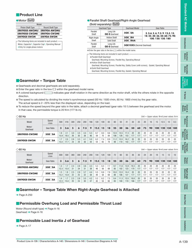
■Product Line ●Motor ●Parallel Shaft Gearhead/Right-Angle Gearhead
Gearhead Type Gearhead Model Gear Ratio
Sta
nd
ard
AC
Mo
tors
In
trod
uctio
n
Ind
uctio
nM
oto
rs
Revers
ible
M
oto
rs
Ele
ctro
m
ag
ne
tic
Bra
ke
Mo
tors
V
Serie
s
Clu
tch
&
Bra
ke
Mo
tors
Sy
nch
ron
ou
s
Mo
tors
L
ow
-Sp
ee
d
Sy
nch
ron
ou
s
Mo
tors
Watertig
ht,
Du
st-Resistan
t M
oto
rs
To
rqu
e
Mo
tors
R
igh
t-An
gle
Gearh
ead
s
Lin
ear
Head
s
Bra
ke P
ack
Accesso
ries
Insta
llatio
n
(Sold separately)Model Pinion Shaft Type Round Shaft Type
5RK90GE-AW2MU 5RK90A-AW2MU Parallel 5RK90GE-CW2ME 5RK90A-CW2ME Shaft 5IK90GE-SW2M 5IK90A-SW2M Right-Angle
Shaft
Parallel Shaft
Motor, Capacitor✽, Capacitor Cap✽, Operating Manual ✽Only for single-phase motors
The following items are included in each product.
Long LifeGE-S Gearhead
Hollow ShaftSolid Shaft
Long LifeGE-S Gearhead
5GE□SA 3, 3.6, 5, 6, 7.5, 9, 12.5, 15, 18, 25, 30, 36, 50, 60, 75, 90,
5GE□RH 100, 120, 150, 180 5GE□RAA
5GE10XS (Decimal Gearhead)
●Enter the gear ratio in the box (□) within the model name.
Parallel Shaft Gearhead● Gearhead, Mounting Screws, Parallel Key, Operating Manual Hollow Shaft Gearhead● Gearhead, Mounting Screws, Parallel Key, Safety Cover (with screws), Gasket, Operating Manual Solid Shaft Gearhead● Gearhead, Mounting Screws, Parallel Key, Gasket, Operating Manual
The following items are included in each product.
■Gearmotor – Torque Table ● Gearheads and decimal gearheads are sold separately.
● Enter the gear ratio in the box (□) within the gearhead model name.
● A colored background ( ) indicates gear shaft rotation in the same direction as the motor shaft, while the others rotate in the opposite
direction.
● The speed is calculated by dividing the motor's synchronous speed (50 Hz: 1500 r/min, 60 Hz: 1800 r/min) by the gear ratio.
The actual speed is 2∼20% less than the displayed value, depending on the load.
● To reduce the speed beyond the gear ratio in the table, attach a decimal gearhead (gear ratio 10:1) between the gearhead and the motor.
In that case, the permissible torque is 20 N·m (177 lb-in).
◇50 Hz Unit = Upper values: N·m/Lower values: lb-in
Model Speed r/min
500 416 300 250 200 166 120 100 83 60 50 41 30 25 20 16 15 12.5 10 8.3
Motor/ Gearhead
Gear Ratio 3 3.6 5 6 7.5 9 12.5 15 18 25 30 36 50 60 75 90 100 120 150 180
5RK90GE-CW2ME 5GE□SA 1.8 15.9
2.1 18.5
3.0 26
3.5 30
4.4 38
5.3 46
6.7 59
8.0 70
9.6 84
12.0 106
14.5 128
17.3 153
20 177
20 177
20 177
20 177
20 177
20 177
20 177
20 177
5IK90GE-SW2M 5GE□SA 1.7 15.0
2.0 17.7
2.8 24
3.3 29
4.1 36
5.0 44
6.2 54
7.4 65
8.9 78
11.2 99
13.5 119
16.2 143
20 177
20 177
20 177
20 177
20 177
20 177
20 177
20 177
◇60 Hz Unit = Upper values: N·m/Lower values: lb-in
Model Speed r/min
600 500 360 300 240 200 144 120 100 72 60 50 36 30 24 20 18 15 12 10
Motor/ Gearhead
Gear Ratio 3 3.6 5 6 7.5 9 12.5 15 18 25 30 36 50 60 75 90 100 120 150 180
5RK90GE-AW2MU 5GE□SA 1.4 12.3
1.7 15.0
2.4 21
2.8 24
3.6 31
4.3 38
5.3 46
6.4 56
7.7 68
9.7 85
11.6 102
13.9 123
19.3 170
20 177
20 177
20 177
20 177
20 177
20 177
20 177
5RK90GE-CW2ME 5GE□SA 1.5 13.2
1.8 15.9
2.5 22
2.9 25
3.7 32
4.4 38
5.5 48
6.6 58
7.9 69
10.0 88
12.0 106
14.4 127
20 177
20 177
20 177
20 177
20 177
20 177
20 177
20 177
5IK90GE-SW2M 5GE□SA 1.4 12.3
1.7 15.0
2.3 20
2.8 24
3.5 30
4.2 37
5.2 46
6.2 54
7.5 66
9.4 83
11.3 100
13.5 119
18.8 166
20 177
20 177
20 177
20 177
20 177
20 177
20 177
■Gearmotor – Torque Table When Right-Angle Gearhead is Attached ➜ Page A-250
■Permissible Overhung Load and Permissible Thrust Load Motor (Round shaft type) ➜ Page A-16
Gearhead ➜ Page A-16
■Permissible Load Inertia J of Gearhead ➜ Page A-17
Product Line A-139 / Characteristics A-140 / Dimensions A-140 / Connection Diagrams A-142 A-139

Sta
nd
ard
AC
Mo
tors
6 W
(1/1
25 H
P)
15 W
(1
/50 H
P)
25 W
(1/3
0 H
P)
40 W
(1/1
9 H
P)
60 W
(1/1
2 H
P)
90 W
(1/8
HP
) 20
0 W
(1
/4 H
P)
■Starting and Braking Characteristics (Reference values)
●Single-Phase Motor ●Three-Phase Motor
SS
ingle-Phingle-Ph
ase 50 Hase 60 H
z z
Braking Time
Starting Time
Overrun
TThree-Phahree-Phase 50 H
se 60 Hz z
Start
Braking Time
ing Time
Overrun
150 150
Over
run
[Rot
atio
ns]
Over
run
[Rot
atio
ns]
5
4 Tim
e [m
s]
1005
4 Tim
e [m
s]
100
3 3 50 50
2 2
1 1
0 0 0.25 0.5 0.75 1 1.25 0 0 0.25 0.5 0.75 1 1.25 [×10−4 kg·m2] [×10−4 kg·m2]
0 1 2 3 4 5 6 7 8 0 1 2 3 4 5 6 7 8 Load Inertia J [oz-in2] Load Inertia J [oz-in2]
■Dimensions Unit = mm (in.)
● Mounting screws are included with gearheads. Dimensions for mounting screws ➜ Page A-310
◇Motor/Gearhead Mass: Motor 3.9 kg (8.6 lb.)
Gearhead 1.5 kg (3.3 lb.)
A472U
ϕ15.875−0.0110
29.5±0.5 (1.16±0.02) 28.58 (1.13)
7 (0.28)
38 (1.50)
65 (2.56)179 (7.05) 7.5
(0.30)
32.5 (1.28)
ϕ17
(ϕ0.
67)
18 ( 0
.71)
ϕ
34
(ϕ1.
34)
ϕ0.6250−0.0004 (5/8")0
Cable: UL Style 2517 ϕ8 (ϕ0.31), 500 mm (20 in.) Length
Cable Cores: 3 Motor Leads UL Style 3271, AWG20 2 Brake Leads UL Style 3266, AWG22
4×ϕ6.5 (ϕ0.256) Thru
90 (3.54) 104±0.5
(4.09±0.02)
5 ( 0
.20)
m
ax.
27 (1.06)
92 ( 3
.62)
14.5
( 0
.57)
No.10-24UNC×10 (0.39) Deep
90 ( 3
.54)
Protective Earth Terminal M4
92 (3.62)
●Cable direction can be switched to the opposite direction.
21.5 (0.85) ◇Key and Key Slot (The key is included with the gearhead)
16.5
( 0.6
5)
Detail Drawing of Protective Earth Terminal
Protective Earth Terminal M4
+0.
1 2.
743
0
( 0.1
08 +
00.00
4 )
0 +0.0016(0.1875−0.0012) (0.1875 0 )(1.125±0.008)
4.76
3−0.
03
( 0.1
875−
0.00
12)
0
0
4.763−0.030 +0.04028.58±0.2 4.763 0
A-140 ORIENTAL MOTOR GENERAL CATALOG 2009/2010 Features A-110 / System Configuration A-113 / Specifications A-138

2
◇Shaft Section of Round Shaft Type ◇Decimal Gearhead The mass and motor’s dimensions (excluding the shaft section) are Can be connected to GE pinion shaft type.
the same as those of the pinion shaft types. 5GE10XS Mass: 3.9 kg (8.6 lb.) Mass: 0.6 kg (1.32 lb.)
A029A473
61 (2.40)
4×ϕ6.5 (ϕ0.256) Thru
Protective Earth Terminal M4
ϕ83
−0.
035
0
ϕ12
−0.
018
0
37 (1.46)
(0.08)
30 (1.18)
11 ( 0
.43)
(ϕ 0.4
724
) −
0.00
070
(ϕ 3.2
677
) −
0.00
140
92 ( 3
.62)
14
.5
( 0.5
7)
27 (1.06)
☐90
(☐3.
54)
92 (3.62)
104±0.5
(4.09±0.02)
40 (1.57) 21 (0.83)2
(0.08)
104±0.5
(4.09±0.02)
□90
( □3.
54)
4×ϕ10.8 (ϕ0.425) Thru
ϕ83
−0.
035
( ϕ3.
2677
−0.
0014
) 0
0
◇Capacitor ◇Capacitor Dimensions Unit = mm (in.)
(Included with single-phase motors) A
6 (0.24)
C B
7 ( 0
.28)
20 (0.79)
10
( 0.3
9)
AMP#187
ϕ4.3 (ϕ0.169)
4 ( 0
.16)
B+15
( 0.5
9)
R10(R0.39)
5RK90GE-AW2MU 5RK90A-AW2MU
Model Pinion Shaft Type Round Shaft Type
5RK90GE-CW2ME 5RK90A-CW2ME
Capacitor Model
A B C Mass g (oz.)
Capacitor Cap
CH300CFAUL2 58 (2.28)
35 (1.38)
50 (1.97)
140 (4.9)
Included CH70BFAUL 58
(2.28) 35
(1.38) 50
(1.97) 138 (4.9)
Sta
nd
ard
AC
Mo
tors
In
trod
uctio
n
Ind
uctio
nM
oto
rs
Revers
ible
M
oto
rs
Ele
ctro
m
ag
ne
tic
Bra
ke
Mo
tors
V
Serie
s
Clu
tch
&
Bra
ke
Mo
tors
Sy
nch
ron
ou
s
Mo
tors
L
ow
-Sp
ee
d
Sy
nch
ron
ou
s
Mo
tors
Watertig
ht,
Du
st-Resistan
t M
oto
rs
To
rqu
e
Mo
tors
R
igh
t-An
gle
Gearh
ead
s
Lin
ear
Head
s
Bra
ke P
ack
Accesso
ries
Insta
llatio
n
Product Line A-139 / Characteristics A-140 / Dimensions A-140 / Connection Diagrams A-142 A-141

Sta
nd
ard
AC
Mo
tors
6 W
(1/1
25 H
P)
15 W
(1
/50 H
P)
25 W
(1/3
0 H
P)
40 W
(1/1
9 H
P)
60 W
(1/1
2 H
P)
90 W
(1/8
HP
) 20
0 W
(1
/4 H
P)
■Connection Diagrams ● The direction of motor rotation is as viewed from the shaft end of the motor. CW represents the clockwise direction, while CCW represents the
counterclockwise direction.
● Connection diagrams are also valid for the equivalent round shaft type.
5RK90GE-AW2MU 5RK90GE-CW2ME
5IK90GE-SW2M
Sing
le-P
hase
Mot
orTh
ree-
Phas
e M
otor
SW1 ON
R0 C0
R0 C0
ON
SW2 CCW CW
L
N
R0 C0
PE
CCW CW
CW
L1(R)
L2(S)
L3(T)
SW1
R0 C0
R0 C0
R0 C0
PE
SW1 operates both motor and electromagnetic brake action. The electromagnetic brake will be released and the motor will rotate when SW1 is switched simultaneously to ON. When SW1 is switched simultaneously to OFF, the motor stops immediately with the electromagnetic brake and holds the load.
If you wish to release the brake while the motor is stopped, apply voltage between the two brake lead wires (orange).
Rotation Direction To rotate the motor in a clockwise (CW) direction, turn SW2 to CW. To rotate the motor in a counterclockwise (CCW) direction, turn SW2 to CCW.
Switch No.
SW1 SW2
Specifications Note
Switched Simultaneously –
125 VAC 5 A minimum (Inductive Load)
250 VAC 5 A minimum (Inductive Load)
Single-Phase 110/115 VAC Input
Single-Phase 220/230 VAC Input
SW1 operates both motor and electromagnetic brake action. The electromagnetic brake will be released and the motor will rotate when SW1 is switched simultaneously to ON. When SW1 is switched simultaneously to OFF, the motor stops immediately with the electromagnetic brake and holds the load.
If you wish to release the brake while the motor is stopped, apply voltage between the two brake lead wires (orange).
Rotation Direction To change the rotation direction, change any two connections between L1(R), L2(S) and L3(T).
Switch No.
SW1
Specifications
250 VAC 5 A minimum (Inductive Load)
Note
Switched Simultaneously
Red
White
Black
Orange
Orange
Capacitor
Electromagnetic Brake
Motor
White
Red
Black
Orange
Orange Electromagnetic
Brake
Motor
PE: Protective Earth ●R0 and C0 indicate CR circuit for surge suppression. [R0 = 5∼200 Ω, C0 = 0.1∼0.2 μF, 200 WV (400 WV)]
EPCR1201-2 (CR circuit) is available as an accessory. ➜ Page A-302 ●How to connect a capacitor ➜ Page A-313
Gearhead, Accessories and Peripheral Equipment
AccessoriesInstantaneous Stop Brake Pack
Space-Saving Right-Angle Gearheads ➜ Page A-239 ➜ Page A-277 ➜ Page A-287
A-142 ORIENTAL MOTOR GENERAL CATALOG 2009/2010 Features A-110 / System Configuration A-113 / Specifications A-138

Sta
nd
ard
AC
Mo
tors
In
trod
uctio
n
Ind
uctio
nM
oto
rs
Revers
ible
M
oto
rs
Ele
ctro
m
ag
ne
tic
Bra
ke
Mo
tors
V
Serie
s
Clu
tch
&
Bra
ke
Mo
tors
Sy
nch
ron
ou
s
Mo
tors
L
ow
-Sp
ee
d
Sy
nch
ron
ou
s
Mo
tors
Watertig
ht,
Du
st-Resistan
t M
oto
rs
To
rqu
e
Mo
tors
R
igh
t-An
gle
Gearh
ead
s
Lin
ear
Head
s
Bra
ke P
ack
Accesso
ries
Insta
llatio
n
Induction Motors BH Series Power Off Activated Electromagnetic Brake
200 W (1/4 HP) Frame Size: □104 mm (□4.09 in.)
Right-Angle Hollow Shaft Parallel Shaft
■Features
●High Power 200 W (1/4 HP) ●"Combination Type" for Easy Installation Smallest frame size among 200 W (1/4 HP) motors The combination type comes with the motor and gearhead
●Hypoid Gear-Employed Right-Angle Gearheads pre-assembled. This enables easy installation in equipment.
Right-angle gearheads employ hypoid gears. Hollow shafts and solid
shafts are available to enable space-saving.
● RoHS-Compliant The BH Series conforms to the RoHS Directive that prohibits the use
of six chemical substances including lead and cadmium.
●Details of RoHS Directive ➜ Page G-38
■Specifications – Continuous Rating
Combination Type:
The combination type comes with the motor and its dedicated gearhead pre-assembled, which simplifies installation in equipment. Motors and gearheads are also available separately to facilitate changes or repairs.
Model
Combination Type Round Shaft Type
Output Power
Voltage Frequency Current Starting Torque
Rated Torque Rated Speed Capacitor
W HP VAC Hz A
N·m oz-in
N·m oz-in r/min μF
200 1/4
Single-Phase 110 60 3
0.88 124 1.27
180 1500 40
Single-Phase 115 0.98 139
200 1/4
Single-Phase 220 60 1.5 0.98 139
1.27 180
1500 10
Single-Phase 230 50
1.5 0.98 139
1.52 210
1250 10
60 1.27 180
1500
200 1/4
Three-Phase 200 50
1.1
1.49 210
1.49 210
1250 –
60 1.25 177
1.25 177
1500
Three-Phase 220 60 0.95
1.23 174
1.23 174
1550 –
Three-Phase 230 60 1.18 167
1.18 167
1600
BHI62FMT-□RH BHI62FMT-□RA BHI62FMT-□
BHI62EMT-□RH BHI62EMT-□RA BHI62EMT-□
BHI62SMT-□RH BHI62SMT-□RA BHI62SMT-□
BHI62FMT-A
BHI62EMT-A
BHI62SMT-A
●Enter the gear ratio in the box (□) within the model name. The values for each specification applies to the motor only. ●Details of safety standards ➜ Page G-2 ●List of safety standard approved products (Model, Standards, Standards File No., Certification Body) ➜ Page G-11
: Contains a built-in thermal protector (automatic return type). If a motor overheats for any reason, the thermal protector is activated and the motor is stopped. (The power supply to the electromagnetic brake is kept and the brake is released.) When the motor temperature drops, the thermal protector closes and the motor restarts. Be sure to turn the motor power off before inspecting.
●Electromagnetic Brake (Power Off Activated Type)
Motor Model Voltage Frequency Current Input Holding Brake Torque
VAC Hz A W N·m oz-in
BHI62FMT-□RH, BHI62FMT-□RA BHI62FMT-□, BHI62FMT-A
Single-Phase 110 60 0.17 12
1.5 210Single-Phase 115
BHI62EMT-□RH, BHI62EMT-□RA BHI62EMT-□, BHI62EMT-A
Single-Phase 220 60 0.09 12 1.5 210
Single-Phase 230 50
0.09 12 1.5 21060
BHI62SMT-□RH, BHI62SMT-□RA BHI62SMT-□, BHI62SMT-A
Single-Phase 200 50
0.09 12 1.5 21060
Single-Phase 220 60 0.09 12
1.5 210Single-Phase 230 60
●Enter the gear ratio in the box (□) within the model name.
Characteristics A-145 / Dimensions A-146 / Connection Diagrams A-150 / Motor and Gearhead Combinations A-151 A-143

■Product Line ●Combination Type ●Round Shaft Type
Voltage Model
Sta
nd
ard
AC
Mo
tors
6 W
(1/1
25 H
P)
15 W
(1
/50 H
P)
25 W
(1/3
0 H
P)
40 W
(1/1
9 H
P)
60 W
(1/1
2 H
P)
90 W
(1/8
HP
) 20
0 W
(1
/4 H
P)
◇Right-Angle Shaft Type Gear Ratio Single-Phase
110/115 VAC Voltage Model
Single-Phase 220/230 VAC
BHI62EMT-□RH
BHI62SMT-□RH
BHI62FMT-□RA
Single-Phase 220/230 VAC
BHI62EMT-□RA
Single-Phase 220/230 VAC
Single-Phase BHI62FMT-□RH110/115 VAC
Hollow Shaft Three-Phase
Three-Phase 5, 6, 7.5, 9, 12.5, 200/220/230 VAC
200/220/230 VAC 15, 18, 25, 30, 36, Single-Phase 50, 60, 75, 90, 100, 110/115 VAC 120, 150, 180
Motor, Capacitor✽, Capacitor Cap✽, Operating Manual Only for single-phase motors✽
The following items are included in each product.
Solid Shaft
Three-Phase BHI62SMT-□RA200/220/230 VAC
BHI62FMT-A
BHI62EMT-A
BHI62SMT-A
●Enter the gear ratio in the box (□) within the model name.
Motor, Gearhead, Capacitor✽, Capacitor Cap✽, Parallel Key, Operating Manual Only for single-phase motors✽
The following items are included in each product.
◇Parallel Shaft
Single-Phase 110/115 VAC
Single-Phase 220/230 VAC
Three-Phase 200/220/230 VAC
BHI62FMT-□
BHI62EMT-□
BHI62SMT-□
3, 3.6, 5, 6, 7.5, 9, 12.5, 15, 18, 25, 30, 36, 50, 60, 75,
90, 100, 120, 150, 180
Voltage Model Gear Ratio
●Enter the gear ratio in the box (□) within the model name.
Motor, Gearhead, Capacitor✽, Capacitor Cap✽, Mounting Screws, Parallel Key, Operating Manual
Only for single-phase motors✽
The following items are included in each product.
■Gearmotor – Torque Table for Combination Type ● Enter the gear ratio in the box (□) within the model name.
● A colored background ( ) indicates gear shaft rotation in the same direction as the motor shaft, while the others rotate in the opposite
direction. The directions will be reversed for all right-angle shaft types.
● The speed is calculated by dividing the motor's synchronous speed (50 Hz: 1500 r/min, 60 Hz: 1800 r/min) by the gear ratio.
The actual speed is 2∼20% less than the displayed value, depending on the load.
● Decimal gearheads are not available for the BH Series.
●Right-Angle Shaft 50 Hz Unit = Upper values: N·m/Lower values: lb-in
Model Speed r/min
300 250 200 167 120 100 83 60 50 42 30 25 20 17 15 12.5 10 8.3
Gear Ratio 5 6 7.5 9 12.5 15 18 25 30 36 50 60 75 90 100 120 150 180
BHI62EMT-□RH/RA 5.5 48
6.7 59
8.3 73
10.0 88
13.9 123
16.6 146
20.0 177
27.7 240
33.3 290
36.0 310
40.0 350
43.0 380
47.0 410
51.5 450
54.5 480
60 530
60 530
60 530
BHI62SMT-□RH/RA 5.4 47
6.5 57
8.2 72
9.8 86
13.6 120
16.3 144
19.6 173
27.2 240
32.6 280
36.0 310
40.0 350
43.0 380
47.0 410
51.5 450
54.5 480
60 530
60 530
60 530
●Right-Angle Shaft 60 Hz Unit = Upper values: N·m/Lower values: lb-in
Model Speed r/min
360 300 240 200 144 120 100 72 60 50 36 30 24 20 18 15 12 10
Gear Ratio 5 6 7.5 9 12.5 15 18 25 30 36 50 60 75 90 100 120 150 180 4.6 40
5.6 49
7.0 61
8.3 73
11.6 102
13.9 123
16.7 147
23.2 200
27.8 240
33.4 290
40.0 350
43.0 380
47.0 410
51.5 450
54.5 480
60 530
60 530
60 530
4.6 40
5.5 48
6.8 60
8.2 72
11.4 100
13.7 121
16.4 145
22.8 200
27.4 240
32.9 290
40.0 350
43.0 380
47.0 410
51.5 450
54.5 480
60 530
60 530
60 530
4.5 39
5.4 47
6.7 59
8.1 71
11.2 99
13.5 119
16.2 143
22.4 198
26.9 230
32.3 280
40.0 350
43.0 380
47.0 410
51.5 450
54.5 480
60 530
60 530
60 530
-□RH/RA (230 VAC) 4.3 38
5.2 46
6.5 57
7.8 69
10.8 95
12.9 114
15.5 137
21.5 190
25.8 220
31.0 270
40.0 350
43.0 380
47.0 410
51.5 450
54.5 480
60 530
60 530
60 530
BHI62FMT-□RH/RA BHI62EMT-□RH/RA
BHI62SMT-□RH/RA (200 VAC)
BHI62SMT-□RH/RA (220 VAC)
BHI62SMT
A-144 ORIENTAL MOTOR GENERAL CATALOG 2009/2010 Features A-143 / System Configuration A-113 / Specifications A-143 / Product Line A-144

●Parallel Shaft 50 Hz Unit = Upper values: N·m/Lower values: lb-in
BHI62EMT-□
BHI62SMT-□
●Parallel Shaft 60 Hz
Model Speed r/min
500 417 300 250 200 167 120 100 83 60 50 42 30 25 20 17 15 12.5 10 8.3
Gear Ratio 3 3.6 5 6 7.5 9 12.5 15 18 25 30 36 50 60 75 90 100 120 150 180 4.1 36
4.9 43
6.8 60
8.2 72
10.3 91
12.3 108
16.3 144
19.6 173
23.5 200
32.7 280
39.2 340
40 350
40 350
40 350
40 350
40 350
40 350
40 350
40 350
40 350
4.0 35
4.8 42
6.7 59
8.0 70
10.1 89
12.1 107
16.0 141
19.2 169
23.1 200
32.0 280
38.4 330
40 350
40 350
40 350
40 350
40 350
40 350
40 350
40 350
40 350
Unit = Upper values: N·m/Lower values: lb-in
Model Speed r/min
600 500 360 300 240 200 144 120 100 72 60 50 36 30 24 20 18 15 12 10
Gear Ratio 3 3.6 5 6 7.5 9 12.5 15 18 25 30 36 50 60 75 90 100 120 150 180 3.4 30
4.1 36
5.7 50
6.9 61
8.6 76
10.3 91
13.7 121
16.4 145
19.7 174
27.3 240
32.8 290
39.3 340
40 350
40 350
40 350
40 350
40 350
40 350
40 350
40 350
3.4 30
4.1 36
5.6 49
6.8 60
8.4 74
10.1 89
13.4 118
16.1 142
19.4 171
26.9 230
32.3 280
38.7 340
40 350
40 350
40 350
40 350
40 350
40 350
40 350
40 350
3.3 29
4.0 35
5.5 48
6.6 58
8.3 73
10.0 88
13.2 116
15.9 140
19.0 168
26.4 230
31.7 280
38.1 330
40 350
40 350
40 350
40 350
40 350
40 350
40 350
40 350
3.2 28
3.8 33
5.3 46
6.4 56
8.0 70
9.6 84
12.7 112
15.2 134
18.3 161
25.4 220
30.4 260
36.5 320
40 350
40 350
40 350
40 350
40 350
40 350
40 350
40 350
BHI62FMT-□
BHI62EMT-□
BHI62SMT-□ (200 VAC)
BHI62SMT-□ (220 VAC)
BHI62SMT-□ (230 VAC)
■Permissible Overhung Load and Permissible Thrust Load Combination Type ➜ Page A-16
Round Shaft Type ➜ Page A-16
■Permissible Load Inertia J of Gearhead ➜ Page A-17
Starting and Braking Characteristics (Reference values) ■
Single-Phase Motor●
50
100
150
200
250
Tim
e [m
s]
Overrun
Starting Time
Braking Time
1
2
3
4
5
0 0.50 1.0 1.5 2.0
Single-Phase 50 Hz Single-Phase 60 Hz
Over
run
[Rot
atio
ns]
[×10−4 kg·m2]
[oz-in2] 20
Load Inertia J 4 6 8 10
Three-Phase Motor ●
0.50 1.0 1.5 2.0
1
2
3
4
5
0
Tim
e [m
s]
Over
run
[Rot
atio
ns] Braking Time
Overrun
Three-Phase 50 Hz Three-Phase 60 Hz
Starting Time50
100
150
200
250
[×10−4 kg·m2]
[oz-in2] 20
Load Inertia J 4 6 8 10
Sta
nd
ard
AC
Mo
tors
In
trod
uctio
n
Ind
uctio
nM
oto
rs
Revers
ible
M
oto
rs
Ele
ctro
m
ag
ne
tic
Bra
ke
Mo
tors
V
Serie
s
Clu
tch
&
Bra
ke
Mo
tors
Sy
nch
ron
ou
s
Mo
tors
L
ow
-Sp
ee
d
Sy
nch
ron
ou
s
Mo
tors
Watertig
ht,
Du
st-Resistan
t M
oto
rs
To
rqu
e
Mo
tors
R
igh
t-An
gle
Gearh
ead
s
Lin
ear
Head
s
Bra
ke P
ack
Accesso
ries
Insta
llatio
n
Characteristics A-145 / Dimensions A-146 / Connection Diagrams A-150 / Motor and Gearhead Combinations A-151 A-145

■Dimensions Unit = mm (in.)
● Mounting screws are included with the combination type, parallel shaft. Dimensions for mounting screws ➜ Page A-310
◇Combination Type: Right-Angle, Hollow Shaft BHI62FMT-□RH, BHI62EMT-□RH, BHI62SMT-□RH Mass: 11.5 kg (25 lb.)
Motor: BHI62FMT-G2, BHI62EMT-G2, BHI62SMT-G2 Gearhead: BH6G2-□RH
A384
16 ( 0
.63)
99
( 3.9
0)
118
( 4.6
5)
4 ( 0.1
6)
109.3 (4.30)154 (6.06)220 (8.66)
102 (4.02)
10.5 (0.41)
4.8 (0.19)
Flange Mounting Surface
Groove for Retaining Ring (ϕ1.03 0 )+0.008
15 (0.59) 1.5 (0.06)
30 (1.18) 30 (1.18) 15 (0.59) 1.5 (0.06)
□10
3 ( □
4.06
)
ϕ40 (ϕ1.57) +0.21ϕ26.2 00
ϕ58−0.046
(ϕ2.2835−0.00180 ) A−A
24 ( 0
.94)
32 (1.26) max.
28.3
( 1
.11)
104
( 4.0
9)
100 (3.94) 175 (6.89)
A
A
8 0 +0.04
(0.31 0 )+0.0016
4×ϕ8.5 (ϕ0.335) Thru
120±0.5
(4.72±0.02) 25 0 (0.9843
+0.033
104 (4.09)
Use cable with a diameter of● ϕ8∼ϕ12 mm (ϕ0.31∼ϕ0.47 in.). Details of terminal box● ➜ Page A-314
Key◇(The key is included with the gearhead)
74 (2.91)
58 ( 2
.28)
66 (2.60)
+0.0013 0 )
8−0.
036
0 ( 0.31
50−
0.00
14)
0
025−0.2 07−0.036
(0.984−00.008) 0(0.2756−0.0014)
Sta
nd
ard
AC
Mo
tors
6 W
(1/1
25 H
P)
15 W
25 W
40 W
60 W
90 W
20
0 W
(1
/50 H
P)
(1/3
0 H
P)
(1/1
9 H
P)
(1/1
2 H
P)
(1/8
HP
) (1
/4 H
P)
●Enter the gear ratio in the box (□) within the model name.
A-146 ORIENTAL MOTOR GENERAL CATALOG 2009/2010 Features A-143 / System Configuration A-113 / Specifications A-143 / Product Line A-144

32
◇Combination Type: Right-Angle, Solid Shaft BHI62FMT-□RA, BHI62EMT-□RA, BHI62SMT-□RA Mass: 11.5 kg (25 lb.)
Motor: BHI62FMT-G2, BHI62EMT-G2, BHI62SMT-G2 Gearhead: BH6G2-□RA
A385
220 (8.66) 154 (6.06)
□10
3 ( □
4.06
)
10.5 (0.41)
102 (4.02)
ϕ22−0.021 0 (ϕ0.8661−0.0008
0 ) 24.5 (0.96)
ϕ58−0.046 0 (ϕ2.2835−0.0018
0 )
( 1.2
6)
16 ( 0
.63)
99
( 3.9
0)
118
( 4.6
5)
48 ( 1
.89)
40±
0.5
( 1.5
7±0.
02)
4 ( 0
.16)
32 (1.26) max.
24 ( 0
.94)
104
( 4.0
9)
100 (3.94) 175 (6.89)
120±0.5
(4.72±0.02)
104 (4.09)
Use cable with a diameter of● ϕ8∼ϕ12 mm (ϕ0.31∼ϕ0.47 in.). Details of terminal box● ➜ Page A-314
Key and Key Slot◇
58 ( 2
.28)
66 (2.60)4×ϕ8.5 (ϕ0.335) Thru
74 (2.91)
32±0.2
(1.260±0.008)
018.5−0.1
(0.728−0.004) 0
6−0.03
(0.2362−0.0012)0 0
0 6−
0.03
( 0.23
62−
0.00
12)
0
●At the shipment, a parallel key is inserted on the gearhead’s shaft.
●Enter the gear ratio in the box (□) within the model name.
Characteristics A-145 / Dimensions A-146 / Connection Diagrams A-150 / Motor and Gearhead Combinations A-151 A-147
Sta
nd
ard
AC
Mo
tors
In
trod
uctio
n
Ind
uctio
nM
oto
rs
Revers
ible
M
oto
rs
Ele
ctro
m
ag
ne
tic
Bra
ke
Mo
tors
V
Serie
s
Clu
tch
&
Bra
ke
Mo
tors
Sy
nch
ron
ou
s
Mo
tors
L
ow
-Sp
ee
d
Sy
nch
ron
ou
s
Mo
tors
Watertig
ht,
Du
st-Resistan
t M
oto
rs
To
rqu
e
Mo
tors
R
igh
t-An
gle
Gearh
ead
s
Lin
ear
Head
s
Bra
ke P
ack
Accesso
ries
Insta
llatio
n

24 (
30(1.18)
◇Combination Type: Parallel Shaft BHI62FMT-□, BHI62EMT-□, BHI62SMT-□
Mass: 9.5 kg (21 lb.)
Motor: BHI62FMT-G2, BHI62EMT-G2, BHI62SMT-G2 Gearhead: BH6G2-□
A386
175 (6.89)
Sta
nd
ard
AC
Mo
tors
6 W
(1/1
25 H
P)
15 W
(1
/50 H
P)
25 W
(1/3
0 H
P)
40 W
(1/1
9 H
P)
60 W
(1/1
2 H
P)
90 W
(1/8
HP
) 20
0 W
(1
/4 H
P)
□10
3 ( □
4.06
)
20 ( 0
.79)
ϕ42
( ϕ
1.65
)
20.5
( 0
.81)
120±0.5
(4.72±0.02)
32 (1.26) max.
0.94
)
10.5 (0.41) 5 (0.20)
58 ( 2
.28)
104
( 4.0
9)
72 (2.83)220 (8.66)
100 (3.94)
42 (1.65)
25 (0.98)
33.5±0.5
(1.32±0.02)
ϕ18−0.018
(ϕ0.7087−0.0007)0
0
4×ϕ8.5 (ϕ0.335) Thru
74 (2.91)
104 (4.09)
●Use cable with a diameter of ϕ8∼ϕ12 mm (ϕ0.31∼ϕ0.47 in.). ●Details of terminal box ➜ Page A-314
◇Key and Key Slot
0 6−
0.03
0 14
.5−
0.1
( 0.2
362−
0.00
12)
0
( 0.5
71−
0.00
4) 0
25±0.2 6−00.03
(0.984±0.008) 0(0.2362−0.0012)
●At the shipment, a parallel key is inserted on the gearhead's shaft.
◇Round Shaft Type BHI62FMT-A, BHI62EMT-A, BHI62SMT-A Mass: 6.5 kg (14 lb.)
A387
175 (6.89) 100 (3.94) 74 (2.91)32 (1.26) max.
24 ( 0
.94)
120±0.5
(4.72±0.02)
58 ( 2
.28)
10
4 ( 4
.09)
4×ϕ8.5 (ϕ0.335) Thru
13 ( 0
.51)
0
ϕ14
−0.
018
( ϕ0.
5512
−0.
0007
0 )
ϕ94
−0.
035
0
( ϕ3.
7008
−0 0.
0014
)
□10
3 ( □
4.06
)
10.5 (0.41) 2 (0.08) 104 (4.09)220 (8.66) 37
(1.46)
●Use cable with a diameter of ϕ8∼ϕ12 mm (ϕ0.31∼ϕ0.47 in.). ●Details of terminal box ➜ Page A-314
●Enter the gear ratio in the box (□) within the model name.
A-148 ORIENTAL MOTOR GENERAL CATALOG 2009/2010 Features A-143 / System Configuration A-113 / Specifications A-143 / Product Line A-144

( R10
◇Capacitor (Included with single-phase motors) ◇Capacitor Dimensions Unit = mm (in.)
A
B7
( 0.2
8)
20 (0.79)
ϕ4.3 (ϕ0.169)
BHI62FMT-□RH BHI62FMT-□RA 58 41 58 175CH400CFAUL2 BHI62FMT-□ (2.28) (1.61) (2.28) (6.2) BHI62FMT-A
Included BHI62EMT-□RH BHI62EMT-□RA
C 10AMP#187
4 ( 0
.16)
58 35 50 132CH100BFAUL 6 (0.24) BHI62EMT-□ (2.28) (1.38) (1.97) (4.7) BHI62EMT-A
Model Capacitor Model A B C Mass g (oz.)
Capacitor Cap
●Enter the gear ratio in the box (□) within the model name.
R0.39) ( 0
.39)
B+15
( 0.5
9)
■Mounting Method for Right-Angle, Hollow Shaft Type These figures below show how to mount loads depending on the ●Inner Diameter of Hollow Shaft and Recommended Load shape of the shaft. The tolerance of the inner diameter for the hollow Shaft Diametershaft is finished as shown in the table on the right, and "key slot"
Model BH6G2-□RH
Unit = mm (in.)
processing is given to mount the load shaft. Use the key provided ϕ25 + 0.033 (0.9843+ 0.0013)Inner Diameter of Hollow Shaft H8 0 0
with the product by fastening it to the shaft. Apply a coating of Recommended Load Shaft Diameter h7 ϕ25 − 0.021
0 (0.9843− 0.0008 0 )
molybdenum disulfide or similar grease to the surface of the load ●Enter the gear ratio in the box (□) within the model name.
shaft and to the inner diameter of the load shaft to prevent sticking.
Recommended load shaft diameter and inner diameter of hollow
shaft are shown in the table on the right.
Stepped Load Shaft●
Load Shaft
Hollow Shaft Spacer
Flat Washer
Bolt
Spring Washer
Retaining Ring for Hole
Straight Load Shaft●
Spacer
Load Shaft
Spacer
Flat Washer
Bolt
Spring Washer
Retaining Ring for Hole
Hollow Shaft
●After securing a load, attach the safety cover included.
Notes: ●Be careful not to apply a shock to the hollow shaft when mounting a load shaft. It may damage the bearing inside the gearhead. ●Bolts or other fasteners used to install the load shaft are not included. These parts must be purchased separately.
Sta
nd
ard
AC
Mo
tors
In
trod
uctio
n
Ind
uctio
nM
oto
rs
Revers
ible
M
oto
rs
Ele
ctro
m
ag
ne
tic
Bra
ke
Mo
tors
V
Serie
s
Clu
tch
&
Bra
ke
Mo
tors
Sy
nch
ron
ou
s
Mo
tors
L
ow
-Sp
ee
d
Sy
nch
ron
ou
s
Mo
tors
Watertig
ht,
Du
st-Resistan
t M
oto
rs
To
rqu
e
Mo
tors
R
igh
t-An
gle
Gearh
ead
s
Lin
ear
Head
s
Bra
ke P
ack
Accesso
ries
Insta
llatio
n
Characteristics A-145 / Dimensions A-146 / Connection Diagrams A-150 / Motor and Gearhead Combinations A-151 A-149

Sta
nd
ard
AC
Mo
tors
6 W
(1/1
25 H
P)
15 W
(1
/50 H
P)
25 W
(1/3
0 H
P)
40 W
(1/1
9 H
P)
60 W
(1/1
2 H
P)
90 W
(1/8
HP
) 20
0 W
(1
/4 H
P)
■Connection Diagrams ● The direction of motor rotation is as viewed from the shaft end of the motor. CW indicates clockwise direction, while CCW counterclockwise
direction.
● Enter the voltage (F, E or S) in the box (□) within the model name.
Single-Phase MotorMotor Type Three-Phase Motor
• Combination Type: Parallel Shaft BHI62□MT-3∼9 BHI62□MT-50∼180
• Round Shaft Type BHI62□MT-A
• Combination Type: Parallel Shaft BHI62□MT-12.5∼36
• Combination Type: Right Angle Shaft BHI62□MT-5∼180RA BHI62□MT-5∼180RH
Clockwise
Clockwise
Clockwise: To rotate in a clockwise (CW) direction, turn SW2 to CW.
Counterclockwise: To rotate in a counterclockwise (CCW) direction, turn SW2 to CCW.
To change the rotation direction, change any two connections between R, S and T.Rotation Direction
PE Capacitor
Electromagnetic Brake
SW1 ON
R0 C0
R0 C0
ON
SW2 CCW CW
L
N
R0 C0
Motor
CCW CW
B
B
U1
U2
Z2
PE
CW
L1(R)
L2(S)
L3(T)
Electromagnetic Brake
SW1
R0 C0
R0 C0
R0 C0
Motor
B B W
V
U
PE Capacitor
Electromagnetic Brake
SW1 ON
R0 C0
R0 C0
ON
SW2 CW CCW
L
N
R0 C0
Motor
CCW CW
B
B
U1
U2
Z2
PE
CW
L1(S)
L2(R)
L3(T)
Electromagnetic Brake
SW1
R0 C0
R0 C0
R0 C0
Motor
B B W
V
U
PE: Protective Earth SW1 operates both motor and electromagnetic brake action. The electromagnetic brake will be released and the motor will rotate when SW1 is switched simultaneously to ON. When SW1 is switched simultaneously to OFF, the motor stops immediately with the electromagnetic brake and holds the load.
Switch No.
Specifications NoteSingle-Phase
110/115 VAC Input Single-Phase
220/230 VAC Input Three-Phase 200/220/230 VAC Input
SW1 125 VAC 5 A minimum (Inductive Load)
250 VAC 5 A minimum (Inductive Load)
250 VAC 5 A minimum (Inductive Load) –
Switched Simultaneously –SW2
Connect a CR circuit (R0 C0) for surge suppression shown on the diagrams to protect the contact. R0=5∼200 Ω C0=0.1∼0.2 μF 200 WV EPCR1201-2 (CR circuit) is available as an accessory. Note: ●Change the direction of single-phase motor rotation only after bringing the motor to a stop. If an attempt is made to change the direction of
rotation while the motor is rotating, motor may ignore reversing command or change its direction of rotation after some delay.
●How to connect a capacitor ➜ Page A-313
A-150 ORIENTAL MOTOR GENERAL CATALOG 2009/2010 Features A-143 / System Configuration A-113 / Specifications A-143 / Product Line A-144

■List of Motor and Gearhead Combinations Motor and gearhead combinations are shown below.
●Combination Type: Right Angle Shaft Model Motor Model Gearhead Model
BHI62FMT-□RH BHI62FMT-□RA
BHI62FMT-G2 BH6G2-□RH BH6G2-□RA
BHI62EMT-□RH BHI62EMT-□RA
BHI62EMT-G2 BH6G2-□RH BH6G2-□RA
BHI62SMT-□RH BHI62SMT-□RA
BHI62SMT-G2 BH6G2-□RH BH6G2-□RA
●Enter the gear ratio in the box (□) within the model name.
Accessories
Accessories
➜Page A-287
●Combination Type: Parallel Shaft Model Motor Model Gearhead Model
BHI62FMT-□ BHI62FMT-G2
BHI62EMT-□ BHI62EMT-G2 BH6G2-□
BHI62SMT-□ BHI62SMT-G2
●Enter the gear ratio in the box (□) within the model name.
Sta
nd
ard
AC
Mo
tors
In
trod
uctio
n
Ind
uctio
nM
oto
rs
Revers
ible
M
oto
rs
Ele
ctro
m
ag
ne
tic
Bra
ke
Mo
tors
V
Serie
s
Clu
tch
&
Bra
ke
Mo
tors
Sy
nch
ron
ou
s
Mo
tors
L
ow
-Sp
ee
d
Sy
nch
ron
ou
s
Mo
tors
Watertig
ht,
Du
st-Resistan
t M
oto
rs
To
rqu
e
Mo
tors
R
igh
t-An
gle
Gearh
ead
s
Lin
ear
Head
s
Bra
ke P
ack
Accesso
ries
Insta
llatio
n
Characteristics A-145 / Dimensions A-146 / Connection Diagrams A-150 / Motor and Gearhead Combinations A-151 A-151

Sta
nd
ard
AC
Mo
tors
A-152 ORIENTAL MOTOR GENERAL CATALOG 2009/2010