Embed Size (px)
Citation preview
Pneumatic Disc Brake
S N 6 . . . / S N 7 . . . / S K 7 . . . / N A 7 . . .D i s c B ra ke
Y 0 0 6 4 7 1 - E N - 0 0 1
S e r v i c e M a n u a l
KNORR-BREMSESystems for Commercial Vehicles
K001262_001 09.06.2004 15:23 Uhr Seite 1
2
IndexPage
1 Overview1.1 Disc Brake Components...................................................................................... 41.2 Disc Brake Identification and Service Kits............................................................. 51.2.1 Wear Indicator Kits .............................................................................................. 51.3 Brake Disc............................................................................................................ 6
2 General Information2.1 Service Tools ....................................................................................................... 72.2 Diagnostic Equipment.......................................................................................... 72.3 Lubrication........................................................................................................... 72.4 Torque Requirements........................................................................................... 7
3 Description and Function3.1 Disc Brake Sectioned View.................................................................................. 83.2 Description of Operation....................................................................................... 93.2.1 Brake Actuation.................................................................................................... 93.2.2 Brake Release...................................................................................................... 93.2.3 Brake Adjustment (automatic)............................................................................... 9
4 Inspection Points............................................................................................... 104.1 Safety Instruction for Service Work and Repair Work........................................... 11
5 Functional and Visual Checks5.1 Wear Check of Pads and Brake Discs.................................................................. 125.1.1 Brake Wear Check using Rubber Bush (6a)......................................................... 145.1.2 Brake Wear Check using Rubber Bush (6b)......................................................... 155.1.3 Brake Wear Check using Carrier to Caliper position (6c)...................................... 165.1.4 Wear Indicators.................................................................................................... 175.1.5 Diagnostic Equipment - Hand held device ZB9031-2........................................... 175.2 Adjuster Check.................................................................................................... 185.3 Caliper Checks..................................................................................................... 205.3.1 Caliper Running Clearance................................................................................... 205.3.2 Caliper Movement along Guide Pins,,,,,,,,,,,,,,,...................................................... 205.3.3 Rubber Bush (6a, 6b) or Guide Sleeve (6c) to Guide Pin clearance...................... 205.4 Check of Seals..................................................................................................... 215.4.1 Caliper Guide Pin Seals........................................................................................ 215.4.2 Checking of Tappet and Boot Assemblies (13)..................................................... 22
6 Pad Replacement6.1 Pad Removal ...................................................................................................... 236.2 Pad Fitting.................... ...................................................................................... 246.3 Wear Indicator Fitting........................................................................................... 256.3.1 Cable Guide (105)................................................................................................. 266.3.2 Cable Guide (105a)............................................................................................... 276.3.3 Protection Plate (104)........................................................................................... 27
7 Replacement of Tappet and Boot Assemblies (13) and Inner Seals (22)7.1 Tappet and Boot Assemblies (13) - Removal........................................................ 287.1.1 Threaded Tubes (16) - Inspection......................................................................... 297.2 Inner Seals (22) - Replacement............................................................................. 297.3 Tappet and Boot Assemblies (13) - Fitting............................................................ 30
8 Caliper Replacement8.1 Caliper Removal.......................................... ........................................................ 328.1.1 Removal of the Cover (10).................................................................................... 328.1.2 Removal of the Cover (68c).................................................................................. 328.1.3 Removal of Cap (68a)........................................................................................... 338.1.4 Removal of Caliper from Carrier............................................................................ 338.2 Caliper Fitting....................................................................................................... 338.2.1 Fitting of Cover (10 and 68c)................................................................................. 348.2.2 Fitting of Cap (68a)............................................................................................... 35
K001262_001 09.06.2004 15:23 Uhr Seite 2
9 Replacement of Inner Boot (9) .......................................................................... 36
10 Replacement of Guide Pin Bushes10.1 Brass Bush (7) - Replacement ............................................................................. 3810.1.1 Removal of Brass Bush (7) .................................................................................. 3810.1.2 Fitting of Brass Bush (7).......... ............................................................................ 3810.2 Rubber Bush (6a or 6b) and Guide Sleeve (6c) - Replacement............................. 3910.2.1 Removal of Rubber Bush (6a or 6b)..................................................................... 3910.2.2 Removal of Guide Sleeve (6c)............................................................................... 4010.2.3 Fitting of Rubber Bush (6a or 6b).......................................................................... 4010.2.4 Fitting of Guide Sleeve (6c)................................................................................... 41
11 Carrier Replacement......... ................................................................................. 42
12 Brake Actuator Replacement12.1 Brake Chamber Removal...................................................................................... 4312.2 Brake Chamber Fitting.......................................................................................... 4312.3 Spring Brake Removal. ........................................................................................ 4412.4 Spring Brake Fitting ............................................................................................. 44
3
PLEASE NOTEThis Service manual is intended for the exclusive use of trained persons within the commercial vehicle industryand workshops, and must not be passed to any third party.
This service manual has been prepared to assist customers to carry out their own service work on the productand does not purport to be all-inclusive or to contain all of the information necessary for this. No responsibilityis assumed as a result of this or as a result of incorrect or inappropriate parts being fitted to the product.Knorr-Bremse SFN cannot accept any nor offer any guarantee regarding data accuracy, completeness ortimeliness. The information in this service manual does not represent any guarantees or ensured characteristics in terms of the German civil code.No liability can be accepted based on the information, its use, recommendations or advice provided within thisservice manual. In no event may we be held liable for any damage or loss except in the case of wilful intent orgross negligence on our part, or if any mandatory legal provisions apply.
Brand names mentioned in this service manual are not identified as such in all cases. We would emphasisehowever, that they are nevertheless subject to the provisions of trademark legislation.
Text and graphics created by us are subject to our regulations on utilisation and exploitation and may only becopied or reproduced with our express permission.
Any legal disputes arising from the use of this service manual or the information contained within shall be subject to German law.
Failure of any individual clause of this disclaimer to comply with current legal provisions does not affect thevalidity of the remaining clauses.
This disclaimer is an English translation of a German text, which should be referred to for all legal purposes.
K001262_001 09.06.2004 15:23 Uhr Seite 3
4
1 Overview
26
44
11
5
7
9 58
37
45
1
13
161
18/1 18/2
12
61
39a*
6a*)39b*
6b*)
68a*)
10
2*
12/2
12/1
mikroverkapseltpre-applied adhesive
40
Weißes Montagefett
White assembly grease
Weißes Montagefett
White assembly grease
22
4c*
9*58*
4ab*
68c*
39c*
FD
0014
8-Ä
i01
)
)
)
)
)
)
6c*)
))
)
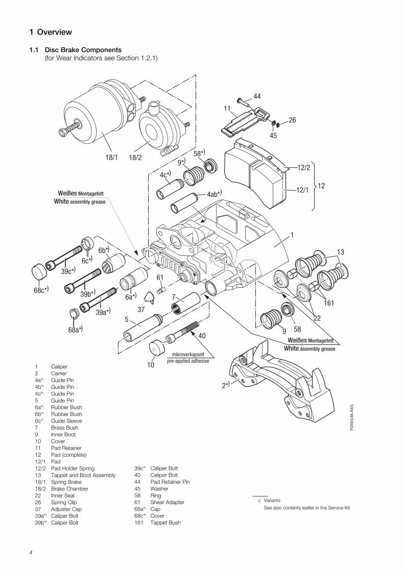
1.1 Disc Brake Components(for Wear Indicators see Section 1.2.1)
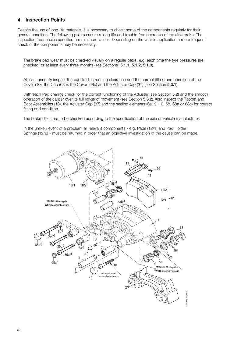
1 Caliper2 Carrier4a*) Guide Pin4b*) Guide Pin4c*) Guide Pin5 Guide Pin6a*) Rubber Bush6b*) Rubber Bush6c*) Guide Sleeve7 Brass Bush9 Inner Boot10 Cover11 Pad Retainer12 Pad (complete)12/1 Pad 12/2 Pad Holder Spring 13 Tappet and Boot Assembly18/1 Spring Brake18/2 Brake Chamber22 Inner Seal26 Spring Clip37 Adjuster Cap39a*) Caliper Bolt39b*) Caliper Bolt
39c*) Caliper Bolt40 Caliper Bolt44 Pad Retainer Pin45 Washer58 Ring61 Shear Adapter68a*) Cap68c*) Cover161 Tappet Bush
*) Variants
See also contents leaflet in the Service Kit
K001262_001 09.06.2004 15:23 Uhr Seite 4
5
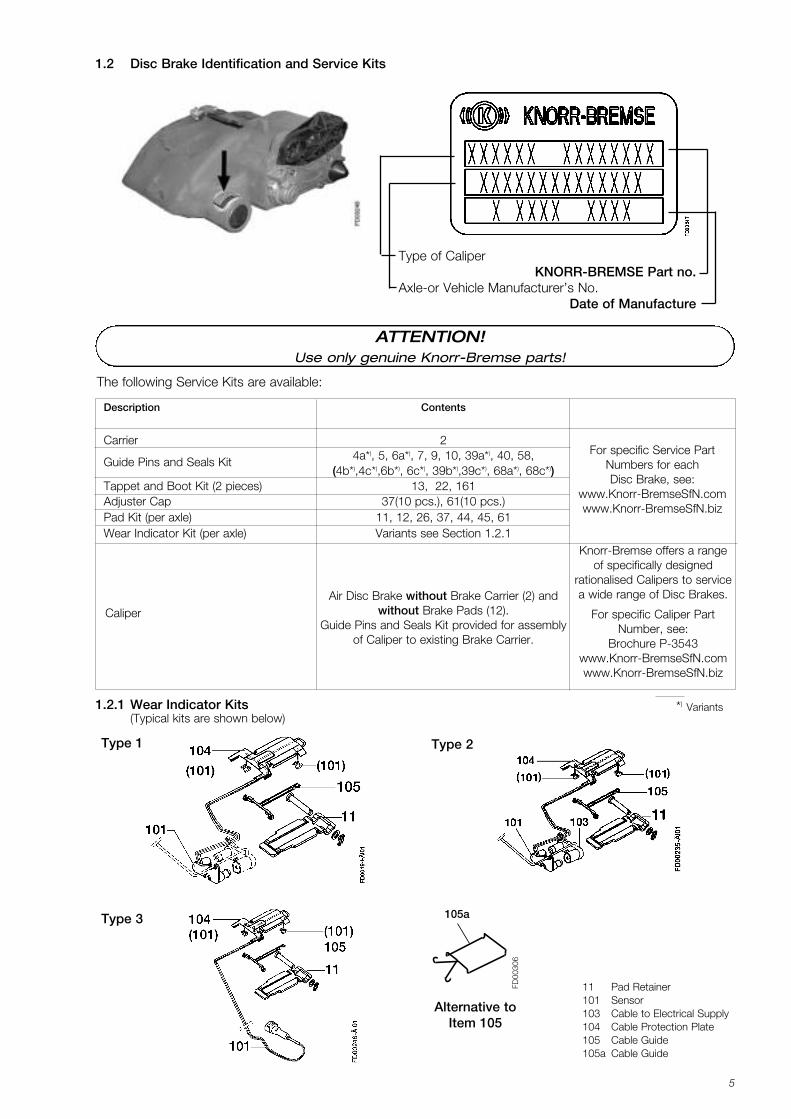
1.2 Disc Brake Identification and Service Kits
1.2.1 Wear Indicator Kits(Typical kits are shown below)
11 Pad Retainer101 Sensor103 Cable to Electrical Supply104 Cable Protection Plate105 Cable Guide105a Cable Guide
Type 1 Type 2
Type 3
The following Service Kits are available:
Description Contents
Carrier 2
Guide Pins and Seals Kit 4a*), 5, 6a*), 7, 9, 10, 39a*), 40, 58, (4b*),4c*),6b*), 6c*), 39b*),39c*), 68a*), 68c*))
Tappet and Boot Kit (2 pieces) 13, 22, 161Adjuster Cap 37(10 pcs.), 61(10 pcs.)Pad Kit (per axle) 11, 12, 26, 37, 44, 45, 61Wear Indicator Kit (per axle) Variants see Section 1.2.1
Air Disc Brake without Brake Carrier (2) and Caliper without Brake Pads (12).
Guide Pins and Seals Kit provided for assembly of Caliper to existing Brake Carrier.
*) Variants
FD00
306
105a
Alternative to Item 105
For specific Service PartNumbers for each Disc Brake, see:
www.Knorr-BremseSfN.comwww.Knorr-BremseSfN.biz
Knorr-Bremse offers a rangeof specifically designed
rationalised Calipers to servicea wide range of Disc Brakes.
For specific Caliper PartNumber, see:
Brochure P-3543 www.Knorr-BremseSfN.comwww.Knorr-BremseSfN.biz
Type of CaliperKNORR-BREMSE Part no.
Axle-or Vehicle Manufacturer’s No.Date of Manufacture
ATTENTION!Use only genuine Knorr-Bremse parts!
K001262_001 09.06.2004 15:23 Uhr Seite 5
6
1.3 Brake Disc
When replacing the Discs, please refer to the instructions of the Vehicle Manufacturer.
This should also be done when fitting Knorr-Bremse Brake Discs.
When replacing Discs, please adhere to the recommended bolt tightening torques.
The use of non-approved Brake Discs will reduce levels of safety and invalidate warranty.
Brake Discs can be ordered through the Knorr-Bremse Aftermarket Organisation.
K001262_001 09.06.2004 15:23 Uhr Seite 6
7
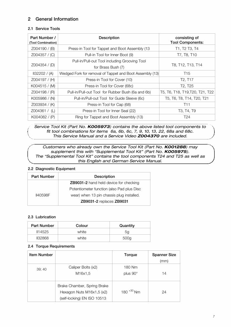
Part Number Colour Quantity
ll14525 white 5g
ll32868 white 500g
Item Number Torque Spanner Size
(mm)
39; 40 Caliper Bolts (x2) 180 Nm
M16x1,5 plus 90° 14
Brake Chamber, Spring Brake
Hexagon Nuts M16x1,5 (x2) 180 +30 Nm 24
(self-locking) EN ISO 10513
2 General Information
2.1 Service Tools
2.3 Lubrication
2.4 Torque Requirements
2.2 Diagnostic Equipment
Part Number Description
ZB9031-2 hand held device for checking
Potentiometer function (also Pad plus Disc
ll40598F wear) when 13 pin chassis plug installed.
ZB9031-2 replaces ZB9031
Service Tool Kit (Part No. K005973) contains the above listed tool components tofit tool combinations for items 6a, 6b, 6c, 7, 9, 10, 13, 22, 68a and 68c.
This Service Manual and a Service Video Z004370 are included.
Part Number / Description consisting of(Tool Combination) Tool Components:
Z004190 / (B) Press-in Tool for Tappet and Boot Assembly (13 T1, T2 T3, T4
Z004357 / (C) Pull-in Tool for Inner Boot (9) T7, T8, T10
Z004354 / (D)Pull-in/Pull-out Tool including Grooving Tool
T8, T12, T13, T14for Brass Bush (7)
II32202 / (A) Wedged Fork for removal of Tappet and Boot Assembly (13) T15
Z004197 / (H) Press-in Tool for Cover (10) T2, T17
K004515 / (M) Press-in Tool for Cover (68c) T2, T25
Z004198 / (R) Pull-in/Pull-out Tool for Rubber Bush (6a and 6b) T5, T6, T18, T19,T20, T21, T22
K005986 / (N) Pull-in/Pull-out Tool for Guide Sleeve (6c) T5, T6, T8, T14, T20, T21
Z003934 / (K) Press-in Tool for Cap (68) T11
Z004361 / (L) Press-in Tool for Inner Seal (22) T3, T4, T9
K004082 / (P) Ring for Tappet and Boot Assembly (13) T24
Customers who already own the Service Tool Kit (Part No. K001288) may supplement this with “Supplemental Tool Kit” (Part No. K005975).
The “Supplemental Tool Kit” contains the tool components T24 and T25 as well asthis English and German Service Manual.
K001262_001 09.06.2004 15:23 Uhr Seite 7
8
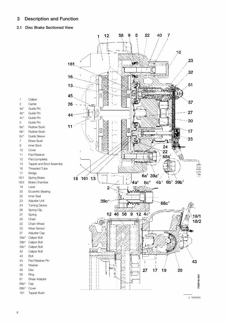
3 Description and Function
3.1 Disc Brake Sectioned View
1 Caliper
2 Carrier
4a*) Guide Pin
4b*) Guide Pin
4c*) Guide Pin
5 Guide Pin
6a*) Rubber Bush
6b*) Rubber Bush
6c*) Guide Sleeve
7 Brass Bush
9 Inner Boot
10 Cover
11 Pad Retainer
12 Pad (complete)
13 Tappet and Boot Assembly
16 Threaded Tube
17 Bridge
18/1 Spring Brake
18/2 Brake Chamber
19 Lever
20 Eccentric Bearing
22 Inner Seal
23 Adjuster Unit
24 Turning Device
26 Spring Clip
27 Spring
30 Chain
32 Chain Wheel
33 Wear Sensor
37 Adjuster Cap
39a*) Caliper Bolt
39b*) Caliper Bolt
39c*) Caliper Bolt
40 Caliper Bolt
43 Bolt
44 Pad Retainer Pin
45 Washer
46 Disc
58 Ring
61 Shear Adapter
68a*) Cap
68b*) Cover
161 Tappet Bush
*) Variants
K001262_001 09.06.2004 15:23 Uhr Seite 8
9
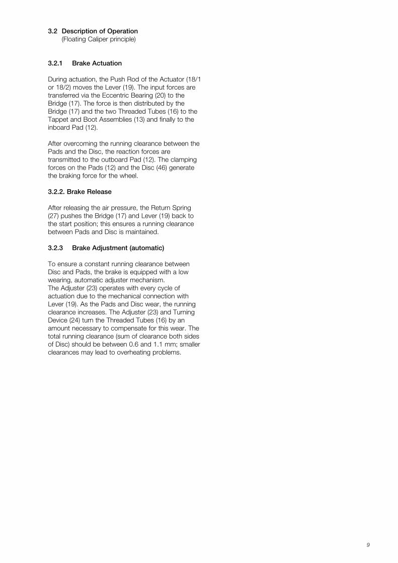
3.2 Description of Operation(Floating Caliper principle)
3.2.1 Brake Actuation
During actuation, the Push Rod of the Actuator (18/1or 18/2) moves the Lever (19). The input forces aretransferred via the Eccentric Bearing (20) to theBridge (17). The force is then distributed by theBridge (17) and the two Threaded Tubes (16) to theTappet and Boot Assemblies (13) and finally to theinboard Pad (12).
After overcoming the running clearance between thePads and the Disc, the reaction forces are transmitted to the outboard Pad (12). The clampingforces on the Pads (12) and the Disc (46) generatethe braking force for the wheel.
3.2.2. Brake Release
After releasing the air pressure, the Return Spring(27) pushes the Bridge (17) and Lever (19) back tothe start position; this ensures a running clearancebetween Pads and Disc is maintained.
3.2.3 Brake Adjustment (automatic)
To ensure a constant running clearance betweenDisc and Pads, the brake is equipped with a lowwearing, automatic adjuster mechanism. The Adjuster (23) operates with every cycle of actuation due to the mechanical connection withLever (19). As the Pads and Disc wear, the runningclearance increases. The Adjuster (23) and TurningDevice (24) turn the Threaded Tubes (16) by an amount necessary to compensate for this wear. Thetotal running clearance (sum of clearance both sidesof Disc) should be between 0.6 and 1.1 mm; smallerclearances may lead to overheating problems.
K001262_001 09.06.2004 15:23 Uhr Seite 9
10
26
44
11
5
7
9 58
37
45
1
13
161
18/1 18/2
12
61
39a*
6a*)39b*
6b*)
68a*)
10
2*
12/2
12/1
mikroverkapseltpre-applied adhesive
40
Weißes Montagefett
White assembly grease
Weißes Montagefett
White assembly grease
22
4c*
9*58*
4ab*
68c*
39c*
FD00
148-
Äi0
1kle
in
)
)
)
)
)
)
6c*)
)
))
4 Inspection Points
Despite the use of long-life materials, it is necessary to check some of the components regularly for their general condition. The following points ensure a long-life and trouble-free operation of the disc brake. The inspection frequencies specified are minimum values. Depending on the vehicle application a more frequentcheck of the components may be necessary.
The brake pad wear must be checked visually on a regular basis, e.g. each time the tyre pressures are checked, or at least every three months (see Sections 5.1.1, 5.1.2, 5.1.3).
At least annually inspect the pad to disc running clearance and the correct fitting and condition of the Cover (10), the Cap (68a), the Cover (68c) and the Adjuster Cap (37) (see Section 5.3.1).
With each Pad change check for the correct functioning of the Adjuster (see Section 5.2) and the smooth operation of the caliper over its full range of movement (see Section 5.3.2). Also inspect the Tappet and Boot Assemblies (13), the Adjuster Cap (37) and the sealing elements (6a, 9, 10, 58, 68a or 68c) for correctfitting and condition.
The brake discs are to be checked according to the specification of the axle or vehicle manufacturer.
In the unlikely event of a problem, all relevant components - e.g. Pads (12/1) and Pad Holder Springs (12/2) - must be returned in order that an objective investigation of the cause can be made.
K001262_001 09.06.2004 15:23 Uhr Seite 10
11
Please follow repair manual instructions and adhereto the wear limits of the Pads and the Discs - seeSection 5.1.
Use only recommended tools - see Section 2.1.
Tighten bolts and nuts to the recommended torquevalues - see Section 2.4.
After re-fitting a wheel according to the VehicleManufacturer’s recommendations, please ensure thatthere is sufficient clearance between the tyre inflationvalve, the caliper and the wheel rim, to avoid damageto the valve.
4.1 Safety Instructions for Service Work and Repair Work
Please also refer to the relevant safety instructions forrepair work and service work on commercial vehicles,especially for jacking up and securing the vehicle.
Use only original Knorr-Bremse parts.
ATTENTION!
Before starting service work, ensure theservice brake and parking brake, as wellas the bus stop temporary hold brake, if
fitted, are not applied and that the vehiclecannot roll away.
ATTENTION!
After every service work: Check the brake performance and the
system behaviour on a rolling road.Check function and effectiveness.
ATTENTION!
Screw threads and tapped holes must beclean and dry (free of lubrication and residuals of pre-applied adhesive).
K001262_001 09.06.2004 15:23 Uhr Seite 11
12
5.1 Wear Check of Pads and Brake Discs
ED
C A
F
M+
P-K
N-0
02Ä
i01
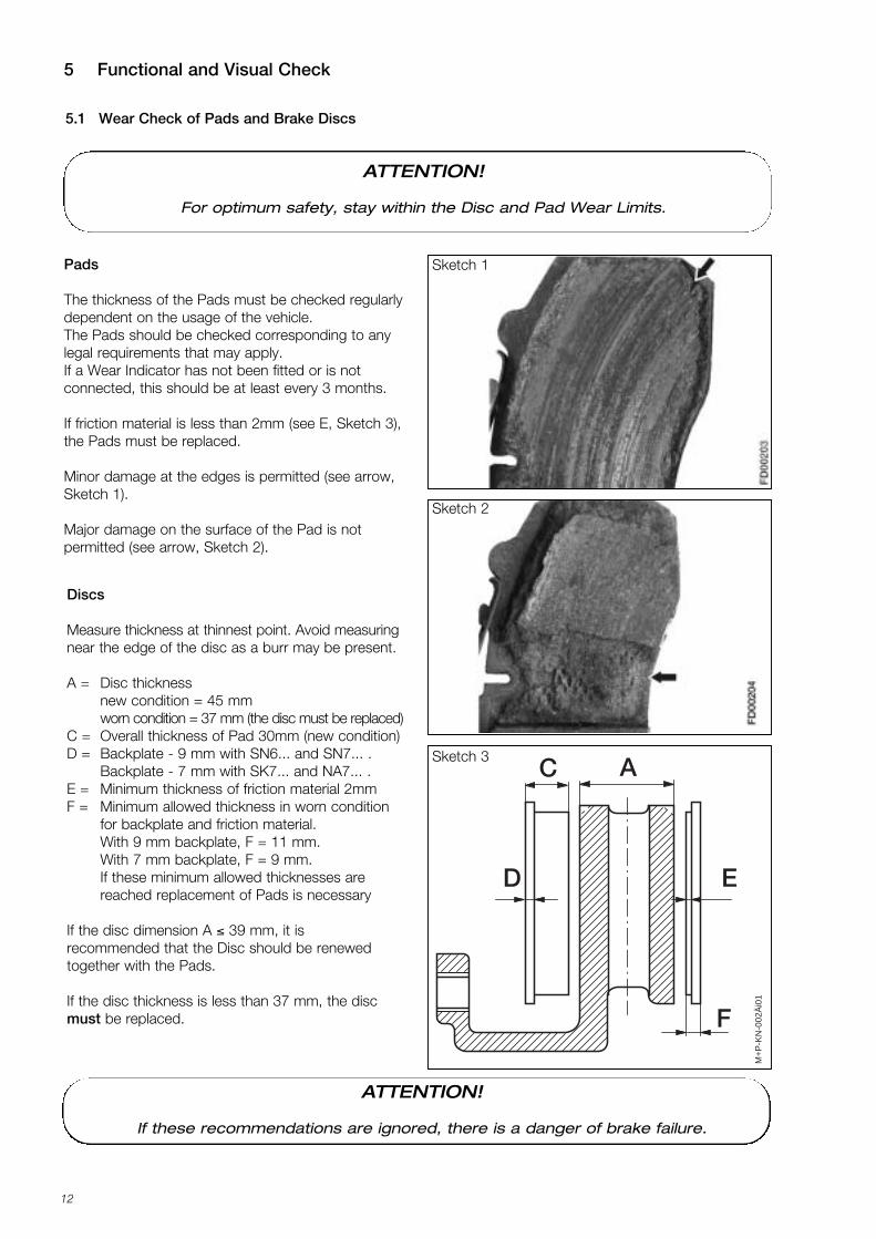
Pads
The thickness of the Pads must be checked regularlydependent on the usage of the vehicle. The Pads should be checked corresponding to anylegal requirements that may apply. If a Wear Indicator has not been fitted or is notconnected, this should be at least every 3 months.
If friction material is less than 2mm (see E, Sketch 3),the Pads must be replaced.
Minor damage at the edges is permitted (see arrow,Sketch 1).
Major damage on the surface of the Pad is not permitted (see arrow, Sketch 2).
Discs
Measure thickness at thinnest point. Avoid measuringnear the edge of the disc as a burr may be present.
A = Disc thicknessnew condition = 45 mmworn condition = 37 mm (the disc must be replaced)
C = Overall thickness of Pad 30mm (new condition) D = Backplate - 9 mm with SN6... and SN7... .
Backplate - 7 mm with SK7... and NA7... .E = Minimum thickness of friction material 2mmF = Minimum allowed thickness in worn condition
for backplate and friction material.With 9 mm backplate, F = 11 mm. With 7 mm backplate, F = 9 mm.If these minimum allowed thicknesses are reached replacement of Pads is necessary
If the disc dimension A ≤ 39 mm, it is recommended that the Disc should be renewedtogether with the Pads.
If the disc thickness is less than 37 mm, the discmust be replaced.
Sketch 1
Sketch 2
Sketch 3
5 Functional and Visual Check
ATTENTION!
For optimum safety, stay within the Disc and Pad Wear Limits.
ATTENTION!
If these recommendations are ignored, there is a danger of brake failure.
K001262_001 09.06.2004 15:23 Uhr Seite 12
13
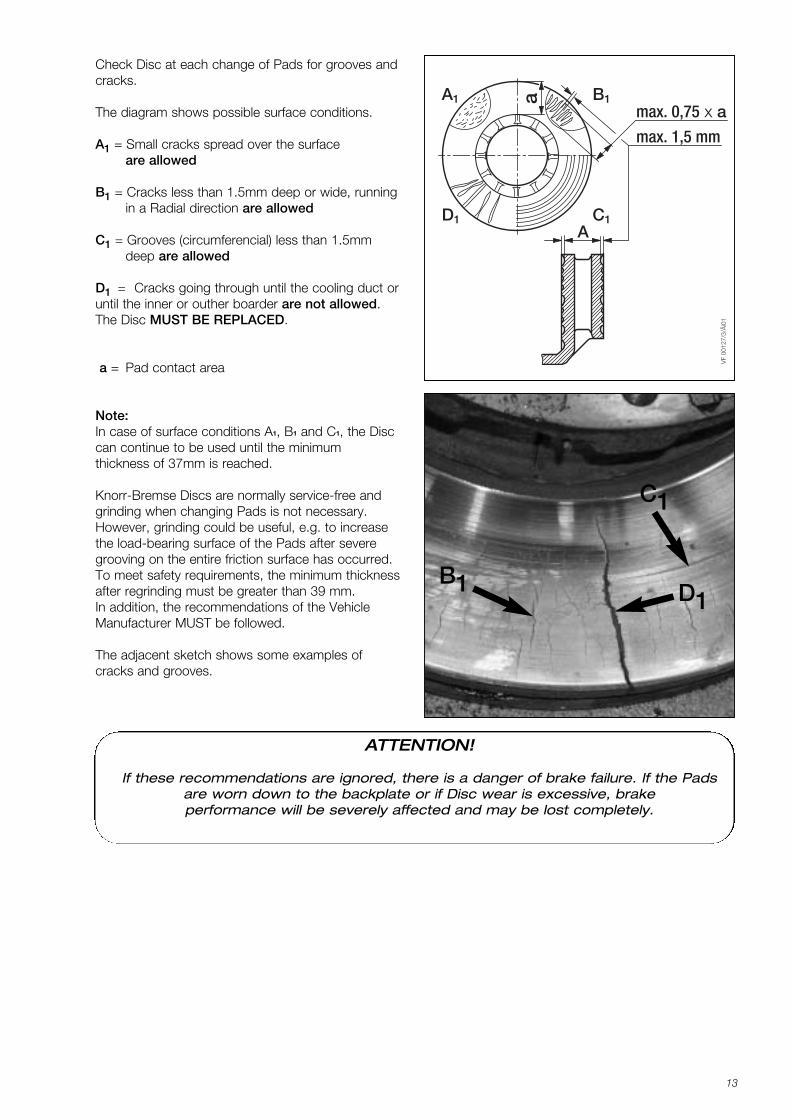
Check Disc at each change of Pads for grooves andcracks.
The diagram shows possible surface conditions.
A1 = Small cracks spread over the surface are allowed
B1 = Cracks less than 1.5mm deep or wide, running in a Radial direction are allowed
C1 = Grooves (circumferencial) less than 1.5mm deep are allowed
D1 = Cracks going through until the cooling duct oruntil the inner or outher boarder are not allowed.The Disc MUST BE REPLACED.
a = Pad contact area
Note:In case of surface conditions A1, B1 and C1, the Disccan continue to be used until the minimum thickness of 37mm is reached.
Knorr-Bremse Discs are normally service-free andgrinding when changing Pads is not necessary.However, grinding could be useful, e.g. to increasethe load-bearing surface of the Pads after severegrooving on the entire friction surface has occurred.To meet safety requirements, the minimum thicknessafter regrinding must be greater than 39 mm. In addition, the recommendations of the VehicleManufacturer MUST be followed.
The adjacent sketch shows some examples ofcracks and grooves.
max. 0,75 x a
max. 1,5 mm
VF
0012
7/3/
Äi0
1
A1 B1
D1 C1
a
A
D1B1
C1
ATTENTION!
If these recommendations are ignored, there is a danger of brake failure. If the Padsare worn down to the backplate or if Disc wear is excessive, brake performance will be severely affected and may be lost completely.
K001262_001 09.06.2004 15:23 Uhr Seite 13
G
G"X" "Z"
6a 6a
FD
0019
0/1Ä
i03
44
H
11
14
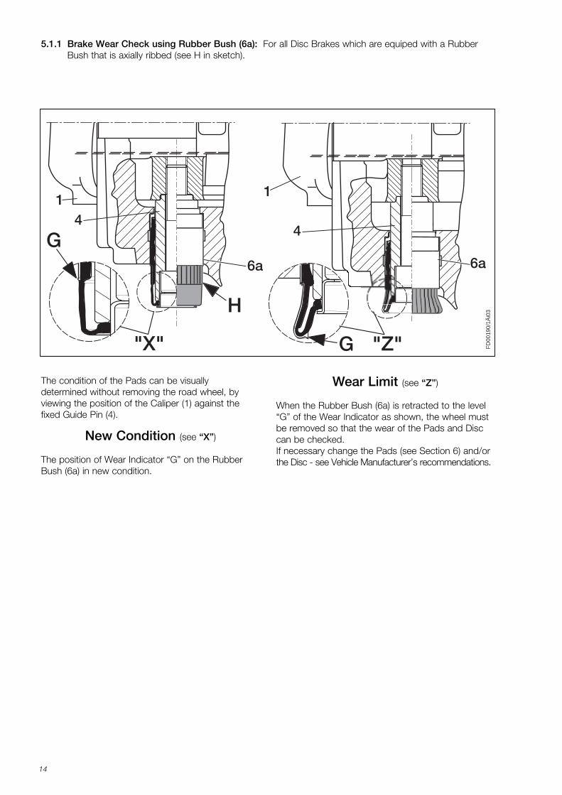
The condition of the Pads can be visually determined without removing the road wheel, by viewing the position of the Caliper (1) against thefixed Guide Pin (4).
5.1.1 Brake Wear Check using Rubber Bush (6a): For all Disc Brakes which are equiped with a Rubber Bush that is axially ribbed (see H in sketch).
New Condition (see “X”)
The position of Wear Indicator “G” on the RubberBush (6a) in new condition.
Wear Limit (see “Z”)
When the Rubber Bush (6a) is retracted to the level“G” of the Wear Indicator as shown, the wheel mustbe removed so that the wear of the Pads and Disccan be checked.If necessary change the Pads (see Section 6) and/orthe Disc - see Vehicle Manufacturer’s recommendations.
K001262_001 09.06.2004 15:23 Uhr Seite 14
15
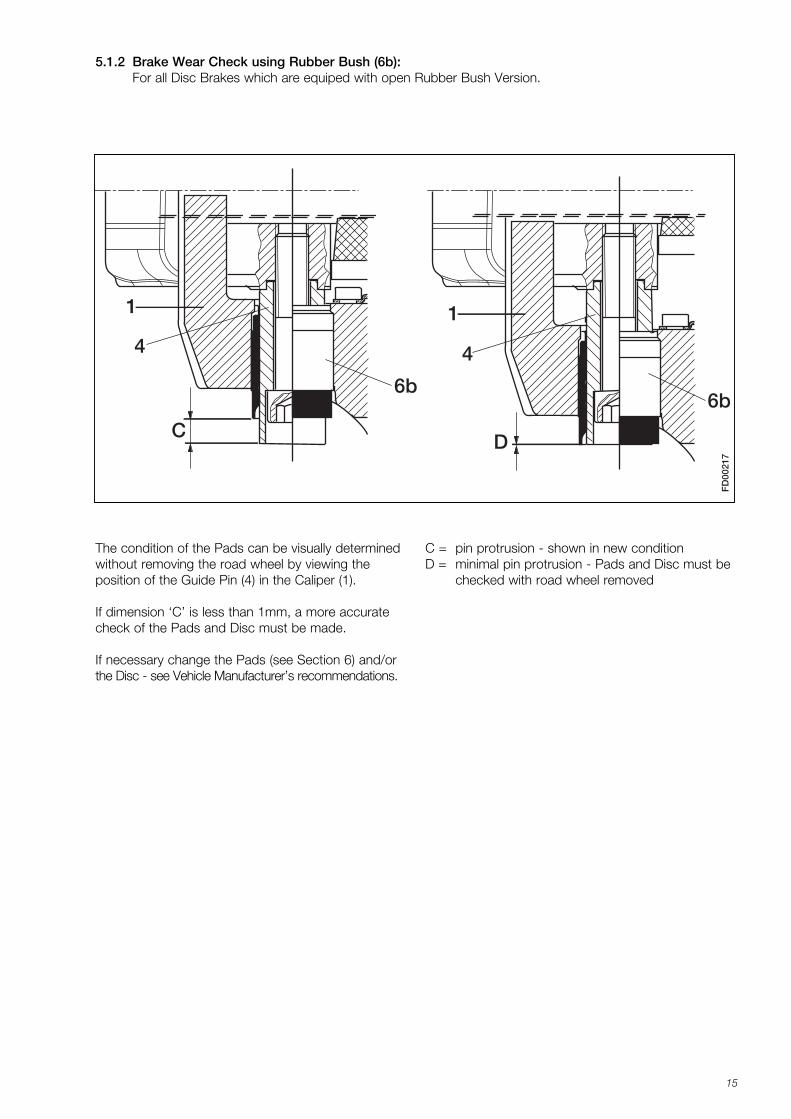
5.1.2 Brake Wear Check using Rubber Bush (6b): For all Disc Brakes which are equiped with open Rubber Bush Version.
FD
0021
7
C D
6b
4
1
6b
4
1
The condition of the Pads can be visually determinedwithout removing the road wheel by viewing the position of the Guide Pin (4) in the Caliper (1).
If dimension ‘C’ is less than 1mm, a more accuratecheck of the Pads and Disc must be made.
If necessary change the Pads (see Section 6) and/orthe Disc - see Vehicle Manufacturer’s recommendations.
C = pin protrusion - shown in new conditionD = minimal pin protrusion - Pads and Disc must be
checked with road wheel removed
K001262_001 09.06.2004 15:23 Uhr Seite 15
16
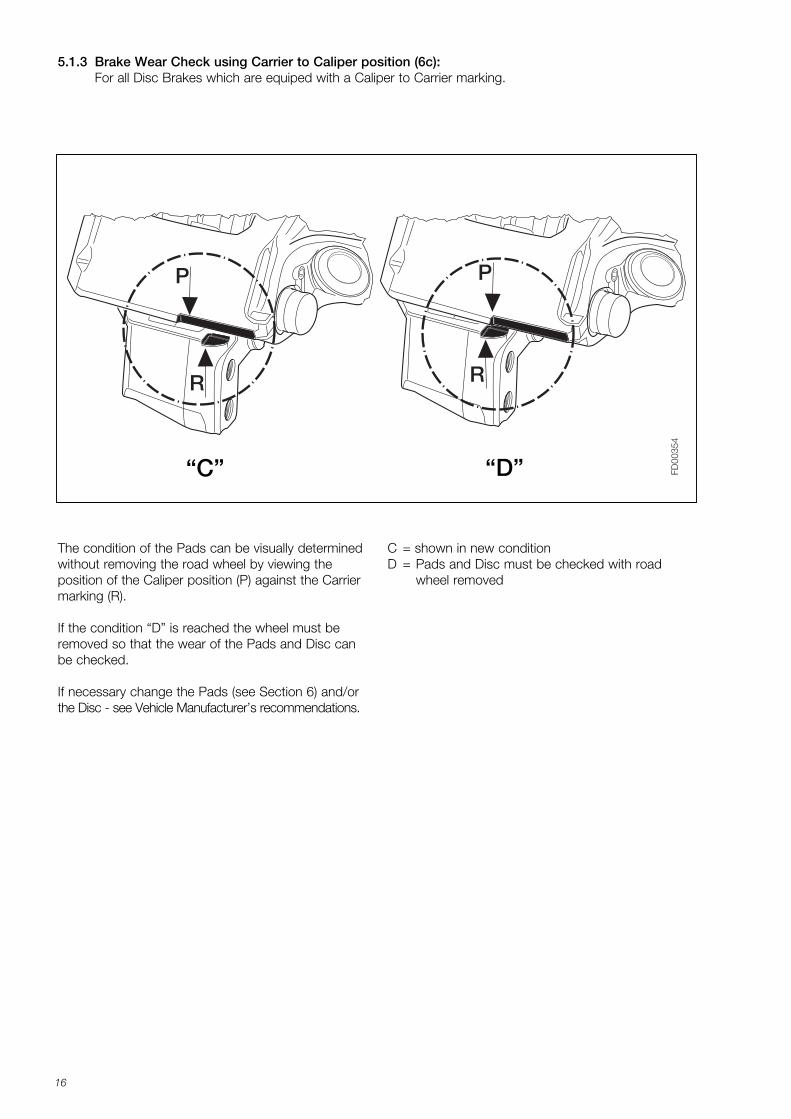
5.1.3 Brake Wear Check using Carrier to Caliper position (6c):For all Disc Brakes which are equiped with a Caliper to Carrier marking.
P
R
P
R
FD00
354
The condition of the Pads can be visually determinedwithout removing the road wheel by viewing the position of the Caliper position (P) against the Carriermarking (R).
If the condition “D” is reached the wheel must beremoved so that the wear of the Pads and Disc canbe checked.
If necessary change the Pads (see Section 6) and/orthe Disc - see Vehicle Manufacturer’s recommendations.
C = shown in new conditionD = Pads and Disc must be checked with road
wheel removed
“C” “D”
K001262_001 09.06.2004 15:23 Uhr Seite 16
17
5.1.5 Diagnostic Equipment
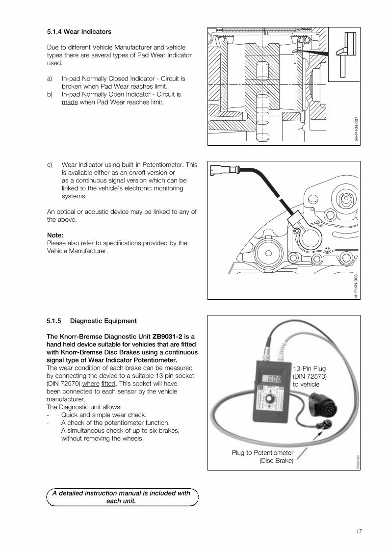
The Knorr-Bremse Diagnostic Unit ZB9031-2 is ahand held device suitable for vehicles that are fittedwith Knorr-Bremse Disc Brakes using a continuoussignal type of Wear Indicator Potentiometer.The wear condition of each brake can be measuredby connecting the device to a suitable 13 pin socket(DIN 72570) where fitted. This socket will have been connected to each sensor by the vehicle manufacturer. The Diagnostic unit allows:- Quick and simple wear check.- A check of the potentiometer function.- A simultaneous check of up to six brakes,
without removing the wheels.
Plug to Potentiometer (Disc Brake)
13-Pin Plug(DIN 72570)to vehicle
5.1.4 Wear Indicators
Due to different Vehicle Manufacturer and vehicletypes there are several types of Pad Wear Indicatorused.
a) In-pad Normally Closed Indicator - Circuit is broken when Pad Wear reaches limit.
b) In-pad Normally Open Indicator - Circuit is made when Pad Wear reaches limit.
c) Wear Indicator using built-in Potentiometer. Thisis available either as an on/off version or as a continuous signal version which can be linked to the vehicle’s electronic monitoring systems.
An optical or acoustic device may be linked to any ofthe above.
Note:Please also refer to specifications provided by theVehicle Manufacturer.
M+
P-K
N-0
07M
+P
-KN
-008
A detailed instruction manual is included with each unit.
K001262_001 09.06.2004 15:23 Uhr Seite 17
18
FD
0015
0
61 37
FD
00
218
FD
0015
1
1
23
3761
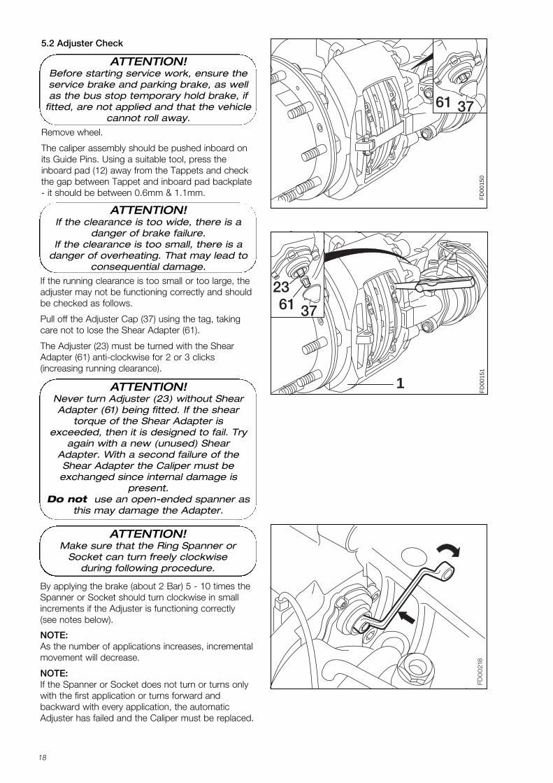
5.2 Adjuster Check
Remove wheel.
The caliper assembly should be pushed inboard onits Guide Pins. Using a suitable tool, press the inboard pad (12) away from the Tappets and checkthe gap between Tappet and inboard pad backplate- it should be between 0.6mm & 1.1mm.
By applying the brake (about 2 Bar) 5 - 10 times theSpanner or Socket should turn clockwise in smallincrements if the Adjuster is functioning correctly (see notes below).
ATTENTION!Make sure that the Ring Spanner or
Socket can turn freely clockwiseduring following procedure.
NOTE: As the number of applications increases, incrementalmovement will decrease.
NOTE: If the Spanner or Socket does not turn or turns onlywith the first application or turns forward and backward with every application, the automaticAdjuster has failed and the Caliper must be replaced.
If the running clearance is too small or too large, theadjuster may not be functioning correctly and shouldbe checked as follows.
Pull off the Adjuster Cap (37) using the tag, takingcare not to lose the Shear Adapter (61).
The Adjuster (23) must be turned with the ShearAdapter (61) anti-clockwise for 2 or 3 clicks (increasing running clearance).
ATTENTION!If the clearance is too wide, there is a
danger of brake failure.If the clearance is too small, there is a
danger of overheating. That may lead toconsequential damage.
ATTENTION!Before starting service work, ensure theservice brake and parking brake, as wellas the bus stop temporary hold brake, if
fitted, are not applied and that the vehiclecannot roll away.
ATTENTION!Never turn Adjuster (23) without ShearAdapter (61) being fitted. If the shear
torque of the Shear Adapter is exceeded, then it is designed to fail. Try
again with a new (unused) ShearAdapter. With a second failure of theShear Adapter the Caliper must be
exchanged since internal damage is present.
Do not use an open-ended spanner asthis may damage the Adapter.
K001262_001 09.06.2004 15:23 Uhr Seite 18
19
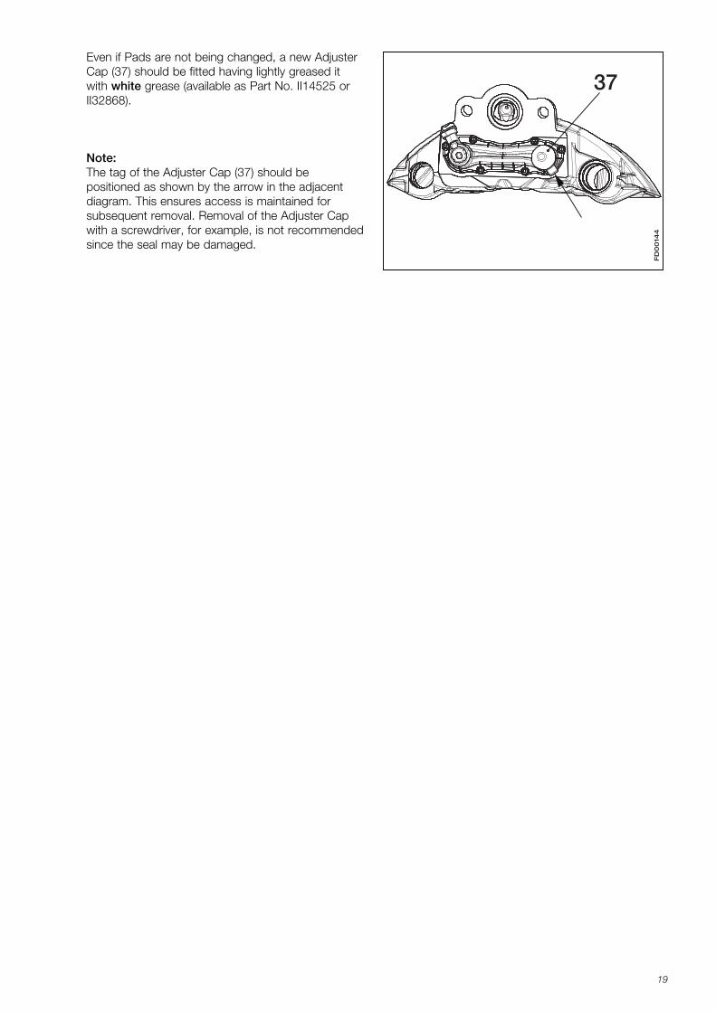
Even if Pads are not being changed, a new AdjusterCap (37) should be fitted having lightly greased itwith white grease (available as Part No. II14525 orII32868).
Note:The tag of the Adjuster Cap (37) should be positioned as shown by the arrow in the adjacentdiagram. This ensures access is maintained for subsequent removal. Removal of the Adjuster Capwith a screwdriver, for example, is not recommendedsince the seal may be damaged.
FD
00
144
37
K001262_001 09.06.2004 15:23 Uhr Seite 19
20
*) Variants
5.3 Caliper Checks
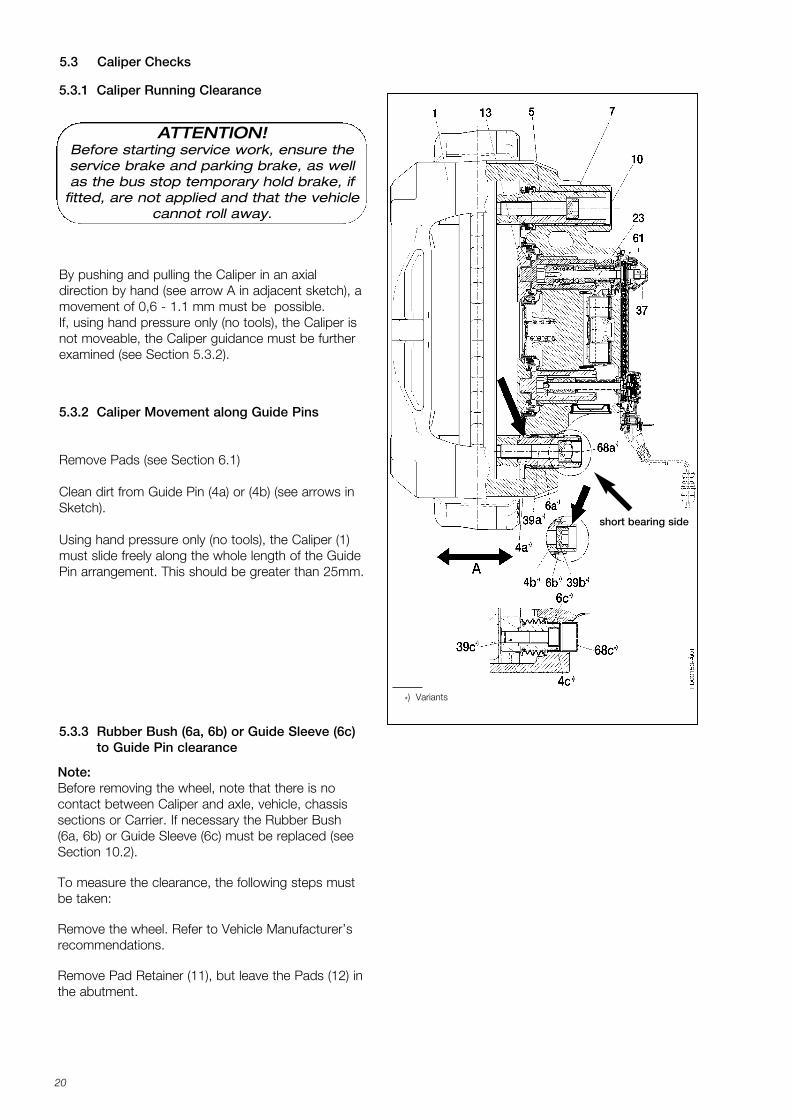
5.3.3 Rubber Bush (6a, 6b) or Guide Sleeve (6c)to Guide Pin clearance
5.3.2 Caliper Movement along Guide Pins
Remove Pads (see Section 6.1)
Clean dirt from Guide Pin (4a) or (4b) (see arrows inSketch).
Using hand pressure only (no tools), the Caliper (1)must slide freely along the whole length of the GuidePin arrangement. This should be greater than 25mm.
5.3.1 Caliper Running Clearance
By pushing and pulling the Caliper in an axial direction by hand (see arrow A in adjacent sketch), amovement of 0,6 - 1.1 mm must be possible. If, using hand pressure only (no tools), the Caliper isnot moveable, the Caliper guidance must be furtherexamined (see Section 5.3.2).
short bearing side
Note:Before removing the wheel, note that there is nocontact between Caliper and axle, vehicle, chassissections or Carrier. If necessary the Rubber Bush(6a, 6b) or Guide Sleeve (6c) must be replaced (seeSection 10.2).
To measure the clearance, the following steps mustbe taken:
Remove the wheel. Refer to Vehicle Manufacturer’srecommendations.
Remove Pad Retainer (11), but leave the Pads (12) inthe abutment.
ATTENTION!Before starting service work, ensure theservice brake and parking brake, as wellas the bus stop temporary hold brake, if
fitted, are not applied and that the vehiclecannot roll away.
K001262_001 09.06.2004 15:23 Uhr Seite 20
21
FD
00
38
3
2
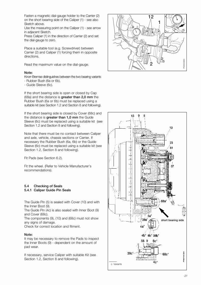
112Fasten a magnetic dial-gauge holder to the Carrier (2)
on the short bearing side of the Caliper (1) - see alsoSketch above.Use the measuring point on the Caliper (1) - see arrowin adjacent Sketch.Press Caliper (1) in the direction of Carrier (2) and setthe dial-gauge to zero.
Place a suitable tool (e.g. Screwdriver) betweenCarrier (2) and Caliper (1) forcing them in oppositedirections.
Read the maximum value on the dial-gauge.
Note:Knorr-Bremse distinguishes between the two bearing variants- Rubber Bush (6a or 6b),- Guide Sleeve (6c).
If the short bearing side is open or closed by Cap(68a) and the distance is greater than 2,0 mm theRubber Bush (6a or 6b) must be replaced using a suitable kit (see Section 1.2 and Section 8 and following).
If the short bearing side is closed by Cover (68c) andthe distance is greater than 1,0 mm the GuideSleeve (6c) must be replaced using a suitable kit (seeSection 1.2 and Section 8 and following).
Note that there must be no contact between Caliperand axle, vehicle, chassis sections or Carrier. If necessary the Rubber Bush (6a, 6b) or the GuideSleeve (6c) must be replaced using a suitable kit (seeSection 1.2, Section 8 and following).
Fit Pads (see Section 6.2).
Fit the wheel. (Refer to Vehicle Manufacturer’srecommendations).
*) Variants
5.4 Checking of Seals5.4.1 Caliper Guide Pin Seals
The Guide Pin (5) is sealed with Cover (10) and withthe Inner Boot (9). The Guide Pin (4c) is also sealed with Inner Boot (9)and Cover (68c).The components (9), (10) and (68c) must not showany signs of damage.Check for correct location and fitment.
Note:It may be necessary to remove the Pads to inspectthe Inner Boots (9) - dependent on the amount ofpad wear.
If necessary, service Caliper with suitable Kit (seeSection 1.2, Section 8 and following).
short bearing side
K001262_001 09.06.2004 15:23 Uhr Seite 21
22
30
FD00
220
13
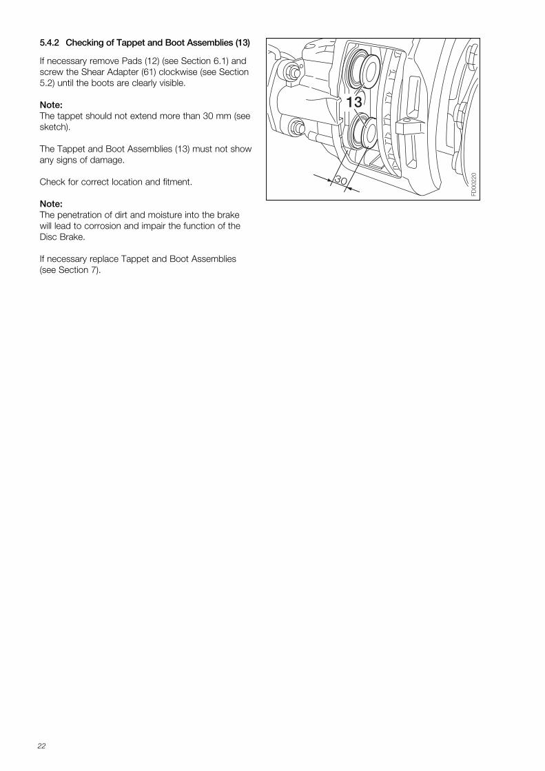
5.4.2 Checking of Tappet and Boot Assemblies (13)
If necessary remove Pads (12) (see Section 6.1) andscrew the Shear Adapter (61) clockwise (see Section5.2) until the boots are clearly visible.
Note:The tappet should not extend more than 30 mm (seesketch).
The Tappet and Boot Assemblies (13) must not showany signs of damage.
Check for correct location and fitment.
Note:The penetration of dirt and moisture into the brakewill lead to corrosion and impair the function of theDisc Brake.
If necessary replace Tappet and Boot Assemblies(see Section 7).
K001262_001 09.06.2004 15:23 Uhr Seite 22
23
6 Pad Replacement
FD
0022
1
1145
26
44
6.1 Pad Removal
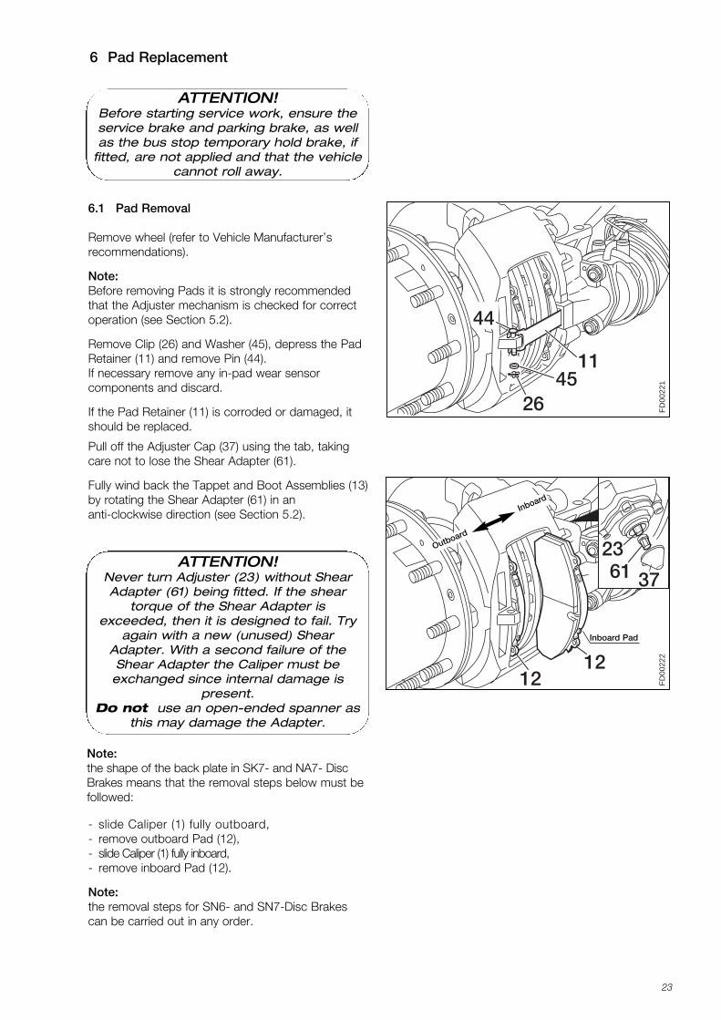
Remove wheel (refer to Vehicle Manufacturer’srecommendations).
Note:Before removing Pads it is strongly recommendedthat the Adjuster mechanism is checked for correctoperation (see Section 5.2).
Remove Clip (26) and Washer (45), depress the PadRetainer (11) and remove Pin (44).If necessary remove any in-pad wear sensor components and discard.
If the Pad Retainer (11) is corroded or damaged, itshould be replaced.
- slide Caliper (1) fully outboard,- remove outboard Pad (12),- slide Caliper (1) fully inboard,- remove inboard Pad (12).
Note:the removal steps for SN6- and SN7-Disc Brakescan be carried out in any order.
FD
0022
21212
2337
23
3761
Pull off the Adjuster Cap (37) using the tab, takingcare not to lose the Shear Adapter (61).
Fully wind back the Tappet and Boot Assemblies (13)by rotating the Shear Adapter (61) in an anti-clockwise direction (see Section 5.2).
Note:the shape of the back plate in SK7- and NA7- DiscBrakes means that the removal steps below must be followed:
Inboard Pad
Outboard
Inboard
ATTENTION!Before starting service work, ensure theservice brake and parking brake, as wellas the bus stop temporary hold brake, if
fitted, are not applied and that the vehiclecannot roll away.
ATTENTION!Never turn Adjuster (23) without ShearAdapter (61) being fitted. If the shear
torque of the Shear Adapter is exceeded, then it is designed to fail. Try
again with a new (unused) ShearAdapter. With a second failure of theShear Adapter the Caliper must be
exchanged since internal damage is present.
Do not use an open-ended spanner asthis may damage the Adapter.
K001262_001 09.06.2004 15:23 Uhr Seite 23
24
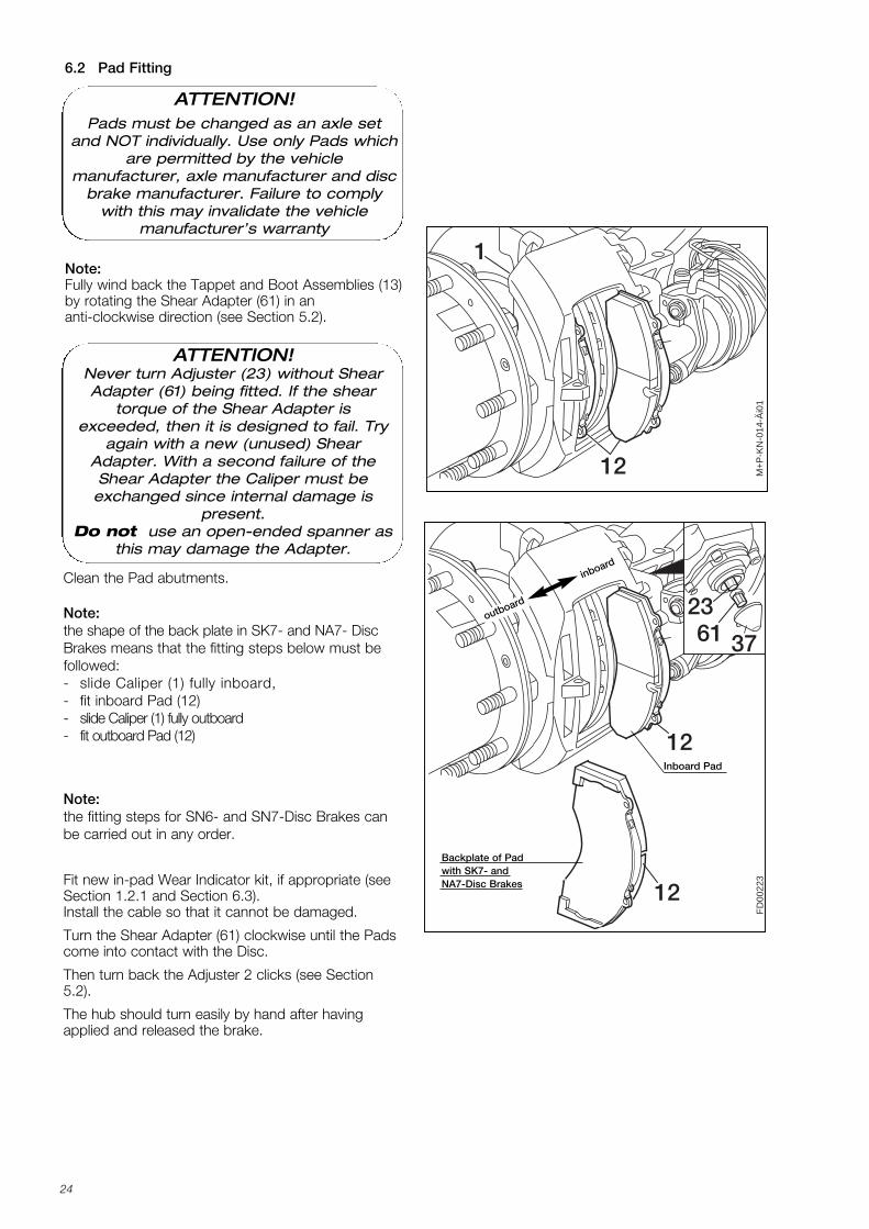
Note: Fully wind back the Tappet and Boot Assemblies (13)by rotating the Shear Adapter (61) in an anti-clockwise direction (see Section 5.2).
6.2 Pad Fitting
M+
P-K
N-0
14-Ä
i01
12
1
Fit new in-pad Wear Indicator kit, if appropriate (seeSection 1.2.1 and Section 6.3). Install the cable so that it cannot be damaged.
Turn the Shear Adapter (61) clockwise until the Padscome into contact with the Disc.
Then turn back the Adjuster 2 clicks (see Section5.2).
The hub should turn easily by hand after havingapplied and released the brake.
FD
0022
3
2337
23
3761
12
12
Note:the fitting steps for SN6- and SN7-Disc Brakes canbe carried out in any order.
Clean the Pad abutments.
Note:the shape of the back plate in SK7- and NA7- DiscBrakes means that the fitting steps below must befollowed:- slide Caliper (1) fully inboard,- fit inboard Pad (12) - slide Caliper (1) fully outboard - fit outboard Pad (12)
outboard
inboard
Inboard Pad
Backplate of Pad with SK7- and NA7-Disc Brakes
ATTENTION!Pads must be changed as an axle set
and NOT individually. Use only Pads whichare permitted by the vehicle
manufacturer, axle manufacturer and discbrake manufacturer. Failure to comply
with this may invalidate the vehicle manufacturer’s warranty
ATTENTION!Never turn Adjuster (23) without ShearAdapter (61) being fitted. If the shear
torque of the Shear Adapter is exceeded, then it is designed to fail. Try
again with a new (unused) ShearAdapter. With a second failure of theShear Adapter the Caliper must be
exchanged since internal damage is present.
Do not use an open-ended spanner asthis may damage the Adapter.
K001262_001 09.06.2004 15:23 Uhr Seite 24
25
111
4526
44
M+
P-K
N-0
16-Ä
i01
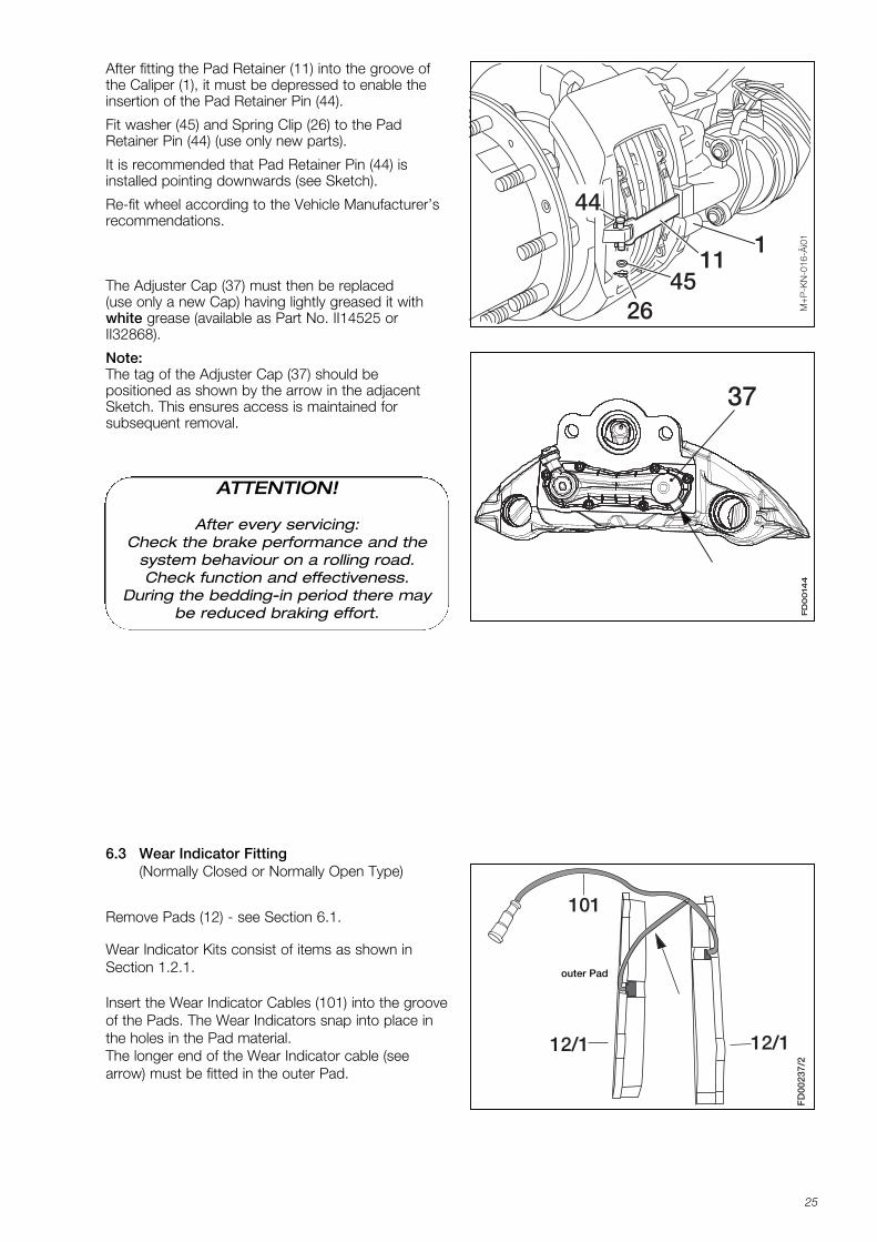
6.3 Wear Indicator Fitting(Normally Closed or Normally Open Type)
Remove Pads (12) - see Section 6.1.
Wear Indicator Kits consist of items as shown inSection 1.2.1.
Insert the Wear Indicator Cables (101) into the grooveof the Pads. The Wear Indicators snap into place inthe holes in the Pad material.The longer end of the Wear Indicator cable (seearrow) must be fitted in the outer Pad.
101
12/112/1
FD
0023
7/2
outer Pad
FD
00
144
37
After fitting the Pad Retainer (11) into the groove ofthe Caliper (1), it must be depressed to enable theinsertion of the Pad Retainer Pin (44).
Fit washer (45) and Spring Clip (26) to the PadRetainer Pin (44) (use only new parts).
It is recommended that Pad Retainer Pin (44) isinstalled pointing downwards (see Sketch).
Re-fit wheel according to the Vehicle Manufacturer’srecommendations.
The Adjuster Cap (37) must then be replaced(use only a new Cap) having lightly greased it withwhite grease (available as Part No. II14525 orII32868).
Note:The tag of the Adjuster Cap (37) should be positioned as shown by the arrow in the adjacentSketch. This ensures access is maintained for subsequent removal.
ATTENTION!
After every servicing: Check the brake performance and the
system behaviour on a rolling road.Check function and effectiveness.
During the bedding-in period there maybe reduced braking effort.
K001262_001 09.06.2004 15:23 Uhr Seite 25
26
FD00
237/
1
12/1
FD00
237/
3
12/2
12/2
12/1
101
FD00
237/
4
4411
4526
101
FD00
237/
5-Ä
i01
105
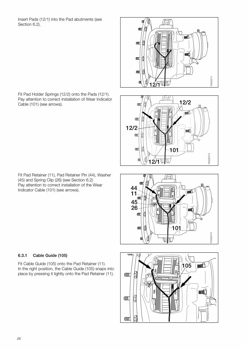
Insert Pads (12/1) into the Pad abutments (seeSection 6.2).
Fit Pad Holder Springs (12/2) onto the Pads (12/1). Pay attention to correct installation of Wear IndicatorCable (101) (see arrows).
Fit Pad Retainer (11), Pad Retainer Pin (44), Washer(45) and Spring Clip (26) (see Section 6.2) Pay attention to correct installation of the WearIndicator Cable (101) (see arrows).
Fit Cable Guide (105) onto the Pad Retainer (11).In the right position, the Cable Guide (105) snaps intoplace by pressing it lightly onto the Pad Retainer (11).
6.3.1 Cable Guide (105)
K001262_001 09.06.2004 15:23 Uhr Seite 26
27
FD00
237/
6-Ä
i01
A
A
B
B
101
FD
0023
7/7-
Äi0
1
104
11
short cable end
FD00
305-
Äi0
1
C
C
105a
B
A A
101
short cable end
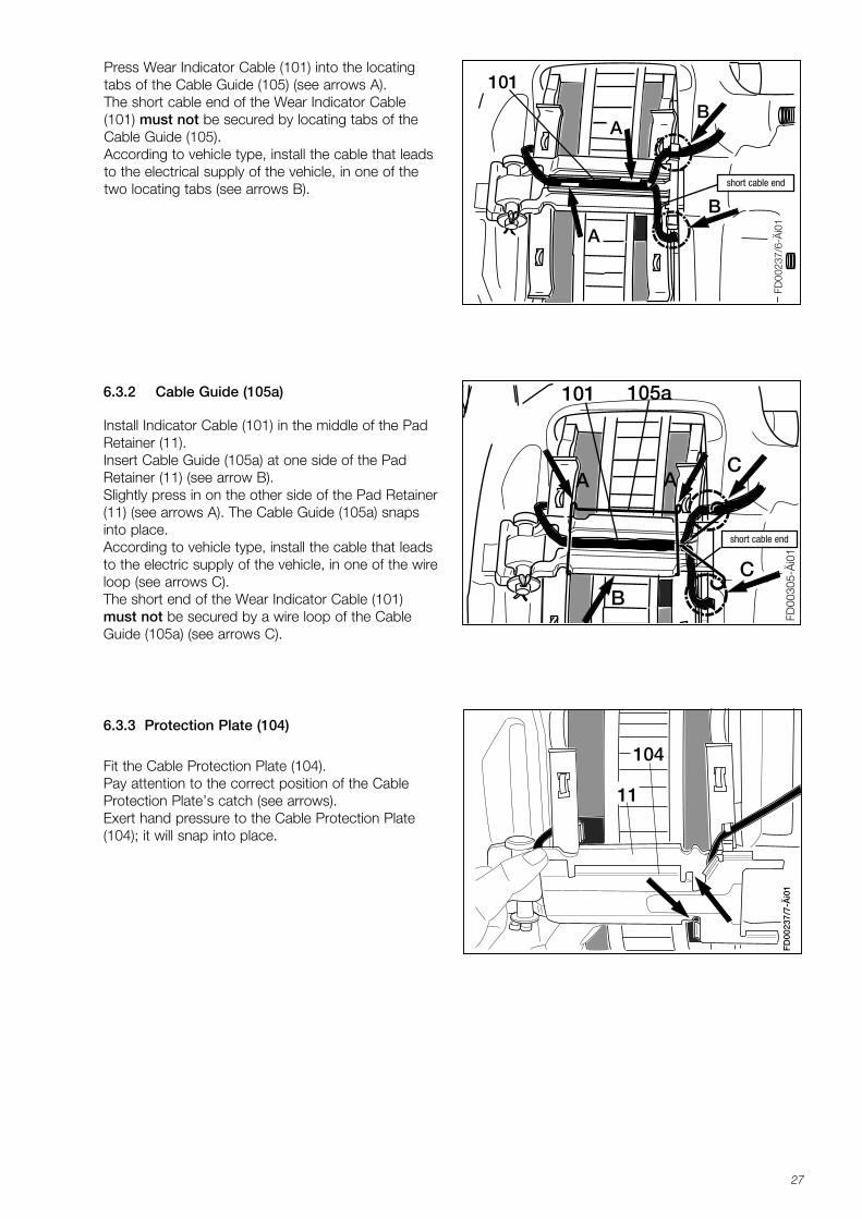
Fit the Cable Protection Plate (104).Pay attention to the correct position of the CableProtection Plate’s catch (see arrows).Exert hand pressure to the Cable Protection Plate(104); it will snap into place.
6.3.2 Cable Guide (105a)
6.3.3 Protection Plate (104)
Install Indicator Cable (101) in the middle of the PadRetainer (11).Insert Cable Guide (105a) at one side of the PadRetainer (11) (see arrow B).Slightly press in on the other side of the Pad Retainer(11) (see arrows A). The Cable Guide (105a) snapsinto place.According to vehicle type, install the cable that leadsto the electric supply of the vehicle, in one of the wireloop (see arrows C).The short end of the Wear Indicator Cable (101)must not be secured by a wire loop of the CableGuide (105a) (see arrows C).
Press Wear Indicator Cable (101) into the locatingtabs of the Cable Guide (105) (see arrows A).The short cable end of the Wear Indicator Cable(101) must not be secured by locating tabs of theCable Guide (105).According to vehicle type, install the cable that leadsto the electrical supply of the vehicle, in one of thetwo locating tabs (see arrows B).
K001262_001 09.06.2004 15:23 Uhr Seite 27
28
A13
FD00
155
A
X
22
1313331
A
161161
X
22
FD
0015
430
1313
B
Press-in Toolarrangement for
Inner Seal (22) whenCaliper is removedfrom the vehicle.
Press-in Toolarrangement for
Inner Seal (22) whenCaliper is fitted on the
vehicle.
Press-in Toolarrangement for
Tappet and BootAssembly (13) whenCaliper is removedfrom the vehicle.
Press-in Toolarrangement for
Tappet and BootAssembly (13) when
Caliper is fitted on thevehicle.
Wedge Fork (A)Press-in Tool (B)
Press-in Tool (L)
Ring (P) for SK7- and NA7- Disc Brakes.
Installation device forTappet and Boot
Assembly (13) whenCaliper is removed
from axle.
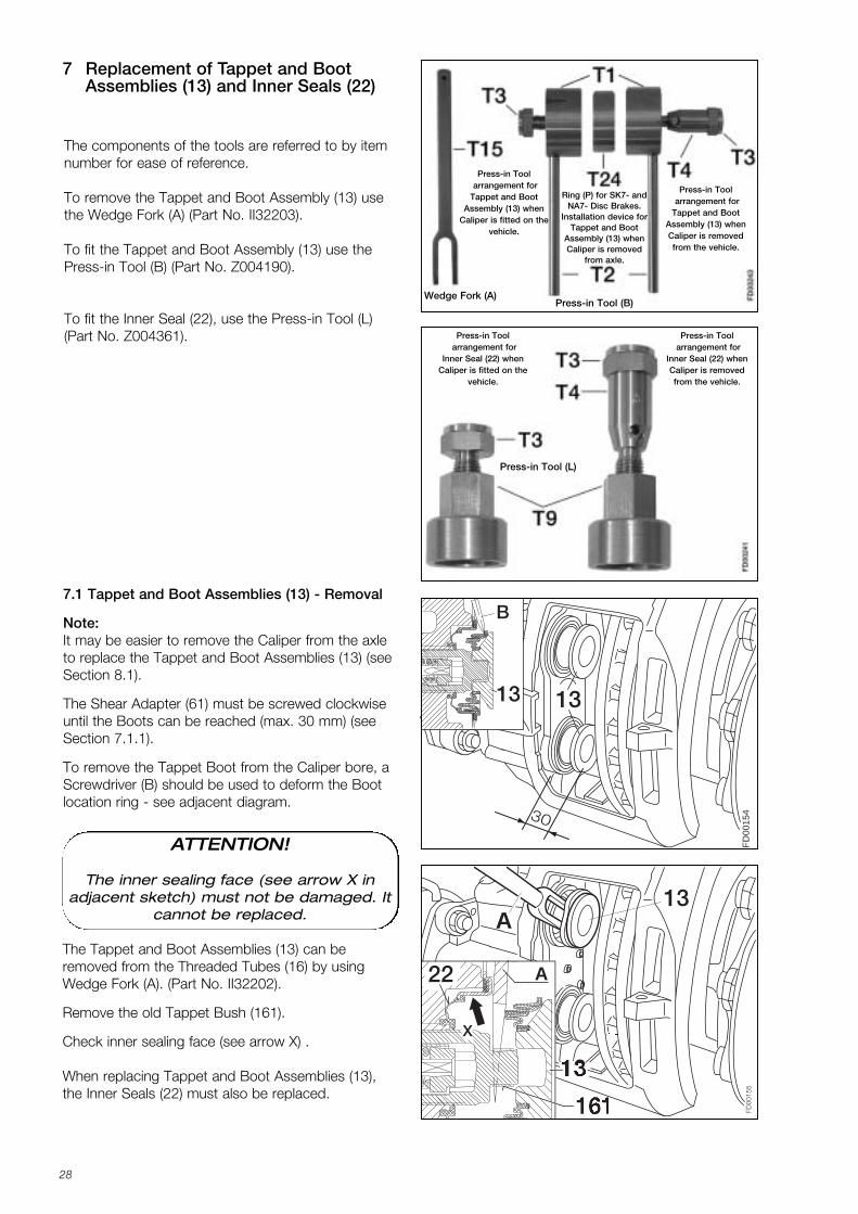
7 Replacement of Tappet and Boot Assemblies (13) and Inner Seals (22)
The components of the tools are referred to by itemnumber for ease of reference.
To remove the Tappet and Boot Assembly (13) usethe Wedge Fork (A) (Part No. II32203).
To fit the Tappet and Boot Assembly (13) use thePress-in Tool (B) (Part No. Z004190).
To fit the Inner Seal (22), use the Press-in Tool (L)(Part No. Z004361).
The Tappet and Boot Assemblies (13) can be removed from the Threaded Tubes (16) by usingWedge Fork (A). (Part No. II32202).
Remove the old Tappet Bush (161).
Check inner sealing face (see arrow X) .
When replacing Tappet and Boot Assemblies (13),the Inner Seals (22) must also be replaced.
7.1 Tappet and Boot Assemblies (13) - Removal
Note:It may be easier to remove the Caliper from the axleto replace the Tappet and Boot Assemblies (13) (seeSection 8.1).
The Shear Adapter (61) must be screwed clockwiseuntil the Boots can be reached (max. 30 mm) (seeSection 7.1.1).
To remove the Tappet Boot from the Caliper bore, aScrewdriver (B) should be used to deform the Boot location ring - see adjacent diagram.
ATTENTION!
The inner sealing face (see arrow X inadjacent sketch) must not be damaged. It
cannot be replaced.
K001262_001 09.06.2004 15:23 Uhr Seite 28
29
VF 0
0127
/13
16
1
70 mm
E
M+P
-KN
-019
12
46
16
A
FD00
239
A
22
16
L
FD00
238
22
L
X16
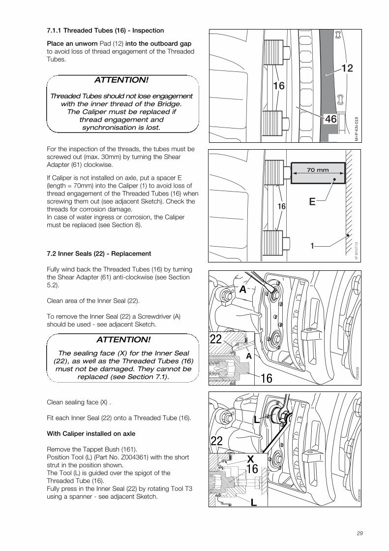
7.2 Inner Seals (22) - Replacement
Fully wind back the Threaded Tubes (16) by turningthe Shear Adapter (61) anti-clockwise (see Section5.2).
Clean area of the Inner Seal (22).
To remove the Inner Seal (22) a Screwdriver (A)should be used - see adjacent Sketch.
ATTENTION!
The sealing face (X) for the Inner Seal(22), as well as the Threaded Tubes (16)must not be damaged. They cannot be
replaced (see Section 7.1).
Clean sealing face (X) .
Fit each Inner Seal (22) onto a Threaded Tube (16).
With Caliper installed on axle
Remove the Tappet Bush (161).Position Tool (L) (Part No. Z004361) with the shortstrut in the position shown.The Tool (L) is guided over the spigot of theThreaded Tube (16). Fully press in the Inner Seal (22) by rotating Tool T3 using a spanner - see adjacent Sketch.
For the inspection of the threads, the tubes must bescrewed out (max. 30mm) by turning the ShearAdapter (61) clockwise.
If Caliper is not installed on axle, put a spacer E(length = 70mm) into the Caliper (1) to avoid loss ofthread engagement of the Threaded Tubes (16) when screwing them out (see adjacent Sketch). Check thethreads for corrosion damage.In case of water ingress or corrosion, the Calipermust be replaced (see Section 8).
7.1.1 Threaded Tubes (16) - Inspection
Place an unworn Pad (12) into the outboard gapto avoid loss of thread engagement of the ThreadedTubes.
ATTENTION!
Threaded Tubes should not lose engagementwith the inner thread of the Bridge.
The Caliper must be replaced if thread engagement and synchronisation is lost.
K001262_001 09.06.2004 15:23 Uhr Seite 29
30
FD00
225
B13
B
FD00
156
161
13
Sketch 1
Sketch 2
FD00
240
22
LX16
L
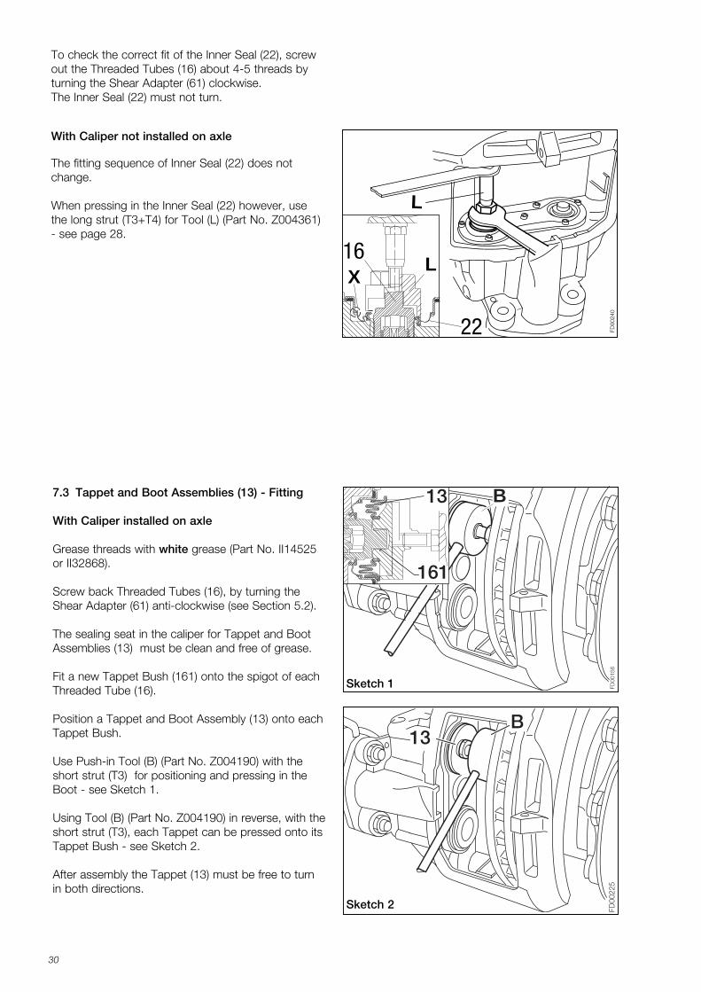
7.3 Tappet and Boot Assemblies (13) - Fitting
With Caliper installed on axle
Grease threads with white grease (Part No. II14525or II32868).
Screw back Threaded Tubes (16), by turning theShear Adapter (61) anti-clockwise (see Section 5.2).
The sealing seat in the caliper for Tappet and BootAssemblies (13) must be clean and free of grease.
Fit a new Tappet Bush (161) onto the spigot of eachThreaded Tube (16).
Position a Tappet and Boot Assembly (13) onto eachTappet Bush.
Use Push-in Tool (B) (Part No. Z004190) with theshort strut (T3) for positioning and pressing in theBoot - see Sketch 1.
Using Tool (B) (Part No. Z004190) in reverse, with theshort strut (T3), each Tappet can be pressed onto itsTappet Bush - see Sketch 2.
After assembly the Tappet (13) must be free to turnin both directions.
With Caliper not installed on axle
The fitting sequence of Inner Seal (22) does notchange.
When pressing in the Inner Seal (22) however, usethe long strut (T3+T4) for Tool (L) (Part No. Z004361)- see page 28.
To check the correct fit of the Inner Seal (22), screwout the Threaded Tubes (16) about 4-5 threads byturning the Shear Adapter (61) clockwise.The Inner Seal (22) must not turn.
K001262_001 09.06.2004 15:23 Uhr Seite 30
31
FD00
227
B
13
FD00
226
B13
Sketch 3
Sketch 4
FD00
355
B
13
T24
Sketch 5
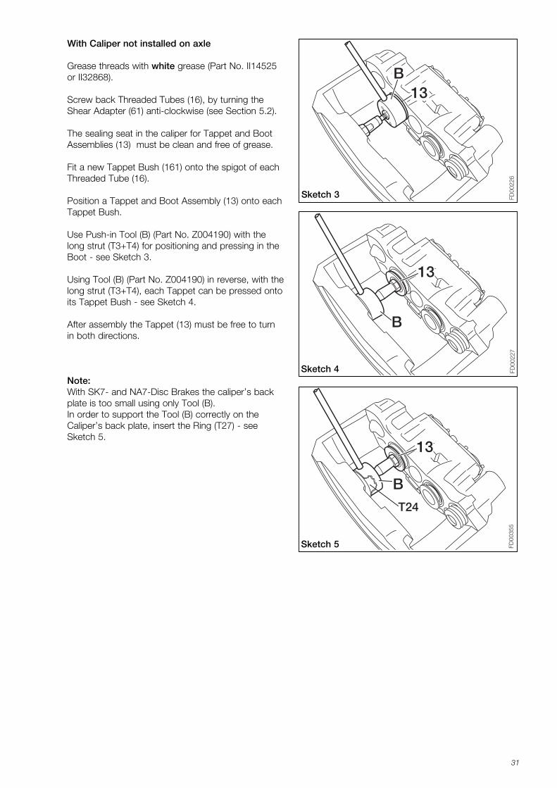
With Caliper not installed on axle
Grease threads with white grease (Part No. II14525or II32868).
Screw back Threaded Tubes (16), by turning theShear Adapter (61) anti-clockwise (see Section 5.2).
The sealing seat in the caliper for Tappet and BootAssemblies (13) must be clean and free of grease.
Fit a new Tappet Bush (161) onto the spigot of eachThreaded Tube (16).
Position a Tappet and Boot Assembly (13) onto eachTappet Bush.
Use Push-in Tool (B) (Part No. Z004190) with thelong strut (T3+T4) for positioning and pressing in theBoot - see Sketch 3.
Using Tool (B) (Part No. Z004190) in reverse, with thelong strut (T3+T4), each Tappet can be pressed ontoits Tappet Bush - see Sketch 4.
After assembly the Tappet (13) must be free to turnin both directions.
Note:With SK7- and NA7-Disc Brakes the caliper’s backplate is too small using only Tool (B).In order to support the Tool (B) correctly on the Caliper’s back plate, insert the Ring (T27) - seeSketch 5.
K001262_001 09.06.2004 15:23 Uhr Seite 31
32
8 Caliper Replacement
FD00
161-
Äi0
1
10
10
8.1 Caliper Removal
Remove Pads (12) (see Section 6.1).
Remove Actuator (see Section 12.1, 12.3).
If fitted, remove Wear Indicator Cable or Cable tobuilt in Potentiometer.
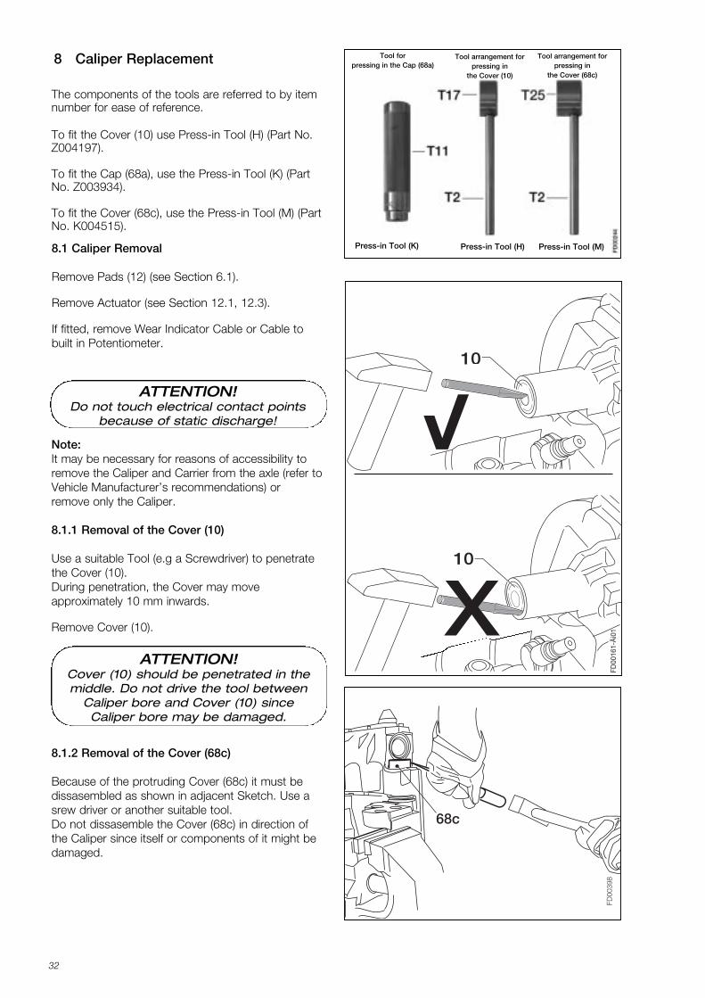
The components of the tools are referred to by itemnumber for ease of reference.
To fit the Cover (10) use Press-in Tool (H) (Part No.Z004197).
To fit the Cap (68a), use the Press-in Tool (K) (PartNo. Z003934).
To fit the Cover (68c), use the Press-in Tool (M) (PartNo. K004515).
Tool for pressing in the Cap (68a)
Tool arrangement for pressing in
the Cover (10)
Press-in Tool (H)Press-in Tool (K) Press-in Tool (M)
Tool arrangement for pressing in
the Cover (68c)
FD00
398
68c
8.1.2 Removal of the Cover (68c)
Because of the protruding Cover (68c) it must be dissasembled as shown in adjacent Sketch. Use asrew driver or another suitable tool.Do not dissasemble the Cover (68c) in direction ofthe Caliper since itself or components of it might bedamaged.
ATTENTION!Do not touch electrical contact points
because of static discharge!
Note:It may be necessary for reasons of accessibility toremove the Caliper and Carrier from the axle (refer toVehicle Manufacturer’s recommendations) or remove only the Caliper.
8.1.1 Removal of the Cover (10)
Use a suitable Tool (e.g a Screwdriver) to penetratethe Cover (10).During penetration, the Cover may move approximately 10 mm inwards.
Remove Cover (10).
ATTENTION!Cover (10) should be penetrated in themiddle. Do not drive the tool between
Caliper bore and Cover (10) sinceCaliper bore may be damaged.
K001262_001 09.06.2004 15:23 Uhr Seite 32
33
401039a*
68a* )
)
39c*
68c* )
)
FD
0020
8-Ä
i01
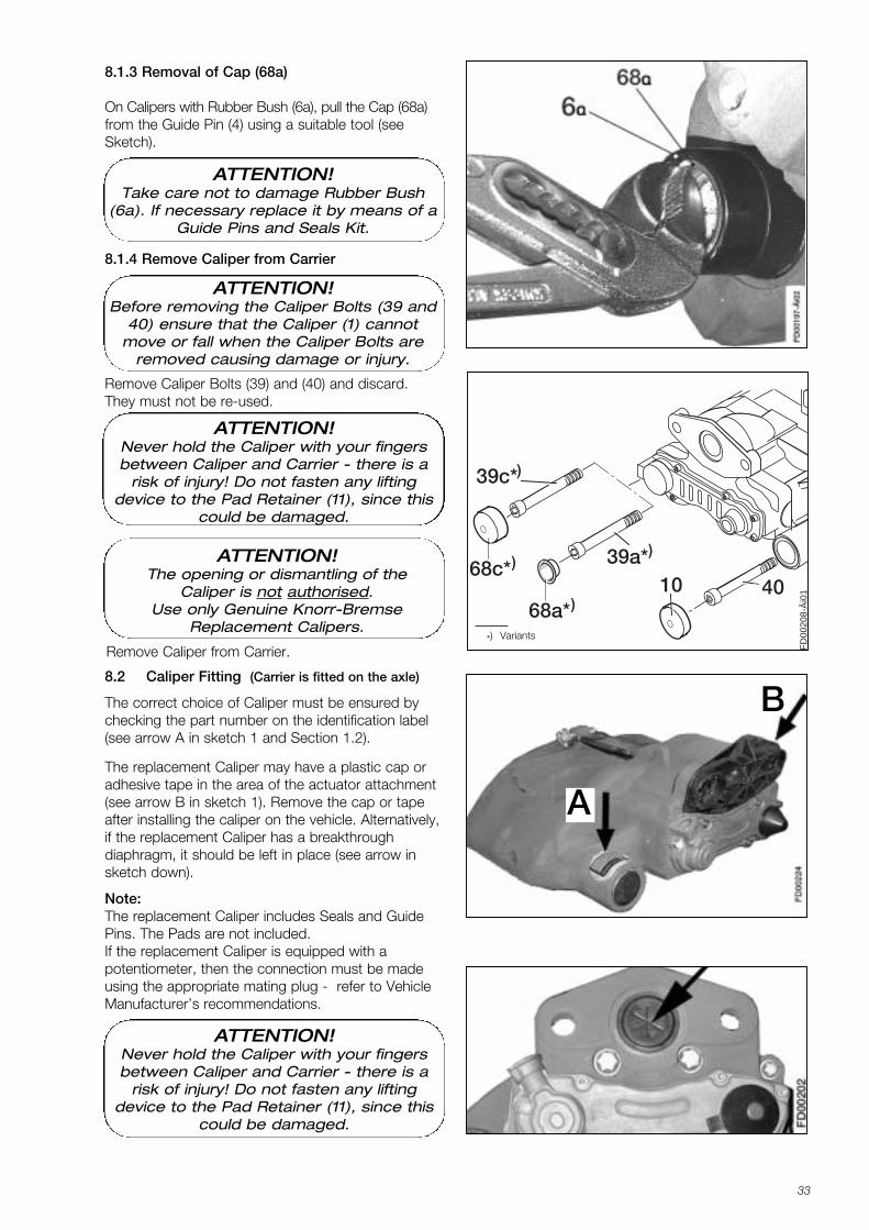
Remove Caliper Bolts (39) and (40) and discard.They must not be re-used.
Remove Caliper from Carrier.*) Variants
8.1.3 Removal of Cap (68a)
On Calipers with Rubber Bush (6a), pull the Cap (68a)from the Guide Pin (4) using a suitable tool (seeSketch).
8.1.4 Remove Caliper from Carrier
8.2 Caliper Fitting (Carrier is fitted on the axle)
The correct choice of Caliper must be ensured bychecking the part number on the identification label(see arrow A in sketch 1 and Section 1.2).
The replacement Caliper may have a plastic cap oradhesive tape in the area of the actuator attachment(see arrow B in sketch 1). Remove the cap or tapeafter installing the caliper on the vehicle. Alternatively,if the replacement Caliper has a breakthrough diaphragm, it should be left in place (see arrow insketch down).
Note:The replacement Caliper includes Seals and GuidePins. The Pads are not included.If the replacement Caliper is equipped with a potentiometer, then the connection must be madeusing the appropriate mating plug - refer to Vehicle Manufacturer’s recommendations.
A
B
ATTENTION!Take care not to damage Rubber Bush
(6a). If necessary replace it by means of a Guide Pins and Seals Kit.
ATTENTION!Before removing the Caliper Bolts (39 and
40) ensure that the Caliper (1) cannotmove or fall when the Caliper Bolts are
removed causing damage or injury.
ATTENTION!Never hold the Caliper with your fingersbetween Caliper and Carrier - there is a
risk of injury! Do not fasten any lifting device to the Pad Retainer (11), since this
could be damaged.
ATTENTION!The opening or dismantling of the
Caliper is not authorised.Use only Genuine Knorr-Bremse
Replacement Calipers.
ATTENTION!Never hold the Caliper with your fingersbetween Caliper and Carrier - there is a
risk of injury! Do not fasten any lifting device to the Pad Retainer (11), since this
could be damaged.
K001262_001 09.06.2004 15:23 Uhr Seite 33
34
10
H
FD
00
37
3
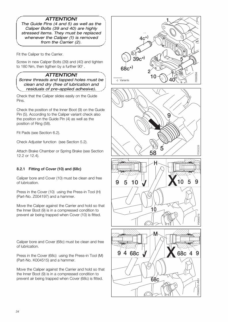
V109 5 X10 5 9
8.2.1 Fitting of Cover (10) and (68c)
Caliper bore and Cover (10) must be clean and freeof lubrication.
Press in the Cover (10) using the Press-in Tool (H)(Part-No. Z004197) and a hammer.
Move the Caliper against the Carrier and hold so thatthe Inner Boot (9) is in a compressed condition toprevent air being trapped when Cover (10) is fitted.
Check that the Caliper slides easily on the GuidePins.
Check the position of the Inner Boot (9) on the GuidePin (5). According to the Caliper variant check alsothe position on the Guide Pin (4) as well as the position of Ring (58).
Fit Pads (see Section 6.2).
Check Adjuster function (see Section 5.2).
Attach Brake Chamber or Spring Brake (see Section12.2 or 12.4). FD
0022
8
58
9
5
68c
M
FD
00
37
2-Ä
i01
X 68c 4 9V49 68c
Caliper bore and Cover (68c) must be clean and freeof lubrication.
Press in the Cover (68c) using the Press-in Tool (M)(Part-No. K004515) and a hammer.
Move the Caliper against the Carrier and hold so thatthe Inner Boot (9) is in a compressed condition toprevent air being trapped when Cover (68c) is fitted.
Fit the Caliper to the Carrier.
Screw in new Caliper Bolts (39) and (40) and tightento 180 Nm, then tigthen by a further 900 .
4010
39c*
68c* )
)
FD
0035
6
4c*)
5
2
1
*) Variants
ATTENTION!The Guide Pins (4 and 5) as well as the
Caliper Bolts (39 and 40) are highly stressed items. They must be replaced
whenever the Caliper (1) is removedfrom the Carrier (2).
ATTENTION!Screw threads and tapped holes must be
clean and dry (free of lubrication and residuals of pre-applied adhesive).
K001262_001 09.06.2004 15:23 Uhr Seite 34
35
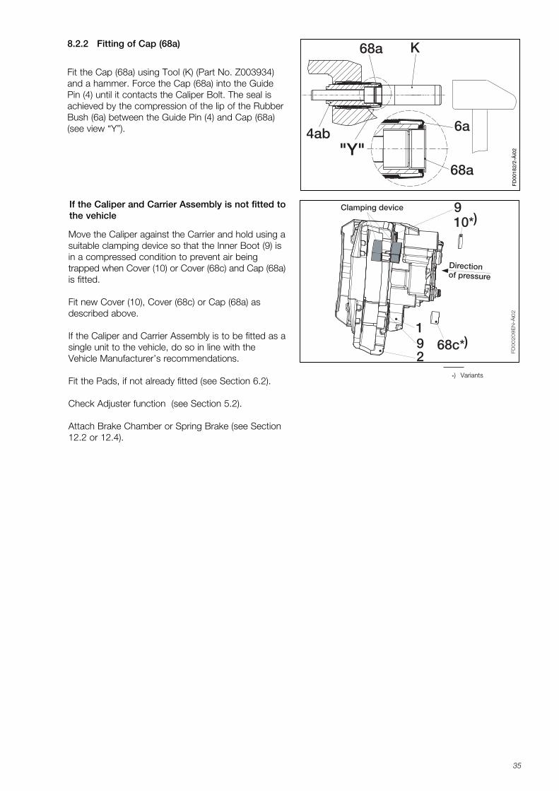
8.2.2 Fitting of Cap (68a) 68a K
68a
6a
"Y"
FD
0018
2/2-
Äi0
2
4ab
Fit the Cap (68a) using Tool (K) (Part No. Z003934)and a hammer. Force the Cap (68a) into the GuidePin (4) until it contacts the Caliper Bolt. The seal isachieved by the compression of the lip of the RubberBush (6a) between the Guide Pin (4) and Cap (68a)(see view “Y”).
Move the Caliper against the Carrier and hold using asuitable clamping device so that the Inner Boot (9) isin a compressed condition to prevent air being trapped when Cover (10) or Cover (68c) and Cap (68a)is fitted.
Fit new Cover (10), Cover (68c) or Cap (68a) asdescribed above.
If the Caliper and Carrier Assembly is to be fitted as asingle unit to the vehicle, do so in line with theVehicle Manufacturer’s recommendations.
Fit the Pads, if not already fitted (see Section 6.2).
Check Adjuster function (see Section 5.2).
Attach Brake Chamber or Spring Brake (see Section12.2 or 12.4).
If the Caliper and Carrier Assembly is not fitted tothe vehicle
9Clamping device
Directionof pressure
FD
00
20
9E
N-Ä
i02
10*
2
168c*9 )
)
*) Variants
K001262_001 09.06.2004 15:23 Uhr Seite 35
36
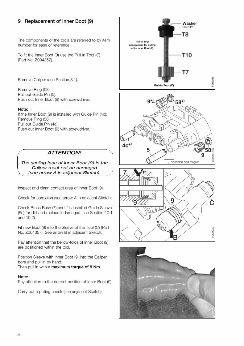
9 Replacement of Inner Boot (9)
The components of the tools are referred to by itemnumber for ease of reference.
To fit the Inner Boot (9) use the Pull-in Tool (C)(Part No. Z004357).
Remove Caliper (see Section 8.1).
Remove Ring (58).Pull out Guide Pin (5).Push out Inner Boot (9) with screwdriver.
Note:If the Inner Boot (9) is installed with Guide Pin (4c):Remove Ring (58).Pull out Guide Pin (4c).Push out Inner Boot (9) with screwdriver.
Pull-in Toolarrangement for pulling
in the Inner Boot (9).
Pull-in Tool (C)
59
58
FD
00
210
-Äi0
2
4c*)
58*))9*
WasherDIN 125
FD
0023
0
99
7 A
B
C
Inspect and clean contact area of Inner Boot (9).
Check for corrosion (see arrow A in adjacent Sketch).
Check Brass Bush (7) and if is installed Guide Sleeve(6c) for dirt and replace if damaged (see Section 10.1and 10.2).
Fit new Boot (9) into the Sleeve of the Tool (C) (PartNo. Z004357). See arrow B in adjacent Sketch.
Pay attention that the bellow-folds of Inner Boot (9)are positioned within the tool.
Position Sleeve with Inner Boot (9) into the Caliperbore and pull in by hand.Then pull in with a maximum torque of 8 Nm.
Note:Pay attention to the correct position of Inner Boot (9).
Carry out a pulling check (see adjacent Sketch).
*) Varianten sind möglich.
ATTENTION!
The sealing face of Inner Boot (9) in theCaliper must not be damaged
(see arrow A in adjacent Sketch).
K001262_001 09.06.2004 15:23 Uhr Seite 36
37
FD00
228
58
9
5
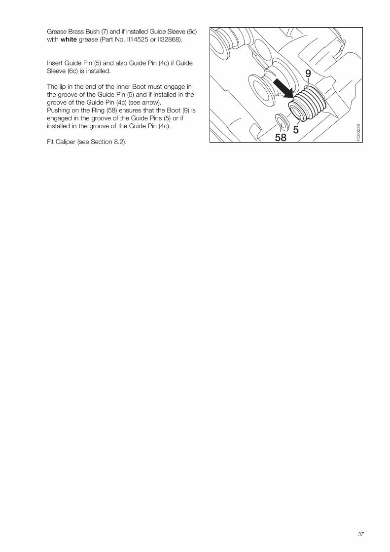
Grease Brass Bush (7) and if installed Guide Sleeve (6c)with white grease (Part No. II14525 or II32868).
Insert Guide Pin (5) and also Guide Pin (4c) if GuideSleeve (6c) is installed.
The lip in the end of the Inner Boot must engage inthe groove of the Guide Pin (5) and if installed in thegroove of the Guide Pin (4c) (see arrow).Pushing on the Ring (58) ensures that the Boot (9) isengaged in the groove of the Guide Pins (5) or ifinstalled in the groove of the Guide Pin (4c).
Fit Caliper (see Section 8.2).
K001262_001 09.06.2004 15:23 Uhr Seite 37
38
FD00
2367
7 7
D D D
a b c
Pull-in Toolarrangement for
pulling in and grooving of Brass
Bush (7)
Pull-out Toolarrangement
for pulling outof Brass Bush (7)
Sketch 1
Bild 2
Sketch 3
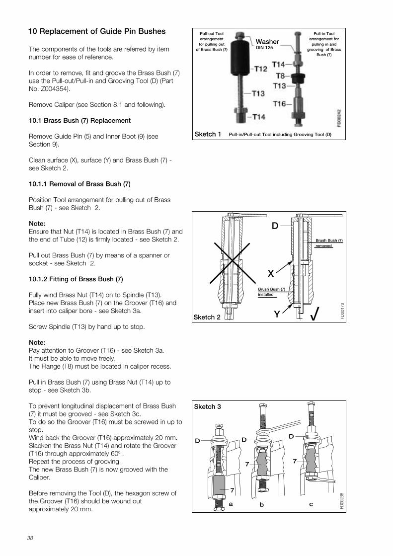
Pull-in/Pull-out Tool including Grooving Tool (D)
WasherDIN 125The components of the tools are referred by item
number for ease of reference.
In order to remove, fit and groove the Brass Bush (7)use the Pull-out/Pull-in and Grooving Tool (D) (PartNo. Z004354).
Remove Caliper (see Section 8.1 and following).
10.1 Brass Bush (7) Replacement
Remove Guide Pin (5) and Inner Boot (9) (seeSection 9).
Clean surface (X), surface (Y) and Brass Bush (7) -see Sketch 2.
10.1.1 Removal of Brass Bush (7)
Position Tool arrangement for pulling out of BrassBush (7) - see Sketch 2.
Note:Ensure that Nut (T14) is located in Brass Bush (7) andthe end of Tube (12) is firmly located - see Sketch 2.
Pull out Brass Bush (7) by means of a spanner orsocket - see Sketch 2.
10.1.2 Fitting of Brass Bush (7)
Fully wind Brass Nut (T14) on to Spindle (T13).Place new Brass Bush (7) on the Groover (T16) andinsert into caliper bore - see Sketch 3a.
Screw Spindle (T13) by hand up to stop.
Note:Pay attention to Groover (T16) - see Sketch 3a. It must be able to move freely. The Flange (T8) must be located in caliper recess.
Pull in Brass Bush (7) using Brass Nut (T14) up tostop - see Sketch 3b.
To prevent longitudinal displacement of Brass Bush(7) it must be grooved - see Sketch 3c.To do so the Groover (T16) must be screwed in up tostop. Wind back the Groover (T16) approximately 20 mm.Slacken the Brass Nut (T14) and rotate the Groover(T16) through approximately 600 . Repeat the process of grooving.The new Brass Bush (7) is now grooved with theCaliper.
Before removing the Tool (D), the hexagon screw ofthe Groover (T16) should be wound out approximately 20 mm.
10 Replacement of Guide Pin Bushes
FD00
170
D
X
YSketch 2 vBrush Bush (7) installed
Brush Bush (7) removed
K001262_001 09.06.2004 15:23 Uhr Seite 38
39
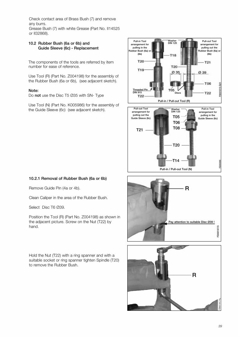
Pay attention to suitable Disc Ø39 !
10.2.1 Removal of Rubber Bush (6a or 6b)
Remove Guide Pin (4a or 4b).
Clean Caliper in the area of the Rubber Bush.
Select Disc T6 Ø39.
Position the Tool (R) (Part No. Z004198) as shown inthe adjacent picture. Screw on the Nut (T22) byhand.
Hold the Nut (T22) with a ring spanner and with asuitable socket or ring spanner tighten Spindle (T20)to remove the Rubber Bush.
10.2 Rubber Bush (6a or 6b) and Guide Sleeve (6c) - Replacement
The components of the tools are referred by itemnumber for ease of reference.
Use Tool (R) (Part No. Z004198) for the assembly ofthe Rubber Bush (6a or 6b), (see adjacent sketch).
Note:Do not use the Disc T5 Ø35 with SN- Type
Use Tool (N) (Part No. K005986) for the assembly ofthe Guide Sleeve (6c) (see adjacent sketch).
Pull-in Toolarrangement for
pulling in the Rubber Bush (6a) or
(6b)
Pull-out Toolarrangement for pulling out the
Rubber Bush (6a) or(6b)
Discs
WasherDIN 125
Threaded PinDIN 915
Check contact area of Brass Bush (7) and removeany burrs.Grease Bush (7) with white Grease (Part No. II14525or II32868).
Pull-in / Pull-out Tool (R)
Pull-in Toolarrangement for
pulling in the Guide Sleeve (6c)
Pull-out Toolarrangement for pulling out the
Guide Sleeve (6c)
Pull-in / Pull-out Tool (N)
WasherDIN 125
T20
T05T06T08
T14
T21
R
R
K001262_001 09.06.2004 15:23 Uhr Seite 39
40
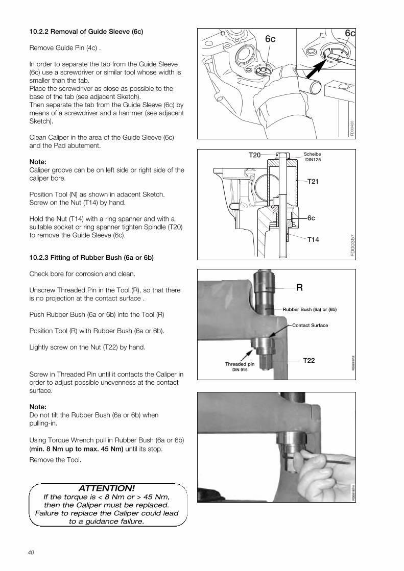
10.2.2 Removal of Guide Sleeve (6c)
Remove Guide Pin (4c) .
In order to separate the tab from the Guide Sleeve(6c) use a screwdriver or similar tool whose width issmaller than the tab.Place the screwdriver as close as possible to the base of the tab (see adjacent Sketch).Then separate the tab from the Guide Sleeve (6c) bymeans of a screwdriver and a hammer (see adjacentSketch).
Clean Caliper in the area of the Guide Sleeve (6c)and the Pad abutement.
Note:Caliper groove can be on left side or right side of thecaliper bore.
Position Tool (N) as shown in adacent Sketch.Screw on the Nut (T14) by hand.
Hold the Nut (T14) with a ring spanner and with asuitable socket or ring spanner tighten Spindle (T20)to remove the Guide Sleeve (6c).
FD00
400
6c6c
FD
00
35
7
T20
6c
T21
T14
Scheibe DIN125
10.2.3 Fitting of Rubber Bush (6a or 6b)
Check bore for corrosion and clean.
Unscrew Threaded Pin in the Tool (R), so that thereis no projection at the contact surface .
Push Rubber Bush (6a or 6b) into the Tool (R)
Position Tool (R) with Rubber Bush (6a or 6b).
Lightly screw on the Nut (T22) by hand.
Screw in Threaded Pin until it contacts the Caliper inorder to adjust possible unevenness at the contactsurface.
Note:Do not tilt the Rubber Bush (6a or 6b) whenpulling-in.
Using Torque Wrench pull in Rubber Bush (6a or 6b)(min. 8 Nm up to max. 45 Nm) until its stop.
Remove the Tool.
T22
R
ATTENTION!If the torque is < 8 Nm or > 45 Nm,then the Caliper must be replaced.
Failure to replace the Caliper could leadto a guidance failure.
Contact Surface
Threaded pinDIN 915
Rubber Bush (6a) or (6b)
K001262_001 09.06.2004 15:23 Uhr Seite 40
41
FD
0019
8/1-
Äi0
2
4ab 6a
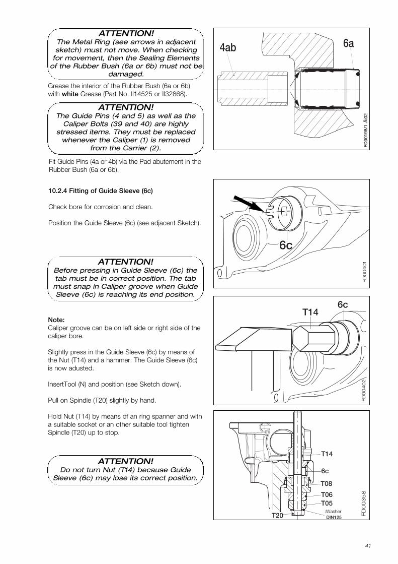
10.2.4 Fitting of Guide Sleeve (6c)
Check bore for corrosion and clean.
Position the Guide Sleeve (6c) (see adjacent Sketch).
FD
00
35
8
T14
Scheibe DIN125
6c
T08
T06T05
T20
Note:Caliper groove can be on left side or right side of thecaliper bore.
Slightly press in the Guide Sleeve (6c) by means ofthe Nut (T14) and a hammer. The Guide Sleeve (6c)is now adusted.
InsertTool (N) and position (see Sketch down).
Pull on Spindle (T20) slightly by hand.
Hold Nut (T14) by means of an ring spanner and witha suitable socket or an other suitable tool tightenSpindle (T20) up to stop.
Fit Guide Pins (4a or 4b) via the Pad abutement in theRubber Bush (6a or 6b).
ATTENTION!Do not turn Nut (T14) because Guide
Sleeve (6c) may lose its correct position.
FD
00
40
1
6c
FD
00
40
2
T146c
ATTENTION!Before pressing in Guide Sleeve (6c) thetab must be in correct position. The tabmust snap in Caliper groove when GuideSleeve (6c) is reaching its end position.
ATTENTION!The Metal Ring (see arrows in adjacentsketch) must not move. When checking
for movement, then the Sealing Elementsof the Rubber Bush (6a or 6b) must not be
damaged.
ATTENTION!The Guide Pins (4 and 5) as well as the
Caliper Bolts (39 and 40) are highly stressed items. They must be replaced
whenever the Caliper (1) is removedfrom the Carrier (2).
Grease the interior of the Rubber Bush (6a or 6b)with white Grease (Part No. Il14525 or II32868).
Washer
K001262_001 09.06.2004 15:23 Uhr Seite 41
42
M+
P-K
N-0
36
2
FD00
403
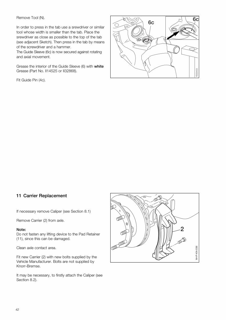
6c6cRemove Tool (N).
In order to press in the tab use a srewdriver or similartool whose width is smaller than the tab. Place thesrewdriver as close as possible to the top of the tab(see adjacent Sketch). Then press in the tab by meansof the screwdriver and a hammer.The Guide Sleeve (6c) is now secured against rotatingand axial movement.
Grease the interior of the Guide Sleeve (6) with whiteGrease (Part No. Il14525 or II32868).
Fit Guide Pin (4c).
If necessary remove Caliper (see Section 8.1)
Remove Carrier (2) from axle.
Note:Do not fasten any lifting device to the Pad Retainer(11), since this can be damaged.
Clean axle contact area.
Fit new Carrier (2) with new bolts supplied by theVehicle Manufacturer. Bolts are not supplied byKnorr-Bremse.
It may be necessary, to firstly attach the Caliper (seeSection 8.2).
11 Carrier Replacement
K001262_001 09.06.2004 15:23 Uhr Seite 42
43
FD00
229
18/2
A
B
B
FD00
231C
19
3 m
m
Push Rod area
Seal
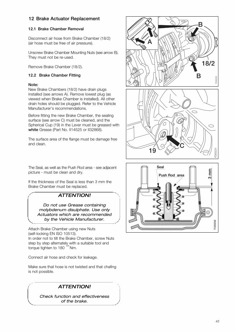
12 Brake Actuator Replacement
12.2 Brake Chamber Fitting
Note:New Brake Chambers (18/2) have drain plugs installed (see arrows A). Remove lowest plug (as viewed when Brake Chamber is installed). All otherdrain holes should be plugged. Refer to the VehicleManufacturer’s recommendations.
Before fitting the new Brake Chamber, the sealingsurface (see arrow C) must be cleaned, and theSpherical Cup (19) in the Lever must be greased withwhite Grease (Part No. II14525 or II32868).
The surface area of the flange must be damage freeand clean.
The Seal, as well as the Push Rod area - see adjacentpicture - must be clean and dry.
If the thickness of the Seal is less than 3 mm theBrake Chamber must be replaced.
Attach Brake Chamber using new Nuts (self-locking EN ISO 10513).In order not to tilt the Brake Chamber, screw Nutsstep by step alternately with a suitable tool and torque tighten to 180
+30 Nm.
Connect air hose and check for leakage.
Make sure that hose is not twisted and that chafingis not possible.
12.1 Brake Chamber Removal
Disconnect air hose from Brake Chamber (18/2)(air hose must be free of air pressure).
Unscrew Brake Chamber Mounting Nuts (see arrow B).They must not be re-used.
Remove Brake Chamber (18/2).
ATTENTION!
Do not use Grease containing molybdenum disulphate. Use only
Actuators which are recommendedby the Vehicle Manufacturer.
ATTENTION!
Check function and effectiveness of the brake.
K001262_001 09.06.2004 15:23 Uhr Seite 43
44
VF
0012
7/11
-Äi0
1B
BA
A
D 18/1
FD00
231C
19
Push Rodarea
Seal
3 mm
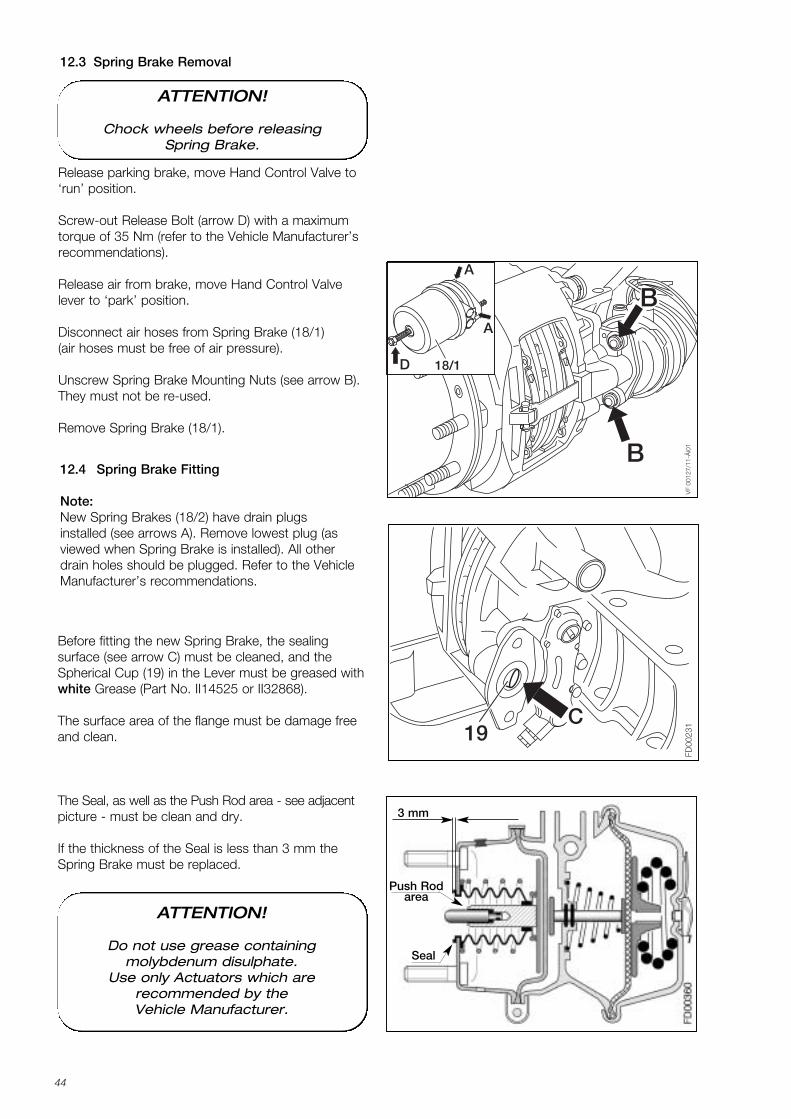
12.3 Spring Brake Removal
Release parking brake, move Hand Control Valve to‘run’ position.
Screw-out Release Bolt (arrow D) with a maximumtorque of 35 Nm (refer to the Vehicle Manufacturer’srecommendations).
Release air from brake, move Hand Control Valvelever to ‘park’ position.
Disconnect air hoses from Spring Brake (18/1)(air hoses must be free of air pressure).
Unscrew Spring Brake Mounting Nuts (see arrow B).They must not be re-used.
Remove Spring Brake (18/1).
12.4 Spring Brake Fitting
Note:New Spring Brakes (18/2) have drain plugs installed (see arrows A). Remove lowest plug (as viewed when Spring Brake is installed). All otherdrain holes should be plugged. Refer to the VehicleManufacturer’s recommendations.
Before fitting the new Spring Brake, the sealing surface (see arrow C) must be cleaned, and theSpherical Cup (19) in the Lever must be greased withwhite Grease (Part No. II14525 or II32868).
The surface area of the flange must be damage freeand clean.
The Seal, as well as the Push Rod area - see adjacentpicture - must be clean and dry.
If the thickness of the Seal is less than 3 mm theSpring Brake must be replaced.
ATTENTION!
Chock wheels before releasing Spring Brake.
ATTENTION!
Do not use grease containing molybdenum disulphate.
Use only Actuators which are recommended by the Vehicle Manufacturer.
K001262_001 09.06.2004 15:23 Uhr Seite 44
45
Attach Spring Brake using new Nuts (self-locking EN ISO 10513).In order not to tilt the Spring Brake, screw Nutsstep by step alternately with a suitable tool and torque tighten to 180
+30 Nm.
Connect air hoses, ensuring that they are replaced inthe correct ports.
Make sure that hoses are not twisted and that chafing is not possible.
Release parking brake, move Hand Control Valvelever to ‘run’ position, and check for leakage.
Screw in Spring Brake Release bolt to maximum 70 Nm.
ATTENTION!
Check function and effectiveness of the brake.
K001262_001 09.06.2004 15:23 Uhr Seite 45

46
Notes:
K001262_001 09.06.2004 15:23 Uhr Seite 46

47
K001262_001 09.06.2004 15:23 Uhr Seite 47
KNORR-BREMSESysteme für Nutzfahrzeuge GmbH
www.knorr-bremse.com www.knorr-bremsesfn.com
The
figur
ativ
e m
ark
” K” a
nd th
e tr
adem
arks
KNO
RR, K
NORR
-BRE
MSE
are
regi
ster
ed in
the
nam
e of
Kno
rr-B
rem
se A
G.
Subj
ect t
o al
tera
tion
with
out n
otic
e. F
or sp
ecifi
c ap
plic
atio
n re
quire
men
ts a
nd d
etai
ls on
the
use
of o
ur p
rodu
cts w
e re
com
men
d th
at y
ou re
ques
t ind
ivid
ual c
onsu
ltatio
n an
d do
cum
enta
tion.
Rep
rodu
ctio
n, e
ven
extr
acts
, is n
ot p
erm
itted
. Prin
ted
in G
erm
any
K001
262-
001
Knorr-BremseAustralia Pty. Ltd.1/2D Factory StreetGranville NSW 2142AustraliaTel: +61 2 8863-6146Fax: +61 2 8863-6151
Knorr-Bremse GmbHSysteme für NutzfahrzeugeBeethovengasse 43-452340 MödlingAustriaTel: +43 2236 409-436Fax: +43 2236 409-434
Knorr-BremseBenelux B.V.B.A.Impulsstraat 11Industriepark zone D2220 Heist-op-den-BergBelgiumTel: +32 1525-7900Fax: +32 1524-9240
Knorr-BremseSistemas para Veículos Comerciais Brasil Ltda.Av. Engº Eusébio Stevaux873 Bloco B-Santo AmaroCep: 04696-902 BrazilTel: +55 11 5681-1104Fax: +55 11 5686-3905
Knorr-Bremse Far East Ltd.Truck Brake Systems Division1301 MassMutual Tower38 Gloucester RoadWanchaiHong KongChinaTel: +852 2861 2669Fax: +852 2520 6259
Knorr-Bremse Brake Equipment(Shanghai) Co. Ltd.Truck Brake DivisionSection C, Building 9353 Riying North Road200131 Waigaoqiao Free Trade ZoneShanghaiChinaTel: +86 21 5046-0776Fax: +86 21 5046-3427
Knorr-BremseSystémy pro uz̆itková vozidla, CR, s.r.o.Petra Bezruc̆e 399463 62 HejniceCzech RepublicTel: +420 482 363-611Fax: +420 482 363-711
Knorr-Bremse Systèmes pour Véhicules Utilitaires France S.A.BP 34178RN 13, La BriqueterieGlos14104 Lisieux CedexFranceTel: +33 2 3132-1200Fax: +33 2 3132-1303
Knorr-BremseFékrendszerek Kft.KecskemétSzegedi út 496000 HungaryTel: +36 76 511-100Fax: +36 76 481-100
Knorr-BremseSystems for Commercial Vehicles India Private Ltd.404-405 HM Geneva HouseCunningham RoadBangalore 560 052IndiaTel: +91 80 20 88-273Fax: +91 80 51199068
Knorr-BremseSistemi per Autoveicoli Commerciali S.p.A.Via C. Battisti, 6820043 ArcoreItalyTel: +39 039 6075-1Fax: +39 039 6075-435
Knorr-Bremse Commercial Vehicle Systems Japan Ltd.3-1-15, NishiikebukuroToshimaku-Tokyo 171-0021JapanTel: +81 3 3971-8501Fax: +81 3 3971-8579
Knorr-Bremse Korea Ltd.Truck Brake Division6th Floor Bongwoo Bldg.31-7, 1 Ka, Jangchoong-DongChung-Ku, Seoul 100-39KoreaTel: +82 2 538-8726Fax: +82 2 538-8723
Knorr-BremseBenelux B.V.B.A.Rendementsweg 4N3641 SK MydrechtNetherlandsTel: +31 297 239330Fax: +31 297 239339
Knorr-Bremse Systeme für Nutzfahrzeuge GmbHRepresentation Office Russia1. Kasatschij Pereulok 5/2119017 MoscowRussian FederationTel: +7 095 234-4995Fax: +7 095 234-4996
Knorr-Bremse S.A. Pty. Ltd.3 Derrick Road(corner Chestnut Road)1610 Kempton ParkSouth AfricaTel: +27 11 961-7800Fax: +27 11 975-8249
Knorr-BremseSystem foer Tunga Fordon ABP.O. Box 6029200 11 MalmoeSwedenTel: +46 40 680 5880Fax: +46 40 937490
Knorr-BremseSysteme für Nutzfahrzeuge GmbHOffice SwitzerlandZürichstraße 468303 BassersdorfSwitzerlandTel: +41 1 888 77-55Fax: +41 1 888 77-50
Knorr-BremseSysteme für Nutzfahrzeuge GmbHLiaison Office IstanbulMeclisi Mebusan Cad. 139/AAtlantik Han Kat: 380040 Findikli-IstanbulTurkeyTel: +90 212 293-4742Fax: +90 212 293-4743
Knorr-Bremse Systems for Commercial Vehicles Ltd.Douglas RoadKingswoodBristol BS15 8NLUnited KingdomTel: +44 117 9846-100Fax: +44 117 9846-101
Bendix Commercial Vehicle Systems LLC901 Cleveland StreetElyria, OH 44035USATel: +1 440 329-9000Fax: +1 440 329-9203
Knorr-Bremse Systeme für Nutzfahrzeuge GmbHMoosacher Straße 8080809 MunichGermanyTel: +49 89 3547-0Fax: +49 89 3547-2767
K001262_001 09.06.2004 15:23 Uhr Seite 48


