Embed Size (px)
Citation preview
Operating ManualGV1 OM 6-18
GV1 OM 6-18© ALTRONIC, LLC 2018 2
Table of Contents
Preface ........................................................................................................ 4
Safety Warning ............................................................................................. 5
Electrostatic Discharge Awareness .................................................................. 6
Glossary of Terms ......................................................................................... 7
Background ................................................................................................. 8
1.0 Theory of Operation ............................................................................. 9
1.1 As a Variable Electronic Pressure Regulator ................................... 9
1.2 As an Air Fuel Ratio Controller ..................................................... 9
1.3 Version “mA” ............................................................................ 10
1.4 Version “Step” .......................................................................... 11
1.5 Version “CAN” .......................................................................... 11
1.6 Version “AFR” ........................................................................... 11
2.0 Specifications ................................................................................... 12
3.0 Features of the GV1 ........................................................................... 13
3.1 Simplicity ................................................................................. 13
3.2 Full Fuel Authority ..................................................................... 13
3.3 Range ...................................................................................... 13
3.4 High Speed Actuator ................................................................. 13
3.5 Pressure Sensor ........................................................................ 13
3.6 Closed Loop Pressure Control ..................................................... 13
3.7 Fully Automatic Control ............................................................. 14
3.8 Communications ....................................................................... 14
3.9 Valve Viewer Software ................................................................ 14
4.0 Do’s and Don’ts of the GV1 System ..................................................... 14
5.0 Wiring Diagrams/Drawings ............................................................ 15-20
5.1 Interface Cable, PCV Configuration .............................................. 15
5.2 Interface Cable, AFR Configuration ............................................. 16
5.3 Interface Cable, Power and Thermal ............................................ 17
5.4 2 Wire O2 Sensor Cable ............................................................. 18
5.5 GV Interface Schematic ............................................................. 19
5.6 GV1 Gas Valve Dimensions ......................................................... 20
GV1 OM 6-18© ALTRONIC, LLC 2018 3
6.0 Modbus Register Map ........................................................................ 21
7.0 Installation Preparations .................................................................... 22
8.0 Installation Procedures ...................................................................... 23
8.1 Installing GV1 ........................................................................... 23
8.2 Installing Thermocouples ........................................................... 23
8.3 Installing Wiring for AFR GV1 ..................................................... 24
8.4 Installing wiring for PCV GV1 ...................................................... 25
8.5 Installing Venturi Insert .............................................................. 26
8.6 Installing Remote Pressure Sensing ............................................ 28
8.7 Installing Turbo Boost Sensing .................................................... 30
8.8 Electrical Checks ...................................................................... 30
8.9 Setting up Communication ......................................................... 30
8.10 Verifying or Changing Settings .................................................... 33
8.11 Changing settings to operate from Warmup Timer or Pre-Catalyst Undertemp ......................................................... 34
9.0 Standard GV1 Kit and Optional Equipment .......................................... 34
9.1 Standard GV1 Kit ...................................................................... 34
9.2 Optional Equipment .................................................................. 34
10.0 Warranty ........................................................................................... 35
GV1 OM 6-18© ALTRONIC, LLC 2018 4
Preface It is highly recommended that the user read this manual in its entirety before commencing operations. It is neither our
intention nor obligation to instruct others on how to design or implement engine control systems.
Altronic will not assume responsibility for engine controls which are not designed or installed by our authorized repre-sentatives.
This manual is intended to help the end user install and operate the GV1and the optional GVI. Do NOT attempt to operate, maintain, or repair the fuel control valve until the contents of this document have been read and are thoroughly understood.
Every attempt has been made to provide sufficient information in this manual for the proper operation and maintenance of the GV1.
All information contained within shall be considered proprietary information and its release to unauthorized personnel is strictly prohibited.
If additional information is required, please contact Altronic.
712 Trumbull AvenueGirard, Ohio 44420Phone: 330.545.9768; Fax: 330.545.3231E-mail: [email protected]
GV1 OM 6-18© ALTRONIC, LLC 2018 5
Safety Warning! It is necessary to always use extreme caution when working with any fuel system. Altronic Fuel Control Valves are
normally used with natural gas. Natural gas and air, when combined together and contained within a confined space such as engine enclosure or inside of a building, can explode in a violent manner when ignited. Controls for gas engines should always be designed to provide redundant fuel shut downs.
The GV1 is not a shutoff valve. The GV1 will shut off enough fuel to stop the engine from running but it should not be used as the primary control to shut down the engine. Shutoff valves should be used in addition to the GV1. The fuel system should be designed in such a way that:
No single failure of a component will cause the fuel system to admit fuel to the engine when the engine has been shut down.
No single failure can result in grossly over-fueling.
Do not allow fuel to the engine until the ignition system is turned on.
Failure to follow the above rules may lead to possible serious damage to equipment and/or injury to personnel.
When installing the GV1 in a Class 1 Division 2 Hazardous location, installation of all electrical equipment MUST be in compliance with the National Electric Code (NEC). The customer is responsible for termination of pigtail wires out of the Cable Harness Assembly on the GV1.
The GV1 and GV1 cables must be continuously supported and protested against physical damage using mechanical protection such as dedicated struts, angles, or channels. The GV1 cables MUST be secured at intervals not exceeding 1.8 Meters (6 feet).
Do not connect or disconnect the GV1 unless power has been switched off. Make sure to disconnect the GV1 if welding is to be performed on the engine or skid.
DO NOT ATTEMPT TO REPAIR THE GV1. THE GV1 MUST BE RETURNED TO ALTRONIC FOR REPAIR AND SERVICE.
WARNING!
GV1 OM 6-18© ALTRONIC, LLC 2018 6
Electrostatic Discharge Awareness Electronic controls contain static-sensitive parts. Observe the following precautions to prevent damage to these parts.
Discharge body static before handling the control unit.
Avoid all plastic, vinyl, and Styrofoam around printed circuit boards.
Do not touch the components or conductors on a printed circuit board with your hands or with conductive devices.
Follow these precautions when working with or near the control unit:
Avoid the build-up of static electricity on your body by not wearing clothing made of synthetic materi-als. Wear cotton or cotton-blend materials as much as possible because these do not store static electric charges as much as synthetics do.
Do not remove the printed circuit board (PCB) from any device unless absolutely necessary. If you must remove the PCB form any device, follow these precautions:
Do not touch any part of the PCB except by the edges.
Do not touch the electrical conductors, the connectors, or the components with conductive devices or with your hands.
When replacing a PCB, keep the new PCB in the plastic antistatic protective bag it comes in until you are ready to install it. Immediately after removing the old PCB from the control cabinet, place it in the antistat-ic protective bag.
GV1 OM 6-18© ALTRONIC, LLC 2018 7
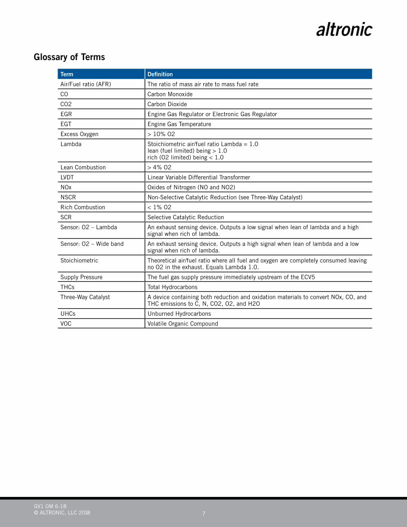
Glossary of Terms
Term Definition
Air/Fuel ratio (AFR) The ratio of mass air rate to mass fuel rate
CO Carbon Monoxide
CO2 Carbon Dioxide
EGR Engine Gas Regulator or Electronic Gas Regulator
EGT Engine Gas Temperature
Excess Oxygen > 10% O2
Lambda Stoichiometric air/fuel ratio Lambda = 1.0 lean (fuel limited) being > 1.0 rich (O2 limited) being < 1.0
Lean Combustion > 4% O2
LVDT Linear Variable Differential Transformer
NOx Oxides of Nitrogen (NO and NO2)
NSCR Non-Selective Catalytic Reduction (see Three-Way Catalyst)
Rich Combustion < 1% O2
SCR Selective Catalytic Reduction
Sensor: O2 – Lambda An exhaust sensing device. Outputs a low signal when lean of lambda and a high signal when rich of lambda.
Sensor: O2 – Wide band An exhaust sensing device. Outputs a high signal when lean of lambda and a low signal when rich of lambda.
Stoichiometric Theoretical air/fuel ratio where all fuel and oxygen are completely consumed leaving no O2 in the exhaust. Equals Lambda 1.0.
Supply Pressure The fuel gas supply pressure immediately upstream of the ECV5
THCs Total Hydrocarbons
Three-Way Catalyst A device containing both reduction and oxidation materials to convert NOx, CO, and THC emissions to C, N, CO2, O2, and H2O
UHCs Unburned Hydrocarbons
VOC Volatile Organic Compound
GV1 OM 6-18© ALTRONIC, LLC 2018 8
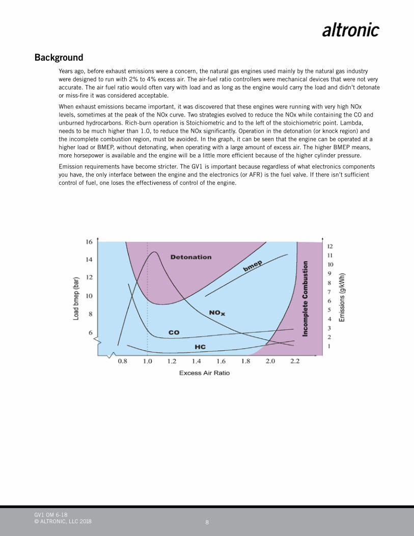
Background Years ago, before exhaust emissions were a concern, the natural gas engines used mainly by the natural gas industry
were designed to run with 2% to 4% excess air. The air-fuel ratio controllers were mechanical devices that were not very accurate. The air fuel ratio would often vary with load and as long as the engine would carry the load and didn’t detonate or miss-fire it was considered acceptable.
When exhaust emissions became important, it was discovered that these engines were running with very high NOx levels, sometimes at the peak of the NOx curve. Two strategies evolved to reduce the NOx while containing the CO and unburned hydrocarbons. Rich-burn operation is Stoichiometric and to the left of the stoichiometric point. Lambda, needs to be much higher than 1.0, to reduce the NOx significantly. Operation in the detonation (or knock region) and the incomplete combustion region, must be avoided. In the graph, it can be seen that the engine can be operated at a higher load or BMEP, without detonating, when operating with a large amount of excess air. The higher BMEP means, more horsepower is available and the engine will be a little more efficient because of the higher cylinder pressure.
Emission requirements have become stricter. The GV1 is important because regardless of what electronics components you have, the only interface between the engine and the electronics (or AFR) is the fuel valve. If there isn’t sufficient control of fuel, one loses the effectiveness of control of the engine.
GV1 OM 6-18© ALTRONIC, LLC 2018 9
1.0 Theory of Operation The GV1 is a voice coil operated valve with a built-in delta pressure transducer. One side of the transducer measures the
outlet pressure of the valve and the other side of the transducer is connected (through machined ports) to a vent plug located on the bottom of the GV1. This port is typically connected to the outlet of the turbocharger. If there is no turbo-charger, the port is simply vented to atmosphere through a vented screen plug.
The electronics in the GV1 opens the metering valve to control the fuel over air pressure coming out of the valve. What determines the pressure set-point the GV1 is set to is dependent on the version of the GV1.
The GV1 has two methods of operation:
1.1. As a variable electronic pressure regulator. In this version the GV1 takes the pressure setpoint by one the three inputs:
4-20mA
Stepper Motor Command
J1939 CANBus
The input used is determined by the version of the GV1 you are using. In the “mA”, “Step”, and ”CAN” versions, the GV1 acts as an electronic pressure regulator.
The GV1 4-20mA, Stepper Motor, and CANBus comprise the simple version of the GV1.
When the valve is off, built in spring pressure forces the valve closed. When it powers up the command interface con-trols the valve through one of the three optional inputs.
The GV1 reads the 4-20mA or CAN signal and modulates the current output to make the reading on the pressure trans-ducer equal to whatever the command is. It does this every 500 microseconds.
The Stepper Motor version divides the number of steps by the range of inches in the water column. The resolution of control is based off the span between minimal pressure to the maximum pressure. Each step changes the pressure command by the max pressure minus the min pressure, divided by the number (#) of steps. The number of steps is dependent upon the controller type. When powered on the GV1 assumes a Setpoint midway between the minimum and maximum.
(If the max pressure is 3 inches, the minimum is -1 inches, and the number of steps is 1400, the equation is equal to 4/1400 or 0.00286 inches of water column per step)
During initial installation, minimum and maximum pressure settings should be set to the engines minimum and maxi-mum operating pressures. The midpoint between these two should provide adequate air fuel ratio for starting the engine.
1.2. As an Air/Fuel Ratio Controller. When configured as an AFR valve, the GV1 reads an O2 signal through an installed Narrow Band O2 Sensor and varies
the fuel pressure in order to maintain the user programmed set-point.
When the power is off the GV1 is closed. Once power is applied, it controls at the default pressure setting. This is consid-ered running in default mode. The engine will continue operating in this mode until one of the following events occurs:
The warm-up timer expires
Pre-Catalyst temperatures exceed the minimum Catalyst temperature setting
The GV1 receives a valid O2 Sensor signal.
Upon expiration of the Warm-Up timer, the GV1 checks if the O2 Sensor feedback is valid, and if so, starts controlling the fuel pressure based on the setting of the O2 Sensor Setpoint.
The temperature requirement can be over-ridden if the thermocouple is unused by setting the Pre-Cat Undertemp limit to 0.
The O2 Sensor will start to operate once the exhaust heats up, thereby minimizing voltage of the resistor to less than 1 VDC.
Once one of the above mentioned things has occurred the GV1 will switch to AFR mode.
GV1 OM 6-18© ALTRONIC, LLC 2018 10
The GV1 will close the loop on O2 and will start adjusting pressure to obtain the desired O2 Sensor Setpoint.
The GV1 controls the pressure to the engine while looking at the feedback from a Narrow Band O2 Sensor. If the Oxygen level is high the engine is considered to be running lean and the GV1 will increase pressure. Conversely, if the Oxygen level is too low the engine is considered to be running rich and the GV1 will decrease the pressure.
The O2 Sensor Setpoint can be biased by utilizing a 4-20mA signal from a MAP Sensor for variable load conditions.
Two shutdowns are available;
Pre-Catalyst Over Temperature
Post-Catalyst Over Temperature
These two inputs are available by using Type K Thermocouples and wires and are available through Continental Controls.
If one of the Over Temperature conditions is reached the GV1 will close and the engine will shut down. To reset the GV1, power must be cycled.
1.3 Version “mA”: Inputs:
10-36Vdc, 36 Watts Peak, 20 Watts Steady State
4-20mA Pressure Command
CANbus
RS232 Modbus RTU
Outputs:
4-20mA Pressure Feedback
CANbus
RS232 Modbus RTU
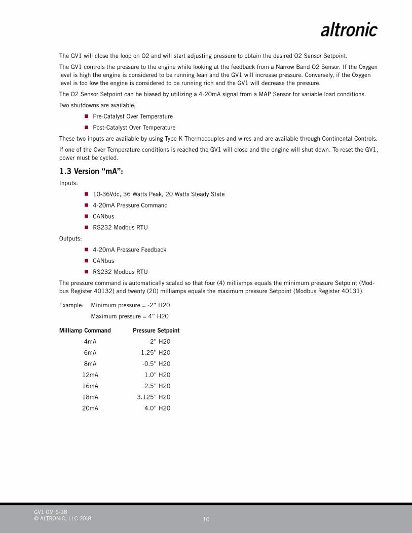
The pressure command is automatically scaled so that four (4) milliamps equals the minimum pressure Setpoint (Mod-bus Register 40132) and twenty (20) milliamps equals the maximum pressure Setpoint (Modbus Register 40131).
Example: Minimum pressure = -2” H20
Maximum pressure = 4” H20
Milliamp Command Pressure Setpoint
4mA -2” H20
6mA -1.25” H20
8mA -0.5” H20
12mA 1.0” H20
16mA 2.5” H20
18mA 3.125” H20
20mA 4.0” H20
GV1 OM 6-18© ALTRONIC, LLC 2018 11
1.4 Version “STEP”: Inputs:
10 – 36 VDC, 36 Watts Peak, 20 Watts Steady State Six (6) wire Stepper Motor Interface
RS232 Modbus RTU
Outputs:
RS232 Modbus RTU
The resolution of each step is calculated by the minimum and maximum pressure span divided by the number of steps.
Example:
Minimum pressure = -2” H20
Maximum pressure = 4” H20
Pressure Span = Max + Min = 6”H20
If the controller had 6 “ H20 divided by 1400 steps, each step would change to an approximate pressure Setpoint of .00429 “ H20.
When the GV1 is powered on the valve will assume the Setpoint is at mid-span (as per our example) of 1.0” H20.
Each step command that is given will increase or decrease the pressure command by the resolution of the step (again as per our example), .00429” H20.
A Pressure Command can also be written to the Modbus Register 40019 to force the setpoint to a specific value.
1.5 Version “CAN”: Inputs:
10-36 VDC, 36 Watts Peak, 20 Watts Steady State CANbus
RS232 Modbus RTU
Outputs:
4-20mA Pressure Feedback
RS232 Modbus RTU
When the GV1is powered on, the valve will assume that the setpoint is at the Minimum pressure setting (Modbus Regis-ter 40132).
The Pressure Setpoint can be modified via the CANbus Port in accordance with J1939 protocol.
1.6 Version “AFR”: Inputs:
10-36Vdc, 36 Watts Peak, 20 Watts Steady State 0-1 V Narrow Band O2 Sensor 4-20mA MAP Sensor 2 Thermocouples, Pre-Catalyst and Post-Catalyst CANbus
RS232 Modbus RTU
Outputs:
4-20mA Pressure Feedback
RS232 Modbus RTU
GV1 OM 6-18© ALTRONIC, LLC 2018 12
2.0 Specifications
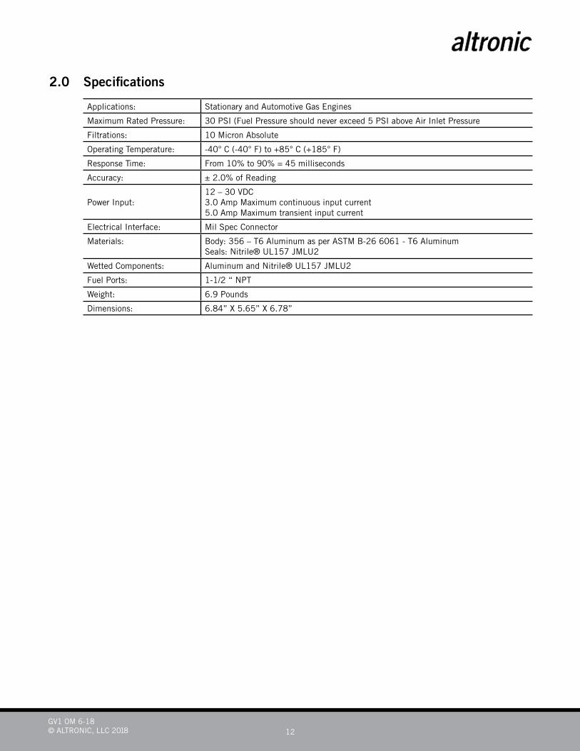
Applications: Stationary and Automotive Gas Engines
Maximum Rated Pressure: 30 PSI (Fuel Pressure should never exceed 5 PSI above Air Inlet Pressure
Filtrations: 10 Micron Absolute
Operating Temperature: -40° C (-40° F) to +85° C (+185° F)
Response Time: From 10% to 90% = 45 milliseconds
Accuracy: ± 2.0% of Reading
Power Input:12 – 30 VDC 3.0 Amp Maximum continuous input current 5.0 Amp Maximum transient input current
Electrical Interface: Mil Spec Connector
Materials: Body: 356 – T6 Aluminum as per ASTM B-26 6061 - T6 AluminumSeals: Nitrile® UL157 JMLU2
Wetted Components: Aluminum and Nitrile® UL157 JMLU2
Fuel Ports: 1-1/2 “ NPT
Weight: 6.9 Pounds
Dimensions: 6.84” X 5.65” X 6.78”
GV1 OM 6-18© ALTRONIC, LLC 2018 13
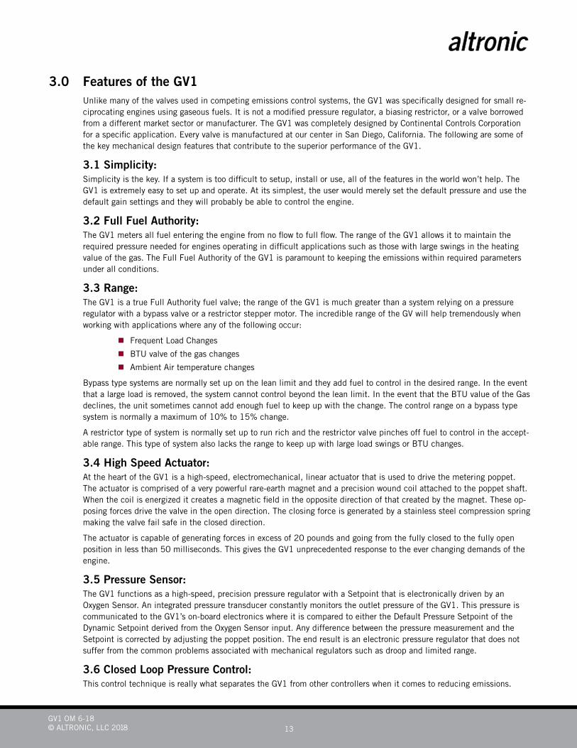
3.0 Features of the GV1 Unlike many of the valves used in competing emissions control systems, the GV1 was specifically designed for small re-
ciprocating engines using gaseous fuels. It is not a modified pressure regulator, a biasing restrictor, or a valve borrowed from a different market sector or manufacturer. The GV1 was completely designed by Continental Controls Corporation for a specific application. Every valve is manufactured at our center in San Diego, California. The following are some of the key mechanical design features that contribute to the superior performance of the GV1.
3.1 Simplicity: Simplicity is the key. If a system is too difficult to setup, install or use, all of the features in the world won’t help. The
GV1 is extremely easy to set up and operate. At its simplest, the user would merely set the default pressure and use the default gain settings and they will probably be able to control the engine.
3.2 Full Fuel Authority: The GV1 meters all fuel entering the engine from no flow to full flow. The range of the GV1 allows it to maintain the
required pressure needed for engines operating in difficult applications such as those with large swings in the heating value of the gas. The Full Fuel Authority of the GV1 is paramount to keeping the emissions within required parameters under all conditions.
3.3 Range: The GV1 is a true Full Authority fuel valve; the range of the GV1 is much greater than a system relying on a pressure
regulator with a bypass valve or a restrictor stepper motor. The incredible range of the GV will help tremendously when working with applications where any of the following occur:
Frequent Load Changes
BTU valve of the gas changes
Ambient Air temperature changes
Bypass type systems are normally set up on the lean limit and they add fuel to control in the desired range. In the event that a large load is removed, the system cannot control beyond the lean limit. In the event that the BTU value of the Gas declines, the unit sometimes cannot add enough fuel to keep up with the change. The control range on a bypass type system is normally a maximum of 10% to 15% change.
A restrictor type of system is normally set up to run rich and the restrictor valve pinches off fuel to control in the accept-able range. This type of system also lacks the range to keep up with large load swings or BTU changes.
3.4 High Speed Actuator: At the heart of the GV1 is a high-speed, electromechanical, linear actuator that is used to drive the metering poppet.
The actuator is comprised of a very powerful rare-earth magnet and a precision wound coil attached to the poppet shaft. When the coil is energized it creates a magnetic field in the opposite direction of that created by the magnet. These op-posing forces drive the valve in the open direction. The closing force is generated by a stainless steel compression spring making the valve fail safe in the closed direction.
The actuator is capable of generating forces in excess of 20 pounds and going from the fully closed to the fully open position in less than 50 milliseconds. This gives the GV1 unprecedented response to the ever changing demands of the engine.
3.5 Pressure Sensor: The GV1 functions as a high-speed, precision pressure regulator with a Setpoint that is electronically driven by an
Oxygen Sensor. An integrated pressure transducer constantly monitors the outlet pressure of the GV1. This pressure is communicated to the GV1’s on-board electronics where it is compared to either the Default Pressure Setpoint of the Dynamic Setpoint derived from the Oxygen Sensor input. Any difference between the pressure measurement and the Setpoint is corrected by adjusting the poppet position. The end result is an electronic pressure regulator that does not suffer from the common problems associated with mechanical regulators such as droop and limited range.
3.6 Closed Loop Pressure Control: This control technique is really what separates the GV1 from other controllers when it comes to reducing emissions.
GV1 OM 6-18© ALTRONIC, LLC 2018 14
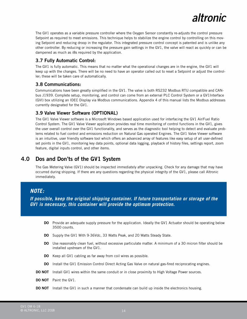
The GV1 operates as a variable pressure controller where the Oxygen Sensor constantly re-adjusts the control pressure Setpoint as required to meet emissions. This technique helps to stabilize the engine control by controlling on this mov-ing Setpoint and reducing droop in the regulator. This integrated pressure control concept is patented and is unlike any other controller. By reducing or increasing the pressure gain settings in the GV1, the valve will react as quickly or can be dampened as much as i8s required by the application.
3.7 Fully Automatic Control: The GV1 is fully automatic. This means that no matter what the operational changes are in the engine, the GV1 will
keep up with the changes. There will be no need to have an operator called out to reset a Setpoint or adjust the control-ler; these will be taken care of automatically.
3.8 Communications: Communications have been greatly simplified in the GV1. The valve is both RS232 Modbus RTU compatible and CAN-
bus J1939. Complete setup, monitoring, and control can come from an external PLC Control System or a GV1Interface (GVI) box utilizing an IDEC Display via Modbus communications. Appendix 4 of this manual lists the Modbus addresses currently designated for the GV1.
3.9 Valve Viewer Software (OPTIONAL) The GV1 Valve Viewer software is a Microsoft Windows based application used for interfacing the GV1 Air/Fuel Ratio
Control System. The GV1 Valve Viewer application provides real time monitoring of control functions in the GV1, gives the user overall control over the GV1 functionality, and serves as the diagnostic tool helping to detect and evaluate prob-lems related to fuel control and emissions reduction on Natural Gas operated Engines. The GV1 Valve Viewer software is an intuitive, user friendly software tool which offers an advanced array of features like easy setup of all user-defined set points in the GV1, monitoring key data points, optional data logging, playback of history files, settings report, zoom feature, digital inputs control, and other items.
4.0 Dos and Don’ts of the GV1 System The Gas Metering Valve (GV1) should be inspected immediately after unpacking. Check for any damage that may have
occurred during shipping. If there are any questions regarding the physical integrity of the GV1, please call Altronic immediately.
DO Provide an adequate supply pressure for the application. Ideally the GV1 Actuator should be operating below 3500 counts.
DO Supply the GV1 With 9-36Vdc, 33 Watts Peak, and 20 Watts Steady State.
DO Use reasonably clean fuel, without excessive particulate matter. A minimum of a 30 micron filter should be installed upstream of the GV1.
DO Keep all GV1 cabling as far away from coil wires as possible.
DO Install the GV1 Emission Control Direct Acting Gas Valve on natural gas-fired reciprocating engines.
DO NOT Install GV1 wires within the same conduit or in close proximity to High Voltage Power sources.
DO NOT Paint the GV1.
DO NOT Install the GV1 in such a manner that condensate can build up inside the electronics housing.
NOTE:If possible, keep the original shipping container. If future transportation or storage of the GV1 is necessary, this container will provide the optimum protection.
GV1 OM 6-18© ALTRONIC, LLC 2018 15
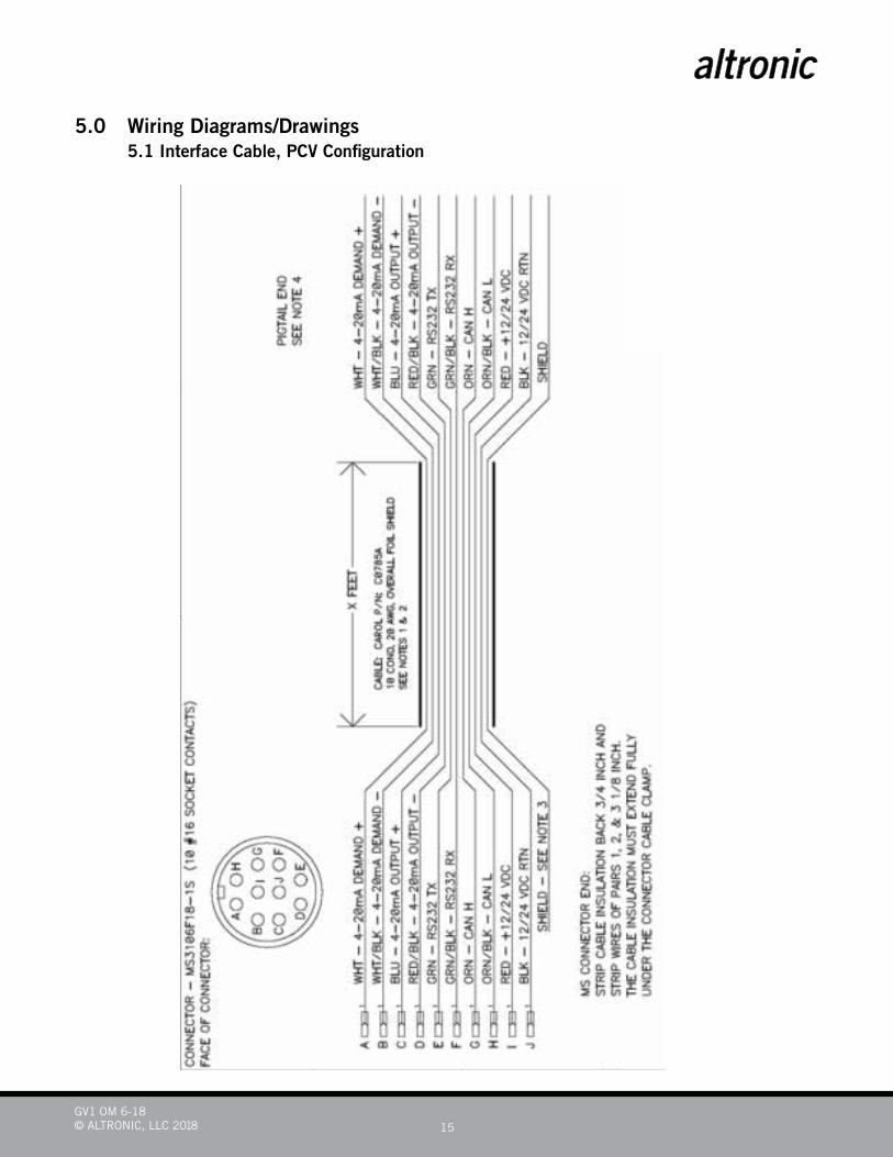
5.0 Wiring Diagrams/Drawings 5.1 Interface Cable, PCV Configuration
GV1 OM 6-18© ALTRONIC, LLC 2018 16
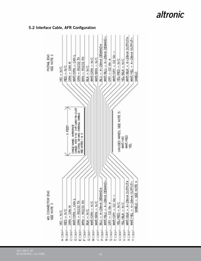
5.2 Interface Cable, AFR Configuration
GV1 OM 6-18© ALTRONIC, LLC 2018 17
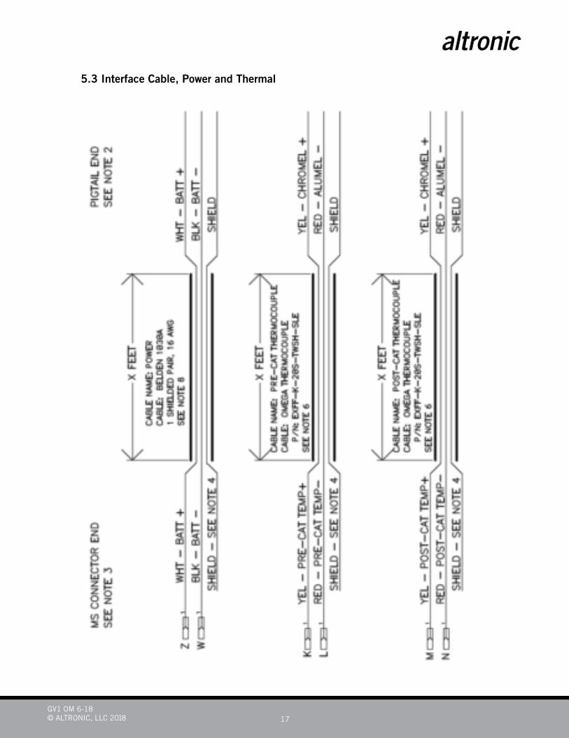
5.3 Interface Cable, Power and Thermal
GV1 OM 6-18© ALTRONIC, LLC 2018 18
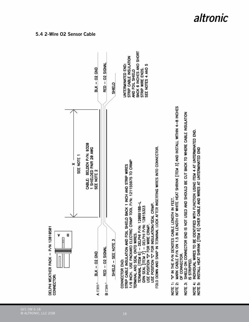
5.4 2-Wire O2 Sensor Cable
GV1 OM 6-18© ALTRONIC, LLC 2018 19
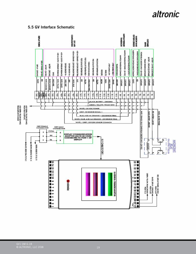
5.5 GV Interface Schematic
GV1 OM 6-18© ALTRONIC, LLC 2018 20
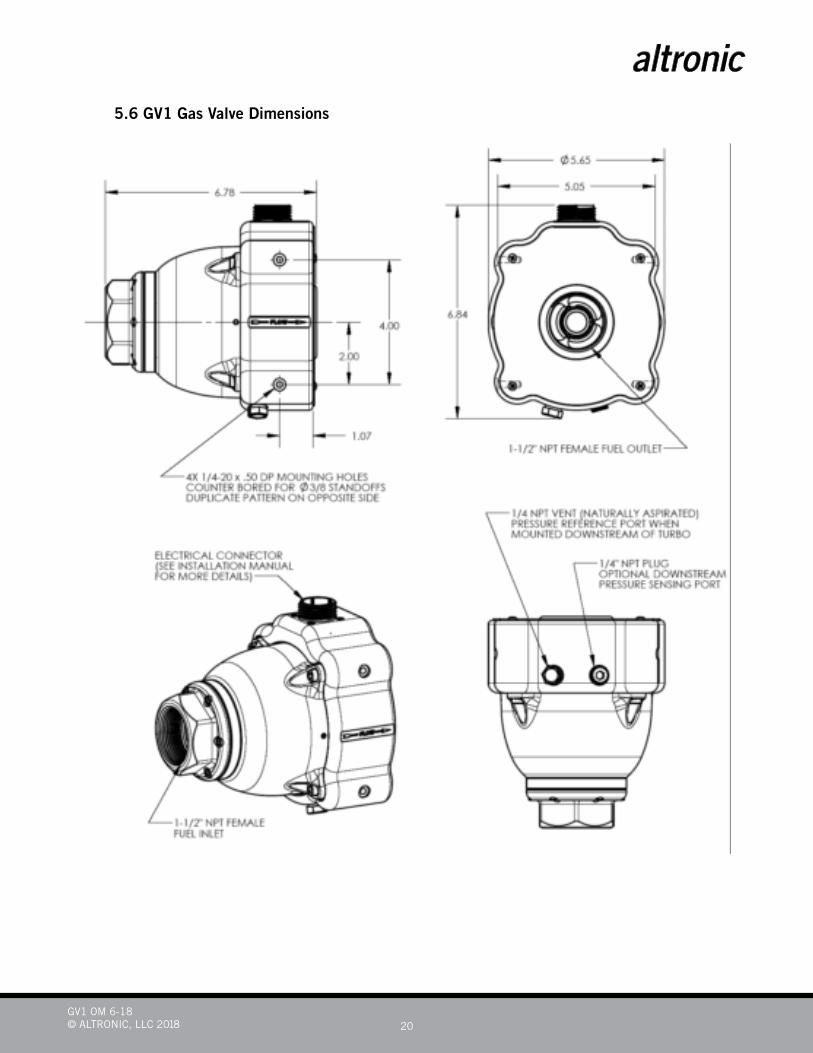
5.6 GV1 Gas Valve Dimensions
GV1 OM 6-18© ALTRONIC, LLC 2018 21
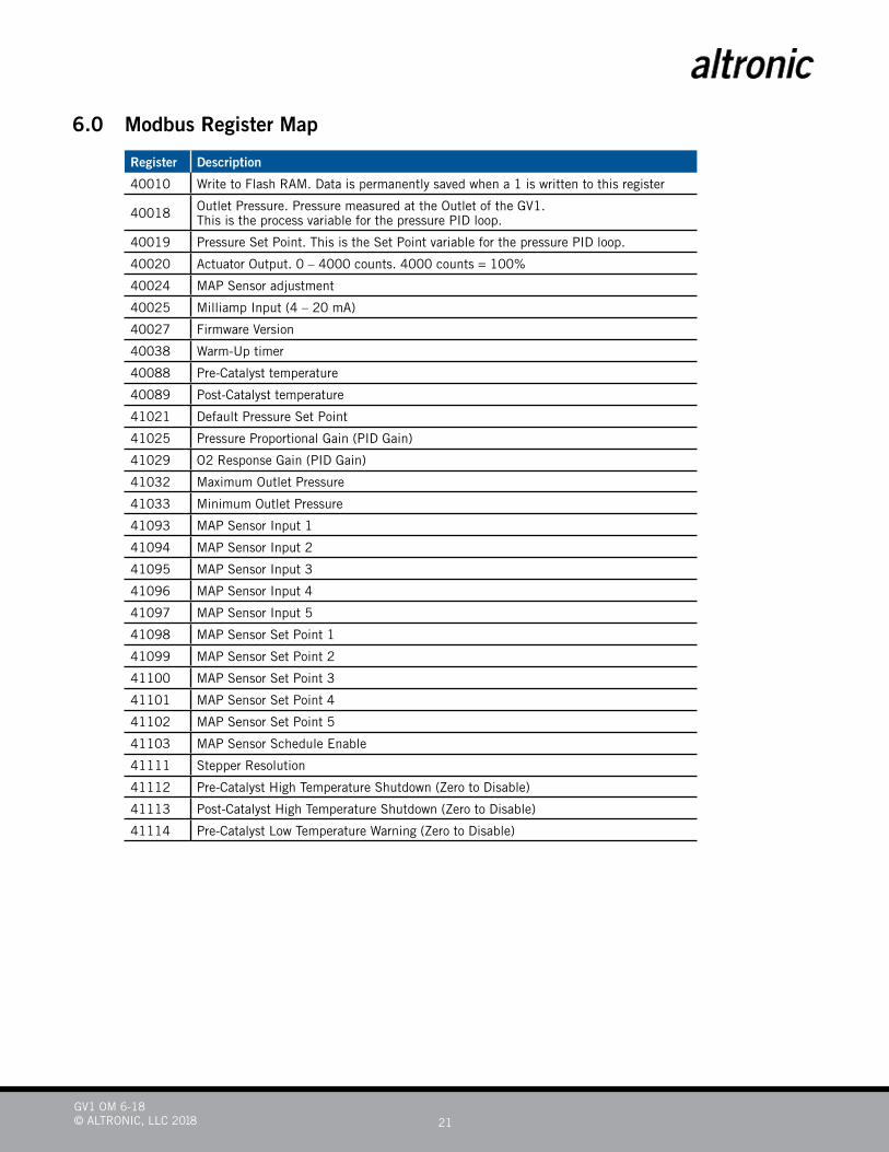
6.0 Modbus Register Map
Register Description
40010 Write to Flash RAM. Data is permanently saved when a 1 is written to this register
40018 Outlet Pressure. Pressure measured at the Outlet of the GV1. This is the process variable for the pressure PID loop.
40019 Pressure Set Point. This is the Set Point variable for the pressure PID loop.
40020 Actuator Output. 0 – 4000 counts. 4000 counts = 100%
40024 MAP Sensor adjustment
40025 Milliamp Input (4 – 20 mA)
40027 Firmware Version
40038 Warm-Up timer
40088 Pre-Catalyst temperature
40089 Post-Catalyst temperature
41021 Default Pressure Set Point
41025 Pressure Proportional Gain (PID Gain)
41029 O2 Response Gain (PID Gain)
41032 Maximum Outlet Pressure
41033 Minimum Outlet Pressure
41093 MAP Sensor Input 1
41094 MAP Sensor Input 2
41095 MAP Sensor Input 3
41096 MAP Sensor Input 4
41097 MAP Sensor Input 5
41098 MAP Sensor Set Point 1
41099 MAP Sensor Set Point 2
41100 MAP Sensor Set Point 3
41101 MAP Sensor Set Point 4
41102 MAP Sensor Set Point 5
41103 MAP Sensor Schedule Enable
41111 Stepper Resolution
41112 Pre-Catalyst High Temperature Shutdown (Zero to Disable)
41113 Post-Catalyst High Temperature Shutdown (Zero to Disable)
41114 Pre-Catalyst Low Temperature Warning (Zero to Disable)
GV1 OM 6-18© ALTRONIC, LLC 2018 22
7.0 Installation Preparations Prior to installing the GV1 valve, prepare your engine for the installation.
1. Understand what type of GV1 you are installing. There are three types; CAN and 4 -20 mA Control which will make the GV1 a Pressure Control Valve and AFR Control which will make the GV1 an Air Fuel Ratio Valve.
2. Know your engine. Know what type of fuel and the composition of the fuel you are using.
3. Know your engine’s electrical system, understanding that the customer will have to provide Continental Controls equipment with a 12 or 24 VDC power source.
4. Ensure you have the correct regulator for the system you are installing. Naturally Aspirated engines require a pres-sure of 5” to 15” of H2O so using a regulator with a Maximum Pressure of 5 PSI will be sufficient.
Turbo charged engines require a regulator delivering a maximum pressure of 5PSI ABOVE BOOST PRESSURE.
5. Ensure you have the conduit (if desired) and connectors to run the wiring through.
6. Prepare the location of the GV Interface enclosure, noting that there is only 30 feet of wiring of the GV1 Cable.
7. Ensure there is an O2 Sensor Bung located in the exhaust piping, again, noting that there is only 30 feet of wiring in the GV1 Cable. If there is currently no bung installed in exhaust piping, the customer must procure an 18 mm bung and weld into exhaust piping.
8. Ensure there is a port available for the Pre-Catalyst and Post Catalyst Thermocouple. If there is currently no ports available, the customer must procure a ¾ inch NPT Bushing and weld into exhaust piping for Thermocouple installation.
NOTE:A pressure of 5 psi is the maximum for a naturally aspirated and a pressure of 5 psi above boost pressure is maximum for a turbo charged application. A regulator delivering more than the maximum pressure will damage the gv1.

GV1 OM 6-18© ALTRONIC, LLC 2018 23
8.0 Installation Procedures 8.1 Installing GV1:
1. Ensure customer’s power is removed from engine controls.
2. Remove existing fuel piping to carburetor.
3. Using appropriate pipe size bushings, install the GV1 to Carburetor.
In picture above the carburetor inlet pipe size is ¾” NPT. The GV1 Inlet and Outlet port is 1½” NPT, so bushings were used for proper installation.
4. Ensure the GV1 is properly supported. In picture above the GV1 is only supported by the fuel pipe installed. For normal operation, this would be unsatisfactory as the weight of the GV1 and fuel pipe would eventually sep-arate and possibly damage the carburetor.
5. This GV1 was installed using approximately 14 inches of fuel piping to ensure the valve was beyond the Dis-tributor and wires.
8.2 Installing Thermocouples:1. Inspect the provided Pre- and Post-Catalyst Thermocouples for any damage caused from shipping.
2. Using the tubing fittings provided, install thermocouples in the bushings that were welded by customer and tighten.

GV1 OM 6-18© ALTRONIC, LLC 2018 24
8.3 Installing and routing wiring for an AFR GV1:1. Ensure customer’s power is removed from engine controls.
2. Plug in the GV1 cable to the GV1 paying close attention to the tabs located on the inside of the GV1 Cable Connector and the tabs located inside of the GV1 Connector. Screw the connector nut to where it hides the red line on the connector.
3. Fish the wires through desired conduit to the mounted GV Interface enclosure.
4. Trim and terminate the GV1 wires to the appropriate terminals in accordance with the GV Interface schematic located on page 21 and GV1 AFR Cable drawing located on page 18.
5. DO NOT land Customer’s power wires at this time.
6. Route Pre Catalyst and Post Catalyst Thermocouple wires through desired conduit and to the correct thermo-couple.
7. Ensure connectors are installed on Thermocouple wires and connect the thermocouples.
8. Route the provided O2 Sensor cable through desired conduit and connectors.
9. Trim and land O2 Sensor cable to terminal strip in accordance with the GV Interface schematic and the GV1 AFR Cable drawing.
10. Connect O2 Sensor to Connector.
GV1 OM 6-18© ALTRONIC, LLC 2018 25
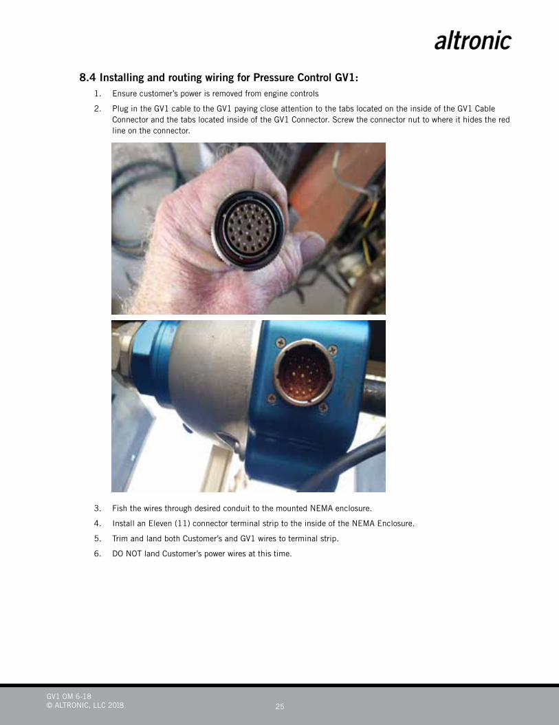
8.4 Installing and routing wiring for Pressure Control GV1:1. Ensure customer’s power is removed from engine controls
2. Plug in the GV1 cable to the GV1 paying close attention to the tabs located on the inside of the GV1 Cable Connector and the tabs located inside of the GV1 Connector. Screw the connector nut to where it hides the red line on the connector.
3. Fish the wires through desired conduit to the mounted NEMA enclosure.
4. Install an Eleven (11) connector terminal strip to the inside of the NEMA Enclosure.
5. Trim and land both Customer’s and GV1 wires to terminal strip.
6. DO NOT land Customer’s power wires at this time.

GV1 OM 6-18© ALTRONIC, LLC 2018 26
8.5 Installing the optional Venturi Insert into Impco 200 Carburetor:1. Ensure the fuel is secured to engine.
2. Remove the screws located on top cover of Carburetor and remove cover
3. When you remove cover take care not to lose the spring inside Carburetor.
4. Remove Diaphragm and spring assembly.
5. Install provided gasket.
GV1 OM 6-18© ALTRONIC, LLC 2018 27
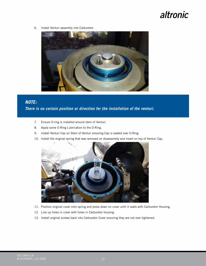
6. Install Venturi assembly into Carburetor.
7. Ensure O-ring is installed around stem of Venturi.
8. Apply some O-Ring Lubrication to the O-Ring.
9. Install Venturi Cap on Stem of Venturi ensuring Cap is seated over O-Ring.
10. Install the original spring that was removed on disassembly and insert on top of Venturi Cap.
11. Position original cover onto spring and press down on cover until it seats with Carburetor Housing.
12. Line up holes in cover with holes in Carburetor housing.
13. Install original screws back into Carburetor Cover ensuring they are not over tightened.
NOTE:There is no certain position or direction for the installation of the venturi.
GV1 OM 6-18© ALTRONIC, LLC 2018 28
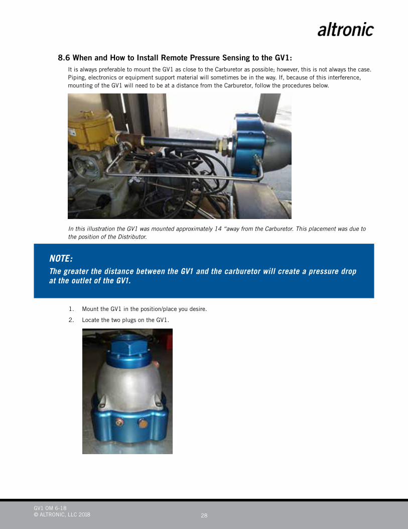
8.6 When and How to Install Remote Pressure Sensing to the GV1:It is always preferable to mount the GV1 as close to the Carburetor as possible; however, this is not always the case. Piping, electronics or equipment support material will sometimes be in the way. If, because of this interference, mounting of the GV1 will need to be at a distance from the Carburetor, follow the procedures below.
In this illustration the GV1 was mounted approximately 14 “away from the Carburetor. This placement was due to the position of the Distributor.
1. Mount the GV1 in the position/place you desire.
2. Locate the two plugs on the GV1.
NOTE:The greater the distance between the GV1 and the carburetor will create a pressure drop at the outlet of the GV1.
GV1 OM 6-18© ALTRONIC, LLC 2018 29
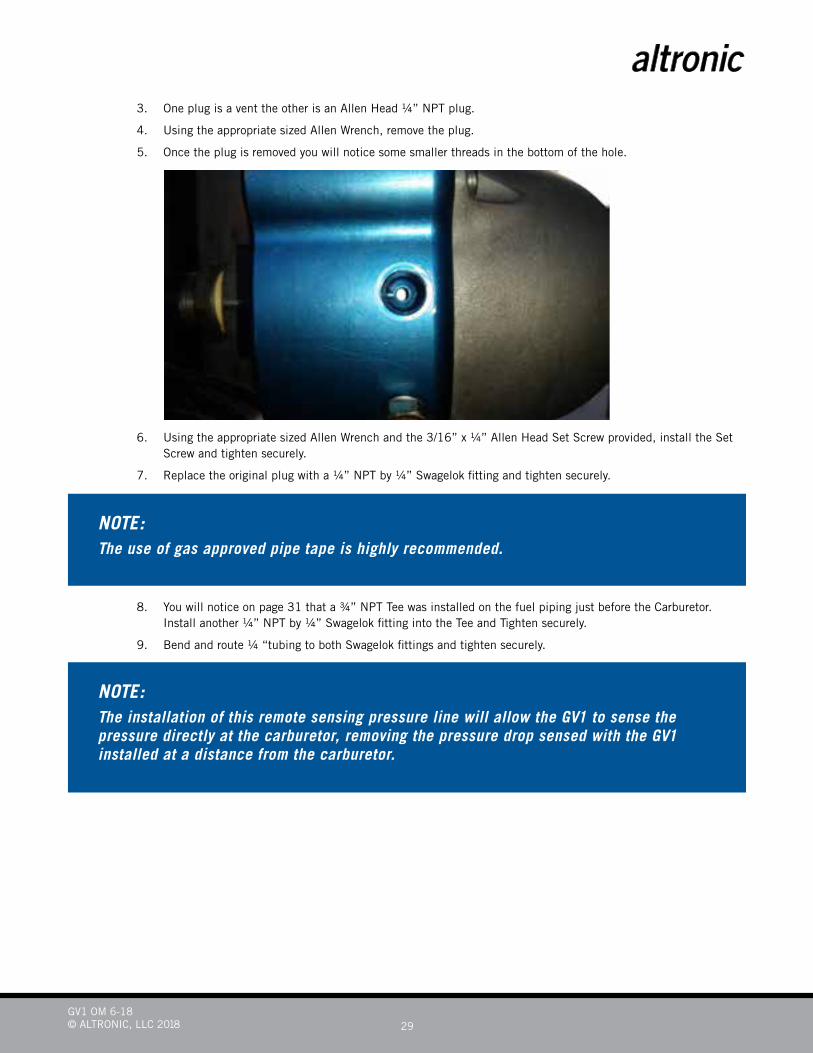
3. One plug is a vent the other is an Allen Head ¼” NPT plug.
4. Using the appropriate sized Allen Wrench, remove the plug.
5. Once the plug is removed you will notice some smaller threads in the bottom of the hole.
6. Using the appropriate sized Allen Wrench and the 3/16” x ¼” Allen Head Set Screw provided, install the Set Screw and tighten securely.
7. Replace the original plug with a ¼” NPT by ¼” Swagelok fitting and tighten securely.
8. You will notice on page 31 that a ¾” NPT Tee was installed on the fuel piping just before the Carburetor. Install another ¼” NPT by ¼” Swagelok fitting into the Tee and Tighten securely.
9. Bend and route ¼ “tubing to both Swagelok fittings and tighten securely.
NOTE:The use of gas approved pipe tape is highly recommended.
NOTE:The installation of this remote sensing pressure line will allow the GV1 to sense the pressure directly at the carburetor, removing the pressure drop sensed with the GV1 installed at a distance from the carburetor.
GV1 OM 6-18© ALTRONIC, LLC 2018 30
8.7 Installing the GV1 Downstream of the Turbo:When operating on a Naturally Aspirated engine the job of the GV1 is to give you an outlet pressure from the GV1 to the Carburetor that is greater than atmospheric pressure. When operating a GV1 downstream of a Turbo Charged unit, the GV1’s job will change. In this case the GV1’s job is to give you an outlet pressure from the GV1 to the Carburetor that is greater than the Turbo Boost pressure.
1. Locate the Screened Vent Plug on the opposite side of the GV1 Connector.
2. Remove the Screened Vent Plug and replace with a ¼” NPT by ¼” Swagelok fitting.
3. Locate a connection on the Carburetor or Upstream of the Carburetor, between the Carburetor and the Turbo.
4. Install another ¼” NPT by ¼” Swagelok fitting into this connection.
5. Bend and route ¼” Tubing between these two fittings and tighten securely.
Example:
If Turbo boost is measured at 15 PSI. The Maximum Regulator Outlet Pressure should be no more than 20 PSI. A Regulator Pressure higher than 20 PSI will damage the GV1.
8.8 Electrical Checks:At this point the GV1 should be mounted and all wiring routed to its desired location and connected.
It is recommended to check the voltage and polarity of the VDC before connecting to the GV1 or GV Interface enclo-sure. Once satisfied at the correct Voltage and Polarity follow these steps.
1. Ensure power is de-energized at this time.
2. Route Power cable to desired Enclosure and connect to the appropriate connections.
3. Switch power on and check the GV Interface Display for proper communications.
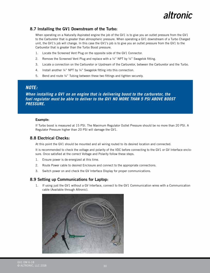
8.9 Setting up Communications for Laptop:1. If using just the GV1 without a GV Interface, connect to the GV1 Communication wires with a Communication
cable (Available through Altronic).
NOTE:When installing a GV1 on an engine that is delivering boost to the carburetor, the fuel regulator must be able to deliver to the GV1 NO MORE THAN 5 PSI ABOVE BOOST PRESSURE.
GV1 OM 6-18© ALTRONIC, LLC 2018 31
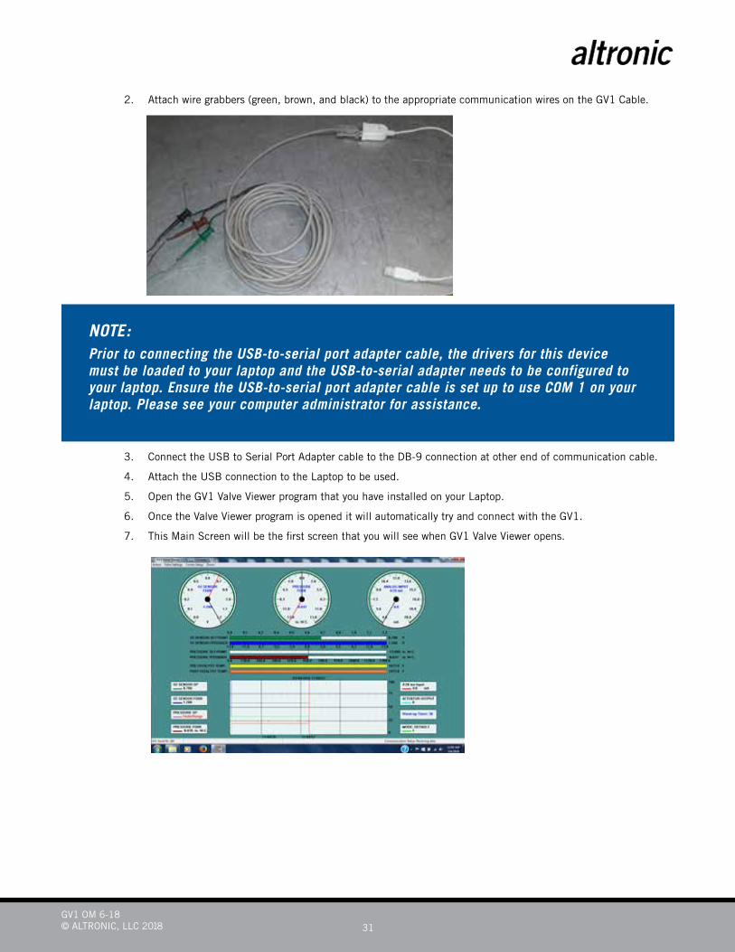
2. Attach wire grabbers (green, brown, and black) to the appropriate communication wires on the GV1 Cable.
3. Connect the USB to Serial Port Adapter cable to the DB-9 connection at other end of communication cable.
4. Attach the USB connection to the Laptop to be used.
5. Open the GV1 Valve Viewer program that you have installed on your Laptop.
6. Once the Valve Viewer program is opened it will automatically try and connect with the GV1.
7. This Main Screen will be the first screen that you will see when GV1 Valve Viewer opens.
NOTE:Prior to connecting the USB-to-serial port adapter cable, the drivers for this device must be loaded to your laptop and the USB-to-serial adapter needs to be configured to your laptop. Ensure the USB-to-serial port adapter cable is set up to use COM 1 on your laptop. Please see your computer administrator for assistance.
GV1 OM 6-18© ALTRONIC, LLC 2018 32
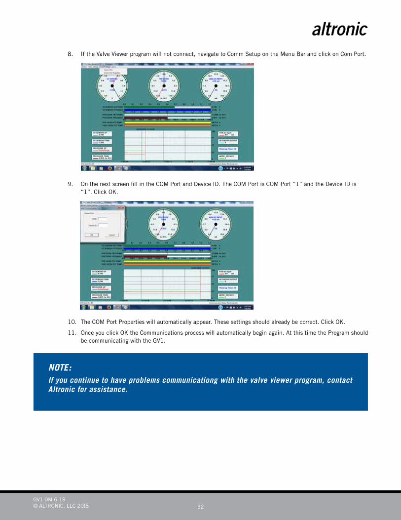
8. If the Valve Viewer program will not connect, navigate to Comm Setup on the Menu Bar and click on Com Port.
9. On the next screen fill in the COM Port and Device ID. The COM Port is COM Port “1” and the Device ID is “1”. Click OK.
10. The COM Port Properties will automatically appear. These settings should already be correct. Click OK.
11. Once you click OK the Communications process will automatically begin again. At this time the Program should be communicating with the GV1.
NOTE:If you continue to have problems communicationg with the valve viewer program, contact Altronic for assistance.

GV1 OM 6-18© ALTRONIC, LLC 2018 33
8.10 Verifying or Changing Settings:1. When you, the customer, receive the GV1 System, the GV1 has the Default settings installed. These settings
may have to be changed for Engine Specific Configuration. Normally these settings will be sufficient to start and operate your engine.
2. From the Main Screen, Navigate to Valve Settings on the Menu Bar.
3. Click on Pressure Settings. Below are the settings you will see.
4. Click on O2 Sensor Settings. Below are the settings you will see.
GV1 OM 6-18© ALTRONIC, LLC 2018 34
5. Click on the setting you wish to change. It will highlight, type in the desired setting and click “Change”, then click “Save and Close”.
8.11 Changing settings to operate from Warmup Timer or Pre-Catalyst Undertemp:1. The Default settings from Continental Controls allow the GV1 to go from Default Mode to Air Fuel Ratio Mode
based on the O2 Sensor Warmup timer setting.
2. If you desire to change this and allow the GV1 to go from the Default Mode to the Air Fuel Ratio Mode based on the Pre Catalyst Temperature then a value in the Calibrate Valve Settings will have to be changed. Currently you would need a password to enter the Calibrate Valve Menu. You will have to contact Continental Controls for this password.
3. A change is being incorporated that will allow this setting to be changed under the Valve Settings. A new menu entry will be titled Catalyst Settings. This menu will allow you the opportunity to change the way the GV1 tran-sitions from Default to Air Fuel Ratio Mode. This change will also be incorporated into the Display in the GV Interface enclosure.
9.0 Standard GV1 Kit and Optional EquipmentThere are 8 GV1 valve configurations.• GV1 Gas Valve AFR 1PSI PT # 52600008-AFR-1PSI
• GV1 Gas Valve AFR-5 PSI Pt # 52600008-AFR-5 PSI
• GV1 Gas Valve 4–20 mA, 1 PSI Pt # 52600008-4/20mA-1PSI
• GV1 Gas Valve 4-20 mA, 5 PSI Pt # 52600008-4/20mA-5 PSI
• GV1 Gas Valve CANBUS PT # 52600008-CANBUS-1 PSI
• GV1 Gas Valve CANBUS Pt # 52600008-CANBUS-5 PSI
• GV1 Gas Valve Stepper Motor Pt # 52600008-SM-1 PSI
• BV1 Gas Valve Stepper Motor Pt # 52600008-SM-5 PSI
9.1 Standard GV1 Kit:• GV1 Air Fuel Ratio Valve Pt # 52600008-XXX-XXX
• 2 Wire, Narrow Band O2 Sensor Pt # 50505019
• AFR Interface Cable, 30’ Pt # 52604027-30
• Oxygen Sensor Cable, 30” Pt # 50505177-30
• Type K Thermocouple, 2 ea Pt # 50505159
• Male NPT Thread Connector, 2 ea Pt # 50505269
9.2 Optional Equipment:• Venturi Insert Rich Burn Pt # 54100008-VNR
• Venturi Insert Lean Burn Pt # 54100008-VNL
• GV Interface Enclosure (GVI) Pt # 52608008
• GV1 Valve Viewer Software Pt # 52600013
• RS 232 to Mini Grabber Communication Cable-Pt # 50505037-30
• KIT, RS232 to Mini Grabber Cable with USB to RS232 Adapter Pt # 50505038
GV1 OM 6-18© ALTRONIC, LLC 2018 35
10.0 Warranty Altronic, LLC warrants that all goods are free from defects in workmanship and material as of the time and place of
delivery.
As a matter of general warranty policy, Altronic, LLC honors an original buyer’s warranty claim in the event of failure within 12 months of shipment to the end-user, when the equipment has been installed and operated under normal conditions and in accordance with installation instructions contained in the operating manual and generally accepted operating practices.
All warranty work must be performed at the Altronic manufacturing facility in Girard, Ohio. The customer is responsible for shipment or delivery of the product to the facility. Altronic will pay return ground freight. The customer will pay any expedited freight fees.
712 Trumbull AvenueGirard, Ohio 44420Phone: 330.545.9768; Fax: 330.545.3231E-mail: [email protected]