Embed Size (px)
Citation preview

Models:PCM23001APCM23401APCM23411A
PCM23000SERIES
Signal-Following Speed Controls
User’s M
anual

Copyright ©© 2002 byMinarik Corporation
All rights reserved. No part of this manual may be reproduced or transmitted in anyform without written permission from Minarik Corporation. The information andtechnical data in this manual are subject to change without notice. MinarikCorporation and its Divisions make no warranty of any kind with respect to thismaterial, including, but not limited to, the implied warranties of its merchantabilityand fitness for a given purpose. Minarik Corporation and its Divisions assume noresponsibility for any errors that may appear in this manual and make nocommitment to update or to keep current the information in this manual. MVD061002
Printed in the United States of America.

i
Safety WarningsNote: This symbol � denotes an important safety message.Please read these sections very carefully before performing anycalibration, repair, or other procedure contained in this manual.
• Have a qualified electrical maintenance technician install, adjust,and service this equipment. Follow the National Electrical Codeand all other applicable electrical and safety codes, including theprovisions of the Occupational Safety and Health Act (OSHA),when installing equipment.
• Reduce the chance of an electrical fire, shock, or explosion byproper grounding, over current protection, thermal protection,and enclosure. Follow sound maintenance procedures.
It is possible for a drive to run at full speed as a resultof a component failure. Minarik strongly recommends theinstallation of a master switch in the main power input tostop the drive in an emergency.
Circuit potentials are at 115 VAC or 230 VAC above earthground. Avoid direct contact with the printed circuit board orwith circuit elements to prevent the risk of serious injury orfatality. Use a non-metallic screwdriver for adjusting the cal-ibration trimpots. Use approved personal protective equip-ment and insulated tools if working on this drive with powerapplied.
�
SHOCKHAZARD
AVOIDHEAT
KEEDR
OIDATION
Safety Warnings iSpecifications 1Dimensions 2
PCM23001A . . . . . . . . . . . . . . . . . . . . . . . . . . . . . . . . . . . . . . . . . . . . .2PCM23401A/PCM23411A . . . . . . . . . . . . . . . . . . . . . . . . . . . . . . . . . .3
Installation 4Mounting . . . . . . . . . . . . . . . . . . . . . . . . . . . . . . . . . . . . . . . . . . . . . . .4Wiring . . . . . . . . . . . . . . . . . . . . . . . . . . . . . . . . . . . . . . . . . . . . . . . . . .5
Shielding guidelines . . . . . . . . . . . . . . . . . . . . . . . . . . . . . . . . . . . . .6Line fuses . . . . . . . . . . . . . . . . . . . . . . . . . . . . . . . . . . . . . . . . . . . . . .7
Line fusing for PCM20000 series drives . . . . . . . . . . . . . . . . . . . . .7Speed adjust potentiometer (Model PCM23001A only) . . . . . . . . . . .8
PCM23001A connections . . . . . . . . . . . . . . . . . . . . . . . . . . . . . . . .9Power input connections . . . . . . . . . . . . . . . . . . . . . . . . . . . . . .9
Connections . . . . . . . . . . . . . . . . . . . . . . . . . . . . . . . . . . . . . . . . . . . . .9Line fuse connections . . . . . . . . . . . . . . . . . . . . . . . . . . . . . . . .10Motor connections . . . . . . . . . . . . . . . . . . . . . . . . . . . . . . . . . .10Field output connections . . . . . . . . . . . . . . . . . . . . . . . . . . . . . .11Current and voltage follower . . . . . . . . . . . . . . . . . . . . . . . . . . .13
PCM23401A/PCM23411A connections . . . . . . . . . . . . . . . . . . . . .15Power input connections . . . . . . . . . . . . . . . . . . . . . . . . . . . . .15Motor connections . . . . . . . . . . . . . . . . . . . . . . . . . . . . . . . . . .16Field output connections . . . . . . . . . . . . . . . . . . . . . . . . . . . . . .16Voltage follower connections . . . . . . . . . . . . . . . . . . . . . . . . . .17
Operation 19Before applying power . . . . . . . . . . . . . . . . . . . . . . . . . . . . . . . . . . .19Operating Modes . . . . . . . . . . . . . . . . . . . . . . . . . . . . . . . . . . . . . . .20
PCM23001A operating modes . . . . . . . . . . . . . . . . . . . . . . . . . . .20
Contents
ii
Manual Mode . . . . . . . . . . . . . . . . . . . . . . . . . . . . . . . . . . . . . .20Signal Follower Mode . . . . . . . . . . . . . . . . . . . . . . . . . . . . . . . .20Signal with Ratio Output . . . . . . . . . . . . . . . . . . . . . . . . . . . . . .20
PCM23401A/PCM23411A Operating Modes . . . . . . . . . . . . . . . .22Manual/Signal With Ratio Output Mode Selector . . . . . . . . . . .22Manual/Signal Only Mode Select . . . . . . . . . . . . . . . . . . . . . . .22
Operating Mode Selector Switch . . . . . . . . . . . . . . . . . . . . . . . . .24Manual/Signal Only Mode Selector . . . . . . . . . . . . . . . . . . . . .24Manual/Signal With Ratio Output Mode Selector . . . . . . . . . . .24Signal Only/Signal With Ratio Output Mode Selector . . . . . . .24
Voltage Select Switches . . . . . . . . . . . . . . . . . . . . . . . . . . . . . . . . . .26Line Voltage (SW501) . . . . . . . . . . . . . . . . . . . . . . . . . . . . . . . . . .27Motor Armature Voltage (SW502) . . . . . . . . . . . . . . . . . . . . . . . . .27
Starting the drive . . . . . . . . . . . . . . . . . . . . . . . . . . . . . . . . . . . . . . . .27Line starting and line stopping . . . . . . . . . . . . . . . . . . . . . . . . . . . . .27
Calibration 28MIN SPD (Minimum Speed) . . . . . . . . . . . . . . . . . . . . . . . . . . . . . . .30MAX SPD (Maximum Speed) . . . . . . . . . . . . . . . . . . . . . . . . . . . . . .30SIG MIN (Signal Minimum) . . . . . . . . . . . . . . . . . . . . . . . . . . . . . . . .31SIG MAX (Signal Maximum) . . . . . . . . . . . . . . . . . . . . . . . . . . . . . . .31TORQUE . . . . . . . . . . . . . . . . . . . . . . . . . . . . . . . . . . . . . . . . . . . . . .32IR COMP (IR Compensation) . . . . . . . . . . . . . . . . . . . . . . . . . . . . . .33
Troubleshooting 35Before troubleshooting . . . . . . . . . . . . . . . . . . . . . . . . . . . . . . . . . . .35Replacement Parts . . . . . . . . . . . . . . . . . . . . . . . . . . . . . . . . . . . . . .41
Certificate of Compliance 42Exhibit A . . . . . . . . . . . . . . . . . . . . . . . . . . . . . . . . . . . . . . . . . . . . . .43
Unconditional Warranty inside back cover
iiiContents
iv
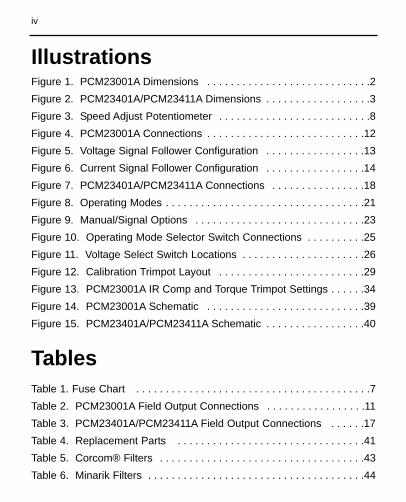
Table 1. Fuse Chart . . . . . . . . . . . . . . . . . . . . . . . . . . . . . . . . . . . . . . . .7Table 2. PCM23001A Field Output Connections . . . . . . . . . . . . . . . . .11Table 3. PCM23401A/PCM23411A Field Output Connections . . . . . .17Table 4. Replacement Parts . . . . . . . . . . . . . . . . . . . . . . . . . . . . . . . .41Table 5. Corcom® Filters . . . . . . . . . . . . . . . . . . . . . . . . . . . . . . . . . . .43Table 6. Minarik Filters . . . . . . . . . . . . . . . . . . . . . . . . . . . . . . . . . . . . .44
Tables
Figure 1. PCM23001A Dimensions . . . . . . . . . . . . . . . . . . . . . . . . . . . .2Figure 2. PCM23401A/PCM23411A Dimensions . . . . . . . . . . . . . . . . . .3Figure 3. Speed Adjust Potentiometer . . . . . . . . . . . . . . . . . . . . . . . . . .8Figure 4. PCM23001A Connections . . . . . . . . . . . . . . . . . . . . . . . . . . .12Figure 5. Voltage Signal Follower Configuration . . . . . . . . . . . . . . . . .13Figure 6. Current Signal Follower Configuration . . . . . . . . . . . . . . . . .14Figure 7. PCM23401A/PCM23411A Connections . . . . . . . . . . . . . . . .18Figure 8. Operating Modes . . . . . . . . . . . . . . . . . . . . . . . . . . . . . . . . . .21Figure 9. Manual/Signal Options . . . . . . . . . . . . . . . . . . . . . . . . . . . . .23Figure 10. Operating Mode Selector Switch Connections . . . . . . . . . .25Figure 11. Voltage Select Switch Locations . . . . . . . . . . . . . . . . . . . . .26Figure 12. Calibration Trimpot Layout . . . . . . . . . . . . . . . . . . . . . . . . .29Figure 13. PCM23001A IR Comp and Torque Trimpot Settings . . . . . .34Figure 14. PCM23001A Schematic . . . . . . . . . . . . . . . . . . . . . . . . . . .39Figure 15. PCM23401A/PCM23411A Schematic . . . . . . . . . . . . . . . . .40
Illustrations
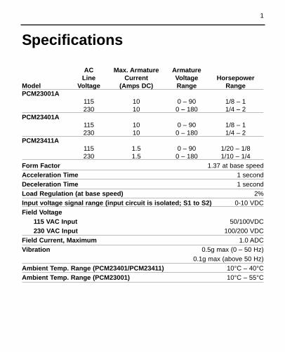
AC Max. Armature ArmatureLine Current Voltage Horsepower
Model Voltage (Amps DC) Range RangePCM23001A
115 10 0 – 90 1/8 – 1230 10 0 – 180 1/4 – 2
PCM23401A115 10 0 – 90 1/8 – 1230 10 0 – 180 1/4 – 2
PCM23411A115 1.5 0 – 90 1/20 – 1/8230 1.5 0 – 180 1/10 – 1/4
Form Factor 1.37 at base speedAcceleration Time 1 secondDeceleration Time 1 secondLoad Regulation (at base speed) 2% Input voltage signal range (input circuit is isolated; S1 to S2) 0-10 VDCField Voltage
115 VAC Input 50/100VDC230 VAC Input 100/200 VDC
Field Current, Maximum 1.0 ADCVibration 0.5g max (0 – 50 Hz)
0.1g max (above 50 Hz)Ambient Temp. Range (PCM23401/PCM23411) 10°C – 40°CAmbient Temp. Range (PCM23001) 10°C – 55°C
Specifications
1
2
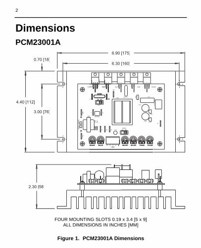
Figure 1. PCM23001A Dimensions
AKAK
2.30 [58]
6.90 [175]
6.30 [160]
4.40 [112]
0.70 [18]
3.00 [76]
C516
SCR502
R5
31
D508
C501
R525
MOV502T501
IC502
A1IC501
C502
A2
SCR
SW501
L
F2
S3S2S1
MOV503
F1
T502
D5
01
D502
NE
G
RS
H
SIG
NA
L IN
PU
T
PO
S
C518
PCM23001A
FOUR MOUNTING SLOTS 0.19 x 3.4 [5 x 9]ALL DIMENSIONS IN INCHES [MM]
Dimensions
3
PCM23401A/PCM23411A
Dimensions
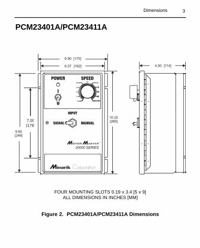
Figure 2. PCM23401A/PCM23411A Dimensions
7.00[178]
FOUR MOUNTING SLOTS 0.19 x 3.4 [5 x 9]ALL DIMENSIONS IN INCHES [MM]

4
Mounting
Warning
Do not install, rewire, or remove this control with inputpower applied. Doing so may cause fire or serious injury.Make sure you have read and understood the SafetyWarnings before attempting installation.
The chassis must be earth grounded. Use a star washerbeneath the head of at least one of the mounting screws topenetrate the anodized chassis surface and to reach baremetal.
�
• Drive components are sensitive to electrostatic fields. Avoiddirect contact with the circuit board. Hold drive by the chassisonly.
• Protect the drive from dirt, moisture, and accidental contact.• Provide sufficient room for access to the terminal block and
calibration trimpots.• Mount the drive away from heat sources. Operate the drive within
the specified ambient operating temperature range.• Prevent loose connections by avoiding excessive vibration of the
drive.• Mount drive with its board in either a horizontal or vertical plane.
Four 0.19 in. (5 mm) wide slots in the chassis accept #8 panhead screws. Fasten either the large base or the narrow flangeof the chassis to the subplate.
Installation

5
Wiring
Installation
• Use 18-24 AWG wire for speed adjust potentiometer wiring. Use14–16 AWG wire for AC line (L1, L2) and motor (A1 and A2)wiring.
Warning
Do not install, remove, or rewire this equipment with powerapplied. Failure to heed this warning may result in fire, explo-sion, or serious injury.
This drive is isolated from earth ground. Circuit potentials areat 115 or 230 VAC above ground. To prevent the risk of injuryor fatality, avoid direct contact with the printed circuit board orwith circuit elements.
Do not disconnect any of the motor leads from the driveunless power is removed or the drive is disabled. Openingany one motor lead may destroy the drive.
��
6
Shielding guidelines
Warning
Under no circumstances should power and logic leads bebundled together. Induced voltage can cause unpredictablebehavior any electronic device, including motor controls.
�
As a general rule, Minarik recommends shielding of all conductors.
If it is not practical to shield power conductors, Minarikrecommends shielding all logic-level leads. If shielding of logic levelleads is not practical, the user should twist all logic leads withthemselves to minimize induced noise.
It may be necessary to earth ground the shielded cable. If noise isproduced by devices other than the drive, ground the shield at thedrive end. If noise is generated by a device on the drive, groundthe shield at the end away from the drive. Do not ground both endsof the shield.
If the drive continues to pick up noise after grounding the shield, itmay be necessary to add AC line filtering devices, or to mount thedrive in a less noisy environment.
Logic wires from other input devices, such as motion controllersand PLL velocity controllers, must be separated from power lines inthe same manner as the logic I/O on this drive.
Installation

7
Line fuses
Protect all Minarik drives with AC line fuses. Use fast acting fusesrated for 250 volts, and approximately 150%–200% of themaximum armature current.
Line fusing for PCM20000 series drives
Minarik drives require an external fuse for protection. Use fastacting fuses rated for 250 VAC or higher, and approximately 150%of the maximum armature current. Fuse both L1 and L2 when theline voltage is 230 VAC. Fuse blocks are included on cased drivesonly.
Table 1 lists the recommended line fuse sizes.
Table 1. Fuse Chart
90 VDC Motor 180 VDC Max. DC Armature AC Line FuseHorsepower Horsepower Current (amps) Size (amps)
1/20 1/10 0.5 11/15 1/8 0.8 1.51/8 1/4 1.5 31/6 1/3 1.7 31/4 1/2 2.6 51/3 3/4 3.5 81/2 1 5.0 103/4 1 1/2 7.6 151 2 10 15
Installation

8 Installation
Figure 3. Speed Adjust Potentiometer
WIPERCW
W
SPEED ADJUSTPOTENTIOMETER
INSULATING DISKPANEL
STARWASHER
NUT
MOUNT THROUGH A 0.38 IN. (10 MM) HOLE
Mount the speed adjust potentiometer through a 0.38 in. (10 mm)hole with the hardware provided (Figure 3). Install the circularinsulating disk between the panel and the 10K ohm speed adjustpotentiometer.
Twist the speed adjust potentiometer wire to avoid picking upunwanted electrical noise. If speed adjust potentiometer wires arelonger than 18 in. (457 mm), use shielded cable. Keep speed adjustpotentiometer wires separate from power leads (L1, L2, A1, A2).
Warning
Be sure that the potentiometer tabs do not make contact withthe potentiometer enclosure. Grounding the input will causedamage to the drive.
�
Speed adjust potentiometer(Model PCM23001A only)

9Installation
Connections
Warning
Do not connect this equipment with power applied.Failure to heed this directive may result in fire or seriousinjury.
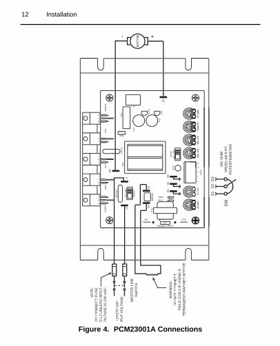
Minarik strongly recommends the installation of a masterpower switch in the voltage input line, as shown inFigure 4, page 12. The switch contacts should be rated at aminimum of 200% of motor nameplate current and 250 volts.
The field output is for shunt wound motors only. Do not makeany connections to F1 and F2 when using a permanentmagnet motor.
�
PCM23001A connections
Connect the power input leads, an external line fuse and a DCmotor to the drive’s printed circuit board (PCB) as shown in Figure4, page 12.
Power input connectionsConnect the AC line power leads to terminals L1 and L2, or to adouble-throw, single-pole master power switch (recommended).

10
Line fuse connectionsWire an external line fuse between the stop switch (if installed) andthe L1 terminal on the PC board. An additional line fuse should beinstalled on L2 if the input voltage is 230VAC. The line fuse(s)should be rated at 250 volts and 150 - 200% of maximum motornameplate current. Refer to the line fuse chart on page 7 for fuseratings.
Motor connectionsMinarik drives supply motor voltage from A1 and A2 terminals. It isassumed throughout this manual that, when A1 is positive withrespect to A2 , the motor will rotate clockwise (CW) while lookingat the output shaft protruding from the front of the motor. If this isopposite of the desired rotation, simply reverse the wiring of A1 andA2 with each other.
Connect a DC motor to PCB terminals A1 and A2 as shown inFigure 4. Ensure that the motor voltage rating is consistentwith the drive’s output voltage.
Installation
11
Field output connections
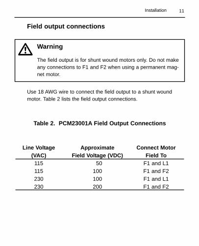
Use 18 AWG wire to connect the field output to a shunt woundmotor. Table 2 lists the field output connections.
Table 2. PCM23001A Field Output Connections
Line Voltage Approximate Connect Motor (VAC) Field Voltage (VDC) Field To115 50 F1 and L1115 100 F1 and F2230 100 F1 and L1230 200 F1 and F2
Warning
The field output is for shunt wound motors only. Do not makeany connections to F1 and F2 when using a permanent mag-net motor.
�
Installation
12 Installation
AG
AA
KA
K
- +
MO
TOR
NO
TE:
NO
T C
ON
NE
CT
FUS
ETO
L2
UN
LES
S IN
PU
TV
OLT
AG
E IS
230
VA
C
MA
STE
R L
INE
SW
ITC
H
115/
230
VA
CN
PU
T V
OLT
AG
E
10K
OH
MS
PE
ED
AD
JUS
TP
OTE
NTI
OM
ETE
Rcw
S3
S2
S1
C51
6
R531
D50
8
C50
1
R525
MO
V50
2T5
01
A1
IC50
1
SW
502
C50
2
D50
6
L2L1
MO
V50
1
F2
S3
S2
S1
T502
43
2S
O50
11
SIG
MIN
NEG
RSH
D50
7
WA
RN
ING
:D
O N
OT
CO
NN
EC
TFI
ELD
CO
ILS
IF U
SIN
G A
PE
RM
AN
EN
T-M
AG
NE
T M
OTO
R
Figure 4. PCM23001A Connections
13
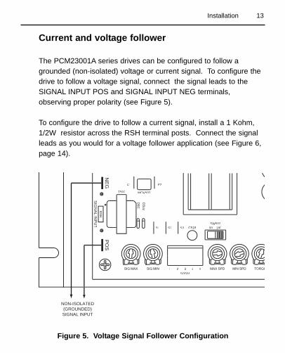
Current and voltage follower
The PCM23001A series drives can be configured to follow agrounded (non-isolated) voltage or current signal. To configure thedrive to follow a voltage signal, connect the signal leads to theSIGNAL INPUT POS and SIGNAL INPUT NEG terminals,observing proper polarity (see Figure 5).
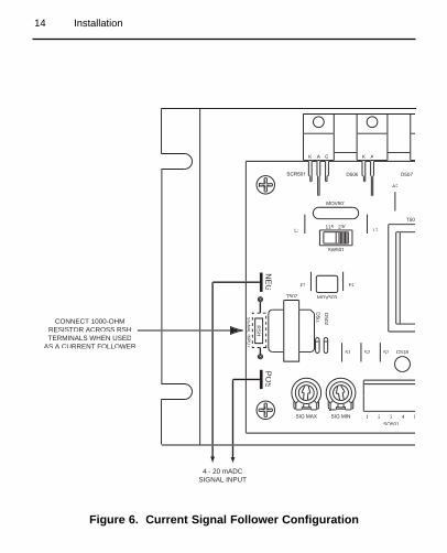
To configure the drive to follow a current signal, install a 1 Kohm,1/2W resistor across the RSH terminal posts. Connect the signalleads as you would for a voltage follower application (see Figure 6,page 14).
90 180SW502
5
F2
S3S2S1
MOV503
F1
T502
D501
D502
432SO501
1
NE
GR
SH
SIG
NA
L INP
UT
PO
S
C518
NON-ISOLATED(GROUNDED)SIGNAL INPUT
Figure 5. Voltage Signal Follower Configuration
Installation
14 Installation
AKGK
T50
5
A2
D506
L2
SW501
L1
MOV501
115 230
F2
S3S2S1
MOV503
F1
T502
D501
D502
432SO501
1
NE
GR
SH
SIG
NA
L INP
UT
PO
S
C518
D507
4 - 20 mADCSIGNAL INPUT
CONNECT 1000-OHMRESISTOR ACROSS RSHTERMINALS WHEN USED
AS A CURRENT FOLLOWER
Figure 6. Current Signal Follower Configuration

15
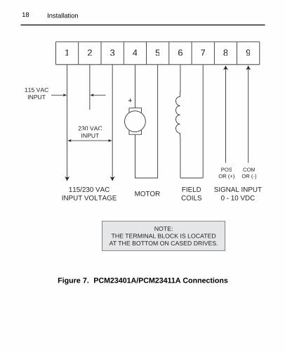
Connect the power input leads, field coil leads and a DC motor tothe drive’s terminal block as shown in Figure 7 (page 18).
Power input connections
115 VAC inputConnect power to terminals 1 and 2 of the terminal board asshown.
230 VAC inputConnect power to terminals 1 and 3 of the terminal board asshown.
PCM23401A/PCM23411A connections
Warning
Do not connect this equipment with power applied.Failure to heed this directive may result in fire or seriousinjury.
Minarik strongly recommends the installation of a masterpower switch in the voltage input line, as shown inFigure 7 (page 18). The switch contacts should be rated at aminimum of 200% of motor nameplate current and 250 volts.
�
Installation
16 Installation
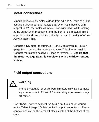
Motor connections
Minarik drives supply motor voltage from A1 and A2 terminals. It isassumed throughout this manual that, when A1 is positive withrespect to A2 , the motor will rotate clockwise (CW) while lookingat the output shaft protruding from the front of the motor. If this isopposite of the desired rotation, simply reverse the wiring of A1 andA2 with each other.
Connect a DC motor to terminals 4 and 5 as shown in Figure 7(page 18). Connect the motor’s negative (-) lead to terminal 4.Connect the motor’s positive (+) lead to terminal 5. Ensure thatthe motor voltage rating is consistent with the drive’s outputvoltage.
Field output connections
Use 18 AWG wire to connect the field output to a shunt woundmotor. Table 3 (page 17) lists the field output connections. Theseconnections are on the terminal block located at the bottom of thecase.
Warning
The field output is for shunt wound motors only. Do not makeany connections to F1 and F2 when using a permanent mag-net motor.
�
17
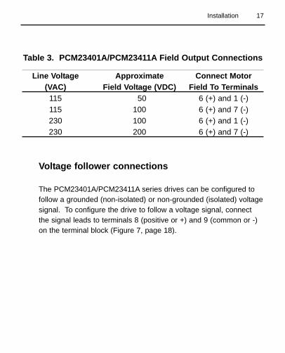
Table 3. PCM23401A/PCM23411A Field Output Connections
Line Voltage Approximate Connect Motor (VAC) Field Voltage (VDC) Field To Terminals115 50 6 (+) and 1 (-)115 100 6 (+) and 7 (-)230 100 6 (+) and 1 (-)230 200 6 (+) and 7 (-)
Voltage follower connections
The PCM23401A/PCM23411A series drives can be configured tofollow a grounded (non-isolated) or non-grounded (isolated) voltagesignal. To configure the drive to follow a voltage signal, connectthe signal leads to terminals 8 (positive or +) and 9 (common or -)on the terminal block (Figure 7, page 18).
Installation
18
Figure 7. PCM23401A/PCM23411A Connections
9
230 VACINPUT
115 VACINPUT
87654321
115/230 VACINPUT VOLTAGE
+
MOTOR FIELDCOILS
SIGNAL INPUT0 - 10 VDC
POSOR (+)
COMOR (-)
NOTE:THE TERMINAL BLOCK IS LOCATED
AT THE BOTTOM ON CASED DRIVES.
Installation

19
Before applying power
1. Verify that no conductive material is present on the printedcircuit board.
2. Verify that the AC supply is properly balanced.
3. Verify that voltage select switches SW1 and SW2 are set to theproper voltage for your application
Warning
Dangerous voltages exist on the drive when it is powered. BEALERT. High voltages can cause serious or fatal injury.
�
Operation
20 Operation
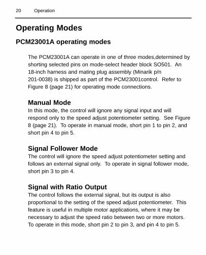
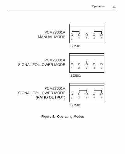
Operating ModesPCM23001A operating modes
The PCM23001A can operate in one of three modes,determined byshorting selected pins on mode-select header block SO501. An18-inch harness and mating plug assembly (Minarik p/n 201-0038) is shipped as part of the PCM23001control. Refer toFigure 8 (page 21) for operating mode connections.
Manual ModeIn this mode, the control will ignore any signal input and willrespond only to the speed adjust potentiometer setting. See Figure8 (page 21). To operate in manual mode, short pin 1 to pin 2, andshort pin 4 to pin 5.
Signal Follower ModeThe control will ignore the speed adjust potentiometer setting andfollows an external signal only. To operate in signal follower mode,short pin 3 to pin 4.
Signal with Ratio OutputThe control follows the external signal, but its output is alsoproportional to the setting of the speed adjust potentiometer. Thisfeature is useful in multiple motor applications, where it may benecessary to adjust the speed ratio between two or more motors.To operate in this mode, short pin 2 to pin 3, and pin 4 to pin 5.
21
1 2 3 4 5
PCM23001AMANUAL MODE
SO501
1 2 3 4 5
PCM23001ASIGNAL FOLLOWER MODE
SO501
1 2 3 4 5
PCM23001ASIGNAL FOLLOWER MODE
(RATIO OUTPUT)
SO501
Figure 8. Operating Modes
Operation

22 Operation
PCM23401A/PCM23411A Operating Modes
The mode selector switch on the PCM23401A drive, mounted on itscover, provides the option of operating in either MANUAL orSIGNAL mode (see Figure 2, page 3). SIGNAL mode includes theratio feature described on page 20.
Manual/Signal With Ratio Output Mode SelectorConnect a switch or relay as shown in Figure 9a (page 23) toselect manual or signal with ratio output modes.
Manual/Signal Only Mode SelectTo remove the ratio feature, rewire the switching device per Figure9b (page 23). This will change the mode options to MANUAL orSIGNAL only.
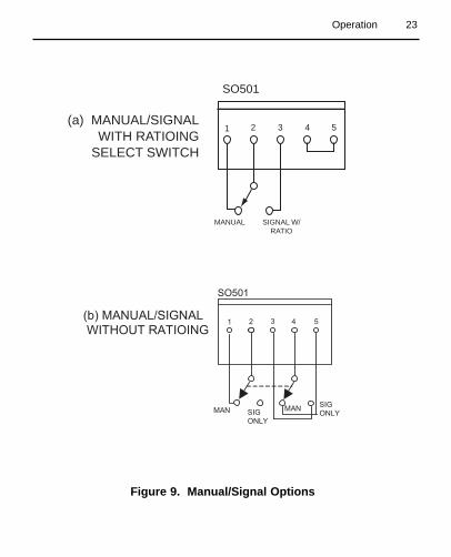
23
1 2 3 4 5(a) MANUAL/SIGNAL
WITH RATIOINGSELECT SWITCH
SO501
MANUAL SIGNAL W/RATIO
Figure 9. Manual/Signal Options
Operation
1 2 5 4 3
MAN SIG ONLY
MAN SIG ONLY
SO501
(b) MANUAL/SIGNAL
WITHOUT RATIOING

24 Operation
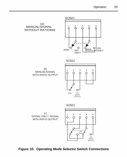
Operating Mode Selector Switch
To enable the selection of an operating mode from either of twopossibilities, connect the harness leads to a switch or a relay inaccordance with figures 10a, 10b, or 10c (page 25) as yourapplication requires.
Manual/Signal Only Mode SelectorTo enable either manual only or signal input only modes, connect aswitch or relay as shown in Figure 10a (page 25).
Manual/Signal With Ratio Output Mode SelectorTo enable either manual only or signal with ratio output modes,connect a switch or relay as shown in Figure 10b (page 25).
Signal Only/Signal With Ratio Output ModeSelectorTo enable either signal only or signal with ratio output modes,connect a switch or relay as shown in Figure 10c (page 25).
25
Figure 10. Operating Mode Selector Switch Connections
1 2 3 4 5(b)MANUAL/SIGNAL
WITH RATIO OUTPUT
SO501
SIG(RATIO
OUTPUT)
MAN
1 2 3 4 5(c)SIGNAL ONLY / SIGNALWITH RATIO OUTPUT
SO501
SIGONLY
SIG(RATIO
OUTPUT)
Operation
1 2 5 4 3
MAN SIG ONLY
MAN SIG ONLY
SO501
(a) MANUAL/SIGNAL
WITHOUT RATIOING
26 Operation
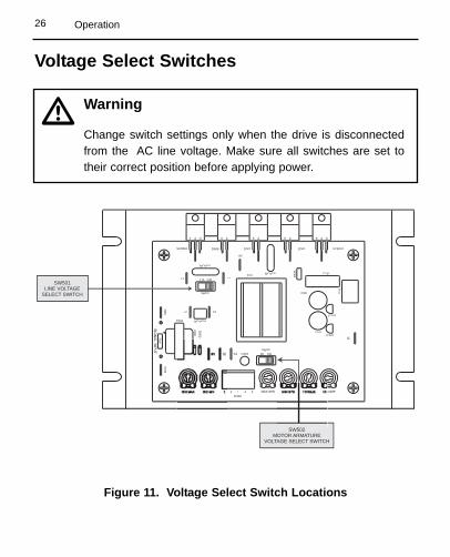
Figure 11. Voltage Select Switch Locations
Voltage Select Switches
K
SW502MOTOR ARMATURE
VOLTAGE SELECT SWITCH
SW501LINE VOLTAGE
SELECT SWITCH
C516
SCR502
R53
1
D508
C501R
525
MOV502T501
IC502
A1IC501
90 180SW502
C502
L2
SCR501
SW501
L1
MOV501
115 230
F2
S3
MOV503
F1
T502
D501
43SO501
NE
G
RS
H
PO
S
C518
D507
Warning
Change switch settings only when the drive is disconnectedfrom the AC line voltage. Make sure all switches are set totheir correct position before applying power.
�
27
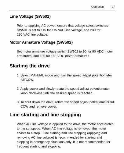
Line Voltage (SW501)
Prior to applying AC power, ensure that voltage select switchesSW501 is set to 115 for 115 VAC line voltage, and 230 for 230 VAC line voltage.
Motor Armature Voltage (SW502)
Set motor armature voltage switch SW502 to 90 for 90 VDC motorarmatures, and 180 for 180 VDC motor armatures.
Starting the drive
1. Select MANUAL mode and turn the speed adjust potentiometerfull CCW.
2. Apply power and slowly rotate the speed adjust potentiometerknob clockwise until the desired speed is reached.
3. To shut down the drive, rotate the speed adjust potentiometer fullCCW and remove power.
Line starting and line stopping
When AC line voltage is applied to the drive, the motor acceleratesto the set speed. When AC line voltage is removed, the motorcoasts to a stop. Line starting and line stopping (applying andremoving AC line voltage) is recommended for starting andstopping in emergency situations only. It is not recommended forfrequent starting and stopping.
Operation

28
Calibration
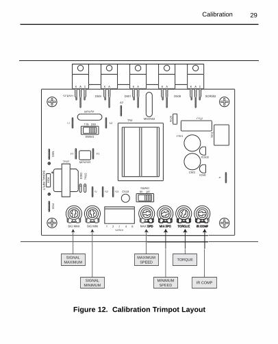
PCM23001A Series drives have six user adjustable trimpots: SIGMAX, SIG MIN, MAX SPD, MIN SPD, IR COMP and TORQUE.
Recalibrate the trimpots if a lower current motor is used (lower thanthe rated maximum of the drive). All trimpot settings increase withclockwise (CW) rotation, and decrease with counterclockwise(CCW) rotation. Use a non-metallic screwdriver for calibration.Each trimpot is identified on the printed circuit board.
Warning
Dangerous voltages exist on the drive when it is powered.When possible, disconnect the voltage input from the drivebefore adjusting the trimpots. If the trimpots must beadjusted with power applied, use insulated tools and theappropriate personal protection equipment. BE ALERT. Highvoltages can cause serious or fatal injury.
�
29Calibration
Figure 12. Calibration Trimpot Layout
AKGK GKAKAK
C516
R53
1
D508
C501
R52
5
MOV502T501
IC502
A1IC501
90 180SW502
C502
A2
D506
L2
SCR501
SW501
L1
MOV501
F2
S3S2S1
MOV503
F1
T502
D501
D502
432SO501
NE
G
RS
H
PO
S
C518
D507
SIGNALMAXIMUM
SIGNALMINIMUM
MAXIMUMSPEED
MINIMUMSPEED
TORQUE
IR COMP
30 Calibration
MIN SPD (Minimum Speed)
NOTE: Check the MIN and MAX trimpot setting after recalibratingto verify that the motor runs at the desired minimum speed.
The MIN trimpot setting determines the motor speed when thespeed adjust potentiometer is turned full CCW. It is operationalonly in MANUAL mode and is factory set to zero speed.
To calibrate MIN trimpot setting:1. Turn the speed adjust potentiometer full CCW.2. Adjust the MIN trimpot until the motor has stopped, or is running
at the desired minimum speed.
MAX SPD (Maximum Speed)
NOTE: Check the MIN and MAX trimpot setting after recalibratingto verify that the motor runs at the desired maximum speed.
The MAX SPD trimpot setting determines the motor speed whenthe speed adjust potentiometer is turned full CW. It is operationalonly when the control is in MANUAL mode.
To calibrate MAX SPD trimpot setting:1. Set the MAX SPD trimpot full CCW.2. Turn the speed adjust potentiometer full CW.3. Adjust the MAX SPD trimpot until the desired maximum motor
speed is reached.
31Calibration
SIG MIN (Signal Minimum)
NOTE: SIG MIN is operative only when the control is in SIGNAL orSIGNAL WITH RATIO OUTPUT mode.
The SIG MIN trimpot establishes the motor speed obtained inresponse to the minimum input signal.
To calibrate the SIG MIN pot, apply the minimum signal. Adjust theSIG MIN trimpot until the motor runs at the desired speed or is justat the threshold of rotation. If the operation is in SIGNAL WITHRATIO OUTPUT mode, the speed adjust potentiometer must beturned fully CW while this calibration is being made.
SIG MAX (Signal Maximum)
NOTE: SIG MAX is operative only when the control is in SIGNALor SIGNAL WITH RATIO OUTPUT mode.
The SIG MAX trimpot establishes the motor speed obtained inresponse to the maximum input signal.
To calibrate the SIG MAX pot, apply the maximum signal. Adjustthe SIG MAX trimpot until the motor runs at the desired speed. Ifthe operation is in SIGNAL WITH RATIO OUTPUT mode, thespeed adjust potentiometer must be turned fully CW while thiscalibration is being made.
32 Calibration
TORQUE
Warning
Although TORQUE LIMIT is set to 120% of motor nameplatecurrent rating, continuous operation beyond that rating maydamage the motor. If you intend to operate beyond the rating,contact your Minarik representative for assistance.
�
The TORQUE trimpot setting determines the maximum torque foraccelerating and driving the motor. Use the following procedure tocalibrate the TORQUE setting:
1. With the power disconnected from the drive, connect a DCammeter in series with the armature.
2. Set the TORQUE trimpot to minimum (full CCW).3. Set the speed adjust potentiometer to maximum speed (full
CW).4. Carefully lock the motor armature. Be sure that the motor is
firmly mounted.5. Apply line power. The motor should be stopped.6. Slowly adjust the TORQUE trimpot CW until the armature
current is 120% of motor rated armature current.7. Turn the speed adjust potentiometer CCW.8. Remove line power.9. Remove the stall from the motor.10. Remove the ammeter in series with the motor armature if it is
no longer needed.
33
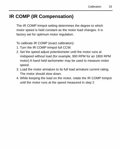
IR COMP (IR Compensation)
The IR COMP trimpot setting determines the degree to whichmotor speed is held constant as the motor load changes. It isfactory set for optimum motor regulation.
To calibrate IR COMP (exact calibration):1. Turn the IR COMP trimpot full CCW.2. Set the speed adjust potentiometer until the motor runs at
midspeed without load (for example, 900 RPM for an 1800 RPMmotor) A hand held tachometer may be used to measure motorspeed.
3. Load the motor armature to its full load armature current rating.The motor should slow down.
4. While keeping the load on the motor, rotate the IR COMP trimpotuntil the motor runs at the speed measured in step 2
Calibration

34
Figure 13. PCM23001A IR Comp and Torque Trimpot Settings
1/4 HORSEPOWER
1750 RPM
90 VDC
2.7 AMP RATING
IR COMP TORQUE
1/2 HORSEPOWER
1750 RPM
90 VDC
5 AMP RATING
1 HORSEPOWER
1750 RPM
90 VDC
10 AMP RATING
1/2 HORSEPOWER
1750 RPM
180 VDC
2.5 AMP RATING
IR COMP TORQUE
1 HORSEPOWER
1750 RPM
180 VDC
5 AMP RATING
2 HORSEPOWER
1750 RPM
180 VDC
9.2 AMP RATING

35
Before troubleshooting
Perform the following steps before starting any procedure in thissection:
1. Disconnect AC line voltage from the drive.
2. Check the drive closely for damaged components.
3. Check that no conductive or other foreign material has becomelodged on the printed circuit board.
4. Verify that every connection is correct and in good condition.
5. Verify that there are no short circuits or grounded connections.
6. Check that the drive’s rated armature outputs are consistentwith the motor ratings.
For additional assistance, contact your local Minarik distributor, orthe factory direct:
1-800-MINARIK (646-2745) or Fax: 1-800-394-6334
TroubleshootingWarning
Dangerous voltages exist on the drive when it is powered.When possible, disconnect the drive while troubleshooting.High voltages can cause serious or fatal injury.
�

36 Troubleshooting
Line fuse blows 1. Line fuses are thewrong size.
2. Motor cable orarmature is shorted toground.
3. Nuisance trippingcaused by acombination ofambient conditionsand high-currentspikes.
4. Field circuit is open.
1. Check that line fusesare the correct size.
2. Check motor cableand armature forshorts.
3. Add a blower to coolthe drive components;decrease TORQUEsettings, or resizemotor and drive foractual load demand,or check for incorrectlyaligned mechanicalcomponents or “jams”.See page 32 forinformation onadjusting theTORQUE trimpot.
4. Send in drive toMinarik repairdepartment.
Problem PossibleCauses
SuggestedSolutions
37
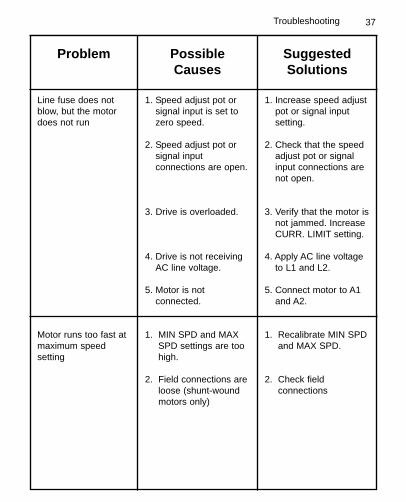
Line fuse does notblow, but the motordoes not run
Motor runs too fast atmaximum speedsetting
1. Speed adjust pot orsignal input is set tozero speed.
2. Speed adjust pot orsignal inputconnections are open.
3. Drive is overloaded.
4. Drive is not receivingAC line voltage.
5. Motor is notconnected.
1. MIN SPD and MAXSPD settings are toohigh.
2. Field connections areloose (shunt-woundmotors only)
1. Increase speed adjustpot or signal inputsetting.
2. Check that the speedadjust pot or signalinput connections arenot open.
3. Verify that the motor isnot jammed. IncreaseCURR. LIMIT setting.
4. Apply AC line voltageto L1 and L2.
5. Connect motor to A1and A2.
1. Recalibrate MIN SPDand MAX SPD.
2. Check fieldconnections
Problem PossibleCauses
SuggestedSolutions
Troubleshooting

38 Troubleshooting
Problem PossibleCauses
SuggestedSolutions
Motor runs too slowor too fast
Motor will not reachthe desired speed.
Motor pulsates orsurges under load
1. MIN SPD and MAXSPD are not calibrated.
1. MAX SPD setting is toolow.
2. IR COMP setting is toolow.
3. Motor is overloaded.
1. IR COMP is set toohigh.
2. Control is in currentlimit mode.
1. Calibrate MIN SPDand MAX SPD.
1. Increase MAX SPDsetting.
2. Increase IR COMPsetting.
3. Check motor load.Resize the motor anddrive if necessary.
1. Adjust the IR COMPsetting slightly CCWuntil the motor speedstabilizes.
2. Check that motor is ofsufficient horsepowerand amperage.
39
C16 .22
C11
.01
C2 .1
PL6
015P
MO
LEX
IC1
240Q4
2N44
01C
10 .47
R21 100
MO
V50
2V
275L
A20
A
D50
6D
8020
LD
508
D80
20L
D50
7D
8020
L
SC
R50
1S
8020
LS
CR
502
S80
20L
R23 22
R24 22
D8
C12
.047
R53
1
.01/
5W
R26
68K
1.5M
P50
525
KC
13.4
7
P50
625
K47
0
D9 R32
100K
R25
47K
2M
R34
100K
25K
IC50
279
L05
IC50
178
L05
C15 .1C14 .1
MO
V50
3
V27
5LA
4
D16
D15
MO
V50
1V
275L
A20
A
DS
T-2-
20S
PD
T
D11
D10
C50
122
0
C50
222
0
D14
R31
100K
R35
R33
10K
R18
33K
R19
470K
C1 .1
R20 100
C8
.01
C7
.47
R15
R17
R14
2.2K
470
Q1
2N44
01R
3
C4
R5
T502
D50
11N
198
P50
125
KP
502
2 5K
R9
47K
C51
822
R10
10K
SO
501
MO
LEX
R12
47K
47K
SW
502
SP
DT
R13 1M
R52
5
2.2M
+
+
+
+ +
+
170-
0345
RE
V 9
-5
MO
DE
SE
LEC
T C
ON
NE
CTO
R
SP
DT
SW
ITC
H
MA
NU
AL
SIG
NA
L
YE
LB
RO
WN
RE
DO
RA
NG
E
54
32
1
+
7
-5V
+5V
OU
TPU
TFI
ELD
RS
H
180-
905
32
1
CO
NN
EC
T 2
TO 3
AN
D 4
TO
5.
TO U
SE
SP
EE
D P
OT
AS
`RA
TIO
' CO
NTR
OL
WIT
H S
IGN
AL
INP
UT,
CO
NN
EC
T 3
TO 4
FO
R S
IGN
AL
INP
UT
OP
ER
ATI
ON
.N
OTE
: CO
NN
EC
T 1
TO 2
AN
D 4
TO
5 F
OR
MA
NU
AL
OP
ER
ATI
ON
.
+5 -5
INP
UT
SIG
NA
L
4
5 7 8
AR
MA
TUR
EM
OTO
R
P1
SP
D A
DJ
10K
CW
+
CW
+5
7
3
+10
+5 -5
-5
TOR
QU
ELI
MIT
CW
IR C
OM
P
IC1
+
8
+10
-10
+ +
+ ++5 -5
+5
MIN
SP
D
4 11 CW
LIN
E IN
PU
T
-5
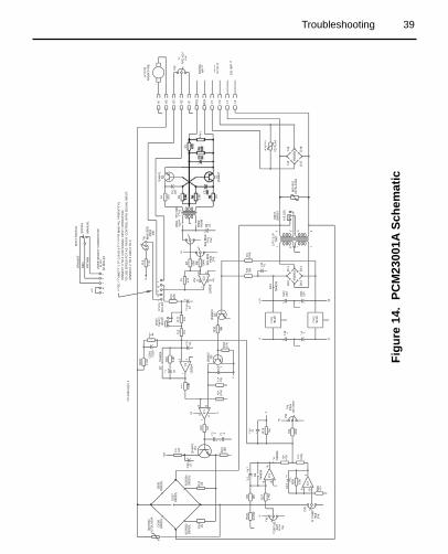
Figu
re 1
4. P
CM
2300
1ASc
hem
atic
Troubleshooting
40
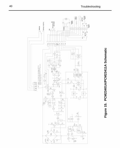
Figu
re 1
5. P
CM
2340
1A/P
CM
2341
1ASc
hem
atic
Troubleshooting
41Troubleshooting
Replacement Parts
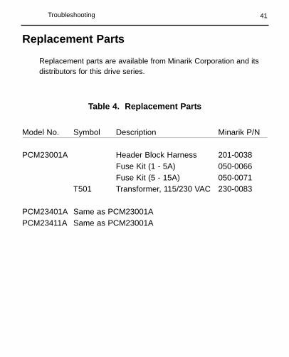
Replacement parts are available from Minarik Corporation and itsdistributors for this drive series.
Table 4. Replacement Parts
Model No. Symbol Description Minarik P/N
PCM23001A Header Block Harness 201-0038Fuse Kit (1 - 5A) 050-0066Fuse Kit (5 - 15A) 050-0071
T501 Transformer, 115/230 VAC 230-0083
PCM23401A Same as PCM23001APCM23411A Same as PCM23001A

42
Minarik Corporation hereby certifies that its PCM20000 seriesdrives have been approved to bear the “CE” mark provided theconditions of approval (listed in Exhibit “A”) have been met by theend user.
The PCM20000 series has been tested to the following testspecifications:
EN55011:1991 (emissions), andEN50082-1:1992 (immunity)
Compliance allows Minarik’s PCM20000 series to bear the CEmark.
The end user, as described herein, falls into one of two categories:
1. The Consumer will deploy a stand-alone unit as anintegral, yet external, portion of the machine he/she isoperating.
2. The Original Equipment Manufacturer (OEM) willimplement the product as a component of the machinebeing manufactured.
Certificate of Compliance
43CE Compliance
Exhibit A
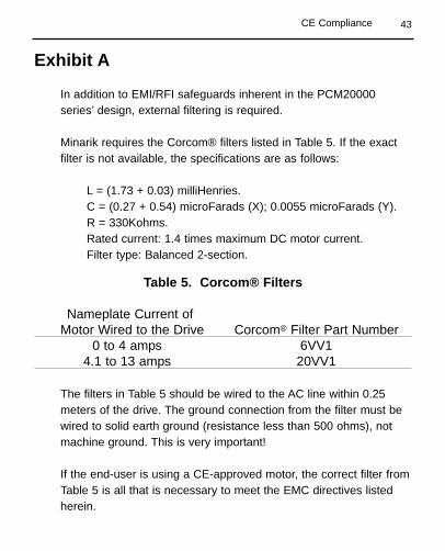
In addition to EMI/RFI safeguards inherent in the PCM20000series’ design, external filtering is required.
Minarik requires the Corcom® filters listed in Table 5. If the exactfilter is not available, the specifications are as follows:
L = (1.73 + 0.03) milliHenries.C = (0.27 + 0.54) microFarads (X); 0.0055 microFarads (Y).R = 330Kohms.Rated current: 1.4 times maximum DC motor current.Filter type: Balanced 2-section.
Table 5. Corcom® Filters
Nameplate Current ofMotor Wired to the Drive Corcom® Filter Part Number
0 to 4 amps 6VV14.1 to 13 amps 20VV1
The filters in Table 5 should be wired to the AC line within 0.25meters of the drive. The ground connection from the filter must bewired to solid earth ground (resistance less than 500 ohms), notmachine ground. This is very important!
If the end-user is using a CE-approved motor, the correct filter fromTable 5 is all that is necessary to meet the EMC directives listedherein.

44 CE Compliance
If the end-user is not using a CE-approved motor, a second filter onthe output, Minarik’s CEXXMM, must be used. XX = rated currentof the filter.
The CE20MM is a Real-Pole Balanced-Pi 3-pole filter. If the exactfilter is not available, the specifications are as follows:
L & L1 = 2 * (0.8) milliHenries.C & C1 = 2 * (0.1) microFarads @ 400W VDC.Rin = 0.1 ohm; Rout = 1.2 ohm.
Table 6. Minarik Filters
Nameplate Current ofMotor Wired to the Drive Minarik Filter Part Number
0 to 4 amps CE4MM4.1 to 13 amps CE20MM
The filters in Table 6 must be wired to the DC output of the drive,as close to the drive as possible. The ground connection from thefilter must be wired to solid earth ground (resistance less than 500ohms); not machine ground. This is very important!
The end user must use the filtration listed in Exhibit A to complywith CE. The OEM may choose to provide alternative filtering thatencompasses the Minarik drive and other electronics within thesame panel.

45
The OEM has this liberty because CE is a machinery directive.Whether or not every component in the OEM’s machinery meetsCE, the OEM must still submit his machine for CE approval. Thus,no component must necessarily meet CE within the machine, aslong as the OEM takes the necessary steps to guarantee themachine does meet CE. By the same token, even if everycomponent in the OEM’s machine does meet CE, the machine willnot necessarily meet CE as a machine.
Using CE-approved wiring practices (like proper shielding) and thefilters listed in Exhibit A guarantee the drive will meet EN55011(1991 emissions standard) and EN50082-1 (1992 immunitystandard).
CE Compliance

46
NOTES

NOTES
47

NOTES
48

Unconditional Warranty
A. WarrantyMinarik Corporation (referred to as "the Corporation") warrants that its products willbe free from defects in workmanship and material for twelve (12) months or 3,000hours, whichever comes first, from date of manufacture thereof. Within this warrantyperiod, the Corporation will repair or replace, at its sole discretion, such products thatare returned to Minarik Corporation, 901 East Thompson Avenue, Glendale, CA91201-2011 USA.
This warranty applies only to standard catalog products, and does not apply tospecials. Any returns for special controls will be evaluated on a case-by-case basis.The Corporation is not responsible for removal, installation, or any other incidentalexpenses incurred in shipping the product to and from the repair point.
B. DisclaimerThe provisions of Paragraph A are the Corporation's sole obligation and exclude allother warranties of merchantability for use, express or implied. The Corporationfurther disclaims any responsibility whatsoever to the customer or to any otherperson for injury to the person or damage or loss of property of value caused by anyproduct that has been subject to misuse, negligence, or accident, or misapplied ormodified by unauthorized persons or improperly installed.
C. Limitations of LiabilityIn the event of any claim for breach of any of the Corporation's obligations, whetherexpress or implied, and particularly of any other claim or breech of warrantycontained in Paragraph A, or of any other warranties, express or implied, or claim ofliability that might, despite Paragraph B, be decided against the Corporation bylawful authority, the Corporation shall under no circumstances be liable for anyconsequential damages, losses, or expense arising in connection with the use of, orinability to use, the Corporation's product for any purpose whatsoever.
An adjustment made under warranty does not void the warranty, nor does it imply anextension of the original 12-month warranty period. Products serviced and/or partsreplaced on a no-charge basis during the warranty period carry the unexpiredportion of the original warranty only.
If for any reason any of the foregoing provisions shall be ineffective, theCorporation's liability for damages arising out of its manufacture or sale ofequipment, or use thereof, whether such liability is based on warranty, contract,negligence, strict liability in tort, or otherwise, shall not in any event exceed the fullpurchase price of such equipment.
Any action against the Corporation based upon any liability or obligation arisinghereunder or under any law applicable to the sale of equipment or the use thereof,must be commenced within one year after the cause of such action arises.

14300 De La Tour Drive, South Beloit, IL 61080Phone Number: (800) MINARIK or (815) 646-2745
Fax: (800) 394-6334 or (815) 624-6960www.minarikdrives.com
Document Number 250-0104, Revision 8Printed in the U.S.A – September 2004


