Embed Size (px)
Citation preview

THERM-X-TROL®
THERMAL EXPANSION ABSORBERS
The Best Solution forControlling Thermal Expansion
2
THERM-X-TROL Expansion Tanks..... 2
What is Thermal Expansion?.............. 2
THERM-X-TROL: The Market Leader 3
Specifications and Sizing .................. 4
Sizing Procedure................................. 5
Typical Installations and Specs .......... 6
Non-ASME Thermal-X-Trol ................. 7
Quick Sizing ........................................ 8
Table of Contents
THERM-X-TROL® Expansion Tanks
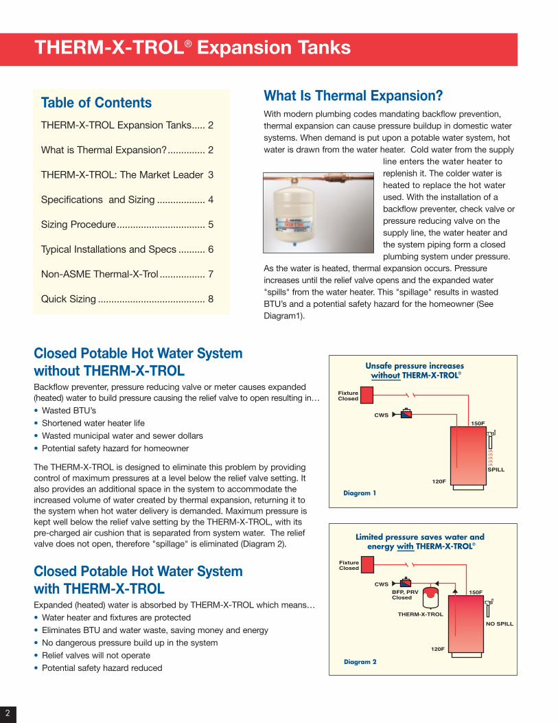
What Is Thermal Expansion?With modern plumbing codes mandating backflow prevention,thermal expansion can cause pressure buildup in domestic watersystems. When demand is put upon a potable water system, hotwater is drawn from the water heater. Cold water from the supply
line enters the water heater toreplenish it. The colder water isheated to replace the hot waterused. With the installation of abackflow preventer, check valve orpressure reducing valve on the supply line, the water heater andthe system piping form a closedplumbing system under pressure.
As the water is heated, thermal expansion occurs. Pressureincreases until the relief valve opens and the expanded water"spills" from the water heater. This "spillage" results in wastedBTU’s and a potential safety hazard for the homeowner (SeeDiagram1).
Closed Potable Hot Water Systemwithout THERM-X-TROLBackflow preventer, pressure reducing valve or meter causes expanded(heated) water to build pressure causing the relief valve to open resulting in…• Wasted BTU’s• Shortened water heater life• Wasted municipal water and sewer dollars• Potential safety hazard for homeowner
The THERM-X-TROL is designed to eliminate this problem by providingcontrol of maximum pressures at a level below the relief valve setting. Italso provides an additional space in the system to accommodate theincreased volume of water created by thermal expansion, returning it tothe system when hot water delivery is demanded. Maximum pressure iskept well below the relief valve setting by the THERM-X-TROL, with itspre-charged air cushion that is separated from system water. The reliefvalve does not open, therefore "spillage" is eliminated (Diagram 2).
Closed Potable Hot Water Systemwith THERM-X-TROLExpanded (heated) water is absorbed by THERM-X-TROL which means…• Water heater and fixtures are protected• Eliminates BTU and water waste, saving money and energy• No dangerous pressure build up in the system• Relief valves will not operate• Potential safety hazard reduced
Unsafe pressure increases without THERM-X-TROL®
FixtureClosed
SPILL
150F
CWS
120F
Diagram 1
Limited pressure saves water and energy with THERM-X-TROL®
FixtureClosed
THERM-X-TROL
NO SPILL
150F
CWS
BFP, PRVClosed
120F
Diagram 2
3
THERM-X-TROL®: The Market Leader
• # 1 choice of Professional Installers in
USA
• Safest and most cost effective way to
control Thermal Expansion
• Easy to install - Maintenance free
• Made in USA since 1965
• The innovator of Thermal Expansion
Control in Closed Potable Hot Water
Systems
• The only Thermal Expansion Absorber
with rigid Poly-Propylene Liner for
maximum corrosion resistance
• Recognized Industry leader in Quality,
Design, Manufacturing, Delivery and
Service
• Broadest line of sizes and models
(37 models, ASME code and non
code)
• Extensive Network of Plumbing &
Heating Wholesale Distributors
• First to obtain ANSI/NSF61, IAPMO,
SBCCI & City of Los Angeles listings
• First to offer 5 year limited warranty
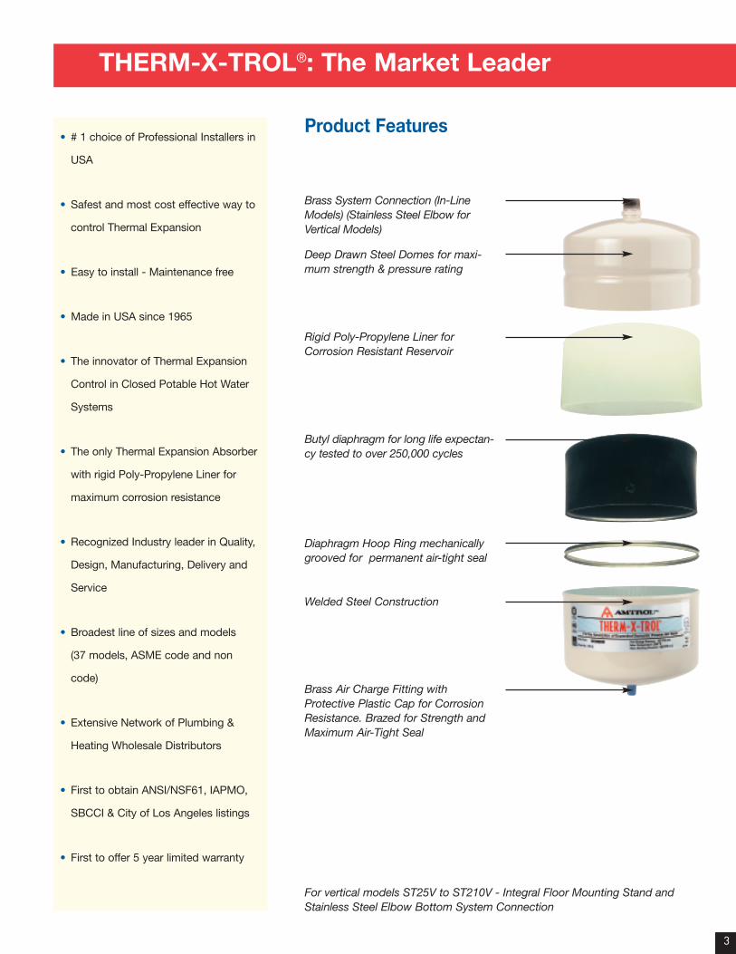
Brass System Connection (In-LineModels) (Stainless Steel Elbow forVertical Models)
Deep Drawn Steel Domes for maxi-mum strength & pressure rating
Rigid Poly-Propylene Liner forCorrosion Resistant Reservoir
Butyl diaphragm for long life expectan-cy tested to over 250,000 cycles
Diaphragm Hoop Ring mechanicallygrooved for permanent air-tight seal
Welded Steel Construction
Brass Air Charge Fitting withProtective Plastic Cap for CorrosionResistance. Brazed for Strength andMaximum Air-Tight Seal
Product Features
For vertical models ST25V to ST210V - Integral Floor Mounting Stand andStainless Steel Elbow Bottom System Connection
Specifications and Sizing
4
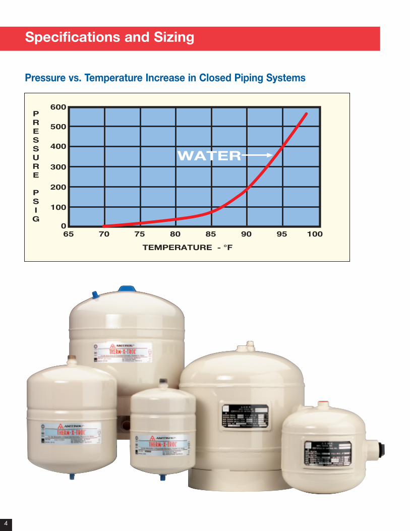
PRESSURE
PSIG
0
100
200
300
400
500
600
65 70 75 80 85 90 95 100
TEMPERATURE - °F
WATER
Pressure vs. Temperature Increase in Closed Piping Systems
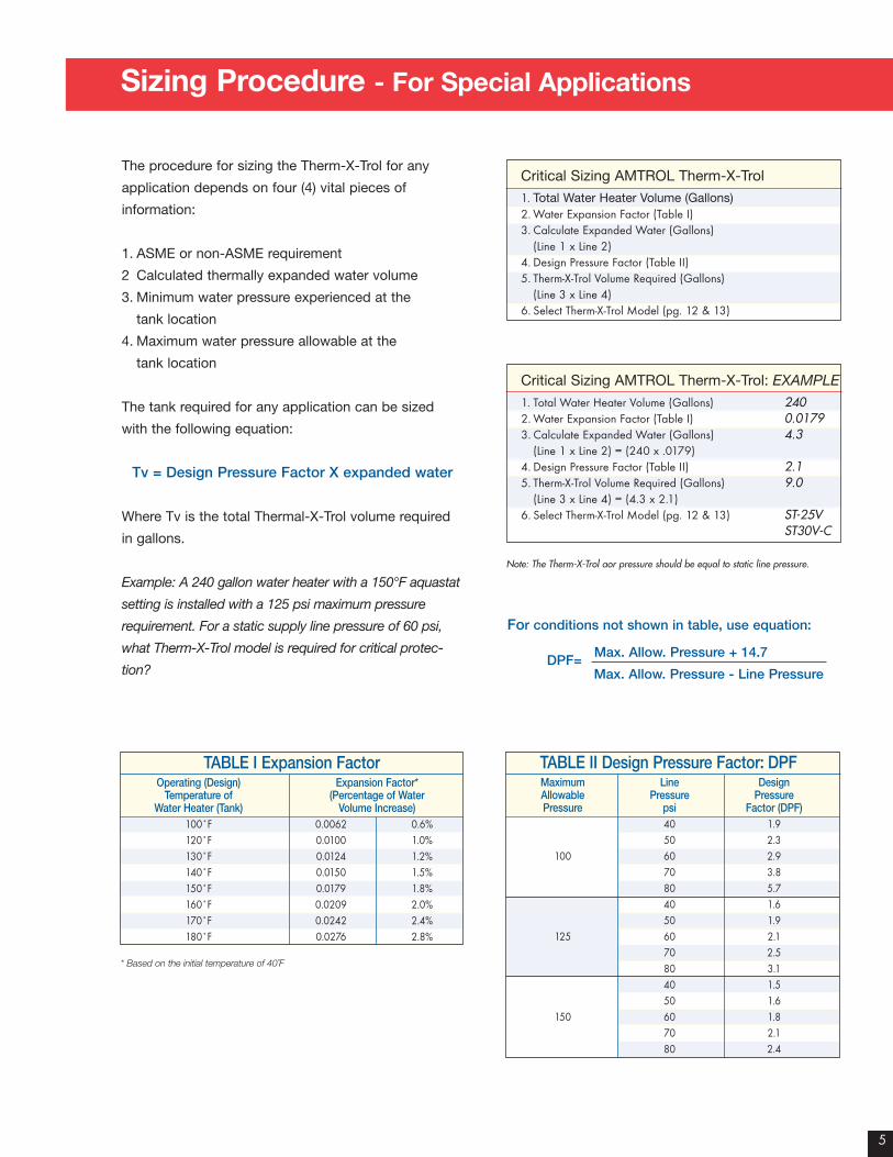
Sizing Procedure - For Special Applications
The procedure for sizing the Therm-X-Trol for any
application depends on four (4) vital pieces of
information:
1. ASME or non-ASME requirement
2 Calculated thermally expanded water volume
3. Minimum water pressure experienced at the
tank location
4. Maximum water pressure allowable at the
tank location
The tank required for any application can be sized
with the following equation:
Tv = Design Pressure Factor X expanded water
Where Tv is the total Thermal-X-Trol volume required
in gallons.
Example: A 240 gallon water heater with a 150°F aquastat
setting is installed with a 125 psi maximum pressure
requirement. For a static supply line pressure of 60 psi,
what Therm-X-Trol model is required for critical protec-
tion?
Critical Sizing AMTROL Therm-X-Trol
1. Total Water Heater Volume (Gallons)2. Water Expansion Factor (Table I)3. Calculate Expanded Water (Gallons)
(Line 1 x Line 2)4. Design Pressure Factor (Table II)5. Therm-X-Trol Volume Required (Gallons)
(Line 3 x Line 4)6. Select Therm-X-Trol Model (pg. 12 & 13)
Critical Sizing AMTROL Therm-X-Trol: EXAMPLE1. Total Water Heater Volume (Gallons) 2402. Water Expansion Factor (Table I) 0.01793. Calculate Expanded Water (Gallons) 4.3
(Line 1 x Line 2) = (240 x .0179)4. Design Pressure Factor (Table II) 2.15. Therm-X-Trol Volume Required (Gallons) 9.0
(Line 3 x Line 4) = (4.3 x 2.1)6. Select Therm-X-Trol Model (pg. 12 & 13) ST-25V
ST30V-C
Note: The Therm-X-Trol aor pressure should be equal to static line pressure.
TABLE I Expansion FactorOperating (Design) Expansion Factor*
Temperature of (Percentage of WaterWater Heater (Tank) Volume Increase)
100˚F 0.0062 0.6%120˚F 0.0100 1.0%130˚F 0.0124 1.2%140˚F 0.0150 1.5%150˚F 0.0179 1.8%160˚F 0.0209 2.0%170˚F 0.0242 2.4%180˚F 0.0276 2.8%
* Based on the initial temperature of 40˚F
TABLE II Design Pressure Factor: DPFMaximum Line DesignAllowable Pressure PressurePressure psi Factor (DPF)
40 1.950 2.3
100 60 2.970 3.880 5.740 1.650 1.9
125 60 2.170 2.580 3.140 1.550 1.6
150 60 1.870 2.180 2.4
For conditions not shown in table, use equation:
DPF=Max. Allow. Pressure + 14.7
Max. Allow. Pressure - Line Pressure
5
6
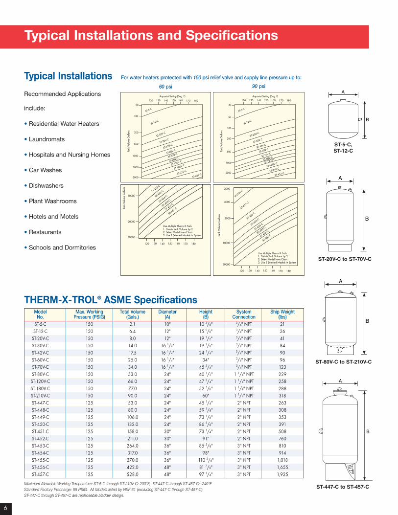
Typical Installations and Specifications
THERM-X-TROL® ASME Specifications Model Max. Working Total Volume Diameter Height System Ship Weight
No. Pressure (PSIG) (Gals.) (A) (B) Connection (lbs)ST-5-C 150 2.1 10" 10 3/8" 3/4" NPT 21ST-12-C 150 6.4 12" 15 5/8" 3/4" NPT 26
ST-20V-C 150 8.0 12" 19 1/2" 3/4" NPT 41ST-30V-C 150 14.0 16 1/4" 19 1/8" 3/4" NPT 84ST-42V-C 150 17.5 16 1/4" 24 1/4" 3/4" NPT 90ST-60V-C 150 25.0 16 1/4" 34" 3/4" NPT 96ST-70V-C 150 34.0 16 1/4" 45 3/4" 3/4" NPT 123ST-80V-C 150 53.0 24" 40 1/2" 1 1/4" NPT 229ST-120V-C 150 66.0 24" 47 3/4" 1 1/4" NPT 258ST-180V-C 150 77.0 24" 52 5/8" 1 1/4" NPT 288ST-210V-C 150 90.0 24" 60" 1 1/4" NPT 318ST-447-C 125 53.0 24" 45 1/4" 2" NPT 263ST-448-C 125 80.0 24" 59 1/8" 2" NPT 308ST-449-C 125 106.0 24" 73 1/8" 2" NPT 353ST-450-C 125 132.0 24" 86 5/8" 2" NPT 391ST-451-C 125 158.0 30" 73 1/4" 2" NPT 508ST-452-C 125 211.0 30" 91" 2" NPT 760ST-453-C 125 264.0 36" 85 5/8" 3" NPT 810ST-454-C 125 317.0 36" 98" 3" NPT 914ST-455-C 125 370.0 36" 110 3/8" 3" NPT 1,018ST-456-C 125 422.0 48" 81 7/8" 3" NPT 1,655ST-457-C 125 528.0 48" 97 1/4" 3" NPT 1,925
Maximum Allowable Working Temperature: ST-5-C through ST-210V-C: 200°F; ST-447-C through ST-457-C: 240°FStandard Factory Precharge: 55 PSIG. All Models listed by NSF 61 (excluding ST-447-C through ST-457-C). ST-447-C through ST-457-C are replaceable bladder design.
Typical Installations
Recommended Applications
include:
• Residential Water Heaters
• Laundromats
• Hospitals and Nursing Homes
• Car Washes
• Dishwashers
• Plant Washrooms
• Hotels and Motels
• Restaurants
• Schools and Dormitories
A
B
A
B
A
B
A
B
ST-5-C,ST-12-C
ST-20V-C to ST-70V-C
ST-80V-C to ST-210V-C
ST-447-C to ST-457-C
50
100
200
500
1000
2000
5000
ST-5-C
ST-12-C
ST-20V-C
ST-30V-C
ST-42V-C
ST-60V-C
ST-70V-C
ST-80V-C
ST-180V-C
ST-210-C
ST-451-C
Aquastat Setting (Deg. F)
120 130 140 150 160 170 180
Tank
Vol
ume
Gal
lons
ST-120V-C
30
50
100
200
500
1000
2000
ST-5-C
ST-12-C
ST-20V-C
ST-30V-C
ST-42V-C
ST-60V-C
ST-70V-C
ST-80V-C
ST-180V-C
ST-210-C
ST-451-C
Aquastat Setting (Deg. F)
120 130 140 150 160 170 180
Tank
Vol
ume
Gal
lons
ST-120V-C
10000
20000
30000
ST-210V-C
ST-451-C
ST-452-C
5000
ST-453-C
ST-454-C
ST-455-C
ST-456-C
ST-457-C
Use Multiple Therm-X-Trols1. Divide Tank Volume by 22. Select Model from Chart3. Use 2 Selected Models in System
Tank
Vol
ume
Gal
lons
120 130 140 150 160 170 180
3000
10000
20000
ST-210V-C
ST-451-C
ST-452-C
2000
ST-453-C
ST-454-C
ST-455-C
ST-456-C
ST-457-C
Use Multiple Therm-X-Trols1. Divide Tank Volume by 22. Select Model from Chart3. Use 2 Selected Models in System
Tank
Vol
ume
Gal
lons
120 130 140 150 160 170 180
5000
For water heaters protected with 150 psi relief valve and supply line pressure up to:
60 psi 90 psi

7
Non-ASME THERM-X-TROL®
A
B
A
B
ST-5, ST-12
ST-25V through ST-210V
THERM-X-TROL Non-ASME Specifications Model Total Volume Diameter Height System Ship Weight
No. (Gals.) (A) (B) Connection (lbs)ST-5 2.0 8" 12 5/8" 3/4" NPT 5ST-12 4.4 11" 15" 3/4" NPT 9ST-25V 10.3 15 3/8" 19 1/4" 1" NPT 23ST-30V 14.0 15 3/8" 23 7/8" 1" NPT 25ST-42V 20.0 15 3/8" 31 5/8" 1" NPT 33ST-60V 34.0 22" 29 5/8" 1 1/4" NPT 61ST-80V 44.0 22" 36" 1 1/4" NPT 69ST-180V 62.0 22" 46 3/4" 1 1/4" NPT 92ST-210V 86.0 26" 47 1/4" 1 1/4" NPT 123ST-451 158.0 73 1/4" 30" 2" NPT 508ST-452 211.0 91" 30" 2" NPT 760ST-453 264.0 85 5/8" 36" 3" NPT 810ST-454 317.0 98" 36" 3" NPT 914ST-455 370.0 110 3/8" 36" 3" NPT 1,018ST-456 422.0 81 7/8" 48" 3" NPT 1,655ST-457 528.0 97 1/4" 48" 3" NPT 1,925
Maximum Working Pressure: 150 PSI. All Models listed by NSF 61 (excluding ST-451 – ST-457); Maximum Allowable WorkingTemperature: ST-5 through ST-210V: 200°F; ST-451 through ST-457: 240°F; Standard Factory Precharge: 40 PSIG (ST-5 –ST-210V); 55 PSIG (ST-451 – ST-457)
General Usage
• Office Buildings
• Apartment Buildings
• Dormitories
• Elderly Housing
• Extended Care Facilities
• Condominiums/Large Residential
• Food Service (other than Restaurants)
• Laundromats
• Hospitals
• Other General-Use Hot Water Systems
50
100
200
500
1000
2000
5000
ST-5
ST-12
ST-25V
ST-30V
ST-42V
ST-60V
ST-80V
ST-180V
ST-210V
ST-451
ST-452
Aquastat Setting (Deg. F)
120 130 140 150 160 170 180
Tota
l Sys
tem
Vol
ume
in G
als.
(tan
k an
d re
circ
. lin
e)
50
100
200
500
1000
2000
3000
ST-5
ST-12
ST-25V
ST-30V
ST-42V
ST-60V
ST-80V
ST-180V
ST-210V
ST-451
ST-452
Aquastat Setting (Deg. F)
120 130 140 150 160 170 180
Tota
l Sys
tem
Vol
ume
in G
als.
(tan
k an
d re
circ
. lin
e)
30
10000
20000
30000
50000
ST-210V
ST-451
ST-452
Tota
l Sys
tem
Vol
ume
in G
als.
(tan
k an
d re
circ
. lin
e)
5000
ST-453
ST-454
ST-455
ST-456
ST-457
Use Multiple Therm-X-Trols1. Divide Tank Volume by 22. Select Model from Chart3. Use 2 Selected Models in System
5000
10000
20000
30000
ST-210V
ST-451
ST-452
Tota
l Sys
tem
Vol
ume
in G
als.
(tan
k an
d re
circ
. lin
e)
ST-453
ST-454
ST-455
ST-456
ST-457
Use Multiple Therm-X-Trols1. Divide Tank Volume by 22. Select Model from Chart3. Use 2 Selected Models in System
For water heaters protected with 150 psi relief valve and supply line pressure up to:
60 psi 90 psi
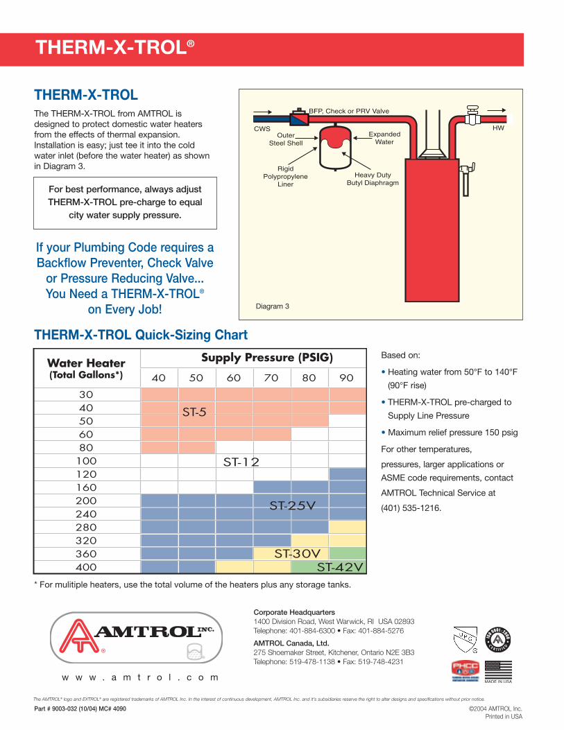
THERM-X-TROL®
HW
BFP, Check or PRV Valve
ExpandedWater
CWSOuter
Steel Shell
RigidPolypropylene
LinerHeavy Duty
Butyl Diaphragm
THERM-X-TROLThe THERM-X-TROL from AMTROL isdesigned to protect domestic water heatersfrom the effects of thermal expansion.Installation is easy; just tee it into the coldwater inlet (before the water heater) as shownin Diagram 3.
For best performance, always adjust THERM-X-TROL pre-charge to equal
city water supply pressure.
Diagram 3
Based on:
• Heating water from 50°F to 140°F
(90°F rise)
• THERM-X-TROL pre-charged to
Supply Line Pressure
• Maximum relief pressure 150 psig
For other temperatures,
pressures, larger applications or
ASME code requirements, contact
AMTROL Technical Service at
(401) 535-1216.
THERM-X-TROL Quick-Sizing Chart
* For mulitiple heaters, use the total volume of the heaters plus any storage tanks.
If your Plumbing Code requires aBackflow Preventer, Check Valve
or Pressure Reducing Valve... You Need a THERM-X-TROL®
on Every Job!
Part # 9003-032 (10/04) MC# 4090 ©2004 AMTROL Inc.Printed in USA
The AMTROL® logo and EXTROL® are registered trademarks of AMTROL Inc. In the interest of continuous development, AMTROL Inc. and it’s subsidiaries reserve the right to alter designs and specifications without prior notice.
®
Corporate Headquarters1400 Division Road, West Warwick, RI USA 02893Telephone: 401-884-6300 • Fax: 401-884-5276
AMTROL Canada, Ltd.275 Shoemaker Street, Kitchener, Ontario N2E 3B3Telephone: 519-478-1138 • Fax: 519-748-4231
w w w . a m t r o l . c o m
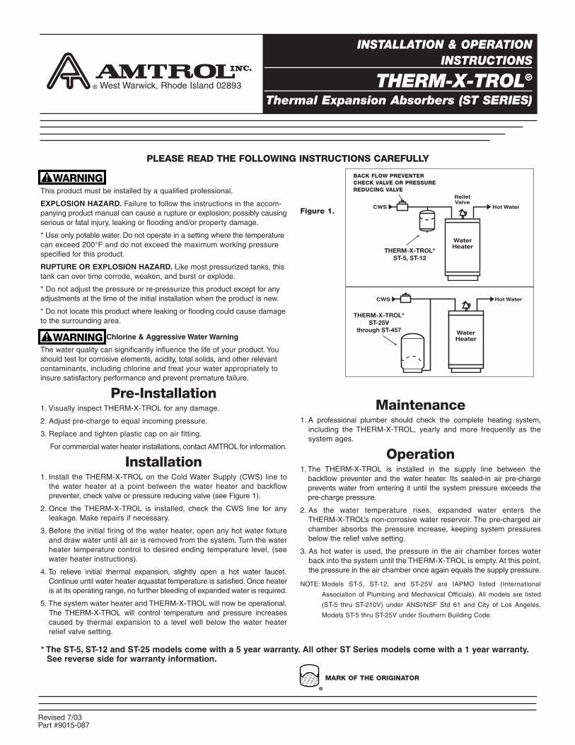
This product must be installed by a qualified professional.
EXPLOSION HAZARD. Failure to follow the instructions in the accom-panying product manual can cause a rupture or explosion; possibly causingserious or fatal injury, leaking or flooding and/or property damage.
* Use only potable water. Do not operate in a setting where the temperaturecan exceed 200°F and do not exceed the maximum working pressurespecified for this product.
RUPTURE OR EXPLOSION HAZARD. Like most pressurized tanks, thistank can over time corrode, weaken, and burst or explode.
* Do not adjust the pressure or re-pressurize this product except for anyadjustments at the time of the initial installation when the product is new.
* Do not locate this product where leaking or flooding could cause damageto the surrounding area.
Chlorine & Aggressive Water Warning
The water quality can significantly influence the life of your product. Youshould test for corrosive elements, acidity, total solids, and other relevantcontaminants, including chlorine and treat your water appropriately toinsure satisfactory performance and prevent premature failure.
Pre-Installation1. Visually inspect THERM-X-TROL for any damage.
2. Adjust pre-charge to equal incoming pressure.
3. Replace and tighten plastic cap on air fitting.
For commercial water heater installations, contact AMTROL for information.
Installation1. Install the THERM-X-TROL on the Cold Water Supply (CWS) line to
the water heater at a point between the water heater and backflowpreventer, check valve or pressure reducing valve (see Figure 1).
2. Once the THERM-X-TROL is installed, check the CWS line for anyleakage. Make repairs if necessary.
3. Before the initial firing of the water heater, open any hot water fixtureand draw water until all air is removed from the system. Turn the waterheater temperature control to desired ending temperature level, (seewater heater instructions).
4. To relieve initial thermal expansion, slightly open a hot water faucet.Continue until water heater aquastat temperature is satisfied. Once heateris at its operating range, no further bleeding of expanded water is required.
5. The system water heater and THERM-X-TROL will now be operational.The THERM-X-TROL will control temperature and pressure increasescaused by thermal expansion to a level well below the water heaterrelief valve setting.
PLEASE READ THE FOLLOWING INSTRUCTIONS CAREFULLY
BACK FLOW PREVENTERCHECK VALVE OR PRESSUREREDUCING VALVE
West Warwick, Rhode Island 02893
INSTALLATION & OPERATIONINSTRUCTIONS
THERM-X-TROL®
Thermal Expansion Absorbers (ST SERIES)
Figure 1.
MARK OF THE ORIGINATOR
Hot WaterCWS
THERM-X-TROL®
ST-25V through ST-457 Water
Heater
CWS
WaterHeater
THERM-X-TROL®
ST-5, ST-12
ReliefValve
Hot Water
Maintenance1. A professional plumber should check the complete heating system,
including the THERM-X-TROL, yearly and more frequently as thesystem ages.
Operation1. The THERM-X-TROL is installed in the supply line between the
backflow preventer and the water heater. Its sealed-in air pre-chargeprevents water from entering it until the system pressure exceeds thepre-charge pressure.
2. As the water temperature rises, expanded water enters theTHERM-X-TROL’s non-corrosive water reservoir. The pre-charged airchamber absorbs the pressure increase, keeping system pressuresbelow the relief valve setting.
3. As hot water is used, the pressure in the air chamber forces waterback into the system until the THERM-X-TROL is empty. At this point,the pressure in the air chamber once again equals the supply pressure.
NOTE: Models ST-5, ST-12, and ST-25V are IAPMO listed (International
Association of Plumbing and Mechanical Officials). All models are listed
(ST-5 thru ST-210V) under ANSI/NSF Std 61 and City of Los Angeles.
Models ST-5 thru ST-25V under Southern Building Code.
* The ST-5, ST-12 and ST-25 models come with a 5 year warranty. All other ST Series models come with a 1 year warranty.See reverse side for warranty information.
Part #9015-087Revised 7/03
AMTROL® INC. LIMITED PRODUCT WARRANTYProducts covered: all Products manufactured by AMTROL Inc. (“AMTROL”).
This warranty cannot be transferred – it is extended only to the original Purchaser or First User of the Product. By accepting and keeping this Productyou agree to all of the warranty terms and limitations of liability described below.
IMPORTANT WARNING – READ CAREFULLY THE INSTALLATION, OPERATING AND MAINTENANCE INSTRUCTIONS MANUAL (“MANUAL”)to avoid serious personal injury and/or property damage and to ensure safe use and proper care of this product.
Who Receives AMTROL’s Product WarrantyAll purchasers or first users of the new Product. The Warranty is non-transferable.
What is covered by this WarrantyAMTROL warrants to the purchaser or first user of the new Product that at the time of manufacture, the Product is free from defects in material andworkmanship. Any warranty claim must be made within one (1) year unless another time period is set forth in the Manual, measured from thetime the Product was purchased.
What AMTROL Will Do If You Have a Covered Warranty ClaimIn the event of a breach of the foregoing warranty, AMTROL will at its option either make repairs to correct any defect in material or workmanship orsupply and ship either new or used replacement parts or products. AMTROL will not accept any claims for labor or other costs.
What This Warranty Does Not Cover — Exclusions and LimitationsThis Warranty does not cover any failure or problem unless it was caused by a defect in material or workmanship. In addition, this Warranty shall not apply:• if the Product is not correctly installed, operated, repaired or maintained as described in the Manual provided with the Product;• to any failure or malfunction resulting from abuse (including freezing); improper or negligent: handling, shipping (by anyone other than AMTROL),
storage, use, operation, accident; or alteration, lightning, flood or any other environmental condition;• to any failure or problem resulting from the use of the Product for any purpose other than those specified in the accompanying Manual or alteration
of any part of the product;• if the Product is used anywhere except the United States, its territories or possessions, or Canada;• this Warranty does not cover labor costs, shipping charges, service charges, delivery expenses, administrative fees or any costs incurred in removing
or reinstalling the Product;• this Warranty does not cover any claims submitted to AMTROL or an AMTROL-authorized distributor or retailer more than 30 days after expiration
of the applicable warranty time period described in this Warranty;• this Warranty also does not cover repair or replacement costs not authorized in advance by AMTROL.
Additional Warranty LimitationsALL IMPLIED WARRANTIES, INCLUDING THE IMPLIED WARRANTIES OF MERCHANTABILITY AND FITNESS FOR A PARTICULAR PURPOSEARE SPECIFICALLY DISCLAIMED. Some states do not allow limitations on how long an implied Warranty lasts, so the above limitation maynot apply to you.
Limitations of RemediesTHE REMEDIES CONTAINED IN THIS WARRANTY ARE THE PURCHASER’S OR FIRST USER’S EXCLUSIVE REMEDIES. IN NO CIRCUMSTANCESWILL AMTROL BE LIABLE FOR MORE THAN, AND PURCHASER-FIRST USER’S REMEDIES SHALL NOT EXCEED, THE PRICE PAID FOR THEPRODUCT. IN NO CASE SHALL AMTROL BE LIABLE FOR ANY SPECIAL, INDIRECT, INCIDENTAL OR CONSEQUENTIAL DAMAGES, WHETHERRESULTING FROM NONDELIVERY OR FROM THE USE, MISUSE, OR INABILITY TO USE THE PRODUCT OR FROM DEFECTS IN THE PRODUCTOR FROM AMTROL’S OWN NEGLIGENCE OR OTHER TORT. This exclusion applies regardless of whether such damages are sought for breach ofwarranty, breach of contract, negligence, strict liability, in tort or under any other legal theory. Such damages include, but are not limited to, inconvenience,loss or damage to property, mold, loss of profits, loss of savings or revenue, loss of use of the Products or any associated equipment, facilities, buildingsor services, downtime, and the claims of third parties including customers. Some states do not allow the exclusion or the limitation of incidental orconsequential damages, so the above limitation or exclusion may not apply to you.
What To Do If You Have a Problem Covered By This WarrantyAny covered Warranty service must be authorized by AMTROL. Contact the person from whom you purchased the Product, who must receive authorization from an AMTROL distributor or AMTROL. If you do not receive a prompt response, call AMTROL directly at 877-517-7673. Notice of aWarranty claim should be submitted by the authorized distributor to AMTROL at the following address:
AMTROL Inc.Warranty Claim Dept.
1400 Division Rd.West Warwick, RI 02893
Before AMTROL determines to provide any replacement part or Product, it may as a pre-condition to making such a determination require that thewarranty claimant ship the Product, postage prepaid to an authorized AMTROL distributor, or to AMTROL and provide proof of purchase evidenced bythe original sales receipt or Product registration.
Replacement Product WarrantyIn case of replacement of a Product or any component part, AMTROL reserves the right to make changes in the design, construction, or material ofthe substitute components or products, which shall be subject to all of the terms and limitations of this Warranty, except that the applicable warrantyperiods shall be reduced by the amount of time the warranty claimant owned the product prior to submitting notification of the warranty claim.
AMTROL Inc. • 1400 Division Road • W. Warwick, Rhode Island 02893 • Telephone 401-884-6300 • Fax 401-885-2567 Revised 7/03
The AMTROL logo and Therm-X-Trol are registered trademarks of AMTROL Inc.