Embed Size (px)
Citation preview

PROTECTION Relay
Operating Manual

Section Contents 1. Introduction 1.1 Display and Operating Elements 1.2 Models 1.2.1 Voltage Relay 1.2.2 Current Relay 2. Measurement Parameters 3. Flow Diagrams 3.1 Voltage Relay 3.1.1 Set up Parameters screen 3.1.2 Measuring Parameters screens 3.2 Current Relay 3.2.1 Set up Parameters screen 3.2.2 Measuring Parameters screens 3.3 Timing Diagrams 4. Programming 4.1 Menu selection 4.1.1 Password Protection 4.1.2 System Parameter selection menu 4.1.2.1 System Type 4.1.2.2 Potential Transformer (PT) Primary V-Line to Line 4.1.2.3 Potential Transformer (PT) Secondary V-Line to Line 4.1.2.4 Current Transformer (CT) Primary 4.1.2.5 Current Transformer (CT) Secondary 4.1.2.6 System Frequency 4.1.2.7 System Phase Sequence 4.1.2.8 Auto Scroll 4.1.2.9 Factory Reset 4.1.3 Parameters Selection menu 4.1.3.1 Parameter Selection 4.1.3.2 YES / NO 4.1.3.3 Trip Point 4.1.3.4 Trip Delay
Installation & Operating Instructions Programmable Multi-function Relay
2-60-006-00-00589_Rev.D - 07/2018
DIGITAL PROTECTION RELAY
1
4.1.3.4 Trip Delay 4.1.3.5 Hysteresis 4.1.3.6 Relay Assignment 4.1.3.7 Quit 4.1.3.8 IDMT 4.1.3.8.1 TMS (Time Multiplier Setting) 4.1.3.8.2 Curve selection 4.1.4 Relay Set Up Menu 4.1.4.1 Power ON Delay 4.1.4.2 Reset Delay 4.1.4.3 Reset control 4.1.4.4 Relay Configuration 4.1.4.5 Relay control 4.1.4.6 AND 4.1.4.7 Quit 4.1.5 Reset Menu 4.1.6 Quit Screen 4.2 Faults 4.2.1 Fault Number 4.2.2 Quit 4.3 Other Indications 5. Other Features 5.1 Test Relay operations 5.2 Manual Reset 6. Default Setting / On Factory Reset 7. Installation 7.1 EMC Installation Requirements 7.2 Case Dimensions and Panel Cut-out 7.3 Wiring 7.4 Auxiliary Supply 7.5 Fusing 7.6 Earth / Ground Connections 8. Connection Diagrams 9. Technical Specifications
2

The Voltage / Current Relay c a n b e c o n f i g u r e d & programmed on site for system type, PT / CT Primary, PT / CT Secondary in 3 Phase 3W, 3 Phase 4W, 1 Phase 2W System.
The front panel has three push button keys namely Reset / Down, Test / Up, Enter.
1. INTRODUCTION
Voltage Relay: - The Multifunction Voltage Relay measures electrical parameters like AC voltage, Frequency in 3 ph 4 wire, 3 ph 3 wire, 1 ph 2 wire Network and can be used to protect against Over Voltage, Under Voltage, Phase Unbalance, Phase Sequence detection, Phase Failure detection, Under Frequency, Over Frequency conditions. Current Relay: -The Multifunction Current Relay measures electrical parameters like AC Current, Frequency in 3 ph 4 wire, 3 ph 3 wire, 1 ph 2 wire Network and can be used to protect against Over Current, Under Current, Current Unbalance, Current Loss. The Voltage / Current Relays integrate accurate measurement technology with 4 Digit 7 Segment LED Display & measure distorted waveform up to
th15 harmonics.
The Micro-USB port must be used for Modbus communication via
USB-based PRKAB.
vk
R
DownKey
UpKey
EnterKey
Micro-USBPort
L3
L2
L1
RELAY1 RELAY2
ENTER
K
V
TESTRESET
3
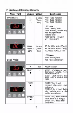
1.1 Display and Operating Elements
Element SignificanceMeter Front
L1L2L3
Phase 1 LED indicationPhase 2 LED indicationPhase 3 LED indication
LED States -Green - Healthy StateGreen (Flashing) - Reset DelayRed - Fault present on particular phaseRed (Flashing) - Trip DelayOFF - Input Absent
Colour
Bi-colour(Green /
Red)
RELAY 1RELAY 2RELAY
RELAY 1 LED (1CO+1CO only)RELAY 2 LED (1CO+1CO only)RELAY LED (1CO/2CO only)
LED States -Green - Healthy StateRed - Fault / Alarm present
Bi-colour(Green /
Red)
K X1000 IndicationRed
RESET / RESET / DOWN Key (< 3 sec): Decrement values, move downwards in menu RESET / Down Key (> 3 sec): Reset relay in manual reset mode
-
TEST / TEST/UP Key (<3 sec):Increment values, move upwa-rds in menu TEST / UP Key (> 3 sec): Switch relay contacts, resets to initial position when released
-
ENTER / ENTER Key (< 3 sec): Confirm values, menu level changesENTER Key (> 3 sec): Enter Setup mode
-
Three Phase:
Single Phase:
L3
L2
L1RELAY1 RELAY2
ENTERTESTRESET
K
V
L3
L2
L1
RELAY
AK
ENTERTESTRESET
L1
RELAY
K
V
ENTERTESTRESET
L1
RELAY1 RELAY2
AK
ENTERTESTRESET
4

1.2 Models
1.2.1 Voltage Relay
Features Line Monitoring Relay
Voltage Protection Relay
Over Voltage
Under Voltage
Over Frequency
Under Frequency
Phase Failure
Phase Reversal
Phase Unbalance
x
xx
1.2.1 Current Relay
Features Current Protection Relay
Over Current
Under Current
Current Loss
Current Unbalance
X Not available
Available
5
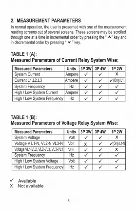
In normal operation, the user is presented with one of the measurement reading screens out of several screens. These screens may be scrolled through one at a time in incremental order by pressing the “ ” key and in decremental order by pressing “ ” key.
TABLE 1 (A): Measured Parameters of Current Relay System Wise:
Available X Not available
TABLE 1 (B): Measured Parameters of Voltage Relay System Wise:
2. MEASUREMENT PARAMETERS
Measured Parameters Units 3P 3W 3P 4W 1P 2WSystem Current Ampere x
System Frequency Hz High / Low System Current Ampere High / Low System Frequency Hz
Current L1,L2,L3 Ampere (Only L1)
Volt x
Measured Parameters Units 3P 3W 3P 4W 1P 2WSystem Voltage Volt x
System Frequency Hz High / Low System Voltage Volt High / Low System Frequency Hz
Voltage V L1-N, VL2-N,VL3-N Volt x (Only L1-N)Voltage VL1-VL2, VL2-VL3, VL3-VL1
6

3.1.1 Setup Parameters screen
START
Measurement screen(Press ‘ENTER’ key continuously for 3 Sec)
SEtP
(Setup parameters)
FALt (Faults Storage
Screen)
codE (Password) _._ _ _
0000Password protection
disabled
SYS(System Parameters menu) (See 4.1.2)
AV
K
E
B
3.1 Voltage Relay
M N Continued....
wPArA
(Protection Parameters menu) (See 4.1.3)
3. FLOW DIAGRAMS
: - UP Key
: - DOWN Key
: - ENTER Key
7

A] SYS (System Parameters Menu)
A
tYPE(System type )
3
PT primary in KVPtPr
G
4 or 3 or 1
Continued....
Exit from setup to Version screen
C
D
K
V
M N
R1
R2
rELY(Relay Parameters)
(See 4.1.4)
rESt(Reset Value)
(See 4.1.5)
quit (Exit Setup Menu)
(See 4.1.6)
8
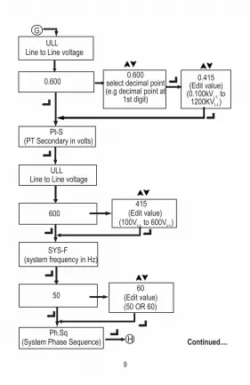
ULLLine to Line voltage
0.6000.600
select decimal point(e.g decimal point at
1st digit)
0.415(Edit value)
(0.100kV to L-L
1200KV )L-L
Pt-S(PT Secondary in volts)
ULLLine to Line voltage
600 415 (Edit value)(100V to 600V )L-L L-L
SYS-F(system frequency in Hz)
50
G
Ph.Sq(System Phase Sequence) H
60(Edit value)(50 OR 60)
Continued....
9

B] PArA (Protection Parameters Menu)
OU (Over
voltage)
B YES (Edit) (YES / no)
triP(Trip set
point)
tr-d(trip delay)
HYS (Hysteresis)
rL1 (Edit relay output)
rL1 (Relay1) /rL2 (Relay2)/ rL12 (Relay 1 & Relay2)/
nOnE (No relay)
125.0 (Edit)(101 to 125 %)
30.00 (Edit)(0 to 30.00 Sec)
15.0 (Edit)(1 to 15 %)
P Q
no
Continued....
O1
Auto (Auto scrolling)
no (Edit) (no or YES)
H 123 321 (Edit value) (123 or 321)
F.rSt ( Factory Reset )
SYS(Back to system parameter menu)
(Meter Reset)
no (Edit)(no or YES)
YES
10
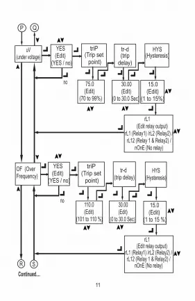
uV(under voltage)
YES (Edit) (YES / no)
triP(Trip set point)
tr-d(trip
delay)
HYS (Hysteresis)
75.0 (Edit) (70 to 99%)
30.00 (Edit) (0 to 30.0 Sec)
P Q
OF (Over Frequency)
triP
110.0 (Edit) (101 to 110 %)
P Q
R SR S
15.0 (Edit)(1 to 15 %)
15.0 (Edit)(1 to 15%)
rL1 (Edit relay output)
rL1 (Relay1) /rL2 (Relay2) / rL12 (Relay 1 & Relay2) /
nOnE (No relay)
YES (Edit) (YES / no)
(Trip set point)
tr-d(trip delay)
HYS (Hysteresis)
30.00 (Edit) (0 to 30.0 Sec)
rL1 (Edit relay output)
rL1 (Relay1) /rL2 (Relay2) / rL12 (Relay 1 & Relay2) /
nOnE (No relay)
Continued....
no
no
11

uF (Under Frequency)
YES (Edit) (YES / no)
triP(Trip set point)
tr-d(trip
delay)
HYS (Hysteresis)
90.0 (Edit) (90 to 99 %)
30.00 (Edit) (0 to 30.0 Sec)
P Q
Ph.F (Phase failure protection)
triP
70.0 (Edit) (20 to 85 %)
R S
R ST U
15.0 (Edit)(1 to 15 %)
15.0 (Edit)(1 to 15%)
rL1 (Edit relay output)
rL1 (Relay1) /rL2 (Relay2) / rL12 (Relay 1 & Relay2) /
nOnE (No relay)
YES (Edit) (YES / no)
(Trip set point)
tr-d(trip delay)
HYS (Hysteresis)
30.00 (Edit) (0 to 30.0 Sec)
rL1 (Edit relay output)
rL1 (Relay1) /rL2 (Relay2) / rL12 (Relay 1 & Relay2) /
nOnE (No relay)
Continued....
no
no
12

Ph.un (Phase unbalance protection)
triP(Trip set
point)
20.0 (Edit) (2 to 20%)
R ST U
Ph.r(Phase
Reversal)
quit(Back to main menu)
w
tr-d(trip
delay)
30.00 (Edit) (0 to 30.0 Sec)
rL1 (Edit relay output)
rL1 (Relay1) /rL2 (Relay2) / rL12 (Relay 1 & Relay2) /
nOnE (No relay)
YES (Edit) (YES / no)
YES (Edit) (YES / no)
no
no
B
O1
rL1 (Edit relay output) rL1 (Relay1) /rL2 (Relay2) / rL12 (Relay 1 & Relay2) / nOnE (No relay)
15.0 (Edit) (1 to 15 %)
HYS (Hysteresis)
13

C] rELY (Relay Parameters)
C
00.50 (Edit) (0.5 to 30 sec)
00.50 (Edit) (0.2 to 30 sec)
Auto
En / dE.En(Edit)
(Energies / De- Energies)
rEL.CRelay control rL-1
(Relay 1)
YES (Edit) (YES / no)
rL1 (Relay 1)
rL2 (Relay 2)
quit(Back to configuration)
J
BuZZ / trip (Edit)
rL-2 (Relay 2)
BuZZ / trip (Edit)
U Z Continued....
Pon.d(Power ON delay)
(See 4.1.4.1)
rSt.d(Reset delay)
(See 4.1.4.2)
rSt.C(Reset Control)
(See 4.1.4.3)
ConF (configuration)
(See 4.1.4.4)
(See 4.1.4.5)
J
P1
J
J
En / dE.En(Edit)
(Energies / De- Energies)
14

E
Ft.no (Fault number to see)
OU(Fault type)
L1 L2 L3
quit (Exit from faults storage screen)
E] FALt (Faults Storage Screen)
D
nonE(No of value should reset )
ALL Hi (Max)
D] rESt (Reset Values)
Lo (Min)
FLt.S(Faults)
R2
Ft.01 (Edit)(1 to 15)
R1
1st (first parameter)
2nd (second parameter)
OV/UV/OF/UF/Ph.F/Ph.Un /Ph.r(Edit 1st parameter)
OV/UV/OF/UF/Ph.F/Ph.Un /Ph.r(Edit 2nd parameter)
U Z YES (Edit) (YES / no)
no
C
X
rL1 (Edit relay output)
rL1 (Relay1) /rL2 (Relay2)/
rL12 (Relay 1 & Relay2) / nOnE (No relay)
And(Relay ANDingconfiguration)(See 4.1.4.6)
quit(Back to main menu)
(See 4.1.4.7)
Continued....
P1
15
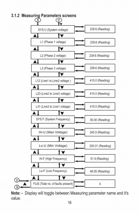
Note: - Display will toggle between Measuring parameter name and it's value.
3.1.2 Measuring Parameters screens
SYS.U (System voltage)
L1 (Phase 1 voltage)
L3 (Phase 3 voltage)
L2 (Phase 2 voltage)
L12 (Line1 to Line2 voltage )
L31 (Line3 to Line1 voltage)
L23 (Line2 to Line3 voltage)
SYS.F (System Frequency)
Hi-U (Max Voltage)
Lo-U (Min Voltage)
Hi-F (High Frequency)
Lo-F (Low Frequency)
239.6 (Reading)
239.6 (Reading)
239.6 (Reading)
415.0 (Reading)
415.0 (Reading)
239.6 (Reading)
415.0 (Reading)
200.01 (Reading)
51.9 (Reading)
48.05 (Reading)
50.00 (Reading)
245.5 (Reading)
X
YFLtS (Total no. of faults present) 4
X Y
16

3.2.1 Setup Parameters screen START
Measurement Screen(Press ‘ENTER’ key continuously for 3 Sec)
SEtP(Setup parameters)
FALt (Faults Storage
Screen)
codE (Password) _._ _ _
0000Password protection
disabled
AV
K
E
B
3.2 Current Relay: -
M N
w
Continued....
SYS(System Parameters Menu) (See 3.1.2)
PArA (Protection Parameters Menu) (See 3.1.3)
: - UP Key
: - DOWN Key
: - ENTER Key
17

A
tYPE(System type )
3
(CT primary)CtPr
G
4 or 3 or 1 (Edit)
Continued....
A] SYS (System Parameters Menu)
Exit from setup to system voltage
C
D
K
V
M N
R1
R2
rELY(Relay Parameters)
(See 4.1.4)
rESt (Reset Value)
(See 4.1.5)
quit (Exit Setup Menu)
(See 4.1.6)
18
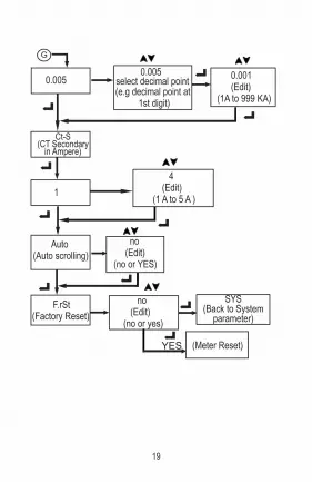
G
0.0050.005
select decimal point(e.g decimal point at 1st digit)
0.001 (Edit) (1A to 999 KA)
Ct-S(CT Secondary
in Ampere)
1
4 (Edit) (1 A to 5 A )
Auto(Auto scrolling)
F.rSt (Factory Reset)
SYS(Back to System
parameter)
(Meter Reset)
no (Edit) (no or YES)
no (Edit) (no or yes)
YES
19

OC (Over Current protection)
B YES (Edit) (YES / no)
id-t (IDMT)
YES (Edit)(YES / no)
no
YES
t.SEt(Time multiplier setting)
CurU(Curve Selection)
n.inU (Normal Inverse)U.inU (Very Inverse)E.inU(Extremely Inverse)L.inU(Long Inverse)
YES
no
triP(Trip set point)
triP(Trip set point)
tr-d(trip delay)
HYS (Hysteresis)
125.0 (Edit)(101 to 140 %)
30.00 (Edit)(0 to 30.0 Sec)
125.0 (Edit)(101 to 125 %)
15.0 (Edit)(1 to 15 %)
1.0 (Edit) (0.1 to 1)
rL1 (Edit relay output) rL1 (Relay1) /rL2 (Relay2) /rL12 (Relay 1 & Relay2) / nOnE (No relay)
rL1 (Edit relay output) rL1 (Relay1) /rL2 (Relay2) /rL12 (Relay 1 & Relay2) / nOnE (No relay)
P QP Q
O1
B] PArA (Protection Parameters Menu)
20

C.LoS (Current Loss)
YES
no
C.un (Current unbalance protection)
(Edit)(1 to 15 %)
YES
no
triP(Trip set point)
triP(Trip set point)
YES (Edit) (YES / no)
YES (Edit) (YES / no)
tr-d(trip delay)
tr-d(trip delay)
HYS (Hysteresis)
HYS (Hysteresis)
15.0 (Edit)(1 to 15 %)
70 .0 (Edit) (5 to 99 %)
30.00 (Edit)(0 to 30.00 Sec)
20 .0 (Edit) (2 to 20 %)
30.00 (Edit)(0 to 30.00 Sec)
rL1 (Edit relay output) rL1 (Relay1) /rL2 (Relay2) /rL12 (Relay 1 & Relay2) / nOnE (No relay)
P1 L M
uC(under Current)
triP(Trip set point)
YES (Edit) (YES / no)
tr-d(trip delay)
HYS (Hysteresis)
30.00 (Edit)(0 to 30.0 Sec)
75.0 (Edit) (10 to 99 %)
15.0 (Edit)(1 to 15 %)
rL1 (Edit relay output) rL1 (Relay1) /rL2 (Relay2) /rL12 (Relay 1 & Relay2) / nOnE (No relay)
no
PP
21

C
00.50 (Edit) (0.5 to 30 sec)
00.50 (Edit) (0.2 to 30 sec)
Auto
En / dE.En (Edit)(Energies / De- Energies)
YES (Edit) (YES / no)
rL1 (Relay 1)
rL2 (Relay 2)
quit(Back to configuration)
En / dE.En (Edit)(Energies / De- Energies)
J J
J
U Z
Pon.d(Power ON delay)
(See 4.1.4.1)
rSt.d(Reset delay)
(See 4.1.4.2)
rSt.C(Reset Control)
(See 4.1.4.3)
COnF (configuration)
(See 4.1.4.4)
quit(Back to main menu)
W
rL1 (Edit relay output) rL1 (Relay1) /rL2 (Relay2) /rL12 (Relay 1 & Relay2) / nOnE (No relay)
BP1
L M
V1
O1
C] rELY (Relay Parameters)
22

D
nonE(No of value should reset )
ALL Hi (Max)
Lo (Min)
FLt.S(Faults)
R2
R1
1st (first parameter)
2nd (second parameter)
OC/UC/C.LoS/C.Un (Edit 1st parameter)
U Z
YES (Edit) (YES / no)
no
C
rL1 (Edit relay output) rL1 (Relay1) /rL2 (Relay2)/ rL12 (Relay 1 & Relay2) / nOnE (No relay)
And(Relay ANDingconfiguration)(See 4.1.4.6)
quit(Back to main menu)
(See 4.1.4.7)
OC/UC/C.LoS/C.Un (Edit 2ndparameter)
rEL.CRelay control (See 4.1.4.5)
rL-1 (Relay 1)
BuZZ / trip (Edit)
rL-2 (Relay 2)
BuZZ / trip (Edit)
V1
D] rESt (Reset Values)
23

Note: - Display will toggle between Measuring parameter name and it's value.
3.2.2 Measuring Parameters screens
SYS.A (System Current)
L1 (Phase 1 Current)
L3 (Phase 3 Current)
L2 (Phase 2 Current)
SYS.F (System Frequency)
Hi-A (Max Current)
Lo-A (Min Current)
Hi-F (High Frequency)
Lo-F (Low Frequency)
5.000 (Reading)
5.000 (Reading)
4.999 (Reading)
5.001 (Reading)
0.500 (Reading)
51.9 (Reading)
48.05 (Reading)
50.00 (Reading)
6.500 (Reading)
X Y
XY
2 FLtS (Total no. of faults present)
E] FALt (Faults Storage Screen)
E
Ft.no (Fault number
to see)
OC(Fault type)
L1 L2 L3
quit (Exit from faults storage screen)
Ft.01 (Edit)(1 to 15)
X
24

Over (OV) and Under (UV) voltage3.3 Timing Diagrams
Over set (%)
L1/L1-2 Vrated
Under set (%)
Voff
Over set (%)
L2/L2-3 Vrated
Under set (%)
Voff
Over set (%)
L3/L3-1 Vrated
Voff
Phase L1-LED
Phase L2-LED
Phase L3-LED
Relay-1 LED (OV)
Relay-2 LED (UV)
AUX supply
Relay 2- UV: 21-24De-energize
Relay 1- OV: 11-14 Energize
Differential (Hysteresis)
Pd Td Rd
Td Rd
Under set (%)Differential (Hysteresis)
Time
Note: 1] Pd- Power ON delay 2] Td- Trip delay 3] Rd- Reset delay 4] Both relay can be configured to energize or de-energize mode 5] Any relay can be assigned to any fault condition
Note: - For safety reasons, if relay has already tripped then it will not reset unless all phases are healthy i.e above or below hysteresis value (as the case may be). This is to prevent unrequired relay chattering.
Red ON - fault condition
Green ON - healthy
Relay LED Indications
conditionRed blinking - Trip Delay(only Phase LEDs)
EnergizedDe-energized
Relay States -
Phase LED Indications -
Green blinking - Reset
Red ON - fault condition Green ON - healthy
Input Absentcondition
(only Phase LEDs)Delay
25

Phase Failure (Ph.F) and Phase Unbalance (Ph.un)
Differential (Hysteresis)
L1/L1-2 Vrated
Phase fail set (%)
Voff
Phase fail set (%)
Voff
L2/L2-3 Vrated
L3/L3-1 Vrated
Phase fail set (%)
Voff
Relay 1- Ph.F:11-14 EnergizeRelay 2- Ph.un:21-24De-energizePhase L1-LED
Phase L2-LED
Phase L3-LED
Relay-1 LED (Ph.F)
Relay-2 LED (Ph.un)
AUX supply
Differential (Hysteresis)
Unbalance
Unbalance
Pd Td Rd
Td Rd
Time
Red ON - fault condition
Green ON - healthy
Relay LED Indications
conditionRed blinking - Trip Delay(only Phase LEDs)
EnergizedDe-energized
Relay States -
Phase LED Indications -
Green blinking - Reset
Red ON - fault condition Green ON - healthy
Input Absentcondition
(only Phase LEDs)Delay
Note: 1] Pd- Power ON delay 2] Td- Trip delay 3] Rd- Reset delay 4] Both relay can be configured to energize or de-energize mode 5] Any relay can be assigned to any fault condition
Note: - For safety reasons, if relay has already tripped then it will not reset unless all phases are healthy i.e above or below hysteresis value (as the case may be). This is to prevent unrequired relay chattering.
26

Over (OF) and Under (UF) Frequency
Red ON - fault condition
Green ON - healthy
Relay LED Indications
conditionRed blinking - Trip Delay(only Phase LEDs)
EnergizedDe-energized
Relay States -
Phase LED Indications -
Green blinking - Reset
Red ON - fault condition Green ON - healthy
Input Absentcondition
(only Phase LEDs)Delay
Note: 1] Pd- Power ON delay 2] Td- Trip delay 3] Rd- Reset delay 4] Both relay can be configured to energize or de-energize mode 5] Any relay can be assigned to any fault condition
Over set (%)
F sys F rated
Under set (%)
Relay 1- OF: 11-14Energize
Relay 2- UF: 21-24De-energize
Phase L1-LED
Phase L2-LED
Phase L3-LED
Relay-1 LED (OF)
Relay-2 LED (UF)
AUX supply
Time
Differential (Hysteresis)
Differential (Hysteresis)
Pd
Td Rd
Td Rd
27

Phase sequence (Ph.r)
Voff
L1 Vrated
Voff
L2 Vrated
Voff
L3 Vrated
Relay 1- Ph.r: 11-14EnergizeRelay 2- Ph.r: 21-24De-energize
Phase L2-LED
Phase L3-LED
Relay-1 LED (Ph.r)
Relay-2 LED (Ph.r)
AUX supply
Phase L1-LED
L2
L1
L1
L2
Incorrect Phase Sequence
correct Phase Sequence
L3 L3
Pd Rd
Time
Red ON - fault condition
Green ON - healthy
Relay LED Indications
conditionRed blinking - Trip Delay(only Phase LEDs)
EnergizedDe-energized
Relay States -
Phase LED Indications -
Green blinking - Reset
Red ON - fault condition Green ON - healthy
Input Absentcondition
(only Phase LEDs)Delay
Note: 1] Pd- Power ON delay 2] Td- Trip delay 3] Rd- Reset delay 4] Both relay can be configured to energize or de-energize mode 5] Any relay can be assigned to any fault condition
28

Over (OC) and Under (UC) Current
Differential (Hysteresis)
Pd Td Rd Td Rd
Time
Differential (Hysteresis) Over set (%)
L1 Irated
Under set (%)
Ioff
Over set (%)
L2 Irated
Under set (%)
Ioff
Over set (%)
L3 Irated
Under set (%)
Ioff
Relay 1- OC: 11-14(Energize)
Relay 2- UC: 21-24(De-energize)
Phase L2-LED
Phase L3-LED
Relay-1 LED (OC)
Relay-2 LED (UC)
AUX supply
Phase L1-LED
Red ON - fault condition
Green ON - healthy
Relay LED Indications
conditionRed blinking - Trip Delay(only Phase LEDs)
EnergizedDe-energized
Relay States -
Phase LED Indications -
Green blinking - Reset
Red ON - fault condition Green ON - healthy
Input Absentcondition
(only Phase LEDs)Delay
Note: 1] Pd- Power ON delay 2] Td- Trip delay 3] Rd- Reset delay 4] Both relay can be configured to energize or de-energize mode 5] Any relay can be assigned to any fault condition
Note: - For safety reasons, if relay has already tripped then it will not reset unless all phases are healthy i.e above or below hysteresis value (as the case may be). This is to prevent unrequired relay chattering.
29

Current Loss (C.LoS) and Current Unbalance (C.un)
Pd Td Rd Td Rd
Time
Differential (Hysteresis)
Unbalance
Differential (Hysteresis)
Unbalance
L1 Irated
Phase Fail Set(%)
Ioff
L2 Irated
Phase Fail Set(%)
Ioff
L3 Irated
Phase Fail Set(%)
Ioff
Relay 1- C.LoS: 11-14(Energize)
Relay 2 - C.un: 21-24(De-energize)
Phase L2-LED
Phase L3-LED
Relay-1 LED (C.LoS)
Relay-2 LED (C.un)
AUX supply
Phase L1-LED
Red ON - fault condition
Green ON - healthy
Relay LED Indications
conditionRed blinking - Trip Delay(only Phase LEDs)
EnergizedDe-energized
Relay States -
Phase LED Indications -
Green blinking - Reset
Red ON - fault condition Green ON - healthy
Input Absentcondition
(only Phase LEDs)Delay
Note: 1] Pd- Power ON delay 2] Td- Trip delay 3] Rd- Reset delay 4] Both relay can be configured to energize or de-energize mode 5] Any relay can be assigned to any fault condition
Note: - For safety reasons, if relay has already tripped then it will not reset unless all phases are healthy i.e above or below hysteresis value (as the case may be). This is to prevent unrequired relay chattering.
30

4.1.1 Password Protection
4. PROGRAMMING 4.1 Menu SelectionThe following sections comprise step by step procedures for configuring the RISH Relay according to individual user requirement.
Then meter will enter into edit mode as shown in fig 3 (*Denotes decimal Point is flashing). Press “ENTER” key, by default password is set to “0000" as shown in fig 4.
To access the Set-Up menu press and hold “ ENTER ” key for 3 Seconds, the screen is shown in fig 1. On pressing “ENTER” key, meter will ask for password shown in fig 2.
New Password Setting
Pressing “ ” key decrements digit value from 9 to 0. Value will wrap from 0 to 9.
Pressing “ “ key increments digit value from 0 to 9, then value will wrap from 9 to 0.
Example: - For Setting New password “1234" follow the procedure. Press “ ” key or “ ” key once, to enter into password edit mode, screen is shown in fig 3 (*Denotes decimal Point is flashing).
Press “ ” key to increment first digit to ‘ 1 ‘ as shown in fig 5. Press “ ENTER “ key to confirm number 1, decimal point will shift to next digit. Press “ ” key to increment second digit to ‘ 2 ’ as shown in fig 6. Press “ ENTER “ key to confirm digit 2.
Press “ ” key to increment third digit to “ 3” as shown in fig 7.
Press “ ENTER “ key to confirm digit “ 3 “.
Press “ ” key to increment fourth digit to “ 4 “ as shown in fig 8.
Press “ ENTER “ key to confirm digit “ 4 “. Fig No: - 8*
Fig No: - 7*
Fig No: - 6*
Fig No: - 5*
Fig No: - 4
Fig No: - 3*
Fig No: - 2
Fig No: - 1
31

On pressing “ ENTER ” key new password will be set as shown in fig 9. On again pressing “ENTER” key meter will confirm new password & will go to SET UP menu.
“SYS” (System) menu allows user to select different system parameters like “System Type”, “PT / CT primary”, “PT / CT Secondary”, “System Frequency”, “Phase Sequence”, “Auto”, “Factory Reset”. (Refer Section 4.1.2.1 to 4.1.2.9)
“PArA” (Parameter) menu allows user to select different fault parameters like “OV” (Over Voltage), “UV” (Under Voltage), “OF” (Over Frequency), “UF” (Under Frequency), “Ph.un” (Phase Unbalance), “Ph.F” (Phase Failure), “Ph.r” (Phase Reversal) for Line Monitoring Relay / Voltage Protection Relay (Refer Section 4.1.3)
OR“OC” (Over Current),”UC” (Under Current),”C.LoS” (Current Loss), “C.un” (Current Unbalance) for Current Protection Relay. (Refer Section 4.1.3)
“rELY” (Relay) menu allows user to select different Relay related parameters like “Pon.d” (Power ON delay), “rSt.d” (Reset delay), “rSt.C” (Reset Control), “COnF” (Relay Configuration), “rEL.C” (Relay Control), “And” (AND). (Refer section 4.1.4)“rESt” (Reset) menu allows user to reset different parameters like “ALL” (all Voltage / Current , Frequency), “Hi” (High Voltage / Current , Frequency), “Lo” (Low Voltage / Current , Frequency), “FLt.S” (Faults). (Refer section 4.1.5)“quit” (Quit) menu allows user to quit from SETUP menu. (Refer section 4.1.6)Fig No: - 14
Fig No: - 13
Fig No: - 12
Fig No: - 11
Fig No: - 10
Fig No: - 9
32
For changing password at screen shown in fig 9, Press “ ” key or “ ” key and start from “New Password Setting”.
SETUP Menu
Press “ ” key or “ ” key to move through set up menu.

4.1.2 System Parameter Selection Menu4.1.2.1 System Type“SYS” (System) menu allows user to set system parameters. On pressing “ENTER” key meter will enter into system parameters & ask for system type selection as shown in fig 16.This screen is used to set the system type (only for 3 phase meter), 3 for 3P3W, 4 for 3P4W & 1 for 1P2W. Now the screen will show previously stored system type “4” as shown in fig: - 17. Setting New system Type: - Pressing “ ” or “ ” key, meter will enter into edit mode. Pressing “ ” key increments digit value & Pressing “ ” key decrements digit value. Example: - For Setting new system type “3" follow the procedure: - Press “ ” key or “ ” key to get number “3 “ as shown in fig 18.On pressing “ ENTER ” key new system type will be set as shown in fig 19. On again pressing “ENTER” key meter will confirm new system type & will go to PT primary setting (for Voltage Relay) (refer Section 4.1.2.2) or to CT primary setting for (Current Relay) (refer Section 4.1.2.4)
This Screen allows user to set Potential Transformer’s primary value in KV. K is indicated by annunciation of ‘K’ LED.The PT primary can be set from 0.100 KV to 1200 KV .L-L LL
“ PtPr ” (Potential transformer primary) is shown in fig 20 & “VLL” (Line to Line Voltage) is shown in fig 21. After VLL, meter will show previously stored PtPr value “ 0.415 “ (415 VL-L) as shown in fig 22 and “ K ” LED will be lit which indicate in KV .
Fig No: -22
Fig No: -21
Fig No: -20
Fig No: - 19
Fig No: - 18
Fig No: - 17
Fig No: - 16
Fig No: - 15
33
Voltage Relay: - 4.1.2.2 Potential Transformer (PT) Primary V-Line to Line

Setting New Potential transformer's Primary Value.
Pressing “ ” or “ ” key, meter will enter into edit mode Pressing “ ” key increments digit value & Pressing “ ” key decrements digit value.
Example: - For setting new PtPr value to 0.230KV, follow the steps:
pressing “ ” key or “ ” key first time, meter will edit position of decimal point. As shown in fig 22 decimal point is adjusted. Pressing “ENTER” key will start blinking decimal point & editing of value as shown in fig 23. Press “ENTER” key to advance to next digit as shown in fig No 24. (*Denotes decimal Point is flashing).
Press “ ” key to decrement digit to “2” as shown in fig 25.Press “ENTER” key to advance to next digit as shown in fig 26.
Now press “ ” key to increment digit to “3”, as shown in fig 27. Press “ENTER” key to advance to next digit as shown in fig 28.
Press “ ” key to decrement digit to “ 0 ” as shown in fig 29. On pressing “ ENTER ” key new PT primary will be set as shown in fig 30. On again pressing “ENTER” key, meter will confirm new PT primary & will go to Potential Transformer’s Secondary setting refer section 4.1.2.3
4.1.2.3 Potential Transformer (PT) Secondary V-Line to Line This screen allows user to set potential transformer’s secondary value in V. The PT secondary can be set from 100 V to 600 V . L-L L-L
“ Pt-S ” (Potential transformer‘s secondary) is shown in fig 31 “VLL” (Line to Line Voltage) is shown in fig 32. After VLL meter will show previously stored PT secondary value. (*Denotes decimal Point is flashing).
Fig No: -32
Fig No: -31
Fig No: -30
Fig No: -29*
Fig No: -28*
Fig No: -27*
Fig No: -24*
Fig No: -25*
Fig No: -26*
Fig No: -23*
34

Fig No: -33
Current Relay: -4.1.2.4 Current Transformer (CT) PrimaryThis Screen “CtPr ” (Current Transformer Primary) allows
Setting New Potential transformer's Secondary Value: Pressing “ ” or “ ” key, meter will enter into edit mode. Pressing “ ” key increments digit value & Pressing “ ” key decrements digit value. Pressing “ENTER” key will advance to next digit. After setting Pt-S value meter will go to System Frequency setting menu. (Refer Section 4.1.2.6)
user to set Current transformer’s primary value in KA. Kilo is indicated by annunciation of K LED. CT primary can be set from 1A to 999 KA.After CtPr meter will show previously stored CT Primary value.Setting New Current transformer's Primary Value:Pressing “ ” or “ ” key, meter will enter into edit mode. Pressing “ ” or “ ” key first time, meter will edit position of decimal point. Pressing “ENTER” key will start decimal point blinking.Pressing “ ” key increments digit value & Pressing “ ” key decrements digit value.Pressing “ENTER” key will advance to next digit. After setting Ct-Pr value meter will go to Current transformer’s secondary setting refer section 4.1.2.5 4.1.2.5 Current Transformer (CT) Secondary This Screen “ Ct-S ” (Current transformer Secondary)
allows user to set Current transformer’s Secondary value in A.
The CT secondary can be set from 1A to 5A. After “Ct-S” as shown in fig 34, meter will show previously stored CT Secondary value.
Fig No: -34
Setting New Current transformer's Secondary Value. Pressing “ ” or “ ” key, meter will enter into edit mode.
Pressing “ ” key increments digit value & Pressing “ ” key decrements digit value.
Pressing “ENTER” key will set new CT secondary. On again pressing “ENTER” key meter will confirm new CT secondary.
Fig No: -35
35

Fig No: -36
After setting Ct-S value meter will go to the Auto scrolling mode refer section 4.1.2.8 4.1.2.6 System Frequency (Voltage Relay only)This Screen “ SY-F ” (System frequency) allows user to set System frequency value as 50 or 60 Hz.After “SY-F” Screen will show previously stored system frequency value.Setting New System frequency Value.Pressing “ ” or “ ” key, meter will enter into edit mode. Again Pressing “ ” or “ ” key meter will show 50 Hz or 60 Hz. Pressing “ENTER” key meter will set new System frequency. On again pressing “ENTER” key meter will confirm new system frequency. After setting “SY-F” value meter will go to Phase sequence setting (refer section 4.1.2.7).4.1.2.7 System Phase Sequence ( Voltage Relay only) This Screen “ Ph.Sq ” (Phase sequence) allows user to set
system phase sequence as 123 or 321. After “Ph.Sq” meter will show previously stored Phase
sequence. Setting New Phase sequence:Pressing “ ” or “ ” key, meter will enter into edit mode. Again Pressing “ ” or “ ” key meter will show “123” OR “321”. Pressing “ENTER” key meter will set new Phase Sequence. On again pressing “ENTER” key meter will confirm new Phase Sequence.After setting “Ph.Sq” meter will go to Auto scrolling mode (refer section 4.1.2.8).4.1.2.8 Auto Scroll This Screen “ Auto” allows user to enable screen scrolling. After “Auto” meter will show previously stored auto
scrolling mode. (YES \ NO)
Setting Auto scrolling mode:Pressing“ ” or “ ” key, meter will enter into edit mode. Press “ ” or“ ” key to get “YES”.On pressing “ ENTER ” key Auto scrolling mode will be set. On again pressing “ENTER” key meter will confirm newly changed auto scrolling mode & go to Factory reset (refer section 4.1.2.9)Note: - If faults are present auto scrolling mode will not work.
Fig No: -37
36

Fig No: -39
Fig No: - 40
Fig No: -41
Fig No: -38
4.1.2.9 Factory Reset This Screen “ F.rst ” (Factory Reset) allows user to reset
meter to factory default setting. Factory Resetting :- To Reset meter to factory default setting follow the procedure: - Pressing “ ” or “ ” key, meter will enter into edit mode. Example: -Press “ ” key to get “YES”. On pressing “ ENTER ” key Meter will be reset to default setting (Refer section 6 for Default settings).
4.1.3 Parameter Selection Menu4.1.3.1 Parameters selection“PArA ” (Parameters selection) allows user to select 7 different parameters For (Line Monitoring Relay) & 4 different parameters For (Voltage Protection Relay, Current Protection Relay) .Press “ENTER” key to enter into parameters selection screen.Press “ ” key or “ ” key to move through parameter selection menu. By pressing “ENTER“ key User can select the desired parameters (refer section 4.1.3.2). The available parameters are “OV” (Over Voltage) , “UV” (Under Voltage), “OF” (Over Frequency), “UF” (Under Frequency), “Ph.un” (Phase Unbalance), “Ph.F” (Phase Failure), “Ph.r” (Phase Reversal) for Voltage Relay and “OC” (Over Current), ”UC” (Under Current), “C.LoS” (Current Loss), “C.un” (Current Unbalance) for Current Relay.
4.1.3.2 YES / NO This screen is used to activate OR Deactivate a
parameter. By default all parameters are disabled as shown in fig 39 Parameters Enable mode :- To enabled parameters follow the steps: - Pressing “ ” or “ ” key, meter will enter into edit
mode. Example: - Press “ ” key to get “YES” on screen as shown in fig 40.
On pressing “ ENTER ” key Selected parameters will be enabled as shown in fig 41.
37
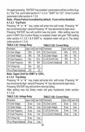
Parameters Upper Limit Lower limit
OV (Over Voltage) 125% 101%
OF (Over Frequency) 110% 101%
UV (Under Voltage) 99% 70%
UF (Under Frequency) 99% 90%
Ph.F (Phase Fail) 85% 20%
Ph.un (Phase Unbalance) 20% 2%
TABLE 2 (A): Voltage Relay
Parameters Upper Limit Lower limit
OC (Over Current) 140% 101%
C.LoS (Current Loss) 99% 5% UC (Under Voltage) 99% 10%
C.un (Current Unbalance) 20% 2%
TABLE 2 (B): Current Relay
4.1.3.4 Trip Delay Pressing “ ” or “ ” key, meter will enter into edit mode. Pressing “ ” key increments digit value & Pressing “ ” key decrements digit value. Pressing “ENTER” key will confirm new trip Delay. After setting new trip Delay meter will goto Hysteresis (refer section 4.1.3.5)
Note: Upper limit for IDMT is 125%.
On again pressing “ENTER” key enabled parameters will be confirm & go to ( “trip” Trip point refer section 4.1.3.3 or “IDMT” for “OC” (Over Current parameter) refer section 4.1.3.8Note: - Phase Failure is enabled by default. It can not be disabled.4.1.3.3 Trip Point Pressing “ ” or “ ” key, meter will enter into edit mode. Pressing “ ” key increments digit value & Pressing “ ” key decrements digit value. Pressing “ENTER” key will confirm new trip point. After setting new trip point if IDMT (for Current Relay) is enabled meter will goto TMS setting refer section 4.1.3.9.1 & if IDMT is disabled meter will go to Trip delay (refer section 4.1.3.4)
Parameters Upper Limit Lower limit
OV (Over Voltage) 30 sec 0 sec
OF (Over Frequency) 30 sec 0 sec
UV (Under Voltage) 30 sec 0 sec
UF (Under Frequency) 30 sec 0 sec
Ph.F (Phase Fail) 30 sec 0 sec
Ph.un (Phase Unbalance) 30 sec 0 sec
TABLE 3 (A): Voltage Relay
Parameters Upper Limit Lower limit
OC (Over Current) 30 sec 0 sec
C.LoS (Current Loss) 30 sec 0 sec UC (Under Voltage) 30 sec 0 sec
C.un (Current Unbalance) 30 sec 0 sec
TABLE 3 (B): Current Relay
38

TABLE 4 (A): Voltage Relay
TABLE 4 (B): Current Relay
4.1.3.5 HysteresisPressing “ ” or “ ” key, meter will enter into edit mode. Pressing “ ” key increments digit value & Pressing “ ” key decrements digit value. Pressing “ENTER” key will confirm new hysteresis.After setting new Hysteresis meter will goto Relay assignment (refer section 4.1.3.6) If “Ph.un” (Phase Unbalance) / “C.un” (Current Unbalance) trip point is greater than 15% then hysteresis upper limit will be 15% & lower limit will be 1%.
Parameters Upper Limit Lower limit
OV (Over Voltage)
OF (Over Frequency)
UV (Under Voltage)
UF (Under Frequency)
Ph.F (Phase Fail) 1%
1%
1%
1%1%
15%
15%
15%15%
15%
Parameters Upper Limit Lower limit
OV (Over Current)
C. Los (Current Loss)
UC (Under Voltage)
1%
1%1%
15%15%
15%
If “Ph.un” (Phase Unbalance) / “C.un” (Current Unbalance) trip point is less than 15% then hysteresis upper limit will be “trip point - 1” & lower limit will be 1%.Example: - For “OV” (Over Voltage) PT Secondary = 100 VL-L.
Trip point = 105% (105 V ) Hysteresis = 2% (2 V )L-L L-L.
Relay Reset = Trip point - Hysteresis = 105 - 2, = 103 VL-L.
39

Example: - For “Ph.un” (Phase Unbalance) PT Secondary = 100 VL-L.
Trip point = 10% (10 V )L-L
Hysteresis = 2% (2 V )L-L.
Relay Reset =Trip point - Hysteresis = 10 - 2 = 8 V L-L.
Note: - For safety reasons, if relay has already tripped then it will not reset unless all phases are healthy i.e above or below hysteresis value (as the case may be). This is to prevent unnecessary relay chattering.
4.1.3.6 Relay AssignmentThis screen allows user to assign any fault to any relay options like "none" (No), "rL1" (Relay 1), "rL2" (Relay2), "rL12" (Relay with two change Over Contacts).Pressing “ ” or “ ” key, meter will enter into edit mode. Example: -To assign Relay 1 to any fault parameter follow the steps.Fig No: - 43
Fig No: - 42
Fig No: - 44
When on screen (fig) 42 press “ ” key to get “rL1” (Relay 1) as shown in fig 43. On pressing “ ENTER ” key Relay 1 will be assigned as shown in fig 44.
On again pressing “ENTER” key meter will confirm newly assigned relay & go to “quit” (quit from parameter selection menu) refer section 4.1.3.7.
40

Fig No: -46
Fig No: - 45
4.1.3.7 QuitOn pressing “ENTER” key meter will quit (Exit) from parameter selection menu.
4.1.3.8 IDMT (Inverse Definite Minimum Time) (Current Relay only)This Screen (Fig) 46 “ id-t ”(IDMT) allows user to assign IDMT to only “OC” (Over Current) fault parameter. For IDMT curves refer Table 5.
TABLE 5:
To calculate Relay Operating time when IDMT is enabled, use the following formula.
Where, T = Time in Sec (Operating time of relay).I = Input Current.Is = Secondary Current.TMS = Time multiplier setting.
I Is (
(T = C -1
x TMSα
C = Constant for relay characteristics.α = Constant representing inverse time type (α > 0)
On pressing “ ENTER ” key meter will show previously enabled or disabled IDMT.To enable IDMT follow the steps: -Pressing “ ” or “ ” key, meter will enter into edit mode Press “ ” key to get “YES” on screen as shown in fig 47.
Fig No: - 47
Fig No: -48
On pressing “ ENTER ” key IDMT will be enabled as shown in fig 48. On again pressing “ENTER” key enabled parameters will be confirm & go to ( “trip” Trip point setting refer section 4.1.3.3
Relay Characteristics type C
Standard Inverse (n.inU) 0.02 0.14Very Inverse (U.inU) 1 13.5
Extremely Inverse (E.inU) 2 80
Long Inverse (L.inU) 1 120
α
41

After setting TMS value meter will go to curve selection refer section 4.1.3.8.2 4.1.3.8.2 Curve selection
Screen (Fig) 50 “ CurU ” (Curve selections) allows user to select 4 different Curves for only “OC” (Over Current) fault parameter.
After “CurU” meter will show previously stored curve as shown in fig 51.
Fig No: -51
Fig No: -50
Fig No: -53
Curve Selection mode:-Pressing “ ” or “ ” key, meter will enter into edit mode. Example: -For Selecting extremely inverse curve, follow the steps: - Press “ ” key to get “E.inV” (Extremely inverse curve) as shown in fig 52.On pressing “ ENTER ” key Extremely inverse curve will be selected as shown in fig 53.
Fig No: -52
Fig No: -49
4.1.3.8.1 TMS (Time multiplier setting)Screen (Fig) 49 “ t.SEt ” (Time multiplier setting) allows user to Set TMS value ranging from 0.1 to 1.
On pressing “ ” or “ ” key, meter will enter into edit mode. Pressing “ ” key increments digit value & Pressing “ ” key decrements digit value.
TMS 1 0.1 Upper limit Lower limit
TABLE 6:
On again pressing “ENTER” key meter will confirm selected curve & go to Relay selection mode. (refer section 4.1.3.6)Note: When a curve is selected the corresponding, and C αconstants get assigned automatically.
42

Pressing “ENTER” key will confirm new Power ON delay.Power ON Delay will be applicable only once when the meter is powered ON, and both relays rL1 & rL2 remain in tripped state during delay.After setting new Power On delay meter will go back to Power on delay screen (refer section 4.1.4.1)
4.1.4.2 Reset Delay
This screen allows user to set Reset Delay from 0.2 Sec to 30 Sec.
Fig No: - 56
Upper Limit Lower limit
Power ON Delay 30 0.5
TABLE 7:
When on “rELY” menu as shown in fig 54. Press “ ENTER ” key to enter into relay related parameters selection screen.Press “ ” key or “ ” key to move through relay related parameters By pressing “ENTER“ key User can select the desired parameters.Different options in this menu are “Pon.d” (Power ON delay) (refer section 4.1.4.1), “rSt.d” (Reset delay) (refer section 4.1.4.2), “rSt.C” (Reset Control) (refer section 4.1.4.3), “COnF” (Relay Configuration) (refer section 4.1.4.4), “rEL.C” (Relay Control) (refer section 4.1.4.5),“And” (AND) (refer section 4.1.4.6).
Fig No: - 54
Fig No: - 55
4.1.4 Relay Setup MenuThis menu “ rELY ” (Relay) allows user to configure different relay related parameters.
4.1.4.1 Power ON DelayThis screen allows user to set Power ON delay from 0.5 Sec to 30 Sec. Pressing “ ” or “ ” key, meter will enter into edit mode. Pressing“ ” key increments digit value & Pressing “ ” key decrements digit value.
43
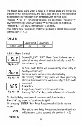
The Reset delay starts when a relay is in tripped state and no fault is present on that particular relay, the faulty state of relay is maintained for the set Reset delay and then relay contacts switch to initial state.Pressing “ ” or “ ” key, meter will enter into edit mode. Pressing “ ” key increments digit value & Pressing “ ” key decrements digit value. Pressing “ENTER” key will confirm new Reset delay.After setting new Reset delay meter will go back to Reset delay screen (refer section 4.1.4.2)
4.1.4.3 Reset Control
Fig No: - 57
In Auto mode Meter will automatically reset relay in healthy condition only.In manual mode user can manually reset relay. On pressing “ENTER” key meter will show previously stored Auto / manual mode. As shown in fig 59 Auto mode is enabled.Example: -Assign Relay Reset control in manual mode.Pressing “ ” or “ ” key, meter will enter into edit mode. Fig No: - 59
Fig No: - 58
Upper Limit Lower limitReset Delay 30 0.2
TABLE 8:
Screen (Fig) 57 “ rSt.C ” (Reset Control) allows user to set whether relay should reset Automatically or wait for manual reset by user.
To disable Relay reset control in auto mode follow the steps.Press “ ” key to get “no” as shown in fig 60.On pressing “ ENTER ” key Relay Reset control will be in manual mode. After setting new Relay Reset control meter will go back
to Relay reset control screen (refer section 4.1.4.3)
Fig No: -6044

Fig No: - 63
Fig No: - 62
Fig No: - 61
Example: -Assign relay in energized mode. Pressing “ ” or “ ” key, meter will enter into edit mode. Press “ ” key to get “En” (energized mode) as shown in fig 61.On pressing “ ENTER ” key Relay will be configured in energized mode After setting new Relay configuration meter will go back to Relay configuration screen (refer section 4.1.4.4) Note: - similarly user can configure relay in “dE.En” de- energized
mode.
4.1.4.5 Relay Control
This screen allows user to assign individual relay to trip mode or to buzzer mode.On pressing Reset key / , if meter is in trip mode the relay will reset only when no fault is present, whereas in
4.1.4.4 Relay ConfigurationThis menu allows user to configured relay in energized or de-energized mode. On Pressing "ENTER" key meter will show previously configured relay.
Press “ ” key to get “trip” (trip mode) as shown in fig 63. On pressing “ ENTER ” key, relay 1 will be assigned to trip mode as shown in fig 64. After setting new Relay control mode, meter will go back to Relay Control screen (refer section 4.1.4.5)
Fig No: - 64
buzzer mode the particular relay will reset immediately even if fault is present.On Pressing "ENTER" key meter will show "rL1" (relay 1) as shown in fig 62 & previously configured relay control mode.Example: -After “rL1”, for Assigning relay1 to trip mode follow the steps. Pressing “ ” or “ ” key, meter will enter into edit mode.
45

Fig No: - 73
Fig No: - 72
Fig No: -71
Fig No: - 69
Fig No: - 68
Fig No: - 67
Fig No: - 66
Fig No: - 65
Screen (Fig) 65 “ And ” (AND) function allows user to assign ANDing between two fault parameters i.e Relay will trip only if both faults are present.Press “ENTER” key screen will show previously stored enabled or disabled AND function. To enable AND function press “ ” key to get “YES” on screen as shown in fig 66.
For Current RelayFor assigning “OC” as first input to anding function and “C.un” as second input to anding function follow the steps-
On pressing “ ENTER ” key screen will show “1st” (First) as shown in fig 67.
4.1.4.6 AND
Fig No: -70
This screen allows to set first parameter for ANDing.After this meter will show first fault parameter.Press “ ” key to get “OV” (Over Voltage) as shown in fig. 68 or “OC” (Over current) as shown in fig 69.On pressing “ ENTER ” key “OV” or “OC” will be assigned as first input to ANDing function shown in fig 70.
On again pressing “ENTER” key meter will confirm first ANDing input & go to “2nd” (Second input) as shown in fig. 71.
This screen allows user to set second parameter for ANDing.
Press “ ” key to get “OF” (Over Frequency) as shown in fig 72 or “C.un” (Current unbalance) shown in fig 73.
Example: -For Voltage RelayFor assigning “OV” as first input to anding function and “OF” as second input to anding function OR
46

4.1.4.7 QuitOn pressing “ENTER” key meter will quit (Exit) from Relay SET UP menu .Fig No: - 75
4.1.5 Reset menuScreen (Fig) 76 “ rESt ” (Reset) function allows user to reset High, Low voltage OR current values, Frequency, stored faults. Press “ENTER” key screen will show “nonE” (No) as shown in fig 77.
Note:- 1. Only the enabled parameters will be available for AND function. 2. In case of AND function, if two ANDing faults occur at the same time the trip delay will be maximum of the two. 3. If any one ANDing parameter is disabled, then AND function will get disabled & Relay will be Reset.
Press “ ” key or “ ” key to move through options in Reset Menu.
Options in Reset menu are: -none: - NoALL - All values.Hi - High values.Lo - Low values.FLtS - Stored Faults.
By pressing “ ENTER “ key User can Reset values from the selected options.
Fig No: - 79
Fig No: - 80
Fig No: -81
Fig No: - 78
Fig No: - 77
Fig No: - 76
On pressing “ ENTER ” key “OF” or “C.un”will be assigned as second input to ANDing function shown in fig 74. After setting two fault parameters to AND function meter will go back to AND (refer section 4.1.4.6)
Fig No: -74
47

Fig No: - 83
Fig No: - 82
4.1.6 Quit ScreenOn pressing “ENTER” key meter will quit (Exit) from main menu.
4.2 Faults4.2.1 Fault NumberScreen (Fig) 83 “ FALt ” (Fault) shows stored faults & corresponding response value.When on “FALt” menu as shown in fig 83,
Fig No: - 86
Fig No: - 85*
Fig No: - 84
When on fault menu, pressing “ENTER” key meter will show “Ft.no” (Fault numbers) as shown in fig 84. This function will show Last 15 faults.
Pressing “ ” key increments digit value & Pressing “ ” key decrements digit value.
To access this Set Up press “Enter” key, meter will show “Ft.01” (Fault1) as shown in fig 85. (* denotes decimal point is flashing).On pressing “ENTER” key meter will show fault name. Pressing “ ” or “ ” key, meter will show all fault parameters values.
Example: - To know the name of first fault & it’s details follow the steps: - Pressing “ ” or “ ” key, meter will enter into edit mode.
pressing “ ” key OR “ ” will go to “quit” (quit) menu refer section 4.2.2 as shown in fig 86.When on “quit” menu as shown in fig 86, pressing “ ” key OR “ ” will go to “FALt” (Fault) menu refer section 4.2.1 as shown in fig 83.
4.2.2 QuitOn pressing “ENTER” key meter will quit (Exit) from fault menu & go to measurement parameters menu.
Note: - Faults are stored in First In First Out (FIFO) order which means the latest fault is always stored on first location and previous faults get shifted downwards.
48

Fig No: -88
Fig No: -87
4.3 Other IndicationsWhen input exceeds 127% of PT Secondary in Voltage Relay OR 145% of CT Secondary in Current Relay, meter will show "-OL-" (Over Load) as shown in fig 87.If no input is present and Hi / Lo parameters are reset, then High frequency & Low frequency will show "----" as shown in fig 88.Caution: - Input should not exceed upper limits of Current OR Voltage specified above.
Fig No: - 89
System Type
CT Secondary
CT Primary
System Frequency Over Current Trip point
Under Current Trip point Current Loss Trip point
Current Unbalance Trip point
Parameters Default values
3
5 A
5 A50 Hz
110%
80%
20%
20%
Trip Delay
Hysteresis
Power ON Delay Reset Delay Fault activation
Relay assignment
System Nominal Current
1 sec
1%1 sec
1 sec0
15 A
Parameters Default values
5. OTHER FEATURES5.1 Test Relay operations"tESt" (Test) feature allows user to test relay operation when healthy inputs are applied i.e no fault is present.
6. DEFAULT SETTINGS / On FACTORY RESET
To Test relay operations follow the steps: - On pressing "TEST / " key for 3 seconds, all relay contacts will switch positions & Relay1, Relay2 LEDs will turn ON, and on releasing will return to initial state.5.2 Manual ResetWhen "Reset / " key is pressed continuously for 3 Sec the manual reset will be acknowledged and when the fault condition is no longer present, the relay will automatically reset.
TABLE 9 (A): Current Relay
49

Note :- 1. User can not disable Phase failure parameter.2. 0: Disabled 1: Enabled
TABLE 9 (B): Voltage Relay
3
415 V
600 V
50 Hz
1-2-3
110%
80%
105%
95%
System Type
System Nominal Voltage PT primary / Secondary
System Frequency
Phase Sequence
Over Voltage Trip point
Under Voltage Trip point
Over Frequency Trip point
Under Frequency Trip point
Parameters Default values
20%
1%
20%
1 sec
1 sec
1 sec
0
1
Trip Delay
Phase Failure Trip point
Phase unbalance Trip point
Hysteresis
Power ON Delay Reset Delay
Fault activation Relay assignment
Parameters Default values
50

7. INSTALLATION
DIN Rail Clip
Caution1. In the interest of safety and functionality
this product must be installed by a qualified engineer, abiding by any local regulations.
2. Voltages dangerous to human life are present at some of the terminal connec-tions of this unit. Ensure that all supplies a, de-energized before attempting any connection or disconnection.
3. These products do not have internal fuses therefore external fuses must be used to ensure safety under fault conditions.
Protection Relay can be mounted on a top-hat rail or directly on to wall by mounting plate.The front of the enclosure conforms to IP 20.The terminals of the product should be protected from liquids.The Meter should be mounted in a reasonably stable ambient temperature
0and where the operating temperature is within the range -10 to 55 C. Vibration should be kept to a minimum and the product should not be mounted where it will be subjected to excessive direct sunlight.7.1 EMC Installation Requirements: -This product has been designed to meet the certification of the EU directives when installed to a good code of practice for EMC in industrial environments, e.g.1. Screened output and low signal input leads or have provision for fitting
RF suppression components, such as ferrite absorbers, line filters etc., in the event that RF fields cause problems.
Note:It is good practice to install sensitive electronic instruments that are performing critical functions, in EMC enclosures that protect against electrical interference which could cause a disturbance in function.
2. Avoid routing leads alongside cables and products that are, or could be, a source of grounded. interference.
3. To protect the product against permanent damage, surge transients must be limited to 2kV pk. It is good EMC practice to suppress differential surges to 2kV at the source. The unit has been designed to
51

7.2 Case Dimension & Panel Cut Out
7.3 WiringInput connections are made directly to screw-type terminals with indirect wire pressure. Numbering is clearly marked on the connector. Choice of cable should meet local regulations. Terminal for both Current and Voltage inputs will accept upto 4mm2 (12AWG) solid or 2.5 mm2 stranded cable. Note : It is recommended to use wire with lug for connection with meter.7.4 Auxiliary SupplyMeter should ideally be powered from a dedicated supply, however powered from the signal source, provided the source remains within it may be the limits of the Chosen auxiliary voltage range.
automatically recover in the event of a high level of transients. In extreme circumstances it may be necessary to temporarily disconnect the auxiliary supply for a period of greater than 5 seconds to restore correct operation. The Current inputs of these products are designed for connection in to systems via Current Transformers only, where one side is grounded.4. ESD precautions must be taken at all times when handling this
product.
52

Current Relay
7.5 FusingIt is recommended that all voltage lines are fitted with 1 Amp HRC fuse.7.6 Earth/Ground ConnectionsFor safety reasons, CT secondary connections should be grounded in accordance with local regulations.
8. CONNECTION DIAGRAMS
Relay 1 Relay 2
Note- Relay Contacts are shown
in power off condition
COM COM
11
12 14
NC NO
21
22 24
NC NO
For 3 Phase 4 Wire Unbalanced Load
1 2 3 4 5 6 7 8
L NAUX SUPPLY
L1 L2L3
L OAD
P1
S1
P1
S1
P1
S1
9
NC
For 3 Phase 3 Wire Unbalanced Load
1 2 3 4 5 6 7 8
L NAUX SUPPLY
L1 L2L3
L OADP1
S1
P1
S1
9
NC
For 1 Phase 2 Wire Load
1 2 3 4 5 6 7 8
L NAUX SUPPLY
L1 L2L3
L OAD
P1
S1
9
NC
53
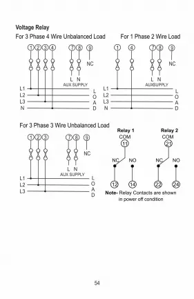
Voltage Relay
Relay 1 Relay 2
Note- Relay Contacts are shown
in power off condition
COM COM
11
12 14
NC NO
21
22 24
NC NO
For 3 Phase 4 Wire Unbalanced Load
1 2 3 4 7 8
L NAUX SUPPLY
L1 L2L3N
L OAD
9
NC
For 1 Phase 2 Wire Load
1 4 7 8
L NAUXSUPPLY
L1 L2L3N
L OAD
9
NC
For 3 Phase 3 Wire Unbalanced Load
1 2 3 7 8
L NAUX SUPPLY
L1 L2L3
L OAD
9
NC
54

9. TECHNICAL SPECIFICATIONS
Auxiliary Supply
Overload Withstand
Operating Measuring Ranges
Voltage Range 20...125% of PT SecondaryCurrent Range 5...140% of CT SecondaryFrequency 40...70Hz
Input Voltage
Input Current
Nominal input voltage (AC RMS) 600 VL-L (346.42VL-N)System PT Primary Values 100VL-L to 1200 KVL-L programmable on siteSystem PT Secondary value 100VL-L to 600 VL-L programmable on siteMax continuous input voltage 127% of PT SecondaryNominal frequency 50 / 60 Hz ( programmable on site)Input voltage burden < 0.6VA approx.
Nominal input current (AC RMS) 5 A System CT Primary Values From 1A to 999 KA programmable on siteSystem CT Primary Values 1A to 5A programmable on siteMax continuous input current 145% of CT SecondaryInput current burden < 0.25 VA approx. per phase
External Higher Aux 60 V – 300V AC-DCHigher Aux Nominal value 230 V AC/DC 50/60 Hz for AC Aux ORExternal Lower Aux 20 V – 60 VDC / 20 V – 40 VACLower Aux Nominal value 48 VDC / 24 VAC 50/60 Hz for AC AuxAux supply frequency 45 to 66 Hz rangeAux supply burden < 4VA approx.
Voltage 2x rated value for 1 second, repeated 10 times at 10 secondsCurrent 20x rated value for 1 second, repeated 5 times at 5 min
55

Voltage ±0.5% of nominal valueInput Current ±0.5% of nominal valueFrequency ±0.2 HzPower ON, Trip, Reset ±140 msec or ±5% of Set Delay, Delays Whichever is Greater (WIG)
Influence of Variations:
Temperature coefficient : 0.025%/°C for VoltageTemperature coefficient : 0.05%/°C for Current
Reference condition for Accuracy :
Reference Condition 23°C +/- 2°C
Input waveform Sinusoidal (distortion factor 0.005)
Input Frequency 50 or 60 Hz ±2%
Auxiliary supply voltage Nominal Value ±1%
Auxiliary supply frequency Nominal Value ±1%
Accuracy :
Applicable Standards:
EMC IEC 61326-1:2012, Table 2Immunity IEC 61000-4-3. 10V/m min – Level 3 industrial Low levelSafety IEC 61010-1-2010, Permanently connected useIP for water & dust IEC60529Pollution degree: 2Installation category: 300V CAT III / 600V CAT IIHigh Voltage Test 2.2 kV AC, 50Hz for 1 minute between all Electrical circuits.
56
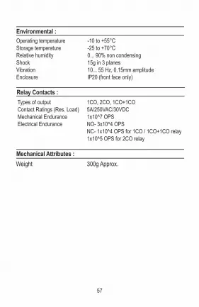
Types of output 1CO, 2CO, 1CO+1CO Contact Ratings (Res. Load) 5A/250VAC/30VDC Mechanical Endurance 1x10^7 OPS Electrical Endurance NO- 3x10^4 OPS NC- 1x10^4 OPS for 1CO / 1CO+1CO relay 1x10^5 OPS for 2CO relay
Mechanical Attributes :
Weight 300g Approx.
Environmental :
Operating temperature -10 to +55°CStorage temperature -25 to +70°CRelative humidity 0... 90% non condensingShock 15g in 3 planesVibration 10... 55 Hz, 0.15mm amplitudeEnclosure IP20 (front face only)
Relay Contacts :
57
NOTE
The information contained in these installation instructions is for use only by installers trained to make electrical power installations and is intended to describe the correct method of installation for this product.However, 'manufacturer' has no control over the field conditions which influence product installation. It is user's responsibility to determine the suitability of installation method in the user's field condition, 'manufacturer' only obligations are responsibility to determine suitability of the installation method in the user's field conditions.'Manufacturer' only obligations are those in manufacturer standard conditions.'Manufacturer' only obligations are those in 'Manufacturer' standard condition of sale for this product and in no case will 'Manufacturer' be liable for any other incidental, indirect or consequential damages arising from the use or misuse of the products.
58


