Embed Size (px)
Citation preview
37352A
Manual Version 3.1xxx
Manual 37352A
MFR 12 Packages Protection Relay
Manual 37352A MFR 12 Packages - Protection Relay
Page 2/62 © Woodward
WARNING Read this entire manual and all other publications pertaining to the work to be performed before install-ing, operating, or servicing this equipment. Practice all plant and safety instructions and precautions. Failure to follow instructions can cause personal injury and/or property damage. The engine, turbine, or other type of prime mover should be equipped with an overspeed (overtempera-ture, or overpressure, where applicable) shutdown device(s), that operates totally independently of the prime mover control device(s) to protect against runaway or damage to the engine, turbine, or other type of prime mover with possible personal injury or loss of life should the mechanical-hydraulic gov-ernor(s) or electric control(s), the actuator(s), fuel control(s), the driving mechanism(s), the linkage(s), or the controlled device(s) fail. Any unauthorized modifications to or use of this equipment outside its specified mechanical, electrical, or other operating limits may cause personal injury and/or property damage, including damage to the equipment. Any such unauthorized modifications: (i) constitute "misuse" and/or "negligence" within the meaning of the product warranty thereby excluding warranty coverage for any resulting damage, and (ii) invalidate product certifications or listings.
CAUTION To prevent damage to a control system that uses an alternator or battery-charging device, make sure the charging device is turned off before disconnecting the battery from the system. Electronic controls contain static-sensitive parts. Observe the following precautions to prevent dam-age to these parts. • Discharge body static before handling the control (with power to the control turned off, contact a
grounded surface and maintain contact while handling the control). • Avoid all plastic, vinyl, and Styrofoam (except antistatic versions) around printed circuit boards. • Do not touch the components or conductors on a printed circuit board with your hands or with
conductive devices.
OUT-OF-DATE PUBLICATION This publication may have been revised or updated since this copy was produced. To verify that you have the latest revision, be sure to check the Woodward website: http://www.woodward.com/pubs/current.pdf The revision level is shown at the bottom of the front cover after the publication number. The latest version of most publications is available at: http://www.woodward.com/publications If your publication is not there, please contact your customer service representative to get the latest copy.
Important definitions
WARNING Indicates a potentially hazardous situation that, if not avoided, could result in death or serious injury.
CAUTION Indicates a potentially hazardous situation that, if not avoided, could result in damage to equipment.
NOTE Provides other helpful information that does not fall under the warning or caution categories.
Woodward reserves the right to update any portion of this publication at any time. Information provided by Woodward is believed to be correct and reliable. However, Woodward assumes no responsibility unless otherwise expressly undertaken.
© Woodward
All Rights Reserved.
Manual 37352A MFR 12 Packages - Protection Relay
© Woodward Page 3/62
Revision History
Rev. Date Editor Changes NEW 06-03-02 TP Release based on 37141A A 07-07-18 TP Minor corrections
Contents
CHAPTER 1. GENERAL INFORMATION.........................................................................................6 Introduction .............................................................................................................................................6 Measured Value Logging ........................................................................................................................7 Package Functional Descriptions ...........................................................................................................8 CHAPTER 2. ELECTROSTATIC DISCHARGE AWARENESS.............................................................9 CHAPTER 3. INSTALLATION .....................................................................................................10 Wiring Diagram .....................................................................................................................................10 Power Supply ........................................................................................................................................11 Measuring Inputs...................................................................................................................................12
Current ........................................................................................................................................12 Voltage........................................................................................................................................14
Discrete Inputs ......................................................................................................................................15 Outputs..................................................................................................................................................15
Relay Outputs (Standard / Packages 51V & IvIkR)....................................................................15 Interface ................................................................................................................................................16
DPC - Direct Configuration Interface ..........................................................................................16 CHAPTER 4. FUNCTIONAL DESCRIPTION ..................................................................................17 Functional Table....................................................................................................................................17 Control Inputs........................................................................................................................................18 Control Outputs .....................................................................................................................................19 Alarms ...................................................................................................................................................20
Alarm Messages .........................................................................................................................20 Alarm Acknowledgement ............................................................................................................20
CHAPTER 5. DISPLAY AND OPERATING ELEMENTS...................................................................21 Brief Description of LEDs and Push Buttons ........................................................................................21 LEDs......................................................................................................................................................22 Push Buttons.........................................................................................................................................23 LC Display.............................................................................................................................................24
Display in Automatic Mode (First Line of the Display: Measured Values)..................................24 Display in Automatic Mode (Second Line of the Display: Measured Values) ............................25 Display in Automatic Mode (Second Line of the Display: Alarm Indication)...............................25
Manual 37352A MFR 12 Packages - Protection Relay
Page 4/62 © Woodward
CHAPTER 6. CONFIGURATION ................................................................................................. 26 Basic Data ............................................................................................................................................ 27 Configuration Access............................................................................................................................ 27
Password.................................................................................................................................... 27 Change Passwords .................................................................................................................... 28
Direct Configuration.............................................................................................................................. 29 Measurement........................................................................................................................................ 30
Voltage Measurement (Package 51V) ....................................................................................... 30 Potential Transformer Configuration (Package 51V) ................................................................. 30 Current Transformer Configuration ............................................................................................ 30 Rated Values.............................................................................................................................. 31 Power Measurement .................................................................................................................. 31
Protection.............................................................................................................................................. 32 Independent Time-Overcurrent Monitoring (Packages CP / 51V) ............................................. 32 Inverse Time-Overcurrent Monitoring (Package 51V) ............................................................... 34 Inverse Time-Overcurrent Monitoring with Voltage Restraint (Package 51V) ........................... 37 Ground Fault Monitoring (Packages CP / 51V / 50-51GN)........................................................ 39 Non-Direct. Ground-Fault Monit. via Displacement Volt. (Package IvIkR) ................................ 41 Ground-Fault Monitoring, Measured (Package IvIkR) ............................................................... 43 Directional Ground Fault Monitoring (Package IvIkR)................................................................ 44
Relay Configuration .............................................................................................................................. 46 Auto Acknowledgement of the Relays ....................................................................................... 46 Auto Acknowledgement of Messages........................................................................................ 47 Changing the Relay Assignment (Standard / Packages 51V & IvIkR)....................................... 48
CHAPTER 7. COMMISSIONING.................................................................................................. 50 APPENDIX A. DIMENSIONS ...................................................................................................... 51 APPENDIX B. TECHNICAL DATA .............................................................................................. 52 APPENDIX C. MEASURED QUANTITIES AND ACCURACY............................................................ 54 APPENDIX D. LIST OF PARAMETERS........................................................................................ 55 APPENDIX E. SERVICE OPTIONS ............................................................................................. 57 Product Service Options....................................................................................................................... 57 Returning Equipment for Repair ........................................................................................................... 57
Packing a Control ....................................................................................................................... 58 Return Authorization Number RAN............................................................................................ 58
Replacement Parts ............................................................................................................................... 58 How to Contact Woodward................................................................................................................... 59 Engineering Services............................................................................................................................ 60 Technical Assistance............................................................................................................................ 61
Manual 37352A MFR 12 Packages - Protection Relay
© Woodward Page 5/62
Illustrations and Tables
Illustrations Figure 3-1: Wiring diagram ..................................................................................................................................................... 10 Figure 3-2: Power supply......................................................................................................................................................... 11 Figure 3-3: Measuring inputs - current .................................................................................................................................... 12 Figure 3-4: Measuring inputs - Connections............................................................................................................................ 13 Figure 3-5: Measuring inputs - Connection ............................................................................................................................. 13 Figure 3-6: Measuring inputs - Displacement voltage ............................................................................................................. 14 Figure 3-7: Measuring inputs - Reference voltage................................................................................................................... 14 Figure 3-8: Discrete inputs....................................................................................................................................................... 15 Figure 3-9: Relay outputs......................................................................................................................................................... 15 Figure 5-1: Front panel ............................................................................................................................................................ 21 Figure 6-1: Diagram for independent time-overcurrent monitoring......................................................................................... 32 Figure 6-2: Inverse time-overcurrent - characteristic "normal inverse" ................................................................................... 35 Figure 6-3: Inverse time-overcurrent - characteristic "very inverse" ....................................................................................... 36 Figure 6-4: Inverse time-overcurrent - characteristic "extremely inverse" .............................................................................. 36 Figure 6-5: Characteristic of the inverse time-overcurrent monitoring with voltage restraint (knee curve setting 20 %) ....... 37 Figure 7-1: Dimensions............................................................................................................................................................ 51
Tables Table 3-1: Conversion chart - wire size ................................................................................................................................... 11 Table 4-1: Alarm messages...................................................................................................................................................... 20 Table 5-1: Alarm messages...................................................................................................................................................... 25 Table 6-1: Release delay of the relays ..................................................................................................................................... 47 Table 6-2: Protective function output to relay ......................................................................................................................... 49
Manual 37352A MFR 12 Packages - Protection Relay
Page 6/62 © Woodward
Chapter 1. General Information
Introduction ≡≡≡≡≡≡≡≡≡≡≡≡≡≡≡≡≡≡≡≡≡≡≡≡≡
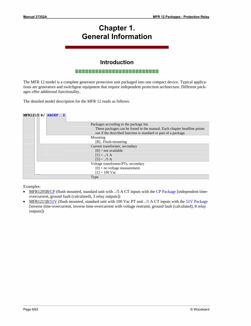
The MFR 12 model is a complete generator protection unit packaged into one compact device. Typical applica-tions are generators and switchgear equipment that require independent protection architecture. Different pack-ages offer additional functionality. The detailed model description for the MFR 12 reads as follows: MFR1215 B/ ABDEF..Z
Packages according to the package list.
These packages can be found in the manual. Each chapter headline points out if the described function is standard or part of a package.
Mounting [B].. Flush-mounting
Current transformer, secondary [0] = not available [1] = ../1 A [5] = ../5 A
Voltage transformer/PTs, secondary
[0] = no voltage measurement [1] = 100 Vac
Type Examples: • MFR1205B/CP (flush mounted, standard unit with ../5 A CT inputs with the CP Package [independent time-
overcurrent, ground fault (calculated), 3 relay outputs]) • MFR1211B/51V (flush mounted, standard unit with 100 Vac PT and ../1 A CT inputs with the 51V Package
[inverse time-overcurrent, inverse time-overcurrent with voltage restraint, ground fault (calculated), 8 relay outputs])

Manual 37352A MFR 12 Packages - Protection Relay
© Woodward Page 7/62
Measured Value Logging ≡≡≡≡≡≡≡≡≡≡≡≡≡≡≡≡≡≡≡≡≡≡≡≡≡
Voltage Package 51V: Voltage dependent time-overcurrent.
Current
Packages CP / 51V: Three-phase measurement of the r.m.s. value. • ../1 A ................................[1] • ../5 A ................................[5]
Ground Fault
The displayed ground current is digitally filtered from the measured currents. This prevents inaccurate values caused by the oscillations of the sine wave associated with ground fault currents from being displayed. Packages CP / 51V: The ground fault current is a calculation of the three phase currents vectorial sum. This measurement is suitable for line-to-ground monitoring in rigid or half-rigid earthen mains (e.g. In phase-to-phase low voltage mains). The measured line-to-ground current should be at least 10% of the current trans-former's rated current to ensure proper protection. Package 50-51GN: The ground fault current is a direct measurement of the single-phase ground current. This measurement is suitable for line-to-ground monitoring in rigid or half-rigid earthen mains (e.g. in phase-to-phase low voltage mains). In addition single-phase current transformers in the mains star point, in Holm-green connection or cable-type current transformers are used for the measuring current. Package IvIkR: The ground fault current is a direct measurement of ground current via cable-type current transformer. This measurement is suitable for the line-to-ground protection in insulated or balanced mains in which very few ground currents appear. In addition cable-type current transformers or balanced transformers in Holm-green connection are used for the measuring current.
Displacement Voltage
Package IvIkR: The ground fault current is a direct measurement of the displacement voltage. The measurement is carried out via the open delta winding (e-n-winding) of a voltage transformer or via a zero-point transformer in the generator star point.
Manual 37352A MFR 12 Packages - Protection Relay
Page 8/62 © Woodward
Package Functional Descriptions ≡≡≡≡≡≡≡≡≡≡≡≡≡≡≡≡≡≡≡≡≡≡≡≡≡
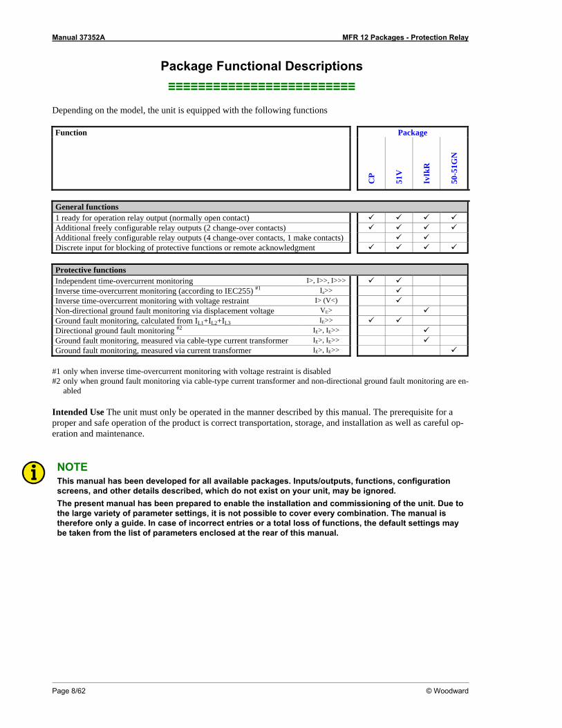
Depending on the model, the unit is equipped with the following functions Function Package
CP
51V
IvIk
R
50-5
1GN
General functions 1 ready for operation relay output (normally open contact) Additional freely configurable relay outputs (2 change-over contacts) Additional freely configurable relay outputs (4 change-over contacts, 1 make contacts) Discrete input for blocking of protective functions or remote acknowledgment Protective functions Independent time-overcurrent monitoring I>, I>>, I>>> Inverse time-overcurrent monitoring (according to IEC255) #1 Ia>> Inverse time-overcurrent monitoring with voltage restraint I> (V<) Non-directional ground fault monitoring via displacement voltage VE> Ground fault monitoring, calculated from IL1+IL2+IL3 IE>> Directional ground fault monitoring #2 IE>, IE>> Ground fault monitoring, measured via cable-type current transformer IE>, IE>> Ground fault monitoring, measured via current transformer IE>, IE>>
#1 only when inverse time-overcurrent monitoring with voltage restraint is disabled #2 only when ground fault monitoring via cable-type current transformer and non-directional ground fault monitoring are en-
abled Intended Use The unit must only be operated in the manner described by this manual. The prerequisite for a proper and safe operation of the product is correct transportation, storage, and installation as well as careful op-eration and maintenance.
NOTE This manual has been developed for all available packages. Inputs/outputs, functions, configuration screens, and other details described, which do not exist on your unit, may be ignored. The present manual has been prepared to enable the installation and commissioning of the unit. Due to the large variety of parameter settings, it is not possible to cover every combination. The manual is therefore only a guide. In case of incorrect entries or a total loss of functions, the default settings may be taken from the list of parameters enclosed at the rear of this manual.
Manual 37352A MFR 12 Packages - Protection Relay
© Woodward Page 9/62
Chapter 2. Electrostatic Discharge Awareness
All electronic equipment is static-sensitive, some components more than others. To protect these components from static damage, you must take special precautions to minimize or eliminate electrostatic discharges. Follow these precautions when working with or near the control. 1. Before doing maintenance on the electronic control, discharge the static electricity on your body to
ground by touching and holding a grounded metal object (pipes, cabinets, equipment, etc.). 2. Avoid the build-up of static electricity on your body by not wearing clothing made of synthetic materials.
Wear cotton or cotton-blend materials as much as possible because these do not store static electric char-ges as easily as synthetics.
3. Keep plastic, vinyl, and Styrofoam materials (such as plastic or Styrofoam cups, cigarette packages, cello-
phane wrappers, vinyl books or folders, plastic bottles, etc.) away from the control, modules, and work area as much as possible.
4. Opening the control cover may void the unit warranty.
Do not remove the printed circuit board (PCB) from the control cabinet unless absolutely necessary. If you must remove the PCB from the control cabinet, follow these precautions:
• Ensure that the device is completely voltage-free (all connectors have to be disconnected).
• Do not touch any part of the PCB except the edges.
• Do not touch the electrical conductors, connectors, or components with conductive devices or with
bare hands.
• When replacing a PCB, keep the new PCB in the plastic antistatic protective bag it comes in until you are ready to install it. Immediately after removing the old PCB from the control cabinet, place it in the antistatic protective bag.
CAUTION To prevent damage to electronic components caused by improper handling, read and observe the pre-cautions in Woodward manual 82715, Guide for Handling and Protection of Electronic Controls, Printed Circuit Boards, and Modules.
Manual 37352A MFR 12 Packages - Protection Relay
Page 10/62 © Woodward
Chapter 3. Installation
Wiring Diagram ≡≡≡≡≡≡≡≡≡≡≡≡≡≡≡≡≡≡≡≡≡≡≡≡≡
supe
rvise
d sy
stem
Subject to technical modifications.
715
78
670
4041
4342
4445
1
Ground fault current viacable-type current transformer
(35 mA)
Blocking of protective functions/remote acknowledgement
0 Vdc
Measuring current L1
Measuring current L2
Measuring current L3
3/4
24
3
Relay 4
Relay 5
Relay 6
Relay 7
Relay 2
Relay 1(Ready for operation)
2005-10-13 | MFR 12 Wiring Diagram r12ww-4105-ap.skf
1211
109
1316
1514
MFR
12
(Mul
ti Fu
nctio
n Re
lay)
L1
L2
L3
N
Displacement voltage via e-n-winding or
zero-point transformer(max. 100 Vac)
14
51V
/ IvI
kRIv
IkR
24 Vdc
2721
2019
2226
2524
2328
3231
3029
all
51V
CP /
51V
Relay 8
Relay 3
The socket for the PC configurationis situated on the side of the unit.This is where the DPC must beplugged in.
Voltage dependent timeover-current protection
all
2
4041
Ground fault current ../1 A
50-51G
NIv
IkR
s2 (l)
s1 (k)
s2 (l)
s1 (k)
s1 (k)
s2 (l)
s2 (l)
s1 (k)
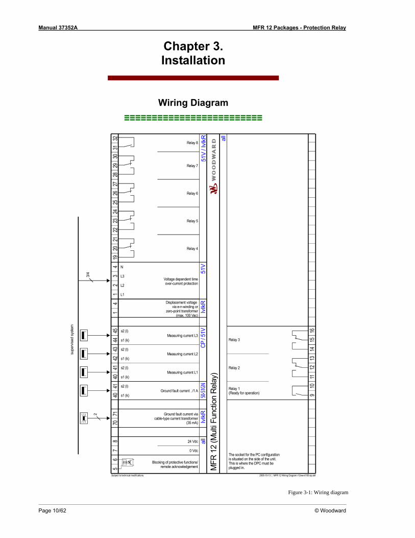
Figure 3-1: Wiring diagram
Manual 37352A MFR 12 Packages - Protection Relay
© Woodward Page 11/62
WARNING All technical data and ratings indicated in this chapter are not definite! Only the values indicated under Technical Data on page 52 are valid!
CAUTION A circuit breaker must be located near to the unit and in a position easily accessible to the operator. This must also bear a sign identifying it as an isolating switch for the unit.
NOTE Inductive devices connected to the system (such as operating current coils, undervoltage tripping units, or auxiliary/power contacts) must be connected to a suitable interference suppressor.
The following chart may be used to convert square millimeters [mm²] to AWG and vice versa:
AWG mm² AWG mm² AWG mm² AWG mm² AWG mm² AWG mm² 30 0.05 21 0.38 14 2.5 4 25 3/0 95 600MCM 300 28 0.08 20 0.5 12 4 2 35 4/0 120 750MCM 400 26 0.14 18 0.75 10 6 1 50 300MCM 150 1000MCM 500 24 0.25 17 1.0 8 10 1/0 55 350MCM 185 22 0.34 16 1.5 6 16 2/0 70 500MCM 240
Table 3-1: Conversion chart - wire size
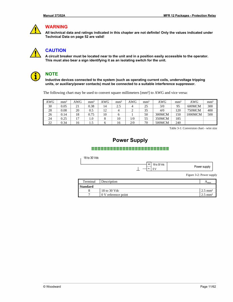
Power Supply ≡≡≡≡≡≡≡≡≡≡≡≡≡≡≡≡≡≡≡≡≡≡≡≡≡
18 to 30 Vdc
78
0 V18 to 30 Vdc
Power supply
Figure 3-2: Power supply
Terminal Description Amax Standard
8 18 to 30 Vdc 2.5 mm² 7 0 V reference point 2.5 mm²
Manual 37352A MFR 12 Packages - Protection Relay
Page 12/62 © Woodward
Measuring Inputs ≡≡≡≡≡≡≡≡≡≡≡≡≡≡≡≡≡≡≡≡≡≡≡≡≡
Current
WARNING Prior to disconnecting the current transformer connections or the connections of the transformer which are located at the unit, ensure that the transformer is short-circuited.
NOTE Grounding of the secondary of a current transformer must always be single-sided.
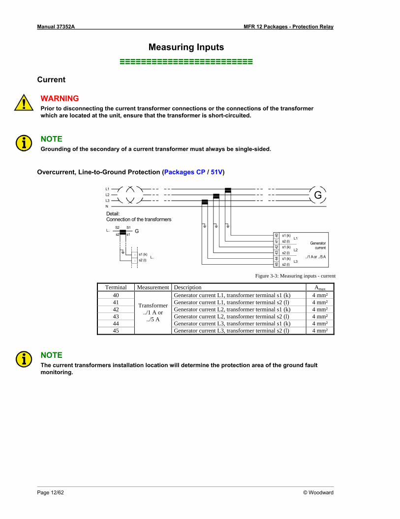
Overcurrent, Line-to-Ground Protection (Packages CP / 51V)
Detail:Connection of the transformers
Generatorcurrent
../1 A or ../5 A
L3L2L1
N
G
S2 S1
s2 (l)s1 (k)
s2L..
....
s1
L.. s1 (k)s2 (l)
s1 (k)s2 (l)
L2
s1 (k)s2 (l)
4243
4041
4445
L1
L3
G
Figure 3-3: Measuring inputs - current
Terminal Measurement Description Amax 40 Generator current L1, transformer terminal s1 (k) 4 mm² 41 Generator current L1, transformer terminal s2 (l) 4 mm² 42 Generator current L2, transformer terminal s1 (k) 4 mm² 43 Generator current L2, transformer terminal s2 (l) 4 mm² 44 Generator current L3, transformer terminal s1 (k) 4 mm² 45
Transformer ../1 A or
../5 A
Generator current L3, transformer terminal s2 (l) 4 mm²
NOTE The current transformers installation location will determine the protection area of the ground fault monitoring.
Manual 37352A MFR 12 Packages - Protection Relay
© Woodward Page 13/62
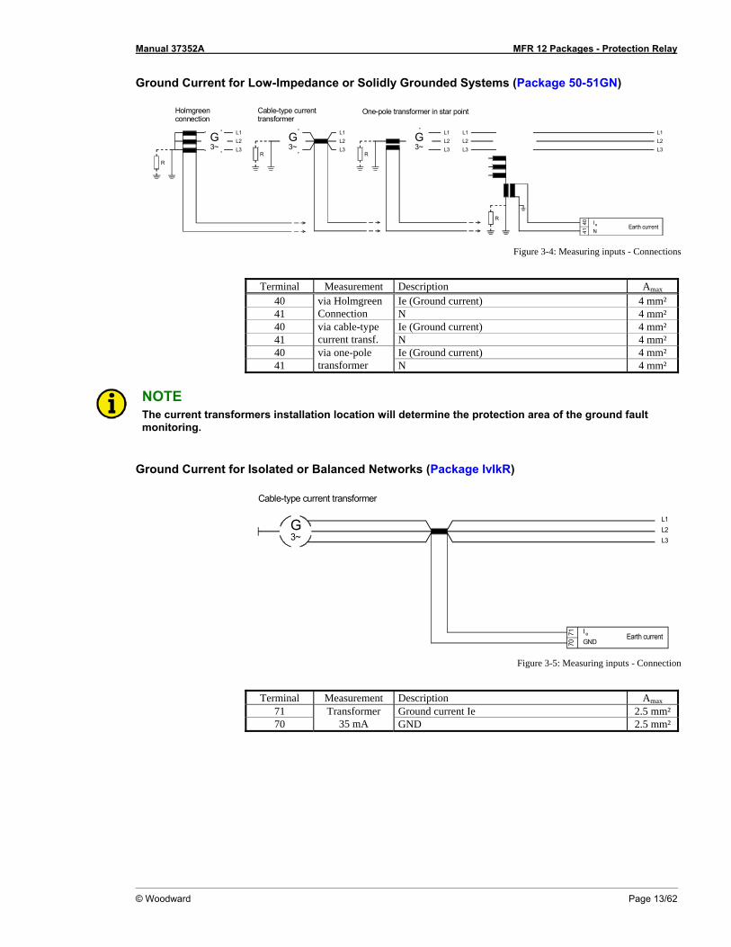
Ground Current for Low-Impedance or Solidly Grounded Systems (Package 50-51GN)
N
4041
L1L2L3
Earth currentI e
G3~
L2L3
L1G3~
L2L3
L1L2L3
L1
Holmgreenconnection
Cable-type currenttransformer
G3~
L2L3
L1
R R
R
One-pole transformer in star point
R
Figure 3-4: Measuring inputs - Connections
Terminal Measurement Description Amax
40 Ie (Ground current) 4 mm² 41
via Holmgreen Connection N 4 mm²
40 Ie (Ground current) 4 mm² 41
via cable-type current transf. N 4 mm²
40 Ie (Ground current) 4 mm² 41
via one-pole transformer N 4 mm²
NOTE The current transformers installation location will determine the protection area of the ground fault monitoring.
Ground Current for Isolated or Balanced Networks (Package IvIkR)
Cable-type current transformer
Earth current
L2L3
L1G3~
7071 I e
GND
Figure 3-5: Measuring inputs - Connection
Terminal Measurement Description Amax
71 Ground current Ie 2.5 mm² 70
Transformer 35 mA GND 2.5 mm²
Manual 37352A MFR 12 Packages - Protection Relay
Page 14/62 © Woodward
Voltage
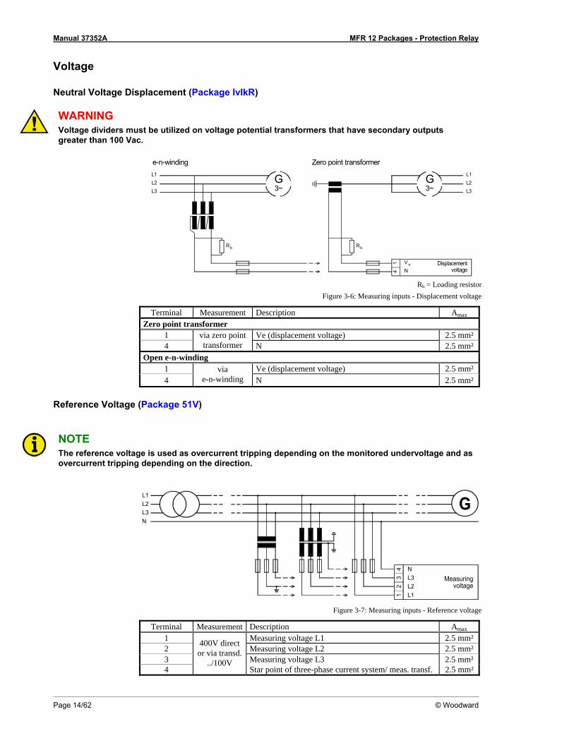
Neutral Voltage Displacement (Package IvIkR)
WARNING Voltage dividers must be utilized on voltage potential transformers that have secondary outputs greater than 100 Vac.
L2L3
L1L1 G3~
G3~
L2L3
NV e
Rb Rb
Displacementvoltage
14
e-n-winding Zero point transformer
Rb = Loading resistor
Figure 3-6: Measuring inputs - Displacement voltage
Terminal Measurement Description Amax Zero point transformer
1 Ve (displacement voltage) 2.5 mm² 4
via zero point transformer N 2.5 mm²
Open e-n-winding 1 Ve (displacement voltage) 2.5 mm² 4
via e-n-winding N 2.5 mm²
Reference Voltage (Package 51V)
NOTE The reference voltage is used as overcurrent tripping depending on the monitored undervoltage and as overcurrent tripping depending on the direction.
Measuringvoltage
L3L2L1
N
G
12
34
L3L2L1
N
Figure 3-7: Measuring inputs - Reference voltage
Terminal Measurement Description Amax 1 Measuring voltage L1 2.5 mm² 2 Measuring voltage L2 2.5 mm² 3 Measuring voltage L3 2.5 mm² 4
400V direct or via transd.
../100V Star point of three-phase current system/ meas. transf. 2.5 mm²
Manual 37352A MFR 12 Packages - Protection Relay
© Woodward Page 15/62
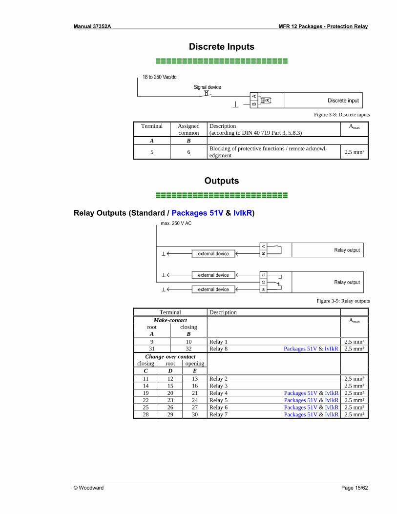
Discrete Inputs ≡≡≡≡≡≡≡≡≡≡≡≡≡≡≡≡≡≡≡≡≡≡≡≡≡
Signal device
Discrete input
AB
18 to 250 Vac/dc
Figure 3-8: Discrete inputs
Terminal Assigned common
Description (according to DIN 40 719 Part 3, 5.8.3)
Amax
A B
5 6 Blocking of protective functions / remote acknowl-edgement 2.5 mm²
Outputs ≡≡≡≡≡≡≡≡≡≡≡≡≡≡≡≡≡≡≡≡≡≡≡≡≡
Relay Outputs (Standard / Packages 51V & IvIkR)
AB
Relay output
Relay outputexternal device
external device
external device
CD
E
max. 250 V AC
Figure 3-9: Relay outputs
Terminal Description Make-contact Amax
root closing A B
9 10 Relay 1 2.5 mm²
31 32 Relay 8 Packages 51V & IvIkR 2.5 mm² Change-over contact
closing root opening C D E
11 12 13 Relay 2 2.5 mm² 14 15 16 Relay 3 2.5 mm² 19 20 21 Relay 4 Packages 51V & IvIkR 2.5 mm² 22 23 24 Relay 5 Packages 51V & IvIkR 2.5 mm² 25 26 27 Relay 6 Packages 51V & IvIkR 2.5 mm² 28 29 30 Relay 7 Packages 51V & IvIkR 2.5 mm²
Manual 37352A MFR 12 Packages - Protection Relay
Page 16/62 © Woodward
Interface ≡≡≡≡≡≡≡≡≡≡≡≡≡≡≡≡≡≡≡≡≡≡≡≡≡
DPC - Direct Configuration Interface
NOTE Configuration with the direct configuration cable DPC (P/N 5417-557) is possible. A laptop/PC, the DPC cable, the program LeoPC1 version 3.1.1 or higher (included on CD Rom with unit), and the proper con-figuration files are required. Please consult the online help installed when the program is installed for a description of the LeoPC1 program and its setup.
WARNING Only the DPC cable may be connected to the DPC interface. If other devices or lines are connected, the unit may be destroyed. Especially the connection of live lines (like phone lines) will destroy the unit.
CAUTION The connection cable delivered with the DPC must be used between DPC and the unit to ensure proper functionality of the unit. An extension or utilization of different cable types for the connection between the unit and DPC may result a malfunction of the unit. This may possibly result in damage to compo-nents of the system. If an extension of the data connection line is required, only the serial cable (RS-232) between DPC and laptop/PC may be extended. It is recommended to use an industry standard ca-ble for this.
NOTE If the parameter "Direct config." is enabled on the control, communication via the CAN bus interface on terminals X1/X5 is disabled. If the control unit detects that the engine is running (ignition speed exceeded), the direct configuration port is disabled.
Manual 37352A MFR 12 Packages - Protection Relay
© Woodward Page 17/62
Chapter 4. Functional Description
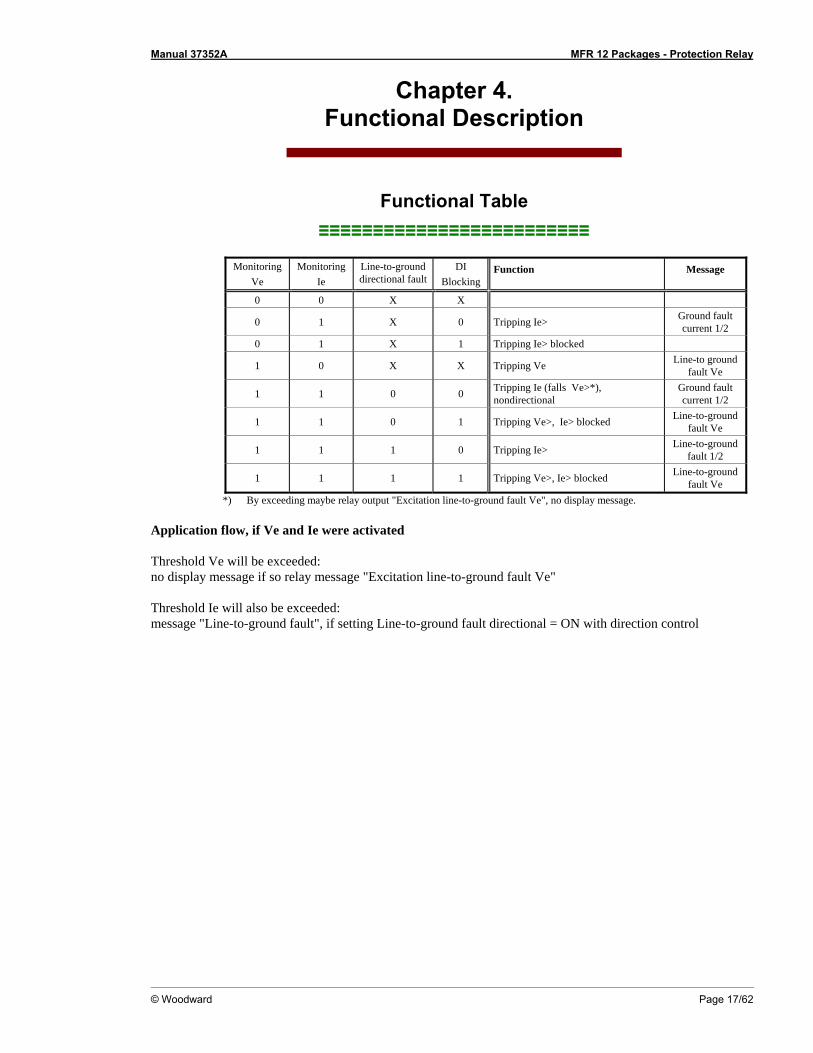
Functional Table ≡≡≡≡≡≡≡≡≡≡≡≡≡≡≡≡≡≡≡≡≡≡≡≡≡
Monitoring
Ve Monitoring
Ie Line-to-ground directional fault
DI Blocking
Function Message
0 0 X X
0 1 X 0 Tripping Ie> Ground fault current 1/2
0 1 X 1 Tripping Ie> blocked
1 0 X X Tripping Ve Line-to ground fault Ve
1 1 0 0 Tripping Ie (falls Ve>*), nondirectional
Ground fault current 1/2
1 1 0 1 Tripping Ve>, Ie> blocked Line-to-ground fault Ve
1 1 1 0 Tripping Ie> Line-to-ground fault 1/2
1 1 1 1 Tripping Ve>, Ie> blocked Line-to-ground fault Ve
*) By exceeding maybe relay output "Excitation line-to-ground fault Ve", no display message. Application flow, if Ve and Ie were activated Threshold Ve will be exceeded: no display message if so relay message "Excitation line-to-ground fault Ve" Threshold Ie will also be exceeded: message "Line-to-ground fault", if setting Line-to-ground fault directional = ON with direction control
Manual 37352A MFR 12 Packages - Protection Relay
Page 18/62 © Woodward
Control Inputs ≡≡≡≡≡≡≡≡≡≡≡≡≡≡≡≡≡≡≡≡≡≡≡≡≡
Blocking of protective
functions / Remote ac-knowledgement
Terminal 5/6
Energizing this discrete input disables various protective functions. This functionality may be desired if the control is used for generator protection. This keeps the control from recognizing fault conditions (i.e. undervoltage, underfrequency) when the generator is not operating. If blocking of these protective functions is not required, the discrete input should not be con-nected to any potential source.
The following protective function cannot be blocked via this discrete in-put: • Non-directional ground fault monitoring via displacement voltage
External acknowledgement
of the relays via the discrete input "Blocking of protec-tive functions / remote ac-
knowledgement"
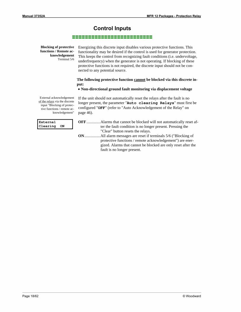
External Clearing ON
If the unit should not automatically reset the relays after the fault is no longer present, the parameter "Auto clearing Relays" must first be configured "OFF" (refer to "Auto Acknowledgement of the Relay" on page 46). OFF ..............Alarms that cannot be blocked will not automatically reset af-
ter the fault condition is no longer present. Pressing the "Clear" button resets the relays.
ON ................All alarm messages are reset if terminals 5/6 ("Blocking of protective functions / remote acknowledgement") are ener-gized. Alarms that cannot be blocked are only reset after the fault is no longer present.
Manual 37352A MFR 12 Packages - Protection Relay
© Woodward Page 19/62
Control Outputs ≡≡≡≡≡≡≡≡≡≡≡≡≡≡≡≡≡≡≡≡≡≡≡≡≡
NOTE A description of the relay manager may be found in Changing the Relay Assignment (Standard / Pack-ages 51V & IvIkR) starting on page 48.
Relay 1 Terminal 9/10
Output relay (type: make contact, N.O.) The "relay manager" controls this relay.
NOTE The "ready for operation" function is always assigned to relay 1. However, other protective functions may also be assigned to relay 1 additionally. Relay 1 is always configured as Normally Closed (break contact) and will de-energize if the unit is not ready for operation.
Relay 2, 3 Terminal 11 through 16
Output relay (type: change-over contact) The "relay manager" controls these relays.
Packages 51V & IvIkR
Relay 4 to 7 Terminal 19 through 30
Output relay (type: change-over contact) The "relay manager" controls these relays.
Packages 51V & IvIkR
Relay 8 Terminal 31/32
Output relay (type: make contact, N.O.) The "relay manager" controls this relay.
Manual 37352A MFR 12 Packages - Protection Relay
Page 20/62 © Woodward
Alarms ≡≡≡≡≡≡≡≡≡≡≡≡≡≡≡≡≡≡≡≡≡≡≡≡≡
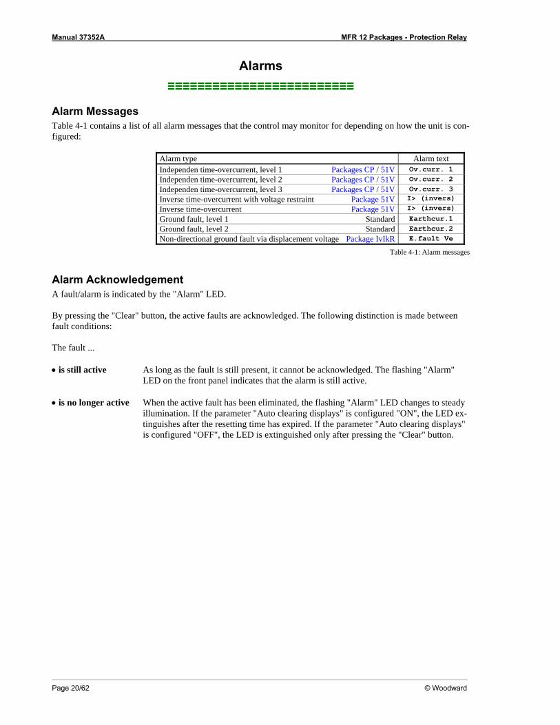
Alarm Messages Table 4-1 contains a list of all alarm messages that the control may monitor for depending on how the unit is con-figured:
Alarm type Alarm text Independen time-overcurrent, level 1 Packages CP / 51V Ov.curr. 1 Independen time-overcurrent, level 2 Packages CP / 51V Ov.curr. 2 Independen time-overcurrent, level 3 Packages CP / 51V Ov.curr. 3 Inverse time-overcurrent with voltage restraint Package 51V I> (invers)
Inverse time-overcurrent Package 51V I> (invers)
Ground fault, level 1 Standard Earthcur.1 Ground fault, level 2 Standard Earthcur.2 Non-directional ground fault via displacement voltage Package IvIkR E.fault Ve
Table 4-1: Alarm messages
Alarm Acknowledgement A fault/alarm is indicated by the "Alarm" LED. By pressing the "Clear" button, the active faults are acknowledged. The following distinction is made between fault conditions: The fault ... • is still active As long as the fault is still present, it cannot be acknowledged. The flashing "Alarm"
LED on the front panel indicates that the alarm is still active. • is no longer active When the active fault has been eliminated, the flashing "Alarm" LED changes to steady
illumination. If the parameter "Auto clearing displays" is configured "ON", the LED ex-tinguishes after the resetting time has expired. If the parameter "Auto clearing displays" is configured "OFF", the LED is extinguished only after pressing the "Clear" button.
Manual 37352A MFR 12 Packages - Protection Relay
© Woodward Page 21/62
Chapter 5. Display and Operating Elements
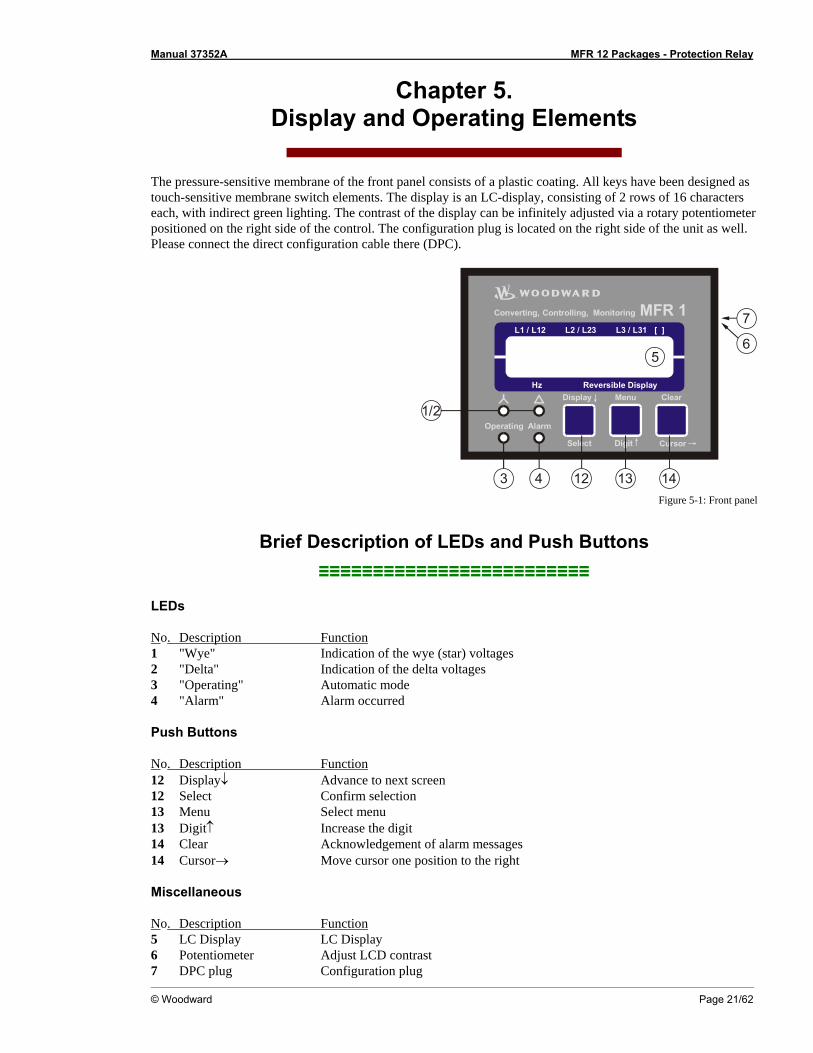
The pressure-sensitive membrane of the front panel consists of a plastic coating. All keys have been designed as touch-sensitive membrane switch elements. The display is an LC-display, consisting of 2 rows of 16 characters each, with indirect green lighting. The contrast of the display can be infinitely adjusted via a rotary potentiometer positioned on the right side of the control. The configuration plug is located on the right side of the unit as well. Please connect the direct configuration cable there (DPC).
MFR 1[ ]L2 / L23L1 / L12 L3 / L31
Hz Reversible Display
Operating
Display Menu
Digit Cursor
Clear
Alarm
Converting, Controlling, Monitoring
Select
14
1/2
131243
5
7
6
Figure 5-1: Front panel
Brief Description of LEDs and Push Buttons ≡≡≡≡≡≡≡≡≡≡≡≡≡≡≡≡≡≡≡≡≡≡≡≡≡
LEDs
No. Description Function 1 "Wye" Indication of the wye (star) voltages 2 "Delta" Indication of the delta voltages 3 "Operating" Automatic mode 4 "Alarm" Alarm occurred
Push Buttons
No. Description Function 12 Display↓ Advance to next screen 12 Select Confirm selection 13 Menu Select menu 13 Digit↑ Increase the digit 14 Clear Acknowledgement of alarm messages 14 Cursor→ Move cursor one position to the right
Miscellaneous
No. Description Function 5 LC Display LC Display 6 Potentiometer Adjust LCD contrast 7 DPC plug Configuration plug
Manual 37352A MFR 12 Packages - Protection Relay
Page 22/62 © Woodward
LEDs ≡≡≡≡≡≡≡≡≡≡≡≡≡≡≡≡≡≡≡≡≡≡≡≡≡
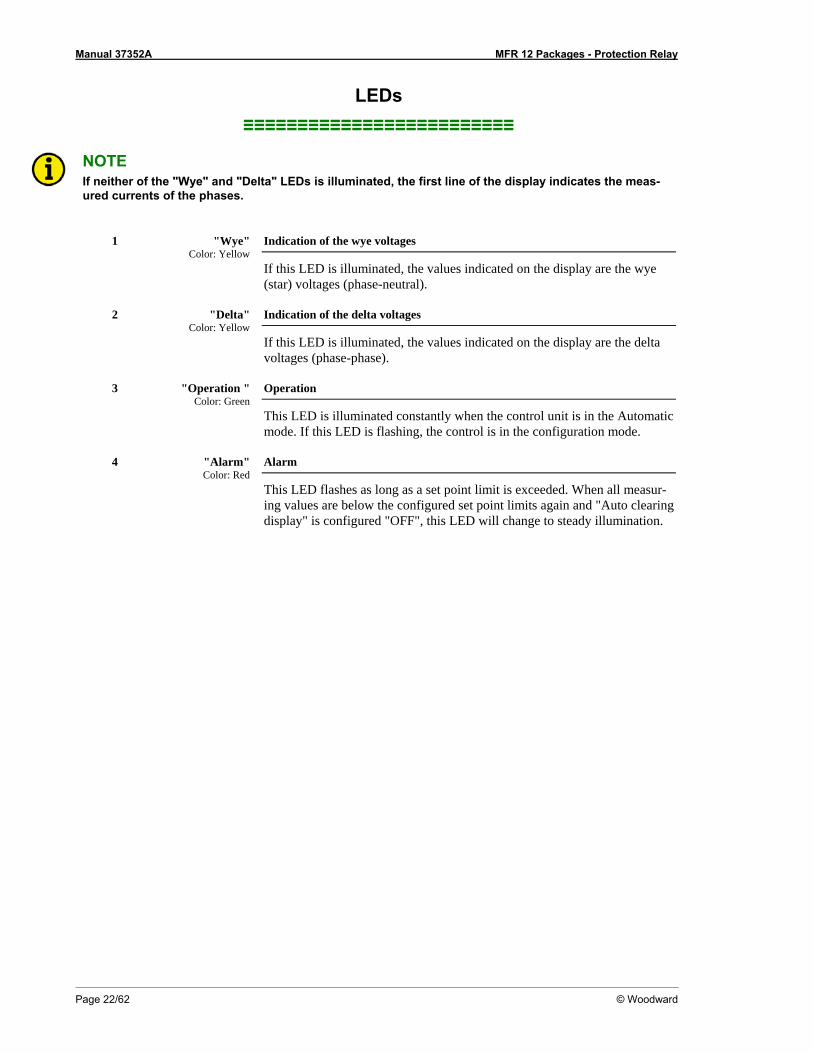
NOTE If neither of the "Wye" and "Delta" LEDs is illuminated, the first line of the display indicates the meas-ured currents of the phases.
1 "Wye" Color: Yellow
Indication of the wye voltages
If this LED is illuminated, the values indicated on the display are the wye (star) voltages (phase-neutral).
2 "Delta"
Color: Yellow Indication of the delta voltages
If this LED is illuminated, the values indicated on the display are the delta voltages (phase-phase).
3 "Operation "
Color: Green Operation
This LED is illuminated constantly when the control unit is in the Automatic mode. If this LED is flashing, the control is in the configuration mode.
4 "Alarm"
Color: Red Alarm
This LED flashes as long as a set point limit is exceeded. When all measur-ing values are below the configured set point limits again and "Auto clearing display" is configured "OFF", this LED will change to steady illumination.
Manual 37352A MFR 12 Packages - Protection Relay
© Woodward Page 23/62
Push Buttons ≡≡≡≡≡≡≡≡≡≡≡≡≡≡≡≡≡≡≡≡≡≡≡≡≡
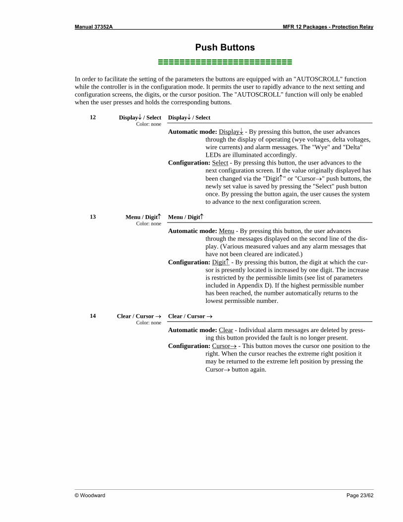
In order to facilitate the setting of the parameters the buttons are equipped with an "AUTOSCROLL" function while the controller is in the configuration mode. It permits the user to rapidly advance to the next setting and configuration screens, the digits, or the cursor position. The "AUTOSCROLL" function will only be enabled when the user presses and holds the corresponding buttons.
12 Display↓ / Select Color: none
Display↓ / Select
Automatic mode: Display↓ - By pressing this button, the user advances through the display of operating (wye voltages, delta voltages, wire currents) and alarm messages. The "Wye" and "Delta" LEDs are illuminated accordingly.
Configuration: Select - By pressing this button, the user advances to the next configuration screen. If the value originally displayed has been changed via the "Digit↑" or "Cursor→" push buttons, the newly set value is saved by pressing the "Select" push button once. By pressing the button again, the user causes the system to advance to the next configuration screen.
13 Menu / Digit↑
Color: none Menu / Digit↑
Automatic mode: Menu - By pressing this button, the user advances through the messages displayed on the second line of the dis-play. (Various measured values and any alarm messages that have not been cleared are indicated.)
Configuration: Digit↑ - By pressing this button, the digit at which the cur-sor is presently located is increased by one digit. The increase is restricted by the permissible limits (see list of parameters included in Appendix D). If the highest permissible number has been reached, the number automatically returns to the lowest permissible number.
14 Clear / Cursor →
Color: none Clear / Cursor →
Automatic mode: Clear - Individual alarm messages are deleted by press-ing this button provided the fault is no longer present.
Configuration: Cursor→ - This button moves the cursor one position to the right. When the cursor reaches the extreme right position it may be returned to the extreme left position by pressing the Cursor→ button again.
Manual 37352A MFR 12 Packages - Protection Relay
Page 24/62 © Woodward
LC Display ≡≡≡≡≡≡≡≡≡≡≡≡≡≡≡≡≡≡≡≡≡≡≡≡≡
5 LC Display LC display
Performance values can be monitored from the two-line display, provided that the control is in automatic mode. In configuration mode, the individual parameters are displayed.
Display in Automatic Mode (First Line of the Display: Measured Values)
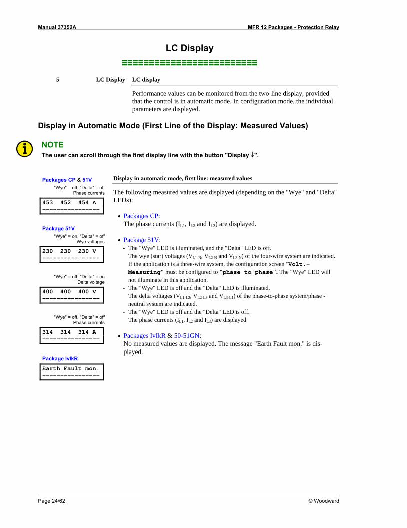
NOTE The user can scroll through the first display line with the button "Display ↓".
Packages CP & 51V "Wye" = off, "Delta" = off
Phase currents
453 452 454 A ----------------
Package 51V "Wye" = on, "Delta" = off
Wye voltages
230 230 230 V ----------------
"Wye" = off, "Delta" = on Delta voltage
400 400 400 V ----------------
"Wye" = off, "Delta" = off Phase currents
314 314 314 A ----------------
Package IvIkR
Earth Fault mon. ----------------
Display in automatic mode, first line: measured values
The following measured values are displayed (depending on the "Wye" and "Delta" LEDs):
• Packages CP:
The phase currents (IL1, IL2 and IL3) are displayed. • Package 51V:
- The "Wye" LED is illuminated, and the "Delta" LED is off. The wye (star) voltages (VL1-N, VL2-N and VL3-N) of the four-wire system are indicated. If the application is a three-wire system, the configuration screen "Volt.-Measuring" must be configured to "phase to phase". The "Wye" LED will not illuminate in this application.
- The "Wye" LED is off and the "Delta" LED is illuminated. The delta voltages (VL1-L2, VL2-L3 and VL3-L1) of the phase-to-phase system/phase -neutral system are indicated.
- The "Wye" LED is off and the "Delta" LED is off. The phase currents (IL1, IL2 and IL3) are displayed
• Packages IvIkR & 50-51GN:
No measured values are displayed. The message "Earth Fault mon." is dis-played.
Manual 37352A MFR 12 Packages - Protection Relay
© Woodward Page 25/62
Display in Automatic Mode (Second Line of the Display: Measured Values)
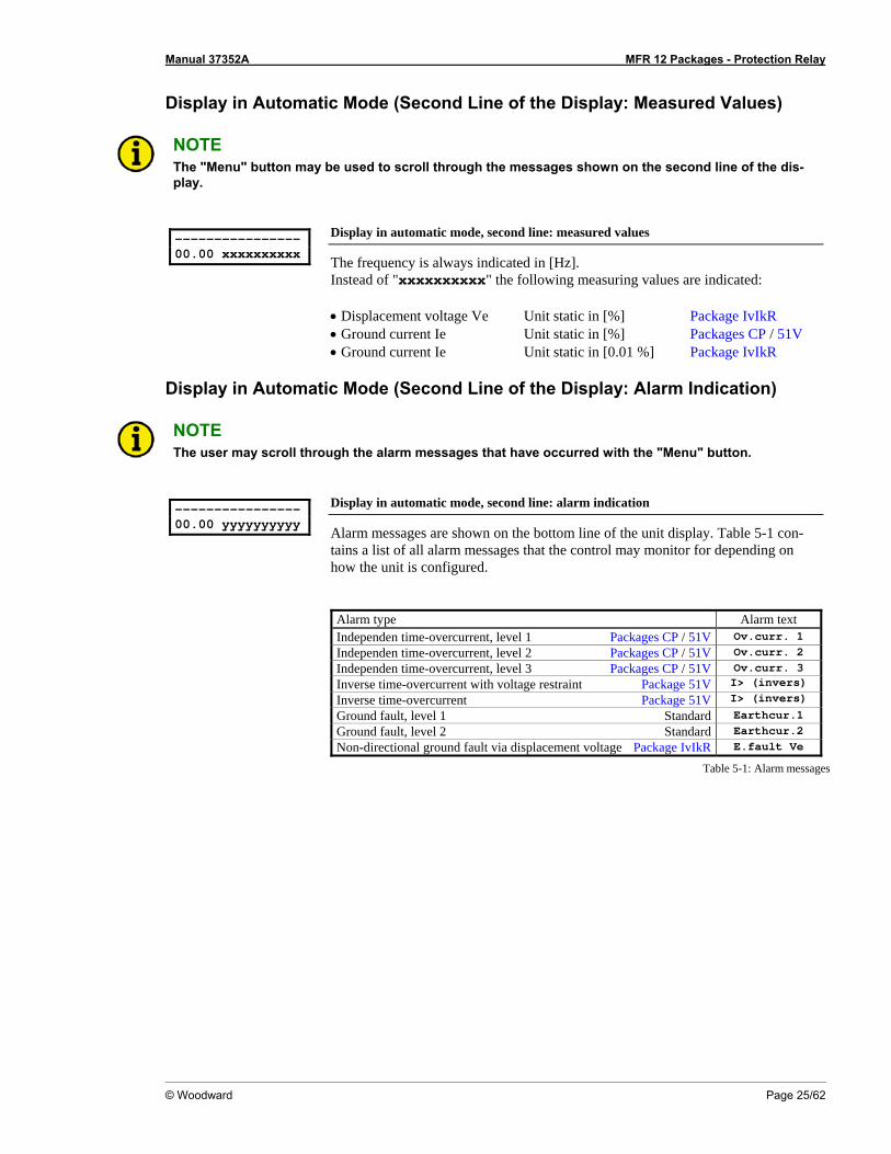
NOTE The "Menu" button may be used to scroll through the messages shown on the second line of the dis-play.
---------------- 00.00 xxxxxxxxxx
Display in automatic mode, second line: measured values
The frequency is always indicated in [Hz]. Instead of "xxxxxxxxxx" the following measuring values are indicated: • Displacement voltage Ve Unit static in [%] Package IvIkR • Ground current Ie Unit static in [%] Packages CP / 51V • Ground current Ie Unit static in [0.01 %] Package IvIkR
Display in Automatic Mode (Second Line of the Display: Alarm Indication)
NOTE The user may scroll through the alarm messages that have occurred with the "Menu" button.
---------------- 00.00 yyyyyyyyyy
Display in automatic mode, second line: alarm indication
Alarm messages are shown on the bottom line of the unit display. Table 5-1 con-tains a list of all alarm messages that the control may monitor for depending on how the unit is configured.
Alarm type Alarm text Independen time-overcurrent, level 1 Packages CP / 51V Ov.curr. 1 Independen time-overcurrent, level 2 Packages CP / 51V Ov.curr. 2 Independen time-overcurrent, level 3 Packages CP / 51V Ov.curr. 3 Inverse time-overcurrent with voltage restraint Package 51V I> (invers)
Inverse time-overcurrent Package 51V I> (invers)
Ground fault, level 1 Standard Earthcur.1 Ground fault, level 2 Standard Earthcur.2 Non-directional ground fault via displacement voltage Package IvIkR E.fault Ve
Table 5-1: Alarm messages
Manual 37352A MFR 12 Packages - Protection Relay
Page 26/62 © Woodward
Chapter 6. Configuration
Configuration can be performed via the front panel push buttons and the front panel LC display or using a PC and the PC program LeoPC1 via the serial interface. If direct configuration via a PC is selected, the following baud rate is to be used: • Configuration via direct configuration plug = 9,600 Baud (8 Bit, no parity, 1 stop bit)
CAUTION Please note that configuration only should be done while the system is not in operation.
NOTE A list of all parameters may be found in Appendix D of this manual.
You can advance through the individual parameter screens if you are in configuration mode (simultaneously pressing of "Digit↑" and "Cursor→" push buttons permits access to the configuration mode) by using the "Se-lect" button. If you press and hold the "Select" push button, the scroll function will be activated, allowing for the parameter screens to be advanced through more rapidly. The control unit will permit the operator to reverse up to four previous screens (exception: it is not possible to reverse from the first parameter to the last parameter). To perform the reverse function through the parameter screens, the "Select" and "Cursor→" push buttons must be pressed and released simultaneously. The control unit will revert to automatic mode if an entry isn’t performed, a change made, or any other action performed for 120 seconds. Adjust Settings: SELECT (ANWAHL)
Configuration mode Button "Select"
After the configuration mode is enabled, the subsequent screens can be viewed and modified within the preset limits. Please note, that by depressing the "Select" but-ton, the following screens are advanced by one screen each. If a parameter is con-figured "OFF", the related screens are not displayed or monitored by the control. Pressing the "Select" button will advance the displayed screen to the next parame-ter.
Manual 37352A MFR 12 Packages - Protection Relay
© Woodward Page 27/62
Basic Data ≡≡≡≡≡≡≡≡≡≡≡≡≡≡≡≡≡≡≡≡≡≡≡≡≡
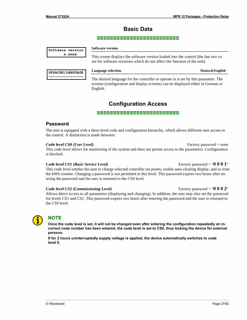
Software version x.xxxx
Software version
This screen displays the software version loaded into the control (the last two xx are for software revisions which do not affect the function of the unit).
SPRACHE/LANGUAGE ----------------
Language selection Deutsch/English
The desired language for the controller to operate in is set by this parameter. The screens (configuration and display screens) can be displayed either in German or English.
Configuration Access ≡≡≡≡≡≡≡≡≡≡≡≡≡≡≡≡≡≡≡≡≡≡≡≡≡
Password The unit is equipped with a three-level code and configuration hierarchy, which allows different user access to the control. A distinction is made between: Code level CS0 (User Level) Factory password = none This code level allows for monitoring of the system and does not permit access to the parameters. Configuration is blocked. Code level CS1 (Basic Service Level) Factory password = "0 0 0 1" This code level entitles the user to change selected controller set points, enable auto-clearing display, and to reset the kWh counter. Changing a password is not permitted at this level. This password expires two hours after en-tering the password and the user is returned to the CS0 level. Code level CS2 (Commissioning Level) Factory password = "0 0 0 2" Allows direct access to all parameters (displaying and changing). In addition, the user may also set the password for levels CS1 and CS2. This password expires two hours after entering the password and the user is returned to the CS0 level.
NOTE Once the code level is set, it will not be changed even after entering the configuration repeatedly an in-correct code number has been entered, the code level is set to CS0, thus locking the device for external persons. If for 2 hours uninterruptedly supply voltage is applied, the device automatically switches to code level 0.
Manual 37352A MFR 12 Packages - Protection Relay
Page 28/62 © Woodward
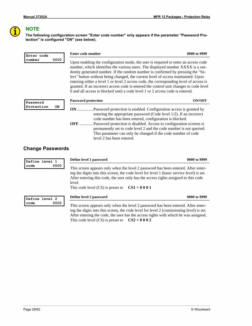
NOTE The following configuration screen "Enter code number" only appears if the parameter "Password Pro-tection" is configured "ON" (see below).
Enter code number 0000
Enter code number 0000 to 9999
Upon enabling the configuration mode, the user is required to enter an access code number, which identifies the various users. The displayed number XXXX is a ran-domly generated number. If the random number is confirmed by pressing the "Se-lect" button without being changed, the current level of access maintained. Upon entering either a level 1 or level 2 access code, the corresponding level of access is granted. If an incorrect access code is entered the control unit changes to code level 0 and all access is blocked until a code level 1 or 2 access code is entered.
Password Protection ON
Password protection ON/OFF
ON ................Password protection is enabled. Configuration access is granted by entering the appropriate password (Code level 1/2). If an incorrect code number has been entered, configuration is blocked.
OFF ..............Password protection is disabled. Access to configuration screens is permanently set to code level 2 and the code number is not queried. This parameter can only be changed if the code number of code level 2 has been entered.
Change Passwords Define level 1 code 0000
Define level 1 password 0000 to 9999
This screen appears only when the level 2 password has been entered. After enter-ing the digits into this screen, the code level for level 1 (basic service level) is set. After entering this code, the user only has the access rights assigned to this code level. This code level (CS) is preset to CS1 = 0 0 0 1
Define level 2 code 0000
Define level 2 password 0000 to 9999
This screen appears only when the level 2 password has been entered. After enter-ing the digits into this screen, the code level for level 2 (comissioning level) is set. After entering the code, the user has the access rights with which he was assigned. This code level (CS) is preset to CS2 = 0 0 0 2
Manual 37352A MFR 12 Packages - Protection Relay
© Woodward Page 29/62
Direct Configuration ≡≡≡≡≡≡≡≡≡≡≡≡≡≡≡≡≡≡≡≡≡≡≡≡≡
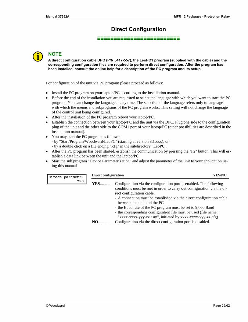
NOTE A direct configuration cable DPC (P/N 5417-557), the LeoPC1 program (supplied with the cable) and the corresponding configuration files are required to perform direct configuration. After the program has been installed, consult the online help for a description of the PC program and its setup.
For configuration of the unit via PC program please proceed as follows: • Install the PC program on your laptop/PC according to the installation manual. • Before the end of the installation you are requested to select the language with which you want to start the PC
program. You can change the language at any time. The selection of the language refers only to language with which the menus and subprograms of the PC program works. This setting will not change the language of the control unit being configured.
• After the installation of the PC program reboot your laptop/PC. • Establish the connection between your laptop/PC and the unit via the DPC. Plug one side to the configuration
plug of the unit and the other side to the COM1 port of your laptop/PC (other possibilities are described in the installation manual).
• You may start the PC program as follows: - by "Start/Program/Woodward/LeoPC" (starting at version 3.1.xxx), or - by a double click on a file ending ".cfg" in the subdirectory "LeoPC".
• After the PC program has been started, establish the communication by pressing the "F2" button. This will es-tablish a data link between the unit and the laptop/PC.
• Start the sub program "Device Parameterization" and adjust the parameter of the unit to your application us-ing this manual.
Direct parametr. YES
Direct configuration YES/NO
YES.............. Configuration via the configuration port is enabled. The following conditions must be met in order to carry out configuration via the di-rect configuration cable: - A connection must be established via the direct configuration cable
between the unit and the PC - the Baud rate of the PC program must be set to 9,600 Baud - the corresponding configuration file must be used (file name:
"xxxx-xxxx-yyy-zz.asm", initiated by xxxx-xxxx-yyy-zz.cfg) NO................ Configuration via the direct configuration port is disabled.
Manual 37352A MFR 12 Packages - Protection Relay
Page 30/62 © Woodward
Measurement ≡≡≡≡≡≡≡≡≡≡≡≡≡≡≡≡≡≡≡≡≡≡≡≡≡
WARNING The following values must be entered correctly for the generator to be monitored. Failure to do so may lead to incorrect measuring of parameters resulting in damage to or destruction of the generator or switchgear and/or personal injury or death.
Voltage Measurement (Package 51V) Volt.-Measuring ----------------
This screen only affects the dis-played values. The protective functions are defined below.
Voltage measuring Phase to phase / Phase neutral
This parameter determines how the voltage is to be measured.
Potential Transformer Configuration (Package 51V) Volt.transformer secondary 000V
Potential transformer secondary 50 to 125 V
The potential transformer secondary voltage is set here in V. This parameter is util-ized to calculate the system voltage in the display. For voltages measured without a potential transformer, secondary and primary voltage must be configured the same.
Volt.transformer primary 00.000kV
Potential transformer primary 00.100 to 65.000 kV
The potential transformer primary voltage is set here in kV. This entry is used to show the system voltage in the display.
Example: If a voltage of 110 V is measured without a potential transformer, the secondary transformer voltage
must be configured to 110V and the primary transformer voltage must be configured to 00.110V.
Current Transformer Configuration Current transf. 0000/0
Current transformer 1 to 9,999/{x} A
The input of the current transformer ratio is necessary for the indication and control of the actual monitored value. The current transformers ratio should be selected so at least 60% of the secondary current rating can be measured when the monitored system is at 100% of operating capacity (i.e. at 100% of system capacity a 5A CT should output 3A). If the current transformers are sized so that the percentage of the output is lower, the loss of resolution may cause inaccuracies in the monitoring and control functions and may affect the functionality of the control. The control may be ordered with either ../1 A or ../5 A current transformer inputs. The CT inputs will dictate how this parameter is displayed on the control. Informa-tion about the current transformers inputs may be found on the unit data plate. {x} = 1..........MFR12x1B/xxx = Current transformer with ../1 A rated current {x} = 5..........MFR12x5B/xxx = Current transformer with ../5 A rated current
Manual 37352A MFR 12 Packages - Protection Relay
© Woodward Page 31/62
Rated Values Rated voltage 000V
Rated voltage 5 to 125 V
This parameter defines the system rated voltage. Rated current 0000A
Rated current 10 to 9,999 A
The system current rating is defined in this parameter. Percentage values in the pro-tective functions refer to this parameter.
Rated power 00000kW
Rated power 5 to 32,000 kW
The rated power is configured here. The exact value of the rated power is abso-lutely vital. Many measurement, control, and monitoring functions refer to this value.
Power Measurement Power measuring ----------------
Power measurement one-phase / three-phase
Power measurement may be configured as single-phase or three-phase. If "single-phase power measurement" is set, the current and the voltage in phase L1 are used for power measurement. If "three-phase power measurement" is set, all three-phase currents and the relevant voltages are used for power measurement. • one-phase power measurement: P = √3 × VL12 × IL1 × P.F (cosϕ) • three-phase power measurement: P = VL1N × IL1 × P.F (cosϕ)+ VL2N × IL2 × P.F (cosϕ)+ VL3N × IL3 × P.F (cosϕ)
Manual 37352A MFR 12 Packages - Protection Relay
Page 32/62 © Woodward
Protection ≡≡≡≡≡≡≡≡≡≡≡≡≡≡≡≡≡≡≡≡≡≡≡≡≡
Independent Time-Overcurrent Monitoring (Packages CP / 51V)
NOTE All percentage values of the current refer to the rated current (page 30).
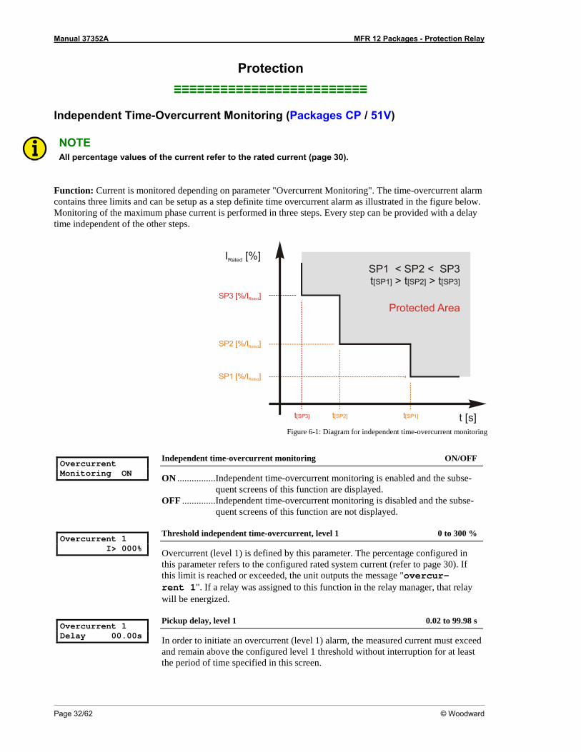
Function: Current is monitored depending on parameter "Overcurrent Monitoring". The time-overcurrent alarm contains three limits and can be setup as a step definite time overcurrent alarm as illustrated in the figure below. Monitoring of the maximum phase current is performed in three steps. Every step can be provided with a delay time independent of the other steps.
t [s]
SP3 [%/I ]Rated
SP2 [%/I ]Rated
SP1 [%/I ]Rated
IRated [%]
Protected Area
SP1 < SP2 < SP3t > t > t[SP1] [SP2] [SP3]
t[SP3] t[SP2] t[SP1]
Figure 6-1: Diagram for independent time-overcurrent monitoring
Overcurrent Monitoring ON
Independent time-overcurrent monitoring ON/OFF
ON ................Independent time-overcurrent monitoring is enabled and the subse-quent screens of this function are displayed.
OFF ..............Independent time-overcurrent monitoring is disabled and the subse-quent screens of this function are not displayed.
Overcurrent 1 I> 000%
Threshold independent time-overcurrent, level 1 0 to 300 %
Overcurrent (level 1) is defined by this parameter. The percentage configured in this parameter refers to the configured rated system current (refer to page 30). If this limit is reached or exceeded, the unit outputs the message "overcur-rent 1". If a relay was assigned to this function in the relay manager, that relay will be energized.
Overcurrent 1 Delay 00.00s
Pickup delay, level 1 0.02 to 99.98 s
In order to initiate an overcurrent (level 1) alarm, the measured current must exceed and remain above the configured level 1 threshold without interruption for at least the period of time specified in this screen.
Manual 37352A MFR 12 Packages - Protection Relay
© Woodward Page 33/62
Overcurrent 2 I> 100%
Threshold independent time-overcurrent, level 2 0 to 300 %
Overcurrent (level 2) is defined by this parameter. The percentage configured in this parameter refers to the configured rated system current (refer to page 30). If this limit is reached or exceeded, the unit outputs the message "overcur-rent 2". If a relay was assigned to this function in the relay manager, that relay will be energized.
Overcurrent 2 Delay 00.00s
Pickup delay, level 2 0.02 to 99.98 s
In order to initiate an overcurrent (level 2) alarm, the measured current must exceed and remain above the configured level 2 threshold without interruption for at least the period of time specified in this screen.
Overcurrent 3 I> 100%
Threshold independent time-overcurrent, level 3 0 to 300 %
Overcurrent (level 3) is defined by this parameter. The percentage configured in this parameter refers to the configured rated system current (refer to page 30). If this limit is reached or exceeded, the unit outputs the message "overcur-rent 3". If a relay was assigned to this function in the relay manager, that relay will be energized.
Overcurrent 3 Delay 00.00s
Pickup delay, level 3 0.02 to 99.98 s
In order to initiate an overcurrent (level 3) alarm, the measured current must exceed and remain above the configured level 3 threshold without interruption for at least the period of time specified in this screen.
Overcurrent Hysteresis 000%
Hysteresis for the independent time-overcurrent monitoring, levels 1, 2 + 3 1 to 300 %
In order to prevent system fluctuations from continually initiating overcurrent alarms (levels 1, 2 + 3), a lower release point is defined here. If the control moni-tors the current above the permissible limit, the current must drop below that threshold and the current level defined here for the fault condition to be recognized as no longer existing. Example: If a 1000A system has an overcurrent limit 1 of 110% (1100A) and a hysteresis of 105% (1050A), the monitored current for an overcurrent alarm must drop below 1050A to reset the alarm.

Manual 37352A MFR 12 Packages - Protection Relay
Page 34/62 © Woodward
Inverse Time-Overcurrent Monitoring (Package 51V)
NOTE All percentage indications of the current refer to the rated current (see page 30).
NOTE This monitoring function is only available if Inverse time-overcurrent with voltage restraint is disabled.
Function: Monitoring of overcurrents including inversely proportional time dependent tripping characteristic. The selected trip curve defines the tripping time according to the measured current. The tripping time will be de-creased according to a defined curve the higher the measured current is. According to IEC 255 three different characteristics are available. Normal inverse: ][*
1)/(14.0
02.0st
IIt p
P −=
Very inverse: ][*
1)/(5.13 st
IIt p
P −=
Extremely inverse: ][*
1)/(80
2 stII
t pP −
=
Formula definitions: t: tripping time tp time set point value I fault current / monitored current Ip current set point value If t is greater than 162 s the system trips at 162 s. If t is lower than tmin the tripping time is tmin. The reaction time for tmin depends on the time it takes to monitor the fault and the operating time of the relays. tmin is at least 20 ms. Please consider during configuration: for Istart: Istart > In and Istart > Ip for Ip the smaller Ip is, the steeper is the slope of the tripping curve
Manual 37352A MFR 12 Packages - Protection Relay
© Woodward Page 35/62
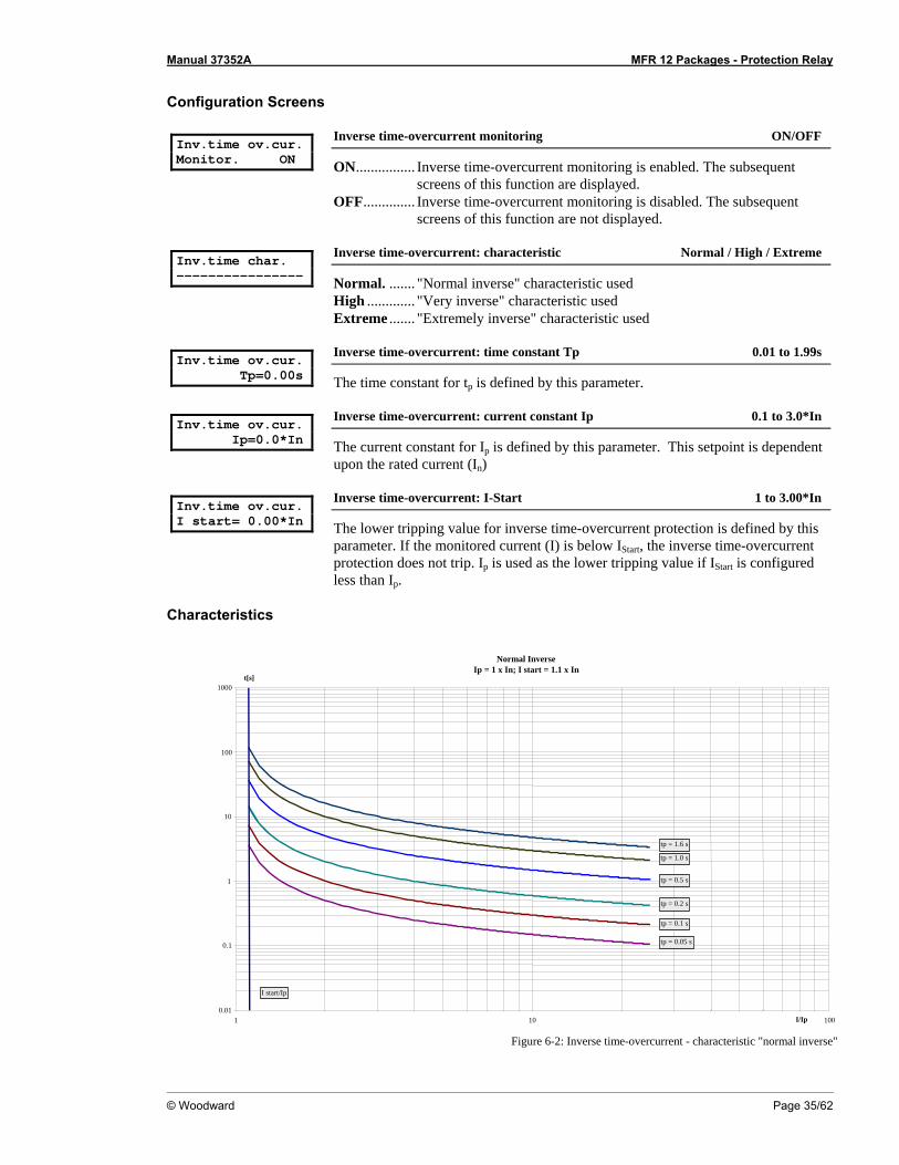
Configuration Screens Inv.time ov.cur. Monitor. ON
Inverse time-overcurrent monitoring ON/OFF
ON................ Inverse time-overcurrent monitoring is enabled. The subsequent screens of this function are displayed.
OFF.............. Inverse time-overcurrent monitoring is disabled. The subsequent screens of this function are not displayed.
Inv.time char. ----------------
Inverse time-overcurrent: characteristic Normal / High / Extreme
Normal. ....... "Normal inverse" characteristic used High ............. "Very inverse" characteristic used Extreme ....... "Extremely inverse" characteristic used
Inv.time ov.cur. Tp=0.00s
Inverse time-overcurrent: time constant Tp 0.01 to 1.99s
The time constant for tp is defined by this parameter. Inv.time ov.cur. Ip=0.0*In
Inverse time-overcurrent: current constant Ip 0.1 to 3.0*In
The current constant for Ip is defined by this parameter. This setpoint is dependent upon the rated current (In)
Inv.time ov.cur. I start= 0.00*In
Inverse time-overcurrent: I-Start 1 to 3.00*In
The lower tripping value for inverse time-overcurrent protection is defined by this parameter. If the monitored current (I) is below IStart, the inverse time-overcurrent protection does not trip. Ip is used as the lower tripping value if IStart is configured less than Ip.
Characteristics
Normal InverseIp = 1 x In; I start = 1.1 x In
0.01
0.1
1
10
100
1000
1 10 100I/Ip
t[s]
tp = 1.6 s tp = 1.0 s tp = 0.5 s tp = 0.2 s tp = 0.1 s tp = 0.05 s
I start/Ip
Figure 6-2: Inverse time-overcurrent - characteristic "normal inverse"
Manual 37352A MFR 12 Packages - Protection Relay
Page 36/62 © Woodward
Very Inverse
Ip = In; I start = 1.1 x In
0.01
0.1
1
10
100
1000
1 10 100I/Ip
t[s]
tp = 1.0 s
tp = 0.5 s
tp = 0.2 s
tp = 0.1 s
tp = 0.05 s
tp = 1.6 s
I start/Ip
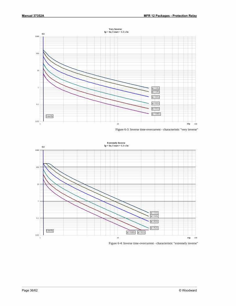
Figure 6-3: Inverse time-overcurrent - characteristic "very inverse"
Extremely Inverse
Ip = In; I start = 1.1 x In
0.01
0.1
1
10
100
1000
1 10 100I/Ip
t[s]
tp = 1.0 s
tp = 0.5 s
tp = 0.2 s
tp = 0.1 stp = 0.05 s
tp = 1.6 s
I start/Ip
Figure 6-4: Inverse time-overcurrent - characteristic "extremely inverse"
Manual 37352A MFR 12 Packages - Protection Relay
© Woodward Page 37/62
Inverse Time-Overcurrent Monitoring with Voltage Restraint (Package 51V)
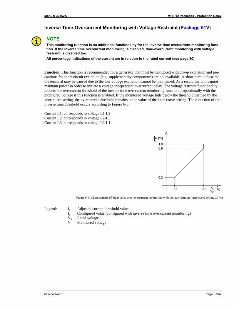
NOTE This monitoring function is an additional functionality for the inverse time overcurrent monitoring func-tion. If the inverse time overcurrent monitoring is disabled, time-overcurrent monitoring with voltage restraint is disabled too. All percentage indications of the current are in relation to the rated current (see page 30).
Function: This function is recommended for a generator that must be monitored with droop excitation and pre-cautions for short-circuit excitation (e.g. supplementary components) are not available. A short-circuit close to the terminal may be caused due to the low voltage excitation cannot be maintained. As a result, the unit cannot maintain power in order to initiate a voltage independent overcurrent delay. The voltage restraint functionality reduces the overcurrent threshold of the inverse time overcurrent monitoring function proportionally with the monitored voltage if this function is enabled. If the monitored voltage falls below the threshold defined by the knee curve setting, the overcurrent threshold remains at the value of the knee curve setting. The reduction of the inverse time threshold occurs according to Figure 6-5. Current L1: corresponds to voltage L1-L2 Current L2: corresponds to voltage L2-L3 Current L3: corresponds to voltage L3-L1
0.2
0.2 0.9
I [%]auI
0.9
V [%]nV
1.0
Figure 6-5: Characteristic of the inverse time-overcurrent monitoring with voltage restraint (knee curve setting 20 %)
Legend: Ia Adjusted current threshold value Ip Configured value (configured with inverse time overcurrent monitoring) Vn Rated voltage V Monitored voltage
Manual 37352A MFR 12 Packages - Protection Relay
Page 38/62 © Woodward
Example: Initial conditions: Rated voltage Vn = 100 V Configured value Ip = 2.0*5 A = 10 A (rated current In = 5 A) Case 1 (monitored voltage V > 90% Vn):
As long as the monitored voltage exceeds 90% of the rated voltage, the configured value will not be adjusted. -> Ia = Ip
Case 2 (monitored voltage V < 90% Vn , but actual voltage V > knee curve setting):
If the monitored voltage falls below 90% of the rated voltage, the configured value is adjusted proportionally with the ratio of monitored and rated voltage. -> Ia = (V/Vn) * Ip
Case 3 (monitored voltage V < knee curve setting):
If the monitored voltage falls below the percentage value of the rated voltage configured by the knee curve setting, the configured value is adjusted to the proportional value at the knee curve setting. -> Ia = {(knee point setting in [%])/100} * Ip If the knee curve setting is configured to 20% for example and the monitored voltage is lower than 20% of the rated voltage, the adjusted value Ia falls not below 20% of the configured value Ip.
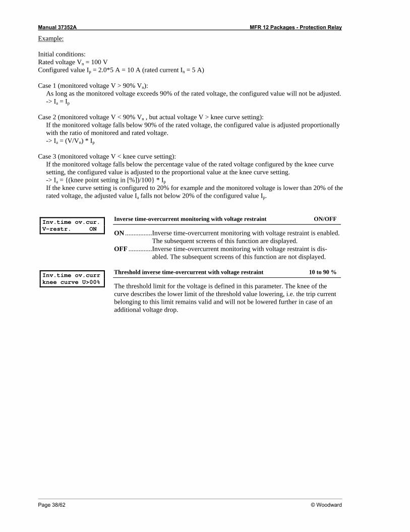
Inv.time ov.cur. V-restr. ON
Inverse time-overcurrent monitoring with voltage restraint ON/OFF
ON ................Inverse time-overcurrent monitoring with voltage restraint is enabled. The subsequent screens of this function are displayed.
OFF ..............Inverse time-overcurrent monitoring with voltage restraint is dis-abled. The subsequent screens of this function are not displayed.
Inv.time ov.curr knee curve U>00%
Threshold inverse time-overcurrent with voltage restraint 10 to 90 %
The threshold limit for the voltage is defined in this parameter. The knee of the curve describes the lower limit of the threshold value lowering, i.e. the trip current belonging to this limit remains valid and will not be lowered further in case of an additional voltage drop.
Manual 37352A MFR 12 Packages - Protection Relay
© Woodward Page 39/62
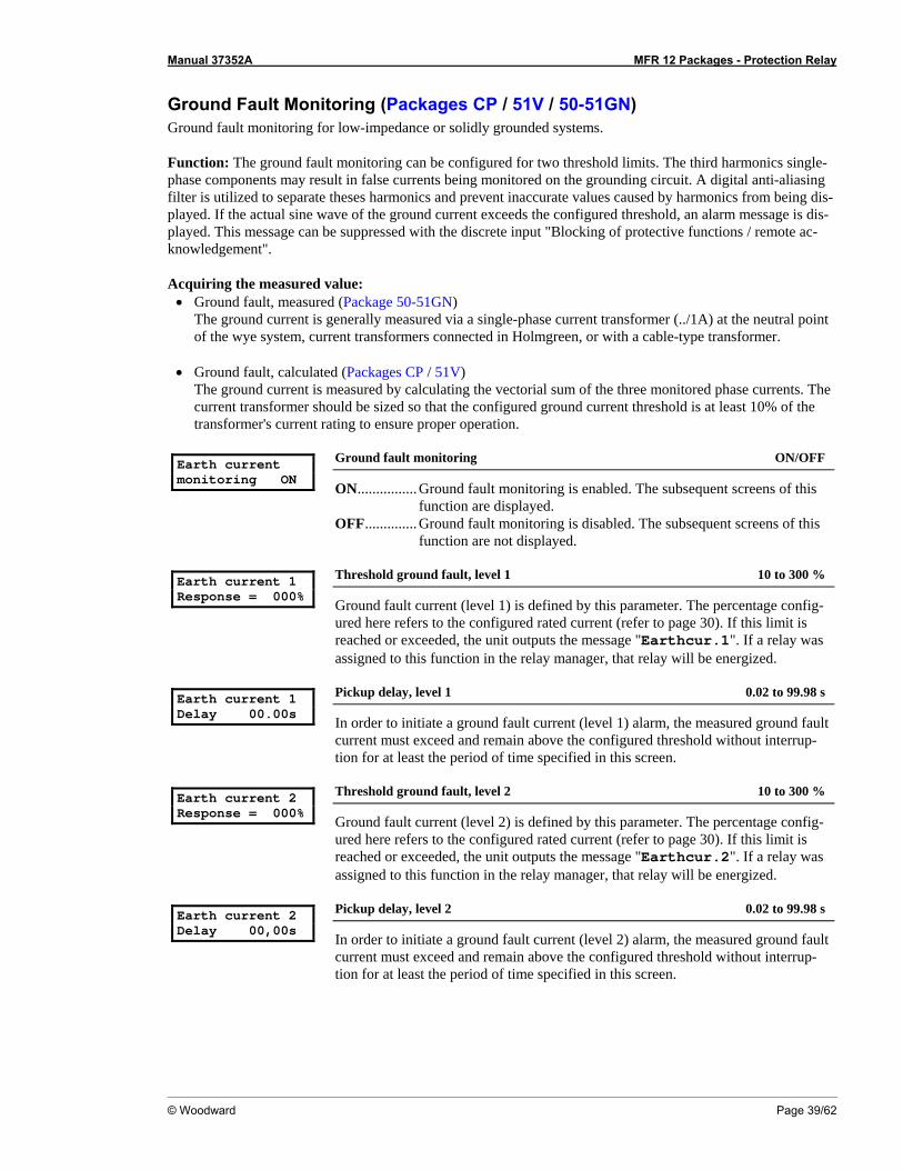
Ground Fault Monitoring (Packages CP / 51V / 50-51GN) Ground fault monitoring for low-impedance or solidly grounded systems. Function: The ground fault monitoring can be configured for two threshold limits. The third harmonics single-phase components may result in false currents being monitored on the grounding circuit. A digital anti-aliasing filter is utilized to separate theses harmonics and prevent inaccurate values caused by harmonics from being dis-played. If the actual sine wave of the ground current exceeds the configured threshold, an alarm message is dis-played. This message can be suppressed with the discrete input "Blocking of protective functions / remote ac-knowledgement". Acquiring the measured value:
• Ground fault, measured (Package 50-51GN) The ground current is generally measured via a single-phase current transformer (../1A) at the neutral point of the wye system, current transformers connected in Holmgreen, or with a cable-type transformer.
• Ground fault, calculated (Packages CP / 51V)
The ground current is measured by calculating the vectorial sum of the three monitored phase currents. The current transformer should be sized so that the configured ground current threshold is at least 10% of the transformer's current rating to ensure proper operation.
Earth current monitoring ON
Ground fault monitoring ON/OFF
ON................ Ground fault monitoring is enabled. The subsequent screens of this function are displayed.
OFF.............. Ground fault monitoring is disabled. The subsequent screens of this function are not displayed.
Earth current 1 Response = 000%
Threshold ground fault, level 1 10 to 300 %
Ground fault current (level 1) is defined by this parameter. The percentage config-ured here refers to the configured rated current (refer to page 30). If this limit is reached or exceeded, the unit outputs the message "Earthcur.1". If a relay was assigned to this function in the relay manager, that relay will be energized.
Earth current 1 Delay 00.00s
Pickup delay, level 1 0.02 to 99.98 s
In order to initiate a ground fault current (level 1) alarm, the measured ground fault current must exceed and remain above the configured threshold without interrup-tion for at least the period of time specified in this screen.
Earth current 2 Response = 000%
Threshold ground fault, level 2 10 to 300 %
Ground fault current (level 2) is defined by this parameter. The percentage config-ured here refers to the configured rated current (refer to page 30). If this limit is reached or exceeded, the unit outputs the message "Earthcur.2". If a relay was assigned to this function in the relay manager, that relay will be energized.
Earth current 2 Delay 00,00s
Pickup delay, level 2 0.02 to 99.98 s
In order to initiate a ground fault current (level 2) alarm, the measured ground fault current must exceed and remain above the configured threshold without interrup-tion for at least the period of time specified in this screen.
Manual 37352A MFR 12 Packages - Protection Relay
Page 40/62 © Woodward
Earth current Hysteresis 000%
Hysteresis for the ground fault monitoring, level 1+2 1 to 300 %
In order to prevent system fluctuations from continually initiating ground fault cur-rent alarms (levels 1 & 2), a lower release point is defined here. If the control moni-tors the current above the permissible limit, the current must drop below that threshold and the current level defined here. Example: If a 1000A system has a ground fault current limit 1 of 5% (50A) and a hysteresis of 2% (20A), the monitored current for a ground fault current alarm must drop below 20A to reset the alarm.
Manual 37352A MFR 12 Packages - Protection Relay
© Woodward Page 41/62
Non-Direct. Ground-Fault Monit. via Displacement Volt. (Package IvIkR) The unit may be used to monitor for earth faults in the stator winding of three-phase motors drawing current from the mains via a unit-connected transformer. If a ground current fault is detected, the control senses the current phase shift, providing about a 95% protection of the windings rating.
First tripping level for the displacement voltage
Function: "Measurement of the displacement voltage (level 1)" The displacement voltage is usually measured via the open delta winding (e-n-winding) of a potential trans-former or via a zero sequence transformer in the star point of the machine. If potential transformers with secon-dary voltages greater than 100V (e.g. 240 V, 500 V), the voltage at the earth fault input terminal must be reduced to a voltage level less than 100V through the use of a voltage divider. The single-phase third harmonics compo-nents may result in false currents being monitored on the grounding circuit. A digital anti-aliasing filter is utilized to separate theses harmonics and prevent inaccurate values caused by harmonics from being displayed. If the ac-tual sine wave of the ground current exceeds the configured threshold, the alarm message "E.fault Ve" is displayed. This message cannot be suppressed with the discrete input "Blocking of protective functions / remote acknowledgement". Earth fault monitoring ON
Non-directional ground fault monitoring ON/OFF
ON................ The non-directional ground fault monitoring is enabled. The subse-quent screens of this function are displayed.
OFF.............. The non-directional ground fault monitoring is disabled. The subse-quent screens of this function are not displayed.
Earth fault Ve> Response v. 000%
Threshold displacement voltage, level 1 3 to 100 %
The displacement voltage threshold (level 1) is defined by this parameter. The per-centage configured here refers to the configured rated voltage of the potential trans-former secondary (generally 100 V). If this limit is reached or exceeded, the unit outputs the message "E.fault Ve". If a relay was assigned to this function in the relay manager, that relay will be energized.
Earth fault Ve> Delay 00.00s
Pickup delay, level 1 0.02 to 99.98 s
In order to initiate a ground fault alarm, the displacement voltage threshold (level 1) must be exceeded and remain above the configured threshold without in-terruption for at least the period of time specified in this screen.
Manual 37352A MFR 12 Packages - Protection Relay
Page 42/62 © Woodward
Second tripping level for the displacement voltage
Function: "Measurement of the displacement voltage (level 2)/disconnect impedance reactor" Isolated or compensated distribution systems may use an impedance reactor to increase the resistance to earth. This type of equipment generally isn't designed for continuous rated current at full displacement. Therefore, this equipment must be disabled when the displacement voltage exceeds a set value. It must be taken into consid-eration that the impedance reactor may only be disabled after the earth fault alarm has been initiated. This requires a longer delay time be configured if the impedance reactor must be turned off. Additionally the dis-placement voltage threshold (level 2) must be configured higher than the level 1 threshold. When the displace-ment voltage threshold (level 2) has been exceeded, the alarm message "Earth Ve>>" is displayed. This mes-sage cannot be suppressed with the discrete input "Blocking of protective functions / remote acknowledgement". Earth fault Ve>> Response v. 000%
Threshold displacement voltage, level 2 3 to 100 %
The displacement voltage threshold (level 2) is defined by this parameter. The per-centage configured here refers to the configured rated voltage of the potential trans-former secondary (generally 100 V). If this limit is reached or exceeded, the unit outputs the message "Earth Ve>>". If a relay was assigned to this function in the relay manager, that relay will be energized.
Earth fault Ve>> Delay =00.00s
Pickup delay, level 2 0.02 to 99.98 s
In order to initiate a ground fault alarm, the displacement voltage threshold (level 2) must be exceeded and remain above the configured threshold without in-terruption for at least the period of time specified in this screen.
Release delay Earth f.v.00.00s
Release delay for non-directional ground fault 0.02 to 99.98 s
In order to prevent system fluctuations from continually initiating non-directional ground fault current alarms (levels 1 & 2), the monitored displacement voltage must remain below the threshold limit for the time configured here. The level 1 alarm will auto-acknowledge only if the parameter "Auto-clearing Relays" is con-figured as "ON". The level 2 alarm will always auto-acknowledge.
Manual 37352A MFR 12 Packages - Protection Relay
© Woodward Page 43/62
Ground-Fault Monitoring, Measured (Package IvIkR) Measured ground fault monitoring with isolated or balanced mains. The line-to-ground current is usually measured via a cable-type transformer or current transformers in Holm-green. Ground faults result in comparatively small ground currents at the location of the fault. The measuring in-put is specially designed for these small ground currents. The measuring input is limited to a maximum of 35mA. The ground fault current input is thermally designed to withstand the CT secondary rated current. All measure-ments are galvanically isolated. If a ground fault does occur, the control unit issues an alarm message. This mes-sage can be suppressed with the discrete input "Blocking of protective functions / remote acknowledgement". Earth current monitoring ON
Ground fault monitoring, measured ON/OFF
ON................ Ground fault monitoring (measured) is enabled. The subsequent screens of this function are displayed.
OFF.............. Ground fault monitoring (measured) is disabled. The subsequent screens of this function are not displayed.
Earth current 1 Response = 000%
Threshold ground fault, measured, level 1 0.05 to 3.50 %
Ground fault current (level 1) is defined by this parameter. The percentage config-ured here refers to the configured rated current (refer to page 30). If this limit is reached or exceeded, the unit outputs the message "Earthcur.1". If a relay was assigned to this function in the relay manager, that relay will be energized.
Earth current 1 Delay 00.00s
Pickup delay, level 1 0.02 to 99.98 s
In order to initiate a ground fault current (level 1) alarm, the measured ground fault current must exceed and remain above the configured threshold without interrup-tion for at least the period of time specified in this screen.
Earth current 2 Response = 000%
Threshold ground fault, measured, level 2 0.05 to 3.50 %
Ground fault current (level 2) is defined by this parameter. The percentage config-ured here refers to the configured rated current (refer to page 30). If this limit is reached or exceeded, the unit outputs the message "Earthcur.2". If a relay was assigned to this function in the relay manager, that relay will be energized.
Earth current 2 Delay 00.00s
Pickup delay, level 2 0.02 to 99.98 s
In order to initiate a ground fault current (level 2) alarm, the measured ground fault current must exceed and remain above the configured threshold without interrup-tion for at least the period of time specified in this screen.
Earth current Hysteresis 0.00%
Hysteresis for the ground fault monitoring, measured, levels 1+2 0.00 to 3.50 %
In order to prevent system fluctuations from continually initiating ground fault cur-rent alarms (levels 1 & 2), a lower release point is defined here. If the control moni-tors the current above the permissible limit, the current must drop below that threshold and the current level defined here. Example: If a 1A CT secondary has a ground fault current limit 1 of 2% (20mA) and a hysteresis of 1.5% (15mA), the monitored current for a ground fault current alarm must drop below 15mA to reset the alarm.
Manual 37352A MFR 12 Packages - Protection Relay
Page 44/62 © Woodward
Directional Ground Fault Monitoring (Package IvIkR) Directional ground fault monitoring is used in isolated and compensated networks.
Functional Description
Function: "Ground fault within the protection area" The Package IvIkR enables to perform a direction-dependent ground fault monitoring. A selective monitoring of several generators, which feed one busbar without block transformers, is possible. The following parameters must be configured to ON to perform directional ground fault monitoring:
• Earth fault monitoring • Earth current monitoring
If the displacement voltage reaches or exceeds the threshold value Ve, the earth fault monitoring will be enabled after expiry of the configured delay time. If the alarm message "Warning earth f." has been configured to a relay, this will be energized. No display message appears. This relay may be used for example to generate a "Ground fault outside the protection area" message together with another relay or to connect a load device.
Function without direction check ("Earth fault Ie restricted" configured to OFF)
If the measured ground current reaches or exceeds the "Earth fault 1" or "Earth fault 2" limit, the "E.fault Ve" message will be issued after expiry of the configured delay time. The current direction will not be taken into ac-count. This message may be suppressed with the discrete input "Blocking of protective functions / Remote ac-knowledgement".
Function with direction check ("Earth fault Ie restricted" configured to ON)
If the measured ground current reaches or exceeds the "Earth fault 1" or "Earth fault 2" limit and the unit detects a ground fault within the protection area by the angle between current and voltage, the "E.fault Ve" message will be issued after expiry of the configured delay time. Therefore, the current direction will be taken into account in the way configured in the following settings. If the unit detects a ground fault outside the protection area, no alarm will be issued. This message may be suppressed with the discrete input "Blocking of protective functions / Remote acknowledgement".
NOTE Ground fault protection at start-up. If the discrete input "Blocking of protective functions / Remote acknowledgement" is energized with open GCB, ground current monitoring and direction detection will be disabled. The "Earfh fault Ve" monitoring operates in its basic functionality. This enables to detect a ground fault when starting the engine already by detecting the occurring displacement voltage and issuing an alarm.
Manual 37352A MFR 12 Packages - Protection Relay
© Woodward Page 45/62
Earth fault Ie restricted ON
Directional ground fault monitoring ON/OFF
ON................ The direction of the ground current is monitored to ensure that it is proportional to the measured displacement voltage. A fault condition is not recognized if the direction element determines that the ground fault is external.
OFF.............. Directional ground fault current monitoring is not enabled and the following screens are not displayed.
Earth fault Ie Evaluation sin
Analysis of the reactive (sin) or active component (cos) sin/cos
sin................. The direction of current is defined by the measurement of the reac-tive current. This setting should be selected if directional ground overcurrent monitoring is being performed in an isolated system.
cos ................ The direction of current is defined by the measurement of the induc-tive current. This setting should be selected if directional ground overcurrent monitoring is being performed in a compensated system.
Earth fault Ie Angle adj. 000°
Angle correction of the ground current -180 to 0 to 180°
To monitor specific systems, the phase angle monitoring can be tuned. This permits threshold limits to be adapted to the plant without having to desensitize ground fault current monitoring. It should be noted that the analysis mode changes auto-matically to adjustments greater than 90° or less than -90°. If the analysis mode "cos" is configured, the monitored phase angle is adjusted by 90° in relationship to a "sin" measurement with a phase angle correction of 0°.
Earth fault Ie Block range 00°
Angle blocking zone for ground current logging 0 to 10°
Compensated systems generally only have very slight ground fault currents. The magnitude of the ground fault current at the fault location is approximately 5% of the capacitive fault current in an isolated system. The phase shift of the ground fault current could be influenced by the potential or current transformers causing an incorrect fault condition to be recognized. Therefore phase angles around 90° can be ignored in the range of +/-10°.
Manual 37352A MFR 12 Packages - Protection Relay
Page 46/62 © Woodward
Relay Configuration ≡≡≡≡≡≡≡≡≡≡≡≡≡≡≡≡≡≡≡≡≡≡≡≡≡
NOTE Clearing of faults and fault messages from the control unit will depend on the parameters "Exter-nal clearing", "Auto-clearing Relays", and "Auto-clearing Display". These three parameters will influence the other depending on how each is configured. This is explained in the following text.
External Clearing ON
External acknowledgement of the relays via the discrete input
"Blocking of protective functions / remote acknowledgement".
Acknowledgement via the discrete input ON/OFF
"Auto-clearing Relays" configured "OFF" (refer to "Auto Acknowledge-ment of the Relay" on page 46): OFF ..............Alarms that cannot be blocked with discrete input "Blocking of pro-
tective functions / remote acknowledgement" will not be reset when the fault condition is no longer present. Pressing the "Clear" button resets the relays.
ON ................All alarms are reset when the discrete input "Blocking of protective functions / remote acknowledgement" (terminals 5/6) is energized. Alarms which cannot be blocked with the discrete input "Blocking of protective functions / remote acknowledgement" are only reset after the fault condition is no longer present.
"Auto-clearing Relays" configured "ON" (refer to "Auto Acknowledge-ment of the Relay" on page 46): OFF ..............Pressing the "Clear" button resets the displayed fault messages. ON ................All displayed fault messages are reset when the discrete input
"Blocking of protective functions / remote acknowledgement" (ter-minals 5/6) is energized. Alarms which cannot be blocked with the discrete input "Blocking of protective functions / remote acknowl-edgement" are only reset after the fault condition is no longer pre-sent.
Auto Acknowledgement of the Relays Auto-clearing Relays ON
Relay auto acknowledgment ON/OFF
ON ................Automatic clearing of the relays is enabled. The relays are automati-cally reset when the fault condition is no longer detected. The alarm message in the display is cleared according to how the parameter "Auto-clearing Display" is configured.
OFF ..............Automatic clearing of the relays is disabled. Pressing the "Clear" but-ton resets the relays.
The alarm message in the display is cleared according to how the parameter "Auto-clearing Display" is configured. The subsequent screens of this function are not indicated.
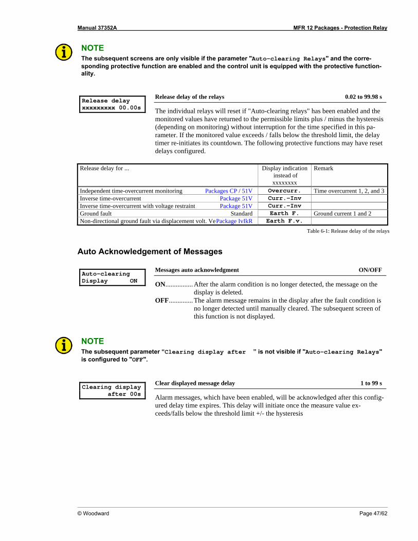
Manual 37352A MFR 12 Packages - Protection Relay
© Woodward Page 47/62
NOTE The subsequent screens are only visible if the parameter "Auto-clearing Relays" and the corre-sponding protective function are enabled and the control unit is equipped with the protective function-ality.
Release delay xxxxxxxxx 00.00s
Release delay of the relays 0.02 to 99.98 s
The individual relays will reset if "Auto-clearing relays" has been enabled and the monitored values have returned to the permissible limits plus / minus the hysteresis (depending on monitoring) without interruption for the time specified in this pa-rameter. If the monitored value exceeds / falls below the threshold limit, the delay timer re-initiates its countdown. The following protective functions may have reset delays configured.
Release delay for ... Display indication
instead of xxxxxxxx
Remark
Independent time-overcurrent monitoring Packages CP / 51V Overcurr. Time overcurrent 1, 2, and 3Inverse time-overcurrent Package 51V Curr.-Inv Inverse time-overcurrent with voltage restraint Package 51V Curr.-Inv Ground fault Standard Earth F. Ground current 1 and 2 Non-directional ground fault via displacement volt. Ve Package IvIkR Earth F.v.
Table 6-1: Release delay of the relays
Auto Acknowledgement of Messages Auto-clearing Display ON
Messages auto acknowledgment ON/OFF
ON................ After the alarm condition is no longer detected, the message on the display is deleted.
OFF.............. The alarm message remains in the display after the fault condition is no longer detected until manually cleared. The subsequent screen of this function is not displayed.
NOTE The subsequent parameter “Clearing display after ” is not visible if "Auto-clearing Relays" is configured to "OFF".
Clearing display after 00s
Clear displayed message delay 1 to 99 s
Alarm messages, which have been enabled, will be acknowledged after this config-ured delay time expires. This delay will initiate once the measure value ex-ceeds/falls below the threshold limit +/- the hysteresis
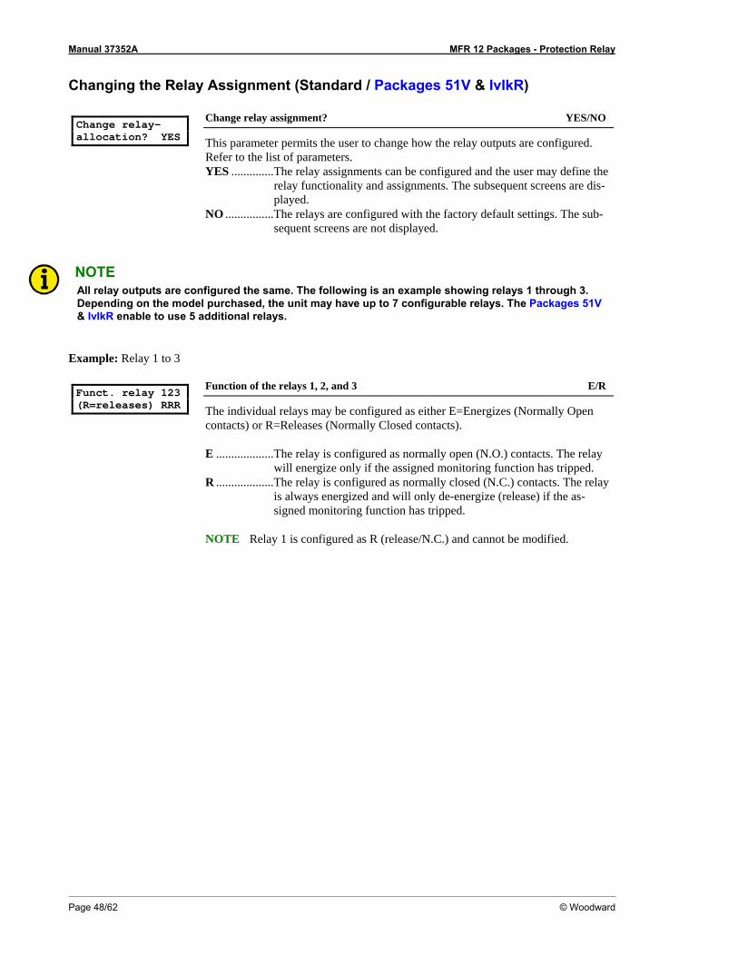
Manual 37352A MFR 12 Packages - Protection Relay
Page 48/62 © Woodward
Changing the Relay Assignment (Standard / Packages 51V & IvIkR) Change relay- allocation? YES
Change relay assignment? YES/NO
This parameter permits the user to change how the relay outputs are configured. Refer to the list of parameters. YES ..............The relay assignments can be configured and the user may define the
relay functionality and assignments. The subsequent screens are dis-played.
NO ................The relays are configured with the factory default settings. The sub-sequent screens are not displayed.
NOTE All relay outputs are configured the same. The following is an example showing relays 1 through 3. Depending on the model purchased, the unit may have up to 7 configurable relays. The Packages 51V & IvIkR enable to use 5 additional relays.
Example: Relay 1 to 3 Funct. relay 123 (R=releases) RRR
Function of the relays 1, 2, and 3 E/R
The individual relays may be configured as either E=Energizes (Normally Open contacts) or R=Releases (Normally Closed contacts). E ...................The relay is configured as normally open (N.O.) contacts. The relay
will energize only if the assigned monitoring function has tripped. R ...................The relay is configured as normally closed (N.C.) contacts. The relay
is always energized and will only de-energize (release) if the as-signed monitoring function has tripped.
NOTE Relay 1 is configured as R (release/N.C.) and cannot be modified.
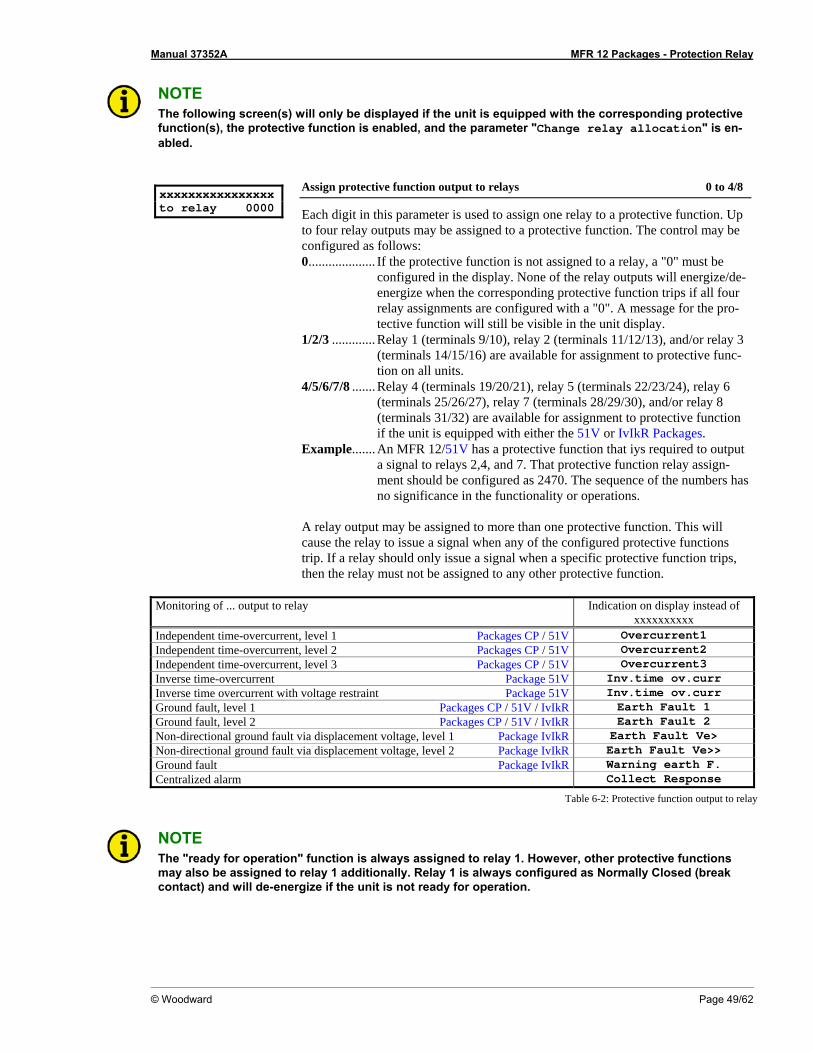
Manual 37352A MFR 12 Packages - Protection Relay
© Woodward Page 49/62
NOTE The following screen(s) will only be displayed if the unit is equipped with the corresponding protective function(s), the protective function is enabled, and the parameter "Change relay allocation" is en-abled.
xxxxxxxxxxxxxxxx to relay 0000
Assign protective function output to relays 0 to 4/8
Each digit in this parameter is used to assign one relay to a protective function. Up to four relay outputs may be assigned to a protective function. The control may be configured as follows: 0.................... If the protective function is not assigned to a relay, a "0" must be
configured in the display. None of the relay outputs will energize/de-energize when the corresponding protective function trips if all four relay assignments are configured with a "0". A message for the pro-tective function will still be visible in the unit display.
1/2/3 ............. Relay 1 (terminals 9/10), relay 2 (terminals 11/12/13), and/or relay 3 (terminals 14/15/16) are available for assignment to protective func-tion on all units.
4/5/6/7/8 ....... Relay 4 (terminals 19/20/21), relay 5 (terminals 22/23/24), relay 6 (terminals 25/26/27), relay 7 (terminals 28/29/30), and/or relay 8 (terminals 31/32) are available for assignment to protective function if the unit is equipped with either the 51V or IvIkR Packages.
Example....... An MFR 12/51V has a protective function that iys required to output a signal to relays 2,4, and 7. That protective function relay assign-ment should be configured as 2470. The sequence of the numbers has no significance in the functionality or operations.
A relay output may be assigned to more than one protective function. This will cause the relay to issue a signal when any of the configured protective functions trip. If a relay should only issue a signal when a specific protective function trips, then the relay must not be assigned to any other protective function.
Monitoring of ... output to relay Indication on display instead of
xxxxxxxxxx Independent time-overcurrent, level 1 Packages CP / 51V Overcurrent1 Independent time-overcurrent, level 2 Packages CP / 51V Overcurrent2 Independent time-overcurrent, level 3 Packages CP / 51V Overcurrent3 Inverse time-overcurrent Package 51V Inv.time ov.curr Inverse time overcurrent with voltage restraint Package 51V Inv.time ov.curr Ground fault, level 1 Packages CP / 51V / IvIkR Earth Fault 1 Ground fault, level 2 Packages CP / 51V / IvIkR Earth Fault 2 Non-directional ground fault via displacement voltage, level 1 Package IvIkR Earth Fault Ve> Non-directional ground fault via displacement voltage, level 2 Package IvIkR Earth Fault Ve>> Ground fault Package IvIkR Warning earth F. Centralized alarm Collect Response
Table 6-2: Protective function output to relay
NOTE The "ready for operation" function is always assigned to relay 1. However, other protective functions may also be assigned to relay 1 additionally. Relay 1 is always configured as Normally Closed (break contact) and will de-energize if the unit is not ready for operation.
Manual 37352A MFR 12 Packages - Protection Relay
Page 50/62 © Woodward
Chapter 7. Commissioning
DANGER - HIGH VOLTAGE When commissioning the control, please observe all safety rules that apply to the handling of live equipment. Ensure that you know how to provide first aid in the event of an uncontrolled release of en-ergy and that you know where the first aid kit and the nearest telephone are. Never touch any live com-ponents of the system or on the back of the system:
L I F E T H R E A T E N I N G
CAUTION Only a qualified technician may commission unit. The "EMERGENCY-STOP" function must be opera-tional prior to commissioning of the system, and must not depend on the unit for its operation.
CAUTION Prior to commissioning ensure that all measuring devices are connected in correct phase sequence. The connect command for the unit circuit breaker must be disconnected at the unit circuit breaker. The field rotation must be monitored for proper rotation. Any absence of or incorrect connection of voltage measuring devices or other signals may lead to malfunctions and damage the unit, the engine, and/or components connected to the unit!
Procedure 1. After wiring the unit and ensuring all voltage-measuring devices are phased correctly, apply the control
system voltage (i.e. 24 Vdc). The "Operation" LED will illuminate. 2. By simultaneously pressing the two push buttons "Digit↑" and "Cursor→", the configuration mode is ac-
cessed. After entering the access code number, the unit may be configured according to the application requirements (see the chapter regarding the parameters).
3. After applying the measured variables, the unit will display the measured values. These values should be
confirmed with a calibrated measuring instrument. 4. After the unit has been configured for the application, the configuration mode is exited by simultaneously
pressing the "Digit↑" and "Cursor→" buttons.
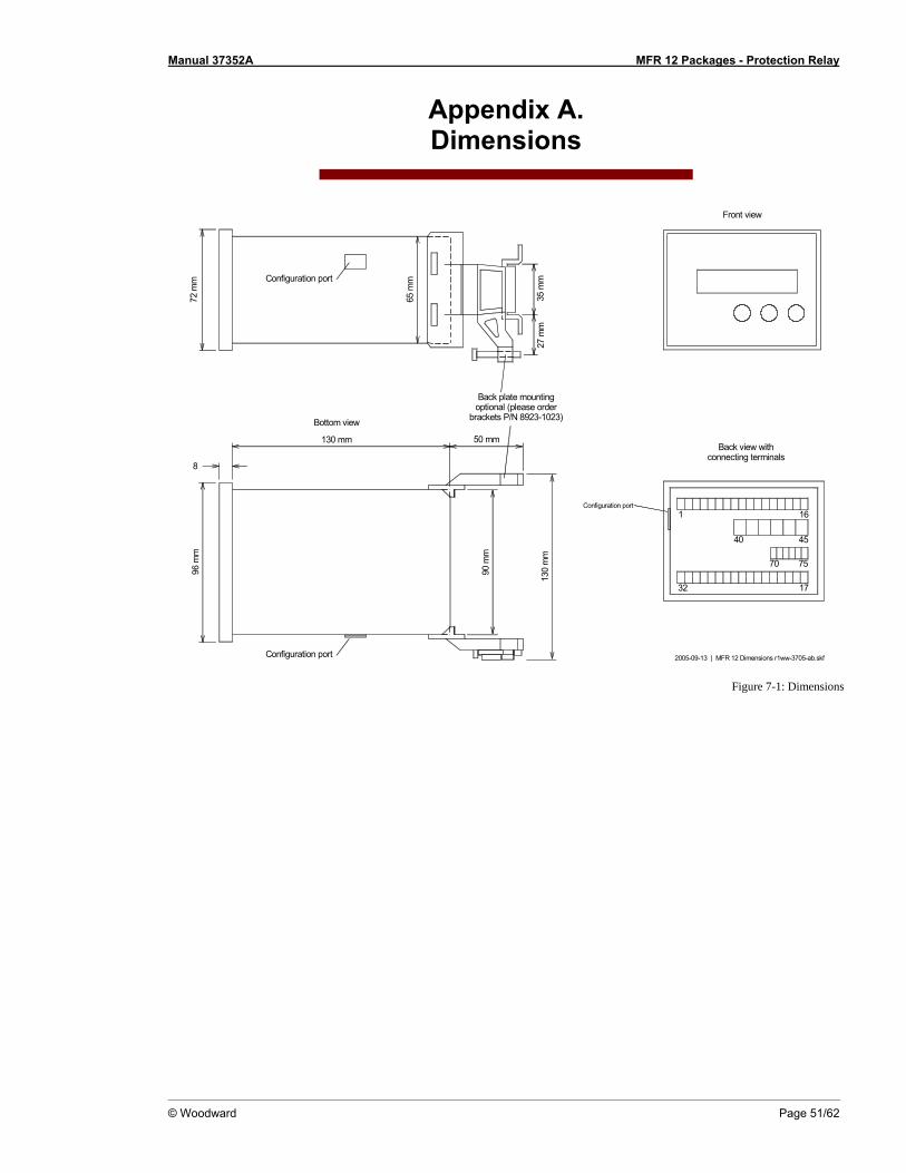
Manual 37352A MFR 12 Packages - Protection Relay
© Woodward Page 51/62
Appendix A. Dimensions
2005-09-13 | MFR 12 Dimensions r1ww-3705-ab.skf
50 mm130 mm
96 m
m
8
90 m
m
130
mm
72 m
m
65 m
m
27 m
m35
mm
Back view withconnecting terminals
Bottom view
Back plate mountingoptional (please order
brackets P/N 8923-1023)
Front view
Configuration port
Configuration port
40
1
70 75
45
16
32 17
Configuration port
Figure 7-1: Dimensions
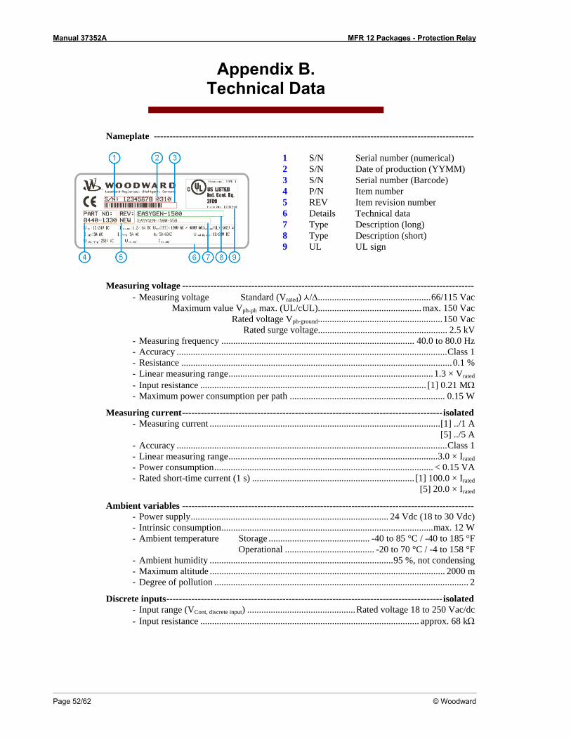
Manual 37352A MFR 12 Packages - Protection Relay
Page 52/62 © Woodward
Appendix B. Technical Data
Nameplate ------------------------------------------------------------------------------------------------------
1 S/N Serial number (numerical) 2 S/N Date of production (YYMM) 3 S/N Serial number (Barcode) 4 P/N Item number 5 REV Item revision number 6 Details Technical data 7 Type Description (long) 8 Type Description (short) 9 UL UL sign
Measuring voltage --------------------------------------------------------------------------------------------- - Measuring voltage Standard (Vrated) /Δ................................................66/115 Vac Maximum value Vph-ph max. (UL/cUL)............................................ max. 150 Vac Rated voltage Vph-ground.....................................................150 Vac Rated surge voltage....................................................... 2.5 kV - Measuring frequency .................................................................................. 40.0 to 80.0 Hz - Accuracy ...................................................................................................................Class 1 - Resistance ...................................................................................................................0.1 % - Linear measuring range....................................................................................... 1.3 × Vrated - Input resistance ................................................................................................ [1] 0.21 MΩ - Maximum power consumption per path .................................................................. 0.15 W
Measuring current-----------------------------------------------------------------------------------isolated - Measuring current ..................................................................................................[1] ../1 A
[5] ../5 A - Accuracy ...................................................................................................................Class 1 - Linear measuring range.........................................................................................3.0 × Irated - Power consumption............................................................................................. < 0.15 VA - Rated short-time current (1 s) ..................................................................... [1] 100.0 × Irated
[5] 20.0 × Irated
Ambient variables --------------------------------------------------------------------------------------------- - Power supply.................................................................................... 24 Vdc (18 to 30 Vdc) - Intrinsic consumption..........................................................................................max. 12 W - Ambient temperature Storage ........................................... -40 to 85 °C / -40 to 185 °F Operational ...................................... -20 to 70 °C / -4 to 158 °F - Ambient humidity ..............................................................................95 %, not condensing - Maximum altitude .................................................................................................... 2000 m - Degree of pollution ............................................................................................................ 2
Discrete inputs----------------------------------------------------------------------------------------isolated - Input range (VCont, discrete input) ..............................................Rated voltage 18 to 250 Vac/dc - Input resistance ............................................................................................. approx. 68 kΩ
Manual 37352A MFR 12 Packages - Protection Relay
© Woodward Page 53/62
Relay outputs ----------------------------------------------------------------------------------potential free - Contact material....................................................................................................... AgCdO - General purpose (GP) (VCont, relay output) AC.................................. 2.00 Aac@250 Vac DC....................................2.00 Adc@24 Vdc
0.36 Adc@125 Vdc 0.18 Adc@250 Vdc
- Pilot duty (PD) (VCont, relay output) AC.................................................................. DC....................................1.00 Adc@24 Vdc
0.22 Adc@125 Vdc 0.10 Adc@250 Vdc
Housing --------------------------------------------------------------------------------------------------------- - Type........................................................................................... APRANORM DIN 43 700 - Dimensions (W × H × D) ....................................................................... 96 × 72 × 130 mm - Front cutout (W × H)...................................................................91 [+1.0] × 67 [+0.7] mm - Wiring........... Screw-type terminals depending on connector 1.5 mm², 2.5 mm², or 4 mm² - Recommended tightening torque.................[1.5 mm² / 2.5 mm²] 0.5 Nm, [4 mm²] 0.6 Nm
use 60/75 °C copper wire only use class 1 wire only or equivalent
- Weight ............................................................................................................approx. 800 g
Protection------------------------------------------------------------------------------------------------------- - Protection system.................................................... IP42 from front with correct mounting
IP54 from front with gasket (gasket: P/N 8923-1036) IP21 from back
- Front foil...................................................................................................insulating surface - EMC test (CE) ...............................................tested according to applicable EN guidelines - Listings ........................................................CE marking; UL listing for ordinary locations
UL/cUL listed, Ordinary Locations, File No.: E231544 - Marine-Approval ............................................................................................................ GL
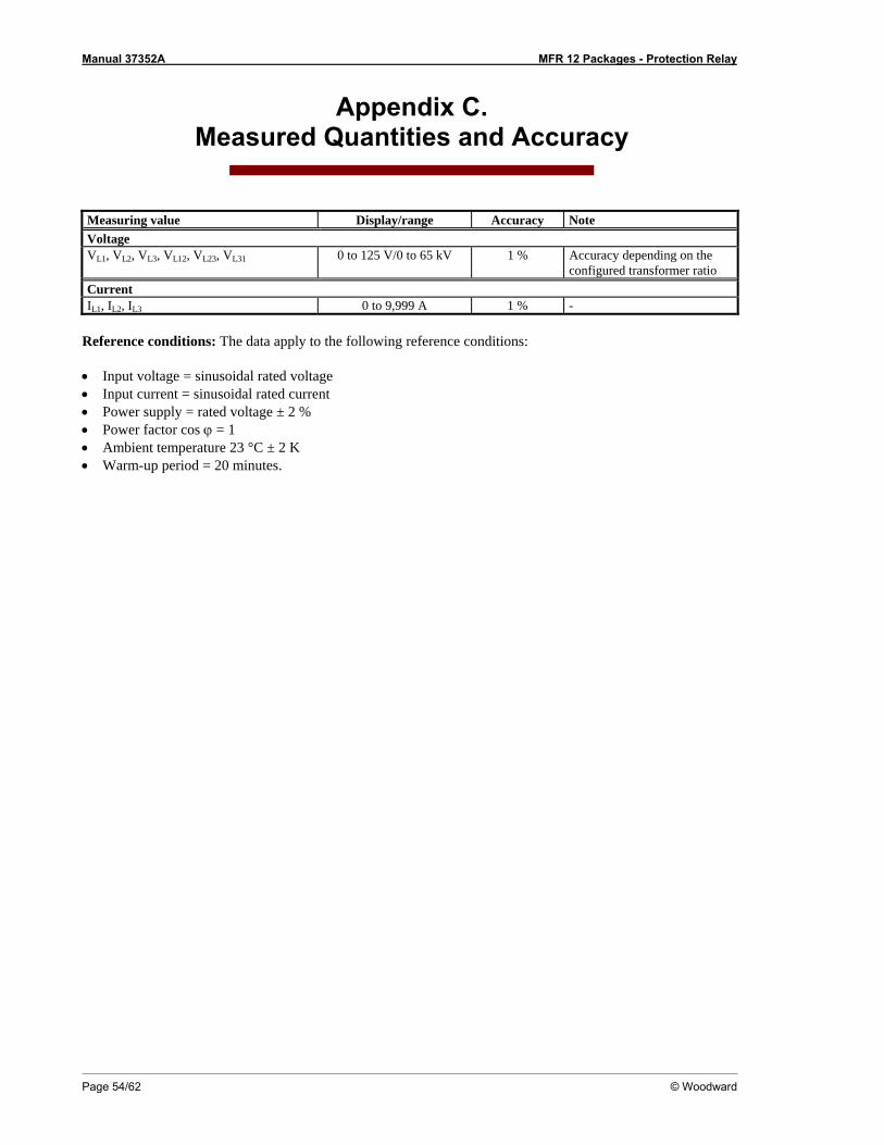
Manual 37352A MFR 12 Packages - Protection Relay
Page 54/62 © Woodward
Appendix C. Measured Quantities and Accuracy
Measuring value Display/range Accuracy Note Voltage VL1, VL2, VL3, VL12, VL23, VL31 0 to 125 V/0 to 65 kV 1 % Accuracy depending on the
configured transformer ratio Current IL1, IL2, IL3 0 to 9,999 A 1 % -
Reference conditions: The data apply to the following reference conditions: • Input voltage = sinusoidal rated voltage • Input current = sinusoidal rated current • Power supply = rated voltage ± 2 % • Power factor cos ϕ = 1 • Ambient temperature 23 °C ± 2 K • Warm-up period = 20 minutes.
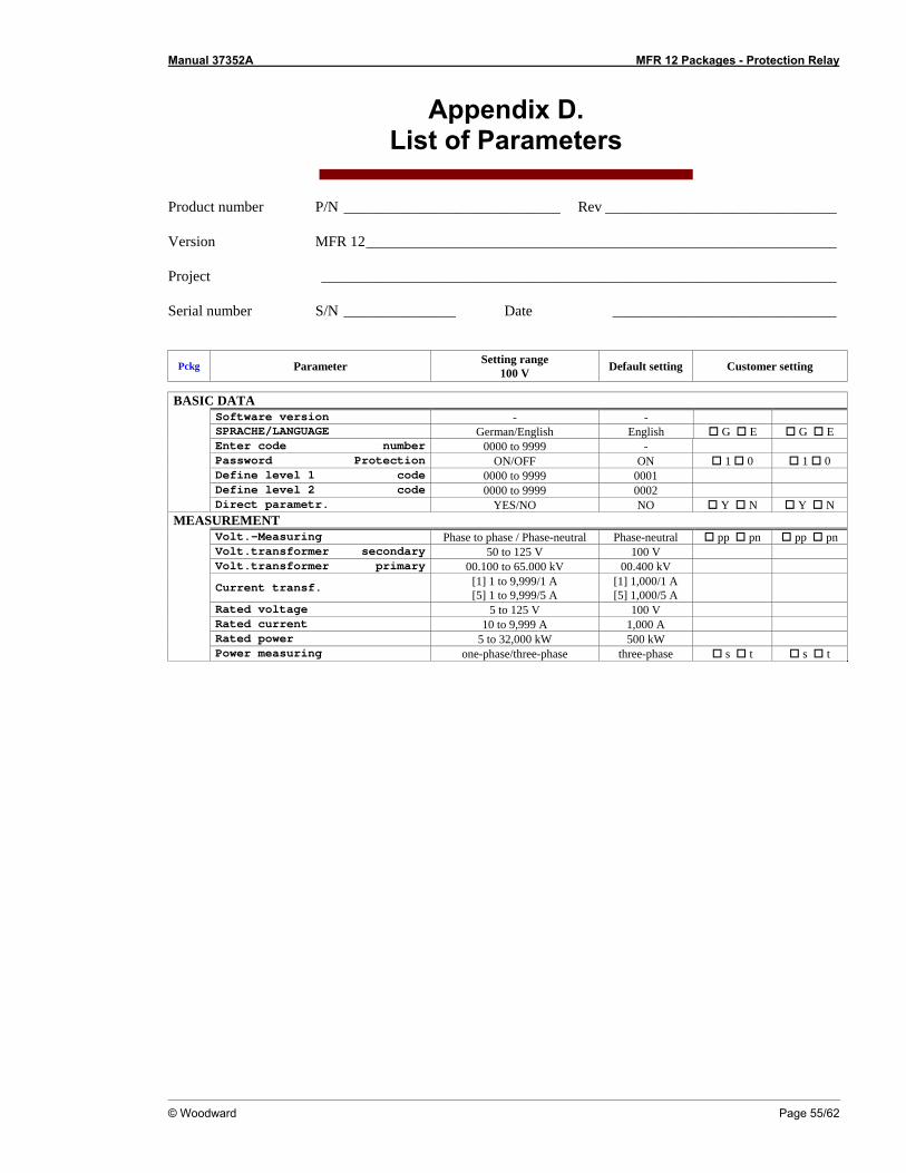
Manual 37352A MFR 12 Packages - Protection Relay
© Woodward Page 55/62
Appendix D. List of Parameters
Product number P/N _____________________________ Rev _______________________________ Version MFR 12_______________________________________________________________ Project _____________________________________________________________________ Serial number S/N _______________ Date ______________________________
Pckg Parameter Setting range 100 V Default setting Customer setting
BASIC DATA
Software version - - SPRACHE/LANGUAGE German/English English G E G E Enter code number 0000 to 9999 - Password Protection ON/OFF ON 1 0 1 0 Define level 1 code 0000 to 9999 0001 Define level 2 code 0000 to 9999 0002 Direct parametr. YES/NO NO Y N Y N
MEASUREMENT Volt.-Measuring Phase to phase / Phase-neutral Phase-neutral pp pn pp pn Volt.transformer secondary 50 to 125 V 100 V Volt.transformer primary 00.100 to 65.000 kV 00.400 kV
Current transf. [1] 1 to 9,999/1 A [5] 1 to 9,999/5 A
[1] 1,000/1 A [5] 1,000/5 A
Rated voltage 5 to 125 V 100 V Rated current 10 to 9,999 A 1,000 A Rated power 5 to 32,000 kW 500 kW Power measuring one-phase/three-phase three-phase s t s t
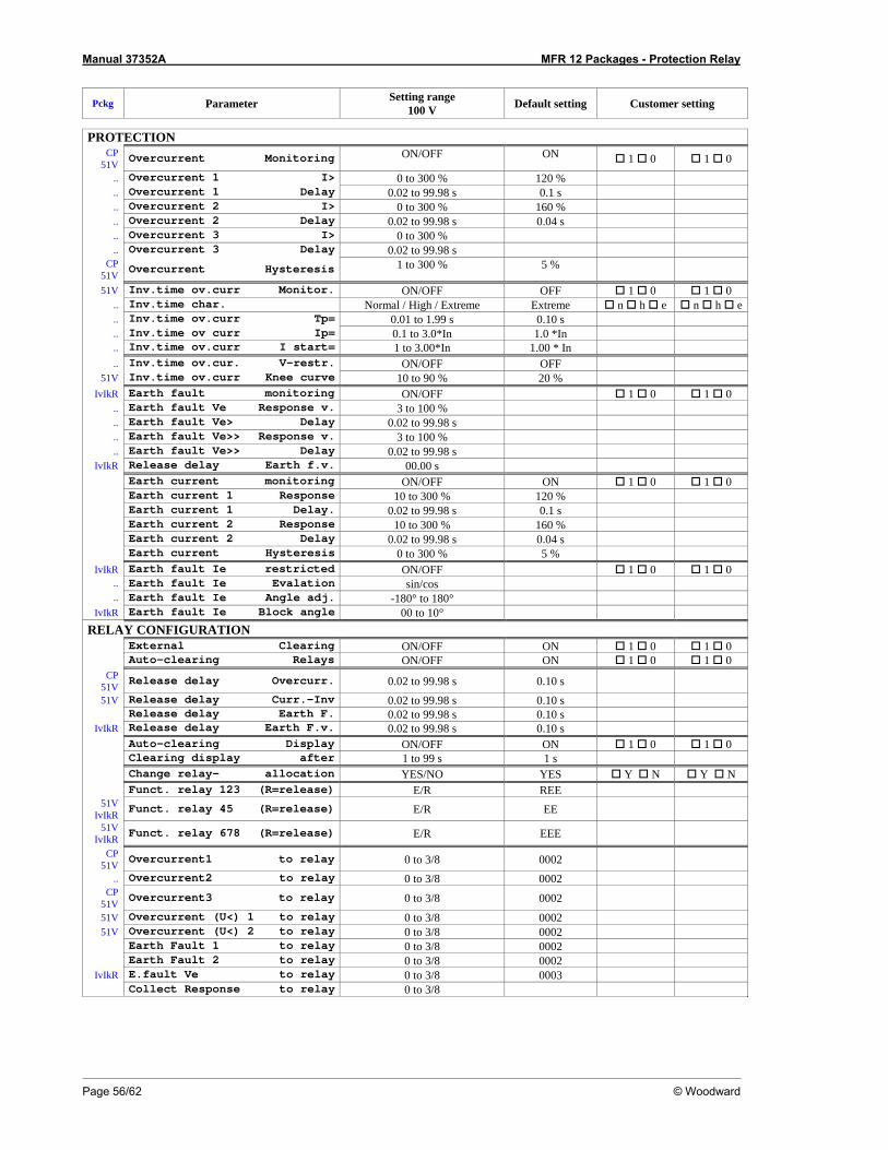
Manual 37352A MFR 12 Packages - Protection Relay
Page 56/62 © Woodward
Pckg Parameter Setting range 100 V Default setting Customer setting
PROTECTION
CP 51V Overcurrent Monitoring ON/OFF ON 1 0 1 0
.. Overcurrent 1 I> 0 to 300 % 120 %
.. Overcurrent 1 Delay 0.02 to 99.98 s 0.1 s
.. Overcurrent 2 I> 0 to 300 % 160 %
.. Overcurrent 2 Delay 0.02 to 99.98 s 0.04 s
.. Overcurrent 3 I> 0 to 300 %
.. Overcurrent 3 Delay 0.02 to 99.98 s CP
51V Overcurrent Hysteresis 1 to 300 % 5 %
51V Inv.time ov.curr Monitor. ON/OFF OFF 1 0 1 0 .. Inv.time char. Normal / High / Extreme Extreme n h e n h e.. Inv.time ov.curr Tp= 0.01 to 1.99 s 0.10 s .. Inv.time ov curr Ip= 0.1 to 3.0*In 1.0 *In .. Inv.time ov.curr I start= 1 to 3.00*In 1.00 * In .. Inv.time ov.cur. V-restr. ON/OFF OFF
51V Inv.time ov.curr Knee curve 10 to 90 % 20 % IvIkR Earth fault monitoring ON/OFF 1 0 1 0
.. Earth fault Ve Response v. 3 to 100 %
.. Earth fault Ve> Delay 0.02 to 99.98 s
.. Earth fault Ve>> Response v. 3 to 100 %
.. Earth fault Ve>> Delay 0.02 to 99.98 s IvIkR Release delay Earth f.v. 00.00 s
Earth current monitoring ON/OFF ON 1 0 1 0 Earth current 1 Response 10 to 300 % 120 % Earth current 1 Delay. 0.02 to 99.98 s 0.1 s Earth current 2 Response 10 to 300 % 160 % Earth current 2 Delay 0.02 to 99.98 s 0.04 s Earth current Hysteresis 0 to 300 % 5 %
IvIkR Earth fault Ie restricted ON/OFF 1 0 1 0 .. Earth fault Ie Evalation sin/cos .. Earth fault Ie Angle adj. -180° to 180°
IvIkR Earth fault Ie Block angle 00 to 10° RELAY CONFIGURATION
External Clearing ON/OFF ON 1 0 1 0 Auto-clearing Relays ON/OFF ON 1 0 1 0
CP 51V Release delay Overcurr. 0.02 to 99.98 s 0.10 s 51V Release delay Curr.-Inv 0.02 to 99.98 s 0.10 s
Release delay Earth F. 0.02 to 99.98 s 0.10 s IvIkR Release delay Earth F.v. 0.02 to 99.98 s 0.10 s
Auto-clearing Display ON/OFF ON 1 0 1 0 Clearing display after 1 to 99 s 1 s Change relay- allocation YES/NO YES Y N Y N Funct. relay 123 (R=release) E/R REE
51V IvIkR Funct. relay 45 (R=release) E/R EE
51V IvIkR Funct. relay 678 (R=release) E/R EEE
CP 51V Overcurrent1 to relay 0 to 3/8 0002
.. Overcurrent2 to relay 0 to 3/8 0002 CP
51V Overcurrent3 to relay 0 to 3/8 0002 51V Overcurrent (U<) 1 to relay 0 to 3/8 0002 51V Overcurrent (U<) 2 to relay 0 to 3/8 0002
Earth Fault 1 to relay 0 to 3/8 0002 Earth Fault 2 to relay 0 to 3/8 0002
IvIkR E.fault Ve to relay 0 to 3/8 0003 Collect Response to relay 0 to 3/8

Manual 37352A MFR 12 Packages - Protection Relay
© Woodward Page 57/62
Appendix E. Service Options
Product Service Options ≡≡≡≡≡≡≡≡≡≡≡≡≡≡≡≡≡≡≡≡≡≡≡≡≡
The following factory options are available for servicing Woodward equipment, based on the standard Wood-ward Product and Service Warranty (5-01-1205) that is in effect at the time the product is purchased from Woodward or the service is performed. If you are experiencing problems with installation or unsatisfactory per-formance of an installed system, the following options are available: • Consult the troubleshooting guide in the manual. • Contact Woodward technical assistance (refer to "How to Contact Woodward" later in this chapter) and dis-
cuss your problem. In most cases, your problem can be resolved over the phone. If not, you can select which course of action you wish to pursue based on the available services listed in this section.
Returning Equipment for Repair ≡≡≡≡≡≡≡≡≡≡≡≡≡≡≡≡≡≡≡≡≡≡≡≡≡
If a control (or any part of an electronic control) is to be returned to Woodward for repair, please contact Wood-ward in advance to obtain a Return Authorization Number. When shipping the unit(s), attach a tag with the fol-lowing information: • name and location where the control is installed; • name and phone number of contact person; • complete Woodward part numbers (P/N) and serial number (S/N); • description of the problem; • instructions describing the desired repair.
CAUTION To prevent damage to electronic components caused by improper handling, read and observe the pre-cautions in Woodward manual 82715, Guide for Handling and Protection of Electronic Controls, Printed Circuit Boards, and Modules.

Manual 37352A MFR 12 Packages - Protection Relay
Page 58/62 © Woodward
Packing a Control Use the following materials when returning a complete control: • protective caps on any connectors; • antistatic protective bags on all electronic modules; • packing materials that will not damage the surface of the unit; • at least 100 mm (4 inches) of tightly packed, industry-approved packing material; • a packing carton with double walls; • a strong tape around the outside of the carton for increased strength.
Return Authorization Number RAN When returning equipment to Woodward, please telephone and ask for the Customer Service Department in Stuttgart [+49 (711) 789 54-0]. They will help expedite the processing of your order through our distributors or local service facility. To expedite the repair process, contact Woodward in advance to obtain a Return Authoriza-tion Number, and arrange for issue of a purchase order for the unit(s) to be repaired. No work can be started until a purchase order is received.
NOTE We highly recommend that you make arrangement in advance for return shipments. Contact a Wood-ward customer service representative at +49 (711) 789 54-0 for instructions and for a Return Authoriza-tion Number.
Replacement Parts ≡≡≡≡≡≡≡≡≡≡≡≡≡≡≡≡≡≡≡≡≡≡≡≡≡
When ordering replacement parts for controls, include the following information: • the part numbers P/N (XXXX-XXX) that is on the enclosure nameplate; • the unit serial number S/N, which is also on the nameplate.
Manual 37352A MFR 12 Packages - Protection Relay
© Woodward Page 59/62
How to Contact Woodward ≡≡≡≡≡≡≡≡≡≡≡≡≡≡≡≡≡≡≡≡≡≡≡≡≡
Please contact following address if you have questions or if you want to send a product for repair: Woodward GmbH Handwerkstrasse 29 70565 Stuttgart - Germany Phone: +49 (711) 789 54-0 (8.00 - 16.30 German time) Fax: +49 (711) 789 54-100 e-mail: [email protected] For assistance outside Germany, call one of the following international Woodward facilities to obtain the address and phone number of the facility nearest your location where you will be able to get information and service. Facility Phone number USA +1 (970) 482 5881 India +91 (129) 409 7100 Brazil +55 (19) 3708 4800 Japan +81 (476) 93 4661 The Netherlands +31 (23) 566 1111 You can also contact the Woodward Customer Service Department or consult our worldwide directory on Woodward’s website (www.woodward.com) for the name of your nearest Woodward distributor or service fa-cility. [For worldwide directory information, go to www.woodward.com/ic/locations.]

Manual 37352A MFR 12 Packages - Protection Relay
Page 60/62 © Woodward
Engineering Services ≡≡≡≡≡≡≡≡≡≡≡≡≡≡≡≡≡≡≡≡≡≡≡≡≡
Woodward Industrial Controls Engineering Services offers the following after-sales support for Woodward prod-ucts. For these services, you can contact us by telephone, by e-mail, or through the Woodward website. • Technical support • Product training • Field service during commissioning Technical Support is available through our many worldwide locations, through our authorized distributors, or through GE Global Controls Services, depending on the product. This service can assist you with technical ques-tions or problem solving during normal business hours. Emergency assistance is also available during non-business hours by phoning our toll-free number and stating the urgency of your problem. For technical engineer-ing support, please contact us via our toll-free or local phone numbers, e-mail us, or use our website and refer-ence technical support. Product Training is available on-site from several of our worldwide facilities, at your location, or from GE Global Controls Services, depending on the product. This training, conducted by experienced personnel, will as-sure that you will be able to maintain system reliability and availability. For information concerning training, please contact us via our toll-free or local phone numbers, e-mail us, or use our website and reference customer training. Field Service engineering on-site support is available, depending on the product and location, from our facility in Colorado, or from one of many worldwide Woodward offices or authorized distributors. Field engineers are experienced on both Woodward products as well as on much of the non-Woodward equipment with which our products interface. For field service engineering assistance, please contact us via our toll-free or local phone numbers, e-mail us, or use our website and reference field service.

Manual 37352A MFR 12 Packages - Protection Relay
© Woodward Page 61/62
Technical Assistance ≡≡≡≡≡≡≡≡≡≡≡≡≡≡≡≡≡≡≡≡≡≡≡≡≡
If you need to telephone for technical assistance, you will need to provide the following information. Please write it down here before phoning: Contact Your company ___________________________________________________ Your name ______________________________________________________ Phone number ____________________________________________________ Fax number ______________________________________________________ Control (see name plate) Unit no. and Revision: P/N: ___________________ REV: ____________ Unit type MFR 12 ___________________________________ Serial number S/N _______________________________________ Description of your problem _______________________________________________________________
_______________________________________________________________
_______________________________________________________________
_______________________________________________________________
_______________________________________________________________
_______________________________________________________________
Please be sure you have a list of all parameters available.

We appreciate your comments about the content of our publications. Please send comments to: [email protected]
Please include the manual number from the front cover of this publication.
Woodward GmbH Handwerkstrasse 29 - 70565 Stuttgart - Germany
Phone +49 (711) 789 54-0 • Fax +49 (711) 789 54-100 [email protected]
Homepage
http://www.woodward.com/power
Woodward has company-owned plants, subsidiaries, and branches, as well as authorized distributors and other authorized service and sales facilities throughout the world.
Complete address/phone/fax/e-mail information
for all locations is available on our website (www.woodward.com).
2007/7/Stuttgart


