Embed Size (px)
Citation preview
OPERATING & MAINTENANCE
OF INSTRUCTION MANUAL
FOR F.D FAN
HYUNDAI MARINE MACHINERY CO., LTD.現 代 船 機 株 式 會 社
ADDRESS : 602-15, GAJWA-DONG,SEO-GU,INCHEON CITY, KOREATEL : +82-32-583-0671 / Fax : +82-32-583-0674URL : http://www.hmmco.co.kr
FORCED DRAFT FAN
INSTRUCTION MANUALPAGE
1 OF 19
= CONTENTS =
1. OPERATION MANUAL
1-1 Cautions Prior to Operation
1-2 Start-Up
1-3 Operation
1-4 Stopping & Shut Down
2. MAINTENANCE MANUAL
2-1 Daily Check Points
2-2 Suspension of Operation
2-3 Periodical Inspection
2-4 Operation Diary
2-5 Causes of Troubles and Their Countermeasures
3. DISSEMBLY AND REPAIR
3-1. Precaution when dissembling
3-2. Precautions when reassembling.
3-3. Checking the impeller
4. SECTIONAL DWG OF F.D FAN
FORCED DRAFT FAN
INSTRUCTION MANUALPAGE
2 OF 19
1. OPERATION MANUAL
1-1 Cautions prior to Operation
Treatment, transportation, installation, operation, and maintenance of the
all devices should be performed carefully in the right sequence.
When disassembling and inspecting the fan, no one except the related
personnels should be admitted, since rotating the impeller by hands can
cause injuries.
1) Make sure that every part is thoroughly equipped, clear around the
machine, and make sure that there is no foreign matter around the
inlet opening or in the suction line piping.
2) Confirm that the power source is normal.
3) Lubricating Oil
Inspect the bearing grease. Excessive filling of grease will cause
excessive heat in bearings. The amount of grease required for the
lubrication of bearing is sufficient when filled and approximately 1/3
for in the bearing case.
If the pillow type inlet is applied, with Shell Alvania grease No. 2
or Equivalent is already filled, there is no need for further feeding.
FORCED DRAFT FAN
INSTRUCTION MANUALPAGE
3 OF 19
4) Turning by Hand
Make sure there is no unreasonable or forced arrangement in the suction
and discharge of ducts or air leakage. Also make sure there are
no remainders of material used during installation work. After confirming
no irregularity, turn the blower by hand to check abnormal contact in
the interior.
5) In case of V-Belt transmission
Even though belt tension and alignment are set before shipping,
the alignment and tension can be checked at site before starting as follows :
* Alignment between both grooved pulleys for V-belts is to be checked either
by applying a stretch to the side of both pulleys or by stretching a thread.
Adjustment is to be made accordingly by moving the motor body on the
slide base.
* Belt tension can also be adjusted by moving motor slide base back or
forward. Care is to be taken to ensure against whirling of overtightness of
the belts. As a reference for normal belt tension, 15mm per 1m of span
length of deflection is appropriate when 1.5kg for A type, 3kg for B type,
5kg for C type or 10kg for D type is applying on the middle of belt span.
6) Starting
Start the blower with the air control damper closed. Sudden increase of
speed should be prohibited. Check the bearing, noise in the casing inside,
vibration and temperature, then increase the speed gradually to the speed.
FORCED DRAFT FAN
INSTRUCTION MANUALPAGE
4 OF 19
1-2 Start-Up
During the start-up of the trial operation, the bearing temperature, vibration
and contact with the rotating member require special attention.
1) Check the direction of rotation of the fan.
2) Carefully observe the variation of the current during the start, and if any
abnormality is found, immediately stop the motor.
3) Pay attention the vibration and sound during the start. If any abnormality is
noticed, stop the fan to check for causes.
Since the abnormal vibration of casing is usually caused by the seal
packing at the center of boss insertion touching the boss strongly, recheck
them.
4) While carefully observing the variation of the current, gradually adjust the
opening of the suction and/or discharge valve to set the current
predetermined value.
5) If the operation condition is smooth thus far, the bearing temperature
becomes constant after half an hour to an hour. Therefore, operate the
fan at least for one hour to check the operational condition such as the
bearing temperature and vibration.
In case of the rapid temperature rise of the motor, check the followings.
Check whether there is any flaw or crack on the outer and inner wheel
or driving part.
Check whether the packing materials are in strong contact with the
boss.

FORCED DRAFT FAN
INSTRUCTION MANUALPAGE
5 OF 19
1-3 Operation
1) Damper Control
After the machine attains full speed, operating the air control damper closed
for a long time incurs danger, because the accumulation of compressed
heat within the blower casing may cause heat distortion. Therefore as soon
as full speed is reached, when using discharge damper, the air control
damper needs to be opened with a minimum amount of air quantity so that
surging phenomenon may not occur. Then loading can be successfully
increased gradually.
When using the suction damper, there is no fear for surging. Control the
damper by watching the ammeter of the motor to make that the motor
doesn't overload. Confirm at this time that the motor ampere is below the
rated value.
2) Temperature of the Bearing
Confirm the circulation of oil after full speed has been attained and measure
the temperature increase in bearing. This should be under 40 and the℃
bearing temperature should be kept under 70 under any condition.℃
The temperature will become constant after one hour from starting.
It is considered safe if you can keep your palm on the bearing for more than
10 seconds. For the blower which is provided with a gland, pay attention so
as not to tighten the gland unbalancedly. Then, operate the motor for a
moment to ascertain the revolving direction and inner contact.
If the bearing temperature is 70 or below, it is normal, however, should the℃
temperature exceed that value, carry out an inspection of oil, bearings and
the shaft alignment.
(Refer to the paragraph under Inspection and Maintenance.)
Damage in the bearing or oil shortage causes a small metallic noise.
FORCED DRAFT FAN
INSTRUCTION MANUALPAGE
6 OF 19
3) Treatment of Gases of other Temperature than Normal
In the case where the gas has a smaller specific gravity than that of a
normal temperature air treated under normal temperature, it sometimes
develops an overload.
Pay attention not to commit such an irregularity.
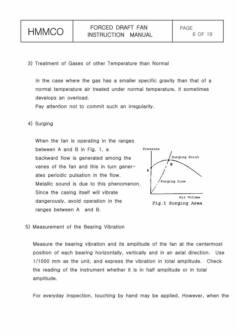
4) Surging
When the fan is operating in the ranges
between A and B in Fig. 1, a
backward flow is generated among the
vanes of the fan and this in turn gener-
ates periodic pulsation in the flow.
Metallic sound is due to this phenomenon.
Since the casing itself will vibrate
dangerously, avoid operation in the
ranges between A and B.
5) Measurement of the Bearing Vibration
Measure the bearing vibration and its amplitude of the fan at the centermost
position of each bearing horizontally, vertically and in an axial direction. Use
1/1000 mm as the unit, and express the vibration in total amplitude. Check
the reading of the instrument whether it is in half amplitude or in total
amplitude.
For everyday inspection, touching by hand may be applied. However, when the
FORCED DRAFT FAN
INSTRUCTION MANUALPAGE
7 OF 19
For everyday inspection, touching by hand may be applied. However, when the
vibration becomes big, measure it with a vibration gauge. If it exceeds the
permissible value of the bearing vibration, stop operation without delay to
inspect and adjust.
When vibration starts and keeps of going, it becomes impossible to operate
continuously.
Therefore the imbalance should be rectified immediately.
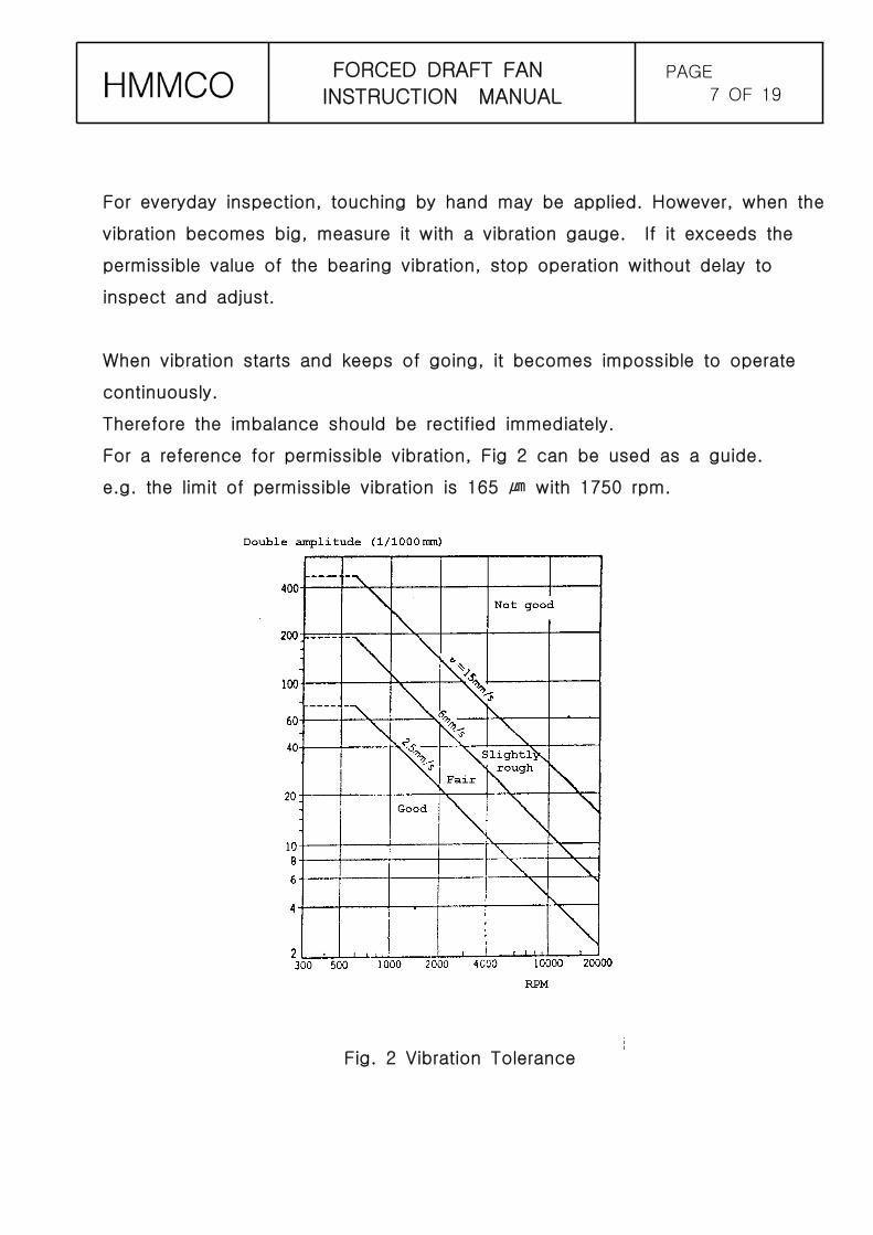
For a reference for permissible vibration, Fig 2 can be used as a guide.
e.g. the limit of permissible vibration is 165 with 1750 rpm.㎛
Fig. 2 Vibration Tolerance
FORCED DRAFT FAN
INSTRUCTION MANUALPAGE
8 OF 19
1-4 Stopping & Shut Down
After the complete closing of air control damper, stop the main electric motor.
Make sure that any abnormal sound is not heard, and that the drop of the
number of revolution is not abnormally fast until the rotor is completely
stopped.
For a shut down of a long period, drain thoroughly the water such as the
cooling water in the bearing housing every part, and also the machine
thoroughly. Coat the finished faces of each section of the machine with
appropriate corrosion inhibitor. Provide cover over the necessary places to
prevent dust, rain, etc., settling in the machine.
Pay special attention to the motor.
FORCED DRAFT FAN
INSTRUCTION MANUALPAGE
9 OF 19
2. MAINTENANCE MANUAL
It is important to perform regular maintenance according the right plan for the long
life expectancy and the safe operation. Although basic maintenance items are the
lubrication and cleaning of the bearing, and regular vibration checking, frequent
measurement of the discharge pressure, air temperature, current, and etc can
prevent the accidents in advance, since the operation of the fan in worse
conditions than specified conditions can causes the accidents. Since the operating
conditions or surroundings other than designed specifications can affect the
performance of the fan, adjust the operating conditions and perform the regular
check-up as early as possible after the first operation.
2-1 Daily Check Points
Pay attention to the following points everyday and carry out the inspection of
the blower.
1) Is there any abnormal noise ?
2) Are the bearing temperature and vibration normal ?
3) Is the value shown by the ammeter normal ?
4) Is the V-belt correctly aligned and properly stretched ?
5) Is the oil quantity proper when using oil bath or oil ring lubrication ?
(Check by means of oil level gauge.)
FORCED DRAFT FAN
INSTRUCTION MANUALPAGE
10 OF 19
2-2 Suspension of Operation
1) When the operation of the fan is to be suspended, pay much attention in
cleaning, rust prevention of the blower, and be cautious in preventing dust,
dirt and water getting into bearings.
2) Pay attention to prevent humidity against all electrical parts such as the
motor and other parts.
3) Remove water completely from the bearing cooling water piping and
bearing cases.
2-3 Periodical Inspection
Carry out periodical inspection at least once a year, and inspect the following
items:
1) Clean disassembled parts thoroughly.
2) Replace lubricating oil (or grease) with fresh ones
3) Examine the contacting surfaces of the rotating elements and the static
sections.
4) Examine the condition of play at fitting sections.
5) Recheck the alignment.
FORCED DRAFT FAN
INSTRUCTION MANUALPAGE
11 OF 19
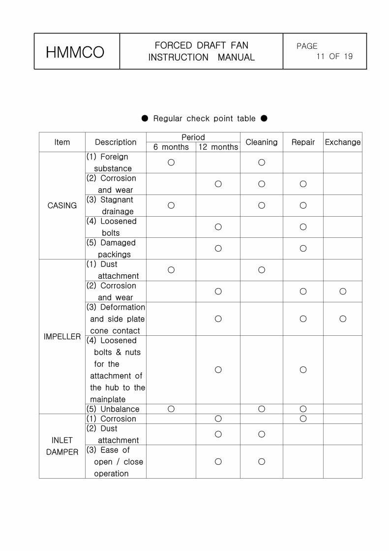
Regular check point table● ●
Item DescriptionPeriod
Cleaning Repair Exchange6 months 12 months
CASING
(1) Foreign
substance○ ○
(2) Corrosion
and wear○ ○ ○
(3) Stagnant
drainage○ ○ ○
(4) Loosened
bolts○ ○
(5) Damaged
packings○ ○
IMPELLER
(1) Dust
attachment○ ○
(2) Corrosion
and wear○ ○ ○
(3) Deformation
and side plate
cone contact
○ ○ ○
(4) Loosened
bolts & nuts
for the
attachment of
the hub to the
mainplate
○ ○
(5) Unbalance ○ ○ ○
INLET
DAMPER
(1) Corrosion ○ ○(2) Dust
attachment○ ○
(3) Ease of
open / close
operation
○ ○
FORCED DRAFT FAN
INSTRUCTION MANUALPAGE
12 OF 19
2-4 Operation Diary
Inasmuch as the operation diary is the data for making a diagnosis of the fan,
keep a meticulous entry for present and future reference. If the operating
record is kept, it is possible to find abnormality in the early stage, and even if
trouble occurs, it is easy to find the cause of trouble.
2-5 Causes of Troubles and Their Countermeasures
Even under the strictest observation, there may be a discrepancy the operator
may have never expected, which may lead to trouble. We will find out its
causes and take proper countermeasure for you provided that you supply us
with history of operation since the beginning and current situation of the
problem.
See Table 1 where causes of troubles and their countermeasure are listed.
FORCED DRAFT FAN
INSTRUCTION MANUALPAGE
13 OF 19
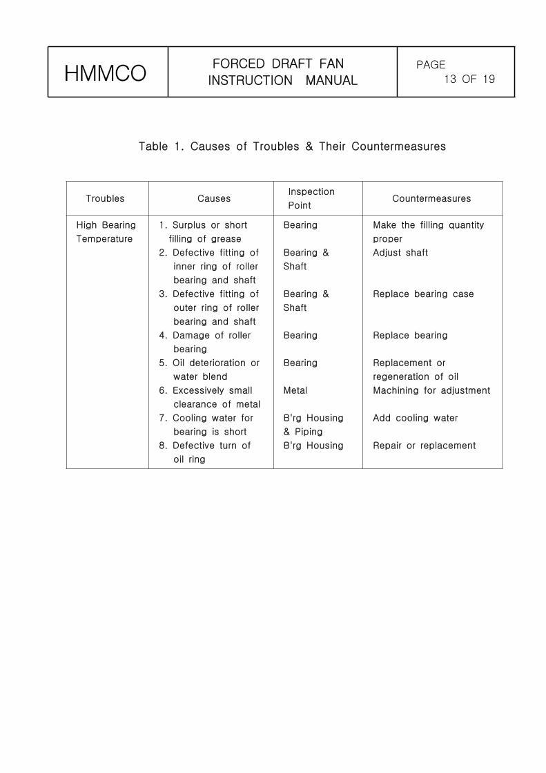
Table 1. Causes of Troubles & Their Countermeasures
Troubles CausesInspection
PointCountermeasures
High Bearing
Temperature
1. Surplus or short
filling of grease
2. Defective fitting of
inner ring of roller
bearing and shaft
3. Defective fitting of
outer ring of roller
bearing and shaft
4. Damage of roller
bearing
5. Oil deterioration or
water blend
6. Excessively small
clearance of metal
7. Cooling water for
bearing is short
8. Defective turn of
oil ring
Bearing
Bearing &
Shaft
Bearing &
Shaft
Bearing
Bearing
Metal
B'rg Housing
& Piping
B'rg Housing
Make the filling quantity
proper
Adjust shaft
Replace bearing case
Replace bearing
Replacement or
regeneration of oil
Machining for adjustment
Add cooling water
Repair or replacement
FORCED DRAFT FAN
INSTRUCTION MANUALPAGE
14 OF 19
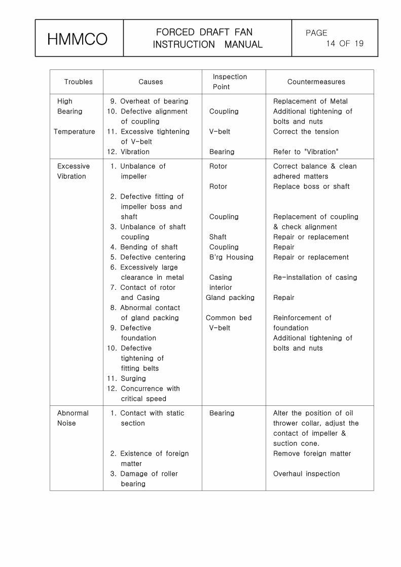
Troubles CausesInspection
PointCountermeasures
High
Bearing
Temperature
9. Overheat of bearing
10. Defective alignment
of coupling
11. Excessive tightening
of V-belt
12. Vibration
Coupling
V-belt
Bearing
Replacement of Metal
Additional tightening of
bolts and nuts
Correct the tension
Refer to "Vibration"
Excessive
Vibration
1. Unbalance of
impeller
2. Defective fitting of
impeller boss and
shaft
3. Unbalance of shaft
coupling
4. Bending of shaft
5. Defective centering
6. Excessively large
clearance in metal
7. Contact of rotor
and Casing
8. Abnormal contact
of gland packing
9. Defective
foundation
10. Defective
tightening of
fitting belts
11. Surging
12. Concurrence with
critical speed
Rotor
Rotor
Coupling
Shaft
Coupling
B'rg Housing
Casing
interior
Gland packing
Common bed
V-belt
Correct balance & clean
adhered matters
Replace boss or shaft
Replacement of coupling
& check alignment
Repair or replacement
Repair
Repair or replacement
Re-installation of casing
Repair
Reinforcement of
foundation
Additional tightening of
bolts and nuts
Abnormal
Noise
1. Contact with static
section
2. Existence of foreign
matter
3. Damage of roller
bearing
Bearing Alter the position of oil
thrower collar, adjust the
contact of impeller &
suction cone.
Remove foreign matter
Overhaul inspection
FORCED DRAFT FAN
INSTRUCTION MANUALPAGE
15 OF 19
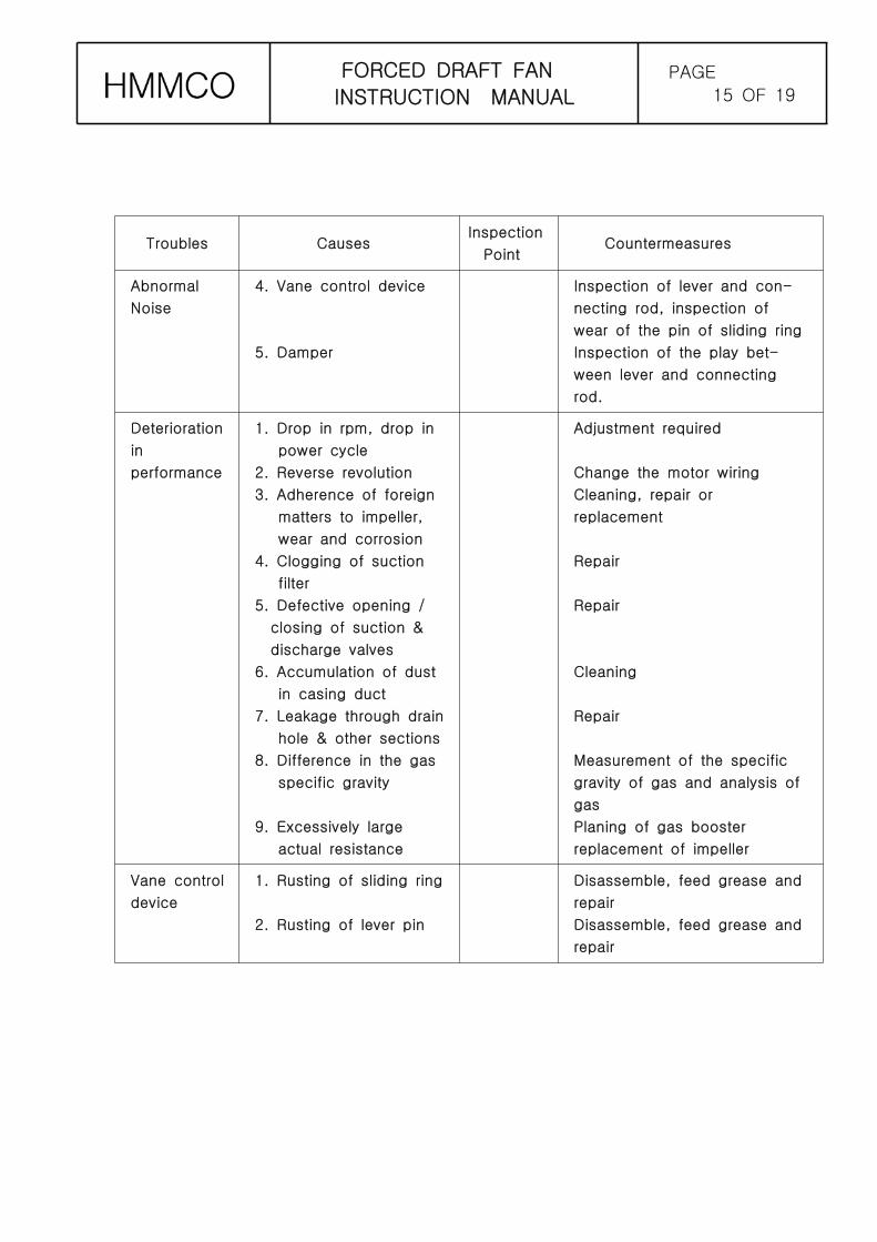
Troubles CausesInspection
PointCountermeasures
Abnormal
Noise
4. Vane control device
5. Damper
Inspection of lever and con-
necting rod, inspection of
wear of the pin of sliding ring
Inspection of the play bet-
ween lever and connecting
rod.
Deterioration
in
performance
1. Drop in rpm, drop in
power cycle
2. Reverse revolution
3. Adherence of foreign
matters to impeller,
wear and corrosion
4. Clogging of suction
filter
5. Defective opening /
closing of suction &
discharge valves
6. Accumulation of dust
in casing duct
7. Leakage through drain
hole & other sections
8. Difference in the gas
specific gravity
9. Excessively large
actual resistance
Adjustment required
Change the motor wiring
Cleaning, repair or
replacement
Repair
Repair
Cleaning
Repair
Measurement of the specific
gravity of gas and analysis of
gas
Planing of gas booster
replacement of impeller
Vane control
device
1. Rusting of sliding ring
2. Rusting of lever pin
Disassemble, feed grease and
repair
Disassemble, feed grease and
repair

FORCED DRAFT FAN
INSTRUCTION MANUALPAGE
16 OF 19
Troubles CausesInspection
PointCountermeasures
Suction
damper
1. Rusting of lever
2. Rusting of bearing
3. Contacting of blades
Disassemble, feed grease and
repair
Disassemble, feed grease and
repair
Repair the distortion of
blades, inspect its contact
duct
FORCED DRAFT FAN
INSTRUCTION MANUALPAGE
17 OF 19
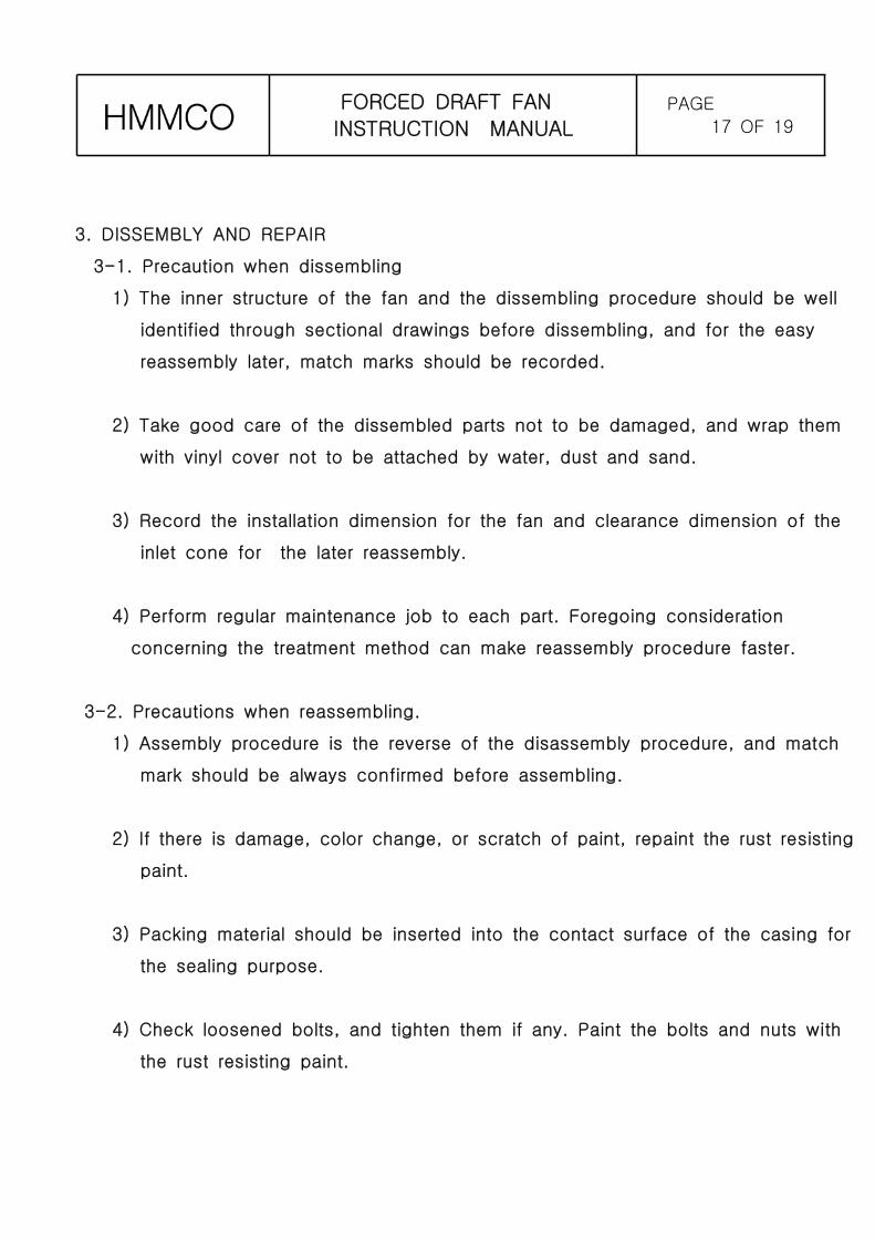
3. DISSEMBLY AND REPAIR
3-1. Precaution when dissembling
1) The inner structure of the fan and the dissembling procedure should be well
identified through sectional drawings before dissembling, and for the easy
reassembly later, match marks should be recorded.
2) Take good care of the dissembled parts not to be damaged, and wrap them
with vinyl cover not to be attached by water, dust and sand.
3) Record the installation dimension for the fan and clearance dimension of the
inlet cone for the later reassembly.
4) Perform regular maintenance job to each part. Foregoing consideration
concerning the treatment method can make reassembly procedure faster.
3-2. Precautions when reassembling.
1) Assembly procedure is the reverse of the disassembly procedure, and match
mark should be always confirmed before assembling.
2) If there is damage, color change, or scratch of paint, repaint the rust resisting
paint.
3) Packing material should be inserted into the contact surface of the casing for
the sealing purpose.
4) Check loosened bolts, and tighten them if any. Paint the bolts and nuts with
the rust resisting paint.
FORCED DRAFT FAN
INSTRUCTION MANUALPAGE
18 OF 19
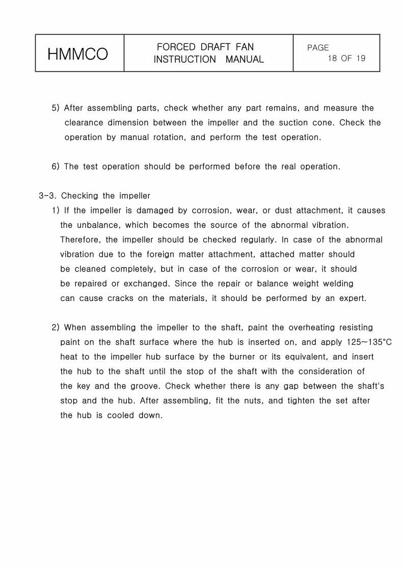
5) After assembling parts, check whether any part remains, and measure the
clearance dimension between the impeller and the suction cone. Check the
operation by manual rotation, and perform the test operation.
6) The test operation should be performed before the real operation.
3-3. Checking the impeller
1) If the impeller is damaged by corrosion, wear, or dust attachment, it causes
the unbalance, which becomes the source of the abnormal vibration.
Therefore, the impeller should be checked regularly. In case of the abnormal
vibration due to the foreign matter attachment, attached matter should
be cleaned completely, but in case of the corrosion or wear, it should
be repaired or exchanged. Since the repair or balance weight welding
can cause cracks on the materials, it should be performed by an expert.
2) When assembling the impeller to the shaft, paint the overheating resisting
paint on the shaft surface where the hub is inserted on, and apply 125~135°C
heat to the impeller hub surface by the burner or its equivalent, and insert
the hub to the shaft until the stop of the shaft with the consideration of
the key and the groove. Check whether there is any gap between the shaft's
stop and the hub. After assembling, fit the nuts, and tighten the set after
the hub is cooled down.
FORCED DRAFT FAN
INSTRUCTION MANUALPAGE
19 OF 19
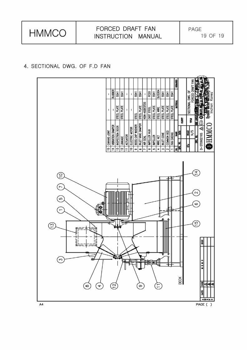
4. SECTIONAL DWG. OF F.D FAN