Embed Size (px)
Citation preview
1.6SERVICE
MANUAL
Manual Part No. 0G3865
CHERY GAS
ENGINE
forewordThis manual has been published by GENERAC® POWER SYSTEMS, INC. to aid our dealers’ mechanics, company service personnel and general con-sumers when servicing the products described herein.
It is assumed that these personnel are familiar with the servicing proce-dures for these products, or like or similar products, manufactured and marketed by GENERAC® POWER SYSTEMS, INC. It is also assumed that they have been trained in the recommended servicing procedures for these products, which includes the use of mechanics hand tools and any special tools that might be required.
Proper service and repair is important to the safe, economical and reliable operation of the products described herein. The troubleshooting, testing, service and repair procedures recommended by GENERAC® POWER SYSTEMS, INC. and described in this manual are effective methods of performing such operations. Some of these operations or procedures may require the use of specialized equipment. Such equipment should be used when and as recommended.
We could not possibly know of and advise the service trade of all conceivable procedures or methods by which a service might be performed, nor of any possible hazards and/or results of each procedure or method. We have not undertaken any such wide evaluation. Therefore, anyone who uses a pro-cedure or method not recommended by the manufacturer must first satisfy himself that neither his safety, nor the product’s safety, will be endangered by the service or operating procedure selected.
All information, illustrations and specifications contained in this manual are based on the latest product information available at the time of publication. However, GENERAC® POWER SYSTEMS, INC. reserves the right to change, alter or otherwise improve the product at any time without prior notice.
Some components or assemblies of the product described in this manual may not be considered repairable. Disassembly, repair and reassembly of such components may not be included in this manual.
The engines described herein may be used to power a wide variety of prod-ucts. Service and repair instructions relating to any such products are not covered in this manual. For information pertaining to use of these engines with other products, refer to any owner’s or service manuals pertaining to said products.
This engine has been engineered for use in Generac Power Systems products. The contents of this manual have been reprinted from the original manufacturer’s service and repair manual.
service recommendations ..................................................................................................................... 2
chery contents .................................................................................................................................................
1.6 Liter Gas engine Table of Contents
1.6 Liter Gas engine Service recommendations
�
◆ EnginEOilREcOmmEndatiOns
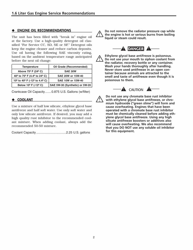
The unit has been filled with “break in” engine oil at the factory. Use a high-quality detergent oil clas-sified “For Service CC, SD, SE or SF.” Detergent oils keep the engine cleaner and reduce carbon deposits. Use oil having the following SAE viscosity rating, based on the ambient temperature range anticipated before the next oil change:
temperature oil Grade (recommended)
above 75º F (24º c) sae 30W
40º to 75º F (4.4º to 24º c) sae 20W or 15W-40
10º to 40º F (-12º to 4.4º c) sae 10W or 15W-40
Below 10º F (-12º c) sae 5W-30 (synthetic) or 5W-20
Crankcase Oil Capacity .......0.875 U.S. Gallons (w/filter)
◆ cOOlant
Use a mixture of half low silicate, ethylene glycol base antifreeze and half soft water. Use only soft water and only low silicate antifreeze. If desired, you may add a high quality rust inhibitor to the recommended cool-ant mixture. When adding coolant, always add the recommended 50-50 mixture.
Coolant Capacity ..................................�.�5 U.S. gallons
* do not remove the radiator pressure cap while the engine is hot or serious burns from boiling liquid or steam could result.
dangER
* ethylene glycol base antifreeze is poisonous. do not use your mouth to siphon coolant from the radiator, recovery bottle or any container. wash your hands thoroughly after handling. Never store used antifreeze in an open con-tainer because animals are attracted to the smell and taste of antifreeze even though it is poisonous to them.
* do not use any chromate base rust inhibitor
with ethylene glycol base antifreeze, or chro-mium hydroxide (“green slime”) will form and cause overheating. engines that have been operated with a chromate base rust inhibitor must be chemically cleaned before adding eth-ylene glycol base antifreeze. Using any high silicate antifreeze boosters or additives also will cause overheating. we also recommend that you do NoT use any soluble oil inhibitor for this equipment.
1.6 Liter Gas engine Service recommendations
�
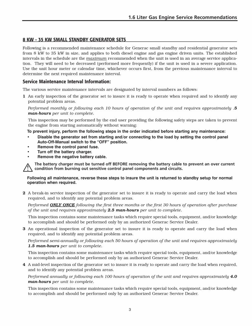
8kW-35kWsmallstandbygEnERatORsEts
Following is a recommended maintenance schedule for Generac small standby and residential generator sets from 8 kW to 35 kW in size, and applies to both diesel engine and gas engine driven units. The established intervals in the schedule are the maximum recommended when the unit is used in an average service applica-tion. They will need to be decreased (performed more frequently) if the unit is used in a severe application. Use the unit hour meter or calendar time, whichever occurs first, from the previous maintenance interval to determine the next required maintenance interval.
servicemaintenanceintervalinformation:The various service maintenance intervals are designated by interval numbers as follows:
1 An early inspection of the generator set to insure it is ready to operate when required and to identify any potential problem areas.
Performed monthly or following each 10 hours of operation of the unit and requires approximately .5 man-hours per unit to complete.
This inspection may be performed by the end user providing the following safety steps are taken to prevent the engine from starting automatically without warning:
Topreventinjury,performthefollowingstepsintheorderindicatedbeforestartinganymaintenance: • Disablethegeneratorsetfromstartingand/orconnectingtotheloadbysettingthecontrolpanel
Auto-Off-Manualswitchtothe“OFF”position. • Removethecontrolpanelfuse. • Turnoffthebatterycharger. • Removethenegativebatterycable.
* The battery charger must be turned off Before removing the battery cable to prevent an over current condition from burning out sensitive control panel components and circuits.
Followingallmaintenance,reversethesestepstoinsuretheunitisreturnedtostandbysetupfornormaloperationwhenrequired.
2 A break-in service inspection of the generator set to insure it is ready to operate and carry the load when required, and to identify any potential problem areas.
Performed ONLY ONCE following the first three months or the first 30 hours of operation after purchase of the unit and requires approximately 2.5 man-hours per unit to complete.
This inspection contains some maintenance tasks which require special tools, equipment, and/or knowledge to accomplish and should be performed only by an authorized Generac Service Dealer.
3 An operational inspection of the generator set to insure it is ready to operate and carry the load when required, and to identify any potential problem areas.
Performed semi-annually or following each 50 hours of operation of the unit and requires approximately 1.5 man-hours per unit to complete.
This inspection contains some maintenance tasks which require special tools, equipment, and/or knowledge to accomplish and should be performed only by an authorized Generac Service Dealer.
4 A mid-level inspection of the generator set to insure it is ready to operate and carry the load when required, and to identify any potential problem areas.
Performed annually or following each 100 hours of operation of the unit and requires approximately 4.0 man-hours per unit to complete.
This inspection contains some maintenance tasks which require special tools, equipment, and/or knowledge to accomplish and should be performed only by an authorized Generac Service Dealer.
�
Liter Gas engine Service recommendations
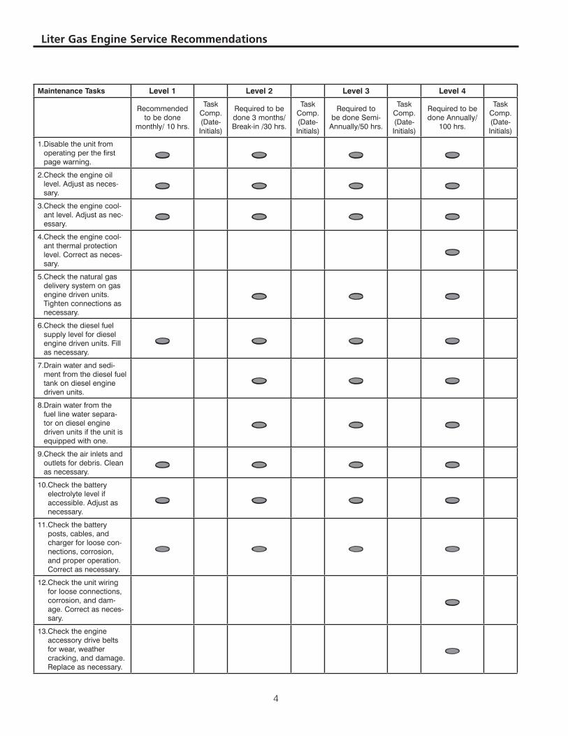
MaintenanceTasks Level1 Level2 Level3 Level4
Recommended to be done
monthly/ 10 hrs.
Task Comp. (Date-Initials)
Required to be done 3 months/ Break-in /30 hrs.
Task Comp. (Date-Initials)
Required to be done Semi-
Annually/50 hrs.
Task Comp. (Date-Initials)
Required to be done Annually/
100 hrs.
Task Comp. (Date-Initials)
1. Disable the unit from operating per the first page warning. • • • •
2. Check the engine oil level. Adjust as neces-sary. • • • •
3. Check the engine cool-ant level. Adjust as nec-essary. • • • •
4. Check the engine cool-ant thermal protection level. Correct as neces-sary.
•5. Check the natural gas
delivery system on gas engine driven units. Tighten connections as necessary.
• • •
6. Check the diesel fuel supply level for diesel engine driven units. Fill as necessary.
• • • •7. Drain water and sedi-
ment from the diesel fuel tank on diesel engine driven units.
• • •8. Drain water from the
fuel line water separa-tor on diesel engine driven units if the unit is equipped with one.
• • •
9. Check the air inlets and outlets for debris. Clean as necessary. • • • •
10. Check the battery electrolyte level if accessible. Adjust as necessary.
• • • •11. Check the battery
posts, cables, and charger for loose con-nections, corrosion, and proper operation. Correct as necessary.
• • • •
12. Check the unit wiring for loose connections, corrosion, and dam-age. Correct as neces-sary.
•
13. Check the engine accessory drive belts for wear, weather cracking, and damage. Replace as necessary.
•
�
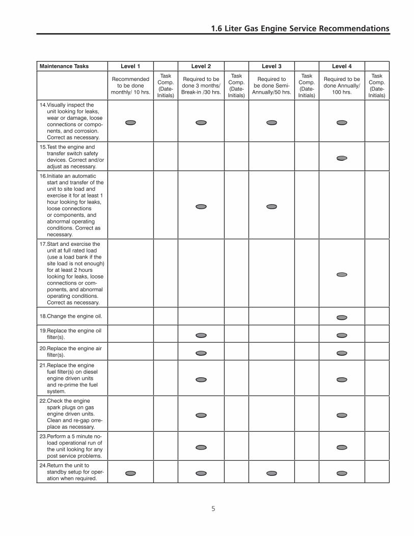
1.6 Liter Gas engine Service recommendations
MaintenanceTasks Level1 Level2 Level3 Level4
Recommended to be done
monthly/ 10 hrs.
Task Comp. (Date-Initials)
Required to be done 3 months/ Break-in /30 hrs.
Task Comp. (Date-Initials)
Required to be done Semi-
Annually/50 hrs.
Task Comp. (Date-Initials)
Required to be done Annually/
100 hrs.
Task Comp. (Date-Initials)
14. Visually inspect the unit looking for leaks, wear or damage, loose connections or compo-nents, and corrosion. Correct as necessary.
• • • •
15. Test the engine and transfer switch safety devices. Correct and/or adjust as necessary.
•16. Initiate an automatic
start and transfer of the unit to site load and exercise it for at least 1 hour looking for leaks, loose connections or components, and abnormal operating conditions. Correct as necessary.
• •
17. Start and exercise the unit at full rated load (use a load bank if the site load is not enough) for at least 2 hours looking for leaks, loose connections or com-ponents, and abnormal operating conditions. Correct as necessary.
•
18. Change the engine oil. •19. Replace the engine oil
filter(s). • •20. Replace the engine air
filter(s). • •21. Replace the engine
fuel filter(s) on diesel engine driven units and re-prime the fuel system.
• •
22. Check the engine spark plugs on gas engine driven units. Clean and re-gap orre-place as necessary.
• •
23. Perform a 5 minute no-load operational run of the unit looking for any post service problems.
• •24. Return the unit to
standby setup for oper-ation when required. • • • •

�
Notes
Engine Maintenance And Servicing Manual
3
Catalogue
Introduction………………………………………………………………………………………1 Engine configuration view and sectional view………………………………………………… 3 Main engine technical indexes and operation parameters………………………………………11 Engine structural features………………………………………………………………………13 Engine removal and assembly procedure………………………………………………17 [1] Positioning no.1 cylinder top dead center (compression) …………………………………17 [2] Upper and lower timing gear cover assemblies removal and installation……………………18 [3] Crankshaft pulley removal and installation…………………………………………………18 [4] Valve cover and seal gasket removal and installation………………………………………19 [5] Timing belt removal, installation and adjustment……………………………………………20 [6] Tension pulley, crankshaft gear and camshaft gear removal, check and installation………22 [7] Camshaft oil seal removal and installation…………………………………………………23 [8] Valve mechanism and cylinder head removal, check and installation………………………24 [9] Piston and connecting rod assembly removal and installation………………………………33 [10] Flywheel assembly and rear oil seal bracket assembly removal and installation …………36 [11] Crankshaft, crankshaft thrust washer, bearing bushing and main bearing cap removal and
installation ……………………………………………………………………………38 [12] Oil baffle assembly removal and installation……………………………………………41 [13] Engine oiling system………………………………………………………………………42 [14] Engine cooling system……………………………………………………………………49 [15] Engine air intake and exhaust system……………………………………………………53 [16] Engine crankcase ventilation system………………………………………………………58 [17] Engine fuel supply system…………………………………………………………………62 Carburetor engine malfunction, cause and correction………………………………………67
PDF 文件使用 "pdfFactory Pro" 试用版本创建 www.fineprint.com.cn
Engine Maintenance And Servicing Manual
Introduction
CAC478, CAC480 series vehicle gasoline engines, which are the products introduced from Ford (Britain) corporation CVH production line, are made by Anhui Chery automobile Corp. Products are made up of carburetor type, single-point electric control fuel injection type and electric control fuel injection type, which may meet the requirements for different performance and emission.
Single-point electric control fuel injection system and multipoint electric control fuel injection system of the above engines are developed though the joint effort with Italy M & M Corp.
With advanced product performance, reliable structure,CAC478、CAC480 series automobile gasoline engines may be applied for both car and light-duty vehicles. Specifications, covering major parameters, structural features, assembly and adjustment, common operation repair and maintenance, trouble shooting for CAC478, CAC480 carburetor and single-point electric control fuel injection engine, may be referred by mechanic, driver, technologist and management section.
Engine Maintenance And Servicing Manual
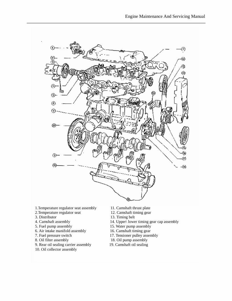
1.Temperature regulator seat assembly 11. Camshaft thrust plate 2.Temperature regulator seat 12. Camshaft timing gear 3. Distributor 13. Timing belt 4. Camshaft assembly 14. Upper\ lower timing gear cap assembly 5. Fuel pump assembly 15. Water pump assembly 6. Air intake manifold assembly 16. Camshaft timing gear 7. Fuel pressure switch 17. Tensioner pulley assembly 8. Oil filter assembly 18. Oil pump assembly 9. Rear oil sealing carrier assembly 19. Camshaft oil sealing 10. Oil collector assembly
PDF 文件使用 "pdfFactory Pro" 试用版本创建 www.fineprint.com.cn
Engine Maintenance And Servicing Manual
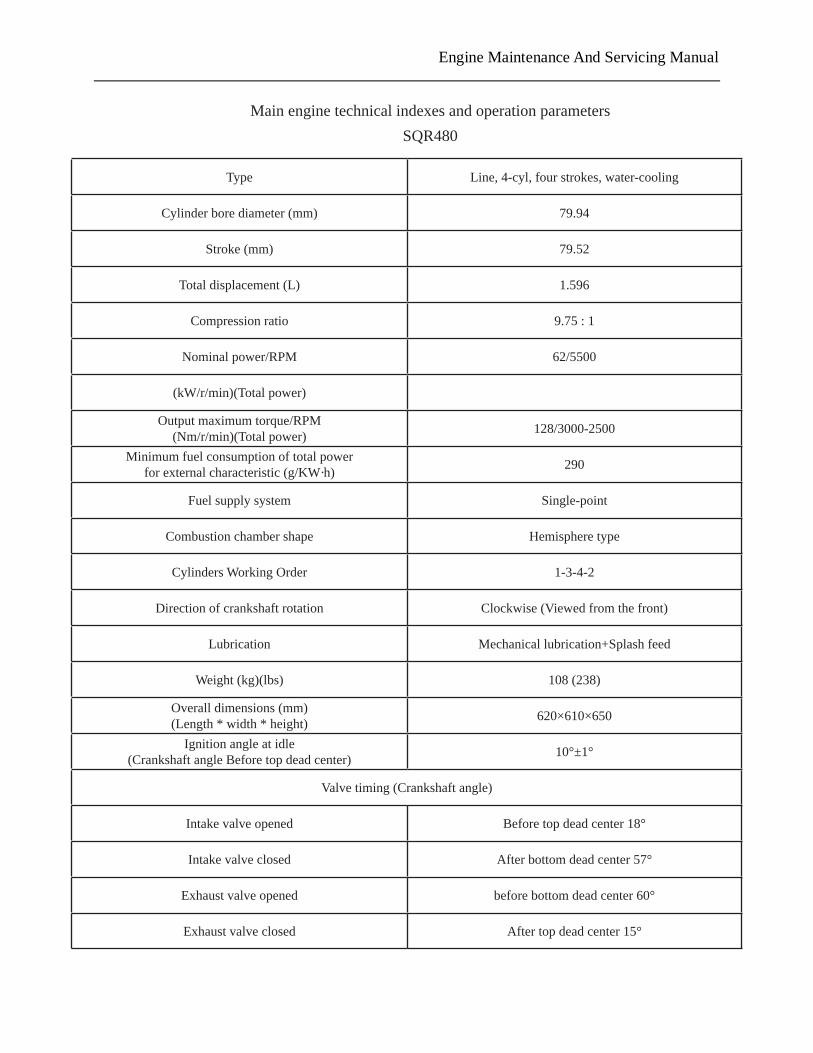
Main engine technical indexes and operation parametersSQR480
Type Line, 4-cyl, four strokes, water-cooling
Cylinder bore diameter (mm) 79.94
Stroke (mm) 79.52
Total displacement (L) 1.596
Compression ratio 9.75 : 1
Nominal power/RPM 62/5500
(kW/r/min)(Total power)
Output maximum torque/RPM(Nm/r/min)(Total power) 128/3000-2500
Minimum fuel consumption of total power for external characteristic (g/KW·h) 290
Fuel supply system Single-point
Combustion chamber shape Hemisphere type
Cylinders Working Order 1-3-4-2
Direction of crankshaft rotation Clockwise (Viewed from the front)
Lubrication Mechanical lubrication+Splash feed
Weight (kg)(lbs) 108 (238)
Overall dimensions (mm)(Length * width * height) 620×610×650
Ignition angle at idle(Crankshaft angle Before top dead center) 10°±1°
Valve timing (Crankshaft angle)
Intake valve opened Before top dead center 18°
Intake valve closed After bottom dead center 57°
Exhaust valve opened before bottom dead center 60°
Exhaust valve closed After top dead center 15°
Engine Maintenance And Servicing Manual
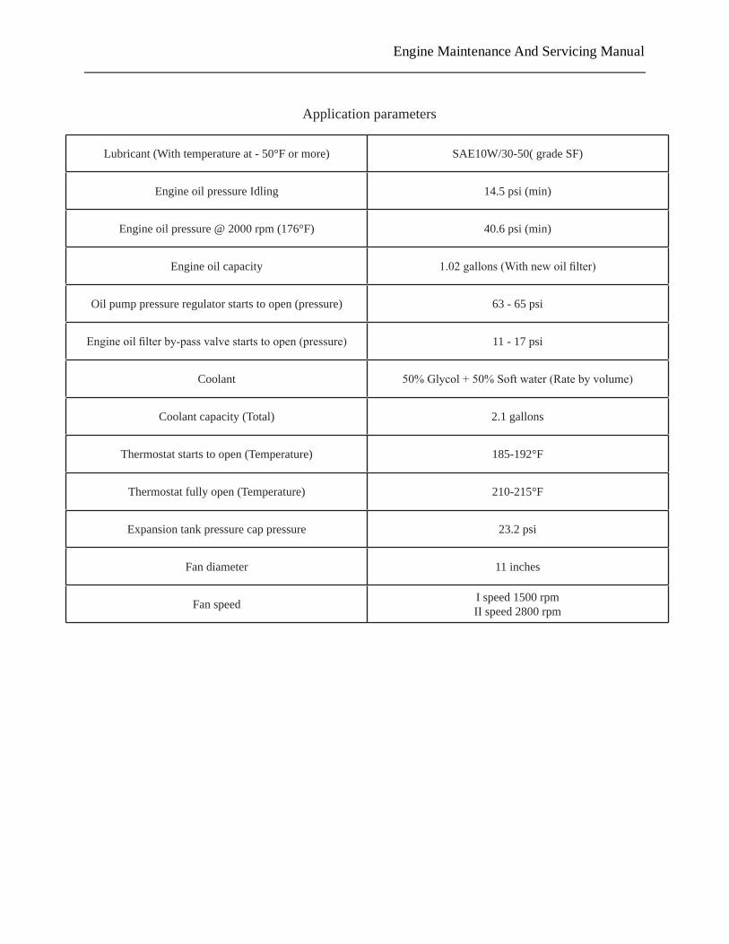
Application parameters
Lubricant (With temperature at - 50°F or more) SAE10W/30-50( grade SF)
Engine oil pressure Idling 14.5 psi (min)
Engine oil pressure @ 2000 rpm (176°F) 40.6 psi (min)
Engine oil capacity 1.02 gallons (With new oil filter)
Oil pump pressure regulator starts to open (pressure) 63 - 65 psi
Engine oil filter by-pass valve starts to open (pressure) 11 - 17 psi
Coolant 50% Glycol + 50% Soft water (Rate by volume)
Coolant capacity (Total) 2.1 gallons
Thermostat starts to open (Temperature) 185-192°F
Thermostat fully open (Temperature) 210-215°F
Expansion tank pressure cap pressure 23.2 psi
Fan diameter 11 inches
Fan speed I speed 1500 rpmII speed 2800 rpm
Engine Maintenance And Servicing Manual
Engine structural features 1.Cylinder block:Made from gray cast iron. Without bibcock. Without cylinder liner.5 main
bearing seats. Main Intermediate bearing anti-thrust. Main bearing caps are retained by spigot. Main bearing bolts of 12.9 grade.
2.Cylinder head:Made from aluminum alloy. Intake and exhaust valve seats and valve guides strutting.6 camshaft supports. Without camshaft bushing. with fuel pump, Push rod and distributor,Thermo-sister in cylinder head for Carburetor engine. with thermo-sister in cylinder head for Electric control engine. Cylinder cover bolts of 10.9 grade.
3.Piston:made from eutectic aluminum silicon. Anti-expansion steel-strutted skirt. Ellipse head and skirt. Cone head. Barrel skirt.
4.Piston ring:First compression ring of ductile cast iron. With excircle sprayed molybdenum. Ground ring with barrel surface. Second compression ring is of twist type. made from alloy cast iron. Steel strip combination oil ring. With scape blade excircle chroming.
5.Piston pin:Low carbon steel. Surface carbonizing and quenching. Semi-floating structure(Interference fit with small end of connecting rod. Clearance fit with piston pin hole.
6.Connecting rod:Forged steel. Flat insection. Without small end bushing. Connecting rod stem and cover are retained by 2 spring dowels. Piston and cylinder block is lubricated by oil spray from connecting rod bearing bore drill. Connecting rod bolts of 12.9 grade.
7.Crankshaft:4 balance weight. Ductalloy. Normalizing treatment. 8.Bearing bushing:Connecting rod bushing,Main bearing bushings and thrust washers are all
made of tin&aluminium duplex metal. Two pieces of thrust washer. They are mounted in cylinder block.
9.Flywheel:It is made of ductalloy. May be fitted with 190 and 210 clutch. Casted with crankshaft speed signal disk.
10.Camshaft:It is made of alloy cast iron. Cam and fuel pump eccentric cam high frequency quenching treatment. 5 supports. Camshaft thrust spacer is made from low carbon steel. Surface carbonitriding .
11.Rocker arm:Low carbon steel、Stamping. Surface carbonitriding. Rocker arm stud of 10.9 grade.
12.Hydraulic lifting rod:The surface contacting cam is quenched. The contact face with rocker arm is made of low carbon steel. Surface carbonitriding,Both contact face are circular-arc.
13.Intake valve seat:It is made of alloy cast iron. 14.Exhaust valve seat:Iron base powder metallurgy. Quench treatment. 15.Valve guide:It is made from alloy cast iron. 16.Valve: Intake valve:Made from 4Cr9Si2. With smaller end of conical surface
quenched,With conical surface angle 45°. With large nest seat in the valve head for hemispherical combustion chamber.
Exhaust valve:4Cr9Si2-21-4N. With conical surface angle 45°. With smaller end quenched.
17.Gear:Made from iron base powder metallurgy. 18.Timing belt:Made from cyaniding butadiene-acrylonitrile rubber.
PDF 文件使用 "pdfFactory Pro" 试用版本创建 www.fineprint.com.cn
Engine Maintenance And Servicing Manual
19.Intake manifold:Made from Aluminum alloy. With mixture warm upped by water jacket. Electric heated intake manifold is optional.
20.Exhaust manifold:Made from ductalloy or black cast iron. 21.Oil pan:Stamping ,Low carbon steel. Oil pool is in the front of cylinder block. 22.Oil pump:Rotor type. Case is made of aluminum alloy.
Speed ratio 1∶1,With pressure relief valve in oil pump. 23.Engine oil filter:Full flows type spinning filter. With by-pass valve in it. 24.Fuel pump:Diaphragm type. Driven by upper camshaft eccentric cam. Electric fuel pump for
electric control engine. In fuel tank. 25.Push rod:Made from low alloy steel,Carbonization & quench treatment. Only applied for
carburetor engine. 26.Water pump:Centrifugal type,Cast iron impeller,Aluminum alloy case,Driven by timing
belt through gear. Speed ratio 1.053∶1.
27.Thermosister:Wax type. 28.Thermosister seat:Aluminum alloy,With overflow valve,overflow pipe and
micro-circulation tube. 29.Carburetor:Pierbort 2E3 carburetor. Throttle valve body for 480M 30MM12 Imported
part. 30.Spark plug:K7RTC 31.Non-contact distributor:Driven by the rear end of camshaft,Type is FDW451& JFD459.Only
applied for carburetor engine. 32.Ignition controller:Type are ZJ5701—HG & KH—3A.Only applied for carburetor engine. 33.Generator:14V 90A,Type are JFZ1913—4 or JFZ1813—2B. 34.Starter:12V 0.95KW QDY1258 or SD6RA78. 35.ECU:I.A.W.6F Imported Only for 480M engine.
PDF 文件使用 "pdfFactory Pro" 试用版本创建 www.fineprint.com.cn
Engine Maintenance And Servicing Manual
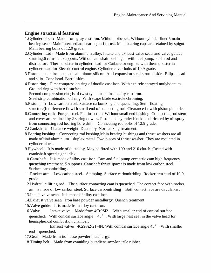
Engine removal and assembly procedure 【1】. Positioning no.1 cylinder top dead center (compression)
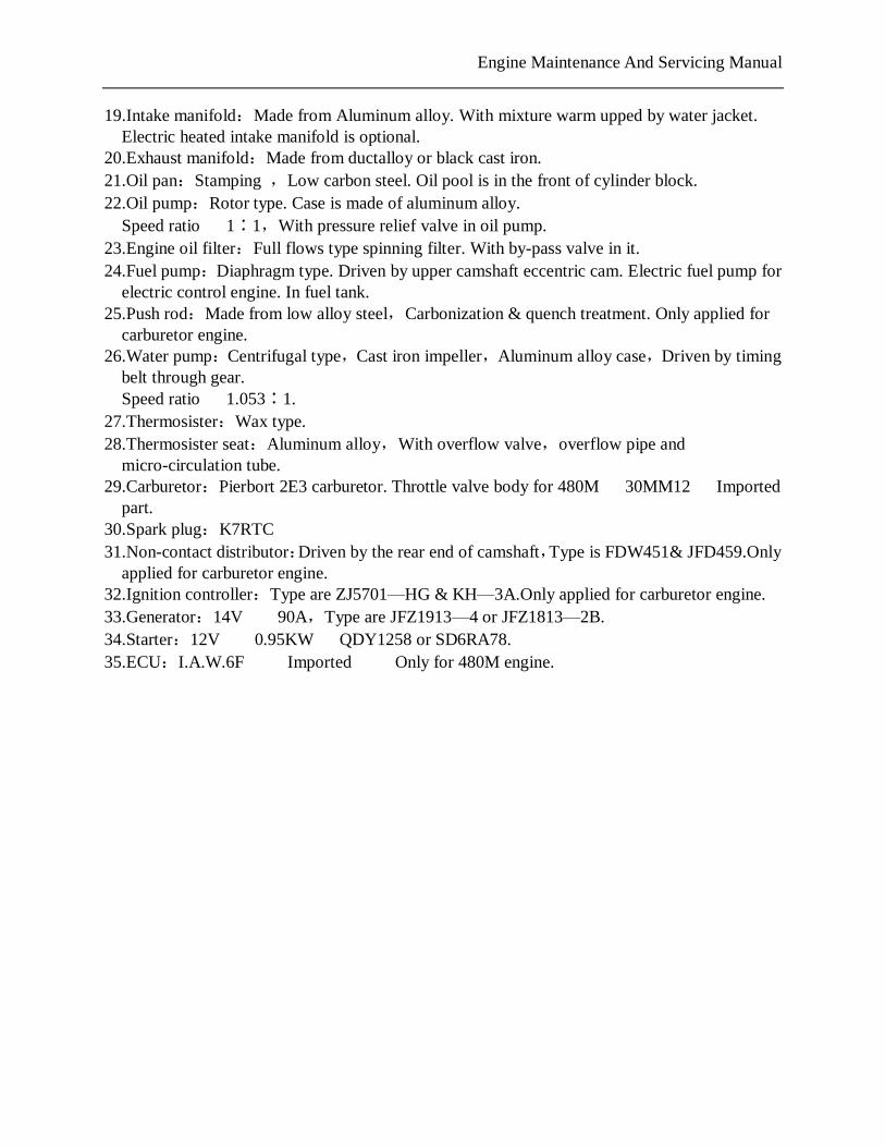
——Remove two M6×55 flange-shaped bolts, remove upper timing gear cover. ——Install a wrench on crankshaft pulley bolt, rotate crankshaft Clockwise (viewed from the direction of pulley) until the TDC notch on crankshaft pulley aligns with the TDC mark (0) on timing gear cover. Note:Before rotation,spark plugs may be removed to reduce effort. ——Check whether the TDC mark on the camshaft gear aligns with the mark on the front end of cylinder head. If not aligned, rotate crankshaft one turn,aligning the TDC mark on the camshaft gear with the TDC mark on the front end of cylinder head,engine should be at no.1 cylinder TDC . ——With crankshaft pulley and lower timing gear removed,position no.1 cylinder at TDC as following:
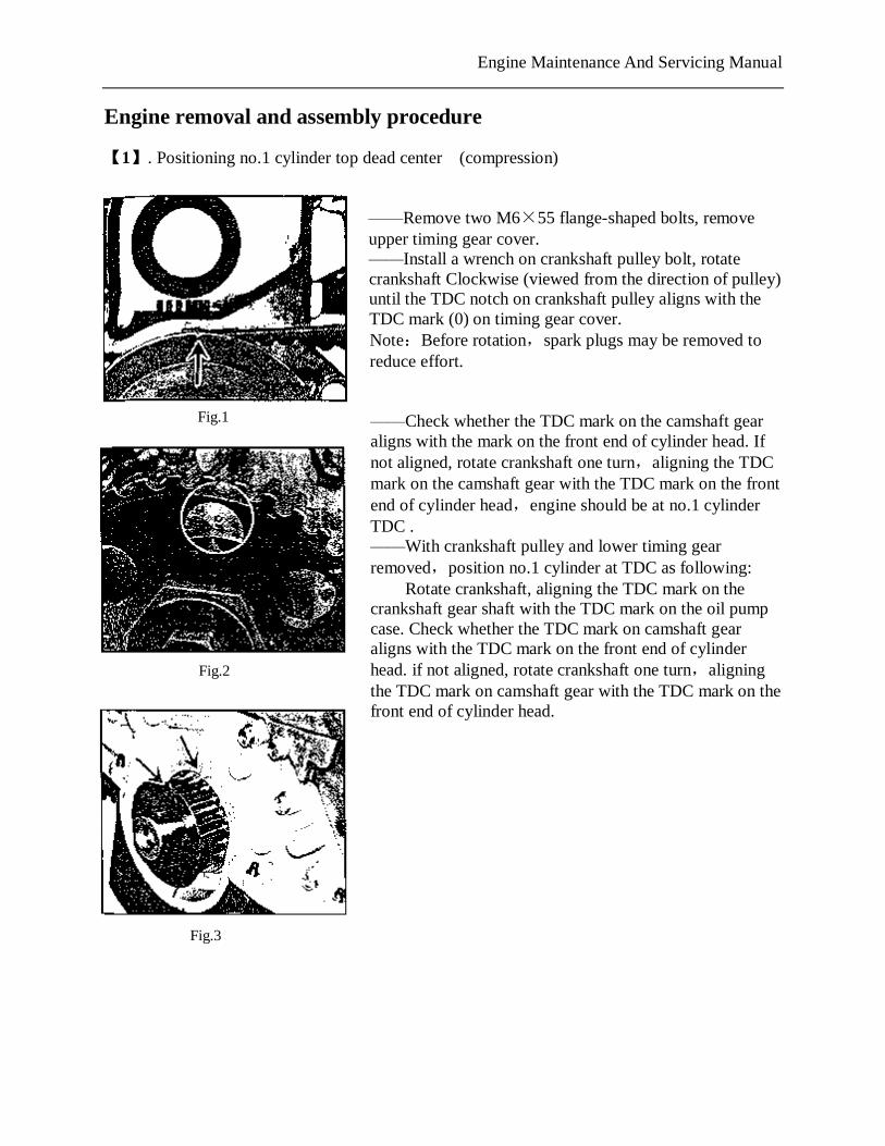
Rotate crankshaft, aligning the TDC mark on the crankshaft gear shaft with the TDC mark on the oil pump case. Check whether the TDC mark on camshaft gear aligns with the TDC mark on the front end of cylinder head. if not aligned, rotate crankshaft one turn,aligning the TDC mark on camshaft gear with the TDC mark on the front end of cylinder head.
Fig.3
Fig.2
Fig.1
PDF 文件使用 "pdfFactory Pro" 试用版本创建 www.fineprint.com.cn
Engine Maintenance And Servicing Manual
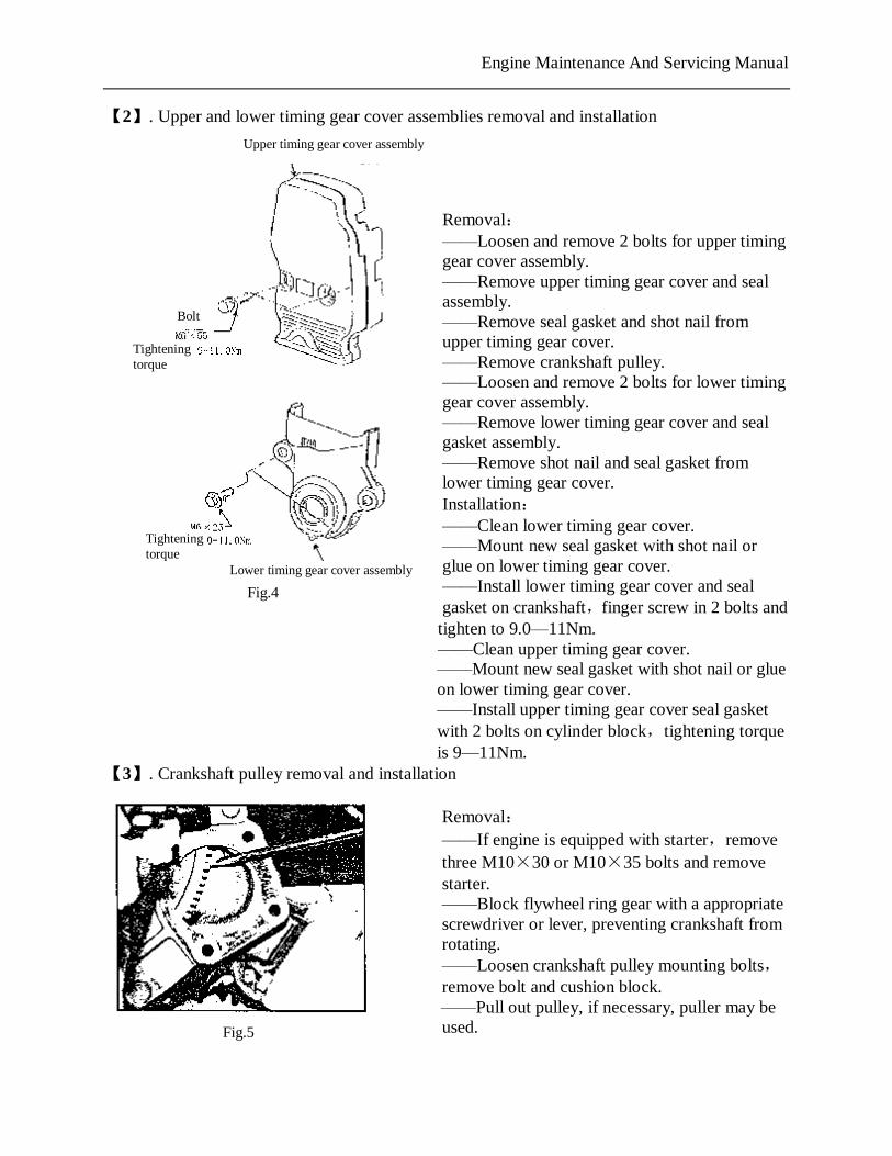
【2】. Upper and lower timing gear cover assemblies removal and installation
Removal: ——Loosen and remove 2 bolts for upper timing gear cover assembly. ——Remove upper timing gear cover and seal assembly. ——Remove seal gasket and shot nail from upper timing gear cover. ——Remove crankshaft pulley. ——Loosen and remove 2 bolts for lower timing gear cover assembly. ——Remove lower timing gear cover and seal gasket assembly. ——Remove shot nail and seal gasket from lower timing gear cover. Installation: ——Clean lower timing gear cover. ——Mount new seal gasket with shot nail or glue on lower timing gear cover. ——Install lower timing gear cover and seal gasket on crankshaft,finger screw in 2 bolts and
tighten to 9.0—11Nm. ——Clean upper timing gear cover. ——Mount new seal gasket with shot nail or glue on lower timing gear cover. ——Install upper timing gear cover seal gasket with 2 bolts on cylinder block,tightening torque is 9—11Nm.
【3】. Crankshaft pulley removal and installation
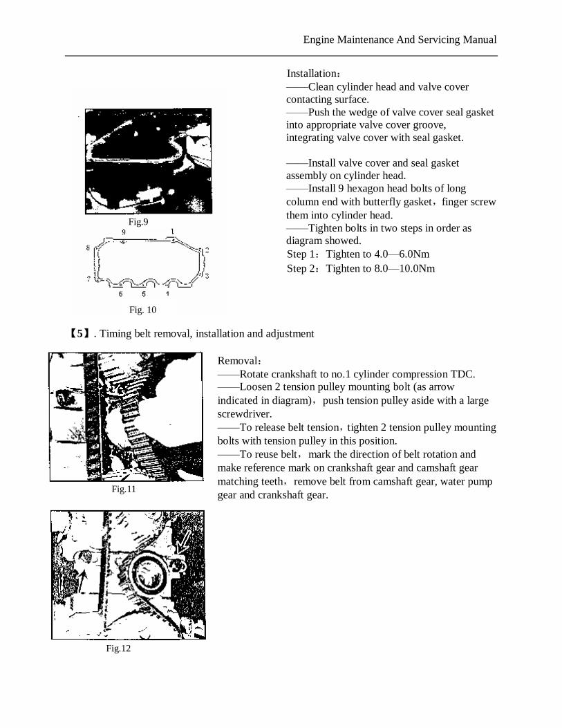
Removal: ——If engine is equipped with starter,remove three M10×30 or M10×35 bolts and remove starter. ——Block flywheel ring gear with a appropriate screwdriver or lever, preventing crankshaft from rotating. ——Loosen crankshaft pulley mounting bolts, remove bolt and cushion block. ——Pull out pulley, if necessary, puller may be used.
Upper timing gear cover assembly
Bolt
Tightening torque
Tightening torque
Lower timing gear cover assembly
Fig.4
Fig.5
PDF 文件使用 "pdfFactory Pro" 试用版本创建 www.fineprint.com.cn
Engine Maintenance And Servicing Manual
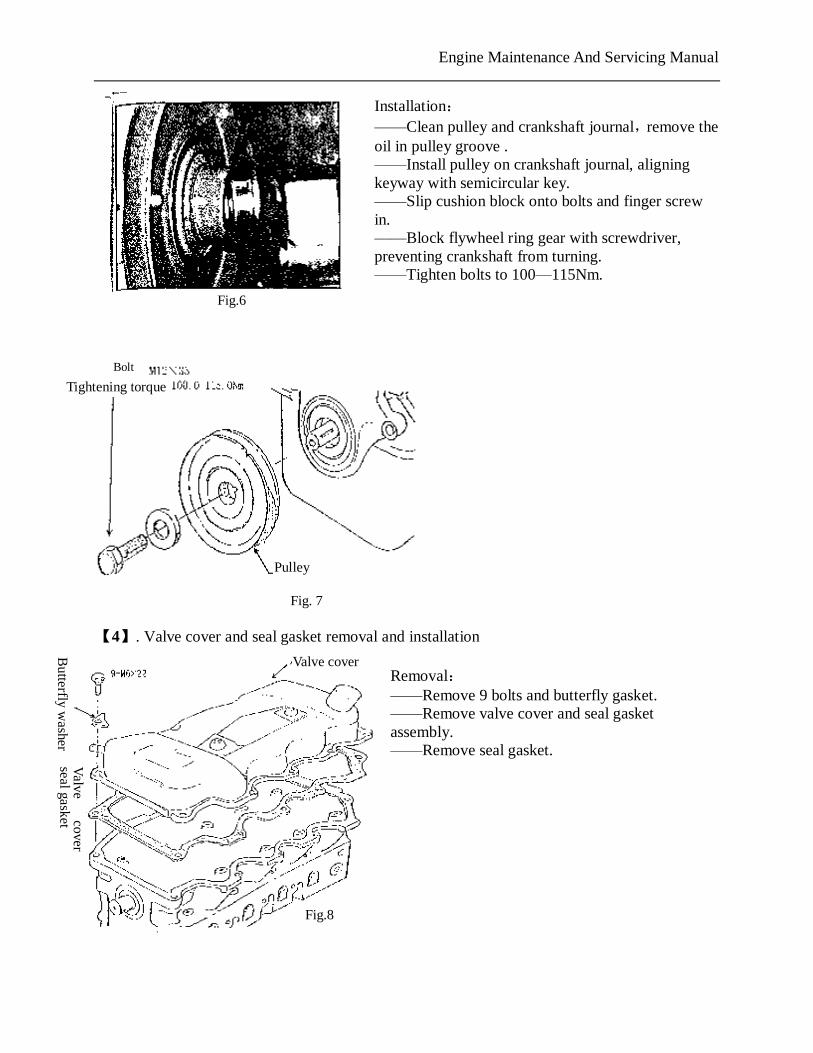
Installation: ——Clean pulley and crankshaft journal,remove the oil in pulley groove . ——Install pulley on crankshaft journal, aligning keyway with semicircular key. ——Slip cushion block onto bolts and finger screw in. ——Block flywheel ring gear with screwdriver, preventing crankshaft from turning. ——Tighten bolts to 100—115Nm.
【4】. Valve cover and seal gasket removal and installation
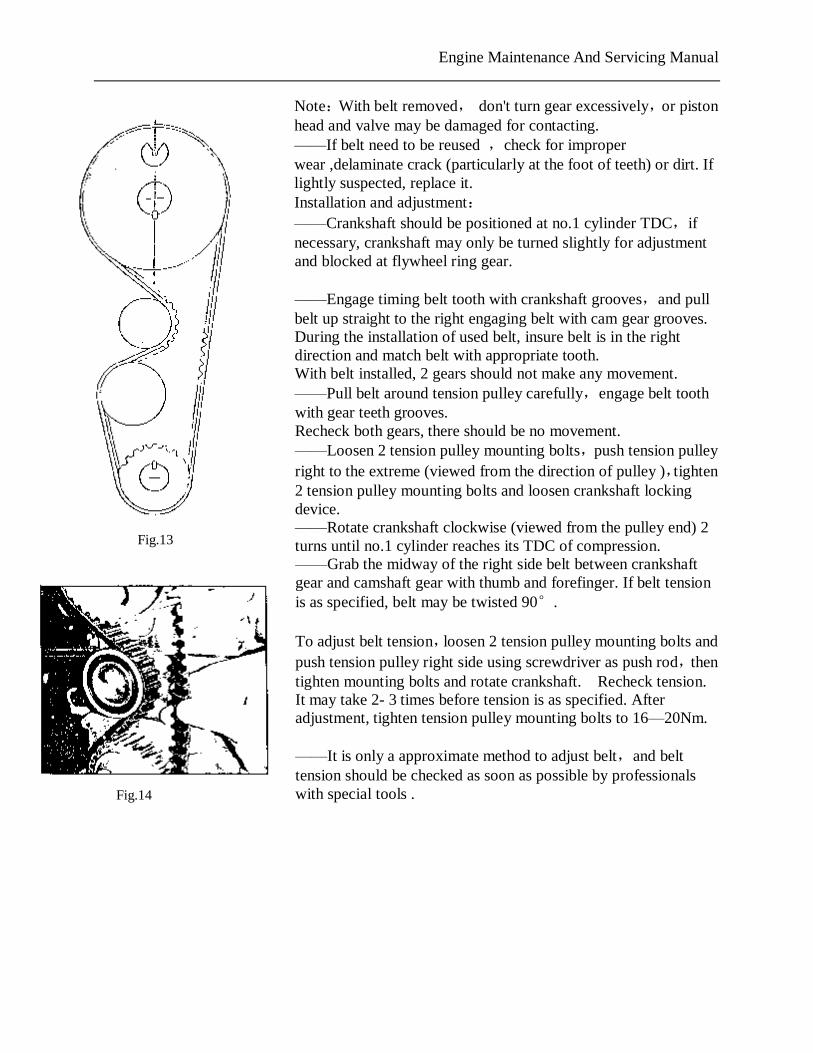
Removal: ——Remove 9 bolts and butterfly gasket. ——Remove valve cover and seal gasket assembly. ——Remove seal gasket.
Butterfly w
asher
Pulley
Tightening torque
Bolt
Valve cover
Fig. 7
Valve
cover seal gasket
Fig.6
Fig.8
PDF 文件使用 "pdfFactory Pro" 试用版本创建 www.fineprint.com.cn
Engine Maintenance And Servicing Manual
Installation: ——Clean cylinder head and valve cover contacting surface. ——Push the wedge of valve cover seal gasket into appropriate valve cover groove, integrating valve cover with seal gasket.
——Install valve cover and seal gasket assembly on cylinder head. ——Install 9 hexagon head bolts of long column end with butterfly gasket,finger screw them into cylinder head. ——Tighten bolts in two steps in order as diagram showed. Step 1:Tighten to 4.0—6.0Nm Step 2:Tighten to 8.0—10.0Nm
【5】. Timing belt removal, installation and adjustment
Removal: ——Rotate crankshaft to no.1 cylinder compression TDC. ——Loosen 2 tension pulley mounting bolt (as arrow indicated in diagram),push tension pulley aside with a large screwdriver. ——To release belt tension,tighten 2 tension pulley mounting bolts with tension pulley in this position. ——To reuse belt,mark the direction of belt rotation and make reference mark on crankshaft gear and camshaft gear matching teeth,remove belt from camshaft gear, water pump gear and crankshaft gear.
Fig.11
Fig.12
Fig.9
Fig. 10
PDF 文件使用 "pdfFactory Pro" 试用版本创建 www.fineprint.com.cn
Engine Maintenance And Servicing Manual
Note:With belt removed, don't turn gear excessively,or piston head and valve may be damaged for contacting. ——If belt need to be reused ,check for improper wear ,delaminate crack (particularly at the foot of teeth) or dirt. If lightly suspected, replace it. Installation and adjustment: ——Crankshaft should be positioned at no.1 cylinder TDC,if necessary, crankshaft may only be turned slightly for adjustment and blocked at flywheel ring gear. ——Engage timing belt tooth with crankshaft grooves,and pull belt up straight to the right engaging belt with cam gear grooves. During the installation of used belt, insure belt is in the right direction and match belt with appropriate tooth. With belt installed, 2 gears should not make any movement. ——Pull belt around tension pulley carefully,engage belt tooth with gear teeth grooves. Recheck both gears, there should be no movement. ——Loosen 2 tension pulley mounting bolts,push tension pulley right to the extreme (viewed from the direction of pulley ),tighten 2 tension pulley mounting bolts and loosen crankshaft locking device. ——Rotate crankshaft clockwise (viewed from the pulley end) 2 turns until no.1 cylinder reaches its TDC of compression. ——Grab the midway of the right side belt between crankshaft gear and camshaft gear with thumb and forefinger. If belt tension is as specified, belt may be twisted 90°. To adjust belt tension,loosen 2 tension pulley mounting bolts and push tension pulley right side using screwdriver as push rod,then tighten mounting bolts and rotate crankshaft. Recheck tension. It may take 2- 3 times before tension is as specified. After adjustment, tighten tension pulley mounting bolts to 16—20Nm. ——It is only a approximate method to adjust belt,and belt tension should be checked as soon as possible by professionals with special tools .
Fig.13
Fig.14
PDF 文件使用 "pdfFactory Pro" 试用版本创建 www.fineprint.com.cn
Engine Maintenance And Servicing Manual
【6】. Tension pulley, crankshaft gear and camshaft gear removal, check and installation
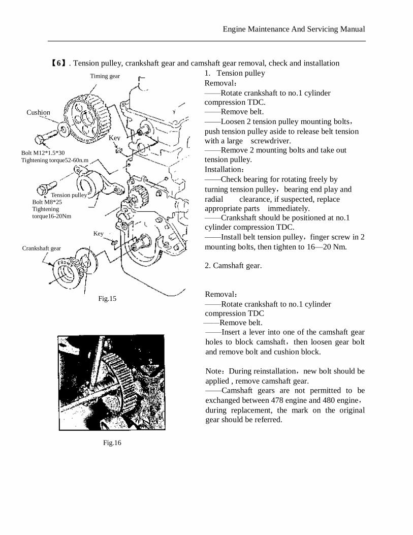
1. Tension pulley Removal: ——Rotate crankshaft to no.1 cylinder compression TDC. ——Remove belt. ——Loosen 2 tension pulley mounting bolts,push tension pulley aside to release belt tension with a large screwdriver. ——Remove 2 mounting bolts and take out tension pulley. Installation: ——Check bearing for rotating freely by turning tension pulley,bearing end play and radial clearance, if suspected, replace appropriate parts immediately. ——Crankshaft should be positioned at no.1 cylinder compression TDC. ——Install belt tension pulley,finger screw in 2 mounting bolts, then tighten to 16—20 Nm. 2. Camshaft gear. Removal: ——Rotate crankshaft to no.1 cylinder compression TDC
——Remove belt. ——Insert a lever into one of the camshaft gear holes to block camshaft,then loosen gear bolt and remove bolt and cushion block. Note:During reinstallation,new bolt should be applied , remove camshaft gear. ——Camshaft gears are not permitted to be exchanged between 478 engine and 480 engine,during replacement, the mark on the original gear should be referred.
Crankshaft gear
Tension pulley
Timing gear
Key
Cushion
Bolt M12*1.5*30 Tightening torque52-60n.m
Key
Bolt M8*25 Tightening torque16-20Nm
Fig.15
Fig.16
Engine Maintenance And Servicing Manual
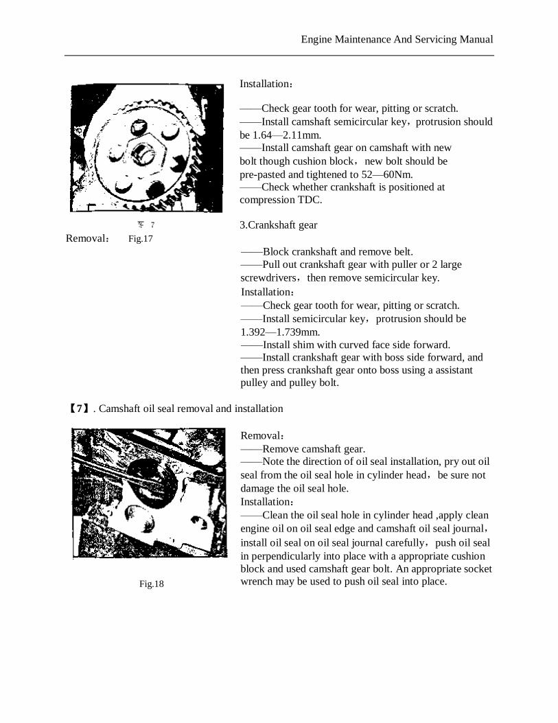
Installation: ——Check gear tooth for wear, pitting or scratch. ——Install camshaft semicircular key,protrusion should be 1.64—2.11mm. ——Install camshaft gear on camshaft with new bolt though cushion block,new bolt should be pre-pasted and tightened to 52—60Nm. ——Check whether crankshaft is positioned at compression TDC. 3.Crankshaft gear
Removal: ——Block crankshaft and remove belt. ——Pull out crankshaft gear with puller or 2 large screwdrivers,then remove semicircular key. Installation: ——Check gear tooth for wear, pitting or scratch. ——Install semicircular key,protrusion should be 1.392—1.739mm. ——Install shim with curved face side forward. ——Install crankshaft gear with boss side forward, and then press crankshaft gear onto boss using a assistant pulley and pulley bolt.
【7】. Camshaft oil seal removal and installation
Removal: ——Remove camshaft gear. ——Note the direction of oil seal installation, pry out oil seal from the oil seal hole in cylinder head,be sure not damage the oil seal hole. Installation: ——Clean the oil seal hole in cylinder head ,apply clean engine oil on oil seal edge and camshaft oil seal journal,install oil seal on oil seal journal carefully,push oil seal in perpendicularly into place with a appropriate cushion block and used camshaft gear bolt. An appropriate socket wrench may be used to push oil seal into place.
Fig.17
Fig.18
PDF 文件使用 "pdfFactory Pro" 试用版本创建 www.fineprint.com.cn
Engine Maintenance And Servicing Manual
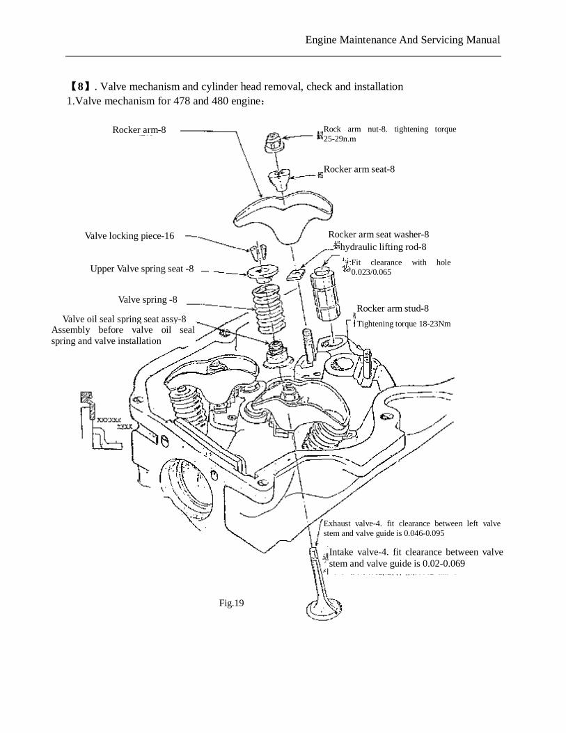
【8】. Valve mechanism and cylinder head removal, check and installation 1.Valve mechanism for 478 and 480 engine:
Rocker arm-8
Valve locking piece-16
Rocker arm seat-8
Fit clearance with hole 0.023/0.065
Rocker arm stud-8
Tightening torque 18-23Nm
Upper Valve spring seat -8
Valve spring -8
Valve oil seal spring seat assy-8 Assembly before valve oil seal spring and valve installation
Rocker arm seat washer-8 hydraulic lifting rod-8
Rock arm nut-8. tightening torque 25-29n.m
Exhaust valve-4. fit clearance between left valve stem and valve guide is 0.046-0.095
Intake valve-4. fit clearance between valve stem and valve guide is 0.02-0.069
Fig.19
PDF 文件使用 "pdfFactory Pro" 试用版本创建 www.fineprint.com.cn
Engine Maintenance And Servicing Manual
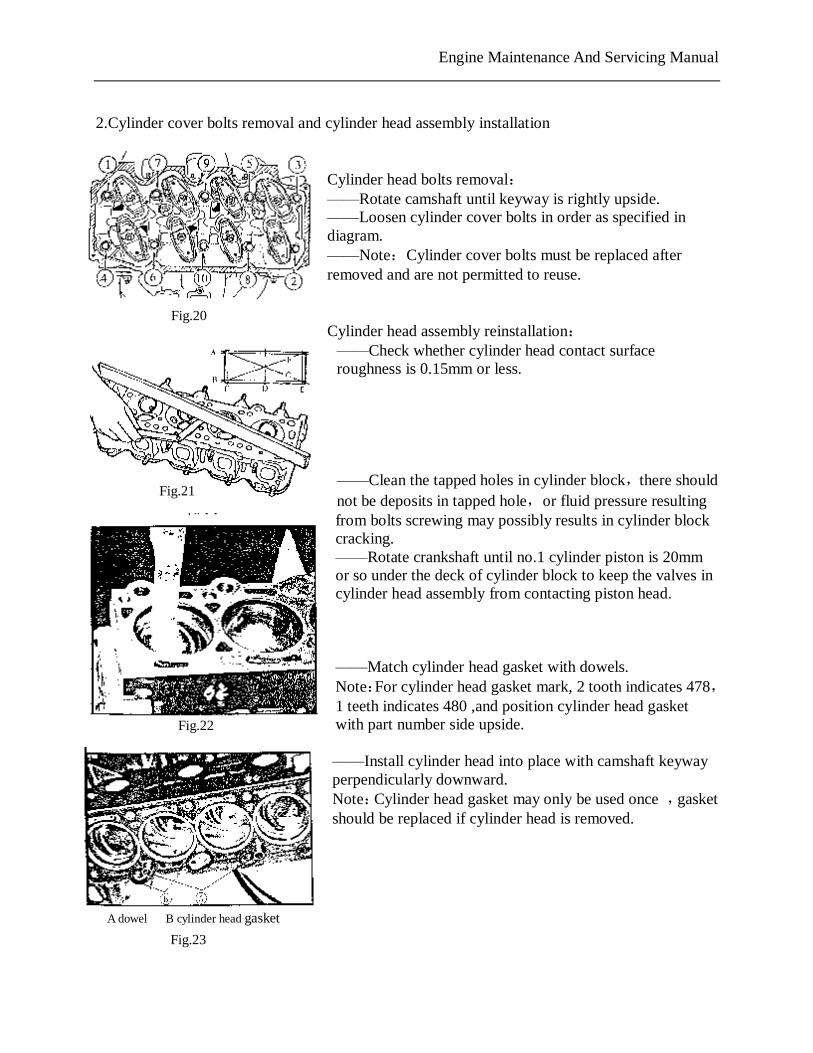
2.Cylinder cover bolts removal and cylinder head assembly installation
Cylinder head bolts removal: ——Rotate camshaft until keyway is rightly upside. ——Loosen cylinder cover bolts in order as specified in diagram. ——Note:Cylinder cover bolts must be replaced after removed and are not permitted to reuse. Cylinder head assembly reinstallation: ——Check whether cylinder head contact surface roughness is 0.15mm or less. ——Clean the tapped holes in cylinder block,there should not be deposits in tapped hole,or fluid pressure resulting from bolts screwing may possibly results in cylinder block cracking. ——Rotate crankshaft until no.1 cylinder piston is 20mm or so under the deck of cylinder block to keep the valves in cylinder head assembly from contacting piston head. ——Match cylinder head gasket with dowels. Note:For cylinder head gasket mark, 2 tooth indicates 478,1 teeth indicates 480 ,and position cylinder head gasket with part number side upside. ——Install cylinder head into place with camshaft keyway perpendicularly downward. Note:Cylinder head gasket may only be used once ,gasket should be replaced if cylinder head is removed.
A dowel B cylinder head gasket
Fig.23
Fig.22
Fig.20
Fig.21
PDF 文件使用 "pdfFactory Pro" 试用版本创建 www.fineprint.com.cn
Engine Maintenance And Servicing Manual
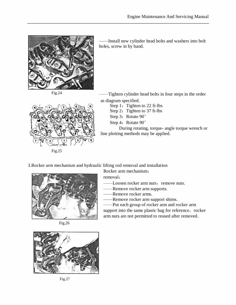
——Install new cylinder head bolts and washers into bolt holes, screw in by hand. ——Tighten cylinder head bolts in four steps in the order
as diagram specified. Step 1:Tighten to 22 ft-lbs Step 2:Tighten to 37 ft-lbs Step 3:Rotate 90° Step 4:Rotate 90° During rotating, torque- angle torque wrench or line plotting methods may be applied.
3.Rocker arm mechanism and hydraulic lifting rod removal and installation
Rocker arm mechanism: removal: ——Loosen rocker arm nuts,remove nuts. ——Remove rocker arm supports. ——Remove rocker arms. ——Remove rocker arm support shims. ——Put each group of rocker arm and rocker arm support into the same plastic bag for reference,rocker arm nuts are not permitted to reused after removed.
Fig.24
Fig.25
Fig.26
PDF 文件使用 "pdfFactory Pro" 试用版本创建 www.fineprint.com.cn
Fig.27
Engine Maintenance And Servicing Manual
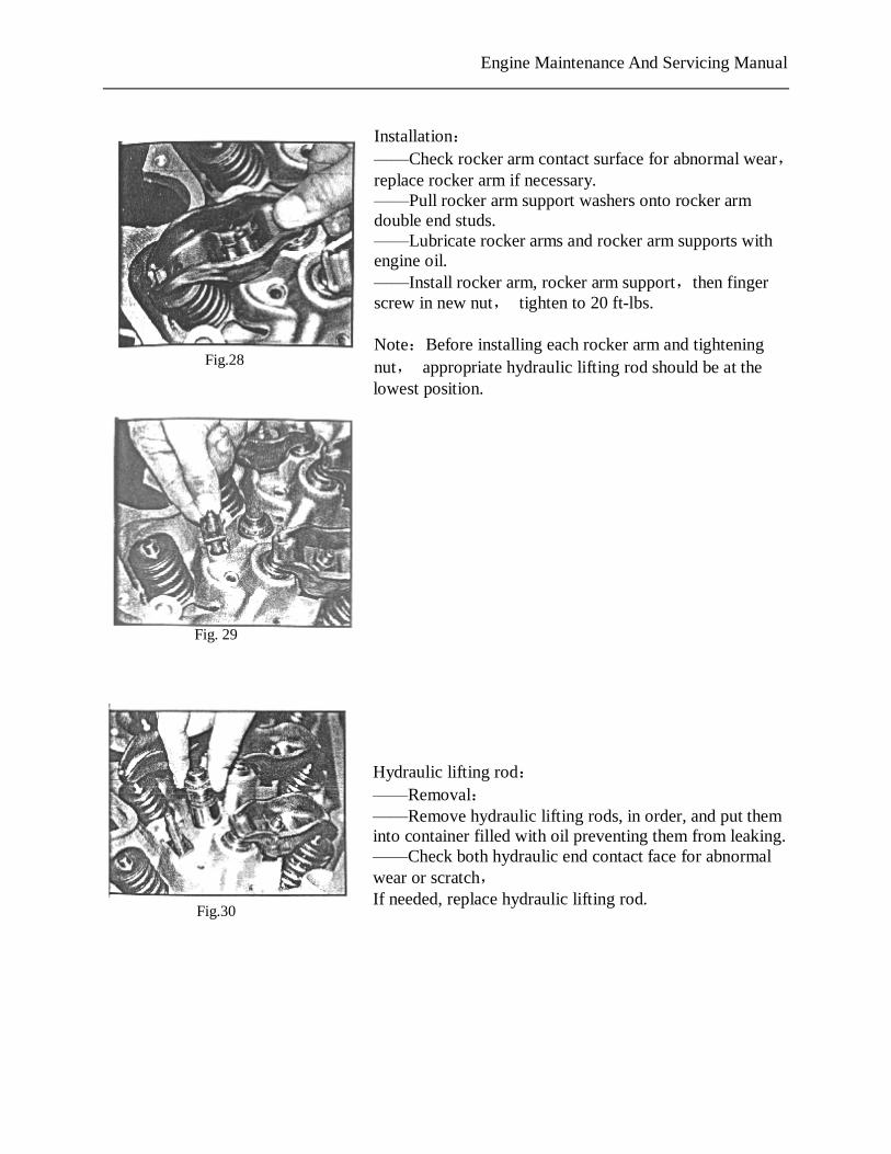
Installation: ——Check rocker arm contact surface for abnormal wear,replace rocker arm if necessary. ——Pull rocker arm support washers onto rocker arm double end studs. ——Lubricate rocker arms and rocker arm supports with engine oil. ——Install rocker arm, rocker arm support,then finger screw in new nut, tighten to 20 ft-lbs. Note:Before installing each rocker arm and tightening nut, appropriate hydraulic lifting rod should be at the lowest position.
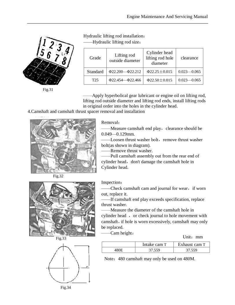
Hydraulic lifting rod: ——Removal: ——Remove hydraulic lifting rods, in order, and put them into container filled with oil preventing them from leaking. ——Check both hydraulic end contact face for abnormal wear or scratch, If needed, replace hydraulic lifting rod.
Fig.28
Fig. 29
Fig.30
PDF 文件使用 "pdfFactory Pro" 试用版本创建 www.fineprint.com.cn
Engine Maintenance And Servicing Manual
Hydraulic lifting rod installation: ——Hydraulic lifting rod size:
——Apply hyperbolical gear lubricant or engine oil on lifting rod, lifting rod outside diameter and lifting rod ends, install lifting rods in original order into the holes in the cylinder head.
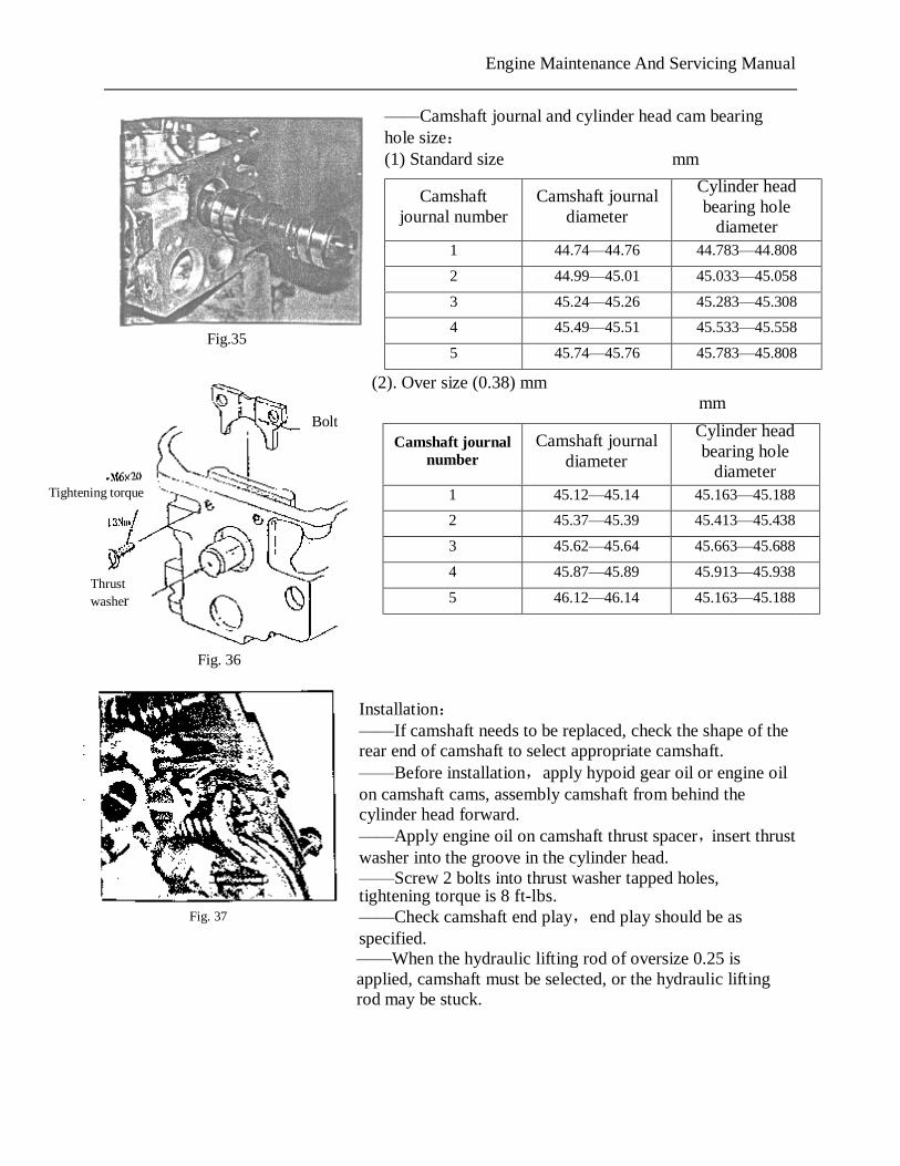
4.Camshaft and camshaft thrust spacer removal and installation Removal: ——Measure camshaft end play,clearance should be 0.049—0.129mm. ——Loosen thrust washer bolt,remove thrust washer bolt(as shown in diagram). ——Remove thrust washer. ——Pull camshaft assembly out from the rear end of cylinder head,don't damage the camshaft hole in Cylinder head.
Inspection: ——Check camshaft cam and journal for wear,if worn out, replace it. ——If camshaft end play exceeds specification, replace thrust washer. ——Measure the diameter of the camshaft hole in cylinder head ,or check journal to hole movement with camshaft,if hole is worn excessively, camshaft may only be replaced. ——Cam height:
Grade Lifting rod
outside diameter
Cylinder head lifting rod hole
diameter clearance
Standard Φ22.200—Φ22.212 Φ22.25±0.015 0.023—0.065
T25 Φ22.454—Φ22.466 Φ22.50±0.015 0.023—0.065
Intake cam T Exhaust cam T 480E 37.559 37.559
Fig.31
Fig.32
Fig.33 Unit:mm
Fig.34
Note:480 camshaft may only be used on 480M.
PDF 文件使用 "pdfFactory Pro" 试用版本创建 www.fineprint.com.cn
Engine Maintenance And Servicing Manual
——Camshaft journal and cylinder head cam bearing hole size: (1) Standard size mm
(2). Over size (0.38) mm mm
Installation: ——If camshaft needs to be replaced, check the shape of the rear end of camshaft to select appropriate camshaft. ——Before installation,apply hypoid gear oil or engine oil on camshaft cams, assembly camshaft from behind the cylinder head forward. ——Apply engine oil on camshaft thrust spacer,insert thrust washer into the groove in the cylinder head. ——Screw 2 bolts into thrust washer tapped holes, tightening torque is 8 ft-lbs. ——Check camshaft end play,end play should be as specified. ——When the hydraulic lifting rod of oversize 0.25 is applied, camshaft must be selected, or the hydraulic lifting rod may be stuck.
Camshaft journal number
Camshaft journal diameter
Cylinder head bearing hole
diameter
1 44.74—44.76 44.783—44.808
2 44.99—45.01 45.033—45.058
3 45.24—45.26 45.283—45.308
4 45.49—45.51 45.533—45.558
5 45.74—45.76 45.783—45.808
Camshaft journal number
Camshaft journal diameter
Cylinder head bearing hole
diameter
1 45.12—45.14 45.163—45.188
2 45.37—45.39 45.413—45.438
3 45.62—45.64 45.663—45.688
4 45.87—45.89 45.913—45.938
5 46.12—46.14 45.163—45.188
Bolt
Tightening torque
Thrust washer
Fig.35
Fig. 36
Fig. 37
PDF 文件使用 "pdfFactory Pro" 试用版本创建 www.fineprint.com.cn
Engine Maintenance And Servicing Manual
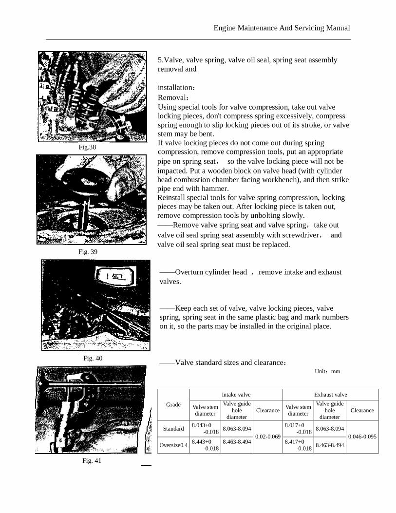
5.Valve, valve spring, valve oil seal, spring seat assembly removal and installation: Removal: Using special tools for valve compression, take out valve locking pieces, don't compress spring excessively, compress spring enough to slip locking pieces out of its stroke, or valve stem may be bent. If valve locking pieces do not come out during spring compression, remove compression tools, put an appropriate pipe on spring seat, so the valve locking piece will not be impacted. Put a wooden block on valve head (with cylinder head combustion chamber facing workbench), and then strike pipe end with hammer. Reinstall special tools for valve spring compression, locking pieces may be taken out. After locking piece is taken out, remove compression tools by unbolting slowly. ——Remove valve spring seat and valve spring,take out valve oil seal spring seat assembly with screwdriver, and valve oil seal spring seat must be replaced. ——Overturn cylinder head ,remove intake and exhaust valves. ——Keep each set of valve, valve locking pieces, valve spring, spring seat in the same plastic bag and mark numbers on it, so the parts may be installed in the original place. ——Valve standard sizes and clearance:
Unit:mm
Intake valve Exhaust valve
Grade Valve stem diameter
Valve guide hole
diameter Clearance
Valve stem diameter
Valve guide hole
diameter Clearance
Standard 8.043+0
-0.018 8.063-8.094 8.017+0
-0.018 8.063-8.094
Oversize0.4 8.443+0
-0.018 8.463-8.494
0.02-0.069 8.417+0
-0.018 8.463-8.494
0.046-0.095
Fig.38
Fig. 39
Fig. 40
Fig. 41
Engine Maintenance And Servicing Manual
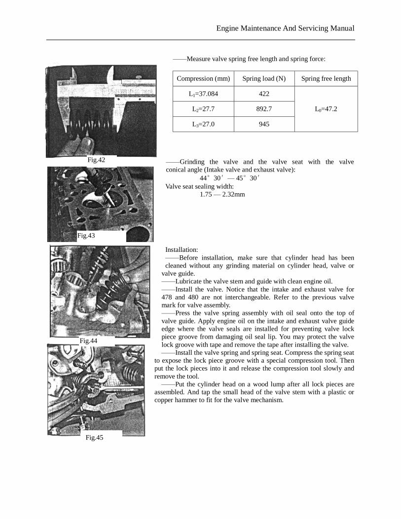
——Measure valve spring free length and spring force:
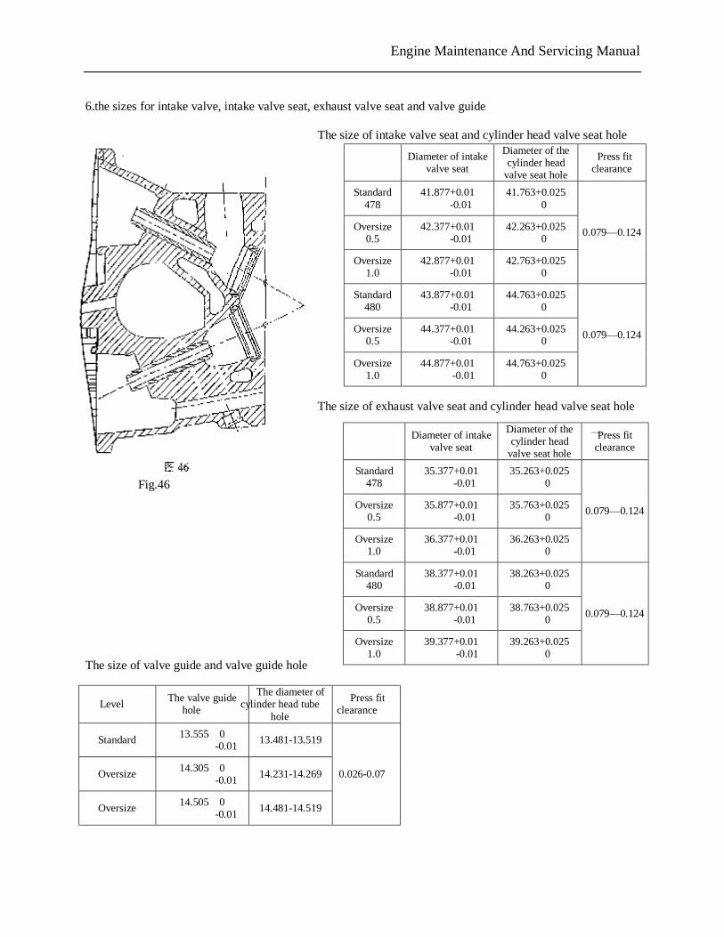
——Grinding the valve and the valve seat with the valve conical angle (Intake valve and exhaust valve):
44°30′— 45°30′ Valve seat sealing width:
1.75 — 2.32mm
Installation: ——Before installation, make sure that cylinder head has been cleaned without any grinding material on cylinder head, valve or
valve guide. ——Lubricate the valve stem and guide with clean engine oil. ——Install the valve. Notice that the intake and exhaust valve for 478 and 480 are not interchangeable. Refer to the previous valve mark for valve assembly. ——Press the valve spring assembly with oil seal onto the top of valve guide. Apply engine oil on the intake and exhaust valve guide edge where the valve seals are installed for preventing valve lock piece groove from damaging oil seal lip. You may protect the valve lock groove with tape and remove the tape after installing the valve. ——Install the valve spring and spring seat. Compress the spring seat
to expose the lock piece groove with a special compression tool. Then put the lock pieces into it and release the compression tool slowly and remove the tool. ——Put the cylinder head on a wood lump after all lock pieces are
assembled. And tap the small head of the valve stem with a plastic or copper hammer to fit for the valve mechanism.
Compression (mm) Spring load (N) Spring free length
L1=37.084 422
L2=27.7 892.7
L3=27.0 945
L0=47.2
Fig.42
Fig.43
Fig.44
Fig.45
Fig.42
PDF 文件使用 "pdfFactory Pro" 试用版本创建 www.fineprint.com.cn
Engine Maintenance And Servicing Manual
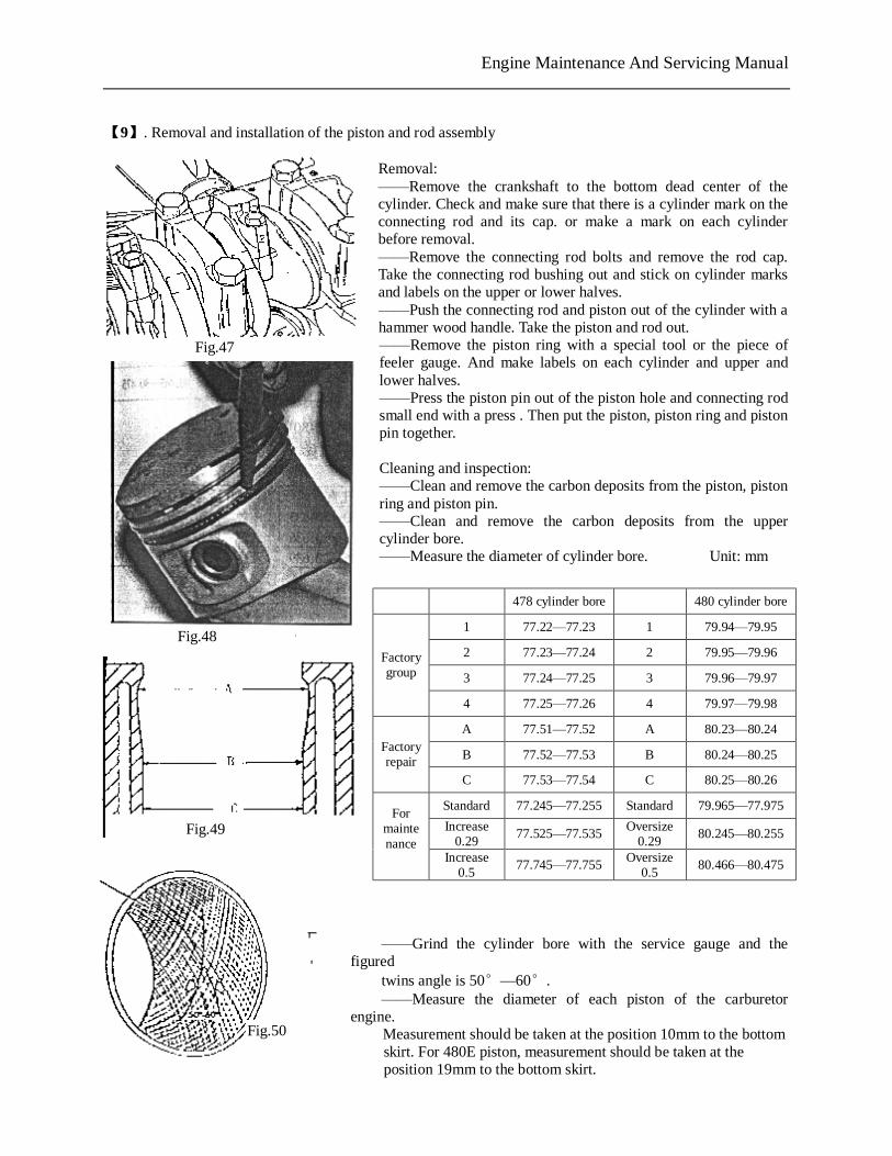
6.the sizes for intake valve, intake valve seat, exhaust valve seat and valve guide
The size of intake valve seat and cylinder head valve seat hole
The size of exhaust valve seat and cylinder head valve seat hole
—
The size of valve guide and valve guide hole
Diameter of intake
valve seat
Diameter of the cylinder head
valve seat hole
Press fit clearance
Standard 478
41.877+0.01 -0.01
41.763+0.025 0
Oversize 0.5
42.377+0.01 -0.01
42.263+0.025 0
Oversize 1.0
42.877+0.01 -0.01
42.763+0.025 0
0.079—0.124
Standard 480
43.877+0.01 -0.01
44.763+0.025 0
Oversize 0.5
44.377+0.01 -0.01
44.263+0.025 0
Oversize 1.0
44.877+0.01 -0.01
44.763+0.025 0
0.079—0.124
Diameter of intake
valve seat
Diameter of the cylinder head
valve seat hole
Press fit clearance
Standard 478
35.377+0.01 -0.01
35.263+0.025 0
Oversize 0.5
35.877+0.01 -0.01
35.763+0.025 0
Oversize 1.0
36.377+0.01 -0.01
36.263+0.025 0
0.079—0.124
Standard 480
38.377+0.01 -0.01
38.263+0.025 0
Oversize 0.5
38.877+0.01 -0.01
38.763+0.025 0
Oversize 1.0
39.377+0.01 -0.01
39.263+0.025 0
0.079—0.124
Level The valve guide
hole
The diameter of cylinder head tube
hole
Press fit clearance
Standard 13.555 0 -0.01
13.481-13.519
Oversize 14.305 0 -0.01
14.231-14.269
Oversize 14.505 0 -0.01
14.481-14.519
0.026-0.07
Fig.46
PDF 文件使用 "pdfFactory Pro" 试用版本创建 www.fineprint.com.cn
Engine Maintenance And Servicing Manual
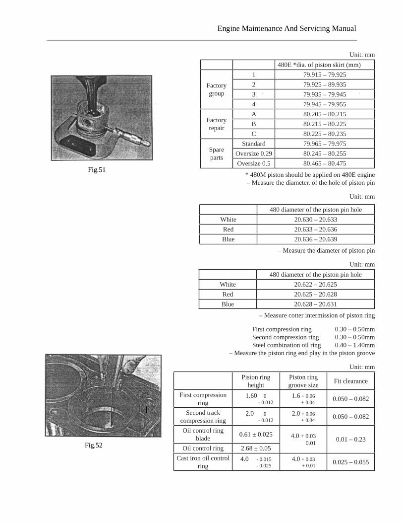
【9】. Removal and installation of the piston and rod assembly
Removal: ——Remove the crankshaft to the bottom dead center of the cylinder. Check and make sure that there is a cylinder mark on the connecting rod and its cap. or make a mark on each cylinder before removal. ——Remove the connecting rod bolts and remove the rod cap. Take the connecting rod bushing out and stick on cylinder marks and labels on the upper or lower halves. ——Push the connecting rod and piston out of the cylinder with a hammer wood handle. Take the piston and rod out. ——Remove the piston ring with a special tool or the piece of feeler gauge. And make labels on each cylinder and upper and lower halves. ——Press the piston pin out of the piston hole and connecting rod small end with a press . Then put the piston, piston ring and piston pin together. Cleaning and inspection: ——Clean and remove the carbon deposits from the piston, piston ring and piston pin. ——Clean and remove the carbon deposits from the upper cylinder bore. ——Measure the diameter of cylinder bore. Unit: mm
——Grind the cylinder bore with the service gauge and the figured
twins angle is 50°—60°. ——Measure the diameter of each piston of the carburetor
engine. Measurement should be taken at the position 10mm to the bottom
478 cylinder bore 480 cylinder bore
1 77.22—77.23 1 79.94—79.95
2 77.23—77.24 2 79.95—79.96
3 77.24—77.25 3 79.96—79.97
Factory group
4 77.25—77.26 4 79.97—79.98
A 77.51—77.52 A 80.23—80.24
B 77.52—77.53 B 80.24—80.25 Factory repair
C 77.53—77.54 C 80.25—80.26
Standard 77.245—77.255 Standard 79.965—77.975
Increase 0.29
77.525—77.535 Oversize 0.29
80.245—80.255
For maintenance
Increase 0.5
77.745—77.755 Oversize 0.5
80.466—80.475
Fig.47
Fig.48
Fig.50
Fig.49
PDF 文件使用 "pdfFactory Pro" 试用版本创建 www.fineprint.com.cn
skirt. For 480E piston, measurement should be taken at the position 19mm to the bottom skirt.
:
Engine Maintenance And Servicing Manual
Fig.51
Fig.52
Unit:mm480E*dia.ofpistonskirt(mm)
Factorygroup
1 79.915–79.9252 79.925–89.9353 79.935–79.9454 79.945–79.955
Factoryrepair
A 80.205–80.215B 80.215–80.225C 80.225–80.235
Spareparts
Standard 79.965–79.975Oversize0.29 80.245–80.255Oversize0.5 80.465–80.475
*480Mpistonshouldbeappliedon480Eengine–Measurethediameter.oftheholeofpistonpin
Unit:mm
480diameterofthepistonpinholeWhite 20.630–20.633Red 20.633–20.636Blue 20.636–20.639
–Measurethediameterofpistonpin
Unit:mm480diameterofthepistonpinhole
White 20.622–20.625Red 20.625–20.628Blue 20.628–20.631
–Measurecotterintermissionofpistonring
Firstcompressionring 0.30–0.50mmSecondcompressionring 0.30–0.50mmSteelcombinationoilring 0.40–1.40mm
–Measurethepistonringendplayinthepistongroove
Unit:mmPistonring
heightPistonringgroovesize Fitclearance
Firstcompressionring
1.600-0.012
1.6+0.06+0.04 0.050–0.082
Secondtrackcompressionring
2.00-0.012
2.0+0.06+0.04 0.050–0.082
Oilcontrolringblade 0.61±0.025 4.0+0.03
0.01 0.01–0.23Oilcontrolring 2.68±0.05
Castironoilcontrolring
4.0-0.015-0.025
4.0+0.03+0.01 0.025–0.055
Engine Maintenance And Servicing Manual
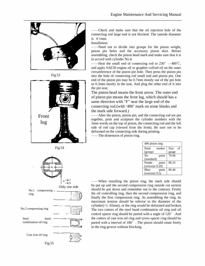
——Check and make sure that the oil injection hole of the connecting rod large end is not blocked. The outside diameter is φ1mm. Installation: ——Need not to divide into groups for the piston weight, piston pin holes and the accessory piston skirt. Before assembling, check the piston head mark and make sure that it is in accord with cylinder No.4. ——Heat the small end of connecting rod to 230°—400℃, and apply SAE50 engine oil or graphite colloid oil on the outer circumference of the piston pin hole. Then press the piston pin into the hole of connecting rod small end and piston pin. One end of the piston pin may be 0.7mm mostly out of the pin hole or 0.3mm mostly in the seat. And plug the other end of it into the pin seat. The piston head means the front arrow. The outer end of piston pin means the front lug, which should has a same direction with “F” near the large end of the connecting rod.(with ‘480’ mark on some blanks and the mark side forward.) ——After the piston, piston pin, and the connecting rod are put together, print and sculpture the cylinder numbers with the 3mm words on the top of piston, the connecting rod and the left side of rod cap (viewed from the front). Be sure not to be deformed on the connecting side during printing. ——The dimension of piston ring.
478 piston ring 480 piston ring Paint marker (group) Size of
gauge Paint marker (group)
Size of gauge
Yellow paint +no paint (standard)
77.22 No paint (standard)
79.94
Yellow paint+ purple paint (oversize 0.29)
77.51 Purple paint (oversize 0.29)
80.23
Yellow paint +blue paint (oversize 0.5)
77.72 Blue paint (oversize 0.5)
80.44
——When installing the piston ring, the mark side should be put up and the second compression ring outside cut section should be put down and remember not to the contrary. Firstly the oil controlling ring, then the second compression ring, and finally the first compression ring. As assembling the ring, its maximum tension should be inferior to the diameter of the cylinder(+1. 65mm), or the ring would be deformed and broken. The two cotters of the steel band combination oil ring and oil control spacer ring should be parted with a angle of 120°.And the cotters of cast iron oil ring and screw spacer ring should be parted with a interval of 180°. The piston should rotate freely in the ring groove without blocking.
Fig.53
Fig.54
Fig.55
Front lug
No.1 compressing ring
No.2 compressing ring
Steel band combination oil ring
Cost iron oil ring
Only one side
Engine Maintenance And Servicing Manual
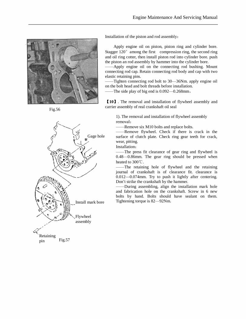
Installation of the piston and rod assembly: Apply engine oil on piston, piston ring and cylinder bore. Stagger 120°among the first compression ring, the second ring and oil ring cotter, then install piston rod into cylinder bore. push the piston an rod assembly by hammer into the cylinder bore. ——Apply engine oil on the connecting rod bushing. Mount connecting rod cap. Retain connecting rod body and cap with two elastic retaining pins. ——Tighten connecting rod bolt to 30—36Nm. apply engine oil on the bolt head and bolt threads before installation. ——The side play of big end is 0.092—0.268mm。 【10】. The removal and installation of flywheel assembly and carrier assembly of real crankshaft oil seal
1). The removal and installation of flywheel assembly removal: ——Remove six M10 bolts and replace bolts. ——Remove flywheel. Check if there is crack in the surface of clutch plate. Check ring gear teeth for crack, wear, pitting. Installation: ——The press fit clearance of gear ring and flywheel is 0.48—0.86mm. The gear ring should be pressed when heated to 300℃. ——The retaining hole of flywheel and the retaining journal of crankshaft is of clearance fit. clearance is 0.012—0.074mm. Try to push it lightly after centering. Don’t strike the crankshaft by the hammer. ——During assembling, align the installation mark hole and fabrication hole on the crankshaft. Screw in 6 new bolts by hand. Bolts should have sealant on them. Tightening torque is 82—92Nm.
Fig.56
Fig.57
Gage hole
Install mark bore
Flywheel assembly
Retaining pin
PDF 文件使用 "pdfFactory Pro" 试用版本创建 www.fineprint.com.cn
Engine Maintenance And Servicing Manual
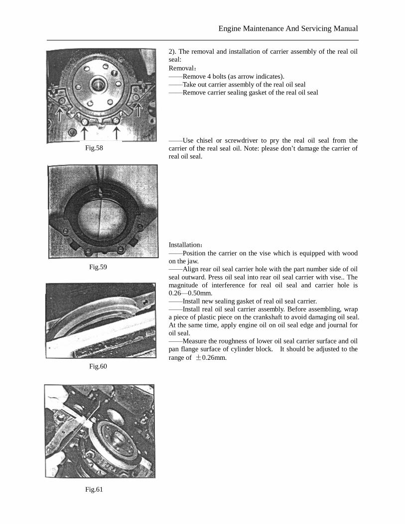
2). The removal and installation of carrier assembly of the real oil seal: Removal: ——Remove 4 bolts (as arrow indicates). ——Take out carrier assembly of the real oil seal ——Remove carrier sealing gasket of the real oil seal ——Use chisel or screwdriver to pry the real oil seal from the carrier of the real seal oil. Note: please don’t damage the carrier of real oil seal.
Installation: ——Position the carrier on the vise which is equipped with wood on the jaw. ——Align rear oil seal carrier hole with the part number side of oil seal outward. Press oil seal into rear oil seal carrier with vise.. The magnitude of interference for real oil seal and carrier hole is 0.26—0.50mm. ——Install new sealing gasket of real oil seal carrier. ——Install real oil seal carrier assembly. Before assembling, wrap a piece of plastic piece on the crankshaft to avoid damaging oil seal. At the same time, apply engine oil on oil seal edge and journal for oil seal. ——Measure the roughness of lower oil seal carrier surface and oil pan flange surface of cylinder block. It should be adjusted to the range of ±0.26mm.
Fig.58
Fig.59
Fig.60
Fig.61
PDF 文件使用 "pdfFactory Pro" 试用版本创建 www.fineprint.com.cn
Engine Maintenance And Servicing Manual
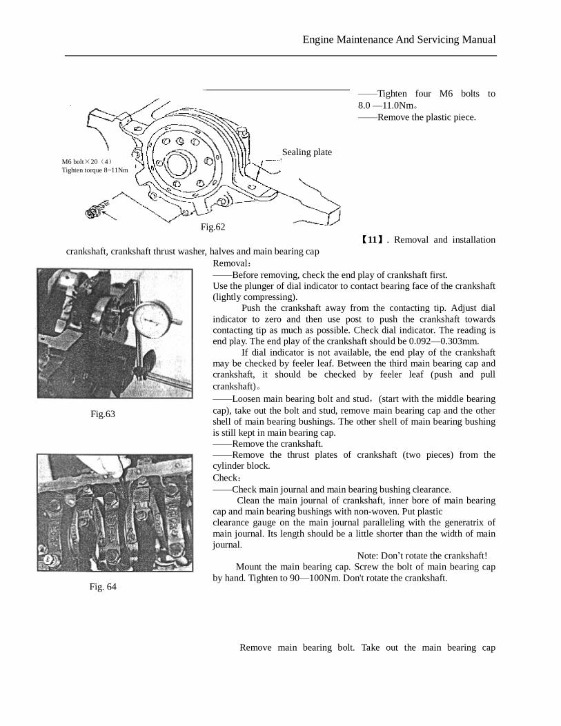
——Tighten four M6 bolts to 8.0 —11.0Nm。 ——Remove the plastic piece. 【11】. Removal and installation
crankshaft, crankshaft thrust washer, halves and main bearing cap Removal: ——Before removing, check the end play of crankshaft first. Use the plunger of dial indicator to contact bearing face of the crankshaft (lightly compressing).
Push the crankshaft away from the contacting tip. Adjust dial indicator to zero and then use post to push the crankshaft towards contacting tip as much as possible. Check dial indicator. The reading is end play. The end play of the crankshaft should be 0.092—0.303mm.
If dial indicator is not available, the end play of the crankshaft may be checked by feeler leaf. Between the third main bearing cap and crankshaft, it should be checked by feeler leaf (push and pull crankshaft)。 ——Loosen main bearing bolt and stud,(start with the middle bearing cap), take out the bolt and stud, remove main bearing cap and the other shell of main bearing bushings. The other shell of main bearing bushing is still kept in main bearing cap. ——Remove the crankshaft. ——Remove the thrust plates of crankshaft (two pieces) from the cylinder block. Check: ——Check main journal and main bearing bushing clearance.
Clean the main journal of crankshaft, inner bore of main bearing cap and main bearing bushings with non-woven. Put plastic clearance gauge on the main journal paralleling with the generatrix of main journal. Its length should be a little shorter than the width of main journal.
Note: Don’t rotate the crankshaft! Mount the main bearing cap. Screw the bolt of main bearing cap
by hand. Tighten to 90—100Nm. Don't rotate the crankshaft.
Remove main bearing bolt. Take out the main bearing cap
Fig.63
Fig. 64
Sealing plate M6 bolt×20(4) Tighten torque 8~11Nm
Fig.62
PDF 文件使用 "pdfFactory Pro" 试用版本创建 www.fineprint.com.cn
Engine Maintenance And Servicing Manual
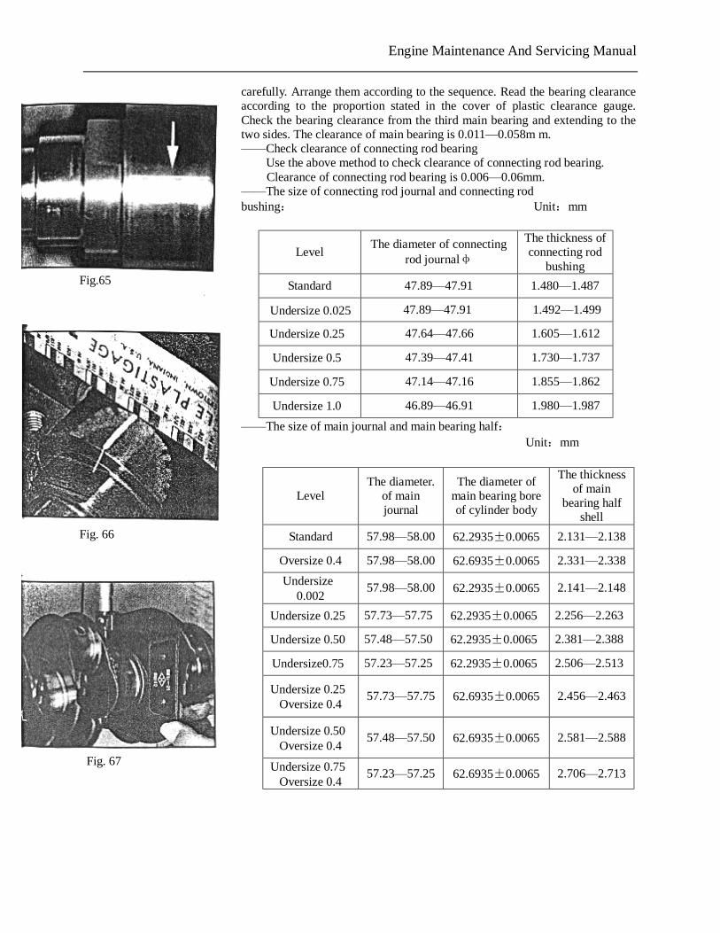
carefully. Arrange them according to the sequence. Read the bearing clearance according to the proportion stated in the cover of plastic clearance gauge. Check the bearing clearance from the third main bearing and extending to the two sides. The clearance of main bearing is 0.011—0.058m m. ——Check clearance of connecting rod bearing
Use the above method to check clearance of connecting rod bearing. Clearance of connecting rod bearing is 0.006—0.06mm.
——The size of connecting rod journal and connecting rod bushing: Unit:mm
——The size of main journal and main bearing half: Unit:mm
Level The diameter of connecting
rod journalφ
The thickness of connecting rod
bushing
Standard 47.89—47.91 1.480—1.487
Undersize 0.025 47.89—47.91 1.492—1.499
Undersize 0.25 47.64—47.66 1.605—1.612
Undersize 0.5 47.39—47.41 1.730—1.737
Undersize 0.75 47.14—47.16 1.855—1.862
Undersize 1.0 46.89—46.91 1.980—1.987
Level The diameter.
of main journal
The diameter of main bearing bore of cylinder body
The thickness of main
bearing half shell
Standard 57.98—58.00 62.2935±0.0065 2.131—2.138
Oversize 0.4 57.98—58.00 62.6935±0.0065 2.331—2.338
Undersize 0.002
57.98—58.00 62.2935±0.0065 2.141—2.148
Undersize 0.25 57.73—57.75 62.2935±0.0065 2.256—2.263
Undersize 0.50 57.48—57.50 62.2935±0.0065 2.381—2.388
Undersize0.75 57.23—57.25 62.2935±0.0065 2.506—2.513
Undersize 0.25 Oversize 0.4
57.73—57.75 62.6935±0.0065 2.456—2.463
Undersize 0.50 Oversize 0.4
57.48—57.50 62.6935±0.0065 2.581—2.588
Undersize 0.75 Oversize 0.4
57.23—57.25 62.6935±0.0065 2.706—2.713
Fig.65
Fig. 66
Fig. 67
PDF 文件使用 "pdfFactory Pro" 试用版本创建 www.fineprint.com.cn
Engine Maintenance And Servicing Manual
—the size of crankshaft thrust, thrust washer and cylinder block thrust: Unit:mm
Installation: ——Before installation, use the second screw tap taps the threaded hole in cylinder body, especially the threaded hole of cylinder head bolt and main bearing bolt.
The threads of cylinder head bolt is M10×1.5—6H,the threaded hole of main bearing bolt is M12×1.75—6H。 ——The installation of crankshaft woodruff key
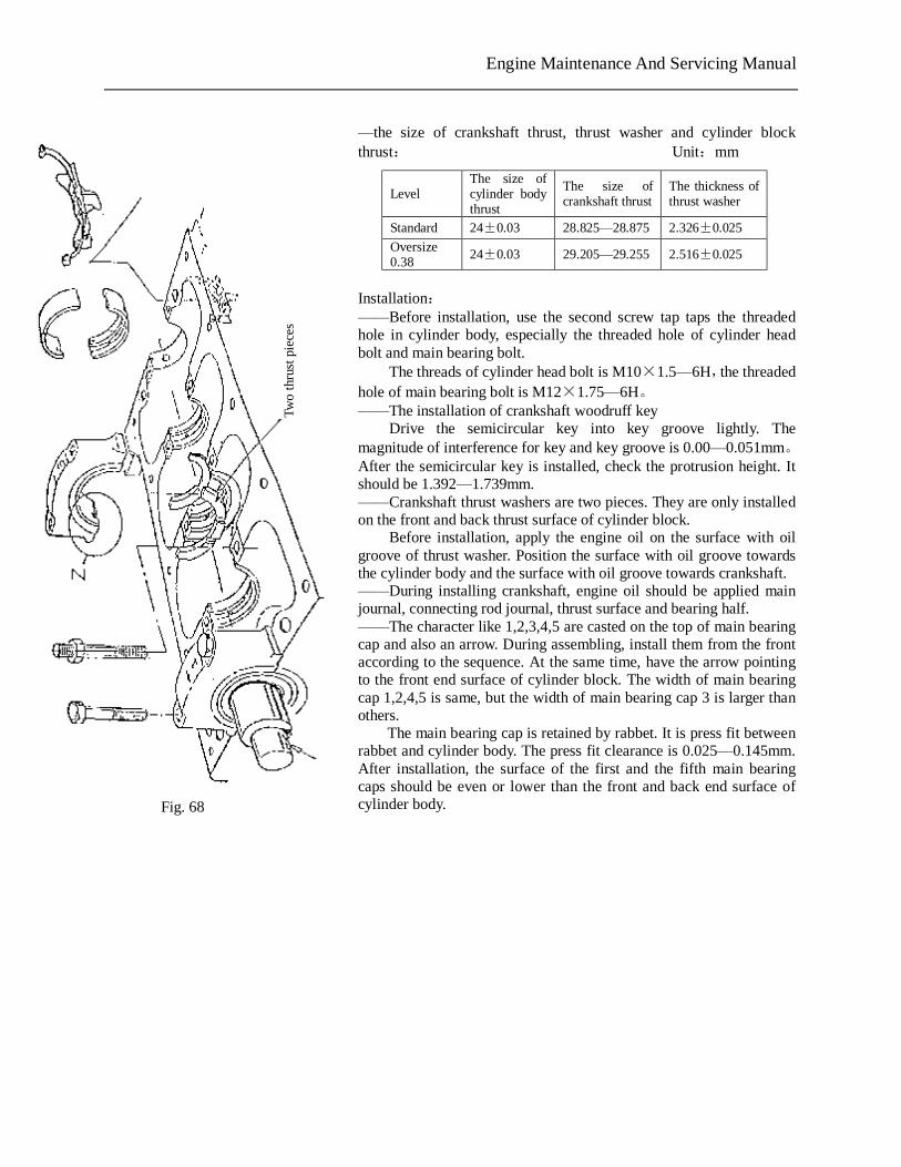
Drive the semicircular key into key groove lightly. The magnitude of interference for key and key groove is 0.00—0.051mm。After the semicircular key is installed, check the protrusion height. It should be 1.392—1.739mm. ——Crankshaft thrust washers are two pieces. They are only installed on the front and back thrust surface of cylinder block.
Before installation, apply the engine oil on the surface with oil groove of thrust washer. Position the surface with oil groove towards the cylinder body and the surface with oil groove towards crankshaft. ——During installing crankshaft, engine oil should be applied main journal, connecting rod journal, thrust surface and bearing half. ——The character like 1,2,3,4,5 are casted on the top of main bearing cap and also an arrow. During assembling, install them from the front according to the sequence. At the same time, have the arrow pointing to the front end surface of cylinder block. The width of main bearing cap 1,2,4,5 is same, but the width of main bearing cap 3 is larger than others.
The main bearing cap is retained by rabbet. It is press fit between rabbet and cylinder body. The press fit clearance is 0.025—0.145mm. After installation, the surface of the first and the fifth main bearing caps should be even or lower than the front and back end surface of cylinder body.
Level The size of cylinder body thrust
The size of crankshaft thrust
The thickness of thrust washer
Standard 24±0.03 28.825—28.875 2.326±0.025
Oversize 0.38
24±0.03 29.205—29.255 2.516±0.025
Two
thru
st p
iece
s
Fig. 68
PDF 文件使用 "pdfFactory Pro" 试用版本创建 www.fineprint.com.cn
Engine Maintenance And Servicing Manual
——Nine main bearing bolts are hex head flange side bolts, and one is stud. For horizontal engine, the stud is mounted in the left threaded hole of the second main bearing cap (see from the front) which is for installing the carrier of oil collector. For the vertical engine, it should be mounted on the left threaded hole of the forth main bearing cap (see from the front).
Before installing the main bearing bolt, engine oil should be applied on the joint surface of head end.
The main bearing bolt and stud should be screwed by hand first and tightened to 90—100Nm. ——The max rotating torque of the crankshaft (with piston rod assembly) is 16Nm. 【12】. The removal and installation of oil baffle assembly
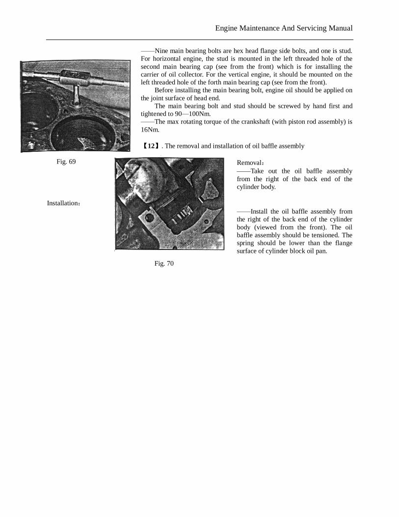
Removal: ——Take out the oil baffle assembly from the right of the back end of the cylinder body.
Installation:
——Install the oil baffle assembly from the right of the back end of the cylinder body (viewed from the front). The oil baffle assembly should be tensioned. The spring should be lower than the flange surface of cylinder block oil pan.
Fig. 69
Fig. 70
PDF 文件使用 "pdfFactory Pro" 试用版本创建 www.fineprint.com.cn
Engine Maintenance And Servicing Manual
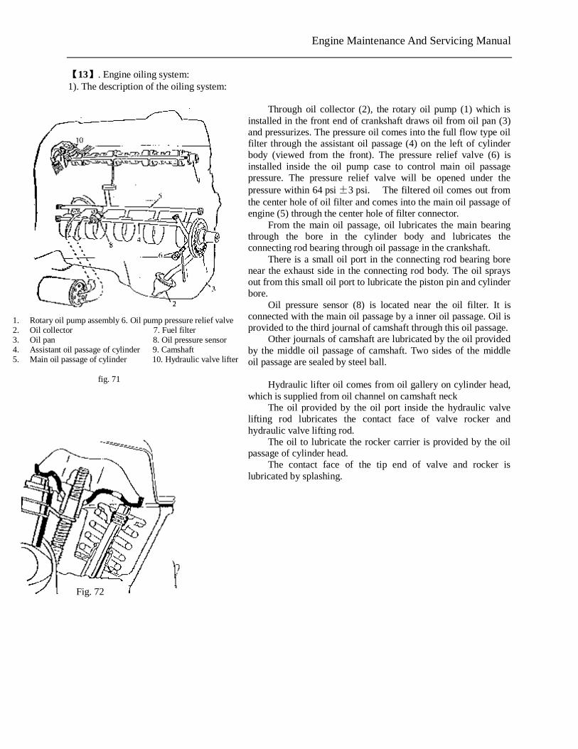
【13】. Engine oiling system: 1). The description of the oiling system:
Through oil collector (2), the rotary oil pump (1) which is installed in the front end of crankshaft draws oil from oil pan (3) and pressurizes. The pressure oil comes into the full flow type oil filter through the assistant oil passage (4) on the left of cylinder body (viewed from the front). The pressure relief valve (6) is installed inside the oil pump case to control main oil passage pressure. The pressure relief valve will be opened under the pressure within 64 psi ±3 psi. The filtered oil comes out from the center hole of oil filter and comes into the main oil passage of engine (5) through the center hole of filter connector. From the main oil passage, oil lubricates the main bearing through the bore in the cylinder body and lubricates the connecting rod bearing through oil passage in the crankshaft. There is a small oil port in the connecting rod bearing bore near the exhaust side in the connecting rod body. The oil sprays out from this small oil port to lubricate the piston pin and cylinder bore. Oil pressure sensor (8) is located near the oil filter. It is connected with the main oil passage by a inner oil passage. Oil is provided to the third journal of camshaft through this oil passage. Other journals of camshaft are lubricated by the oil provided by the middle oil passage of camshaft. Two sides of the middle oil passage are sealed by steel ball.
Hydraulic lifter oil comes from oil gallery on cylinder head, which is supplied from oil channel on camshaft neck The oil provided by the oil port inside the hydraulic valve lifting rod lubricates the contact face of valve rocker and hydraulic valve lifting rod. The oil to lubricate the rocker carrier is provided by the oil passage of cylinder head. The contact face of the tip end of valve and rocker is lubricated by splashing.
1. Rotary oil pump assembly 6. Oil pump pressure relief valve 2. Oil collector 7. Fuel filter 3. Oil pan 8. Oil pressure sensor 4. Assistant oil passage of cylinder 9. Camshaft 5. Main oil passage of cylinder 10. Hydraulic valve lifter fig. 71
Fig. 72
PDF 文件使用 "pdfFactory Pro" 试用版本创建 www.fineprint.com.cn
Engine Maintenance And Servicing Manual
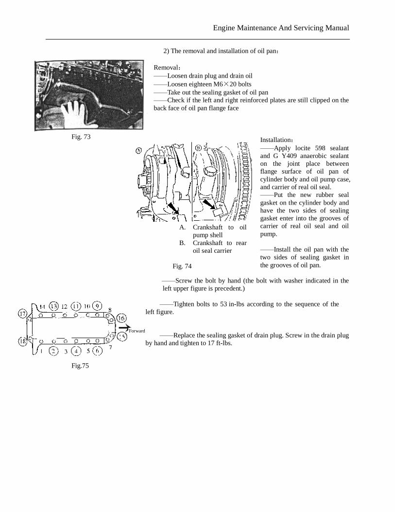
2) The removal and installation of oil pan: Removal: ——Loosen drain plug and drain oil ——Loosen eighteen M6×20 bolts ——Take out the sealing gasket of oil pan ——Check if the left and right reinforced plates are still clipped on the back face of oil pan flange face
Installation: ——Apply locite 598 sealant and G Y409 anaerobic sealant on the joint place between flange surface of oil pan of cylinder body and oil pump case, and carrier of real oil seal. ——Put the new rubber seal gasket on the cylinder body and have the two sides of sealing gasket enter into the grooves of carrier of real oil seal and oil pump.
——Install the oil pan with the two sides of sealing gasket in the grooves of oil pan.
——Screw the bolt by hand (the bolt with washer indicated in the left upper figure is precedent.)
——Tighten bolts to 53 in-lbs according to the sequence of the
left figure.
——Replace the sealing gasket of drain plug. Screw in the drain plug
by hand and tighten to 17 ft-lbs.
Fig. 73
A. Crankshaft to oil pump shell
B. Crankshaft to rear oil seal carrier
Fig. 74
Fig.75
Forward
PDF 文件使用 "pdfFactory Pro" 试用版本创建 www.fineprint.com.cn
Engine Maintenance And Servicing Manual
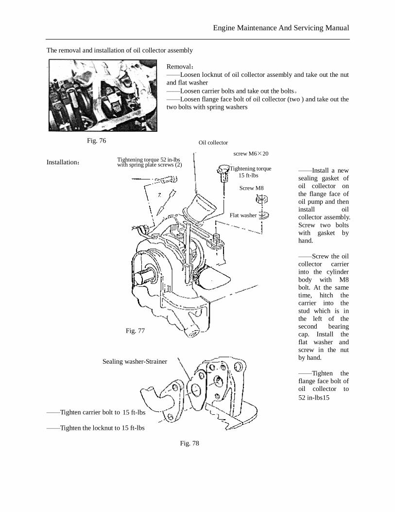
The removal and installation of oil collector assembly Removal: ——Loosen locknut of oil collector assembly and take out the nut and flat washer ——Loosen carrier bolts and take out the bolts。 ——Loosen flange face bolt of oil collector (two ) and take out the two bolts with spring washers
Installation:
——Install a new sealing gasket of oil collector on the flange face of oil pump and then install oil collector assembly. Screw two bolts with gasket by hand.
——Screw the oil collector carrier into the cylinder body with M8 bolt. At the same time, hitch the carrier into the stud which is in the left of the second bearing cap. Install the flat washer and screw in the nut by hand.
——Tighten the flange face bolt of oil collector to 8.0—12.0Nm.
——Tighten carrier bolt to 17—23Nm ——Tighten the locknut to 17—23Nm
Fig. 76
Tightening torque 52 in-lbs with spring plate screws (2)
Oil collector
screw M6×20
Tightening torque 15 ft-lbs
Screw M8
Flat washer
Fig. 77
Fig. 78
Sealing washer-Strainer
PDF 文件使用 "pdfFactory Pro" 试用版本创建 www.fineprint.com.cn
52 in-lbs15
15 ft-lbs
15 ft-lbs
Engine Maintenance And Servicing Manual
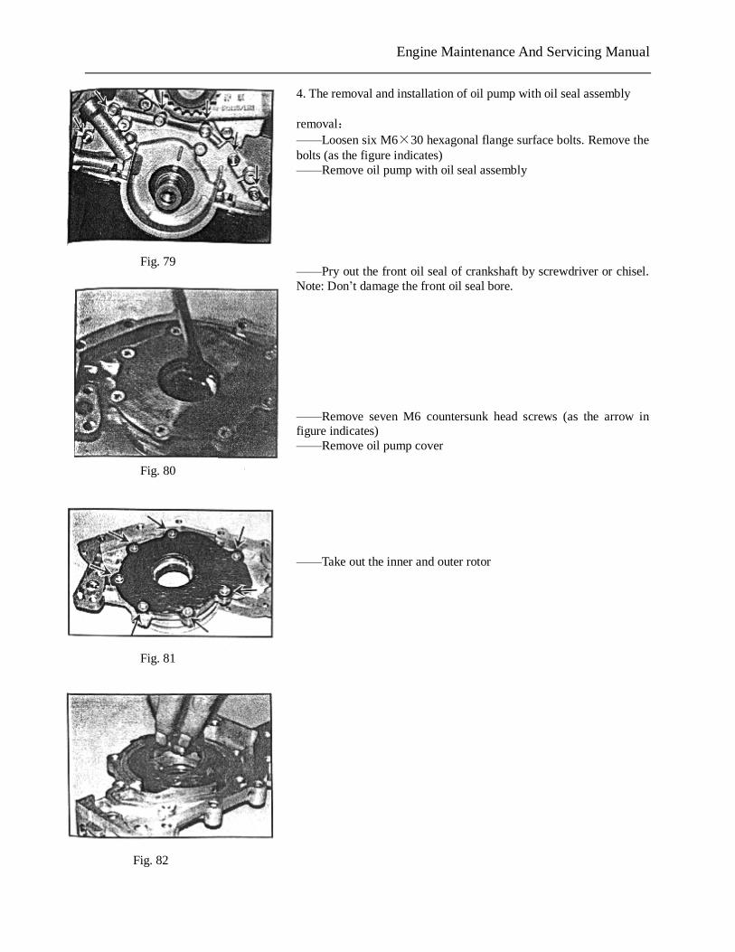
4. The removal and installation of oil pump with oil seal assembly removal: ——Loosen six M6×30 hexagonal flange surface bolts. Remove the bolts (as the figure indicates) ——Remove oil pump with oil seal assembly ——Pry out the front oil seal of crankshaft by screwdriver or chisel. Note: Don’t damage the front oil seal bore. ——Remove seven M6 countersunk head screws (as the arrow in figure indicates) ——Remove oil pump cover ——Take out the inner and outer rotor
Fig. 79
Fig. 80
Fig. 81
Fig. 82
PDF 文件使用 "pdfFactory Pro" 试用版本创建 www.fineprint.com.cn
Engine Maintenance And Servicing Manual
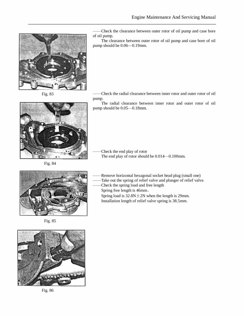
——Check the clearance between outer rotor of oil pump and case bore of oil pump.
The clearance between outer rotor of oil pump and case bore of oil pump should be 0.06—0.19mm. ——Check the radial clearance between inner rotor and outer rotor of oil pump. The radial clearance between inner rotor and outer rotor of oil pump should be 0.05—0.18mm. ——Check the end play of rotor The end play of rotor should be 0.014—0.100mm. ——Remove horizontal hexagonal socket head plug (small one) ——Take out the spring of relief valve and plunger of relief valve. ——Check the spring load and free length Spring free length is 46mm。 Spring load is 32.8N±2N when the length is 29mm. Installation length of relief valve spring is 38.5mm.
Fig. 83
Fig. 84
Fig. 85
Fig. 86
PDF 文件使用 "pdfFactory Pro" 试用版本创建 www.fineprint.com.cn
Engine Maintenance And Servicing Manual
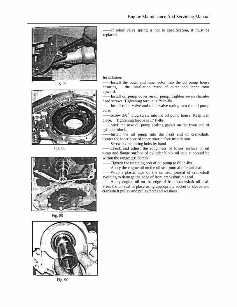
——If relief valve spring is not to specification, it must be replaced. Installation: ——Install the outer and inner rotor into the oil pump house ensuring the installation mark of outer and inner rotor upward. ——Install oil pump cover on oil pump. Tighten seven chamfer head screws. Tightening torque is 79 in-lbs. ——Install relief valve and relief valve spring into the oil pump bore. ——Screw 3/8″plug screw into the oil pump house. Keep it in place. Tightening torque is 17 ft-lbs. ——Stick the new oil pump sealing gasket on the front end of cylinder block. ——Install the oil pump into the front end of crankshaft. Center the inner bore of inner rotor before installation. ——Screw six mounting bolts by hand. ——Check and adjust the roughness of lower surface of oil pump and flange surface of cylinder block oil pan. It should be within the range:±0.26mm. ——Tighten the retaining bolt of oil pump to 89 in-lbs. ——Apply the engine oil on the oil seal journal of crankshaft. ——Wrap a plastic tape on the oil seal journal of crankshaft avoiding to damage the edge of front crankshaft oil seal. ——Apply engine oil on the edge of front crankshaft oil seal. Press the oil seal in place using appropriate socket or sleeve and crankshaft pulley and pulley bolt and washers.
Fig. 87
Fig. 88
Fig. 89
Fig. 90
PDF 文件使用 "pdfFactory Pro" 试用版本创建 www.fineprint.com.cn
Engine Maintenance And Servicing Manual
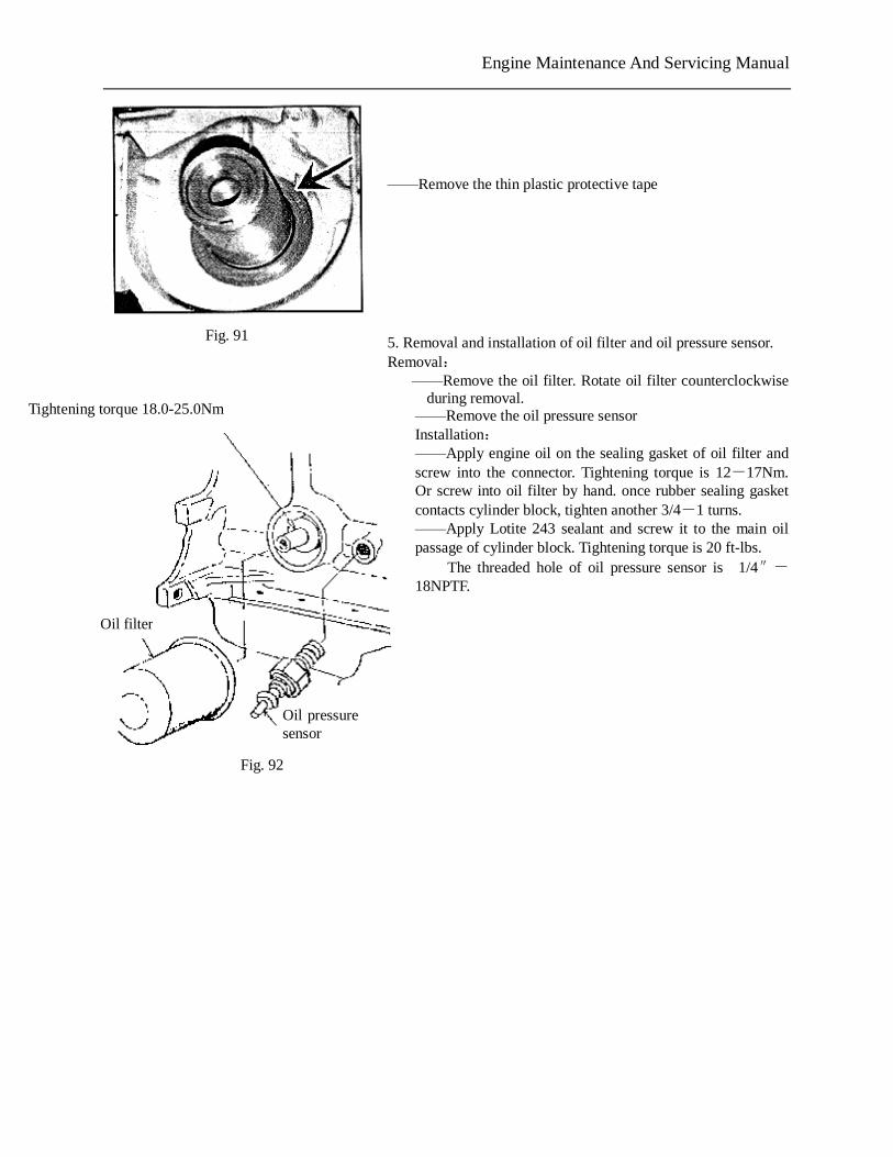
——Remove the thin plastic protective tape 5. Removal and installation of oil filter and oil pressure sensor. Removal: ——Remove the oil filter. Rotate oil filter counterclockwise
during removal. ——Remove the oil pressure sensor Installation: ——Apply engine oil on the sealing gasket of oil filter and screw into the connector. Tightening torque is 12-17Nm. Or screw into oil filter by hand. once rubber sealing gasket contacts cylinder block, tighten another 3/4-1 turns. ——Apply Lotite 243 sealant and screw it to the main oil passage of cylinder block. Tightening torque is 20 ft-lbs.-
The threaded hole of oil pressure sensor is 1/4″-18NPTF.
The operating voltage of oil pressure sensor is 6-24V.
The starting warning pressure is 30±15kPa.
Fig. 91
Tightening torque 18.0-25.0Nm
Oil filter
Oil pressure sensor
Fig. 92
Engine Maintenance And Servicing Manual
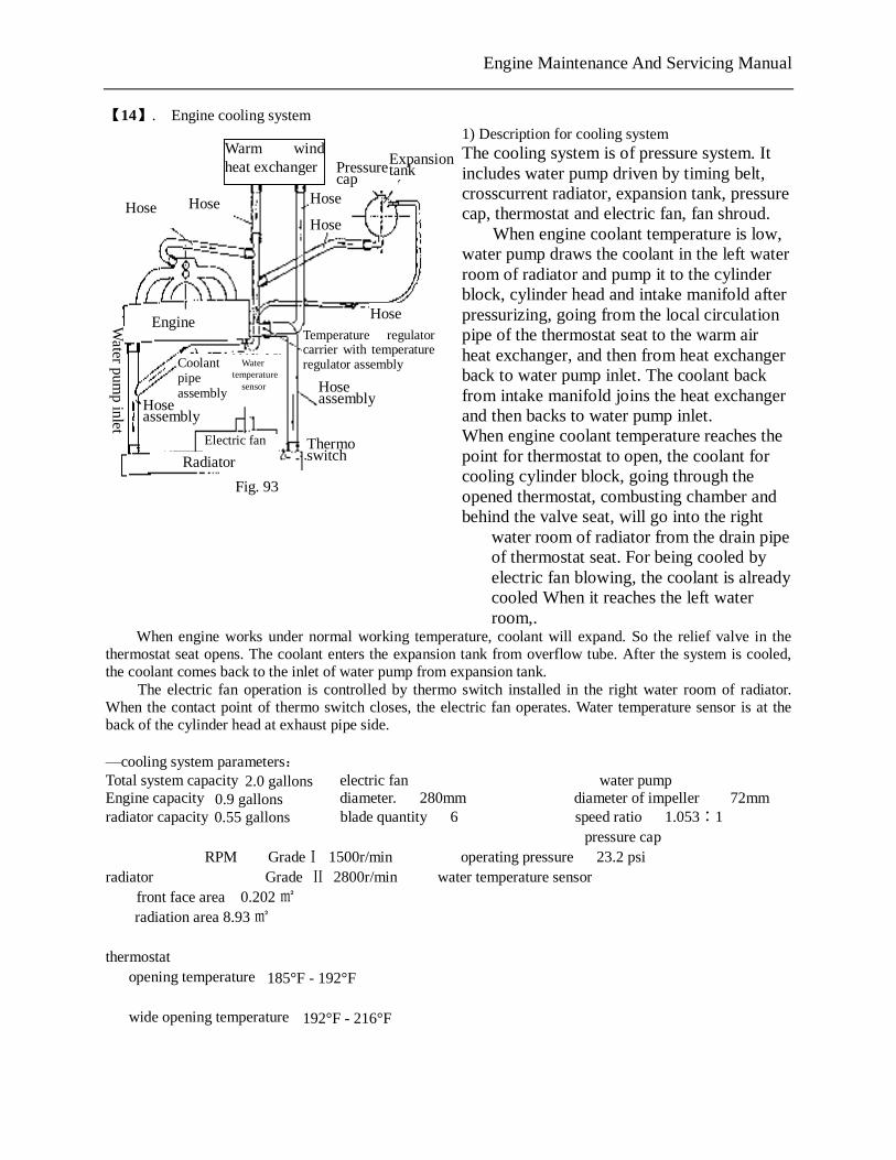
【14】. Engine cooling system 1) Description for cooling system The cooling system is of pressure system. It includes water pump driven by timing belt, crosscurrent radiator, expansion tank, pressure cap, thermostat and electric fan, fan shroud.
When engine coolant temperature is low, water pump draws the coolant in the left water room of radiator and pump it to the cylinder block, cylinder head and intake manifold after pressurizing, going from the local circulation pipe of the thermostat seat to the warm air heat exchanger, and then from heat exchanger back to water pump inlet. The coolant back from intake manifold joins the heat exchanger and then backs to water pump inlet. When engine coolant temperature reaches the point for thermostat to open, the coolant for cooling cylinder block, going through the opened thermostat, combusting chamber and behind the valve seat, will go into the right
water room of radiator from the drain pipe of thermostat seat. For being cooled by electric fan blowing, the coolant is already cooled When it reaches the left water room,.
When engine works under normal working temperature, coolant will expand. So the relief valve in the thermostat seat opens. The coolant enters the expansion tank from overflow tube. After the system is cooled, the coolant comes back to the inlet of water pump from expansion tank.
The electric fan operation is controlled by thermo switch installed in the right water room of radiator. When the contact point of thermo switch closes, the electric fan operates. Water temperature sensor is at the back of the cylinder head at exhaust pipe side.
—cooling system parameters: Total system capacity (L) 8 electric fan water pump Engine capacity (L) 3.3 diameter. 280mm diameter of impeller 72mm radiator capacity (L) 2.1 blade quantity 6 speed ratio 1.053∶1 expansion tank capacity(L)0.4 operating voltage 9-16V pressure cap RPM GradeⅠ 1500r/min operating pressure 23.2 psiradiator Grade Ⅱ 2800r/min water temperature sensor front face area 0.202㎡ thermo switch
radiation area 8.93㎡ operating temperature GradeⅠ95 ℃
thermostat GradeⅡ102±3℃ opening temperature 85°-89° cut off temperature
GradeⅠ≤84℃ wide opening temperature 89°-102° Ⅱ≤91℃
+2 -3
Hose Hose
Warm wind heat exchanger
Hose
Hose
Pressure cap
Expansion tank
Hose Engine Temperature regulator carrier with temperature regulator assembly Water
temperature sensor
Coolant pipe assembly Hose
assembly Hose assembly
Radiator Thermo switch
Electric fan
Water pum
p inlet
Fig. 93
PDF 文件使用 "pdfFactory Pro" 试用版本创建 www.fineprint.com.cn
2.0 gallons0.9 gallons0.55 gallons
185°F - 192°F
192°F - 216°F
Engine Maintenance And Servicing Manual
——Coolant draining : (1) Remove pressure cap of expansion water tank
(2) Connect a container under the radiator. Remove the outlet hose of radiator or open the drain plug of radiator.
——Cleaning cooling system: (1) Drain the coolant and then close the drain plug of radiator or install the outlet hose of radiator (2) Add clean water into the max water level of expansion tank and install the pressure cap (3) Start engine and keep idling., warm engine to normal working temperature and stop engine cooling
down. (4) Drain water (5) Repeat step (2)—(4) until the water drained is the same as clean water. (6) If the previous coolant application and replacement is not to specification, do some cleaning as the
following method: a. Drain coolant b. Remove outlet hose of radiator. Insert the water supply hose into the inlet of radiator until the water
drained is clean. c. Connect the hose connected to water supply to the water outlet of thermostat seat to wash the engine
until the water drained from the water pump inlet is clean. d. If radiator is too dirty, it may be washed from the reverse direction. Connect the hose connected to the
water supply to the water outlet of thermostat seat to wash the engine until the water coming out from the water pump inlet is clean.
——Add coolant (1) Before adding coolant, check if the drain plug of radiator is closed and if the pipeline is connected and
tight (2) Remove the pressure cap and add coolant by the filler of expansion tank slowly. Since the expansion
tank is in the highest point of cooling system, with the coolant level raising, the air in the system will be discharged into the expansion tank. Adding coolant slowly may discharge the air.
(3) Keep adding coolant until coolant level reaches the “maximum” line. Install the filler cover to avoid coolant splashing.
(4) Start engine and keep idling. Warm engine to normal working temperature. Fan starts to run. Observe the water thermometer and check if engine is overheated. If the coolant level of expansion tank drops quickly, add coolant to the “maximum” line to reduce the air circulation in the system.
(5) Stop engine to cool engine completely (one night if possible). Remove pressure cap and check coolant level, fill coolant to the “maximum” line.
PDF 文件使用 "pdfFactory Pro" 试用版本创建 www.fineprint.com.cn
Engine Maintenance And Servicing Manual
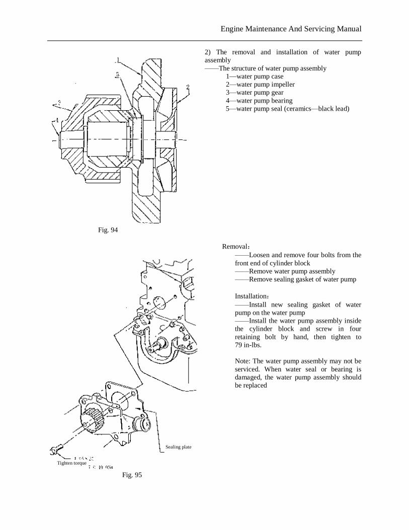
2) The removal and installation of water pump assembly ——The structure of water pump assembly 1—water pump case 2—water pump impeller 3—water pump gear 4—water pump bearing
5—water pump seal (ceramics—black lead)
Removal: ——Loosen and remove four bolts from the front end of cylinder block ——Remove water pump assembly ——Remove sealing gasket of water pump Installation: ——Install new sealing gasket of water pump on the water pump ——Install the water pump assembly inside the cylinder block and screw in four retaining bolt by hand, then tighten to 79 in-lbs. Note: The water pump assembly may not be serviced. When water seal or bearing is damaged, the water pump assembly should be replaced
Fig. 94
Tighten torque
Sealing plate
Fig. 95
PDF 文件使用 "pdfFactory Pro" 试用版本创建 www.fineprint.com.cn
Engine Maintenance And Servicing Manual
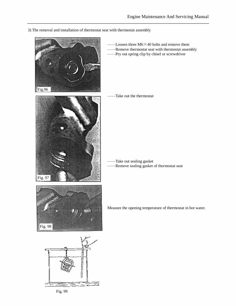
3) The removal and installation of thermostat seat with thermostat assembly ——Loosen three M6×40 bolts and remove them ——Remove thermostat seat with thermostat assembly ——Pry out spring clip by chisel or screwdriver ——Take out the thermostat ——Take out sealing gasket ——Remove sealing gasket of thermostat seat Measure the opening temperature of thermostat in hot water.
Fig.96
Fig. 97
Fig. 98
Fig. 99
PDF 文件使用 "pdfFactory Pro" 试用版本创建 www.fineprint.com.cn
Engine Maintenance And Servicing Manual
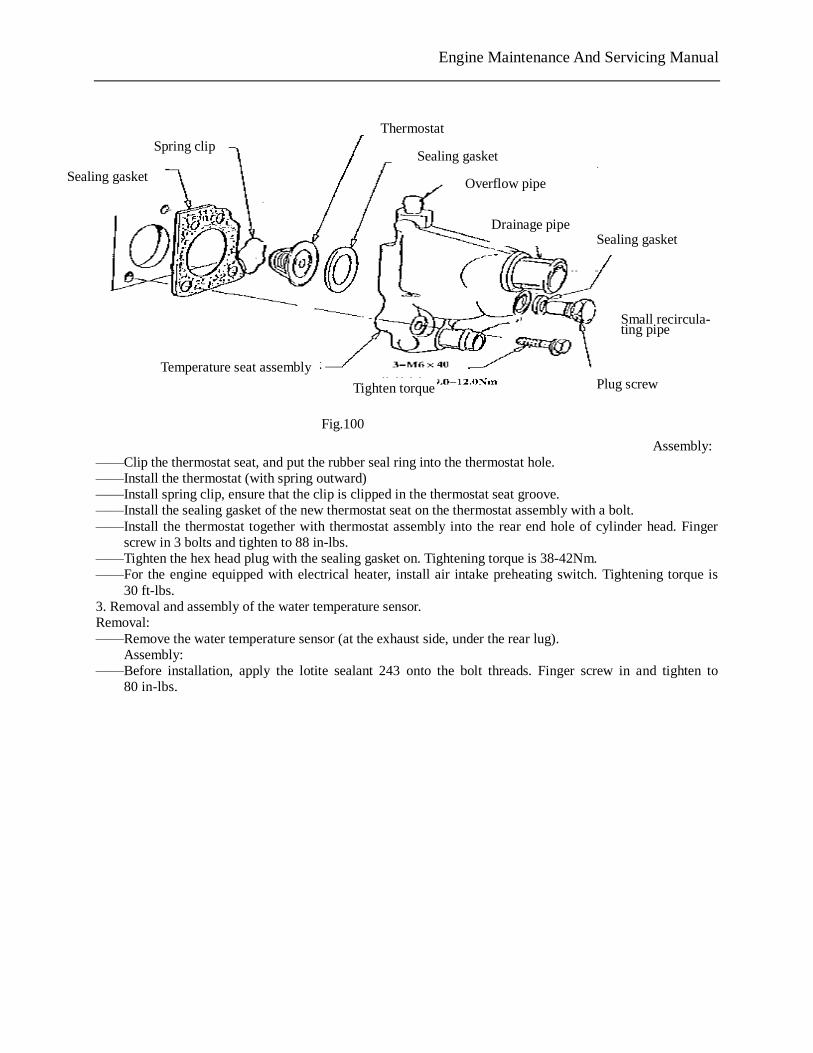
Assembly: ——Clip the thermostat seat, and put the rubber seal ring into the thermostat hole. ——Install the thermostat (with spring outward) ——Install spring clip, ensure that the clip is clipped in the thermostat seat groove. ——Install the sealing gasket of the new thermostat seat on the thermostat assembly with a bolt. ——Install the thermostat together with thermostat assembly into the rear end hole of cylinder head. Finger
screw in 3 bolts and tighten to 88 in-lbs. ——Tighten the hex head plug with the sealing gasket on. Tightening torque is 38-42Nm. ——For the engine equipped with electrical heater, install air intake preheating switch. Tightening torque is
30 ft-lbs. 3. Removal and assembly of the water temperature sensor. Removal: ——Remove the water temperature sensor (at the exhaust side, under the rear lug).
Assembly: ——Before installation, apply the lotite sealant 243 onto the bolt threads. Finger screw in and tighten to
80 in-lbs. 【15】. The intake and exhaust system of the engine 1. Description for the intake and exhaust system of carburetor engine. The intake system of Carburetor Engine 478 and 480 includes: air filter, Intake hose, Guide cover, Carburetor, Intake hose, Intake air preheating hose of Positive Crankcase Ventilation(PCV), and so on. ——Air filter type is 1GD129607G, and its basic parameters are as the following: Filtering area: 100cm2 nominal air flow(L): 600±150 filtering efficiency: ≥99% filtering resistance: 2kPa
Thermostat
Sealing gasket
Overflow pipe
Drainage pipe Sealing gasket
Small recircula- ting pipe
Plug screw
Spring clip
Sealing gasket
Tighten torque
Fig.100
Temperature seat assembly
PDF 文件使用 "pdfFactory Pro" 试用版本创建 www.fineprint.com.cn
Engine Maintenance And Servicing Manual
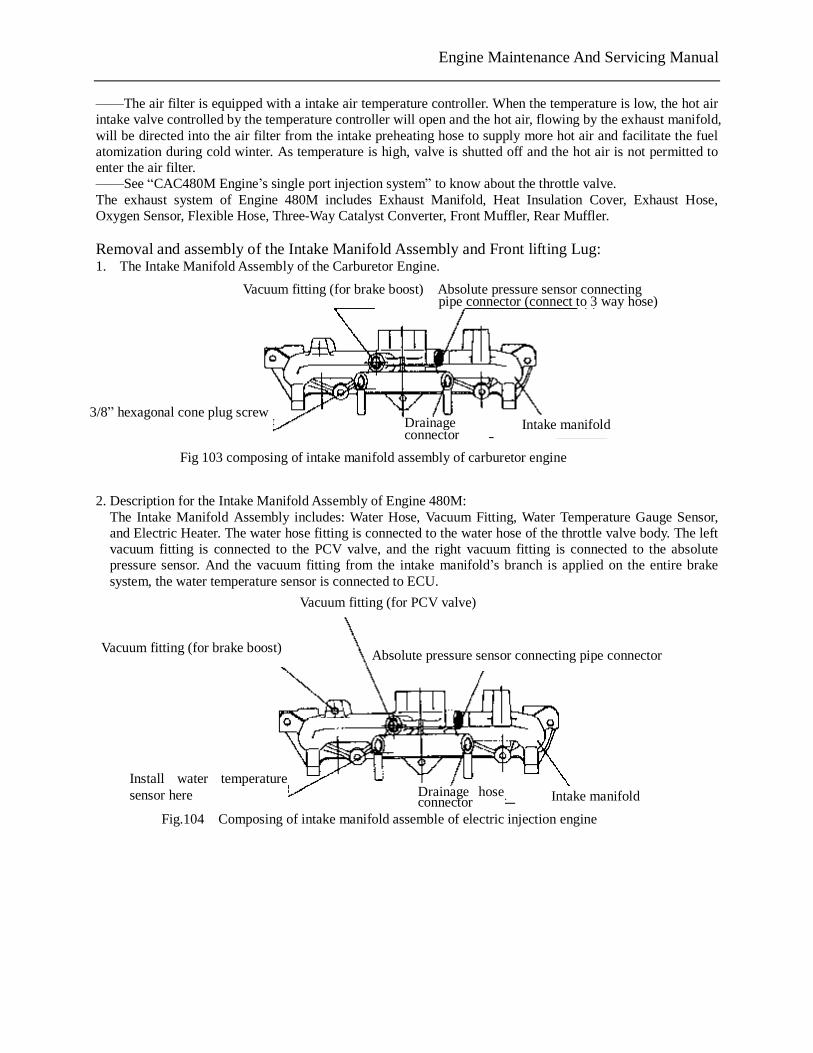
——The air filter is equipped with a intake air temperature controller. When the temperature is low, the hot air intake valve controlled by the temperature controller will open and the hot air, flowing by the exhaust manifold, will be directed into the air filter from the intake preheating hose to supply more hot air and facilitate the fuel atomization during cold winter. As temperature is high, valve is shutted off and the hot air is not permitted to enter the air filter. ——See “CAC480M Engine’s single port injection system” to know about the throttle valve. The exhaust system of Engine 480M includes Exhaust Manifold, Heat Insulation Cover, Exhaust Hose, Oxygen Sensor, Flexible Hose, Three-Way Catalyst Converter, Front Muffler, Rear Muffler. Removal and assembly of the Intake Manifold Assembly and Front lifting Lug: 1. The Intake Manifold Assembly of the Carburetor Engine.
2. Description for the Intake Manifold Assembly of Engine 480M: The Intake Manifold Assembly includes: Water Hose, Vacuum Fitting, Water Temperature Gauge Sensor, and Electric Heater. The water hose fitting is connected to the water hose of the throttle valve body. The left vacuum fitting is connected to the PCV valve, and the right vacuum fitting is connected to the absolute pressure sensor. And the vacuum fitting from the intake manifold’s branch is applied on the entire brake system, the water temperature sensor is connected to ECU.
Fig 103 composing of intake manifold assembly of carburetor engine
Vacuum fitting (for brake boost) Absolute pressure sensor connecting pipe connector (connect to 3 way hose)
3/8” hexagonal cone plug screw Drainage connector
Intake manifold
Fig.104 Composing of intake manifold assemble of electric injection engine
Vacuum fitting (for brake boost)
Vacuum fitting (for PCV valve)
Absolute pressure sensor connecting pipe connector
Install water temperature sensor here Intake manifold Drainage hose
connector
PDF 文件使用 "pdfFactory Pro" 试用版本创建 www.fineprint.com.cn
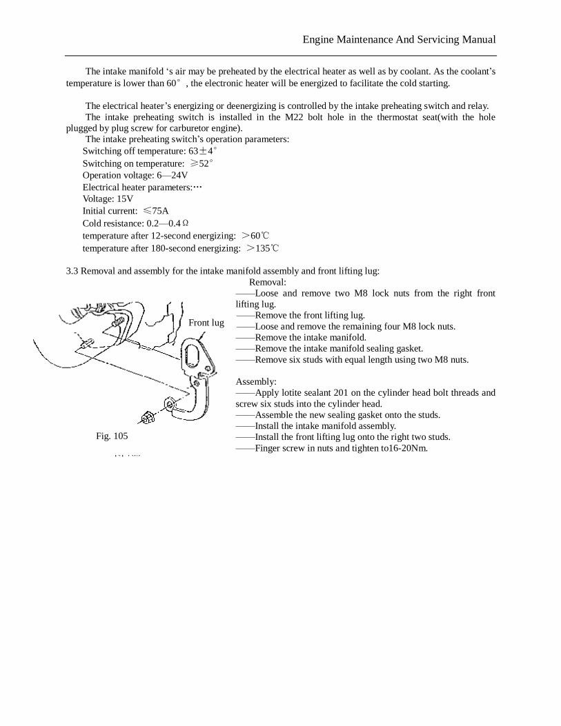
Engine Maintenance And Servicing Manual
The intake manifold ‘s air may be preheated by the electrical heater as well as by coolant. As the coolant’s temperature is lower than 60°, the electronic heater will be energized to facilitate the cold starting.
The electrical heater’s energizing or deenergizing is controlled by the intake preheating switch and relay. The intake preheating switch is installed in the M22 bolt hole in the thermostat seat(with the hole
plugged by plug screw for carburetor engine). The intake preheating switch’s operation parameters:
Switching off temperature: 63±4° Switching on temperature: ≥52° Operation voltage: 6—24V Electrical heater parameters:… Voltage: 15V Initial current: ≤75A Cold resistance: 0.2—0.4Ω temperature after 12-second energizing: >60℃ temperature after 180-second energizing: >135℃
3.3 Removal and assembly for the intake manifold assembly and front lifting lug:
Removal: ——Loose and remove two M8 lock nuts from the right front lifting lug. ——Remove the front lifting lug. ——Loose and remove the remaining four M8 lock nuts. ——Remove the intake manifold. ——Remove the intake manifold sealing gasket. ——Remove six studs with equal length using two M8 nuts. Assembly: ——Apply lotite sealant 201 on the cylinder head bolt threads and screw six studs into the cylinder head. ——Assemble the new sealing gasket onto the studs. ——Install the intake manifold assembly. ——Install the front lifting lug onto the right two studs. ——Finger screw in nuts and tighten to16-20Nm.
Fig. 105
Front lug
PDF 文件使用 "pdfFactory Pro" 试用版本创建 www.fineprint.com.cn
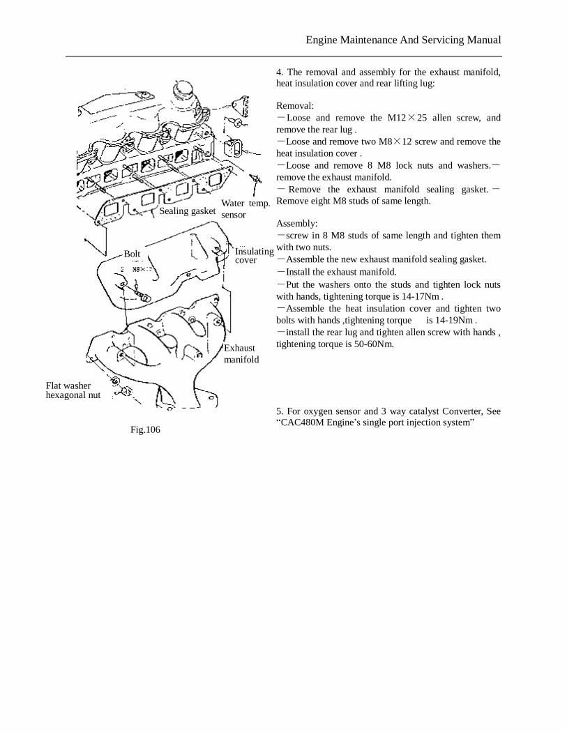
Engine Maintenance And Servicing Manual
4. The removal and assembly for the exhaust manifold, heat insulation cover and rear lifting lug:
Removal: -Loose and remove the M12×25 allen screw, and remove the rear lug . -Loose and remove two M8×12 screw and remove the heat insulation cover . -Loose and remove 8 M8 lock nuts and washers.-remove the exhaust manifold. - Remove the exhaust manifold sealing gasket.-Remove eight M8 studs of same length. Assembly: -screw in 8 M8 studs of same length and tighten them with two nuts. -Assemble the new exhaust manifold sealing gasket. -Install the exhaust manifold. -Put the washers onto the studs and tighten lock nuts with hands, tightening torque is 14-17Nm . -Assemble the heat insulation cover and tighten two bolts with hands ,tightening torque is 14-19Nm . -install the rear lug and tighten allen screw with hands , tightening torque is 50-60Nm. 5. For oxygen sensor and 3 way catalyst Converter, See “CAC480M Engine’s single port injection system”
Bolt Insulating cover
Exhaust manifold
Fig.106
Flat washer hexagonal nut
Water temp. sensor Sealing gasket
PDF 文件使用 "pdfFactory Pro" 试用版本创建 www.fineprint.com.cn
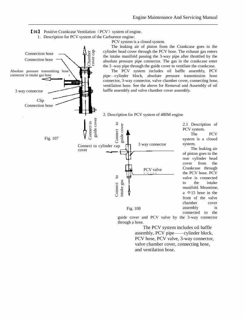
Engine Maintenance And Servicing Manual
【16】 Positive Crankcase Ventilation(PCV)system of engine. 1. Description for PCV system of the Carburetor engine:
PCV system is a closed system. The leaking air of piston from the Crankcase goes to the
cylinder head cover through the PCV hose. The exhaust gas enters the intake manifold passing the 3-way pipe after throttled by the absolute pressure pipe connector. The gas in the crankcase enter the 3 -way pipe through the guide cover to ventilate the crankcase.
The PCV system includes oil baffle assembly, PCV pipe—cylinder block, absolute pressure transmission hose connector, 3-way connector, valve chamber cover, connecting hose, ventilation hose. See the above for Removal and Assembly of oil baffle assembly and valve chamber cover assembly. 2. Description for PCV system of 480M engine
2.1 Description of PCV system.
The PCV system is a closed system.
The leaking air of piston goes to the rear cylinder head cover from the Crankcase through the PCV hose. PCV valve is connected to the intake manifold. Meantime, a Ф15 hose in the front of the valve chamber cover assembly is connected to the
guide cover and PCV valve by the 3-way connector through a hose.
The PCV system includes oil baffle assembly, PCV pipe——cylinder block, PCV hose, PCV valve, 3-way connector, valve chamber cover, connecting hose, and ventilation hose.
Connection hose
3 way connector
Absolute pressure transmitting hose connector in intake gas hose
PCV valve
3 way connector
Con
nect
to
gu
ide
cove
r
Connect to cylinder cap cover
Con
nect
to
in
take
gas
Con
nect
to
gui
de c
over
Connection hose
Cha
mbe
r co
ver
cap
Clip
Fig. 107
Connection hose
Fig. 108
PDF 文件使用 "pdfFactory Pro" 试用版本创建 www.fineprint.com.cn
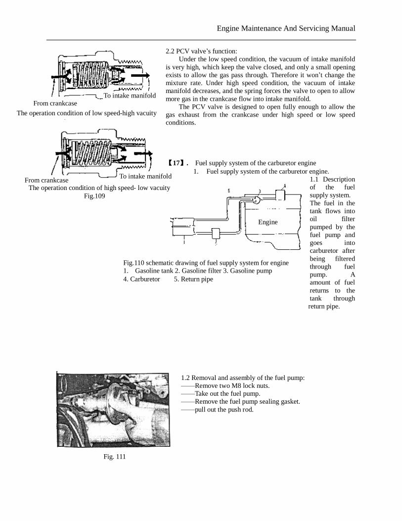
Engine Maintenance And Servicing Manual
2.2 PCV valve’s function: Under the low speed condition, the vacuum of intake manifold
is very high, which keep the valve closed, and only a small opening exists to allow the gas pass through. Therefore it won’t change the mixture rate. Under high speed condition, the vacuum of intake manifold decreases, and the spring forces the valve to open to allow more gas in the crankcase flow into intake manifold.
The PCV valve is designed to open fully enough to allow the gas exhaust from the crankcase under high speed or low speed conditions. 【17】. Fuel supply system of the carburetor engine
1. Fuel supply system of the carburetor engine. 1.1 Description of the fuel supply system. The fuel in the tank flows into oil filter pumped by the fuel pump and goes into carburetor after being filtered through fuel pump. A amount of fuel returns to the tank through return pipe.
1.2 Removal and assembly of the fuel pump: ——Remove two M8 lock nuts. ——Take out the fuel pump. ——Remove the fuel pump sealing gasket. ——pull out the push rod.
From crankcase
From crankcase
The operation condition of low speed-high vacuity
To intake manifold
The operation condition of high speed- low vacuity Fig.109
To intake manifold
Engine
Fig.110 schematic drawing of fuel supply system for engine 1. Gasoline tank 2. Gasoline filter 3. Gasoline pump 4. Carburetor 5. Return pipe
Fig. 111
PDF 文件使用 "pdfFactory Pro" 试用版本创建 www.fineprint.com.cn
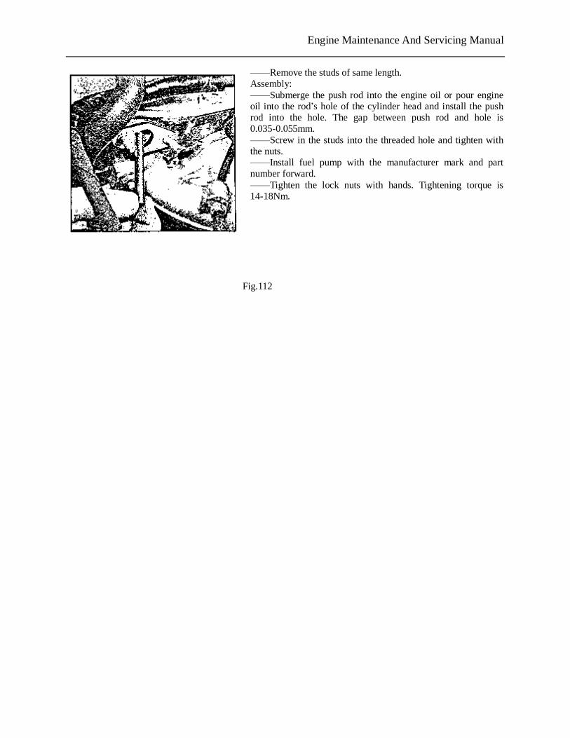
Engine Maintenance And Servicing Manual
——Remove the studs of same length. Assembly: ——Submerge the push rod into the engine oil or pour engine oil into the rod’s hole of the cylinder head and install the push rod into the hole. The gap between push rod and hole is 0.035-0.055mm. ——Screw in the studs into the threaded hole and tighten with the nuts. ——Install fuel pump with the manufacturer mark and part number forward. ——Tighten the lock nuts with hands. Tightening torque is 14-18Nm.
Fig.112
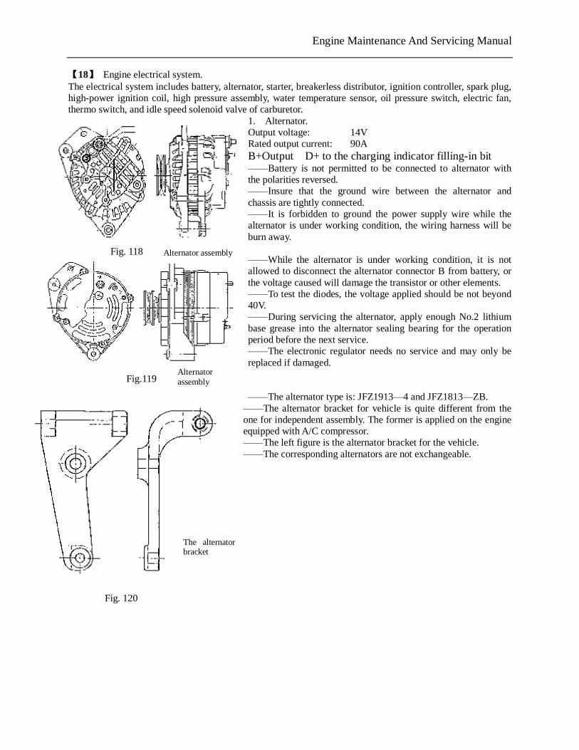
Engine Maintenance And Servicing Manual
【18】 Engine electrical system. The electrical system includes battery, alternator, starter, breakerless distributor, ignition controller, spark plug, high-power ignition coil, high pressure assembly, water temperature sensor, oil pressure switch, electric fan, thermo switch, and idle speed solenoid valve of carburetor.
1. Alternator. Output voltage: 14V Rated output current: 90A B+Output D+ to the charging indicator filling-in bit ——Battery is not permitted to be connected to alternator with the polarities reversed. ——Insure that the ground wire between the alternator and chassis are tightly connected. ——It is forbidden to ground the power supply wire while the alternator is under working condition, the wiring harness will be burn away. ——While the alternator is under working condition, it is not allowed to disconnect the alternator connector B from battery, or the voltage caused will damage the transistor or other elements. ——To test the diodes, the voltage applied should be not beyond 40V. ——During servicing the alternator, apply enough No.2 lithium base grease into the alternator sealing bearing for the operation period before the next service. ——The electronic regulator needs no service and may only be replaced if damaged. ——The alternator type is: JFZ1913—4 and JFZ1813—ZB. ——The alternator bracket for vehicle is quite different from the one for independent assembly. The former is applied on the engine equipped with A/C compressor. ——The left figure is the alternator bracket for the vehicle. ——The corresponding alternators are not exchangeable.
Alternator assembly Fig. 118
Alternator assembly Fig.119
The alternator bracket
Fig. 120
PDF 文件使用 "pdfFactory Pro" 试用版本创建 www.fineprint.com.cn
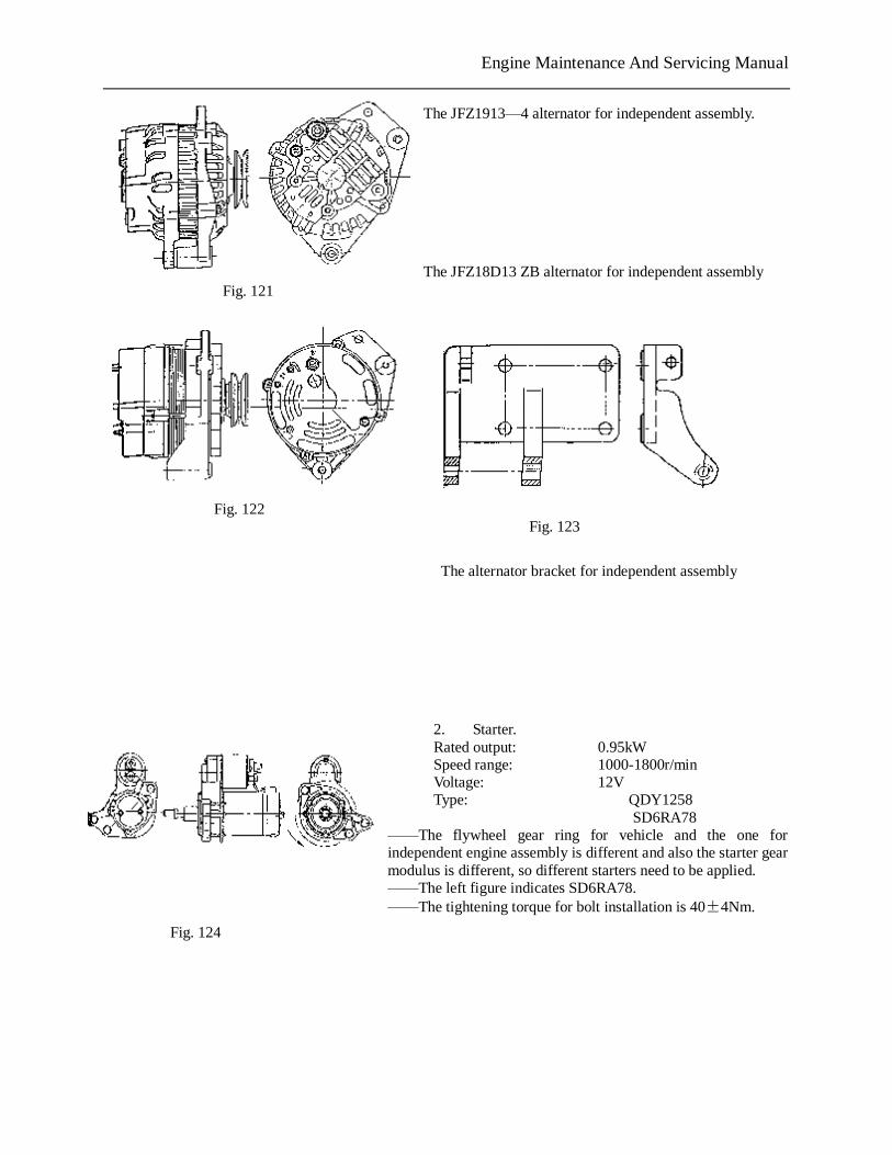
Engine Maintenance And Servicing Manual
The JFZ1913—4 alternator for independent assembly. The JFZ18D13 ZB alternator for independent assembly
The alternator bracket for independent assembly
2. Starter. Rated output: 0.95kW Speed range: 1000-1800r/min Voltage: 12V Type: QDY1258
SD6RA78 ——The flywheel gear ring for vehicle and the one for independent engine assembly is different and also the starter gear modulus is different, so different starters need to be applied. ——The left figure indicates SD6RA78. ——The tightening torque for bolt installation is 40±4Nm.
Fig. 121
Fig. 123
Fig. 124
Fig. 122
PDF 文件使用 "pdfFactory Pro" 试用版本创建 www.fineprint.com.cn
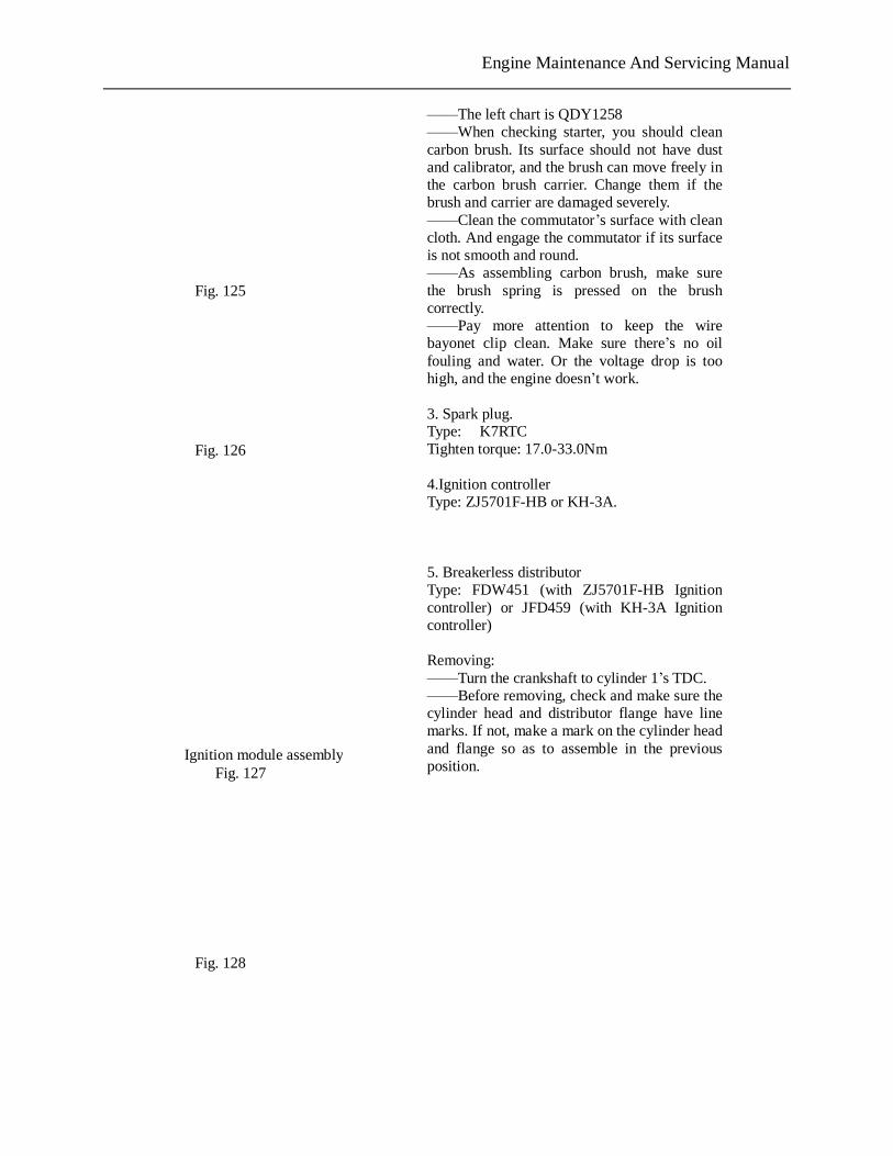
Engine Maintenance And Servicing Manual
——The left chart is QDY1258 ——When checking starter, you should clean carbon brush. Its surface should not have dust and calibrator, and the brush can move freely in the carbon brush carrier. Change them if the brush and carrier are damaged severely. ——Clean the commutator’s surface with clean cloth. And engage the commutator if its surface is not smooth and round. ——As assembling carbon brush, make sure the brush spring is pressed on the brush correctly. ——Pay more attention to keep the wire bayonet clip clean. Make sure there’s no oil fouling and water. Or the voltage drop is too high, and the engine doesn’t work. 3. Spark plug. Type: K7RTC Tighten torque: 17.0-33.0Nm 4.Ignition controller Type: ZJ5701F-HB or KH-3A. 5. Breakerless distributor Type: FDW451 (with ZJ5701F-HB Ignition controller) or JFD459 (with KH-3A Ignition controller) Removing: ——Turn the crankshaft to cylinder 1’s TDC. ——Before removing, check and make sure the cylinder head and distributor flange have line marks. If not, make a mark on the cylinder head and flange so as to assemble in the previous position.
Fig. 125
Fig. 126
Ignition module assembly Fig. 127
Fig. 128
PDF 文件使用 "pdfFactory Pro" 试用版本创建 www.fineprint.com.cn
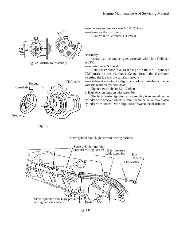
Engine Maintenance And Servicing Manual
——Loosen and remove two M6× 20 bolts. ——Remove the distributor. ——Remove the distributor’s “O “seal. Assembly: ——Insure that the engine is set correctly with No.1 Cylinder at TDC. ——Install new “O” seal. ——Rotate distributor to align the lug with the No. 1 cylinder TDC mark on the distributor flange. Install the distributor inserting the lug into the camshaft groove. ——Rotate distributor to align the mark on distributor flange with the mark on cylinder head. ——Tighten two bolts to 5.0—7.0Nm. 6. High tension ignition wire assembly:
The high tension ignition wire assembly is mounted on the cylinder wire bracket which is installed on the valve cover, also cylinder wire and coil wire clips exist between the distributor
Fig. 129 distributor assembly
Groove
Camshaft Tongue
TDC mark
Fig. 130
Slave cylinder and high pressure wiring harness
Slave cylinder and high pressure wiring harness High pressure
cable assembly
Flat washer
Slave cylinder and high pressure wiring harness carrier
Fig. 131
Bolt
PDF 文件使用 "pdfFactory Pro" 试用版本创建 www.fineprint.com.cn
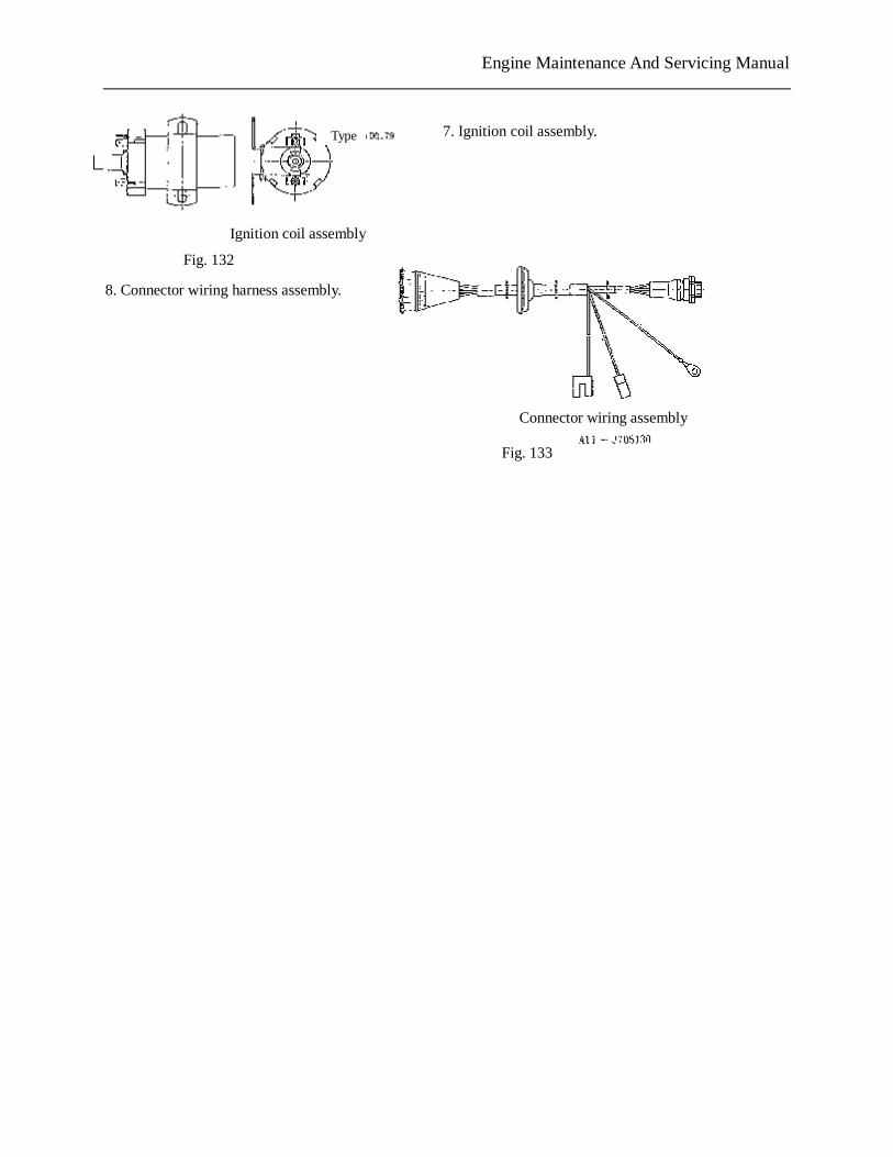
Engine Maintenance And Servicing Manual
7. Ignition coil assembly.
8. Connector wiring harness assembly.
Connector wiring assembly
Ignition coil assembly
Fig. 132
Type
Fig. 133
PDF 文件使用 "pdfFactory Pro" 试用版本创建 www.fineprint.com.cn
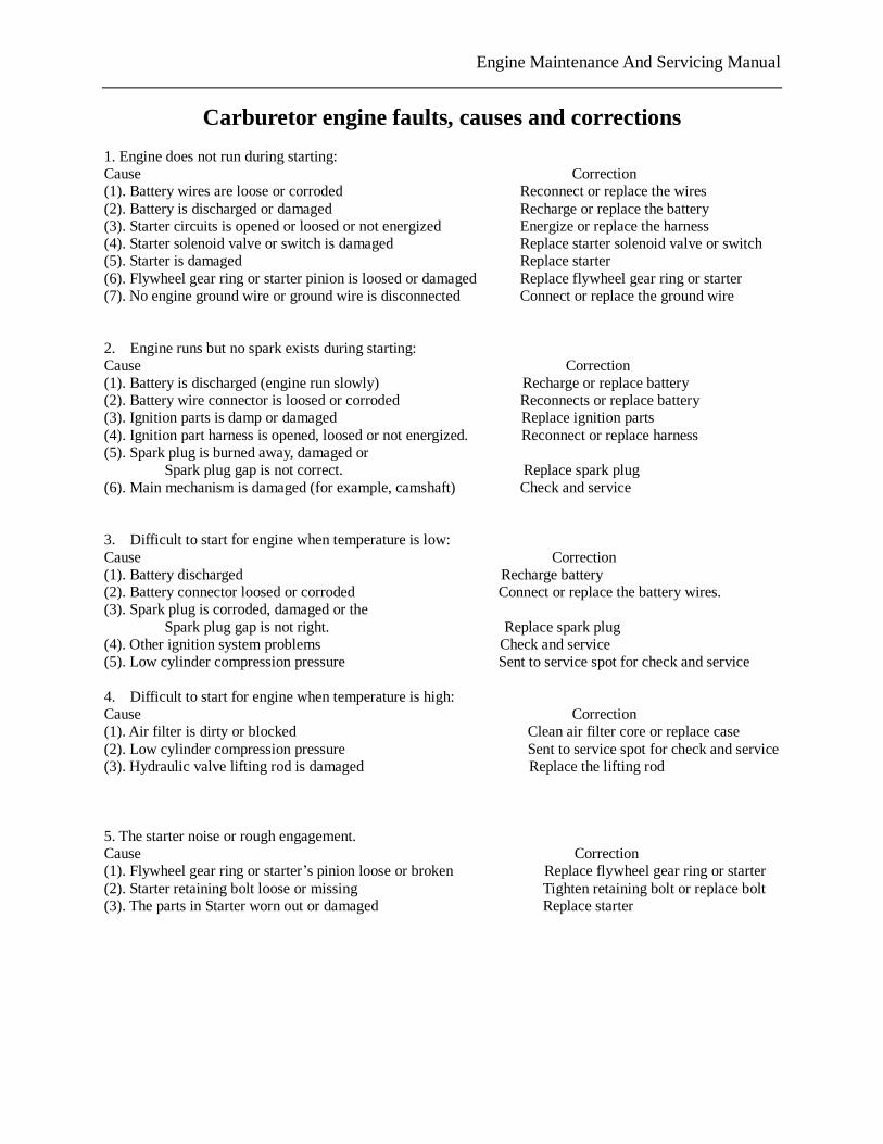
Engine Maintenance And Servicing Manual
Carburetor engine faults, causes and corrections 1. Engine does not run during starting: Cause Correction (1). Battery wires are loose or corroded Reconnect or replace the wires (2). Battery is discharged or damaged Recharge or replace the battery (3). Starter circuits is opened or loosed or not energized Energize or replace the harness (4). Starter solenoid valve or switch is damaged Replace starter solenoid valve or switch (5). Starter is damaged Replace starter (6). Flywheel gear ring or starter pinion is loosed or damaged Replace flywheel gear ring or starter (7). No engine ground wire or ground wire is disconnected Connect or replace the ground wire 2. Engine runs but no spark exists during starting: Cause Correction (1). Battery is discharged (engine run slowly) Recharge or replace battery (2). Battery wire connector is loosed or corroded Reconnects or replace battery (3). Ignition parts is damp or damaged Replace ignition parts (4). Ignition part harness is opened, loosed or not energized. Reconnect or replace harness (5). Spark plug is burned away, damaged or
Spark plug gap is not correct. Replace spark plug (6). Main mechanism is damaged (for example, camshaft) Check and service 3. Difficult to start for engine when temperature is low: Cause Correction (1). Battery discharged Recharge battery (2). Battery connector loosed or corroded Connect or replace the battery wires. (3). Spark plug is corroded, damaged or the
Spark plug gap is not right. Replace spark plug (4). Other ignition system problems Check and service (5). Low cylinder compression pressure Sent to service spot for check and service 4. Difficult to start for engine when temperature is high: Cause Correction (1). Air filter is dirty or blocked Clean air filter core or replace case (2). Low cylinder compression pressure Sent to service spot for check and service (3). Hydraulic valve lifting rod is damaged Replace the lifting rod 5. The starter noise or rough engagement. Cause Correction (1). Flywheel gear ring or starter’s pinion loose or broken Replace flywheel gear ring or starter (2). Starter retaining bolt loose or missing Tighten retaining bolt or replace bolt (3). The parts in Starter worn out or damaged Replace starter
PDF 文件使用 "pdfFactory Pro" 试用版本创建 www.fineprint.com.cn
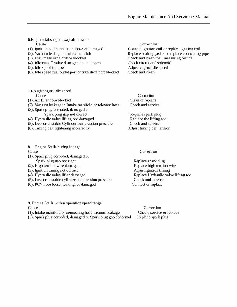
Engine Maintenance And Servicing Manual
6.Engine stalls right away after started.
Cause Correction (1). Ignition coil connection loose or damaged Connect ignition coil or replace ignition coil (2). Vacuum leakage in intake manifold Replace sealing gasket or replace connecting pipe(3). Mail measuring orifice blocked Check and clean mail measuring orifice (4). Idle cut-off valve damaged and not open Check circuit and solenoid (5). Idle speed too low Adjust engine idle speed (6). Idle speed fuel outlet port or transition port blocked Check and clean
7.Rough engine idle speed Cause Correction
(1). Air filter core blocked Clean or replace (2). Vacuum leakage in Intake manifold or relevant hose Check and service (3). Spark plug corroded, damaged or
Spark plug gap not correct Replace spark plug (4). Hydraulic valve lifting rod damaged Replace the lifting rod (5). Low or unstable Cylinder compression pressure Check and service (6). Timing belt tightening incorrectly Adjust timing belt tension 8. Engine Stalls during idling: Cause Correction (1). Spark plug corroded, damaged or
Spark plug gap not right. Replace spark plug (2). High tension wire damaged Replace high tension wire (3). Ignition timing not correct Adjust ignition timing (4). Hydraulic valve lifter damaged Replace Hydraulic valve lifting rod (5). Low or unstable cylinder compression pressure Check and service (6). PCV hose loose, leaking, or damaged Connect or replace 9. Engine Stalls within operation speed range Cause Correction (1). Intake manifold or connecting hose vacuum leakage Check, service or replace (2). Spark plug corroded, damaged or Spark plug gap abnormal Replace spark plug
PDF 文件使用 "pdfFactory Pro" 试用版本创建 www.fineprint.com.cn
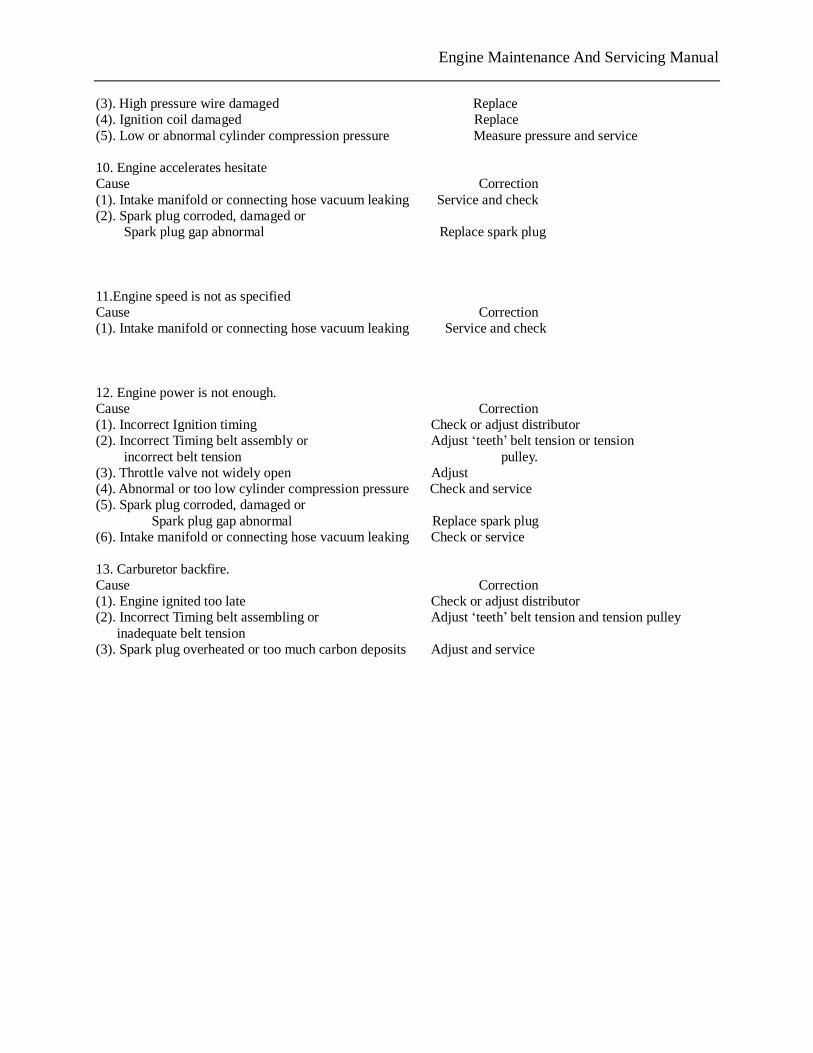
Engine Maintenance And Servicing Manual
(3). High pressure wire damaged Replace (4). Ignition coil damaged Replace (5). Low or abnormal cylinder compression pressure Measure pressure and service 10. Engine accelerates hesitate Cause Correction (1). Intake manifold or connecting hose vacuum leaking Service and check (2). Spark plug corroded, damaged or
Spark plug gap abnormal Replace spark plug 11.Engine speed is not as specified Cause Correction (1). Intake manifold or connecting hose vacuum leaking Service and check 12. Engine power is not enough. Cause Correction (1). Incorrect Ignition timing Check or adjust distributor (2). Incorrect Timing belt assembly or Adjust ‘teeth’ belt tension or tension
incorrect belt tension pulley. (3). Throttle valve not widely open Adjust (4). Abnormal or too low cylinder compression pressure Check and service (5). Spark plug corroded, damaged or
Spark plug gap abnormal Replace spark plug (6). Intake manifold or connecting hose vacuum leaking Check or service 13. Carburetor backfire. Cause Correction (1). Engine ignited too late Check or adjust distributor (2). Incorrect Timing belt assembling or Adjust ‘teeth’ belt tension and tension pulley
inadequate belt tension (3). Spark plug overheated or too much carbon deposits Adjust and service
PDF 文件使用 "pdfFactory Pro" 试用版本创建 www.fineprint.com.cn
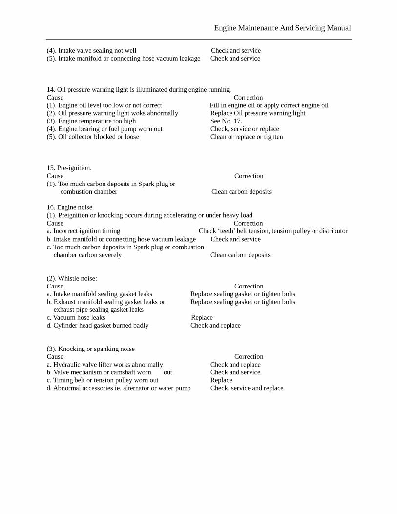
Engine Maintenance And Servicing Manual
(4). Intake valve sealing not well Check and service (5). Intake manifold or connecting hose vacuum leakage Check and service 14. Oil pressure warning light is illuminated during engine running. Cause Correction (1). Engine oil level too low or not correct Fill in engine oil or apply correct engine oil (2). Oil pressure warning light woks abnormally Replace Oil pressure warning light (3). Engine temperature too high See No. 17. (4). Engine bearing or fuel pump worn out Check, service or replace (5). Oil collector blocked or loose Clean or replace or tighten 15. Pre-ignition. Cause Correction (1). Too much carbon deposits in Spark plug or
combustion chamber Clean carbon deposits 16. Engine noise. (1). Preignition or knocking occurs during accelerating or under heavy load Cause Correction a. Incorrect ignition timing Check ‘teeth’ belt tension, tension pulley or distributor b. Intake manifold or connecting hose vacuum leakage Check and service c. Too much carbon deposits in Spark plug or combustion
chamber carbon severely Clean carbon deposits
(2). Whistle noise: Cause Correction a. Intake manifold sealing gasket leaks Replace sealing gasket or tighten bolts b. Exhaust manifold sealing gasket leaks or Replace sealing gasket or tighten bolts exhaust pipe sealing gasket leaks c. Vacuum hose leaks Replace d. Cylinder head gasket burned badly Check and replace (3). Knocking or spanking noise Cause Correction a. Hydraulic valve lifter works abnormally Check and replace b. Valve mechanism or camshaft worn out Check and service c. Timing belt or tension pulley worn out Replace d. Abnormal accessories ie. alternator or water pump Check, service and replace
PDF 文件使用 "pdfFactory Pro" 试用版本创建 www.fineprint.com.cn
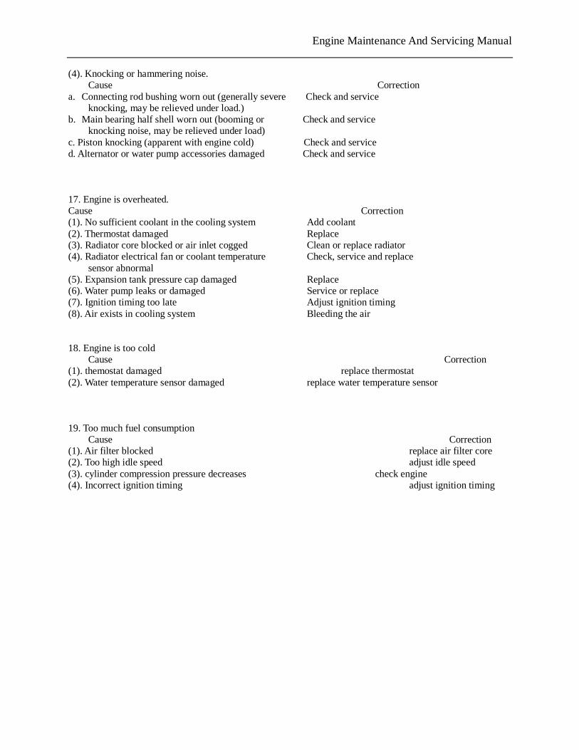
Engine Maintenance And Servicing Manual
(4). Knocking or hammering noise. Cause Correction
a. Connecting rod bushing worn out (generally severe Check and service knocking, may be relieved under load.)
b. Main bearing half shell worn out (booming or Check and service knocking noise, may be relieved under load)
c. Piston knocking (apparent with engine cold) Check and service d. Alternator or water pump accessories damaged Check and service 17. Engine is overheated. Cause Correction (1). No sufficient coolant in the cooling system Add coolant (2). Thermostat damaged Replace (3). Radiator core blocked or air inlet cogged Clean or replace radiator (4). Radiator electrical fan or coolant temperature Check, service and replace
sensor abnormal (5). Expansion tank pressure cap damaged Replace (6). Water pump leaks or damaged Service or replace (7). Ignition timing too late Adjust ignition timing (8). Air exists in cooling system Bleeding the air 18. Engine is too cold
Cause Correction (1). themostat damaged replace thermostat (2). Water temperature sensor damaged replace water temperature sensor 19. Too much fuel consumption
Cause Correction (1). Air filter blocked replace air filter core (2). Too high idle speed adjust idle speed (3). cylinder compression pressure decreases check engine (4). Incorrect ignition timing adjust ignition timing
PDF 文件使用 "pdfFactory Pro" 试用版本创建 www.fineprint.com.cn
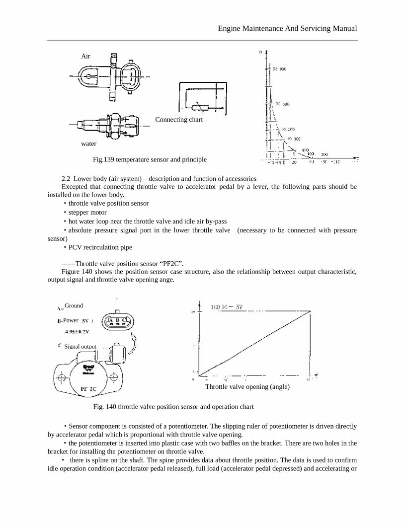
Engine Maintenance And Servicing Manual
2.2 Lower body (air system)—description and function of accessories Excepted that connecting throttle valve to accelerator pedal by a lever, the following parts should be
installed on the lower body. ·throttle valve position sensor ·stepper motor ·hot water loop near the throttle valve and idle air by-pass ·absolute pressure signal port in the lower throttle valve (necessary to be connected with pressure
sensor) ·PCV recirculation pipe ——Throttle valve position sensor “PF2C”. Figure 140 shows the position sensor case structure, also the relationship between output characteristic,
output signal and throttle valve opening ange.
·Sensor component is consisted of a potentiometer. The slipping ruler of potentiometer is driven directly
by accelerator pedal which is proportional with throttle valve opening. ·the potentiometer is inserted into plastic case with two baffles on the bracket. There are two holes in the
bracket for installing the potentiometer on throttle valve. · there is spline on the shaft. The spine provides data about throttle position. The data is used to confirm
idle operation condition (accelerator pedal released), full load (accelerator pedal depressed) and accelerating or
Fig.139 temperature sensor and principle
water
Air
Connecting chart
Fig. 140 throttle valve position sensor and operation chart
Ground
Signal output
Power
Throttle valve opening (angle)
Engine Maintenance And Servicing Manual
decelerating conditions. · with absolute pressure sensor out of work, the position sensor will function when working condition
comes back. ·ECU supplies 5V voltage to the variable resistance terminal of throttle valve potentiometer . And
potentiometer output voltage varies with throttle valve position. ·sensor needs not adjustment(through assembling hole), for ECU program may self adjust to minimum
impedance (2°to 14°). Warning——the following order should be taken during potentiometer replacement: 1. Tighten mounting bolt on the new potentiometer. 2. Turn ignition key to the MAR before connecting line to the potentiometer, and wait for several
minutes. 3. Turn ignition key to stop. 4. Connect wire to the potentiometer’s insert hole. 5. Insert CHECK-UP1 tester. Turn ignition key to CN and erase trouble display. 6. Keep connection until throttle valve position displayed on the screen is 2°~14°. If the parameter
is above 14°, you should check throttle cable and make sure it’s correct (not very tight). Or it needs to be adjusted again.
Notice: Don’t adjust the potentiometer bolt if it does not return to the specified value of throttle valve opening angle. The potentiometer should be replaced because it fails.
——Engine idle speed actuator (idle control stepper motor) Idle control stepper motor is a position actuator of high precision and high distinguishability ( +/-50r/min)
for controlling idle speed. It is consisted of stepper motor and screw rod-type reduction gear. The reduction gear converts the valve
rotating into linear movement. Stepper motor receives the signal from ECU and makes valve shaft move by screw rod changing air by-pass passage (see figure 8). Then engine air intake will change during idling. It will vary with coolant water temperature whether air intake is increasing or decreasing, which keeps speed stable. Engine minimum idle air intake is set by adjusting throttle valve opening when by-pass channel is closed completely. Be sure not to touch mixture adjustment bolt. Engine maximum idle air intake is set by valve returning position, i.e. about 200 steps (8mm travel). The operation steps are the function of engine conditions (preheating cycle, electrical load, A/C working condition, engine running (hot)).
PDF 文件使用 "pdfFactory Pro" 试用版本创建 www.fineprint.com.cn
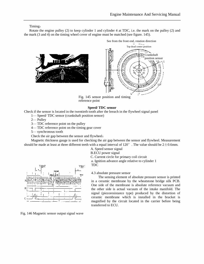
Engine Maintenance And Servicing Manual
Timing: Rotate the engine pulley (2) to keep cylinder 1 and cylinder 4 at TDC, i.e. the mark on the pulley (2) and the mark (3 and 4) on the timing wheel cover of engine must be matched (see figure. 145).
Speed/ TDC sensor
Check if the sensor is located in the twentieth tooth after the breach in the flywheel signal panel 1— Speed/ TDC sensor (crankshaft position sensor) 2— Pulley 3— TDC reference point on the pulley 4— TDC reference point on the timing gear cover 5— synchronous tooth Check the air gap between the sensor and flywheel:
Magnetic thickness gauge is used for checking the air gap between the sensor and flywheel. Measurement should be made at least at three different teeth with a equal interval of 120°. The value should be 2±0.6mm.
A. Speed sensor signal B.ECU power signal C. Current circle for primary coil circuit a. Ignition advance angle relative to cylinder 1 TDC 4.3 absolute pressure sensor The sensing element of absolute pressure sensor is printed in a ceramic membrane by the wheatstone bridge silk PCB. One side of the membrane is absolute reference vacuum and the other side is actual vacuum of the intake manifold. The signal (piezoresistance type) produced by the distortion of ceramic membrane which is installed in the bracket is magnified by the circuit located in the carrier before being transferred to ECU.
See from the front end, rotation direction
Top dead center position
Crankshaft position sensor
Fig. 145 sensor position and timing reference point
Fig. 146 Magnetic sensor output signal wave
PDF 文件使用 "pdfFactory Pro" 试用版本创建 www.fineprint.com.cn
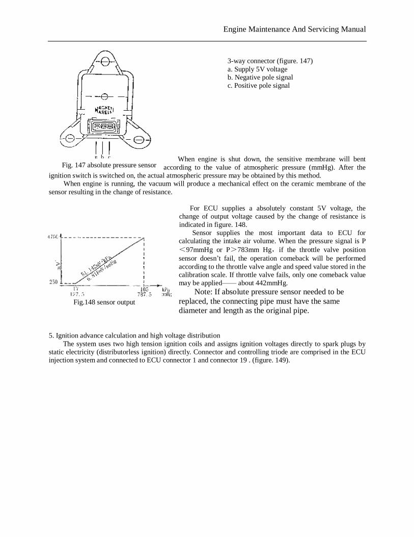
Engine Maintenance And Servicing Manual
3-way connector (figure. 147) a. Supply 5V voltage b. Negative pole signal c. Positive pole signal
When engine is shut down, the sensitive membrane will bent according to the value of atmospheric pressure (mmHg). After the
ignition switch is switched on, the actual atmospheric pressure may be obtained by this method. When engine is running, the vacuum will produce a mechanical effect on the ceramic membrane of the
sensor resulting in the change of resistance.
For ECU supplies a absolutely constant 5V voltage, the change of output voltage caused by the change of resistance is indicated in figure. 148.
Sensor supplies the most important data to ECU for calculating the intake air volume. When the pressure signal is P<97mmHg or P>783mm Hg,if the throttle valve position sensor doesn’t fail, the operation comeback will be performed according to the throttle valve angle and speed value stored in the calibration scale. If throttle valve fails, only one comeback value may be applied—— about 442mmHg.
Note: If absolute pressure sensor needed to be replaced, the connecting pipe must have the same diameter and length as the original pipe.
5. Ignition advance calculation and high voltage distribution The system uses two high tension ignition coils and assigns ignition voltages directly to spark plugs by static electricity (distributorless ignition) directly. Connector and controlling triode are comprised in the ECU injection system and connected to ECU connector 1 and connector 19 . (figure. 149).
Fig. 147 absolute pressure sensor
Fig.148 sensor output
PDF 文件使用 "pdfFactory Pro" 试用版本创建 www.fineprint.com.cn
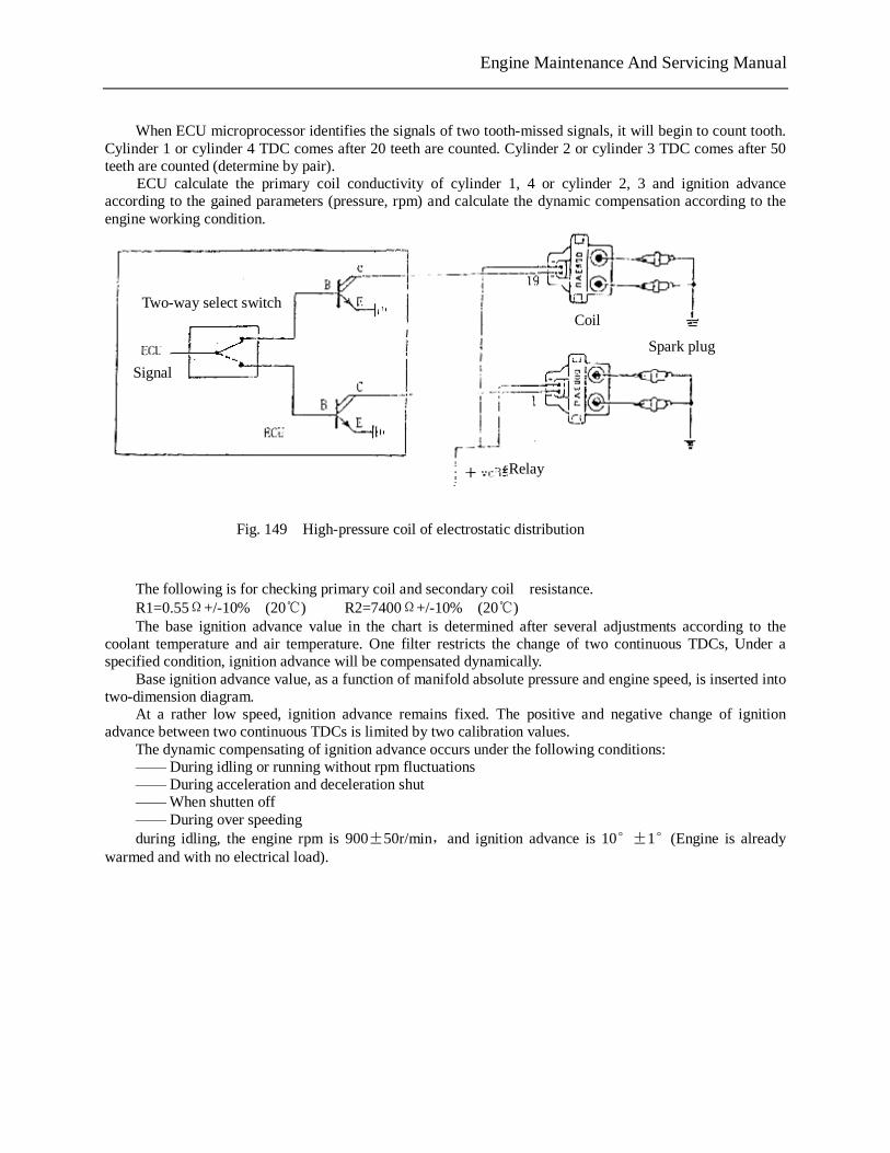
Engine Maintenance And Servicing Manual
When ECU microprocessor identifies the signals of two tooth-missed signals, it will begin to count tooth. Cylinder 1 or cylinder 4 TDC comes after 20 teeth are counted. Cylinder 2 or cylinder 3 TDC comes after 50 teeth are counted (determine by pair).
ECU calculate the primary coil conductivity of cylinder 1, 4 or cylinder 2, 3 and ignition advance according to the gained parameters (pressure, rpm) and calculate the dynamic compensation according to the engine working condition.
The following is for checking primary coil and secondary coil resistance. R1=0.55Ω+/-10% (20℃) R2=7400Ω+/-10% (20℃) The base ignition advance value in the chart is determined after several adjustments according to the coolant temperature and air temperature. One filter restricts the change of two continuous TDCs, Under a specified condition, ignition advance will be compensated dynamically. Base ignition advance value, as a function of manifold absolute pressure and engine speed, is inserted into two-dimension diagram. At a rather low speed, ignition advance remains fixed. The positive and negative change of ignition advance between two continuous TDCs is limited by two calibration values. The dynamic compensating of ignition advance occurs under the following conditions: —— During idling or running without rpm fluctuations —— During acceleration and deceleration shut —— When shutten off —— During over speeding during idling, the engine rpm is 900±50r/min,and ignition advance is 10°±1°(Engine is already warmed and with no electrical load).
Fig. 149 High-pressure coil of electrostatic distribution
Two-way select switch Coil
Relay
Signal
Spark plug
PDF 文件使用 "pdfFactory Pro" 试用版本创建 www.fineprint.com.cn

�
Notes

�
Notes

P.O. BOX 310 EAGLE, WI 53119
Part No. 0G3865 Revision A (10/24/06) Printed in U.S.A.


