Embed Size (px)
Citation preview
11A-1
GROUP 11A
ENGINE MECHANICAL
<2.4L ENGINE>CONTENTS
GENERAL INFORMATION . . . . . . . . 11A-2
ENGINE DIAGNOSIS. . . . . . . . . . . . . 11A-3
SERVICE SPECIFICATIONS. . . . . . . 11A-4
SEALANTS AND ADHESIVE . . . . . . 11A-4
SPECIAL TOOLS. . . . . . . . . . . . . . . . 11A-5
ON-VEHICLE SERVICE. . . . . . . . . . . 11A-9DRIVE BELT TENSION CHECK. . . . . . . . . 11A-9AUTO-TENSIONER CHECK . . . . . . . . . . . 11A-9VALVE CLEARANCE CHECK AND ADJUSTMENT . . . . . . . . . . . . . . . . . . . . . . 11A-13IGNITION TIMING CHECK. . . . . . . . . . . . . 11A-13CURB IDLE SPEED CHECK . . . . . . . . . . . 11A-15IDLE MIXTURE CHECK . . . . . . . . . . . . . . . 11A-16COMPRESSION PRESSURE CHECK. . . . 11A-18MANIFOLD VACUUM CHECK . . . . . . . . . . 11A-19
CRANKSHAFT PULLEY . . . . . . . . . . 11A-21REMOVAL AND INSTALLATION . . . . . . . . 11A-21
CAMSHAFT . . . . . . . . . . . . . . . . . . . . 11A-26REMOVAL AND INSTALLATION . . . . . . . . 11A-26
VALVE STEM SEAL. . . . . . . . . . . . . . 11A-40REMOVAL AND INSTALLATION . . . . . . . . 11A-40
OIL PAN . . . . . . . . . . . . . . . . . . . . . . . 11A-49REMOVAL AND INSTALLATION . . . . . . . . 11A-49INSPECTION. . . . . . . . . . . . . . . . . . . . . . . . 11A-51
CRANKSHAFT OIL SEAL . . . . . . . . . 11A-52REMOVAL AND INSTALLATION . . . . . . . . 11A-52
CYLINDER HEAD GASKET . . . . . . . . 11A-55REMOVAL AND INSTALLATION . . . . . . . . 11A-55
TIMING CHAIN . . . . . . . . . . . . . . . . . . 11A-67REMOVAL AND INSTALLATION . . . . . . . . 11A-67
BALANCER TIMING CHAIN, BALANCER SHAFT AND OIL PUMP MODULE. . . . . . . . . . . . . . 11A-77
REMOVAL AND INSTALLATION . . . . . . . . 11A-77
BALANCER SHAFT AND OIL PUMP MODULE . . . . . . . . . . . . . . . . . 11A-81
REMOVAL AND INSTALLATION . . . . . . . . 11A-81
ENGINE ASSEMBLY . . . . . . . . . . . . . 11A-86REMOVAL AND INSTALLATION . . . . . . . . 11A-86
GENERAL INFORMATIONENGINE MECHANICAL <2.4L ENGINE>11A-2
GENERAL INFORMATIONM1111000101315
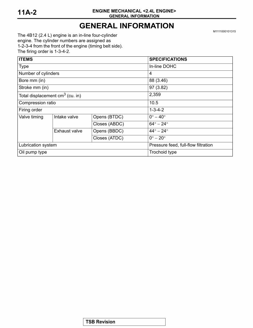
The 4B12 (2.4 L) engine is an in-line four-cylinder engine. The cylinder numbers are assigned as 1-2-3-4 from the front of the engine (timing belt side). The firing order is 1-3-4-2.
ITEMS SPECIFICATIONSType In-line DOHCNumber of cylinders 4Bore mm (in) 88 (3.46)Stroke mm (in) 97 (3.82)
Total displacement cm3 (cu. in) 2,359
Compression ratio 10.5Firing order 1-3-4-2Valve timing Intake valve Opens (BTDC) 0° − 40°
Closes (ABDC) 64° − 24°Exhaust valve Opens (BBDC) 44° − 24°
Closes (ATDC) 0° − 20°Lubrication system Pressure feed, full-flow filtrationOil pump type Trochoid type
TSB Revision
ENGINE DIAGNOSISENGINE MECHANICAL <2.4L ENGINE> 11A-3
ENGINE DIAGNOSISM1111000700400
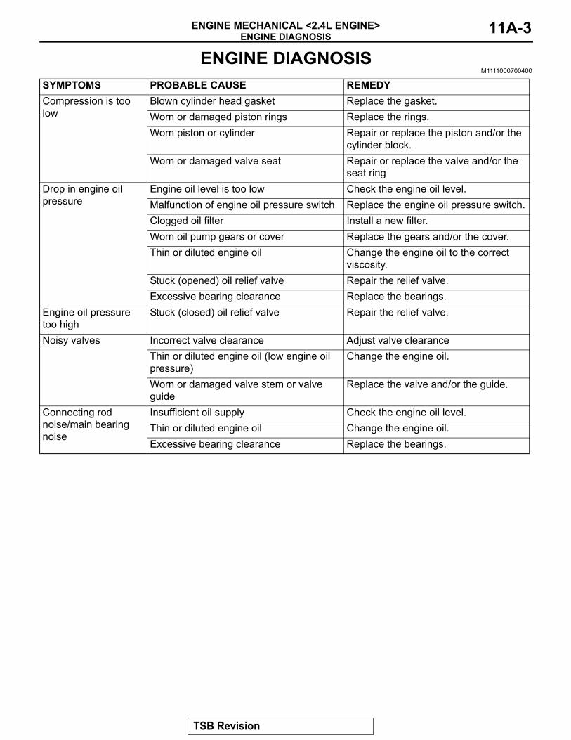
SYMPTOMS PROBABLE CAUSE REMEDYCompression is too low
Blown cylinder head gasket Replace the gasket.Worn or damaged piston rings Replace the rings.Worn piston or cylinder Repair or replace the piston and/or the
cylinder block.Worn or damaged valve seat Repair or replace the valve and/or the
seat ringDrop in engine oil pressure
Engine oil level is too low Check the engine oil level.Malfunction of engine oil pressure switch Replace the engine oil pressure switch.Clogged oil filter Install a new filter.Worn oil pump gears or cover Replace the gears and/or the cover.Thin or diluted engine oil Change the engine oil to the correct
viscosity.Stuck (opened) oil relief valve Repair the relief valve.Excessive bearing clearance Replace the bearings.
Engine oil pressure too high
Stuck (closed) oil relief valve Repair the relief valve.
Noisy valves Incorrect valve clearance Adjust valve clearanceThin or diluted engine oil (low engine oil pressure)
Change the engine oil.
Worn or damaged valve stem or valve guide
Replace the valve and/or the guide.
Connecting rod noise/main bearing noise
Insufficient oil supply Check the engine oil level.Thin or diluted engine oil Change the engine oil.Excessive bearing clearance Replace the bearings.
TSB Revision
SERVICE SPECIFICATIONSENGINE MECHANICAL <2.4L ENGINE>11A-4
SERVICE SPECIFICATIONSM1112000301475
SEALANTS AND ADHESIVEM1112000502643
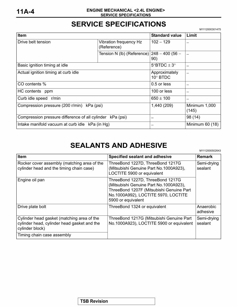
Item Standard value LimitDrive belt tension Vibration frequency Hz
(Reference)102 − 129 −
Tension N (lb) (Reference) 248 − 400 (56 − 90)
−
Basic ignition timing at idle 5°BTDC ± 3° −Actual ignition timing at curb idle Approximately
10° BTDC−
CO contents % 0.5 or less −HC contents ppm 100 or less −Curb idle speed r/min 650 ± 100 −Compression pressure (200 r/min) kPa (psi) 1,440 (209) Minimum 1,000
(145)Compression pressure difference of all cylinder kPa (psi) − 98 (14)
Intake manifold vacuum at curb idle kPa (in Hg) − Minimum 60 (18)
Item Specified sealant and adhesive RemarkRocker cover assembly (matching area of the cylinder head and the timing chain case)
ThreeBond 1227D, ThreeBond 1217G (Mitsubishi Genuine Part No.1000A923), LOCTITE 5900 or equivalent
Semi-drying sealant
Engine oil pan ThreeBond 1227D, ThreeBond 1217G (Mitsubishi Genuine Part No.1000A923), ThreeBond 1207F (Mitsubishi Genuine Part No.1000A992), LOCTITE 5970, LOCTITE 5900 or equivalent
Drive plate bolt ThreeBond 1324 or equivalent Anaerobic adhesive
Cylinder head gasket (matching area of the cylinder head, cylinder head gasket and the cylinder block)
ThreeBond 1217G (Mitsubishi Genuine Part No.1000A923), LOCTITE 5900 or equivalent
Semi-drying sealant
Timing chain case assembly
TSB Revision
SPECIAL TOOLSENGINE MECHANICAL <2.4L ENGINE> 11A-5
SPECIAL TOOLSM1112000602985
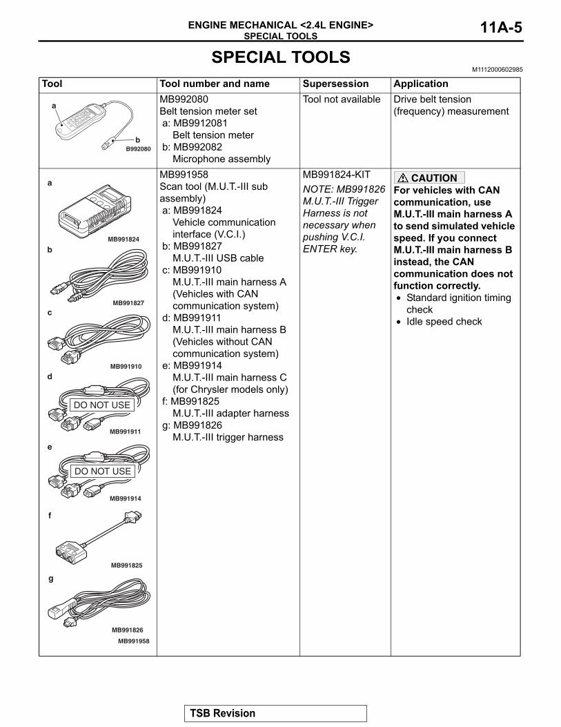
Tool Tool number and name Supersession ApplicationMB992080Belt tension meter seta: MB9912081
Belt tension meterb: MB992082
Microphone assembly
Tool not available Drive belt tension (frequency) measurement
MB991958Scan tool (M.U.T.-III sub assembly)a: MB991824
Vehicle communication interface (V.C.I.)
b: MB991827M.U.T.-III USB cable
c: MB991910M.U.T.-III main harness A (Vehicles with CAN communication system)
d: MB991911M.U.T.-III main harness B (Vehicles without CAN communication system)
e: MB991914M.U.T.-III main harness C (for Chrysler models only)
f: MB991825M.U.T.-III adapter harness
g: MB991826M.U.T.-III trigger harness
MB991824-KITNOTE: MB991826 M.U.T.-III Trigger Harness is not necessary when pushing V.C.I. ENTER key.
CAUTIONFor vehicles with CAN communication, use M.U.T.-III main harness A to send simulated vehicle speed. If you connect M.U.T.-III main harness B instead, the CAN communication does not function correctly.• Standard ignition timing
check• Idle speed check
B992080
a
b
MB991910
MB991826
MB991958
MB991911
MB991914
MB991824
MB991827
MB991825
DO NOT USE
a
b
c
d
e
f
g
DO NOT USE
TSB Revision
SPECIAL TOOLSENGINE MECHANICAL <2.4L ENGINE>11A-6
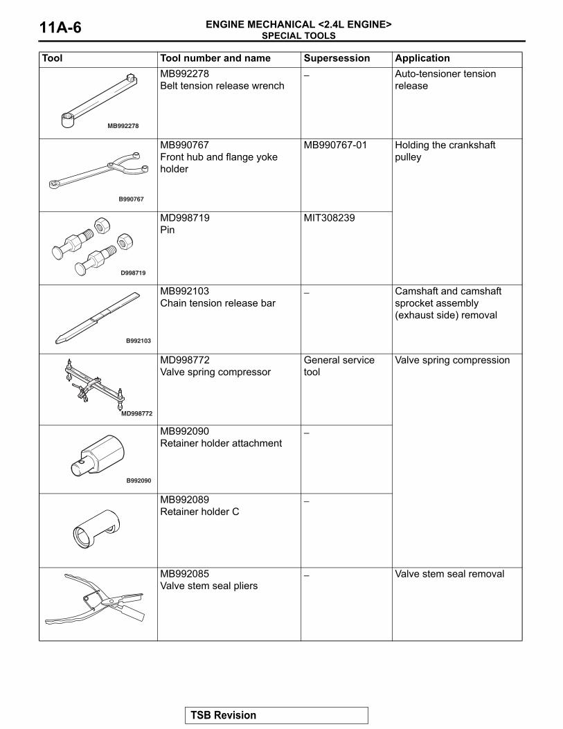
MB992278Belt tension release wrench
− Auto-tensioner tension release
MB990767Front hub and flange yoke holder
MB990767-01 Holding the crankshaft pulley
MD998719Pin
MIT308239
MB992103Chain tension release bar
− Camshaft and camshaft sprocket assembly (exhaust side) removal
MD998772Valve spring compressor
General service tool
Valve spring compression
MB992090Retainer holder attachment
−
MB992089Retainer holder C
−
MB992085Valve stem seal pliers
− Valve stem seal removal
Tool Tool number and name Supersession Application
MB992278
B990767
D998719
B992103
MD998772
B992090
TSB Revision
SPECIAL TOOLSENGINE MECHANICAL <2.4L ENGINE> 11A-7
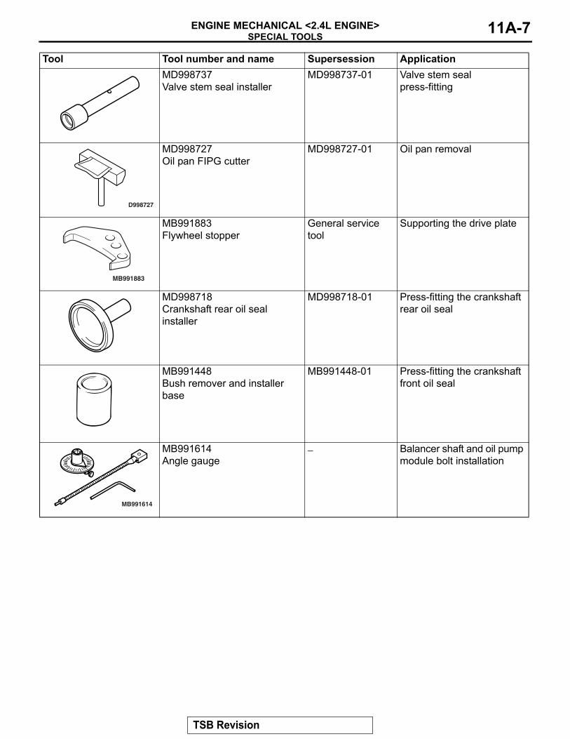
MD998737Valve stem seal installer
MD998737-01 Valve stem seal press-fitting
MD998727Oil pan FIPG cutter
MD998727-01 Oil pan removal
MB991883Flywheel stopper
General service tool
Supporting the drive plate
MD998718Crankshaft rear oil seal installer
MD998718-01 Press-fitting the crankshaft rear oil seal
MB991448Bush remover and installer base
MB991448-01 Press-fitting the crankshaft front oil seal
MB991614Angle gauge
− Balancer shaft and oil pump module bolt installation
Tool Tool number and name Supersession Application
D998727
MB991883
MB991614
TSB Revision
SPECIAL TOOLSENGINE MECHANICAL <2.4L ENGINE>11A-8
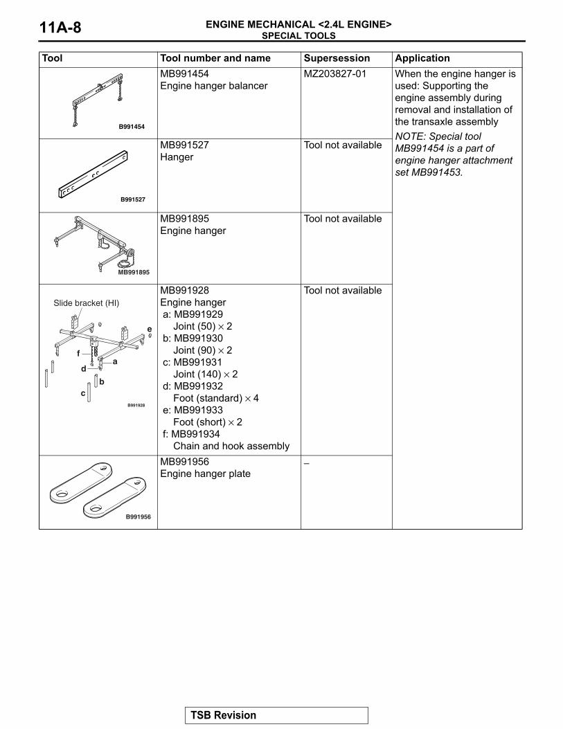
MB991454Engine hanger balancer
MZ203827-01 When the engine hanger is used: Supporting the engine assembly during removal and installation of the transaxle assemblyNOTE: Special tool MB991454 is a part of engine hanger attachment set MB991453.
MB991527Hanger
Tool not available
MB991895Engine hanger
Tool not available
MB991928Engine hangera: MB991929
Joint (50) × 2b: MB991930
Joint (90) × 2c: MB991931
Joint (140) × 2d: MB991932
Foot (standard) × 4e: MB991933
Foot (short) × 2f: MB991934
Chain and hook assembly
Tool not available
MB991956Engine hanger plate
−
Tool Tool number and name Supersession Application
B991454
B991527
MB991895
B991928
a
bc
d
e
f
Slide bracket (HI)
B991956
TSB Revision
ON-VEHICLE SERVICEENGINE MECHANICAL <2.4L ENGINE> 11A-9
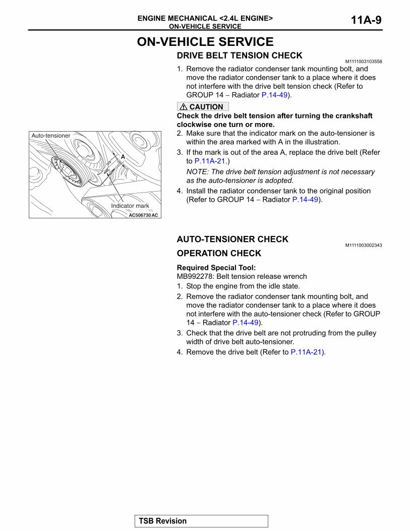
ON-VEHICLE SERVICEDRIVE BELT TENSION CHECK
M1111003103558
1. Remove the radiator condenser tank mounting bolt, and move the radiator condenser tank to a place where it does not interfere with the drive belt tension check (Refer to GROUP 14 − Radiator P.14-49).CAUTION
Check the drive belt tension after turning the crankshaft clockwise one turn or more.2. Make sure that the indicator mark on the auto-tensioner is
within the area marked with A in the illustration.3. If the mark is out of the area A, replace the drive belt (Refer
to P.11A-21.)NOTE: The drive belt tension adjustment is not necessary as the auto-tensioner is adopted.
4. Install the radiator condenser tank to the original position (Refer to GROUP 14 − Radiator P.14-49).
AUTO-TENSIONER CHECKM1111003002343
OPERATION CHECKRequired Special Tool:MB992278: Belt tension release wrench1. Stop the engine from the idle state.2. Remove the radiator condenser tank mounting bolt, and
move the radiator condenser tank to a place where it does not interfere with the auto-tensioner check (Refer to GROUP 14 − Radiator P.14-49).
3. Check that the drive belt are not protruding from the pulley width of drive belt auto-tensioner.
4. Remove the drive belt (Refer to P.11A-21).
AC506730AC
A
Indicator mark
Auto-tensioner
TSB Revision
ON-VEHICLE SERVICEENGINE MECHANICAL <2.4L ENGINE>11A-10
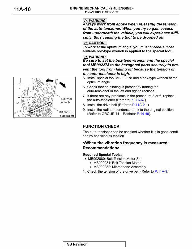
WARNINGAlways work from above when releasing the tension of the auto-tensioner. When you try to gain access from underneath the vehicle, you will experience diffi-culty, thus causing the tool to be dropped off.
CAUTIONTo work at the optimum angle, you must choose a most suitable box-type wrench is applied to the special tool.
WARNINGBe sure to set the box-type wrench and the special tool MB992278 to the hexagonal parts securely to pre-vent the tool from falling off because the tension of the auto-tensioner is high.5. Install special tool MB992278 and a box-type wrench at the
optimum angle.6. Check that no binding is present by turning the
auto-tensioner in the left and right directions.7. If there are any problems in the procedure 3 or 6, replace
the auto-tensioner (Refer to P.11A-67).8. Install the drive belt (Refer to P.11A-21.)9. Install the radiator condenser tank to the original position
(Refer to GROUP 14 − Radiator P.14-49).
FUNCTION CHECKThe auto-tensioner can be checked whether it is in good condi-tion by checking its tension..
<When the vibration frequency is measured: Recommendation>Required Special Tools:
• MB992080: Belt Tension Meter Set• MB992081: Belt Tension Meter• MB992082: Microphone Assembly
1. Check the tension of the drive belt (Refer to P.11A-9.)
AC804028AM
Auto-tensioner
MB992278
Box-type wrench
TSB Revision
ON-VEHICLE SERVICEENGINE MECHANICAL <2.4L ENGINE> 11A-11
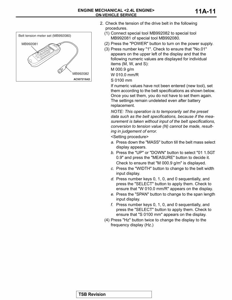
2. Check the tension of the drive belt in the following procedures.(1) Connect special tool MB992082 to special tool
MB992081 of special tool MB992080.(2) Press the "POWER" button to turn on the power supply.(3) Press number key "1". Check to ensure that "No.01"
appears on the upper left of the display and that the following numeric values are displayed for individual items (M, W, and S):M 000.9 g/mW 010.0 mm/RS 0100 mmIf numeric values have not been entered (new tool), set them according to the belt specifications as shown below. Once you set them, you do not have to set them again. The settings remain undeleted even after battery replacement.NOTE: This operation is to temporarily set the preset data such as the belt specifications, because if the mea-surement is taken without input of the belt specifications, conversion to tension value (N) cannot be made, result-ing in judgement of error.<Setting procedure>a. Press down the "MASS" button till the belt mass select
display appears.b. Press the "UP" or "DOWN" button to select "01 1.5GT
0.9" and press the "MEASURE" button to decide it.Check to ensure that "M 000.9 g/m" is displayed.
c. Press the "WIDTH" button to change to the belt width input display.
d. Press number keys 0, 1, 0, and 0 sequentially, and press the "SELECT" button to apply them. Check to ensure that "W 010.0 mm/R" appears on the display.
e. Press the "SPAN" button to change to the span length input display.
f. Press number keys 0, 1, 0, and 0 sequentially, and press the "SELECT" button to apply them. Check to ensure that "S 0100 mm" appears on the display.
(4) Press "Hz" button twice to change the display to the frequency display (Hz.)
AC507219AD
MB992082
MB992081
Belt tension meter set (MB992080)
TSB Revision
ON-VEHICLE SERVICEENGINE MECHANICAL <2.4L ENGINE>11A-12
CAUTION• When measuring, make sure that the engine is cold.• Measure after turning the crankshaft clockwise one
turn or more.• Do not allow any contaminants such as water or oil to
get onto the microphone.• If strong gusts of wind blow against the microphone or
if there are any loud sources of noise nearby, the val-ues measured by the microphone may not correspond to actual values.
• If the microphone is touching the belt while the mea-surement is being made, the values measured by the microphone may not correspond to actual values.
• Do not take the measurement while the vehicle's engine is running.
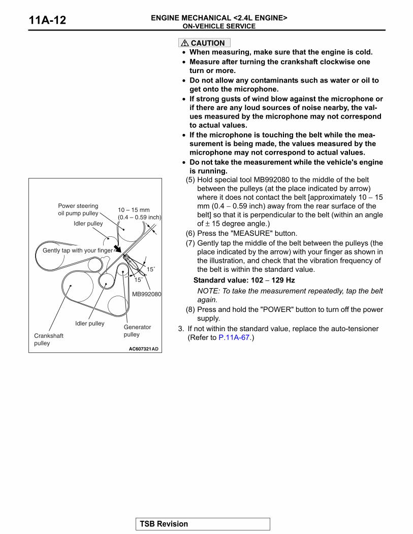
(5) Hold special tool MB992080 to the middle of the belt between the pulleys (at the place indicated by arrow) where it does not contact the belt [approximately 10 − 15 mm (0.4 − 0.59 inch) away from the rear surface of the belt] so that it is perpendicular to the belt (within an angle of ± 15 degree angle.)
(6) Press the "MEASURE" button.(7) Gently tap the middle of the belt between the pulleys (the
place indicated by the arrow) with your finger as shown in the illustration, and check that the vibration frequency of the belt is within the standard value.
Standard value: 102 − 129 HzNOTE: To take the measurement repeatedly, tap the belt again.
(8) Press and hold the "POWER" button to turn off the power supply.
3. If not within the standard value, replace the auto-tensioner (Refer to P.11A-67.)
.
AC607321AD
MB992080
15˚
Gently tap with your finger
15˚
10 – 15 mm(0.4 – 0.59 inch)
Generatorpulley
Idler pulley
Idler pulley
Crankshaft pulley
Power steeringoil pump pulley
TSB Revision
ON-VEHICLE SERVICEENGINE MECHANICAL <2.4L ENGINE> 11A-13
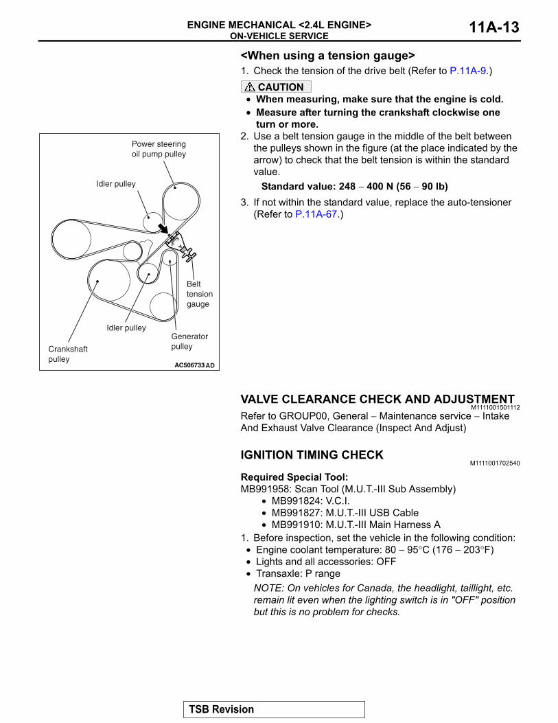
<When using a tension gauge>1. Check the tension of the drive belt (Refer to P.11A-9.)
CAUTION• When measuring, make sure that the engine is cold.• Measure after turning the crankshaft clockwise one
turn or more.2. Use a belt tension gauge in the middle of the belt between
the pulleys shown in the figure (at the place indicated by the arrow) to check that the belt tension is within the standard value.
Standard value: 248 − 400 N (56 − 90 lb)3. If not within the standard value, replace the auto-tensioner
(Refer to P.11A-67.)
VALVE CLEARANCE CHECK AND ADJUSTMENTM1111001501112
Refer to GROUP00, General − Maintenance service − Intake And Exhaust Valve Clearance (Inspect And Adjust)
IGNITION TIMING CHECKM1111001702540
Required Special Tool:MB991958: Scan Tool (M.U.T.-III Sub Assembly)
• MB991824: V.C.I.• MB991827: M.U.T.-III USB Cable• MB991910: M.U.T.-III Main Harness A
1. Before inspection, set the vehicle in the following condition:• Engine coolant temperature: 80 − 95°C (176 − 203°F)• Lights and all accessories: OFF• Transaxle: P range
NOTE: On vehicles for Canada, the headlight, taillight, etc. remain lit even when the lighting switch is in "OFF" position but this is no problem for checks.
AC506733 AD
Generatorpulley
Idler pulley
Idler pulley
Crankshaft pulley
Power steeringoil pump pulley
Belt tension gauge
TSB Revision
ON-VEHICLE SERVICEENGINE MECHANICAL <2.4L ENGINE>11A-14
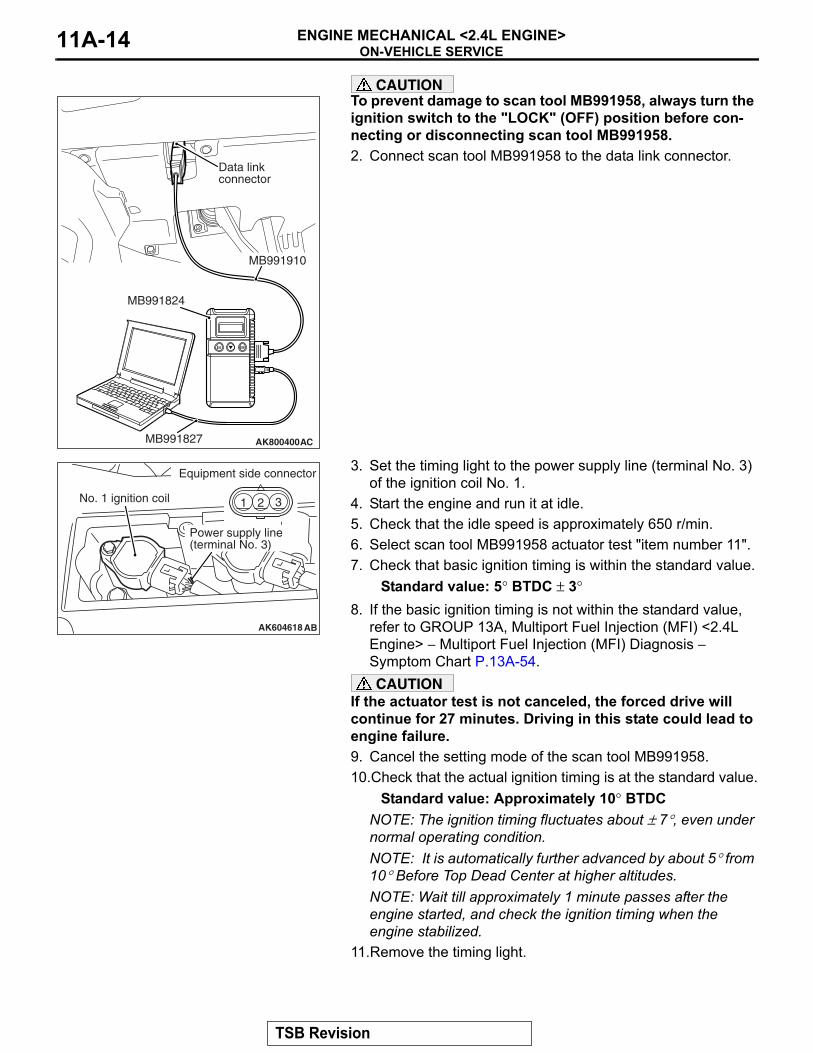
CAUTIONTo prevent damage to scan tool MB991958, always turn the ignition switch to the "LOCK" (OFF) position before con-necting or disconnecting scan tool MB991958.2. Connect scan tool MB991958 to the data link connector.
3. Set the timing light to the power supply line (terminal No. 3) of the ignition coil No. 1.
4. Start the engine and run it at idle.5. Check that the idle speed is approximately 650 r/min.6. Select scan tool MB991958 actuator test "item number 11".7. Check that basic ignition timing is within the standard value.
Standard value: 5° BTDC ± 3°8. If the basic ignition timing is not within the standard value,
refer to GROUP 13A, Multiport Fuel Injection (MFI) <2.4L Engine> − Multiport Fuel Injection (MFI) Diagnosis − Symptom Chart P.13A-54. CAUTION
If the actuator test is not canceled, the forced drive will continue for 27 minutes. Driving in this state could lead to engine failure.9. Cancel the setting mode of the scan tool MB991958.10.Check that the actual ignition timing is at the standard value.
Standard value: Approximately 10° BTDCNOTE: The ignition timing fluctuates about ± 7°, even under normal operating condition.NOTE: It is automatically further advanced by about 5° from 10° Before Top Dead Center at higher altitudes.NOTE: Wait till approximately 1 minute passes after the engine started, and check the ignition timing when the engine stabilized.
11.Remove the timing light.
AK800400
Data linkconnector
MB991827
MB991824
MB991910
AC
AK604618
321 321
AB
No. 1 ignition coil
Equipment side connector
Power supply line(terminal No. 3)
TSB Revision
ON-VEHICLE SERVICEENGINE MECHANICAL <2.4L ENGINE> 11A-15
CAUTIONTo prevent damage to scan tool MB991958, always turn the ignition switch to the "LOCK" (OFF) position before con-necting or disconnecting scan tool MB991958.12.Disconnect scan tool MB991958 from the data link
connector.
CURB IDLE SPEED CHECKM1111003502519
Required Special Tool:MB991958: Scan Tool (M.U.T.-III Sub Assembly)
• MB991824: V.C.I.• MB991827: M.U.T.-III USB Cable• MB991910: M.U.T.-III Main Harness A
1. Before inspection, set the vehicle in the following condition:• Engine coolant temperature: 80 − 95°C (176 − 203°F)• Lights and all accessories: OFF• Transaxle: P range
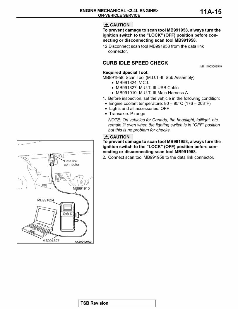
NOTE: On vehicles for Canada, the headlight, taillight, etc. remain lit even when the lighting switch is in "OFF" position but this is no problem for checks.CAUTION
To prevent damage to scan tool MB991958, always turn the ignition switch to the "LOCK" (OFF) position before con-necting or disconnecting scan tool MB991958.2. Connect scan tool MB991958 to the data link connector.
AK800400
Data linkconnector
MB991827
MB991824
MB991910
AC
TSB Revision
ON-VEHICLE SERVICEENGINE MECHANICAL <2.4L ENGINE>11A-16
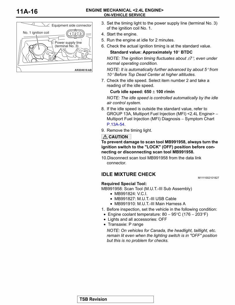
3. Set the timing light to the power supply line (terminal No. 3) of the ignition coil No. 1.
4. Start the engine.5. Run the engine at idle for 2 minutes.6. Check the actual ignition timing is at the standard value.
Standard value: Approximately 10° BTDCNOTE: The ignition timing fluctuates about ±7°, even under normal operating condition.NOTE: It is automatically further advanced by about 5° from 10° Before Top Dead Center at higher altitudes.
7. Check the idle speed. Select item number 2 and take a reading of the idle speed.
Curb idle speed: 650 ± 100 r/minNOTE: The idle speed is controlled automatically by the idle air control system.
8. If the idle speed is outside the standard value, refer to GROUP 13A, Multiport Fuel Injection (MFI) <2.4L Engine> − Multiport Fuel Injection (MFI) Diagnosis − Symptom Chart P.13A-54.
9. Remove the timing light.CAUTION
To prevent damage to scan tool MB991958, always turn the ignition switch to the "LOCK" (OFF) position before con-necting or disconnecting scan tool MB991958.10.Disconnect scan tool MB991958 from the data link
connector.
IDLE MIXTURE CHECKM1111002101827
Required Special Tool:MB991958: Scan Tool (M.U.T.-III Sub Assembly)
• MB991824: V.C.I.• MB991827: M.U.T.-III USB Cable• MB991910: M.U.T.-III Main Harness A
1. Before inspection, set the vehicle in the following condition:• Engine coolant temperature: 80 − 95°C (176 − 203°F)• Lights and all accessories: OFF• Transaxie: P range
NOTE: On vehicles for Canada, the headlight, taillight, etc. remain lit even when the lighting switch is in "OFF" position but this is no problem for checks.
AK604618
321 321
AB
No. 1 ignition coil
Equipment side connector
Power supply line(terminal No. 3)
TSB Revision
ON-VEHICLE SERVICEENGINE MECHANICAL <2.4L ENGINE> 11A-17
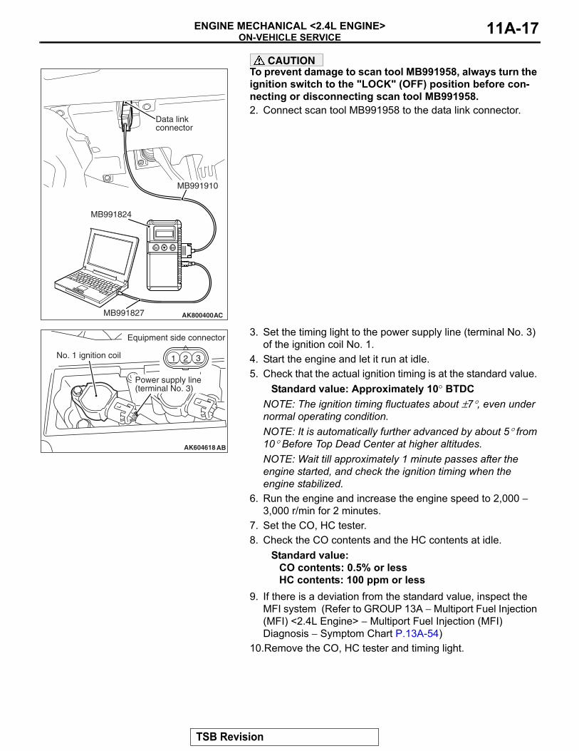
CAUTIONTo prevent damage to scan tool MB991958, always turn the ignition switch to the "LOCK" (OFF) position before con-necting or disconnecting scan tool MB991958.2. Connect scan tool MB991958 to the data link connector.
3. Set the timing light to the power supply line (terminal No. 3) of the ignition coil No. 1.
4. Start the engine and let it run at idle.5. Check that the actual ignition timing is at the standard value.
Standard value: Approximately 10° BTDCNOTE: The ignition timing fluctuates about ±7°, even under normal operating condition.NOTE: It is automatically further advanced by about 5° from 10° Before Top Dead Center at higher altitudes.NOTE: Wait till approximately 1 minute passes after the engine started, and check the ignition timing when the engine stabilized.
6. Run the engine and increase the engine speed to 2,000 − 3,000 r/min for 2 minutes.
7. Set the CO, HC tester.8. Check the CO contents and the HC contents at idle.
Standard value:CO contents: 0.5% or lessHC contents: 100 ppm or less
9. If there is a deviation from the standard value, inspect the MFI system (Refer to GROUP 13A − Multiport Fuel Injection (MFI) <2.4L Engine> − Multiport Fuel Injection (MFI) Diagnosis − Symptom Chart P.13A-54)
10.Remove the CO, HC tester and timing light.
AK800400
Data linkconnector
MB991827
MB991824
MB991910
AC
AK604618
321 321
AB
No. 1 ignition coil
Equipment side connector
Power supply line(terminal No. 3)
TSB Revision
ON-VEHICLE SERVICEENGINE MECHANICAL <2.4L ENGINE>11A-18
CAUTIONTo prevent damage to scan tool MB991958, always turn the ignition switch to the "LOCK" (OFF) position before con-necting or disconnecting scan tool MB991958.11.Disconnect scan tool MB991958 from the data link
connector.
COMPRESSION PRESSURE CHECKM1111002603293
Required Special Tool:MB991958: Scan Tool (M.U.T.-III Sub Assembly)
• MB991824: V.C.I.• MB991827: M.U.T.-III USB Cable• MB991910: M.U.T.-III Main Harness A
1. Before inspection, check that the engine oil, starter and battery are normal. Also, set the vehicle in the following condition:
• Engine coolant temperature: 80 − 95°C (176 − 203°F)• Lights and all accessories: OFF• Transaxle: P range
NOTE: On vehicles for Canada, the headlight, taillight, etc. remain lit even when the lighting switch is in "OFF" position but this is no problem for checks.
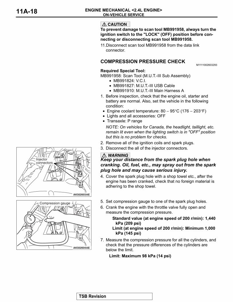
2. Remove all of the ignition coils and spark plugs.3. Disconnect the all of the injector connectors.
WARNINGKeep your distance from the spark plug hole when cranking. Oil, fuel, etc., may spray out from the spark plug hole and may cause serious injury.4. Cover the spark plug hole with a shop towel etc., after the
engine has been cranked, check that no foreign material is adhering to the shop towel.
5. Set compression gauge to one of the spark plug holes.6. Crank the engine with the throttle valve fully open and
measure the compression pressure.Standard value (at engine speed of 200 r/min): 1,440
kPa (209 psi)Limit (at engine speed of 200 r/min): Minimum 1,000
kPa (145 psi)7. Measure the compression pressure for all the cylinders, and
check that the pressure differences of the cylinders are below the limit.
Limit: Maximum 98 kPa (14 psi)
AK502603AE
Injector connectors
AK502604AE
Compression gauge
TSB Revision
ON-VEHICLE SERVICEENGINE MECHANICAL <2.4L ENGINE> 11A-19
8. If there is a cylinder with compression or a compression difference that is outside the limit, pour a small amount of engine oil through the spark plug hole, and repeat the operations in steps from 5 to 7.(1) If the compression increases after oil is added, the cause
of the malfunction is a worn or damaged piston ring and/or cylinder inner surface.
(2) If the compression does not rise after oil is added, the cause is a burnt or defective valve seat, or pressure is leaking from the gasket.
9. Connect the all of the injector connector.10.Install the spark plugs and ignition coils.11.Use the scan tool MB991958 to erase the diagnosis codes.
NOTE: This will erase the diagnosis code resulting from the injector connectors being disconnected.
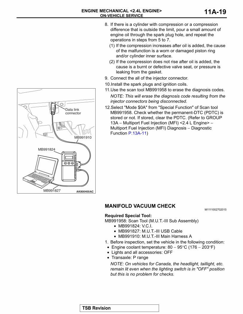
12.Select "Mode $0A" from "Special Function" of Scan tool MB991958. Check whether the permanent-DTC (PDTC) is stored or not. If stored, clear the PDTC. (Refer to GROUP 13A − Multiport Fuel Injection (MFI) <2.4 L Engine> − Multiport Fuel Injection (MFI) Diagnosis − Diagnostic Function P.13A-11)
MANIFOLD VACUUM CHECKM1111002702015
Required Special Tool:MB991958: Scan Tool (M.U.T.-III Sub Assembly)
• MB991824: V.C.I.• MB991827: M.U.T.-III USB Cable• MB991910: M.U.T.-III Main Harness A
1. Before inspection, set the vehicle in the following condition:• Engine coolant temperature: 80 − 95°C (176 − 203°F)• Lights and all accessories: OFF• Transaxle: P range
NOTE: On vehicles for Canada, the headlight, taillight, etc. remain lit even when the lighting switch is in "OFF" position but this is no problem for checks.
AK800400
Data linkconnector
MB991827
MB991824
MB991910
AC
TSB Revision
ON-VEHICLE SERVICEENGINE MECHANICAL <2.4L ENGINE>11A-20
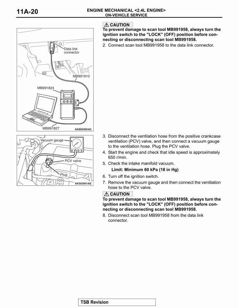
CAUTIONTo prevent damage to scan tool MB991958, always turn the ignition switch to the "LOCK" (OFF) position before con-necting or disconnecting scan tool MB991958.2. Connect scan tool MB991958 to the data link connector.
3. Disconnect the ventilation hose from the positive crankcase ventilation (PCV) valve, and then connect a vacuum gauge to the ventilation hose. Plug the PCV valve.
4. Start the engine and check that idle speed is approximately 650 r/min.
5. Check the intake manifold vacuum.Limit: Minimum 60 kPa (18 in Hg)
6. Turn off the ignition switch.7. Remove the vacuum gauge and then connect the ventilation
hose to the PCV valve.CAUTION
To prevent damage to scan tool MB991958, always turn the ignition switch to the "LOCK" (OFF) position before con-necting or disconnecting scan tool MB991958.8. Disconnect scan tool MB991958 from the data link
connector.
AK800400
Data linkconnector
MB991827
MB991824
MB991910
AC
AK502601AE
Plug
PCV valve
Vacuum gauge
TSB Revision
CRANKSHAFT PULLEYENGINE MECHANICAL <2.4L ENGINE> 11A-21
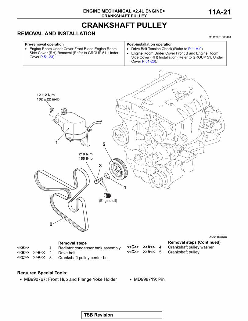
CRANKSHAFT PULLEYREMOVAL AND INSTALLATION
M1112001603464
Required Special Tools:• MB990767: Front Hub and Flange Yoke Holder • MD998719: Pin
Pre-removal operation• Engine Room Under Cover Front B and Engine Room
Side Cover (RH) Removal (Refer to GROUP 51, Under Cover P.51-23).
Post-installation operation• Drive Belt Tension Check (Refer to P.11A-9).• Engine Room Under Cover Front B and Engine Room
Side Cover (RH) Installation (Refer to GROUP 51, Under Cover P.51-23).
AC611683AC
210 N·m155 ft-lb
2
3
4
51
12 ± 2 N·m102 ± 22 in-lb
(Engine oil)
Removal steps <<A>> 1. Radiator condenser tank assembly<<B>> >>B<< 2. Drive belt<<C>> >>A<< 3. Crankshaft pulley center bolt
<<C>> >>A<< 4. Crankshaft pulley washer<<C>> >>A<< 5. Crankshaft pulley
Removal steps (Continued)
TSB Revision
CRANKSHAFT PULLEYENGINE MECHANICAL <2.4L ENGINE>11A-22
REMOVAL SERVICE POINTS.
<<A>> RADIATOR CONDENSER TANK ASSEM-BLY REMOVALRemove the radiator condenser tank assembly mounting bolt, and move the radiator condenser tank assembly to a place where it does not interfere with the drive belt removal and installation..
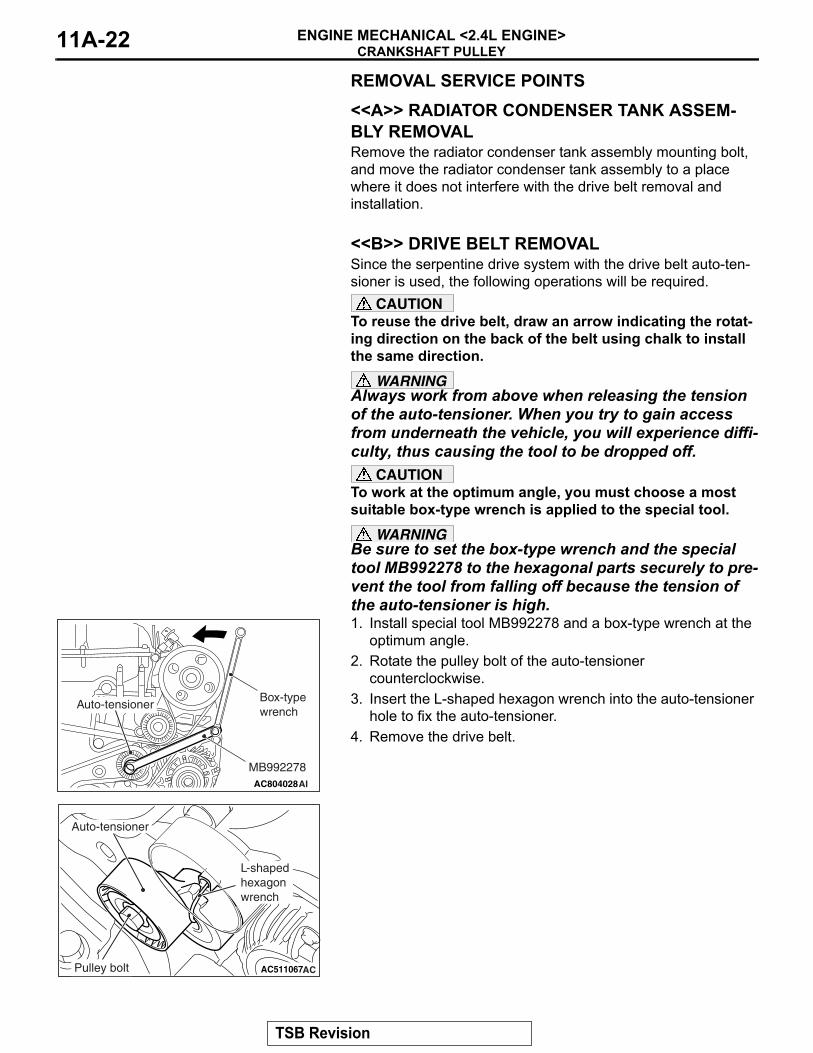
<<B>> DRIVE BELT REMOVALSince the serpentine drive system with the drive belt auto-ten-sioner is used, the following operations will be required.
CAUTIONTo reuse the drive belt, draw an arrow indicating the rotat-ing direction on the back of the belt using chalk to install the same direction.
WARNINGAlways work from above when releasing the tension of the auto-tensioner. When you try to gain access from underneath the vehicle, you will experience diffi-culty, thus causing the tool to be dropped off.
CAUTIONTo work at the optimum angle, you must choose a most suitable box-type wrench is applied to the special tool.
WARNINGBe sure to set the box-type wrench and the special tool MB992278 to the hexagonal parts securely to pre-vent the tool from falling off because the tension of the auto-tensioner is high.1. Install special tool MB992278 and a box-type wrench at the
optimum angle.2. Rotate the pulley bolt of the auto-tensioner
counterclockwise.3. Insert the L-shaped hexagon wrench into the auto-tensioner
hole to fix the auto-tensioner.4. Remove the drive belt.
.
AC804028AI
Auto-tensioner
MB992278
Box-type wrench
AC511067AC
Auto-tensioner
Pulley bolt
L-shaped hexagon wrench
TSB Revision
CRANKSHAFT PULLEYENGINE MECHANICAL <2.4L ENGINE> 11A-23
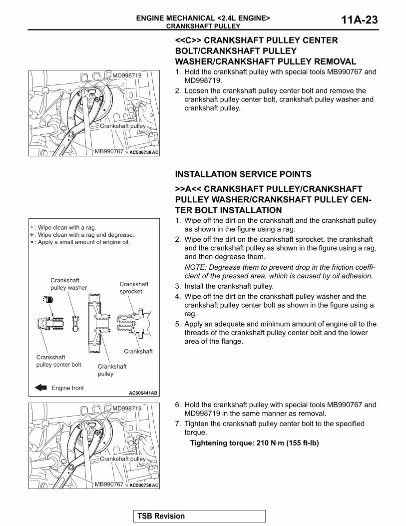
<<C>> CRANKSHAFT PULLEY CENTER BOLT/CRANKSHAFT PULLEY WASHER/CRANKSHAFT PULLEY REMOVAL1. Hold the crankshaft pulley with special tools MB990767 and
MD998719.2. Loosen the crankshaft pulley center bolt and remove the
crankshaft pulley center bolt, crankshaft pulley washer and crankshaft pulley.
INSTALLATION SERVICE POINTS.
>>A<< CRANKSHAFT PULLEY/CRANKSHAFT PULLEY WASHER/CRANKSHAFT PULLEY CEN-TER BOLT INSTALLATION1. Wipe off the dirt on the crankshaft and the crankshaft pulley
as shown in the figure using a rag.2. Wipe off the dirt on the crankshaft sprocket, the crankshaft
and the crankshaft pulley as shown in the figure using a rag, and then degrease them.NOTE: Degrease them to prevent drop in the friction coeffi-cient of the pressed area, which is caused by oil adhesion.
3. Install the crankshaft pulley.4. Wipe off the dirt on the crankshaft pulley washer and the
crankshaft pulley center bolt as shown in the figure using a rag.
5. Apply an adequate and minimum amount of engine oil to the threads of the crankshaft pulley center bolt and the lower area of the flange.
6. Hold the crankshaft pulley with special tools MB990767 and MD998719 in the same manner as removal.
7. Tighten the crankshaft pulley center bolt to the specified torque.
Tightening torque: 210 N⋅m (155 ft-lb)
.
AC506738ACMB990767
MD998719
Crankshaft pulley
AC606441AB
: Wipe clean with a rag.: Wipe clean with a rag and degrease.: Apply a small amount of engine oil.
Crankshaftpulley center bolt
Crankshaftpulley washer
Crankshaftpulley
Crankshaft
Crankshaftsprocket
Engine front
AC506738ACMB990767
MD998719
Crankshaft pulley
TSB Revision
CRANKSHAFT PULLEYENGINE MECHANICAL <2.4L ENGINE>11A-24
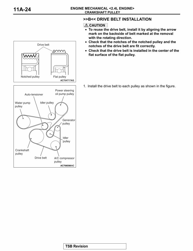
>>B<< DRIVE BELT INSTALLATIONCAUTION
• To reuse the drive belt, install it by aligning the arrow mark on the backside of belt marked at the removal with the rotating direction.
• Check that the notches of the notched pulley and the notches of the drive belt are fit correctly.
• Check that the drive belt is installed in the center of the flat surface of the flat pulley.
1. Install the drive belt to each pulley as shown in the figure.
AC704717AG
Drive belt
Notched pulley Flat pulley
AC706598AC
Generatorpulley
Idler pulley
Idler pulley
Crankshaft pulley
Power steeringoil pump pulley
Drive belt
Auto-tensioner
A/C compressor pulley
Water pumppulley
TSB Revision
CRANKSHAFT PULLEYENGINE MECHANICAL <2.4L ENGINE> 11A-25
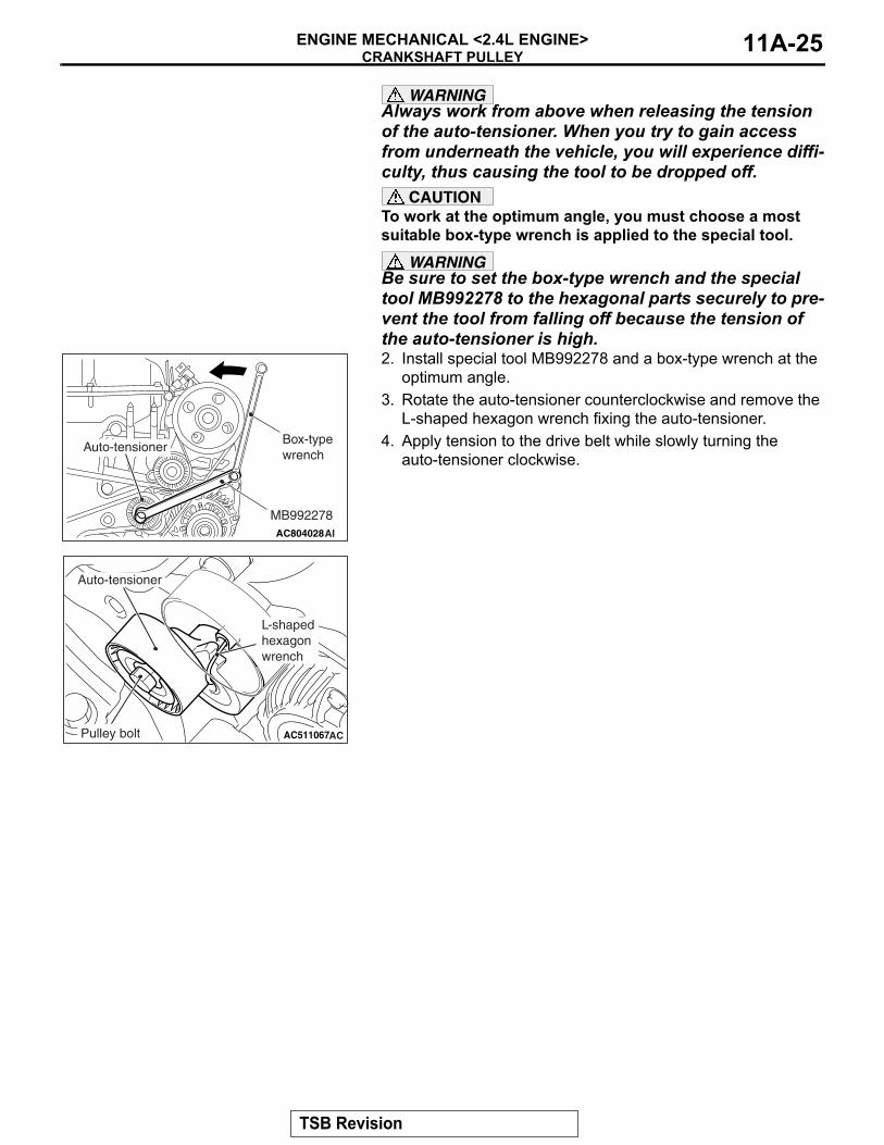
WARNINGAlways work from above when releasing the tension of the auto-tensioner. When you try to gain access from underneath the vehicle, you will experience diffi-culty, thus causing the tool to be dropped off.
CAUTIONTo work at the optimum angle, you must choose a most suitable box-type wrench is applied to the special tool.
WARNINGBe sure to set the box-type wrench and the special tool MB992278 to the hexagonal parts securely to pre-vent the tool from falling off because the tension of the auto-tensioner is high.2. Install special tool MB992278 and a box-type wrench at the
optimum angle.3. Rotate the auto-tensioner counterclockwise and remove the
L-shaped hexagon wrench fixing the auto-tensioner.4. Apply tension to the drive belt while slowly turning the
auto-tensioner clockwise.
AC804028AI
Auto-tensioner
MB992278
Box-type wrench
AC511067AC
Auto-tensioner
Pulley bolt
L-shaped hexagon wrench
TSB Revision
CAMSHAFTENGINE MECHANICAL <2.4L ENGINE>11A-26
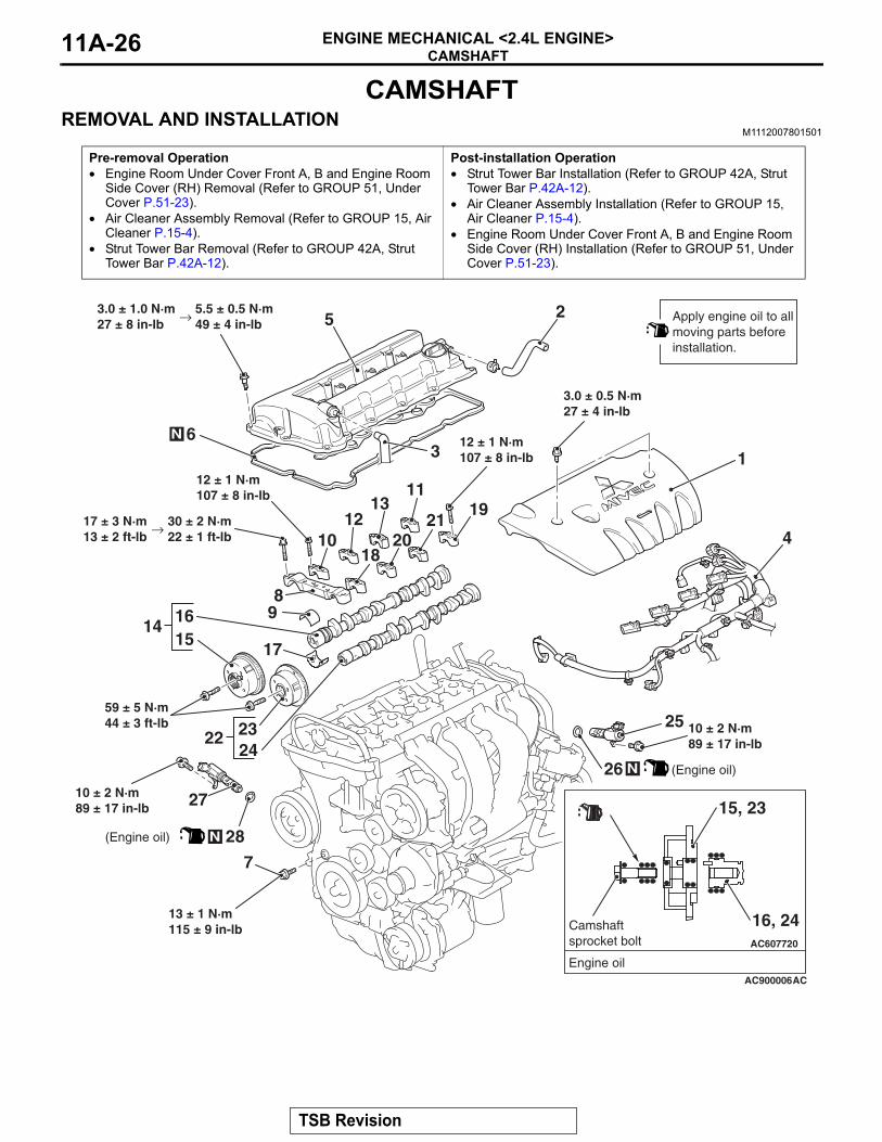
CAMSHAFTREMOVAL AND INSTALLATION
M1112007801501
Pre-removal Operation• Engine Room Under Cover Front A, B and Engine Room
Side Cover (RH) Removal (Refer to GROUP 51, Under Cover P.51-23).
• Air Cleaner Assembly Removal (Refer to GROUP 15, Air Cleaner P.15-4).
• Strut Tower Bar Removal (Refer to GROUP 42A, Strut Tower Bar P.42A-12).
Post-installation Operation• Strut Tower Bar Installation (Refer to GROUP 42A, Strut
Tower Bar P.42A-12).• Air Cleaner Assembly Installation (Refer to GROUP 15,
Air Cleaner P.15-4).• Engine Room Under Cover Front A, B and Engine Room
Side Cover (RH) Installation (Refer to GROUP 51, Under Cover P.51-23).
AC900006
2
19
14
13
10
16
4
3
AC
5
15
25
18
8
1
11
1220
21
222423
27
26 N
28N
7
9
17
6N
Apply engine oil to allmoving parts beforeinstallation.
(Engine oil)
(Engine oil)
AC607720
Engine oil
Camshaftsprocket bolt
16, 24
15, 23
59 ± 5 N·m44 ± 3 ft-lb
3.0 ± 0.5 N·m27 ± 4 in-lb
3.0 ± 1.0 N·m27 ± 8 in-lb
→ 5.5 ± 0.5 N·m49 ± 4 in-lb
12 ± 1 N·m107 ± 8 in-lb
17 ± 3 N·m13 ± 2 ft-lb
→ 30 ± 2 N·m22 ± 1 ft-lb
10 ± 2 N·m89 ± 17 in-lb
10 ± 2 N·m89 ± 17 in-lb
13 ± 1 N·m115 ± 9 in-lb
12 ± 1 N·m107 ± 8 in-lb
TSB Revision
CAMSHAFTENGINE MECHANICAL <2.4L ENGINE> 11A-27
Required Special Tool:• MB992103: Chain Tension Release Bar
REMOVAL SERVICE POINTS.
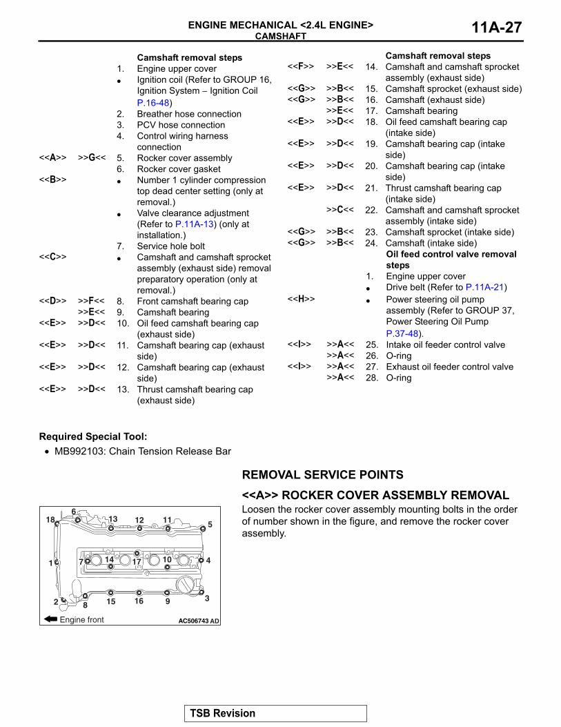
<<A>> ROCKER COVER ASSEMBLY REMOVALLoosen the rocker cover assembly mounting bolts in the order of number shown in the figure, and remove the rocker cover assembly.
.
Camshaft removal steps 1. Engine upper cover• Ignition coil (Refer to GROUP 16,
Ignition System − Ignition Coil P.16-48)
2. Breather hose connection3. PCV hose connection4. Control wiring harness
connection<<A>> >>G<< 5. Rocker cover assembly
6. Rocker cover gasket<<B>> • Number 1 cylinder compression
top dead center setting (only at removal.)
• Valve clearance adjustment (Refer to P.11A-13) (only at installation.)
7. Service hole bolt<<C>> • Camshaft and camshaft sprocket
assembly (exhaust side) removal preparatory operation (only at removal.)
<<D>> >>F<< 8. Front camshaft bearing cap>>E<< 9. Camshaft bearing
<<E>> >>D<< 10. Oil feed camshaft bearing cap (exhaust side)
<<E>> >>D<< 11. Camshaft bearing cap (exhaust side)
<<E>> >>D<< 12. Camshaft bearing cap (exhaust side)
<<E>> >>D<< 13. Thrust camshaft bearing cap (exhaust side)
<<F>> >>E<< 14. Camshaft and camshaft sprocket assembly (exhaust side)
<<G>> >>B<< 15. Camshaft sprocket (exhaust side)<<G>> >>B<< 16. Camshaft (exhaust side)
>>E<< 17. Camshaft bearing<<E>> >>D<< 18. Oil feed camshaft bearing cap
(intake side)<<E>> >>D<< 19. Camshaft bearing cap (intake
side)<<E>> >>D<< 20. Camshaft bearing cap (intake
side)<<E>> >>D<< 21. Thrust camshaft bearing cap
(intake side)>>C<< 22. Camshaft and camshaft sprocket
assembly (intake side)<<G>> >>B<< 23. Camshaft sprocket (intake side)<<G>> >>B<< 24. Camshaft (intake side)
Oil feed control valve removal steps
1. Engine upper cover• Drive belt (Refer to P.11A-21)
<<H>> • Power steering oil pump assembly (Refer to GROUP 37, Power Steering Oil Pump P.37-48).
<<I>> >>A<< 25. Intake oil feeder control valve>>A<< 26. O-ring
<<I>> >>A<< 27. Exhaust oil feeder control valve>>A<< 28. O-ring
Camshaft removal steps
AC506743 AD
3
6
1
9
5
2
10 4
8
7
111213
14
15 16
17
18
Engine front
TSB Revision
CAMSHAFTENGINE MECHANICAL <2.4L ENGINE>11A-28
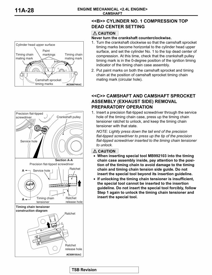
<<B>> CYLINDER NO. 1 COMPRESSION TOP DEAD CENTER SETTING
CAUTIONNever turn the crankshaft counterclockwise.1. Turn the crankshaft clockwise so that the camshaft sprocket
timing marks become horizontal to the cylinder head upper surface, and set the cylinder No. 1 to the top dead center of compression. At this time, check that the crankshaft pulley timing mark is in the 0-degree position of the ignition timing indicator of the timing chain case assembly.
2. Put paint marks on both the camshaft sprocket and timing chain at the position of camshaft sprocket timing chain mating mark (circular hole).
.
<<C>> CAMSHAFT AND CAMSHAFT SPROCKET ASSEMBLY (EXHAUST SIDE) REMOVAL PREPARATORY OPERATION1. Insert a precision flat-tipped screwdriver through the service
hole of the timing chain case, press up the timing chain tensioner ratchet to unlock, and keep the timing chain tensioner with that state.NOTE: Lightly press down the tail end of the precision flat-tipped screwdriver to press up the tip of the precision flat-tipped screwdriver inserted to the timing chain tensioner to unlock.CAUTION
• When inserting special tool MB992103 into the timing chain case assembly inside, pay attention to the posi-tion of the timing chain to avoid damage to the timing chain and timing chain tension side guide. Do not insert the special tool beyond its insertion guideline.
• If unlocking the timing chain tensioner is insufficient, the special tool cannot be inserted to the insertion guideline. Do not insert the special tool forcibly, follow Step 1 again to unlock the timing chain tensioner and insert the special tool.
AC506744
Paint markings
Camshaft sprocket timing marks
Timing chainmating mark
Timing chainmating mark
AC
Cylinder head upper surface
AC509155AC
Section A-A
A
A
Precision flat-tipped screwdriver
Service hole
Crankshaft pulley
Service holeRatchet
Precision flat-tipped screwdriver
Ratchetrelease hole
Timing chaintensioner
Ratchet
Ratchetrelease hole
Timing chain tensionerconstruction diagram
TSB Revision
CAMSHAFTENGINE MECHANICAL <2.4L ENGINE> 11A-29
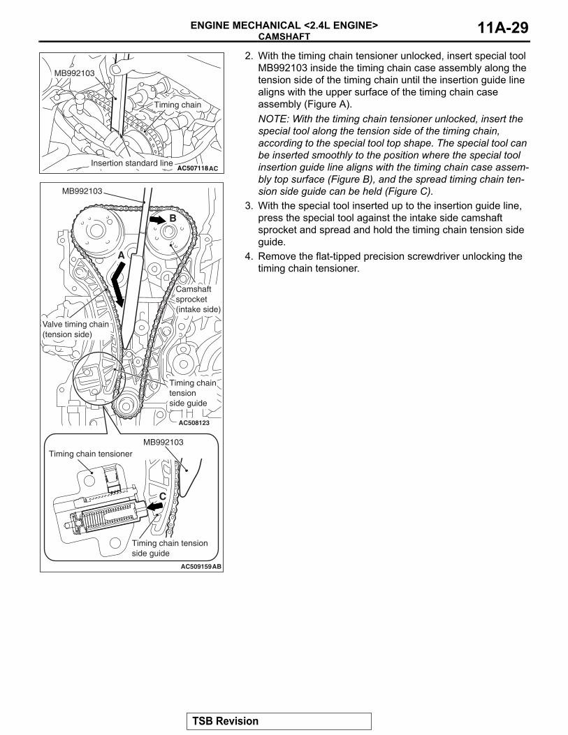
2. With the timing chain tensioner unlocked, insert special tool MB992103 inside the timing chain case assembly along the tension side of the timing chain until the insertion guide line aligns with the upper surface of the timing chain case assembly (Figure A). NOTE: With the timing chain tensioner unlocked, insert the special tool along the tension side of the timing chain, according to the special tool top shape. The special tool can be inserted smoothly to the position where the special tool insertion guide line aligns with the timing chain case assem-bly top surface (Figure B), and the spread timing chain ten-sion side guide can be held (Figure C).
3. With the special tool inserted up to the insertion guide line, press the special tool against the intake side camshaft sprocket and spread and hold the timing chain tension side guide.
4. Remove the flat-tipped precision screwdriver unlocking the timing chain tensioner.
AC507118AC
Timing chain
MB992103
Insertion standard line
AC508123
AC509159AB
MB992103
MB992103Timing chain tensioner
Timing chain tensionside guide
Timing chaintensionside guide
Camshaftsprocket(intake side)
Valve timing chain(tension side)
A
B
C
TSB Revision
CAMSHAFTENGINE MECHANICAL <2.4L ENGINE>11A-30
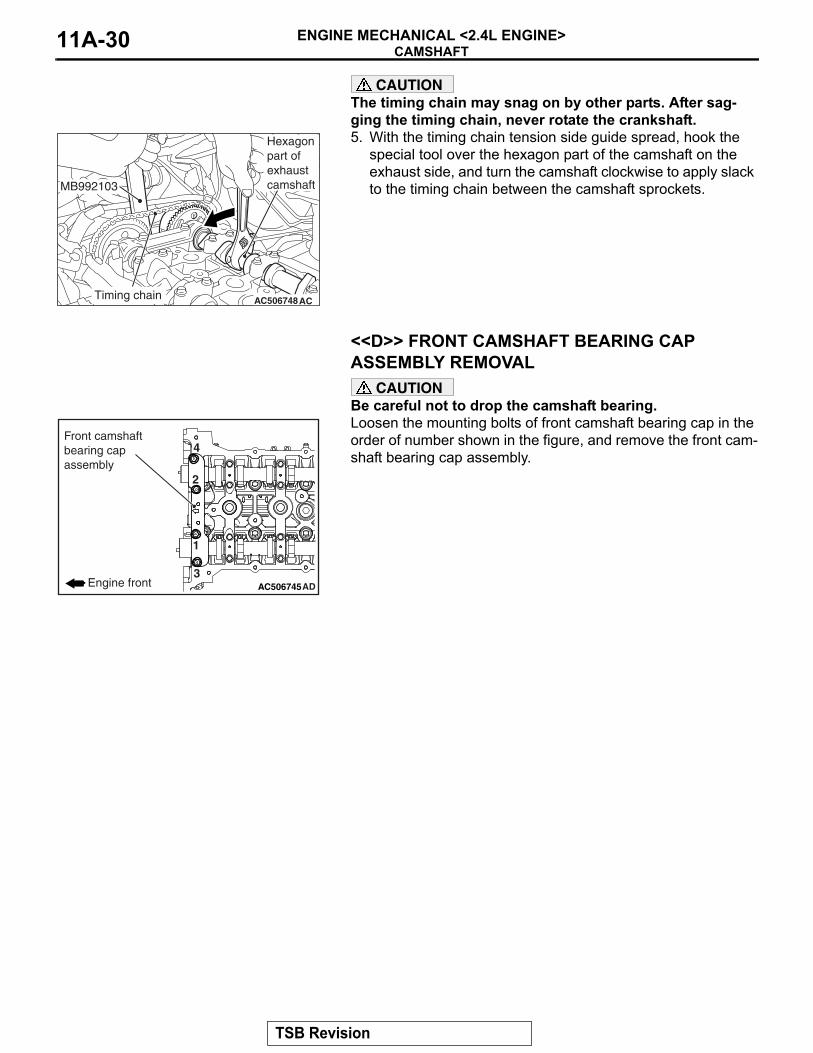
CAUTIONThe timing chain may snag on by other parts. After sag-ging the timing chain, never rotate the crankshaft.5. With the timing chain tension side guide spread, hook the
special tool over the hexagon part of the camshaft on the exhaust side, and turn the camshaft clockwise to apply slack to the timing chain between the camshaft sprockets.
.
<<D>> FRONT CAMSHAFT BEARING CAP ASSEMBLY REMOVAL
CAUTIONBe careful not to drop the camshaft bearing.Loosen the mounting bolts of front camshaft bearing cap in the order of number shown in the figure, and remove the front cam-shaft bearing cap assembly.
.
AC506748AC
MB992103
Timing chain
Hexagon part of exhaust camshaft
AC506745AD
1
2
3
4
Engine front
Front camshaftbearing capassembly
TSB Revision
CAMSHAFTENGINE MECHANICAL <2.4L ENGINE> 11A-31
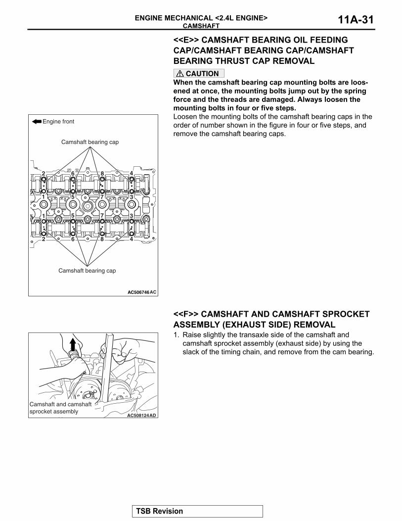
<<E>> CAMSHAFT BEARING OIL FEEDING CAP/CAMSHAFT BEARING CAP/CAMSHAFT BEARING THRUST CAP REMOVAL
CAUTIONWhen the camshaft bearing cap mounting bolts are loos-ened at once, the mounting bolts jump out by the spring force and the threads are damaged. Always loosen the mounting bolts in four or five steps.Loosen the mounting bolts of the camshaft bearing caps in the order of number shown in the figure in four or five steps, and remove the camshaft bearing caps.
.
<<F>> CAMSHAFT AND CAMSHAFT SPROCKET ASSEMBLY (EXHAUST SIDE) REMOVAL1. Raise slightly the transaxle side of the camshaft and
camshaft sprocket assembly (exhaust side) by using the slack of the timing chain, and remove from the cam bearing.
AC506746AC
1
1
2
2
3
3
4
4
5
5
6
6
7
7
8
8
Engine front
Camshaft bearing cap
Camshaft bearing cap
AC508124AD
Camshaft and camshaft sprocket assembly
TSB Revision
CAMSHAFTENGINE MECHANICAL <2.4L ENGINE>11A-32
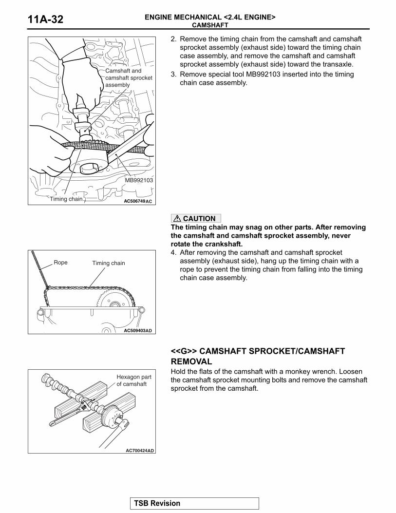
2. Remove the timing chain from the camshaft and camshaft sprocket assembly (exhaust side) toward the timing chain case assembly, and remove the camshaft and camshaft sprocket assembly (exhaust side) toward the transaxle.
3. Remove special tool MB992103 inserted into the timing chain case assembly.
CAUTIONThe timing chain may snag on other parts. After removing the camshaft and camshaft sprocket assembly, never rotate the crankshaft.4. After removing the camshaft and camshaft sprocket
assembly (exhaust side), hang up the timing chain with a rope to prevent the timing chain from falling into the timing chain case assembly.
.
<<G>> CAMSHAFT SPROCKET/CAMSHAFT REMOVALHold the flats of the camshaft with a monkey wrench. Loosen the camshaft sprocket mounting bolts and remove the camshaft sprocket from the camshaft.
.
AC506749AC
MB992103
Timing chain
Camshaft andcamshaft sprocketassembly
AC509403AD
Rope Timing chain
AC700424AD
Hexagon part of camshaft
TSB Revision
CAMSHAFTENGINE MECHANICAL <2.4L ENGINE> 11A-33
<<H>> POWER STEERING OIL PUMP ASSEMBLY REMOVAL1. With the hose installed, remove the power steering oil pump
assembly from the bracket.2. Tie the removed power steering oil pump assembly with a
string at a position where it will not interfere with the removal and installation of oil control valve.
.
<<I>> OIL FEEDER CONTROL VALVE REMOVALCAUTION
After removal of the oil feeder control valve, be careful to prevent dust from getting into the oil passage in the cylin-der head.
INSTALLATION SERVICE POINTS.
>>A<< O-RING/OIL FEEDER CONTROL VALVE INSTALLATION
CAUTIONWhen installing the oil feeder control valve, be careful to avoid damage to the O-ring.Apply engine oil to the O-ring of the oil feeder control valve and install the oil feeder control valve to the cylinder head..
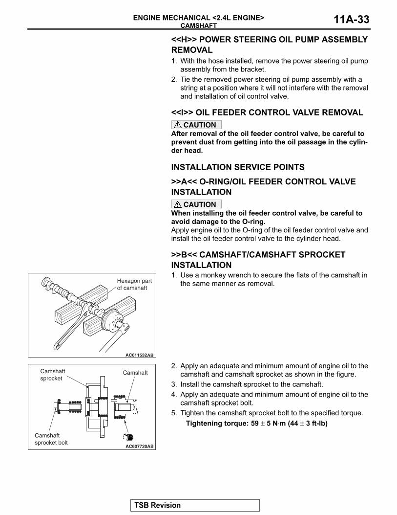
>>B<< CAMSHAFT/CAMSHAFT SPROCKET INSTALLATION1. Use a monkey wrench to secure the flats of the camshaft in
the same manner as removal.
2. Apply an adequate and minimum amount of engine oil to the camshaft and camshaft sprocket as shown in the figure.
3. Install the camshaft sprocket to the camshaft.4. Apply an adequate and minimum amount of engine oil to the
camshaft sprocket bolt.5. Tighten the camshaft sprocket bolt to the specified torque.
Tightening torque: 59 ± 5 N⋅m (44 ± 3 ft-lb)
.
AC611532AB
Hexagon part of camshaft
AC607720AB
CamshaftCamshaft sprocket
Camshaft sprocket bolt
TSB Revision
CAMSHAFTENGINE MECHANICAL <2.4L ENGINE>11A-34
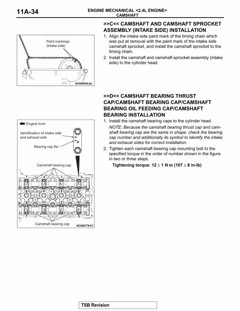
>>C<< CAMSHAFT AND CAMSHAFT SPROCKET ASSEMBLY (INTAKE SIDE) INSTALLATION1. Align the intake side paint mark of the timing chain which
was put at removal with the paint mark of the intake side camshaft sprocket, and install the camshaft sprocket to the timing chain.
2. Install the camshaft and camshaft sprocket assembly (intake side) to the cylinder head.
.
>>D<< CAMSHAFT BEARING THRUST CAP/CAMSHAFT BEARING CAP/CAMSHAFT BEARING OIL FEEDING CAP/CAMSHAFT BEARING INSTALLATION1. Install the camshaft bearing caps to the cylinder head.
NOTE: Because the camshaft bearing thrust cap and cam-shaft bearing cap are the same in shape, check the bearing cap number and additionally its symbol to identify the intake and exhaust sides for correct installation.
2. Tighten each camshaft bearing cap mounting bolt to the specified torque in the order of number shown in the figure in two or three steps.
Tightening torque: 12 ± 1 N⋅m (107 ± 8 in-lb)
.
AC509403AE
Paint markings(intake side)
AC506778AC
8
8
7
7
6
6
5
5
4
4
3
3
2
2
1
1
E 5
Engine front
Camshaft bearing cap
Camshaft bearing cap
Bearing cap No.
Identification of intake side and exhaust side
TSB Revision
CAMSHAFTENGINE MECHANICAL <2.4L ENGINE> 11A-35
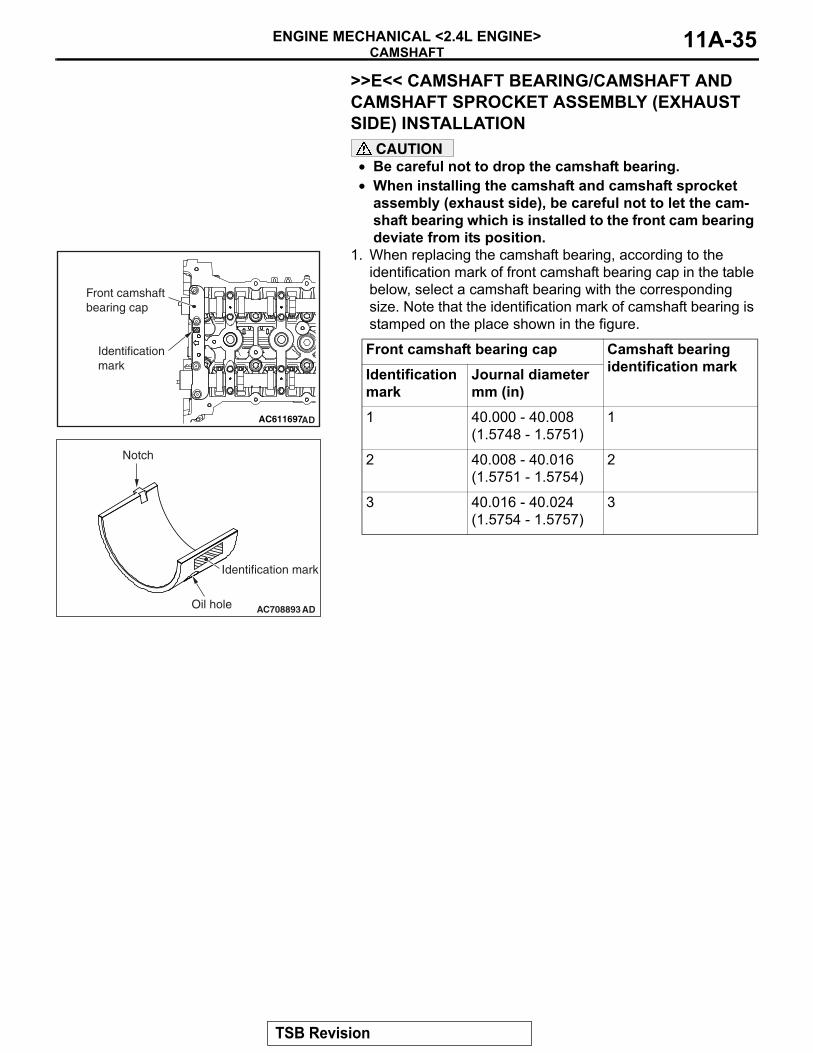
>>E<< CAMSHAFT BEARING/CAMSHAFT AND CAMSHAFT SPROCKET ASSEMBLY (EXHAUST SIDE) INSTALLATION
CAUTION• Be careful not to drop the camshaft bearing.• When installing the camshaft and camshaft sprocket
assembly (exhaust side), be careful not to let the cam-shaft bearing which is installed to the front cam bearing deviate from its position.
1. When replacing the camshaft bearing, according to the identification mark of front camshaft bearing cap in the table below, select a camshaft bearing with the corresponding size. Note that the identification mark of camshaft bearing is stamped on the place shown in the figure.
Front camshaft bearing cap Camshaft bearing identification markIdentification
markJournal diameter mm (in)
1 40.000 - 40.008 (1.5748 - 1.5751)
1
2 40.008 - 40.016 (1.5751 - 1.5754)
2
3 40.016 - 40.024 (1.5754 - 1.5757)
3
AC611697AD
Front camshaft bearing cap
Identificationmark
AC708893
Notch
Identification mark
Oil hole AD
TSB Revision
CAMSHAFTENGINE MECHANICAL <2.4L ENGINE>11A-36
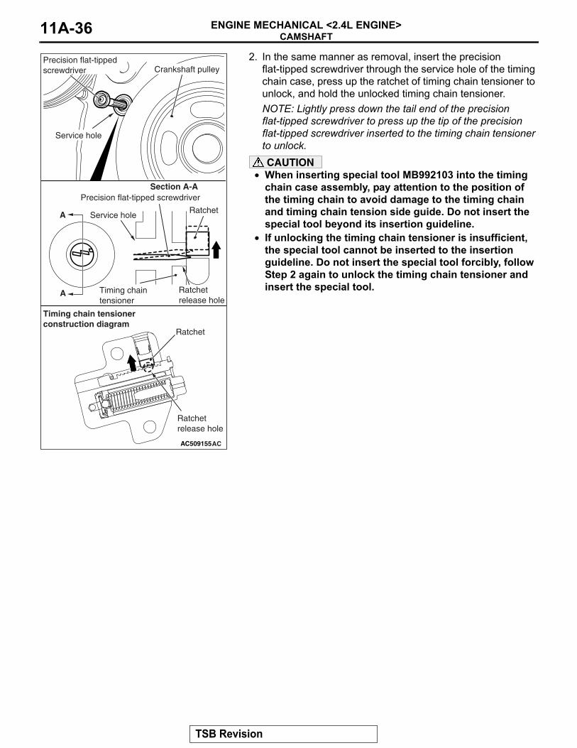
2. In the same manner as removal, insert the precision flat-tipped screwdriver through the service hole of the timing chain case, press up the ratchet of timing chain tensioner to unlock, and hold the unlocked timing chain tensioner.NOTE: Lightly press down the tail end of the precision flat-tipped screwdriver to press up the tip of the precision flat-tipped screwdriver inserted to the timing chain tensioner to unlock.CAUTION
• When inserting special tool MB992103 into the timing chain case assembly, pay attention to the position of the timing chain to avoid damage to the timing chain and timing chain tension side guide. Do not insert the special tool beyond its insertion guideline.
• If unlocking the timing chain tensioner is insufficient, the special tool cannot be inserted to the insertion guideline. Do not insert the special tool forcibly, follow Step 2 again to unlock the timing chain tensioner and insert the special tool.
AC509155AC
Section A-A
A
A
Precision flat-tipped screwdriver
Service hole
Crankshaft pulley
Service holeRatchet
Precision flat-tipped screwdriver
Ratchetrelease hole
Timing chaintensioner
Ratchet
Ratchetrelease hole
Timing chain tensionerconstruction diagram
TSB Revision
CAMSHAFTENGINE MECHANICAL <2.4L ENGINE> 11A-37
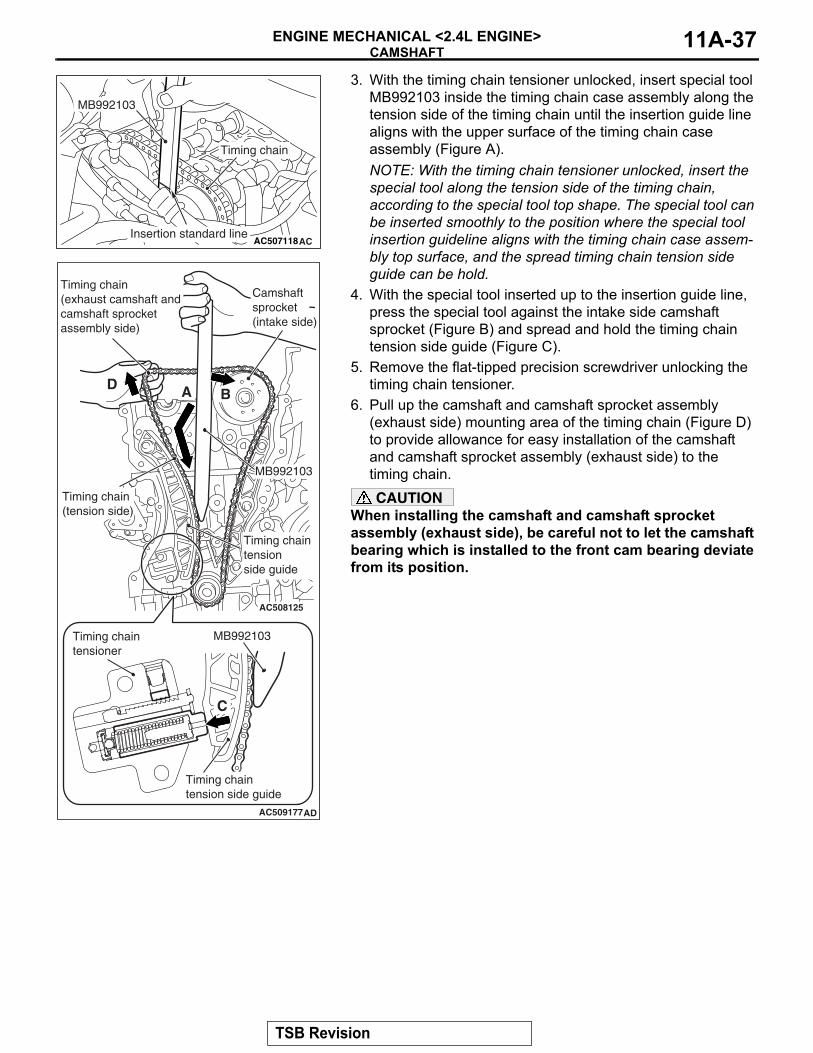
3. With the timing chain tensioner unlocked, insert special tool MB992103 inside the timing chain case assembly along the tension side of the timing chain until the insertion guide line aligns with the upper surface of the timing chain case assembly (Figure A). NOTE: With the timing chain tensioner unlocked, insert the special tool along the tension side of the timing chain, according to the special tool top shape. The special tool can be inserted smoothly to the position where the special tool insertion guideline aligns with the timing chain case assem-bly top surface, and the spread timing chain tension side guide can be hold.
4. With the special tool inserted up to the insertion guide line, press the special tool against the intake side camshaft sprocket (Figure B) and spread and hold the timing chain tension side guide (Figure C).
5. Remove the flat-tipped precision screwdriver unlocking the timing chain tensioner.
6. Pull up the camshaft and camshaft sprocket assembly (exhaust side) mounting area of the timing chain (Figure D) to provide allowance for easy installation of the camshaft and camshaft sprocket assembly (exhaust side) to the timing chain.CAUTION
When installing the camshaft and camshaft sprocket assembly (exhaust side), be careful not to let the camshaft bearing which is installed to the front cam bearing deviate from its position.
AC507118AC
Timing chain
MB992103
Insertion standard line
AC509177
AC508125
AD
MB992103
MB992103Timing chaintensioner
Timing chaintension side guide
Timing chaintension side guide
Timing chain(tension side)
Camshaftsprocket(intake side)
Timing chain(exhaust camshaft andcamshaft sprocketassembly side)
A B
C
D
TSB Revision
CAMSHAFTENGINE MECHANICAL <2.4L ENGINE>11A-38
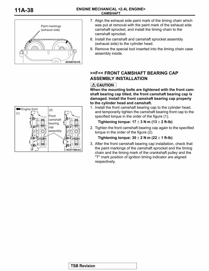
7. Align the exhaust side paint mark of the timing chain which was put at removal with the paint mark of the exhaust side camshaft sprocket, and install the timing chain to the camshaft sprocket.
8. Install the camshaft and camshaft sprocket assembly (exhaust side) to the cylinder head.
9. Remove the special tool inserted into the timing chain case assembly inside.
.
>>F<< FRONT CAMSHAFT BEARING CAP ASSEMBLY INSTALLATION
CAUTIONWhen the mounting bolts are tightened with the front cam-shaft bearing cap tilted, the front camshaft bearing cap is damaged. Install the front camshaft bearing cap properly to the cylinder head and camshaft.1. Install the front camshaft bearing cap to the cylinder head,
and temporarily tighten the camshaft bearing front cap to the specified torque in the order of the figure (1).
Tightening torque: 17 ± 3 N⋅m (13 ± 2 ft-lb)2. Tighten the front camshaft bearing cap again to the specified
torque in the order of the figure (2).Tightening torque: 30 ± 2 N⋅m (22 ± 1 ft-lb)
3. After the front camshaft bearing cap installation, check that the paint markings of the camshaft sprocket and the timing chain and the timing mark of the crankshaft pulley and the "T" mark position of ignition timing indicator are aligned respectively.
.
AC506752AB
Paint markings(exhaust side)
AC511062AC
4
3
2
1
4
3
2
1
(1)(2)Engine front
Front camshaftbearingcapassembly
TSB Revision
CAMSHAFTENGINE MECHANICAL <2.4L ENGINE> 11A-39
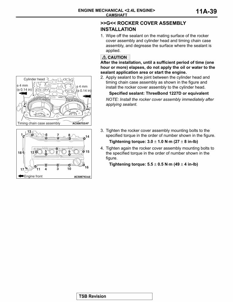
>>G<< ROCKER COVER ASSEMBLY INSTALLATION1. Wipe off the sealant on the mating surface of the rocker
cover assembly and cylinder head and timing chain case assembly, and degrease the surface where the sealant is applied.CAUTION
After the installation, until a sufficient period of time (one hour or more) elapses, do not apply the oil or water to the sealant application area or start the engine.2. Apply sealant to the joint between the cylinder head and
timing chain case assembly as shown in the figure and install the rocker cover assembly to the cylinder head.
Specified sealant: ThreeBond 1227D or equivalentNOTE: Install the rocker cover assembly immediately after applying sealant.
3. Tighten the rocker cover assembly mounting bolts to the specified torque in the order of number shown in the figure.
Tightening torque: 3.0 ± 1.0 N⋅m (27 ± 8 in-lb)4. Tighten again the rocker cover assembly mounting bolts to
the specified torque in the order of number shown in the figure.
Tightening torque: 5.5 ± 0.5 N⋅m (49 ± 4 in-lb)
AC506753AF
Cylinder head
Timing chain case assembly
φ 4 mm(φ 0.14 in)
φ 4 mm(φ 0.14 in)
AC506743AE
3
61
95
104
87
11
13
14
15
1617
18 212
Engine front
TSB Revision
VALVE STEM SEALENGINE MECHANICAL <2.4L ENGINE>11A-40
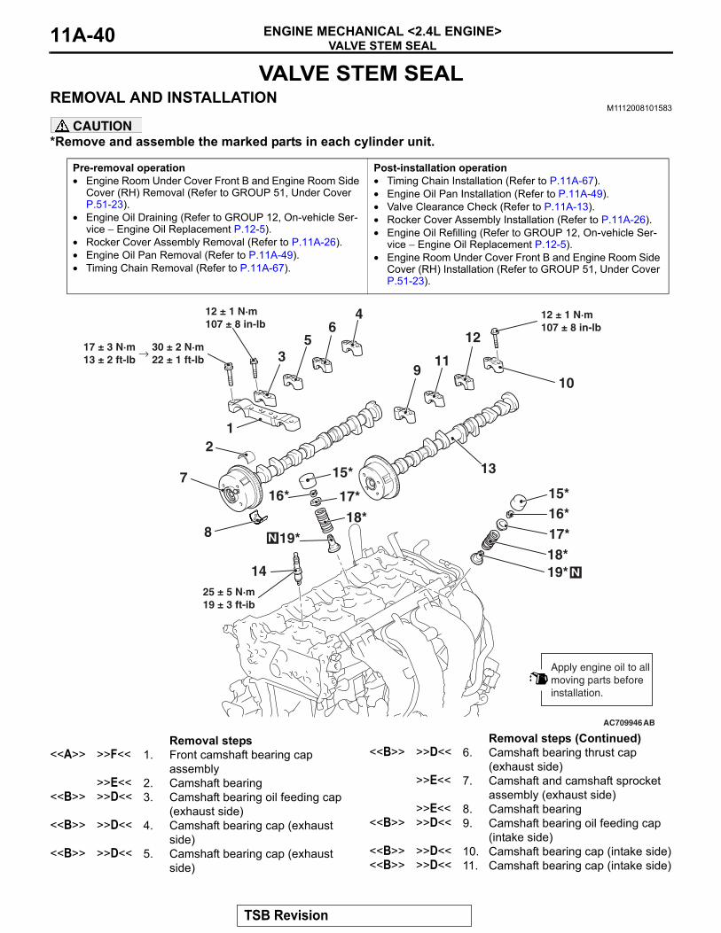
VALVE STEM SEALREMOVAL AND INSTALLATION
M1112008101583
CAUTION*Remove and assemble the marked parts in each cylinder unit.
Pre-removal operation• Engine Room Under Cover Front B and Engine Room Side
Cover (RH) Removal (Refer to GROUP 51, Under Cover P.51-23).
• Engine Oil Draining (Refer to GROUP 12, On-vehicle Ser-vice − Engine Oil Replacement P.12-5).
• Rocker Cover Assembly Removal (Refer to P.11A-26).• Engine Oil Pan Removal (Refer to P.11A-49).• Timing Chain Removal (Refer to P.11A-67).
Post-installation operation• Timing Chain Installation (Refer to P.11A-67).• Engine Oil Pan Installation (Refer to P.11A-49).• Valve Clearance Check (Refer to P.11A-13).• Rocker Cover Assembly Installation (Refer to P.11A-26).• Engine Oil Refilling (Refer to GROUP 12, On-vehicle Ser-
vice − Engine Oil Replacement P.12-5).• Engine Room Under Cover Front B and Engine Room Side
Cover (RH) Installation (Refer to GROUP 51, Under Cover P.51-23).
AC709946
6
3 11
AB
7
12
13
1
4
5
109
14 N
N
2
8
15*16*17*18*19*
15*
16* 17*
18*
19*
25 ± 5 N·m19 ± 3 ft-ib
Apply engine oil to allmoving parts beforeinstallation.
12 ± 1 N·m107 ± 8 in-lb
12 ± 1 N·m107 ± 8 in-lb
→ 17 ± 3 N·m13 ± 2 ft-lb
30 ± 2 N·m22 ± 1 ft-lb
Removal steps <<A>> >>F<< 1. Front camshaft bearing cap
assembly>>E<< 2. Camshaft bearing
<<B>> >>D<< 3. Camshaft bearing oil feeding cap (exhaust side)
<<B>> >>D<< 4. Camshaft bearing cap (exhaust side)
<<B>> >>D<< 5. Camshaft bearing cap (exhaust side)
<<B>> >>D<< 6. Camshaft bearing thrust cap (exhaust side)
>>E<< 7. Camshaft and camshaft sprocket assembly (exhaust side)
>>E<< 8. Camshaft bearing<<B>> >>D<< 9. Camshaft bearing oil feeding cap
(intake side)<<B>> >>D<< 10. Camshaft bearing cap (intake side)<<B>> >>D<< 11. Camshaft bearing cap (intake side)
Removal steps (Continued)
TSB Revision
VALVE STEM SEALENGINE MECHANICAL <2.4L ENGINE> 11A-41
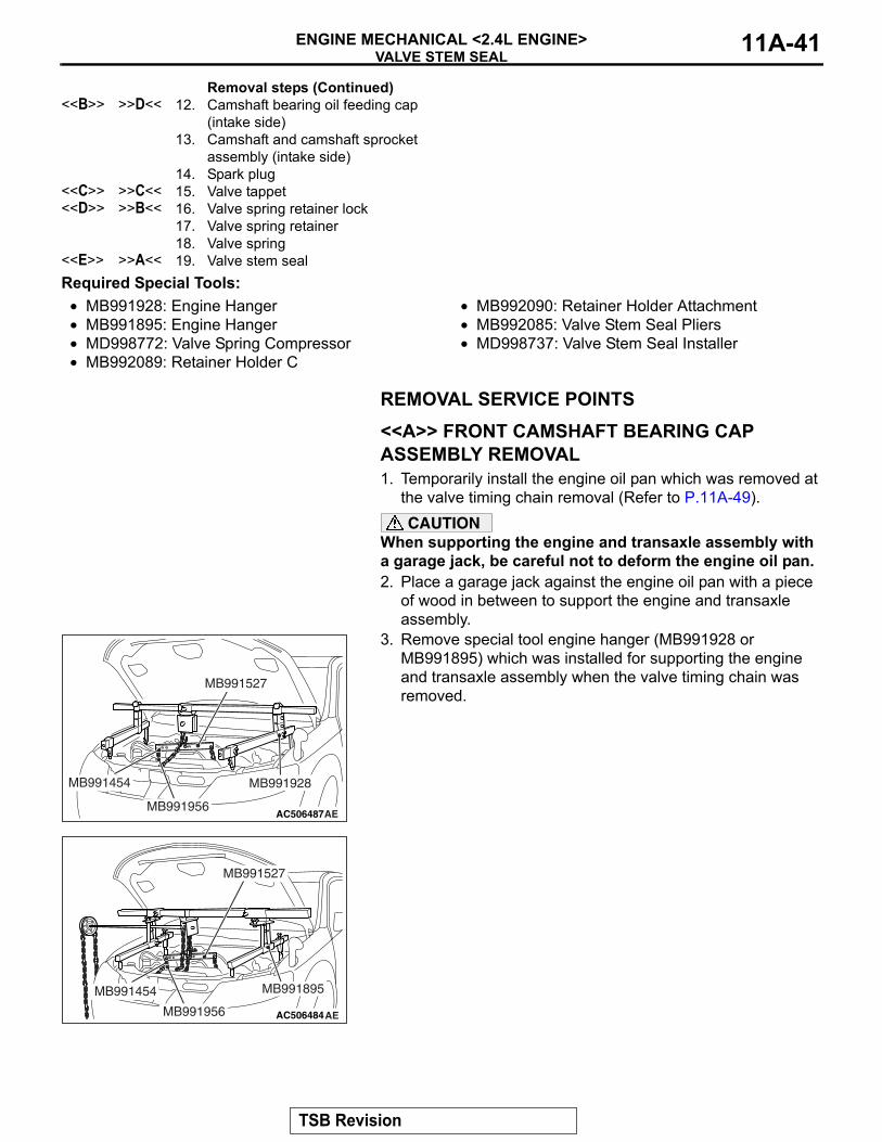
Required Special Tools:• MB991928: Engine Hanger• MB991895: Engine Hanger• MD998772: Valve Spring Compressor• MB992089: Retainer Holder C
• MB992090: Retainer Holder Attachment• MB992085: Valve Stem Seal Pliers• MD998737: Valve Stem Seal Installer
REMOVAL SERVICE POINTS.
<<A>> FRONT CAMSHAFT BEARING CAP ASSEMBLY REMOVAL1. Temporarily install the engine oil pan which was removed at
the valve timing chain removal (Refer to P.11A-49).CAUTION
When supporting the engine and transaxle assembly with a garage jack, be careful not to deform the engine oil pan.2. Place a garage jack against the engine oil pan with a piece
of wood in between to support the engine and transaxle assembly.
3. Remove special tool engine hanger (MB991928 or MB991895) which was installed for supporting the engine and transaxle assembly when the valve timing chain was removed.
<<B>> >>D<< 12. Camshaft bearing oil feeding cap (intake side)
13. Camshaft and camshaft sprocket assembly (intake side)
14. Spark plug<<C>> >>C<< 15. Valve tappet<<D>> >>B<< 16. Valve spring retainer lock
17. Valve spring retainer18. Valve spring
<<E>> >>A<< 19. Valve stem seal
Removal steps (Continued)
AC506487AE
MB991527
MB991454 MB991928
MB991956
AC506484
MB991527
AE
MB991454
MB991956
MB991895
TSB Revision
VALVE STEM SEALENGINE MECHANICAL <2.4L ENGINE>11A-42
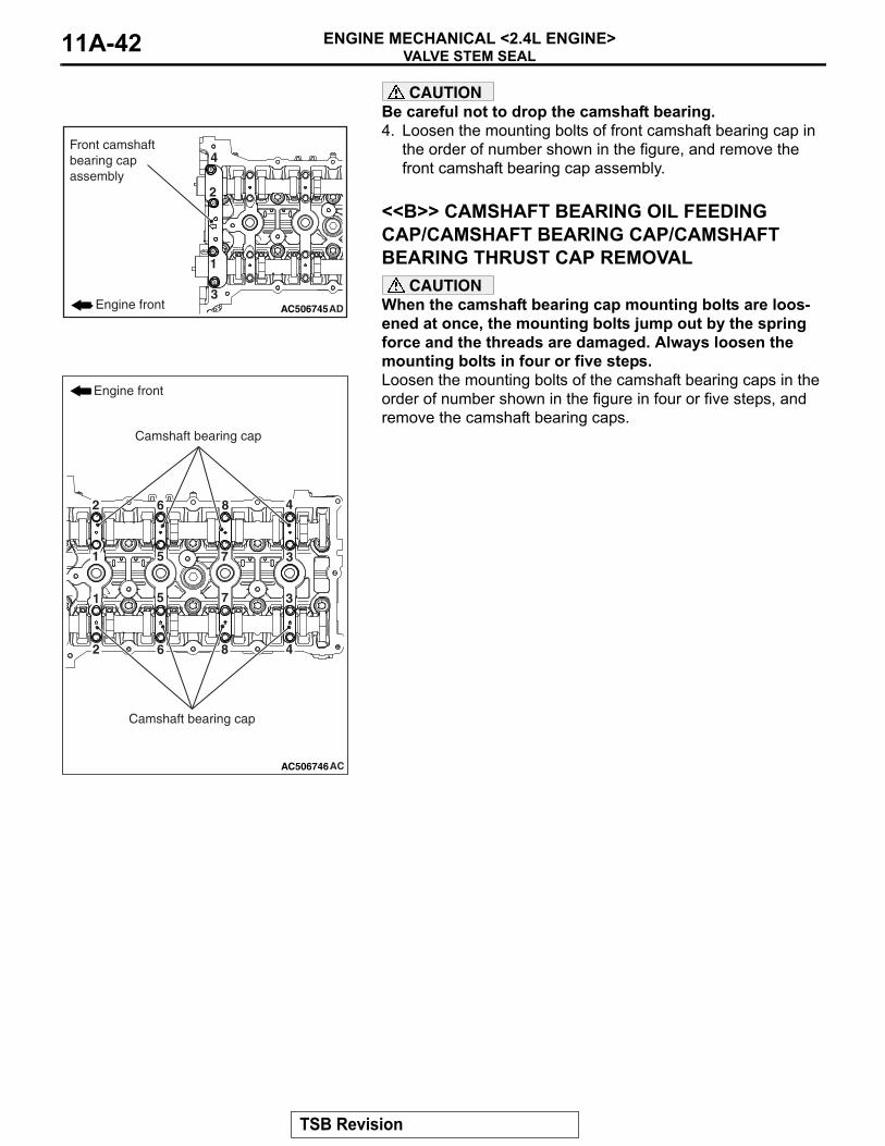
CAUTIONBe careful not to drop the camshaft bearing.4. Loosen the mounting bolts of front camshaft bearing cap in
the order of number shown in the figure, and remove the front camshaft bearing cap assembly.
.
<<B>> CAMSHAFT BEARING OIL FEEDING CAP/CAMSHAFT BEARING CAP/CAMSHAFT BEARING THRUST CAP REMOVAL
CAUTIONWhen the camshaft bearing cap mounting bolts are loos-ened at once, the mounting bolts jump out by the spring force and the threads are damaged. Always loosen the mounting bolts in four or five steps.Loosen the mounting bolts of the camshaft bearing caps in the order of number shown in the figure in four or five steps, and remove the camshaft bearing caps.
.
AC506745AD
1
2
3
4
Engine front
Front camshaftbearing capassembly
AC506746AC
1
1
2
2
3
3
4
4
5
5
6
6
7
7
8
8
Engine front
Camshaft bearing cap
Camshaft bearing cap
TSB Revision
VALVE STEM SEALENGINE MECHANICAL <2.4L ENGINE> 11A-43
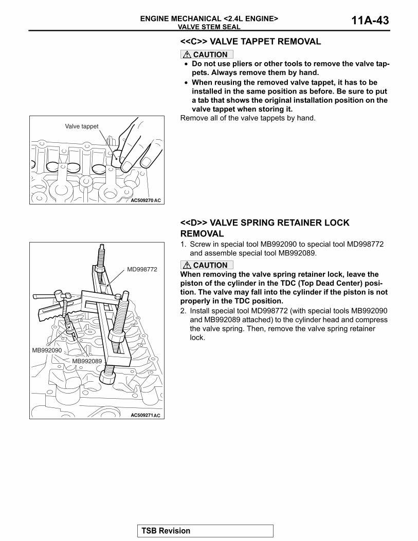
<<C>> VALVE TAPPET REMOVALCAUTION
• Do not use pliers or other tools to remove the valve tap-pets. Always remove them by hand.
• When reusing the removed valve tappet, it has to be installed in the same position as before. Be sure to put a tab that shows the original installation position on the valve tappet when storing it.
Remove all of the valve tappets by hand.
.
<<D>> VALVE SPRING RETAINER LOCK REMOVAL1. Screw in special tool MB992090 to special tool MD998772
and assemble special tool MB992089.CAUTION
When removing the valve spring retainer lock, leave the piston of the cylinder in the TDC (Top Dead Center) posi-tion. The valve may fall into the cylinder if the piston is not properly in the TDC position.2. Install special tool MD998772 (with special tools MB992090
and MB992089 attached) to the cylinder head and compress the valve spring. Then, remove the valve spring retainer lock.
.
AC509270 AC
Valve tappet
AC509271AC
MD998772
MB992090
MB992089
TSB Revision
VALVE STEM SEALENGINE MECHANICAL <2.4L ENGINE>11A-44
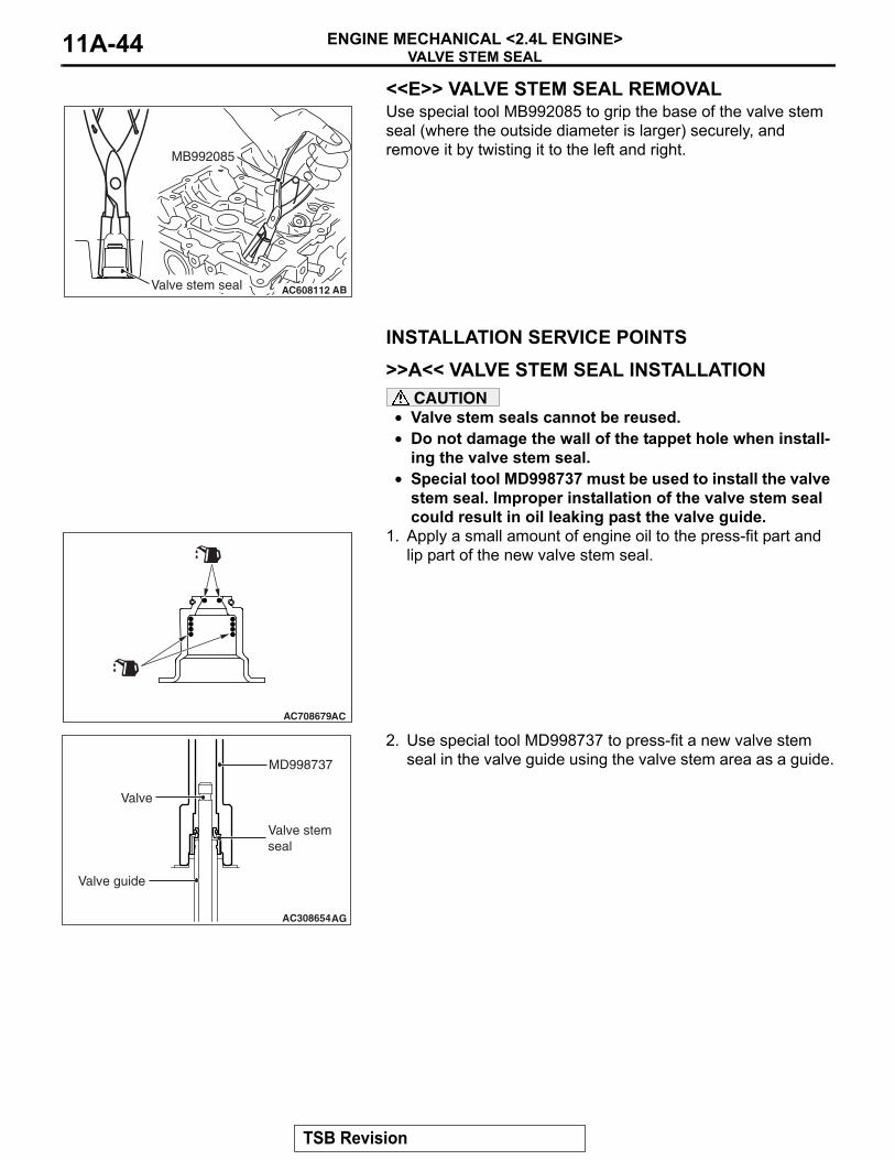
<<E>> VALVE STEM SEAL REMOVALUse special tool MB992085 to grip the base of the valve stem seal (where the outside diameter is larger) securely, and remove it by twisting it to the left and right.
INSTALLATION SERVICE POINTS.
>>A<< VALVE STEM SEAL INSTALLATIONCAUTION
• Valve stem seals cannot be reused.• Do not damage the wall of the tappet hole when install-
ing the valve stem seal.• Special tool MD998737 must be used to install the valve
stem seal. Improper installation of the valve stem seal could result in oil leaking past the valve guide.
1. Apply a small amount of engine oil to the press-fit part and lip part of the new valve stem seal.
2. Use special tool MD998737 to press-fit a new valve stem seal in the valve guide using the valve stem area as a guide.
.
AC608112 ABValve stem seal
MB992085
AC708679AC
AC308654AG
MD998737
Valve
Valve guide
Valve stem seal
TSB Revision
VALVE STEM SEALENGINE MECHANICAL <2.4L ENGINE> 11A-45
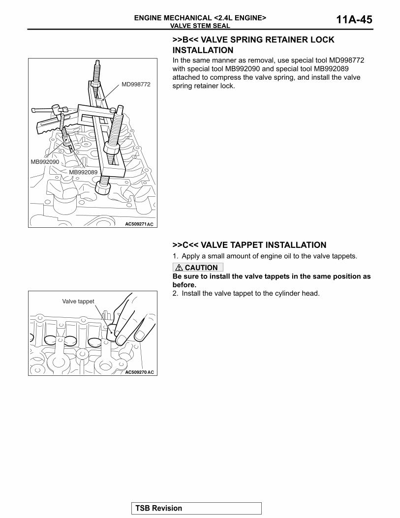
>>B<< VALVE SPRING RETAINER LOCK INSTALLATIONIn the same manner as removal, use special tool MD998772 with special tool MB992090 and special tool MB992089 attached to compress the valve spring, and install the valve spring retainer lock.
.
>>C<< VALVE TAPPET INSTALLATION1. Apply a small amount of engine oil to the valve tappets.
CAUTIONBe sure to install the valve tappets in the same position as before.2. Install the valve tappet to the cylinder head.
.
AC509271AC
MD998772
MB992090
MB992089
AC509270 AC
Valve tappet
TSB Revision
VALVE STEM SEALENGINE MECHANICAL <2.4L ENGINE>11A-46
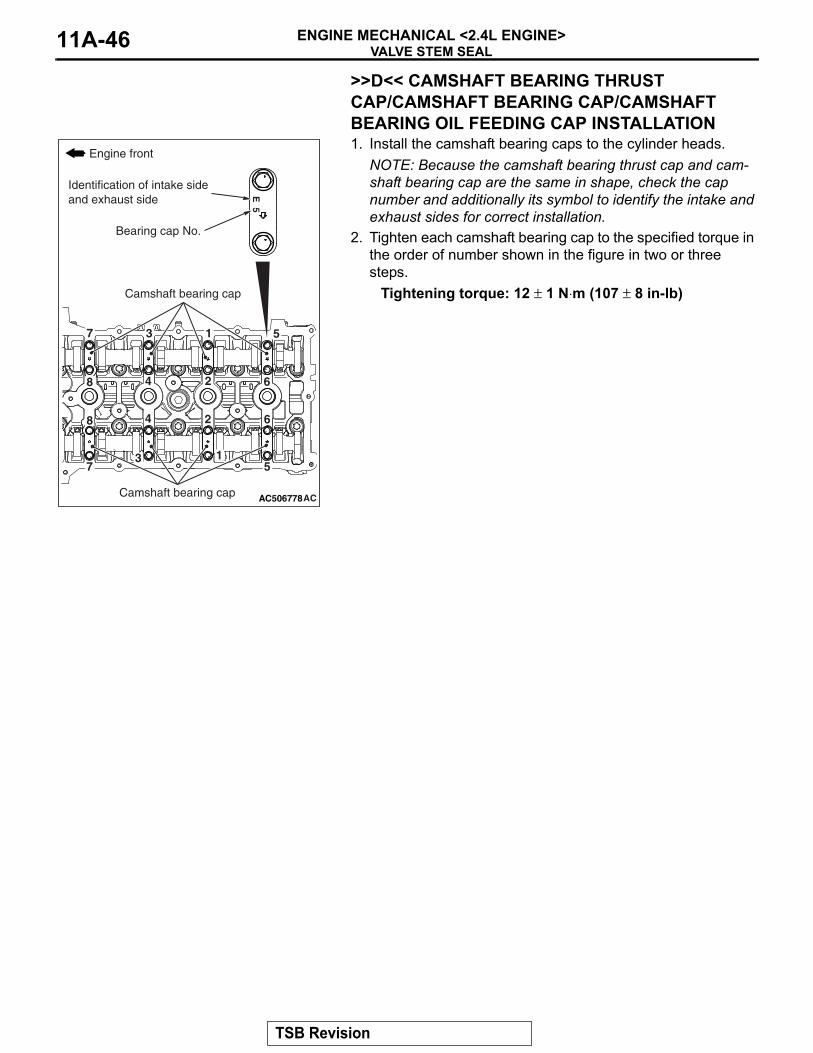
>>D<< CAMSHAFT BEARING THRUST CAP/CAMSHAFT BEARING CAP/CAMSHAFT BEARING OIL FEEDING CAP INSTALLATION1. Install the camshaft bearing caps to the cylinder heads.
NOTE: Because the camshaft bearing thrust cap and cam-shaft bearing cap are the same in shape, check the cap number and additionally its symbol to identify the intake and exhaust sides for correct installation.
2. Tighten each camshaft bearing cap to the specified torque in the order of number shown in the figure in two or three steps.
Tightening torque: 12 ± 1 N⋅m (107 ± 8 in-lb)
.
AC506778AC
8
8
7
7
6
6
5
5
4
4
3
3
2
2
1
1
E 5
Engine front
Camshaft bearing cap
Camshaft bearing cap
Bearing cap No.
Identification of intake side and exhaust side
TSB Revision
VALVE STEM SEALENGINE MECHANICAL <2.4L ENGINE> 11A-47
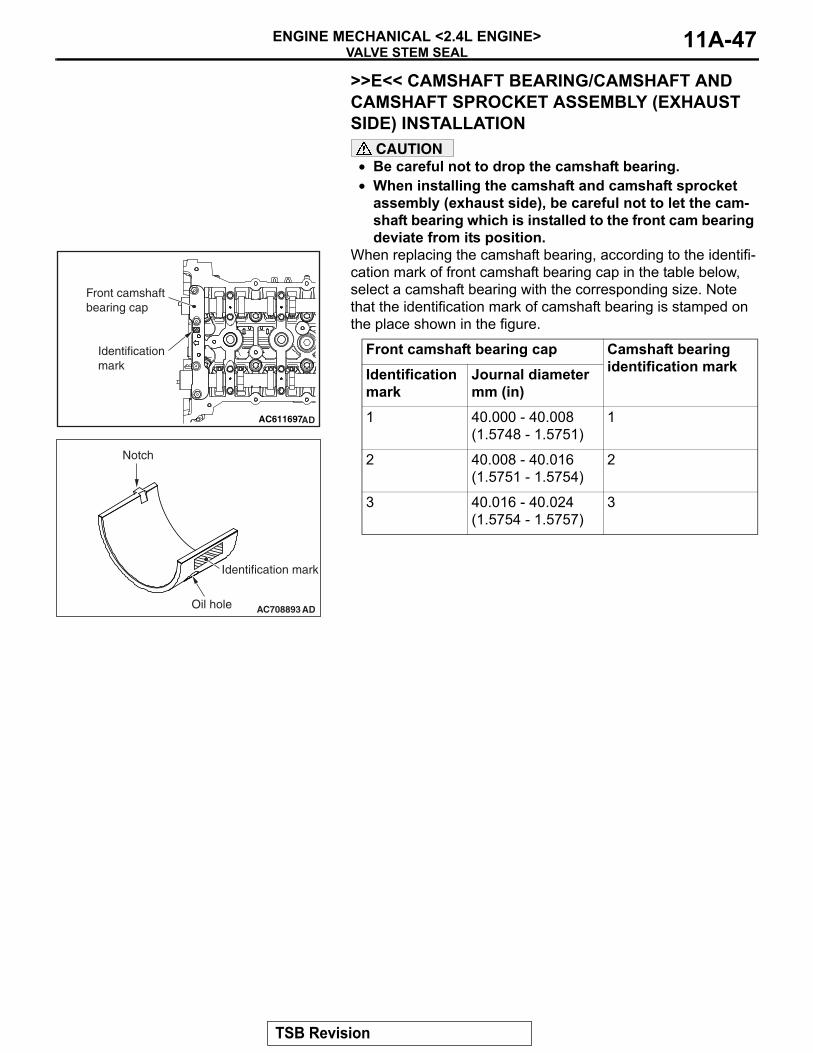
>>E<< CAMSHAFT BEARING/CAMSHAFT AND CAMSHAFT SPROCKET ASSEMBLY (EXHAUST SIDE) INSTALLATION
CAUTION• Be careful not to drop the camshaft bearing.• When installing the camshaft and camshaft sprocket
assembly (exhaust side), be careful not to let the cam-shaft bearing which is installed to the front cam bearing deviate from its position.
When replacing the camshaft bearing, according to the identifi-cation mark of front camshaft bearing cap in the table below, select a camshaft bearing with the corresponding size. Note that the identification mark of camshaft bearing is stamped on the place shown in the figure.
Front camshaft bearing cap Camshaft bearing identification markIdentification
markJournal diameter mm (in)
1 40.000 - 40.008 (1.5748 - 1.5751)
1
2 40.008 - 40.016 (1.5751 - 1.5754)
2
3 40.016 - 40.024 (1.5754 - 1.5757)
3
AC611697AD
Front camshaft bearing cap
Identificationmark
AC708893
Notch
Identification mark
Oil hole AD
TSB Revision
VALVE STEM SEALENGINE MECHANICAL <2.4L ENGINE>11A-48
.
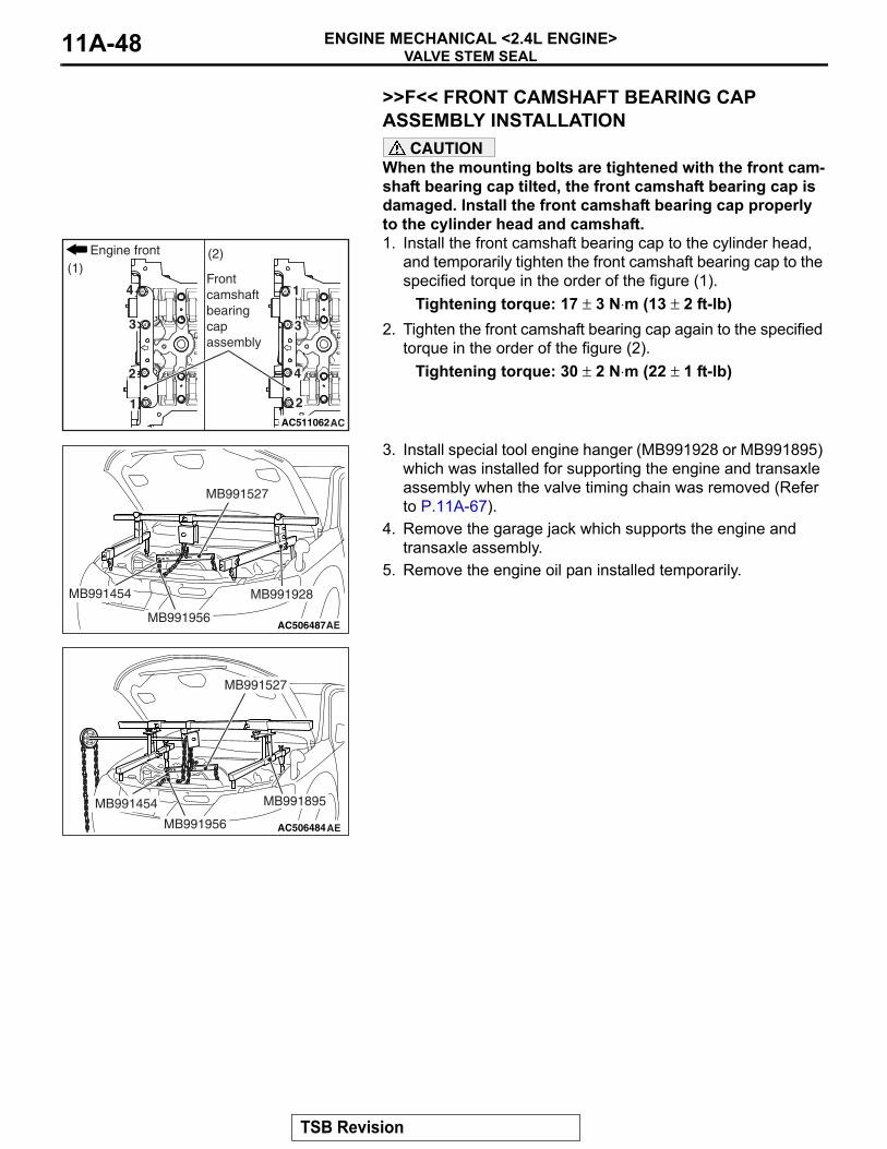
>>F<< FRONT CAMSHAFT BEARING CAP ASSEMBLY INSTALLATION
CAUTIONWhen the mounting bolts are tightened with the front cam-shaft bearing cap tilted, the front camshaft bearing cap is damaged. Install the front camshaft bearing cap properly to the cylinder head and camshaft.1. Install the front camshaft bearing cap to the cylinder head,
and temporarily tighten the front camshaft bearing cap to the specified torque in the order of the figure (1).
Tightening torque: 17 ± 3 N⋅m (13 ± 2 ft-lb)2. Tighten the front camshaft bearing cap again to the specified
torque in the order of the figure (2).Tightening torque: 30 ± 2 N⋅m (22 ± 1 ft-lb)
3. Install special tool engine hanger (MB991928 or MB991895) which was installed for supporting the engine and transaxle assembly when the valve timing chain was removed (Refer to P.11A-67).
4. Remove the garage jack which supports the engine and transaxle assembly.
5. Remove the engine oil pan installed temporarily.
AC511062AC
4
3
2
1
4
3
2
1
(1)(2)Engine front
Front camshaftbearingcapassembly
AC506487AE
MB991527
MB991454 MB991928
MB991956
AC506484
MB991527
AE
MB991454
MB991956
MB991895
TSB Revision
OIL PANENGINE MECHANICAL <2.4L ENGINE> 11A-49
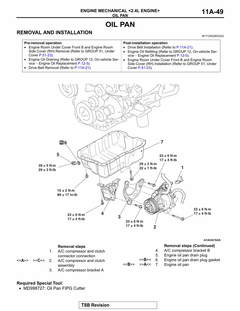
OIL PANREMOVAL AND INSTALLATION
M1112002803342
Required Special Tool:• MD998727: Oil Pan FIPG Cutter
Pre-removal operation• Engine Room Under Cover Front B and Engine Room
Side Cover (RH) Removal (Refer to GROUP 51, Under Cover P.51-23).
• Engine Oil Draining (Refer to GROUP 12, On-vehicle Ser-vice − Engine Oil Replacement P.12-5).
• Drive Belt Removal (Refer to P.11A-21).
Post-installation operation• Drive Belt Installation (Refer to P.11A-21).• Engine Oil Refilling (Refer to GROUP 12, On-vehicle Ser-
vice − Engine Oil Replacement P.12-5).• Engine Room Under Cover Front B and Engine Room
Side Cover (RH) Installation (Refer to GROUP 51, Under Cover P.51-23).
AC803678
6
5
7
1
4
39 ± 5 N·m29 ± 3 ft-lb
10 ± 2 N·m89 ± 17 in-lb
29 ± 2 N·m22 ± 1 ft-lb
23 ± 6 N·m17 ± 4 ft-lb
23 ± 6 N·m17 ± 4 ft-lb
N
AB
323 ± 6 N·m17 ± 4 ft-lb
23 ± 6 N·m17 ± 4 ft-lb
2
Removal steps 1. A/C compressor and clutch
connector connection<<A>> >>C<< 2. A/C compressor and clutch
assembly3. A/C compressor bracket A
4. A/C compressor bracket B5. Engine oil pan drain plug
>>B<< 6. Engine oil pan drain plug gasket<<B>> >>A<< 7. Engine oil pan
Removal steps (Continued)
TSB Revision
OIL PANENGINE MECHANICAL <2.4L ENGINE>11A-50
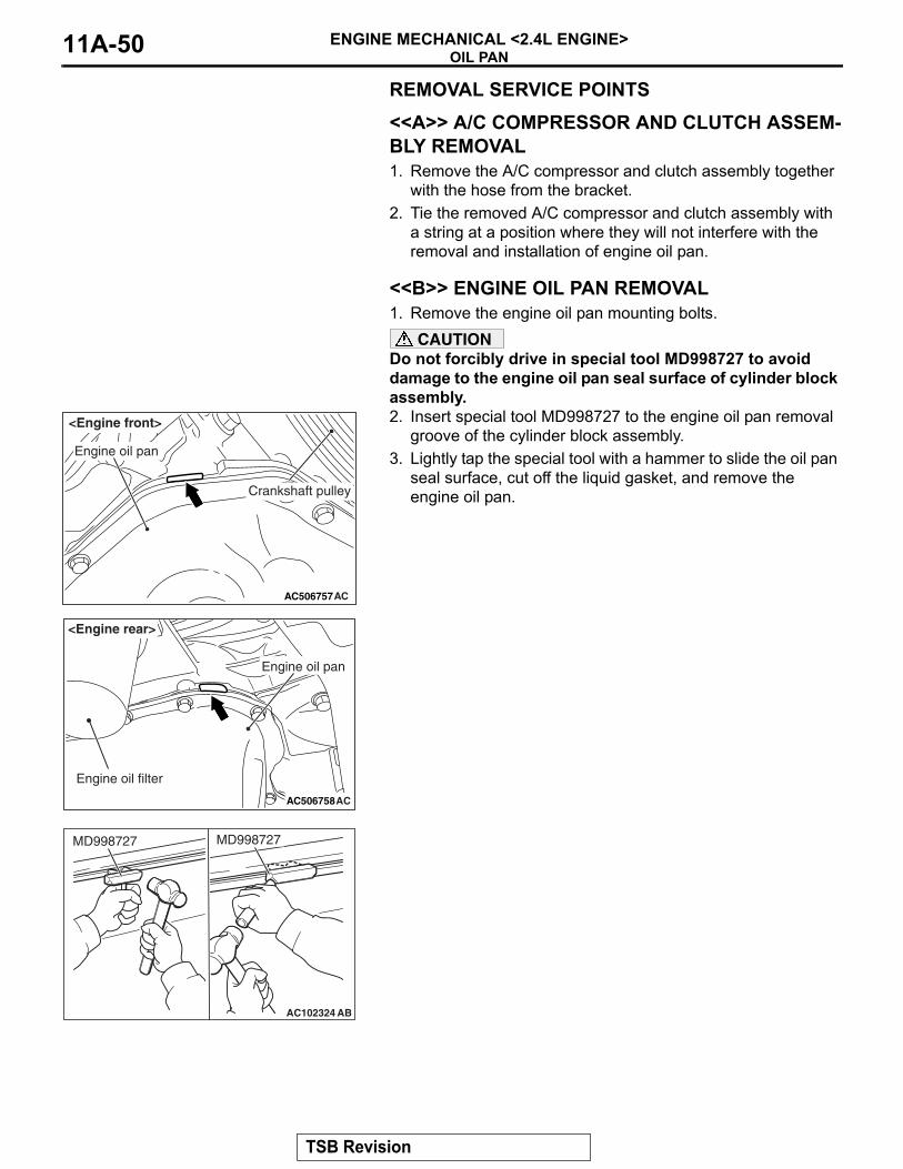
REMOVAL SERVICE POINTS.
<<A>> A/C COMPRESSOR AND CLUTCH ASSEM-BLY REMOVAL1. Remove the A/C compressor and clutch assembly together
with the hose from the bracket.2. Tie the removed A/C compressor and clutch assembly with
a string at a position where they will not interfere with the removal and installation of engine oil pan.
.
<<B>> ENGINE OIL PAN REMOVAL1. Remove the engine oil pan mounting bolts.
CAUTIONDo not forcibly drive in special tool MD998727 to avoid damage to the engine oil pan seal surface of cylinder block assembly.2. Insert special tool MD998727 to the engine oil pan removal
groove of the cylinder block assembly. 3. Lightly tap the special tool with a hammer to slide the oil pan
seal surface, cut off the liquid gasket, and remove the engine oil pan.
AC506757AC
<Engine front>
Engine oil pan
Crankshaft pulley
AC506758AC
Engine oil filter
Engine oil pan
<Engine rear>
AC102324 AB
MD998727 MD998727
TSB Revision
OIL PANENGINE MECHANICAL <2.4L ENGINE> 11A-51
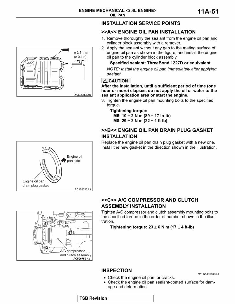
INSTALLATION SERVICE POINTS.
>>A<< ENGINE OIL PAN INSTALLATION1. Remove thoroughly the sealant from the engine oil pan and
cylinder block assembly with a remover.2. Apply the sealant without any gap to the mating surface of
engine oil pan as shown in the figure, and install the engine oil pan to the cylinder block assembly.
Specified sealant: ThreeBond 1227D or equivalentNOTE: Install the engine oil pan immediately after applying sealant.CAUTION
After the installation, until a sufficient period of time (one hour or more) elapses, do not apply the oil or water to the sealant application area or start the engine.3. Tighten the engine oil pan mounting bolts to the specified
torque.Tightening torque:
M6: 10 ± 2 N⋅m (89 ± 17 in-lb)M8: 29 ± 2 N⋅m (22 ± 1 ft-lb)
.
>>B<< ENGINE OIL PAN DRAIN PLUG GASKET INSTALLATIONReplace the engine oil pan drain plug gasket with a new one. Install the new gasket in the direction shown in the illustration.
.
>>C<< A/C COMPRESSOR AND CLUTCH ASSEMBLY INSTALLATIONTighten A/C compressor and clutch assembly mounting bolts to the specified torque in the order of number shown in the illus-tration.
Tightening torque: 23 ± 6 N⋅m (17 ± 4 ft-lb)
INSPECTIONM1112002900641
• Check the engine oil pan for cracks.• Check the engine oil pan sealant-coated surface for dam-
age and deformation.
AC506756AD
φ 2.5 mm (φ 0.1in)
AC102325AJ
Engine oil pan side
Engine oil pandrain plug gasket
AC506759 AE
1
2
3
A/C compressor and clutch assembly
TSB Revision
CRANKSHAFT OIL SEALENGINE MECHANICAL <2.4L ENGINE>11A-52
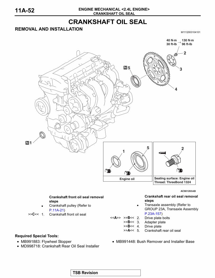
CRANKSHAFT OIL SEALREMOVAL AND INSTALLATION
M1112003104101
Required Special Tools:• MB991883: Flywheel Stopper• MD998718: Crankshaft Rear Oil Seal Installer
• MB991448: Bush Remover and Installer Base
AC901263
1
2
3
4
5N
N
AB
40 N·m30 ft-lb
130 N·m96 ft-lb
15 2
Engine oil Seating surface: Engine oilThread: ThreeBond 1324
→
Crankshaft front oil seal removal steps
• Crankshaft pulley (Refer to P.11A-21)
>>C<< 1. Crankshaft front oil seal
Crankshaft rear oil seal removal steps
• Transaxle assembly (Refer to GROUP 23A, Transaxle Assembly P.23A-157)
<<A>> >>B<< 2. Drive plate bolts>>B<< 3. Adapter plate>>B<< 4. Drive plate>>A<< 5. Crankshaft rear oil seal
TSB Revision
CRANKSHAFT OIL SEALENGINE MECHANICAL <2.4L ENGINE> 11A-53
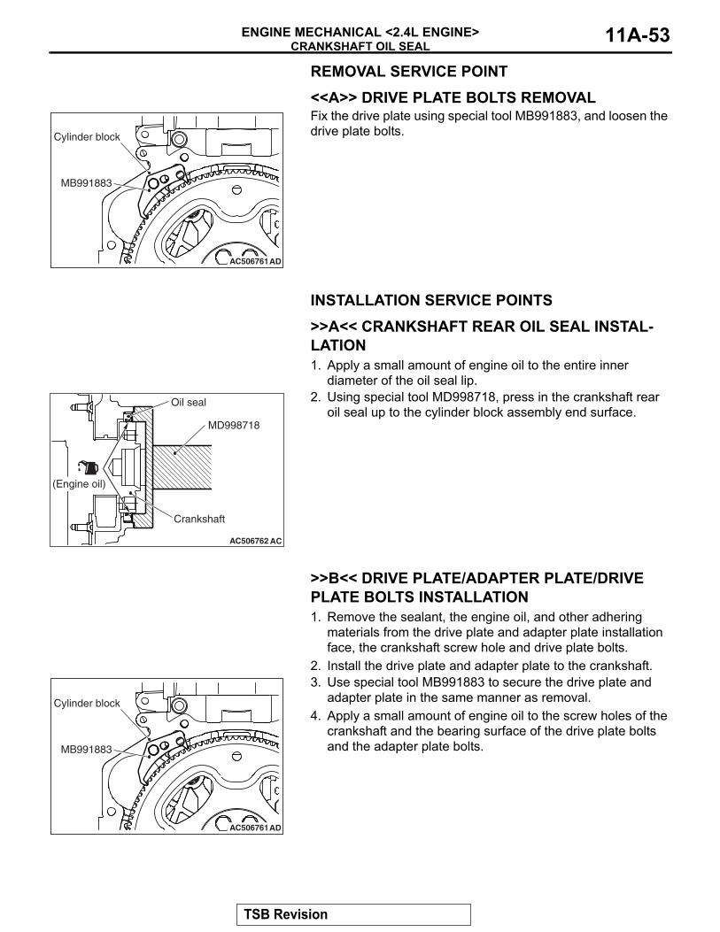
REMOVAL SERVICE POINT.
<<A>> DRIVE PLATE BOLTS REMOVALFix the drive plate using special tool MB991883, and loosen the drive plate bolts.
INSTALLATION SERVICE POINTS.
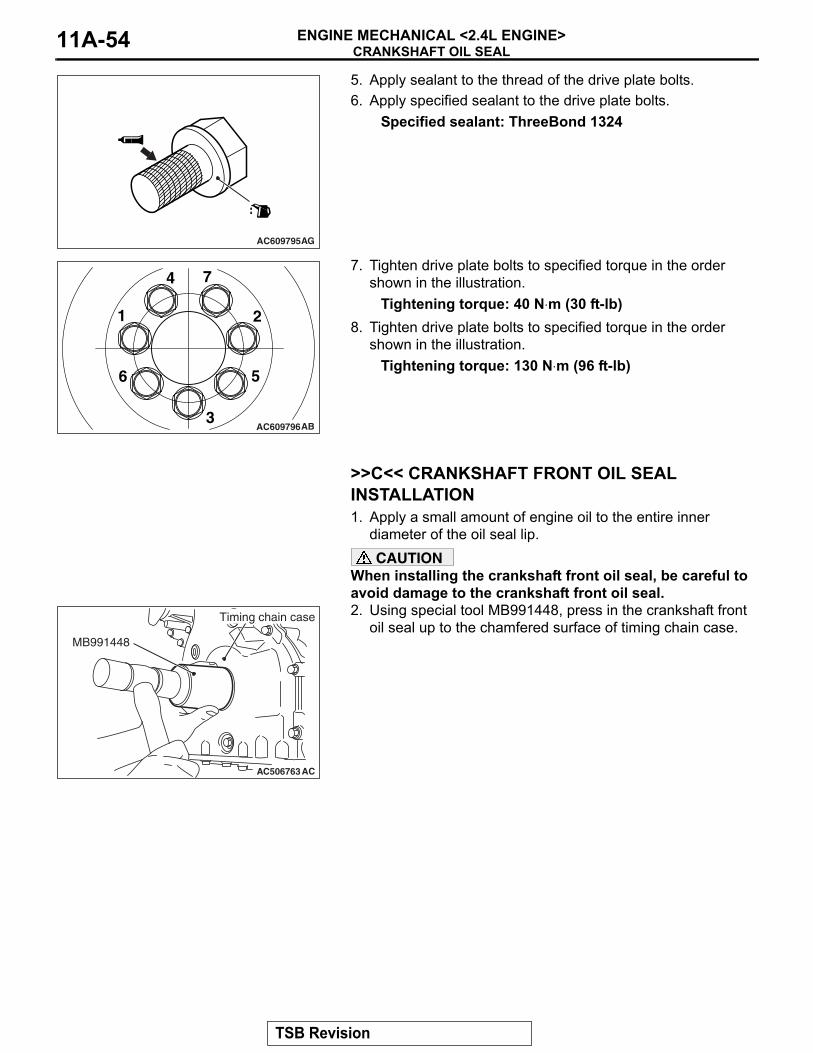
>>A<< CRANKSHAFT REAR OIL SEAL INSTAL-LATION1. Apply a small amount of engine oil to the entire inner
diameter of the oil seal lip.2. Using special tool MD998718, press in the crankshaft rear
oil seal up to the cylinder block assembly end surface.
.
>>B<< DRIVE PLATE/ADAPTER PLATE/DRIVE PLATE BOLTS INSTALLATION1. Remove the sealant, the engine oil, and other adhering
materials from the drive plate and adapter plate installation face, the crankshaft screw hole and drive plate bolts.
2. Install the drive plate and adapter plate to the crankshaft.3. Use special tool MB991883 to secure the drive plate and
adapter plate in the same manner as removal.4. Apply a small amount of engine oil to the screw holes of the
crankshaft and the bearing surface of the drive plate bolts and the adapter plate bolts.
AC506761AD
MB991883
Cylinder block
AC506762 AC
MD998718
Oil seal
Crankshaft
(Engine oil)
AC506761AD
MB991883
Cylinder block
TSB Revision
CRANKSHAFT OIL SEALENGINE MECHANICAL <2.4L ENGINE>11A-54
5. Apply sealant to the thread of the drive plate bolts.6. Apply specified sealant to the drive plate bolts.
Specified sealant: ThreeBond 1324
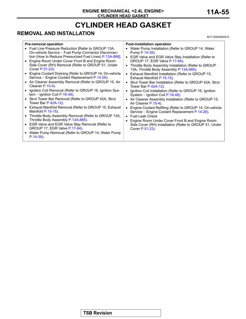
7. Tighten drive plate bolts to specified torque in the order shown in the illustration.
Tightening torque: 40 N⋅m (30 ft-lb)8. Tighten drive plate bolts to specified torque in the order
shown in the illustration.Tightening torque: 130 N⋅m (96 ft-lb)
.
>>C<< CRANKSHAFT FRONT OIL SEAL INSTALLATION1. Apply a small amount of engine oil to the entire inner
diameter of the oil seal lip.CAUTION
When installing the crankshaft front oil seal, be careful to avoid damage to the crankshaft front oil seal.2. Using special tool MB991448, press in the crankshaft front
oil seal up to the chamfered surface of timing chain case.
AC609795AG
AC609796
1 2
3
4
56
7
AB
AC506763AC
MB991448
Timing chain case
TSB Revision
CYLINDER HEAD GASKETENGINE MECHANICAL <2.4L ENGINE> 11A-55
CYLINDER HEAD GASKETREMOVAL AND INSTALLATION
M1112004004914
Pre-removal operation• Fuel Line Pressure Reduction [Refer to GROUP 13A,
On-vehicle Service − Fuel Pump Connector Disconnec-tion (How to Reduce Pressurized Fuel Lines) P.13A-866].
• Engine Room Under Cover Front B and Engine Room Side Cover (RH) Removal (Refer to GROUP 51, Under Cover P.51-23).
• Engine Coolant Draining (Refer to GROUP 14, On-vehicle Service − Engine Coolant Replacement P.14-26).
• Air Cleaner Assembly Removal (Refer to GROUP 15, Air Cleaner P.15-4).
• Ignition Coil Removal (Refer to GROUP 16, Ignition Sys-tem − Ignition Coil P.16-48).
• Strut Tower Bar Removal (Refer to GROUP 42A, Strut Tower Bar P.42A-12).
• Exhaust Manifold Removal (Refer to GROUP 15, Exhaust Manifold P.15-15).
• Throttle Body Assembly Removal (Refer to GROUP 13A, Throttle Body Assembly P.13A-885).
• EGR Valve and EGR Valve Stay Removal (Refer to GROUP 17, EGR Valve P.17-84).
• Water Pump Removal (Refer to GROUP 14, Water Pump P.14-39).
Post-installation operation• Water Pump Installation (Refer to GROUP 14, Water
Pump P.14-39).• EGR Valve and EGR Valve Stay Installation (Refer to
GROUP 17, EGR Valve P.17-84).• Throttle Body Assembly Installation (Refer to GROUP
13A, Throttle Body Assembly P.13A-885).• Exhaust Manifold Installation (Refer to GROUP 15,
Exhaust Manifold P.15-15).• Strut Tower Bar Installation (Refer to GROUP 42A, Strut
Tower Bar P.42A-12).• Ignition Coil Installation (Refer to GROUP 16, Ignition
System − Ignition Coil P.16-48).• Air Cleaner Assembly Installation (Refer to GROUP 15,
Air Cleaner P.15-4).• Engine Coolant Refilling (Refer to GROUP 14, On-vehicle
Service − Engine Coolant Replacement P.14-26).• Fuel Leak Check• Engine Room Under Cover Front B and Engine Room
Side Cover (RH) Installation (Refer to GROUP 51, Under Cover P.51-23).
TSB Revision
CYLINDER HEAD GASKETENGINE MECHANICAL <2.4L ENGINE>11A-56
AC702470
1
1110
8
6N
AG
9N
12
13
14
15
167
24 ± 3 N·m18 ± 2 ft-lb
20 ± 2 N·m15 ± 1 ft-lb
2
3
N
5
4 N
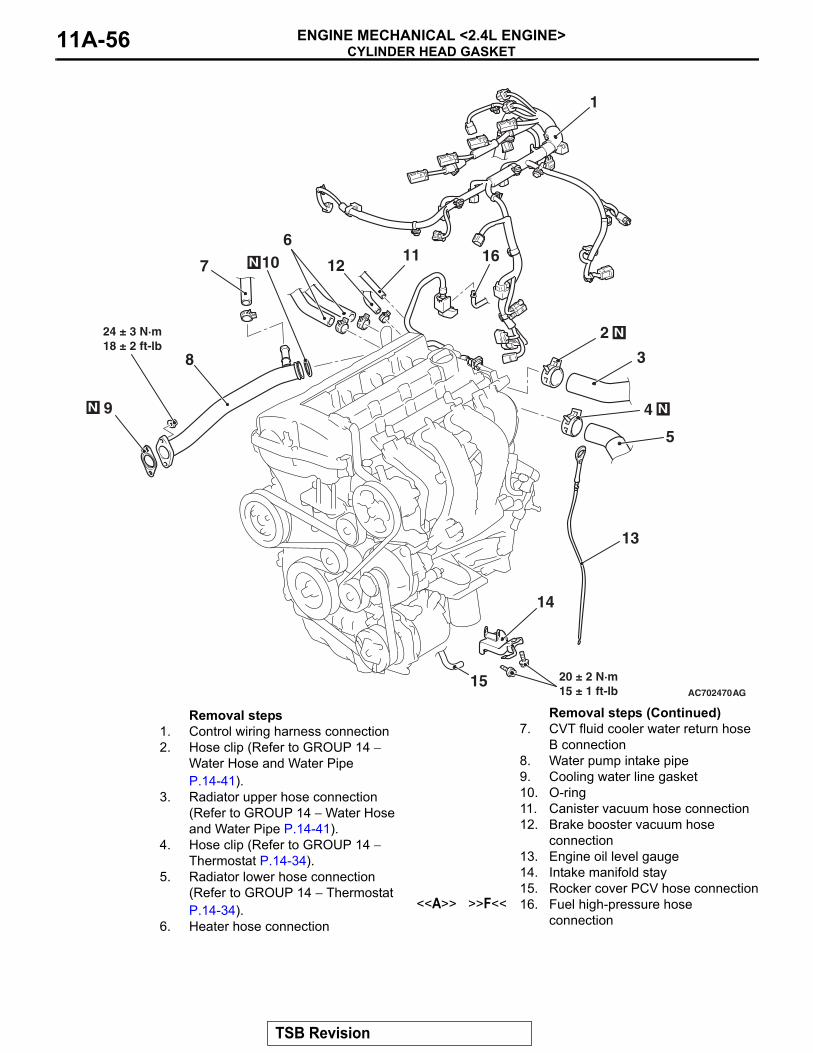
Removal steps 1. Control wiring harness connection2. Hose clip (Refer to GROUP 14 −
Water Hose and Water Pipe P.14-41).
3. Radiator upper hose connection (Refer to GROUP 14 − Water Hose and Water Pipe P.14-41).
4. Hose clip (Refer to GROUP 14 − Thermostat P.14-34).
5. Radiator lower hose connection (Refer to GROUP 14 − Thermostat P.14-34).
6. Heater hose connection
7. CVT fluid cooler water return hose B connection
8. Water pump intake pipe9. Cooling water line gasket10. O-ring11. Canister vacuum hose connection12. Brake booster vacuum hose
connection13. Engine oil level gauge14. Intake manifold stay15. Rocker cover PCV hose connection
<<A>> >>F<< 16. Fuel high-pressure hose connection
Removal steps (Continued)
TSB Revision

CYLINDER HEAD GASKETENGINE MECHANICAL <2.4L ENGINE> 11A-57
Required Special Tools:• MB991895: Engine Hanger • MB991928: Engine Hanger
AC704318AJ
28
25
27
23
N
22
19
17
2021
N
26 N18
24
Apply engine oil to allmoving parts beforeinstallation.
(Engine oil)
(Engine oil)
12 ± 1 N·m107 ± 8 in-lb
17 ± 3 N·m13 ± 2 ft-lb
30 ± 2 N·m22 ± 1 ft-lb
12 ± 1 N·m107 ± 8 in-lb
→
→
<Cold engine>35 ± 2 N·m26 ± 1 ft-lb +90˚ → +90˚
→
<Cold engine>35 ± 2 N·m26 ± 1 ft-lb +90˚ → +90˚
Removal steps • Timing chain (Refer to P.11A-67).
<<B>> >>E<< 17 Front camshaft bearing cap assembly
18. Camshaft bearing<<C>> >>D<< 19. Camshaft bearing oil feeding cap<<C>> >>D<< 20. Camshaft bearing cap<<C>> >>D<< 21. Camshaft bearing cap
<<C>> >>D<< 22. Camshaft thrust bearing cap>>C<< 23. Camshaft and camshaft sprocket
assembly24. Camshaft bearing
<<D>> >>B<< 25. Cylinder head bolt<<D>> >>B<< 26. Cylinder head bolt assembly
>>A<< 27. Cylinder head assembly>>A<< 28. Cylinder head gasket
Removal steps (Continued)
TSB Revision
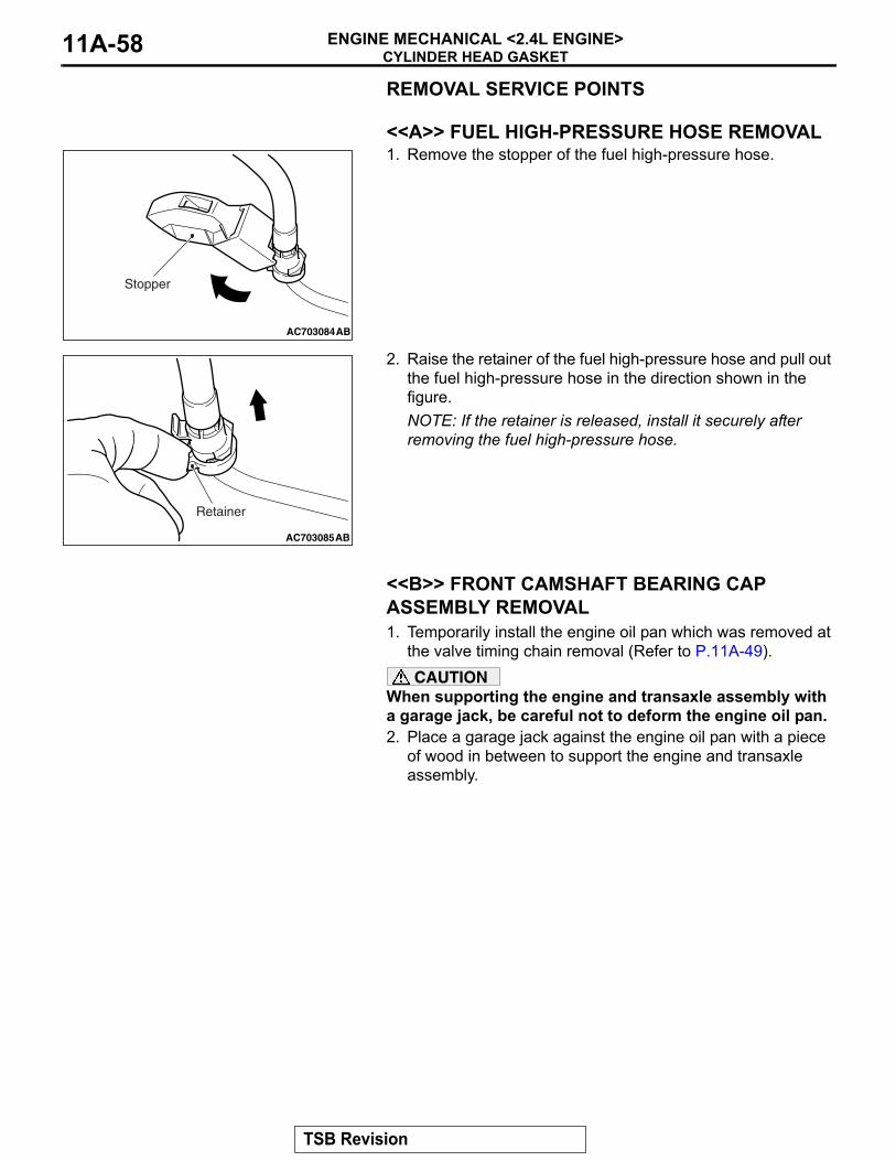
CYLINDER HEAD GASKETENGINE MECHANICAL <2.4L ENGINE>11A-58
REMOVAL SERVICE POINTS.
<<A>> FUEL HIGH-PRESSURE HOSE REMOVAL1. Remove the stopper of the fuel high-pressure hose.
2. Raise the retainer of the fuel high-pressure hose and pull out the fuel high-pressure hose in the direction shown in the figure.NOTE: If the retainer is released, install it securely after removing the fuel high-pressure hose.
.
<<B>> FRONT CAMSHAFT BEARING CAP ASSEMBLY REMOVAL1. Temporarily install the engine oil pan which was removed at
the valve timing chain removal (Refer to P.11A-49).CAUTION
When supporting the engine and transaxle assembly with a garage jack, be careful not to deform the engine oil pan.2. Place a garage jack against the engine oil pan with a piece
of wood in between to support the engine and transaxle assembly.
AC703084
Stopper
AB
AC703085
Retainer
AB
TSB Revision
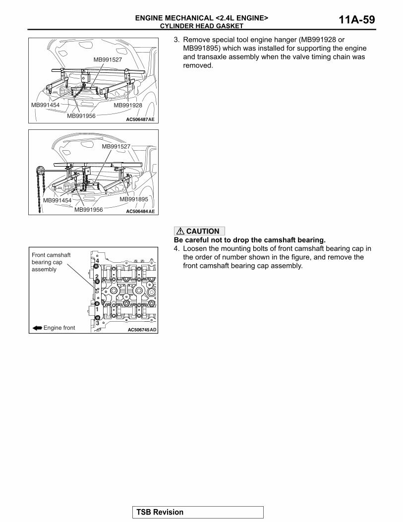
CYLINDER HEAD GASKETENGINE MECHANICAL <2.4L ENGINE> 11A-59
3. Remove special tool engine hanger (MB991928 or MB991895) which was installed for supporting the engine and transaxle assembly when the valve timing chain was removed.
CAUTIONBe careful not to drop the camshaft bearing.4. Loosen the mounting bolts of front camshaft bearing cap in
the order of number shown in the figure, and remove the front camshaft bearing cap assembly.
.
AC506487AE
MB991527
MB991454 MB991928
MB991956
AC506484
MB991527
AE
MB991454
MB991956
MB991895
AC506745AD
1
2
3
4
Engine front
Front camshaftbearing capassembly
TSB Revision
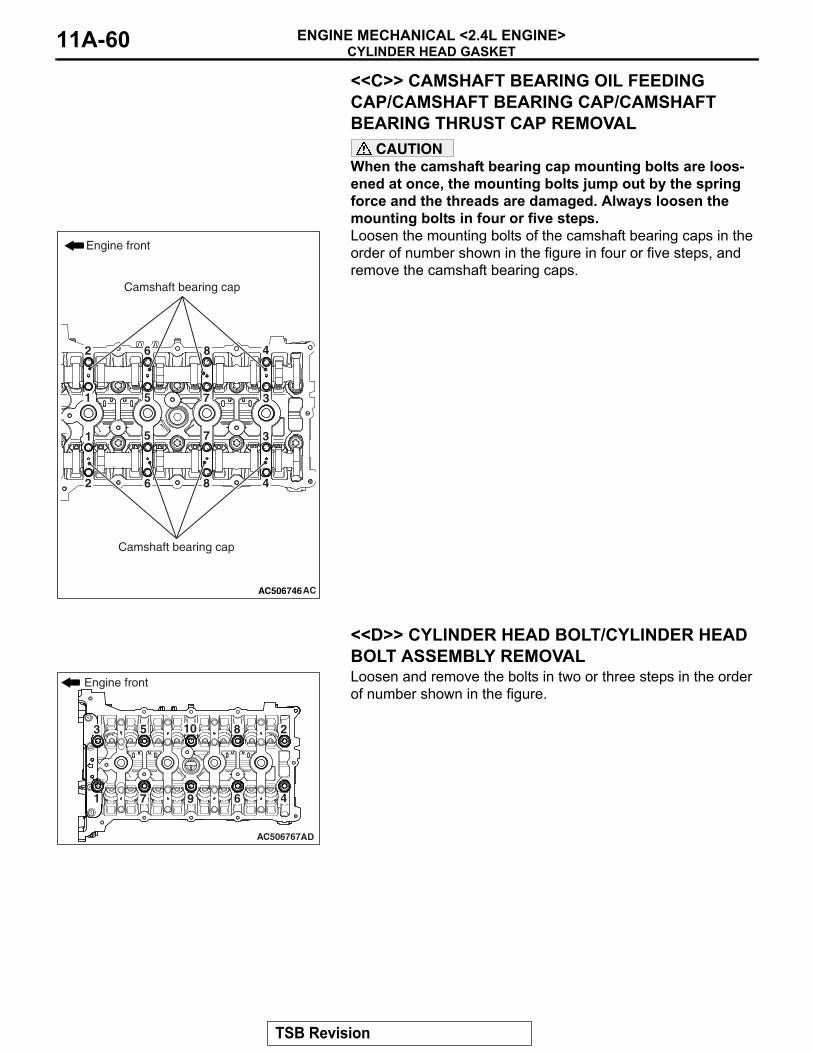
CYLINDER HEAD GASKETENGINE MECHANICAL <2.4L ENGINE>11A-60
<<C>> CAMSHAFT BEARING OIL FEEDING CAP/CAMSHAFT BEARING CAP/CAMSHAFT BEARING THRUST CAP REMOVAL
CAUTIONWhen the camshaft bearing cap mounting bolts are loos-ened at once, the mounting bolts jump out by the spring force and the threads are damaged. Always loosen the mounting bolts in four or five steps.Loosen the mounting bolts of the camshaft bearing caps in the order of number shown in the figure in four or five steps, and remove the camshaft bearing caps.
.
<<D>> CYLINDER HEAD BOLT/CYLINDER HEAD BOLT ASSEMBLY REMOVALLoosen and remove the bolts in two or three steps in the order of number shown in the figure.
AC506746AC
1
1
2
2
3
3
4
4
5
5
6
6
7
7
8
8
Engine front
Camshaft bearing cap
Camshaft bearing cap
AC506767AD
1
23
4
5
67
8
9
10
Engine front
TSB Revision
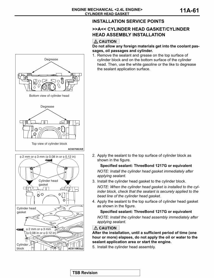
CYLINDER HEAD GASKETENGINE MECHANICAL <2.4L ENGINE> 11A-61
INSTALLATION SERVICE POINTS.
>>A<< CYLINDER HEAD GASKET/CYLINDER HEAD ASSEMBLY INSTALLATION
CAUTIONDo not allow any foreign materials get into the coolant pas-sages, oil passages and cylinder.1. Remove the sealant and grease on the top surface of
cylinder block and on the bottom surface of the cylinder head. Then, use the white gasoline or the like to degrease the sealant application surface.
2. Apply the sealant to the top surface of cylinder block as shown in the figure.
Specified sealant: ThreeBond 1217G or equivalentNOTE: Install the cylinder head gasket immediately after applying sealant.
3. Install the cylinder head gasket to the cylinder block.NOTE: When the cylinder head gasket is installed to the cyl-inder block, check that the sealant is securely applied to the bead line of the cylinder head gasket.
4. Apply the sealant to the top surface of cylinder head gasket as shown in the figure.
Specified sealant: ThreeBond 1217G or equivalentNOTE: Install the cylinder head assembly immediately after applying sealant.CAUTION
After the installation, until a sufficient period of time (one hour or more) elapses, do not apply the oil or water to the sealant application area or start the engine.5. Install the cylinder head assembly.
.
AC607682AB
Degrease
Degrease
Bottom view of cylinder head
Top view of cylinder block
AC511063AD
φ 2 mm or φ 3 mm (φ 0.08 in or φ 0.12 in)
Cylinder headgasket
Cylinder head gasket
Cylinder block
φ 2 mm or φ 3 mm(φ 0.08 in or φ 0.12 in)
TSB Revision
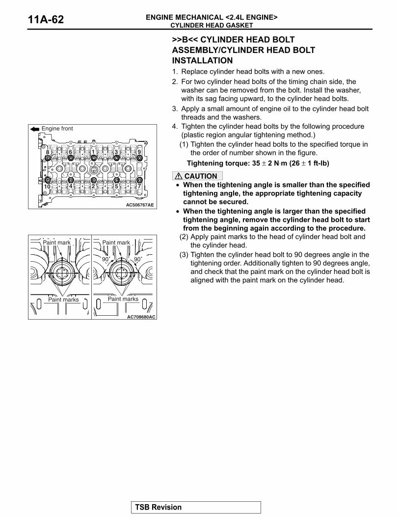
CYLINDER HEAD GASKETENGINE MECHANICAL <2.4L ENGINE>11A-62
>>B<< CYLINDER HEAD BOLT ASSEMBLY/CYLINDER HEAD BOLT INSTALLATION1. Replace cylinder head bolts with a new ones.2. For two cylinder head bolts of the timing chain side, the
washer can be removed from the bolt. Install the washer, with its sag facing upward, to the cylinder head bolts.
3. Apply a small amount of engine oil to the cylinder head bolt threads and the washers.
4. Tighten the cylinder head bolts by the following procedure (plastic region angular tightening method.)(1) Tighten the cylinder head bolts to the specified torque in
the order of number shown in the figure.Tightening torque: 35 ± 2 N⋅m (26 ± 1 ft-lb)
CAUTION• When the tightening angle is smaller than the specified
tightening angle, the appropriate tightening capacity cannot be secured.
• When the tightening angle is larger than the specified tightening angle, remove the cylinder head bolt to start from the beginning again according to the procedure.
(2) Apply paint marks to the head of cylinder head bolt and the cylinder head.
(3) Tighten the cylinder head bolt to 90 degrees angle in the tightening order. Additionally tighten to 90 degrees angle, and check that the paint mark on the cylinder head bolt is aligned with the paint mark on the cylinder head.
AC506767AE
1
2
3
4 5
6
7
8 9
10
Engine front
AC708680AC
90˚90˚
Paint markPaint mark
Paint marks Paint marks
TSB Revision
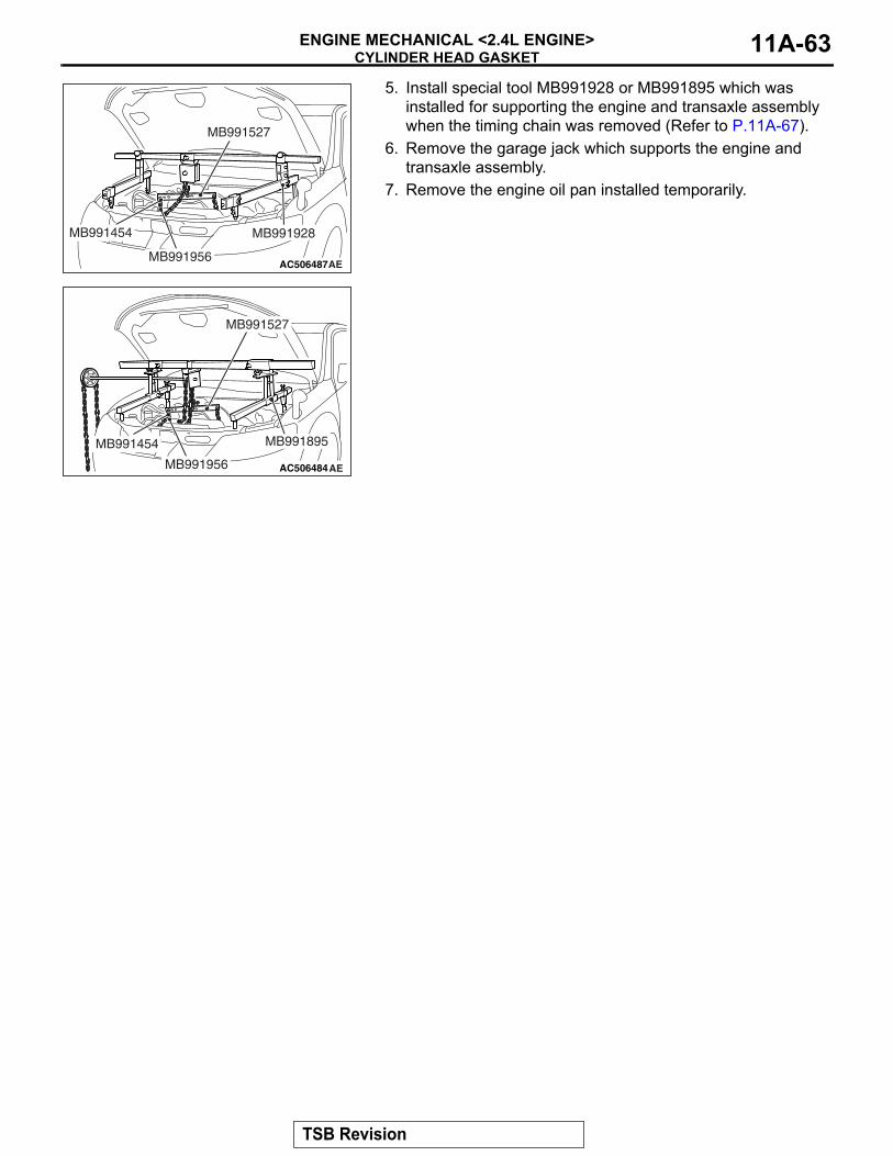
CYLINDER HEAD GASKETENGINE MECHANICAL <2.4L ENGINE> 11A-63
5. Install special tool MB991928 or MB991895 which was installed for supporting the engine and transaxle assembly when the timing chain was removed (Refer to P.11A-67).
6. Remove the garage jack which supports the engine and transaxle assembly.
7. Remove the engine oil pan installed temporarily.
.
AC506487AE
MB991527
MB991454 MB991928
MB991956
AC506484
MB991527
AE
MB991454
MB991956
MB991895
TSB Revision
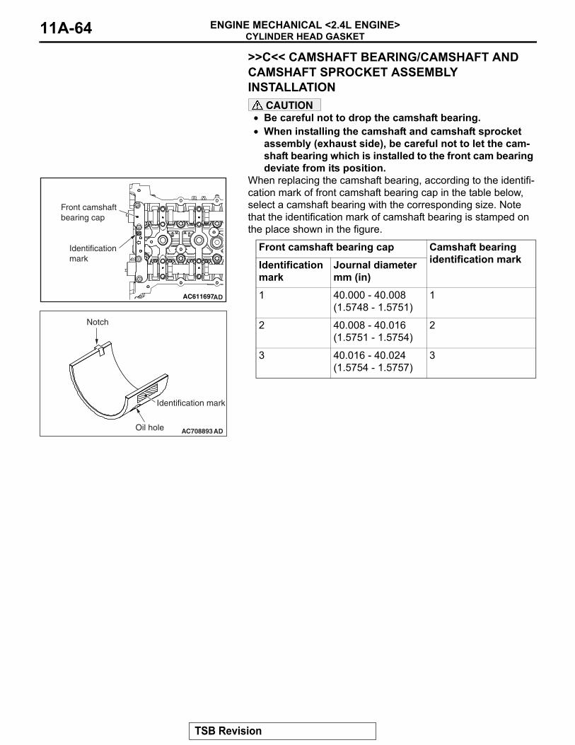
CYLINDER HEAD GASKETENGINE MECHANICAL <2.4L ENGINE>11A-64
>>C<< CAMSHAFT BEARING/CAMSHAFT AND CAMSHAFT SPROCKET ASSEMBLY INSTALLATION
CAUTION• Be careful not to drop the camshaft bearing.• When installing the camshaft and camshaft sprocket
assembly (exhaust side), be careful not to let the cam-shaft bearing which is installed to the front cam bearing deviate from its position.
When replacing the camshaft bearing, according to the identifi-cation mark of front camshaft bearing cap in the table below, select a camshaft bearing with the corresponding size. Note that the identification mark of camshaft bearing is stamped on the place shown in the figure.
.
Front camshaft bearing cap Camshaft bearing identification markIdentification
markJournal diameter mm (in)
1 40.000 - 40.008 (1.5748 - 1.5751)
1
2 40.008 - 40.016 (1.5751 - 1.5754)
2
3 40.016 - 40.024 (1.5754 - 1.5757)
3
AC611697AD
Front camshaft bearing cap
Identificationmark
AC708893
Notch
Identification mark
Oil hole AD
TSB Revision
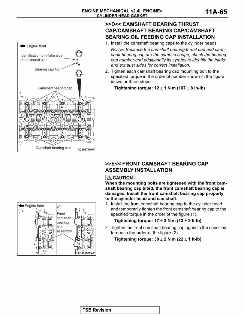
CYLINDER HEAD GASKETENGINE MECHANICAL <2.4L ENGINE> 11A-65
>>D<< CAMSHAFT BEARING THRUST CAP/CAMSHAFT BEARING CAP/CAMSHAFT BEARING OIL FEEDING CAP INSTALLATION1. Install the camshaft bearing caps to the cylinder heads.
NOTE: Because the camshaft bearing thrust cap and cam-shaft bearing cap are the same in shape, check the bearing cap number and additionally its symbol to identify the intake and exhaust sides for correct installation.
2. Tighten each camshaft bearing cap mounting bolt to the specified torque in the order of number shown in the figure in two or three steps.
Tightening torque: 12 ± 1 N⋅m (107 ± 8 in-lb)
.
>>E<< FRONT CAMSHAFT BEARING CAP ASSEMBLY INSTALLATION
CAUTIONWhen the mounting bolts are tightened with the front cam-shaft bearing cap tilted, the front camshaft bearing cap is damaged. Install the front camshaft bearing cap properly to the cylinder head and camshaft.1. Install the front camshaft bearing cap to the cylinder head,
and temporarily tighten the front camshaft bearing cap to the specified torque in the order of the figure (1).
Tightening torque: 17 ± 3 N⋅m (13 ± 2 ft-lb)2. Tighten the front camshaft bearing cap again to the specified
torque in the order of the figure (2).Tightening torque: 30 ± 2 N⋅m (22 ± 1 ft-lb)
.
AC506778AC
8
8
7
7
6
6
5
5
4
4
3
3
2
2
1
1
E 5
Engine front
Camshaft bearing cap
Camshaft bearing cap
Bearing cap No.
Identification of intake side and exhaust side
AC511062AC
4
3
2
1
4
3
2
1
(1)(2)Engine front
Front camshaftbearingcapassembly
TSB Revision
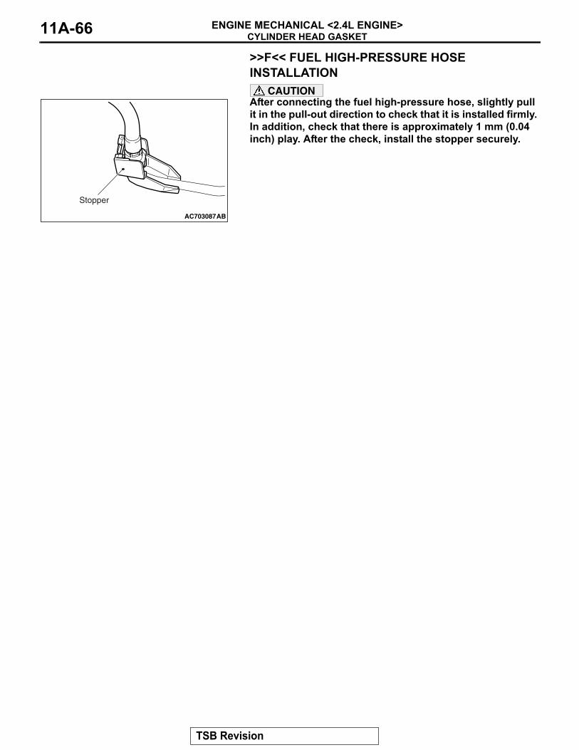
CYLINDER HEAD GASKETENGINE MECHANICAL <2.4L ENGINE>11A-66
>>F<< FUEL HIGH-PRESSURE HOSE INSTALLATION
CAUTIONAfter connecting the fuel high-pressure hose, slightly pull it in the pull-out direction to check that it is installed firmly. In addition, check that there is approximately 1 mm (0.04 inch) play. After the check, install the stopper securely.
AC703087
Stopper
AB
TSB Revision
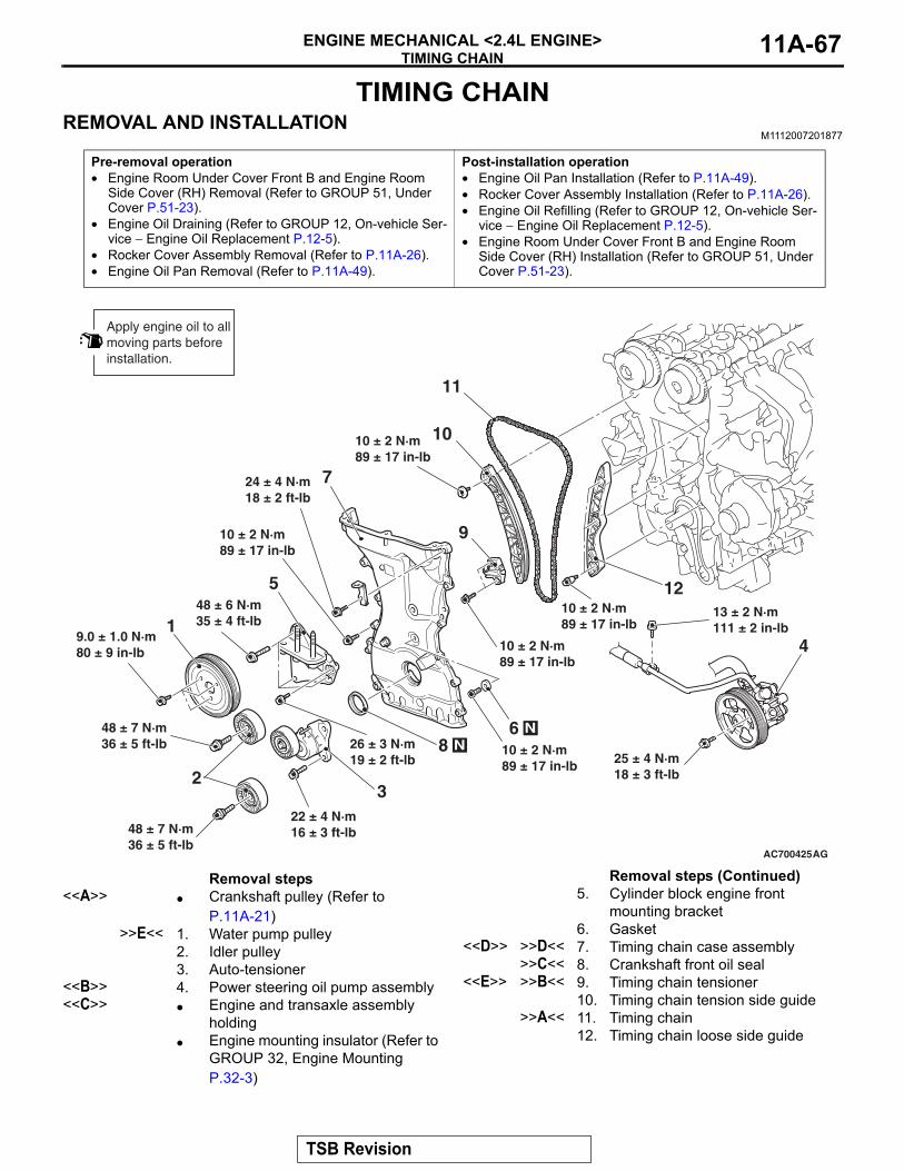
TIMING CHAINENGINE MECHANICAL <2.4L ENGINE> 11A-67
TIMING CHAINREMOVAL AND INSTALLATION
M1112007201877
Pre-removal operation• Engine Room Under Cover Front B and Engine Room
Side Cover (RH) Removal (Refer to GROUP 51, Under Cover P.51-23).
• Engine Oil Draining (Refer to GROUP 12, On-vehicle Ser-vice − Engine Oil Replacement P.12-5).
• Rocker Cover Assembly Removal (Refer to P.11A-26).• Engine Oil Pan Removal (Refer to P.11A-49).
Post-installation operation• Engine Oil Pan Installation (Refer to P.11A-49).• Rocker Cover Assembly Installation (Refer to P.11A-26).• Engine Oil Refilling (Refer to GROUP 12, On-vehicle Ser-
vice − Engine Oil Replacement P.12-5).• Engine Room Under Cover Front B and Engine Room
Side Cover (RH) Installation (Refer to GROUP 51, Under Cover P.51-23).
AC700425AG
1
23
5
7
9
10
11
12
6 N
Apply engine oil to allmoving parts beforeinstallation.
4
8 N
24 ± 4 N·m18 ± 2 ft-lb
48 ± 6 N·m35 ± 4 ft-lb
48 ± 7 N·m36 ± 5 ft-lb
22 ± 4 N·m16 ± 3 ft-lb
9.0 ± 1.0 N·m80 ± 9 in-lb
26 ± 3 N·m19 ± 2 ft-lb
10 ± 2 N·m89 ± 17 in-lb
48 ± 7 N·m36 ± 5 ft-lb
10 ± 2 N·m89 ± 17 in-lb
10 ± 2 N·m89 ± 17 in-lb
10 ± 2 N·m89 ± 17 in-lb
10 ± 2 N·m89 ± 17 in-lb 25 ± 4 N·m
18 ± 3 ft-lb
13 ± 2 N·m111 ± 2 in-lb
Removal steps <<A>> • Crankshaft pulley (Refer to
P.11A-21)>>E<< 1. Water pump pulley
2. Idler pulley3. Auto-tensioner
<<B>> 4. Power steering oil pump assembly<<C>> • Engine and transaxle assembly
holding• Engine mounting insulator (Refer to
GROUP 32, Engine Mounting P.32-3)
5. Cylinder block engine front mounting bracket
6. Gasket<<D>> >>D<< 7. Timing chain case assembly
>>C<< 8. Crankshaft front oil seal<<E>> >>B<< 9. Timing chain tensioner
10. Timing chain tension side guide>>A<< 11. Timing chain
12. Timing chain loose side guide
Removal steps (Continued)
TSB Revision
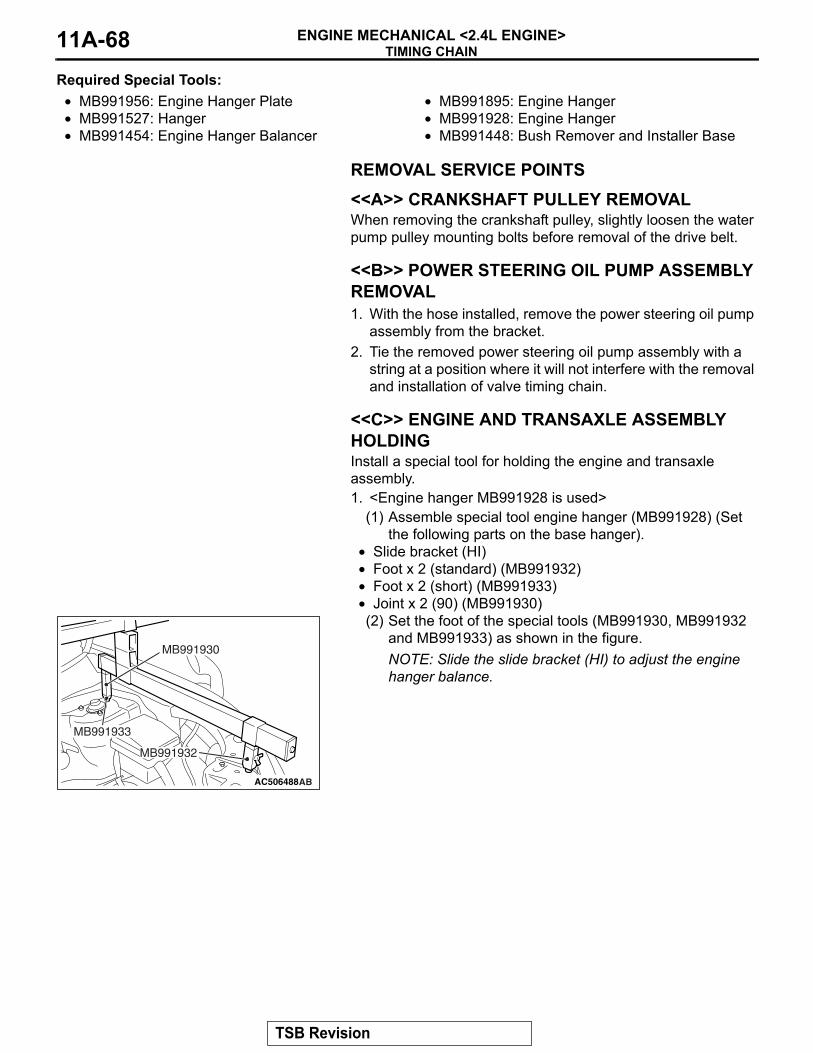
TIMING CHAINENGINE MECHANICAL <2.4L ENGINE>11A-68
Required Special Tools:• MB991956: Engine Hanger Plate• MB991527: Hanger• MB991454: Engine Hanger Balancer
• MB991895: Engine Hanger• MB991928: Engine Hanger• MB991448: Bush Remover and Installer Base
REMOVAL SERVICE POINTS.
<<A>> CRANKSHAFT PULLEY REMOVALWhen removing the crankshaft pulley, slightly loosen the water pump pulley mounting bolts before removal of the drive belt..
<<B>> POWER STEERING OIL PUMP ASSEMBLY REMOVAL1. With the hose installed, remove the power steering oil pump
assembly from the bracket.2. Tie the removed power steering oil pump assembly with a
string at a position where it will not interfere with the removal and installation of valve timing chain.
.
<<C>> ENGINE AND TRANSAXLE ASSEMBLY HOLDINGInstall a special tool for holding the engine and transaxle assembly.1. <Engine hanger MB991928 is used>
(1) Assemble special tool engine hanger (MB991928) (Set the following parts on the base hanger).
• Slide bracket (HI)• Foot x 2 (standard) (MB991932)• Foot x 2 (short) (MB991933)• Joint x 2 (90) (MB991930)(2) Set the foot of the special tools (MB991930, MB991932
and MB991933) as shown in the figure.NOTE: Slide the slide bracket (HI) to adjust the engine hanger balance.
AC506488AB
MB991930
MB991932
MB991933
TSB Revision
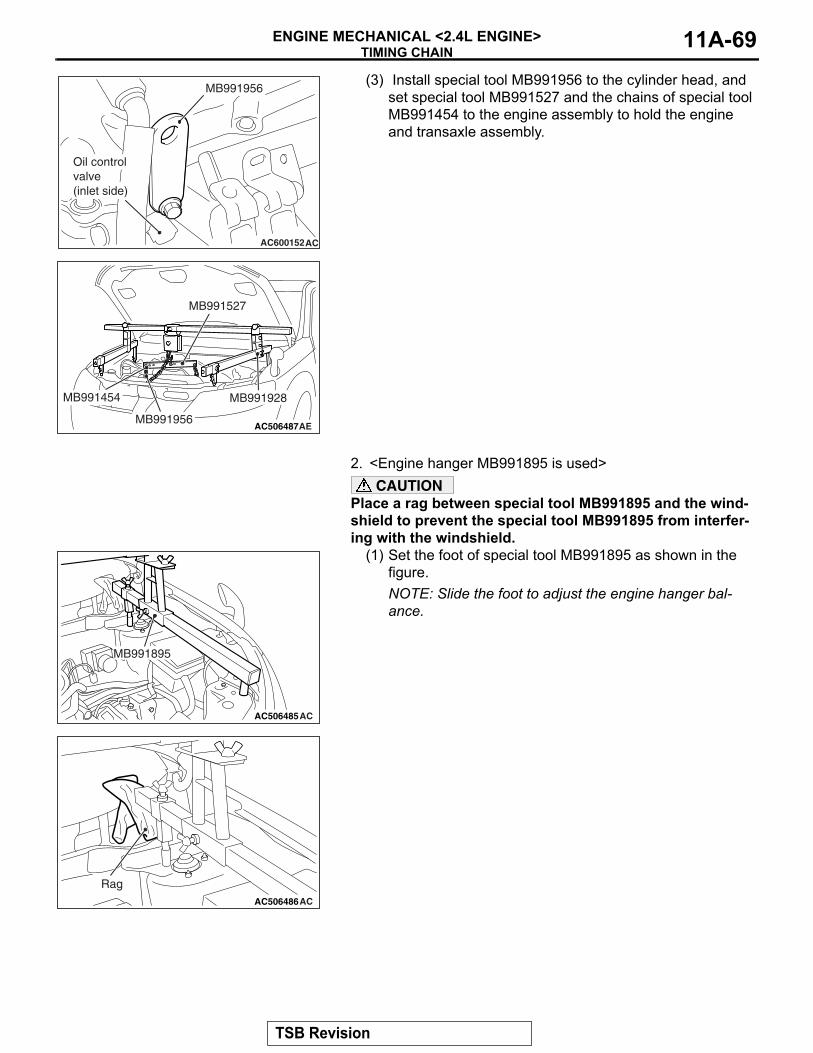
TIMING CHAINENGINE MECHANICAL <2.4L ENGINE> 11A-69
(3) Install special tool MB991956 to the cylinder head, and set special tool MB991527 and the chains of special tool MB991454 to the engine assembly to hold the engine and transaxle assembly.
2. <Engine hanger MB991895 is used>CAUTION
Place a rag between special tool MB991895 and the wind-shield to prevent the special tool MB991895 from interfer-ing with the windshield.
(1) Set the foot of special tool MB991895 as shown in the figure.NOTE: Slide the foot to adjust the engine hanger bal-ance.
AC600152AC
MB991956
Oil control valve (inlet side)
AC506487AE
MB991527
MB991454 MB991928
MB991956
AC506485AC
MB991895
AC506486AC
Rag
TSB Revision
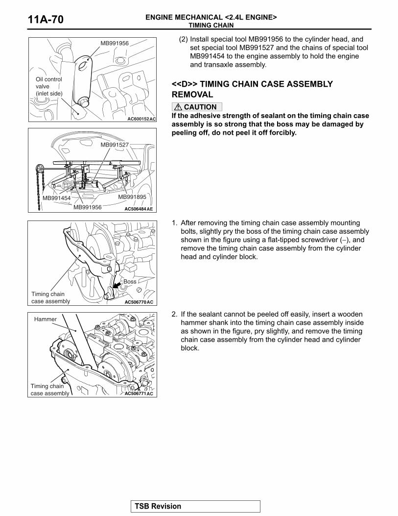
TIMING CHAINENGINE MECHANICAL <2.4L ENGINE>11A-70
(2) Install special tool MB991956 to the cylinder head, and set special tool MB991527 and the chains of special tool MB991454 to the engine assembly to hold the engine and transaxle assembly.
.
<<D>> TIMING CHAIN CASE ASSEMBLY REMOVAL
CAUTIONIf the adhesive strength of sealant on the timing chain case assembly is so strong that the boss may be damaged by peeling off, do not peel it off forcibly.
1. After removing the timing chain case assembly mounting bolts, slightly pry the boss of the timing chain case assembly shown in the figure using a flat-tipped screwdriver (−), and remove the timing chain case assembly from the cylinder head and cylinder block.
2. If the sealant cannot be peeled off easily, insert a wooden hammer shank into the timing chain case assembly inside as shown in the figure, pry slightly, and remove the timing chain case assembly from the cylinder head and cylinder block.
.
AC600152AC
MB991956
Oil control valve (inlet side)
AC506484
MB991527
AE
MB991454
MB991956
MB991895
AC506770AC
Boss
Timing chaincase assembly
AC506771AC
Hammer
Timing chaincase assembly
TSB Revision
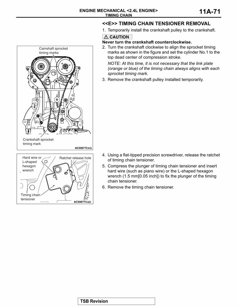
TIMING CHAINENGINE MECHANICAL <2.4L ENGINE> 11A-71
<<E>> TIMING CHAIN TENSIONER REMOVAL1. Temporarily install the crankshaft pulley to the crankshaft.
CAUTIONNever turn the crankshaft counterclockwise.2. Turn the crankshaft clockwise to align the sprocket timing
marks as shown in the figure and set the cylinder No.1 to the top dead center of compression stroke.NOTE: At this time, it is not necessary that the link plate (orange or blue) of the timing chain always aligns with each sprocket timing mark.
3. Remove the crankshaft pulley installed temporarily.
4. Using a flat-tipped precision screwdriver, release the ratchet of timing chain tensioner.
5. Compress the plunger of timing chain tensioner and insert hard wire (such as piano wire) or the L-shaped hexagon wrench (1.5 mm[0.05 inch]) to fix the plunger of the timing chain tensioner.
6. Remove the timing chain tensioner.
AC506772AG
Camshaft sprockettiming marks
Crankshaft sprockettiming mark
AC506773 AD
Timing chain tensioner
Ratchet release holeHard wire or L-shaped hexagon wrench
TSB Revision
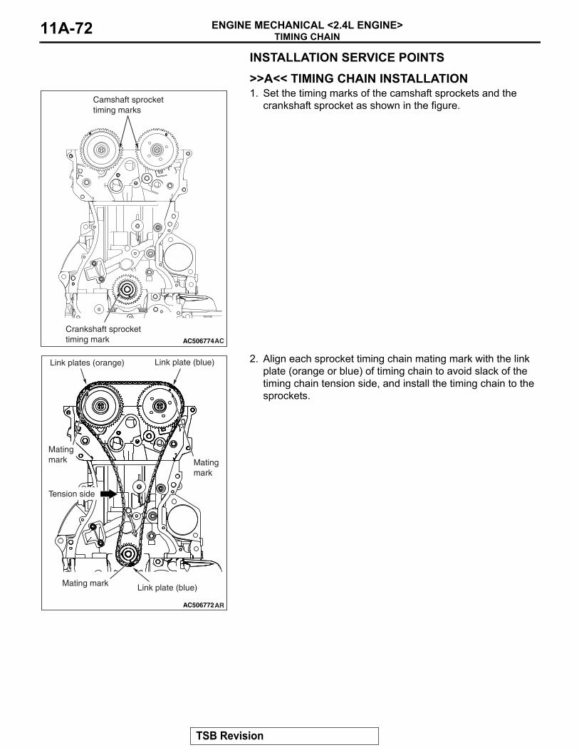
TIMING CHAINENGINE MECHANICAL <2.4L ENGINE>11A-72
INSTALLATION SERVICE POINTS.
>>A<< TIMING CHAIN INSTALLATION1. Set the timing marks of the camshaft sprockets and the
crankshaft sprocket as shown in the figure.
2. Align each sprocket timing chain mating mark with the link plate (orange or blue) of timing chain to avoid slack of the timing chain tension side, and install the timing chain to the sprockets.
.
AC506774AC
Camshaft sprockettiming marks
Crankshaft sprockettiming mark
AC506772AR
Tension side
Link plates (orange)
Link plate (blue)
Mating mark Mating
mark
Mating mark
Link plate (blue)
TSB Revision
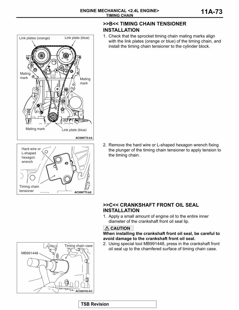
TIMING CHAINENGINE MECHANICAL <2.4L ENGINE> 11A-73
>>B<< TIMING CHAIN TENSIONER INSTALLATION1. Check that the sprocket timing chain mating marks align
with the link plates (orange or blue) of the timing chain, and install the timing chain tensioner to the cylinder block.
2. Remove the hard wire or L-shaped hexagon wrench fixing the plunger of the timing chain tensioner to apply tension to the timing chain.
.
>>C<< CRANKSHAFT FRONT OIL SEAL INSTALLATION1. Apply a small amount of engine oil to the entire inner
diameter of the crankshaft front oil seal lip.CAUTION
When installing the crankshaft front oil seal, be careful to avoid damage to the crankshaft front oil seal.2. Using special tool MB991448, press in the crankshaft front
oil seal up to the chamfered surface of timing chain case.
AC506772AS
Link plates (orange)
Link plate (blue)
Mating mark Mating
mark
Mating mark
Link plate (blue)
AC506773AE
Timing chain tensioner
Hard wire or L-shaped hexagon wrench
AC506763AC
MB991448
Timing chain case
TSB Revision
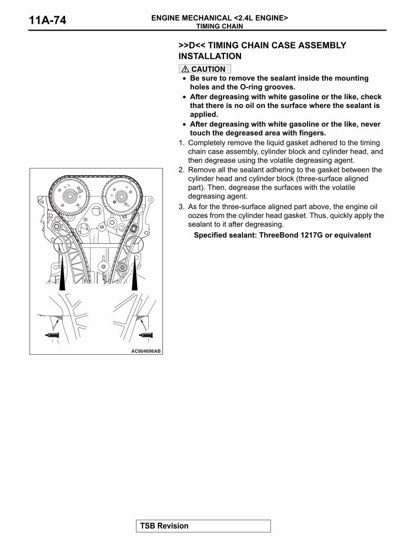
TIMING CHAINENGINE MECHANICAL <2.4L ENGINE>11A-74
.
>>D<< TIMING CHAIN CASE ASSEMBLY INSTALLATION
CAUTION• Be sure to remove the sealant inside the mounting
holes and the O-ring grooves.• After degreasing with white gasoline or the like, check
that there is no oil on the surface where the sealant is applied.
• After degreasing with white gasoline or the like, never touch the degreased area with fingers.
1. Completely remove the liquid gasket adhered to the timing chain case assembly, cylinder block and cylinder head, and then degrease using the volatile degreasing agent.
2. Remove all the sealant adhering to the gasket between the cylinder head and cylinder block (three-surface aligned part). Then, degrease the surfaces with the volatile degreasing agent.
3. As for the three-surface aligned part above, the engine oil oozes from the cylinder head gasket. Thus, quickly apply the sealant to it after degreasing.
Specified sealant: ThreeBond 1217G or equivalent
AC904698AB
TSB Revision
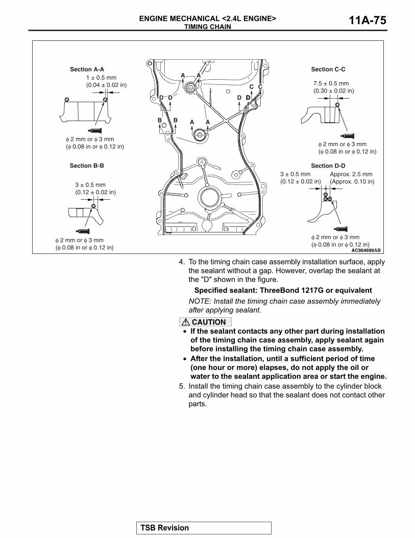
TIMING CHAINENGINE MECHANICAL <2.4L ENGINE> 11A-75
4. To the timing chain case assembly installation surface, apply the sealant without a gap. However, overlap the sealant at the "D" shown in the figure.
Specified sealant: ThreeBond 1217G or equivalentNOTE: Install the timing chain case assembly immediately after applying sealant.CAUTION
• If the sealant contacts any other part during installation of the timing chain case assembly, apply sealant again before installing the timing chain case assembly.
• After the installation, until a sufficient period of time (one hour or more) elapses, do not apply the oil or water to the sealant application area or start the engine.
5. Install the timing chain case assembly to the cylinder block and cylinder head so that the sealant does not contact other parts.
AC904699
A A
A A
B B
C C
D DD DD DD D
AB
φ 2 mm or φ 3 mm(φ 0.08 in or φ 0.12 in)
φ 2 mm or φ 3 mm(φ 0.08 in or φ 0.12 in)
φ 2 mm or φ 3 mm(φ 0.08 in or φ 0.12 in)
φ 2 mm or φ 3 mm(φ 0.08 in or φ 0.12 in)
Section A-A
Section B-B
Section C-C
Section D-DApprox. 2.5 mm(Approx. 0.10 in)
3 ± 0.5 mm(0.12 ± 0.02 in)
7.5 ± 0.5 mm(0.30 ± 0.02 in)
1 ± 0.5 mm(0.04 ± 0.02 in)
3 ± 0.5 mm(0.12 ± 0.02 in)
TSB Revision
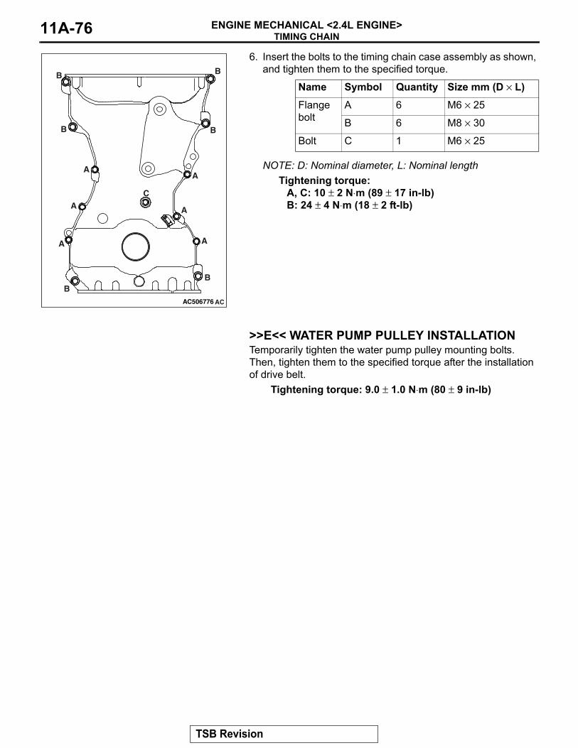
TIMING CHAINENGINE MECHANICAL <2.4L ENGINE>11A-76
6. Insert the bolts to the timing chain case assembly as shown, and tighten them to the specified torque.
NOTE: D: Nominal diameter, L: Nominal lengthTightening torque:
A, C: 10 ± 2 N⋅m (89 ± 17 in-lb)B: 24 ± 4 N⋅m (18 ± 2 ft-lb)
.
>>E<< WATER PUMP PULLEY INSTALLATIONTemporarily tighten the water pump pulley mounting bolts. Then, tighten them to the specified torque after the installation of drive belt.
Tightening torque: 9.0 ± 1.0 N⋅m (80 ± 9 in-lb)
Name Symbol Quantity Size mm (D × L)Flange bolt
A 6 M6 × 25
B 6 M8 × 30
Bolt C 1 M6 × 25
AC506776 AC
A
A
A
A
AA
BB
B
BB
B
C
TSB Revision
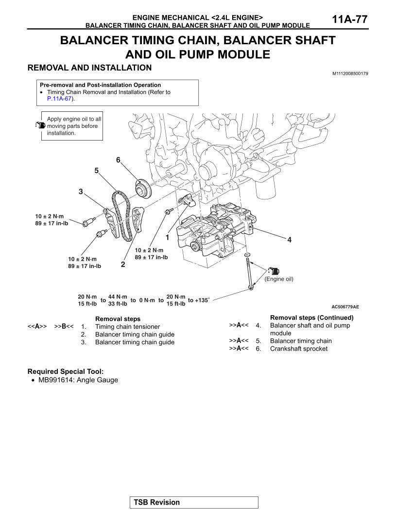
BALANCER TIMING CHAIN, BALANCER SHAFT AND OIL PUMP MODULEENGINE MECHANICAL <2.4L ENGINE> 11A-77
BALANCER TIMING CHAIN, BALANCER SHAFT AND OIL PUMP MODULE
REMOVAL AND INSTALLATIONM1112008500179
Required Special Tool:• MB991614: Angle Gauge
Pre-removal and Post-installation Operation• Timing Chain Removal and Installation (Refer to
P.11A-67).
AC506779
20 N·m15 ft-lb
44 N·m33 ft-lb
to 0 N·mto to20 N·m15 ft-lb
to +135˚AE
1
5
4
3
2
10 ± 2 N·m89 ± 17 in-lb
6
Apply engine oil to allmoving parts beforeinstallation.
(Engine oil)
10 ± 2 N·m89 ± 17 in-lb
10 ± 2 N·m89 ± 17 in-lb
Removal steps <<A>> >>B<< 1. Timing chain tensioner
2. Balancer timing chain guide3. Balancer timing chain guide
>>A<< 4. Balancer shaft and oil pump module
>>A<< 5. Balancer timing chain>>A<< 6. Crankshaft sprocket
Removal steps (Continued)
TSB Revision
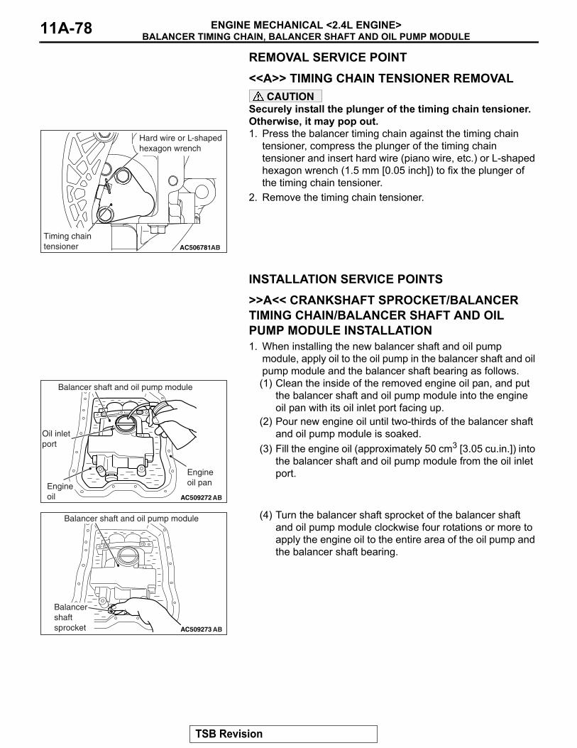
BALANCER TIMING CHAIN, BALANCER SHAFT AND OIL PUMP MODULEENGINE MECHANICAL <2.4L ENGINE>11A-78
REMOVAL SERVICE POINT.
<<A>> TIMING CHAIN TENSIONER REMOVALCAUTION
Securely install the plunger of the timing chain tensioner. Otherwise, it may pop out. 1. Press the balancer timing chain against the timing chain
tensioner, compress the plunger of the timing chain tensioner and insert hard wire (piano wire, etc.) or L-shaped hexagon wrench (1.5 mm [0.05 inch]) to fix the plunger of the timing chain tensioner.
2. Remove the timing chain tensioner.
INSTALLATION SERVICE POINTS.
>>A<< CRANKSHAFT SPROCKET/BALANCER TIMING CHAIN/BALANCER SHAFT AND OIL PUMP MODULE INSTALLATION1. When installing the new balancer shaft and oil pump
module, apply oil to the oil pump in the balancer shaft and oil pump module and the balancer shaft bearing as follows.(1) Clean the inside of the removed engine oil pan, and put
the balancer shaft and oil pump module into the engine oil pan with its oil inlet port facing up.
(2) Pour new engine oil until two-thirds of the balancer shaft and oil pump module is soaked.
(3) Fill the engine oil (approximately 50 cm3 [3.05 cu.in.]) into the balancer shaft and oil pump module from the oil inlet port.
(4) Turn the balancer shaft sprocket of the balancer shaft and oil pump module clockwise four rotations or more to apply the engine oil to the entire area of the oil pump and the balancer shaft bearing.
AC506781AB
Timing chain tensioner
Hard wire or L-shaped hexagon wrench
AC509272 AB
Oil inletport
Engineoil
Engineoil pan
Balancer shaft and oil pump module
AC509273 AB
Balancershaft sprocket
Balancer shaft and oil pump module
TSB Revision
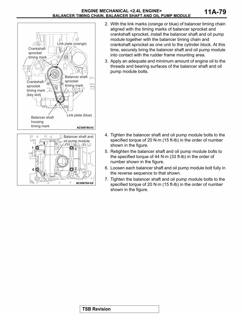
BALANCER TIMING CHAIN, BALANCER SHAFT AND OIL PUMP MODULEENGINE MECHANICAL <2.4L ENGINE> 11A-79
2. With the link marks (orange or blue) of balancer timing chain aligned with the timing marks of balancer sprocket and crankshaft sprocket, install the balancer shaft and oil pump module together with the balancer timing chain and crankshaft sprocket as one unit to the cylinder block. At this time, securely bring the balancer shaft and oil pump module into contact with the rudder frame mounting area.
3. Apply an adequate and minimum amount of engine oil to the threads and bearing surfaces of the balancer shaft and oil pump module bolts.
4. Tighten the balancer shaft and oil pump module bolts to the specified torque of 20 N⋅m (15 ft-lb) in the order of number shown in the figure.
5. Retighten the balancer shaft and oil pump module bolts to the specified torque of 44 N⋅m (33 ft-lb) in the order of number shown in the figure.
6. Loosen each balancer shaft and oil pump module bolt fully in the reverse sequence to that shown.
7. Tighten the balancer shaft and oil pump module bolts to the specified torque of 20 N⋅m (15 ft-lb) in the order of number shown in the figure.
AC506780AE
Balancer shaft sprockettiming mark
Crankshaft sprockettiming mark(key slot)
Crankshaft sprockettiming mark
Link plate (orange)
Link plate (blue)Balancer shaft housing timing mark
AC506784AB
1
2
3
4
Balancer shaft andoil pump module
TSB Revision
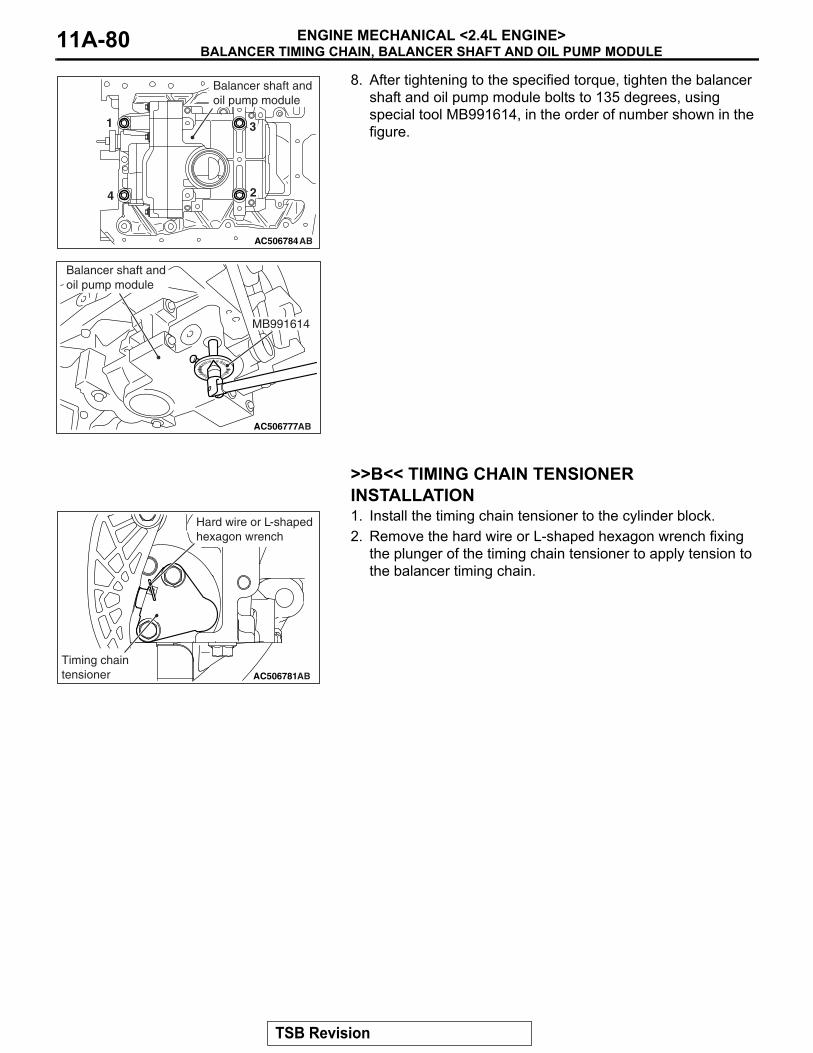
BALANCER TIMING CHAIN, BALANCER SHAFT AND OIL PUMP MODULEENGINE MECHANICAL <2.4L ENGINE>11A-80
8. After tightening to the specified torque, tighten the balancer shaft and oil pump module bolts to 135 degrees, using special tool MB991614, in the order of number shown in the figure.
.
>>B<< TIMING CHAIN TENSIONER INSTALLATION1. Install the timing chain tensioner to the cylinder block.2. Remove the hard wire or L-shaped hexagon wrench fixing
the plunger of the timing chain tensioner to apply tension to the balancer timing chain.
AC506784AB
1
2
3
4
Balancer shaft andoil pump module
AC506777AB
MB991614
Balancer shaft and oil pump module
AC506781AB
Timing chain tensioner
Hard wire or L-shaped hexagon wrench
TSB Revision
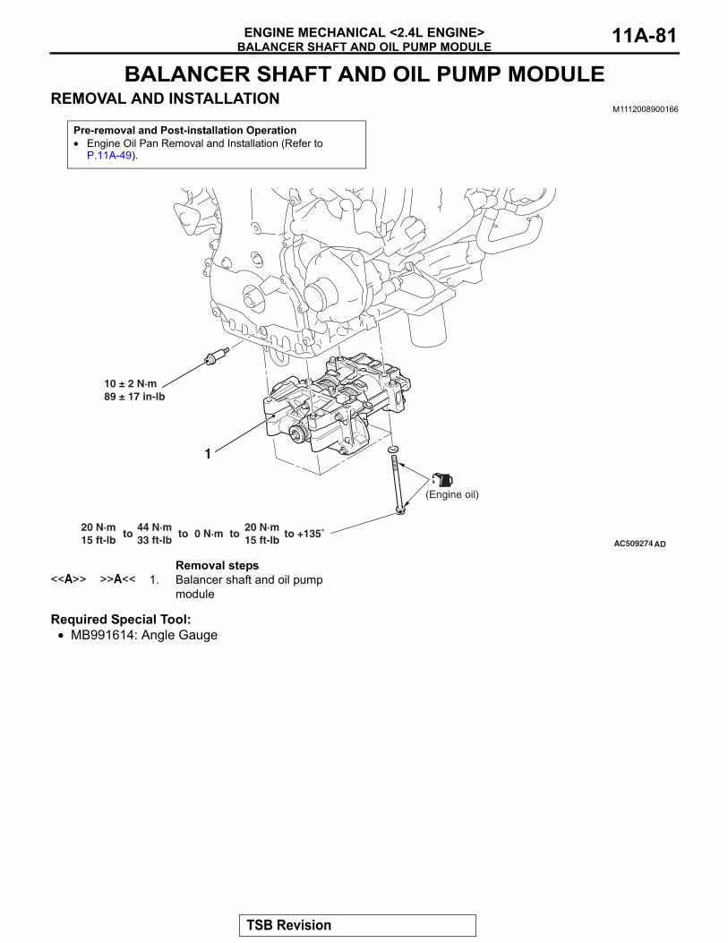
BALANCER SHAFT AND OIL PUMP MODULEENGINE MECHANICAL <2.4L ENGINE> 11A-81
BALANCER SHAFT AND OIL PUMP MODULEREMOVAL AND INSTALLATION
M1112008900166
Required Special Tool:• MB991614: Angle Gauge
Pre-removal and Post-installation Operation• Engine Oil Pan Removal and Installation (Refer to
P.11A-49).
AC509274
20 N·m15 ft-lb
44 N·m33 ft-lb
to 0 N·mto to20 N·m15 ft-lb
to +135˚
1
(Engine oil)
10 ± 2 N·m89 ± 17 in-lb
AD
Removal steps <<A>> >>A<< 1. Balancer shaft and oil pump
module
TSB Revision
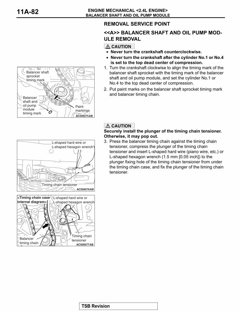
BALANCER SHAFT AND OIL PUMP MODULEENGINE MECHANICAL <2.4L ENGINE>11A-82
REMOVAL SERVICE POINT.
<<A>> BALANCER SHAFT AND OIL PUMP MOD-ULE REMOVAL
CAUTION• Never turn the crankshaft counterclockwise.• Never turn the crankshaft after the cylinder No.1 or No.4
is set to the top dead center of compression.1. Turn the crankshaft clockwise to align the timing mark of the
balancer shaft sprocket with the timing mark of the balancer shaft and oil pump module, and set the cylinder No.1 or No.4 to the top dead center of compression.
2. Put paint marks on the balancer shaft sprocket timing mark and balancer timing chain.
CAUTIONSecurely install the plunger of the timing chain tensioner. Otherwise, it may pop out. 3. Press the balancer timing chain against the timing chain
tensioner, compress the plunger of the timing chain tensioner and insert L-shaped hard wire (piano wire, etc.) or L-shaped hexagon wrench (1.5 mm [0.05 inch]) to the plunger fixing hole of the timing chain tensioner from under the timing chain case, and fix the plunger of the timing chain tensioner.
AC509275AB
Balancer shaftsprockettiming mark
Paintmarkings
Balancershaft andoil pumpmoduletiming mark
AC509276AB
L-shaped hard wire or L-shaped hexagon wrench
Timing chain tensioner
AC509277AB
L-shaped hard wire or L-shaped hexagon wrench
Timing chaintensionerBalancer
timing chain
<Timing chain caseinternal diagram>
TSB Revision
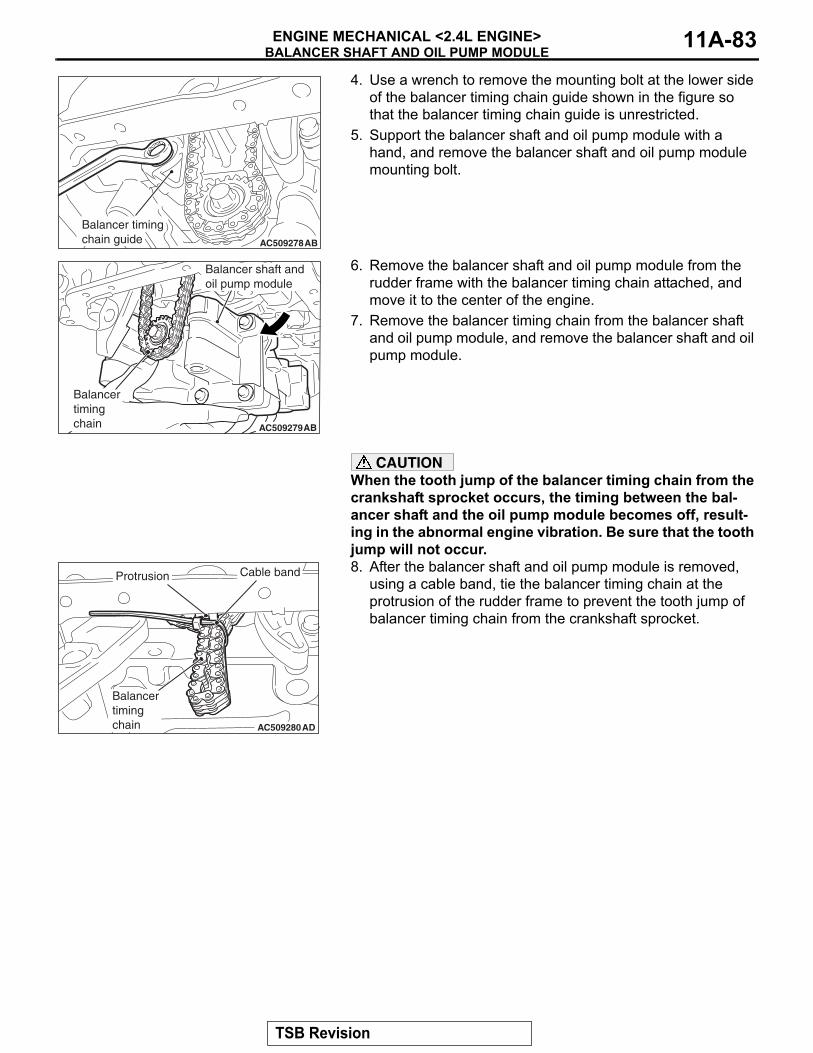
BALANCER SHAFT AND OIL PUMP MODULEENGINE MECHANICAL <2.4L ENGINE> 11A-83
4. Use a wrench to remove the mounting bolt at the lower side of the balancer timing chain guide shown in the figure so that the balancer timing chain guide is unrestricted.
5. Support the balancer shaft and oil pump module with a hand, and remove the balancer shaft and oil pump module mounting bolt.
6. Remove the balancer shaft and oil pump module from the rudder frame with the balancer timing chain attached, and move it to the center of the engine.
7. Remove the balancer timing chain from the balancer shaft and oil pump module, and remove the balancer shaft and oil pump module.
CAUTIONWhen the tooth jump of the balancer timing chain from the crankshaft sprocket occurs, the timing between the bal-ancer shaft and the oil pump module becomes off, result-ing in the abnormal engine vibration. Be sure that the tooth jump will not occur.8. After the balancer shaft and oil pump module is removed,
using a cable band, tie the balancer timing chain at the protrusion of the rudder frame to prevent the tooth jump of balancer timing chain from the crankshaft sprocket.
AC509278AB
Balancer timing chain guide
AC509279AB
Balancertimingchain
Balancer shaft andoil pump module
AC509280AD
Protrusion Cable band
Balancertimingchain
TSB Revision
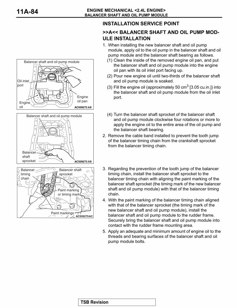
BALANCER SHAFT AND OIL PUMP MODULEENGINE MECHANICAL <2.4L ENGINE>11A-84
INSTALLATION SERVICE POINT.
>>A<< BALANCER SHAFT AND OIL PUMP MOD-ULE INSTALLATION1. When installing the new balancer shaft and oil pump
module, apply oil to the oil pump in the balancer shaft and oil pump module and the balancer shaft bearing as follows.(1) Clean the inside of the removed engine oil pan, and put
the balancer shaft and oil pump module into the engine oil pan with its oil inlet port facing up.
(2) Pour new engine oil until two-thirds of the balancer shaft and oil pump module is soaked.
(3) Fill the engine oil (approximately 50 cm3 [3.05 cu.in.]) into the balancer shaft and oil pump module from the oil inlet port.
(4) Turn the balancer shaft sprocket of the balancer shaft and oil pump module clockwise four rotations or more to apply the engine oil to the entire area of the oil pump and the balancer shaft bearing.
2. Remove the cable band installed to prevent the tooth jump of the balancer timing chain from the crankshaft sprocket from the balancer timing chain.
3. Regarding the prevention of the tooth jump of the balancer timing chain, install the balancer shaft sprocket to the balancer timing chain with aligning the paint marking of the balancer shaft sprocket (the timing mark of the new balancer shaft and oil pump module) with that of the balancer timing chain.
4. With the paint marking of the balancer timing chain aligned with that of the balancer sprocket (the timing mark of the new balancer shaft and oil pump module), install the balancer shaft and oil pump module to the rudder frame. Securely bring the balancer shaft and oil pump module into contact with the rudder frame mounting area.
5. Apply an adequate and minimum amount of engine oil to the threads and bearing surfaces of the balancer shaft and oil pump module bolts.
AC509272 AB
Oil inletport
Engineoil
Engineoil pan
Balancer shaft and oil pump module
AC509273 AB
Balancershaft sprocket
Balancer shaft and oil pump module
AC509279AC
Balancertimingchain
Paint markings
Balancer shaftsprocket
Paint markingor timing mark
TSB Revision
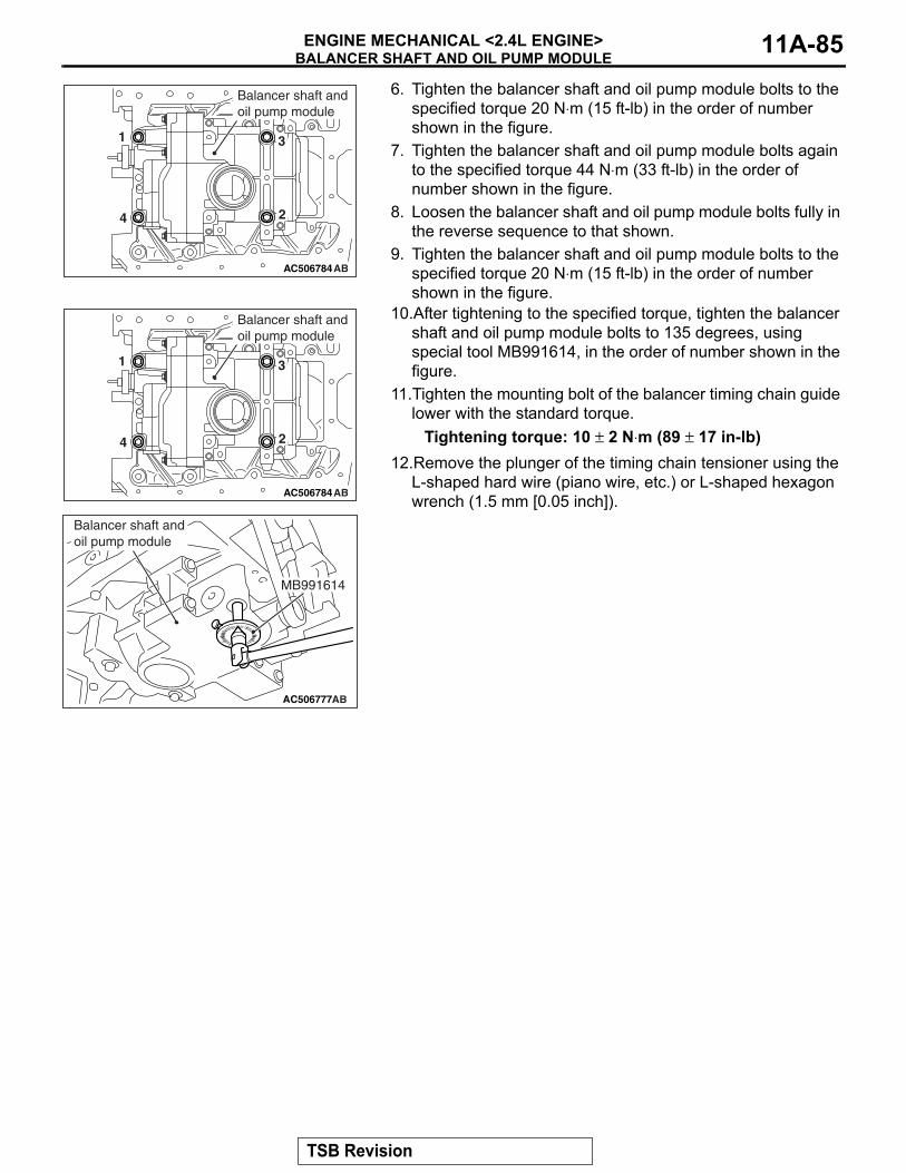
BALANCER SHAFT AND OIL PUMP MODULEENGINE MECHANICAL <2.4L ENGINE> 11A-85
6. Tighten the balancer shaft and oil pump module bolts to the specified torque 20 N⋅m (15 ft-lb) in the order of number shown in the figure.
7. Tighten the balancer shaft and oil pump module bolts again to the specified torque 44 N⋅m (33 ft-lb) in the order of number shown in the figure.
8. Loosen the balancer shaft and oil pump module bolts fully in the reverse sequence to that shown.
9. Tighten the balancer shaft and oil pump module bolts to the specified torque 20 N⋅m (15 ft-lb) in the order of number shown in the figure.
10.After tightening to the specified torque, tighten the balancer shaft and oil pump module bolts to 135 degrees, using special tool MB991614, in the order of number shown in the figure.
11.Tighten the mounting bolt of the balancer timing chain guide lower with the standard torque.
Tightening torque: 10 ± 2 N⋅m (89 ± 17 in-lb)12.Remove the plunger of the timing chain tensioner using the
L-shaped hard wire (piano wire, etc.) or L-shaped hexagon wrench (1.5 mm [0.05 inch]).
AC506784AB
1
2
3
4
Balancer shaft andoil pump module
AC506784AB
1
2
3
4
Balancer shaft andoil pump module
AC506777AB
MB991614
Balancer shaft and oil pump module
TSB Revision
ENGINE ASSEMBLYENGINE MECHANICAL <2.4L ENGINE>11A-86
ENGINE ASSEMBLYREMOVAL AND INSTALLATION
M1112001006591
CAUTIONWhen the engine assembly replacement is performed, use scan tool MB991958 to initialize the learn-ing value (Refer to GROUP 00, Initialization Procedure for Learning Value in MFI Engine P.00-53).
Pre-removal operation• Hood Removal (Refer to GROUP 42A, Hood P.42A-7).• Fuel Line Pressure Reduction [Refer to GROUP 13A,
On-vehicle Service, Fuel Pump Connector Disconnection (How to Reduce Pressurized Fuel Lines) P.13A-866].
• Engine Room Under Cover Front and Engine Room Side Cover Removal (Refer to GROUP 51, Under Cover P.51-23).
• Engine Coolant Draining (Refer to GROUP 14, On-vehicle Service − Engine Coolant Replacement P.14-26).
• Engine Oil Draining (Refer to GROUP 12, On-vehicle Ser-vice − Engine Oil Replacement P.12-5).
• Transmission Fluid Draining (Refer to GROUP 23A, On-vehicle Service − CVT Fluid Replacement P.23A-140).
• Engine Upper Cover Removal (Refer to GROUP 11A, Camshaft P.11A-26).
• Air Cleaner Assembly Removal (Refer to GROUP 15, Air Cleaner P.15-4).
• Battery and Battery Tray Removal (Refer to GROUP 54A, Battery P.54A-11).
• Engine Control Module Removal (Refer to GROUP 13A, Engine Control Module P.13A-887).
• Drive Shaft Removal (Refer to GROUP 26, Drive Shaft Assembly P.26-23).
• Transfer Removal (Refer to GROUP 23A, Transfer Assembly P.23A-163).
• Strut Tower Bar Removal (Refer to GROUP 42A, Strut Tower Bar P.42A-12).
• Exhaust Manifold Removal (Refer to GROUP 15, Exhaust Manifold P.15-15).
• Throttle Body Removal (Refer to GROUP 13A, Throttle Body Assembly P.13A-885).
Post-installation operation• Throttle Body Installation (Refer to GROUP 13A, Throttle
Body Assembly P.13A-885).• Exhaust Manifold Installation (Refer to GROUP 15,
Exhaust Manifold P.15-15).• Strut Tower Bar Installation (Refer to GROUP 42A, Strut
Tower Bar P.42A-12).• Transfer Installation (Refer to GROUP 23A, Transfer
Assembly P.23A-163).• Drive Shaft Installation (Refer to GROUP 26, Drive Shaft
Assembly P.26-23).• Engine Control Module Installation (Refer to GROUP 13A,
Engine Control Module P.13A-887).• Battery and Battery Tray Installation (Refer to GROUP
54A, Battery P.54A-11).• Air Cleaner Assembly Installation (Refer to GROUP 15,
Air Cleaner P.15-4).• Transmission Fluid Draining (Refer to GROUP 23A,
On-vehicle Service − CVT Fluid Replacement P.23A-140).
• Engine Oil Refilling (Refer to GROUP 12, On-vehicle Ser-vice − Engine Oil Replacement P.12-5).
• Engine Coolant Refilling (Refer to GROUP 14, On-vehicle Service − Engine Coolant Replacement P.14-26).
• Drive Belt Tension Check (Refer to P.11A-9).• Engine Room Under Cover Front and Engine Room Side
Cover Installation (Refer to GROUP 51, Under Cover P.51-23).
• Engine Upper Cover Installation (Refer to GROUP 11A, Camshaft P.11A-26).
• Fuel Leak Check• Hood Installation (Refer to GROUP 42A, Hood P.42A-7).
TSB Revision
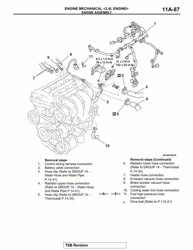
ENGINE ASSEMBLYENGINE MECHANICAL <2.4L ENGINE> 11A-87
AC506785AE
1
98
7
12 ± 2 N·m102 ± 22 in-lb
10
11
2
8.5 ± 1.5 N·m76 ± 13 in-lb
4
6
5N
3N
Removal steps 1. Control wiring harness connection2. Battery cable connection3. Hose clip (Refer to GROUP 14 −
Water Hose and Water Pipe P.14-41).
4. Radiator upper hose connection (Refer to GROUP 14 − Water Hose and Water Pipe P.14-41).
5. Hose clip (Refer to GROUP 14 − Thermostat P.14-34).
6. Radiator lower hose connection (Refer to GROUP 14 − Thermostat P.14-34).
7. Heater hose connection8. Emission vacuum hose connection9. Brake booster vacuum hose
connection10. Cooling water line hose connection
<<A>> >>E<< 11. Fuel high-pressure hose connection
• Drive belt (Refer to P.11A-21)
Removal steps (Continued)
TSB Revision
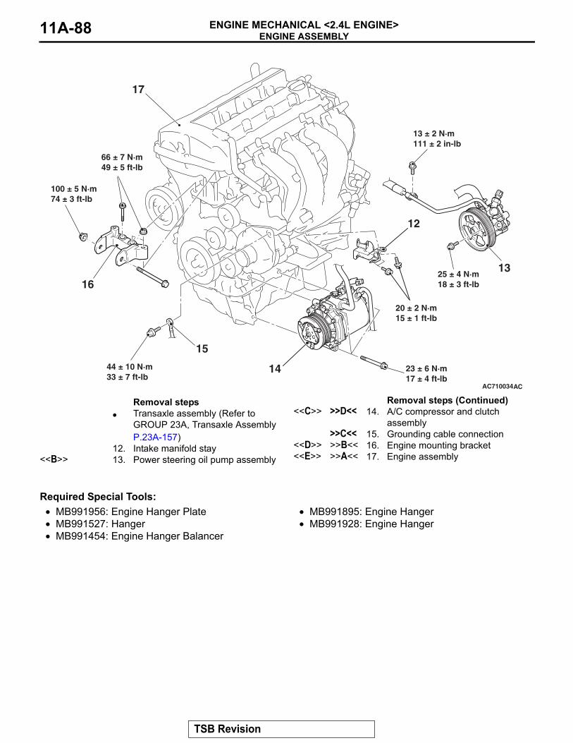
ENGINE ASSEMBLYENGINE MECHANICAL <2.4L ENGINE>11A-88
Required Special Tools:• MB991956: Engine Hanger Plate• MB991527: Hanger• MB991454: Engine Hanger Balancer
• MB991895: Engine Hanger• MB991928: Engine Hanger
AC710034AC
13
14
16
15
44 ± 10 N·m33 ± 7 ft-lb
17
25 ± 4 N·m18 ± 3 ft-lb
23 ± 6 N·m17 ± 4 ft-lb
66 ± 7 N·m49 ± 5 ft-lb
13 ± 2 N·m111 ± 2 in-lb
100 ± 5 N·m74 ± 3 ft-lb
12
20 ± 2 N·m15 ± 1 ft-lb
Removal steps • Transaxle assembly (Refer to
GROUP 23A, Transaxle Assembly P.23A-157)
12. Intake manifold stay<<B>> 13. Power steering oil pump assembly
<<C>> >>D<< 14. A/C compressor and clutch assembly
>>C<< 15. Grounding cable connection<<D>> >>B<< 16. Engine mounting bracket<<E>> >>A<< 17. Engine assembly
Removal steps (Continued)
TSB Revision
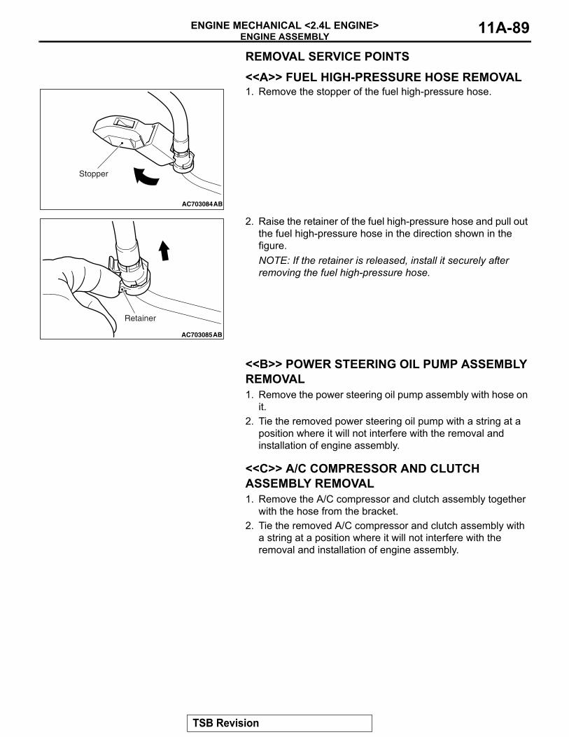
ENGINE ASSEMBLYENGINE MECHANICAL <2.4L ENGINE> 11A-89
REMOVAL SERVICE POINTS.
<<A>> FUEL HIGH-PRESSURE HOSE REMOVAL1. Remove the stopper of the fuel high-pressure hose.
2. Raise the retainer of the fuel high-pressure hose and pull out the fuel high-pressure hose in the direction shown in the figure.NOTE: If the retainer is released, install it securely after removing the fuel high-pressure hose.
.
<<B>> POWER STEERING OIL PUMP ASSEMBLY REMOVAL1. Remove the power steering oil pump assembly with hose on
it.2. Tie the removed power steering oil pump with a string at a
position where it will not interfere with the removal and installation of engine assembly.
.
<<C>> A/C COMPRESSOR AND CLUTCH ASSEMBLY REMOVAL1. Remove the A/C compressor and clutch assembly together
with the hose from the bracket.2. Tie the removed A/C compressor and clutch assembly with
a string at a position where it will not interfere with the removal and installation of engine assembly.
.
AC703084
Stopper
AB
AC703085
Retainer
AB
TSB Revision
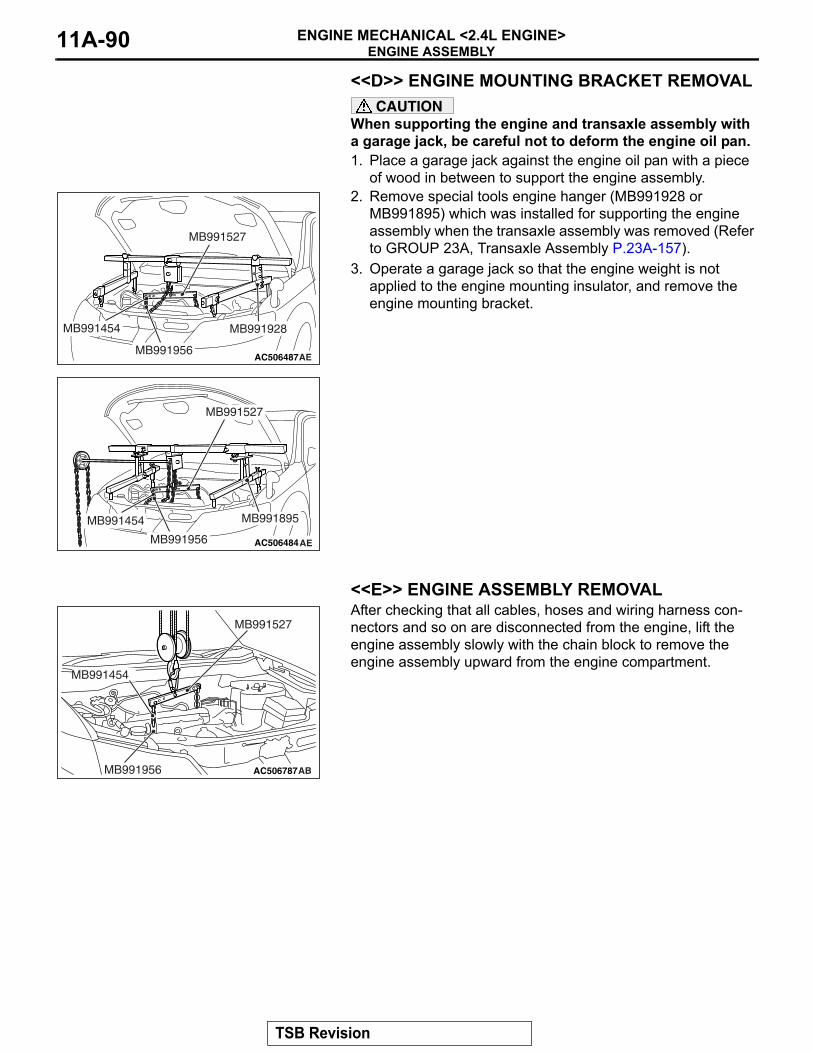
ENGINE ASSEMBLYENGINE MECHANICAL <2.4L ENGINE>11A-90
<<D>> ENGINE MOUNTING BRACKET REMOVALCAUTION
When supporting the engine and transaxle assembly with a garage jack, be careful not to deform the engine oil pan.1. Place a garage jack against the engine oil pan with a piece
of wood in between to support the engine assembly.2. Remove special tools engine hanger (MB991928 or
MB991895) which was installed for supporting the engine assembly when the transaxle assembly was removed (Refer to GROUP 23A, Transaxle Assembly P.23A-157).
3. Operate a garage jack so that the engine weight is not applied to the engine mounting insulator, and remove the engine mounting bracket.
.
<<E>> ENGINE ASSEMBLY REMOVALAfter checking that all cables, hoses and wiring harness con-nectors and so on are disconnected from the engine, lift the engine assembly slowly with the chain block to remove the engine assembly upward from the engine compartment.
AC506487AE
MB991527
MB991454 MB991928
MB991956
AC506484
MB991527
AE
MB991454
MB991956
MB991895
AC506787
MB991527
MB991454
ABMB991956
TSB Revision
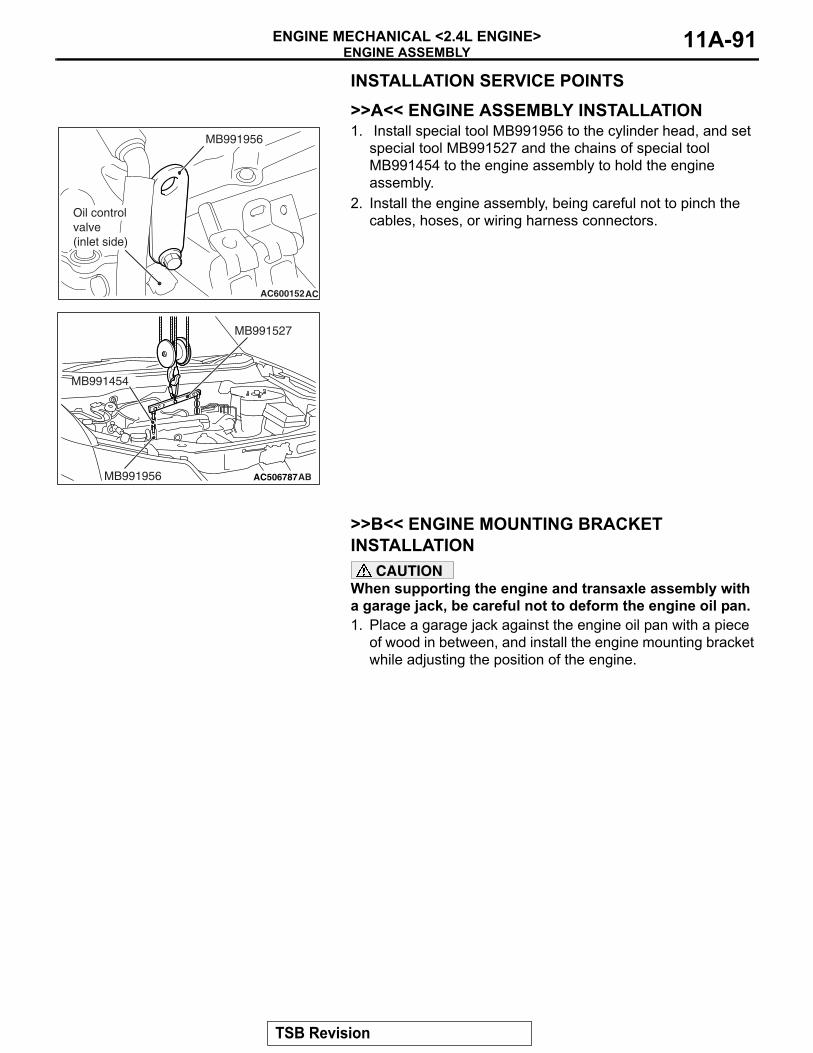
ENGINE ASSEMBLYENGINE MECHANICAL <2.4L ENGINE> 11A-91
INSTALLATION SERVICE POINTS.
>>A<< ENGINE ASSEMBLY INSTALLATION1. Install special tool MB991956 to the cylinder head, and set
special tool MB991527 and the chains of special tool MB991454 to the engine assembly to hold the engine assembly.
2. Install the engine assembly, being careful not to pinch the cables, hoses, or wiring harness connectors.
.
>>B<< ENGINE MOUNTING BRACKET INSTALLATION
CAUTIONWhen supporting the engine and transaxle assembly with a garage jack, be careful not to deform the engine oil pan.1. Place a garage jack against the engine oil pan with a piece
of wood in between, and install the engine mounting bracket while adjusting the position of the engine.
AC600152AC
MB991956
Oil control valve (inlet side)
AC506787
MB991527
MB991454
ABMB991956
TSB Revision
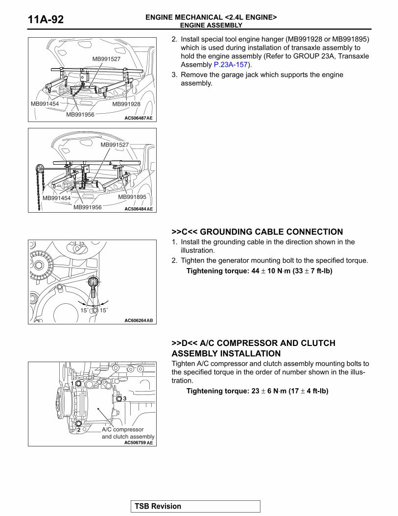
ENGINE ASSEMBLYENGINE MECHANICAL <2.4L ENGINE>11A-92
2. Install special tool engine hanger (MB991928 or MB991895) which is used during installation of transaxle assembly to hold the engine assembly (Refer to GROUP 23A, Transaxle Assembly P.23A-157).
3. Remove the garage jack which supports the engine assembly.
.
>>C<< GROUNDING CABLE CONNECTION1. Install the grounding cable in the direction shown in the
illustration.2. Tighten the generator mounting bolt to the specified torque.
Tightening torque: 44 ± 10 N⋅m (33 ± 7 ft-lb)
.
>>D<< A/C COMPRESSOR AND CLUTCH ASSEMBLY INSTALLATIONTighten A/C compressor and clutch assembly mounting bolts to the specified torque in the order of number shown in the illus-tration.
Tightening torque: 23 ± 6 N⋅m (17 ± 4 ft-lb)
.
AC506487AE
MB991527
MB991454 MB991928
MB991956
AC506484
MB991527
AE
MB991454
MB991956
MB991895
AC606264AB
15˚15˚
AC506759 AE
1
2
3
A/C compressor and clutch assembly
TSB Revision
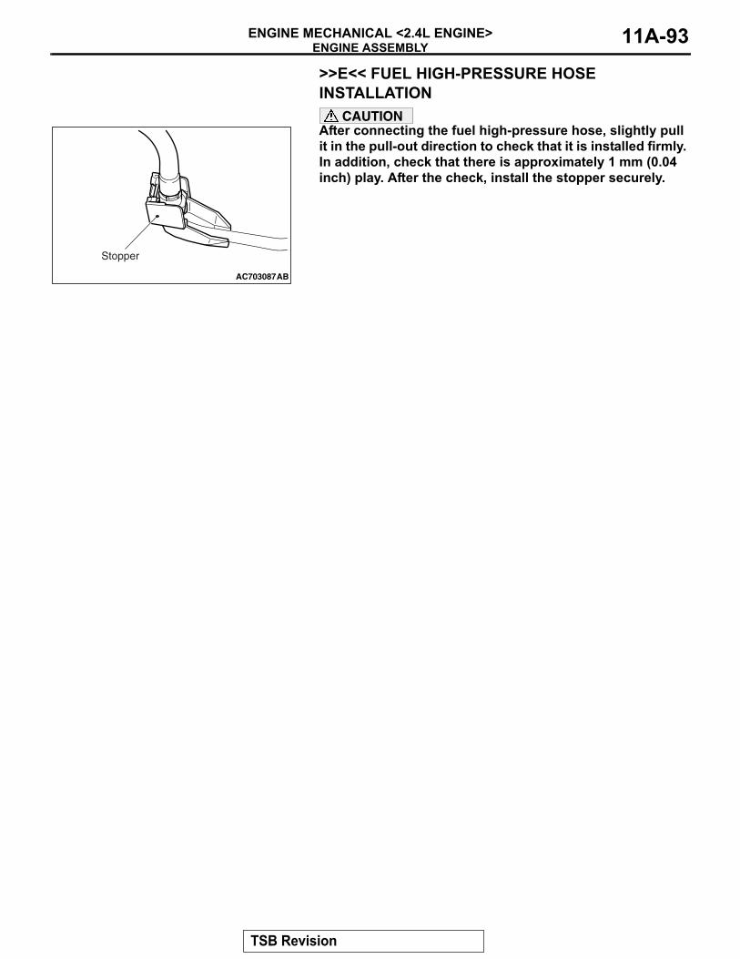
ENGINE ASSEMBLYENGINE MECHANICAL <2.4L ENGINE> 11A-93
>>E<< FUEL HIGH-PRESSURE HOSE INSTALLATION
CAUTIONAfter connecting the fuel high-pressure hose, slightly pull it in the pull-out direction to check that it is installed firmly. In addition, check that there is approximately 1 mm (0.04 inch) play. After the check, install the stopper securely.
AC703087
Stopper
AB
TSB Revision

NOTES


