Embed Size (px)
Citation preview
3
Operating Instruction
Part 2 - HTK (2 t - 3.5 t)Three-way tipper
000 Series humbaur.com
en

Humbaur GmbHMercedesring 186368 Gersthofen, Germany
Tel. + 49 821 [email protected] + 49 821 249-100www.humbaur.com
Your dealer
Name
Address
Telephone
Please enter the name of your dealer.
Please fill in the service card on the back page and send it to
Humbaur GmbH.
Ask for the handover inspection to be recorded when accepting your trailer.
@
Your trailer:
Model
Type (abbreviation)
VehicleIdentificationNumber (VIN)
Registration number
Please enter your trailer type and the identification.
You will find the dimensions / technical data of your trailer in the vehicle documents.
Contents of this operating instruction manual
Notes on useThis operating instruction manual must be carefully read, understood and complied with in full by anyone who is responsible for the trailer of Humbaur GmbH and its modules. Humbaur GmbH accepts no liability for damage or failures which arise through disregard of this manual!
Read and observe the operating instruction manual with all the instructions, warnings and notes before driving for the first time!
Please note that all illustrations are representative and may differ from the actual appearance / equipment.
Also read and observe the instruction manuals for components such as axles, support devices, cable winches, etc.!
PART 2This operating instruction manual “Part 2 - HTK three-way tipper” is intended for you as the user of a ready-to-use trailer.
It provides detailed instructions for handling a three-way tipper and its specific accessories.
It contains supplementary information on safe operation, care/cleaning, maintenance/servicing,troubleshooting and decommissioning/disposal of the trailer.
PART 1
For all other general information on trailers up to 3.5 to, see the operating instruction manual, “Trailers up to 3.5 to (General Points – Part 1).”
This specific operating instruction manual (Part 2) for your trailer is provided on the enclosed CD. You can also download it from www.humbaur.com in the section: Downloads – Operating manuals
The complete technical documentation is part of the product and should be kept in the driver's cab of the traction unit for reference at all times.
Key details for the handling, operation and the requisite care and maintenance work of the trailer are referred to in this operating instruction manual, and errors can only be avoided and trouble-free operation guaranteed if you are familiar with them.
Errors excepted. The manufacturer:
Humbaur GmbHMercedesring 189368 Gersthofen (Germany)
reserves the right make technical changes to the design, equipment and accessories with respect to the information and illustrations in the operating instruction manual.
As a result, no claims whatsoever can be derived from the information, illustrations and descriptions.
Obligations of the operator
The trailer may only be operated in perfect condition.
Ensure that the operating instruction manual is included with the trailer e.g. if it is sold.
Only utilise trained or instructed personnel.
Ensure that the operating instruction manual is complied with in all life cycle phases of the trailer and that the prescribed personal protective equipment is worn.
Provide the requisite operating and auxiliary materials.
User group
The trailer should only be operated by users who possess the following additional prerequisites and knowledge:
Experience in handling tippers.
Initiating tipping processes.
Loading / unloading bulk goods.
3
Contents of this operating instruction manual
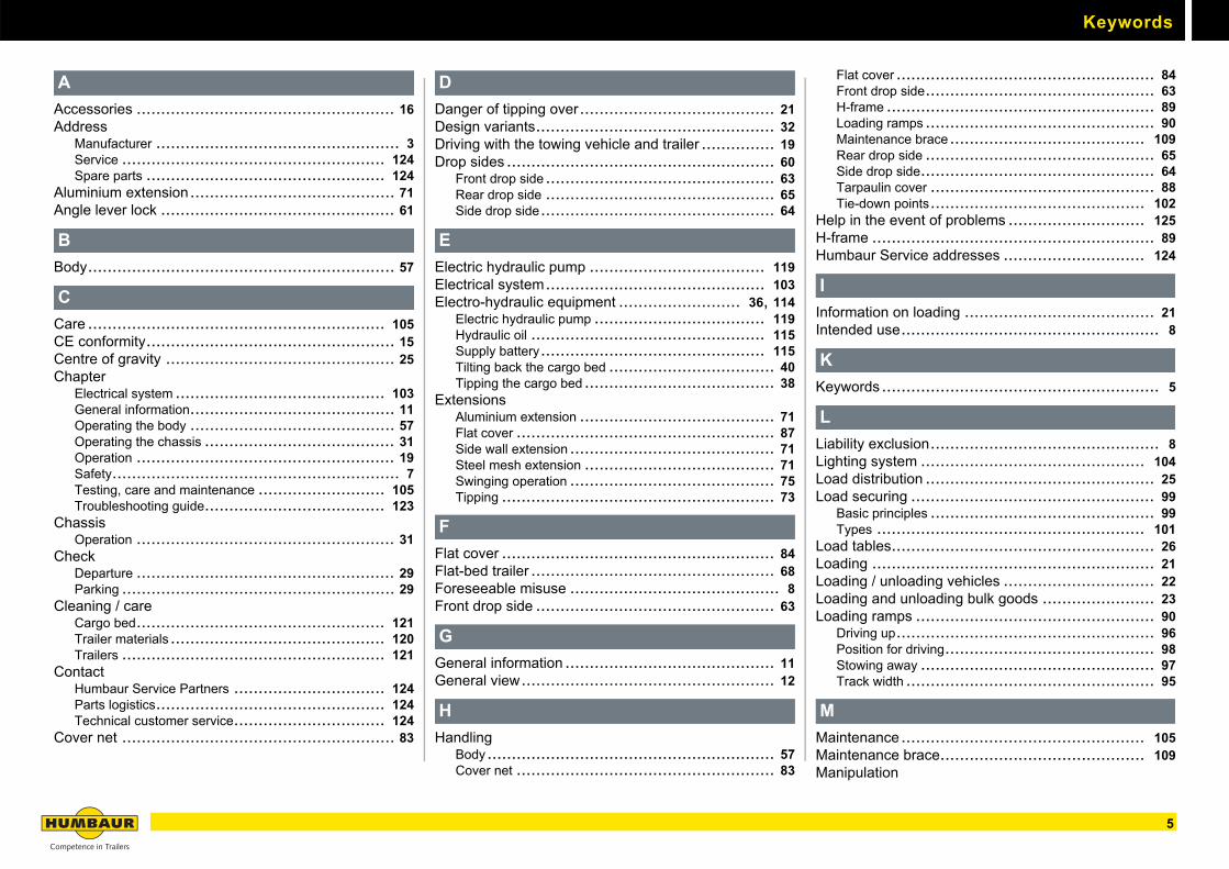
Keyword index
Use the keyword index from page 5 to search for specific topics.
Refer to the technical documentation of the installed components for additional information.
1 Safety
You will find safety information for the correct handling of the trailer in the "Safety" chapter from page 7. Read this chapter before driving for the first time.
2 General information
You will find details on trailer identification in the "General information" chapter from page 11.
3 Operation
You will find information on loading and unloading, correct load distribution and parking in the chapter on "Operation" from page 19.
4 Operating the chassis
You will find valuable information on the operating elements of the chassis, such as the electro-hydraulic equipment, support devices and loading ramp, in the chapter on "Operating the chassis" from page 31.
5 Operating the body / load securing
You will find out how to operate the body, drop sides and extensions correctly or about the equipment you can use to secure the load in the chapter on the "Body" from page 57.
6 Electrical system
You will find information on the lighting in the chapter on the "Electrical system" from page 103.
7 Testing, care and maintenance
You will find out more about the work required to maintain operational safety and the value of your trailer in the chapter on "Testing, care and maintenance" from page 105.
8 Troubleshooting guide
You will find information on troubleshooting and important service addresses in the "Troubleshooting guide" from page 123.
4
Keywords
A
Accessories ..................................................... 16Address
Manufacturer .................................................. 3Service ...................................................... 124Spare parts ................................................. 124
Aluminium extension.......................................... 71Angle lever lock ................................................ 61
B
Body............................................................... 57
C
Care ............................................................. 105CE conformity................................................... 15Centre of gravity ............................................... 25Chapter
Electrical system ........................................... 103General information.......................................... 11Operating the body .......................................... 57Operating the chassis ....................................... 31Operation ..................................................... 19Safety........................................................... 7Testing, care and maintenance .......................... 105Troubleshooting guide..................................... 123
ChassisOperation ..................................................... 31
CheckDeparture ..................................................... 29Parking ........................................................ 29
Cleaning / careCargo bed................................................... 121Trailer materials ............................................ 120Trailers ...................................................... 121
ContactHumbaur Service Partners ............................... 124Parts logistics............................................... 124Technical customer service............................... 124
Cover net ........................................................ 83
D
Danger of tipping over........................................ 21Design variants................................................. 32Driving with the towing vehicle and trailer ............... 19Drop sides ....................................................... 60
Front drop side ............................................... 63Rear drop side ............................................... 65Side drop side................................................ 64
E
Electric hydraulic pump .................................... 119Electrical system............................................. 103Electro-hydraulic equipment ......................... 36, 114
Electric hydraulic pump ................................... 119Hydraulic oil ................................................ 115Supply battery.............................................. 115Tilting back the cargo bed .................................. 40Tipping the cargo bed ....................................... 38
ExtensionsAluminium extension ........................................ 71Flat cover ..................................................... 87Side wall extension .......................................... 71Steel mesh extension ....................................... 71Swinging operation .......................................... 75Tipping ........................................................ 73
F
Flat cover ........................................................ 84Flat-bed trailer .................................................. 68Foreseeable misuse ........................................... 8Front drop side ................................................. 63
G
General information ........................................... 11General view.................................................... 12
H
HandlingBody........................................................... 57Cover net ..................................................... 83
Flat cover ..................................................... 84Front drop side............................................... 63H-frame ....................................................... 89Loading ramps ............................................... 90Maintenance brace........................................ 109Rear drop side ............................................... 65Side drop side................................................ 64Tarpaulin cover .............................................. 88Tie-down points............................................ 102
Help in the event of problems ............................ 125H-frame .......................................................... 89Humbaur Service addresses ............................. 124
I
Information on loading ....................................... 21Intended use..................................................... 8
K
Keywords......................................................... 5
L
Liability exclusion............................................... 8Lighting system .............................................. 104Load distribution ............................................... 25Load securing .................................................. 99
Basic principles .............................................. 99Types ....................................................... 101
Load tables...................................................... 26Loading .......................................................... 21Loading / unloading vehicles ............................... 22Loading and unloading bulk goods ....................... 23Loading ramps ................................................. 90
Driving up..................................................... 96Position for driving........................................... 98Stowing away ................................................ 97Track width ................................................... 95
M
Maintenance.................................................. 105Maintenance brace.......................................... 109Manipulation
5

Keywords
Wheel chocks ................................................ 28Manual emergency pump.................................... 42Manual pump ................................................... 33Manufacturer.................................................. 3, 8
N
NotesOperating Instruction Manual................................ 3
O
Operation ........................................................ 19Angle lever lock .............................................. 61Cargo bed..................................................... 46Chassis........................................................ 31Drop sides .................................................... 60Electro-hydraulic equipment................................ 38Manual emergency pump................................... 42Manual pump................................................. 33Spare wheel holder .......................................... 56Telescopic prop stands ..................................... 51Toolbox........................................................ 55
Optional accessories.......................................... 16
P
Permissible weights ........................................... 25Positional stability.............................................. 21Product description............................................ 12Proof of inspection........................................... 107
Q
Qualification of the personnel................................ 8
R
Rear drop side.................................................. 65
S
Safety .............................................................. 7Body ........................................................... 58Body area ...................................................... 9Chassis area .................................................. 9Driving with the towing vehicle and trailer ................ 20
Drop sides .................................................... 60Electro-hydraulic equipment......................... 36, 114Extensions.................................................... 72General ........................................................ 9Hydraulic supply ............................................. 32Loading / unloading vehicles ............................... 22Loading and unloading bulk goods ........................ 23Maintenance brace ........................................ 109Positional stability............................................ 21Telescopic prop stands ..................................... 52
Service address.............................................. 124Side drop side .................................................. 64Side wall extension............................................ 71Sources of danger.............................................. 9Spare parts address ........................................ 124Spare wheel................................................... 108Spare wheel holder ........................................... 56Stability........................................................... 21Start of the journey ............................................. 9Steel mesh extension......................................... 71Supply battery ........................................... 36, 115
Trickle charge .............................................. 117Swinging operation............................................ 66Switch-off / securing mechanisms....................... 112
T
Tarpaulin cover................................................. 88Telescopic cylinder
Components................................................ 111Telescopic prop stands ...................................... 51Testing ......................................................... 105Tie-down points .............................................. 102Tilting bearings
Components................................................ 113Pinning for tipping to the rear .............................. 49Pinning for tipping to the side .............................. 50Securing the cargo bed ..................................... 46setting / securing............................................. 47
Toolbox........................................................... 55Track width ................................................. 21, 95Troubleshooting........................................ 123, 125Troubleshooting guide...................................... 123Tyre types ..................................................... 108
U
Uncoupling ...................................................... 27Unloading........................................................ 21Use
Foreseeable misuse ......................................... 8Intended ....................................................... 8
W
Wheel chocks .................................................. 28Towing ring connection 235
6
1
Safety7
1
UseIntended use
The following is permitted:
– Transport of bulk goods such as sand, gravel, stone, etc.
– Transport of loose load materials such as wood, wood chips.
– Transport of materials and load materials as solid/packaged load units, such as bricks on pallets.
– Load securing on the cargo bed with lashing brackets using form and force load securing methods.
– Lateral tipping of bulk goods to the right & left as well as to the rear.
Qualification of the personnel
HUMBAUR trailers and bodies and theiroperating components may only be used and maintained by personnel who are aware of:
– this operating instruction manual.
– the trailer and the associated traction unit.
– the operating and maintenance instructions of the suppliers.
– the German Road Traffic Act (StVO) and German Road Traffic Licensing Regulations (StVZO).
– all the respective health and safety / accident prevention regulations as well as other safety, occupational health and road traffic regulations.
– the basic requirements of goods transport.
– the hazards arising from handling tippers.
Reasonably foreseeablemisuse
Any use extending beyond the prescribed transport applications is regarded as other than intended.In particular, this includes:
– Driving when the drop sides and side wall extension, e.g. steel mesh extension, aluminium extension, are not secured.
– Tipping the cargo bed if personnel / objects are located on the tipping side.
– Tipping the load onto people or objects.
– Driving with a tipped / unsecured cargo bed.
– Driving with folded down / unsecured folding supports at the rear.
– Climbing onto a tipped trailer or walking underneath an unsecured loading bridge.
– Non-observance of the safety instructions in the operating instruction manual "Trailers up to 3.5 to, Part 1 - General”.
The manufacturer:
Humbaur GmbHMercedesring 186368 Gersthofen (Germany)
rejects any damage which arises through disregard of this manual – the risks are borne solely by the user.
Liability exclusion
Any liability of the manufacturer becomes null and void if:
– the trailer and its components are altered without authorization.
– the original parts or conversion parts / accessories approved by Humbaur GmbH are replaced by other components.
– retrospective changes have been made to the trailer (e.g. new drill holes in the frame or the reboring of existing drill holes in the frame). This is considered by Humbaur GmbH to be a structural change, and the type approval therefore becomes null and void.
– non-approved accessories or third-party spare / component parts which are not original HUMBAUR parts are attached or installed. The type approval of the trailer, possibly even the insurance cover, becomes null and void.
– care and maintenance intervals prescribed by the manufacturer are not complied with.
Any risks and liability exclusions resulting from this also exist if:
– Acceptance inspections have been carried out by inspectors / authorised experts of the technical inspection authorities or officially recognised organisations.
– Official approvals are available.
8 Safety
1Check, adjust and secure before each journey
Safety first!
Sources of danger
Take note of the following points without fail:
– Coupling and uncoupling a trailer: Standing in the danger area is prohibited.
– Driving with unsecured support devices.
– Driving with unsecured ramps (loading ramps).
– Clearance heights on the route, while loading and unloading.
– Driving with a tipped cargo bed - not permitted by law.
– Exceeding the permissible gross weight or one-sided overloading through incorrect loading.
– Poorly secured or unsecured goods and / or body components.
– Reversing - keep an eye on the rear area.
– Excessive twisting while manoeuvring.
– Overloading of the trailer, axles and brakes.
– Overstressing caused by fitting incorrect wheel and tyre sizes.
– Use of wheels with incorrect offsets, one-sided run-out or centrifugal imbalance.
– Overstressing as a result of reckless and inappropriate driving or handling.
– Impact and shock stress of the axles.
– Speed inappropriate for the road conditions and the loading status of the trailer, especially in bends.
– The parked trailer can tilt or sink in on soft uneven ground.
– Driving on severe inclines.
– Tilting the loading bridge too close to a slope or excavation.
– Loading / unloading of the trailer in an area with a steep gradient.
– Standing on / in a tipped / moving cargo bed.
– Going under an unsecured loading bridge.
– Jerky braking during tipping.
– Tipping with an engaged parking brake.
– Failure to clean the cargo bed after every use.
– Tipping viscous load materials e.g. asphalt, soil, loamy sand.
– Tipping large rocks.
– Tipping with an inclined combination.
– Tipping under high-voltage transmission lines (open power lines).
In the chassis area
Note the following in general:
– Establish the electrical connections.
– Retract the support devices and lock them.
– Check the tyres and rims for damage.
– Check the tyre pressure, including the spare wheel.
– Check the tightening torque of the wheel nuts.
– In the case of a new trailer, re-tighten the wheel nuts after 50 km and after the first journey with a load.
– Secure the:spare wheel / spare wheel holder, wheel chocks
– Check the trailer lights, repair defective lights.
– Comply with the permissible gross weight.
– Check the number plate and signs.
– Check that the trailer coupling is in perfect condition.
In the body area
Close and secure all body components, such as:
–Loading ramps
–Drop sides
–Side wall extension
–Steel mesh extension
– Aluminium extension
–H-frame
– Flat cover
– Tarpaulin cover / frame
–Toolbox
–Load securing equipment
–Fix and secure the load.
–Ensure that the load distribution is balanced.
9Safety

Check, adjust and secure before each journey1
10 Safety
2
General information11
HTK product description2
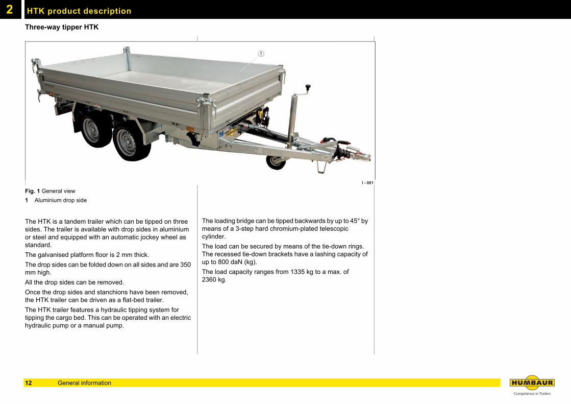
Three-way tipper HTKFig. 1 General view
1 Aluminium drop side
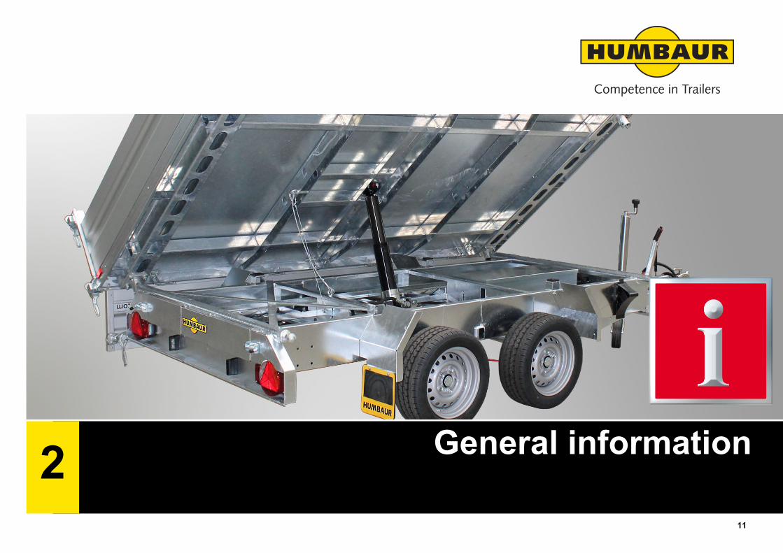
The HTK is a tandem trailer which can be tipped on three sides. The trailer is available with drop sides in aluminium or steel and equipped with an automatic jockey wheel as standard.
The galvanised platform floor is 2 mm thick.
The drop sides can be folded down on all sides and are 350 mm high.
All the drop sides can be removed.
Once the drop sides and stanchions have been removed, the HTK trailer can be driven as a flat-bed trailer.
The HTK trailer features a hydraulic tipping system for tipping the cargo bed. This can be operated with an electric hydraulic pump or a manual pump.
The loading bridge can be tipped backwards by up to 45° by means of a 3-step hard chromium-plated telescopic cylinder.
The load can be secured by means of the tie-down rings. The recessed tie-down brackets have a lashing capacity of up to 800 daN (kg).
The load capacity ranges from 1335 kg to a max. of 2360 kg.
I - 001
1
12 General information
HTK product description 2
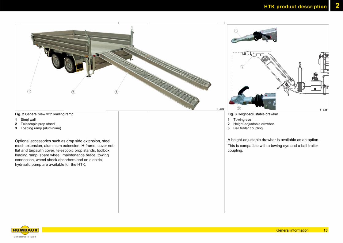
Fig. 2 General view with loading ramp
1 Steel wall2 Telescopic prop stand3 Loading ramp (aluminium)
Optional accessories such as drop side extension, steel mesh extension, aluminium extension, H-frame, cover net, flat and tarpaulin cover, telescopic prop stands, toolbox, loading ramp, spare wheel, maintenance brace, towing connection, wheel shock absorbers and an electric hydraulic pump are available for the HTK.
Fig. 3 Height-adjustable drawbar
1 Towing eye2 Height-adjustable drawbar3 Ball trailer coupling
A height-adjustable drawbar is available as an option.
This is compatible with a towing eye and a ball trailer coupling.
I - 002
31 2
I - 025
1
3
2
13General information
HTK product description2
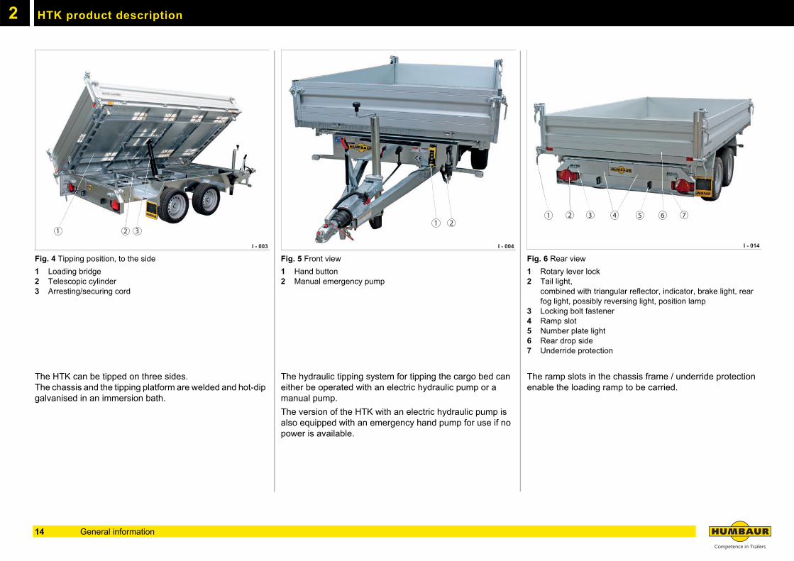
Fig. 4 Tipping position, to the side
1 Loading bridge2 Telescopic cylinder3 Arresting/securing cord
The HTK can be tipped on three sides.The chassis and the tipping platform are welded and hot-dip galvanised in an immersion bath.
Fig. 5 Front view
1 Hand button2 Manual emergency pump
The hydraulic tipping system for tipping the cargo bed can either be operated with an electric hydraulic pump or a manual pump.
The version of the HTK with an electric hydraulic pump is also equipped with an emergency hand pump for use if no power is available.
Fig. 6 Rear view
1 Rotary lever lock2 Tail light,
combined with triangular reflector, indicator, brake light, rear fog light, possibly reversing light, position lamp
3 Locking bolt fastener4 Ramp slot5 Number plate light6 Rear drop side7 Underride protection
The ramp slots in the chassis frame / underride protection enable the loading ramp to be carried.
I - 003
1 32
I - 004
1 2
I - 014
1 3 4 5 6 72
14 General information
HTK product description 2
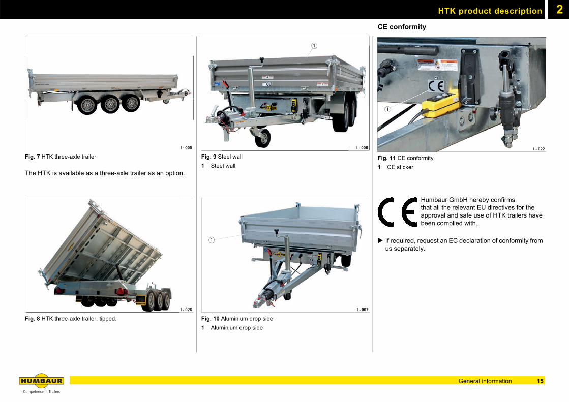
Fig. 7 HTK three-axle trailer
The HTK is available as a three-axle trailer as an option.
Fig. 8 HTK three-axle trailer, tipped.
Fig. 9 Steel wall
1 Steel wall
Fig. 10 Aluminium drop side
1 Aluminium drop side
CE conformity
Fig. 11 CE conformity
1 CE sticker
Humbaur GmbH hereby confirmsthat all the relevant EU directives for the approval and safe use of HTK trailers have been complied with.
If required, request an EC declaration of conformity from us separately.
I - 005
I - 026
I - 006I - 006
1
I - 007
1
I - 022
1
15General information
HTK product description2
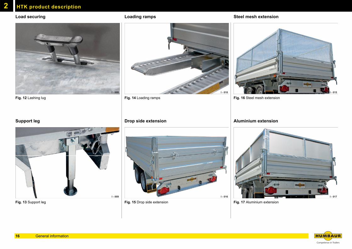
Load securingFig. 12 Lashing lug
Support leg
Fig. 13 Support leg
Loading ramps
Fig. 14 Loading ramps
Drop side extension
Fig. 15 Drop side extension
Steel mesh extension
Fig. 16 Steel mesh extension
Aluminium extension
Fig. 17 Aluminium extension
I - 008
I - 009
I - 010
I - 016
I - 015
I - 017
16 General information
HTK product description 2
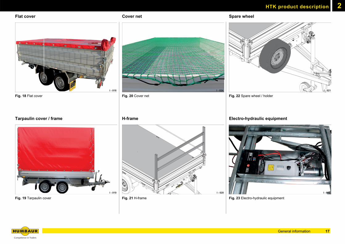
Flat coverFig. 18 Flat cover
Tarpaulin cover / frame
Fig. 19 Tarpaulin cover
Cover net
Fig. 20 Cover net
H-frame
Fig. 21 H-frame
Spare wheel
Fig. 22 Spare wheel / holder
Electro-hydraulic equipment
Fig. 23 Electro-hydraulic equipment
I - 018
I - 019
I - 024
I - 020
I - 021
I - 012
17General information
HTK product description2
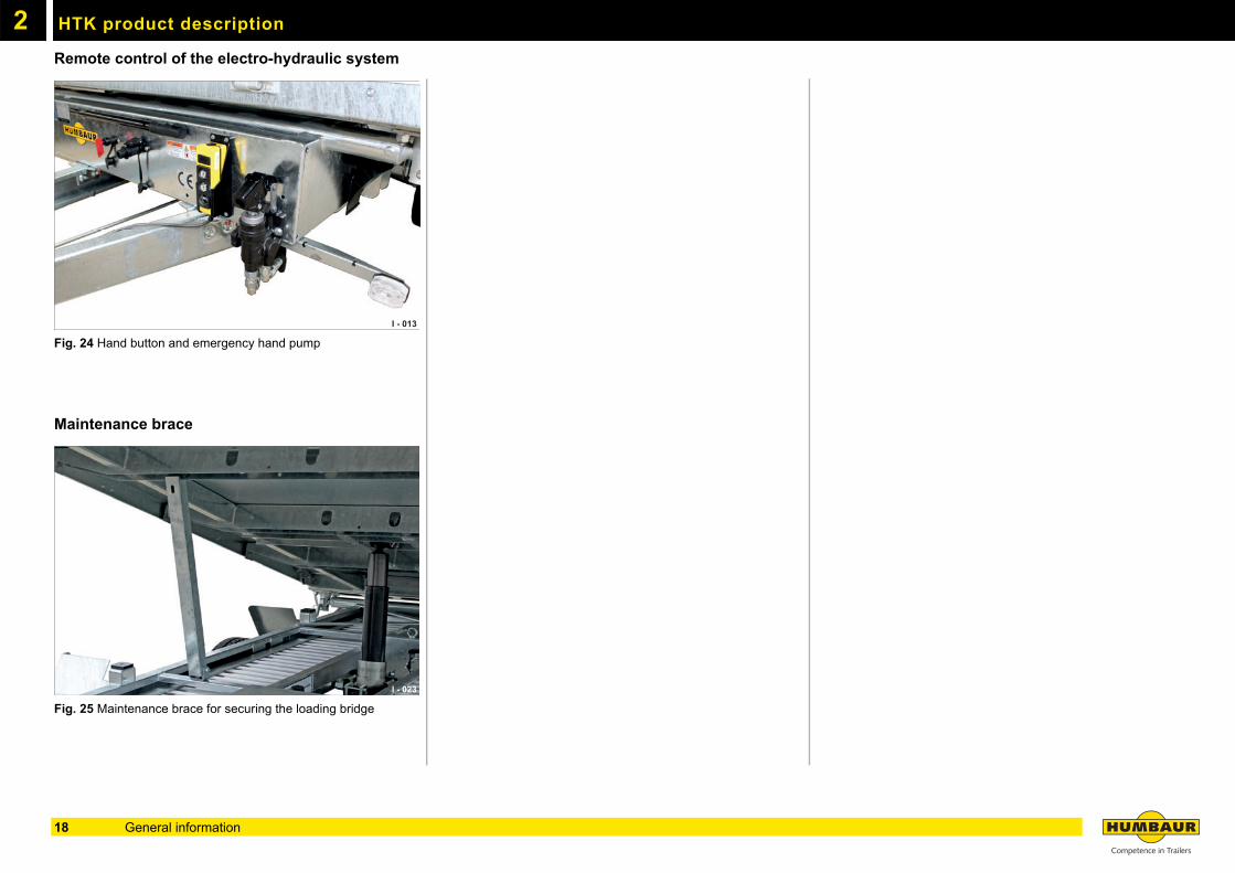
Remote control of the electro-hydraulic systemFig. 24 Hand button and emergency hand pump
Maintenance brace
Fig. 25 Maintenance brace for securing the loading bridge
I - 013
I - 023
18 General information

3
Operation19
3
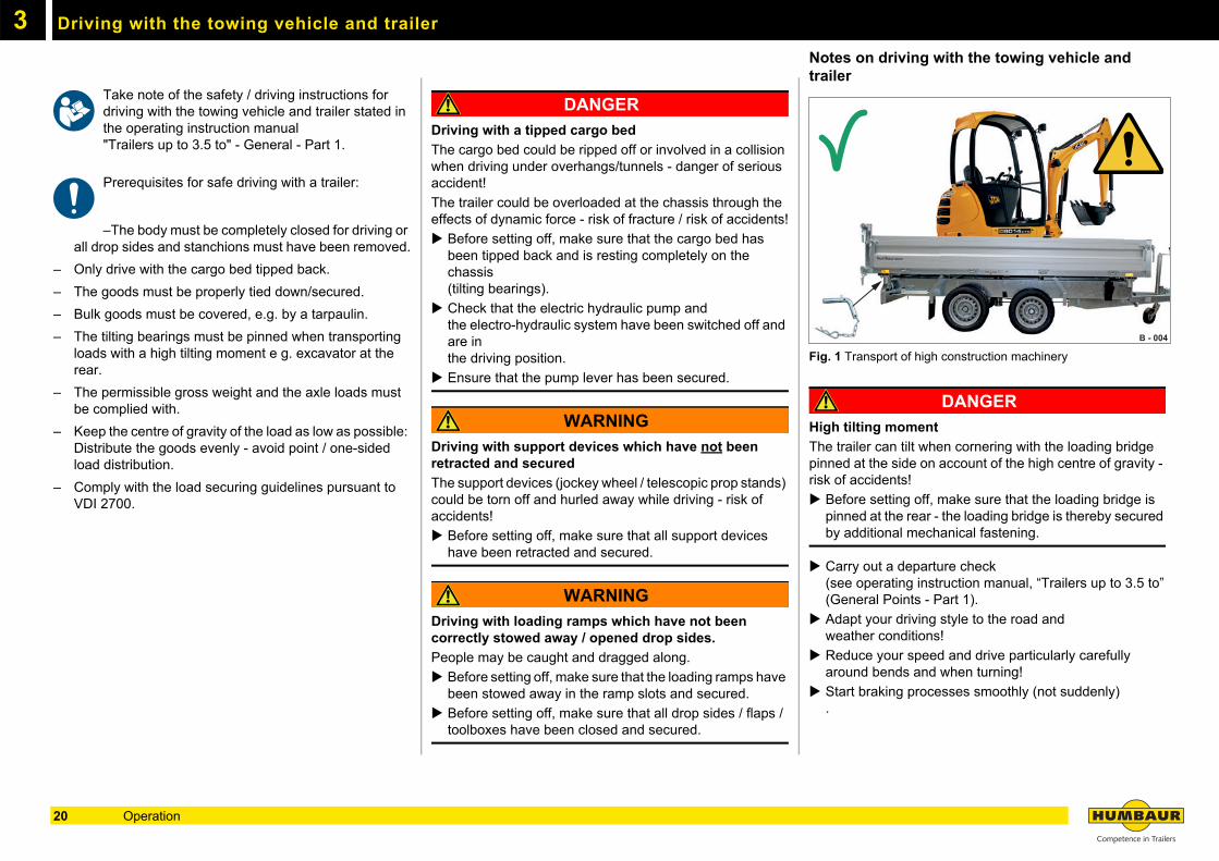
Driving with the towing vehicle and trailerTake note of the safety / driving instructions for driving with the towing vehicle and trailer stated in the operating instruction manual "Trailers up to 3.5 to" - General - Part 1.
Prerequisites for safe driving with a trailer:
–The body must be completely closed for driving or all drop sides and stanchions must have been removed.
– Only drive with the cargo bed tipped back.
– The goods must be properly tied down/secured.
– Bulk goods must be covered, e.g. by a tarpaulin.
– The tilting bearings must be pinned when transporting loads with a high tilting moment e g. excavator at the rear.
– The permissible gross weight and the axle loads must be complied with.
– Keep the centre of gravity of the load as low as possible: Distribute the goods evenly - avoid point / one-sided load distribution.
– Comply with the load securing guidelines pursuant to VDI 2700.
DANGER
Driving with a tipped cargo bed
The cargo bed could be ripped off or involved in a collision when driving under overhangs/tunnels - danger of serious accident!
The trailer could be overloaded at the chassis through the effects of dynamic force - risk of fracture / risk of accidents!
Before setting off, make sure that the cargo bed has been tipped back and is resting completely on the chassis (tilting bearings).
Check that the electric hydraulic pump and the electro-hydraulic system have been switched off and are in the driving position.
Ensure that the pump lever has been secured.
WARNING
Driving with support devices which have not been retracted and secured
The support devices (jockey wheel / telescopic prop stands) could be torn off and hurled away while driving - risk of accidents!
Before setting off, make sure that all support devices have been retracted and secured.
WARNING
Driving with loading ramps which have not been correctly stowed away / opened drop sides.
People may be caught and dragged along.
Before setting off, make sure that the loading ramps have been stowed away in the ramp slots and secured.
Before setting off, make sure that all drop sides / flaps / toolboxes have been closed and secured.
Notes on driving with the towing vehicle and trailer
Fig. 1 Transport of high construction machinery
DANGER
High tilting moment
The trailer can tilt when cornering with the loading bridge pinned at the side on account of the high centre of gravity - risk of accidents!
Before setting off, make sure that the loading bridge is pinned at the rear - the loading bridge is thereby secured by additional mechanical fastening.
Carry out a departure check(see operating instruction manual, “Trailers up to 3.5 to”(General Points - Part 1).
Adapt your driving style to the road and weather conditions!
Reduce your speed and drive particularly carefully around bends and when turning!
Start braking processes smoothly (not suddenly) .
B - 004
20 Operation
3Positional stability
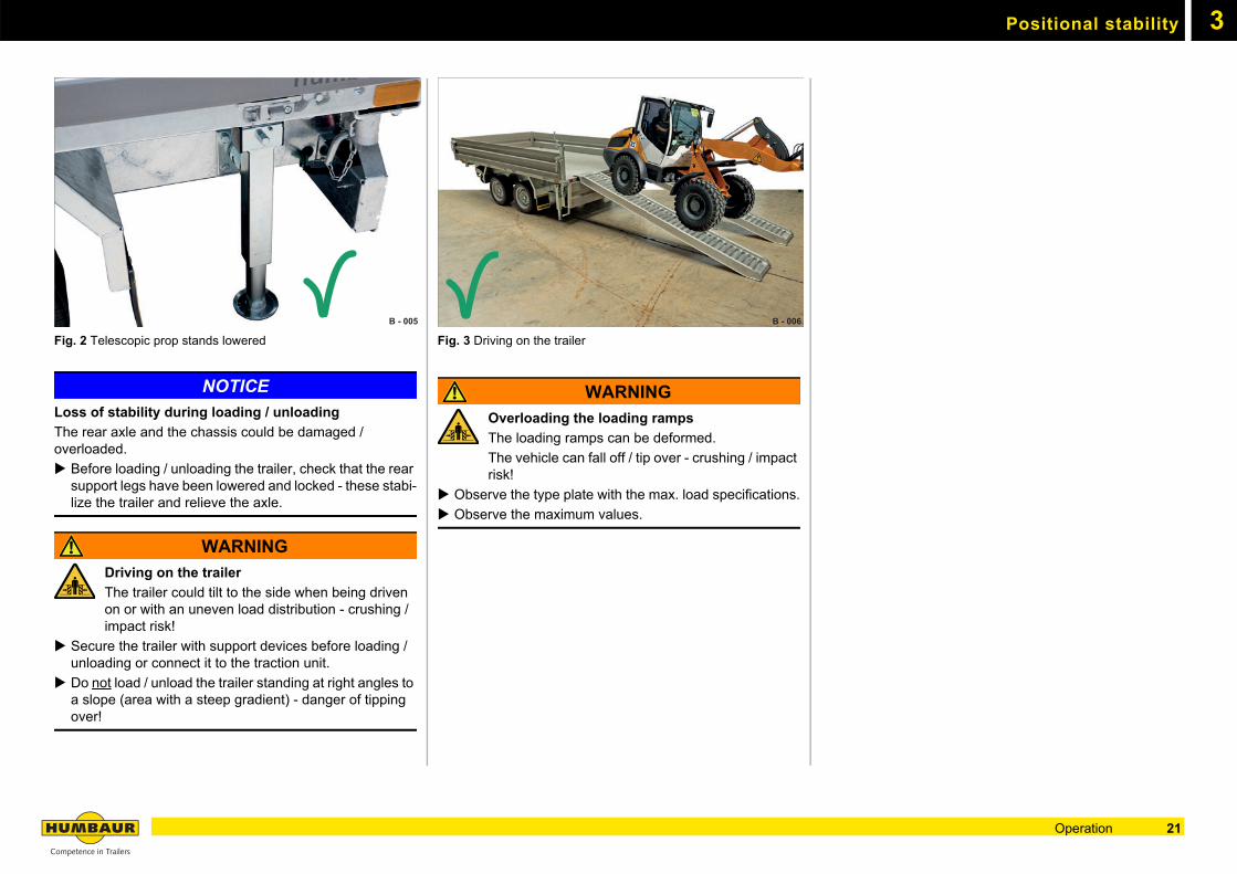
Fig. 2 Telescopic prop stands lowered
NOTICE
Loss of stability during loading / unloading
The rear axle and the chassis could be damaged / overloaded.
Before loading / unloading the trailer, check that the rear support legs have been lowered and locked - these stabi-lize the trailer and relieve the axle.
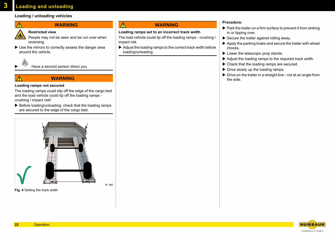
WARNING
Driving on the trailer
The trailer could tilt to the side when being driven on or with an uneven load distribution - crushing / impact risk!
Secure the trailer with support devices before loading / unloading or connect it to the traction unit.
Do not load / unload the trailer standing at right angles to a slope (area with a steep gradient) - danger of tipping over!
Fig. 3 Driving on the trailer
WARNING
Overloading the loading ramps
The loading ramps can be deformed.
The vehicle can fall off / tip over - crushing / impact risk!
Observe the type plate with the max. load specifications.
Observe the maximum values.
B - 005 B - 006
21Operation
Loading and unloading3
Loading / unloading vehiclesWARNING
Restricted view
People may not be seen and be run over when reversing.
Use the mirrors to correctly assess the danger area around the vehicle.
Have a second person direct you.
WARNING
Loading ramps not secured
The loading ramps could slip off the edge of the cargo bed and the load vehicle could tip off the loading ramps - crushing / impact risk!
Before loading/unloading, check that the loading ramps are secured to the edge of the cargo bed.
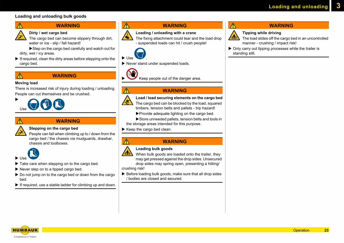
Fig. 4 Setting the track width
WARNING
Loading ramps set to an incorrect track width
The load vehicle could tip off the loading ramps - crushing / impact risk
Adjust the loading ramps to the correct track width before loading/unloading.
Procedure:
Park the trailer on a firm surface to prevent it from sinking in or tipping over.
Secure the trailer against rolling away.
Apply the parking brake and secure the trailer with wheel chocks.
Lower the telescopic prop stands.
Adjust the loading ramps to the required track width.
Check that the loading ramps are secured.
Drive slowly up the loading ramps.
Drive on the trailer in a straight line - not at an angle from the side.
B - 007
22 Operation
Loading and unloading 3
Loading and unloading bulk goodsWARNING
Dirty / wet cargo bed
The cargo bed can become slippery through dirt, water or ice - slip / fall hazard!
Step on the cargo bed carefully and watch out for dirty, wet / icy areas.
If required, clean the dirty areas before stepping onto the cargo bed.
WARNING
Moving load
There is increased risk of injury during loading / unloading.
People can cut themselves and be crushed.
Use , , .
WARNING
Stepping on the cargo bed
People can fall when climbing up to / down from the cargo bed / the chassis via mudguards, drawbar, chassis and toolboxes.
.
Use .
Take care when stepping on to the cargo bed.
Never step on to a tipped cargo bed.
Do not jump on to the cargo bed or down from the cargo bed.
If required, use a stable ladder for climbing up and down.
WARNING
Loading / unloading with a crane
The fixing attachment could tear and the load drop - suspended loads can hit / crush people!
Use .
Never stand under suspended loads.
Keep people out of the danger area.
WARNING
Load / load securing elements on the cargo bed
The cargo bed can be blocked by the load, squared timbers, tension belts and pallets - trip hazard!
Provide adequate lighting on the cargo bed.
Store unneeded pallets, tension belts and tools in the storage areas intended for this purpose.
Keep the cargo bed clean.
WARNING
Loading bulk goods
When bulk goods are loaded onto the trailer, they may get pressed against the drop sides. Unsecured drop sides may spring open, presenting a hitting/
crushing risk!
Before loading bulk goods, make sure that all drop sides / bodies are closed and secured.
WARNING
Tipping while driving
The load slides off the cargo bed in an uncontrolled manner - crushing / impact risk!
Only carry out tipping processes while the trailer is standing still.
23Operation
Loading and unloading3
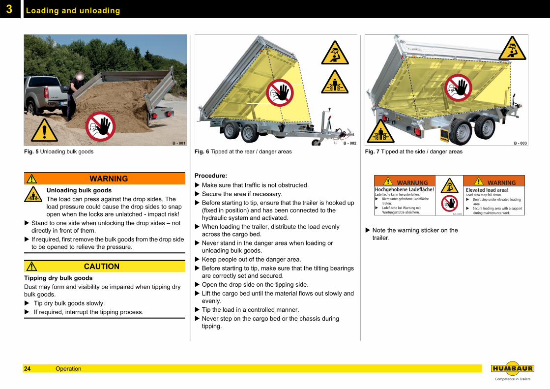
Fig. 5 Unloading bulk goods
WARNING
Unloading bulk goods
The load can press against the drop sides. The load pressure could cause the drop sides to snap open when the locks are unlatched - impact risk!
Stand to one side when unlocking the drop sides – not directly in front of them.
If required, first remove the bulk goods from the drop side to be opened to relieve the pressure.
CAUTION
Tipping dry bulk goods
Dust may form and visibility be impaired when tipping dry bulk goods.
Tip dry bulk goods slowly.
If required, interrupt the tipping process.
Fig. 6 Tipped at the rear / danger areas
Procedure:
Make sure that traffic is not obstructed.
Secure the area if necessary.
Before starting to tip, ensure that the trailer is hooked up (fixed in position) and has been connected to the hydraulic system and activated.
When loading the trailer, distribute the load evenly across the cargo bed.
Never stand in the danger area when loading or unloading bulk goods.
Keep people out of the danger area.
Before starting to tip, make sure that the tilting bearings are correctly set and secured.
Open the drop side on the tipping side.
Lift the cargo bed until the material flows out slowly and evenly.
Tip the load in a controlled manner.
Never step on the cargo bed or the chassis during tipping.
Fig. 7 Tipped at the side / danger areas
Note the warning sticker on the trailer.
B - 001 B - 002 B - 003
WARNUNG WARNINGHochgehobene Ladefläche!Ladefläche kann herunterfallen.
Nicht unter gehobene Ladefläche treten.
Ladefläche bei Wartung mit Wartungsstütze absichern.
Elevated load area!Load area may fall down.
Don‘t step under elevated loading area.
Secure loading area with a support during maintenance work.620.00034
24 Operation
3Load distribution / Max. weights
Permissible weights and load distribution
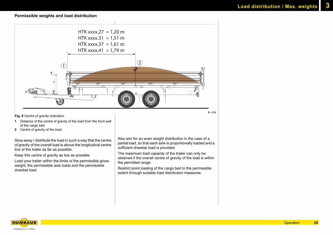
Fig. 8 Centre of gravity indication
1 Distance of the centre of gravity of the load from the front wall of the cargo bed
2 Centre of gravity of the load
Stow away / distribute the load in such a way that the centre of gravity of the overall load is above the longitudinal centre line of the trailer as far as possible.
Keep this centre of gravity as low as possible.
Load your trailer within the limits of the permissible gross weight, the permissible axle loads and the permissible drawbar load.
Also aim for an even weight distribution in the case of a partial load, so that each axle is proportionally loaded and a sufficient drawbar load is provided.
The maximum load capacity of the trailer can only be obtained if the overall centre of gravity of the load is within the permitted range.
Restrict point loading of the cargo bed to the permissible extent through suitable load distribution measures.
HTK xxxx.27 = 1,20 mHTK xxxx.31 = 1,51 mHTK xxxx.37 = 1,61 mHTK xxxx.41 = 1,79 m
B - 014
12
25Operation
Load distribution / Max. weights3
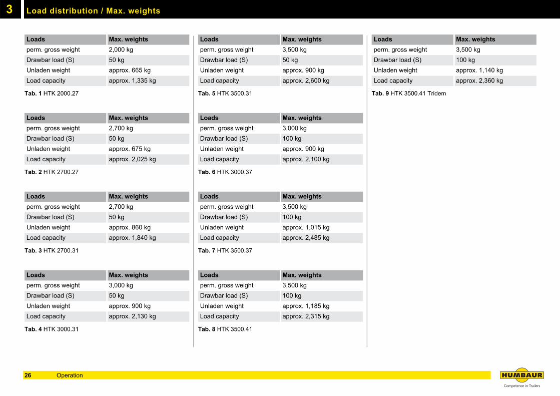
Tab. 1 HTK 2000.27
Tab. 2 HTK 2700.27
Tab. 3 HTK 2700.31
Tab. 4 HTK 3000.31
Tab. 5 HTK 3500.31
Tab. 6 HTK 3000.37
Tab. 7 HTK 3500.37
Tab. 8 HTK 3500.41
Tab. 9 HTK 3500.41 Tridem
Loads Max. weights
perm. gross weight 2,000 kg
Drawbar load (S) 50 kg
Unladen weight approx. 665 kg
Load capacity approx. 1,335 kg
Loads Max. weights
perm. gross weight 2,700 kg
Drawbar load (S) 50 kg
Unladen weight approx. 675 kg
Load capacity approx. 2,025 kg
Loads Max. weights
perm. gross weight 2,700 kg
Drawbar load (S) 50 kg
Unladen weight approx. 860 kg
Load capacity approx. 1,840 kg
Loads Max. weights
perm. gross weight 3,000 kg
Drawbar load (S) 50 kg
Unladen weight approx. 900 kg
Load capacity approx. 2,130 kg
Loads Max. weights
perm. gross weight 3,500 kg
Drawbar load (S) 50 kg
Unladen weight approx. 900 kg
Load capacity approx. 2,600 kg
Loads Max. weights
perm. gross weight 3,000 kg
Drawbar load (S) 100 kg
Unladen weight approx. 900 kg
Load capacity approx. 2,100 kg
Loads Max. weights
perm. gross weight 3,500 kg
Drawbar load (S) 100 kg
Unladen weight approx. 1,015 kg
Load capacity approx. 2,485 kg
Loads Max. weights
perm. gross weight 3,500 kg
Drawbar load (S) 100 kg
Unladen weight approx. 1,185 kg
Load capacity approx. 2,315 kg
Loads Max. weights
perm. gross weight 3,500 kg
Drawbar load (S) 100 kg
Unladen weight approx. 1,140 kg
Load capacity approx. 2,360 kg
26 Operation
3Uncoupling / Parking
Uncoupling
In the tipper trailer, the wheel chocks are attached to the chassis in the front section of the trailer as standard.
In addition to the parking brake, the trailer must be secured with wheel chocks on slopes / gradients and when uncoupled.
Wheel chocks must always be available. Replace any lost or damaged wheel chocks immediately.
WARNING
Incorrectly uncoupled trailer
The trailer could start moving and tip over.
People could be struck by the trailer and run over - risk of crushing!
Only uncouple the trailer when it is empty.
Use wheel chocks to secure the trailer from rolling away before uncoupling.
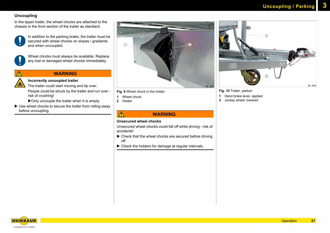
Fig. 9 Wheel chock in the holder
1 Wheel chock2 Holder
WARNING
Unsecured wheel chocks
Unsecured wheel chocks could fall off while driving - risk of accidents!
Check that the wheel chocks are secured before driving off.
Check the holders for damage at regular intervals.
Fig. 10 Trailer, parked
1 Hand brake lever, applied2 Jockey wheel, lowered
B - 011
1 2
B - 012
1
2
27Operation
Uncoupling / Parking3
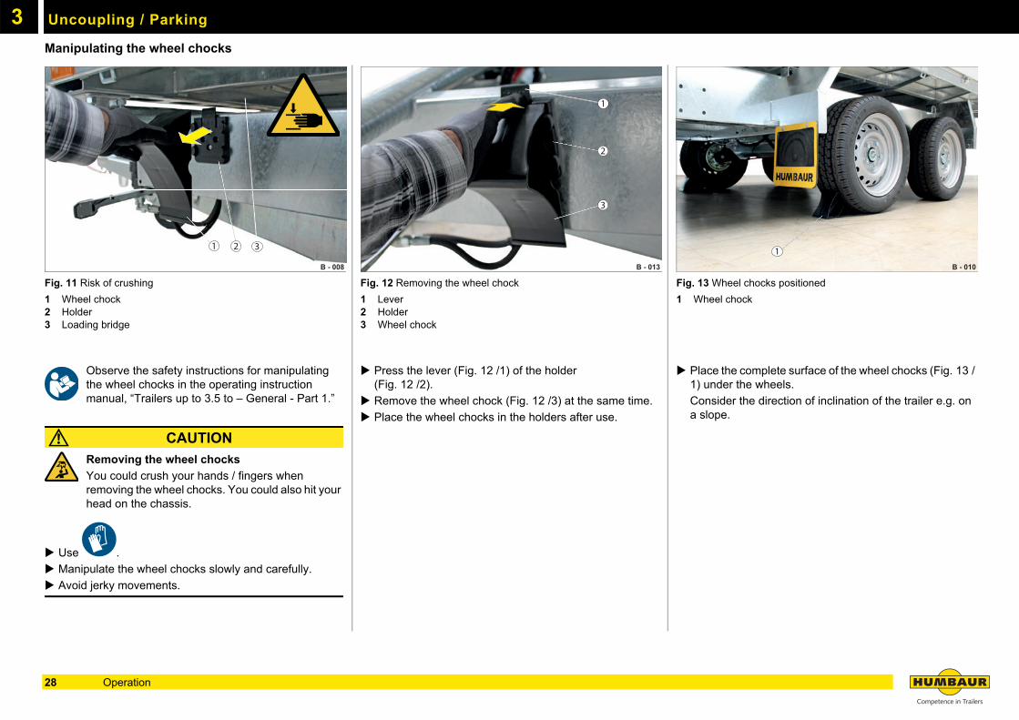
Manipulating the wheel chocksFig. 11 Risk of crushing
1 Wheel chock2 Holder3 Loading bridge
Observe the safety instructions for manipulating the wheel chocks in the operating instruction manual, “Trailers up to 3.5 to – General - Part 1.”
CAUTION
Removing the wheel chocks
You could crush your hands / fingers when removing the wheel chocks. You could also hit your head on the chassis.
Use .
Manipulate the wheel chocks slowly and carefully.
Avoid jerky movements.
Fig. 12 Removing the wheel chock
1 Lever2 Holder3 Wheel chock
Press the lever (Fig. 12 /1) of the holder (Fig. 12 /2).
Remove the wheel chock (Fig. 12 /3) at the same time.
Place the wheel chocks in the holders after use.
Fig. 13 Wheel chocks positioned
1 Wheel chock
Place the complete surface of the wheel chocks (Fig. 13 /1) under the wheels.
Consider the direction of inclination of the trailer e.g. on a slope.
B - 008
1 2 3
B - 013
1
2
3
B - 010
1
28 Operation
3Check before departure & when parking
Check before departure
– Trailer has been correctly coupled.
– Electrical plug has been connected.
– Towing connection has been disconnected and parked.
– Cargo bed has been tipped back.
– Parking brake has been released.
– Telescopic prop stands have been raised and locked.
– Drop sides / extensions / flaps / ramp slots have been closed and secured.
– Toolbox has been locked and secured.
– Loading ramps have been stowed away and secured.
Check when parking
– Trailer has been correctly uncoupled.
– Parking brake has been applied.
– Wheel chocks have been positioned.
– Cargo bed has been tipped back.
– Electrical plug has been parked.
– Drop sides / extensions / flaps / ramp slots have been locked.
– Loading ramps have been stowed away and secured.
– Toolbox has been locked.
29Operation

Check before departure & when parking3
30 Operation
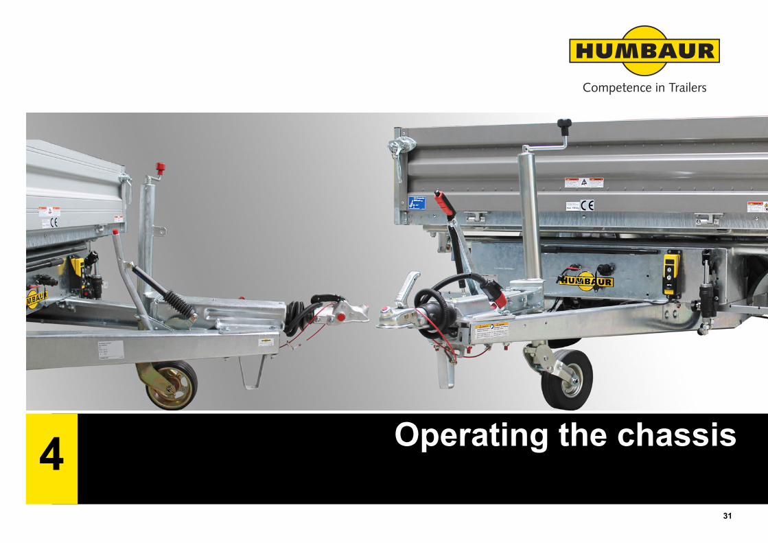
4
Operating the chassis31
4
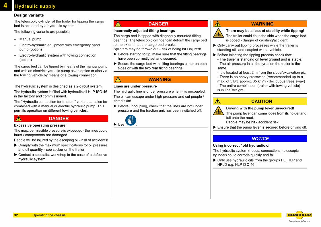
Hydraulic supplyDesign variants
The telescopic cylinder of the trailer for tipping the cargo bed is actuated by a hydraulic system.
The following variants are possible:
– Manual pump
– Electro-hydraulic equipment with emergency hand pump (option)
– Electro-hydraulic system with towing connection (option)
The cargo bed can be tipped by means of the manual pump and with an electric hydraulic pump as an option or also via the towing vehicle by means of a towing connection.
The hydraulic system is designed as a 2-circuit system.
The hydraulic system is filled with hydraulic oil HLP ISO 46 in the factory and commissioned.
The "Hydraulic connection for tractors" variant can also be combined with a manual or electric hydraulic pump. This permits operation on different towing vehicles.
DANGER
Excessive operating pressure
The max. permissible pressure is exceeded - the lines could burst / components are damaged.
People will be injured by the escaping oil - risk of accidents!
Comply with the maximum specifications for oil pressure and oil quantity - see sticker on the trailer.
Contact a specialist workshop in the case of a defective hydraulic system.
DANGER
Incorrectly adjusted tilting bearings
The cargo bed is tipped with diagonally mounted tilting bearings. The telescopic cylinder can deform the cargo bed to the extent that the cargo bed breaks.Splinters may be thrown out - risk of being hit / injured!
Before starting to tip, make sure that the tilting bearings have been correctly set and secured.
Secure the cargo bed with tilting bearings either on both sides or with the two rear tilting bearings.
WARNING
Lines are under pressure
The hydraulic line is under pressure when it is uncoupled.
The oil can escape under high pressure and cut people / shred skin!
Before uncoupling, check that the lines are not under pressure and the traction unit has been switched off.
Use .
WARNING
There may be a loss of stability while tipping!
The trailer could tip to the side when the cargo bed is tipped - danger of crushing/accident!
Only carry out tipping processes while the trailer is standing still and coupled with a vehicle.
Before initiating the tipping process check that:- The trailer is standing on level ground and is stable.- The air pressure in all the tyres on the trailer is the same.- It is located at least 2 m from the slope/excavation pit.- There is no heavy crosswind (recommended up to a max. of 5 Bft, approx. 35 km/h - deciduous trees sway)- The entire combination (trailer with towing vehicle) is in line/straight.
CAUTION
Driving with the pump lever unsecured!
The pump lever can come loose from its holder and fall onto the road.People may be hit - accident risk!
Ensure that the pump lever is secured before driving off.
NOTICE
Using incorrect / old hydraulic oil
The hydraulic system (hoses, connections, telescopic cylinder) could corrode quickly and fail.
Only use hydraulic oils from the groups HL, HLP and HPLD e.g. HLP ISO 46.
32 Operating the chassis
4Manual pump
Manual pump
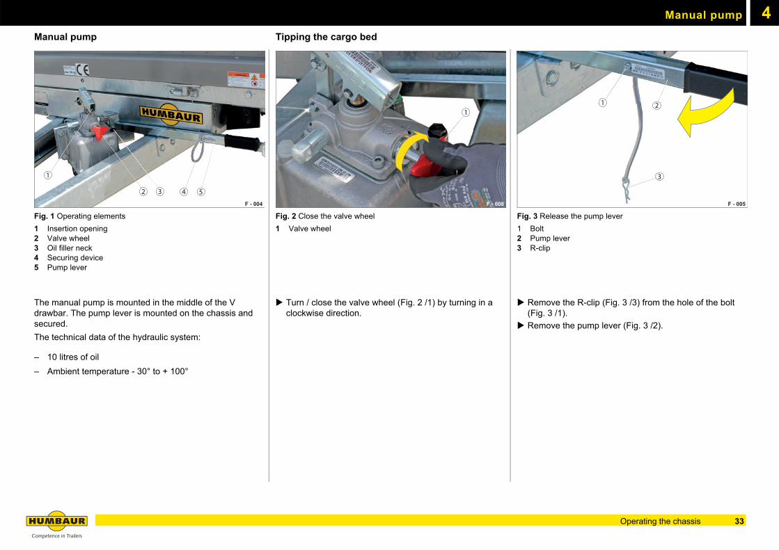
Fig. 1 Operating elements
1 Insertion opening2 Valve wheel3 Oil filler neck4 Securing device5 Pump lever
The manual pump is mounted in the middle of the V drawbar. The pump lever is mounted on the chassis and secured.
The technical data of the hydraulic system:
– 10 litres of oil
– Ambient temperature - 30° to + 100°
Tipping the cargo bed
Fig. 2 Close the valve wheel
1 Valve wheel
Turn / close the valve wheel (Fig. 2 /1) by turning in a clockwise direction.
Fig. 3 Release the pump lever
1 Bolt2 Pump lever3 R-clip
Remove the R-clip (Fig. 3 /3) from the hole of the bolt (Fig. 3 /1).
Remove the pump lever (Fig. 3 /2).
F - 004
2 3
1
4 5
F - 008
1
F - 005
1
3
2
33Operating the chassis
Manual pump4
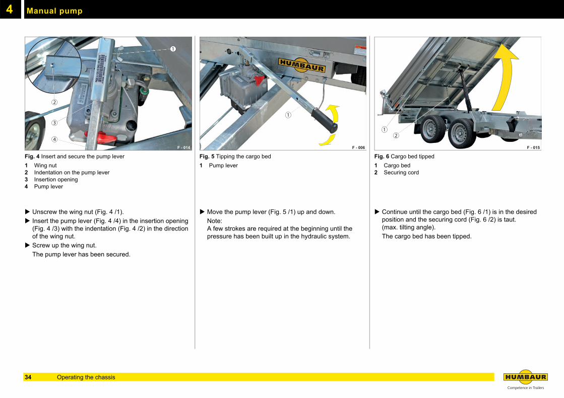
Fig. 4 Insert and secure the pump lever
1 Wing nut2 Indentation on the pump lever3 Insertion opening4 Pump lever
Unscrew the wing nut (Fig. 4 /1).
Insert the pump lever (Fig. 4 /4) in the insertion opening (Fig. 4 /3) with the indentation (Fig. 4 /2) in the direction of the wing nut.
Screw up the wing nut.
The pump lever has been secured.
Fig. 5 Tipping the cargo bed
1 Pump lever
Move the pump lever (Fig. 5 /1) up and down.
Note: A few strokes are required at the beginning until the pressure has been built up in the hydraulic system.
Fig. 6 Cargo bed tipped
1 Cargo bed2 Securing cord
Continue until the cargo bed (Fig. 6 /1) is in the desired position and the securing cord (Fig. 6 /2) is taut. (max. tilting angle).
The cargo bed has been tipped.
F - 014
1
2
4
3
F - 006
1
F - 015 F - 015
12
34 Operating the chassis
Manual pump 4
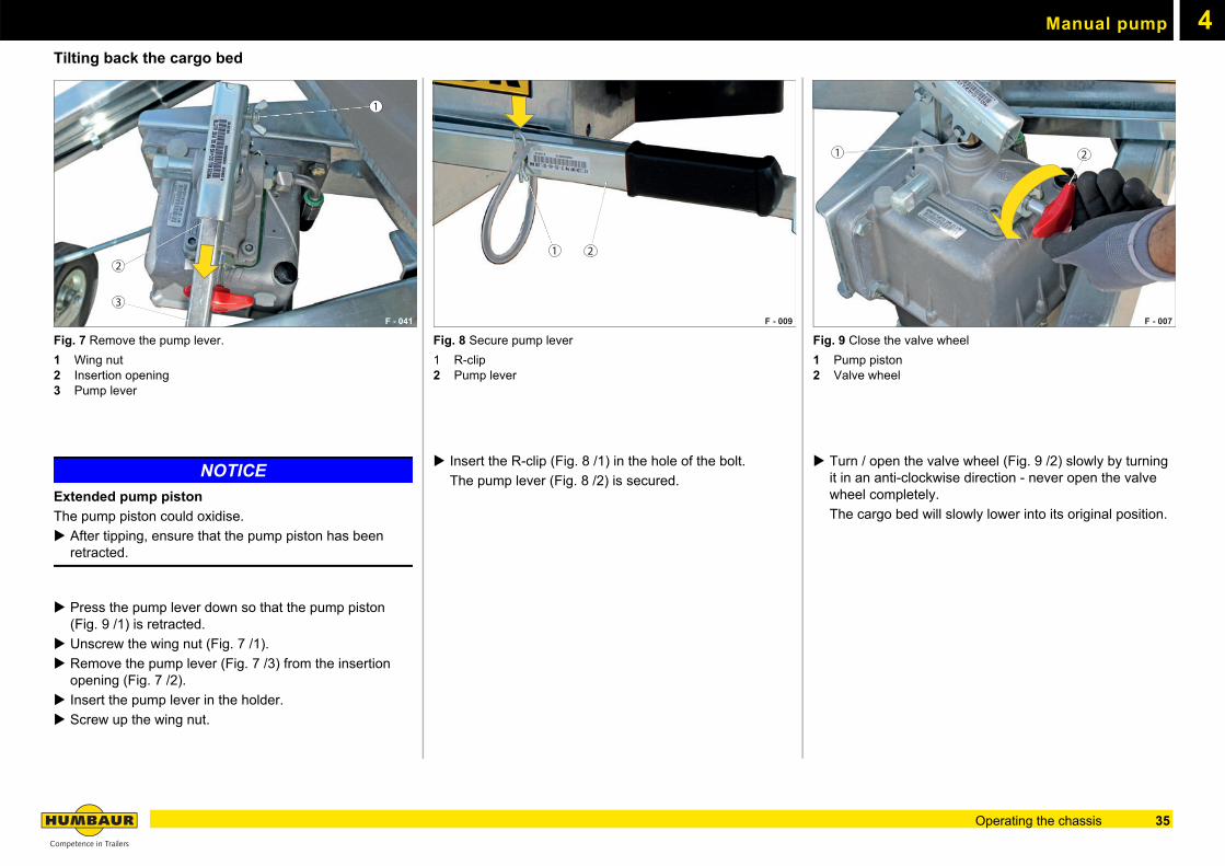
Tilting back the cargo bedFig. 7 Remove the pump lever.
1 Wing nut2 Insertion opening3 Pump lever
NOTICE
Extended pump piston
The pump piston could oxidise.
After tipping, ensure that the pump piston has been retracted.
Press the pump lever down so that the pump piston (Fig. 9 /1) is retracted.
Unscrew the wing nut (Fig. 7 /1).
Remove the pump lever (Fig. 7 /3) from the insertion opening (Fig. 7 /2).
Insert the pump lever in the holder.
Screw up the wing nut.
Fig. 8 Secure pump lever
1 R-clip2 Pump lever
Insert the R-clip (Fig. 8 /1) in the hole of the bolt.
The pump lever (Fig. 8 /2) is secured.
Fig. 9 Close the valve wheel
1 Pump piston2 Valve wheel
Turn / open the valve wheel (Fig. 9 /2) slowly by turning it in an anti-clockwise direction - never open the valve wheel completely.
The cargo bed will slowly lower into its original position.
F - 041
1
3
2
F - 009
1 2
F - 007
21
35Operating the chassis
4
Electro-hydraulic equipmentElectro-hydraulic equipment
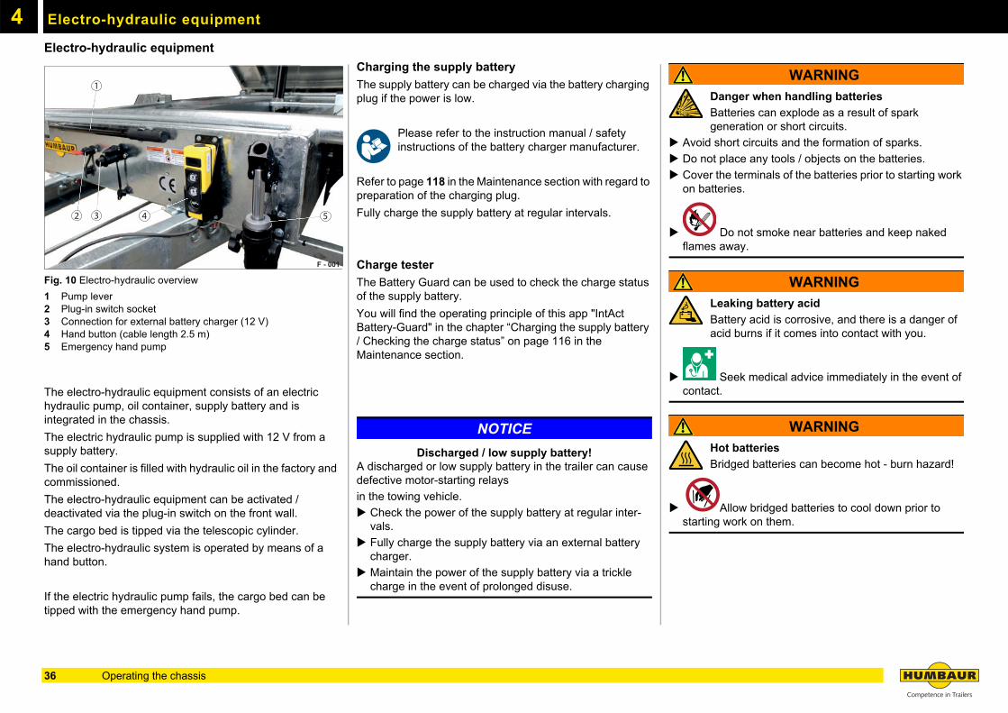
Fig. 10 Electro-hydraulic overview
1 Pump lever2 Plug-in switch socket3 Connection for external battery charger (12 V)4 Hand button (cable length 2.5 m)5 Emergency hand pump
The electro-hydraulic equipment consists of an electric hydraulic pump, oil container, supply battery and is integrated in the chassis.
The electric hydraulic pump is supplied with 12 V from a supply battery.
The oil container is filled with hydraulic oil in the factory and commissioned.
The electro-hydraulic equipment can be activated / deactivated via the plug-in switch on the front wall.
The cargo bed is tipped via the telescopic cylinder.
The electro-hydraulic system is operated by means of a hand button.
If the electric hydraulic pump fails, the cargo bed can be tipped with the emergency hand pump.
Charging the supply battery
The supply battery can be charged via the battery charging plug if the power is low.
Please refer to the instruction manual / safety instructions of the battery charger manufacturer.
Refer to page 118 in the Maintenance section with regard to preparation of the charging plug.
Fully charge the supply battery at regular intervals.
Charge tester
The Battery Guard can be used to check the charge status of the supply battery.
You will find the operating principle of this app "IntAct Battery-Guard" in the chapter “Charging the supply battery / Checking the charge status” on page 116 in the Maintenance section.
NOTICE
Discharged / low supply battery!A discharged or low supply battery in the trailer can cause defective motor-starting relays
in the towing vehicle.
Check the power of the supply battery at regular inter-vals.
Fully charge the supply battery via an external battery charger.
Maintain the power of the supply battery via a trickle charge in the event of prolonged disuse.
WARNING
Danger when handling batteries
Batteries can explode as a result of spark generation or short circuits.
Avoid short circuits and the formation of sparks.
Do not place any tools / objects on the batteries.
Cover the terminals of the batteries prior to starting work on batteries.
Do not smoke near batteries and keep naked flames away.
WARNING
Leaking battery acid
Battery acid is corrosive, and there is a danger of acid burns if it comes into contact with you.
Seek medical advice immediately in the event of contact.
WARNING
Hot batteries
Bridged batteries can become hot - burn hazard!
Allow bridged batteries to cool down prior to starting work on them.
F - 001
1
2 3 4 5
36 Operating the chassis
Electro-hydraulic equipment 4
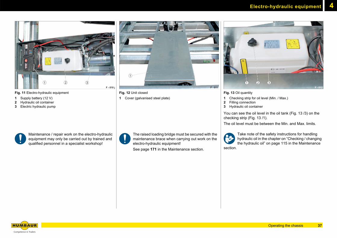
Fig. 11 Electro-hydraulic equipment
1 Supply battery (12 V)2 Hydraulic oil container3 Electric hydraulic pump
Maintenance / repair work on the electro-hydraulic equipment may only be carried out by trained and qualified personnel in a specialist workshop!
Fig. 12 Unit closed
1 Cover (galvanised steel plate)
The raised loading bridge must be secured with the maintenance brace when carrying out work on the electro-hydraulic equipment!
See page 171 in the Maintenance section.
Fig. 13 Oil quantity
1 Checking strip for oil level (Min. / Max.)2 Filling connection3 Hydraulic oil container
You can see the oil level in the oil tank (Fig. 13 /3) on the checking strip (Fig. 13 /1).
The oil level must be between the Min. and Max. limits.
Take note of the safety instructions for handling hydraulic oil in the chapter on “Checking / changing the hydraulic oil” on page 115 in the Maintenance
section.
F - 010
1 2 3F - 011
1
F - 012
1 2 3
37Operating the chassis
Electro-hydraulic equipment4
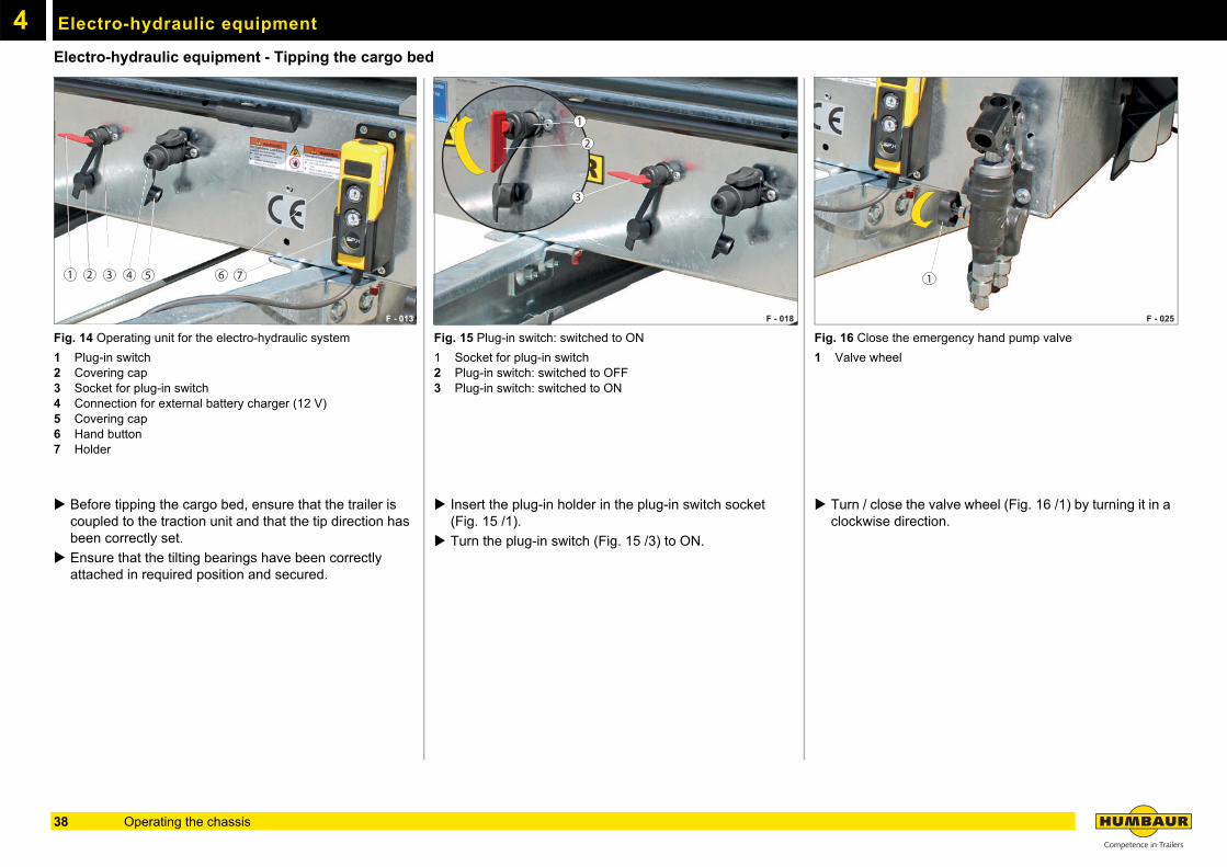
Electro-hydraulic equipment - Tipping the cargo bedFig. 14 Operating unit for the electro-hydraulic system
1 Plug-in switch2 Covering cap3 Socket for plug-in switch4 Connection for external battery charger (12 V)5 Covering cap6 Hand button7 Holder
Before tipping the cargo bed, ensure that the trailer is coupled to the traction unit and that the tip direction has been correctly set.
Ensure that the tilting bearings have been correctly attached in required position and secured.
Fig. 15 Plug-in switch: switched to ON
1 Socket for plug-in switch2 Plug-in switch: switched to OFF3 Plug-in switch: switched to ON
Insert the plug-in holder in the plug-in switch socket (Fig. 15 /1).
Turn the plug-in switch (Fig. 15 /3) to ON.
Fig. 16 Close the emergency hand pump valve
1 Valve wheel
Turn / close the valve wheel (Fig. 16 /1) by turning it in a clockwise direction.
F - 013
4 51 6 732
F - 018
11111111111
2
3
1
F - 025
1
38 Operating the chassis
Electro-hydraulic equipment 4
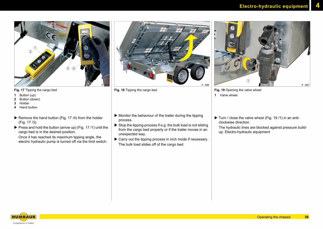
Fig. 17 Tipping the cargo bed
1 Button (up)2 Button (down)3 Holder4 Hand button
Remove the hand button (Fig. 17 /4) from the holder (Fig. 17 /3).
Press and hold the button (arrow up) (Fig. 17 /1) until the cargo bed is in the desired position.
Once it has reached its maximum tipping angle, the electric hydraulic pump is turned off via the limit switch.
Fig. 18 Tipping the cargo bed
Monitor the behaviour of the trailer during the tipping process.
Stop the tipping process if e.g. the bulk load is not sliding from the cargo bed properly or if the trailer moves in an unexpected way.
Carry out the tipping process in inch mode if necessary.
The bulk load slides off of the cargo bed.
Fig. 19 Opening the valve wheel
1 Valve wheel
Turn / close the valve wheel (Fig. 19 /1) in an anti-clockwise direction.
The hydraulic lines are blocked against pressure build-up. Electro-hydraulic equipment
F - 019
21
3 4
F - 020F - 020 F - 027 1
39Operating the chassis
Electro-hydraulic equipment4
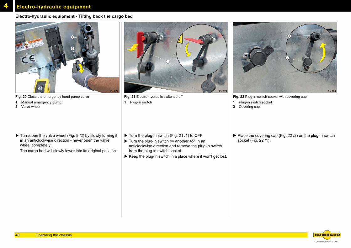
Electro-hydraulic equipment - Tilting back the cargo bedFig. 20 Close the emergency hand pump valve
1 Manual emergency pump2 Valve wheel
Turn/open the valve wheel (Fig. 9 /2) by slowly turning it in an anticlockwise direction - never open the valve wheel completely.
The cargo bed will slowly lower into its original position.
Fig. 21 Electro-hydraulic switched off
1 Plug-in switch
Turn the plug-in switch (Fig. 21 /1) to OFF.
Turn the plug-in switch by another 45° in an anticlockwise direction and remove the plug-in switch from the plug-in switch socket.
Keep the plug-in switch in a place where it won't get lost.
Fig. 22 Plug-in switch socket with covering cap
1 Plug-in switch socket2 Covering cap
Place the covering cap (Fig. 22 /2) on the plug-in switch socket (Fig. 22 /1).
F - 022
1
2
F - 021
1
F - 024
1
2
40 Operating the chassis
Electro-hydraulic equipment 4
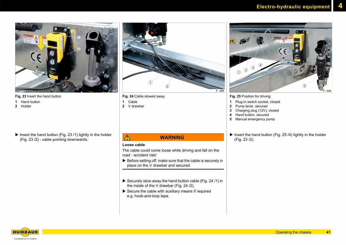
Fig. 23 Insert the hand button
1 Hand button2 Holder
Insert the hand button (Fig. 23 /1) tightly in the holder (Fig. 23 /2) - cable pointing downwards.
Fig. 24 Cable stowed away
1 Cable2 V drawbar
WARNING
Loose cable
The cable could come loose while driving and fall on the road - accident risk!
Before setting off, make sure that the cable is securely in place on the V drawbar and secured.
Securely stow away the hand button cable (Fig. 24 /1) in the inside of the V drawbar (Fig. 24 /2).
Secure the cable with auxiliary means if required e.g. hook-and-loop tape.
Fig. 25 Position for driving
1 Plug-in switch socket, closed2 Pump lever, secured3 Charging plug (12V), closed4 Hand button, secured5 Manual emergency pump
Insert the hand button (Fig. 25 /4) tightly in the holder (Fig. 23 /2).
F - 023
1
2
F - 029
21
F - 043
12
34
5
41Operating the chassis
Electro-hydraulic equipment4
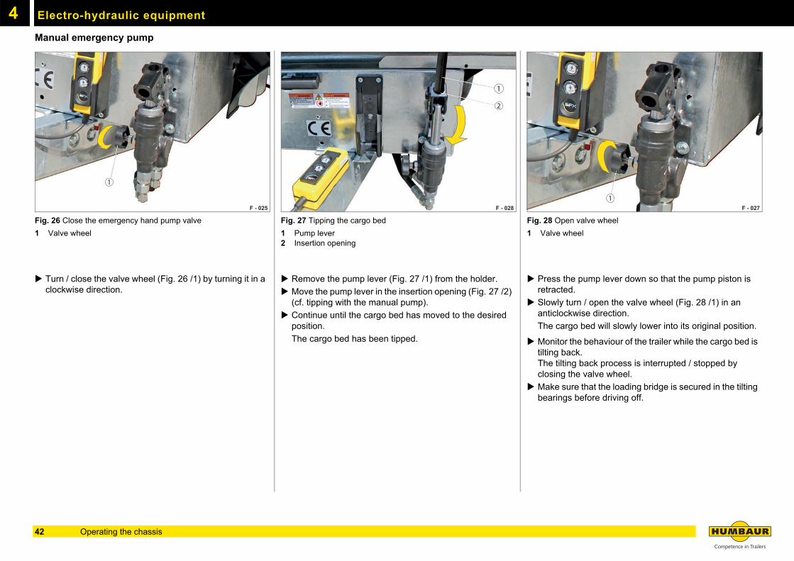
Manual emergency pumpFig. 26 Close the emergency hand pump valve
1 Valve wheel
Turn / close the valve wheel (Fig. 26 /1) by turning it in a clockwise direction.
Fig. 27 Tipping the cargo bed
1 Pump lever2 Insertion opening
Remove the pump lever (Fig. 27 /1) from the holder.
Move the pump lever in the insertion opening (Fig. 27 /2) (cf. tipping with the manual pump).
Continue until the cargo bed has moved to the desired position.
The cargo bed has been tipped.
Fig. 28 Open valve wheel
1 Valve wheel
Press the pump lever down so that the pump piston is retracted.
Slowly turn / open the valve wheel (Fig. 28 /1) in an anticlockwise direction.
The cargo bed will slowly lower into its original position.
Monitor the behaviour of the trailer while the cargo bed is tilting back.The tilting back process is interrupted / stopped by closing the valve wheel.
Make sure that the loading bridge is secured in the tilting bearings before driving off.
F - 025
1
F - 028
1
2
F - 027 1
42 Operating the chassis
4Towing connection
Towing connection (option)
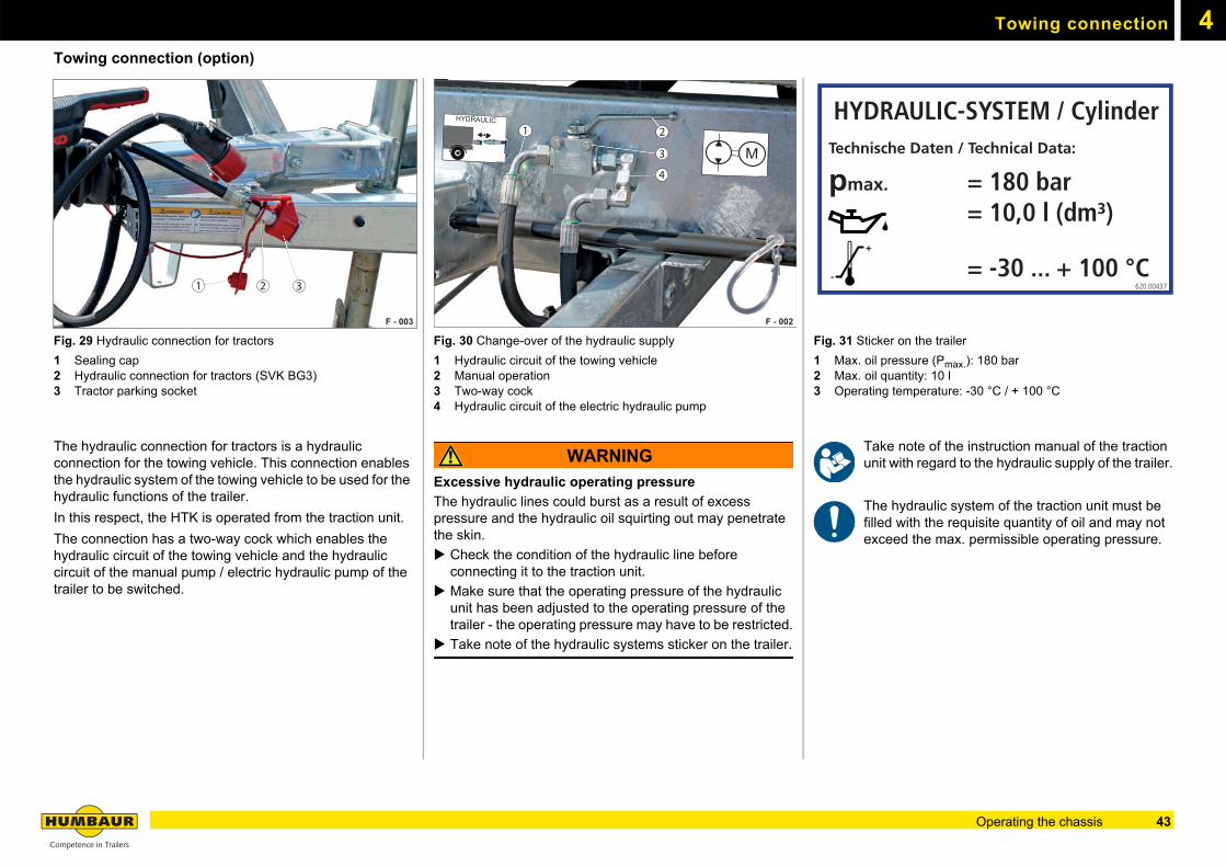
Fig. 29 Hydraulic connection for tractors
1 Sealing cap2 Hydraulic connection for tractors (SVK BG3)3 Tractor parking socket
The hydraulic connection for tractors is a hydraulic connection for the towing vehicle. This connection enables the hydraulic system of the towing vehicle to be used for the hydraulic functions of the trailer.
In this respect, the HTK is operated from the traction unit.
The connection has a two-way cock which enables the hydraulic circuit of the towing vehicle and the hydraulic circuit of the manual pump / electric hydraulic pump of the trailer to be switched.
Fig. 30 Change-over of the hydraulic supply
1 Hydraulic circuit of the towing vehicle2 Manual operation3 Two-way cock4 Hydraulic circuit of the electric hydraulic pump
WARNING
Excessive hydraulic operating pressure
The hydraulic lines could burst as a result of excess pressure and the hydraulic oil squirting out may penetrate the skin.
Check the condition of the hydraulic line before connecting it to the traction unit.
Make sure that the operating pressure of the hydraulic unit has been adjusted to the operating pressure of the trailer - the operating pressure may have to be restricted.
Take note of the hydraulic systems sticker on the trailer.
Fig. 31 Sticker on the trailer
1 Max. oil pressure (Pmax.): 180 bar2 Max. oil quantity: 10 l3 Operating temperature: -30 °C / + 100 °C
Take note of the instruction manual of the traction unit with regard to the hydraulic supply of the trailer.
The hydraulic system of the traction unit must be filled with the requisite quantity of oil and may not exceed the max. permissible operating pressure.
F - 003
1 2 3
F - 002
2
3
4
HYDRAULIC
620.00439
M620.00440
1HYDRAULIC-SYSTEM / Cylinder
Technische Daten / Technical Data:
pmax. = 180 bar = 10,0 l (dm³)
= -30 ... + 100 °C+
-620.00437
43Operating the chassis
Towing connection4
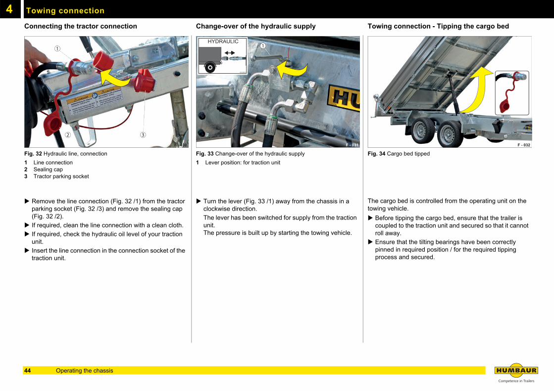
Connecting the tractor connectionFig. 32 Hydraulic line, connection
1 Line connection2 Sealing cap3 Tractor parking socket
Remove the line connection (Fig. 32 /1) from the tractor parking socket (Fig. 32 /3) and remove the sealing cap (Fig. 32 /2).
If required, clean the line connection with a clean cloth.
If required, check the hydraulic oil level of your traction unit.
Insert the line connection in the connection socket of the traction unit.
Change-over of the hydraulic supply
Fig. 33 Change-over of the hydraulic supply
1 Lever position: for traction unit
Turn the lever (Fig. 33 /1) away from the chassis in a clockwise direction.
The lever has been switched for supply from the traction unit.The pressure is built up by starting the towing vehicle.
Towing connection - Tipping the cargo bed
Fig. 34 Cargo bed tipped
The cargo bed is controlled from the operating unit on the towing vehicle.
Before tipping the cargo bed, ensure that the trailer is coupled to the traction unit and secured so that it cannot roll away.
Ensure that the tilting bearings have been correctly pinned in required position / for the required tipping process and secured.
F - 030
1
32
F - 016
1HYDRAULIC
620.00439
F - 031
1HYDRAULIC
620.00439
F - 032
44 Operating the chassis
Towing connection 4
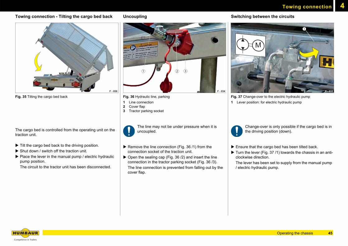
Towing connection - Tilting the cargo bed backFig. 35 Tilting the cargo bed back
The cargo bed is controlled from the operating unit on the traction unit.
Tilt the cargo bed back to the driving position.
Shut down / switch off the traction unit.
Place the lever in the manual pump / electric hydraulic pump position.
The circuit to the tractor unit has been disconnected.
Uncoupling
Fig. 36 Hydraulic line, parking
1 Line connection2 Cover flap3 Tractor parking socket
The line may not be under pressure when it is uncoupled.
Remove the line connection (Fig. 36 /1) from the connection socket of the traction unit.
Open the sealing cap (Fig. 36 /2) and insert the line connection in the tractor parking socket (Fig. 36 /3).
The line connection is prevented from falling out by the cover flap.
Switching between the circuits
Fig. 37 Change-over to the electric hydraulic pump
1 Lever position: for electric hydraulic pump
Change-over is only possible if the cargo bed is in the driving position (down).
Ensure that the cargo bed has been tilted back.
Turn the lever (Fig. 37 /1) towards the chassis in an anti-clockwise direction.
The lever has been set to supply from the manual pump / electric hydraulic pump.
F - 059 F - 034
21 3
F - 033
1
M620.00440
45Operating the chassis
4
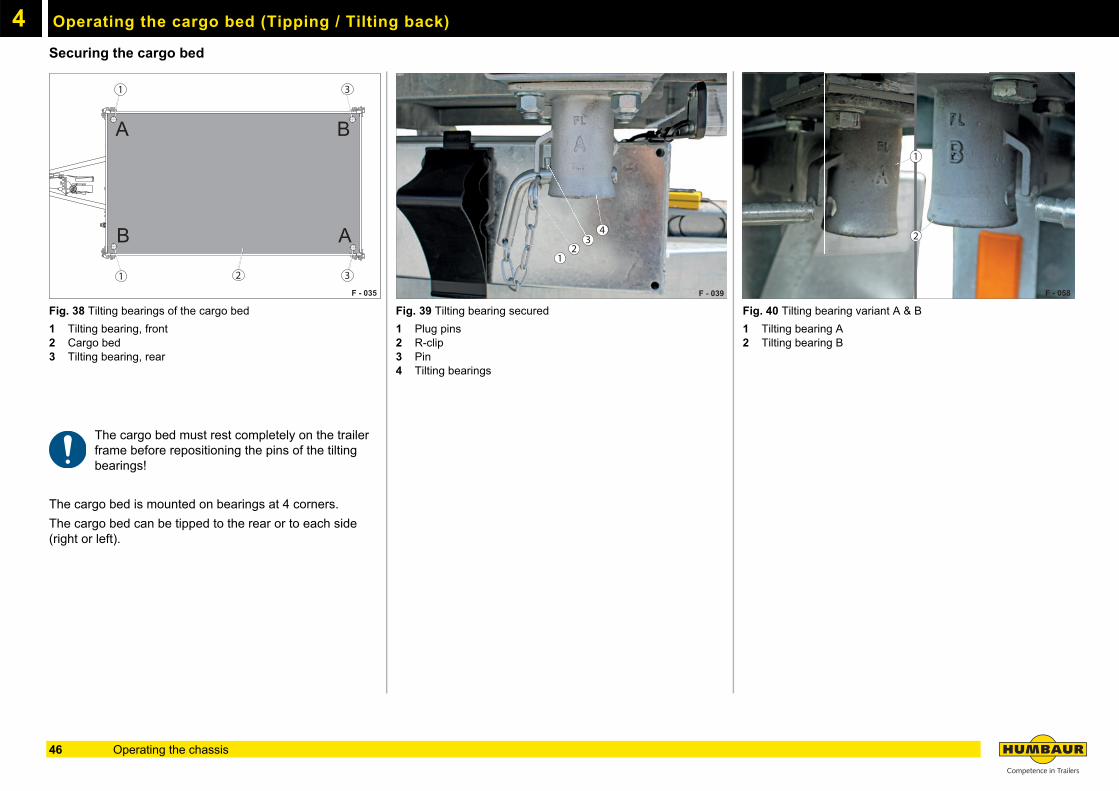
Operating the cargo bed (Tipping / Tilting back)Securing the cargo bed
Fig. 38 Tilting bearings of the cargo bed
1 Tilting bearing, front2 Cargo bed3 Tilting bearing, rear
The cargo bed must rest completely on the trailer frame before repositioning the pins of the tilting bearings!
The cargo bed is mounted on bearings at 4 corners.
The cargo bed can be tipped to the rear or to each side (right or left).
Fig. 39 Tilting bearing secured
1 Plug pins2 R-clip3 Pin4 Tilting bearings
Fig. 40 Tilting bearing variant A & B
1 Tilting bearing A2 Tilting bearing B
F - 035
B
B
A
A
1
1
3
32
F - 039
34
21
F - 058
2
1
46 Operating the chassis
Operating the cargo bed (Tipping / Tilting back) 4
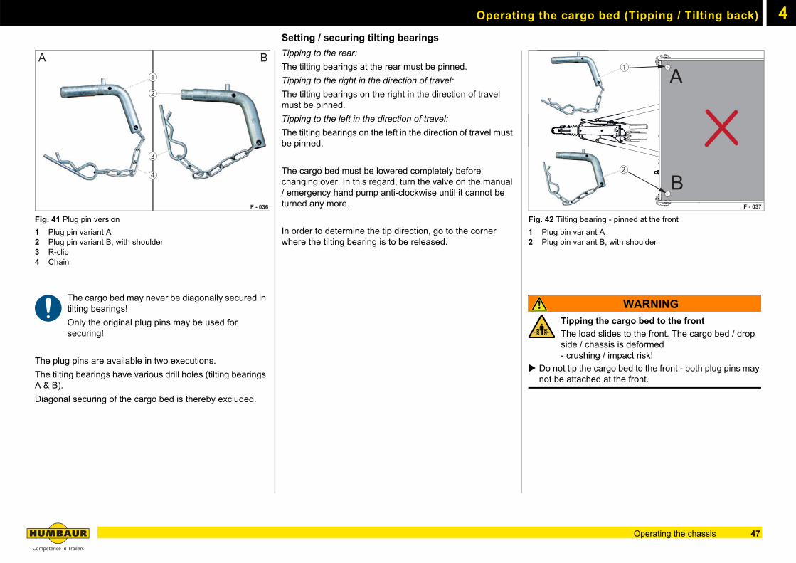
Fig. 41 Plug pin version
1 Plug pin variant A2 Plug pin variant B, with shoulder3 R-clip4 Chain
The cargo bed may never be diagonally secured in tilting bearings!
Only the original plug pins may be used for securing!
The plug pins are available in two executions.
The tilting bearings have various drill holes (tilting bearings A & B).
Diagonal securing of the cargo bed is thereby excluded.
Setting / securing tilting bearings
Tipping to the rear:
The tilting bearings at the rear must be pinned.
Tipping to the right in the direction of travel:
The tilting bearings on the right in the direction of travel must be pinned.
Tipping to the left in the direction of travel:
The tilting bearings on the left in the direction of travel must be pinned.
The cargo bed must be lowered completely before changing over. In this regard, turn the valve on the manual / emergency hand pump anti-clockwise until it cannot be turned any more.
In order to determine the tip direction, go to the corner where the tilting bearing is to be released.
Fig. 42 Tilting bearing - pinned at the front
1 Plug pin variant A2 Plug pin variant B, with shoulder
WARNING
Tipping the cargo bed to the front
The load slides to the front. The cargo bed / drop side / chassis is deformed - crushing / impact risk!
Do not tip the cargo bed to the front - both plug pins may not be attached at the front.
F - 036
BA1
2
4
3
F - 037
B
A1
2
47Operating the chassis
Operating the cargo bed (Tipping / Tilting back)4
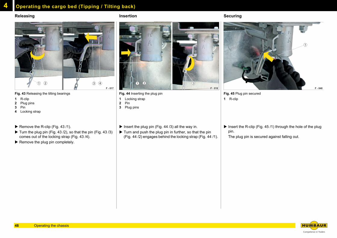
ReleasingFig. 43 Releasing the tilting bearings
1 R-clip2 Plug pins3 Pin4 Locking strap
Remove the R-clip (Fig. 43 /1).
Turn the plug pin (Fig. 43 /2), so that the pin (Fig. 43 /3) comes out of the locking strap (Fig. 43 /4).
Remove the plug pin completely.
Insertion
Fig. 44 Inserting the plug pin
1 Locking strap2 Pin3 Plug pins
Insert the plug pin (Fig. 44 /3) all the way in.
Turn and push the plug pin in further, so that the pin (Fig. 44 /2) engages behind the locking strap (Fig. 44 /1).
Securing
Fig. 45 Plug pin secured
1 R-clip
Insert the R-clip (Fig. 45 /1) through the hole of the plug pin.
The plug pin is secured against falling out.
F - 017
1 2 3 4F - 016
1 2 3
F - 040
1
48 Operating the chassis
Operating the cargo bed (Tipping / Tilting back) 4
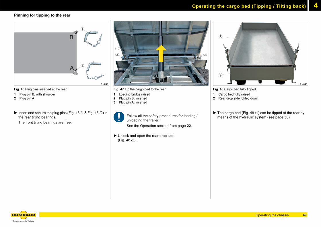
Pinning for tipping to the rearFig. 46 Plug pins inserted at the rear
1 Plug pin B, with shoulder2 Plug pin A
Insert and secure the plug pins (Fig. 46 /1 & Fig. 46 /2) in the rear tilting bearings.
The front tilting bearings are free.
Fig. 47 Tip the cargo bed to the rear
1 Loading bridge raised2 Plug pin B, inserted3 Plug pin A, inserted
Follow all the safety procedures for loading / unloading the trailer.
See the Operation section from page 22.
Unlock and open the rear drop side (Fig. 48 /2).
Fig. 48 Cargo bed fully tipped
1 Cargo bed fully raised2 Rear drop side folded down
The cargo bed (Fig. 48 /1) can be tipped at the rear by means of the hydraulic system (see page 38).
F - 038
B
A 2
1
F - 044
2 3
1
F - 045
2
1
49Operating the chassis
Operating the cargo bed (Tipping / Tilting back)4
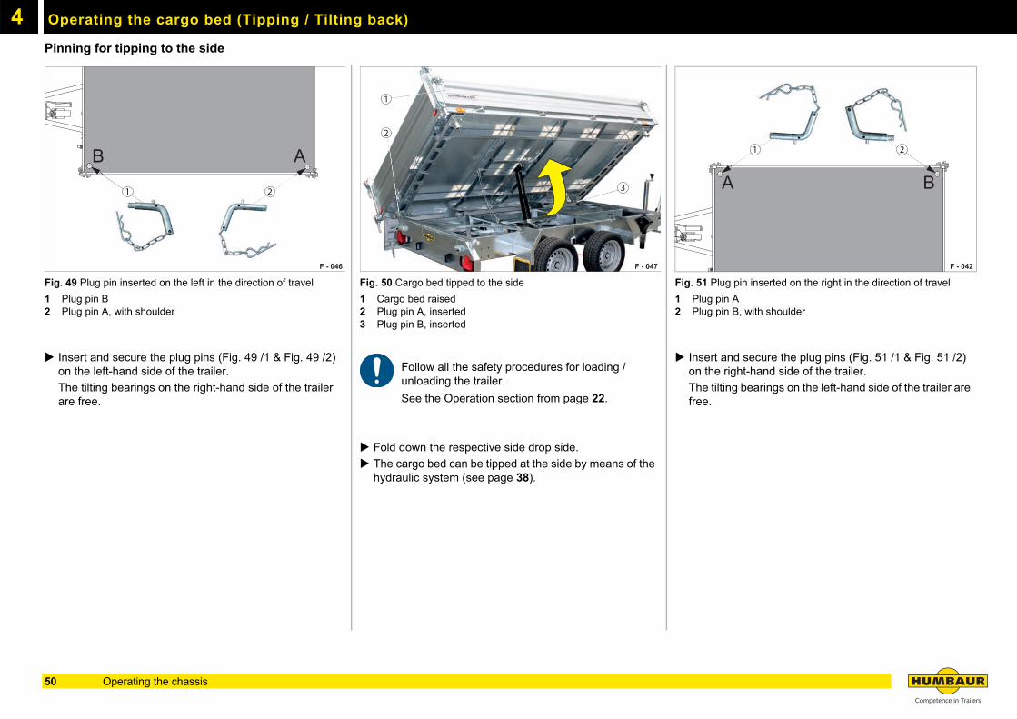
Pinning for tipping to the sideFig. 49 Plug pin inserted on the left in the direction of travel
1 Plug pin B2 Plug pin A, with shoulder
Insert and secure the plug pins (Fig. 49 /1 & Fig. 49 /2) on the left-hand side of the trailer.
The tilting bearings on the right-hand side of the trailer are free.
Fig. 50 Cargo bed tipped to the side
1 Cargo bed raised2 Plug pin A, inserted3 Plug pin B, inserted
Follow all the safety procedures for loading / unloading the trailer.
See the Operation section from page 22.
Fold down the respective side drop side.
The cargo bed can be tipped at the side by means of the hydraulic system (see page 38).
Fig. 51 Plug pin inserted on the right in the direction of travel
1 Plug pin A2 Plug pin B, with shoulder
Insert and secure the plug pins (Fig. 51 /1 & Fig. 51 /2) on the right-hand side of the trailer.
The tilting bearings on the left-hand side of the trailer are free.
F - 046
B A
21
F - 047
1
2
3
F - 042
BA
1 2
50 Operating the chassis
4Telescopic prop stands
Operating the telescopic prop stands
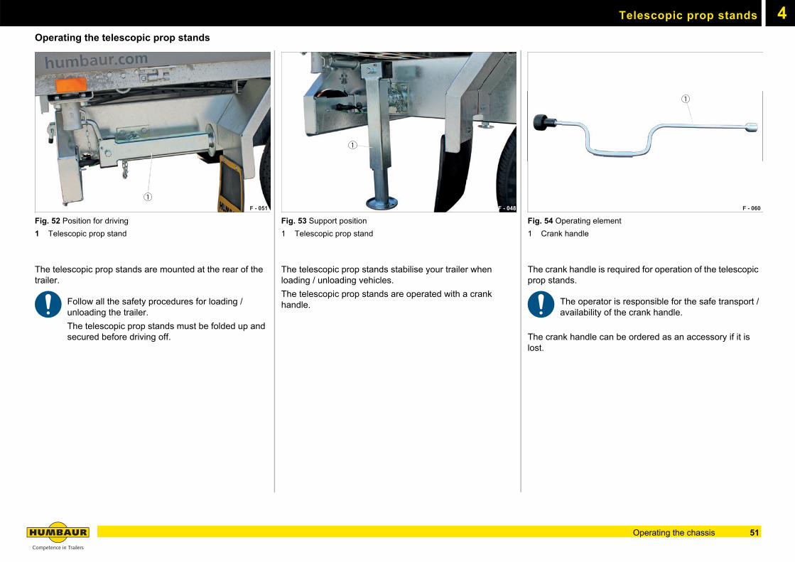
Fig. 52 Position for driving
1 Telescopic prop stand
The telescopic prop stands are mounted at the rear of the trailer.
Follow all the safety procedures for loading / unloading the trailer.
The telescopic prop stands must be folded up and secured before driving off.
Fig. 53 Support position
1 Telescopic prop stand
The telescopic prop stands stabilise your trailer when loading / unloading vehicles.
The telescopic prop stands are operated with a crank handle.
Fig. 54 Operating element
1 Crank handle
The crank handle is required for operation of the telescopic prop stands.
The operator is responsible for the safe transport /availability of the crank handle.
The crank handle can be ordered as an accessory if it is lost.
F - 051
1F - 048
1
F - 060
1
51Operating the chassis
Telescopic prop stands4
WARNING
Sinking support legs
The support legs could sink in on a soft / yielding surface.
The trailer can tip over - risk of crushing!
Ensure that the surface is strong enough (firm).
Use a stable support if the surface is soft / yielding.
WARNING
Driving with the telescopic prop stands in thesupport position
The telescopic prop stands could make contact with the road while driving and be torn off - risk of accidents!
Before setting off, make sure that the telescopic prop stands have been retracted and secured.
WARNING
Loading / unloading without lowering the telescopic prop stands
Loading / unloading without lowering the telescopic prop stands can cause a loss of stability.
The trailer can tip over - risk of crushing!
Swivel the telescopic prop stands down before loading / unloading.
Before setting off, make sure that the telescopic prop stands have been secured with plug pins.
CAUTION
Working under the trailer
You can hit your head.
Avoid jerky movements.
Only operate the telescopic prop stands with the drop sides closed.
CAUTION
Operating the telescopic prop stands
You can crush your fingers / hands between the chassis and telescopic prop stands.
Operate the telescopic prop stands carefully and in a controlled manner - do not allow them to drop down.
Use .
Keep your feet away from the crush area when lowering the telescopic prop stands.
Only operate the telescopic prop stands when the trailer is at standstill.
NOTICE
Uneven support of the trailer!
Uneven support of the trailer could overload the telescopic prop stands on one side and cause defects.
Wind the telescopic prop stands down evenly.
Ensure that the trailer is not standing at an angle.
NOTICE
Manoeuvring / driving off with the telescopic prop stands lowered!
Telescopic prop stands could be deformed and the trailer damaged if they are lowered when manoeuvring / driving off.
Always wind up / swivel in the telescopic prop stands before setting off.
52 Operating the chassis
Telescopic prop stands 4
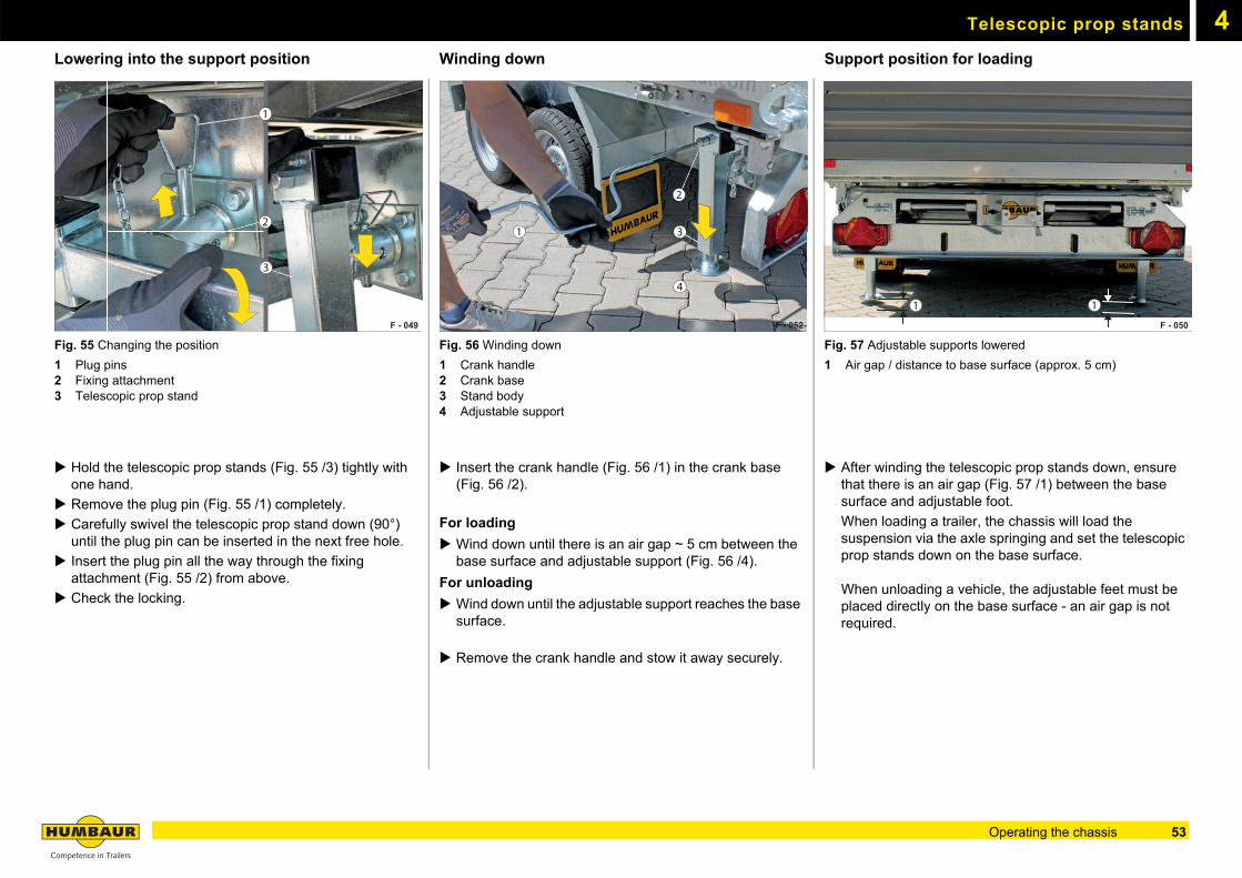
Lowering into the support positionFig. 55 Changing the position
1 Plug pins2 Fixing attachment3 Telescopic prop stand
Hold the telescopic prop stands (Fig. 55 /3) tightly with one hand.
Remove the plug pin (Fig. 55 /1) completely.
Carefully swivel the telescopic prop stand down (90°) until the plug pin can be inserted in the next free hole.
Insert the plug pin all the way through the fixing attachment (Fig. 55 /2) from above.
Check the locking.
Winding down
Fig. 56 Winding down
1 Crank handle2 Crank base3 Stand body4 Adjustable support
Insert the crank handle (Fig. 56 /1) in the crank base (Fig. 56 /2).
For loading
Wind down until there is an air gap ~ 5 cm between the base surface and adjustable support (Fig. 56 /4).
For unloading
Wind down until the adjustable support reaches the base surface.
Remove the crank handle and stow it away securely.
Support position for loading
Fig. 57 Adjustable supports lowered
1 Air gap / distance to base surface (approx. 5 cm)
After winding the telescopic prop stands down, ensure that there is an air gap (Fig. 57 /1) between the base surface and adjustable foot.
When loading a trailer, the chassis will load the suspension via the axle springing and set the telescopic prop stands down on the base surface.
When unloading a vehicle, the adjustable feet must be placed directly on the base surface - an air gap is not required.
F - 049
1
2
3
F - 052
1
2
4
3
F - 050
1 1
53Operating the chassis
Telescopic prop stands4
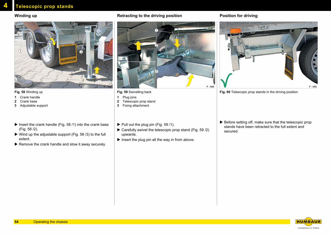
Winding upFig. 58 Winding up
1 Crank handle2 Crank base3 Adjustable support
Insert the crank handle (Fig. 58 /1) into the crank base (Fig. 58 /2).
Wind up the adjustable support (Fig. 58 /3) to the full extent.
Remove the crank handle and stow it away securely.
Retracting to the driving position
Fig. 59 Swivelling back
1 Plug pins2 Telescopic prop stand3 Fixing attachment
Pull out the plug pin (Fig. 59 /1).
Carefully swivel the telescopic prop stand (Fig. 59 /2) upwards.
Insert the plug pin all the way in from above.
Position for driving
Fig. 60 Telescopic prop stands in the driving position
Before setting off, make sure that the telescopic prop stands have been retracted to the full extent and secured.
F - 054
1 2
3
F - 054
1
2
3
F - 055
54 Operating the chassis
4Toolbox
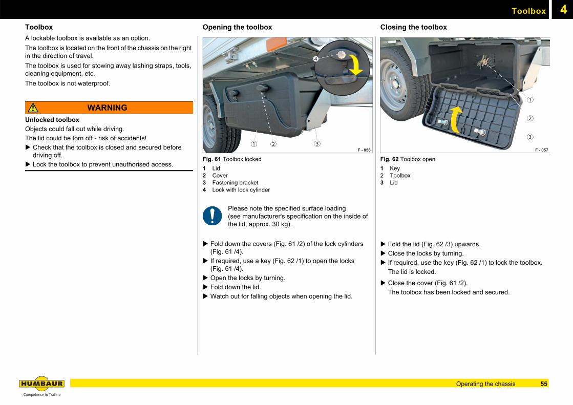
Toolbox
A lockable toolbox is available as an option.
The toolbox is located on the front of the chassis on the right in the direction of travel.
The toolbox is used for stowing away lashing straps, tools, cleaning equipment, etc.
The toolbox is not waterproof.
WARNING
Unlocked toolbox
Objects could fall out while driving.
The lid could be torn off - risk of accidents!
Check that the toolbox is closed and secured before driving off.
Lock the toolbox to prevent unauthorised access.
Opening the toolbox
Fig. 61 Toolbox locked
1 Lid2 Cover3 Fastening bracket4 Lock with lock cylinder
Please note the specified surface loading (see manufacturer's specification on the inside of the lid, approx. 30 kg).
Fold down the covers (Fig. 61 /2) of the lock cylinders (Fig. 61 /4).
If required, use a key (Fig. 62 /1) to open the locks (Fig. 61 /4).
Open the locks by turning.
Fold down the lid.
Watch out for falling objects when opening the lid.
Closing the toolbox
Fig. 62 Toolbox open
1 Key2 Toolbox3 Lid
Fold the lid (Fig. 62 /3) upwards.
Close the locks by turning.
If required, use the key (Fig. 62 /1) to lock the toolbox.
The lid is locked.
Close the cover (Fig. 61 /2).
The toolbox has been locked and secured.
F - 056 F - 056 1 2 3
4
F - 057
1
2
3
55Operating the chassis
4
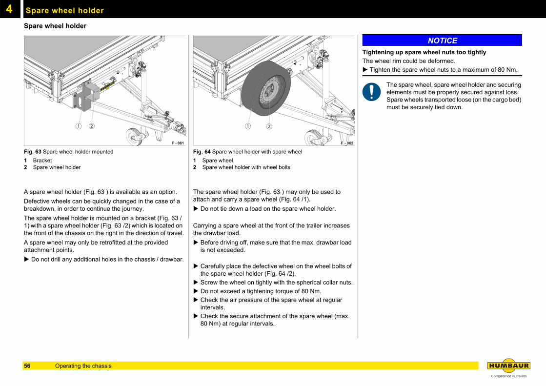
Spare wheel holderSpare wheel holder
Fig. 63 Spare wheel holder mounted
1 Bracket2 Spare wheel holder
A spare wheel holder (Fig. 63 ) is available as an option.
Defective wheels can be quickly changed in the case of a breakdown, in order to continue the journey.
The spare wheel holder is mounted on a bracket (Fig. 63 /1) with a spare wheel holder (Fig. 63 /2) which is located on the front of the chassis on the right in the direction of travel.
A spare wheel may only be retrofitted at the provided attachment points.
Do not drill any additional holes in the chassis / drawbar.
Fig. 64 Spare wheel holder with spare wheel
1 Spare wheel2 Spare wheel holder with wheel bolts
The spare wheel holder (Fig. 63 ) may only be used to attach and carry a spare wheel (Fig. 64 /1).
Do not tie down a load on the spare wheel holder.
Carrying a spare wheel at the front of the trailer increases the drawbar load.
Before driving off, make sure that the max. drawbar load is not exceeded.
Carefully place the defective wheel on the wheel bolts of the spare wheel holder (Fig. 64 /2).
Screw the wheel on tightly with the spherical collar nuts.
Do not exceed a tightening torque of 80 Nm.
Check the air pressure of the spare wheel at regular intervals.
Check the secure attachment of the spare wheel (max. 80 Nm) at regular intervals.
NOTICE
Tightening up spare wheel nuts too tightly
The wheel rim could be deformed.
Tighten the spare wheel nuts to a maximum of 80 Nm.
The spare wheel, spare wheel holder and securing elements must be properly secured against loss.Spare wheels transported loose (on the cargo bed) must be securely tied down.
F - 061
1 2 1
F - 062
2
56 Operating the chassis
5
Load securing / Operating the body57
5
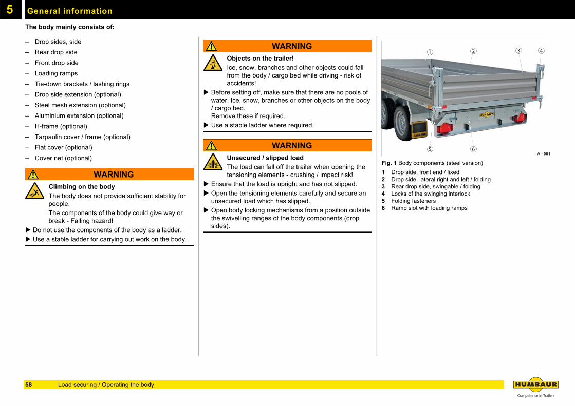
General informationThe body mainly consists of:
– Drop sides, side
– Rear drop side
– Front drop side
– Loading ramps
– Tie-down brackets / lashing rings
– Drop side extension (optional)
– Steel mesh extension (optional)
– Aluminium extension (optional)
– H-frame (optional)
– Tarpaulin cover / frame (optional)
– Flat cover (optional)
– Cover net (optional)
WARNING
Climbing on the body
The body does not provide sufficient stability for people.
The components of the body could give way or break - Falling hazard!
Do not use the components of the body as a ladder.
Use a stable ladder for carrying out work on the body.
WARNING
Objects on the trailer!
Ice, snow, branches and other objects could fall from the body / cargo bed while driving - risk of accidents!
Before setting off, make sure that there are no pools of water, Ice, snow, branches or other objects on the body / cargo bed. Remove these if required.
Use a stable ladder where required.
WARNING
Unsecured / slipped load
The load can fall off the trailer when opening the tensioning elements - crushing / impact risk!
Ensure that the load is upright and has not slipped.
Open the tensioning elements carefully and secure an unsecured load which has slipped.
Open body locking mechanisms from a position outside the swivelling ranges of the body components (drop sides).
Fig. 1 Body components (steel version)
1 Drop side, front end / fixed2 Drop side, lateral right and left / folding3 Rear drop side, swingable / folding4 Locks of the swinging interlock5 Folding fasteners6 Ramp slot with loading ramps
A - 001
1
5
2 3 4
6
58 Load securing / Operating the body
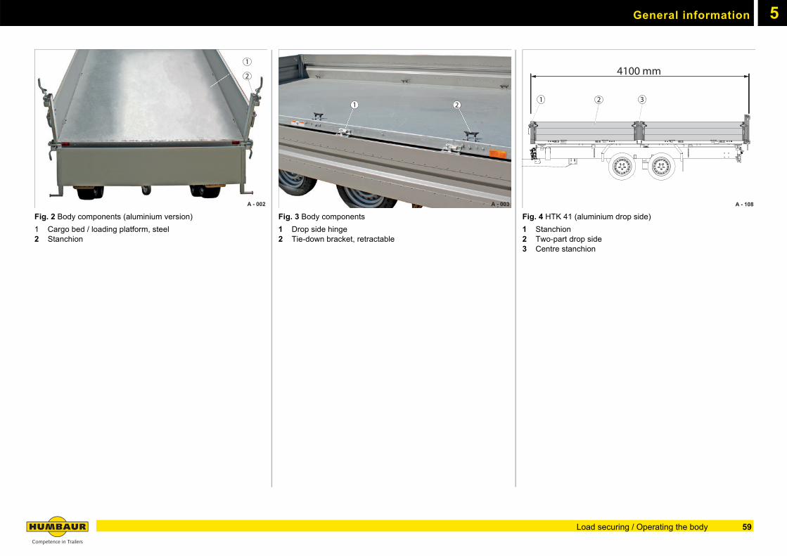
General information 5
Fig. 2 Body components (aluminium version)
1 Cargo bed / loading platform, steel2 Stanchion
Fig. 3 Body components
1 Drop side hinge2 Tie-down bracket, retractable
Fig. 4 HTK 41 (aluminium drop side)
1 Stanchion2 Two-part drop side3 Centre stanchion
A - 002
1
2
A - 003
21
A - 108
21 3
4100 mm
59Load securing / Operating the body
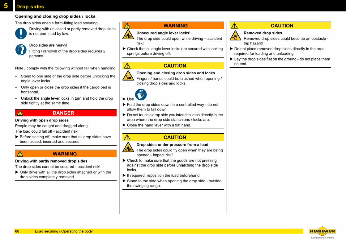
5
Drop sidesOpening and closing drop sides / locks
The drop sides enable form-fitting load securing.
Driving with unlocked or partly removed drop sides is not permitted by law.
Drop sides are heavy!
Fitting / removal of the drop sides requires 2 persons.
Note / comply with the following without fail when handling:
– Stand to one side of the drop side before unlocking the angle lever locks
– Only open or close the drop sides if the cargo bed is horizontal.
– Unlock the angle lever locks in turn and hold the drop side tightly at the same time.
DANGER
Driving with open drop sides
People may be caught and dragged along.
The load could fall off - accident risk!
Before setting off, make sure that all drop sides have been closed, inserted and secured.
WARNING
Driving with partly removed drop sides
The drop sides cannot be secured - accident risk!
Only drive with all the drop sides attached or with the drop sides completely removed.
WARNING
Unsecured angle lever locks!
The drop side could open while driving – accident risk!
Check that all angle lever locks are secured with locking springs before driving off.
CAUTION
Opening and closing drop sides and locks
Fingers / hands could be crushed when opening / closing drop sides and locks.
Use .
Fold the drop sides down in a controlled way - do not allow them to fall down.
Do not touch a drop side you intend to latch directly in the area where the drop side stanchions / locks are.
Close the hand lever with a flat hand.
CAUTION
Drop sides under pressure from a load
The drop sides could fly open when they are being opened - impact risk!
Check to make sure that the goods are not pressing against the drop side before unlatching the drop side locks.
If required, reposition the load beforehand.
Stand to the side when opening the drop side - outside the swinging range.
CAUTION
Removed drop sides
Removed drop sides could become an obstacle - trip hazard!
Do not place removed drop sides directly in the area required for loading and unloading.
Lay the drop sides flat on the ground - do not place them on end.
60 Load securing / Operating the body
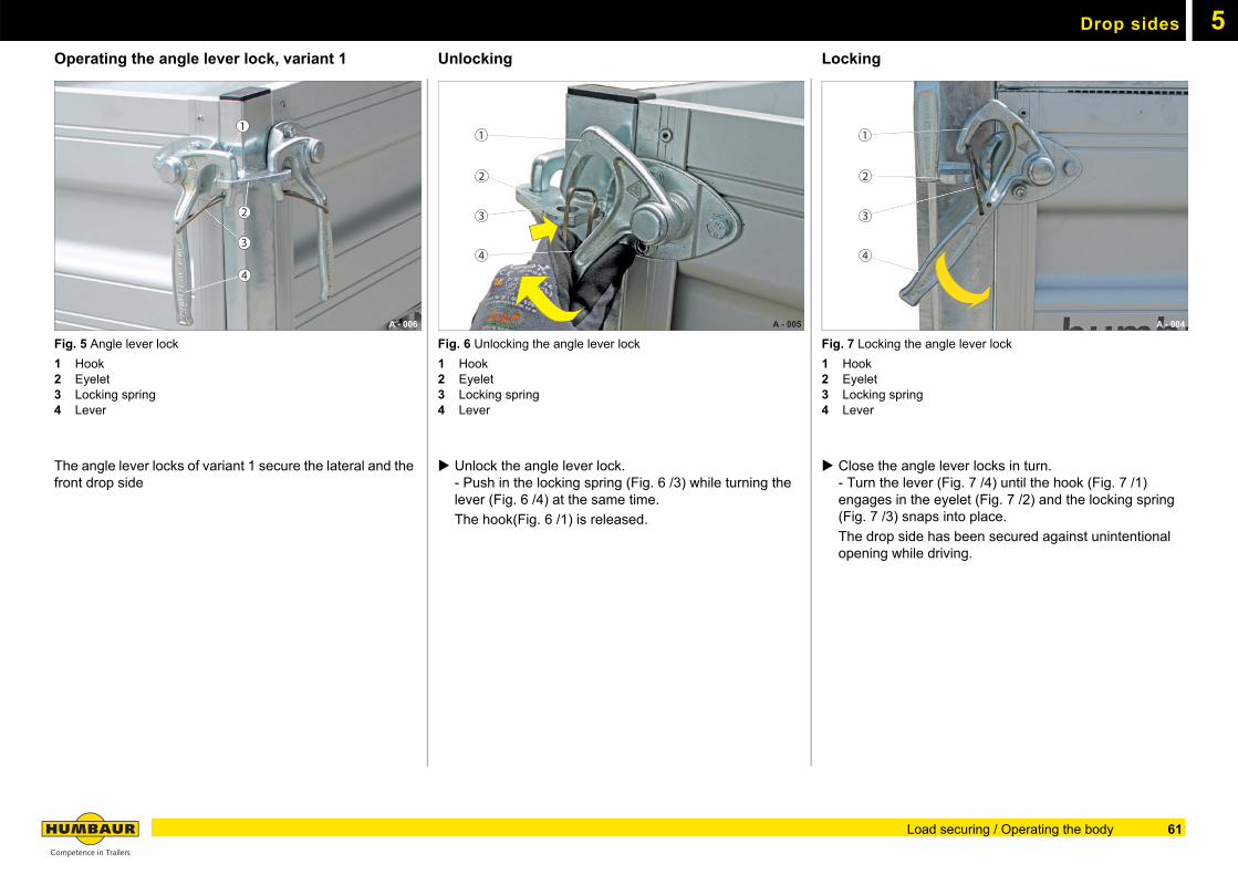
Drop sides 5
Operating the angle lever lock, variant 1Fig. 5 Angle lever lock
1 Hook2 Eyelet3 Locking spring4 Lever
The angle lever locks of variant 1 secure the lateral and the front drop side
Unlocking
Fig. 6 Unlocking the angle lever lock
1 Hook2 Eyelet3 Locking spring4 Lever
Unlock the angle lever lock.- Push in the locking spring (Fig. 6 /3) while turning the lever (Fig. 6 /4) at the same time.
The hook(Fig. 6 /1) is released.
Locking
Fig. 7 Locking the angle lever lock
1 Hook2 Eyelet3 Locking spring4 Lever
Close the angle lever locks in turn.- Turn the lever (Fig. 7 /4) until the hook (Fig. 7 /1) engages in the eyelet (Fig. 7 /2) and the locking spring (Fig. 7 /3) snaps into place.
The drop side has been secured against unintentional opening while driving.
A - 006
1
2
3
4
A - 005
1
2
3
4
A - 004
1
2
3
4
61Load securing / Operating the body
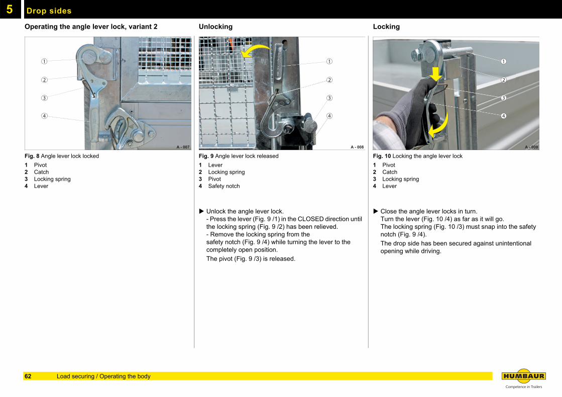
Drop sides5
Operating the angle lever lock, variant 2Fig. 8 Angle lever lock locked
1 Pivot2 Catch3 Locking spring4 Lever
Unlocking
Fig. 9 Angle lever lock released
1 Lever2 Locking spring3 Pivot4 Safety notch
Unlock the angle lever lock.- Press the lever (Fig. 9 /1) in the CLOSED direction until the locking spring (Fig. 9 /2) has been relieved.- Remove the locking spring from thesafety notch (Fig. 9 /4) while turning the lever to the completely open position.
The pivot (Fig. 9 /3) is released.
Locking
Fig. 10 Locking the angle lever lock
1 Pivot2 Catch3 Locking spring4 Lever
Close the angle lever locks in turn.Turn the lever (Fig. 10 /4) as far as it will go.The locking spring (Fig. 10 /3) must snap into the safety notch (Fig. 9 /4).
The drop side has been secured against unintentional opening while driving.
A - 007
1
2
3
4
A - 008
1
2
3
4
A - 009
1
2
3
4
62 Load securing / Operating the body
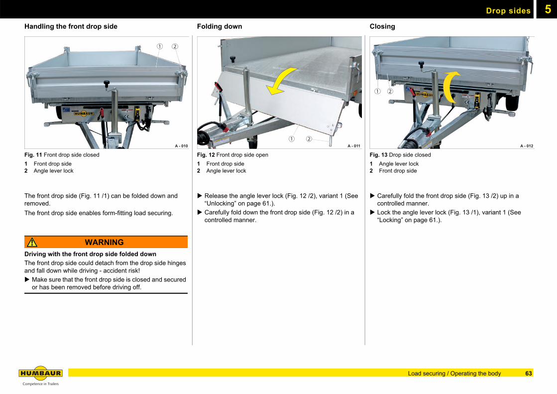
Drop sides 5
Handling the front drop sideFig. 11 Front drop side closed
1 Front drop side2 Angle lever lock
The front drop side (Fig. 11 /1) can be folded down and removed.
The front drop side enables form-fitting load securing.
WARNING
Driving with the front drop side folded down
The front drop side could detach from the drop side hinges and fall down while driving - accident risk!
Make sure that the front drop side is closed and secured or has been removed before driving off.
Folding down
Fig. 12 Front drop side open
1 Front drop side2 Angle lever lock
Release the angle lever lock (Fig. 12 /2), variant 1 (See “Unlocking” on page 61.).
Carefully fold down the front drop side (Fig. 12 /2) in a controlled manner.
Closing
Fig. 13 Drop side closed
1 Angle lever lock2 Front drop side
Carefully fold the front drop side (Fig. 13 /2) up in a controlled manner.
Lock the angle lever lock (Fig. 13 /1), variant 1 (See “Locking” on page 61.).
A - 010
1 2
A - 011 1 2
A - 012
1 2
63Load securing / Operating the body
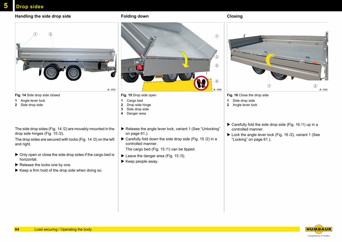
Drop sides5
Handling the side drop sideFig. 14 Side drop side closed
1 Angle lever lock2 Side drop side
The side drop sides (Fig. 14 /2) are movably mounted in the drop side hinges (Fig. 15 /2).
The drop sides are secured with locks (Fig. 14 /2) on the left and right.
Only open or close the side drop sides if the cargo bed is horizontal.
Release the locks one by one.
Keep a firm hold of the drop side when doing so.
Folding down
Fig. 15 Drop side open
1 Cargo bed2 Drop side hinge3 Side drop side4 Danger area
Release the angle lever lock, variant 1 (See “Unlocking” on page 61.).
Carefully fold down the side drop side (Fig. 15 /2) in a controlled manner.
The cargo bed (Fig. 15 /1) can be tipped.
Leave the danger area (Fig. 15 /3).
Keep people away.
Closing
Fig. 16 Close the drop side
1 Side drop side2 Angle lever lock
Carefully fold the side drop side (Fig. 16 /1) up in a controlled manner.
Lock the angle lever lock (Fig. 16 /2), variant 1 (See “Locking” on page 61.).
A - 013
1 2
A - 016
3
1
4
2
A - 015 1 2
64 Load securing / Operating the body
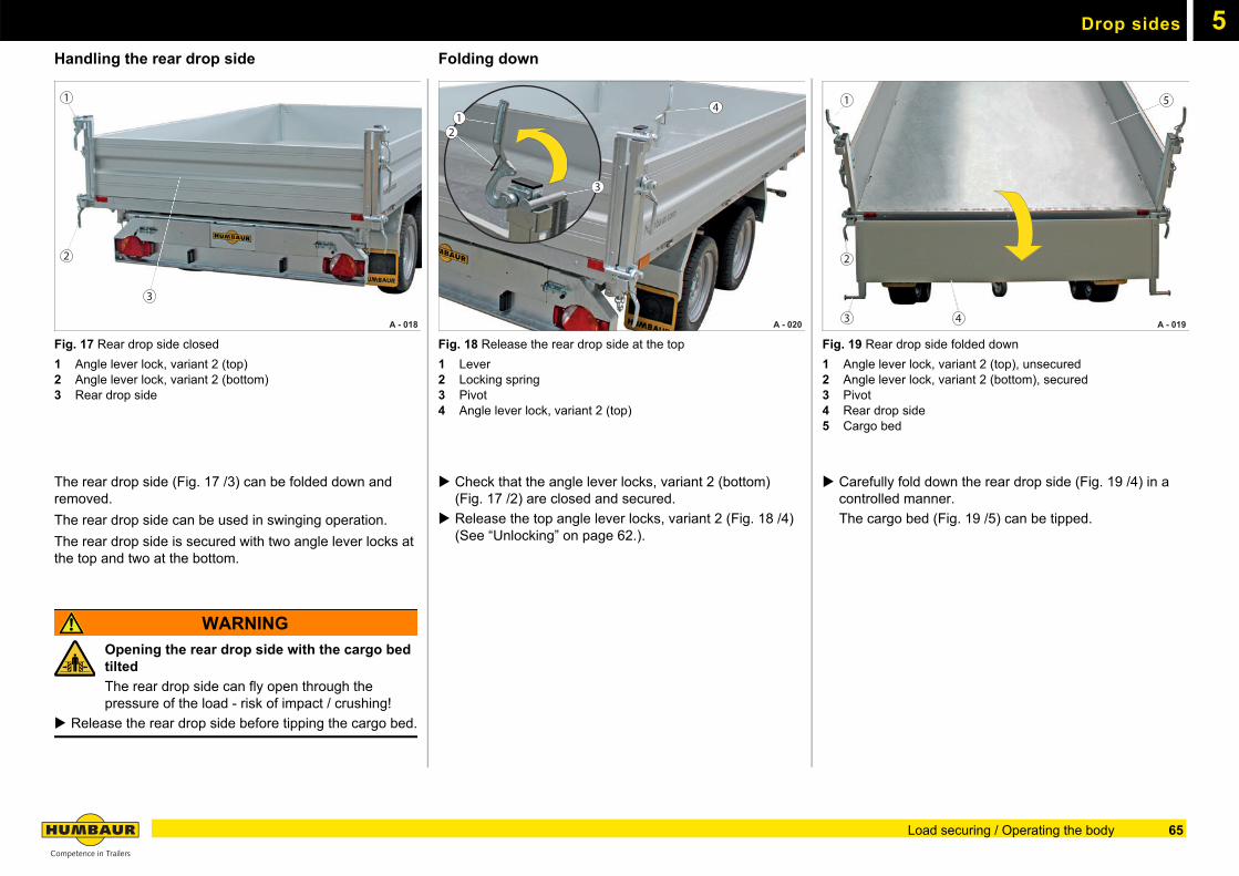
Drop sides 5
Handling the rear drop sideFig. 17 Rear drop side closed
1 Angle lever lock, variant 2 (top)2 Angle lever lock, variant 2 (bottom)3 Rear drop side
The rear drop side (Fig. 17 /3) can be folded down and removed.
The rear drop side can be used in swinging operation.
The rear drop side is secured with two angle lever locks at the top and two at the bottom.
WARNING
Opening the rear drop side with the cargo bed tilted
The rear drop side can fly open through the pressure of the load - risk of impact / crushing!
Release the rear drop side before tipping the cargo bed.
Folding down
Fig. 18 Release the rear drop side at the top
1 Lever2 Locking spring3 Pivot4 Angle lever lock, variant 2 (top)
Check that the angle lever locks, variant 2 (bottom) (Fig. 17 /2) are closed and secured.
Release the top angle lever locks, variant 2 (Fig. 18 /4) (See “Unlocking” on page 62.).
Fig. 19 Rear drop side folded down
1 Angle lever lock, variant 2 (top), unsecured2 Angle lever lock, variant 2 (bottom), secured 3 Pivot4 Rear drop side5 Cargo bed
Carefully fold down the rear drop side (Fig. 19 /4) in a controlled manner.
The cargo bed (Fig. 19 /5) can be tipped.
A - 018
1
2
3
A - 020
41
2
3
A - 019
1
2
3 4
5
65Load securing / Operating the body
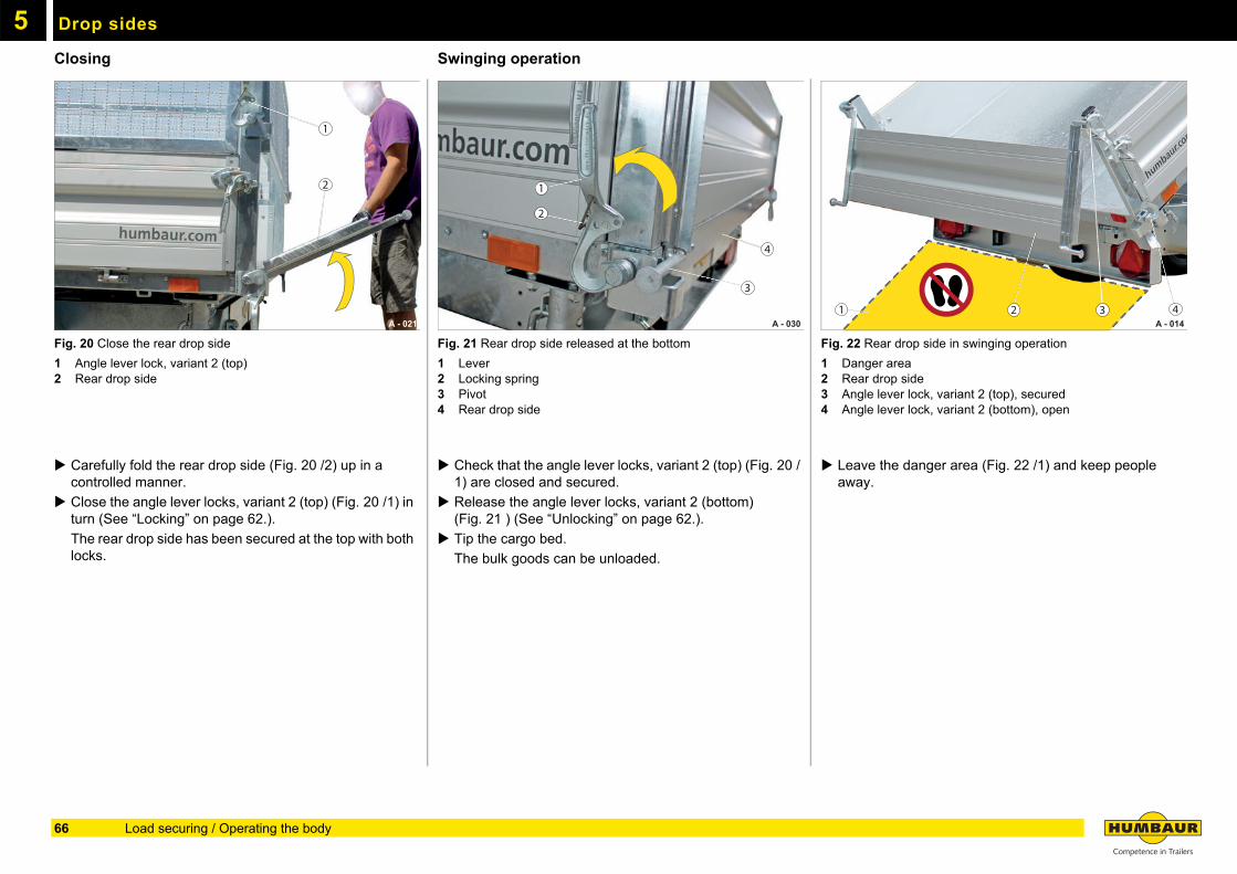
Drop sides5
ClosingFig. 20 Close the rear drop side
1 Angle lever lock, variant 2 (top)2 Rear drop side
Carefully fold the rear drop side (Fig. 20 /2) up in a controlled manner.
Close the angle lever locks, variant 2 (top) (Fig. 20 /1) in turn (See “Locking” on page 62.).
The rear drop side has been secured at the top with both locks.
Swinging operation
Fig. 21 Rear drop side released at the bottom
1 Lever2 Locking spring3 Pivot4 Rear drop side
Check that the angle lever locks, variant 2 (top) (Fig. 20 /1) are closed and secured.
Release the angle lever locks, variant 2 (bottom) (Fig. 21 ) (See “Unlocking” on page 62.).
Tip the cargo bed.
The bulk goods can be unloaded.
Fig. 22 Rear drop side in swinging operation
1 Danger area2 Rear drop side3 Angle lever lock, variant 2 (top), secured4 Angle lever lock, variant 2 (bottom), open
Leave the danger area (Fig. 22 /1) and keep people away.
A - 021
2
1
A - 030
1
2
3
4
A - 014 2 3 41
66 Load securing / Operating the body
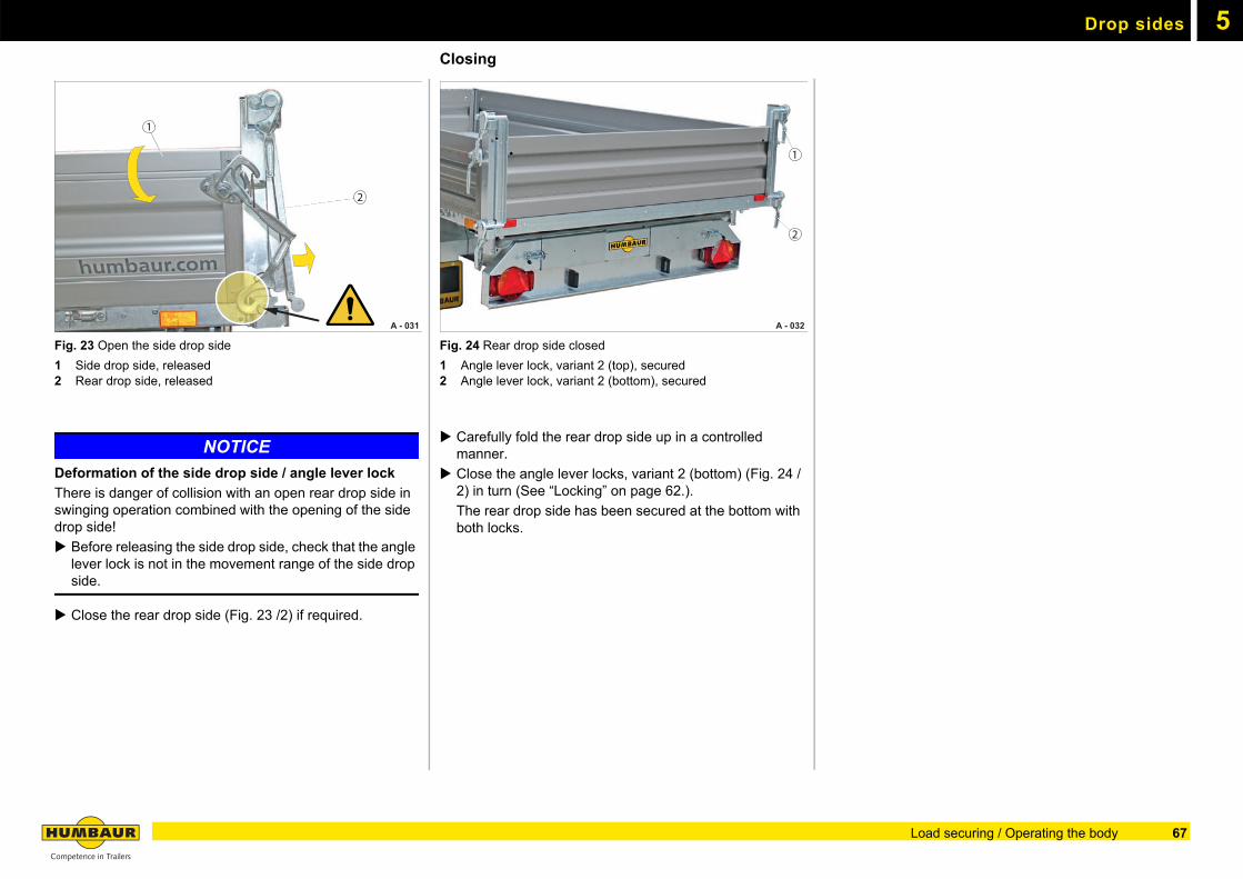
Drop sides 5
Fig. 23 Open the side drop side
1 Side drop side, released2 Rear drop side, released
NOTICE
Deformation of the side drop side / angle lever lock
There is danger of collision with an open rear drop side in swinging operation combined with the opening of the side drop side!
Before releasing the side drop side, check that the angle lever lock is not in the movement range of the side drop side.
Close the rear drop side (Fig. 23 /2) if required.
Closing
Fig. 24 Rear drop side closed
1 Angle lever lock, variant 2 (top), secured2 Angle lever lock, variant 2 (bottom), secured
Carefully fold the rear drop side up in a controlled manner.
Close the angle lever locks, variant 2 (bottom) (Fig. 24 /2) in turn (See “Locking” on page 62.).
The rear drop side has been secured at the bottom with both locks.
A - 031
2
1
A - 032
1
2
67Load securing / Operating the body
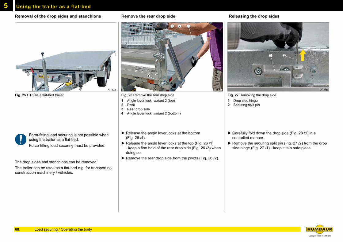
5
Using the trailer as a flat-bedRemoval of the drop sides and stanchions
Fig. 25 HTK as a flat-bed trailer
Form-fitting load securing is not possible when using the trailer as a flat-bed.
Force-fitting load securing must be provided.
The drop sides and stanchions can be removed.
The trailer can be used as a flat-bed e.g. for transporting construction machinery / vehicles.
Remove the rear drop side
Fig. 26 Remove the rear drop side
1 Angle lever lock, variant 2 (top)2 Pivot3 Rear drop side4 Angle lever lock, variant 2 (bottom)
Release the angle lever locks at the bottom(Fig. 26 /4).
Release the angle lever locks at the top (Fig. 26 /1) - keep a firm hold of the rear drop side (Fig. 26 /3) when doing so.
Remove the rear drop side from the pivots (Fig. 26 /2).
Releasing the drop sides
Fig. 27 Removing the drop side
1 Drop side hinge2 Securing split pin
Carefully fold down the drop side (Fig. 28 /1) in a controlled manner.
Remove the securing split pin (Fig. 27 /2) from the drop side hinge (Fig. 27 /1) - keep it in a safe place.
A - 022 A - 028
1 2 3
4
A - 023
1 2
68 Load securing / Operating the body
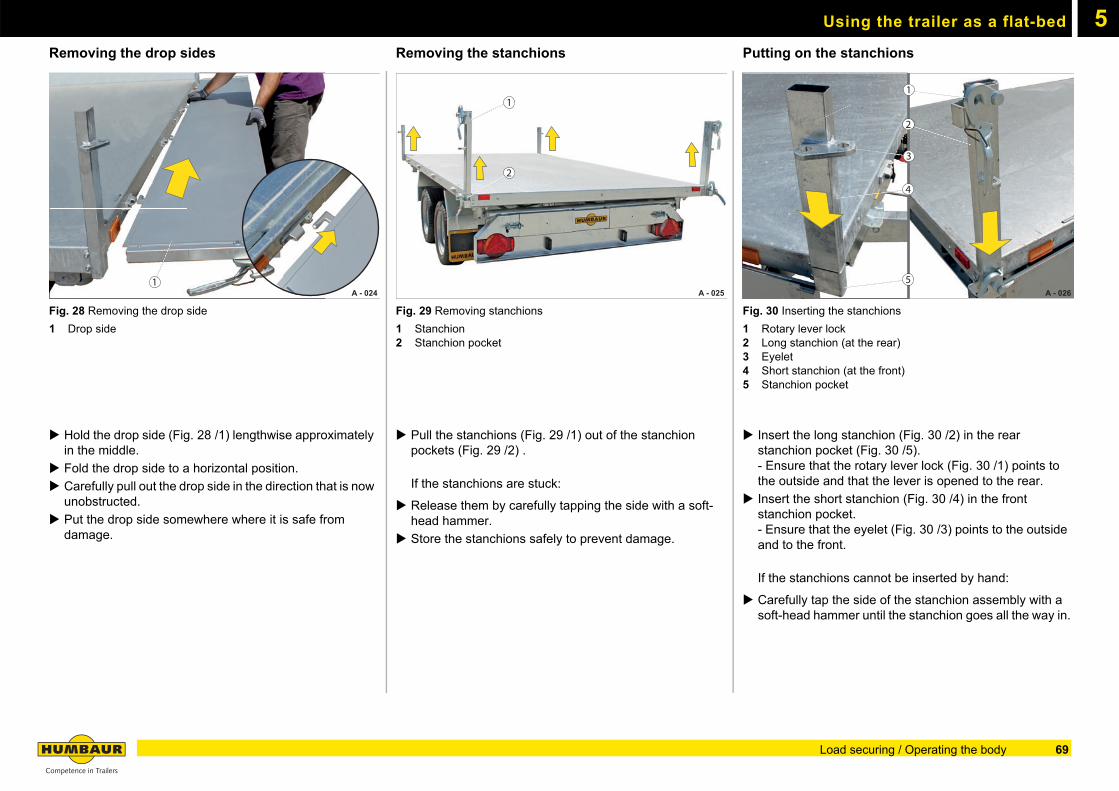
Using the trailer as a flat-bed 5
Removing the drop sidesFig. 28 Removing the drop side
1 Drop side
Hold the drop side (Fig. 28 /1) lengthwise approximately in the middle.
Fold the drop side to a horizontal position.
Carefully pull out the drop side in the direction that is now unobstructed.
Put the drop side somewhere where it is safe from damage.
Removing the stanchions
Fig. 29 Removing stanchions
1 Stanchion2 Stanchion pocket
Pull the stanchions (Fig. 29 /1) out of the stanchion pockets (Fig. 29 /2) .
If the stanchions are stuck:
Release them by carefully tapping the side with a soft-head hammer.
Store the stanchions safely to prevent damage.
Putting on the stanchions
Fig. 30 Inserting the stanchions
1 Rotary lever lock2 Long stanchion (at the rear)3 Eyelet4 Short stanchion (at the front)5 Stanchion pocket
Insert the long stanchion (Fig. 30 /2) in the rear stanchion pocket (Fig. 30 /5).- Ensure that the rotary lever lock (Fig. 30 /1) points to the outside and that the lever is opened to the rear.
Insert the short stanchion (Fig. 30 /4) in the front stanchion pocket.- Ensure that the eyelet (Fig. 30 /3) points to the outside and to the front.
If the stanchions cannot be inserted by hand:
Carefully tap the side of the stanchion assembly with a soft-head hammer until the stanchion goes all the way in.
A - 024 1
A - 025
1
2
A - 026
1
2
11111111111
22222222222222
1
2
3
4
5
69Load securing / Operating the body
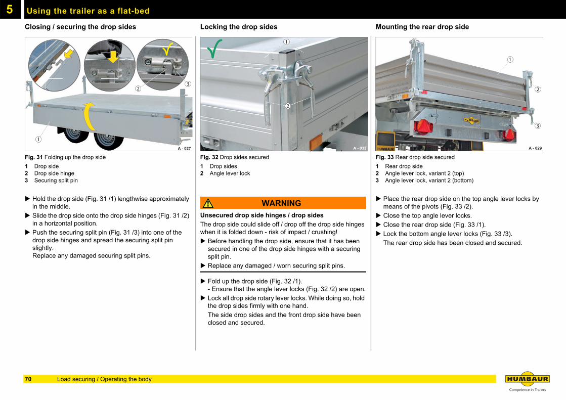
Using the trailer as a flat-bed5
Closing / securing the drop sidesFig. 31 Folding up the drop side
1 Drop side2 Drop side hinge3 Securing split pin
Hold the drop side (Fig. 31 /1) lengthwise approximately in the middle.
Slide the drop side onto the drop side hinges (Fig. 31 /2) in a horizontal position.
Push the securing split pin (Fig. 31 /3) into one of the drop side hinges and spread the securing split pin slightly.Replace any damaged securing split pins.
Locking the drop sides
Fig. 32 Drop sides secured
1 Drop sides2 Angle lever lock
WARNING
Unsecured drop side hinges / drop sides
The drop side could slide off / drop off the drop side hinges when it is folded down - risk of impact / crushing!
Before handling the drop side, ensure that it has been secured in one of the drop side hinges with a securing split pin.
Replace any damaged / worn securing split pins.
Fold up the drop side (Fig. 32 /1).- Ensure that the angle lever locks (Fig. 32 /2) are open.
Lock all drop side rotary lever locks. While doing so, hold the drop sides firmly with one hand.
The side drop sides and the front drop side have been closed and secured.
Mounting the rear drop side
Fig. 33 Rear drop side secured
1 Rear drop side2 Angle lever lock, variant 2 (top)3 Angle lever lock, variant 2 (bottom)
Place the rear drop side on the top angle lever locks by means of the pivots (Fig. 33 /2).
Close the top angle lever locks.
Close the rear drop side (Fig. 33 /1).
Lock the bottom angle lever locks (Fig. 33 /3).
The rear drop side has been closed and secured.
A - 027
1
23
A - 033
1
2
A - 029
1
2
3
70 Load securing / Operating the body
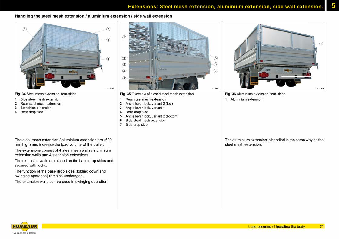
5Extensions: Steel mesh extension, aluminium extension, side wall extension.
Handling the steel mesh extension / aluminium extension / side wall extension
Fig. 34 Steel mesh extension, four-sided
1 Side steel mesh extension2 Rear steel mesh extension3 Stanchion extension4 Rear drop side
The steel mesh extension / aluminium extension are (620 mm high) and increase the load volume of the trailer.
The extensions consist of 4 steel mesh walls / aluminium extension walls and 4 stanchion extensions.
The extension walls are placed on the base drop sides and secured with locks.
The function of the base drop sides (folding down and swinging operation) remains unchanged.
The extension walls can be used in swinging operation.
Fig. 35 Overview of closed steel mesh extension
1 Rear steel mesh extension2 Angle lever lock, variant 2 (top)3 Angle lever lock, variant 14 Rear drop side5 Angle lever lock, variant 2 (bottom)6 Side steel mesh extension7 Side drop side
Fig. 36 Aluminium extension, four-sided
1 Aluminium extension
The aluminium extension is handled in the same way as the steel mesh extension.
A - 060
1 2
3
4
A - 061
6
3
1
2
3
5
74
A - 090 A - 090
1
71Load securing / Operating the body
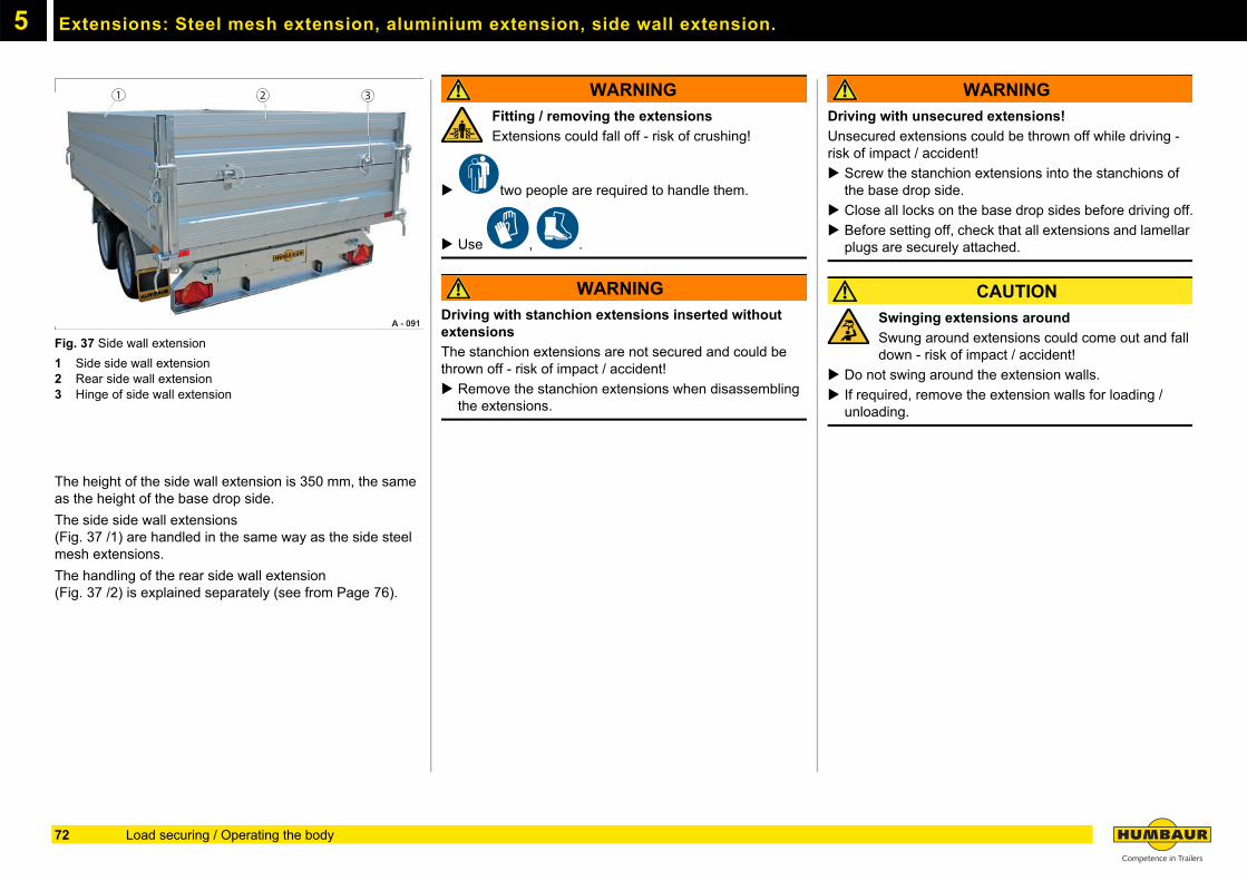
Extensions: Steel mesh extension, aluminium extension, side wall extension.5
Fig. 37 Side wall extension
1 Side side wall extension2 Rear side wall extension3 Hinge of side wall extension
The height of the side wall extension is 350 mm, the same as the height of the base drop side.
The side side wall extensions(Fig. 37 /1) are handled in the same way as the side steel mesh extensions.
The handling of the rear side wall extension(Fig. 37 /2) is explained separately (see from Page 76).
WARNING
Fitting / removing the extensions
Extensions could fall off - risk of crushing!
two people are required to handle them.
Use , .
WARNING
Driving with stanchion extensions inserted without extensions
The stanchion extensions are not secured and could be thrown off - risk of impact / accident!
Remove the stanchion extensions when disassembling the extensions.
WARNING
Driving with unsecured extensions!
Unsecured extensions could be thrown off while driving - risk of impact / accident!
Screw the stanchion extensions into the stanchions of the base drop side.
Close all locks on the base drop sides before driving off.
Before setting off, check that all extensions and lamellar plugs are securely attached.
CAUTION
Swinging extensions around
Swung around extensions could come out and fall down - risk of impact / accident!
Do not swing around the extension walls.
If required, remove the extension walls for loading / unloading.
A - 091 A - 091
1 2 3
72 Load securing / Operating the body
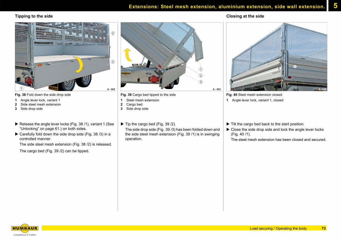
Extensions: Steel mesh extension, aluminium extension, side wall extension. 5
Tipping to the sideFig. 38 Fold down the side drop side
1 Angle lever lock, variant 12 Side steel mesh extension3 Side drop side
Release the angle lever locks (Fig. 38 /1), variant 1 (See “Unlocking” on page 61.) on both sides.
Carefully fold down the side drop side (Fig. 38 /3) in a controlled manner.
The side steel mesh extension (Fig. 38 /2) is released.
The cargo bed (Fig. 39 /2) can be tipped.
Fig. 39 Cargo bed tipped to the side
1 Steel mesh extension2 Cargo bed3 Side drop side
Tip the cargo bed (Fig. 39 /2).
The side drop side (Fig. 39 /3) has been folded down and the side steel mesh extension (Fig. 39 /1) is in swinging operation.
Closing at the side
Fig. 40 Steel mesh extension closed
1 Angle lever lock, variant 1, closed
Tilt the cargo bed back to the start position.
Close the side drop side and lock the angle lever locks (Fig. 40 /1).
The steel mesh extension has been closed and secured.
A - 062
2
3
1 A - 063
1
3
2
A - 088
1
73Load securing / Operating the body
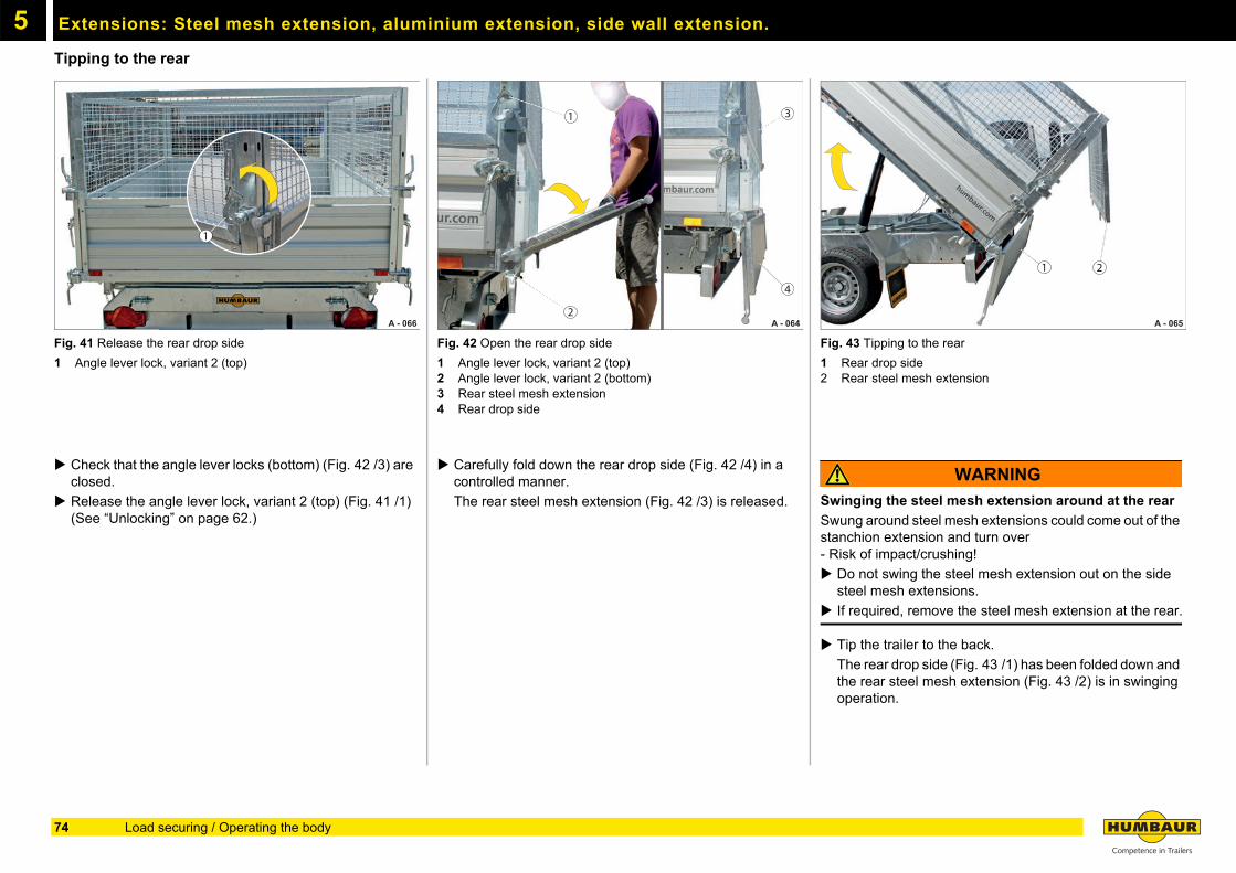
Extensions: Steel mesh extension, aluminium extension, side wall extension.5
Tipping to the rearFig. 41 Release the rear drop side
1 Angle lever lock, variant 2 (top)
Check that the angle lever locks (bottom) (Fig. 42 /3) are closed.
Release the angle lever lock, variant 2 (top) (Fig. 41 /1) (See “Unlocking” on page 62.)
Fig. 42 Open the rear drop side
1 Angle lever lock, variant 2 (top)2 Angle lever lock, variant 2 (bottom)3 Rear steel mesh extension4 Rear drop side
Carefully fold down the rear drop side (Fig. 42 /4) in a controlled manner.
The rear steel mesh extension (Fig. 42 /3) is released.
Fig. 43 Tipping to the rear
1 Rear drop side2 Rear steel mesh extension
WARNING
Swinging the steel mesh extension around at the rear
Swung around steel mesh extensions could come out of the stanchion extension and turn over- Risk of impact/crushing!
Do not swing the steel mesh extension out on the side steel mesh extensions.
If required, remove the steel mesh extension at the rear.
Tip the trailer to the back.
The rear drop side (Fig. 43 /1) has been folded down and the rear steel mesh extension (Fig. 43 /2) is in swinging operation.
A - 066
1
A - 064
1
2
3
4
A - 065
21
74 Load securing / Operating the body
Extensions: Steel mesh extension, aluminium extension, side wall extension. 5
Swinging operation of rear drop side with steel mesh - tippingFig. 44 Tipped to the rear
1 Rear drop side, swinging operation
The rear drop side can be opened for unloading fine-grain bulk goods such as sand and gravel.
Release the angle lever lock, variant 2 (bottom) (See “Unlocking” on page 62.).
Tip the trailer to the back.
The rear drop side (Fig. 44 /1) is in swinging operation.
The steel mesh extension has been closed and secured.
Fig. 45 Steel mesh extension swinging freely
1 Rear steel mesh extension
NOTICE
Unloading coarse bulk goods e.g. stone
The rear drop side could be deformed when unloading large rocks in swinging operation.
Remove the rear drop side.
The rear drop side can be removed if required.
Remove the rear drop side (Fig. 44 /1)(See “Remove the rear drop side” on page 68.).
Tip the trailer to the back.
The rear steel mesh extension (Fig. 45 /1) is swinging freely.
Fig. 46 Steel mesh extension unsecured
1 Rear steel mesh extension2 Rear drop side
CAUTION
Steel mesh extension and rear drop side in swinging operation!
The rear steel mesh extension bangs against the rear drop side during the tilting back process - risk of crushing!
Ensure that the rear steel mesh extension has been secured before tipping through the rear drop side.
Driving with the rear drop side removed is prohibited!
Mount the rear drop side (Fig. 46 /2) after tilting back the cargo bed (See “Mounting the rear drop side” on page 70.).
A - 068
1
A - 069
1
A - 070
1
2
75Load securing / Operating the body
Extensions: Steel mesh extension, aluminium extension, side wall extension.5
Swinging operation of rear drop side with side wall extension - tippingFig. 47 Swinging operation with side wall extension
1 Rear side wall extension2 Hinge of side wall extension3 Rear drop side4 Angle lever lock, variant 2 (top)5 Angle lever lock, variant 2 (bottom)
Swinging operation
Release the angle lever locks, variant 2 (top) (Fig. 47 /4) (see “Unlocking” on page 62)
Release the angle lever locks, variant 2 (bottom) (Fig. 47 /5) (see “Unlocking” on page 62).
The rear side wall extension (Fig. 47 /1) is released.
The rear drop side is attached to the hinges (Fig. 47 /2) of the side wall extension.
The cargo bed can be tipped.
Tip the cargo bed.
The rear drop side (Fig. 47 /3) and the rear steel mesh extension are in swinging operation.
Fig. 48 Release the hinge of the side wall extension
1 Elastic cord2 Plug pins3 Latch
Folding down
Swivel the latch (Fig. 48 /3) into the horizontal position.
Pull the plug pin (Fig. 48 /2) from the hinge (Fig. 48 ).
The plug pin is secured against loss with an elastic cord (Fig. 48 /1).
The rear drop side has been detached from the side wall extension
Fig. 49 Release the rear drop side
1 Rear drop side2 Plug pins3 Angle lever lock, variant 2 (top)
Release the angle lever locks, variant 2 (top) (Fig. 49 /3) (see “Unlocking” on page 62)
Carefully fold down the rear drop side (Fig. 49 /1) slightly.
The plug pins (Fig. 49 /2) hang over the rear drop side.
A - 113
1
2
4
53
A - 110
2 31
A - 111
2
1
3
76 Load securing / Operating the body
Extensions: Steel mesh extension, aluminium extension, side wall extension. 5
Fig. 50 Fold down the rear drop side
1 Rear drop side2 Plug pins
CAUTION
Folding down the rear drop side
Freely suspended plug pins could bounce up when the rear drop side is being folded down - risk of being hit!
Check that the plug pins are not in the movement range of the rear drop side.
Position the plug pins (Fig. 50 /2) to the inside.
Fold down the rear drop side (Fig. 50 /1) completely.
Fig. 51 Folding down the rear drop side
1 Side wall extension2 Plug pin secured
Insert the plug pins (Fig. 51 /2) in the hinges of the side wall extension (Fig. 51 /1).
Tip the cargo bed to the back.
Fig. 52 Drop side / side wall extension secured
1 Side wall extension2 Rear drop side3 Plug pin secured4 Hinge
Tilt the cargo bed back to the driving position.
Release and pull the plug pin (Fig. 52 /3) out of the hinges (Fig. 52 /4).
Carefully fold up the rear drop side (Fig. 52 /2).
Position the plug pins in front of the rear drop side in the process.
Close the rear drop side and lock the angle lever locks.
Secure the hinges with the plug pins.
The rear drop side and the side wall extension(Fig. 52 /1) have been closed and secured.
A - 114 2
1
A - 112
1
2
A - 115
1
2
3
4
77Load securing / Operating the body
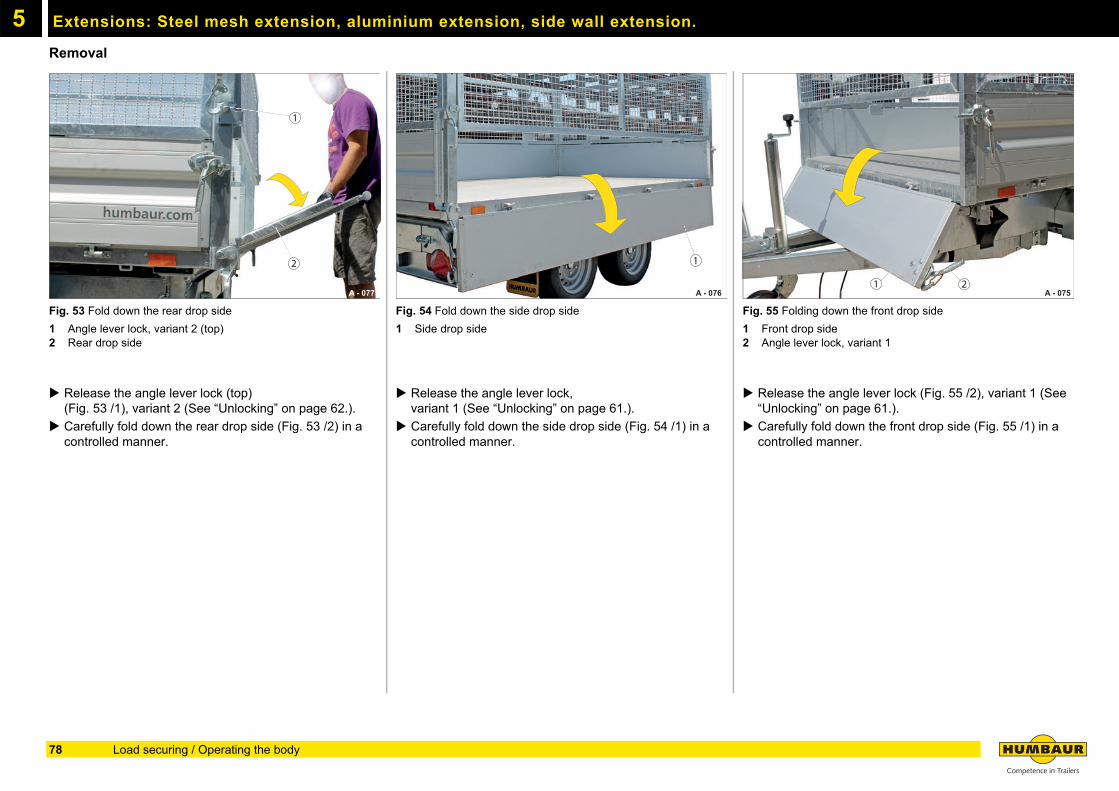
Extensions: Steel mesh extension, aluminium extension, side wall extension.5
RemovalFig. 53 Fold down the rear drop side
1 Angle lever lock, variant 2 (top)2 Rear drop side
Release the angle lever lock (top)(Fig. 53 /1), variant 2 (See “Unlocking” on page 62.).
Carefully fold down the rear drop side (Fig. 53 /2) in a controlled manner.
Fig. 54 Fold down the side drop side
1 Side drop side
Release the angle lever lock,variant 1 (See “Unlocking” on page 61.).
Carefully fold down the side drop side (Fig. 54 /1) in a controlled manner.
Fig. 55 Folding down the front drop side
1 Front drop side2 Angle lever lock, variant 1
Release the angle lever lock (Fig. 55 /2), variant 1 (See “Unlocking” on page 61.).
Carefully fold down the front drop side (Fig. 55 /1) in a controlled manner.
A - 077
1
2
A - 076
1
A - 075 21
78 Load securing / Operating the body
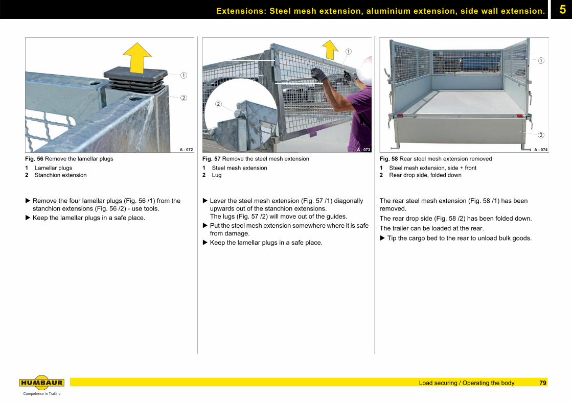
Extensions: Steel mesh extension, aluminium extension, side wall extension. 5
Fig. 56 Remove the lamellar plugs
1 Lamellar plugs2 Stanchion extension
Remove the four lamellar plugs (Fig. 56 /1) from the stanchion extensions (Fig. 56 /2) - use tools.
Keep the lamellar plugs in a safe place.
Fig. 57 Remove the steel mesh extension
1 Steel mesh extension2 Lug
Lever the steel mesh extension (Fig. 57 /1) diagonally upwards out of the stanchion extensions.The lugs (Fig. 57 /2) will move out of the guides.
Put the steel mesh extension somewhere where it is safe from damage.
Keep the lamellar plugs in a safe place.
Fig. 58 Rear steel mesh extension removed
1 Steel mesh extension, side + front2 Rear drop side, folded down
The rear steel mesh extension (Fig. 58 /1) has been removed.
The rear drop side (Fig. 58 /2) has been folded down.
The trailer can be loaded at the rear.
Tip the cargo bed to the rear to unload bulk goods.
A - 072
1
2
A - 073
1
2
A - 074
1
2
79Load securing / Operating the body
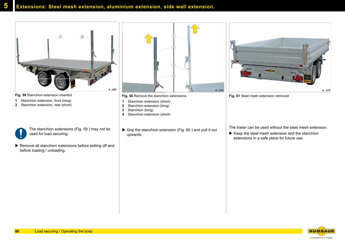
Extensions: Steel mesh extension, aluminium extension, side wall extension.5
Fig. 59 Stanchion extension inserted
1 Stanchion extension, front (long)2 Stanchion extension, rear (short)
The stanchion extensions (Fig. 59 ) may not be used for load securing.
Remove all stanchion extensions before setting off and before loading / unloading.
Fig. 60 Remove the stanchion extensions
1 Stanchion extension (short)2 Stanchion extension (long)3 Stanchion (long)4 Stanchion extension (short)
Grip the stanchion extension (Fig. 60 ) and pull it out upwards.
Fig. 61 Steel mesh extension removed
The trailer can be used without the steel mesh extension.
Keep the steel mesh extension and the stanchion extensions in a safe place for future use.
A - 089
21
A - 078
1
2
3
4
A - 079
80 Load securing / Operating the body
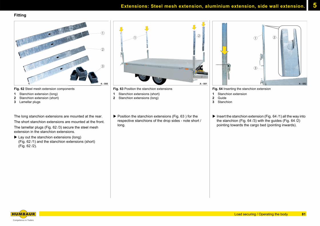
Extensions: Steel mesh extension, aluminium extension, side wall extension. 5
FittingFig. 62 Steel mesh extension components
1 Stanchion extension (long)2 Stanchion extension (short)3 Lamellar plugs
The long stanchion extensions are mounted at the rear.
The short stanchion extensions are mounted at the front.
The lamellar plugs (Fig. 62 /3) secure the steel mesh extension in the stanchion extensions.
Lay out the stanchion extensions (long)(Fig. 62 /1) and the stanchion extensions (short) (Fig. 62 /2).
Fig. 63 Position the stanchion extensions
1 Stanchion extensions (short)2 Stanchion extensions (long)
Position the stanchion extensions (Fig. 63 ) for the respective stanchions of the drop sides - note short / long.
Fig. 64 Inserting the stanchion extension
1 Stanchion extension2 Guide3 Stanchion
Insert the stanchion extension (Fig. 64 /1) all the way into the stanchion (Fig. 64 /3) with the guides (Fig. 64 /2) pointing towards the cargo bed (pointing inwards).
A - 080
2
A
1
3
A - 081
21
A - 082
1 2
3
81Load securing / Operating the body
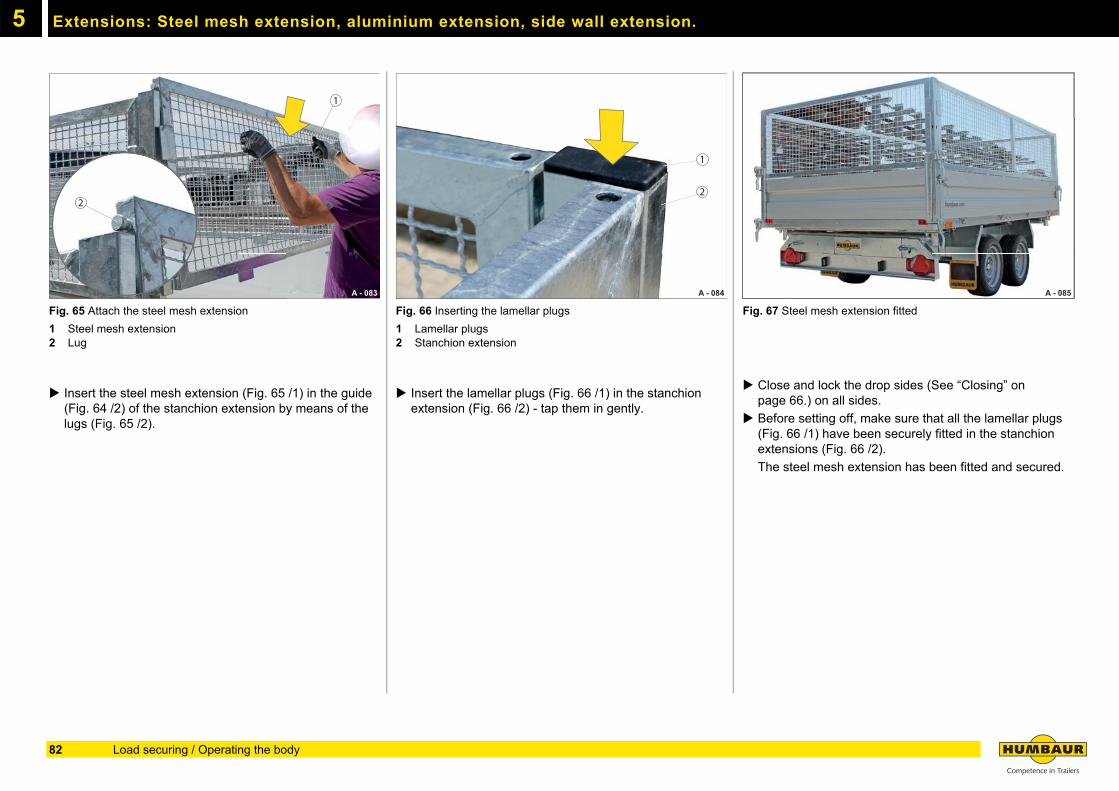
Extensions: Steel mesh extension, aluminium extension, side wall extension.5
Fig. 65 Attach the steel mesh extension
1 Steel mesh extension2 Lug
Insert the steel mesh extension (Fig. 65 /1) in the guide (Fig. 64 /2) of the stanchion extension by means of the lugs (Fig. 65 /2).
Fig. 66 Inserting the lamellar plugs
1 Lamellar plugs2 Stanchion extension
Insert the lamellar plugs (Fig. 66 /1) in the stanchion extension (Fig. 66 /2) - tap them in gently.
Fig. 67 Steel mesh extension fitted
Close and lock the drop sides (See “Closing” on page 66.) on all sides.
Before setting off, make sure that all the lamellar plugs (Fig. 66 /1) have been securely fitted in the stanchion extensions (Fig. 66 /2).
The steel mesh extension has been fitted and secured.
A - 083
1
2
A - 084
1
2
A - 085 A - 085
82 Load securing / Operating the body
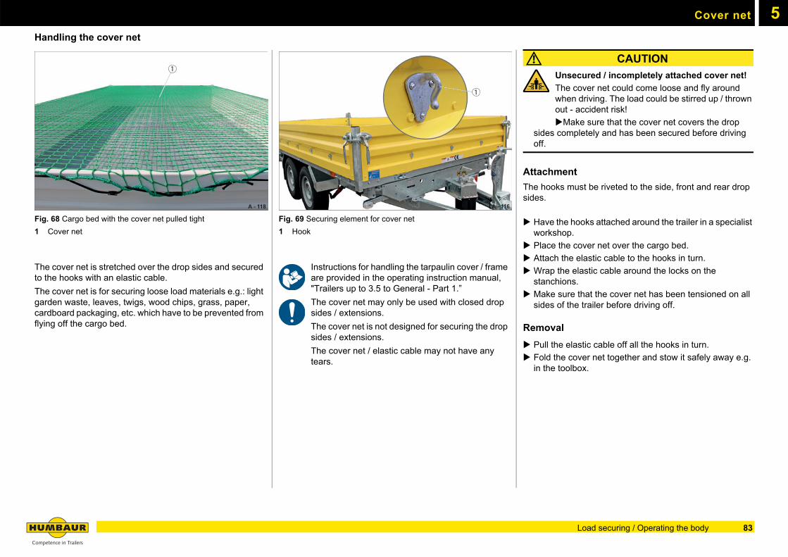
5Cover net
Handling the cover net
Fig. 68 Cargo bed with the cover net pulled tight
1 Cover net
The cover net is stretched over the drop sides and secured to the hooks with an elastic cable.
The cover net is for securing loose load materials e.g.: light garden waste, leaves, twigs, wood chips, grass, paper, cardboard packaging, etc. which have to be prevented from flying off the cargo bed.
Fig. 69 Securing element for cover net
1 Hook
Instructions for handling the tarpaulin cover / frame are provided in the operating instruction manual, "Trailers up to 3.5 to General - Part 1.”
The cover net may only be used with closed drop sides / extensions.
The cover net is not designed for securing the drop sides / extensions.
The cover net / elastic cable may not have any tears.
CAUTION
Unsecured / incompletely attached cover net!
The cover net could come loose and fly around when driving. The load could be stirred up / thrown out - accident risk!
Make sure that the cover net covers the drop sides completely and has been secured before driving off.
Attachment
The hooks must be riveted to the side, front and rear drop sides.
Have the hooks attached around the trailer in a specialist workshop.
Place the cover net over the cargo bed.
Attach the elastic cable to the hooks in turn.
Wrap the elastic cable around the locks on the stanchions.
Make sure that the cover net has been tensioned on all sides of the trailer before driving off.
Removal
Pull the elastic cable off all the hooks in turn.
Fold the cover net together and stow it safely away e.g. in the toolbox.
A - 118
1
A - 116
1
83Load securing / Operating the body
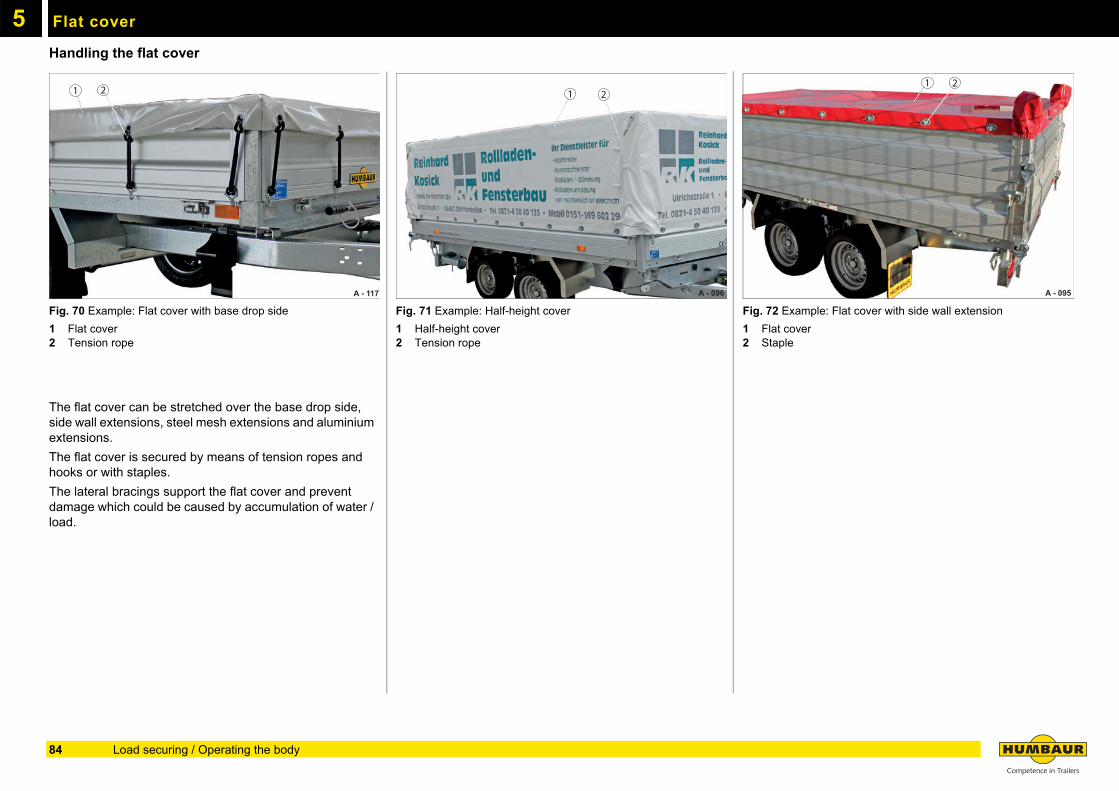
5
Flat coverHandling the flat cover
Fig. 70 Example: Flat cover with base drop side
1 Flat cover2 Tension rope
The flat cover can be stretched over the base drop side, side wall extensions, steel mesh extensions and aluminium extensions.
The flat cover is secured by means of tension ropes and hooks or with staples.
The lateral bracings support the flat cover and prevent damage which could be caused by accumulation of water / load.
Fig. 71 Example: Half-height cover
1 Half-height cover2 Tension rope
Fig. 72 Example: Flat cover with side wall extension
1 Flat cover2 Staple
A - 117
1 2
A - 096
1 2
A - 095
1 2
84 Load securing / Operating the body
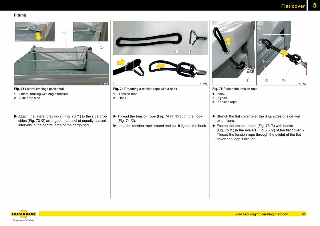
Flat cover 5
FittingFig. 73 Lateral bracings positioned
1 Lateral bracing with angle bracket2 Side drop side
Attach the lateral bracing(s) (Fig. 73 /1) to the side drop sides (Fig. 73 /2) arranged in parallel at equally spaced intervals in the central area of the cargo bed.
Fig. 74 Preparing a tension rope with a hook
1 Tension rope2 Hook
Thread the tension rope (Fig. 74 /1) through the hook (Fig. 74 /2).
Loop the tension rope around and pull it tight at the hook.
Fig. 75 Fasten the tension rope
1 Hook2 Eyelet3 Tension rope
Stretch the flat cover over the drop sides or side wall extensions.
Fasten the tension ropes (Fig. 75 /3) with hooks (Fig. 75 /1) in the eyelets (Fig. 75 /2) of the flat cover. - Thread the tension rope through the eyelet of the flat cover and loop it around.
A - 094
1
2
A - 092 A 092
1 2
A - 093 21 3
85Load securing / Operating the body
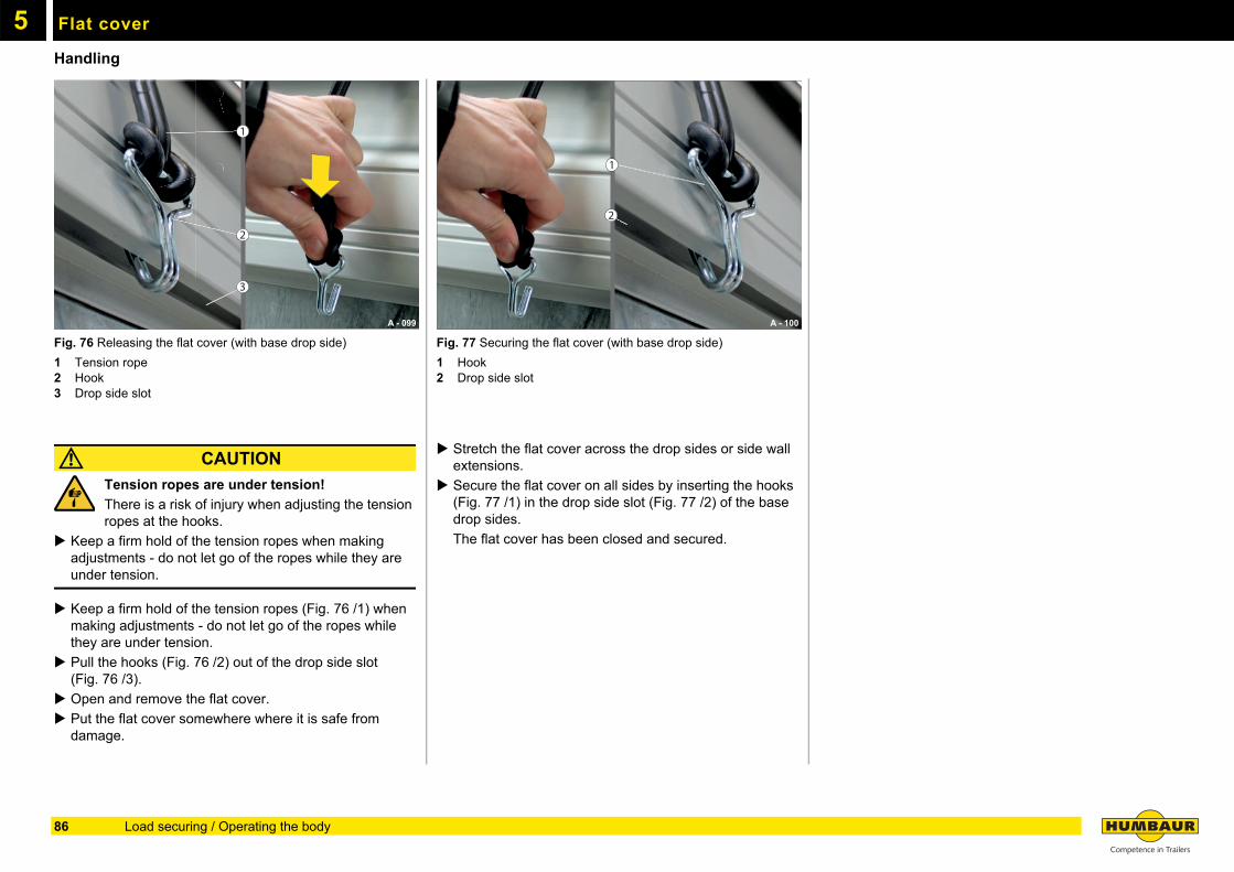
Flat cover5
HandlingFig. 76 Releasing the flat cover (with base drop side)
1 Tension rope2 Hook3 Drop side slot
CAUTION
Tension ropes are under tension!
There is a risk of injury when adjusting the tension ropes at the hooks.
Keep a firm hold of the tension ropes when making adjustments - do not let go of the ropes while they are under tension.
Keep a firm hold of the tension ropes (Fig. 76 /1) when making adjustments - do not let go of the ropes while they are under tension.
Pull the hooks (Fig. 76 /2) out of the drop side slot (Fig. 76 /3).
Open and remove the flat cover.
Put the flat cover somewhere where it is safe from damage.
Fig. 77 Securing the flat cover (with base drop side)
1 Hook2 Drop side slot
Stretch the flat cover across the drop sides or side wall extensions.
Secure the flat cover on all sides by inserting the hooks (Fig. 77 /1) in the drop side slot (Fig. 77 /2) of the base drop sides.
The flat cover has been closed and secured.
A - 099
1
2
11111111111111111111111111
2222222222
2
3
1
A - 100
1
2
86 Load securing / Operating the body
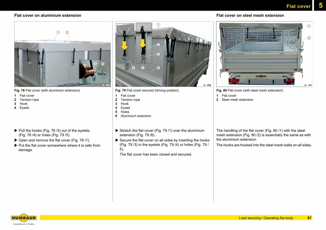
Flat cover 5
Flat cover on aluminium extensionFig. 78 Flat cover (with aluminium extension)
1 Flat cover2 Tension rope3 Hook4 Eyelet
Pull the hooks (Fig. 78 /3) out of the eyelets(Fig. 78 /4) or holes (Fig. 79 /5).
Open and remove the flat cover (Fig. 78 /1).
Put the flat cover somewhere where it is safe from damage.
Fig. 79 Flat cover secured (driving position)
1 Flat cover2 Tension rope3 Hook4 Eyelet5 Holes6 Aluminium extension
Stretch the flat cover (Fig. 79 /1) over the aluminium extension (Fig. 79 /6).
Secure the flat cover on all sides by inserting the hooks(Fig. 79 /3) in the eyelets (Fig. 79 /4) or holes (Fig. 79 /5).
The flat cover has been closed and secured.
Flat cover on steel mesh extension
Fig. 80 Flat cover (with steel mesh extension)
1 Flat cover2 Steel mesh extension
The handling of the flat cover (Fig. 80 /1) with the steel mesh extension (Fig. 80 /2) is essentially the same as with the aluminium extension.
The hooks are hooked into the steel mesh walls on all sides.
A - 097
1
3 4
2
A - 098
4
1
2
3
5 6
A - 101
1
2
A
11111111111111111111111111111111111111111111111
22222222222222222
1
2
87Load securing / Operating the body
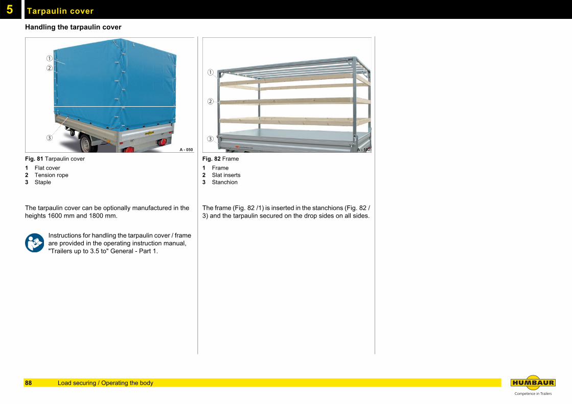
5
Tarpaulin coverHandling the tarpaulin cover
Fig. 81 Tarpaulin cover
1 Flat cover2 Tension rope3 Staple
The tarpaulin cover can be optionally manufactured in the heights 1600 mm and 1800 mm.
Instructions for handling the tarpaulin cover / frame are provided in the operating instruction manual, "Trailers up to 3.5 to" General - Part 1.
Fig. 82 Frame
1 Frame2 Slat inserts3 Stanchion
The frame (Fig. 82 /1) is inserted in the stanchions (Fig. 82 /3) and the tarpaulin secured on the drop sides on all sides.
A - 050
1
2
3
A - 102
1
2
3
88 Load securing / Operating the body
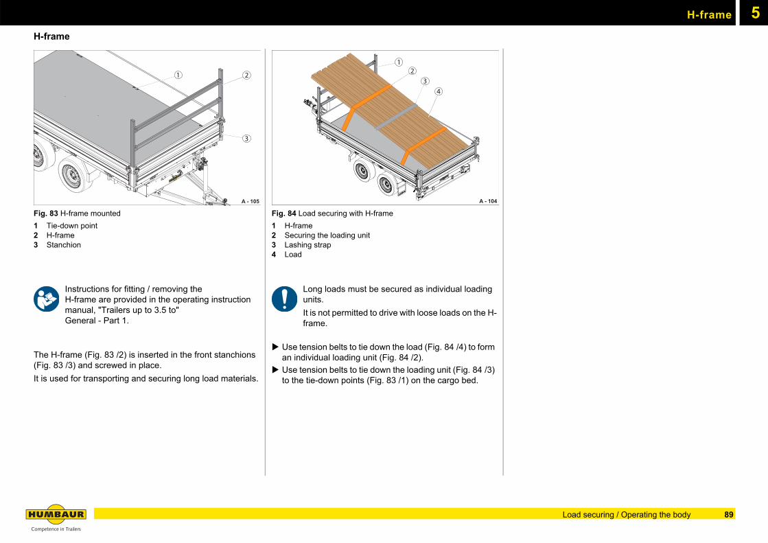
5H-frame
H-frame
Fig. 83 H-frame mounted
1 Tie-down point2 H-frame3 Stanchion
Instructions for fitting / removing theH-frame are provided in the operating instruction manual, "Trailers up to 3.5 to"General - Part 1.
The H-frame (Fig. 83 /2) is inserted in the front stanchions (Fig. 83 /3) and screwed in place.
It is used for transporting and securing long load materials.
Fig. 84 Load securing with H-frame
1 H-frame2 Securing the loading unit3 Lashing strap4 Load
Long loads must be secured as individual loading units.
It is not permitted to drive with loose loads on the H-frame.
Use tension belts to tie down the load (Fig. 84 /4) to form an individual loading unit (Fig. 84 /2).
Use tension belts to tie down the loading unit (Fig. 84 /3) to the tie-down points (Fig. 83 /1) on the cargo bed.
A - 105
21
3
A - 104
12
34
89Load securing / Operating the body
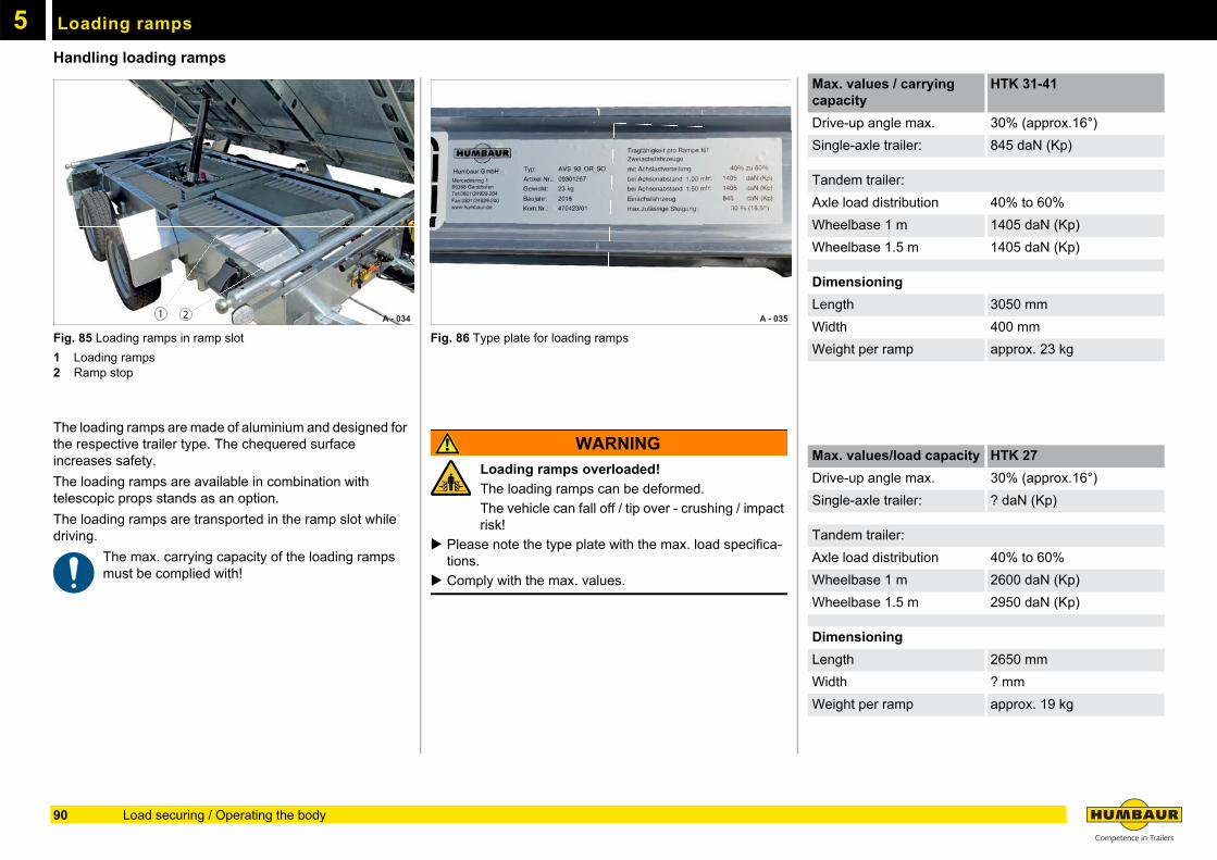
5
Loading rampsHandling loading ramps
Fig. 85 Loading ramps in ramp slot
1 Loading ramps2 Ramp stop
The loading ramps are made of aluminium and designed for the respective trailer type. The chequered surface increases safety.
The loading ramps are available in combination with telescopic props stands as an option.
The loading ramps are transported in the ramp slot while driving.
The max. carrying capacity of the loading ramps must be complied with!
Fig. 86 Type plate for loading ramps
WARNING
Loading ramps overloaded!
The loading ramps can be deformed.
The vehicle can fall off / tip over - crushing / impact risk!
Please note the type plate with the max. load specifica-tions.
Comply with the max. values.
A - 034 1 2 A - 035
Max. values / carrying capacity
HTK 31-41
Drive-up angle max. 30% (approx.16°)
Single-axle trailer: 845 daN (Kp)
Tandem trailer:
Axle load distribution 40% to 60%
Wheelbase 1 m 1405 daN (Kp)
Wheelbase 1.5 m 1405 daN (Kp)
Dimensioning
Length 3050 mm
Width 400 mm
Weight per ramp approx. 23 kg
Max. values/load capacity HTK 27
Drive-up angle max. 30% (approx.16°)
Single-axle trailer: ? daN (Kp)
Tandem trailer:
Axle load distribution 40% to 60%
Wheelbase 1 m 2600 daN (Kp)
Wheelbase 1.5 m 2950 daN (Kp)
Dimensioning
Length 2650 mm
Width ? mm
Weight per ramp approx. 19 kg
90 Load securing / Operating the body
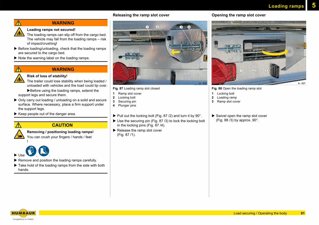
Loading ramps 5
WARNING
Loading ramps not secured!
The loading ramps can slip off from the cargo bed. The vehicle may fall from the loading ramps – risk of impact/crushing!
Before loading/unloading, check that the loading ramps are secured to the cargo bed.
Note the warning label on the loading ramps.
WARNING
Risk of loss of stability!
The trailer could lose stability when being loaded / unloaded with vehicles and the load could tip over.
Before using the loading ramps, extend the support legs and secure them.
Only carry out loading / unloading on a solid and secure surface. Where necessary, place a firm support under the support legs.
Keep people out of the danger area.
CAUTION
Removing / positioning loading ramps!
You can crush your fingers / hands / feet!
Use , .
Remove and position the loading ramps carefully.
Take hold of the loading ramps from the side with both hands.
Releasing the ramp slot cover
Fig. 87 Loading ramp slot closed
1 Ramp slot cover2 Locking bolt3 Securing pin4 Plunger pins
Pull out the locking bolt (Fig. 87 /2) and turn it by 90°.
Use the securing pin (Fig. 87 /3) to lock the locking bolt in the locking pins (Fig. 87 /4).
Release the ramp slot cover(Fig. 87 /1).
Opening the ramp slot cover
Fig. 88 Open the loading ramp slot
1 Locking bolt2 Loading ramp3 Ramp slot cover
Swivel open the ramp slot cover (Fig. 88 /3) by approx. 90°.
A - 036
1 2 3 4
A - 037
1 2 3
91Load securing / Operating the body
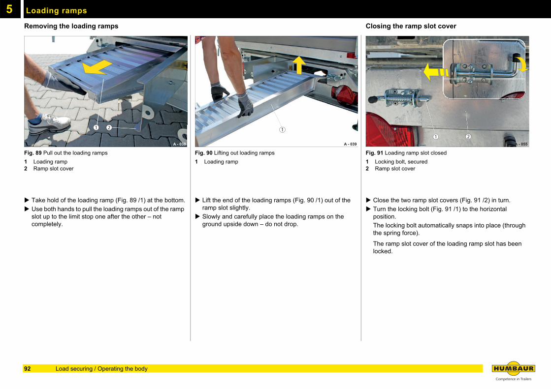
Loading ramps5
Removing the loading rampsFig. 89 Pull out the loading ramps
1 Loading ramp2 Ramp slot cover
Take hold of the loading ramp (Fig. 89 /1) at the bottom.
Use both hands to pull the loading ramps out of the ramp slot up to the limit stop one after the other – not completely.
Fig. 90 Lifting out loading ramps
1 Loading ramp
Lift the end of the loading ramps (Fig. 90 /1) out of the ramp slot slightly.
Slowly and carefully place the loading ramps on the ground upside down – do not drop.
Closing the ramp slot cover
Fig. 91 Loading ramp slot closed
1 Locking bolt, secured2 Ramp slot cover
Close the two ramp slot covers (Fig. 91 /2) in turn.
Turn the locking bolt (Fig. 91 /1) to the horizontal position.
The locking bolt automatically snaps into place (through the spring force).
The ramp slot cover of the loading ramp slot has been locked.
A - 038
21
A - 039
1
A - 055
1 2
92 Load securing / Operating the body
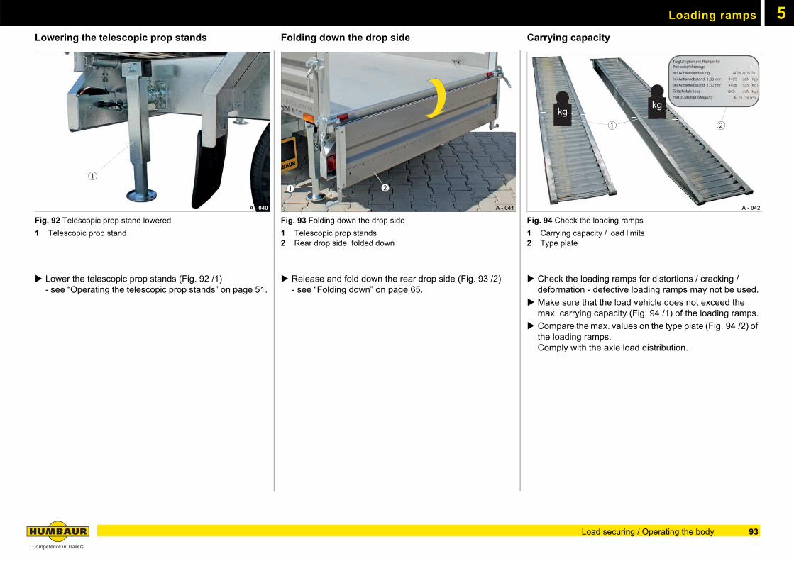
Loading ramps 5
Lowering the telescopic prop standsFig. 92 Telescopic prop stand lowered
1 Telescopic prop stand
Lower the telescopic prop stands (Fig. 92 /1) - see “Operating the telescopic prop stands” on page 51.
Folding down the drop side
Fig. 93 Folding down the drop side
1 Telescopic prop stands2 Rear drop side, folded down
Release and fold down the rear drop side (Fig. 93 /2) - see “Folding down” on page 65.
Carrying capacity
Fig. 94 Check the loading ramps
1 Carrying capacity / load limits2 Type plate
Check the loading ramps for distortions / cracking / deformation - defective loading ramps may not be used.
Make sure that the load vehicle does not exceed the max. carrying capacity (Fig. 94 /1) of the loading ramps.
Compare the max. values on the type plate (Fig. 94 /2) of the loading ramps. Comply with the axle load distribution.
A - 040
1
A - 041
21
A - 042
1
kgkg
2
93Load securing / Operating the body
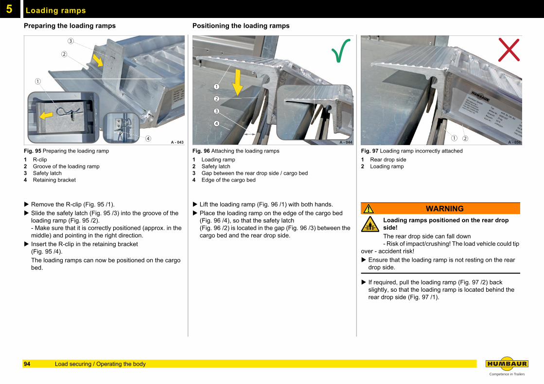
Loading ramps5
Preparing the loading rampsFig. 95 Preparing the loading ramp
1 R-clip2 Groove of the loading ramp3 Safety latch4 Retaining bracket
Remove the R-clip (Fig. 95 /1).
Slide the safety latch (Fig. 95 /3) into the groove of the loading ramp (Fig. 95 /2).- Make sure that it is correctly positioned (approx. in the middle) and pointing in the right direction.
Insert the R-clip in the retaining bracket (Fig. 95 /4).
The loading ramps can now be positioned on the cargo bed.
Positioning the loading ramps
Fig. 96 Attaching the loading ramps
1 Loading ramp2 Safety latch3 Gap between the rear drop side / cargo bed4 Edge of the cargo bed
Lift the loading ramp (Fig. 96 /1) with both hands.
Place the loading ramp on the edge of the cargo bed (Fig. 96 /4), so that the safety latch(Fig. 96 /2) is located in the gap (Fig. 96 /3) between the cargo bed and the rear drop side.
Fig. 97 Loading ramp incorrectly attached
1 Rear drop side2 Loading ramp
WARNING
Loading ramps positioned on the rear drop side!
The rear drop side can fall down- Risk of impact/crushing! The load vehicle could tip
over - accident risk!
Ensure that the loading ramp is not resting on the rear drop side.
If required, pull the loading ramp (Fig. 97 /2) back slightly, so that the loading ramp is located behind the rear drop side (Fig. 97 /1).
A - 043
1
3
2
4 A - 044
1
3
2
4
A - 056 1 2
94 Load securing / Operating the body
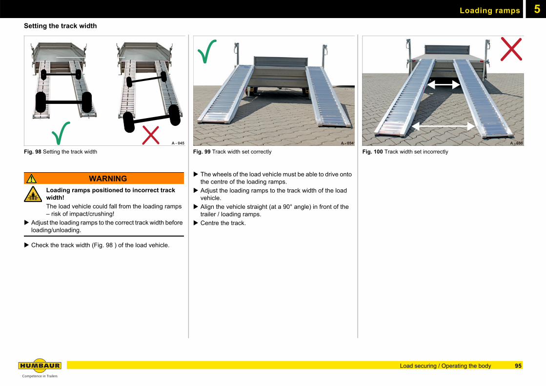
Loading ramps 5
Setting the track widthFig. 98 Setting the track width
WARNING
Loading ramps positioned to incorrect track width!
The load vehicle could fall from the loading ramps – risk of impact/crushing!
Adjust the loading ramps to the correct track width before loading/unloading.
Check the track width (Fig. 98 ) of the load vehicle.
Fig. 99 Track width set correctly
The wheels of the load vehicle must be able to drive onto the centre of the loading ramps.
Adjust the loading ramps to the track width of the load vehicle.
Align the vehicle straight (at a 90° angle) in front of the trailer / loading ramps.
Centre the track.
Fig. 100 Track width set incorrectly
A - 045 A - 054 A - 050
95Load securing / Operating the body
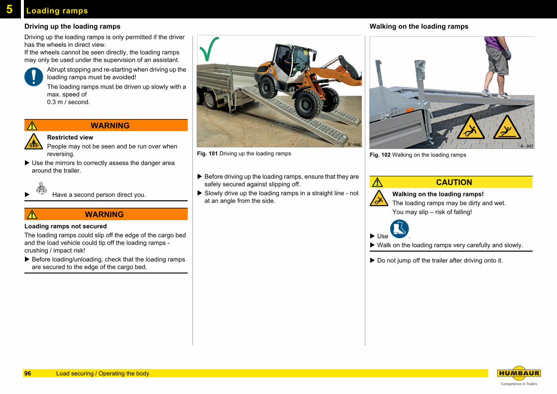
Loading ramps5
Driving up the loading rampsDriving up the loading ramps is only permitted if the driver has the wheels in direct view.If the wheels cannot be seen directly, the loading ramps may only be used under the supervision of an assistant.
Abrupt stopping and re-starting when driving up the loading ramps must be avoided!
The loading ramps must be driven up slowly with a max. speed of 0.3 m / second.
WARNING
Restricted view
People may not be seen and be run over when reversing.
Use the mirrors to correctly assess the danger area around the trailer.
Have a second person direct you.
WARNING
Loading ramps not secured
The loading ramps could slip off the edge of the cargo bed and the load vehicle could tip off the loading ramps - crushing / impact risk!
Before loading/unloading, check that the loading ramps are secured to the edge of the cargo bed.
Fig. 101 Driving up the loading ramps
Before driving up the loading ramps, ensure that they are safely secured against slipping off.
Slowly drive up the loading ramps in a straight line - not at an angle from the side.
Walking on the loading ramps
Fig. 102 Walking on the loading ramps
CAUTION
Walking on the loading ramps!
The loading ramps may be dirty and wet.
You may slip – risk of falling!
Use .
Walk on the loading ramps very carefully and slowly.
Do not jump off the trailer after driving onto it.
A - 046 A - 047
96 Load securing / Operating the body
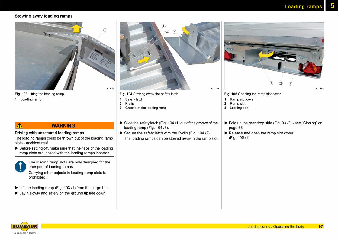
Loading ramps 5
Stowing away loading rampsFig. 103 Lifting the loading ramp
1 Loading ramp
WARNING
Driving with unsecured loading ramps
The loading ramps could be thrown out of the loading ramp slots - accident risk!
Before setting off, make sure that the flaps of the loading ramp slots are locked with the loading ramps inserted.
The loading ramp slots are only designed for the transport of loading ramps.
Carrying other objects in loading ramp slots is prohibited!
Lift the loading ramp (Fig. 103 /1) from the cargo bed.
Lay it slowly and safely on the ground upside down.
Fig. 104 Stowing away the safety latch
1 Safety latch2 R-clip3 Groove of the loading ramp
Slide the safety latch (Fig. 104 /1) out of the groove of the loading ramp (Fig. 104 /3).
Secure the safety latch with the R-clip (Fig. 104 /2).
The loading ramps can be stowed away in the ramp slot.
Fig. 105 Opening the ramp slot cover
1 Ramp slot cover2 Ramp slot3 Locking bolt
Fold up the rear drop side (Fig. 93 /2) - see “Closing” on page 66.
Release and open the ramp slot cover(Fig. 105 /1).
A - 048
1
A - 049
1
2 3
A - 051
1 2 3
97Load securing / Operating the body
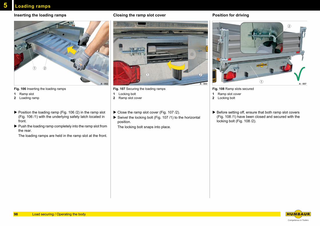
Loading ramps5
Inserting the loading rampsFig. 106 Inserting the loading ramps
1 Ramp slot2 Loading ramp
Position the loading ramp (Fig. 106 /2) in the ramp slot (Fig. 106 /1) with the underlying safety latch located in front.
Push the loading ramp completely into the ramp slot from the rear.
The loading ramps are held in the ramp slot at the front.
Closing the ramp slot cover
Fig. 107 Securing the loading ramps
1 Locking bolt2 Ramp slot cover
Close the ramp slot cover (Fig. 107 /2).
Swivel the locking bolt (Fig. 107 /1) to the horizontal position.
The locking bolt snaps into place.
Position for driving
Fig. 108 Ramp slots secured
1 Ramp slot cover2 Locking bolt
Before setting off, ensure that both ramp slot covers (Fig. 108 /1) have been closed and secured with the locking bolt (Fig. 108 /2).
A - 052
1 2
A - 053
1 2
A - 0571
2
98 Load securing / Operating the body
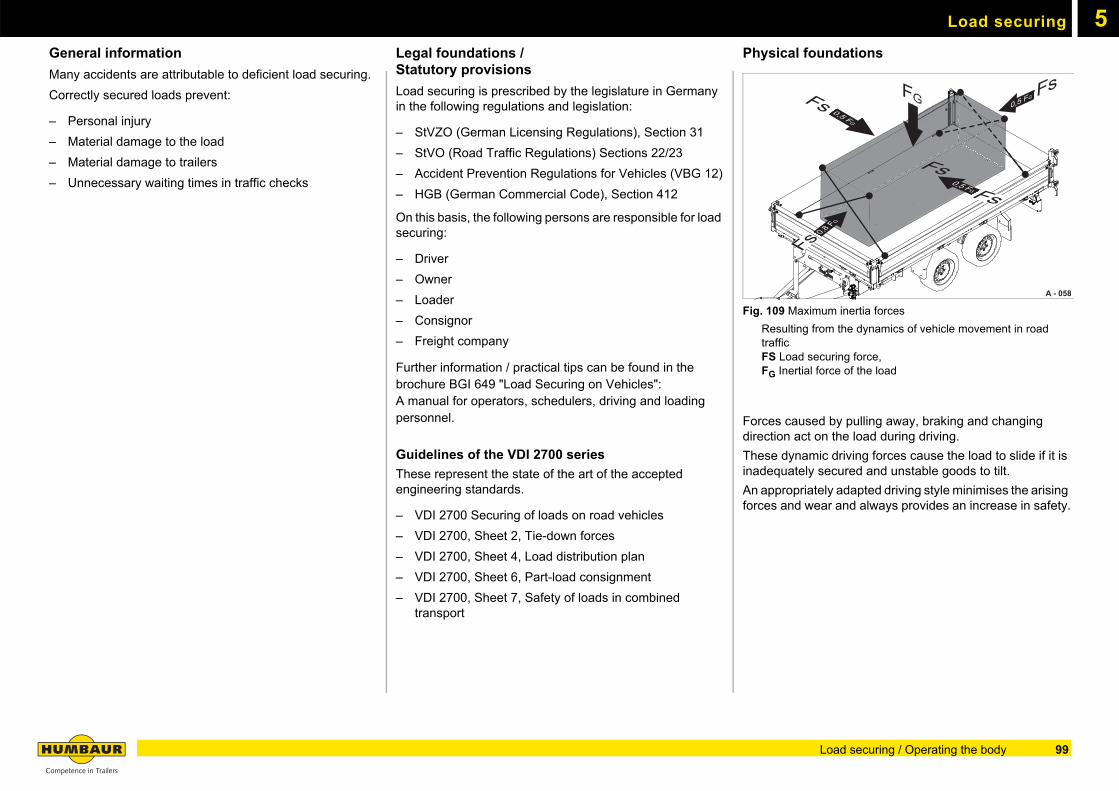
5Load securing
General information
Many accidents are attributable to deficient load securing.
Correctly secured loads prevent:
– Personal injury
– Material damage to the load
– Material damage to trailers
– Unnecessary waiting times in traffic checks
Legal foundations / Statutory provisions
Load securing is prescribed by the legislature in Germany in the following regulations and legislation:
– StVZO (German Licensing Regulations), Section 31
– StVO (Road Traffic Regulations) Sections 22/23
– Accident Prevention Regulations for Vehicles (VBG 12)
– HGB (German Commercial Code), Section 412
On this basis, the following persons are responsible for load securing:
– Driver
– Owner
– Loader
– Consignor
– Freight company
Further information / practical tips can be found in the brochure BGI 649 "Load Securing on Vehicles": A manual for operators, schedulers, driving and loading personnel.
Guidelines of the VDI 2700 series
These represent the state of the art of the accepted engineering standards.
– VDI 2700 Securing of loads on road vehicles
– VDI 2700, Sheet 2, Tie-down forces
– VDI 2700, Sheet 4, Load distribution plan
– VDI 2700, Sheet 6, Part-load consignment
– VDI 2700, Sheet 7, Safety of loads in combined transport
Physical foundations
Fig. 109 Maximum inertia forces
Resulting from the dynamics of vehicle movement in road traffic
FS Load securing force, FG Inertial force of the load
Forces caused by pulling away, braking and changing direction act on the load during driving.
These dynamic driving forces cause the load to slide if it is inadequately secured and unstable goods to tilt.
An appropriately adapted driving style minimises the arising forces and wear and always provides an increase in safety.
A - 058
Fs0,5 FG
0,5 FG
FG Fs0,5 FG
FsFs
Fs0,8 FG
99Load securing / Operating the body
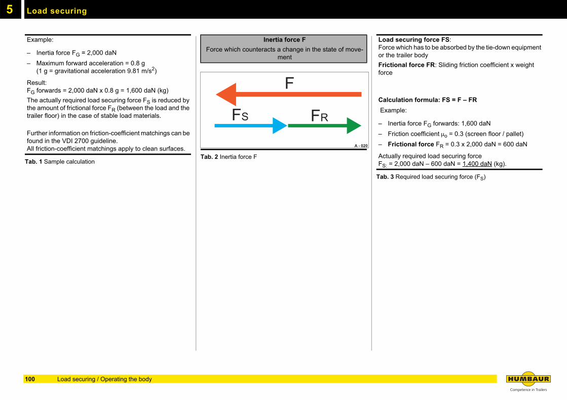
Load securing5
Tab. 1 Sample calculationTab. 2 Inertia force F
Tab. 3 Required load securing force (FS)
Example:
– Inertia force FG = 2,000 daN
– Maximum forward acceleration = 0.8 g (1 g = gravitational acceleration 9.81 m/s2)
Result: FG forwards = 2,000 daN x 0.8 g = 1,600 daN (kg)
The actually required load securing force FS is reduced by the amount of frictional force FR (between the load and the trailer floor) in the case of stable load materials.
Further information on friction-coefficient matchings can be found in the VDI 2700 guideline. All friction-coefficient matchings apply to clean surfaces.
Inertia force F
Force which counteracts a change in the state of move-ment
F
FS FR
A - 020
Load securing force FS:Force which has to be absorbed by the tie-down equipment or the trailer body
Frictional force FR: Sliding friction coefficient x weight force
Calculation formula: FS = F – FR
Example:
– Inertia force FG forwards: 1,600 daN
– Friction coefficient o = 0.3 (screen floor / pallet)
– Frictional force FR = 0.3 x 2,000 daN = 600 daN
Actually required load securing forceFS: = 2,000 daN – 600 daN = 1,400 daN (kg).
100 Load securing / Operating the body
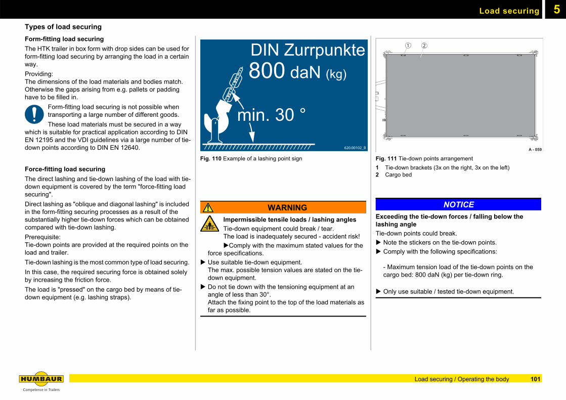
Load securing 5
Types of load securingForm-fitting load securing
The HTK trailer in box form with drop sides can be used for form-fitting load securing by arranging the load in a certain way.
Providing:The dimensions of the load materials and bodies match. Otherwise the gaps arising from e.g. pallets or padding have to be filled in.
Form-fitting load securing is not possible when transporting a large number of different goods.
These load materials must be secured in a way which is suitable for practical application according to DIN EN 12195 and the VDI guidelines via a large number of tie-down points according to DIN EN 12640.
Force-fitting load securing
The direct lashing and tie-down lashing of the load with tie-down equipment is covered by the term "force-fitting load securing".
Direct lashing as "oblique and diagonal lashing" is included in the form-fitting securing processes as a result of the substantially higher tie-down forces which can be obtained compared with tie-down lashing.
Prerequisite:Tie-down points are provided at the required points on the load and trailer.
Tie-down lashing is the most common type of load securing.
In this case, the required securing force is obtained solely by increasing the friction force.
The load is "pressed" on the cargo bed by means of tie-down equipment (e.g. lashing straps).
Fig. 110 Example of a lashing point sign
WARNING
Impermissible tensile loads / lashing angles
Tie-down equipment could break / tear. The load is inadequately secured - accident risk!
Comply with the maximum stated values for the force specifications.
Use suitable tie-down equipment.The max. possible tension values are stated on the tie-down equipment.
Do not tie down with the tensioning equipment at an angle of less than 30°.Attach the fixing point to the top of the load materials as far as possible.
Fig. 111 Tie-down points arrangement
1 Tie-down brackets (3x on the right, 3x on the left)2 Cargo bed
NOTICE
Exceeding the tie-down forces / falling below the lashing angle
Tie-down points could break.
Note the stickers on the tie-down points.
Comply with the following specifications:
- Maximum tension load of the tie-down points on the cargo bed: 800 daN (kg) per tie-down ring.
Only use suitable / tested tie-down equipment.
DIN Zurrpunkte800 daN (kg)
min. 30 °620.00102_B A - 059
1 2
101Load securing / Operating the body
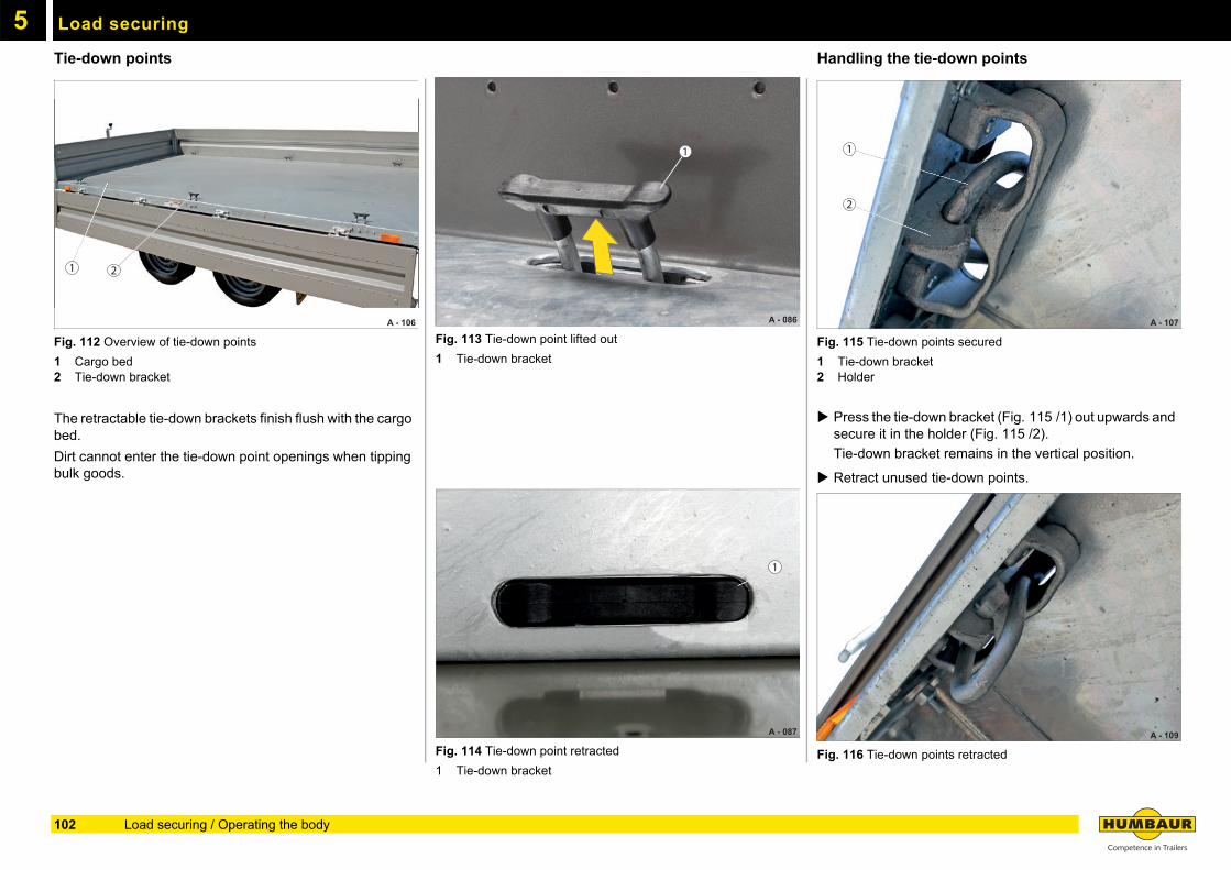
Load securing5
Tie-down pointsFig. 112 Overview of tie-down points
1 Cargo bed2 Tie-down bracket
The retractable tie-down brackets finish flush with the cargo bed.
Dirt cannot enter the tie-down point openings when tipping bulk goods.
Fig. 113 Tie-down point lifted out
1 Tie-down bracket
Fig. 114 Tie-down point retracted
1 Tie-down bracket
Handling the tie-down points
Fig. 115 Tie-down points secured
1 Tie-down bracket2 Holder
Press the tie-down bracket (Fig. 115 /1) out upwards and secure it in the holder (Fig. 115 /2).
Tie-down bracket remains in the vertical position.
Retract unused tie-down points.
Fig. 116 Tie-down points retracted
1
2
A - 106
111111111111111
222222
1 2
1
A - 086
1
A - 087
1
A - 107
2
A - 109
102 Load securing / Operating the body
6
Electrical system103
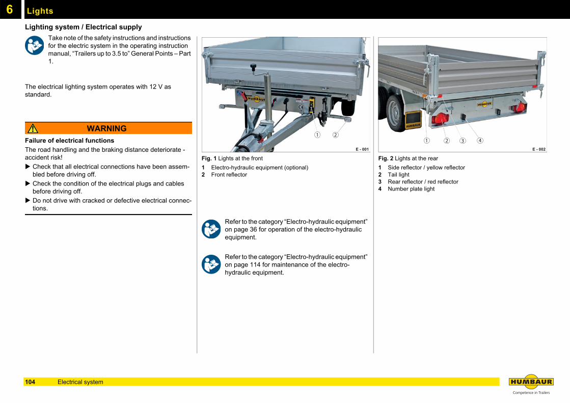
Lights6
Lighting system / Electrical supplyTake note of the safety instructions and instructions for the electric system in the operating instruction manual, “Trailers up to 3.5 to” General Points – Part 1.
The electrical lighting system operates with 12 V as standard.
WARNING
Failure of electrical functions
The road handling and the braking distance deteriorate - accident risk!
Check that all electrical connections have been assem-bled before driving off.
Check the condition of the electrical plugs and cables before driving off.
Do not drive with cracked or defective electrical connec-tions.
Fig. 1 Lights at the front
1 Electro-hydraulic equipment (optional)2 Front reflector
Refer to the category “Electro-hydraulic equipment” on page 36 for operation of the electro-hydraulic equipment.
Refer to the category “Electro-hydraulic equipment” on page 114 for maintenance of the electro-hydraulic equipment.
Fig. 2 Lights at the rear
1 Side reflector / yellow reflector2 Tail light3 Rear reflector / red reflector4 Number plate light
E - 001
21
E - 002
1 2 3 4
104 Electrical system
7
Testing,care and maintenance105
7
Safety inspectionTrailers must be inspected by a competent / qualified specialist for their condition for safe operation as and when required, but at least once a year.
This also applies to all components which are used for the load securing according to VDI 2700 or / and EN 12642.
All important mechanical components must be inspected and maintained at regular intervals for safety reasons.
These include:
– Axles
– Brakes
– Bolts
– Pipe connections
– Attachments
– Switch-off and securing mechanisms
– Electrical system / electro-hydraulic system
– Comply with the accident prevention regulations for all maintenance work.
– Comply with the environmental protection guidelines.
– Switch off the engine of the towing vehicle prior to starting maintenance work.
– Ensure that the electro-hydraulic equipment has not been switched on.
– Damaged tie-down points may not be repaired on any account, but must be exchanged for new parts.
– Damaged and non-functioning trailer parts must be exchanged for original spare parts of Humbaur GmbH.
Note the maintenance regulations in the operating instruction manual “Trailers up to 3.5 to” General – Part 1.
Certain maintenance work may only be carried out by trained and qualified personnel.
The prescribed maintenance intervals must be complied with.
106 Testing, care and maintenance
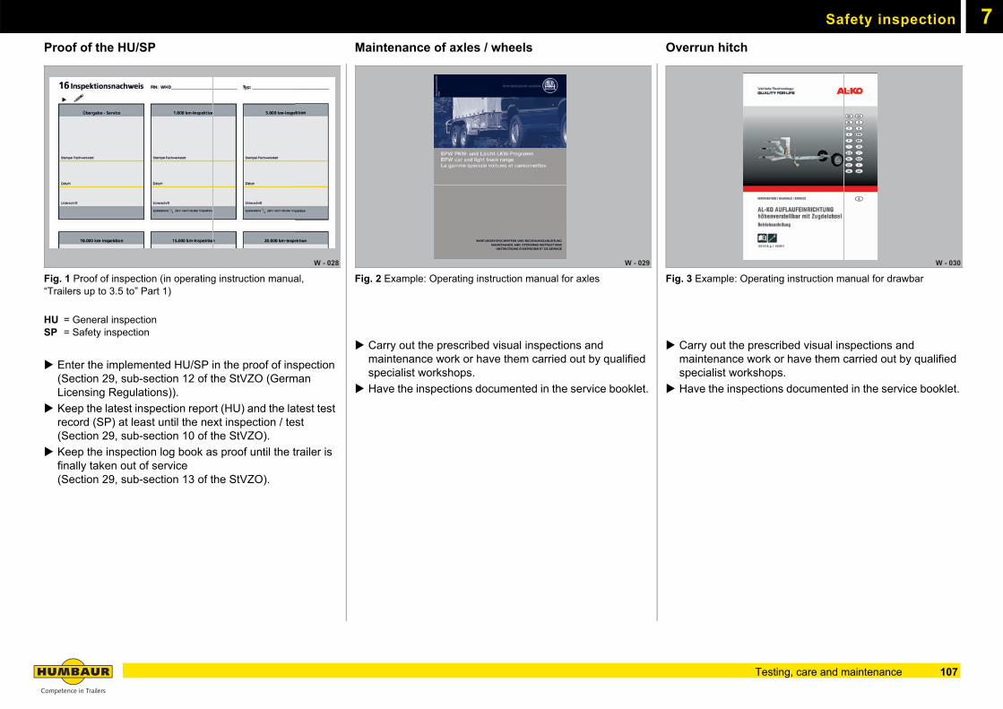
Safety inspection 7
Proof of the HU/SPFig. 1 Proof of inspection (in operating instruction manual, “Trailers up to 3.5 to” Part 1)
HU = General inspectionSP = Safety inspection
Enter the implemented HU/SP in the proof of inspection (Section 29, sub-section 12 of the StVZO (German Licensing Regulations)).
Keep the latest inspection report (HU) and the latest test record (SP) at least until the next inspection / test (Section 29, sub-section 10 of the StVZO).
Keep the inspection log book as proof until the trailer is finally taken out of service (Section 29, sub-section 13 of the StVZO).
Maintenance of axles / wheels
Fig. 2 Example: Operating instruction manual for axles
Carry out the prescribed visual inspections and maintenance work or have them carried out by qualified specialist workshops.
Have the inspections documented in the service booklet.
Overrun hitch
Fig. 3 Example: Operating instruction manual for drawbar
Carry out the prescribed visual inspections and maintenance work or have them carried out by qualified specialist workshops.
Have the inspections documented in the service booklet.
W - 028 W - 029 W - 030
107Testing, care and maintenance
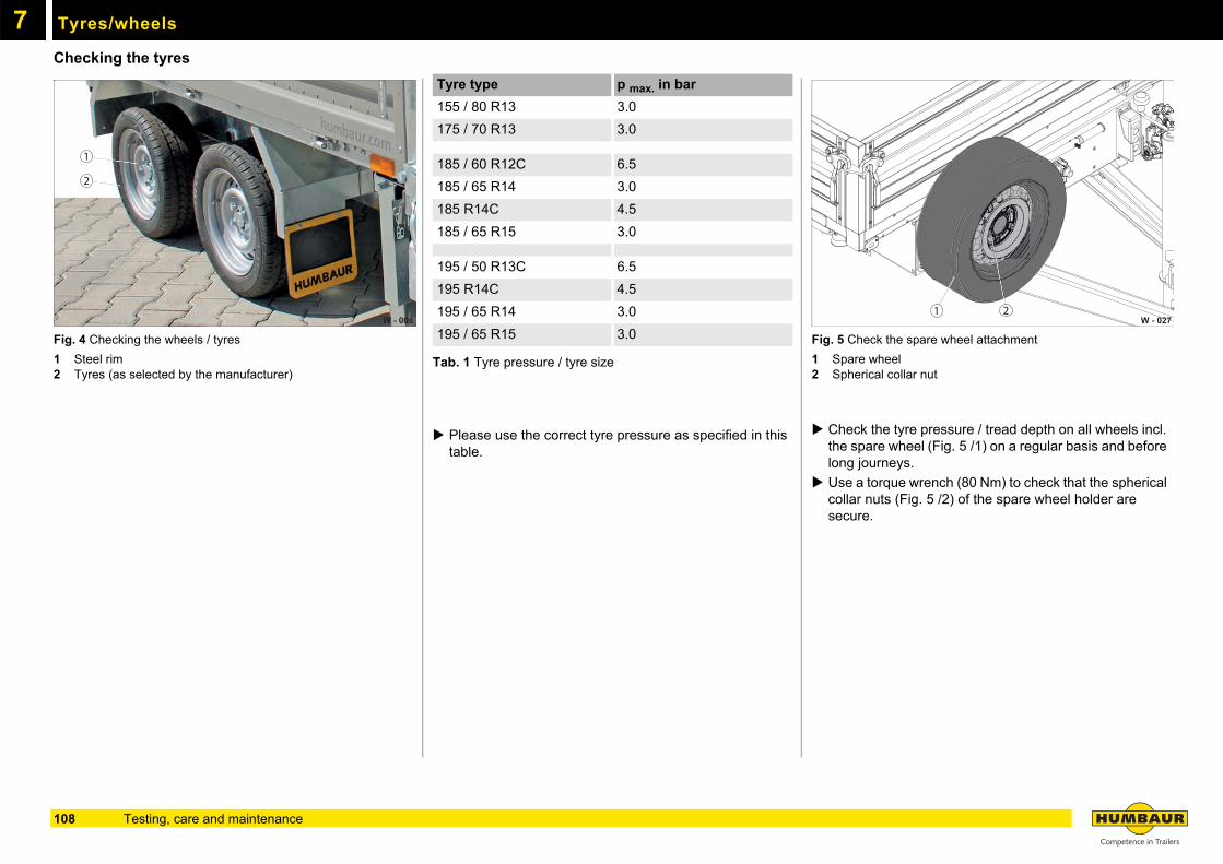
7
Tyres/wheelsChecking the tyres
Fig. 4 Checking the wheels / tyres
1 Steel rim 2 Tyres (as selected by the manufacturer)
Tab. 1 Tyre pressure / tyre size
Please use the correct tyre pressure as specified in this table.
Fig. 5 Check the spare wheel attachment
1 Spare wheel2 Spherical collar nut
Check the tyre pressure / tread depth on all wheels incl. the spare wheel (Fig. 5 /1) on a regular basis and before long journeys.
Use a torque wrench (80 Nm) to check that the spherical collar nuts (Fig. 5 /2) of the spare wheel holder are secure.
W - 008
2
1
Tyre type p max. in bar
155 / 80 R13 3.0
175 / 70 R13 3.0
185 / 60 R12C 6.5
185 / 65 R14 3.0
185 R14C 4.5
185 / 65 R15 3.0
195 / 50 R13C 6.5
195 R14C 4.5
195 / 65 R14 3.0
195 / 65 R15 3.0W - 027
1 2
108 Testing, care and maintenance
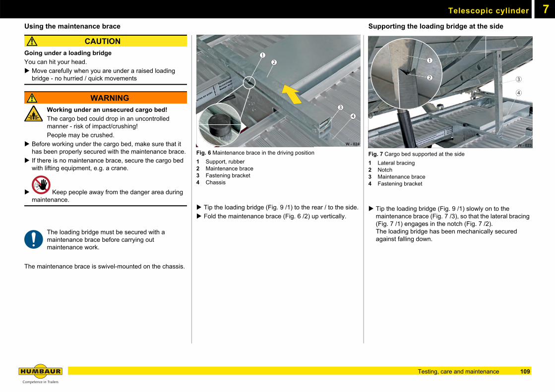
Telescopic cylinder 7
Using the maintenance braceCAUTION
Going under a loading bridge
You can hit your head.
Move carefully when you are under a raised loading bridge - no hurried / quick movements
WARNING
Working under an unsecured cargo bed!
The cargo bed could drop in an uncontrolled manner - risk of impact/crushing!
People may be crushed.
Before working under the cargo bed, make sure that it has been properly secured with the maintenance brace.
If there is no maintenance brace, secure the cargo bed with lifting equipment, e.g. a crane.
Keep people away from the danger area during maintenance.
The loading bridge must be secured with a maintenance brace before carrying out maintenance work.
The maintenance brace is swivel-mounted on the chassis.
Fig. 6 Maintenance brace in the driving position
1 Support, rubber2 Maintenance brace3 Fastening bracket4 Chassis
Tip the loading bridge (Fig. 9 /1) to the rear / to the side.
Fold the maintenance brace (Fig. 6 /2) up vertically.
Supporting the loading bridge at the side
Fig. 7 Cargo bed supported at the side
1 Lateral bracing2 Notch3 Maintenance brace4 Fastening bracket
Tip the loading bridge (Fig. 9 /1) slowly on to the maintenance brace (Fig. 7 /3), so that the lateral bracing (Fig. 7 /1) engages in the notch (Fig. 7 /2).The loading bridge has been mechanically secured against falling down.
W - 024
3
4
12
W - 023
1 311111111111111111111111111
4
1
2
109Testing, care and maintenance
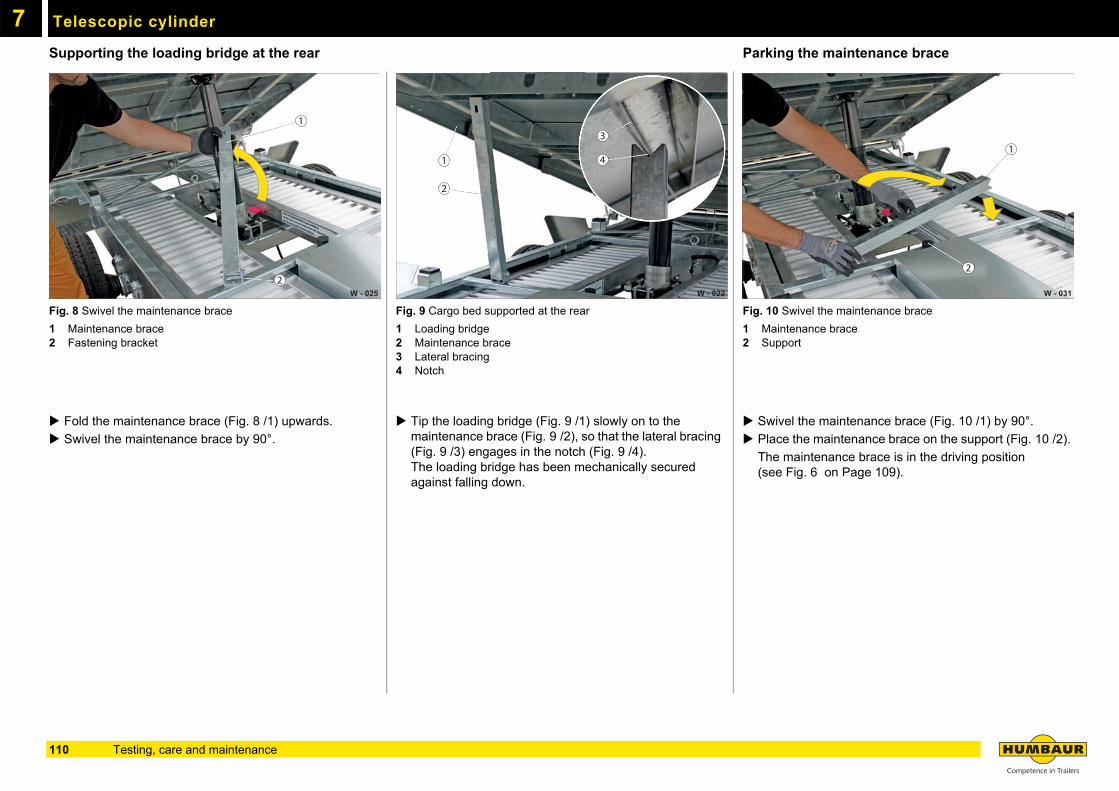
Telescopic cylinder7
Supporting the loading bridge at the rearFig. 8 Swivel the maintenance brace
1 Maintenance brace2 Fastening bracket
Fold the maintenance brace (Fig. 8 /1) upwards.
Swivel the maintenance brace by 90°.
Fig. 9 Cargo bed supported at the rear
1 Loading bridge2 Maintenance brace3 Lateral bracing4 Notch
Tip the loading bridge (Fig. 9 /1) slowly on to the maintenance brace (Fig. 9 /2), so that the lateral bracing (Fig. 9 /3) engages in the notch (Fig. 9 /4).The loading bridge has been mechanically secured against falling down.
Parking the maintenance brace
Fig. 10 Swivel the maintenance brace
1 Maintenance brace2 Support
Swivel the maintenance brace (Fig. 10 /1) by 90°.
Place the maintenance brace on the support (Fig. 10 /2).
The maintenance brace is in the driving position (see Fig. 6 on Page 109).
W - 025
1
2W - 022
1
3
4
2
W - 031
1
2
110 Testing, care and maintenance
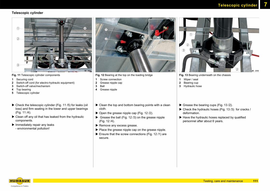
Telescopic cylinder 7
Telescopic cylinderFig. 11 Telescopic cylinder components
1 Securing cord2 Switch-off cord (for electro-hydraulic equipment)3 Switch-off valve/mechanism4 Top bearing5 Telescopic cylinder
Check the telescopic cylinder (Fig. 11 /5) for leaks (oil loss) and firm seating in the lower and upper bearings (Fig. 11 /4).
Clean off any oil that has leaked from the hydraulic components.
Immediately repair any leaks- environmental pollution!
Fig. 12 Bearing at the top on the loading bridge
1 Screw connection2 Grease nipple cap3 Ball4 Grease nipple
Clean the top and bottom bearing points with a clean cloth.
Open the grease nipple cap (Fig. 12 /2).
Grease the ball (Fig. 12 /3) on the grease nipple(Fig. 12 /4).
Remove any excess grease.
Place the grease nipple cap on the grease nipple.
Ensure that the screw connections (Fig. 12 /1) are secure.
Fig. 13 Bearing underneath on the chassis
1 Wiper / seal2 Bearing cup3 Hydraulic hose
Grease the bearing cups (Fig. 13 /2).
Check the hydraulic hoses (Fig. 13 /3) for cracks / deformation.
Have the hydraulic hoses replaced by qualified personnel after about 6 years.
W - 021
1
2
3
4
5
W - 020
1
2
3
4
W - 019
1
2
3
2
111Testing, care and maintenance
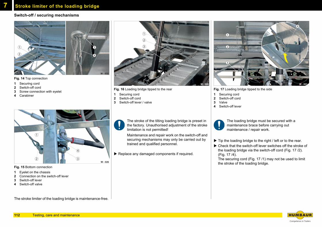
7
Stroke limiter of the loading bridgeSwitch-off / securing mechanisms
Fig. 14 Top connection
1 Securing cord2 Switch-off cord3 Screw connection with eyelet4 Carabiner
Fig. 15 Bottom connection
1 Eyelet on the chassis2 Connection on the switch-off lever3 Switch-off lever 4 Switch-off valve
The stroke limiter of the loading bridge is maintenance-free.
Fig. 16 Loading bridge tipped to the rear
1 Securing cord2 Switch-off cord3 Switch-off lever / valve
The stroke of the tilting loading bridge is preset in the factory. Unauthorised adjustment of the stroke limitation is not permitted!
Maintenance and repair work on the switch-off and securing mechanisms may only be carried out by trained and qualified personnel.
Replace any damaged components if required.
Fig. 17 Loading bridge tipped to the side
1 Securing cord2 Switch-off cord3 Valve4 Switch-off lever
The loading bridge must be secured with a maintenance brace before carrying out maintenance / repair work.
Tip the loading bridge to the right / left or to the rear.
Check that the switch-off lever switches off the stroke of the loading bridge via the switch-off cord (Fig. 17 /2).(Fig. 17 /4).The securing cord (Fig. 17 /1) may not be used to limit the stroke of the loading bridge.
W - 032
1
2 4
3
W - 026
1
2 3
4
W - 006
2
3
1
W - 007
2
3
1
4
112 Testing, care and maintenance
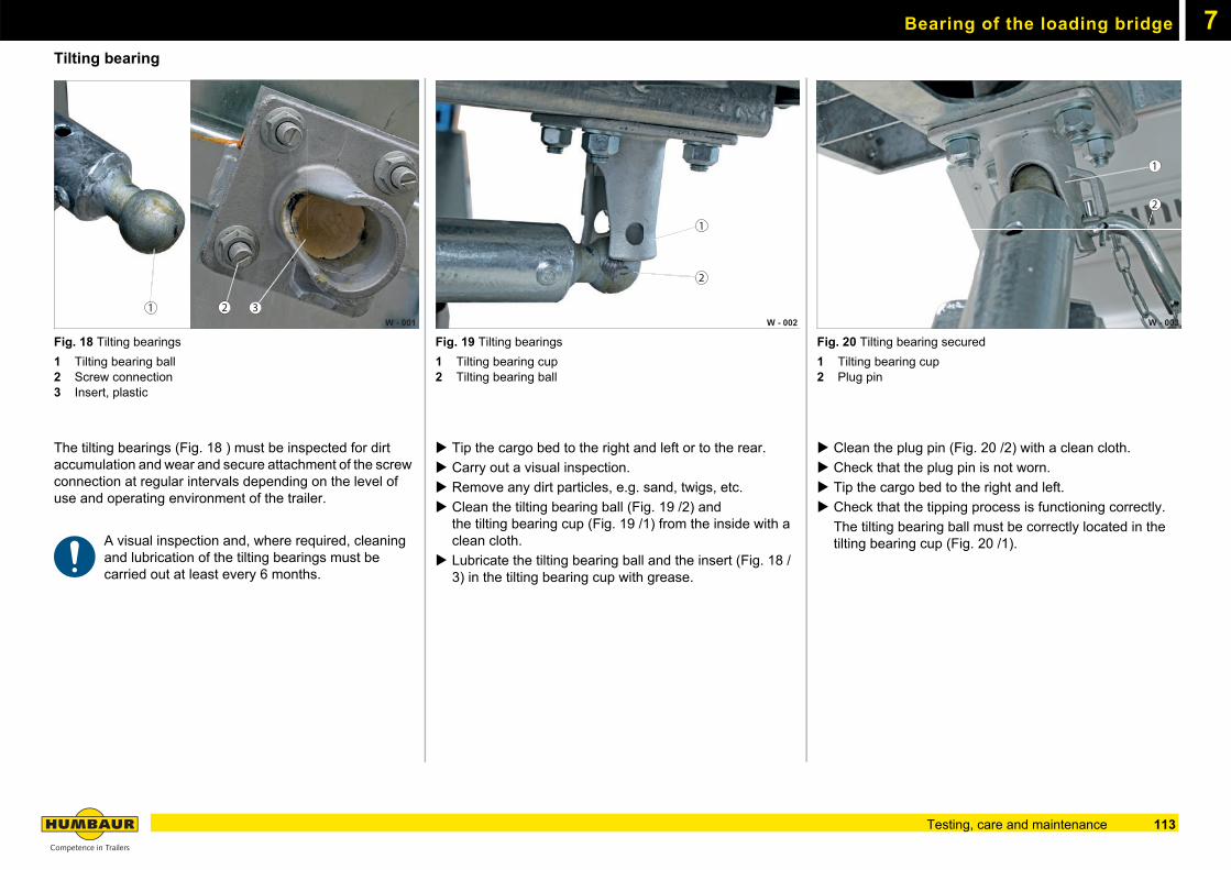
7Bearing of the loading bridge
Tilting bearing
Fig. 18 Tilting bearings
1 Tilting bearing ball2 Screw connection3 Insert, plastic
The tilting bearings (Fig. 18 ) must be inspected for dirt accumulation and wear and secure attachment of the screw connection at regular intervals depending on the level of use and operating environment of the trailer.
A visual inspection and, where required, cleaning and lubrication of the tilting bearings must be carried out at least every 6 months.
Fig. 19 Tilting bearings
1 Tilting bearing cup2 Tilting bearing ball
Tip the cargo bed to the right and left or to the rear.
Carry out a visual inspection.
Remove any dirt particles, e.g. sand, twigs, etc.
Clean the tilting bearing ball (Fig. 19 /2) andthe tilting bearing cup (Fig. 19 /1) from the inside with a clean cloth.
Lubricate the tilting bearing ball and the insert (Fig. 18 /3) in the tilting bearing cup with grease.
Fig. 20 Tilting bearing secured
1 Tilting bearing cup2 Plug pin
Clean the plug pin (Fig. 20 /2) with a clean cloth.
Check that the plug pin is not worn.
Tip the cargo bed to the right and left.
Check that the tipping process is functioning correctly.
The tilting bearing ball must be correctly located in the tilting bearing cup (Fig. 20 /1).
W - 001321
1
W - 002
2
1
W - 003
2
113Testing, care and maintenance
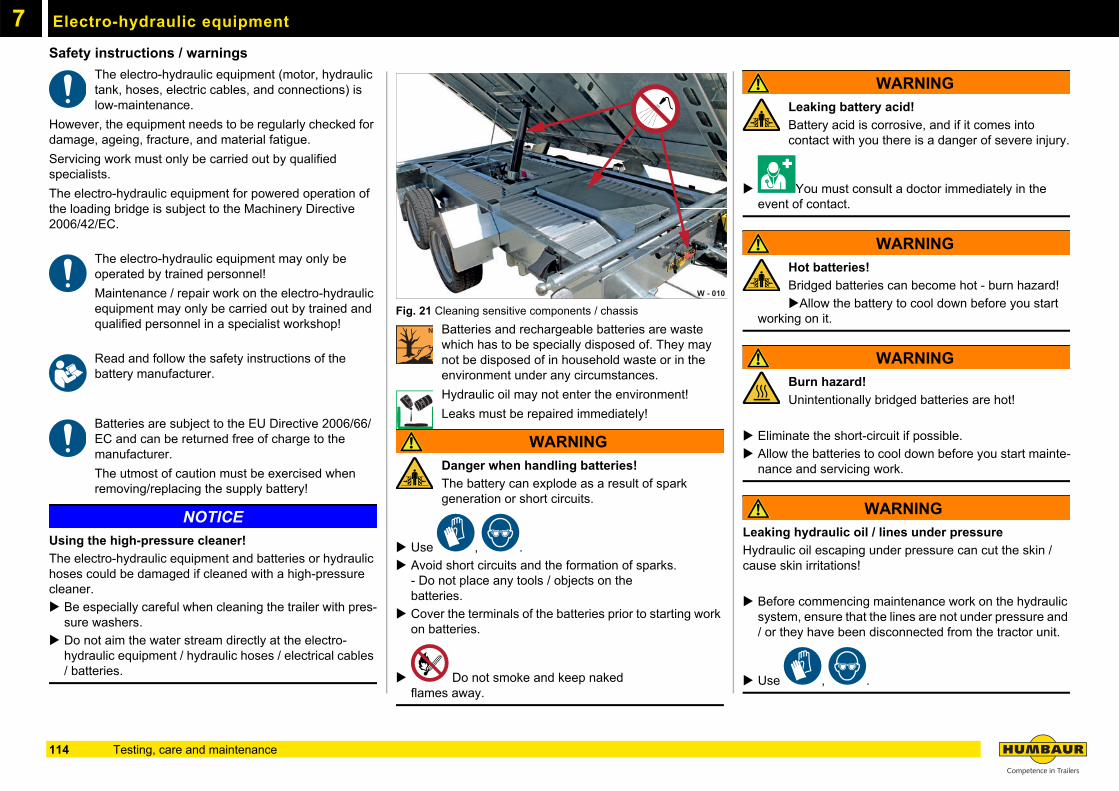
7
Electro-hydraulic equipmentSafety instructions / warnings
The electro-hydraulic equipment (motor, hydraulic tank, hoses, electric cables, and connections) is low-maintenance.
However, the equipment needs to be regularly checked for damage, ageing, fracture, and material fatigue.
Servicing work must only be carried out by qualified specialists.
The electro-hydraulic equipment for powered operation of the loading bridge is subject to the Machinery Directive 2006/42/EC.
The electro-hydraulic equipment may only be operated by trained personnel!
Maintenance / repair work on the electro-hydraulic equipment may only be carried out by trained and qualified personnel in a specialist workshop!
Read and follow the safety instructions of the battery manufacturer.
Batteries are subject to the EU Directive 2006/66/EC and can be returned free of charge to the manufacturer.
The utmost of caution must be exercised when removing/replacing the supply battery!
NOTICE
Using the high-pressure cleaner!
The electro-hydraulic equipment and batteries or hydraulic hoses could be damaged if cleaned with a high-pressure cleaner.
Be especially careful when cleaning the trailer with pres-sure washers.
Do not aim the water stream directly at the electro-hydraulic equipment / hydraulic hoses / electrical cables / batteries.
Fig. 21 Cleaning sensitive components / chassis
Batteries and rechargeable batteries are waste which has to be specially disposed of. They may not be disposed of in household waste or in the environment under any circumstances.
Hydraulic oil may not enter the environment!
Leaks must be repaired immediately!
WARNING
Danger when handling batteries!
The battery can explode as a result of spark generation or short circuits.
Use , .
Avoid short circuits and the formation of sparks.- Do not place any tools / objects on thebatteries.
Cover the terminals of the batteries prior to starting work on batteries.
Do not smoke and keep nakedflames away.
WARNING
Leaking battery acid!
Battery acid is corrosive, and if it comes into contact with you there is a danger of severe injury.
You must consult a doctor immediately in the event of contact.
WARNING
Hot batteries!
Bridged batteries can become hot - burn hazard!
Allow the battery to cool down before you start working on it.
WARNING
Burn hazard!
Unintentionally bridged batteries are hot!
Eliminate the short-circuit if possible.
Allow the batteries to cool down before you start mainte-nance and servicing work.
WARNING
Leaking hydraulic oil / lines under pressure
Hydraulic oil escaping under pressure can cut the skin / cause skin irritations!
Before commencing maintenance work on the hydraulic system, ensure that the lines are not under pressure and / or they have been disconnected from the tractor unit.
Use , .
W - 010
114 Testing, care and maintenance
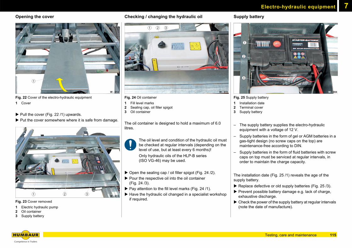
Electro-hydraulic equipment 7
Opening the coverFig. 22 Cover of the electro-hydraulic equipment
1 Cover
Pull the cover (Fig. 22 /1) upwards.
Put the cover somewhere where it is safe from damage.
Fig. 23 Cover removed
1 Electric hydraulic pump2 Oil container3 Supply battery
Checking / changing the hydraulic oil
Fig. 24 Oil container
1 Fill level marks2 Sealing cap, oil filler spigot3 Oil container
The oil container is designed to hold a maximum of 6.0 litres.
The oil level and condition of the hydraulic oil must be checked at regular intervals (depending on the level of use, but at least every 6 months)!
Only hydraulic oils of the HLP-B series(ISO VG-46) may be used.
Open the sealing cap / oil filler spigot (Fig. 24 /2).
Pour the respective oil into the oil container(Fig. 24 /3).
Pay attention to the fill level marks (Fig. 24 /1).
Have the hydraulic oil changed in a specialist workshop if required.
Supply battery
Fig. 25 Supply battery
1 Installation date2 Terminal cover3 Supply battery
– The supply battery supplies the electro-hydraulic equipment with a voltage of 12 V.
– Supply batteries in the form of gel or AGM batteries in a gas-tight design (no screw caps on the top) are maintenance-free according to DIN.
– Supply batteries in the form of fluid batteries with screw caps on top must be serviced at regular intervals, in order to maintain the charge capacity.
The installation date (Fig. 25 /1) reveals the age of the supply battery.
Replace defective or old supply batteries (Fig. 25 /3).
Prevent possible battery damage e.g. lack of charge, exhaustive discharge.
Check the power of the supply battery at regular intervals (note the date of manufacture).
W - 012
1
W - 013 1 2 3
W - 011
1 2 3
W - 004
2
1
3
115Testing, care and maintenance
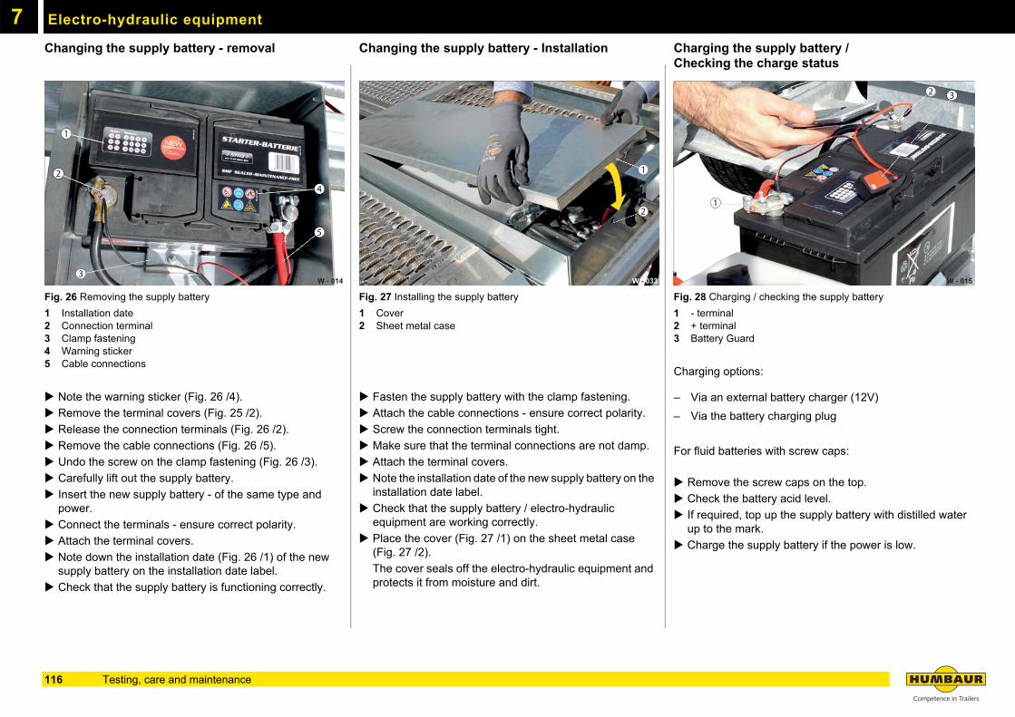
Electro-hydraulic equipment7
Changing the supply battery - removalFig. 26 Removing the supply battery
1 Installation date2 Connection terminal3 Clamp fastening4 Warning sticker5 Cable connections
Note the warning sticker (Fig. 26 /4).
Remove the terminal covers (Fig. 25 /2).
Release the connection terminals (Fig. 26 /2).
Remove the cable connections (Fig. 26 /5).
Undo the screw on the clamp fastening (Fig. 26 /3).
Carefully lift out the supply battery.
Insert the new supply battery - of the same type and power.
Connect the terminals - ensure correct polarity.
Attach the terminal covers.
Note down the installation date (Fig. 26 /1) of the new supply battery on the installation date label.
Check that the supply battery is functioning correctly.
Changing the supply battery - Installation
Fig. 27 Installing the supply battery
1 Cover2 Sheet metal case
Fasten the supply battery with the clamp fastening.
Attach the cable connections - ensure correct polarity.
Screw the connection terminals tight.
Make sure that the terminal connections are not damp.
Attach the terminal covers.
Note the installation date of the new supply battery on the installation date label.
Check that the supply battery / electro-hydraulic equipment are working correctly.
Place the cover (Fig. 27 /1) on the sheet metal case (Fig. 27 /2).
The cover seals off the electro-hydraulic equipment and protects it from moisture and dirt.
Charging the supply battery / Checking the charge status
Fig. 28 Charging / checking the supply battery
1 - terminal2 + terminal3 Battery Guard
Charging options:
– Via an external battery charger (12V)
– Via the battery charging plug
For fluid batteries with screw caps:
Remove the screw caps on the top.
Check the battery acid level.
If required, top up the supply battery with distilled water up to the mark.
Charge the supply battery if the power is low.
W - 014
1
2
3
4
5
1
W - 033
2
W - 015
1
2 3
116 Testing, care and maintenance
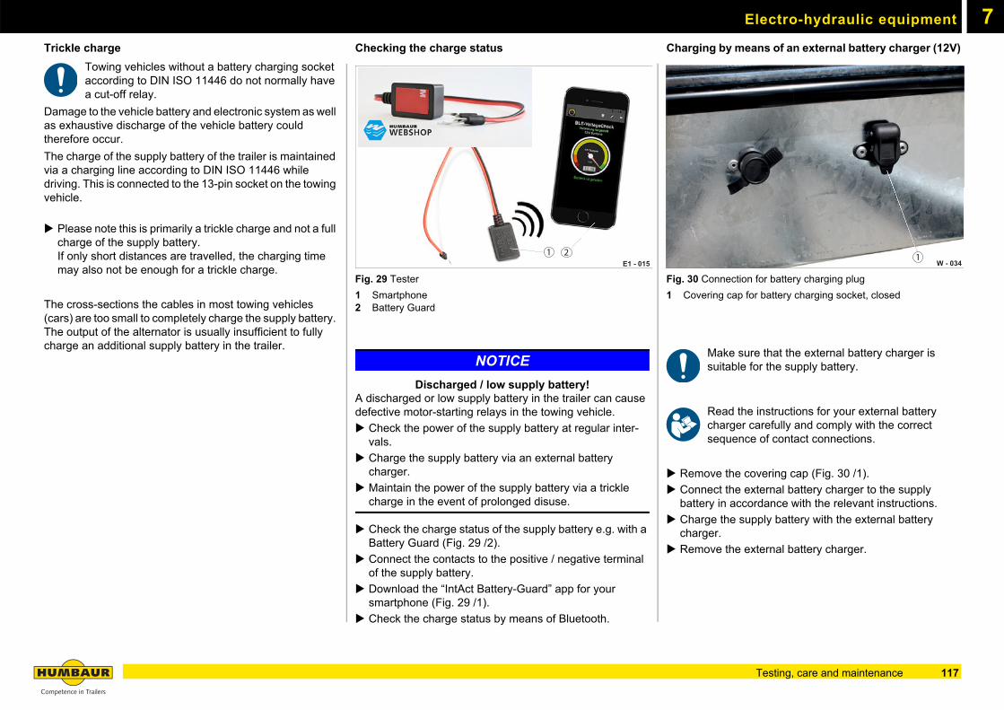
Electro-hydraulic equipment 7
Trickle chargeTowing vehicles without a battery charging socket according to DIN ISO 11446 do not normally have a cut-off relay.
Damage to the vehicle battery and electronic system as well as exhaustive discharge of the vehicle battery could therefore occur.
The charge of the supply battery of the trailer is maintained via a charging line according to DIN ISO 11446 while driving. This is connected to the 13-pin socket on the towing vehicle.
Please note this is primarily a trickle charge and not a full charge of the supply battery.If only short distances are travelled, the charging time may also not be enough for a trickle charge.
The cross-sections the cables in most towing vehicles (cars) are too small to completely charge the supply battery. The output of the alternator is usually insufficient to fully charge an additional supply battery in the trailer.
Checking the charge status
Fig. 29 Tester
1 Smartphone2 Battery Guard
NOTICE
Discharged / low supply battery!A discharged or low supply battery in the trailer can cause defective motor-starting relays in the towing vehicle.
Check the power of the supply battery at regular inter-vals.
Charge the supply battery via an external battery charger.
Maintain the power of the supply battery via a trickle charge in the event of prolonged disuse.
Check the charge status of the supply battery e.g. with a Battery Guard (Fig. 29 /2).
Connect the contacts to the positive / negative terminal of the supply battery.
Download the “IntAct Battery-Guard” app for your smartphone (Fig. 29 /1).
Check the charge status by means of Bluetooth.
Charging by means of an external battery charger (12V)
Fig. 30 Connection for battery charging plug
1 Covering cap for battery charging socket, closed
Make sure that the external battery charger is suitable for the supply battery.
Read the instructions for your external batterycharger carefully and comply with the correct sequence of contact connections.
Remove the covering cap (Fig. 30 /1).
Connect the external battery charger to the supply battery in accordance with the relevant instructions.
Charge the supply battery with the external battery charger.
Remove the external battery charger.
E1 - 0151 2
W - 0341
117Testing, care and maintenance
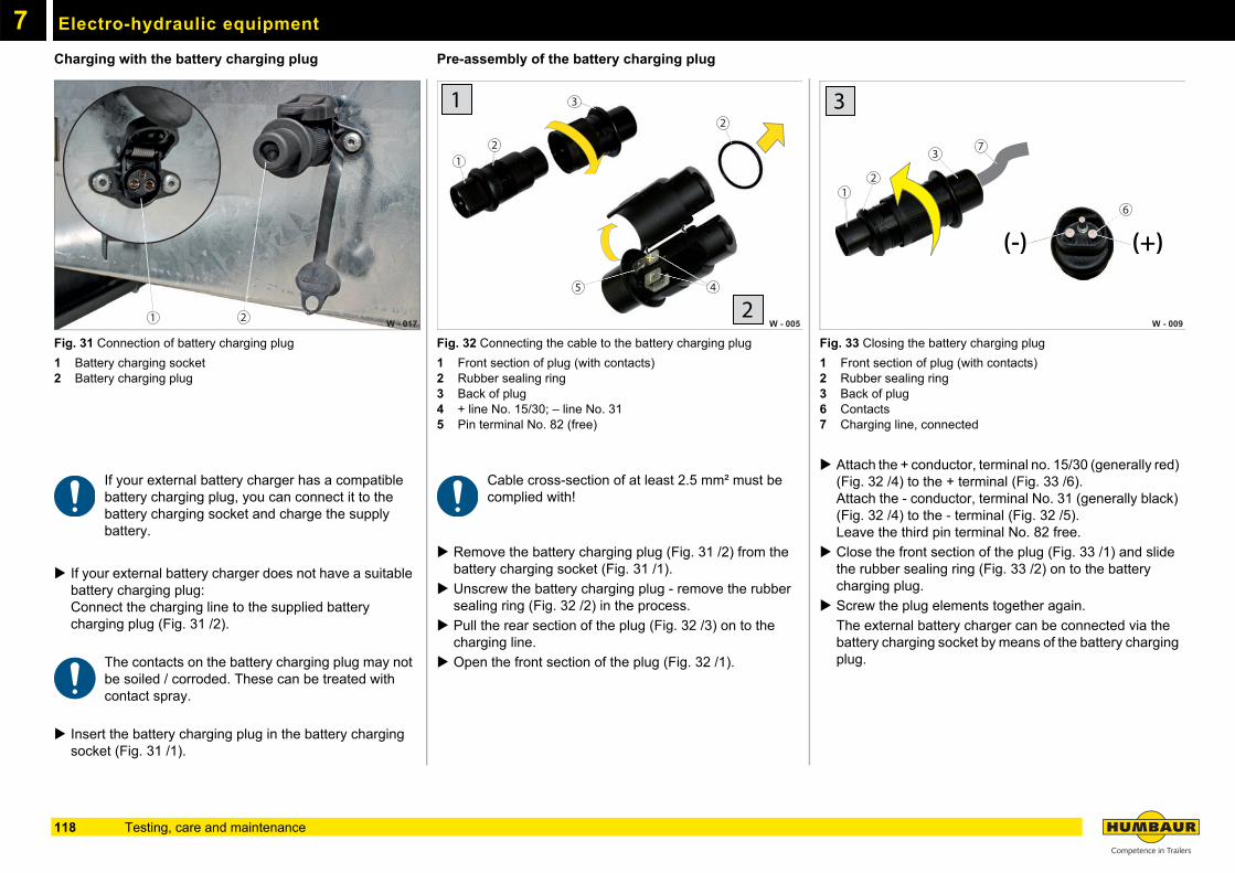
Electro-hydraulic equipment7
Charging with the battery charging plugFig. 31 Connection of battery charging plug
1 Battery charging socket2 Battery charging plug
If your external battery charger has a compatible battery charging plug, you can connect it to the battery charging socket and charge the supply battery.
If your external battery charger does not have a suitable battery charging plug:Connect the charging line to the supplied battery charging plug (Fig. 31 /2).
The contacts on the battery charging plug may not be soiled / corroded. These can be treated with contact spray.
Insert the battery charging plug in the battery charging socket (Fig. 31 /1).
Pre-assembly of the battery charging plug
Fig. 32 Connecting the cable to the battery charging plug
1 Front section of plug (with contacts)2 Rubber sealing ring3 Back of plug4 + line No. 15/30; – line No. 315 Pin terminal No. 82 (free)
Cable cross-section of at least 2.5 mm² must be complied with!
Remove the battery charging plug (Fig. 31 /2) from the battery charging socket (Fig. 31 /1).
Unscrew the battery charging plug - remove the rubber sealing ring (Fig. 32 /2) in the process.
Pull the rear section of the plug (Fig. 32 /3) on to the charging line.
Open the front section of the plug (Fig. 32 /1).
Fig. 33 Closing the battery charging plug
1 Front section of plug (with contacts)2 Rubber sealing ring3 Back of plug6 Contacts7 Charging line, connected
Attach the + conductor, terminal no. 15/30 (generally red) (Fig. 32 /4) to the + terminal (Fig. 33 /6).Attach the - conductor, terminal No. 31 (generally black) (Fig. 32 /4) to the - terminal (Fig. 32 /5).Leave the third pin terminal No. 82 free.
Close the front section of the plug (Fig. 33 /1) and slide the rubber sealing ring (Fig. 33 /2) on to the battery charging plug.
Screw the plug elements together again.
The external battery charger can be connected via the battery charging socket by means of the battery charging plug.
W - 017 21
3
12
W - 005
2
45
1
2W - 009
73
21
6
3
(+)(-)
118 Testing, care and maintenance
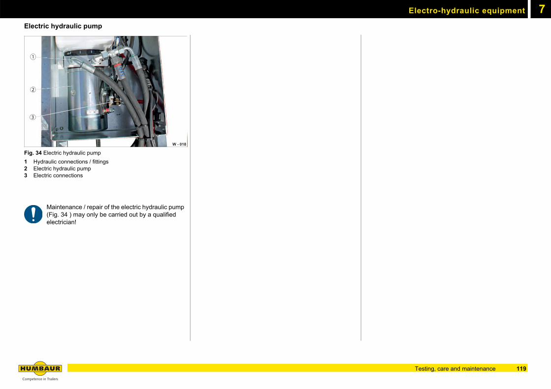
Electro-hydraulic equipment 7
Electric hydraulic pumpFig. 34 Electric hydraulic pump
1 Hydraulic connections / fittings 2 Electric hydraulic pump3 Electric connections
Maintenance / repair of the electric hydraulic pump (Fig. 34 ) may only be carried out by a qualified electrician!
W - 018
2
1
3
119Testing, care and maintenance
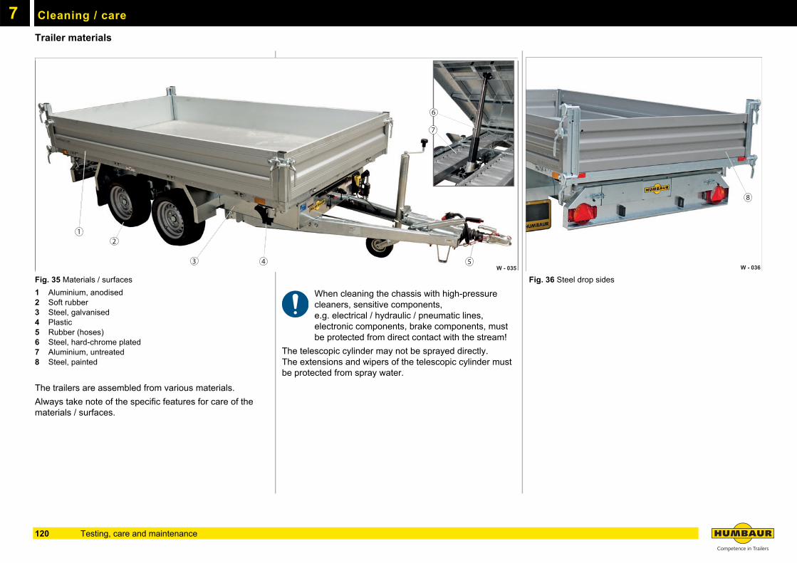
7
Cleaning / careTrailer materials
Fig. 35 Materials / surfaces
1 Aluminium, anodised2 Soft rubber3 Steel, galvanised4 Plastic5 Rubber (hoses)6 Steel, hard-chrome plated7 Aluminium, untreated8 Steel, painted
The trailers are assembled from various materials.
Always take note of the specific features for care of the materials / surfaces.
When cleaning the chassis with high-pressure cleaners, sensitive components, e.g. electrical / hydraulic / pneumatic lines, electronic components, brake components, must be protected from direct contact with the stream!
The telescopic cylinder may not be sprayed directly.The extensions and wipers of the telescopic cylinder must be protected from spray water.
Fig. 36 Steel drop sides
W - 035
12
3 4 5
6
7
W - 036
8
120 Testing, care and maintenance
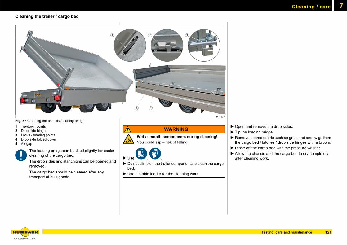
Cleaning / care 7
Cleaning the trailer / cargo bedFig. 37 Cleaning the chassis / loading bridge
1 Tie-down points2 Drop side hinge3 Locks / bearing points4 Drop side folded down5 Air gap
The loading bridge can be tilted slightly for easier cleaning of the cargo bed.
The drop sides and stanchions can be opened and removed.
The cargo bed should be cleaned after any transport of bulk goods.
WARNING
Wet / smooth components during cleaning!
You could slip – risk of falling!
Use , .
Do not climb on the trailer components to clean the cargo bed.
Use a stable ladder for the cleaning work.
Open and remove the drop sides.
Tip the loading bridge.
Remove coarse debris such as grit, sand and twigs from the cargo bed / latches / drop side hinges with a broom.
Rinse off the cargo bed with the pressure washer.
Allow the chassis and the cargo bed to dry completely after cleaning work.
W - 037
1 2 3
4 5
121Testing, care and maintenance

Cleaning / care7
122 Testing, care and maintenance

8
Troubleshooting guide123
General information8
Action in the case of faultsThis section contains information on possible faults in the trailer. The information should facilitate the search for the fault source and enable it to be rectified to the extent that the next service station of Humbaur GmbH can be reached.
Faults which occur as a consequence of failing to comply with the operating instruction manual or as a result of a lack of maintenance are not considered.
Unfortunately we cannot cover all the problems which may occur here.
In the case of major faults, please notify the Humbaur Service (see contact addresses stated below).
WARNING
Improper troubleshooting
Improper troubleshooting can cause components to fail - accident risk!
Have faults rectified only by a qualified specialist work-shop.
WARNING
Unsecured trailer / unexpected movement
Going under the chassis when troubleshooting - risk of crushing if the trailer starts to move unexpectedly. Make sure that the trailer is secured by wheel chocks /
wooden blocks, so that it cannot roll away.
Do not actuate the hydraulic system when you or anyone else go under the chassis.
Humbaur Service
Any warranty claims become invalid if the trailer or its modules are altered or disassembled without our previous written agreement.
Technical customer service
tel.: +49 821 24929 0
fax.:+49 821 24929 540
email: [email protected]
Humbaur Service Partners
can be found at www.humbaur.com under Dealers/Service > Service/Repairs
Address of the manufacturer
Humbaur GmbH
Mercedesring 1
86368 Gersthofen (Germany)
tel.: +49 821 24929 0
fax.:+49 821 24929 100
www.humbaur.com
Spare parts
Only use original Humbaur spare parts!
Spare parts can be obtained stating the VIN and the part designation as follows:
- Online, email, telephone
Contact parts logistics
tel.: +49 821 24929 0
fax.:+49 821 24929 200
email: [email protected]
124 Troubleshooting guide
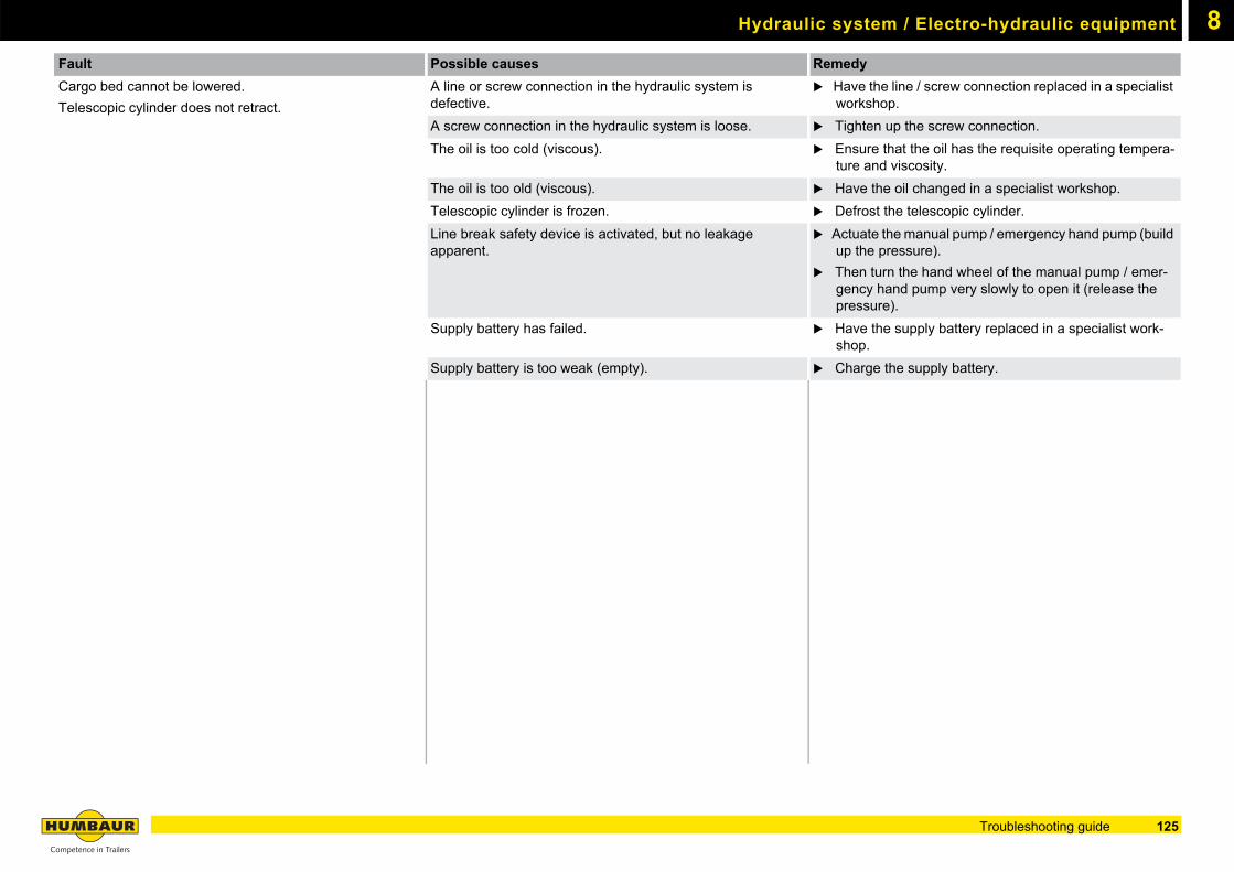
8Hydraulic system / Electro-hydraulic equipment
Fault Possible causes Remedy
Cargo bed cannot be lowered.
Telescopic cylinder does not retract.
A line or screw connection in the hydraulic system is defective.
Have the line / screw connection replaced in a specialist workshop.
A screw connection in the hydraulic system is loose. Tighten up the screw connection.
The oil is too cold (viscous). Ensure that the oil has the requisite operating tempera-ture and viscosity.
The oil is too old (viscous). Have the oil changed in a specialist workshop.
Telescopic cylinder is frozen. Defrost the telescopic cylinder.
Line break safety device is activated, but no leakage apparent.
Actuate the manual pump / emergency hand pump (build up the pressure).
Then turn the hand wheel of the manual pump / emer-gency hand pump very slowly to open it (release the pressure).
Supply battery has failed. Have the supply battery replaced in a specialist work-shop.
Supply battery is too weak (empty). Charge the supply battery.
125Troubleshooting guide
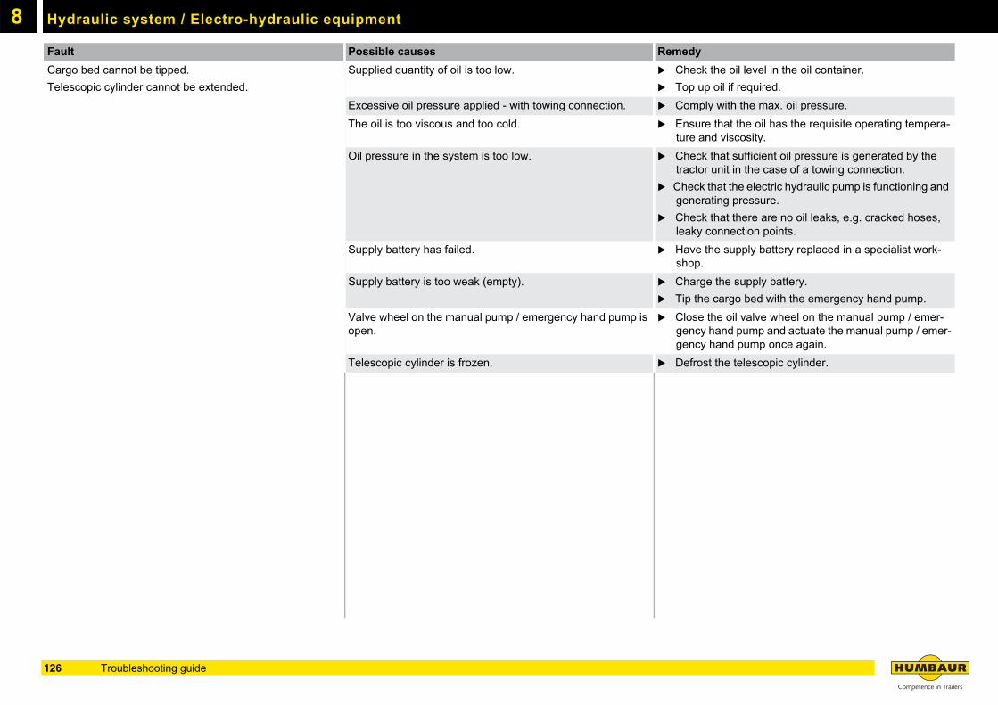
Hydraulic system / Electro-hydraulic equipment8
Fault Possible causes Remedy
Cargo bed cannot be tipped.
Telescopic cylinder cannot be extended.
Supplied quantity of oil is too low. Check the oil level in the oil container.
Top up oil if required.
Excessive oil pressure applied - with towing connection. Comply with the max. oil pressure.
The oil is too viscous and too cold. Ensure that the oil has the requisite operating tempera-ture and viscosity.
Oil pressure in the system is too low. Check that sufficient oil pressure is generated by the tractor unit in the case of a towing connection.
Check that the electric hydraulic pump is functioning and generating pressure.
Check that there are no oil leaks, e.g. cracked hoses, leaky connection points.
Supply battery has failed. Have the supply battery replaced in a specialist work-shop.
Supply battery is too weak (empty). Charge the supply battery.
Tip the cargo bed with the emergency hand pump.
Valve wheel on the manual pump / emergency hand pump is open.
Close the oil valve wheel on the manual pump / emer-gency hand pump and actuate the manual pump / emer-gency hand pump once again.
Telescopic cylinder is frozen. Defrost the telescopic cylinder.
126 Troubleshooting guide

“Quality madein Germany…”
We wish you a pleasant & safe journey
Service card

Competencein Trailers
Humbaur GmbH Mercedesring 1 86368 Gersthofen Germany Tel. +49 821 24929-0 [email protected] www.humbaur.com
Saf
ety
no
te!
Th
e tr
aile
r m
ay o
nly
be
use
d w
ith e
xpre
ss c
ompl
ian
ce w
ith a
ll ro
ad
tra
ffic,
pro
fess
ion
al a
sso
ciat
ion
and
load
se
curin
g re
gula
tion
s.
All
illu
stra
tion
s a
re r
epr
ese
nta
tive
an
d m
ay
sho
w s
peci
al e
qui
pme
nt -
they
are
not
bin
din
g.D
evi
atio
ns
and
mo
dific
atio
ns
are
subj
ect
to th
e m
odel
typ
e. W
e a
ssu
me
no
resp
on
sibi
lity
for
prin
ting
or
oth
er
erro
rs o
r o
mis
-si
ons.
Sub
ject
to
tech
nic
al m
odifi
catio
ns.
All
spe
cific
atio
ns
are
ap
prox
imat
e v
alu
es a
nd r
elat
e to
a s
erie
s ve
hicl
e w
ithou
t acc
ess
orie
s.
Co
pyin
g p
rohi
bite
d. P
rin
ted
in G
erm
any.
Dat
e: V
12/2
016