Embed Size (px)
Citation preview
Read this information first
Basic Operation
DG-ID/DP-ID Function
Repeater Operation
Using the Memory
Scanning Function
Using the Digital GM Function
Using the APRS FunctionUsing the WIRES-X Function
Using the GPS Function
Convenient Functions
Communicating with a Specific Remote Station
Functions Used As Needed
Appendix
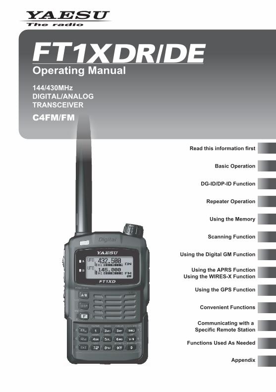
144/430MHzDIGITAL/ANALOG TRANSCEIVER
C4FM/FM
Operating Manual
2
Read this inform
ation first
Read this information first
Table of ContentsDigital Personal ID (DP-ID) feature .......................... 42
Registering the DP-ID to a DR-2X/XE digital repeater................................................................ 42Registering the transceiver .................................. 42Deleting the registered DP-ID .............................. 43
Repeater Operation ................................................ 44Repeater Operation .................................................. 44
Communicating Via the Repeater ........................ 44Tone Calling (1750 Hz) ........................................ 44
Repeater Shift........................................................... 45Automatic Repeater Shift (ARS) .......................... 45
Using the Memory .................................................. 46A Wide Variety of Memory Functions ........................ 46
Registering to Memory Channel .......................... 47Split Memory ........................................................ 48Recalling a Memory Channel ............................... 48Recalling Home Channel ..................................... 49
Returning to the Previous Frequency .............. 49Deleting Memory Channel ................................... 50
Restoring Deleted Memory Channel ............... 50Using Memory Tag ............................................... 50
Assigning a Name to a Memory Channel ........ 51Displaying Memory Tag ................................... 51
Using Memory Bank ................................................. 52Registering a Memory Channel in a Memory Bank ... 52Recalling Memory Bank ....................................... 53Canceling Memory Channel Registration in Memory Bank ....................................................... 53Assigning Name to Memory Bank........................ 53
Convenient Preset Receiver Memory Channels....... 55Registering Your Favorite Preset Receiver Memory Channels in Memory Bank...... 55Recalling Preset Receiver Memory Channel to Listen to the Weather Broadcast .......................... 55Recalling Preset Receiver Memory Channel to Listen to the International VHF (Marine) Radio.... 56Recalling Preset Receiver Memory Channel to Listen to the World Broadcast .............................. 58
Worldwide short wave broadcast .................... 58
Scanning Function ................................................. 60Using the Scanning Function.................................... 60
VFO Scan ............................................................ 60Canceling Scanning ........................................ 61Skipping a Frequency You Do Not Want to Scan (Skip Search Memory) ........................... 61Specifying the Frequency You Do Not Want to Scan ................................................................ 62Deleting a Frequency Registered to the Skip Search Memory Channel ................................ 62Selecting a Reception Method When Scanning Stops ............................................... 63
Memory Channel Scanning.................................. 63Specifying a Skip/Selected Memory Channel ... 64Scanning Only the Selected Memory Channel .. 65
Read this information first ....................................... 2Introduction ................................................................. 5
How to Read This Manual ...................................... 6Checking Bundled Items ........................................ 6
Safety Precautions (Be Sure to Read) ....................... 7Before Transmitting Radio Waves .............................11Names and Functions of Controls ............................ 12
Basic Operation ...................................................... 15Preparation ............................................................... 15
Installing the Antenna........................................... 15Attaching the Accessory Belt Clip/Protective Cap ... 15
Attaching the Protective Cap ........................... 15Attaching the Belt Clip ..................................... 15
Attaching a Hand Strap ........................................ 16How to Use the Battery Case (FBA-39) Optional ... 16Installing/Removing the Battery Pack .................. 17
Installing the Battery Pack ............................... 17Removing the Battery Pack ............................. 17
Charging the Battery Pack ................................... 17Connecting an External Power Supply for Use in Vehicle ..................................................... 20Connecting to an External Power Supply Using a Power Cable ........................................... 20
Using a microSD memory card................................. 22Usable microSD memory cards ........................... 22Cautions when using a micro SD memory card ... 22Mounting and dismounting microSD memory card ...22Formatting a microSD memory card .................... 24
Performing Communication ...................................... 25Turning on the Transceiver .................................. 25Adjusting the Volume Level.................................. 26Selecting an Operating Band ............................... 27Selecting a Frequency Band ................................ 29Tuning in to a Frequency ..................................... 30Selecting Communication Mode .......................... 30Performing Communication ................................. 31Selecting Communication Mode .......................... 32
Listening to the Radio ............................................... 33Listening to the AM/FM Radio .............................. 33Switching between AM Antennas ......................... 33
Miscellaneous Settings ............................................. 34Setting clock time ................................................. 34Setting the Time Signal ........................................ 34Muting Audio ........................................................ 35Changing the Transmission Power Level............. 36Adjusting the Squelch Level................................. 37Changing the Frequency Step Manually .............. 37Changing the Mode Manually .............................. 38Locking keys and switches .................................. 39Restoring to Defaults (All Reset).......................... 39
DG-ID/DP-ID Function ............................................ 40Digital Group ID (DG-ID) feature .............................. 40
Communicating only with the specific members by setting the DG-ID number except for “00”. ........... 40
3
Read this inform
ation first
Table of Contents
Scanning a Memory Bank .................................... 65Memory Bank Link Scan ................................. 66
Programmable Memory Channel Scan (PMS)..... 67Registering to a Programmable Memory Channel ........................................................... 67Performing Programmable Memory Channel Scan ................................................................ 68
Using the Digital GM Function (Digital Group Monitor Function) ............... 69What is the GM function? ......................................... 69Standard Operation of the GM Function................... 69
Using the APRS/WIRES-X Functions .................... 71What is the APRS (Automatic Packet Reporting System)? .................................................................. 71What is the WIRES-X Function? .............................. 71
Using the GPS Function ........................................ 72What is GPS? ........................................................... 72Activating the GPS Function..................................... 72Method of Positioning by GPS.................................. 73
Displaying Current Position Information of Your Station .................................................................. 73Displaying Position Information of Remote Station in Digital Mode ........................... 73Saving GPS Information (GPS Log Function)...... 75Checking Tracks on a PC .................................... 75
Explanation of GPS Screen and Operation .............. 76Smart Navigation Function ....................................... 77
Using the Smart Navigation Function .................. 77Description of the BACK TRACK Function Screen... 78
Convenient Functions ............................................ 79Dual Reception (DW) Function ................................. 79
VFO Dual Reception VFO mode → Priority memory channel ......... 79Memory Channel Dual Reception Memory channel → Priority memory channel .....80Home Channel Dual Reception Home channel → Priority memory channel ........80AF-DUAL Function for simultaneous signal reception over the other frequency while listening to the radio.................................... 81
Using the DTMF Function......................................... 83Confirming the entered DTMF code by the sound .............................................................. 84
Sending the Registered DTMF Code ................... 84Sending a DTMF Code Manually ......................... 85
Searching for signals with the signal strength graph. Band Scope Function ............................................... 86Taking picture with the optional camera mounted on speaker microphone ............................. 86
Communicating with a Specific Remote Station ... 88Using the Tone Squelch Function ............................. 88
Selecting a Tone Frequency ............................ 89
Searching for the Frequency of the Tone Squelch Used by the Remote Station ......... 90
Selecting a DCS Code .................................... 90Searching for the Frequency of the DCS Used by the Remote Station ........................... 91
Notification of Call from the Remote Station by Vibration of the Vibrator ....................................... 92
Selecting Vibrator Operation Mode ................. 92Notification of a Call from a Remote Station by the Bell ............................................................ 93
Changing the Number of Times the Bell Rings ........................................................ 93
Calling Only a Specific Station New Pager Function ............................................ 94
Flow of Operation to Use the Pager Function ... 94Setting the Code of Your Station ..................... 95Turning on the New Pager Function ................ 95Calling a Specific Station ................................ 96Being Called by the Remote Station (Standby Operation) ........................................ 97
Functions Used As Needed ................................... 98Set Mode .................................................................. 98
Using the Set Mode ............................................. 98Resetting the Set Mode Options ..................... 98
Set Mode Option List ........................................... 99Displaying the GPS screen. ............................... 107Setting the display method of the remote station information ................................. 108Setting the display method for BACKTRACK .... 108Setting the search channels for the BAND SCOPE function ...................................... 109Changing the Lighting Condition ........................ 109Selecting a Display Language ............................110Adjusting the LCD Contrast Level .......................110Adjusting the LCD Backlight and Keypad Key Light Brightness Level.........................................111Changing the Opening Message Displayed Immediately after Power-on ................................111Measuring the Battery Voltage and the Transceiver Temperature Power Supply Voltage Measurement Function/Temperature Measurement Function .......................................112Changing the Display Pattern of the PO Meter ...113Switching between AM Antennas ........................113Reducing receiver sensitivity Attenuator (ATT) Function ...................................113Setting the transmission modulation level...........114Changing the mode manually .............................114Switching between digital and analog mode .......115Setting the AMS transmission mode ...................116Setting the pop up time of the remote station information ..........................................................117Setting the Standby Beep ...................................117Displaying the version of the DSP program ........118Adjusting the microphone sensitivity Microphone Gain.................................................118
4
Read this inform
ation first
Table of Contents
Muting Voice .......................................................119Simultaneously radio broadcast reception ..........119Changing the sound volume setting method ......119Setting memory bank link................................... 120Assigning a name to a memory bank................. 120Assigning a name to a memory channel ............ 120Prohibiting registration to memory channel Memory Channel Protect Function .................... 121Setting memory skip function ............................. 121Registering to a memory channel with the lowest memory channel number ........................ 121Memory Channel Write Function ....................... 121Notifying a call from a remote station by the bell ... 122Selecting a DCS code ........................................ 122Transmit and receive a DCS Code with a inverted phase DCS INVERSION Function ....... 122Setting the transmission method of the DTMF code ........................................................ 123Setting DTMF code ............................................ 123Calling only a specific station New Pager Function .......................................... 123Enabling no-communication squelch function PR FREQUENCY Function ................................ 123Adjusting the squelch level SQL LEVEL Function ......................................... 124Setting the signal strength to output sound S Meter Squelch Function.................................. 124Setting the squelch type for transmission and reception SQL EXPANTION FUNCTION ........... 125Setting the type of tone squelch ........................ 126Selecting a tone frequency ................................ 126Setting the sound and speed during tone search Tone Search Function ........................................ 126ON/OFF for the Weather Alert Feature .............. 127Setting the surveillance interval time for priority channels DW TIME Function ............................. 127Turning illumination off when scanning stops SCAN LAMP Function ....................................... 128Setting the time to resume scan SCAN RE-START Function................................ 128Selecting a reception method when scanning stops ................................................... 129Setting the range for SCAN ............................... 129Turning off the power automatically APO Function..................................................... 130Preventing accidental transmission Busy Channel Lockout (BCLO) Function ........... 131Muting the key operation confirmation tone ....... 131Turning off the BUSY Indicator .......................... 132Setting the clock shift for the micro computer Clock Type Function .......................................... 132Setting interval to save GPS position information ... 133Permitting Transfer of Home Channel Frequency to VFO ............................................. 133Using the White LED as a Flashlight ................. 134Setting the conditions for locking LOCK Function .................................................. 134
Setting the operation of T .............................. 135Turning on/off the transceiver at the specified time Timer Function ............................ 135Password Function ............................................ 136Setting the PTT delay time PTT DELAY Function ......................................... 137Setting the ARS function RPT ARS Function ............................................. 137Setting the direction for repeater shift RPT SHIFT Function .......................................... 138Setting the range for repeater shift RPT SHIFT FREQ Function ............................... 138Disabling reception while no signal is received Reception Save Function ................................... 139Changing the frequency step manually ............. 139Setting clock time ............................................... 139Restricting the continuous transmission time TOT Function ..................................................... 140Setting the frequency selection range for operation in the VFO mode VFO MODE Function ......................................... 141Notification of a call from a remote station by vibration ............................................................. 142Saving/ Loading data to/from microSD memory card .................................................................... 142Saving/ Loading memory channel information to/from microSD memory card ........................... 143Formatting a microSD memory card .................. 143Setting the optional microphone with camera for use ................................................... 144Registering CALLSIGN ...................................... 144Using the transceiver for packet communication 146Clone Operation ................................................. 147Connecting an external device........................... 148
Connecting to a PC ....................................... 148Connecting the FT1XDR/DE to external devices ............................................ 149Data Cable (CT-170) ..................................... 149Data Cable (2.5Φ) (CT-176) .......................... 149
Appendix ............................................................... 150Optional Parts ......................................................... 150If you suspect malfunction Check the following items before requesting for repair. ..... 151
The transceiver does not turn on. ................. 151There is no sound ......................................... 151There is no transmission of radio waves. ...... 151The keys or O does not respond. ............... 151
The battery pack cannot be charged or battery power depletes immediately after charging. ...... 152
Index ....................................................................... 153Specifications ......................................................... 156
5
Read this inform
ation first
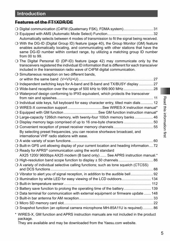
IntroductionFeatures of the FT1XDR/DEm Digital communication (C4FM (Quaternary FSK), FDMA system) ............................. 31m Equipped with AMS (Automatic Mode Select) Function ............................................. 32 Automatically selects between 4 modes of transmission to fit the signal being received.m With the DG-ID (Digital Group ID) feature (page 40), the Group Monitor (GM) feature
enables automatically locating, and communicating with other stations that have the same DG-ID number within contact range, by utilizing a matching group ID number from 00 to 99.
m The Digital Personal ID (DP-ID) feature (page 42) may communicate only by the transceivers registered the individual ID information that is different for each transceiver included in the transmission radio wave of C4FM digital communication.
m Simultaneous reception on two different bands, or within the same band (V+V/U+U) ......................................................................... 27
m Independent switching keys for A-band and B-band and TX/BUSY display .............. 27 m Wide-band reception over the range of 500 kHz to 999.900 MHz ............................. 28m Waterproof design conforming to IPX5 equivalent, which protects the transceiver
from rain and splashes ............................................................................................... 11m Individual side keys, full keyboard for easy character entry, tilted main dials ............ 12m WIRES-X connection support ..................................See WIRES-X instruction manual*m Equipped with GM function ..................................See GM function instruction manual*m Large-capacity 1266ch memory, with twenty-four 100ch memory banks .................. 46m Display memory tags comprised of up to 16 one-byte characters ............................. 50m Convenient reception of preset receiver memory channels ....................................... 55 By selecting preset frequencies, you can receive shortwave broadcast, and
international VHF radio stations with ease.m A wide variety of scan functions ................................................................................. 60m Built-in GPS unit allowing display of your current location and heading information .... 72m Ready for APRS® communication using the world standard AX25 1200/ 9600bps AX25 modem (B band only) ...... See APRS instruction manual.*m High-resolution band scope function to display ± 50 channels .................................. 86m A variety of individual selective calling functions; such as tone squelch (CTCSS)
and DCS functions ..................................................................................................... 88m Vibrator to alert you of signal reception, in addition to the audible bell ...................... 92m Illumination by white LED for easy viewing of the LCD outdoors ............................. 134m Built-in temperature sensor ...................................................................................... 112 m Battery save function to prolong the operating time of the battery ........................... 139m Data terminal for communication with external equipment or firmware update ....... 148m Built-in bar antenna for AM reception ......................................................................... 33m Micro SD memory card slot ........................................................................................ 22m Snapshot function (an optional camera microphone MH-85A11U is required) .......... 86
* WIRES-X, GM function and APRS instruction manuals are not included in the product package.
They are available and may be downloaded from the Yaesu.com website.
6
Read this inform
ation first
Introduction
How to Read This ManualTypical explanatory expressions used in this manual are as follows:For pressing the B key short .........Press B.For pressing the B key long ...........Press and hold B for over 1 second.For pressingF→B .......................Press F and then B.For pressing or turning v while pressing the O key .....Turn v while pressing O.
Caution ...Explains caution to observe during operation.
Tip
...Explains operating suggestions or useful tips.
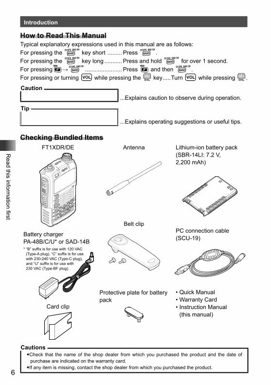
Checking Bundled ItemsFT1XDR/DE Antenna
Belt clip
Protective plate for battery pack
Lithium-ion battery pack (SBR-14LI: 7.2 V, 2,200 mAh)
Battery charger PA-48B/C/U* or SAD-14B * “B” suffix is for use with 120 VAC
(Type-A plug), “C” suffix is for use with 230-240 VAC (Type-C plug), and “U” suffix is for use with 230 VAC (Type-BF plug).
Card clip
PC connection cable (SCU-19)
• Quick Manual• Warranty Card• Instruction Manual
(this manual)
Cautions�Check that the name of the shop dealer from which you purchased the product and the date of
purchase are indicated on the warranty card.�If any item is missing, contact the shop dealer from which you purchased the product.
7
Read this inform
ation first
Safety Precautions (Be Sure to Read)Be sure to read the safety precautions to use this product safely.
We are not liable for failures and other problems caused due to misuse or use of this product by you or a third party as well as the damages caused through use of this product by you or a third party except in the case where we are ordered to pay for damages under the laws.
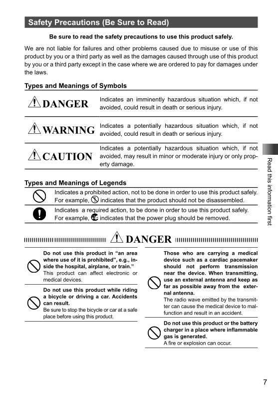
Types and Meanings of Symbols
DANGER Indicates an imminently hazardous situation which, if not avoided, could result in death or serious injury.
WARNING Indicates a potentially hazardous situation which, if not avoided, could result in death or serious injury.
CAUTIONIndicates a potentially hazardous situation which, if not avoided, may result in minor or moderate injury or only prop-erty damage.
Types and Meanings of LegendsIndicates a prohibited action, not to be done in order to use this product safely. For example, indicates that the product should not be disassembled.Indicates a required action, to be done in order to use this product safely.For example, indicates that the power plug should be removed.
DANGERDo not use this product in “an area where use of it is prohibited”, e.g., in-side the hospital, airplane, or train.”This product can affect electronic or medical devices.
Do not use this product while riding a bicycle or driving a car. Accidents can result.Be sure to stop the bicycle or car at a safe place before using this product.
Those who are carrying a medical device such as a cardiac pacemaker should not perform transmission near the device. When transmitting, use an external antenna and keep as far as possible away from the exter-nal antenna.The radio wave emitted by the transmit-ter can cause the medical device to mal-function and result in an accident.
Do not use this product or the battery charger in a place where inflammable gas is generated.A fire or explosion can occur.
8
Read this inform
ation first
Safety Precautions (Be Sure to Read)
Do not perform transmission in a crowded place for the safety of per-sons using a medical device such as a cardiac pacemaker.The radio wave emitted from this prod-uct can cause the medical device to mal-function and result in an accident.
Do not touch any material leak-ing from the battery pack with bare hands.The chemical that has stuck to your skin or entered your eye can cause chemical burns. In such a case, consult the doctor immediately.
Do not solder or short-circuit the ter-minal of the battery pack.A fire, leak, overheating, explosion, or igni-tion can result. Do not carry the battery pack together with a necklace, hair pin, or small metal objects. A short circuit can result.
If it starts thundering when the exter-nal antenna is used, immediately turn off this product and disconnect the external antenna from it.A fire, electrical shock, or damage may result.
WARNINGDo not power this transceiver with a voltage other than the specified pow-er supply voltage.A fire, electric shock, or damage may result.
Do not use the battery pack for any model other than the specified trans-ceiver.A fire, leak, overheating, explosion, or ignition can result.
This product has a waterproof struc-ture and conforms to “IPX5” when the included antenna and battery pack are installed and rubber caps are securely attached to the MIC/SP jack, EXTDC IN jack, DATA terminal, and micro SD slot. If this transceiver gets wet, wipe it with a dry cloth, etc. do not leave it exposed to the mois-ture.Leaving this product in a wet condition can degrade its performance, shorten its life, or cause a failure or electrical shock.
Do not make very long transmissions.The main body of the transceiver may overheat, resulting in a failure or burns.
Do not disassemble or make any al-teration to this product.An injury, electric shock, or failure can result.
Do not handle the battery pack or charger with wet hands. Do not insert or remove the power plug with wet hands.An injury, leak, fire, or failure can result.
If smoke or strange odor is emitted from the main body, battery pack, or battery charger, immediately turn the transceiver off; remove the bat-tery pack, and remove the power plug from the outlet.A fire, leak, overheating, damage, igni-tion, or failure can result. Contact the dealer from which you purchased this product or Yaesu Amateur Customer Support.
Do not use the battery pack which is externally damaged or deformed.A fire, leak, heating, explosion, or igni-tion can result.
Do not use any battery charger which is not specified by Yaesu.A fire or failure can result.
9
Read this inform
ation first
Safety Precautions (Be Sure to Read)
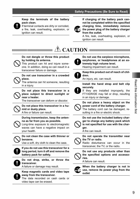
Keep the terminals of the battery pack clean.If terminal contacts are dirty or corroded, a fire, leak, overheating, explosion, or ignition can result.
If charging of the battery pack can-not be completed within the specified charging time, immediately remove the power plug of the battery charger from the outlet.A fire, leak, overheating, explosion, or ignition can result.
CAUTIONDo not dangle or throw this product by holding its antenna.This product can hit and injure some-one. In addition, doing so can result in a transceiver failure or damage.
Do not use transceiver in a crowded place.The antenna can hit someone, resulting in a injury.
Do not place this transceiver in a place subject to direct sunlight or near a heater.The transceiver can deform or discolor.
Do not place this transceiver in a hu-mid or dusty place.A fire or failure can result.
During transmission, keep the anten-na as far from you as possible.Long-time exposure to electromagnetic waves can have a negative impact on your health.
Do not clean the case with thinner or benzene.Use a soft, dry cloth to clean the case.
If you do not use this transceiver for a long period, turn it off and remove the battery pack for safety.
Do not drop, strike, or throw the transceiver.A failure or damage may result.
Keep magnetic cards and video tape away from the transceiver.The data recorded on cash cards or video tape can be erased.
Do not use the earpiece microphone, earphones, or headphones at an ex-tremely high volume level.Hearing impairment can result.
Keep this product out of reach of chil-dren.An injury, etc. can result.
Install the hand strap and belt clip securely.If they are installed improperly, the FT1XDR/DE may fall or drop, resulting in an injury or damage.
Do not place a heavy object on the power cord of the battery charger.The battery cord can be damaged, re-sulting in a fire or electric shock.
Do not use the included battery char-ger to charge any battery pack which is not specified for use with the char-ger.A fire can result.
Do not operate the transmitter near the TV or radio.Radio disturbance can occur in the transceiver, the TV, or the radio.
Do not use any products other than the specified options and accesso-ries.A failure can result.
When the battery charger is not in use, remove its power plug from the outlet
10
Read this inform
ation first
Safety Precautions (Be Sure to Read)
Charge the battery pack within the temperature range from +5 °C to +35 °C (+41 °F to +95 °F).Charging the battery pack outside this temperature range can cause leak, overheating, decrease in performance, or reduction in service life can result.
When unplugging the power cord of the battery charger, be sure to hold the power plug.Pulling the power cord can damage it and cause a fire or electronic shock.
Before discarding the worn battery pack, affix tape or the like to its ter-minals.
Before using this transceiver in a hybrid or fuel-saving car, be sure to check with the automobile manufac-turer regarding use of the transceiver in that car.Noise generated by an onboard electri-cal device (inverter, etc.) can disrupt the normal operation of the transceiver.
11
Read this inform
ation first
Safety Precautions (Be Sure to Read)
About Waterproofing Feature Conforming to IPX5
When the included antenna and battery pack are installed and the MIC/SP jack, EXT DC IN jack, DATA terminal, and micro SD slot are securely covered with rubber caps, this product is moisture and splash resistant. To ensure continued waterproofing pro-tection, be sure to check the following points before use.m Check for damages, deterioration, and dirt.
Antenna rubber, key switch rubber, MIC/SP jack, EXT DC IN jack, DATA terminal, micro SD slot rubber cap, and battery pack joint.
m CleaningWhen this product is contaminated with seawater, sand, or dirt, rinse with fresh water, and then wipe with a dry cloth immediately.
m Recommended maintenance intervalIt is recommended that you ask for maintenance of this product when one year has passed since purchase or previous maintenance or when any damage or deterioration is found. Note that the maintenance service is subject to fees.
m Do not immerse this product in the following liquids:Sea, pool, hot spring, water containing soap, detergent, or bath additive, alcohol, or chemicals
m Do not leave this product for a long time in the following places:Bathroom, kitchen, or humid place
m Other precautionsSince this product is not totally waterproof, it cannot be used in water.
Before Transmitting Radio WavesIf you are informed that the radio waves emitted from your amateur station are interfering with the TV, radio reception, etc., of a neighbor, you should stop emitting the radio waves, and determine whether any problem of interference exists, and if necessary resolve the interference problem.
12
Read this inform
ation first
Names and Functions of Controls
①②
③
④⑤
⑥
⑦⑧⑨⑩
⑪
⑫
⑬⑭⑮⑯⑰⑱
⑲
⑳
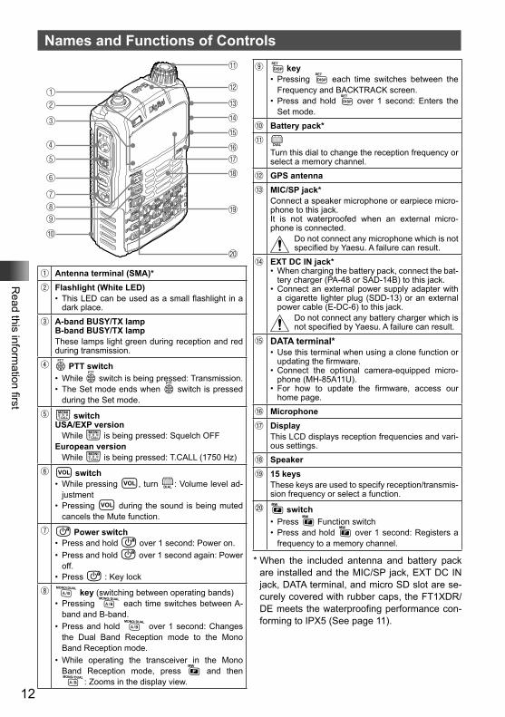
① Antenna terminal (SMA)*② Flashlight (White LED)
• This LED can be used as a small flashlight in a dark place.
③ A-band BUSY/TX lampB-band BUSY/TX lampThese lamps light green during reception and red during transmission.
④ p PTT switch• While p switch is being pressed: Transmission.• The Set mode ends when p switch is pressed
during the Set mode.
⑤ T switchUSA/EXP version
While T is being pressed: Squelch OFFEuropean version
While T is being pressed: T.CALL (1750 Hz)
⑥ v switch• While pressing v, turn O: Volume level ad-
justment• Pressing v during the sound is being muted
cancels the Mute function.
⑦ P Power switch• Press and hold P over 1 second: Power on.• Press and hold P over 1 second again: Power
off.• Press P : Key lock
⑧ A key (switching between operating bands)• Pressing A each time switches between A-
band and B-band.• Press and hold A over 1 second: Changes
the Dual Band Reception mode to the Mono Band Reception mode.
• While operating the transceiver in the Mono Band Reception mode, press F and then A: Zooms in the display view.
⑨ M key• Pressing M each time switches between the
Frequency and BACKTRACK screen.• Press and hold M over 1 second: Enters the
Set mode.
⑩ Battery pack*⑪ O
Turn this dial to change the reception frequency or select a memory channel.
⑫ GPS antenna⑬ MIC/SP jack*
Connect a speaker microphone or earpiece micro-phone to this jack.It is not waterproofed when an external micro-phone is connected.
Do not connect any microphone which is not specified by Yaesu. A failure can result.
⑭ EXT DC IN jack*• When charging the battery pack, connect the bat-
tery charger (PA-48 or SAD-14B) to this jack.• Connect an external power supply adapter with
a cigarette lighter plug (SDD-13) or an external power cable (E-DC-6) to this jack.
Do not connect any battery charger which is not specified by Yaesu. A failure can result.
⑮ DATA terminal*• Use this terminal when using a clone function or
updating the firmware.• Connect the optional camera-equipped micro-
phone (MH-85A11U).• For how to update the firmware, access our
home page.
⑯ Microphone⑰ Display
This LCD displays reception frequencies and vari-ous settings.
⑱ Speaker⑲ 15 keys
These keys are used to specify reception/transmis-sion frequency or select a function.
⑳ F switch• Press F Function switch• Press and hold F over 1 second: Registers a
frequency to a memory channel.
* When the included antenna and battery pack are installed and the MIC/SP jack, EXT DC IN jack, DATA terminal, and micro SD slot are se-curely covered with rubber caps, the FT1XDR/DE meets the waterproofing performance con-forming to IPX5 (See page 11).
13
Read this inform
ation first
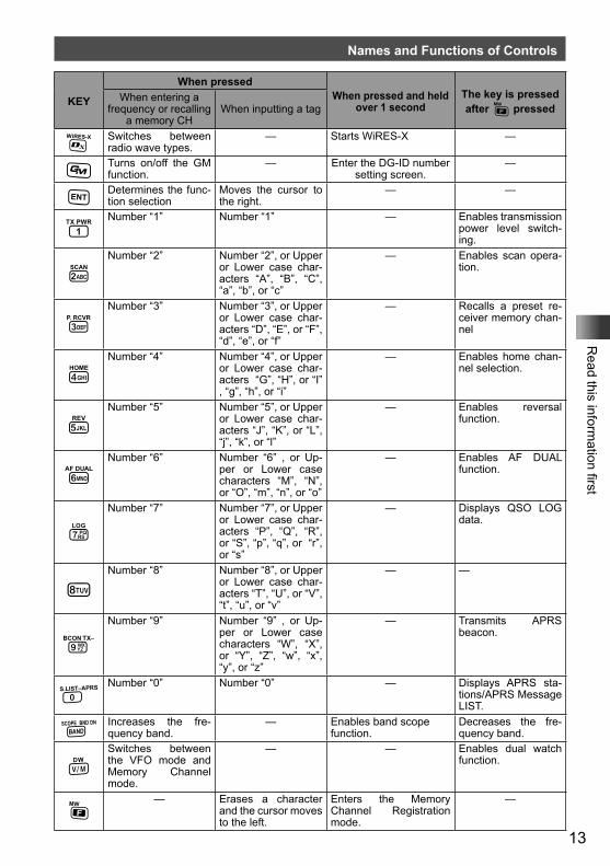
Names and Functions of Controls
KEY
When pressedWhen pressed and held
over 1 secondThe key is pressed after F pressed
When entering a frequency or recalling
a memory CHWhen inputting a tag
% Switches between radio wave types.
— Starts WiRES-X —
D Turns on/off the GM function.
— Enter the DG-ID number setting screen.
—
H Determines the func-tion selection
Moves the cursor to the right.
— —
1Number “1” Number “1” — Enables transmission
power level switch-ing.
2Number “2” Number “2”, or Upper
or Lower case char-acters “A”, “B”, “C”, “a”, “b”, or “c”
— Enables scan opera-tion.
3Number “3” Number “3”, or Upper
or Lower case char-acters “D”, “E”, or “F”, “d”, “e”, or “f”
— Recalls a preset re-ceiver memory chan-nel
4Number “4” Number “4”, or Upper
or Lower case char-acters “G”, “H”, or “I” , “g”, “h”, or “i”
— Enables home chan-nel selection.
5Number “5” Number “5”, or Upper
or Lower case char-acters “J”, “K”, or “L”, “j”, “k”, or “l”
— Enables reversal function.
6Number “6” Number “6” , or Up-
per or Lower case characters “M”, “N”, or “O”, “m”, “n”, or “o”
— Enables AF DUAL function.
7
Number “7” Number “7”, or Upper or Lower case char-acters “P”, “Q”, “R”, or “S”, “p”, “q”, or “r”, or “s”
— Displays QSO LOG data.
8Number “8” Number “8”, or Upper
or Lower case char-acters “T”, “U”, or “V”, “t”, “u”, or “v”
— —
9
Number “9” Number “9” , or Up-per or Lower case characters “W”, “X”, or “Y”, “Z”, “w”, “x”, “y”, or “z”
— Transmits APRS beacon.
0Number “0” Number “0” — Displays APRS sta-
tions/APRS Message LIST.
B Increases the fre-quency band.
— Enables band scope function.
Decreases the fre-quency band.
VSwitches between the VFO mode and Memory Channel mode.
— — Enables dual watch function.
F— Erases a character
and the cursor moves to the left.
Enters the Memory Channel Registration mode.
—
14
Read this inform
ation first
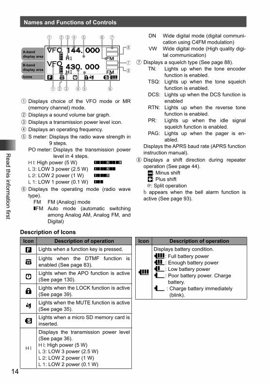
Names and Functions of Controls
①
① ② ③ ④ ⑤ ⑥
② ③ ④ ⑤ ⑥ ⑦
⑧
⑦
⑧
A-band display area
B-band display area
Icons
① Displays choice of the VFO mode or MR (memory channel) mode.
② Displays a sound volume bar graph.③ Displays a transmission power level icon.④ Displays an operating frequency.⑤ S meter: Displays the radio wave strength in
9 steps.PO meter: Displays the transmission power
level in 4 steps.H I: High power (5 W) L 3: LOW 3 power (2.5 W) L 2: LOW 2 power (1 W) L 1: LOW 1 power (0.1 W)
⑥ Displays the operating mode (radio wave type).
FM FM (Analog) modeFM Auto mode (automatic switching
among Analog AM, Analog FM, and Digital)
DN Wide digital mode (digital communi-cation using C4FM modulation)
VW Wide digital mode (High quality digi-tal communication)
⑦ Displays a squelch type (See page 88).TN: Lights up when the tone encoder
function is enabled.TSQ: Lights up when the tone squelch
function is enabled.DCS: Lights up when the DCS function is
enabledRTN: Lights up when the reverse tone
function is enabled.PR: Lights up when the idle signal
squelch function is enabled.PAG: Lights up when the pager is en-
abled.Displays the APRS baud rate (APRS function instruction manual).
⑧ Displays a shift direction during repeater operation (See page 44).
: Minus shift: Plus shift
@: Split operationb appears when the bell alarm function is active (See page 93).
Description of IconsIcon Description of operation
f Lights when a function key is pressed.
dLights when the DTMF function is enabled (See page 83).
[Lights when the APO function is active (See page 130).
lLights when the LOCK function is active (See page 39).
]Lights when the MUTE function is active (See page 35).
sLights when a micro SD memory card is inserted.
H I
Displays the transmission power level (See page 36).H I: High power (5 W)L 3: LOW 3 power (2.5 W)L 2: LOW 2 power (1 W)L 1: LOW 2 power (0.1 W)
Icon Description of operation
<
Displays battery condition.<: Full battery power>: Enough battery power?: Low battery power_: Poor battery power. Charge
battery._ : Charge battery immediately
(blink).
15
Basic O
perationBasic Operation
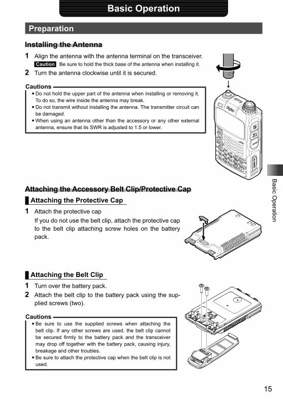
Preparation
Installing the Antenna1 Align the antenna with the antenna terminal on the transceiver.
Caution Be sure to hold the thick base of the antenna when installing it.
2 Turn the antenna clockwise until it is secured.
Cautions�Do not hold the upper part of the antenna when installing or removing it.
To do so, the wire inside the antenna may break.�Do not transmit without installing the antenna. The transmitter circuit can
be damaged.�When using an antenna other than the accessory or any other external
antenna, ensure that its SWR is adjusted to 1.5 or lower.
Attaching the Accessory Belt Clip/Protective CapAttaching the Protective Cap
1 Attach the protective cap If you do not use the belt clip, attach the protective cap
to the belt clip attaching screw holes on the battery pack.
Attaching the Belt Clip1 Turn over the battery pack.2 Attach the belt clip to the battery pack using the sup-
plied screws (two).
Cautions�Be sure to use the supplied screws when attaching the
belt clip. If any other screws are used. the belt clip cannot be secured firmly to the battery pack and the transceiver may drop off together with the battery pack, causing injury, breakage and other troubles.
�Be sure to attach the protective cap when the belt clip is not used.
16
Basic O
peration
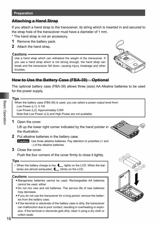
Preparation
Attaching a Hand StrapIf you attach a hand strap to the transceiver, its string which is inserted in and secured to the strap hole of the transceiver must have a diameter of 1 mm.* The hand strap is not an accessory.1 Remove the battery pack.2 Attach the hand strap.
CautionsUse a hand strap which can withstand the weight of the transceiver. If you use a hand strap which is not strong enough, the hand strap can break and the transceiver fall down, causing injury, breakage and other troubles.
How to Use the Battery Case (FBA-39) OptionalThe optional battery case (FBA-39) allows three (size) AA Alkaline batteries to be used for the power supply.
TipsWhen the battery case (FBA-39) is used, you can select a power output level from:
Low Power (L1): 0.1WLow Power (L2): Approximately 0.8WNote that Low Power (L3) and High Power are not available.
1 Open the cover. Lift up the lower right corner indicated by the hand pointer in
the illustration.2 Put alkaline batteries in the battery case.
Caution Use three alkaline batteries. Pay attention to polarities (+ and –) of the alkaline batteries.
3 Close the cover. Push the four corners of the cover firmly to close it tightly.
Tips• When the battery charge is low, _ lights on the LCD. When the bat-
teries are almost exhausted, _ blinks on the LCD.
Cautions�Manganese batteries cannot be used. Rechargeable AA batteries
cannot be used, either.�Do not mix new and old batteries. The service life of new batteries
may decrease.�If you do not use the transceiver for a long period, remove the batter-
ies from the battery case.�If the terminal or electrode of the battery case is dirty, the transceiver
can malfunction due to poor contact, resulting in overheating or explo-sion. If the terminal or electrode gets dirty, clean it using a dry cloth or cotton swab.
17
Basic O
peration
Preparation
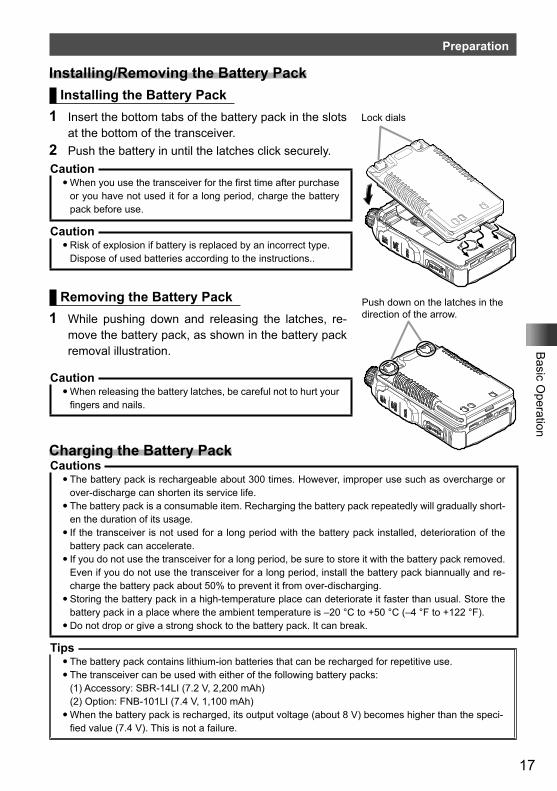
Installing/Removing the Battery PackInstalling the Battery Pack
1 Insert the bottom tabs of the battery pack in the slots at the bottom of the transceiver.
2 Push the battery in until the latches click securely.Caution�When you use the transceiver for the first time after purchase
or you have not used it for a long period, charge the battery pack before use.
Caution�Risk of explosion if battery is replaced by an incorrect type.Dispose of used batteries according to the instructions..
Removing the Battery Pack1 While pushing down and releasing the latches, re-
move the battery pack, as shown in the battery pack removal illustration.
Caution�When releasing the battery latches, be careful not to hurt your
fingers and nails.
Charging the Battery PackCautions�The battery pack is rechargeable about 300 times. However, improper use such as overcharge or
over-discharge can shorten its service life.�The battery pack is a consumable item. Recharging the battery pack repeatedly will gradually short-
en the duration of its usage.�If the transceiver is not used for a long period with the battery pack installed, deterioration of the
battery pack can accelerate.�If you do not use the transceiver for a long period, be sure to store it with the battery pack removed.
Even if you do not use the transceiver for a long period, install the battery pack biannually and re-charge the battery pack about 50% to prevent it from over-discharging.
�Storing the battery pack in a high-temperature place can deteriorate it faster than usual. Store the battery pack in a place where the ambient temperature is –20 °C to +50 °C (–4 °F to +122 °F).
�Do not drop or give a strong shock to the battery pack. It can break.
Tips�The battery pack contains lithium-ion batteries that can be recharged for repetitive use.�The transceiver can be used with either of the following battery packs:(1) Accessory: SBR-14LI (7.2 V, 2,200 mAh)(2) Option: FNB-101LI (7.4 V, 1,100 mAh)�When the battery pack is recharged, its output voltage (about 8 V) becomes higher than the speci-
fied value (7.4 V). This is not a failure.
Push down on the latches in the direction of the arrow.
Lock dials
18
Basic O
peration
Preparation
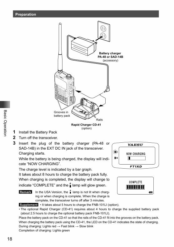
Battery charger PA-48 or SAD-14B
(accessory)
Grooves in battery pack
Rails
Rapid Charger CD-41 (option)
1 Install the Battery Pack2 Turn off the transceiver.3 Insert the plug of the battery charger (PA-48 or
SAD-14B) in the EXT DC IN jack of the transceiver. Charging starts. While the battery is being charged, the display will indi-
cate “NOW CHARGING”. The charge level is indicated by a bar graph. It takes about 8 hours to charge the battery pack fully. When charging is completed, the display will change to
indicate “COMPLETE” and the lamp will glow green.
Remark In the USA Version, the lamp is not lit when charg-ing or when charging is complete. When the charge is complete, the transceiver turns off after 3 minutes.
Supplement • It takes about 5 hours to charge the FNB-101LI (option).• The optional Rapid Charger (CD-41) requires about 4 hours to charge the supplied battery pack
(about 2.5 hours to charge the optional battery pack FNB-101LI).Place the battery pack on the CD-41 so that the rails of the CD-41 fit into the grooves on the battery pack.When charging the battery pack using the CD-41, the LED on the CD-41 indicates the state of charging. During charging: Lights red → Fast blink → Slow blink Completion of charging: Lights green
19
Basic O
peration
Preparation
4 When charging is complete, remove the plug of the battery charger from the jack of the transceiver.
Cautions�Neither transmission nor reception can be performed while charging the battery pack using the sup-
plied battery charger.�Charging may cause noise in the nearby TV or radio. Charge the battery pack with the battery char-
ger as far away as possible from a TV or radio.�If “BATTERY NOT INSTALLED” appears on the LCD and the battery pack cannot be charged after
lapse of 11 or more hours, stop charging the battery pack immediately. If the same message ap-pears again, the battery pack is presumably at the end of its service life or defective. If so, replace the battery pack with a new one.
�While charging the battery pack, protect the transceiver from water.�Charge the battery pack in a place where the ambient temperature is +5 °C to +35 °C (+41 °F to
+95 °F).�If the terminal or electrode of the battery case is dirty, this transceiver can malfunction due to poor
contact, resulting in overheating or rupture. If the terminal or electrode gets dirty, clean it using a dry cloth or cotton swab.
Tips• The battery charger may become hot during charging. This is not a malfunction.• If _ starts blinking, the battery pack charge is depleted. Charge it immediately.
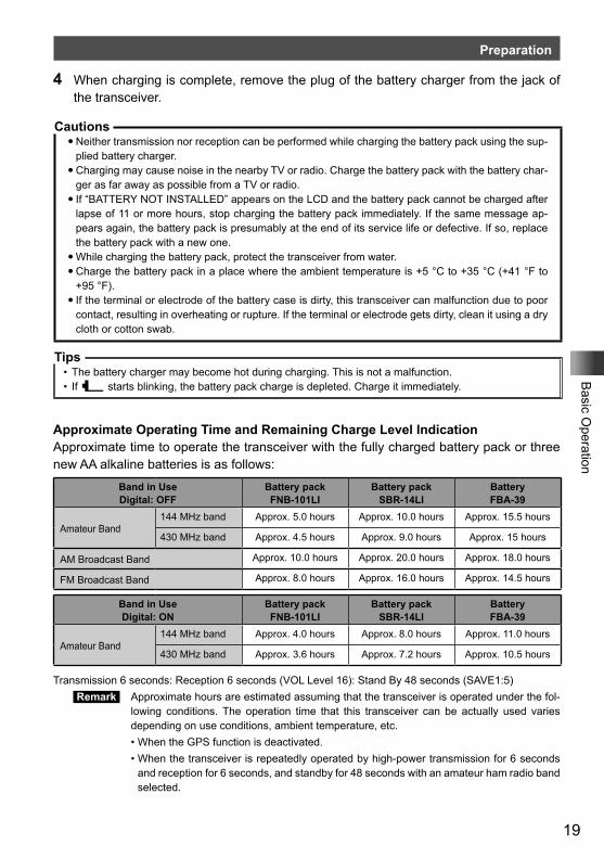
Approximate Operating Time and Remaining Charge Level IndicationApproximate time to operate the transceiver with the fully charged battery pack or three new AA alkaline batteries is as follows:
Band in UseDigital: OFF
Battery pack FNB-101LI
Battery pack SBR-14LI
Battery FBA-39
Amateur Band144 MHz band Approx. 5.0 hours Approx. 10.0 hours Approx. 15.5 hours
430 MHz band Approx. 4.5 hours Approx. 9.0 hours Approx. 15 hours
AM Broadcast Band Approx. 10.0 hours Approx. 20.0 hours Approx. 18.0 hours
FM Broadcast Band Approx. 8.0 hours Approx. 16.0 hours Approx. 14.5 hours
Band in UseDigital: ON
Battery pack FNB-101LI
Battery pack SBR-14LI
Battery FBA-39
Amateur Band144 MHz band Approx. 4.0 hours Approx. 8.0 hours Approx. 11.0 hours
430 MHz band Approx. 3.6 hours Approx. 7.2 hours Approx. 10.5 hours
Transmission 6 seconds: Reception 6 seconds (VOL Level 16): Stand By 48 seconds (SAVE1:5) Remark Approximate hours are estimated assuming that the transceiver is operated under the fol-
lowing conditions. The operation time that this transceiver can be actually used varies depending on use conditions, ambient temperature, etc.
• When the GPS function is deactivated. • When the transceiver is repeatedly operated by high-power transmission for 6 seconds
and reception for 6 seconds, and standby for 48 seconds with an amateur ham radio band selected.
20
Basic O
peration
Preparation
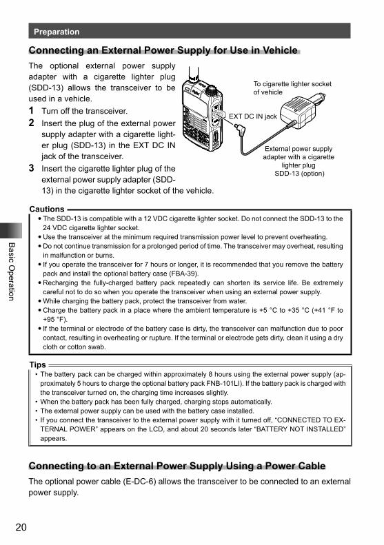
Connecting an External Power Supply for Use in Vehicle The optional external power supply adapter with a cigarette lighter plug (SDD-13) allows the transceiver to be used in a vehicle.1 Turn off the transceiver.2 Insert the plug of the external power
supply adapter with a cigarette light-er plug (SDD-13) in the EXT DC IN jack of the transceiver.
3 Insert the cigarette lighter plug of the external power supply adapter (SDD-13) in the cigarette lighter socket of the vehicle.
Cautions�The SDD-13 is compatible with a 12 VDC cigarette lighter socket. Do not connect the SDD-13 to the
24 VDC cigarette lighter socket.�Use the transceiver at the minimum required transmission power level to prevent overheating.�Do not continue transmission for a prolonged period of time. The transceiver may overheat, resulting
in malfunction or burns.�If you operate the transceiver for 7 hours or longer, it is recommended that you remove the battery
pack and install the optional battery case (FBA-39).�Recharging the fully-charged battery pack repeatedly can shorten its service life. Be extremely
careful not to do so when you operate the transceiver when using an external power supply.�While charging the battery pack, protect the transceiver from water.�Charge the battery pack in a place where the ambient temperature is +5 °C to +35 °C (+41 °F to
+95 °F).�If the terminal or electrode of the battery case is dirty, the transceiver can malfunction due to poor
contact, resulting in overheating or rupture. If the terminal or electrode gets dirty, clean it using a dry cloth or cotton swab.
Tips• The battery pack can be charged within approximately 8 hours using the external power supply (ap-
proximately 5 hours to charge the optional battery pack FNB-101LI). If the battery pack is charged with the transceiver turned on, the charging time increases slightly.
• When the battery pack has been fully charged, charging stops automatically.• The external power supply can be used with the battery case installed.• If you connect the transceiver to the external power supply with it turned off, “CONNECTED TO EX-
TERNAL POWER” appears on the LCD, and about 20 seconds later “BATTERY NOT INSTALLED” appears.
Connecting to an External Power Supply Using a Power CableThe optional power cable (E-DC-6) allows the transceiver to be connected to an external power supply.
To cigarette lighter socket of vehicle
EXT DC IN jack
External power supply adapter with a cigarette
lighter plug SDD-13 (option)
21
Basic O
peration
Preparation
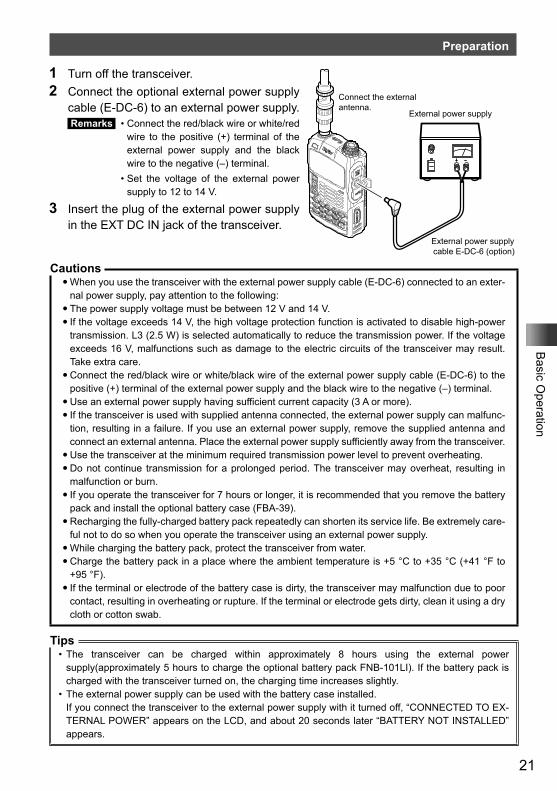
1 Turn off the transceiver.2 Connect the optional external power supply
cable (E-DC-6) to an external power supply. Remarks • Connect the red/black wire or white/red
wire to the positive (+) terminal of the external power supply and the black wire to the negative (–) terminal.
• Set the voltage of the external power supply to 12 to 14 V.
3 Insert the plug of the external power supply in the EXT DC IN jack of the transceiver.
Cautions�When you use the transceiver with the external power supply cable (E-DC-6) connected to an exter-
nal power supply, pay attention to the following:�The power supply voltage must be between 12 V and 14 V.�If the voltage exceeds 14 V, the high voltage protection function is activated to disable high-power
transmission. L3 (2.5 W) is selected automatically to reduce the transmission power. If the voltage exceeds 16 V, malfunctions such as damage to the electric circuits of the transceiver may result. Take extra care.
�Connect the red/black wire or white/black wire of the external power supply cable (E-DC-6) to the positive (+) terminal of the external power supply and the black wire to the negative (–) terminal.
�Use an external power supply having sufficient current capacity (3 A or more).�If the transceiver is used with supplied antenna connected, the external power supply can malfunc-
tion, resulting in a failure. If you use an external power supply, remove the supplied antenna and connect an external antenna. Place the external power supply sufficiently away from the transceiver.
�Use the transceiver at the minimum required transmission power level to prevent overheating.�Do not continue transmission for a prolonged period. The transceiver may overheat, resulting in
malfunction or burn.�If you operate the transceiver for 7 hours or longer, it is recommended that you remove the battery
pack and install the optional battery case (FBA-39).�Recharging the fully-charged battery pack repeatedly can shorten its service life. Be extremely care-
ful not to do so when you operate the transceiver using an external power supply.�While charging the battery pack, protect the transceiver from water.�Charge the battery pack in a place where the ambient temperature is +5 °C to +35 °C (+41 °F to
+95 °F).�If the terminal or electrode of the battery case is dirty, the transceiver may malfunction due to poor
contact, resulting in overheating or rupture. If the terminal or electrode gets dirty, clean it using a dry cloth or cotton swab.
Tips• The transceiver can be charged within approximately 8 hours using the external power
supply(approximately 5 hours to charge the optional battery pack FNB-101LI). If the battery pack is charged with the transceiver turned on, the charging time increases slightly.
• The external power supply can be used with the battery case installed.If you connect the transceiver to the external power supply with it turned off, “CONNECTED TO EX-TERNAL POWER” appears on the LCD, and about 20 seconds later “BATTERY NOT INSTALLED” appears.
Connect the external antenna.
External power supply
External power supply cable E-DC-6 (option)
22
Basic O
peration
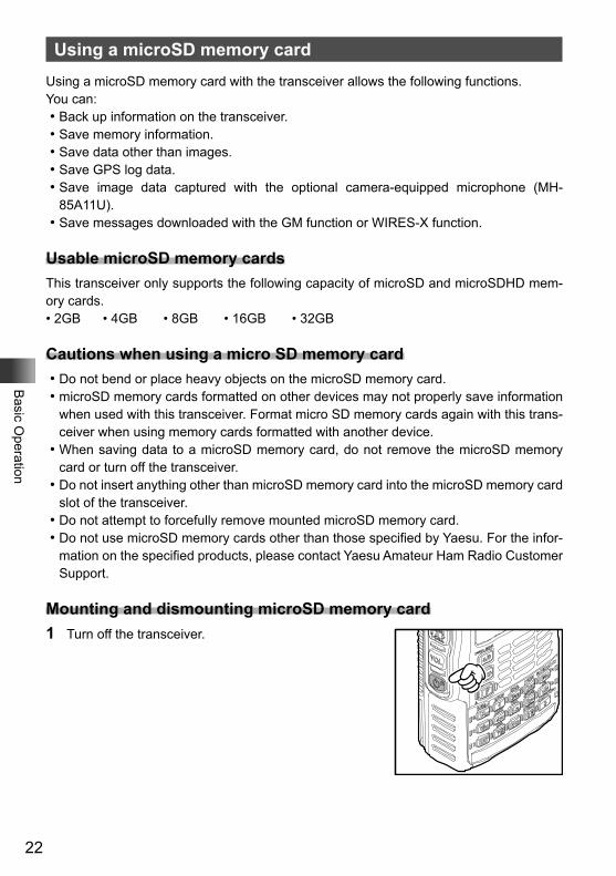
Using a microSD memory cardUsing a microSD memory card with the transceiver allows the following functions.You can:Back up information on the transceiver.Save memory information.Save data other than images.Save GPS log data.Save image data captured with the optional camera-equipped microphone (MH-
85A11U).Save messages downloaded with the GM function or WIRES-X function.
Usable microSD memory cardsThis transceiver only supports the following capacity of microSD and microSDHD mem-ory cards.• 2GB • 4GB • 8GB • 16GB • 32GB
Cautions when using a micro SD memory cardDo not bend or place heavy objects on the microSD memory card.microSD memory cards formatted on other devices may not properly save information
when used with this transceiver. Format micro SD memory cards again with this trans-ceiver when using memory cards formatted with another device.When saving data to a microSD memory card, do not remove the microSD memory
card or turn off the transceiver.Do not insert anything other than microSD memory card into the microSD memory card
slot of the transceiver.Do not attempt to forcefully remove mounted microSD memory card.Do not use microSD memory cards other than those specified by Yaesu. For the infor-
mation on the specified products, please contact Yaesu Amateur Ham Radio Customer Support.
Mounting and dismounting microSD memory card1 Turn off the transceiver.
23
Basic O
peration
Using a microSD memory card
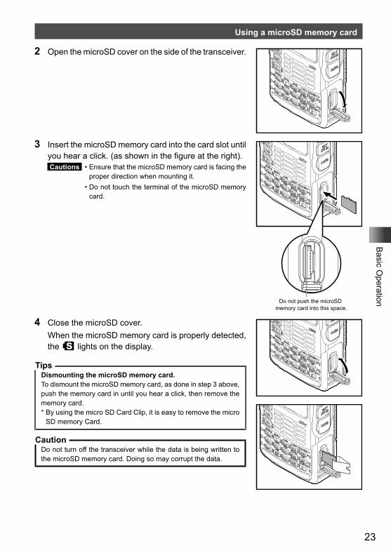
2 Open the microSD cover on the side of the transceiver.
3 Insert the microSD memory card into the card slot until you hear a click. (as shown in the figure at the right). Cautions • Ensure that the microSD memory card is facing the
proper direction when mounting it. • Do not touch the terminal of the microSD memory
card.
Do not push the microSD memory card into this space.
4 Close the microSD cover. When the microSD memory card is properly detected,
the s lights on the display.
TipsDismounting the microSD memory card.To dismount the microSD memory card, as done in step 3 above, push the memory card in until you hear a click, then remove the memory card.* By using the micro SD Card Clip, it is easy to remove the micro
SD memory Card.
CautionDo not turn off the transceiver while the data is being written to the microSD memory card. Doing so may corrupt the data.
24
Basic O
peration
Using a microSD memory card
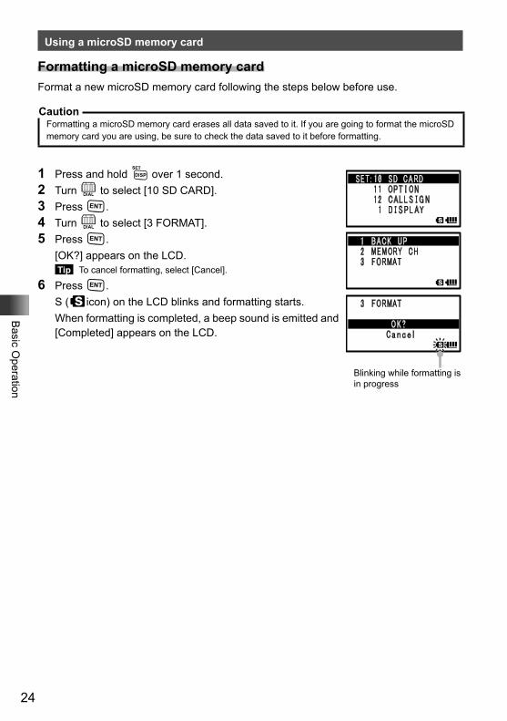
Formatting a microSD memory cardFormat a new microSD memory card following the steps below before use.
CautionFormatting a microSD memory card erases all data saved to it. If you are going to format the microSD memory card you are using, be sure to check the data saved to it before formatting.
1 Press and hold M over 1 second.2 Turn O to select [10 SD CARD].3 Press H.4 Turn O to select [3 FORMAT].5 Press H. [OK?] appears on the LCD.
Tip To cancel formatting, select [Cancel].
6 Press H. S (sicon) on the LCD blinks and formatting starts. When formatting is completed, a beep sound is emitted and
[Completed] appears on the LCD.
Blinking while formatting is in progress
25
Basic O
peration
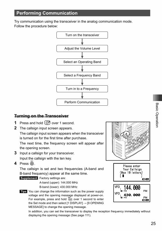
Performing CommunicationTry communication using the transceiver in the analog communication mode. Follow the procedure below:
Turn on the transceiver
Adjust the Volume Level
Select an Operating Band
Select a Frequency Band
Turn in to a Frequency
Perform Communication
Turning on the Transceiver1 Press and hold P over 1 second.2 The callsign input screen appears. The callsign input screen appears when the transceiver
is turned on for the first time after purchase. The next time, the frequency screen will appear after
the opening screen.3 Input a callsign for your transceiver. Input the callsign with the ten key.4 Press p. The callsign is set and two frequencies (A-band and
B-band frequency) appear at the same time. Supplement Factory settings are: A-band (upper): 144.000 MHz B-band (lower): 430.000 MHz Tips You can change the information such as the power supply
voltage and the opening message displayed at power-on. For example, press and hold M over 1 second to enter the Set mode and then select [1 DISPLAY] → [9 OPENING MESSAGE] to change the opening message.
In addition, you can set the transceiver to display the reception frequency immediately without displaying the opening message (See page 111).
26
Basic O
peration
Performing Communication
�Turning off the TransceiverTo turn off the transceiver, press and hold P over 1 second.
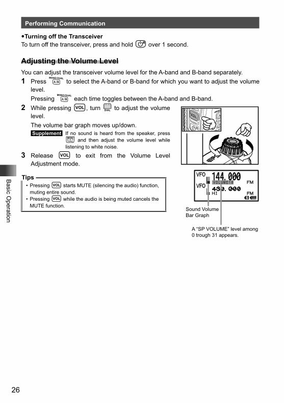
Adjusting the Volume LevelYou can adjust the transceiver volume level for the A-band and B-band separately.1 Press A to select the A-band or B-band for which you want to adjust the volume
level. Pressing A each time toggles between the A-band and B-band.2 While pressing v, turn O to adjust the volume
level. The volume bar graph moves up/down.
Supplement If no sound is heard from the speaker, press T and then adjust the volume level while listening to white noise.
3 Release v to exit from the Volume Level Adjustment mode.
Tips• Pressing v starts MUTE (silencing the audio) function,
muting entire sound.• Pressing v while the audio is being muted cancels the
MUTE function.Sound Volume Bar Graph
A “SP VOLUME” level among 0 trough 31 appears.
27
Basic O
peration
Performing Communication
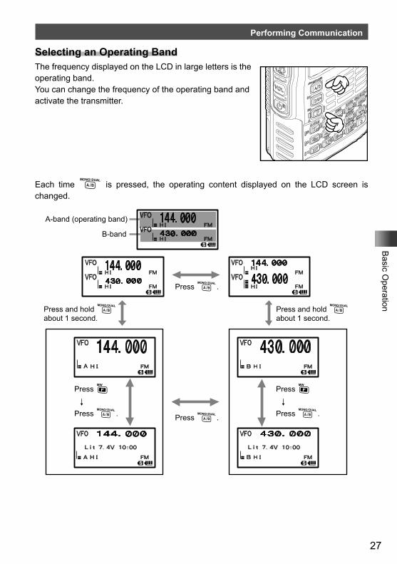
Selecting an Operating BandThe frequency displayed on the LCD in large letters is the operating band.You can change the frequency of the operating band and activate the transmitter.
Each time A is pressed, the operating content displayed on the LCD screen is changed.
Press F↓
Press A.
Press F↓
Press A.
Press A.
Press A.
A-band (operating band)
B-band
Press and hold A about 1 second.
Press and hold A about 1 second.
28
Basic O
peration
Performing Communication
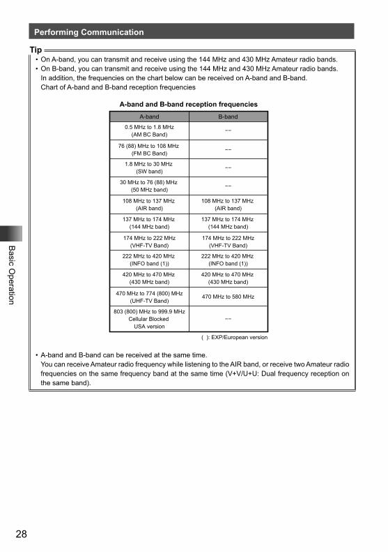
Tip• On A-band, you can transmit and receive using the 144 MHz and 430 MHz Amateur radio bands.• On B-band, you can transmit and receive using the 144 MHz and 430 MHz Amateur radio bands.
In addition, the frequencies on the chart below can be received on A-band and B-band.Chart of A-band and B-band reception frequencies
A-band and B-band reception frequencies
A-band B-band
0.5 MHz to 1.8 MHz(AM BC Band)
30 MHz to 76 (88) MHz (50 MHz band)
108 MHz to 137 MHz (AIR band)
137 MHz to 174 MHz (144 MHz band)
174 MHz to 222 MHz(VHF-TV Band)
222 MHz to 420 MHz (INFO band (1))
420 MHz to 470 MHz (430 MHz band)
470 MHz to 774 (800) MHz(UHF-TV Band)
803 (800) MHz to 999.9 MHzCellular Blocked
USA version
108 MHz to 137 MHz (AIR band)
137 MHz to 174 MHz (144 MHz band)
174 MHz to 222 MHz(VHF-TV Band)
222 MHz to 420 MHz (INFO band (1))
420 MHz to 470 MHz (430 MHz band)
470 MHz to 580 MHz
( ): EXP/European version
−−
−−
−−
1.8 MHz to 30 MHz (SW band)
−−
76 (88) MHz to 108 MHz (FM BC Band)
−−
• A-band and B-band can be received at the same time.You can receive Amateur radio frequency while listening to the AIR band, or receive two Amateur radio frequencies on the same frequency band at the same time (V+V/U+U: Dual frequency reception on the same band).
29
Basic O
peration
Performing Communication
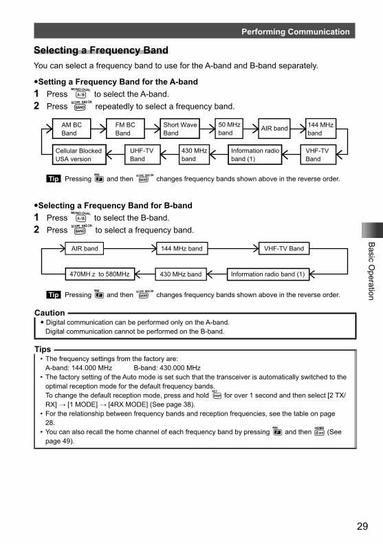
Selecting a Frequency BandYou can select a frequency band to use for the A-band and B-band separately.
�Setting a Frequency Band for the A-band1 Press A to select the A-band.2 Press B repeatedly to select a frequency band.
Short Wave Band
50 MHz band
FM BC Band
AIR band 144 MHz band
VHF-TV Band
Information radio band (1)
430 MHz band
UHF-TV Band
Cellular BlockedUSA version
AM BC Band
Tip Pressing F and then B changes frequency bands shown above in the reverse order.
�Selecting a Frequency Band for B-band1 Press A to select the B-band.2 Press B to select a frequency band.
AIR band 144 MHz band VHF-TV Band
Information radio band (1)430 MHz band470MHz to 580MHz
Tip Pressing F and then B changes frequency bands shown above in the reverse order.
Caution� Digital communication can be performed only on the A-band.
Digital communication cannot be performed on the B-band.
Tips• The frequency settings from the factory are:
A-band: 144.000 MHz B-band: 430.000 MHz• The factory setting of the Auto mode is set such that the transceiver is automatically switched to the
optimal reception mode for the default frequency bands.To change the default reception mode, press and hold M for over 1 second and then select [2 TX/RX] → [1 MODE] → [4RX MODE] (See page 38).
• For the relationship between frequency bands and reception frequencies, see the table on page 28.
• You can also recall the home channel of each frequency band by pressing F and then 4 (See page 49).
30
Basic O
peration
Performing Communication
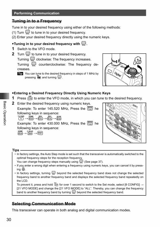
Tuning in to a FrequencyTune in to your desired frequency using either of the following methods:(1) Turn O to tune in to your desired frequency.(2) Enter your desired frequency directly using the numeric keys.
�Tuning in to your desired frequency with O.1 Switch to the VFO mode.2 Turn O to tune in to your desired frequency. Turning O clockwise: The frequency increases. Turning O counterclockwise: The frequency de-
creases. Tip You can tune to the desired frequency in steps of 1 MHz by
pressing F and turning O.
�Entering a Desired Frequency Directly Using Numeric Keys1 Press V to enter the VFO mode, in which you can tune to the desired frequency.2 Enter the desired frequency using numeric keys. Example: To enter 145.520 MHz, Press the T he
following keys in sequence: 1→4→5→5→2 Example: To enter 430.000 MHz, Press the T he
following keys in sequence: 4→3→H
Tips• In factory settings, the Auto Step mode is set such that the transceiver is automatically switched to the
optimal frequency steps for the reception frequency.You can change frequency steps manually using O (See page 37).
• If you enter a wrong digit when entering a frequency using numeric keys, you can cancel it by press-ing p.
• In factory settings, turning O beyond the selected frequency band does not change the selected frequency band to another frequency band and displays the selected frequency band repeatedly on the LCD.To prevent it, press and hold M for over 1 second to switch to the Set mode, select [8 CONFIG] → [21 VFO MODE] and change the [21 VFO MODE] to “ALL”. Thereby, you can change the frequency band to another frequency band by turning O beyond the selected frequency band.
Selecting Communication ModeThis transceiver can operate in both analog and digital communication modes.
31
Basic O
peration
Performing Communication
Pressing % repeatedly switches the communication mode as follows.[Analog (FM)] → [Auto (¢FM)] → [Digital (DN)] → [Digital Wide (VW)]FM: Analog Analog communication using FM mode.¢○○ Auto Automatically switches between Analog AM (¢AM), Analog
FM (¢FM), and Digital (¢DN).DN: Digital Digital communication using (C4FM (Quaternary FSK)
modulationVW: Wide Digital High sound quality of Digital Communication
Caution� Digital communication can be performed only on the A-band.
Performing Communication1 Speak into the microphone while pressing p. When speaking into the microphone, keep it about 5 cm away from your mouth.2 Release p. The transceiver returns to the Reception mode.
Cautions�Use the transceiver at the minimum required transmission power level.�Doing so prevents the transceiver from overheating and saves battery power, increasing the operat-
ing time.�Do not continue transmitting for a prolonged period. The transceiver can overheat, resulting in mal-
function or burn.�If transmission is continued for a long period, the transceiver overheats and the overheat protection
function is activated. As a result, the transmitting power level is automatically set to Low Power. If you continue transmitting while the overheat protection function is active, the transceiver will be forc-ibly returned to the Reception mode.
�If you touch the transceiver immediately after the overheat protection function has become active, you can get burned. Wait for the temperature inside the transceiver to drop sufficiently before resum-ing transmission.
�Do not perform transmission without attaching the antenna. The transmitter circuit can be damaged.
Tips• In the FM mode, you can transmit on the 144 MHz and 430 MHz ham radio bands.• Even while you are receiving in the AM mode, you can transmit in the FM mode by pressing p.• You can change the transmit power level by pressing F and then 1.
Transmit power level may be lower when using the battery pack or the alkaline battery case.For more details, see “Changing the Transmission Power Level” on page 36.
• If p is pressed when a frequency other than the amateur ham radio band is selected, an alarm tone (beep) will be emitted and “ERROR” appears on the LCD, disabling transmission.
• Pressing and holding M for over 1 second, and changing the Set Mode option [8 CONFIG] will allow you to use the transceiver more conveniently.
• Selecting [8 CONFIG] → [2 BCLO] prohibits transmission during reception of a signal.
32
Basic O
peration
Performing Communication
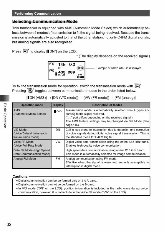
Selecting Communication ModeThis transceiver is equipped with AMS (Automatic Mode Select) which automatically se-lects between 4 modes of transmission to fit the signal being received. Because the trans-mission is automatically adjusted to that of the other station, not only C4FM digital signals, but analog signals are also recognized.
Press % to display [¢DN*] on the LCD.* (The display depends on the received signal.)
Example of when AMS is displayed.
To fix the transmission mode for operation, switch the transmission mode with %.Pressing % toggles between communication modes in the order listed below.
[¢DN (AMS)] → [DN (V/D mode)] → [VW (FR mode)] → [FM (analog)]
Operation mode Display Description of Modes
AMS (Automatic Mode Select)
¢○○ Transmission mode is automatically selected from 4 types ac-cording to the signal received.(“○○” part differs depending on the received signal.)The AMS feature settings may be changed via Set Mode (See page.116).
V/D Mode (Voice/Data simultaneous transmission mode)
DN Call is less prone to interruption due to detection and correction of voice signals during digital voice signal transmission. This is the standard mode for C4FM Digital
Voice FR Mode (Voice Full Rate Mode)
VW Digital voice data transmission using the entire 12.5 kHz band. Enables high-quality voice communication.
Data FR Mode (High Speed Data Communication Mode)
High speed data communication using entire 12.5 kHz band.This mode is automatically selected for image communication.
Analog FM Mode FM Analog communication using FM mode. Effective when the signal is weak and audio is susceptible to interruption in digital mode.
Cautions�Digital communication can be performed only on the A-band.�Digital communication cannot be performed on the B-band.�In V/D mode (“DN” on the LCD), position information is included in the radio wave during voice
communication, however, it is not include in the Voice FR mode (“VW” on the LCD).
33
Basic O
peration
Listening to the Radio
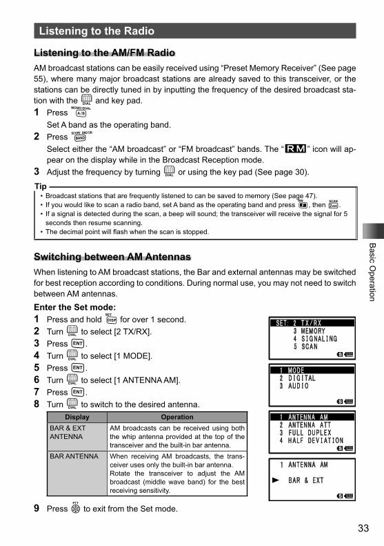
Listening to the AM/FM RadioAM broadcast stations can be easily received using “Preset Memory Receiver” (See page 55), where many major broadcast stations are already saved to this transceiver, or the stations can be directly tuned in by inputting the frequency of the desired broadcast sta-tion with the O and key pad.1 Press A Set A band as the operating band.2 Press B Select either the “AM broadcast” or “FM broadcast” bands. The “R” icon will ap-
pear on the display while in the Broadcast Reception mode.3 Adjust the frequency by turning O or using the key pad (See page 30).
Tip• Broadcast stations that are frequently listened to can be saved to memory (See page 47).• If you would like to scan a radio band, set A band as the operating band and press F, then 2.• If a signal is detected during the scan, a beep will sound; the transceiver will receive the signal for 5
seconds then resume scanning.• The decimal point will flash when the scan is stopped.
Switching between AM AntennasWhen listening to AM broadcast stations, the Bar and external antennas may be switched for best reception according to conditions. During normal use, you may not need to switch between AM antennas.Enter the Set mode:1 Press and hold M for over 1 second.2 Turn O to select [2 TX/RX].3 Press H.4 Turn O to select [1 MODE].5 Press H.6 Turn O to select [1 ANTENNA AM].7 Press H.8 Turn O to switch to the desired antenna.
Display OperationBAR & EXT ANTENNA
AM broadcasts can be received using both the whip antenna provided at the top of the transceiver and the built-in bar antenna.
BAR ANTENNA When receiving AM broadcasts, the trans-ceiver uses only the built-in bar antenna.Rotate the transceiver to adjust the AM broadcast (middle wave band) for the best receiving sensitivity.
9 Press p to exit from the Set mode.
34
Basic O
peration
Miscellaneous Settings
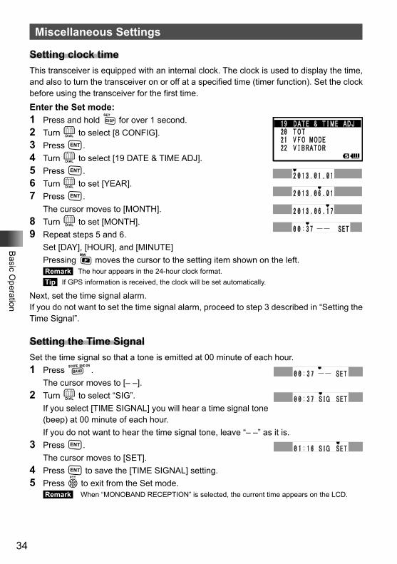
Setting clock timeThis transceiver is equipped with an internal clock. The clock is used to display the time, and also to turn the transceiver on or off at a specified time (timer function). Set the clock before using the transceiver for the first time.Enter the Set mode:1 Press and hold M for over 1 second.2 Turn O to select [8 CONFIG].3 Press H.4 Turn O to select [19 DATE & TIME ADJ].5 Press H.6 Turn O to set [YEAR].7 Press H. The cursor moves to [MONTH].8 Turn O to set [MONTH].9 Repeat steps 5 and 6. Set [DAY], [HOUR], and [MINUTE] Pressing F moves the cursor to the setting item shown on the left.
Remark The hour appears in the 24-hour clock format. Tip If GPS information is received, the clock will be set automatically.
Next, set the time signal alarm.If you do not want to set the time signal alarm, proceed to step 3 described in “Setting the Time Signal”.
Setting the Time SignalSet the time signal so that a tone is emitted at 00 minute of each hour.1 Press B. The cursor moves to [– –].2 Turn O to select “SIG”. If you select [TIME SIGNAL] you will hear a time signal tone
(beep) at 00 minute of each hour. If you do not want to hear the time signal tone, leave “– –” as it is.3 Press H. The cursor moves to [SET].4 Press H to save the [TIME SIGNAL] setting.5 Press p to exit from the Set mode.
Remark When “MONOBAND RECEPTION” is selected, the current time appears on the LCD.
35
Basic O
peration
Miscellaneous Settings
Tips• The accuracy of the clock is 30 seconds/month. However, it may vary depending on the environment
conditions, such as the temperature.• The transceiver is equipped with a dedicated rechargeable lithium battery for the clock.
Normally, the transceiver is powered from the battery pack. When the battery pack is detached or runs out, the lithium battery starts operating automatically. The lithium battery can power the clock for approximately 2 months.
• When you use the transceiver for the first time or without the battery pack for a long period of time, the accuracy of the clock may be poor. In such case, reattach the battery pack and adjust the time.
• When the transceiver is operating in “Mono” band, the current time appears on the LCD.However, when display of double-size characters or dual display is selected, the current time does not appear on the LCD.
• The calendar can display dates from January 1, 2000 A.D. up to December 31, 2099 A.D.• If AUTO is selected in [9 APRS] → [21 GPS TIME SET] in the Set mode, the clock will automatically
display accurate time. However, the day of the week is not set automatically. Set the day of the week manually.
• If you use the timer function, the transceiver will be turned off automatically (See page 135).In addition, you can set the transceiver to turn on at the specified time (See page 135).
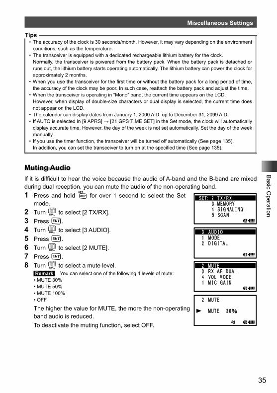
Muting AudioIf it is difficult to hear the voice because the audio of A-band and the B-band are mixed during dual reception, you can mute the audio of the non-operating band.1 Press and hold M for over 1 second to select the Set
mode.2 Turn O to select [2 TX/RX].3 Press H.4 Turn O to select [3 AUDIO].5 Press H.6 Turn O to select [2 MUTE].7 Press H.8 Turn O to select a mute level.
Remark You can select one of the following 4 levels of mute:• MUTE 30%• MUTE 50%• MUTE 100%• OFF
The higher the value for MUTE, the more the non-operating band audio is reduced.
To deactivate the muting function, select OFF.
36
Basic O
peration
Miscellaneous Settings
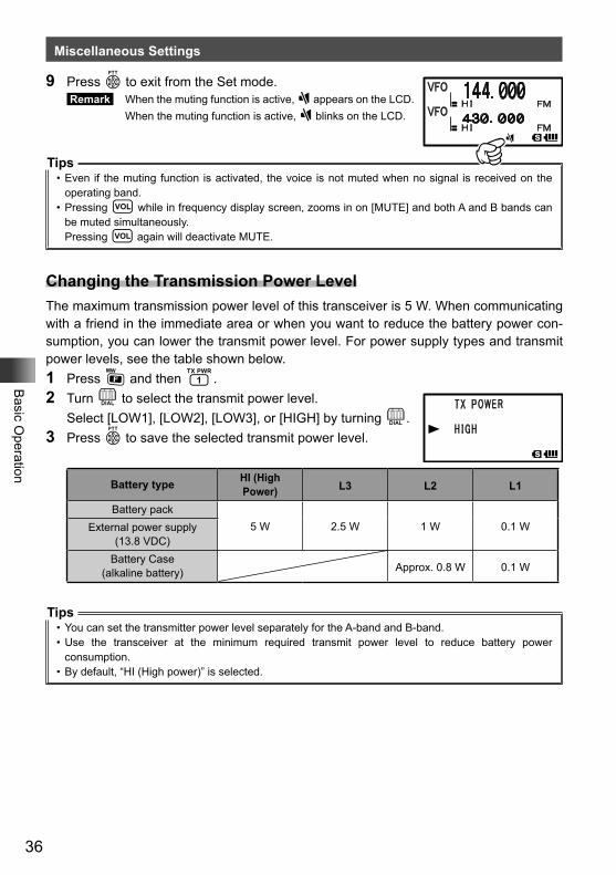
9 Press p to exit from the Set mode. Remark When the muting function is active, ] appears on the LCD. When the muting function is active, ] blinks on the LCD.
Tips• Even if the muting function is activated, the voice is not muted when no signal is received on the
operating band.• Pressing v while in frequency display screen, zooms in on [MUTE] and both A and B bands can
be muted simultaneously.Pressing v again will deactivate MUTE.
Changing the Transmission Power LevelThe maximum transmission power level of this transceiver is 5 W. When communicating with a friend in the immediate area or when you want to reduce the battery power con-sumption, you can lower the transmit power level. For power supply types and transmit power levels, see the table shown below.1 Press F and then 1.2 Turn O to select the transmit power level. Select [LOW1], [LOW2], [LOW3], or [HIGH] by turning O.3 Press p to save the selected transmit power level.
Battery type HI (High Power) L3 L2 L1
Battery pack5 W 2.5 W 1 W 0.1 WExternal power supply
(13.8 VDC)Battery Case
(alkaline battery) Approx. 0.8 W 0.1 W
Tips• You can set the transmitter power level separately for the A-band and B-band.• Use the transceiver at the minimum required transmit power level to reduce battery power
consumption.• By default, “HI (High power)” is selected.
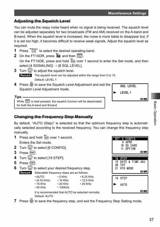
37
Basic O
peration
Miscellaneous Settings
Adjusting the Squelch LevelYou can mute the raspy noise heard when no signal is being received. The squelch level can be adjusted separately for two broadcasts (FM and AM) received on the A-band and B-band. When the squelch level is increased, the noise is more liable to disappear but, if it is set too high, it becomes difficult to receive weak signals. Adjust the squelch level as required.1 Press A to select the desired operating band.2 On the FT1XDR, press F and then T. On the FT1XDE, press and hold M over 1 second to enter the Set mode, and then
select [4 SIGNALING] → [8 SQL LEVEL].3 Turn O to adjust the squelch level.
Remark The squelch level can be adjusted within the range from 0 to 15. Default: LEVEL 1
4 Press p to save the Squelch Level Adjustment and exit the Squelch Level Adjustment mode.
TipsWhile T is held pressed, the squelch function will be deactivated for both the A-band and B-band.
Changing the Frequency Step ManuallyBy default, “AUTO (Step)” is selected so that the optimum frequency step is automati-cally selected according to the received frequency. You can change this frequency step manually.1 Press and hold M over 1 second. Enters the Set mode.2 Turn O to select [8 CONFIG].3 Press H.4 Turn O to select [18 STEP].5 Press H.6 Turn O to select your desired frequency step.
Remark Selectable frequency steps are as follows:• AUTO • 5 KHz • 6.25 KHz• (8.33 KHz) • 10 KHz • 12.5 KHz• 15 KHz • 20 KHz • 25 KHz• 50 KHz • 100KHz
It is recommended that AUTO be selected normally. Default: AUTO
7 Press p to save the frequency step, and exit the Frequency Step Setting mode.
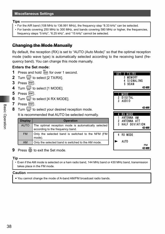
38
Basic O
peration
Miscellaneous Settings
Tips• For the AIR band (108 MHz to 136.991 MHz), the frequency step “8.33 kHz” can be selected.• For bands covering 250 MHz to 300 MHz, and bands covering 580 MHz or higher, the frequencies,
frequency steps “5 kHz”, “6.25 kHz”, and “15 kHz” cannot be selected.
Changing the Mode ManuallyBy default, the reception (RX) is set to “AUTO (Auto Mode)” so that the optimal reception mode (radio wave type) is automatically selected according to the receiving band (fre-quency band). You can change this mode manually.Enters the Set mode:1 Press and hold M for over 1 second.2 Turn O to select [2 TX/RX].3 Press H.4 Turn O to select [1 MODE].5 Press H.6 Turn O to select [4 RX MODE].7 Press H.8 Turn O to select your desired reception mode. It is recommended that AUTO be selected normally.
Display OperationAUTO The optimal reception mode is automatically selected
according to the frequency band.FM Only the selected band is switched to the NFM (FM
mode).AM Only the selected band is switched to the AM mode.
9 Press p to exit the Set mode.
Tip• Even if the AM mode is selected on a ham radio band, 144 MHz band or 430 MHz band, transmission
takes place in the FM mode.
Caution� You cannot change the mode of A-band AM/FM broadcast radio bands.
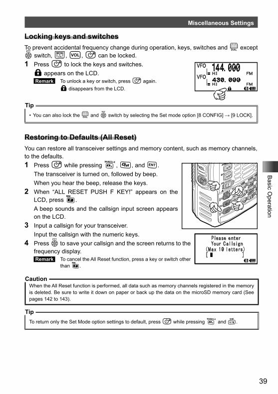
39
Basic O
peration
Miscellaneous Settings
Locking keys and switchesTo prevent accidental frequency change during operation, keys, switches and O except p switch, T, v, P can be locked.1 Press P to lock the keys and switches. l appears on the LCD.
Remark To unlock a key or switch, press P again. l disappears from the LCD.
Tip• You can also lock the O and p switch by selecting the Set mode option [8 CONFIG] → [9 LOCK].
Restoring to Defaults (All Reset)You can restore all transceiver settings and memory content, such as memory channels, to the defaults.1 Press P while pressing %, D, and H. The transceiver is turned on, followed by beep. When you hear the beep, release the keys.2 When “ALL RESET PUSH F KEY!” appears on the
LCD, press F. A beep sounds and the callsign input screen appears
on the LCD.3 Input a callsign for your transceiver. Input the callsign with the numeric keys.4 Press p to save your callsign and the screen returns to the
frequency display. Remark To cancel the All Reset function, press a key or switch other
than F.
CautionWhen the All Reset function is performed, all data such as memory channels registered in the memory is deleted. Be sure to write it down on paper or back up the data on the microSD memory card (See pages 142 to 143).
TipTo return only the Set Mode option settings to default, press P while pressing % and V.
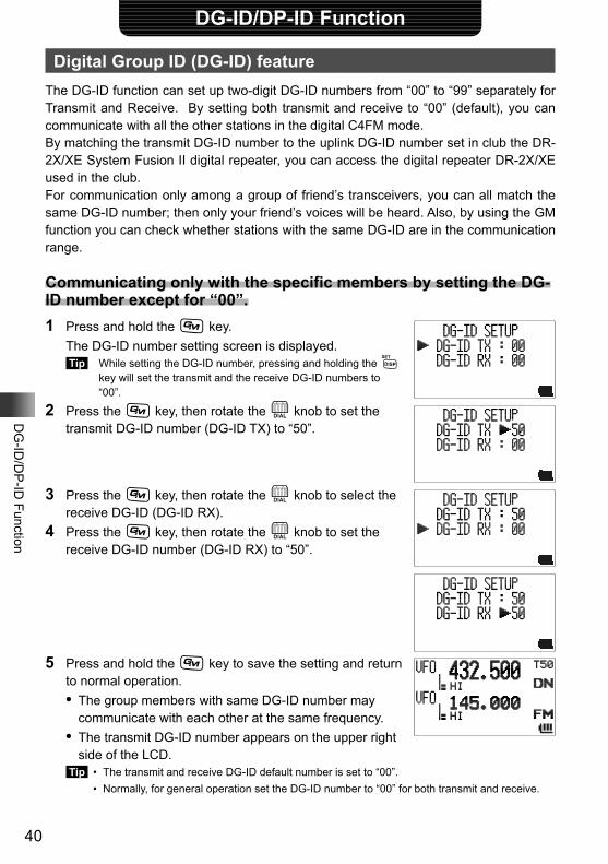
40
DG
-ID/D
P-ID
Function
DG-ID/DP-ID Function
Digital Group ID (DG-ID) featureThe DG-ID function can set up two-digit DG-ID numbers from “00” to “99” separately for Transmit and Receive. By setting both transmit and receive to “00” (default), you can communicate with all the other stations in the digital C4FM mode.By matching the transmit DG-ID number to the uplink DG-ID number set in club the DR-2X/XE System Fusion II digital repeater, you can access the digital repeater DR-2X/XE used in the club.For communication only among a group of friend’s transceivers, you can all match the same DG-ID number; then only your friend’s voices will be heard. Also, by using the GM function you can check whether stations with the same DG-ID are in the communication range.
Communicating only with the specific members by setting the DG-ID number except for “00”.1 Press and hold the D key. The DG-ID number setting screen is displayed.
Tip While setting the DG-ID number, pressing and holding the M key will set the transmit and the receive DG-ID numbers to “00”.
2 Press the D key, then rotate the O knob to set the transmit DG-ID number (DG-ID TX) to “50”.
3 Press the D key, then rotate the O knob to select the receive DG-ID (DG-ID RX).
4 Press the D key, then rotate the O knob to set the receive DG-ID number (DG-ID RX) to “50”.
5 Press and hold the D key to save the setting and return to normal operation.• The group members with same DG-ID number may
communicate with each other at the same frequency.• The transmit DG-ID number appears on the upper right
side of the LCD. Tip • The transmit and receive DG-ID default number is set to “00”. • Normally, for general operation set the DG-ID number to “00” for both transmit and receive.
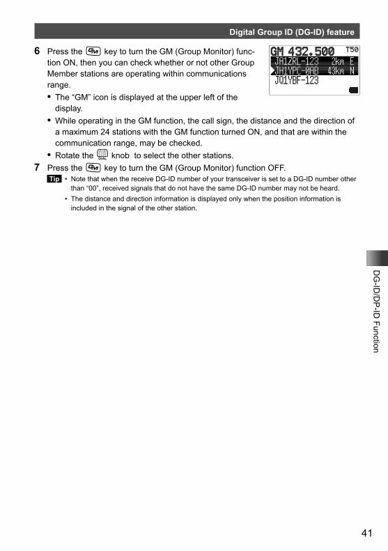
41
DG
-ID/D
P-ID
Function
Digital Group ID (DG-ID) feature
6 Press the D key to turn the GM (Group Monitor) func-tion ON, then you can check whether or not other Group Member stations are operating within communications range.• The “GM” icon is displayed at the upper left of the
display.• While operating in the GM function, the call sign, the distance and the direction of
a maximum 24 stations with the GM function turned ON, and that are within the communication range, may be checked.
• Rotate the O knob to select the other stations.7 Press the D key to turn the GM (Group Monitor) function OFF.
Tip • Note that when the receive DG-ID number of your transceiver is set to a DG-ID number other than “00”, received signals that do not have the same DG-ID number may not be heard.
• The distance and direction information is displayed only when the position information is included in the signal of the other station.
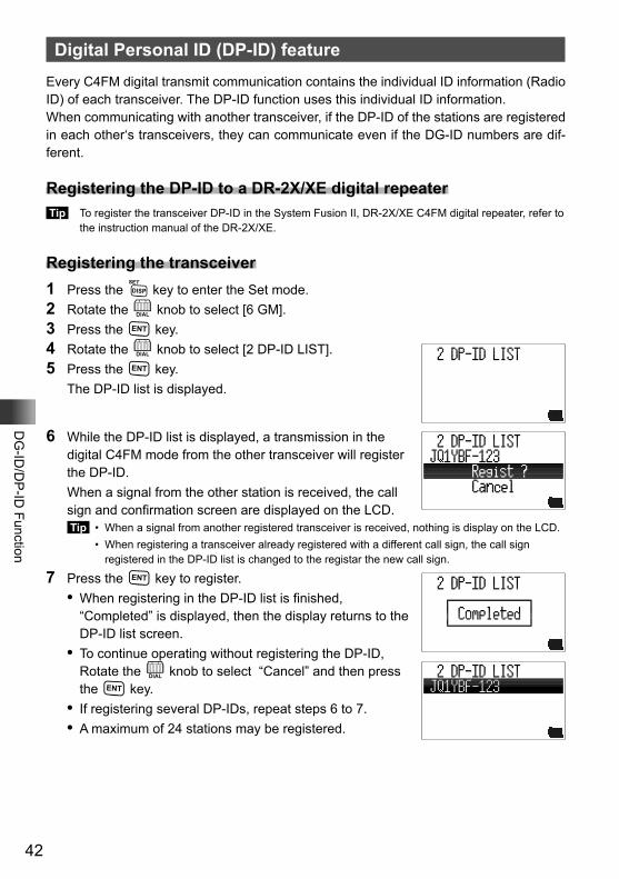
42
DG
-ID/D
P-ID
Function
Digital Personal ID (DP-ID) featureEvery C4FM digital transmit communication contains the individual ID information (Radio ID) of each transceiver. The DP-ID function uses this individual ID information.When communicating with another transceiver, if the DP-ID of the stations are registered in each other‘s transceivers, they can communicate even if the DG-ID numbers are dif-ferent.
Registering the DP-ID to a DR-2X/XE digital repeater Tip To register the transceiver DP-ID in the System Fusion II, DR-2X/XE C4FM digital repeater, refer to
the instruction manual of the DR-2X/XE.
Registering the transceiver1 Press the M key to enter the Set mode.2 Rotate the O knob to select [6 GM].3 Press the H key.4 Rotate the O knob to select [2 DP-ID LIST].5 Press the H key. The DP-ID list is displayed.
6 While the DP-ID list is displayed, a transmission in the digital C4FM mode from the other transceiver will register the DP-ID.
When a signal from the other station is received, the call sign and confirmation screen are displayed on the LCD. Tip • When a signal from another registered transceiver is received, nothing is display on the LCD. • When registering a transceiver already registered with a different call sign, the call sign
registered in the DP-ID list is changed to the registar the new call sign.
7 Press the H key to register.• When registering in the DP-ID list is finished,
“Completed” is displayed, then the display returns to the DP-ID list screen.
• To continue operating without registering the DP-ID, Rotate the O knob to select “Cancel” and then press the H key.
• If registering several DP-IDs, repeat steps 6 to 7.• A maximum of 24 stations may be registered.
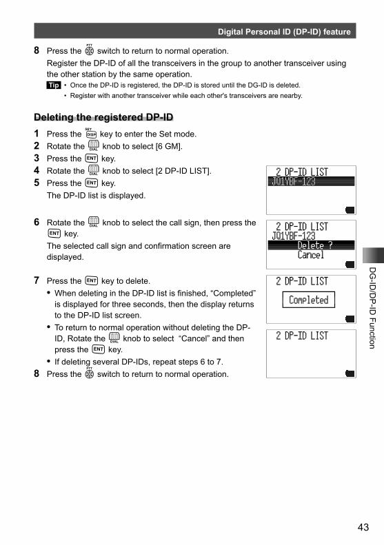
43
DG
-ID/D
P-ID
Function
Digital Personal ID (DP-ID) feature
8 Press the p switch to return to normal operation. Register the DP-ID of all the transceivers in the group to another transceiver using
the other station by the same operation. Tip • Once the DP-ID is registered, the DP-ID is stored until the DG-ID is deleted. • Register with another transceiver while each other's transceivers are nearby.
Deleting the registered DP-ID1 Press the M key to enter the Set mode.2 Rotate the O knob to select [6 GM].3 Press the H key.4 Rotate the O knob to select [2 DP-ID LIST].5 Press the H key. The DP-ID list is displayed.
6 Rotate the O knob to select the call sign, then press the H key.
The selected call sign and confirmation screen are displayed.
7 Press the H key to delete.• When deleting in the DP-ID list is finished, “Completed”
is displayed for three seconds, then the display returns to the DP-ID list screen.
• To return to normal operation without deleting the DP-ID, Rotate the O knob to select “Cancel” and then press the H key.
• If deleting several DP-IDs, repeat steps 6 to 7.8 Press the p switch to return to normal operation.
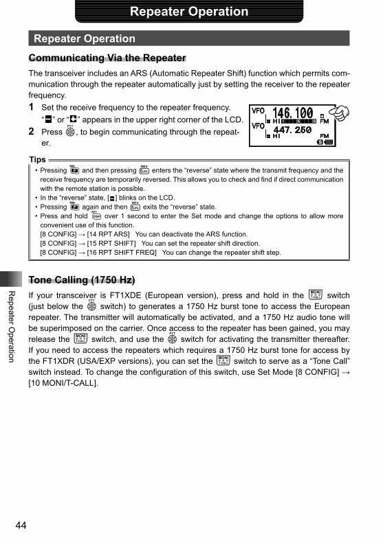
44
Repeater O
peration
Repeater Operation
Repeater OperationCommunicating Via the RepeaterThe transceiver includes an ARS (Automatic Repeater Shift) function which permits com-munication through the repeater automatically just by setting the receiver to the repeater frequency.1 Set the receive frequency to the repeater frequency. “ ” or “ ” appears in the upper right corner of the LCD.2 Press p, to begin communicating through the repeat-
er.
Tips• Pressing F and then pressing 5 enters the “reverse” state where the transmit frequency and the
receive frequency are temporarily reversed. This allows you to check and find if direct communication with the remote station is possible.
• In the “reverse” state, [ ] blinks on the LCD.• Pressing F again and then 5 exits the “reverse” state.• Press and hold M over 1 second to enter the Set mode and change the options to allow more
convenient use of this function.[8 CONFIG] → [14 RPT ARS] You can deactivate the ARS function.[8 CONFIG] → [15 RPT SHIFT] You can set the repeater shift direction.[8 CONFIG] → [16 RPT SHIFT FREQ] You can change the repeater shift step.
Tone Calling (1750 Hz)If your transceiver is FT1XDE (European version), press and hold in the T switch (just below the p switch) to generates a 1750 Hz burst tone to access the European repeater. The transmitter will automatically be activated, and a 1750 Hz audio tone will be superimposed on the carrier. Once access to the repeater has been gained, you may release the T switch, and use the p switch for activating the transmitter thereafter. If you need to access the repeaters which requires a 1750 Hz burst tone for access by the FT1XDR (USA/EXP versions), you can set the T switch to serve as a “Tone Call” switch instead. To change the configuration of this switch, use Set Mode [8 CONFIG] → [10 MONI/T-CALL].
45
Repeater O
peration
Repeater ShiftThe FT1XDR/DE has been configured, at the factory, for the repeater shifts customary in the country where it is sold. For the 144 MHz band, this usually will be 600 kHz, while the 430 MHz shift will be 1.6 MHz, 7.6 MHz, or 5 MHz (USA version).Depending on the part of the band in which you are operating, the repeater shift may be either downward (−) or upward (+), and one of these icons will appear to the right of the display frequency on the LCD when repeater shifts have been enabled.
Automatic Repeater Shift (ARS)The FT1XDR/DE Automatic Repeater Shift feature causes the appropriate repeater shift to be automatically applied whenever it is tuned into the designated repeater sub-bands. If the ARS feature does not appear to be working, you may have accidentally disabled it.To re-enable ARS: 1 Press and hold the M for over 1 second to enter the set mode.2 Turn the O to select [8 CONFIG].3 Press H.4 Turn the O to select [14 RPT ARS].5 Press H.6 Turn the O to select “ON” (to enable Automatic Repeater Shift).7 Press the p to save the new setting and exit the Set mode.
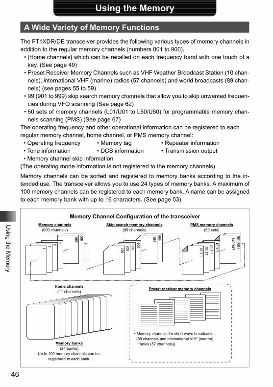
46
Using the M
emory
Using the Memory
A Wide Variety of Memory FunctionsThe FT1XDR/DE transceiver provides the following various types of memory channels in addition to the regular memory channels (numbers 001 to 900).
• [Home channels] which can be recalled on each frequency band with one touch of a key. (See page 49)
• Preset Receiver Memory Channels such as VHF Weather Broadcast Station (10 chan-nels), international VHF (marine) radios (57 channels) and world broadcasts (89 chan-nels) (see pages 55 to 59)
• 99 (901 to 999) skip search memory channels that allow you to skip unwanted frequen-cies during VFO scanning (See page 62)
• 50 sets of memory channels (L01/U01 to L50/U50) for programmable memory chan-nels scanning (PMS) (See page 67)
The operating frequency and other operational information can be registered to eachregular memory channel, home channel, or PMS memory channel:
• Operating frequency • Memory tag • Repeater information• Tone information • DCS information • Transmission output• Memory channel skip information
(The operating mode information is not registered to the memory channels)Memory channels can be sorted and registered to memory banks according to the in-tended use. The transceiver allows you to use 24 types of memory banks. A maximum of 100 memory channels can be registered to each memory bank. A name can be assigned to each memory bank with up to 16 characters. (See page 53)
Memory Channel Configuration of the transceiverMemory channels
(900 channels)
Home channels(11 channels)
Memory banks(24 banks)
Up to 100 memory channels can be registered to each bank.
Skip search memory channels(99 channels)
PMS memory channels(50 sets)
Preset receiver memory channels
• Memory channels for short wave broadcasts
(89 channels and international VHF (marine) radios (57 channels))
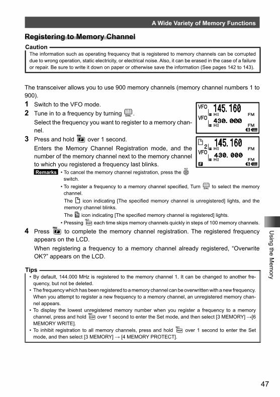
47
Using the M
emory
A Wide Variety of Memory Functions
Registering to Memory ChannelCaution
The information such as operating frequency that is registered to memory channels can be corrupted due to wrong operation, static electricity, or electrical noise. Also, it can be erased in the case of a failure or repair. Be sure to write it down on paper or otherwise save the information (See pages 142 to 143).
The transceiver allows you to use 900 memory channels (memory channel numbers 1 to 900).1 Switch to the VFO mode.2 Tune in to a frequency by turning O. Select the frequency you want to register to a memory chan-
nel.3 Press and hold F over 1 second. Enters the Memory Channel Registration mode, and the
number of the memory channel next to the memory channel to which you registered a frequency last blinks. Remarks • To cancel the memory channel registration, press the p
switch. • To register a frequency to a memory channel specified, Turn O to select the memory
channel. The ( icon indicating [The specified memory channel is unregistered] lights, and the
memory channel blinks. The ) icon indicating [The specified memory channel is registered] lights. • Pressing M each time skips memory channels quickly in steps of 100 memory channels.
4 Press F to complete the memory channel registration. The registered frequency appears on the LCD.
When registering a frequency to a memory channel already registered, “Overwrite OK?” appears on the LCD.
Tips• By default, 144.000 MHz is registered to the memory channel 1. It can be changed to another fre-
quency, but not be deleted.• The frequency which has been registered to a memory channel can be overwritten with a new frequency.
When you attempt to register a new frequency to a memory channel, an unregistered memory chan-nel appears.
• To display the lowest unregistered memory number when you register a frequency to a memory channel, press and hold M over 1 second to enter the Set mode, and then select [3 MEMORY] →[6 MEMORY WRITE].
• To inhibit registration to all memory channels, press and hold M over 1 second to enter the Set mode, and then select [3 MEMORY] → [4 MEMORY PROTECT].
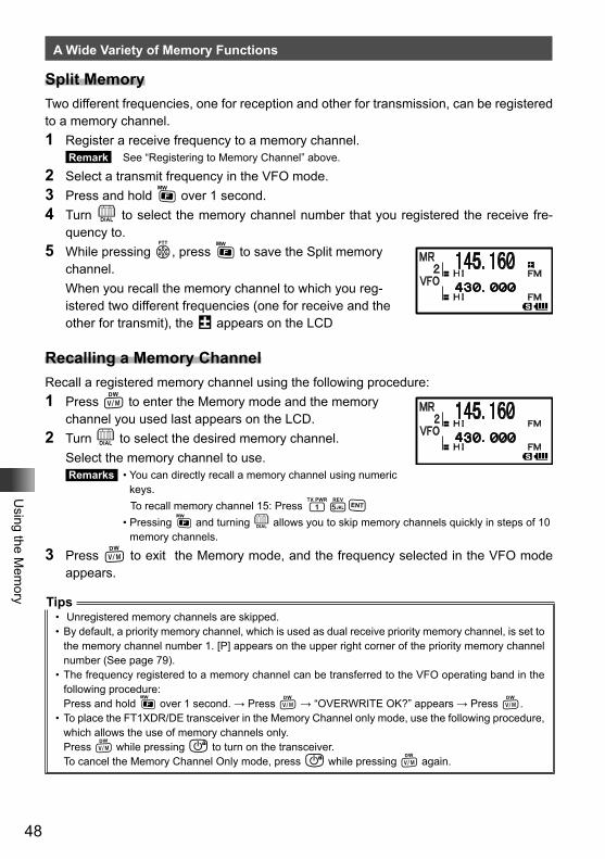
48
Using the M
emory
A Wide Variety of Memory Functions
Split MemoryTwo different frequencies, one for reception and other for transmission, can be registered to a memory channel.1 Register a receive frequency to a memory channel.
Remark See “Registering to Memory Channel” above.
2 Select a transmit frequency in the VFO mode.3 Press and hold F over 1 second.4 Turn O to select the memory channel number that you registered the receive fre-
quency to.5 While pressing p, press F to save the Split memory
channel. When you recall the memory channel to which you reg-
istered two different frequencies (one for receive and the other for transmit), the @ appears on the LCD
Recalling a Memory ChannelRecall a registered memory channel using the following procedure:1 Press V to enter the Memory mode and the memory
channel you used last appears on the LCD.2 Turn O to select the desired memory channel. Select the memory channel to use.
Remarks • You can directly recall a memory channel using numeric keys.
To recall memory channel 15: Press 15H • Pressing F and turning O allows you to skip memory channels quickly in steps of 10
memory channels.
3 Press V to exit the Memory mode, and the frequency selected in the VFO mode appears.
Tips• Unregistered memory channels are skipped.• By default, a priority memory channel, which is used as dual receive priority memory channel, is set to
the memory channel number 1. [P] appears on the upper right corner of the priority memory channel number (See page 79).
• The frequency registered to a memory channel can be transferred to the VFO operating band in the following procedure:Press and hold F over 1 second. → Press V → “OVERWRITE OK?” appears → Press V.
• To place the FT1XDR/DE transceiver in the Memory Channel only mode, use the following procedure, which allows the use of memory channels only.Press V while pressing P to turn on the transceiver.To cancel the Memory Channel Only mode, press P while pressing V again.
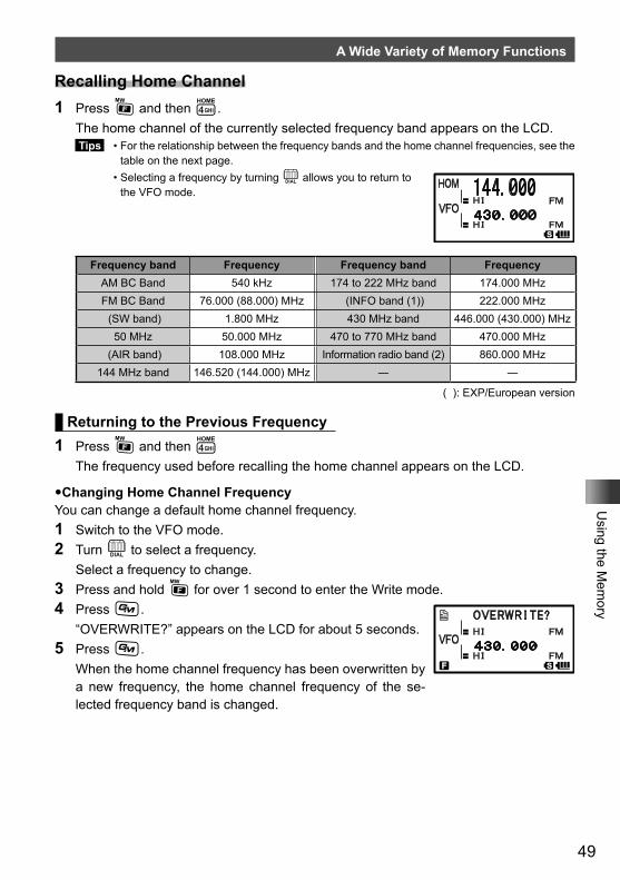
49
Using the M
emory
A Wide Variety of Memory Functions
Recalling Home Channel1 Press F and then 4. The home channel of the currently selected frequency band appears on the LCD.
Tips • For the relationship between the frequency bands and the home channel frequencies, see the table on the next page.
• Selecting a frequency by turning O allows you to return to the VFO mode.
Frequency band Frequency Frequency band FrequencyAM BC Band 540 kHz 174 to 222 MHz band 174.000 MHzFM BC Band 76.000 (88.000) MHz (INFO band (1)) 222.000 MHz (SW band) 1.800 MHz 430 MHz band 446.000 (430.000) MHz
50 MHz 50.000 MHz 470 to 770 MHz band 470.000 MHz (AIR band) 108.000 MHz Information radio band (2) 860.000 MHz
144 MHz band 146.520 (144.000) MHz ― ―
( ): EXP/European version
Returning to the Previous Frequency1 Press F and then 4 The frequency used before recalling the home channel appears on the LCD.
�Changing Home Channel FrequencyYou can change a default home channel frequency.1 Switch to the VFO mode.2 Turn O to select a frequency. Select a frequency to change.3 Press and hold F for over 1 second to enter the Write mode.4 Press D. “OVERWRITE?” appears on the LCD for about 5 seconds.5 Press D. When the home channel frequency has been overwritten by
a new frequency, the home channel frequency of the se-lected frequency band is changed.
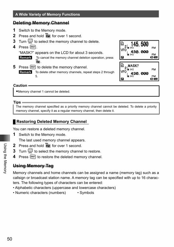
50
Using the M
emory
A Wide Variety of Memory Functions
Deleting Memory Channel1 Switch to the Memory mode.2 Press and hold F for over 1 second.3 Turn O to select the memory channel to delete.4 Press H. “MASK?” appears on the LCD for about 3 seconds.
Remark To cancel the memory channel deletion operation, press F.
5 Press H to delete the memory channel. Remark To delete other memory channels, repeat steps 2 through
5.
Caution�Memory channel 1 cannot be deleted.
TipsThe memory channel specified as a priority memory channel cannot be deleted. To delete a priority memory channel, specify it as a regular memory channel, then delete it.
Restoring Deleted Memory Channel
You can restore a deleted memory channel.1 Switch to the Memory mode. The last used memory channel appears.2 Press and hold F for over 1 second.3 Turn O to select the memory channel to restore.4 Press H to restore the deleted memory channel.
Using Memory TagMemory channels and home channels can be assigned a name (memory tag) such as a callsign or broadcast station name. A memory tag can be specified with up to 16 charac-ters. The following types of characters can be entered:• Alphabetic characters (uppercase and lowercase characters)• Numeric characters (numbers) • Symbols
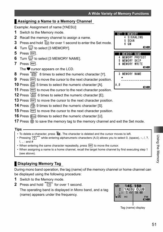
51
Using the M
emory
A Wide Variety of Memory Functions
Assigning a Name to a Memory ChannelExample: Assignment of name [YAESU]1 Switch to the Memory mode.2 Recall the memory channel to assign a name.3 Press and hold M for over 1 second to enter the Set mode.4 Turn O to select [3 MEMORY].5 Press H.6 Turn O to select [3 MEMORY NAME].7 Press H. The cursor appears on the LCD.8 Press 9 8 times to select the numeric character [Y].9 Press H to move the cursor to the next character position.10 Press 2 5 times to select the numeric character [A].11 Press H to move the cursor to the next character position.12 Press 3 6 times to select the numeric character [E].13 Press H to move the cursor to the next character position.14 Press 7 9 times to select the numeric character [S].15 Press H to move the cursor to the next character position.16 Press 8 6times to select the numeric character [U].17 Press p to save the memory tag to the memory channel and exit the Set mode.
Tips• To delete a character, press F. The character is deleted and the cursor moves to left.• Pressing 0 while entering alphanumeric characters (A,0) allows you to select 0, (space), –, /, ?,
!, ., : and # • When entering the same character repeatedly, press H to move the cursor.• When assigning a name to a home channel, recall the target home channel by first executing step 1
(see above).
Displaying Memory TagDuring mono band operation, the tag (name) of the memory channel or home channel can be displayed using the following procedure:1 Switch to the Memory mode.2 Press and hold A for over 1 second. The operating band is displayed in Mono band, and a tag
(name) appears under the frequency.
Tag (name) display
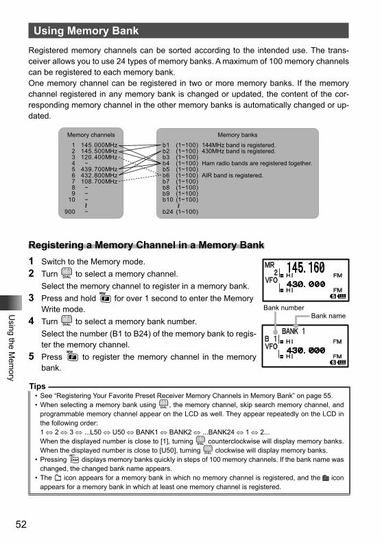
52
Using the M
emory
Using Memory BankRegistered memory channels can be sorted according to the intended use. The trans-ceiver allows you to use 24 types of memory banks. A maximum of 100 memory channels can be registered to each memory bank.One memory channel can be registered in two or more memory banks. If the memory channel registered in any memory bank is changed or updated, the content of the cor-responding memory channel in the other memory banks is automatically changed or up-dated.
Memory banks
b1b2b3b4 b5b6b7b8b9
(1~100)(1~100)(1~100)(1~100)(1~100)(1~100)(1~100)(1~100)(1~100)
b10 (1~100)
b24 (1~100)
144MHz band is registered.430MHz band is registered.
Ham radio bands are registered together.
AIR band is registered.~
Memory channels
1 145.000MHz2 145.500MHz3 120.400MHz4 −5 439.700MHz6 432.800MHz7 108.700MHz8 −9 −
10 −
900 −
~
Registering a Memory Channel in a Memory Bank1 Switch to the Memory mode.2 Turn O to select a memory channel. Select the memory channel to register in a memory bank.3 Press and hold F for over 1 second to enter the Memory
Write mode.4 Turn O to select a memory bank number. Select the number (B1 to B24) of the memory bank to regis-
ter the memory channel.5 Press F to register the memory channel in the memory
bank.
Tips• See “Registering Your Favorite Preset Receiver Memory Channels in Memory Bank” on page 55.• When selecting a memory bank using O, the memory channel, skip search memory channel, and
programmable memory channel appear on the LCD as well. They appear repeatedly on the LCD in the following order:1 ⇔ 2 ⇔ 3 ⇔ ...L50 ⇔ U50 ⇔ BANK1 ⇔ BANK2 ⇔ ...BANK24 ⇔ 1 ⇔ 2...When the displayed number is close to [1], turning O counterclockwise will display memory banks. When the displayed number is close to [U50], turning O clockwise will display memory banks.
• Pressing M displays memory banks quickly in steps of 100 memory channels. If the bank name was changed, the changed bank name appears.
• The icon appears for a memory bank in which no memory channel is registered, and the icon appears for a memory bank in which at least one memory channel is registered.
Bank numberBank name
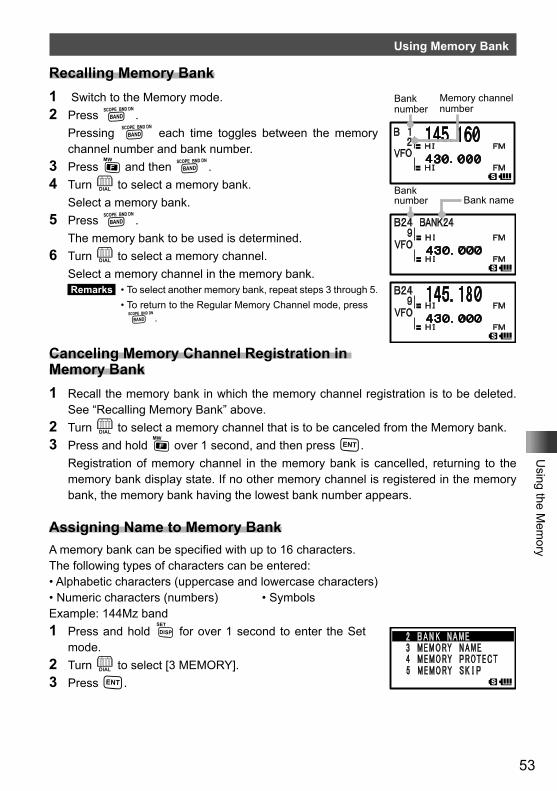
53
Using the M
emory
Using Memory Bank
Recalling Memory Bank1 Switch to the Memory mode.2 Press B. Pressing B each time toggles between the memory
channel number and bank number.3 Press F and then B.4 Turn O to select a memory bank. Select a memory bank.5 Press B. The memory bank to be used is determined.6 Turn O to select a memory channel. Select a memory channel in the memory bank.
Remarks • To select another memory bank, repeat steps 3 through 5. • To return to the Regular Memory Channel mode, press
B.
Canceling Memory Channel Registration in Memory Bank1 Recall the memory bank in which the memory channel registration is to be deleted.
See “Recalling Memory Bank” above.2 Turn O to select a memory channel that is to be canceled from the Memory bank.3 Press and hold F over 1 second, and then press H. Registration of memory channel in the memory bank is cancelled, returning to the
memory bank display state. If no other memory channel is registered in the memory bank, the memory bank having the lowest bank number appears.
Assigning Name to Memory BankA memory bank can be specified with up to 16 characters.The following types of characters can be entered:• Alphabetic characters (uppercase and lowercase characters)• Numeric characters (numbers) • SymbolsExample: 144Mz band1 Press and hold M for over 1 second to enter the Set
mode.2 Turn O to select [3 MEMORY].3 Press H.
Memory channel number
Bank number
Bank number Bank name
Bank number
Change the bank name.Enter a name (First digit)
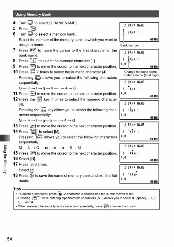
54
Using the M
emory
Using Memory Bank
4 Turn O to select [2 BANK NAME].5 Press H.6 Turn O to select a memory bank. Select the number of the memory bank to which you want to
assign a name.7 Press H to move the cursor to the first character of the
bank name.8 Press 1 to select the numeric character [1].9 Press H to move the cursor to the next character position.10 Press 4 7 times to select the numeric character [4]. Pressing 4 allows you to select the following characters
sequentially: G → H → I → g → h → i → 4 → G11 Press H to move the cursor to the next character position.12 Press the 4 key 7 times to select the numeric character
[4]. Pressing the 4 key allows you to select the following char-
acters sequentially: G → H → I → g→ h → i → 4 → G13 Press H to move the cursor to the next character position.14 Press 6 to select [M]. Pressing 6 allows you to select the following characters
sequentially: M → N → O → m → n → o → 6 → M15 Press H to move the cursor to the next character position.16 Select [H].17 Press [9] 8 times. Select [z].18 Press p to save the name of memory bank and exit the Set
mode.
Tips• To delete a character, press F. A character is deleted and the cursor moves to left.• Pressing 0 while entering alphanumeric characters (A,0) allows you to select 0, (space), –, /, ?,
!, ., : and # • When entering the same type of characters repeatedly, press H to move the cursor.
Bank number
Change the bank name.Enter a name (First digit)
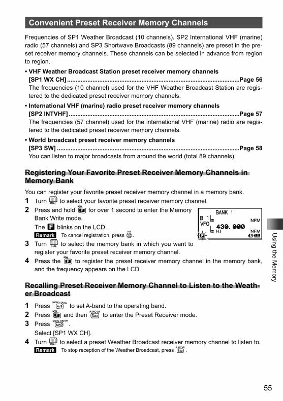
55
Using the M
emory
Convenient Preset Receiver Memory ChannelsFrequencies of SP1 Weather Broadcast (10 channels). SP2 International VHF (marine) radio (57 channels) and SP3 Shortwave Broadcasts (89 channels) are preset in the pre-set receiver memory channels. These channels can be selected in advance from region to region.• VHF Weather Broadcast Station preset receiver memory channels
[SP1 WX CH] ......................................................................................................Page 56The frequencies (10 channel) used for the VHF Weather Broadcast Station are regis-tered to the dedicated preset receiver memory channels.
• International VHF (marine) radio preset receiver memory channels [SP2 INTVHF] .....................................................................................................Page 57The frequencies (57 channel) used for the international VHF (marine) radio are regis-tered to the dedicated preset receiver memory channels.
• World broadcast preset receiver memory channels [SP3 SW] ............................................................................................................Page 58You can listen to major broadcasts from around the world (total 89 channels).
Registering Your Favorite Preset Receiver Memory Channels in Memory BankYou can register your favorite preset receiver memory channel in a memory bank.1 Turn O to select your favorite preset receiver memory channel.2 Press and hold F for over 1 second to enter the Memory
Bank Write mode. The f blinks on the LCD.
Remark To cancel registration, press p.
3 Turn O to select the memory bank in which you want to register your favorite preset receiver memory channel.
4 Press the F to register the preset receiver memory channel in the memory bank, and the frequency appears on the LCD.
Recalling Preset Receiver Memory Channel to Listen to the Weath-er Broadcast1 Press A to set A-band to the operating band.2 Press F and then 3 to enter the Preset Receiver mode.3 Press B. Select [SP1 WX CH].4 Turn O to select a preset Weather Broadcast receiver memory channel to listen to.
Remark To stop reception of the Weather Broadcast, press 3.
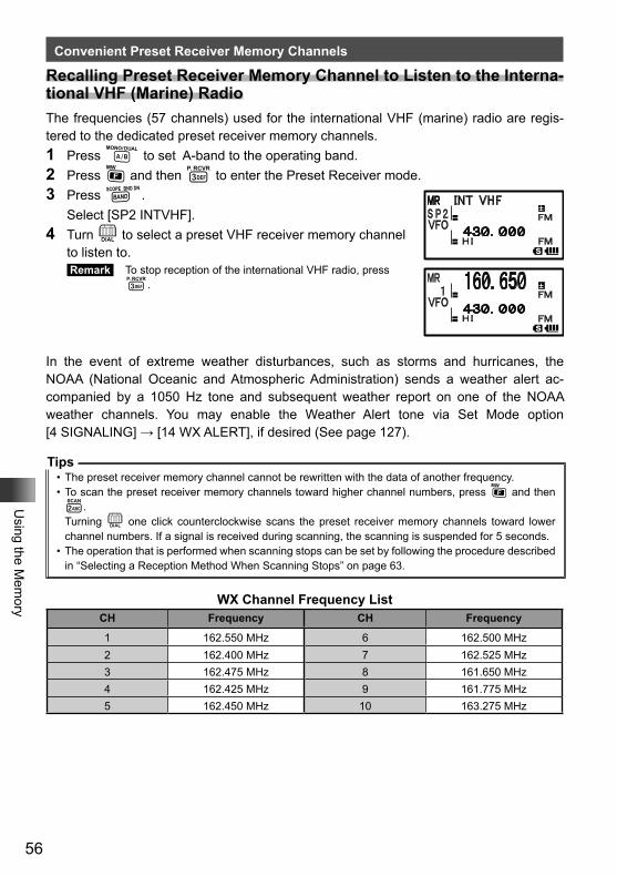
56
Using the M
emory
Convenient Preset Receiver Memory Channels
Recalling Preset Receiver Memory Channel to Listen to the Interna-tional VHF (Marine) RadioThe frequencies (57 channels) used for the international VHF (marine) radio are regis-tered to the dedicated preset receiver memory channels.1 Press A to set A-band to the operating band.2 Press F and then 3 to enter the Preset Receiver mode.3 Press B. Select [SP2 INTVHF].4 Turn O to select a preset VHF receiver memory channel
to listen to. Remark To stop reception of the international VHF radio, press
3.
In the event of extreme weather disturbances, such as storms and hurricanes, the NOAA (National Oceanic and Atmospheric Administration) sends a weather alert ac-companied by a 1050 Hz tone and subsequent weather report on one of the NOAA weather channels. You may enable the Weather Alert tone via Set Mode option [4 SIGNALING] → [14 WX ALERT], if desired (See page 127).
Tips• The preset receiver memory channel cannot be rewritten with the data of another frequency.• To scan the preset receiver memory channels toward higher channel numbers, press F and then 2.Turning O one click counterclockwise scans the preset receiver memory channels toward lower channel numbers. If a signal is received during scanning, the scanning is suspended for 5 seconds.
• The operation that is performed when scanning stops can be set by following the procedure described in “Selecting a Reception Method When Scanning Stops” on page 63.
WX Channel Frequency ListCH Frequency CH Frequency
1 162.550 MHz 6 162.500 MHz2 162.400 MHz 7 162.525 MHz3 162.475 MHz 8 161.650 MHz4 162.425 MHz 9 161.775 MHz5 162.450 MHz 10 163.275 MHz
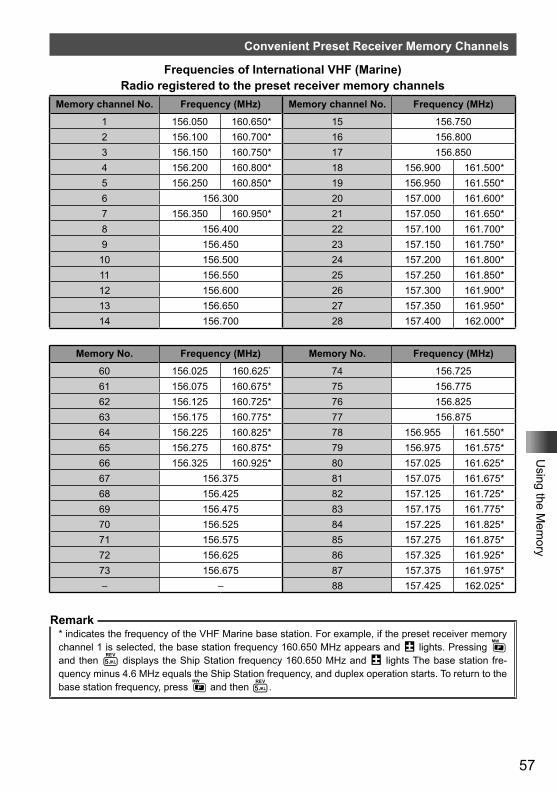
57
Using the M
emory
Convenient Preset Receiver Memory Channels
Frequencies of International VHF (Marine) Radio registered to the preset receiver memory channels
Memory channel No. Frequency (MHz) Memory channel No. Frequency (MHz)
1 156.050 160.650* 15 156.7502 156.100 160.700* 16 156.8003 156.150 160.750* 17 156.8504 156.200 160.800* 18 156.900 161.500*5 156.250 160.850* 19 156.950 161.550*6 156.300 20 157.000 161.600*7 156.350 160.950* 21 157.050 161.650*8 156.400 22 157.100 161.700*9 156.450 23 157.150 161.750*10 156.500 24 157.200 161.800*11 156.550 25 157.250 161.850*12 156.600 26 157.300 161.900*13 156.650 27 157.350 161.950*14 156.700 28 157.400 162.000*
Memory No. Frequency (MHz) Memory No. Frequency (MHz)
60 156.025 160.625* 74 156.72561 156.075 160.675* 75 156.77562 156.125 160.725* 76 156.82563 156.175 160.775* 77 156.87564 156.225 160.825* 78 156.955 161.550*65 156.275 160.875* 79 156.975 161.575*66 156.325 160.925* 80 157.025 161.625*67 156.375 81 157.075 161.675*68 156.425 82 157.125 161.725*69 156.475 83 157.175 161.775*70 156.525 84 157.225 161.825*71 156.575 85 157.275 161.875*72 156.625 86 157.325 161.925*73 156.675 87 157.375 161.975*– – 88 157.425 162.025*
Remark* indicates the frequency of the VHF Marine base station. For example, if the preset receiver memory channel 1 is selected, the base station frequency 160.650 MHz appears and @ lights. Pressing F and then 5 displays the Ship Station frequency 160.650 MHz and @ lights The base station fre-quency minus 4.6 MHz equals the Ship Station frequency, and duplex operation starts. To return to the base station frequency, press F and then 5.
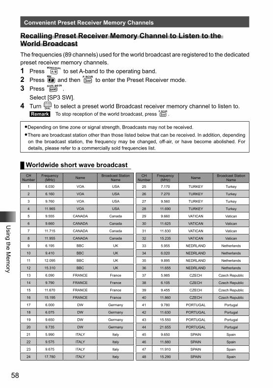
58
Using the M
emory
Convenient Preset Receiver Memory Channels
Worldwide short wave broadcastCH
NumberFrequency
(MHz) Name Broadcast Station Name
1 6.030 VOA USA
2 6.160 VOA USA
3 9.760 VOA USA
4 11.965 VOA USA
5 9.555 CANADA Canada
6 9.660 CANADA Canada
7 11.715 CANADA Canada
8 11.955 CANADA Canada
9 6.195 BBC UK
10 9.410 BBC UK
11 12.095 BBC UK
12 15.310 BBC UK
13 6.090 FRANCE France
14 9.790 FRANCE France
15 11.670 FRANCE France
16 15.195 FRANCE France
17 6.000 DW Germany
18 6.075 DW Germany
19 9.650 DW Germany
20 9.735 DW Germany
21 5.990 ITALY Italy
22 9.575 ITALY Italy
23 9.675 ITALY Italy
24 17.780 ITALY Italy
CH Number
Frequency (MHz) Name Broadcast Station
Name
25 7.170 TURKEY Turkey
26 7.270 TURKEY Turkey
27 9.560 TURKEY Turkey
28 11.690 TURKEY Turkey
29 9.660 VATICAN Vatican
30 11.625 VATICAN Vatican
31 11.830 VATICAN Vatican
32 15.235 VATICAN Vatican
33 5.955 NEDRLAND Netherlands
34 6.020 NEDRLAND Netherlands
35 9.895 NEDRLAND Netherlands
36 11.655 NEDRLAND Netherlands
37 5.985 CZECH Czech Republic
38 6.105 CZECH Czech Republic
39 9.455 CZECH Czech Republic
40 11.860 CZECH Czech Republic
41 9.780 PORTUGAL Portugal
42 11.630 PORTUGAL Portugal
43 15.550 PORTUGAL Portugal
44 21.655 PORTUGAL Portugal
45 9.650 SPAIN Spain
46 11.880 SPAIN Spain
47 11.910 SPAIN Spain
48 15.290 SPAIN Spain
Recalling Preset Receiver Memory Channel to Listen to the World BroadcastThe frequencies (89 channels) used for the world broadcast are registered to the dedicated preset receiver memory channels.1 Press A to set A-band to the operating band.2 Press F and then 3 to enter the Preset Receiver mode.3 Press B. Select [SP3 SW].4 Turn O to select a preset world Broadcast receiver memory channel to listen to.
Remark To stop reception of the world broadcast, press 3.
�Depending on time zone or signal strength, Broadcasts may not be received.�There are broadcast station other than those listed below that can be received. In addition, depending
on the broadcast station, the frequency may be changed, off-air, or have become abolished. For details, please refer to a commercially sold frequencies list.
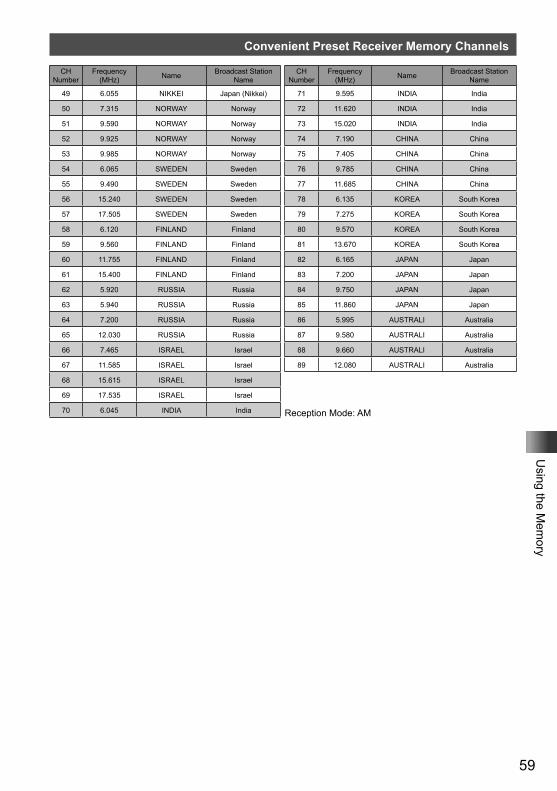
59
Using the M
emory
Convenient Preset Receiver Memory Channels
CH Number
Frequency (MHz) Name Broadcast Station
Name
49 6.055 NIKKEI Japan (Nikkei)
50 7.315 NORWAY Norway
51 9.590 NORWAY Norway
52 9.925 NORWAY Norway
53 9.985 NORWAY Norway
54 6.065 SWEDEN Sweden
55 9.490 SWEDEN Sweden
56 15.240 SWEDEN Sweden
57 17.505 SWEDEN Sweden
58 6.120 FINLAND Finland
59 9.560 FINLAND Finland
60 11.755 FINLAND Finland
61 15.400 FINLAND Finland
62 5.920 RUSSIA Russia
63 5.940 RUSSIA Russia
64 7.200 RUSSIA Russia
65 12.030 RUSSIA Russia
66 7.465 ISRAEL Israel
67 11.585 ISRAEL Israel
68 15.615 ISRAEL Israel
69 17.535 ISRAEL Israel
70 6.045 INDIA India
CH Number
Frequency (MHz) Name Broadcast Station
Name
71 9.595 INDIA India
72 11.620 INDIA India
73 15.020 INDIA India
74 7.190 CHINA China
75 7.405 CHINA China
76 9.785 CHINA China
77 11.685 CHINA China
78 6.135 KOREA South Korea
79 7.275 KOREA South Korea
80 9.570 KOREA South Korea
81 13.670 KOREA South Korea
82 6.165 JAPAN Japan
83 7.200 JAPAN Japan
84 9.750 JAPAN Japan
85 11.860 JAPAN Japan
86 5.995 AUSTRALI Australia
87 9.580 AUSTRALI Australia
88 9.660 AUSTRALI Australia
89 12.080 AUSTRALI Australia
Reception Mode: AM
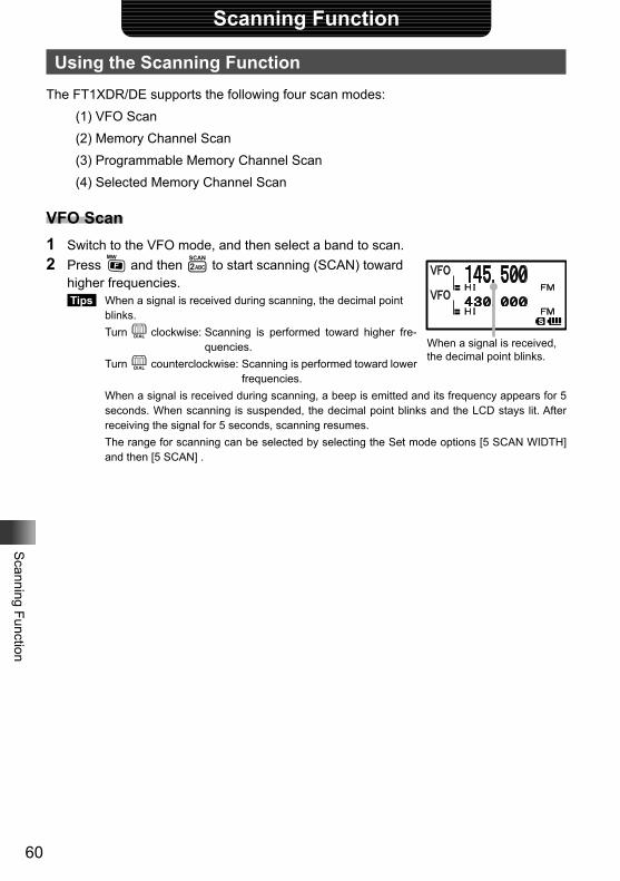
60
Scanning Function
Scanning Function
Using the Scanning FunctionThe FT1XDR/DE supports the following four scan modes:
(1) VFO Scan(2) Memory Channel Scan(3) Programmable Memory Channel Scan(4) Selected Memory Channel Scan
VFO Scan1 Switch to the VFO mode, and then select a band to scan.2 Press F and then 2 to start scanning (SCAN) toward
higher frequencies. Tips When a signal is received during scanning, the decimal point
blinks. Turn O clockwise: Scanning is performed toward higher fre-
quencies. Turn O counterclockwise: Scanning is performed toward lower
frequencies. When a signal is received during scanning, a beep is emitted and its frequency appears for 5
seconds. When scanning is suspended, the decimal point blinks and the LCD stays lit. After receiving the signal for 5 seconds, scanning resumes.
The range for scanning can be selected by selecting the Set mode options [5 SCAN WIDTH] and then [5 SCAN] .
When a signal is received, the decimal point blinks.
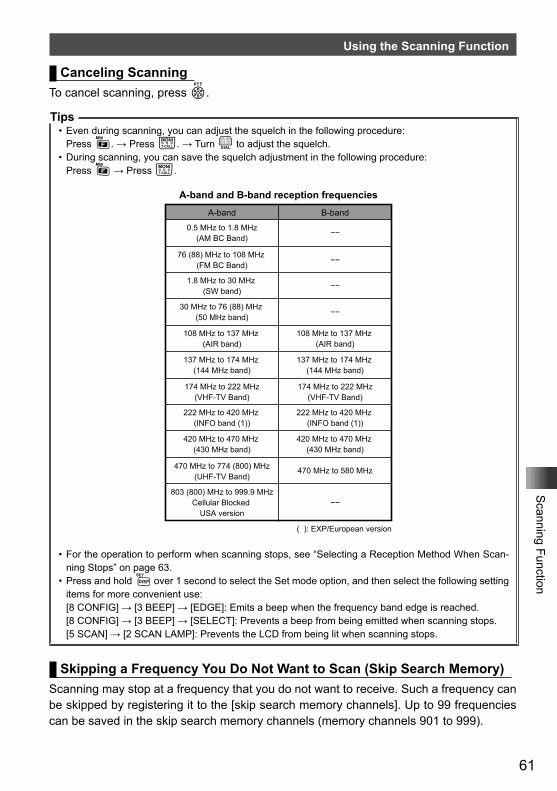
61
Scanning Function
Using the Scanning Function
Canceling ScanningTo cancel scanning, press p.
Tips• Even during scanning, you can adjust the squelch in the following procedure:
Press F. → Press T. → Turn O to adjust the squelch.• During scanning, you can save the squelch adjustment in the following procedure:
Press F → Press T.
A-band and B-band reception frequencies
A-band B-band
0.5 MHz to 1.8 MHz(AM BC Band)
30 MHz to 76 (88) MHz (50 MHz band)
108 MHz to 137 MHz (AIR band)
137 MHz to 174 MHz (144 MHz band)
174 MHz to 222 MHz(VHF-TV Band)
222 MHz to 420 MHz (INFO band (1))
420 MHz to 470 MHz (430 MHz band)
470 MHz to 774 (800) MHz(UHF-TV Band)
803 (800) MHz to 999.9 MHzCellular Blocked
USA version
108 MHz to 137 MHz (AIR band)
137 MHz to 174 MHz (144 MHz band)
174 MHz to 222 MHz(VHF-TV Band)
222 MHz to 420 MHz (INFO band (1))
420 MHz to 470 MHz (430 MHz band)
470 MHz to 580 MHz
( ): EXP/European version
−−
−−
−−
1.8 MHz to 30 MHz (SW band)
−−
76 (88) MHz to 108 MHz (FM BC Band)
−−
• For the operation to perform when scanning stops, see “Selecting a Reception Method When Scan-ning Stops” on page 63.
• Press and hold M over 1 second to select the Set mode option, and then select the following setting items for more convenient use:[8 CONFIG] → [3 BEEP] → [EDGE]: Emits a beep when the frequency band edge is reached.[8 CONFIG] → [3 BEEP] → [SELECT]: Prevents a beep from being emitted when scanning stops.[5 SCAN] → [2 SCAN LAMP]: Prevents the LCD from being lit when scanning stops.
Skipping a Frequency You Do Not Want to Scan (Skip Search Memory)Scanning may stop at a frequency that you do not want to receive. Such a frequency can be skipped by registering it to the [skip search memory channels]. Up to 99 frequencies can be saved in the skip search memory channels (memory channels 901 to 999).
62
Scanning Function
Using the Scanning Function
Specifying the Frequency You Do Not Want to Scan1 Start VFO scanning. Start VFO scanning with reference to [VFO Scanning] on page 60.2 When scanning stops at a frequency you do not want to receive, press and hold F
for over 1 second. The number of the next unregistered skip search memory channel will blink.
Tips Turning O allows you to specify other skip search memory channels.3 Press F to save (register) the frequency to the skip search memory channel, and
resume scanning. Tips • You can register a frequency you do not want to receive to a skip search memory channel by
using the following procedure in advance: 1 In the VFO mode, tune in to the frequency you do not want to scan. 2 Press and hold F for over 1 second. 3 Turn O to select a skip search memory channel. 4 Press F to save (register) the frequency to the skip search memory channel. • To stop scanning, press p.
Deleting a Frequency Registered to the Skip Search Memory ChannelThe frequency registered to the skip search memory channel can be deleted in the follow-ing procedure. After it is deleted the frequency is scanned.1 Switch to the Memory mode.2 Press and hold F for over 1 second.3 Turn O to select a skip search memory channel from which you wish to delete the
registered frequency. Select the skip search memory channel (901-999) from which the registered frequen-
cy is to be deleted. When selecting a skip search memory channel number, pressing M allows you to
skip memory channel numbers in steps of 100 memory channel numbers.4 Press H. [DELETE OK?] appears on the LCD.5 Press H to delete the registered frequency from the skip search memory channel.
Tip To delete another frequency from the skip search memory channel, repeat steps 2 through 4.
Tips• Restoring the Frequency Deleted from the Skip Search Memory Channel
If you have not specified a new frequency for the same memory channel, you can restore the deleted frequency by repeating steps 1 through 4.
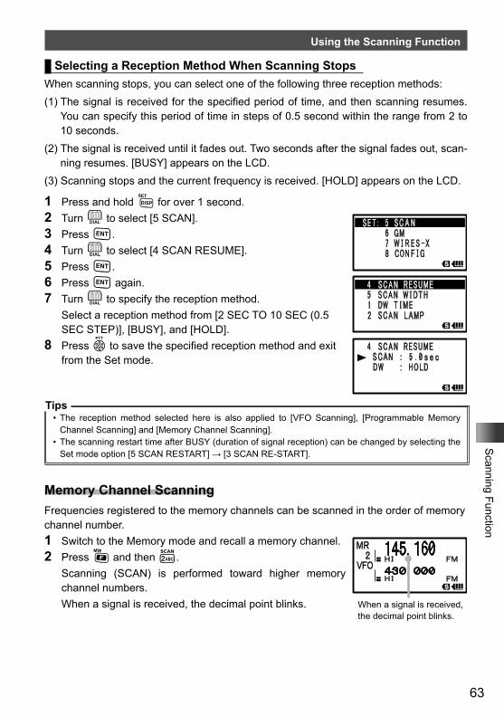
63
Scanning Function
Using the Scanning Function
Selecting a Reception Method When Scanning StopsWhen scanning stops, you can select one of the following three reception methods:(1) The signal is received for the specified period of time, and then scanning resumes.
You can specify this period of time in steps of 0.5 second within the range from 2 to 10 seconds.
(2) The signal is received until it fades out. Two seconds after the signal fades out, scan-ning resumes. [BUSY] appears on the LCD.
(3) Scanning stops and the current frequency is received. [HOLD] appears on the LCD.
1 Press and hold M for over 1 second.2 Turn O to select [5 SCAN].3 Press H.4 Turn O to select [4 SCAN RESUME].5 Press H.6 Press H again.7 Turn O to specify the reception method. Select a reception method from [2 SEC TO 10 SEC (0.5
SEC STEP)], [BUSY], and [HOLD].8 Press p to save the specified reception method and exit
from the Set mode.
Tips• The reception method selected here is also applied to [VFO Scanning], [Programmable Memory
Channel Scanning] and [Memory Channel Scanning].• The scanning restart time after BUSY (duration of signal reception) can be changed by selecting the
Set mode option [5 SCAN RESTART] → [3 SCAN RE-START].
Memory Channel ScanningFrequencies registered to the memory channels can be scanned in the order of memory channel number.1 Switch to the Memory mode and recall a memory channel.2 Press F and then 2. Scanning (SCAN) is performed toward higher memory
channel numbers. When a signal is received, the decimal point blinks. When a signal is received,
the decimal point blinks.
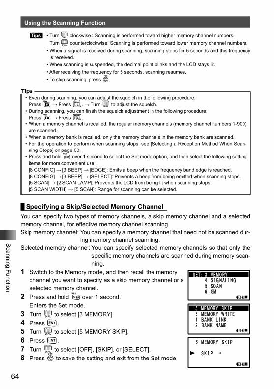
64
Scanning Function
Using the Scanning Function
Tips • Turn O clockwise.: Scanning is performed toward higher memory channel numbers. Turn O counterclockwise: Scanning is performed toward lower memory channel numbers. • When a signal is received during scanning, scanning stops for 5 seconds and this frequency
is received. • When scanning is suspended, the decimal point blinks and the LCD stays lit. • After receiving the frequency for 5 seconds, scanning resumes. • To stop scanning, press p.
Tips• Even during scanning, you can adjust the squelch in the following procedure:
Press F → Press T. → Turn O to adjust the squelch.• During scanning, you can finish the squelch adjustment in the following procedure:
Press F → Press T.• When a memory channel is recalled, the regular memory channels (memory channel numbers 1-900)
are scanned.• When a memory bank is recalled, only the memory channels in the memory bank are scanned.• For the operation to perform when scanning stops, see [Selecting a Reception Method When Scan-
ning Stops] on page 63.• Press and hold M over 1 second to select the Set mode option, and then select the following setting
items for more convenient use:[8 CONFIG] → [3 BEEP] → [EDGE]: Emits a beep when the frequency band edge is reached.[8 CONFIG] → [3 BEEP] → [SELECT]: Prevents a beep from being emitted when scanning stops.[5 SCAN] → [2 SCAN LAMP]: Prevents the LCD from being lit when scanning stops.[5 SCAN WIDTH] → [5 SCAN]: Range for scanning can be selected.
Specifying a Skip/Selected Memory ChannelYou can specify two types of memory channels, a skip memory channel and a selected memory channel, for effective memory channel scanning.Skip memory channel: You can specify a memory channel that need not be scanned dur-
ing memory channel scanning.Selected memory channel: You can specify selected memory channels so that only the
specific memory channels are scanned during memory scan-ning.
1 Switch to the Memory mode, and then recall the memory channel you want to specify as a skip memory channel or a selected memory channel.
2 Press and hold M over 1 second. Enters the Set mode.3 Turn O to select [3 MEMORY].4 Press H.5 Turn O to select [5 MEMORY SKIP].6 Press H.7 Turn O to select [OFF], [SKIP], or [SELECT].8 Press p to save the setting and exit from the Set mode.
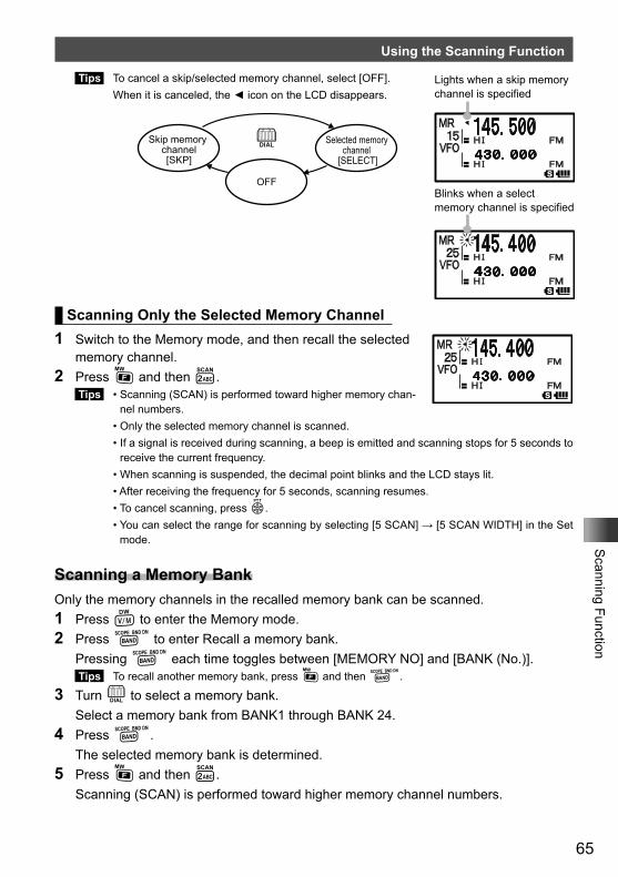
65
Scanning Function
Using the Scanning Function
Tips To cancel a skip/selected memory channel, select [OFF]. When it is canceled, the ◄ icon on the LCD disappears.
Scanning Only the Selected Memory Channel1 Switch to the Memory mode, and then recall the selected
memory channel.2 Press F and then 2.
Tips • Scanning (SCAN) is performed toward higher memory chan-nel numbers.
• Only the selected memory channel is scanned. • If a signal is received during scanning, a beep is emitted and scanning stops for 5 seconds to
receive the current frequency. • When scanning is suspended, the decimal point blinks and the LCD stays lit. • After receiving the frequency for 5 seconds, scanning resumes. • To cancel scanning, press p. • You can select the range for scanning by selecting [5 SCAN] → [5 SCAN WIDTH] in the Set
mode.
Scanning a Memory BankOnly the memory channels in the recalled memory bank can be scanned.1 Press V to enter the Memory mode. 2 Press B to enter Recall a memory bank. Pressing B each time toggles between [MEMORY NO] and [BANK (No.)].
Tips To recall another memory bank, press F and then B.
3 Turn O to select a memory bank. Select a memory bank from BANK1 through BANK 24.4 Press B. The selected memory bank is determined.5 Press F and then 2. Scanning (SCAN) is performed toward higher memory channel numbers.
Lights when a skip memory channel is specified
Blinks when a select memory channel is specified
Skip memory channel[SKP]
Selected memory channel
[SELECT]
O
OFF
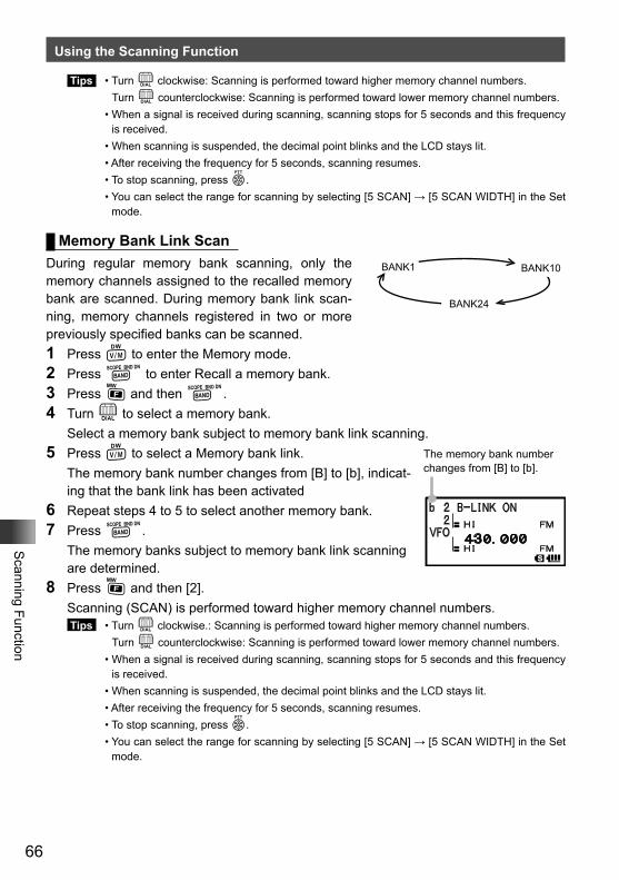
66
Scanning Function
Using the Scanning Function
Tips • Turn O clockwise: Scanning is performed toward higher memory channel numbers. Turn O counterclockwise: Scanning is performed toward lower memory channel numbers. • When a signal is received during scanning, scanning stops for 5 seconds and this frequency
is received. • When scanning is suspended, the decimal point blinks and the LCD stays lit. • After receiving the frequency for 5 seconds, scanning resumes. • To stop scanning, press p. • You can select the range for scanning by selecting [5 SCAN] → [5 SCAN WIDTH] in the Set
mode.
Memory Bank Link ScanDuring regular memory bank scanning, only the memory channels assigned to the recalled memory bank are scanned. During memory bank link scan-ning, memory channels registered in two or more previously specified banks can be scanned.1 Press V to enter the Memory mode. 2 Press B to enter Recall a memory bank.3 Press F and then B.4 Turn O to select a memory bank. Select a memory bank subject to memory bank link scanning.5 Press V to select a Memory bank link. The memory bank number changes from [B] to [b], indicat-
ing that the bank link has been activated6 Repeat steps 4 to 5 to select another memory bank.7 Press B. The memory banks subject to memory bank link scanning
are determined.8 Press F and then [2]. Scanning (SCAN) is performed toward higher memory channel numbers.
Tips • Turn O clockwise.: Scanning is performed toward higher memory channel numbers. Turn O counterclockwise: Scanning is performed toward lower memory channel numbers. • When a signal is received during scanning, scanning stops for 5 seconds and this frequency
is received. • When scanning is suspended, the decimal point blinks and the LCD stays lit. • After receiving the frequency for 5 seconds, scanning resumes. • To stop scanning, press p. • You can select the range for scanning by selecting [5 SCAN] → [5 SCAN WIDTH] in the Set
mode.
BANK1 BANK10
BANK24
The memory bank number changes from [B] to [b].
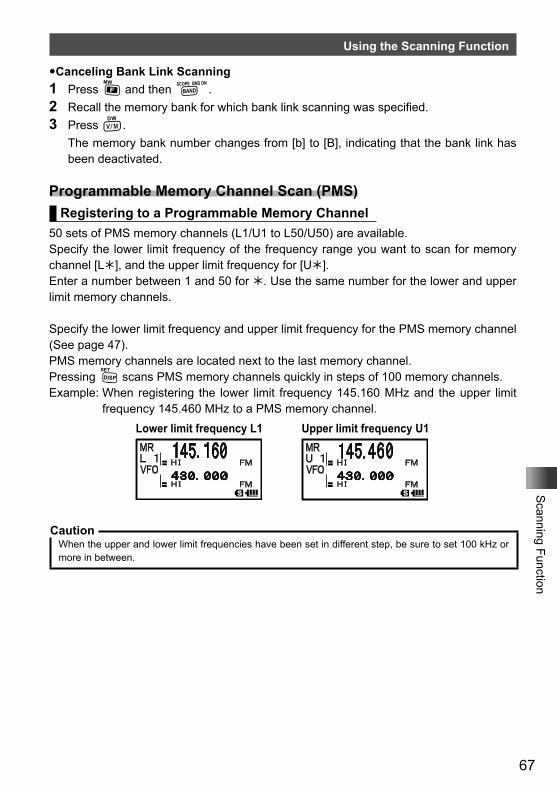
67
Scanning Function
Using the Scanning Function
�Canceling Bank Link Scanning1 Press F and then B.2 Recall the memory bank for which bank link scanning was specified.3 Press V. The memory bank number changes from [b] to [B], indicating that the bank link has
been deactivated.
Programmable Memory Channel Scan (PMS)Registering to a Programmable Memory Channel
50 sets of PMS memory channels (L1/U1 to L50/U50) are available.Specify the lower limit frequency of the frequency range you want to scan for memory channel [L], and the upper limit frequency for [U].Enter a number between 1 and 50 for . Use the same number for the lower and upper limit memory channels.
Specify the lower limit frequency and upper limit frequency for the PMS memory channel (See page 47).PMS memory channels are located next to the last memory channel. Pressing M scans PMS memory channels quickly in steps of 100 memory channels.Example: When registering the lower limit frequency 145.160 MHz and the upper limit
frequency 145.460 MHz to a PMS memory channel.Lower limit frequency L1 Upper limit frequency U1
CautionWhen the upper and lower limit frequencies have been set in different step, be sure to set 100 kHz or more in between.
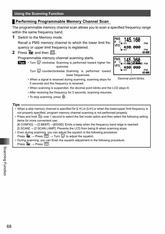
68
Scanning Function
Using the Scanning Function
Performing Programmable Memory Channel ScanThe programmable memory channel scan allows you to scan a specified frequency range within the same frequency band.1 Switch to the Memory mode. Recall a PMS memory channel to which the lower limit fre-
quency or upper limit frequency is registered.2 Press F and then 2. Programmable memory channel scanning starts.
Tips • Turn O clockwise: Scanning is performed toward higher fre-quencies.
Turn O counterclockwise: Scanning is performed toward lower frequencies.
• When a signal is received during scanning, scanning stops for 5 seconds and this frequency is received.
• When scanning is suspended, the decimal point blinks and the LCD stays lit. • After receiving the frequency for 5 seconds, scanning resumes. • To stop scanning, press p.
Tips• When a skip memory channel is specified for [L] or [U] or when the lower/upper limit frequency is
not properly specified, program memory channel scanning is not performed properly.• Press and hold M over 1 second to select the Set mode option and then select the following setting
items for more convenient use:[8 CONFIG] → [3 BEEP] →[EDGE]: Emits a beep when the frequency band edge is reached.[5 SCAN] → [2 SCAN LAMP]: Prevents the LCD from being lit when scanning stops.
• Even during scanning, you can adjust the squelch in the following procedure:Press F → Press T → Turn O to adjust the squelch.
• During scanning, you can finish the squelch adjustment in the following procedure:Press F → Press T.
Decimal point blinks.
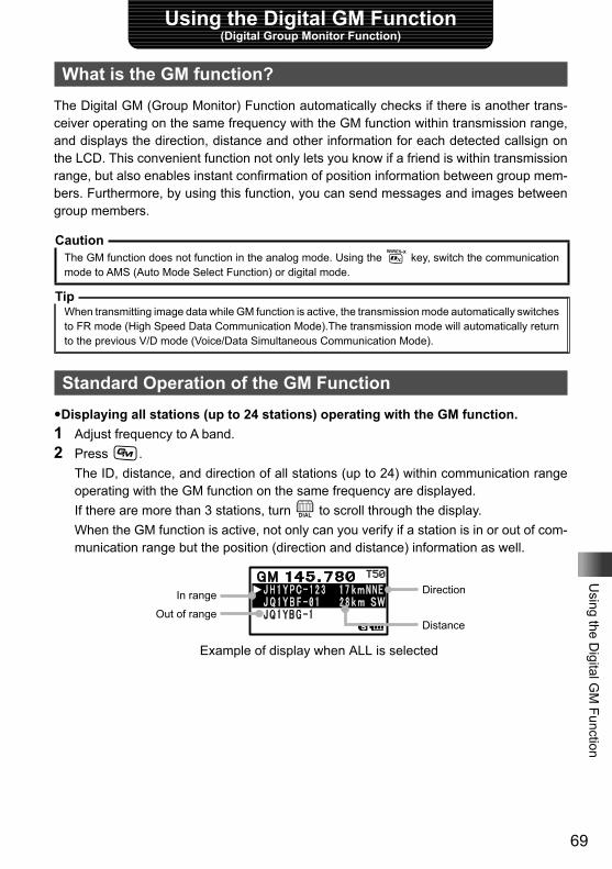
69
Using the D
igital GM
FunctionUsing the Digital GM Function
(Digital Group Monitor Function)
What is the GM function?The Digital GM (Group Monitor) Function automatically checks if there is another trans-ceiver operating on the same frequency with the GM function within transmission range, and displays the direction, distance and other information for each detected callsign on the LCD. This convenient function not only lets you know if a friend is within transmission range, but also enables instant confirmation of position information between group mem-bers. Furthermore, by using this function, you can send messages and images between group members.
CautionThe GM function does not function in the analog mode. Using the % key, switch the communication mode to AMS (Auto Mode Select Function) or digital mode.
TipWhen transmitting image data while GM function is active, the transmission mode automatically switches to FR mode (High Speed Data Communication Mode).The transmission mode will automatically return to the previous V/D mode (Voice/Data Simultaneous Communication Mode).
Standard Operation of the GM Function�Displaying all stations (up to 24 stations) operating with the GM function.1 Adjust frequency to A band.2 Press D. The ID, distance, and direction of all stations (up to 24) within communication range
operating with the GM function on the same frequency are displayed. If there are more than 3 stations, turn O to scroll through the display. When the GM function is active, not only can you verify if a station is in or out of com-
munication range but the position (direction and distance) information as well.
DirectionIn range
Out of rangeDistance
Example of display when ALL is selected
70
Using the D
igital GM
Function
Standard Operation of the GM Function
�Turning the GPS Function OFFPress D.The GM function is deactivated and the transceiver returns to the state previous to when GM function was activated.
TipWith the GM function, data such as messages and images can be transmitted between members.For details, refer to the GM function instruction manual (please download it from our company website).
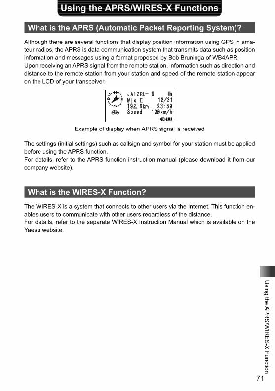
71
Using the A
PR
S/W
IRE
S-X
FunctionUsing the APRS/WIRES-X Functions
What is the APRS (Automatic Packet Reporting System)?Although there are several functions that display position information using GPS in ama-teur radios, the APRS is data communication system that transmits data such as position information and messages using a format proposed by Bob Bruninga of WB4APR.Upon receiving an APRS signal from the remote station, information such as direction and distance to the remote station from your station and speed of the remote station appear on the LCD of your transceiver.
Example of display when APRS signal is received
The settings (initial settings) such as callsign and symbol for your station must be applied before using the APRS function.For details, refer to the APRS function instruction manual (please download it from our company website).
What is the WIRES-X Function?The WIRES-X is a system that connects to other users via the Internet. This function en-ables users to communicate with other users regardless of the distance.For details, refer to the separate WIRES-X Instruction Manual which is available on the Yaesu website.
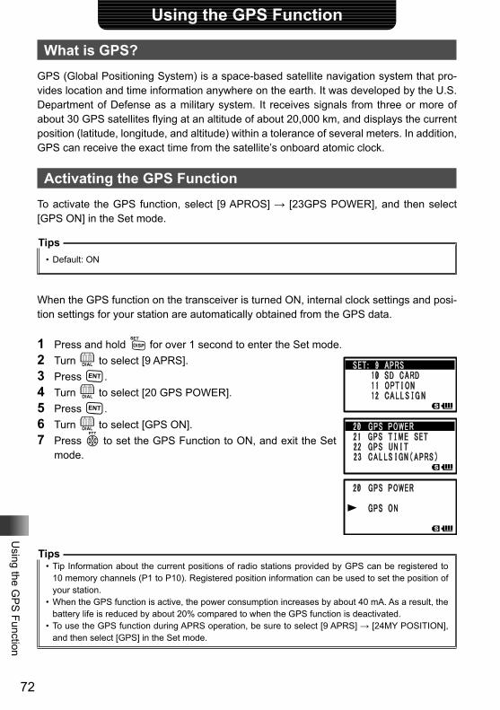
72
Using the G
PS
Function
Using the GPS Function
What is GPS?GPS (Global Positioning System) is a space-based satellite navigation system that pro-vides location and time information anywhere on the earth. It was developed by the U.S. Department of Defense as a military system. It receives signals from three or more of about 30 GPS satellites flying at an altitude of about 20,000 km, and displays the current position (latitude, longitude, and altitude) within a tolerance of several meters. In addition, GPS can receive the exact time from the satellite’s onboard atomic clock.
Activating the GPS FunctionTo activate the GPS function, select [9 APROS] → [23GPS POWER], and then select [GPS ON] in the Set mode.
Tips• Default: ON
When the GPS function on the transceiver is turned ON, internal clock settings and posi-tion settings for your station are automatically obtained from the GPS data.
1 Press and hold M for over 1 second to enter the Set mode.2 Turn O to select [9 APRS].3 Press H.4 Turn O to select [20 GPS POWER].5 Press H.6 Turn O to select [GPS ON].7 Press p to set the GPS Function to ON, and exit the Set
mode.
Tips• Tip Information about the current positions of radio stations provided by GPS can be registered to
10 memory channels (P1 to P10). Registered position information can be used to set the position of your station.
• When the GPS function is active, the power consumption increases by about 40 mA. As a result, the battery life is reduced by about 20% compared to when the GPS function is deactivated.
• To use the GPS function during APRS operation, be sure to select [9 APRS] → [24MY POSITION], and then select [GPS] in the Set mode.
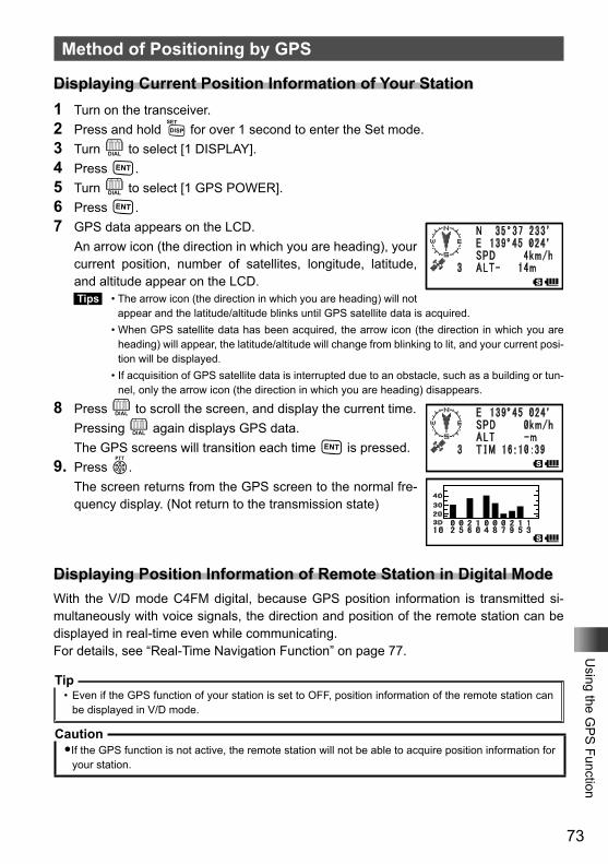
73
Using the G
PS
Function
Method of Positioning by GPS
Displaying Current Position Information of Your Station1 Turn on the transceiver.2 Press and hold M for over 1 second to enter the Set mode.3 Turn O to select [1 DISPLAY].4 Press H.5 Turn O to select [1 GPS POWER].6 Press H.7 GPS data appears on the LCD. An arrow icon (the direction in which you are heading), your
current position, number of satellites, longitude, latitude, and altitude appear on the LCD. Tips • The arrow icon (the direction in which you are heading) will not
appear and the latitude/altitude blinks until GPS satellite data is acquired. • When GPS satellite data has been acquired, the arrow icon (the direction in which you are
heading) will appear, the latitude/altitude will change from blinking to lit, and your current posi-tion will be displayed.
• If acquisition of GPS satellite data is interrupted due to an obstacle, such as a building or tun-nel, only the arrow icon (the direction in which you are heading) disappears.
8 Press O to scroll the screen, and display the current time. Pressing O again displays GPS data. The GPS screens will transition each time H is pressed.9. Press p. The screen returns from the GPS screen to the normal fre-
quency display. (Not return to the transmission state)
Displaying Position Information of Remote Station in Digital ModeWith the V/D mode C4FM digital, because GPS position information is transmitted si-multaneously with voice signals, the direction and position of the remote station can be displayed in real-time even while communicating.For details, see “Real-Time Navigation Function” on page 77.
Tip• Even if the GPS function of your station is set to OFF, position information of the remote station can
be displayed in V/D mode.
Caution�If the GPS function is not active, the remote station will not be able to acquire position information for
your station.
74
Using the G
PS
Function
Method of Positioning by GPS
About Positioning by GPS“Positioning” refers to calculation of your current position from the satellite orbit information and radio propagation time. At least three satellites need to be acquired for successful positioning. If positioning fails, move away from buildings as far as possible and stand in an area with open sky.
● About errorsA positioning error by several hundred meters can occur due to the environmental conditions. Under favorable conditions, positioning can be performed successfully using only three satellites. However, under the following poor conditions, the positioning accuracy can decrease or positioning can fail.- Between tall buildings- Narrow paths between buildings- Indoors or in close vicinity to large buildings- Beneath bridges or high-voltage lines- Between trees such as in forests or woods- Inside tunnel or underground- Usage behind heat reflective glass- Areas with strong magnetic fields.
● Searching for satellites when using the GPS function for the first time each day
When you use the GPS function for the first time after purchase or the first time in the day, a few minutes are required to search for satellites. Also, when using the GPS function after turning off the transceiver for several hours, a few minutes may be required to search for satellites.
75
Using the G
PS
Function
Method of Positioning by GPS
Saving GPS Information (GPS Log Function)Position information from the GPS can be saved periodically to the microSD memory card.Using the saved data and a personal computer, tracks can be displayed with commer-cially sold map software*.* Map software, and methods of use are not supported by YAESU.1 Check that the GPS function is active. If it is not active, refer to page 72 and enable the GPS function.2 Press M for over 1 second.3 Turn O to select [8 CONFIG].4 Press H.5 Turn O to select [6 GPS LOG].6 Press H.7 Turn O to select the interval for saving data. OFF / 1 sec / 2 sec / 5 sec / 10 sec / 30 sec / 60 sec Position information is not saved if OFF is selected.8 Press p to enable the GPS log function and exit from the Set mode.
Tip• Position information will continue to be saved unless “OFF” is selected in step 7, shown above, or the
power of the transceiver is turned off.• If “ON” is selected again in step 7, shown above, or the power for the transceiver is turned on, position
information will start being saved to a differently named file.
Checking Tracks on a PC1 Turn the transceiver off.2 Remove the microSD.3 Connect the microSD card to a PC using a commercially sold memory card reader.4 Open the folder named [FT1D] within the microSD memory card.5 Open the folder named [GPSLOG]. Data is saved with the name [GPSyymmddhhmmss.log]. The [yymmddhhmmss] part of the name represents year (yy), month (mm), day (dd),
hour (hh), minute (mm), and second (ss).
Tip• Tracks can be displayed on a personal computer using commercially sold map software by importing
the GPS data.• For information on importing and using the GPS data, please refer to the operation manual for the
map software being used.
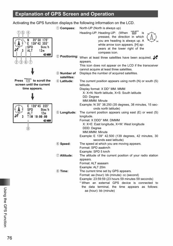
76
Using the G
PS
Function
Explanation of GPS Screen and OperationActivating the GPS function displays the following information on the LCD.
①
②
⑧
③⑥⑦
⑤ ④
Press A to scroll the screen until the current
time appears.
① Compass: North-UP (North is always up)Heading-UP: Heading-UP: (When B is
pressed, the direction in which you are heading is always up. A white arrow icon appears. [H] ap-pears at the lower right of the compass icon.
② Positioning: When at least three satellites have been acquired, appears.This icon does not appear on the LCD if the transceiver cannot acquire at least three satellites.
③ Number of satellites:
Displays the number of acquired satellites.
④ Latitude: The current position appears using north (N) or south (S) latitude.Display format: X DD° MM. MMM X: X=N: North latitude, X=S: South latitude DD: Degree MM.MMM: MinuteExample: N 35° 38.250 (35 degrees, 38 minutes, 15 sec-
onds north latitude)⑤ Longitude: The current position appears using east (E) or west (S)
longitude.Format: X DDD° MM. DMMM X: X=E: East longitude, X=W: West longitude DDD: Degree MM.MMM: MinuteExample: E 139° 42.500 (139 degrees, 42 minutes, 30
seconds east latitude)⑥ Speed: The speed at which you are moving appears.
Format: SPD aaakm/hExample: SPD 5 km/h
⑦ Altitude: The altitude of the current position of your radio station appears.Format: ALT aaaaamExample: ALT 20m
⑧ Time: The current time set by GPS appears.Format: aa (hour): bb (minute): cc (second)Example: 23:59:59 (23 hours 59 minutes 59 seconds)* When an external GPS device is connected to
the data terminal, the time appears as follows: aa (hour): bb (minute)
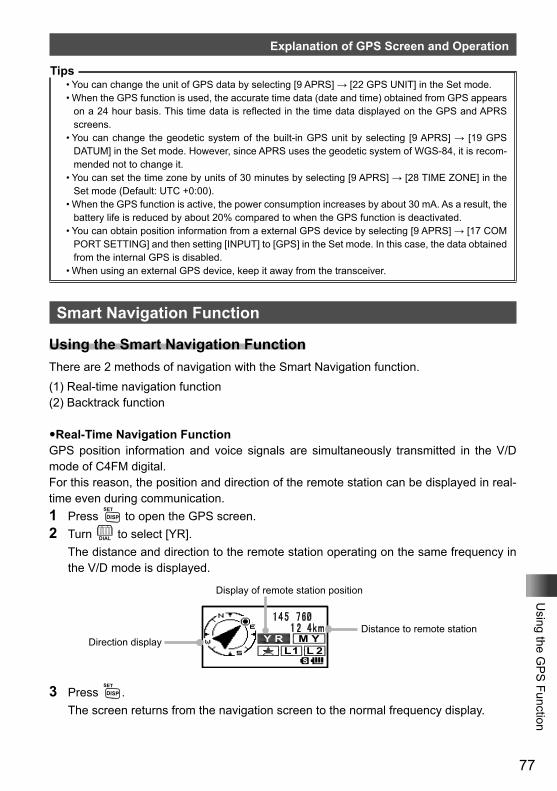
77
Using the G
PS
Function
Explanation of GPS Screen and Operation
Tips• You can change the unit of GPS data by selecting [9 APRS] → [22 GPS UNIT] in the Set mode.• When the GPS function is used, the accurate time data (date and time) obtained from GPS appears
on a 24 hour basis. This time data is reflected in the time data displayed on the GPS and APRS screens.
• You can change the geodetic system of the built-in GPS unit by selecting [9 APRS] → [19 GPS DATUM] in the Set mode. However, since APRS uses the geodetic system of WGS-84, it is recom-mended not to change it.
• You can set the time zone by units of 30 minutes by selecting [9 APRS] → [28 TIME ZONE] in the Set mode (Default: UTC +0:00).
• When the GPS function is active, the power consumption increases by about 30 mA. As a result, the battery life is reduced by about 20% compared to when the GPS function is deactivated.
• You can obtain position information from a external GPS device by selecting [9 APRS] → [17 COM PORT SETTING] and then setting [INPUT] to [GPS] in the Set mode. In this case, the data obtained from the internal GPS is disabled.
• When using an external GPS device, keep it away from the transceiver.
Smart Navigation Function
Using the Smart Navigation FunctionThere are 2 methods of navigation with the Smart Navigation function.(1) Real-time navigation function(2) Backtrack function
�Real-Time Navigation FunctionGPS position information and voice signals are simultaneously transmitted in the V/D mode of C4FM digital.For this reason, the position and direction of the remote station can be displayed in real-time even during communication.1 Press M to open the GPS screen.2 Turn O to select [YR]. The distance and direction to the remote station operating on the same frequency in
the V/D mode is displayed.
Display of remote station position
Distance to remote stationDirection display
3 Press M. The screen returns from the navigation screen to the normal frequency display.
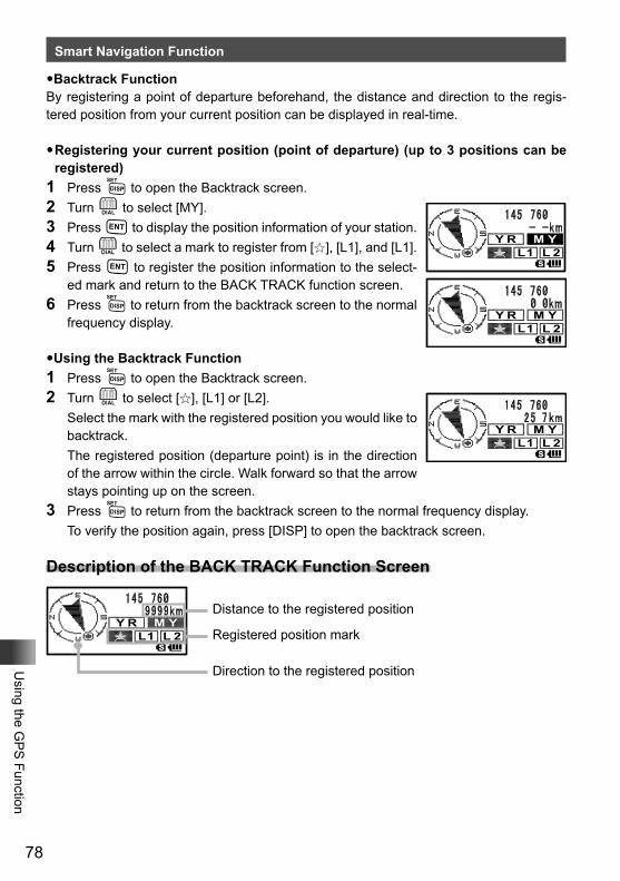
78
Using the G
PS
Function
Smart Navigation Function
�Backtrack FunctionBy registering a point of departure beforehand, the distance and direction to the regis-tered position from your current position can be displayed in real-time.
�Registering your current position (point of departure) (up to 3 positions can be registered)
1 Press M to open the Backtrack screen.2 Turn O to select [MY].3 Press H to display the position information of your station.4 Turn O to select a mark to register from [I], [L1], and [L1].5 Press H to register the position information to the select-
ed mark and return to the BACK TRACK function screen.6 Press M to return from the backtrack screen to the normal
frequency display.
�Using the Backtrack Function1 Press M to open the Backtrack screen.2 Turn O to select [I], [L1] or [L2]. Select the mark with the registered position you would like to
backtrack. The registered position (departure point) is in the direction
of the arrow within the circle. Walk forward so that the arrow stays pointing up on the screen.
3 Press M to return from the backtrack screen to the normal frequency display. To verify the position again, press [DISP] to open the backtrack screen.
Description of the BACK TRACK Function Screen
Distance to the registered position
Registered position mark
Direction to the registered position
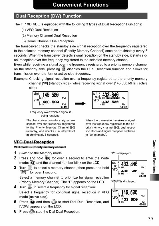
79
Convenient Functions
Convenient Functions
Dual Reception (DW) FunctionThe FT1XDR/DE is equipped with the following 3 types of Dual Reception Functions:
(1) VFO Dual Reception(2) Memory Channel Dual Reception(3) Home Channel Dual Reception
The transceiver checks the standby side signal reception over the frequency registered to the selected memory channel (Priority Memory Channel) once approximately every 5 seconds. When the transceiver detects signal reception on the standby side, it starts sig-nal reception over the frequency registered to the selected memory channel.Even while receiving a signal over the frequency registered to a priority memory channel on the standby side, pressing p disables the Dual Reception function and allows for transmission over the former active side frequency.Example: Checking signal reception over a frequency registered to the priority memory
channel [90] (standby side), while receiving signal over [145.500 MHz] (active side).
Frequency over which a signal is being received.
The transceiver monitors signal re-ception over the frequency registered to the Priority Memory Channel [90] (standby) and checks it in intervals of approximately 5 seconds.
When the transceiver receives a signal over the frequency registered to the pri-ority memory channel [90], dual recep-tion stops and signal reception switches to [90] (standby).
VFO Dual Reception VFO mode → Priority memory channel
1 Switch to the Memory mode.2 Press and hold F for over 1 second to enter the Write
mode; F and the channel number blink on the LCD.3 Turn O to select a memory channel, then press and hold B for over 1 second.
Select a memory channel to prioritize for signal reception (Priority Memory Channel). The “P” appears on the LCD.
4 Turn O to select a frequency for signal reception. Select a frequency for continual signal reception in VFO
mode (active side).5 Press F and then V to start Dial Dual Reception, and
[VDW] appears on the LCD.6 Press V stop the Dial Dual Reception.
“P” is displayed.
“VDW” is displayed.
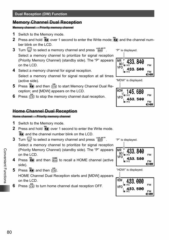
80
Convenient Functions
Dual Reception (DW) Function
Memory Channel Dual Reception Memory channel → Priority memory channel
1 Switch to the Memory mode.2 Press and hold F over 1 second to enter the Write mode;F and the channel num-
ber blink on the LCD.3 Turn O to select a memory channel and press B. Select a memory channel to prioritize for signal reception
(Priority Memory Channel) (standby side). The “P” appears on the LCD.
4 Select a memory channel for signal reception. Select a memory channel for signal reception at all times
(active side).5 Press F and then V to start Memory Channel Dual Re-
ception; and [MDW] appears on the LCD.6 Press V to stop the memory channel dual reception.
Home Channel Dual Reception Home channel → Priority memory channel
1 Switch to the Memory mode.2 Press and hold F over 1 second to enter the Write mode. F and the channel number blink on the LCD.3 Turn O to select a memory channel and press B. Select a memory channel to prioritize for signal reception
(Priority Memory Channel) (standby side). The “P” appears on the LCD.
4 Press F and then 4 to recall a HOME channel (active side).
5 Press F and then V. HOME Channel Dual Reception starts and [MDW] appears
on the LCD.6 Press V to turn home channel dual reception OFF.
“P” is displayed.
“MDW” is displayed.
“P” is displayed.
“HDW” is displayed.
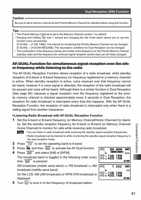
81
Convenient Functions
Dual Reception (DW) Function
CautionBe sure to set a memory channel as the Priority Memory Channel for standby before using this function.
Tips• The Priority Memory Channel is set to the Memory Channel number 1 by default.• Pressing and holding M over 1 second and changing the Set mode option allows you to use this
function more conveniently.[5 SCAN] → [1 DW TIME]: The interval for monitoring the Priority Memory Channel can be changed.[5 SCAN] → [4 SCAN RESUME]: The resumption conditions for Dual Reception can be changed.
• The combination of the frequency bands and modes of the frequency for the Priority Memory Channel (standby side) and the frequency for continual signal reception (active side) can be freely changed.
AF-DUAL Function for simultaneous signal reception over the oth-er frequency while listening to the radioThe AF-DUAL Reception Function allows reception of a radio broadcast, while standby reception of A-band or B-band frequency (or frequency registered to a memory channel) is active. When standby reception is active, voice received over that frequency cannot be heard, however if a voice signal is detected, the reception of the radio broadcast will be paused and voice will be heard. Although there is a similar function in Dual Reception (See page 80), because a signal reception over the frequency registered to the prior-ity memory channel is checked approximately every 5 seconds in Dual Reception, the reception for radio broadcast is interrupted every time this happens. With the AF-DUAL Reception Function, the reception of radio broadcast is interrupted only when there is a calling signal from another transceiver.
�Listening Radio Broadcast with AF-DUAL Reception Function1 Set the A-band or B-band frequency (or Memory Channel/Home Channel) for stand-
by. Set the standby reception frequency for A-band or B-band (or Memory Channel/ Home Channel) to monitor for calls while receiving radio broadcast. Tips • You can listen to radio broadcast while scanning the standby signal reception frequencies. • Radio broadcast can be listened to while monitoring the standby signal reception frequency in
the dual reception mode.
2 Press A to set the operating band to A-band.3 Press F and then 6 to activate the AF-Dual function.4 Press B and select [AM] or [WFM]. The broadcast band is toggled in the following order every
time B is pressed: AM broadcast (middle wave band) ⇔ FM broadcast ⇔ AM
broadcast (middle wave band) On the LCD, AM (AM broadcast) or WFM (FM broadcast) is
displayed.5 Turn O to tune in to the frequency of broadcast station.
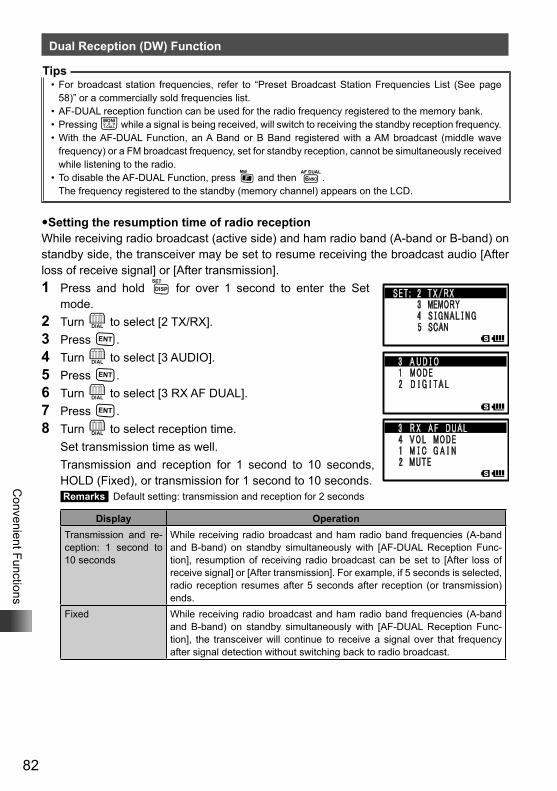
82
Convenient Functions
Dual Reception (DW) Function
Tips• For broadcast station frequencies, refer to “Preset Broadcast Station Frequencies List (See page
58)” or a commercially sold frequencies list.• AF-DUAL reception function can be used for the radio frequency registered to the memory bank.• Pressing T while a signal is being received, will switch to receiving the standby reception frequency.• With the AF-DUAL Function, an A Band or B Band registered with a AM broadcast (middle wave
frequency) or a FM broadcast frequency, set for standby reception, cannot be simultaneously received while listening to the radio.
• To disable the AF-DUAL Function, press F and then 6.The frequency registered to the standby (memory channel) appears on the LCD.
�Setting the resumption time of radio receptionWhile receiving radio broadcast (active side) and ham radio band (A-band or B-band) on standby side, the transceiver may be set to resume receiving the broadcast audio [After loss of receive signal] or [After transmission].1 Press and hold M for over 1 second to enter the Set
mode.2 Turn O to select [2 TX/RX].3 Press H.4 Turn O to select [3 AUDIO].5 Press H.6 Turn O to select [3 RX AF DUAL].7 Press H.8 Turn O to select reception time. Set transmission time as well. Transmission and reception for 1 second to 10 seconds,
HOLD (Fixed), or transmission for 1 second to 10 seconds. Remarks Default setting: transmission and reception for 2 seconds
Display OperationTransmission and re-ception: 1 second to 10 seconds
While receiving radio broadcast and ham radio band frequencies (A-band and B-band) on standby simultaneously with [AF-DUAL Reception Func-tion], resumption of receiving radio broadcast can be set to [After loss of receive signal] or [After transmission]. For example, if 5 seconds is selected, radio reception resumes after 5 seconds after reception (or transmission) ends.
Fixed While receiving radio broadcast and ham radio band frequencies (A-band and B-band) on standby simultaneously with [AF-DUAL Reception Func-tion], the transceiver will continue to receive a signal over that frequency after signal detection without switching back to radio broadcast.
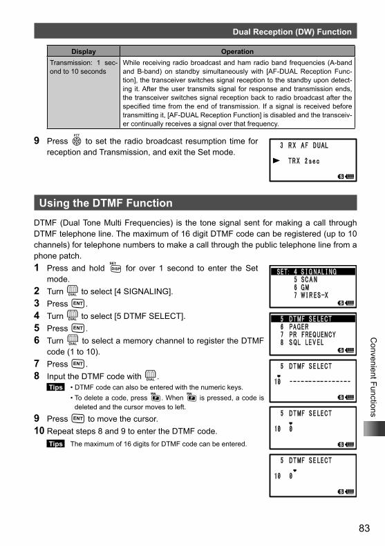
83
Convenient Functions
Dual Reception (DW) Function
Display OperationTransmission: 1 sec-ond to 10 seconds
While receiving radio broadcast and ham radio band frequencies (A-band and B-band) on standby simultaneously with [AF-DUAL Reception Func-tion], the transceiver switches signal reception to the standby upon detect-ing it. After the user transmits signal for response and transmission ends, the transceiver switches signal reception back to radio broadcast after the specified time from the end of transmission. If a signal is received before transmitting it, [AF-DUAL Reception Function] is disabled and the transceiv-er continually receives a signal over that frequency.
9 Press p to set the radio broadcast resumption time for reception and Transmission, and exit the Set mode.
Using the DTMF FunctionDTMF (Dual Tone Multi Frequencies) is the tone signal sent for making a call through DTMF telephone line. The maximum of 16 digit DTMF code can be registered (up to 10 channels) for telephone numbers to make a call through the public telephone line from a phone patch.1 Press and hold M for over 1 second to enter the Set
mode.2 Turn O to select [4 SIGNALING].3 Press H.4 Turn O to select [5 DTMF SELECT].5 Press H.6 Turn O to select a memory channel to register the DTMF
code (1 to 10).7 Press H.8 Input the DTMF code with O.
Tips • DTMF code can also be entered with the numeric keys. • To delete a code, press F. When F is pressed, a code is
deleted and the cursor moves to left.
9 Press H to move the cursor. 10 Repeat steps 8 and 9 to enter the DTMF code.
Tips The maximum of 16 digits for DTMF code can be entered.
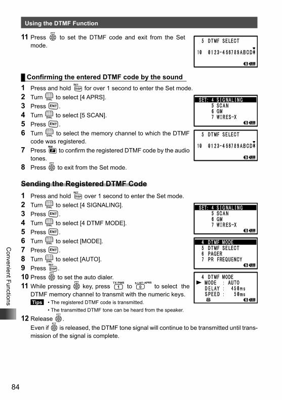
84
Convenient Functions
Using the DTMF Function
11 Press p to set the DTMF code and exit from the Set mode.
Confirming the entered DTMF code by the sound1 Press and hold M for over 1 second to enter the Set mode.2 Turn O to select [4 APRS].3 Press H.4 Turn O to select [5 SCAN].5 Press H.6 Turn O to select the memory channel to which the DTMF
code was registered.7 Press F to confirm the registered DTMF code by the audio
tones. 8 Press p to exit from the Set mode.
Sending the Registered DTMF Code1 Press and hold M over 1 second to enter the Set mode. 2 Turn O to select [4 SIGNALING].3 Press H.4 Turn O to select [4 DTMF MODE].5 Press H.6 Turn O to select [MODE].7 Press H.8 Turn O to select [AUTO].9 Press M.10 Press p to set the auto dialer.11 While pressing p key, press 1 to 0 to select the
DTMF memory channel to transmit with the numeric keys. Tips • The registered DTMF code is transmitted. • The transmitted DTMF tone can be heard from the speaker.
12 Release p. Even if p is released, the DTMF tone signal will continue to be transmitted until trans-
mission of the signal is complete.
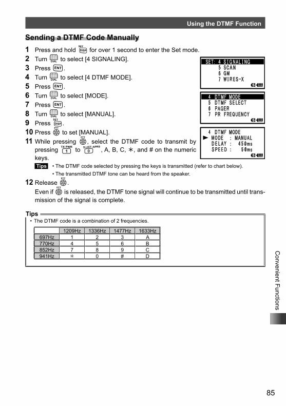
85
Convenient Functions
Using the DTMF Function
Sending a DTMF Code Manually1 Press and hold M for over 1 second to enter the Set mode.2 Turn O to select [4 SIGNALING].3 Press H.4 Turn O to select [4 DTMF MODE].5 Press H.6 Turn O to select [MODE].7 Press H.8 Turn O to select [MANUAL].9 Press M.10 Press p to set [MANUAL].11 While pressing p, select the DTMF code to transmit by
pressing 1 to 0, A, B, C, , and # on the numeric keys. Tips • The DTMF code selected by pressing the keys is transmitted (refer to chart below). • The transmitted DTMF tone can be heard from the speaker.
12 Release p. Even if p is released, the DTMF tone signal will continue to be transmitted until trans-
mission of the signal is complete.
Tips• The DTMF code is a combination of 2 frequencies.
1209Hz 1336Hz 1477Hz 1633Hz697Hz 1 2 3 A770Hz 4 5 6 B852Hz 7 8 9 C941Hz 0 # D
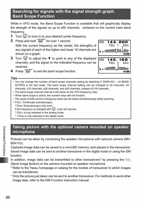
86
Convenient Functions
Searching for signals with the signal strength graph. Band Scope Function
While in VFO mode, the Band Scope Function is available that will graphically display the strength of the signals on up to ±50 channels, centered on the current main band frequency.1 Turn O to tune in to your desired center frequency.2 Press and hold B for over 1 second. With the current frequency as the center, the strengths of
any signals of each of the higher and lower 16 channels are shown on a graph.
3 Turn O to adjust the ▼ to point to any of the displayed channels, and the signal on the indicated frequency can be received.
4 Press B to exit the band scope function.
Tips• You can change the number of band scope channels setting by selecting [1 DISPLAY] → [4 BAND
SCOPE] in the Set mode. The band scope channel setting can be changed to ±5 channels, ±9 channels, ±16 channels, ±24 channels, and ±50 channels, instead of ±16 channels.
• The band scope channel interval is the same as the VFO frequency step.• When band scope is active, the numeric keys will not function.• The audio of A/B common frequency band can be heard simultaneously while scanning.• FULL: Continualy scans(scoops).
1Time: Scans(scoops) only once.If the frequency is changed with O, scan will resume.
* FULL is only selected in the analog mode. * 1Time is only selected in the digital mode.
Taking picture with the optional camera mounted on speaker microphone
Pictures can be taken by connecting the speaker microphone with optional camera (MH-85A11U).Captured image data can be saved to a microSD memory card placed in the transceiver.Saved image data can be sent to another transceiver in the digital mode or using the GM function.In addition, image data can be transmitted to other transceivers* by pressing the (Send Image Button] on the camera mounted on speaker microphone.* Refer to the Yaesu homepage or catalog for the models of transceiver to which images
can be transferred.* Only the picture just taken can be sent to another transceiver. For methods to send other
image data, refer to the GM Function instruction manual.
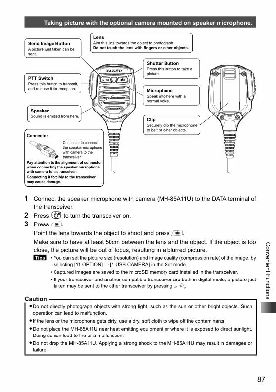
87
Convenient Functions
Taking picture with the optional camera mounted on speaker microphone.
Send Image ButtonA picture just taken can be sent.
LensAim this lrns towards the object to photograph.Do not touch the lens with fingers or other objects.
PTT SwitchPress this button to transmit, and release it for reception.
SpeakerSound is emitted from here.
Shutter ButtonPress this button to take a picture.
MicrophoneSpeak into here with a normal voice.
ClipSecurely clip the microphone to belt or other objects.
ConnectorConnector to connect the speaker microphone with camera to the transceiver
Pay attention to the alignment of connector when connecting the speaker microphone with camera to the ranceiver.Connecting it forcibly to the transceiver may cause damage.
1 Connect the speaker microphone with camera (MH-85A11U) to the DATA terminal of the transceiver.
2 Press P to turn the transceiver on.3 Press . Point the lens towards the object to shoot and press . Make sure to have at least 50cm between the lens and the object. If the object is too
close, the picture will be out of focus, resulting in a blurred picture. Tips • You can set the picture size (resolution) and image quality (compression rate) of the image, by
selecting [11 OPTION] → [1 USB CAMERA] in the Set mode. • Captured images are saved to the microSD memory card installed in the transceiver. • If your transceiver and another compatible transceiver are both in digital mode, a picture just
taken may be sent to the other transceiver by pressing .
Caution�Do not directly photograph objects with strong light, such as the sun or other bright objects. Such
operation can lead to malfunction.�If the lens or the microphone gets dirty, use a dry, soft cloth to wipe off the contaminants.�Do not place the MH-85A11U near heat emitting equipment or where it is exposed to direct sunlight.
Doing so can lead to fire or a malfunction.�Do not drop the MH-85A11U. Applying a strong shock to the MH-85A11U may result in damages or
failure.
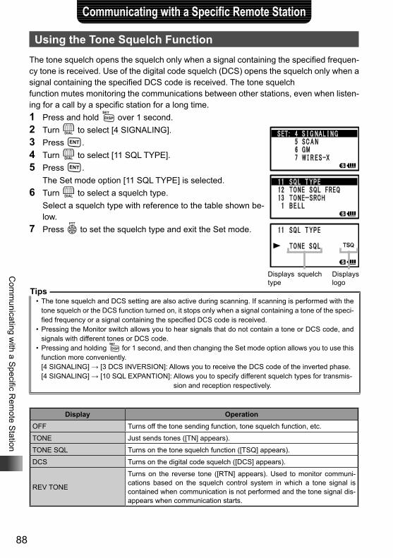
88
Com
municating w
ith a Specific R
emote S
tation
Communicating with a Specific Remote Station
Using the Tone Squelch FunctionThe tone squelch opens the squelch only when a signal containing the specified frequen-cy tone is received. Use of the digital code squelch (DCS) opens the squelch only when a signal containing the specified DCS code is received. The tone squelchfunction mutes monitoring the communications between other stations, even when listen-ing for a call by a specific station for a long time.1 Press and hold M over 1 second.2 Turn O to select [4 SIGNALING].3 Press H.4 Turn O to select [11 SQL TYPE].5 Press H. The Set mode option [11 SQL TYPE] is selected.6 Turn O to select a squelch type. Select a squelch type with reference to the table shown be-
low.7 Press p to set the squelch type and exit the Set mode.
Tips• The tone squelch and DCS setting are also active during scanning. If scanning is performed with the
tone squelch or the DCS function turned on, it stops only when a signal containing a tone of the speci-fied frequency or a signal containing the specified DCS code is received.
• Pressing the Monitor switch allows you to hear signals that do not contain a tone or DCS code, and signals with different tones or DCS code.
• Pressing and holding M for 1 second, and then changing the Set mode option allows you to use this function more conveniently.[4 SIGNALING] → [3 DCS INVERSION]: Allows you to receive the DCS code of the inverted phase.[4 SIGNALING] → [10 SQL EXPANTION]: Allows you to specify different squelch types for transmis-
sion and reception respectively.
Display OperationOFF Turns off the tone sending function, tone squelch function, etc.
TONE Just sends tones ([TN] appears).
TONE SQL Turns on the tone squelch function ([TSQ] appears).
DCS Turns on the digital code squelch ([DCS] appears).
REV TONE
Turns on the reverse tone ([RTN] appears). Used to monitor communi-cations based on the squelch control system in which a tone signal is contained when communication is not performed and the tone signal dis-appears when communication starts.
Displays squelch type
Displays logo
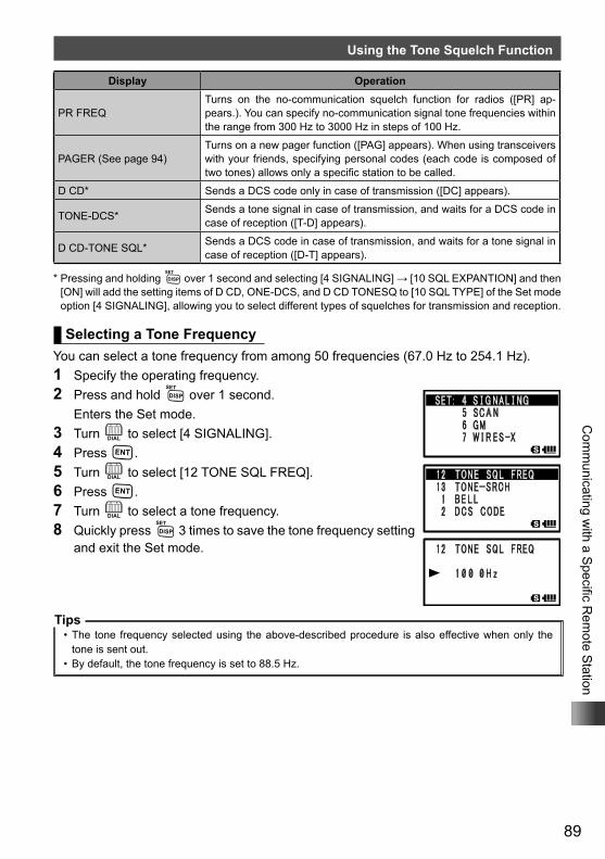
89
Com
municating w
ith a Specific R
emote S
tation
Using the Tone Squelch Function
Display Operation
PR FREQTurns on the no-communication squelch function for radios ([PR] ap-pears.). You can specify no-communication signal tone frequencies within the range from 300 Hz to 3000 Hz in steps of 100 Hz.
PAGER (See page 94)Turns on a new pager function ([PAG] appears). When using transceivers with your friends, specifying personal codes (each code is composed of two tones) allows only a specific station to be called.
D CD* Sends a DCS code only in case of transmission ([DC] appears).
TONE-DCS* Sends a tone signal in case of transmission, and waits for a DCS code in case of reception ([T-D] appears).
D CD-TONE SQL* Sends a DCS code in case of transmission, and waits for a tone signal in case of reception ([D-T] appears).
* Pressing and holding M over 1 second and selecting [4 SIGNALING] → [10 SQL EXPANTION] and then [ON] will add the setting items of D CD, ONE-DCS, and D CD TONESQ to [10 SQL TYPE] of the Set mode option [4 SIGNALING], allowing you to select different types of squelches for transmission and reception.
Selecting a Tone FrequencyYou can select a tone frequency from among 50 frequencies (67.0 Hz to 254.1 Hz).1 Specify the operating frequency.2 Press and hold M over 1 second. Enters the Set mode.3 Turn O to select [4 SIGNALING].4 Press H.5 Turn O to select [12 TONE SQL FREQ].6 Press H.7 Turn O to select a tone frequency.8 Quickly press M 3 times to save the tone frequency setting
and exit the Set mode.
Tips• The tone frequency selected using the above-described procedure is also effective when only the
tone is sent out.• By default, the tone frequency is set to 88.5 Hz.
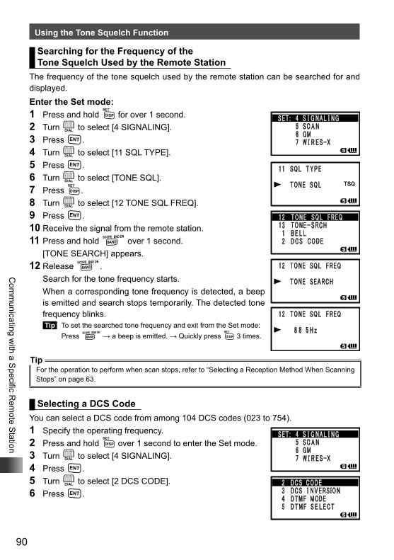
90
Com
municating w
ith a Specific R
emote S
tation
Using the Tone Squelch Function
Searching for the Frequency of the Tone Squelch Used by the Remote Station
The frequency of the tone squelch used by the remote station can be searched for and displayed.Enter the Set mode:1 Press and hold M for over 1 second.2 Turn O to select [4 SIGNALING].3 Press H.4 Turn O to select [11 SQL TYPE].5 Press H.6 Turn O to select [TONE SQL].7 Press M.8 Turn O to select [12 TONE SQL FREQ].9 Press H.10 Receive the signal from the remote station.11 Press and hold B over 1 second. [TONE SEARCH] appears.12 Release B. Search for the tone frequency starts. When a corresponding tone frequency is detected, a beep
is emitted and search stops temporarily. The detected tone frequency blinks. Tip To set the searched tone frequency and exit from the Set mode: Press B → a beep is emitted. → Quickly press M 3 times.
TipFor the operation to perform when scan stops, refer to “Selecting a Reception Method When Scanning Stops” on page 63.
Selecting a DCS CodeYou can select a DCS code from among 104 DCS codes (023 to 754).1 Specify the operating frequency.2 Press and hold M over 1 second to enter the Set mode.3 Turn O to select [4 SIGNALING].4 Press H.5 Turn O to select [2 DCS CODE].6 Press H.
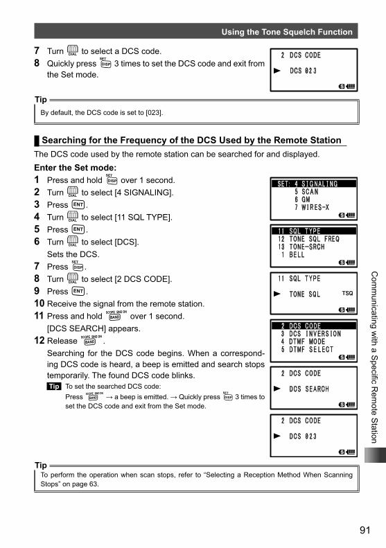
91
Com
municating w
ith a Specific R
emote S
tation
Using the Tone Squelch Function
7 Turn O to select a DCS code.8 Quickly press M 3 times to set the DCS code and exit from
the Set mode.
TipBy default, the DCS code is set to [023].
Searching for the Frequency of the DCS Used by the Remote StationThe DCS code used by the remote station can be searched for and displayed.Enter the Set mode:1 Press and hold M over 1 second.2 Turn O to select [4 SIGNALING].3 Press H.4 Turn O to select [11 SQL TYPE].5 Press H.6 Turn O to select [DCS]. Sets the DCS.7 Press M.8 Turn O to select [2 DCS CODE].9 Press H.10 Receive the signal from the remote station.11 Press and hold B over 1 second. [DCS SEARCH] appears.12 Release B. Searching for the DCS code begins. When a correspond-
ing DCS code is heard, a beep is emitted and search stops temporarily. The found DCS code blinks. Tip To set the searched DCS code:
Press B → a beep is emitted. → Quickly press M 3 times to set the DCS code and exit from the Set mode.
TipTo perform the operation when scan stops, refer to “Selecting a Reception Method When Scanning Stops” on page 63.
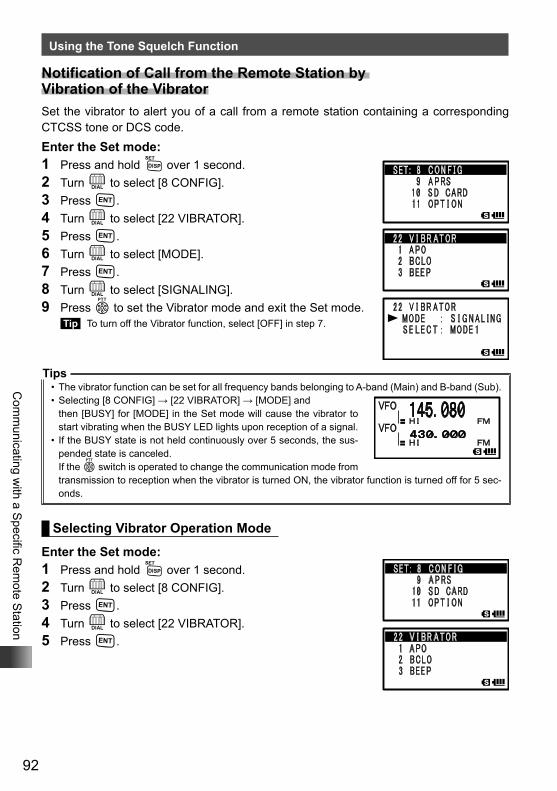
92
Com
municating w
ith a Specific R
emote S
tation
Using the Tone Squelch Function
Notification of Call from the Remote Station by Vibration of the VibratorSet the vibrator to alert you of a call from a remote station containing a corresponding CTCSS tone or DCS code. Enter the Set mode:1 Press and hold M over 1 second.2 Turn O to select [8 CONFIG].3 Press H.4 Turn O to select [22 VIBRATOR].5 Press H.6 Turn O to select [MODE].7 Press H.8 Turn O to select [SIGNALING].9 Press p to set the Vibrator mode and exit the Set mode.
Tip To turn off the Vibrator function, select [OFF] in step 7.
Tips• The vibrator function can be set for all frequency bands belonging to A-band (Main) and B-band (Sub).• Selecting [8 CONFIG] → [22 VIBRATOR] → [MODE] and
then [BUSY] for [MODE] in the Set mode will cause the vibrator to start vibrating when the BUSY LED lights upon reception of a signal.
• If the BUSY state is not held continuously over 5 seconds, the sus-pended state is canceled.If the p switch is operated to change the communication mode from transmission to reception when the vibrator is turned ON, the vibrator function is turned off for 5 sec-onds.
Selecting Vibrator Operation Mode
Enter the Set mode:1 Press and hold M over 1 second.2 Turn O to select [8 CONFIG].3 Press H.4 Turn O to select [22 VIBRATOR].5 Press H.
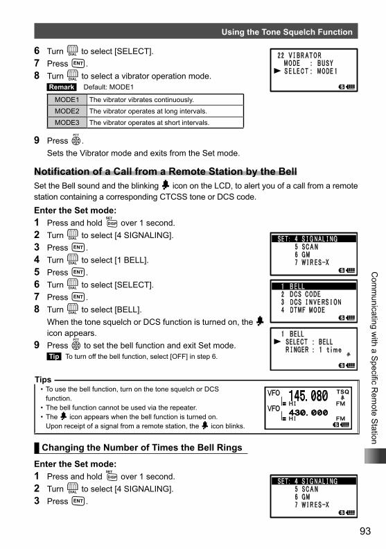
93
Com
municating w
ith a Specific R
emote S
tation
Using the Tone Squelch Function
6 Turn O to select [SELECT].7 Press H.8 Turn O to select a vibrator operation mode.
Remark Default: MODE1
MODE1 The vibrator vibrates continuously.MODE2 The vibrator operates at long intervals.MODE3 The vibrator operates at short intervals.
9 Press p. Sets the Vibrator mode and exits from the Set mode.
Notification of a Call from a Remote Station by the BellSet the Bell sound and the blinking b icon on the LCD, to alert you of a call from a remote station containing a corresponding CTCSS tone or DCS code. Enter the Set mode:1 Press and hold M over 1 second.2 Turn O to select [4 SIGNALING].3 Press H.4 Turn O to select [1 BELL].5 Press H.6 Turn O to select [SELECT].7 Press H.8 Turn O to select [BELL]. When the tone squelch or DCS function is turned on, the b
icon appears.9 Press p to set the bell function and exit Set mode.
Tip To turn off the bell function, select [OFF] in step 6.
Tips• To use the bell function, turn on the tone squelch or DCS
function.• The bell function cannot be used via the repeater.• The b icon appears when the bell function is turned on.
Upon receipt of a signal from a remote station, the b icon blinks.
Changing the Number of Times the Bell Rings
Enter the Set mode:1 Press and hold M over 1 second.2 Turn O to select [4 SIGNALING].3 Press H.
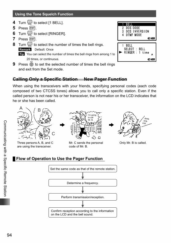
94
Com
municating w
ith a Specific R
emote S
tation
Using the Tone Squelch Function
4 Turn O to select [1 BELL].5 Press H.6 Turn O to select [RINGER].7 Press H.8 Turn O to select the number of times the bell rings.
Remark Default: Once Tip You can select the number of times the bell rings from among 1 to
20 times, or continuous.
9 Press p to set the selected number of times the bell rings and exit from the Set mode.
Calling Only a Specific Station New Pager FunctionWhen using the transceivers with your friends, specifying personal codes (each code composed of two CTCSS tones) allows you to call only a specific station. Even if the called person is not near his or her transceiver, the information on the LCD indicates that he or she has been called.
A
C
B
Mr. C sends the personal code of Mr. B.
Three persons A, B, and C are using the transceiver.
Only Mr. B is called.
I’m going to call Mr. B. Ring,
ring, ring
Flow of Operation to Use the Pager Function
Set the same code as that of the remote station.
Determine a frequency.
Perform transmission/reception.
Confirm reception according to the information on the LCD and the bell sound.
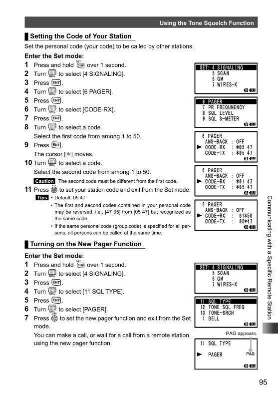
95
Com
municating w
ith a Specific R
emote S
tation
Using the Tone Squelch Function
Setting the Code of Your StationSet the personal code (your code) to be called by other stations.Enter the Set mode:1 Press and hold M over 1 second.2 Turn O to select [4 SIGNALING].3 Press H.4 Turn O to select [6 PAGER].5 Press H.6 Turn O to select [CODE-RX].7 Press H.8 Turn O to select a code. Select the first code from among 1 to 50.9 Press H. The cursor [] moves.10 Turn O to select a code. Select the second code from among 1 to 50.
Caution The second code must be different from the first code.
11 Press p to set your station code and exit from the Set mode. Tips • Default: 05 47 • The first and second codes contained in your personal code
may be reversed, i.e., [47 05] from [05 47] but recognized as the same code.
• If the same personal code (group code) is specified for all per-sons, all persons can be called at the same time.
Turning on the New Pager Function
Enter the Set mode:1 Press and hold M over 1 second.2 Turn O to select [4 SIGNALING].3 Press H.4 Turn O to select [11 SQL TYPE].5 Press H.6 Turn O to select [PAGER].7 Press p to set the new pager function and exit from the Set
mode. You can make a call, or wait for a call from a remote station,
using the new pager function.
PAG appears.
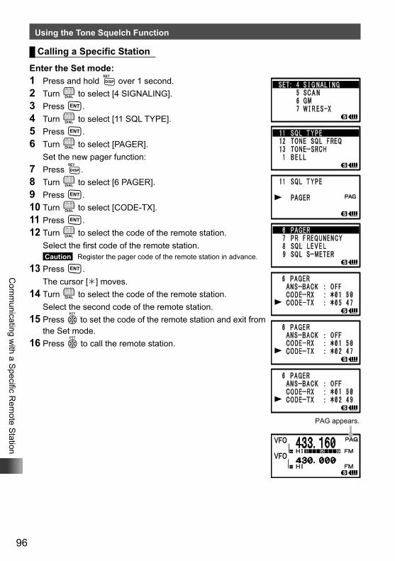
96
Com
municating w
ith a Specific R
emote S
tation
Using the Tone Squelch Function
Calling a Specific Station
Enter the Set mode:1 Press and hold M over 1 second.2 Turn O to select [4 SIGNALING].3 Press H.4 Turn O to select [11 SQL TYPE].5 Press H.6 Turn O to select [PAGER]. Set the new pager function:7 Press M.8 Turn O to select [6 PAGER].9 Press H.10 Turn O to select [CODE-TX].11 Press H.12 Turn O to select the code of the remote station. Select the first code of the remote station.
Caution Register the pager code of the remote station in advance.
13 Press H. The cursor [] moves.14 Turn O to select the code of the remote station. Select the second code of the remote station.15 Press p to set the code of the remote station and exit from
the Set mode.16 Press p to call the remote station.
PAG appears.
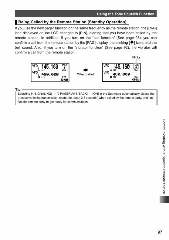
97
Com
municating w
ith a Specific R
emote S
tation
Using the Tone Squelch Function
Being Called by the Remote Station (Standby Operation)If you use the new pager function on the same frequency as the remote station, the [PAG] icon displayed on the LCD changes to [PIN], alerting that you have been called by the remote station. In addition, if you turn on the “bell function” (See page 93), you can confirm a call from the remote station by the [PAG] display, the blinking [b] icon, and the bell sound. Also, if you turn on the “vibrator function” (See page 92), the vibrator will confirm a call from the remote station.
TipSelecting [4 SIGNALING] → [9 PAGER ANS-BACK] → [ON] in the Set mode automatically places the transceiver in the transmission mode (for about 2.5 seconds) when called by the remote party, and noti-fies the remote party to get ready for communication.
When called
Blinks
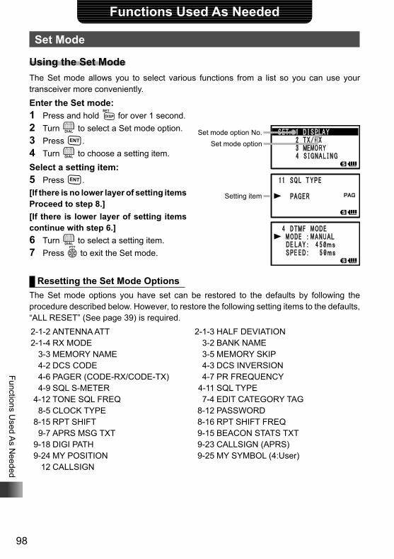
98
Functions Used A
s Needed
Functions Used As Needed
Set Mode
Using the Set ModeThe Set mode allows you to select various functions from a list so you can use your transceiver more conveniently.Enter the Set mode:1 Press and hold M for over 1 second.2 Turn O to select a Set mode option.3 Press H.4 Turn O to choose a setting item.Select a setting item:5 Press H.[If there is no lower layer of setting items Proceed to step 8.][If there is lower layer of setting items continue with step 6.]6 Turn O to select a setting item.7 Press p to exit the Set mode.
Resetting the Set Mode OptionsThe Set mode options you have set can be restored to the defaults by following the procedure described below. However, to restore the following setting items to the defaults, “ALL RESET” (See page 39) is required. 2-1-2 ANTENNA ATT 2-1-4 RX MODE 3-3 MEMORY NAME 4-2 DCS CODE 4-6 PAGER (CODE-RX/CODE-TX) 4-9 SQL S-METER 4-12 TONE SQL FREQ 8-5 CLOCK TYPE 8-15 RPT SHIFT 9-7 APRS MSG TXT 9-18 DIGI PATH 9-24 MY POSITION 12 CALLSIGN
2-1-3 HALF DEVIATION 3-2 BANK NAME 3-5 MEMORY SKIP 4-3 DCS INVERSION 4-7 PR FREQUENCY 4-11 SQL TYPE 7-4 EDIT CATEGORY TAG 8-12 PASSWORD 8-16 RPT SHIFT FREQ 9-15 BEACON STATS TXT 9-23 CALLSIGN (APRS) 9-25 MY SYMBOL (4:User)
Set mode option No.Set mode option
Setting item
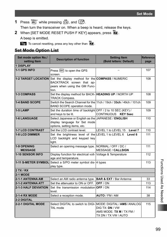
99
Functions Used A
s Needed
Set Mode
1 Press % while pressing V, and P. Then turn the transceiver on. When a beep is heard, release the keys.2 When [SET MODE RESET PUSH F KEY] appears, press F. A beep is emitted.
Tip To cancel resetting, press any key other than F.
Set Mode Option ListSet mode option No./
setting Item Description of function Setting Item (Bold letters: Default)
Reference page
1 DISPLAY1-1 GPS INFO Press H to open the GPS
screen.– 107
1-2 TARGET LOCATION Set the display method for the BACKTRACK screen that ap-pears when using the GM Func-tion.
COMPASS / NUMERIC 108
1-3 COMPASS Set the display method for BACK-TRACK Compass.
HEADING UP / NORTH UP 108
1-4 BAND SCOPE Switch the Search Channel for the BAND SCOPE operation mode.
11ch / 19ch / 33ch / 49ch / 101ch 109
1-5 LAMP Set the duration time of backlight and keys to be lit.
OFF / 2 to 10 SEC (KEY) / CONTINUOUS KEY 5sec
109
1-6 LANGUAGE Select Japanese or English as the display language for Set mode options, setting items, etc.
JAPANESE / ENGLISH 110
1-7 LCD CONTRAST Set the LCD contrast level. LEVEL 1 to LEVEL 15 Level 7 1101-8 LCD DIMMER Set the brightness level of the
LCD backlight and keypad key light.
LEVEL 1 to LEVEL 6 Level 6 111
1-9 OPENING MESSAGE
Select an opening message type. NORMAL / OFF / DC / MESSAGE / CALLSIGN
111
1-10 SENSOR INFO Display function for electrical volt-age and temperature.
Voltage & Temperature 112
1-11 S-METER SYMBOL Select a S/PO meter symbol dis-play type.
4 types 113
2 TX / RX2-1 MODE2-1-1 ANTENNA AM Select an AM radio antenna type. BAR & EXT / Bar Antenna 332-1-2 ANTENNA ATT Set the attenuator to ON or OFF. OFF / ON 1132-1-3 HALF DEVIATION Set the transmission modulation
level.OFF / ON 114
2-1-4 RX MODE Select a reception mode. AUTO / FM / AM 382-2 DIGITAL2-2-1 DIGITAL MODE Select DIGITAL to switch to DIGI-
TAL modeMODE: DIGITAL / AMS / ANALOGDIG TX: DN / VWAMS MODE: TX M / TX FM /TX DN / TX VW / AUTO
115
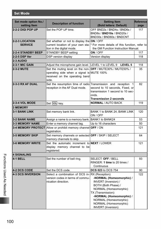
100
Functions Used A
s Needed
Set Mode
Set mode option No./setting Item Description of function Setting Item
(Bold letters: Default)Reference
page2-2-2 DIGI POP UP Set the POP UP time. OFF BND2s / BND4s / BND6s /
BND8s / BND10s / BND20s / BND30s / BND60s / BNDCNT
117
2-2-3 LOCATION SERVICE
Set whether or not to display the current location of your own sta-tion in the digital mode.
ON / OFF* For more details of this function, refer to
the GM Function Instruction Manual.2-2-4 STANDBY BEEP STANDBY BEEP setting ON / OFF 1172-2-5 DSP Ver DSP version display Version display 1182-3 AUDIO2-3-1 MIC GAIN Adjust the microphone gain level. LEVEL 1 to LEVEL 9 LEVEL 5 1182-3-2 MUTE Set the muting level on the non-
operating side when a signal is received on the operating band side.
OFF / MUTE30% / MUTE50% / MUTE 100%
35
2-3-3 RX AF DUAL Set the resumption time of radio reception in the AF Dual mode.
Transmission and reception 1 second to 10 seconds, Fixed, or transmission 1 second to 10 sec-onds.Transmission 2 seconds
82
2-3-4 VOL MODE Set v key. NORMAL / AUTO BACK 1193 MEMORY3-1 BANK LINK Set memory bank link. BANK 1 to BANK 24, BANK LINK
ON / OFF120
3-2 BANK NAME Assign a name to a memory bank. BANK1 to BANK24 533-3 MEMORY NAME Enter a memory channel tag. Up to 16 characters 503-4 MEMORY PROTECT Allow or prohibit memory channel
registration.OFF / ON 121
3-5 MEMORY SKIP Set memory channels or selected memory channels to skip.
OFF / SKIP / SELECT 64
3-6 MEMORY WRITE Set the automatic increment to display memory channel to be registered.
NEXT / LOWER 121
4 SIGNALING4-1 BELL Set the number of bell ring. SELECT: OFF / BELL
RINGER: 1 time to 20 times / Continuous
93
4-2 DCS CODE Set the DCS code. DCS 023 to DCS 754 904-3 DCS INVERSION Select a combination of DCS in-
version codes in terms of commu-nication direction.
RX (Reception): -NORMAL (Homeomorphic) / INVERT (Inversion) / BOTH (Both Phase) / NORMAL (Homeomorphic)
TX (Transmission): -NORMAL (Homeomorphic) / NORMAL (Homeomorphic) NORMAL (Homeomorphic) INVERT (Inversion)
122
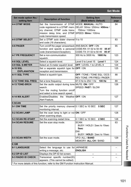
101
Functions Used A
s Needed
Set Mode
Set mode option No./setting Item Description of function Setting Item
(Bold letters: Default)Reference
page4-4 DTMF MODE Set the transmission of DTMF
code registered to a DTMF mem-ory channel, DTMF code trans-mission delay time, and DTMF code transmission speed.
MODE: MANUAL / AUTODELAY: 50ms / 250ms / 450ms /
750ms / 1000msSPEED: 50ms / 100ms
84
4-5 DTMF SELECT Set a DTMF auto dialer channel and code (16 characters).
1 to 10 83
4-6 PAGER Turn on/off the pager answerback function and specify a personal code (transmission/reception).
ANS-BACK: OFF / ONCODE-RX: 01 02 to 50 49 05 47CODE-TX: 01 02 to 50 49 05 47
95
4-7 PR FREQUENCY Set a non-communication squelch.
300 Hz to 3000 Hz 1600 Hz 123
4-8 SQL LEVEL Select a squelch level. Level 0 to Level 15 Level 1 1244-9 SQL S-METER Select an S-meter squelch level. OFF / LEVEL 1 to LEVEL 9 1244-10 SQL
EXPLANATIONSet a separate squelch type for reception and transmission.
OFF / ON 125
4-11 SQL TYPE Select a squelch type. OFF / TONE / TONE SQL / DCS / REV TONE / PR FREQ / PAGER
88
4-12 TONE SQL FREQ Set a tone frequency. 67.0 Hz to 254.1 Hz 100 Hz 894-13 TONE-SRCH Set the audio output during tone
search.Turn the muting function on/off and select a tone search speed.
MUTE: ON / OFFSPEED: FAST / SLOW
126
4-14 WX ALERT Enables/Disables the Weather Alert Feature.
OFF / ON 127
5 SCAN5-1 DW TIME Set the priority memory channel
monitoring interval.0.1 SEC to 10 SEC 5 SEC 127
5-2 SCAN LAMP Set the scan lamp to light or not when scanning stops.
ON / OFF 128
5-3 SCAN RE-START Set the scanning restart time. 0.1 SEC to 10 SEC 2 SEC 1285-4 SCAN RESUME Set the scan stop mode. SCAN:
BUSY / HOLD / 2sec to 10sec 5sec
DW: BUSY / HOLD / 2sec to 10sec
63
5-5 SCAN WIDTH Set the scan mode. VFO: ALL / BANDMEMORY: ALL CH / BAND
129
6 GM6-1 LANGUAGE Select the language to use for
writing a message, etc.JAPANESEENGLISH
–
6-2 DP-ID LIST Displays the DP-ID list screen. – –6-3 RADIO ID CHECK Transceiver specific number(ID)
appears. (This cannot be edited)– –
* For more details of this function, refer to the GM Function Instruction Manual.
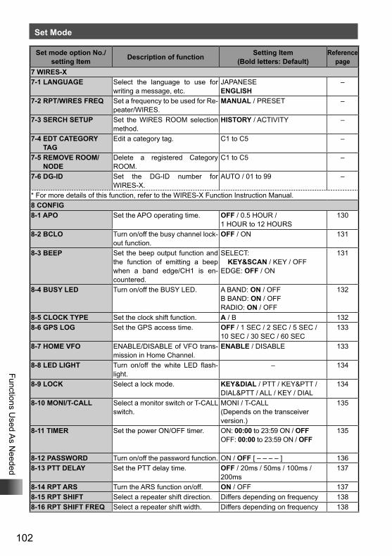
102
Functions Used A
s Needed
Set Mode
Set mode option No./setting Item Description of function Setting Item
(Bold letters: Default)Reference
page7 WIRES-X7-1 LANGUAGE Select the language to use for
writing a message, etc.JAPANESEENGLISH
–
7-2 RPT/WIRES FREQ Set a frequency to be used for Re-peater/WIRES.
MANUAL / PRESET –
7-3 SERCH SETUP Set the WIRES ROOM selection method.
HISTORY / ACTIVITY –
7-4 EDT CATEGORY TAG
Edit a category tag. C1 to C5 –
7-5 REMOVE ROOM/NODE
Delete a registered Category ROOM.
C1 to C5 –
7-6 DG-ID Set the DG-ID number for WIRES-X.
AUTO / 01 to 99 –
* For more details of this function, refer to the WIRES-X Function Instruction Manual.8 CONFIG8-1 APO Set the APO operating time. OFF / 0.5 HOUR /
1 HOUR to 12 HOURS130
8-2 BCLO Turn on/off the busy channel lock-out function.
OFF / ON 131
8-3 BEEP Set the beep output function and the function of emitting a beep when a band edge/CH1 is en-countered.
SELECT: KEY&SCAN / KEY / OFF
EDGE: OFF / ON
131
8-4 BUSY LED Turn on/off the BUSY LED. A BAND: ON / OFFB BAND: ON / OFFRADIO: ON / OFF
132
8-5 CLOCK TYPE Set the clock shift function. A / B 1328-6 GPS LOG Set the GPS access time. OFF / 1 SEC / 2 SEC / 5 SEC /
10 SEC / 30 SEC / 60 SEC133
8-7 HOME VFO ENABLE/DISABLE of VFO trans-mission in Home Channel.
ENABLE / DISABLE 133
8-8 LED LIGHT Turn on/off the white LED flash-light.
– 134
8-9 LOCK Select a lock mode. KEY&DIAL / PTT / KEY&PTT / DIAL&PTT / ALL / KEY / DIAL
134
8-10 MONI/T-CALL Select a monitor switch or T-CALL switch.
MONI / T-CALL(Depends on the transceiver version.)
135
8-11 TIMER Set the power ON/OFF timer. ON: 00:00 to 23:59 ON / OFFOFF: 00:00 to 23:59 ON / OFF
135
8-12 PASSWORD Turn on/off the password function. ON / OFF [ – – – – ] 1368-13 PTT DELAY Set the PTT delay time. OFF / 20ms / 50ms / 100ms /
200ms137
8-14 RPT ARS Turn the ARS function on/off. ON / OFF 1378-15 RPT SHIFT Select a repeater shift direction. Differs depending on frequency 1388-16 RPT SHIFT FREQ Select a repeater shift width. Differs depending on frequency 138
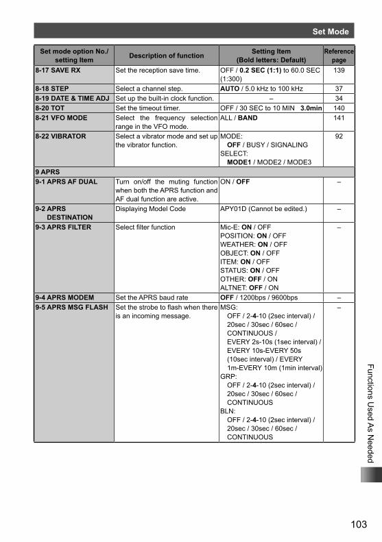
103
Functions Used A
s Needed
Set Mode
Set mode option No./setting Item Description of function Setting Item
(Bold letters: Default)Reference
page8-17 SAVE RX Set the reception save time. OFF / 0.2 SEC (1:1) to 60.0 SEC
(1:300)139
8-18 STEP Select a channel step. AUTO / 5.0 kHz to 100 kHz 378-19 DATE & TIME ADJ Set up the built-in clock function. – 348-20 TOT Set the timeout timer. OFF / 30 SEC to 10 MIN 3.0min 1408-21 VFO MODE Select the frequency selection
range in the VFO mode.ALL / BAND 141
8-22 VIBRATOR Select a vibrator mode and set up the vibrator function.
MODE: OFF / BUSY / SIGNALING
SELECT: MODE1 / MODE2 / MODE3
92
9 APRS9-1 APRS AF DUAL Turn on/off the muting function
when both the APRS function and AF dual function are active.
ON / OFF –
9-2 APRS DESTINATION
Displaying Model Code APY01D (Cannot be edited.) –
9-3 APRS FILTER Select filter function Mic-E: ON / OFFPOSITION: ON / OFFWEATHER: ON / OFFOBJECT: ON / OFFITEM: ON / OFFSTATUS: ON / OFFOTHER: OFF / ONALTNET: OFF / ON
–
9-4 APRS MODEM Set the APRS baud rate OFF / 1200bps / 9600bps –9-5 APRS MSG FLASH Set the strobe to flash when there
is an incoming message.MSG:
OFF / 2-4-10 (2sec interval) / 20sec / 30sec / 60sec / CONTINUOUS / EVERY 2s-10s (1sec interval) / EVERY 10s-EVERY 50s (10sec interval) / EVERY 1m-EVERY 10m (1min interval)
GRP: OFF / 2-4-10 (2sec interval) / 20sec / 30sec / 60sec / CONTINUOUS
BLN: OFF / 2-4-10 (2sec interval) / 20sec / 30sec / 60sec / CONTINUOUS
–
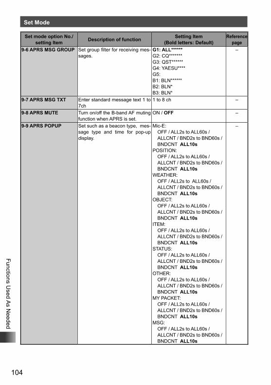
104
Functions Used A
s Needed
Set Mode
Set mode option No./setting Item Description of function Setting Item
(Bold letters: Default)Reference
page9-6 APRS MSG GROUP Set group filter for receiving mes-
sages.G1: ALL******G2: CQ*******G3: QST******G4: YAESU****G5: B1: BLN******B2: BLN*B3: BLN*
–
9-7 APRS MSG TXT Enter standard message text 1 to 7ch
1 to 8 ch –
9-8 APRS MUTE Turn on/off the B-band AF muting function when APRS is set.
ON / OFF –
9-9 APRS POPUP Set such as a beacon type, mes-sage type and time for pop-up display.
Mic-E: OFF / ALL2s to ALL60s / ALLCNT / BND2s to BND60s /
BNDCNT ALL10sPOSITION: OFF / ALL2s to ALL60s / ALLCNT / BND2s to BND60s /
BNDCNT ALL10sWEATHER: OFF / ALL2s to ALL60s / ALLCNT / BND2s to BND60s /
BNDCNT ALL10sOBJECT: OFF / ALL2s to ALL60s / ALLCNT / BND2s to BND60s /
BNDCNT ALL10sITEM: OFF / ALL2s to ALL60s / ALLCNT / BND2s to BND60s /
BNDCNT ALL10sSTATUS: OFF / ALL2s to ALL60s / ALLCNT / BND2s to BND60s /
BNDCNT ALL10sOTHER: OFF / ALL2s to ALL60s / ALLCNT / BND2s to BND60s /
BNDCNT ALL10sMY PACKET: OFF / ALL2s to ALL60s / ALLCNT / BND2s to BND60s /
BNDCNT ALL10sMSG: OFF / ALL2s to ALL60s / ALLCNT / BND2s to BND60s /
BNDCNT ALL10s
–
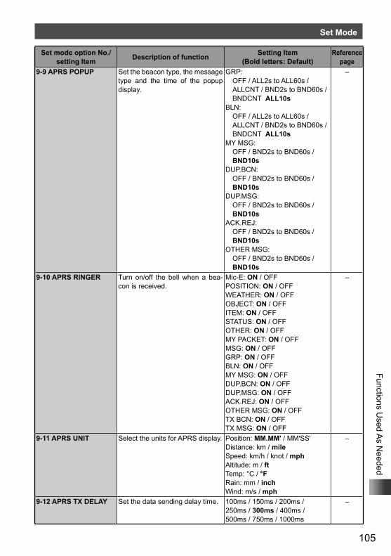
105
Functions Used A
s Needed
Set Mode
Set mode option No./setting Item Description of function Setting Item
(Bold letters: Default)Reference
page9-9 APRS POPUP Set the beacon type, the message
type and the time of the popup display.
GRP: OFF / ALL2s to ALL60s / ALLCNT / BND2s to BND60s /
BNDCNT ALL10sBLN: OFF / ALL2s to ALL60s / ALLCNT / BND2s to BND60s /
BNDCNT ALL10sMY MSG: OFF / BND2s to BND60s /
BND10sDUP.BCN: OFF / BND2s to BND60s /
BND10sDUP.MSG: OFF / BND2s to BND60s /
BND10sACK.REJ: OFF / BND2s to BND60s /
BND10sOTHER MSG: OFF / BND2s to BND60s /
BND10s
–
9-10 APRS RINGER Turn on/off the bell when a bea-con is received.
Mic-E: ON / OFFPOSITION: ON / OFFWEATHER: ON / OFFOBJECT: ON / OFFITEM: ON / OFFSTATUS: ON / OFFOTHER: ON / OFFMY PACKET: ON / OFFMSG: ON / OFFGRP: ON / OFFBLN: ON / OFFMY MSG: ON / OFFDUP.BCN: ON / OFFDUP.MSG: ON / OFFACK.REJ: ON / OFFOTHER MSG: ON / OFFTX BCN: ON / OFFTX MSG: ON / OFF
–
9-11 APRS UNIT Select the units for APRS display. Position: MM.MM' / MM'SS'Distance: km / mileSpeed: km/h / knot / mphAltitude: m / ftTemp: °C / °FRain: mm / inchWind: m/s / mph
–
9-12 APRS TX DELAY Set the data sending delay time. 100ms / 150ms / 200ms / 250ms / 300ms / 400ms / 500ms / 750ms / 1000ms
–
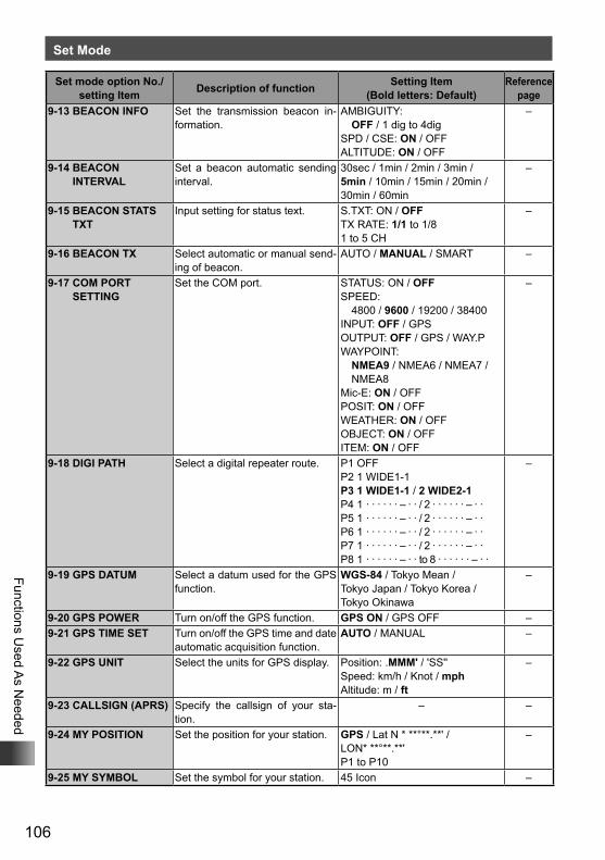
106
Functions Used A
s Needed
Set Mode
Set mode option No./setting Item Description of function Setting Item
(Bold letters: Default)Reference
page9-13 BEACON INFO Set the transmission beacon in-
formation.AMBIGUITY:
OFF / 1 dig to 4digSPD / CSE: ON / OFFALTITUDE: ON / OFF
–
9-14 BEACON INTERVAL
Set a beacon automatic sending interval.
30sec / 1min / 2min / 3min / 5min / 10min / 15min / 20min / 30min / 60min
–
9-15 BEACON STATS TXT
Input setting for status text. S.TXT: ON / OFFTX RATE: 1/1 to 1/81 to 5 CH
–
9-16 BEACON TX Select automatic or manual send-ing of beacon.
AUTO / MANUAL / SMART –
9-17 COM PORT SETTING
Set the COM port. STATUS: ON / OFFSPEED:
4800 / 9600 / 19200 / 38400INPUT: OFF / GPSOUTPUT: OFF / GPS / WAY.PWAYPOINT:
NMEA9 / NMEA6 / NMEA7 / NMEA8
Mic-E: ON / OFFPOSIT: ON / OFFWEATHER: ON / OFFOBJECT: ON / OFFITEM: ON / OFF
–
9-18 DIGI PATH Select a digital repeater route. P1 OFFP2 1 WIDE1-1P3 1 WIDE1-1 / 2 WIDE2-1P4 1 · · · · · · – · · / 2 · · · · · · – · · P5 1 · · · · · · – · · / 2 · · · · · · – · ·P6 1 · · · · · · – · · / 2 · · · · · · – · ·P7 1 · · · · · · – · · / 2 · · · · · · – · ·P8 1 · · · · · · – · · to 8 · · · · · · – · ·
–
9-19 GPS DATUM Select a datum used for the GPS function.
WGS-84 / Tokyo Mean / Tokyo Japan / Tokyo Korea / Tokyo Okinawa
–
9-20 GPS POWER Turn on/off the GPS function. GPS ON / GPS OFF –9-21 GPS TIME SET Turn on/off the GPS time and date
automatic acquisition function.AUTO / MANUAL –
9-22 GPS UNIT Select the units for GPS display. Position: .MMM' / 'SS''Speed: km/h / Knot / mphAltitude: m / ft
–
9-23 CALLSIGN (APRS) Specify the callsign of your sta-tion.
– –
9-24 MY POSITION Set the position for your station. GPS / Lat N * **°**.**' / LON* **°**.**'P1 to P10
–
9-25 MY SYMBOL Set the symbol for your station. 45 Icon –
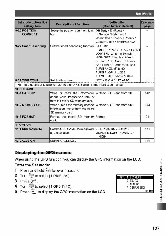
107
Functions Used A
s Needed
Set Mode
Set mode option No./setting Item Description of function Setting Item
(Bold letters: Default)Reference
page9-26 POSITION
COMMENTSet up the position comment func-tion.
Off Duty / En Route / In Service / Returning / Committed / Special / Priority / Custom 0 to 6 / EMERGENCY!
–
9-27 SmartBeaconing Set the smart beaconing function. STATUS: OFF / TYPE1 / TYPE2 / TYPE3
LOW SPD: 2mph to 30mphHIGH SPD: 31mph to 90mphSLOW RATE: 1min to 100minFAST RATE: 10sec to 180secTURN ANGL: 5° to 90°TURN SLOP: 1 to 255TURN TIME: 5sec to 180sec
–
9-28 TIME ZONE Set the time zone. UTC ±13.0 H / UTC+0:00 –* For more details of functions, refer to the APRS Section in the instruction manual.10 SD CARD10-1 BACKUP Write or read the information
about your transceiver into or from the micro SD memory card.
Write to SD / Read from SD 142
10-2 MEMORY CH Write or read the memory channel information into or from the micro SD memory card.
Write to SD / Read from SD 143
10-3 FORMAT Format the micro SD memory card.
Format 24
11 OPTION11-1 USB CAMERA Set the USB CAMERA image size
and resolution.SIZE: 160x120 / 320x240QUALITY: LOW / NORMAL /
HIGH
144
12 CALLSIGN Set the CALLSIGN. – 144
Displaying the GPS screen.When using the GPS function, you can display the GPS information on the LCD.Enter the Set mode:1 Press and hold M for over 1 second.2 Turn O to select [1 DISPLAY].3 Press H.4 Turn O to select [1 GPS INFO].5 Press H to display the GPS information on the LCD.
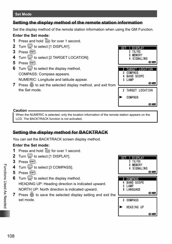
108
Functions Used A
s Needed
Set Mode
Setting the display method of the remote station informationSet the display method of the remote station information when using the GM Function.Enter the Set mode:1 Press and hold M for over 1 second.2 Turn O to select [1 DISPLAY].3 Press H.4 Turn O to select [2 TARGET LOCATION].5 Press H.6 Turn O to select the display method. COMPASS: Compass appears. NUMERIC: Longitude and latitude appear.7 Press p to set the selected display method, and exit from
the Set mode.
CautionWhen the NUMERIC is selected, only the location information of the remote station appears on the LCD. The BACKTRACK function is not activated.
Setting the display method for BACKTRACKYou can set the BACKTRACK screen display method.Enter the Set mode:1 Press and hold M for over 1 second.2 Turn O to select [1 DISPLAY].3 Press H.4 Turn O to select [3 COMPASS].5 Press H.6 Turn O to select the display method. HEADING UP: Heading direction is indicated upward. NORTH UP: North direction is indicated upward.7 Press p to save the selected display setting and exit the
set mode.
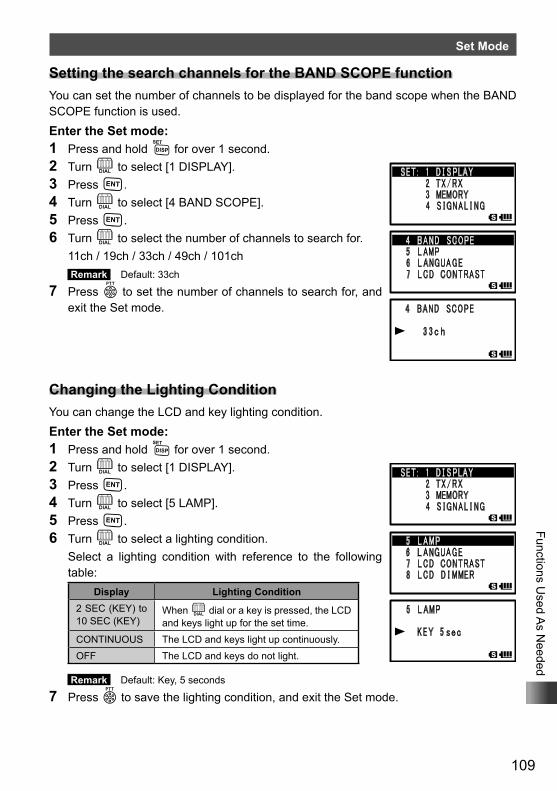
109
Functions Used A
s Needed
Set Mode
Setting the search channels for the BAND SCOPE functionYou can set the number of channels to be displayed for the band scope when the BAND SCOPE function is used.Enter the Set mode:1 Press and hold M for over 1 second.2 Turn O to select [1 DISPLAY].3 Press H.4 Turn O to select [4 BAND SCOPE].5 Press H.6 Turn O to select the number of channels to search for. 11ch / 19ch / 33ch / 49ch / 101ch
Remark Default: 33ch
7 Press p to set the number of channels to search for, and exit the Set mode.
Changing the Lighting ConditionYou can change the LCD and key lighting condition.Enter the Set mode:1 Press and hold M for over 1 second.2 Turn O to select [1 DISPLAY].3 Press H.4 Turn O to select [5 LAMP].5 Press H.6 Turn O to select a lighting condition. Select a lighting condition with reference to the following
table:Display Lighting Condition
2 SEC (KEY) to 10 SEC (KEY)
When O dial or a key is pressed, the LCD and keys light up for the set time.
CONTINUOUS The LCD and keys light up continuously.OFF The LCD and keys do not light.
Remark Default: Key, 5 seconds
7 Press p to save the lighting condition, and exit the Set mode.
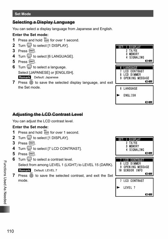
110
Functions Used A
s Needed
Set Mode
Selecting a Display LanguageYou can select a display language from Japanese and English.Enter the Set mode:1 Press and hold M for over 1 second.2 Turn O to select [1 DISPLAY].3 Press H.4 Turn O to select [6 LANGUAGE].5 Press H.6 Turn O to select a language. Select [JAPANESE] or [ENGLISH].
Remark Default: Japanese
7 Press p to save the selected display language, and exit the Set mode.
Adjusting the LCD Contrast LevelYou can adjust the LCD contrast level.Enter the Set mode:1 Press and hold M for over 1 second.2 Turn O to select [1 DISPLAY].3 Press H.4 Turn O to select [7 LCD CONTRAST].5 Press H.6 Turn O to select a contrast level. Select from among LEVEL 1 (LIGHT) to LEVEL 15 (DARK).
Remark Default: LEVEL 7
7 Press p to save the selected contrast, and exit the Set mode.
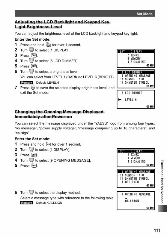
111
Functions Used A
s Needed
Set Mode
Adjusting the LCD Backlight and Keypad Key Light Brightness LevelYou can adjust the brightness level of the LCD backlight and keypad key light.Enter the Set mode:1 Press and hold M for over 1 second.2 Turn O to select [1 DISPLAY].3 Press H.4 Turn O to select [8 LCD DIMMER].5 Press H.6 Turn O to select a brightness level. You can select from LEVEL 1 (DARK) to LEVEL 6 (BRIGHT).
Remark Default: LEVEL 6
7 Press p to save the selected display brightness level, and exit the Set mode.
Changing the Opening Message Displayed Immediately after Power-onYou can select the message displayed under the “YAESU” logo from among four types: “no message”, “power supply voltage”, “message comprising up to 16 characters”, and “callsign”.Enter the Set mode:1 Press and hold M for over 1 second.2 Turn O to select [1 DISPLAY].3 Press H.4 Turn O to select [9 OPENING MESSAGE].5 Press H.
6 Turn O to select the display method. Select a message type with reference to the following table:
Remark Default: CALLSIGN
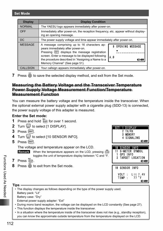
112
Functions Used A
s Needed
Set Mode
Display Display ConditionNORMAL The YAESU logo appears immediately after power-on.OFF Immediately after power-on, the reception frequency, etc. appear without display-
ing an opening message.DC The power supply voltage and time appear immediately after power-on.MESSAGE A message comprising up to 16 characters ap-
pears immediately after power-on.Pressing H displays the message registration screen. Enter a message to be displayed following the procedure described in “Assigning a Name to a Memory Channel” (See page 51).
CALLSIGN Your callsign appears immediately after power-on.
7 Press p to save the selected display method, and exit from the Set mode.
Measuring the Battery Voltage and the Transceiver Temperature Power Supply Voltage Measurement Function/Temperature Measurement FunctionYou can measure the battery voltage and the temperature inside the transceiver. When the optional external power supply adapter with a cigarette plug (SDD-13) is connected, the power supply voltage of this adapter is measured.Enter the Set mode:1 Press and hold M for over 1 second.2 Turn O to select [1 DISPLAY].3 Press H.4 Turn O to select [10 SENSOR INFO].5 Press H. The voltage and temperature appear on the LCD.
Remark When the temperature appears on the LCD, pressing V toggles the unit of temperature display between °C and °F.
7 Press M.8 Press p to exit from the Set mode.
Tips• The display changes as follows depending on the type of the power supply used.
Battery pack: “Lit”Battery case: “Dry”External power supply adapter: “Ext”
• During mono band reception, the voltage can be displayed on the LCD constantly (See page 27).• This function displays the temperature inside the transceiver.• In a situation where the temperature inside of the transceiver does not rise (e.g., standby reception),
you can know the approximate outside temperature from the temperature displayed on the LCD.
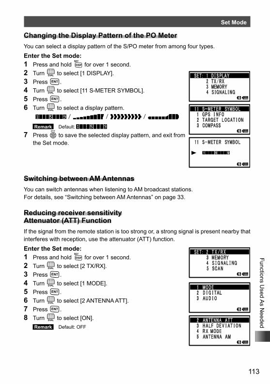
113
Functions Used A
s Needed
Set Mode
Changing the Display Pattern of the PO MeterYou can select a display pattern of the S/PO meter from among four types.Enter the Set mode:1 Press and hold M for over 1 second.2 Turn O to select [1 DISPLAY].3 Press H.4 Turn O to select [11 S-METER SYMBOL].5 Press H.6 Turn O to select a display pattern.
/ / /
Remark Default: / / /
7 Press p to save the selected display pattern, and exit from the Set mode.
Switching between AM AntennasYou can switch antennas when listening to AM broadcast stations.For details, see “Switching between AM Antennas” on page 33.
Reducing receiver sensitivity Attenuator (ATT) FunctionIf the signal from the remote station is too strong or, a strong signal is present nearby that interferes with reception, use the attenuator (ATT) function.Enter the Set mode:1 Press and hold M for over 1 second.2 Turn O to select [2 TX/RX].3 Press H.4 Turn O to select [1 MODE].5 Press H.6 Turn O to select [2 ANTENNA ATT].7 Press H.8 Turn O to select [ON].
Remark Default: OFF
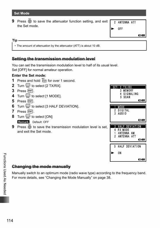
114
Functions Used A
s Needed
Set Mode
9 Press p to save the attenuator function setting, and exit the Set mode.
Tip• The amount of attenuation by the attenuator (ATT) is about 10 dB.
Setting the transmission modulation levelYou can set the transmission modulation level to half of its usual level.Set [OFF] for normal amateur operation.Enter the Set mode:1 Press and hold M for over 1 second.2 Turn O to select [2 TX/RX].3 Press H.4 Turn O to select [1 MODE].5 Press H.6 Turn O to select [3 HALF DEVIATION].7 Press H.8 Turn O to select [ON]
Remark Default: OFF
9 Press p to save the transmission modulation level is set, and exit the Set mode.
Changing the mode manuallyManually switch to an optimum mode (radio wave type) according to the frequency band.For more details, see “Changing the Mode Manually” on page 38.
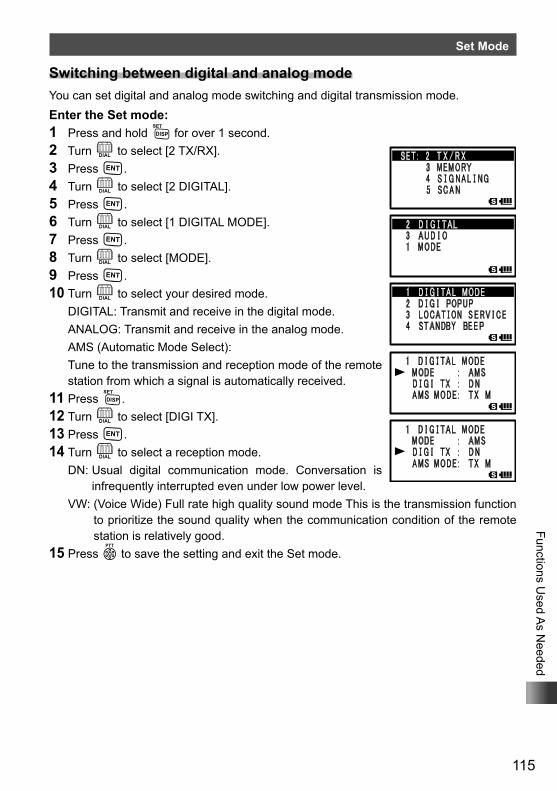
115
Functions Used A
s Needed
Set Mode
Switching between digital and analog modeYou can set digital and analog mode switching and digital transmission mode.Enter the Set mode:1 Press and hold M for over 1 second.2 Turn O to select [2 TX/RX].3 Press H.4 Turn O to select [2 DIGITAL].5 Press H.6 Turn O to select [1 DIGITAL MODE].7 Press H.8 Turn O to select [MODE].9 Press H.10 Turn O to select your desired mode. DIGITAL: Transmit and receive in the digital mode. ANALOG: Transmit and receive in the analog mode. AMS (Automatic Mode Select): Tune to the transmission and reception mode of the remote
station from which a signal is automatically received.11 Press M.12 Turn O to select [DIGI TX].13 Press H.14 Turn O to select a reception mode. DN: Usual digital communication mode. Conversation is
infrequently interrupted even under low power level. VW: (Voice Wide) Full rate high quality sound mode This is the transmission function
to prioritize the sound quality when the communication condition of the remote station is relatively good.
15 Press p to save the setting and exit the Set mode.
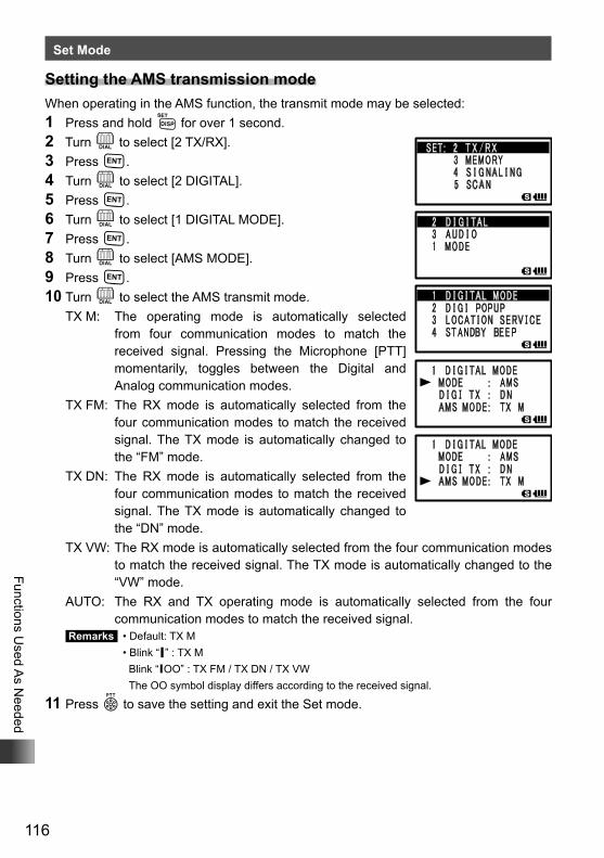
116
Functions Used A
s Needed
Set Mode
Setting the AMS transmission modeWhen operating in the AMS function, the transmit mode may be selected:1 Press and hold M for over 1 second.2 Turn O to select [2 TX/RX].3 Press H.4 Turn O to select [2 DIGITAL].5 Press H.6 Turn O to select [1 DIGITAL MODE].7 Press H.8 Turn O to select [AMS MODE].9 Press H.10 Turn O to select the AMS transmit mode.
TX M: The operating mode is automatically selected from four communication modes to match the received signal. Pressing the Microphone [PTT] momentarily, toggles between the Digital and Analog communication modes.
TX FM: The RX mode is automatically selected from the four communication modes to match the received signal. The TX mode is automatically changed to the “FM” mode.
TX DN: The RX mode is automatically selected from the four communication modes to match the received signal. The TX mode is automatically changed to the “DN” mode.
TX VW: The RX mode is automatically selected from the four communication modes to match the received signal. The TX mode is automatically changed to the “VW” mode.
AUTO: The RX and TX operating mode is automatically selected from the four communication modes to match the received signal.
Remarks • Default: TX M • Blink “▎” : TX M
Blink “▎OO” : TX FM / TX DN / TX VWThe OO symbol display differs according to the received signal.
11 Press p to save the setting and exit the Set mode.
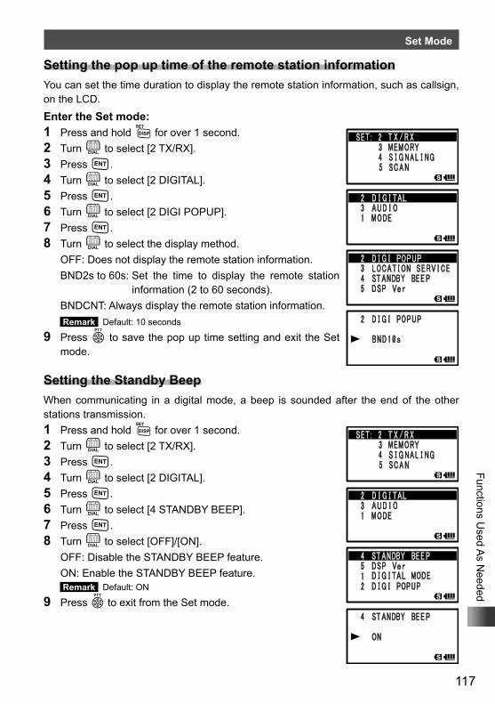
117
Functions Used A
s Needed
Set Mode
Setting the pop up time of the remote station informationYou can set the time duration to display the remote station information, such as callsign, on the LCD.Enter the Set mode:1 Press and hold M for over 1 second.2 Turn O to select [2 TX/RX].3 Press H.4 Turn O to select [2 DIGITAL].5 Press H.6 Turn O to select [2 DIGI POPUP].7 Press H.8 Turn O to select the display method. OFF: Does not display the remote station information. BND2s to 60s: Set the time to display the remote station
information (2 to 60 seconds). BNDCNT: Always display the remote station information.
Remark Default: 10 seconds
9 Press p to save the pop up time setting and exit the Set mode.
Setting the Standby BeepWhen communicating in a digital mode, a beep is sounded after the end of the other stations transmission.1 Press and hold M for over 1 second.2 Turn O to select [2 TX/RX].3 Press H.4 Turn O to select [2 DIGITAL].5 Press H.6 Turn O to select [4 STANDBY BEEP].7 Press H.8 Turn O to select [OFF]/[ON]. OFF: Disable the STANDBY BEEP feature. ON: Enable the STANDBY BEEP feature.
Remark Default: ON
9 Press p to exit from the Set mode.
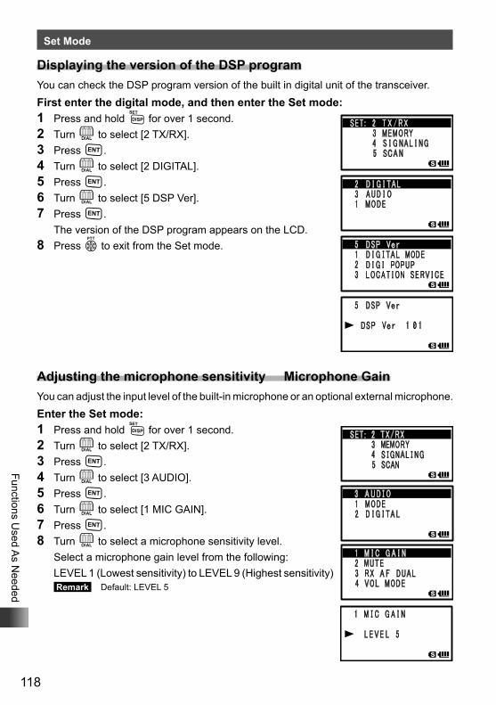
118
Functions Used A
s Needed
Set Mode
Displaying the version of the DSP programYou can check the DSP program version of the built in digital unit of the transceiver.First enter the digital mode, and then enter the Set mode:1 Press and hold M for over 1 second.2 Turn O to select [2 TX/RX].3 Press H.4 Turn O to select [2 DIGITAL].5 Press H.6 Turn O to select [5 DSP Ver].7 Press H. The version of the DSP program appears on the LCD.8 Press p to exit from the Set mode.
Adjusting the microphone sensitivity Microphone GainYou can adjust the input level of the built-in microphone or an optional external microphone.Enter the Set mode:1 Press and hold M for over 1 second.2 Turn O to select [2 TX/RX].3 Press H.4 Turn O to select [3 AUDIO].5 Press H.6 Turn O to select [1 MIC GAIN].7 Press H.8 Turn O to select a microphone sensitivity level. Select a microphone gain level from the following: LEVEL 1 (Lowest sensitivity) to LEVEL 9 (Highest sensitivity)
Remark Default: LEVEL 5
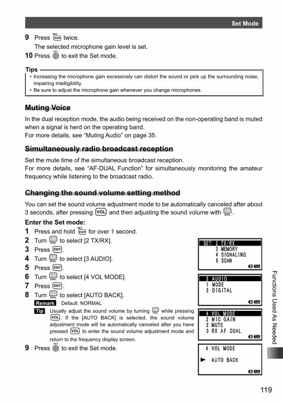
119
Functions Used A
s Needed
Set Mode
9 Press M twice. The selected microphone gain level is set.10 Press p to exit the Set mode.
Tips• Increasing the microphone gain excessively can distort the sound or pick up the surrounding noise,
impairing intelligibility.• Be sure to adjust the microphone gain whenever you change microphones.
Muting VoiceIn the dual reception mode, the audio being received on the non-operating band is muted when a signal is herd on the operating band.For more details, see “Muting Audio” on page 35.
Simultaneously radio broadcast receptionSet the mute time of the simultaneous broadcast reception.For more details, see “AF-DUAL Function” for simultaneously monitoring the amateur frequency while listening to the broadcast radio.
Changing the sound volume setting methodYou can set the sound volume adjustment mode to be automatically canceled after about 3 seconds, after pressing v and then adjusting the sound volume with O.Enter the Set mode:1 Press and hold M for over 1 second.2 Turn O to select [2 TX/RX].3 Press H.4 Turn O to select [3 AUDIO].5 Press H.6 Turn O to select [4 VOL MODE].7 Press H.8 Turn O to select [AUTO BACK].
Remark Default: NORMAL Tip Usually adjust the sound volume by turning O while pressing
v. If the [AUTO BACK] is selected, the sound volume adjustment mode will be automatically canceled after you have pressed v to enter the sound volume adjustment mode and return to the frequency display screen.
9 Press p to exit the Set mode.
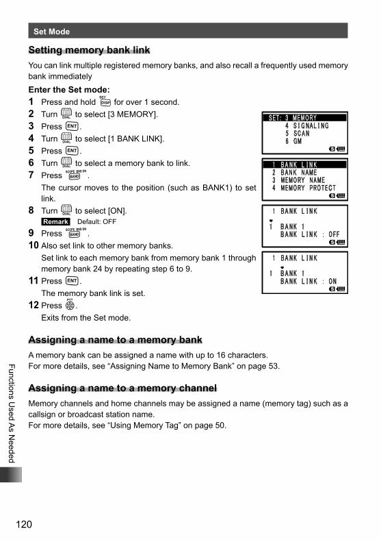
120
Functions Used A
s Needed
Set Mode
Setting memory bank linkYou can link multiple registered memory banks, and also recall a frequently used memory bank immediatelyEnter the Set mode:1 Press and hold M for over 1 second.2 Turn O to select [3 MEMORY].3 Press H.4 Turn O to select [1 BANK LINK].5 Press H.6 Turn O to select a memory bank to link.7 Press B. The cursor moves to the position (such as BANK1) to set
link.8 Turn O to select [ON].
Remark Default: OFF
9 Press B.10 Also set link to other memory banks. Set link to each memory bank from memory bank 1 through
memory bank 24 by repeating step 6 to 9.11 Press H. The memory bank link is set.12 Press p. Exits from the Set mode.
Assigning a name to a memory bankA memory bank can be assigned a name with up to 16 characters.For more details, see “Assigning Name to Memory Bank” on page 53.
Assigning a name to a memory channelMemory channels and home channels may be assigned a name (memory tag) such as a callsign or broadcast station name.For more details, see “Using Memory Tag” on page 50.
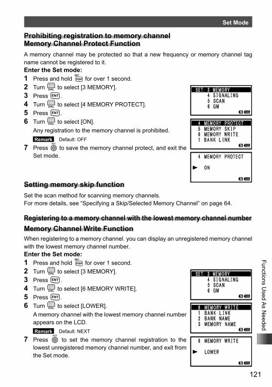
121
Functions Used A
s Needed
Set Mode
Prohibiting registration to memory channel Memory Channel Protect FunctionA memory channel may be protected so that a new frequency or memory channel tag name cannot be registered to it.Enter the Set mode:1 Press and hold M for over 1 second.2 Turn O to select [3 MEMORY].3 Press H.4 Turn O to select [4 MEMORY PROTECT].5 Press H.6 Turn O to select [ON]. Any registration to the memory channel is prohibited.
Remark Default: OFF
7 Press p to save the memory channel protect, and exit the Set mode.
Setting memory skip functionSet the scan method for scanning memory channels.For more details, see “Specifying a Skip/Selected Memory Channel” on page 64.
Registering to a memory channel with the lowest memory channel numberMemory Channel Write FunctionWhen registering to a memory channel. you can display an unregistered memory channel with the lowest memory channel number.Enter the Set mode:1 Press and hold M for over 1 second.2 Turn O to select [3 MEMORY].3 Press H.4 Turn O to select [6 MEMORY WRITE].5 Press H.6 Turn O to select [LOWER]. A memory channel with the lowest memory channel number
appears on the LCD. Remark Default: NEXT
7 Press p to set the memory channel registration to the lowest unregistered memory channel number, and exit from the Set mode.
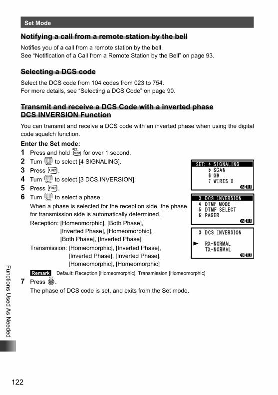
122
Functions Used A
s Needed
Set Mode
Notifying a call from a remote station by the bellNotifies you of a call from a remote station by the bell.See “Notification of a Call from a Remote Station by the Bell” on page 93.
Selecting a DCS codeSelect the DCS code from 104 codes from 023 to 754.For more details, see “Selecting a DCS Code” on page 90.
Transmit and receive a DCS Code with a inverted phase DCS INVERSION FunctionYou can transmit and receive a DCS code with an inverted phase when using the digital code squelch function.Enter the Set mode:1 Press and hold M for over 1 second.2 Turn O to select [4 SIGNALING].3 Press H.4 Turn O to select [3 DCS INVERSION].5 Press H.6 Turn O to select a phase. When a phase is selected for the reception side, the phase
for transmission side is automatically determined. Reception: [Homeomorphic], [Both Phase],
[Inverted Phase], [Homeomorphic], [Both Phase], [Inverted Phase]
Transmission: [Homeomorphic], [Inverted Phase], [Inverted Phase], [Inverted Phase], [Homeomorphic], [Homeomorphic]
Remark Default: Reception [Homeomorphic], Transmission [Homeomorphic]
7 Press p. The phase of DCS code is set, and exits from the Set mode.
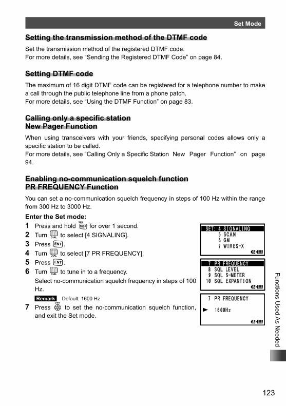
123
Functions Used A
s Needed
Set Mode
Setting the transmission method of the DTMF codeSet the transmission method of the registered DTMF code.For more details, see “Sending the Registered DTMF Code” on page 84.
Setting DTMF codeThe maximum of 16 digit DTMF code can be registered for a telephone number to make a call through the public telephone line from a phone patch.For more details, see “Using the DTMF Function” on page 83.
Calling only a specific station New Pager FunctionWhen using transceivers with your friends, specifying personal codes allows only a specific station to be called.For more details, see “Calling Only a Specific Station New Pager Function” on page 94.
Enabling no-communication squelch function PR FREQUENCY FunctionYou can set a no-communication squelch frequency in steps of 100 Hz within the range from 300 Hz to 3000 Hz.Enter the Set mode:1 Press and hold M for over 1 second.2 Turn O to select [4 SIGNALING].3 Press H.4 Turn O to select [7 PR FREQUENCY].5 Press H.6 Turn O to tune in to a frequency. Select no-communication squelch frequency in steps of 100
Hz. Remark Default: 1600 Hz
7 Press p to set the no-communication squelch function, and exit the Set mode.
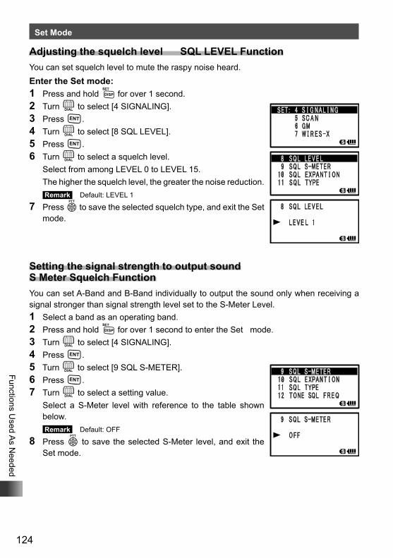
124
Functions Used A
s Needed
Set Mode
Adjusting the squelch level SQL LEVEL FunctionYou can set squelch level to mute the raspy noise heard.Enter the Set mode:1 Press and hold M for over 1 second.2 Turn O to select [4 SIGNALING].3 Press H.4 Turn O to select [8 SQL LEVEL].5 Press H.6 Turn O to select a squelch level. Select from among LEVEL 0 to LEVEL 15. The higher the squelch level, the greater the noise reduction.
Remark Default: LEVEL 1
7 Press p to save the selected squelch type, and exit the Set mode.
Setting the signal strength to output sound S Meter Squelch FunctionYou can set A-Band and B-Band individually to output the sound only when receiving a signal stronger than signal strength level set to the S-Meter Level.1 Select a band as an operating band.2 Press and hold M for over 1 second to enter the Set mode.3 Turn O to select [4 SIGNALING].4 Press H.5 Turn O to select [9 SQL S-METER].6 Press H.7 Turn O to select a setting value. Select a S-Meter level with reference to the table shown
below. Remark Default: OFF
8 Press p to save the selected S-Meter level, and exit the Set mode.
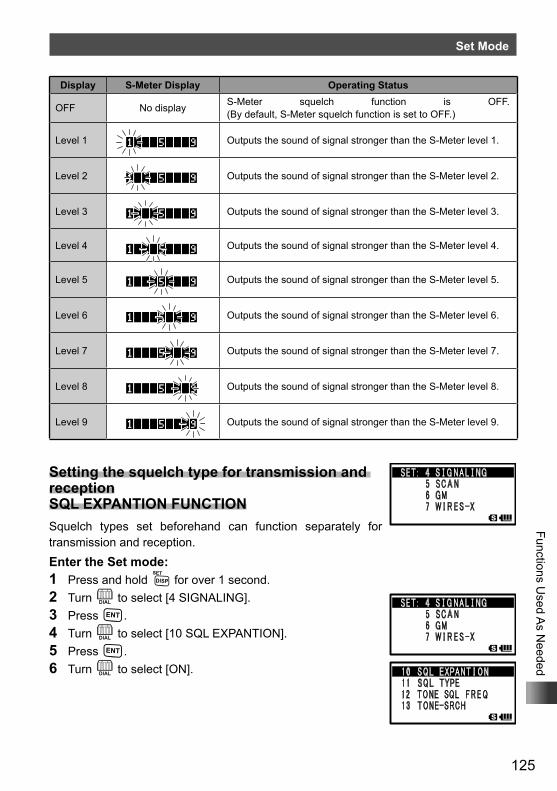
125
Functions Used A
s Needed
Set Mode
Display S-Meter Display Operating Status
OFF No display S-Meter squelch function is OFF. (By default, S-Meter squelch function is set to OFF.)
Level 1 Outputs the sound of signal stronger than the S-Meter level 1.
Level 2 Outputs the sound of signal stronger than the S-Meter level 2.
Level 3 Outputs the sound of signal stronger than the S-Meter level 3.
Level 4 Outputs the sound of signal stronger than the S-Meter level 4.
Level 5 Outputs the sound of signal stronger than the S-Meter level 5.
Level 6 Outputs the sound of signal stronger than the S-Meter level 6.
Level 7 Outputs the sound of signal stronger than the S-Meter level 7.
Level 8 Outputs the sound of signal stronger than the S-Meter level 8.
Level 9 Outputs the sound of signal stronger than the S-Meter level 9.
Setting the squelch type for transmission and reception SQL EXPANTION FUNCTIONSquelch types set beforehand can function separately for transmission and reception.Enter the Set mode:1 Press and hold M for over 1 second.2 Turn O to select [4 SIGNALING].3 Press H.4 Turn O to select [10 SQL EXPANTION].5 Press H.6 Turn O to select [ON].
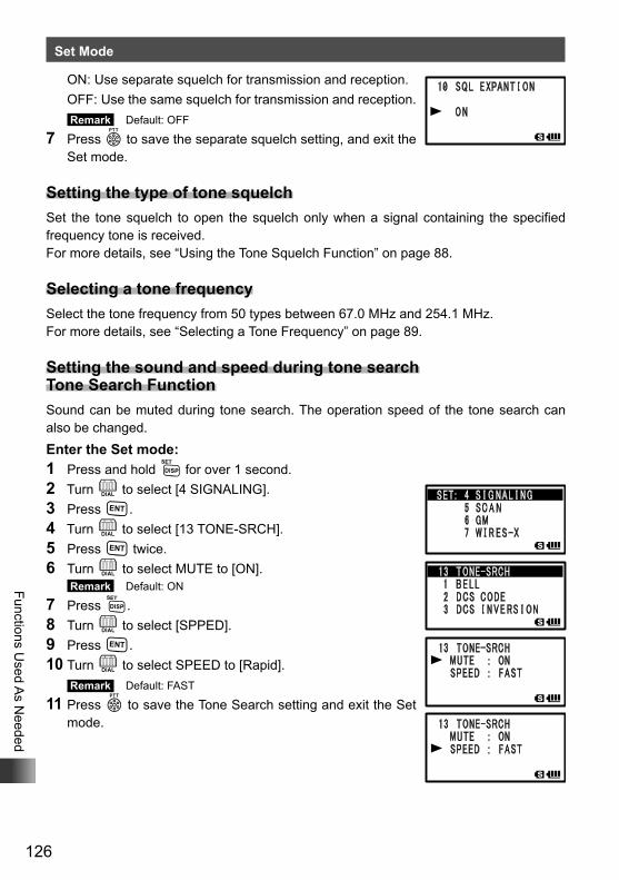
126
Functions Used A
s Needed
Set Mode
ON: Use separate squelch for transmission and reception. OFF: Use the same squelch for transmission and reception.
Remark Default: OFF
7 Press p to save the separate squelch setting, and exit the Set mode.
Setting the type of tone squelchSet the tone squelch to open the squelch only when a signal containing the specified frequency tone is received.For more details, see “Using the Tone Squelch Function” on page 88.
Selecting a tone frequencySelect the tone frequency from 50 types between 67.0 MHz and 254.1 MHz.For more details, see “Selecting a Tone Frequency” on page 89.
Setting the sound and speed during tone search Tone Search FunctionSound can be muted during tone search. The operation speed of the tone search can also be changed.Enter the Set mode:1 Press and hold M for over 1 second.2 Turn O to select [4 SIGNALING].3 Press H.4 Turn O to select [13 TONE-SRCH].5 Press H twice.6 Turn O to select MUTE to [ON].
Remark Default: ON
7 Press M.8 Turn O to select [SPPED].9 Press H.10 Turn O to select SPEED to [Rapid].
Remark Default: FAST
11 Press p to save the Tone Search setting and exit the Set mode.
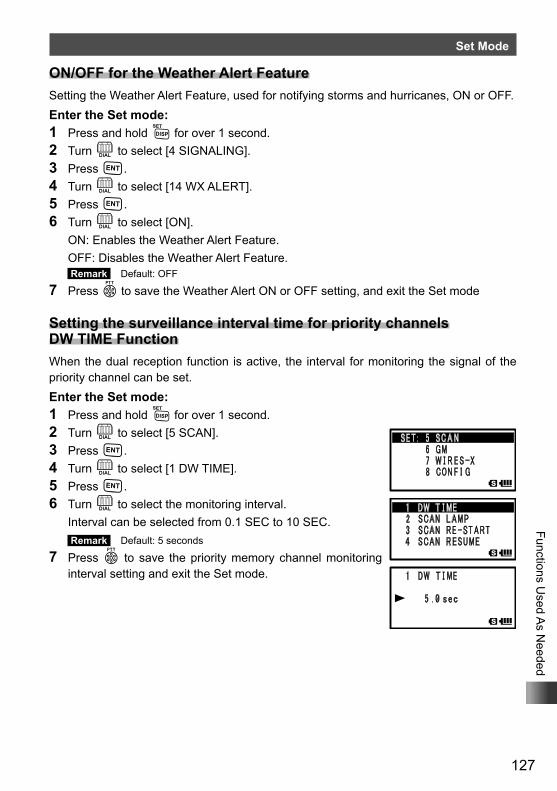
127
Functions Used A
s Needed
Set Mode
ON/OFF for the Weather Alert FeatureSetting the Weather Alert Feature, used for notifying storms and hurricanes, ON or OFF.Enter the Set mode:1 Press and hold M for over 1 second.2 Turn O to select [4 SIGNALING].3 Press H.4 Turn O to select [14 WX ALERT].5 Press H.6 Turn O to select [ON]. ON: Enables the Weather Alert Feature. OFF: Disables the Weather Alert Feature.
Remark Default: OFF
7 Press p to save the Weather Alert ON or OFF setting, and exit the Set mode
Setting the surveillance interval time for priority channels DW TIME FunctionWhen the dual reception function is active, the interval for monitoring the signal of the priority channel can be set.Enter the Set mode:1 Press and hold M for over 1 second.2 Turn O to select [5 SCAN].3 Press H.4 Turn O to select [1 DW TIME].5 Press H.6 Turn O to select the monitoring interval. Interval can be selected from 0.1 SEC to 10 SEC.
Remark Default: 5 seconds
7 Press p to save the priority memory channel monitoring interval setting and exit the Set mode.
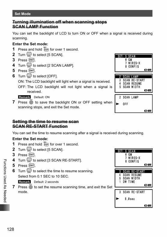
128
Functions Used A
s Needed
Set Mode
Turning illumination off when scanning stops SCAN LAMP FunctionYou can set the backlight of LCD to turn ON or OFF when a signal is received during scanning.Enter the Set mode:1 Press and hold M for over 1 second.2 Turn O to select [5 SCAN].3 Press H.4 Turn O to select [2 SCAN LAMP].5 Press H.6 Turn O to select [OFF]. ON: The LCD backlight will light when a signal is received. OFF: The LCD backlight will not light when a signal is
received. Remark Default: ON
7 Press p to save the backlight ON or OFF setting when scanning stops, and exit the Set mode.
Setting the time to resume scan SCAN RE-START FunctionYou can set the time to resume scanning after a signal is received during scanning.Enter the Set mode:1 Press and hold M for over 1 second.2 Turn O to select [5 SCAN].3 Press H.4 Turn O to select [3 SCAN RE-START].5 Press H.6 Turn O to select the time to resume scanning. Select from 0.1 SEC to 10 SEC.
Remark Default: 2 seconds
7 Press p to set the resume scanning time, and exit the Set mode.
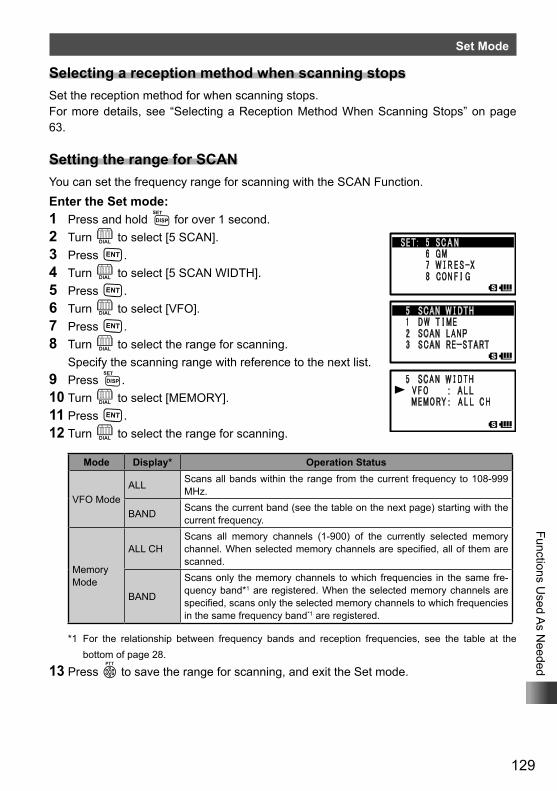
129
Functions Used A
s Needed
Set Mode
Selecting a reception method when scanning stopsSet the reception method for when scanning stops.For more details, see “Selecting a Reception Method When Scanning Stops” on page 63.
Setting the range for SCANYou can set the frequency range for scanning with the SCAN Function.Enter the Set mode:1 Press and hold M for over 1 second. 2 Turn O to select [5 SCAN].3 Press H.4 Turn O to select [5 SCAN WIDTH].5 Press H.6 Turn O to select [VFO].7 Press H.8 Turn O to select the range for scanning. Specify the scanning range with reference to the next list.9 Press M.10 Turn O to select [MEMORY].11 Press H.12 Turn O to select the range for scanning.
Mode Display* Operation Status
VFO ModeALL Scans all bands within the range from the current frequency to 108-999
MHz.
BAND Scans the current band (see the table on the next page) starting with the current frequency.
Memory Mode
ALL CHScans all memory channels (1-900) of the currently selected memory channel. When selected memory channels are specified, all of them are scanned.
BAND
Scans only the memory channels to which frequencies in the same fre-quency band*1 are registered. When the selected memory channels are specified, scans only the selected memory channels to which frequencies in the same frequency band*1 are registered.
*1 For the relationship between frequency bands and reception frequencies, see the table at the bottom of page 28.
13 Press p to save the range for scanning, and exit the Set mode.
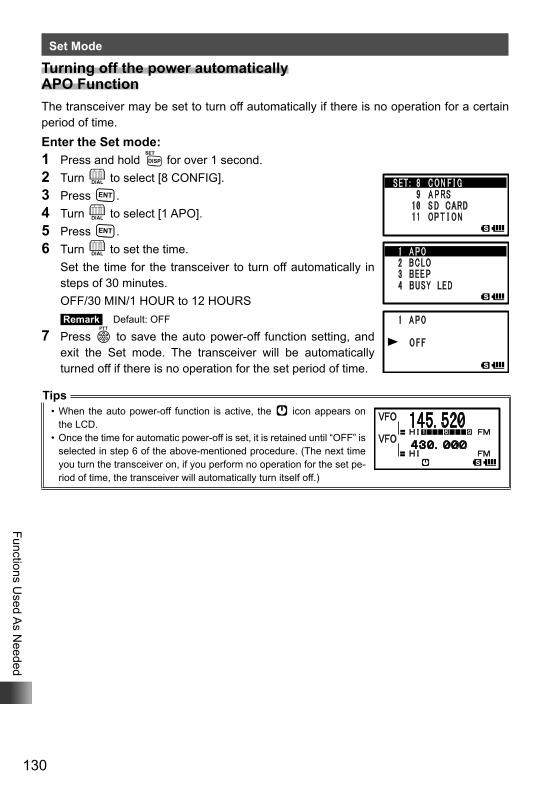
130
Functions Used A
s Needed
Set Mode
Turning off the power automatically APO FunctionThe transceiver may be set to turn off automatically if there is no operation for a certain period of time.Enter the Set mode:1 Press and hold M for over 1 second.2 Turn O to select [8 CONFIG].3 Press H.4 Turn O to select [1 APO].5 Press H.6 Turn O to set the time. Set the time for the transceiver to turn off automatically in
steps of 30 minutes. OFF/30 MIN/1 HOUR to 12 HOURS
Remark Default: OFF
7 Press p to save the auto power-off function setting, and exit the Set mode. The transceiver will be automatically turned off if there is no operation for the set period of time.
Tips• When the auto power-off function is active, the [ icon appears on
the LCD.• Once the time for automatic power-off is set, it is retained until “OFF” is
selected in step 6 of the above-mentioned procedure. (The next time you turn the transceiver on, if you perform no operation for the set pe-riod of time, the transceiver will automatically turn itself off.)
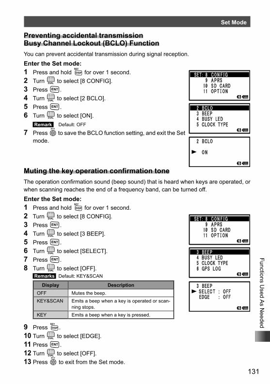
131
Functions Used A
s Needed
Set Mode
Preventing accidental transmission Busy Channel Lockout (BCLO) FunctionYou can prevent accidental transmission during signal reception.Enter the Set mode:1 Press and hold M for over 1 second.2 Turn O to select [8 CONFIG].3 Press H.4 Turn O to select [2 BCLO].5 Press H.6 Turn O to select [ON].
Remark Default: OFF
7 Press p to save the BCLO function setting, and exit the Set mode.
Muting the key operation confirmation toneThe operation confirmation sound (beep sound) that is heard when keys are operated, or when scanning reaches the end of a frequency band, can be turned off.Enter the Set mode:1 Press and hold M for over 1 second.2 Turn O to select [8 CONFIG].3 Press H.4 Turn O to select [3 BEEP].5 Press H.6 Turn O to select [SELECT].7 Press H.8 Turn O to select [OFF].
Remarks Default: KEY&SCAN
Display DescriptionOFF Mutes the beep.KEY&SCAN Emits a beep when a key is operated or scan-
ning stops.KEY Emits a beep when a key is pressed.
9 Press M.10 Turn O to select [EDGE].11 Press H.12 Turn O to select [OFF].13 Press p to exit from the Set mode.
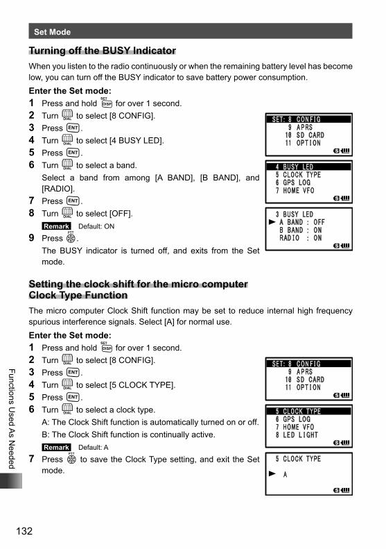
132
Functions Used A
s Needed
Set Mode
Turning off the BUSY IndicatorWhen you listen to the radio continuously or when the remaining battery level has become low, you can turn off the BUSY indicator to save battery power consumption.Enter the Set mode:1 Press and hold M for over 1 second.2 Turn O to select [8 CONFIG].3 Press H.4 Turn O to select [4 BUSY LED].5 Press H.6 Turn O to select a band. Select a band from among [A BAND], [B BAND], and
[RADIO].7 Press H.8 Turn O to select [OFF].
Remark Default: ON
9 Press p. The BUSY indicator is turned off, and exits from the Set
mode.
Setting the clock shift for the micro computer Clock Type FunctionThe micro computer Clock Shift function may be set to reduce internal high frequency spurious interference signals. Select [A] for normal use.Enter the Set mode:1 Press and hold M for over 1 second.2 Turn O to select [8 CONFIG].3 Press H.4 Turn O to select [5 CLOCK TYPE].5 Press H.6 Turn O to select a clock type. A: The Clock Shift function is automatically turned on or off. B: The Clock Shift function is continually active.
Remark Default: A
7 Press p to save the Clock Type setting, and exit the Set mode.
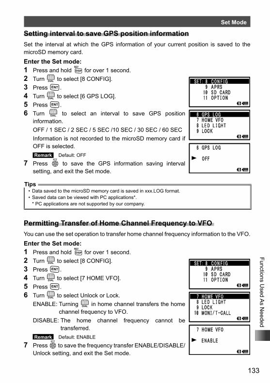
133
Functions Used A
s Needed
Set Mode
Setting interval to save GPS position informationSet the interval at which the GPS information of your current position is saved to the microSD memory card.Enter the Set mode:1 Press and hold M for over 1 second.2 Turn O to select [8 CONFIG].3 Press H.4 Turn O to select [6 GPS LOG].5 Press H.6 Turn O to select an interval to save GPS position
information. OFF / 1 SEC / 2 SEC / 5 SEC /10 SEC / 30 SEC / 60 SEC Information is not recorded to the microSD memory card if
OFF is selected. Remark Default: OFF
7 Press p to save the GPS information saving interval setting, and exit the Set mode.
Tips• Data saved to the microSD memory card is saved in xxx.LOG format.• Saved data can be viewed with PC applications*.
* PC applications are not supported by our company.
Permitting Transfer of Home Channel Frequency to VFO You can use the set operation to transfer home channel frequency information to the VFO.Enter the Set mode:1 Press and hold M for over 1 second.2 Turn O to select [8 CONFIG].3 Press H.4 Turn O to select [7 HOME VFO].5 Press H.6 Turn O to select Unlock or Lock. ENABLE: Turning O in home channel transfers the home
channel frequency to VFO. DISABLE: The home channel frequency cannot be
transferred. Remark Default: ENABLE
7 Press p to save the frequency transfer ENABLE/DISABLE/Unlock setting, and exit the Set mode.
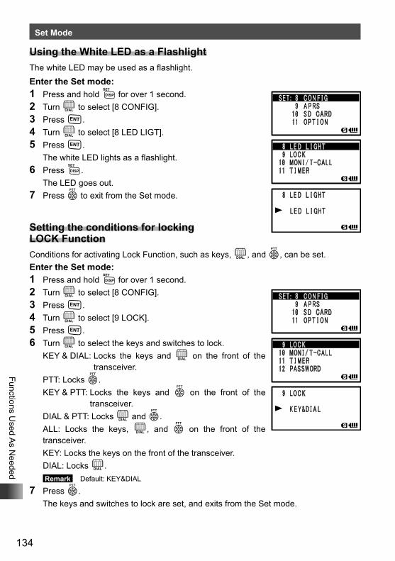
134
Functions Used A
s Needed
Set Mode
Using the White LED as a FlashlightThe white LED may be used as a flashlight.Enter the Set mode:1 Press and hold M for over 1 second.2 Turn O to select [8 CONFIG].3 Press H.4 Turn O to select [8 LED LIGT].5 Press H. The white LED lights as a flashlight.6 Press M. The LED goes out.7 Press p to exit from the Set mode.
Setting the conditions for locking LOCK FunctionConditions for activating Lock Function, such as keys, O, and p, can be set.Enter the Set mode:1 Press and hold M for over 1 second.2 Turn O to select [8 CONFIG].3 Press H.4 Turn O to select [9 LOCK].5 Press H.6 Turn O to select the keys and switches to lock. KEY & DIAL: Locks the keys and O on the front of the
transceiver. PTT: Locks p. KEY & PTT: Locks the keys and p on the front of the
transceiver. DIAL & PTT: Locks O and p. ALL: Locks the keys, O, and p on the front of the
transceiver. KEY: Locks the keys on the front of the transceiver. DIAL: Locks O.
Remark Default: KEY&DIAL
7 Press p. The keys and switches to lock are set, and exits from the Set mode.
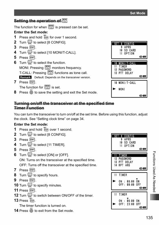
135
Functions Used A
s Needed
Set Mode
Setting the operation of The function for when T is pressed can be set.Enter the Set mode:1 Press and hold M for over 1 second.2 Turn O to select [8 CONFIG].3 Press H.4 Turn O to select [10 MONI/T-CALL].5 Press H.6 Turn O to select the function. MONI: Pressing T monitors frequency. T-CALL: Pressing T functions as tone call.
Remark Default: Depends on the transceiver version.
7 Press H. The function for T is set.8 Press p to save the setting and exit the Set mode.
Turning on/off the transceiver at the specified time Timer FunctionYou can turn the transceiver to turn on/off at the set time. Before using this function, adjust the clock. See “Setting clock time” on page 34.Enter the Set mode:1 Press and hold M over 1 second.2 Turn O to select [8 CONFIG].3 Press H.4 Turn O to select [11 TIMER].5 Press H.6 Turn O to select [ON] or [OFF]. ON: Turns on the transceiver at the specified time. OFF: Turns off the transceiver at the specified time.7 Press H.8 Turn O to specify hours.9 Press H.10 Turn O to specify minutes.11 Press H.12 Turn O to switch between ON/OFF of the timer.13 Press M. The timer function is turned on.14 Press p to exit from the Set mode.
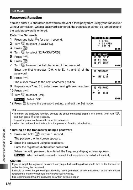
136
Functions Used A
s Needed
Set Mode
Password FunctionYou can enter a 4-character password to prevent a third party from using your transceiver without permission. Once a password is entered, the transceiver cannot be turned on until the valid password is entered.Enter the Set mode:1 Press and hold M for over 1 second.2 Turn O to select [8 CONFIG].3 Press H.4 Turn O to select [12 PASSWORD].5 Press H.6 Press H.7 Turn O to enter the first character of the password. Enter the first character (0-9. A to D, , and #) of the
password.8 Press H. The cursor moves to the next character position.9 Repeat steps 7 and 8 to enter the remaining three characters.10 Press H.11 Turn O to select [ON].
Remark Default: OFF
12 Press p to save the password setting, and exit the Set mode.
Tips• To cancel the password function, execute the above-mentioned steps 1 to 5, select “OFF” with O,
and then press p over 1 second.• Keypad keys cannot be used to enter the password.• When the on-timer function is active, the password function is ineffective.
�Turning on the transceiver using a password1 Press and hold P for over 1 second. The password entry screen appears.2 Enter the password using keypad keys. Enter the registered 4-character password. When the valid password is entered, the frequency display screen appears.
Remark When an invalid password is entered, the transceiver is turned off automatically.
CautionIf you’ve forget the registered password, carrying out all resetting allows you to turn on the transceiver without entering the password.It should be noted that performing all resetting resets (initializes) all information such as the information registered to memory channels and various setting values.It is recommended that the password be written down on paper.
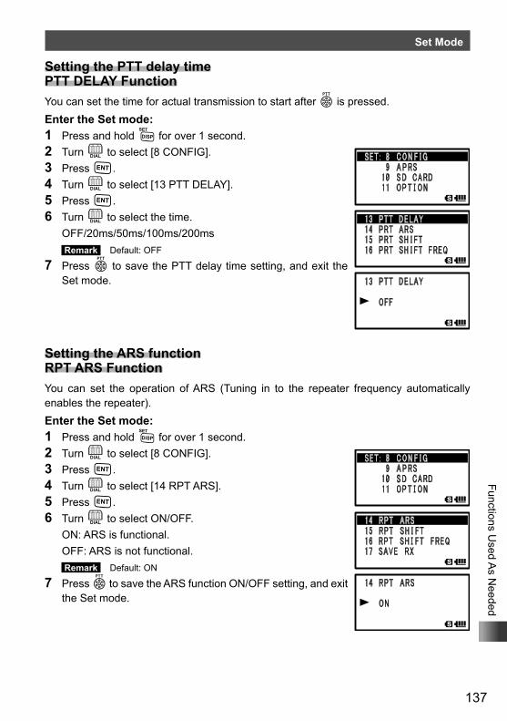
137
Functions Used A
s Needed
Set Mode
Setting the PTT delay time PTT DELAY FunctionYou can set the time for actual transmission to start after p is pressed.Enter the Set mode:1 Press and hold M for over 1 second.2 Turn O to select [8 CONFIG].3 Press H.4 Turn O to select [13 PTT DELAY].5 Press H.6 Turn O to select the time. OFF/20ms/50ms/100ms/200ms
Remark Default: OFF
7 Press p to save the PTT delay time setting, and exit the Set mode.
Setting the ARS function RPT ARS FunctionYou can set the operation of ARS (Tuning in to the repeater frequency automatically enables the repeater).Enter the Set mode:1 Press and hold M for over 1 second.2 Turn O to select [8 CONFIG].3 Press H.4 Turn O to select [14 RPT ARS].5 Press H.6 Turn O to select ON/OFF. ON: ARS is functional. OFF: ARS is not functional.
Remark Default: ON
7 Press p to save the ARS function ON/OFF setting, and exit the Set mode.
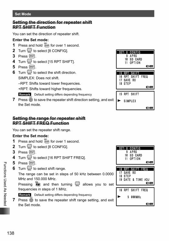
138
Functions Used A
s Needed
Set Mode
Setting the direction for repeater shift RPT SHIFT FunctionYou can set the direction of repeater shift.Enter the Set mode:1 Press and hold M for over 1 second.2 Turn O to select [8 CONFIG].3 Press H.4 Turn O to select [15 RPT SHIFT].5 Press H.6 Turn O to select the shift direction. SIMPLEX: Does not shift. –RPT: Shifts toward lower frequencies. +RPT: Shifts toward higher frequencies.
Remark Default setting differs depending frequency
7 Press p to save the repeater shift direction setting, and exit the Set mode.
Setting the range for repeater shift RPT SHIFT FREQ FunctionYou can set the repeater shift range.Enter the Set mode:1 Press and hold M for over 1 second.2 Turn O to select [8 CONFIG].3 Press H.4 Turn O to select [16 RPT SHIFT FREQ].5 Press H.6 Turn O to select shift range. The range can be set in steps of 50 kHz between 0.0000
MHz and 150.000 MHz. Pressing F and then turning O allows you to set
frequencies in steps of 1 MHz. Remark Default setting differs depending frequency
7 Press p to save the repeater shift range setting, and exit the Set mode.
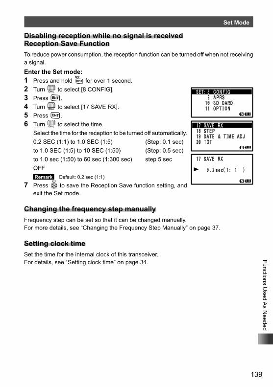
139
Functions Used A
s Needed
Set Mode
Disabling reception while no signal is received Reception Save FunctionTo reduce power consumption, the reception function can be turned off when not receiving a signal.Enter the Set mode:1 Press and hold M for over 1 second.2 Turn O to select [8 CONFIG].3 Press H.4 Turn O to select [17 SAVE RX].5 Press H.6 Turn O to select the time. Select the time for the reception to be turned off automatically. 0.2 SEC (1:1) to 1.0 SEC (1:5) (Step: 0.1 sec) to 1.0 SEC (1:5) to 10 SEC (1:50) (Step: 0.5 sec) to 1.0 sec (1:50) to 60 sec (1:300 sec) step 5 sec OFF
Remark Default: 0.2 sec (1:1)
7 Press p to save the Reception Save function setting, and exit the Set mode.
Changing the frequency step manuallyFrequency step can be set so that it can be changed manually.For more details, see “Changing the Frequency Step Manually” on page 37.
Setting clock timeSet the time for the internal clock of this transceiver.For details, see “Setting clock time” on page 34.
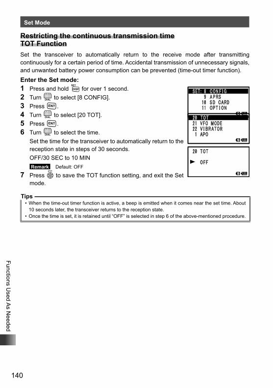
140
Functions Used A
s Needed
Set Mode
Restricting the continuous transmission time TOT FunctionSet the transceiver to automatically return to the receive mode after transmitting continuously for a certain period of time. Accidental transmission of unnecessary signals, and unwanted battery power consumption can be prevented (time-out timer function).Enter the Set mode:1 Press and hold M for over 1 second.2 Turn O to select [8 CONFIG].3 Press H.4 Turn O to select [20 TOT].5 Press H.6 Turn O to select the time. Set the time for the transceiver to automatically return to the
reception state in steps of 30 seconds. OFF/30 SEC to 10 MIN
Remark Default: OFF
7 Press p to save the TOT function setting, and exit the Set mode.
Tips• When the time-out timer function is active, a beep is emitted when it comes near the set time. About
10 seconds later, the transceiver returns to the reception state.• Once the time is set, it is retained until “OFF” is selected in step 6 of the above-mentioned procedure.
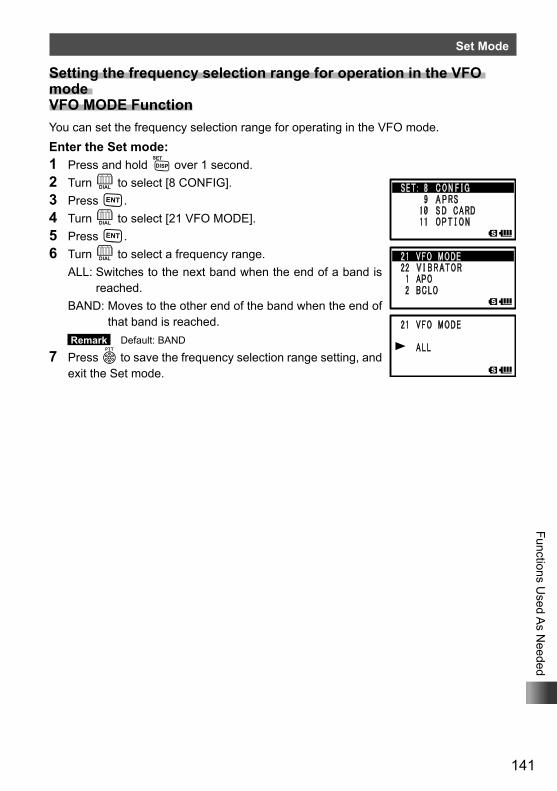
141
Functions Used A
s Needed
Set Mode
Setting the frequency selection range for operation in the VFO mode VFO MODE FunctionYou can set the frequency selection range for operating in the VFO mode.Enter the Set mode:1 Press and hold M over 1 second.2 Turn O to select [8 CONFIG].3 Press H.4 Turn O to select [21 VFO MODE].5 Press H.6 Turn O to select a frequency range. ALL: Switches to the next band when the end of a band is
reached. BAND: Moves to the other end of the band when the end of
that band is reached. Remark Default: BAND
7 Press p to save the frequency selection range setting, and exit the Set mode.
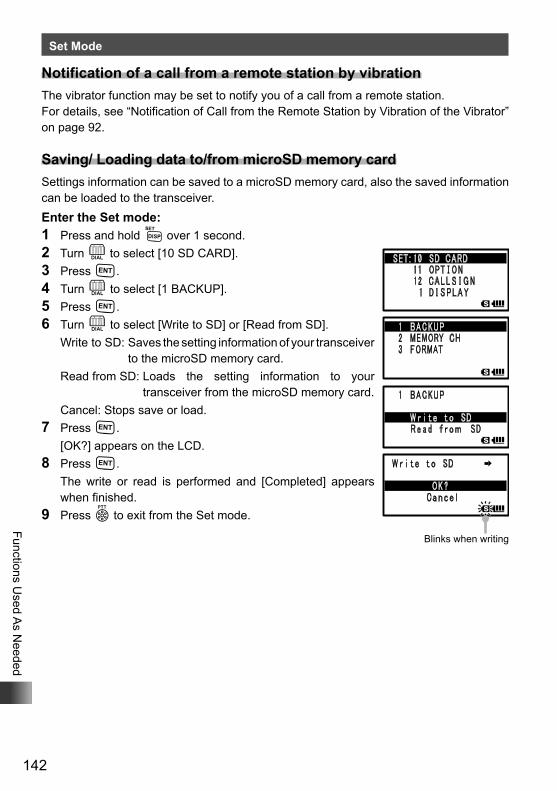
142
Functions Used A
s Needed
Set Mode
Notification of a call from a remote station by vibrationThe vibrator function may be set to notify you of a call from a remote station. For details, see “Notification of Call from the Remote Station by Vibration of the Vibrator” on page 92.
Saving/ Loading data to/from microSD memory cardSettings information can be saved to a microSD memory card, also the saved information can be loaded to the transceiver.Enter the Set mode:1 Press and hold M over 1 second.2 Turn O to select [10 SD CARD].3 Press H.4 Turn O to select [1 BACKUP].5 Press H.6 Turn O to select [Write to SD] or [Read from SD]. Write to SD: Saves the setting information of your transceiver
to the microSD memory card. Read from SD: Loads the setting information to your
transceiver from the microSD memory card. Cancel: Stops save or load.7 Press H. [OK?] appears on the LCD.8 Press H. The write or read is performed and [Completed] appears
when finished.9 Press p to exit from the Set mode.
Blinks when writing
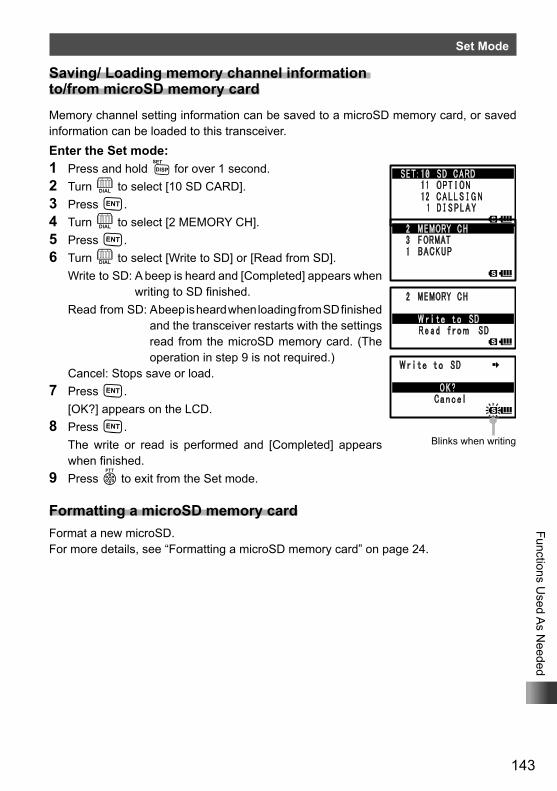
143
Functions Used A
s Needed
Set Mode
Saving/ Loading memory channel information to/from microSD memory cardMemory channel setting information can be saved to a microSD memory card, or saved information can be loaded to this transceiver.Enter the Set mode:1 Press and hold M for over 1 second.2 Turn O to select [10 SD CARD].3 Press H.4 Turn O to select [2 MEMORY CH].5 Press H.6 Turn O to select [Write to SD] or [Read from SD]. Write to SD: A beep is heard and [Completed] appears when
writing to SD finished. Read from SD: A beep is heard when loading from SD finished
and the transceiver restarts with the settings read from the microSD memory card. (The operation in step 9 is not required.)
Cancel: Stops save or load.7 Press H. [OK?] appears on the LCD.8 Press H. The write or read is performed and [Completed] appears
when finished.9 Press p to exit from the Set mode.
Formatting a microSD memory cardFormat a new microSD.For more details, see “Formatting a microSD memory card” on page 24.
Blinks when writingBlinks when writing
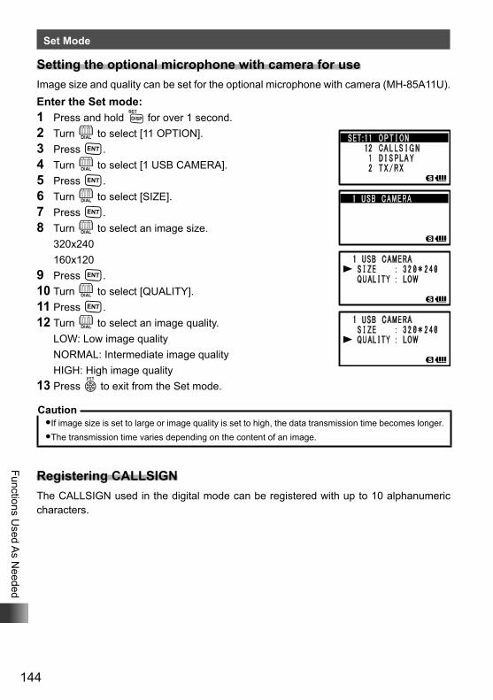
144
Functions Used A
s Needed
Set Mode
Setting the optional microphone with camera for useImage size and quality can be set for the optional microphone with camera (MH-85A11U).Enter the Set mode:1 Press and hold M for over 1 second.2 Turn O to select [11 OPTION].3 Press H.4 Turn O to select [1 USB CAMERA].5 Press H.6 Turn O to select [SIZE].7 Press H.8 Turn O to select an image size. 320x240 160x1209 Press H.10 Turn O to select [QUALITY].11 Press H.12 Turn O to select an image quality. LOW: Low image quality NORMAL: Intermediate image quality HIGH: High image quality13 Press p to exit from the Set mode.
Caution�If image size is set to large or image quality is set to high, the data transmission time becomes longer.�The transmission time varies depending on the content of an image.
Registering CALLSIGNThe CALLSIGN used in the digital mode can be registered with up to 10 alphanumeric characters.
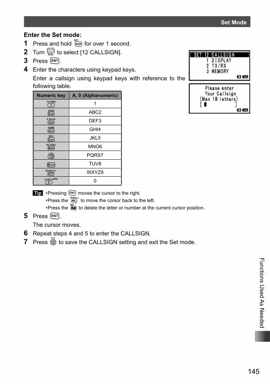
145
Functions Used A
s Needed
Set Mode
Enter the Set mode:1 Press and hold M for over 1 second.2 Turn O to select [12 CALLSIGN].3 Press H.4 Enter the characters using keypad keys. Enter a callsign using keypad keys with reference to the
following table.Numeric key A, 0 (Alphanumeric)
1 1
2 ABC2
3 DEF3
4 GHI4
5 JKL5
6 MNO6
7 PQRS7
8 TUV8
9 WXYZ9
0 0
Tip • Pressing H moves the cursor to the right. • Press the % to move the corsor back to the left. • Press the F to delete the letter or number at the current cursor position.
5 Press H. The cursor moves.6 Repeat steps 4 and 5 to enter the CALLSIGN.7 Press p to save the CALLSIGN setting and exit the Set mode.
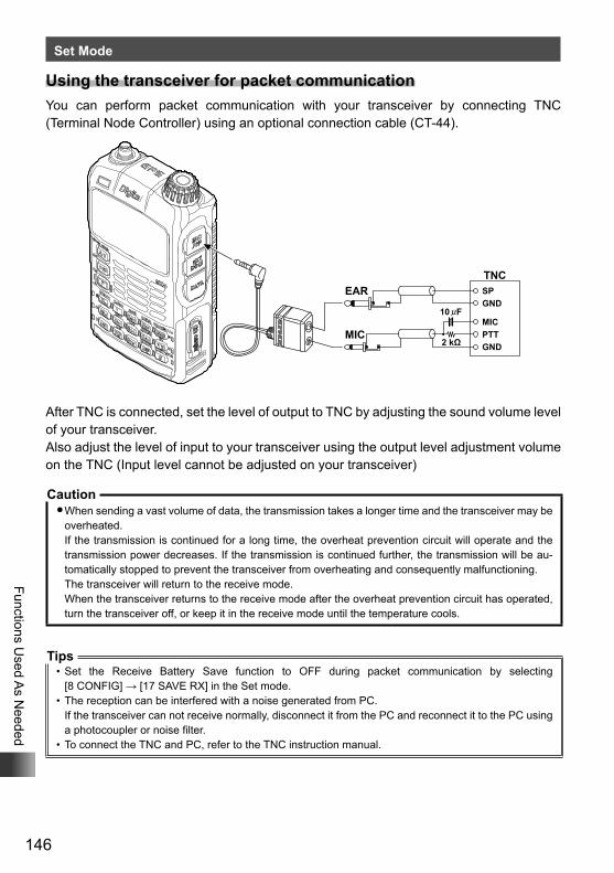
146
Functions Used A
s Needed
Set Mode
Using the transceiver for packet communicationYou can perform packet communication with your transceiver by connecting TNC (Terminal Node Controller) using an optional connection cable (CT-44).
TNCSPGND
GND2 kΩ
10 FMIC
MIC
EAR
PTT
After TNC is connected, set the level of output to TNC by adjusting the sound volume level of your transceiver.Also adjust the level of input to your transceiver using the output level adjustment volume on the TNC (Input level cannot be adjusted on your transceiver)
Caution�When sending a vast volume of data, the transmission takes a longer time and the transceiver may be
overheated.If the transmission is continued for a long time, the overheat prevention circuit will operate and the transmission power decreases. If the transmission is continued further, the transmission will be au-tomatically stopped to prevent the transceiver from overheating and consequently malfunctioning.The transceiver will return to the receive mode.When the transceiver returns to the receive mode after the overheat prevention circuit has operated, turn the transceiver off, or keep it in the receive mode until the temperature cools.
Tips• Set the Receive Battery Save function to OFF during packet communication by selecting
[8 CONFIG] → [17 SAVE RX] in the Set mode.• The reception can be interfered with a noise generated from PC.
If the transceiver can not receive normally, disconnect it from the PC and reconnect it to the PC using a photocoupler or noise filter.
• To connect the TNC and PC, refer to the TNC instruction manual.
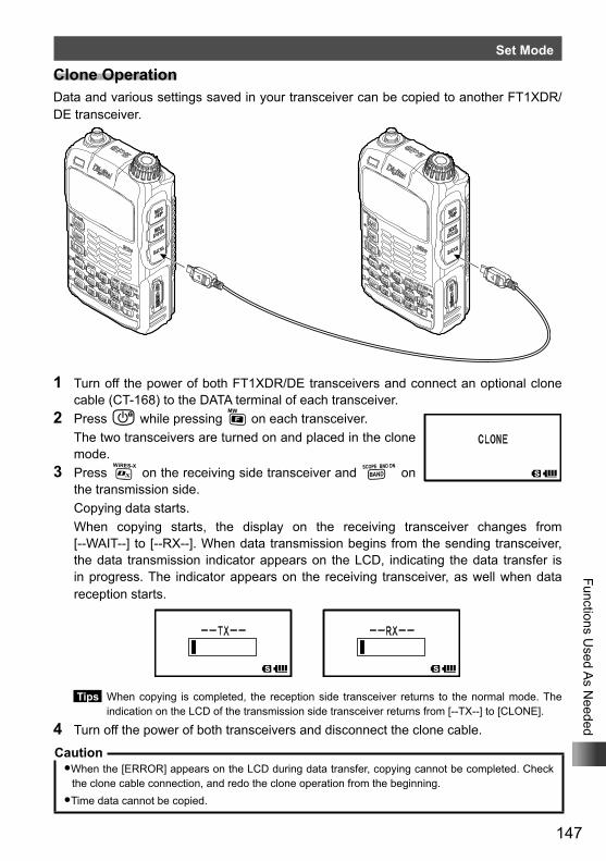
147
Functions Used A
s Needed
Set Mode
Clone OperationData and various settings saved in your transceiver can be copied to another FT1XDR/DE transceiver.
1 Turn off the power of both FT1XDR/DE transceivers and connect an optional clone cable (CT-168) to the DATA terminal of each transceiver.
2 Press P while pressing F on each transceiver. The two transceivers are turned on and placed in the clone
mode.3 Press % on the receiving side transceiver and B on
the transmission side. Copying data starts. When copying starts, the display on the receiving transceiver changes from
[--WAIT--] to [--RX--]. When data transmission begins from the sending transceiver, the data transmission indicator appears on the LCD, indicating the data transfer is in progress. The indicator appears on the receiving transceiver, as well when data reception starts.
Tips When copying is completed, the reception side transceiver returns to the normal mode. The indication on the LCD of the transmission side transceiver returns from [--TX--] to [CLONE].
4 Turn off the power of both transceivers and disconnect the clone cable.
Caution�When the [ERROR] appears on the LCD during data transfer, copying cannot be completed. Check
the clone cable connection, and redo the clone operation from the beginning.�Time data cannot be copied.
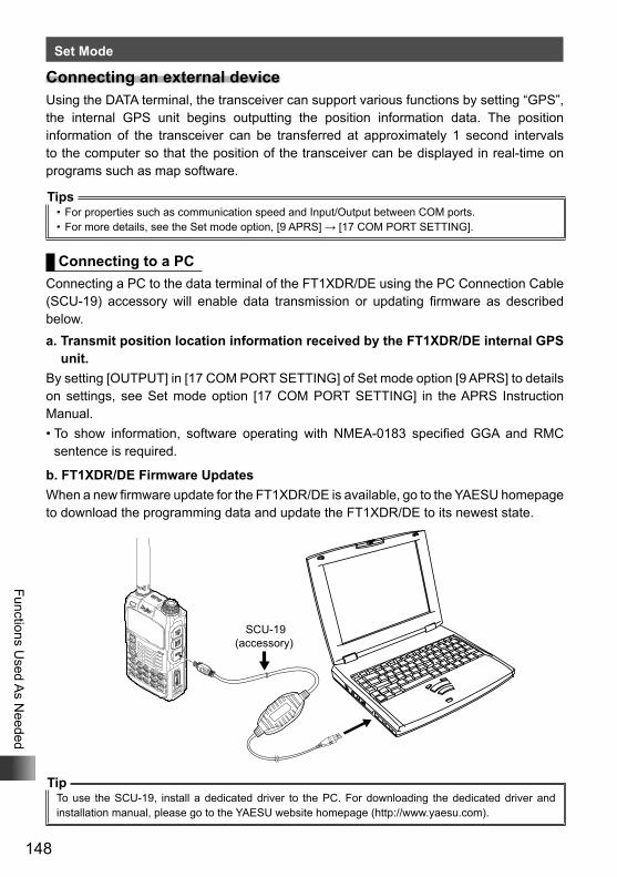
148
Functions Used A
s Needed
Set Mode
Connecting an external deviceUsing the DATA terminal, the transceiver can support various functions by setting “GPS”, the internal GPS unit begins outputting the position information data. The position information of the transceiver can be transferred at approximately 1 second intervals to the computer so that the position of the transceiver can be displayed in real-time on programs such as map software.
Tips• For properties such as communication speed and Input/Output between COM ports.• For more details, see the Set mode option, [9 APRS] → [17 COM PORT SETTING].
Connecting to a PCConnecting a PC to the data terminal of the FT1XDR/DE using the PC Connection Cable (SCU-19) accessory will enable data transmission or updating firmware as described below.a. Transmit position location information received by the FT1XDR/DE internal GPS
unit.By setting [OUTPUT] in [17 COM PORT SETTING] of Set mode option [9 APRS] to details on settings, see Set mode option [17 COM PORT SETTING] in the APRS Instruction Manual.• To show information, software operating with NMEA-0183 specified GGA and RMC
sentence is required.
b. FT1XDR/DE Firmware UpdatesWhen a new firmware update for the FT1XDR/DE is available, go to the YAESU homepage to download the programming data and update the FT1XDR/DE to its newest state.
SCU-19(accessory)
TipTo use the SCU-19, install a dedicated driver to the PC. For downloading the dedicated driver and installation manual, please go to the YAESU website homepage (http://www.yaesu.com).
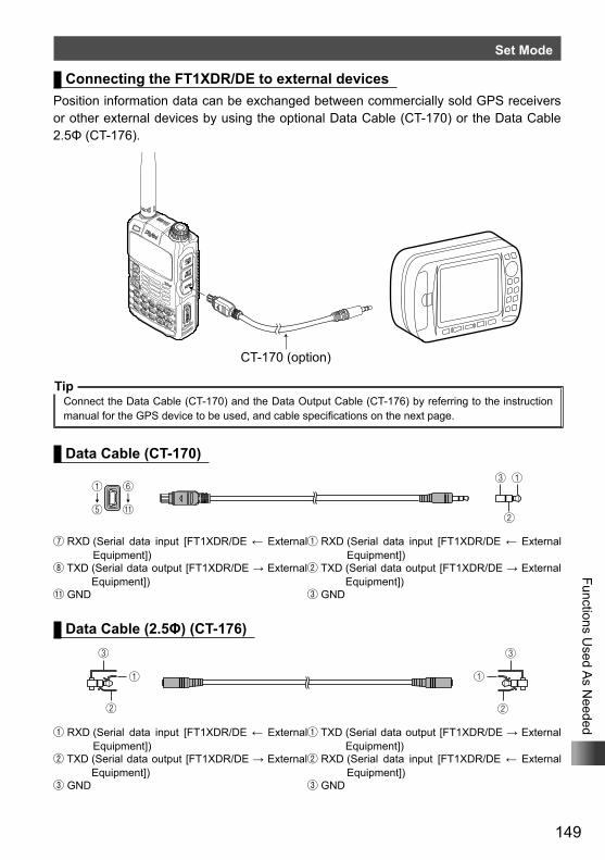
149
Functions Used A
s Needed
Set Mode
Connecting the FT1XDR/DE to external devicesPosition information data can be exchanged between commercially sold GPS receivers or other external devices by using the optional Data Cable (CT-170) or the Data Cable 2.5Φ (CT-176).
CT-170 (option)
TipConnect the Data Cable (CT-170) and the Data Output Cable (CT-176) by referring to the instruction manual for the GPS device to be used, and cable specifications on the next page.
Data Cable (CT-170)
①↓⑤
⑥↓⑪
①
②
③
⑦ RXD (Serial data input [FT1XDR/DE ← External Equipment])
① RXD (Serial data input [FT1XDR/DE ← External Equipment])
⑧ TXD (Serial data output [FT1XDR/DE → External Equipment])
② TXD (Serial data output [FT1XDR/DE → External Equipment])
⑪ GND ③ GND
Data Cable (2.5Φ) (CT-176)③
①
②
③
①
②
① RXD (Serial data input [FT1XDR/DE ← External Equipment])
① TXD (Serial data output [FT1XDR/DE → External Equipment])
② TXD (Serial data output [FT1XDR/DE → External Equipment])
② RXD (Serial data input [FT1XDR/DE ← External Equipment])
③ GND ③ GND
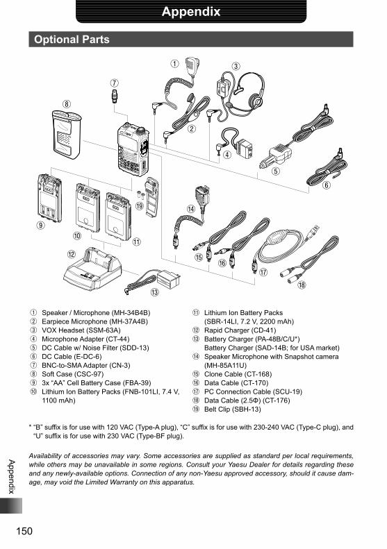
150
Appendix
Appendix
Optional Parts
⑧
⑦
①
②
③
④
⑤⑥
⑨⑩
⑫⑪
⑭
⑮ ⑯⑰
⑱⑬
⑲
① Speaker / Microphone (MH-34B4B)② Earpiece Microphone (MH-37A4B)③ VOX Headset (SSM-63A)④ Microphone Adapter (CT-44)⑤ DC Cable w/ Noise Filter (SDD-13)⑥ DC Cable (E-DC-6)⑦ BNC-to-SMA Adapter (CN-3)⑧ Soft Case (CSC-97)⑨ 3x “AA” Cell Battery Case (FBA-39)⑩ Lithium Ion Battery Packs (FNB-101LI, 7.4 V,
1100 mAh)
⑪ Lithium Ion Battery Packs (SBR-14LI, 7.2 V, 2200 mAh)⑫ Rapid Charger (CD-41)⑬ Battery Charger (PA-48B/C/U*) Battery Charger (SAD-14B; for USA market)⑭ Speaker Microphone with Snapshot camera
(MH-85A11U)⑮ Clone Cable (CT-168)⑯ Data Cable (CT-170)⑰ PC Connection Cable (SCU-19)⑱ Data Cable (2.5Φ) (CT-176)⑲ Belt Clip (SBH-13)
* “B” suffix is for use with 120 VAC (Type-A plug), “C” suffix is for use with 230-240 VAC (Type-C plug), and “U” suffix is for use with 230 VAC (Type-BF plug).
Availability of accessories may vary. Some accessories are supplied as standard per local requirements, while others may be unavailable in some regions. Consult your Yaesu Dealer for details regarding these and any newly-available options. Connection of any non-Yaesu approved accessory, should it cause dam-age, may void the Limited Warranty on this apparatus.
151
Appendix
If you suspect malfunction Check the following items before requesting for repair.
The transceiver does not turn on. Is the battery is depleted? Charge the battery pack after purchase, and when the transceiver has not been used for a long time. Is the battery pack properly set?Refer to “Mounting the battery pack” and securely mount the battery pack. Is the external power supply properly connected?When using a external power supply, connect an external power supply adapter with a cigarette lighter plug (SDD-13) or an external power cable (E-DC-6) to this jack. Is the voltage of the battery pack or the SDD-13 correct?Be sure that there is a charge left in the battery pack (do not completely discharge). Check that the output voltage of the SDD-13 is approximately 12V.
There is no sound Is the level of squelch (or S meter squelch) set too high?Press the Monitor Switch and check that you can hear white noise.Adjust the level of squelch (or S meter squelch) when receiving a weak signal. Is the volume low?Turn O clockwise while pressing v to increase the sound volume. Is the tone squelch or DCS on?When the tone squelch or DCS is on, the sound is not output until the transceiver receives a signal containing the same tone frequency or DCS code set.
There is no transmission of radio waves. Are you pressing the p switch properly? Is the PTT lock on? Is the Busy TX Block (BCLO function) on?When the Busy TX Block (BCLO Function) is on, transmission cannot be done when receiving a signal even if p is pressed. Wait until signal being received stops and then press p. Is the transmission frequency on an ham radio band?Transmission cannot be performed on the AM Radio Broadcast Band/ Short Wave Radio Band/ FM Radio Broadcast Band/ Air Band/ Information Radio Band. Is the voltage of the battery pack or external power source correct?Check the remaining charge on the battery pack.In addition, using a power supply where voltage drops during transmission will prevent the FT1XDR/DE from operating on full capability.
The keys or O does not respond. Is the Key Lock or DIAL Lock on?
152
Appendix
If you suspect malfunction
The battery pack cannot be charged or battery power depletes immediately after charging. Is the battery pack being charged with a charger specified by Yaesu?Charge the battery pack using the accessory battery charger (PA-48B or SAD-14B) or the rapid charge cradle (CD-41).When using a external power supply, use the external power supply adapter with a cigarette lighter plug (SDD-13) or an external power cable (E-DC-6). Is the battery pack in use exhausted?If the “Charging Error” appears on the LCD when charging, there is a chance the battery pack is over discharged. If the error is repetitively displayed after charging the battery pack several times, the battery pack may have reached its service life or defective. Battery packs are consumables. Please replace the battery pack with a new one immediately. Battery packs can be charged and reused up to approximately 300 times.
Depending on the combination for simultaneous reception, there may be internal beats from high frequen-cies caused by the internal oscillator. This is not a malfunction. (See the calculation formula below: “n” is for the arbitrary integer). Depending on the combination for simultaneous reception, there may be fluctuations in reception sensitivity.
Reception Frequency = 16 MHz × n multiplicative Reception Frequency = 15.6 MHz × n multiplicative Reception Frequency = 4.9152 MHz × n multiplicative Reception Frequency = 15.6 MHz × n multiplicative Reception Frequency = 18.432 MHz × n multiplicative Upper Side (A-Band) Frequency = (Lower Side (B-band) Frequency ± 46.35 MHz) × n multiplicative Upper Side (A-Band) Frequency = (Lower Side (B-band) Frequency ± 47.25 MHz) × n multiplicative @ Upper Side (A-band) Mode = NFM
153
Appendix
IndexSymbol
A key ................................................................................12B key ................................................................................12D key ...................................................................................12F key ....................................................................................12H key ...................................................................................12p switch .................................................................................12P switch ..............................................................................12T key ...................................................................................12
AActivating the GPS function .....................................................72Adjusting the LCD backlight and keypad key light brightness level ... 111Adjusting the LCD contrast level ...........................................110Adjusting the microphone sensitivity .....................................118Adjusting the squelch level ..............................................37, 124Adjusting the volume level .......................................................26AF-DUAL function ....................................................................81All reset....................................................................................39AMS .........................................................................................32AMS transmission mode........................................................116Analog FM mode .....................................................................32Antenna .....................................................................................6Antenna terminal .....................................................................12APO function .........................................................................130APRS function .........................................................................71
*webAssigning a name to a memory channel .................................51Assigning name to memory bank ............................................53ATT function ..........................................................................113Attaching a hand strap.............................................................16Attaching the belt clip ..............................................................15Attaching the protective cap ....................................................15Attenuator function ................................................................113
BBACK TRACK function screen ................................................78Backtrack function ...................................................................78Band scope function ................................................................86Battery approximate operating time.........................................19Battery case (FBA-39) .............................................................16Battery Case 3x “AA” Cell (FBA-39) ......................................150Battery charger (PA-48B/C/U*) ..............................................150Battery charger (SAD-14B; for USA market) .........................150BCLO function .......................................................................131Before transmitting radio waves ..............................................11Being called by the remote station (standby operation) ..........97Bell...........................................................................................93Belt clip ......................................................................................6BNC-to-SMA adapter (CN-3) .................................................150Bundled items ............................................................................6Busy Channel Lockout function .............................................131BUSY/TX lamp ........................................................................12
CCalling a specific station ..........................................................96Calling only a specific station (new pager function).................94Callsign ....................................................................................25Canceling memory channel registration in memory bank........53Canceling scanning .................................................................61Changing home channel frequency .........................................49Changing the display pattern of the PO meter ......................113
Changing the frequency step manually ...................................37Changing the lighting condition .............................................109Changing the mode manually ..................................................38Changing the number of times the bell rings ...........................93Changing the opening message displayed immediately after power-on ... 111Changing the sound volume setting method .........................119Changing the transmission power level ...................................36Charging the battery pack .......................................................17Clock Type function ...............................................................132Clone cable (CT-168) ............................................................150Clone operation .....................................................................147Communicating via the repeater..............................................44Communicating with a apecific remote station ........................88Communication mode..............................................................32Confirming the entered DTMF code by the sound...................84Connecting the FT1XDR/DE to external devices ..................149
DData Cable (2.5Φ) (CT-176) ..................................................150Data cable (CT-170) ..............................................................150Data FR mode .........................................................................32DATA terminal ..........................................................................12DC cable (E-DC-6) ................................................................150DC cable w/ noise filter (SDD-13)..........................................150DCS .........................................................................................88DCS code ................................................................................90DCS INVERSION function.....................................................122Deleting a frequency registered to the skip search memory channel ...62Deleting memory channel ........................................................50Digital communication .............................................................32Digital mode.............................................................................32Disabling reception while no signal is received .....................139Dismounting microSD memory card ........................................23Displaying memory tag ............................................................51Displaying the GPS screen....................................................107Displaying the version of the DSP program ...........................118DTMF function .........................................................................83Dual reception function ............................................................79DW ...........................................................................................79DW TIME function .................................................................127
EEarpiece microphone (MH-37A4B)........................................150Enabling no-communication squelch function .......................124Enter the Set mode..................................................................98EXT DC IN jack .......................................................................12External power supply .............................................................21External power supply for use in vehicle .................................20
FFlashlight (white LED) .............................................................12Flow of operation to use the pager function ............................94FM mode .................................................................................32Formatting a microSD memory card........................................24Frequencies of international VHF (marine) radio.....................57Frequency band for the A-band ...............................................29Frequency band for the B-band ...............................................29FT1XDR/DE ...............................................................................6FT1XDR/DE Firmware Updates ............................................148
*web: Please download the instruction manuals for GM function and APRS from our website.
154
Appendix
Index
GGM function .............................................................................69
*webGPS .........................................................................................72Group monitor function ............................................................69
*web
HHome channel .........................................................................49Home channel dual reception ..................................................80HOME VFO ...........................................................................133
IInput a callsign.........................................................................25Installing the antenna ..............................................................15Installing the battery pack ........................................................17International VHF (marine) radio .............................................56IPX5 .........................................................................................11
LListen to the international VHF (marine) radio .........................56Listening radio broadcast with AF-DUAL reception function ...81Lithium ion battery packs (FNB-101LI, 7.4 V, 1100 mAh) ......150Lithium ion battery packs (SBR-14LI, 7.2 V, 2200 mAh) .......150LOCK function .......................................................................134Locking keys ............................................................................39Locking switches .....................................................................39
MMeasuring the battery voltage and the transceiver temperature ...........................................................................112Memory bank link scan ............................................................66Memory channel dual reception ..............................................80Memory channel protect function ..........................................121Memory channel scanning.......................................................63Memory channel write function ..............................................121Memory functions ....................................................................46Memory tag..............................................................................50Method of positioning by GPS .................................................73Microphone adapter (CT-44) .................................................150Microphone gain ....................................................................118microSD memory card .............................................................22Mounting microSD memory card .............................................22Mute.........................................................................................35Muting audio ............................................................................35Muting the key operation confirmation tone...........................131
NNew pager function..................................................................94Notification of a call from a remote station by the bell .............93Notification of call from the remote station by vibration of the vibrator ....92
OOperating band ........................................................................27Optional parts ........................................................................150
PPacket communication ..........................................................146Password function .................................................................136PC connection cable (SCU-19) .........................................6, 150Performing communication ................................................25, 31Performing programmable memory channel scan...................68Permitting transfer of home channel frequency to VFO ........133PMS .........................................................................................67PMS memory channel .............................................................67Positioning by GPS..................................................................74Power cable .............................................................................20Power supply voltage measurement function ........................112PR FREQUENCY function ....................................................123Preset receiver memory channel .............................................55Preventing accidental transmission .......................................131Priority memory channel ..........................................................79Programmable memory channel .............................................67Programmable memory channel scan .....................................67Prohibiting registration to memory channel ...........................121Protective plate for battery pack ................................................6PTT DELAY function ..............................................................137
RRapid charger (CD-41) ..........................................................150Real-time navigation function ..................................................77Recalling a memory channel ...................................................48Recalling home channel ..........................................................49Recalling memory bank ...........................................................53Reception frequencies .............................................................28Reception mode (radio wave type) ..........................................38Reception Save function........................................................139Reducing receiver sensitivity .................................................113Register to a memory channel.................................................47Registering a memory channel in a memory bank ..................52Registering CALLSIGN..........................................................145Registering to a memory channel with the lowest memory channel number....121Registering to a programmable memory channel....................67Registering your current position .............................................78Registering your favorite preset receiver memory channels in memory bank.....55Removing the battery pack ......................................................17Repeater operation ..................................................................44Resetting the Set mode options ..............................................98Restoring deleted memory channel .........................................50Restoring to defaults................................................................39Restricting the continuous transmission time ........................140RPT ARS function ..................................................................137RPT SHIFT FREQ function ...................................................138RPT SHIFT function ..............................................................138
SS meter squelch function .......................................................124Safety precautions .....................................................................7Saving/ Loading data to/from microSD memory card ............142Saving/ Loading memory channel information to/from microSD memory card .......143SCAN LAMP function ............................................................128SCAN RE-START function ....................................................128Scanning a memory bank ........................................................65Scanning function ....................................................................60Scanning only the selected memory channel ..........................65Searching for signals with the signal strength graph ...............86Searching for the frequency of the DCS used by the remote station .....91
*web: Please download the instruction manuals for GM function and APRS from our home page.
155
Appendix
Index
Searching for the frequency of the tone squelch used by the remote station ......90Select a tone squelch type ......................................................88Selected memory channel .......................................................64Selecting a band ......................................................................29Selecting a DCS code .............................................................90Selecting a display language .................................................110Selecting a frequency band .....................................................29Selecting a reception method when scanning stops ...............63Selecting a tone frequency ......................................................89Selecting an operating band ....................................................27Selecting communication mode...............................................32Selecting vibrator operation mode ...........................................92Sending a DTMF code manually .............................................85Sending the registered DTMF code.........................................84Set mode .................................................................................98Set mode option list .................................................................99Setting clock time ....................................................................34Setting interval to save GPS position information .................133Setting memory bank link ......................................................120Setting the ARS function........................................................137Setting the clock shift for the micro computer........................132Setting the code of your station ...............................................95Setting the conditions for locking ...........................................134Setting the direction for repeater shift....................................138Setting the display method for BACKTRACK ........................108Setting the display method of the remote station information .............................................................................108Setting the DTMF code............................................................83Setting the frequency selection range for operation in the VFO mode ....141Setting the operation of T .................................................135Setting the operation of Monitor key ......................................135Setting the optional microphone with camera for use............144Setting the pop up time of the remote station information .....117Setting the PTT delay time ....................................................137Setting the range for repeater shift ........................................138Setting the range for SCAN ...................................................129Setting the resumption time of radio reception ........................82Setting the search channels for the BAND SCOPE function ..................................................................................109Setting the signal strength to output sound ...........................124Setting the sound and speed during tone search ..................126Setting the squelch type for transmission and reception .......125Setting the surveillance interval time for priority channels.....127Setting the time signal .............................................................34Setting the time to resume scan ............................................128Setting the transmission modulation level .............................114Simultaneous radio broadcast reception .................................81Simultaneous signal reception over the other frequency while listening to the radio .......................................................81Skip memory channel ..............................................................64Skip search memory ................................................................61Smart navigation function ........................................................77Soft case (CSC-97) ...............................................................150Speaker / microphone (MH-34B4B) ......................................150Speaker Microphone with Snapshot camera (MH-85A11U) .......86, 150Specifying a selected memory channel ...................................64Specifying a skip memory channel ..........................................64Specifying the frequency you do not want to scan ..................62Split memory............................................................................48SQL EXPANTION function ....................................................125SQL LEVEL function ..............................................................124Squelch level ...........................................................................37STANDBY BEEP setting ........................................................117Switching between AM antennas.............................................33Switching between digital and analog mode .........................115
TTaking picture ..........................................................................86Taking picture with the optional camera mounted on speaker microphone .........86Temperature measurement function ......................................112Time signal tone ......................................................................34Timer function ........................................................................135Tone Calling (1750 Hz) ............................................................44Tone Search function .............................................................126Tone squelch ...........................................................................88TOT function ..........................................................................140Transmission power level ........................................................36Transmit and receive a DCS code with a inverted phase ......122Transmitting GPS data ..........................................................148Tuning in to a frequency ..........................................................30Turning illumination off when scanning stops ........................128Turning off the BUSY indicator ..............................................132Turning off the power automatically .......................................130Turning on the transceiver .......................................................25Turning on/off the transceiver at the specified time ...............135
UUsable microSD memory card.................................................22Using memory bank.................................................................52Using the memory ...................................................................46Using the scanning function ....................................................60Using the white LED as a flashlight .......................................134
VV/D mode.................................................................................32VFO dual reception..................................................................79VFO MODE function ..............................................................141VFO scan.................................................................................60Vibrator ....................................................................................92Vibrator operation mode ..........................................................92Voice FR mode ........................................................................32VOX headset (SSM-63A) ......................................................150
WWIRES-X Function ..................................................................71Worldwide short wave broadcast .............................................58
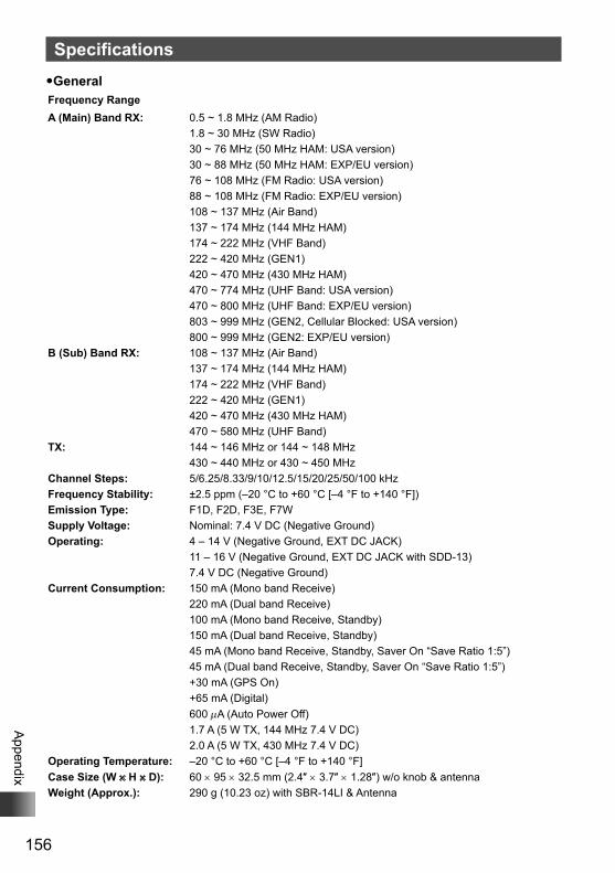
156
Appendix
Specifications�GeneralFrequency RangeA (Main) Band RX: 0.5 ~ 1.8 MHz (AM Radio)
1.8 ~ 30 MHz (SW Radio)30 ~ 76 MHz (50 MHz HAM: USA version)30 ~ 88 MHz (50 MHz HAM: EXP/EU version)76 ~ 108 MHz (FM Radio: USA version)88 ~ 108 MHz (FM Radio: EXP/EU version)108 ~ 137 MHz (Air Band)137 ~ 174 MHz (144 MHz HAM)174 ~ 222 MHz (VHF Band)222 ~ 420 MHz (GEN1)420 ~ 470 MHz (430 MHz HAM)470 ~ 774 MHz (UHF Band: USA version)470 ~ 800 MHz (UHF Band: EXP/EU version)803 ~ 999 MHz (GEN2, Cellular Blocked: USA version)800 ~ 999 MHz (GEN2: EXP/EU version)
B (Sub) Band RX: 108 ~ 137 MHz (Air Band)137 ~ 174 MHz (144 MHz HAM)174 ~ 222 MHz (VHF Band)222 ~ 420 MHz (GEN1)420 ~ 470 MHz (430 MHz HAM)470 ~ 580 MHz (UHF Band)
TX: 144 ~ 146 MHz or 144 ~ 148 MHz430 ~ 440 MHz or 430 ~ 450 MHz
Channel Steps: 5/6.25/8.33/9/10/12.5/15/20/25/50/100 kHzFrequency Stability: ±2.5 ppm (–20 °C to +60 °C [–4 °F to +140 °F])Emission Type: F1D, F2D, F3E, F7WSupply Voltage: Nominal: 7.4 V DC (Negative Ground)Operating: 4 – 14 V (Negative Ground, EXT DC JACK)
11 – 16 V (Negative Ground, EXT DC JACK with SDD-13)7.4 V DC (Negative Ground)
Current Consumption: 150 mA (Mono band Receive)220 mA (Dual band Receive)100 mA (Mono band Receive, Standby)150 mA (Dual band Receive, Standby)45 mA (Mono band Receive, Standby, Saver On “Save Ratio 1:5”)45 mA (Dual band Receive, Standby, Saver On “Save Ratio 1:5”)+30 mA (GPS On)+65 mA (Digital)600 μA (Auto Power Off)1.7 A (5 W TX, 144 MHz 7.4 V DC)2.0 A (5 W TX, 430 MHz 7.4 V DC)
Operating Temperature: –20 °C to +60 °C [–4 °F to +140 °F]Case Size (W × H × D): 60 × 95 × 32.5 mm (2.4″ × 3.7″ × 1.28″) w/o knob & antennaWeight (Approx.): 290 g (10.23 oz) with SBR-14LI & Antenna
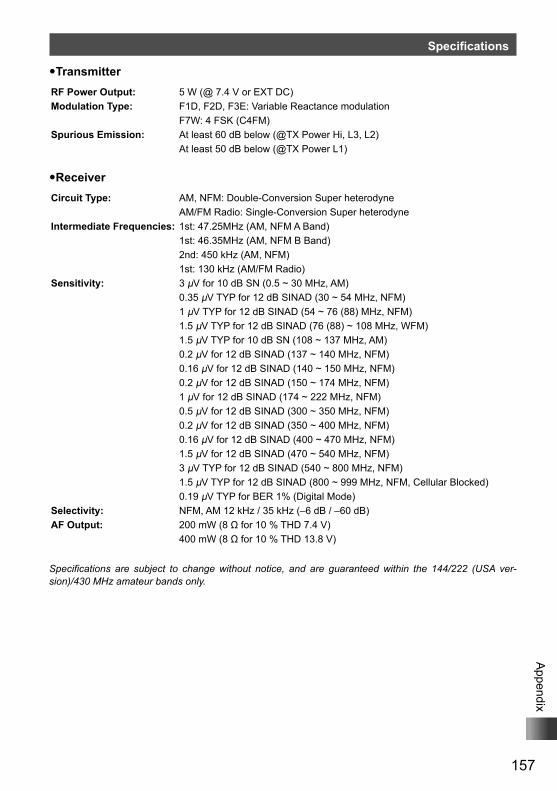
157
Appendix
Specifications
�TransmitterRF Power Output: 5 W (@ 7.4 V or EXT DC)Modulation Type: F1D, F2D, F3E: Variable Reactance modulation
F7W: 4 FSK (C4FM)Spurious Emission: At least 60 dB below (@TX Power Hi, L3, L2)
At least 50 dB below (@TX Power L1)
�ReceiverCircuit Type: AM, NFM: Double-Conversion Super heterodyne
AM/FM Radio: Single-Conversion Super heterodyneIntermediate Frequencies: 1st: 47.25MHz (AM, NFM A Band) 1st: 46.35MHz (AM, NFM B Band)
2nd: 450 kHz (AM, NFM)1st: 130 kHz (AM/FM Radio)
Sensitivity: 3 μV for 10 dB SN (0.5 ~ 30 MHz, AM)0.35 μV TYP for 12 dB SINAD (30 ~ 54 MHz, NFM)1 μV TYP for 12 dB SINAD (54 ~ 76 (88) MHz, NFM)1.5 μV TYP for 12 dB SINAD (76 (88) ~ 108 MHz, WFM)1.5 μV TYP for 10 dB SN (108 ~ 137 MHz, AM)0.2 μV for 12 dB SINAD (137 ~ 140 MHz, NFM)0.16 μV for 12 dB SINAD (140 ~ 150 MHz, NFM)0.2 μV for 12 dB SINAD (150 ~ 174 MHz, NFM)1 μV for 12 dB SINAD (174 ~ 222 MHz, NFM)0.5 μV for 12 dB SINAD (300 ~ 350 MHz, NFM)0.2 μV for 12 dB SINAD (350 ~ 400 MHz, NFM)0.16 μV for 12 dB SINAD (400 ~ 470 MHz, NFM)1.5 μV for 12 dB SINAD (470 ~ 540 MHz, NFM)3 μV TYP for 12 dB SINAD (540 ~ 800 MHz, NFM)1.5 μV TYP for 12 dB SINAD (800 ~ 999 MHz, NFM, Cellular Blocked)0.19 μV TYP for BER 1% (Digital Mode)
Selectivity: NFM, AM 12 kHz / 35 kHz (–6 dB / –60 dB)AF Output: 200 mW (8 Ω for 10 % THD 7.4 V)
400 mW (8 Ω for 10 % THD 13.8 V)
Specifications are subject to change without notice, and are guaranteed within the 144/222 (USA ver-sion)/430 MHz amateur bands only.
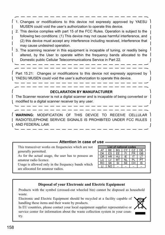
158
1. Changes or modifications to this device not expressly approved by YAESU MUSEN could void the user’s authorization to operate this device.
2. This device complies with part 15 of the FCC Rules. Operation is subject to the following two conditions: (1) This device may not cause harmful interference, and (2) this device must accept any interference including received, interference that may cause undesired operation.
3. The scanning receiver in this equipment is incapable of tuning, or readily being altered, by the User to operate within the frequency bands allocated to the Domestic public Cellular Telecommunications Service in Part 22.
Part 15.21: Changes or modifications to this device not expressly approved by YAESU MUSEN could void the user’s authorization to operate this device.
DECLARATION BY MANUFACTURERThe Scanner receiver is not a digital scanner and is incapable of being converted or modified to a digital scanner receiver by any user.
WARNING: MODIFICATION OF THIS DEVICE TO RECEIVE CELLULAR RADIOTELEPHONE SERVICE SIGNALS IS PROHIBITED UNDER FCC RULES AND FEDERAL LAW.
Disposal of your Electronic and Electric EquipmentProducts with the symbol (crossed-out wheeled bin) cannot be disposed as household waste.Electronic and Electric Equipment should be recycled at a facility capable of handling these items and their waste by products.In EU countries, please contact your local equipment supplier representative or service center for information about the waste collection system in your coun-try.
This transceiver works on frequencies which are not generally permitted.As for the actual usage, the user has to possess an amateur radio licence.Usage is allowed only in the frequency bands which are allocated for amateur radios.
Attention in case of useList of national codes
AT BE BG CY CZ DEDK ES EE FI FR GBGR HR HU IE IT LTLU LV MT NL PL PTRO SK SI SE CH ISLI NO – – – –
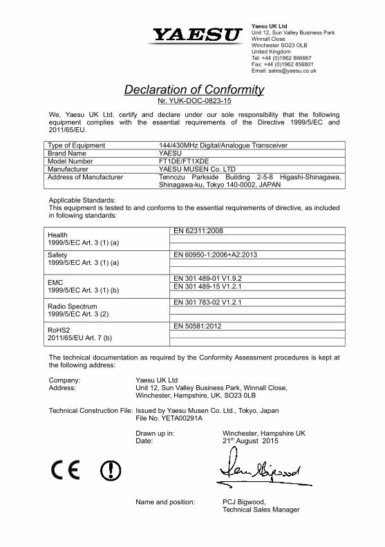
Yaesu UK Ltd
Unit 12, Sun Valley Business ParkWinnall CloseWinchester SO23 OLBUnited KingdomTel: +44 (0)1962 866667Fax: +44 (0)1962 856801Email: [email protected]
Declaration of ConformityNr. YUK-DOC-0823-15
We, Yaesu UK Ltd. certify and declare under our sole responsibility that the followingequipment complies with the essential requirements of the Directive 1999/5/EC and2011/65/EU.
Type of Equipment 144/430MHz Digital/Analogue TransceiverBrand Name YAESUModel Number FT1DE/FT1XDEManufacturer YAESU MUSEN Co. LTDAddress of Manufacturer Tennozu Parkside Building 2-5-8 Higashi-Shinagawa,
Shinagawa-ku, Tokyo 140-0002, JAPAN
Applicable Standards:This equipment is tested to and conforms to the essential requirements of directive, as includedin following standards:
Health1999/5/EC Art. 3 (1) (a)
EN 62311:2008
Safety 1999/5/EC Art. 3 (1) (a)
EN 60950-1:2006+A2:2013
EMC 1999/5/EC Art. 3 (1) (b)
EN 301 489-01 V1.9.2EN 301 489-15 V1.2.1
Radio Spectrum1999/5/EC Art. 3 (2)
EN 301 783-02 V1.2.1
RoHS2 2011/65/EU Art. 7 (b)
EN 50581:2012
The technical documentation as required by the Conformity Assessment procedures is kept atthe following address:
Company: Yaesu UK LtdAddress: Unit 12, Sun Valley Business Park, Winnall Close,
Winchester, Hampshire, UK, SO23 0LB
Technical Construction File: Issued by Yaesu Musen Co. Ltd., Tokyo, JapanFile No. YETA00291A
Drawn up in: Winchester, Hampshire UKDate: 21th August 2015
Name and position: PCJ Bigwood, Technical Sales Manager

1607C-BO-1
YAESU MUSEN CO., LTD.Tennozu Parkside Building2-5-8 Higashi-Shinagawa, Shinagawa-ku, Tokyo 140-0002 JapanYAESU USA6125 Phyllis Drive, Cypress, CA 90630, U.S.A.YAESU UKUnit 12, Sun Valley Business Park, Winnall CloseWinchester, Hampshire, SO23 0LB, U.K.
Printed in Japan
Copyright 2017YAESU MUSEN CO., LTD.All rights reserved.No portion of this manual may be reproduced without the permission ofYAESU MUSEN CO., LTD.


