Embed Size (px)
Citation preview

Installation and operating
manual
Please read the following instructions carefully before installing the product. Trouble free and safe operating of the product can only be guaranteed if recommendations and conditions stated in this manual are respected
3401837 - User_Manual_OS16/OS40_28102019
OS 16 / OS 40
(Pressure sensor)

2
Dear Customer,
Thank you for choosing our product.
Before you start up the device please read the operating instructions in
full and carefully observe them. The manufacturer cannot be held liable for any damage which occurs as a result of non-observance or non-
compliance with this manual.
Should the device be tampered with in any manner other than a
procedure which is described and specified in the manual, the warranty
is canceled and the manufacturer is exempt from liability.
The device is destined exclusively for the described application.
Omega Air d.o.o. Ljubljana offers no guarantee for the suitability for any
other purpose.
Omega Air d.o.o. Ljubljana is also not liable for consequential damage
resulting from the delivery, capability or use of this device.

3
1. Safety instructions
Please check if this instruction manual accords to the
product type.
Please observe all notes and instructions indicated in this
manual. It contains essential information which have to be
observed before and during installation, operation and maintenance. Therefore this instruction manual has to be read carefully
by the technician as well as by the responsible user / qualified
personnel.
This instruction manual has to be available at the operation site of the
pressure sensor at any time. In case of any obscurities or questions,
regarding this manual or the product, please contact the manufacturer.
ATTENTION!
Compressed air!
Any contact with quickly escaping air or bursting
parts of the compressed air system can lead to serious injuries or even death!
• Do not exceed the maximum permitted pressure range. • Only use pressure tight installation material.
• Avoid that persons get hit escaping air or bursting parts of the
instrument.
• The system must be pressureless during maintenance work.
WARNING!
Voltage used for supply!
Any contact with energized parts of the product, may
lead to an electrical shock which can lead to serious injuries or even death!
• Consider all regulations for electrical installations.
• The system must be disconnected from any power supply during
maintenance work.
• Any electrical work on the system is only allowed by authorized
qualified personal.

4
ATTENTION!
Permitted operating parameters!
Observe the permitted operating parameters, any
operation exceeding these parameters can lead to
malfunctions and may lead to damage on the instrument or the system.
• Do not exceed the permitted operating parameters. • Make sure the product is operated in its permitted limitations.
• Do not exceed or undercut the permitted storage and operation
temperature and pressure. • The product should be maintained and calibrated frequently, at least
annually.
General safety instructions
• It is not allowed to use the product in explosive areas.
• Please observe the national regulations before/during installation and
operation.
Remarks
• It is not allowed to disassemble the product.
• Always use spanner to mount the product properly.
ATTENTION!
Measurement values can be affected by
malfunction!
The product must be installed properly and
frequently maintained, otherwise it may lead to wrong measurement values, which can lead to
wrong results.
• Do not exceed the maximum operation temperature at the sensors tip.
• Avoid condensation on the sensor element as this will affect the
accuracy enormously.

5
Storage and transportation
• Make sure that the transportation temperature of the sensor is between -40°C ... 100°C.
• For transportation it is recommended to use the packaging which
comes with the sensor. • Please make sure that the storage temperature of the sensor is
between -40°C ... 100°C.
• Avoid direct UV and solar radiation during storage.
• For the storage the humidity has to be <90%, no condensation.
2. Application
The pressure sensor is designed to measure the pressure of compressed
air and gases within the permissible operating parameter. These parameters can be found in the technical data section.
The pressure sensor can measure the following values: pressure in MPa
The pressure sensor is not developed to be used in explosive areas. For the use in explosive areas please contact the manufacturer.
The pressure sensor is mainly used in compressed air systems in
industrial environment.
3. Features
• High accurate and affordable industrial pressure sensor.
• Excellent anti-interference capability (EMC, EMI).
• Salt-spay, temperature and humidity test. • IP67 protection
• 4 … 20mA loop powered

6
4. Technical data
4.1 General
Parameters Standard unit pressure: MPa
Sensor Thin-film measuring cell
Measuring medium Air, gas (non corrosive gas)
Measuring range 0 ... 1.6 MPa or
0 ... 40 MPa (Depending on model)
Temperature of the
meas. medium
-30°C ... 100°C
Operating pressure 2 x F.S.
Burst pressure 2.5 x F.S.
Storage temperature -40°C ... 100°C
Operating temperature -30°C ... 80°C
Casing material Stainless steel
Protection class IP67
Dimensions See dimensional drawing on the next page
Screwing thread G 1/4” A (ISO 228/1)
Electrical connection M12, 4 pins
Stability
< ± 0.25% F.S.
Vibration resistance IEC 60068-2-6
5 … 2000Hz, 10g
Weight 70 g
4.2 Electrical data
Power supply 24 VDC (12 ... 32 VDC)
4.3 Output signals
Analogue output 4 ... 20 mA, 2-wire
4.4 Accuracy
Accuracy
± 0.5% F.S.
Repeatability
± 0.25% F.S.

7
5. Dimensional drawing
8
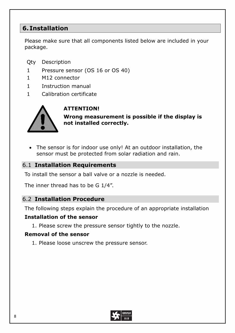
6. Installation
Please make sure that all components listed below are included in your
package.
Qty Description
1 Pressure sensor (OS 16 or OS 40)
1 M12 connector
1 Instruction manual
1 Calibration certificate
ATTENTION!
Wrong measurement is possible if the display is
not installed correctly.
• The sensor is for indoor use only! At an outdoor installation, the
sensor must be protected from solar radiation and rain.
6.1 Installation Requirements
To install the sensor a ball valve or a nozzle is needed.
The inner thread has to be G 1/4”.
6.2 Installation Procedure
The following steps explain the procedure of an appropriate installation
Installation of the sensor
1. Please screw the pressure sensor tightly to the nozzle.
Removal of the sensor
1. Please loose unscrew the pressure sensor.

9
6.3 Electrical connection
The cables are connected to the sensor through the M12 connector.
5m cable connection ( 4 … 20 mA )
Pin Signal Color Pin assignment
1 24 VDC brown 24 V power
supply
2 I+ white Positive 4 … 20
mA signal
3 N/A blue Not available
4 N/A black Not available
10m cable connection ( 4 … 20 mA )
In case longer (more than 5m) cable required please order separated
sensor cable. The cable is different from above. It has 5 pins and details
are shown in table below.
Pin Signal Color Pin assignment
1 V+ brown Positive power supply
2 I+ white Positive 4 … 20 mA signal
3 N/A blue Not available
4 N/A black Not available
5 N/A grey Not available
ATTENTION! Do not screw the M12 plug using force. Otherwise, it may damage the connecting pins.

10
7. Signal outputs
7.1 Analog output
The sensor has an analog output range of 4 ... 20 mA. It is a 2-wire
analog output.
8. Calibration
The sensor is calibrated ex work. The exact calibration date is printed on the certificate which is supplied together with the sensor. The
accuracy of the sensor is regulated by the on site conditions,
parameters like oil, high humidity or other impurities can affect the
calibration and furthermore the accuracy. However we recommend to
calibrate the instrument at least once per year. The calibration is
excluded from the instruments warranty.For this please contact the manufacturer.
9. Maintenance
To clean the sensor and its accessories it is recommended to use s
moist cloth only
ATTENTION!
Do not use isopropyl alcohol to clean the sensor
and its accessories !
10. Disposal or waste
Electronic devices are recyclable material and do not
belong in the household waste.
The sensor, the accessories and its packings must be disposed according to your local statutory requirements.
The dispose can also be carried bythe manufacturer of the
product, for this please contact the manufacturer.

11
11. Warranty
Omega Air d.o.o. Ljubljana provides a warranty for this product of 24
months covering the material and workmanship under the stated
operating conditions from the date of delivery. Please report any findings immediately and within the warranty time. If faults occurring
during the warranty time Omega Air d.o.o. Ljubljana will repair or
replace the defective unit, without charge for labour and material costs but there is a charge for other service such as transport and packing
costs.
Excluded from this warranty is:
• Damage caused by:
o Improper use and non-adherence to the instruction manual. o Use of unsuitable accessories.
o External influences (e.g. damage caused by vibration, damage
during transportation, excess heat or moisture).
The warranty is cancelled:
• If the user opens the measurement instrument without a direct
request written in this instruction manual. • If repairs or modifications are undertaken by third parties or
unauthorised persons.
• If the serial number has been changed, damaged or removed.
Other claims, especially those for damage occurring outside the
instrument are not included unless responsibility is legally binding.
Warranty repairs do not extend the period of warranty.
ATTENTION!
Batteries have a reduced warranty time of 12 month.

12
OMEGA AIR d.o.o. Ljubljana Cesta Dolomitskega odreda 10
SI-1000 Ljubljana, Slovenia T: +386 (0)1 200 68 00 F: +386 (0)1 200 68 50


