Embed Size (px)
Citation preview
Installation/Operating Manual
Amarex N
Submersible Motor Pumps
Amarex N
1 General ............................................................................................................................................................4
1.1 Principles .........................................................................................................................................................4
1.2 Other applicable documents............................................................................................................................4
1.3 Symbols...........................................................................................................................................................5
2 Safety ..............................................................................................................................................................6
2.1 Key to safety symbols / markings ....................................................................................................................6
2.2 General ............................................................................................................................................................6
2.3 Personnel qualification and training.................................................................................................................7
2.4 Non-compliane with operating and safety instructions ....................................................................................7
2.5 Safety awareness ............................................................................................................................................7
2.6 Safety instructions for operator / user..............................................................................................................7
2.7 Safety information for maintenance, inspection and installation work .............................................................8
2.8 Unauthorized modes of operation ...................................................................................................................8
2.9 Intended use....................................................................................................................................................8
3 Transport / Temporary Storage / Disposal ....................................................................................................10
3.1 Checking the condition upon delivery............................................................................................................10
3.2 Transport .......................................................................................................................................................10
3.3 Storage / Preservation...................................................................................................................................10
3.4 Disposal .........................................................................................................................................................11
4 Description of the Pump (Set) .......................................................................................................................12
4.1 General description .......................................................................................................................................12
4.2 Designation....................................................................................................................................................12
4.3 Name plate ....................................................................................................................................................12
4.4 Design details ................................................................................................................................................13
4.5 Types of installation.......................................................................................................................................13
4.6 Configuration and function.............................................................................................................................14
4.7 Scope of supply .............................................................................................................................................15
5 Installation at Site ..........................................................................................................................................16
5.1 Safety regulations..........................................................................................................................................16
5.2 Checks to be carried out prior to installation .................................................................................................16
5.2.1 Preparing the place of installation .................................................................................................................16
5.2.2 Checking the lubricant level...........................................................................................................................17
5.2.3 Check the direction of rotation.......................................................................................................................17
5.3 Installing the pump set...................................................................................................................................18
5.3.1 Stationary wet installation..............................................................................................................................18
5.3.1.1 Fastening the duck foot bend ........................................................................................................................18
5.3.1.2 Connecting the piping....................................................................................................................................19
5.3.1.3 Fitting the guide wire arrangement ................................................................................................................20
5.3.1.4 Fitting the guide hoop arrangement (for DN 50 only) ....................................................................................21
5.3.1.5 Preparing the pump set .................................................................................................................................21
Contents
Legal information/Copyright
Installation/Operating Manual Amarex N
Original operating manual
KSB Pumps Ltd., Pune, India.
All rights reserved. Contents provided herein must neither be distributed, copied, reproduced, edited or
processed for any other purpose, nor otherwise transmitted, published or made available to a third party
without KSB´s express written consent.
Subject to technical modification without prior notice.
© KSB India 01.04.2013.
Amarex N
Amarex N
Contents
7.2.2.1.2 Lubricant quality ............................................................................................................................................37
7.2.2.1.3 Lubricant quantity ..........................................................................................................................................37
7.2.2.1.4 Changing the lubricant...................................................................................................................................37
7.2.2.2 Lubricating the rolling element bearings........................................................................................................38
7.3 Drainage / Cleaning.......................................................................................................................................38
7.4 Dismantling the pump set ..............................................................................................................................38
7.4.1 General information / Safety regulations .......................................................................................................38
7.4.2 Preparing the pump set .................................................................................................................................39
7.4.3 Dismantling the pump section .......................................................................................................................39
7.4.4 Removing the mechanical seal and motor section ........................................................................................40
7.5 Reassembling the pump set ..........................................................................................................................40
7.5.1 General information / Safety regulations .......................................................................................................40
7.5.2 Reassembling the pump section ...................................................................................................................41
7.5.2.1 Installing the mechanical seal........................................................................................................................41
7.5.2.2 Fitting the impeller .........................................................................................................................................41
7.5.2.2.1 Fitting impeller type S and cutter ...................................................................................................................41
7.5.2.2.2 Fitting impeller type F ....................................................................................................................................43
7.5.3 Checking the connection of motor/power supply...........................................................................................43
7.6 Tightening torques.........................................................................................................................................43
7.7 Spare parts stock...........................................................................................................................................43
7.7.1 Ordering spare parts......................................................................................................................................43
7.7.2 Recommended spare parts stock for 2 years' operation to DIN 24296 .........................................................44
7.7.3 Sets of spare parts ........................................................................................................................................44
8 Trouble-shooting............................................................................................................................................45
9 Related Documents .......................................................................................................................................46
9.1 General assembly drawing with list of components.......................................................................................46
9.1.1 Amarex N - variant ULG ................................................................................................................................46
9.1.2 Exploded views..............................................................................................................................................47
9.2 Wiring diagram for variant ULG .....................................................................................................................50
9.3 Wiring diagrams over load protection ............................................................................................................51
9.4 Installation drawings of the mechanical seal .................................................................................................52
Annexure I - Environment Protection - Product Disposal after useful life......................................................53
Amarex N
5.3.1.6 Installing the pump set...................................................................................................................................22
5.3.2 Transportable wet installation........................................................................................................................22
5.3.3 Connecting the piping....................................................................................................................................23
5.4 Electrical system............................................................................................................................................23
5.4.1 Information for planning the control system...................................................................................................23
5.4.1.1 Overload protection .......................................................................................................................................23
5.4.1.2 Level control ..................................................................................................................................................23
5.4.1.3 Frequency inverter operation.........................................................................................................................24
5.4.1.4 Sensors .........................................................................................................................................................25
5.4.1.5 Motor temperature .........................................................................................................................................25
5.4.2 Electrical connection......................................................................................................................................25
6 Commissioning / Start-up / Shutdown ...........................................................................................................28
6.1 Commissioning / Start-up ..............................................................................................................................28
6.1.1 Preconditions for commissioning / Start-up ...................................................................................................28
6.1.2 Start-up..........................................................................................................................................................28
6.2 Operating limits..............................................................................................................................................29
6.2.1 Frequency of starts........................................................................................................................................29
6.2.2 Supply voltage ...............................................................................................................................................29
6.2.3 Frequency inverter operation.........................................................................................................................30
6.2.4 Fluid handled .................................................................................................................................................30
6.2.4.1 Temperature of the fluid handled...................................................................................................................30
6.2.4.2 Minimum level of fluid handled ......................................................................................................................30
6.2.4.3 Density of the fluid handled ...........................................................................................................................31
6.3 Shutdown / Storage / Preservation................................................................................................................31
6.3.1 Measures to be taken for shutdown ..............................................................................................................31
6.4 Returning to service.......................................................................................................................................32
6.5 Storage of new pumps...................................................................................................................................32
6.6 Measures for prolonged shut down periods ..................................................................................................33
6.7 Re-starting pump after storage......................................................................................................................33
7 Servicing / Maintenance ................................................................................................................................34
7.1 Safety regulations..........................................................................................................................................34
7.2 Maintenance / Inspection...............................................................................................................................35
7.2.1 Inspection work..............................................................................................................................................35
7.2.1.1 Checking the lifting chain/rope ......................................................................................................................35
7.2.1.2 Checking the power cables ...........................................................................................................................35
7.2.1.3 Measuring the insulation resistance ..............................................................................................................36
7.2.1.4 Checking the sensors ....................................................................................................................................36
7.2.2 Lubrication and lubricant change...................................................................................................................36
7.2.2.1 Lubricating the mechanical seal ....................................................................................................................36
7.2.2.1.1 Intervals .........................................................................................................................................................36
Contents
Amarex N
Contents
7.2.2.1.2 Lubricant quality ............................................................................................................................................37
7.2.2.1.3 Lubricant quantity ..........................................................................................................................................37
7.2.2.1.4 Changing the lubricant...................................................................................................................................37
7.2.2.2 Lubricating the rolling element bearings........................................................................................................38
7.3 Drainage / Cleaning.......................................................................................................................................38
7.4 Dismantling the pump set ..............................................................................................................................38
7.4.1 General information / Safety regulations .......................................................................................................38
7.4.2 Preparing the pump set .................................................................................................................................39
7.4.3 Dismantling the pump section .......................................................................................................................39
7.4.4 Removing the mechanical seal and motor section ........................................................................................40
7.5 Reassembling the pump set ..........................................................................................................................40
7.5.1 General information / Safety regulations .......................................................................................................40
7.5.2 Reassembling the pump section ...................................................................................................................41
7.5.2.1 Installing the mechanical seal........................................................................................................................41
7.5.2.2 Fitting the impeller .........................................................................................................................................41
7.5.2.2.1 Fitting impeller type S and cutter ...................................................................................................................41
7.5.2.2.2 Fitting impeller type F ....................................................................................................................................43
7.5.3 Checking the connection of motor/power supply...........................................................................................43
7.6 Tightening torques.........................................................................................................................................43
7.7 Spare parts stock...........................................................................................................................................43
7.7.1 Ordering spare parts......................................................................................................................................43
7.7.2 Recommended spare parts stock for 2 years' operation to DIN 24296 .........................................................44
7.7.3 Sets of spare parts ........................................................................................................................................44
8 Trouble-shooting............................................................................................................................................45
9 Related Documents .......................................................................................................................................46
9.1 General assembly drawing with list of components.......................................................................................46
9.1.1 Amarex N - variant ULG ................................................................................................................................46
9.1.2 Exploded views..............................................................................................................................................47
9.2 Wiring diagram for variant ULG .....................................................................................................................50
9.3 Wiring diagrams over load protection ............................................................................................................51
9.4 Installation drawings of the mechanical seal .................................................................................................52
Annexure I - Environment Protection - Product Disposal after useful life......................................................53
Amarex N
5.3.1.6 Installing the pump set...................................................................................................................................22
5.3.2 Transportable wet installation........................................................................................................................22
5.3.3 Connecting the piping....................................................................................................................................23
5.4 Electrical system............................................................................................................................................23
5.4.1 Information for planning the control system...................................................................................................23
5.4.1.1 Overload protection .......................................................................................................................................23
5.4.1.2 Level control ..................................................................................................................................................23
5.4.1.3 Frequency inverter operation.........................................................................................................................24
5.4.1.4 Sensors .........................................................................................................................................................25
5.4.1.5 Motor temperature .........................................................................................................................................25
5.4.2 Electrical connection......................................................................................................................................25
6 Commissioning / Start-up / Shutdown ...........................................................................................................28
6.1 Commissioning / Start-up ..............................................................................................................................28
6.1.1 Preconditions for commissioning / Start-up ...................................................................................................28
6.1.2 Start-up..........................................................................................................................................................28
6.2 Operating limits..............................................................................................................................................29
6.2.1 Frequency of starts........................................................................................................................................29
6.2.2 Supply voltage ...............................................................................................................................................29
6.2.3 Frequency inverter operation.........................................................................................................................30
6.2.4 Fluid handled .................................................................................................................................................30
6.2.4.1 Temperature of the fluid handled...................................................................................................................30
6.2.4.2 Minimum level of fluid handled ......................................................................................................................30
6.2.4.3 Density of the fluid handled ...........................................................................................................................31
6.3 Shutdown / Storage / Preservation................................................................................................................31
6.3.1 Measures to be taken for shutdown ..............................................................................................................31
6.4 Returning to service.......................................................................................................................................32
6.5 Storage of new pumps...................................................................................................................................32
6.6 Measures for prolonged shut down periods ..................................................................................................33
6.7 Re-starting pump after storage......................................................................................................................33
7 Servicing / Maintenance ................................................................................................................................34
7.1 Safety regulations..........................................................................................................................................34
7.2 Maintenance / Inspection...............................................................................................................................35
7.2.1 Inspection work..............................................................................................................................................35
7.2.1.1 Checking the lifting chain/rope ......................................................................................................................35
7.2.1.2 Checking the power cables ...........................................................................................................................35
7.2.1.3 Measuring the insulation resistance ..............................................................................................................36
7.2.1.4 Checking the sensors ....................................................................................................................................36
7.2.2 Lubrication and lubricant change...................................................................................................................36
7.2.2.1 Lubricating the mechanical seal ....................................................................................................................36
7.2.2.1.1 Intervals .........................................................................................................................................................36
Contents
1.3 Symbols
Table 3 : Symbols used in this manual
1 General
1.
Symbol Description
Step-by-step instructions
NoteRecommendations and important information on how tohandle the product
Symbol Description
Conditions which need to be fulfilled before proceeding withthe step-by step instructions
Safety instructions
Result of an action
Cross-references
Amarex N54
1 General
1.1 Principles
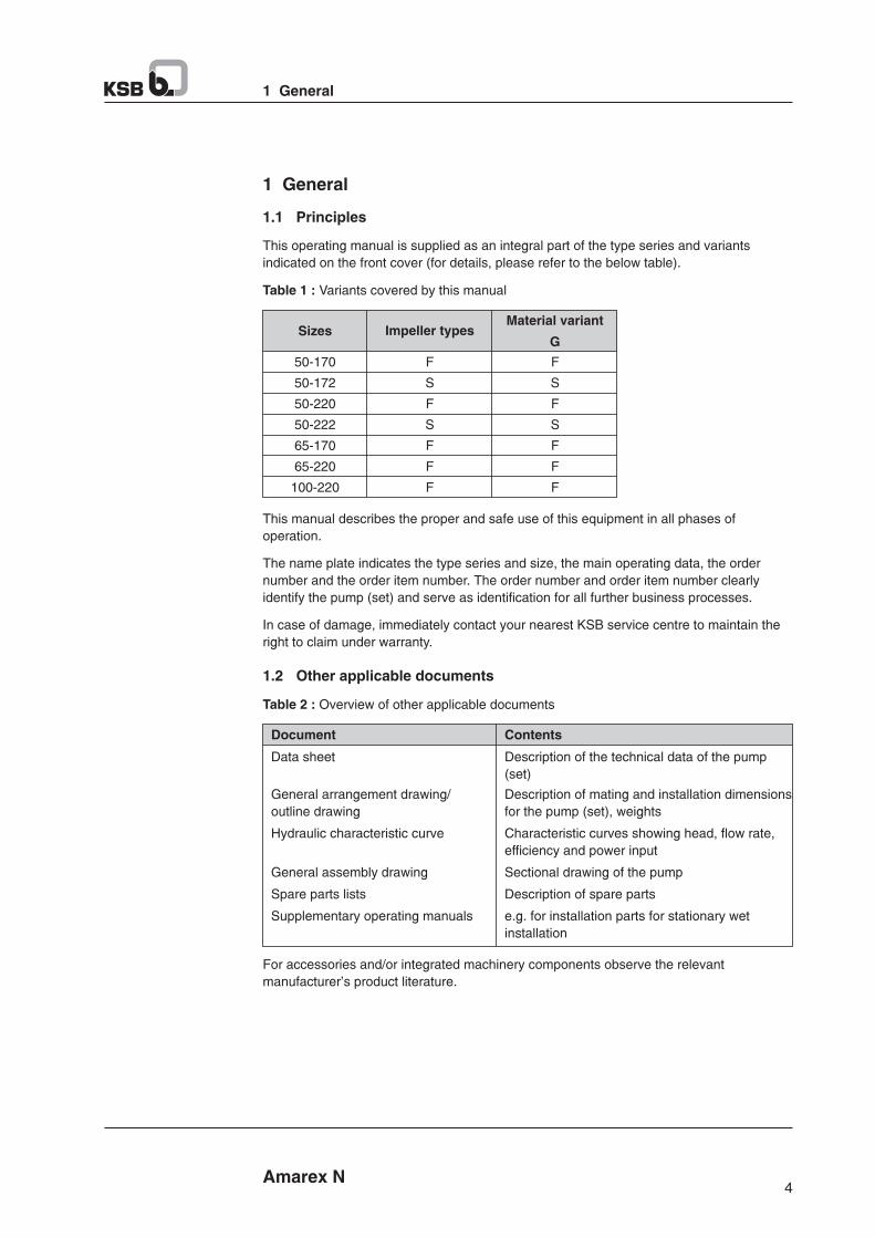
This operating manual is supplied as an integral part of the type series and variants
indicated on the front cover (for details, please refer to the below table).
Table 1 : Variants covered by this manual
1 General
Amarex N
Sizes Impeller typesMaterial variant
G
50-170
50-172
50-220
50-222
65-170
65-220
100-220
F
S
F
S
F
F
F
F
S
F
S
F
F
F
This manual describes the proper and safe use of this equipment in all phases of
operation.
The name plate indicates the type series and size, the main operating data, the order
number and the order item number. The order number and order item number clearly
identify the pump (set) and serve as identification for all further business processes.
In case of damage, immediately contact your nearest KSB service centre to maintain the
right to claim under warranty.
1.2 Other applicable documents
Table 2 : Overview of other applicable documents
Document Contents
Data sheet Description of the technical data of the pump
(set)
General arrangement drawing/ Description of mating and installation dimensions
outline drawing for the pump (set), weights
Hydraulic characteristic curve Characteristic curves showing head, flow rate,
efficiency and power input
General assembly drawing Sectional drawing of the pump
Spare parts lists Description of spare parts
Supplementary operating manuals e.g. for installation parts for stationary wet
installation
For accessories and/or integrated machinery components observe the relevant
manufacturer's product literature.
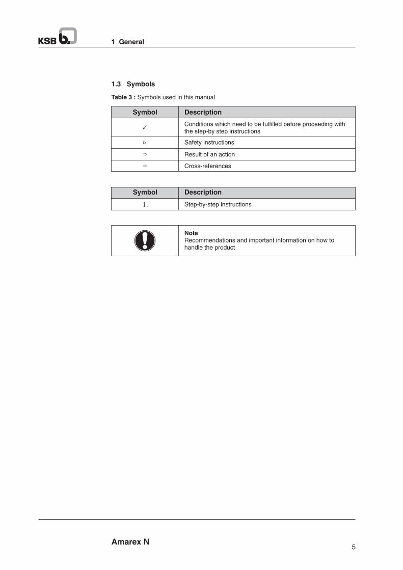
1.3 Symbols
Table 3 : Symbols used in this manual
1 General
1.
Symbol Description
Step-by-step instructions
NoteRecommendations and important information on how tohandle the product
Symbol Description
Conditions which need to be fulfilled before proceeding withthe step-by step instructions
Safety instructions
Result of an action
Cross-references
Amarex N54
1 General
1.1 Principles
This operating manual is supplied as an integral part of the type series and variants
indicated on the front cover (for details, please refer to the below table).
Table 1 : Variants covered by this manual
1 General
Amarex N
Sizes Impeller typesMaterial variant
G
50-170
50-172
50-220
50-222
65-170
65-220
100-220
F
S
F
S
F
F
F
F
S
F
S
F
F
F
This manual describes the proper and safe use of this equipment in all phases of
operation.
The name plate indicates the type series and size, the main operating data, the order
number and the order item number. The order number and order item number clearly
identify the pump (set) and serve as identification for all further business processes.
In case of damage, immediately contact your nearest KSB service centre to maintain the
right to claim under warranty.
1.2 Other applicable documents
Table 2 : Overview of other applicable documents
Document Contents
Data sheet Description of the technical data of the pump
(set)
General arrangement drawing/ Description of mating and installation dimensions
outline drawing for the pump (set), weights
Hydraulic characteristic curve Characteristic curves showing head, flow rate,
efficiency and power input
General assembly drawing Sectional drawing of the pump
Spare parts lists Description of spare parts
Supplementary operating manuals e.g. for installation parts for stationary wet
installation
For accessories and/or integrated machinery components observe the relevant
manufacturer's product literature.
Amarex N
2 Safety
7
2.3 Personnel qualification and training
All personnel involved in operating, maintaining, service, inspection and installing the
pump must be fully qualified to carry out the work involved taking care of safety clauses
mentioned throughout the manual. If not proper training and instruction must be acquired
to ensure proper understanding of the operating and safety instructions contained.
2.4 Non-compliance with operating and safety instructions
Non-compliance with the operating, the electrical and the safety instructions will
jeopardize the safety of the personnel, the environment and the pump itself. This will also
lead to forfeiture of any and all rights and claims for damages including KSB's warranty.
The pump unit must not be operated beyond the limiting values for the fluid handled in
terms of capacity, speed, density, pressure, temperature, voltage, frequency, motor
starting methods, starting current, motor rating and other physical and electrical properties
specified in the technical documentation.
Never start the pump without ensuring that sensors and monitoring equipment (protection
devices) are connected and functioning as per the set parameters. In case the pumps are
operated without these features the KSB's warranty claims will be null and void.
The warranty related to the operating reliability and safety of the unit is valid only if the
equipment is used in accordance with all of its designated data as mentioned in this
manual and data sheet.
Non-compliance can, for example, cause the following :
- Failure of important pump / system functions
- Failure of servicing and maintenance methods
- Hazard to person by electrical, mechanical and chemical effects.
- Hazard to environment due to leakage of hazardous substances.
2.5 Safety awareness
In addition to the safety information contained in this manual and the intended use, the
following safety regulations shall be complied with :
§ Accident prevention, health and safety regulations
§ Explosion protection regulations
§ Safety regulations for handling hazardous substance
§ Applicable standards and laws
2.6 Safety instructions for operator / user
§ Any hot or cold components that could be a hazard must be equipped with safety
equipments by the operator.
§ Guards which are fitted to prevent accidental contact with hot or cold moving parts
(coupling) must not be removed while the pump is operating.
§ Leakages (e.g. at shaft seal) of hazardous fluids (e.g. explosive, toxic, hot fluids) must
be disposed off in such a manner as to avoid any danger to personnel and
environment.
§ All relevant laws must be followed.
§ Electrical hazards must be taken care of (see details of local safety regulations
applicable).
§ Work on pump must be carried out only during stand still.
2 Safety
DANGER
2 Safety
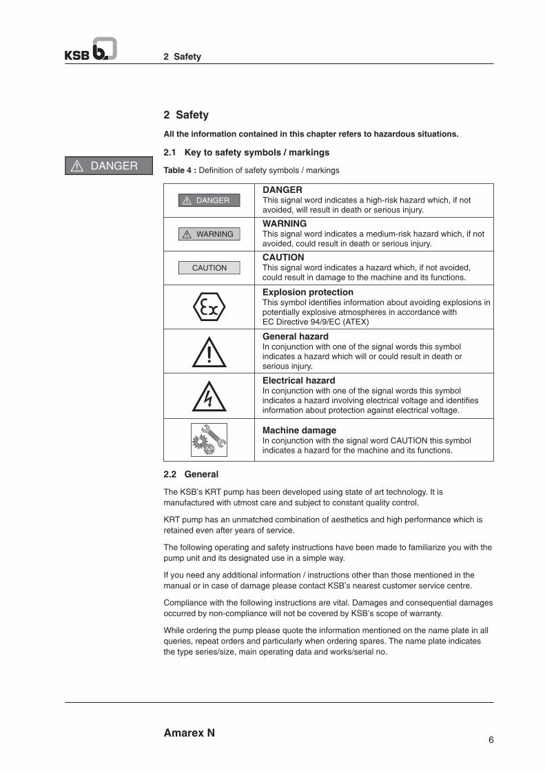
All the information contained in this chapter refers to hazardous situations.
2.1 Key to safety symbols / markings
Table 4 : Definition of safety symbols / markings
WARNING
DANGER
DANGERThis signal word indicates a high-risk hazard which, if notavoided, will result in death or serious injury.
WARNINGThis signal word indicates a medium-risk hazard which, if notavoided, could result in death or serious injury.
CAUTION
CAUTIONThis signal word indicates a hazard which, if not avoided,could result in damage to the machine and its functions.
General hazardIn conjunction with one of the signal words this symbolindicates a hazard which will or could result in death orserious injury.
Electrical hazardIn conjunction with one of the signal words this symbolindicates a hazard involving electrical voltage and identifiesinformation about protection against electrical voltage.
Machine damageIn conjunction with the signal word CAUTION this symbolindicates a hazard for the machine and its functions.
Explosion protectionThis symbol identifies information about avoiding explosions inpotentially explosive atmospheres in accordance withEC Directive 94/9/EC (ATEX)
2.2 General
The KSB's KRT pump has been developed using state of art technology. It is
manufactured with utmost care and subject to constant quality control.
KRT pump has an unmatched combination of aesthetics and high performance which is
retained even after years of service.
The following operating and safety instructions have been made to familiarize you with the
pump unit and its designated use in a simple way.
If you need any additional information / instructions other than those mentioned in the
manual or in case of damage please contact KSB's nearest customer service centre.
Compliance with the following instructions are vital. Damages and consequential damages
occurred by non-compliance will not be covered by KSB's scope of warranty.
While ordering the pump please quote the information mentioned on the name plate in all
queries, repeat orders and particularly when ordering spares. The name plate indicates
the type series/size, main operating data and works/serial no.
6 Amarex N
Amarex N
2 Safety
7
2.3 Personnel qualification and training
All personnel involved in operating, maintaining, service, inspection and installing the
pump must be fully qualified to carry out the work involved taking care of safety clauses
mentioned throughout the manual. If not proper training and instruction must be acquired
to ensure proper understanding of the operating and safety instructions contained.
2.4 Non-compliance with operating and safety instructions
Non-compliance with the operating, the electrical and the safety instructions will
jeopardize the safety of the personnel, the environment and the pump itself. This will also
lead to forfeiture of any and all rights and claims for damages including KSB's warranty.
The pump unit must not be operated beyond the limiting values for the fluid handled in
terms of capacity, speed, density, pressure, temperature, voltage, frequency, motor
starting methods, starting current, motor rating and other physical and electrical properties
specified in the technical documentation.
Never start the pump without ensuring that sensors and monitoring equipment (protection
devices) are connected and functioning as per the set parameters. In case the pumps are
operated without these features the KSB's warranty claims will be null and void.
The warranty related to the operating reliability and safety of the unit is valid only if the
equipment is used in accordance with all of its designated data as mentioned in this
manual and data sheet.
Non-compliance can, for example, cause the following :
- Failure of important pump / system functions
- Failure of servicing and maintenance methods
- Hazard to person by electrical, mechanical and chemical effects.
- Hazard to environment due to leakage of hazardous substances.
2.5 Safety awareness
In addition to the safety information contained in this manual and the intended use, the
following safety regulations shall be complied with :
§ Accident prevention, health and safety regulations
§ Explosion protection regulations
§ Safety regulations for handling hazardous substance
§ Applicable standards and laws
2.6 Safety instructions for operator / user
§ Any hot or cold components that could be a hazard must be equipped with safety
equipments by the operator.
§ Guards which are fitted to prevent accidental contact with hot or cold moving parts
(coupling) must not be removed while the pump is operating.
§ Leakages (e.g. at shaft seal) of hazardous fluids (e.g. explosive, toxic, hot fluids) must
be disposed off in such a manner as to avoid any danger to personnel and
environment.
§ All relevant laws must be followed.
§ Electrical hazards must be taken care of (see details of local safety regulations
applicable).
§ Work on pump must be carried out only during stand still.
2 Safety
DANGER
2 Safety
All the information contained in this chapter refers to hazardous situations.
2.1 Key to safety symbols / markings
Table 4 : Definition of safety symbols / markings
WARNING
DANGER
DANGERThis signal word indicates a high-risk hazard which, if notavoided, will result in death or serious injury.
WARNINGThis signal word indicates a medium-risk hazard which, if notavoided, could result in death or serious injury.
CAUTION
CAUTIONThis signal word indicates a hazard which, if not avoided,could result in damage to the machine and its functions.
General hazardIn conjunction with one of the signal words this symbolindicates a hazard which will or could result in death orserious injury.
Electrical hazardIn conjunction with one of the signal words this symbolindicates a hazard involving electrical voltage and identifiesinformation about protection against electrical voltage.
Machine damageIn conjunction with the signal word CAUTION this symbolindicates a hazard for the machine and its functions.
Explosion protectionThis symbol identifies information about avoiding explosions inpotentially explosive atmospheres in accordance withEC Directive 94/9/EC (ATEX)
2.2 General
The KSB's KRT pump has been developed using state of art technology. It is
manufactured with utmost care and subject to constant quality control.
KRT pump has an unmatched combination of aesthetics and high performance which is
retained even after years of service.
The following operating and safety instructions have been made to familiarize you with the
pump unit and its designated use in a simple way.
If you need any additional information / instructions other than those mentioned in the
manual or in case of damage please contact KSB's nearest customer service centre.
Compliance with the following instructions are vital. Damages and consequential damages
occurred by non-compliance will not be covered by KSB's scope of warranty.
While ordering the pump please quote the information mentioned on the name plate in all
queries, repeat orders and particularly when ordering spares. The name plate indicates
the type series/size, main operating data and works/serial no.
6 Amarex N

Amarex N
2 Safety
9
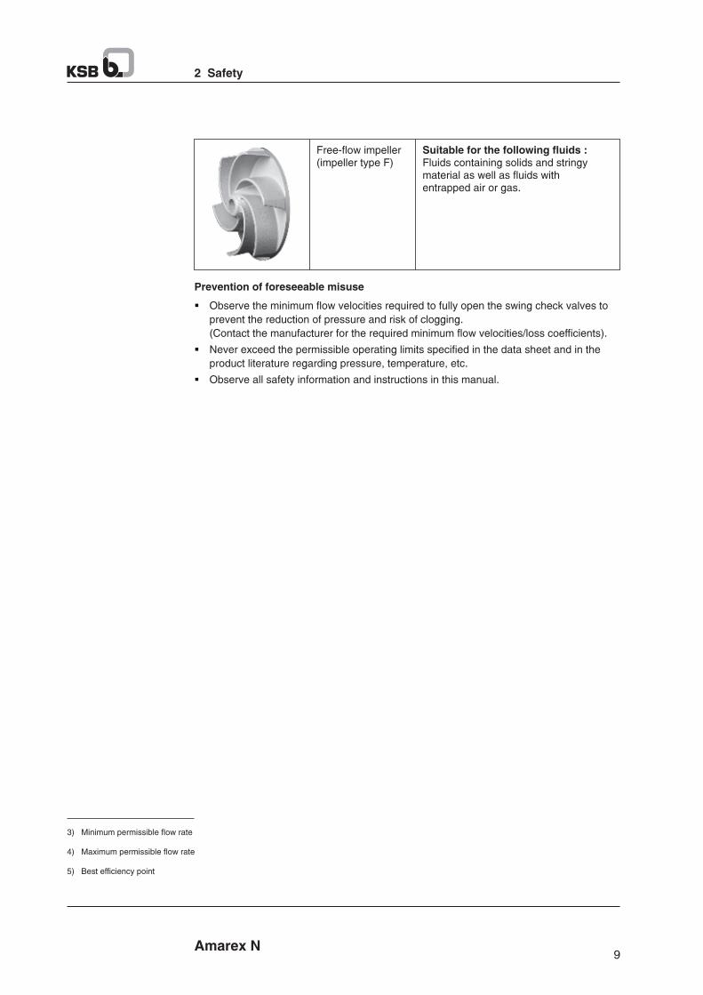
Free-flow impeller(impeller type F)
Suitable for the following fluids :Fluids containing solids and stringymaterial as well as fluids withentrapped air or gas.
Prevention of foreseeable misuse
§ Observe the minimum flow velocities required to fully open the swing check valves to
prevent the reduction of pressure and risk of clogging.
(Contact the manufacturer for the required minimum flow velocities/loss coefficients).
§ Never exceed the permissible operating limits specified in the data sheet and in the
product literature regarding pressure, temperature, etc.
§ Observe all safety information and instructions in this manual.
3) Minimum permissible flow rate
4) Maximum permissible flow rate
5) Best efficiency point
8
2 Safety
Amarex N
§ Pump / units handling hazardous media must be decontaminated.
§ Immediately following the completion of pump unit's installation, all safety relevant and
protective devices must be analyzed, installed and activated before starting the pump.
Refer to section 6 ‘‘Commissioning / start up’’ before running the pump.
2.7 Safety information for maintenance, inspection and installation work
§ Modifications or alterations of the pump are only permitted with the manufacturer's
prior consent.
§ Use only original spare parts or parts authorised by the manufacturer. The use of other
parts can invalidate any liability of the manufacturer for resulting damage.
2.8 Unauthorized modes of operation
§ Never operate the pump (set) outside the limits stated in the data sheet and in this
manual.
§ The warranty relating to the operating reliability and safety of the supplied pump (set) is
only valid if the equipment is used in accordance with its intended use.
2.9 Intended use
The pump (set) must only be operated within the operating limits described in the other
applicable documents.
§ Only operate pump sets which are in perfect technical condition.
§ Do not operate partially assembled pump sets.
§ Only use the pump set to handle the fluids described in the data sheet or product
literature of the pump model.
§ Never operate the pump set without the fluid to be handled.
§ Observe the limits for continuous operation specified in the data sheet or product 3) 4)literature (Q and Q ) (to prevent damage such as shaft fracture, bearing failure, min max
mechanical seal damage, etc.).
§ When untreated waste water is handled the duty points in continuous operation lie 5) within 0.7 to 1.2 x Q to minimise the risk of clogging/hardening.opt
§ Avoid duty points for continuous operation at very low speeds and small flow rates 5)(<0.7 x Q ).opt
§ Observe the maximum flow rates indicated in the data sheet or product literature (to
prevent overheating, mechanical seal damage, cavitation damage, bearing damage,
etc.).
§ Do not throttle the flow rate on the suction side of the pump set (to prevent cavitation
damage).
§ Consult the manufacturer about any use or mode of operation not described in the data
sheet or product literature.
§ Only use impeller types designed for the fluid handled, as described below.
Impeller with cutter(impeller type S)
Suitable for the following fluids :Faces, domestic sewage and wastewater containing long fibers.
Amarex N
2 Safety
9
Free-flow impeller(impeller type F)
Suitable for the following fluids :Fluids containing solids and stringymaterial as well as fluids withentrapped air or gas.
Prevention of foreseeable misuse
§ Observe the minimum flow velocities required to fully open the swing check valves to
prevent the reduction of pressure and risk of clogging.
(Contact the manufacturer for the required minimum flow velocities/loss coefficients).
§ Never exceed the permissible operating limits specified in the data sheet and in the
product literature regarding pressure, temperature, etc.
§ Observe all safety information and instructions in this manual.
3) Minimum permissible flow rate
4) Maximum permissible flow rate
5) Best efficiency point
8
2 Safety
Amarex N
§ Pump / units handling hazardous media must be decontaminated.
§ Immediately following the completion of pump unit's installation, all safety relevant and
protective devices must be analyzed, installed and activated before starting the pump.
Refer to section 6 ‘‘Commissioning / start up’’ before running the pump.
2.7 Safety information for maintenance, inspection and installation work
§ Modifications or alterations of the pump are only permitted with the manufacturer's
prior consent.
§ Use only original spare parts or parts authorised by the manufacturer. The use of other
parts can invalidate any liability of the manufacturer for resulting damage.
2.8 Unauthorized modes of operation
§ Never operate the pump (set) outside the limits stated in the data sheet and in this
manual.
§ The warranty relating to the operating reliability and safety of the supplied pump (set) is
only valid if the equipment is used in accordance with its intended use.
2.9 Intended use
The pump (set) must only be operated within the operating limits described in the other
applicable documents.
§ Only operate pump sets which are in perfect technical condition.
§ Do not operate partially assembled pump sets.
§ Only use the pump set to handle the fluids described in the data sheet or product
literature of the pump model.
§ Never operate the pump set without the fluid to be handled.
§ Observe the limits for continuous operation specified in the data sheet or product 3) 4)literature (Q and Q ) (to prevent damage such as shaft fracture, bearing failure, min max
mechanical seal damage, etc.).
§ When untreated waste water is handled the duty points in continuous operation lie 5) within 0.7 to 1.2 x Q to minimise the risk of clogging/hardening.opt
§ Avoid duty points for continuous operation at very low speeds and small flow rates 5)(<0.7 x Q ).opt
§ Observe the maximum flow rates indicated in the data sheet or product literature (to
prevent overheating, mechanical seal damage, cavitation damage, bearing damage,
etc.).
§ Do not throttle the flow rate on the suction side of the pump set (to prevent cavitation
damage).
§ Consult the manufacturer about any use or mode of operation not described in the data
sheet or product literature.
§ Only use impeller types designed for the fluid handled, as described below.
Impeller with cutter(impeller type S)
Suitable for the following fluids :Faces, domestic sewage and wastewater containing long fibers.
11 Amarex N
3 Transport / Temporary Storage / Disposal
Damage during storage by humidity, dirt, or vermin
Corrosion/contamination of the pump (set)!
Ø For outdoor storage cover the packed or unpacked pump (set) and accessories with
waterproof material.
CAUTION
Wet, contaminated or damaged openings and connections
Leakage or damage to the pump set!
Ø Only remove caps/covers from the openings of the pump set at the time.
CAUTION
Store the pump set under dry and vibration-free conditions, if possible in its original
packaging.
1. Spray-coat the inside wall of the pump casing and in particular the impeller clearance
areas, with a preservative.
2. Spray the preservative through the suction and discharge nozzles.
It is advisable to then close the pump nozzles (e.g. with plastic caps or similar).
3.4 Disposal
Fluids posing a health hazard and/or hot fluids
Hazard to persons and the environment!
Ø Collect and properly dispose of flushing liquid and any residues of the fluid handled.
Ø Wear safety clothing and a protective mask, if required.
Ø Observe all legal regulations on the disposal of fluids posing a health hazard.
WARNING
1. Dismantle the pump (set).
Collect greases and other lubricants during dismantling.
2. Separate and sort the pump materials, e.g. by :
- Metals
- Plastics
- Electronic waste
- Greases and other lubricants
3. Dispose of materials in accordance with local regulations or in another controlled
manner.
Amarex N
3 Transport / Temporary Storage / Disposal
10
3 Transport / Temporary Storage / Disposal
3.1 Checking the condition upon delivery
1. On transfer of goods, check each packaging unit for damage.
2. In the event of in-transit damage, assess the exact damage, document it an notify KSB
or the supplying dealer (as applicable) and the insurer about the damage in writing
immediately.
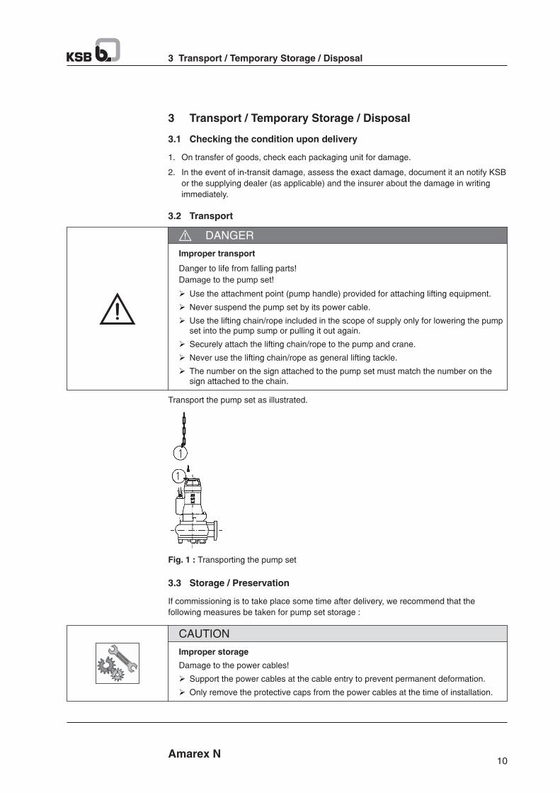
3.2 Transport
Improper transport
Danger to life from falling parts!
Damage to the pump set!
Ø Use the attachment point (pump handle) provided for attaching lifting equipment.
Ø Never suspend the pump set by its power cable.
Ø Use the lifting chain/rope included in the scope of supply only for lowering the pump set into the pump sump or pulling it out again.
Ø Securely attach the lifting chain/rope to the pump and crane.
Ø Never use the lifting chain/rope as general lifting tackle.
Ø The number on the sign attached to the pump set must match the number on the sign attached to the chain.
DANGER
Transport the pump set as illustrated.
Fig. 1 : Transporting the pump set
3.3 Storage / Preservation
If commissioning is to take place some time after delivery, we recommend that the
following measures be taken for pump set storage :
Improper storage
Damage to the power cables!
Ø Support the power cables at the cable entry to prevent permanent deformation.
Ø Only remove the protective caps from the power cables at the time of installation.
CAUTION
11 Amarex N
3 Transport / Temporary Storage / Disposal
Damage during storage by humidity, dirt, or vermin
Corrosion/contamination of the pump (set)!
Ø For outdoor storage cover the packed or unpacked pump (set) and accessories with
waterproof material.
CAUTION
Wet, contaminated or damaged openings and connections
Leakage or damage to the pump set!
Ø Only remove caps/covers from the openings of the pump set at the time.
CAUTION
Store the pump set under dry and vibration-free conditions, if possible in its original
packaging.
1. Spray-coat the inside wall of the pump casing and in particular the impeller clearance
areas, with a preservative.
2. Spray the preservative through the suction and discharge nozzles.
It is advisable to then close the pump nozzles (e.g. with plastic caps or similar).
3.4 Disposal
Fluids posing a health hazard and/or hot fluids
Hazard to persons and the environment!
Ø Collect and properly dispose of flushing liquid and any residues of the fluid handled.
Ø Wear safety clothing and a protective mask, if required.
Ø Observe all legal regulations on the disposal of fluids posing a health hazard.
WARNING
1. Dismantle the pump (set).
Collect greases and other lubricants during dismantling.
2. Separate and sort the pump materials, e.g. by :
- Metals
- Plastics
- Electronic waste
- Greases and other lubricants
3. Dispose of materials in accordance with local regulations or in another controlled
manner.
Amarex N
3 Transport / Temporary Storage / Disposal
10
3 Transport / Temporary Storage / Disposal
3.1 Checking the condition upon delivery
1. On transfer of goods, check each packaging unit for damage.
2. In the event of in-transit damage, assess the exact damage, document it an notify KSB
or the supplying dealer (as applicable) and the insurer about the damage in writing
immediately.
3.2 Transport
Improper transport
Danger to life from falling parts!
Damage to the pump set!
Ø Use the attachment point (pump handle) provided for attaching lifting equipment.
Ø Never suspend the pump set by its power cable.
Ø Use the lifting chain/rope included in the scope of supply only for lowering the pump set into the pump sump or pulling it out again.
Ø Securely attach the lifting chain/rope to the pump and crane.
Ø Never use the lifting chain/rope as general lifting tackle.
Ø The number on the sign attached to the pump set must match the number on the sign attached to the chain.
DANGER
Transport the pump set as illustrated.
Fig. 1 : Transporting the pump set
3.3 Storage / Preservation
If commissioning is to take place some time after delivery, we recommend that the
following measures be taken for pump set storage :
Improper storage
Damage to the power cables!
Ø Support the power cables at the cable entry to prevent permanent deformation.
Ø Only remove the protective caps from the power cables at the time of installation.
CAUTION

13 Amarex N
4 Description of the Pump (Set)
4.4 Design details
Design
§ Fully floodable submersible motor pump
§ Not self-priming
§ Close-coupled pump set
Impeller type
§ Various, application-based impeller types
Shaft seal
§ Two bi-directional mechanical seals in tandem arrangement, with liquid reservoir.
Standard bearings
§ Grease-lubricated bearings sealed for life
§ Maintenance-free
Reinforced bearings (optional) Pump-end bearings :
§ Grease-lubricaated bearing sealed for life
The following hydraulic system/motor combinations can be equipped with a reinforced
bearing :
Table 6 : Reinforced bearing assembly
Hydraulic system sizes Motor size and number of poles
50-172 002, 012, 022
50-222 032, 042
Drive
§ Three-phase asynchronous squirrel-cage motor.
Explosion-proof pump sets comply with Ex d IIB type of protection.
4.5 Types of installation
Two design variants are available, depending on the installation type:
§ Stationary wet installation (installation type S)
§ Transportable wet installation (installation type P)
The pump set is designed for continuous operation in submerged condition. The motor is
cooled by the fluid handled on the motor surface. Operation with the motor outside the
fluid handled is possible for short periods.
Amarex N
4 Description of the Pump (Set)
12
4 Description of the Pump (Set)
4.1 General description
Pump for handling untreated waste water containing long fibers and solid substances,
fluids containing air/gas as well as raw, activated and digested sludge.
4.2 Designation
Example : Amarex N F 50-170/012 ULG 120
Table 5 : Key of the designation
Code Description
Amarex N Type series
F Impeller type, e.g. F = free flow
50 Nominal discharge nozzle diameter [mm]
170 Code number for hydraulic system size code
01 Number for motor size
2 Number of polesoUL Motor variant, e.g. UL = with non-explosion protection (55 C)
G Casing material, e.g. G - grey cast iron
120 Nominal impeller diameter [mm]
4.3 Name plate
KSB PUMPS LTD.
Type 1Sr.No. 2 3
V 4 A 5 50. 6
Cos 7 n 8 IP 9rpm
P2 Ex.10 kW 11
12Pumping liquid temp.
A 52x74 - IN 03572D
Field No. to be Filled with **
1 Motor type and size
2 Sr. No. (Work order no.) - Mfg. division - Identification No. (i.e. 75X)*
3 Year of manufacturing : e.g. 2003
4 Rated voltage
5 Rated current
6 Frequency
7 Power factor - Cos
8 Speed
9 Type of encloser (IP 68)
10 Rated output / Power
11 Excise no.o12 Pumping liquid temperature C
15 Amarex N
4 Description of the Pump (Set)
4.7 Scope of supply
Depending on the model, the following items are included in the scope of supply :
Stationary wet installation
§ Pump set complete with power cables
§ Claw with sealing and mounting elements
§ Lifting rope/chain
§ Mounting bracket with mounting elements
§ Duck foot bend with mounting elements
Transportable wet installation
§ Pump set complete with power cables
§ Foot pad or pump stool with mounting elements
§ Lifting rope/chain
4.8 Dimensions and weights
For dimensions and eights please refer to the general arrangement drawing/outline
drawing or data sheet of the pump set.
A seperate name plate is included in KSB's scope of supply. This name plate must be attached in a clearly visible position outside the place of installation, e.g. at the control panel, pipeline of mounting bracket.
NOTE
Amarex N
4 Description of the Pump (Set)
14
4.6 Configuration and function
1
3
5
7
9
2
4
6
8
10
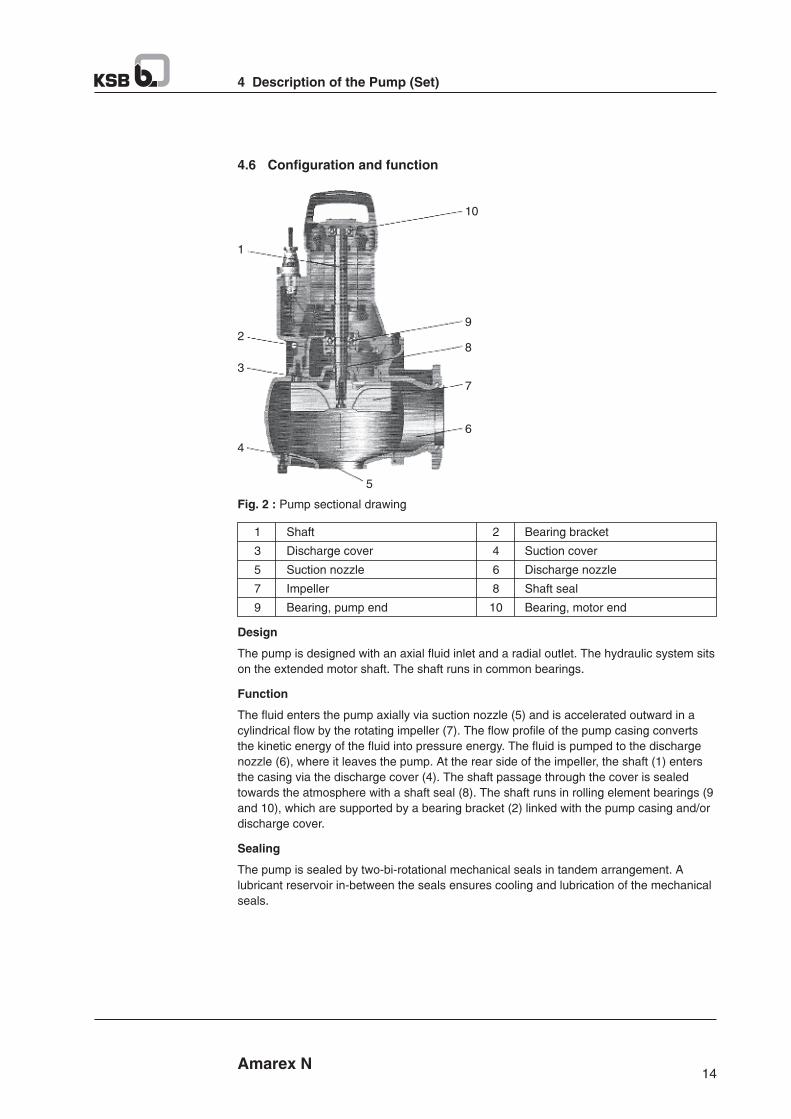
Shaft
Discharge cover
Suction nozzle
Impeller
Bearing, pump end
Bearing bracket
Suction cover
Discharge nozzle
Shaft seal
Bearing, motor end
Design
The pump is designed with an axial fluid inlet and a radial outlet. The hydraulic system sits
on the extended motor shaft. The shaft runs in common bearings.
Function
The fluid enters the pump axially via suction nozzle (5) and is accelerated outward in a
cylindrical flow by the rotating impeller (7). The flow profile of the pump casing converts
the kinetic energy of the fluid into pressure energy. The fluid is pumped to the discharge
nozzle (6), where it leaves the pump. At the rear side of the impeller, the shaft (1) enters
the casing via the discharge cover (4). The shaft passage through the cover is sealed
towards the atmosphere with a shaft seal (8). The shaft runs in rolling element bearings (9
and 10), which are supported by a bearing bracket (2) linked with the pump casing and/or
discharge cover.
Sealing
The pump is sealed by two-bi-rotational mechanical seals in tandem arrangement. A
lubricant reservoir in-between the seals ensures cooling and lubrication of the mechanical
seals.
1
2
3
4
5
6
7
8
9
10
Fig. 2 : Pump sectional drawing
15 Amarex N
4 Description of the Pump (Set)
4.7 Scope of supply
Depending on the model, the following items are included in the scope of supply :
Stationary wet installation
§ Pump set complete with power cables
§ Claw with sealing and mounting elements
§ Lifting rope/chain
§ Mounting bracket with mounting elements
§ Duck foot bend with mounting elements
Transportable wet installation
§ Pump set complete with power cables
§ Foot pad or pump stool with mounting elements
§ Lifting rope/chain
4.8 Dimensions and weights
For dimensions and eights please refer to the general arrangement drawing/outline
drawing or data sheet of the pump set.
A seperate name plate is included in KSB's scope of supply. This name plate must be attached in a clearly visible position outside the place of installation, e.g. at the control panel, pipeline of mounting bracket.
NOTE
Amarex N
4 Description of the Pump (Set)
14
4.6 Configuration and function
1
3
5
7
9
2
4
6
8
10
Shaft
Discharge cover
Suction nozzle
Impeller
Bearing, pump end
Bearing bracket
Suction cover
Discharge nozzle
Shaft seal
Bearing, motor end
Design
The pump is designed with an axial fluid inlet and a radial outlet. The hydraulic system sits
on the extended motor shaft. The shaft runs in common bearings.
Function
The fluid enters the pump axially via suction nozzle (5) and is accelerated outward in a
cylindrical flow by the rotating impeller (7). The flow profile of the pump casing converts
the kinetic energy of the fluid into pressure energy. The fluid is pumped to the discharge
nozzle (6), where it leaves the pump. At the rear side of the impeller, the shaft (1) enters
the casing via the discharge cover (4). The shaft passage through the cover is sealed
towards the atmosphere with a shaft seal (8). The shaft runs in rolling element bearings (9
and 10), which are supported by a bearing bracket (2) linked with the pump casing and/or
discharge cover.
Sealing
The pump is sealed by two-bi-rotational mechanical seals in tandem arrangement. A
lubricant reservoir in-between the seals ensures cooling and lubrication of the mechanical
seals.
1
2
3
4
5
6
7
8
9
10
Fig. 2 : Pump sectional drawing
17 Amarex N
5 Installation at Site
Place of installation for transportable model
Incorrect positioning
Personal injury and damage to property!
Ø Install the pump set vertically with the motor on top.
Ø Use appropriate means to secure the pump set against overturning and tipping over.
Ø Refer to the weights given in the data sheet/on the name plate.
WARNING
Resonance Any resonances at the usual excitation frequencies (1 x and 2 x rotational frequency,
rotational noise) must be prevented both in the foundation and in the connected piping, as
such frequencies may cause extreme vibrations.
1. Check the structural requirements.
All structural work required must have been prepared in accordance with the
dimensions stated in the outline drawing/general arrangement drawing.
5.2.2 Checking the lubricant level
The lubricant reservoirs have been filled with an environmentally-friendly, lubricant at the
Factory.
1. Position the pump set as shown.
a)
Fig. 3 : Checking the lubricant level
2. Unscrew screwed plug 903 with joint ring 411. The lubricant level must be 21 mm
below the filter opening.
3. If the lubricant level is any lower, top up the lubricant reservoir through the filler
opening until the indicated level is reached.
4. Close screwed plug 903 with joint ring 411. Observe the tightening torques.
(⇨ Section 7.6).
5.2.3 Checking the direction of rotation
Pump set running dry
Explosion hazard!
Ø Check the direction of rotation of pump sets.
DANGER
903411
M = 21 mm
Amarex N
5 Installation at Site
16
5 Installation at Site
5.1 Safety regulations
Improper installation in potentially explosive atmospheres
Explosion hazard!
Damage to the pump set!
Ø Comply with the applicable local explosion protection regulations.
Ø Observe the information given in the data sheet and on the name plate of the pump set.
DANGER
Persons in the tank during pump operation
Explosion shock!
Damage to the pump set!
Ø Never start up the pump set when there are persons in the tank.
DANGER
Immersible solid objects (tools, screws/bolts or similar) in the pump sump/inlet
tank
During pump start up
Personal injury and damage to property!
Ø Check the pump sump/inlet tank for impermissible solid objects before flooding and
remove, if necessary.
WARNING
5.2 Checks to be carried out prior to installation
5.2.1 Preparing the place of installation
Place of installation for stationary models
Installation on mounting surfaces which are unsecured and cannot support the
load
Personal injury and damage to property!
Ø Ensure the concrete's compressive strength is sufficient
Ø The mounting surface must have set and must be completely horizontal and even.
Ø Observe the weights indicated.
WARNING
Resonance Any resonances at the usual excitation frequencies (1 x and 2 x rotational frequency,
rotational noise) must be prevented both in the foundation and in the connected piping, as
such frequencies may cause extreme vibrations.
1. Check the structural requirements.
All structural work required must have been prepared in accordance with the
dimensions stated in the outline drawing/general arrangement drawing.
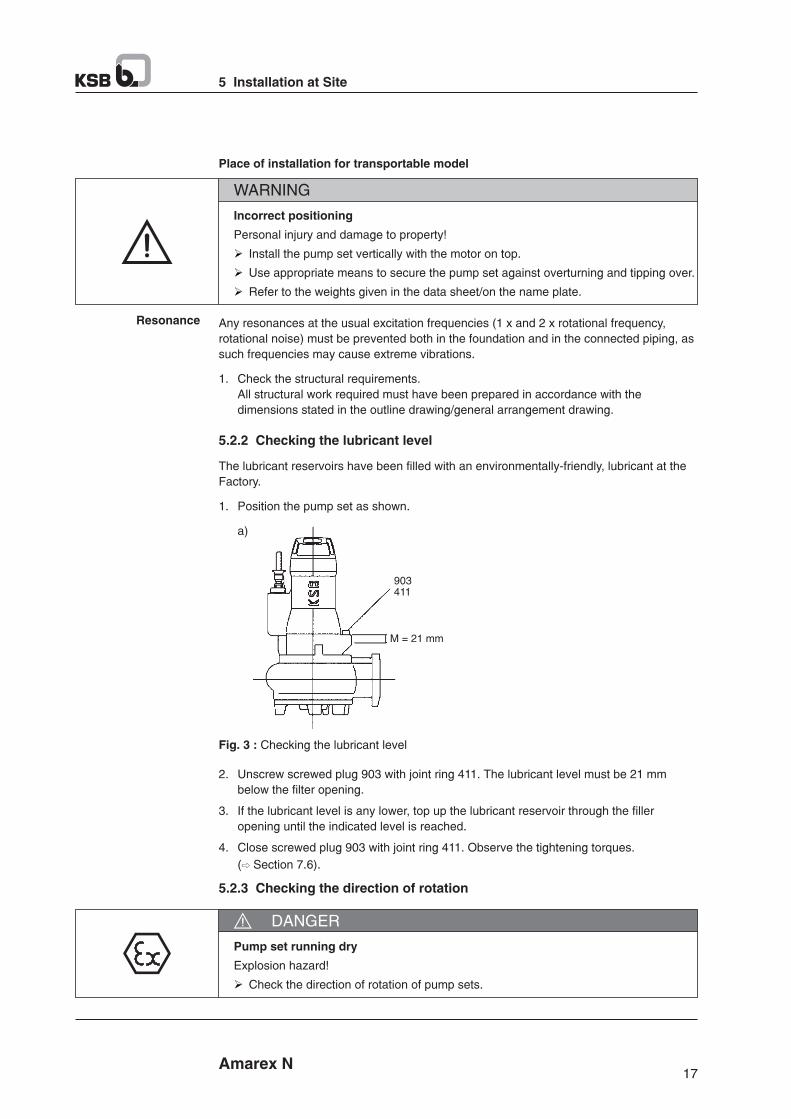
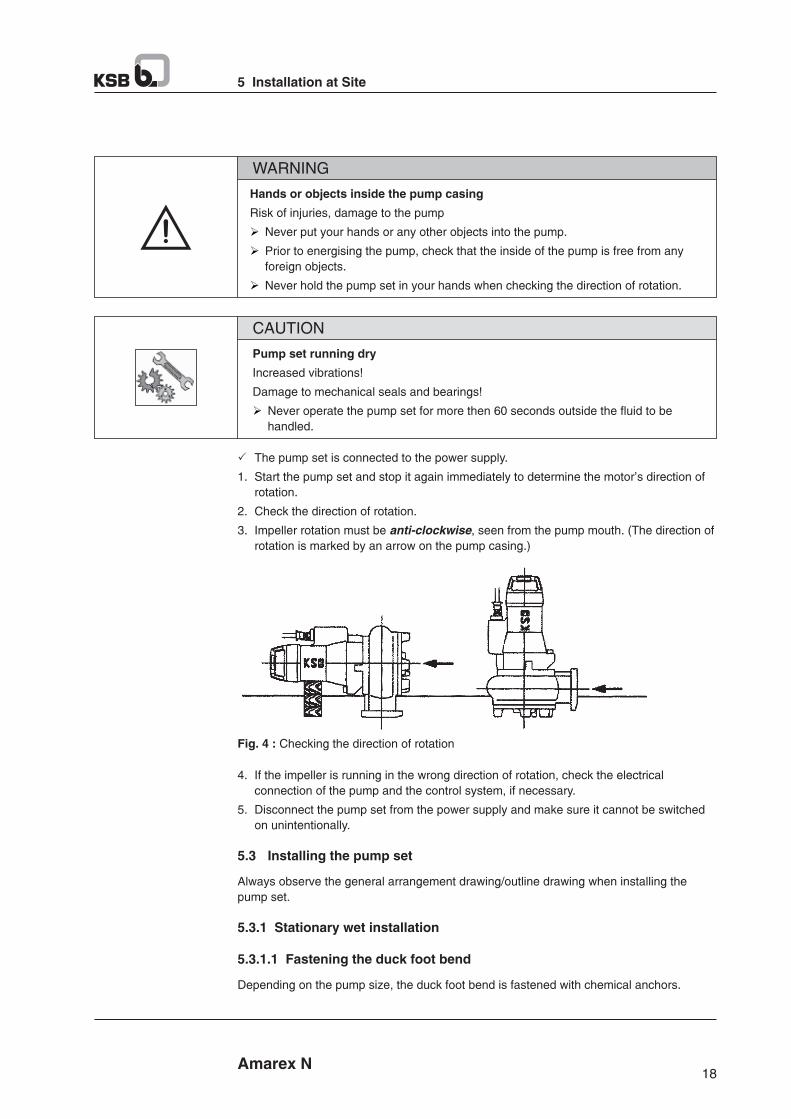
19 Amarex N
5 Installation at Site
Fastening the duck foot bend with chemical anchors
1. Position duck foot bend 72-1 on the floor of the tank/sump.
2. Insert chemical anchors 90-3.38.
3. Bolt duck foot bend 72-1 to the floor with chemical anchors 90-3.38.
5.3.1.2 Connecting the piping
DANGER
Impermissible loads acting on the flange of the duck foot bend
Danger to life from leakage of hot, toxic, corrosive or flammable fluids!
Ø Do not use the pump as an anchorage point for the piping.
Ø Anchor the pipelines in close proximity to the pump and connect them without transmitting any stresses or strains.
Ø Observe the permissible flange loads.
Ø Take appropriate measures to compensate thermal expansion of the piping.
When the pump set is used for draining low-level building areas, install a swing check valve in the discharge line to avoid back flow from the sewer system.
NOTE
Critical speed
Increased vibrations!
Damage to mechanical seals and bearings!
Ø Install a swing check valve in longer riser pipes to prevent the pump from excessive
running in reverse.
Ø When fitting a swing check valve, make sure that the unit can still be vented
properly.
CAUTION
72-1
90-3.38
Table 7 : Permissible flange loads
Nominal flange
diameter
Forces [N] Moments [Nm]
Fy Fz Fx My Mz Mx
50-65
100
1350
2700
1650
3350
1500
3000
2600
5250
1000
1250
1150
1450
1400
1750
2050
2600
Fig. 5 : Fastening the duck foot bend
Fig. 6 : Permissible flange loads
Amarex N
5 Installation at Site
18
Hands or objects inside the pump casing
Risk of injuries, damage to the pump
Ø Never put your hands or any other objects into the pump.
Ø Prior to energising the pump, check that the inside of the pump is free from any
foreign objects.
Ø Never hold the pump set in your hands when checking the direction of rotation.
WARNING
Pump set running dry
Increased vibrations!
Damage to mechanical seals and bearings!
Ø Never operate the pump set for more then 60 seconds outside the fluid to be
handled.
CAUTION
P The pump set is connected to the power supply.
1. Start the pump set and stop it again immediately to determine the motor's direction of
rotation.
2. Check the direction of rotation.
3. Impeller rotation must be anti-clockwise, seen from the pump mouth. (The direction of
rotation is marked by an arrow on the pump casing.)
Fig. 4 : Checking the direction of rotation
4. If the impeller is running in the wrong direction of rotation, check the electrical
connection of the pump and the control system, if necessary.
5. Disconnect the pump set from the power supply and make sure it cannot be switched
on unintentionally.
5.3 Installing the pump set
Always observe the general arrangement drawing/outline drawing when installing the
pump set.
5.3.1 Stationary wet installation
5.3.1.1 Fastening the duck foot bend
Depending on the pump size, the duck foot bend is fastened with chemical anchors.
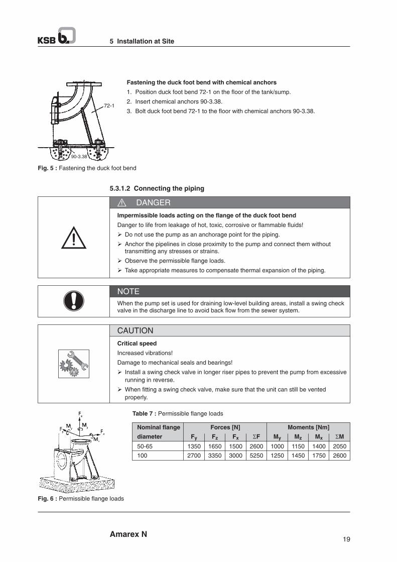
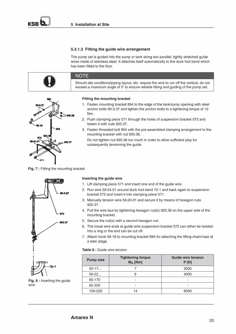
Fig. 9 : Fitting the guidehoop arrangement
5.3.1.5 Preparing the pump set
Fastening the claw for guide wire and guide hoop arrangement.
1. Fasten claw 723 with screw 914.05 and washer 550.35 to the discharge flange
(see drawing). Tighten the screw to a torque of 17 Nm.
Fig. 10 : Fastening the claw forguide wire and guide hoop arrangement.
Attaching the lifting chain/rope
Stationary wet installation
1. Attach the lifting chain with shackle or the lifting rope to the recess in the pump handle
opposite the discharge nozzle. This attachment point achieves a forward inclination of
the pump set towards the discharge nozzle, which allows the pump claw to hook onto
the duck foot bend.
Fig. 11 : Attaching the liftingchain/rope stationary wetinstallation
21 Amarex N
5 Installation at Site
5.3.1.4 Fitting the guide hoop arrangement (for DN 50 only)
1. Insert the ends of guide hoop 571 into the grooves of duck foot bend 72.1.
2. Fasten the flanged duck foot bend to the tank/sump floor with 2 anchor bolts 90-3.38.
(⇨ Section 5.3.1.1)
Amarex N
5 Installation at Site
20
5.3.1.3 Fitting the guide wire arrangement
The pump set is guided into the sump or tank along two parallel, tightly stretched guide
wires made of stainless steel. It attaches itself automatically to the duck foot bend which
has been fitted to the floor.
Should site conditions/piping layout, etc. require the wire to run off the vertical, do not oexceed a maximum angle of 5 to ensure reliable fitting and guiding of the pump set.
NOTE
Fitting the mounting bracket
1. Fasten mounting bracket 894 to the edge of the tank/sump opening with steel
anchor bolts 90-3.37 and tighten the anchor bolts to a tightening torque of 10
Nm.
2. Push clamping piece 571 through the holes of suspension bracket 572 and
fasten it with nuts 920.37.
3. Fasten threaded bolt 904 with the pre-assembled clamping arrangement to the
mounting bracket with nut 920.36.
Do not tighten nut 920.36 too much in order to allow sufficient play for
subsequently tensioning the guide.
Inserting the guide wire
1. Lift clamping piece 571 and insert one end of the guide wire.
2. Run wire 59-24.01 around duck foot bend 72-1 and back again to suspension
bracket 572 and insert it into clamping piece 571.
3. Manually tension wire 59-24.01 and secure it by means of hexagon nuts
920.37.
4. Pull the wire taut by tightening hexagon nut(s) 920.36 on the upper side of the
mounting bracket.
5. Secure the nut(s) with a second hexagon nut.
6. The loose wire ends at guide wire suspension bracket 572 can either be twisted
into a ring or the end can be cut off.
7. Attach hook 59-18 to mounting bracket 894 for attaching the lifting chain/rope at
a later stage.
Table 8 : Guide wire tension
Pump sizeTightening torque
M [Nm]A
Guide wire tension
P [N]
50-17...
50-22...
65-170
65-220
100-220
7
9
-
-
14
3000
4000
-
-
6000
Fig. 7 : Fitting the mounting bracket
Fig. 8 : Inserting the guidewire
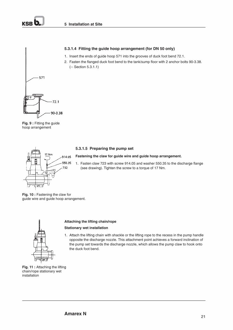
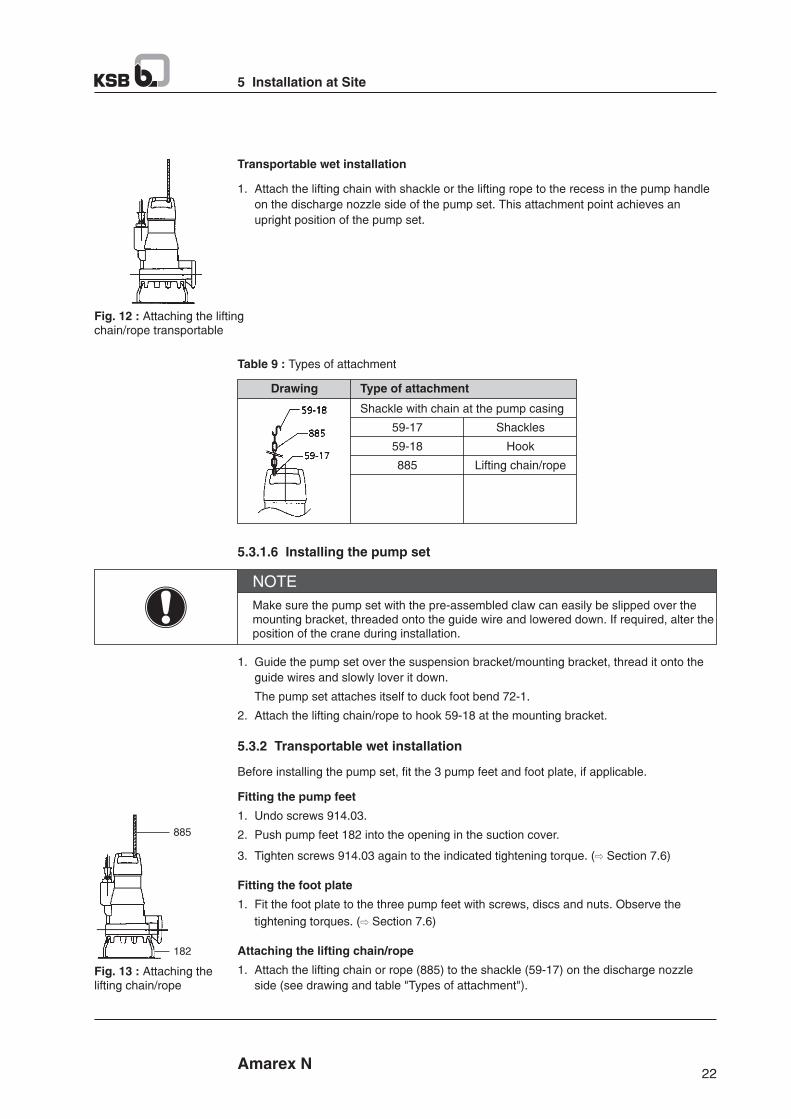
5.4 Electrical system
5.4.1 Information for planning the control system
For the electrical connection of the pump set observe the wiring diagrams contained in the
Annex.
The pump set is supplied with power cables; it is wired for DOL starting.
Pump set running dry.
Explosion hazard!
Ø Never allow an pump set to run dry!
DANGER
23 Amarex N
5 Installation at Site
5.3.3 Connecting the piping
The DIN connection can be connected to rigid or flexible pipes.
The motors can be connected to electrical low voltage networks with nominal voltages and
voltage tolerances as per IEC 38 or other networks or supply systems with rated voltage
tolerances of max. 10%.
5.4.1.1 Overload protection
1. Protect the pump set against overloading by using a thermal time-lag overload
protection device in accordance with IEC 947 and local regulations. (⇨ Section 9.3)
2. Set the overload protection device to the rated current specified on the name plate.
5.4.1.2 Level control
When laying a cable between the control system and the pump sets connection point, make sure that the number of cores is sufficient for the sensors. A minimum cross-
2section of 1.5 mm is required.
NOTE
Fig. 14 : Connection options
* Not in KSB's scope of supply.
* *
Amarex N
5 Installation at Site
22
Transportable wet installation
1. Attach the lifting chain with shackle or the lifting rope to the recess in the pump handle
on the discharge nozzle side of the pump set. This attachment point achieves an
upright position of the pump set.
Fig. 12 : Attaching the liftingchain/rope transportable
Table 9 : Types of attachment
Drawing Type of attachment
Shackle with chain at the pump casing
59-17
59-18
885
Shackles
Hook
Lifting chain/rope
5.3.1.6 Installing the pump set
Make sure the pump set with the pre-assembled claw can easily be slipped over the mounting bracket, threaded onto the guide wire and lowered down. If required, alter the position of the crane during installation.
NOTE
1. Guide the pump set over the suspension bracket/mounting bracket, thread it onto the
guide wires and slowly lover it down.
The pump set attaches itself to duck foot bend 72-1.
2. Attach the lifting chain/rope to hook 59-18 at the mounting bracket.
5.3.2 Transportable wet installation
Before installing the pump set, fit the 3 pump feet and foot plate, if applicable.
Fitting the pump feet
1. Undo screws 914.03.
2. Push pump feet 182 into the opening in the suction cover.
3. Tighten screws 914.03 again to the indicated tightening torque. (⇨ Section 7.6)
Fitting the foot plate
1. Fit the foot plate to the three pump feet with screws, discs and nuts. Observe the
tightening torques. (⇨ Section 7.6)
Attaching the lifting chain/rope
1. Attach the lifting chain or rope (885) to the shackle (59-17) on the discharge nozzle
side (see drawing and table "Types of attachment").Fig. 13 : Attaching thelifting chain/rope
885
182
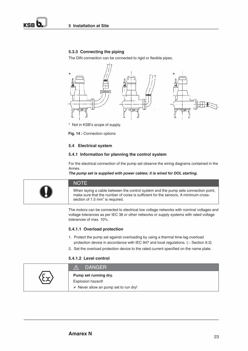
25 Amarex N
5 Installation at Site
Operating an incompletely connected pump set.
Explosion hazard!
Damage to the pump set!
Ø Never start up a pump set with incompletely connected power cables or non-operational monitoring devices.
DANGER
Incorrect connection
Damage to the sensors!
Ø Observe the limits stated in the following sections of this manual when connecting
the sensors.
CAUTION
The pump set is equipped with sensors designed to prevent hazards and damage to the
pump set.
Reliable and safe operation of the pump within the scope of our warranty is only possible if the sensor signals are properly analyzed as stipulated in these operating instructions.
NOTE
All sensors are located inside the pump set and are connected to the power cable. For
information on wiring and core marking please refer to the wiring diagrams. The individual
sensors and the limit values to be set are described in the following sections.
5.4.1.5 Motor temperature
Standard pump sets (variants UL) :
Two bimetal switches (terminals 21 and 22, max. 250 V~/2 A) serve as temperature
control devices which open when the winding temperature is too high.
Opening of the switch contacts must result in the pump set cutting out. Automatic re-start
is permissible.
5.4.2 Electrical connection
5.4.1.4 Sensors
Work on the pump set by unqualified personnel
Danger of death from electric shock
Ø Always have the electrical connections installed by a trained and qualified electrician.
DANGER
Incorrect connection to the mains
Damage to the mains network, short circuit!
Ø Observe the technical specifications of the local energy supply companies.
WARNING
Amarex N
5 Installation at Site
24
Fluid level below the specified minimum.
Damage to teh pump set by cavitation!
Ø Never allow the fluid level to drop below the specified minimum.
CAUTION
Automatic operation of the pump set in a tank requires the use of level control equipment.
Observe the minimum fluid level (Section 6.2.4.2).
5.4.1.3 Frequency inverter operation
The motors can also be operated on frequency inverter. Make sure to observe the design data of the motor in this case prevent an inadmissible heat build-up in the motor, motors operated on frequency inverter must always be equipped bimetal switches in the stator. When reaching the temperature limit, the motor must be cut out by means of a tripping order for the equipment to comply with the ATEX 100a Directive. This tripping unit shall be connected to the measuring points provide to ensure the temperature class stipulated for the plant is observed.
NOTE
DANGER
Incorrect setting of frequency inverter current limit
Explosion hazard!
Ø Set the current limit to max. 1.2 times the rated current indicated on the name plate.
When selecting a frequency inverter, check the following details :
P Data provided by manufacturer.
P Electrical data of pump set, particularly the rated current.
P Ensure short start ramps (maximum 5 seconds).
P Only start speed controlled operations after 2 minutes at the earliest. Pump start up
with long start ramps and low frequency may cause clogging.
P Only utilize up to 95% of the motor rating P2 indicated on the name plate.
P Frequency range 30-50 Hz
Frequency inverter operation produces RFI emissions whose level varies depending on
the inverter used (type, interference suppression make). To prevent the drive system,
consisting of a submersible motor and a frequency inverter, from exceeding the limits
stipulated in EN 50081 always observe the EMC information provided by the inverter
manufacturer. If the inverter manufacturer recommends a shielded power cable, make
sure to use a pump set with a shielded power cable.
The Pump set generally meets the interference immunity requirements to EN 50082. For
monitoring the sensors installed the operator must ensure sufficient interference immunity
by appropriately selecting and laying the cables in the plant. No modifications are required
on the power/control cable of the pump set. Suitable analyzing devices must be selected.
Selection
Start up
Operation
Electromagnetic
compatibility
Interference
immunity

Chemically corrosive fluids
Electric shock
Ø If the pump set is used in chemically corrosive fluids, never use the external terminal
for potential equalisation.
Ø Connect the potential equalisation conductor to a non-wetted flange of the discharge
line and establish an electric connection between the newly fitted potential
equalisation and the pump set.
DANGER
27 Amarex N
5 Installation at Site
Flow-induced motion
Damage to the power cable!
Ø Run the power cable upwards without slack.
CAUTION
1. Run the power cables upwards without slack and fasten them.
2. Only remove the protective caps from the power cables immediately before
connecting the cables.
3. If necessary, adjust the length of the power cables to the site requirements.
4. After shortening the cables, correctly re-affix the markings on the individual cores
at the cable ends.
Potential equalisation shall be provided for in compliance with EN 60 20Potential equalisation
conductor
Touching the pump set during operation
Electric shock
Ø Make sure that the pump set cannot be touched during operation.
DANGER
Fig. 15 : Fastening the power cables
Amarex N
5 Installation at Site
26
Improper routing of power cable
Damage to the power cables!
Ø oNever move the power cables at temperature below - 25 C.
Ø Never crush the power cable.
Ø Never lift the pump set by the power cables.
Ø Adjust the length of the power cables to the site requirements.
CAUTION
Motor overload
Damage to the motor!
Ø Protect the motor by a thermal time-lag overload protection device in accordance
with IEC 947 and local regulations.
CAUTION
For electrical connection observe the wiring diagrams in the Annex and the information for
planning the control system.
The pump set is supplied complete with power cable. Always connect all marked
conductors.
Incorrect connection
Explosion hazard!
Ø The connection point of the cable ends must be located outside the potentially explosive atmosphere or inside electrical equipment approved to equipment category II2G.
DANGER
Operating an incompletely connected pump set
Explosion hazard!
Damage to the pump set!
Ø Never start up a pump set with incompletely connected power cables or non-operational monitoring device.
DANGER
Connection of damaged power cables
Danger of death from electric shock!
Ø Check the power cables for damage before connecting them to the power supply.
Ø Never connect damaged power cables.
DANGER
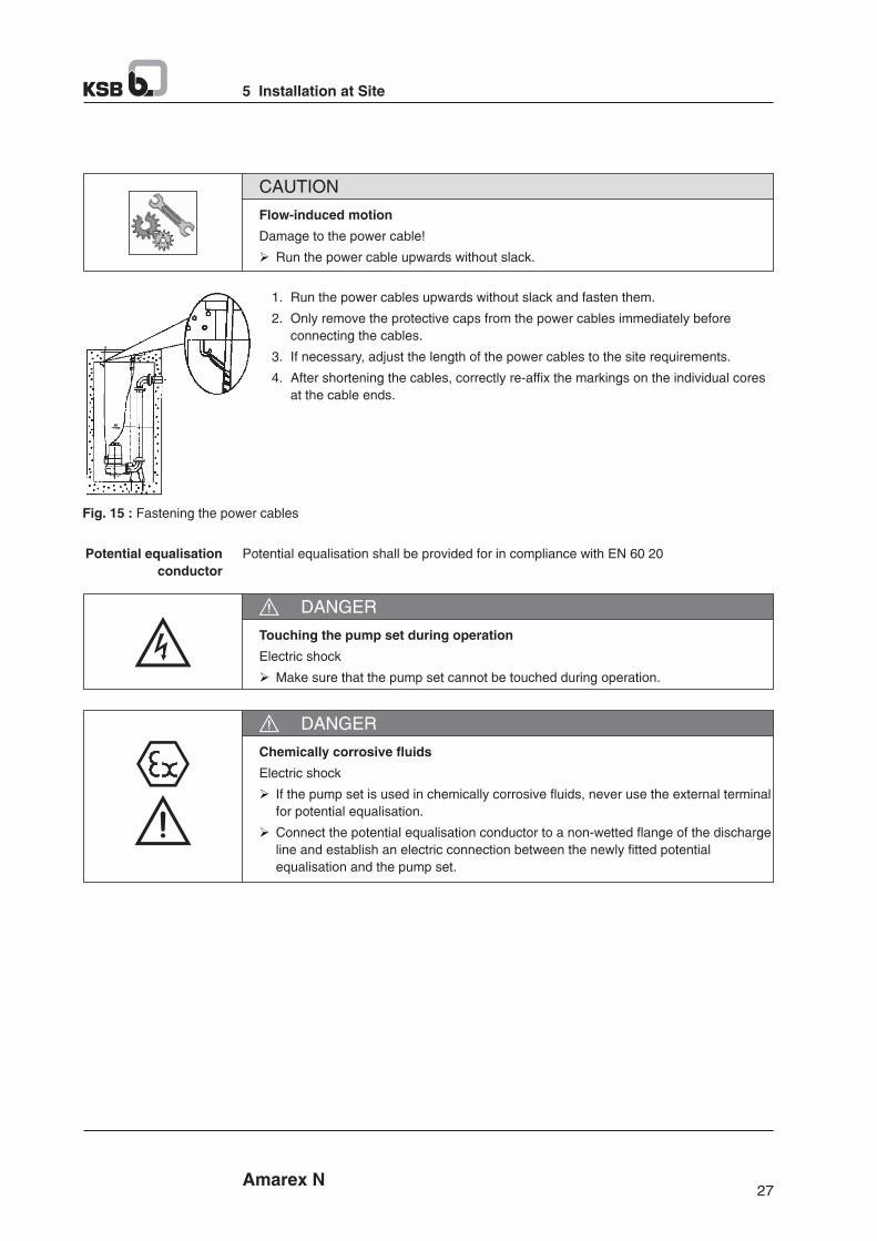
29 Amarex N
6 Commissioning / Start-up / Shutdown
Pump start-up against a closed shut-off element
Increased vibrations!
Damage to mechanical seals and bearings!
Ø Never operate the pump set against a closed shut-off element.
CAUTION
P Fully open the discharge line shut-off element, if any.
P Start up the pump set.
6.2 Operating limits
Non-compliance with operating limits
Damage to the pump set!
Ø Comply with the operating data indicated in the data sheet.
Ø Avoid operation against a closed shut-off element.
Ø Never operate teh pump set outside the limits specified.
DANGER
6.2.1 Frequency of starts
Excessive frequency of starts
Risk of damage to the motor!
Ø Never exceed the specified frequency of starts.
CAUTION
To prevent high temperature increases in the motor, do not exceed the following number
of start-ups per hour.
Table 10 : Frequency of starts
IntervalMaximum frequency of starts
[No. of starts]
per hour
per year
30
5000
These values apply to mains start-up (DOL, auto transformer, soft starter).
Frequency inverter operation is not limited by these values.
6.2.2 Supply voltage
Non-compliance with permissible supply voltage tolerances
Explosion hazard!
Ø Never operate pump (set) outside the specified range.
DANGER
The standard voltage 400 V, 50 Hz.
The maximum permissible operating voltage deviation is +10 -15%, supply frequency
+/- 3%.
The voltage difference between individual phases must not exceed 1%.
28 Amarex N
6 Commissioning / Start-up / Shutdown
6 Commissioning / Start-up / Shutdown
6.1 Commissioning / Start-up
6.1.1 Preconditions for commissioning / Start-up
Fluid level too low
Explosion hazard and damage to the pump set!
Ø Completely prime the pump set with the fluid to be handled to reliably prevent the formation of a potentially explosive atmosphere.
Ø Always operate the pump set in such a way that air cannot enters into the pump casing.
Ø Never allow the fluid level to drop below the specified minimum (R3). (⇨ Section 6.2.4.2).
Ø For continuous operation (S1) operate the pump in fully submerged condition.
DANGER
Before starting up the pump set make sure that the following requirements are met :
§ The pump set has been properly connected to the power supply and is equipped with
all protection devices.
§ The pump has been primed with the fluid to be handled.
§ The direction of rotation has been checked.
§ The lubricant has been checked.
§ After prolonged shutdown of the pump (set), the required activities have been carried
out. (⇨ Section 6.4)
6.1.2 Start-up
Persons in the tank during pump operation
Explosion shock!
Ø Never start up the pump set when there are persons in the tank.
DANGER
Re-starting while motor is still running down
Damage to the pump set!
Ø Do not re-start the pump set before it has come to a standstill.
Ø Never start up the pump set while the pump is running in reverse.
CAUTION
P Make sure that the fluid level is sufficiently high.
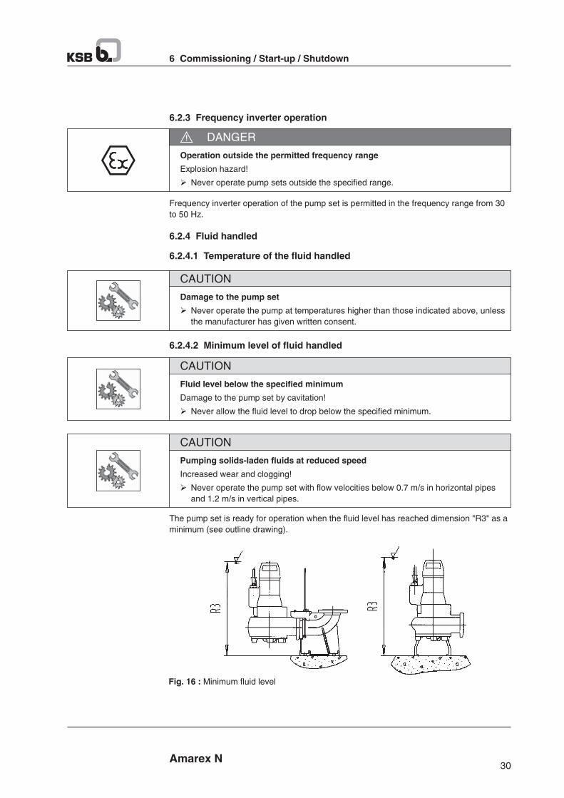
31 Amarex N
6 Commissioning / Start-up / Shutdown
NOTE
For pump sets with cutters it is recommended to continue pump operation for about 10 seconds after the minimum suction level has been reached.
As long as the liquid level is above the measuring mark ‘‘s’’, the pump can be in
operation. This minimum liquid level also applies to pumping stations with automatic pump
operation. If the pump set is completely submerged it will operate continuously. Built in
temperature control winding will protect the motor from overheating.
6.2.4.3 Density of the fluid handled
Impermissibly high density of the fluid handled
Motor overload!
Ø Observe the information on fluid density indicated in the data sheet.
Ø Make sure the motor has sufficient power reserves.
CAUTION
P Power input of the pump increases proportionally to the density of the pumped
medium.
P To avoid overloading of the motor this density must comply with the data stated in the
purchase order.
6.3 Shutdown / Storage / Preservation
6.3.1 Measures to be taken for shutdown
Unintentional starting of pump set
Risk of injuries by moving parts!
Ø Make sure that the pump set cannot be started up unintentionally.
Ø Always make sure the electrical connections are disconnected before carrying out
work on the pump set.
WARNING
Work on the pump set by unqualified personnel
Danger of death from electric shock!
Ø Always have the electrical connections installed by a trained and qualified electrician.
Ø Observe the IEC 60079 (DIN VDE 0100) regulation.
DANGER
30 Amarex N
6 Commissioning / Start-up / Shutdown
6.2.3 Frequency inverter operation
Operation outside the permitted frequency range
Explosion hazard!
Ø Never operate pump sets outside the specified range.
DANGER
Frequency inverter operation of the pump set is permitted in the frequency range from 30
to 50 Hz.
6.2.4 Fluid handled
6.2.4.1 Temperature of the fluid handled
Damage to the pump set
Ø Never operate the pump at temperatures higher than those indicated above, unless
the manufacturer has given written consent.
CAUTION
Fluid level below the specified minimum
Damage to the pump set by cavitation!
Ø Never allow the fluid level to drop below the specified minimum.
CAUTION
6.2.4.2 Minimum level of fluid handled
Pumping solids-laden fluids at reduced speed
Increased wear and clogging!
Ø Never operate the pump set with flow velocities below 0.7 m/s in horizontal pipes
and 1.2 m/s in vertical pipes.
CAUTION
The pump set is ready for operation when the fluid level has reached dimension "R3" as a
minimum (see outline drawing).
Fig. 16 : Minimum fluid level
33 Amarex N
6 Commissioning / Start-up / Shutdown
6.6 Measures for prolonged shut down periods
§ To make installed pump everyday for operation
Start up the pump at least once in every three months for a short time (1 minute
approx.) to ensure instant start-up, to prevent unwanted substances (dirt, dust, salts, or
any other substance) from depositing within the pump and its intake. Don't forget to
check the required liquid level before operating the pump.
§ The pump is dismantled and stored
Prior to the storage of pump one must carry out all maintenance and checking work.
Then apply protective caps. Make up for any damage occurred to the pump coating.
Rotate the impeller by a quarter turn at least once in every 3 months. Prevent any
crushing in the cable during storage.
6.7 Re-starting pump after storage
Ø Free running of impeller should be checked. This can be done by putting one hand
into the pump casing and manually turning the impeller.
CAUTION
Ø Always disconnect all electrical supplies prior to working at pump. Safe guard the
pump from being started accidentally. Otherwise there will be danger or life.
Ø Observe the IEC 60079 (DIN VDE 0100) regulation.
DANGER
Ø Immediately after completion of the maintenance work, all safety and protection
equipment has to be installed expertly and must be set working.
DANGER
32 Amarex N
6 Commissioning / Start-up / Shutdown
Fluids posing a health hazard and/or hot fluids
Risk of personal injury!
Ø Observe all relevant laws
Ø When draining the fluid take appropriate measures to protect persons and the
environment.
Ø Decontaminate pumps which handle fluids posing a health hazard.
WARNING
P Make sure sufficient fluid is available for the operation check run of the pump set.
1. For prolonged shutdown periods, start up the pump set regularly between once a
month and once every three months for approximately one minute.
This will prevent the formation of deposits within the pump and the pump intake area.
The pump (set) is removed from the pipe and stored
P All safety regulations are observed. (⇨ Section 7.1)
1. Clean the pump set.
2. Preserve the pump set.
3. Observe the instructions for storage/preservation given in (⇨ Section 3.3).
6.4 Returning to service
For returning the pump set to service observe the sections on commissioning/start-up
(⇨ Section 6) and operating limits. (⇨ Section 6.2)
For returning the pump set to service after storage also follow the instructions for
servicing/inspection.
Failure to re-install or re-activate protective devices
Risk of personal injury from moving parts or escaping fluid!
Ø As soon as the work is complete, re-install and/or re-activate any safety-relevant and
protective devices.
WARNING
6.5 Storage of new pumps
§ Spray the inside of the pump casing with oil by paying special attention to the area
around the impeller gap. Spray oil through inlet and outlet flanges. It is then
recommended to close the flanges, for protecting them.
§ Store the pump in an upright position in a dry place. Support all electrical cables at
cable entry points to avoid permanent distortion.
§ Electric connecting cables are capped securely for protection purposes prior to
delivery. This protection must not be removed in any case.
7.2 Maintenance / Inspection
35 Amarex N
7 Servicing / Maintenance
7.2.1 Inspection work
7.2.1.1 Checking the lifting chain/rope
P The pump set has been lifted out of the pump sump and cleaned.
1. Inspect the lifting chain/rope as well as the attachment for any visible damage.
2. Replace may damaged comp\onents by original spare parts.
7.2.1.2 Checking the power cables
P The pump set has been pulled out of the pump sump and cleaned.
1. Inspect the power cable for any visual damage.
2. Replace any damaged components by original spare parts.
P The pump set has been pulled out of the pump sump and cleaned.
1. Measure the resistance between earth conductor and earth.
The resistance measured must be less than 1 W.
2. Replace any damaged components by original spare parts.
Visual inspection
Checking the earthconductor
Defective earth conductor
Electric shock!
Ø Never switch on a pump set with a defective earth conductor.
DANGER
Maintenance interval Maintenance work For details see ...
Visually inspect the lifting chain/rope
Check the power cables
Measure the insulation resistance
Check the sensors
Change the lubricant
Inspect the bearings / seal / motor
General overhaul
7)Every 4,000 operating hours
-
Every five years
(⇨ Section 7.2.1.1)
(⇨ Section 7.2.1.2)
(⇨ Section 7.2.1.3)
(⇨ Section 7.2.1.4)
(⇨ Section 7.2.2.1.4)
(⇨ Section 7.4.4)
Table 11 : Overview of maintenance work
7) At least once a year
34 Amarex N
7 Servicing / Maintenance
7 Servicing / Maintenance
7.1 Safety regulations
The operator ensures that all maintenance, inspection and installation work is performed
by authorised, qualified specialist personnel who are thoroughly familiar with the manual.
Sparks produced during servicing work
Explosion hazard!
Ø Observe the safety regulations in force at the place of installation!
DANGER
Unintentional starting of pump set
Risk of injuries by moving parts!
Ø Make sure that the pump set cannot be started up unintentionally.
Ø Always make sure the electrical connections are disconnected before carrying.
WARNING
Fluids posing a health hazard and/or hot fluids.
Risk of personal injury
Ø observe all relevant laws
Ø When draining the fluid take appropriate measures to protect persons and the
environment.
Ø Do-contaminate pumps which handle fluids posing a health hazard.
WARNING
Hot surface
Risk of injury!
Ø Allow the pump set to cool down to ambient temperature.
WARNING
Improper lifting/moving of heavy assemblies or components
Personal injury and damage to property!
Ø Use suitable transport devices, lifting equipment and lifting tackle to move heavy
assemblies or components.
WARNING
Insufficient stability
Risk of crushing hands and feet!
Ø During assembly/dismantling, secure the pump (set)/pump parts to prevent tipping
or falling over.
WARNING
37 Amarex N
7 Servicing / Maintenance
7.2.2.1.2 Lubricant quality
The lubricant reservoir is filled at the factory with an environmentally friendly, lubricant of
medical quality (unless otherwise specified by the customer).
The following lubricants can be used to lubricate the mechanical seals :
Table 14 : Oil quality
Paraffin oil or white oil
Alternative : motor oils of
grade SAE 10W to
SAE 20W
Description PropertiesoKinematic viscosity at 40 C
Ignition temperature
Flash point (to Cleveland)
Solidification point (pour point)
2< 20 mm /so> 185 Co+ 160 C
o-15 C
Recommended
oil quality
Glycol solution
Lubricant contaminating fluid handled
Hazard to persons and the environment!
Ø Using machine oil is only permitted if the oil is disposed of properly.
WARNING
7.2.2.1.3 Lubricant quantity
Table 15 : Lubricant quantity
Motor variant Lubricant quantity[Iitre]
UL 0.25
7.2.2.1.4 Changing the lubricant
Draining the lubricant
§ The suction cover and the impeller have been removed (⇨ Section 7.4.3)
1. Place a suitable container under the pump set.
2. Move mechanical seal 433.02 along the shaft.
3. Drain the oil
Fig. 17 : Draining the lubricant
Filling in the lubricant
1. Fill 0.25 litres of oil through the opening between the stationary part of mechanical
seal 433.02 and rotor 818.
2. Thoroughly clean rotor 818 and the contact face of the stationary part of
mechanical seal 433.02. Remove any oil residues.
3. Fit the rotating part of mechanical seal 433.02.
4. Fit impeller 230 and suction cover 162. Observe the tightening torques. (⇨ Section
7.6)
Fig. 18 : Filling in the lubricant
36 Amarex N
7 Servicing / Maintenance
7.2.1.3 Measuring the insulation resistance
Measure the insulation resistance of the motor winding during annual maintenance work.
P The pump set has been disconnected in the control cabinet.
P Use can insulation resistance measuring device.
P The recommended measuring voltage equals 500 V (maximum permissible 1000 V).
1. Measure the winding against earth. To do so, connect all winding ends together.
2. Measure the winding temperature sensors against earth. To do so, connect all core
ends of the winding temperature sensors together and connect winding ends to earth.
NOTE
Ø If the insulation resistance for one of the power cables is below 1MW, the cable is defective and must be replaced.
Ø If the insulation resistance values measured on the motor are too low, the winding insulation is defective. The pump set must not be returned to service in this case.
7.2.1.4 Checking the sensors
Excessive test voltage
Damage to the sensors!
Ø Never test the sensors with voltages exceeding 30 V.
CAUTION
Table 12 : Resistance measurement of bimetal switch in the motor (Section 9.2)
Measurement between terminals ... Resistance
between 21 and 22
Bimetal switches
in the motor
If the specified tolerances are exceeded, disconnect the power cable at the pump set and
repeat the check inside the motor.If the tolerances are exceeded here, too, the motor section has to be opened and
overhauled. The temperature sensors are fitted in the stator winding and cannot be
replaced.
Table 13 : Resistance measurement of the leakage sensor in the motor
Measurement between terminals ... Resistance
9 and earth conductor (PE)
Lower resistance values suggest water ingress into the motor.In this case the motor must be opened and overhauled.
7.2.2 Lubrication and lubricant change
7.2.2.1 Lubricating the mechanical seal
The mechanical seal is supplied with lubricant from teh lubricant reservoir.
7.2.2.1.1 Intervals
Change the lubricant every 4000 operating hours but at lease once a year.
Leakage sensor
in the motor
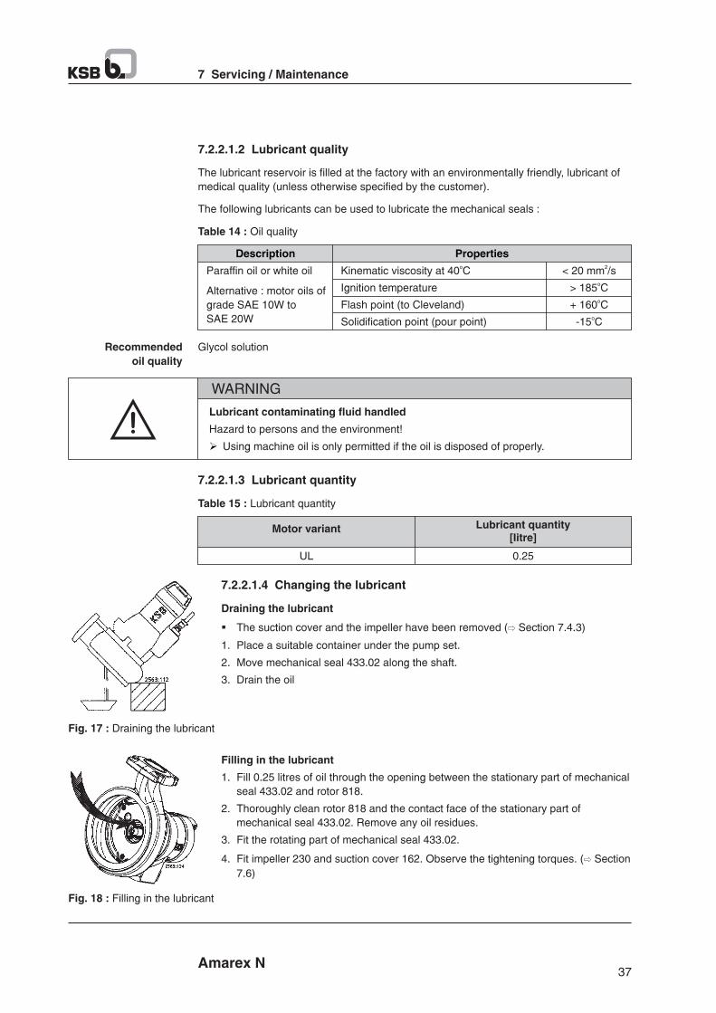
39 Amarex N
7 Servicing / Maintenance
Components with sharp edges
Risk of cutting or shearing injuries!
Ø Always use appropriate caution for installation and dismantling work.
Ø Wear work gloves.
WARNING
Fig. 19 : Forcing screw
Insufficient preparation of work on the pump set
Risk of injury!
Ø Properly shut down the pump set.
Ø Close the shut-off elements in suction and discharge line.
Ø Drain the pump and release the pump pressure.
Ø Close my auxiliary connections.
Ø Allow the pump set to cool down to ambient temperature.
DANGER
7.4.2 Preparing the pump set
P The notes and steps stated in (⇨ Section 7.4.1) have been observed/carried out.
1. De-energise the pump set and secure it against unintentional start-up.
2. Drain the lubricant.
3. Drain the leakage chamber and leave it open for the duration of the disassembly.
7.4.3 Dismantling the pump section
Dismantle the pump section in accordance with the relevant general assembly drawing.
1. Remove suction cover 162.
2. Undo and remove the M8 impeller fastening screw.
The impeller/shaft connection is a tapered fit.
3. For removing the impeller, an M10 jacking thread is provided at the impeller hub.
Screw in the jack as shown in the drawing below and remove the impeller.
38 Amarex N
7 Servicing / Maintenance
7.2.2.2 Lubricating the rolling element bearings
The rolling element bearings of the pump sets are grease-packed and maintenance-free.
7.3 Drainage / Cleaning
Fluids posing a health hazard and/or hot fluids
Hazard to persons and the environment!
Ø Collect and properly dispose of flushing liquid and any residues of the fluid handled.
Ø Wear safety clothing and a protective mask, if required.
Ø Observe all legal regulations on the disposal of fluids posing a health hazard.
WARNING
1. Always flush the pump if it has been used for handling noxious, explosive, hot or other
hazardous fluids.
2. Always flush and clean the pump before sending it to the workshop.
7.4 Dismantling the pump set
7.4.1 General information / Safety regulations
Unqualified personnel performing work on pump (set)
Risk of injury!
Ø Always have repair and maintenance work performed by specially trained, qualified
personnel.
WARNING
Improper lifting/moving of heavy assemblies or components
Personal injury and damage to property!
Ø Use suitable transport devices, lifting equipment and lifting tackle to move heavy
assemblies or components.
WARNING
§ Observe the general safety instructions and information. (⇨ Section 7)
§ For dismantling and reassembly observe the general assembly drawing.
§ In the event of damage you can always contact our service staff.
Hot surface
Risk of injury!
Ø Allow the pump set to cool down to ambient temperature.
WARNING
41 Amarex N
7 Servicing / Maintenance
7.5.2 Reassembling the pump section
7.5.2.1 Installing the mechanical seal
Observe the following points to ensure trouble-free operation of the mechanical
seal :
§ Make sure the surface of the shaft is absolutely clean and undamaged.
§ Immediately before installing the mechanical seal, wet the contact faces with a drop of
oil.
§ For easier installation of bellow-type mechanical seals, wet the inside diameter of the
bellows with soapy water (not oil).
§ To prevent any damage to the rubber bellows, place a thin foil (thickness approximately
0.1 to 0.3 mm) around the free shaft stub.
Slip the rotating assembly over the foil into its installation position. Then remove the
foil.
P The shaft and rolling element bearings have been properly installed in the motor.
1. Push drive-end mechanical seal 433.01 on shaft 210 and secure it with taper lock ring
515 or circlip 932.03.
2. Insert O-rings 412.04/412.35 and 412.15/412.11 into discharge cover 163, and press
them into bearing bracket 330 as far as they will go.
3. Push pump-end mechanical seal 433.02 onto shaft 210.
Fig. 20 : Installation dimension "A"
Table 16 : Installation dimension A
Pump size Installation dimension "A" [mm]
All sizes 29
7.5.2.2 Fitting the impeller
7.5.2.2.1 Fitting impeller type S and cutter
NOTE
For bearing brackets with tapered fit make sure that the tapered fit of impeller and shaft is undamaged and installed free from grease.
1. Slide impeller 230 onto the shaft end.
2. Insert grooved pin 561 into impeller 230.
3. Place impeller body 23-7 on the centring hub.
4. Insert impeller screw 914.04 and tighten it to a torque of 30 Nm.
5. Fasten ring 500 in suction cover 162 with screws 914.06.
40 Amarex N
7 Servicing / Maintenance
7.4.4 Removing the mechanical seal and motor section
P The oil has been drained. (⇨ Section 7.2.2.1.4).
1. Undo and remove screws 914.02 at bearing bracket 330.
2. Remove rotor unit 818 from bearing bracket 330.
3. Push mating ring 433.02 out of bearing bracket 330.
4. Remove circlip 932.02.
5. Take bearing bracket 330 off rotor 818.
6. Remove circlip 932.03.
7. Remove primary ring 433.01.
8. Pull off mating ring holder 476.
9. Take mating ring 433.01 out of mating ring holder 476.
10. Remove circlip 932.01
11. Extract rolling element bearing 321.02.
12. Extract rolling element bearing 321.01.
7.5 Reassembling the pump set
7.5.1 General information / Safety regulations
Improper lifting / moving of heavy assemblies or components
Personal injury and damage to property!
Ø Use suitable transport devices, lifting equipment and lifting tackle to move heavy
assemblies or components.
WARNING
Improper reassembly
Damage to the pump!
Ø Reassemble the pump (set) in accordance with the general rules of sound
engineering practice.
Ø Use original spare parts only.
CAUTION
Always reassemble the pump set in accordance with the corresponding general assembly
drawing
§ O-ring
- Check O-rings for any damage and replace by new O-rings, if required.
§ Assembly adhesives
- Avoid the use of assembly adhesives, if possible.
For reassembly, tighten all screws and bolts as specified in the manual. (⇨ Section 7.6)
Sequence
Sealing elements
Tightening torques
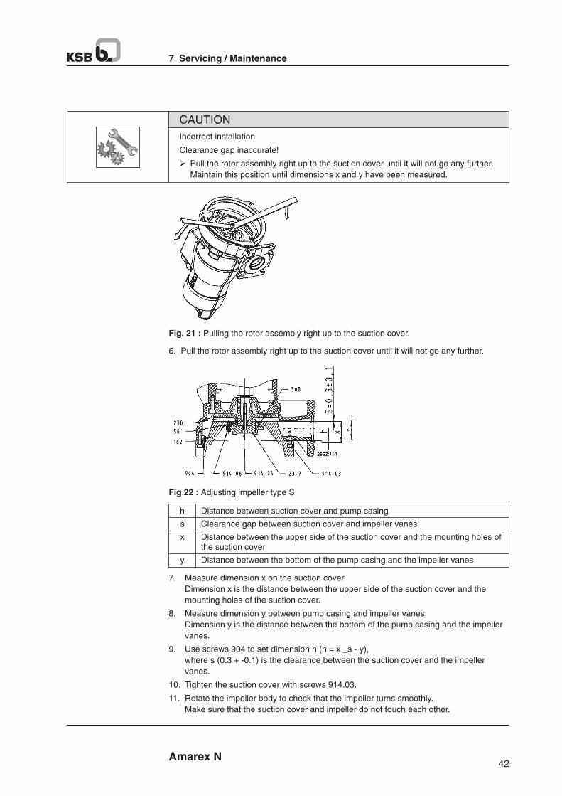
43 Amarex N
7 Servicing / Maintenance
7.5.2.2.2 Fitting impeller type F
Apply loctite 243 (or similar) to the shaft thread and to the bore of impeller type F 230 and
screw the impeller onto the impeller onto the shaft with a tightening torque of 2.5 Nm.
Incorrect assembly
Damage to the shaft
Ø Wait for at-least 2 hours before starting the pump again.
CAUTION
Thread
M8
Impeller screw M8
Screw plug 903
Torque [Nm]
17
40
23
7.7 Spare parts stock
7.7.1 Ordering spare parts
Always quote the following data when ordering replacement or spare parts :
§ Pump type
§ KSB order number
§ Motor number
Refer to the name plate for all data. Also supply the following data :
§ Description
§ Part No.
§ Quantity of spare parts
§ Shipping address
§ Mode of dispatch (freight, mail, express freight, air freight)
Refer to the general assembly drawing for part numbers and descriptions.
7.5.3 Checking the connection of motor/power supply
Once assembly has been completed, carry out the inspection work again (⇨ Section 7.2.1)
7.6 Tightening torques
Table 17 : Tightening torques
42 Amarex N
7 Servicing / Maintenance
Incorrect installation
Clearance gap inaccurate!
Ø Pull the rotor assembly right up to the suction cover until it will not go any further.
Maintain this position until dimensions x and y have been measured.
CAUTION
Fig. 21 : Pulling the rotor assembly right up to the suction cover.
6. Pull the rotor assembly right up to the suction cover until it will not go any further.
Fig 22 : Adjusting impeller type S
h Distance between suction cover and pump casing
s Clearance gap between suction cover and impeller vanes
x Distance between the upper side of the suction cover and the mounting holes of the suction cover
y Distance between the bottom of the pump casing and the impeller vanes
7. Measure dimension x on the suction cover
Dimension x is the distance between the upper side of the suction cover and the
mounting holes of the suction cover.
8. Measure dimension y between pump casing and impeller vanes.
Dimension y is the distance between the bottom of the pump casing and the impeller
vanes.
9. Use screws 904 to set dimension h (h = x _s - y),
where s (0.3 + -0.1) is the clearance between the suction cover and the impeller
vanes.
10. Tighten the suction cover with screws 914.03.
11. Rotate the impeller body to check that the impeller turns smoothly.
Make sure that the suction cover and impeller do not touch each other.

45 Amarex N
8 Trouble shooting
8 Trouble-shooting
A Pump is running but does not deliver
B Pump delivers insufficient flow rate
C Excessive current/power consumption
D Insufficient discharge head
E Vibration and noise during pump operation
Table 20 : Trouble-shooting
A B C D E Possible cause Remedy
x Pump delivers against an excessively high Re-adjust to duty point. pressure.
x Gate valve in the discharge line is not fully Fully open the gate valve. open.
x x Pump is running in the off-design range Check the pump's operating data. (low flow/overload).
x Pump or piping are not completely vented. Vent by lifting the pump off the duck foot bend and lowering it again.
x Pump intake clogged by deposits. Clean the intake, pump components and non-return valve.
x x x Suction line or impeller clogged. Remove deposits in the pump and/or piping.
x x Dirt/fibres in teh clearance between the Check whether the impeller can be easily casing wall and impeller; sluggish rotor. rotated. Clean the impeller, if required.
x x x x Wear of internal parts. Replace worn parts by new ones.
x x x Defective riser (pipe and sealing elements) Replace defective riser pipes, replace sealing elements.
x x x Impermissible air or gas content in the fluid Contact KSB. handled.
x System-induced vibrations. Contact KSB.
x x x x Wrong direction of rotation Check the connection of the motor and switchgear, if any.
x Wrong supply voltage. Check the power cable. Check the cable connections.
x Motor is not running because of lock of Check the electrical installation. voltage. Contact the energy supplier.
x x Motor winding or power cable are defective. Replace by new original KSB parts or contact KSB.
x Defective rolling element bearing. Contact KSB.
x Water level lowered too much during Check level control equipment. operation.
x The temperature control device for The motor will restart automatically once it has monitoring the winding has tripped due to cooled down. excessive winding temperature.
x Temperature limiter (explosion protection) Have cause determined and eliminated by has tripped the pump as a result of the qualified and trained personnel. permissible winding temperature being exceeded.
x Motor has been tripped by leakage monitor. Have cause determined and eliminated by qualified and trained personnel.
230
320 / 321.02
321.01 / 322
433.01
433.02
99-9
Part No. Description
Number of pumps (including stand-by pumps)
2 3 4 5 6 and 7 8 and 9 10 and
more
Impeller
Rolling element bearing, pump end
Rolling element bearing, motor end
Mechanical seal, motor end
Mechanical seal, pump end
Set of O-ring
1
1
1
2
2
4
1
1
1
3
3
6
1
2
2
4
4
8
2
2
2
4
4
8
2
3
3
4
4
9
3
4
4
6
6
10
30%
50%
50%
90%
90%
100%
8)Table 18 : Quantity of spare parts for recommended spare parts stock
44 Amarex N
7 Servicing / Maintenance
7.7.3 Sets of spare parts
Table 19 : Overview of spare parts sets
Description
Rolling element bearing, motor end
Rolling element, bearing pump end
Mechanical seal, motor end
Mechanical seal, pump end
Set of seal elements
Repair kit
1 set of circlips
Part No.
321.01
321.02
433.01
433.02
99-9
99-20
--
7.7.2 Recommended spare parts stock for 2 years' operation to DIN 24296
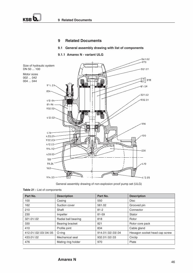
47 Amarex N
9 Related Documents
9.1.2 Exploded views
Amarex N - S 50
Fig. 23 : Amarex N S 50
Table 21 : List of components
100
162
210
230
321.01/.02
330
410
412.01/.02/.03/.04/.05
433.01/.02
476
550
561.02
81-2
81-59
818
821
834
914.01/.02/.03/.04
932.01/.02/.03
970
Part No. Description Part No. Description
Casing
Suction cover
Shaft
Impeller
Radial ball bearing
Bearing bracket
Profile joint
O-ring
Mechanical seal
Mating ring holder
Disc
Grooved pin
Connector
Stator
Rotor
Rotor core pack
Cable gland
Hexagon socket head cap screw
Circlip
Plate
46 Amarex N
9 Related Documents
9 Related Documents
9.1 General assembly drawing with list of components
9.1.1 Amarex N - variant ULG
Size of hydraulic systemDN 50 ... 100
Motor sizes002 ... 042004 ... 044
General assembly drawing of non-explosion proof pump set (ULG)
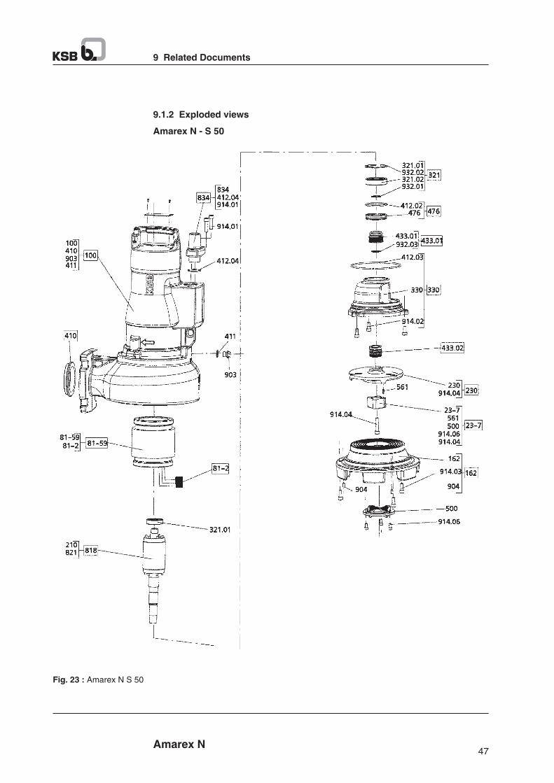
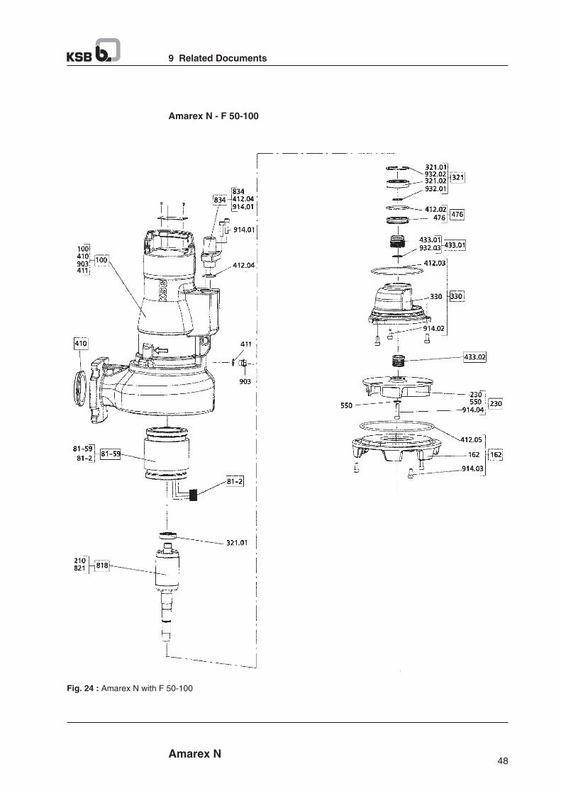
49 Amarex N
9 Related Documents
Table 22 : List of components
100
113
162
182
210
23-7
230
321.01/.02
330
355
410
411
412.01/.02/.03/.04/.05
433.01/.02
476
59-17
500
550
561
69-6
69-16
81-2
81-59
818
821
834
99-9
903
904
914.01/.02/.03/.04/.06
932.01/.02/.03/.04
Part No. Description Part No. Description
Casing
Intermediate casing
Suction cover
Feet
Shaft
Impeller body
Impeller
Radial ball bearing
Bearing bracket
Bearing bracket housing
Profile joint
Joint ring
O-ring
Mechanical seal
Mating ring holder
Shackle
Ring
Disc
Grooved pin
Temperature sensor
Moisture sensor
connector
Stator
Rotor
Rotor core pack
Cable gland
Set of seal elements
Screw plug
Grub screw
Socket head cap screw
Circlip
48 Amarex N
9 Related Documents
Amarex N - F 50-100
Fig. 24 : Amarex N with F 50-100
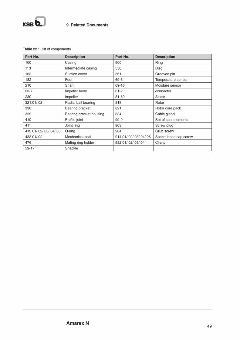
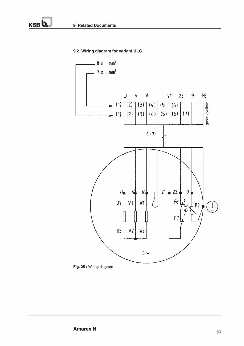
51 Amarex N
9 Related Documents
9.3 Wiring diagrams over load protection
Table 23 : Examples of wiring diagrams for overload protection
Key Circuit diagram
Q : residual current device 3~ 30 mA
e.g. residual current device Merlin Guérin C60 L,
trip characteristic K
§ Earth leakage module VIGI, instantaneous, 3~ 30 mA
§ Auxiliary contact (change-over contact)
KM : Motor contactor 3~
e.g. Télémécanique LC1 D0910
F : Remote control
Q : Motor contactor
e.g. Télémécanique GV2M + GV2 AN 11
KM : Motor contactor 3~
e.g. Télémécanique LC1 D0910
RH : Earth leakage protection relay with separate toroid
e.g. Vigirex RH 328 A Merlin Guérin + Tore
F : Remote control
H : Auxiliary supply
Q : Motor contactor
e.g. Télémécanique GV2M + GV2 AN 11
KM : Motor contactor 3~
e.g. Télémécanique LC1 D0910
SM : Insulation monitor, de-energised
e.g. V12G1LOHM SM21 Merlin Guérin
F : Remote control
H : Auxiliary supply
50 Amarex N
9 Related Documents
9.2 Wiring diagram for variant ULG
gre
en
/ y
ello
w
Fig. 25 : Wiring diagram
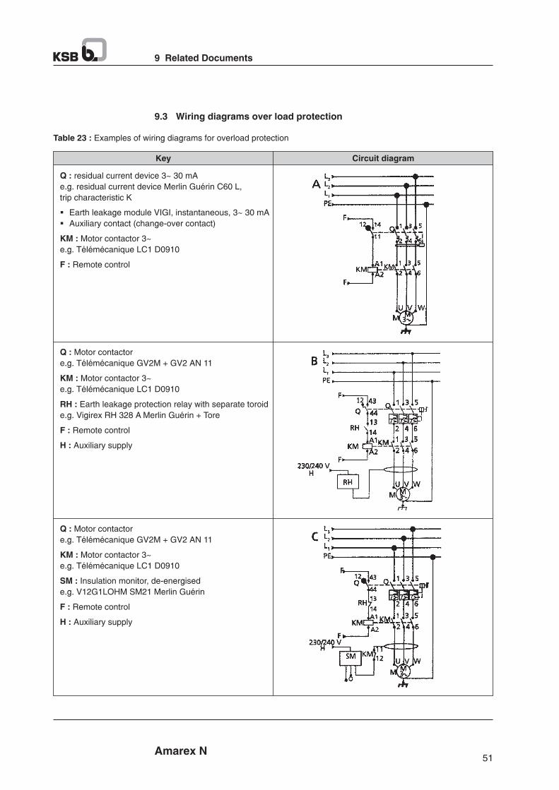
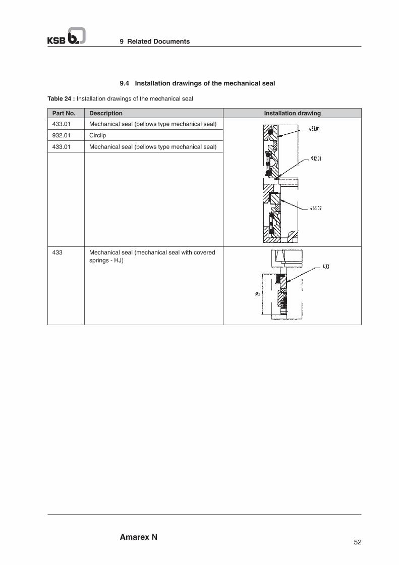
Amarex N
Annexure I - Environment Protection - Product Disposal after useful life
Products manufactured by KSB Pumps are designed with utmost care for environmental protection. Innovative
designs and wide product range takes care of specific customer requirements reducing material and electrical energy
consumption. Product materials are recyclable. Our customers are educated with environment friendly methods of
disposing product ingredients at the end of their useful life. Please find herewith methods of disposing used pump
ingredients.
Environment Production measures during product disposal.
Sr. No. Product Ingredients Disposal Methods
1 Pumps Paint : Pump body, Base frame Sludge to be disposed through authorised re-processor
Non ferrous parts :a) Impellers, Diffusersb) Bushesc) Stage sleevesd) Thrust platee) Wearing ringf) Coupling guardg) Bearing guard
Rubber / Plastic parts :a) Cover for NRVb) Plastic capc) Nozzle blankingd) Cooling fan
To be disposed through authorised re-processor
To be disposed through authorised re-processor
2 Motor Paint : Motor body, Rotor Sludge to be disposed through authorised re-processor
Non ferrous parts :a) Support bushesb) Copper sticks and stampingsc) Balancing ringsd) Winding wire with varnish
Rubber / Plastic parts :a) Oil sealb) Sand guardc) Notch keys, slot insulatorsd) Overhand protection pipe
To be disposed through authorised re-processor
To be disposed through authorised re-processor
5352 Amarex N
9 Related Documents
9.4 Installation drawings of the mechanical seal
Table 24 : Installation drawings of the mechanical seal
Part No. Installation drawingDescription
433.01
932.01
433.01
Mechanical seal (bellows type mechanical seal)
Circlip
Mechanical seal (bellows type mechanical seal)
433 Mechanical seal (mechanical seal with covered
springs - HJ)
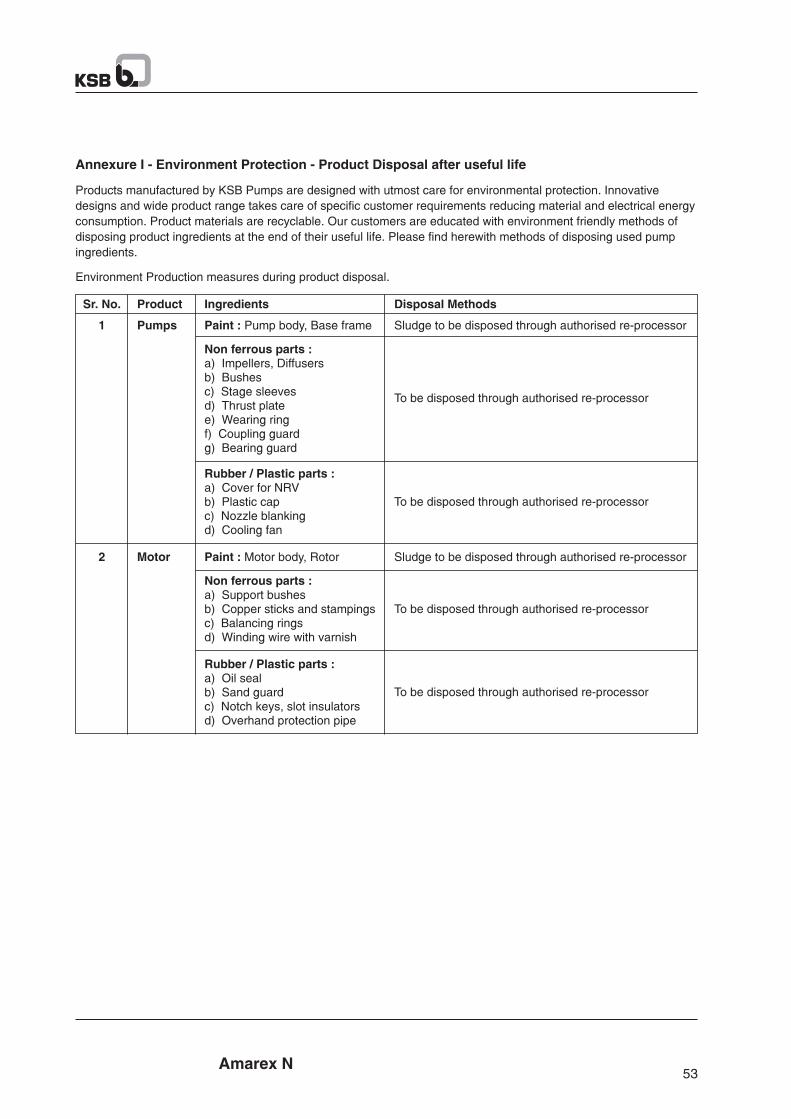

Amarex N
Notes:
Amarex N
Notes:

Amarex N
Notes:
Amarex N
Notes:

25
63
.81
/12
-EN
KSB Pumps LimitedMumbai-Pune Road, Pimpri, Pune 411 018. (India)Tel.: +91 20 2710 1000 Fax : +91 20 2742 6000 www.ksbindia.co.in
Mktg. Serv. / 06-15 / 500