Embed Size (px)
Citation preview
Installation and
Operating Manual
VCX-SERIES
ROTARY CLAW
VACUUM PUMPS
Airtech Vacuum Inc.
301 Veterans Blvd
Rutherford, NJ 07070
Phone: (888) 222-9940
Fax: (201) 569-1696
INSTALLATION & OPERATING MANUAL
VCX-SERIES
ROTARY CLAW
VACUUM PUMPS
Please read the manual before operating the vacuum pump.
Table of Contents 1.0 INSTALLATION ................................................................................................................... 2
1.1 General description ....................................................................................................................... 2 1.2 Unpacking ........................................................................................................................................... 2 1.3 Location ............................................................................................................................................... 2 1.4 Power Requirements ........................................................................................................................... 2 1.5 Vacuum Connections .......................................................................................................................... 3 1.6 Oil Filling on Gear Box ........................................................................................................................ 3 1.7 Lubrication of the bearings .................................................................................................................. 3
2.0 SAFETY ............................................................................................................................... 4
2.1 General Notices .................................................................................................................................. 4 2.2 Warning labels and their explanations ................................................................................................ 4 2.3 Location of the labels .......................................................................................................................... 4
3.0 OPERATION ........................................................................................................................ 4
3.1 Start-up................................................................................................................................................ 4 3.2 Stopping the pump .............................................................................................................................. 4 3.3 Operating Conditions .......................................................................................................................... 4
4.0 MAINTENANCE ................................................................................................................... 5
4.1 Gear Box Lube Oil ............................................................................................................................... 5 4.2 Inline (Inlet) Filter ................................................................................................................................ 6 4.3 Maintenance Chart .............................................................................................................................. 6
5.0 TROUBLESHOOTING ......................................................................................................... 7 6.0 TECHNICAL DATA .............................................................................................................. 9 7.0 SAFETY ............................................................................................................................. 10 8.0 STORAGE ....................................................................................................................... 100 9.0 DISPOSAL ......................................................................................................................... 10 10.0 VCX-SERIES EXPLODED VIEW + DRAWINGS AND PARTS LISTS ............................. 11 INSTALLATION AND OPERATING MANUAL
This manual covers all models of the VCX rotary claw vacuum pump. The model number is printed on the
nameplate with the unit’s serial number.
Please identify the model number and serial number when ordering part
Page 1
1.0 INSTALLATION 1.1 General description
VCX pumps are dry, contactless machines
enclosed in a fan-cooled, ventilated acoustic sound
shield. The modular construction consists of two
compartments separated by labyrinth seals: a
pumping chamber and a gear chamber. In the pump
chamber, two rotary claws rotate in opposite
directions. The gear chamber contains gears for
synchronization of the claw rotation. An anti-suck
back valve can be installed in the inlet flange to
prevent air from flowing back into the vacuum
chamber after the pump is shut down. The pump is
directly driven by a flanged motor via a coupling.
1.2 Unpacking
Inspect the box and pump carefully for any signs of
damage incurred in transit. Since all pumps are
ordinarily shipped F. O. B. from Airtech’s factory,
such damage is the responsibility of the carrier and
should be reported to them.
The vacuum pump is bolted to the skid with studs
that are connected through the rubber feet of the
pump.
Remove the nuts from the underside of the crate
and remove the unit from the skid. Unscrew the
studs from the rubber feet.
The inlet and exhaust of the vacuum pump are
covered with plastic caps to prevent dirt and other
foreign
substances from entering the unit. Leave these
caps in place until you are ready to pipe the unit to
your equipment.
1.3 Location
Install the compressor in a horizontal position on a
level surface in a well-ventilated area. Leave 8”-10”
of access around the pump to allow proper cooling.
Allow access to the oil sight glass in order to inspect
the oil level regularly, and the oil fill and oil drain port
for easy service.
1.4 Power Requirements
A schematic diagram for the electrical motor
terminal connections is located in box of the motor
or on the motor nameplate.
INSTALLATION
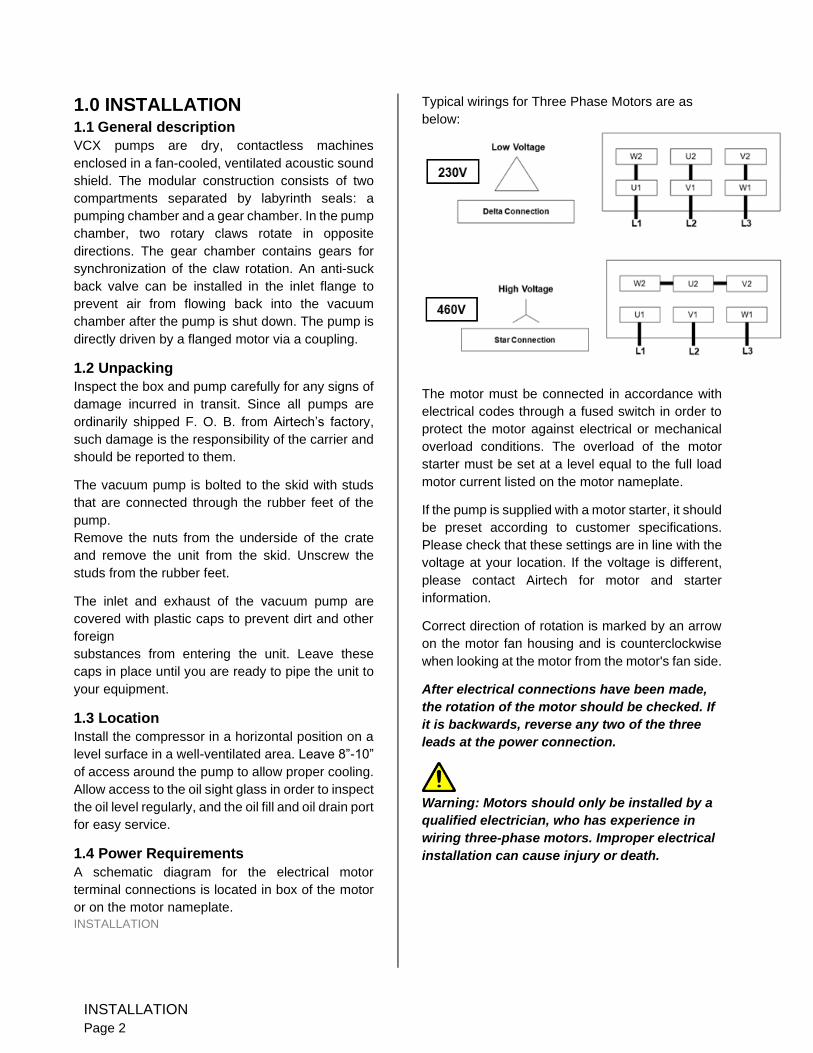
Typical wirings for Three Phase Motors are as
below:
The motor must be connected in accordance with
electrical codes through a fused switch in order to
protect the motor against electrical or mechanical
overload conditions. The overload of the motor
starter must be set at a level equal to the full load
motor current listed on the motor nameplate.
If the pump is supplied with a motor starter, it should
be preset according to customer specifications.
Please check that these settings are in line with the
voltage at your location. If the voltage is different,
please contact Airtech for motor and starter
information.
Correct direction of rotation is marked by an arrow
on the motor fan housing and is counterclockwise
when looking at the motor from the motor's fan side.
After electrical connections have been made,
the rotation of the motor should be checked. If
it is backwards, reverse any two of the three
leads at the power connection.
Warning: Motors should only be installed by a
qualified electrician, who has experience in
wiring three-phase motors. Improper electrical
installation can cause injury or death.
INSTALLATION
Page 2
Caution: VCX pumps must not be allowed
to run backwards. The splash lubrication
system is not designed for backward operation
and this may result in premature failure of the
rotary claw machine.
1.5 Vacuum Connections
Use a pipe size that is at least the size of the pump
outlet connection. Smaller pipelines result in
reduced pump capacity.
Pumps operating in parallel on a common main line
should have a manual or automatic shut-off valve or
positive action check valve installed in the suction
line adjacent to the pump suction flange. The built-
in anti-suck back valve should not be used as a
shut-off valve for the vacuum system. Remove the
plastic protective cap from the inlet port prior to
connection of pump to the system. Should process
gas contain dust or other foreign particles, a
suitable in line (inlet) filter should be connected to
the inlet port. Contact Airtech for recommendations.
The following thread sizes are standard on the
pumps (NPT thread is available upon request)
Pump Model Inlet Size
Exhaust Size
VCX 60 1” 1”
VCX 100 / VCX 100B 1-1/2” 1-1/2”
VCX 150 / VCX 150B / VCX155
1-1/2” 1-1/2”
VCX 250 / VCX 250B / VCX205
2” 2”
VCX 255 / VCX 305 2” 2”
VCX 300 / VCX 300B 2” 2”
VCX 400 & 505 3" 3"
VCX 515 DN80 PN10
3"
1.6 Oil Filling on Gear Box
After level installation and correct rotation has been
established, fill the pump with the recommended
gear oil through the oil fill port if it is not shipped
without oil.
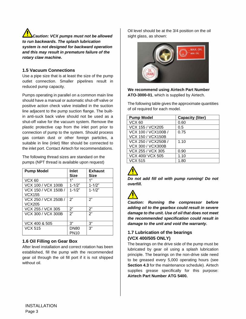
Oil level should be at the 3/4 position on the oil
sight glass, as shown:
We recommend using Airtech Part Number
ATO-3000-01, which is supplied by Airtech.
The following table gives the approximate quantities
of oil required for each model.
Pump Model Capacity (liter)
VCX 60 0.60
VCX 155 / VCX205 0.5
VCX 100 / VCX100B / VCX 150 / VCX150B
0.75
VCX 250 / VCX250B / VCX 300 / VCX300B
1.10
VCX 255 / VCX 305 0.90
VCX 400/ VCX 505 1.10
VCX 515 1.80
Do not add fill oil with pump running! Do not
overfill.
Caution: Running the compressor before
adding oil to the gearbox could result in severe
damage to the unit. Use of oil that does not meet
the recommended specification could result in
damage to the unit and void the warranty.
1.7 Lubrication of the bearings
(VCX 400/505 ONLY)
The bearings on the drive side of the pump must be
lubricated by gear oil using a splash lubrication
principle. The bearings on the non-drive side need
to be greased every 5,000 operating hours (see
Section 4.3 for the maintenance schedule). Airtech
supplies grease specifically for this purpose:
Airtech Part Number ATG 5400.
INSTALLATION
Page 3
2.0 SAFETY
Please read the following safety notices carefully
before operating the pump.
2.1 General Notices
• Please read the entirety of this installation and operating manual before operating the vacuum pump.
• Airtech shall assume no liability for any accident or failure associated with a failure to comply with instructions in this manual.
• Only a qualified technician should operate the pump
• If the pump is not operating correctly, it must be stopped immediately.
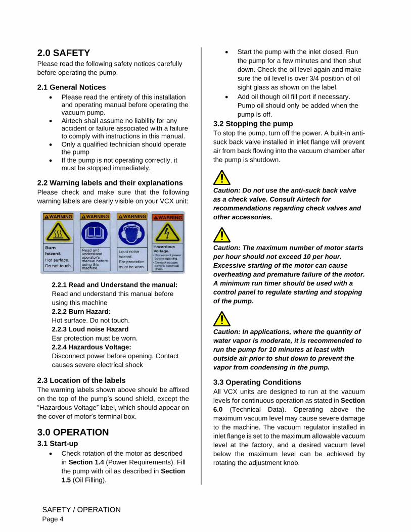
2.2 Warning labels and their explanations
Please check and make sure that the following
warning labels are clearly visible on your VCX unit:
2.2.1 Read and Understand the manual:
Read and understand this manual before
using this machine
2.2.2 Burn Hazard:
Hot surface. Do not touch.
2.2.3 Loud noise Hazard
Ear protection must be worn.
2.2.4 Hazardous Voltage:
Disconnect power before opening. Contact
causes severe electrical shock
2.3 Location of the labels
The warning labels shown above should be affixed
on the top of the pump’s sound shield, except the
“Hazardous Voltage” label, which should appear on
the cover of motor’s terminal box.
3.0 OPERATION 3.1 Start-up
• Check rotation of the motor as described
in Section 1.4 (Power Requirements). Fill
the pump with oil as described in Section
1.5 (Oil Filling).
• Start the pump with the inlet closed. Run
the pump for a few minutes and then shut
down. Check the oil level again and make
sure the oil level is over 3/4 position of oil
sight glass as shown on the label.
• Add oil though oil fill port if necessary.
Pump oil should only be added when the
pump is off.
3.2 Stopping the pump
To stop the pump, turn off the power. A built-in anti-
suck back valve installed in inlet flange will prevent
air from back flowing into the vacuum chamber after
the pump is shutdown.
Caution: Do not use the anti-suck back valve
as a check valve. Consult Airtech for
recommendations regarding check valves and
other accessories.
Caution: The maximum number of motor starts
per hour should not exceed 10 per hour.
Excessive starting of the motor can cause
overheating and premature failure of the motor.
A minimum run timer should be used with a
control panel to regulate starting and stopping
of the pump.
Caution: In applications, where the quantity of
water vapor is moderate, it is recommended to
run the pump for 10 minutes at least with
outside air prior to shut down to prevent the
vapor from condensing in the pump.
3.3 Operating Conditions
All VCX units are designed to run at the vacuum
levels for continuous operation as stated in Section
6.0 (Technical Data). Operating above the
maximum vacuum level may cause severe damage
to the machine. The vacuum regulator installed in
inlet flange is set to the maximum allowable vacuum
level at the factory, and a desired vacuum level
below the maximum level can be achieved by
rotating the adjustment knob.
SAFETY / OPERATION
Page 4
Standard VCX units are for use of dry air only and
should not be used for hazardous areas. Handling
of humid air or gases containing aggressive
chemicals is possible only with specially configures
units. Consult Airtech for assistance.
Excessive back pressure on the unit may result in
excessive current draw. Do not operate the vacuum
pump over 2 psi back pressure.
For operating personnel working near the pump,
ear protection is recommended. If noise below the
typical dBA is required, an external sound
enclosure can be added to the system, provided
adequate ventilation is provided. Please consult
Airtech for recommendations.
The ambient and suction air temperature must be
between 41° F (5° C) and 104° F (40° C).
Caution: Failure to ensure proper operating
conditions may lead to severe injury to
persons and damage to the pump.
4.0 MAINTENANCE VCX-Series vacuum pumps require very little
maintenance. To ensure optimum performance,
the following maintenance steps should be
followed:
4.1 Gear Box Lube Oil
4.1.1 Gear Oil Level
Check the oil level on monthly basis. Under normal circumstances it should not be necessary to add oil between oil changes. A significant drop in oil level could indicate an oil leak. If the pump is leaking oil, please check the o-rings, drain plug or oil sight glass.
Check the oil level only when the pump is shut off. Replenish oil if it drops below bottom position of the oil sight glass.
Caution: Do not add oil while the pump is
running. Hot oil can escape from the oil
fill port.
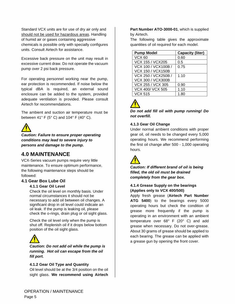
4.1.2 Gear Oil Type and Quantity
Oil level should be at the 3/4 position on the oil
sight glass. We recommend using Airtech
Part Number ATO-3000-01, which is supplied
by Airtech.
The following table gives the approximate
quantities of oil required for each model.
Pump Model Capacity (liter)
VCX 60 0.60
VCX 155 / VCX205 0.5
VCX 100 / VCX100B / VCX 150 / VCX150B
0.75
VCX 250 / VCX250B / VCX 300 / VCX300B
1.10
VCX 255 / VCX 305 0.90
VCX 400/ VCX 505 1.10
VCX 515 1.80
Do not add fill oil with pump running! Do
not overfill.
4.1.3 Gear Oil Change
Under normal ambient conditions with proper
gear oil, oil needs to be changed every 5,000
operating hours. We recommend performing
the first oil change after 500 - 1,000 operating
hours.
Caution: If different brand of oil is being
filled, the old oil must be drained
completely from the gear box.
4.1.4 Grease Supply on the bearings
(Applies only to VCX 400/500)
Apply fresh grease (Airtech Part Number
ATG 5400) to the bearings every 5000
operating hours but check the condition of
grease more frequently if the pump is
operating in an environment with an ambient
temperature over 68° F (20° C) and add
grease when necessary. Do not over-grease.
About 30 grams of grease should be applied to
each bearing. The grease can be applied with
a grease gun by opening the front cover.
OPERATION / MAINTENANCE
Page 5
Caution: The interval of lubrication stated
above is based on ambient temperature of 68°
F (20°C). At 104° F (40°C) ambient temperature,
the interval may be reduced to 2,500 operating
hours.
4.2 Inline (Inlet) Filter
Check inline (inlet) filter on a weekly basis. The filter
cartridge should be cleaned or replaced if it is dirty.
Consult Airtech for replacement elements.
Caution: Depending on the mounting position
of the filter, be careful not to allow
accumulated foreign material to fall in the
pump suction inlet when removing the filter
cartridge. Horizontal filter installation is
recommended to prevent this.
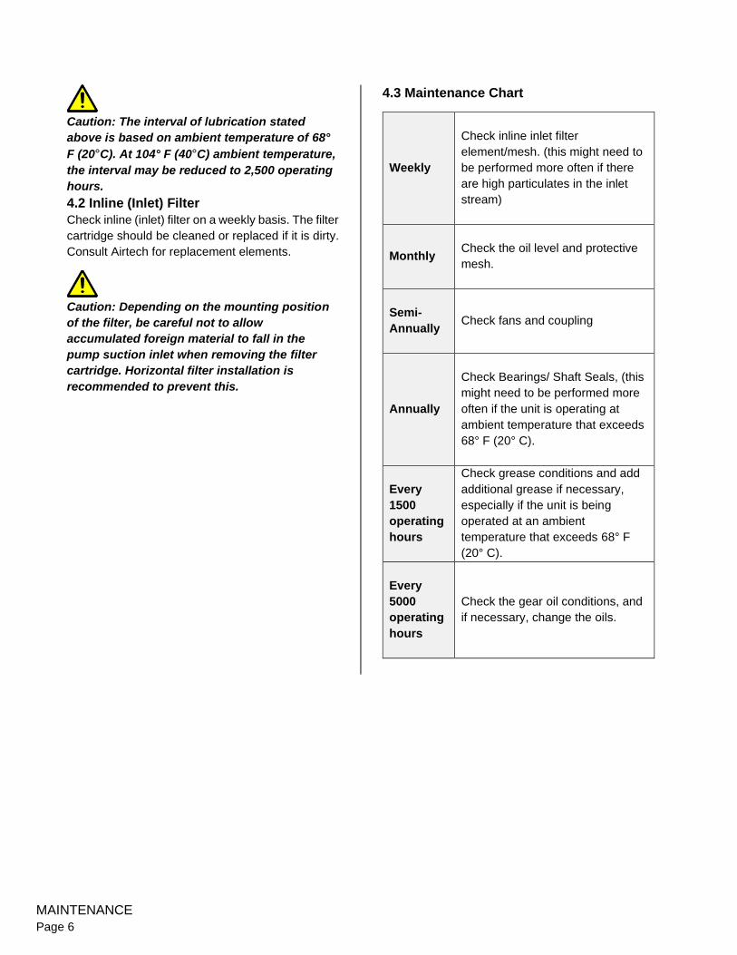
4.3 Maintenance Chart
Weekly
Check inline inlet filter
element/mesh. (this might need to
be performed more often if there
are high particulates in the inlet
stream)
Monthly
Check the oil level and protective
mesh.
Semi-
Annually
Check fans and coupling
Annually
Check Bearings/ Shaft Seals, (this
might need to be performed more
often if the unit is operating at
ambient temperature that exceeds
68° F (20° C).
Every
1500
operating
hours
Check grease conditions and add
additional grease if necessary,
especially if the unit is being
operated at an ambient
temperature that exceeds 68° F
(20° C).
Every
5000
operating
hours
Check the gear oil conditions, and
if necessary, change the oils.
MAINTENANCE
Page 6
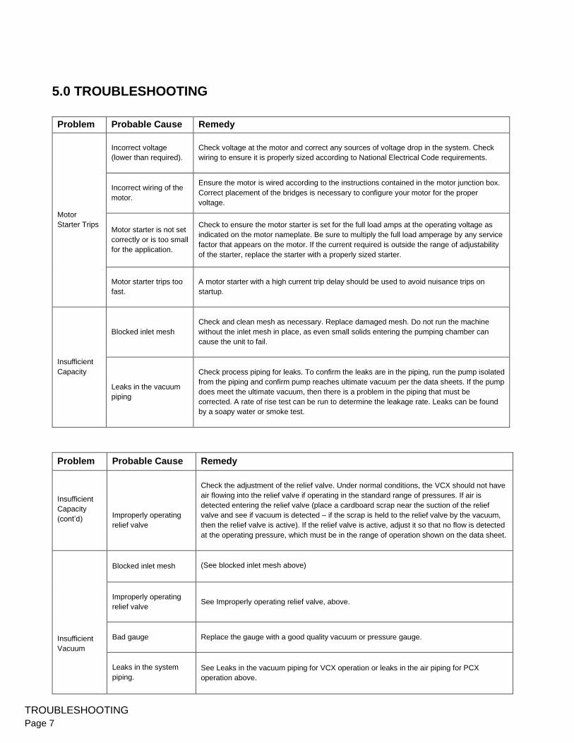
5.0 TROUBLESHOOTING
Problem Probable Cause Remedy
Motor
Starter Trips
Incorrect voltage
(lower than required).
Check voltage at the motor and correct any sources of voltage drop in the system. Check
wiring to ensure it is properly sized according to National Electrical Code requirements.
Incorrect wiring of the
motor.
Ensure the motor is wired according to the instructions contained in the motor junction box.
Correct placement of the bridges is necessary to configure your motor for the proper
voltage.
Motor starter is not set
correctly or is too small
for the application.
Check to ensure the motor starter is set for the full load amps at the operating voltage as
indicated on the motor nameplate. Be sure to multiply the full load amperage by any service
factor that appears on the motor. If the current required is outside the range of adjustability
of the starter, replace the starter with a properly sized starter.
Motor starter trips too
fast.
A motor starter with a high current trip delay should be used to avoid nuisance trips on
startup.
Insufficient
Capacity
Blocked inlet mesh
Check and clean mesh as necessary. Replace damaged mesh. Do not run the machine
without the inlet mesh in place, as even small solids entering the pumping chamber can
cause the unit to fail.
Leaks in the vacuum
piping
Check process piping for leaks. To confirm the leaks are in the piping, run the pump isolated
from the piping and confirm pump reaches ultimate vacuum per the data sheets. If the pump
does meet the ultimate vacuum, then there is a problem in the piping that must be
corrected. A rate of rise test can be run to determine the leakage rate. Leaks can be found
by a soapy water or smoke test.
Problem Probable Cause Remedy
Insufficient
Capacity
(cont’d)
Improperly operating
relief valve
Check the adjustment of the relief valve. Under normal conditions, the VCX should not have
air flowing into the relief valve if operating in the standard range of pressures. If air is
detected entering the relief valve (place a cardboard scrap near the suction of the relief
valve and see if vacuum is detected – if the scrap is held to the relief valve by the vacuum,
then the relief valve is active). If the relief valve is active, adjust it so that no flow is detected
at the operating pressure, which must be in the range of operation shown on the data sheet.
Insufficient
Vacuum
Blocked inlet mesh
(See blocked inlet mesh above)
Improperly operating
relief valve
See Improperly operating relief valve, above.
Bad gauge
Replace the gauge with a good quality vacuum or pressure gauge.
Leaks in the system
piping.
See Leaks in the vacuum piping for VCX operation or leaks in the air piping for PCX
operation above.
TROUBLESHOOTING
Page 7
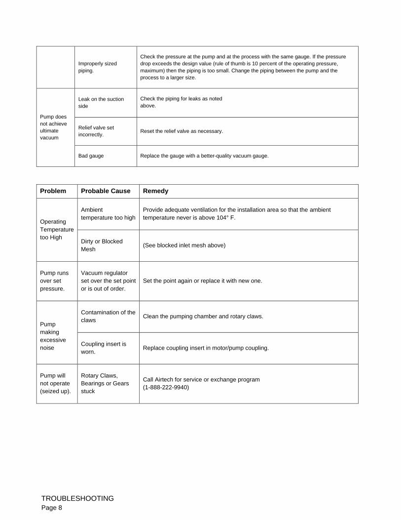
Improperly sized
piping.
Check the pressure at the pump and at the process with the same gauge. If the pressure
drop exceeds the design value (rule of thumb is 10 percent of the operating pressure,
maximum) then the piping is too small. Change the piping between the pump and the
process to a larger size.
Pump does
not achieve
ultimate
vacuum
Leak on the suction
side
Check the piping for leaks as noted
above.
Relief valve set
incorrectly.
Reset the relief valve as necessary.
Bad gauge
Replace the gauge with a better-quality vacuum gauge.
Problem Probable Cause Remedy
Operating
Temperature
too High
Ambient
temperature too high
Provide adequate ventilation for the installation area so that the ambient
temperature never is above 104° F.
Dirty or Blocked
Mesh
(See blocked inlet mesh above)
Pump runs
over set
pressure.
Vacuum regulator
set over the set point
or is out of order.
Set the point again or replace it with new one.
Pump
making
excessive
noise
Contamination of the
claws
Clean the pumping chamber and rotary claws.
Coupling insert is
worn.
Replace coupling insert in motor/pump coupling.
Pump will
not operate
(seized up).
Rotary Claws,
Bearings or Gears
stuck
Call Airtech for service or exchange program
(1-888-222-9940)
TROUBLESHOOTING
Page 8
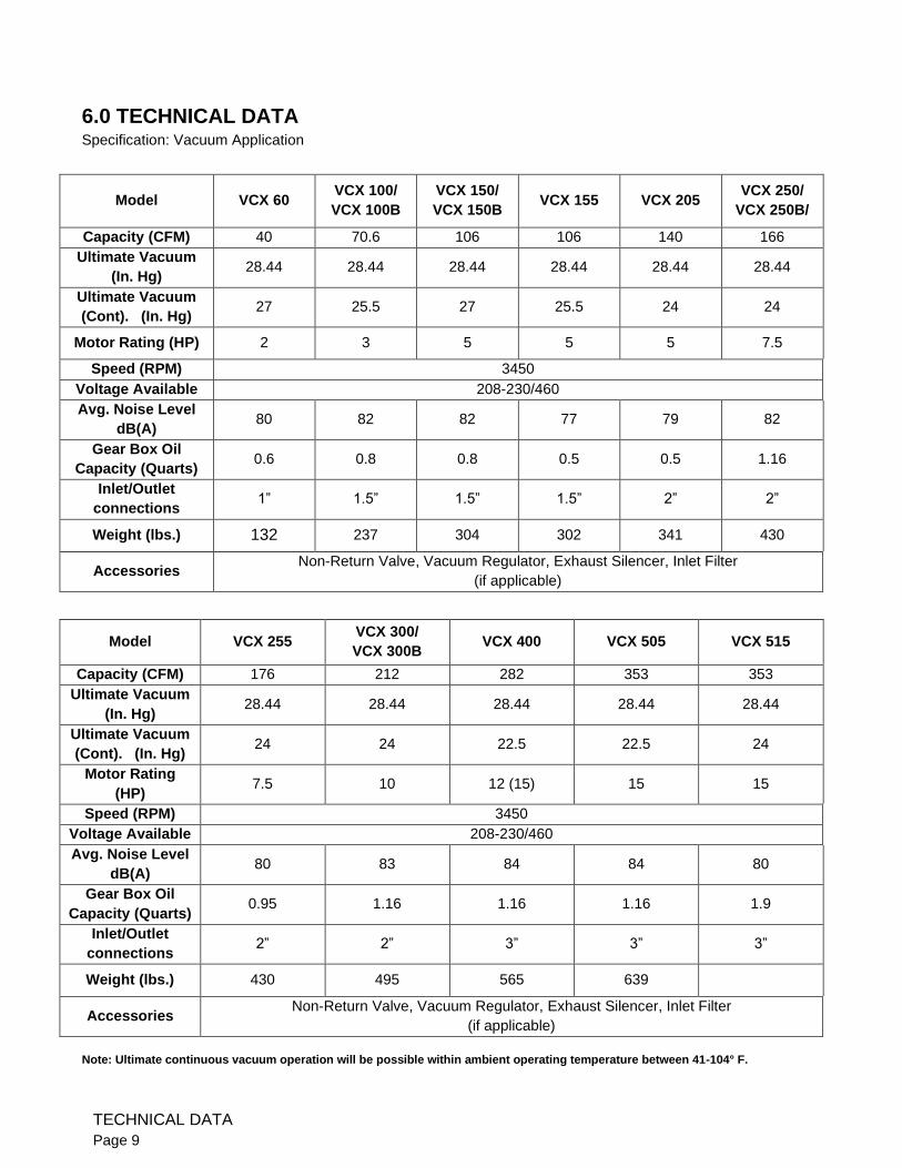
6.0 TECHNICAL DATA
Specification: Vacuum Application
Model VCX 60 VCX 100/
VCX 100B
VCX 150/
VCX 150B VCX 155 VCX 205
VCX 250/
VCX 250B/
Capacity (CFM) 40 70.6 106 106 140 166
Ultimate Vacuum
(In. Hg) 28.44 28.44 28.44 28.44 28.44 28.44
Ultimate Vacuum
(Cont). (In. Hg) 27 25.5 27 25.5 24 24
Motor Rating (HP) 2 3 5 5 5 7.5
Speed (RPM) 3450
Voltage Available 208-230/460
Avg. Noise Level
dB(A) 80 82 82 77 79 82
Gear Box Oil
Capacity (Quarts) 0.6 0.8 0.8 0.5 0.5 1.16
Inlet/Outlet
connections 1” 1.5” 1.5” 1.5” 2” 2”
Weight (lbs.) 132 237 304 302 341 430
Accessories Non-Return Valve, Vacuum Regulator, Exhaust Silencer, Inlet Filter
(if applicable)
Model VCX 255 VCX 300/
VCX 300B VCX 400 VCX 505 VCX 515
Capacity (CFM) 176 212 282 353 353
Ultimate Vacuum
(In. Hg) 28.44 28.44 28.44 28.44 28.44
Ultimate Vacuum
(Cont). (In. Hg) 24 24 22.5 22.5 24
Motor Rating
(HP) 7.5 10 12 (15) 15 15
Speed (RPM) 3450
Voltage Available 208-230/460
Avg. Noise Level
dB(A) 80 83 84 84 80
Gear Box Oil
Capacity (Quarts) 0.95 1.16 1.16 1.16 1.9
Inlet/Outlet
connections 2” 2” 3” 3” 3”
Weight (lbs.) 430 495 565 639
Accessories Non-Return Valve, Vacuum Regulator, Exhaust Silencer, Inlet Filter
(if applicable)
Note: Ultimate continuous vacuum operation will be possible within ambient operating temperature between 41-104° F.
TECHNICAL DATA
Page 9
7.0 SAFETY 7.1 Before repairs are attempted, be sure the power to the unit is off and locked out so accidental startup
cannot occur during repairs or troubleshooting.
7.2 When lifting the VCX pump, use proper and well-maintained equipment to avoid injury.
7.3 Some surfaces on the VCX pump can become too hot to touch during normal operation. Do not attempt to
service the pump until it has cooled to room temperature.
7.4 Ensure the electrical installation is done by a qualified electrician in compliance with the National Electrical
Code and all local laws and regulations. Failure to do so can cause extreme injury including death.
8.0 STORAGE 8.1 Store the unit in a clean dry place, using desiccant bags if excessive humidity is expected to avoid rusting
of the internals of the machine. Rotation of the shaft by hand is recommended if storing for more than 6
months.
9.0 DISPOSAL 9.1 Dispose of any waste oil in compliance with local codes and regulations.
SAFETY / STORAGE / DISPOSAL
Page 10
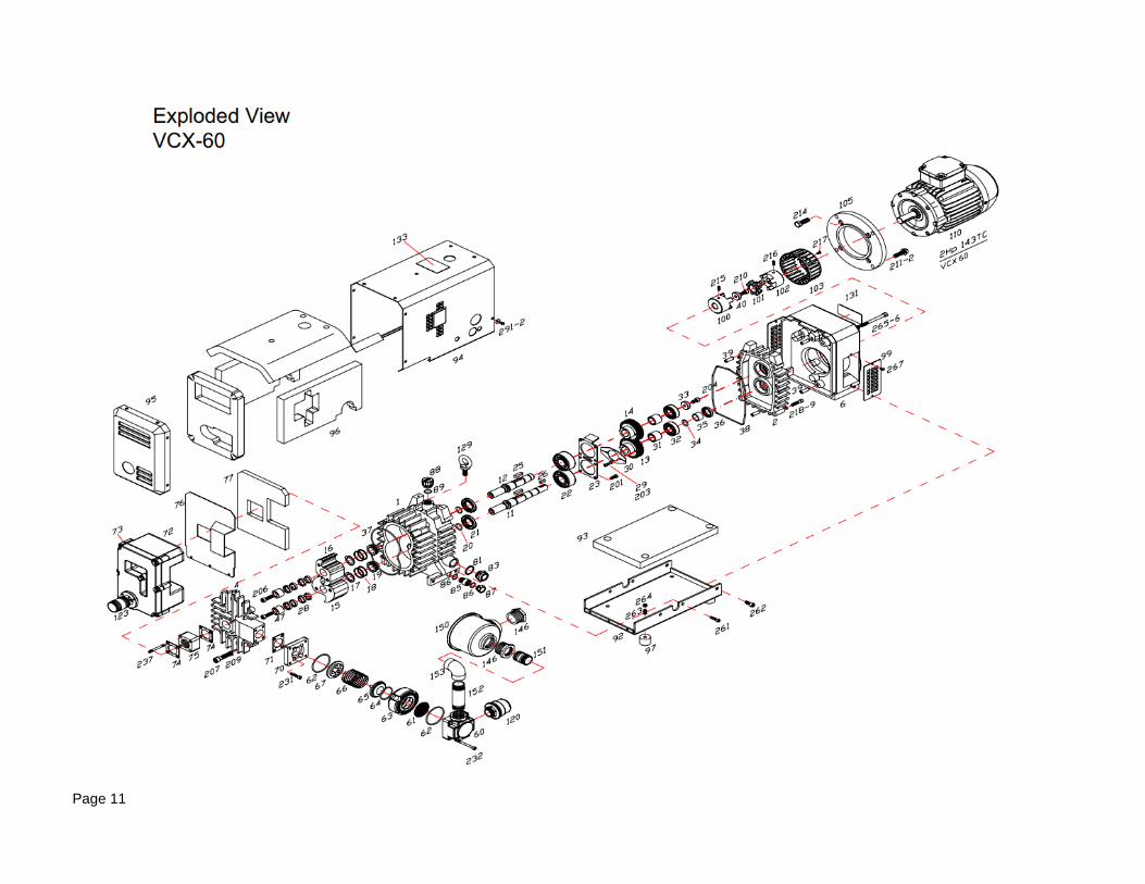
Page 11
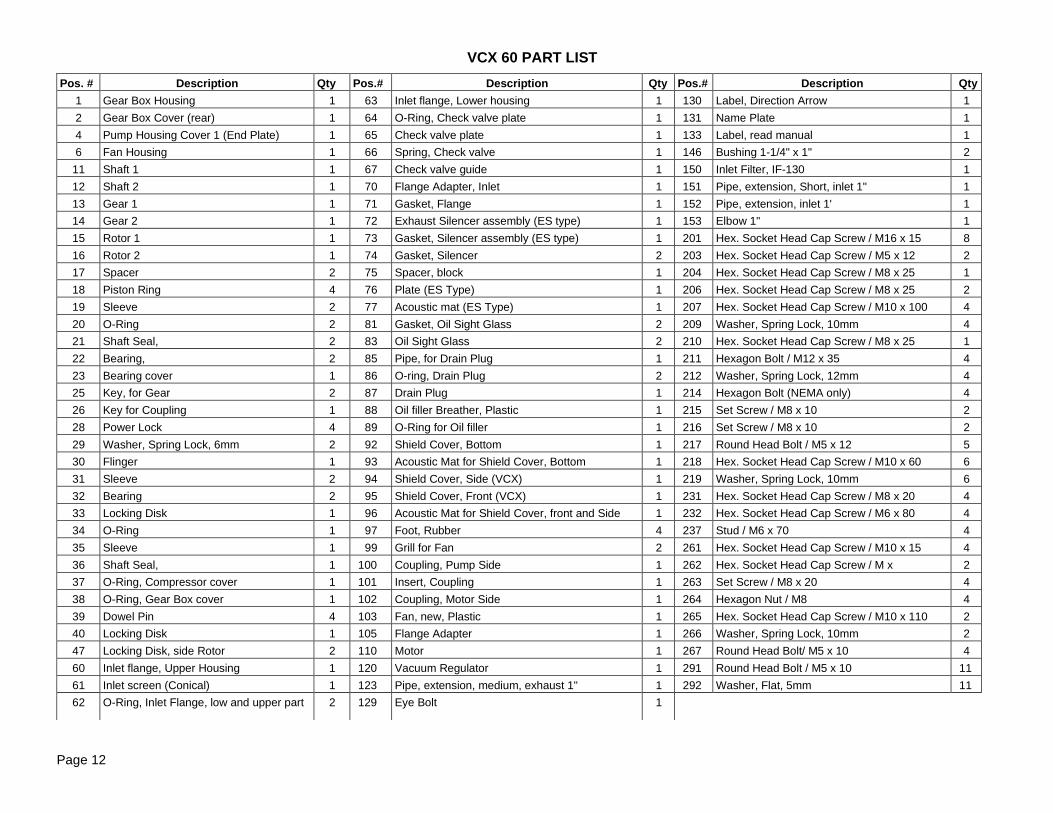
Pos. # Description Qty Pos.# Description Qty Pos.# Description Qty
1 Gear Box Housing 1 63 Inlet flange, Lower housing 1 130 Label, Direction Arrow 1
2 Gear Box Cover (rear) 1 64 O-Ring, Check valve plate 1 131 Name Plate 1
4 Pump Housing Cover 1 (End Plate) 1 65 Check valve plate 1 133 Label, read manual 1
6 Fan Housing 1 66 Spring, Check valve 1 146 Bushing 1-1/4" x 1" 2
11 Shaft 1 1 67 Check valve guide 1 150 Inlet Filter, IF-130 1
12 Shaft 2 1 70 Flange Adapter, Inlet 1 151 Pipe, extension, Short, inlet 1" 1
13 Gear 1 1 71 Gasket, Flange 1 152 Pipe, extension, inlet 1' 1
14 Gear 2 1 72 Exhaust Silencer assembly (ES type) 1 153 Elbow 1" 1
15 Rotor 1 1 73 Gasket, Silencer assembly (ES type) 1 201 Hex. Socket Head Cap Screw / M16 x 15 8
16 Rotor 2 1 74 Gasket, Silencer 2 203 Hex. Socket Head Cap Screw / M5 x 12 2
17 Spacer 2 75 Spacer, block 1 204 Hex. Socket Head Cap Screw / M8 x 25 1
18 Piston Ring 4 76 Plate (ES Type) 1 206 Hex. Socket Head Cap Screw / M8 x 25 2
19 Sleeve 2 77 Acoustic mat (ES Type) 1 207 Hex. Socket Head Cap Screw / M10 x 100 4
20 O-Ring 2 81 Gasket, Oil Sight Glass 2 209 Washer, Spring Lock, 10mm 4
21 Shaft Seal, 2 83 Oil Sight Glass 2 210 Hex. Socket Head Cap Screw / M8 x 25 1
22 Bearing, 2 85 Pipe, for Drain Plug 1 211 Hexagon Bolt / M12 x 35 4
23 Bearing cover 1 86 O-ring, Drain Plug 2 212 Washer, Spring Lock, 12mm 4
25 Key, for Gear 2 87 Drain Plug 1 214 Hexagon Bolt (NEMA only) 4
26 Key for Coupling 1 88 Oil filler Breather, Plastic 1 215 Set Screw / M8 x 10 2
28 Power Lock 4 89 O-Ring for Oil filler 1 216 Set Screw / M8 x 10 2
29 Washer, Spring Lock, 6mm 2 92 Shield Cover, Bottom 1 217 Round Head Bolt / M5 x 12 5
30 Flinger 1 93 Acoustic Mat for Shield Cover, Bottom 1 218 Hex. Socket Head Cap Screw / M10 x 60 6
31 Sleeve 2 94 Shield Cover, Side (VCX) 1 219 Washer, Spring Lock, 10mm 6
32 Bearing 2 95 Shield Cover, Front (VCX) 1 231 Hex. Socket Head Cap Screw / M8 x 20 4
33 Locking Disk 1 96 Acoustic Mat for Shield Cover, front and Side 1 232 Hex. Socket Head Cap Screw / M6 x 80 4
34 O-Ring 1 97 Foot, Rubber 4 237 Stud / M6 x 70 4
35 Sleeve 1 99 Grill for Fan 2 261 Hex. Socket Head Cap Screw / M10 x 15 4
36 Shaft Seal, 1 100 Coupling, Pump Side 1 262 Hex. Socket Head Cap Screw / M x 2
37 O-Ring, Compressor cover 1 101 Insert, Coupling 1 263 Set Screw / M8 x 20 4
38 O-Ring, Gear Box cover 1 102 Coupling, Motor Side 1 264 Hexagon Nut / M8 4
39 Dowel Pin 4 103 Fan, new, Plastic 1 265 Hex. Socket Head Cap Screw / M10 x 110 2
40 Locking Disk 1 105 Flange Adapter 1 266 Washer, Spring Lock, 10mm 2
47 Locking Disk, side Rotor 2 110 Motor 1 267 Round Head Bolt/ M5 x 10 4
60 Inlet flange, Upper Housing 1 120 Vacuum Regulator 1 291 Round Head Bolt / M5 x 10 11
61 Inlet screen (Conical) 1 123 Pipe, extension, medium, exhaust 1" 1 292 Washer, Flat, 5mm 11
62 O-Ring, Inlet Flange, low and upper part 2 129 Eye Bolt 1
Page 12
VCX 60 PART LIST
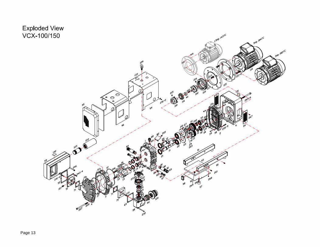
Page 13
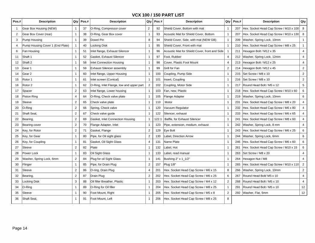
Pos.# Description Qty Pos.# Description Qty Pos # Description Qty Pos.# Description Qty
1 Gear Box Housing (NEW) 1 37 O-Ring, Compressor cover 2 92 Shield Cover, Bottom with mat 1 207 Hex. Socket Head Cap Screw / M10 x 100 8
2 Gear Box Cover (rear) 1 38 O-Ring, Gear Box cover 1 93 Acoustic Mat for Shield Cover, Bottom 1 207 Hex. Socket Head Cap Screw / M10 x 130 8
3 Pump Housing 1 39 Dowel Pin 8 94 Shield Cover, Side, with mat (NEW GB) 1 209 Washer, Spring Lock, 10mm 1
4 Pump Housing Cover 1 (End Plate) 1 40 Locking Disk 1 95 Shield Cover, Front with mat 1 210 Hex. Socket Head Cap Screw / M8 x 25 1
6 Fan Housing 1 51 Inlet flange, Exhaust Silencer 1 96 Acoustic Mat for Shield Cover, front and Side 1 211 Hexagon Bolt / M12 x 35 4
11 Shaft 1 1 52 Gasket, Exhaust Silencer 1 97 Foot, Rubber 4 212 Washer, Spring Lock, 12mm 4
12 Shaft 2 1 58 Inlet Connection Housing 1 98 Cover, Plastic Foot Mount 4 213 Hexagon Bolt / M12 x 25 4
13 Gear 1 1 59 Exhaust Silencer assembly 1 99 Grill for Fan 2 214 Hexagon Bolt / M12 x 45 2
14 Gear 2 1 60 Inlet flange, Upper Housing 1 100 Coupling, Pump Side 1 215 Set Screw / M8 x 10 2
15 Rotor 1 1 61 Inlet screen (Conical) 1 101 Insert, Coupling 1 216 Set Screw / M8 x 10 2
16 Rotor 2 1 62 O-Ring, Inlet Flange, low and upper part 2 102 Coupling, Motor Side 1 217 Round Head Bolt / M5 x 12 5
17 Spacer 2 63 Inlet flange, Lower housing 1 103 Fan, new, Plastic 1 218 Hex. Socket Head Cap Screw / M10 x 60 6
18 Piston Ring 4 64 O-Ring, Check valve plate 1 105 Flange Adapter 1 219 Washer, Spring Lock, 10mm 6
19 Sleeve 2 65 Check valve plate 1 110 Motor 1 231 Hex. Socket Head Cap Screw / M8 x 20 4
20 O-Ring 2 66 Spring, Check valve 1 120 Vacuum Regulator 1 232 Hex. Socket Head Cap Screw / M6 x 80 4
21 Shaft Seal, 2 67 Check valve guide 1 122 Silencer, exhaust 1 233 Hex. Socket Head Cap Screw / M6 x 65 4
22 Bearing, 2 69 Gasket, Inlet Connection Housing 1 122.1 Baffle, for Exhaust Silencer 1 241 Hex. Socket Head Cap Screw / M8 x 60 4
23 Bearing cover 2 70 Flange Adapter, Inlet 1 123 Pipe, extension, medium, exhaust 1 242 Washer, Spring Lock, 8 mm 4
24 Key, for Rotor 2 71 Gasket, Flange 2 129 Eye Bolt 1 243 Hex. Socket Head Cap Screw / M6 x 25 6
25 Key, for Gear 1 80 Pipe, for Oil sight glass 2 130 Label, Direction Arrow 1 244 Washer, Spring Lock, 6mm 6
26 Key, for Coupling 1 81 Gasket, Oil Sight Glass 4 131 Name Plate 1 246 Hex. Socket Head Cap Screw / M6 x 60 6
27 Sleeve 2 82 Plate 1 132 Label, Hot 1 261 Hex. Socket Head Cap Screw / M10 x 15 6
28 Power Lock 1 83 Oil Sight Glass 1 133 Label, read manual 1 263 Set Screw / M8 x 20 4
29 Washer, Spring Lock, 6mm 2 84 Plug for oil Sight Glass 1 141 Bushing 2" x 1_1/2" 1 264 Hexagon Nut / M8 4
30 Flinger 1 85 Pipe, for Drain Plug 2 157 Plug 1/8" 1 265 Hex. Socket Head Cap Screw / M10 x 110 2
31 Sleeve 2 86 O-ring, Drain Plug 4 201 Hex. Socket Head Cap Screw / M6 x 15 8 266 Washer, Spring Lock, 10mm 2
32 Bearing, 2 87 Drain Plug 2 202 Hex. Socket Head Cap Screw / M6 x 25 6 267 Round Head Bolt/ M5 x 10 4
33 Locking Disk 3 88 Oil filler Breather, Plastic 1 203 Hex. Socket Head Cap Screw / M4 x 12 2 268 Round Head Bolt / M5 x 10 4
34 O-Ring 1 89 O-Ring for Oil filler 1 204 Hex. Socket Head Cap Screw / M8 x 25 1 291 Round Head Bolt / M5 x 10 12
35 Sleeve 1 90 Foot Mount, Right 1 205 Hex. Socket Head Cap Screw / M5 x 8 2 292 Washer, Flat, 5mm 12
36 Shaft Seal, 1 91 Foot Mount, Left 1 206 Hex. Socket Head Cap Screw / M8 x 25 8
Page 14
VCX 100 / 150 PART LIST
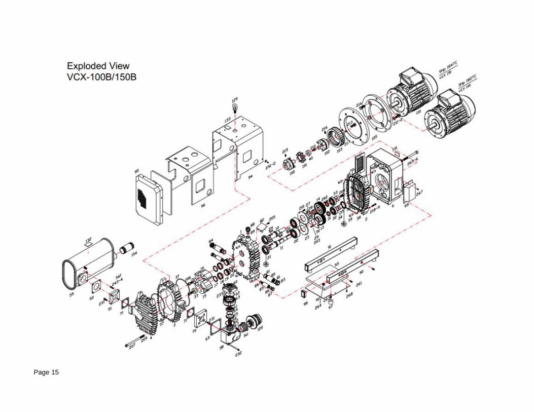
Page 15
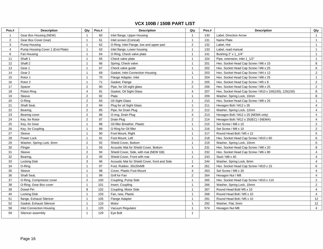
Pos.# Description Qty Pos.# Description Qty Pos.# Description Qty
1 Gear Box Housing (NEW) 1 60 Inlet flange, Upper Housing 1 130 Label, Direction Arrow 1
2 Gear Box Cover (rear) 1 61 Inlet screen (Conical) 1 131 Name Plate 1
3 Pump Housing 1 62 O-Ring, Inlet Flange, low and upper part 2 132 Label, Hot 1
4 Pump Housing Cover 1 (End Plate) 1 63 Inlet flange, Lower housing 1 133 Label, read manual 1
6 Fan Housing 1 64 O-Ring, Check valve plate 1 141 Bushing 2" x 1_1/4" 1
11 Shaft 1 1 65 Check valve plate 1 154 Pipe, extension, inlet 1_1/2" 1
12 Shaft 2 1 66 Spring, Check valve 1 201 Hex. Socket Head Cap Screw / M6 x 15 8
13 Gear 1 1 67 Check valve guide 1 202 Hex. Socket Head Cap Screw / M6 x 25 6
14 Gear 2 1 69 Gasket, Inlet Connection Housing 1 203 Hex. Socket Head Cap Screw / M4 x 12 2
15 Rotor 1 1 70 Flange Adapter, Inlet 1 204 Hex. Socket Head Cap Screw / M8 x 25 1
16 Rotor 2 1 71 Gasket, Flange 2 205 Hex. Socket Head Cap Screw / M5 x 8 2
17 Spacer 2 80 Pipe, for Oil sight glass 2 206 Hex. Socket Head Cap Screw / M8 x 25 2
18 Piston Ring 4 81 Gasket, Oil Sight Glass 4 207 Hex. Socket Head Cap Screw / M10 x 100(100), 120(150) 8
19 Sleeve 2 82 Plate 1 209 Washer, Spring Lock, 10mm 8
20 O-Ring 2 83 Oil Sight Glass 1 210 Hex. Socket Head Cap Screw / M8 x 25 1
21 Shaft Seal, 2 84 Plug for oil Sight Glass 1 211 Hexagon Bolt / M12 x 35 4
22 Bearing, 2 85 Pipe, for Drain Plug 2 212 Washer, Spring Lock, 12mm 4
23 Bearing cover 2 86 O-ring, Drain Plug 4 213 Hexagon Bolt / M12 x 25 (NEMA only) 4
24 Key, for Rotor 2 87 Drain Plug 2 214 Hexagon Bolt / M12 x 25(IEC) / (NEMA) 4
25 Key, for Gear 1 88 Oil filler Breather, Plastic 1 215 Set Screw / M8 x 10 2
26 Key, for Coupling 1 89 O-Ring for Oil filler 1 216 Set Screw / M8 x 10 2
27 Sleeve 1 90 Foot Mount, Right 1 217 Round Head Bolt / M5 x 12 5
28 Power Lock 1 91 Foot Mount, Left 1 218 Hex. Socket Head Cap Screw / M10 x 60 6
29 Washer, Spring Lock, 6mm 2 92 Shield Cover, Bottom 1 219 Washer, Spring Lock, 10mm 6
30 Flinger 1 93 Acoustic Mat for Shield Cover, Bottom 1 231 Hex. Socket Head Cap Screw / M8 x 20 8
31 Sleeve 2 94 Shield Cover, Side, with mat (NEW GB) 1 232 Hex. Socket Head Cap Screw / M6 x 80 4
32 Bearing, 2 95 Shield Cover, Front with mat 1 243 Stud / M8 x 40 4
33 Locking Disk 3 96 Acoustic Mat for Shield Cover, front and Side 1 244 Washer, Spring Lock, 8mm 4
34 O-Ring 1 97 Foot, Rubber, 30x20xM8 4 261 Hex. Socket Head Cap Screw / M10 x 15 6
35 Sleeve 1 98 Cover, Plastic Foot Mount 4 263 Set Screw / M8 x 20 4
36 Shaft Seal, 1 99 Grill for Fan 2 264 Hexagon Nut / M8 4
37 O-Ring, Compressor cover 2 100 Coupling, Pump Side 1 265 Hex. Socket Head Cap Screw / M10 x 110 2
38 O-Ring, Gear Box cover 1 101 Insert, Coupling 1 266 Washer, Spring Lock, 10mm 2
39 Dowel Pin 8 102 Coupling, Motor Side 1 267 Round Head Bolt/ M5 x 10 4
40 Locking Disk 1 103 Fan, new, Plastic 1 268 Round Head Bolt / M5 x 10 4
51 flange, Exhaust Silencer 1 105 Flange Adapter 1 291 Round Head Bolt / M5 x 10 12
52 Gasket, Exhaust Silencer 1 110 Motor 1 292 Washer, Flat, 5mm 12
58 Inlet Connection Housing 1 120 Vacuum Regulator 1 574 Hexagon Nut M8 4
59 Silencer assembly 1 129 Eye Bolt 1
Page 16
VCX 100B / 150B PART LIST
Page 17
Page 18
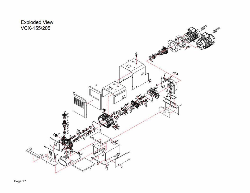
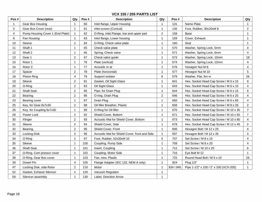
Pos # Description Qty Pos # Description Qty Pos # Description Qty
1 Gear Box Housing 1 60 Inlet flange, Upper Housing 1 131 Name Plate 1
2 Gear Box Cover (rear) 1 61 Inlet screen (Conical) 1 135 Foot, Rubber, 30x20xM 8 2
4 Pump Housing Cover 1 (End Plate) 1 62 O-Ring, Inlet Flange, low and upper part 2 158 Base 1
6 Fan Housing 1 63 Inlet flange, Lower housing 1 159 Cover, Exhaust 1
10 Sleeve 2 64 O-Ring, Check valve plate 1 160 Seal 1
11 Shaft 1 1 65 Check valve plate 1 570 Washer, Spring Lock, 5mm 4
12 Shaft 2 1 66 Spring, Check valve 1 571 Washer, Spring Lock, 6mm 4
13 Gear 1 2 67 Check valve guide 1 573 Washer, Spring Lock, 10mm 18
15 Rotor 1 1 76 Plate (vertical) 1 574 Washer, Spring Lock, 12mm 4
16 Rotor 2 1 77 Acoustic m at 1 576 Hexagon Nut M 8 4
17 Spacer 2 78 Plate (horizontal) 1 577 Hexagon Nut M 10 5
18 Piston Ring 4 79 Support isolator 8 579 Washer, Flat, 5m m 26
19 Sleeve 2 81 Gasket, Oil Sight Glass 1 641 Hex. Socket Head Cap Screw / M 5 x 15 9
20 O-Ring 2 83 Oil Sight Glass 1 643 Hex. Socket Head Cap Screw / M 6 x 10 4
21 Shaft Seal, 2 85 Pipe, for Drain Plug 1 644 Hex. Socket Head Cap Screw / M 6 x 15 8
22 Bearing, 2 86 O-ring, Drain Plug 2 646 Hex. Socket Head Cap Screw / M 6 x 25 4
23 Bearing cover 1 87 Drain Plug 1 650 Hex. Socket Head Cap Screw / M 6 x 65 4
25 Key, for Gear 8x7x30 2 88 Oil filler Breather, Plastic 1 656 Hex. Socket Head Cap Screw / M 8 x 25 2
26 Key, for Coupling 8x7x30 1 89 O-Ring for Oil filler 1 670 Hex. Socket Head Cap Screw / M 10 x 35 7
28 Power Lock 2 92 Shield Cover, Bottom 1 671 Hex. Socket Head Cap Screw / M 10 x 50 7
30 Flinger 2 93 Acoustic Mat for Shield Cover, Bottom 1 673 Hex. Socket Head Cap Screw / M 10 x 85 4
31 Sleeve 2 94 Shield Cover, Side 1 678 Hex. Socket Head Cap Screw / M 12 x 45 2
32 Bearing, 2 95 Shield Cover, Front 1 695 Hexagon Bolt / M 12 x 25 4
33 Locking Disk 2 96 Acoustic Mat for Shield Cover, front and Side 1 697 Hexagon Bolt / M 12 x 35 4
34 O-Ring 1 97 Foot, Rubber, 52x30xM 10 5 707 Set Screw / M 8 x 15 4
35 Sleeve 1 100 Coupling, Pump Side 1 709 Set Screw / M 8 x 20 4
36 Shaft Seal, 1 101 Insert, Coupling 1 712 Set Screw / M 10 x 25 6
37 O-Ring, Com pressor cover 1 102 Coupling, Motor Side 1 716 Eye Bolt M 12 1
38 O-Ring, Gear Box cover 1 103 Fan, new, Plastic 1 725 Round Head Bolt / M 5 x 10 26
39 Dowel Pin 4 105 Flange Adapter (IEC 132, NEM A only) 1 824 Plug 1/2" 1
47 Locking Disk, side Rotor 2 110 Motor 1 934 / 940 Pipe 1-1/2" x 100 / 2" x 100 (VCX-205) 1
52 Gasket, Exhaust Silencer 1 120 Vacuum Regulator 1
59 Silencer assembly 1 130 Label, Direction Arrow 1
VCX 155 / 205 PARTS LIST
Page 19
Pos # Description Qty Pos # Description Qty Pos # Description Qty Pos # Description Qty
1 Gear Box Housing (NEW) 1 37 O-Ring, Compressor cover, 2 92 Shield Cover, Bottom, with mat 1 207 Hex. Socket Head Cap Screw / M12 x 100 /120 8
2 Gear Box Cover (rear) 1 38 O-Ring, Gear Box cover, 1 93 Acoustic Mat for Shield Cover, Bottom 1 209 Washer, Spring Lock, 12mm 8
3 Pump Housing 1 39 Dowel Pin 8 94 Shield Cover, Side, with mat (NEW GB) 1 210 Hex. Socket Head Cap Screw / M12 x 25 1
4 Pump Housing Cover 1 (End Plate) 1 40 Locking Disk 1 95 Shield Cover, Front with mat 1 211 Hexagon Bolt / M12 x 35 4
6 Fan Housing 1 51 Flange, Exhaust Silencer 1 96 Acoustic Mat for Shield Cover, Front & Side 1 212 Washer, Spring Lock, 12mm 4
11 Shaft 1 1 52 Gasket, Exhaust Silencer 1 97 Foot, Rubber 4 213 Hexagon Bolt / M12 x 25 4
12 Shaft 2 1 59 Exhaust Silencer assembly 1 98 Cover, Plastic Foot Mount 4 215 Set Screw / M8 x 15 2
13 Gear 1 1 60 Inlet flange, Upper Housing, G 2" 1 99 Grill for Fan 2 216 Set Screw / M8 x 15 2
14 Gear 2 1 61 Inlet screen (Conical) 1 100 Coupling, Pump Side 1 217 Round Head Bolt / M5 x 10 5
15 Rotor 1 1 62 O-Ring, Inlet Flange, low and upper part 2 101 Insert, Coupling 1 218 Hex. Socket Head Cap Screw / M12 x 60 6
16 Rotor 2 1 63 Inlet flange, Lower housing 1 102 Coupling, Motor Side 1 219 Washer, Spring Lock, 12mm 6
17 Spacer 2 64 O-Ring, Check valve plate 1 103 Fan, new, Plastic 1 231 Hex. Socket Head Cap Screw / M12 x 25 4
18 Piston Ring 2 65 Check valve plate 1 105 Flange Adapter 1 232 Hex. Socket Head Cap Screw / M6 x 120 4
19 Sleeve 2 66 Spring, Check valve 1 110 Motor 1 233 Hex. Socket Head Cap Screw / M8 x 115 4
20 O-Ring 2 67 Check valve guide 1 120 Vacuum Regulator 1 241 Hex. Socket Head Cap Screw / M12 x 70 4
21 Shaft Seal 2 68 Inlet Connection Housing 1 121 Silencer, Inlet 1 242 Washer, Spring Lock, 12mm 4
22 Bearing, 2 69 Gasket, Inlet Connection Housing 1 122 Silencer, exhaust 1 243 Hex. Socket Head Cap Screw / M8 x 30 6
23 Bearing cover 2 70 Flange Adapter, Inlet 1 123 Pipe, extension, medium, 1_1/2" 2 244 Washer, Spring Lock, 8mm 6
24 Key, for Rotor 2 71 Gasket, Flange 2 124 Bushing, Exhaust 2" x 1_1/2" 1 246 Hex. Socket Head Cap Screw / M8 x 90 9
25 Key, for Gear 1 80 Pipe, for Oil sight glass 2 129 Eye Bolt 1 261 Hex. Socket Head Cap Screw / M12 x 25 6
26 Key, for Coupling 1 81 Gasket, Oil Sight Glass 4 130 Label, Direction Arrow 1 263 Set Screw / M10 x 20 4
27 Sleeve 2 82 Plate 1 131 Name Plate 1 264 Hexagon Nut / M10 4
28 Power Lock 1 83 Oil Sight Glass 1 132 Label, Hot 1 265 Hex. Socket Head Cap Screw / M12 x 140 2
29 Washer, Spring Lock, 6mm 2 84 Plug for oil Sight Glass 1 133 Label, read manual 1 266 Washer, Spring Lock, 12mm 2
30 Flinger 1 85 Pipe, for Drain Plug 2 157 Plug 1/8" 1 267 Round Head Bolt/ M5 x 10 4
31 Sleeve 2 86 O-ring, Drain Plug 4 201 Hex. Socket Head Cap Screw / M6 x 15 8 268 Round Head Bolt / M5 x 10 4
32 Bearing, 2 87 Drain Plug 2 202 Hex. Socket Head Cap Screw / M6 x 30 8 291 Round Head Bolt / M5 x 10 12
33 Locking Disk 3 88 Oil filler Breather, Plastic 1 203 Hex. Socket Head Cap Screw / M6 x 15 2 292 Washer, Flat, 5mm 12
34 O-Ring 1 89 O-Ring for Oil filler, for PN 100.088.01 1 204 Hex. Socket Head Cap Screw / M12 x 25 1
35 Sleeve 1 90 Foot Mount, Right 1 205 Hex. Socket Head Cap Screw / M5 x 8 2
36 Shaft Seal, 1 91 Foot Mount, Left 1 206 Hex. Socket Head Cap Screw / M12 x 25 2
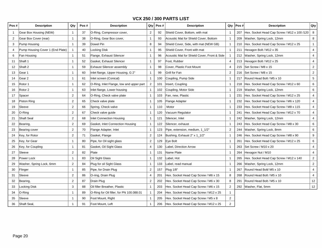
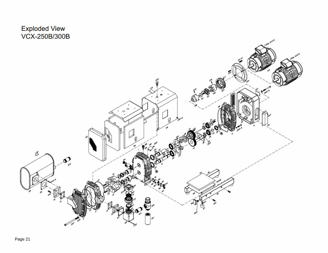
Page 20
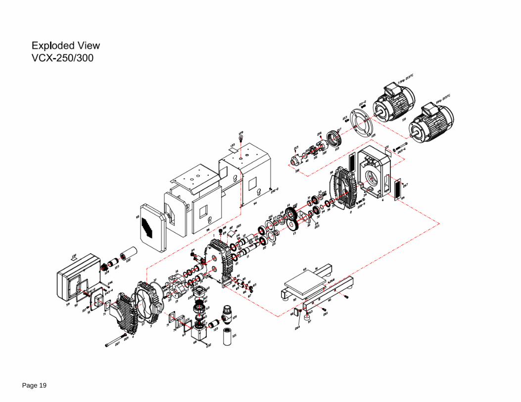
VCX 250 / 300 PARTS LIST
Page 21
Pos.# Description Qty Pos.# Description Qty Pos # Description Qty
1 Gear Box Housing (NEW) 1 62 O-Ring, Inlet Flange, low and upper part 2 130 Label, Direction Arrow 1
2 Gear Box Cover (rear) 1 63 Inlet flange, Lower housing 1 131 Name Plate 1
3 Pump Housing 1 64 O-Ring, Check valve plate 1 132 Label, Hot 1
4 Pump Housing Cover 1 (End Plate) 1 65 Check valve plate 1 133 Label, read manual 1
6 Fan Housing 1 66 Spring, Check valve 1 134 Pipe, extension, medium, 2" 1
11 Shaft 1 1 67 Check valve guide 1 201 Hex. Socket Head Cap Screw / M6 x 15 8
12 Shaft 2 1 68 Inlet Connection Housing 1 202 Hex. Socket Head Cap Screw / M6 x 30 8
13 Gear 1 1 69 Gasket, Inlet Connection Housing 1 203 Hex. Socket Head Cap Screw / M6 x 15 2
14 Gear 2 1 70 Flange Adapter, Inlet 1 204 Hex. Socket Head Cap Screw / M12 x 25 1
15 Rotor 1 1 71 Gasket, Flange 2 205 Hex. Socket Head Cap Screw / M5 x 8 2
16 Rotor 2 1 80 Pipe, for Oil sight glass 2 206 Hex. Socket Head Cap Screw / M12 x 25 2
17 Spacer 2 81 Gasket, Oil Sight Glass 4 207 Hex. Socket Head Cap Screw / M12 x 100 / 120 8
18 Piston Ring 4 82 Plate 1 209 Washer, Spring Lock, 12mm 8
19 Sleeve 2 83 Oil Sight Glass 1 210 Hex. Socket Head Cap Screw / M12 x 25 1
20 O-Ring 2 84 Plug for oil Sight Glass 1 211 Hexagon Bolt / M12 x 35 4
21 Shaft Seal 2 85 Pipe, for Drain Plug 2 212 Washer, Spring Lock, 12mm 4
22 Bearing, 2 86 O-ring, Drain Plug 4 213 Hexagon Bolt / M12 x 25 4
23 Bearing cover 2 87 Drain Plug 2 214 Hexagon Bolt / (NEMA only) 4
24 Key, for Rotor 2 88 Oil filler Breather, Plastic 1 215 Set Screw / M8 x 15 2
25 Key, for Gear 1 89 O-Ring for Oil filler, for PN 100.088.01 1 216 Set Screw / M8 x 15 2
26 Key, for Coupling 1 90 Foot Mount, Right 1 217 Round Head Bolt / M5 x 10 5
27 Sleeve 2 91 Foot Mount, Left 1 218 Hex. Socket Head Cap Screw / M12 x 60 6
28 Power Lock 1 92 Shield Cover, Bottom 1 219 Washer, Spring Lock, 12mm 6
29 Washer, Spring Lock, 6mm 2 93 Acoustic Mat for Shield Cover, Bottom 1 231 Hex. Socket Head Cap Screw / M12 x 25 4
30 Flinger 1 94 Shield Cover, Side, (NEW GB) 1 232 Hex. Socket Head Cap Screw / M6 x 120 4
31 Sleeve 2 95 Shield Cover, Front 1 233 Hex. Socket Head Cap Screw / M8 x 115 4
32 Bearing, 2 96 Acoustic Mat for Shield Cover, Front & Side 1 241 Hex. Socket Head Cap Screw / M12 x 20 4
33 Locking Disk 3 97 Foot, Rubber 4 243 Stud / M8 x 40 4
34 O-Ring 1 98 Cover, Plastic Foot Mount 4 244 Nut / M8 4
35 Sleeve 1 99 Grill for Fan 2 261 Hex. Socket Head Cap Screw / M12 x 25 6
36 Shaft Seal, 1 100 Coupling, Pump Side 1 263 Set Screw / M10 x 20 4
37 O-Ring, Compressor cover, 2 101 Insert, Coupling 1 264 Hexagon Nut / M10 4
38 O-Ring, Gear Box cover, 1 102 Coupling, Motor Side 1 265 Hex. Socket Head Cap Screw / M12 x 140 2
39 Dowel Pin 8 103 Fan, new, Plastic 1 266 Washer, Spring Lock, 12mm 2
40 Locking Disk 1 105 Flange Adapter 1 267 Round Head Bolt/ M5 x 10 4
51 flange, Exhaust Silencer 1 110 Motor 1 268 Round Head Bolt / M5 x 10 4
52 Gasket, Exhaust Silencer 1 120 Vacuum Regulator 1 291 Round Head Bolt / M5 x 10 12
59 Silencer assembly 1 121 Silencer, Inlet 1 292 Washer, Flat, 5mm 12
60 Inlet flange, Upper Housing, G 2" 1 123 Pipe, extension, medium, 1 1/2" 1
61 Inlet screen (Conical) 1 129 Eye Bolt 1
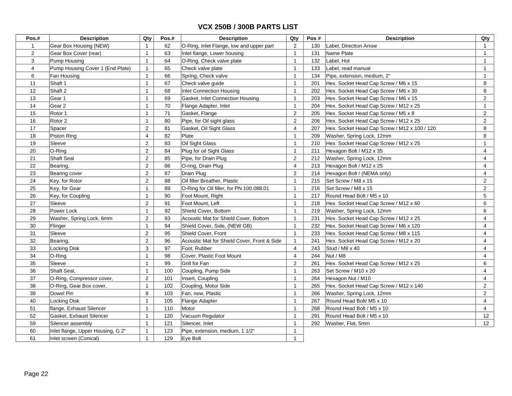
Page 22
VCX 250B / 300B PARTS LIST
Page 23
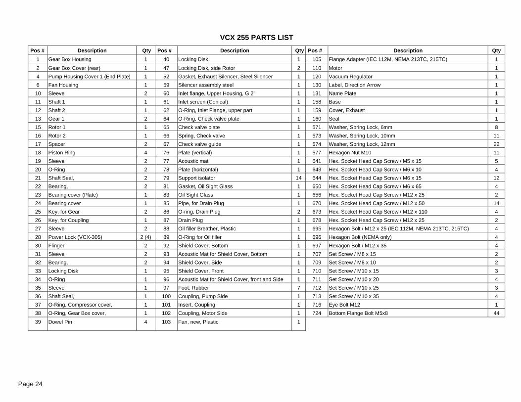
Pos # Description Qty Pos # Description Qty Pos # Description Qty
1 Gear Box Housing 1 40 Locking Disk 1 105 Flange Adapter (IEC 112M, NEMA 213TC, 215TC) 1
2 Gear Box Cover (rear) 1 47 Locking Disk, side Rotor 2 110 Motor 1
4 Pump Housing Cover 1 (End Plate) 1 52 Gasket, Exhaust Silencer, Steel Silencer 1 120 Vacuum Regulator 1
6 Fan Housing 1 59 Silencer assembly steel 1 130 Label, Direction Arrow 1
10 Sleeve 2 60 Inlet flange, Upper Housing, G 2" 1 131 Name Plate 1
11 Shaft 1 1 61 Inlet screen (Conical) 1 158 Base 1
12 Shaft 2 1 62 O-Ring, Inlet Flange, upper part 1 159 Cover, Exhaust 1
13 Gear 1 2 64 O-Ring, Check valve plate 1 160 Seal 1
15 Rotor 1 1 65 Check valve plate 1 571 Washer, Spring Lock, 6mm 8
16 Rotor 2 1 66 Spring, Check valve 1 573 Washer, Spring Lock, 10mm 11
17 Spacer 2 67 Check valve guide 1 574 Washer, Spring Lock, 12mm 22
18 Piston Ring 4 76 Plate (vertical) 1 577 Hexagon Nut M10 11
19 Sleeve 2 77 Acoustic mat 1 641 Hex. Socket Head Cap Screw / M5 x 15 5
20 O-Ring 2 78 Plate (horizontal) 1 643 Hex. Socket Head Cap Screw / M6 x 10 4
21 Shaft Seal, 2 79 Support isolator 14 644 Hex. Socket Head Cap Screw / M6 x 15 12
22 Bearing, 2 81 Gasket, Oil Sight Glass 1 650 Hex. Socket Head Cap Screw / M6 x 65 4
23 Bearing cover (Plate) 1 83 Oil Sight Glass 1 656 Hex. Socket Head Cap Screw / M12 x 25 2
24 Bearing cover 1 85 Pipe, for Drain Plug 1 670 Hex. Socket Head Cap Screw / M12 x 50 14
25 Key, for Gear 2 86 O-ring, Drain Plug 2 673 Hex. Socket Head Cap Screw / M12 x 110 4
26 Key, for Coupling 1 87 Drain Plug 1 678 Hex. Socket Head Cap Screw / M12 x 25 2
27 Sleeve 2 88 Oil filler Breather, Plastic 1 695 Hexagon Bolt / M12 x 25 (IEC 112M, NEMA 213TC, 215TC) 4
28 Power Lock (VCX-305) 2 (4) 89 O-Ring for Oil filler 1 696 Hexagon Bolt (NEMA only) 4
30 Flinger 2 92 Shield Cover, Bottom 1 697 Hexagon Bolt / M12 x 35 4
31 Sleeve 2 93 Acoustic Mat for Shield Cover, Bottom 1 707 Set Screw / M8 x 15 2
32 Bearing, 2 94 Shield Cover, Side 1 709 Set Screw / M8 x 10 2
33 Locking Disk 1 95 Shield Cover, Front 1 710 Set Screw / M10 x 15 3
34 O-Ring 1 96 Acoustic Mat for Shield Cover, front and Side 1 711 Set Screw / M10 x 20 4
35 Sleeve 1 97 Foot, Rubber 7 712 Set Screw / M10 x 25 3
36 Shaft Seal, 1 100 Coupling, Pump Side 1 713 Set Screw / M10 x 35 4
37 O-Ring, Compressor cover, 1 101 Insert, Coupling 1 716 Eye Bolt M12 1
38 O-Ring, Gear Box cover, 1 102 Coupling, Motor Side 1 724 Bottom Flange Bolt M5x8 44
39 Dowel Pin 4 103 Fan, new, Plastic 1
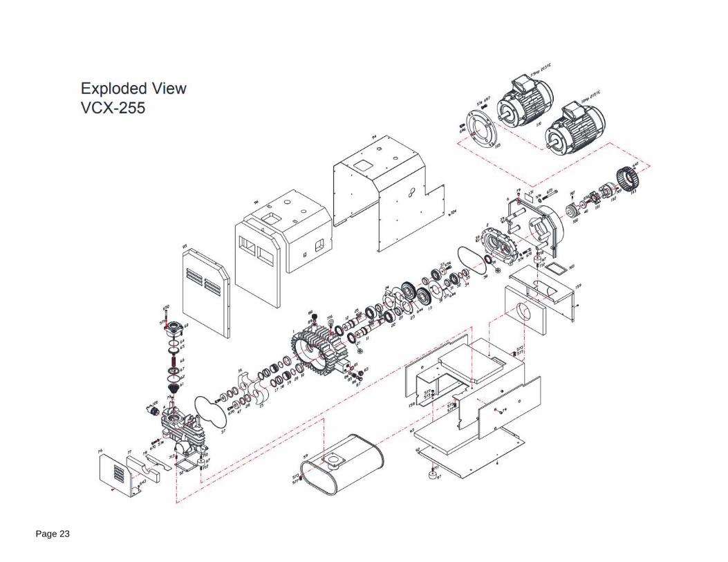
Page 24
VCX 255 PARTS LIST
Page 25
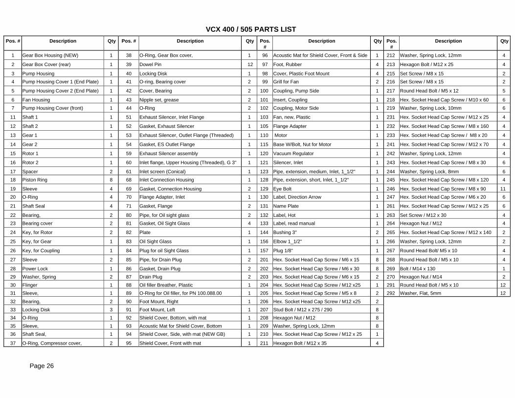
Pos. # Description Qty Pos. # Description Qty Pos.
#
Description Qty Pos.
#
Description Qty
1 Gear Box Housing (NEW) 1 38 O-Ring, Gear Box cover, 1 96 Acoustic Mat for Shield Cover, Front & Side 1 212 Washer, Spring Lock, 12mm 4
2 Gear Box Cover (rear) 1 39 Dowel Pin 12 97 Foot, Rubber 4 213 Hexagon Bolt / M12 x 25 4
3 Pump Housing 1 40 Locking Disk 1 98 Cover, Plastic Foot Mount 4 215 Set Screw / M8 x 15 2
4 Pump Housing Cover 1 (End Plate) 1 41 O-ring, Bearing cover 2 99 Grill for Fan 2 216 Set Screw / M8 x 15 2
5 Pump Housing Cover 2 (End Plate) 1 42 Cover, Bearing 2 100 Coupling, Pump Side 1 217 Round Head Bolt / M5 x 12 5
6 Fan Housing 1 43 Nipple set, grease 2 101 Insert, Coupling 1 218 Hex. Socket Head Cap Screw / M10 x 60 6
7 Pump Housing Cover (front) 1 44 O-Ring 2 102 Coupling, Motor Side 1 219 Washer, Spring Lock, 10mm 6
11 Shaft 1 1 51 Exhaust Silencer, Inlet Flange 1 103 Fan, new, Plastic 1 231 Hex. Socket Head Cap Screw / M12 x 25 4
12 Shaft 2 1 52 Gasket, Exhaust Silencer 1 105 Flange Adapter 1 232 Hex. Socket Head Cap Screw / M8 x 160 4
13 Gear 1 1 53 Exhaust Silencer, Outlet Flange (Threaded) 1 110 Motor 1 233 Hex. Socket Head Cap Screw / M8 x 20 4
14 Gear 2 1 54 Gasket, ES Outlet Flange 1 115 Base W/Bolt, Nut for Motor 1 241 Hex. Socket Head Cap Screw / M12 x 70 4
15 Rotor 1 1 59 Exhaust Silencer assembly 1 120 Vacuum Regulator 1 242 Washer, Spring Lock, 12mm 4
16 Rotor 2 1 60 Inlet flange, Upper Housing (Threaded), G 3" 1 121 Silencer, Inlet 1 243 Hex. Socket Head Cap Screw / M8 x 30 6
17 Spacer 2 61 Inlet screen (Conical) 1 123 Pipe, extension, medium, Inlet, 1_1/2" 1 244 Washer, Spring Lock, 8mm 6
18 Piston Ring 8 68 Inlet Connection Housing 1 128 Pipe, extension, short, Inlet, 1_1/2" 1 245 Hex. Socket Head Cap Screw / M8 x 120 4
19 Sleeve 4 69 Gasket, Connection Housing 2 129 Eye Bolt 1 246 Hex. Socket Head Cap Screw / M8 x 90 11
20 O-Ring 4 70 Flange Adapter, Inlet 1 130 Label, Direction Arrow 1 247 Hex. Socket Head Cap Screw / M6 x 20 6
21 Shaft Seal 4 71 Gasket, Flange 2 131 Name Plate 1 261 Hex. Socket Head Cap Screw / M12 x 25 6
22 Bearing, 2 80 Pipe, for Oil sight glass 2 132 Label, Hot 1 263 Set Screw / M12 x 30 4
23 Bearing cover 2 81 Gasket, Oil Sight Glass 4 133 Label, read manual 1 264 Hexagon Nut / M12 4
24 Key, for Rotor 2 82 Plate 1 144 Bushing 3" 2 265 Hex. Socket Head Cap Screw / M12 x 140 2
25 Key, for Gear 1 83 Oil Sight Glass 1 156 Elbow 1_1/2" 1 266 Washer, Spring Lock, 12mm 2
26 Key, for Coupling 1 84 Plug for oil Sight Glass 1 157 Plug 1/8" 1 267 Round Head Bolt/ M5 x 10 4
27 Sleeve 2 85 Pipe, for Drain Plug 2 201 Hex. Socket Head Cap Screw / M6 x 15 8 268 Round Head Bolt / M5 x 10 4
28 Power Lock 1 86 Gasket, Drain Plug 2 202 Hex. Socket Head Cap Screw / M6 x 30 8 269 Bolt / M14 x 130 1
29 Washer, Spring 2 87 Drain Plug 2 203 Hex. Socket Head Cap Screw / M6 x 15 2 270 Hexagon Nut / M14 2
30 Flinger 1 88 Oil filler Breather, Plastic 1 204 Hex. Socket Head Cap Screw / M12 x25 1 291 Round Head Bolt / M5 x 10 12
31 Sleeve, 1 89 O-Ring for Oil filler, for PN 100.088.00 1 205 Hex. Socket Head Cap Screw / M5 x 8 2 292 Washer, Flat, 5mm 12
32 Bearing, 2 90 Foot Mount, Right 1 206 Hex. Socket Head Cap Screw / M12 x25 2
33 Locking Disk 3 91 Foot Mount, Left 1 207 Stud Bolt / M12 x 275 / 290 8
34 O-Ring 1 92 Shield Cover, Bottom, with mat 1 208 Hexagon Nut / M12 8
35 Sleeve, 1 93 Acoustic Mat for Shield Cover, Bottom 1 209 Washer, Spring Lock, 12mm 8
36 Shaft Seal, 1 94 Shield Cover, Side, with mat (NEW GB) 1 210 Hex. Socket Head Cap Screw / M12 x 25 1
37 O-Ring, Compressor cover, 2 95 Shield Cover, Front with mat 1 211 Hexagon Bolt / M12 x 35 4
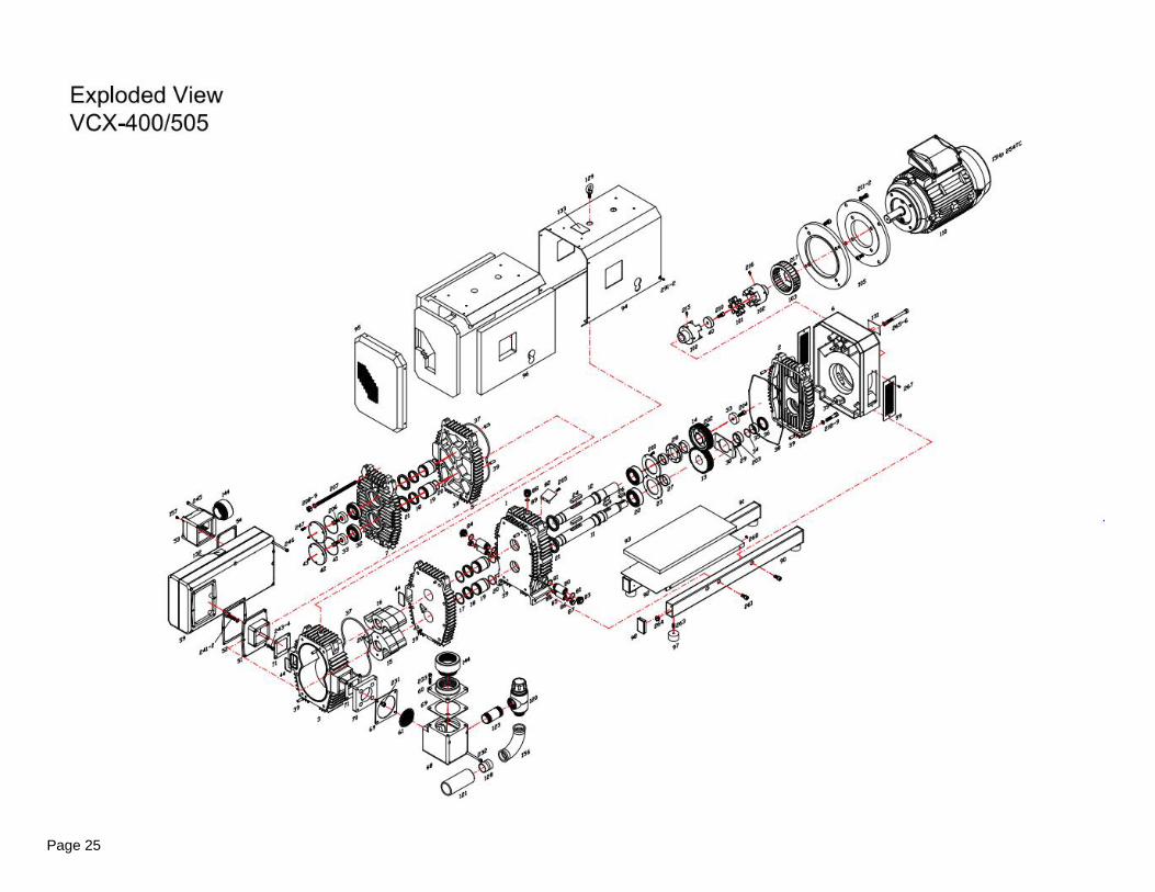
VCX 400 / 505 PARTS LIST
Page 26
Page 27
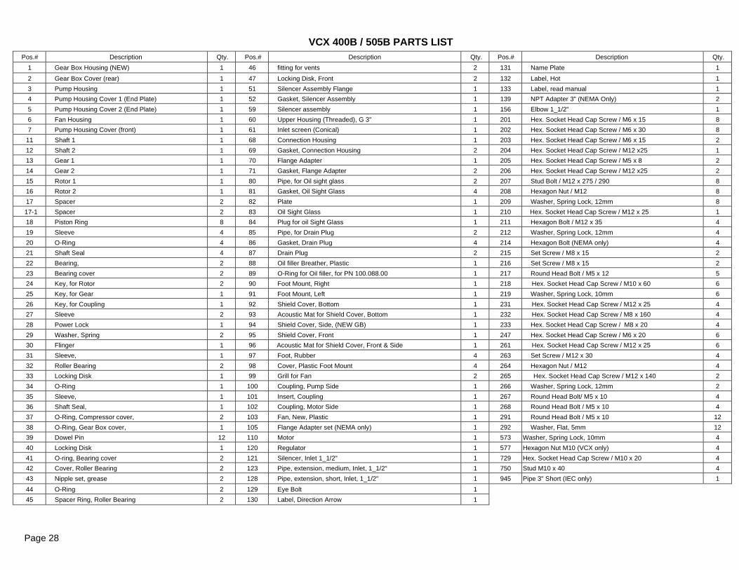
Pos.# Description Qty. Pos.# Description Qty. Pos.# Description Qty.
1 Gear Box Housing (NEW) 1 46 fitting for vents 2 131 Name Plate 1
2 Gear Box Cover (rear) 1 47 Locking Disk, Front 2 132 Label, Hot 1
3 Pump Housing 1 51 Silencer Assembly Flange 1 133 Label, read manual 1
4 Pump Housing Cover 1 (End Plate) 1 52 Gasket, Silencer Assembly 1 139 NPT Adapter 3" (NEMA Only) 2
5 Pump Housing Cover 2 (End Plate) 1 59 Silencer assembly 1 156 Elbow 1_1/2" 1
6 Fan Housing 1 60 Upper Housing (Threaded), G 3" 1 201 Hex. Socket Head Cap Screw / M6 x 15 8
7 Pump Housing Cover (front) 1 61 Inlet screen (Conical) 1 202 Hex. Socket Head Cap Screw / M6 x 30 8
11 Shaft 1 1 68 Connection Housing 1 203 Hex. Socket Head Cap Screw / M6 x 15 2
12 Shaft 2 1 69 Gasket, Connection Housing 2 204 Hex. Socket Head Cap Screw / M12 x25 1
13 Gear 1 1 70 Flange Adapter 1 205 Hex. Socket Head Cap Screw / M5 x 8 2
14 Gear 2 1 71 Gasket, Flange Adapter 2 206 Hex. Socket Head Cap Screw / M12 x25 2
15 Rotor 1 1 80 Pipe, for Oil sight glass 2 207 Stud Bolt / M12 x 275 / 290 8
16 Rotor 2 1 81 Gasket, Oil Sight Glass 4 208 Hexagon Nut / M12 8
17 Spacer 2 82 Plate 1 209 Washer, Spring Lock, 12mm 8
17-1 Spacer 2 83 Oil Sight Glass 1 210 Hex. Socket Head Cap Screw / M12 x 25 1
18 Piston Ring 8 84 Plug for oil Sight Glass 1 211 Hexagon Bolt / M12 x 35 4
19 Sleeve 4 85 Pipe, for Drain Plug 2 212 Washer, Spring Lock, 12mm 4
20 O-Ring 4 86 Gasket, Drain Plug 4 214 Hexagon Bolt (NEMA only) 4
21 Shaft Seal 4 87 Drain Plug 2 215 Set Screw / M8 x 15 2
22 Bearing, 2 88 Oil filler Breather, Plastic 1 216 Set Screw / M8 x 15 2
23 Bearing cover 2 89 O-Ring for Oil filler, for PN 100.088.00 1 217 Round Head Bolt / M5 x 12 5
24 Key, for Rotor 2 90 Foot Mount, Right 1 218 Hex. Socket Head Cap Screw / M10 x 60 6
25 Key, for Gear 1 91 Foot Mount, Left 1 219 Washer, Spring Lock, 10mm 6
26 Key, for Coupling 1 92 Shield Cover, Bottom 1 231 Hex. Socket Head Cap Screw / M12 x 25 4
27 Sleeve 2 93 Acoustic Mat for Shield Cover, Bottom 1 232 Hex. Socket Head Cap Screw / M8 x 160 4
28 Power Lock 1 94 Shield Cover, Side, (NEW GB) 1 233 Hex. Socket Head Cap Screw / M8 x 20 4
29 Washer, Spring 2 95 Shield Cover, Front 1 247 Hex. Socket Head Cap Screw / M6 x 20 6
30 Flinger 1 96 Acoustic Mat for Shield Cover, Front & Side 1 261 Hex. Socket Head Cap Screw / M12 x 25 6
31 Sleeve, 1 97 Foot, Rubber 4 263 Set Screw / M12 x 30 4
32 Roller Bearing 2 98 Cover, Plastic Foot Mount 4 264 Hexagon Nut / M12 4
33 Locking Disk 1 99 Grill for Fan 2 265 Hex. Socket Head Cap Screw / M12 x 140 2
34 O-Ring 1 100 Coupling, Pump Side 1 266 Washer, Spring Lock, 12mm 2
35 Sleeve, 1 101 Insert, Coupling 1 267 Round Head Bolt/ M5 x 10 4
36 Shaft Seal, 1 102 Coupling, Motor Side 1 268 Round Head Bolt / M5 x 10 4
37 O-Ring, Compressor cover, 2 103 Fan, New, Plastic 1 291 Round Head Bolt / M5 x 10 12
38 O-Ring, Gear Box cover, 1 105 Flange Adapter set (NEMA only) 1 292 Washer, Flat, 5mm 12
39 Dowel Pin 12 110 Motor 1 573 Washer, Spring Lock, 10mm 4
40 Locking Disk 1 120 Regulator 1 577 Hexagon Nut M10 (VCX only) 4
41 O-ring, Bearing cover 2 121 Silencer, Inlet 1_1/2" 1 729 Hex. Socket Head Cap Screw / M10 x 20 4
42 Cover, Roller Bearing 2 123 Pipe, extension, medium, Inlet, 1_1/2" 1 750 Stud M10 x 40 4
43 Nipple set, grease 2 128 Pipe, extension, short, Inlet, 1_1/2" 1 945 Pipe 3" Short (IEC only) 1
44 O-Ring 2 129 Eye Bolt 1
45 Spacer Ring, Roller Bearing 2 130 Label, Direction Arrow 1
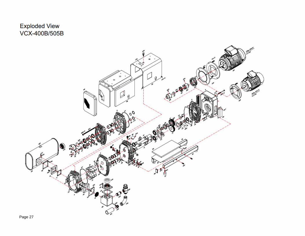
Page 28
VCX 400B / 505B PARTS LIST
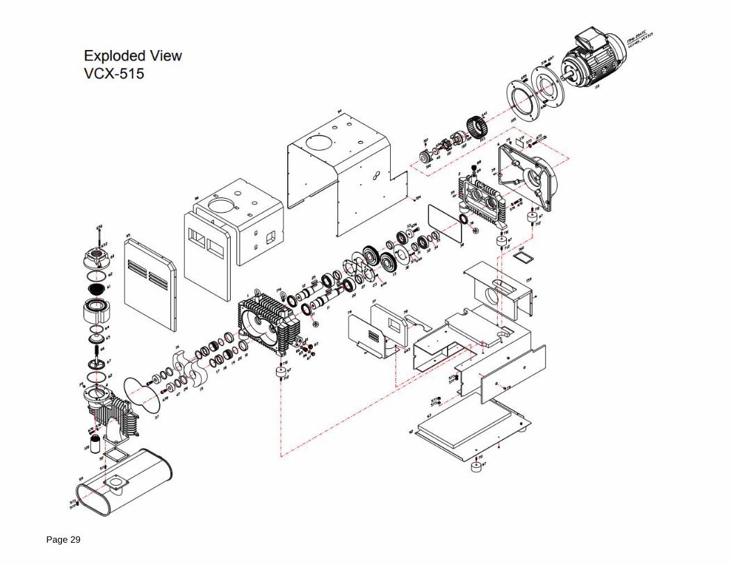
Page 29
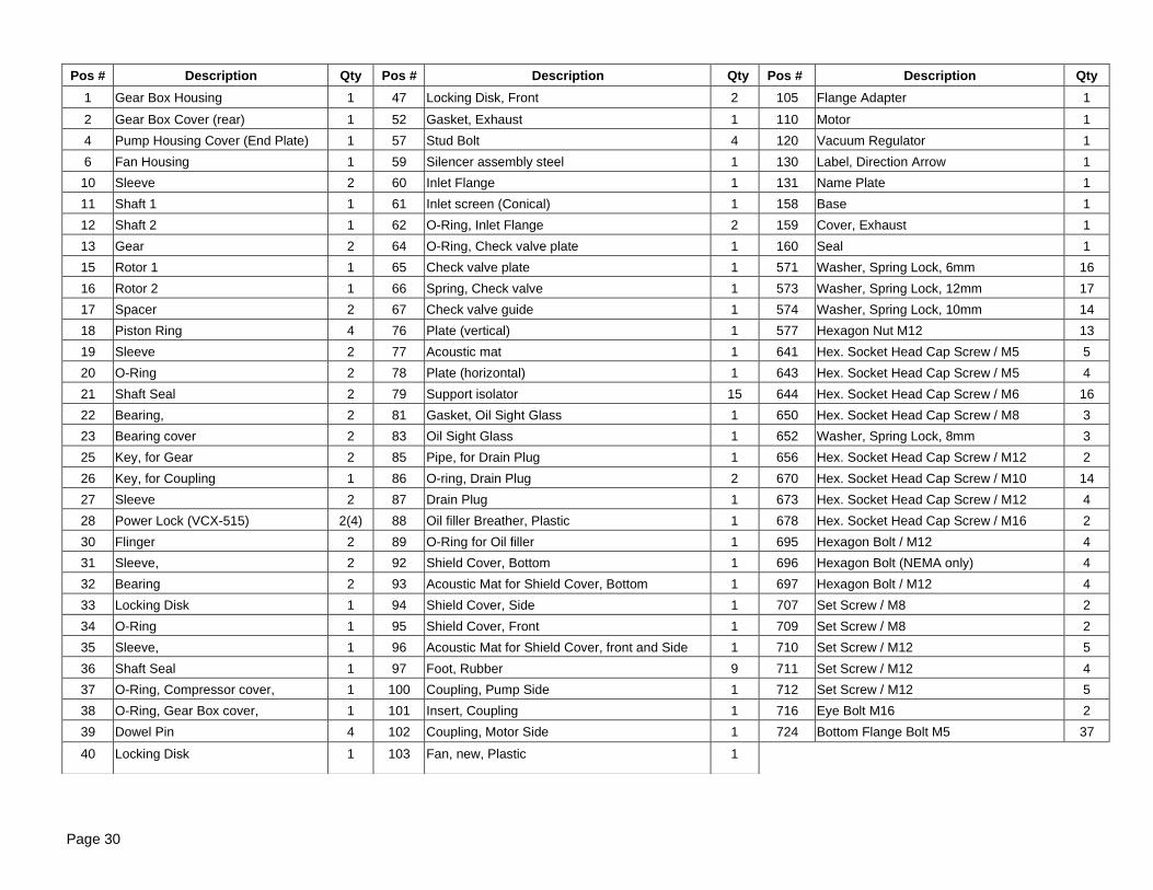
Pos # Description Qty Pos # Description Qty Pos # Description Qty
1 Gear Box Housing 1 47 Locking Disk, Front 2 105 Flange Adapter 1
2 Gear Box Cover (rear) 1 52 Gasket, Exhaust 1 110 Motor 1
4 Pump Housing Cover (End Plate) 1 57 Stud Bolt 4 120 Vacuum Regulator 1
6 Fan Housing 1 59 Silencer assembly steel 1 130 Label, Direction Arrow 1
10 Sleeve 2 60 Inlet Flange 1 131 Name Plate 1
11 Shaft 1 1 61 Inlet screen (Conical) 1 158 Base 1
12 Shaft 2 1 62 O-Ring, Inlet Flange 2 159 Cover, Exhaust 1
13 Gear 2 64 O-Ring, Check valve plate 1 160 Seal 1
15 Rotor 1 1 65 Check valve plate 1 571 Washer, Spring Lock, 6mm 16
16 Rotor 2 1 66 Spring, Check valve 1 573 Washer, Spring Lock, 12mm 17
17 Spacer 2 67 Check valve guide 1 574 Washer, Spring Lock, 10mm 14
18 Piston Ring 4 76 Plate (vertical) 1 577 Hexagon Nut M12 13
19 Sleeve 2 77 Acoustic mat 1 641 Hex. Socket Head Cap Screw / M5 5
20 O-Ring 2 78 Plate (horizontal) 1 643 Hex. Socket Head Cap Screw / M5 4
21 Shaft Seal 2 79 Support isolator 15 644 Hex. Socket Head Cap Screw / M6 16
22 Bearing, 2 81 Gasket, Oil Sight Glass 1 650 Hex. Socket Head Cap Screw / M8 3
23 Bearing cover 2 83 Oil Sight Glass 1 652 Washer, Spring Lock, 8mm 3
25 Key, for Gear 2 85 Pipe, for Drain Plug 1 656 Hex. Socket Head Cap Screw / M12 2
26 Key, for Coupling 1 86 O-ring, Drain Plug 2 670 Hex. Socket Head Cap Screw / M10 14
27 Sleeve 2 87 Drain Plug 1 673 Hex. Socket Head Cap Screw / M12 4
28 Power Lock (VCX-515) 2(4) 88 Oil filler Breather, Plastic 1 678 Hex. Socket Head Cap Screw / M16 2
30 Flinger 2 89 O-Ring for Oil filler 1 695 Hexagon Bolt / M12 4
31 Sleeve, 2 92 Shield Cover, Bottom 1 696 Hexagon Bolt (NEMA only) 4
32 Bearing 2 93 Acoustic Mat for Shield Cover, Bottom 1 697 Hexagon Bolt / M12 4
33 Locking Disk 1 94 Shield Cover, Side 1 707 Set Screw / M8 2
34 O-Ring 1 95 Shield Cover, Front 1 709 Set Screw / M8 2
35 Sleeve, 1 96 Acoustic Mat for Shield Cover, front and Side 1 710 Set Screw / M12 5
36 Shaft Seal 1 97 Foot, Rubber 9 711 Set Screw / M12 4
37 O-Ring, Compressor cover, 1 100 Coupling, Pump Side 1 712 Set Screw / M12 5
38 O-Ring, Gear Box cover, 1 101 Insert, Coupling 1 716 Eye Bolt M16 2
39 Dowel Pin 4 102 Coupling, Motor Side 1 724 Bottom Flange Bolt M5 37
40 Locking Disk 1 103 Fan, new, Plastic 1
Page 30
Page 31


