Embed Size (px)
Citation preview
Products Solutions Services
Operating InstructionsProline Prowirl F 200HARTVortex flowmeter
BA01154D/06/EN/04.1571299401
Valid as of version01.02.zz (Device firmware)

Proline Prowirl F 200 HART
2 Endress+Hauser
• Make sure the document is stored in a safe place such that it is always available whenworking on or with the device.
• To avoid danger to individuals or the facility, read the "Basic safety instructions" sectioncarefully, as well as all other safety instructions in the document that are specific toworking procedures.
• The manufacturer reserves the right to modify technical data without prior notice. YourEndress+Hauser Sales Center will supply you with current information and updates tothese instructions.
Proline Prowirl F 200 HART Table of contents
Endress+Hauser 3
Table of contents
1 Document information . . . . . . . . . . . . . . 61.1 Document function . . . . . . . . . . . . . . . . . . . . . 61.2 Symbols used . . . . . . . . . . . . . . . . . . . . . . . . . . 6
1.2.1 Safety symbols . . . . . . . . . . . . . . . . . . 61.2.2 Electrical symbols . . . . . . . . . . . . . . . . 61.2.3 Tool symbols . . . . . . . . . . . . . . . . . . . . 61.2.4 Symbols for certain types of
information . . . . . . . . . . . . . . . . . . . . 71.2.5 Symbols in graphics . . . . . . . . . . . . . . . 7
1.3 Documentation . . . . . . . . . . . . . . . . . . . . . . . . 71.3.1 Standard documentation . . . . . . . . . . . 81.3.2 Supplementary device-dependent
documentation . . . . . . . . . . . . . . . . . . 81.4 Registered trademarks . . . . . . . . . . . . . . . . . . . 8
2 Basic safety instructions . . . . . . . . . . . . 92.1 Requirements for the personnel . . . . . . . . . . . . 92.2 Designated use . . . . . . . . . . . . . . . . . . . . . . . . 92.3 Workplace safety . . . . . . . . . . . . . . . . . . . . . . 102.4 Operational safety . . . . . . . . . . . . . . . . . . . . . 102.5 Product safety . . . . . . . . . . . . . . . . . . . . . . . . 102.6 IT security . . . . . . . . . . . . . . . . . . . . . . . . . . . 10
3 Product description . . . . . . . . . . . . . . . . 113.1 Product design . . . . . . . . . . . . . . . . . . . . . . . . 11
4 Incoming acceptance and productidentification . . . . . . . . . . . . . . . . . . . . . 12
4.1 Incoming acceptance . . . . . . . . . . . . . . . . . . . 124.2 Product identification . . . . . . . . . . . . . . . . . . . 12
4.2.1 Transmitter nameplate . . . . . . . . . . . 134.2.2 Sensor nameplate . . . . . . . . . . . . . . . 144.2.3 Symbols on measuring device . . . . . . 16
5 Storage and transport . . . . . . . . . . . . . 175.1 Storage conditions . . . . . . . . . . . . . . . . . . . . . 175.2 Transporting the product . . . . . . . . . . . . . . . . 17
5.2.1 Measuring devices without liftinglugs . . . . . . . . . . . . . . . . . . . . . . . . . 17
5.2.2 Measuring devices with lifting lugs . . 185.2.3 Transporting with a fork lift . . . . . . . . 18
5.3 Packaging disposal . . . . . . . . . . . . . . . . . . . . . 18
6 Installation . . . . . . . . . . . . . . . . . . . . . . . 196.1 Installation conditions . . . . . . . . . . . . . . . . . . 19
6.1.1 Mounting position . . . . . . . . . . . . . . . 196.1.2 Requirements from environment and
process . . . . . . . . . . . . . . . . . . . . . . . 236.1.3 Special mounting instructions . . . . . . 24
6.2 Mounting the measuring device . . . . . . . . . . . 256.2.1 Required tools . . . . . . . . . . . . . . . . . . 25
6.2.2 Preparing the measuring device . . . . . 256.2.3 Mounting the sensor . . . . . . . . . . . . . 256.2.4 Mounting the transmitter of the
remote version . . . . . . . . . . . . . . . . . 266.2.5 Turning the transmitter housing . . . . 276.2.6 Turning the display module . . . . . . . . 27
6.3 Post-installation check . . . . . . . . . . . . . . . . . . 28
7 Electrical connection . . . . . . . . . . . . . . 297.1 Connection conditions . . . . . . . . . . . . . . . . . . 29
7.1.1 Required tools . . . . . . . . . . . . . . . . . . 297.1.2 Connecting cable requirements . . . . . 297.1.3 Terminal assignment . . . . . . . . . . . . . 317.1.4 Requirements for the supply unit . . . . 327.1.5 Preparing the measuring device . . . . . 34
7.2 Connecting the measuring device . . . . . . . . . . 347.2.1 Connecting the remote version . . . . . 347.2.2 Connecting the transmitter . . . . . . . . 387.2.3 Ensuring potential equalization . . . . . 40
7.3 Special connection instructions . . . . . . . . . . . . 407.3.1 Connection examples . . . . . . . . . . . . . 40
7.4 Ensuring the degree of protection . . . . . . . . . . 427.5 Post-connection check . . . . . . . . . . . . . . . . . . 43
8 Operation options . . . . . . . . . . . . . . . . . 448.1 Overview of operating options . . . . . . . . . . . . 448.2 Structure and function of the operating
menu . . . . . . . . . . . . . . . . . . . . . . . . . . . . . . 458.2.1 Structure of the operating menu . . . . 458.2.2 Operating philosophy . . . . . . . . . . . . 46
8.3 Access to the operating menu via the localdisplay . . . . . . . . . . . . . . . . . . . . . . . . . . . . . 478.3.1 Operational display . . . . . . . . . . . . . . 478.3.2 Navigation view . . . . . . . . . . . . . . . . 488.3.3 Editing view . . . . . . . . . . . . . . . . . . . 508.3.4 Operating elements . . . . . . . . . . . . . . 528.3.5 Opening the context menu . . . . . . . . . 528.3.6 Navigating and selecting from list . . . 548.3.7 Calling the parameter directly . . . . . . 548.3.8 Calling up help text . . . . . . . . . . . . . . 558.3.9 Changing the parameters . . . . . . . . . 568.3.10 User roles and related access
authorization . . . . . . . . . . . . . . . . . . 578.3.11 Disabling write protection via access
code . . . . . . . . . . . . . . . . . . . . . . . . . 578.3.12 Enabling and disabling the keypad
lock . . . . . . . . . . . . . . . . . . . . . . . . . 578.4 Access to the operating menu via the
operating tool . . . . . . . . . . . . . . . . . . . . . . . . 588.4.1 Connecting the operating tool . . . . . . 598.4.2 Field Xpert SFX350, SFX370 . . . . . . . 598.4.3 FieldCare . . . . . . . . . . . . . . . . . . . . . 598.4.4 AMS Device Manager . . . . . . . . . . . . 618.4.5 SIMATIC PDM . . . . . . . . . . . . . . . . . . 61
Table of contents Proline Prowirl F 200 HART
4 Endress+Hauser
8.4.6 Field Communicator 475 . . . . . . . . . . 61
9 System integration . . . . . . . . . . . . . . . . 629.1 Overview of device description files . . . . . . . . . 62
9.1.1 Current version data for the device . . . 629.1.2 Operating tools . . . . . . . . . . . . . . . . . 62
9.2 Measured variables via HART protocol . . . . . . 629.3 Other settings . . . . . . . . . . . . . . . . . . . . . . . . 64
9.3.1 Burst mode functionality inaccordance with HART 7Specification . . . . . . . . . . . . . . . . . . . 64
10 Commissioning . . . . . . . . . . . . . . . . . . . . 6710.1 Function check . . . . . . . . . . . . . . . . . . . . . . . 6710.2 Switching on the measuring device . . . . . . . . . 6710.3 Setting the operating language . . . . . . . . . . . . 6710.4 Configuring the measuring device . . . . . . . . . . 68
10.4.1 Defining the tag name . . . . . . . . . . . . 6810.4.2 Selecting and setting the medium . . . 7010.4.3 Configuring the current input . . . . . . 7210.4.4 Configuring the current output . . . . . 7510.4.5 Configuring the pulse/frequency/
switch output . . . . . . . . . . . . . . . . . . 7810.4.6 Configuring the local display . . . . . . . 8910.4.7 Configuring the output
conditioning . . . . . . . . . . . . . . . . . . . 9110.4.8 Configuring the low flow cut off . . . . . 92
10.5 Advanced settings . . . . . . . . . . . . . . . . . . . . . 9410.5.1 Setting the system units . . . . . . . . . . 9510.5.2 Setting the medium properties . . . . . . 9810.5.3 Performing external compensation . 11210.5.4 Carrying out a sensor adjustment . . . 11410.5.5 Configuring the totalizer . . . . . . . . . 11510.5.6 Carrying out additional display
configurations . . . . . . . . . . . . . . . . . 11710.6 Configuration management . . . . . . . . . . . . . 119
10.6.1 Function scope of the "Configurationmanagement" parameter . . . . . . . . . 120
10.7 Simulation . . . . . . . . . . . . . . . . . . . . . . . . . . 12110.8 Protecting settings from unauthorized
access . . . . . . . . . . . . . . . . . . . . . . . . . . . . . 12310.8.1 Write protection via access code . . . 12310.8.2 Write protection via write protection
switch . . . . . . . . . . . . . . . . . . . . . . . 124
11 Operation . . . . . . . . . . . . . . . . . . . . . . . 12711.1 Reading the device locking status . . . . . . . . . 12711.2 Adjusting the operating language . . . . . . . . . 12711.3 Configuring the display . . . . . . . . . . . . . . . . 12711.4 Reading measured values . . . . . . . . . . . . . . . 127
11.4.1 Process variables . . . . . . . . . . . . . . . 12711.4.2 Totalizer . . . . . . . . . . . . . . . . . . . . . 13011.4.3 Input values . . . . . . . . . . . . . . . . . . 13011.4.4 Output values . . . . . . . . . . . . . . . . . 131
11.5 Adapting the measuring device to the processconditions . . . . . . . . . . . . . . . . . . . . . . . . . . 132
11.6 Performing a totalizer reset . . . . . . . . . . . . . 132
11.7 Showing data logging . . . . . . . . . . . . . . . . . 133
12 Diagnostics and troubleshooting . . 13612.1 General troubleshooting . . . . . . . . . . . . . . . . 13612.2 Diagnostic information on local display . . . . . 138
12.2.1 Diagnostic message . . . . . . . . . . . . . 13812.2.2 Calling up remedial measures . . . . . 140
12.3 Diagnostic information in FieldCare . . . . . . . 14012.3.1 Diagnostic options . . . . . . . . . . . . . . 14012.3.2 Calling up remedy information . . . . 141
12.4 Adapting the diagnostic information . . . . . . 14212.4.1 Adapting the diagnostic behavior . . . 14212.4.2 Adapting the status signal . . . . . . . . 142
12.5 Overview of diagnostic information . . . . . . . 14312.6 Pending diagnostic events . . . . . . . . . . . . . . 14612.7 Diagnostic list . . . . . . . . . . . . . . . . . . . . . . . 14712.8 Event logbook . . . . . . . . . . . . . . . . . . . . . . . 148
12.8.1 Event history . . . . . . . . . . . . . . . . . . 14812.8.2 Filtering the event logbook . . . . . . . 14812.8.3 Overview of information events . . . . 148
12.9 Resetting the measuring device . . . . . . . . . . 14912.9.1 Function scope of the "Device reset"
parameter . . . . . . . . . . . . . . . . . . . . 15012.10 Device information . . . . . . . . . . . . . . . . . . . 15012.11 Firmware history . . . . . . . . . . . . . . . . . . . . . 153
13 Maintenance . . . . . . . . . . . . . . . . . . . . 15413.1 Maintenance tasks . . . . . . . . . . . . . . . . . . . . 154
13.1.1 Exterior cleaning . . . . . . . . . . . . . . . 15413.1.2 Interior cleaning . . . . . . . . . . . . . . . 15413.1.3 Replacing seals . . . . . . . . . . . . . . . . 154
13.2 Measuring and test equipment . . . . . . . . . . . 15413.3 Endress+Hauser services . . . . . . . . . . . . . . . 154
14 Repair . . . . . . . . . . . . . . . . . . . . . . . . . . . 15514.1 General notes . . . . . . . . . . . . . . . . . . . . . . . 15514.2 Spare parts . . . . . . . . . . . . . . . . . . . . . . . . . 15514.3 Endress+Hauser services . . . . . . . . . . . . . . . 15614.4 Return . . . . . . . . . . . . . . . . . . . . . . . . . . . . . 15614.5 Disposal . . . . . . . . . . . . . . . . . . . . . . . . . . . 156
14.5.1 Removing the measuring device . . . . 15614.5.2 Disposing of the measuring device . . 157
15 Accessories . . . . . . . . . . . . . . . . . . . . . . 15815.1 Device-specific accessories . . . . . . . . . . . . . . 158
15.1.1 For the transmitter . . . . . . . . . . . . . 15815.1.2 For the sensor . . . . . . . . . . . . . . . . . 159
15.2 Communication-specific accessories . . . . . . . 15915.3 Service-specific accessories . . . . . . . . . . . . . . 16015.4 System components . . . . . . . . . . . . . . . . . . . 160
16 Technical data . . . . . . . . . . . . . . . . . . . 16216.1 Application . . . . . . . . . . . . . . . . . . . . . . . . . 16216.2 Function and system design . . . . . . . . . . . . . 16216.3 Input . . . . . . . . . . . . . . . . . . . . . . . . . . . . . . 16216.4 Output . . . . . . . . . . . . . . . . . . . . . . . . . . . . 169

Proline Prowirl F 200 HART Table of contents
Endress+Hauser 5
16.5 Power supply . . . . . . . . . . . . . . . . . . . . . . . . 17116.6 Performance characteristics . . . . . . . . . . . . . 17316.7 Installation . . . . . . . . . . . . . . . . . . . . . . . . . 17616.8 Environment . . . . . . . . . . . . . . . . . . . . . . . . 17616.9 Process . . . . . . . . . . . . . . . . . . . . . . . . . . . . 17716.10 Mechanical construction . . . . . . . . . . . . . . . 17816.11 Operability . . . . . . . . . . . . . . . . . . . . . . . . . 18516.12 Certificates and approvals . . . . . . . . . . . . . . 18716.13 Application packages . . . . . . . . . . . . . . . . . . 18816.14 Accessories . . . . . . . . . . . . . . . . . . . . . . . . . 18916.15 Supplementary documentation . . . . . . . . . . . 189
Index . . . . . . . . . . . . . . . . . . . . . . . . . . . . . . . . . 191
Document information Proline Prowirl F 200 HART
6 Endress+Hauser
1 Document information
1.1 Document functionThese Operating Instructions contain all the information that is required in various phasesof the life cycle of the device: from product identification, incoming acceptance andstorage, to mounting, connection, operation and commissioning through totroubleshooting, maintenance and disposal.
1.2 Symbols used
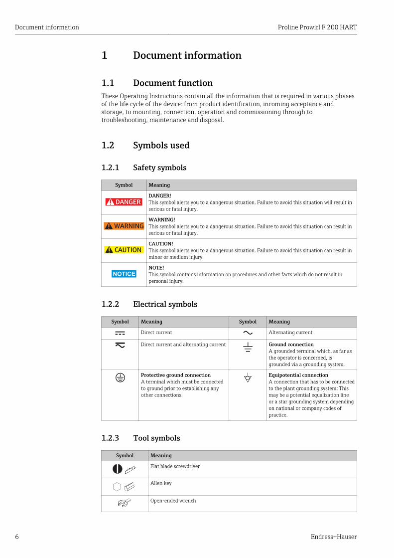
1.2.1 Safety symbols
Symbol Meaning
DANGER
DANGER!This symbol alerts you to a dangerous situation. Failure to avoid this situation will result inserious or fatal injury.
WARNING
WARNING!This symbol alerts you to a dangerous situation. Failure to avoid this situation can result inserious or fatal injury.
CAUTION
CAUTION!This symbol alerts you to a dangerous situation. Failure to avoid this situation can result inminor or medium injury.
NOTICE
NOTE!This symbol contains information on procedures and other facts which do not result inpersonal injury.
1.2.2 Electrical symbols
Symbol Meaning Symbol Meaning
Direct current Alternating current
Direct current and alternating current Ground connectionA grounded terminal which, as far asthe operator is concerned, isgrounded via a grounding system.
Protective ground connectionA terminal which must be connectedto ground prior to establishing anyother connections.
Equipotential connectionA connection that has to be connectedto the plant grounding system: Thismay be a potential equalization lineor a star grounding system dependingon national or company codes ofpractice.
1.2.3 Tool symbols
Symbol Meaning
Flat blade screwdriver
Allen key
Open-ended wrench
Proline Prowirl F 200 HART Document information
Endress+Hauser 7
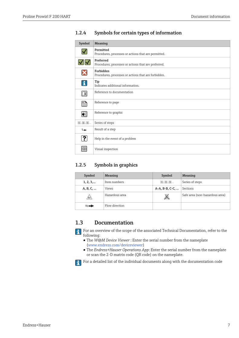
1.2.4 Symbols for certain types of information
Symbol Meaning
PermittedProcedures, processes or actions that are permitted.
PreferredProcedures, processes or actions that are preferred.
ForbiddenProcedures, processes or actions that are forbidden.
TipIndicates additional information.
Reference to documentation
Reference to page
Reference to graphic
, …, Series of steps
Result of a step
Help in the event of a problem
Visual inspection
1.2.5 Symbols in graphics
Symbol Meaning Symbol Meaning
1, 2, 3,... Item numbers , …, Series of steps
A, B, C, ... Views A-A, B-B, C-C, ... Sections
-Hazardous area
.Safe area (non-hazardous area)
Flow direction
1.3 DocumentationFor an overview of the scope of the associated Technical Documentation, refer to thefollowing:• The W@M Device Viewer : Enter the serial number from the nameplate
(www.endress.com/deviceviewer)• The Endress+Hauser Operations App: Enter the serial number from the nameplate
or scan the 2-D matrix code (QR code) on the nameplate.
For a detailed list of the individual documents along with the documentation code
Document information Proline Prowirl F 200 HART
8 Endress+Hauser
1.3.1 Standard documentation
Document type Purpose and content of the document
Technical Information Planning aid for your deviceThe document contains all the technical data on the device and providesan overview of the accessories and other products that can be ordered forthe device.
Brief Operating Instructions Guide that takes you quickly to the 1st measured valueThe Brief Operating Instructions contain all the essential informationfrom incoming acceptance to initial commissioning.
1.3.2 Supplementary device-dependent documentationAdditional documents are supplied depending on the device version ordered: Alwayscomply strictly with the instructions in the supplementary documentation. Thesupplementary documentation is an integral part of the device documentation.
1.4 Registered trademarksHART®
Registered trademark of the HART Communication Foundation, Austin, USA
KALREZ ®, VITON ®Registered trademarks of DuPont Performance Elastomers L.L.C., Wilmington, DE USA
GYLON®
Registered trademark of Garlock Sealing Technologies, Palmyar, NY, USA
Applicator®, FieldCare®, DeviceCare ®, Field XpertTM, HistoROM®, HeartbeatTechnologyTM
Registered or registration-pending trademarks of the Endress+Hauser Group
Proline Prowirl F 200 HART Basic safety instructions
Endress+Hauser 9
2 Basic safety instructions
2.1 Requirements for the personnelThe personnel for installation, commissioning, diagnostics and maintenance must fulfillthe following requirements:‣ Trained, qualified specialists must have a relevant qualification for this specific function
and task‣ Are authorized by the plant owner/operator‣ Are familiar with federal/national regulations‣ Before beginning work, the specialist staff must have read and understood the
instructions in the Operating Instructions and supplementary documentation as well asin the certificates (depending on the application)
‣ Following instructions and basic conditions
The operating personnel must fulfill the following requirements:‣ Being instructed and authorized according to the requirements of the task by the
facility's owner-operator‣ Following the instructions in these Operating Instructions
2.2 Designated useApplication and mediaDepending on the version ordered, the measuring device can also measure potentiallyexplosive, flammable, poisonous and oxidizing media.
Measuring devices for use in hazardous areas, in hygienic applications or in applicationswhere there is an increased risk due to process pressure, are labeled accordingly on thenameplate.
To ensure that the measuring device remains in proper condition for the operation time:‣ Only use the measuring device in full compliance with the data on the nameplate and
the general conditions listed in the Operating Instructions and supplementarydocumentation.
‣ Check the nameplate to verify if the device ordered can be put to its intended use in theapproval-related area (e.g. explosion protection, pressure vessel safety).
‣ Use the measuring device only for media against which the process-wetted materialsare adequately resistant.
‣ If the measuring device is not operated at atmospheric temperature, compliance withthe relevant basic conditions specified in the associated device documentation isabsolutely essential: "Documentation" section → 7.
‣ Protect the measuring device permanently against corrosion from environmentalinfluences.
Incorrect useNon-designated use can compromise safety. The manufacturer is not liable for damagecaused by improper or non-designated use.
LWARNINGDanger of breakage of the sensor due to corrosive or abrasive fluids or fromenvironmental conditions!‣ Verify the compatibility of the process fluid with the sensor material.‣ Ensure the resistance of all fluid-wetted materials in the process.‣ Keep within the specified pressure and temperature range.
Verification for borderline cases:‣ For special fluids and fluids for cleaning, Endress+Hauser is glad to provide assistance
in verifying the corrosion resistance of fluid-wetted materials, but does not accept any
Basic safety instructions Proline Prowirl F 200 HART
10 Endress+Hauser
warranty or liability as minute changes in the temperature, concentration or level ofcontamination in the process can alter the corrosion resistance properties.
Residual risksPossible burn hazard due to fluid temperatures!‣ For elevated fluid temperature, ensure protection against contact to prevent burns.
2.3 Workplace safetyFor work on and with the device:‣ Wear the required personal protective equipment according to federal/national
regulations.
For welding work on the piping:‣ Do not ground the welding unit via the measuring device.
If working on and with the device with wet hands:‣ It is recommended to wear gloves on account of the higher risk of electric shock.
2.4 Operational safetyRisk of injury.‣ Operate the device in proper technical condition and fail-safe condition only.‣ The operator is responsible for interference-free operation of the device.
Conversions to the deviceUnauthorized modifications to the device are not permitted and can lead to unforeseeabledangers.‣ If, despite this, modifications are required, consult with Endress+Hauser.
RepairTo ensure continued operational safety and reliability,‣ Carry out repairs on the device only if they are expressly permitted.‣ Observe federal/national regulations pertaining to repair of an electrical device.‣ Use original spare parts and accessories from Endress+Hauser only.
2.5 Product safetyThis measuring device is designed in accordance with good engineering practice to meetstate-of-the-art safety requirements, has been tested, and left the factory in a condition inwhich it is safe to operate.
It meets general safety standards and legal requirements. It also complies with the ECdirectives listed in the device-specific EC Declaration of Conformity. Endress+Hauserconfirms this by affixing the CE mark to the device.
2.6 IT securityWe only provide a warranty if the device is installed and used as described in theOperating Instructions. The device is equipped with security mechanisms to protect itagainst any inadvertent changes to the device settings.
IT security measures in line with operators' security standards and designed to provideadditional protection for the device and device data transfer must be implemented by theoperators themselves.
Proline Prowirl F 200 HART Product description
Endress+Hauser 11
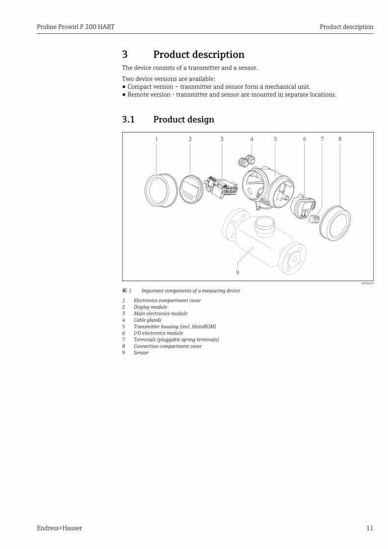
3 Product descriptionThe device consists of a transmitter and a sensor.
Two device versions are available:• Compact version – transmitter and sensor form a mechanical unit.• Remote version - transmitter and sensor are mounted in separate locations.
3.1 Product design
1 2 3 4 5 6 7 8
9
+
E
–
A0020649
1 Important components of a measuring device
1 Electronics compartment cover2 Display module3 Main electronics module4 Cable glands5 Transmitter housing (incl. HistoROM)6 I/O electronics module7 Terminals (pluggable spring terminals)8 Connection compartment cover9 Sensor
Incoming acceptance and product identification Proline Prowirl F 200 HART
12 Endress+Hauser
4 Incoming acceptance and productidentification
4.1 Incoming acceptance
1+
2
1+
2
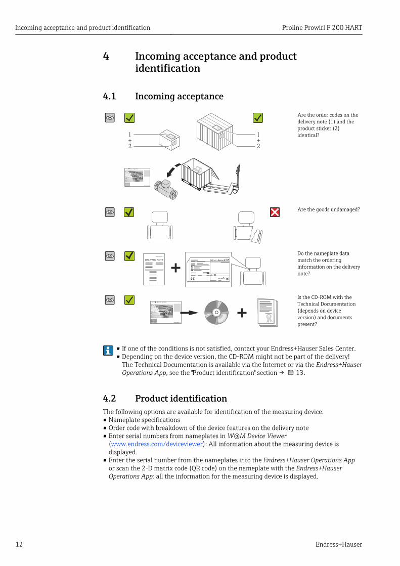
Are the order codes on thedelivery note (1) and theproduct sticker (2)identical?
Are the goods undamaged?
Do the nameplate datamatch the orderinginformation on the deliverynote?
Is the CD-ROM with theTechnical Documentation(depends on deviceversion) and documentspresent?
• If one of the conditions is not satisfied, contact your Endress+Hauser Sales Center.• Depending on the device version, the CD-ROM might not be part of the delivery!
The Technical Documentation is available via the Internet or via the Endress+HauserOperations App, see the "Product identification" section → 13.
4.2 Product identificationThe following options are available for identification of the measuring device:• Nameplate specifications• Order code with breakdown of the device features on the delivery note• Enter serial numbers from nameplates in W@M Device Viewer
(www.endress.com/deviceviewer): All information about the measuring device isdisplayed.
• Enter the serial number from the nameplates into the Endress+Hauser Operations Appor scan the 2-D matrix code (QR code) on the nameplate with the Endress+HauserOperations App: all the information for the measuring device is displayed.
Proline Prowirl F 200 HART Incoming acceptance and product identification
Endress+Hauser 13
For an overview of the scope of the associated Technical Documentation, refer to thefollowing:• The chapters "Additional standard documentation on the device" → 8 and
"Supplementary device-dependent documentation" → 8• The W@M Device Viewer: Enter the serial number from the nameplate
(www.endress.com/deviceviewer)• The Endress+Hauser Operations App: Enter the serial number from the nameplate or
scan the 2-D matrix code (QR code) on the nameplate.
4.2.1 Transmitter nameplate
Order code:
Ext. ord. cd.:
Ser. no.:
Date:
i
i
Patents
322540-0001
1
2
3 4 5
6
7
8
9
10 11 12
14
15
16
17
13
A0013906
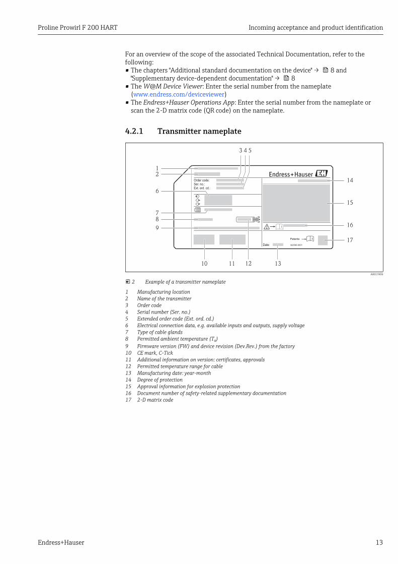
2 Example of a transmitter nameplate
1 Manufacturing location2 Name of the transmitter3 Order code4 Serial number (Ser. no.)5 Extended order code (Ext. ord. cd.)6 Electrical connection data, e.g. available inputs and outputs, supply voltage7 Type of cable glands8 Permitted ambient temperature (Ta)9 Firmware version (FW) and device revision (Dev.Rev.) from the factory10 CE mark, C-Tick11 Additional information on version: certificates, approvals12 Permitted temperature range for cable13 Manufacturing date: year-month14 Degree of protection15 Approval information for explosion protection16 Document number of safety-related supplementary documentation17 2-D matrix code
Incoming acceptance and product identification Proline Prowirl F 200 HART
14 Endress+Hauser
4.2.2 Sensor nameplate
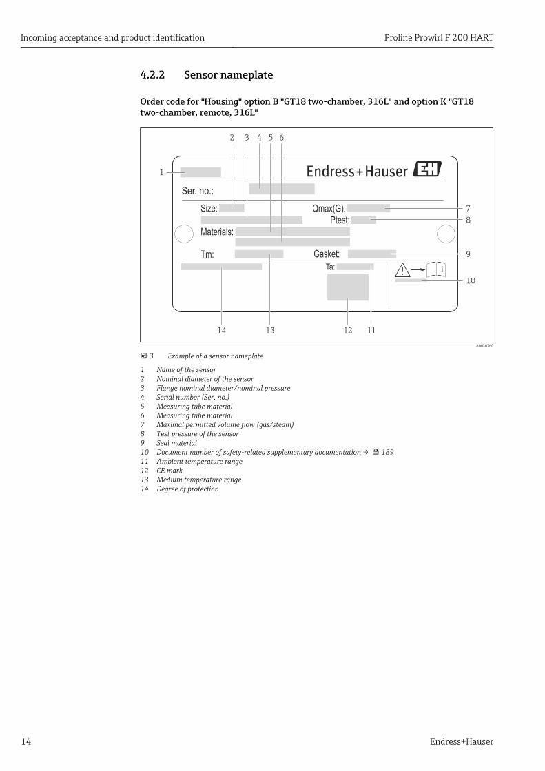
Order code for "Housing" option B "GT18 two-chamber, 316L" and option K "GT18two-chamber, remote, 316L"
Ser. no.:
Ptest:Size:
Materials:
Gasket:Tm:
Qmax(G):
Ta:
1
2 6
7
8
3
9
10
13 12
4 5
14 11
A0020760
3 Example of a sensor nameplate
1 Name of the sensor2 Nominal diameter of the sensor3 Flange nominal diameter/nominal pressure4 Serial number (Ser. no.)5 Measuring tube material6 Measuring tube material7 Maximal permitted volume flow (gas/steam)8 Test pressure of the sensor9 Seal material10 Document number of safety-related supplementary documentation → 18911 Ambient temperature range12 CE mark13 Medium temperature range14 Degree of protection
Proline Prowirl F 200 HART Incoming acceptance and product identification
Endress+Hauser 15
Order code for "Housing" option C "GT20 two-chamber, aluminum coated"
Ser. no.:
Ptest:Size:
Materials:
Tm:
Qmax(G):
Gasket:Ta:
1 2 5 6 87
9
3 4
10
111213
A0020758
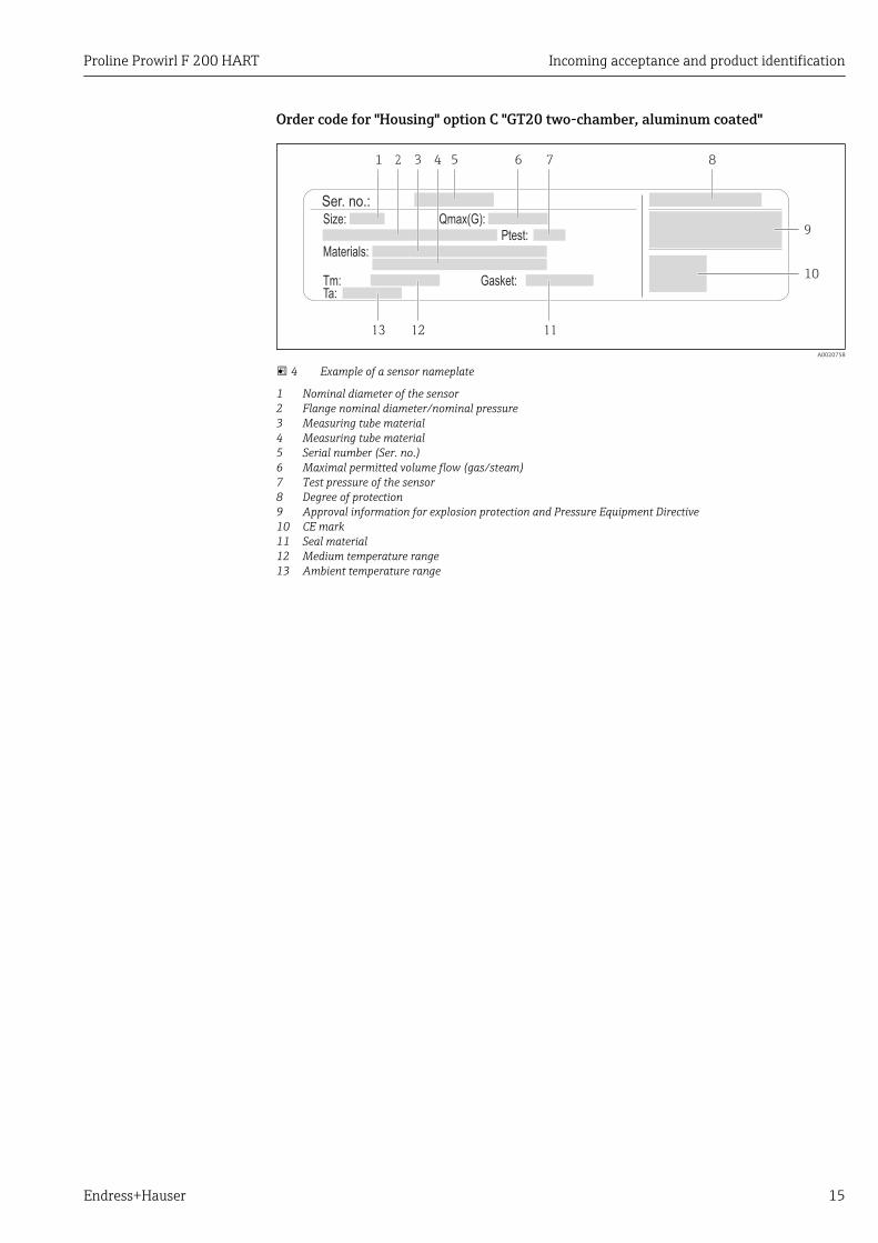
4 Example of a sensor nameplate
1 Nominal diameter of the sensor2 Flange nominal diameter/nominal pressure3 Measuring tube material4 Measuring tube material5 Serial number (Ser. no.)6 Maximal permitted volume flow (gas/steam)7 Test pressure of the sensor8 Degree of protection9 Approval information for explosion protection and Pressure Equipment Directive10 CE mark11 Seal material12 Medium temperature range13 Ambient temperature range
Incoming acceptance and product identification Proline Prowirl F 200 HART
16 Endress+Hauser
Order code for "Housing" option J "GT20 two-chamber, remote, aluminum coated"
Order code:
Ext. ord. cd.:Ser. no.:
Ptest:Size: Ta:
Materials:
Gasket:Tm:
Qmax(G):
4
1
5
8
12
2 7
9
10
11
13141516
3 6
A0020759
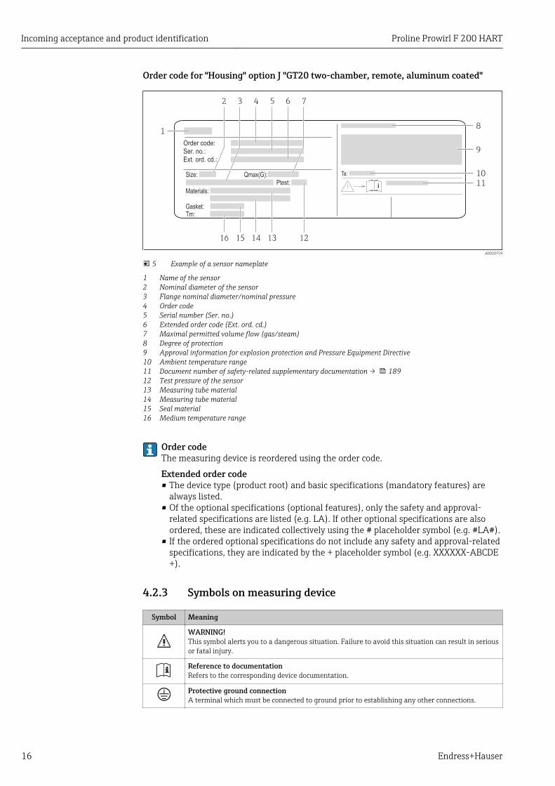
5 Example of a sensor nameplate
1 Name of the sensor2 Nominal diameter of the sensor3 Flange nominal diameter/nominal pressure4 Order code5 Serial number (Ser. no.)6 Extended order code (Ext. ord. cd.)7 Maximal permitted volume flow (gas/steam)8 Degree of protection9 Approval information for explosion protection and Pressure Equipment Directive10 Ambient temperature range11 Document number of safety-related supplementary documentation → 18912 Test pressure of the sensor13 Measuring tube material14 Measuring tube material15 Seal material16 Medium temperature range
Order codeThe measuring device is reordered using the order code.
Extended order code• The device type (product root) and basic specifications (mandatory features) are
always listed.• Of the optional specifications (optional features), only the safety and approval-
related specifications are listed (e.g. LA). If other optional specifications are alsoordered, these are indicated collectively using the # placeholder symbol (e.g. #LA#).
• If the ordered optional specifications do not include any safety and approval-relatedspecifications, they are indicated by the + placeholder symbol (e.g. XXXXXX-ABCDE+).
4.2.3 Symbols on measuring device
Symbol Meaning
WARNING!This symbol alerts you to a dangerous situation. Failure to avoid this situation can result in seriousor fatal injury.
Reference to documentationRefers to the corresponding device documentation.
Protective ground connectionA terminal which must be connected to ground prior to establishing any other connections.
Proline Prowirl F 200 HART Storage and transport
Endress+Hauser 17
5 Storage and transport
5.1 Storage conditionsObserve the following notes for storage:• Store in the original packaging to ensure protection from shock.• Do not remove protective covers or protective caps installed on process connections.
They prevent mechanical damage to the sealing surfaces and contamination in themeasuring tube.
• Protect from direct sunlight to avoid unacceptably high surface temperatures.• Store in a dry and dust-free place.• Do not store outdoors.
Storage temperature:– All components apart from the display modules: –50 to +80 °C (–58 to +176 °F)– Display modules: –40 to +80 °C (–40 to +176 °F)
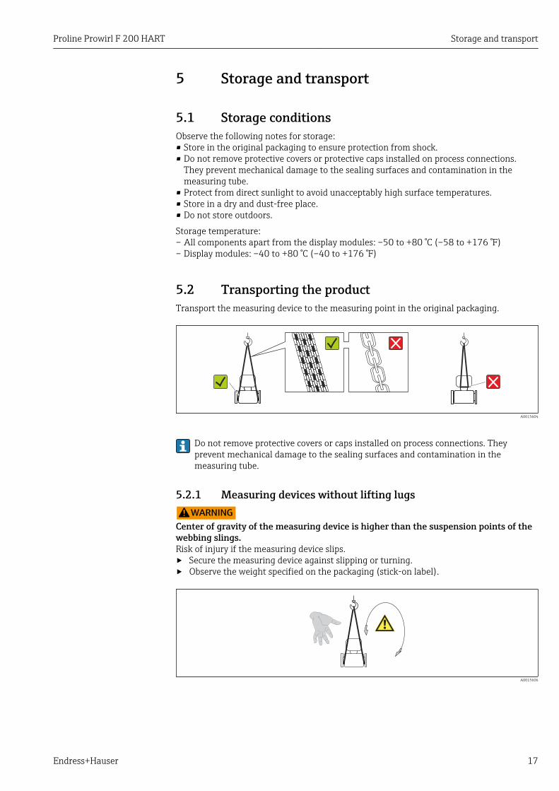
5.2 Transporting the productTransport the measuring device to the measuring point in the original packaging.
A0015604
Do not remove protective covers or caps installed on process connections. Theyprevent mechanical damage to the sealing surfaces and contamination in themeasuring tube.
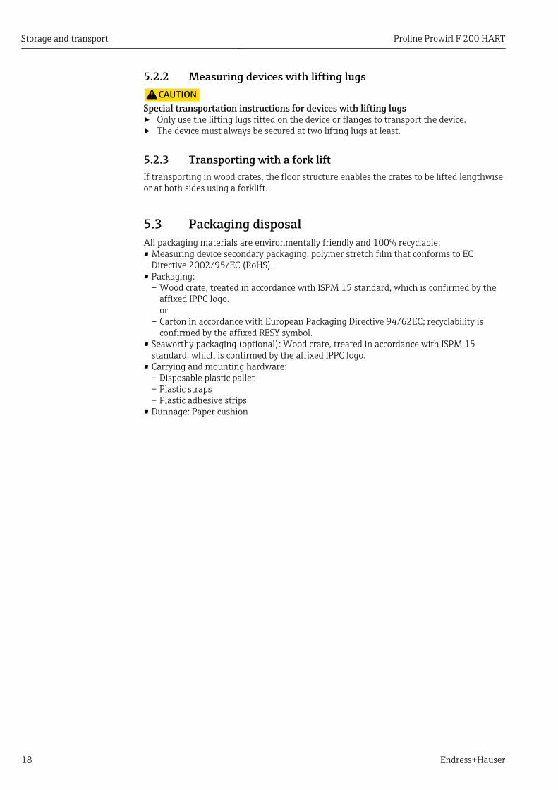
5.2.1 Measuring devices without lifting lugsLWARNING
Center of gravity of the measuring device is higher than the suspension points of thewebbing slings.Risk of injury if the measuring device slips.‣ Secure the measuring device against slipping or turning.‣ Observe the weight specified on the packaging (stick-on label).
A0015606
Storage and transport Proline Prowirl F 200 HART
18 Endress+Hauser
5.2.2 Measuring devices with lifting lugsLCAUTION
Special transportation instructions for devices with lifting lugs‣ Only use the lifting lugs fitted on the device or flanges to transport the device.‣ The device must always be secured at two lifting lugs at least.
5.2.3 Transporting with a fork liftIf transporting in wood crates, the floor structure enables the crates to be lifted lengthwiseor at both sides using a forklift.
5.3 Packaging disposalAll packaging materials are environmentally friendly and 100% recyclable:• Measuring device secondary packaging: polymer stretch film that conforms to EC
Directive 2002/95/EC (RoHS).• Packaging:
– Wood crate, treated in accordance with ISPM 15 standard, which is confirmed by theaffixed IPPC logo.or
– Carton in accordance with European Packaging Directive 94/62EC; recyclability isconfirmed by the affixed RESY symbol.
• Seaworthy packaging (optional): Wood crate, treated in accordance with ISPM 15standard, which is confirmed by the affixed IPPC logo.
• Carrying and mounting hardware:– Disposable plastic pallet– Plastic straps– Plastic adhesive strips
• Dunnage: Paper cushion
Proline Prowirl F 200 HART Installation
Endress+Hauser 19
6 Installation
6.1 Installation conditions
6.1.1 Mounting position
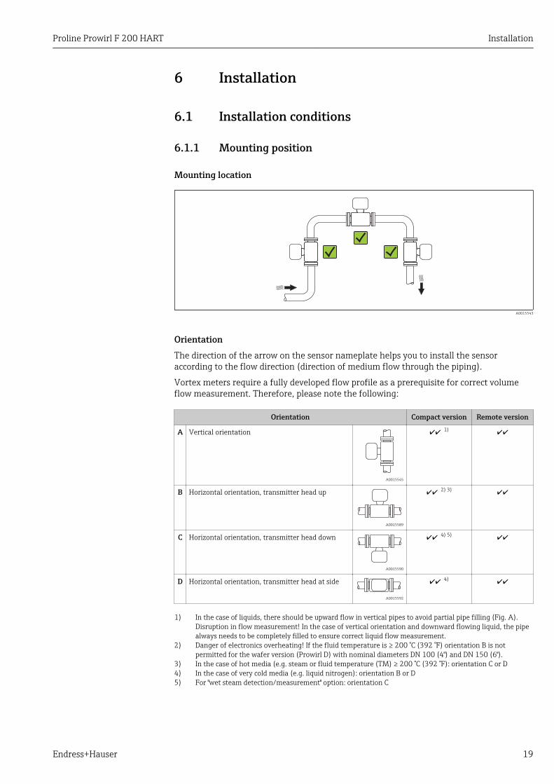
Mounting location
A0015543
OrientationThe direction of the arrow on the sensor nameplate helps you to install the sensoraccording to the flow direction (direction of medium flow through the piping).
Vortex meters require a fully developed flow profile as a prerequisite for correct volumeflow measurement. Therefore, please note the following:
Orientation Compact version Remote version
A Vertical orientation
A0015545
1)
B Horizontal orientation, transmitter head up
A0015589
2) 3)
C Horizontal orientation, transmitter head down
A0015590
4) 5)
D Horizontal orientation, transmitter head at side
A0015592
4)
1) In the case of liquids, there should be upward flow in vertical pipes to avoid partial pipe filling (Fig. A).Disruption in flow measurement! In the case of vertical orientation and downward flowing liquid, the pipealways needs to be completely filled to ensure correct liquid flow measurement.
2) Danger of electronics overheating! If the fluid temperature is ≥ 200 °C (392 °F) orientation B is notpermitted for the wafer version (Prowirl D) with nominal diameters DN 100 (4") and DN 150 (6").
3) In the case of hot media (e.g. steam or fluid temperature (TM) ≥ 200 °C (392 °F): orientation C or D4) In the case of very cold media (e.g. liquid nitrogen): orientation B or D5) For "wet steam detection/measurement" option: orientation C
Installation Proline Prowirl F 200 HART
20 Endress+Hauser
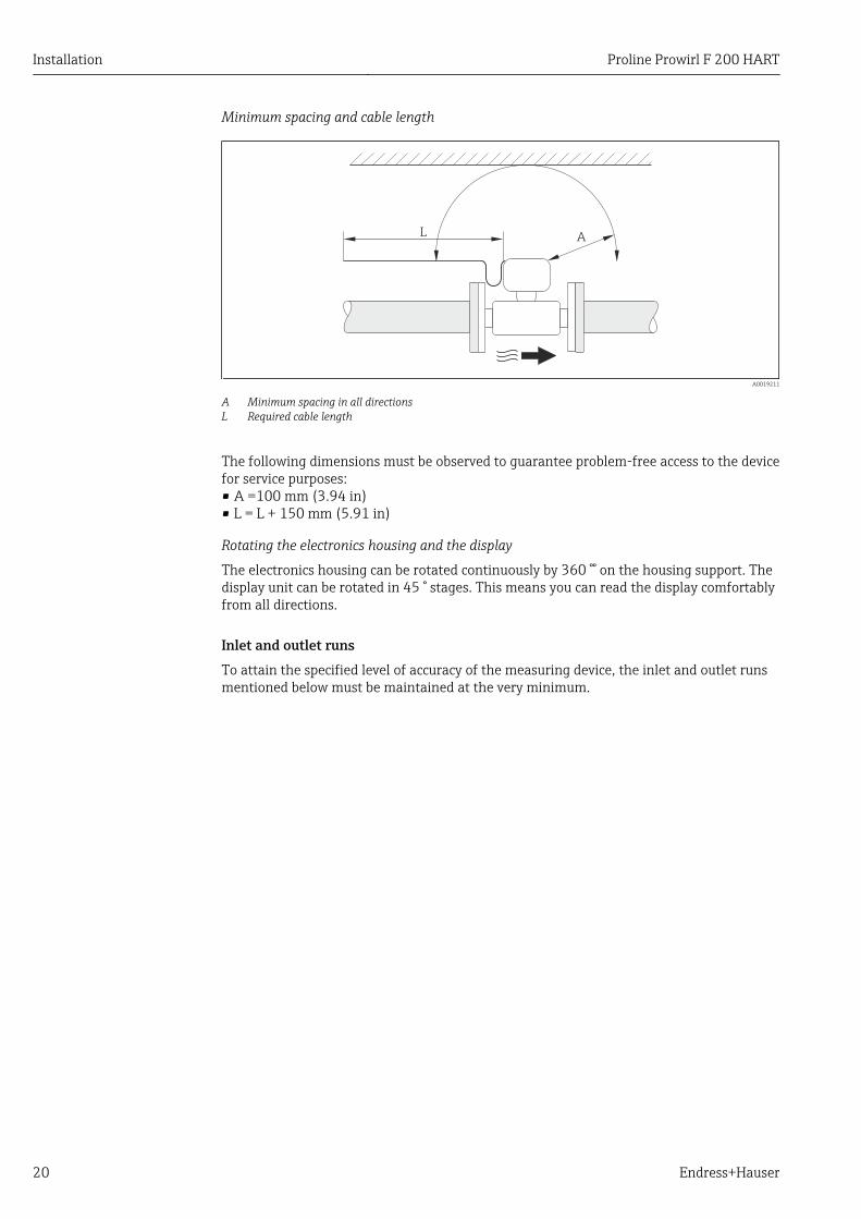
Minimum spacing and cable length
AL
A0019211
A Minimum spacing in all directionsL Required cable length
The following dimensions must be observed to guarantee problem-free access to the devicefor service purposes:• A =100 mm (3.94 in)• L = L + 150 mm (5.91 in)
Rotating the electronics housing and the display
The electronics housing can be rotated continuously by 360 °° on the housing support. Thedisplay unit can be rotated in 45 ° stages. This means you can read the display comfortablyfrom all directions.
Inlet and outlet runsTo attain the specified level of accuracy of the measuring device, the inlet and outlet runsmentioned below must be maintained at the very minimum.
Proline Prowirl F 200 HART Installation
Endress+Hauser 21
15 × DN 5 × DN
1
325 × DN 5 × DN 40 × DN 5 × DN
4
2
20 × DN 5 × DN
5
20 × DN 5 × DN6
17 × DN + 8 × h 5 × DNh
7
50 × DN 5 × DN
9
40 × DN 5 × DN
8
5 × DN
DN 25 (1"):≤
DN 40 (1½"):≥
A0019189
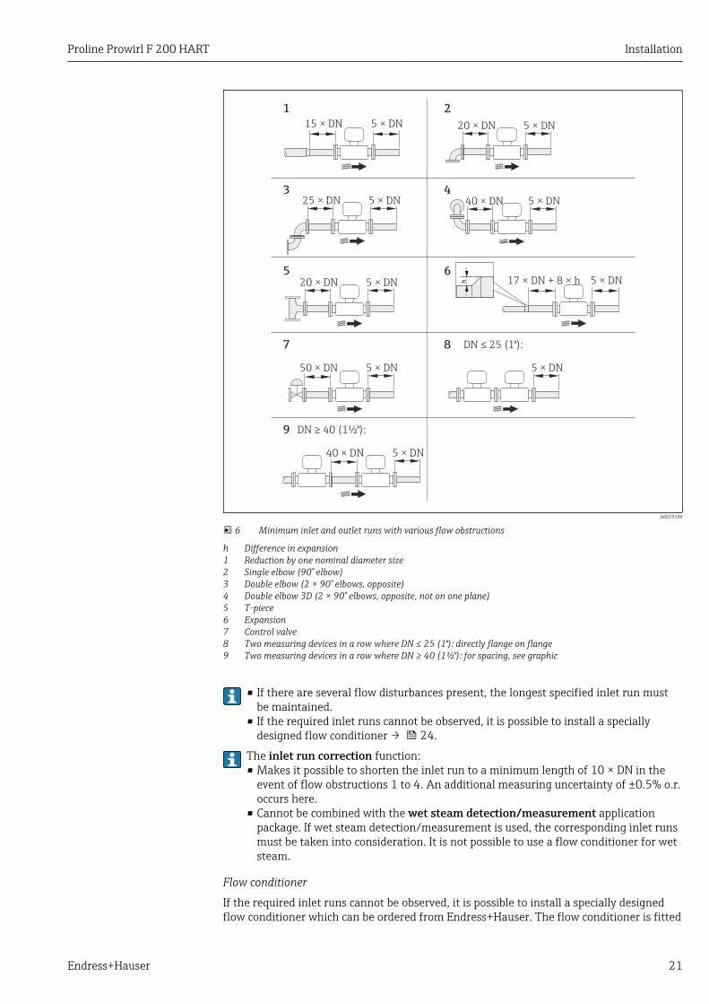
6 Minimum inlet and outlet runs with various flow obstructions
h Difference in expansion1 Reduction by one nominal diameter size2 Single elbow (90° elbow)3 Double elbow (2 × 90° elbows, opposite)4 Double elbow 3D (2 × 90° elbows, opposite, not on one plane)5 T-piece6 Expansion7 Control valve8 Two measuring devices in a row where DN ≤ 25 (1"): directly flange on flange9 Two measuring devices in a row where DN ≥ 40 (1½"): for spacing, see graphic
• If there are several flow disturbances present, the longest specified inlet run mustbe maintained.
• If the required inlet runs cannot be observed, it is possible to install a speciallydesigned flow conditioner → 24.
The inlet run correction function:• Makes it possible to shorten the inlet run to a minimum length of 10 × DN in the
event of flow obstructions 1 to 4. An additional measuring uncertainty of ±0.5% o.r.occurs here.
• Cannot be combined with the wet steam detection/measurement applicationpackage. If wet steam detection/measurement is used, the corresponding inlet runsmust be taken into consideration. It is not possible to use a flow conditioner for wetsteam.
Flow conditioner
If the required inlet runs cannot be observed, it is possible to install a specially designedflow conditioner which can be ordered from Endress+Hauser. The flow conditioner is fitted
Installation Proline Prowirl F 200 HART
22 Endress+Hauser
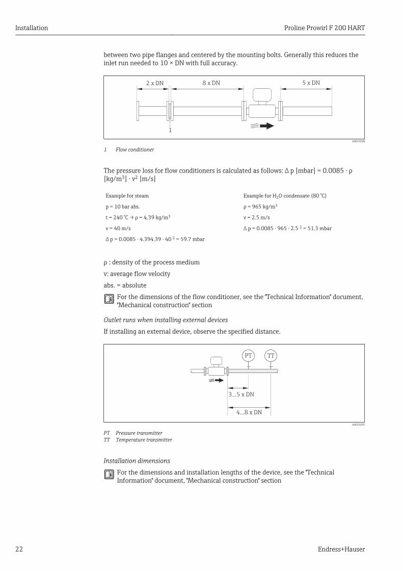
between two pipe flanges and centered by the mounting bolts. Generally this reduces theinlet run needed to 10 × DN with full accuracy.
8 x DN2 x DN 5 x DN
1
A0019208
1 Flow conditioner
The pressure loss for flow conditioners is calculated as follows: ∆ p [mbar] = 0.0085 ⋅ ρ[kg/m3] ⋅ v2 [m/s]
Example for steam Example for H2O condensate (80 °C)
p = 10 bar abs. ρ = 965 kg/m3
t = 240 °C → ρ = 4.39 kg/m3 v = 2.5 m/s
v = 40 m/s ∆ p = 0.0085 ⋅ 965 ⋅ 2.5 2 = 51.3 mbar
∆ p = 0.0085 ⋅ 4.394.39 ⋅ 40 2 = 59.7 mbar
ρ : density of the process medium
v: average flow velocity
abs. = absolute
For the dimensions of the flow conditioner, see the "Technical Information" document,"Mechanical construction" section
Outlet runs when installing external devices
If installing an external device, observe the specified distance.
PT TT
3...5 x DN
4...8 x DN
A0019205
PT Pressure transmitterTT Temperature transmitter
Installation dimensions
For the dimensions and installation lengths of the device, see the "TechnicalInformation" document, "Mechanical construction" section
Proline Prowirl F 200 HART Installation
Endress+Hauser 23
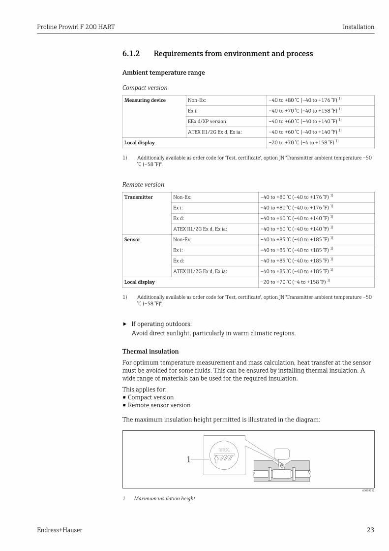
6.1.2 Requirements from environment and process
Ambient temperature range
Compact version
Measuring device Non-Ex: –40 to +80 °C (–40 to +176 °F) 1)
Ex i: –40 to +70 °C (–40 to +158 °F) 1)
EEx d/XP version: –40 to +60 °C (–40 to +140 °F) 1)
ATEX II1/2G Ex d, Ex ia: –40 to +60 °C (–40 to +140 °F) 1)
Local display –20 to +70 °C (–4 to +158 °F) 1)
1) Additionally available as order code for "Test, certificate", option JN "Transmitter ambient temperature –50°C (–58 °F)".
Remote version
Transmitter Non-Ex: –40 to +80 °C (–40 to +176 °F) 1)
Ex i: –40 to +80 °C (–40 to +176 °F) 1)
Ex d: –40 to +60 °C (–40 to +140 °F) 1)
ATEX II1/2G Ex d, Ex ia: –40 to +60 °C (–40 to +140 °F) 1)
Sensor Non-Ex: –40 to +85 °C (–40 to +185 °F) 1)
Ex i: –40 to +85 °C (–40 to +185 °F) 1)
Ex d: –40 to +85 °C (–40 to +185 °F) 1)
ATEX II1/2G Ex d, Ex ia: –40 to +85 °C (–40 to +185 °F) 1)
Local display –20 to +70 °C (–4 to +158 °F) 1)
1) Additionally available as order code for "Test, certificate", option JN "Transmitter ambient temperature –50°C (–58 °F)".
‣ If operating outdoors:Avoid direct sunlight, particularly in warm climatic regions.
Thermal insulationFor optimum temperature measurement and mass calculation, heat transfer at the sensormust be avoided for some fluids. This can be ensured by installing thermal insulation. Awide range of materials can be used for the required insulation.
This applies for:• Compact version• Remote sensor version
The maximum insulation height permitted is illustrated in the diagram:
1
A0019212
1 Maximum insulation height
Installation Proline Prowirl F 200 HART
24 Endress+Hauser
‣ When insulating, ensure that a sufficiently large area of the housing support remainsexposed.
The uncovered part serves as a radiator and protects the electronics from overheating andexcessive cooling.
NOTICEElectronics overheating on account of thermal insulation!‣ Observe the maximum permitted insulation height of the transmitter neck so that the
transmitter head and/or the connection housing of the remote version is completelyfree.
‣ Observe information on the permissible temperature ranges .‣ Note that a certain orientation might be required, depending on the fluid temperature
→ 19.
VibrationsThe correct operation of the measuring system is not affected by plant vibrations up to 1 g,10 to 500 Hz. Therefore no special measures are needed to secure the sensors.
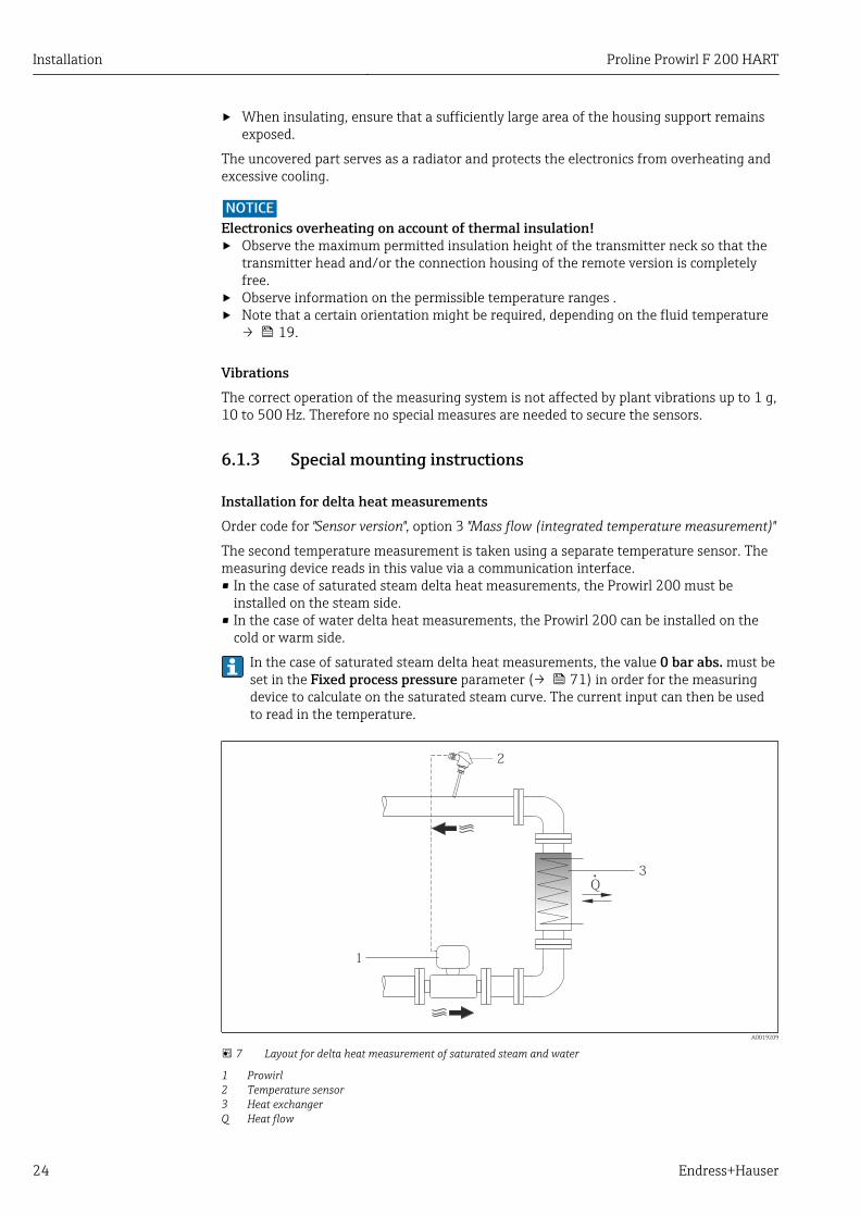
6.1.3 Special mounting instructions
Installation for delta heat measurementsOrder code for "Sensor version", option 3 "Mass flow (integrated temperature measurement)"
The second temperature measurement is taken using a separate temperature sensor. Themeasuring device reads in this value via a communication interface.• In the case of saturated steam delta heat measurements, the Prowirl 200 must be
installed on the steam side.• In the case of water delta heat measurements, the Prowirl 200 can be installed on the
cold or warm side.
In the case of saturated steam delta heat measurements, the value 0 bar abs. must beset in the Fixed process pressure parameter (→ 71) in order for the measuringdevice to calculate on the saturated steam curve. The current input can then be usedto read in the temperature.
Q
1
2
3
A0019209
7 Layout for delta heat measurement of saturated steam and water
1 Prowirl2 Temperature sensor3 Heat exchangerQ Heat flow
Proline Prowirl F 200 HART Installation
Endress+Hauser 25
Weather protection coverObserve the following minimum head clearance: 222 mm (8.74 in)
For information on the weather protection cover, see → 158
6.2 Mounting the measuring device
6.2.1 Required tools
For transmitter• For turning the transmitter housing: Open-ended wrench8 mm• For opening the securing clamps: Allen key3 mm
For sensorFor flanges and other process connections: Corresponding mounting tools
6.2.2 Preparing the measuring device1. Remove all remaining transport packaging.
2. Remove any protective covers or protective caps present from the sensor.
3. Remove stick-on label on the electronics compartment cover.
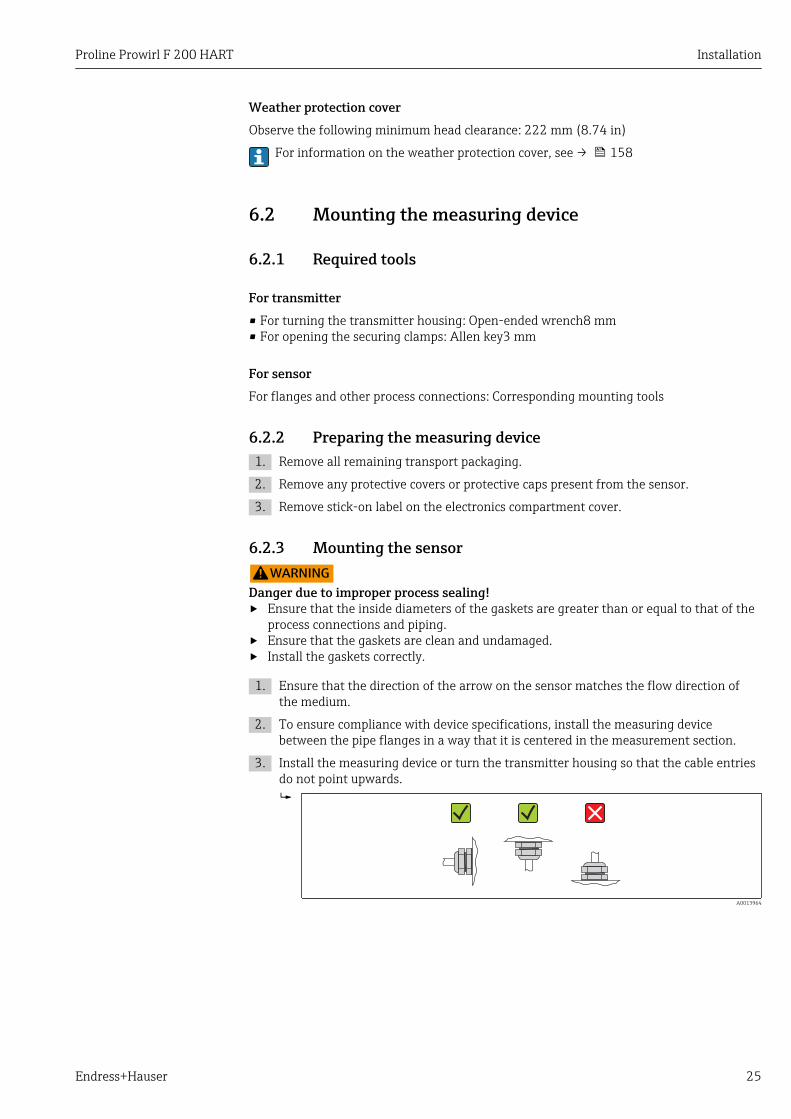
6.2.3 Mounting the sensorLWARNING
Danger due to improper process sealing!‣ Ensure that the inside diameters of the gaskets are greater than or equal to that of the
process connections and piping.‣ Ensure that the gaskets are clean and undamaged.‣ Install the gaskets correctly.
1. Ensure that the direction of the arrow on the sensor matches the flow direction ofthe medium.
2. To ensure compliance with device specifications, install the measuring devicebetween the pipe flanges in a way that it is centered in the measurement section.
3. Install the measuring device or turn the transmitter housing so that the cable entriesdo not point upwards.
A0013964
Installation Proline Prowirl F 200 HART
26 Endress+Hauser
6.2.4 Mounting the transmitter of the remote versionLCAUTION
Ambient temperature too high!Danger of electronics overheating and housing deformation.‣ Do not exceed the permitted maximum ambient temperature .‣ If operating outdoors: Avoid direct sunlight and exposure to weathering, particularly in
warm climatic regions.
LCAUTIONExcessive force can damage the housing!‣ Avoid excessive mechanical stress.
The transmitter of the remote version can be mounted in the following ways:• Wall mounting• Pipe mounting
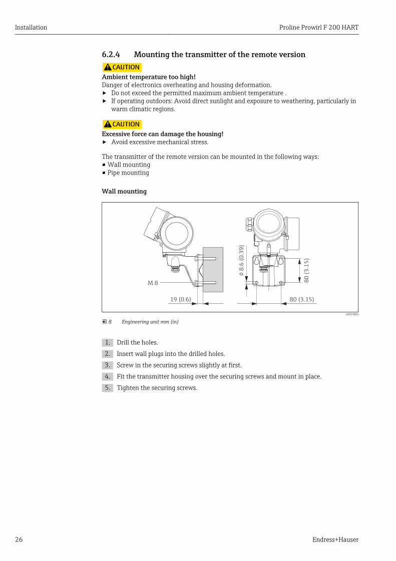
Wall mounting
80 (3.15)8
0 (
3.1
5)
19 (0.6)
!8
.6 (
0.3
9)
M 8
A0019864
8 Engineering unit mm (in)
1. Drill the holes.
2. Insert wall plugs into the drilled holes.
3. Screw in the securing screws slightly at first.
4. Fit the transmitter housing over the securing screws and mount in place.
5. Tighten the securing screws.
Proline Prowirl F 200 HART Installation
Endress+Hauser 27
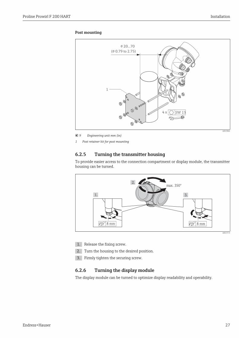
Post mounting
! 20…70
(! 0.79 to 2.75)
1
4 x SW 13
A0019862
9 Engineering unit mm (in)
1 Post retainer kit for post mounting
6.2.5 Turning the transmitter housingTo provide easier access to the connection compartment or display module, the transmitterhousing can be turned.
max. 350°
8 mm 8 mm
A0013713
1. Release the fixing screw.
2. Turn the housing to the desired position.
3. Firmly tighten the securing screw.
6.2.6 Turning the display moduleThe display module can be turned to optimize display readability and operability.
Installation Proline Prowirl F 200 HART
28 Endress+Hauser
+
E
–
1
3 mm
A0013905
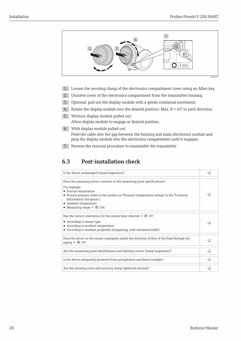
1. Loosen the securing clamp of the electronics compartment cover using an Allen key.
2. Unscrew cover of the electronics compartment from the transmitter housing.
3. Optional: pull out the display module with a gentle rotational movement.
4. Rotate the display module into the desired position: Max. 8 × 45° in each direction.
5. Without display module pulled out:Allow display module to engage at desired position.
6. With display module pulled out:Feed the cable into the gap between the housing and main electronics module andplug the display module into the electronics compartment until it engages.
7. Reverse the removal procedure to reassemble the transmitter.
6.3 Post-installation check
Is the device undamaged (visual inspection)?
Does the measuring device conform to the measuring point specifications?
For example:• Process temperature• Process pressure (refer to the section on "Pressure-temperature ratings" in the "Technical
Information" document )• Ambient temperature• Measuring range → 166
Has the correct orientation for the sensor been selected → 19?
• According to sensor type• According to medium temperature• According to medium properties (outgassing, with entrained solids)
Does the arrow on the sensor nameplate match the direction of flow of the fluid through thepiping → 19?
Are the measuring point identification and labeling correct (visual inspection)?
Is the device adequately protected from precipitation and direct sunlight?
Are the securing screw and securing clamp tightened securely?
Proline Prowirl F 200 HART Electrical connection
Endress+Hauser 29
7 Electrical connectionThe measuring device does not have an internal circuit breaker. For this reason,assign the measuring device a switch or power-circuit breaker so that the powersupply line can be easily disconnected from the mains.
7.1 Connection conditions
7.1.1 Required tools• For cable entries: Use corresponding tools• For securing clamp: Allen key 3 mm• Wire stripper• When using stranded cables: crimping tool for ferrule• For removing cables from terminal: flat blade screwdriver ≤3 mm (0.12 in)
7.1.2 Connecting cable requirementsThe connecting cables provided by the customer must fulfill the following requirements.
Electrical safetyIn accordance with applicable federal/national regulations.
Permitted temperature range• –40 °C (–40 °F) to +80 °C (+176 °F)• Minimum requirement: cable temperature range ≥ ambient temperature +20 K
Signal cableCurrent output
• For 4-20 mA: standard installation cable is sufficient.• For 4-20 mA HART: Shielded cable recommended. Observe grounding concept of the
plant.
Pulse/frequency/switch output
Standard installation cable is sufficient.
Current input
Standard installation cable is sufficient.
Connecting cable for remote versionConnecting cable (standard)
Standard cable 2 × 2 × 0.34 mm2 (22 AWG) PVC cable with common shield (2 pairs, pair-stranded)
Flame resistance According to DIN EN 60332-1-2
Oil-resistance According to DIN EN 60811-2-1
Shielding Galvanized copper-braid, opt. density approx. 85%
Cable length 5 m (16 ft), 10 m (32 ft), 20 m (65 ft), 30 m (98 ft)
Operating temperature When mounted in a fixed position: –50 to +105 °C (–58 to +221 °F); when cablecan move freely: –25 to +105 °C (–13 to +221 °F)
Electrical connection Proline Prowirl F 200 HART
30 Endress+Hauser
Connecting cable (reinforced)
Cable, reinforced 2 × 2 × 0.34 mm2 (22 AWG) PVC cable with common shield (2 pairs, pair-stranded) and additional steel-wire braided sheath
Flame resistance According to DIN EN 60332-1-2
Oil-resistance According to DIN EN 60811-2-1
Shielding Galvanized copper-braid, opt. density approx. 85%
Strain relief andreinforcement
Steel-wire braid, galvanized
Cable length 5 m (16 ft), 10 m (32 ft), 20 m (65 ft), 30 m (98 ft)
Operating temperature When mounted in a fixed position: –50 to +105 °C (–58 to +221 °F); when cablecan move freely: –25 to +105 °C (–13 to +221 °F)
Cable diameter• Cable glands supplied:
M20 × 1.5 with cable 6 to 12 mm (0.24 to 0.47 in)• Plug-in spring terminals for device version without integrated overvoltage protection:
wire cross-sections 0.5 to 2.5 mm2 (20 to 14 AWG)• Screw terminals for device version with integrated overvoltage protection: wire cross-
sections 0.2 to 2.5 mm2 (24 to 14 AWG)
Proline Prowirl F 200 HART Electrical connection
Endress+Hauser 31
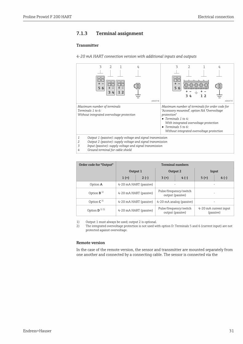
7.1.3 Terminal assignment
Transmitter
4-20 mA HART connection version with additional inputs and outputs
–
4
+
1
–
2
+
3
12 4
–
6
+
5
3
A0020738
+
1
–
2
–
4
+
3
–
6
+
5
3 12 4
A0020739
Maximum number of terminalsTerminals 1 to 6:Without integrated overvoltage protection
Maximum number of terminals for order code for"Accessory mounted", option NA "Overvoltageprotection"• Terminals 1 to 4:
With integrated overvoltage protection• Terminals 5 to 6:
Without integrated overvoltage protection
1234
Output 1 (passive): supply voltage and signal transmissionOutput 2 (passive): supply voltage and signal transmissionInput (passive): supply voltage and signal transmissionGround terminal for cable shield
Order code for "Output" Terminal numbers
Output 1 Output 2 Input
1 (+) 2 (-) 3 (+) 4 (-) 5 (+) 6 (-)
Option A 4-20 mA HART (passive) - -
Option B 1) 4-20 mA HART (passive) Pulse/frequency/switchoutput (passive) -
Option C 1) 4-20 mA HART (passive) 4-20 mA analog (passive) -
Option D 1) 2) 4-20 mA HART (passive) Pulse/frequency/switchoutput (passive)
4-20 mA current input(passive)
1) Output 1 must always be used; output 2 is optional.2) The integrated overvoltage protection is not used with option D: Terminals 5 and 6 (current input) are not
protected against overvoltage.
Remote versionIn the case of the remote version, the sensor and transmitter are mounted separately fromone another and connected by a connecting cable. The sensor is connected via the
Electrical connection Proline Prowirl F 200 HART
32 Endress+Hauser
connection housing while the transmitter is connected via the connection compartment ofthe wall holder unit.
The way the transmitter wall holder is connected depends on the measuring deviceapproval and the version of the connecting cable used.
Connection is only possible via terminals:• For approvals Ex n, Ex tb and cCSAus Div. 1• If a reinforced connecting cable is used
The connection is via an M12 connector:• For all other approvals• If the standard connecting cable is used
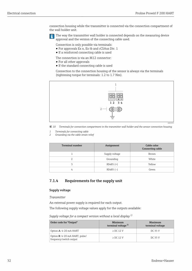
Connection to the connection housing of the sensor is always via the terminals(tightening torque for terminals: 1.2 to 1.7 Nm).
41 2 3
1
2
+ –
A0019335
10 Terminals for connection compartment in the transmitter wall holder and the sensor connection housing
1 Terminals for connecting cable2 Grounding via the cable strain relief
Terminal number Assignment Cable colorConnecting cable
1 Supply voltage Brown
2 Grounding White
3 RS485 (+) Yellow
4 RS485 (–) Green
7.1.4 Requirements for the supply unit
Supply voltage
Transmitter
An external power supply is required for each output.
The following supply voltage values apply for the outputs available:
Supply voltage for a compact version without a local display 1)
Order code for "Output" Minimumterminal voltage 2)
Maximumterminal voltage
Option A: 4-20 mA HART ≥ DC 12 V DC 35 V
Option B: 4-20 mA HART, pulse/frequency/switch output ≥ DC 12 V DC 35 V
Proline Prowirl F 200 HART Electrical connection
Endress+Hauser 33
Order code for "Output" Minimumterminal voltage 2)
Maximumterminal voltage
Option C: 4-20 mA HART + 4-20 mAanalog ≥ DC 12 V DC 30 V
Option D: 4-20 mA HART, pulse/frequency/switch output, 4-20 mA currentinput 3)
≥ DC 12 V DC 35 V
1) In event of external supply voltage of the power supply unit with load2) The minimum terminal voltage increases if local operation is used: see the following table3) Voltage drop 2.2 to 3 V for 3.59 to 22 mA
Increase in minimum terminal voltage
Local operation Increase in minimumterminal voltage
Order code for "Display; Operation", option C:Local operation SD02 + DC 1 V
Order code for "Display; Operation", option E:Local operation SD03 with lighting(backlighting not used)
+ DC 1 V
Order code for "Display; Operation", option E:Local operation SD03 with lighting(backlighting used)
+ DC 3 V
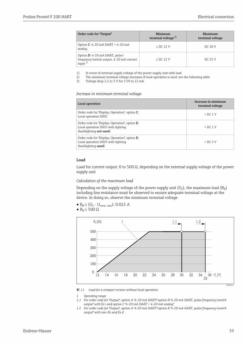
LoadLoad for current output: 0 to 500 Ω, depending on the external supply voltage of the powersupply unit
Calculation of the maximum load
Depending on the supply voltage of the power supply unit (US), the maximum load (RB)including line resistance must be observed to ensure adequate terminal voltage at thedevice. In doing so, observe the minimum terminal voltage
• RB ≤ (US - Uterm. min): 0.022 A• RB ≤ 500 Ω
0
100
200
300
400
500
12 14 16 18 20 22 24 26 28 U [V]s
R [ ]b W 1.1 1.21
30 32 34 3635
A0020417
11 Load for a compact version without local operation
1 Operating range1.1 For order code for "Output", option A "4-20 mA HART"/option B "4-20 mA HART, pulse/frequency/switch
output" with Ex i and option C "4-20 mA HART + 4-20 mA analog"1.2 For order code for "Output", option A "4-20 mA HART"/option B "4-20 mA HART, pulse/frequency/switch
output" with non-Ex and Ex d
Electrical connection Proline Prowirl F 200 HART
34 Endress+Hauser
Sample calculationSupply voltage of the supply unit:– US = 19 V– Uterm. min = 12 V (measuring device) + 1 V (local operation without lighting) = 13 V
Maximum load: RB ≤ (19 V - 13 V): 0.022 A = 273 Ω
The minimum terminal voltage (Uterm. min) increases if local operation is used(Verweisziel existiert nicht, aber @y.link.required='true').
7.1.5 Preparing the measuring device1. Remove dummy plug if present.
2. NOTICEInsufficient sealing of the housing!Operational reliability of the measuring device could be compromised.‣ Use suitable cable glands corresponding to the degree of protection.
If measuring device is delivered without cable glands:Provide suitable cable gland for corresponding connecting cable .
3. If measuring device is delivered with cable glands:Observe cable specification .
7.2 Connecting the measuring deviceNOTICE
Limitation of electrical safety due to incorrect connection!‣ Have electrical connection work carried out by correspondingly trained specialists only.‣ Observe applicable federal/national installation codes and regulations.‣ Comply with local workplace safety regulations.‣ For use in potentially explosive atmospheres, observe the information in the device-
specific Ex documentation.
7.2.1 Connecting the remote versionLWARNING
Risk of damaging the electronic components!‣ Ground the remote version and in doing so connect the sensor and transmitter to the
same potential equalization.‣ Only connect the sensor to a transmitter with the same serial number.
The following procedure (in the action sequence given) is recommended for the remoteversion:
1. Mount the transmitter and sensor.
2. Connect the connecting cable.
Proline Prowirl F 200 HART Electrical connection
Endress+Hauser 35
3. Connect the transmitter.
The way the transmitter wall holder is connected depends on the measuring deviceapproval and the version of the connecting cable used.
Connection is only possible via terminals:• For approvals Ex n, Ex tb and cCSAus Div. 1• If a reinforced connecting cable is used
The connection is via an M12 connector:• For all other approvals• If the standard connecting cable is used
Connection to the connection housing of the sensor is always via the terminals(tightening torque for terminals: 1.2 to 1.7 Nm).
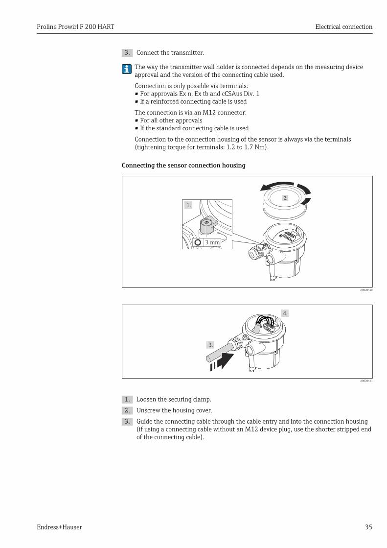
Connecting the sensor connection housing
3 mm
A0020410
A0020411
1. Loosen the securing clamp.
2. Unscrew the housing cover.
3. Guide the connecting cable through the cable entry and into the connection housing(if using a connecting cable without an M12 device plug, use the shorter stripped endof the connecting cable).
Electrical connection Proline Prowirl F 200 HART
36 Endress+Hauser
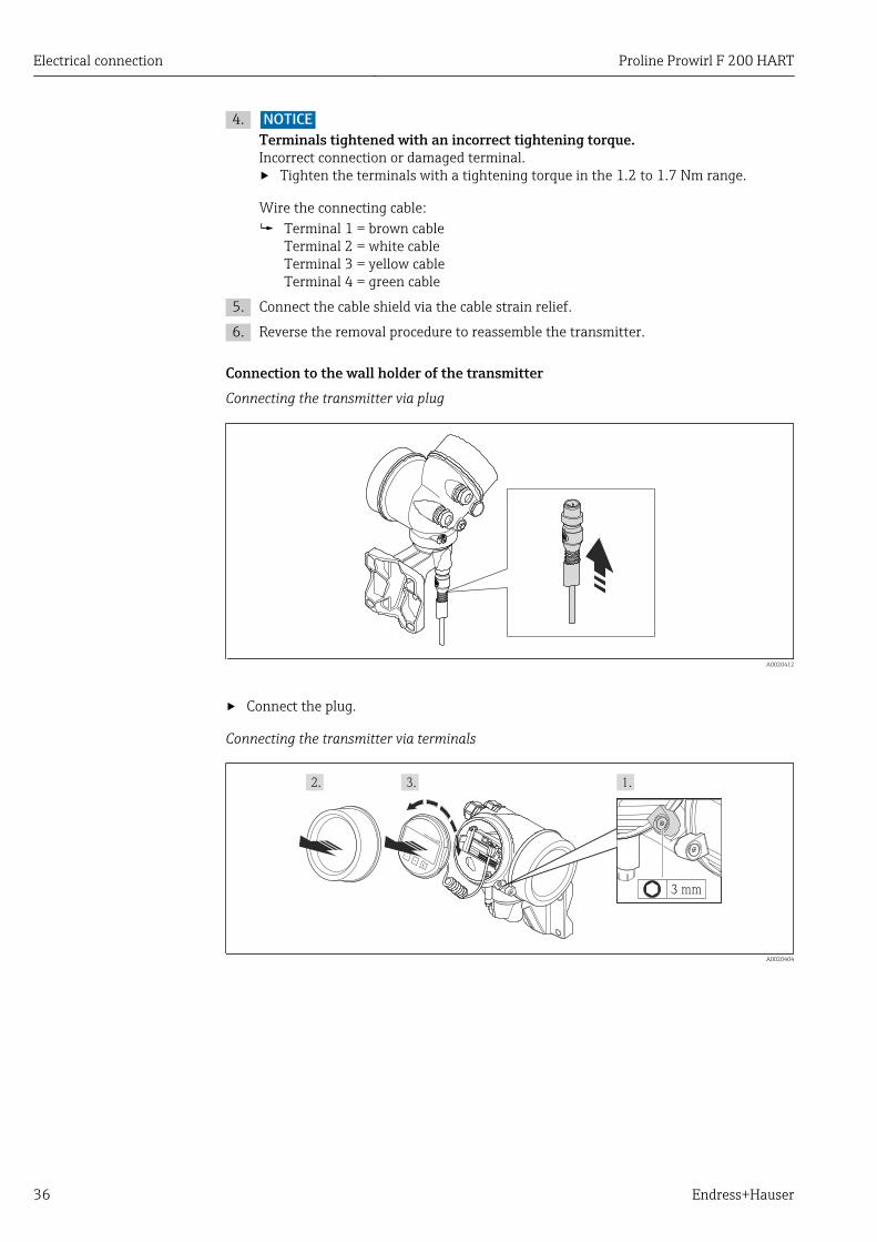
4. NOTICETerminals tightened with an incorrect tightening torque.Incorrect connection or damaged terminal.‣ Tighten the terminals with a tightening torque in the 1.2 to 1.7 Nm range.
Wire the connecting cable: Terminal 1 = brown cable
Terminal 2 = white cableTerminal 3 = yellow cableTerminal 4 = green cable
5. Connect the cable shield via the cable strain relief.
6. Reverse the removal procedure to reassemble the transmitter.
Connection to the wall holder of the transmitterConnecting the transmitter via plug
A0020412
‣ Connect the plug.
Connecting the transmitter via terminals
+
E
–
3 mm
A0020404
Proline Prowirl F 200 HART Electrical connection
Endress+Hauser 37
8 mm
TX 10
A0020405
~15°
A0020406
A0020407
Electrical connection Proline Prowirl F 200 HART
38 Endress+Hauser
A0020409
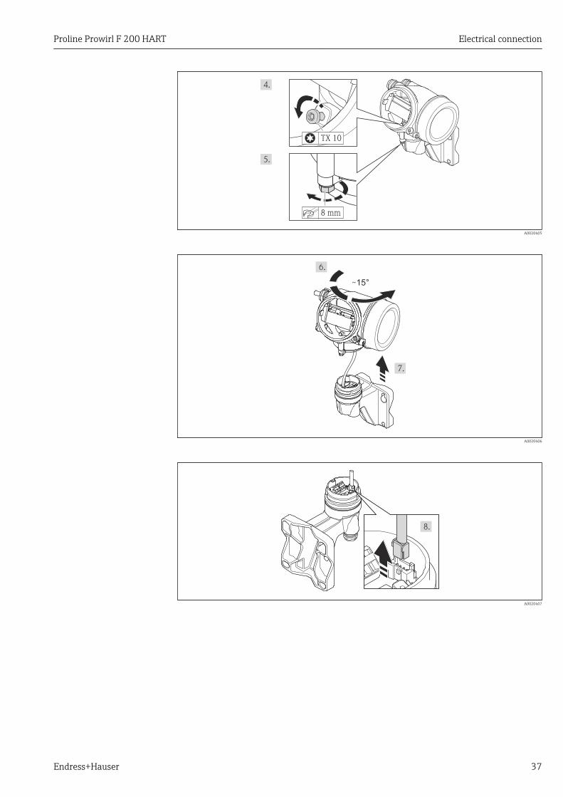
1. Loosen the securing clamp of the transmitter housing.
2. Loosen the securing clamp of the electronics compartment cover.
3. Unscrew the electronics compartment cover.
4. Pull out the display module with a gentle rotational movement. To make it easier toaccess the lock switch, attach the display module to the edge of the electronicscompartment.
5. Loosen the locking screw of the transmitter housing.
6. Turn the transmitter housing to the right until the mark and lift it up. The connectionboard of the wall housing is connected to the electronics board of the transmitter viaa signal cable. Pay attention to the signal cable when lifting the transmitter housing!
7. Disconnect the signal cable from the connection board of the wall housing bypressing in the locking clip on the connector.
8. Remove the transmitter housing.
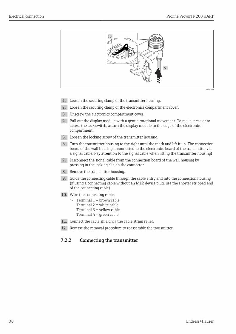
9. Guide the connecting cable through the cable entry and into the connection housing(if using a connecting cable without an M12 device plug, use the shorter stripped endof the connecting cable).
10. Wire the connecting cable: Terminal 1 = brown cable
Terminal 2 = white cableTerminal 3 = yellow cableTerminal 4 = green cable
11. Connect the cable shield via the cable strain relief.
12. Reverse the removal procedure to reassemble the transmitter.
7.2.2 Connecting the transmitter
Proline Prowirl F 200 HART Electrical connection
Endress+Hauser 39
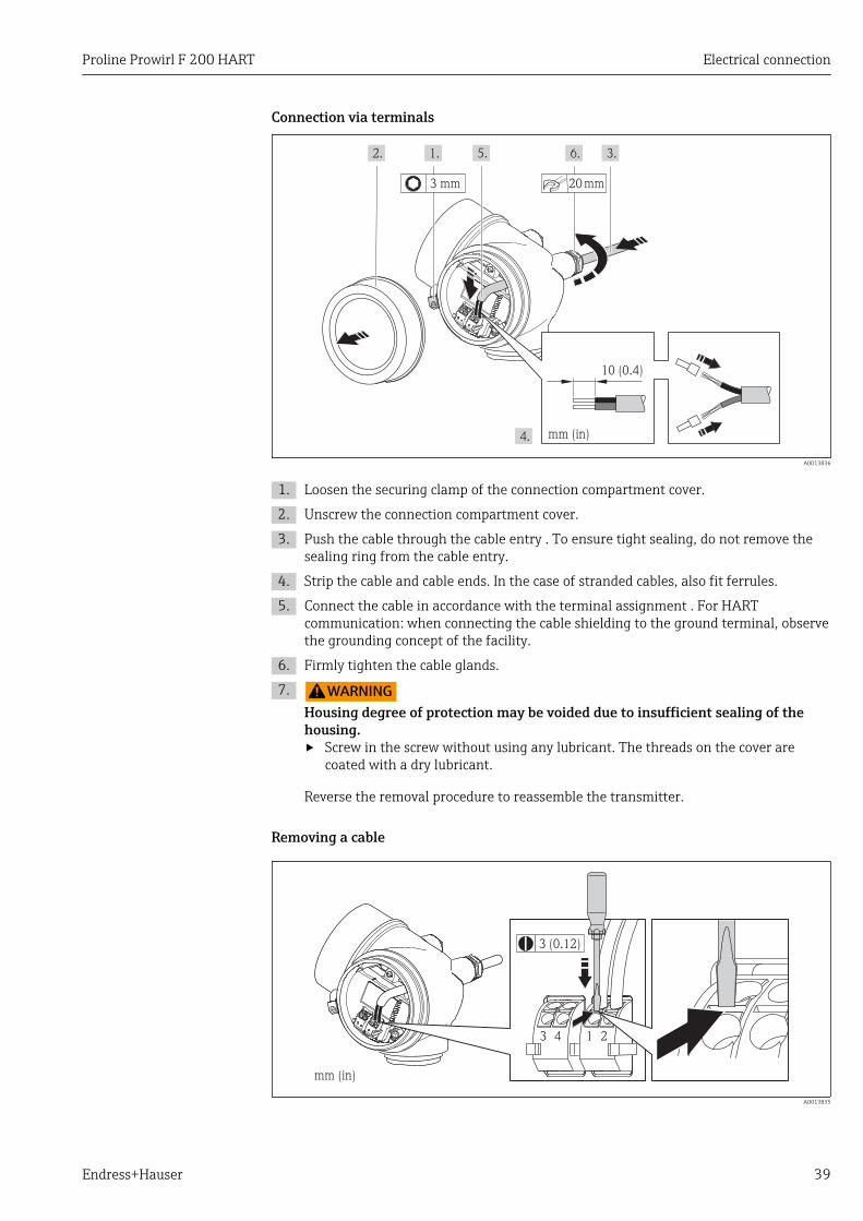
Connection via terminals
10 (0.4)
mm (in)
20mm3 mm
A0013836
1. Loosen the securing clamp of the connection compartment cover.
2. Unscrew the connection compartment cover.
3. Push the cable through the cable entry . To ensure tight sealing, do not remove thesealing ring from the cable entry.
4. Strip the cable and cable ends. In the case of stranded cables, also fit ferrules.
5. Connect the cable in accordance with the terminal assignment . For HARTcommunication: when connecting the cable shielding to the ground terminal, observethe grounding concept of the facility.
6. Firmly tighten the cable glands.
7. LWARNINGHousing degree of protection may be voided due to insufficient sealing of thehousing.‣ Screw in the screw without using any lubricant. The threads on the cover are
coated with a dry lubricant.
Reverse the removal procedure to reassemble the transmitter.
Removing a cable
mm (in)
213 4
3 (0.12)
A0013835
Electrical connection Proline Prowirl F 200 HART
40 Endress+Hauser
‣ To remove a cable from the terminal, use a flat-blade screwdriver to push the slotbetween the two terminal holes while simultaneously pulling the cable end out of theterminal.
7.2.3 Ensuring potential equalization
RequirementsPlease consider the following to ensure correct measurement:• Same electrical potential for the fluid and sensor• Remote version: same electrical potential for the sensor and transmitter• Company-internal grounding concepts• Pipe material and grounding
For devices intended for use in hazardous locations, please observe the guidelines inthe Ex documentation (XA).
7.3 Special connection instructions
7.3.1 Connection examples
Current output 4-20 mA HART
2 3
4...20 mA
41
+
-5
+
-
A0015511
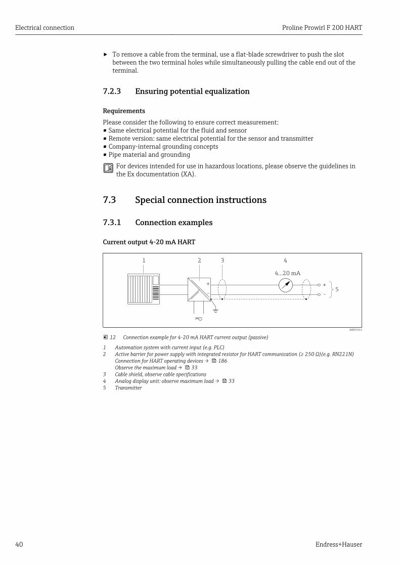
12 Connection example for 4-20 mA HART current output (passive)
1 Automation system with current input (e.g. PLC)2 Active barrier for power supply with integrated resistor for HART communication (≥ 250 Ω)(e.g. RN221N)
Connection for HART operating devices → 186Observe the maximum load → 33
3 Cable shield, observe cable specifications4 Analog display unit: observe maximum load → 335 Transmitter
Proline Prowirl F 200 HART Electrical connection
Endress+Hauser 41
Pulse/frequency output
1
+
_
12345
2
+
–
+–
3
A0016801
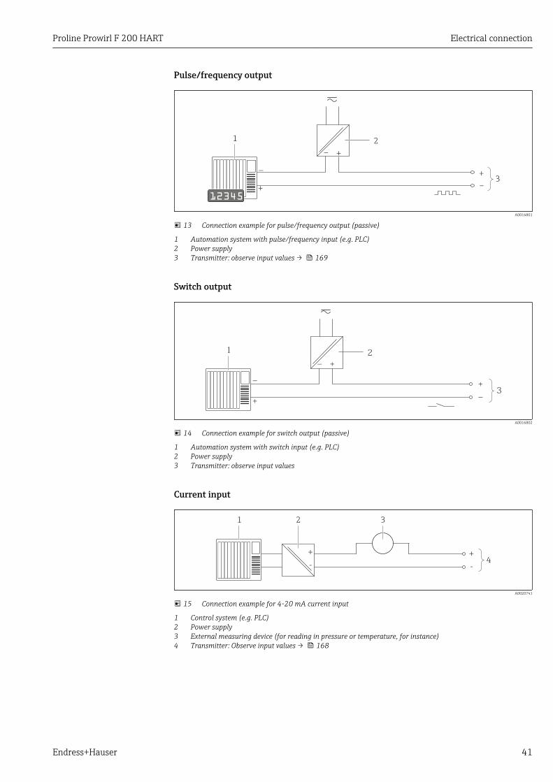
13 Connection example for pulse/frequency output (passive)
1 Automation system with pulse/frequency input (e.g. PLC)2 Power supply3 Transmitter: observe input values → 169
Switch output
1
+_
+
_
2
+
_ 3
A0016802
14 Connection example for switch output (passive)
1 Automation system with switch input (e.g. PLC)2 Power supply3 Transmitter: observe input values
Current input
2
+
-4
+
-
31
A0020741
15 Connection example for 4-20 mA current input
1 Control system (e.g. PLC)2 Power supply3 External measuring device (for reading in pressure or temperature, for instance)4 Transmitter: Observe input values → 168
Electrical connection Proline Prowirl F 200 HART
42 Endress+Hauser
HART input
3
4...20 mA
51
+
-
3
6
+
–
+
+
–
+
–
+
–
+
–
–
2 4
4
7
+
-
A0016029
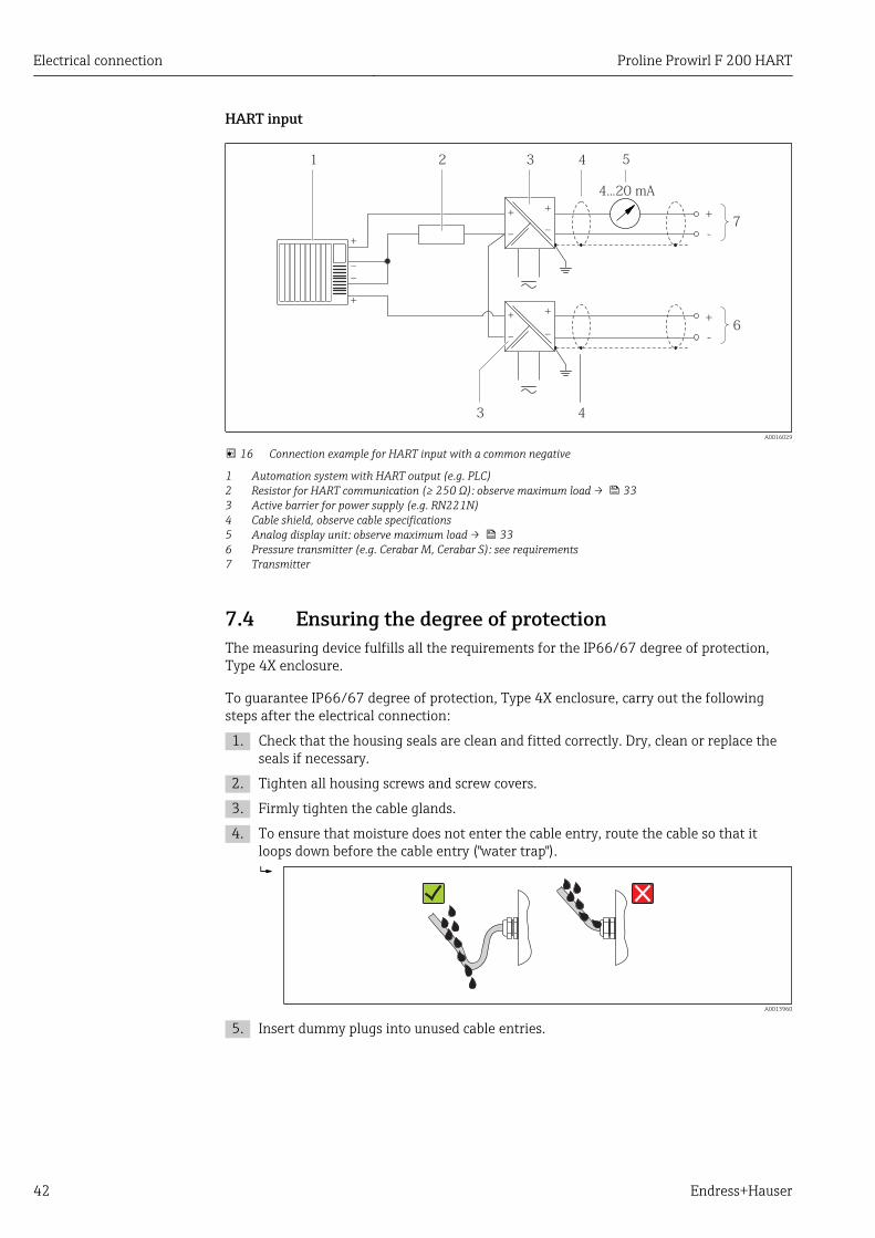
16 Connection example for HART input with a common negative
1 Automation system with HART output (e.g. PLC)2 Resistor for HART communication (≥ 250 Ω): observe maximum load → 333 Active barrier for power supply (e.g. RN221N)4 Cable shield, observe cable specifications5 Analog display unit: observe maximum load → 336 Pressure transmitter (e.g. Cerabar M, Cerabar S): see requirements7 Transmitter
7.4 Ensuring the degree of protectionThe measuring device fulfills all the requirements for the IP66/67 degree of protection,Type 4X enclosure.
To guarantee IP66/67 degree of protection, Type 4X enclosure, carry out the followingsteps after the electrical connection:
1. Check that the housing seals are clean and fitted correctly. Dry, clean or replace theseals if necessary.
2. Tighten all housing screws and screw covers.
3. Firmly tighten the cable glands.
4. To ensure that moisture does not enter the cable entry, route the cable so that itloops down before the cable entry ("water trap").
A0013960
5. Insert dummy plugs into unused cable entries.

Proline Prowirl F 200 HART Electrical connection
Endress+Hauser 43
7.5 Post-connection check
Are cables or the device undamaged (visual inspection)?
Do the cables comply with the requirements ?
Do the cables have adequate strain relief?
Are all the cable glands installed, firmly tightened and leak-tight? Cable run with "water trap"→ 42 ?
Depending on the device version: are all the device plugs firmly tightened ?
Does the supply voltage match the specifications on the transmitter nameplate ?
Is the terminal assignment correct ?
If supply voltage is present, do values appear on the display module?
Are all housing covers installed and firmly tightened?
Is the securing clamp tightened correctly?
Operation options Proline Prowirl F 200 HART
44 Endress+Hauser
8 Operation options
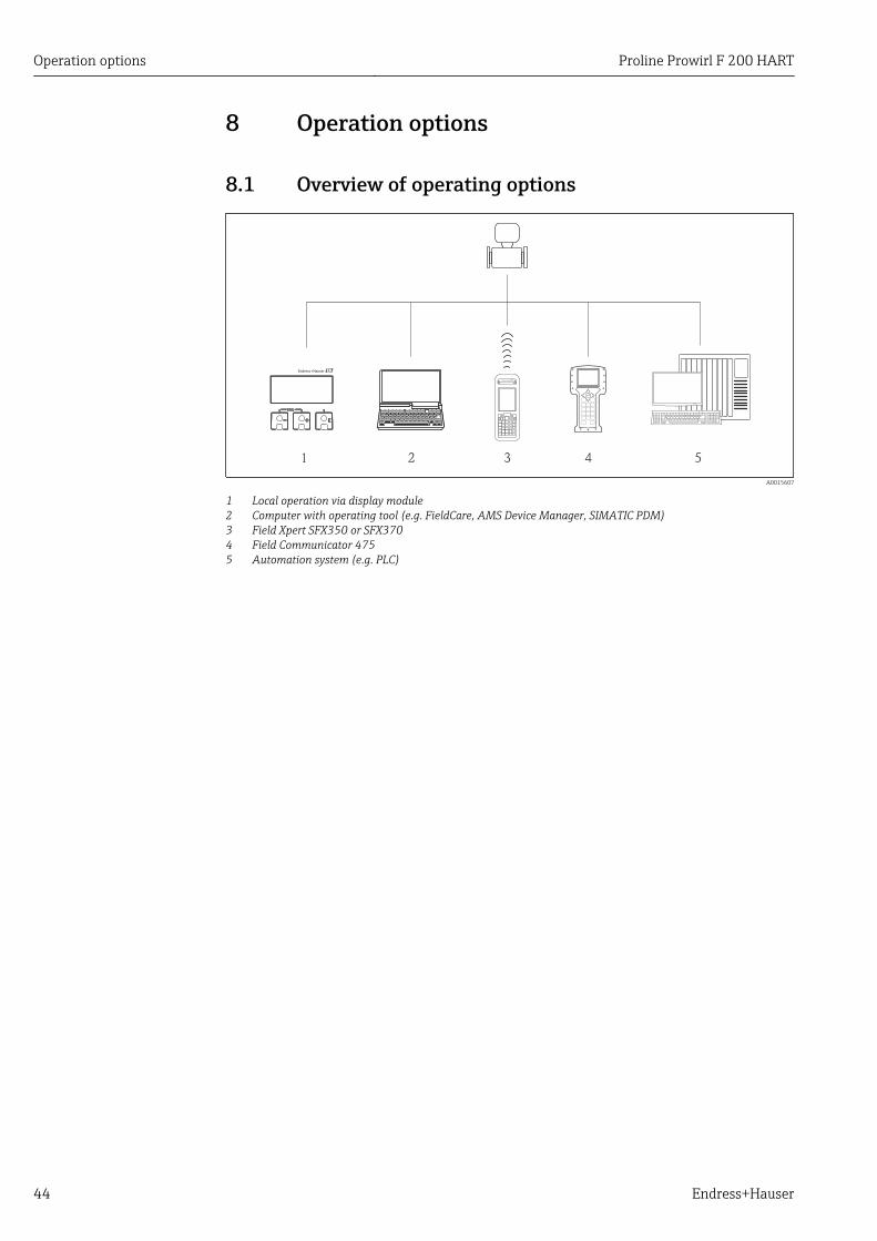
8.1 Overview of operating options
1 2 3 4 5
SC
A0015607
1 Local operation via display module2 Computer with operating tool (e.g. FieldCare, AMS Device Manager, SIMATIC PDM)3 Field Xpert SFX350 or SFX3704 Field Communicator 4755 Automation system (e.g. PLC)
Proline Prowirl F 200 HART Operation options
Endress+Hauser 45
8.2 Structure and function of the operating menu
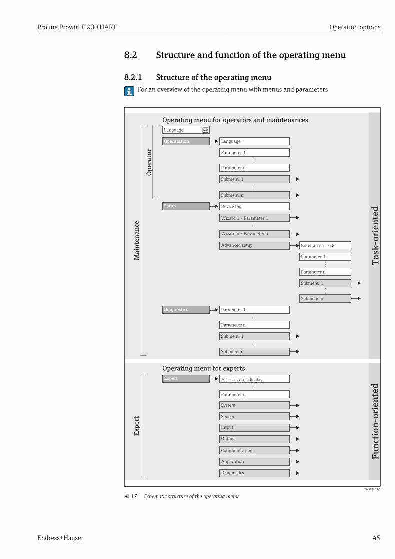
8.2.1 Structure of the operating menuFor an overview of the operating menu with menus and parameters
!
Expert
System
Sensor
Communication
Application
Diagnostics
Access status display
Output
Operating menu for experts
Language
Operatation Language
Parameter 1
Setup
Submenu 1
Submenu n
Device tag
Advanced setup Enter access code
Parameter 1
Parameter n
Submenu 1
Submenu n
Diagnostics Parameter 1
Parameter n
Submenu 1
Submenu n
Operating menu for operators and maintenances
Parameter n
Op
era
tor
Ma
inte
na
nce
Ta
sk-o
rie
nte
dF
un
ctio
n-o
rie
nte
d
Ex
pe
rt
Wizard 1 / Parameter 1
Wizard n / Parameter n
Parameter n
Intput
A0018237-EN
17 Schematic structure of the operating menu
Operation options Proline Prowirl F 200 HART
46 Endress+Hauser
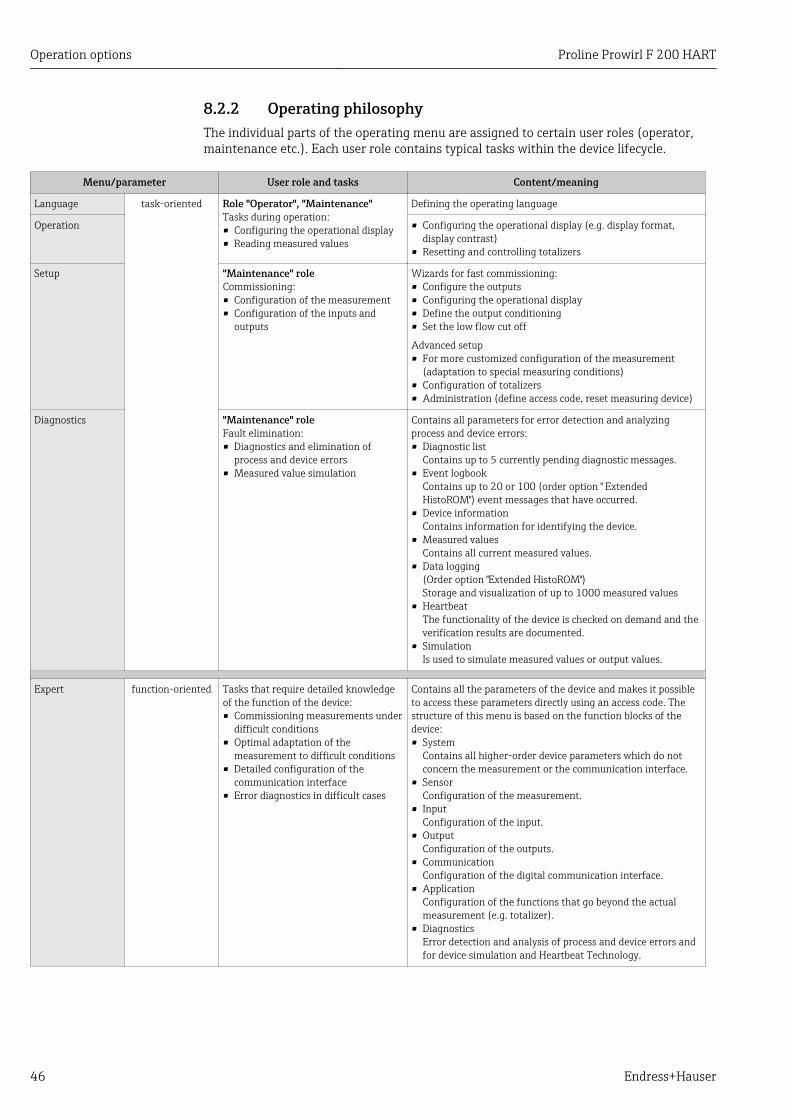
8.2.2 Operating philosophyThe individual parts of the operating menu are assigned to certain user roles (operator,maintenance etc.). Each user role contains typical tasks within the device lifecycle.
Menu/parameter User role and tasks Content/meaning
Language task-oriented Role "Operator", "Maintenance"Tasks during operation:• Configuring the operational display• Reading measured values
Defining the operating language
Operation • Configuring the operational display (e.g. display format,display contrast)
• Resetting and controlling totalizers
Setup "Maintenance" roleCommissioning:• Configuration of the measurement• Configuration of the inputs and
outputs
Wizards for fast commissioning:• Configure the outputs• Configuring the operational display• Define the output conditioning• Set the low flow cut off
Advanced setup• For more customized configuration of the measurement
(adaptation to special measuring conditions)• Configuration of totalizers• Administration (define access code, reset measuring device)
Diagnostics "Maintenance" roleFault elimination:• Diagnostics and elimination of
process and device errors• Measured value simulation
Contains all parameters for error detection and analyzingprocess and device errors:• Diagnostic list
Contains up to 5 currently pending diagnostic messages.• Event logbook
Contains up to 20 or 100 (order option " ExtendedHistoROM") event messages that have occurred.
• Device informationContains information for identifying the device.
• Measured valuesContains all current measured values.
• Data logging(Order option "Extended HistoROM")Storage and visualization of up to 1000 measured values
• HeartbeatThe functionality of the device is checked on demand and theverification results are documented.
• SimulationIs used to simulate measured values or output values.
Expert function-oriented Tasks that require detailed knowledgeof the function of the device:• Commissioning measurements under
difficult conditions• Optimal adaptation of the
measurement to difficult conditions• Detailed configuration of the
communication interface• Error diagnostics in difficult cases
Contains all the parameters of the device and makes it possibleto access these parameters directly using an access code. Thestructure of this menu is based on the function blocks of thedevice:• System
Contains all higher-order device parameters which do notconcern the measurement or the communication interface.
• SensorConfiguration of the measurement.
• InputConfiguration of the input.
• OutputConfiguration of the outputs.
• CommunicationConfiguration of the digital communication interface.
• ApplicationConfiguration of the functions that go beyond the actualmeasurement (e.g. totalizer).
• DiagnosticsError detection and analysis of process and device errors andfor device simulation and Heartbeat Technology.
Proline Prowirl F 200 HART Operation options
Endress+Hauser 47
8.3 Access to the operating menu via the local display
8.3.1 Operational display
X X X X X X XX X
4
2
1
3
5
l/h
1120.50
F
A0016502
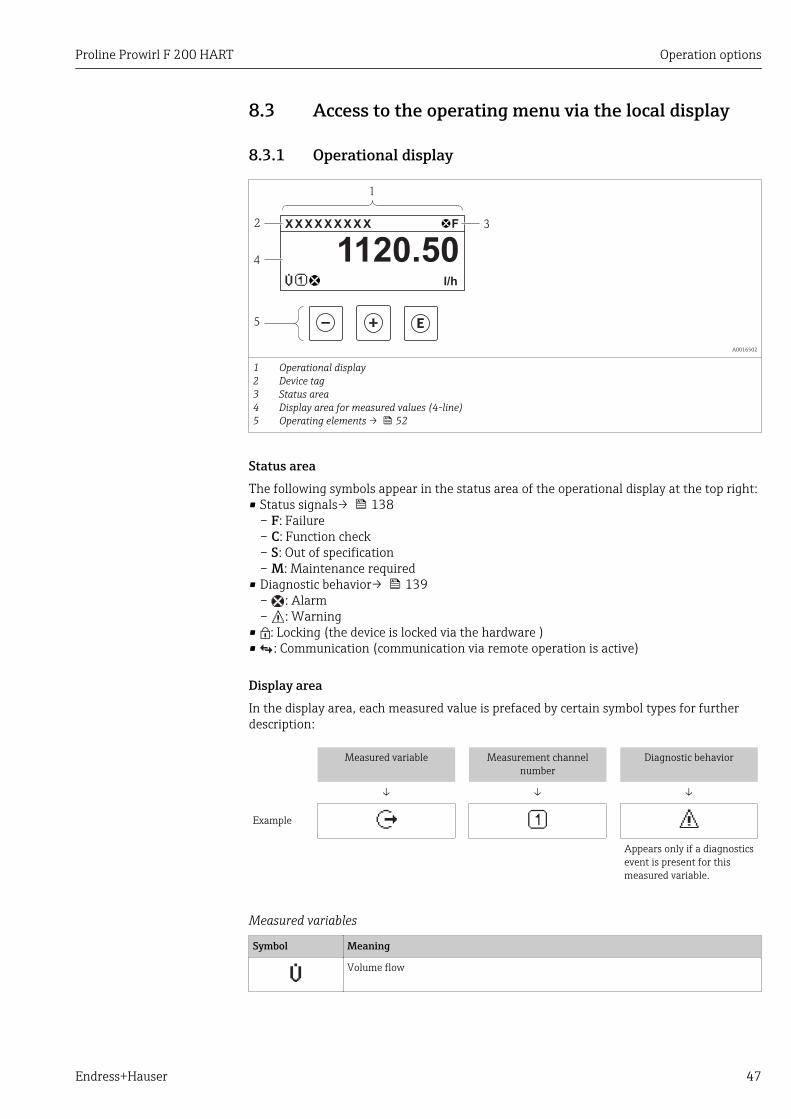
12345
Operational displayDevice tagStatus areaDisplay area for measured values (4-line)Operating elements → 52
Status areaThe following symbols appear in the status area of the operational display at the top right:• Status signals→ 138
– F: Failure– C: Function check– S: Out of specification– M: Maintenance required
• Diagnostic behavior→ 139– : Alarm– : Warning
• : Locking (the device is locked via the hardware )• : Communication (communication via remote operation is active)
Display areaIn the display area, each measured value is prefaced by certain symbol types for furtherdescription:
Measured variable Measurement channelnumber
Diagnostic behavior
↓ ↓ ↓
Example
Appears only if a diagnosticsevent is present for thismeasured variable.
Measured variables
Symbol Meaning
Volume flow
Operation options Proline Prowirl F 200 HART
48 Endress+Hauser
Totalizer
The measurement channel number indicates which of the three totalizers isdisplayed.
Output
The measurement channel number indicates which of the two current outputs isdisplayed.
Measurement channel numbers
Symbol Meaning
Measurement channel 1 to 4
The measurement channel number is displayed only if more than one channel is present for the same measuredvariable type (e.g. totalizer 1-3).
Diagnostic behavior
The diagnostic behavior pertains to a diagnostic event that is relevant to the displayed measured variable.For information on the symbols → 139
The number and display format of the measured values can be configured via the"Format display" parameter → 89. "Operation" menu → Display → Formatdisplay
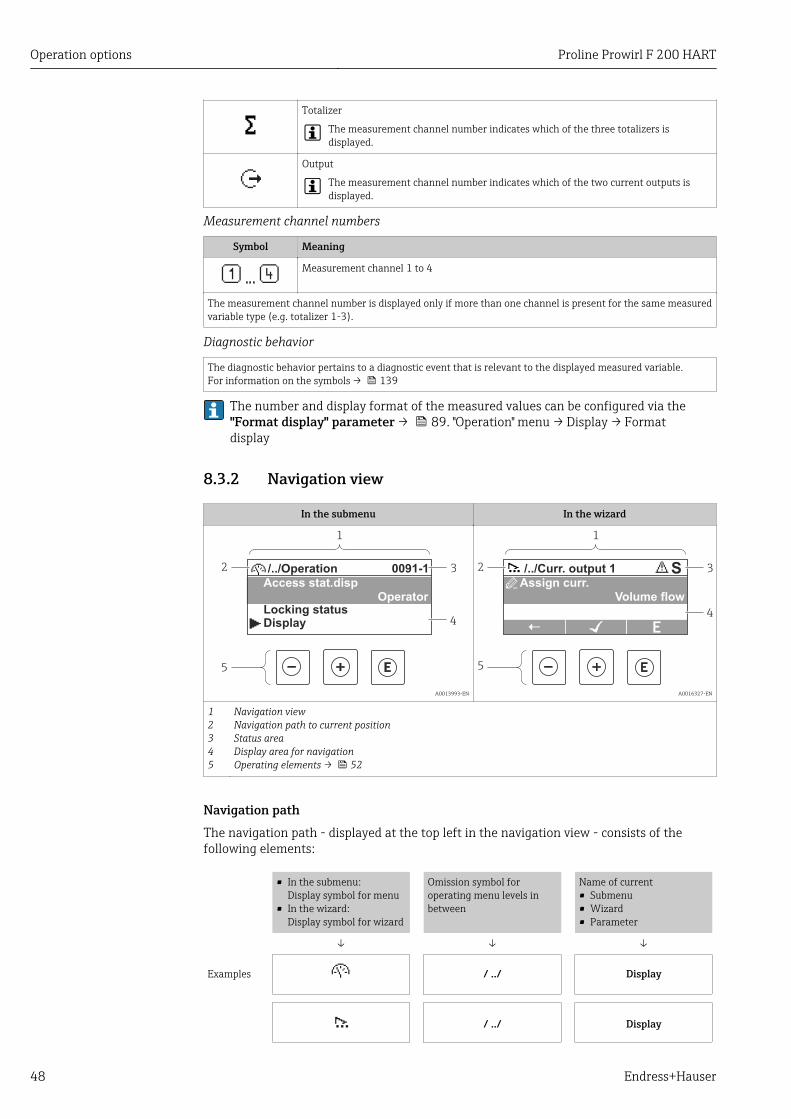
8.3.2 Navigation view
In the submenu In the wizard
4
2
1
3
5
/../Operation 0091-1
Access stat.dispOperator
Locking statusDisplay
A0013993-EN
S
4
2
1
5
3/../Curr. output 1
Assign curr.Volume flow
A0016327-EN
12345
Navigation viewNavigation path to current positionStatus areaDisplay area for navigationOperating elements → 52
Navigation pathThe navigation path - displayed at the top left in the navigation view - consists of thefollowing elements:
• In the submenu:Display symbol for menu
• In the wizard:Display symbol for wizard
Omission symbol foroperating menu levels inbetween
Name of current• Submenu• Wizard• Parameter
↓ ↓ ↓
Examples / ../ Display
/ ../ Display
Proline Prowirl F 200 HART Operation options
Endress+Hauser 49
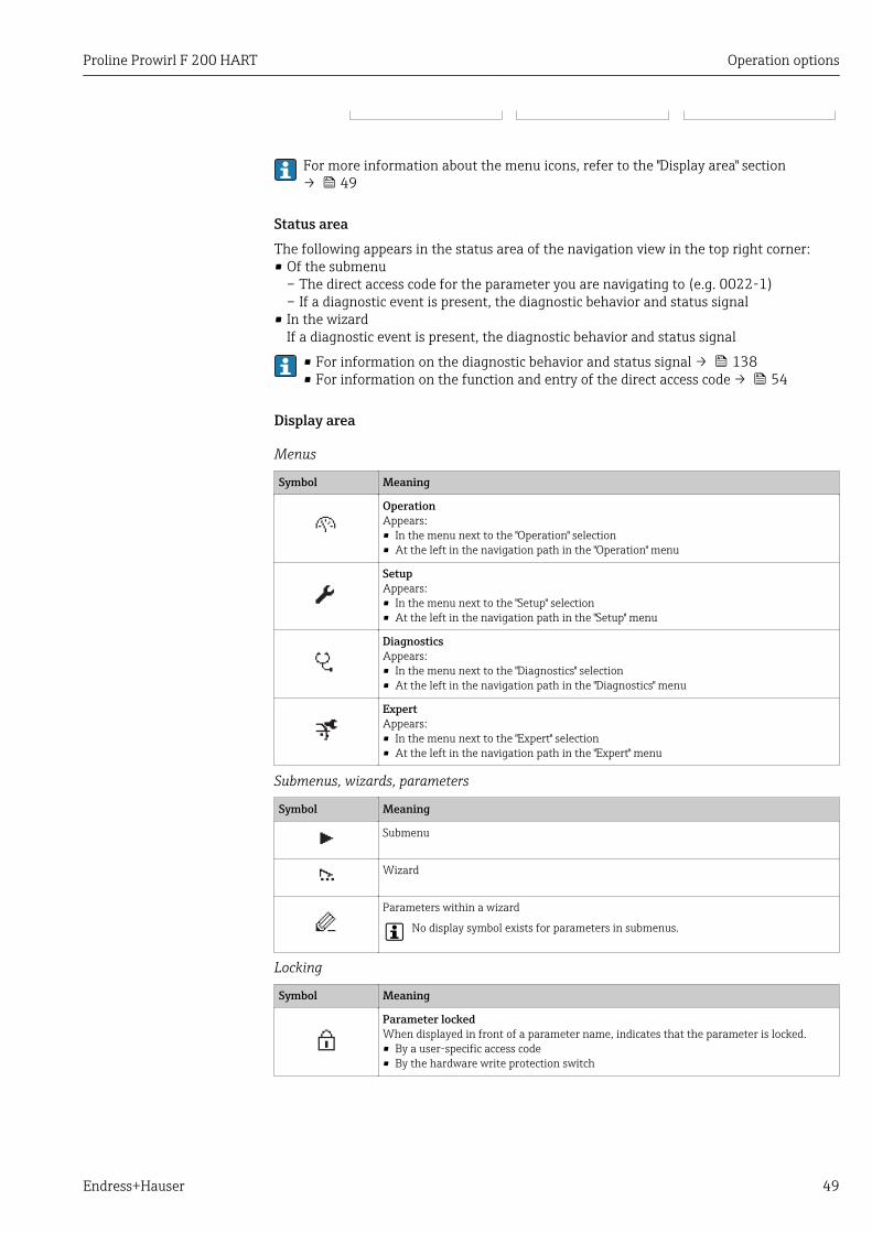
For more information about the menu icons, refer to the "Display area" section→ 49
Status areaThe following appears in the status area of the navigation view in the top right corner:• Of the submenu
– The direct access code for the parameter you are navigating to (e.g. 0022-1)– If a diagnostic event is present, the diagnostic behavior and status signal
• In the wizardIf a diagnostic event is present, the diagnostic behavior and status signal
• For information on the diagnostic behavior and status signal → 138• For information on the function and entry of the direct access code → 54
Display area
Menus
Symbol Meaning
OperationAppears:• In the menu next to the "Operation" selection• At the left in the navigation path in the "Operation" menu
SetupAppears:• In the menu next to the "Setup" selection• At the left in the navigation path in the "Setup" menu
DiagnosticsAppears:• In the menu next to the "Diagnostics" selection• At the left in the navigation path in the "Diagnostics" menu
ExpertAppears:• In the menu next to the "Expert" selection• At the left in the navigation path in the "Expert" menu
Submenus, wizards, parameters
Symbol Meaning
Submenu
Wizard
Parameters within a wizard
No display symbol exists for parameters in submenus.
Locking
Symbol Meaning
Parameter lockedWhen displayed in front of a parameter name, indicates that the parameter is locked.• By a user-specific access code• By the hardware write protection switch
Operation options Proline Prowirl F 200 HART
50 Endress+Hauser
Wizard operation
Symbol Meaning
Switches to the previous parameter.
Confirms the parameter value and switches to the next parameter.
Opens the editing view of the parameter.
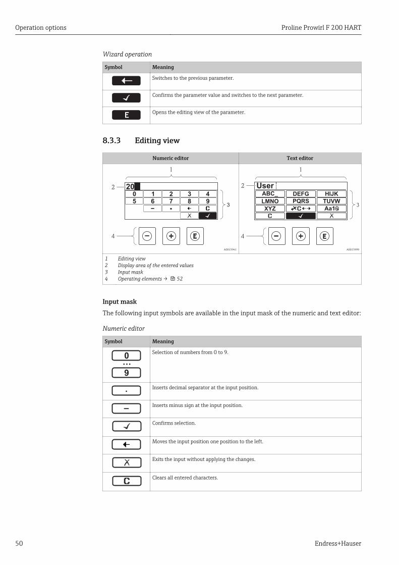
8.3.3 Editing view
Numeric editor Text editor
3
2
1
4
3 40 1 2
95 6 87
20
A0013941 A0013999
1234
Editing viewDisplay area of the entered valuesInput maskOperating elements → 52
Input maskThe following input symbols are available in the input mask of the numeric and text editor:
Numeric editor
Symbol Meaning
…0
9
Selection of numbers from 0 to 9.
.
Inserts decimal separator at the input position.
–
Inserts minus sign at the input position.
Confirms selection.
Moves the input position one position to the left.
Exits the input without applying the changes.
Clears all entered characters.
Proline Prowirl F 200 HART Operation options
Endress+Hauser 51
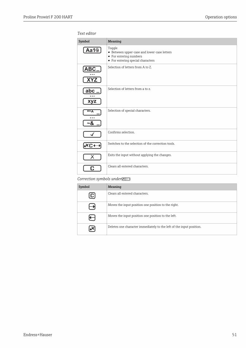
Text editor
Symbol Meaning
Aa1Toggle• Between upper-case and lower-case letters• For entering numbers• For entering special characters
XYZ
ABC_…
Selection of letters from A to Z.
xyz
abc _…
Selection of letters from a to z.
~&
"'^ _…
_
Selection of special characters.
Confirms selection.
Switches to the selection of the correction tools.
Exits the input without applying the changes.
Clears all entered characters.
Correction symbols under
Symbol Meaning
Clears all entered characters.
Moves the input position one position to the right.
Moves the input position one position to the left.
Deletes one character immediately to the left of the input position.
Operation options Proline Prowirl F 200 HART
52 Endress+Hauser
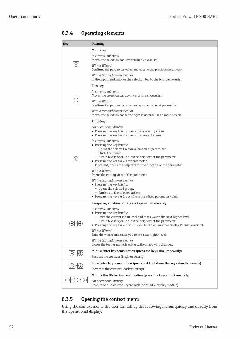
8.3.4 Operating elements
Key Meaning
Minus key
In a menu, submenuMoves the selection bar upwards in a choose list.
With a WizardConfirms the parameter value and goes to the previous parameter.
With a text and numeric editorIn the input mask, moves the selection bar to the left (backwards).
Plus key
In a menu, submenuMoves the selection bar downwards in a choose list.
With a WizardConfirms the parameter value and goes to the next parameter.
With a text and numeric editorMoves the selection bar to the right (forwards) in an input screen.
Enter key
For operational display• Pressing the key briefly opens the operating menu.• Pressing the key for 2 s opens the context menu.
In a menu, submenu• Pressing the key briefly:
– Opens the selected menu, submenu or parameter.– Starts the wizard.– If help text is open, closes the help text of the parameter.
• Pressing the key for 2 s for parameter:If present, opens the help text for the function of the parameter.
With a WizardOpens the editing view of the parameter.
With a text and numeric editor• Pressing the key briefly:
– Opens the selected group.– Carries out the selected action.
• Pressing the key for 2 s confirms the edited parameter value.
+
Escape key combination (press keys simultaneously)
In a menu, submenu• Pressing the key briefly:
– Exits the current menu level and takes you to the next higher level.– If help text is open, closes the help text of the parameter.
• Pressing the key for 2 s returns you to the operational display ("home position").
With a WizardExits the wizard and takes you to the next higher level.
With a text and numeric editorCloses the text or numeric editor without applying changes.
+Minus/Enter key combination (press the keys simultaneously)
Reduces the contrast (brighter setting).
+Plus/Enter key combination (press and hold down the keys simultaneously)
Increases the contrast (darker setting).
++
Minus/Plus/Enter key combination (press the keys simultaneously)
For operational displayEnables or disables the keypad lock (only SD02 display module).
8.3.5 Opening the context menuUsing the context menu, the user can call up the following menus quickly and directly fromthe operational display:
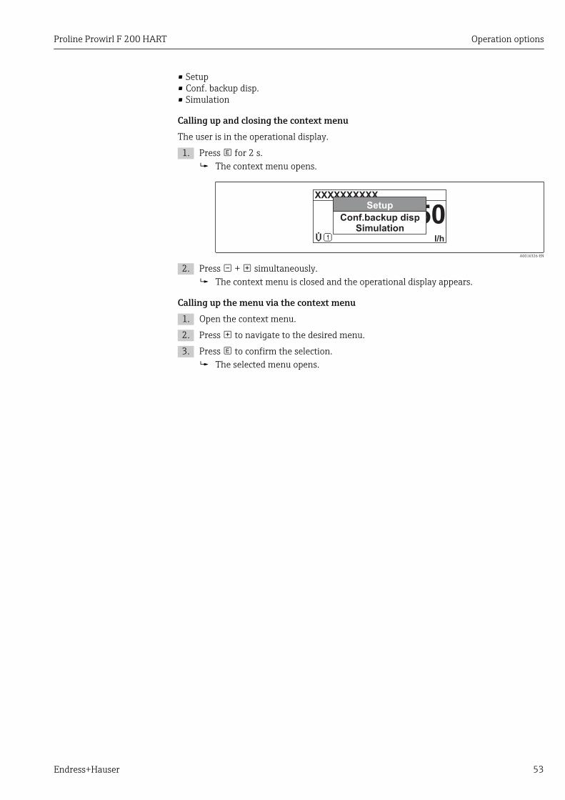
Proline Prowirl F 200 HART Operation options
Endress+Hauser 53
• Setup• Conf. backup disp.• Simulation
Calling up and closing the context menuThe user is in the operational display.
1. Press for 2 s. The context menu opens.
A0016326-EN
2. Press + simultaneously. The context menu is closed and the operational display appears.
Calling up the menu via the context menu1. Open the context menu.
2. Press to navigate to the desired menu.
3. Press to confirm the selection. The selected menu opens.
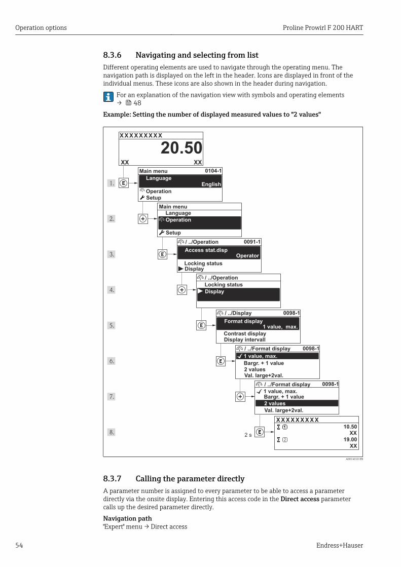
Operation options Proline Prowirl F 200 HART
54 Endress+Hauser
8.3.6 Navigating and selecting from listDifferent operating elements are used to navigate through the operating menu. Thenavigation path is displayed on the left in the header. Icons are displayed in front of theindividual menus. These icons are also shown in the header during navigation.
For an explanation of the navigation view with symbols and operating elements→ 48
Example: Setting the number of displayed measured values to "2 values"
X X X X X X XX X
20.500104-1
2 s
0091-1
0098-1
0098-1
0098-1
X X X X X X XX X10.50
19.00
XX
XX
XXXX
Operation
Operation
Setup
Main menu
English
Main menu
Format display
/ ../Display
Contrast displayDisplay intervall
1 value, max.
Setup
Access stat.disp
/ ../Operation
Display
Locking status
1 value, max.
/ ../Format display
2 valuesVal. large+2val.
Bargr. + 1 value
Locking status
/ ../Operation
Display
1 value, max.
/ ../Format display
2 values
Val. large+2val.
Bargr. + 1 value
Operator
Language
Language
A0014010-EN
8.3.7 Calling the parameter directlyA parameter number is assigned to every parameter to be able to access a parameterdirectly via the onsite display. Entering this access code in the Direct access parametercalls up the desired parameter directly.
Navigation path"Expert" menu → Direct access
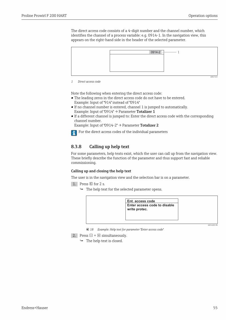
Proline Prowirl F 200 HART Operation options
Endress+Hauser 55
The direct access code consists of a 4-digit number and the channel number, whichidentifies the channel of a process variable: e.g. 0914-1. In the navigation view, thisappears on the right-hand side in the header of the selected parameter.
10914-2
A0017223
1 Direct access code
Note the following when entering the direct access code:• The leading zeros in the direct access code do not have to be entered.
Example: Input of "914" instead of "0914"• If no channel number is entered, channel 1 is jumped to automatically.
Example: Input of "0914" → Parameter Totalizer 1• If a different channel is jumped to: Enter the direct access code with the corresponding
channel number.Example: Input of "0914-2" → Parameter Totalizer 2
For the direct access codes of the individual parameters
8.3.8 Calling up help textFor some parameters, help texts exist, which the user can call up from the navigation view.These briefly describe the function of the parameter and thus support fast and reliablecommissioning.
Calling up and closing the help textThe user is in the navigation view and the selection bar is on a parameter.
1. Press for 2 s. The help text for the selected parameter opens.
Ent. access code
Enter access code to disable
write protec.
A0014002-EN
18 Example: Help text for parameter "Enter access code"
2. Press + simultaneously. The help text is closed.
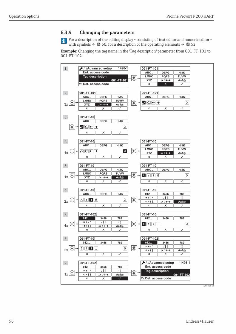
Operation options Proline Prowirl F 200 HART
56 Endress+Hauser
8.3.9 Changing the parametersFor a description of the editing display - consisting of text editor and numeric editor -with symbols → 50, for a description of the operating elements → 52
Example: Changing the tag name in the "Tag description" parameter from 001-FT-101 to001-FT-102
3x
001-FT-101
DEFG HIJK
LMNO PQRS TUVW
XYZ Aa1@
ABC
001-FT-101
DEFG HIJK
LMNO PQRS TUVW
XYZ Aa1@
ABC
001-FT-101
DEFG HIJKABC
001-FT-10
DEFG HIJKABC
001-FT-10
DEFG HIJKABC
1x
001-FT-10
DEFG HIJK
LMNO PQRS TUVW
XYZ Aa1@
ABC
001-FT-10
DEFG HIJK
LMNO PQRS TUVW
XYZ Aa1@
ABC
001-FT-10
DEFG HIJKABC
A a 1 @
001-FT-10
DEFG HIJKABC
A a 1 @
001-FT-10
3456 789
= + - * / [ ] ( )
< > Aa1@
012
001-FT-10
3456 789012
0 1 2
001-FT-10
3456 789012
0 1 2
001-FT-102
3456 789012
0 1 2
001-FT-102
3456 789
= + - * / [ ] ( )
< > Aa1@
012
001-FT-102
3456 789012
0 1 2
001-FT-102
3456 789
= + - * / [ ] ( )
< > Aa1@
012
001-FT-102
3456 789012
0 1 2
001-FT-102
3456 789
= + - * / [ ] ( )
< > Aa1@
012
001-FT-102
1496-1
1x
2x
4x
2x
1x
001-FT-101
1496-1
Max.Tag description
Ent. access code
Def. access code
/../Advanced setup
Tag description
/../Advanced setup
Ent. access code
Def. access code
A0014020-EN
Proline Prowirl F 200 HART Operation options
Endress+Hauser 57
8.3.10 User roles and related access authorizationThe two user roles "Operator" and "Maintenance" have different write access to theparameters if the customer defines a user-specific access code. This protects the deviceconfiguration via the local display from unauthorized access .
Access authorization to parameters
User role Read access Write access
Without access code(from the factory)
With access code Without access code(from the factory)
With access code
Operator -- 1)
Maintenance
1) Despite the defined access code, certain parameters can always be modified and thus are excepted fromthe write protection, as they do not affect the measurement. Refer to the "Write protection via access code"section
If an incorrect access code is entered, the user obtains the access rights of the "Operator"role.
The user role with which the user is currently logged on is indicated by the Accessstatus display parameter. Navigation path: Operation → Access status display
8.3.11 Disabling write protection via access codeIf the -symbol appears on the local display in front of a parameter, the parameter iswrite-protected by a user-specific access code and its value cannot be changed at themoment using the local display .
The locking of the write access via local operation can be disabled by entering thecustomer-defined access code via the respective access option.
1. After you press , the input prompt for the access code appears.
2. Enter the access code. The -symbol in front of the parameters disappears; all previously write-
protected parameters are now re-enabled.
8.3.12 Enabling and disabling the keypad lockThe keypad lock makes it possible to block access to the entire operating menu via localoperation. As a result, it is no longer possible to navigate through the operating menu orchange the values of individual parameters. Users can only read the measured values onthe operational display.
Local operation with mechanical push buttons (display module SD02)Display module SD02: order characteristic "Display; Operation", option C
The keypad lock is switched on and off in the same way:
Switching on the keypad lock
‣ The device is in the measured value display.Press the + + keys simultaneously. The message Keylock on appears on the display: The keypad lock is switched on.
If the user attempts to access the operating menu while the keypad lock is active, themessage Keylock on appears.
Operation options Proline Prowirl F 200 HART
58 Endress+Hauser
Switching off the keypad lock
‣ The keypad lock is switched on.Press the + + keys simultaneously. The message Keylock off appears on the display: The keypad lock is switched off.
Local operation with touch control (display module SD03)Display module SD03: Order characteristic "Display; Operation", option E
The keypad lock is switched on and off via the context menu.
Switching on the keypad lock
The keypad lock is switched on automatically:• Each time the device is restarted.• If the device has not been operated for longer than one minute in the measured value
display.
1. The device is in the measured value display.Press the key for longer than 2 seconds. A context menu appears.
2. In the context menu, select the Keylock on option. The keypad lock is switched on.
If the user attempts to access the operating menu while the keypad lock is active, themessage Keylock on appears.
Switching off the keypad lock
1. The keypad lock is switched on.Press the key for longer than 2 seconds. A context menu appears.
2. In the context menu, select the Keylock off option. The keypad lock is switched off.
8.4 Access to the operating menu via the operating toolThe structure of the operating menu in the operating tools is the same as for operation viathe local display.
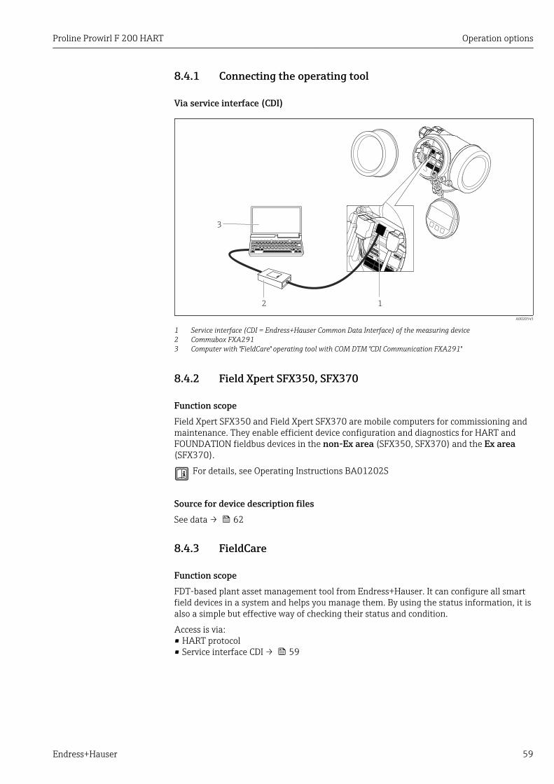
Proline Prowirl F 200 HART Operation options
Endress+Hauser 59
8.4.1 Connecting the operating tool
Via service interface (CDI)
12
3 +
E
–
A0020545
1 Service interface (CDI = Endress+Hauser Common Data Interface) of the measuring device2 Commubox FXA2913 Computer with "FieldCare" operating tool with COM DTM "CDI Communication FXA291"
8.4.2 Field Xpert SFX350, SFX370
Function scopeField Xpert SFX350 and Field Xpert SFX370 are mobile computers for commissioning andmaintenance. They enable efficient device configuration and diagnostics for HART andFOUNDATION fieldbus devices in the non-Ex area (SFX350, SFX370) and the Ex area(SFX370).
For details, see Operating Instructions BA01202S
Source for device description filesSee data → 62
8.4.3 FieldCare
Function scopeFDT-based plant asset management tool from Endress+Hauser. It can configure all smartfield devices in a system and helps you manage them. By using the status information, it isalso a simple but effective way of checking their status and condition.
Access is via:• HART protocol• Service interface CDI → 59
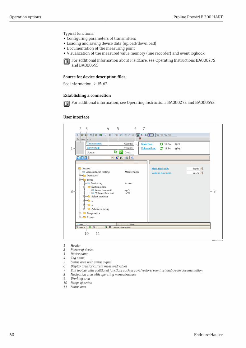
Operation options Proline Prowirl F 200 HART
60 Endress+Hauser
Typical functions:• Configuring parameters of transmitters• Loading and saving device data (upload/download)• Documentation of the measuring point• Visualization of the measured value memory (line recorder) and event logbook
For additional information about FieldCare, see Operating Instructions BA00027Sand BA00059S
Source for device description filesSee information → 62
Establishing a connectionFor additional information, see Operating Instructions BA00027S and BA00059S
User interface
6532
1
Xxxxxx/…/…/
7
P
P
+
–
P
–
P
+
+
+
+
+
+
4
8 9
10 11
Xxxxxxx
GoodStatus:
Device tag:
XxxxxxxDevice name: Mass flow: 12.34 kg/h
Volume flow: 12.34 m /h³
Mass flow unit:
Volume flow unit:
kg/h
m /h³Access status tooling
Operation
Setup
Xxxxxx
Mass flow unitVolume flow unit
Select medium
Device tag
…
…
Advanced setup
Diagnostics
Expert
Maintenance
kg/hm /h³
Xxxxxx
System units
A0021051-EN
1 Header2 Picture of device3 Device name4 Tag name5 Status area with status signal6 Display area for current measured values7 Edit toolbar with additional functions such as save/restore, event list and create documentation8 Navigation area with operating menu structure9 Working area10 Range of action11 Status area
Proline Prowirl F 200 HART Operation options
Endress+Hauser 61
8.4.4 AMS Device Manager
Function scopeProgram from Emerson Process Management for operating and configuring measuringdevices via HART protocol.
Source for device description filesSee data → 62
8.4.5 SIMATIC PDM
Function scopeSIMATIC PDM is a standardized, manufacturer-independent program from Siemens forthe operation, configuration, maintenance and diagnosis of intelligent field devices viaHART protocol.
Source for device description filesSee data → 62
8.4.6 Field Communicator 475
Function scopeIndustrial handheld terminal from Emerson Process Management for remoteconfiguration and measured value display via HART protocol.
Source for device description filesSee data → 62
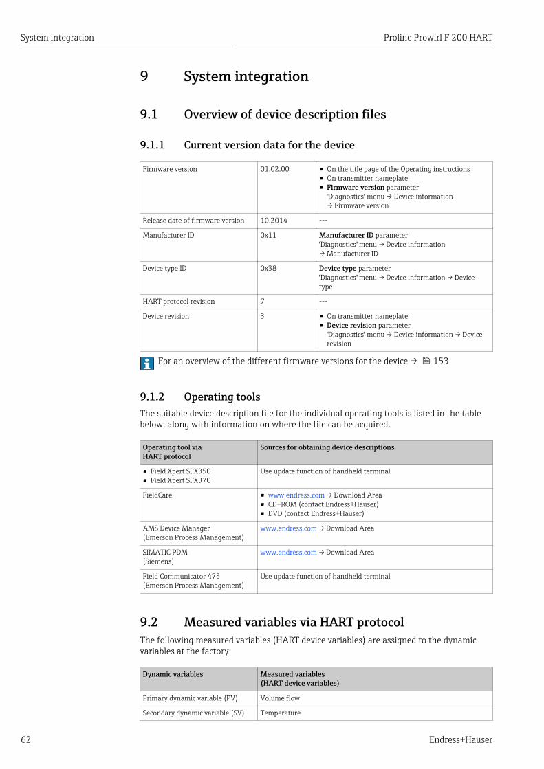
System integration Proline Prowirl F 200 HART
62 Endress+Hauser
9 System integration
9.1 Overview of device description files
9.1.1 Current version data for the device
Firmware version 01.02.00 • On the title page of the Operating instructions• On transmitter nameplate• Firmware version parameter
"Diagnostics" menu → Device information→ Firmware version
Release date of firmware version 10.2014 ---
Manufacturer ID 0x11 Manufacturer ID parameter"Diagnostics" menu → Device information→ Manufacturer ID
Device type ID 0x38 Device type parameter"Diagnostics" menu → Device information → Devicetype
HART protocol revision 7 ---
Device revision 3 • On transmitter nameplate• Device revision parameter
"Diagnostics" menu → Device information → Devicerevision
For an overview of the different firmware versions for the device → 153
9.1.2 Operating toolsThe suitable device description file for the individual operating tools is listed in the tablebelow, along with information on where the file can be acquired.
Operating tool viaHART protocol
Sources for obtaining device descriptions
• Field Xpert SFX350• Field Xpert SFX370
Use update function of handheld terminal
FieldCare • www.endress.com → Download Area• CD–ROM (contact Endress+Hauser)• DVD (contact Endress+Hauser)
AMS Device Manager(Emerson Process Management)
www.endress.com → Download Area
SIMATIC PDM(Siemens)
www.endress.com → Download Area
Field Communicator 475(Emerson Process Management)
Use update function of handheld terminal
9.2 Measured variables via HART protocolThe following measured variables (HART device variables) are assigned to the dynamicvariables at the factory:
Dynamic variables Measured variables(HART device variables)
Primary dynamic variable (PV) Volume flow
Secondary dynamic variable (SV) Temperature
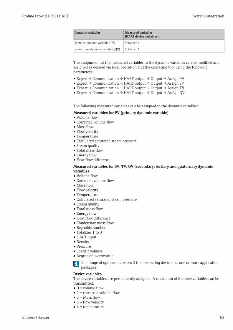
Proline Prowirl F 200 HART System integration
Endress+Hauser 63
Dynamic variables Measured variables(HART device variables)
Tertiary dynamic variable (TV) Totalizer 1
Quaternary dynamic variable (QV) Totalizer 2
The assignment of the measured variables to the dynamic variables can be modified andassigned as desired via local operation and the operating tool using the followingparameters:
• Expert → Communication → HART output → Output → Assign PV• Expert → Communication → HART output → Output → Assign SV• Expert → Communication → HART output → Output → Assign TV• Expert → Communication → HART output → Output → Assign QV
The following measured variables can be assigned to the dynamic variables:
Measured variables for PV (primary dynamic variable)• Volume flow• Corrected volume flow• Mass flow• Flow velocity• Temperature• Calculated saturated steam pressure• Steam quality• Total mass flow• Energy flow• Heat flow difference
Measured variables for SV, TV, QV (secondary, tertiary and quaternary dynamicvariable)• Volume flow• Corrected volume flow• Mass flow• Flow velocity• Temperature• Calculated saturated steam pressure• Steam quality• Total mass flow• Energy flow• Heat flow difference• Condensate mass flow• Reynolds number• Totalizer 1 to 3• HART input• Density• Pressure• Specific volume• Degree of overheating
The range of options increases if the measuring device has one or more applicationpackages.
Device variablesThe device variables are permanently assigned. A maximum of 8 device variables can betransmitted:• 0 = volume flow• 1 = corrected volume flow• 2 = Mass flow• 3 = flow velocity• 4 = temperature
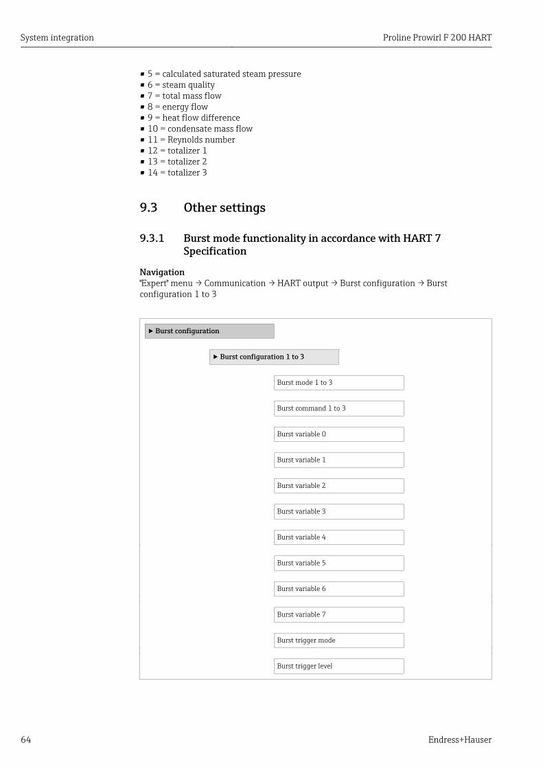
System integration Proline Prowirl F 200 HART
64 Endress+Hauser
• 5 = calculated saturated steam pressure• 6 = steam quality• 7 = total mass flow• 8 = energy flow• 9 = heat flow difference• 10 = condensate mass flow• 11 = Reynolds number• 12 = totalizer 1• 13 = totalizer 2• 14 = totalizer 3
9.3 Other settings
9.3.1 Burst mode functionality in accordance with HART 7Specification
Navigation"Expert" menu → Communication → HART output → Burst configuration → Burstconfiguration 1 to 3
‣ Burst configuration
‣ Burst configuration 1 to 3
Burst mode 1 to 3
Burst command 1 to 3
Burst variable 0
Burst variable 1
Burst variable 2
Burst variable 3
Burst variable 4
Burst variable 5
Burst variable 6
Burst variable 7
Burst trigger mode
Burst trigger level
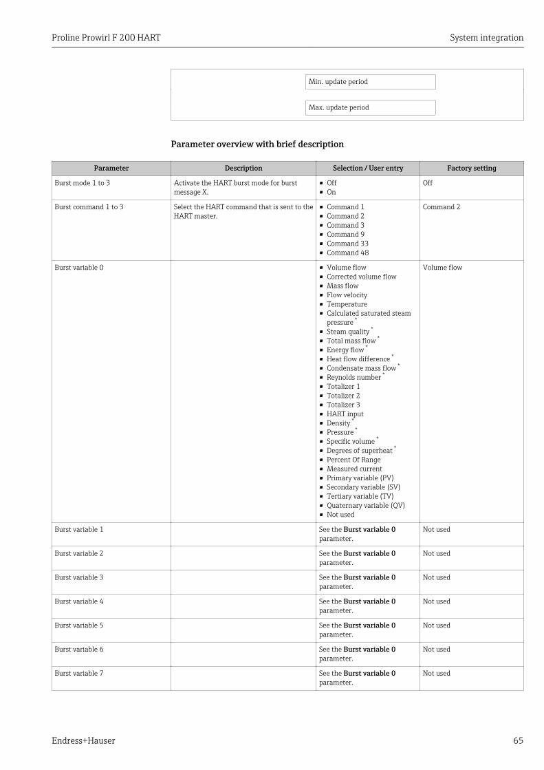
Proline Prowirl F 200 HART System integration
Endress+Hauser 65
Min. update period
Max. update period
Parameter overview with brief description
Parameter Description Selection / User entry Factory setting
Burst mode 1 to 3 Activate the HART burst mode for burstmessage X.
• Off• On
Off
Burst command 1 to 3 Select the HART command that is sent to theHART master.
• Command 1• Command 2• Command 3• Command 9• Command 33• Command 48
Command 2
Burst variable 0 • Volume flow• Corrected volume flow• Mass flow• Flow velocity• Temperature• Calculated saturated steam
pressure *
• Steam quality *
• Total mass flow *
• Energy flow *
• Heat flow difference *
• Condensate mass flow *
• Reynolds number *
• Totalizer 1• Totalizer 2• Totalizer 3• HART input• Density *
• Pressure *
• Specific volume *
• Degrees of superheat *
• Percent Of Range• Measured current• Primary variable (PV)• Secondary variable (SV)• Tertiary variable (TV)• Quaternary variable (QV)• Not used
Volume flow
Burst variable 1 See the Burst variable 0parameter.
Not used
Burst variable 2 See the Burst variable 0parameter.
Not used
Burst variable 3 See the Burst variable 0parameter.
Not used
Burst variable 4 See the Burst variable 0parameter.
Not used
Burst variable 5 See the Burst variable 0parameter.
Not used
Burst variable 6 See the Burst variable 0parameter.
Not used
Burst variable 7 See the Burst variable 0parameter.
Not used
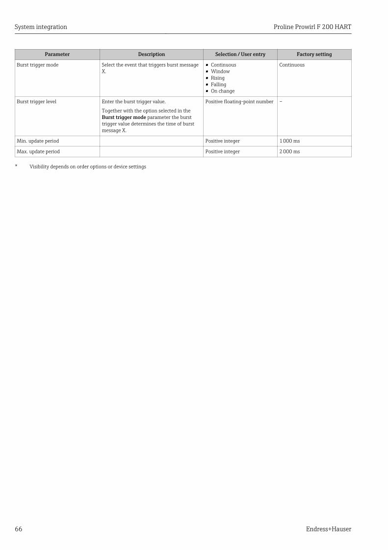
System integration Proline Prowirl F 200 HART
66 Endress+Hauser
Parameter Description Selection / User entry Factory setting
Burst trigger mode Select the event that triggers burst messageX.
• Continuous• Window• Rising• Falling• On change
Continuous
Burst trigger level Enter the burst trigger value.
Together with the option selected in theBurst trigger mode parameter the bursttrigger value determines the time of burstmessage X.
Positive floating-point number –
Min. update period Positive integer 1 000 ms
Max. update period Positive integer 2 000 ms
* Visibility depends on order options or device settings
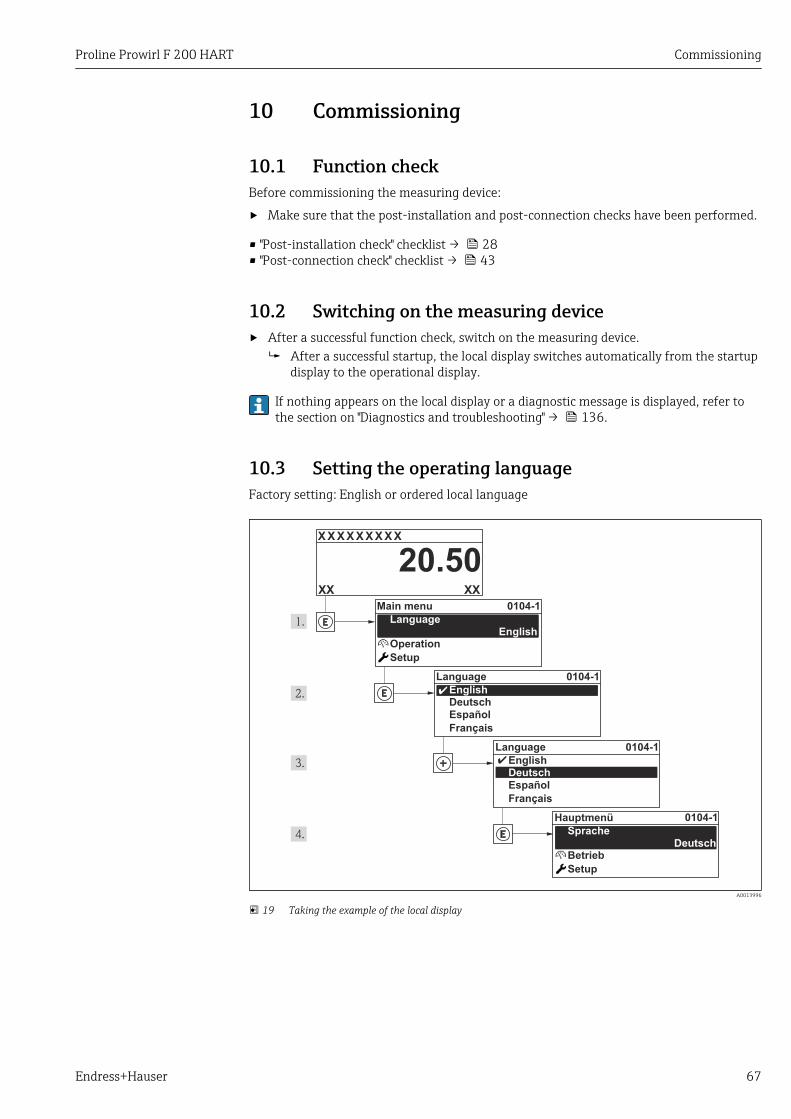
Proline Prowirl F 200 HART Commissioning
Endress+Hauser 67
10 Commissioning
10.1 Function checkBefore commissioning the measuring device:
‣ Make sure that the post-installation and post-connection checks have been performed.
• "Post-installation check" checklist → 28• "Post-connection check" checklist → 43
10.2 Switching on the measuring device‣ After a successful function check, switch on the measuring device.
After a successful startup, the local display switches automatically from the startupdisplay to the operational display.
If nothing appears on the local display or a diagnostic message is displayed, refer tothe section on "Diagnostics and troubleshooting" → 136.
10.3 Setting the operating languageFactory setting: English or ordered local language
X X X X X X XX X
20.50
Operation
Setup
Main menu 0104-1
LanguageEnglish
Español
Français
Language
EnglishDeutsch
Ã
0104-1
Ã
Español
Français
Language
EnglishDeutsch
0104-1
Betrieb
Setup
Hauptmenü
SpracheDeutsch
0104-1
XXXX
A0013996
19 Taking the example of the local display
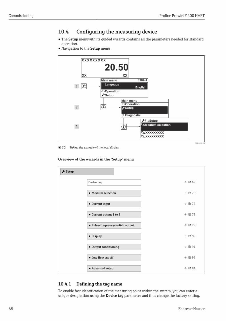
Commissioning Proline Prowirl F 200 HART
68 Endress+Hauser
10.4 Configuring the measuring device• The Setup menuwith its guided wizards contains all the parameters needed for standard
operation.• Navigation to the Setup menu
X X X X X X XX X
20.500104-1
XXXXXXXXX
XXXXXXXXX
XXXX
Operation
Setup
Diagnostic
Operation
Setup
Main menu
English
Main menu
Medium selection
/ ../Setup
Language
A0014007-EN
20 Taking the example of the local display
Overview of the wizards in the "Setup" menu
Setup
Device tag → 69
‣ Medium selection → 70
‣ Current input → 72
‣ Current output 1 to 2 → 75
‣ Pulse/frequency/switch output → 78
‣ Display → 89
‣ Output conditioning → 91
‣ Low flow cut off → 92
‣ Advanced setup → 94
10.4.1 Defining the tag nameTo enable fast identification of the measuring point within the system, you can enter aunique designation using the Device tag parameter and thus change the factory setting.
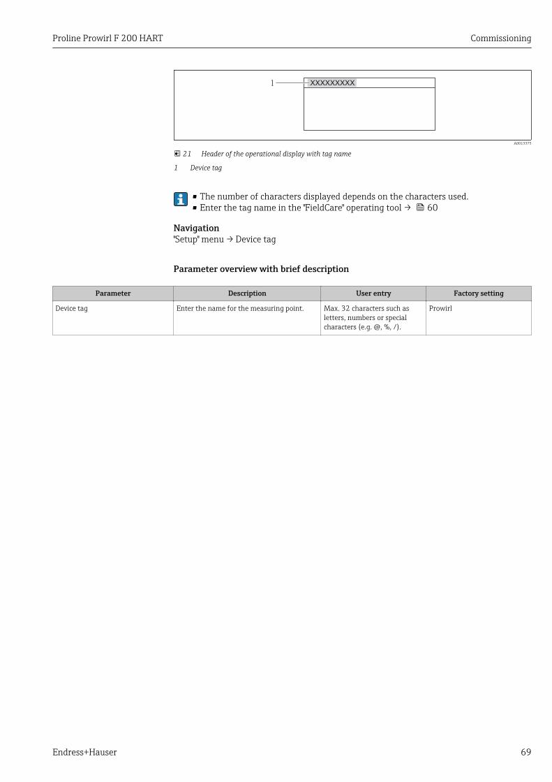
Proline Prowirl F 200 HART Commissioning
Endress+Hauser 69
1 XXXXXXXXX
A0013375
21 Header of the operational display with tag name
1 Device tag
• The number of characters displayed depends on the characters used.• Enter the tag name in the "FieldCare" operating tool → 60
Navigation"Setup" menu → Device tag
Parameter overview with brief description
Parameter Description User entry Factory setting
Device tag Enter the name for the measuring point. Max. 32 characters such asletters, numbers or specialcharacters (e.g. @, %, /).
Prowirl
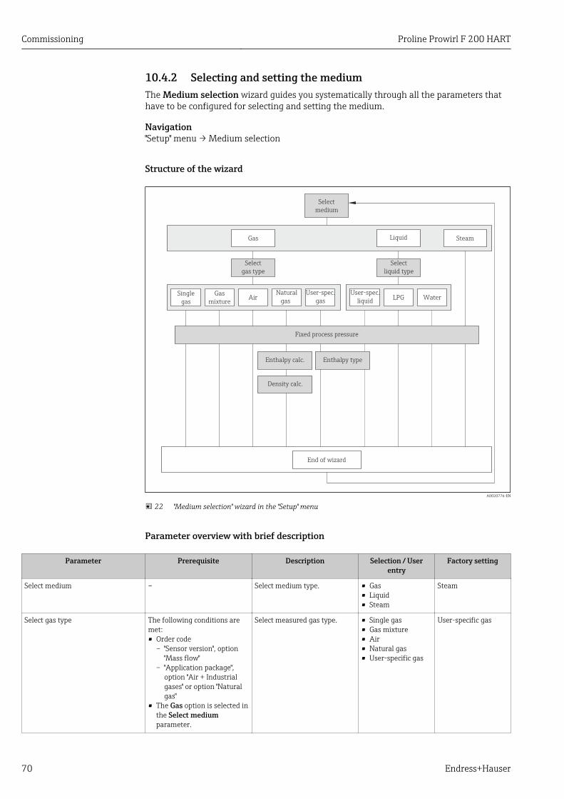
Commissioning Proline Prowirl F 200 HART
70 Endress+Hauser
10.4.2 Selecting and setting the mediumThe Medium selection wizard guides you systematically through all the parameters thathave to be configured for selecting and setting the medium.
Navigation"Setup" menu → Medium selection
Structure of the wizard
End of wizard
Select
medium
LiquidGas Steam
Select
gas type
Select
liquid type
AirNatural
gas
Enthalpy calc.
Density calc.
User-spec.
gasGas
mixture
Single
gasWaterLPG
User-spec.
liquid
Fixed process pressure
Enthalpy type
A0020776-EN
22 "Medium selection" wizard in the "Setup" menu
Parameter overview with brief description
Parameter Prerequisite Description Selection / Userentry
Factory setting
Select medium – Select medium type. • Gas• Liquid• Steam
Steam
Select gas type The following conditions aremet:• Order code
– "Sensor version", option"Mass flow"
– "Application package",option "Air + Industrialgases" or option "Naturalgas"
• The Gas option is selected inthe Select mediumparameter.
Select measured gas type. • Single gas• Gas mixture• Air• Natural gas• User-specific gas
User-specific gas
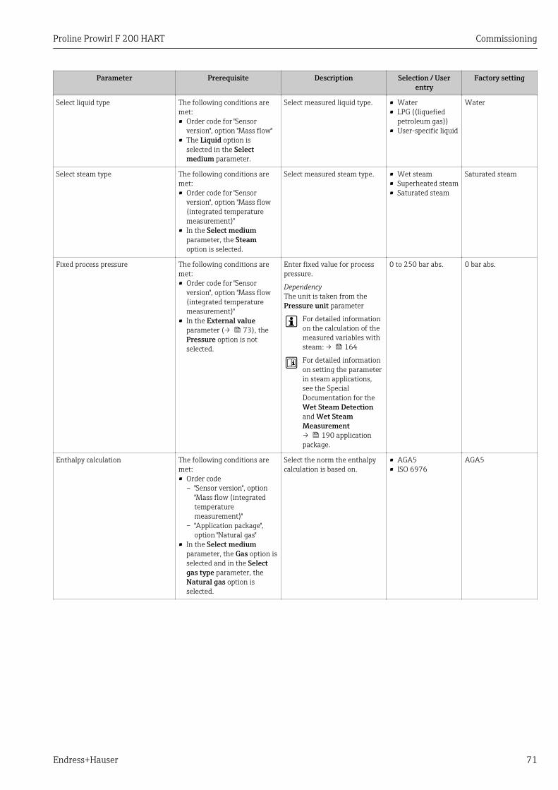
Proline Prowirl F 200 HART Commissioning
Endress+Hauser 71
Parameter Prerequisite Description Selection / Userentry
Factory setting
Select liquid type The following conditions aremet:• Order code for "Sensor
version", option "Mass flow"• The Liquid option is
selected in the Selectmedium parameter.
Select measured liquid type. • Water• LPG ((liquefied
petroleum gas))• User-specific liquid
Water
Select steam type The following conditions aremet:• Order code for "Sensor
version", option "Mass flow(integrated temperaturemeasurement)"
• In the Select mediumparameter, the Steamoption is selected.
Select measured steam type. • Wet steam• Superheated steam• Saturated steam
Saturated steam
Fixed process pressure The following conditions aremet:• Order code for "Sensor
version", option "Mass flow(integrated temperaturemeasurement)"
• In the External valueparameter (→ 73), thePressure option is notselected.
Enter fixed value for processpressure.
DependencyThe unit is taken from thePressure unit parameter
For detailed informationon the calculation of themeasured variables withsteam: → 164
For detailed informationon setting the parameterin steam applications,see the SpecialDocumentation for theWet Steam Detectionand Wet SteamMeasurement→ 190 applicationpackage.
0 to 250 bar abs. 0 bar abs.
Enthalpy calculation The following conditions aremet:• Order code
– "Sensor version", option"Mass flow (integratedtemperaturemeasurement)"
– "Application package",option "Natural gas"
• In the Select mediumparameter, the Gas option isselected and in the Selectgas type parameter, theNatural gas option isselected.
Select the norm the enthalpycalculation is based on.
• AGA5• ISO 6976
AGA5
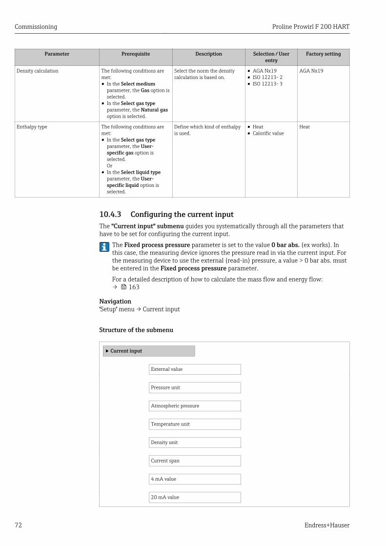
Commissioning Proline Prowirl F 200 HART
72 Endress+Hauser
Parameter Prerequisite Description Selection / Userentry
Factory setting
Density calculation The following conditions aremet:• In the Select medium
parameter, the Gas option isselected.
• In the Select gas typeparameter, the Natural gasoption is selected.
Select the norm the densitycalculation is based on.
• AGA Nx19• ISO 12213- 2• ISO 12213- 3
AGA Nx19
Enthalpy type The following conditions aremet:• In the Select gas type
parameter, the User-specific gas option isselected.Or
• In the Select liquid typeparameter, the User-specific liquid option isselected.
Define which kind of enthalpyis used.
• Heat• Calorific value
Heat
10.4.3 Configuring the current inputThe "Current input" submenu guides you systematically through all the parameters thathave to be set for configuring the current input.
The Fixed process pressure parameter is set to the value 0 bar abs. (ex works). Inthis case, the measuring device ignores the pressure read in via the current input. Forthe measuring device to use the external (read-in) pressure, a value > 0 bar abs. mustbe entered in the Fixed process pressure parameter.
For a detailed description of how to calculate the mass flow and energy flow:→ 163
Navigation"Setup" menu → Current input
Structure of the submenu
‣ Current input
External value
Pressure unit
Atmospheric pressure
Temperature unit
Density unit
Current span
4 mA value
20 mA value
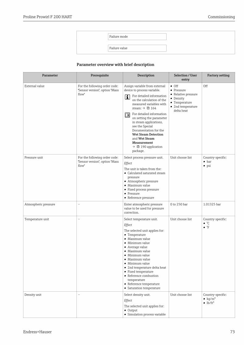
Proline Prowirl F 200 HART Commissioning
Endress+Hauser 73
Failure mode
Failure value
Parameter overview with brief description
Parameter Prerequisite Description Selection / Userentry
Factory setting
External value For the following order code:"Sensor version", option "Massflow"
Assign variable from externaldevice to process variable.
For detailed informationon the calculation of themeasured variables withsteam: → 164
For detailed informationon setting the parameterin steam applications,see the SpecialDocumentation for theWet Steam Detectionand Wet SteamMeasurement→ 190 applicationpackage.
• Off• Pressure• Relative pressure• Density• Temperature• 2nd temperature
delta heat
Off
Pressure unit For the following order code:"Sensor version", option "Massflow"
Select process pressure unit.
Effect
The unit is taken from the:• Calculated saturated steam
pressure• Atmospheric pressure• Maximum value• Fixed process pressure• Pressure• Reference pressure
Unit choose list Country-specific:• bar• psi
Atmospheric pressure – Enter atmospheric pressurevalue to be used for pressurecorrection.
0 to 250 bar 1.01325 bar
Temperature unit – Select temperature unit.
Effect
The selected unit applies for:• Temperature• Maximum value• Minimum value• Average value• Maximum value• Minimum value• Maximum value• Minimum value• 2nd temperature delta heat• Fixed temperature• Reference combustion
temperature• Reference temperature• Saturation temperature
Unit choose list Country-specific:• °C• °F
Density unit – Select density unit.
Effect
The selected unit applies for:• Output• Simulation process variable
Unit choose list Country-specific:• kg/m³• lb/ft³
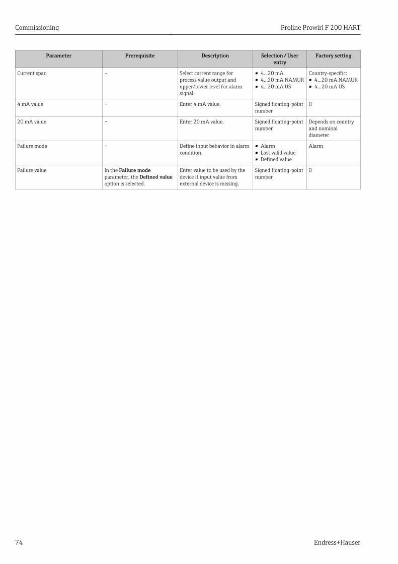
Commissioning Proline Prowirl F 200 HART
74 Endress+Hauser
Parameter Prerequisite Description Selection / Userentry
Factory setting
Current span – Select current range forprocess value output andupper/lower level for alarmsignal.
• 4...20 mA• 4...20 mA NAMUR• 4...20 mA US
Country-specific:• 4...20 mA NAMUR• 4...20 mA US
4 mA value – Enter 4 mA value. Signed floating-pointnumber
0
20 mA value – Enter 20 mA value. Signed floating-pointnumber
Depends on countryand nominaldiameter
Failure mode – Define input behavior in alarmcondition.
• Alarm• Last valid value• Defined value
Alarm
Failure value In the Failure modeparameter, the Defined valueoption is selected.
Enter value to be used by thedevice if input value fromexternal device is missing.
Signed floating-pointnumber
0
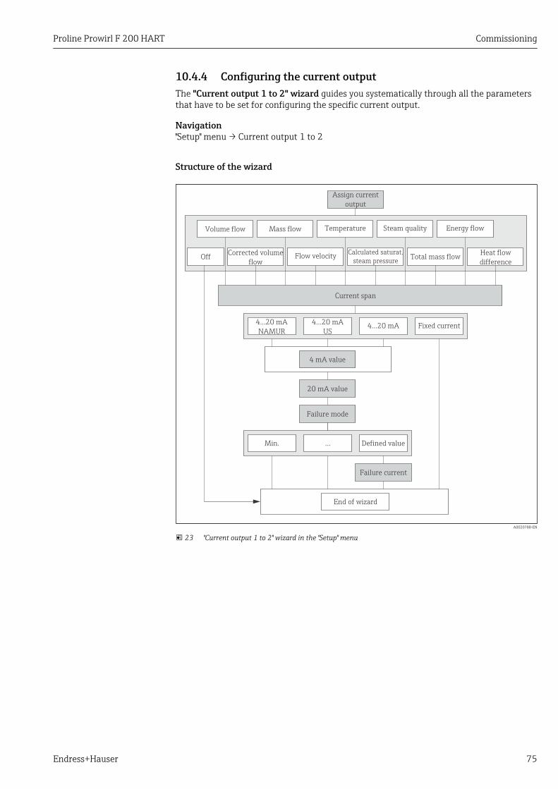
Proline Prowirl F 200 HART Commissioning
Endress+Hauser 75
10.4.4 Configuring the current outputThe "Current output 1 to 2" wizard guides you systematically through all the parametersthat have to be set for configuring the specific current output.
Navigation"Setup" menu → Current output 1 to 2
Structure of the wizard
Assign current
output
4...20 mA
NAMUR
4...20 mA
US4...20 mA Fixed current
4 mA value
20 mA value
Failure mode
Min. Defined value
Failure current
Current span
Mass flow Steam qualityTemperatureVolume flow
Flow velocity Total mass flowCalculated saturat.
steam pressureCorrected volume
flow
Energy flow
Heat flow
difference
…
End of wizard
Off
A0020788-EN
23 "Current output 1 to 2" wizard in the "Setup" menu
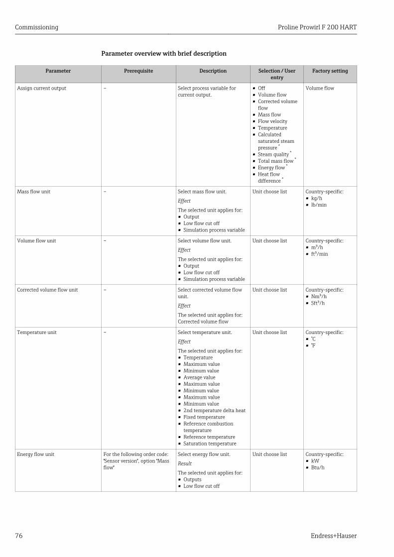
Commissioning Proline Prowirl F 200 HART
76 Endress+Hauser
Parameter overview with brief description
Parameter Prerequisite Description Selection / Userentry
Factory setting
Assign current output – Select process variable forcurrent output.
• Off• Volume flow• Corrected volume
flow• Mass flow• Flow velocity• Temperature• Calculated
saturated steampressure *
• Steam quality *
• Total mass flow *
• Energy flow *
• Heat flowdifference *
Volume flow
Mass flow unit – Select mass flow unit.
Effect
The selected unit applies for:• Output• Low flow cut off• Simulation process variable
Unit choose list Country-specific:• kg/h• lb/min
Volume flow unit – Select volume flow unit.
Effect
The selected unit applies for:• Output• Low flow cut off• Simulation process variable
Unit choose list Country-specific:• m³/h• ft³/min
Corrected volume flow unit – Select corrected volume flowunit.
Effect
The selected unit applies for:Corrected volume flow
Unit choose list Country-specific:• Nm³/h• Sft³/h
Temperature unit – Select temperature unit.
Effect
The selected unit applies for:• Temperature• Maximum value• Minimum value• Average value• Maximum value• Minimum value• Maximum value• Minimum value• 2nd temperature delta heat• Fixed temperature• Reference combustion
temperature• Reference temperature• Saturation temperature
Unit choose list Country-specific:• °C• °F
Energy flow unit For the following order code:"Sensor version", option "Massflow"
Select energy flow unit.
Result
The selected unit applies for:• Outputs• Low flow cut off
Unit choose list Country-specific:• kW• Btu/h
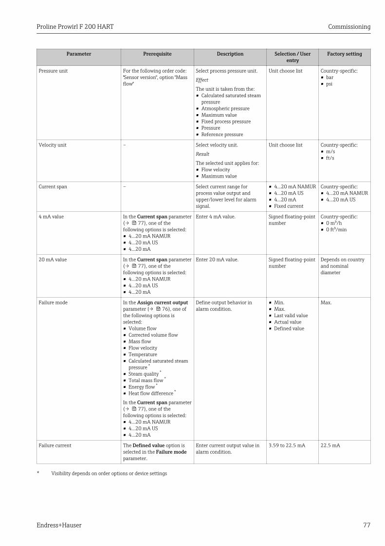
Proline Prowirl F 200 HART Commissioning
Endress+Hauser 77
Parameter Prerequisite Description Selection / Userentry
Factory setting
Pressure unit For the following order code:"Sensor version", option "Massflow"
Select process pressure unit.
Effect
The unit is taken from the:• Calculated saturated steam
pressure• Atmospheric pressure• Maximum value• Fixed process pressure• Pressure• Reference pressure
Unit choose list Country-specific:• bar• psi
Velocity unit – Select velocity unit.
Result
The selected unit applies for:• Flow velocity• Maximum value
Unit choose list Country-specific:• m/s• ft/s
Current span – Select current range forprocess value output andupper/lower level for alarmsignal.
• 4...20 mA NAMUR• 4...20 mA US• 4...20 mA• Fixed current
Country-specific:• 4...20 mA NAMUR• 4...20 mA US
4 mA value In the Current span parameter(→ 77), one of thefollowing options is selected:• 4...20 mA NAMUR• 4...20 mA US• 4...20 mA
Enter 4 mA value. Signed floating-pointnumber
Country-specific:• 0 m³/h• 0 ft³/min
20 mA value In the Current span parameter(→ 77), one of thefollowing options is selected:• 4...20 mA NAMUR• 4...20 mA US• 4...20 mA
Enter 20 mA value. Signed floating-pointnumber
Depends on countryand nominaldiameter
Failure mode In the Assign current outputparameter (→ 76), one ofthe following options isselected:• Volume flow• Corrected volume flow• Mass flow• Flow velocity• Temperature• Calculated saturated steam
pressure *
• Steam quality *
• Total mass flow *
• Energy flow *
• Heat flow difference *
In the Current span parameter(→ 77), one of thefollowing options is selected:• 4...20 mA NAMUR• 4...20 mA US• 4...20 mA
Define output behavior inalarm condition.
• Min.• Max.• Last valid value• Actual value• Defined value
Max.
Failure current The Defined value option isselected in the Failure modeparameter.
Enter current output value inalarm condition.
3.59 to 22.5 mA 22.5 mA
* Visibility depends on order options or device settings
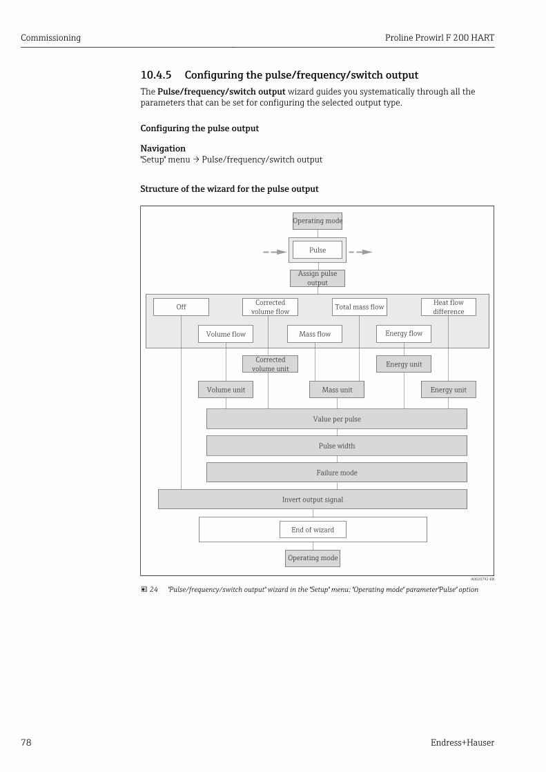
Commissioning Proline Prowirl F 200 HART
78 Endress+Hauser
10.4.5 Configuring the pulse/frequency/switch outputThe Pulse/frequency/switch output wizard guides you systematically through all theparameters that can be set for configuring the selected output type.
Configuring the pulse output
Navigation"Setup" menu → Pulse/frequency/switch output
Structure of the wizard for the pulse output
Operating mode
Pulse
Assign pulse
output
Value per pulse
Mass flowVolume flow
Total mass flowCorrected
volume flow
Energy flow
Heat flow
difference
Volume unit
Corrected
volume unit
Energy unitMass unit
Off
Energy unit
Pulse width
Failure mode
Invert output signal
End of wizard
Operating mode
A0020792-EN
24 "Pulse/frequency/switch output" wizard in the "Setup" menu: "Operating mode" parameter"Pulse" option
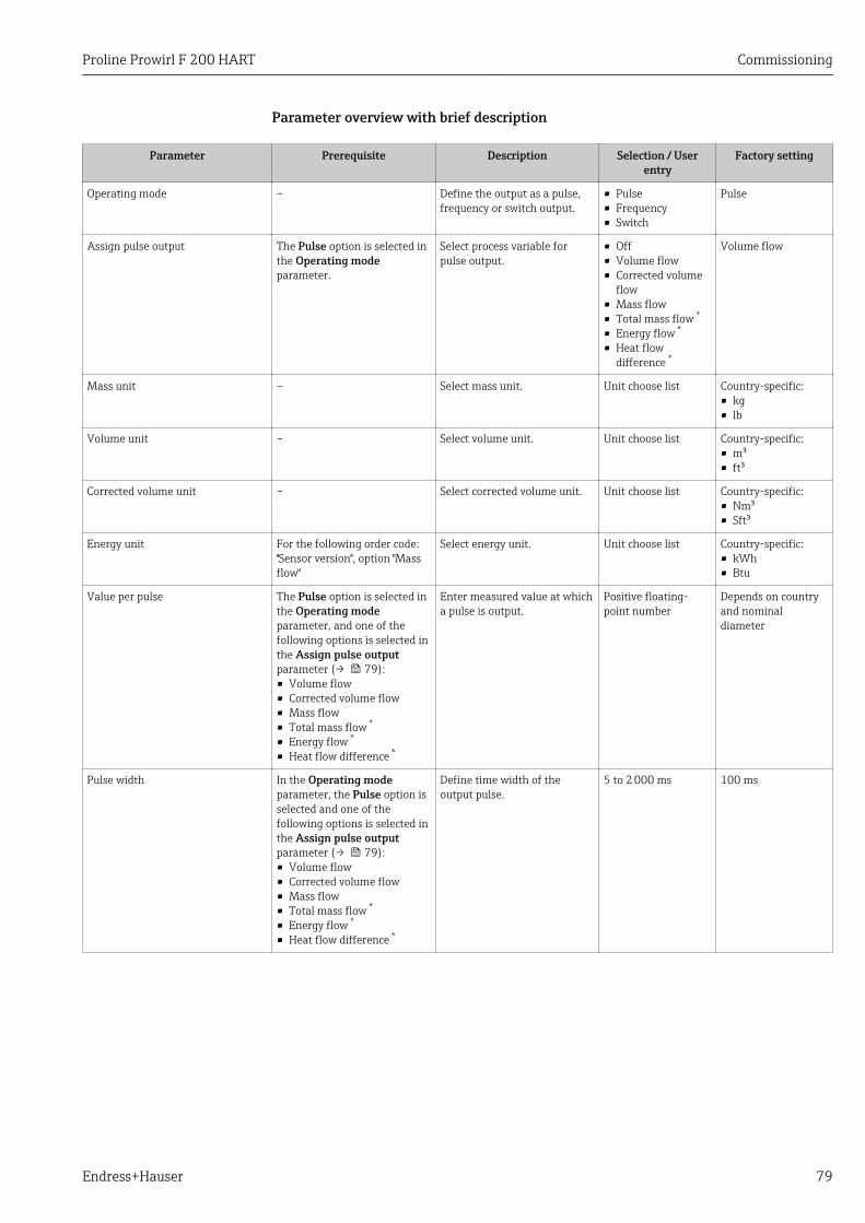
Proline Prowirl F 200 HART Commissioning
Endress+Hauser 79
Parameter overview with brief description
Parameter Prerequisite Description Selection / Userentry
Factory setting
Operating mode – Define the output as a pulse,frequency or switch output.
• Pulse• Frequency• Switch
Pulse
Assign pulse output The Pulse option is selected inthe Operating modeparameter.
Select process variable forpulse output.
• Off• Volume flow• Corrected volume
flow• Mass flow• Total mass flow *
• Energy flow *
• Heat flowdifference *
Volume flow
Mass unit – Select mass unit. Unit choose list Country-specific:• kg• lb
Volume unit – Select volume unit. Unit choose list Country-specific:• m³• ft³
Corrected volume unit – Select corrected volume unit. Unit choose list Country-specific:• Nm³• Sft³
Energy unit For the following order code:"Sensor version", option "Massflow"
Select energy unit. Unit choose list Country-specific:• kWh• Btu
Value per pulse The Pulse option is selected inthe Operating modeparameter, and one of thefollowing options is selected inthe Assign pulse outputparameter (→ 79):• Volume flow• Corrected volume flow• Mass flow• Total mass flow *
• Energy flow *
• Heat flow difference *
Enter measured value at whicha pulse is output.
Positive floating-point number
Depends on countryand nominaldiameter
Pulse width In the Operating modeparameter, the Pulse option isselected and one of thefollowing options is selected inthe Assign pulse outputparameter (→ 79):• Volume flow• Corrected volume flow• Mass flow• Total mass flow *
• Energy flow *
• Heat flow difference *
Define time width of theoutput pulse.
5 to 2 000 ms 100 ms
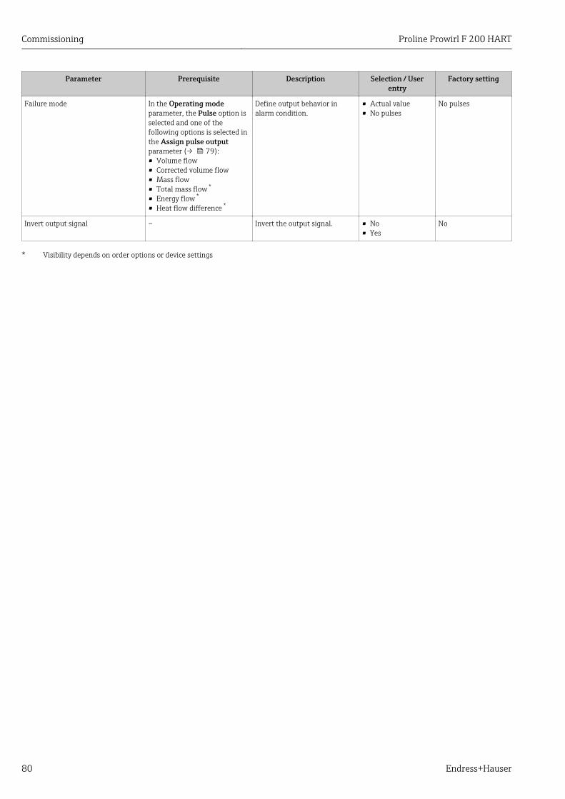
Commissioning Proline Prowirl F 200 HART
80 Endress+Hauser
Parameter Prerequisite Description Selection / Userentry
Factory setting
Failure mode In the Operating modeparameter, the Pulse option isselected and one of thefollowing options is selected inthe Assign pulse outputparameter (→ 79):• Volume flow• Corrected volume flow• Mass flow• Total mass flow *
• Energy flow *
• Heat flow difference *
Define output behavior inalarm condition.
• Actual value• No pulses
No pulses
Invert output signal – Invert the output signal. • No• Yes
No
* Visibility depends on order options or device settings
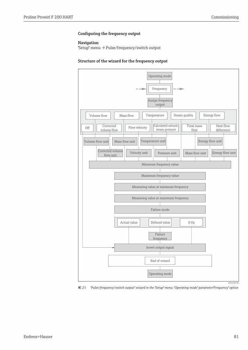
Proline Prowirl F 200 HART Commissioning
Endress+Hauser 81
Configuring the frequency output
Navigation"Setup" menu → Pulse/frequency/switch output
Structure of the wizard for the frequency output
Measuring value at minimum frequency
Invert output signal
Maximum frequency value
Measuring value at maximum frequency
Failure mode
Assign frequency
output
Minimum frequency value
Mass flow Steam qualityTemperatureVolume flow
Flow velocityTotal mass
flow
Calculated saturat.
steam pressureCorrected
volume flow
Energy flow
Heat flow
differenceOff
Actual value Defined value 0 Hz
Failure
frequency
End of wizard
Operating mode
Operating mode
Frequency
Volume flow unit Temperature unitMass flow unit Energy flow unit
Corrected volume
flow unitPressure unit Mass flow unit Energy flow unitVelocity unit
A0020789-EN
25 "Pulse/frequency/switch output" wizard in the "Setup" menu: "Operating mode" parameter"Frequency" option
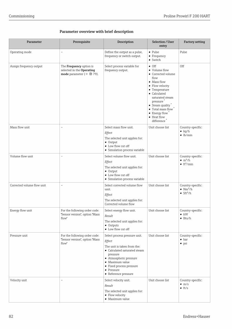
Commissioning Proline Prowirl F 200 HART
82 Endress+Hauser
Parameter overview with brief description
Parameter Prerequisite Description Selection / Userentry
Factory setting
Operating mode – Define the output as a pulse,frequency or switch output.
• Pulse• Frequency• Switch
Pulse
Assign frequency output The Frequency option isselected in the Operatingmode parameter (→ 79).
Select process variable forfrequency output.
• Off• Volume flow• Corrected volume
flow• Mass flow• Flow velocity• Temperature• Calculated
saturated steampressure *
• Steam quality *
• Total mass flow *
• Energy flow *
• Heat flowdifference *
Off
Mass flow unit – Select mass flow unit.
Effect
The selected unit applies for:• Output• Low flow cut off• Simulation process variable
Unit choose list Country-specific:• kg/h• lb/min
Volume flow unit – Select volume flow unit.
Effect
The selected unit applies for:• Output• Low flow cut off• Simulation process variable
Unit choose list Country-specific:• m³/h• ft³/min
Corrected volume flow unit – Select corrected volume flowunit.
Effect
The selected unit applies for:Corrected volume flow
Unit choose list Country-specific:• Nm³/h• Sft³/h
Energy flow unit For the following order code:"Sensor version", option "Massflow"
Select energy flow unit.
Result
The selected unit applies for:• Outputs• Low flow cut off
Unit choose list Country-specific:• kW• Btu/h
Pressure unit For the following order code:"Sensor version", option "Massflow"
Select process pressure unit.
Effect
The unit is taken from the:• Calculated saturated steam
pressure• Atmospheric pressure• Maximum value• Fixed process pressure• Pressure• Reference pressure
Unit choose list Country-specific:• bar• psi
Velocity unit – Select velocity unit.
Result
The selected unit applies for:• Flow velocity• Maximum value
Unit choose list Country-specific:• m/s• ft/s
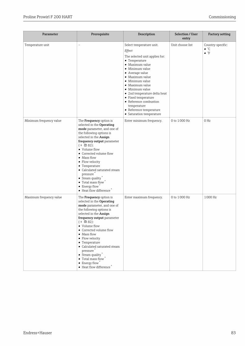
Proline Prowirl F 200 HART Commissioning
Endress+Hauser 83
Parameter Prerequisite Description Selection / Userentry
Factory setting
Temperature unit – Select temperature unit.
Effect
The selected unit applies for:• Temperature• Maximum value• Minimum value• Average value• Maximum value• Minimum value• Maximum value• Minimum value• 2nd temperature delta heat• Fixed temperature• Reference combustion
temperature• Reference temperature• Saturation temperature
Unit choose list Country-specific:• °C• °F
Minimum frequency value The Frequency option isselected in the Operatingmode parameter, and one ofthe following options isselected in the Assignfrequency output parameter(→ 82):• Volume flow• Corrected volume flow• Mass flow• Flow velocity• Temperature• Calculated saturated steam
pressure *
• Steam quality *
• Total mass flow *
• Energy flow *
• Heat flow difference *
Enter minimum frequency. 0 to 1 000 Hz 0 Hz
Maximum frequency value The Frequency option isselected in the Operatingmode parameter, and one ofthe following options isselected in the Assignfrequency output parameter(→ 82):• Volume flow• Corrected volume flow• Mass flow• Flow velocity• Temperature• Calculated saturated steam
pressure *
• Steam quality *
• Total mass flow *
• Energy flow *
• Heat flow difference *
Enter maximum frequency. 0 to 1 000 Hz 1 000 Hz
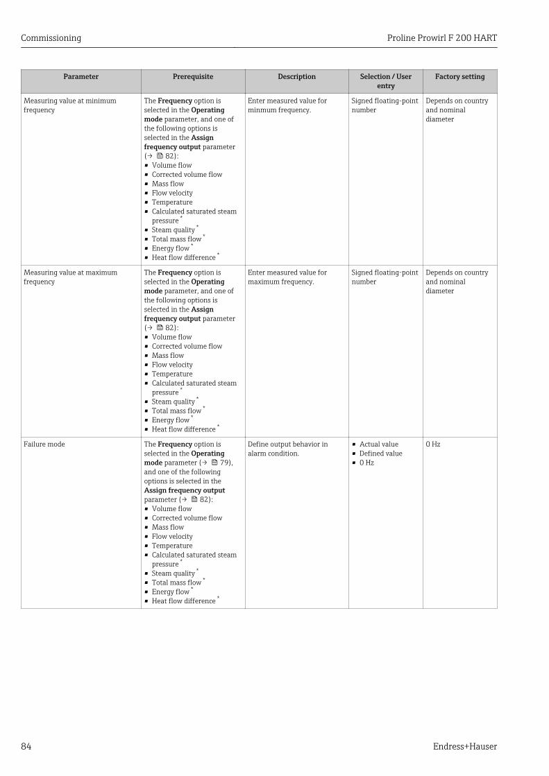
Commissioning Proline Prowirl F 200 HART
84 Endress+Hauser
Parameter Prerequisite Description Selection / Userentry
Factory setting
Measuring value at minimumfrequency
The Frequency option isselected in the Operatingmode parameter, and one ofthe following options isselected in the Assignfrequency output parameter(→ 82):• Volume flow• Corrected volume flow• Mass flow• Flow velocity• Temperature• Calculated saturated steam
pressure *
• Steam quality *
• Total mass flow *
• Energy flow *
• Heat flow difference *
Enter measured value forminmum frequency.
Signed floating-pointnumber
Depends on countryand nominaldiameter
Measuring value at maximumfrequency
The Frequency option isselected in the Operatingmode parameter, and one ofthe following options isselected in the Assignfrequency output parameter(→ 82):• Volume flow• Corrected volume flow• Mass flow• Flow velocity• Temperature• Calculated saturated steam
pressure *
• Steam quality *
• Total mass flow *
• Energy flow *
• Heat flow difference *
Enter measured value formaximum frequency.
Signed floating-pointnumber
Depends on countryand nominaldiameter
Failure mode The Frequency option isselected in the Operatingmode parameter (→ 79),and one of the followingoptions is selected in theAssign frequency outputparameter (→ 82):• Volume flow• Corrected volume flow• Mass flow• Flow velocity• Temperature• Calculated saturated steam
pressure *
• Steam quality *
• Total mass flow *
• Energy flow *
• Heat flow difference *
Define output behavior inalarm condition.
• Actual value• Defined value• 0 Hz
0 Hz
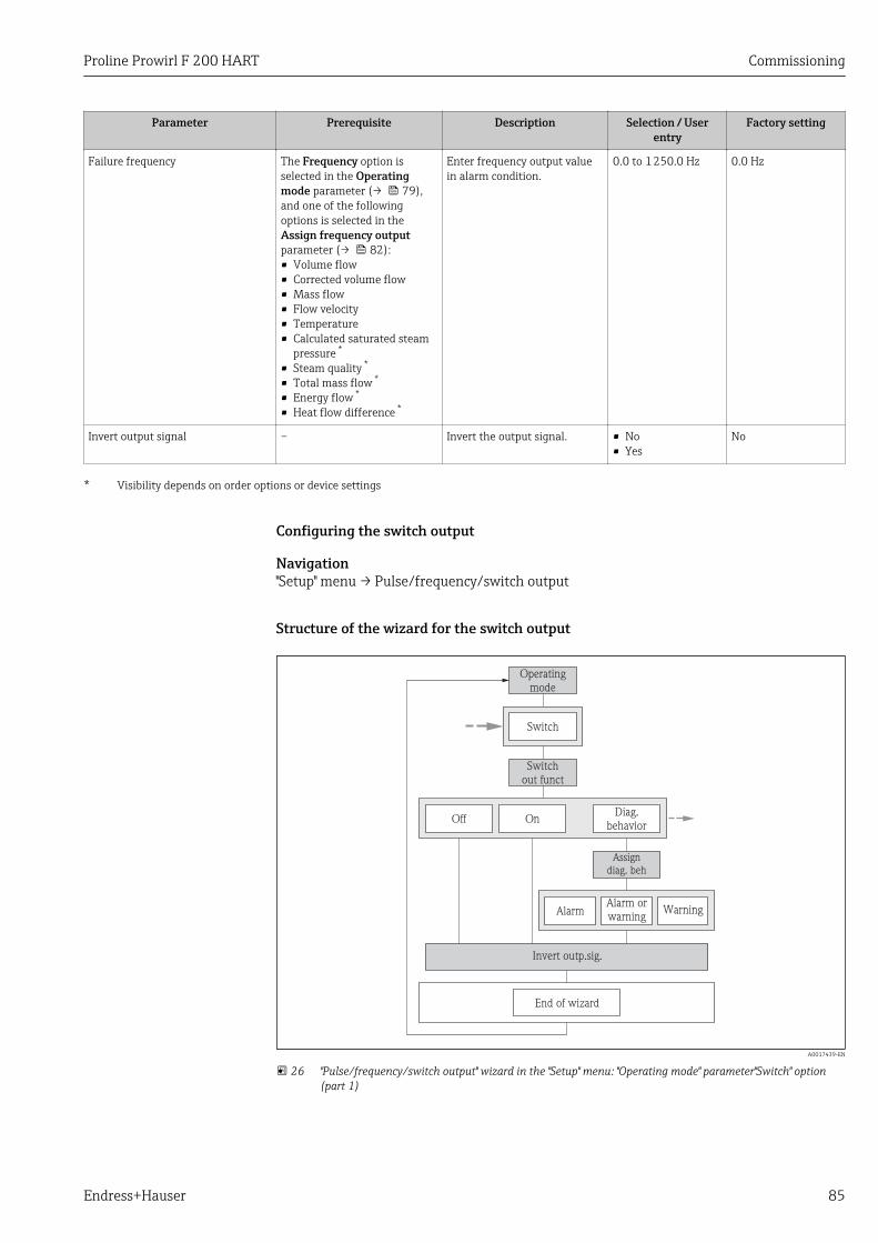
Proline Prowirl F 200 HART Commissioning
Endress+Hauser 85
Parameter Prerequisite Description Selection / Userentry
Factory setting
Failure frequency The Frequency option isselected in the Operatingmode parameter (→ 79),and one of the followingoptions is selected in theAssign frequency outputparameter (→ 82):• Volume flow• Corrected volume flow• Mass flow• Flow velocity• Temperature• Calculated saturated steam
pressure *
• Steam quality *
• Total mass flow *
• Energy flow *
• Heat flow difference *
Enter frequency output valuein alarm condition.
0.0 to 1 250.0 Hz 0.0 Hz
Invert output signal – Invert the output signal. • No• Yes
No
* Visibility depends on order options or device settings
Configuring the switch output
Navigation"Setup" menu → Pulse/frequency/switch output
Structure of the wizard for the switch output
End of wizard
Operatingmode
Switch
Switchout funct
Diag.behavior
Off On
Assigndiag. beh
AlarmAlarm orwarning
Warning
Invert outp.sig.
A0017439-EN
26 "Pulse/frequency/switch output" wizard in the "Setup" menu: "Operating mode" parameter"Switch" option(part 1)
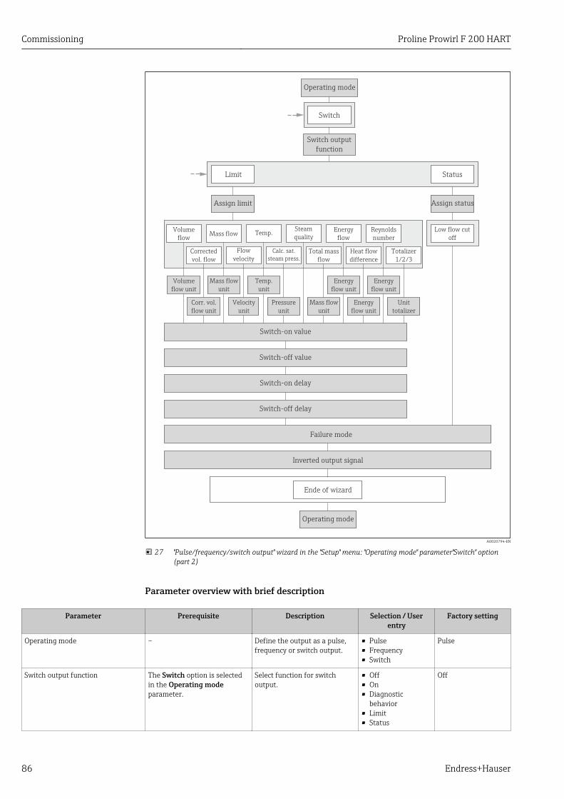
Commissioning Proline Prowirl F 200 HART
86 Endress+Hauser
Operating mode
Operating mode
Limit Status
Assign limit Assign status
Switch
Switch output
function
Switch-on value
Switch-off value
Switch-on delay
Switch-off delay
Failure mode
Inverted output signal
Ende of wizard
Steam
qualityLow flow cut
off
Volume
flow unit
Mass flow
unit
Corrected
vol. flow
Flow
velocity
Temp.
Calc. sat.
steam press.
Corr. vol.
flow unit
Velocity
unit
Energy
flow unit
Energy
flow
Total mass
flow
Mass flow
unit
Reynolds
number
Unit
totalizer
Mass flowVolume
flow
Heat flow
difference
Totalizer
1/2/3
Temp.
unit
Pressure
unit
Energy
flow unit
Energy
flow unit
A0020794-EN
27 "Pulse/frequency/switch output" wizard in the "Setup" menu: "Operating mode" parameter"Switch" option(part 2)
Parameter overview with brief description
Parameter Prerequisite Description Selection / Userentry
Factory setting
Operating mode – Define the output as a pulse,frequency or switch output.
• Pulse• Frequency• Switch
Pulse
Switch output function The Switch option is selectedin the Operating modeparameter.
Select function for switchoutput.
• Off• On• Diagnostic
behavior• Limit• Status
Off
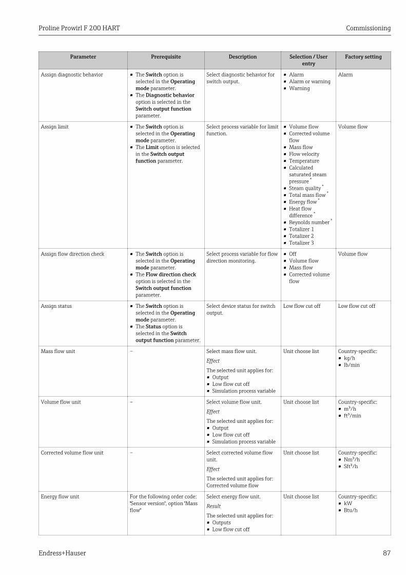
Proline Prowirl F 200 HART Commissioning
Endress+Hauser 87
Parameter Prerequisite Description Selection / Userentry
Factory setting
Assign diagnostic behavior • The Switch option isselected in the Operatingmode parameter.
• The Diagnostic behavioroption is selected in theSwitch output functionparameter.
Select diagnostic behavior forswitch output.
• Alarm• Alarm or warning• Warning
Alarm
Assign limit • The Switch option isselected in the Operatingmode parameter.
• The Limit option is selectedin the Switch outputfunction parameter.
Select process variable for limitfunction.
• Volume flow• Corrected volume
flow• Mass flow• Flow velocity• Temperature• Calculated
saturated steampressure *
• Steam quality *
• Total mass flow *
• Energy flow *
• Heat flowdifference *
• Reynolds number *
• Totalizer 1• Totalizer 2• Totalizer 3
Volume flow
Assign flow direction check • The Switch option isselected in the Operatingmode parameter.
• The Flow direction checkoption is selected in theSwitch output functionparameter.
Select process variable for flowdirection monitoring.
• Off• Volume flow• Mass flow• Corrected volume
flow
Volume flow
Assign status • The Switch option isselected in the Operatingmode parameter.
• The Status option isselected in the Switchoutput function parameter.
Select device status for switchoutput.
Low flow cut off Low flow cut off
Mass flow unit – Select mass flow unit.
Effect
The selected unit applies for:• Output• Low flow cut off• Simulation process variable
Unit choose list Country-specific:• kg/h• lb/min
Volume flow unit – Select volume flow unit.
Effect
The selected unit applies for:• Output• Low flow cut off• Simulation process variable
Unit choose list Country-specific:• m³/h• ft³/min
Corrected volume flow unit – Select corrected volume flowunit.
Effect
The selected unit applies for:Corrected volume flow
Unit choose list Country-specific:• Nm³/h• Sft³/h
Energy flow unit For the following order code:"Sensor version", option "Massflow"
Select energy flow unit.
Result
The selected unit applies for:• Outputs• Low flow cut off
Unit choose list Country-specific:• kW• Btu/h
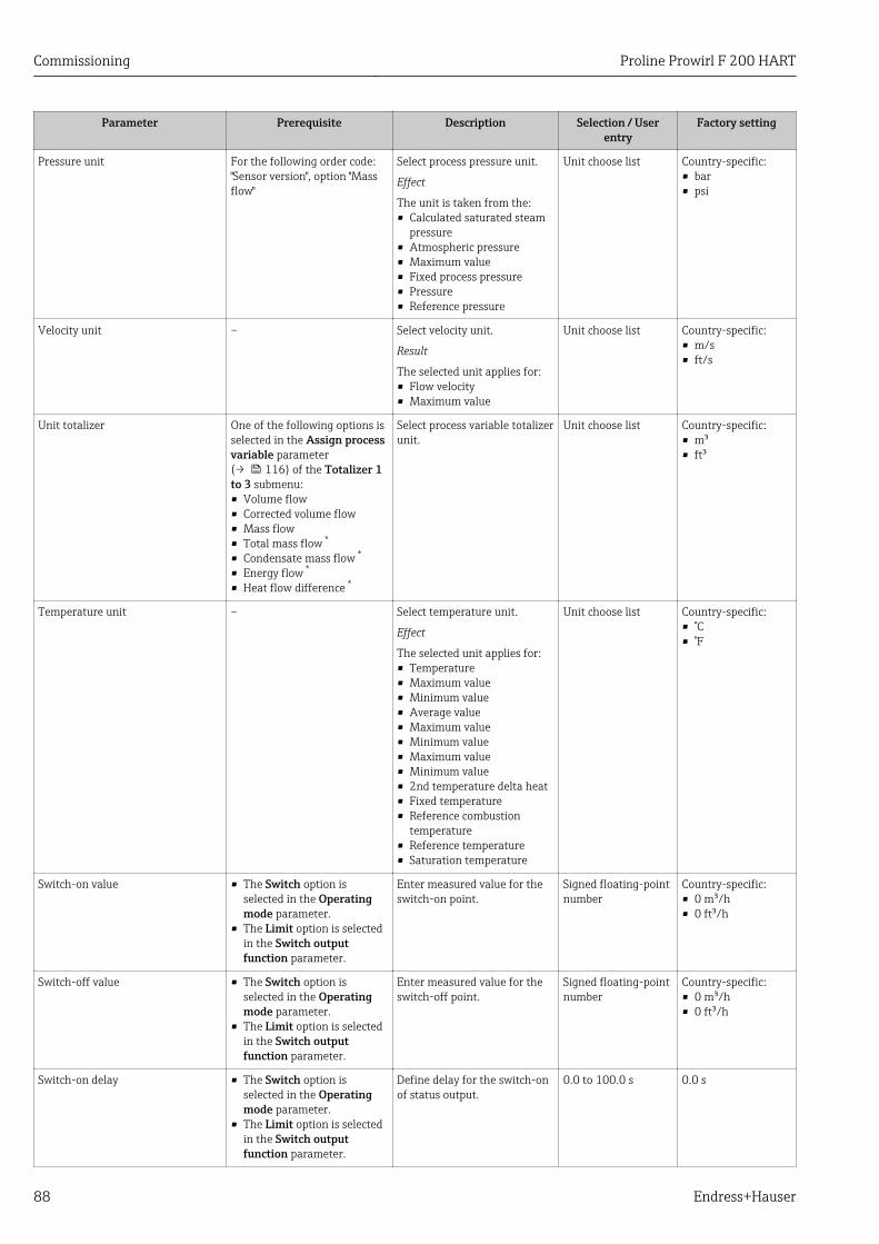
Commissioning Proline Prowirl F 200 HART
88 Endress+Hauser
Parameter Prerequisite Description Selection / Userentry
Factory setting
Pressure unit For the following order code:"Sensor version", option "Massflow"
Select process pressure unit.
Effect
The unit is taken from the:• Calculated saturated steam
pressure• Atmospheric pressure• Maximum value• Fixed process pressure• Pressure• Reference pressure
Unit choose list Country-specific:• bar• psi
Velocity unit – Select velocity unit.
Result
The selected unit applies for:• Flow velocity• Maximum value
Unit choose list Country-specific:• m/s• ft/s
Unit totalizer One of the following options isselected in the Assign processvariable parameter(→ 116) of the Totalizer 1to 3 submenu:• Volume flow• Corrected volume flow• Mass flow• Total mass flow *
• Condensate mass flow *
• Energy flow *
• Heat flow difference *
Select process variable totalizerunit.
Unit choose list Country-specific:• m³• ft³
Temperature unit – Select temperature unit.
Effect
The selected unit applies for:• Temperature• Maximum value• Minimum value• Average value• Maximum value• Minimum value• Maximum value• Minimum value• 2nd temperature delta heat• Fixed temperature• Reference combustion
temperature• Reference temperature• Saturation temperature
Unit choose list Country-specific:• °C• °F
Switch-on value • The Switch option isselected in the Operatingmode parameter.
• The Limit option is selectedin the Switch outputfunction parameter.
Enter measured value for theswitch-on point.
Signed floating-pointnumber
Country-specific:• 0 m³/h• 0 ft³/h
Switch-off value • The Switch option isselected in the Operatingmode parameter.
• The Limit option is selectedin the Switch outputfunction parameter.
Enter measured value for theswitch-off point.
Signed floating-pointnumber
Country-specific:• 0 m³/h• 0 ft³/h
Switch-on delay • The Switch option isselected in the Operatingmode parameter.
• The Limit option is selectedin the Switch outputfunction parameter.
Define delay for the switch-onof status output.
0.0 to 100.0 s 0.0 s
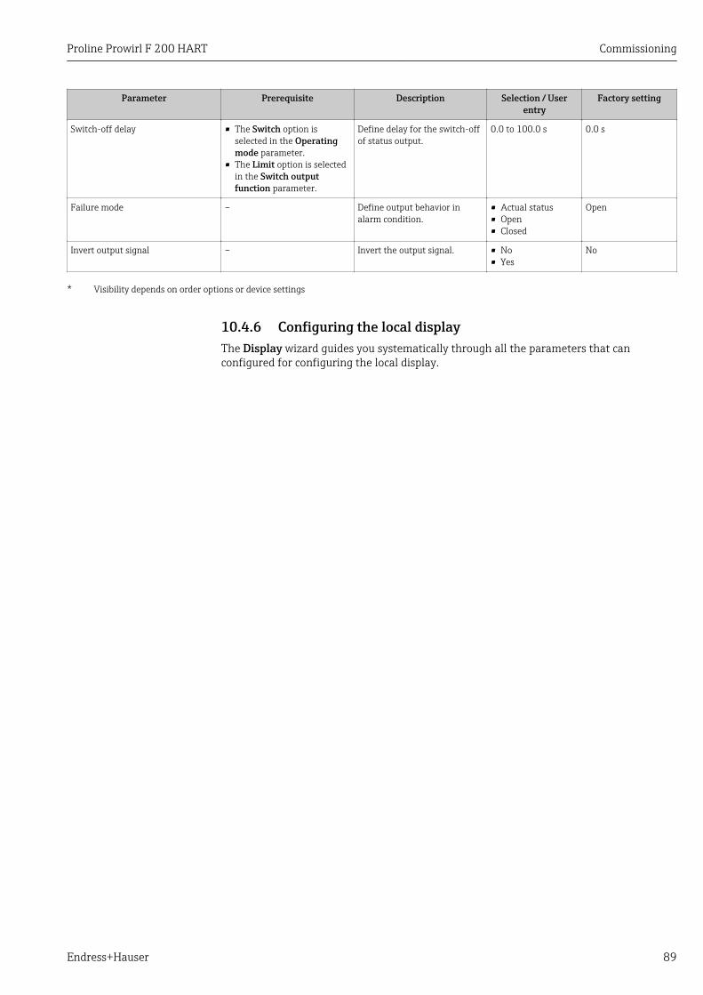
Proline Prowirl F 200 HART Commissioning
Endress+Hauser 89
Parameter Prerequisite Description Selection / Userentry
Factory setting
Switch-off delay • The Switch option isselected in the Operatingmode parameter.
• The Limit option is selectedin the Switch outputfunction parameter.
Define delay for the switch-offof status output.
0.0 to 100.0 s 0.0 s
Failure mode – Define output behavior inalarm condition.
• Actual status• Open• Closed
Open
Invert output signal – Invert the output signal. • No• Yes
No
* Visibility depends on order options or device settings
10.4.6 Configuring the local displayThe Display wizard guides you systematically through all the parameters that canconfigured for configuring the local display.
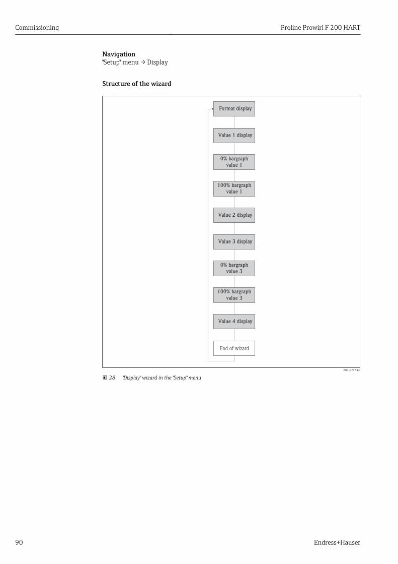
Commissioning Proline Prowirl F 200 HART
90 Endress+Hauser
Navigation"Setup" menu → Display
Structure of the wizard
Format display
Value 1 display
0% bargraph
value 1
100% bargraph
value 1
Value 2 display
Value 3 display
0% bargraph
value 3
100% bargraph
value 3
Value 4 display
End of wizard
A0013797-EN
28 "Display" wizard in the "Setup" menu
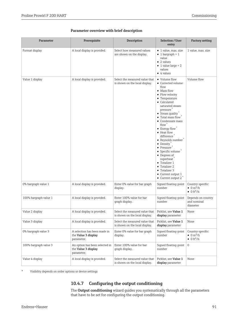
Proline Prowirl F 200 HART Commissioning
Endress+Hauser 91
Parameter overview with brief description
Parameter Prerequisite Description Selection / Userentry
Factory setting
Format display A local display is provided. Select how measured valuesare shown on the display.
• 1 value, max. size• 1 bargraph + 1
value• 2 values• 1 value large + 2
values• 4 values
1 value, max. size
Value 1 display A local display is provided. Select the measured value thatis shown on the local display.
• Volume flow• Corrected volume
flow• Mass flow• Flow velocity• Temperature• Calculated
saturated steampressure *
• Steam quality *
• Total mass flow *
• Condensate massflow *
• Energy flow *
• Heat flowdifference *
• Reynolds number *
• Density *
• Pressure *
• Specific volume *
• Degrees ofsuperheat *
• Totalizer 1• Totalizer 2• Totalizer 3• Current output 1• Current output 2 *
Volume flow
0% bargraph value 1 A local display is provided. Enter 0% value for bar graphdisplay.
Signed floating-pointnumber
Country-specific:• 0 m³/h• 0 ft³/h
100% bargraph value 1 A local display is provided. Enter 100% value for bargraph display.
Signed floating-pointnumber
Depends on countryand nominaldiameter
Value 2 display A local display is provided. Select the measured value thatis shown on the local display.
Picklist, see Value 1display parameter
None
Value 3 display A local display is provided. Select the measured value thatis shown on the local display.
Picklist, see Value 1display parameter
None
0% bargraph value 3 A selection has been made inthe Value 3 displayparameter.
Enter 0% value for bar graphdisplay.
Signed floating-pointnumber
Country-specific:• 0 m³/h• 0 ft³/h
100% bargraph value 3 An option has been selected inthe Value 3 displayparameter.
Enter 100% value for bargraph display.
Signed floating-pointnumber
0
Value 4 display A local display is provided. Select the measured value thatis shown on the local display.
Picklist, see Value 1display parameter
None
* Visibility depends on order options or device settings
10.4.7 Configuring the output conditioningThe Output conditioning wizard guides you systematically through all the parametersthat have to be set for configuring the output conditioning.
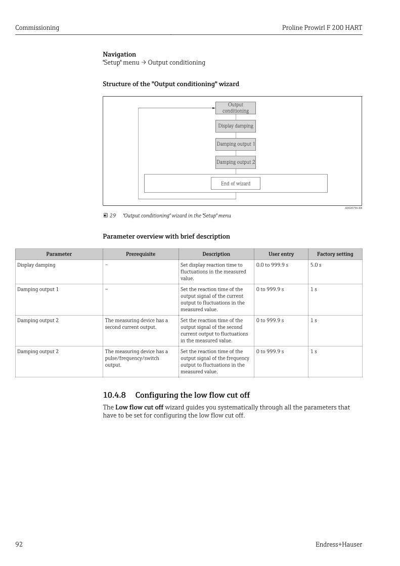
Commissioning Proline Prowirl F 200 HART
92 Endress+Hauser
Navigation"Setup" menu → Output conditioning
Structure of the "Output conditioning" wizard
End of wizard
Display damping
Damping output 1
Damping output 2
Outputconditioning
A0020796-EN
29 "Output conditioning" wizard in the "Setup" menu
Parameter overview with brief description
Parameter Prerequisite Description User entry Factory setting
Display damping – Set display reaction time tofluctuations in the measuredvalue.
0.0 to 999.9 s 5.0 s
Damping output 1 – Set the reaction time of theoutput signal of the currentoutput to fluctuations in themeasured value.
0 to 999.9 s 1 s
Damping output 2 The measuring device has asecond current output.
Set the reaction time of theoutput signal of the secondcurrent output to fluctuationsin the measured value.
0 to 999.9 s 1 s
Damping output 2 The measuring device has apulse/frequency/switchoutput.
Set the reaction time of theoutput signal of the frequencyoutput to fluctuations in themeasured value.
0 to 999.9 s 1 s
10.4.8 Configuring the low flow cut offThe Low flow cut off wizard guides you systematically through all the parameters thathave to be set for configuring the low flow cut off.
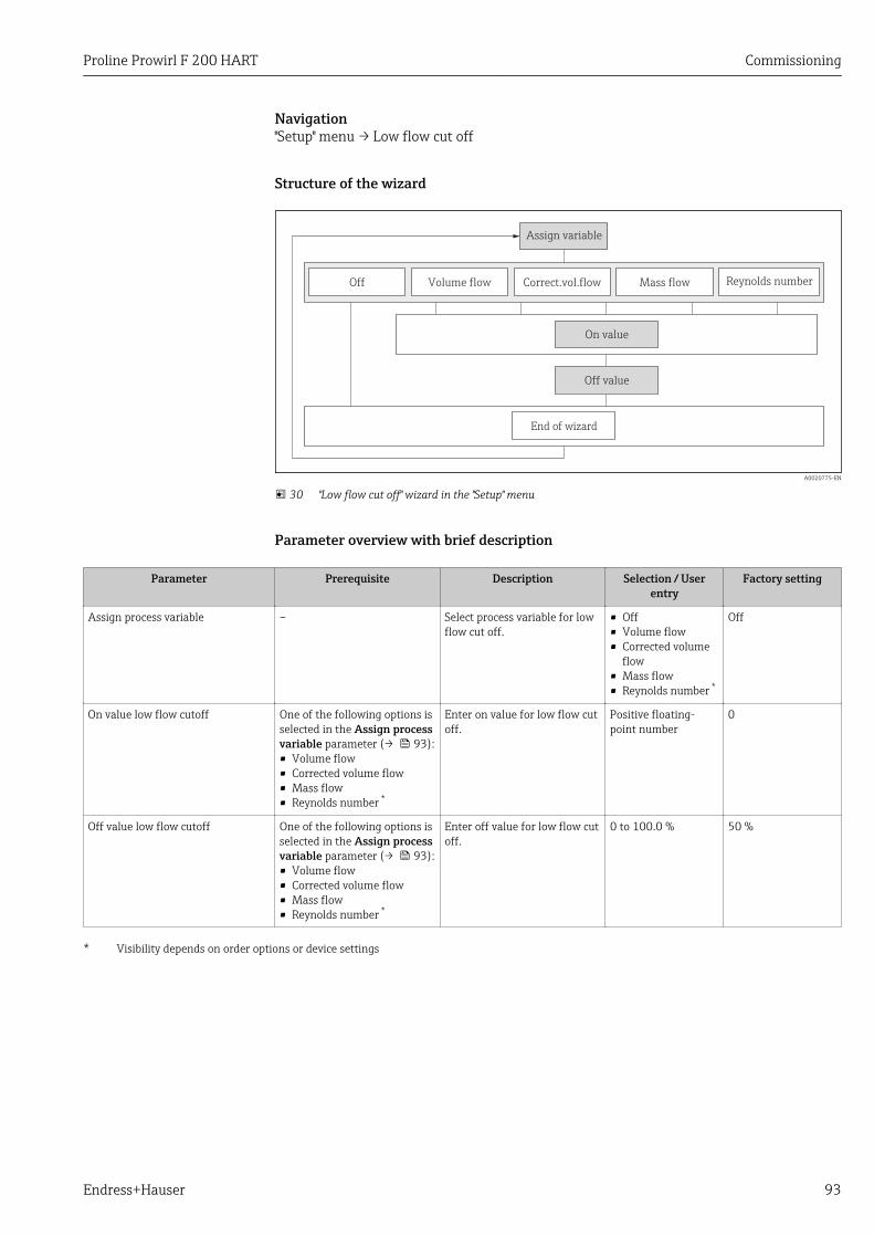
Proline Prowirl F 200 HART Commissioning
Endress+Hauser 93
Navigation"Setup" menu → Low flow cut off
Structure of the wizard
Volume flow
Assign variable
Correct.vol.flow Reynolds number
Off value
End of wizard
Off
On value
Mass flow
A0020775-EN
30 "Low flow cut off" wizard in the "Setup" menu
Parameter overview with brief description
Parameter Prerequisite Description Selection / Userentry
Factory setting
Assign process variable – Select process variable for lowflow cut off.
• Off• Volume flow• Corrected volume
flow• Mass flow• Reynolds number *
Off
On value low flow cutoff One of the following options isselected in the Assign processvariable parameter (→ 93):• Volume flow• Corrected volume flow• Mass flow• Reynolds number *
Enter on value for low flow cutoff.
Positive floating-point number
0
Off value low flow cutoff One of the following options isselected in the Assign processvariable parameter (→ 93):• Volume flow• Corrected volume flow• Mass flow• Reynolds number *
Enter off value for low flow cutoff.
0 to 100.0 % 50 %
* Visibility depends on order options or device settings
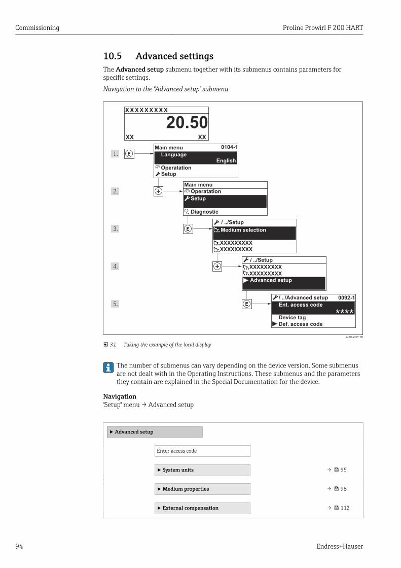
Commissioning Proline Prowirl F 200 HART
94 Endress+Hauser
10.5 Advanced settingsThe Advanced setup submenu together with its submenus contains parameters forspecific settings.
Navigation to the "Advanced setup" submenu
X X X X X X XX X
20.50
0104-1
0092-1
****
XXXXXXXXX
XXXXXXXXX
XXXXXXXXX
XXXXXXXXX
XXXX
Operatation
Setup
Diagnostic
Operatation
Setup
Main menu
English
Main menu
/ ../Setup
/ ../Setup
Advanced setup
Ent. access code
/ ../Advanced setup
Def. access code
Device tag
Language
Medium selection
A0014009-EN
31 Taking the example of the local display
The number of submenus can vary depending on the device version. Some submenusare not dealt with in the Operating Instructions. These submenus and the parametersthey contain are explained in the Special Documentation for the device.
Navigation"Setup" menu → Advanced setup
‣ Advanced setup
Enter access code
‣ System units → 95
‣ Medium properties → 98
‣ External compensation → 112
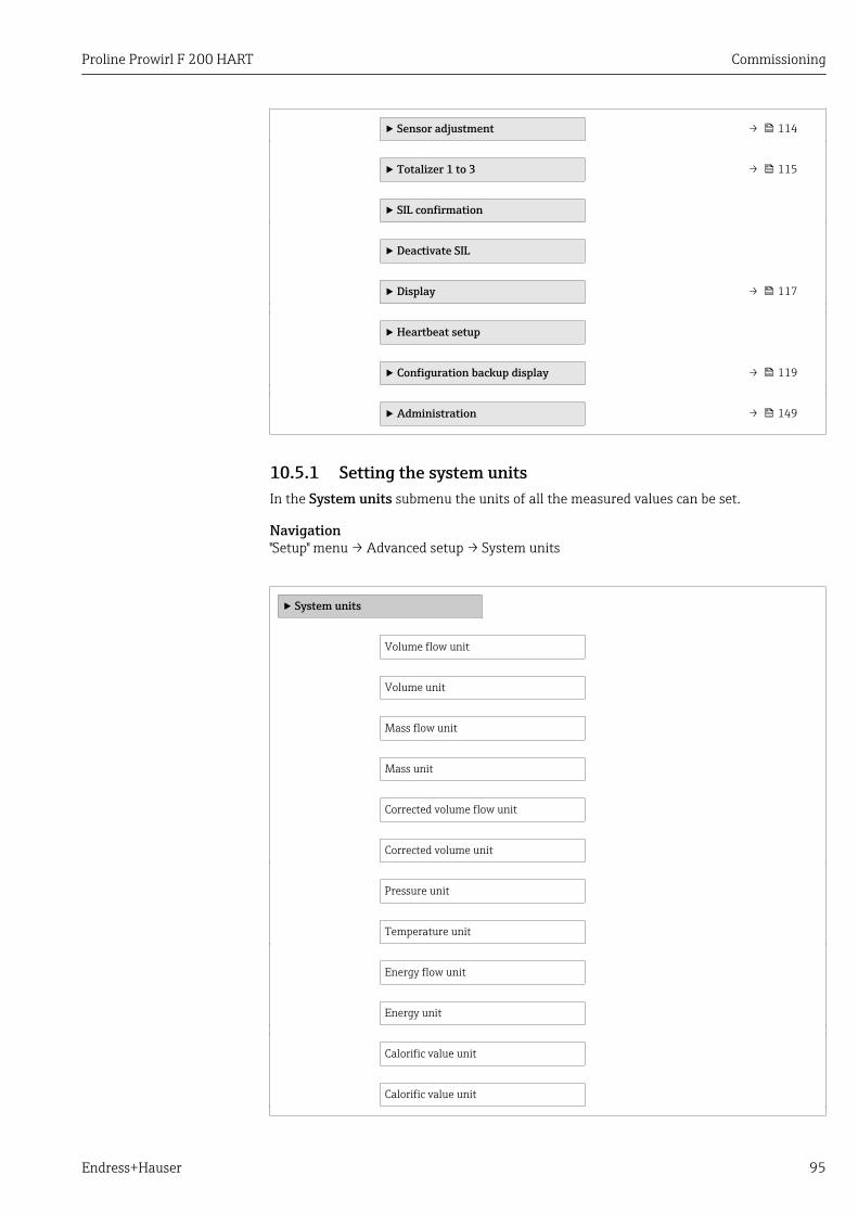
Proline Prowirl F 200 HART Commissioning
Endress+Hauser 95
‣ Sensor adjustment → 114
‣ Totalizer 1 to 3 → 115
‣ SIL confirmation
‣ Deactivate SIL
‣ Display → 117
‣ Heartbeat setup
‣ Configuration backup display → 119
‣ Administration → 149
10.5.1 Setting the system unitsIn the System units submenu the units of all the measured values can be set.
Navigation"Setup" menu → Advanced setup → System units
‣ System units
Volume flow unit
Volume unit
Mass flow unit
Mass unit
Corrected volume flow unit
Corrected volume unit
Pressure unit
Temperature unit
Energy flow unit
Energy unit
Calorific value unit
Calorific value unit
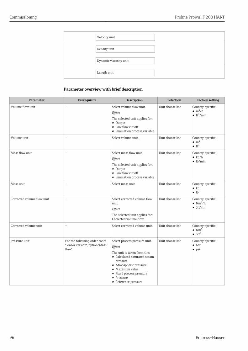
Commissioning Proline Prowirl F 200 HART
96 Endress+Hauser
Velocity unit
Density unit
Dynamic viscosity unit
Length unit
Parameter overview with brief description
Parameter Prerequisite Description Selection Factory setting
Volume flow unit – Select volume flow unit.
Effect
The selected unit applies for:• Output• Low flow cut off• Simulation process variable
Unit choose list Country-specific:• m³/h• ft³/min
Volume unit – Select volume unit. Unit choose list Country-specific:• m³• ft³
Mass flow unit – Select mass flow unit.
Effect
The selected unit applies for:• Output• Low flow cut off• Simulation process variable
Unit choose list Country-specific:• kg/h• lb/min
Mass unit – Select mass unit. Unit choose list Country-specific:• kg• lb
Corrected volume flow unit – Select corrected volume flowunit.
Effect
The selected unit applies for:Corrected volume flow
Unit choose list Country-specific:• Nm³/h• Sft³/h
Corrected volume unit – Select corrected volume unit. Unit choose list Country-specific:• Nm³• Sft³
Pressure unit For the following order code:"Sensor version", option "Massflow"
Select process pressure unit.
Effect
The unit is taken from the:• Calculated saturated steam
pressure• Atmospheric pressure• Maximum value• Fixed process pressure• Pressure• Reference pressure
Unit choose list Country-specific:• bar• psi
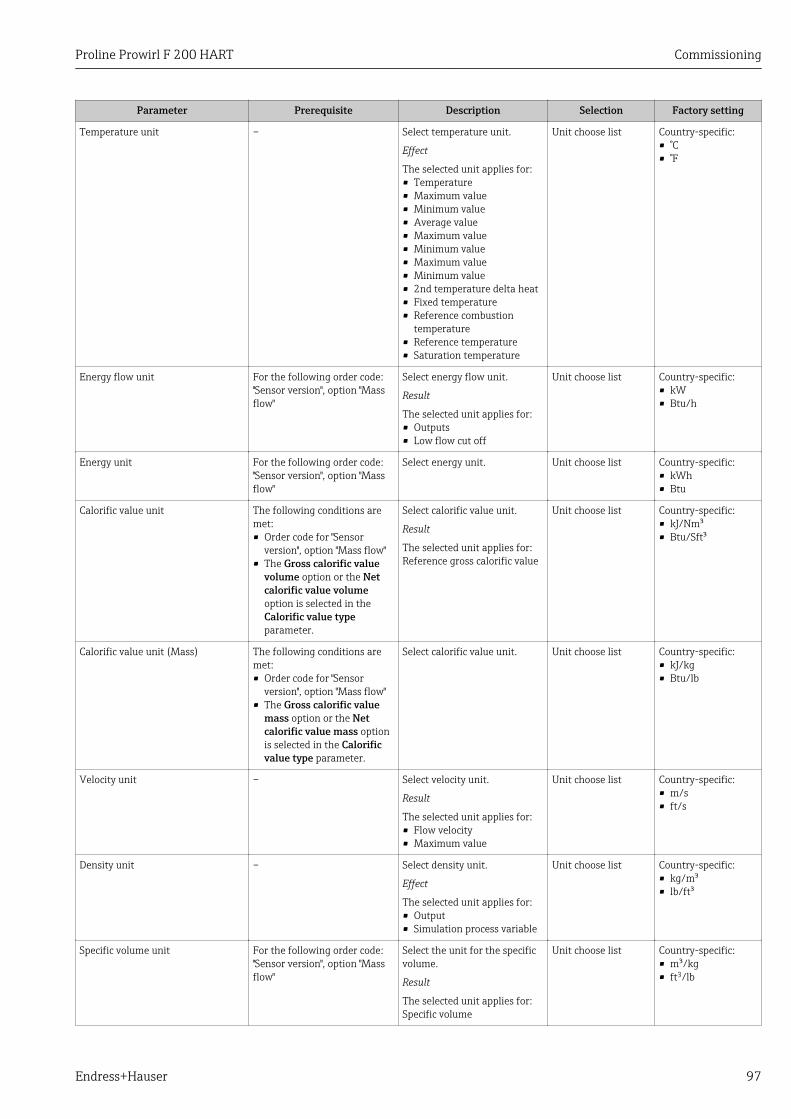
Proline Prowirl F 200 HART Commissioning
Endress+Hauser 97
Parameter Prerequisite Description Selection Factory setting
Temperature unit – Select temperature unit.
Effect
The selected unit applies for:• Temperature• Maximum value• Minimum value• Average value• Maximum value• Minimum value• Maximum value• Minimum value• 2nd temperature delta heat• Fixed temperature• Reference combustion
temperature• Reference temperature• Saturation temperature
Unit choose list Country-specific:• °C• °F
Energy flow unit For the following order code:"Sensor version", option "Massflow"
Select energy flow unit.
Result
The selected unit applies for:• Outputs• Low flow cut off
Unit choose list Country-specific:• kW• Btu/h
Energy unit For the following order code:"Sensor version", option "Massflow"
Select energy unit. Unit choose list Country-specific:• kWh• Btu
Calorific value unit The following conditions aremet:• Order code for "Sensor
version", option "Mass flow"• The Gross calorific value
volume option or the Netcalorific value volumeoption is selected in theCalorific value typeparameter.
Select calorific value unit.
Result
The selected unit applies for:Reference gross calorific value
Unit choose list Country-specific:• kJ/Nm³• Btu/Sft³
Calorific value unit (Mass) The following conditions aremet:• Order code for "Sensor
version", option "Mass flow"• The Gross calorific value
mass option or the Netcalorific value mass optionis selected in the Calorificvalue type parameter.
Select calorific value unit. Unit choose list Country-specific:• kJ/kg• Btu/lb
Velocity unit – Select velocity unit.
Result
The selected unit applies for:• Flow velocity• Maximum value
Unit choose list Country-specific:• m/s• ft/s
Density unit – Select density unit.
Effect
The selected unit applies for:• Output• Simulation process variable
Unit choose list Country-specific:• kg/m³• lb/ft³
Specific volume unit For the following order code:"Sensor version", option "Massflow"
Select the unit for the specificvolume.
Result
The selected unit applies for:Specific volume
Unit choose list Country-specific:• m³/kg• ft3/lb
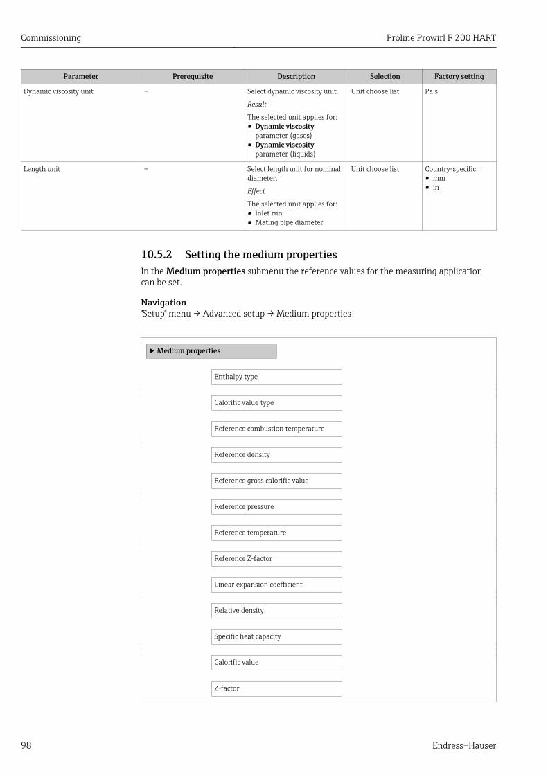
Commissioning Proline Prowirl F 200 HART
98 Endress+Hauser
Parameter Prerequisite Description Selection Factory setting
Dynamic viscosity unit – Select dynamic viscosity unit.
Result
The selected unit applies for:• Dynamic viscosity
parameter (gases)• Dynamic viscosity
parameter (liquids)
Unit choose list Pa s
Length unit – Select length unit for nominaldiameter.
Effect
The selected unit applies for:• Inlet run• Mating pipe diameter
Unit choose list Country-specific:• mm• in
10.5.2 Setting the medium propertiesIn the Medium properties submenu the reference values for the measuring applicationcan be set.
Navigation"Setup" menu → Advanced setup → Medium properties
‣ Medium properties
Enthalpy type
Calorific value type
Reference combustion temperature
Reference density
Reference gross calorific value
Reference pressure
Reference temperature
Reference Z-factor
Linear expansion coefficient
Relative density
Specific heat capacity
Calorific value
Z-factor
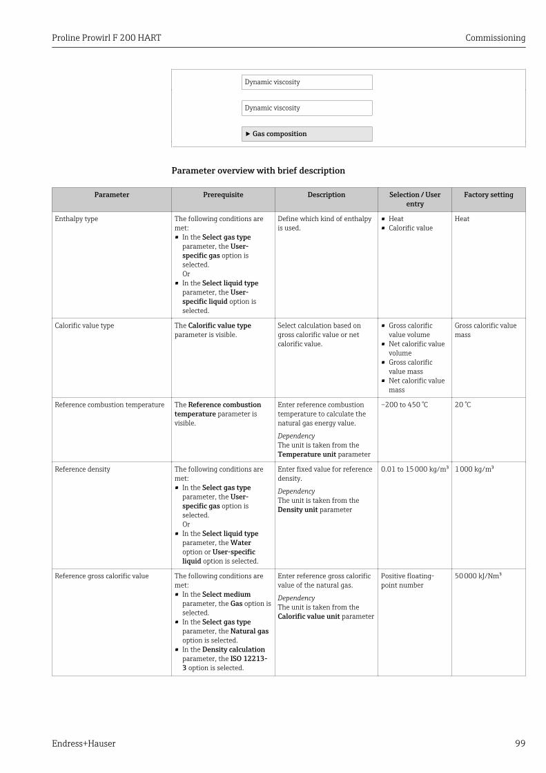
Proline Prowirl F 200 HART Commissioning
Endress+Hauser 99
Dynamic viscosity
Dynamic viscosity
‣ Gas composition
Parameter overview with brief description
Parameter Prerequisite Description Selection / Userentry
Factory setting
Enthalpy type The following conditions aremet:• In the Select gas type
parameter, the User-specific gas option isselected.Or
• In the Select liquid typeparameter, the User-specific liquid option isselected.
Define which kind of enthalpyis used.
• Heat• Calorific value
Heat
Calorific value type The Calorific value typeparameter is visible.
Select calculation based ongross calorific value or netcalorific value.
• Gross calorificvalue volume
• Net calorific valuevolume
• Gross calorificvalue mass
• Net calorific valuemass
Gross calorific valuemass
Reference combustion temperature The Reference combustiontemperature parameter isvisible.
Enter reference combustiontemperature to calculate thenatural gas energy value.
DependencyThe unit is taken from theTemperature unit parameter
–200 to 450 °C 20 °C
Reference density The following conditions aremet:• In the Select gas type
parameter, the User-specific gas option isselected.Or
• In the Select liquid typeparameter, the Wateroption or User-specificliquid option is selected.
Enter fixed value for referencedensity.
DependencyThe unit is taken from theDensity unit parameter
0.01 to 15 000 kg/m³ 1 000 kg/m³
Reference gross calorific value The following conditions aremet:• In the Select medium
parameter, the Gas option isselected.
• In the Select gas typeparameter, the Natural gasoption is selected.
• In the Density calculationparameter, the ISO 12213-3 option is selected.
Enter reference gross calorificvalue of the natural gas.
DependencyThe unit is taken from theCalorific value unit parameter
Positive floating-point number
50 000 kJ/Nm³
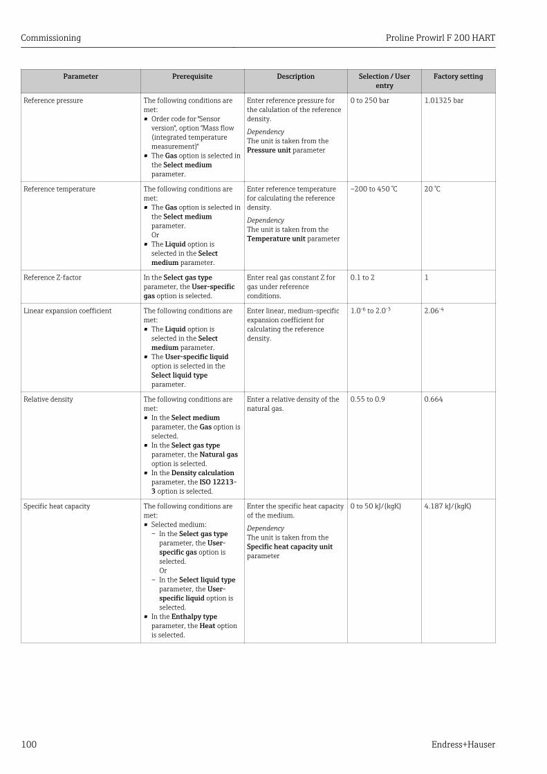
Commissioning Proline Prowirl F 200 HART
100 Endress+Hauser
Parameter Prerequisite Description Selection / Userentry
Factory setting
Reference pressure The following conditions aremet:• Order code for "Sensor
version", option "Mass flow(integrated temperaturemeasurement)"
• The Gas option is selected inthe Select mediumparameter.
Enter reference pressure forthe calulation of the referencedensity.
DependencyThe unit is taken from thePressure unit parameter
0 to 250 bar 1.01325 bar
Reference temperature The following conditions aremet:• The Gas option is selected in
the Select mediumparameter.Or
• The Liquid option isselected in the Selectmedium parameter.
Enter reference temperaturefor calculating the referencedensity.
DependencyThe unit is taken from theTemperature unit parameter
–200 to 450 °C 20 °C
Reference Z-factor In the Select gas typeparameter, the User-specificgas option is selected.
Enter real gas constant Z forgas under referenceconditions.
0.1 to 2 1
Linear expansion coefficient The following conditions aremet:• The Liquid option is
selected in the Selectmedium parameter.
• The User-specific liquidoption is selected in theSelect liquid typeparameter.
Enter linear, medium-specificexpansion coefficient forcalculating the referencedensity.
1.0-6 to 2.0-3 2.06-4
Relative density The following conditions aremet:• In the Select medium
parameter, the Gas option isselected.
• In the Select gas typeparameter, the Natural gasoption is selected.
• In the Density calculationparameter, the ISO 12213-3 option is selected.
Enter a relative density of thenatural gas.
0.55 to 0.9 0.664
Specific heat capacity The following conditions aremet:• Selected medium:
– In the Select gas typeparameter, the User-specific gas option isselected.Or
– In the Select liquid typeparameter, the User-specific liquid option isselected.
• In the Enthalpy typeparameter, the Heat optionis selected.
Enter the specific heat capacityof the medium.
DependencyThe unit is taken from theSpecific heat capacity unitparameter
0 to 50 kJ/(kgK) 4.187 kJ/(kgK)
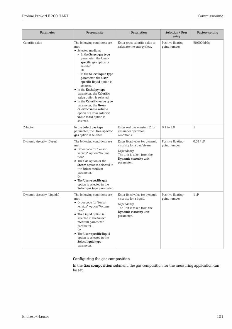
Proline Prowirl F 200 HART Commissioning
Endress+Hauser 101
Parameter Prerequisite Description Selection / Userentry
Factory setting
Calorific value The following conditions aremet:• Selected medium:
– In the Select gas typeparameter, the User-specific gas option isselected.Or
– In the Select liquid typeparameter, the User-specific liquid option isselected.
• In the Enthalpy typeparameter, the Calorificvalue option is selected.
• In the Calorific value typeparameter, the Grosscalorific value volumeoption or Gross calorificvalue mass option isselected.
Enter gross calorific value tocalculate the energy flow.
Positive floating-point number
50 000 kJ/kg
Z-factor In the Select gas typeparameter, the User-specificgas option is selected.
Enter real gas constant Z forgas under operationconditions.
0.1 to 2.0 1
Dynamic viscosity (Gases) The following conditions aremet:• Order code for "Sensor
version", option "Volumeflow"
• The Gas option or theSteam option is selected inthe Select mediumparameter.Or
• The User-specific gasoption is selected in theSelect gas type parameter.
Enter fixed value for dynamicviscosity for a gas/steam.
DependencyThe unit is taken from theDynamic viscosity unitparameter.
Positive floating-point number
0.015 cP
Dynamic viscosity (Liquids) The following conditions aremet:• Order code for "Sensor
version", option "Volumeflow"
• The Liquid option isselected in the Selectmedium parameterparameter.Or
• The User-specific liquidoption is selected in theSelect liquid typeparameter.
Enter fixed value for dynamicviscosity for a liquid.
DependencyThe unit is taken from theDynamic viscosity unitparameter.
Positive floating-point number
1 cP
Configuring the gas compositionIn the Gas composition submenu the gas composition for the measuring application canbe set.
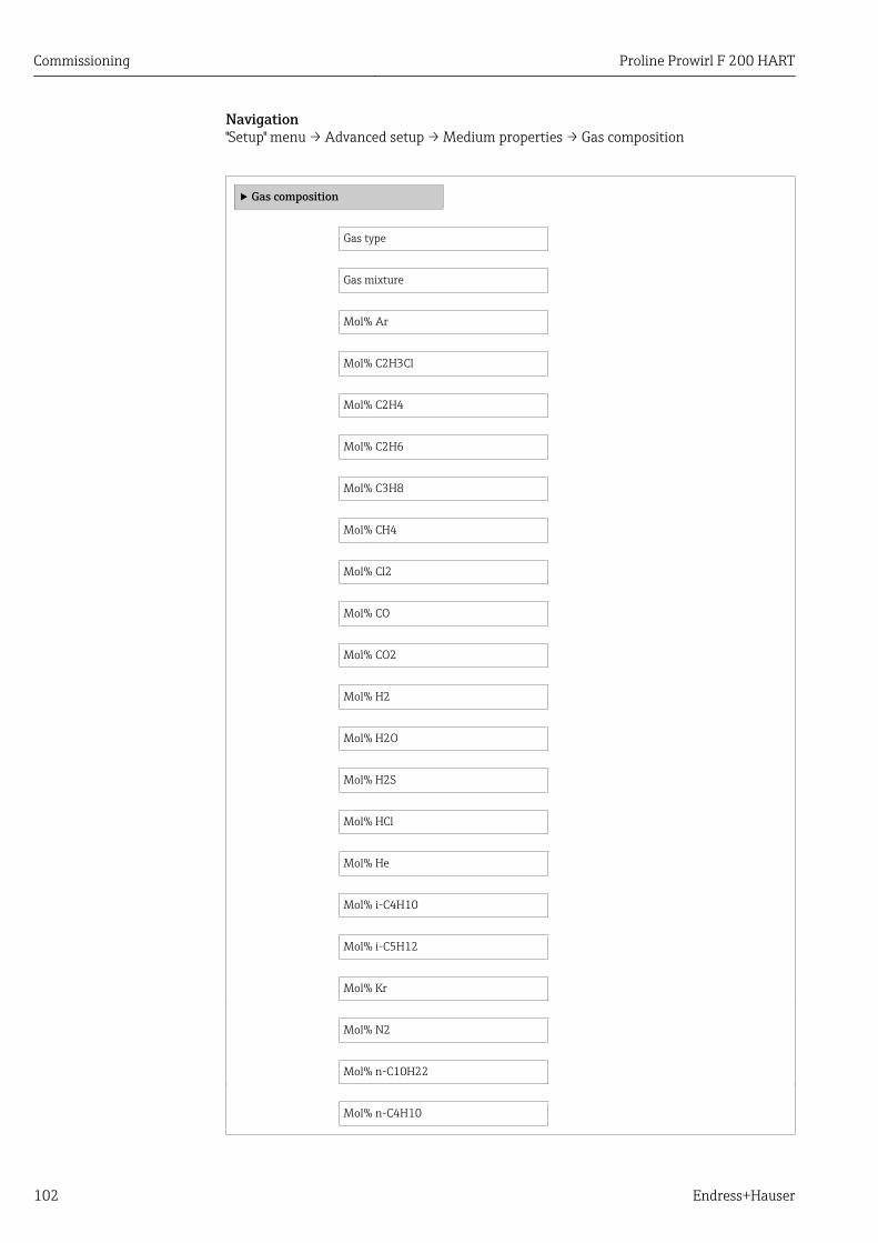
Commissioning Proline Prowirl F 200 HART
102 Endress+Hauser
Navigation"Setup" menu → Advanced setup → Medium properties → Gas composition
‣ Gas composition
Gas type
Gas mixture
Mol% Ar
Mol% C2H3Cl
Mol% C2H4
Mol% C2H6
Mol% C3H8
Mol% CH4
Mol% Cl2
Mol% CO
Mol% CO2
Mol% H2
Mol% H2O
Mol% H2S
Mol% HCl
Mol% He
Mol% i-C4H10
Mol% i-C5H12
Mol% Kr
Mol% N2
Mol% n-C10H22
Mol% n-C4H10
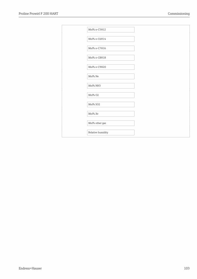
Proline Prowirl F 200 HART Commissioning
Endress+Hauser 103
Mol% n-C5H12
Mol% n-C6H14
Mol% n-C7H16
Mol% n-C8H18
Mol% n-C9H20
Mol% Ne
Mol% NH3
Mol% O2
Mol% SO2
Mol% Xe
Mol% other gas
Relative humidity
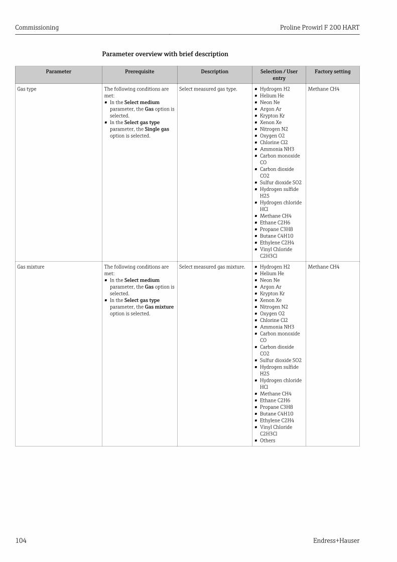
Commissioning Proline Prowirl F 200 HART
104 Endress+Hauser
Parameter overview with brief description
Parameter Prerequisite Description Selection / Userentry
Factory setting
Gas type The following conditions aremet:• In the Select medium
parameter, the Gas option isselected.
• In the Select gas typeparameter, the Single gasoption is selected.
Select measured gas type. • Hydrogen H2• Helium He• Neon Ne• Argon Ar• Krypton Kr• Xenon Xe• Nitrogen N2• Oxygen O2• Chlorine Cl2• Ammonia NH3• Carbon monoxide
CO• Carbon dioxide
CO2• Sulfur dioxide SO2• Hydrogen sulfide
H2S• Hydrogen chloride
HCl• Methane CH4• Ethane C2H6• Propane C3H8• Butane C4H10• Ethylene C2H4• Vinyl Chloride
C2H3Cl
Methane CH4
Gas mixture The following conditions aremet:• In the Select medium
parameter, the Gas option isselected.
• In the Select gas typeparameter, the Gas mixtureoption is selected.
Select measured gas mixture. • Hydrogen H2• Helium He• Neon Ne• Argon Ar• Krypton Kr• Xenon Xe• Nitrogen N2• Oxygen O2• Chlorine Cl2• Ammonia NH3• Carbon monoxide
CO• Carbon dioxide
CO2• Sulfur dioxide SO2• Hydrogen sulfide
H2S• Hydrogen chloride
HCl• Methane CH4• Ethane C2H6• Propane C3H8• Butane C4H10• Ethylene C2H4• Vinyl Chloride
C2H3Cl• Others
Methane CH4
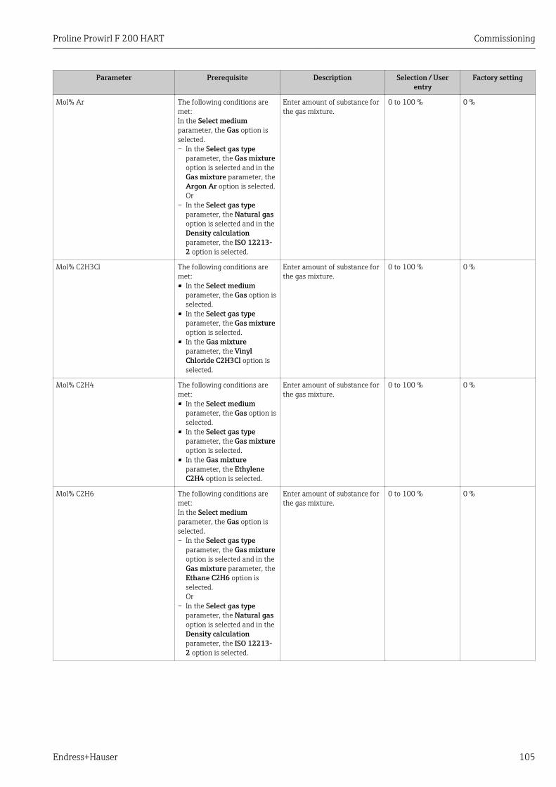
Proline Prowirl F 200 HART Commissioning
Endress+Hauser 105
Parameter Prerequisite Description Selection / Userentry
Factory setting
Mol% Ar The following conditions aremet:In the Select mediumparameter, the Gas option isselected.– In the Select gas type
parameter, the Gas mixtureoption is selected and in theGas mixture parameter, theArgon Ar option is selected.Or
– In the Select gas typeparameter, the Natural gasoption is selected and in theDensity calculationparameter, the ISO 12213-2 option is selected.
Enter amount of substance forthe gas mixture.
0 to 100 % 0 %
Mol% C2H3Cl The following conditions aremet:• In the Select medium
parameter, the Gas option isselected.
• In the Select gas typeparameter, the Gas mixtureoption is selected.
• In the Gas mixtureparameter, the VinylChloride C2H3Cl option isselected.
Enter amount of substance forthe gas mixture.
0 to 100 % 0 %
Mol% C2H4 The following conditions aremet:• In the Select medium
parameter, the Gas option isselected.
• In the Select gas typeparameter, the Gas mixtureoption is selected.
• In the Gas mixtureparameter, the EthyleneC2H4 option is selected.
Enter amount of substance forthe gas mixture.
0 to 100 % 0 %
Mol% C2H6 The following conditions aremet:In the Select mediumparameter, the Gas option isselected.– In the Select gas type
parameter, the Gas mixtureoption is selected and in theGas mixture parameter, theEthane C2H6 option isselected.Or
– In the Select gas typeparameter, the Natural gasoption is selected and in theDensity calculationparameter, the ISO 12213-2 option is selected.
Enter amount of substance forthe gas mixture.
0 to 100 % 0 %
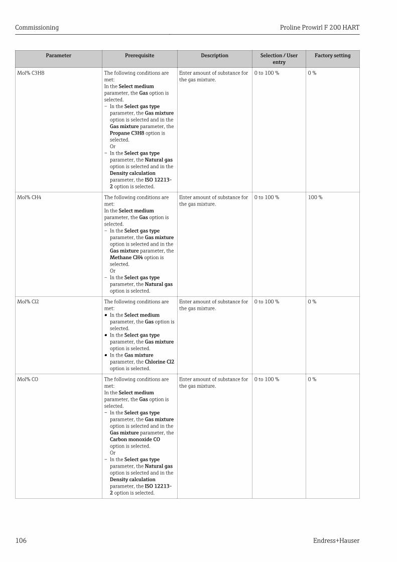
Commissioning Proline Prowirl F 200 HART
106 Endress+Hauser
Parameter Prerequisite Description Selection / Userentry
Factory setting
Mol% C3H8 The following conditions aremet:In the Select mediumparameter, the Gas option isselected.– In the Select gas type
parameter, the Gas mixtureoption is selected and in theGas mixture parameter, thePropane C3H8 option isselected.Or
– In the Select gas typeparameter, the Natural gasoption is selected and in theDensity calculationparameter, the ISO 12213-2 option is selected.
Enter amount of substance forthe gas mixture.
0 to 100 % 0 %
Mol% CH4 The following conditions aremet:In the Select mediumparameter, the Gas option isselected.– In the Select gas type
parameter, the Gas mixtureoption is selected and in theGas mixture parameter, theMethane CH4 option isselected.Or
– In the Select gas typeparameter, the Natural gasoption is selected.
Enter amount of substance forthe gas mixture.
0 to 100 % 100 %
Mol% Cl2 The following conditions aremet:• In the Select medium
parameter, the Gas option isselected.
• In the Select gas typeparameter, the Gas mixtureoption is selected.
• In the Gas mixtureparameter, the Chlorine Cl2option is selected.
Enter amount of substance forthe gas mixture.
0 to 100 % 0 %
Mol% CO The following conditions aremet:In the Select mediumparameter, the Gas option isselected.– In the Select gas type
parameter, the Gas mixtureoption is selected and in theGas mixture parameter, theCarbon monoxide COoption is selected.Or
– In the Select gas typeparameter, the Natural gasoption is selected and in theDensity calculationparameter, the ISO 12213-2 option is selected.
Enter amount of substance forthe gas mixture.
0 to 100 % 0 %
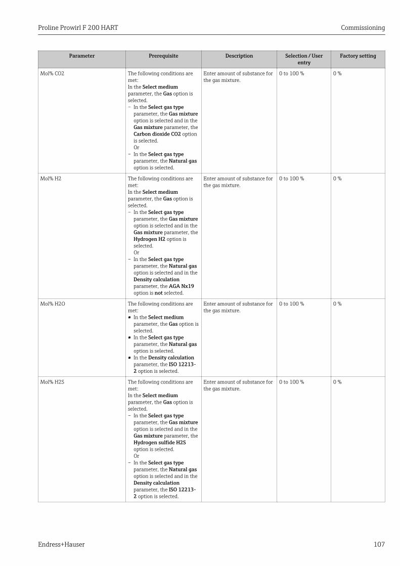
Proline Prowirl F 200 HART Commissioning
Endress+Hauser 107
Parameter Prerequisite Description Selection / Userentry
Factory setting
Mol% CO2 The following conditions aremet:In the Select mediumparameter, the Gas option isselected.– In the Select gas type
parameter, the Gas mixtureoption is selected and in theGas mixture parameter, theCarbon dioxide CO2 optionis selected.Or
– In the Select gas typeparameter, the Natural gasoption is selected.
Enter amount of substance forthe gas mixture.
0 to 100 % 0 %
Mol% H2 The following conditions aremet:In the Select mediumparameter, the Gas option isselected.– In the Select gas type
parameter, the Gas mixtureoption is selected and in theGas mixture parameter, theHydrogen H2 option isselected.Or
– In the Select gas typeparameter, the Natural gasoption is selected and in theDensity calculationparameter, the AGA Nx19option is not selected.
Enter amount of substance forthe gas mixture.
0 to 100 % 0 %
Mol% H2O The following conditions aremet:• In the Select medium
parameter, the Gas option isselected.
• In the Select gas typeparameter, the Natural gasoption is selected.
• In the Density calculationparameter, the ISO 12213-2 option is selected.
Enter amount of substance forthe gas mixture.
0 to 100 % 0 %
Mol% H2S The following conditions aremet:In the Select mediumparameter, the Gas option isselected.– In the Select gas type
parameter, the Gas mixtureoption is selected and in theGas mixture parameter, theHydrogen sulfide H2Soption is selected.Or
– In the Select gas typeparameter, the Natural gasoption is selected and in theDensity calculationparameter, the ISO 12213-2 option is selected.
Enter amount of substance forthe gas mixture.
0 to 100 % 0 %
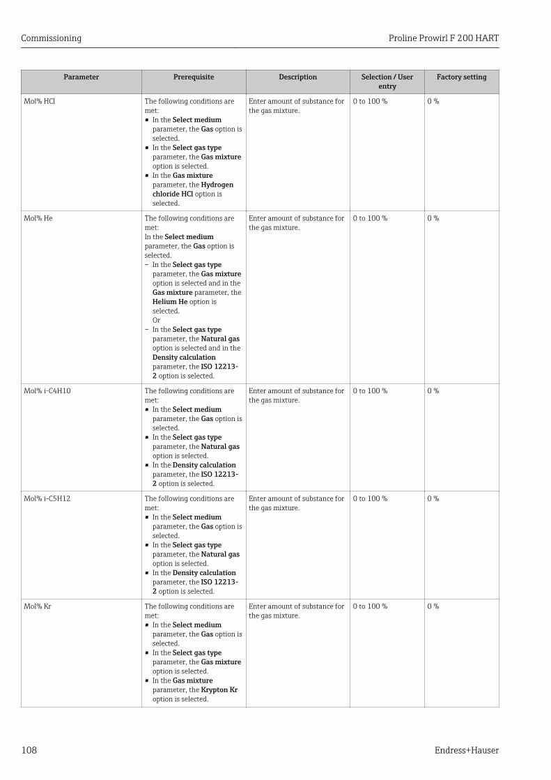
Commissioning Proline Prowirl F 200 HART
108 Endress+Hauser
Parameter Prerequisite Description Selection / Userentry
Factory setting
Mol% HCl The following conditions aremet:• In the Select medium
parameter, the Gas option isselected.
• In the Select gas typeparameter, the Gas mixtureoption is selected.
• In the Gas mixtureparameter, the Hydrogenchloride HCl option isselected.
Enter amount of substance forthe gas mixture.
0 to 100 % 0 %
Mol% He The following conditions aremet:In the Select mediumparameter, the Gas option isselected.– In the Select gas type
parameter, the Gas mixtureoption is selected and in theGas mixture parameter, theHelium He option isselected.Or
– In the Select gas typeparameter, the Natural gasoption is selected and in theDensity calculationparameter, the ISO 12213-2 option is selected.
Enter amount of substance forthe gas mixture.
0 to 100 % 0 %
Mol% i-C4H10 The following conditions aremet:• In the Select medium
parameter, the Gas option isselected.
• In the Select gas typeparameter, the Natural gasoption is selected.
• In the Density calculationparameter, the ISO 12213-2 option is selected.
Enter amount of substance forthe gas mixture.
0 to 100 % 0 %
Mol% i-C5H12 The following conditions aremet:• In the Select medium
parameter, the Gas option isselected.
• In the Select gas typeparameter, the Natural gasoption is selected.
• In the Density calculationparameter, the ISO 12213-2 option is selected.
Enter amount of substance forthe gas mixture.
0 to 100 % 0 %
Mol% Kr The following conditions aremet:• In the Select medium
parameter, the Gas option isselected.
• In the Select gas typeparameter, the Gas mixtureoption is selected.
• In the Gas mixtureparameter, the Krypton Kroption is selected.
Enter amount of substance forthe gas mixture.
0 to 100 % 0 %
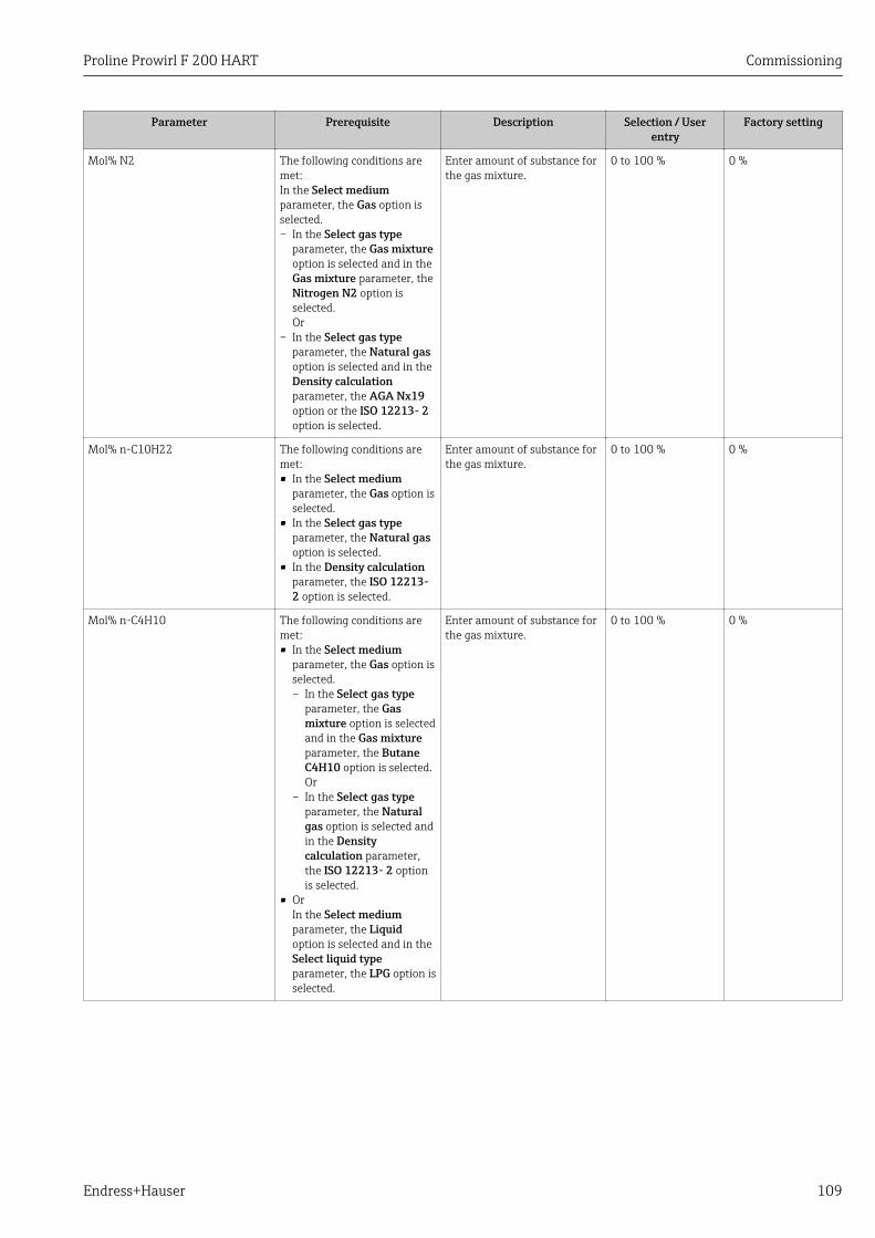
Proline Prowirl F 200 HART Commissioning
Endress+Hauser 109
Parameter Prerequisite Description Selection / Userentry
Factory setting
Mol% N2 The following conditions aremet:In the Select mediumparameter, the Gas option isselected.– In the Select gas type
parameter, the Gas mixtureoption is selected and in theGas mixture parameter, theNitrogen N2 option isselected.Or
– In the Select gas typeparameter, the Natural gasoption is selected and in theDensity calculationparameter, the AGA Nx19option or the ISO 12213- 2option is selected.
Enter amount of substance forthe gas mixture.
0 to 100 % 0 %
Mol% n-C10H22 The following conditions aremet:• In the Select medium
parameter, the Gas option isselected.
• In the Select gas typeparameter, the Natural gasoption is selected.
• In the Density calculationparameter, the ISO 12213-2 option is selected.
Enter amount of substance forthe gas mixture.
0 to 100 % 0 %
Mol% n-C4H10 The following conditions aremet:• In the Select medium
parameter, the Gas option isselected.– In the Select gas type
parameter, the Gasmixture option is selectedand in the Gas mixtureparameter, the ButaneC4H10 option is selected.Or
– In the Select gas typeparameter, the Naturalgas option is selected andin the Densitycalculation parameter,the ISO 12213- 2 optionis selected.
• OrIn the Select mediumparameter, the Liquidoption is selected and in theSelect liquid typeparameter, the LPG option isselected.
Enter amount of substance forthe gas mixture.
0 to 100 % 0 %
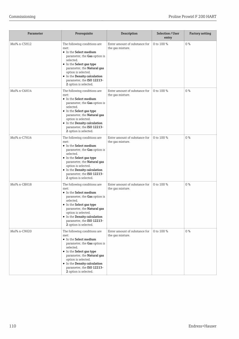
Commissioning Proline Prowirl F 200 HART
110 Endress+Hauser
Parameter Prerequisite Description Selection / Userentry
Factory setting
Mol% n-C5H12 The following conditions aremet:• In the Select medium
parameter, the Gas option isselected.
• In the Select gas typeparameter, the Natural gasoption is selected.
• In the Density calculationparameter, the ISO 12213-2 option is selected.
Enter amount of substance forthe gas mixture.
0 to 100 % 0 %
Mol% n-C6H14 The following conditions aremet:• In the Select medium
parameter, the Gas option isselected.
• In the Select gas typeparameter, the Natural gasoption is selected.
• In the Density calculationparameter, the ISO 12213-2 option is selected.
Enter amount of substance forthe gas mixture.
0 to 100 % 0 %
Mol% n-C7H16 The following conditions aremet:• In the Select medium
parameter, the Gas option isselected.
• In the Select gas typeparameter, the Natural gasoption is selected.
• In the Density calculationparameter, the ISO 12213-2 option is selected.
Enter amount of substance forthe gas mixture.
0 to 100 % 0 %
Mol% n-C8H18 The following conditions aremet:• In the Select medium
parameter, the Gas option isselected.
• In the Select gas typeparameter, the Natural gasoption is selected.
• In the Density calculationparameter, the ISO 12213-2 option is selected.
Enter amount of substance forthe gas mixture.
0 to 100 % 0 %
Mol% n-C9H20 The following conditions aremet:• In the Select medium
parameter, the Gas option isselected.
• In the Select gas typeparameter, the Natural gasoption is selected.
• In the Density calculationparameter, the ISO 12213-2 option is selected.
Enter amount of substance forthe gas mixture.
0 to 100 % 0 %
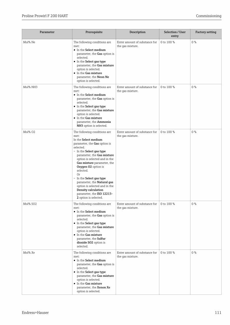
Proline Prowirl F 200 HART Commissioning
Endress+Hauser 111
Parameter Prerequisite Description Selection / Userentry
Factory setting
Mol% Ne The following conditions aremet:• In the Select medium
parameter, the Gas option isselected.
• In the Select gas typeparameter, the Gas mixtureoption is selected.
• In the Gas mixtureparameter, the Neon Neoption is selected.
Enter amount of substance forthe gas mixture.
0 to 100 % 0 %
Mol% NH3 The following conditions aremet:• In the Select medium
parameter, the Gas option isselected.
• In the Select gas typeparameter, the Gas mixtureoption is selected.
• In the Gas mixtureparameter, the AmmoniaNH3 option is selected.
Enter amount of substance forthe gas mixture.
0 to 100 % 0 %
Mol% O2 The following conditions aremet:In the Select mediumparameter, the Gas option isselected.– In the Select gas type
parameter, the Gas mixtureoption is selected and in theGas mixture parameter, theOxygen O2 option isselected.Or
– In the Select gas typeparameter, the Natural gasoption is selected and in theDensity calculationparameter, the ISO 12213-2 option is selected.
Enter amount of substance forthe gas mixture.
0 to 100 % 0 %
Mol% SO2 The following conditions aremet:• In the Select medium
parameter, the Gas option isselected.
• In the Select gas typeparameter, the Gas mixtureoption is selected.
• In the Gas mixtureparameter, the Sulfurdioxide SO2 option isselected.
Enter amount of substance forthe gas mixture.
0 to 100 % 0 %
Mol% Xe The following conditions aremet:• In the Select medium
parameter, the Gas option isselected.
• In the Select gas typeparameter, the Gas mixtureoption is selected.
• In the Gas mixtureparameter, the Xenon Xeoption is selected.
Enter amount of substance forthe gas mixture.
0 to 100 % 0 %
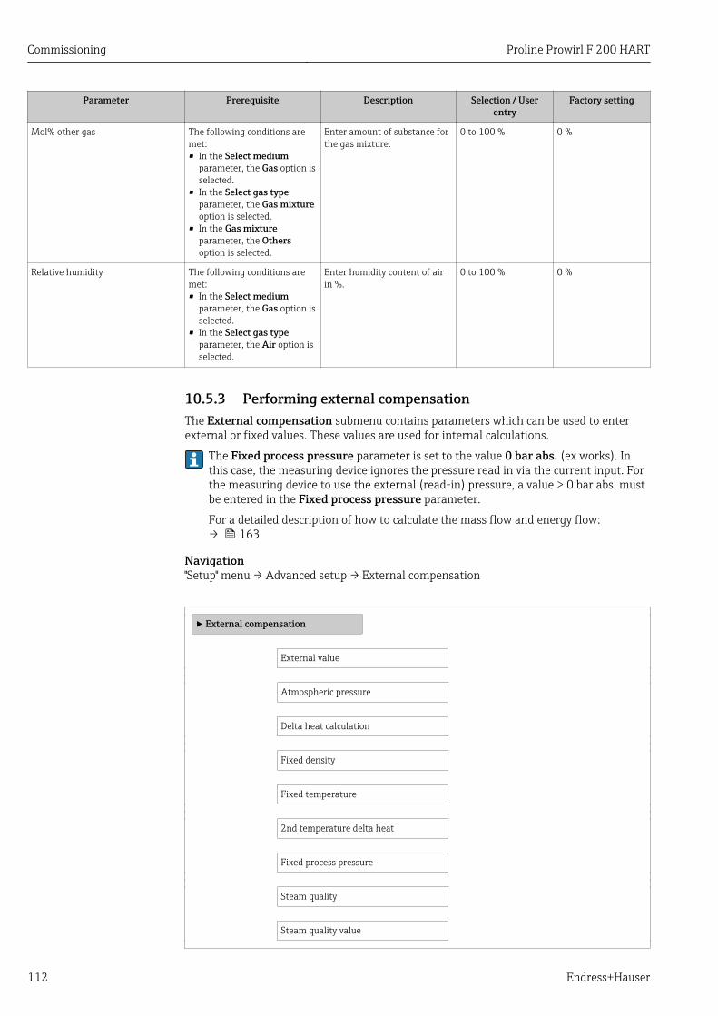
Commissioning Proline Prowirl F 200 HART
112 Endress+Hauser
Parameter Prerequisite Description Selection / Userentry
Factory setting
Mol% other gas The following conditions aremet:• In the Select medium
parameter, the Gas option isselected.
• In the Select gas typeparameter, the Gas mixtureoption is selected.
• In the Gas mixtureparameter, the Othersoption is selected.
Enter amount of substance forthe gas mixture.
0 to 100 % 0 %
Relative humidity The following conditions aremet:• In the Select medium
parameter, the Gas option isselected.
• In the Select gas typeparameter, the Air option isselected.
Enter humidity content of airin %.
0 to 100 % 0 %
10.5.3 Performing external compensationThe External compensation submenu contains parameters which can be used to enterexternal or fixed values. These values are used for internal calculations.
The Fixed process pressure parameter is set to the value 0 bar abs. (ex works). Inthis case, the measuring device ignores the pressure read in via the current input. Forthe measuring device to use the external (read-in) pressure, a value > 0 bar abs. mustbe entered in the Fixed process pressure parameter.
For a detailed description of how to calculate the mass flow and energy flow:→ 163
Navigation"Setup" menu → Advanced setup → External compensation
‣ External compensation
External value
Atmospheric pressure
Delta heat calculation
Fixed density
Fixed temperature
2nd temperature delta heat
Fixed process pressure
Steam quality
Steam quality value
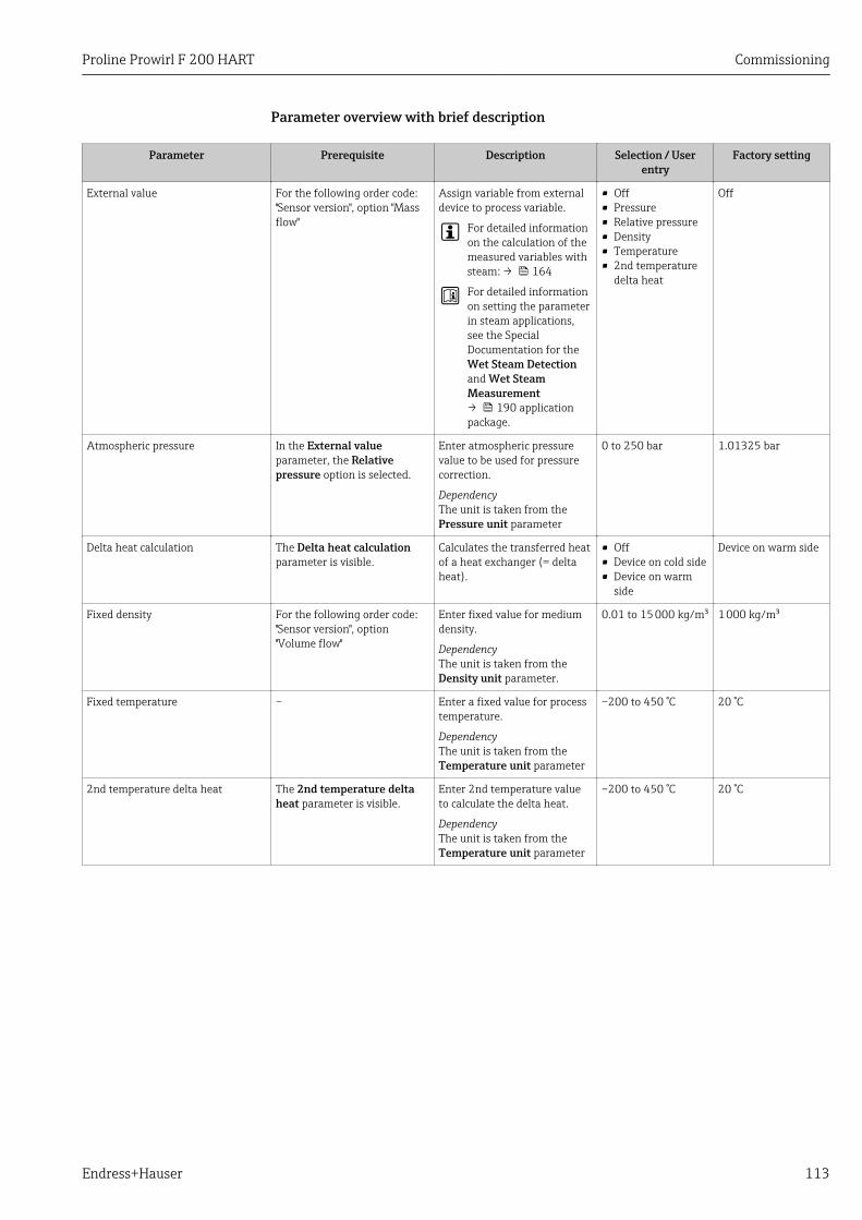
Proline Prowirl F 200 HART Commissioning
Endress+Hauser 113
Parameter overview with brief description
Parameter Prerequisite Description Selection / Userentry
Factory setting
External value For the following order code:"Sensor version", option "Massflow"
Assign variable from externaldevice to process variable.
For detailed informationon the calculation of themeasured variables withsteam: → 164
For detailed informationon setting the parameterin steam applications,see the SpecialDocumentation for theWet Steam Detectionand Wet SteamMeasurement→ 190 applicationpackage.
• Off• Pressure• Relative pressure• Density• Temperature• 2nd temperature
delta heat
Off
Atmospheric pressure In the External valueparameter, the Relativepressure option is selected.
Enter atmospheric pressurevalue to be used for pressurecorrection.
DependencyThe unit is taken from thePressure unit parameter
0 to 250 bar 1.01325 bar
Delta heat calculation The Delta heat calculationparameter is visible.
Calculates the transferred heatof a heat exchanger (= deltaheat).
• Off• Device on cold side• Device on warm
side
Device on warm side
Fixed density For the following order code:"Sensor version", option"Volume flow"
Enter fixed value for mediumdensity.
DependencyThe unit is taken from theDensity unit parameter.
0.01 to 15 000 kg/m³ 1 000 kg/m³
Fixed temperature – Enter a fixed value for processtemperature.
DependencyThe unit is taken from theTemperature unit parameter
–200 to 450 °C 20 °C
2nd temperature delta heat The 2nd temperature deltaheat parameter is visible.
Enter 2nd temperature valueto calculate the delta heat.
DependencyThe unit is taken from theTemperature unit parameter
–200 to 450 °C 20 °C
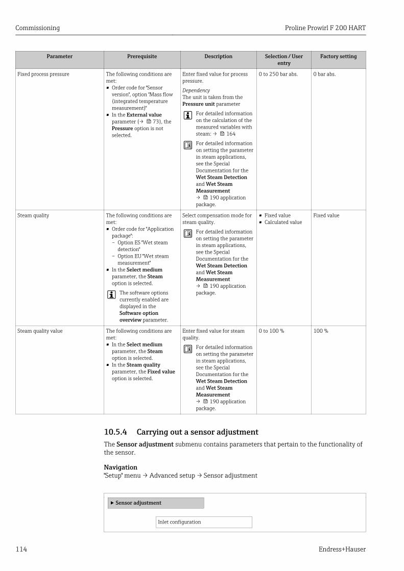
Commissioning Proline Prowirl F 200 HART
114 Endress+Hauser
Parameter Prerequisite Description Selection / Userentry
Factory setting
Fixed process pressure The following conditions aremet:• Order code for "Sensor
version", option "Mass flow(integrated temperaturemeasurement)"
• In the External valueparameter (→ 73), thePressure option is notselected.
Enter fixed value for processpressure.
DependencyThe unit is taken from thePressure unit parameter
For detailed informationon the calculation of themeasured variables withsteam: → 164
For detailed informationon setting the parameterin steam applications,see the SpecialDocumentation for theWet Steam Detectionand Wet SteamMeasurement→ 190 applicationpackage.
0 to 250 bar abs. 0 bar abs.
Steam quality The following conditions aremet:• Order code for "Application
package":– Option ES "Wet steam
detection"– Option EU "Wet steam
measurement"• In the Select medium
parameter, the Steamoption is selected.
The software optionscurrently enabled aredisplayed in theSoftware optionoverview parameter.
Select compensation mode forsteam quality.
For detailed informationon setting the parameterin steam applications,see the SpecialDocumentation for theWet Steam Detectionand Wet SteamMeasurement→ 190 applicationpackage.
• Fixed value• Calculated value
Fixed value
Steam quality value The following conditions aremet:• In the Select medium
parameter, the Steamoption is selected.
• In the Steam qualityparameter, the Fixed valueoption is selected.
Enter fixed value for steamquality.
For detailed informationon setting the parameterin steam applications,see the SpecialDocumentation for theWet Steam Detectionand Wet SteamMeasurement→ 190 applicationpackage.
0 to 100 % 100 %
10.5.4 Carrying out a sensor adjustmentThe Sensor adjustment submenu contains parameters that pertain to the functionality ofthe sensor.
Navigation"Setup" menu → Advanced setup → Sensor adjustment
‣ Sensor adjustment
Inlet configuration
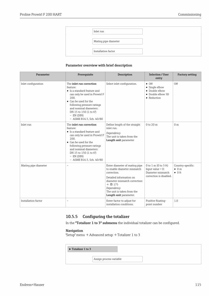
Proline Prowirl F 200 HART Commissioning
Endress+Hauser 115
Inlet run
Mating pipe diameter
Installation factor
Parameter overview with brief description
Parameter Prerequisite Description Selection / Userentry
Factory setting
Inlet configuration The inlet run correctionfeature:• Is a standard feature and
can only be used in Prowirl F200.
• Can be used for thefollowing pressure ratingsand nominal diameters:DN 15 to 150 (1 to 6")– EN (DIN)– ASME B16.5, Sch. 40/80
Select inlet configuration. • Off• Single elbow• Double elbow• Double elbow 3D• Reduction
Off
Inlet run The inlet run correctionfeature:• Is a standard feature and
can only be used in Prowirl F200.
• Can be used for thefollowing pressure ratingsand nominal diameters:DN 15 to 150 (1 to 6")– EN (DIN)– ASME B16.5, Sch. 40/80
Define length of the straightinlet run.
DependencyThe unit is taken from theLength unit parameter
0 to 20 m 0 m
Mating pipe diameter – Enter diameter of mating pipeto enable diameter mismatchcorrection.
Detailed information ondiameter mismatch correction:→ 175DependencyThe unit is taken from theLength unit parameter.
0 to 1 m (0 to 3 ft)Input value = 0:Diameter mismatchcorrection is disabled.
Country-specific:• 0 m• 0 ft
Installation factor – Enter factor to adjust forinstallation conditions.
Positive floating-point number
1.0
10.5.5 Configuring the totalizerIn the "Totalizer 1 to 3" submenu the individual totalizer can be configured.
Navigation"Setup" menu → Advanced setup → Totalizer 1 to 3
‣ Totalizer 1 to 3
Assign process variable
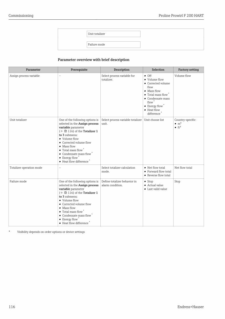
Commissioning Proline Prowirl F 200 HART
116 Endress+Hauser
Unit totalizer
Failure mode
Parameter overview with brief description
Parameter Prerequisite Description Selection Factory setting
Assign process variable – Select process variable fortotalizer.
• Off• Volume flow• Corrected volume
flow• Mass flow• Total mass flow *
• Condensate massflow *
• Energy flow *
• Heat flowdifference *
Volume flow
Unit totalizer One of the following options isselected in the Assign processvariable parameter(→ 116) of the Totalizer 1to 3 submenu:• Volume flow• Corrected volume flow• Mass flow• Total mass flow *
• Condensate mass flow *
• Energy flow *
• Heat flow difference *
Select process variable totalizerunit.
Unit choose list Country-specific:• m³• ft³
Totalizer operation mode – Select totalizer calculationmode.
• Net flow total• Forward flow total• Reverse flow total
Net flow total
Failure mode One of the following options isselected in the Assign processvariable parameter(→ 116) of the Totalizer 1to 3 submenu:• Volume flow• Corrected volume flow• Mass flow• Total mass flow *
• Condensate mass flow *
• Energy flow *
• Heat flow difference *
Define totalizer behavior inalarm condition.
• Stop• Actual value• Last valid value
Stop
* Visibility depends on order options or device settings
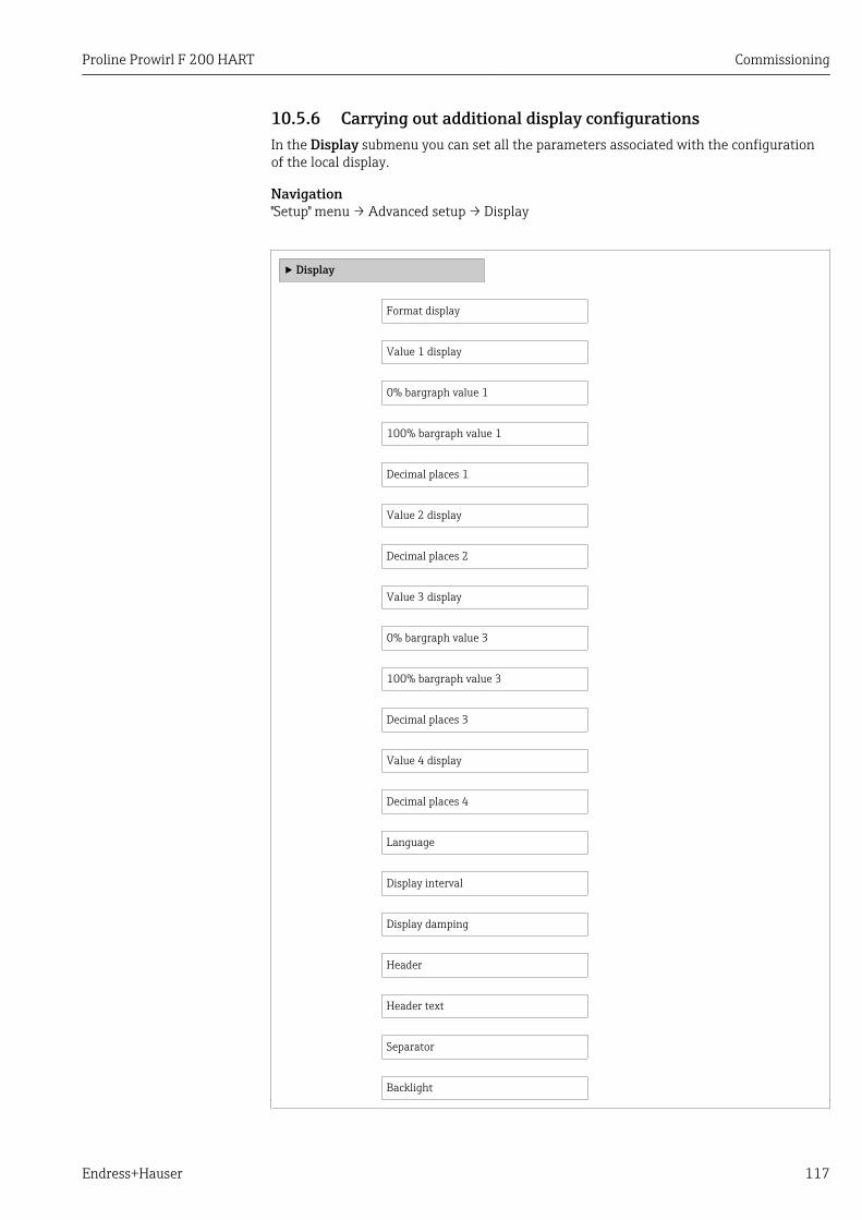
Proline Prowirl F 200 HART Commissioning
Endress+Hauser 117
10.5.6 Carrying out additional display configurationsIn the Display submenu you can set all the parameters associated with the configurationof the local display.
Navigation"Setup" menu → Advanced setup → Display
‣ Display
Format display
Value 1 display
0% bargraph value 1
100% bargraph value 1
Decimal places 1
Value 2 display
Decimal places 2
Value 3 display
0% bargraph value 3
100% bargraph value 3
Decimal places 3
Value 4 display
Decimal places 4
Language
Display interval
Display damping
Header
Header text
Separator
Backlight
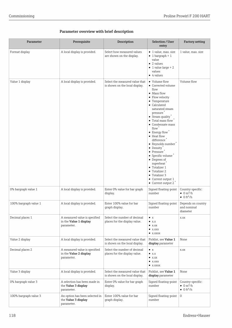
Commissioning Proline Prowirl F 200 HART
118 Endress+Hauser
Parameter overview with brief description
Parameter Prerequisite Description Selection / Userentry
Factory setting
Format display A local display is provided. Select how measured valuesare shown on the display.
• 1 value, max. size• 1 bargraph + 1
value• 2 values• 1 value large + 2
values• 4 values
1 value, max. size
Value 1 display A local display is provided. Select the measured value thatis shown on the local display.
• Volume flow• Corrected volume
flow• Mass flow• Flow velocity• Temperature• Calculated
saturated steampressure *
• Steam quality *
• Total mass flow *
• Condensate massflow *
• Energy flow *
• Heat flowdifference *
• Reynolds number *
• Density *
• Pressure *
• Specific volume *
• Degrees ofsuperheat *
• Totalizer 1• Totalizer 2• Totalizer 3• Current output 1• Current output 2 *
Volume flow
0% bargraph value 1 A local display is provided. Enter 0% value for bar graphdisplay.
Signed floating-pointnumber
Country-specific:• 0 m³/h• 0 ft³/h
100% bargraph value 1 A local display is provided. Enter 100% value for bargraph display.
Signed floating-pointnumber
Depends on countryand nominaldiameter
Decimal places 1 A measured value is specifiedin the Value 1 displayparameter.
Select the number of decimalplaces for the display value.
• x• x.x• x.xx• x.xxx• x.xxxx
x.xx
Value 2 display A local display is provided. Select the measured value thatis shown on the local display.
Picklist, see Value 1display parameter
None
Decimal places 2 A measured value is specifiedin the Value 2 displayparameter.
Select the number of decimalplaces for the display value.
• x• x.x• x.xx• x.xxx• x.xxxx
x.xx
Value 3 display A local display is provided. Select the measured value thatis shown on the local display.
Picklist, see Value 1display parameter
None
0% bargraph value 3 A selection has been made inthe Value 3 displayparameter.
Enter 0% value for bar graphdisplay.
Signed floating-pointnumber
Country-specific:• 0 m³/h• 0 ft³/h
100% bargraph value 3 An option has been selected inthe Value 3 displayparameter.
Enter 100% value for bargraph display.
Signed floating-pointnumber
0
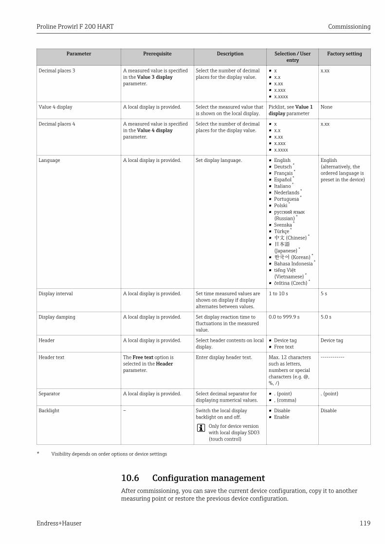
Proline Prowirl F 200 HART Commissioning
Endress+Hauser 119
Parameter Prerequisite Description Selection / Userentry
Factory setting
Decimal places 3 A measured value is specifiedin the Value 3 displayparameter.
Select the number of decimalplaces for the display value.
• x• x.x• x.xx• x.xxx• x.xxxx
x.xx
Value 4 display A local display is provided. Select the measured value thatis shown on the local display.
Picklist, see Value 1display parameter
None
Decimal places 4 A measured value is specifiedin the Value 4 displayparameter.
Select the number of decimalplaces for the display value.
• x• x.x• x.xx• x.xxx• x.xxxx
x.xx
Language A local display is provided. Set display language. • English• Deutsch *
• Français *
• Español *
• Italiano *
• Nederlands *
• Portuguesa *
• Polski *
• русский язык(Russian) *
• Svenska *
• Türkçe *
• 中文 (Chinese) *
• 日本語(Japanese) *
• 한국어 (Korean) *
• Bahasa Indonesia *
• tiếng Việt(Vietnamese) *
• čeština (Czech) *
English(alternatively, theordered language ispreset in the device)
Display interval A local display is provided. Set time measured values areshown on display if displayalternates between values.
1 to 10 s 5 s
Display damping A local display is provided. Set display reaction time tofluctuations in the measuredvalue.
0.0 to 999.9 s 5.0 s
Header A local display is provided. Select header contents on localdisplay.
• Device tag• Free text
Device tag
Header text The Free text option isselected in the Headerparameter.
Enter display header text. Max. 12 characterssuch as letters,numbers or specialcharacters (e.g. @,%, /)
------------
Separator A local display is provided. Select decimal separator fordisplaying numerical values.
• . (point)• , (comma)
. (point)
Backlight – Switch the local displaybacklight on and off.
Only for device versionwith local display SD03(touch control)
• Disable• Enable
Disable
* Visibility depends on order options or device settings
10.6 Configuration managementAfter commissioning, you can save the current device configuration, copy it to anothermeasuring point or restore the previous device configuration.
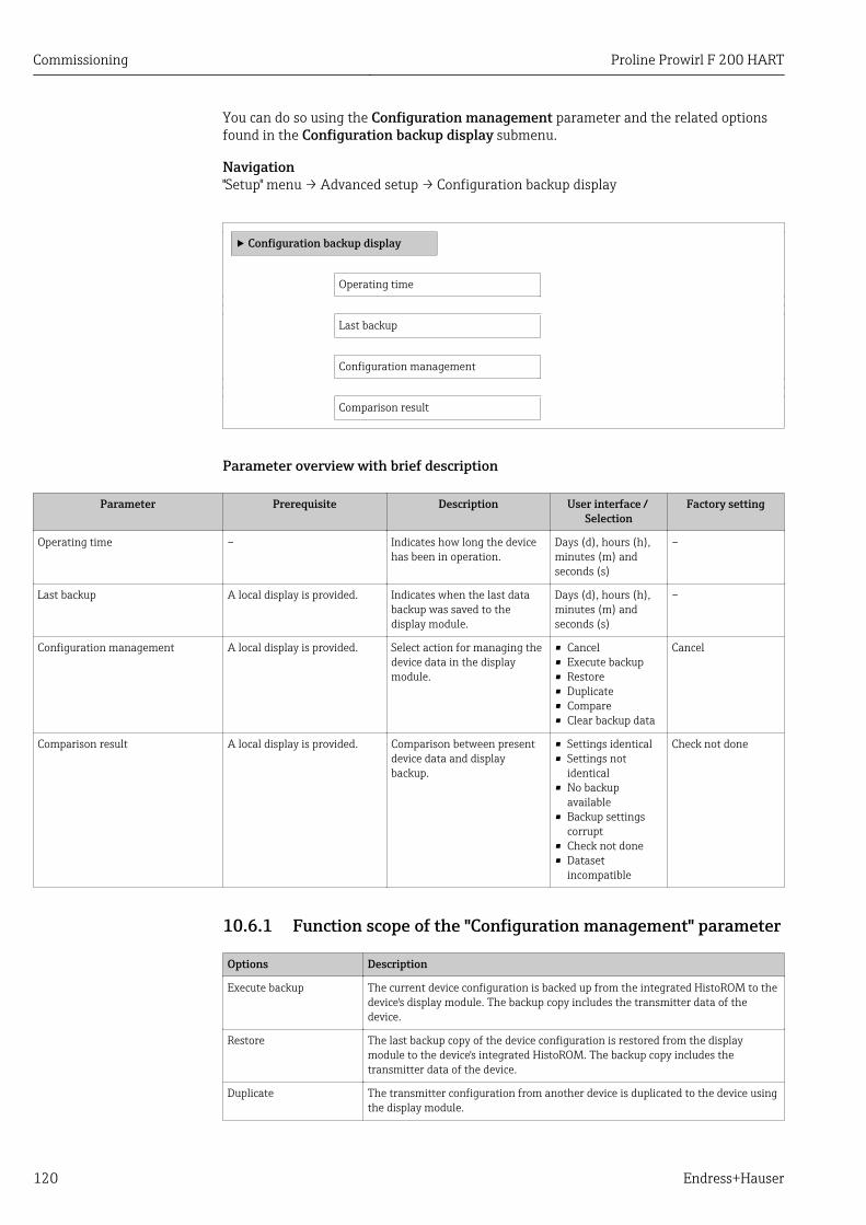
Commissioning Proline Prowirl F 200 HART
120 Endress+Hauser
You can do so using the Configuration management parameter and the related optionsfound in the Configuration backup display submenu.
Navigation"Setup" menu → Advanced setup → Configuration backup display
‣ Configuration backup display
Operating time
Last backup
Configuration management
Comparison result
Parameter overview with brief description
Parameter Prerequisite Description User interface / Selection
Factory setting
Operating time – Indicates how long the devicehas been in operation.
Days (d), hours (h),minutes (m) andseconds (s)
–
Last backup A local display is provided. Indicates when the last databackup was saved to thedisplay module.
Days (d), hours (h),minutes (m) andseconds (s)
–
Configuration management A local display is provided. Select action for managing thedevice data in the displaymodule.
• Cancel• Execute backup• Restore• Duplicate• Compare• Clear backup data
Cancel
Comparison result A local display is provided. Comparison between presentdevice data and displaybackup.
• Settings identical• Settings not
identical• No backup
available• Backup settings
corrupt• Check not done• Dataset
incompatible
Check not done
10.6.1 Function scope of the "Configuration management" parameter
Options Description
Execute backup The current device configuration is backed up from the integrated HistoROM to thedevice's display module. The backup copy includes the transmitter data of thedevice.
Restore The last backup copy of the device configuration is restored from the displaymodule to the device's integrated HistoROM. The backup copy includes thetransmitter data of the device.
Duplicate The transmitter configuration from another device is duplicated to the device usingthe display module.
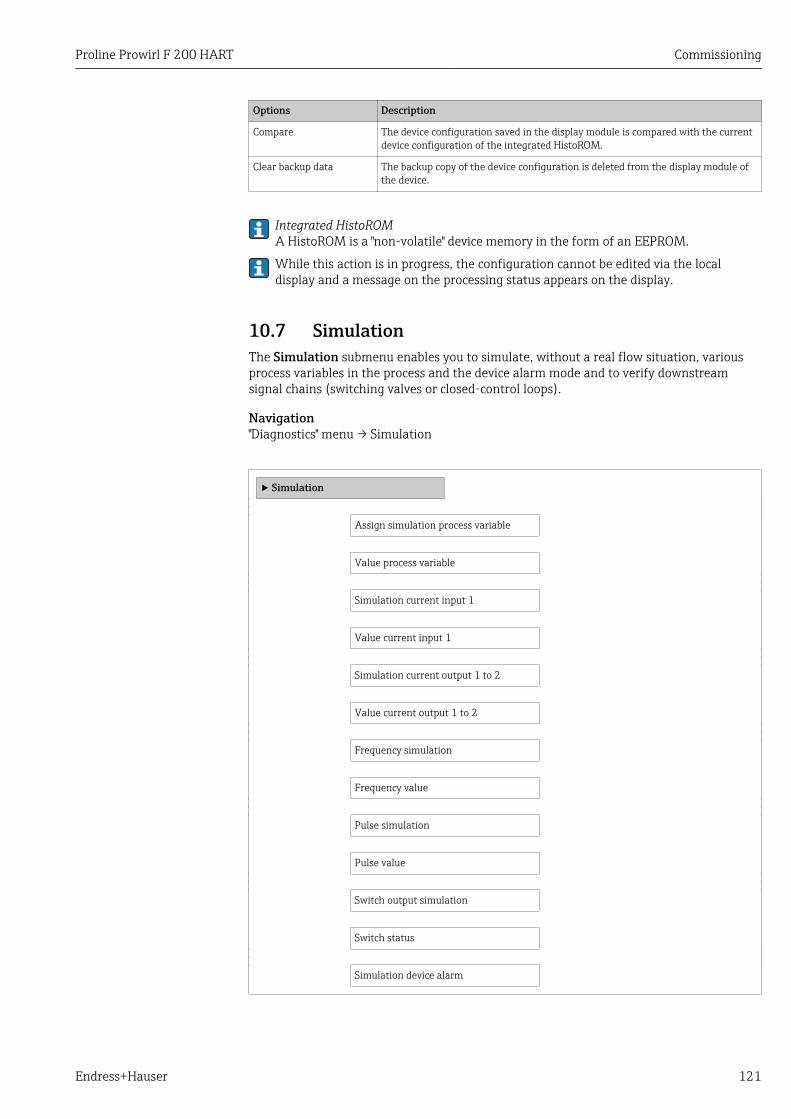
Proline Prowirl F 200 HART Commissioning
Endress+Hauser 121
Options Description
Compare The device configuration saved in the display module is compared with the currentdevice configuration of the integrated HistoROM.
Clear backup data The backup copy of the device configuration is deleted from the display module ofthe device.
Integrated HistoROMA HistoROM is a "non-volatile" device memory in the form of an EEPROM.
While this action is in progress, the configuration cannot be edited via the localdisplay and a message on the processing status appears on the display.
10.7 SimulationThe Simulation submenu enables you to simulate, without a real flow situation, variousprocess variables in the process and the device alarm mode and to verify downstreamsignal chains (switching valves or closed-control loops).
Navigation"Diagnostics" menu → Simulation
‣ Simulation
Assign simulation process variable
Value process variable
Simulation current input 1
Value current input 1
Simulation current output 1 to 2
Value current output 1 to 2
Frequency simulation
Frequency value
Pulse simulation
Pulse value
Switch output simulation
Switch status
Simulation device alarm
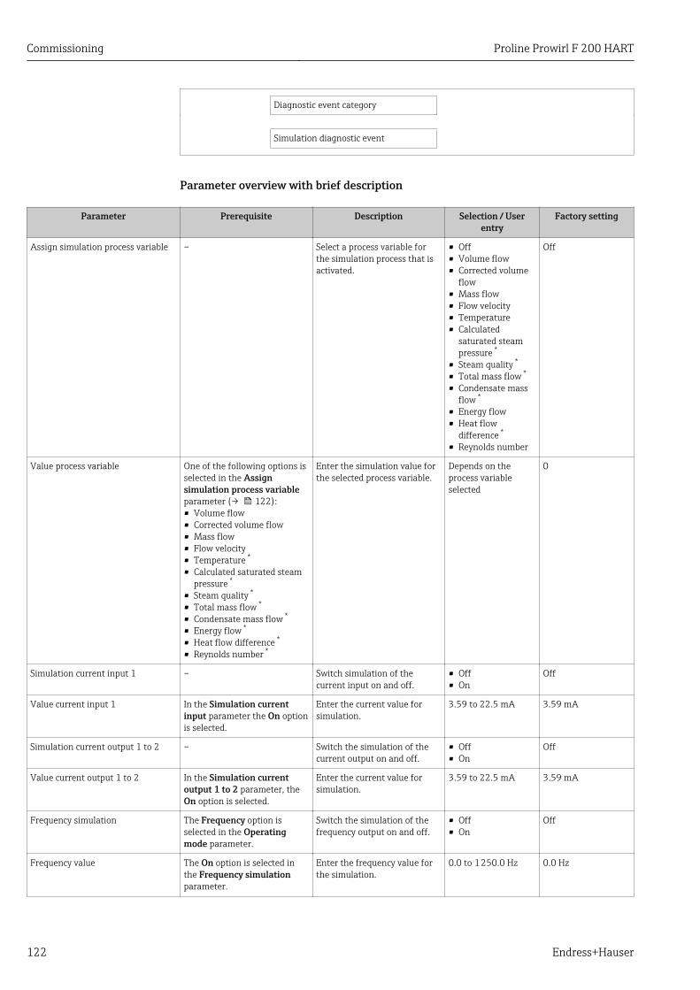
Commissioning Proline Prowirl F 200 HART
122 Endress+Hauser
Diagnostic event category
Simulation diagnostic event
Parameter overview with brief description
Parameter Prerequisite Description Selection / Userentry
Factory setting
Assign simulation process variable – Select a process variable forthe simulation process that isactivated.
• Off• Volume flow• Corrected volume
flow• Mass flow• Flow velocity• Temperature• Calculated
saturated steampressure *
• Steam quality *
• Total mass flow *
• Condensate massflow *
• Energy flow• Heat flow
difference *
• Reynolds number
Off
Value process variable One of the following options isselected in the Assignsimulation process variableparameter (→ 122):• Volume flow• Corrected volume flow• Mass flow• Flow velocity• Temperature *
• Calculated saturated steampressure *
• Steam quality *
• Total mass flow *
• Condensate mass flow *
• Energy flow *
• Heat flow difference *
• Reynolds number *
Enter the simulation value forthe selected process variable.
Depends on theprocess variableselected
0
Simulation current input 1 – Switch simulation of thecurrent input on and off.
• Off• On
Off
Value current input 1 In the Simulation currentinput parameter the On optionis selected.
Enter the current value forsimulation.
3.59 to 22.5 mA 3.59 mA
Simulation current output 1 to 2 – Switch the simulation of thecurrent output on and off.
• Off• On
Off
Value current output 1 to 2 In the Simulation currentoutput 1 to 2 parameter, theOn option is selected.
Enter the current value forsimulation.
3.59 to 22.5 mA 3.59 mA
Frequency simulation The Frequency option isselected in the Operatingmode parameter.
Switch the simulation of thefrequency output on and off.
• Off• On
Off
Frequency value The On option is selected inthe Frequency simulationparameter.
Enter the frequency value forthe simulation.
0.0 to 1 250.0 Hz 0.0 Hz
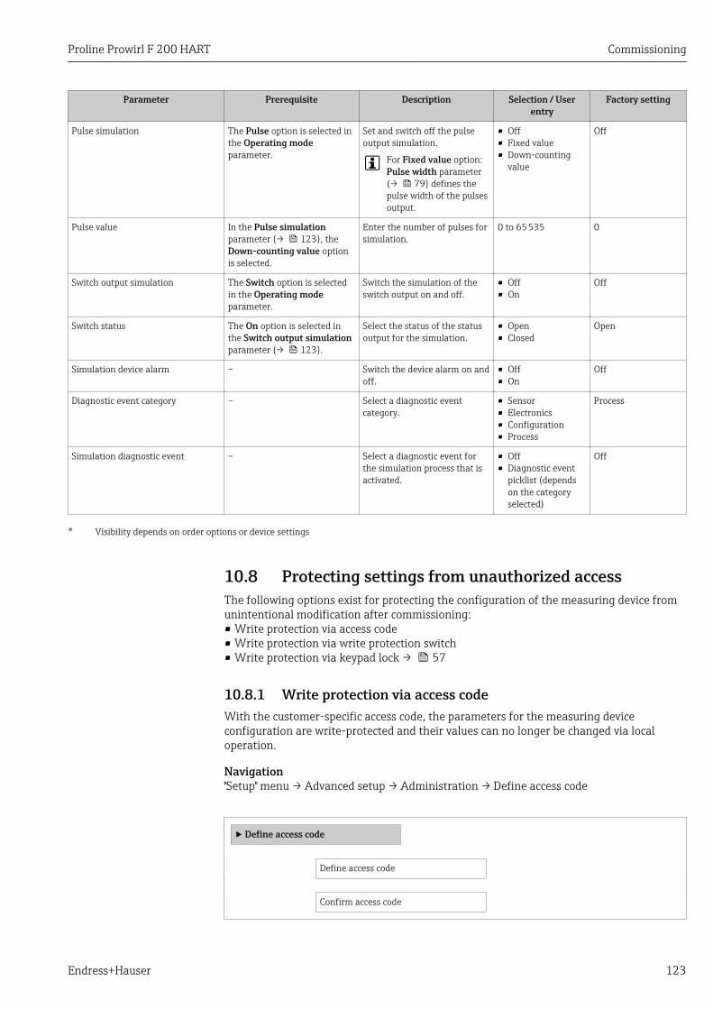
Proline Prowirl F 200 HART Commissioning
Endress+Hauser 123
Parameter Prerequisite Description Selection / Userentry
Factory setting
Pulse simulation The Pulse option is selected inthe Operating modeparameter.
Set and switch off the pulseoutput simulation.
For Fixed value option:Pulse width parameter(→ 79) defines thepulse width of the pulsesoutput.
• Off• Fixed value• Down-counting
value
Off
Pulse value In the Pulse simulationparameter (→ 123), theDown-counting value optionis selected.
Enter the number of pulses forsimulation.
0 to 65 535 0
Switch output simulation The Switch option is selectedin the Operating modeparameter.
Switch the simulation of theswitch output on and off.
• Off• On
Off
Switch status The On option is selected inthe Switch output simulationparameter (→ 123).
Select the status of the statusoutput for the simulation.
• Open• Closed
Open
Simulation device alarm – Switch the device alarm on andoff.
• Off• On
Off
Diagnostic event category – Select a diagnostic eventcategory.
• Sensor• Electronics• Configuration• Process
Process
Simulation diagnostic event – Select a diagnostic event forthe simulation process that isactivated.
• Off• Diagnostic event
picklist (dependson the categoryselected)
Off
* Visibility depends on order options or device settings
10.8 Protecting settings from unauthorized accessThe following options exist for protecting the configuration of the measuring device fromunintentional modification after commissioning:• Write protection via access code• Write protection via write protection switch• Write protection via keypad lock → 57
10.8.1 Write protection via access codeWith the customer-specific access code, the parameters for the measuring deviceconfiguration are write-protected and their values can no longer be changed via localoperation.
Navigation"Setup" menu → Advanced setup → Administration → Define access code
‣ Define access code
Define access code
Confirm access code
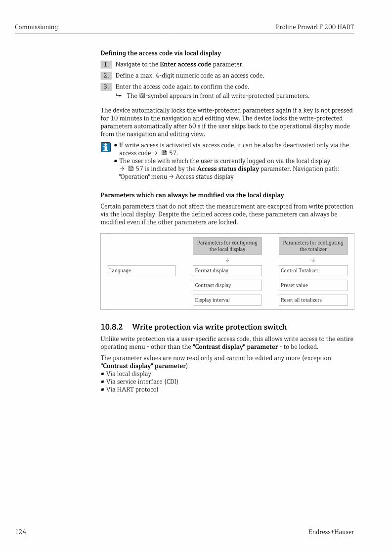
Commissioning Proline Prowirl F 200 HART
124 Endress+Hauser
Defining the access code via local display1. Navigate to the Enter access code parameter.
2. Define a max. 4-digit numeric code as an access code.
3. Enter the access code again to confirm the code. The -symbol appears in front of all write-protected parameters.
The device automatically locks the write-protected parameters again if a key is not pressedfor 10 minutes in the navigation and editing view. The device locks the write-protectedparameters automatically after 60 s if the user skips back to the operational display modefrom the navigation and editing view.
• If write access is activated via access code, it can be also be deactivated only via theaccess code → 57.
• The user role with which the user is currently logged on via the local display→ 57 is indicated by the Access status display parameter. Navigation path:"Operation" menu → Access status display
Parameters which can always be modified via the local displayCertain parameters that do not affect the measurement are excepted from write protectionvia the local display. Despite the defined access code, these parameters can always bemodified even if the other parameters are locked.
Parameters for configuringthe local display
Parameters for configuringthe totalizer
↓ ↓
Language Format display Control Totalizer
Contrast display Preset value
Display interval Reset all totalizers
10.8.2 Write protection via write protection switchUnlike write protection via a user-specific access code, this allows write access to the entireoperating menu - other than the "Contrast display" parameter - to be locked.
The parameter values are now read only and cannot be edited any more (exception"Contrast display" parameter):• Via local display• Via service interface (CDI)• Via HART protocol
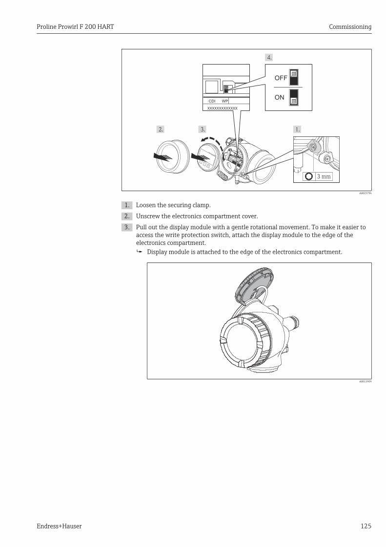
Proline Prowirl F 200 HART Commissioning
Endress+Hauser 125
+
E
–
3 mm
XXXXXXXXXXXXX
WPCDION
OFF
A0025794
1. Loosen the securing clamp.
2. Unscrew the electronics compartment cover.
3. Pull out the display module with a gentle rotational movement. To make it easier toaccess the write protection switch, attach the display module to the edge of theelectronics compartment. Display module is attached to the edge of the electronics compartment.
A0013909
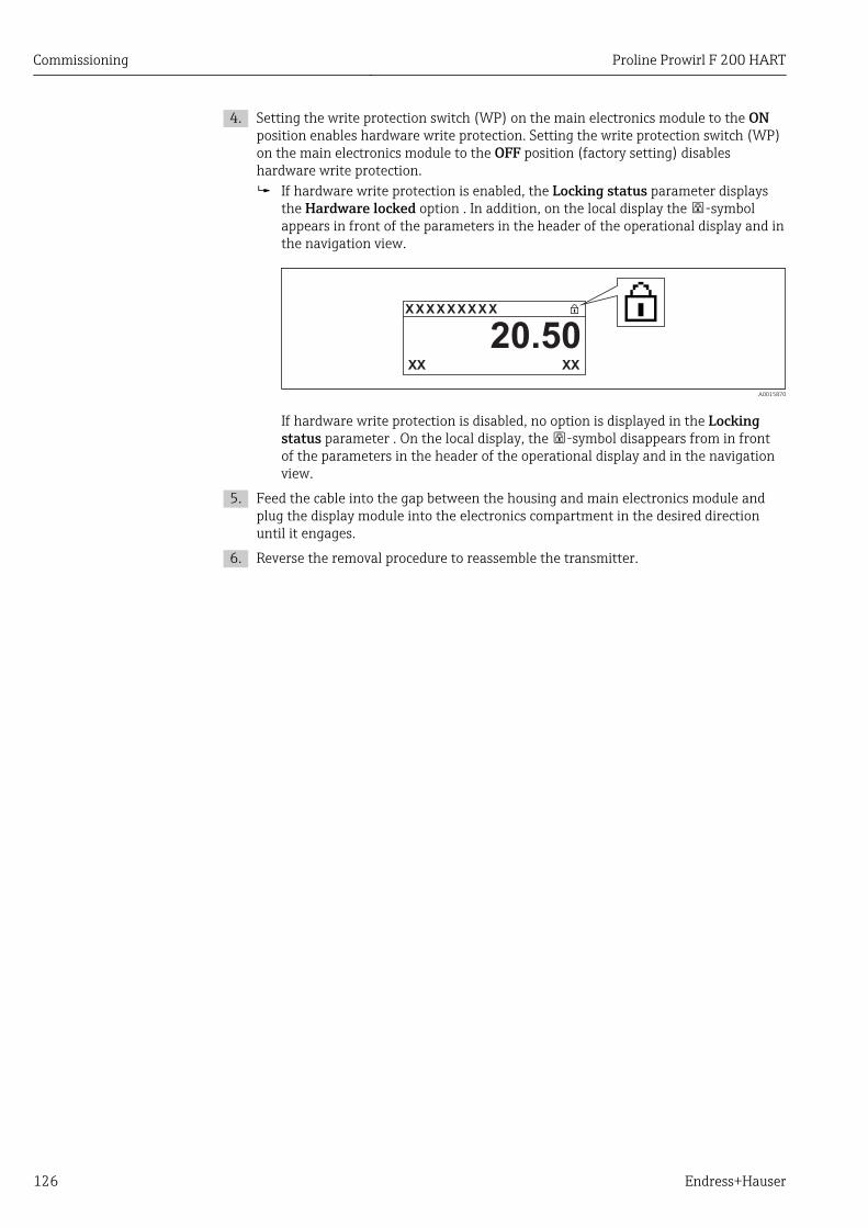
Commissioning Proline Prowirl F 200 HART
126 Endress+Hauser
4. Setting the write protection switch (WP) on the main electronics module to the ONposition enables hardware write protection. Setting the write protection switch (WP)on the main electronics module to the OFF position (factory setting) disableshardware write protection. If hardware write protection is enabled, the Locking status parameter displays
the Hardware locked option . In addition, on the local display the -symbolappears in front of the parameters in the header of the operational display and inthe navigation view.
X X X X X X XX X
20.50XXXX
A0015870
If hardware write protection is disabled, no option is displayed in the Lockingstatus parameter . On the local display, the -symbol disappears from in frontof the parameters in the header of the operational display and in the navigationview.
5. Feed the cable into the gap between the housing and main electronics module andplug the display module into the electronics compartment in the desired directionuntil it engages.
6. Reverse the removal procedure to reassemble the transmitter.
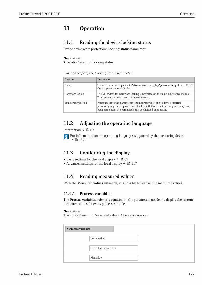
Proline Prowirl F 200 HART Operation
Endress+Hauser 127
11 Operation
11.1 Reading the device locking statusDevice active write protection: Locking status parameter
Navigation"Operation" menu → Locking status
Function scope of the "Locking status" parameter
Options Description
None The access status displayed in "Access status display" parameter applies → 57.Only appears on local display.
Hardware locked The DIP switch for hardware locking is activated on the main electronics module.This prevents write access to the parameters .
Temporarily locked Write access to the parameters is temporarily lock due to device-internalprocessing (e.g. data upload/download, reset). Once the internal processing hasbeen completed, the parameters can be changed once again.
11.2 Adjusting the operating languageInformation → 67
For information on the operating languages supported by the measuring device→ 187
11.3 Configuring the display• Basic settings for the local display → 89• Advanced settings for the local display → 117
11.4 Reading measured valuesWith the Measured values submenu, it is possible to read all the measured values.
11.4.1 Process variablesThe Process variables submenu contains all the parameters needed to display the currentmeasured values for every process variable.
Navigation"Diagnostics" menu → Measured values → Process variables
‣ Process variables
Volume flow
Corrected volume flow
Mass flow
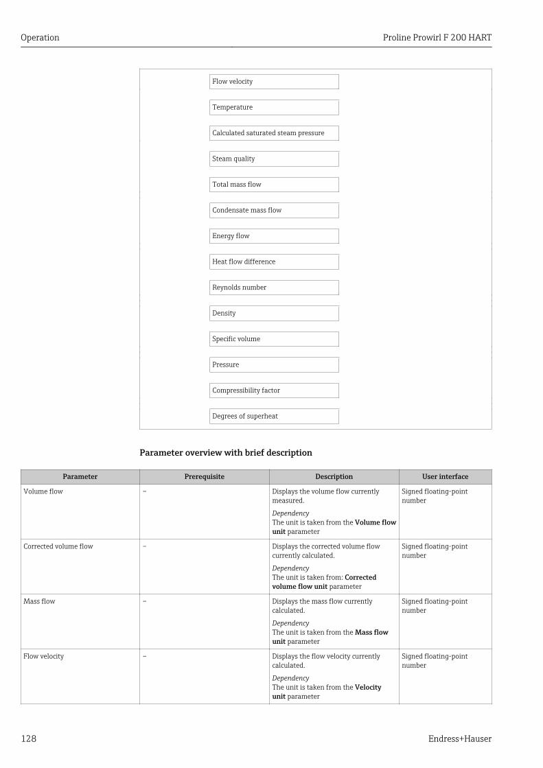
Operation Proline Prowirl F 200 HART
128 Endress+Hauser
Flow velocity
Temperature
Calculated saturated steam pressure
Steam quality
Total mass flow
Condensate mass flow
Energy flow
Heat flow difference
Reynolds number
Density
Specific volume
Pressure
Compressibility factor
Degrees of superheat
Parameter overview with brief description
Parameter Prerequisite Description User interface
Volume flow – Displays the volume flow currentlymeasured.
DependencyThe unit is taken from the Volume flowunit parameter
Signed floating-pointnumber
Corrected volume flow – Displays the corrected volume flowcurrently calculated.
DependencyThe unit is taken from: Correctedvolume flow unit parameter
Signed floating-pointnumber
Mass flow – Displays the mass flow currentlycalculated.
DependencyThe unit is taken from the Mass flowunit parameter
Signed floating-pointnumber
Flow velocity – Displays the flow velocity currentlycalculated.
DependencyThe unit is taken from the Velocityunit parameter
Signed floating-pointnumber
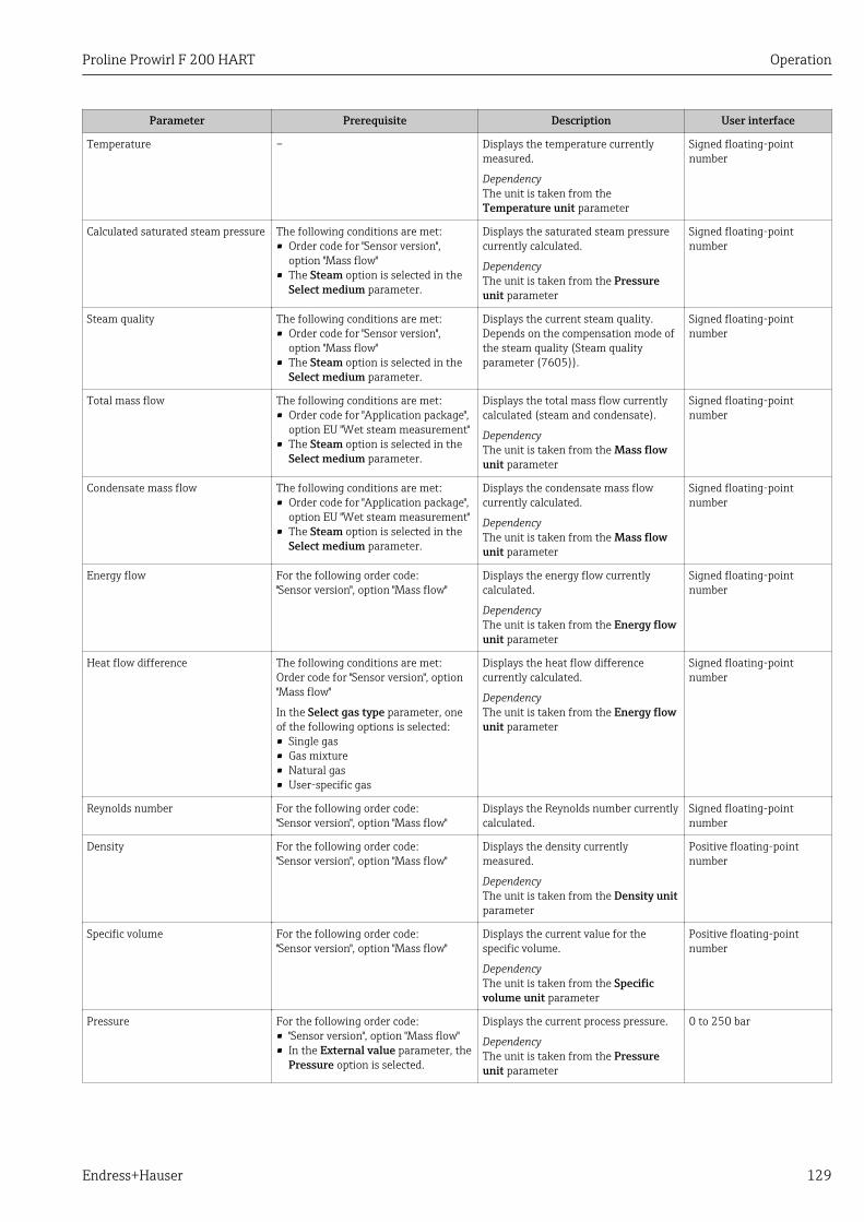
Proline Prowirl F 200 HART Operation
Endress+Hauser 129
Parameter Prerequisite Description User interface
Temperature – Displays the temperature currentlymeasured.
DependencyThe unit is taken from theTemperature unit parameter
Signed floating-pointnumber
Calculated saturated steam pressure The following conditions are met:• Order code for "Sensor version",
option "Mass flow"• The Steam option is selected in the
Select medium parameter.
Displays the saturated steam pressurecurrently calculated.
DependencyThe unit is taken from the Pressureunit parameter
Signed floating-pointnumber
Steam quality The following conditions are met:• Order code for "Sensor version",
option "Mass flow"• The Steam option is selected in the
Select medium parameter.
Displays the current steam quality.Depends on the compensation mode ofthe steam quality (Steam qualityparameter (7605)).
Signed floating-pointnumber
Total mass flow The following conditions are met:• Order code for "Application package",
option EU "Wet steam measurement"• The Steam option is selected in the
Select medium parameter.
Displays the total mass flow currentlycalculated (steam and condensate).
DependencyThe unit is taken from the Mass flowunit parameter
Signed floating-pointnumber
Condensate mass flow The following conditions are met:• Order code for "Application package",
option EU "Wet steam measurement"• The Steam option is selected in the
Select medium parameter.
Displays the condensate mass flowcurrently calculated.
DependencyThe unit is taken from the Mass flowunit parameter
Signed floating-pointnumber
Energy flow For the following order code:"Sensor version", option "Mass flow"
Displays the energy flow currentlycalculated.
DependencyThe unit is taken from the Energy flowunit parameter
Signed floating-pointnumber
Heat flow difference The following conditions are met:Order code for "Sensor version", option"Mass flow"
In the Select gas type parameter, oneof the following options is selected:• Single gas• Gas mixture• Natural gas• User-specific gas
Displays the heat flow differencecurrently calculated.
DependencyThe unit is taken from the Energy flowunit parameter
Signed floating-pointnumber
Reynolds number For the following order code:"Sensor version", option "Mass flow"
Displays the Reynolds number currentlycalculated.
Signed floating-pointnumber
Density For the following order code:"Sensor version", option "Mass flow"
Displays the density currentlymeasured.
DependencyThe unit is taken from the Density unitparameter
Positive floating-pointnumber
Specific volume For the following order code:"Sensor version", option "Mass flow"
Displays the current value for thespecific volume.
DependencyThe unit is taken from the Specificvolume unit parameter
Positive floating-pointnumber
Pressure For the following order code:• "Sensor version", option "Mass flow"• In the External value parameter, the
Pressure option is selected.
Displays the current process pressure.
DependencyThe unit is taken from the Pressureunit parameter
0 to 250 bar
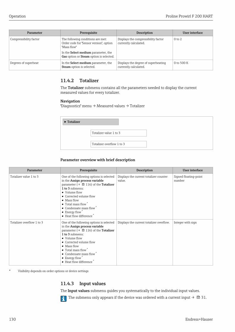
Operation Proline Prowirl F 200 HART
130 Endress+Hauser
Parameter Prerequisite Description User interface
Compressibility factor The following conditions are met:Order code for "Sensor version", option"Mass flow"
In the Select medium parameter, theGas option or Steam option is selected.
Displays the compressibility factorcurrently calculated.
0 to 2
Degrees of superheat In the Select medium parameter, theSteam option is selected.
Displays the degree of superheatingcurrently calculated.
0 to 500 K
11.4.2 TotalizerThe Totalizer submenu contains all the parameters needed to display the currentmeasured values for every totalizer.
Navigation"Diagnostics" menu → Measured values → Totalizer
‣ Totalizer
Totalizer value 1 to 3
Totalizer overflow 1 to 3
Parameter overview with brief description
Parameter Prerequisite Description User interface
Totalizer value 1 to 3 One of the following options is selectedin the Assign process variableparameter (→ 116) of the Totalizer1 to 3 submenu:• Volume flow• Corrected volume flow• Mass flow• Total mass flow *
• Condensate mass flow *
• Energy flow *
• Heat flow difference *
Displays the current totalizer countervalue.
Signed floating-pointnumber
Totalizer overflow 1 to 3 One of the following options is selectedin the Assign process variableparameter (→ 116) of the Totalizer1 to 3 submenu:• Volume flow• Corrected volume flow• Mass flow• Total mass flow *
• Condensate mass flow *
• Energy flow *
• Heat flow difference *
Displays the current totalizer overflow. Integer with sign
* Visibility depends on order options or device settings
11.4.3 Input valuesThe Input values submenu guides you systematically to the individual input values.
The submenu only appears if the device was ordered with a current input → 31.
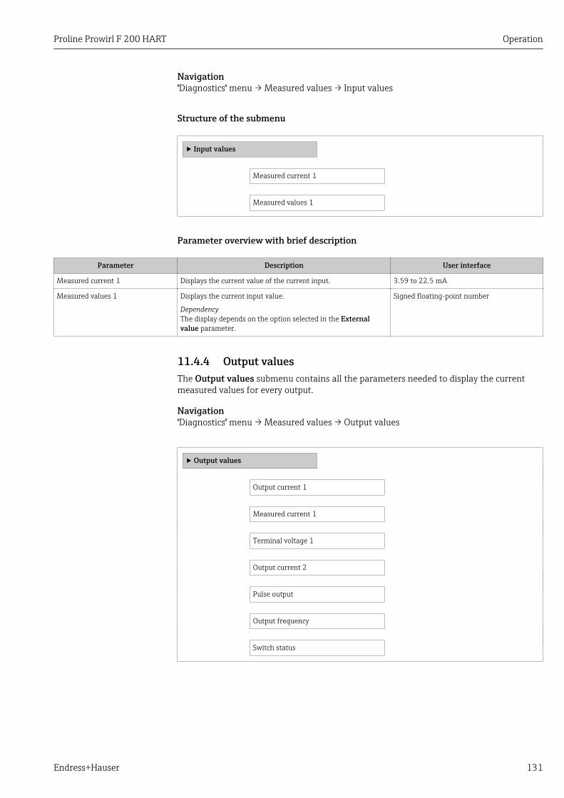
Proline Prowirl F 200 HART Operation
Endress+Hauser 131
Navigation"Diagnostics" menu → Measured values → Input values
Structure of the submenu
‣ Input values
Measured current 1
Measured values 1
Parameter overview with brief description
Parameter Description User interface
Measured current 1 Displays the current value of the current input. 3.59 to 22.5 mA
Measured values 1 Displays the current input value.
DependencyThe display depends on the option selected in the Externalvalue parameter.
Signed floating-point number
11.4.4 Output valuesThe Output values submenu contains all the parameters needed to display the currentmeasured values for every output.
Navigation"Diagnostics" menu → Measured values → Output values
‣ Output values
Output current 1
Measured current 1
Terminal voltage 1
Output current 2
Pulse output
Output frequency
Switch status
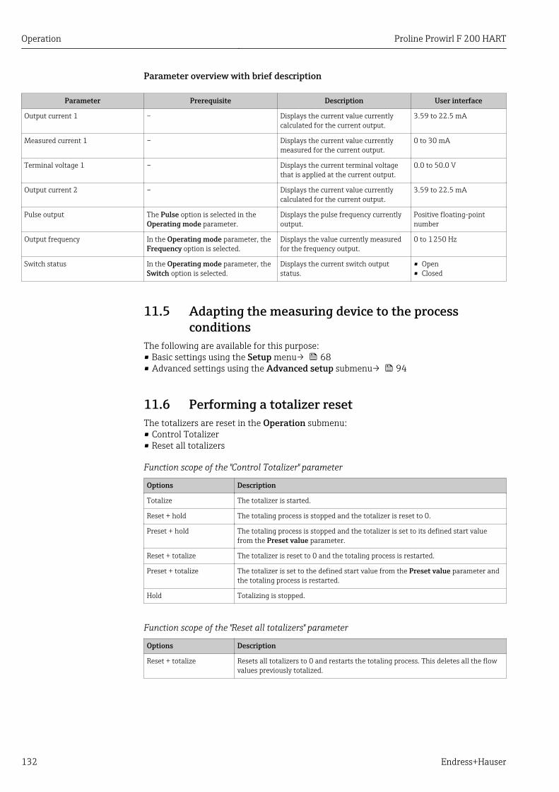
Operation Proline Prowirl F 200 HART
132 Endress+Hauser
Parameter overview with brief description
Parameter Prerequisite Description User interface
Output current 1 – Displays the current value currentlycalculated for the current output.
3.59 to 22.5 mA
Measured current 1 – Displays the current value currentlymeasured for the current output.
0 to 30 mA
Terminal voltage 1 – Displays the current terminal voltagethat is applied at the current output.
0.0 to 50.0 V
Output current 2 – Displays the current value currentlycalculated for the current output.
3.59 to 22.5 mA
Pulse output The Pulse option is selected in theOperating mode parameter.
Displays the pulse frequency currentlyoutput.
Positive floating-pointnumber
Output frequency In the Operating mode parameter, theFrequency option is selected.
Displays the value currently measuredfor the frequency output.
0 to 1 250 Hz
Switch status In the Operating mode parameter, theSwitch option is selected.
Displays the current switch outputstatus.
• Open• Closed
11.5 Adapting the measuring device to the processconditions
The following are available for this purpose:• Basic settings using the Setup menu→ 68• Advanced settings using the Advanced setup submenu→ 94
11.6 Performing a totalizer resetThe totalizers are reset in the Operation submenu:• Control Totalizer• Reset all totalizers
Function scope of the "Control Totalizer" parameter
Options Description
Totalize The totalizer is started.
Reset + hold The totaling process is stopped and the totalizer is reset to 0.
Preset + hold The totaling process is stopped and the totalizer is set to its defined start valuefrom the Preset value parameter.
Reset + totalize The totalizer is reset to 0 and the totaling process is restarted.
Preset + totalize The totalizer is set to the defined start value from the Preset value parameter andthe totaling process is restarted.
Hold Totalizing is stopped.
Function scope of the "Reset all totalizers" parameter
Options Description
Reset + totalize Resets all totalizers to 0 and restarts the totaling process. This deletes all the flowvalues previously totalized.
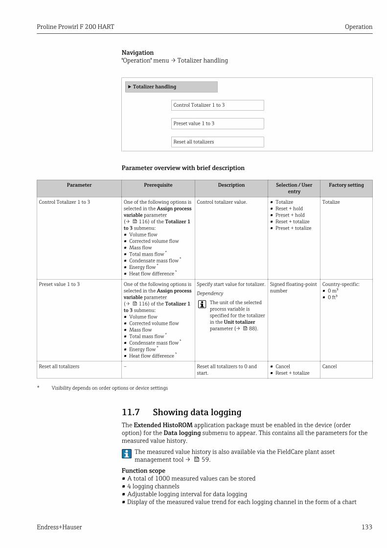
Proline Prowirl F 200 HART Operation
Endress+Hauser 133
Navigation"Operation" menu → Totalizer handling
‣ Totalizer handling
Control Totalizer 1 to 3
Preset value 1 to 3
Reset all totalizers
Parameter overview with brief description
Parameter Prerequisite Description Selection / Userentry
Factory setting
Control Totalizer 1 to 3 One of the following options isselected in the Assign processvariable parameter(→ 116) of the Totalizer 1to 3 submenu:• Volume flow• Corrected volume flow• Mass flow• Total mass flow *
• Condensate mass flow *
• Energy flow *
• Heat flow difference *
Control totalizer value. • Totalize• Reset + hold• Preset + hold• Reset + totalize• Preset + totalize
Totalize
Preset value 1 to 3 One of the following options isselected in the Assign processvariable parameter(→ 116) of the Totalizer 1to 3 submenu:• Volume flow• Corrected volume flow• Mass flow• Total mass flow *
• Condensate mass flow *
• Energy flow *
• Heat flow difference *
Specify start value for totalizer.
Dependency
The unit of the selectedprocess variable isspecified for the totalizerin the Unit totalizerparameter (→ 88).
Signed floating-pointnumber
Country-specific:• 0 m³• 0 ft³
Reset all totalizers – Reset all totalizers to 0 andstart.
• Cancel• Reset + totalize
Cancel
* Visibility depends on order options or device settings
11.7 Showing data loggingThe Extended HistoROM application package must be enabled in the device (orderoption) for the Data logging submenu to appear. This contains all the parameters for themeasured value history.
The measured value history is also available via the FieldCare plant assetmanagement tool → 59.
Function scope• A total of 1000 measured values can be stored• 4 logging channels• Adjustable logging interval for data logging• Display of the measured value trend for each logging channel in the form of a chart
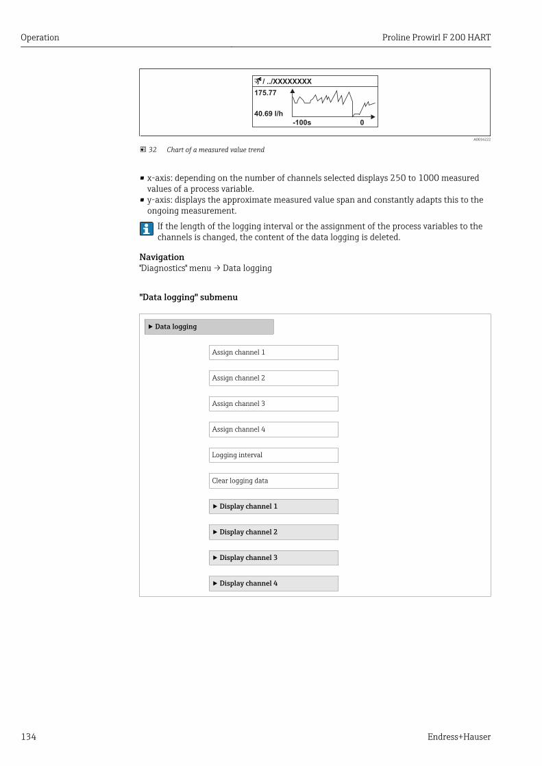
Operation Proline Prowirl F 200 HART
134 Endress+Hauser
A0016222
32 Chart of a measured value trend
• x-axis: depending on the number of channels selected displays 250 to 1000 measuredvalues of a process variable.
• y-axis: displays the approximate measured value span and constantly adapts this to theongoing measurement.
If the length of the logging interval or the assignment of the process variables to thechannels is changed, the content of the data logging is deleted.
Navigation"Diagnostics" menu → Data logging
"Data logging" submenu
‣ Data logging
Assign channel 1
Assign channel 2
Assign channel 3
Assign channel 4
Logging interval
Clear logging data
‣ Display channel 1
‣ Display channel 2
‣ Display channel 3
‣ Display channel 4
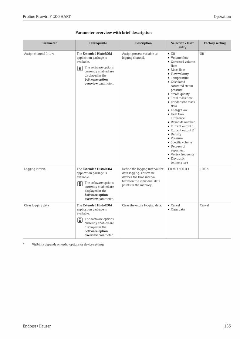
Proline Prowirl F 200 HART Operation
Endress+Hauser 135
Parameter overview with brief description
Parameter Prerequisite Description Selection / Userentry
Factory setting
Assign channel 1 to 4 The Extended HistoROMapplication package isavailable.
The software optionscurrently enabled aredisplayed in theSoftware optionoverview parameter.
Assign process variable tologging channel.
• Off• Volume flow• Corrected volume
flow• Mass flow• Flow velocity• Temperature• Calculated
saturated steampressure
• Steam quality• Total mass flow• Condensate mass
flow• Energy flow• Heat flow
difference• Reynolds number• Current output 1• Current output 2 *
• Density• Pressure• Specific volume• Degrees of
superheat• Vortex frequency• Electronic
temperature
Off
Logging interval The Extended HistoROMapplication package isavailable.
The software optionscurrently enabled aredisplayed in theSoftware optionoverview parameter.
Define the logging interval fordata logging. This valuedefines the time intervalbetween the individual datapoints in the memory.
1.0 to 3 600.0 s 10.0 s
Clear logging data The Extended HistoROMapplication package isavailable.
The software optionscurrently enabled aredisplayed in theSoftware optionoverview parameter.
Clear the entire logging data. • Cancel• Clear data
Cancel
* Visibility depends on order options or device settings
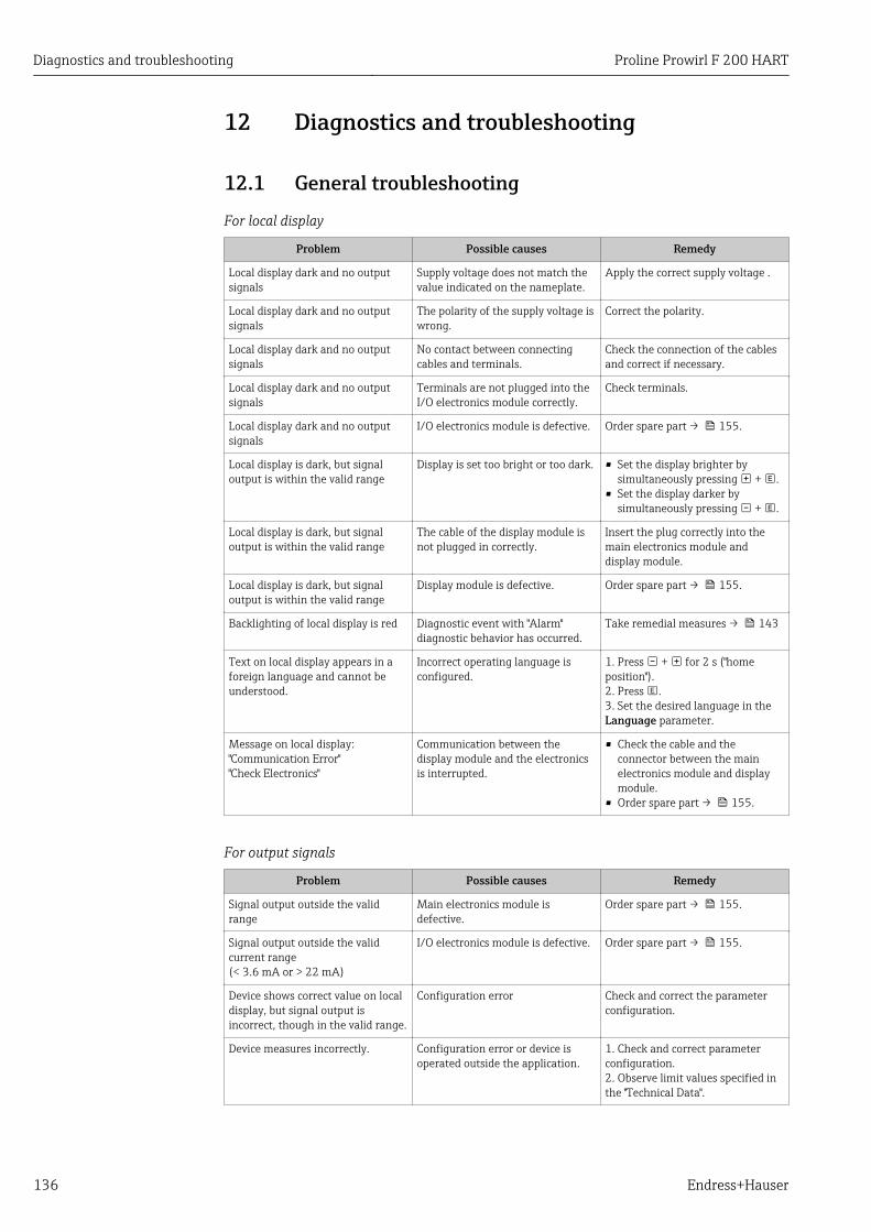
Diagnostics and troubleshooting Proline Prowirl F 200 HART
136 Endress+Hauser
12 Diagnostics and troubleshooting
12.1 General troubleshooting
For local display
Problem Possible causes Remedy
Local display dark and no outputsignals
Supply voltage does not match thevalue indicated on the nameplate.
Apply the correct supply voltage .
Local display dark and no outputsignals
The polarity of the supply voltage iswrong.
Correct the polarity.
Local display dark and no outputsignals
No contact between connectingcables and terminals.
Check the connection of the cablesand correct if necessary.
Local display dark and no outputsignals
Terminals are not plugged into theI/O electronics module correctly.
Check terminals.
Local display dark and no outputsignals
I/O electronics module is defective. Order spare part → 155.
Local display is dark, but signaloutput is within the valid range
Display is set too bright or too dark. • Set the display brighter bysimultaneously pressing + .
• Set the display darker bysimultaneously pressing + .
Local display is dark, but signaloutput is within the valid range
The cable of the display module isnot plugged in correctly.
Insert the plug correctly into themain electronics module anddisplay module.
Local display is dark, but signaloutput is within the valid range
Display module is defective. Order spare part → 155.
Backlighting of local display is red Diagnostic event with "Alarm"diagnostic behavior has occurred.
Take remedial measures → 143
Text on local display appears in aforeign language and cannot beunderstood.
Incorrect operating language isconfigured.
1. Press + for 2 s ("homeposition").2. Press .3. Set the desired language in theLanguage parameter.
Message on local display:"Communication Error""Check Electronics"
Communication between thedisplay module and the electronicsis interrupted.
• Check the cable and theconnector between the mainelectronics module and displaymodule.
• Order spare part → 155.
For output signals
Problem Possible causes Remedy
Signal output outside the validrange
Main electronics module isdefective.
Order spare part → 155.
Signal output outside the validcurrent range(< 3.6 mA or > 22 mA)
I/O electronics module is defective. Order spare part → 155.
Device shows correct value on localdisplay, but signal output isincorrect, though in the valid range.
Configuration error Check and correct the parameterconfiguration.
Device measures incorrectly. Configuration error or device isoperated outside the application.
1. Check and correct parameterconfiguration.2. Observe limit values specified inthe "Technical Data".
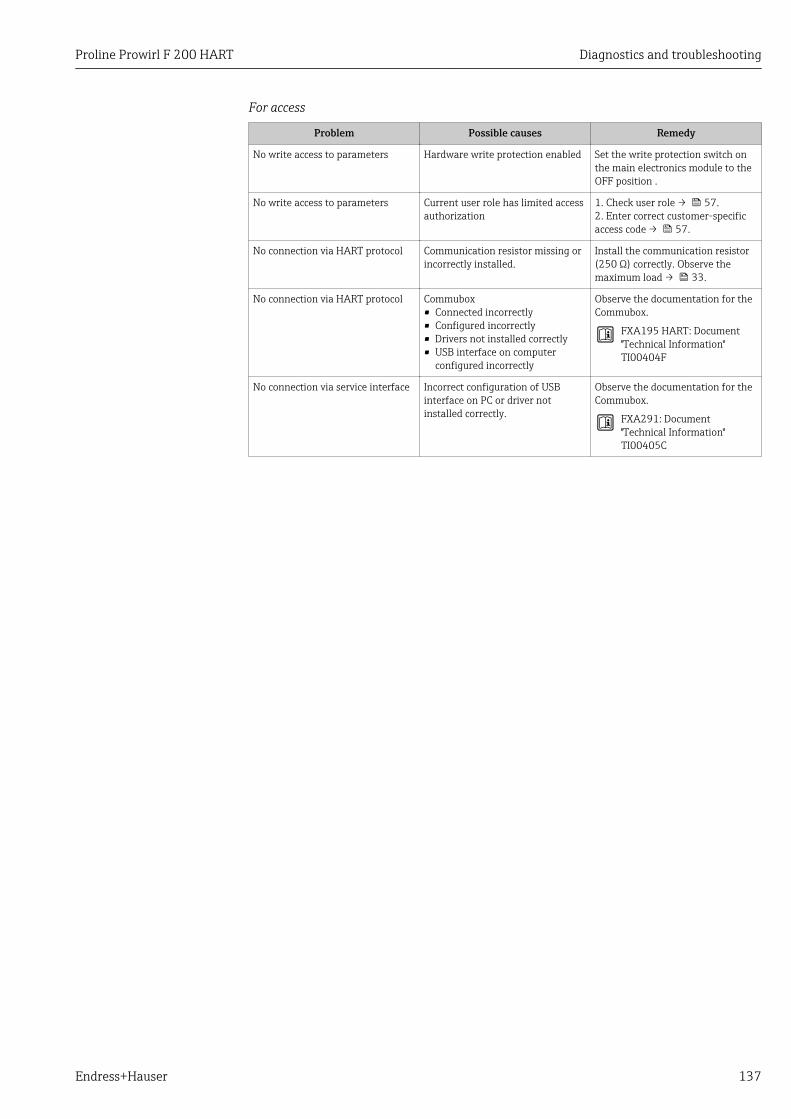
Proline Prowirl F 200 HART Diagnostics and troubleshooting
Endress+Hauser 137
For access
Problem Possible causes Remedy
No write access to parameters Hardware write protection enabled Set the write protection switch onthe main electronics module to theOFF position .
No write access to parameters Current user role has limited accessauthorization
1. Check user role → 57.2. Enter correct customer-specificaccess code → 57.
No connection via HART protocol Communication resistor missing orincorrectly installed.
Install the communication resistor(250 Ω) correctly. Observe themaximum load → 33.
No connection via HART protocol Commubox• Connected incorrectly• Configured incorrectly• Drivers not installed correctly• USB interface on computer
configured incorrectly
Observe the documentation for theCommubox.
FXA195 HART: Document"Technical Information"TI00404F
No connection via service interface Incorrect configuration of USBinterface on PC or driver notinstalled correctly.
Observe the documentation for theCommubox.
FXA291: Document"Technical Information"TI00405C
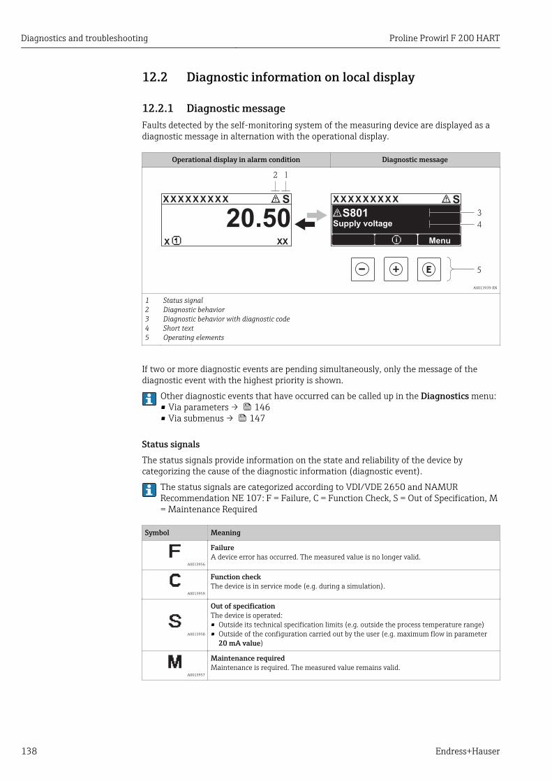
Diagnostics and troubleshooting Proline Prowirl F 200 HART
138 Endress+Hauser
12.2 Diagnostic information on local display
12.2.1 Diagnostic messageFaults detected by the self-monitoring system of the measuring device are displayed as adiagnostic message in alternation with the operational display.
Operational display in alarm condition Diagnostic message
1
4
3
X X X X X X XX X X X X X X X XX X
2
S S
XX
20.50
5
X i
S801
Menu
Supply voltage
A0013939-EN
12345
Status signalDiagnostic behaviorDiagnostic behavior with diagnostic codeShort textOperating elements
If two or more diagnostic events are pending simultaneously, only the message of thediagnostic event with the highest priority is shown.
Other diagnostic events that have occurred can be called up in the Diagnostics menu:• Via parameters → 146• Via submenus → 147
Status signalsThe status signals provide information on the state and reliability of the device bycategorizing the cause of the diagnostic information (diagnostic event).
The status signals are categorized according to VDI/VDE 2650 and NAMURRecommendation NE 107: F = Failure, C = Function Check, S = Out of Specification, M= Maintenance Required
Symbol Meaning
A0013956
FailureA device error has occurred. The measured value is no longer valid.
A0013959
Function checkThe device is in service mode (e.g. during a simulation).
A0013958
Out of specificationThe device is operated:• Outside its technical specification limits (e.g. outside the process temperature range)• Outside of the configuration carried out by the user (e.g. maximum flow in parameter
20 mA value)
A0013957
Maintenance requiredMaintenance is required. The measured value remains valid.
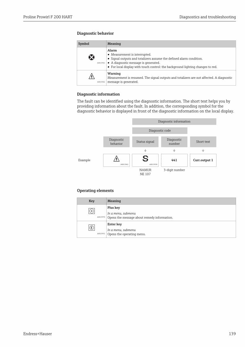
Proline Prowirl F 200 HART Diagnostics and troubleshooting
Endress+Hauser 139
Diagnostic behavior
Symbol Meaning
A0013961
Alarm• Measurement is interrupted.• Signal outputs and totalizers assume the defined alarm condition.• A diagnostic message is generated.• For local display with touch control: the background lighting changes to red.
A0013962
WarningMeasurement is resumed. The signal outputs and totalizers are not affected. A diagnosticmessage is generated.
Diagnostic informationThe fault can be identified using the diagnostic information. The short text helps you byproviding information about the fault. In addition, the corresponding symbol for thediagnostic behavior is displayed in front of the diagnostic information on the local display.
Diagnostic information
Diagnostic code
Diagnosticbehavior Status signal Diagnostic
number Short text
↓ ↓ ↓
Example A0013962 A0013958
441 Curr.output 1
NAMURNE 107
3-digit number
Operating elements
Key Meaning
A0013970
Plus key
In a menu, submenuOpens the message about remedy information.
A0013952
Enter key
In a menu, submenuOpens the operating menu.
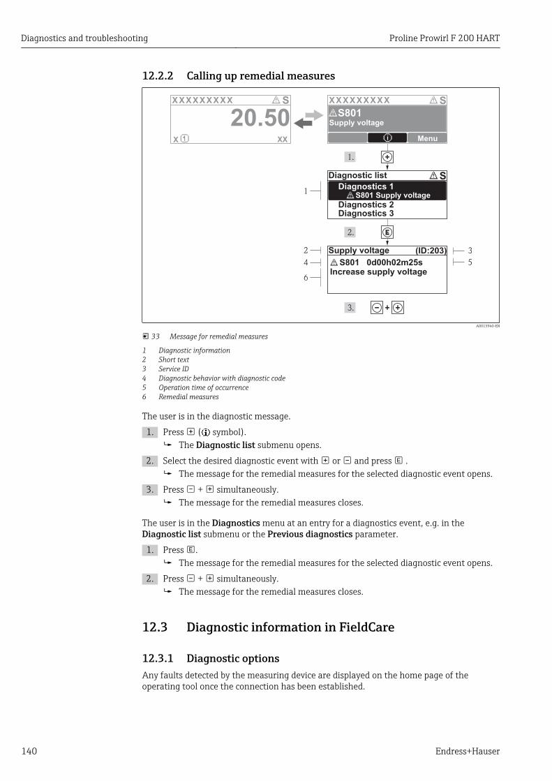
Diagnostics and troubleshooting Proline Prowirl F 200 HART
140 Endress+Hauser
12.2.2 Calling up remedial measures
X X X X X X XX X X X X X X X XX XS S
XX
20.50X i
S801
Menu
S
(ID:203)
S801 0d00h02m25s
1
2
4
6
3
5
Increase supply voltage
S801 Supply voltage
Diagnostic list
Diagnostics 1
Diagnostics 2Diagnostics 3
Supply voltage
Supply voltage
A0013940-EN
33 Message for remedial measures
1 Diagnostic information2 Short text3 Service ID4 Diagnostic behavior with diagnostic code5 Operation time of occurrence6 Remedial measures
The user is in the diagnostic message.
1. Press ( symbol). The Diagnostic list submenu opens.
2. Select the desired diagnostic event with or and press . The message for the remedial measures for the selected diagnostic event opens.
3. Press + simultaneously. The message for the remedial measures closes.
The user is in the Diagnostics menu at an entry for a diagnostics event, e.g. in theDiagnostic list submenu or the Previous diagnostics parameter.
1. Press . The message for the remedial measures for the selected diagnostic event opens.
2. Press + simultaneously. The message for the remedial measures closes.
12.3 Diagnostic information in FieldCare
12.3.1 Diagnostic optionsAny faults detected by the measuring device are displayed on the home page of theoperating tool once the connection has been established.
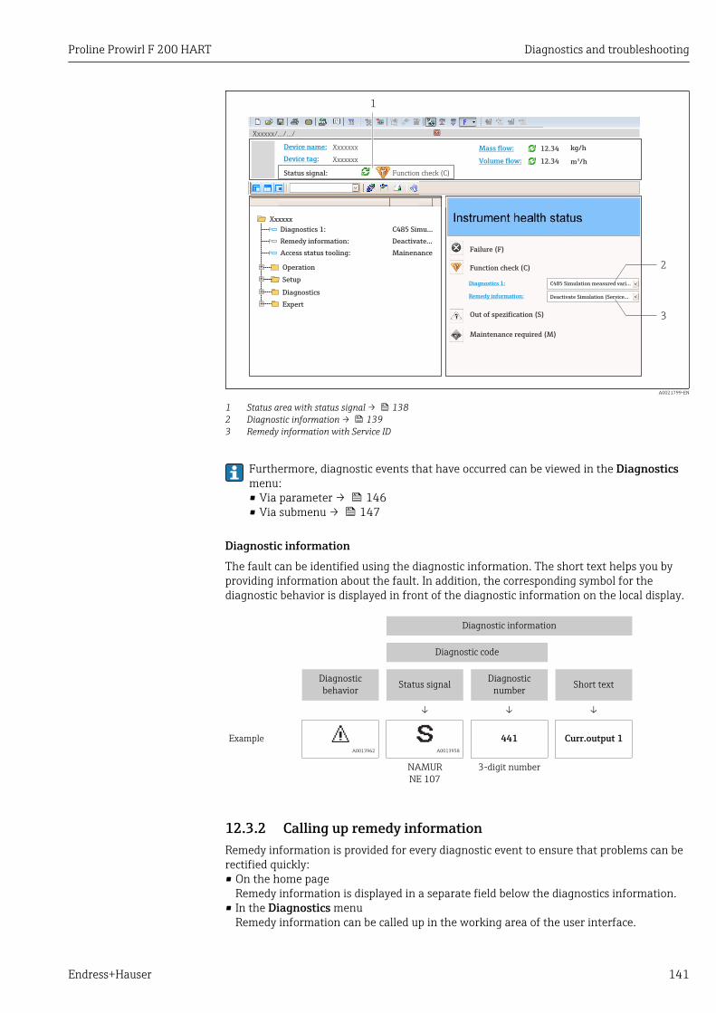
Proline Prowirl F 200 HART Diagnostics and troubleshooting
Endress+Hauser 141
Xxxxxx/…/…/
Xxxxxx
P
P
P
+
+
+
+Diagnostics 1:
Remedy information:
Failure (F)
Function check (C)
Out of spezification (S)
Maintenance required (M)
C485 Simulation measured vari...
Deactivate Simulation (Service...
Diagnostics 1: C485 Simu...
Remedy information: Deactivate...
Access status tooling: Mainenance
Operation
Setup
Diagnostics
Expert
Function check (C)Status signal:
Device tag:
Device name: Mass flow:
Volume flow:Xxxxxxx
12.34 kg/h
12.34 m /h³
Xxxxxxx
1
2
3
A0021799-EN
1 Status area with status signal → 1382 Diagnostic information → 1393 Remedy information with Service ID
Furthermore, diagnostic events that have occurred can be viewed in the Diagnosticsmenu:• Via parameter → 146• Via submenu → 147
Diagnostic informationThe fault can be identified using the diagnostic information. The short text helps you byproviding information about the fault. In addition, the corresponding symbol for thediagnostic behavior is displayed in front of the diagnostic information on the local display.
Diagnostic information
Diagnostic code
Diagnosticbehavior Status signal Diagnostic
number Short text
↓ ↓ ↓
Example A0013962 A0013958
441 Curr.output 1
NAMURNE 107
3-digit number
12.3.2 Calling up remedy informationRemedy information is provided for every diagnostic event to ensure that problems can berectified quickly:• On the home page
Remedy information is displayed in a separate field below the diagnostics information.• In the Diagnostics menu
Remedy information can be called up in the working area of the user interface.
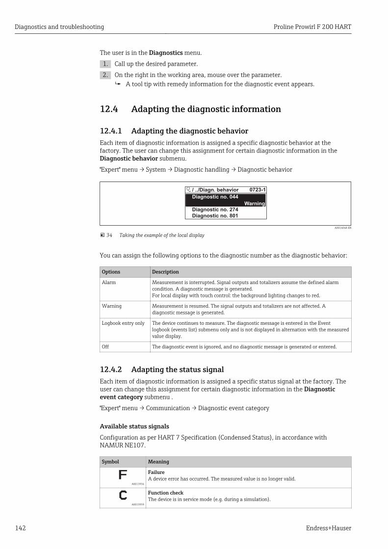
Diagnostics and troubleshooting Proline Prowirl F 200 HART
142 Endress+Hauser
The user is in the Diagnostics menu.
1. Call up the desired parameter.
2. On the right in the working area, mouse over the parameter. A tool tip with remedy information for the diagnostic event appears.
12.4 Adapting the diagnostic information
12.4.1 Adapting the diagnostic behaviorEach item of diagnostic information is assigned a specific diagnostic behavior at thefactory. The user can change this assignment for certain diagnostic information in theDiagnostic behavior submenu.
"Expert" menu → System → Diagnostic handling → Diagnostic behavior
A0014048-EN
34 Taking the example of the local display
You can assign the following options to the diagnostic number as the diagnostic behavior:
Options Description
Alarm Measurement is interrupted. Signal outputs and totalizers assume the defined alarmcondition. A diagnostic message is generated.For local display with touch control: the background lighting changes to red.
Warning Measurement is resumed. The signal outputs and totalizers are not affected. Adiagnostic message is generated.
Logbook entry only The device continues to measure. The diagnostic message is entered in the Eventlogbook (events list) submenu only and is not displayed in alternation with the measuredvalue display.
Off The diagnostic event is ignored, and no diagnostic message is generated or entered.
12.4.2 Adapting the status signalEach item of diagnostic information is assigned a specific status signal at the factory. Theuser can change this assignment for certain diagnostic information in the Diagnosticevent category submenu .
"Expert" menu → Communication → Diagnostic event category
Available status signalsConfiguration as per HART 7 Specification (Condensed Status), in accordance withNAMUR NE107.
Symbol Meaning
A0013956
FailureA device error has occurred. The measured value is no longer valid.
A0013959
Function checkThe device is in service mode (e.g. during a simulation).
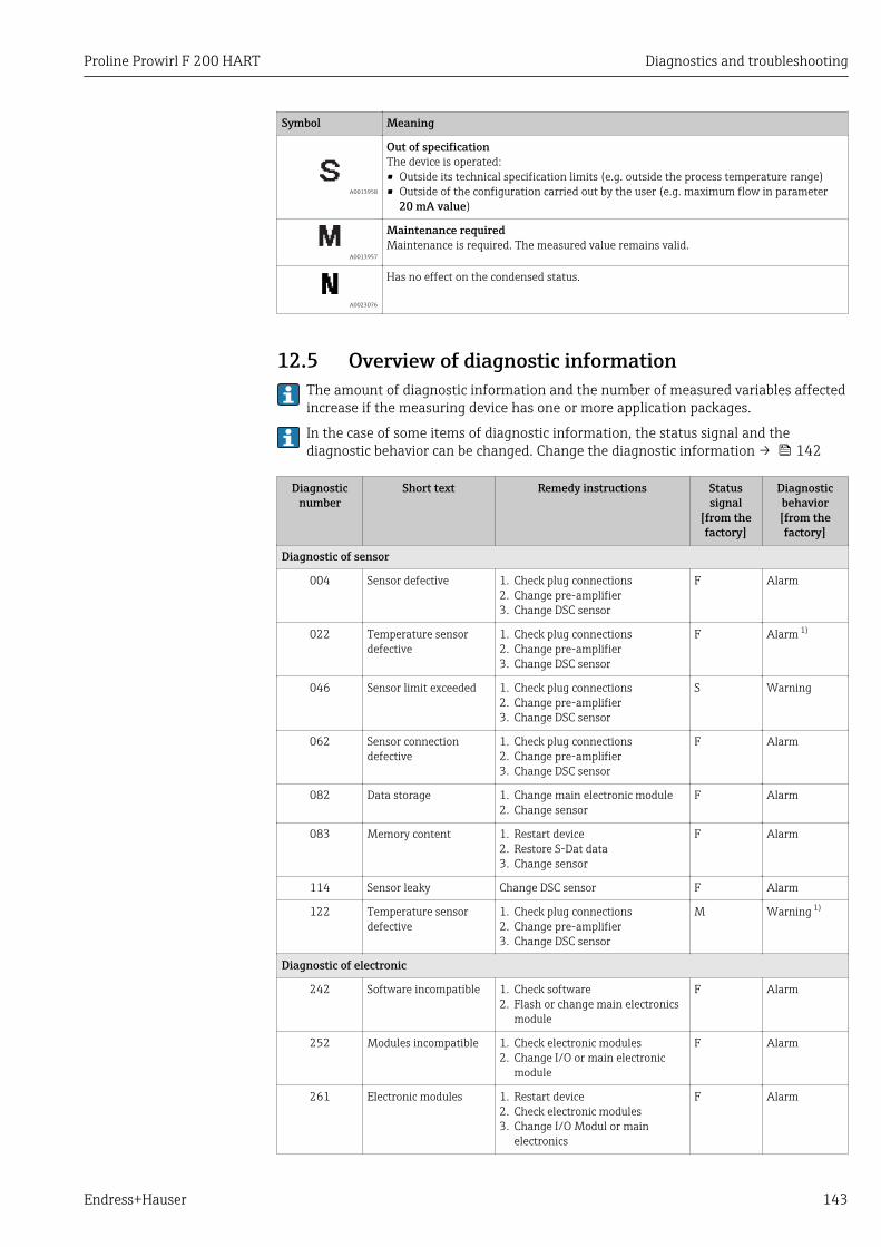
Proline Prowirl F 200 HART Diagnostics and troubleshooting
Endress+Hauser 143
Symbol Meaning
A0013958
Out of specificationThe device is operated:• Outside its technical specification limits (e.g. outside the process temperature range)• Outside of the configuration carried out by the user (e.g. maximum flow in parameter
20 mA value)
A0013957
Maintenance requiredMaintenance is required. The measured value remains valid.
A0023076
Has no effect on the condensed status.
12.5 Overview of diagnostic information The amount of diagnostic information and the number of measured variables affectedincrease if the measuring device has one or more application packages.
In the case of some items of diagnostic information, the status signal and thediagnostic behavior can be changed. Change the diagnostic information → 142
Diagnosticnumber
Short text Remedy instructions Statussignal
[from thefactory]
Diagnosticbehavior[from thefactory]
Diagnostic of sensor
004 Sensor defective 1. Check plug connections2. Change pre-amplifier3. Change DSC sensor
F Alarm
022 Temperature sensordefective
1. Check plug connections2. Change pre-amplifier3. Change DSC sensor
F Alarm 1)
046 Sensor limit exceeded 1. Check plug connections2. Change pre-amplifier3. Change DSC sensor
S Warning
062 Sensor connectiondefective
1. Check plug connections2. Change pre-amplifier3. Change DSC sensor
F Alarm
082 Data storage 1. Change main electronic module2. Change sensor
F Alarm
083 Memory content 1. Restart device2. Restore S-Dat data3. Change sensor
F Alarm
114 Sensor leaky Change DSC sensor F Alarm
122 Temperature sensordefective
1. Check plug connections2. Change pre-amplifier3. Change DSC sensor
M Warning 1)
Diagnostic of electronic
242 Software incompatible 1. Check software2. Flash or change main electronics
module
F Alarm
252 Modules incompatible 1. Check electronic modules2. Change I/O or main electronic
module
F Alarm
261 Electronic modules 1. Restart device2. Check electronic modules3. Change I/O Modul or main
electronics
F Alarm
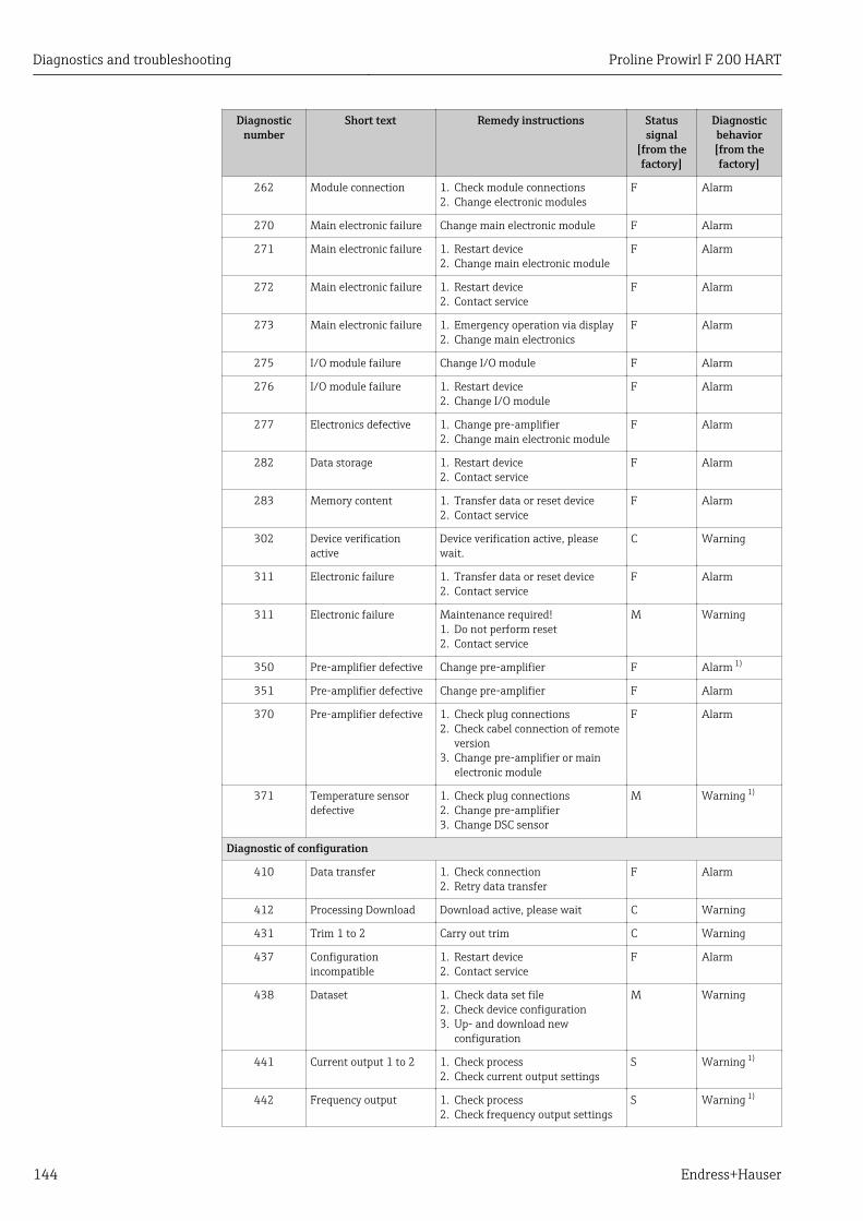
Diagnostics and troubleshooting Proline Prowirl F 200 HART
144 Endress+Hauser
Diagnosticnumber
Short text Remedy instructions Statussignal
[from thefactory]
Diagnosticbehavior[from thefactory]
262 Module connection 1. Check module connections2. Change electronic modules
F Alarm
270 Main electronic failure Change main electronic module F Alarm
271 Main electronic failure 1. Restart device2. Change main electronic module
F Alarm
272 Main electronic failure 1. Restart device2. Contact service
F Alarm
273 Main electronic failure 1. Emergency operation via display2. Change main electronics
F Alarm
275 I/O module failure Change I/O module F Alarm
276 I/O module failure 1. Restart device2. Change I/O module
F Alarm
277 Electronics defective 1. Change pre-amplifier2. Change main electronic module
F Alarm
282 Data storage 1. Restart device2. Contact service
F Alarm
283 Memory content 1. Transfer data or reset device2. Contact service
F Alarm
302 Device verificationactive
Device verification active, pleasewait.
C Warning
311 Electronic failure 1. Transfer data or reset device2. Contact service
F Alarm
311 Electronic failure Maintenance required!1. Do not perform reset2. Contact service
M Warning
350 Pre-amplifier defective Change pre-amplifier F Alarm 1)
351 Pre-amplifier defective Change pre-amplifier F Alarm
370 Pre-amplifier defective 1. Check plug connections2. Check cabel connection of remote
version3. Change pre-amplifier or main
electronic module
F Alarm
371 Temperature sensordefective
1. Check plug connections2. Change pre-amplifier3. Change DSC sensor
M Warning 1)
Diagnostic of configuration
410 Data transfer 1. Check connection2. Retry data transfer
F Alarm
412 Processing Download Download active, please wait C Warning
431 Trim 1 to 2 Carry out trim C Warning
437 Configurationincompatible
1. Restart device2. Contact service
F Alarm
438 Dataset 1. Check data set file2. Check device configuration3. Up- and download new
configuration
M Warning
441 Current output 1 to 2 1. Check process2. Check current output settings
S Warning 1)
442 Frequency output 1. Check process2. Check frequency output settings
S Warning 1)
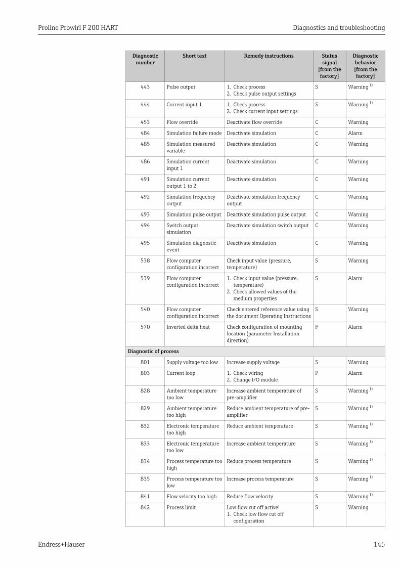
Proline Prowirl F 200 HART Diagnostics and troubleshooting
Endress+Hauser 145
Diagnosticnumber
Short text Remedy instructions Statussignal
[from thefactory]
Diagnosticbehavior[from thefactory]
443 Pulse output 1. Check process2. Check pulse output settings
S Warning 1)
444 Current input 1 1. Check process2. Check current input settings
S Warning 1)
453 Flow override Deactivate flow override C Warning
484 Simulation failure mode Deactivate simulation C Alarm
485 Simulation measuredvariable
Deactivate simulation C Warning
486 Simulation currentinput 1
Deactivate simulation C Warning
491 Simulation currentoutput 1 to 2
Deactivate simulation C Warning
492 Simulation frequencyoutput
Deactivate simulation frequencyoutput
C Warning
493 Simulation pulse output Deactivate simulation pulse output C Warning
494 Switch outputsimulation
Deactivate simulation switch output C Warning
495 Simulation diagnosticevent
Deactivate simulation C Warning
538 Flow computerconfiguration incorrect
Check input value (pressure,temperature)
S Warning
539 Flow computerconfiguration incorrect
1. Check input value (pressure,temperature)
2. Check allowed values of themedium properties
S Alarm
540 Flow computerconfiguration incorrect
Check entered reference value usingthe document Operating Instructions
S Warning
570 Inverted delta heat Check configuration of mountinglocation (parameter Installationdirection)
F Alarm
Diagnostic of process
801 Supply voltage too low Increase supply voltage S Warning
803 Current loop 1. Check wiring2. Change I/O module
F Alarm
828 Ambient temperaturetoo low
Increase ambient temperature ofpre-amplifier
S Warning 1)
829 Ambient temperaturetoo high
Reduce ambient temperature of pre-amplifier
S Warning 1)
832 Electronic temperaturetoo high
Reduce ambient temperature S Warning 1)
833 Electronic temperaturetoo low
Increase ambient temperature S Warning 1)
834 Process temperature toohigh
Reduce process temperature S Warning 1)
835 Process temperature toolow
Increase process temperature S Warning 1)
841 Flow velocity too high Reduce flow velocity S Warning 1)
842 Process limit Low flow cut off active!1. Check low flow cut off
configuration
S Warning
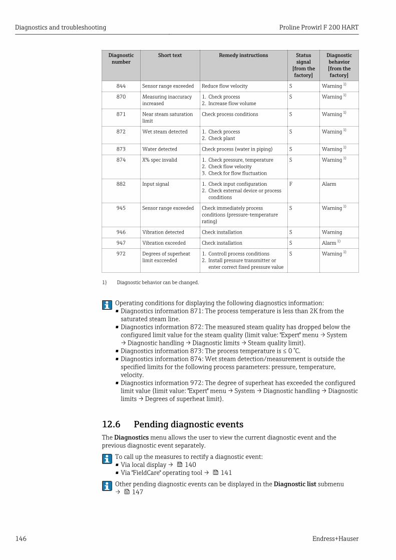
Diagnostics and troubleshooting Proline Prowirl F 200 HART
146 Endress+Hauser
Diagnosticnumber
Short text Remedy instructions Statussignal
[from thefactory]
Diagnosticbehavior[from thefactory]
844 Sensor range exceeded Reduce flow velocity S Warning 1)
870 Measuring inaccuracyincreased
1. Check process2. Increase flow volume
S Warning 1)
871 Near steam saturationlimit
Check process conditions S Warning 1)
872 Wet steam detected 1. Check process2. Check plant
S Warning 1)
873 Water detected Check process (water in piping) S Warning 1)
874 X% spec invalid 1. Check pressure, temperature2. Check flow velocity3. Check for flow fluctuation
S Warning 1)
882 Input signal 1. Check input configuration2. Check external device or process
conditions
F Alarm
945 Sensor range exceeded Check immediately processconditions (pressure-temperaturerating)
S Warning 1)
946 Vibration detected Check installation S Warning
947 Vibration exceeded Check installation S Alarm 1)
972 Degrees of superheatlimit excceeded
1. Controll process conditions2. Install pressure transmitter or
enter correct fixed pressure value
S Warning 1)
1) Diagnostic behavior can be changed.
Operating conditions for displaying the following diagnostics information:• Diagnostics information 871: The process temperature is less than 2K from the
saturated steam line.• Diagnostics information 872: The measured steam quality has dropped below the
configured limit value for the steam quality (limit value: "Expert" menu → System→ Diagnostic handling → Diagnostic limits → Steam quality limit).
• Diagnostics information 873: The process temperature is ≤ 0 °C.• Diagnostics information 874: Wet steam detection/measurement is outside the
specified limits for the following process parameters: pressure, temperature,velocity.
• Diagnostics information 972: The degree of superheat has exceeded the configuredlimit value (limit value: "Expert" menu → System → Diagnostic handling → Diagnosticlimits → Degrees of superheat limit).
12.6 Pending diagnostic eventsThe Diagnostics menu allows the user to view the current diagnostic event and theprevious diagnostic event separately.
To call up the measures to rectify a diagnostic event:• Via local display → 140• Via "FieldCare" operating tool → 141
Other pending diagnostic events can be displayed in the Diagnostic list submenu→ 147
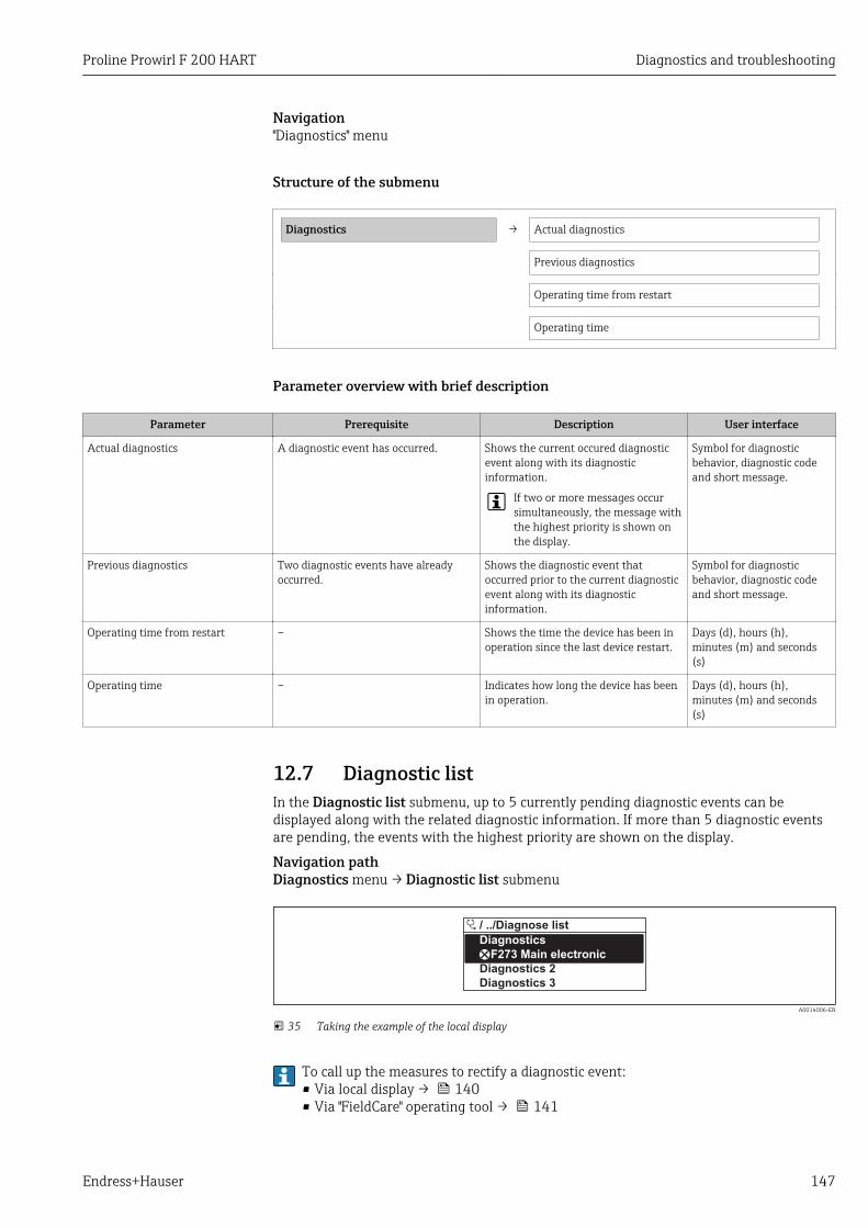
Proline Prowirl F 200 HART Diagnostics and troubleshooting
Endress+Hauser 147
Navigation"Diagnostics" menu
Structure of the submenu
Diagnostics → Actual diagnostics
Previous diagnostics
Operating time from restart
Operating time
Parameter overview with brief description
Parameter Prerequisite Description User interface
Actual diagnostics A diagnostic event has occurred. Shows the current occured diagnosticevent along with its diagnosticinformation.
If two or more messages occursimultaneously, the message withthe highest priority is shown onthe display.
Symbol for diagnosticbehavior, diagnostic codeand short message.
Previous diagnostics Two diagnostic events have alreadyoccurred.
Shows the diagnostic event thatoccurred prior to the current diagnosticevent along with its diagnosticinformation.
Symbol for diagnosticbehavior, diagnostic codeand short message.
Operating time from restart – Shows the time the device has been inoperation since the last device restart.
Days (d), hours (h),minutes (m) and seconds(s)
Operating time – Indicates how long the device has beenin operation.
Days (d), hours (h),minutes (m) and seconds(s)
12.7 Diagnostic listIn the Diagnostic list submenu, up to 5 currently pending diagnostic events can bedisplayed along with the related diagnostic information. If more than 5 diagnostic eventsare pending, the events with the highest priority are shown on the display.
Navigation pathDiagnostics menu → Diagnostic list submenu
Diagnostics
/ ../Diagnose list
Diagnostics 3
Diagnostics 2
F273 Main electronic
A0014006-EN
35 Taking the example of the local display
To call up the measures to rectify a diagnostic event:• Via local display → 140• Via "FieldCare" operating tool → 141
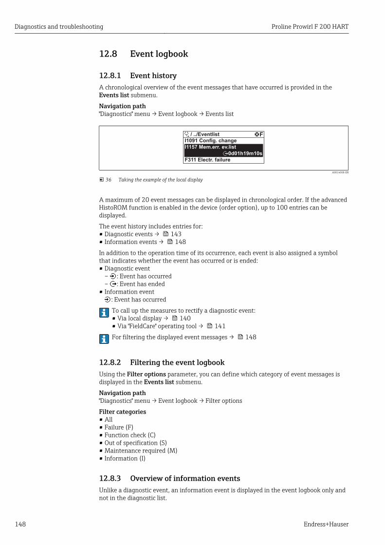
Diagnostics and troubleshooting Proline Prowirl F 200 HART
148 Endress+Hauser
12.8 Event logbook
12.8.1 Event historyA chronological overview of the event messages that have occurred is provided in theEvents list submenu.
Navigation path"Diagnostics" menu → Event logbook → Events list
FI1091 Config. change
I1157 Mem.err. ev.list
F311 Electr. failure
/ ../Eventlist
0d01h19m10s
A0014008-EN
36 Taking the example of the local display
A maximum of 20 event messages can be displayed in chronological order. If the advancedHistoROM function is enabled in the device (order option), up to 100 entries can bedisplayed.
The event history includes entries for:• Diagnostic events → 143• Information events → 148
In addition to the operation time of its occurrence, each event is also assigned a symbolthat indicates whether the event has occurred or is ended:• Diagnostic event
– : Event has occurred– : Event has ended
• Information event: Event has occurred
To call up the measures to rectify a diagnostic event:• Via local display → 140• Via "FieldCare" operating tool → 141
For filtering the displayed event messages → 148
12.8.2 Filtering the event logbookUsing the Filter options parameter, you can define which category of event messages isdisplayed in the Events list submenu.
Navigation path"Diagnostics" menu → Event logbook → Filter options
Filter categories• All• Failure (F)• Function check (C)• Out of specification (S)• Maintenance required (M)• Information (I)
12.8.3 Overview of information eventsUnlike a diagnostic event, an information event is displayed in the event logbook only andnot in the diagnostic list.
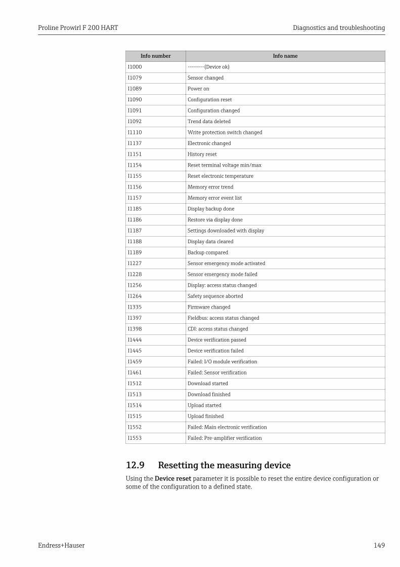
Proline Prowirl F 200 HART Diagnostics and troubleshooting
Endress+Hauser 149
Info number Info name
I1000 --------(Device ok)
I1079 Sensor changed
I1089 Power on
I1090 Configuration reset
I1091 Configuration changed
I1092 Trend data deleted
I1110 Write protection switch changed
I1137 Electronic changed
I1151 History reset
I1154 Reset terminal voltage min/max
I1155 Reset electronic temperature
I1156 Memory error trend
I1157 Memory error event list
I1185 Display backup done
I1186 Restore via display done
I1187 Settings downloaded with display
I1188 Display data cleared
I1189 Backup compared
I1227 Sensor emergency mode activated
I1228 Sensor emergency mode failed
I1256 Display: access status changed
I1264 Safety sequence aborted
I1335 Firmware changed
I1397 Fieldbus: access status changed
I1398 CDI: access status changed
I1444 Device verification passed
I1445 Device verification failed
I1459 Failed: I/O module verification
I1461 Failed: Sensor verification
I1512 Download started
I1513 Download finished
I1514 Upload started
I1515 Upload finished
I1552 Failed: Main electronic verification
I1553 Failed: Pre-amplifier verification
12.9 Resetting the measuring deviceUsing the Device reset parameter it is possible to reset the entire device configuration orsome of the configuration to a defined state.
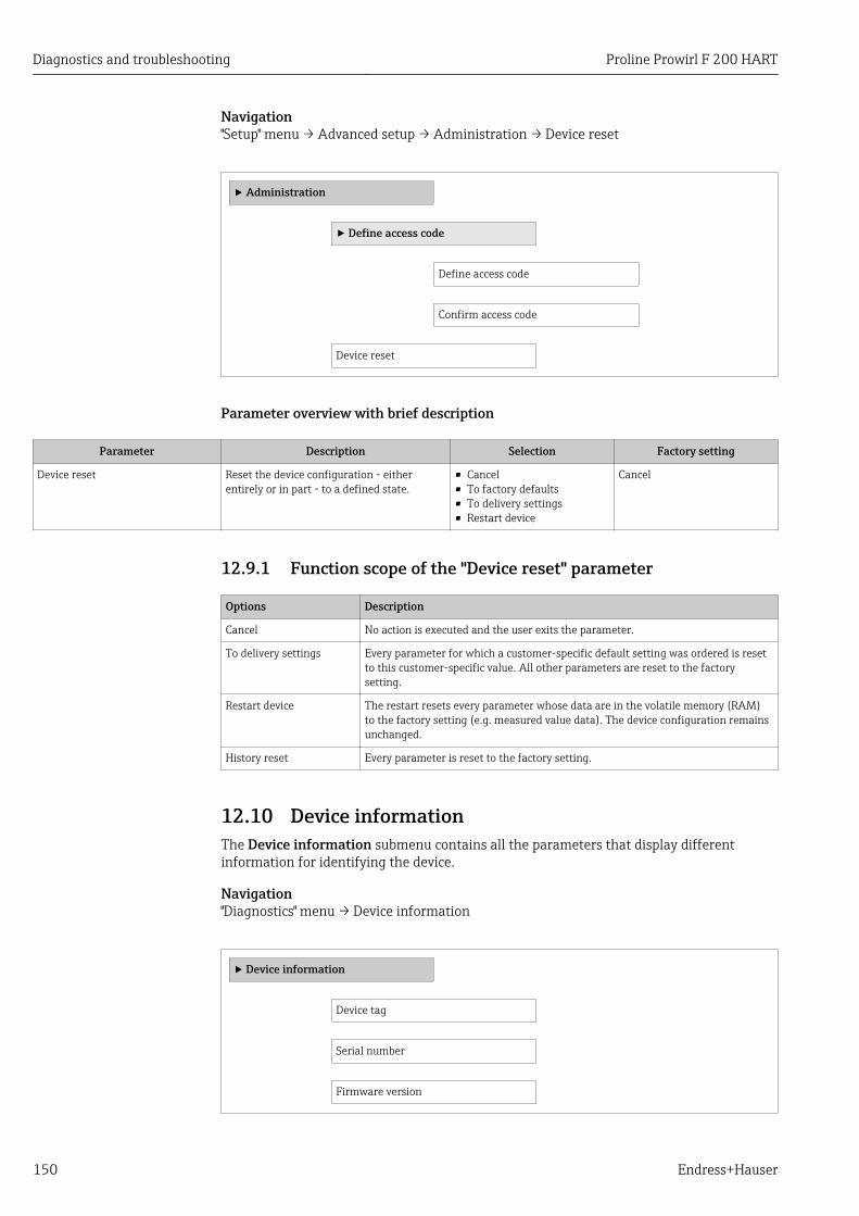
Diagnostics and troubleshooting Proline Prowirl F 200 HART
150 Endress+Hauser
Navigation"Setup" menu → Advanced setup → Administration → Device reset
‣ Administration
‣ Define access code
Define access code
Confirm access code
Device reset
Parameter overview with brief description
Parameter Description Selection Factory setting
Device reset Reset the device configuration - eitherentirely or in part - to a defined state.
• Cancel• To factory defaults• To delivery settings• Restart device
Cancel
12.9.1 Function scope of the "Device reset" parameter
Options Description
Cancel No action is executed and the user exits the parameter.
To delivery settings Every parameter for which a customer-specific default setting was ordered is resetto this customer-specific value. All other parameters are reset to the factorysetting.
Restart device The restart resets every parameter whose data are in the volatile memory (RAM)to the factory setting (e.g. measured value data). The device configuration remainsunchanged.
History reset Every parameter is reset to the factory setting.
12.10 Device informationThe Device information submenu contains all the parameters that display differentinformation for identifying the device.
Navigation"Diagnostics" menu → Device information
‣ Device information
Device tag
Serial number
Firmware version
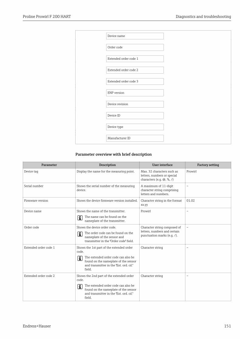
Proline Prowirl F 200 HART Diagnostics and troubleshooting
Endress+Hauser 151
Device name
Order code
Extended order code 1
Extended order code 2
Extended order code 3
ENP version
Device revision
Device ID
Device type
Manufacturer ID
Parameter overview with brief description
Parameter Description User interface Factory setting
Device tag Display the name for the measuring point. Max. 32 characters such asletters, numbers or specialcharacters (e.g. @, %, /)
Prowirl
Serial number Shows the serial number of the measuringdevice.
A maximum of 11-digitcharacter string comprisingletters and numbers.
–
Firmware version Shows the device firmware version installed. Character string in the formatxx.yy
01.02
Device name Shows the name of the transmitter.
The name can be found on thenameplate of the transmitter.
Prowirl –
Order code Shows the device order code.
The order code can be found on thenameplate of the sensor andtransmitter in the "Order code" field.
Character string composed ofletters, numbers and certainpunctuation marks (e.g. /).
–
Extended order code 1 Shows the 1st part of the extended ordercode.
The extended order code can also befound on the nameplate of the sensorand transmitter in the "Ext. ord. cd."field.
Character string –
Extended order code 2 Shows the 2nd part of the extended ordercode.
The extended order code can also befound on the nameplate of the sensorand transmitter in the "Ext. ord. cd."field.
Character string –
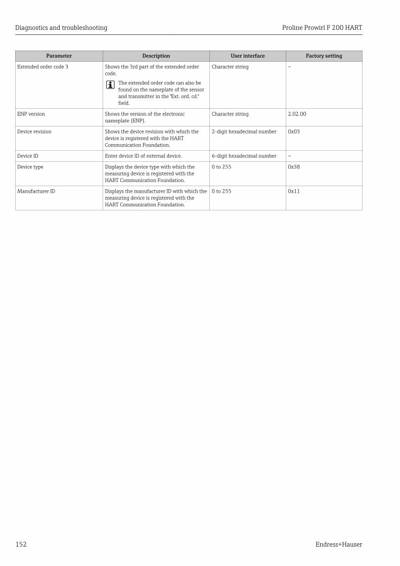
Diagnostics and troubleshooting Proline Prowirl F 200 HART
152 Endress+Hauser
Parameter Description User interface Factory setting
Extended order code 3 Shows the 3rd part of the extended ordercode.
The extended order code can also befound on the nameplate of the sensorand transmitter in the "Ext. ord. cd."field.
Character string –
ENP version Shows the version of the electronicnameplate (ENP).
Character string 2.02.00
Device revision Shows the device revision with which thedevice is registered with the HARTCommunication Foundation.
2-digit hexadecimal number 0x03
Device ID Enter device ID of external device. 6-digit hexadecimal number –
Device type Displays the device type with which themeasuring device is registered with theHART Communication Foundation.
0 to 255 0x38
Manufacturer ID Displays the manufacturer ID with which themeasuring device is registered with theHART Communication Foundation.
0 to 255 0x11
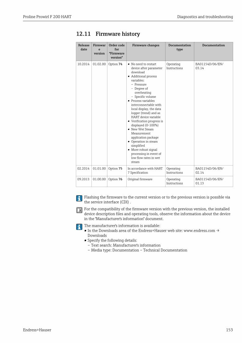
Proline Prowirl F 200 HART Diagnostics and troubleshooting
Endress+Hauser 153
12.11 Firmware history
Releasedate
Firmware
version
Order codefor
"Firmwareversion"
Firmware changes Documentationtype
Documentation
10.2014 01.02.00 Option 74 • No need to restartdevice after parameterdownload
• Additional processvariables:– Pressure– Degree of
overheating– Specific volume
• Process variablesinterconnectable withlocal display, the datalogger (trend) and asHART device variable
• Verification progress isdisplayed (0-100%)
• New Wet SteamMeasurementapplication package
• Operation in steamsimplified
• More robust signalprocessing in event oflow flow rates in wetsteam
OperatingInstructions
BA01154D/06/EN/03.14
02.2014 01.01.00 Option 75 In accordance with HART7 Specification
OperatingInstructions
BA01154D/06/EN/02.14
09.2013 01.00.00 Option 76 Original firmware OperatingInstructions
BA01154D/06/EN/01.13
Flashing the firmware to the current version or to the previous version is possible viathe service interface (CDI) .
For the compatibility of the firmware version with the previous version, the installeddevice description files and operating tools, observe the information about the devicein the "Manufacturer's information" document.
The manufacturer's information is available:• In the Downloads area of the Endress+Hauser web site: www.endress.com →
Downloads• Specify the following details:
– Text search: Manufacturer's information– Media type: Documentation – Technical Documentation
Maintenance Proline Prowirl F 200 HART
154 Endress+Hauser
13 Maintenance
13.1 Maintenance tasksNo special maintenance work is required.
13.1.1 Exterior cleaningWhen cleaning the exterior of measuring devices, always use cleaning agents that do notattack the surface of the housing or the seals.
13.1.2 Interior cleaningNOTICE
The use of unsuitable equipment or cleaning liquids can damage the transducer.‣ Do not use pigs to clean the pipe.
13.1.3 Replacing seals
Replacing sensor sealsNOTICE
Under normal circumstances, wetted seals must not be replaced.Replacement is necessary only in special circumstances, for example if aggressive orcorrosive fluids are incompatible with the seal material.‣ The time span between the individual replacement procedures depends on the fluid
properties.‣ Only Endress+Hauser sensor seals may be used: replacement seals
Replacing housing sealsThe housing seals must be clean and undamaged when inserted into their grooves. Dry,clean or replace the seals if necessary.
NOTICEWhen the measuring device is used in a dusty atmosphere:‣ only use the associated Endress+Hauser housing seals.
13.2 Measuring and test equipmentEndress+Hauser offers a wide variety of measuring and test equipment, such as W@M ordevice tests.
Your Endress+Hauser Sales Center can provide detailed information on the services.
For a list of some of the measuring and test equipment, refer to the "Accessories"chapter of the "Technical Information" document for the device.
13.3 Endress+Hauser servicesEndress+Hauser offers a wide variety of services for maintenance such as recalibration,maintenance service or device tests.
Your Endress+Hauser Sales Center can provide detailed information on the services.
Proline Prowirl F 200 HART Repair
Endress+Hauser 155
14 Repair
14.1 General notesRepair and conversion conceptThe Endress+Hauser repair and conversion concept provides for the following:• The measuring devices have a modular design.• Spare parts are grouped into logical kits with the associated Installation Instructions.• Repairs are carried out by Endress+Hauser Service or by correspondingly trained
customers.• Certified devices can be converted into other certified devices by Endress+Hauser Service
or at the factory only.
Notes for repair and conversionFor repair and modification of a measuring device, observe the following notes:• Use only original Endress+Hauser spare parts.• Carry out the repair according to the Installation Instructions.• Observe the applicable standards, federal/national regulations, Ex documentation (XA)
and certificates.• Document every repair and each conversion and enter them into the W@M life cycle
management database.
14.2 Spare partsSome interchangeable measuring device components are listed on an overview sign in theconnection compartment cover.
The spare part overview sign contains the following information:• A list of the most important spare parts for the measuring device, including their
ordering information.• The URL for the W@M Device Viewer (www.endress.com/deviceviewer):
All the spare parts for the measuring device, along with the order code, are listed hereand can be ordered. If available, users can also download the associated InstallationInstructions.
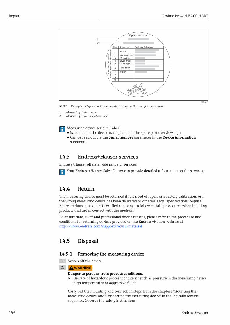
Repair Proline Prowirl F 200 HART
156 Endress+Hauser
Spare parts for
Spare partItem Part no. / structure
Sensor1
2
3
4
5
6
7
8
9
10
Main electronic
I/O module
Cover (front)
Cover (right)
Transmitter
Display
Ad
ditio
na
l in
form
ation
:w
ww
.endre
ss.c
om
/devic
evie
wer
47
2
6
35
1
1
2
A0014017
37 Example for "Spare part overview sign" in connection compartment cover
1 Measuring device name2 Measuring device serial number
Measuring device serial number:• Is located on the device nameplate and the spare part overview sign.• Can be read out via the Serial number parameter in the Device information
submenu .
14.3 Endress+Hauser servicesEndress+Hauser offers a wide range of services.
Your Endress+Hauser Sales Center can provide detailed information on the services.
14.4 ReturnThe measuring device must be returned if it is need of repair or a factory calibration, or ifthe wrong measuring device has been delivered or ordered. Legal specifications requireEndress+Hauser, as an ISO-certified company, to follow certain procedures when handlingproducts that are in contact with the medium.
To ensure safe, swift and professional device returns, please refer to the procedure andconditions for returning devices provided on the Endress+Hauser website athttp://www.endress.com/support/return-material
14.5 Disposal
14.5.1 Removing the measuring device1. Switch off the device.
2. LWARNINGDanger to persons from process conditions.‣ Beware of hazardous process conditions such as pressure in the measuring device,
high temperatures or aggressive fluids.
Carry out the mounting and connection steps from the chapters "Mounting themeasuring device" and "Connecting the measuring device" in the logically reversesequence. Observe the safety instructions.

Proline Prowirl F 200 HART Repair
Endress+Hauser 157
14.5.2 Disposing of the measuring deviceLWARNING
Danger to personnel and environment from fluids that are hazardous to health.‣ Ensure that the measuring device and all cavities are free of fluid residues that are
hazardous to health or the environment, e.g. substances that have permeated intocrevices or diffused through plastic.
Observe the following notes during disposal:• Observe valid federal/national regulations.• Ensure proper separation and reuse of the device components.
Accessories Proline Prowirl F 200 HART
158 Endress+Hauser
15 AccessoriesVarious accessories, which can be ordered with the device or subsequently from Endress+Hauser, are available for the device. Detailed information on the order code in question isavailable from your local Endress+Hauser sales center or on the product page of theEndress+Hauser website: www.endress.com.
15.1 Device-specific accessories
15.1.1 For the transmitter
Accessories Description
Prowirl 200 transmitter Transmitter for replacement or storage. Use the order code to define the followingspecifications:• Approvals• Output• Display / operation• Housing• Software
For details, see Installation Instructions EA01056D
Remote displayFHX50
FHX50 housing for accommodating a display module → 186.
• FHX50 housing suitable for:– SD02 display module (push buttons)– SD03 display module (touch control)
• Housing material:– Plastic PBT– Stainless steel CF-3M (316L, 1.4404)
• Length of connecting cable: up to max. 60 m (196 ft)(cable lengths available for order: 5 m (16 ft), 10 m (32 ft), 20 m (65 ft),30 m (98 ft))
The measuring device can be ordered with the FHX50 housing and a displaymodule. The following options must be selected in the separate order codes:• Order code for measuring device, feature 030:
Option L or M "Prepared for FHX50 display"• Order code for FHX50 housing, feature 050 (device version):
Option A "Prepared for FHX50 display"• Order code for FHX50 housing, depends on the desired display module in feature
020 (display, operation):– Option C: for an SD02 display module (push buttons)– Option E: for an SD03 display module (touch control)
The FHX50 housing can also be ordered as a retrofit kit. The measuring devicedisplay module is used in the FHX50 housing. The following options must beselected in the order code for the FHX50 housing:• Feature 050 (measuring device version): option B "Not prepared for FHX50
display"• Feature 020 (display, operation): option A "None, existing displayed used"
For details, see Special Documentation SD01007F
(Order number: FHX50)
Overvoltage protection for2-wire devices
Ideally, the overvoltage protection module should be ordered directly with thedevice. See product structure, characteristic 610 "Accessory mounted", option NA"Overvoltage protection". Separate order necessary only if retrofitting.
• OVP10: For 1-channel devices (characteristic 020, option A):• OVP20: For 2-channel devices (characteristic 020, options B, C, E or G)
For details, see Special Documentation SD01090F.
Proline Prowirl F 200 HART Accessories
Endress+Hauser 159
Weather protection cover Is used to protect the measuring device from the effects of the weather: e.g.rainwater, excess heating from direct sunlight or extreme cold in winter.
For details, see Special Documentation SD00333F
Connecting cable forremote version
• Connecting cable available in various lengths:– 5 m (16 ft)– 10 m (32 ft)– 20 m (65 ft)– 30 m (98 ft)
• Reinforced cables available on request.
Standard length: 5 m (16 ft)Is always supplied if no other cable length has been ordered.
Post mounting kit Post mounting kit for transmitter.
The post mounting kit can only be ordered together with a transmitter.
(Order number: DK8WM-B)
15.1.2 For the sensor
Accessories Description
Flow conditioner Is used to shorten the necessary inlet run.(Order number: DK7ST)
15.2 Communication-specific accessories
Accessories Description
Commubox FXA195HART
For intrinsically safe HART communication with FieldCare via the USB interface.
For details, see "Technical Information" TI00404F
Commubox FXA291 Connects Endress+Hauser field devices with a CDI interface (= Endress+HauserCommon Data Interface) and the USB port of a computer or laptop.
For details, see the "Technical Information" document TI405C/07
HART Loop ConverterHMX50
Is used to evaluate and convert dynamic HART process variables to analog currentsignals or limit values.
For details, see "Technical Information" TI00429F and Operating InstructionsBA00371F
Wireless HART adapterSWA70
Is used for the wireless connection of field devices.The WirelessHART adapter can be easily integrated into field devices and existinginfrastructures, offers data protection and transmission safety and can be operatedin parallel with other wireless networks with minimum cabling complexity.
For details, see Operating Instructions BA00061S
Fieldgate FXA320 Gateway for the remote monitoring of connected 4-20 mA measuring devices via aWeb browser.
For details, see "Technical Information" TI00025S and Operating InstructionsBA00053S
Fieldgate FXA520 Gateway for the remote diagnostics and remote configuration of connected HARTmeasuring devices via a Web browser.
For details, see "Technical Information" TI00025S and Operating InstructionsBA00051S
Accessories Proline Prowirl F 200 HART
160 Endress+Hauser
Field Xpert SFX350 Field Xpert SFX350 is a mobile computer for commissioning and maintenance. Itenables efficient device configuration and diagnostics for HART and FOUNDATIONFieldbus devices in the non-Ex area.
For details, see Operating Instructions BA01202S
Field Xpert SFX370 Field Xpert SFX370 is a mobile computer for commissioning and maintenance. Itenables efficient device configuration and diagnostics for HART and FOUNDATIONFieldbus devices in the non-Ex area and the Ex area.
For details, see Operating Instructions BA01202S
15.3 Service-specific accessories
Accessories Description
Applicator Software for selecting and sizing Endress+Hauser measuring devices:• Calculation of all the necessary data for identifying the optimum flowmeter: e.g.
nominal diameter, pressure loss, accuracy or process connections.• Graphic illustration of the calculation results
Administration, documentation and access to all project-related data andparameters throughout the entire life cycle of a project.
Applicator is available:• Via the Internet: https://wapps.endress.com/applicator• On CD-ROM for local PC installation.
W@M Life cycle management for your plantW@M supports you with a wide range of software applications over the entireprocess: from planning and procurement, to the installation, commissioning andoperation of the measuring devices. All the relevant device information, such asthe device status, spare parts and device-specific documentation, is available forevery device over the entire life cycle.The application already contains the data of your Endress+Hauser device. Endress+Hauser also takes care of maintaining and updating the data records.
W@M is available:• Via the Internet: www.endress.com/lifecyclemanagement• On CD-ROM for local PC installation.
FieldCare FDT-based plant asset management tool from Endress+Hauser.It can configure all smart field units in your system and helps you manage them. Byusing the status information, it is also a simple but effective way of checking theirstatus and condition.
For details, see Operating Instructions BA00027S and BA00059S
DeviceCare Tool for connecting and configuring Endress+Hauser field devices.
For details, see Innovation brochure IN01047S
15.4 System components
Accessories Description
Memograph M graphicdisplay recorder
The Memograph M graphic display recorder provides information on all relevantmeasured variables. Measured values are recorded correctly, limit values aremonitored and measuring points analyzed. The data are stored in the 256 MBinternal memory and also on a SD card or USB stick.
For details, see "Technical Information" TI00133R and Operating InstructionsBA00247R
RN221N Active barrier with power supply for safe separation of 4-20 mA standard signalcircuits. Offers bidirectional HART transmission.
For details, see "Technical Information" TI00073R and Operating InstructionsBA00202R

Proline Prowirl F 200 HART Accessories
Endress+Hauser 161
RNS221 Supply unit for powering two 2-wire measuring devices solely in the non-Ex area.Bidirectional communication is possible via the HART communication jacks.
For details, see "Technical Information" TI00081R and Brief OperatingInstructions KA00110R
Cerabar M The pressure transmitter for measuring the absolute and gauge pressure of gases,steam and liquids. It can be used to read in the operating pressure value.
For details, see "Technical Information" TI00426P, TI00436P and OperatingInstructions BA00200P, BA00382P
Cerabar S The pressure transmitter for measuring the absolute and gauge pressure of gases,steam and liquids. It can be used to read in the operating pressure value.
For details, see "Technical Information" TI00383P and Operating InstructionsBA00271P
Technical data Proline Prowirl F 200 HART
162 Endress+Hauser
16 Technical data
16.1 ApplicationDepending on the version ordered, the measuring device can also measure potentiallyexplosive, flammable, poisonous and oxidizing media.
To ensure that the device remains in proper operating condition for its service life, use themeasuring device only for media against which the process-wetted materials areadequately resistant.
16.2 Function and system design
Measuring principle Vortex meters work on the principle of the Karman vortex street.
Measuring system The device consists of a transmitter and a sensor.
Two device versions are available:• Compact version – transmitter and sensor form a mechanical unit.• Remote version - transmitter and sensor are mounted in separate locations.
For information on the structure of the device → 11
16.3 Input
Measured variable Direct measured variablesOrder code for "Sensor version":• Option 1 "Volume flow, basis" and• Option 2 "Volume flow, high-temperature/low temperature":
Volume flow
Order code for "Sensor version":Option 3 "Mass flow (integrated temperature measurement)":– Volume flow– Temperature
Calculated measured variablesOrder code for "Sensor version":• Option 1 "Volume flow, basis" and• Option 2 "Volume flow, high-temperature/low temperature":
– In the case of constant process conditions: Mass flow 1) or Corrected volume flow– The totalized values for Volume flow, Mass flow 1), or Corrected volume flow
Order code for "Sensor version":Option 3 "Mass flow (integrated temperature measurement)":– Corrected volume flow– Mass flow– Calculated saturated steam pressure– Energy flow
1) A fixed density must be entered for calculating the mass flow (Setup menu → Advanced setup submenu → External compensation submenu →Fixed density parameter).
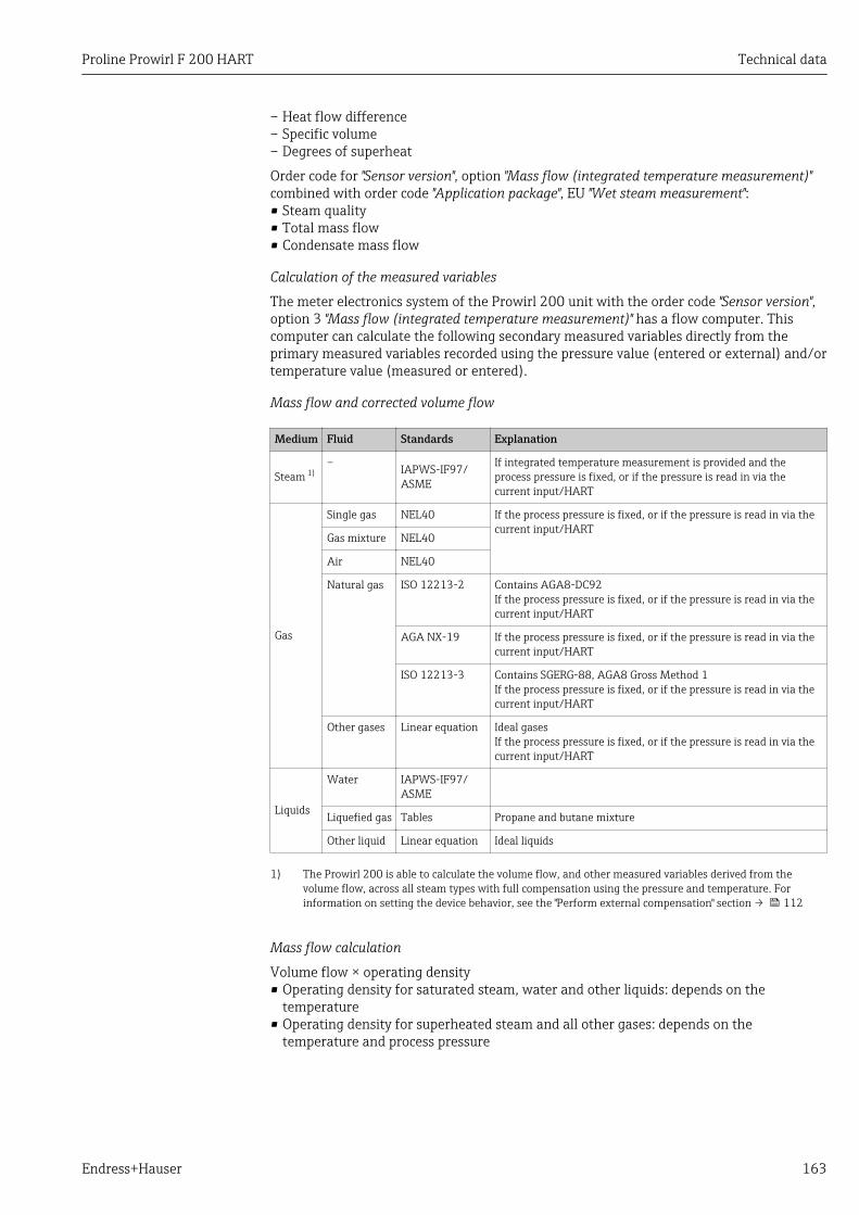
Proline Prowirl F 200 HART Technical data
Endress+Hauser 163
– Heat flow difference– Specific volume– Degrees of superheat
Order code for "Sensor version", option "Mass flow (integrated temperature measurement)"combined with order code "Application package", EU "Wet steam measurement":• Steam quality• Total mass flow• Condensate mass flow
Calculation of the measured variables
The meter electronics system of the Prowirl 200 unit with the order code "Sensor version",option 3 "Mass flow (integrated temperature measurement)" has a flow computer. Thiscomputer can calculate the following secondary measured variables directly from theprimary measured variables recorded using the pressure value (entered or external) and/ortemperature value (measured or entered).
Mass flow and corrected volume flow
Medium Fluid Standards Explanation
Steam 1)– IAPWS-IF97/
ASME
If integrated temperature measurement is provided and theprocess pressure is fixed, or if the pressure is read in via thecurrent input/HART
Gas
Single gas NEL40 If the process pressure is fixed, or if the pressure is read in via thecurrent input/HART
Gas mixture NEL40
Air NEL40
Natural gas ISO 12213-2 Contains AGA8-DC92If the process pressure is fixed, or if the pressure is read in via thecurrent input/HART
AGA NX-19 If the process pressure is fixed, or if the pressure is read in via thecurrent input/HART
ISO 12213-3 Contains SGERG-88, AGA8 Gross Method 1If the process pressure is fixed, or if the pressure is read in via thecurrent input/HART
Other gases Linear equation Ideal gasesIf the process pressure is fixed, or if the pressure is read in via thecurrent input/HART
Liquids
Water IAPWS-IF97/ASME
Liquefied gas Tables Propane and butane mixture
Other liquid Linear equation Ideal liquids
1) The Prowirl 200 is able to calculate the volume flow, and other measured variables derived from thevolume flow, across all steam types with full compensation using the pressure and temperature. Forinformation on setting the device behavior, see the "Perform external compensation" section → 112
Mass flow calculation
Volume flow × operating density• Operating density for saturated steam, water and other liquids: depends on the
temperature• Operating density for superheated steam and all other gases: depends on the
temperature and process pressure
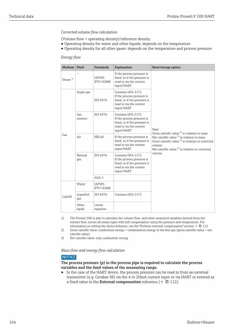
Technical data Proline Prowirl F 200 HART
164 Endress+Hauser
Corrected volume flow calculation
(Volume flow × operating density)/reference density• Operating density for water and other liquids: depends on the temperature• Operating density for all other gases: depends on the temperature and process pressure
Energy flow
Medium Fluid Standards Explanation Heat/energy option
Steam 1)
–IAPWS-IF97/ASME
If the process pressure isfixed, or if the pressure isread in via the currentinput/HART
HeatGross calorific value 2) in relation to massNet calorific value 3) in relation to massGross calorific value 2) in relation to correctedvolumeNet calorific value 3) in relation to correctedvolume
Gas
Single gas
ISO 6976
Contains GPA 2172If the process pressure isfixed, or if the pressure isread in via the currentinput/HART
Gasmixture
ISO 6976 Contains GPA 2172If the process pressure isfixed, or if the pressure isread in via the currentinput/HART
Air NEL40 If the process pressure isfixed, or if the pressure isread in via the currentinput/HART
Naturalgas
ISO 6976 Contains GPA 2172If the process pressure isfixed, or if the pressure isread in via the currentinput/HART
AGA 5
Liquids
Water IAPWS-IF97/ASME
Liquefiedgas
ISO 6976 Contains GPA 2172
Otherliquid
Linearequation
1) The Prowirl 200 is able to calculate the volume flow, and other measured variables derived from thevolume flow, across all steam types with full compensation using the pressure and temperature. Forinformation on setting the device behavior, see the "Perform external compensation" section → 112
2) Gross calorific value: combustion energy + condensation energy of the flue gas (gross calorific value > netcalorific value)
3) Net calorific value: only combustion energy
Mass flow and energy flow calculation
NOTICEThe process pressure (p) in the process pipe is required to calculate the processvariables and the limit values of the measuring range.‣ In the case of the HART device, the process pressure can be read in from an external
transmitter (e.g. Cerabar-M) via the 4 to 20mA current input or via HART or entered asa fixed value in the External compensation submenu (→ 112).
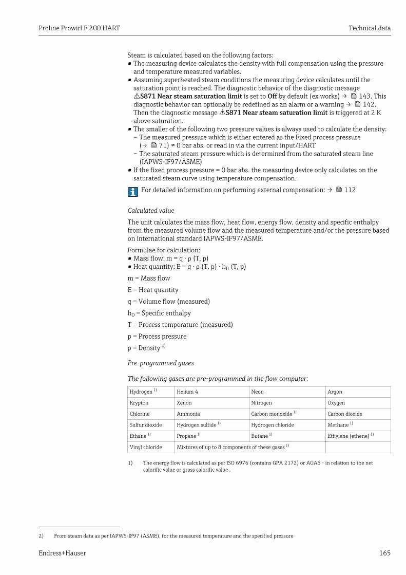
Proline Prowirl F 200 HART Technical data
Endress+Hauser 165
Steam is calculated based on the following factors:• The measuring device calculates the density with full compensation using the pressure
and temperature measured variables.• Assuming superheated steam conditions the measuring device calculates until the
saturation point is reached. The diagnostic behavior of the diagnostic messageS871 Near steam saturation limit is set to Off by default (ex works) → 143. Thisdiagnostic behavior can optionally be redefined as an alarm or a warning → 142.Then the diagnostic message S871 Near steam saturation limit is triggered at 2 Kabove saturation.
• The smaller of the following two pressure values is always used to calculate the density:– The measured pressure which is either entered as the Fixed process pressure
(→ 71) ≠ 0 bar abs. or read in via the current input/HART– The saturated steam pressure which is determined from the saturated steam line
(IAPWS-IF97/ASME)• If the fixed process pressure = 0 bar abs. the measuring device only calculates on the
saturated steam curve using temperature compensation.
For detailed information on performing external compensation: → 112
Calculated value
The unit calculates the mass flow, heat flow, energy flow, density and specific enthalpyfrom the measured volume flow and the measured temperature and/or the pressure basedon international standard IAPWS-IF97/ASME.
Formulae for calculation:• Mass flow: m = q ⋅ ρ (T, p)• Heat quantity: E = q ⋅ ρ (T, p) ⋅ hD (T, p)
m = Mass flow
E = Heat quantity
q = Volume flow (measured)
hD = Specific enthalpy
T = Process temperature (measured)
p = Process pressure
ρ = Density 2)
Pre-programmed gases
The following gases are pre-programmed in the flow computer:
Hydrogen 1) Helium 4 Neon Argon
Krypton Xenon Nitrogen Oxygen
Chlorine Ammonia Carbon monoxide 1) Carbon dioxide
Sulfur dioxide Hydrogen sulfide 1) Hydrogen chloride Methane 1)
Ethane 1) Propane 1) Butane 1) Ethylene (ethene) 1)
Vinyl chloride Mixtures of up to 8 components of these gases 1)
1) The energy flow is calculated as per ISO 6976 (contains GPA 2172) or AGA5 - in relation to the netcalorific value or gross calorific value .
2) From steam data as per IAPWS-IF97 (ASME), for the measured temperature and the specified pressure
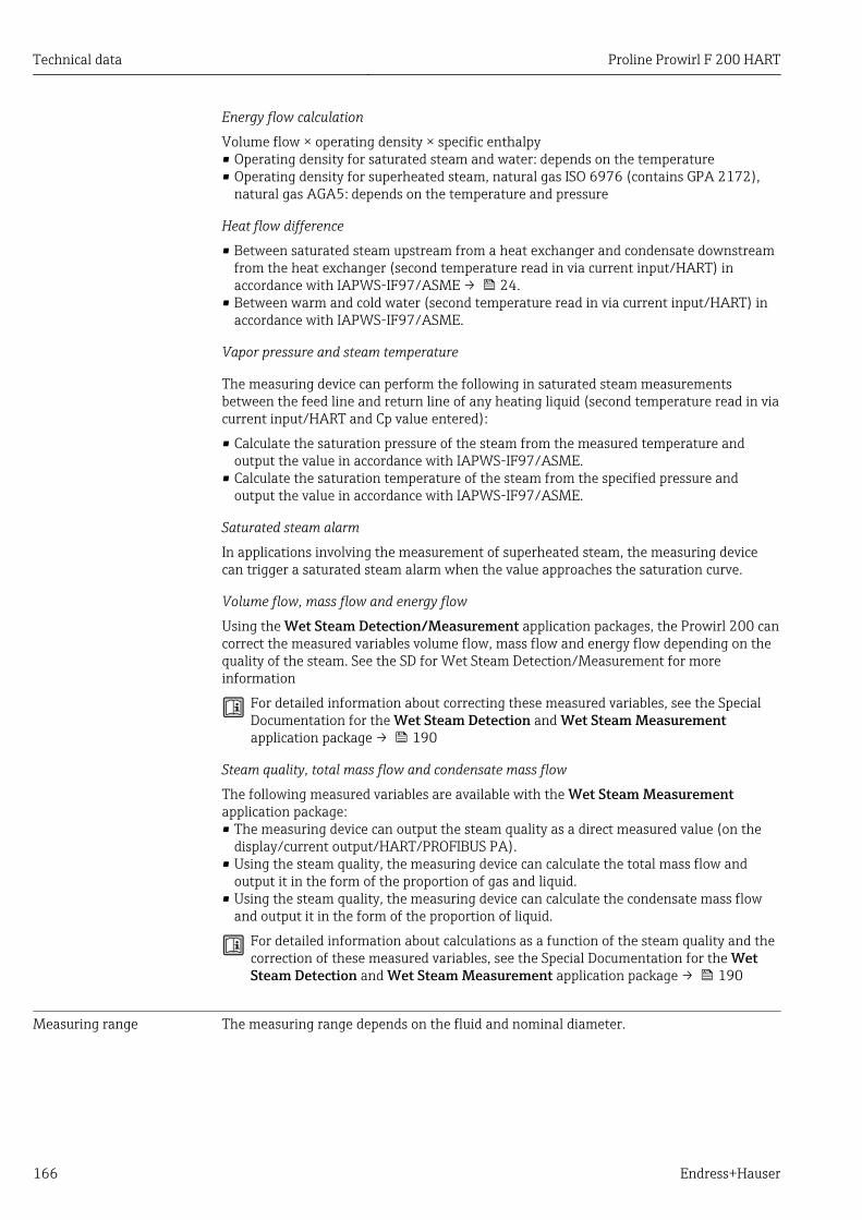
Technical data Proline Prowirl F 200 HART
166 Endress+Hauser
Energy flow calculation
Volume flow × operating density × specific enthalpy• Operating density for saturated steam and water: depends on the temperature• Operating density for superheated steam, natural gas ISO 6976 (contains GPA 2172),
natural gas AGA5: depends on the temperature and pressure
Heat flow difference
• Between saturated steam upstream from a heat exchanger and condensate downstreamfrom the heat exchanger (second temperature read in via current input/HART) inaccordance with IAPWS-IF97/ASME → 24.
• Between warm and cold water (second temperature read in via current input/HART) inaccordance with IAPWS-IF97/ASME.
Vapor pressure and steam temperature
The measuring device can perform the following in saturated steam measurementsbetween the feed line and return line of any heating liquid (second temperature read in viacurrent input/HART and Cp value entered):
• Calculate the saturation pressure of the steam from the measured temperature andoutput the value in accordance with IAPWS-IF97/ASME.
• Calculate the saturation temperature of the steam from the specified pressure andoutput the value in accordance with IAPWS-IF97/ASME.
Saturated steam alarm
In applications involving the measurement of superheated steam, the measuring devicecan trigger a saturated steam alarm when the value approaches the saturation curve.
Volume flow, mass flow and energy flow
Using the Wet Steam Detection/Measurement application packages, the Prowirl 200 cancorrect the measured variables volume flow, mass flow and energy flow depending on thequality of the steam. See the SD for Wet Steam Detection/Measurement for moreinformation
For detailed information about correcting these measured variables, see the SpecialDocumentation for the Wet Steam Detection and Wet Steam Measurementapplication package → 190
Steam quality, total mass flow and condensate mass flow
The following measured variables are available with the Wet Steam Measurementapplication package:• The measuring device can output the steam quality as a direct measured value (on the
display/current output/HART/PROFIBUS PA).• Using the steam quality, the measuring device can calculate the total mass flow and
output it in the form of the proportion of gas and liquid.• Using the steam quality, the measuring device can calculate the condensate mass flow
and output it in the form of the proportion of liquid.
For detailed information about calculations as a function of the steam quality and thecorrection of these measured variables, see the Special Documentation for the WetSteam Detection and Wet Steam Measurement application package → 190
Measuring range The measuring range depends on the fluid and nominal diameter.
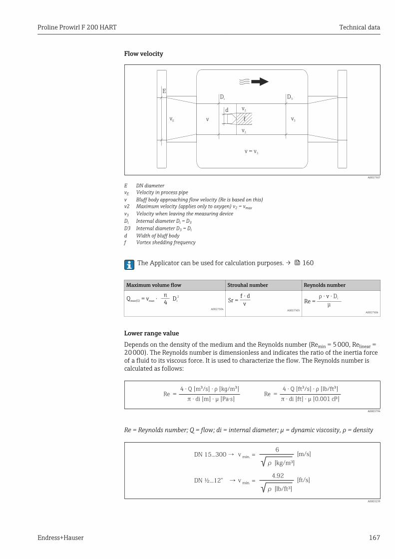
Proline Prowirl F 200 HART Technical data
Endress+Hauser 167
Flow velocity
Di
D3
vE v v
3
v2
v2
E
v = v3
d
f
A0027507
E DN diametervE Velocity in process pipev Bluff body approaching flow velocity (Re is based on this)v2 Maximum velocity (applies only to oxygen) v2 = vmax
v3 Velocity when leaving the measuring deviceDi Internal diameter Di = D3
D3 Internal diameter D3 = Di
d Width of bluff bodyf Vortex shedding frequency
The Applicator can be used for calculation purposes. → 160
Maximum volume flow Strouhal number Reynolds number
4Qmax(G) = v ·max Di
2
A0027504
Sr =v
f d·
A0027505
Re =μ
ρ Di· v ·
A0027506
Lower range valueDepends on the density of the medium and the Reynolds number (Remin = 5 000, Relinear =20 000). The Reynolds number is dimensionless and indicates the ratio of the inertia forceof a fluid to its viscous force. It is used to characterize the flow. The Reynolds number iscalculated as follows:
Re =4 · Q · m³[m³/s] [kg/ ]ρ
di [m] · µπ π · [Pa·s]Re =
4 · Q · ³[ft³/s] [lb/ft ]ρ
di [ft] · µπ · [0.001 cP]
A0003794
Re = Reynolds number; Q = flow; di = internal diameter; µ = dynamic viscosity, ρ = density
vDN ½...12" → =min.
4.92
ρ [lb/ft³]
[ft/s]
vDN 15...300 → =min.
6
ρ [kg/m³]
[m/s]
A0003239
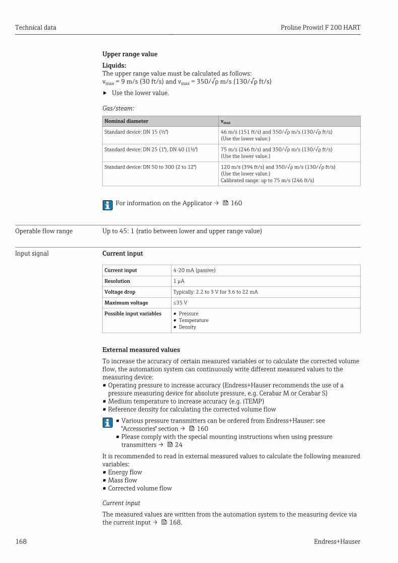
Technical data Proline Prowirl F 200 HART
168 Endress+Hauser
Upper range valueLiquids:The upper range value must be calculated as follows:vmax = 9 m/s (30 ft/s) and vmax = 350/√ρ m/s (130/√ρ ft/s)
‣ Use the lower value.
Gas/steam:
Nominal diameter vmax
Standard device: DN 15 (½") 46 m/s (151 ft/s) and 350/√ρ m/s (130/√ρ ft/s)(Use the lower value.)
Standard device: DN 25 (1"), DN 40 (1½") 75 m/s (246 ft/s) and 350/√ρ m/s (130/√ρ ft/s)(Use the lower value.)
Standard device: DN 50 to 300 (2 to 12") 120 m/s (394 ft/s) and 350/√ρ m/s (130/√ρ ft/s)(Use the lower value.)Calibrated range: up to 75 m/s (246 ft/s)
For information on the Applicator → 160
Operable flow range Up to 45: 1 (ratio between lower and upper range value)
Input signal Current input
Current input 4-20 mA (passive)
Resolution 1 µA
Voltage drop Typically: 2.2 to 3 V for 3.6 to 22 mA
Maximum voltage ≤35 V
Possible input variables • Pressure• Temperature• Density
External measured valuesTo increase the accuracy of certain measured variables or to calculate the corrected volumeflow, the automation system can continuously write different measured values to themeasuring device:• Operating pressure to increase accuracy (Endress+Hauser recommends the use of a
pressure measuring device for absolute pressure, e.g. Cerabar M or Cerabar S)• Medium temperature to increase accuracy (e.g. iTEMP)• Reference density for calculating the corrected volume flow
• Various pressure transmitters can be ordered from Endress+Hauser: see"Accessories" section → 160
• Please comply with the special mounting instructions when using pressuretransmitters → 24
It is recommended to read in external measured values to calculate the following measuredvariables:• Energy flow• Mass flow• Corrected volume flow
Current input
The measured values are written from the automation system to the measuring device viathe current input → 168.
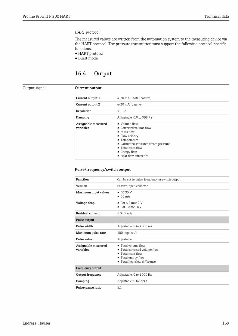
Proline Prowirl F 200 HART Technical data
Endress+Hauser 169
HART protocol
The measured values are written from the automation system to the measuring device viathe HART protocol. The pressure transmitter must support the following protocol-specificfunctions:• HART protocol• Burst mode
16.4 Output
Output signal Current output
Current output 1 4-20 mA HART (passive)
Current output 2 4-20 mA (passive)
Resolution < 1 µA
Damping Adjustable: 0.0 to 999.9 s
Assignable measuredvariables
• Volume flow• Corrected volume flow• Mass flow• Flow velocity• Temperature• Calculated saturated steam pressure• Total mass flow• Energy flow• Heat flow difference
Pulse/frequency/switch output
Function Can be set to pulse, frequency or switch output
Version Passive, open collector
Maximum input values • DC 35 V• 50 mA
Voltage drop • For ≤ 2 mA: 2 V• For 10 mA: 8 V
Residual current ≤ 0.05 mA
Pulse output
Pulse width Adjustable: 5 to 2 000 ms
Maximum pulse rate 100 Impulse/s
Pulse value Adjustable
Assignable measuredvariables
• Total volume flow• Total corrected volume flow• Total mass flow• Total energy flow• Total heat flow difference
Frequency output
Output frequency Adjustable: 0 to 1 000 Hz
Damping Adjustable: 0 to 999 s
Pulse/pause ratio 1:1
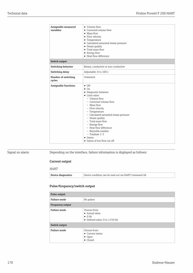
Technical data Proline Prowirl F 200 HART
170 Endress+Hauser
Assignable measuredvariables
• Volume flow• Corrected volume flow• Mass flow• Flow velocity• Temperature• Calculated saturated steam pressure• Steam quality• Total mass flow• Energy flow• Heat flow difference
Switch output
Switching behavior Binary, conductive or non-conductive
Switching delay Adjustable: 0 to 100 s
Number of switchingcycles
Unlimited
Assignable functions • Off• On• Diagnostic behavior• Limit value
– Volume flow– Corrected volume flow– Mass flow– Flow velocity– Temperature– Calculated saturated steam pressure– Steam quality– Total mass flow– Energy flow– Heat flow difference– Reynolds number– Totalizer 1-3
• Status• Status of low flow cut off
Signal on alarm Depending on the interface, failure information is displayed as follows:
Current output
HART
Device diagnostics Device condition can be read out via HART Command 48
Pulse/frequency/switch output
Pulse output
Failure mode No pulses
Frequency output
Failure mode Choose from:• Actual value• 0 Hz• Defined value: 0 to 1 250 Hz
Switch output
Failure mode Choose from:• Current status• Open• Closed
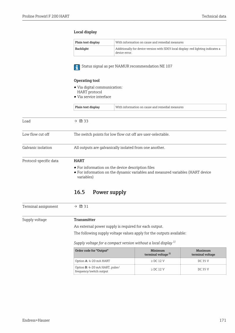
Proline Prowirl F 200 HART Technical data
Endress+Hauser 171
Local display
Plain text display With information on cause and remedial measures
Backlight Additionally for device version with SD03 local display: red lighting indicates adevice error.
Status signal as per NAMUR recommendation NE 107
Operating tool• Via digital communication:
HART protocol• Via service interface
Plain text display With information on cause and remedial measures
Load → 33
Low flow cut off The switch points for low flow cut off are user-selectable.
Galvanic isolation All outputs are galvanically isolated from one another.
Protocol-specific data HART• For information on the device description files• For information on the dynamic variables and measured variables (HART device
variables)
16.5 Power supply
Terminal assignment → 31
Supply voltage TransmitterAn external power supply is required for each output.
The following supply voltage values apply for the outputs available:
Supply voltage for a compact version without a local display 1)
Order code for "Output" Minimumterminal voltage 2)
Maximumterminal voltage
Option A: 4-20 mA HART ≥ DC 12 V DC 35 V
Option B: 4-20 mA HART, pulse/frequency/switch output ≥ DC 12 V DC 35 V
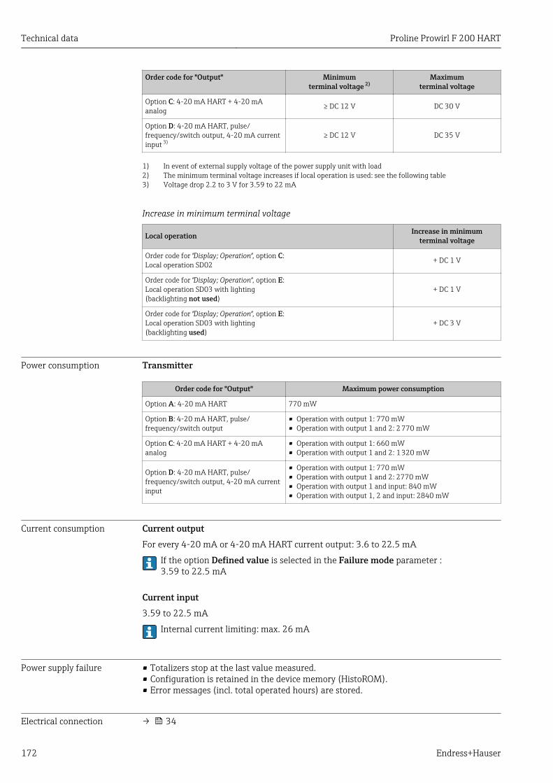
Technical data Proline Prowirl F 200 HART
172 Endress+Hauser
Order code for "Output" Minimumterminal voltage 2)
Maximumterminal voltage
Option C: 4-20 mA HART + 4-20 mAanalog ≥ DC 12 V DC 30 V
Option D: 4-20 mA HART, pulse/frequency/switch output, 4-20 mA currentinput 3)
≥ DC 12 V DC 35 V
1) In event of external supply voltage of the power supply unit with load2) The minimum terminal voltage increases if local operation is used: see the following table3) Voltage drop 2.2 to 3 V for 3.59 to 22 mA
Increase in minimum terminal voltage
Local operation Increase in minimumterminal voltage
Order code for "Display; Operation", option C:Local operation SD02 + DC 1 V
Order code for "Display; Operation", option E:Local operation SD03 with lighting(backlighting not used)
+ DC 1 V
Order code for "Display; Operation", option E:Local operation SD03 with lighting(backlighting used)
+ DC 3 V
Power consumption Transmitter
Order code for "Output" Maximum power consumption
Option A: 4-20 mA HART 770 mW
Option B: 4-20 mA HART, pulse/frequency/switch output
• Operation with output 1: 770 mW• Operation with output 1 and 2: 2 770 mW
Option C: 4-20 mA HART + 4-20 mAanalog
• Operation with output 1: 660 mW• Operation with output 1 and 2: 1 320 mW
Option D: 4-20 mA HART, pulse/frequency/switch output, 4-20 mA currentinput
• Operation with output 1: 770 mW• Operation with output 1 and 2: 2770 mW• Operation with output 1 and input: 840 mW• Operation with output 1, 2 and input: 2840 mW
Current consumption Current outputFor every 4-20 mA or 4-20 mA HART current output: 3.6 to 22.5 mA
If the option Defined value is selected in the Failure mode parameter :3.59 to 22.5 mA
Current input3.59 to 22.5 mA
Internal current limiting: max. 26 mA
Power supply failure • Totalizers stop at the last value measured.• Configuration is retained in the device memory (HistoROM).• Error messages (incl. total operated hours) are stored.
Electrical connection → 34
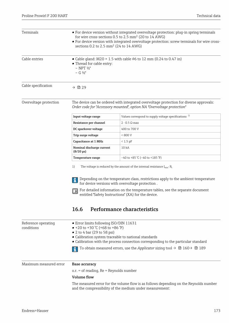
Proline Prowirl F 200 HART Technical data
Endress+Hauser 173
Terminals • For device version without integrated overvoltage protection: plug-in spring terminalsfor wire cross-sections 0.5 to 2.5 mm2 (20 to 14 AWG)
• For device version with integrated overvoltage protection: screw terminals for wire cross-sections 0.2 to 2.5 mm2 (24 to 14 AWG)
Cable entries • Cable gland: M20 × 1.5 with cable 6 to 12 mm (0.24 to 0.47 in)• Thread for cable entry:
– NPT ½"– G ½"
Cable specification → 29
Overvoltage protection The device can be ordered with integrated overvoltage protection for diverse approvals:Order code for "Accessory mounted", option NA "Overvoltage protection"
Input voltage range Values correspond to supply voltage specifications 1)
Resistance per channel 2 ⋅ 0.5 Ω max
DC sparkover voltage 400 to 700 V
Trip surge voltage < 800 V
Capacitance at 1 MHz < 1.5 pF
Nominal discharge current(8/20 μs)
10 kA
Temperature range –40 to +85 °C (–40 to +185 °F)
1) The voltage is reduced by the amount of the internal resistance Imin⋅ Ri
Depending on the temperature class, restrictions apply to the ambient temperaturefor device versions with overvoltage protection .
For detailed information on the temperature tables, see the separate documententitled "Safety Instructions" (XA) for the device.
16.6 Performance characteristics
Reference operatingconditions
• Error limits following ISO/DIN 11631• +20 to +30 °C (+68 to +86 °F)• 2 to 4 bar (29 to 58 psi)• Calibration system traceable to national standards• Calibration with the process connection corresponding to the particular standard
To obtain measured errors, use the Applicator sizing tool → 160→ 189
Maximum measured error Base accuracyo.r. = of reading, Re = Reynolds number
Volume flowThe measured error for the volume flow is as follows depending on the Reynolds numberand the compressibility of the medium under measurement:
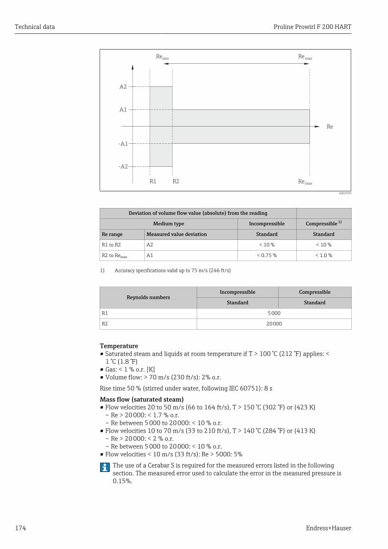
Technical data Proline Prowirl F 200 HART
174 Endress+Hauser
ReminRe
max
Re
Remax
A2
A1
-A1
-A2
R1 R2
A0019703
Deviation of volume flow value (absolute) from the reading
Medium type Incompressible Compressible 1)
Re range Measured value deviation Standard Standard
R1 to R2 A2 < 10 % < 10 %
R2 to Remax A1 < 0.75 % < 1.0 %
1) Accuracy specifications valid up to 75 m/s (246 ft/s)
Reynolds numbersIncompressible Compressible
Standard Standard
R1 5 000
R2 20 000
Temperature• Saturated steam and liquids at room temperature if T > 100 °C (212 °F) applies: <
1 °C (1.8 °F)• Gas: < 1 % o.r. [K]• Volume flow: > 70 m/s (230 ft/s): 2% o.r.
Rise time 50 % (stirred under water, following IEC 60751): 8 s
Mass flow (saturated steam)• Flow velocities 20 to 50 m/s (66 to 164 ft/s), T > 150 °C (302 °F) or (423 K)
– Re > 20 000: < 1.7 % o.r.– Re between 5 000 to 20 000: < 10 % o.r.
• Flow velocities 10 to 70 m/s (33 to 210 ft/s), T > 140 °C (284 °F) or (413 K)– Re > 20 000: < 2 % o.r.– Re between 5 000 to 20 000: < 10 % o.r.
• Flow velocities < 10 m/s (33 ft/s): Re > 5000: 5%
The use of a Cerabar S is required for the measured errors listed in the followingsection. The measured error used to calculate the error in the measured pressure is0.15%.
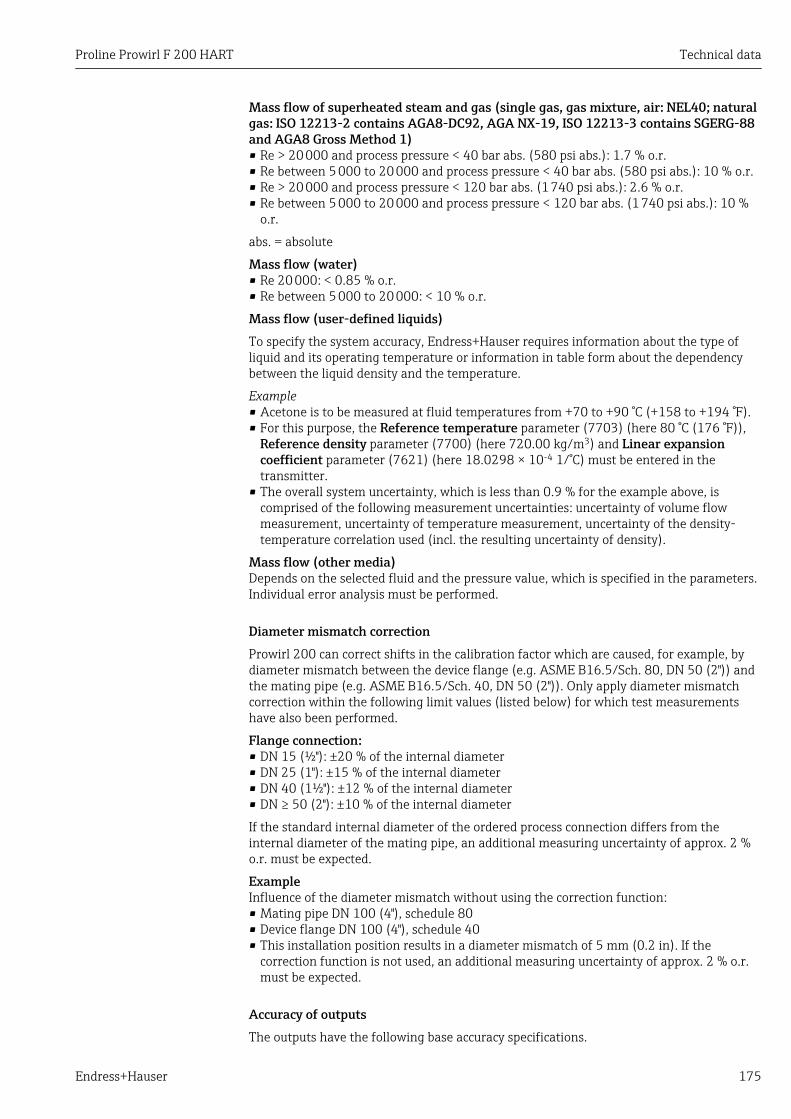
Proline Prowirl F 200 HART Technical data
Endress+Hauser 175
Mass flow of superheated steam and gas (single gas, gas mixture, air: NEL40; naturalgas: ISO 12213-2 contains AGA8-DC92, AGA NX-19, ISO 12213-3 contains SGERG-88and AGA8 Gross Method 1)• Re > 20 000 and process pressure < 40 bar abs. (580 psi abs.): 1.7 % o.r.• Re between 5 000 to 20 000 and process pressure < 40 bar abs. (580 psi abs.): 10 % o.r.• Re > 20 000 and process pressure < 120 bar abs. (1 740 psi abs.): 2.6 % o.r.• Re between 5 000 to 20 000 and process pressure < 120 bar abs. (1 740 psi abs.): 10 %
o.r.
abs. = absolute
Mass flow (water)• Re 20 000: < 0.85 % o.r.• Re between 5 000 to 20 000: < 10 % o.r.
Mass flow (user-defined liquids)To specify the system accuracy, Endress+Hauser requires information about the type ofliquid and its operating temperature or information in table form about the dependencybetween the liquid density and the temperature.
Example• Acetone is to be measured at fluid temperatures from +70 to +90 °C (+158 to +194 °F).• For this purpose, the Reference temperature parameter (7703) (here 80 °C (176 °F)),
Reference density parameter (7700) (here 720.00 kg/m3) and Linear expansioncoefficient parameter (7621) (here 18.0298 × 10⁻⁴ 1/°C) must be entered in thetransmitter.
• The overall system uncertainty, which is less than 0.9 % for the example above, iscomprised of the following measurement uncertainties: uncertainty of volume flowmeasurement, uncertainty of temperature measurement, uncertainty of the density-temperature correlation used (incl. the resulting uncertainty of density).
Mass flow (other media)Depends on the selected fluid and the pressure value, which is specified in the parameters.Individual error analysis must be performed.
Diameter mismatch correctionProwirl 200 can correct shifts in the calibration factor which are caused, for example, bydiameter mismatch between the device flange (e.g. ASME B16.5/Sch. 80, DN 50 (2")) andthe mating pipe (e.g. ASME B16.5/Sch. 40, DN 50 (2")). Only apply diameter mismatchcorrection within the following limit values (listed below) for which test measurementshave also been performed.
Flange connection:• DN 15 (½"): ±20 % of the internal diameter• DN 25 (1"): ±15 % of the internal diameter• DN 40 (1½"): ±12 % of the internal diameter• DN ≥ 50 (2"): ±10 % of the internal diameter
If the standard internal diameter of the ordered process connection differs from theinternal diameter of the mating pipe, an additional measuring uncertainty of approx. 2 %o.r. must be expected.
ExampleInfluence of the diameter mismatch without using the correction function:• Mating pipe DN 100 (4"), schedule 80• Device flange DN 100 (4"), schedule 40• This installation position results in a diameter mismatch of 5 mm (0.2 in). If the
correction function is not used, an additional measuring uncertainty of approx. 2 % o.r.must be expected.
Accuracy of outputsThe outputs have the following base accuracy specifications.
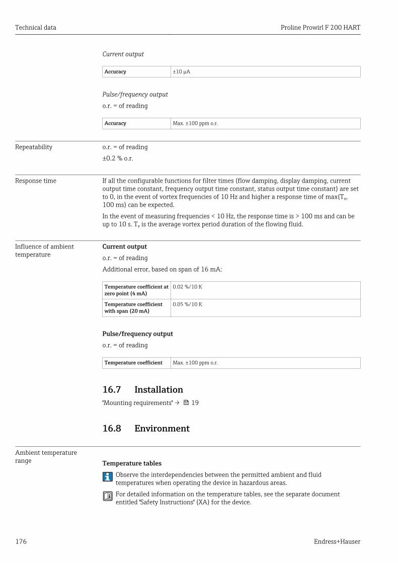
Technical data Proline Prowirl F 200 HART
176 Endress+Hauser
Current output
Accuracy ±10 µA
Pulse/frequency output
o.r. = of reading
Accuracy Max. ±100 ppm o.r.
Repeatability o.r. = of reading
±0.2 % o.r.
Response time If all the configurable functions for filter times (flow damping, display damping, currentoutput time constant, frequency output time constant, status output time constant) are setto 0, in the event of vortex frequencies of 10 Hz and higher a response time of max(Tν,100 ms) can be expected.
In the event of measuring frequencies < 10 Hz, the response time is > 100 ms and can beup to 10 s. Tν is the average vortex period duration of the flowing fluid.
Influence of ambienttemperature
Current outputo.r. = of reading
Additional error, based on span of 16 mA:
Temperature coefficient atzero point (4 mA)
0.02 %/10 K
Temperature coefficientwith span (20 mA)
0.05 %/10 K
Pulse/frequency outputo.r. = of reading
Temperature coefficient Max. ±100 ppm o.r.
16.7 Installation"Mounting requirements" → 19
16.8 Environment
Ambient temperaturerange Temperature tables
Observe the interdependencies between the permitted ambient and fluidtemperatures when operating the device in hazardous areas.
For detailed information on the temperature tables, see the separate documententitled "Safety Instructions" (XA) for the device.
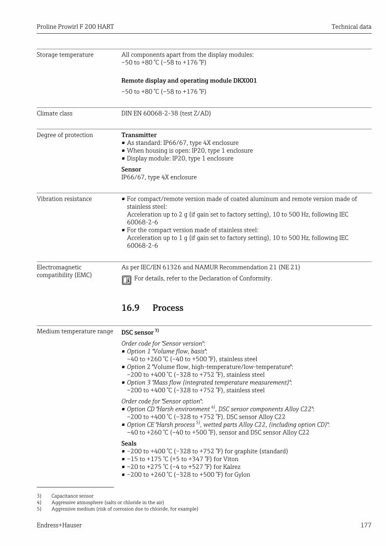
Proline Prowirl F 200 HART Technical data
Endress+Hauser 177
Storage temperature All components apart from the display modules:–50 to +80 °C (–58 to +176 °F)
Remote display and operating module DKX001–50 to +80 °C (–58 to +176 °F)
Climate class DIN EN 60068-2-38 (test Z/AD)
Degree of protection Transmitter• As standard: IP66/67, type 4X enclosure• When housing is open: IP20, type 1 enclosure• Display module: IP20, type 1 enclosure
SensorIP66/67, type 4X enclosure
Vibration resistance • For compact/remote version made of coated aluminum and remote version made ofstainless steel:Acceleration up to 2 g (if gain set to factory setting), 10 to 500 Hz, following IEC60068-2-6
• For the compact version made of stainless steel:Acceleration up to 1 g (if gain set to factory setting), 10 to 500 Hz, following IEC60068-2-6
Electromagneticcompatibility (EMC)
As per IEC/EN 61326 and NAMUR Recommendation 21 (NE 21)
For details, refer to the Declaration of Conformity.
16.9 Process
Medium temperature range DSC sensor 3)
Order code for "Sensor version":• Option 1 "Volume flow, basis":
–40 to +260 °C (–40 to +500 °F), stainless steel• Option 2 "Volume flow, high-temperature/low-temperature":
–200 to +400 °C (–328 to +752 °F), stainless steel• Option 3 "Mass flow (integrated temperature measurement)":
–200 to +400 °C (–328 to +752 °F), stainless steel
Order code for "Sensor option":• Option CD "Harsh environment 4), DSC sensor components Alloy C22":
–200 to +400 °C (–328 to +752 °F), DSC sensor Alloy C22• Option CE "Harsh process 5), wetted parts Alloy C22, (including option CD)":
–40 to +260 °C (–40 to +500 °F), sensor and DSC sensor Alloy C22
Seals• –200 to +400 °C (–328 to +752 °F) for graphite (standard)• –15 to +175 °C (+5 to +347 °F) for Viton• –20 to +275 °C (–4 to +527 °F) for Kalrez• –200 to +260 °C (–328 to +500 °F) for Gylon
3) Capacitance sensor4) Aggressive atmosphere (salts or chloride in the air)5) Aggressive medium (risk of corrosion due to chloride, for example)
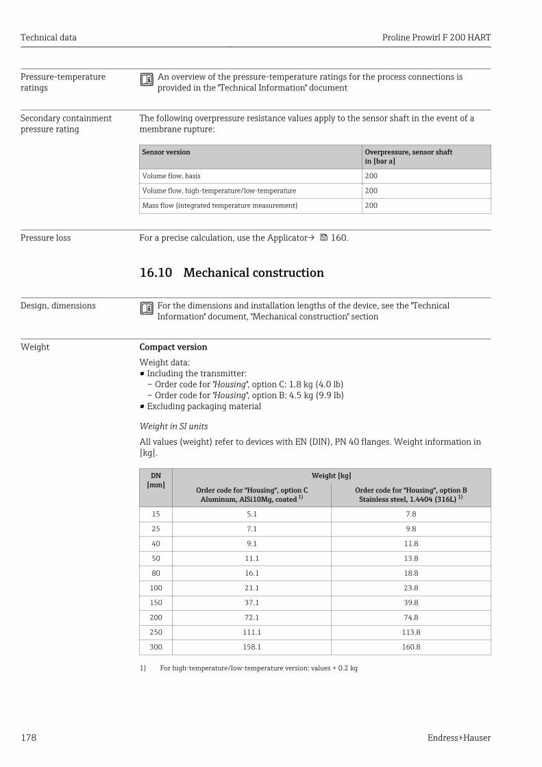
Technical data Proline Prowirl F 200 HART
178 Endress+Hauser
Pressure-temperatureratings
An overview of the pressure-temperature ratings for the process connections isprovided in the "Technical Information" document
Secondary containmentpressure rating
The following overpressure resistance values apply to the sensor shaft in the event of amembrane rupture:
Sensor version Overpressure, sensor shaftin [bar a]
Volume flow, basis 200
Volume flow, high-temperature/low-temperature 200
Mass flow (integrated temperature measurement) 200
Pressure loss For a precise calculation, use the Applicator→ 160.
16.10 Mechanical construction
Design, dimensions For the dimensions and installation lengths of the device, see the "TechnicalInformation" document, "Mechanical construction" section
Weight Compact versionWeight data:• Including the transmitter:
– Order code for "Housing", option C: 1.8 kg (4.0 lb)– Order code for "Housing", option B: 4.5 kg (9.9 lb)
• Excluding packaging material
Weight in SI units
All values (weight) refer to devices with EN (DIN), PN 40 flanges. Weight information in[kg].
DN[mm]
Weight [kg]
Order code for "Housing", option CAluminum, AlSi10Mg, coated 1)
Order code for "Housing", option BStainless steel, 1.4404 (316L) 1)
15 5.1 7.8
25 7.1 9.8
40 9.1 11.8
50 11.1 13.8
80 16.1 18.8
100 21.1 23.8
150 37.1 39.8
200 72.1 74.8
250 111.1 113.8
300 158.1 160.8
1) For high-temperature/low-temperature version: values + 0.2 kg
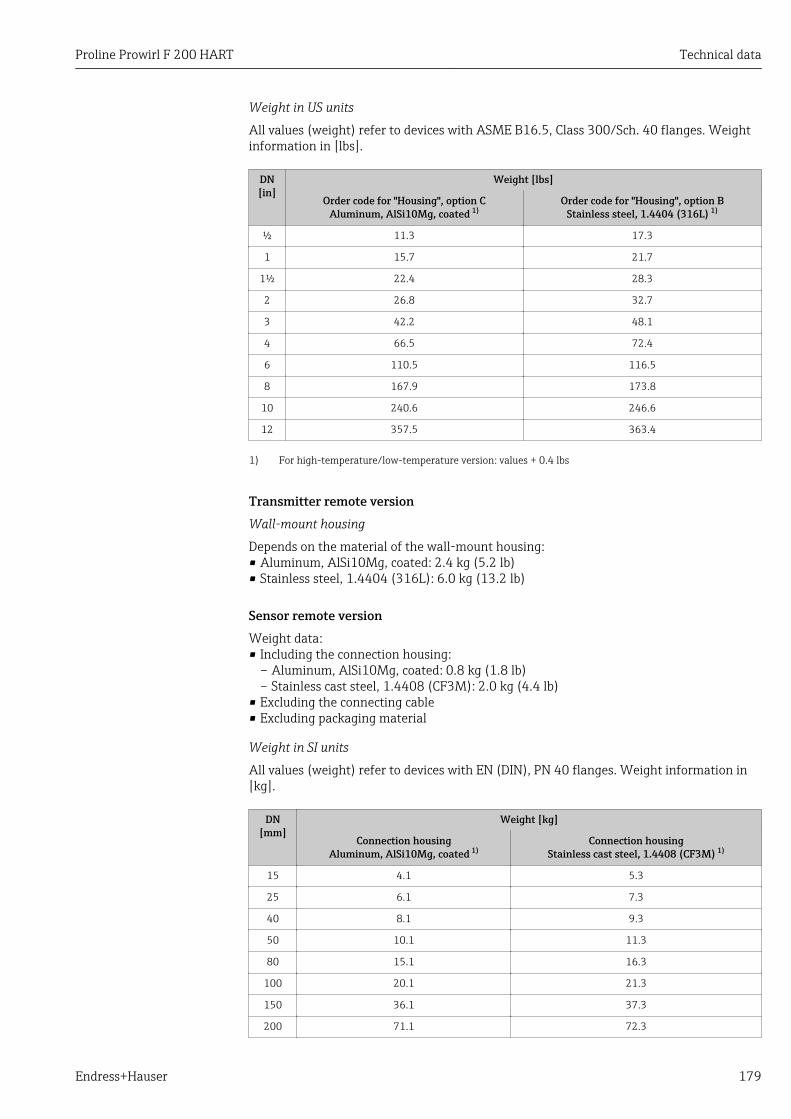
Proline Prowirl F 200 HART Technical data
Endress+Hauser 179
Weight in US units
All values (weight) refer to devices with ASME B16.5, Class 300/Sch. 40 flanges. Weightinformation in [lbs].
DN[in]
Weight [lbs]
Order code for "Housing", option CAluminum, AlSi10Mg, coated 1)
Order code for "Housing", option BStainless steel, 1.4404 (316L) 1)
½ 11.3 17.3
1 15.7 21.7
1½ 22.4 28.3
2 26.8 32.7
3 42.2 48.1
4 66.5 72.4
6 110.5 116.5
8 167.9 173.8
10 240.6 246.6
12 357.5 363.4
1) For high-temperature/low-temperature version: values + 0.4 lbs
Transmitter remote versionWall-mount housing
Depends on the material of the wall-mount housing:• Aluminum, AlSi10Mg, coated: 2.4 kg (5.2 lb)• Stainless steel, 1.4404 (316L): 6.0 kg (13.2 lb)
Sensor remote versionWeight data:• Including the connection housing:
– Aluminum, AlSi10Mg, coated: 0.8 kg (1.8 lb)– Stainless cast steel, 1.4408 (CF3M): 2.0 kg (4.4 lb)
• Excluding the connecting cable• Excluding packaging material
Weight in SI units
All values (weight) refer to devices with EN (DIN), PN 40 flanges. Weight information in[kg].
DN[mm]
Weight [kg]
Connection housingAluminum, AlSi10Mg, coated 1)
Connection housingStainless cast steel, 1.4408 (CF3M) 1)
15 4.1 5.3
25 6.1 7.3
40 8.1 9.3
50 10.1 11.3
80 15.1 16.3
100 20.1 21.3
150 36.1 37.3
200 71.1 72.3
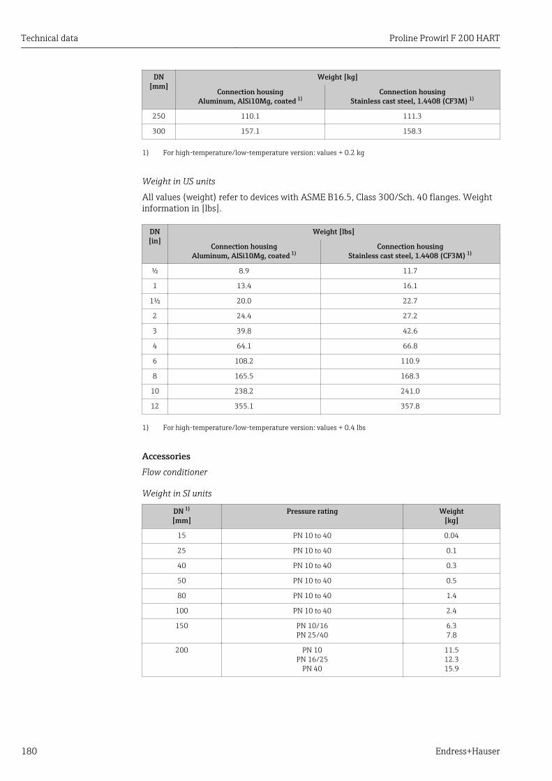
Technical data Proline Prowirl F 200 HART
180 Endress+Hauser
DN[mm]
Weight [kg]
Connection housingAluminum, AlSi10Mg, coated 1)
Connection housingStainless cast steel, 1.4408 (CF3M) 1)
250 110.1 111.3
300 157.1 158.3
1) For high-temperature/low-temperature version: values + 0.2 kg
Weight in US units
All values (weight) refer to devices with ASME B16.5, Class 300/Sch. 40 flanges. Weightinformation in [lbs].
DN[in]
Weight [lbs]
Connection housingAluminum, AlSi10Mg, coated 1)
Connection housingStainless cast steel, 1.4408 (CF3M) 1)
½ 8.9 11.7
1 13.4 16.1
1½ 20.0 22.7
2 24.4 27.2
3 39.8 42.6
4 64.1 66.8
6 108.2 110.9
8 165.5 168.3
10 238.2 241.0
12 355.1 357.8
1) For high-temperature/low-temperature version: values + 0.4 lbs
AccessoriesFlow conditioner
Weight in SI units
DN 1)
[mm]Pressure rating Weight
[kg]
15 PN 10 to 40 0.04
25 PN 10 to 40 0.1
40 PN 10 to 40 0.3
50 PN 10 to 40 0.5
80 PN 10 to 40 1.4
100 PN 10 to 40 2.4
150 PN 10/16PN 25/40
6.37.8
200 PN 10PN 16/25
PN 40
11.512.315.9
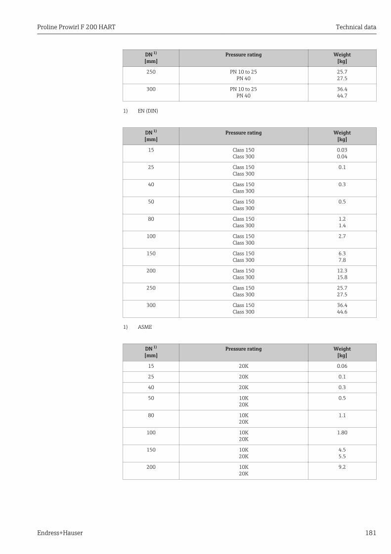
Proline Prowirl F 200 HART Technical data
Endress+Hauser 181
DN 1)
[mm]Pressure rating Weight
[kg]
250 PN 10 to 25PN 40
25.727.5
300 PN 10 to 25PN 40
36.444.7
1) EN (DIN)
DN 1)
[mm]Pressure rating Weight
[kg]
15 Class 150Class 300
0.030.04
25 Class 150Class 300
0.1
40 Class 150Class 300
0.3
50 Class 150Class 300
0.5
80 Class 150Class 300
1.21.4
100 Class 150Class 300
2.7
150 Class 150Class 300
6.37.8
200 Class 150Class 300
12.315.8
250 Class 150Class 300
25.727.5
300 Class 150Class 300
36.444.6
1) ASME
DN 1)
[mm]Pressure rating Weight
[kg]
15 20K 0.06
25 20K 0.1
40 20K 0.3
50 10K20K
0.5
80 10K20K
1.1
100 10K20K
1.80
150 10K20K
4.55.5
200 10K20K
9.2
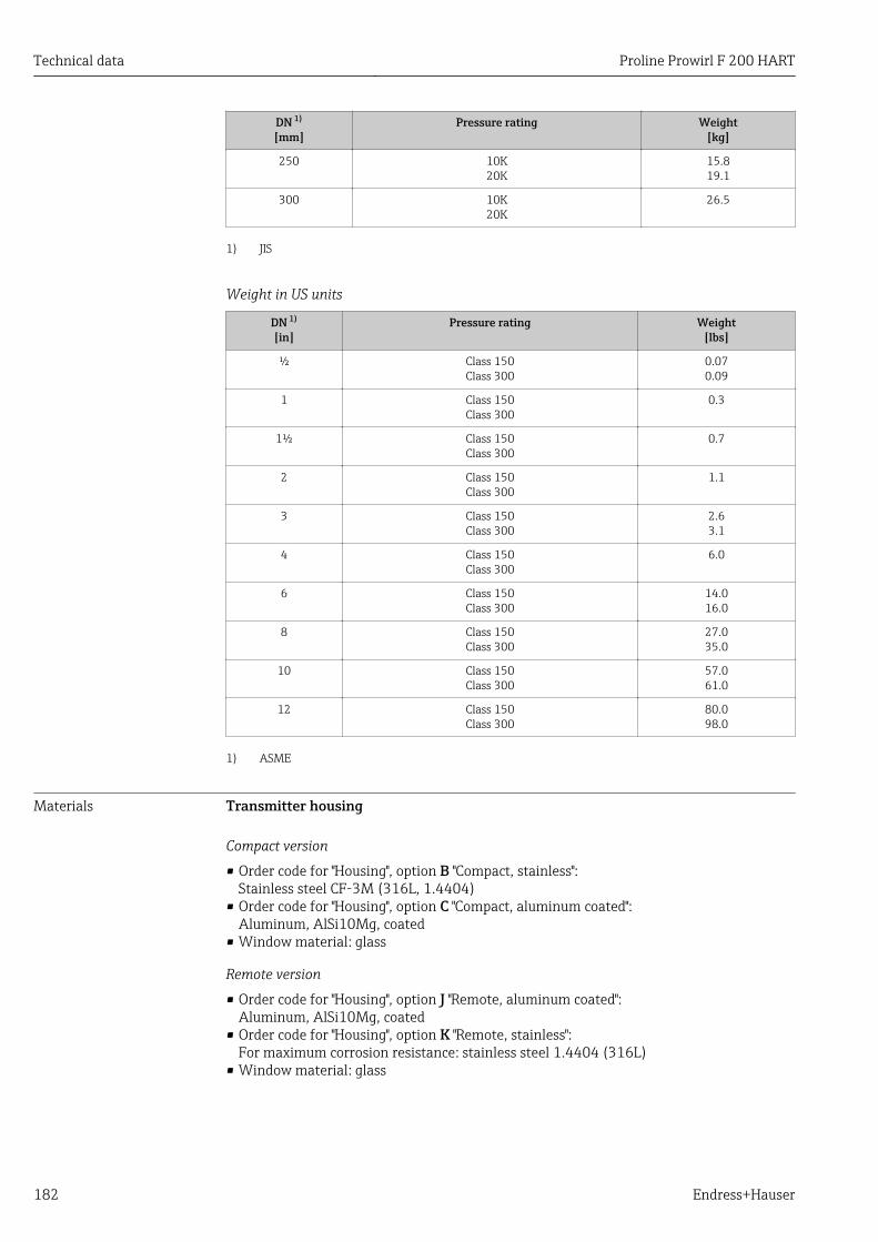
Technical data Proline Prowirl F 200 HART
182 Endress+Hauser
DN 1)
[mm]Pressure rating Weight
[kg]
250 10K20K
15.819.1
300 10K20K
26.5
1) JIS
Weight in US units
DN 1)
[in]Pressure rating Weight
[lbs]
½ Class 150Class 300
0.070.09
1 Class 150Class 300
0.3
1½ Class 150Class 300
0.7
2 Class 150Class 300
1.1
3 Class 150Class 300
2.63.1
4 Class 150Class 300
6.0
6 Class 150Class 300
14.016.0
8 Class 150Class 300
27.035.0
10 Class 150Class 300
57.061.0
12 Class 150Class 300
80.098.0
1) ASME
Materials Transmitter housing
Compact version
• Order code for "Housing", option B "Compact, stainless":Stainless steel CF-3M (316L, 1.4404)
• Order code for "Housing", option C "Compact, aluminum coated":Aluminum, AlSi10Mg, coated
• Window material: glass
Remote version
• Order code for "Housing", option J "Remote, aluminum coated":Aluminum, AlSi10Mg, coated
• Order code for "Housing", option K "Remote, stainless":For maximum corrosion resistance: stainless steel 1.4404 (316L)
• Window material: glass
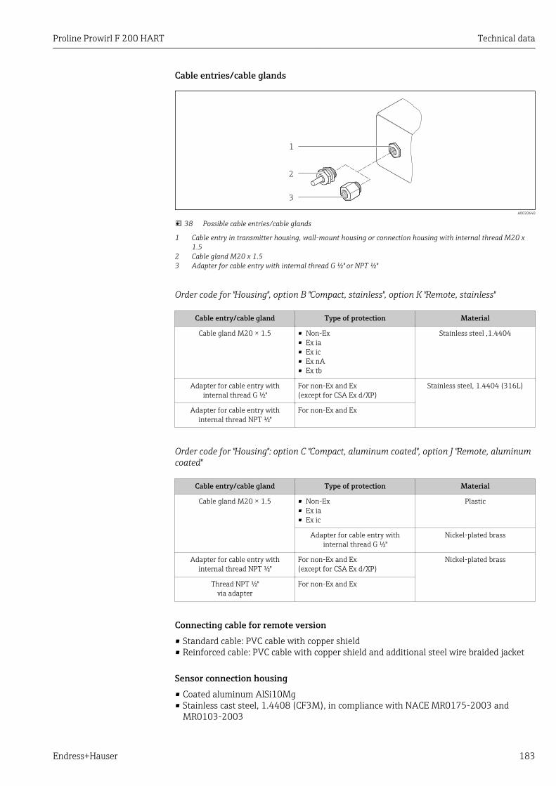
Proline Prowirl F 200 HART Technical data
Endress+Hauser 183
Cable entries/cable glands
1
2
3
A0020640
38 Possible cable entries/cable glands
1 Cable entry in transmitter housing, wall-mount housing or connection housing with internal thread M20 x1.5
2 Cable gland M20 x 1.53 Adapter for cable entry with internal thread G ½" or NPT ½"
Order code for "Housing", option B "Compact, stainless", option K "Remote, stainless"
Cable entry/cable gland Type of protection Material
Cable gland M20 × 1.5 • Non-Ex• Ex ia• Ex ic• Ex nA• Ex tb
Stainless steel ,1.4404
Adapter for cable entry withinternal thread G ½"
For non-Ex and Ex(except for CSA Ex d/XP)
Stainless steel, 1.4404 (316L)
Adapter for cable entry withinternal thread NPT ½"
For non-Ex and Ex
Order code for "Housing": option C "Compact, aluminum coated", option J "Remote, aluminumcoated"
Cable entry/cable gland Type of protection Material
Cable gland M20 × 1.5 • Non-Ex• Ex ia• Ex ic
Plastic
Adapter for cable entry withinternal thread G ½"
Nickel-plated brass
Adapter for cable entry withinternal thread NPT ½"
For non-Ex and Ex(except for CSA Ex d/XP)
Nickel-plated brass
Thread NPT ½"via adapter
For non-Ex and Ex
Connecting cable for remote version• Standard cable: PVC cable with copper shield• Reinforced cable: PVC cable with copper shield and additional steel wire braided jacket
Sensor connection housing• Coated aluminum AlSi10Mg• Stainless cast steel, 1.4408 (CF3M), in compliance with NACE MR0175-2003 and
MR0103-2003
Technical data Proline Prowirl F 200 HART
184 Endress+Hauser
Measuring tubesPressure ratings up to PN 40, Class 150/300, and JIS 10K/20K:• Stainless cast steel, 1.4408 (CF3M), in compliance with AD2000 (for AD2000 the
temperature range is limited to –10 to +400 °C (+14 to +752 °F)) and in compliance withNACE MR0175-2003 and MR0103-2003
• Order code for "Sensor option", option CE "Harsh process 6), wetted parts, Alloy C22,(including option CD)":Cast alloy CX2MW similar to Alloy C22/2.4602, in compliance with NACEMR0175-2003 and MR0103-2003
DSC sensorPressure ratings up to PN 40, Class 150/300, and JIS 10K/20K:Parts in contact with medium (marked as "wet" on the DSC sensor flange):• Stainless steel, 1.4435 (316, 316L), in compliance with NACE MR0175-2003 and
MR0103-2003• Order code for "Sensor option", option CE "Harsh process 6), wetted parts, Alloy C22,
(including option CD)":UNS N06022 similar to Alloy C22/2.4602, in compliance with NACE MR0175-2003and MR0103-2003
Parts not in contact with medium:• Stainless steel 1.4301 (304)• Order code for "Sensor option", option CD "Harsh environment 7), DSC sensor sensor
components Alloy C22":Alloy C22 sensor: UNS N06022 similar to Alloy C22/2.4602, in compliance with NACEMR0175-2003 and MR0103-2003
Process connectionsPressure ratings up to PN 40, Class 150/300, and JIS 10K/20K:Welding neck flanges DN 15 to 150 (½ to 6"), in compliance with NACE MR0175-2003and MR0103-2003
The following materials are available depending on the pressure rating:• Stainless steel, multiple certifications, 1.4404 (F316, F316L)• Cast alloy CX2MW similar to Alloy C22/2.4602
DN 200 to 300 (8 to 12"):Stainless cast steel, 1.4408 (CF3M)
List of all available process connections → 185
Seals• Graphite (standard)
Sigraflex HochdruckTM with smooth sheet metal insert made of stainless steel,316/316L (BAM-certified for oxygen applications, "high quality in terms of TA Luft"(German Clean Air Act))
• FPM (Viton)• Kalrez 6375• Gylon 3504 (BAM-certified for oxygen applications, "high quality in terms of TA Luft
(German Clean Air Act"))
Housing supportStainless steel, 1.4408 (CF3M)
6) Aggressive medium (risk of corrosion due to chloride, for example)7) Aggressive atmosphere (salts or chloride in the air)
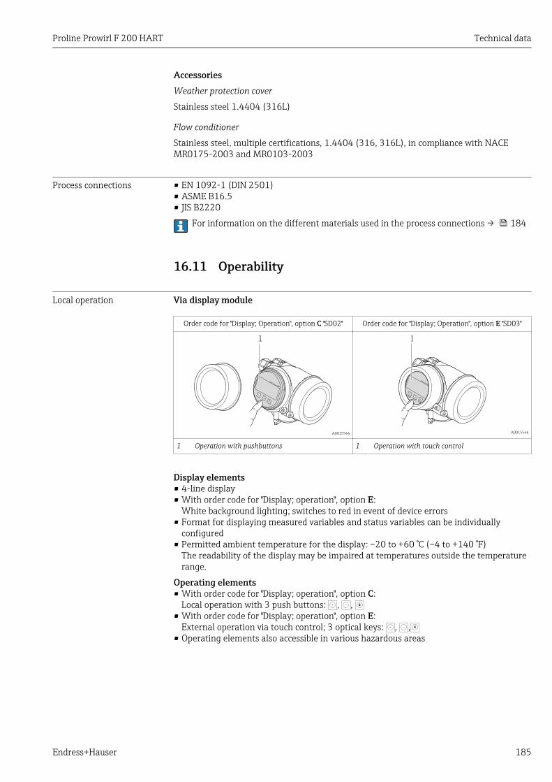
Proline Prowirl F 200 HART Technical data
Endress+Hauser 185
AccessoriesWeather protection cover
Stainless steel 1.4404 (316L)
Flow conditioner
Stainless steel, multiple certifications, 1.4404 (316, 316L), in compliance with NACEMR0175-2003 and MR0103-2003
Process connections • EN 1092-1 (DIN 2501)• ASME B16.5• JIS B2220
For information on the different materials used in the process connections → 184
16.11 Operability
Local operation Via display module
Order code for "Display; Operation", option C "SD02" Order code for "Display; Operation", option E "SD03"
+
E
–
1
A0015544
1
+
E
–
A0015546
1 Operation with pushbuttons 1 Operation with touch control
Display elements• 4-line display• With order code for "Display; operation", option E:
White background lighting; switches to red in event of device errors• Format for displaying measured variables and status variables can be individually
configured• Permitted ambient temperature for the display: –20 to +60 °C (–4 to +140 °F)
The readability of the display may be impaired at temperatures outside the temperaturerange.
Operating elements• With order code for "Display; operation", option C:
Local operation with 3 push buttons: , , E
• With order code for "Display; operation", option E:External operation via touch control; 3 optical keys: , , E
• Operating elements also accessible in various hazardous areas
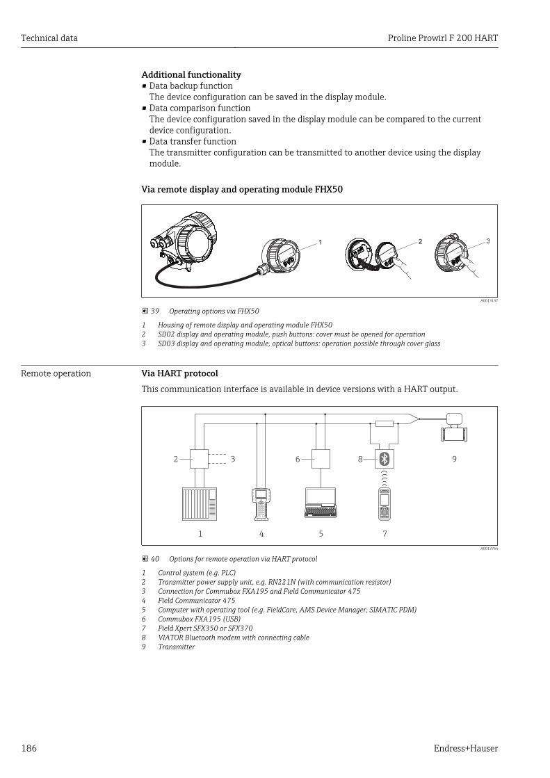
Technical data Proline Prowirl F 200 HART
186 Endress+Hauser
Additional functionality• Data backup function
The device configuration can be saved in the display module.• Data comparison function
The device configuration saved in the display module can be compared to the currentdevice configuration.
• Data transfer functionThe transmitter configuration can be transmitted to another device using the displaymodule.
Via remote display and operating module FHX50
321
A0013137
39 Operating options via FHX50
1 Housing of remote display and operating module FHX502 SD02 display and operating module, push buttons: cover must be opened for operation3 SD03 display and operating module, optical buttons: operation possible through cover glass
Remote operation Via HART protocolThis communication interface is available in device versions with a HART output.
1 4 5 7
96 82 3
A0013764
40 Options for remote operation via HART protocol
1 Control system (e.g. PLC)2 Transmitter power supply unit, e.g. RN221N (with communication resistor)3 Connection for Commubox FXA195 and Field Communicator 4754 Field Communicator 4755 Computer with operating tool (e.g. FieldCare, AMS Device Manager, SIMATIC PDM)6 Commubox FXA195 (USB)7 Field Xpert SFX350 or SFX3708 VIATOR Bluetooth modem with connecting cable9 Transmitter
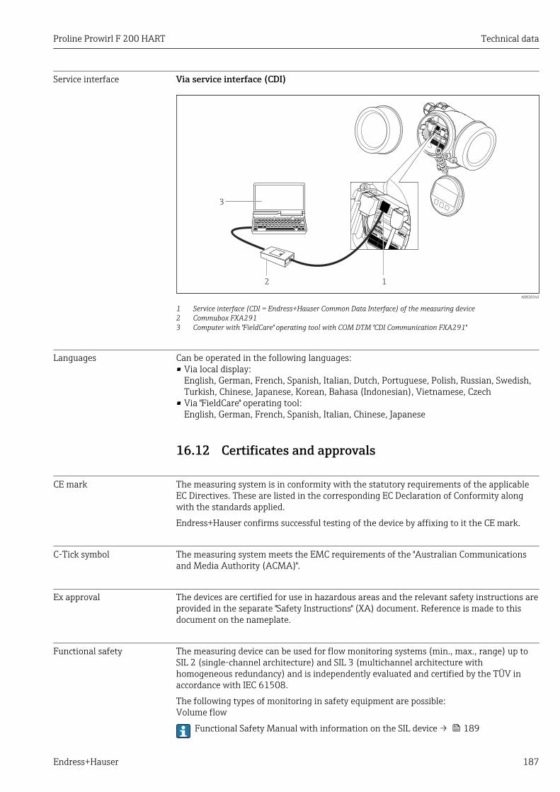
Proline Prowirl F 200 HART Technical data
Endress+Hauser 187
Service interface Via service interface (CDI)
12
3 +
E
–
A0020545
1 Service interface (CDI = Endress+Hauser Common Data Interface) of the measuring device2 Commubox FXA2913 Computer with "FieldCare" operating tool with COM DTM "CDI Communication FXA291"
Languages Can be operated in the following languages:• Via local display:
English, German, French, Spanish, Italian, Dutch, Portuguese, Polish, Russian, Swedish,Turkish, Chinese, Japanese, Korean, Bahasa (Indonesian), Vietnamese, Czech
• Via "FieldCare" operating tool:English, German, French, Spanish, Italian, Chinese, Japanese
16.12 Certificates and approvals
CE mark The measuring system is in conformity with the statutory requirements of the applicableEC Directives. These are listed in the corresponding EC Declaration of Conformity alongwith the standards applied.
Endress+Hauser confirms successful testing of the device by affixing to it the CE mark.
C-Tick symbol The measuring system meets the EMC requirements of the "Australian Communicationsand Media Authority (ACMA)".
Ex approval The devices are certified for use in hazardous areas and the relevant safety instructions areprovided in the separate "Safety Instructions" (XA) document. Reference is made to thisdocument on the nameplate.
Functional safety The measuring device can be used for flow monitoring systems (min., max., range) up toSIL 2 (single-channel architecture) and SIL 3 (multichannel architecture withhomogeneous redundancy) and is independently evaluated and certified by the TÜV inaccordance with IEC 61508.
The following types of monitoring in safety equipment are possible:Volume flow
Functional Safety Manual with information on the SIL device → 189
Technical data Proline Prowirl F 200 HART
188 Endress+Hauser
Pressure EquipmentDirective
• With the PED/G1/x (x = category) marking on the sensor nameplate, Endress+Hauserconfirms compliance with the "Essential Safety Requirements" specified in Annex I of thePressure Equipment Directive 97/23/EC.
• Devices not bearing this marking (PED) are designed and manufactured according togood engineering practice. They meet the requirements of Art.3 Section 3 of thePressure Equipment Directive 97/23/EC. The range of application is indicated in tables 6to 9 in Annex II of the Pressure Equipment Directive.
Experience The Prowirl 200 measuring system is the official successor to Prowirl 72 and Prowirl 73.
Other standards andguidelines
• EN 60529Degrees of protection provided by enclosures (IP code)
• DIN ISO 13359Measurement of conductive liquid flow in closed conduits - Flanged-typeelectromagnetic flowmeters - Overall length
• EN 61010-1Safety requirements for electrical equipment for measurement, control and laboratoryuse - general requirements
• IEC/EN 61326Emission in accordance with Class A requirements. Electromagnetic compatibility (EMCrequirements).
• NAMUR NE 21Electromagnetic compatibility (EMC) of industrial process and laboratory controlequipment
• NAMUR NE 32Data retention in the event of a power failure in field and control instruments withmicroprocessors
• NAMUR NE 43Standardization of the signal level for the breakdown information of digital transmitterswith analog output signal.
• NAMUR NE 53Software of field devices and signal-processing devices with digital electronics
• NAMUR NE 105Specifications for integrating fieldbus devices in engineering tools for field devices
• NAMUR NE 107Self-monitoring and diagnosis of field devices
• NAMUR NE 131Requirements for field devices for standard applications
• ASME BPVC Section VIII, Division 1Rules for Construction of Pressure Vessels
16.13 Application packagesMany different application packages are available to enhance the functionality of thedevice. Such packages might be needed to address safety aspects or specific applicationrequirements.
The application packages can be ordered with the device or subsequently fromEndress+Hauser. Detailed information on the order code in question is available from yourlocal Endress+Hauser sales center or on the product page of the Endress+Hauser website:www.endress.com.
Detailed information on the application packages:• Special Documentation for the device → 190• Special Documentation for the device
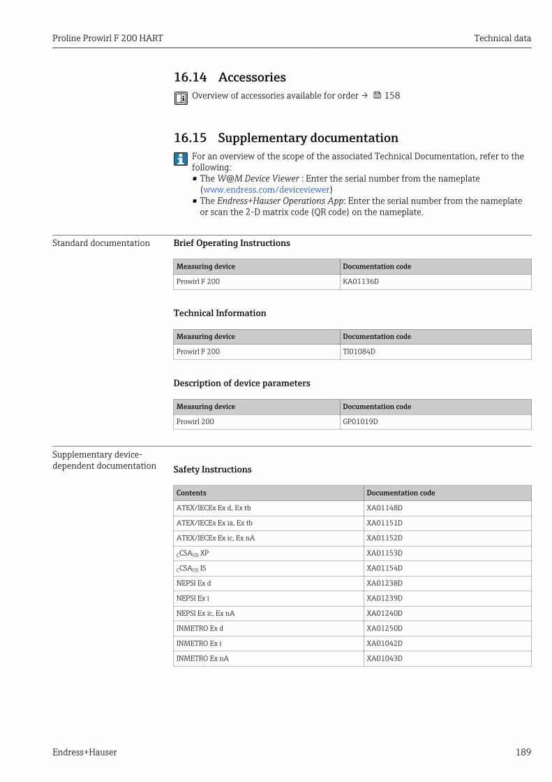
Proline Prowirl F 200 HART Technical data
Endress+Hauser 189
16.14 AccessoriesOverview of accessories available for order → 158
16.15 Supplementary documentationFor an overview of the scope of the associated Technical Documentation, refer to thefollowing:• The W@M Device Viewer : Enter the serial number from the nameplate
(www.endress.com/deviceviewer)• The Endress+Hauser Operations App: Enter the serial number from the nameplate
or scan the 2-D matrix code (QR code) on the nameplate.
Standard documentation Brief Operating Instructions
Measuring device Documentation code
Prowirl F 200 KA01136D
Technical Information
Measuring device Documentation code
Prowirl F 200 TI01084D
Description of device parameters
Measuring device Documentation code
Prowirl 200 GP01019D
Supplementary device-dependent documentation Safety Instructions
Contents Documentation code
ATEX/IECEx Ex d, Ex tb XA01148D
ATEX/IECEx Ex ia, Ex tb XA01151D
ATEX/IECEx Ex ic, Ex nA XA01152D
CCSAUS XP XA01153D
CCSAUS IS XA01154D
NEPSI Ex d XA01238D
NEPSI Ex i XA01239D
NEPSI Ex ic, Ex nA XA01240D
INMETRO Ex d XA01250D
INMETRO Ex i XA01042D
INMETRO Ex nA XA01043D
Technical data Proline Prowirl F 200 HART
190 Endress+Hauser
Special Documentation
Contents Documentation code
Information on the Pressure Equipment Directive SD01163D
Functional Safety Manual SD01162D
Heartbeat Technology SD01204D
Natural gas SD01194D
Air + Industrial Gases (Single Gas + Gas Mixtures) SD01195D
Wet steam detection SD01193D
Wet steam measurement SD01315D
Inlet run correction SD01226D
Installation Instructions
Contents Documentation code
Installation Instructions for spare part sets Overview of accessories available for order → 158
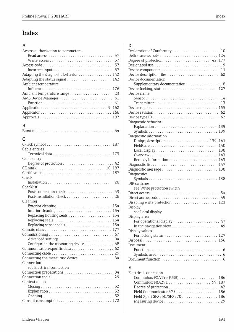
Proline Prowirl F 200 HART Index
Endress+Hauser 191
Index
AAccess authorization to parameters
Read access . . . . . . . . . . . . . . . . . . . . . . . . . . . . . 57Write access . . . . . . . . . . . . . . . . . . . . . . . . . . . . . 57
Access code . . . . . . . . . . . . . . . . . . . . . . . . . . . . . . . . 57Incorrect input . . . . . . . . . . . . . . . . . . . . . . . . . . . 57
Adapting the diagnostic behavior . . . . . . . . . . . . . . . 142Adapting the status signal . . . . . . . . . . . . . . . . . . . . 142Ambient temperature
Influence . . . . . . . . . . . . . . . . . . . . . . . . . . . . . . 176Ambient temperature range . . . . . . . . . . . . . . . . . . . 23AMS Device Manager . . . . . . . . . . . . . . . . . . . . . . . . 61
Function . . . . . . . . . . . . . . . . . . . . . . . . . . . . . . . 61Application . . . . . . . . . . . . . . . . . . . . . . . . . . . . . 9, 162Applicator . . . . . . . . . . . . . . . . . . . . . . . . . . . . . . . . 166Approvals . . . . . . . . . . . . . . . . . . . . . . . . . . . . . . . . 187
BBurst mode . . . . . . . . . . . . . . . . . . . . . . . . . . . . . . . . 64
CC-Tick symbol . . . . . . . . . . . . . . . . . . . . . . . . . . . . . 187Cable entries
Technical data . . . . . . . . . . . . . . . . . . . . . . . . . . 173Cable entry
Degree of protection . . . . . . . . . . . . . . . . . . . . . . . 42CE mark . . . . . . . . . . . . . . . . . . . . . . . . . . . . . . 10, 187Certificates . . . . . . . . . . . . . . . . . . . . . . . . . . . . . . . 187Check
Installation . . . . . . . . . . . . . . . . . . . . . . . . . . . . . 28Checklist
Post-connection check . . . . . . . . . . . . . . . . . . . . . 43Post-installation check . . . . . . . . . . . . . . . . . . . . . 28
CleaningExterior cleaning . . . . . . . . . . . . . . . . . . . . . . . . 154Interior cleaning . . . . . . . . . . . . . . . . . . . . . . . . . 154Replacing housing seals . . . . . . . . . . . . . . . . . . . 154Replacing seals . . . . . . . . . . . . . . . . . . . . . . . . . . 154Replacing sensor seals . . . . . . . . . . . . . . . . . . . . 154
Climate class . . . . . . . . . . . . . . . . . . . . . . . . . . . . . . 177Commissioning . . . . . . . . . . . . . . . . . . . . . . . . . . . . . 67
Advanced settings . . . . . . . . . . . . . . . . . . . . . . . . 94Configuring the measuring device . . . . . . . . . . . . . 68
Communication-specific data . . . . . . . . . . . . . . . . . . . 62Connecting cable . . . . . . . . . . . . . . . . . . . . . . . . . . . . 29Connecting the measuring device . . . . . . . . . . . . . . . . 34Connection
see Electrical connectionConnection preparations . . . . . . . . . . . . . . . . . . . . . . 34Connection tools . . . . . . . . . . . . . . . . . . . . . . . . . . . . 29Context menu
Closing . . . . . . . . . . . . . . . . . . . . . . . . . . . . . . . . . 52Explanation . . . . . . . . . . . . . . . . . . . . . . . . . . . . . 52Opening . . . . . . . . . . . . . . . . . . . . . . . . . . . . . . . . 52
Current consumption . . . . . . . . . . . . . . . . . . . . . . . . 172
DDeclaration of Conformity . . . . . . . . . . . . . . . . . . . . . 10Define access code . . . . . . . . . . . . . . . . . . . . . . . . . . 124Degree of protection . . . . . . . . . . . . . . . . . . . . . 42, 177Designated use . . . . . . . . . . . . . . . . . . . . . . . . . . . . . . 9Device components . . . . . . . . . . . . . . . . . . . . . . . . . . 11Device description files . . . . . . . . . . . . . . . . . . . . . . . 62Device documentation
Supplementary documentation . . . . . . . . . . . . . . . . 8Device locking, status . . . . . . . . . . . . . . . . . . . . . . . 127Device name
Sensor . . . . . . . . . . . . . . . . . . . . . . . . . . . . . . . . . 14Transmitter . . . . . . . . . . . . . . . . . . . . . . . . . . . . . 13
Device repair . . . . . . . . . . . . . . . . . . . . . . . . . . . . . . 155Device revision . . . . . . . . . . . . . . . . . . . . . . . . . . . . . 62Device type ID . . . . . . . . . . . . . . . . . . . . . . . . . . . . . . 62Diagnostic behavior
Explanation . . . . . . . . . . . . . . . . . . . . . . . . . . . . 139Symbols . . . . . . . . . . . . . . . . . . . . . . . . . . . . . . . 139
Diagnostic informationDesign, description . . . . . . . . . . . . . . . . . . . 139, 141FieldCare . . . . . . . . . . . . . . . . . . . . . . . . . . . . . . 140Local display . . . . . . . . . . . . . . . . . . . . . . . . . . . 138Overview . . . . . . . . . . . . . . . . . . . . . . . . . . . . . . 143Remedy information . . . . . . . . . . . . . . . . . . . . . . 143
Diagnostic list . . . . . . . . . . . . . . . . . . . . . . . . . . . . . 147Diagnostic message . . . . . . . . . . . . . . . . . . . . . . . . . 138Diagnostics
Symbols . . . . . . . . . . . . . . . . . . . . . . . . . . . . . . . 138DIP switches
see Write protection switchDirect access . . . . . . . . . . . . . . . . . . . . . . . . . . . . . . . 54Direct access code . . . . . . . . . . . . . . . . . . . . . . . . . . . 49Disabling write protection . . . . . . . . . . . . . . . . . . . . 123Display
see Local displayDisplay area
For operational display . . . . . . . . . . . . . . . . . . . . . 47In the navigation view . . . . . . . . . . . . . . . . . . . . . 49
Display valuesFor locking status . . . . . . . . . . . . . . . . . . . . . . . . 127
Disposal . . . . . . . . . . . . . . . . . . . . . . . . . . . . . . . . . 156Document
Function . . . . . . . . . . . . . . . . . . . . . . . . . . . . . . . . 6Symbols used . . . . . . . . . . . . . . . . . . . . . . . . . . . . . 6
Document function . . . . . . . . . . . . . . . . . . . . . . . . . . . 6
EElectrical connection
Commubox FXA195 (USB) . . . . . . . . . . . . . . . . . 186Commubox FXA291 . . . . . . . . . . . . . . . . . . . 59, 187Degree of protection . . . . . . . . . . . . . . . . . . . . . . . 42Field Communicator 475 . . . . . . . . . . . . . . . . . . 186Field Xpert SFX350/SFX370 . . . . . . . . . . . . . . . . 186Measuring device . . . . . . . . . . . . . . . . . . . . . . . . . 29
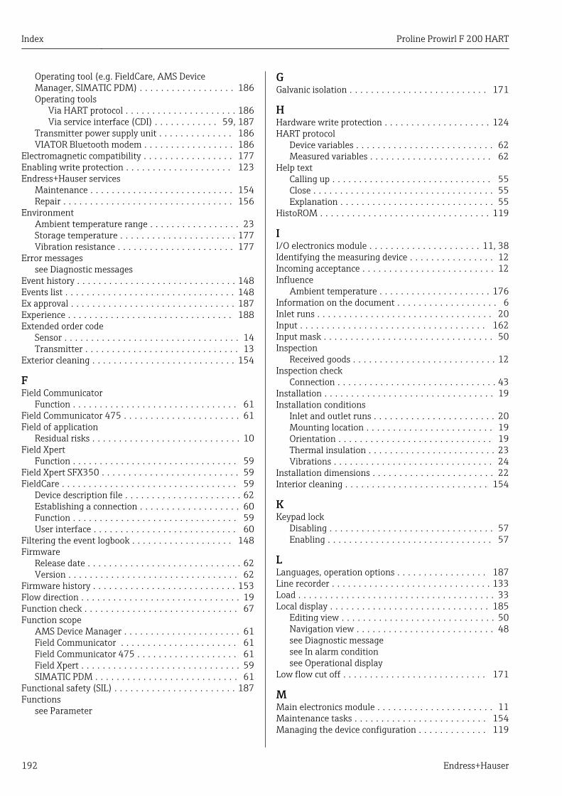
Index Proline Prowirl F 200 HART
192 Endress+Hauser
Operating tool (e.g. FieldCare, AMS DeviceManager, SIMATIC PDM) . . . . . . . . . . . . . . . . . . 186Operating tools
Via HART protocol . . . . . . . . . . . . . . . . . . . . . 186Via service interface (CDI) . . . . . . . . . . . . 59, 187
Transmitter power supply unit . . . . . . . . . . . . . . 186VIATOR Bluetooth modem . . . . . . . . . . . . . . . . . 186
Electromagnetic compatibility . . . . . . . . . . . . . . . . . 177Enabling write protection . . . . . . . . . . . . . . . . . . . . 123Endress+Hauser services
Maintenance . . . . . . . . . . . . . . . . . . . . . . . . . . . 154Repair . . . . . . . . . . . . . . . . . . . . . . . . . . . . . . . . 156
EnvironmentAmbient temperature range . . . . . . . . . . . . . . . . . 23Storage temperature . . . . . . . . . . . . . . . . . . . . . . 177Vibration resistance . . . . . . . . . . . . . . . . . . . . . . 177
Error messagessee Diagnostic messages
Event history . . . . . . . . . . . . . . . . . . . . . . . . . . . . . . 148Events list . . . . . . . . . . . . . . . . . . . . . . . . . . . . . . . . 148Ex approval . . . . . . . . . . . . . . . . . . . . . . . . . . . . . . . 187Experience . . . . . . . . . . . . . . . . . . . . . . . . . . . . . . . 188Extended order code
Sensor . . . . . . . . . . . . . . . . . . . . . . . . . . . . . . . . . 14Transmitter . . . . . . . . . . . . . . . . . . . . . . . . . . . . . 13
Exterior cleaning . . . . . . . . . . . . . . . . . . . . . . . . . . . 154
FField Communicator
Function . . . . . . . . . . . . . . . . . . . . . . . . . . . . . . . 61Field Communicator 475 . . . . . . . . . . . . . . . . . . . . . . 61Field of application
Residual risks . . . . . . . . . . . . . . . . . . . . . . . . . . . . 10Field Xpert
Function . . . . . . . . . . . . . . . . . . . . . . . . . . . . . . . 59Field Xpert SFX350 . . . . . . . . . . . . . . . . . . . . . . . . . . 59FieldCare . . . . . . . . . . . . . . . . . . . . . . . . . . . . . . . . . 59
Device description file . . . . . . . . . . . . . . . . . . . . . . 62Establishing a connection . . . . . . . . . . . . . . . . . . . 60Function . . . . . . . . . . . . . . . . . . . . . . . . . . . . . . . 59User interface . . . . . . . . . . . . . . . . . . . . . . . . . . . 60
Filtering the event logbook . . . . . . . . . . . . . . . . . . . 148Firmware
Release date . . . . . . . . . . . . . . . . . . . . . . . . . . . . . 62Version . . . . . . . . . . . . . . . . . . . . . . . . . . . . . . . . 62
Firmware history . . . . . . . . . . . . . . . . . . . . . . . . . . . 153Flow direction . . . . . . . . . . . . . . . . . . . . . . . . . . . . . . 19Function check . . . . . . . . . . . . . . . . . . . . . . . . . . . . . 67Function scope
AMS Device Manager . . . . . . . . . . . . . . . . . . . . . . 61Field Communicator . . . . . . . . . . . . . . . . . . . . . . 61Field Communicator 475 . . . . . . . . . . . . . . . . . . . 61Field Xpert . . . . . . . . . . . . . . . . . . . . . . . . . . . . . . 59SIMATIC PDM . . . . . . . . . . . . . . . . . . . . . . . . . . . 61
Functional safety (SIL) . . . . . . . . . . . . . . . . . . . . . . . 187Functions
see Parameter
GGalvanic isolation . . . . . . . . . . . . . . . . . . . . . . . . . . 171
HHardware write protection . . . . . . . . . . . . . . . . . . . . 124HART protocol
Device variables . . . . . . . . . . . . . . . . . . . . . . . . . . 62Measured variables . . . . . . . . . . . . . . . . . . . . . . . 62
Help textCalling up . . . . . . . . . . . . . . . . . . . . . . . . . . . . . . 55Close . . . . . . . . . . . . . . . . . . . . . . . . . . . . . . . . . . 55Explanation . . . . . . . . . . . . . . . . . . . . . . . . . . . . . 55
HistoROM . . . . . . . . . . . . . . . . . . . . . . . . . . . . . . . . 119
II/O electronics module . . . . . . . . . . . . . . . . . . . . . 11, 38Identifying the measuring device . . . . . . . . . . . . . . . . 12Incoming acceptance . . . . . . . . . . . . . . . . . . . . . . . . . 12Influence
Ambient temperature . . . . . . . . . . . . . . . . . . . . . 176Information on the document . . . . . . . . . . . . . . . . . . . 6Inlet runs . . . . . . . . . . . . . . . . . . . . . . . . . . . . . . . . . 20Input . . . . . . . . . . . . . . . . . . . . . . . . . . . . . . . . . . . 162Input mask . . . . . . . . . . . . . . . . . . . . . . . . . . . . . . . . 50Inspection
Received goods . . . . . . . . . . . . . . . . . . . . . . . . . . . 12Inspection check
Connection . . . . . . . . . . . . . . . . . . . . . . . . . . . . . . 43Installation . . . . . . . . . . . . . . . . . . . . . . . . . . . . . . . . 19Installation conditions
Inlet and outlet runs . . . . . . . . . . . . . . . . . . . . . . . 20Mounting location . . . . . . . . . . . . . . . . . . . . . . . . 19Orientation . . . . . . . . . . . . . . . . . . . . . . . . . . . . . 19Thermal insulation . . . . . . . . . . . . . . . . . . . . . . . . 23Vibrations . . . . . . . . . . . . . . . . . . . . . . . . . . . . . . 24
Installation dimensions . . . . . . . . . . . . . . . . . . . . . . . 22Interior cleaning . . . . . . . . . . . . . . . . . . . . . . . . . . . 154
KKeypad lock
Disabling . . . . . . . . . . . . . . . . . . . . . . . . . . . . . . . 57Enabling . . . . . . . . . . . . . . . . . . . . . . . . . . . . . . . 57
LLanguages, operation options . . . . . . . . . . . . . . . . . 187Line recorder . . . . . . . . . . . . . . . . . . . . . . . . . . . . . . 133Load . . . . . . . . . . . . . . . . . . . . . . . . . . . . . . . . . . . . . 33Local display . . . . . . . . . . . . . . . . . . . . . . . . . . . . . . 185
Editing view . . . . . . . . . . . . . . . . . . . . . . . . . . . . . 50Navigation view . . . . . . . . . . . . . . . . . . . . . . . . . . 48see Diagnostic messagesee In alarm conditionsee Operational display
Low flow cut off . . . . . . . . . . . . . . . . . . . . . . . . . . . 171
MMain electronics module . . . . . . . . . . . . . . . . . . . . . . 11Maintenance tasks . . . . . . . . . . . . . . . . . . . . . . . . . 154Managing the device configuration . . . . . . . . . . . . . 119
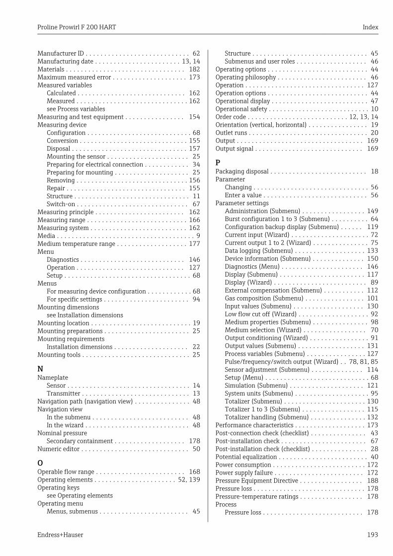
Proline Prowirl F 200 HART Index
Endress+Hauser 193
Manufacturer ID . . . . . . . . . . . . . . . . . . . . . . . . . . . . 62Manufacturing date . . . . . . . . . . . . . . . . . . . . . . . 13, 14Materials . . . . . . . . . . . . . . . . . . . . . . . . . . . . . . . . 182Maximum measured error . . . . . . . . . . . . . . . . . . . . 173Measured variables
Calculated . . . . . . . . . . . . . . . . . . . . . . . . . . . . . 162Measured . . . . . . . . . . . . . . . . . . . . . . . . . . . . . . 162see Process variables
Measuring and test equipment . . . . . . . . . . . . . . . . 154Measuring device
Configuration . . . . . . . . . . . . . . . . . . . . . . . . . . . . 68Conversion . . . . . . . . . . . . . . . . . . . . . . . . . . . . . 155Disposal . . . . . . . . . . . . . . . . . . . . . . . . . . . . . . . 157Mounting the sensor . . . . . . . . . . . . . . . . . . . . . . 25Preparing for electrical connection . . . . . . . . . . . . 34Preparing for mounting . . . . . . . . . . . . . . . . . . . . 25Removing . . . . . . . . . . . . . . . . . . . . . . . . . . . . . . 156Repair . . . . . . . . . . . . . . . . . . . . . . . . . . . . . . . . 155Structure . . . . . . . . . . . . . . . . . . . . . . . . . . . . . . . 11Switch-on . . . . . . . . . . . . . . . . . . . . . . . . . . . . . . 67
Measuring principle . . . . . . . . . . . . . . . . . . . . . . . . 162Measuring range . . . . . . . . . . . . . . . . . . . . . . . . . . . 166Measuring system . . . . . . . . . . . . . . . . . . . . . . . . . . 162Media . . . . . . . . . . . . . . . . . . . . . . . . . . . . . . . . . . . . . 9Medium temperature range . . . . . . . . . . . . . . . . . . . 177Menu
Diagnostics . . . . . . . . . . . . . . . . . . . . . . . . . . . . 146Operation . . . . . . . . . . . . . . . . . . . . . . . . . . . . . 127Setup . . . . . . . . . . . . . . . . . . . . . . . . . . . . . . . . . . 68
MenusFor measuring device configuration . . . . . . . . . . . . 68For specific settings . . . . . . . . . . . . . . . . . . . . . . . 94
Mounting dimensionssee Installation dimensions
Mounting location . . . . . . . . . . . . . . . . . . . . . . . . . . . 19Mounting preparations . . . . . . . . . . . . . . . . . . . . . . . 25Mounting requirements
Installation dimensions . . . . . . . . . . . . . . . . . . . . 22Mounting tools . . . . . . . . . . . . . . . . . . . . . . . . . . . . . 25
NNameplate
Sensor . . . . . . . . . . . . . . . . . . . . . . . . . . . . . . . . . 14Transmitter . . . . . . . . . . . . . . . . . . . . . . . . . . . . . 13
Navigation path (navigation view) . . . . . . . . . . . . . . . 48Navigation view
In the submenu . . . . . . . . . . . . . . . . . . . . . . . . . . 48In the wizard . . . . . . . . . . . . . . . . . . . . . . . . . . . . 48
Nominal pressureSecondary containment . . . . . . . . . . . . . . . . . . . 178
Numeric editor . . . . . . . . . . . . . . . . . . . . . . . . . . . . . 50
OOperable flow range . . . . . . . . . . . . . . . . . . . . . . . . 168Operating elements . . . . . . . . . . . . . . . . . . . . . . 52, 139Operating keys
see Operating elementsOperating menu
Menus, submenus . . . . . . . . . . . . . . . . . . . . . . . . 45
Structure . . . . . . . . . . . . . . . . . . . . . . . . . . . . . . . 45Submenus and user roles . . . . . . . . . . . . . . . . . . . 46
Operating options . . . . . . . . . . . . . . . . . . . . . . . . . . . 44Operating philosophy . . . . . . . . . . . . . . . . . . . . . . . . 46Operation . . . . . . . . . . . . . . . . . . . . . . . . . . . . . . . . 127Operation options . . . . . . . . . . . . . . . . . . . . . . . . . . . 44Operational display . . . . . . . . . . . . . . . . . . . . . . . . . . 47Operational safety . . . . . . . . . . . . . . . . . . . . . . . . . . . 10Order code . . . . . . . . . . . . . . . . . . . . . . . . . . . 12, 13, 14Orientation (vertical, horizontal) . . . . . . . . . . . . . . . . 19Outlet runs . . . . . . . . . . . . . . . . . . . . . . . . . . . . . . . . 20Output . . . . . . . . . . . . . . . . . . . . . . . . . . . . . . . . . . 169Output signal . . . . . . . . . . . . . . . . . . . . . . . . . . . . . 169
PPackaging disposal . . . . . . . . . . . . . . . . . . . . . . . . . . 18Parameter
Changing . . . . . . . . . . . . . . . . . . . . . . . . . . . . . . . 56Enter a value . . . . . . . . . . . . . . . . . . . . . . . . . . . . 56
Parameter settingsAdministration (Submenu) . . . . . . . . . . . . . . . . . 149Burst configuration 1 to 3 (Submenu) . . . . . . . . . . 64Configuration backup display (Submenu) . . . . . . 119Current input (Wizard) . . . . . . . . . . . . . . . . . . . . . 72Current output 1 to 2 (Wizard) . . . . . . . . . . . . . . . 75Data logging (Submenu) . . . . . . . . . . . . . . . . . . . 133Device information (Submenu) . . . . . . . . . . . . . . 150Diagnostics (Menu) . . . . . . . . . . . . . . . . . . . . . . 146Display (Submenu) . . . . . . . . . . . . . . . . . . . . . . . 117Display (Wizard) . . . . . . . . . . . . . . . . . . . . . . . . . 89External compensation (Submenu) . . . . . . . . . . . 112Gas composition (Submenu) . . . . . . . . . . . . . . . . 101Input values (Submenu) . . . . . . . . . . . . . . . . . . . 130Low flow cut off (Wizard) . . . . . . . . . . . . . . . . . . . 92Medium properties (Submenu) . . . . . . . . . . . . . . . 98Medium selection (Wizard) . . . . . . . . . . . . . . . . . 70Output conditioning (Wizard) . . . . . . . . . . . . . . . . 91Output values (Submenu) . . . . . . . . . . . . . . . . . . 131Process variables (Submenu) . . . . . . . . . . . . . . . . 127Pulse/frequency/switch output (Wizard) . . 78, 81, 85Sensor adjustment (Submenu) . . . . . . . . . . . . . . 114Setup (Menu) . . . . . . . . . . . . . . . . . . . . . . . . . . . . 68Simulation (Submenu) . . . . . . . . . . . . . . . . . . . . 121System units (Submenu) . . . . . . . . . . . . . . . . . . . . 95Totalizer (Submenu) . . . . . . . . . . . . . . . . . . . . . . 130Totalizer 1 to 3 (Submenu) . . . . . . . . . . . . . . . . . 115Totalizer handling (Submenu) . . . . . . . . . . . . . . . 132
Performance characteristics . . . . . . . . . . . . . . . . . . . 173Post-connection check (checklist) . . . . . . . . . . . . . . . 43Post-installation check . . . . . . . . . . . . . . . . . . . . . . . 67Post-installation check (checklist) . . . . . . . . . . . . . . . 28Potential equalization . . . . . . . . . . . . . . . . . . . . . . . . 40Power consumption . . . . . . . . . . . . . . . . . . . . . . . . . 172Power supply failure . . . . . . . . . . . . . . . . . . . . . . . . 172Pressure Equipment Directive . . . . . . . . . . . . . . . . . 188Pressure loss . . . . . . . . . . . . . . . . . . . . . . . . . . . . . . 178Pressure-temperature ratings . . . . . . . . . . . . . . . . . 178Process
Pressure loss . . . . . . . . . . . . . . . . . . . . . . . . . . . 178
Index Proline Prowirl F 200 HART
194 Endress+Hauser
Process conditionsMedium temperature . . . . . . . . . . . . . . . . . . . . . 177
Process connections . . . . . . . . . . . . . . . . . . . . . . . . 185Product safety . . . . . . . . . . . . . . . . . . . . . . . . . . . . . . 10Protecting parameter settings . . . . . . . . . . . . . . . . . 123
RRead access . . . . . . . . . . . . . . . . . . . . . . . . . . . . . . . . 57Reading measured values . . . . . . . . . . . . . . . . . . . . 127Recalibration . . . . . . . . . . . . . . . . . . . . . . . . . . . . . . 154Reference operating conditions . . . . . . . . . . . . . . . . 173Registered trademarks . . . . . . . . . . . . . . . . . . . . . . . . . 8Remedial measures
Calling up . . . . . . . . . . . . . . . . . . . . . . . . . . . . . 140Closing . . . . . . . . . . . . . . . . . . . . . . . . . . . . . . . 140
Remote operation . . . . . . . . . . . . . . . . . . . . . . . . . . 186Remote version
Connecting the connecting cable . . . . . . . . . . . . . . 34Repair . . . . . . . . . . . . . . . . . . . . . . . . . . . . . . . . . . . 155
Notes . . . . . . . . . . . . . . . . . . . . . . . . . . . . . . . . . 155Repair of a device . . . . . . . . . . . . . . . . . . . . . . . . . . 155Repeatability . . . . . . . . . . . . . . . . . . . . . . . . . . . . . . 176Replacement
Device components . . . . . . . . . . . . . . . . . . . . . . . 155Replacing seals . . . . . . . . . . . . . . . . . . . . . . . . . . . . 154Requirements for personnel . . . . . . . . . . . . . . . . . . . . . 9Response time . . . . . . . . . . . . . . . . . . . . . . . . . . . . . 176Return . . . . . . . . . . . . . . . . . . . . . . . . . . . . . . . . . . 156
SSafety . . . . . . . . . . . . . . . . . . . . . . . . . . . . . . . . . . . . . 9Sensor
Mounting . . . . . . . . . . . . . . . . . . . . . . . . . . . . . . . 25Serial number . . . . . . . . . . . . . . . . . . . . . . . . . . . 13, 14Setting the operating language . . . . . . . . . . . . . . . . . 67Settings
Adapting the measuring device to the processconditions . . . . . . . . . . . . . . . . . . . . . . . . . . . . . 132Advanced display configurations . . . . . . . . . . . . . 117Current input . . . . . . . . . . . . . . . . . . . . . . . . . . . . 72Current output . . . . . . . . . . . . . . . . . . . . . . . . . . . 75Device reset . . . . . . . . . . . . . . . . . . . . . . . . . . . . 149Device tag . . . . . . . . . . . . . . . . . . . . . . . . . . . . . . 68External compensation . . . . . . . . . . . . . . . . . . . . 112Gas composition . . . . . . . . . . . . . . . . . . . . . . . . . 101Local display . . . . . . . . . . . . . . . . . . . . . . . . . . . . 89Low flow cut off . . . . . . . . . . . . . . . . . . . . . . . . . . 92Managing the device configuration . . . . . . . . . . . 119Medium . . . . . . . . . . . . . . . . . . . . . . . . . . . . . . . . 70Medium properties . . . . . . . . . . . . . . . . . . . . . . . . 98Operating language . . . . . . . . . . . . . . . . . . . . . . . 67Output conditioning . . . . . . . . . . . . . . . . . . . . . . . 91Pulse output . . . . . . . . . . . . . . . . . . . . . . . . . . . . . 78Pulse/frequency/switch output . . . . . . . . . . . . 78, 81Resetting the totalizer . . . . . . . . . . . . . . . . . . . . 132Sensor adjustment . . . . . . . . . . . . . . . . . . . . . . . 114Simulation . . . . . . . . . . . . . . . . . . . . . . . . . . . . . 121Switch output . . . . . . . . . . . . . . . . . . . . . . . . . . . . 85System units . . . . . . . . . . . . . . . . . . . . . . . . . . . . 95
Totalizer . . . . . . . . . . . . . . . . . . . . . . . . . . . . . . 115Totalizer reset . . . . . . . . . . . . . . . . . . . . . . . . . . 132
Showing data logging . . . . . . . . . . . . . . . . . . . . . . . 133Signal on alarm . . . . . . . . . . . . . . . . . . . . . . . . . . . . 170SIL (functional safety) . . . . . . . . . . . . . . . . . . . . . . . 187SIMATIC PDM . . . . . . . . . . . . . . . . . . . . . . . . . . . . . . 61
Function . . . . . . . . . . . . . . . . . . . . . . . . . . . . . . . 61Spare part . . . . . . . . . . . . . . . . . . . . . . . . . . . . . . . . 155Spare parts . . . . . . . . . . . . . . . . . . . . . . . . . . . . . . . 155Special connection instructions . . . . . . . . . . . . . . . . . 40Standards and guidelines . . . . . . . . . . . . . . . . . . . . . 188Status area
For operational display . . . . . . . . . . . . . . . . . . . . . 47In the navigation view . . . . . . . . . . . . . . . . . . . . . 49
Status signals . . . . . . . . . . . . . . . . . . . . . . . . . . . . . 138Storage conditions . . . . . . . . . . . . . . . . . . . . . . . . . . . 17Storage temperature . . . . . . . . . . . . . . . . . . . . . . . . . 17Storage temperature range . . . . . . . . . . . . . . . . . . . 177Structure
Measuring device . . . . . . . . . . . . . . . . . . . . . . . . . 11Operating menu . . . . . . . . . . . . . . . . . . . . . . . . . . 45
SubmenuAdministration . . . . . . . . . . . . . . . . . . . . . . . . . . 149Advanced setup . . . . . . . . . . . . . . . . . . . . . . . . . . 94Burst configuration 1 to 3 . . . . . . . . . . . . . . . . . . . 64Configuration backup display . . . . . . . . . . . . . . . 119Data logging . . . . . . . . . . . . . . . . . . . . . . . . . . . 133Device information . . . . . . . . . . . . . . . . . . . . . . . 150Display . . . . . . . . . . . . . . . . . . . . . . . . . . . . . . . . 117Events list . . . . . . . . . . . . . . . . . . . . . . . . . . . . . 148External compensation . . . . . . . . . . . . . . . . . . . . 112Gas composition . . . . . . . . . . . . . . . . . . . . . . . . . 101Input values . . . . . . . . . . . . . . . . . . . . . . . . . . . . 130Medium properties . . . . . . . . . . . . . . . . . . . . . . . . 98Output values . . . . . . . . . . . . . . . . . . . . . . . . . . . 131Overview . . . . . . . . . . . . . . . . . . . . . . . . . . . . . . . 46Process variables . . . . . . . . . . . . . . . . . . . . . . . . 127Sensor adjustment . . . . . . . . . . . . . . . . . . . . . . . 114Simulation . . . . . . . . . . . . . . . . . . . . . . . . . . . . . 121System units . . . . . . . . . . . . . . . . . . . . . . . . . . . . 95Totalizer . . . . . . . . . . . . . . . . . . . . . . . . . . . . . . 130Totalizer 1 to 3 . . . . . . . . . . . . . . . . . . . . . . . . . . 115Totalizer handling . . . . . . . . . . . . . . . . . . . . . . . 132
Supplementary documentation . . . . . . . . . . . . . . . . 189Supply unit
Requirements . . . . . . . . . . . . . . . . . . . . . . . . . . . . 32Supply voltage . . . . . . . . . . . . . . . . . . . . . . . . . . 32, 171Symbols
For communication . . . . . . . . . . . . . . . . . . . . . . . 47For correction . . . . . . . . . . . . . . . . . . . . . . . . . . . . 50For diagnostic behavior . . . . . . . . . . . . . . . . . . . . 47For locking . . . . . . . . . . . . . . . . . . . . . . . . . . . . . . 47For measured variable . . . . . . . . . . . . . . . . . . . . . 47For measurement channel number . . . . . . . . . . . . 47For menus . . . . . . . . . . . . . . . . . . . . . . . . . . . . . . 49For parameters . . . . . . . . . . . . . . . . . . . . . . . . . . . 49For status signal . . . . . . . . . . . . . . . . . . . . . . . . . . 47For submenu . . . . . . . . . . . . . . . . . . . . . . . . . . . . 49For wizard . . . . . . . . . . . . . . . . . . . . . . . . . . . . . . 49
Proline Prowirl F 200 HART Index
Endress+Hauser 195
In the status area of the local display . . . . . . . . . . . 47In the text and numeric editor . . . . . . . . . . . . . . . . 50
System designMeasuring system . . . . . . . . . . . . . . . . . . . . . . . 162see Measuring device design
System integration . . . . . . . . . . . . . . . . . . . . . . . . . . 62
TTechnical data, overview . . . . . . . . . . . . . . . . . . . . . 162Temperature range
Ambient temperature range for display . . . . . . . . 185Storage temperature . . . . . . . . . . . . . . . . . . . . . . . 17
Terminal assignment . . . . . . . . . . . . . . . . . . . . . . 31, 38terminal voltage . . . . . . . . . . . . . . . . . . . . . . . . . . . . 33Terminals . . . . . . . . . . . . . . . . . . . . . . . . . . . . . . . . 173Text editor . . . . . . . . . . . . . . . . . . . . . . . . . . . . . . . . 50Thermal insulation . . . . . . . . . . . . . . . . . . . . . . . . . . 23Tool tip
see Help textTools
Electrical connection . . . . . . . . . . . . . . . . . . . . . . 29Installation . . . . . . . . . . . . . . . . . . . . . . . . . . . . . 25Transport . . . . . . . . . . . . . . . . . . . . . . . . . . . . . . . 17
TransmitterConnecting the signal cables . . . . . . . . . . . . . . . . . 38Turning the display module . . . . . . . . . . . . . . . . . 27Turning the housing . . . . . . . . . . . . . . . . . . . . . . . 27
Transporting the measuring device . . . . . . . . . . . . . . 17Troubleshooting
General . . . . . . . . . . . . . . . . . . . . . . . . . . . . . . . 136Turning the display module . . . . . . . . . . . . . . . . . . . . 27Turning the electronics housing
see Turning the transmitter housingTurning the transmitter housing . . . . . . . . . . . . . . . . 27
UUse of the measuring device
Borderline cases . . . . . . . . . . . . . . . . . . . . . . . . . . . 9Incorrect use . . . . . . . . . . . . . . . . . . . . . . . . . . . . . 9see Designated use
User interfaceCurrent diagnostic event . . . . . . . . . . . . . . . . . . . 146Previous diagnostic event . . . . . . . . . . . . . . . . . . 146
User roles . . . . . . . . . . . . . . . . . . . . . . . . . . . . . . . . . 46
VVersion data for the device . . . . . . . . . . . . . . . . . . . . 62Vibration resistance . . . . . . . . . . . . . . . . . . . . . . . . 177Vibrations . . . . . . . . . . . . . . . . . . . . . . . . . . . . . . . . . 24
WW@M . . . . . . . . . . . . . . . . . . . . . . . . . . . . . . 154, 155W@M Device Viewer . . . . . . . . . . . . . . . . . . . . 12, 155Weight
Compact versionSI units . . . . . . . . . . . . . . . . . . . . . . . . . . . . . 178US units . . . . . . . . . . . . . . . . . . . . . . . . . . . . 179
Flow conditioner . . . . . . . . . . . . . . . . . . . . . . . . 180Sensor remote version
SI units . . . . . . . . . . . . . . . . . . . . . . . . . . . . . 179
US units . . . . . . . . . . . . . . . . . . . . . . . . . . . . 180Transport (notes) . . . . . . . . . . . . . . . . . . . . . . . . . 17
WizardCurrent input . . . . . . . . . . . . . . . . . . . . . . . . . . . . 72Current output 1 to 2 . . . . . . . . . . . . . . . . . . . . . . 75Define access code . . . . . . . . . . . . . . . . . . . . . . . 123Display . . . . . . . . . . . . . . . . . . . . . . . . . . . . . . . . . 89Low flow cut off . . . . . . . . . . . . . . . . . . . . . . . . . . 92Medium selection . . . . . . . . . . . . . . . . . . . . . . . . . 70Output conditioning . . . . . . . . . . . . . . . . . . . . . . . 91Pulse/frequency/switch output . . . . . . . . . 78, 81, 85
Workplace safety . . . . . . . . . . . . . . . . . . . . . . . . . . . 10Write access . . . . . . . . . . . . . . . . . . . . . . . . . . . . . . . 57Write protection
Via access code . . . . . . . . . . . . . . . . . . . . . . . . . . 123Via write protection switch . . . . . . . . . . . . . . . . . 124
Write protection switch . . . . . . . . . . . . . . . . . . . . . . 124

www.addresses.endress.com


