Embed Size (px)
Citation preview

The specialist for demanding water and wastewater applications, as remoteversion with up to 4 I/Os
Application
• The bidirectional measuring principle is virtuallyindependent of pressure, density, temperature and viscosity
• Dedicated to the measurement of industrial or municipalwater and wastewate
Device properties• International drinking water approvals• Degree of protection IP68 (Type 6P enclosure)• Remote version with up to 3 I/Os• Backlit display with touch control and WLAN access• Standard cable between sensor and transmitter
Your benefits
• With EN ISO 12944 corrosion protection for undergroundinstallation or permanent underwater use
• Flexible engineering – sensor with welded or lap-jointprocess connections
• Reliable measurement – accurate measured values even with0 DN inlet run
• Improved plant availability – sensor compliant withindustryspecific requirements
• Full access to process and diagnostic information –numerous, freely combinable I/Os and fieldbuses
• Reduced complexity and variety – freely configurable I/Ofunctionality
• Integrated verification – Heartbeat Technology
Products Solutions Services
Technical InformationProline Promag W 500Electromagnetic flowmeter
TI01227D/06/EN/06.19714431872019-07-01
Proline Promag W 500
2 Endress+Hauser
Table of contents
About this document . . . . . . . . . . . . . . . . . . . . . . . . 4Symbols . . . . . . . . . . . . . . . . . . . . . . . . . . . . . . . . . . . . 4
Function and system design . . . . . . . . . . . . . . . . . . . 5Measuring principle . . . . . . . . . . . . . . . . . . . . . . . . . . . . 5Measuring system . . . . . . . . . . . . . . . . . . . . . . . . . . . . . 6Equipment architecture . . . . . . . . . . . . . . . . . . . . . . . . . 8Safety . . . . . . . . . . . . . . . . . . . . . . . . . . . . . . . . . . . . . 8
Input . . . . . . . . . . . . . . . . . . . . . . . . . . . . . . . . . . . . 10Measured variable . . . . . . . . . . . . . . . . . . . . . . . . . . . . 10Measuring range . . . . . . . . . . . . . . . . . . . . . . . . . . . . . 10Operable flow range . . . . . . . . . . . . . . . . . . . . . . . . . . . 14Input signal . . . . . . . . . . . . . . . . . . . . . . . . . . . . . . . . 14
Output . . . . . . . . . . . . . . . . . . . . . . . . . . . . . . . . . . 16Output and input variants . . . . . . . . . . . . . . . . . . . . . . . 16Output signal . . . . . . . . . . . . . . . . . . . . . . . . . . . . . . . 18Signal on alarm . . . . . . . . . . . . . . . . . . . . . . . . . . . . . . 22Ex connection data . . . . . . . . . . . . . . . . . . . . . . . . . . . 24Low flow cut off . . . . . . . . . . . . . . . . . . . . . . . . . . . . . 26Galvanic isolation . . . . . . . . . . . . . . . . . . . . . . . . . . . . 26Protocol-specific data . . . . . . . . . . . . . . . . . . . . . . . . . . 26
Power supply . . . . . . . . . . . . . . . . . . . . . . . . . . . . . 32Terminal assignment . . . . . . . . . . . . . . . . . . . . . . . . . . 32Device plugs available . . . . . . . . . . . . . . . . . . . . . . . . . . 33Pin assignment, device plug . . . . . . . . . . . . . . . . . . . . . . 34Supply voltage . . . . . . . . . . . . . . . . . . . . . . . . . . . . . . 35Power consumption . . . . . . . . . . . . . . . . . . . . . . . . . . . 35Current consumption . . . . . . . . . . . . . . . . . . . . . . . . . . 35Power supply failure . . . . . . . . . . . . . . . . . . . . . . . . . . 35Electrical connection . . . . . . . . . . . . . . . . . . . . . . . . . . 36Potential equalization . . . . . . . . . . . . . . . . . . . . . . . . . 47terminals . . . . . . . . . . . . . . . . . . . . . . . . . . . . . . . . . . 49Cable entries . . . . . . . . . . . . . . . . . . . . . . . . . . . . . . . 49Cable specification . . . . . . . . . . . . . . . . . . . . . . . . . . . . 49
Performance characteristics . . . . . . . . . . . . . . . . . . 53Reference operating conditions . . . . . . . . . . . . . . . . . . . 53Maximum measured error . . . . . . . . . . . . . . . . . . . . . . . 53Repeatability . . . . . . . . . . . . . . . . . . . . . . . . . . . . . . . 55Influence of ambient temperature . . . . . . . . . . . . . . . . . 55
Installation . . . . . . . . . . . . . . . . . . . . . . . . . . . . . . . 55Mounting location . . . . . . . . . . . . . . . . . . . . . . . . . . . . 55Orientation . . . . . . . . . . . . . . . . . . . . . . . . . . . . . . . . 56Inlet and outlet runs . . . . . . . . . . . . . . . . . . . . . . . . . . 57Adapters . . . . . . . . . . . . . . . . . . . . . . . . . . . . . . . . . . 58Length of connecting cable . . . . . . . . . . . . . . . . . . . . . . 58Mounting the transmitter housing . . . . . . . . . . . . . . . . . 60Special mounting instructions . . . . . . . . . . . . . . . . . . . . 62
Environment . . . . . . . . . . . . . . . . . . . . . . . . . . . . . . 63Ambient temperature range . . . . . . . . . . . . . . . . . . . . . 63Storage temperature . . . . . . . . . . . . . . . . . . . . . . . . . . 63Degree of protection . . . . . . . . . . . . . . . . . . . . . . . . . . 63
Vibration resistance . . . . . . . . . . . . . . . . . . . . . . . . . . . 64Shock resistance . . . . . . . . . . . . . . . . . . . . . . . . . . . . . 64Shock resistance . . . . . . . . . . . . . . . . . . . . . . . . . . . . . 64Mechanical load . . . . . . . . . . . . . . . . . . . . . . . . . . . . . 64Electromagnetic compatibility (EMC) . . . . . . . . . . . . . . . 64
Process . . . . . . . . . . . . . . . . . . . . . . . . . . . . . . . . . . 64Medium temperature range . . . . . . . . . . . . . . . . . . . . . . 64Conductivity . . . . . . . . . . . . . . . . . . . . . . . . . . . . . . . . 65Pressure-temperature ratings . . . . . . . . . . . . . . . . . . . . 65Pressure tightness . . . . . . . . . . . . . . . . . . . . . . . . . . . . 68Flow limit . . . . . . . . . . . . . . . . . . . . . . . . . . . . . . . . . 69Pressure loss . . . . . . . . . . . . . . . . . . . . . . . . . . . . . . . 69System pressure . . . . . . . . . . . . . . . . . . . . . . . . . . . . . 70Thermal insulation . . . . . . . . . . . . . . . . . . . . . . . . . . . 70Vibrations . . . . . . . . . . . . . . . . . . . . . . . . . . . . . . . . . 70
Mechanical construction . . . . . . . . . . . . . . . . . . . . 71Dimensions in SI units . . . . . . . . . . . . . . . . . . . . . . . . . 71Dimensions in US units . . . . . . . . . . . . . . . . . . . . . . . . . 89Weight . . . . . . . . . . . . . . . . . . . . . . . . . . . . . . . . . . 100Measuring tube specification . . . . . . . . . . . . . . . . . . . . 103Materials . . . . . . . . . . . . . . . . . . . . . . . . . . . . . . . . . 105Fitted electrodes . . . . . . . . . . . . . . . . . . . . . . . . . . . . 108Process connections . . . . . . . . . . . . . . . . . . . . . . . . . . 108Surface roughness . . . . . . . . . . . . . . . . . . . . . . . . . . . 108
Human interface . . . . . . . . . . . . . . . . . . . . . . . . . . 108Operating concept . . . . . . . . . . . . . . . . . . . . . . . . . . . 108Languages . . . . . . . . . . . . . . . . . . . . . . . . . . . . . . . . 109Local operation . . . . . . . . . . . . . . . . . . . . . . . . . . . . . 109Remote operation . . . . . . . . . . . . . . . . . . . . . . . . . . . 109Service interface . . . . . . . . . . . . . . . . . . . . . . . . . . . . 115Network integration . . . . . . . . . . . . . . . . . . . . . . . . . . 117Supported operating tools . . . . . . . . . . . . . . . . . . . . . . 117HistoROM data management . . . . . . . . . . . . . . . . . . . . 118
Certificates and approvals . . . . . . . . . . . . . . . . . . 120CE mark . . . . . . . . . . . . . . . . . . . . . . . . . . . . . . . . . . 120RCM-tick symbol . . . . . . . . . . . . . . . . . . . . . . . . . . . . 120Ex approval . . . . . . . . . . . . . . . . . . . . . . . . . . . . . . . 120Pharmaceutical compatibility . . . . . . . . . . . . . . . . . . . . 122Drinking water approval . . . . . . . . . . . . . . . . . . . . . . . 122Functional safety . . . . . . . . . . . . . . . . . . . . . . . . . . . . 122HART certification . . . . . . . . . . . . . . . . . . . . . . . . . . . 122FOUNDATION Fieldbus certification . . . . . . . . . . . . . . . 123Certification PROFIBUS . . . . . . . . . . . . . . . . . . . . . . . . 123EtherNet/IP certification . . . . . . . . . . . . . . . . . . . . . . . 123Certification PROFINET . . . . . . . . . . . . . . . . . . . . . . . . 123Radio approval . . . . . . . . . . . . . . . . . . . . . . . . . . . . . 123Measuring instrument approval . . . . . . . . . . . . . . . . . . 123Other standards and guidelines . . . . . . . . . . . . . . . . . . 123
Ordering information . . . . . . . . . . . . . . . . . . . . . . 124
Application packages . . . . . . . . . . . . . . . . . . . . . . 124Diagnostics functions . . . . . . . . . . . . . . . . . . . . . . . . . 124

Proline Promag W 500
Endress+Hauser 3
Heartbeat Technology . . . . . . . . . . . . . . . . . . . . . . . . 124Cleaning . . . . . . . . . . . . . . . . . . . . . . . . . . . . . . . . . 125OPC-UA server . . . . . . . . . . . . . . . . . . . . . . . . . . . . . 125
Accessories . . . . . . . . . . . . . . . . . . . . . . . . . . . . . . 125Device-specific accessories . . . . . . . . . . . . . . . . . . . . . . 125Communication-specific accessories . . . . . . . . . . . . . . . 126Service-specific accessories . . . . . . . . . . . . . . . . . . . . . 127System components . . . . . . . . . . . . . . . . . . . . . . . . . . 128
Supplementary documentation . . . . . . . . . . . . . . 128Standard documentation . . . . . . . . . . . . . . . . . . . . . . . 128Device-dependent additional documentation . . . . . . . . . 128
Registered trademarks . . . . . . . . . . . . . . . . . . . . . 129
Proline Promag W 500
4 Endress+Hauser
About this document
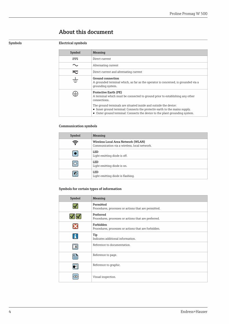
Symbols Electrical symbols
Symbol Meaning
Direct current
Alternating current
Direct current and alternating current
Ground connectionA grounded terminal which, as far as the operator is concerned, is grounded via agrounding system.
Protective Earth (PE)A terminal which must be connected to ground prior to establishing any otherconnections.
The ground terminals are situated inside and outside the device:• Inner ground terminal: Connects the protectiv earth to the mains supply.• Outer ground terminal: Connects the device to the plant grounding system.
Communication symbols
Symbol Meaning
Wireless Local Area Network (WLAN)Communication via a wireless, local network.
LEDLight emitting diode is off.
LEDLight emitting diode is on.
LEDLight emitting diode is flashing.
Symbols for certain types of information
Symbol Meaning
PermittedProcedures, processes or actions that are permitted.
PreferredProcedures, processes or actions that are preferred.
ForbiddenProcedures, processes or actions that are forbidden.
TipIndicates additional information.
Reference to documentation.
A Reference to page.
Reference to graphic.
Visual inspection.
Proline Promag W 500
Endress+Hauser 5
Symbols in graphics
Symbol Meaning
1, 2, 3, ... Item numbers
1. , 2. , 3. , … Series of steps
A, B, C, ... Views
A-A, B-B, C-C, ... Sections
-Hazardous area
. Safe area (non-hazardous area)
Flow direction
Function and system design
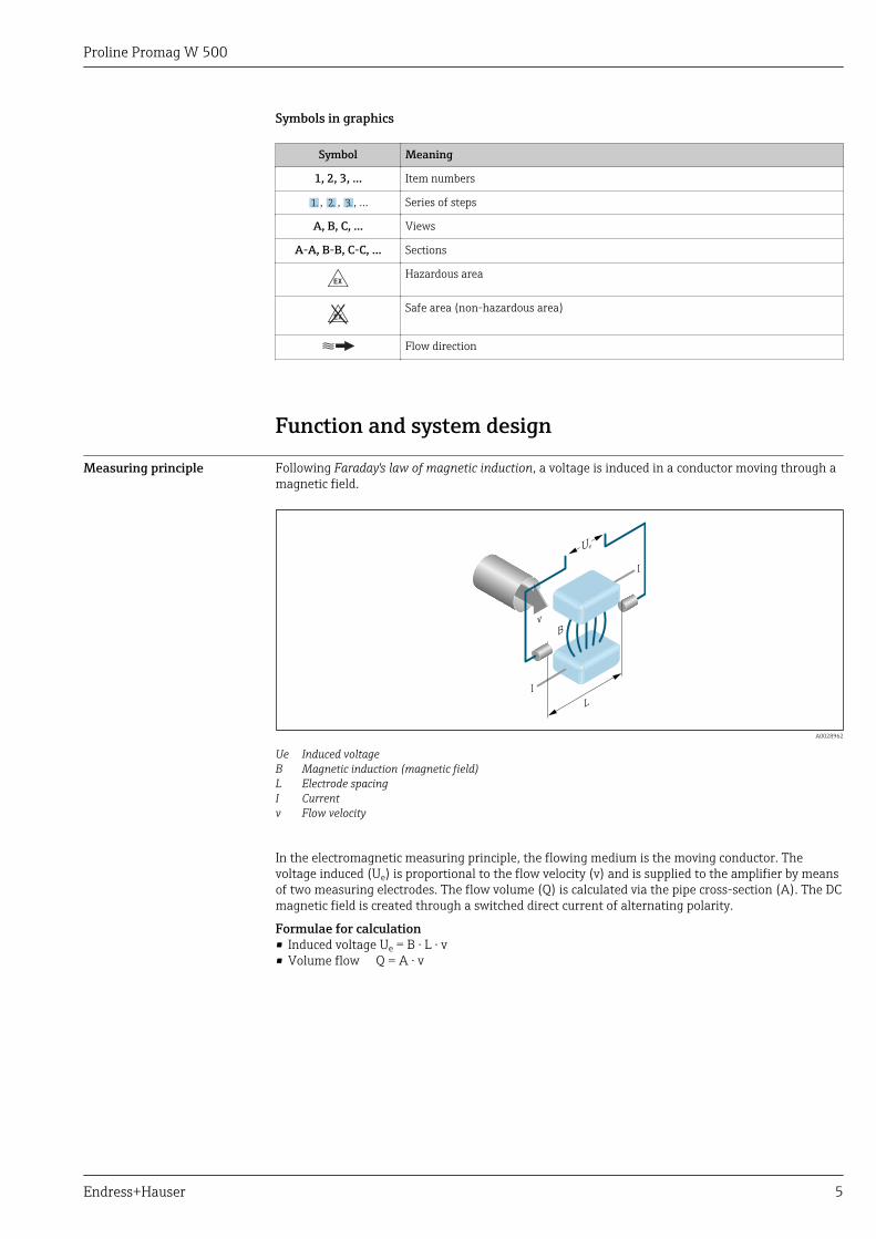
Measuring principle Following Faraday's law of magnetic induction, a voltage is induced in a conductor moving through amagnetic field.
Ue
L
B
I
I
v
A0028962
Ue Induced voltageB Magnetic induction (magnetic field)L Electrode spacingI Currentv Flow velocity
In the electromagnetic measuring principle, the flowing medium is the moving conductor. Thevoltage induced (Ue) is proportional to the flow velocity (v) and is supplied to the amplifier by meansof two measuring electrodes. The flow volume (Q) is calculated via the pipe cross-section (A). The DCmagnetic field is created through a switched direct current of alternating polarity.
Formulae for calculation• Induced voltage Ue = B · L · v• Volume flow Q = A · v
Proline Promag W 500
6 Endress+Hauser
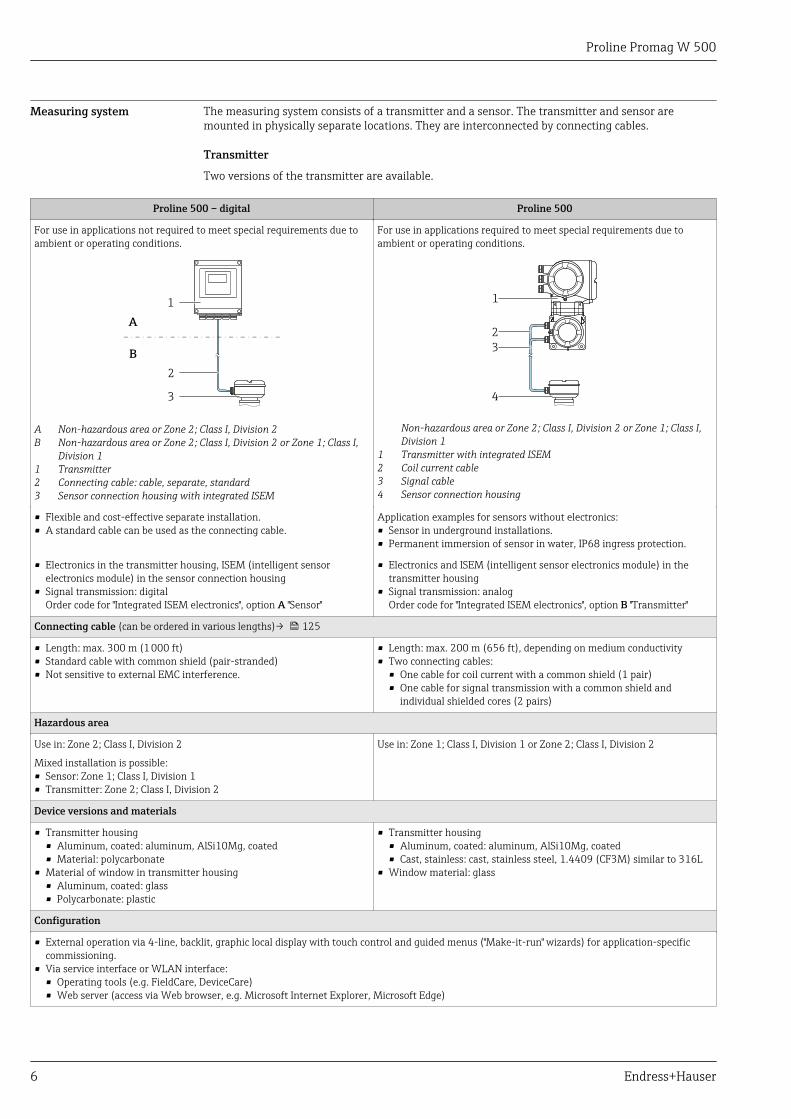
Measuring system The measuring system consists of a transmitter and a sensor. The transmitter and sensor aremounted in physically separate locations. They are interconnected by connecting cables.
Transmitter
Two versions of the transmitter are available.
Proline 500 – digital Proline 500
For use in applications not required to meet special requirements due toambient or operating conditions.
For use in applications required to meet special requirements due toambient or operating conditions.
2
3
1
A
B
A Non-hazardous area or Zone 2; Class I, Division 2B Non-hazardous area or Zone 2; Class I, Division 2 or Zone 1; Class I,
Division 11 Transmitter2 Connecting cable: cable, separate, standard3 Sensor connection housing with integrated ISEM
1
3
4
2
Non-hazardous area or Zone 2; Class I, Division 2 or Zone 1; Class I,Division 1
1 Transmitter with integrated ISEM2 Coil current cable3 Signal cable4 Sensor connection housing
• Flexible and cost-effective separate installation.• A standard cable can be used as the connecting cable.
Application examples for sensors without electronics:• Sensor in underground installations.• Permanent immersion of sensor in water, IP68 ingress protection.
• Electronics in the transmitter housing, ISEM (intelligent sensorelectronics module) in the sensor connection housing
• Signal transmission: digitalOrder code for "Integrated ISEM electronics", option A "Sensor"
• Electronics and ISEM (intelligent sensor electronics module) in thetransmitter housing
• Signal transmission: analogOrder code for "Integrated ISEM electronics", option B "Transmitter"
Connecting cable (can be ordered in various lengths)→ 125
• Length: max. 300 m (1 000 ft)• Standard cable with common shield (pair-stranded)• Not sensitive to external EMC interference.
• Length: max. 200 m (656 ft), depending on medium conductivity• Two connecting cables:
• One cable for coil current with a common shield (1 pair)• One cable for signal transmission with a common shield and
individual shielded cores (2 pairs)
Hazardous area
Use in: Zone 2; Class I, Division 2
Mixed installation is possible:• Sensor: Zone 1; Class I, Division 1• Transmitter: Zone 2; Class I, Division 2
Use in: Zone 1; Class I, Division 1 or Zone 2; Class I, Division 2
Device versions and materials
• Transmitter housing• Aluminum, coated: aluminum, AlSi10Mg, coated• Material: polycarbonate
• Material of window in transmitter housing• Aluminum, coated: glass• Polycarbonate: plastic
• Transmitter housing• Aluminum, coated: aluminum, AlSi10Mg, coated• Cast, stainless: cast, stainless steel, 1.4409 (CF3M) similar to 316L
• Window material: glass
Configuration
• External operation via 4-line, backlit, graphic local display with touch control and guided menus ("Make-it-run" wizards) for application-specificcommissioning.
• Via service interface or WLAN interface:• Operating tools (e.g. FieldCare, DeviceCare)• Web server (access via Web browser, e.g. Microsoft Internet Explorer, Microsoft Edge)
Proline Promag W 500
Endress+Hauser 7
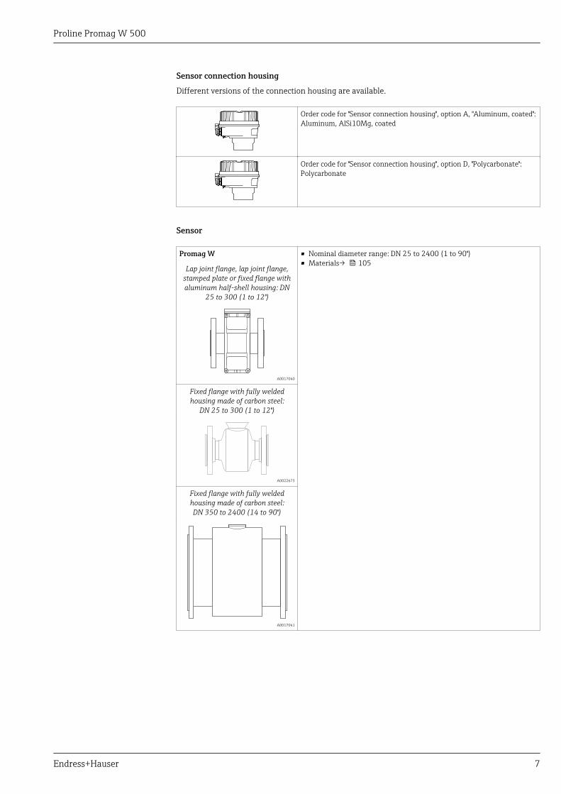
Sensor connection housing
Different versions of the connection housing are available.
Order code for "Sensor connection housing", option A, "Aluminum, coated":Aluminum, AlSi10Mg, coated
Order code for "Sensor connection housing", option D, "Polycarbonate":Polycarbonate
Sensor
Promag W • Nominal diameter range: DN 25 to 2400 (1 to 90")• Materials→ 105
Lap joint flange, lap joint flange,stamped plate or fixed flange withaluminum half-shell housing: DN
25 to 300 (1 to 12")
A0017040
Fixed flange with fully weldedhousing made of carbon steel:
DN 25 to 300 (1 to 12")
A0022673
Fixed flange with fully weldedhousing made of carbon steel:DN 350 to 2400 (14 to 90")
A0017041
Proline Promag W 500
8 Endress+Hauser
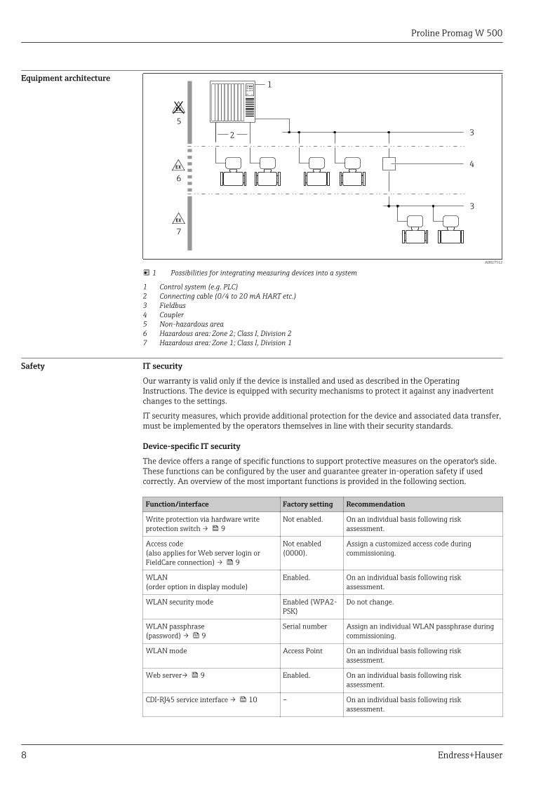
Equipment architecture
2
1
6
5
7
4
3
3
A0027512
1 Possibilities for integrating measuring devices into a system
1 Control system (e.g. PLC)2 Connecting cable (0/4 to 20 mA HART etc.)3 Fieldbus4 Coupler5 Non-hazardous area6 Hazardous area: Zone 2; Class I, Division 27 Hazardous area: Zone 1; Class I, Division 1
Safety IT security
Our warranty is valid only if the device is installed and used as described in the OperatingInstructions. The device is equipped with security mechanisms to protect it against any inadvertentchanges to the settings.
IT security measures, which provide additional protection for the device and associated data transfer,must be implemented by the operators themselves in line with their security standards.
Device-specific IT security
The device offers a range of specific functions to support protective measures on the operator's side.These functions can be configured by the user and guarantee greater in-operation safety if usedcorrectly. An overview of the most important functions is provided in the following section.
Function/interface Factory setting Recommendation
Write protection via hardware writeprotection switch → 9
Not enabled. On an individual basis following riskassessment.
Access code(also applies for Web server login orFieldCare connection) → 9
Not enabled(0000).
Assign a customized access code duringcommissioning.
WLAN(order option in display module)
Enabled. On an individual basis following riskassessment.
WLAN security mode Enabled (WPA2-PSK)
Do not change.
WLAN passphrase(password) → 9
Serial number Assign an individual WLAN passphrase duringcommissioning.
WLAN mode Access Point On an individual basis following riskassessment.
Web server→ 9 Enabled. On an individual basis following riskassessment.
CDI-RJ45 service interface → 10 – On an individual basis following riskassessment.
Proline Promag W 500
Endress+Hauser 9
Protecting access via hardware write protection
Write access to the device parameters via the local display, Web browser or operating tool (e.g.FieldCare, DeviceCare) can be disabled via a write protection switch (DIP switch on themotherboard). When hardware write protection is enabled, only read access to the parameters ispossible.
Hardware write protection is disabled when the device is delivered.
Protecting access via a password
Different passwords are available to protect write access to the device parameters or access to thedevice via the WLAN interface.
• User-specific access codeProtect write access to the device parameters via the local display, Web browser or operating tool(e.g. FieldCare, DeviceCare). Access authorization is clearly regulated through the use of a user-specific access code.
• WLAN passphraseThe network key protects a connection between an operating unit (e.g. notebook or tablet) and thedevice via the WLAN interface which can be ordered as an option.
• Infrastructure modeWhen the device is operated in infrastructure mode, the WLAN passphrase corresponds to theWLAN passphrase configured on the operator side.
User-specific access code
Write access to the device parameters via the local display, Web browser or operating tool (e.g.FieldCare, DeviceCare) can be protected by the modifiable, user-specific access code.
WLAN passphrase: Operation as WLAN access point
A connection between an operating unit (e.g. notebook or tablet) and the device via the WLANinterface, which can be ordered as an optional extra, is protected by the network key. The WLANauthentication of the network key complies with the IEEE 802.11 standard.
When the device is delivered, the network key is pre-defined depending on the device. It can bechanged via the WLAN settings submenu in the WLAN passphrase parameter.
Infrastructure mode
A connection between the device and WLAN access point is protected by means of an SSID andpassphrase on the system side. Please contact the relevant system administrator for access.
General notes on the use of passwords
• The access code and network key supplied with the device should be changed duringcommissioning.
• Follow the general rules for generating a secure password when defining and managing the accesscode or network key.
• The user is responsible for the management and careful handling of the access code and networkkey.
Access via Web server
The device can be operated and configured via a Web browser with the integrated Web server. Theconnection is via the service interface (CDI-RJ45) or the WLAN interface. For device versions withthe EtherNet/IP and PROFINET communication protocols, the connection can also be established viathe terminal connection for signal transmission with EtherNet/IP or PROFINET (RJ45 connector).
The Web server is enabled when the device is delivered. The Web server can be disabled if necessary(e.g. after commissioning) via the Web server functionality parameter.
The device and status information can be hidden on the login page. This prevents unauthorizedaccess to the information.
For detailed information on device parameters, see:The "Description of Device Parameters" document → 128
Access via OPC-UA
The "OPC UA Server" application package is available in the device version with the HARTcommunication protocol → 125.
Proline Promag W 500
10 Endress+Hauser
The device can communicate with OPC UA clients using the "OPC UA Server" application package.
The OPC UA server integrated in the device can be accessed via the WLAN access point using theWLAN interface - which can be ordered as an optional extra - or the service interface (CDI- RJ45) viaEthernet network. Access rights and authorization as per separate configuration.
The following Security Modes are supported as per the OPC UA Specification (IEC 62541):• None• Basic128Rsa15 – signed• Basic128Rsa15 – signed and encrypted
Access via service interface (CDI-RJ45)
The device can be connected to a network via the service interface (CDI-RJ45). Device-specificfunctions guarantee the secure operation of the device in a network.
The use of relevant industrial standards and guidelines that have been defined by national andinternational safety committees, such as IEC/ISA62443 or the IEEE, is recommended. This includesorganizational security measures such as the assignment of access authorization as well as technicalmeasures such as network segmentation.
Transmitters with an Ex de approval may not be connected via the service interface (CDI-RJ45)!
Order code for "Approval transmitter + sensor", options (Ex de): BA, BB, C1, C2, GA, GB, MA,MB, NA, NBThe device can be integrated in a ring topology. The device is integrated via the terminalconnection for signal transmission (output 1) and the connection to the service interface (CDI-RJ45) .
Input
Measured variable Direct measured variables
• Volume flow (proportional to induced voltage)• Electrical conductivity
Calculated measured variables
• Mass flow• Corrected volume flow
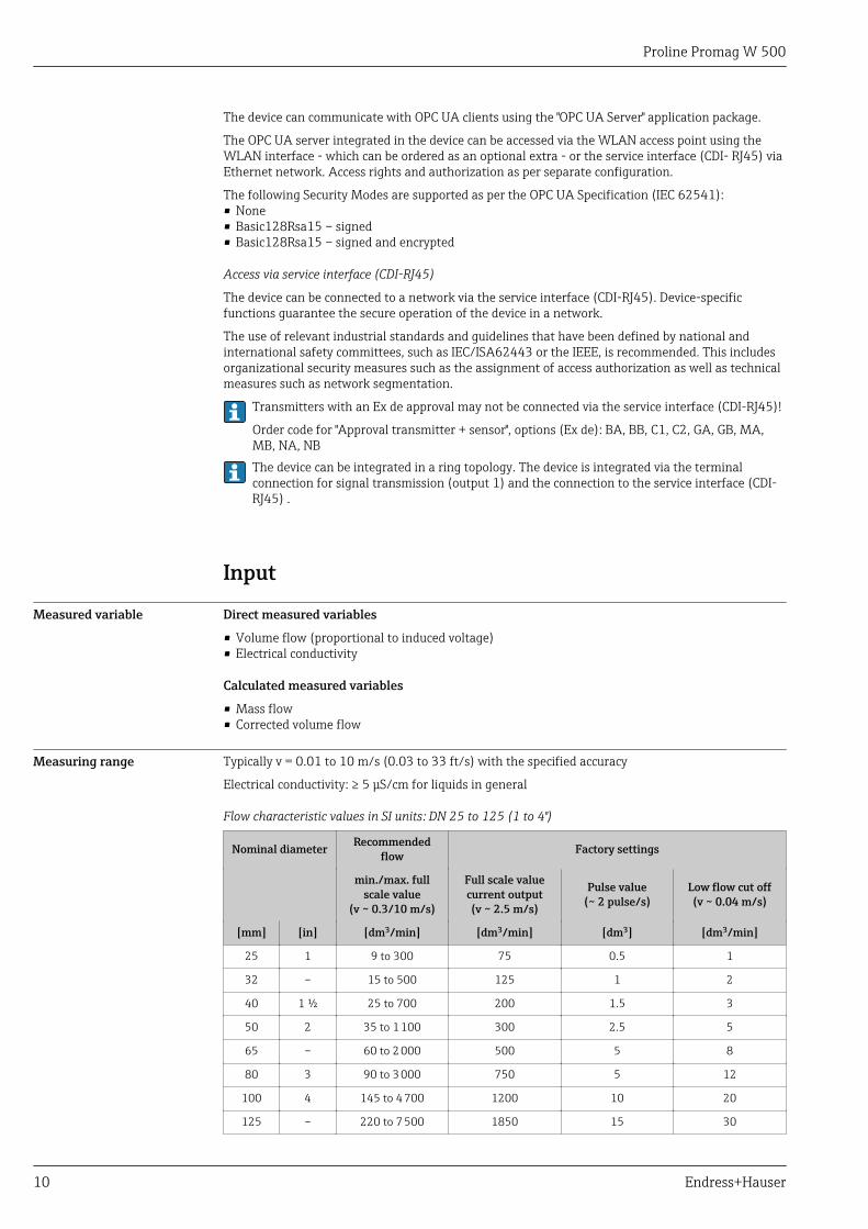
Measuring range Typically v = 0.01 to 10 m/s (0.03 to 33 ft/s) with the specified accuracy
Electrical conductivity: ≥ 5 μS/cm for liquids in general
Flow characteristic values in SI units: DN 25 to 125 (1 to 4")
Nominal diameter Recommendedflow Factory settings
min./max. fullscale value
(v ~ 0.3/10 m/s)
Full scale valuecurrent output(v ~ 2.5 m/s)
Pulse value(~ 2 pulse/s)
Low flow cut off(v ~ 0.04 m/s)
[mm] [in] [dm3/min] [dm3/min] [dm3] [dm3/min]
25 1 9 to 300 75 0.5 1
32 – 15 to 500 125 1 2
40 1 ½ 25 to 700 200 1.5 3
50 2 35 to 1 100 300 2.5 5
65 – 60 to 2 000 500 5 8
80 3 90 to 3 000 750 5 12
100 4 145 to 4 700 1200 10 20
125 – 220 to 7 500 1850 15 30
Proline Promag W 500
Endress+Hauser 11
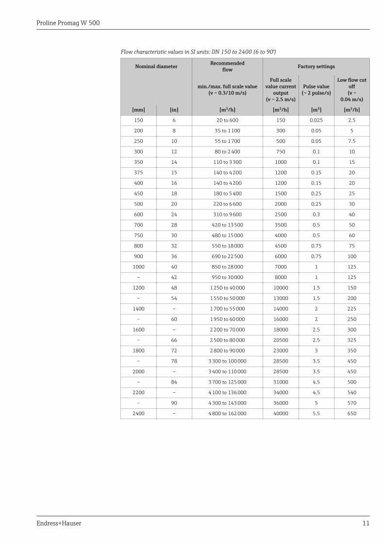
Flow characteristic values in SI units: DN 150 to 2400 (6 to 90")
Nominal diameter Recommendedflow Factory settings
min./max. full scale value(v ~ 0.3/10 m/s)
Full scalevalue current
output(v ~ 2.5 m/s)
Pulse value(~ 2 pulse/s)
Low flow cutoff(v ~
0.04 m/s)
[mm] [in] [m3/h] [m3/h] [m3] [m3/h]
150 6 20 to 600 150 0.025 2.5
200 8 35 to 1 100 300 0.05 5
250 10 55 to 1 700 500 0.05 7.5
300 12 80 to 2 400 750 0.1 10
350 14 110 to 3 300 1000 0.1 15
375 15 140 to 4 200 1200 0.15 20
400 16 140 to 4 200 1200 0.15 20
450 18 180 to 5 400 1500 0.25 25
500 20 220 to 6 600 2000 0.25 30
600 24 310 to 9 600 2500 0.3 40
700 28 420 to 13 500 3500 0.5 50
750 30 480 to 15 000 4000 0.5 60
800 32 550 to 18 000 4500 0.75 75
900 36 690 to 22 500 6000 0.75 100
1000 40 850 to 28 000 7000 1 125
– 42 950 to 30 000 8000 1 125
1200 48 1 250 to 40 000 10000 1.5 150
– 54 1 550 to 50 000 13000 1.5 200
1400 – 1 700 to 55 000 14000 2 225
– 60 1 950 to 60 000 16000 2 250
1600 – 2 200 to 70 000 18000 2.5 300
– 66 2 500 to 80 000 20500 2.5 325
1800 72 2 800 to 90 000 23000 3 350
– 78 3 300 to 100 000 28500 3.5 450
2000 – 3 400 to 110 000 28500 3.5 450
– 84 3 700 to 125 000 31000 4.5 500
2200 – 4 100 to 136 000 34000 4.5 540
– 90 4 300 to 143 000 36000 5 570
2400 – 4 800 to 162 000 40000 5.5 650
Proline Promag W 500
12 Endress+Hauser
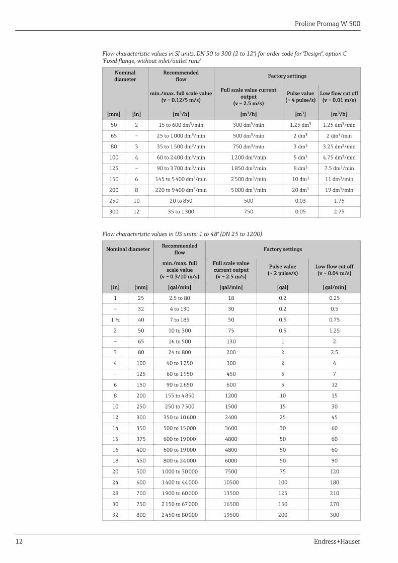
Flow characteristic values in SI units: DN 50 to 300 (2 to 12") for order code for "Design", option C"Fixed flange, without inlet/outlet runs"
Nominaldiameter
Recommendedflow Factory settings
min./max. full scale value(v ~ 0.12/5 m/s)
Full scale value currentoutput
(v ~ 2.5 m/s)
Pulse value(~ 4 pulse/s)
Low flow cut off(v ~ 0.01 m/s)
[mm] [in] [m3/h] [m3/h] [m3] [m3/h]
50 2 15 to 600 dm3/min 300 dm3/min 1.25 dm3 1.25 dm3/min
65 – 25 to 1 000 dm3/min 500 dm3/min 2 dm3 2 dm3/min
80 3 35 to 1 500 dm3/min 750 dm3/min 3 dm3 3.25 dm3/min
100 4 60 to 2 400 dm3/min 1 200 dm3/min 5 dm3 4.75 dm3/min
125 – 90 to 3 700 dm3/min 1 850 dm3/min 8 dm3 7.5 dm3/min
150 6 145 to 5 400 dm3/min 2 500 dm3/min 10 dm3 11 dm3/min
200 8 220 to 9 400 dm3/min 5 000 dm3/min 20 dm3 19 dm3/min
250 10 20 to 850 500 0.03 1.75
300 12 35 to 1 300 750 0.05 2.75
Flow characteristic values in US units: 1 to 48" (DN 25 to 1200)
Nominal diameter Recommendedflow Factory settings
min./max. fullscale value
(v ~ 0.3/10 m/s)
Full scale valuecurrent output(v ~ 2.5 m/s)
Pulse value(~ 2 pulse/s)
Low flow cut off(v ~ 0.04 m/s)
[in] [mm] [gal/min] [gal/min] [gal] [gal/min]
1 25 2.5 to 80 18 0.2 0.25
– 32 4 to 130 30 0.2 0.5
1 ½ 40 7 to 185 50 0.5 0.75
2 50 10 to 300 75 0.5 1.25
– 65 16 to 500 130 1 2
3 80 24 to 800 200 2 2.5
4 100 40 to 1 250 300 2 4
– 125 60 to 1 950 450 5 7
6 150 90 to 2 650 600 5 12
8 200 155 to 4 850 1200 10 15
10 250 250 to 7 500 1500 15 30
12 300 350 to 10 600 2400 25 45
14 350 500 to 15 000 3600 30 60
15 375 600 to 19 000 4800 50 60
16 400 600 to 19 000 4800 50 60
18 450 800 to 24 000 6000 50 90
20 500 1 000 to 30 000 7500 75 120
24 600 1 400 to 44 000 10500 100 180
28 700 1 900 to 60 000 13500 125 210
30 750 2 150 to 67 000 16500 150 270
32 800 2 450 to 80 000 19500 200 300
Proline Promag W 500
Endress+Hauser 13
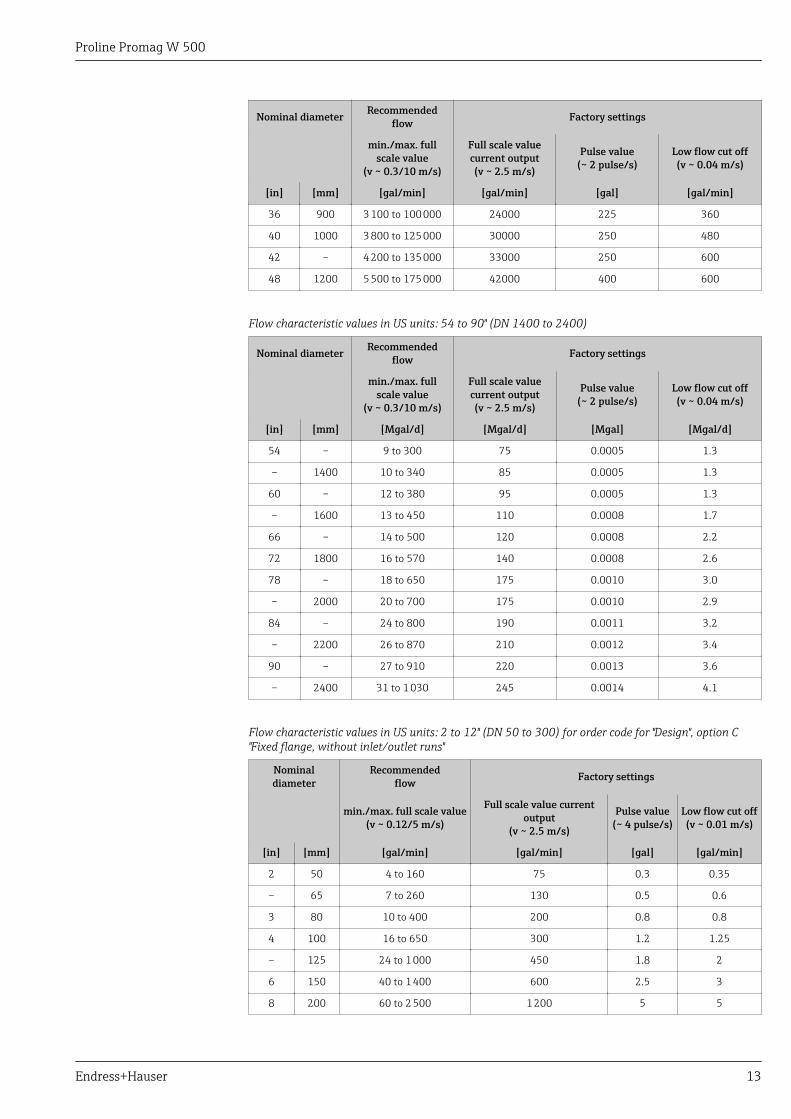
Nominal diameter Recommendedflow Factory settings
min./max. fullscale value
(v ~ 0.3/10 m/s)
Full scale valuecurrent output(v ~ 2.5 m/s)
Pulse value(~ 2 pulse/s)
Low flow cut off(v ~ 0.04 m/s)
[in] [mm] [gal/min] [gal/min] [gal] [gal/min]
36 900 3 100 to 100 000 24000 225 360
40 1000 3 800 to 125 000 30000 250 480
42 – 4 200 to 135 000 33000 250 600
48 1200 5 500 to 175 000 42000 400 600
Flow characteristic values in US units: 54 to 90" (DN 1400 to 2400)
Nominal diameter Recommendedflow Factory settings
min./max. fullscale value
(v ~ 0.3/10 m/s)
Full scale valuecurrent output(v ~ 2.5 m/s)
Pulse value(~ 2 pulse/s)
Low flow cut off(v ~ 0.04 m/s)
[in] [mm] [Mgal/d] [Mgal/d] [Mgal] [Mgal/d]
54 – 9 to 300 75 0.0005 1.3
– 1400 10 to 340 85 0.0005 1.3
60 – 12 to 380 95 0.0005 1.3
– 1600 13 to 450 110 0.0008 1.7
66 – 14 to 500 120 0.0008 2.2
72 1800 16 to 570 140 0.0008 2.6
78 – 18 to 650 175 0.0010 3.0
– 2000 20 to 700 175 0.0010 2.9
84 – 24 to 800 190 0.0011 3.2
– 2200 26 to 870 210 0.0012 3.4
90 – 27 to 910 220 0.0013 3.6
– 2400 31 to 1 030 245 0.0014 4.1
Flow characteristic values in US units: 2 to 12" (DN 50 to 300) for order code for "Design", option C"Fixed flange, without inlet/outlet runs"
Nominaldiameter
Recommendedflow Factory settings
min./max. full scale value(v ~ 0.12/5 m/s)
Full scale value currentoutput
(v ~ 2.5 m/s)
Pulse value(~ 4 pulse/s)
Low flow cut off(v ~ 0.01 m/s)
[in] [mm] [gal/min] [gal/min] [gal] [gal/min]
2 50 4 to 160 75 0.3 0.35
– 65 7 to 260 130 0.5 0.6
3 80 10 to 400 200 0.8 0.8
4 100 16 to 650 300 1.2 1.25
– 125 24 to 1 000 450 1.8 2
6 150 40 to 1 400 600 2.5 3
8 200 60 to 2 500 1 200 5 5
Proline Promag W 500
14 Endress+Hauser
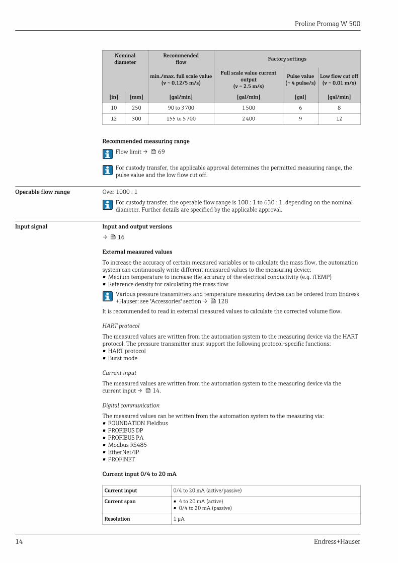
Nominaldiameter
Recommendedflow Factory settings
min./max. full scale value(v ~ 0.12/5 m/s)
Full scale value currentoutput
(v ~ 2.5 m/s)
Pulse value(~ 4 pulse/s)
Low flow cut off(v ~ 0.01 m/s)
[in] [mm] [gal/min] [gal/min] [gal] [gal/min]
10 250 90 to 3 700 1 500 6 8
12 300 155 to 5 700 2 400 9 12
Recommended measuring range
Flow limit → 69
For custody transfer, the applicable approval determines the permitted measuring range, thepulse value and the low flow cut off.
Operable flow range Over 1000 : 1
For custody transfer, the operable flow range is 100 : 1 to 630 : 1, depending on the nominaldiameter. Further details are specified by the applicable approval.
Input signal Input and output versions
→ 16
External measured values
To increase the accuracy of certain measured variables or to calculate the mass flow, the automationsystem can continuously write different measured values to the measuring device:• Medium temperature to increase the accuracy of the electrical conductivity (e.g. iTEMP)• Reference density for calculating the mass flow
Various pressure transmitters and temperature measuring devices can be ordered from Endress+Hauser: see "Accessories" section → 128
It is recommended to read in external measured values to calculate the corrected volume flow.
HART protocol
The measured values are written from the automation system to the measuring device via the HARTprotocol. The pressure transmitter must support the following protocol-specific functions:• HART protocol• Burst mode
Current input
The measured values are written from the automation system to the measuring device via thecurrent input → 14.
Digital communication
The measured values can be written from the automation system to the measuring via:• FOUNDATION Fieldbus• PROFIBUS DP• PROFIBUS PA• Modbus RS485• EtherNet/IP• PROFINET
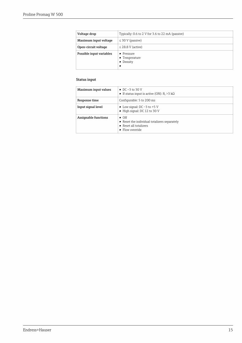
Current input 0/4 to 20 mA
Current input 0/4 to 20 mA (active/passive)
Current span • 4 to 20 mA (active)• 0/4 to 20 mA (passive)
Resolution 1 µA
Proline Promag W 500
Endress+Hauser 15
Voltage drop Typically: 0.6 to 2 V for 3.6 to 22 mA (passive)
Maximum input voltage ≤ 30 V (passive)
Open-circuit voltage ≤ 28.8 V (active)
Possible input variables • Pressure• Temperature• Density•
Status input
Maximum input values • DC –3 to 30 V• If status input is active (ON): Ri >3 kΩ
Response time Configurable: 5 to 200 ms
Input signal level • Low signal: DC –3 to +5 V• High signal: DC 12 to 30 V
Assignable functions • Off• Reset the individual totalizers separately• Reset all totalizers• Flow override
Proline Promag W 500
16 Endress+Hauser
Output
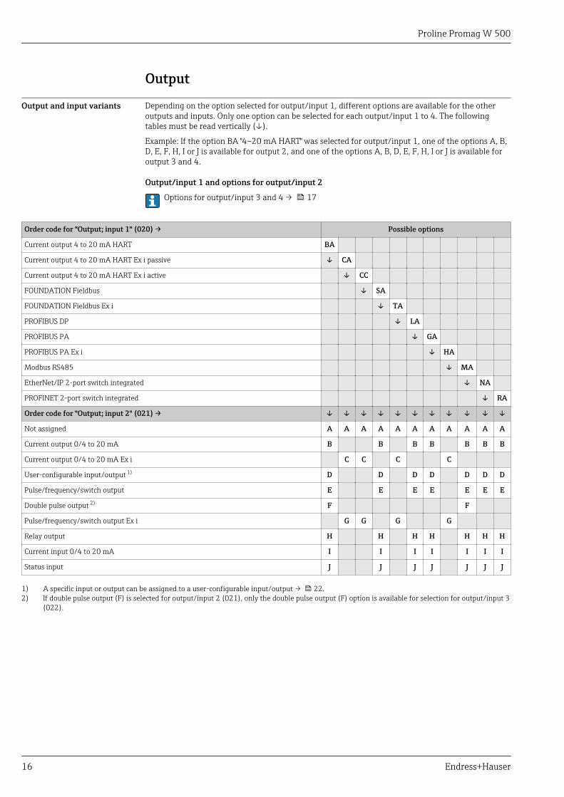
Output and input variants Depending on the option selected for output/input 1, different options are available for the otheroutputs and inputs. Only one option can be selected for each output/input 1 to 4. The followingtables must be read vertically (↓).
Example: If the option BA "4–20 mA HART" was selected for output/input 1, one of the options A, B,D, E, F, H, I or J is available for output 2, and one of the options A, B, D, E, F, H, I or J is available foroutput 3 and 4.
Output/input 1 and options for output/input 2
Options for output/input 3 and 4 → 17
Order code for "Output; input 1" (020) → Possible options
Current output 4 to 20 mA HART BA
Current output 4 to 20 mA HART Ex i passive ↓ CA
Current output 4 to 20 mA HART Ex i active ↓ CC
FOUNDATION Fieldbus ↓ SA
FOUNDATION Fieldbus Ex i ↓ TA
PROFIBUS DP ↓ LA
PROFIBUS PA ↓ GA
PROFIBUS PA Ex i ↓ HA
Modbus RS485 ↓ MA
EtherNet/IP 2-port switch integrated ↓ NA
PROFINET 2-port switch integrated ↓ RA
Order code for "Output; input 2" (021) → ↓ ↓ ↓ ↓ ↓ ↓ ↓ ↓ ↓ ↓ ↓
Not assigned A A A A A A A A A A A
Current output 0/4 to 20 mA B B B B B B B
Current output 0/4 to 20 mA Ex i C C C C
User-configurable input/output 1) D D D D D D D
Pulse/frequency/switch output E E E E E E E
Double pulse output 2) F F
Pulse/frequency/switch output Ex i G G G G
Relay output H H H H H H H
Current input 0/4 to 20 mA I I I I I I I
Status input J J J J J J J
1) A specific input or output can be assigned to a user-configurable input/output → 22.2) If double pulse output (F) is selected for output/input 2 (021), only the double pulse output (F) option is available for selection for output/input 3
(022).
Proline Promag W 500
Endress+Hauser 17
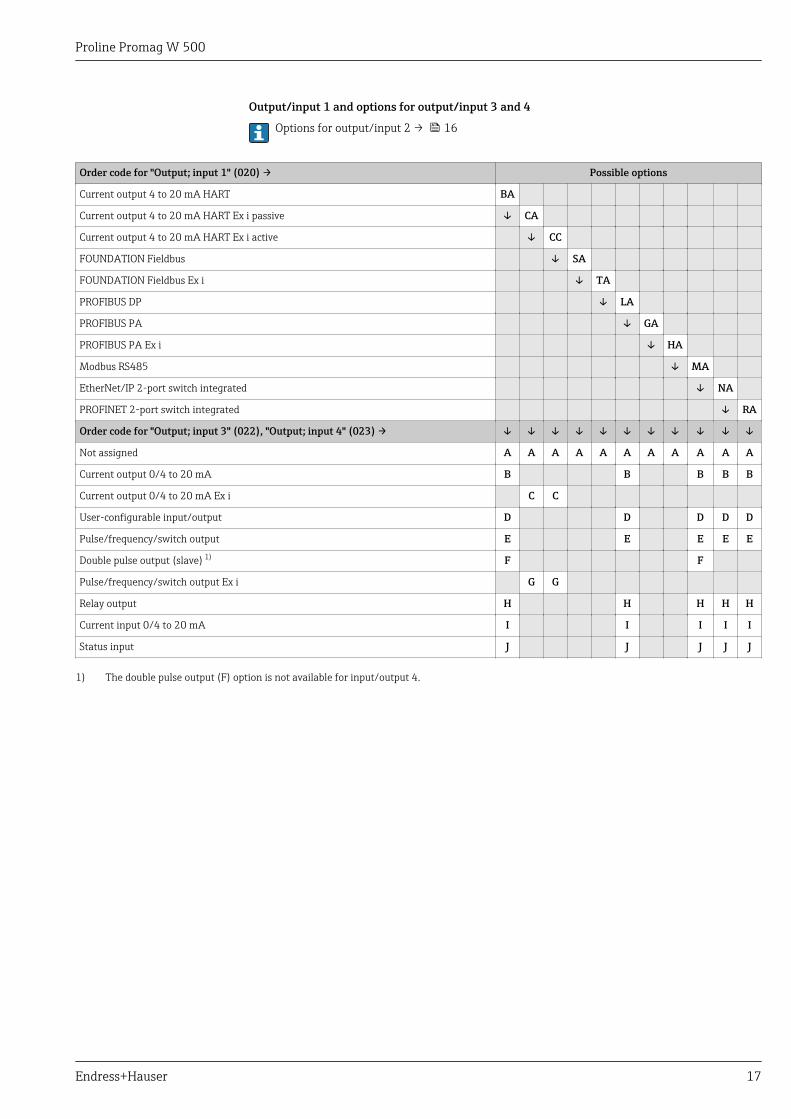
Output/input 1 and options for output/input 3 and 4
Options for output/input 2 → 16
Order code for "Output; input 1" (020) → Possible options
Current output 4 to 20 mA HART BA
Current output 4 to 20 mA HART Ex i passive ↓ CA
Current output 4 to 20 mA HART Ex i active ↓ CC
FOUNDATION Fieldbus ↓ SA
FOUNDATION Fieldbus Ex i ↓ TA
PROFIBUS DP ↓ LA
PROFIBUS PA ↓ GA
PROFIBUS PA Ex i ↓ HA
Modbus RS485 ↓ MA
EtherNet/IP 2-port switch integrated ↓ NA
PROFINET 2-port switch integrated ↓ RA
Order code for "Output; input 3" (022), "Output; input 4" (023) → ↓ ↓ ↓ ↓ ↓ ↓ ↓ ↓ ↓ ↓ ↓
Not assigned A A A A A A A A A A A
Current output 0/4 to 20 mA B B B B B
Current output 0/4 to 20 mA Ex i C C
User-configurable input/output D D D D D
Pulse/frequency/switch output E E E E E
Double pulse output (slave) 1) F F
Pulse/frequency/switch output Ex i G G
Relay output H H H H H
Current input 0/4 to 20 mA I I I I I
Status input J J J J J
1) The double pulse output (F) option is not available for input/output 4.
Proline Promag W 500
18 Endress+Hauser
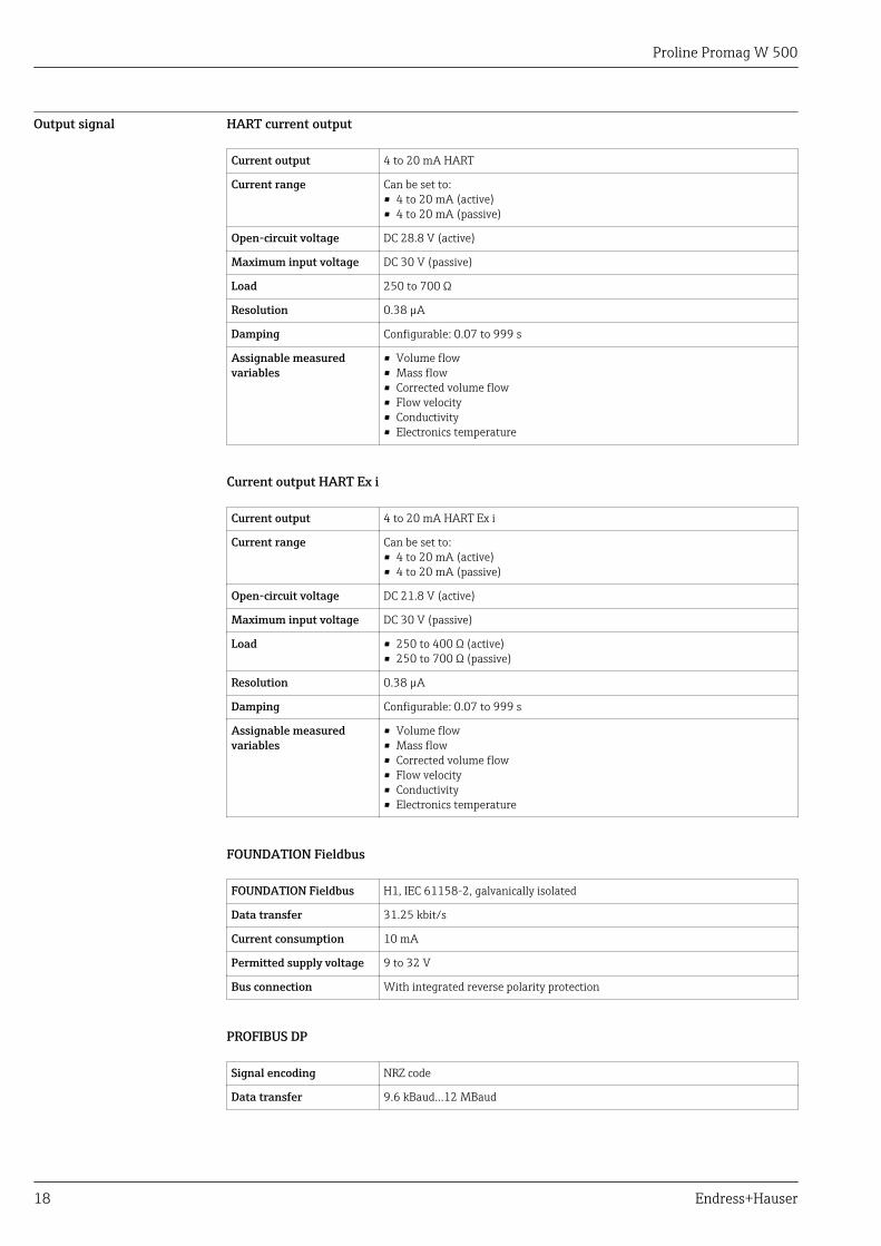
Output signal HART current output
Current output 4 to 20 mA HART
Current range Can be set to:• 4 to 20 mA (active)• 4 to 20 mA (passive)
Open-circuit voltage DC 28.8 V (active)
Maximum input voltage DC 30 V (passive)
Load 250 to 700 Ω
Resolution 0.38 µA
Damping Configurable: 0.07 to 999 s
Assignable measuredvariables
• Volume flow• Mass flow• Corrected volume flow• Flow velocity• Conductivity• Electronics temperature
Current output HART Ex i
Current output 4 to 20 mA HART Ex i
Current range Can be set to:• 4 to 20 mA (active)• 4 to 20 mA (passive)
Open-circuit voltage DC 21.8 V (active)
Maximum input voltage DC 30 V (passive)
Load • 250 to 400 Ω (active)• 250 to 700 Ω (passive)
Resolution 0.38 µA
Damping Configurable: 0.07 to 999 s
Assignable measuredvariables
• Volume flow• Mass flow• Corrected volume flow• Flow velocity• Conductivity• Electronics temperature
FOUNDATION Fieldbus
FOUNDATION Fieldbus H1, IEC 61158-2, galvanically isolated
Data transfer 31.25 kbit/s
Current consumption 10 mA
Permitted supply voltage 9 to 32 V
Bus connection With integrated reverse polarity protection
PROFIBUS DP
Signal encoding NRZ code
Data transfer 9.6 kBaud…12 MBaud
Proline Promag W 500
Endress+Hauser 19
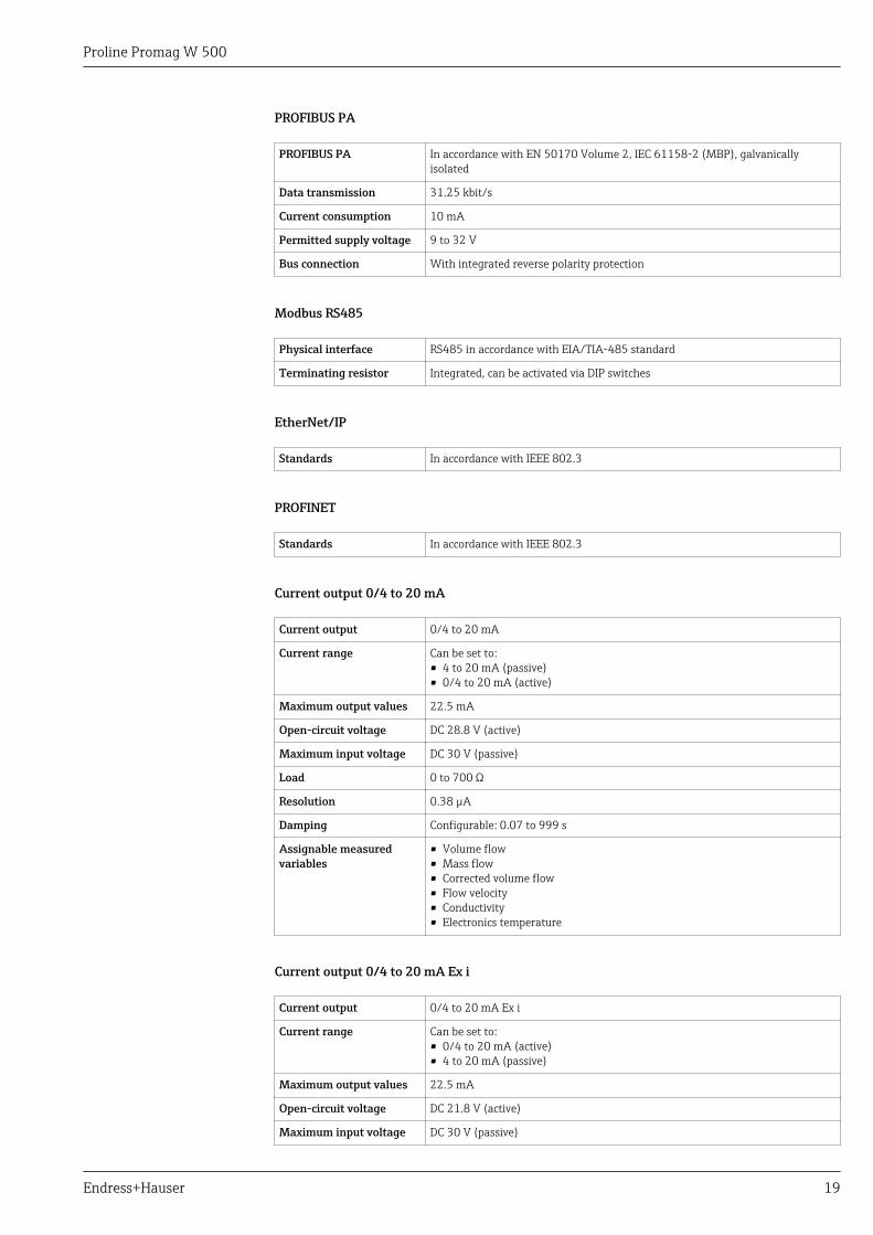
PROFIBUS PA
PROFIBUS PA In accordance with EN 50170 Volume 2, IEC 61158-2 (MBP), galvanicallyisolated
Data transmission 31.25 kbit/s
Current consumption 10 mA
Permitted supply voltage 9 to 32 V
Bus connection With integrated reverse polarity protection
Modbus RS485
Physical interface RS485 in accordance with EIA/TIA-485 standard
Terminating resistor Integrated, can be activated via DIP switches
EtherNet/IP
Standards In accordance with IEEE 802.3
PROFINET
Standards In accordance with IEEE 802.3
Current output 0/4 to 20 mA
Current output 0/4 to 20 mA
Current range Can be set to:• 4 to 20 mA (passive)• 0/4 to 20 mA (active)
Maximum output values 22.5 mA
Open-circuit voltage DC 28.8 V (active)
Maximum input voltage DC 30 V (passive)
Load 0 to 700 Ω
Resolution 0.38 µA
Damping Configurable: 0.07 to 999 s
Assignable measuredvariables
• Volume flow• Mass flow• Corrected volume flow• Flow velocity• Conductivity• Electronics temperature
Current output 0/4 to 20 mA Ex i
Current output 0/4 to 20 mA Ex i
Current range Can be set to:• 0/4 to 20 mA (active)• 4 to 20 mA (passive)
Maximum output values 22.5 mA
Open-circuit voltage DC 21.8 V (active)
Maximum input voltage DC 30 V (passive)
Proline Promag W 500
20 Endress+Hauser
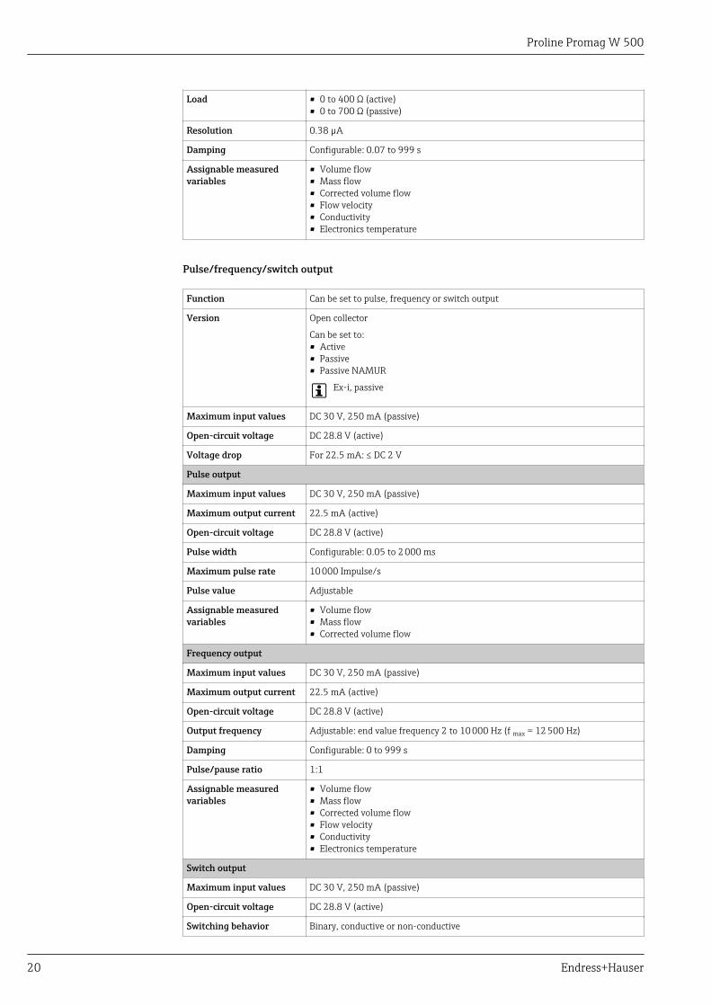
Load • 0 to 400 Ω (active)• 0 to 700 Ω (passive)
Resolution 0.38 µA
Damping Configurable: 0.07 to 999 s
Assignable measuredvariables
• Volume flow• Mass flow• Corrected volume flow• Flow velocity• Conductivity• Electronics temperature
Pulse/frequency/switch output
Function Can be set to pulse, frequency or switch output
Version Open collector
Can be set to:• Active• Passive• Passive NAMUR
Ex-i, passive
Maximum input values DC 30 V, 250 mA (passive)
Open-circuit voltage DC 28.8 V (active)
Voltage drop For 22.5 mA: ≤ DC 2 V
Pulse output
Maximum input values DC 30 V, 250 mA (passive)
Maximum output current 22.5 mA (active)
Open-circuit voltage DC 28.8 V (active)
Pulse width Configurable: 0.05 to 2 000 ms
Maximum pulse rate 10 000 Impulse/s
Pulse value Adjustable
Assignable measuredvariables
• Volume flow• Mass flow• Corrected volume flow
Frequency output
Maximum input values DC 30 V, 250 mA (passive)
Maximum output current 22.5 mA (active)
Open-circuit voltage DC 28.8 V (active)
Output frequency Adjustable: end value frequency 2 to 10 000 Hz (f max = 12 500 Hz)
Damping Configurable: 0 to 999 s
Pulse/pause ratio 1:1
Assignable measuredvariables
• Volume flow• Mass flow• Corrected volume flow• Flow velocity• Conductivity• Electronics temperature
Switch output
Maximum input values DC 30 V, 250 mA (passive)
Open-circuit voltage DC 28.8 V (active)
Switching behavior Binary, conductive or non-conductive
Proline Promag W 500
Endress+Hauser 21
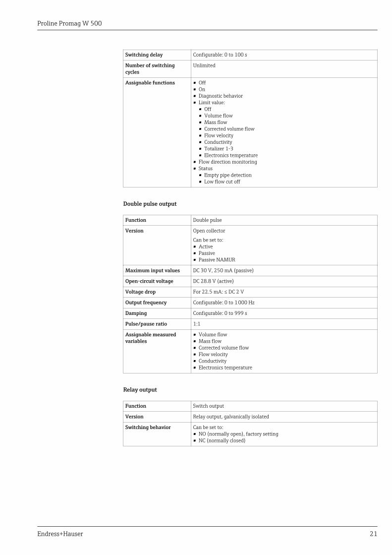
Switching delay Configurable: 0 to 100 s
Number of switchingcycles
Unlimited
Assignable functions • Off• On• Diagnostic behavior• Limit value:
• Off• Volume flow• Mass flow• Corrected volume flow• Flow velocity• Conductivity• Totalizer 1-3• Electronics temperature
• Flow direction monitoring• Status
• Empty pipe detection• Low flow cut off
Double pulse output
Function Double pulse
Version Open collector
Can be set to:• Active• Passive• Passive NAMUR
Maximum input values DC 30 V, 250 mA (passive)
Open-circuit voltage DC 28.8 V (active)
Voltage drop For 22.5 mA: ≤ DC 2 V
Output frequency Configurable: 0 to 1 000 Hz
Damping Configurable: 0 to 999 s
Pulse/pause ratio 1:1
Assignable measuredvariables
• Volume flow• Mass flow• Corrected volume flow• Flow velocity• Conductivity• Electronics temperature
Relay output
Function Switch output
Version Relay output, galvanically isolated
Switching behavior Can be set to:• NO (normally open), factory setting• NC (normally closed)
Proline Promag W 500
22 Endress+Hauser
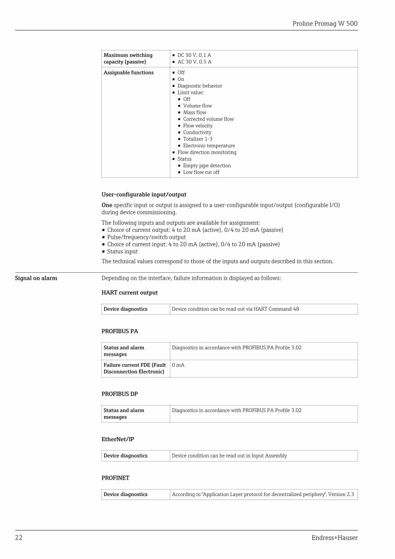
Maximum switchingcapacity (passive)
• DC 30 V, 0.1 A• AC 30 V, 0.5 A
Assignable functions • Off• On• Diagnostic behavior• Limit value:
• Off• Volume flow• Mass flow• Corrected volume flow• Flow velocity• Conductivity• Totalizer 1-3• Electronic temperature
• Flow direction monitoring• Status
• Empty pipe detection• Low flow cut off
User-configurable input/output
One specific input or output is assigned to a user-configurable input/output (configurable I/O)during device commissioning.
The following inputs and outputs are available for assignment:• Choice of current output: 4 to 20 mA (active), 0/4 to 20 mA (passive)• Pulse/frequency/switch output• Choice of current input: 4 to 20 mA (active), 0/4 to 20 mA (passive)• Status inputThe technical values correspond to those of the inputs and outputs described in this section.
Signal on alarm Depending on the interface, failure information is displayed as follows:
HART current output
Device diagnostics Device condition can be read out via HART Command 48
PROFIBUS PA
Status and alarmmessages
Diagnostics in accordance with PROFIBUS PA Profile 3.02
Failure current FDE (FaultDisconnection Electronic)
0 mA
PROFIBUS DP
Status and alarmmessages
Diagnostics in accordance with PROFIBUS PA Profile 3.02
EtherNet/IP
Device diagnostics Device condition can be read out in Input Assembly
PROFINET
Device diagnostics According to "Application Layer protocol for decentralized periphery", Version 2.3
Proline Promag W 500
Endress+Hauser 23
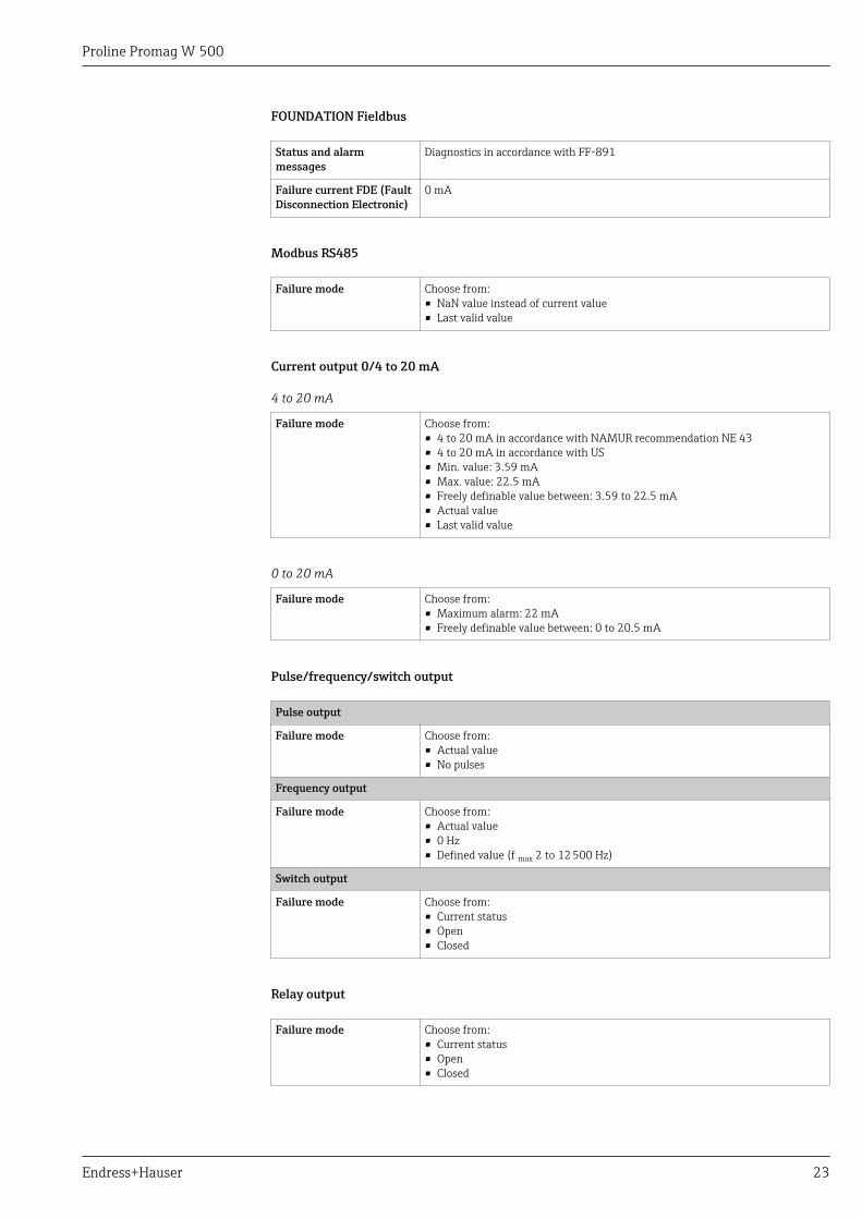
FOUNDATION Fieldbus
Status and alarmmessages
Diagnostics in accordance with FF-891
Failure current FDE (FaultDisconnection Electronic)
0 mA
Modbus RS485
Failure mode Choose from:• NaN value instead of current value• Last valid value
Current output 0/4 to 20 mA
4 to 20 mA
Failure mode Choose from:• 4 to 20 mA in accordance with NAMUR recommendation NE 43• 4 to 20 mA in accordance with US• Min. value: 3.59 mA• Max. value: 22.5 mA• Freely definable value between: 3.59 to 22.5 mA• Actual value• Last valid value
0 to 20 mA
Failure mode Choose from:• Maximum alarm: 22 mA• Freely definable value between: 0 to 20.5 mA
Pulse/frequency/switch output
Pulse output
Failure mode Choose from:• Actual value• No pulses
Frequency output
Failure mode Choose from:• Actual value• 0 Hz• Defined value (f max 2 to 12 500 Hz)
Switch output
Failure mode Choose from:• Current status• Open• Closed
Relay output
Failure mode Choose from:• Current status• Open• Closed
Proline Promag W 500
24 Endress+Hauser
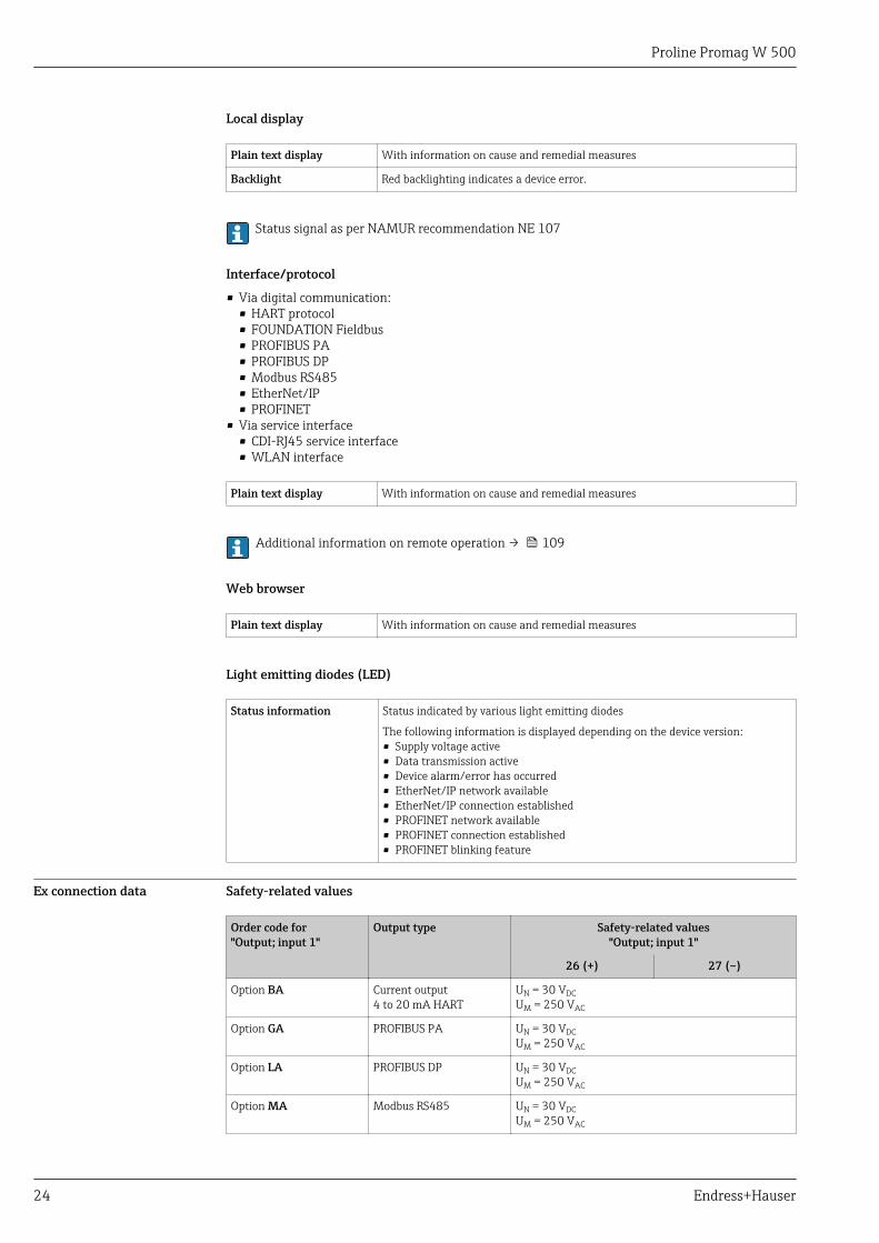
Local display
Plain text display With information on cause and remedial measures
Backlight Red backlighting indicates a device error.
Status signal as per NAMUR recommendation NE 107
Interface/protocol
• Via digital communication:• HART protocol• FOUNDATION Fieldbus• PROFIBUS PA• PROFIBUS DP• Modbus RS485• EtherNet/IP• PROFINET
• Via service interface• CDI-RJ45 service interface• WLAN interface
Plain text display With information on cause and remedial measures
Additional information on remote operation → 109
Web browser
Plain text display With information on cause and remedial measures
Light emitting diodes (LED)
Status information Status indicated by various light emitting diodes
The following information is displayed depending on the device version:• Supply voltage active• Data transmission active• Device alarm/error has occurred• EtherNet/IP network available• EtherNet/IP connection established• PROFINET network available• PROFINET connection established• PROFINET blinking feature
Ex connection data Safety-related values
Order code for"Output; input 1"
Output type Safety-related values"Output; input 1"
26 (+) 27 (–)
Option BA Current output4 to 20 mA HART
UN = 30 VDCUM = 250 VAC
Option GA PROFIBUS PA UN = 30 VDCUM = 250 VAC
Option LA PROFIBUS DP UN = 30 VDCUM = 250 VAC
Option MA Modbus RS485 UN = 30 VDCUM = 250 VAC
Proline Promag W 500
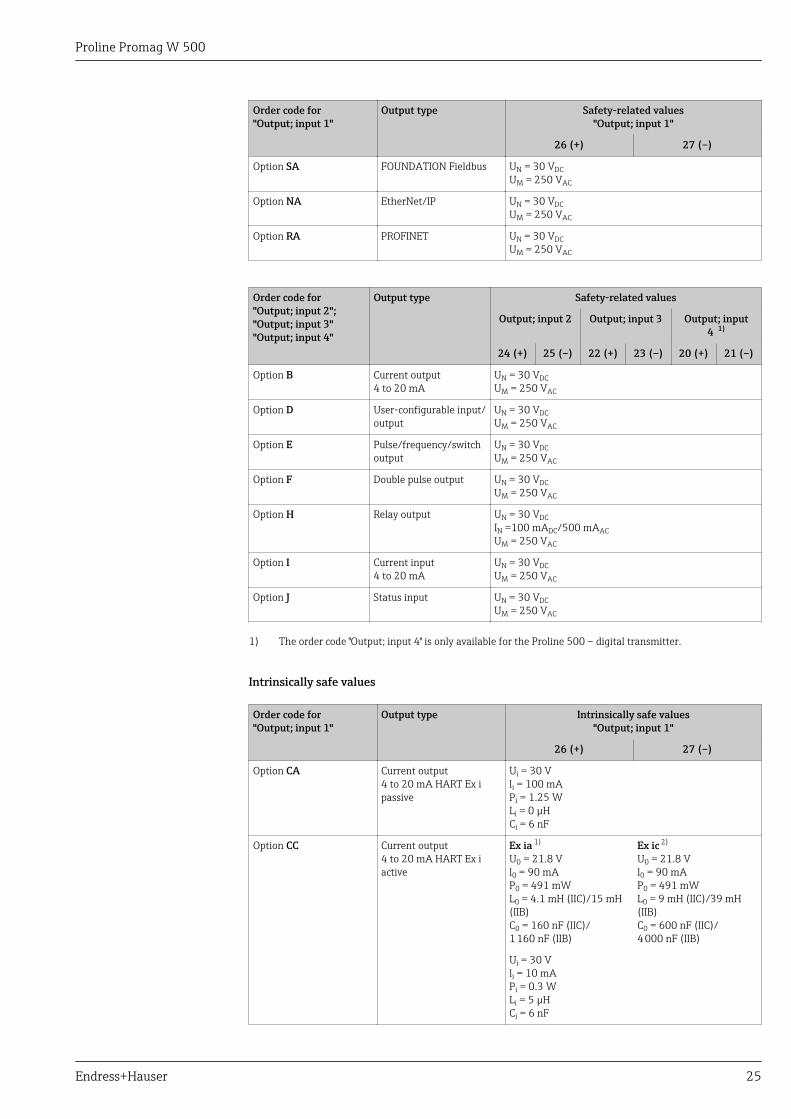
Endress+Hauser 25
Order code for"Output; input 1"
Output type Safety-related values"Output; input 1"
26 (+) 27 (–)
Option SA FOUNDATION Fieldbus UN = 30 VDCUM = 250 VAC
Option NA EtherNet/IP UN = 30 VDCUM = 250 VAC
Option RA PROFINET UN = 30 VDCUM = 250 VAC
Order code for"Output; input 2";"Output; input 3""Output; input 4"
Output type Safety-related values
Output; input 2 Output; input 3 Output; input4 1)
24 (+) 25 (–) 22 (+) 23 (–) 20 (+) 21 (–)
Option B Current output4 to 20 mA
UN = 30 VDCUM = 250 VAC
Option D User-configurable input/output
UN = 30 VDCUM = 250 VAC
Option E Pulse/frequency/switchoutput
UN = 30 VDCUM = 250 VAC
Option F Double pulse output UN = 30 VDCUM = 250 VAC
Option H Relay output UN = 30 VDCIN =100 mADC/500 mAACUM = 250 VAC
Option I Current input4 to 20 mA
UN = 30 VDCUM = 250 VAC
Option J Status input UN = 30 VDCUM = 250 VAC
1) The order code "Output; input 4" is only available for the Proline 500 – digital transmitter.
Intrinsically safe values
Order code for"Output; input 1"
Output type Intrinsically safe values"Output; input 1"
26 (+) 27 (–)
Option CA Current output4 to 20 mA HART Ex ipassive
Ui = 30 Vli = 100 mAPi = 1.25 WLi = 0 µHCi = 6 nF
Option CC Current output4 to 20 mA HART Ex iactive
Ex ia 1)
U0 = 21.8 Vl0 = 90 mAP0 = 491 mWL0 = 4.1 mH (IIC)/15 mH(IIB)C0 = 160 nF (IIC)/1 160 nF (IIB)
Ex ic 2)
U0 = 21.8 Vl0 = 90 mAP0 = 491 mWL0 = 9 mH (IIC)/39 mH(IIB)C0 = 600 nF (IIC)/4 000 nF (IIB)
Ui = 30 Vli = 10 mAPi = 0.3 WLi = 5 µHCi = 6 nF
Proline Promag W 500
26 Endress+Hauser
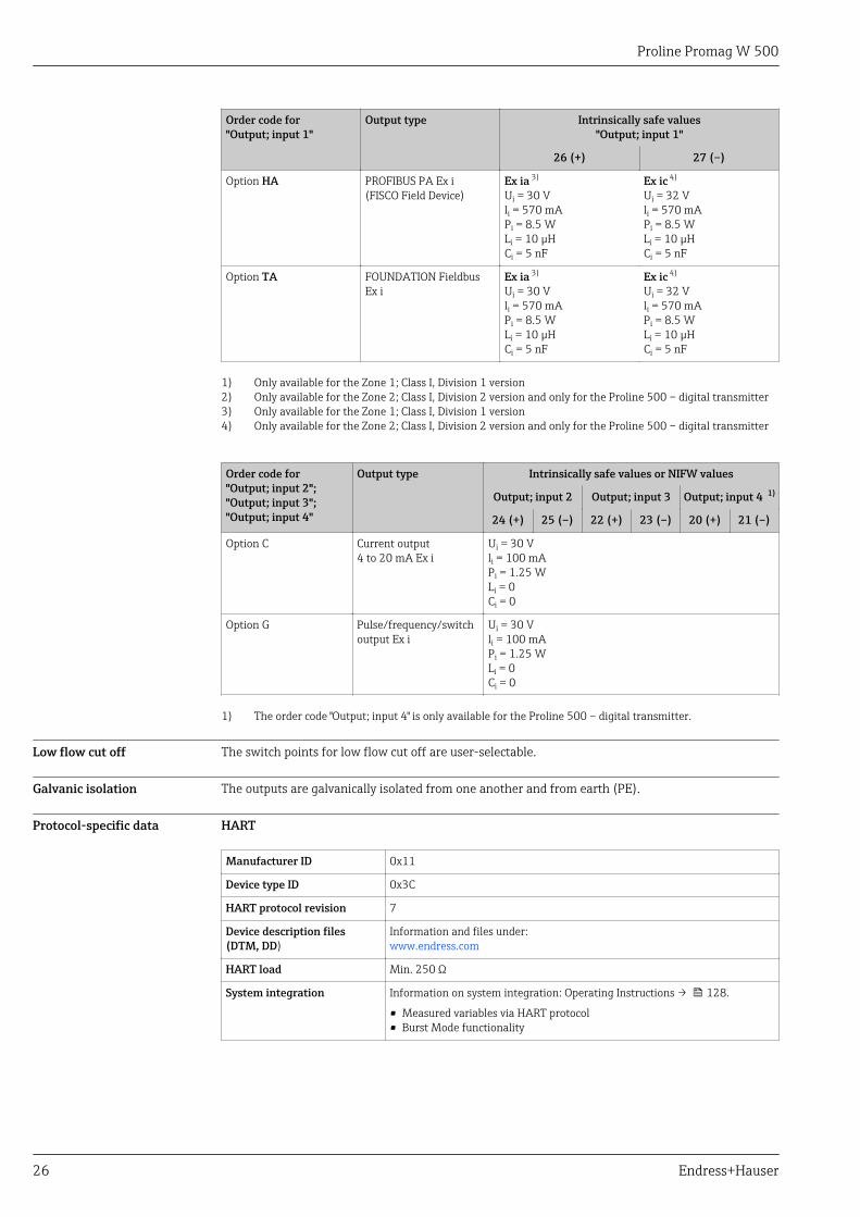
Order code for"Output; input 1"
Output type Intrinsically safe values"Output; input 1"
26 (+) 27 (–)
Option HA PROFIBUS PA Ex i(FISCO Field Device)
Ex ia 3)
Ui = 30 Vli = 570 mAPi = 8.5 WLi = 10 µHCi = 5 nF
Ex ic 4)
Ui = 32 Vli = 570 mAPi = 8.5 WLi = 10 µHCi = 5 nF
Option TA FOUNDATION FieldbusEx i
Ex ia 3)
Ui = 30 Vli = 570 mAPi = 8.5 WLi = 10 µHCi = 5 nF
Ex ic 4)
Ui = 32 Vli = 570 mAPi = 8.5 WLi = 10 µHCi = 5 nF
1) Only available for the Zone 1; Class I, Division 1 version2) Only available for the Zone 2; Class I, Division 2 version and only for the Proline 500 – digital transmitter3) Only available for the Zone 1; Class I, Division 1 version4) Only available for the Zone 2; Class I, Division 2 version and only for the Proline 500 – digital transmitter
Order code for"Output; input 2";"Output; input 3";"Output; input 4"
Output type Intrinsically safe values or NIFW values
Output; input 2 Output; input 3 Output; input 4 1)
24 (+) 25 (–) 22 (+) 23 (–) 20 (+) 21 (–)
Option C Current output4 to 20 mA Ex i
Ui = 30 Vli = 100 mAPi = 1.25 WLi = 0Ci = 0
Option G Pulse/frequency/switchoutput Ex i
Ui = 30 Vli = 100 mAPi = 1.25 WLi = 0Ci = 0
1) The order code "Output; input 4" is only available for the Proline 500 – digital transmitter.
Low flow cut off The switch points for low flow cut off are user-selectable.
Galvanic isolation The outputs are galvanically isolated from one another and from earth (PE).
Protocol-specific data HART
Manufacturer ID 0x11
Device type ID 0x3C
HART protocol revision 7
Device description files(DTM, DD)
Information and files under:www.endress.com
HART load Min. 250 Ω
System integration Information on system integration: Operating Instructions → 128.
• Measured variables via HART protocol• Burst Mode functionality
Proline Promag W 500
Endress+Hauser 27
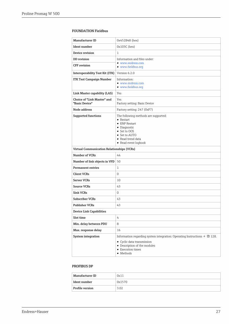
FOUNDATION Fieldbus
Manufacturer ID 0x452B48 (hex)
Ident number 0x103C (hex)
Device revision 1
DD revision Information and files under:• www.endress.com• www.fieldbus.orgCFF revision
Interoperability Test Kit (ITK) Version 6.2.0
ITK Test Campaign Number Information:• www.endress.com• www.fieldbus.org
Link Master capability (LAS) Yes
Choice of "Link Master" and"Basic Device"
YesFactory setting: Basic Device
Node address Factory setting: 247 (0xF7)
Supported functions The following methods are supported:• Restart• ENP Restart• Diagnostic• Set to OOS• Set to AUTO• Read trend data• Read event logbook
Virtual Communication Relationships (VCRs)
Number of VCRs 44
Number of link objects in VFD 50
Permanent entries 1
Client VCRs 0
Server VCRs 10
Source VCRs 43
Sink VCRs 0
Subscriber VCRs 43
Publisher VCRs 43
Device Link Capabilities
Slot time 4
Min. delay between PDU 8
Max. response delay 16
System integration Information regarding system integration: Operating Instructions → 128.
• Cyclic data transmission• Description of the modules• Execution times• Methods
PROFIBUS DP
Manufacturer ID 0x11
Ident number 0x1570
Profile version 3.02
Proline Promag W 500
28 Endress+Hauser
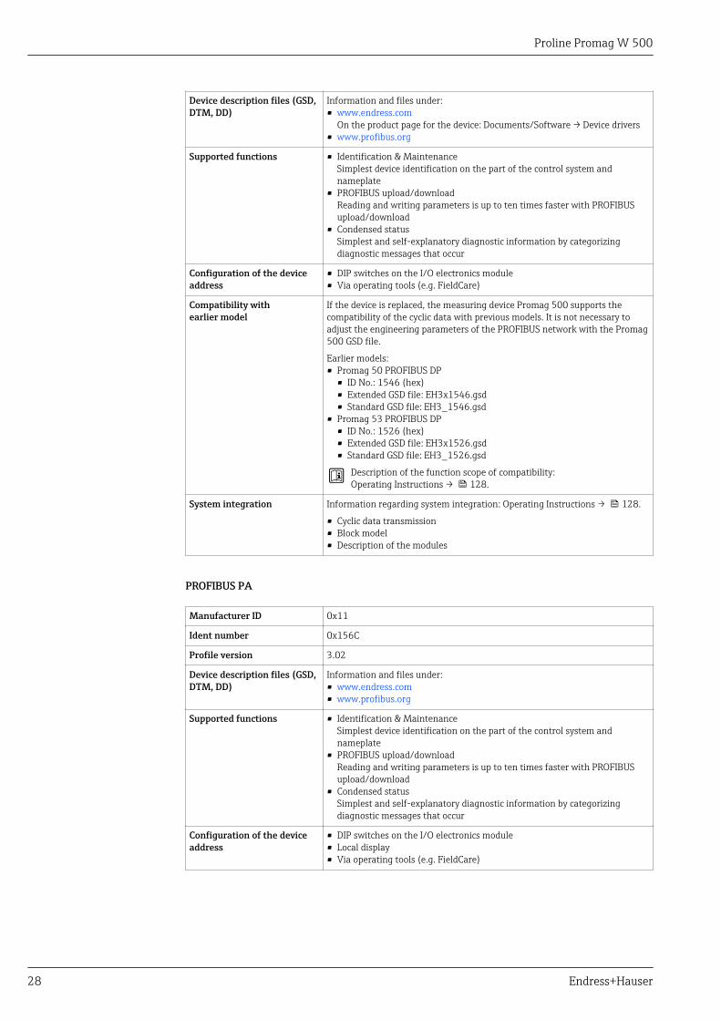
Device description files (GSD,DTM, DD)
Information and files under:• www.endress.com
On the product page for the device: Documents/Software → Device drivers• www.profibus.org
Supported functions • Identification & MaintenanceSimplest device identification on the part of the control system andnameplate
• PROFIBUS upload/downloadReading and writing parameters is up to ten times faster with PROFIBUSupload/download
• Condensed statusSimplest and self-explanatory diagnostic information by categorizingdiagnostic messages that occur
Configuration of the deviceaddress
• DIP switches on the I/O electronics module• Via operating tools (e.g. FieldCare)
Compatibility withearlier model
If the device is replaced, the measuring device Promag 500 supports thecompatibility of the cyclic data with previous models. It is not necessary toadjust the engineering parameters of the PROFIBUS network with the Promag500 GSD file.
Earlier models:• Promag 50 PROFIBUS DP
• ID No.: 1546 (hex)• Extended GSD file: EH3x1546.gsd• Standard GSD file: EH3_1546.gsd
• Promag 53 PROFIBUS DP• ID No.: 1526 (hex)• Extended GSD file: EH3x1526.gsd• Standard GSD file: EH3_1526.gsd
Description of the function scope of compatibility:Operating Instructions → 128.
System integration Information regarding system integration: Operating Instructions → 128.
• Cyclic data transmission• Block model• Description of the modules
PROFIBUS PA
Manufacturer ID 0x11
Ident number 0x156C
Profile version 3.02
Device description files (GSD,DTM, DD)
Information and files under:• www.endress.com• www.profibus.org
Supported functions • Identification & MaintenanceSimplest device identification on the part of the control system andnameplate
• PROFIBUS upload/downloadReading and writing parameters is up to ten times faster with PROFIBUSupload/download
• Condensed statusSimplest and self-explanatory diagnostic information by categorizingdiagnostic messages that occur
Configuration of the deviceaddress
• DIP switches on the I/O electronics module• Local display• Via operating tools (e.g. FieldCare)
Proline Promag W 500
Endress+Hauser 29
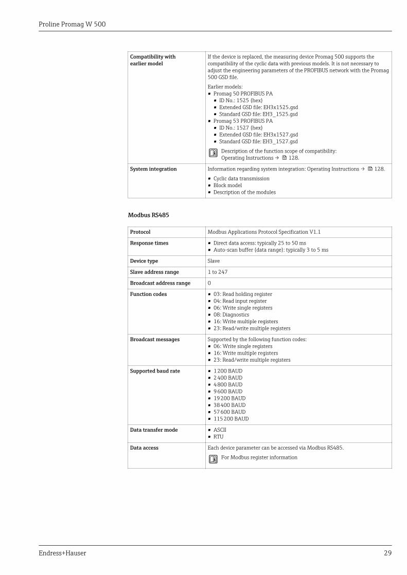
Compatibility withearlier model
If the device is replaced, the measuring device Promag 500 supports thecompatibility of the cyclic data with previous models. It is not necessary toadjust the engineering parameters of the PROFIBUS network with the Promag500 GSD file.
Earlier models:• Promag 50 PROFIBUS PA
• ID No.: 1525 (hex)• Extended GSD file: EH3x1525.gsd• Standard GSD file: EH3_1525.gsd
• Promag 53 PROFIBUS PA• ID No.: 1527 (hex)• Extended GSD file: EH3x1527.gsd• Standard GSD file: EH3_1527.gsd
Description of the function scope of compatibility:Operating Instructions → 128.
System integration Information regarding system integration: Operating Instructions → 128.
• Cyclic data transmission• Block model• Description of the modules
Modbus RS485
Protocol Modbus Applications Protocol Specification V1.1
Response times • Direct data access: typically 25 to 50 ms• Auto-scan buffer (data range): typically 3 to 5 ms
Device type Slave
Slave address range 1 to 247
Broadcast address range 0
Function codes • 03: Read holding register• 04: Read input register• 06: Write single registers• 08: Diagnostics• 16: Write multiple registers• 23: Read/write multiple registers
Broadcast messages Supported by the following function codes:• 06: Write single registers• 16: Write multiple registers• 23: Read/write multiple registers
Supported baud rate • 1 200 BAUD• 2 400 BAUD• 4 800 BAUD• 9 600 BAUD• 19 200 BAUD• 38 400 BAUD• 57 600 BAUD• 115 200 BAUD
Data transfer mode • ASCII• RTU
Data access Each device parameter can be accessed via Modbus RS485.
For Modbus register information
Proline Promag W 500
30 Endress+Hauser
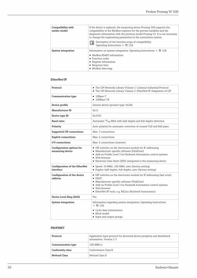
Compatibility withearlier model
If the device is replaced, the measuring device Promag 500 supports thecompatibility of the Modbus registers for the process variables and thediagnostic information with the previous model Promag 53. It is not necessaryto change the engineering parameters in the automation system.
Description of the function scope of compatibility:Operating Instructions → 128.
System integration Information on system integration: Operating Instructions → 128.
• Modbus RS485 information• Function codes• Register information• Response time• Modbus data map
EtherNet/IP
Protocol • The CIP Networks Library Volume 1: Common Industrial Protocol• The CIP Networks Library Volume 2: EtherNet/IP Adaptation of CIP
Communication type • 10Base-T• 100Base-TX
Device profile Generic device (product type: 0x2B)
Manufacturer ID 0x11
Device type ID 0x103C
Baud rates Automatic ¹⁰⁄₁₀₀ Mbit with half-duplex and full-duplex detection
Polarity Auto-polarity for automatic correction of crossed TxD and RxD pairs
Supported CIP connections Max. 3 connections
Explicit connections Max. 6 connections
I/O connections Max. 6 connections (scanner)
Configuration options formeasuring device
• DIP switches on the electronics module for IP addressing• Manufacturer-specific software (FieldCare)• Add-on Profile Level 3 for Rockwell Automation control systems• Web browser• Electronic Data Sheet (EDS) integrated in the measuring device
Configuration of the EtherNetinterface
• Speed: 10 MBit, 100 MBit, auto (factory setting)• Duplex: half-duplex, full-duplex, auto (factory setting)
Configuration of the deviceaddress
• DIP switches on the electronics module for IP addressing (last octet)• DHCP• Manufacturer-specific software (FieldCare)• Add-on Profile Level 3 for Rockwell Automation control systems• Web browser• EtherNet/IP tools, e.g. RSLinx (Rockwell Automation)
Device Level Ring (DLR) Yes
System integration Information regarding system integration: Operating Instructions→ 128.
• Cyclic data transmission• Block model• Input and output groups
PROFINET
Protocol Application layer protocol for decentral device periphery and distributedautomation, Version 2.3
Communication type 100 MBit/s
Conformity class Conformance Class B
Netload Class Netload Class II
Proline Promag W 500
Endress+Hauser 31
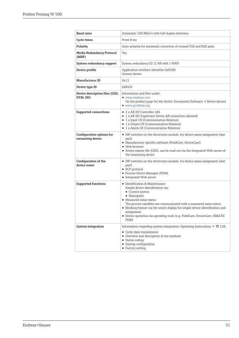
Baud rates Automatic 100 Mbit/s with full-duplex detection
Cycle times From 8 ms
Polarity Auto-polarity for automatic correction of crossed TxD and RxD pairs
Media Redundancy Protocol(MRP)
Yes
System redundancy support System redundancy S2 (2 AR with 1 NAP)
Device profile Application interface identifier 0xF600Generic device
Manufacturer ID 0x11
Device type ID 0x843C
Device description files (GSD,DTM, DD)
Information and files under:• www.endress.com
On the product page for the device: Documents/Software → Device drivers• www.profibus.org
Supported connections • 2 x AR (IO Controller AR)• 1 x AR (IO-Supervisor Device AR connection allowed)• 1 x Input CR (Communication Relation)• 1 x Output CR (Communication Relation)• 1 x Alarm CR (Communication Relation)
Configuration options formeasuring device
• DIP switches on the electronics module, for device name assignment (lastpart)
• Manufacturer-specific software (FieldCare, DeviceCare)• Web browser• Device master file (GSD), can be read out via the integrated Web server of
the measuring device
Configuration of thedevice name
• DIP switches on the electronics module, for device name assignment (lastpart)
• DCP protocol• Process Device Manager (PDM)• Integrated Web server
Supported functions • Identification & MaintenanceSimple device identification via:• Control system• Nameplate
• Measured value statusThe process variables are communicated with a measured value status
• Blinking feature via the onsite display for simple device identification andassignment
• Device operation via operating tools (e.g. FieldCare, DeviceCare, SIMATICPDM)
System integration Information regarding system integration: Operating Instructions → 128.
• Cyclic data transmission• Overview and description of the modules• Status coding• Startup configuration• Factory setting
Proline Promag W 500
32 Endress+Hauser
Power supply
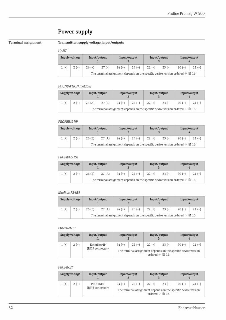
Terminal assignment Transmitter: supply voltage, input/outputs
HART
Supply voltage Input/output1
Input/output2
Input/output3
Input/output4
1 (+) 2 (–) 26 (+) 27 (–) 24 (+) 25 (–) 22 (+) 23 (–) 20 (+) 21 (–)
The terminal assignment depends on the specific device version ordered → 16.
FOUNDATION Fieldbus
Supply voltage Input/output1
Input/output2
Input/output3
Input/output4
1 (+) 2 (–) 26 (A) 27 (B) 24 (+) 25 (–) 22 (+) 23 (–) 20 (+) 21 (–)
The terminal assignment depends on the specific device version ordered → 16.
PROFIBUS DP
Supply voltage Input/output1
Input/output2
Input/output3
Input/output4
1 (+) 2 (–) 26 (B) 27 (A) 24 (+) 25 (–) 22 (+) 23 (–) 20 (+) 21 (–)
The terminal assignment depends on the specific device version ordered → 16.
PROFIBUS PA
Supply voltage Input/output1
Input/output2
Input/output3
Input/output4
1 (+) 2 (–) 26 (B) 27 (A) 24 (+) 25 (–) 22 (+) 23 (–) 20 (+) 21 (–)
The terminal assignment depends on the specific device version ordered → 16.
Modbus RS485
Supply voltage Input/output1
Input/output2
Input/output3
Input/output4
1 (+) 2 (–) 26 (B) 27 (A) 24 (+) 25 (–) 22 (+) 23 (–) 20 (+) 21 (–)
The terminal assignment depends on the specific device version ordered → 16.
EtherNet/IP
Supply voltage Input/output1
Input/output2
Input/output3
Input/output4
1 (+) 2 (–) EtherNet/IP(RJ45 connector)
24 (+) 25 (–) 22 (+) 23 (–) 20 (+) 21 (–)
The terminal assignment depends on the specific device versionordered → 16.
PROFINET
Supply voltage Input/output1
Input/output2
Input/output3
Input/output4
1 (+) 2 (–) PROFINET(RJ45 connector)
24 (+) 25 (–) 22 (+) 23 (–) 20 (+) 21 (–)
The terminal assignment depends on the specific device versionordered → 16.
Proline Promag W 500
Endress+Hauser 33
Transmitter and sensor connection housing: connecting cable
The sensor and transmitter, which are mounted in separate locations, are interconnected by aconnecting cable. The cable is connected via the sensor connection housing and the transmitterhousing.
Terminal assignment and connection of the connecting cable:• Proline 500 – digital→ 36• Proline 500 → 36
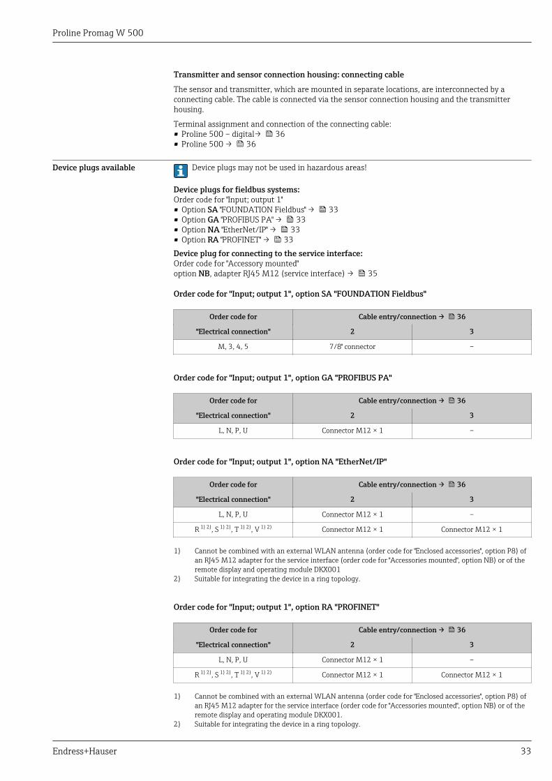
Device plugs available Device plugs may not be used in hazardous areas!
Device plugs for fieldbus systems:Order code for "Input; output 1"• Option SA "FOUNDATION Fieldbus" → 33• Option GA "PROFIBUS PA" → 33• Option NA "EtherNet/IP" → 33• Option RA "PROFINET" → 33Device plug for connecting to the service interface:Order code for "Accessory mounted"option NB, adapter RJ45 M12 (service interface) → 35
Order code for "Input; output 1", option SA "FOUNDATION Fieldbus"
Order code for Cable entry/connection → 36
"Electrical connection" 2 3
M, 3, 4, 5 7/8" connector –
Order code for "Input; output 1", option GA "PROFIBUS PA"
Order code for Cable entry/connection → 36
"Electrical connection" 2 3
L, N, P, U Connector M12 × 1 –
Order code for "Input; output 1", option NA "EtherNet/IP"
Order code for Cable entry/connection → 36
"Electrical connection" 2 3
L, N, P, U Connector M12 × 1 –
R 1) 2), S 1) 2), T 1) 2), V 1) 2) Connector M12 × 1 Connector M12 × 1
1) Cannot be combined with an external WLAN antenna (order code for "Enclosed accessories", option P8) ofan RJ45 M12 adapter for the service interface (order code for "Accessories mounted", option NB) or of theremote display and operating module DKX001
2) Suitable for integrating the device in a ring topology.
Order code for "Input; output 1", option RA "PROFINET"
Order code for Cable entry/connection → 36
"Electrical connection" 2 3
L, N, P, U Connector M12 × 1 –
R 1) 2), S 1) 2), T 1) 2), V 1) 2) Connector M12 × 1 Connector M12 × 1
1) Cannot be combined with an external WLAN antenna (order code for "Enclosed accessories", option P8) ofan RJ45 M12 adapter for the service interface (order code for "Accessories mounted", option NB) or of theremote display and operating module DKX001.
2) Suitable for integrating the device in a ring topology.
Proline Promag W 500
34 Endress+Hauser
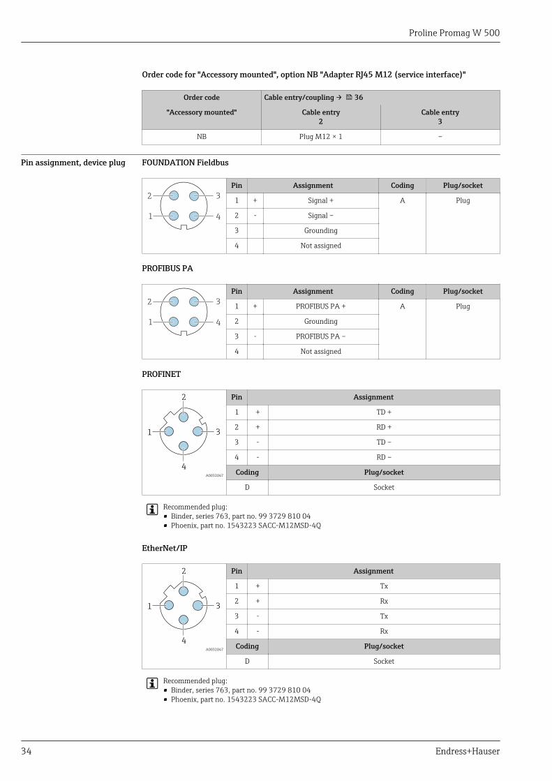
Order code for "Accessory mounted", option NB "Adapter RJ45 M12 (service interface)"
Order code Cable entry/coupling → 36
"Accessory mounted" Cable entry2
Cable entry3
NB Plug M12 × 1 –
Pin assignment, device plug FOUNDATION Fieldbus
1
2
4
3
Pin Assignment Coding Plug/socket
1 + Signal + A Plug
2 - Signal –
3 Grounding
4 Not assigned
PROFIBUS PA
1
2
4
3
Pin Assignment Coding Plug/socket
1 + PROFIBUS PA + A Plug
2 Grounding
3 - PROFIBUS PA –
4 Not assigned
PROFINET
3
2
4
1
A0032047
Pin Assignment
1 + TD +
2 + RD +
3 - TD –
4 - RD –
Coding Plug/socket
D Socket
Recommended plug:• Binder, series 763, part no. 99 3729 810 04• Phoenix, part no. 1543223 SACC-M12MSD-4Q
EtherNet/IP
3
2
4
1
A0032047
Pin Assignment
1 + Tx
2 + Rx
3 - Tx
4 - Rx
Coding Plug/socket
D Socket
Recommended plug:• Binder, series 763, part no. 99 3729 810 04• Phoenix, part no. 1543223 SACC-M12MSD-4Q
Proline Promag W 500
Endress+Hauser 35
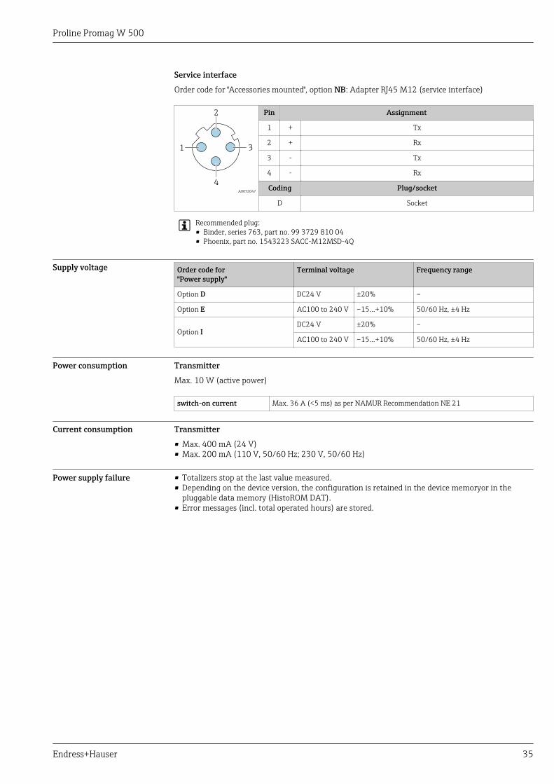
Service interface
Order code for "Accessories mounted", option NB: Adapter RJ45 M12 (service interface)
3
2
4
1
A0032047
Pin Assignment
1 + Tx
2 + Rx
3 - Tx
4 - Rx
Coding Plug/socket
D Socket
Recommended plug:• Binder, series 763, part no. 99 3729 810 04• Phoenix, part no. 1543223 SACC-M12MSD-4Q
Supply voltage Order code for"Power supply"
Terminal voltage Frequency range
Option D DC24 V ±20% –
Option E AC100 to 240 V –15…+10% 50/60 Hz, ±4 Hz
Option IDC24 V ±20% –
AC100 to 240 V –15…+10% 50/60 Hz, ±4 Hz
Power consumption Transmitter
Max. 10 W (active power)
switch-on current Max. 36 A (<5 ms) as per NAMUR Recommendation NE 21
Current consumption Transmitter
• Max. 400 mA (24 V)• Max. 200 mA (110 V, 50/60 Hz; 230 V, 50/60 Hz)
Power supply failure • Totalizers stop at the last value measured.• Depending on the device version, the configuration is retained in the device memoryor in the
pluggable data memory (HistoROM DAT).• Error messages (incl. total operated hours) are stored.
Proline Promag W 500
36 Endress+Hauser
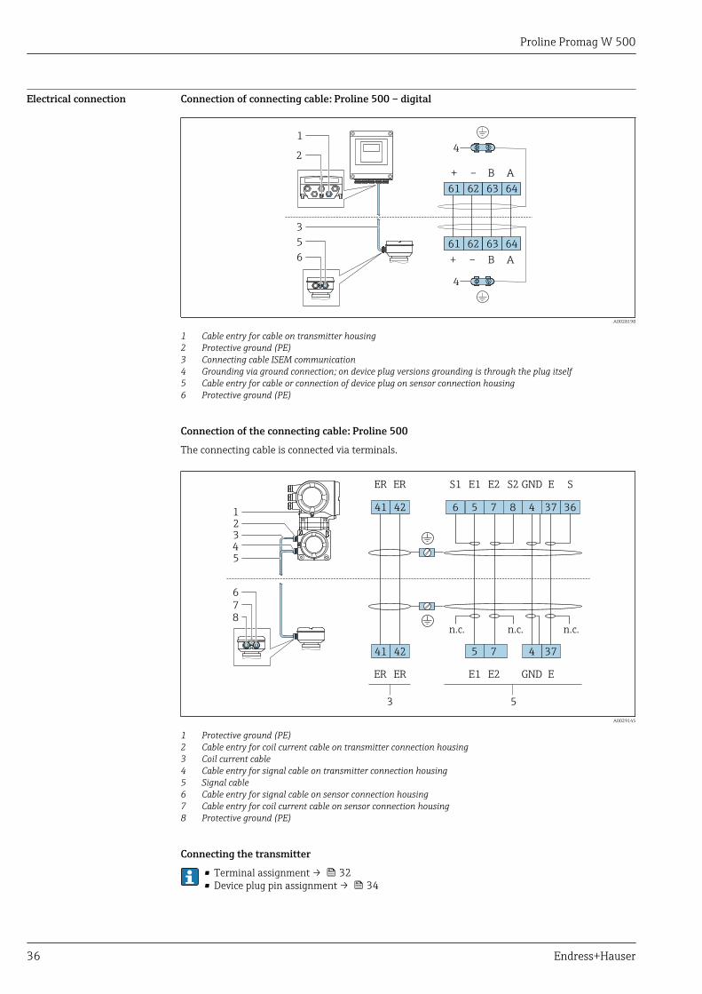
Electrical connection Connection of connecting cable: Proline 500 – digital
+ – AB
61 62 63 64
+ – AB
61 62 63 64
4
2
1
4
3
5
6
A0028198
1 Cable entry for cable on transmitter housing2 Protective ground (PE)3 Connecting cable ISEM communication4 Grounding via ground connection; on device plug versions grounding is through the plug itself5 Cable entry for cable or connection of device plug on sensor connection housing6 Protective ground (PE)
Connection of the connecting cable: Proline 500
The connecting cable is connected via terminals.
41 42
GNDE1S1 E2 S2 SE
GNDE1 E2 E
ER
ER
ER
ER
456 7 8 37 3641 42
45 7 37
n.c.n.c.
53
2
8
1
3
7
4
5
6
n.c.
A0029145
1 Protective ground (PE)2 Cable entry for coil current cable on transmitter connection housing3 Coil current cable4 Cable entry for signal cable on transmitter connection housing5 Signal cable6 Cable entry for signal cable on sensor connection housing7 Cable entry for coil current cable on sensor connection housing8 Protective ground (PE)
Connecting the transmitter
• Terminal assignment → 32• Device plug pin assignment → 34
Proline Promag W 500
Endress+Hauser 37
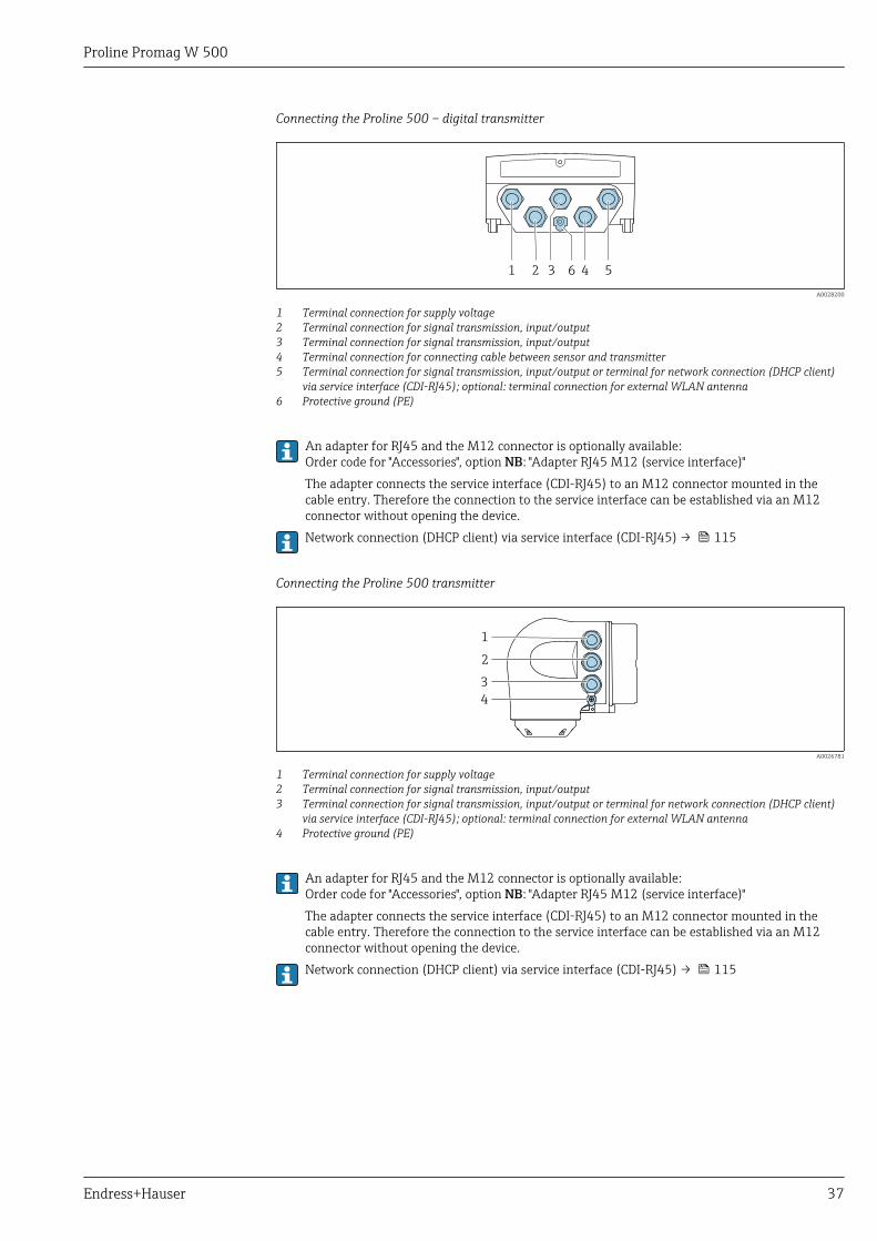
Connecting the Proline 500 – digital transmitter
1 2 3 4 56
A0028200
1 Terminal connection for supply voltage2 Terminal connection for signal transmission, input/output3 Terminal connection for signal transmission, input/output4 Terminal connection for connecting cable between sensor and transmitter5 Terminal connection for signal transmission, input/output or terminal for network connection (DHCP client)
via service interface (CDI-RJ45); optional: terminal connection for external WLAN antenna6 Protective ground (PE)
An adapter for RJ45 and the M12 connector is optionally available:Order code for "Accessories", option NB: "Adapter RJ45 M12 (service interface)"The adapter connects the service interface (CDI-RJ45) to an M12 connector mounted in thecable entry. Therefore the connection to the service interface can be established via an M12connector without opening the device.Network connection (DHCP client) via service interface (CDI-RJ45) → 115
Connecting the Proline 500 transmitter
1
2
3
4
A0026781
1 Terminal connection for supply voltage2 Terminal connection for signal transmission, input/output3 Terminal connection for signal transmission, input/output or terminal for network connection (DHCP client)
via service interface (CDI-RJ45); optional: terminal connection for external WLAN antenna4 Protective ground (PE)
An adapter for RJ45 and the M12 connector is optionally available:Order code for "Accessories", option NB: "Adapter RJ45 M12 (service interface)"The adapter connects the service interface (CDI-RJ45) to an M12 connector mounted in thecable entry. Therefore the connection to the service interface can be established via an M12connector without opening the device.Network connection (DHCP client) via service interface (CDI-RJ45) → 115
Proline Promag W 500
38 Endress+Hauser
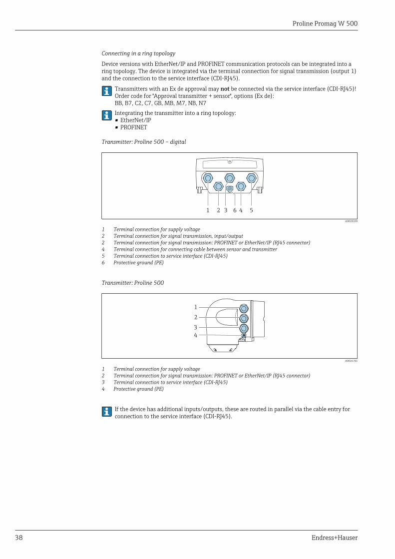
Connecting in a ring topology
Device versions with EtherNet/IP and PROFINET communication protocols can be integrated into aring topology. The device is integrated via the terminal connection for signal transmission (output 1)and the connection to the service interface (CDI-RJ45).
Transmitters with an Ex de approval may not be connected via the service interface (CDI-RJ45)!Order code for "Approval transmitter + sensor", options (Ex de):BB, B7, C2, C7, GB, MB, M7, NB, N7Integrating the transmitter into a ring topology:• EtherNet/IP• PROFINET
Transmitter: Proline 500 – digital
1 2 3 4 56
A0028200
1 Terminal connection for supply voltage2 Terminal connection for signal transmission, input/output2 Terminal connection for signal transmission: PROFINET or EtherNet/IP (RJ45 connector)4 Terminal connection for connecting cable between sensor and transmitter5 Terminal connection to service interface (CDI-RJ45)6 Protective ground (PE)
Transmitter: Proline 500
1
2
3
4
A0026781
1 Terminal connection for supply voltage2 Terminal connection for signal transmission: PROFINET or EtherNet/IP (RJ45 connector)3 Terminal connection to service interface (CDI-RJ45)4 Protective ground (PE)
If the device has additional inputs/outputs, these are routed in parallel via the cable entry forconnection to the service interface (CDI-RJ45).
Proline Promag W 500
Endress+Hauser 39
Connection examples
Current output 4 to 20 mA HART
4
4...20 mA
5
21 3
6
A0029055
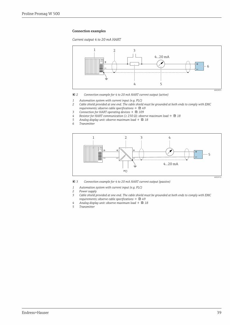
2 Connection example for 4 to 20 mA HART current output (active)
1 Automation system with current input (e.g. PLC)2 Cable shield provided at one end. The cable shield must be grounded at both ends to comply with EMC
requirements; observe cable specifications → 493 Connection for HART operating devices → 1094 Resistor for HART communication (≥ 250 Ω): observe maximum load → 185 Analog display unit: observe maximum load → 186 Transmitter
2 3
4...20 mA
41
5
A0028762
3 Connection example for 4 to 20 mA HART current output (passive)
1 Automation system with current input (e.g. PLC)2 Power supply3 Cable shield provided at one end. The cable shield must be grounded at both ends to comply with EMC
requirements; observe cable specifications → 494 Analog display unit: observe maximum load → 185 Transmitter
Proline Promag W 500
40 Endress+Hauser
HART input
2
4...20 mA
41
2
3
3
6
5
A0028763
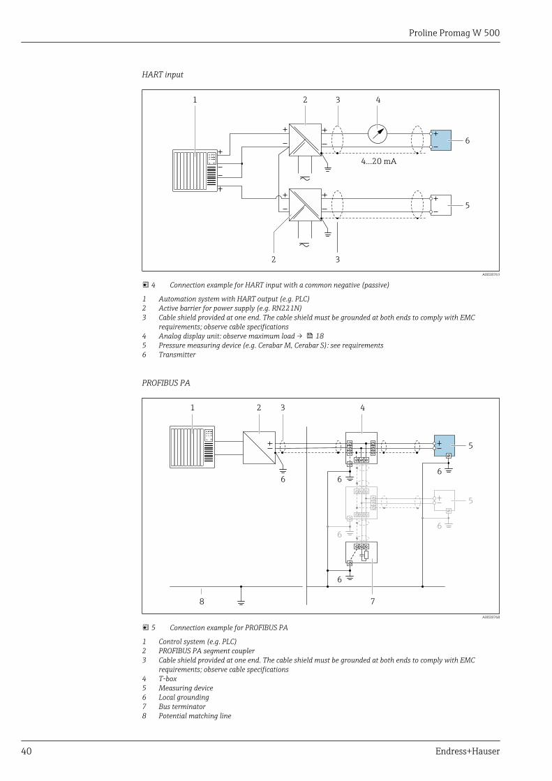
4 Connection example for HART input with a common negative (passive)
1 Automation system with HART output (e.g. PLC)2 Active barrier for power supply (e.g. RN221N)3 Cable shield provided at one end. The cable shield must be grounded at both ends to comply with EMC
requirements; observe cable specifications4 Analog display unit: observe maximum load → 185 Pressure measuring device (e.g. Cerabar M, Cerabar S): see requirements6 Transmitter
PROFIBUS PA
21 3 4
78
6 6
6
6
5
6
6
5
A0028768
5 Connection example for PROFIBUS PA
1 Control system (e.g. PLC)2 PROFIBUS PA segment coupler3 Cable shield provided at one end. The cable shield must be grounded at both ends to comply with EMC
requirements; observe cable specifications4 T-box5 Measuring device6 Local grounding7 Bus terminator8 Potential matching line
Proline Promag W 500
Endress+Hauser 41
PROFIBUS DP
21
A
B
3
4
4
A
B
A
B
A0028765
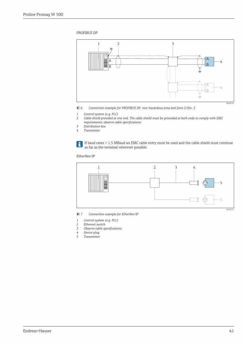
6 Connection example for PROFIBUS DP, non-hazardous area and Zone 2/Div. 2
1 Control system (e.g. PLC)2 Cable shield provided at one end. The cable shield must be grounded at both ends to comply with EMC
requirements; observe cable specifications3 Distribution box4 Transmitter
If baud rates > 1.5 MBaud an EMC cable entry must be used and the cable shield must continueas far as the terminal wherever possible.
EtherNet/IP
1 2 43
5
5
A0028767
7 Connection example for EtherNet/IP
1 Control system (e.g. PLC)2 Ethernet switch3 Observe cable specifications4 Device plug5 Transmitter
Proline Promag W 500
42 Endress+Hauser
EtherNet/IP: DLR (Device Level Ring)
1 2 53 4
4
A0027544
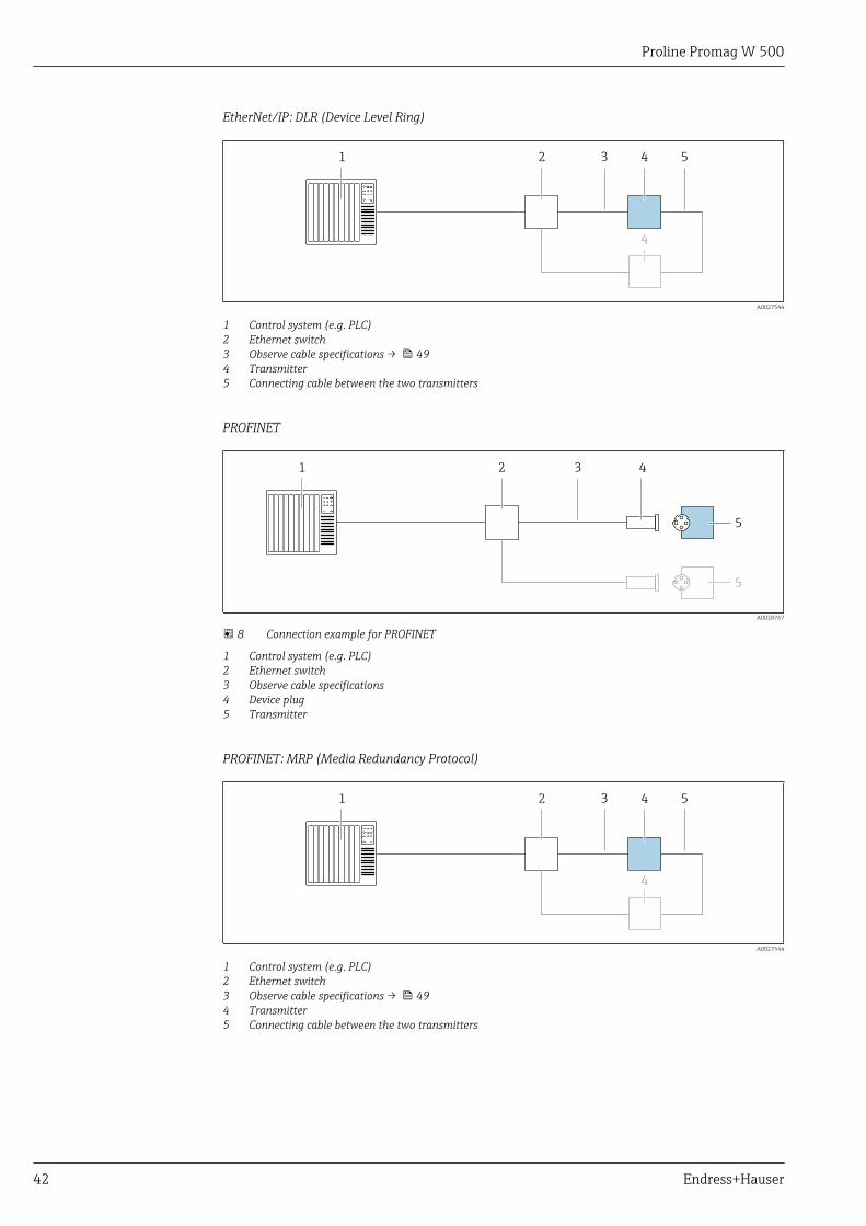
1 Control system (e.g. PLC)2 Ethernet switch3 Observe cable specifications → 494 Transmitter5 Connecting cable between the two transmitters
PROFINET
1 2 43
5
5
A0028767
8 Connection example for PROFINET
1 Control system (e.g. PLC)2 Ethernet switch3 Observe cable specifications4 Device plug5 Transmitter
PROFINET: MRP (Media Redundancy Protocol)
1 2 53 4
4
A0027544
1 Control system (e.g. PLC)2 Ethernet switch3 Observe cable specifications → 494 Transmitter5 Connecting cable between the two transmitters
Proline Promag W 500
Endress+Hauser 43
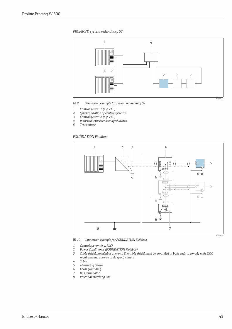
PROFINET: system redundancy S2
1
2
555
4
3
A0039553
9 Connection example for system redundancy S2
1 Control system 1 (e.g. PLC)2 Synchronization of control systems3 Control system 2 (e.g. PLC)4 Industrial Ethernet Managed Switch5 Transmitter
FOUNDATION Fieldbus
21 3 4
78
6 6
6
6
5
6
6
5
A0028768
10 Connection example for FOUNDATION Fieldbus
1 Control system (e.g. PLC)2 Power Conditioner (FOUNDATION Fieldbus)3 Cable shield provided at one end. The cable shield must be grounded at both ends to comply with EMC
requirements; observe cable specifications4 T-box5 Measuring device6 Local grounding7 Bus terminator8 Potential matching line
Proline Promag W 500
44 Endress+Hauser
Modbus RS485
21
A
B
3
4
4
A
B
A
B
A0028765
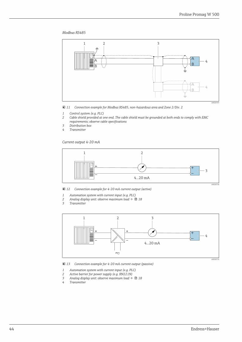
11 Connection example for Modbus RS485, non-hazardous area and Zone 2/Div. 2
1 Control system (e.g. PLC)2 Cable shield provided at one end. The cable shield must be grounded at both ends to comply with EMC
requirements; observe cable specifications3 Distribution box4 Transmitter
Current output 4-20 mA
4...20 mA
21
3
A0028758
12 Connection example for 4-20 mA current output (active)
1 Automation system with current input (e.g. PLC)2 Analog display unit: observe maximum load → 183 Transmitter
2
4...20 mA
31
4
A0028759
13 Connection example for 4-20 mA current output (passive)
1 Automation system with current input (e.g. PLC)2 Active barrier for power supply (e.g. RN221N)3 Analog display unit: observe maximum load → 184 Transmitter
Proline Promag W 500
Endress+Hauser 45
Pulse/frequency output
1 2
3
12345
A0028761
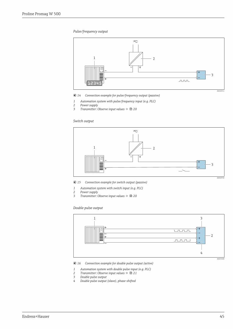
14 Connection example for pulse/frequency output (passive)
1 Automation system with pulse/frequency input (e.g. PLC)2 Power supply3 Transmitter: Observe input values → 20
Switch output
1 2
3
A0028760
15 Connection example for switch output (passive)
1 Automation system with switch input (e.g. PLC)2 Power supply3 Transmitter: Observe input values → 20
Double pulse output
1
2
3
4
A0029280
16 Connection example for double pulse output (active)
1 Automation system with double pulse input (e.g. PLC)2 Transmitter: Observe input values → 213 Double pulse output4 Double pulse output (slave), phase-shifted
Proline Promag W 500
46 Endress+Hauser
1
3
2
4
5
A0029279
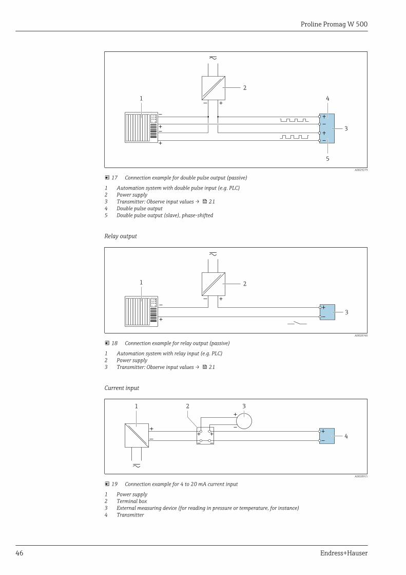
17 Connection example for double pulse output (passive)
1 Automation system with double pulse input (e.g. PLC)2 Power supply3 Transmitter: Observe input values → 214 Double pulse output5 Double pulse output (slave), phase-shifted
Relay output
1 2
3
A0028760
18 Connection example for relay output (passive)
1 Automation system with relay input (e.g. PLC)2 Power supply3 Transmitter: Observe input values → 21
Current input
31
4
2
A0028915
19 Connection example for 4 to 20 mA current input
1 Power supply2 Terminal box3 External measuring device (for reading in pressure or temperature, for instance)4 Transmitter
Proline Promag W 500
Endress+Hauser 47
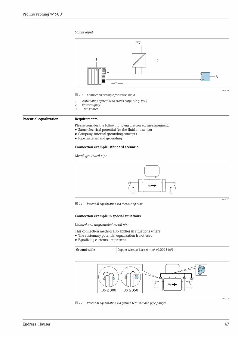
Status input
1 2
3
A0028764
20 Connection example for status input
1 Automation system with status output (e.g. PLC)2 Power supply3 Transmitter
Potential equalization Requirements
Please consider the following to ensure correct measurement:• Same electrical potential for the fluid and sensor• Company-internal grounding concepts• Pipe material and grounding
Connection example, standard scenario
Metal, grounded pipe
A0016315
21 Potential equalization via measuring tube
Connection example in special situations
Unlined and ungrounded metal pipe
This connection method also applies in situations where:• The customary potential equalization is not used• Equalizing currents are present
Ground cable Copper wire, at least 6 mm2 (0.0093 in2)
DN 300≤ DN 350≥
A0029338
22 Potential equalization via ground terminal and pipe flanges
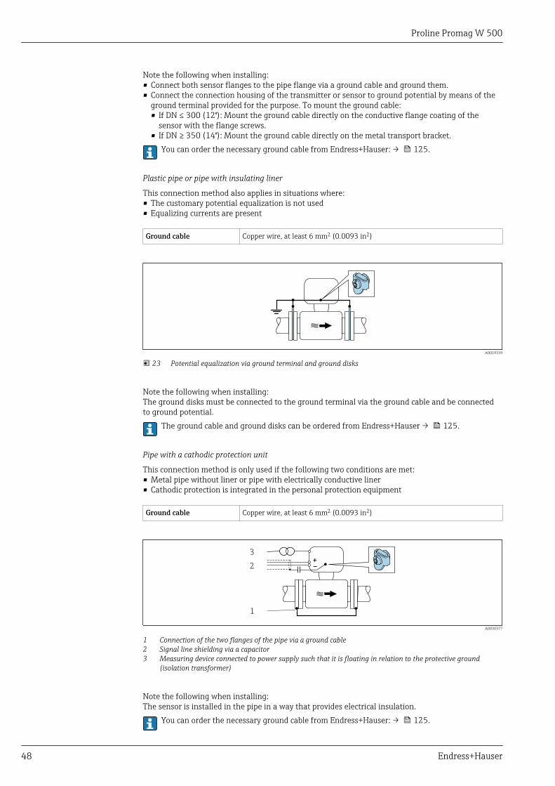
Proline Promag W 500
48 Endress+Hauser
Note the following when installing:• Connect both sensor flanges to the pipe flange via a ground cable and ground them.• Connect the connection housing of the transmitter or sensor to ground potential by means of the
ground terminal provided for the purpose. To mount the ground cable:• If DN ≤ 300 (12"): Mount the ground cable directly on the conductive flange coating of the
sensor with the flange screws.• If DN ≥ 350 (14"): Mount the ground cable directly on the metal transport bracket.
You can order the necessary ground cable from Endress+Hauser: → 125.
Plastic pipe or pipe with insulating liner
This connection method also applies in situations where:• The customary potential equalization is not used• Equalizing currents are present
Ground cable Copper wire, at least 6 mm2 (0.0093 in2)
A0029339
23 Potential equalization via ground terminal and ground disks
Note the following when installing:The ground disks must be connected to the ground terminal via the ground cable and be connectedto ground potential.
The ground cable and ground disks can be ordered from Endress+Hauser → 125.
Pipe with a cathodic protection unit
This connection method is only used if the following two conditions are met:• Metal pipe without liner or pipe with electrically conductive liner• Cathodic protection is integrated in the personal protection equipment
Ground cable Copper wire, at least 6 mm2 (0.0093 in2)
+
–
1
2
3
A0030377
1 Connection of the two flanges of the pipe via a ground cable2 Signal line shielding via a capacitor3 Measuring device connected to power supply such that it is floating in relation to the protective ground
(isolation transformer)
Note the following when installing:The sensor is installed in the pipe in a way that provides electrical insulation.
You can order the necessary ground cable from Endress+Hauser: → 125.
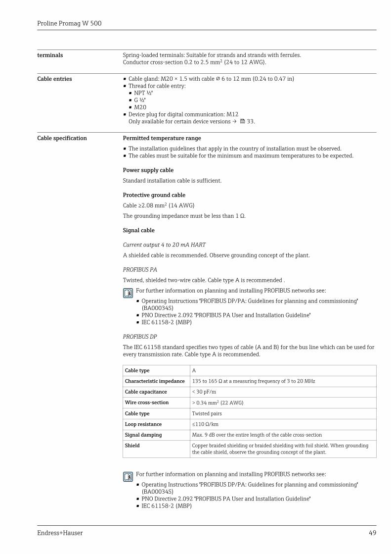
Proline Promag W 500
Endress+Hauser 49
terminals Spring-loaded terminals: Suitable for strands and strands with ferrules.Conductor cross-section 0.2 to 2.5 mm2 (24 to 12 AWG).
Cable entries • Cable gland: M20 × 1.5 with cable 6 to 12 mm (0.24 to 0.47 in)• Thread for cable entry:
• NPT ½"• G ½"• M20
• Device plug for digital communication: M12Only available for certain device versions → 33.
Cable specification Permitted temperature range
• The installation guidelines that apply in the country of installation must be observed.• The cables must be suitable for the minimum and maximum temperatures to be expected.
Power supply cable
Standard installation cable is sufficient.
Protective ground cable
Cable ≥2.08 mm2 (14 AWG)
The grounding impedance must be less than 1 Ω.
Signal cable
Current output 4 to 20 mA HART
A shielded cable is recommended. Observe grounding concept of the plant.
PROFIBUS PA
Twisted, shielded two-wire cable. Cable type A is recommended .
For further information on planning and installing PROFIBUS networks see:
• Operating Instructions "PROFIBUS DP/PA: Guidelines for planning and commissioning"(BA00034S)
• PNO Directive 2.092 "PROFIBUS PA User and Installation Guideline"• IEC 61158-2 (MBP)
PROFIBUS DP
The IEC 61158 standard specifies two types of cable (A and B) for the bus line which can be used forevery transmission rate. Cable type A is recommended.
Cable type A
Characteristic impedance 135 to 165 Ω at a measuring frequency of 3 to 20 MHz
Cable capacitance < 30 pF/m
Wire cross-section > 0.34 mm2 (22 AWG)
Cable type Twisted pairs
Loop resistance ≤110 Ω/km
Signal damping Max. 9 dB over the entire length of the cable cross-section
Shield Copper braided shielding or braided shielding with foil shield. When groundingthe cable shield, observe the grounding concept of the plant.
For further information on planning and installing PROFIBUS networks see:
• Operating Instructions "PROFIBUS DP/PA: Guidelines for planning and commissioning"(BA00034S)
• PNO Directive 2.092 "PROFIBUS PA User and Installation Guideline"• IEC 61158-2 (MBP)
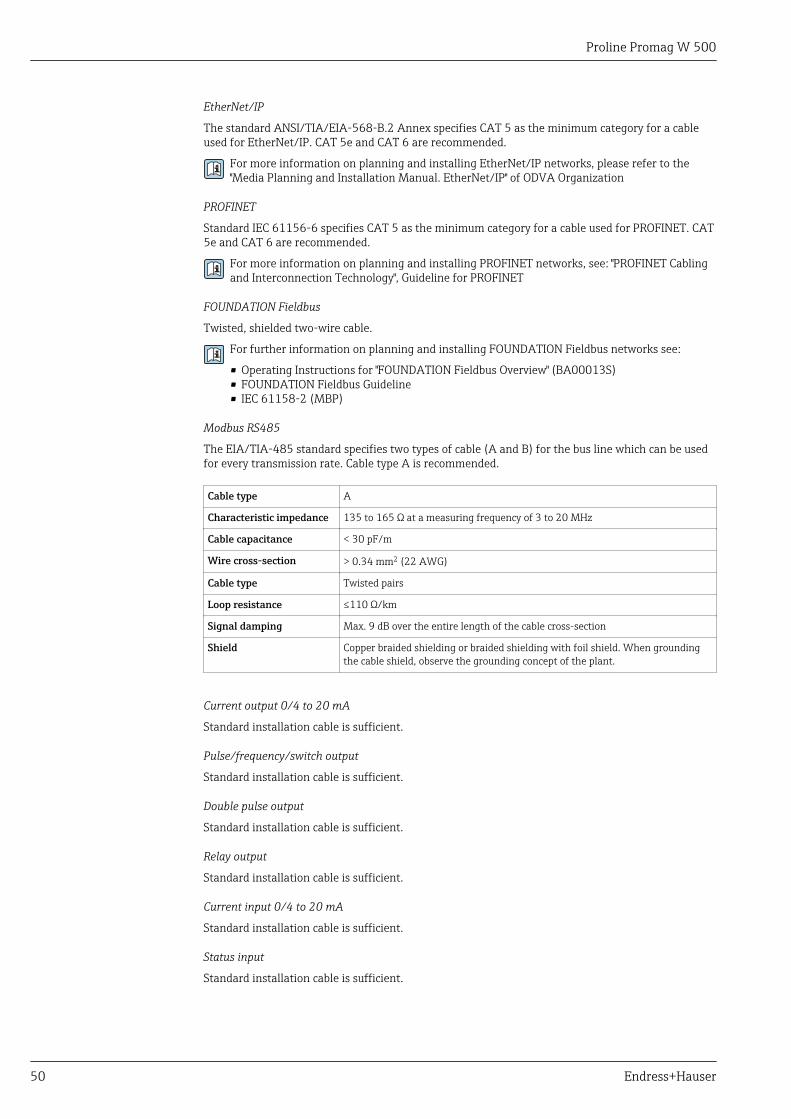
Proline Promag W 500
50 Endress+Hauser
EtherNet/IP
The standard ANSI/TIA/EIA-568-B.2 Annex specifies CAT 5 as the minimum category for a cableused for EtherNet/IP. CAT 5e and CAT 6 are recommended.
For more information on planning and installing EtherNet/IP networks, please refer to the"Media Planning and Installation Manual. EtherNet/IP" of ODVA Organization
PROFINET
Standard IEC 61156-6 specifies CAT 5 as the minimum category for a cable used for PROFINET. CAT5e and CAT 6 are recommended.
For more information on planning and installing PROFINET networks, see: "PROFINET Cablingand Interconnection Technology", Guideline for PROFINET
FOUNDATION Fieldbus
Twisted, shielded two-wire cable.
For further information on planning and installing FOUNDATION Fieldbus networks see:
• Operating Instructions for "FOUNDATION Fieldbus Overview" (BA00013S)• FOUNDATION Fieldbus Guideline• IEC 61158-2 (MBP)
Modbus RS485
The EIA/TIA-485 standard specifies two types of cable (A and B) for the bus line which can be usedfor every transmission rate. Cable type A is recommended.
Cable type A
Characteristic impedance 135 to 165 Ω at a measuring frequency of 3 to 20 MHz
Cable capacitance < 30 pF/m
Wire cross-section > 0.34 mm2 (22 AWG)
Cable type Twisted pairs
Loop resistance ≤110 Ω/km
Signal damping Max. 9 dB over the entire length of the cable cross-section
Shield Copper braided shielding or braided shielding with foil shield. When groundingthe cable shield, observe the grounding concept of the plant.
Current output 0/4 to 20 mA
Standard installation cable is sufficient.
Pulse/frequency/switch output
Standard installation cable is sufficient.
Double pulse output
Standard installation cable is sufficient.
Relay output
Standard installation cable is sufficient.
Current input 0/4 to 20 mA
Standard installation cable is sufficient.
Status input
Standard installation cable is sufficient.
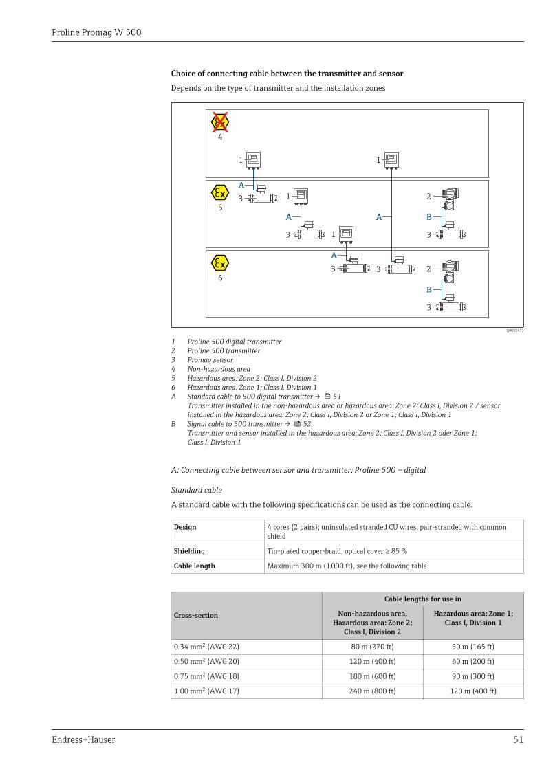
Proline Promag W 500
Endress+Hauser 51
Choice of connecting cable between the transmitter and sensor
Depends on the type of transmitter and the installation zones
2
3
B
1
3
A
1
3
A
1
3
A
1
3
A
2
3
B
4
5
6
A0032477
1 Proline 500 digital transmitter2 Proline 500 transmitter3 Promag sensor4 Non-hazardous area5 Hazardous area: Zone 2; Class I, Division 26 Hazardous area: Zone 1; Class I, Division 1A Standard cable to 500 digital transmitter → 51
Transmitter installed in the non-hazardous area or hazardous area: Zone 2; Class I, Division 2 / sensorinstalled in the hazardous area: Zone 2; Class I, Division 2 or Zone 1; Class I, Division 1
B Signal cable to 500 transmitter → 52Transmitter and sensor installed in the hazardous area: Zone 2; Class I, Division 2 oder Zone 1;Class I, Division 1
A: Connecting cable between sensor and transmitter: Proline 500 – digital
Standard cable
A standard cable with the following specifications can be used as the connecting cable.
Design 4 cores (2 pairs); uninsulated stranded CU wires; pair-stranded with commonshield
Shielding Tin-plated copper-braid, optical cover ≥ 85 %
Cable length Maximum 300 m (1 000 ft), see the following table.
Cross-section
Cable lengths for use in
Non-hazardous area,Hazardous area: Zone 2;
Class I, Division 2
Hazardous area: Zone 1;Class I, Division 1
0.34 mm2 (AWG 22) 80 m (270 ft) 50 m (165 ft)
0.50 mm2 (AWG 20) 120 m (400 ft) 60 m (200 ft)
0.75 mm2 (AWG 18) 180 m (600 ft) 90 m (300 ft)
1.00 mm2 (AWG 17) 240 m (800 ft) 120 m (400 ft)
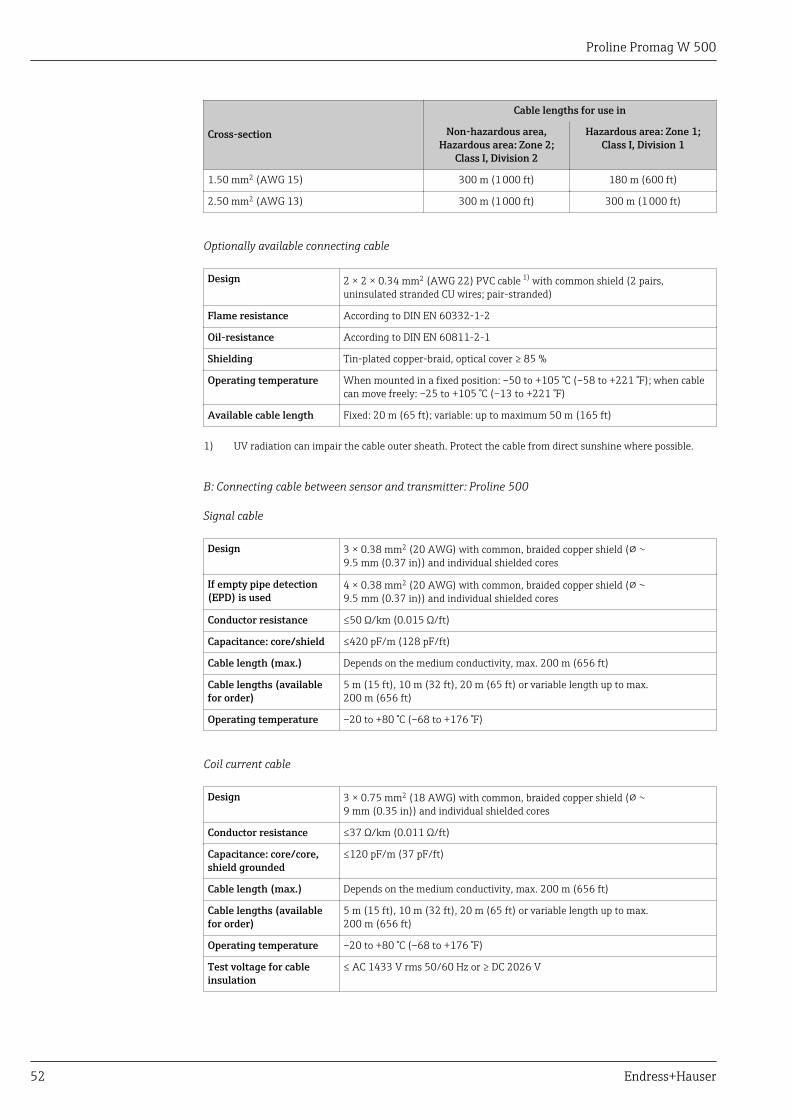
Proline Promag W 500
52 Endress+Hauser
Cross-section
Cable lengths for use in
Non-hazardous area,Hazardous area: Zone 2;
Class I, Division 2
Hazardous area: Zone 1;Class I, Division 1
1.50 mm2 (AWG 15) 300 m (1 000 ft) 180 m (600 ft)
2.50 mm2 (AWG 13) 300 m (1 000 ft) 300 m (1 000 ft)
Optionally available connecting cable
Design 2 × 2 × 0.34 mm2 (AWG 22) PVC cable 1) with common shield (2 pairs,uninsulated stranded CU wires; pair-stranded)
Flame resistance According to DIN EN 60332-1-2
Oil-resistance According to DIN EN 60811-2-1
Shielding Tin-plated copper-braid, optical cover ≥ 85 %
Operating temperature When mounted in a fixed position: –50 to +105 °C (–58 to +221 °F); when cablecan move freely: –25 to +105 °C (–13 to +221 °F)
Available cable length Fixed: 20 m (65 ft); variable: up to maximum 50 m (165 ft)
1) UV radiation can impair the cable outer sheath. Protect the cable from direct sunshine where possible.
B: Connecting cable between sensor and transmitter: Proline 500
Signal cable
Design 3 × 0.38 mm2 (20 AWG) with common, braided copper shield ( 9.5 mm (0.37 in)) and individual shielded cores
If empty pipe detection(EPD) is used
4 × 0.38 mm2 (20 AWG) with common, braided copper shield ( 9.5 mm (0.37 in)) and individual shielded cores
Conductor resistance ≤50 Ω/km (0.015 Ω/ft)
Capacitance: core/shield ≤420 pF/m (128 pF/ft)
Cable length (max.) Depends on the medium conductivity, max. 200 m (656 ft)
Cable lengths (availablefor order)
5 m (15 ft), 10 m (32 ft), 20 m (65 ft) or variable length up to max.200 m (656 ft)
Operating temperature –20 to +80 °C (–68 to +176 °F)
Coil current cable
Design 3 × 0.75 mm2 (18 AWG) with common, braided copper shield ( 9 mm (0.35 in)) and individual shielded cores
Conductor resistance ≤37 Ω/km (0.011 Ω/ft)
Capacitance: core/core,shield grounded
≤120 pF/m (37 pF/ft)
Cable length (max.) Depends on the medium conductivity, max. 200 m (656 ft)
Cable lengths (availablefor order)
5 m (15 ft), 10 m (32 ft), 20 m (65 ft) or variable length up to max.200 m (656 ft)
Operating temperature –20 to +80 °C (–68 to +176 °F)
Test voltage for cableinsulation
≤ AC 1433 V rms 50/60 Hz or ≥ DC 2026 V
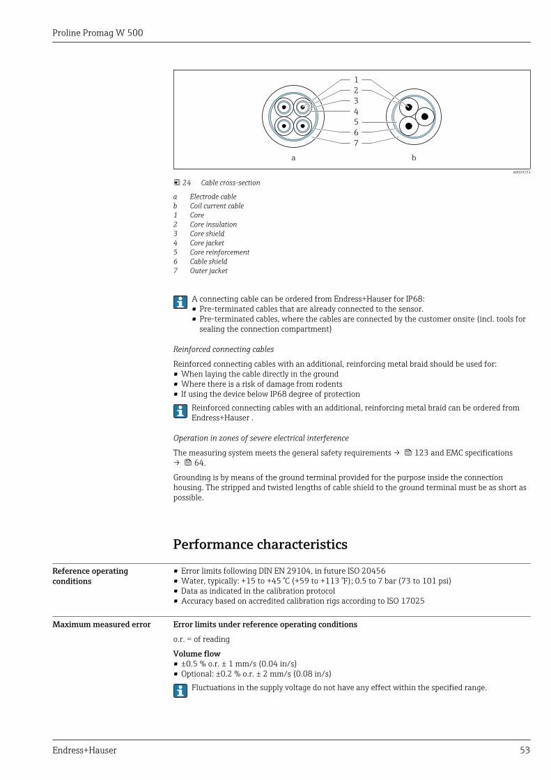
Proline Promag W 500
Endress+Hauser 53
1
2
3
4
5
6
7
a b
A0029151
24 Cable cross-section
a Electrode cableb Coil current cable1 Core2 Core insulation3 Core shield4 Core jacket5 Core reinforcement6 Cable shield7 Outer jacket
A connecting cable can be ordered from Endress+Hauser for IP68:• Pre-terminated cables that are already connected to the sensor.• Pre-terminated cables, where the cables are connected by the customer onsite (incl. tools for
sealing the connection compartment)
Reinforced connecting cables
Reinforced connecting cables with an additional, reinforcing metal braid should be used for:• When laying the cable directly in the ground• Where there is a risk of damage from rodents• If using the device below IP68 degree of protection
Reinforced connecting cables with an additional, reinforcing metal braid can be ordered fromEndress+Hauser .
Operation in zones of severe electrical interference
The measuring system meets the general safety requirements → 123 and EMC specifications→ 64.
Grounding is by means of the ground terminal provided for the purpose inside the connectionhousing. The stripped and twisted lengths of cable shield to the ground terminal must be as short aspossible.
Performance characteristics
Reference operatingconditions
• Error limits following DIN EN 29104, in future ISO 20456• Water, typically: +15 to +45 °C (+59 to +113 °F); 0.5 to 7 bar (73 to 101 psi)• Data as indicated in the calibration protocol• Accuracy based on accredited calibration rigs according to ISO 17025
Maximum measured error Error limits under reference operating conditions
o.r. = of reading
Volume flow• ±0.5 % o.r. ± 1 mm/s (0.04 in/s)• Optional: ±0.2 % o.r. ± 2 mm/s (0.08 in/s)
Fluctuations in the supply voltage do not have any effect within the specified range.
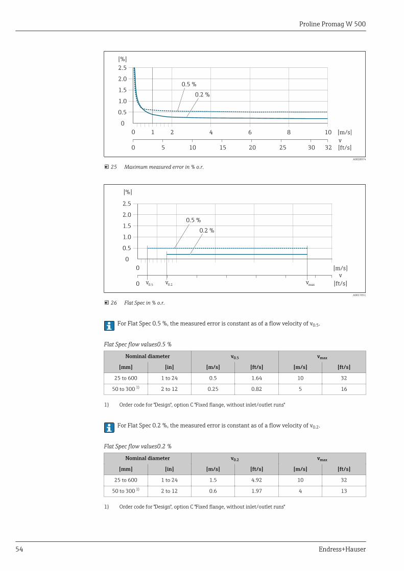
Proline Promag W 500
54 Endress+Hauser
2.5
[%]
2.0
1.5
1.0
0.5
0
0.2 %
0.5 %
0 1 2 4 6 8 10 [m/s]
v
5 10 15 20 25 30 32 [ft/s]0
A0028974
25 Maximum measured error in % o.r.
2.5
[%]
2.0
1.5
1.0
0.5
0
0.2 %
0.5 %
0 [m/s]v
[ft/s]v0.2v0.50 vmax
A0017051
26 Flat Spec in % o.r.
For Flat Spec 0.5 %, the measured error is constant as of a flow velocity of v0.5.
Flat Spec flow values0.5 %
Nominal diameter v0.5 vmax
[mm] [in] [m/s] [ft/s] [m/s] [ft/s]
25 to 600 1 to 24 0.5 1.64 10 32
50 to 300 1) 2 to 12 0.25 0.82 5 16
1) Order code for "Design", option C "Fixed flange, without inlet/outlet runs"
For Flat Spec 0.2 %, the measured error is constant as of a flow velocity of v0.2.
Flat Spec flow values0.2 %
Nominal diameter v0.2 vmax
[mm] [in] [m/s] [ft/s] [m/s] [ft/s]
25 to 600 1 to 24 1.5 4.92 10 32
50 to 300 1) 2 to 12 0.6 1.97 4 13
1) Order code for "Design", option C "Fixed flange, without inlet/outlet runs"
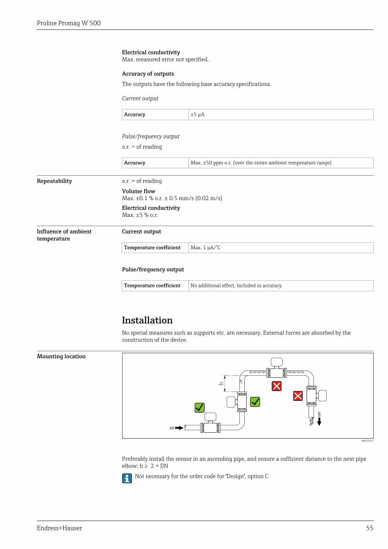
Proline Promag W 500
Endress+Hauser 55
Electrical conductivityMax. measured error not specified.
Accuracy of outputs
The outputs have the following base accuracy specifications.
Current output
Accuracy ±5 µA
Pulse/frequency output
o.r. = of reading
Accuracy Max. ±50 ppm o.r. (over the entire ambient temperature range)
Repeatability o.r. = of reading
Volume flowMax. ±0.1 % o.r. ± 0.5 mm/s (0.02 in/s)Electrical conductivityMax. ±5 % o.r.
Influence of ambienttemperature
Current output
Temperature coefficient Max. 1 μA/°C
Pulse/frequency output
Temperature coefficient No additional effect. Included in accuracy.
InstallationNo special measures such as supports etc. are necessary. External forces are absorbed by theconstruction of the device.
Mounting location
h
A0029343
Preferably install the sensor in an ascending pipe, and ensure a sufficient distance to the next pipeelbow: h ≥ 2 × DN
Not necessary for the order code for "Design", option C
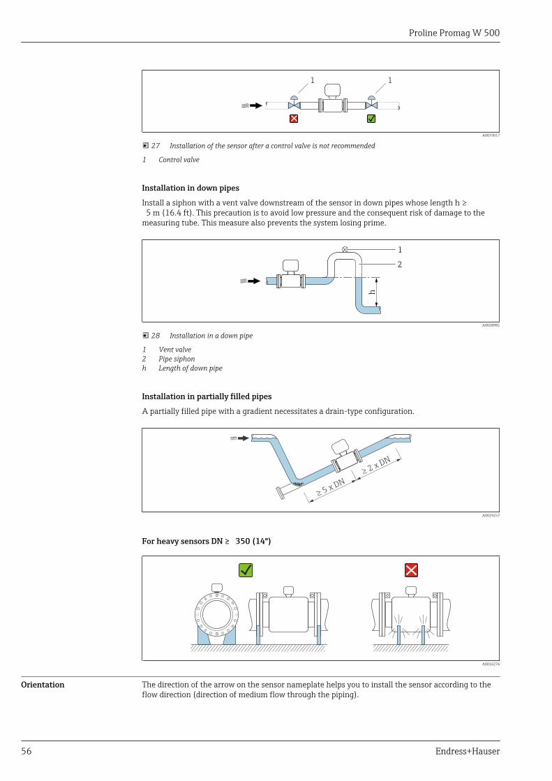
Proline Promag W 500
56 Endress+Hauser
1 1
A0033017
27 Installation of the sensor after a control valve is not recommended
1 Control valve
Installation in down pipes
Install a siphon with a vent valve downstream of the sensor in down pipes whose length h ≥ 5 m (16.4 ft). This precaution is to avoid low pressure and the consequent risk of damage to themeasuring tube. This measure also prevents the system losing prime.
h
2
1
A0028981
28 Installation in a down pipe
1 Vent valve2 Pipe siphonh Length of down pipe
Installation in partially filled pipes
A partially filled pipe with a gradient necessitates a drain-type configuration.
2 x DN
³
5 x DN
³
A0029257
For heavy sensors DN ≥ 350 (14")
A0016276
Orientation The direction of the arrow on the sensor nameplate helps you to install the sensor according to theflow direction (direction of medium flow through the piping).
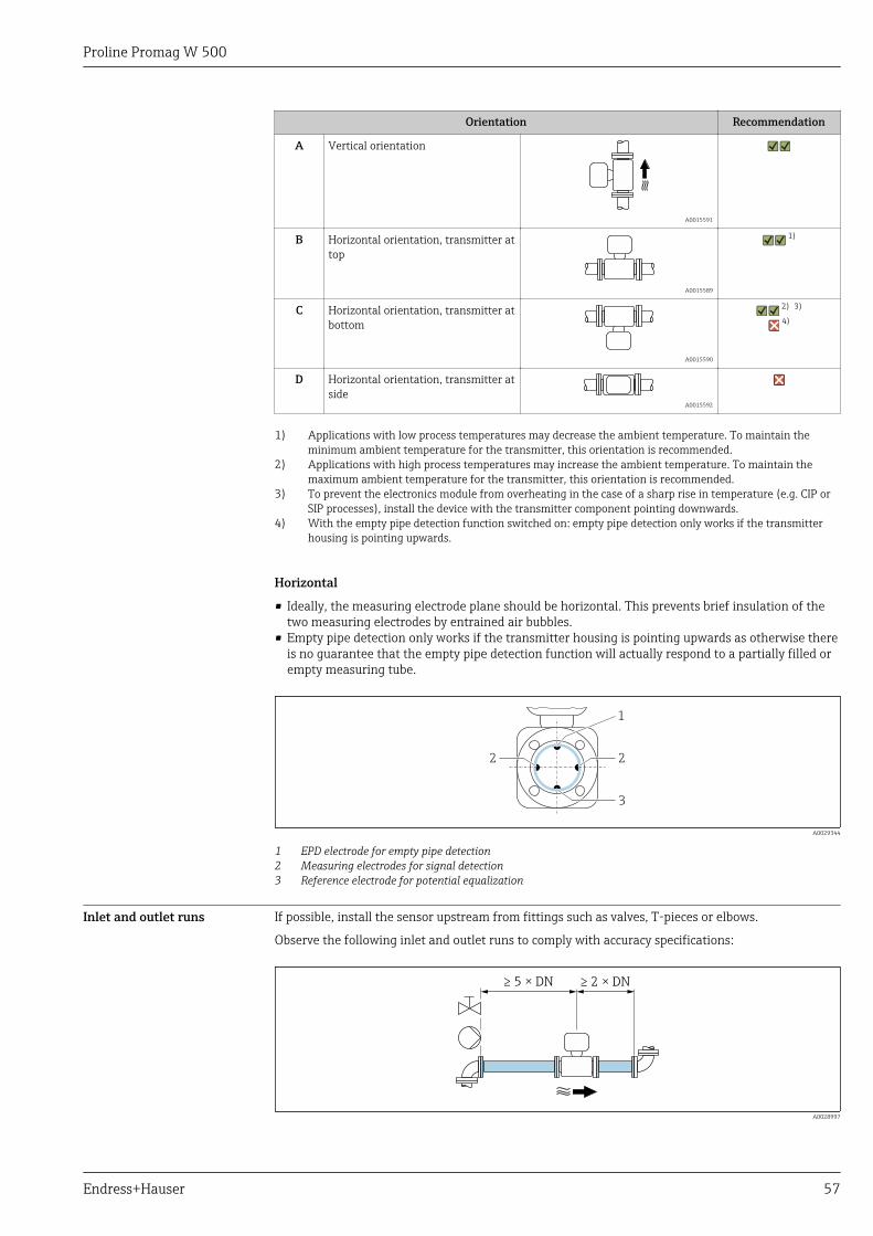
Proline Promag W 500
Endress+Hauser 57
Orientation Recommendation
A Vertical orientation
A0015591
B Horizontal orientation, transmitter attop
A0015589
1)
C Horizontal orientation, transmitter atbottom
A0015590
2) 3)
4)
D Horizontal orientation, transmitter atside
A0015592
1) Applications with low process temperatures may decrease the ambient temperature. To maintain theminimum ambient temperature for the transmitter, this orientation is recommended.
2) Applications with high process temperatures may increase the ambient temperature. To maintain themaximum ambient temperature for the transmitter, this orientation is recommended.
3) To prevent the electronics module from overheating in the case of a sharp rise in temperature (e.g. CIP orSIP processes), install the device with the transmitter component pointing downwards.
4) With the empty pipe detection function switched on: empty pipe detection only works if the transmitterhousing is pointing upwards.
Horizontal
• Ideally, the measuring electrode plane should be horizontal. This prevents brief insulation of thetwo measuring electrodes by entrained air bubbles.
• Empty pipe detection only works if the transmitter housing is pointing upwards as otherwise thereis no guarantee that the empty pipe detection function will actually respond to a partially filled orempty measuring tube.
1
2
3
2
A0029344
1 EPD electrode for empty pipe detection2 Measuring electrodes for signal detection3 Reference electrode for potential equalization
Inlet and outlet runs If possible, install the sensor upstream from fittings such as valves, T-pieces or elbows.
Observe the following inlet and outlet runs to comply with accuracy specifications:
≥ 5 × DN ≥ 2 × DN
A0028997
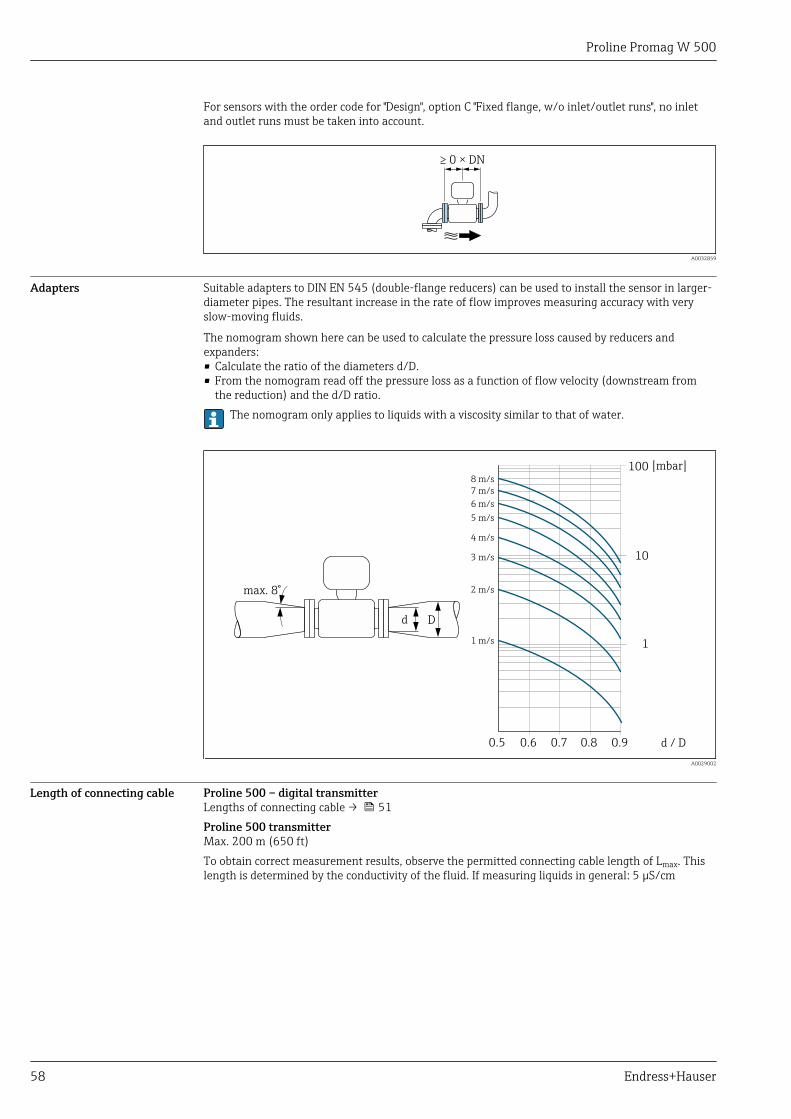
Proline Promag W 500
58 Endress+Hauser
For sensors with the order code for "Design", option C "Fixed flange, w/o inlet/outlet runs", no inletand outlet runs must be taken into account.
≥ 0 × DN
A0032859
Adapters Suitable adapters to DIN EN 545 (double-flange reducers) can be used to install the sensor in larger-diameter pipes. The resultant increase in the rate of flow improves measuring accuracy with veryslow-moving fluids.
The nomogram shown here can be used to calculate the pressure loss caused by reducers andexpanders:• Calculate the ratio of the diameters d/D.• From the nomogram read off the pressure loss as a function of flow velocity (downstream from
the reduction) and the d/D ratio.The nomogram only applies to liquids with a viscosity similar to that of water.
100
10
0.5 d / D
[mbar]
0.6 0.7 0.8 0.9
1 m/s
2 m/s
3 m/s
4 m/s
5 m/s
6 m/s
7 m/s
8 m/s
1
Dd
max. 8°
A0029002
Length of connecting cable Proline 500 – digital transmitterLengths of connecting cable → 51Proline 500 transmitterMax. 200 m (650 ft)To obtain correct measurement results, observe the permitted connecting cable length of Lmax. Thislength is determined by the conductivity of the fluid. If measuring liquids in general: 5 µS/cm
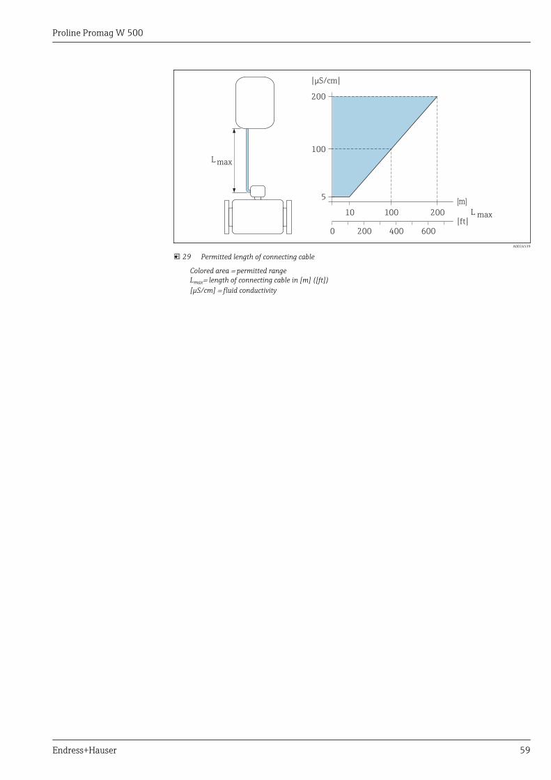
Proline Promag W 500
Endress+Hauser 59
200
100
5
10 100 200
[m]
[ S/cm]µ
L max[ ]ft
200 6000 400
L max
A0016539
29 Permitted length of connecting cable
Colored area = permitted rangeLmax= length of connecting cable in [m] ([ft])[µS/cm] = fluid conductivity
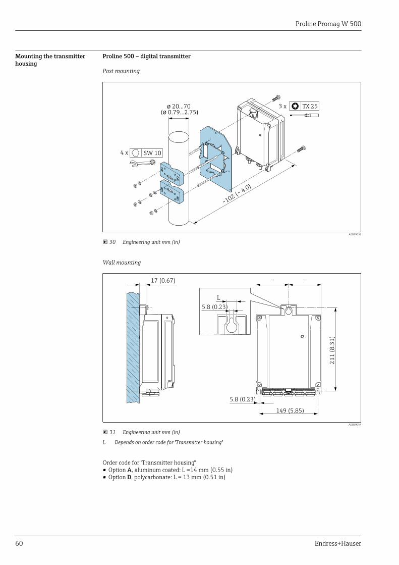
Proline Promag W 500
60 Endress+Hauser
Mounting the transmitterhousing
Proline 500 – digital transmitter
Post mounting
ø 20…70( 0.79…2.75)ø
~102 (~4.0)
4 x SW 10
3 x TX 25
A0029051
30 Engineering unit mm (in)
Wall mounting
149 (5.85)
21
1 (
8.3
1)
=
5.8 (0.23)
17 (0.67) =
L
5.8 (0.23)
A0029054
31 Engineering unit mm (in)
L Depends on order code for "Transmitter housing"
Order code for "Transmitter housing"• Option A, aluminum coated: L =14 mm (0.55 in)• Option D, polycarbonate: L = 13 mm (0.51 in)
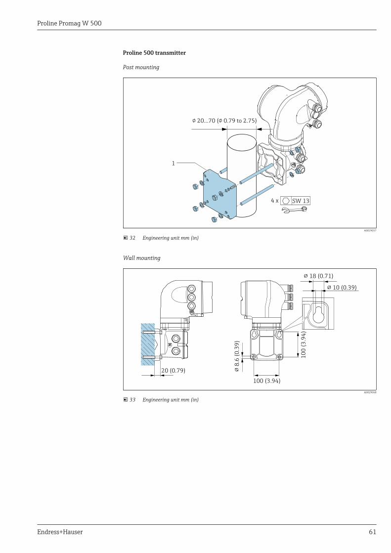
Proline Promag W 500
Endress+Hauser 61
Proline 500 transmitter
Post mounting
1
4 x SW 13
! … (! 0.79 to 2.75)20 70
A0029057
32 Engineering unit mm (in)
Wall mounting
20 (0.79)
100 (3.94)
10
0 (
3.9
4)
!8
.6 (
0.3
9)
! 18 (0.71)
! 10 (0.39)
A0029068
33 Engineering unit mm (in)
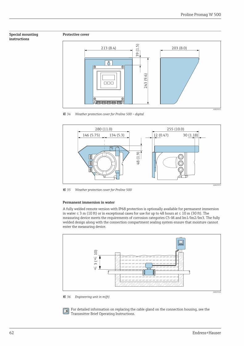
Proline Promag W 500
62 Endress+Hauser
Special mountinginstructions
Protective cover
213 (8.4)
39
(1
.5)
24
3 (
9.6
)
203 (8.0)
A0029552
34 Weather protection cover for Proline 500 – digital
146 (5.75)4
8 (
1.9
)12 (0.47)
280 (11.0) 255 (10.0)
134 (5.3) 30 (1.18)
A0029553
35 Weather protection cover for Proline 500
Permanent immersion in water
A fully welded remote version with IP68 protection is optionally available for permanent immersionin water ≤ 3 m (10 ft) or in exceptional cases for use for up to 48 hours at ≤ 10 m (30 ft). Themeasuring device meets the requirements of corrosion categories C5-M and Im1/Im2/Im3. The fullywelded design along with the connection compartment sealing system ensure that moisture cannotenter the measuring device.
≤≤
3 (
10
)
A0029320
36 Engineering unit in m(ft)
For detailed information on replacing the cable gland on the connection housing, see theTransmitter Brief Operating Instructions.
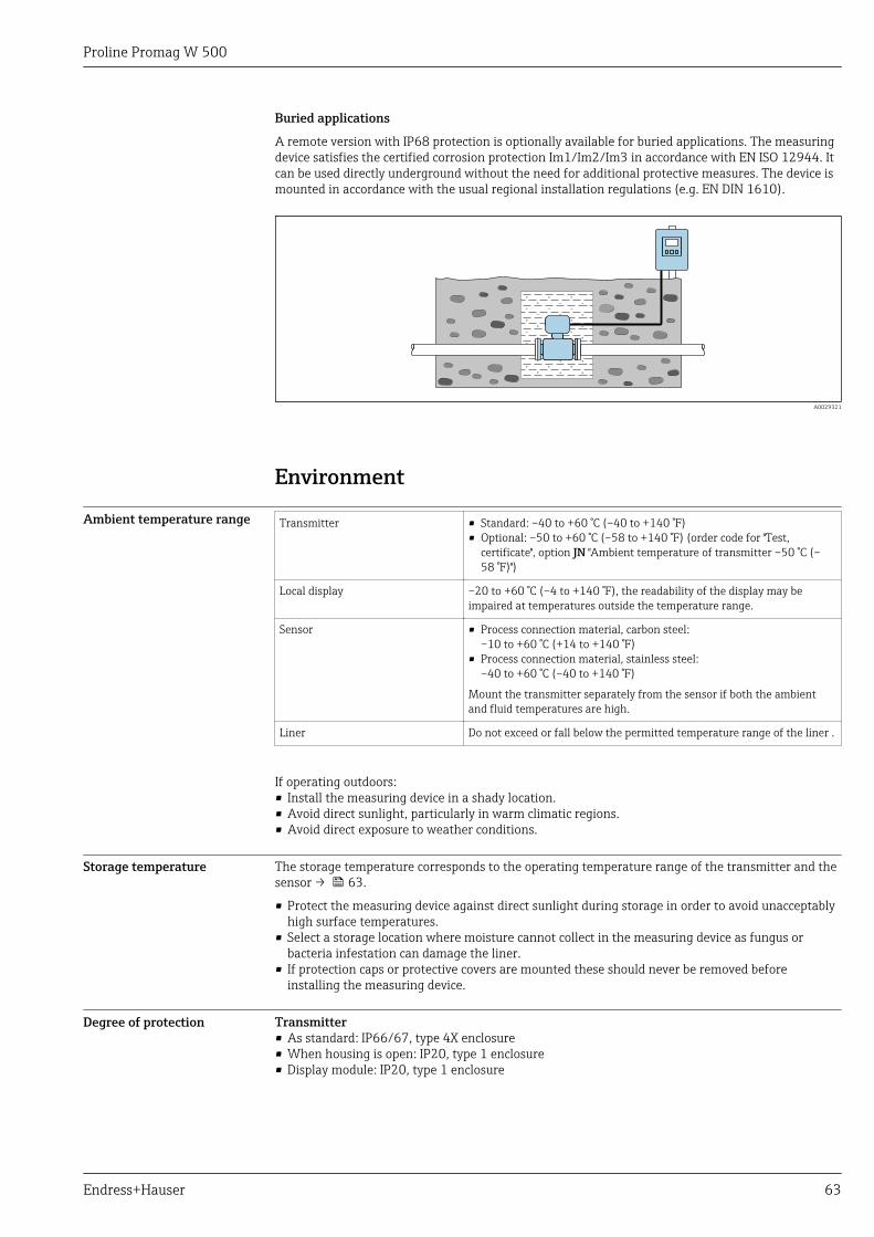
Proline Promag W 500
Endress+Hauser 63
Buried applications
A remote version with IP68 protection is optionally available for buried applications. The measuringdevice satisfies the certified corrosion protection Im1/Im2/Im3 in accordance with EN ISO 12944. Itcan be used directly underground without the need for additional protective measures. The device ismounted in accordance with the usual regional installation regulations (e.g. EN DIN 1610).
A0029321
Environment
Ambient temperature range Transmitter • Standard: –40 to +60 °C (–40 to +140 °F)• Optional: –50 to +60 °C (–58 to +140 °F) (order code for "Test,
certificate", option JN "Ambient temperature of transmitter –50 °C (–58 °F)")
Local display –20 to +60 °C (–4 to +140 °F), the readability of the display may beimpaired at temperatures outside the temperature range.
Sensor • Process connection material, carbon steel:–10 to +60 °C (+14 to +140 °F)
• Process connection material, stainless steel:–40 to +60 °C (–40 to +140 °F)
Mount the transmitter separately from the sensor if both the ambientand fluid temperatures are high.
Liner Do not exceed or fall below the permitted temperature range of the liner .
If operating outdoors:• Install the measuring device in a shady location.• Avoid direct sunlight, particularly in warm climatic regions.• Avoid direct exposure to weather conditions.
Storage temperature The storage temperature corresponds to the operating temperature range of the transmitter and thesensor → 63.
• Protect the measuring device against direct sunlight during storage in order to avoid unacceptablyhigh surface temperatures.
• Select a storage location where moisture cannot collect in the measuring device as fungus orbacteria infestation can damage the liner.
• If protection caps or protective covers are mounted these should never be removed beforeinstalling the measuring device.
Degree of protection Transmitter• As standard: IP66/67, type 4X enclosure• When housing is open: IP20, type 1 enclosure• Display module: IP20, type 1 enclosure
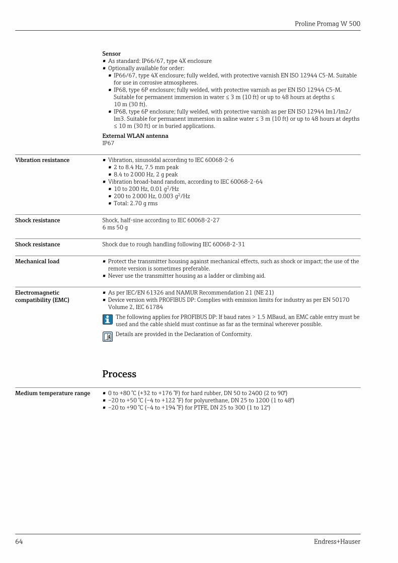
Proline Promag W 500
64 Endress+Hauser
Sensor• As standard: IP66/67, type 4X enclosure• Optionally available for order:
• IP66/67, type 4X enclosure; fully welded, with protective varnish EN ISO 12944 C5-M. Suitablefor use in corrosive atmospheres.
• IP68, type 6P enclosure; fully welded, with protective varnish as per EN ISO 12944 C5-M.Suitable for permanent immersion in water ≤ 3 m (10 ft) or up to 48 hours at depths ≤10 m (30 ft).
• IP68, type 6P enclosure; fully welded, with protective varnish as per EN ISO 12944 Im1/Im2/Im3. Suitable for permanent immersion in saline water ≤ 3 m (10 ft) or up to 48 hours at depths≤ 10 m (30 ft) or in buried applications.
External WLAN antennaIP67
Vibration resistance • Vibration, sinusoidal according to IEC 60068-2-6• 2 to 8.4 Hz, 7.5 mm peak• 8.4 to 2 000 Hz, 2 g peak
• Vibration broad-band random, according to IEC 60068-2-64• 10 to 200 Hz, 0.01 g2/Hz• 200 to 2 000 Hz, 0.003 g2/Hz• Total: 2.70 g rms
Shock resistance Shock, half-sine according to IEC 60068-2-276 ms 50 g
Shock resistance Shock due to rough handling following IEC 60068-2-31
Mechanical load • Protect the transmitter housing against mechanical effects, such as shock or impact; the use of theremote version is sometimes preferable.
• Never use the transmitter housing as a ladder or climbing aid.
Electromagneticcompatibility (EMC)
• As per IEC/EN 61326 and NAMUR Recommendation 21 (NE 21)• Device version with PROFIBUS DP: Complies with emission limits for industry as per EN 50170
Volume 2, IEC 61784The following applies for PROFIBUS DP: If baud rates > 1.5 MBaud, an EMC cable entry must beused and the cable shield must continue as far as the terminal wherever possible.Details are provided in the Declaration of Conformity.
Process
Medium temperature range • 0 to +80 °C (+32 to +176 °F) for hard rubber, DN 50 to 2400 (2 to 90")• –20 to +50 °C (–4 to +122 °F) for polyurethane, DN 25 to 1200 (1 to 48")• –20 to +90 °C (–4 to +194 °F) for PTFE, DN 25 to 300 (1 to 12")
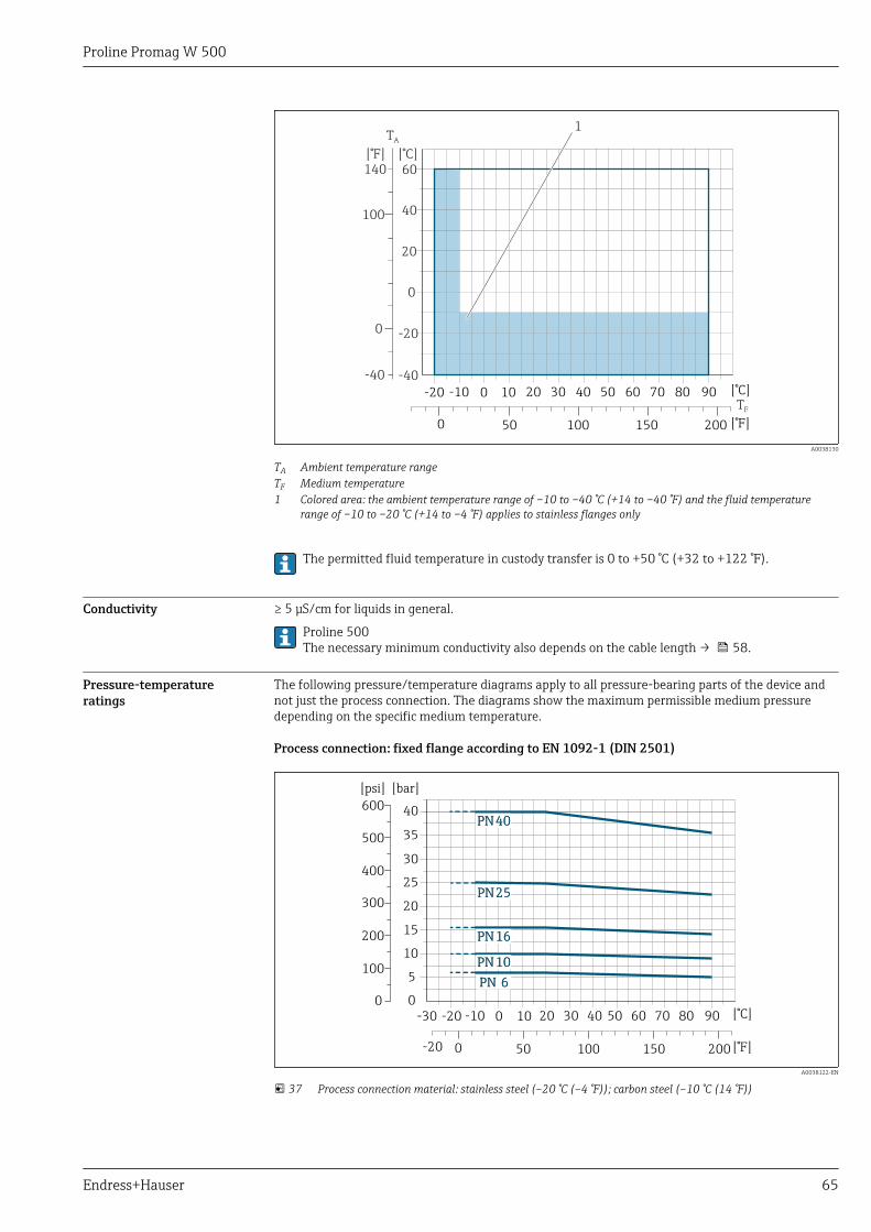
Proline Promag W 500
Endress+Hauser 65
0
0
20
40100
60140
[°F] [°C]
-20
-40-40
TA
TF
1
-20 -10 0 10 20 30 40 50 60 70 80 90
0 100 200
[°C]
[° ]F50 150
A0038130
TA Ambient temperature rangeTF Medium temperature1 Colored area: the ambient temperature range of –10 to –40 °C (+14 to –40 °F) and the fluid temperature
range of –10 to –20 °C (+14 to –4 °F) applies to stainless flanges only
The permitted fluid temperature in custody transfer is 0 to +50 °C (+32 to +122 °F).
Conductivity ≥ 5 μS/cm for liquids in general.
Proline 500The necessary minimum conductivity also depends on the cable length → 58.
Pressure-temperatureratings
The following pressure/temperature diagrams apply to all pressure-bearing parts of the device andnot just the process connection. The diagrams show the maximum permissible medium pressuredepending on the specific medium temperature.
Process connection: fixed flange according to EN 1092-1 (DIN 2501)
0
5
10
15
20
25
35
30
40
[bar][psi]
200
100
400
300
500
600
0
PN16
PN10
PN40
PN 6
PN25
PN16
PN10
PN40
PN 6
PN25
-30 -20 -10 0 10 20 30 40 50 60 70 80 90
0-20 100 200
[°C]
[° ]F50 150
A0038122-EN
37 Process connection material: stainless steel (–20 °C (–4 °F)); carbon steel (–10 °C (14 °F))
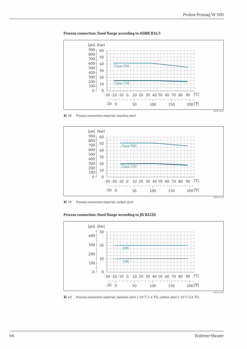
Proline Promag W 500
66 Endress+Hauser
Process connection: fixed flange according to ASME B16.5
[bar][psi]
200100
400300
500600
0
Class300
Class150
0
10
20
30
40
50
60800700
900
-30 -20 -10 0 10 20 30 40 50 60 70 80 90
0-20 100 200
[°C]
[° ]F50 150
A0038123-EN
38 Process connection material: stainless steel
[bar][psi]
200100
400300
500600
0
Class300
Class150
0
10
20
30
40
50
60800700
900
-30 -20 -10 0 10 20 30 40 50 60 70 80 90
0-20 100 200
[°C]
[° ]F50 150
A0038121-EN
39 Process connection material: carbon steel
Process connection: fixed flange according to JIS B2220
[bar][psi]
100
200
300
0 0
10
20
30400
20K
10K
-30 -20 -10 0 10 20 30 40 50 60 70 80 90
0-20 100 200
[°C]
[° ]F50 150
A0038124-EN
40 Process connection material: stainless steel (–20 °C (–4 °F)); carbon steel (–10 °C (14 °F))
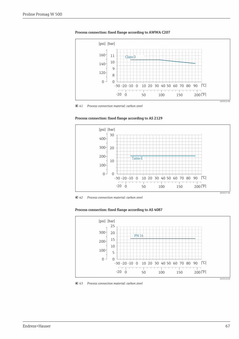
Proline Promag W 500
Endress+Hauser 67
Process connection: fixed flange according to AWWA C207
ClassD
[bar]
0
8
10
9
11
[psi]
1 02
140
160
0-30 -20 -10 0 10 20 30 40 50 60 70 80 90
0-20 100 200
[°C]
[° ]F50 150
A0038126-EN
41 Process connection material: carbon steel
Process connection: fixed flange according to AS 2129
[bar][psi]
100
200
300
0 0
10
20
30400
TableE
-30 -20 -10 0 10 20 30 40 50 60 70 80 90
0-20 100 200
[°C]
[° ]F50 150
A0038127-EN
42 Process connection material: carbon steel
Process connection: fixed flange according to AS 4087
PN16
[bar]
0
5
15
10
20
25
[psi]
100
200
300
0-30 -20 -10 0 10 20 30 40 50 60 70 80 90
0-20 100 200
[°C]
[° ]F50 150
A0038128-EN
43 Process connection material: carbon steel
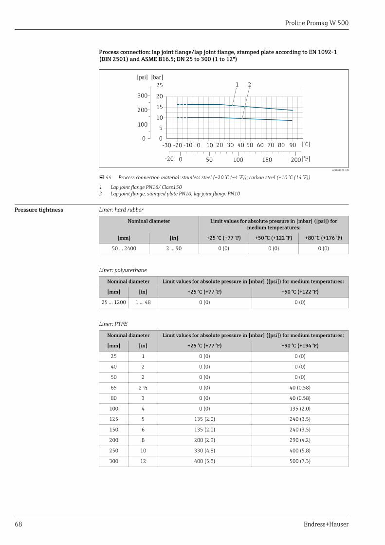
Proline Promag W 500
68 Endress+Hauser
Process connection: lap joint flange/lap joint flange, stamped plate according to EN 1092-1(DIN 2501) and ASME B16.5; DN 25 to 300 (1 to 12")
[bar]
0
5
15
10
20
25
[psi]
100
200
300
0-30 -20 -10 0 10 20 30 40 50 60 70 80 90
0-20 100 200
[°C]
[° ]F50 150
1 2
A0038129-EN
44 Process connection material: stainless steel (–20 °C (–4 °F)); carbon steel (–10 °C (14 °F))
1 Lap joint flange PN16/ Class1502 Lap joint flange, stamped plate PN10, lap joint flange PN10
Pressure tightness Liner: hard rubber
Nominal diameter Limit values for absolute pressure in [mbar] ([psi]) formedium temperatures:
[mm] [in] +25 °C (+77 °F) +50 °C (+122 °F) +80 °C (+176 °F)
50 … 2400 2 … 90 0 (0) 0 (0) 0 (0)
Liner: polyurethane
Nominal diameter Limit values for absolute pressure in [mbar] ([psi]) for medium temperatures:
[mm] [in] +25 °C (+77 °F) +50 °C (+122 °F)
25 … 1200 1 … 48 0 (0) 0 (0)
Liner: PTFE
Nominal diameter Limit values for absolute pressure in [mbar] ([psi]) for medium temperatures:
[mm] [in] +25 °C (+77 °F) +90 °C (+194 °F)
25 1 0 (0) 0 (0)
40 2 0 (0) 0 (0)
50 2 0 (0) 0 (0)
65 2 ½ 0 (0) 40 (0.58)
80 3 0 (0) 40 (0.58)
100 4 0 (0) 135 (2.0)
125 5 135 (2.0) 240 (3.5)
150 6 135 (2.0) 240 (3.5)
200 8 200 (2.9) 290 (4.2)
250 10 330 (4.8) 400 (5.8)
300 12 400 (5.8) 500 (7.3)
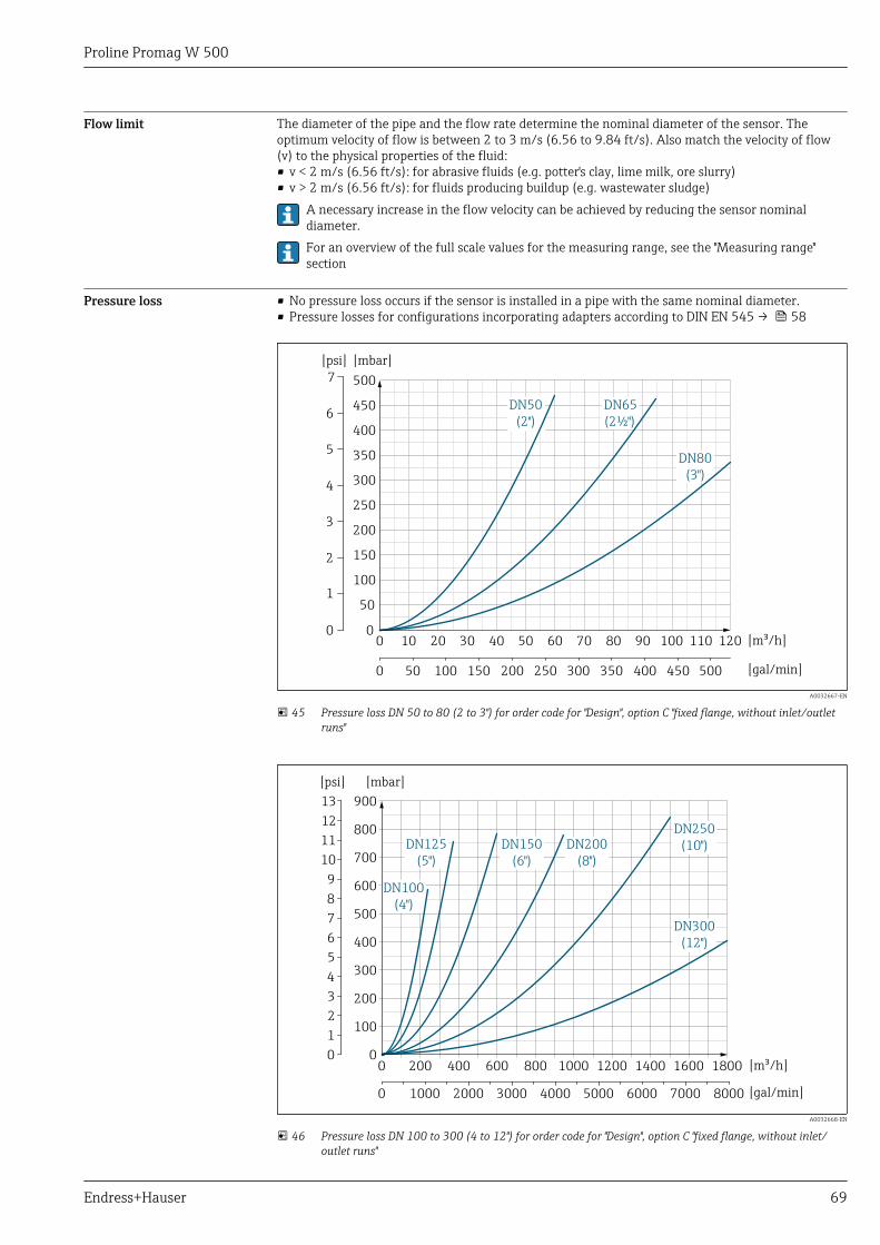
Proline Promag W 500
Endress+Hauser 69
Flow limit The diameter of the pipe and the flow rate determine the nominal diameter of the sensor. Theoptimum velocity of flow is between 2 to 3 m/s (6.56 to 9.84 ft/s). Also match the velocity of flow(v) to the physical properties of the fluid:• v < 2 m/s (6.56 ft/s): for abrasive fluids (e.g. potter's clay, lime milk, ore slurry)• v > 2 m/s (6.56 ft/s): for fluids producing buildup (e.g. wastewater sludge)
A necessary increase in the flow velocity can be achieved by reducing the sensor nominaldiameter.For an overview of the full scale values for the measuring range, see the "Measuring range"section
Pressure loss • No pressure loss occurs if the sensor is installed in a pipe with the same nominal diameter.• Pressure losses for configurations incorporating adapters according to DIN EN 545 → 58
DN80(3")
DN65(2½")
DN50(2")
500
450
400
350
300
250
200
150
100
50
00 10 20 30 40 50 60 70 80 90 100 110 120
[mbar]
[m /h]³
0 100 200 300 400 50050 150 250 350 450 [gal/min]
7[psi]
0
1
2
3
4
5
6
A0032667-EN
45 Pressure loss DN 50 to 80 (2 to 3") for order code for "Design", option C "fixed flange, without inlet/outletruns"
DN300(12")
DN100(4")
DN250(10")DN200
(8")DN150
(6")DN125
(5")
[mbar]
900
800
700
600
500
400
300
200
100
00 200 400 600 800 1000 1200 1400 1600 1800 [m /h]³
0
13
12
11
10
9
8
7
6
5
4
3
2
1
[psi]
0 1000 2000 3000 4000 5000 6000 7000 8000 [gal/min]
A0032668-EN
46 Pressure loss DN 100 to 300 (4 to 12") for order code for "Design", option C "fixed flange, without inlet/outlet runs"
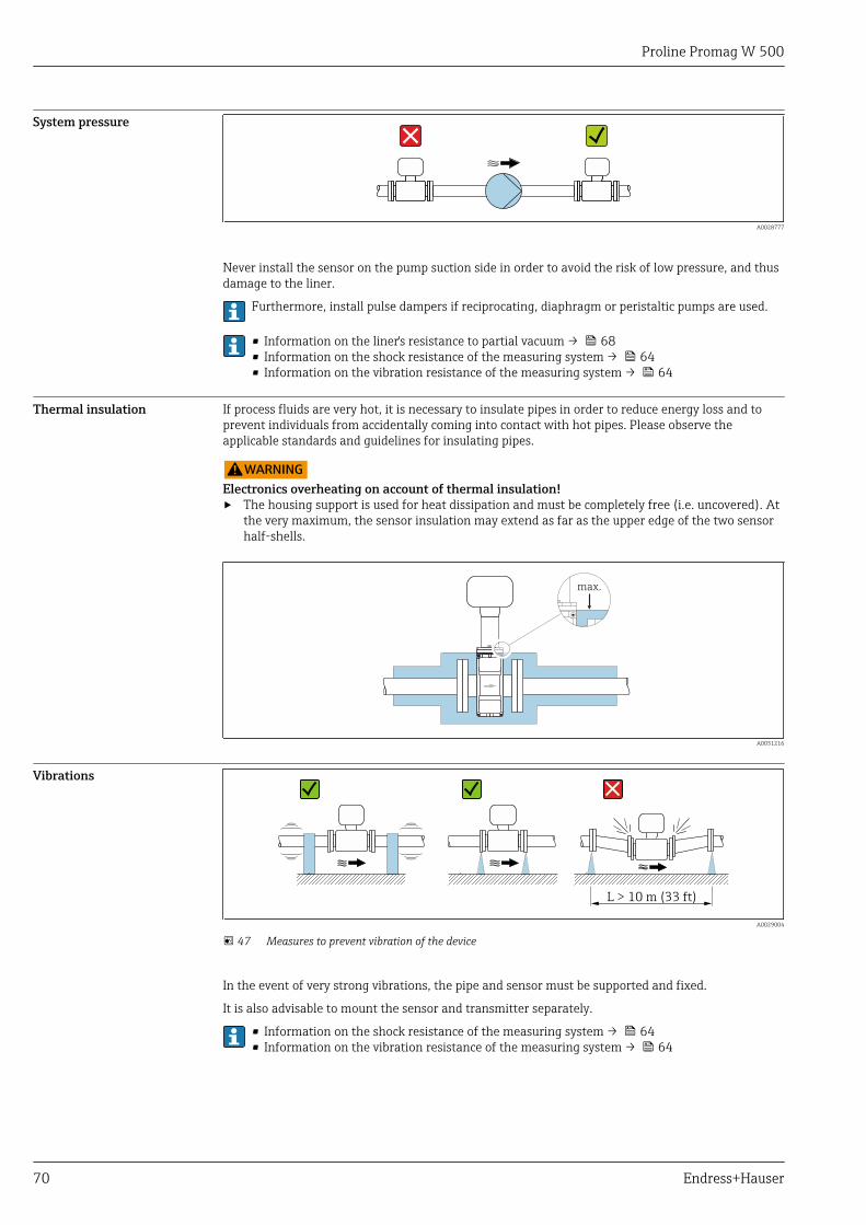
Proline Promag W 500
70 Endress+Hauser
System pressure
A0028777
Never install the sensor on the pump suction side in order to avoid the risk of low pressure, and thusdamage to the liner.
Furthermore, install pulse dampers if reciprocating, diaphragm or peristaltic pumps are used.
• Information on the liner's resistance to partial vacuum → 68• Information on the shock resistance of the measuring system → 64• Information on the vibration resistance of the measuring system → 64
Thermal insulation If process fluids are very hot, it is necessary to insulate pipes in order to reduce energy loss and toprevent individuals from accidentally coming into contact with hot pipes. Please observe theapplicable standards and guidelines for insulating pipes.
LWARNINGElectronics overheating on account of thermal insulation!‣ The housing support is used for heat dissipation and must be completely free (i.e. uncovered). At
the very maximum, the sensor insulation may extend as far as the upper edge of the two sensorhalf-shells.
max.
A0031216
Vibrations
L > 10 m (33 ft)
A0029004
47 Measures to prevent vibration of the device
In the event of very strong vibrations, the pipe and sensor must be supported and fixed.
It is also advisable to mount the sensor and transmitter separately.
• Information on the shock resistance of the measuring system → 64• Information on the vibration resistance of the measuring system → 64
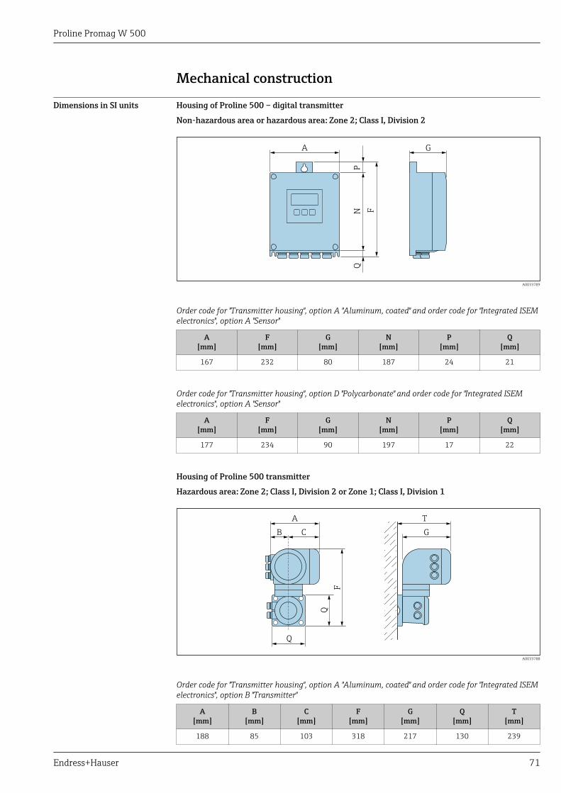
Proline Promag W 500
Endress+Hauser 71
Mechanical construction
Dimensions in SI units Housing of Proline 500 – digital transmitter
Non-hazardous area or hazardous area: Zone 2; Class I, Division 2
NP
F
GA
Q
A0033789
Order code for "Transmitter housing", option A "Aluminum, coated" and order code for "Integrated ISEMelectronics", option A "Sensor"
A[mm]
F[mm]
G[mm]
N[mm]
P[mm]
Q[mm]
167 232 80 187 24 21
Order code for "Transmitter housing", option D "Polycarbonate" and order code for "Integrated ISEMelectronics", option A "Sensor"
A[mm]
F[mm]
G[mm]
N[mm]
P[mm]
Q[mm]
177 234 90 197 17 22
Housing of Proline 500 transmitter
Hazardous area: Zone 2; Class I, Division 2 or Zone 1; Class I, Division 1
T
G
A
B C
Q
Q
F
A0033788
Order code for "Transmitter housing", option A "Aluminum, coated" and order code for "Integrated ISEMelectronics", option B "Transmitter"
A[mm]
B[mm]
C[mm]
F[mm]
G[mm]
Q[mm]
T[mm]
188 85 103 318 217 130 239
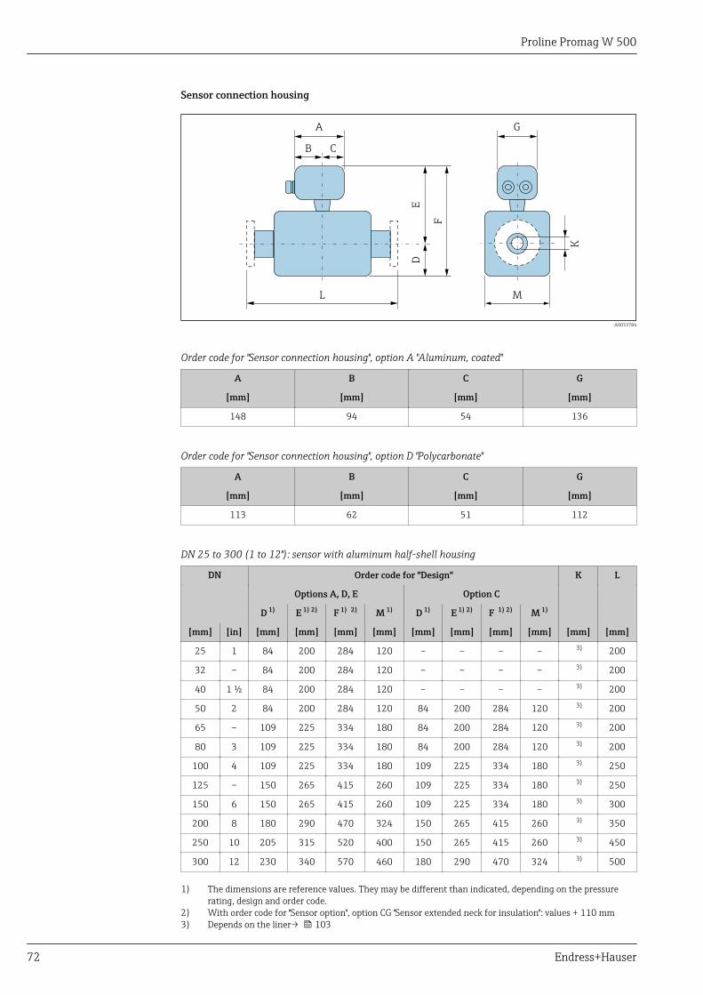
Proline Promag W 500
72 Endress+Hauser
Sensor connection housing
A
B C
G
D
L
E
F
K
M
A0033784
Order code for "Sensor connection housing", option A "Aluminum, coated"
A B C G
[mm] [mm] [mm] [mm]
148 94 54 136
Order code for "Sensor connection housing", option D "Polycarbonate"
A B C G
[mm] [mm] [mm] [mm]
113 62 51 112
DN 25 to 300 (1 to 12"): sensor with aluminum half-shell housing
DN Order code for "Design" K L
Options A, D, E Option C
D 1) E 1) 2) F 1) 2) M 1) D 1) E 1) 2) F 1) 2) M 1)
[mm] [in] [mm] [mm] [mm] [mm] [mm] [mm] [mm] [mm] [mm] [mm]
25 1 84 200 284 120 – – – – 3) 200
32 – 84 200 284 120 – – – – 3) 200
40 1 ½ 84 200 284 120 – – – – 3) 200
50 2 84 200 284 120 84 200 284 120 3) 200
65 – 109 225 334 180 84 200 284 120 3) 200
80 3 109 225 334 180 84 200 284 120 3) 200
100 4 109 225 334 180 109 225 334 180 3) 250
125 – 150 265 415 260 109 225 334 180 3) 250
150 6 150 265 415 260 109 225 334 180 3) 300
200 8 180 290 470 324 150 265 415 260 3) 350
250 10 205 315 520 400 150 265 415 260 3) 450
300 12 230 340 570 460 180 290 470 324 3) 500
1) The dimensions are reference values. They may be different than indicated, depending on the pressurerating, design and order code.
2) With order code for "Sensor option", option CG "Sensor extended neck for insulation": values + 110 mm3) Depends on the liner→ 103
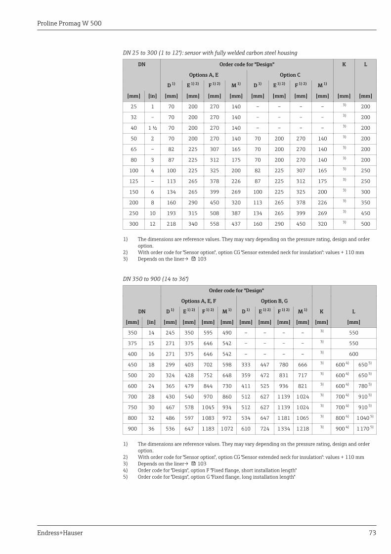
Proline Promag W 500
Endress+Hauser 73
DN 25 to 300 (1 to 12"): sensor with fully welded carbon steel housing
DN Order code for "Design" K L
Options A, E Option C
D 1) E 1) 2) F 1) 2) M 1) D 1) E 1) 2) F 1) 2) M 1)
[mm] [in] [mm] [mm] [mm] [mm] [mm] [mm] [mm] [mm] [mm] [mm]
25 1 70 200 270 140 – – – – 3) 200
32 – 70 200 270 140 – – – – 3) 200
40 1 ½ 70 200 270 140 – – – – 3) 200
50 2 70 200 270 140 70 200 270 140 3) 200
65 – 82 225 307 165 70 200 270 140 3) 200
80 3 87 225 312 175 70 200 270 140 3) 200
100 4 100 225 325 200 82 225 307 165 3) 250
125 – 113 265 378 226 87 225 312 175 3) 250
150 6 134 265 399 269 100 225 325 200 3) 300
200 8 160 290 450 320 113 265 378 226 3) 350
250 10 193 315 508 387 134 265 399 269 3) 450
300 12 218 340 558 437 160 290 450 320 3) 500
1) The dimensions are reference values. They may vary depending on the pressure rating, design and orderoption.
2) With order code for "Sensor option", option CG "Sensor extended neck for insulation": values + 110 mm3) Depends on the liner→ 103
DN 350 to 900 (14 to 36")
Order code for "Design"
Options A, E, F Option B, G
DN D 1) E 1) 2) F 1) 2) M 1) D 1) E 1) 2) F 1) 2) M 1) K L
[mm] [in] [mm] [mm] [mm] [mm] [mm] [mm] [mm] [mm] [mm] [mm]
350 14 245 350 595 490 – – – – 3) 550
375 15 271 375 646 542 – – – – 3) 550
400 16 271 375 646 542 – – – – 3) 600
450 18 299 403 702 598 333 447 780 666 3) 600 4) 650 5)
500 20 324 428 752 648 359 472 831 717 3) 600 4) 650 5)
600 24 365 479 844 730 411 525 936 821 3) 600 4) 780 5)
700 28 430 540 970 860 512 627 1 139 1 024 3) 700 4) 910 5)
750 30 467 578 1 045 934 512 627 1 139 1 024 3) 700 4) 910 5)
800 32 486 597 1 083 972 534 647 1 181 1 065 3) 800 4) 1 040 5)
900 36 536 647 1 183 1 072 610 724 1 334 1 218 3) 900 4) 1 170 5)
1) The dimensions are reference values. They may vary depending on the pressure rating, design and orderoption.
2) With order code for "Sensor option", option CG "Sensor extended neck for insulation": values + 110 mm3) Depends on the liner→ 1034) Order code for "Design", option F "Fixed flange, short installation length"5) Order code for "Design", option G "Fixed flange, long installation length"
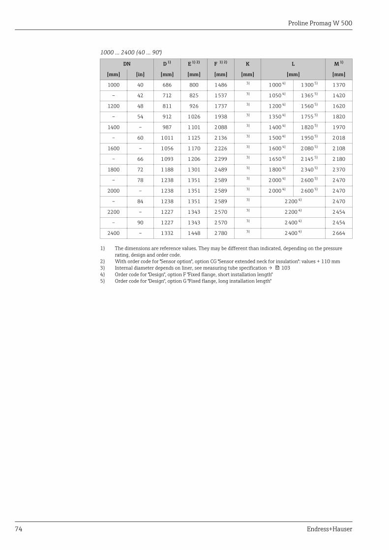
Proline Promag W 500
74 Endress+Hauser
1000 … 2400 (40 … 90")
DN D 1) E 1) 2) F 1) 2) K L M 1)
[mm] [in] [mm] [mm] [mm] [mm] [mm] [mm]
1000 40 686 800 1 486 3) 1 000 4) 1 300 5) 1 370
– 42 712 825 1 537 3) 1 050 4) 1 365 5) 1 420
1200 48 811 926 1 737 3) 1 200 4) 1 560 5) 1 620
– 54 912 1 026 1 938 3) 1 350 4) 1 755 5) 1 820
1400 – 987 1 101 2 088 3) 1 400 4) 1 820 5) 1 970
– 60 1 011 1 125 2 136 3) 1 500 4) 1 950 5) 2 018
1600 – 1 056 1 170 2 226 3) 1 600 4) 2 080 5) 2 108
– 66 1 093 1 206 2 299 3) 1 650 4) 2 145 5) 2 180
1800 72 1 188 1 301 2 489 3) 1 800 4) 2 340 5) 2 370
– 78 1 238 1 351 2 589 3) 2 000 4) 2 600 5) 2 470
2000 – 1 238 1 351 2 589 3) 2 000 4) 2 600 5) 2 470
– 84 1 238 1 351 2 589 3) 2 200 4) 2 470
2200 – 1 227 1 343 2 570 3) 2 200 4) 2 454
– 90 1 227 1 343 2 570 3) 2 400 4) 2 454
2400 – 1 332 1 448 2 780 3) 2 400 4) 2 664
1) The dimensions are reference values. They may be different than indicated, depending on the pressurerating, design and order code.
2) With order code for "Sensor option", option CG "Sensor extended neck for insulation": values + 110 mm3) Internal diameter depends on liner, see measuring tube specification → 1034) Order code for "Design", option F "Fixed flange, short installation length"5) Order code for "Design", option G "Fixed flange, long installation length"
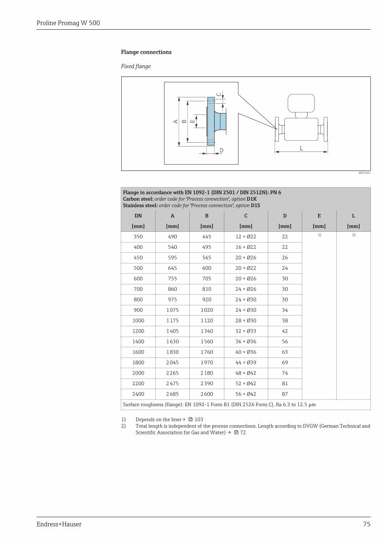
Proline Promag W 500
Endress+Hauser 75
Flange connections
Fixed flange
C
D
A B E
L
A0015621
Flange in accordance with EN 1092-1 (DIN 2501 / DIN 2512N): PN 6Carbon steel: order code for "Process connection", option D1KStainless steel: order code for "Process connection", option D1S
DN A B C D E L
[mm] [mm] [mm] [mm] [mm] [mm] [mm]
350 490 445 12 × Ø22 22 1) 2)
400 540 495 16 × Ø22 22
450 595 565 20 × Ø26 26
500 645 600 20 × Ø22 24
600 755 705 20 × Ø26 30
700 860 810 24 × Ø26 30
800 975 920 24 × Ø30 30
900 1 075 1 020 24 × Ø30 34
1000 1 175 1 120 28 × Ø30 38
1200 1 405 1 340 32 × Ø33 42
1400 1 630 1 560 36 × Ø36 56
1600 1 830 1 760 40 × Ø36 63
1800 2 045 1 970 44 × Ø39 69
2000 2 265 2 180 48 × Ø42 74
2200 2 475 2 390 52 × Ø42 81
2400 2 685 2 600 56 × Ø42 87
Surface roughness (flange): EN 1092-1 Form B1 (DIN 2526 Form C), Ra 6.3 to 12.5 µm
1) Depends on the liner→ 1032) Total length is independent of the process connections. Length according to DVGW (German Technical and
Scientific Association for Gas and Water) → 72
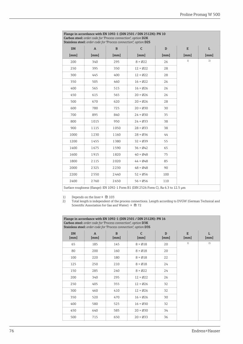
Proline Promag W 500
76 Endress+Hauser
Flange in accordance with EN 1092-1 (DIN 2501 / DIN 2512N): PN 10Carbon steel: order code for "Process connection", option D2KStainless steel: order code for "Process connection", option D2S
DN A B C D E L
[mm] [mm] [mm] [mm] [mm] [mm] [mm]
200 340 295 8 × Ø22 26 1) 2)
250 395 350 12 × Ø22 28
300 445 400 12 × Ø22 28
350 505 460 16 × Ø22 26
400 565 515 16 × Ø26 26
450 615 565 20 × Ø26 26
500 670 620 20 × Ø26 28
600 780 725 20 × Ø30 30
700 895 840 24 × Ø30 35
800 1 015 950 24 × Ø33 38
900 1 115 1 050 28 × Ø33 38
1000 1 230 1 160 28 × Ø36 44
1200 1 455 1 380 32 × Ø39 55
1400 1 675 1 590 36 × Ø42 65
1600 1 915 1 820 40 × Ø48 75
1800 2 115 2 020 44 × Ø48 85
2000 2 325 2 230 48 × Ø48 90
2200 2 550 2 440 52 × Ø56 100
2400 2 760 2 650 56 × Ø56 110
Surface roughness (flange): EN 1092-1 Form B1 (DIN 2526 Form C), Ra 6.3 to 12.5 µm
1) Depends on the liner→ 1032) Total length is independent of the process connections. Length according to DVGW (German Technical and
Scientific Association for Gas and Water) → 72
Flange in accordance with EN 1092-1 (DIN 2501 / DIN 2512N): PN 16Carbon steel: order code for "Process connection", option D3KStainless steel: order code for "Process connection", option D3S
DN[mm]
A[mm]
B[mm]
C[mm]
D[mm]
E[mm]
L[mm]
65 185 145 8 × Ø18 20 1) 2)
80 200 160 8 × Ø18 20
100 220 180 8 × Ø18 22
125 250 210 8 × Ø18 24
150 285 240 8 × Ø22 24
200 340 295 12 × Ø22 26
250 405 355 12 × Ø26 32
300 460 410 12 × Ø26 32
350 520 470 16 × Ø26 30
400 580 525 16 × Ø30 32
450 640 585 20 × Ø30 34
500 715 650 20 × Ø33 36
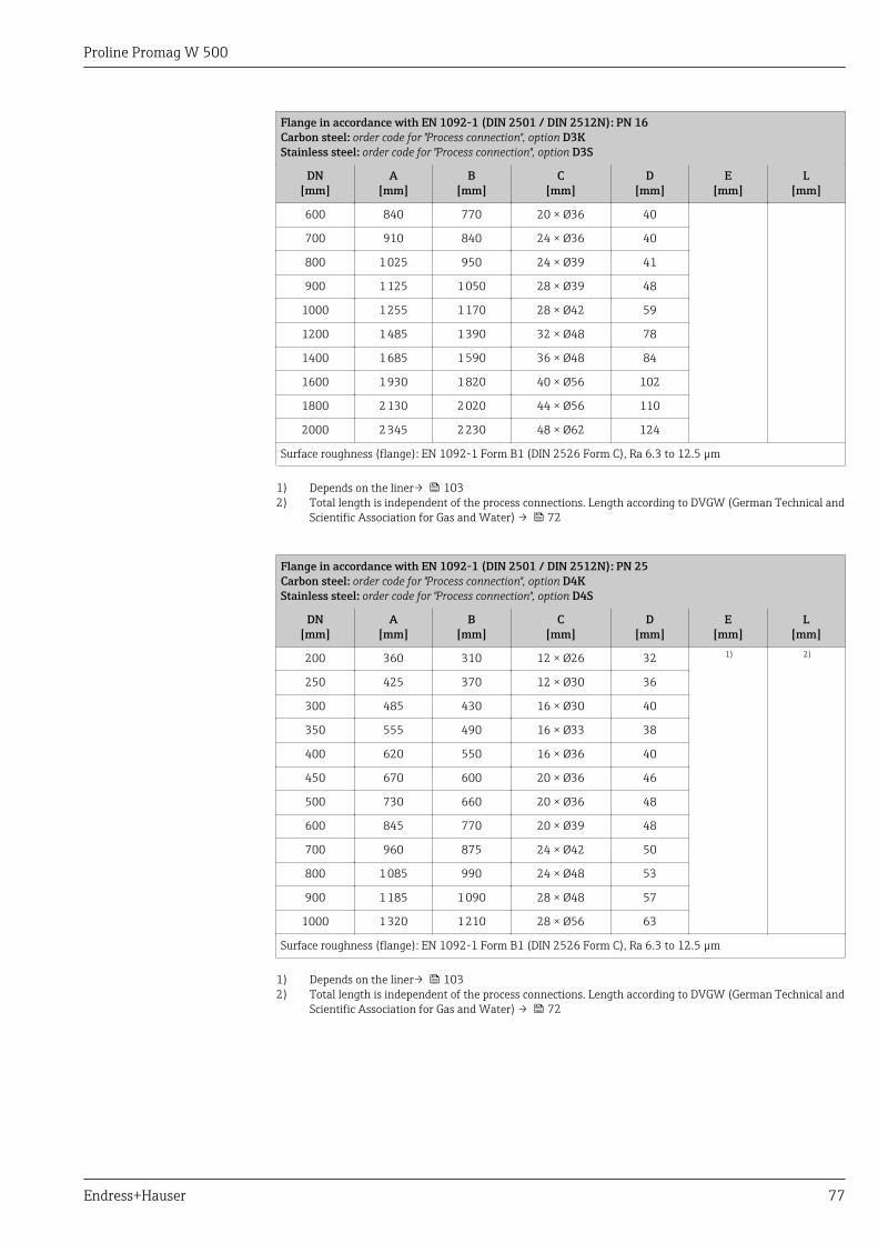
Proline Promag W 500
Endress+Hauser 77
Flange in accordance with EN 1092-1 (DIN 2501 / DIN 2512N): PN 16Carbon steel: order code for "Process connection", option D3KStainless steel: order code for "Process connection", option D3S
DN[mm]
A[mm]
B[mm]
C[mm]
D[mm]
E[mm]
L[mm]
600 840 770 20 × Ø36 40
700 910 840 24 × Ø36 40
800 1 025 950 24 × Ø39 41
900 1 125 1 050 28 × Ø39 48
1000 1 255 1 170 28 × Ø42 59
1200 1 485 1 390 32 × Ø48 78
1400 1 685 1 590 36 × Ø48 84
1600 1 930 1 820 40 × Ø56 102
1800 2 130 2 020 44 × Ø56 110
2000 2 345 2 230 48 × Ø62 124
Surface roughness (flange): EN 1092-1 Form B1 (DIN 2526 Form C), Ra 6.3 to 12.5 µm
1) Depends on the liner→ 1032) Total length is independent of the process connections. Length according to DVGW (German Technical and
Scientific Association for Gas and Water) → 72
Flange in accordance with EN 1092-1 (DIN 2501 / DIN 2512N): PN 25Carbon steel: order code for "Process connection", option D4KStainless steel: order code for "Process connection", option D4S
DN[mm]
A[mm]
B[mm]
C[mm]
D[mm]
E[mm]
L[mm]
200 360 310 12 × Ø26 32 1) 2)
250 425 370 12 × Ø30 36
300 485 430 16 × Ø30 40
350 555 490 16 × Ø33 38
400 620 550 16 × Ø36 40
450 670 600 20 × Ø36 46
500 730 660 20 × Ø36 48
600 845 770 20 × Ø39 48
700 960 875 24 × Ø42 50
800 1 085 990 24 × Ø48 53
900 1 185 1 090 28 × Ø48 57
1000 1 320 1 210 28 × Ø56 63
Surface roughness (flange): EN 1092-1 Form B1 (DIN 2526 Form C), Ra 6.3 to 12.5 µm
1) Depends on the liner→ 1032) Total length is independent of the process connections. Length according to DVGW (German Technical and
Scientific Association for Gas and Water) → 72
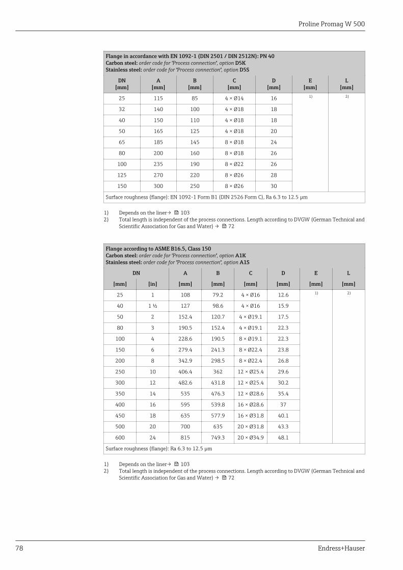
Proline Promag W 500
78 Endress+Hauser
Flange in accordance with EN 1092-1 (DIN 2501 / DIN 2512N): PN 40Carbon steel: order code for "Process connection", option D5KStainless steel: order code for "Process connection", option D5S
DN[mm]
A[mm]
B[mm]
C[mm]
D[mm]
E[mm]
L[mm]
25 115 85 4 × Ø14 16 1) 2)
32 140 100 4 × Ø18 18
40 150 110 4 × Ø18 18
50 165 125 4 × Ø18 20
65 185 145 8 × Ø18 24
80 200 160 8 × Ø18 26
100 235 190 8 × Ø22 26
125 270 220 8 × Ø26 28
150 300 250 8 × Ø26 30
Surface roughness (flange): EN 1092-1 Form B1 (DIN 2526 Form C), Ra 6.3 to 12.5 µm
1) Depends on the liner→ 1032) Total length is independent of the process connections. Length according to DVGW (German Technical and
Scientific Association for Gas and Water) → 72
Flange according to ASME B16.5, Class 150Carbon steel: order code for "Process connection", option A1KStainless steel: order code for "Process connection", option A1S
DN A B C D E L
[mm] [in] [mm] [mm] [mm] [mm] [mm] [mm]
25 1 108 79.2 4 × Ø16 12.6 1) 2)
40 1 ½ 127 98.6 4 × Ø16 15.9
50 2 152.4 120.7 4 × Ø19.1 17.5
80 3 190.5 152.4 4 × Ø19.1 22.3
100 4 228.6 190.5 8 × Ø19.1 22.3
150 6 279.4 241.3 8 × Ø22.4 23.8
200 8 342.9 298.5 8 × Ø22.4 26.8
250 10 406.4 362 12 × Ø25.4 29.6
300 12 482.6 431.8 12 × Ø25.4 30.2
350 14 535 476.3 12 × Ø28.6 35.4
400 16 595 539.8 16 × Ø28.6 37
450 18 635 577.9 16 × Ø31.8 40.1
500 20 700 635 20 × Ø31.8 43.3
600 24 815 749.3 20 × Ø34.9 48.1
Surface roughness (flange): Ra 6.3 to 12.5 µm
1) Depends on the liner→ 1032) Total length is independent of the process connections. Length according to DVGW (German Technical and
Scientific Association for Gas and Water) → 72
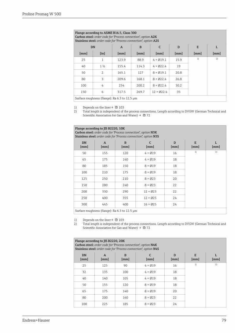
Proline Promag W 500
Endress+Hauser 79
Flange according to ASME B16.5, Class 300Carbon steel: order code for "Process connection", option A2KStainless steel: order code for "Process connection", option A2S
DN A B C D E L
[mm] [in] [mm] [mm] [mm] [mm] [mm] [mm]
25 1 123.9 88.9 4 × Ø19.1 15.9 1) 2)
40 1 ½ 155.4 114.3 4 × Ø22.4 19
50 2 165.1 127 8 × Ø19.1 20.8
80 3 209.6 168.1 8 × Ø22.4 26.8
100 4 254 200.2 8 × Ø22.4 30.2
150 6 317.5 269.7 12 × Ø22.4 35
Surface roughness (flange): Ra 6.3 to 12.5 µm
1) Depends on the liner→ 1032) Total length is independent of the process connections. Length according to DVGW (German Technical and
Scientific Association for Gas and Water) → 72
Flange according to JIS B2220, 10KCarbon steel: order code for "Process connection", option N3KStainless steel: order code for "Process connection", option N3S
DN[mm]
A[mm]
B[mm]
C[mm]
D[mm]
E[mm]
L[mm]
50 155 120 4 × Ø19 16 1) 2)
65 175 140 4 × Ø19 18
80 185 150 8 × Ø19 18
100 210 175 8 × Ø19 18
125 250 210 8 × Ø23 20
150 280 240 8 × Ø23 22
200 330 290 12 × Ø23 22
250 400 355 12 × Ø25 24
300 445 400 16 × Ø25 24
Surface roughness (flange): Ra 6.3 to 12.5 µm
1) Depends on the liner→ 1032) Total length is independent of the process connections. Length according to DVGW (German Technical and
Scientific Association for Gas and Water) → 72
Flange according to JIS B2220, 20KCarbon steel: order code for "Process connection", option N4KStainless steel: order code for "Process connection", option N4S
DN[mm]
A[mm]
B[mm]
C[mm]
D[mm]
E[mm]
L[mm]
25 125 90 4 × Ø19 16 1) 2)
32 135 100 4 × Ø19 18
40 140 105 4 × Ø19 18
50 155 120 8 × Ø19 18
65 175 140 8 × Ø19 20
80 200 160 8 × Ø23 22
100 225 185 8 × Ø23 24
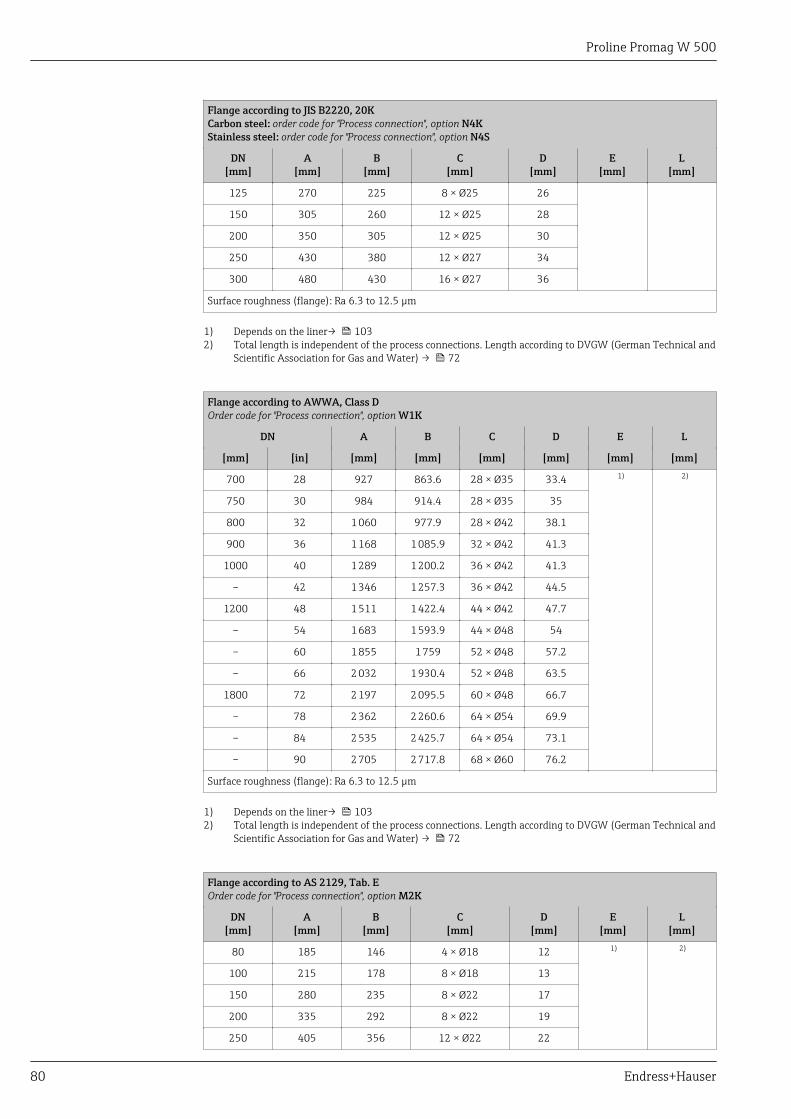
Proline Promag W 500
80 Endress+Hauser
Flange according to JIS B2220, 20KCarbon steel: order code for "Process connection", option N4KStainless steel: order code for "Process connection", option N4S
DN[mm]
A[mm]
B[mm]
C[mm]
D[mm]
E[mm]
L[mm]
125 270 225 8 × Ø25 26
150 305 260 12 × Ø25 28
200 350 305 12 × Ø25 30
250 430 380 12 × Ø27 34
300 480 430 16 × Ø27 36
Surface roughness (flange): Ra 6.3 to 12.5 µm
1) Depends on the liner→ 1032) Total length is independent of the process connections. Length according to DVGW (German Technical and
Scientific Association for Gas and Water) → 72
Flange according to AWWA, Class DOrder code for "Process connection", option W1K
DN A B C D E L
[mm] [in] [mm] [mm] [mm] [mm] [mm] [mm]
700 28 927 863.6 28 × Ø35 33.4 1) 2)
750 30 984 914.4 28 × Ø35 35
800 32 1 060 977.9 28 × Ø42 38.1
900 36 1 168 1 085.9 32 × Ø42 41.3
1000 40 1 289 1 200.2 36 × Ø42 41.3
– 42 1 346 1 257.3 36 × Ø42 44.5
1200 48 1 511 1 422.4 44 × Ø42 47.7
– 54 1 683 1 593.9 44 × Ø48 54
– 60 1 855 1 759 52 × Ø48 57.2
– 66 2 032 1 930.4 52 × Ø48 63.5
1800 72 2 197 2 095.5 60 × Ø48 66.7
– 78 2 362 2 260.6 64 × Ø54 69.9
– 84 2 535 2 425.7 64 × Ø54 73.1
– 90 2 705 2 717.8 68 × Ø60 76.2
Surface roughness (flange): Ra 6.3 to 12.5 µm
1) Depends on the liner→ 1032) Total length is independent of the process connections. Length according to DVGW (German Technical and
Scientific Association for Gas and Water) → 72
Flange according to AS 2129, Tab. EOrder code for "Process connection", option M2K
DN[mm]
A[mm]
B[mm]
C[mm]
D[mm]
E[mm]
L[mm]
80 185 146 4 × Ø18 12 1) 2)
100 215 178 8 × Ø18 13
150 280 235 8 × Ø22 17
200 335 292 8 × Ø22 19
250 405 356 12 × Ø22 22
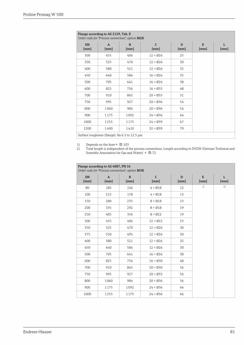
Proline Promag W 500
Endress+Hauser 81
Flange according to AS 2129, Tab. EOrder code for "Process connection", option M2K
DN[mm]
A[mm]
B[mm]
C[mm]
D[mm]
E[mm]
L[mm]
300 455 406 12 × Ø26 25
350 525 470 12 × Ø26 30
400 580 521 12 × Ø26 32
450 640 584 16 × Ø26 35
500 705 641 16 × Ø26 38
600 825 756 16 × Ø33 48
700 910 845 20 × Ø33 51
750 995 927 20 × Ø36 54
800 1 060 984 20 × Ø36 54
900 1 175 1 092 24 × Ø36 64
1000 1 255 1 175 24 × Ø39 67
1200 1 490 1 410 32 × Ø39 79
Surface roughness (flange): Ra 6.3 to 12.5 µm
1) Depends on the liner→ 1032) Total length is independent of the process connections. Length according to DVGW (German Technical and
Scientific Association for Gas and Water) → 72
Flange according to AS 4087, PN 16Order code for "Process connection", option M3K
DN[mm]
A[mm]
B[mm]
C[mm]
D[mm]
E[mm]
L[mm]
80 185 146 4 × Ø18 12 1) 2)
100 215 178 4 × Ø18 13
150 280 235 8 × Ø18 13
200 335 292 8 × Ø18 19
250 405 356 8 × Ø22 19
300 455 406 12 × Ø22 23
350 525 470 12 × Ø26 30
375 550 495 12 × Ø26 30
400 580 521 12 × Ø26 32
450 640 584 12 × Ø26 30
500 705 641 16 × Ø26 38
600 825 756 16 × Ø30 48
700 910 845 20 × Ø30 56
750 995 927 20 × Ø33 56
800 1 060 984 20 × Ø36 56
900 1 175 1 092 24 × Ø36 66
1000 1 255 1 175 24 × Ø36 66
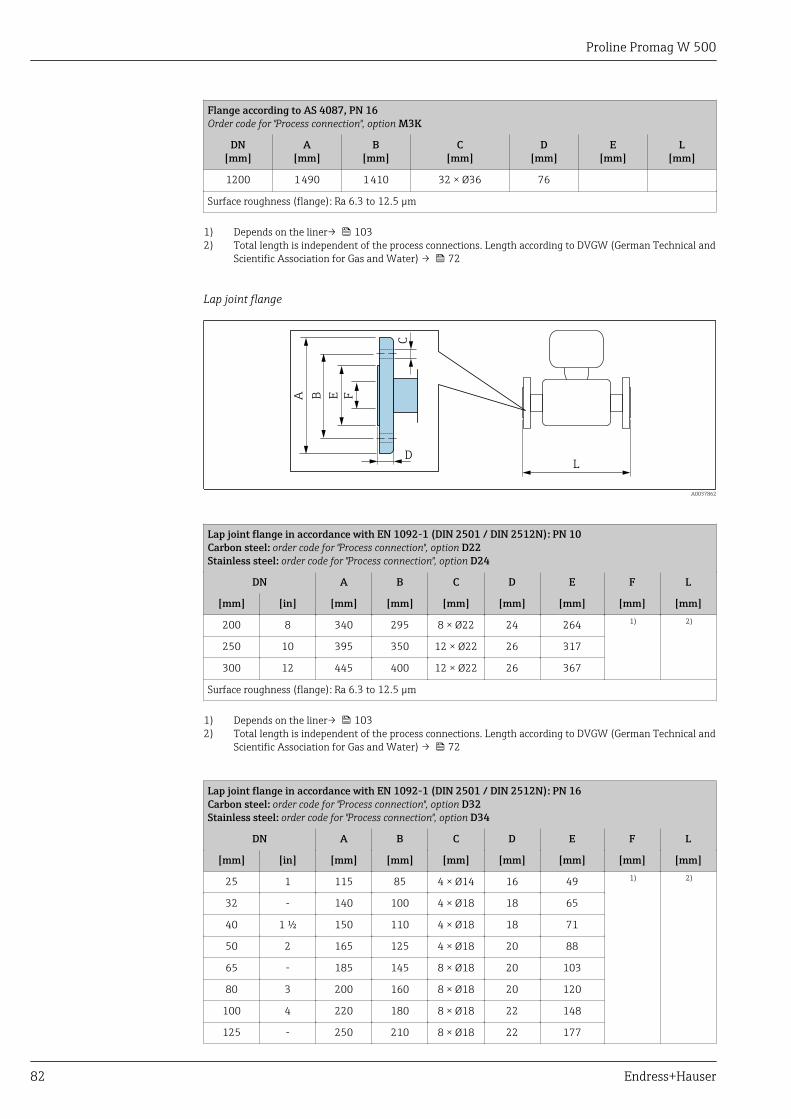
Proline Promag W 500
82 Endress+Hauser
Flange according to AS 4087, PN 16Order code for "Process connection", option M3K
DN[mm]
A[mm]
B[mm]
C[mm]
D[mm]
E[mm]
L[mm]
1200 1 490 1 410 32 × Ø36 76
Surface roughness (flange): Ra 6.3 to 12.5 µm
1) Depends on the liner→ 1032) Total length is independent of the process connections. Length according to DVGW (German Technical and
Scientific Association for Gas and Water) → 72
Lap joint flange
C
D
A B FE
L
A0037862
Lap joint flange in accordance with EN 1092-1 (DIN 2501 / DIN 2512N): PN 10Carbon steel: order code for "Process connection", option D22Stainless steel: order code for "Process connection", option D24
DN A B C D E F L
[mm] [in] [mm] [mm] [mm] [mm] [mm] [mm] [mm]
200 8 340 295 8 × Ø22 24 264 1) 2)
250 10 395 350 12 × Ø22 26 317
300 12 445 400 12 × Ø22 26 367
Surface roughness (flange): Ra 6.3 to 12.5 µm
1) Depends on the liner→ 1032) Total length is independent of the process connections. Length according to DVGW (German Technical and
Scientific Association for Gas and Water) → 72
Lap joint flange in accordance with EN 1092-1 (DIN 2501 / DIN 2512N): PN 16Carbon steel: order code for "Process connection", option D32Stainless steel: order code for "Process connection", option D34
DN A B C D E F L
[mm] [in] [mm] [mm] [mm] [mm] [mm] [mm] [mm]
25 1 115 85 4 × Ø14 16 49 1) 2)
32 - 140 100 4 × Ø18 18 65
40 1 ½ 150 110 4 × Ø18 18 71
50 2 165 125 4 × Ø18 20 88
65 - 185 145 8 × Ø18 20 103
80 3 200 160 8 × Ø18 20 120
100 4 220 180 8 × Ø18 22 148
125 - 250 210 8 × Ø18 22 177
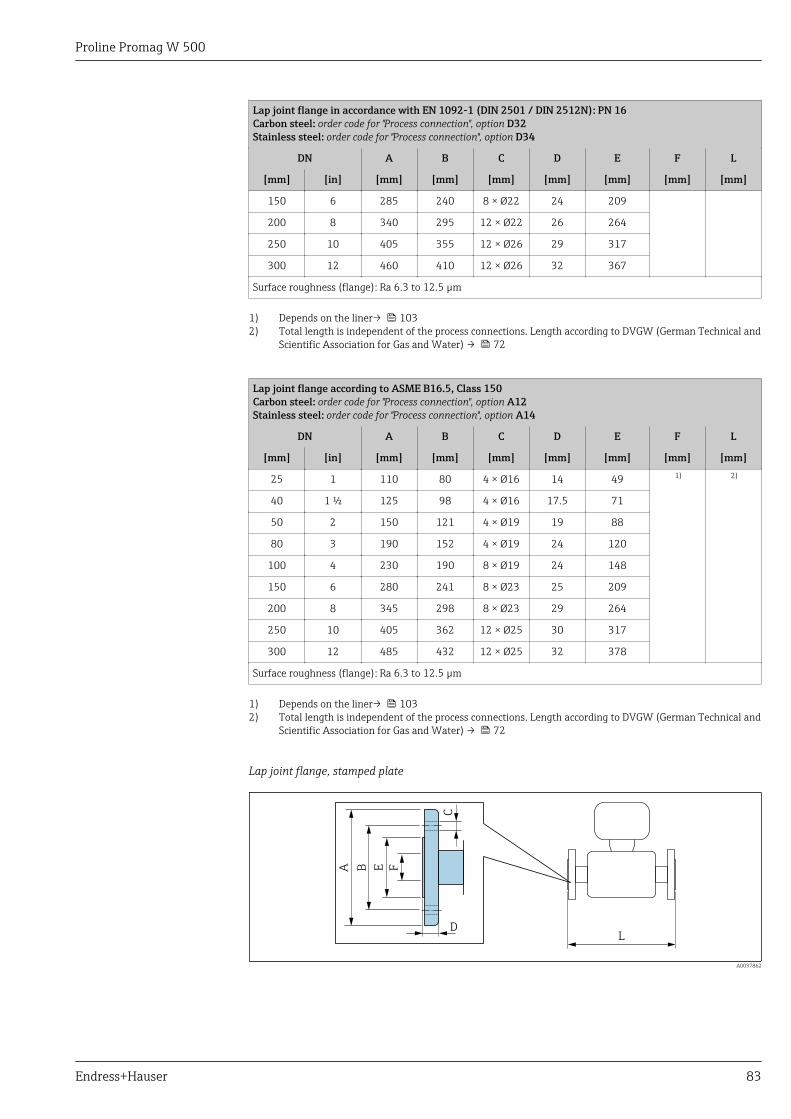
Proline Promag W 500
Endress+Hauser 83
Lap joint flange in accordance with EN 1092-1 (DIN 2501 / DIN 2512N): PN 16Carbon steel: order code for "Process connection", option D32Stainless steel: order code for "Process connection", option D34
DN A B C D E F L
[mm] [in] [mm] [mm] [mm] [mm] [mm] [mm] [mm]
150 6 285 240 8 × Ø22 24 209
200 8 340 295 12 × Ø22 26 264
250 10 405 355 12 × Ø26 29 317
300 12 460 410 12 × Ø26 32 367
Surface roughness (flange): Ra 6.3 to 12.5 µm
1) Depends on the liner→ 1032) Total length is independent of the process connections. Length according to DVGW (German Technical and
Scientific Association for Gas and Water) → 72
Lap joint flange according to ASME B16.5, Class 150Carbon steel: order code for "Process connection", option A12Stainless steel: order code for "Process connection", option A14
DN A B C D E F L
[mm] [in] [mm] [mm] [mm] [mm] [mm] [mm] [mm]
25 1 110 80 4 × Ø16 14 49 1) 2)
40 1 ½ 125 98 4 × Ø16 17.5 71
50 2 150 121 4 × Ø19 19 88
80 3 190 152 4 × Ø19 24 120
100 4 230 190 8 × Ø19 24 148
150 6 280 241 8 × Ø23 25 209
200 8 345 298 8 × Ø23 29 264
250 10 405 362 12 × Ø25 30 317
300 12 485 432 12 × Ø25 32 378
Surface roughness (flange): Ra 6.3 to 12.5 µm
1) Depends on the liner→ 1032) Total length is independent of the process connections. Length according to DVGW (German Technical and
Scientific Association for Gas and Water) → 72
Lap joint flange, stamped plate
C
D
A B FE
L
A0037862
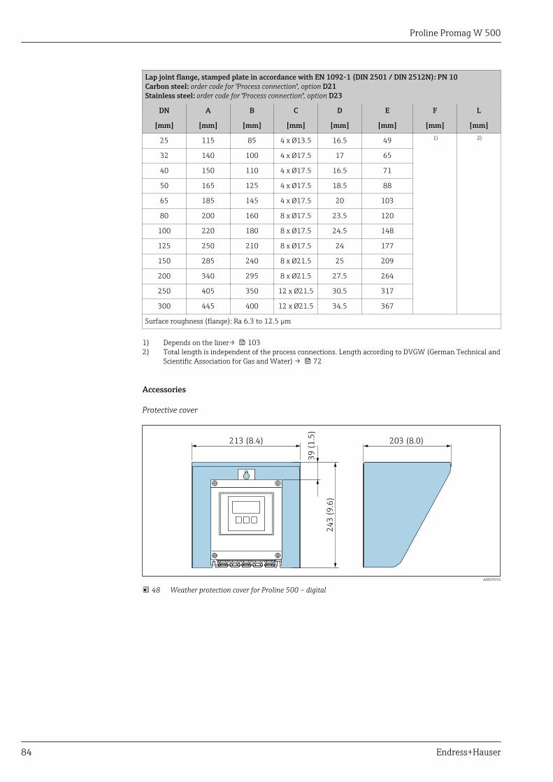
Proline Promag W 500
84 Endress+Hauser
Lap joint flange, stamped plate in accordance with EN 1092-1 (DIN 2501 / DIN 2512N): PN 10Carbon steel: order code for "Process connection", option D21Stainless steel: order code for "Process connection", option D23
DN A B C D E F L
[mm] [mm] [mm] [mm] [mm] [mm] [mm] [mm]
25 115 85 4 x Ø13.5 16.5 49 1) 2)
32 140 100 4 x Ø17.5 17 65
40 150 110 4 x Ø17.5 16.5 71
50 165 125 4 x Ø17.5 18.5 88
65 185 145 4 x Ø17.5 20 103
80 200 160 8 x Ø17.5 23.5 120
100 220 180 8 x Ø17.5 24.5 148
125 250 210 8 x Ø17.5 24 177
150 285 240 8 x Ø21.5 25 209
200 340 295 8 x Ø21.5 27.5 264
250 405 350 12 x Ø21.5 30.5 317
300 445 400 12 x Ø21.5 34.5 367
Surface roughness (flange): Ra 6.3 to 12.5 µm
1) Depends on the liner→ 1032) Total length is independent of the process connections. Length according to DVGW (German Technical and
Scientific Association for Gas and Water) → 72
Accessories
Protective cover
213 (8.4)
39
(1
.5)
24
3 (
9.6
)
203 (8.0)
A0029552
48 Weather protection cover for Proline 500 – digital
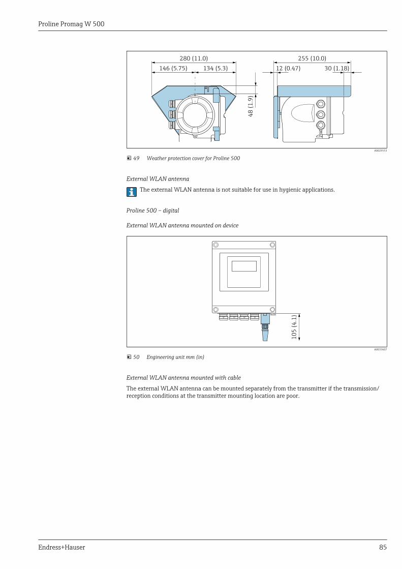
Proline Promag W 500
Endress+Hauser 85
146 (5.75)
48
(1
.9)
12 (0.47)
280 (11.0) 255 (10.0)
134 (5.3) 30 (1.18)
A0029553
49 Weather protection cover for Proline 500
External WLAN antenna
The external WLAN antenna is not suitable for use in hygienic applications.
Proline 500 – digital
External WLAN antenna mounted on device
10
5 (
4.1
)
A0033607
50 Engineering unit mm (in)
External WLAN antenna mounted with cable
The external WLAN antenna can be mounted separately from the transmitter if the transmission/reception conditions at the transmitter mounting location are poor.
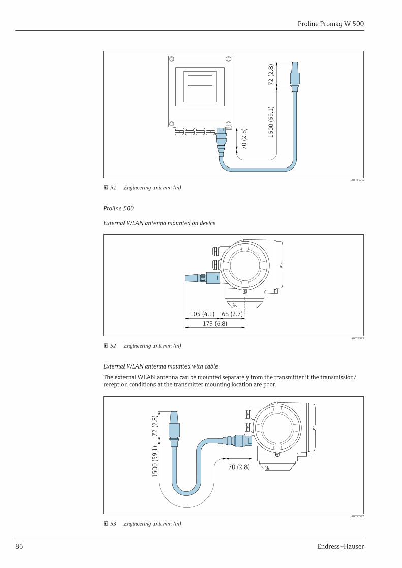
Proline Promag W 500
86 Endress+Hauser
70
(2
.8)
15
00
(5
9.1
)7
2 (
2.8
)
A0033606
51 Engineering unit mm (in)
Proline 500
External WLAN antenna mounted on device
68 (2.7)105 (4.1)
173 (6.8)
A0028923
52 Engineering unit mm (in)
External WLAN antenna mounted with cable
The external WLAN antenna can be mounted separately from the transmitter if the transmission/reception conditions at the transmitter mounting location are poor.
70 (2.8)
15
00
(5
9.1
)7
2 (
2.8
)
A0033597
53 Engineering unit mm (in)
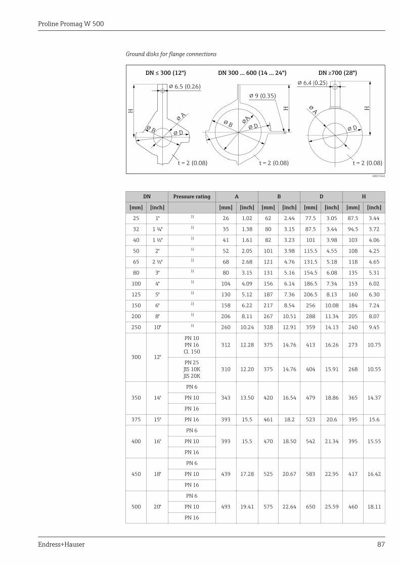
Proline Promag W 500
Endress+Hauser 87
Ground disks for flange connections
DN ≤ 300 (12")
H H H
DN 300 … 600 (14 … 24")
t = 2 (0.08)
! 9 (0.35)
DN 700 (28")≥
! 6.5 (0.26)
! B
!A
! D
! 6.4 (0.25)
! B !A
! D
!A
! D
t = 2 (0.08)t = 2 (0.08)
A0015442
DN Pressure rating A B D H
[mm] [inch] [mm] [inch] [mm] [inch] [mm] [inch] [mm] [inch]
25 1" 1) 26 1.02 62 2.44 77.5 3.05 87.5 3.44
32 1 ¼" 1) 35 1.38 80 3.15 87.5 3.44 94.5 3.72
40 1 ½" 1) 41 1.61 82 3.23 101 3.98 103 4.06
50 2" 1) 52 2.05 101 3.98 115.5 4.55 108 4.25
65 2 ½" 1) 68 2.68 121 4.76 131.5 5.18 118 4.65
80 3" 1) 80 3.15 131 5.16 154.5 6.08 135 5.31
100 4" 1) 104 4.09 156 6.14 186.5 7.34 153 6.02
125 5" 1) 130 5.12 187 7.36 206.5 8.13 160 6.30
150 6" 1) 158 6.22 217 8.54 256 10.08 184 7.24
200 8" 1) 206 8.11 267 10.51 288 11.34 205 8.07
250 10" 1) 260 10.24 328 12.91 359 14.13 240 9.45
300 12"
PN 10PN 16Cl. 150
312 12.28 375 14.76 413 16.26 273 10.75
PN 25JIS 10KJIS 20K
310 12.20 375 14.76 404 15.91 268 10.55
350 14"
PN 6
343 13.50 420 16.54 479 18.86 365 14.37PN 10
PN 16
375 15" PN 16 393 15.5 461 18.2 523 20.6 395 15.6
400 16"
PN 6
393 15.5 470 18.50 542 21.34 395 15.55PN 10
PN 16
450 18"
PN 6
439 17.28 525 20.67 583 22.95 417 16.42PN 10
PN 16
500 20"
PN 6
493 19.41 575 22.64 650 25.59 460 18.11PN 10
PN 16
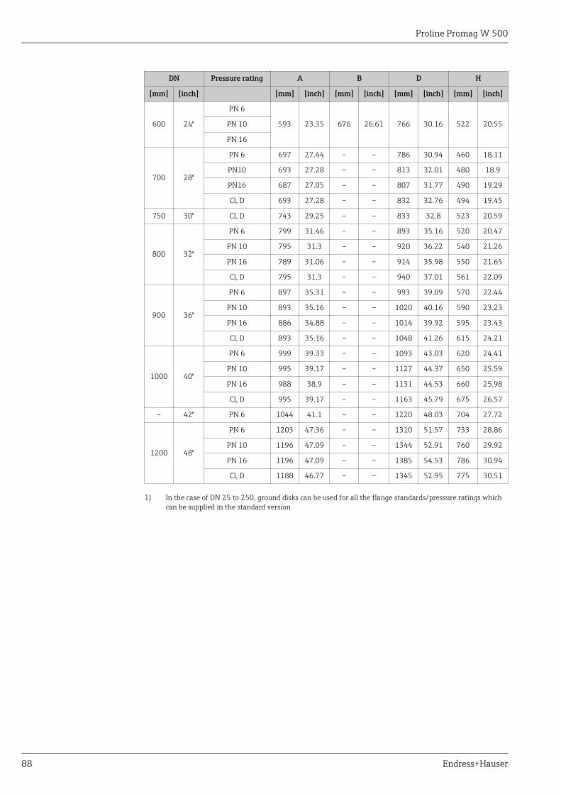
Proline Promag W 500
88 Endress+Hauser
DN Pressure rating A B D H
[mm] [inch] [mm] [inch] [mm] [inch] [mm] [inch] [mm] [inch]
600 24"
PN 6
593 23.35 676 26.61 766 30.16 522 20.55PN 10
PN 16
700 28"
PN 6 697 27.44 – – 786 30.94 460 18.11
PN10 693 27.28 – – 813 32.01 480 18.9
PN16 687 27.05 – – 807 31.77 490 19.29
Cl, D 693 27.28 – – 832 32.76 494 19.45
750 30" Cl, D 743 29.25 – – 833 32.8 523 20.59
800 32"
PN 6 799 31.46 – – 893 35.16 520 20.47
PN 10 795 31.3 – – 920 36.22 540 21.26
PN 16 789 31.06 – – 914 35.98 550 21.65
Cl, D 795 31.3 – – 940 37.01 561 22.09
900 36"
PN 6 897 35.31 – – 993 39.09 570 22.44
PN 10 893 35.16 – – 1020 40.16 590 23.23
PN 16 886 34.88 – – 1014 39.92 595 23.43
Cl, D 893 35.16 – – 1048 41.26 615 24.21
1000 40"
PN 6 999 39.33 – – 1093 43.03 620 24.41
PN 10 995 39.17 – – 1127 44.37 650 25.59
PN 16 988 38.9 – – 1131 44.53 660 25.98
Cl, D 995 39.17 – – 1163 45.79 675 26.57
– 42" PN 6 1044 41.1 – – 1220 48.03 704 27.72
1200 48"
PN 6 1203 47.36 – – 1310 51.57 733 28.86
PN 10 1196 47.09 – – 1344 52.91 760 29.92
PN 16 1196 47.09 – – 1385 54.53 786 30.94
Cl, D 1188 46.77 – – 1345 52.95 775 30.51
1) In the case of DN 25 to 250, ground disks can be used for all the flange standards/pressure ratings whichcan be supplied in the standard version
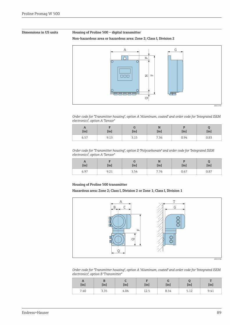
Proline Promag W 500
Endress+Hauser 89
Dimensions in US units Housing of Proline 500 – digital transmitter
Non-hazardous area or hazardous area: Zone 2; Class I, Division 2
NP
F
GA
Q
A0033789
Order code for "Transmitter housing", option A "Aluminum, coated" and order code for "Integrated ISEMelectronics", option A "Sensor"
A[in]
F[in]
G[in]
N[in]
P[in]
Q[in]
6.57 9.13 3.15 7.36 0.94 0.83
Order code for "Transmitter housing", option D "Polycarbonate" and order code for "Integrated ISEMelectronics", option A "Sensor"
A[in]
F[in]
G[in]
N[in]
P[in]
Q[in]
6.97 9.21 3.54 7.76 0.67 0.87
Housing of Proline 500 transmitter
Hazardous area: Zone 2; Class I, Division 2 or Zone 1; Class I, Division 1
T
G
A
B C
Q
Q
F
A0033788
Order code for "Transmitter housing", option A "Aluminum, coated" and order code for "Integrated ISEMelectronics", option B "Transmitter"
A[in]
B[in]
C[in]
F[in]
G[in]
Q[in]
T[in]
7.40 3.35 4.06 12.5 8.54 5.12 9.41
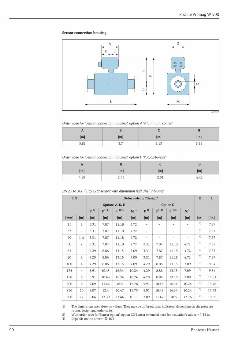
Proline Promag W 500
90 Endress+Hauser
Sensor connection housing
A
B C
G
D
L
E
F
K
M
A0033784
Order code for "Sensor connection housing", option A "Aluminum, coated"
A B C G
[in] [in] [in] [in]
5.83 3.7 2.13 5.35
Order code for "Sensor connection housing", option D "Polycarbonate"
A B C G
[in] [in] [in] [in]
4.45 2.44 2.01 4.41
DN 25 to 300 (1 to 12"): sensor with aluminum half-shell housing
DN Order code for "Design" K L
Options A, D, E Option C
D 1) E 1) 2) F 1) 2) M 1) D 1) E 1) 2) F 1) 2) M 1)
[mm] [in] [in] [in] [in] [in] [in] [in] [in] [in] [in] [in]
25 1 3.31 7.87 11.18 4.72 – – – – 3) 7.87
32 – 3.31 7.87 11.18 4.72 – – – – 3) 7.87
40 1 ½ 3.31 7.87 11.18 4.72 – – – – 3) 7.87
50 2 3.31 7.87 11.18 4.72 3.31 7.87 11.18 4.72 3) 7.87
65 – 4.29 8.86 13.15 7.09 3.31 7.87 11.18 4.72 3) 7.87
80 3 4.29 8.86 13.15 7.09 3.31 7.87 11.18 4.72 3) 7.87
100 4 4.29 8.86 13.15 7.09 4.29 8.86 13.15 7.09 3) 9.84
125 – 5.91 10.43 16.34 10.24 4.29 8.86 13.15 7.09 3) 9.84
150 6 5.91 10.43 16.34 10.24 4.29 8.86 13.15 7.09 3) 11.81
200 8 7.09 11.42 18.5 12.76 5.91 10.43 16.34 10.24 3) 13.78
250 10 8.07 12.4 20.47 15.75 5.91 10.43 16.34 10.24 3) 17.72
300 12 9.06 13.39 22.44 18.11 7.09 11.42 18.5 12.76 3) 19.69
1) The dimensions are reference values. They may be different than indicated, depending on the pressurerating, design and order code.
2) With order code for "Sensor option", option CG "Sensor extended neck for insulation": values + 4.33 in3) Depends on the liner→ 103
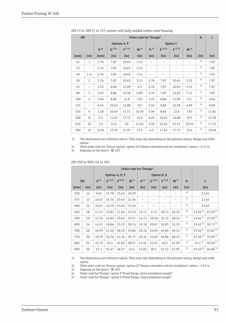
Proline Promag W 500
Endress+Hauser 91
DN 25 to 300 (1 to 12"): sensor with fully welded carbon steel housing
DN Order code for "Design" K L
Options A, E Option C
D 1) E 1) 2) F 1) 2) M 1) D 1) E 1) 2) F 1) 2) M 1)
[mm] [in] [mm] [in] [in] [in] [in] [in] [in] [in] [in] [in]
25 1 2.76 7.87 10.63 5.51 – – – – 3) 7.87
32 – 2.76 7.87 10.63 5.51 – – – – 3) 7.87
40 1 ½ 2.76 7.87 10.63 5.51 – – – – 3) 7.87
50 2 2.76 7.87 10.63 5.51 2.76 7.87 10.63 5.51 3) 7.87
65 – 3.23 8.86 12.09 6.5 2.76 7.87 10.63 5.51 3) 7.87
80 3 3.43 8.86 12.28 6.89 2.76 7.87 10.63 5.51 3) 7.87
100 4 3.94 8.86 12.8 7.87 3.23 8.86 12.09 6.5 3) 9.84
125 – 4.45 10.43 14.88 8.9 3.43 8.86 12.28 6.89 3) 9.84
150 6 5.28 10.43 15.71 10.59 3.94 8.86 12.8 7.87 3) 11.81
200 8 6.3 11.42 17.72 12.6 4.45 10.43 14.88 8.9 3) 13.78
250 10 7.6 12.4 20 15.24 5.28 10.43 15.71 10.59 3) 17.72
300 12 8.58 13.39 21.97 17.2 6.3 11.42 17.72 12.6 3) 19.69
1) The dimensions are reference values. They may vary depending on the pressure rating, design and orderoption.
2) With order code for "Sensor option", option CG "Sensor extended neck for insulation": values + 4.33 in3) Depends on the liner→ 103
DN 350 to 900 (14 to 36")
Order code for "Design"
Options A, E, F Option B, G
DN D 1) E 1) 2) F 1) 2) M 1) D 1) E 1) 2) F 1) 2) M 1) K L
[mm] [in] [in] [in] [in] [in] [in] [in] [in] [in] [in] [in]
350 14 9.65 13.78 23.43 19.29 – – – – 3) 21.65
375 15 10.67 14.76 25.43 21.34 – – – – 3) 21.65
400 16 10.67 14.76 25.43 21.34 – – – – 3) 23.62
450 18 11.77 15.87 27.64 23.54 13.11 17.6 30.71 26.22 3) 23.62 4) 25.59 5)
500 20 12.76 16.85 29.61 25.51 14.13 18.58 32.72 28.23 3) 23.62 4) 25.59 5)
600 24 14.37 18.86 33.23 28.74 16.18 20.67 36.85 32.32 3) 23.62 4) 30.71 5)
700 28 16.93 21.26 38.19 33.86 20.16 24.69 44.84 40.31 3) 27.56 4) 35.83 5)
750 30 18.39 22.76 41.14 36.77 20.16 24.69 44.84 40.31 3) 27.56 4) 35.83 5)
800 32 19.13 23.5 42.64 38.27 21.02 25.47 46.5 41.93 3) 31.5 4) 40.94 5)
900 36 21.1 25.47 46.57 42.2 24.02 28.5 52.52 47.95 3) 35.43 4) 46.06 5)
1) The dimensions are reference values. They may vary depending on the pressure rating, design and orderoption.
2) With order code for "Sensor option", option CG "Sensor extended neck for insulation": values + 4.33 in3) Depends on the liner→ 1034) Order code for "Design", option F "Fixed flange, short installation length"5) Order code for "Design", option G "Fixed flange, long installation length"
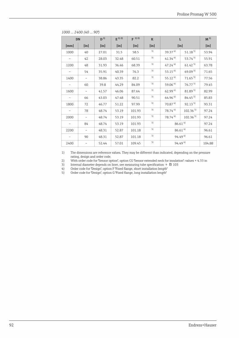
Proline Promag W 500
92 Endress+Hauser
1000 … 2400 (40 … 90")
DN D 1) E 1) 2) F 1) 2) K L M 1)
[mm] [in] [in] [in] [in] [in] [in] [in]
1000 40 27.01 31.5 58.5 3) 39.37 4) 51.18 5) 53.94
– 42 28.03 32.48 60.51 3) 41.34 4) 53.74 5) 55.91
1200 48 31.93 36.46 68.39 3) 47.24 4) 61.42 5) 63.78
– 54 35.91 40.39 76.3 3) 53.15 4) 69.09 5) 71.65
1400 – 38.86 43.35 82.2 3) 55.12 4) 71.65 5) 77.56
– 60 39.8 44.29 84.09 3) 59.06 4) 76.77 5) 79.45
1600 – 41.57 46.06 87.64 3) 62.99 4) 81.89 5) 82.99
– 66 43.03 47.48 90.51 3) 64.96 4) 84.45 5) 85.83
1800 72 46.77 51.22 97.99 3) 70.87 4) 92.13 5) 93.31
– 78 48.74 53.19 101.93 3) 78.74 4) 102.36 5) 97.24
2000 – 48.74 53.19 101.93 3) 78.74 4) 102.36 5) 97.24
– 84 48.74 53.19 101.93 3) 86.61 4) 97.24
2200 – 48.31 52.87 101.18 3) 86.61 4) 96.61
– 90 48.31 52.87 101.18 3) 94.49 4) 96.61
2400 – 52.44 57.01 109.45 3) 94.49 4) 104.88
1) The dimensions are reference values. They may be different than indicated, depending on the pressurerating, design and order code.
2) With order code for "Sensor option", option CG "Sensor extended neck for insulation": values + 4.33 in3) Internal diameter depends on liner, see measuring tube specification → 1034) Order code for "Design", option F "Fixed flange, short installation length"5) Order code for "Design", option G "Fixed flange, long installation length"
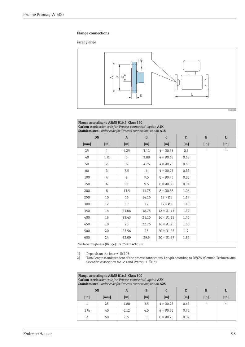
Proline Promag W 500
Endress+Hauser 93
Flange connections
Fixed flange
C
D
A B E
L
A0015621
Flange according to ASME B16.5, Class 150Carbon steel: order code for "Process connection", option A1KStainless steel: order code for "Process connection", option A1S
DN A B C D E L
[mm] [in] [in] [in] [in] [in] [in] [in]
25 1 4.25 3.12 4 × Ø0.63 0.5 1) 2)
40 1 ½ 5 3.88 4 × Ø0.63 0.63
50 2 6 4.75 4 × Ø0.75 0.69
80 3 7.5 6 4 × Ø0.75 0.88
100 4 9 7.5 8 × Ø0.75 0.88
150 6 11 9.5 8 × Ø0.88 0.94
200 8 13.5 11.75 8 × Ø0.88 1.06
250 10 16 14.25 12 × Ø1 1.17
300 12 19 17 12 × Ø1 1.19
350 14 21.06 18.75 12 × Ø1.13 1.39
400 16 23.43 21.25 16 × Ø1.13 1.46
450 18 25 22.75 16 × Ø1.25 1.58
500 20 27.56 25 20 × Ø1.25 1.7
600 24 32.09 29.5 20 × Ø1.37 1.89
Surface roughness (flange): Ra 250 to 492 µm
1) Depends on the liner→ 1032) Total length is independent of the process connections. Length according to DVGW (German Technical and
Scientific Association for Gas and Water) → 90
Flange according to ASME B16.5, Class 300Carbon steel: order code for "Process connection", option A2KStainless steel: order code for "Process connection", option A2S
DN A B C D E L
[in] [mm] [in] [in] [in] [in] [in] [in]
1 25 4.88 3.5 4 × Ø0.75 0.63 1) 2)
1 ½ 40 6.12 4.5 4 × Ø0.88 0.75
2 50 6.5 5 8 × Ø0.75 0.82
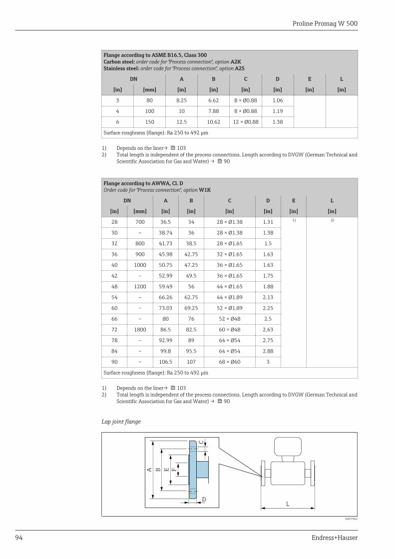
Proline Promag W 500
94 Endress+Hauser
Flange according to ASME B16.5, Class 300Carbon steel: order code for "Process connection", option A2KStainless steel: order code for "Process connection", option A2S
DN A B C D E L
[in] [mm] [in] [in] [in] [in] [in] [in]
3 80 8.25 6.62 8 × Ø0.88 1.06
4 100 10 7.88 8 × Ø0.88 1.19
6 150 12.5 10.62 12 × Ø0.88 1.38
Surface roughness (flange): Ra 250 to 492 µm
1) Depends on the liner→ 1032) Total length is independent of the process connections. Length according to DVGW (German Technical and
Scientific Association for Gas and Water) → 90
Flange according to AWWA, Cl. DOrder code for "Process connection", option W1K
DN A B C D E L
[in] [mm] [in] [in] [in] [in] [in] [in]
28 700 36.5 34 28 × Ø1.38 1.31 1) 2)
30 – 38.74 36 28 × Ø1.38 1.38
32 800 41.73 38.5 28 × Ø1.65 1.5
36 900 45.98 42.75 32 × Ø1.65 1.63
40 1000 50.75 47.25 36 × Ø1.65 1.63
42 – 52.99 49.5 36 × Ø1.65 1.75
48 1200 59.49 56 44 × Ø1.65 1.88
54 – 66.26 62.75 44 × Ø1.89 2.13
60 – 73.03 69.25 52 × Ø1.89 2.25
66 – 80 76 52 × Ø48 2.5
72 1800 86.5 82.5 60 × Ø48 2.63
78 – 92.99 89 64 × Ø54 2.75
84 – 99.8 95.5 64 × Ø54 2.88
90 – 106.5 107 68 × Ø60 3
Surface roughness (flange): Ra 250 to 492 µin
1) Depends on the liner→ 1032) Total length is independent of the process connections. Length according to DVGW (German Technical and
Scientific Association for Gas and Water) → 90
Lap joint flange
C
D
A B FE
L
A0037862
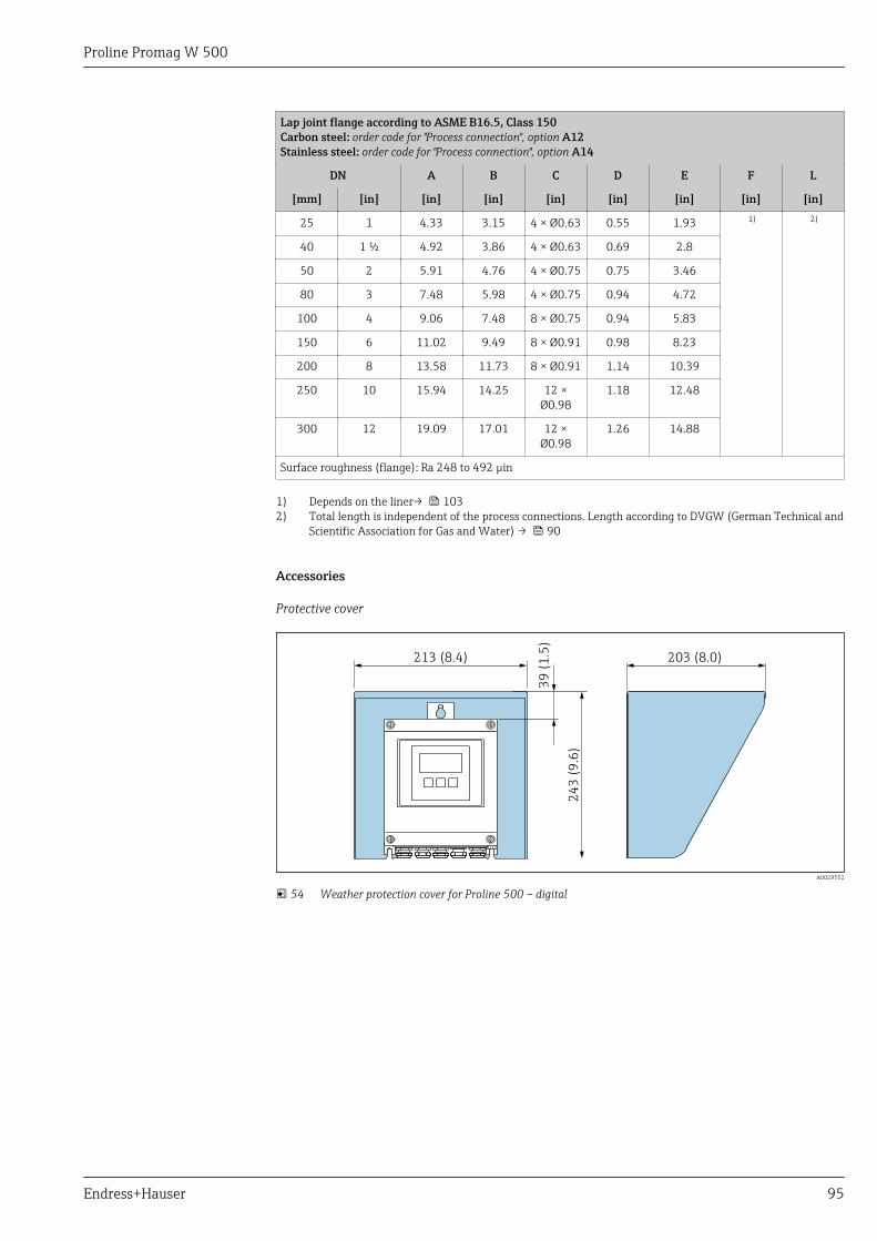
Proline Promag W 500
Endress+Hauser 95
Lap joint flange according to ASME B16.5, Class 150Carbon steel: order code for "Process connection", option A12Stainless steel: order code for "Process connection", option A14
DN A B C D E F L
[mm] [in] [in] [in] [in] [in] [in] [in] [in]
25 1 4.33 3.15 4 × Ø0.63 0.55 1.93 1) 2)
40 1 ½ 4.92 3.86 4 × Ø0.63 0.69 2.8
50 2 5.91 4.76 4 × Ø0.75 0.75 3.46
80 3 7.48 5.98 4 × Ø0.75 0.94 4.72
100 4 9.06 7.48 8 × Ø0.75 0.94 5.83
150 6 11.02 9.49 8 × Ø0.91 0.98 8.23
200 8 13.58 11.73 8 × Ø0.91 1.14 10.39
250 10 15.94 14.25 12 ×Ø0.98
1.18 12.48
300 12 19.09 17.01 12 ×Ø0.98
1.26 14.88
Surface roughness (flange): Ra 248 to 492 µin
1) Depends on the liner→ 1032) Total length is independent of the process connections. Length according to DVGW (German Technical and
Scientific Association for Gas and Water) → 90
Accessories
Protective cover
213 (8.4)
39
(1
.5)
24
3 (
9.6
)
203 (8.0)
A0029552
54 Weather protection cover for Proline 500 – digital
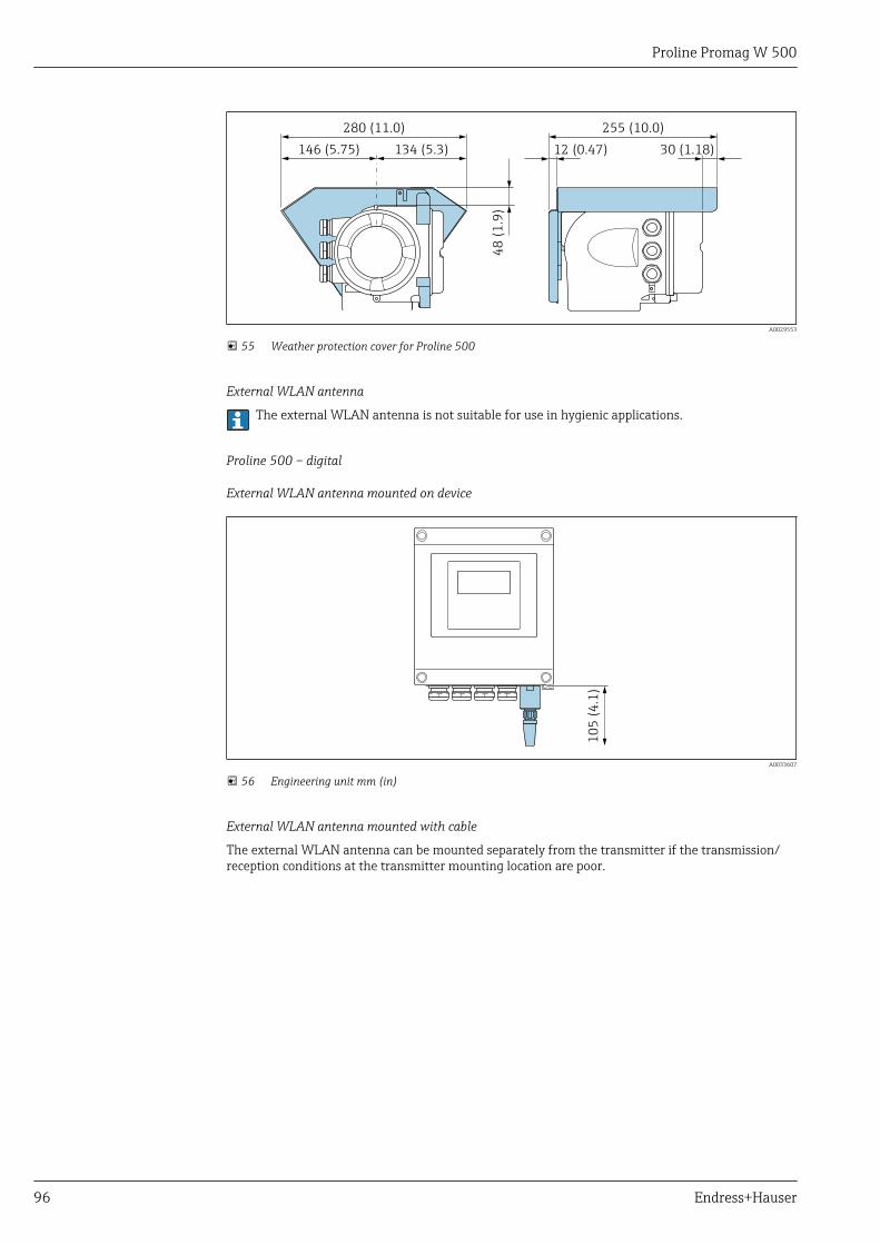
Proline Promag W 500
96 Endress+Hauser
146 (5.75)
48
(1
.9)
12 (0.47)
280 (11.0) 255 (10.0)
134 (5.3) 30 (1.18)
A0029553
55 Weather protection cover for Proline 500
External WLAN antenna
The external WLAN antenna is not suitable for use in hygienic applications.
Proline 500 – digital
External WLAN antenna mounted on device
10
5 (
4.1
)
A0033607
56 Engineering unit mm (in)
External WLAN antenna mounted with cable
The external WLAN antenna can be mounted separately from the transmitter if the transmission/reception conditions at the transmitter mounting location are poor.
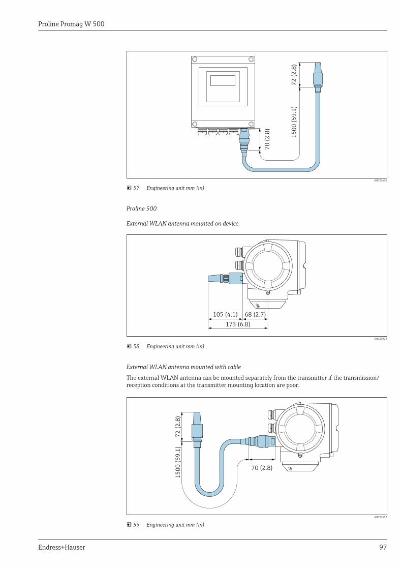
Proline Promag W 500
Endress+Hauser 97
70
(2
.8)
15
00
(5
9.1
)7
2 (
2.8
)
A0033606
57 Engineering unit mm (in)
Proline 500
External WLAN antenna mounted on device
68 (2.7)105 (4.1)
173 (6.8)
A0028923
58 Engineering unit mm (in)
External WLAN antenna mounted with cable
The external WLAN antenna can be mounted separately from the transmitter if the transmission/reception conditions at the transmitter mounting location are poor.
70 (2.8)
15
00
(5
9.1
)7
2 (
2.8
)
A0033597
59 Engineering unit mm (in)
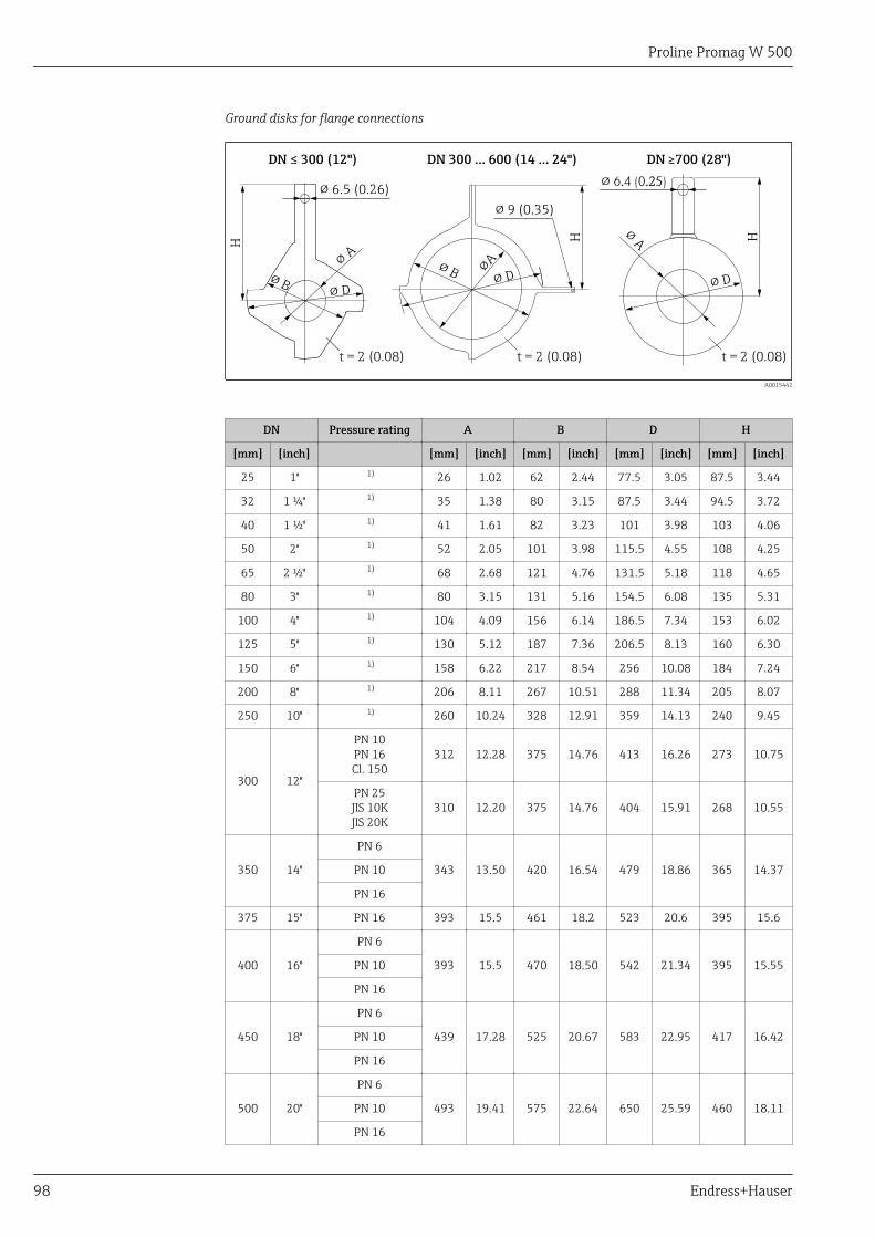
Proline Promag W 500
98 Endress+Hauser
Ground disks for flange connections
DN ≤ 300 (12")
H H H
DN 300 … 600 (14 … 24")
t = 2 (0.08)
! 9 (0.35)
DN 700 (28")≥
! 6.5 (0.26)
! B
!A
! D
! 6.4 (0.25)
! B !A
! D
!A
! D
t = 2 (0.08)t = 2 (0.08)
A0015442
DN Pressure rating A B D H
[mm] [inch] [mm] [inch] [mm] [inch] [mm] [inch] [mm] [inch]
25 1" 1) 26 1.02 62 2.44 77.5 3.05 87.5 3.44
32 1 ¼" 1) 35 1.38 80 3.15 87.5 3.44 94.5 3.72
40 1 ½" 1) 41 1.61 82 3.23 101 3.98 103 4.06
50 2" 1) 52 2.05 101 3.98 115.5 4.55 108 4.25
65 2 ½" 1) 68 2.68 121 4.76 131.5 5.18 118 4.65
80 3" 1) 80 3.15 131 5.16 154.5 6.08 135 5.31
100 4" 1) 104 4.09 156 6.14 186.5 7.34 153 6.02
125 5" 1) 130 5.12 187 7.36 206.5 8.13 160 6.30
150 6" 1) 158 6.22 217 8.54 256 10.08 184 7.24
200 8" 1) 206 8.11 267 10.51 288 11.34 205 8.07
250 10" 1) 260 10.24 328 12.91 359 14.13 240 9.45
300 12"
PN 10PN 16Cl. 150
312 12.28 375 14.76 413 16.26 273 10.75
PN 25JIS 10KJIS 20K
310 12.20 375 14.76 404 15.91 268 10.55
350 14"
PN 6
343 13.50 420 16.54 479 18.86 365 14.37PN 10
PN 16
375 15" PN 16 393 15.5 461 18.2 523 20.6 395 15.6
400 16"
PN 6
393 15.5 470 18.50 542 21.34 395 15.55PN 10
PN 16
450 18"
PN 6
439 17.28 525 20.67 583 22.95 417 16.42PN 10
PN 16
500 20"
PN 6
493 19.41 575 22.64 650 25.59 460 18.11PN 10
PN 16
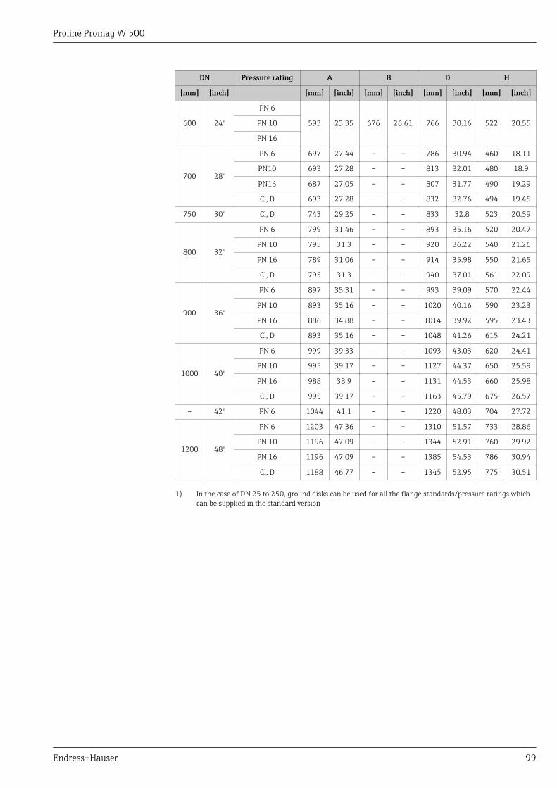
Proline Promag W 500
Endress+Hauser 99
DN Pressure rating A B D H
[mm] [inch] [mm] [inch] [mm] [inch] [mm] [inch] [mm] [inch]
600 24"
PN 6
593 23.35 676 26.61 766 30.16 522 20.55PN 10
PN 16
700 28"
PN 6 697 27.44 – – 786 30.94 460 18.11
PN10 693 27.28 – – 813 32.01 480 18.9
PN16 687 27.05 – – 807 31.77 490 19.29
Cl, D 693 27.28 – – 832 32.76 494 19.45
750 30" Cl, D 743 29.25 – – 833 32.8 523 20.59
800 32"
PN 6 799 31.46 – – 893 35.16 520 20.47
PN 10 795 31.3 – – 920 36.22 540 21.26
PN 16 789 31.06 – – 914 35.98 550 21.65
Cl, D 795 31.3 – – 940 37.01 561 22.09
900 36"
PN 6 897 35.31 – – 993 39.09 570 22.44
PN 10 893 35.16 – – 1020 40.16 590 23.23
PN 16 886 34.88 – – 1014 39.92 595 23.43
Cl, D 893 35.16 – – 1048 41.26 615 24.21
1000 40"
PN 6 999 39.33 – – 1093 43.03 620 24.41
PN 10 995 39.17 – – 1127 44.37 650 25.59
PN 16 988 38.9 – – 1131 44.53 660 25.98
Cl, D 995 39.17 – – 1163 45.79 675 26.57
– 42" PN 6 1044 41.1 – – 1220 48.03 704 27.72
1200 48"
PN 6 1203 47.36 – – 1310 51.57 733 28.86
PN 10 1196 47.09 – – 1344 52.91 760 29.92
PN 16 1196 47.09 – – 1385 54.53 786 30.94
Cl, D 1188 46.77 – – 1345 52.95 775 30.51
1) In the case of DN 25 to 250, ground disks can be used for all the flange standards/pressure ratings whichcan be supplied in the standard version
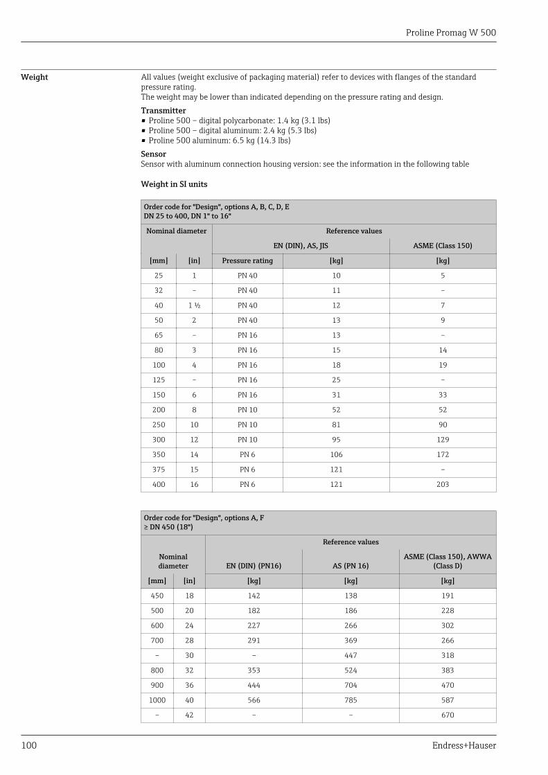
Proline Promag W 500
100 Endress+Hauser
Weight All values (weight exclusive of packaging material) refer to devices with flanges of the standardpressure rating.The weight may be lower than indicated depending on the pressure rating and design.Transmitter• Proline 500 – digital polycarbonate: 1.4 kg (3.1 lbs)• Proline 500 – digital aluminum: 2.4 kg (5.3 lbs)• Proline 500 aluminum: 6.5 kg (14.3 lbs)SensorSensor with aluminum connection housing version: see the information in the following table
Weight in SI units
Order code for "Design", options A, B, C, D, EDN 25 to 400, DN 1" to 16"
Nominal diameter Reference values
EN (DIN), AS, JIS ASME (Class 150)
[mm] [in] Pressure rating [kg] [kg]
25 1 PN 40 10 5
32 – PN 40 11 –
40 1 ½ PN 40 12 7
50 2 PN 40 13 9
65 – PN 16 13 –
80 3 PN 16 15 14
100 4 PN 16 18 19
125 – PN 16 25 –
150 6 PN 16 31 33
200 8 PN 10 52 52
250 10 PN 10 81 90
300 12 PN 10 95 129
350 14 PN 6 106 172
375 15 PN 6 121 –
400 16 PN 6 121 203
Order code for "Design", options A, F≥ DN 450 (18")
Nominaldiameter
Reference values
EN (DIN) (PN16) AS (PN 16)ASME (Class 150), AWWA
(Class D)
[mm] [in] [kg] [kg] [kg]
450 18 142 138 191
500 20 182 186 228
600 24 227 266 302
700 28 291 369 266
– 30 – 447 318
800 32 353 524 383
900 36 444 704 470
1000 40 566 785 587
– 42 – – 670
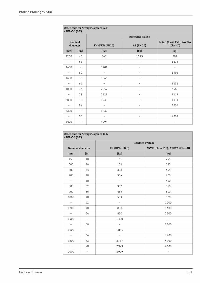
Proline Promag W 500
Endress+Hauser 101
Order code for "Design", options A, F≥ DN 450 (18")
Nominaldiameter
Reference values
EN (DIN) (PN16) AS (PN 16)ASME (Class 150), AWWA
(Class D)
[mm] [in] [kg] [kg] [kg]
1200 48 843 1 229 901
– 54 – – 1 273
1400 – 1 204 – –
– 60 – – 1 594
1600 – 1 845 – –
– 66 – – 2 131
1800 72 2 357 – 2 568
– 78 2 929 – 3 113
2000 – 2 929 – 3 113
– 84 – – 3 755
2200 – 3 422 – –
– 90 – – 4 797
2400 – 4 094 – –
Order code for "Design", options B, G≥ DN 450 (18")
Nominal diameter
Reference values
EN (DIN) (PN 6) ASME (Class 150), AWWA (Class D)
[mm] [in] [kg] [kg]
450 18 161 255
500 20 156 285
600 24 208 405
700 28 304 400
– 30 – 460
800 32 357 550
900 36 485 800
1000 40 589 900
– 42 – 1 100
1200 48 850 1 400
– 54 850 2 200
1400 – 1 300 –
– 60 – 2 700
1600 – 1 845 –
– 66 – 3 700
1800 72 2 357 4 100
– 78 2 929 4 600
2000 – 2 929 –
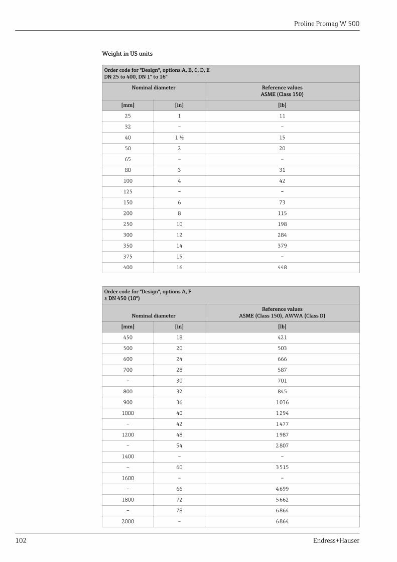
Proline Promag W 500
102 Endress+Hauser
Weight in US units
Order code for "Design", options A, B, C, D, EDN 25 to 400, DN 1" to 16"
Nominal diameter Reference valuesASME (Class 150)
[mm] [in] [lb]
25 1 11
32 – –
40 1 ½ 15
50 2 20
65 – –
80 3 31
100 4 42
125 – –
150 6 73
200 8 115
250 10 198
300 12 284
350 14 379
375 15 –
400 16 448
Order code for "Design", options A, F≥ DN 450 (18")
Nominal diameterReference values
ASME (Class 150), AWWA (Class D)
[mm] [in] [lb]
450 18 421
500 20 503
600 24 666
700 28 587
– 30 701
800 32 845
900 36 1 036
1000 40 1 294
– 42 1 477
1200 48 1 987
– 54 2 807
1400 – –
– 60 3 515
1600 – –
– 66 4 699
1800 72 5 662
– 78 6 864
2000 – 6 864
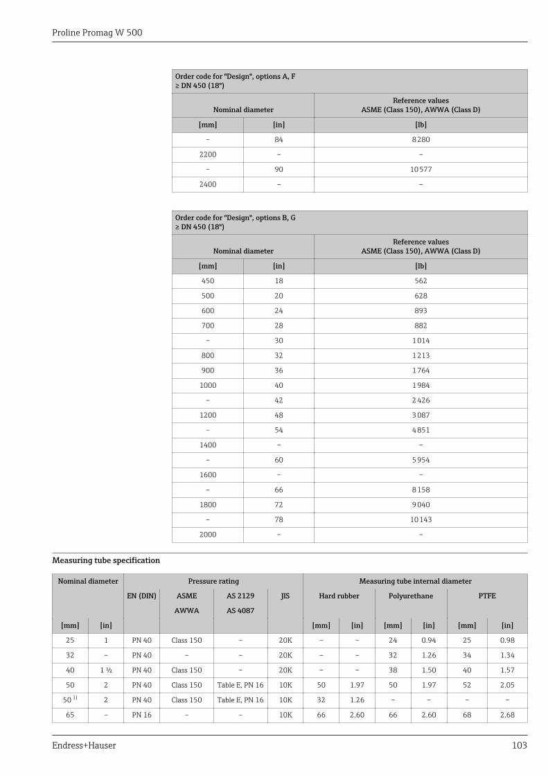
Proline Promag W 500
Endress+Hauser 103
Order code for "Design", options A, F≥ DN 450 (18")
Nominal diameterReference values
ASME (Class 150), AWWA (Class D)
[mm] [in] [lb]
– 84 8 280
2200 – –
– 90 10 577
2400 – –
Order code for "Design", options B, G≥ DN 450 (18")
Nominal diameterReference values
ASME (Class 150), AWWA (Class D)
[mm] [in] [lb]
450 18 562
500 20 628
600 24 893
700 28 882
– 30 1 014
800 32 1 213
900 36 1 764
1000 40 1 984
– 42 2 426
1200 48 3 087
– 54 4 851
1400 – –
– 60 5 954
1600 – –
– 66 8 158
1800 72 9 040
– 78 10 143
2000 – –
Measuring tube specification
Nominal diameter Pressure rating Measuring tube internal diameter
EN (DIN) ASME AS 2129 JIS Hard rubber Polyurethane PTFE
AWWA AS 4087
[mm] [in] [mm] [in] [mm] [in] [mm] [in]
25 1 PN 40 Class 150 – 20K – – 24 0.94 25 0.98
32 – PN 40 – – 20K – – 32 1.26 34 1.34
40 1 ½ PN 40 Class 150 – 20K – – 38 1.50 40 1.57
50 2 PN 40 Class 150 Table E, PN 16 10K 50 1.97 50 1.97 52 2.05
50 1) 2 PN 40 Class 150 Table E, PN 16 10K 32 1.26 – – – –
65 – PN 16 – – 10K 66 2.60 66 2.60 68 2.68
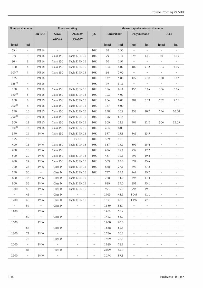
Proline Promag W 500
104 Endress+Hauser
Nominal diameter Pressure rating Measuring tube internal diameter
EN (DIN) ASME AS 2129 JIS Hard rubber Polyurethane PTFE
AWWA AS 4087
[mm] [in] [mm] [in] [mm] [in] [mm] [in]
65 1) – PN 16 – – 10K 38 1.50 – – – –
80 3 PN 16 Class 150 Table E, PN 16 10K 79 3.11 79 3.11 80 3.15
80 1) 3 PN 16 Class 150 Table E, PN 16 10K 50 1.97 – – – –
100 4 PN 16 Class 150 Table E, PN 16 10K 102 4.02 102 4.02 104 4.09
100 1) 4 PN 16 Class 150 Table E, PN 16 10K 66 2.60 – – – –
125 – PN 16 – – 10K 127 5.00 127 5.00 130 5.12
125 1) – PN 16 – – 10K 79 3.11 – – – –
150 6 PN 16 Class 150 Table E, PN 16 10K 156 6.14 156 6.14 156 6.14
150 1) 6 PN 16 Class 150 Table E, PN 16 10K 102 4.02 – – – –
200 8 PN 10 Class 150 Table E, PN 16 10K 204 8.03 204 8.03 202 7.95
200 1) 8 PN 16 Class 150 Table E, PN 16 10K 127 5.00 – – – –
250 10 PN 10 Class 150 Table E, PN 16 10K 258 10.2 258 10.2 256 10.08
250 1) 10 PN 16 Class 150 Table E, PN 16 10K 156 6.14 – – – –
300 12 PN 10 Class 150 Table E, PN 16 10K 309 12.2 309 12.2 306 12.05
300 1) 12 PN 16 Class 150 Table E, PN 16 10K 204 8.03 – – – –
350 14 PN 6 Class 150 Table E, PN 16 10K 337 13.3 342 13.5 – –
375 15 – – PN 16 10K 389 15.3 – – – –
400 16 PN 6 Class 150 Table E, PN 16 10K 387 15.2 392 15.4 – –
450 18 PN 6 Class 150 – 10K 436 17.1 437 17.2 – –
500 20 PN 6 Class 150 Table E, PN 16 10K 487 19.1 492 19.4 – –
600 24 PN 6 Class 150 Table E, PN 16 10K 589 23.0 594 23.4 – –
700 28 PN 6 Class D Table E, PN 16 10K 688 27.1 692 27.2 – –
750 30 – Class D Table E, PN 16 10K 737 29.1 742 29.2 – –
800 32 PN 6 Class D Table E, PN 16 – 788 31.0 794 31.3 – –
900 36 PN 6 Class D Table E, PN 16 – 889 35.0 891 35.1 – –
1000 40 PN 6 Class D Table E, PN 16 – 991 39.0 994 39.1 – –
– 42 – Class D – – 1 043 41.1 1 043 41.1 – –
1200 48 PN 6 Class D Table E, PN 16 – 1 191 46.9 1 197 47.1 – –
– 54 – Class D – – 1 339 52.7 – – – –
1400 – PN 6 – – – 1 402 55.2 – – – –
– 60 – Class D – – 1 492 58.7 – – – –
1600 – PN 6 – – – 1 600 63.0 – – – –
– 66 – Class D – – 1 638 64.5 – – – –
1800 72 PN 6 – – – 1 786 70.3 – – – –
– 78 – Class D – – 1 989 78.3 – – – –
2000 – PN 6 – – – 1 989 78.3 – – – –
– 84 – Class D – – 2 099 84.0 – – – –
2200 – PN 6 – – – 2 194 87.8 – – – –
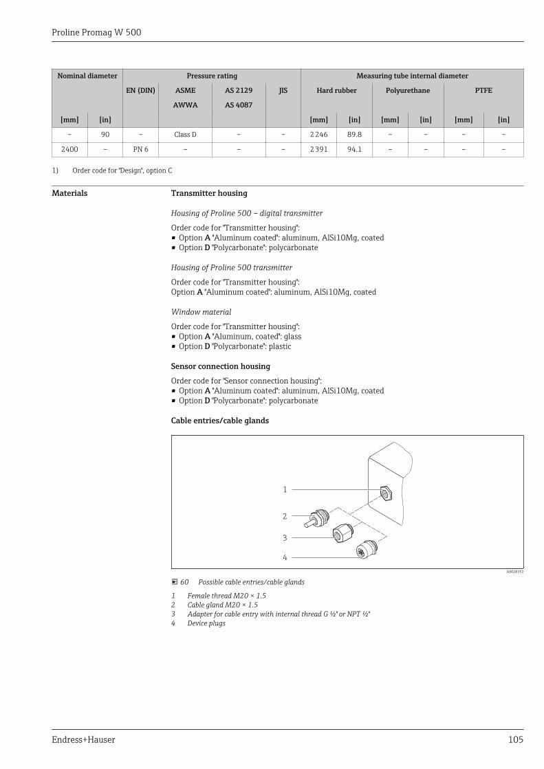
Proline Promag W 500
Endress+Hauser 105
Nominal diameter Pressure rating Measuring tube internal diameter
EN (DIN) ASME AS 2129 JIS Hard rubber Polyurethane PTFE
AWWA AS 4087
[mm] [in] [mm] [in] [mm] [in] [mm] [in]
– 90 – Class D – – 2 246 89.8 – – – –
2400 – PN 6 – – – 2 391 94.1 – – – –
1) Order code for "Design", option C
Materials Transmitter housing
Housing of Proline 500 – digital transmitter
Order code for "Transmitter housing":• Option A "Aluminum coated": aluminum, AlSi10Mg, coated• Option D "Polycarbonate": polycarbonate
Housing of Proline 500 transmitter
Order code for "Transmitter housing":Option A "Aluminum coated": aluminum, AlSi10Mg, coated
Window material
Order code for "Transmitter housing":• Option A "Aluminum, coated": glass• Option D "Polycarbonate": plastic
Sensor connection housing
Order code for "Sensor connection housing":• Option A "Aluminum coated": aluminum, AlSi10Mg, coated• Option D "Polycarbonate": polycarbonate
Cable entries/cable glands
1
2
3
4
A0028352
60 Possible cable entries/cable glands
1 Female thread M20 × 1.52 Cable gland M20 × 1.53 Adapter for cable entry with internal thread G ½" or NPT ½"4 Device plugs
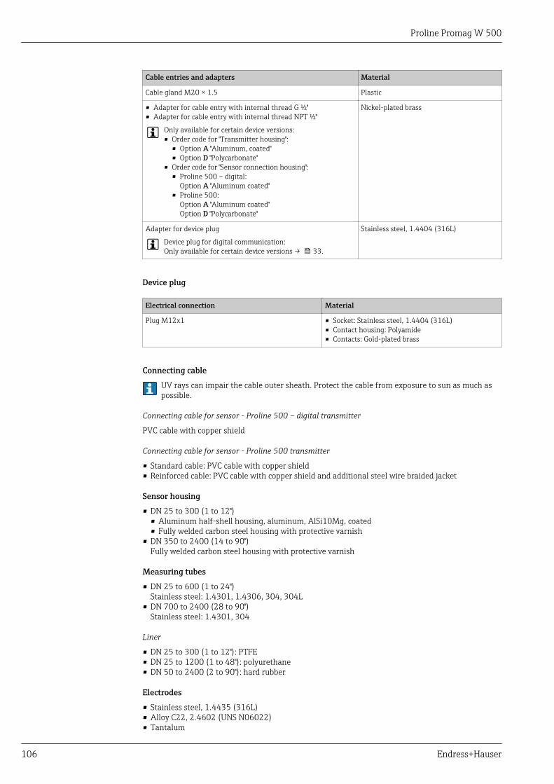
Proline Promag W 500
106 Endress+Hauser
Cable entries and adapters Material
Cable gland M20 × 1.5 Plastic
• Adapter for cable entry with internal thread G ½"• Adapter for cable entry with internal thread NPT ½"
Only available for certain device versions:• Order code for "Transmitter housing":
• Option A "Aluminum, coated"• Option D "Polycarbonate"
• Order code for "Sensor connection housing":• Proline 500 – digital:
Option A "Aluminum coated"• Proline 500:
Option A "Aluminum coated"Option D "Polycarbonate"
Nickel-plated brass
Adapter for device plug
Device plug for digital communication:Only available for certain device versions → 33.
Stainless steel, 1.4404 (316L)
Device plug
Electrical connection Material
Plug M12x1 • Socket: Stainless steel, 1.4404 (316L)• Contact housing: Polyamide• Contacts: Gold-plated brass
Connecting cable
UV rays can impair the cable outer sheath. Protect the cable from exposure to sun as much aspossible.
Connecting cable for sensor - Proline 500 – digital transmitter
PVC cable with copper shield
Connecting cable for sensor - Proline 500 transmitter
• Standard cable: PVC cable with copper shield• Reinforced cable: PVC cable with copper shield and additional steel wire braided jacket
Sensor housing
• DN 25 to 300 (1 to 12")• Aluminum half-shell housing, aluminum, AlSi10Mg, coated• Fully welded carbon steel housing with protective varnish
• DN 350 to 2400 (14 to 90")Fully welded carbon steel housing with protective varnish
Measuring tubes
• DN 25 to 600 (1 to 24")Stainless steel: 1.4301, 1.4306, 304, 304L
• DN 700 to 2400 (28 to 90")Stainless steel: 1.4301, 304
Liner
• DN 25 to 300 (1 to 12"): PTFE• DN 25 to 1200 (1 to 48"): polyurethane• DN 50 to 2400 (2 to 90"): hard rubber
Electrodes
• Stainless steel, 1.4435 (316L)• Alloy C22, 2.4602 (UNS N06022)• Tantalum
Proline Promag W 500
Endress+Hauser 107
Process connections
For flanges made of carbon steel:• DN ≤ 300 (12"): with Al/Zn protective coating or protective varnish• DN ≥ 350 (14"): protective varnishAll carbon steel lap joint flanges are supplied with a hot-dip galvanized finish.
EN 1092-1 (DIN 2501)
Fixed flange• Carbon steel:
• DN ≤ 300: S235JRG2, S235JR+N, P245GH, A105, E250C• DN 350 to 2400: P245GH, S235JRG2, A105, E250C
• Stainless steel:• DN ≤ 300: 1.4404, 1.4571, F316L• DN 350 to 600: 1.4571, F316L, 1.4404• DN 700 to 1000: 1.4404, F316L
Lap joint flange• Carbon steel DN ≤ 300: S235JRG2, A105, E250C• Stainless steel DN ≤ 300: 1.4306,1.4404, 1.4571, F316LLap joint flange, stamped plate• Carbon steel DN ≤ 300: S235JRG2 similar to S235JR+AR or 1.0038• Stainless steel DN ≤ 300: 1.4301 similar to 304
ASME B16.5
Fixed flange, lap joint flange• Carbon steel: A105• Stainless steel: F316L
JIS B2220
• Carbon steel: A105, A350 LF2• Stainless steel: F316L
AWWA C207
Carbon steel: A105, P265GH, A181 Class 70, E250C, S275JR
AS 2129
Carbon steel: A105, E250C, P235GH, P265GH, S235JRG2
AS 4087
Carbon steel: A105, P265GH, S275JR
Seals
As per DIN EN 1514-1, form IBC
Accessories
Protective cover
Stainless steel, 1.4404 (316L)
External WLAN antenna
• Antenna: ASA plastic (acrylic ester-styrene-acrylonitrile) and nickel-plated brass• Adapter: Stainless steel and nickel-plated brass• Cable: Polyethylene• Plug: Nickel-plated brass• Angle bracket: Stainless steel

Proline Promag W 500
108 Endress+Hauser
Ground disks
• Stainless steel, 1.4435 (316L)• Alloy C22, 2.4602 (UNS N06022)• Tantalum
Fitted electrodes Measurement, reference and empty pipe detection electrodes available as standard with:• 1.4435 (316L)• Alloy C22, 2.4602 (UNS N06022)• Tantalum
Process connections • EN 1092-1 (DIN 2501)• DN ≤ 300: fixed flange (PN 10/16/25/40) = Form A, lap joint flange (PN 10/16), lap joint
flange, stamped plate (PN 10) = Form A• DN ≥ 350: fixed flange (PN 6/10/16/25) = flat face (Form B)• DN 450 to 2400: fixed flange (PN 6/10/16) = flat face (Form B)
• ASME B16.5• DN 350 to 2400 (14 to 90"): fixed flange (Class 150)• DN 25 to 600 (1 to 24"): lap joint flange (Class 150)• DN 25 to 150 (1 to 6"): fixed flange (Class 300)
• JIS B2220• DN 50 to 750: fixed flange (10K)• DN 25 to 600: fixed flange (20K)
• AWWA C207DN 48 to 90": fixed flange (Class D)
• AS 2129DN 50 to 1200: fixed flange (Table E)
• AS 4087DN 50 to 1200): fixed flange (PN 16)
For information on the different materials used in the process connections → 107
Surface roughness Electrodes with 1.4435 (316L); Alloy C22, 2.4602 (UNS N06022); tantalum:≤ 0.3 to 0.5 µm (11.8 to 19.7 µin)(All data relate to parts in contact with fluid)
Human interface
Operating concept Operator-oriented menu structure for user-specific tasks• Commissioning• Operation• Diagnostics• Expert levelFast and safe commissioning• Guided menus ("Make-it-run" wizards) for applications• Menu guidance with brief descriptions of the individual parameter functions• Access to the device via Web server → 127• WLAN access to the device via mobile handheld terminal, tablet or smart phoneReliable operation• Operation in local language → 109• Uniform operating philosophy applied to device and operating tools• If replacing electronic modules, transfer the device configuration via the integrated memory
(HistoROM backup) which contains the process and measuring device data and the event logbook.No need to reconfigure.
Efficient diagnostics increase measurement availability• Troubleshooting measures can be called up via the device and in the operating tools• Diverse simulation options, logbook for events that occur and optional line recorder functions
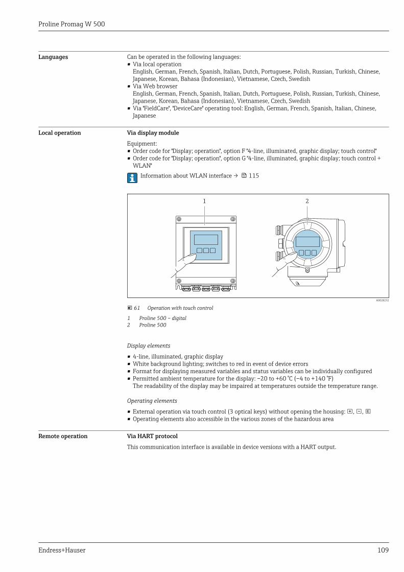
Proline Promag W 500
Endress+Hauser 109
Languages Can be operated in the following languages:• Via local operation
English, German, French, Spanish, Italian, Dutch, Portuguese, Polish, Russian, Turkish, Chinese,Japanese, Korean, Bahasa (Indonesian), Vietnamese, Czech, Swedish
• Via Web browserEnglish, German, French, Spanish, Italian, Dutch, Portuguese, Polish, Russian, Turkish, Chinese,Japanese, Korean, Bahasa (Indonesian), Vietnamese, Czech, Swedish
• Via "FieldCare", "DeviceCare" operating tool: English, German, French, Spanish, Italian, Chinese,Japanese
Local operation Via display module
Equipment:• Order code for "Display; operation", option F "4-line, illuminated, graphic display; touch control"• Order code for "Display; operation", option G "4-line, illuminated, graphic display; touch control +
WLAN"Information about WLAN interface → 115
1 2
A0028232
61 Operation with touch control
1 Proline 500 – digital2 Proline 500
Display elements
• 4-line, illuminated, graphic display• White background lighting; switches to red in event of device errors• Format for displaying measured variables and status variables can be individually configured• Permitted ambient temperature for the display: –20 to +60 °C (–4 to +140 °F)
The readability of the display may be impaired at temperatures outside the temperature range.
Operating elements
• External operation via touch control (3 optical keys) without opening the housing: , , • Operating elements also accessible in the various zones of the hazardous area
Remote operation Via HART protocol
This communication interface is available in device versions with a HART output.
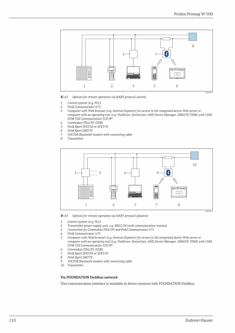
Proline Promag W 500
110 Endress+Hauser
1 2 3 5
8
4 7
6
A0028747
62 Options for remote operation via HART protocol (active)
1 Control system (e.g. PLC)2 Field Communicator 4753 Computer with Web browser (e.g. Internet Explorer) for access to the integrated device Web server or
computer with an operating tool (e.g. FieldCare, DeviceCare, AMS Device Manager, SIMATIC PDM) with COMDTM "CDI Communication TCP/IP"
4 Commubox FXA195 (USB)5 Field Xpert SFX350 or SFX3706 Field Xpert SMT707 VIATOR Bluetooth modem with connecting cable8 Transmitter
1
10
2 3
4 5 7
6 9
8
A0028746
63 Options for remote operation via HART protocol (passive)
1 Control system (e.g. PLC)2 Transmitter power supply unit, e.g. RN221N (with communication resistor)3 Connection for Commubox FXA195 and Field Communicator 4754 Field Communicator 4755 Computer with Web browser (e.g. Internet Explorer) for access to the integrated device Web server or
computer with an operating tool (e.g. FieldCare, DeviceCare, AMS Device Manager, SIMATIC PDM) with COMDTM "CDI Communication TCP/IP"
6 Commubox FXA195 (USB)7 Field Xpert SFX350 or SFX3708 Field Xpert SMT709 VIATOR Bluetooth modem with connecting cable10 Transmitter
Via FOUNDATION Fieldbus network
This communication interface is available in device versions with FOUNDATION Fieldbus.
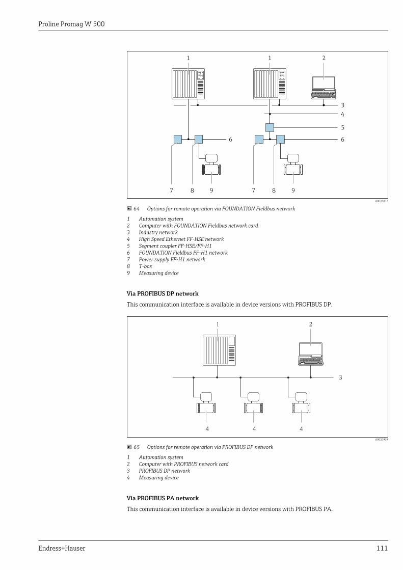
Proline Promag W 500
Endress+Hauser 111
1 2
3
1
98 98
4
6 6
7 7
5
A0028837
64 Options for remote operation via FOUNDATION Fieldbus network
1 Automation system2 Computer with FOUNDATION Fieldbus network card3 Industry network4 High Speed Ethernet FF-HSE network5 Segment coupler FF-HSE/FF-H16 FOUNDATION Fieldbus FF-H1 network7 Power supply FF-H1 network8 T-box9 Measuring device
Via PROFIBUS DP network
This communication interface is available in device versions with PROFIBUS DP.
1 2
3
444
A0020903
65 Options for remote operation via PROFIBUS DP network
1 Automation system2 Computer with PROFIBUS network card3 PROFIBUS DP network4 Measuring device
Via PROFIBUS PA network
This communication interface is available in device versions with PROFIBUS PA.
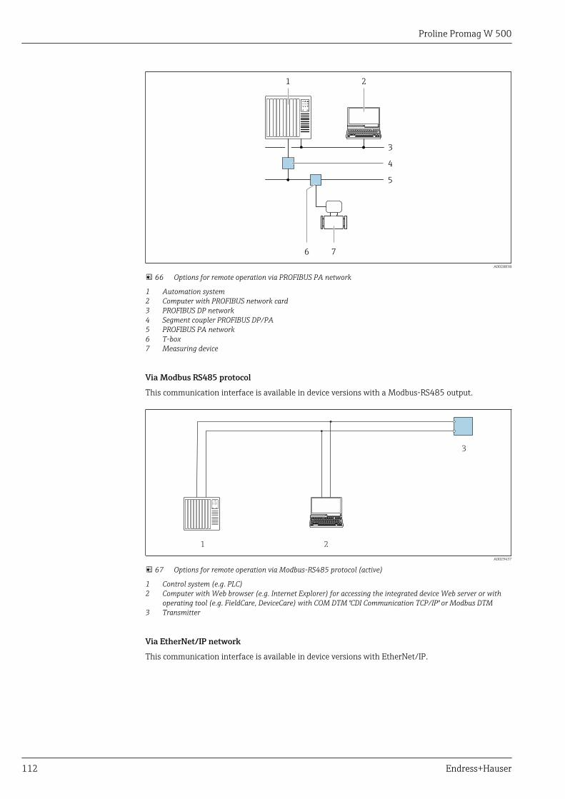
Proline Promag W 500
112 Endress+Hauser
2
3
1
76
5
4
A0028838
66 Options for remote operation via PROFIBUS PA network
1 Automation system2 Computer with PROFIBUS network card3 PROFIBUS DP network4 Segment coupler PROFIBUS DP/PA5 PROFIBUS PA network6 T-box7 Measuring device
Via Modbus RS485 protocol
This communication interface is available in device versions with a Modbus-RS485 output.
1 2
3
A0029437
67 Options for remote operation via Modbus-RS485 protocol (active)
1 Control system (e.g. PLC)2 Computer with Web browser (e.g. Internet Explorer) for accessing the integrated device Web server or with
operating tool (e.g. FieldCare, DeviceCare) with COM DTM "CDI Communication TCP/IP" or Modbus DTM3 Transmitter
Via EtherNet/IP network
This communication interface is available in device versions with EtherNet/IP.

Proline Promag W 500
Endress+Hauser 113
Star topology
4
21 3
5 5 5
A0032078
68 Options for remote operation via EtherNet/IP network: star topology
1 Automation system, e.g. "RSLogix" (Rockwell Automation)2 Workstation for measuring device operation: with Custom Add-On Profile for "RSLogix 5000" (Rockwell
Automation) or with Electronic Data Sheet (EDS)3 Computer with Web browser (e.g. Internet Explorer) for accessing the integrated device Web server or
computer with operating tool (e.g. FieldCare, DeviceCare) with COM DTM "CDI Communication TCP/IP"4 Ethernet switch5 Measuring device
Ring topology
The device is integrated via the terminal connection for signal transmission (output 1) and theservice interface (CDI-RJ45).
4
21 3
5 5 5
A0033725
69 Options for remote operation via EtherNet/IP network: ring topology
1 Automation system, e.g. "RSLogix" (Rockwell Automation)2 Workstation for measuring device operation: with Custom Add-On Profile for "RSLogix 5000" (Rockwell
Automation) or with Electronic Data Sheet (EDS)3 Computer with Web browser (e.g. Internet Explorer) for accessing the integrated device Web server or
computer with operating tool (e.g. FieldCare, DeviceCare) with COM DTM "CDI Communication TCP/IP"4 Ethernet switch5 Measuring device
Via PROFINET network
This communication interface is available in device versions with PROFINET.
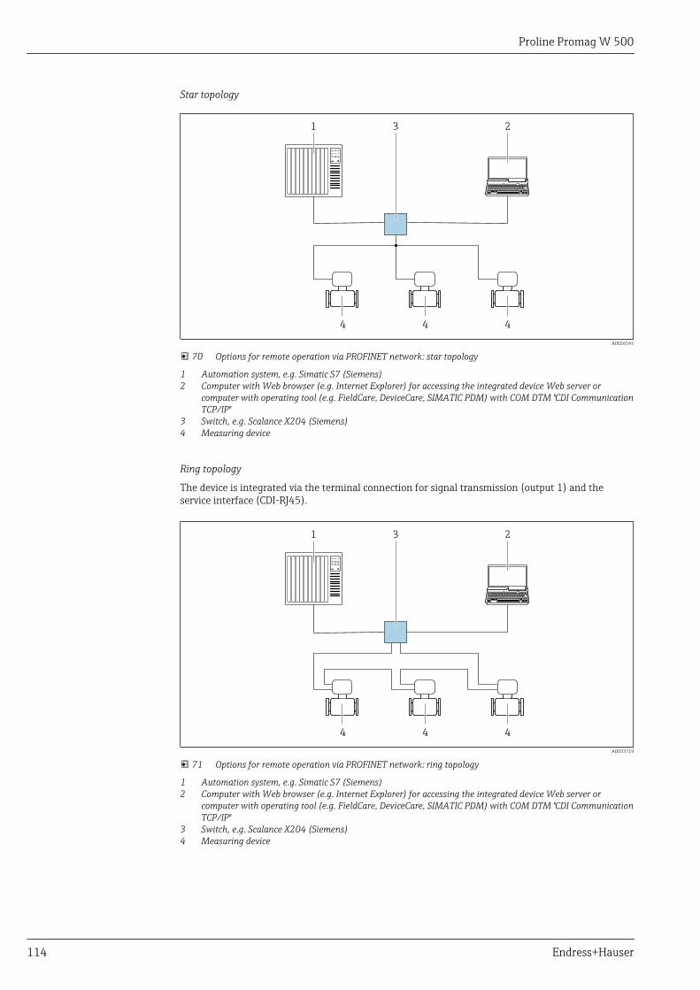
Proline Promag W 500
114 Endress+Hauser
Star topology
31 2
4 4 4
A0026545
70 Options for remote operation via PROFINET network: star topology
1 Automation system, e.g. Simatic S7 (Siemens)2 Computer with Web browser (e.g. Internet Explorer) for accessing the integrated device Web server or
computer with operating tool (e.g. FieldCare, DeviceCare, SIMATIC PDM) with COM DTM "CDI CommunicationTCP/IP"
3 Switch, e.g. Scalance X204 (Siemens)4 Measuring device
Ring topology
The device is integrated via the terminal connection for signal transmission (output 1) and theservice interface (CDI-RJ45).
31 2
4 4 4
A0033719
71 Options for remote operation via PROFINET network: ring topology
1 Automation system, e.g. Simatic S7 (Siemens)2 Computer with Web browser (e.g. Internet Explorer) for accessing the integrated device Web server or
computer with operating tool (e.g. FieldCare, DeviceCare, SIMATIC PDM) with COM DTM "CDI CommunicationTCP/IP"
3 Switch, e.g. Scalance X204 (Siemens)4 Measuring device
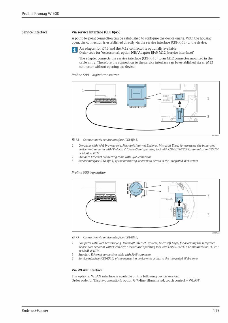
Proline Promag W 500
Endress+Hauser 115
Service interface Via service interface (CDI-RJ45)
A point-to-point connection can be established to configure the device onsite. With the housingopen, the connection is established directly via the service interface (CDI-RJ45) of the device.
An adapter for RJ45 and the M12 connector is optionally available:Order code for "Accessories", option NB: "Adapter RJ45 M12 (service interface)"The adapter connects the service interface (CDI-RJ45) to an M12 connector mounted in thecable entry. Therefore the connection to the service interface can be established via an M12connector without opening the device.
Proline 500 – digital transmitter
open
press
1
2
3
A0029163
72 Connection via service interface (CDI-RJ45)
1 Computer with Web browser (e.g. Microsoft Internet Explorer, Microsoft Edge) for accessing the integrateddevice Web server or with "FieldCare", "DeviceCare" operating tool with COM DTM "CDI Communication TCP/IP"or Modbus DTM
2 Standard Ethernet connecting cable with RJ45 connector3 Service interface (CDI-RJ45) of the measuring device with access to the integrated Web server
Proline 500 transmitter
2
3
1
A0027563
73 Connection via service interface (CDI-RJ45)
1 Computer with Web browser (e.g. Microsoft Internet Explorer, Microsoft Edge) for accessing the integrateddevice Web server or with "FieldCare", "DeviceCare" operating tool with COM DTM "CDI Communication TCP/IP"or Modbus DTM
2 Standard Ethernet connecting cable with RJ45 connector3 Service interface (CDI-RJ45) of the measuring device with access to the integrated Web server
Via WLAN interface
The optional WLAN interface is available on the following device version:Order code for "Display; operation", option G "4-line, illuminated; touch control + WLAN"
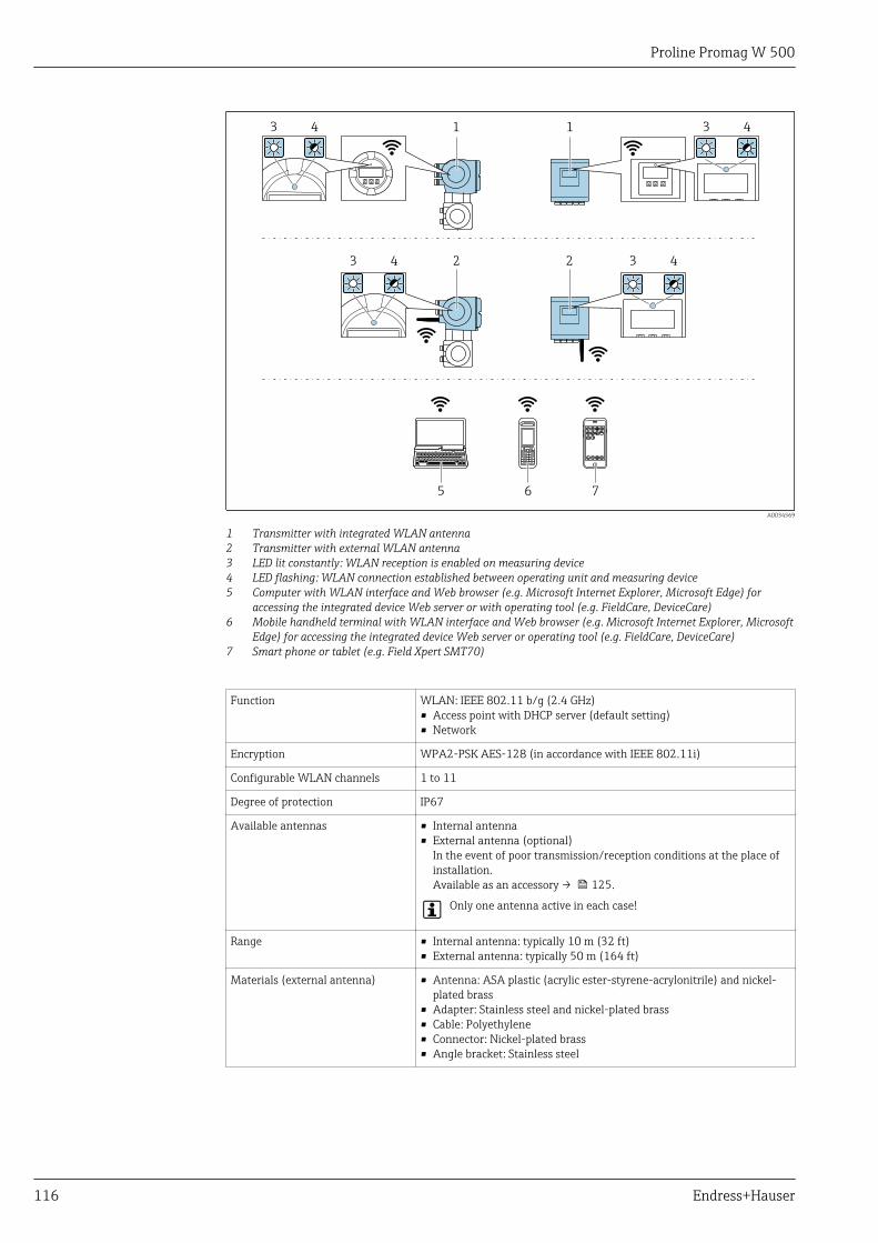
Proline Promag W 500
116 Endress+Hauser
1
2 2
1 3 4
3 4 3 4
3 4
5 6 7
A0034569
1 Transmitter with integrated WLAN antenna2 Transmitter with external WLAN antenna3 LED lit constantly: WLAN reception is enabled on measuring device4 LED flashing: WLAN connection established between operating unit and measuring device5 Computer with WLAN interface and Web browser (e.g. Microsoft Internet Explorer, Microsoft Edge) for
accessing the integrated device Web server or with operating tool (e.g. FieldCare, DeviceCare)6 Mobile handheld terminal with WLAN interface and Web browser (e.g. Microsoft Internet Explorer, Microsoft
Edge) for accessing the integrated device Web server or operating tool (e.g. FieldCare, DeviceCare)7 Smart phone or tablet (e.g. Field Xpert SMT70)
Function WLAN: IEEE 802.11 b/g (2.4 GHz)• Access point with DHCP server (default setting)• Network
Encryption WPA2-PSK AES-128 (in accordance with IEEE 802.11i)
Configurable WLAN channels 1 to 11
Degree of protection IP67
Available antennas • Internal antenna• External antenna (optional)
In the event of poor transmission/reception conditions at the place ofinstallation.Available as an accessory → 125.
Only one antenna active in each case!
Range • Internal antenna: typically 10 m (32 ft)• External antenna: typically 50 m (164 ft)
Materials (external antenna) • Antenna: ASA plastic (acrylic ester-styrene-acrylonitrile) and nickel-plated brass
• Adapter: Stainless steel and nickel-plated brass• Cable: Polyethylene• Connector: Nickel-plated brass• Angle bracket: Stainless steel
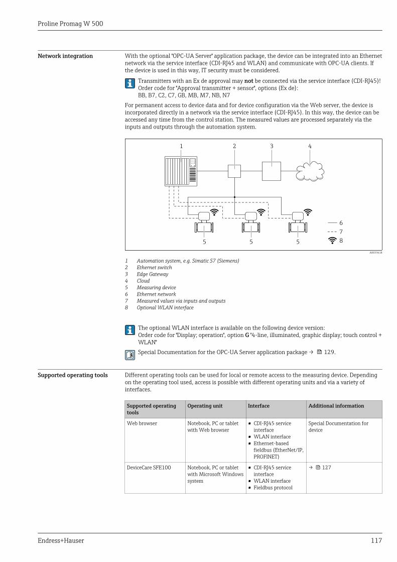
Proline Promag W 500
Endress+Hauser 117
Network integration With the optional "OPC-UA Server" application package, the device can be integrated into an Ethernetnetwork via the service interface (CDI-RJ45 and WLAN) and communicate with OPC-UA clients. Ifthe device is used in this way, IT security must be considered.
Transmitters with an Ex de approval may not be connected via the service interface (CDI-RJ45)!Order code for "Approval transmitter + sensor", options (Ex de):BB, B7, C2, C7, GB, MB, M7, NB, N7
For permanent access to device data and for device configuration via the Web server, the device isincorporated directly in a network via the service interface (CDI-RJ45). In this way, the device can beaccessed any time from the control station. The measured values are processed separately via theinputs and outputs through the automation system.
21 3
5 5 5
4
6
7
8
A0033618
1 Automation system, e.g. Simatic S7 (Siemens)2 Ethernet switch3 Edge Gateway4 Cloud5 Measuring device6 Ethernet network7 Measured values via inputs and outputs8 Optional WLAN interface
The optional WLAN interface is available on the following device version:Order code for "Display; operation", option G "4-line, illuminated, graphic display; touch control +WLAN"Special Documentation for the OPC-UA Server application package → 129.
Supported operating tools Different operating tools can be used for local or remote access to the measuring device. Dependingon the operating tool used, access is possible with different operating units and via a variety ofinterfaces.
Supported operatingtools
Operating unit Interface Additional information
Web browser Notebook, PC or tabletwith Web browser
• CDI-RJ45 serviceinterface
• WLAN interface• Ethernet-based
fieldbus (EtherNet/IP,PROFINET)
Special Documentation fordevice
DeviceCare SFE100 Notebook, PC or tabletwith Microsoft Windowssystem
• CDI-RJ45 serviceinterface
• WLAN interface• Fieldbus protocol
→ 127
Proline Promag W 500
118 Endress+Hauser
Supported operatingtools
Operating unit Interface Additional information
FieldCare SFE500 Notebook, PC or tabletwith Microsoft Windowssystem
• CDI-RJ45 serviceinterface
• WLAN interface• Fieldbus protocol
→ 127
Device Xpert Field Xpert SFX100/350/370
HART andFOUNDATION Fieldbusfieldbus protocol
Operating InstructionsBA01202S
Device description files:Use update function ofhandheld terminal
Other operating tools based on FDT technology with a device driver such as DTM/iDTM orDD/EDD can be used for device operation. These operating tools are available from theindividual manufacturers. Integration into the following operating tools, among others, issupported:
• FactoryTalk AssetCentre (FTAC) by Rockwell Automation → www.rockwellautomation.com• Process Device Manager (PDM) by Siemens → www.siemens.com• Asset Management Solutions (AMS) by Emerson → www.emersonprocess.com• FieldCommunicator 375/475 by Emerson → www.emersonprocess.com• Field Device Manager (FDM) by Honeywell → www.honeywellprocess.com• FieldMate by Yokogawa → www.yokogawa.com• PACTWare → www.pactware.comThe associated device description files are available at: www.endress.com → Downloads
Web server
Thanks to the integrated Web server, the device can be operated and configured via a Web browserand via a service interface (CDI-RJ45) or via a WLAN interface. The structure of the operating menuis the same as for the local display. In addition to the measured values, status information on thedevice is also displayed and allows the user to monitor the status of the device. Furthermore thedevice data can be managed and the network parameters can be configured.
A device that has a WLAN interface (can be ordered as an option) is required for the WLANconnection: order code for "Display; operation", option G "4-line, illuminated; touch control + WLAN".The device acts as an Access Point and enables communication by computer or a mobile handheldterminal.
Supported functionsData exchange between the operating unit (such as a notebook for example) and the measuringdevice:• Upload the configuration from the measuring device (XML format, configuration backup)• Save the configuration to the measuring device (XML format, restore configuration)• Export event list (.csv file)• Export parameter settings (.csv file or PDF file, document the measuring point configuration)• Export the Heartbeat verification log (PDF file, only available with the "Heartbeat Verification"
application package)• Flash firmware version for device firmware upgrade, for instance• Download driver for system integration• Visualize up to 1000 saved measured values (only available with the Extended HistoROM
application package → 124)Web server special documentation → 129
HistoROM data management The measuring device features HistoROM data management. HistoROM data managementcomprises both the storage and import/export of key device and process data, making operation andservicing far more reliable, secure and efficient.
When the device is delivered, the factory settings of the configuration data are stored as abackup in the device memory. This memory can be overwritten with an updated data record, forexample after commissioning.
Proline Promag W 500
Endress+Hauser 119
Additional information on the data storage concept
There are different types of data storage units in which device data are stored and used by the device:
Device memory T-DAT S-DAT
Available data • Event logbook such as diagnostic events for example• Parameter data record backup• Device firmware package• Driver for system integration for exporting via Web
server, e.g:• GSD for PROFIBUS DP• GSD for PROFIBUS PA• GSDML for PROFINET• EDS for EtherNet/IP• DD for FOUNDATION Fieldbus
• Measured value logging("Extended HistoROM" orderoption)
• Current parameter data record(used by firmware at run time)
• Peakhold indicator (min/maxvalues)
• Totalizer values
• Sensor data: nominal diameteretc.
• Serial number• Calibration data• Device configuration (e.g. SW
options, fixed I/O or multi I/O)
Storage location Fixed on the user interface board in the connectioncompartment
Attachable to the user interfaceboard in the connectioncompartment
In the sensor plug in the transmitterneck part
Data backup
Automatic• The most important device data (sensor and transmitter) are automatically saved in the DAT
modules• If the transmitter or measuring device is replaced: once the T-DAT containing the previous device
data has been exchanged, the new measuring device is ready for operation again immediatelywithout any errors
• If the sensor is replaced: once the sensor has been replaced, new sensor data are transferred fromthe S-DAT in the measuring device and the measuring device is ready for operation againimmediately without any errors
• If exchanging the electronics module (e.g. I/O electronics module): Once the electronics modulehas been replaced, the software of the module is compared against the current device firmware.The module software is upgraded or downgraded where necessary. The electronics module isavailable for use immediately afterwards and no compatibility problems occur.
ManualAdditional parameter data record (complete parameter settings) in the integrated device memoryHistoROM backup for:• Data backup function
Backup and subsequent restoration of a device configuration in the device memory HistoROMbackup
• Data comparison functionComparison of the current device configuration with the device configuration saved in the devicememory HistoROM backup
Data transfer
Manual• Transfer of a device configuration to another device using the export function of the specific
operating tool, e.g. with FieldCare, DeviceCare or Web server: to duplicate the configuration or tostore in an archive (e.g. for backup purposes)
• Transmission of the drivers for system integration via Web server, e.g.:• GSD for PROFIBUS DP• GSD for PROFIBUS PA• GSDML for PROFINET• EDS for EtherNet/IP• DD for FOUNDATION Fieldbus
Event list
Automatic• Chronological display of up to 20 event messages in the events list• If the Extended HistoROM application package (order option) is enabled: up to 100 event
messages are displayed in the events list along with a time stamp, plain text description andremedial measures
• The events list can be exported and displayed via a variety of interfaces and operating tools e.g.DeviceCare, FieldCare or Web server
Proline Promag W 500
120 Endress+Hauser
Data logging
ManualIf the Extended HistoROM application package (order option) is enabled:• Record up to 1 000 measured values via 1 to 4 channels• User configurable recording interval• Record up to 250 measured values via each of the 4 memory channels• Export the measured value log via a variety of interfaces and operating tools e.g. FieldCare,
DeviceCare or web server
Certificates and approvalsCurrently available certificates and approvals can be called up via the product configurator.
CE mark The device meets the legal requirements of the applicable EU Directives. These are listed in thecorresponding EU Declaration of Conformity along with the standards applied.
Endress+Hauser confirms successful testing of the device by affixing to it the CE mark.
RCM-tick symbol The measuring system meets the EMC requirements of the "Australian Communications and MediaAuthority (ACMA)".
Ex approval The measuring device is certified for use in hazardous areas and the relevant safety instructions areprovided in the separate "Safety Instructions" (XA) document. Reference is made to this document onthe nameplate.
The separate Ex documentation (XA) containing all the relevant explosion protection data isavailable from your Endress+Hauser sales center.
Proline 500 – digital
ATEX, IECEx
Currently, the following versions for use in hazardous areas are available:
Ex ia, Ex db
Transmitter Sensor
Category Type of protection Category Type of protection
II(1)G [Ex ia] IIC II2G Ex db ia IIC T6…T1 Gb
II3(1)G Ex ec [ia Ga] IIC T5…T4 Gc II2G Ex db ia IIC T6…T1 Gb
Ex tb
Transmitter Sensor
Category Type of protection Category Type of protection
II(1)D [Ex ia] IIIC II2D Ex ia tb IIIC T** °C Db
Non-Ex, Ex ec
Transmitter Sensor
Category Type of protection Category Type of protection
Non-Ex Non-Ex II3G Ex ec ic IIC T5…T1 Gc
II3G Ex ec IIC T5…T4 Gc II3G Ex ec ic IIC T5…T1 Gc
cCSAus
Currently, the following versions for use in hazardous areas are available:
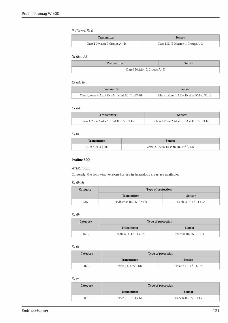
Proline Promag W 500
Endress+Hauser 121
IS (Ex nA, Ex i)
Transmitter Sensor
Class I Division 2 Groups A - D Class I, II, III Division 1 Groups A-G
NI (Ex nA)
Transmitter Sensor
Class I Division 2 Groups A - D
Ex nA, Ex i
Transmitter Sensor
Class I, Zone 2 AEx/ Ex nA [ia Ga] IIC T5…T4 Gb Class I, Zone 1 AEx/ Ex d ia IIC T6…T1 Gb
Ex nA
Transmitter Sensor
Class I, Zone 2 AEx/ Ex nA IIC T5...T4 Gc Class I, Zone 2 AEx/Ex nA ic IIC T5...T1 Gc
Ex tb
Transmitter Sensor
[AEx / Ex ia ] IIIC Zone 21 AEx/ Ex ia tb IIIC T** °C Db
Proline 500
ATEX, IECEx
Currently, the following versions for use in hazardous areas are available:
Ex db eb
Category Type of protection
Transmitter Sensor
II2G Ex db eb ia IIC T6…T4 Gb Ex eb ia IIC T6…T1 Gb
Ex db
Category Type of protection
Transmitter Sensor
II2G Ex db ia IIC T6…T4 Gb Ex eb ia IIC T6…T1 Gb
Ex tb
Category Type of protection
Transmitter Sensor
II2G Ex tb IIIC T85°C Db Ex ia tb IIIC T** °C Db
Ex ec
Category Type of protection
Transmitter Sensor
II3G Ex ec IIC T5…T4 Gc Ex ec ic IIC T5…T1 Gc
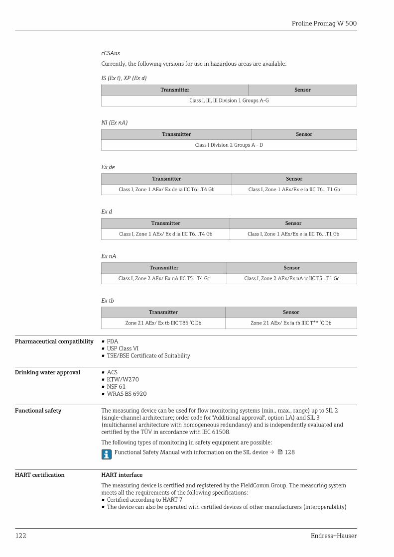
Proline Promag W 500
122 Endress+Hauser
cCSAus
Currently, the following versions for use in hazardous areas are available:
IS (Ex i), XP (Ex d)
Transmitter Sensor
Class I, III, III Division 1 Groups A-G
NI (Ex nA)
Transmitter Sensor
Class I Division 2 Groups A - D
Ex de
Transmitter Sensor
Class I, Zone 1 AEx/ Ex de ia IIC T6…T4 Gb Class I, Zone 1 AEx/Ex e ia IIC T6…T1 Gb
Ex d
Transmitter Sensor
Class I, Zone 1 AEx/ Ex d ia IIC T6…T4 Gb Class I, Zone 1 AEx/Ex e ia IIC T6…T1 Gb
Ex nA
Transmitter Sensor
Class I, Zone 2 AEx/ Ex nA IIC T5...T4 Gc Class I, Zone 2 AEx/Ex nA ic IIC T5...T1 Gc
Ex tb
Transmitter Sensor
Zone 21 AEx/ Ex tb IIIC T85 °C Db Zone 21 AEx/ Ex ia tb IIIC T** °C Db
Pharmaceutical compatibility • FDA• USP Class VI• TSE/BSE Certificate of Suitability
Drinking water approval • ACS• KTW/W270• NSF 61• WRAS BS 6920
Functional safety The measuring device can be used for flow monitoring systems (min., max., range) up to SIL 2(single-channel architecture; order code for "Additional approval", option LA) and SIL 3(multichannel architecture with homogeneous redundancy) and is independently evaluated andcertified by the TÜV in accordance with IEC 61508.
The following types of monitoring in safety equipment are possible:Functional Safety Manual with information on the SIL device → 128
HART certification HART interface
The measuring device is certified and registered by the FieldComm Group. The measuring systemmeets all the requirements of the following specifications:• Certified according to HART 7• The device can also be operated with certified devices of other manufacturers (interoperability)
Proline Promag W 500
Endress+Hauser 123
FOUNDATION Fieldbuscertification
FOUNDATION Fieldbus interface
The measuring device is certified and registered by the FieldComm Group. The measuring systemmeets all the requirements of the following specifications:• Certified in accordance with FOUNDATION Fieldbus H1• Interoperability Test Kit (ITK), revision version 6.2.0 (certificate available on request)• Physical Layer Conformance Test• The device can also be operated with certified devices of other manufacturers (interoperability)
Certification PROFIBUS PROFIBUS interface
The measuring device is certified and registered by the PNO (PROFIBUS User OrganizationOrganization). The measuring system meets all the requirements of the following specifications:• Certified in accordance with PROFIBUS PA Profile 3.02• The device can also be operated with certified devices of other manufacturers (interoperability)
EtherNet/IP certification The measuring device is certified and registered by the ODVA (Open Device Vendor Association).The measuring system meets all the requirements of the following specifications:• Certified in accordance with the ODVA Conformance Test• EtherNet/IP Performance Test• EtherNet/IP PlugFest compliance• The device can also be operated with certified devices of other manufacturers (interoperability)
Certification PROFINET PROFINET interface
The measuring device is certified and registered by the PNO (PROFIBUS User Organization). Themeasuring system meets all the requirements of the following specifications:• Certified according to:
• Test specification for PROFINET devices• PROFINET Security Level 2 – Netload Class
• The device can also be operated with certified devices of other manufacturers (interoperability)• The device supports PROFINET S2 system redundancy.
Radio approval The measuring device has radio approval.
For detailed information regarding radio approval, see Special Documentation
Measuring instrumentapproval
The measuring device is qualified to OIML R49: 2013 OIML R117 and has an OIML Certificate ofConformity (optional).
Other standards andguidelines
• EN 60529Degrees of protection provided by enclosures (IP code)
• EN 61010-1Safety requirements for electrical equipment for measurement, control and laboratory use -general requirements
• IEC/EN 61326Emission in accordance with Class A requirements. Electromagnetic compatibility (EMCrequirements).
• NAMUR NE 21Electromagnetic compatibility (EMC) of industrial process and laboratory control equipment
• NAMUR NE 32Data retention in the event of a power failure in field and control instruments withmicroprocessors
• NAMUR NE 43Standardization of the signal level for the breakdown information of digital transmitters withanalog output signal.
• NAMUR NE 53Software of field devices and signal-processing devices with digital electronics
• NAMUR NE 105Specifications for integrating fieldbus devices in engineering tools for field devices
• NAMUR NE 107Self-monitoring and diagnosis of field devices
• NAMUR NE 131Requirements for field devices for standard applications
Proline Promag W 500
124 Endress+Hauser
Ordering informationDetailed ordering information is available for your nearest sales organizationwww.addresses.endress.com or in the Product Configurator under www.endress.com :
1. Click Corporate2. Select the country3. Click Products4. Select the product using the filters and search field5. Open the product page
The Configuration button to the right of the product image opens the Product Configurator.
Product Configurator - the tool for individual product configuration• Up-to-the-minute configuration data• Depending on the device: Direct input of measuring point-specific information such as
measuring range or operating language• Automatic verification of exclusion criteria• Automatic creation of the order code and its breakdown in PDF or Excel output format• Ability to order directly in the Endress+Hauser Online Shop
Application packagesMany different application packages are available to enhance the functionality of the device. Suchpackages might be needed to address safety aspects or specific application requirements.
The application packages can be ordered with the device or subsequently from Endress+Hauser.Detailed information on the order code in question is available from your local Endress+Hauser salescenter or on the product page of the Endress+Hauser website: www.endress.com.
Diagnostics functions Package Description
Extended HistoROM Comprises extended functions concerning the event log and the activation of themeasured value memory.
Event log:Memory volume is extended from 20 message entries (standard version) to up to100 entries.
Data logging (line recorder):• Memory capacity for up to 1000 measured values is activated.• 250 measured values can be output via each of the 4 memory channels. The
recording interval can be defined and configured by the user.• Measured value logs can be accessed via the local display or operating tool e.g.
FieldCare, DeviceCare or Web server.
Heartbeat Technology Package Description
Heartbeat Verification+Monitoring
Heartbeat VerificationMeets the requirement for traceable verification to DIN ISO 9001:2008 Chapter7.6 a) "Control of monitoring and measuring equipment".• Functional testing in the installed state without interrupting the process.• Traceable verification results on request, including a report.• Simple testing process via local operation or other operating interfaces.• Clear measuring point assessment (pass/fail) with high test coverage within the
framework of manufacturer specifications.• Extension of calibration intervals according to operator's risk assessment.
Heartbeat MonitoringContinuously supplies data, which are characteristic of the measuring principle, toan external condition monitoring system for the purpose of preventivemaintenance or process analysis. These data enable the operator to:• Draw conclusions - using these data and other information - about the impact
process influences (such as corrosion, abrasion, buildup etc.) have on themeasuring performance over time.
• Schedule servicing in time.• Monitor the process or product quality, e.g. gas pockets.
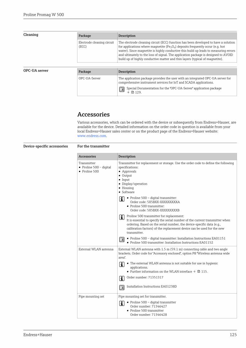
Proline Promag W 500
Endress+Hauser 125
Cleaning Package Description
Electrode cleaning circuit(ECC)
The electrode cleaning circuit (ECC) function has been developed to have a solutionfor applications where magnetite (Fe3O4) deposits frequently occur (e.g. hotwater). Since magnetite is highly conductive this build up leads to measuring errorsand ultimately to the loss of signal. The application package is designed to AVOIDbuild up of highly conductive matter and thin layers (typical of magnetite).
OPC-UA server Package Description
OPC-UA-Server The application package provides the user with an integrated OPC-UA server forcomprehensive instrument services for IoT and SCADA applications.
Special Documentation for the "OPC-UA-Server" application package→ 129.
AccessoriesVarious accessories, which can be ordered with the device or subsequently from Endress+Hauser, areavailable for the device. Detailed information on the order code in question is available from yourlocal Endress+Hauser sales center or on the product page of the Endress+Hauser website:www.endress.com.
Device-specific accessories For the transmitter
Accessories Description
Transmitter• Proline 500 – digital• Proline 500
Transmitter for replacement or storage. Use the order code to define the followingspecifications:• Approvals• Output• Input• Display/operation• Housing• Software
• Proline 500 – digital transmitter:Order code: 5X5BXX-XXXXXXXXXA
• Proline 500 transmitter:Order code: 5X5BXX-XXXXXXXXXB
Proline 500 transmitter for replacement:It is essential to specify the serial number of the current transmitter whenordering. Based on the serial number, the device-specific data (e.g.,calibration factors) of the replacement device can be used for the newtransmitter.
• Proline 500 – digital transmitter: Installation Instructions EA01151• Proline 500 transmitter: Installation Instructions EA01152
External WLAN antenna External WLAN antenna with 1.5 m (59.1 in) connecting cable and two anglebrackets. Order code for "Accessory enclosed", option P8 "Wireless antenna widearea".
• The external WLAN antenna is not suitable for use in hygienicapplications.
• Further information on the WLAN interface → 115.
Order number: 71351317
Installation Instructions EA01238D
Pipe mounting set Pipe mounting set for transmitter.
• Proline 500 – digital transmitterOrder number: 71346427
• Proline 500 transmitterOrder number: 71346428
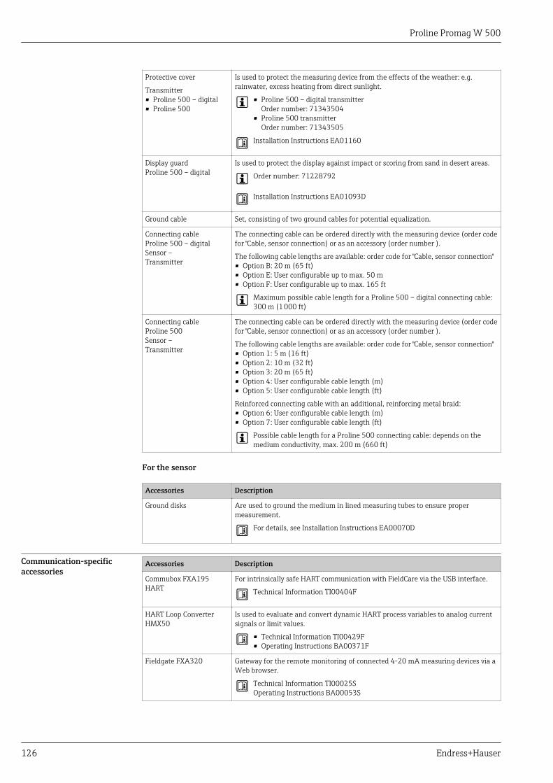
Proline Promag W 500
126 Endress+Hauser
Protective cover
Transmitter• Proline 500 – digital• Proline 500
Is used to protect the measuring device from the effects of the weather: e.g.rainwater, excess heating from direct sunlight.
• Proline 500 – digital transmitterOrder number: 71343504
• Proline 500 transmitterOrder number: 71343505
Installation Instructions EA01160
Display guardProline 500 – digital
Is used to protect the display against impact or scoring from sand in desert areas.
Order number: 71228792
Installation Instructions EA01093D
Ground cable Set, consisting of two ground cables for potential equalization.
Connecting cableProline 500 – digitalSensor –Transmitter
The connecting cable can be ordered directly with the measuring device (order codefor "Cable, sensor connection) or as an accessory (order number ).
The following cable lengths are available: order code for "Cable, sensor connection"• Option B: 20 m (65 ft)• Option E: User configurable up to max. 50 m• Option F: User configurable up to max. 165 ft
Maximum possible cable length for a Proline 500 – digital connecting cable:300 m (1 000 ft)
Connecting cableProline 500Sensor –Transmitter
The connecting cable can be ordered directly with the measuring device (order codefor "Cable, sensor connection) or as an accessory (order number ).
The following cable lengths are available: order code for "Cable, sensor connection"• Option 1: 5 m (16 ft)• Option 2: 10 m (32 ft)• Option 3: 20 m (65 ft)• Option 4: User configurable cable length (m)• Option 5: User configurable cable length (ft)
Reinforced connecting cable with an additional, reinforcing metal braid:• Option 6: User configurable cable length (m)• Option 7: User configurable cable length (ft)
Possible cable length for a Proline 500 connecting cable: depends on themedium conductivity, max. 200 m (660 ft)
For the sensor
Accessories Description
Ground disks Are used to ground the medium in lined measuring tubes to ensure propermeasurement.
For details, see Installation Instructions EA00070D
Communication-specificaccessories
Accessories Description
Commubox FXA195HART
For intrinsically safe HART communication with FieldCare via the USB interface.
Technical Information TI00404F
HART Loop ConverterHMX50
Is used to evaluate and convert dynamic HART process variables to analog currentsignals or limit values.
• Technical Information TI00429F• Operating Instructions BA00371F
Fieldgate FXA320 Gateway for the remote monitoring of connected 4-20 mA measuring devices via aWeb browser.
Technical Information TI00025SOperating Instructions BA00053S
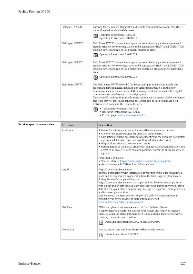
Proline Promag W 500
Endress+Hauser 127
Fieldgate FXA520 Gateway for the remote diagnostics and remote configuration of connected HARTmeasuring devices via a Web browser.
Technical Information TI00025SOperating Instructions BA00051S
Field Xpert SFX350 Field Xpert SFX350 is a mobile computer for commissioning and maintenance. Itenables efficient device configuration and diagnostics for HART and FOUNDATIONFieldbus devices and can be used in non-hazardous areas.
Operating Instructions BA01202S
Field Xpert SFX370 Field Xpert SFX370 is a mobile computer for commissioning and maintenance. Itenables efficient device configuration and diagnostics for HART and FOUNDATIONFieldbus devices and can be used in the non-hazardous area and in the hazardousarea.
Operating Instructions BA01202S
Field Xpert SMT70 The Field Xpert SMT70 tablet PC for device configuration enables mobile plantasset management in hazardous and non-hazardous areas. It is suitable forcommissioning and maintenance staff to manage field instruments with a digitalcommunication interface and to record progress.This tablet PC is designed as an all-in-one solution with a preinstalled driver libraryand is an easy-to-use, touch-sensitive tool which can be used to manage fieldinstruments throughout their entire life cycle.
• Technical Information TI01342S• Operating Instructions BA01709S• Product page: www.endress.com/smt70
Service-specific accessories Accessories Description
Applicator Software for selecting and sizing Endress+Hauser measuring devices:• Choice of measuring devices for industrial requirements• Calculation of all the necessary data for identifying the optimum flowmeter:
e.g. nominal diameter, pressure loss, flow velocity and accuracy.• Graphic illustration of the calculation results• Determination of the partial order code, administration, documentation and
access to all project-related data and parameters over the entire life cycle ofa project.
Applicator is available:• Via the Internet: https://portal.endress.com/webapp/applicator• As a downloadable DVD for local PC installation.
W@M W@M Life Cycle ManagementImproved productivity with information at your fingertips. Data relevant to aplant and its components is generated from the first stages of planning andduring the asset’s complete life cycle.W@M Life Cycle Management is an open and flexible information platformwith online and on-site tools. Instant access for your staff to current, in-depthdata shortens your plant’s engineering time, speeds up procurement processesand increases plant uptime.Combined with the right services, W@M Life Cycle Management boostsproductivity in every phase. For more information, visitwww.endress.com/lifecyclemanagement
FieldCare FDT-based plant asset management tool from Endress+Hauser.It can configure all smart field units in your system and helps you managethem. By using the status information, it is also a simple but effective way ofchecking their status and condition.
Operating Instructions BA00027S and BA00059S
DeviceCare Tool to connect and configure Endress+Hauser field devices.
Innovation brochure IN01047S
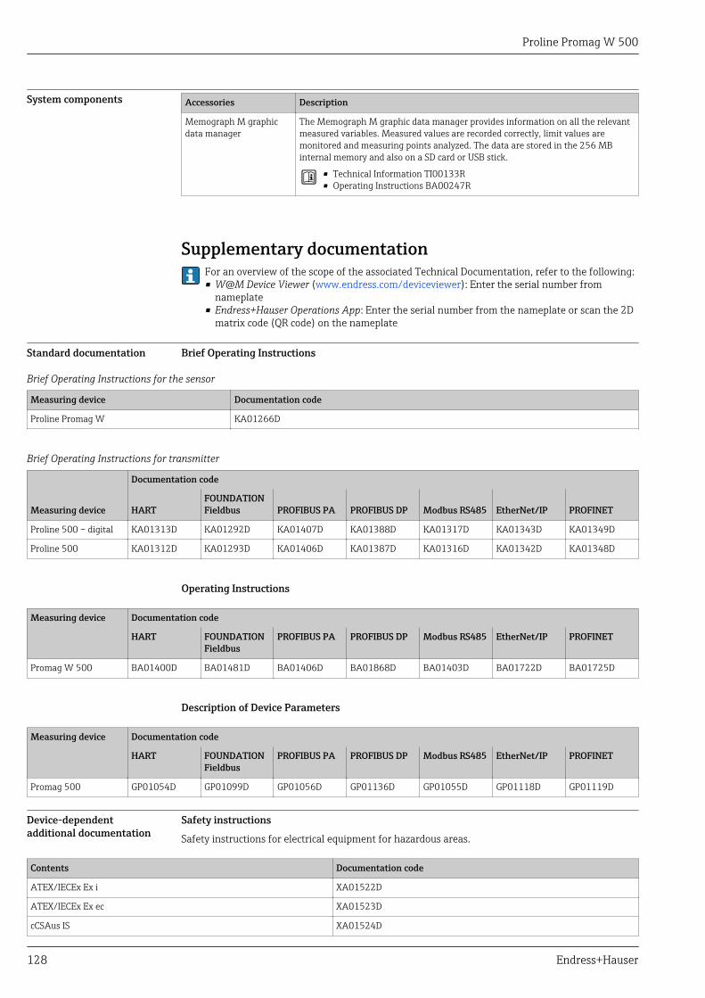
Proline Promag W 500
128 Endress+Hauser
System components Accessories Description
Memograph M graphicdata manager
The Memograph M graphic data manager provides information on all the relevantmeasured variables. Measured values are recorded correctly, limit values aremonitored and measuring points analyzed. The data are stored in the 256 MBinternal memory and also on a SD card or USB stick.
• Technical Information TI00133R• Operating Instructions BA00247R
Supplementary documentationFor an overview of the scope of the associated Technical Documentation, refer to the following:• W@M Device Viewer (www.endress.com/deviceviewer): Enter the serial number from
nameplate• Endress+Hauser Operations App: Enter the serial number from the nameplate or scan the 2D
matrix code (QR code) on the nameplate
Standard documentation Brief Operating Instructions
Brief Operating Instructions for the sensor
Measuring device Documentation code
Proline Promag W KA01266D
Brief Operating Instructions for transmitter
Measuring device
Documentation code
HARTFOUNDATIONFieldbus PROFIBUS PA PROFIBUS DP Modbus RS485 EtherNet/IP PROFINET
Proline 500 – digital KA01313D KA01292D KA01407D KA01388D KA01317D KA01343D KA01349D
Proline 500 KA01312D KA01293D KA01406D KA01387D KA01316D KA01342D KA01348D
Operating Instructions
Measuring device Documentation code
HART FOUNDATIONFieldbus
PROFIBUS PA PROFIBUS DP Modbus RS485 EtherNet/IP PROFINET
Promag W 500 BA01400D BA01481D BA01406D BA01868D BA01403D BA01722D BA01725D
Description of Device Parameters
Measuring device Documentation code
HART FOUNDATIONFieldbus
PROFIBUS PA PROFIBUS DP Modbus RS485 EtherNet/IP PROFINET
Promag 500 GP01054D GP01099D GP01056D GP01136D GP01055D GP01118D GP01119D
Device-dependentadditional documentation
Safety instructions
Safety instructions for electrical equipment for hazardous areas.
Contents Documentation code
ATEX/IECEx Ex i XA01522D
ATEX/IECEx Ex ec XA01523D
cCSAus IS XA01524D
Proline Promag W 500
Endress+Hauser 129
Contents Documentation code
cCSAus Ex e ia/Ex d ia XA01525D
cCSAus Ex nA XA01526D
INMETRO Ex i XA01527D
INMETRO Ex ec XA01528D
NEPSI Ex i XA01529D
NEPSI Ex nA XA01530D
EAC Ex i XA01658D
EAC Ex nA XA01659D
JPN XA01776D
Special Documentation
Contents Documentation code
Information on the Pressure Equipment Directive SD01614D
Functional Safety Manual SD01741D
Radio approvals for WLAN interface for A309/A310 display module SD01793D
OPC-UA Server 1) SD02044D
1) This Special Documentation is only available for device versions with a HART output.
Contents Documentation code
HART FOUNDATIONFieldbus
PROFIBUS PA PROFIBUS DP Modbus RS485 PROFINET EtherNet/IP
Heartbeat Technology SD01641D SD01745D SD01747D SD02207D SD01746D SD01987D SD01981D
Web server SD01658D SD01661D SD01660D SD02236D SD01659D SD01979D SD01978D
Installation Instructions
Content Comment
Installation instructions for spare part sets and accessories Documentation code: specified for each individual accessory → 125.
Registered trademarksHART®Registered trademark of the FieldComm Group, Austin, Texas, USAPROFIBUS®Registered trademark of the PROFIBUS User Organization, Karlsruhe, GermanyFOUNDATION™ FieldbusRegistration-pending trademark of the FieldComm Group, Austin, Texas, USAModbus®Registered trademark of SCHNEIDER AUTOMATION, INC.EtherNet/IP™Trademark of ODVA, Inc.PROFINET®Registered trademark of the PROFIBUS User Organization, Karlsruhe, Germany

www.addresses.endress.com