Embed Size (px)
Citation preview
APURBA PAWARMA Advanced Product DesignDegree Project Report, 2013
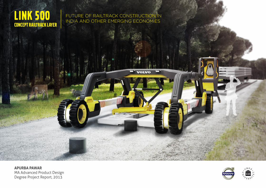
LINK 500CONCEPT RAILTRACK LAYER
FUTURE OF RAILTRACK CONSTRUCTION IN INDIA AND OTHER EMERGING ECONOMIES
// Introduction
ACKNOWLEDGEMENTS
Massive thanks to all the cool cats who made it possible! From late night sanding, chocolate, bad jokes and songs to keep the spirits up, massage to relieve CAD strain, food offerings, hugs, late night workshop assistance, just saying - ‘you will do it’, wake up calls... And being plain awesome!
I would like to thank my family - Mom, dad, brother and relatives for their support and encouragement. Anders Smith, Thomas Degn, Mikal Hallstrup and all UID faculty and staff for the tutoring sessions, time and valuable feedback. Viktor Holmqvist and the great team at Volvo design studio for providing me with their time, valuable inputs and support throughout the project. Mr. Ashish Sharma (Indian Railways) and Mr. MK Mallik (Indian Railways) for getting me in contact with contractors at on-going Indian Railway construction sites.Mr. Shiv Shankar and his team at Punj Lloyd for their hospitality and going out of their way to assist my research at the urban transit rail line construction site (Bangalore, India).Mr. Manoj Arora (IRICEN, Pune, India) for taking out time to answer my questions and throw light on the present day railway construction scenario in India. And to continually provide feedback on the project.Pawan Kumar Barak, Jagjit Singh and Manoj & Sangwan Contractors for their patience and showing me around the construction sight, answering my questions and helping me understand the construction methods and processes.
Lisa, Marco, Melanie, Simon, Jiawei, Dogan, Hanako, Stephanie, Kim, Philip, Florian, Maja, Marie, Jacob, Siri, Narayan, Shivanjali, Juhan, Jenni, Lynn, Alexander, Malin, Aaron, Sha, Angad, Subhdeep, Shreyas and all my friends and classmates - for sticking with me and pushing me to do my best!
Thank you! :)
3COMPACT RAILWAY TRACK LAYER - Future of railway construction in India | DEGREE PROJECT MA Advanced Product Design | Apurba Pawar | [email protected]
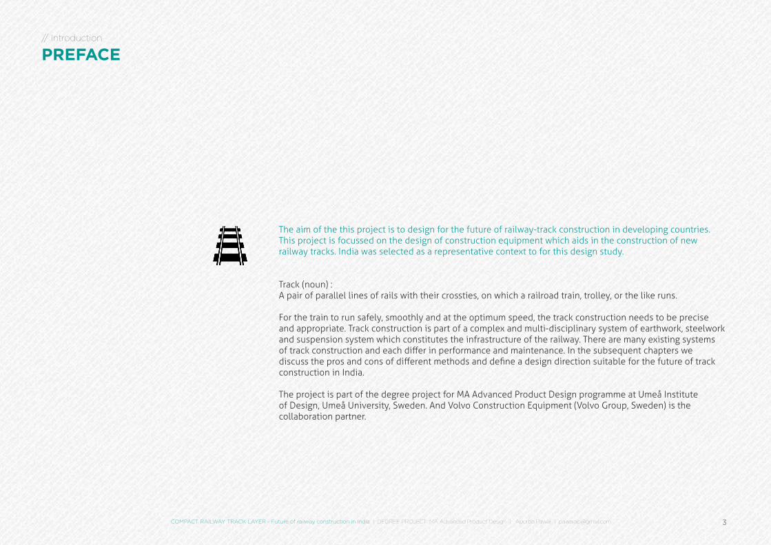
The aim of the this project is to design for the future of railway-track construction in developing countries. This project is focussed on the design of construction equipment which aids in the construction of new railway tracks. India was selected as a representative context to for this design study.
Track (noun) :A pair of parallel lines of rails with their crossties, on which a railroad train, trolley, or the like runs.
For the train to run safely, smoothly and at the optimum speed, the track construction needs to be precise and appropriate. Track construction is part of a complex and multi-disciplinary system of earthwork, steelwork and suspension system which constitutes the infrastructure of the railway. There are many existing systems of track construction and each differ in performance and maintenance. In the subsequent chapters we discuss the pros and cons of different methods and define a design direction suitable for the future of track construction in India.
The project is part of the degree project for MA Advanced Product Design programme at Umeå Institute of Design, Umeå University, Sweden. And Volvo Construction Equipment (Volvo Group, Sweden) is the collaboration partner.
// Introduction
PREFACE
// Introduction
CONTENTS
IntroductionAcknowledgementsPrefaceAbstractCollaboration Partner | Volvo Volvo Construction Equipment Indian Railways
ResearchHistory | Track EvolutionTrack ComponentsTrack Structure TypesNew Track Construction MethodsExisting Track Laying MachinesTrack Construction Trends & ConclusionsField studies & interviews
Research SynthesisInsights - Problem AreasStakeholdersNew Track Construction - India | BallastedTrack Structure Types- ComparisonTrack Laying Methods - ComparisonMarket Research - Opportunity MappingConclusions & FutureDesign RequirementsRe-defining Goals and Wishes
IdeationIdeation WorkshopsConcept Directions - InitialConcept Direction EvaluationTrack Construction- New System ScenarioDesign LanguageRefined Concepts
Refined Concept EvaluationFinal Concept
Detailing & DevelopmentMockupsSketch | CAD Process Slab Raising Mechanism Operator Cabin Central Beam Arm Wheels Slab Lift Mechanism Housing/ Engine assemblyModel Building Final DesignLink 500 | Concept Railtrack LayerMovement | FunctionMajor ComponentsWork FlowDetails Operator Cabin Wheel AssemblyStructure | DimensionsIn Context Render
Reflections
AppendixReferencesGlossaryQuestionnaireAdditional Research | InspirationTime plan
02030507
1213141618202122
30313233343536373839
40414448495154
6061
646566
78
808182838486
8889
90
929394959698
5COMPACT RAILWAY TRACK LAYER - Future of railway construction in India | DEGREE PROJECT MA Advanced Product Design | Apurba Pawar | [email protected]
// Introduction
ABSTRACT
Indian railway which was started in 1853 has grown more than 10-fold between 1951 and 2007, but the rail track length has only grown 1.4 times in this period. In spite of increase in investment in railway infrastructure around the world, in India the construction of new tracks is sluggish and uses the same manual intensive workflows that were used during its conception. A major development has been the introduction of concrete slabs, used as the track base instead of using traditional ballast (stone bed to stabilise and support the track) at some locations.
The aim of the this project was to design for the future of railway-track construction in developing countries like India and exploring a new track construction system suitable in this context.
This project resulted in the Volvo Link 500, a track laying machine which delivers value in terms of safety, consistency and efficiency of track construction.
INSPIRATION AND METHOD
The project is a collaboration with Volvo Construction Equipment, a leading manufacturer of construction equipment. It was crucial to observe the process of railway track laying in India to be able to understand and extract key insights specific for the emerging-economy context. To do this, a field study in two construction sites in India was done. Interviews were conducted on site with site managers, and workers to get insights on their workflows. Experts from the Indian Railways Institute of Civil Engineering (IRICEN) were consulted to validate these insights and observations.
The research phase was concluded with the identification of quality, consistency issues of track laying and worker safety as the core problems of track construction in India . The opportunity direction chosen was to design a machine to assist linking the tracks and embedding the research insights in the design.
RESULT
Volvo Link 500 is a new concept rail track layer which aids in the construction of an alternate railway track system.
The track layer lays prefabricated concrete slabs cyclically along a GPS route, minimizing operator error and increasing efficiency. Manual workforce is still involved in the rough work of placing dowels, which serve as GPS locators / slab guides. The design of the machine allows it to pass over a flat bed material-carrying train. It is cheaper, easier to assemble and transport than current solutions, and requires no auxiliary track because it uses pneumatic tyres.
This future concept tries to match the real present day needs of the emerging economy context with developments in railway track construction around the world. In essence, proposing to bring a future track laying product as the next step in the evolution of track laying in countries like India.
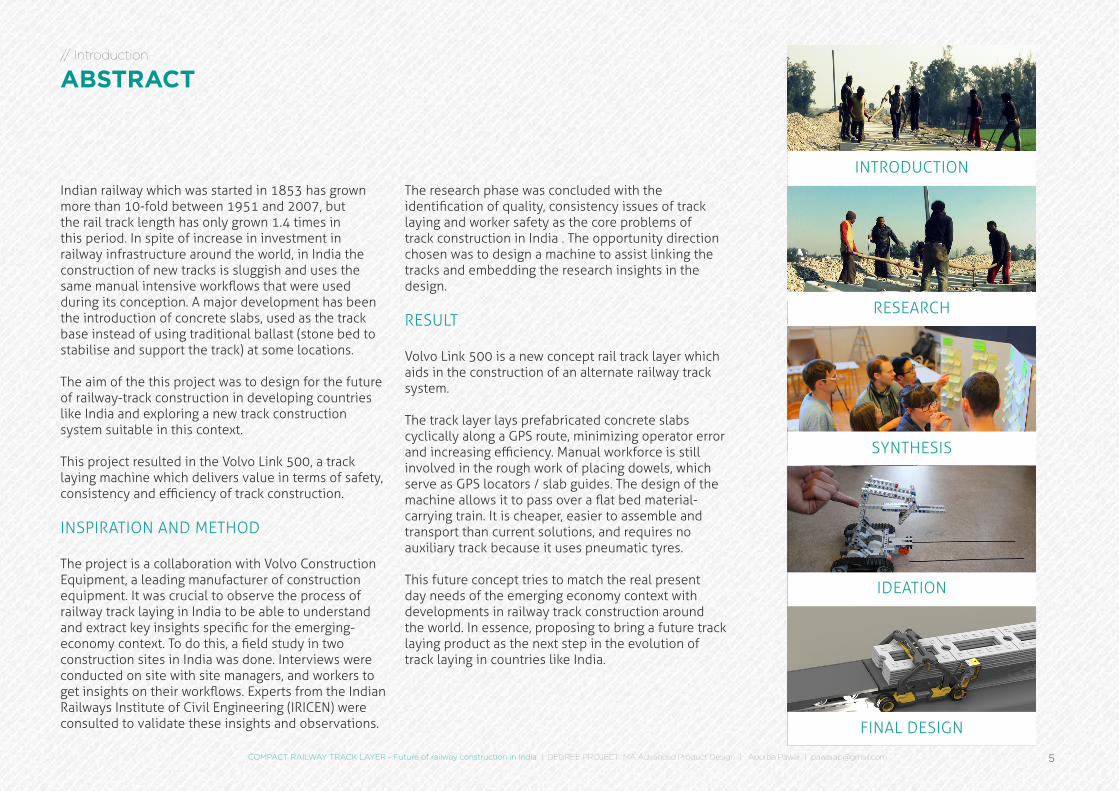
INTRODUCTION
RESEARCH
SYNTHESIS
IDEATION
FINAL DESIGN
INTRODUCTION
7COMPACT RAILWAY TRACK LAYER - Future of railway construction in India | DEGREE PROJECT MA Advanced Product Design | Apurba Pawar | [email protected]
// Introduction
COLLABORATION PARTNER VOLVO
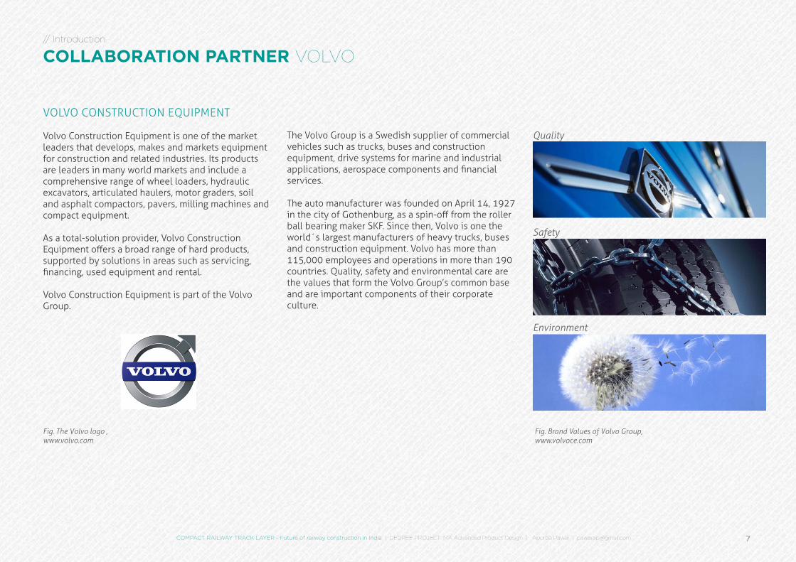
The Volvo Group is a Swedish supplier of commercial vehicles such as trucks, buses and construction equipment, drive systems for marine and industrial applications, aerospace components and financial services.
The auto manufacturer was founded on April 14, 1927 in the city of Gothenburg, as a spin-off from the roller ball bearing maker SKF. Since then, Volvo is one the world´s largest manufacturers of heavy trucks, buses and construction equipment. Volvo has more than 115,000 employees and operations in more than 190 countries. Quality, safety and environmental care are the values that form the Volvo Group’s common base and are important components of their corporate culture.
Fig. The Volvo logo ,www.volvo.com
VOLVO CONSTRUCTION EQUIPMENT
Volvo Construction Equipment is one of the market leaders that develops, makes and markets equipment for construction and related industries. Its products are leaders in many world markets and include a comprehensive range of wheel loaders, hydraulic excavators, articulated haulers, motor graders, soil and asphalt compactors, pavers, milling machines and compact equipment.
As a total-solution provider, Volvo Construction Equipment offers a broad range of hard products, supported by solutions in areas such as servicing, financing, used equipment and rental.
Volvo Construction Equipment is part of the Volvo Group.
Quality
Safety
Environment
Fig. Brand Values of Volvo Group,www.volvoce.com
8
// Introduction
VOLVO CONSTRUCTION EQUIPMENT
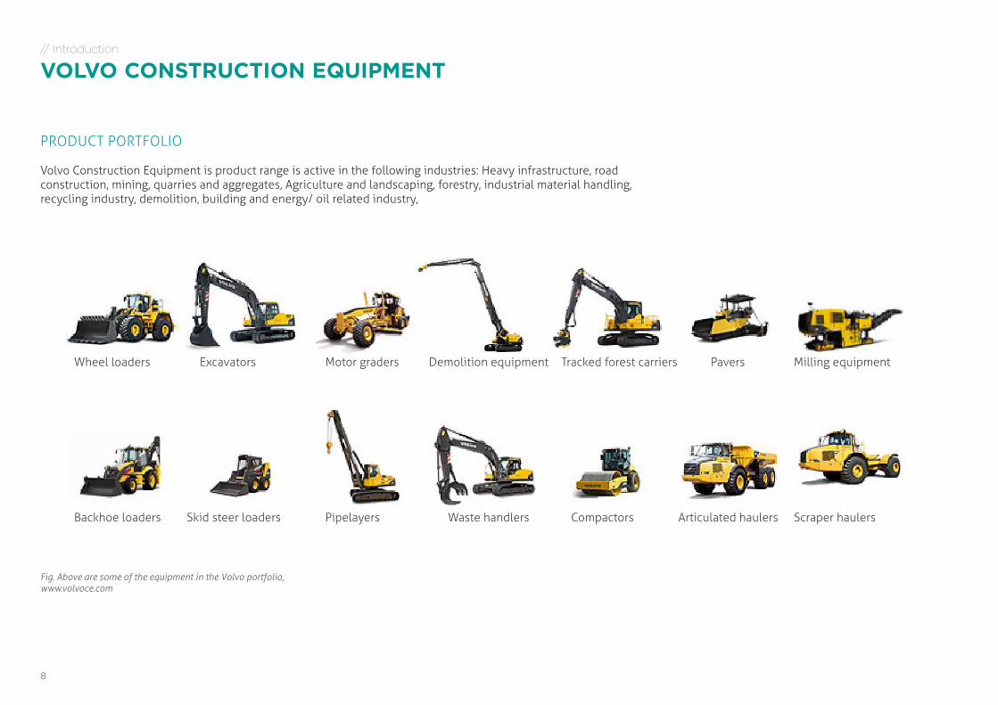
Wheel loaders Excavators Motor graders Demolition equipment Tracked forest carriers Pavers Milling equipment
Backhoe loaders Skid steer loaders Pipelayers Waste handlers Compactors Articulated haulers Scraper haulers
PRODUCT PORTFOLIO
Volvo Construction Equipment is product range is active in the following industries: Heavy infrastructure, road construction, mining, quarries and aggregates, Agriculture and landscaping, forestry, industrial material handling, recycling industry, demolition, building and energy/ oil related industry,
Fig. Above are some of the equipment in the Volvo portfolio,www.volvoce.com
COMPACT RAILWAY TRACK LAYER - Future of railway construction in India | DEGREE PROJECT MA Advanced Product Design | Apurba Pawar | [email protected] 9
“Further, the higher dependence on road transport is adverse for the environment as emissions from road transport are higher than emissions from rail. Road transport emits 84g of CO2 equivalent per ton-km compared to 28g for railways..”
- Infrastructure Practice, July 2010, McKinsey & Company, www.mckinsey.com
In the first phase, DFCCIL will be constructing two corridors – the Western DFC and Eastern DFC- spanning a total length of about 3300 route km
- Economic Times, February 2013, www.economictimes.com
Looking at Indian railway, in its past and present, it is obvious that growth is imminent & needed. It has to go hand in hand with the best practices in safety, quality and sustainability.
The Indian railways was chosen as a target market for Volvo Construction Equipment because it offered a unique set of conditions representative of developing countries. These commonalities range from geographical terrains to use of semi-manual nature of technologies used in construction.
In India, railway construction is seen as a high growth industry due to increasing industrialisation of the remotest parts of the country, interest from foreign investors and the Indian government in upgrading existing infrastructure and laying new railway tracks. Furthermore, the railways is recognised as a more sustainable mode of transportation than by vehicles on the road.
Considering all of the above factors, we selected the Indian railway construction industry as a opportunity area for Volvo Construction Equipment.
“Aim - To support the government's initiatives toward ecological sustainability by encouraging users to adopt railways as the most environment friendly mode for their transport requirements”
- Dedicated Freight Corridor Corp. of India Ltd. (DFCC), www.dfccil.org
// Introduction
INDIAN RAILWAYS
While traffic on rail has grown more than 10-fold between 1951 and 2007, rail track length has only grown 1.4 times in the same period. - Infrastructure Practice, July 2010, McKinsey & Company, www.mckinsey.com
Fig. Indian railways logo,www.indianrailways.gov.in/railwayboard/view_section.jsp?lang=0&id=0,1www.wikipedia.org
10
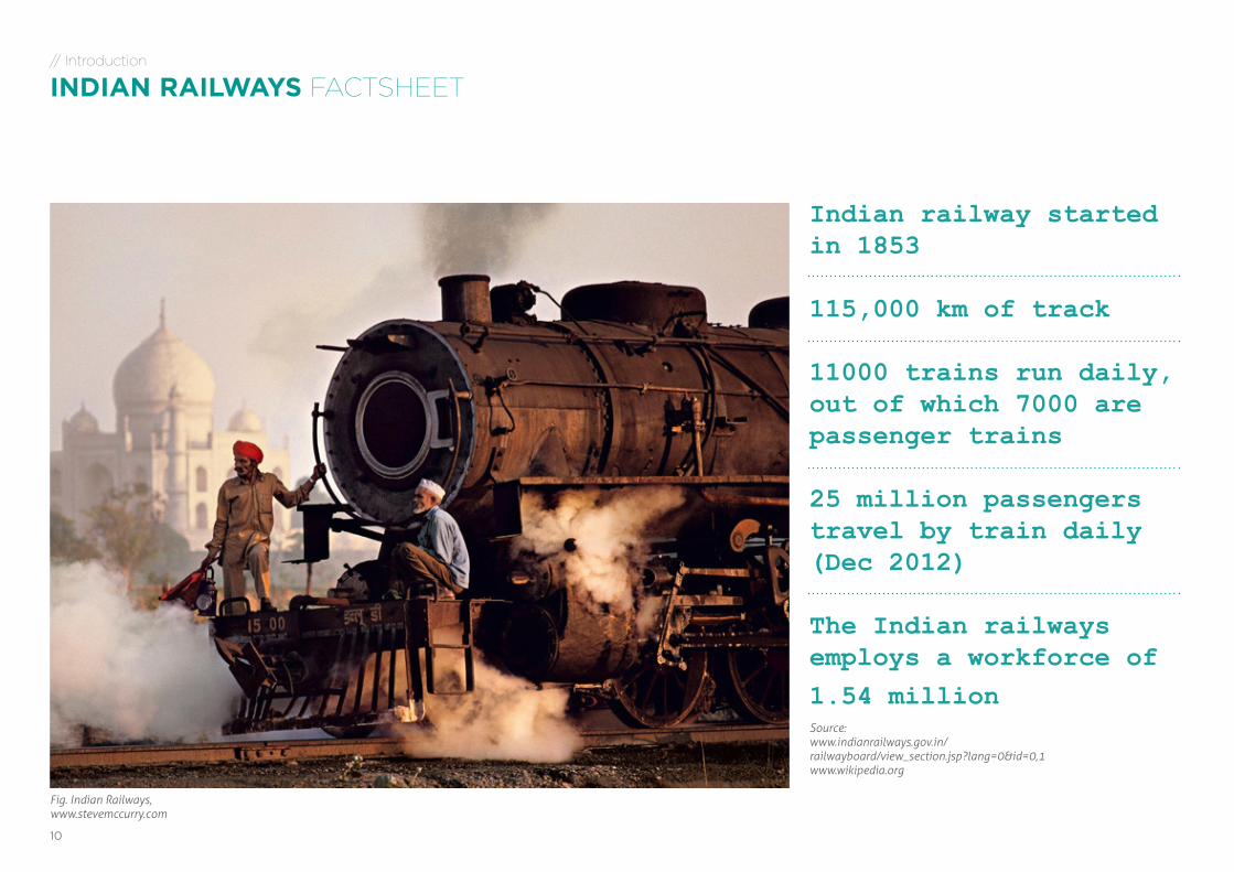
Indian railway started in 1853
115,000 km of track
11000 trains run daily, out of which 7000 are passenger trains
25 million passengers travel by train daily (Dec 2012)
The Indian railways employs a workforce of 1.54 millionSource: www.indianrailways.gov.in/railwayboard/view_section.jsp?lang=0&id=0,1www.wikipedia.org
// Introduction
INDIAN RAILWAYS FACTSHEET
Fig. Indian Railways,www.stevemccurry.com
COMPACT RAILWAY TRACK LAYER - Future of railway construction in India | DEGREE PROJECT MA Advanced Product Design | Apurba Pawar | [email protected] 11
// Introduction
INDIAN RAILWAYS TRACK LAYING
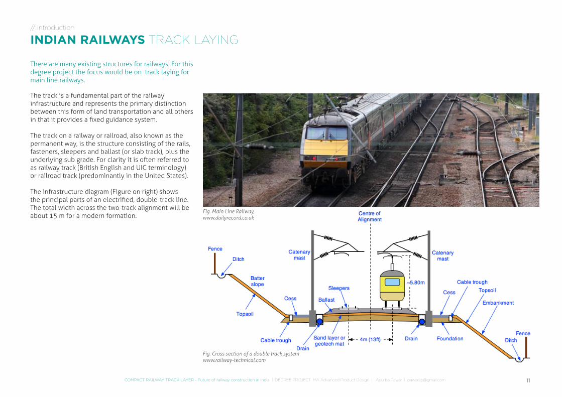
The track is a fundamental part of the railway infrastructure and represents the primary distinction between this form of land transportation and all others in that it provides a fixed guidance system.
The track on a railway or railroad, also known as the permanent way, is the structure consisting of the rails, fasteners, sleepers and ballast (or slab track), plus the underlying sub grade. For clarity it is often referred to as railway track (British English and UIC terminology) or railroad track (predominantly in the United States).
The infrastructure diagram (Figure on right) shows the principal parts of an electrified, double-track line. The total width across the two-track alignment will be about 15 m for a modern formation.
Fig. Cross section of a double track systemwww.railway-technical.com
Fig. Main Line Railway,www.dailyrecord.co.uk
There are many existing structures for railways. For this degree project the focus would be on track laying for main line railways.

RESEARCH
13COMPACT RAILWAY TRACK LAYER - Future of railway construction in India | DEGREE PROJECT MA Advanced Product Design | Apurba Pawar | [email protected]
// Research
HISTORY TRACK EVOLUTION (MAIN LINE)
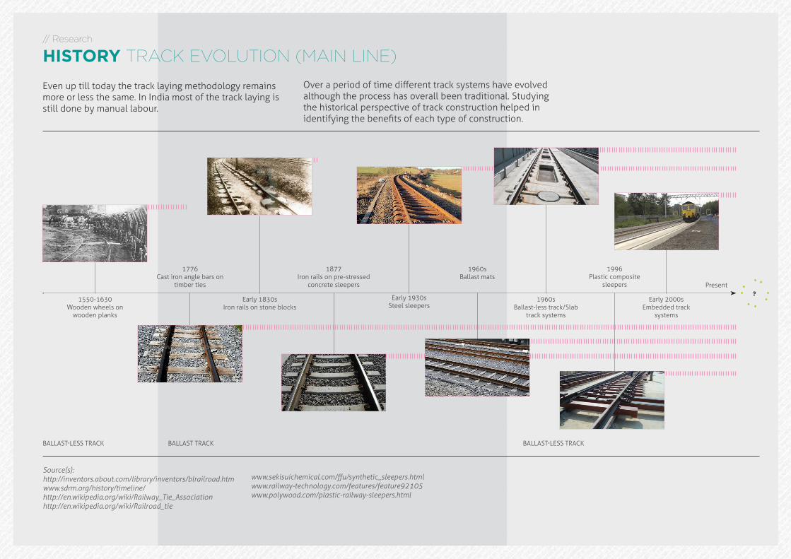
Early 1830sIron rails on stone blocks
1550-1630Wooden wheels on
wooden planks
1877Iron rails on pre-stressed
concrete sleepers
Source(s): http://inventors.about.com/library/inventors/blrailroad.htmwww.sdrm.org/history/timeline/http://en.wikipedia.org/wiki/Railway_Tie_Associationhttp://en.wikipedia.org/wiki/Railroad_tie
1776Cast iron angle bars on
timber ties
Early 1930sSteel sleepers
1960sBallast-less track/Slab
track systems
1960sBallast mats
Early 2000sEmbedded track
systems
1996Plastic composite
sleepers
BALLAST-LESS TRACK BALLAST TRACK BALLAST-LESS TRACK
Present?
Over a period of time different track systems have evolved although the process has overall been traditional. Studying the historical perspective of track construction helped in identifying the benefits of each type of construction.
Even up till today the track laying methodology remains more or less the same. In India most of the track laying is still done by manual labour.
www.sekisuichemical.com/ffu/synthetic_sleepers.htmlwww.railway-technology.com/features/feature92105www.polywood.com/plastic-railway-sleepers.html
14
RAIL SUPPORT (SLEEPER/TIE)
A railroad sleeper (also called a railroad tie/cross-tie in USA) is a rectangular object on which the rails are supported and fixed. The sleeper has two main roles: to transfer the loads from the rails to the track ballast and the ground underneath, and to hold the rails to the correct width apart (to maintain the rail gauge). They are generally laid transverse (perpendicular) to the rails.
RAIL
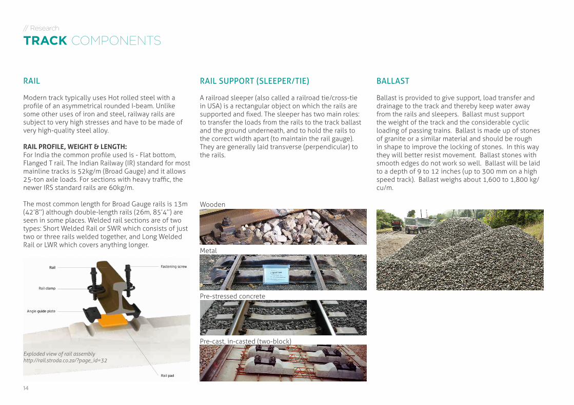
Modern track typically uses Hot rolled steel with a profile of an asymmetrical rounded I-beam. Unlike some other uses of iron and steel, railway rails are subject to very high stresses and have to be made of very high-quality steel alloy.
RAIL PROFILE, WEIGHT & LENGTH:For India the common profile used is - Flat bottom, Flanged T rail. The Indian Railway (IR) standard for most mainline tracks is 52kg/m (Broad Gauge) and it allows 25-ton axle loads. For sections with heavy traffic, the newer IRS standard rails are 60kg/m.
The most common length for Broad Gauge rails is 13m (42’8’’) although double-length rails (26m, 85’4’’) are seen in some places. Welded rail sections are of two types: Short Welded Rail or SWR which consists of just two or three rails welded together, and Long Welded Rail or LWR which covers anything longer.
Wooden
Metal
Pre-stressed concrete
Pre-cast, in-casted (two-block)
BALLAST
Ballast is provided to give support, load transfer and drainage to the track and thereby keep water away from the rails and sleepers. Ballast must support the weight of the track and the considerable cyclic loading of passing trains. Ballast is made up of stones of granite or a similar material and should be rough in shape to improve the locking of stones. In this way they will better resist movement. Ballast stones with smooth edges do not work so well. Ballast will be laid to a depth of 9 to 12 inches (up to 300 mm on a high speed track). Ballast weighs about 1,600 to 1,800 kg/cu/m.
// Research
TRACK COMPONENTS
Exploded view of rail assemblyhttp://rail.stroda.co.za/?page_id=32
15COMPACT RAILWAY TRACK LAYER - Future of railway construction in India | DEGREE PROJECT MA Advanced Product Design | Apurba Pawar | [email protected]
// Research
TRACK COMPONENTS
JOINING RAIL
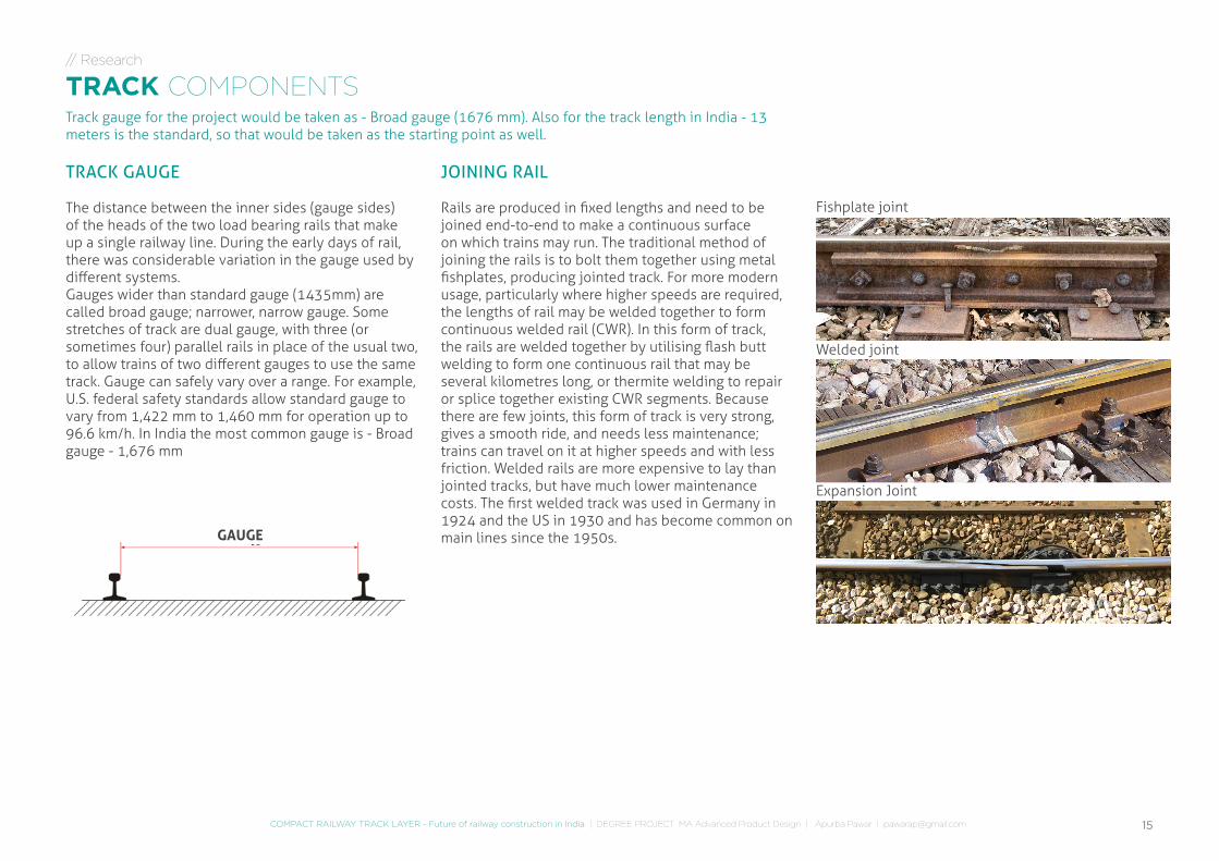
Rails are produced in fixed lengths and need to be joined end-to-end to make a continuous surface on which trains may run. The traditional method of joining the rails is to bolt them together using metal fishplates, producing jointed track. For more modern usage, particularly where higher speeds are required, the lengths of rail may be welded together to form continuous welded rail (CWR). In this form of track, the rails are welded together by utilising flash butt welding to form one continuous rail that may be several kilometres long, or thermite welding to repair or splice together existing CWR segments. Because there are few joints, this form of track is very strong, gives a smooth ride, and needs less maintenance; trains can travel on it at higher speeds and with less friction. Welded rails are more expensive to lay than jointed tracks, but have much lower maintenance costs. The first welded track was used in Germany in 1924 and the US in 1930 and has become common on main lines since the 1950s.
Fishplate joint
Welded joint
Expansion Joint
TRACK GAUGE
The distance between the inner sides (gauge sides) of the heads of the two load bearing rails that make up a single railway line. During the early days of rail, there was considerable variation in the gauge used by different systems. Gauges wider than standard gauge (1435mm) are called broad gauge; narrower, narrow gauge. Some stretches of track are dual gauge, with three (or sometimes four) parallel rails in place of the usual two, to allow trains of two different gauges to use the same track. Gauge can safely vary over a range. For example, U.S. federal safety standards allow standard gauge to vary from 1,422 mm to 1,460 mm for operation up to 96.6 km/h. In India the most common gauge is - Broad gauge - 1,676 mm
Track gauge for the project would be taken as - Broad gauge (1676 mm). Also for the track length in India - 13 meters is the standard, so that would be taken as the starting point as well.
GAUGE
16
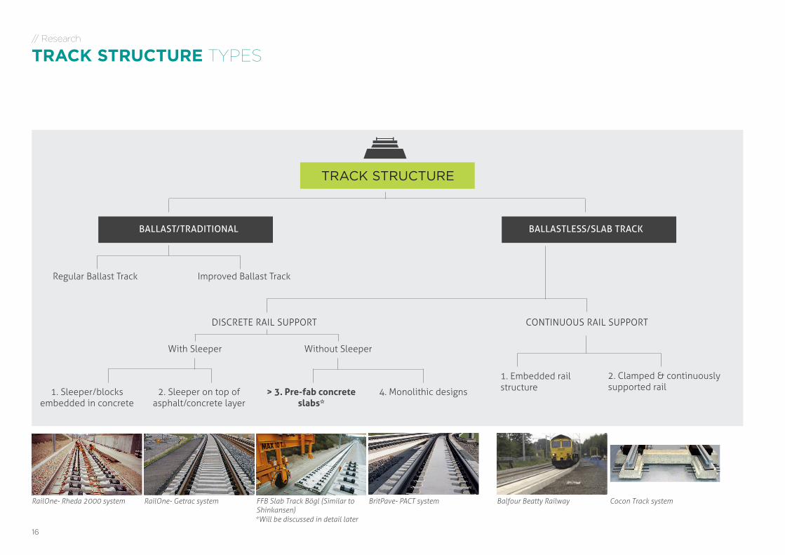
TRACK STRUCTURE
BALLAST/TRADITIONAL BALLASTLESS/SLAB TRACK
DISCRETE RAIL SUPPORT
Regular Ballast Track
// Research
TRACK STRUCTURE TYPES
Improved Ballast Track
CONTINUOUS RAIL SUPPORT
1. Sleeper/blocks embedded in concrete
2. Sleeper on top of asphalt/concrete layer
> 3. Pre-fab concrete slabs*
4. Monolithic designs
1. Embedded rail structure
2. Clamped & continuously supported rail
Without SleeperWith Sleeper
RailOne- Rheda 2000 system RailOne- Getrac system FFB Slab Track Bögl (Similar to Shinkansen)
BritPave- PACT system Balfour Beatty Railway Cocon Track system
*Will be discussed in detail later
17COMPACT RAILWAY TRACK LAYER - Future of railway construction in India | DEGREE PROJECT MA Advanced Product Design | Apurba Pawar | [email protected]
// Research
TRACK STRUCTURE TYPES
TRADITIONAL BALLASTED TRACK
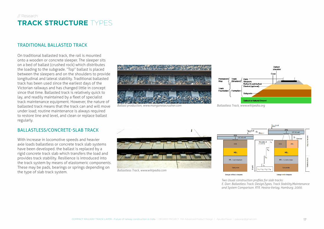
On traditional ballasted track, the rail is mounted onto a wooden or concrete sleeper. The sleeper sits on a bed of ballast (crushed rock) which distributes the loading to the subgrade. “Top” ballast is placed between the sleepers and on the shoulders to provide longitudinal and lateral stability. Traditional ballasted track has been used since the earliest days of the Victorian railways and has changed little in concept since that time. Ballasted track is relatively quick to lay, and readily maintained by a fleet of specialist track maintenance equipment. However, the nature of ballasted track means that the track can and will move under load; routine maintenance is always required to restore line and level, and clean or replace ballast regularly.
BALLASTLESS/CONCRETE-SLAB TRACK
With increase in locomotive speeds and heavier axle loads ballastless or concrete track slab systems have been developed. the ballast is replaced by a rigid concrete track slab which transfers the load and provides track stability. Resilience is introduced into the track system by means of elastomeric components. These may be pads, bearings or springs depending on the type of slab track system.
Ballast production, www.manganesecrusher.com
Ballastless Track, www.wikipedia.com
Ballastless Track, www.wikipedia.org
Two Usual construction profiles for slab tracks:E. Darr. Ballastless Track: Design,Types, Track Stability,Maintenance and System Comparison. RTR. Hestra-Verlag, Hamburg. 2000.
18
// Research
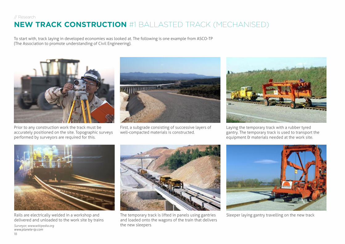
NEW TRACK CONSTRUCTION #1 BALLASTED TRACK (MECHANISED)
First, a subgrade consisting of successive layers of well-compacted materials is constructed.
Laying the temporary track with a rubber tyred gantry. The temporary track is used to transport the equipment & materials needed at the work site.
Sleeper laying gantry travelling on the new track
Surveyor, www.wikipedia.org
Prior to any construction work the track must be accurately positioned on the site. Topographic surveys performed by surveyors are required for this.
Rails are electrically welded in a workshop and delivered and unloaded to the work site by trains
The temporary track is lifted in panels using gantries and loaded onto the wagons of the train that delivers the new sleepers
To start with, track laying in developed economies was looked at. The following is one example from ASCO-TP (The Association to promote understanding of Civil Engineering).
www.planete-tp.com
19COMPACT RAILWAY TRACK LAYER - Future of railway construction in India | DEGREE PROJECT MA Advanced Product Design | Apurba Pawar | [email protected]
// Research
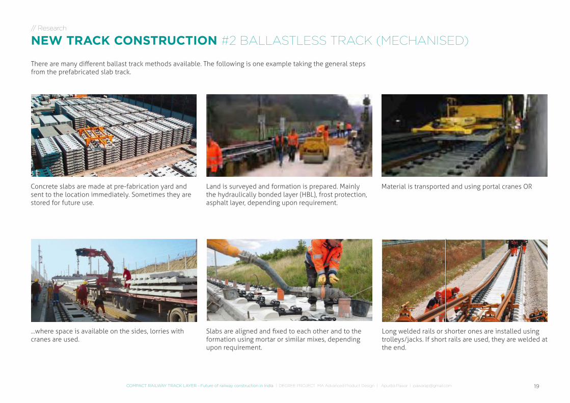
NEW TRACK CONSTRUCTION #2 BALLASTLESS TRACK (MECHANISED)
There are many different ballast track methods available. The following is one example taking the general steps from the prefabricated slab track.
Land is surveyed and formation is prepared. Mainly the hydraulically bonded layer (HBL), frost protection, asphalt layer, depending upon requirement.
Material is transported and using portal cranes OR
Slabs are aligned and fixed to each other and to the formation using mortar or similar mixes, depending upon requirement.
Concrete slabs are made at pre-fabrication yard and sent to the location immediately. Sometimes they are stored for future use.
...where space is available on the sides, lorries with cranes are used.
Long welded rails or shorter ones are installed using trolleys/jacks. If short rails are used, they are welded at the end.
20
// Research
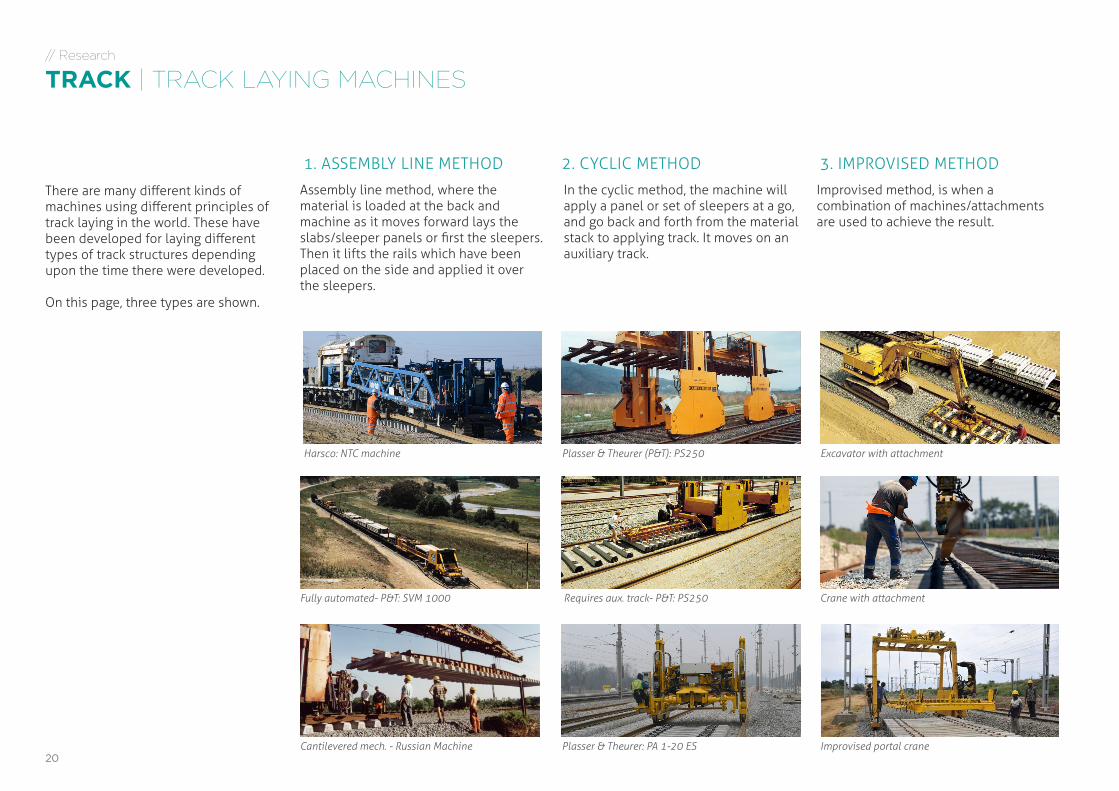
TRACK | TRACK LAYING MACHINES
There are many different kinds of machines using different principles of track laying in the world. These have been developed for laying different types of track structures depending upon the time there were developed.
On this page, three types are shown.
1. ASSEMBLY LINE METHOD 2. CYCLIC METHOD 3. IMPROVISED METHOD
Harsco: NTC machine Plasser & Theurer (P&T): PS250 Excavator with attachment
Fully automated- P&T: SVM 1000 Requires aux. track- P&T: PS250 Crane with attachment
Cantilevered mech. - Russian Machine Plasser & Theurer: PA 1-20 ES Improvised portal crane
Assembly line method, where the material is loaded at the back and machine as it moves forward lays the slabs/sleeper panels or first the sleepers. Then it lifts the rails which have been placed on the side and applied it over the sleepers.
In the cyclic method, the machine will apply a panel or set of sleepers at a go, and go back and forth from the material stack to applying track. It moves on an auxiliary track.
Improvised method, is when a combination of machines/attachments are used to achieve the result.
21COMPACT RAILWAY TRACK LAYER - Future of railway construction in India | DEGREE PROJECT MA Advanced Product Design | Apurba Pawar | [email protected]
// Research
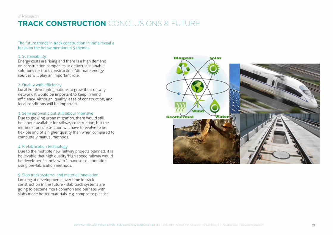
TRACK CONSTRUCTION CONCLUSIONS & FUTURE
1. Sustainability Energy costs are rising and there is a high demand on construction companies to deliver sustainable solutions for track construction. Alternate energy sources will play an important role.
2. Quality with efficiencyLocal For developing nations to grow their railway network, it would be important to keep in mind efficiency. Although, quality, ease of construction, and local conditions will be important.
3. Semi automatic but still labour intensiveDue to growing urban migration, there would still be labour available for railway construction, but the methods for construction will have to evolve to be flexible and of a higher quality than when compared to completely manual methods.
4. Prefabrication technology Due to the multiple new railway projects planned, it is believable that high quality/high speed railway would be developed in India with Japanese collaboration using pre-fabrication methods.
5. Slab track systems and material innovationLooking at developments over time in track construction in the future - slab track systems are going to become more common and perhaps with slabs made better materials e.g. composite plastics.
The future trends in track construction in India reveal a focus on the below mentioned 5 themes.
22
342 km
2116 km
840 km
1588
km
New Delhi
Neelon
Bengaluru
Pune
INDIA
// Research
FIELD RESEARCH INDIA
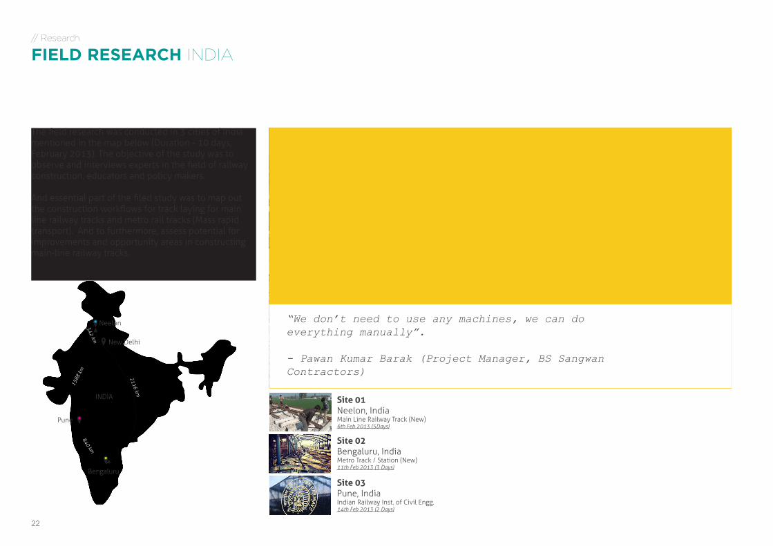
The field research was conducted in 3 cities of India mentioned in the map below (Duration - 10 days, February 2013). The objective of the study was to observe and interviews experts in the field of railway construction, educators and policy makers.
And essential part of the filed study was to map out the construction workflows for track laying for main line railway tracks and metro rail tracks (Mass rapid transport). And to furthermore, assess potential for improvements and opportunity areas in constructing main-line railway tracks.
“We don’t need to use any machines, we can do everything manually”. - Pawan Kumar Barak (Project Manager, BS Sangwan Contractors)
Site 01Neelon, IndiaMain Line Railway Track (New)6th Feb 2013 (5Days)
Site 02Bengaluru, IndiaMetro Track / Station (New)11th Feb 2013 (3 Days)
Site 03Pune, IndiaIndian Railway Inst. of Civil Engg.14th Feb 2013 (2 Days)
23COMPACT RAILWAY TRACK LAYER - Future of railway construction in India | DEGREE PROJECT MA Advanced Product Design | Apurba Pawar | [email protected]
// Research
FIELD RESEARCH (INDIA) EXPERT INTERVIEWS
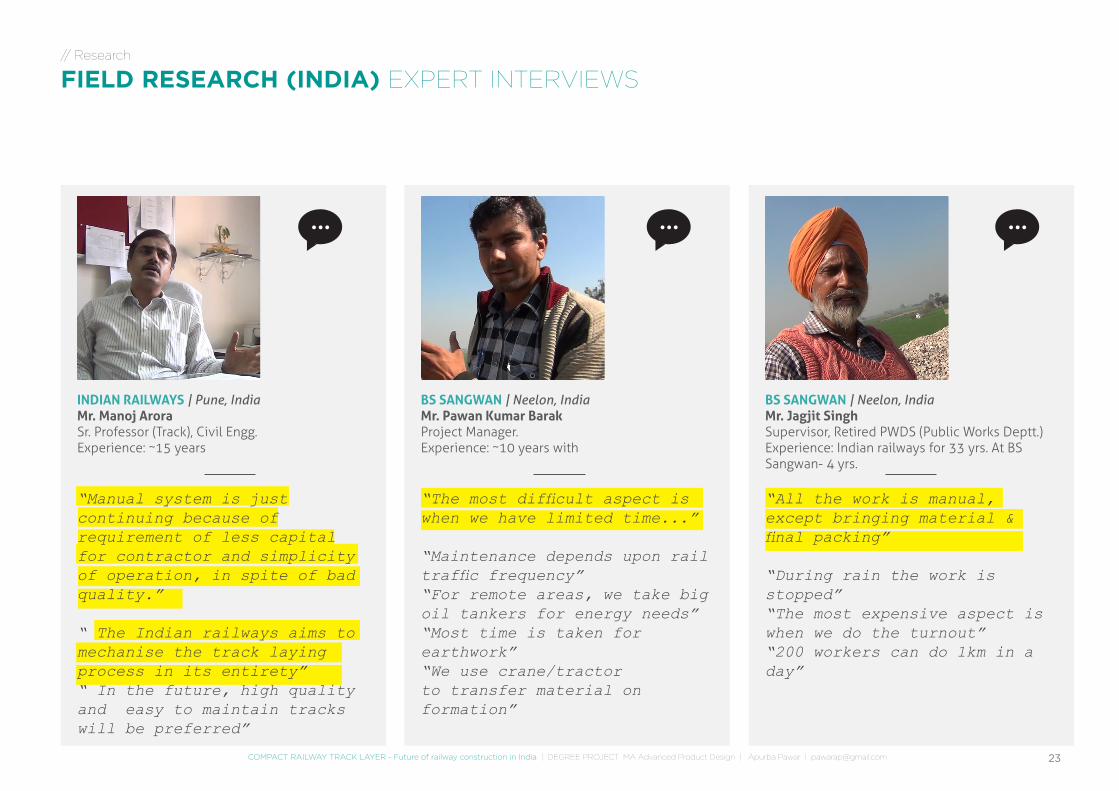
BS SANGWAN | Neelon, India Mr. Jagjit SinghSupervisor, Retired PWDS (Public Works Deptt.)Experience: Indian railways for 33 yrs. At BS Sangwan- 4 yrs.
“All the work is manual, except bringing material & final packing”
“During rain the work is stopped”“The most expensive aspect is when we do the turnout”“200 workers can do 1km in a day”
BS SANGWAN | Neelon, IndiaMr. Pawan Kumar BarakProject Manager.Experience: ~10 years with
“The most difficult aspect is when we have limited time...”
“Maintenance depends upon rail traffic frequency”“For remote areas, we take big oil tankers for energy needs”“Most time is taken for earthwork”“We use crane/tractor to transfer material on formation”
INDIAN RAILWAYS | Pune, IndiaMr. Manoj AroraSr. Professor (Track), Civil Engg.Experience: ~15 years
“Manual system is just continuing because of requirement of less capital for contractor and simplicity of operation, in spite of bad quality.”
“ The Indian railways aims to mechanise the track laying process in its entirety”“ In the future, high quality and easy to maintain tracks will be preferred”
24
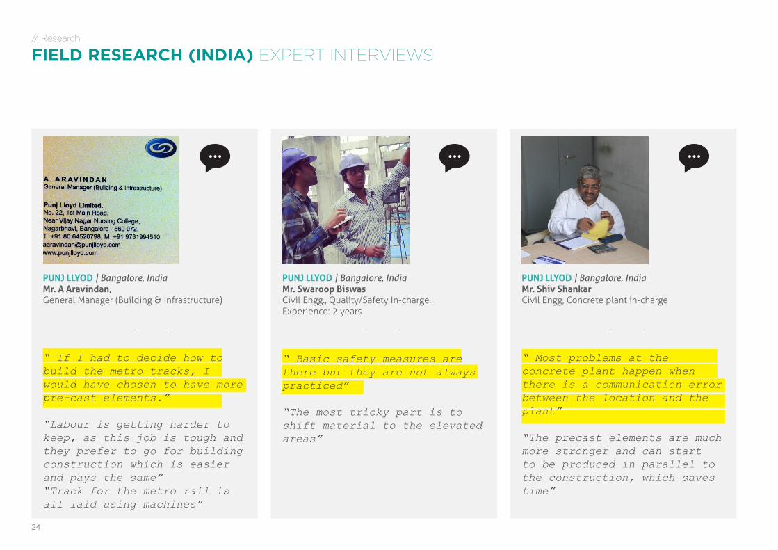
PUNJ LLYOD | Bangalore, IndiaMr. Shiv ShankarCivil Engg, Concrete plant in-charge
“ Most problems at the concrete plant happen when there is a communication error between the location and the plant”
“The precast elements are much more stronger and can start to be produced in parallel to the construction, which saves time”
PUNJ LLYOD | Bangalore, IndiaMr. Swaroop BiswasCivil Engg., Quality/Safety In-charge.Experience: 2 years
“ Basic safety measures are there but they are not always practiced”
“The most tricky part is to shift material to the elevated areas”
PUNJ LLYOD | Bangalore, IndiaMr. A Aravindan,General Manager (Building & Infrastructure)
“ If I had to decide how to build the metro tracks, I would have chosen to have more pre-cast elements.”
“Labour is getting harder to keep, as this job is tough and they prefer to go for building construction which is easier and pays the same”“Track for the metro rail is all laid using machines”
// Research
FIELD RESEARCH (INDIA) EXPERT INTERVIEWS
25COMPACT RAILWAY TRACK LAYER - Future of railway construction in India | DEGREE PROJECT MA Advanced Product Design | Apurba Pawar | [email protected]
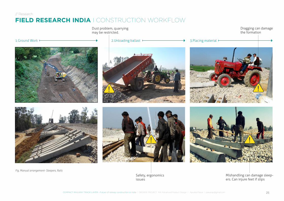
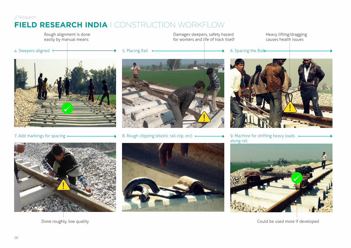
1.Ground Work 2.Unloading ballast 3.Placing material
Fig. Manual arrangement- Sleepers, Rails
Dragging can damage the formation
Dust problem, quarrying may be restricted.
Safety, ergonomics issues
Mishandling can damage sleep-ers. Can injure feet if slips
!
!
!
!
// Research
FIELD RESEARCH INDIA I CONSTRUCTION WORKFLOW
26
5. Placing Rail4. Sleepers aligned 6. Spacing the Rails
7. Add markings for spacing 8. Rough clipping (elastic rail clip, erc) 9. Machine for shifting heavy loads along rail
Damages sleepers, safety hazard for workers and life of track itself
Done roughly, low quality
Heavy lifting/dragging causes health issues
Could be used more if developed
Rough alignment is done easily by manual means
!
!!
// Research
FIELD RESEARCH INDIA I CONSTRUCTION WORKFLOW
27COMPACT RAILWAY TRACK LAYER - Future of railway construction in India | DEGREE PROJECT MA Advanced Product Design | Apurba Pawar | [email protected]
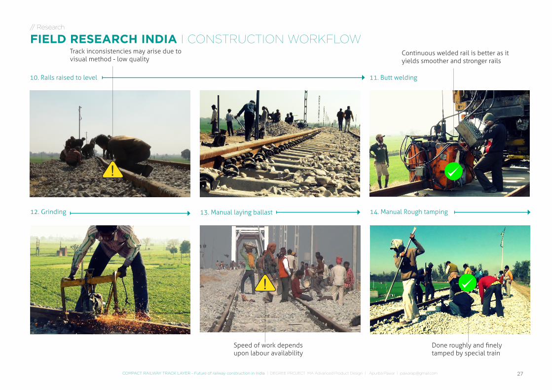
10. Rails raised to level 11. Butt welding
12. Grinding 14. Manual Rough tamping13. Manual laying ballast
Track inconsistencies may arise due to visual method - low quality
Done roughly and finely tamped by special train
Continuous welded rail is better as it yields smoother and stronger rails
Speed of work depends upon labour availability
!
!
// Research
FIELD RESEARCH INDIA I CONSTRUCTION WORKFLOW

28
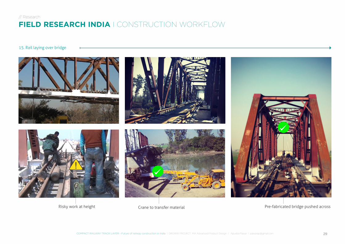
29COMPACT RAILWAY TRACK LAYER - Future of railway construction in India | DEGREE PROJECT MA Advanced Product Design | Apurba Pawar | [email protected]
15. Rail laying over bridge
Risky work at height Crane to transfer material Pre-fabricated bridge pushed across
!
// Research
FIELD RESEARCH INDIA I CONSTRUCTION WORKFLOW

RESEARCH SYNTHESIS
31COMPACT RAILWAY TRACK LAYER - Future of railway construction in India | DEGREE PROJECT MA Advanced Product Design | Apurba Pawar | [email protected]
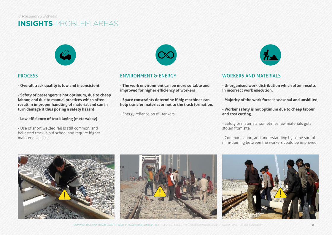
// Research Synthesis
INSIGHTS PROBLEM AREAS
PROCESS
- Overall track quality is low and inconsistent.
- Safety of passengers is not optimum, due to cheap labour, and due to manual practices which often result in improper handling of material and can in turn damage it thus posing a safety hazard
- Low efficiency of track laying (meters/day)
- Use of short welded rail is still common, and ballasted track is old school and require higher maintenance cost.
ENVIRONMENT & ENERGY
- The work environment can be more suitable and improved for higher efficiency of workers
- Space constraints determine if big machines can help transfer material or not to the track formation.
- Energy reliance on oil-tankers.
WORKERS AND MATERIALS
- Unorganised work distribution which often results in incorrect work execution.
- Majority of the work force is seasonal and unskilled,
- Worker safety is not optimum due to cheap labour and cost cutting.
- Safety or materials, sometimes raw materials gets stolen from site.
- Communication, and understanding by some sort of mini-training between the workers could be improved
! !!
32
// Research Synthesis
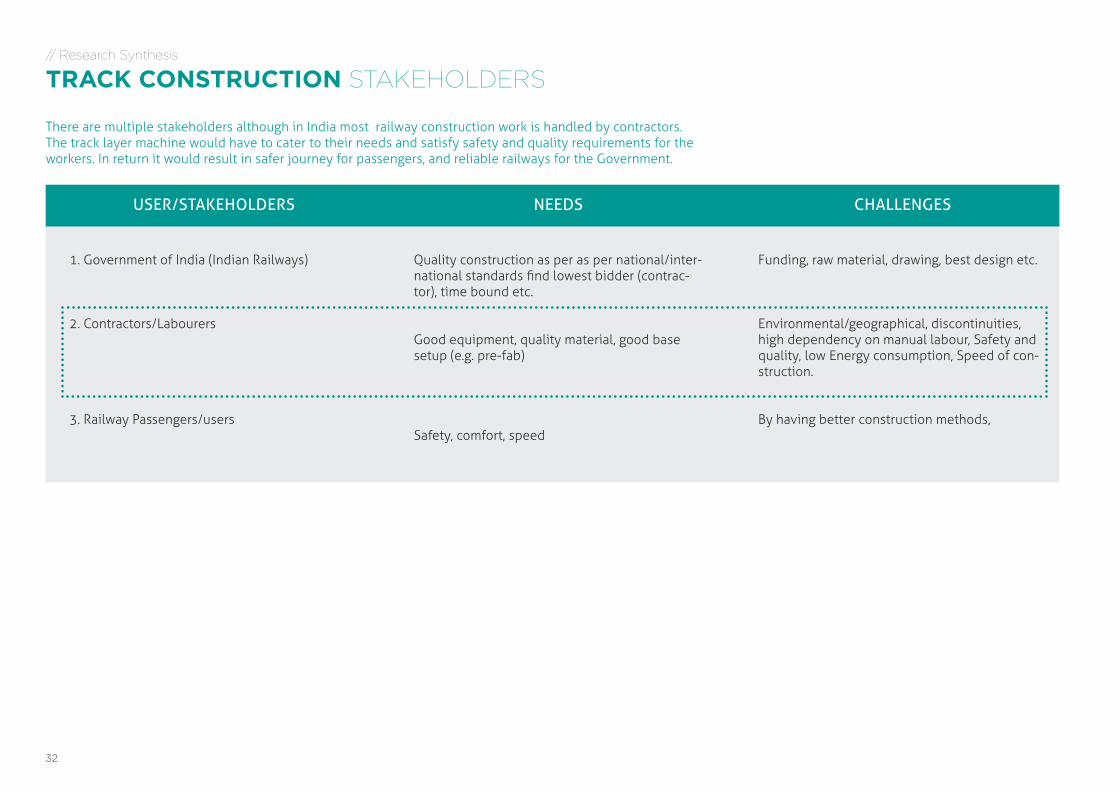
TRACK CONSTRUCTION STAKEHOLDERS
There are multiple stakeholders although in India most railway construction work is handled by contractors. The track layer machine would have to cater to their needs and satisfy safety and quality requirements for the workers. In return it would result in safer journey for passengers, and reliable railways for the Government.
USER/STAKEHOLDERS
1. Government of India (Indian Railways)
2. Contractors/Labourers
3. Railway Passengers/users
NEEDS
Quality construction as per as per national/inter-national standards find lowest bidder (contrac-tor), time bound etc.
Good equipment, quality material, good base setup (e.g. pre-fab)
Safety, comfort, speed
CHALLENGES
Funding, raw material, drawing, best design etc.
Environmental/geographical, discontinuities, high dependency on manual labour, Safety and quality, low Energy consumption, Speed of con-struction.
By having better construction methods,
33COMPACT RAILWAY TRACK LAYER - Future of railway construction in India | DEGREE PROJECT MA Advanced Product Design | Apurba Pawar | [email protected]
// Research Synthesis
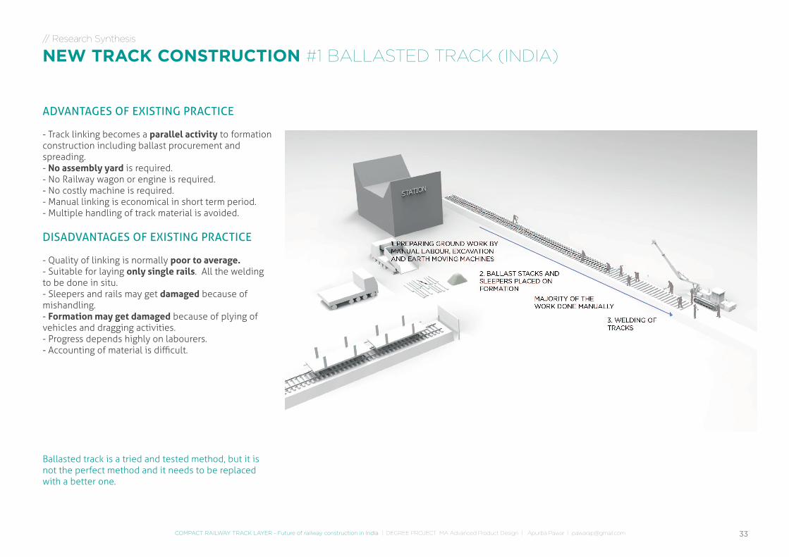
NEW TRACK CONSTRUCTION #1 BALLASTED TRACK (INDIA)
ADVANTAGES OF EXISTING PRACTICE
- Track linking becomes a parallel activity to formation construction including ballast procurement and spreading. - No assembly yard is required.- No Railway wagon or engine is required. - No costly machine is required.- Manual linking is economical in short term period.- Multiple handling of track material is avoided.
DISADVANTAGES OF EXISTING PRACTICE
- Quality of linking is normally poor to average.- Suitable for laying only single rails. All the welding to be done in situ.- Sleepers and rails may get damaged because of mishandling.- Formation may get damaged because of plying of vehicles and dragging activities.- Progress depends highly on labourers.- Accounting of material is difficult.
Ballasted track is a tried and tested method, but it is not the perfect method and it needs to be replaced with a better one.
34
// Research Synthesis
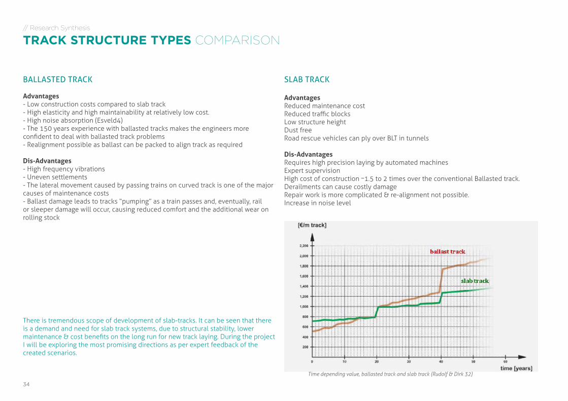
TRACK STRUCTURE TYPES COMPARISON
BALLASTED TRACK
Advantages- Low construction costs compared to slab track- High elasticity and high maintainability at relatively low cost. - High noise absorption (Esveld4)- The 150 years experience with ballasted tracks makes the engineers more confident to deal with ballasted track problems- Realignment possible as ballast can be packed to align track as required
Dis-Advantages- High frequency vibrations- Uneven settlements- The lateral movement caused by passing trains on curved track is one of the major causes of maintenance costs- Ballast damage leads to tracks “pumping” as a train passes and, eventually, rail or sleeper damage will occur, causing reduced comfort and the additional wear on rolling stock
Time depending value, ballasted track and slab track (Rudolf & Dirk 32)
There is tremendous scope of development of slab-tracks. It can be seen that there is a demand and need for slab track systems, due to structural stability, lower maintenance & cost benefits on the long run for new track laying. During the project I will be exploring the most promising directions as per expert feedback of the created scenarios.
SLAB TRACK
AdvantagesReduced maintenance costReduced traffic blocksLow structure heightDust freeRoad rescue vehicles can ply over BLT in tunnels
Dis-AdvantagesRequires high precision laying by automated machinesExpert supervisionHigh cost of construction ~1.5 to 2 times over the conventional Ballasted track.Derailments can cause costly damageRepair work is more complicated & re-alignment not possible.Increase in noise level
35
// Research Synthesis
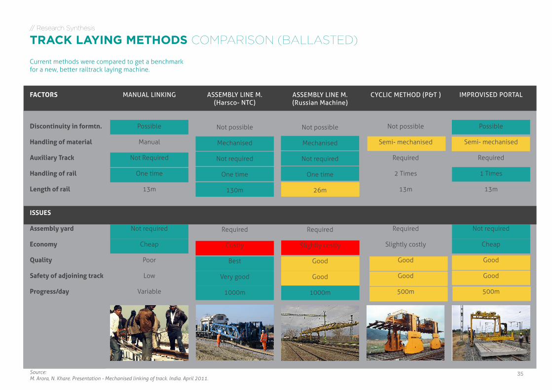
TRACK LAYING METHODS COMPARISON (BALLASTED)
FACTORS
Discontinuity in formtn.
Handling of material
Auxiliary Track
Handling of rail
Length of rail
ISSUES
Assembly yard
Economy
Quality
Safety of adjoining track
Progress/day
ASSEMBLY LINE M.(Harsco- NTC)
Source: M. Arora, N. Khare. Presentation - Mechanised linking of track. India. April 2011.
MANUAL LINKING
Possible
Manual
Not Required
One time
13m
Not required
Cheap
Poor
Low
Variable
Not possible
Mechanised
Not required
One time
130m
Required
Costly
Best
Very good
1000m
IMPROVISED PORTAL
Possible
Semi- mechanised
Required
1 Times
13m
Not required
Cheap
Good
Good
500m
ASSEMBLY LINE M. (Russian Machine)
Not possible
Mechanised
Not required
One time
26m
Required
Slightly costly
Good
Good
1000m
CYCLIC METHOD (P&T )
Not possible
Semi- mechanised
Required
2 Times
13m
Required
Slightly costly
Good
Good
500m
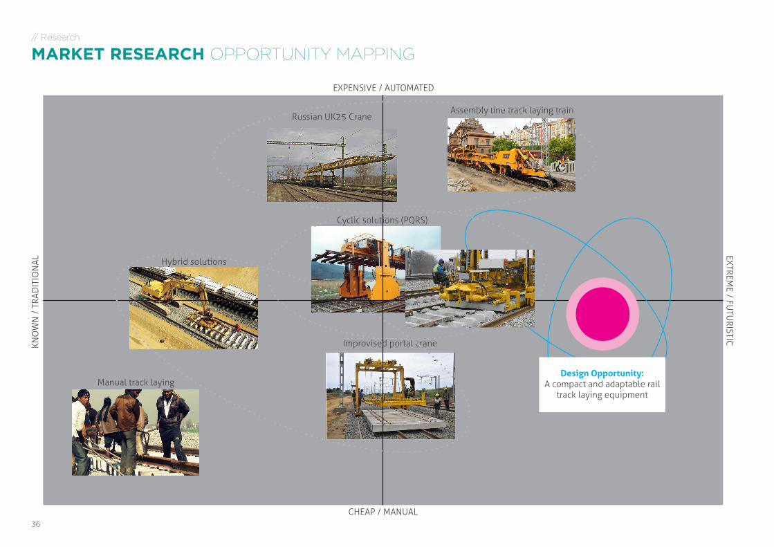
Current methods were compared to get a benchmark for a new, better railtrack laying machine.
36
// Research
MARKET RESEARCH OPPORTUNITY MAPPING
EXPENSIVE / AUTOMATED
CHEAP / MANUAL
KNO
WN
/ T
RAD
ITIO
NAL
EXTREME / FU
TURISTIC
Russian UK25 CraneAssembly line track laying train
Hybrid solutions
Cyclic solutions (PQRS)
Improvised portal crane
Manual track layingDesign Opportunity:
A compact and adaptable rail track laying equipment
37COMPACT RAILWAY TRACK LAYER - Future of railway construction in India | DEGREE PROJECT MA Advanced Product Design | Apurba Pawar | [email protected]
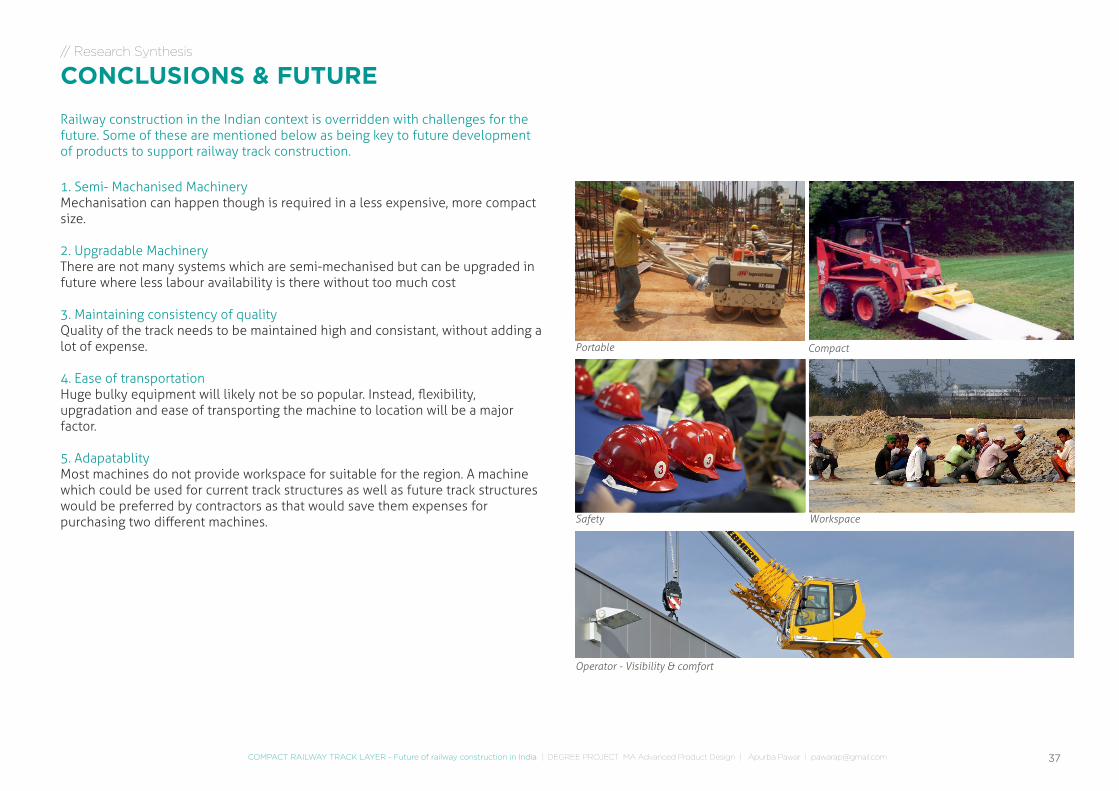
// Research Synthesis
CONCLUSIONS & FUTURE
1. Semi- Machanised MachineryMechanisation can happen though is required in a less expensive, more compact size.
2. Upgradable MachineryThere are not many systems which are semi-mechanised but can be upgraded in future where less labour availability is there without too much cost
3. Maintaining consistency of qualityQuality of the track needs to be maintained high and consistant, without adding a lot of expense.
4. Ease of transportationHuge bulky equipment will likely not be so popular. Instead, flexibility, upgradation and ease of transporting the machine to location will be a major factor.
5. AdapatablityMost machines do not provide workspace for suitable for the region. A machine which could be used for current track structures as well as future track structures would be preferred by contractors as that would save them expenses for purchasing two different machines.
Railway construction in the Indian context is overridden with challenges for the future. Some of these are mentioned below as being key to future development of products to support railway track construction.
Portable Compact
Safety Workspace
Operator - Visibility & comfort
38
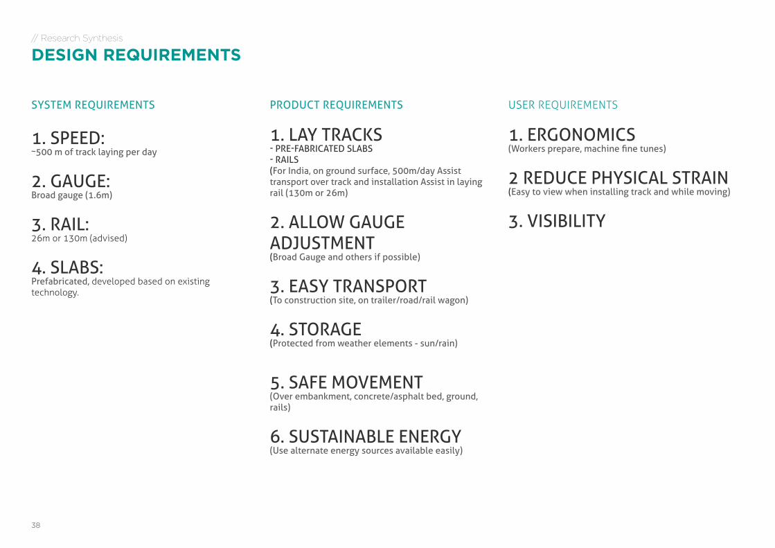
// Research Synthesis
DESIGN REQUIREMENTS
SYSTEM REQUIREMENTS
1. SPEED: ~500 m of track laying per day
2. GAUGE: Broad gauge (1.6m)
3. RAIL: 26m or 130m (advised)
4. SLABS: Prefabricated, developed based on existing technology.
PRODUCT REQUIREMENTS
1. LAY TRACKS- PRE-FABRICATED SLABS- RAILS(For India, on ground surface, 500m/day Assist transport over track and installation Assist in laying rail (130m or 26m)
2. ALLOW GAUGE ADJUSTMENT(Broad Gauge and others if possible)
3. EASY TRANSPORT(To construction site, on trailer/road/rail wagon)
4. STORAGE(Protected from weather elements - sun/rain)
5. SAFE MOVEMENT(Over embankment, concrete/asphalt bed, ground, rails)
6. SUSTAINABLE ENERGY(Use alternate energy sources available easily)
USER REQUIREMENTS
1. ERGONOMICS(Workers prepare, machine fine tunes)
2 REDUCE PHYSICAL STRAIN(Easy to view when installing track and while moving)
3. VISIBILITY
39COMPACT RAILWAY TRACK LAYER - Future of railway construction in India | DEGREE PROJECT MA Advanced Product Design | Apurba Pawar | [email protected]
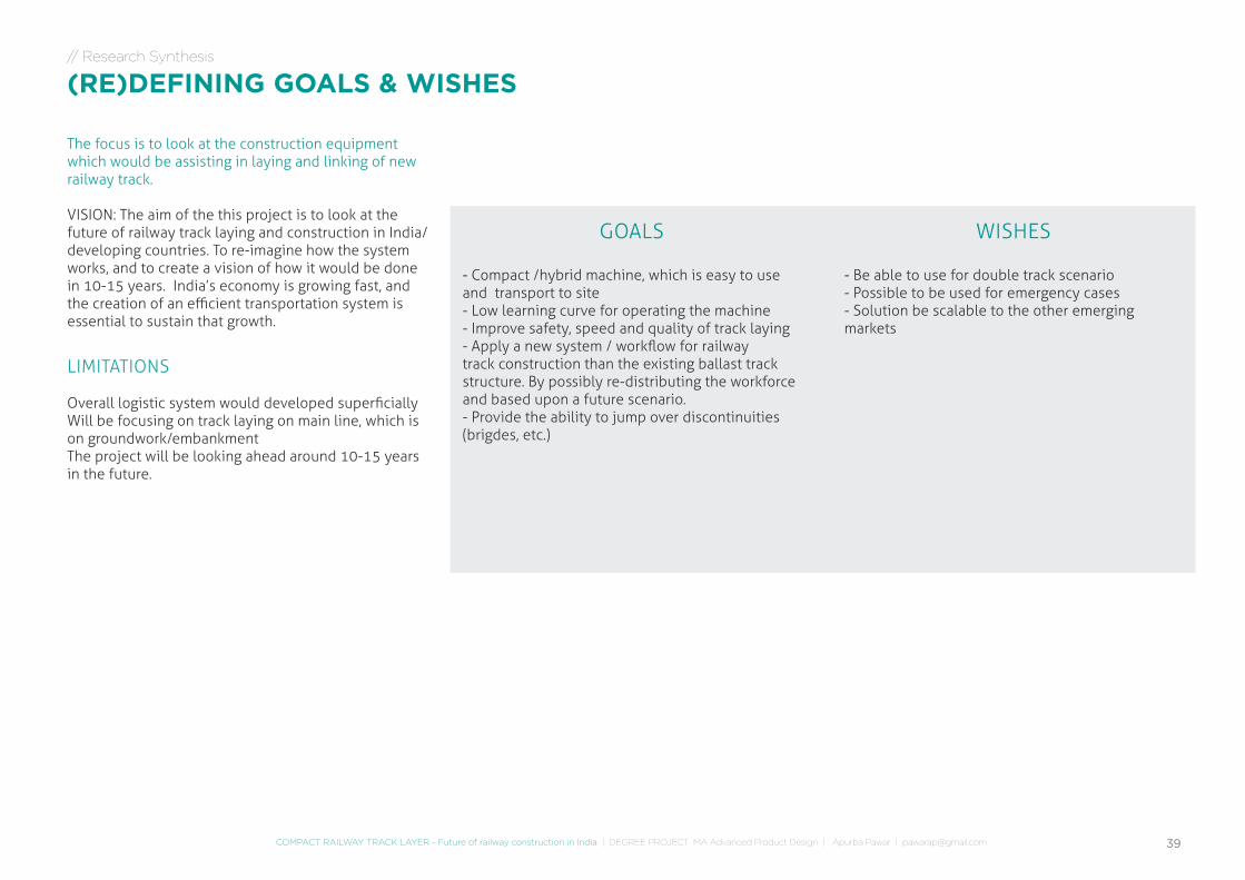
- Compact /hybrid machine, which is easy to use and transport to site- Low learning curve for operating the machine- Improve safety, speed and quality of track laying- Apply a new system / workflow for railway track construction than the existing ballast track structure. By possibly re-distributing the workforce and based upon a future scenario.- Provide the ability to jump over discontinuities (brigdes, etc.)
- Be able to use for double track scenario- Possible to be used for emergency cases- Solution be scalable to the other emerging markets
The focus is to look at the construction equipment which would be assisting in laying and linking of new railway track.
VISION: The aim of the this project is to look at the future of railway track laying and construction in India/developing countries. To re-imagine how the system works, and to create a vision of how it would be done in 10-15 years. India’s economy is growing fast, and the creation of an efficient transportation system is essential to sustain that growth.
LIMITATIONS
Overall logistic system would developed superficiallyWill be focusing on track laying on main line, which is on groundwork/embankmentThe project will be looking ahead around 10-15 years in the future.
GOALS WISHES
// Research Synthesis
(RE)DEFINING GOALS & WISHES
IDEATION
41COMPACT RAILWAY TRACK LAYER - Future of railway construction in India | DEGREE PROJECT MA Advanced Product Design | Apurba Pawar | [email protected]
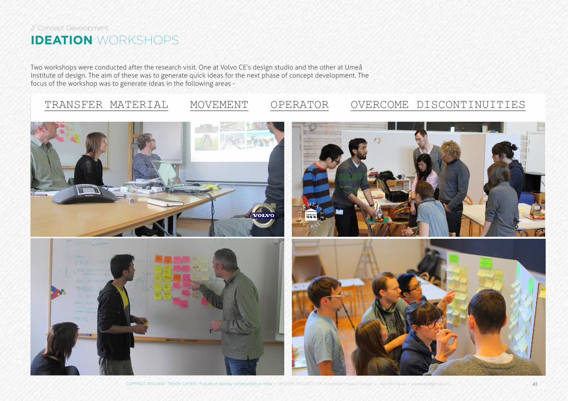
// Concept Development
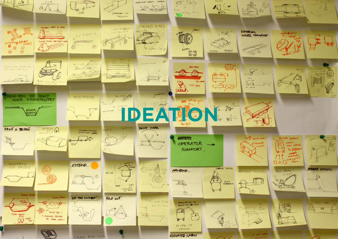
IDEATION WORKSHOPS
TRANSFER MATERIAL MOVEMENT OPERATOR OVERCOME DISCONTINUITIES
Two workshops were conducted after the research visit. One at Volvo CE’s design studio and the other at Umeå Institute of design. The aim of these was to generate quick ideas for the next phase of concept development. The focus of the workshop was to generate ideas in the following areas -
42
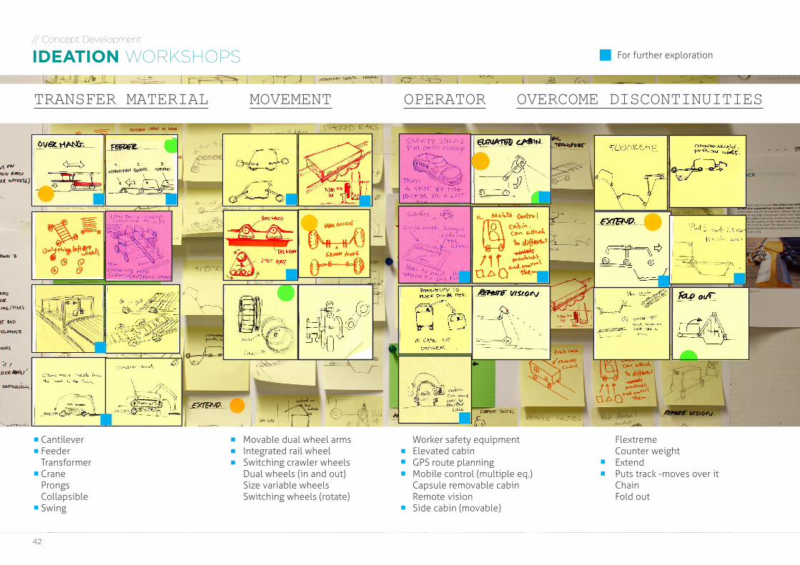
TRANSFER MATERIAL MOVEMENT OPERATOR OVERCOME DISCONTINUITIES
// Concept Development
IDEATION WORKSHOPS
CantileverFeederTransformerCraneProngsCollapsibleSwing
Movable dual wheel armsIntegrated rail wheelSwitching crawler wheelsDual wheels (in and out)Size variable wheelsSwitching wheels (rotate)
Worker safety equipmentElevated cabinGPS route planningMobile control (multiple eq.)Capsule removable cabinRemote visionSide cabin (movable)
FlextremeCounter weightExtendPuts track -moves over itChainFold out
For further exploration
43COMPACT RAILWAY TRACK LAYER - Future of railway construction in India | DEGREE PROJECT MA Advanced Product Design | Apurba Pawar | [email protected]
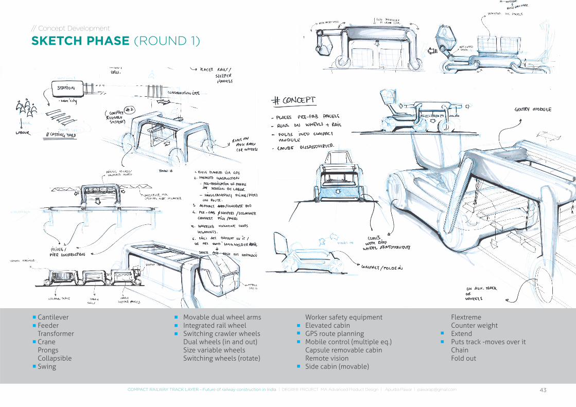
// Concept Development
SKETCH PHASE (ROUND 1)
CantileverFeederTransformerCraneProngsCollapsibleSwing
Movable dual wheel armsIntegrated rail wheelSwitching crawler wheelsDual wheels (in and out)Size variable wheelsSwitching wheels (rotate)
Worker safety equipmentElevated cabinGPS route planningMobile control (multiple eq.)Capsule removable cabinRemote visionSide cabin (movable)
FlextremeCounter weightExtendPuts track -moves over itChainFold out
44
// Concept Development
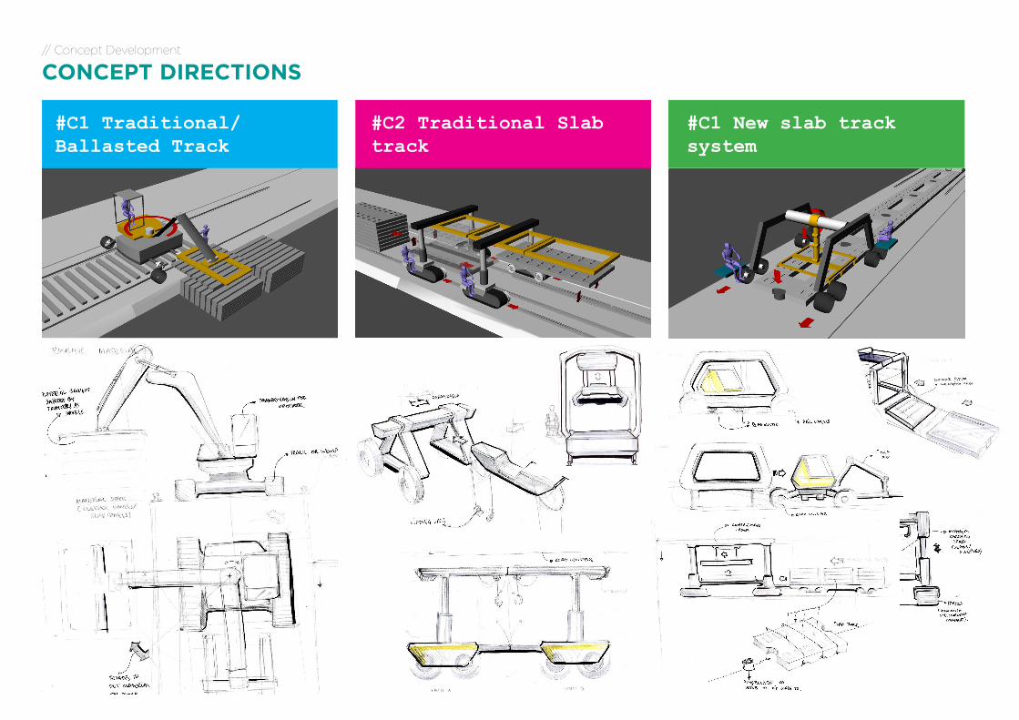
CONCEPT DIRECTIONS
#C1 Traditional/Ballasted Track
#C1 New slab track system
#C2 Traditional Slab track
45COMPACT RAILWAY TRACK LAYER - Future of railway construction in India | DEGREE PROJECT MA Advanced Product Design | Apurba Pawar | [email protected]
// Concept Development
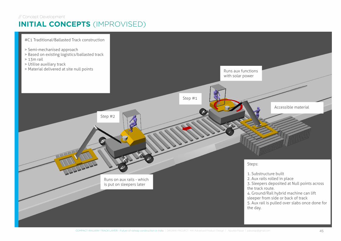
INITIAL CONCEPTS (IMPROVISED)
#C1 Traditional/Ballasted Track construction
> Semi-mechanised approach> Based on existing logistics/ballasted track> 13m rail> Utilise auxiliary track> Material delivered at site null points
Step #1
Step #2
Accessible material
Runs on aux rails - which is put on sleepers later
Runs aux functions with solar power
Steps:
1. Substructure built2. Aux rails rolled in place3. Sleepers deposited at Null points across the track route.4. Ground/Rail hybrid machine can lift sleeper from side or back of track5. Aux rail is pulled over slabs once done for the day.
46
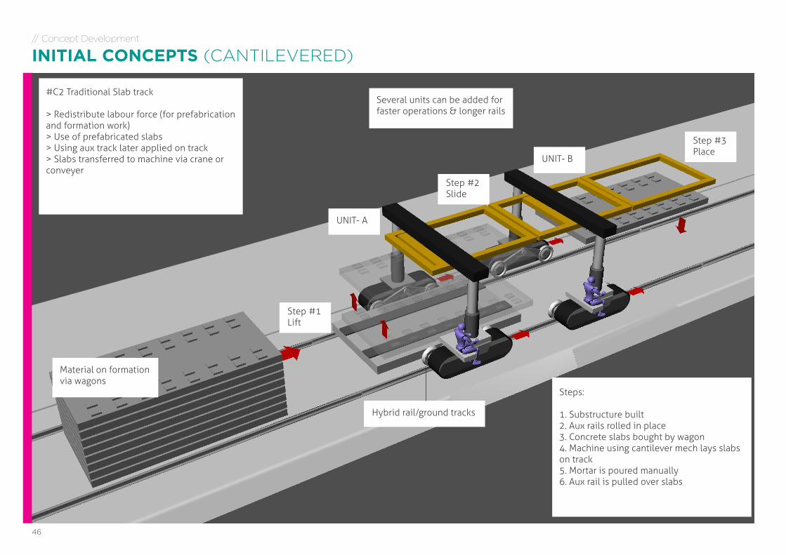
#C2 Traditional Slab track
> Redistribute labour force (for prefabrication and formation work)> Use of prefabricated slabs> Using aux track later applied on track> Slabs transferred to machine via crane or conveyer
Step #1Lift
Material on formation via wagons
Hybrid rail/ground tracks
Several units can be added for faster operations & longer rails
UNIT- A
UNIT- B
Step #2Slide
Step #3Place
Steps:
1. Substructure built2. Aux rails rolled in place3. Concrete slabs bought by wagon4. Machine using cantilever mech lays slabs on track5. Mortar is poured manually6. Aux rail is pulled over slabs
// Concept Development
INITIAL CONCEPTS (CANTILEVERED)
47COMPACT RAILWAY TRACK LAYER - Future of railway construction in India | DEGREE PROJECT MA Advanced Product Design | Apurba Pawar | [email protected]
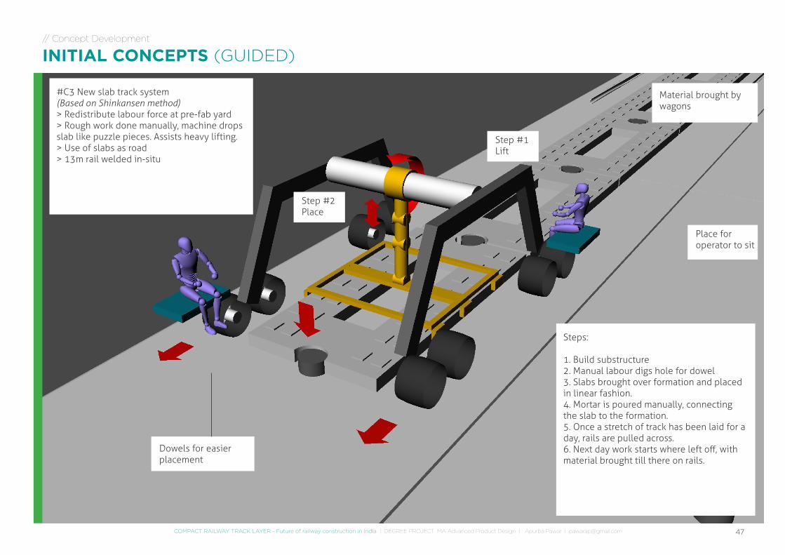
#C3 New slab track system(Based on Shinkansen method)> Redistribute labour force at pre-fab yard> Rough work done manually, machine drops slab like puzzle pieces. Assists heavy lifting.> Use of slabs as road> 13m rail welded in-situ
Step #1Lift
Material brought by wagons
Dowels for easier placement
Step #2Place
Place for operator to sit
Steps:
1. Build substructure2. Manual labour digs hole for dowel3. Slabs brought over formation and placed in linear fashion.4. Mortar is poured manually, connecting the slab to the formation.5. Once a stretch of track has been laid for a day, rails are pulled across.6. Next day work starts where left off, with material brought till there on rails.
// Concept Development
INITIAL CONCEPTS (GUIDED)
48
// Concept Development
CONCEPT DIRECTION EVALUATION
#C1 Traditional/Ballasted Track construction
> Semi-mechanised approach> Based on existing logistics/ballasted track> 13m rail> Utilise auxiliary track> Material delivered at site nts
Steps:
1. Substructure built2. Aux rails rolled in place3. Sleepers deposited at Null points across the track route.4. Ground/Rail hybrid machine can lift sleeper from side or back of track5. Aux rail is pulled over slab
#C1 New slab track system(Based on Shinkansen method)> Redistribute labour force at pre-fab yard> Rough work done manually, machine drops slab like puzzle pieces. Assists heavy lifting.> Use of slabs as road> 13m rail welded in-situ
Steps:
1. Build substructure2. Manual labour digs hole for dowel3. Slabs brought over formation and placed in linear fashion.4. Mortar is poured manually, connecting the slab to the formation.5. Once a stretch of track has been laid for a day, rails are pulled across.
#C2 Traditional Slab track
> Redistribute labour force (for prefabrication and formation work)> Use of prefabricated slabs> Using aux track later applied on track> Slabs transferred to machine via crane or conveyer
Steps:
1. Substructure built2. Aux rails rolled in place3. Concrete slabs bought by wagon4. Machine using cantilever mech lays slabs on track5. Mortar is poured manually6. Aux rail is pulled over slabs
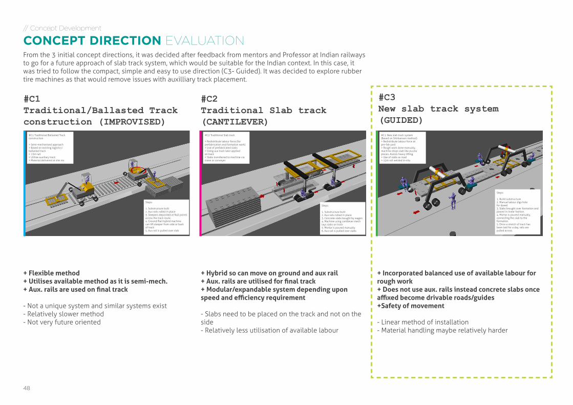
#C1Traditional/Ballasted Track construction (IMPROVISED)
#C3New slab track system(GUIDED)
#C2Traditional Slab track(CANTILEVER)
+ Flexible method+ Utilises available method as it is semi-mech.+ Aux. rails are used on final track
- Not a unique system and similar systems exist- Relatively slower method- Not very future oriented
+ Hybrid so can move on ground and aux rail+ Aux. rails are utilised for final track+ Modular/expandable system depending upon speed and efficiency requirement
- Slabs need to be placed on the track and not on the side- Relatively less utilisation of available labour
+ Incorporated balanced use of available labour for rough work+ Does not use aux. rails instead concrete slabs once affixed become drivable roads/guides+Safety of movement
- Linear method of installation- Material handling maybe relatively harder
From the 3 initial concept directions, it was decided after feedback from mentors and Professor at Indian railways to go for a future approach of slab track system, which would be suitable for the Indian context. In this case, it was tried to follow the compact, simple and easy to use direction (C3- Guided). It was decided to explore rubber tire machines as that would remove issues with auxilliary track placement.
49COMPACT RAILWAY TRACK LAYER - Future of railway construction in India | DEGREE PROJECT MA Advanced Product Design | Apurba Pawar | [email protected]
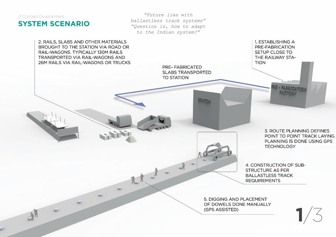
“Future lies with ballastless track systems” “Question is, how to adapt
to the Indian system?”
1/3
// Concept Development
SYSTEM SCENARIO
50
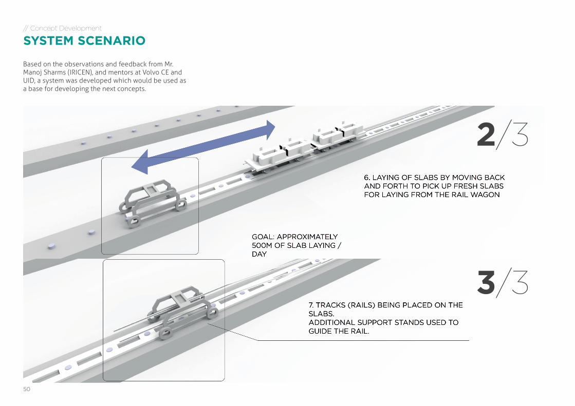
Based on the observations and feedback from Mr. Manoj Sharms (IRICEN), and mentors at Volvo CE and UID, a system was developed which would be used as a base for developing the next concepts.
// Concept Development
SYSTEM SCENARIO
2/3
3/3
51COMPACT RAILWAY TRACK LAYER - Future of railway construction in India | DEGREE PROJECT MA Advanced Product Design | Apurba Pawar | [email protected]
// Concept Development
DESIGN LANGUAGE CORE VALUES | COLOUR
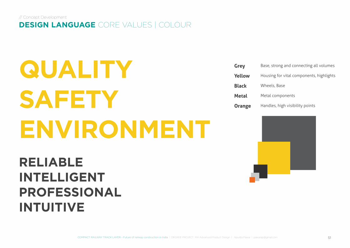
QUALITYSAFETYENVIRONMENTRELIABLEINTELLIGENTPROFESSIONALINTUITIVE
Grey
Yellow
Black
Metal
Orange
Base, strong and connecting all volumes
Housing for vital components, highlights
Wheels, Base
Metal components
Handles, high visibility points
52
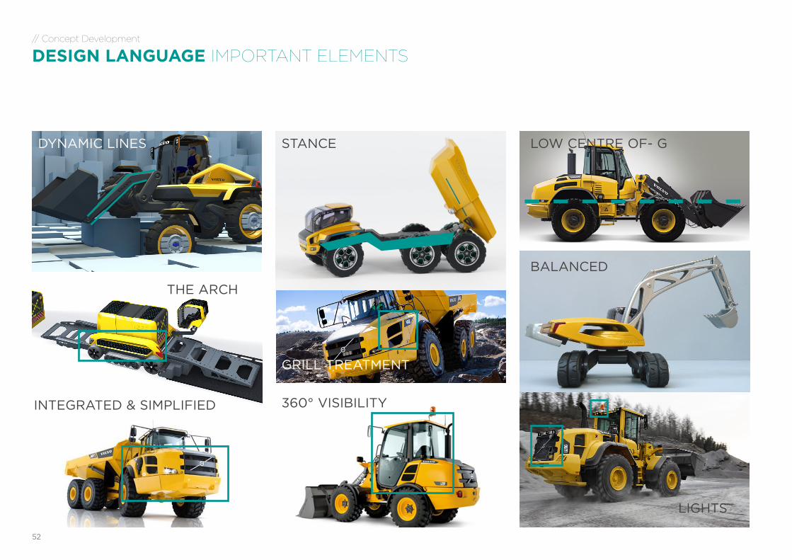
// Concept Development
DESIGN LANGUAGE IMPORTANT ELEMENTS
STANCE
BALANCED
GRILL TREATMENT
THE ARCH
DYNAMIC LINES LOW CENTRE OF- G
360° VISIBILITYINTEGRATED & SIMPLIFIED
LIGHTS
53COMPACT RAILWAY TRACK LAYER - Future of railway construction in India | DEGREE PROJECT MA Advanced Product Design | Apurba Pawar | [email protected]
LIGHTS
// Concept Development
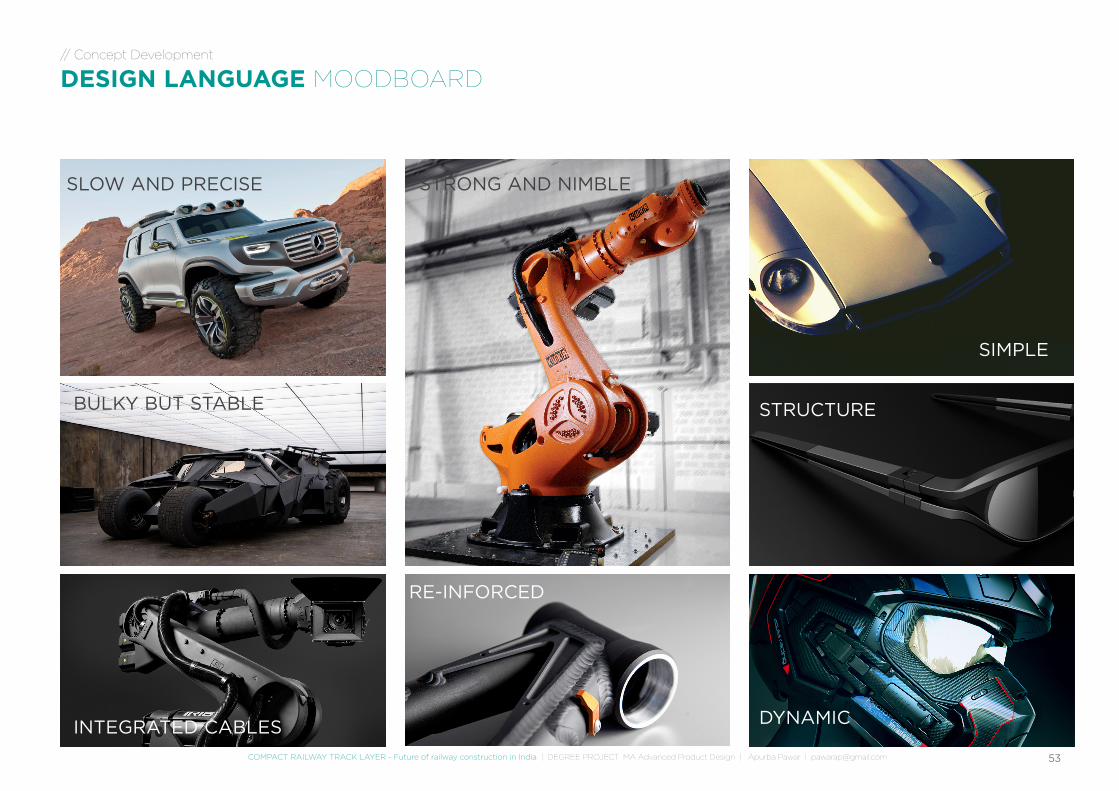
DESIGN LANGUAGE MOODBOARD
BULKY BUT STABLE
DYNAMIC
STRONG AND NIMBLE
INTEGRATED CABLES
RE-INFORCED
SLOW AND PRECISE
STRUCTURE
SIMPLE
// Research
WORK FLOW
INDIA
Yo
54
// Concept Development
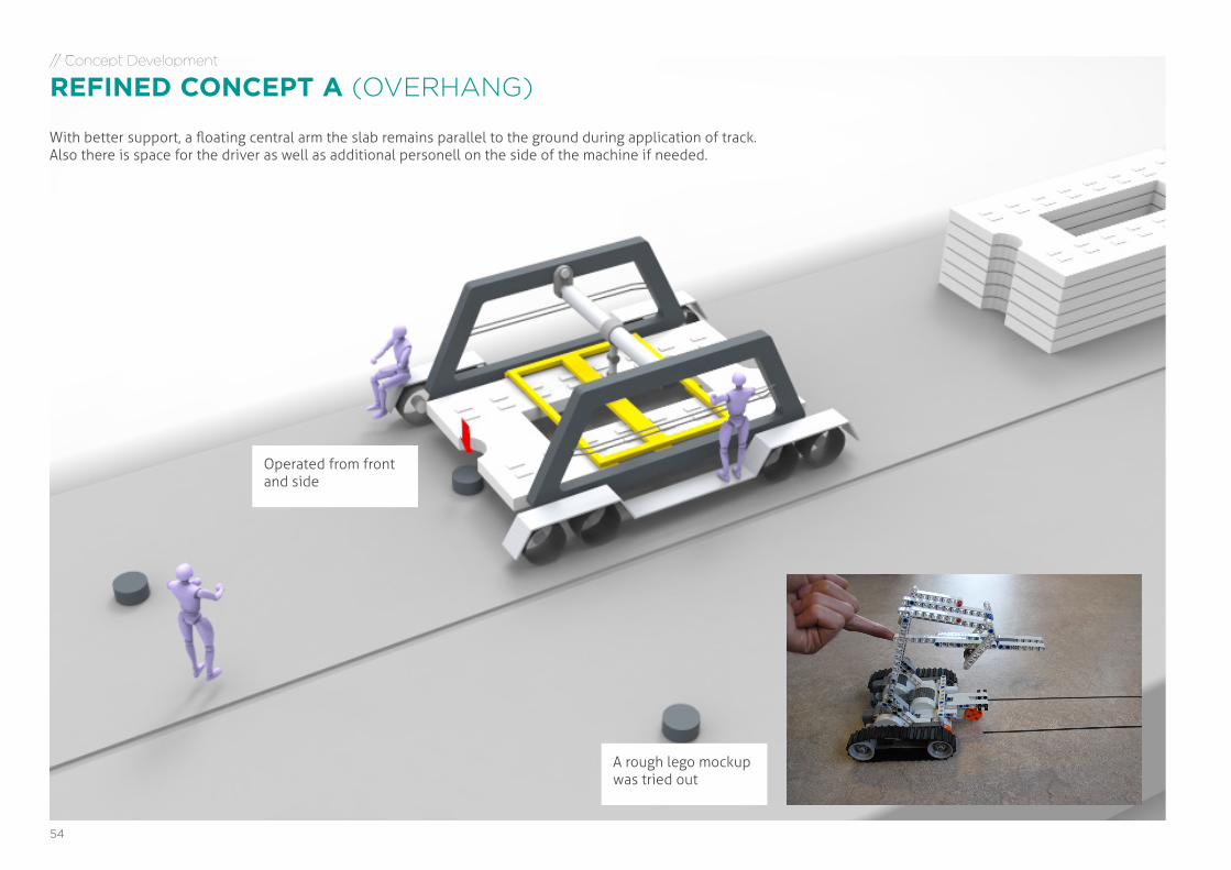
REFINED CONCEPT A (OVERHANG)
Operated from front and side
A rough lego mockup was tried out
With better support, a floating central arm the slab remains parallel to the ground during application of track. Also there is space for the driver as well as additional personell on the side of the machine if needed.
55COMPACT RAILWAY TRACK LAYER - Future of railway construction in India | DEGREE PROJECT MA Advanced Product Design | Apurba Pawar | [email protected]
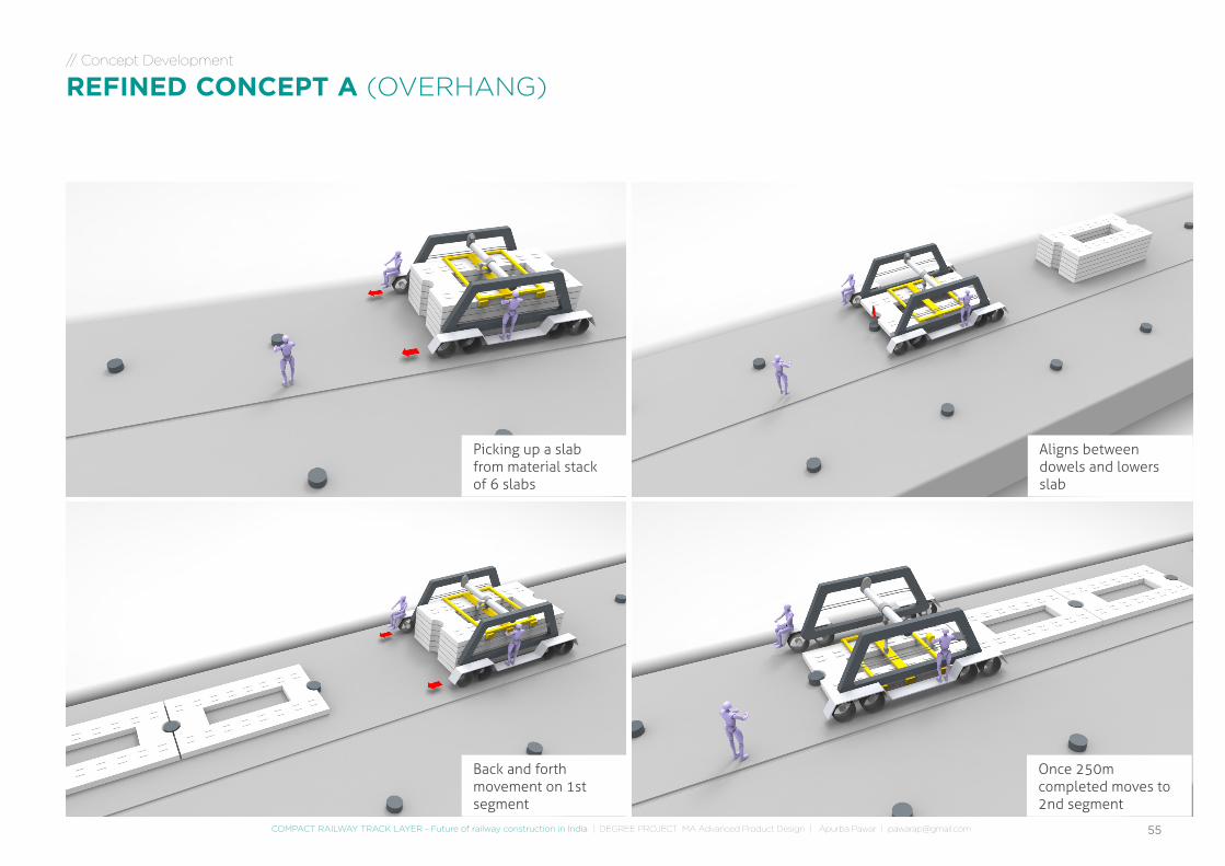
Picking up a slab from material stack of 6 slabs
Aligns between dowels and lowers slab
Back and forth movement on 1st segment
Once 250m completed moves to 2nd segment
// Concept Development
REFINED CONCEPT A (OVERHANG)
// Research
WORK FLOW
INDIA
Yo
56
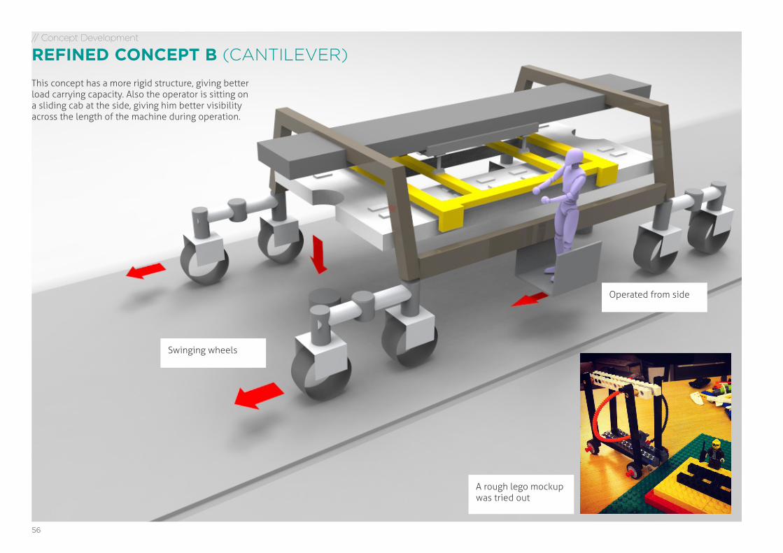
// Concept Development
REFINED CONCEPT B (CANTILEVER)
Operated from side
A rough lego mockup was tried out
Swinging wheels
This concept has a more rigid structure, giving better load carrying capacity. Also the operator is sitting on a sliding cab at the side, giving him better visibility across the length of the machine during operation.
57COMPACT RAILWAY TRACK LAYER - Future of railway construction in India | DEGREE PROJECT MA Advanced Product Design | Apurba Pawar | [email protected]
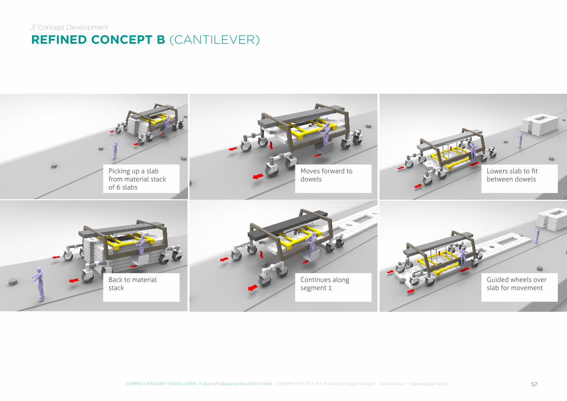
// Concept Development
REFINED CONCEPT B (CANTILEVER)
Picking up a slab from material stack of 6 slabs
Moves forward to dowels
Lowers slab to fit between dowels
Back to material stack
Continues along segment 1
Guided wheels over slab for movement
// Research
WORK FLOW
INDIA
Yo
58
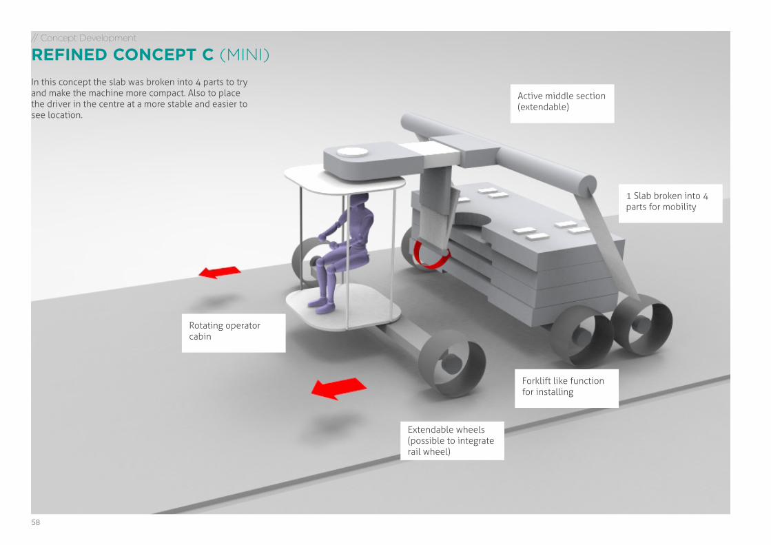
// Concept Development
REFINED CONCEPT C (MINI)
Rotating operator cabin
Forklift like function for installing
1 Slab broken into 4 parts for mobility
Active middle section (extendable)
Extendable wheels (possible to integrate rail wheel)
In this concept the slab was broken into 4 parts to try and make the machine more compact. Also to place the driver in the centre at a more stable and easier to see location.
59COMPACT RAILWAY TRACK LAYER - Future of railway construction in India | DEGREE PROJECT MA Advanced Product Design | Apurba Pawar | [email protected]
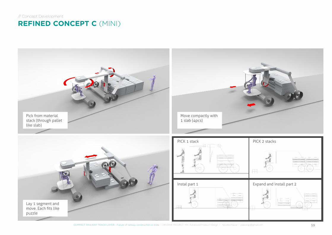
// Concept Development
REFINED CONCEPT C (MINI)
Pick from material stack (through pallet like slab)
Move compactly with 1 slab (4pcs)
Lay 1 segment and move. Each fits like puzzle
PICK 1 stack PICK 2 stacks
Instal part 1 Expand and install part 2
60
#REFINED A(OVERHANG)
#REFINED C(MINI)
#REFINED B(CANTILEVER)
// Concept Development
REFINED CONCEPT C
Rotating operator cabin
Forklift like function for installing
1 Slab broken into 4 parts for mobility
Active middle section (extendable)
Extendable wheels (possible to integrate rail wheel)
// Concept Development
REFINED CONCEPT B
Operated from front and side
A rough lego mockup was tried out
// Concept Development
REFINED CONCEPT A
Operated from front and side
A rough lego mockup was tried out
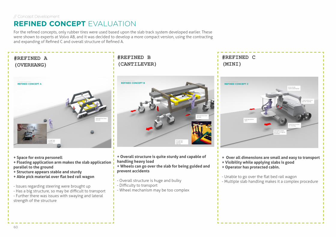
+ Space for extra personell+ Floating application arm makes the slab application parallel to the ground+ Structure appears stable and sturdy+ Able pick material over flat bed rail wagon
- Issues regarding steering were brought up- Has a big structure, so may be difficult to transport- Further there was issues with swaying and lateral strength of the structure
+ Overall structure is quite sturdy and capable of handling heavy load+ Wheels can go over the slab for being guided and prevent accidents
- Overall structure is huge and bulky- Difficulty to transport- Wheel mechanism may be too complex
+ Over all dimensions are small and easy to transport+ Visibility while applying slabs is good+ Operator has protected cabin.
- Unable to go over the flat bed rail wagon- Multiple slab handling makes it a complex procedure
// Concept Development
REFINED CONCEPT EVALUATIONFor the refined concepts, only rubber tires were used based upon the slab track system developed earlier. These were shown to experts at Volvo AB, and it was decided to develop a more compact version, using the contracting and expanding of Refined C and overall structure of Refined A.
61COMPACT RAILWAY TRACK LAYER - Future of railway construction in India | DEGREE PROJECT MA Advanced Product Design | Apurba Pawar | [email protected]
// Concept Development
FINAL CONCEPT
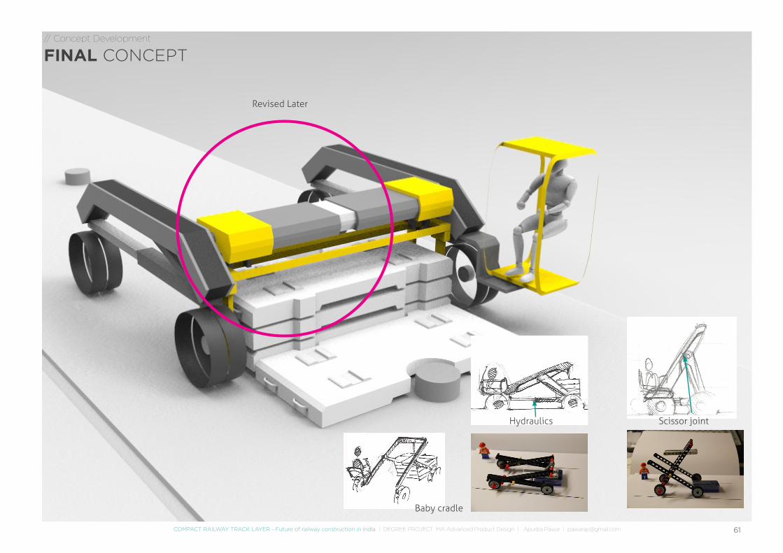
Hydraulics Scissor joint
Baby cradle
Revised Later
62
// Concept Development
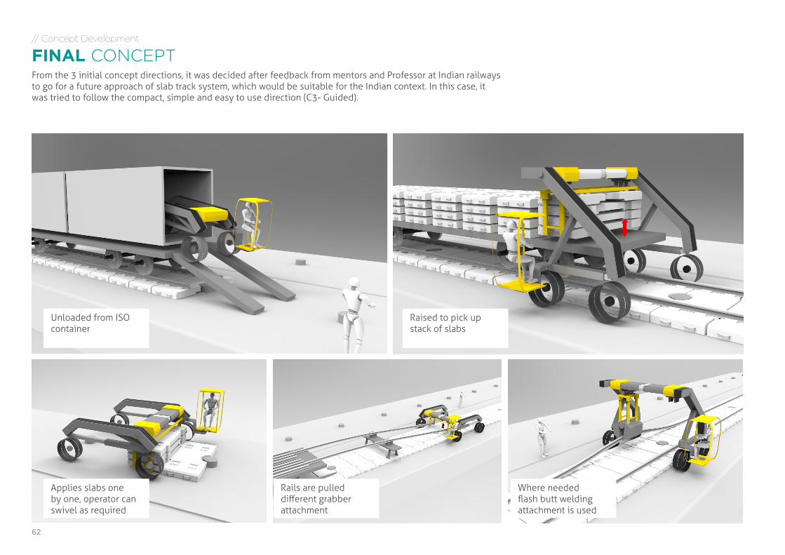
FINAL CONCEPTFrom the 3 initial concept directions, it was decided after feedback from mentors and Professor at Indian railways to go for a future approach of slab track system, which would be suitable for the Indian context. In this case, it was tried to follow the compact, simple and easy to use direction (C3- Guided).
Unloaded from ISO container
Raised to pick up stack of slabs
Applies slabs one by one, operator can swivel as required
Rails are pulled different grabber attachment
Where needed flash butt welding attachment is used
63COMPACT RAILWAY TRACK LAYER - Future of railway construction in India | DEGREE PROJECT MA Advanced Product Design | Apurba Pawar | [email protected]
// Concept Development
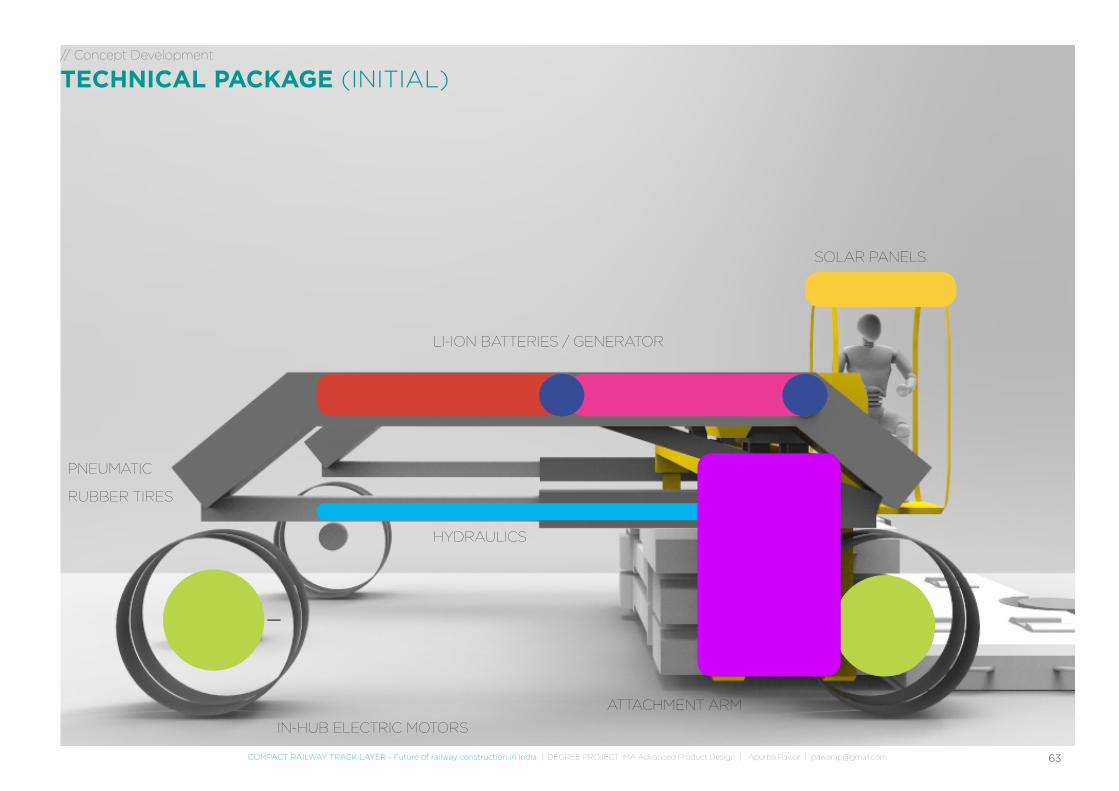
TECHNICAL PACKAGE (INITIAL)
IN-HUB ELECTRIC MOTORS
HYDRAULICS
LI-ION BATTERIES / GENERATOR
SOLAR PANELS
ATTACHMENT ARM
PNEUMATIC
RUBBER TIRES
DETAILING AND DEVELOPMENT
65COMPACT RAILWAY TRACK LAYER - Future of railway construction in India | DEGREE PROJECT MA Advanced Product Design | Apurba Pawar | [email protected]
// Detailing & Development
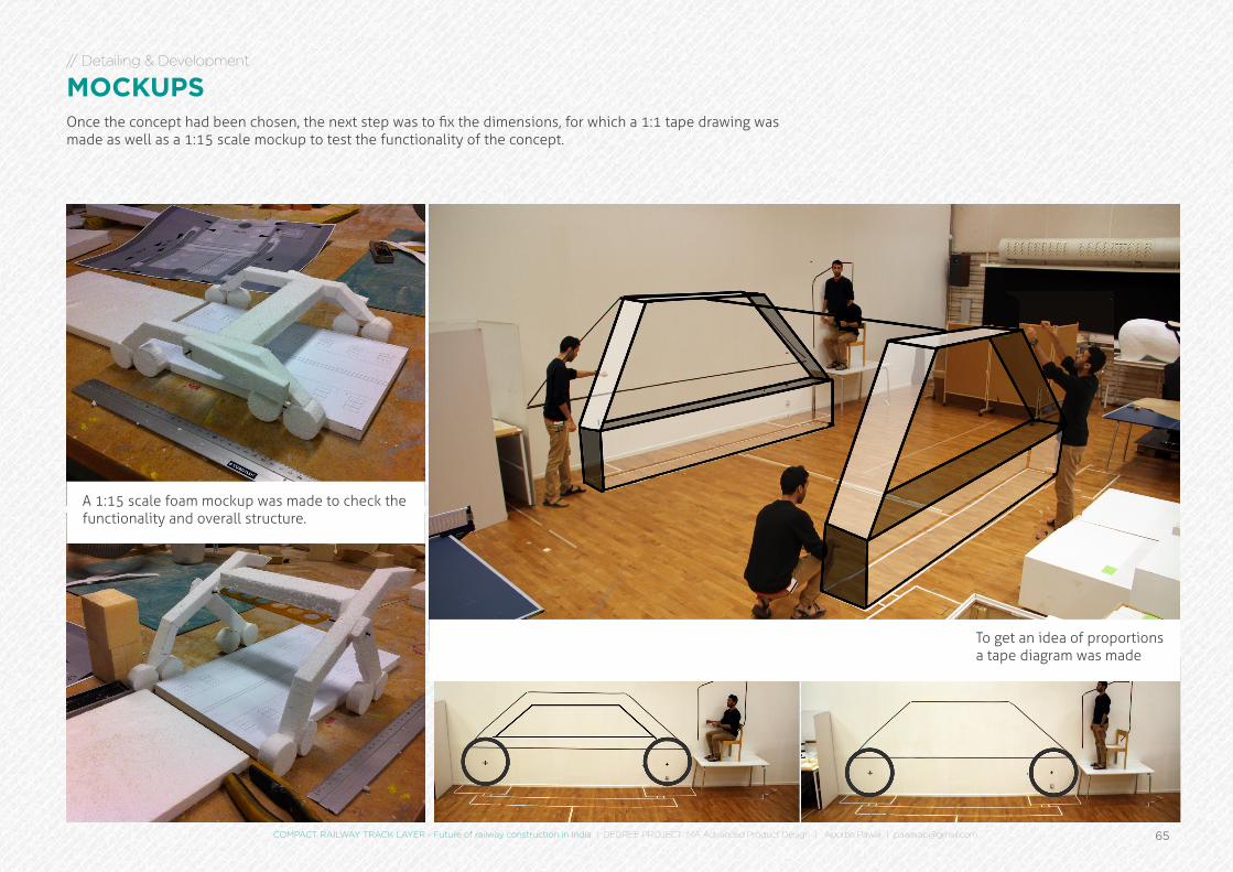
MOCKUPSOnce the concept had been chosen, the next step was to fix the dimensions, for which a 1:1 tape drawing was made as well as a 1:15 scale mockup to test the functionality of the concept.
To get an idea of proportions a tape diagram was made
A 1:15 scale foam mockup was made to check the functionality and overall structure.
66
// Detailing & Development
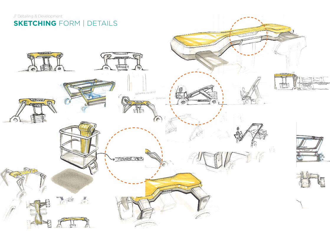
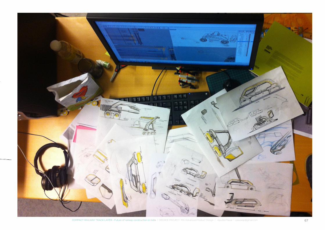
SKETCHING FORM | DETAILS
67COMPACT RAILWAY TRACK LAYER - Future of railway construction in India | DEGREE PROJECT MA Advanced Product Design | Apurba Pawar | [email protected]
68
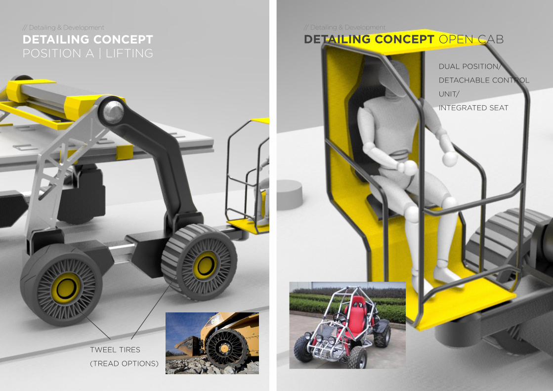
// Detailing & Development
DETAILING CONCEPT OPEN CAB
DUAL POSITION/
DETACHABLE CONTROL
UNIT/
INTEGRATED SEAT
// Detailing & Development
DETAILING CONCEPT POSITION A | LIFTING
TWEEL TIRES
(TREAD OPTIONS)
69COMPACT RAILWAY TRACK LAYER - Future of railway construction in India | DEGREE PROJECT MA Advanced Product Design | Apurba Pawar | [email protected]
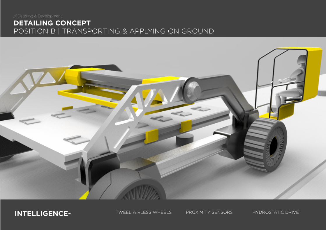
SLIDING BEAM
HYDROSTATIC DRIVEPROXIMITY SENSORSINTELLIGENCE- TWEEL AIRLESS WHEELS
// Detailing & Development
DETAILING CONCEPT POSITION B | TRANSPORTING & APPLYING ON GROUND
ROAD LIGHTS
CAST METAL STRUCTURE
SLIDING BEAM
CAST METAL STRUCTURE
70
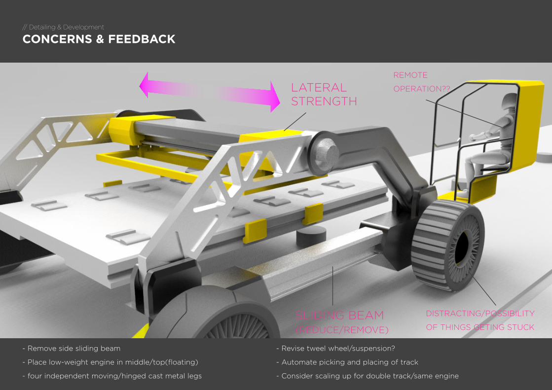
// Detailing & Development
CONCERNS & FEEDBACK
SLIDING BEAM(REDUCE/REMOVE)
DISTRACTING/POSSIBILITY
OF THINGS GETING STUCK
LATERAL STRENGTH
REMOTE
OPERATION??
- Remove side sliding beam
- Place low-weight engine in middle/top(floating)
- four independent moving/hinged cast metal legs
- Revise tweel wheel/suspension?
- Automate picking and placing of track
- Consider scaling up for double track/same engine
71COMPACT RAILWAY TRACK LAYER - Future of railway construction in India | DEGREE PROJECT MA Advanced Product Design | Apurba Pawar | [email protected]
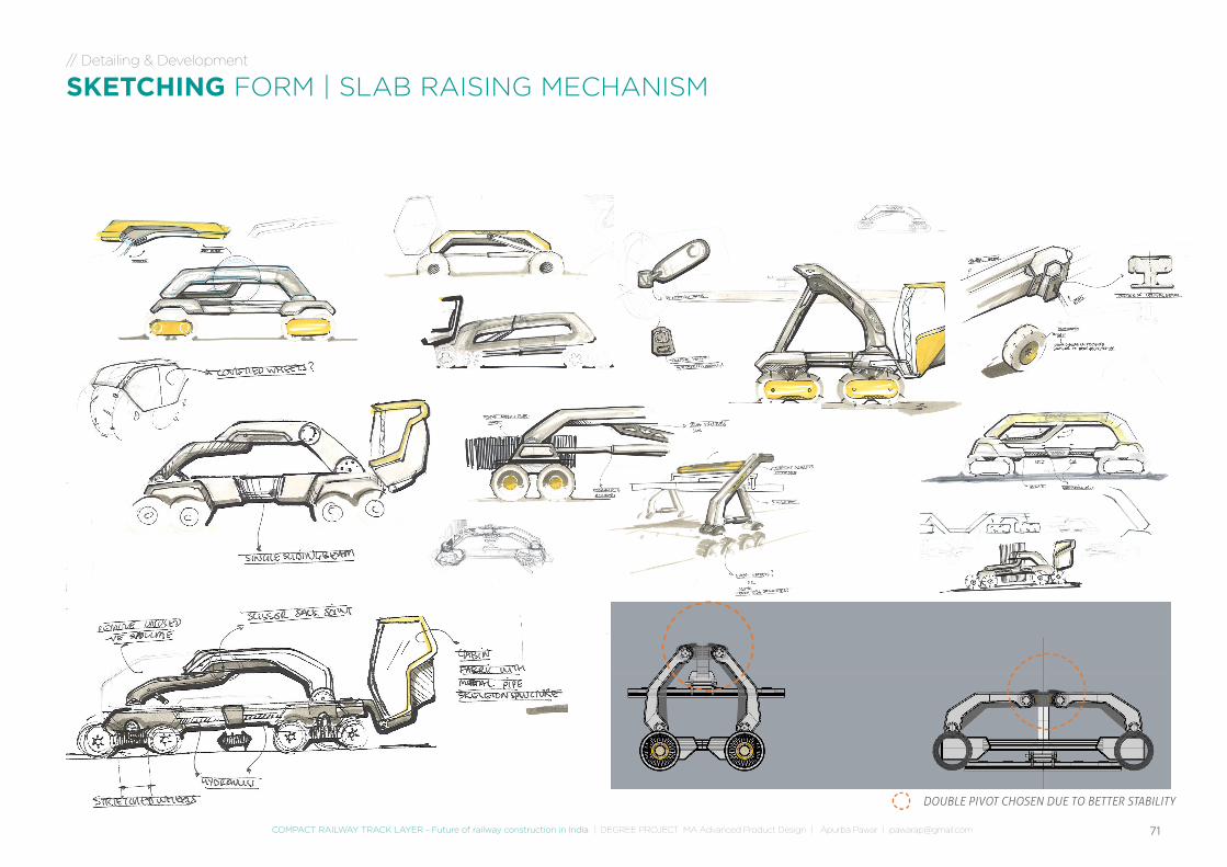
// Detailing & Development
SKETCHING FORM | SLAB RAISING MECHANISM
DOUBLE PIVOT CHOSEN DUE TO BETTER STABILITY
72
// Detailing & Development
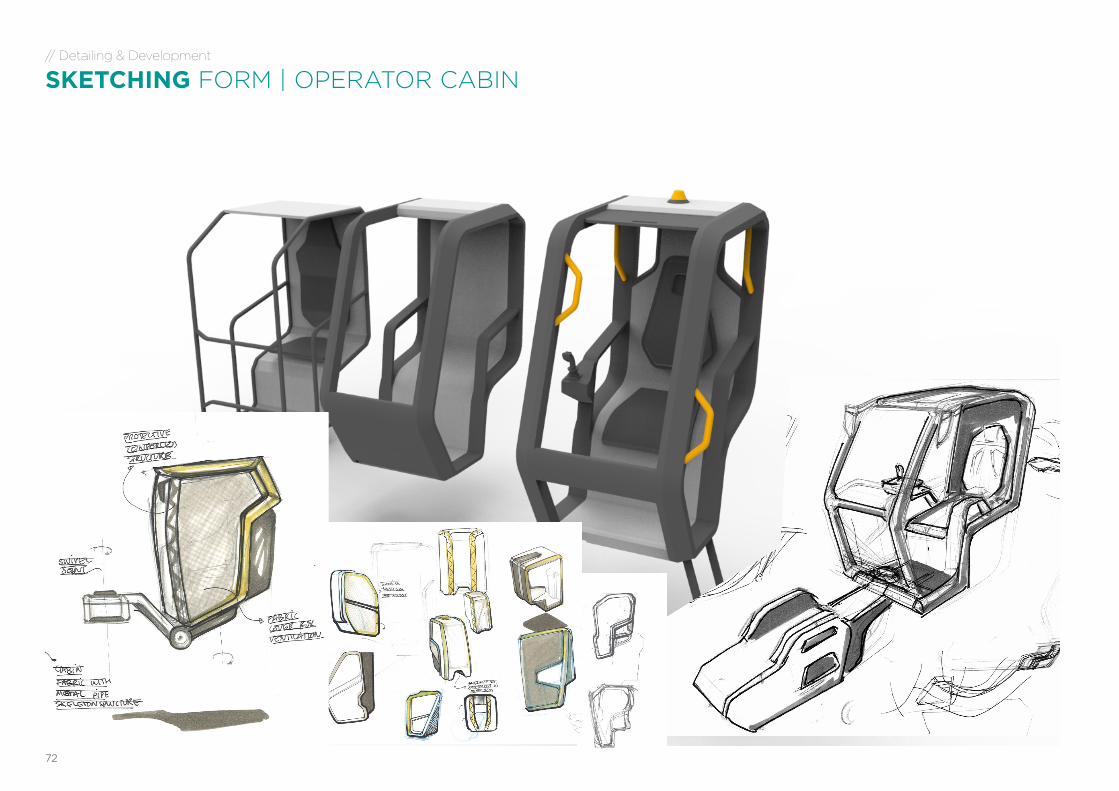
SKETCHING FORM | OPERATOR CABIN
73COMPACT RAILWAY TRACK LAYER - Future of railway construction in India | DEGREE PROJECT MA Advanced Product Design | Apurba Pawar | [email protected]
// Detailing & Development
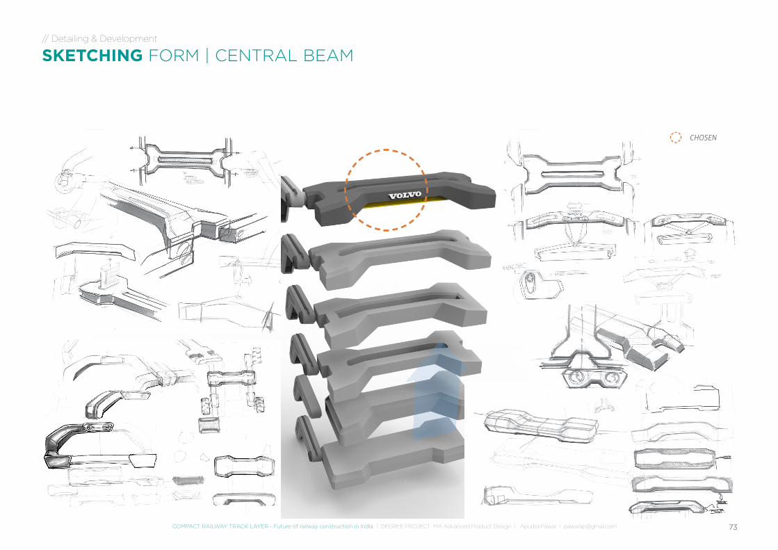
SKETCHING FORM | CENTRAL BEAM
CHOSEN
74
// Detailing & Development
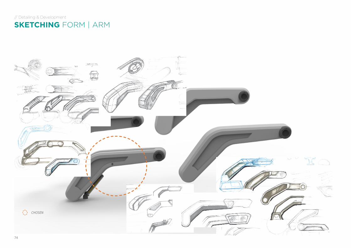
SKETCHING FORM | ARM
CHOSEN
75COMPACT RAILWAY TRACK LAYER - Future of railway construction in India | DEGREE PROJECT MA Advanced Product Design | Apurba Pawar | [email protected]
// Detailing & Development
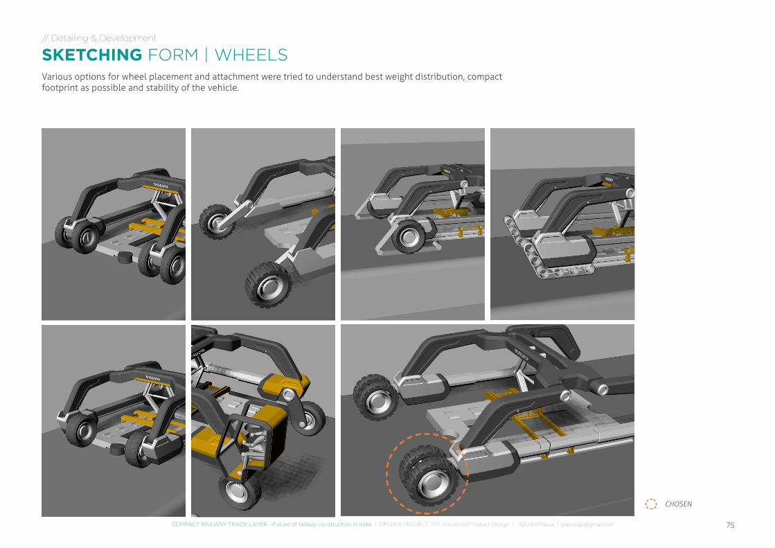
SKETCHING FORM | WHEELSVarious options for wheel placement and attachment were tried to understand best weight distribution, compact footprint as possible and stability of the vehicle.
CHOSEN
76
// Detailing & Development
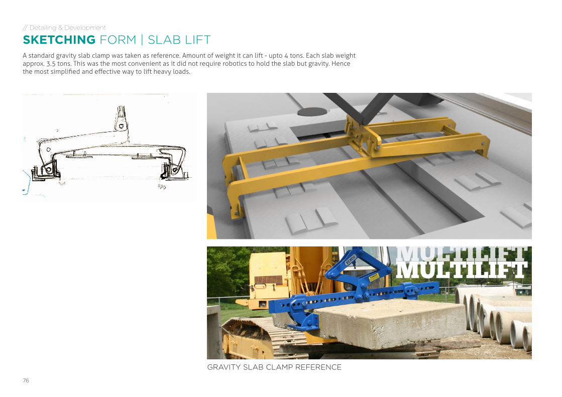
SKETCHING FORM | SLAB LIFTA standard gravity slab clamp was taken as reference. Amount of weight it can lift - upto 4 tons. Each slab weight approx. 3.5 tons. This was the most convenient as it did not require robotics to hold the slab but gravity. Hence the most simplified and effective way to lift heavy loads.
GRAVITY SLAB CLAMP REFERENCE
77COMPACT RAILWAY TRACK LAYER - Future of railway construction in India | DEGREE PROJECT MA Advanced Product Design | Apurba Pawar | [email protected]
// Detailing & Development
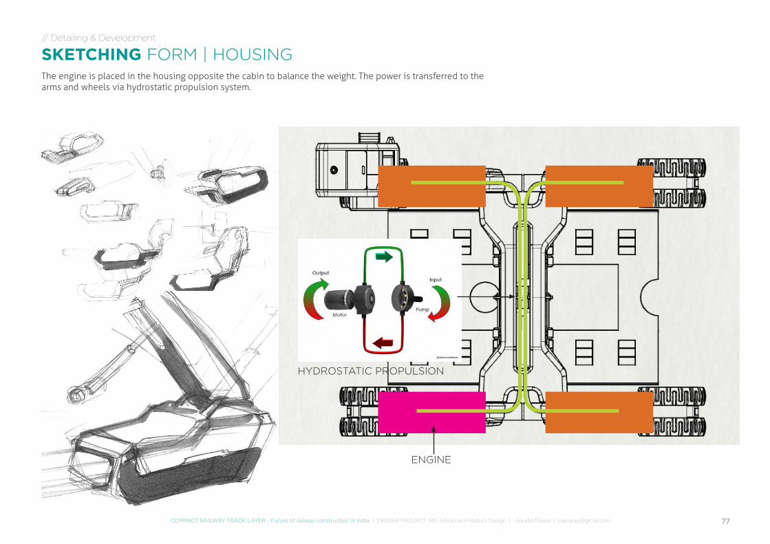
SKETCHING FORM | HOUSINGThe engine is placed in the housing opposite the cabin to balance the weight. The power is transferred to the arms and wheels via hydrostatic propulsion system.
HYDROSTATIC PROPULSION
ENGINE
78
// Detailing & Development
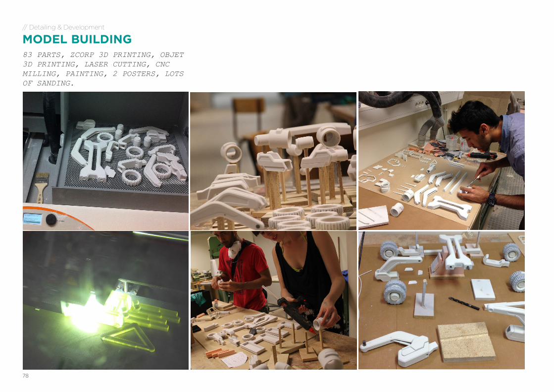
MODEL BUILDING83 PARTS, ZCORP 3D PRINTING, OBJET 3D PRINTING, LASER CUTTING, CNC MILLING, PAINTING, 2 POSTERS, LOTS OF SANDING.
79COMPACT RAILWAY TRACK LAYER - Future of railway construction in India | DEGREE PROJECT MA Advanced Product Design | Apurba Pawar | [email protected]
// Detailing & Development
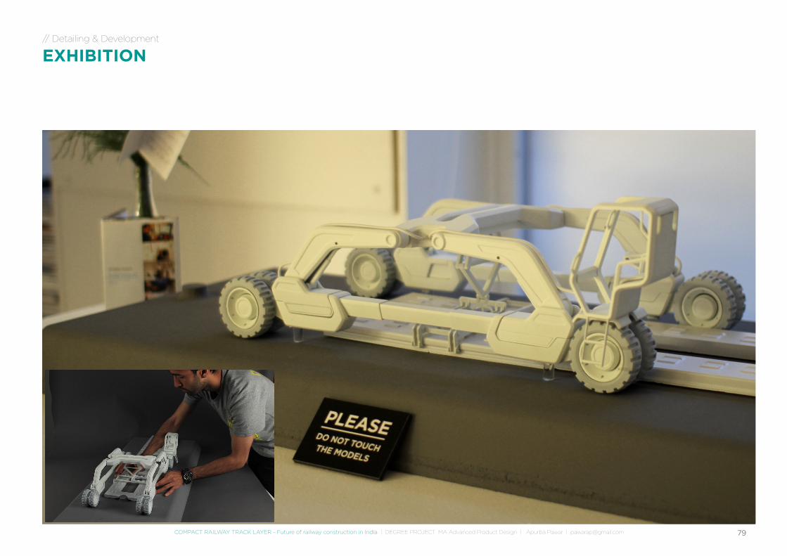
EXHIBITION
FINAL DESIGN
81COMPACT RAILWAY TRACK LAYER - Future of railway construction in India | DEGREE PROJECT MA Advanced Product Design | Apurba Pawar | [email protected]
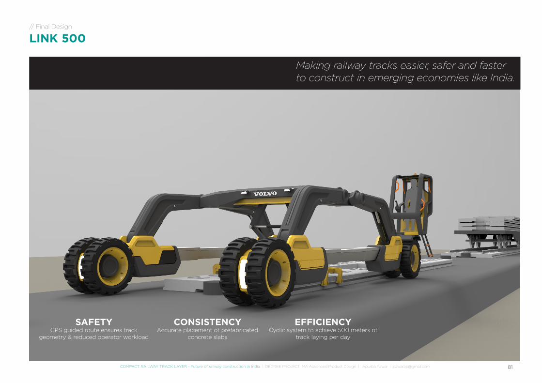
SAFETYGPS guided route ensures track
geometry & reduced operator workload
CONSISTENCYAccurate placement of prefabricated
concrete slabs
EFFICIENCYCyclic system to achieve 500 meters of
track laying per day
// Final Design
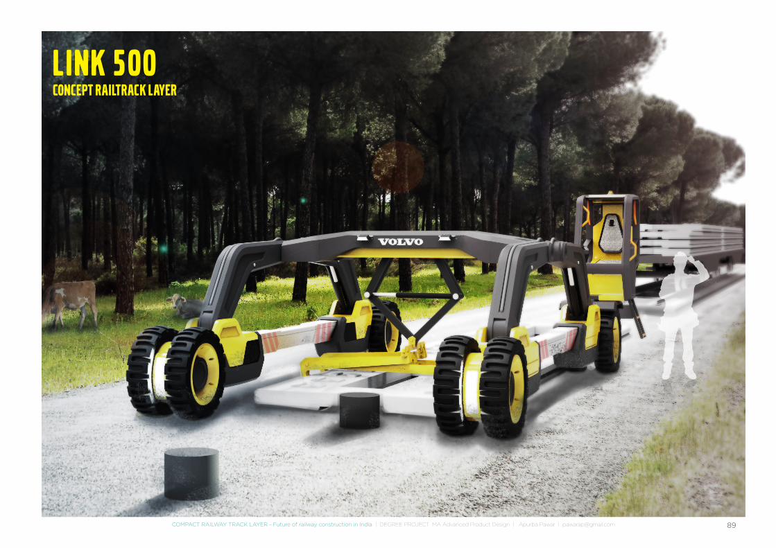
LINK 500
Making railway tracks easier, safer and faster to construct in emerging economies like India.
82
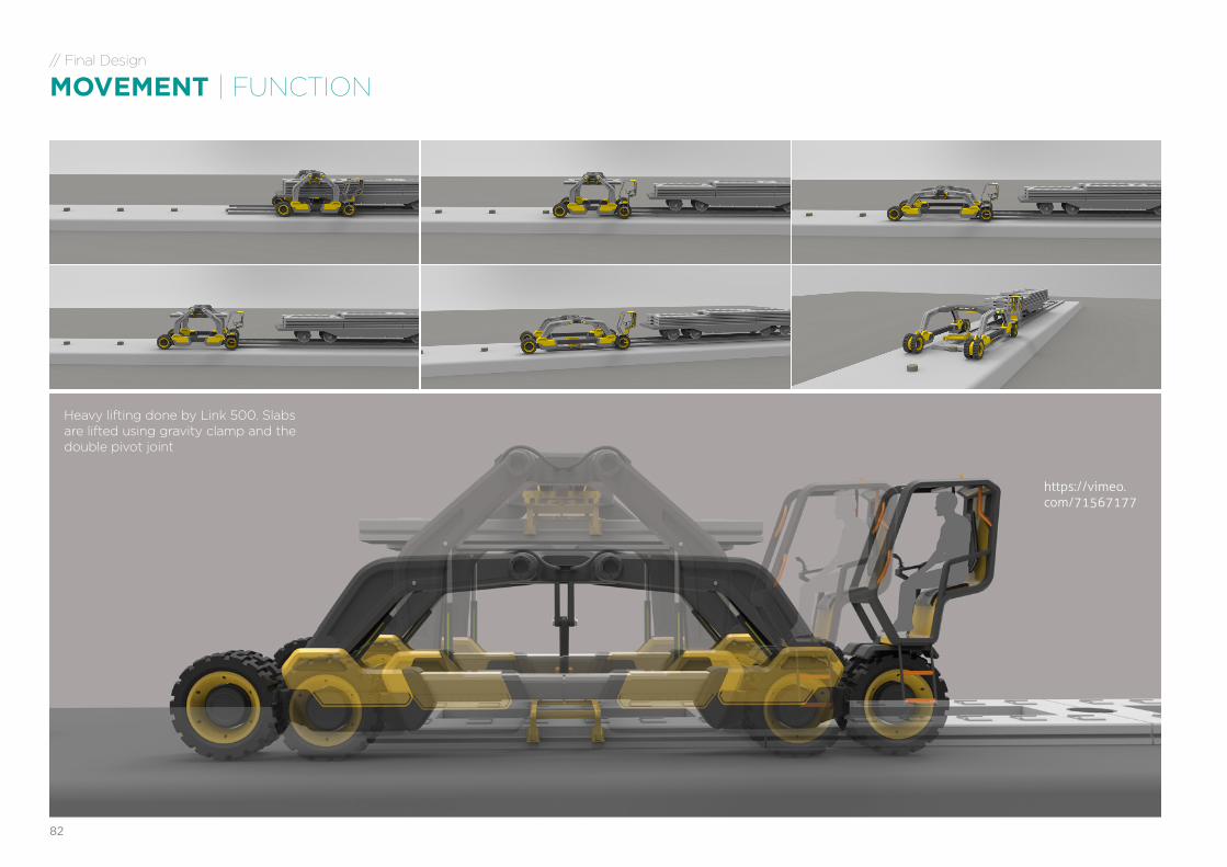
Heavy lifting done by Link 500. Slabs are lifted using gravity clamp and the double pivot joint
https://vimeo.com/71567177
// Final Design
MOVEMENT | FUNCTION
83COMPACT RAILWAY TRACK LAYER - Future of railway construction in India | DEGREE PROJECT MA Advanced Product Design | Apurba Pawar | [email protected]
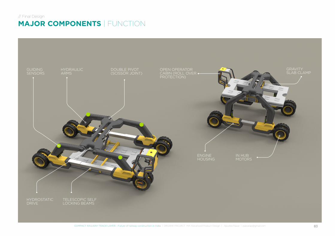
DOUBLE PIVOT (SCISSOR JOINT)
ENGINE HOUSING
IN HUB MOTORS
TELESCOPIC SELF LOCKING BEAMS
OPEN OPERATOR CABIN (ROLL OVER PROTECTION)
HYDRAULIC ARMS
HYDROSTATIC DRIVE
GRAVITY SLAB CLAMP
GUIDING SENSORS
// Final Design
MAJOR COMPONENTS | FUNCTION
84
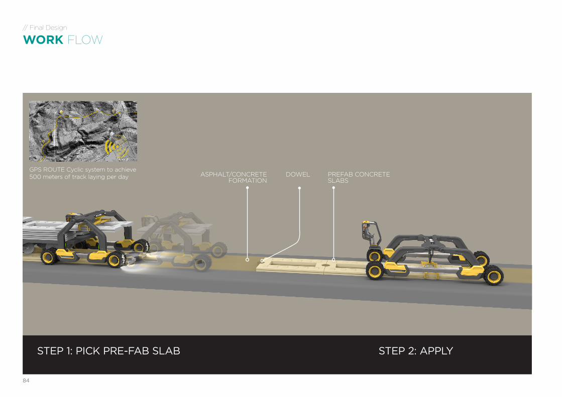
PREFAB CONCRETE SLABS
ASPHALT/CONCRETE FORMATION
DOWEL
STEP 2: APPLYSTEP 1: PICK PRE-FAB SLAB
GPS ROUTE Cyclic system to achieve 500 meters of track laying per day
// Final Design
WORK FLOW
85COMPACT RAILWAY TRACK LAYER - Future of railway construction in India | DEGREE PROJECT MA Advanced Product Design | Apurba Pawar | [email protected]
// Final Design
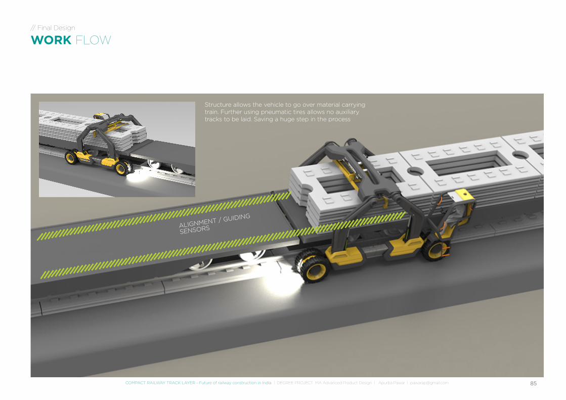
WORK FLOW
Structure allows the vehicle to go over material carrying train. Further using pneumatic tires allows no auxiliary tracks to be laid. Saving a huge step in the process
ALIGNMENT / GUIDING
SENSORS
86
// Final Design
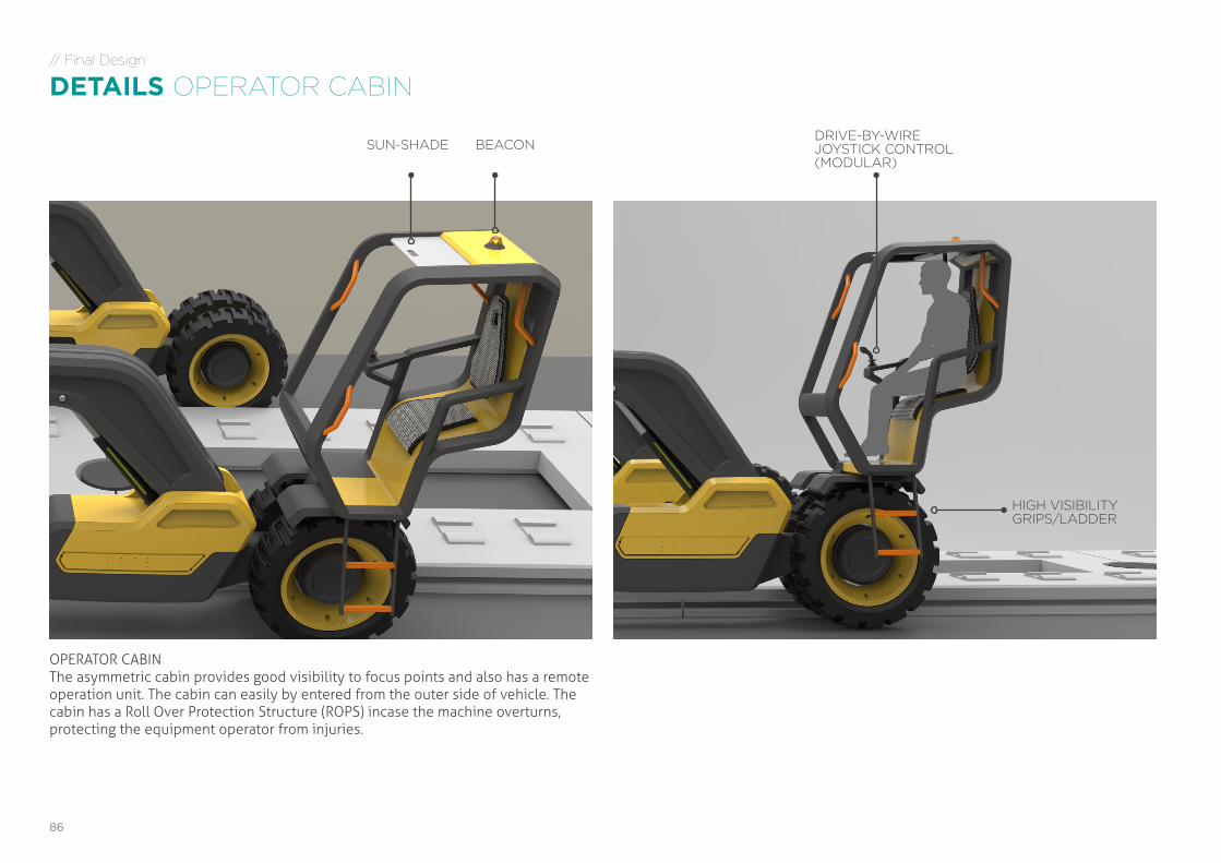
DETAILS OPERATOR CABIN
OPERATOR CABINThe asymmetric cabin provides good visibility to focus points and also has a remote operation unit. The cabin can easily by entered from the outer side of vehicle. The cabin has a Roll Over Protection Structure (ROPS) incase the machine overturns, protecting the equipment operator from injuries.
BEACON
HIGH VISIBILITY GRIPS/LADDER
DRIVE-BY-WIREJOYSTICK CONTROL(MODULAR)
SUN-SHADE
87COMPACT RAILWAY TRACK LAYER - Future of railway construction in India | DEGREE PROJECT MA Advanced Product Design | Apurba Pawar | [email protected]
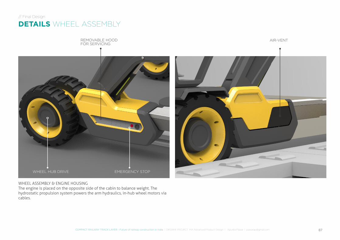
WHEEL ASSEMBLY & ENGINE HOUSINGThe engine is placed on the opposite side of the cabin to balance weight. The hydrostatic propulsion system powers the arm hydraulics, in-hub wheel motors via cables.
AIR-VENT
EMERGENCY STOPWHEEL HUB DRIVE
REMOVABLE HOOD FOR SERVICING
// Final Design
DETAILS WHEEL ASSEMBLY
88
426
0 m
m
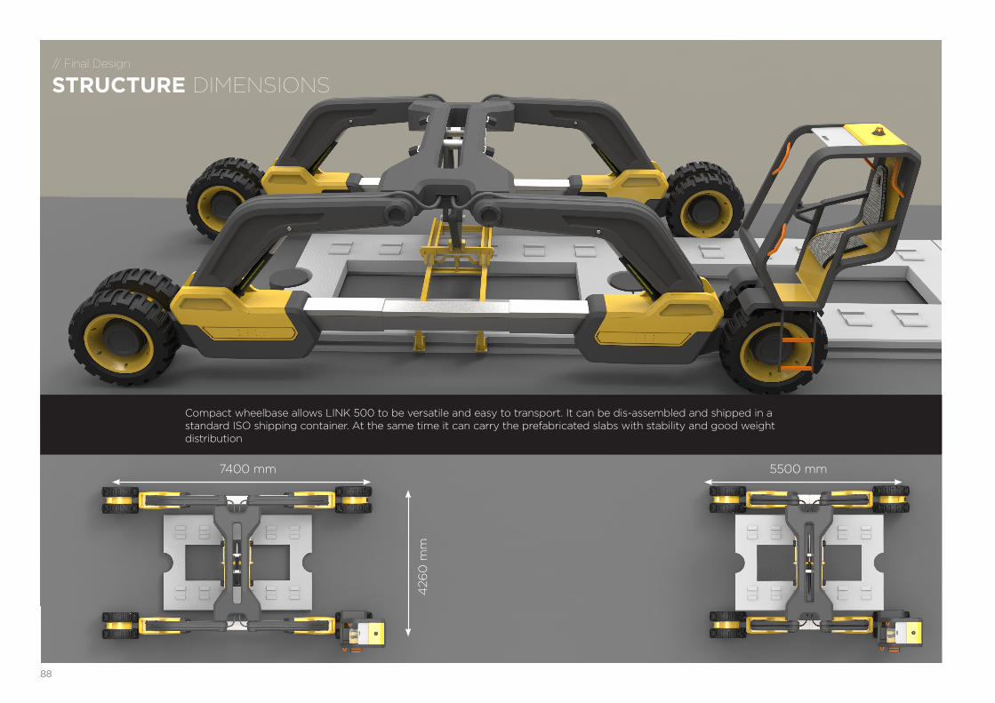
5500 mm7400 mm
Compact wheelbase allows LINK 500 to be versatile and easy to transport. It can be dis-assembled and shipped in a standard ISO shipping container. At the same time it can carry the prefabricated slabs with stability and good weight distribution
// Final Design
STRUCTURE DIMENSIONS
89COMPACT RAILWAY TRACK LAYER - Future of railway construction in India | DEGREE PROJECT MA Advanced Product Design | Apurba Pawar | [email protected]
LINK 500CONCEPT RAILTRACK LAYER

REFLECTIONS
91COMPACT RAILWAY TRACK LAYER - Future of railway construction in India | DEGREE PROJECT MA Advanced Product Design | Apurba Pawar | [email protected]
// Reflections
OVERALL
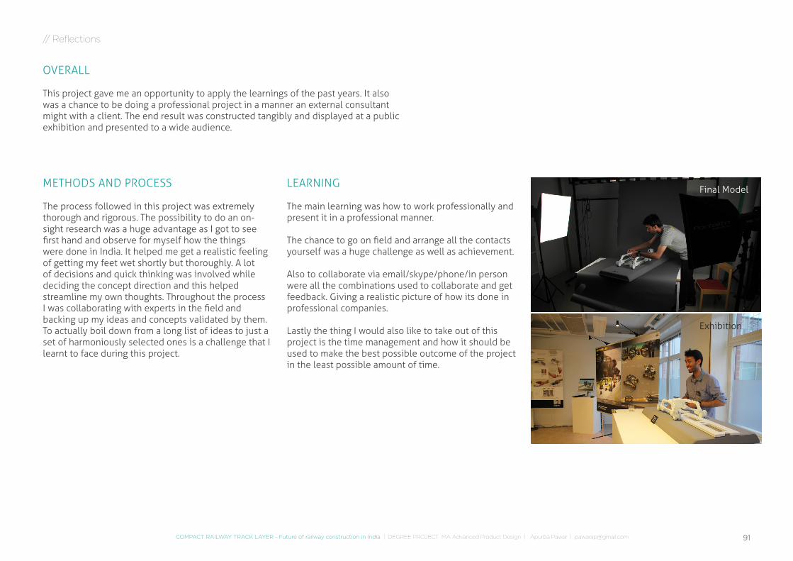
This project gave me an opportunity to apply the learnings of the past years. It also was a chance to be doing a professional project in a manner an external consultant might with a client. The end result was constructed tangibly and displayed at a public exhibition and presented to a wide audience.
METHODS AND PROCESS
The process followed in this project was extremely thorough and rigorous. The possibility to do an on-sight research was a huge advantage as I got to see first hand and observe for myself how the things were done in India. It helped me get a realistic feeling of getting my feet wet shortly but thoroughly. A lot of decisions and quick thinking was involved while deciding the concept direction and this helped streamline my own thoughts. Throughout the process I was collaborating with experts in the field and backing up my ideas and concepts validated by them. To actually boil down from a long list of ideas to just a set of harmoniously selected ones is a challenge that I learnt to face during this project.
LEARNING
The main learning was how to work professionally and present it in a professional manner.
The chance to go on field and arrange all the contacts yourself was a huge challenge as well as achievement.
Also to collaborate via email/skype/phone/in person were all the combinations used to collaborate and get feedback. Giving a realistic picture of how its done in professional companies.
Lastly the thing I would also like to take out of this project is the time management and how it should be used to make the best possible outcome of the project in the least possible amount of time.
Exhibition
Final Model

APPENDIX
93COMPACT RAILWAY TRACK LAYER - Future of railway construction in India | DEGREE PROJECT MA Advanced Product Design | Apurba Pawar | [email protected]
// Appendix
REFERENCES
PAPERS & WEBSITES
- Population Census India: www.census2011.co.in/census/state/delhi.html- C. K. Prahalad (2002): Strategies for the Bottom of the Pyramid: India as a Source of Innovations, Reflections, Volume 3, Number 4.- World Bank: www.worldbank.org/en/country/india- India Brand Equity Foundation: www.ibef.org/download/Construction_Equipment_10708.pdf- Indian Railways: http://www.indianrailways.gov.in/railwayboard/view_section.jsp?lang=0&id=0,1- Track (rail transport): http://en.wikipedia.org/wiki/Track_(rail_transport)- Track types: www.britpave.org.uk/RailWhyBuild.ink[1] Indian Railways: http://www.indianrailways.gov.in/railwayboard/view_section.jsp?lang=0&id=0,1[2] Track (rail transport): http://en.wikipedia.org/wiki/Track_(rail_transport)[3] Track types: www.britpave.org.uk/RailWhyBuild.ink
IMAGES AND ICONS
- http://thenounproject.com/- http://bharathautos.com/truck-runs-on-railway-track-truckee-train.html- http://enr.construction.com/images2/2011/10/WEB10032011RAIL_Opener.jpg- (pg21) Russian Track layer: http://vytopna.hekttor.biz/rservice.php?akce=tisk&cisloclanku=2009030010
[4] Georgios Michas. Slab Track Systems for High-Speed Railways. Master Degree Project. Sweden. 201232. R. Schilder, D. Diederich. Installation Quality of Slab Track – A Decisive Factor for Maintenance. RTR Special. Austria. July 2007. 5. International Union of Railways UIC. High Speed Around the World Maps. UIC Lecture. Paris. 2010.
- www.irfca.org/faq/faq-pway.html- www.planete-tp.com- www.railway-technical.com/track.shtml- Ballastless Track (BLT) System , by Rajesh Agarwal, GM(Projects)/KRCL- 6. M. Arora, N. Khare. Presentation - Mechanised linking of track. India. April 2011.- www.plassertheurer.com/en/machines-systems/track-renewal-laying.html- www.harscorail.com/services/track-construction-NTC.aspx- www.remtech.info/Rebuilt_tl70.htm
94
1. rail track / railroad track / permanent wayThe track on a railway or railroad, also known as the permanent way, is the structure consisting of the rails, fasteners, railroad ties (sleepers, British English) and ballast (or slab track), plus the underlying subgrade.
2. slab track / ballastless trackA railway sleeper or railroad tie (in US usage) is a rectangular object used as a base for railroad tracks without underlying ballast as stabilising material.
3. pre·fab·ri·cateManufacture sections of (a building or piece of furniture) to enable quick or easy assembly on site: “prefabricated homes”.
4. as•phalt A mixture of dark bituminous pitch with sand or gravel, used for surfacing roads, flooring, roofing, etc.
5. railway sleeper / railroad tie A railway sleeper or railroad tie (in US usage) is a rectangular object used as a base for railroad tracks.
6. bal•last Heavy material, such as gravel, placed low in a vessel /construction to improve its stability.
// Appendix
GLOSSARY
7. dow•elA peg of wood, metal, or plastic without a distinct head, used for holding together components of a structure.
8. piv•otThe central point, pin, or shaft on which a mechanism turns or oscillate
9. subgradeIn transport engineering, subgrade is the native material underneath a constructed road
10. mor•tar A mixture of lime with cement, sand, and water, used in building to bond bricks or stones.
11. grout A mortar or paste for filling crevices, esp. the gaps between wall or floor tiles.
95COMPACT RAILWAY TRACK LAYER - Future of railway construction in India | DEGREE PROJECT MA Advanced Product Design | Apurba Pawar | [email protected]
1. What are the steps to lay tracks?
2. What is the speed of laying tracks?a. Kms/day?b. No. Of workers c. No. Oh hours
3. What is the pay rate per labourer?Ans: 250 dehadi – workers gets 200, contractor gets commission of 50.
4. For the construction process, what tasks are done –a. Manually? b. Assistance of machines?
5. Which part of the process is most –a. Difficult b. Expensivec. Time consuming
6. How has the track laying changed over time? (Past few yrs.?)
7. Are there any new technologies being adopted? a. By you?b. By others?
8. The process of track laying and tools used, is it standard? Or does it change from contractor to
contractor?
9. In comparison, how much skilled labour vs. Unskilled?
10. Which machine is the most important in the process?
11. How does the process change when there is a bridge/tunnel etc.?
12. How does the system work? - Setup base camp- Transport workers everyday- Etc.?
13. What are the responsibilities of a contractor? Who clears track as ok?
14. Raw materials? How are they sourced?
15. How does it work in remote ares? Transportation/electricity?
16. What happens when it rains? (protection?)
17. Do you have to train the workers? How do you recruit new ones?
18. What safety measures are in place?
19. How and from where do you get the machines from?
20. What are the different ways of laying tracks?
21. Track laying steps –- Machines- People- Time- Tough- Time consuming- Expensive
// Appendix
QUESTIONNAIRE
96
// Research
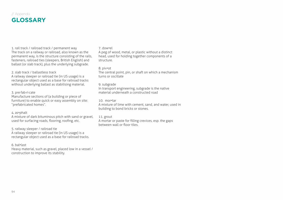
ADDITIONAL FIELD RESEARCH INSPIRATIONSite 04Bengaluru, IndiaMetro Track / Station (New)11th Feb 2013 (3 Days)
97COMPACT RAILWAY TRACK LAYER - Future of railway construction in India | DEGREE PROJECT MA Advanced Product Design | Apurba Pawar | [email protected]
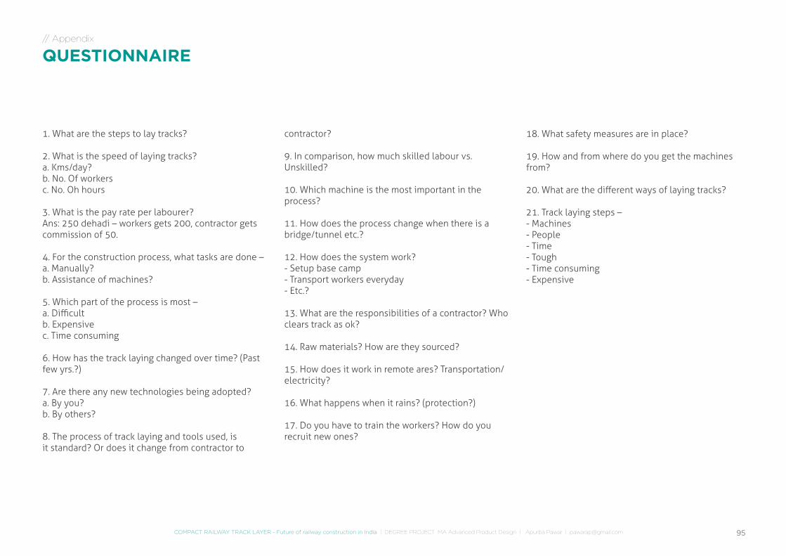
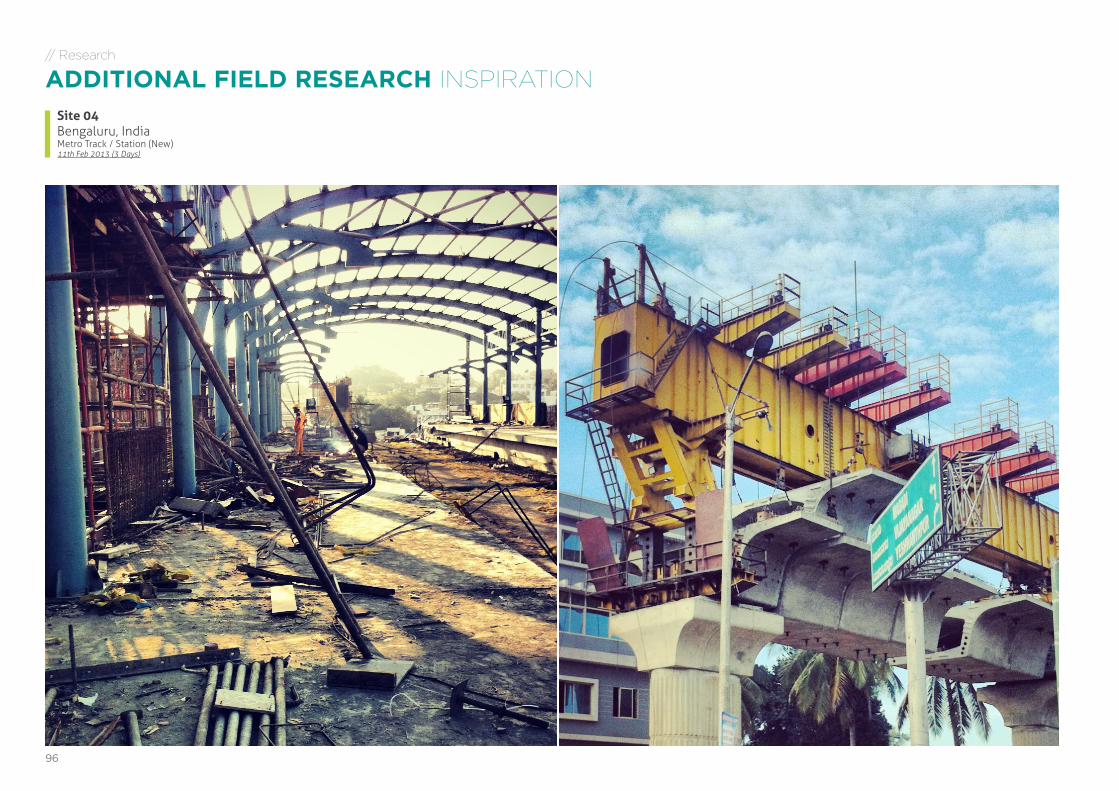
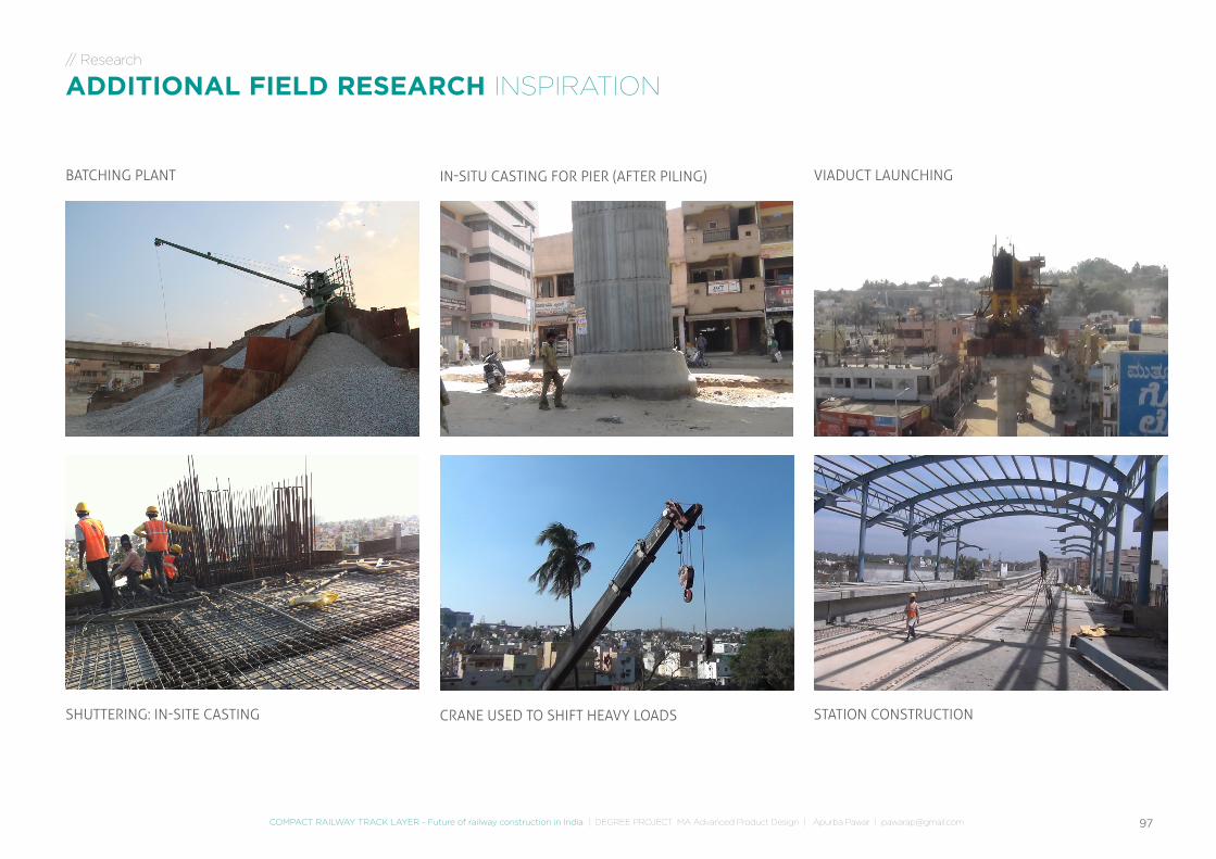
SHUTTERING: IN-SITE CASTING STATION CONSTRUCTIONCRANE USED TO SHIFT HEAVY LOADS
BATCHING PLANT VIADUCT LAUNCHINGIN-SITU CASTING FOR PIER (AFTER PILING)
// Research
ADDITIONAL FIELD RESEARCH INSPIRATION
JAN 07 - 11 FEB 04 - 08JAN 21 - 25 FEB 18 - 22 MAR 11 - 15JAN 14 - 18 FEB 11 - 15 MAR 04 - 08JAN 28 - FEB 01 FEB 25 - MAR 01 MAR 18 - 22
02 06 08 1103 07 1005 09 12
// Pre-PHASE: Reflect & Decide // PHASE 1: Preparation, Research and Brief // PHASE 2: Ideation, concept development, evaluation
04
Offi
cial
Kic
koff
Fina
lise
Pre-
brie
f
Rese
arch
& C
oncl
.
Pres
enta
tion
- V
CE
Dis
cuss
ion
wit
h VC
E
Exte
rnal
tuto
r vis
it
Mid
-Pre
sent
atio
n(3
con
cept
dir.
)Ex
tern
al tu
tor v
isit
Exte
rnal
tuto
r vis
it
Exte
rnal
tuto
r vis
it
Pre
- br
ief t
o VC
E
// Pre-PHASE
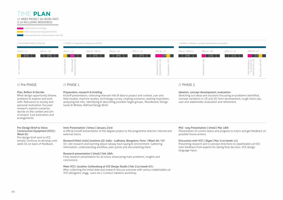
Plan, Reflect & Decide:What design opportunity (theme, problem) to explore and work with. Relevance to society and personal motivation. Focused research, explore scenarios, decide on the context and aim of project. Cost estimation and arrangements.
Pre-Design Brief to Volvo Construction Equipment (VCE) | Week 02:Pre-design brief sent to VCE (email). Continue to develop until week 03 on basis of feedback.
// PHASE 1
Preparation, research & briefing:Kickoff presentation, collecting relevant info & data to project and context, user and field studies, machine studies, technology survey, creating scenarios, seeking inspiration, analysing the info., identifying & describing possible Target groups., Moodboard, Design Goals & Wishes, Refined Design Brief.
Intro Presentation | Umea | January 23rd:A official kickoff presentation of the degree project to the programme director, internal and external tutors.
Research/field visits| locations (3): India - Ludhiana, Bangalore, Pune | Week 06 / 07:On -site research and learning about railway track laying & environment. Gathering information, understanding workflow, pain points and documenting them.
Research presentation | Umeå | Feb 18th:Final research presentation for all tutors showcasing main problems, insights and conclusions.
Meet VCE | location: Gothenburg at VCE Design Studio | Feb 21st (week 07) :After collecting the initial data and research discuss outcome with various stakeholders at VCE (designers, engg., users etc.). Conduct Ideation workshop.
// PHASE 2
Ideation, concept development, evaluation:Sketching out ideas and solutions focussing on problems identified, concept variations in 2D and 3D, form development, rough mock-ups, user and stakeholder evaluation and refinement.
Mid - way Presentation | Umeå | Mar 18thPresentation of current status and progress to tutors and get feedback on possible future actions.
Discussion with VCE | Skype | Mar 21st (week 11)Presenting research and 3 concept directions to stakeholders at VCE. Gain feedback from experts for taking final decision. VCE design language input.
17 WEEK PROJECT, 85 WORK DAYS (119 INCLUDING WEEKENDS)
Umeå Institute of Design
Volvo Construction Equipment (VCE)
Documentation & Communication with VCE
TIME PLAN
98
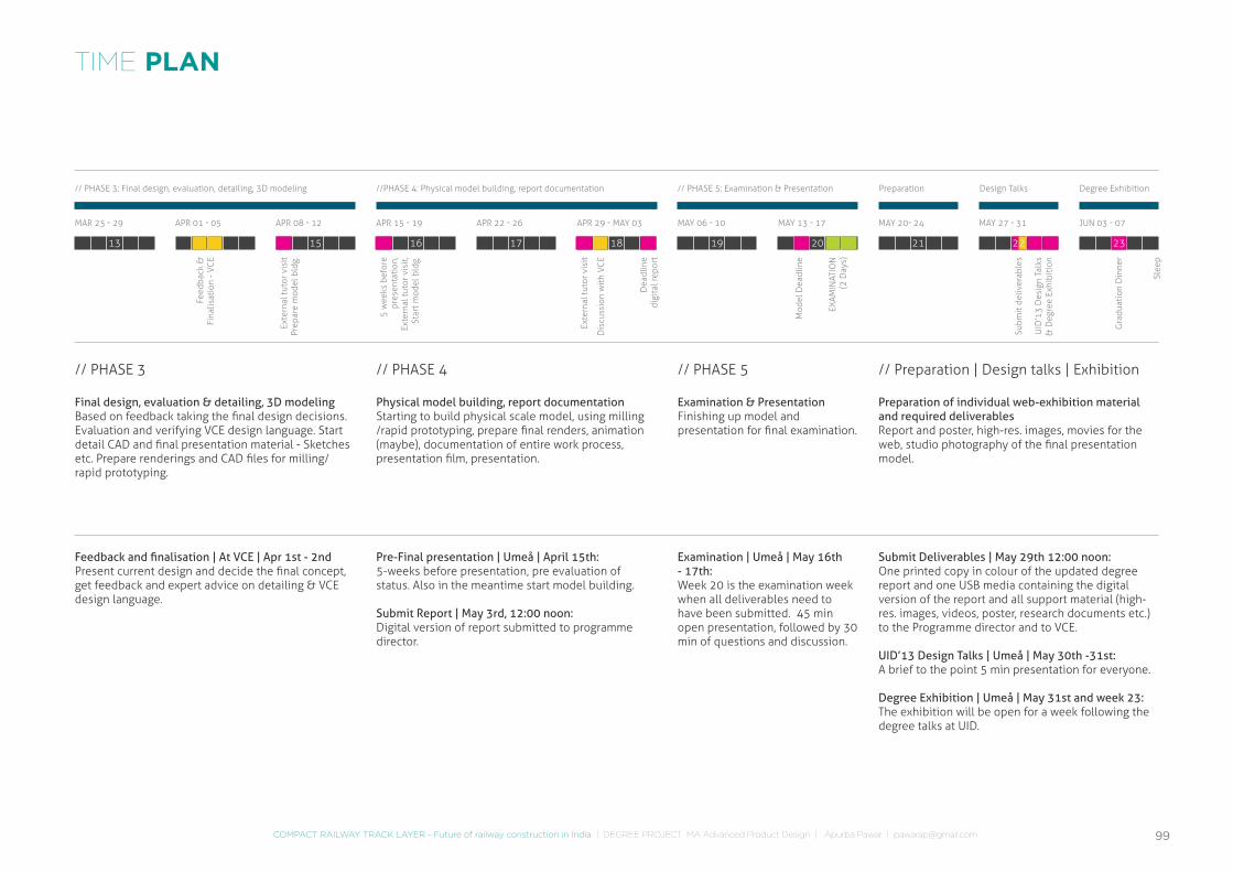
MAR 25 - 29 APR 22 - 26APR 08 - 12 MAY 06 - 10 MAY 27 - 31APR 01 - 05 APR 29 - MAY 03 MAY 20- 24APR 15 - 19 MAY 13 - 17 JUN 03 - 07
13 1715 1914 18 2116 20
//PHASE 4: Physical model building, report documentation // PHASE 5: Examination & Presentation Preparation Design Talks Degree Exhibition// PHASE 3: Final design, evaluation, detailing, 3D modeling
Dis
cuss
ion
wit
h VC
E
Feed
back
&
Fina
lisat
ion
- VC
E
Exte
rnal
tuto
r vis
itPr
epar
e m
odel
bld
g.
Exte
rnal
tuto
r vis
it
EXAM
INAT
ION
(2 D
ays)
UID
’13
Des
ign
Talk
s &
Deg
ree
Exhi
biti
on
Gra
duat
ion
Din
ner
Slee
p
Subm
it d
eliv
erab
les
Mod
el D
eadl
ine
Dea
dlin
e di
gita
l rep
ort
5 w
eeks
bef
ore
pres
enta
tion
,Ex
tern
al tu
tor v
isit
,St
art m
odel
bld
g.
// PHASE 3
Final design, evaluation & detailing, 3D modelingBased on feedback taking the final design decisions. Evaluation and verifying VCE design language. Start detail CAD and final presentation material - Sketches etc. Prepare renderings and CAD files for milling/rapid prototyping.
Feedback and finalisation | At VCE | Apr 1st - 2ndPresent current design and decide the final concept, get feedback and expert advice on detailing & VCE design language.
// PHASE 4
Physical model building, report documentationStarting to build physical scale model, using milling /rapid prototyping, prepare final renders, animation (maybe), documentation of entire work process, presentation film, presentation.
Pre-Final presentation | Umeå | April 15th:5-weeks before presentation, pre evaluation of status. Also in the meantime start model building.
Submit Report | May 3rd, 12:00 noon:Digital version of report submitted to programme director.
// PHASE 5
Examination & PresentationFinishing up model and presentation for final examination.
Examination | Umeå | May 16th - 17th:Week 20 is the examination week when all deliverables need to have been submitted. 45 min open presentation, followed by 30 min of questions and discussion.
// Preparation | Design talks | Exhibition
Preparation of individual web-exhibition material and required deliverablesReport and poster, high-res. images, movies for the web, studio photography of the final presentation model.
Submit Deliverables | May 29th 12:00 noon:One printed copy in colour of the updated degree report and one USB media containing the digital version of the report and all support material (high-res. images, videos, poster, research documents etc.) to the Programme director and to VCE.
UID’13 Design Talks | Umeå | May 30th -31st:A brief to the point 5 min presentation for everyone.
Degree Exhibition | Umeå | May 31st and week 23:The exhibition will be open for a week following the degree talks at UID.
22 23
TIME PLAN
COMPACT RAILWAY TRACK LAYER - Future of railway construction in India | DEGREE PROJECT MA Advanced Product Design | Apurba Pawar | [email protected] 99
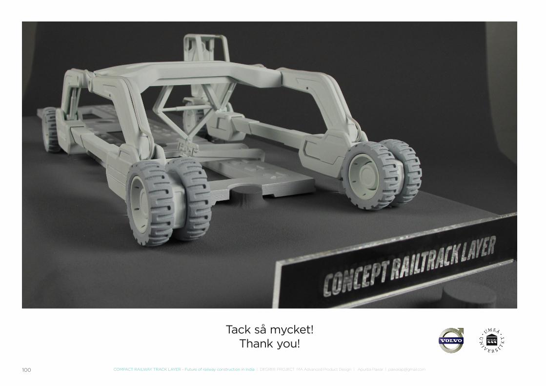
100 COMPACT RAILWAY TRACK LAYER - Future of railway construction in India | DEGREE PROJECT MA Advanced Product Design | Apurba Pawar | [email protected]
Tack så mycket!Thank you!