Embed Size (px)
Citation preview

CM2-AVP702-2001
Smart Valve Positioner 700 Serieswith HART Communication Protocol
Model AVP701/702
User's Manual
Notice
• Make sure that this manual is delivered to the user of this product.• It is prohibited to copy or reprint this manual in whole or in part without
permission.• The contents of this manual are subject to change without notice.• Although Azbil took all possible measures to ensure the accuracy of
this manual, contact us if you find any errors or missing information.• Note that we cannot be held responsible for the results of customer
operation.• HART® is a registered trademark of the FieldComm Group.
© 2014-2021 Azbil Corporation. All Rights Reserved.
i
Introduction
Thank you for purchasing our AVP702 Smart Valve Positioner. The AVP702 (called “the device” below) is a smart valve positioner that can be connected to the 4 to 20 mA loop.
The auto setup function makes it easy to set up the valve.
All adjustments and setup can be performed from the HART communication. The Local User Interface (LUI), which consists of the LCD (liquid crystal display) and operation buttons, facilitates monitoring of input signals, valve opening, pressure display, and other items as well as basic adjustments.
In addition, the built-in pressure sensor can be used to measure the supply air pressure and output air pressure. As a result, the device can not only perform self-diagnostics but can also be combined with the control valve maintenance support system called “Valstaff” in order to monitor the characteristics, operating status, and other data of the control valve, helping to improve the maintenance efficiency of control valves. This instruction manual describes how to handle the device. Read this manual to make full use of the features of this product.
Scope of this manual and related documentsThis document describes the functions and method of installation and adjustment of this device. For details on HART communication, refer to Smart Valve Positioner 700 Series with HART Communication Protocol Model AVP701/702 HART Communication Manual (No. CM2-AVP702-2002*).
For details on the control valve diagnostic items, refer to the “Smart Valve Positioner 700 Series Control Valve Diagnostic Function Manual” (No. CM2-AVP700-2003*).
* If you need the above documents, please contact one of our sales representatives.
ii
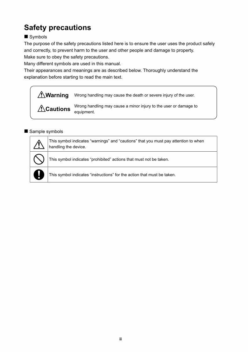
Safety precautions SymbolsThe purpose of the safety precautions listed here is to ensure the user uses the product safely and correctly, to prevent harm to the user and other people and damage to property. Make sure to obey the safety precautions.Many different symbols are used in this manual.Their appearances and meanings are as described below. Thoroughly understand the explanation before starting to read the main text.
Sample symbols
This symbol indicates “warnings” and “cautions” that you must pay attention to when handling the device.
This symbol indicates “prohibited” actions that must not be taken.
This symbol indicates “instructions” for the action that must be taken.
Warning Wrong handling may cause the death or severe injury of the user.
Cautions Wrong handling may cause a minor injury to the user or damage to equipment.
iii
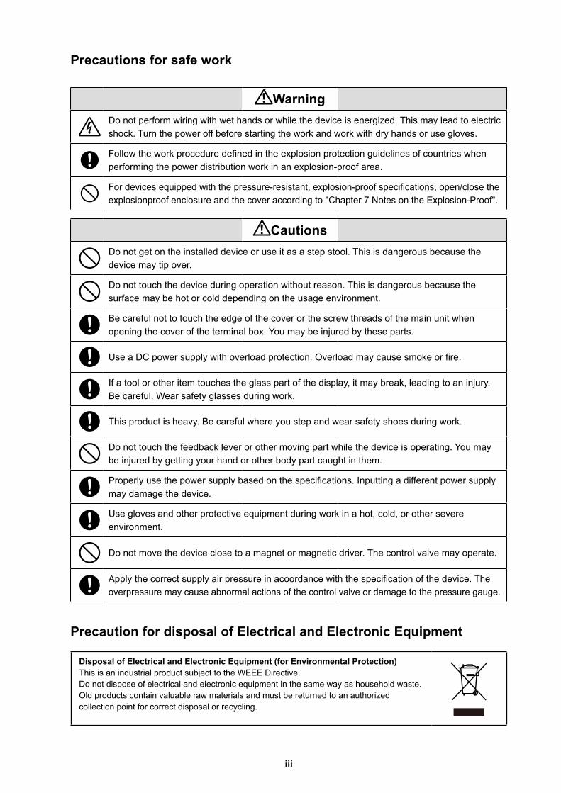
Precautions for safe work
WarningDo not perform wiring with wet hands or while the device is energized. This may lead to electric shock. Turn the power off before starting the work and work with dry hands or use gloves.
Follow the work procedure defined in the explosion protection guidelines of countries when performing the power distribution work in an explosion-proof area.
For devices equipped with the pressure-resistant, explosion-proof specifications, open/close the explosionproof enclosure and the cover according to "Chapter 7 Notes on the Explosion-Proof".
CautionsDo not get on the installed device or use it as a step stool. This is dangerous because the device may tip over.
Do not touch the device during operation without reason. This is dangerous because the surface may be hot or cold depending on the usage environment.
Be careful not to touch the edge of the cover or the screw threads of the main unit when opening the cover of the terminal box. You may be injured by these parts.
Use a DC power supply with overload protection. Overload may cause smoke or fire.
If a tool or other item touches the glass part of the display, it may break, leading to an injury. Be careful. Wear safety glasses during work.
This product is heavy. Be careful where you step and wear safety shoes during work.
Do not touch the feedback lever or other moving part while the device is operating. You may be injured by getting your hand or other body part caught in them.
Properly use the power supply based on the specifications. Inputting a different power supply may damage the device.
Use gloves and other protective equipment during work in a hot, cold, or other severe environment.
Do not move the device close to a magnet or magnetic driver. The control valve may operate.
Apply the correct supply air pressure in acoordance with the specification of the device. The overpressure may cause abnormal actions of the control valve or damage to the pressure gauge.
Precaution for disposal of Electrical and Electronic Equipment
Disposal of Electrical and Electronic Equipment (for Environmental Protection)This is an industrial product subject to the WEEE Directive.Do not dispose of electrical and electronic equipment in the same way as household waste.Old products contain valuable raw materials and must be returned to an authorized collection point for correct disposal or recycling.
iv
Unpacking, Verification, and Storage of Product
UnpackingThis device is precision measuring equipment. Carefully handle it to prevent accidents or damage.After unpacking, check that the items below are included.• The device• Feedback lever and hexagon socket bolts x 2• (4-mm) hexagon wrench x 1 (for feedback lever) (Included only when the device is shipped alone.)• Regulator (KZ03) (optional)• Mounting plate set (optional)• Pressure-resistant packing cable adapter and pressure-resistant elbow (option for
explosion-proof specifications)• Instruction manual (this document) (Included if specified at the time of purchase.)• Extension lever and hexagon socket bolts x 2 (optional)
Specifications checkThe specifications are shown on the nameplate of the main unit. Check that the specifications are the same as what you specified. In particular, confirm the following points.• Tag No. (TAG No.)• Model (MODEL)• Work No. (PROD.)• Input current range (INPUT)• Supply air pressure (SUPPLY)• Explosion protection certification seal (for explosion-proof specifications)
WARNINGWhen using the device in an explosion-proof area, be sure to select the model that satisfies the necessary explosion-proof requirements. Non-explosion-proof products cannot be used in an explosion-proof area.
ContactFor inquiries about this device, please contact us.When contacting us, let us know the model number and production number.
StorageWhen storing the device after purchase, obey the following precautions.• When storing the device before it has been used
1. Store the device as packed at shipment.2. Store the device at an indoor location with little vibration or shocks and at
normal temperature and humidity (about 25°C, 65%).• When storing the device after it has been used
1. Tightly secure the terminal box cover and block the conduit connection port with tape to prevent humidity intrusion.
2. Block the three pneumatic piping connection ports (SUP , OUT1 and OUT2) with tape to prevent humidity and dust intrusion.
3. Pack the device in the same way as at shipment.4. Store the device at an indoor location with little vibration or shocks where it will not be
exposed to rain or water and at normal temperature and humidity (about 25°C, 65%).
v
Table of Contents
Chapter 1 Structure of the 700 Series Control System . . . . . . . . . . . . . . 1-11-1 System Configuration . . . . . . . . . . . . . . . . . . . . . . . . . . . . . . . . . . . . . . . . . . . . . . . 1-11-2 System Configuration without Motion Transmission . . . . . . . . . . . . . . . . . . . . . . . . 1-21-3 System Configuration with Motion Transmission . . . . . . . . . . . . . . . . . . . . . . . . . . 1-21-4 Structure of the Device and Description of Each Part . . . . . . . . . . . . . . . . . . . . . . . 1-3
1-4-1 Structure of the Device . . . . . . . . . . . . . . . . . . . . . . . . . . . . . . . . . . . . . . . . . 1-31-4-2 Structure of Terminal Box . . . . . . . . . . . . . . . . . . . . . . . . . . . . . . . . . . . . . . . 1-51-4-3 Display on the Local User Interface (LUI) . . . . . . . . . . . . . . . . . . . . . . . . . . . 1-7
Chapter 2 Installation of the 700 Series . . . . . . . . . . . . . . . . . . . . . . . . . . 2-12-1 Usage Conditions . . . . . . . . . . . . . . . . . . . . . . . . . . . . . . . . . . . . . . . . . . . . . . . . . . 2-12-2 Selection Criteria for Installation Location . . . . . . . . . . . . . . . . . . . . . . . . . . . . . . . . 2-1
2-2-1 Selection Criteria for Installation Location . . . . . . . . . . . . . . . . . . . . . . . . . . 2-22-2-2 Criteria for instrumentation air . . . . . . . . . . . . . . . . . . . . . . . . . . . . . . . . . . . 2-2
2-3 Installation Procedure . . . . . . . . . . . . . . . . . . . . . . . . . . . . . . . . . . . . . . . . . . . . . . . 2-42-3-1 Mounting the 700 Series onto the Actuator . . . . . . . . . . . . . . . . . . . . . . . . . . 2-42-3-2 Pneumatic Piping Connection . . . . . . . . . . . . . . . . . . . . . . . . . . . . . . . . . . . 2-112-3-3 Electrical Wiring Connection . . . . . . . . . . . . . . . . . . . . . . . . . . . . . . . . . . . . 2-142-3-4 Input Signals and Travel Transmission Power . . . . . . . . . . . . . . . . . . . . . . 2-162-3-5 Cables . . . . . . . . . . . . . . . . . . . . . . . . . . . . . . . . . . . . . . . . . . . . . . . . . . . . . 2-17
2-4 Cable gland and flameproof universal elbow for TIIS Flameproof apparatus . . . . 2-19
Chapter 3 Operation of the 700 Series . . . . . . . . . . . . . . . . . . . . . . . . . . . 3-13-1 Local User Interface (LUI) . . . . . . . . . . . . . . . . . . . . . . . . . . . . . . . . . . . . . . . . . . . . 3-13-2 Adjustment before Operation . . . . . . . . . . . . . . . . . . . . . . . . . . . . . . . . . . . . . . . . . 3-5
3-2-1 Auto Setup . . . . . . . . . . . . . . . . . . . . . . . . . . . . . . . . . . . . . . . . . . . . . . . . . . 3-53-2-2 Zero Span Adjustment . . . . . . . . . . . . . . . . . . . . . . . . . . . . . . . . . . . . . . . . . 3-93-2-3 Supply Bypass . . . . . . . . . . . . . . . . . . . . . . . . . . . . . . . . . . . . . . . . . . . . . . 3-123-2-4 Control Parameters . . . . . . . . . . . . . . . . . . . . . . . . . . . . . . . . . . . . . . . . . . . 3-133-2-5 Password . . . . . . . . . . . . . . . . . . . . . . . . . . . . . . . . . . . . . . . . . . . . . . . . . . 3-15
3-3 Starting Operation . . . . . . . . . . . . . . . . . . . . . . . . . . . . . . . . . . . . . . . . . . . . . . . . . 3-163-3-1 Preoperation Check . . . . . . . . . . . . . . . . . . . . . . . . . . . . . . . . . . . . . . . . . . 3-16
Chapter 4 Operation with HART Communication . . . . . . . . . . . . . . . . . . 4-14-1 Operation with HART Communication . . . . . . . . . . . . . . . . . . . . . . . . . . . . . . . . . . 4-14-2 Setup and Adjustment of Device . . . . . . . . . . . . . . . . . . . . . . . . . . . . . . . . . . . . . . . 4-2
4-2-1 Process Variables . . . . . . . . . . . . . . . . . . . . . . . . . . . . . . . . . . . . . . . . . . . . . 4-24-2-2 Auto Setup . . . . . . . . . . . . . . . . . . . . . . . . . . . . . . . . . . . . . . . . . . . . . . . . . . 4-34-2-3 Input Range . . . . . . . . . . . . . . . . . . . . . . . . . . . . . . . . . . . . . . . . . . . . . . . . . 4-54-2-4 Valve System . . . . . . . . . . . . . . . . . . . . . . . . . . . . . . . . . . . . . . . . . . . . . . . . 4-54-2-5 Control Configuration . . . . . . . . . . . . . . . . . . . . . . . . . . . . . . . . . . . . . . . . . . 4-64-2-6 Input Characterization . . . . . . . . . . . . . . . . . . . . . . . . . . . . . . . . . . . . . . . . . . 4-84-2-7 Travel Cutoff . . . . . . . . . . . . . . . . . . . . . . . . . . . . . . . . . . . . . . . . . . . . . . . . . 4-84-2-8 Units . . . . . . . . . . . . . . . . . . . . . . . . . . . . . . . . . . . . . . . . . . . . . . . . . . . . . . . 4-94-2-9 Travel Calibration . . . . . . . . . . . . . . . . . . . . . . . . . . . . . . . . . . . . . . . . . . . . 4-104-2-10 Input Calibration . . . . . . . . . . . . . . . . . . . . . . . . . . . . . . . . . . . . . . . . . . . . . 4-124-2-11 Pressure Sensor Adjustment . . . . . . . . . . . . . . . . . . . . . . . . . . . . . . . . . . . 4-124-2-12 Simulation . . . . . . . . . . . . . . . . . . . . . . . . . . . . . . . . . . . . . . . . . . . . . . . . . 4-124-2-13 Adjustment of EPM Drive Signal (Pneumatic Modules) . . . . . . . . . . . . . . . 4-134-2-14 Restore factory settings . . . . . . . . . . . . . . . . . . . . . . . . . . . . . . . . . . . . . . . 4-134-2-15 Operator Action Records . . . . . . . . . . . . . . . . . . . . . . . . . . . . . . . . . . . . . . 4-13

vi
4-2-16 Real Time Clock . . . . . . . . . . . . . . . . . . . . . . . . . . . . . . . . . . . . . . . . . . . . . 4-134-2-17 Password . . . . . . . . . . . . . . . . . . . . . . . . . . . . . . . . . . . . . . . . . . . . . . . . . . 4-134-2-18 Device Information . . . . . . . . . . . . . . . . . . . . . . . . . . . . . . . . . . . . . . . . . . . 4-144-2-19 Option . . . . . . . . . . . . . . . . . . . . . . . . . . . . . . . . . . . . . . . . . . . . . . . . . . . . 4-164-2-20 Diagnostic Messages . . . . . . . . . . . . . . . . . . . . . . . . . . . . . . . . . . . . . . . . . 4-174-2-21 Control Valve Diagnostic Messages . . . . . . . . . . . . . . . . . . . . . . . . . . . . . . 4-19
Chapter 5 Troubleshooting . . . . . . . . . . . . . . . . . . . . . . . . . . . . . . . . . . . . 5-15-1 Troubleshooting . . . . . . . . . . . . . . . . . . . . . . . . . . . . . . . . . . . . . . . . . . . . . . . . . . . 5-2
5-1-1 The Device Does Not Operate. (There Is No Output Air Pressure.) . . . . . . . 5-25-1-2 The Control Valve Operates Abnormally (There Is Output Air Pressure.) . . . 5-25-1-3 Failure to communicate with the communicator . . . . . . . . . . . . . . . . . . . . . . 5-25-1-4 Adjustment Procedure When Hunting Occurs . . . . . . . . . . . . . . . . . . . . . . . 5-35-1-5 Auto Setup Failure . . . . . . . . . . . . . . . . . . . . . . . . . . . . . . . . . . . . . . . . . . . . 5-4
5-2 Description of Messages . . . . . . . . . . . . . . . . . . . . . . . . . . . . . . . . . . . . . . . . . . . . . 5-5
Chapter 6 Maintenance . . . . . . . . . . . . . . . . . . . . . . . . . . . . . . . . . . . . . . . 6-16-1 A/M Switch . . . . . . . . . . . . . . . . . . . . . . . . . . . . . . . . . . . . . . . . . . . . . . . . . . . . . . . 6-26-2 Replacement of Filter and Maintenance of Flow Restriction . . . . . . . . . . . . . . . . . . 6-46-3 Cleaning the Flapper . . . . . . . . . . . . . . . . . . . . . . . . . . . . . . . . . . . . . . . . . . . . . . . . 6-56-4 Adjusting the Pilot Relay . . . . . . . . . . . . . . . . . . . . . . . . . . . . . . . . . . . . . . . . . . . . . 6-66-5 Insulation Resistance Test . . . . . . . . . . . . . . . . . . . . . . . . . . . . . . . . . . . . . . . . . . . 6-76-6 Adjustment Procedure When Using the Device with the Booster Relay Attached . 6-86-7 List of Default Values for Internal Data . . . . . . . . . . . . . . . . . . . . . . . . . . . . . . . . . . 6-96-8 Internal Block Diagram of the 700 Series . . . . . . . . . . . . . . . . . . . . . . . . . . . . . . . 6-106-9 Resale Parts . . . . . . . . . . . . . . . . . . . . . . . . . . . . . . . . . . . . . . . . . . . . . . . . . . . . . 6-11
6-9-1 Procedure to Change Switch Block . . . . . . . . . . . . . . . . . . . . . . . . . . . . . . 6-156-9-2 Procedure to Change Pilot Relay . . . . . . . . . . . . . . . . . . . . . . . . . . . . . . . . 6-16
Chapter 7 Notes on the Explosion-Proof 700 Series . . . . . . . . . . . . . . . 7-17-1 TIIS Flameproof Model . . . . . . . . . . . . . . . . . . . . . . . . . . . . . . . . . . . . . . . . . . . . . . 7-27-2 IECEx Flameproof and Dust Ignition Protection . . . . . . . . . . . . . . . . . . . . . . . . . . . 7-37-3 FM Explosionproof / Dust Ignition Protection . . . . . . . . . . . . . . . . . . . . . . . . . . . . . 7-57-4 FM Intrinsically safe (ic) and Nonincendive . . . . . . . . . . . . . . . . . . . . . . . . . . . . . . 7-67-5 FMC Explosionproof / Dust Ignition Protection . . . . . . . . . . . . . . . . . . . . . . . . . . . 7-117-6 CCC Flameproof / Dust Ignition Protection . . . . . . . . . . . . . . . . . . . . . . . . . . . . . . 7-127-7 KOSHA Flameproof . . . . . . . . . . . . . . . . . . . . . . . . . . . . . . . . . . . . . . . . . . . . . . . 7-137-8 INMETRO Flameproof / Dust Ignition Protection . . . . . . . . . . . . . . . . . . . . . . . . . 7-147-9 EAC Flameproof . . . . . . . . . . . . . . . . . . . . . . . . . . . . . . . . . . . . . . . . . . . . . . . . . . 7-167-10 ATEX Intrinsic Safety and Dust Ignition Protection . . . . . . . . . . . . . . . . . . . . . . . . 7-177-11 IECEx Intrinsic Safety and Dust Ignition Protection . . . . . . . . . . . . . . . . . . . . . . . 7-187-12 CCC Intrinsic Safety and Dust Ignition Protection . . . . . . . . . . . . . . . . . . . . . . . . 7-19
Appendix A LUI Display Example . . . . . . . . . . . . . . . . . . . . . . . . . . . . . . . .A-1
Appendix B Menu List . . . . . . . . . . . . . . . . . . . . . . . . . . . . . . . . . . . . . . . . . .B-1
Appendix C Specification . . . . . . . . . . . . . . . . . . . . . . . . . . . . . . . . . . . . . . .C-1
Appendix D Model Selection . . . . . . . . . . . . . . . . . . . . . . . . . . . . . . . . . . . .D-1
Appendix E Outline Dimensional Drawing . . . . . . . . . . . . . . . . . . . . . . . . .E-1
1-1
Chapter 1 Structure of the 700 Series Control System
This chapter describes the device configuration of the control system that uses the device.
• Description of the configuration of the input/output system in the device
• Description of the structure of the main unit of the device and the name and function of each part
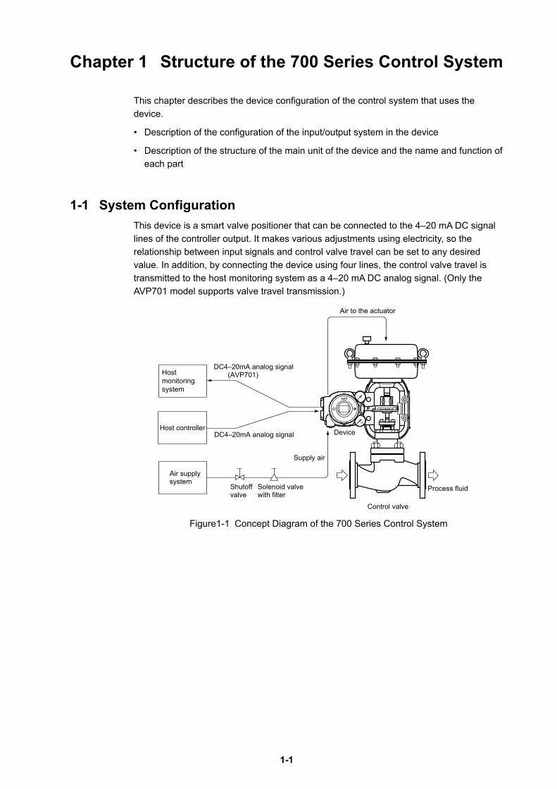
1-1 System ConfigurationThis device is a smart valve positioner that can be connected to the 4–20 mA DC signal lines of the controller output. It makes various adjustments using electricity, so the relationship between input signals and control valve travel can be set to any desired value. In addition, by connecting the device using four lines, the control valve travel is transmitted to the host monitoring system as a 4–20 mA DC analog signal. (Only the AVP701 model supports valve travel transmission.)
Hostmonitoringsystem
Air supplysystem
Host controllerDC4–20mA analog signal
DC4–20mA analog signal (AVP701)
Shutoff Solenoid valve with filter
Supply air
Device
Air to the actuator
Control valve
Process fluid valve
Figure1-1 Concept Diagram of the 700 Series Control System
1-2
1-2 System Configuration without Motion Transmission
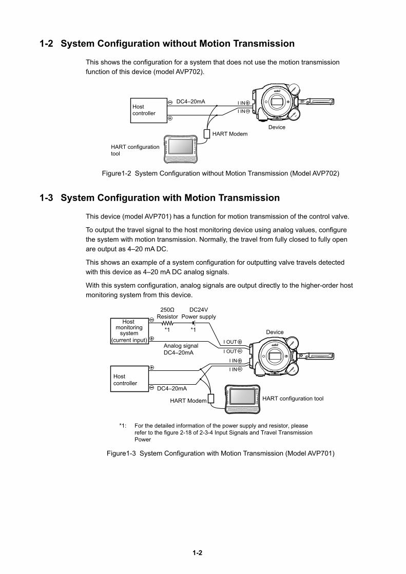
This shows the configuration for a system that does not use the motion transmission function of this device (model AVP702).
Hostcontroller
DC4–20mA I IN
I IN
HART ModemDevice
HART configurationtool
Figure1-2 System Configuration without Motion Transmission (Model AVP702)
1-3 System Configuration with Motion Transmission
This device (model AVP701) has a function for motion transmission of the control valve.
To output the travel signal to the host monitoring device using analog values, configure the system with motion transmission. Normally, the travel from fully closed to fully open are output as 4–20 mA DC.
This shows an example of a system configuration for outputting valve travels detected with this device as 4–20 mA DC analog signals.
With this system configuration, analog signals are output directly to the higher-order host monitoring system from this device.
Device
Analog signalDC4–20mA
DC4–20mA
Hostcontroller
Host monitoring
system(current input)
HART Modem HART configuration tool
250ΩResistor
DC24VPower supply
*1 *1
*1: For the detailed information of the power supply and resistor, please refer to the figure 2-18 of 2-3-4 Input Signals and Travel Transmission Power
Figure1-3 System Configuration with Motion Transmission (Model AVP701)
1-3
1-4 Structure of the Device and Description of Each Part1-4-1 Structure of the Device
1) Major components
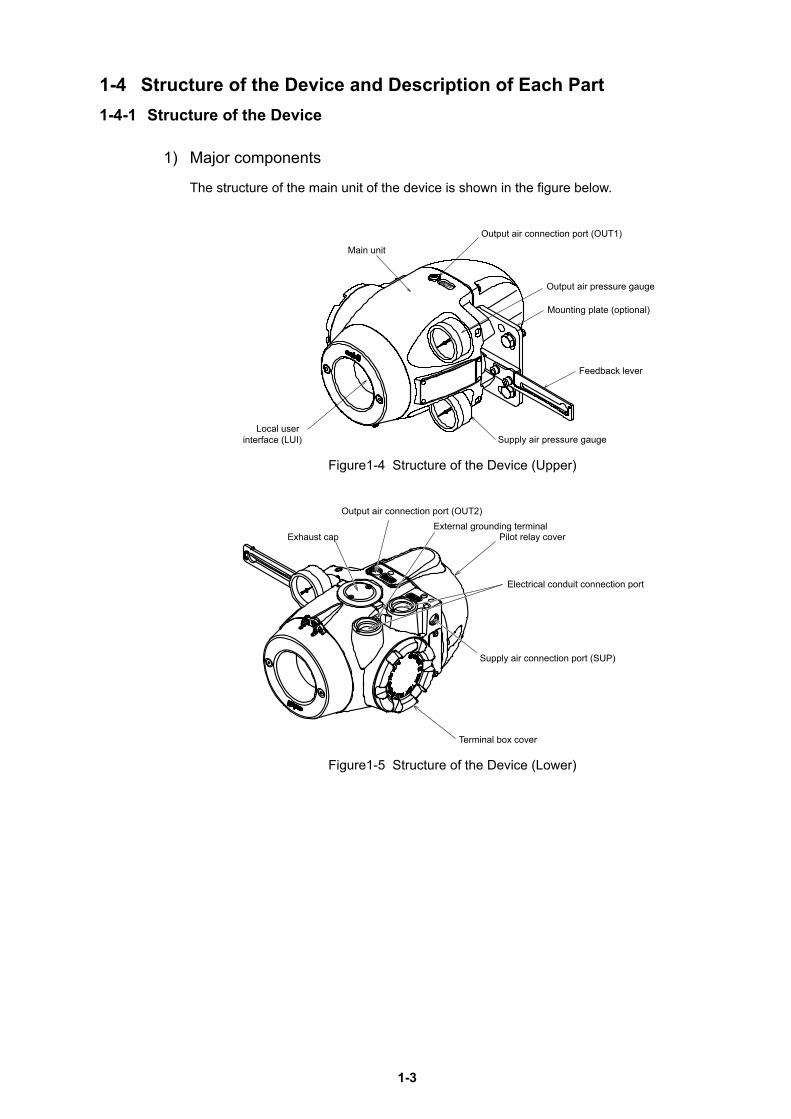
The structure of the main unit of the device is shown in the figure below.
Mounting plate (optional)
Feedback lever
Supply air pressure gauge
Main unit
Local user interface (LUI)
Output air pressure gauge
Output air connection port (OUT1)
Figure1-4 Structure of the Device (Upper)
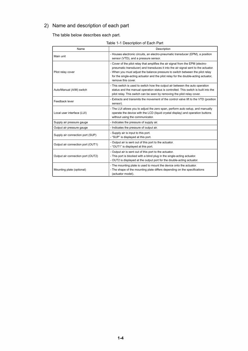
Electrical conduit connection port
Pilot relay coverExternal grounding terminal
Terminal box cover
Exhaust cap
Output air connection port (OUT2)
Supply air connection port (SUP)
Figure1-5 Structure of the Device (Lower)
1-4
2) Name and description of each part
The table below describes each part.
Table 1-1 Description of Each PartName Description
Main unit- Houses electronic circuits, an electro-pneumatic transducer (EPM), a position
sensor (VTD), and a pressure sensor.
Pilot relay cover
- Cover of the pilot relay that amplifies the air signal from the EPM (electro-pneumatic transducer) and transduces it into the air signal sent to the actuator.
- When you must adjust the balance pressure to switch between the pilot relay for the single-acting actuator and the pilot relay for the double-acting actuator, remove this cover.
Auto/Manual (A/M) switch- This switch is used to switch how the output air between the auto operation
status and the manual operation status is controlled. This switch is built into the pilot relay. This switch can be seen by removing the pilot relay cover.
Feedback lever- Extracts and transmits the movement of the control valve lift to the VTD (position
sensor).
Local user interface (LUI)- The LUI allows you to adjust the zero span, perform auto setup, and manually
operate the device with the LCD (liquid crystal display) and operation buttons without using the communicator.
Supply air pressure gauge - Indicates the pressure of supply air.
Output air pressure gauge - Indicates the pressure of output air.
Supply air connection port (SUP)- Supply air is input to this port.- “SUP” is displayed at this port.
Output air connection port (OUT1)- Output air is sent out of this port to the actuator.- “OUT1” is displayed at this port.
Output air connection port (OUT2)- Output air is sent out of this port to the actuator.- This port is blocked with a blind plug in the single-acting actuator.- OUT2 is displayed at the output port for the double-acting actuator.
Mounting plate (optional)- The mounting plate is used to mount the device onto the actuator.- The shape of the mounting plate differs depending on the specifications
(actuator model).
1-5
1-4-2 Structure of Terminal Box
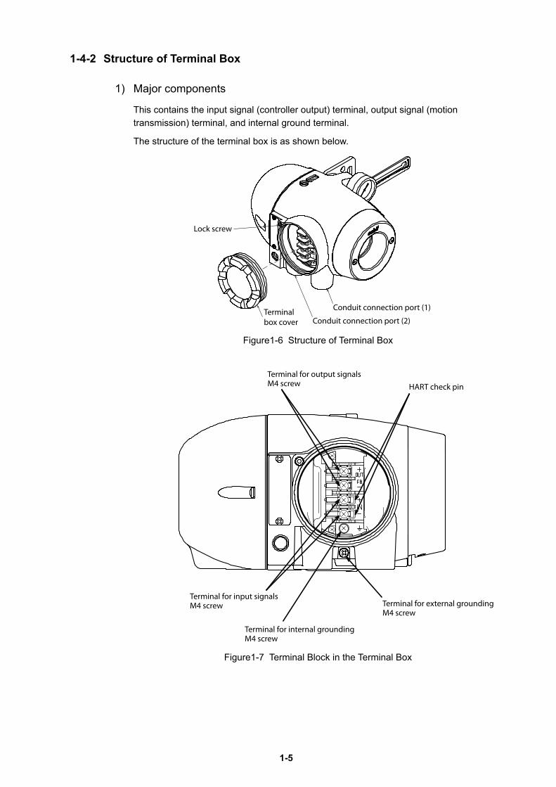
1) Major components
This contains the input signal (controller output) terminal, output signal (motion transmission) terminal, and internal ground terminal.
The structure of the terminal box is as shown below.
Figure1-6 Structure of Terminal Box
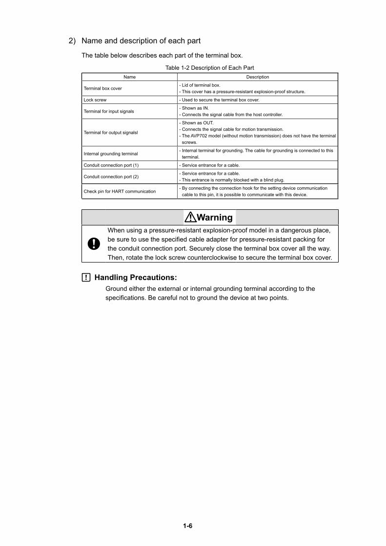
Figure1-7 Terminal Block in the Terminal Box
Lock screw
Conduit connection port (2)
Conduit connection port (1)Terminal box cover
HART check pin
Terminal for output signalsM4 screw
Terminal for input signalsM4 screw
Terminal for internal groundingM4 screw
Terminal for external groundingM4 screw
1-6
2) Name and description of each part
The table below describes each part of the terminal box.
Table 1-2 Description of Each PartName Description
Terminal box cover- Lid of terminal box.- This cover has a pressure-resistant explosion-proof structure.
Lock screw - Used to secure the terminal box cover.
Terminal for input signals- Shown as IN.- Connects the signal cable from the host controller.
Terminal for output signalsl
- Shown as OUT.- Connects the signal cable for motion transmission.- The AVP702 model (without motion transmission) does not have the terminal
screws.
Internal grounding terminal- Internal terminal for grounding. The cable for grounding is connected to this
terminal.
Conduit connection port (1) - Service entrance for a cable.
Conduit connection port (2)- Service entrance for a cable.- This entrance is normally blocked with a blind plug.
Check pin for HART communication- By connecting the connection hook for the setting device communication
cable to this pin, it is possible to communicate with this device.
WarningWhen using a pressure-resistant explosion-proof model in a dangerous place, be sure to use the specified cable adapter for pressure-resistant packing for the conduit connection port. Securely close the terminal box cover all the way. Then, rotate the lock screw counterclockwise to secure the terminal box cover.
Handling Precautions:Ground either the external or internal grounding terminal according to the specifications. Be careful not to ground the device at two points.
1-7
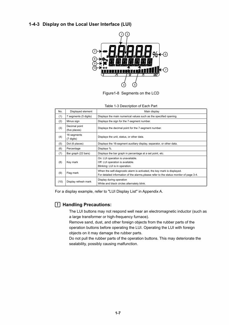
1-4-3 Display on the Local User Interface (LUI)
3
6
7
1
10
5
89
2
4
Figure1-8 Segments on the LCD
Table 1-3 Description of Each PartNo. Displayed element Main display
(1) 7 segments (5 digits) Displays the main numerical values such as the specified opening.
(2) Minus sign Displays the sign for the 7-segment number.
(3)Decimal point (five places)
Displays the decimal point for the 7-segment number.
(4)16 segments (7 digits)
Displays the unit, status, or other data.
(5) Dot (6 places) Displays the 16-segment auxiliary display, separator, or other data.
(6) Percentage Displays %.
(7) Bar graph (22 bars) Displays the bar graph in percentage at a set point, etc.
(8) Key markOn: LUI operation is unavailable.Off: LUI operation is available.Blinking: LUI is in operation.
(9) Flag markWhen the self-diagnostic alarm is activated, the key mark is displayed. For detailed information of the alarms,please refer to the status monitor of page 3-4.
(10) Display refresh markDisplay during operationWhite and black circles alternately blink.
For a display example, refer to "LUI Display List" in Appendix A.
Handling Precautions:The LUI buttons may not respond well near an electromagnetic inductor (such as a large transformer or high-frequency furnace). Remove sand, dust, and other foreign objects from the rubber parts of the operation buttons before operating the LUI. Operating the LUI with foreign objects on it may damage the rubber parts. Do not pull the rubber parts of the operation buttons. This may deteriorate the sealability, possibly causing malfunction.

1-8
2-1
Chapter 2 Installation of the 700 Series
This chapter describes the usage conditions, installation, piping, and wiring of the device.
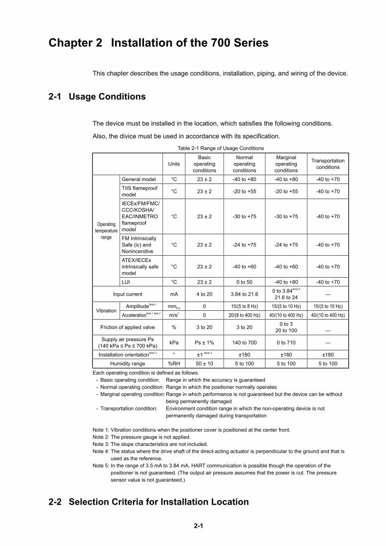
2-1 Usage Conditions
The device must be installed in the location, which satisfies the following conditions.
Also, the divice must be used in accordance with its specification.
Table 2-1 Range of Usage Conditions
UnitsBasic
operating conditions
Normal operating conditions
Marginal operating conditions
Transportation conditions
Operating temperature
range
General model °C 23 ± 2 -40 to +80 -40 to +80 -40 to +70
TIIS flameproof model °C 23 ± 2 -20 to +55 -20 to +55 -40 to +70
IECEx/FM/FMC/CCC/KOSHA/EAC/INMETRO flameproof model
°C 23 ± 2 -30 to +75 -30 to +75 -40 to +70
FM Intrinsically Safe (ic) and Nonincendive
°C 23 ± 2 -24 to +75 -24 to +75 -40 to +70
ATEX/IECEx intrinsically safe model
°C 23 ± 2 -40 to +60 -40 to +60 -40 to +70
LUI °C 23 ± 2 0 to 50 -40 to +80 -40 to +70
Input current mA 4 to 20 3.84 to 21.6 0 to 3.84Note 5
21.6 to 24 ―
VibrationAmplitudeNote 1 mmp-p 0 15/(5 to 8 Hz) 15/(5 to 10 Hz) 15/(5 to 10 Hz)
AccelerationNote 1 Note 2 m/s2 0 20/(8 to 400 Hz) 40/(10 to 400 Hz) 40/(10 to 400 Hz)
Friction of applied valve % 3 to 20 3 to 20 0 to 320 to 100 ―
Supply air pressure Ps(140 kPa ≤ Ps ≤ 700 kPa) kPa Ps ± 1% 140 to 700 0 to 710 ―
Installation orientationNote 3 ° ±1 Note 4 ±180 ±180 ±180
Humidity range %RH 50 ± 10 5 to 100 5 to 100 5 to 100
Each operating condition is defined as follows.- Basic operating condition: Range in which the accuracy is guaranteed- Normal operating condition: Range in which the positioner normally operates- Marginal operating condition: Range in which performance is not guaranteed but the device can be without
being permanently damaged- Transportation condition: Environment condition range in which the non-operating device is not
permanently damaged during transportation
Note 1: Vibration conditions when the positioner cover is positioned at the center front.Note 2: The pressure gauge is not applied.Note 3: The slope characteristics are not included.Note 4: The status where the drive shaft of the direct-acting actuator is perpendicular to the ground and that is
used as the reference.Note 5: In the range of 3.5 mA to 3.84 mA, HART communication is possible though the operation of the
positioner is not guaranteed. (The output air pressure assumes that the power is cut. The pressure sensor value is not guaranteed.)
2-2 Selection Criteria for Installation Location
2-2
The device is designed to withstand severe conditions, but the installation location should be selected according to the criteria described below to maximize performance.
2-2-1 Selection Criteria for Installation Location
Install the device in a location that satisfies all of the following conditions.
• Operating temperature range that conforms to the explosion protection rules
• Relative humidity: 5 to 100%RH
• Ambient temperature change rate: ±20°C/hr or slower
• Electromagnetic induction: 400 A/m or less (Avoid places near a large transducer, high-frequency furnace, or other such equipment.)
• Do not use a transceiver near the device.
• Vibration: 20 m/s2 (5 to 400 Hz) or less (The vibration conditions defined for the device are the vibrations at the positioner part.)
2-2-2 Criteria for instrumentation air
The device employs a nozzle flapper structure in the electropneumatic transduction section. If instrumentation air is contaminated (includes oil, water, or other substance), the positioner function of the device may not function properly or an irrecoverable failure may occur. Therefore, the quality of instrumentation air supplied to the device is defined as follows.
• Solid material : No particles with a diameter larger than 3 μm.
• Oil : Less than 1 ppm.
• Supply air humidity : The dew point temperature is at least 10°C lower than that of the device.
(This criterion is based on Japanese Industrial Standards JIS C 1805-1(2001).)
Select a compressor and main line or terminal-installation type compressed air purifier by referring to the above specifications.
(1) Compressed air purifier for the main line
Select a compressed air purifier for the main line, such as a main line filter or micro-alescer, to satisfy the above specifications.
Domestic compressed air purifier manufacturers of Japan: SMC Corporation and CKD Corporation
(2) Compressed air purifier to be installed on the terminal
If an air purifier cannot be installed on the main line due to installation of a control valve or for other reasons, use an compressed air purifier that can be installed on the terminal in order to satisfy the above specifications.
2-3
<Example devices>
- Products from SMC Corporation
Mist Separator AM150 or AM250 Series
(Filtering level: 0.3 μm, Secondary oil mist concentration: 1.0 mg/m3)
- CKD Corporation
Oil mist filter
M1000 or M3000 Series
Mantle S Type (Filtering level: 0.3 μm, Remaining oil: 1.0 mg/m3)
Handling Precautions:Select a compressed air purifier with specifications suited to the usage conditions. Even when you install the above oil removal equipment, it is necessary to properly inspect and maintain the air circuit section for long-term stable operation. Install the oil removal equipment before use and perform periodic inspection and maintenance. The warranty is void if the device fails because the quality of the above instrumentation air was not sufficient.
2-4
2-3 Installation Procedure2-3-1 Mounting the 700 Series onto the Actuator
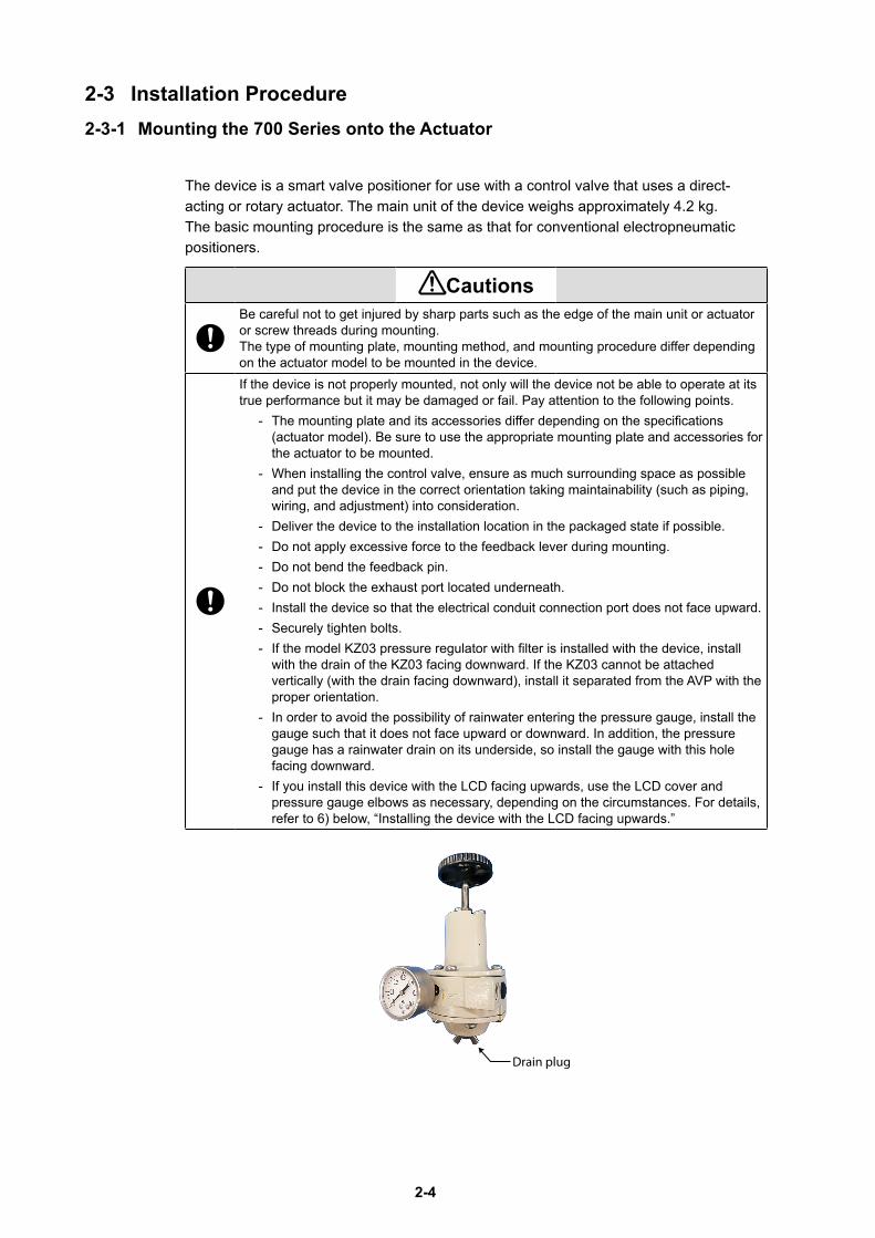
The device is a smart valve positioner for use with a control valve that uses a direct-acting or rotary actuator. The main unit of the device weighs approximately 4.2 kg. The basic mounting procedure is the same as that for conventional electropneumatic positioners.
CautionsBe careful not to get injured by sharp parts such as the edge of the main unit or actuator or screw threads during mounting. The type of mounting plate, mounting method, and mounting procedure differ depending on the actuator model to be mounted in the device.If the device is not properly mounted, not only will the device not be able to operate at its true performance but it may be damaged or fail. Pay attention to the following points.
- The mounting plate and its accessories differ depending on the specifications (actuator model). Be sure to use the appropriate mounting plate and accessories for the actuator to be mounted.
- When installing the control valve, ensure as much surrounding space as possible and put the device in the correct orientation taking maintainability (such as piping, wiring, and adjustment) into consideration.
- Deliver the device to the installation location in the packaged state if possible.- Do not apply excessive force to the feedback lever during mounting.- Do not bend the feedback pin.- Do not block the exhaust port located underneath.- Install the device so that the electrical conduit connection port does not face upward.- Securely tighten bolts.- If the model KZ03 pressure regulator with filter is installed with the device, install
with the drain of the KZ03 facing downward. If the KZ03 cannot be attached vertically (with the drain facing downward), install it separated from the AVP with the proper orientation.
- In order to avoid the possibility of rainwater entering the pressure gauge, install the gauge such that it does not face upward or downward. In addition, the pressure gauge has a rainwater drain on its underside, so install the gauge with this hole facing downward.
- If you install this device with the LCD facing upwards, use the LCD cover and pressure gauge elbows as necessary, depending on the circumstances. For details, refer to 6) below, “Installing the device with the LCD facing upwards.”
Drain plug
2-5
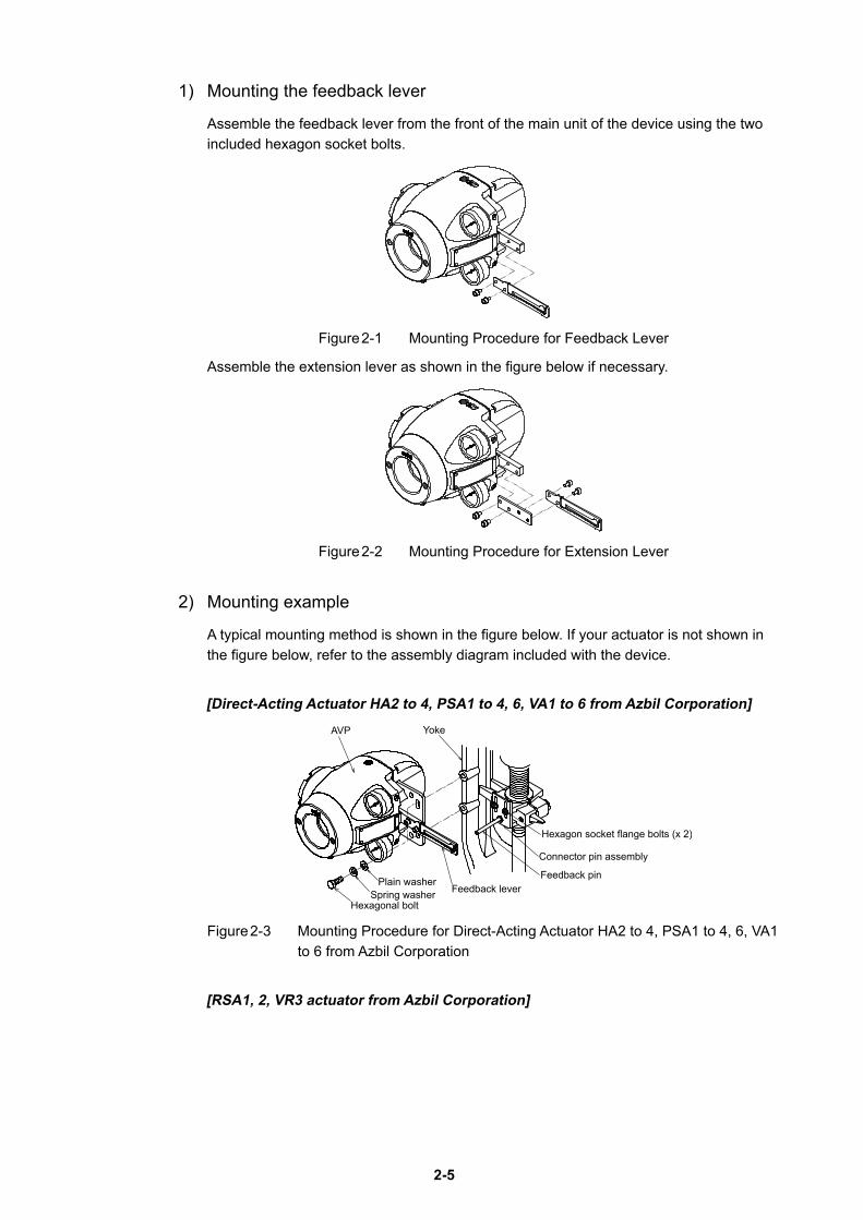
1) Mounting the feedback lever
Assemble the feedback lever from the front of the main unit of the device using the two included hexagon socket bolts.
Figure 2-1 Mounting Procedure for Feedback Lever
Assemble the extension lever as shown in the figure below if necessary.
Figure 2-2 Mounting Procedure for Extension Lever
2) Mounting example
A typical mounting method is shown in the figure below. If your actuator is not shown in the figure below, refer to the assembly diagram included with the device.
[Direct-Acting Actuator HA2 to 4, PSA1 to 4, 6, VA1 to 6 from Azbil Corporation]
Plain washer
Hexagon socket flange bolts (x 2)
Connector pin assembly
YokeAVP
Feedback leverFeedback pin
Spring washerHexagonal bolt
Figure 2-3 Mounting Procedure for Direct-Acting Actuator HA2 to 4, PSA1 to 4, 6, VA1 to 6 from Azbil Corporation
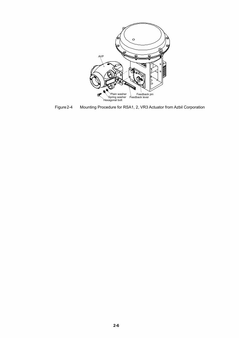
[RSA1, 2, VR3 actuator from Azbil Corporation]
2-6
AVP
Feedback leverFeedback pin
Spring washerHexagonal bolt
Plain washer
Figure 2-4 Mounting Procedure for RSA1, 2, VR3 Actuator from Azbil Corporation
2-7
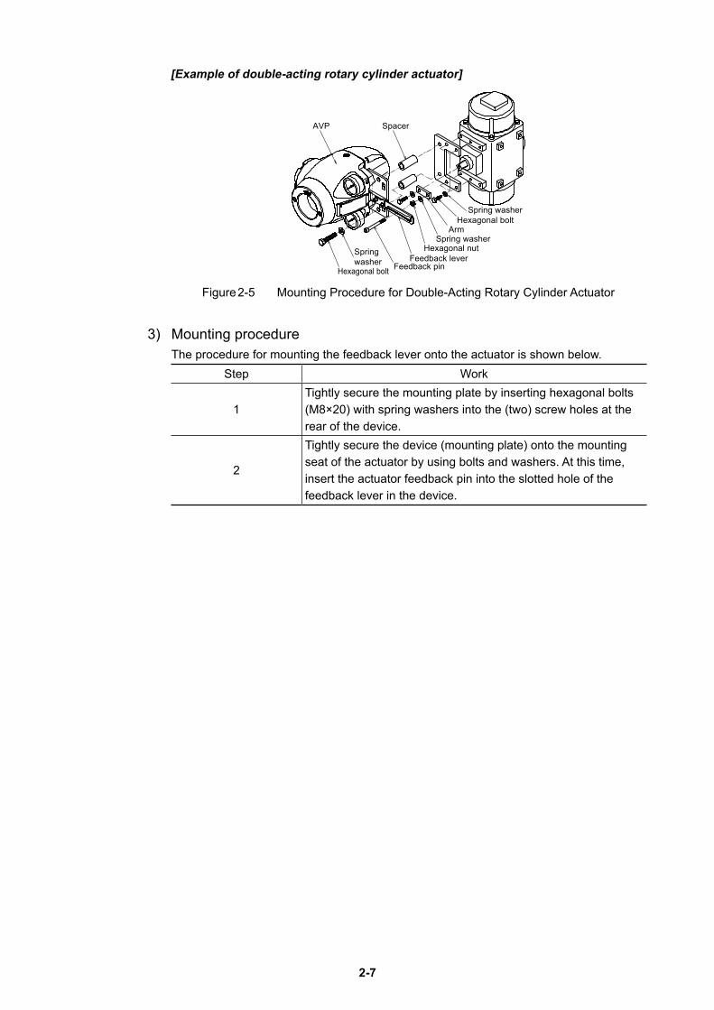
[Example of double-acting rotary cylinder actuator]
SpacerAVP
Spring washerHexagonal bolt
ArmSpring washer
Hexagonal nutFeedback lever
Feedback pin
Spring washer
Hexagonal bolt
Figure 2-5 Mounting Procedure for Double-Acting Rotary Cylinder Actuator
3) Mounting procedureThe procedure for mounting the feedback lever onto the actuator is shown below.
Step Work
1Tightly secure the mounting plate by inserting hexagonal bolts (M8×20) with spring washers into the (two) screw holes at the rear of the device.
2
Tightly secure the device (mounting plate) onto the mounting seat of the actuator by using bolts and washers. At this time, insert the actuator feedback pin into the slotted hole of the feedback lever in the device.
2-8
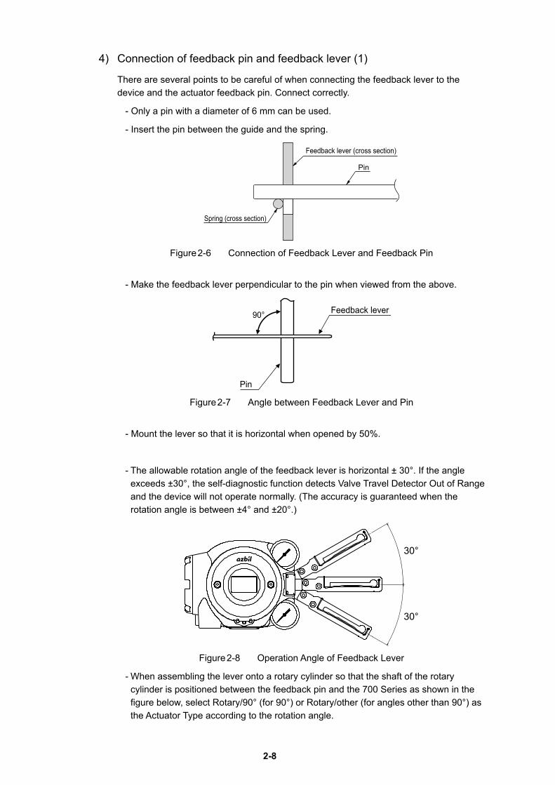
4) Connection of feedback pin and feedback lever (1)
There are several points to be careful of when connecting the feedback lever to the device and the actuator feedback pin. Connect correctly.
- Only a pin with a diameter of 6 mm can be used.
- Insert the pin between the guide and the spring.
Feedback lever (cross section)
Spring (cross section)
Pin
Figure 2-6 Connection of Feedback Lever and Feedback Pin
- Make the feedback lever perpendicular to the pin when viewed from the above.
90°
Pin
Feedback lever
Figure 2-7 Angle between Feedback Lever and Pin
- Mount the lever so that it is horizontal when opened by 50%.
- The allowable rotation angle of the feedback lever is horizontal ± 30°. If the angle exceeds ±30°, the self-diagnostic function detects Valve Travel Detector Out of Range and the device will not operate normally. (The accuracy is guaranteed when the rotation angle is between ±4° and ±20°.)
30°
30°
Figure 2-8 Operation Angle of Feedback Lever
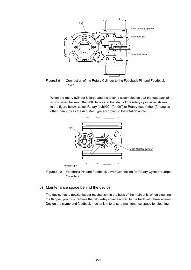
- When assembling the lever onto a rotary cylinder so that the shaft of the rotary cylinder is positioned between the feedback pin and the 700 Series as shown in the figure below, select Rotary/90° (for 90°) or Rotary/other (for angles other than 90°) as the Actuator Type according to the rotation angle.
2-9
Shaft of rotary cylinder
Feedback lever
Feedback pin
AVP
Figure 2-9 Connection of the Rotary Cylinder to the Feedback Pin and Feedback Lever
- When the rotary cylinder is large and the lever is assembled so that the feedback pin is positioned between the 700 Series and the shaft of the rotary cylinder as shown in the figure below, select Rotary (sub)/90° (for 90°) or Rotary (sub)/other (for angles other than 90°) as the Actuator Type according to the rotation angle.
Feedback pin
AVP
Shaft of rotary cylinder
Figure 2-10 Feedback Pin and Feedback Lever Connection for Rotary Cylinder (Large Cylinder)
5) Maintenance space behind the device
The device has a nozzle flapper mechanism in the back of the main unit. When cleaning the flapper, you must remove the pilot relay cover secured to the back with three screws. Design the clamp and feedback mechanism to ensure maintenance space for cleaning.
2-10
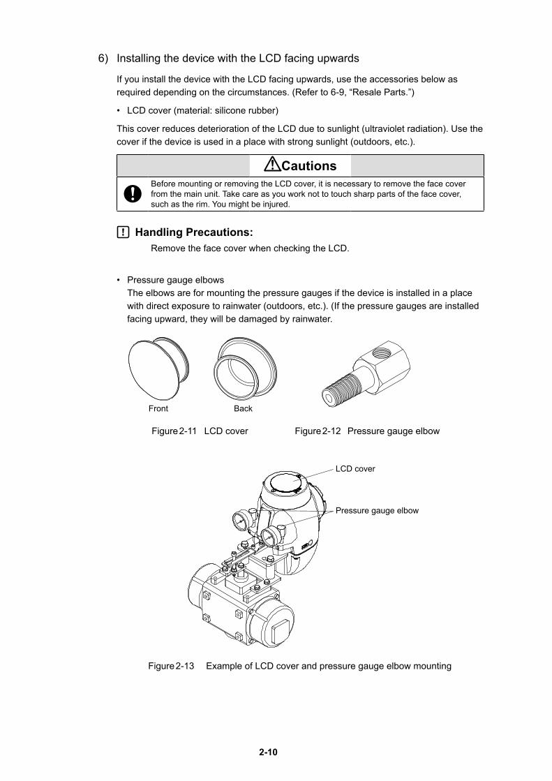
6) Installing the device with the LCD facing upwards
If you install the device with the LCD facing upwards, use the accessories below as required depending on the circumstances. (Refer to 6-9, “Resale Parts.”)
• LCD cover (material: silicone rubber)
This cover reduces deterioration of the LCD due to sunlight (ultraviolet radiation). Use the cover if the device is used in a place with strong sunlight (outdoors, etc.).
CautionsBefore mounting or removing the LCD cover, it is necessary to remove the face cover from the main unit. Take care as you work not to touch sharp parts of the face cover, such as the rim. You might be injured.
Handling Precautions:Remove the face cover when checking the LCD.
• Pressure gauge elbows The elbows are for mounting the pressure gauges if the device is installed in a place with direct exposure to rainwater (outdoors, etc.). (If the pressure gauges are installed facing upward, they will be damaged by rainwater.
Figure 2-11 LCD cover Figure 2-12 Pressure gauge elbow
Figure 2-13 Example of LCD cover and pressure gauge elbow mounting
Front Back
LCD cover
Pressure gauge elbow
2-11
2-3-2 Pneumatic Piping Connection
This section describes how to supply the air for the device to drive the actuator.
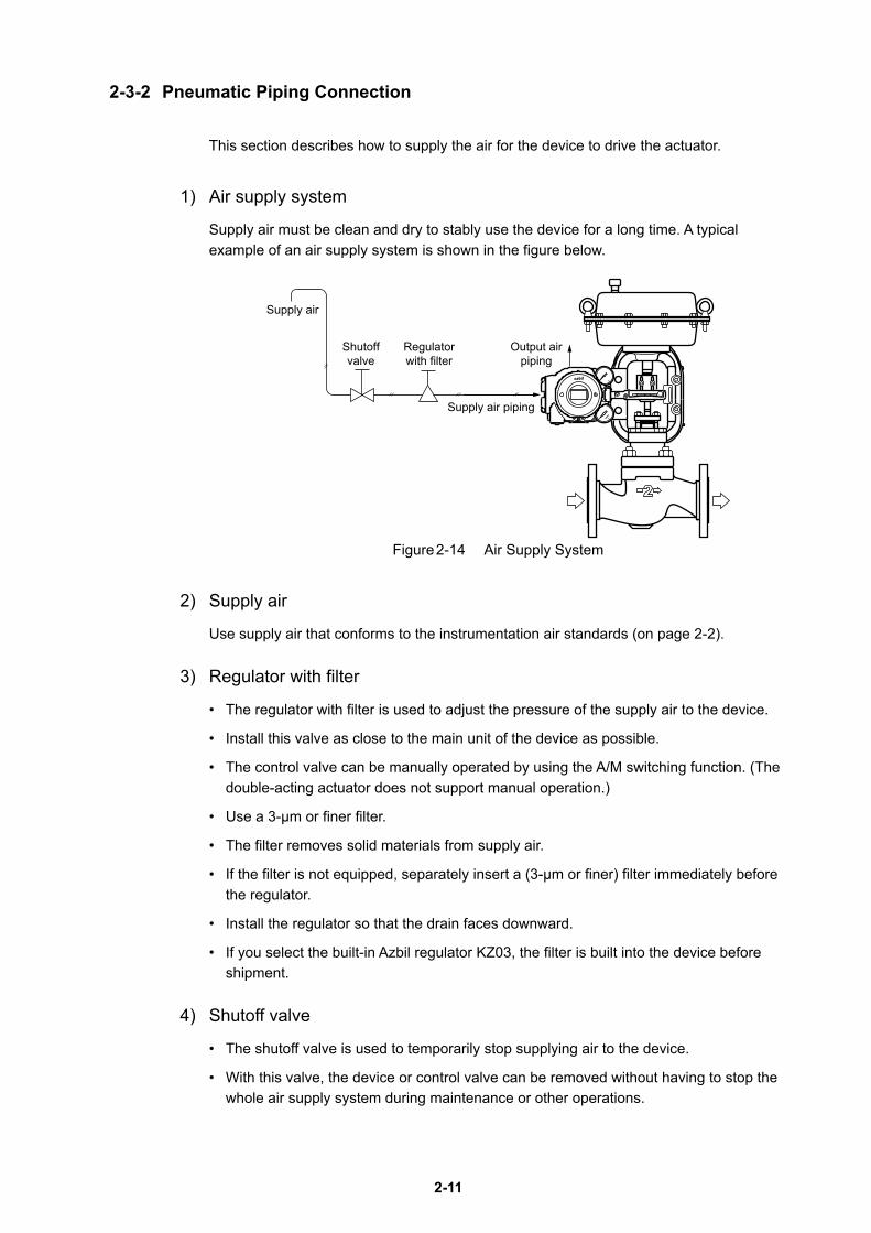
1) Air supply system
Supply air must be clean and dry to stably use the device for a long time. A typical example of an air supply system is shown in the figure below.
Supply air
Supply air piping
Output airpiping
Shutoffvalve
Regulatorwith filter
Figure 2-14 Air Supply System
2) Supply air
Use supply air that conforms to the instrumentation air standards (on page 2-2).
3) Regulator with filter
• The regulator with filter is used to adjust the pressure of the supply air to the device.
• Install this valve as close to the main unit of the device as possible.
• The control valve can be manually operated by using the A/M switching function. (The double-acting actuator does not support manual operation.)
• Use a 3-μm or finer filter.
• The filter removes solid materials from supply air.
• If the filter is not equipped, separately insert a (3-μm or finer) filter immediately before the regulator.
• Install the regulator so that the drain faces downward.
• If you select the built-in Azbil regulator KZ03, the filter is built into the device before shipment.
4) Shutoff valve
• The shutoff valve is used to temporarily stop supplying air to the device.
• With this valve, the device or control valve can be removed without having to stop the whole air supply system during maintenance or other operations.
2-12
5) Piping
• Use piping with an inside diameter of 6 mm.
• When using the device in a corrosive atmosphere, select piping appropriate to the environment of the installation location. For example, you may use the vinyl-coated copper pipe.
• To prevent air leaks, be sure to use a fitting that is appropriate for the pipe.
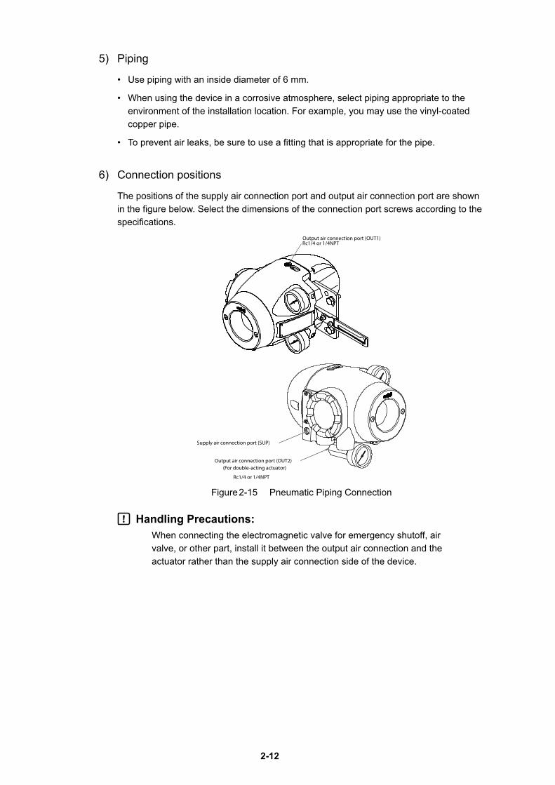
6) Connection positions
The positions of the supply air connection port and output air connection port are shown in the figure below. Select the dimensions of the connection port screws according to the specifications.
Rc1/4 or 1/4NPTOutput air connection port (OUT1)
Supply air connection port (SUP)
Output air connection port (OUT2)(For double-acting actuator)
Rc1/4 or 1/4NPT
Figure 2-15 Pneumatic Piping Connection
Handling Precautions:When connecting the electromagnetic valve for emergency shutoff, air valve, or other part, install it between the output air connection and the actuator rather than the supply air connection side of the device.
2-13
7) Mounting procedureThe procedure for connecting pneumatic piping to operate the device is shown below.
Step Work
1
Connect the joint for piping to the connection port using seal tape.
Handling Precautions:- Use seal tape as the seal material. Avoid using solid
or liquid seal material if possible.- Do not let the seal tape get in the piping.- If you do use a liquid seal, make sure that no drops
of the seal material get in the piping.
2
Connect the supply and output pipes to each joint in consideration of the arrangement of the piping.
Handling Precautions:- For the double-acting actuator, the connection
between output air connection ports OUT1 and OUT2 and the actuator is determined by the valve operation. Check the valve operation before connecting pipes.
- Sufficiently flush piping before connection to prevent burrs on the piping or other foreign objects from getting in the piping.
- Keep the output air piping as short as possible.3 After all piping is complete, make sure that air does not leak.
2-14
2-3-3 Electrical Wiring Connection
This section describes the methods for electrical wiring for signal input from the controller and signal output to the monitoring system.
WarningTurn the power off before starting wiring work. Otherwise, electric shock may occur.
When using the explosion-proof 700 Series in a dangerous place, be sure to connect the wiring while following “Chapter 7 Precautions for the Explosion-Proof 700 Series.”
CautionsBe sure to perform grounding work following the electrical work guidelines in each region.
Handling Precautions:Be sure to attach a blind plug to the unused conduit connection port so that it is completely covered.
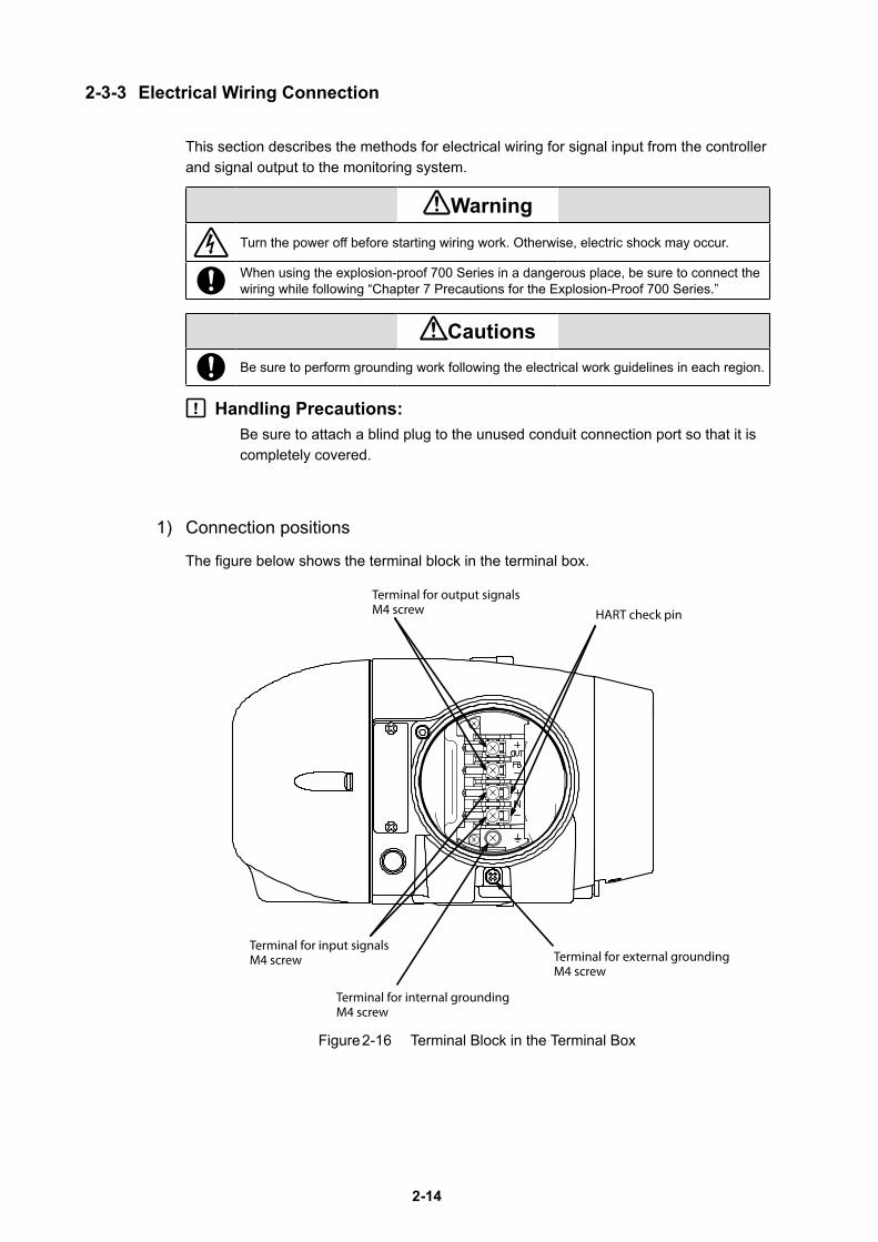
1) Connection positions
The figure below shows the terminal block in the terminal box.
Figure 2-16 Terminal Block in the Terminal Box
HART check pin
Terminal for output signalsM4 screw
Terminal for input signalsM4 screw
Terminal for internal groundingM4 screw
Terminal for external groundingM4 screw
2-15
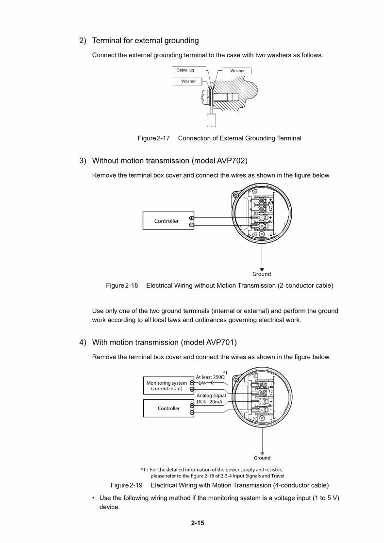
2) Terminal for external grounding
Connect the external grounding terminal to the case with two washers as follows.
Figure 2-17 Connection of External Grounding Terminal
3) Without motion transmission (model AVP702)
Remove the terminal box cover and connect the wires as shown in the figure below.
Figure 2-18 Electrical Wiring without Motion Transmission (2-conductor cable)
Use only one of the two ground terminals (internal or external) and perform the ground work according to all local laws and ordinances governing electrical work.
4) With motion transmission (model AVP701)
Remove the terminal box cover and connect the wires as shown in the figure below.
Figure 2-19 Electrical Wiring with Motion Transmission (4-conductor cable)
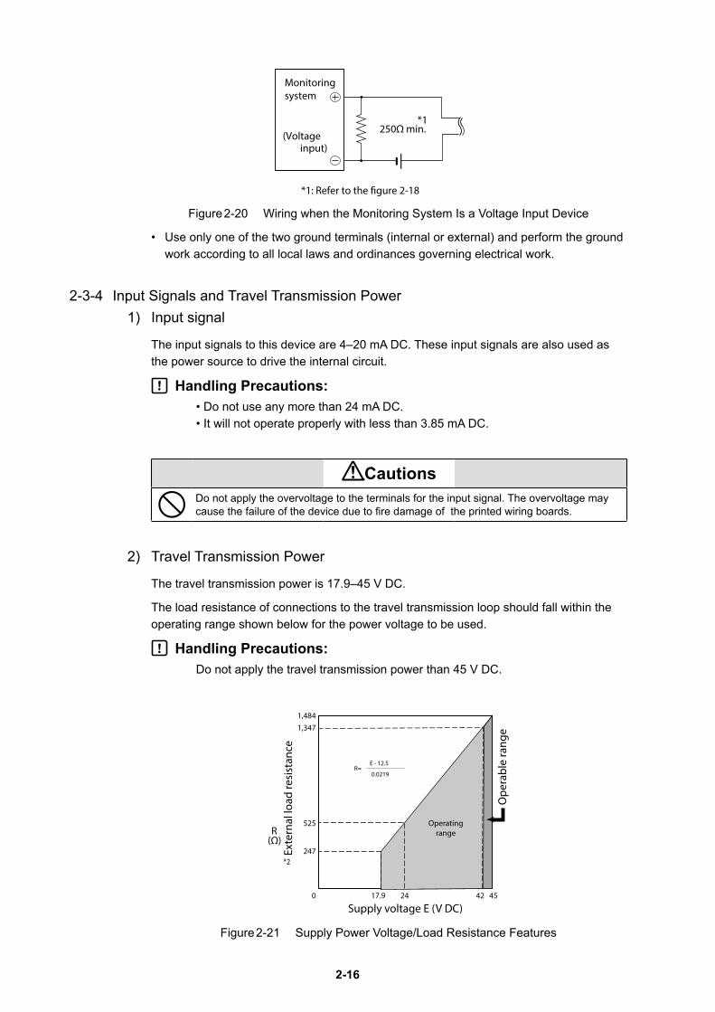
• Use the following wiring method if the monitoring system is a voltage input (1 to 5 V) device.
Washer
Washer
Cable lug
Controller
Ground
At least 250ΩMonitoring system
(current input)
Controller
*1
*1 : For the detailed information of the power supply and resistor, please refer to the �gure 2-18 of 2-3-4 Input Signals and Travel
Analog signalDC4 - 20mA
Ground
2-16
Figure 2-20 Wiring when the Monitoring System Is a Voltage Input Device
• Use only one of the two ground terminals (internal or external) and perform the ground work according to all local laws and ordinances governing electrical work.
2-3-4 Input Signals and Travel Transmission Power1) Input signal
The input signals to this device are 4–20 mA DC. These input signals are also used as the power source to drive the internal circuit.
Handling Precautions:• Do not use any more than 24 mA DC.• It will not operate properly with less than 3.85 mA DC.
CautionsDo not apply the overvoltage to the terminals for the input signal. The overvoltage may cause the failure of the device due to fire damage of the printed wiring boards.
2) Travel Transmission Power
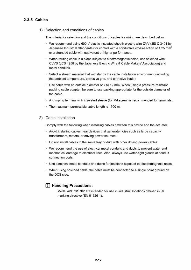
The travel transmission power is 17.9–45 V DC.
The load resistance of connections to the travel transmission loop should fall within the operating range shown below for the power voltage to be used.
Handling Precautions:Do not apply the travel transmission power than 45 V DC.
Figure 2-21 Supply Power Voltage/Load Resistance Features
Monitoringsystem
(Voltage 250Ω min.
*1: Refer to the �gure 2-18
*1
input)
525
247
17.9 24 450
1,484
(Ω)
Supply voltage E (V DC)42
*2
1,347
R
E - 12.5
0.0219R=
Exte
rnal
load
resi
stan
ce
Ope
rabl
e ra
nge
Operatingrange
2-17
2-3-5 Cables
1) Selection and conditions of cables
The criteria for selection and the conditions of cables for wiring are described below.
• We recommend using 600-V plastic insulated sheath electric wire CVV (JIS C 3401 by Japanese Industrial Standards) for control with a conductive cross-section of 1.25 mm2 or a stranded cable with equivalent or higher performance.
• When routing cable in a place subject to electromagnetic noise, use shielded wire CVVS (JCS 4258 by the Japanese Electric Wire & Cable Makers’ Association) and metal conduits.
• Select a sheath material that withstands the cable installation environment (including the ambient temperature, corrosive gas, and corrosive liquid).
• Use cable with an outside diameter of 7 to 12 mm. When using a pressure-resistant packing cable adapter, be sure to use packing appropriate for the outside diameter of the cable.
• A crimping terminal with insulated sleeve (for M4 screw) is recommended for terminals.
• The maximum permissible cable length is 1500 m.
2) Cable installation
Comply with the following when installing cables between this device and the actuator.
• Avoid installing cables near devices that generate noise such as large capacity transformers, motors, or driving power sources.
• Do not install cables in the same tray or duct with other driving power cables.
• We recommend the use of electrical metal conduits and ducts to prevent water and mechanical damage to electrical lines. Also, always use water-tight glands at conduit connection ports.
• Use electrical metal conduits and ducts for locations exposed to electromagnetic noise.
• When using shielded cable, the cable must be connected to a single point ground on the DCS side.
Handling Precautions:Model AVP701/702 are intended for use in industrial locations defined in CE marking directive (EN 61326-1).
2-18
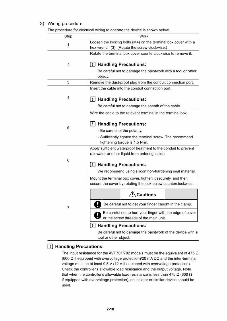
3) Wiring procedureThe procedure for electrical wiring to operate the device is shown below.
Step Work
1Loosen the locking bolts (M4) on the terminal box cover with a hex wrench (3). (Rotate the screw clockwise.)
2
Rotate the terminal box cover counterclockwise to remove it.
Handling Precautions:Be careful not to damage the paintwork with a tool or other object.
3 Remove the dust-proof plug from the conduit connection port.
4
Insert the cable into the conduit connection port.
Handling Precautions:Be careful not to damage the sheath of the cable.
5
Wire the cable to the relevant terminal in the terminal box.
Handling Precautions:- Be careful of the polarity.- Sufficiently tighten the terminal screw. The recommend
tightening torque is 1.5 N·m.
6
Apply sufficient waterproof treatment to the conduit to prevent rainwater or other liquid from entering inside.
Handling Precautions:We recommend using silicon non-hardening seal material.
7
Mount the terminal box cover, tighten it securely, and then secure the cover by rotating the lock screw counterclockwise.
Cautions
Be careful not to get your finger caught in the clamp.
Be careful not to hurt your finger with the edge of cover or the screw threads of the main unit.
Handling Precautions:Be careful not to damage the paintwork of the device with a tool or other object.
Handling Precautions:The input resistance for the AVP701/702 models must be the equivalent of 475 Ω (600 Ω if equipped with overvoltage protection)/20 mA DC and the inter-terminal voltage must be at least 9.5 V (12 V if equipped with overvoltage protection). Check the controller's allowable load resistance and the output voltage. Note that when the controller's allowable load resistance is less than 475 Ω (600 Ω if equipped with overvoltage protection), an isolator or similar device should be used.
2-19
2-4 Cable gland and flameproof universal elbow for TIIS Flameproof apparatus
TIIS Flameproof SVP model is provided with a certified cable gland.
The cable gland seals the cable entering the SVP enclosure to withstand an internal explosion and protects the cable from being damaged mechanically and electrically.
Use the dedicated elbow if it is necessary to change the direction of the cable with these models.
Handling Precautions:If the device is to be used under the authorization other than that for the TIIS Flameproof standards, the wiring of cables must be performed according to local regulations for electrical installations in explosive atmospheres.
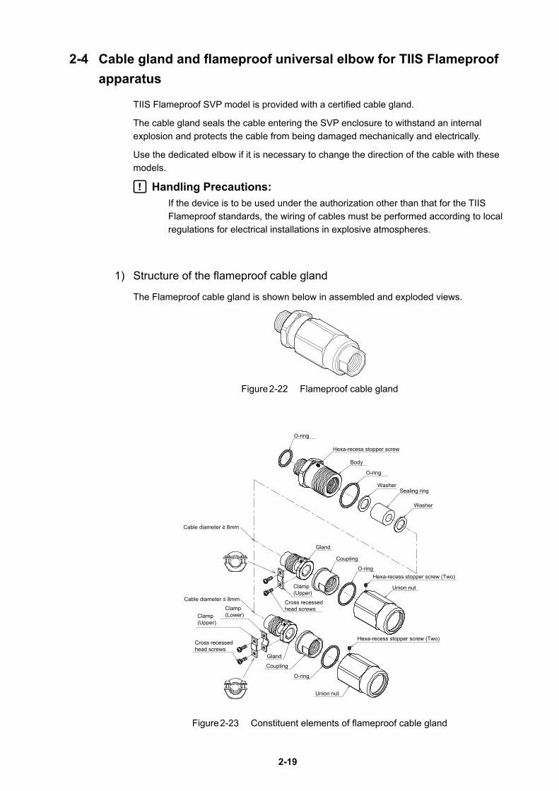
1) Structure of the flameproof cable gland
The Flameproof cable gland is shown below in assembled and exploded views.
Figure 2-22 Flameproof cable gland
O-ring
Body
O-ring
Washer
Washer
Sealing ring
Union nut
O-ring
Coupling
Gland
Cross recessedhead screws
O-ring
Clamp(Upper)
Coupling
Union nut
Gland
Hexa-recess stopper screw (Two)
Hexa-recess stopper screw (Two)
Hexa-recess stopper screw
Cable diameter ≥ 8mm
Cable diameter ≤ 8mm
Clamp(Lower)Clamp
(Upper)
Cross recessedhead screws
Figure 2-23 Constituent elements of flameproof cable gland
2-20
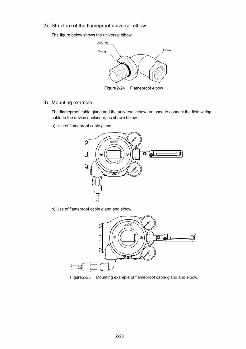
2) Structure of the flameproof universal elbow
The figure below shows the universal elbow.
Elbow
Lock nut
O-ring
Figure 2-24 Flameproof elbow
3) Mounting example
The flameproof cable gland and the universal elbow are used to connect the field wiring cable to the device enclosure, as shown below.
a) Use of flameproof cable gland
b) Use of flameproof cable gland and elbow
Figure 2-25 Mounting example of flameproof cable gland and elbow
2-21
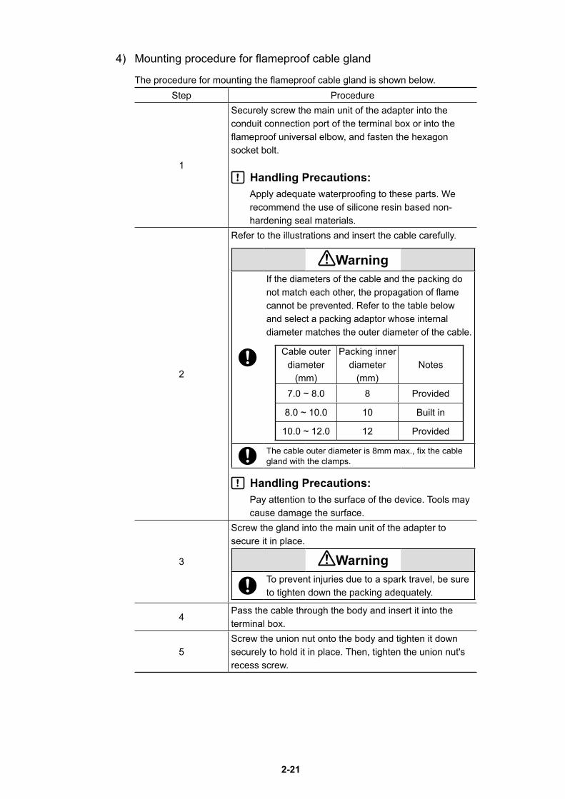
4) Mounting procedure for flameproof cable gland
The procedure for mounting the flameproof cable gland is shown below.Step Procedure
1
Securely screw the main unit of the adapter into the conduit connection port of the terminal box or into the flameproof universal elbow, and fasten the hexagon socket bolt.
Handling Precautions:Apply adequate waterproofing to these parts. We recommend the use of silicone resin based non-hardening seal materials.
2
Refer to the illustrations and insert the cable carefully.
WarningIf the diameters of the cable and the packing do not match each other, the propagation of flame cannot be prevented. Refer to the table below and select a packing adaptor whose internal diameter matches the outer diameter of the cable.
Cable outer diameter
(mm)
Packing inner diameter
(mm)Notes
7.0 ~ 8.0 8 Provided
8.0 ~ 10.0 10 Built in
10.0 ~ 12.0 12 Provided
The cable outer diameter is 8mm max., fix the cable gland with the clamps.
Handling Precautions:Pay attention to the surface of the device. Tools may cause damage the surface.
3
Screw the gland into the main unit of the adapter to secure it in place.
WarningTo prevent injuries due to a spark travel, be sure to tighten down the packing adequately.
4Pass the cable through the body and insert it into the terminal box.
5Screw the union nut onto the body and tighten it down securely to hold it in place. Then, tighten the union nut's recess screw.
2-22
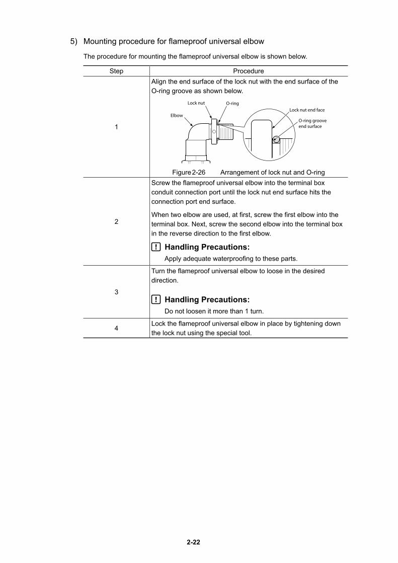
5) Mounting procedure for flameproof universal elbow
The procedure for mounting the flameproof universal elbow is shown below.
Step Procedure
1
Align the end surface of the lock nut with the end surface of the O-ring groove as shown below.
Elbow
Lock nut O-ring Lock nut end face
O-ring grooveend surface
Figure 2-26 Arrangement of lock nut and O-ring
2
Screw the flameproof universal elbow into the terminal box conduit connection port until the lock nut end surface hits the connection port end surface.
When two elbow are used, at first, screw the first elbow into the terminal box. Next, screw the second elbow into the terminal box in the reverse direction to the first elbow.
Handling Precautions:Apply adequate waterproofing to these parts.
3
Turn the flameproof universal elbow to loose in the desired direction.
Handling Precautions:Do not loosen it more than 1 turn.
4Lock the flameproof universal elbow in place by tightening down the lock nut using the special tool.
3-1
Chapter 3 Operation of the 700 Series
This chapter describes how to start operating the device and adjust the device using the local user interface (LUI). When you purchase the device alone, be sure to read “Installation of the 700 Series” before reading this chapter.
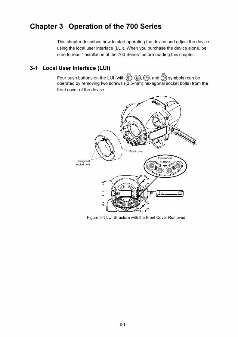
3-1 Local User Interface (LUI)Four push buttons on the LUI (with , , , and symbols) can be operated by removing two screws ((2.5-mm) hexagonal socket bolts) from the front cover of the device.
Front cover
Hexagonal socket bolts
Operationbuttons
Figure 3-1 LUI Structure with the Front Cover Removed
3-2
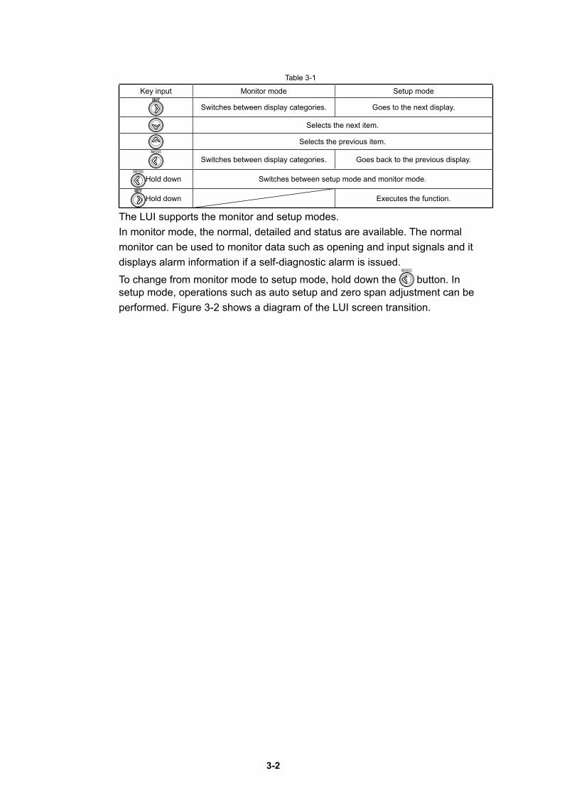
Table 3-1
Key input Monitor mode Setup mode
Switches between display categories. Goes to the next display.
Selects the next item.
Selects the previous item.
Switches between display categories. Goes back to the previous display.
Hold down Switches between setup mode and monitor mode.
Hold down Executes the function.
The LUI supports the monitor and setup modes.In monitor mode, the normal, detailed and status are available. The normal monitor can be used to monitor data such as opening and input signals and it displays alarm information if a self-diagnostic alarm is issued.To change from monitor mode to setup mode, hold down the button. In setup mode, operations such as auto setup and zero span adjustment can be performed. Figure 3-2 shows a diagram of the LUI screen transition.
3-3
The LUI displays the dynamic values in the device and can be used to adjust and set up the following five functions.
• Auto setup function
• Zero span adjustment
• Supply pressure bypass function
• Specification of control parameters
• Setup of the control valve system
This section explains adjustment and setup using the LUI.
Handling Precautions:- Operations cannot be performed from the host when you are using the LUI to
make adjustments or change settings.- If there is an object near the operation button, remove it before operation.- Please return display to the nomal monitor when you want to let you display
alarm. Because you can not display alarm when let you display the monitor except
the normal monitor.- Alarm and the present value are displayed at that time of the alarm outbreak in
turn.- If you have made adjustments, make sure to verify them by checking device
operation. If you have also modified settings, make sure that they were modified correctly.
3-4
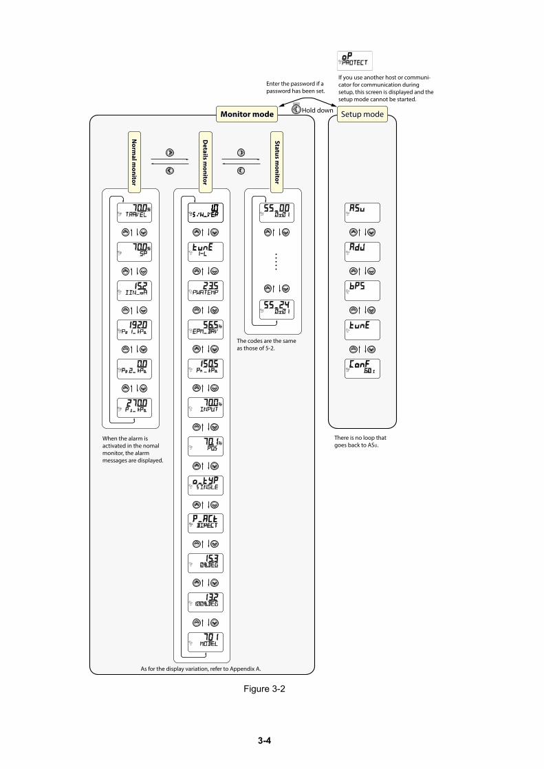
Setup modeSetup mode
Enter the password if a password has been set.
If you use another host or communi-cator for communication during setup, this screen is displayed and the setup mode cannot be started.
There is no loop that goes back to ASU.
Hold downMonitor modeMonitor mode
Status monitor
Status monitor
Details m
onitorD
etails monitor
Norm
al monitor
Norm
al monitor
When the alarm is activated in the nomalmonitor, the alarmmessages are displayed.
The codes are the sameas those of 5-2.
As for the display variation, refer to Appendix A.
Figure 3-2
3-5
3-2 Adjustment before OperationPerform auto setup before using the device. Then, adjust the zero span if necessary.The zero span adjustment function in the device electrically sets the fully closed and fully open positions of the valve independently of each other. Therefore, you can adjust each of these positions without interfering with the other one.
3-2-1 Auto SetupThere are two auto setup methods.• Method using the LUI• Method through HART communication
This section describes the method using the LUI. For the method through HART communication and the details of auto setup, refer to Chapter 4.
Handling Precautions:• The input signal should be 5 mA or more. If it is less than 5 mA, auto setup may not operate normally.
• If any of the self-diagnostic messages shown in Table 4-5 in 4-2-20, “Diagnostic Messages” appears, auto setup cannot be executed.
• Once auto setup and zero span adjustment are completed, always remember to change the input signal and to check the opening, valve travel, and other valve operations.
• Correctly set the actuator type and feedback lever position when fully closed before starting auto setup.
• In some cases, the dynamic characteristic is not set correctly with the actuator capacity, operation stroke, inner diameter of pneumatic piping and piping length. If this occurs, refer to '4-2-5 Control Configuration' and adjust the dynamic characteristic manually.
• When the actuator size is Custom, the size is not changed with the Auto setup. When selecting the actuator size with the Auto setup, set the size as below. Param 1 to 6 or Param A to C.
• In some cases, the initial setting is not same even though the actuator and valve size is same. Please perform the operation check and configuration of the device if necessary.
• There is a possibility that the forced open value described on page '4-2-7 Travel Cutoff' may change after performing the Auto-setup operation. Please reconfigure the forced open value if necessary.
• If the booster relay is on, and is operating the Auto-setup function, there might be a possibility of hunting. In this case, adjust the booster's sensitivity, or refer to '4-2-5 Control Configuration and adjust the dynamic characteristic manually.
• If a speed controller is incorporated, set it to full open and execute auto-setup. Afterwards, adjust the speed with the speed controller.
• When the device is purchased separately, its initial settings are set to those in the list of default values in '6-7 List of Default Values for Internal Data' of this manual. Because the default actuator direction is reverse, if you mount the device on the direct actuator the device will not work. Please be sure to execute the auto setup program before operation and be sure that appropriate settings are created in the device.
3-6
CautionsIt is dangerous during auto setup because the fully closed valve moves to fully open. Be prepared in advance to prevent injury and effects on the process when the valve moves.
The Actuator Type is set to Linear and the Valve Closed Position is set to Down when the valve is fully closed at the time of shipment unless there are other shipment setup instructions. If factory setting (initial setup) is requested, check the settings at the time of shipment. Configure settings as needed.
If auto setup fails, refer to 5-1-5, “Auto Setup Failure.”
The reverse action actuator fully closes, fully opens, and fully closes the valve when auto setup starts. The direct action actuator fully opens, fully closes, and fully opens the valve.Then, it is opened to between 20% and 25% and between 80% and 85%.
After auto setup, the valve moves to the opening appropriate to the input signal.
Check the following points before starting auto setup.
• Actuator Type
Linear (standard): Direct-acting actuatorRotary/90°: When the distance between the feedback lever of the
rotary actuator (90°) and the pin is longer than the distance from the valve shaft
Rotary/Other: When the distance between the feedback lever of the rotary actuator (around 60°) and the pin is longer than the distance from the valve shaft
Rotary(sub)/90°: When the distance between the feedback lever of the rotary actuator (90°) and the pin is shorter than the distance from the valve shaft
Rotary(sub)/Other: When the distance between the feedback lever of the rotary actuator (around 60°) and the pin is shorter than the distance from the valve shaft
• Valve Closed Position DOWN (standard) UP
3-7
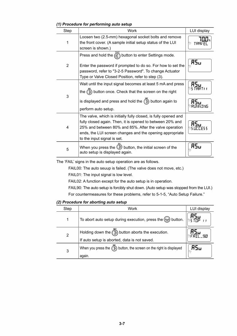
(1) Procedure for performing auto setupStep Work LUI display
1Loosen two (2.5-mm) hexagonal socket bolts and remove the front cover. (A sample initial setup status of the LUI screen is shown.)
2
Press and hold the button to enter Settings mode.
Enter the password if prompted to do so. For how to set the password, refer to "3-2-5 Password". To change Actuator Type or Valve Closed Position, refer to step (3).
3
Wait until the input signal becomes at least 5 mA and press
the button once. Check that the screen on the right
is displayed and press and hold the button again to
perform auto setup.
4
The valve, which is initially fully closed, is fully opened and fully closed again. Then, it is opened to between 20% and 25% and between 80% and 85%. After the valve operation ends, the LUI screen changes and the opening appropriate to the input signal is set.
5 When you press the button, the initial screen of the auto setup is displayed again.
The ‘FAIL’ signs in the auto setup operation are as follows. FAIL00: The auto seuup is failed. (The valve does not move, etc.) FAIL01: The input signal is low level. FAIL02: A function except for the auto setup is in operation. FAIL90: The auto setup is forcibly shut down. (Auto setup was stopped from the LUI.) For countermeasures for these problems, refer to 5-1-5, “Auto Setup Failure.”
(2) Procedure for aborting auto setupStep Work LUI display
1 To abort auto setup during execution, press the button.
2Holding down the button aborts the execution.
If auto setup is aborted, data is not saved.
3When you press the button, the screen on the right is displayed
again.
3-8
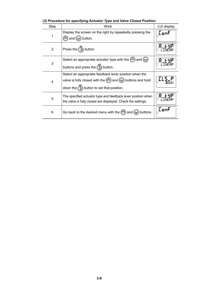
(3) Procedure for specifying Actuator Type and Valve Closed PositionStep Work LUI display
1Display the screen on the right by repeatedly pressing the
and button.
2 Press the button.
3Select an appropriate actuator type with the and
buttons and press the button.
4
Select an appropriate feedback lever position when the
valve is fully closed with the and buttons and hold
down the button to set that position.
5The specified actuator type and feedback lever position when the valve is fully closed are displayed. Check the settings.
6 Go back to the desired menu with the and buttons.
3-9
3-2-2 Zero Span Adjustment
After auto setup, check the 0% and 100% positions. If adjustment is required, adjust the zero span.
The following two zero span adjustment methods are available.
• Method using the LUI
• Method using HART communication (This method is further broken down into the following four methods.)
- Auto Travel Calibration
- Angle Correction
- Manual Setting
- Change Travel Angle
This section describes the method using the LUI. For the method using HART communication, refer to Chapter 4.
Handling Precautions: If you adjust the span after auto setup, the forced fully opening value is automatically changed to the value calculated by subtracting 1% from the overstroke percentage.
Cautions Then zero span adjustment is dangerous because of valve action. Take measures in advance to prevent injury to personnel and effects on the process in case the valve operates.
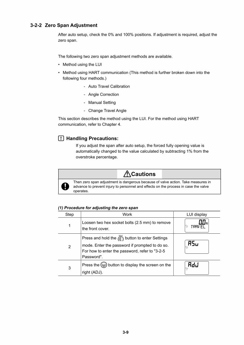
(1) Procedure for adjusting the zero spanStep Work LUI display
1Loosen two hex socket bolts (2.5 mm) to remove the front cover.
2
Press and hold the button to enter Settings
mode. Enter the password if prompted to do so. For how to enter the password, refer to "3-2-5 Password".
3Press the button to display the screen on the
right (ADJ).
3-10
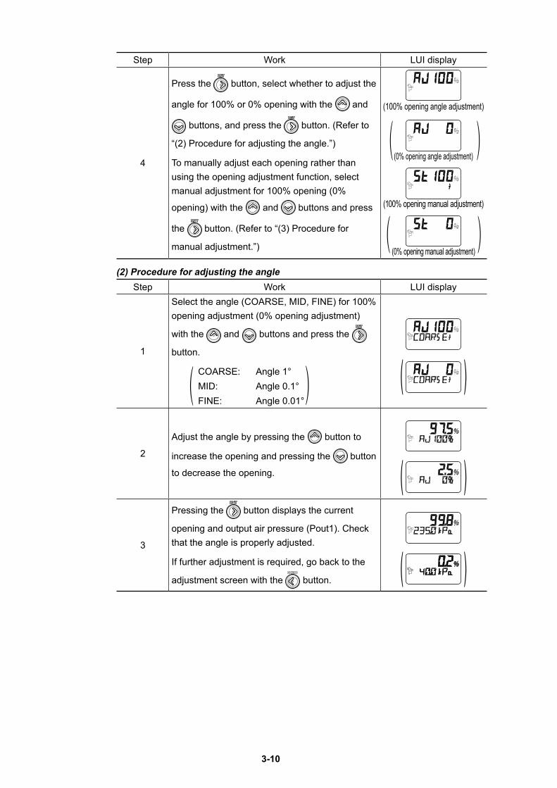
Step Work LUI display
4
Press the button, select whether to adjust the
angle for 100% or 0% opening with the and
buttons, and press the button. (Refer to
“(2) Procedure for adjusting the angle.”)
To manually adjust each opening rather than using the opening adjustment function, select manual adjustment for 100% opening (0%
opening) with the and buttons and press
the button. (Refer to “(3) Procedure for
manual adjustment.”)
(100% opening angle adjustment)
(0% opening angle adjustment)
(100% opening manual adjustment)
(0% opening manual adjustment)
(2) Procedure for adjusting the angleStep Work LUI display
1
Select the angle (COARSE, MID, FINE) for 100% opening adjustment (0% opening adjustment)
with the and buttons and press the
button.
COARSE: Angle 1°MID: Angle 0.1°FINE: Angle 0.01°
( )
2
Adjust the angle by pressing the button to
increase the opening and pressing the button
to decrease the opening. ( )3
Pressing the button displays the current
opening and output air pressure (Pout1). Check that the angle is properly adjusted.
If further adjustment is required, go back to the
adjustment screen with the button. ( )
3-11
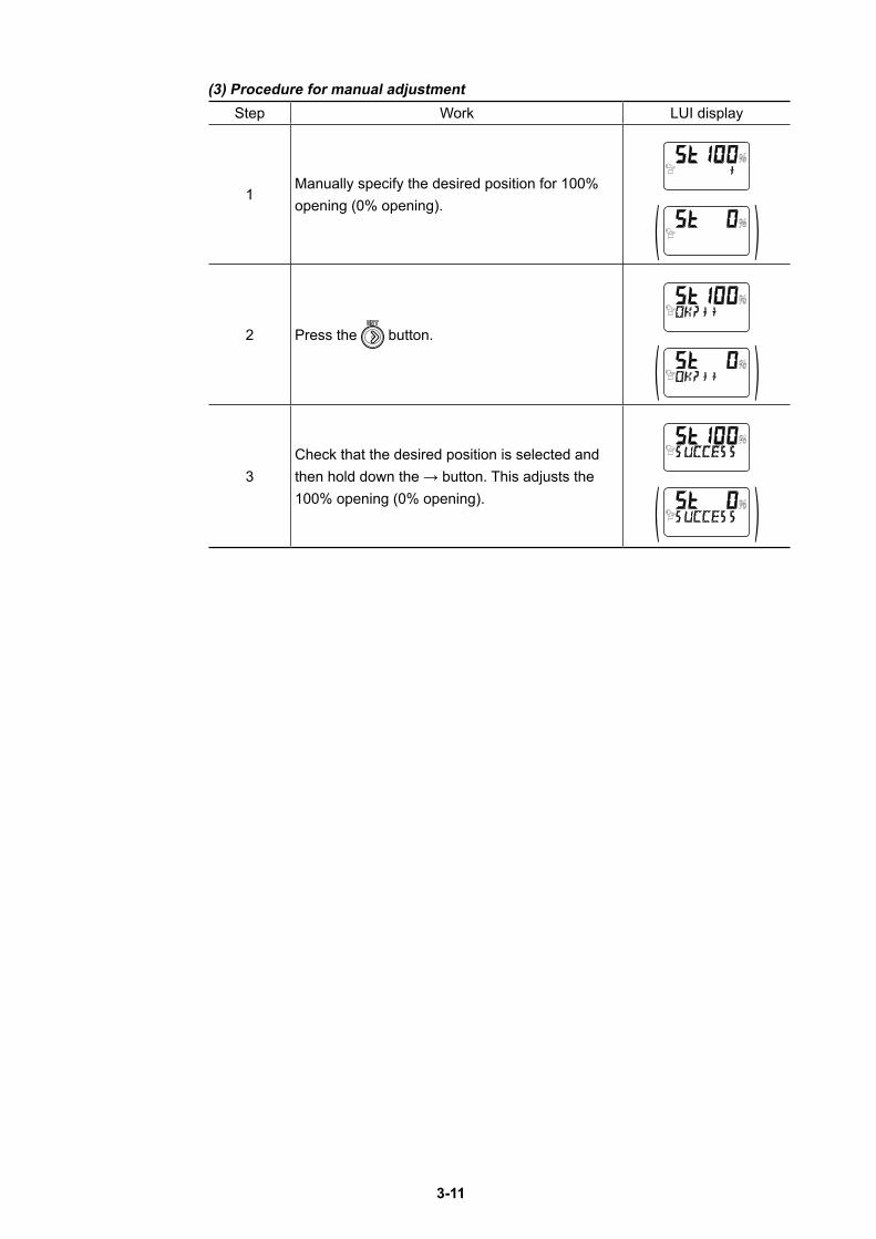
(3) Procedure for manual adjustmentStep Work LUI display
1Manually specify the desired position for 100% opening (0% opening). ( )
2 Press the button.
( )3
Check that the desired position is selected and then hold down the → button. This adjusts the 100% opening (0% opening). ( )
3-12
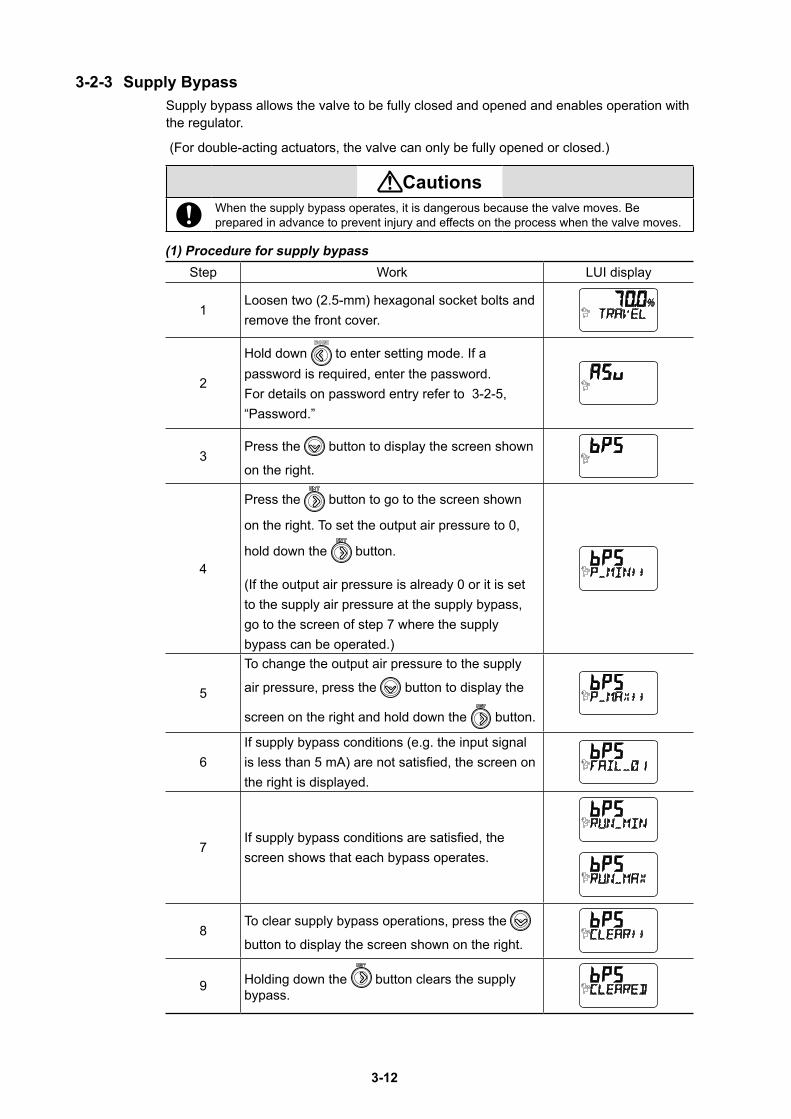
3-2-3 Supply BypassSupply bypass allows the valve to be fully closed and opened and enables operation with the regulator.
(For double-acting actuators, the valve can only be fully opened or closed.)
Cautions When the supply bypass operates, it is dangerous because the valve moves. Be prepared in advance to prevent injury and effects on the process when the valve moves.
(1) Procedure for supply bypassStep Work LUI display
1Loosen two (2.5-mm) hexagonal socket bolts and remove the front cover.
2
Hold down to enter setting mode. If a password is required, enter the password. For details on password entry refer to 3-2-5, “Password.”
3Press the button to display the screen shown
on the right.
4
Press the button to go to the screen shown
on the right. To set the output air pressure to 0,
hold down the button.
(If the output air pressure is already 0 or it is set to the supply air pressure at the supply bypass, go to the screen of step 7 where the supply bypass can be operated.)
5
To change the output air pressure to the supply
air pressure, press the button to display the
screen on the right and hold down the button.
6If supply bypass conditions (e.g. the input signal is less than 5 mA) are not satisfied, the screen on the right is displayed.
7If supply bypass conditions are satisfied, the screen shows that each bypass operates.
8To clear supply bypass operations, press the
button to display the screen shown on the right.
9 Holding down the button clears the supply bypass.
3-13
The ‘FAIL’ signs in the supply bypass operation are as follows. FAIL01: The input signal is low level. FAIL02: A function except for the supply bypass is in operation. FAIL90: The auto setup is forcibly shut down.
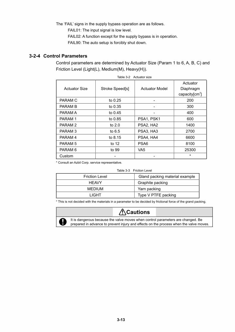
3-2-4 Control ParametersControl parameters are determined by Actuator Size (Param 1 to 6, A, B, C) and Friction Level (Light(L), Medium(M), Heavy(H)).
Table 3-2 Actuator size
Actuator Size Stroke Speed[s] Actuator ModelActuator
Diaphragm capacity[cm3]
PARAM C to 0.25 - 200PARAM B to 0.35 - 300PARAM A to 0.45 - 400PARAM 1 to 0.85 PSA1, PSK1 600PARAM 2 to 2.0 PSA2, HA2 1400PARAM 3 to 6.5 PSA3, HA3 2700PARAM 4 to 8.15 PSA4, HA4 6600PARAM 5 to 12 PSA6 8100PARAM 6 to 99 VA5 25300Custom - - *
* Consult an Azbil Corp. service representative.
Table 3-3 Friction Level
Friction Level Gland packing material exampleHEAVY Graphite packing
MEDIUM Yarn packingLIGHT Type V PTFE packing
* This is not decided with the materials in a parameter to be decided by frictional force of the grand packing.
Cautions It is dangerous because the valve moves when control parameters are changed. Be prepared in advance to prevent injury and effects on the process when the valve moves.
3-14
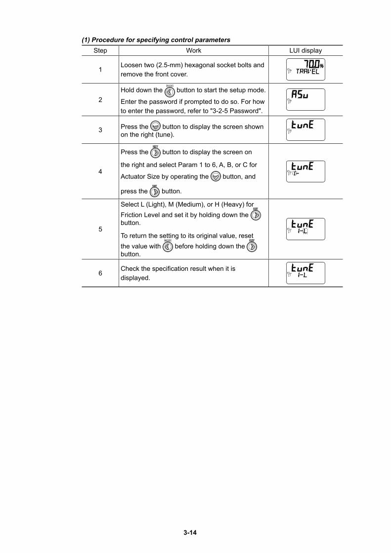
(1) Procedure for specifying control parametersStep Work LUI display
1Loosen two (2.5-mm) hexagonal socket bolts and remove the front cover.
2Hold down the button to start the setup mode.
Enter the password if prompted to do so. For how to enter the password, refer to "3-2-5 Password".
3 Press the button to display the screen shown on the right (tune).
4
Press the button to display the screen on
the right and select Param 1 to 6, A, B, or C for
Actuator Size by operating the button, and
press the button.
5
Select L (Light), M (Medium), or H (Heavy) for Friction Level and set it by holding down the button.
To return the setting to its original value, reset the value with before holding down the button.
6Check the specification result when it is displayed.
3-15
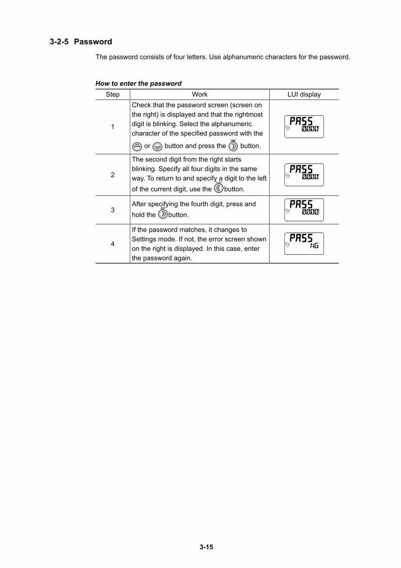
3-2-5 Password
The password consists of four letters. Use alphanumeric characters for the password.
How to enter the passwordStep Work LUI display
1
Check that the password screen (screen on the right) is displayed and that the rightmost digit is blinking. Select the alphanumeric character of the specified password with the
or button and press the button.
2
The second digit from the right starts blinking. Specify all four digits in the same way. To return to and specify a digit to the left of the current digit, use the button.
3After specifying the fourth digit, press and hold the button.
4
If the password matches, it changes to Settings mode. If not, the error screen shown on the right is displayed. In this case, enter the password again.
3-16
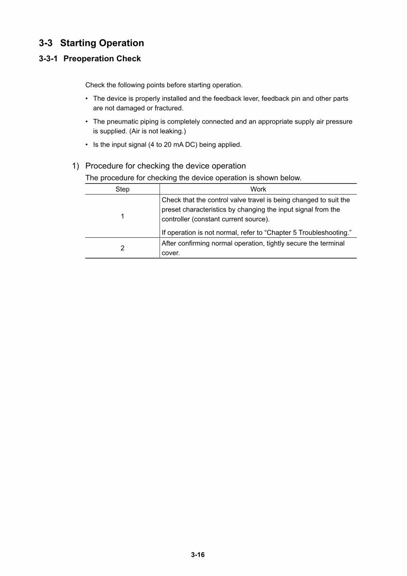
3-3 Starting Operation3-3-1 Preoperation Check
Check the following points before starting operation.
• The device is properly installed and the feedback lever, feedback pin and other parts are not damaged or fractured.
• The pneumatic piping is completely connected and an appropriate supply air pressure is supplied. (Air is not leaking.)
• Is the input signal (4 to 20 mA DC) being applied.
1) Procedure for checking the device operationThe procedure for checking the device operation is shown below.
Step Work
1
Check that the control valve travel is being changed to suit the preset characteristics by changing the input signal from the controller (constant current source).
If operation is not normal, refer to “Chapter 5 Troubleshooting.”
2After confirming normal operation, tightly secure the terminal cover.
4-1
Chapter 4 Operation with HART Communication
This chapter describes the operations performed using HART communication.For the basic operations, the relationship between the mode and data settings, the specification and modification of data, how to save each type of data, and other descriptions, refer to this chapter.
4-1 Operation with HART CommunicationThis section describes the menu configuration and functions for adjustment and setting items using HART communication. The HART communication tool is used to adjust, set, and read data for this device. For details, see the operation manual for the HART communication tool.
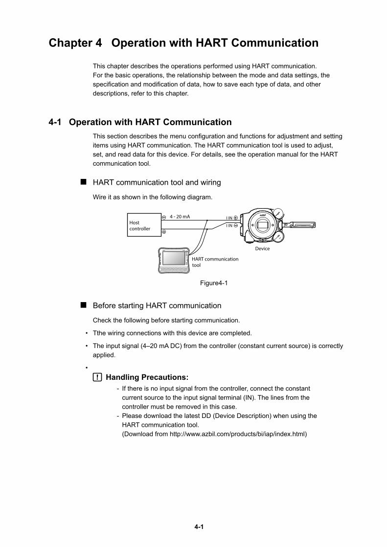
HART communication tool and wiring
Wire it as shown in the following diagram.
Hostcontroller
4 - 20 mA I IN
I IN
HART communicationtool
Device
Figure4-1
Before starting HART communication
Check the following before starting communication.
• Tthe wiring connections with this device are completed.
• The input signal (4–20 mA DC) from the controller (constant current source) is correctly applied.
• Handling Precautions:
- If there is no input signal from the controller, connect the constant current source to the input signal terminal (IN). The lines from the controller must be removed in this case.
- Please download the latest DD (Device Description) when using the HART communication tool. (Download from http://www.azbil.com/products/bi/iap/index.html)
4-2
4-2 Setup and Adjustment of Device
Set up and adjust the functions required for the device to operate properly.
This section describes the menu of the 475 communicator.To change settings and make adjustments, select [Device] → [Configuration] → [Operator Action Setting] → [Allow operation action].
This allows you to change settings and make adjustments, and also restricts settings changes and adjustments from LUI and the other HART master*.
* HART communication master stations are configured for either the primary or secondary. In most cases, the host system is the primary and the 475 communicator is the secondary.
Once the settings and adjustments are complete, select [Device] → [Configuration] → [Operator Action Setting] → [Forbid operation action]. The LUI becomes inoperable if you do not perform this operation. (When there has been no HART communication for more than 10 minutes, this operation will be performed automatically and the LUI becomes operable.)
4-2-1 Process Variables
The measurement value data present when the device is operating can be viewed.
Select [Process Variables].
Checking measured values
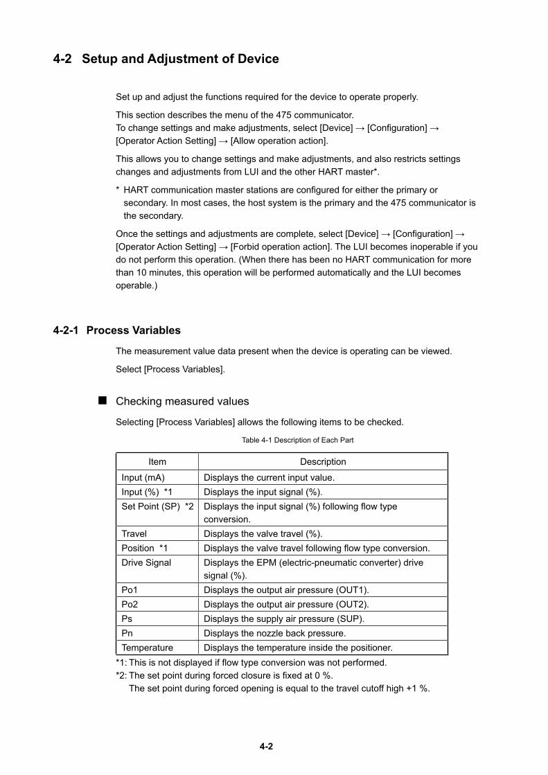
Selecting [Process Variables] allows the following items to be checked.
Table 4-1 Description of Each Part
Item Description
Input (mA) Displays the current input value.Input (%) *1 Displays the input signal (%).Set Point (SP) *2 Displays the input signal (%) following flow type
conversion.Travel Displays the valve travel (%).Position *1 Displays the valve travel following flow type conversion.Drive Signal Displays the EPM (electric-pneumatic converter) drive
signal (%).Po1 Displays the output air pressure (OUT1).Po2 Displays the output air pressure (OUT2).Ps Displays the supply air pressure (SUP).Pn Displays the nozzle back pressure.Temperature Displays the temperature inside the positioner.
*1: This is not displayed if flow type conversion was not performed.*2: The set point during forced closure is fixed at 0 %.
The set point during forced opening is equal to the travel cutoff high +1 %.
4-3
4-2-2 Auto Setup
Auto setup is a function that automatically performs basic adjustments and setup after the device is assembled onto the actuator.
Select [Device]→[Basic Setup]→[Auto Setup].
CautionsIt is dangerous during auto setup because the fully closed valve moves to fully open. Be prepared in advance to prevent injury and effects on the process when the valve moves.
Handling Precautions:- The input signal should be 5 mA or more. If it is less than 5 mA, auto setup
may not operate normally.- If any of the self-diagnostic messages shown in Table 4-5 in 4-2-20,
“Diagnostic Messages” appears, auto setup cannot be executed.- When auto setup and zero span adjustment are complete, change the input
signal and be sure to check valve operations such as opening and shutoff.- Before the Auto setup operation, set the position of the actuator type and the
forced close feedback lever correctly.- In some cases, the dynamic characteristic is not set correctly with the actuator
capacity, operation stroke, inner diameter of pneumatic piping and piping length. If this occurs, refer to '4-2-5 Control Configuration' and adjust the dynamic characteristic manually.
- When the actuator size is Custom, the size is not changed with the Auto setup. When selecting the actuator size with the Auto setup, set the size as below. Param 1 to 6 or Param A to C.
- In some cases, the initial setting is not same even though the actuator and valve size is same. Please perform the operation check and configuration of the device if necessary.
- There is a possibility that the forced open value described on page '4-2-7 Travel Cutoff' may change after performing the Auto-setup operation. Please reconfigure the forced open value if necessary.
- If the booster relay is on, and is operating the Auto-setup function, there might be a possibility of hunting. In this case, adjust the booster's sensitivity, or refer to '4-2-5 Control Configuration and adjust the dynamic characteristic manually.
- If a speed controller is incorporated, set it to full open and execute auto-setup. Afterwards, adjust the speed with the speed controller.
- When the device is purchased separately, its initial settings are set to those in the list of default values in '6-7 List of Default Values for Internal Data' of this manual. Because the default actuator direction is reverse, if you mount the device on the direct actuator the device will not work. Please be sure to execute the auto setup program before operation and be sure that appropriate settings are created in the device.
Check the Actuator Type and Valve Closed Position before starting auto setup.
The Actuator Type is set to Linear and the Valve Closed Position is set to Down when the valve is fully closed at the time of shipment unless there are other shipment setup instructions. If factory setting (initial setup) is requested, check the settings at the time of shipment. Configure settings as needed.
4-4
If auto setup fails, refer to 5-1-5, “Auto Setup Failure.”
The reverse action actuator fully closes, fully opens, and fully closes the valve when auto setup starts. The direct action actuator fully opens, fully closes, and fully opens the valve.Then, it is opened to between 20% and 25% and between 80% and 85%.
After auto setup, the valve moves to the opening appropriate to the input signal.
The following items are automatically adjusted and set during auto setup.
(1) Zero span adjustment The zero point is set to the travel when the valve is fully closed. The span point (100
% travel) is set in such a way that the travel when the valve is fully opened is Travel Cutoff High + 1 %. (If Travel Cutoff High is 99 %, the fully opened position is the span point.) If the span is adjusted after auto setup, Travel Cutoff High will be automatically changed and saved.
(2) Input signal range (Input Range), Input Range Low (Close) and Input Range High (Open) settings The input range settings are changed so that the valve operation direction (close or open) when the input current is lowered from 20 mA to 4 mA is the same as the direction for power-off (input current: 0 mA). Example: If Valve Closed Position is set to DOWN (normal)
When the actuator action is reversed: Input Range Low (Close) = 4mA, Input Range High (Open) = 20mA When the actuator action is forwarded: Input Range Low (Close) =20mA, Input Range High (Open) = 4mA
(3) Specification of Actuator Size Select the actuator size from among Param 1 to Param 6, Param A, B, and C.
(4) Specification of Friction Level Select the friction level of the gland packing from among LIGHT, MEDIUM, and HEAVY.
(5) Specification of Feedback Lever Motion Specify UP or DOWN as the operation of the feedback lever when output air
pressure OUT1 increases.
(6) Specification of Positioner Action When the input signal is “Disconnected,” the positioner operation is forward operation
(Direct) if the output air pressure is 0. When the input signal is “Disconnected,” the positioner operation is reverse operation (Reverse) if the output air pressure is the supply air pressure.
(7) Specification of Pilot Relay Type Select Single Acting or Double Acting as the operation of the actuator.
4-5
4-2-3 Input RangeSets the current input value when the valve travel is at 0% (Input Range Low (Close)) and the current input value when the valve travel is at 100% (Input Range High (Open)). An input in the 4–20 mA range can be used.Select [Device] → [Configuration] → [Input Range].
CautionsChanging the input signal range will move the valve, which is dangerous. Ensure ahead of time that there will be no injuries or effects on the processes if the valve is moved.
Input Range High (Open/100%): Set the input signal at 100% travel.Input Range Low (Closed/0%): Set the input signal at 0% travel.
Handling Precautions:- Set the current input span to not exceed 4 mA for (Input Range High
(Open) - Input Range Low (Close)). If the current input span is less than 8 mA, the precision will be ±1.5% of full scale.
- Set the value so that the operation direction is the same when the input signal is 0 mA and 4 mA. The following conditions must be satisfied. If the valve is fully closed at power-off : Input Range High (Open/100%) > Input Range Low (Closed/0%) If the valve is fully open at power-off : Input Range High (Open/100%) < Input Range Low (Closed/0%)
4-2-4 Valve SystemSpecify the operation of the control valve (actuator and valve) and the positioner.Select [Device] → [Configuration] → [Valve System].
CautionsIt is dangerous because the valve moves when the settings are changed. Be prepared in advance to prevent injury and effects on the process when the valve moves.
• Actuator Type
- Linear Linear motion valve
- Rotary/90° When the distance between the feedback lever of the rotary actuator (90°) and the pin
is longer than the distance from the valve shaft
- Rotary/Other When the distance between the feedback lever of the rotary actuator (around 60°) and
the pin is longer than the distance from the valve shaft
- Rotary sub/90° When the distance between the feedback lever of the rotary actuator (90°) and the pin
is shorter than the distance from the valve shaft
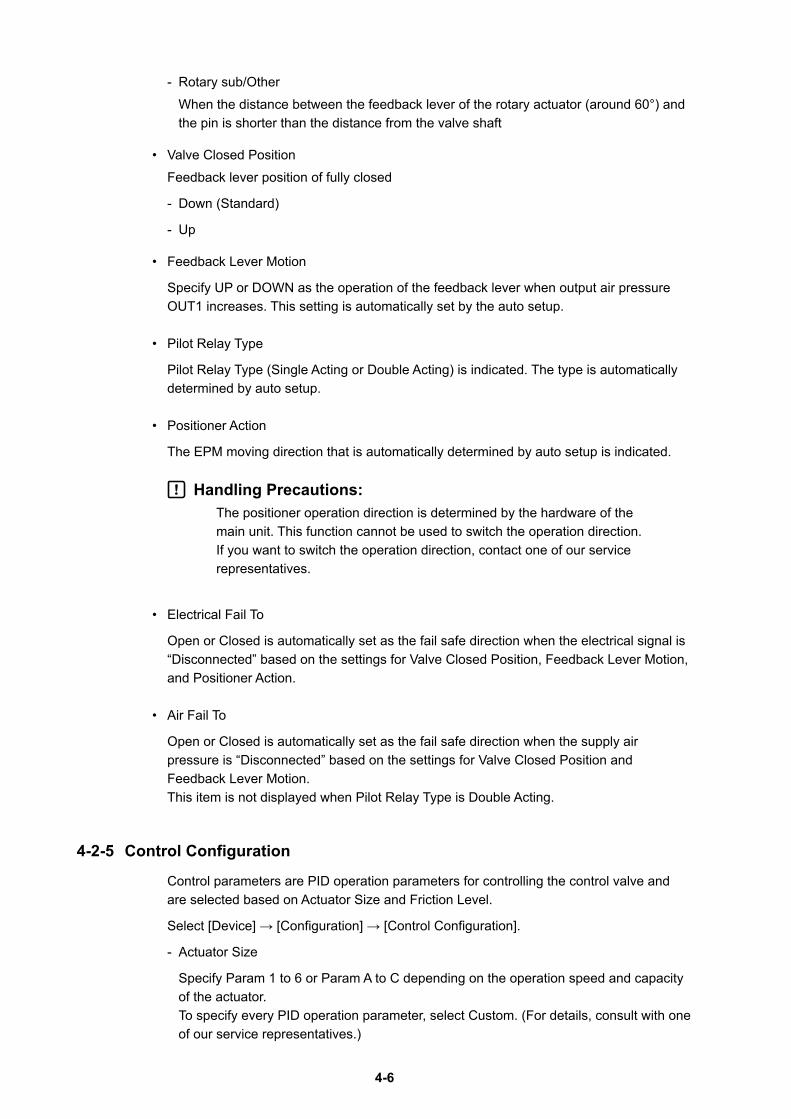
4-6
- Rotary sub/Other When the distance between the feedback lever of the rotary actuator (around 60°) and
the pin is shorter than the distance from the valve shaft
• Valve Closed PositionFeedback lever position of fully closed
- Down (Standard)
- Up
• Feedback Lever Motion
Specify UP or DOWN as the operation of the feedback lever when output air pressure OUT1 increases. This setting is automatically set by the auto setup.
• Pilot Relay Type
Pilot Relay Type (Single Acting or Double Acting) is indicated. The type is automatically determined by auto setup.
• Positioner Action
The EPM moving direction that is automatically determined by auto setup is indicated.
Handling Precautions:The positioner operation direction is determined by the hardware of the main unit. This function cannot be used to switch the operation direction. If you want to switch the operation direction, contact one of our service representatives.
• Electrical Fail To
Open or Closed is automatically set as the fail safe direction when the electrical signal is “Disconnected” based on the settings for Valve Closed Position, Feedback Lever Motion, and Positioner Action.
• Air Fail To
Open or Closed is automatically set as the fail safe direction when the supply air pressure is “Disconnected” based on the settings for Valve Closed Position and Feedback Lever Motion. This item is not displayed when Pilot Relay Type is Double Acting.
4-2-5 Control Configuration
Control parameters are PID operation parameters for controlling the control valve and are selected based on Actuator Size and Friction Level.
Select [Device] → [Configuration] → [Control Configuration].
- Actuator Size
Specify Param 1 to 6 or Param A to C depending on the operation speed and capacity of the actuator. To specify every PID operation parameter, select Custom. (For details, consult with one of our service representatives.)
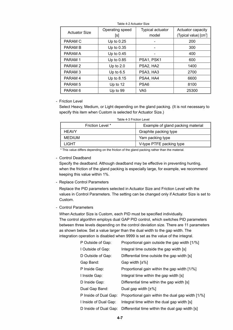
4-7
Table 4-2 Actuator Size
Actuator SizeOperating speed
[s]Typical actuator
modelActuator capacity(Typical value) [cm3]
PARAM C Up to 0.25 - 200PARAM B Up to 0.35 - 300PARAM A Up to 0.45 - 400PARAM 1 Up to 0.85 PSA1, PSK1 600PARAM 2 Up to 2.0 PSA2, HA2 1400PARAM 3 Up to 6.5 PSA3, HA3 2700PARAM 4 Up to 8.15 PSA4, HA4 6600PARAM 5 Up to 12 PSA6 8100PARAM 6 Up to 99 VA5 25300
- Friction Level Select Heavy, Medium, or Light depending on the gland packing. (It is not necessary to
specify this item when Custom is selected for Actuator Size.)
Table 4-3 Friction Level
Friction Level * Example of gland packing materialHEAVY Graphite packing typeMEDIUM Yarn packing typeLIGHT V-type PTFE packing type
* This value differs depending on the friction of the gland packing rather than the material.
- Control Deadband Specify the deadband. Although deadband may be effective in preventing hunting,
when the friction of the gland packing is especially large, for example, we recommend keeping this value within 1%.
- Replace Control Parameters Replace the PID parameters selected in Actuator Size and Friction Level with the
values in Control Parameters. The setting can be changed only if Actuator Size is set to Custom.
- Control Parameters When Actuator Size is Custom, each PID must be specified individually.
The control algorithm employs dual GAP PID control, which switches PID parameters between three levels depending on the control deviation size. There are 11 parameters as shown below. Set a value larger than the dual width to the gap width. The integration operation is disabled when 9999 is set as the value of the integral.
P Outside of Gap: Proportional gain outside the gap width [1/%] I Outside of Gap: Integral time outside the gap width [s] D Outside of Gap: Differential time outside the gap width [s] Gap Band: Gap width [±%] P Inside Gap: Proportional gain within the gap width [1/%] I Inside Gap: Integral time within the gap width [s] D Inside Gap: Differential time within the gap width [s] Dual Gap Band: Dual gap width [±%] P Inside of Dual Gap: Proportional gain within the dual gap width [1/%] I Inside of Dual Gap: Integral time within the dual gap width [s] D Inside of Dual Gap: Differential time within the dual gap width [s]
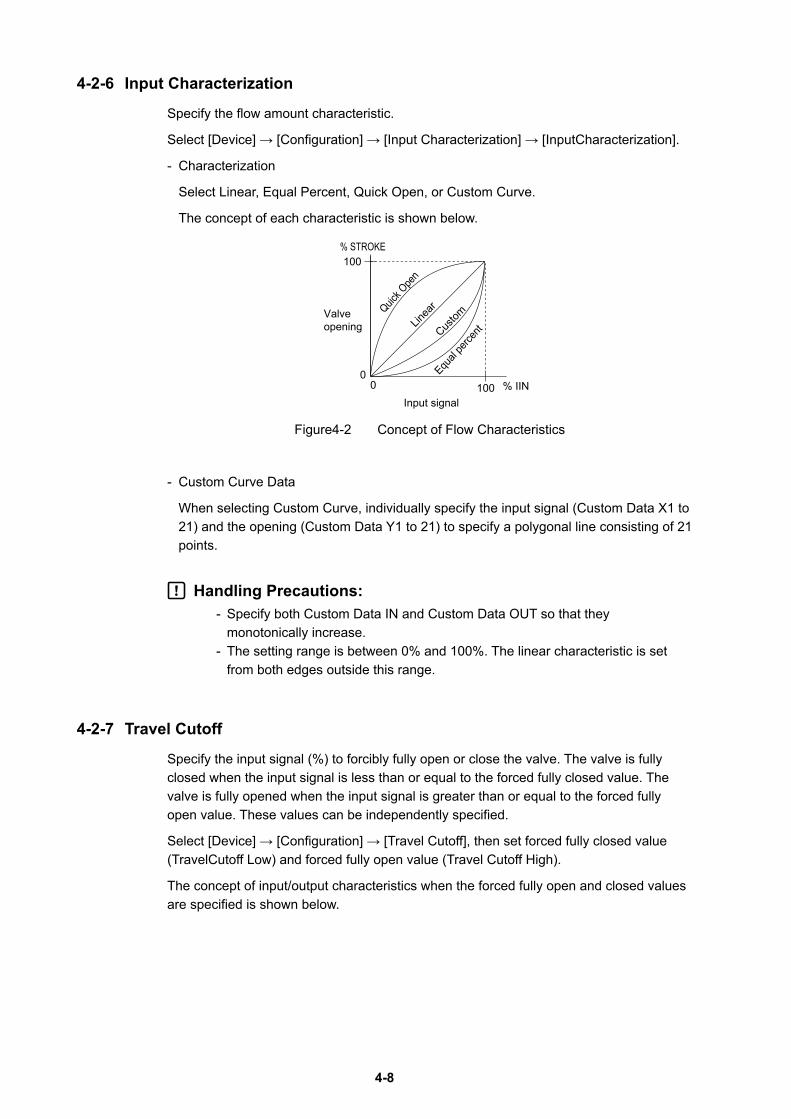
4-8
4-2-6 Input Characterization
Specify the flow amount characteristic.
Select [Device] → [Configuration] → [Input Characterization] → [InputCharacterization].
- Characterization
Select Linear, Equal Percent, Quick Open, or Custom Curve.
The concept of each characteristic is shown below.
% STROKE100
100 % IINQuic
k Ope
n
Equal
perce
nt
Linea
r
Custom
00
Valve opening
Input signal
Figure4-2 Concept of Flow Characteristics
- Custom Curve Data
When selecting Custom Curve, individually specify the input signal (Custom Data X1 to 21) and the opening (Custom Data Y1 to 21) to specify a polygonal line consisting of 21 points.
Handling Precautions:- Specify both Custom Data IN and Custom Data OUT so that they
monotonically increase.- The setting range is between 0% and 100%. The linear characteristic is set
from both edges outside this range.
4-2-7 Travel Cutoff
Specify the input signal (%) to forcibly fully open or close the valve. The valve is fully closed when the input signal is less than or equal to the forced fully closed value. The valve is fully opened when the input signal is greater than or equal to the forced fully open value. These values can be independently specified.
Select [Device] → [Configuration] → [Travel Cutoff], then set forced fully closed value (TravelCutoff Low) and forced fully open value (Travel Cutoff High).
The concept of input/output characteristics when the forced fully open and closed values are specified is shown below.
4-9
% STROKE
100
100 % IIN
Valve opening
Forced fully closed value
Forced fully open value
00
Input signal-0.1% +0.1% -0.1% +0.1%
Figure4-3 Forced Fully Open and Closed Values
Handling Precautions:- Specify values such that the forced fully closed value is smaller than the forced
fully open value. If the forced fully closed value is equal to the forced fully open value, the valve performs the ON/OFF operation.
- The settable range is between -200% and 50% for the forced fully closed value and between 50% and 200% for the forced fully open value.
- If you adjust the span after auto setup, the forced fully open value is automatically changed to the value calculated by subtracting 1% from the overstroke percentage.
- The forced fully closed and open values each have a hysteresis difference of 0.1%.
- When the valve is forced fully closed (open), Working Setpoint shows the value for the fully closed (open) status.
4-2-8 Units
Specify the units for pressure.
Select [Device] → [Configuration] → [Unit].
Initial setting of SI system unit and non-SI system unit is as follows. You can not change the initial setting.
If the non-SI system unit is needed, order kg/cm2 or psi at the time of purchase.
SI system: kPa, MPa, Bar
Non-SI system: kPa, MPa, Bar, kg/cm2, PSI
This unit setting is invalid in the LUI display. Only the kPa is valid in the LUI display.
4-10
4-2-9 Travel Calibration
Adjust zero and span of valve opening.
Select [Device]→[Maintenance]→[Travel Calibration].
The following four types of zero span adjustment methods are available.
(1) Auto Travel Calibration
(2) Angle Correction
(3) Manual Setting
(4) Change Travel Angle
Handling Precautions:If you adjust the span after auto setup, the forced fully open value is changed to the value calculated by subtracting 1% from the overstroke percentage.
(1) Auto Travel Calibration
When you select [Device]→[Maintenance]→[Travel Calibration]→[Auto Travel Calibration], the valve, which is initially fully closed, is fully opened and then fully closed, and the zero point and span point are automatically set.
CautionsIt is dangerous during automatic opening adjustment because the fully opened valve moves to fully closed. Be prepared in advance to prevent injury and effects on the process when the valve moves.
Handling Precautions:- Set the input signal 5 mA min. If the input signal is below 5 mA, the device may
not operate properly.- If any of the self-diagnostic messages shown in Table 4-5 in 4-2-20,
“Diagnostic Messages” appears, auto travel calibration cannot be executed.- After device operation is performed, make sure Travel Cutoff of the valve with
changing input signals.
(2) Angle Correction
Adjust the angles of the zero and span points.
Select [Device]→[Maintenance]→[Travel Calibration]→[Angle Correction].
- 0% Travel
Set 0% to Final Valve.
Set a value less than 0% to Final Value Lo Cutoff, select the angle increment and decrement values, and adjust the zero point. (To increase the value by 0.01°, select Increment/0.01.)
After adjustment, return Final Value Lo Cutoff to the original value.
4-11
- 100% Travel
Set 100% to Final Valve.
If Final Value Hi Cutoff is less than 100%, set a value larger than 100%, select the angle increment and decrement values, and adjust the span point. After adjustment, return Final Value Hi Cutoff to its original value.
Handling Precautions:If the angle after adjustment changes by more than ±30°, the operation is disabled.
(3) Manual Setting
Manually fix the 0% or 100% opening and set the zero and span points.
Select [Device]→[Maintenance]→[Travel Calibration]→[Manual Setting].
- 0% Travel
Move the valve to the 0% opening position by operating the input signal, actuator pressure, manual handle, or other factor and set the zero point.
- 100% Travel
Move the valve to the 100% opening position by operating the input signal, actuator pressure, manual handle, or other factor and set the span point.
Handling Precautions: If the angle after adjustment changes by more than ±30°, the operation is disabled.
(4) Change Travel Angle
Set the angles of 0% opening and 100% opening.
The angle is 0° when the feedback lever is horizontal. The angle is negative if the lever is lower than the horizontal position. The angle is positive if the lever is higher than the horizontal position.
Select [Device]→[Maintenance]→[Travel Calibration]→[Change Travel Angle].
- 0% Travel Angle
Set the angle of the 0% opening position.
- 100% Travel Angle
Set the angle of the 100% opening position.
Handling Precautions: Specify an angle within ±30°. Accuracy is guaranteed between ±4° and ±20°.
4-12
4-2-10 Input Calibration
Calibrates the input signal (4 mA, 20 mA).
Select [Device] → [Maintenance] → [Input Calibration].
• Calibrate the 4 mA signal
Set after making the current input (controller output) 4 mA.
• Calibrate the 20 mA signal
Set after making the current input (controller output) 20 mA.
4-2-11 Pressure Sensor Adjustment
Adjust the zero point of the pressure sensor.
Select [Device] → [Maintenance] → [Pressure Sensor Adjustment] → [ZeroAdjustment].
Shut off the supply air pressure before zero adjustment.
4-2-12 Simulation
The following two operations can be changed.
Handling Precautions: The input signal should be 5 mA or more. If it is lower than 5 mA, the device does not operate normally.
(1) Dummy Input Signal
Specify the pseudo input signal (0% to 100%) and operate the valve. Regardless of the actual input current, the desired input signal can be sent to the device.
Select [Device] → [Maintenance] → [Simulation] → [Dummy Input Signal].
(2) Dummy Drive Signal
Specify the pseudo EPM drive signal (0% to 100%). Regardless of the actual input current and travel, the desired EPM drive signal can be output from the device.
Select [Device] → [Maintenance] → [Simulation] → [Dummy Drive Signal].
CautionsWhen a simulation is running, it is dangerous to leave it unused for more than 10 minutes, as this will cancel out the setting, and the valve may start moving.Ensure ahead of time that there will be no injuries or effects on process if the valve is moved.
4-13
4-2-13 Adjustment of EPM Drive Signal (Pneumatic Modules)
This function is used to adjust the EPM drive signal if the signal has shifted or if Positioner Action has changed.
Select [Device] → [Maintenance] → [Pneumatic Modules] → [EPM Adjustment].
Handling Precautions: Ask our service representative for the operation not to damage a device by erroneous operation..
4-2-14 Restore factory settings
Restore the data that was set when the device was shipped from the factory.
Select [Device]→[Maintenance]→[Restore factory settings].
(It may be necessary to restart the communication tool after restoring the factory data.)
Handling Precautions: This operation does not change the HART communication settings such as Device Tag and Long Tag, diagnostics-related settings, and history information.
4-2-15 Operator Action Records
Save the history of setting modification operations.
The operation item, operation method, and time of the last 10 modifications are saved.
Simulation operations are not saved.
Select [Device]→[Maintenance]→[Operator Action Records].
4-2-16 Real Time ClockChecks and sets the current time.Select [Device] → [Maintenance] → [Real Time Clock].
Handling Precautions: The current time set with this operation is reset when the power is cut. (2012/04/01 00:000)
4-2-17 PasswordSets whether to use the password function and sets the password.Select [Device] → [Maintenance] → [Password].
4-14
4-2-18 Device Information
Select [Device] → [Device Information].
The following information can be checked and the settings can be changed.
• Manufacturer
Displays Azbil Corporation as the device manufacturer.
• Model
Displays AVP700 as the name and model number of the device.
• Device ID
Displays the unique ID information of the device.
• Device Tag
Displays and changes the Tag No. assigned to the device.
• Long Tag
Displays and changes the Tag No. assigned to the device.
• Date
Displays and changes specific dates such as the final settings date of the device.
• Descriptor
Displays and changes the various information required to manage the device.
• Message
Displays and changes the messages registered in the device.Config Change Counter
Displays and changes the messages registered in the device.
• Serial Number
Displays the unique serial number of the device.
• Final Assembly Number
Displays and changes specific management numbers such as the final settings date for the device and system.
• Distributor
Displays the name of the company selling the device.
• Config Change Counter
Displays the number of changes made to the set device.
• Operating Time
Displays the time the device has been operating.
• Polling Address
Displays and changes the device address. Specifies the device address when multiple devices are connected to the same loop (split range, multi-drop connection, etc.).
4-15
• Number of Request Preambles
Displays the number of preambles requested from the device to the host.
• Number of Response Preambles
Displays the number of preambles returned from the device to the host.
• Revision Numbers
HART Version:
Displays the revision number of the HART universal command supported by this device.
Device Revision:
Displays the revision number of the device-specific command supported by this device.
Software Revision:
Displays the revision number of the software in a given Device Revision.
Hardware Revision:
Displays the revision number of the hardware for this device.
• Factory Setting Information
Production Number:
Displays the production number.
Model Number:
Displays the model number.
Valve Model Number:
Displays the valve model number.
Factory Setting Date:
Displays the factory shipping date.
4-16
4-2-19 Option
Additional functions include the following.
Travel transmission signal output
Selecting [Device] → [Option] → [Travel Transmission (AO)] → [TravelTransmission] allows the travel signal output to be monitored.
Selecting [Device] → [Option] → [Travel Transmission (AO)] → [Dummy TravelTransmission] allows the travel signal output to be changed freely.
Selecting [Device] → [Option] → [Travel Transmission (AO)] → [Fail SafeDirection] allows the failsafe direction (High or Low) for the travel signal to be checked.
This setting is set at the time of factory shipment, and the setting change after the delivery is not possible.
If a self-diagnostic message pertaining to fail-safe operation (Table 4-5 in section 4-2-20) appears, the travel transmission signal is sent according to the specified fail safe direction.
Selecting [Device] → [Option] → [Travel Transmission (AO)] → [D/A Trim] calibrates the travel signal output (4 mA, 20 mA). Connect to an ammeter to calibrate the current value.
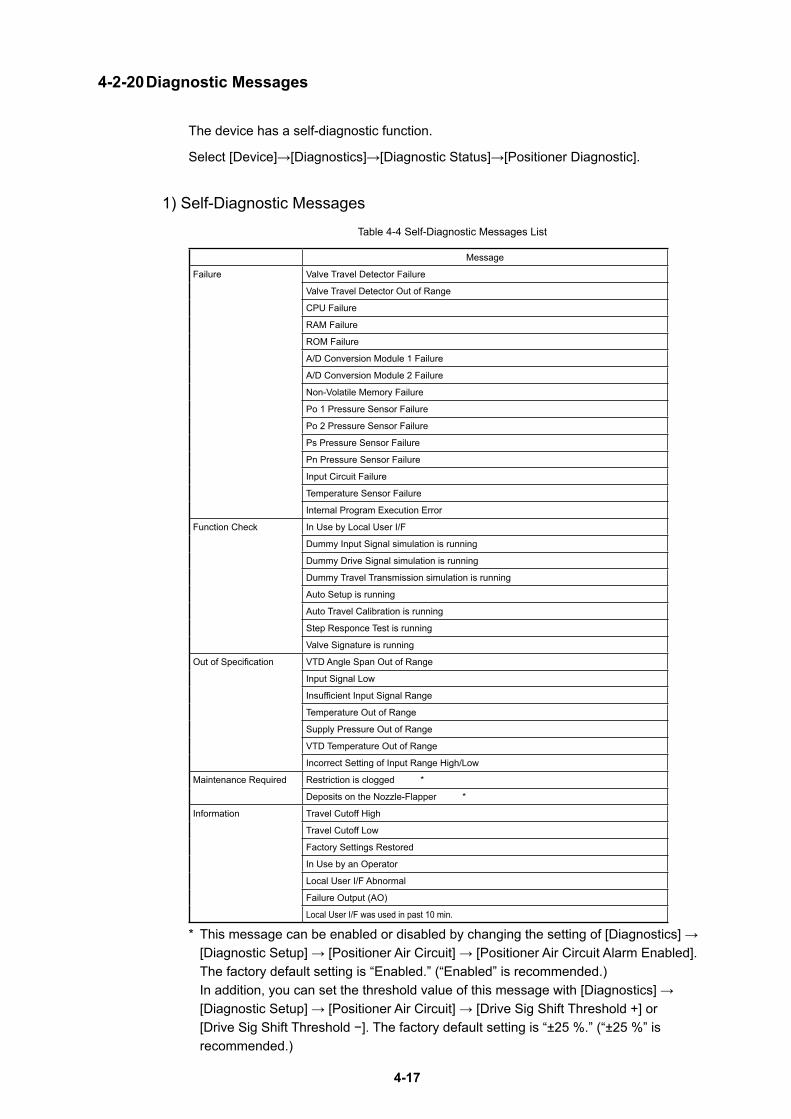
4-17
4-2-20 Diagnostic Messages
The device has a self-diagnostic function.
Select [Device]→[Diagnostics]→[Diagnostic Status]→[Positioner Diagnostic].
1) Self-Diagnostic MessagesTable 4-4 Self-Diagnostic Messages List
Message
Failure Valve Travel Detector Failure
Valve Travel Detector Out of Range
CPU Failure
RAM Failure
ROM Failure
A/D Conversion Module 1 Failure
A/D Conversion Module 2 Failure
Non-Volatile Memory Failure
Po 1 Pressure Sensor Failure
Po 2 Pressure Sensor Failure
Ps Pressure Sensor Failure
Pn Pressure Sensor Failure
Input Circuit Failure
Temperature Sensor Failure
Internal Program Execution Error
Function Check In Use by Local User I/F
Dummy Input Signal simulation is running
Dummy Drive Signal simulation is running
Dummy Travel Transmission simulation is running
Auto Setup is running
Auto Travel Calibration is running
Step Responce Test is running
Valve Signature is running
Out of Specification VTD Angle Span Out of Range
Input Signal Low
Insufficient Input Signal Range
Temperature Out of Range
Supply Pressure Out of Range
VTD Temperature Out of Range
Incorrect Setting of Input Range High/Low
Maintenance Required Restriction is clogged *
Deposits on the Nozzle-Flapper *
Information Travel Cutoff High
Travel Cutoff Low
Factory Settings Restored
In Use by an Operator
Local User I/F Abnormal
Failure Output (AO)
Local User I/F was used in past 10 min.
* This message can be enabled or disabled by changing the setting of [Diagnostics] → [Diagnostic Setup] → [Positioner Air Circuit] → [Positioner Air Circuit Alarm Enabled]. The factory default setting is “Enabled.” (“Enabled” is recommended.) In addition, you can set the threshold value of this message with [Diagnostics] → [Diagnostic Setup] → [Positioner Air Circuit] → [Drive Sig Shift Threshold +] or [Drive Sig Shift Threshold −]. The factory default setting is “±25 %.” (“±25 %” is recommended.)
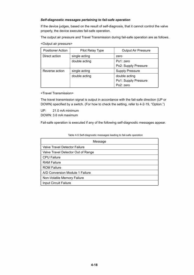
4-18
Self-diagnostic messages pertaining to fail-safe operation
If the device judges, based on the result of self-diagnosis, that it cannot control the valve properly, the device executes fail-safe operation.
The output air pressure and Travel Transmission during fail-safe operation are as follows.
<Output air pressure>
Positioner Action Pilot Relay Type Output Air Pressure
Direct action single acting zerodouble acting Po1: zero
Po2: Supply PressureReverse action single acting Supply Pressure
double acting double acting Po1: Supply Pressure Po2: zero
<Travel Transmission>
The travel transmission signal is output in accordance with the fail-safe direction (UP or DOWN) specified by a switch. (For how to check the setting, refer to 4-2-19, “Option.”)
UP: 21.0 mA minimum DOWN: 3.6 mA maximum
Fail-safe operation is executed if any of the following self-diagnostic messages appear.
Table 4-5 Self-diagnostic messages leading to fail-safe operation
Message
Valve Travel Detector FailureValve Travel Detector Out of RangeCPU FailureRAM FailureROM FailureA/D Conversion Module 1 FailureNon-Volatile Memory FailureInput Circuit Failure
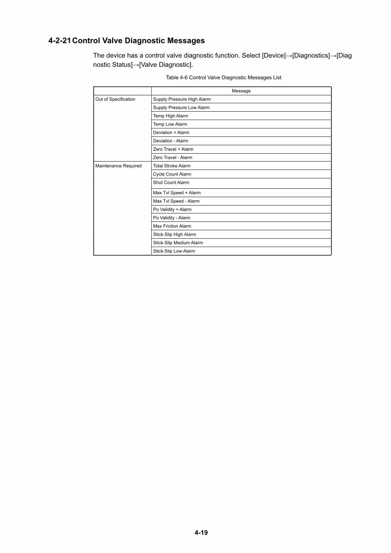
4-19
4-2-21 Control Valve Diagnostic Messages
The device has a control valve diagnostic function. Select [Device]→[Diagnostics]→[Diagnostic Status]→[Valve Diagnostic].
Table 4-6 Control Valve Diagnostic Messages List
Message
Out of Specification Supply Pressure High Alarm
Supply Pressure Low Alarm
Temp High Alarm
Temp Low Alarm
Deviation + Alarm
Deviation - Alarm
Zero Travel + Alarm
Zero Travel - Alarm
Maintenance Required Total Stroke Alarm
Cycle Count Alarm
Shut Count Alarm
Max Tvl Speed + Alarm
Max Tvl Speed - Alarm
Po Validity + Alarm
Po Validity - Alarm
Max Friction Alarm
Stick-Slip High Alarm
Stick-Slip Medium Alarm
Stick-Slip Low Alarm

4-20

5-1
Chapter 5 TroubleshootingThis chapter describes how to address problems in case of troubles.
The following three types of problems may occur when you start up and start operating the device.• Problems that occur because the specifications of the device are not suitable for the
actual use conditions• Problems due to setup or operation errors• Problems due to failure of the deviceIf a problem occurs, take appropriate actions according to the troubleshooting guidelines described in this chapter.
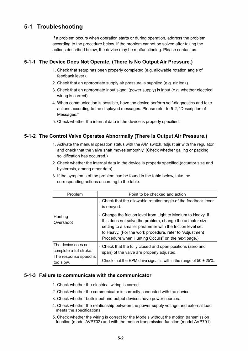
5-2
5-1 Troubleshooting
If a problem occurs when operation starts or during operation, address the problem according to the procedure below. If the problem cannot be solved after taking the actions described below, the device may be malfunctioning. Please contact us.
5-1-1 The Device Does Not Operate . (There Is No Output Air Pressure .)1. Check that setup has been properly completed (e.g. allowable rotation angle of
feedback lever).2. Check that an appropriate supply air pressure is supplied (e.g. air leak).3. Check that an appropriate input signal (power supply) is input (e.g. whether electrical
wiring is correct).4. When communication is possible, have the device perform self-diagnostics and take
actions according to the displayed messages. Please refer to 5-2, “Description of Messages.”
5. Check whether the internal data in the device is properly specified.
5-1-2 The Control Valve Operates Abnormally (There Is Output Air Pressure .)1. Activate the manual operation status with the A/M switch, adjust air with the regulator,
and check that the valve shaft moves smoothly. (Check whether galling or packing solidification has occurred.)
2. Check whether the internal data in the device is properly specified (actuator size and hysteresis, among other data).
3. If the symptoms of the problem can be found in the table below, take the corresponding actions according to the table.
Problem Point to be checked and action
HuntingOvershoot
- Check that the allowable rotation angle of the feedback lever is obeyed.
- Change the friction level from Light to Medium to Heavy. If this does not solve the problem, change the actuator size setting to a smaller parameter with the friction level set to Heavy. (For the work procedure, refer to “Adjustment Procedure when Hunting Occurs” on the next page.)
The device does not complete a full stroke.The response speed is too slow.
- Check that the fully closed and open positions (zero and span) of the valve are properly adjusted.
- Check that the EPM drive signal is within the range of 50 ± 25%.
5-1-3 Failure to communicate with the communicator
1. Check whether the electrical wiring is correct.2. Check whether the communicator is correctly connected with the device.3. Check whether both input and output devices have power sources.4. Check whether the relationship between the power supply voltage and external load
meets the specifications.5. Check whether the wiring is correct for the Models without the motion transmission
function (model AVP702) and with the motion transmission function (model AVP701)
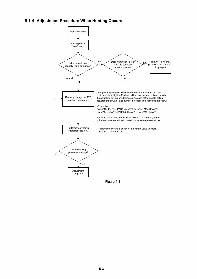
5-3
5-1-4 Adjustment Procedure When Hunting Occurs
Start adjustment
Hunting event confirmed
Is the control loop controller auto or manual?
Does hunting still occur after the controller is set to manual?
The AVP is normal.Adjust the control
loop again.
Manually change the AVPcontrol parameters.
Perform the dynamiccharacteristics test.
Did the huntingphenomenon stop?
Adjustmentcompleted
NO
NOAuto
Manual
YES
Perform the five-point check for the control valve to check dynamic characteristics.
YES
Change the hysteresis, which is a control parameter for the AVP positioner, from Light to Medium to Heavy or in the direction in which the actuator size number decreases. (In case of the double-acting actuator, the actuator size number increases in the reverse direction.)
<Example>PARAM4-LIGHT → PARAM4-MEDIUM→PARAM4-HEAVY→PARAM3-HEAVY→PARAM2-HEAVY→ PARAM1-HEAVY
If hunting still occurs after PARAM1-HEAVY is set or if you need quick response, consult with one of our service representatives.
Figure 5.1
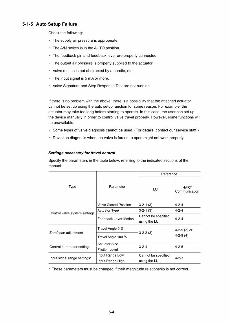
5-4
5-1-5 Auto Setup Failure
Check the following:
• The supply air pressure is appropriate.
• The A/M switch is in the AUTO position.
• The feedback pin and feedback lever are properly connected.
• The output air pressure is properly supplied to the actuator.
• Valve motion is not obstructed by a handle, etc.
• The input signal is 5 mA or more.
• Valve Signature and Step Response Test are not running.
If there is no problem with the above, there is a possibility that the attached actuator cannot be set up using the auto setup function for some reason. For example, the actuator may take too long before starting to operate. In this case, the user can set up the device manually in order to control valve travel properly. However, some functions will be unavailable.
• Some types of valve diagnosis cannot be used. (For details, contact our service staff.)
• Deviation diagnosis when the valve is forced to open might not work properly.
Settings necessary for travel control
Specify the parameters in the table below, referring to the indicated sections of the manual.
Type Parameter
Reference
LUI HART Communication
Control valve system settings
Valve Closed Position 3-2-1 (3) 4-2-4Actuator Type 3-2-1 (3) 4-2-4
Feedback Lever MotionCannot be specified using the LUI.
4-2-4
Zero/span adjustmentTravel Angle 0 %
3-2-2 (3)4-2-9 (3) or 4-2-9 (4)Travel Angle 100 %
Control parameter settingsActuator Size
3-2-4 4-2-5Fliction Level
Input signal range settings*Input Range Low Cannot be specified
using the LUI.4-2-3
Input Range High
* These parameters must be changed if their magnitude relationship is not correct.
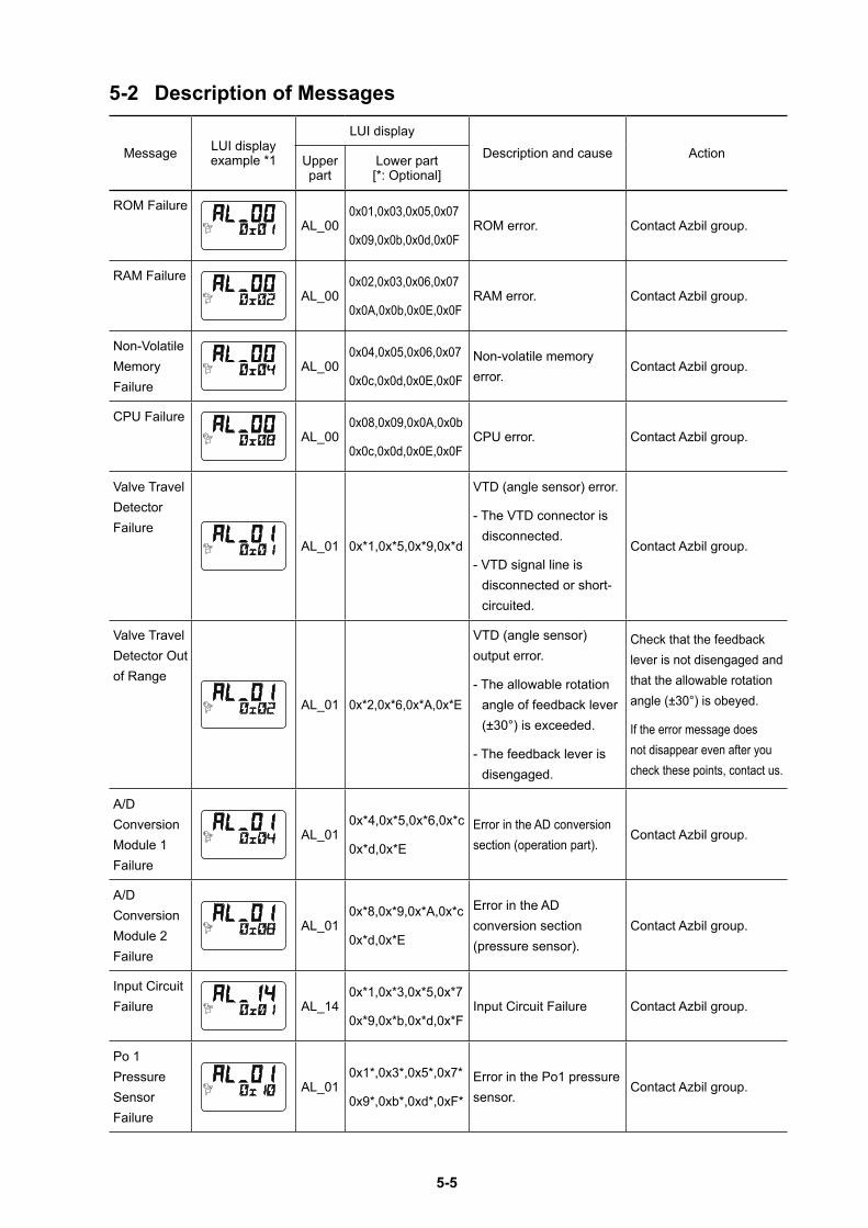
5-5
5-2 Description of Messages
Message LUI display example *1
LUI displayDescription and cause ActionUpper
partLower part [*: Optional]
ROM FailureAL_00
0x01,0x03,0x05,0x07
0x09,0x0b,0x0d,0x0FROM error. Contact Azbil group.
RAM FailureAL_00
0x02,0x03,0x06,0x07
0x0A,0x0b,0x0E,0x0FRAM error. Contact Azbil group.
Non-Volatile Memory Failure
AL_000x04,0x05,0x06,0x07
0x0c,0x0d,0x0E,0x0F
Non-volatile memory error.
Contact Azbil group.
CPU FailureAL_00
0x08,0x09,0x0A,0x0b
0x0c,0x0d,0x0E,0x0FCPU error. Contact Azbil group.
Valve Travel Detector Failure
AL_01 0x*1,0x*5,0x*9,0x*d
VTD (angle sensor) error.
- The VTD connector is disconnected.
- VTD signal line is disconnected or short-circuited.
Contact Azbil group.
Valve Travel Detector Out of Range
AL_01 0x*2,0x*6,0x*A,0x*E
VTD (angle sensor) output error.
- The allowable rotation angle of feedback lever (±30°) is exceeded.
- The feedback lever is disengaged.
Check that the feedback lever is not disengaged and that the allowable rotation angle (±30°) is obeyed.
If the error message does not disappear even after you check these points, contact us.
A/D Conversion Module 1 Failure
AL_010x*4,0x*5,0x*6,0x*c
0x*d,0x*E
Error in the AD conversion section (operation part).
Contact Azbil group.
A/D Conversion Module 2 Failure
AL_010x*8,0x*9,0x*A,0x*c
0x*d,0x*E
Error in the AD conversion section (pressure sensor).
Contact Azbil group.
Input Circuit Failure AL_14
0x*1,0x*3,0x*5,0x*7
0x*9,0x*b,0x*d,0x*FInput Circuit Failure Contact Azbil group.
Po 1 Pressure Sensor Failure
AL_010x1*,0x3*,0x5*,0x7*
0x9*,0xb*,0xd*,0xF*
Error in the Po1 pressure sensor.
Contact Azbil group.
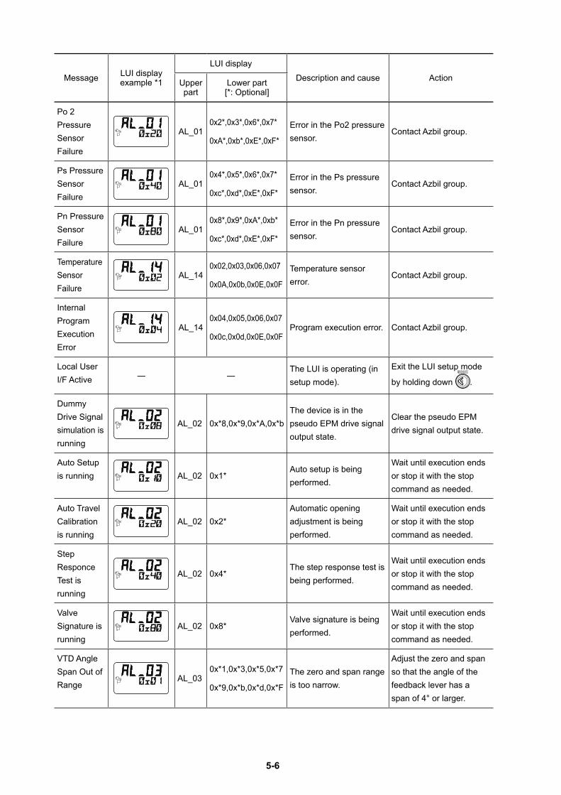
5-6
Message LUI display example *1
LUI displayDescription and cause ActionUpper
partLower part [*: Optional]
Po 2 Pressure Sensor Failure
AL_010x2*,0x3*,0x6*,0x7*
0xA*,0xb*,0xE*,0xF*
Error in the Po2 pressure sensor.
Contact Azbil group.
Ps Pressure Sensor Failure
AL_010x4*,0x5*,0x6*,0x7*
0xc*,0xd*,0xE*,0xF*
Error in the Ps pressure sensor.
Contact Azbil group.
Pn Pressure Sensor Failure
AL_010x8*,0x9*,0xA*,0xb*
0xc*,0xd*,0xE*,0xF*
Error in the Pn pressure sensor.
Contact Azbil group.
Temperature Sensor Failure
AL_140x02,0x03,0x06,0x07
0x0A,0x0b,0x0E,0x0F
Temperature sensor error.
Contact Azbil group.
Internal Program Execution Error
AL_140x04,0x05,0x06,0x07
0x0c,0x0d,0x0E,0x0FProgram execution error. Contact Azbil group.
Local User I/F Active ― ―
The LUI is operating (in setup mode).
Exit the LUI setup mode
by holding down .
Dummy Drive Signal simulation is running
AL_02 0x*8,0x*9,0x*A,0x*bThe device is in the pseudo EPM drive signal output state.
Clear the pseudo EPM drive signal output state.
Auto Setup is running AL_02 0x1*
Auto setup is being performed.
Wait until execution ends or stop it with the stop command as needed.
Auto Travel Calibration is running
AL_02 0x2*Automatic opening adjustment is being performed.
Wait until execution ends or stop it with the stop command as needed.
Step Responce Test is running
AL_02 0x4*The step response test is being performed.
Wait until execution ends or stop it with the stop command as needed.
Valve Signature is running
AL_02 0x8*Valve signature is being performed.
Wait until execution ends or stop it with the stop command as needed.
VTD Angle Span Out of Range
AL_030x*1,0x*3,0x*5,0x*7
0x*9,0x*b,0x*d,0x*F
The zero and span range is too narrow.
Adjust the zero and span so that the angle of the feedback lever has a span of 4° or larger.
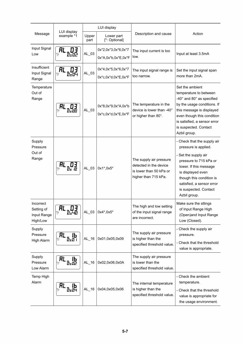
5-7
Message LUI display example *1
LUI displayDescription and cause ActionUpper
partLower part [*: Optional]
Input Signal Low AL_03
0x*2,0x*3,0x*6,0x*7
0x*A,0x*b,0x*E,0x*F
The input current is too low.
Input at least 3.5mA
Insufficient Input Signal Range
AL_030x*4,0x*5,0x*6,0x*7
0x*c,0x*d,0x*E,0x*F
The input signal range is too narrow.
Set the input signal span more than 2mA.
Temperature Out of Range
AL_030x*8,0x*9,0x*A,0x*b
0x*c,0x*d,0x*E,0x*F
The temperature in the device is lower than -40° or higher than 80°.
Set the ambient temperature to between -40° and 80° as specified by the usage conditions. If this message is displayed even though this condition is satisfied, a sensor error is suspected. Contact Azbil group.
Supply Pressure Out of Range
AL_03 0x1*,0x5*
The supply air pressure detected in the device is lower than 50 kPa or higher than 715 kPa.
- Check that the supply air pressure is applied.
- Set the supply air pressure to 715 kPa or lower. If this message is displayed even though this condition is satisfied, a sensor error is suspected. Contact Azbil group.
Incorrect Setting of Input Range High/Low
AL_03 0x4*,0x5*The high and low setting of the input signal range are incorrect.
Make sure the sttings of Input Range High (Open)and Input Range Low (Closed).
Supply Pressure High Alarm AL_16 0x01,0x05,0x09
The supply air pressure is higher than the specified threshold value.
- Check the supply air pressure.
- Check that the threshold value is appropriate.
Supply Pressure Low Alarm
AL_16 0x02,0x06,0x0AThe supply air pressure is lower than the specified threshold value.
Temp High Alarm
AL_16 0x04,0x05,0x06The internal temperature is higher than the specified threshold value.
- Check the ambient temperature.
- Check that the threshold value is appropriate for the usage environment.
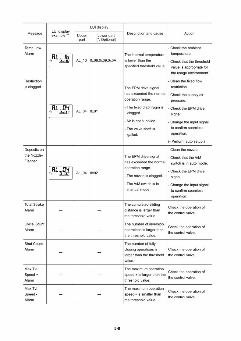
5-8
Message LUI display example *1
LUI displayDescription and cause ActionUpper
partLower part [*: Optional]
Temp Low Alarm
AL_16 0x08,0x09,0x0AThe internal temperature is lower than the specified threshold value.
- Check the ambient temperature.
- Check that the threshold value is appropriate for the usage environment.
Restriction is clogged
AL_04 0x01
The EPM drive signal has exceeded the normal operation range.
- The fixed diaphragm is clogged.
- Air is not supplied.
- The valve shaft is galled.
- Clean the fixed flow restriction.
- Check the supply air pressure.
- Check the EPM drive signal.
- Change the input signal to confirm seamless operation.
(- Perform auto setup.)
Deposits on the Nozzle-Flapper
AL_04 0x02
The EPM drive signal has exceeded the normal operation range.
- The nozzle is clogged.
- The A/M switch is in manual mode.
- Clean the nozzle.
- Check that the A/M switch is in auto mode.
- Check the EPM drive signal.
- Change the input signal to confirm seamless operation.
Total Stroke Alarm ― ―
The cumulated sliding distance is larger than the threshold value.
Check the operation of the control valve.
Cycle Count Alarm ― ―
The number of inversion operations is larger than the threshold value.
Check the operation of the control valve.
Shut Count Alarm
― ―
The number of fully closing operations is larger than the threshold value.
Check the operation of the control valve.
Max Tvl Speed + Alarm
― ―The maximum operation speed + is larger than the threshold value.
Check the operation of the control valve.
Max Tvl Speed - Alarm
― ―The maximum operation speed - is smaller than the threshold value.
Check the operation of the control valve.
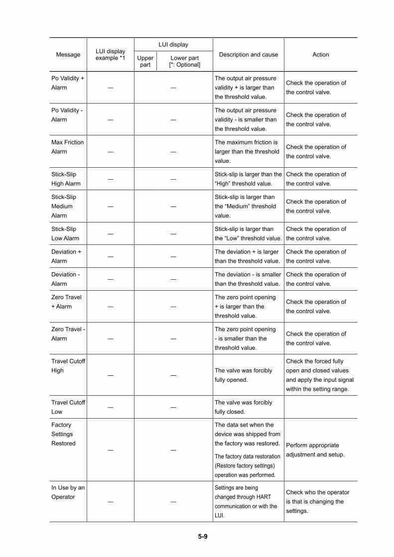
5-9
Message LUI display example *1
LUI displayDescription and cause ActionUpper
partLower part [*: Optional]
Po Validity + Alarm ― ―
The output air pressure validity + is larger than the threshold value.
Check the operation of the control valve.
Po Validity - Alarm ― ―
The output air pressure validity - is smaller than the threshold value.
Check the operation of the control valve.
Max Friction Alarm ― ―
The maximum friction is larger than the threshold value.
Check the operation of the control valve.
Stick-Slip High Alarm
― ―Stick-slip is larger than the “High” threshold value.
Check the operation of the control valve.
Stick-Slip Medium Alarm
― ―Stick-slip is larger than the “Medium” threshold value.
Check the operation of the control valve.
Stick-Slip Low Alarm
― ―Stick-slip is larger than the “Low” threshold value.
Check the operation of the control valve.
Deviation + Alarm
― ―The deviation + is larger than the threshold value.
Check the operation of the control valve.
Deviation - Alarm
― ―The deviation - is smaller than the threshold value.
Check the operation of the control valve.
Zero Travel + Alarm ― ―
The zero point opening + is larger than the threshold value.
Check the operation of the control valve.
Zero Travel - Alarm ― ―
The zero point opening - is smaller than the threshold value.
Check the operation of the control valve.
Travel Cutoff High
― ―The valve was forcibly fully opened.
Check the forced fully open and closed values and apply the input signal within the setting range.
Travel Cutoff Low
― ―The valve was forcibly fully closed.
Factory Settings Restored
― ―
The data set when the device was shipped from the factory was restored.
The factory data restoration (Restore factory settings) operation was performed.
Perform appropriate adjustment and setup.
In Use by an Operator
― ―
Settings are being changed through HART communication or with the LUI.
Check who the operator is that is changing the settings.
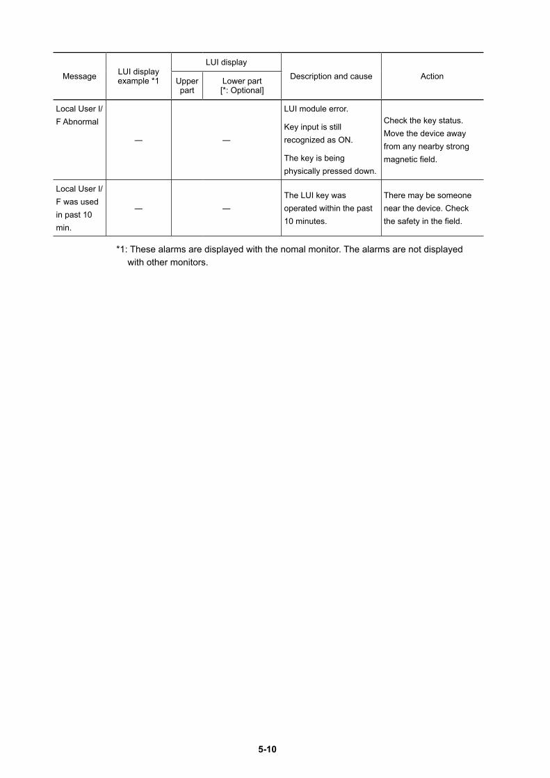
5-10
Message LUI display example *1
LUI displayDescription and cause ActionUpper
partLower part [*: Optional]
Local User I/F Abnormal
― ―
LUI module error.
Key input is still recognized as ON.
The key is being physically pressed down.
Check the key status. Move the device away from any nearby strong magnetic field.
Local User I/F was used in past 10 min.
― ―The LUI key was operated within the past 10 minutes.
There may be someone near the device. Check the safety in the field.
*1: These alarms are displayed with the nomal monitor. The alarms are not displayed with other monitors.
6-1
Chapter 6 MaintenanceThis chapter describes periodic maintenance for the device. You can properly use the device by performing appropriate maintenance. In addition, the limited life parts are listed as resale parts in 6-8. Because the replacement frequencies of resale parts differ depending on the usage environment and usage situation of the device, specify appropriate replacement frequencies.
Precautions for safe workCautions
If appropriate maintenance is not performed, an unexpected operation may cause the feedback lever to move, causing an injury. Perform maintenance at appropriate times.
Maintenance work is dangerous because the valve moves. Be prepared in advance to prevent injury and effects on the process when the valve moves.
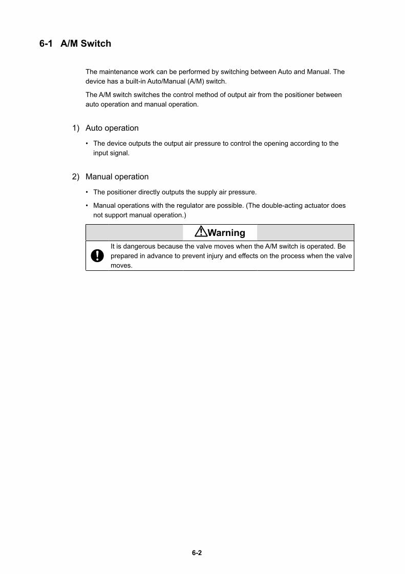
6-2
6-1 A/M Switch
The maintenance work can be performed by switching between Auto and Manual. The device has a built-in Auto/Manual (A/M) switch.
The A/M switch switches the control method of output air from the positioner between auto operation and manual operation.
1) Auto operation
• The device outputs the output air pressure to control the opening according to the input signal.
2) Manual operation
• The positioner directly outputs the supply air pressure.
• Manual operations with the regulator are possible. (The double-acting actuator does not support manual operation.)
WarningIt is dangerous because the valve moves when the A/M switch is operated. Be prepared in advance to prevent injury and effects on the process when the valve moves.
6-3
3) Structure of A/M switch
The structure of the A/M switch is shown in the figure below.
Remove the pilot relay cover.
Setscrew A/M switchMANUAL
AUTO
Figure 6-1 Structure of A/M Switch
CautionsDo not loosen the setscrew. If the setscrew is loosened, the A/M switch will pop out due to the air pressure, potentially causing an injury.
4) Procedure for switching from auto operation to manual operationThe procedure for switching from auto operation to manual operation is shown below.
Step Work
1Loosen the three screws to remove the pilot relay cover in order to operate the A/M switch.
2
Rotate the A/M switch counterclockwise (in the MAN direction) by one revolution using a flat-head screwdriver. (Confirm that operation has switched by using the output air pressure gauge.)
5) Procedure for switching from manual operation to auto operationThe procedure for switching from auto operation to manual operation is shown below.
Step Work
1
Securely rotate the A/M switch clockwise (in the AUTO direction) using a flat-head screwdriver until it stops. (Confirm that operation has switched by using the output air pressure gauge.)
2Attach the pilot relay cover onto the main unit with the three screws.
6-4
6-2 Replacement of Filter and Maintenance of Flow Restriction
The contamination of the flow restriction section in the device caused by instrumentation air can be removed during maintenance. The replacement and maintenance procedures are described below.
Handling Precautions:Use clean dry air with solid particles no larger than 3-μm as the instrumentation air.
Step Work1 Shut off the supply air to the device.
2Loosen the three screws to remove the pilot relay cover and remove the setscrew in the A/M switch section.
3 Rotate the A/M switch in the MAN direction to remove.
4
Cut the holder with nippers or other tool to remove the old filter.
Handling Precautions:Properly dispose of the old holder and filter.
5
Clean the flow restriction section using a wire (with a diameter of 0.25 mm) or other tool.
Handling Precautions:When cleaning, be careful not to damage the hole of the flow restriction. Do not use an air gun. Be careful not to let oil get on the cleaned flow restriction again.
6Wrap a new filter around the A/M switch and hold it with the holder.
7 Screw in the A/M switch until it stops.8 Screw the setscrew into the A/M switch section.9 Attach the pilot relay cover with the three screws.
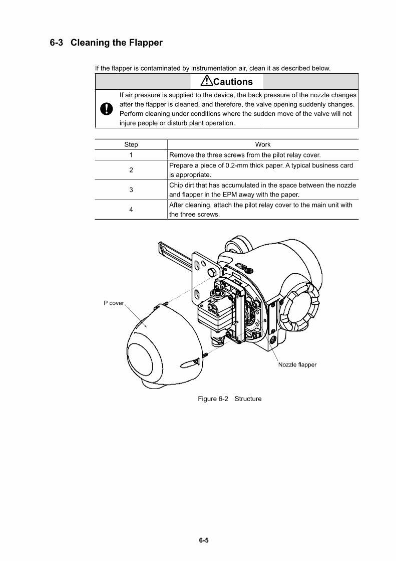
6-5
6-3 Cleaning the Flapper
If the flapper is contaminated by instrumentation air, clean it as described below.
CautionsIf air pressure is supplied to the device, the back pressure of the nozzle changes after the flapper is cleaned, and therefore, the valve opening suddenly changes. Perform cleaning under conditions where the sudden move of the valve will not injure people or disturb plant operation.
Step Work1 Remove the three screws from the pilot relay cover.
2Prepare a piece of 0.2-mm thick paper. A typical business card is appropriate.
3Chip dirt that has accumulated in the space between the nozzle and flapper in the EPM away with the paper.
4After cleaning, attach the pilot relay cover to the main unit with the three screws.
Figure 6-2 Structure
P cover
Nozzle flapper
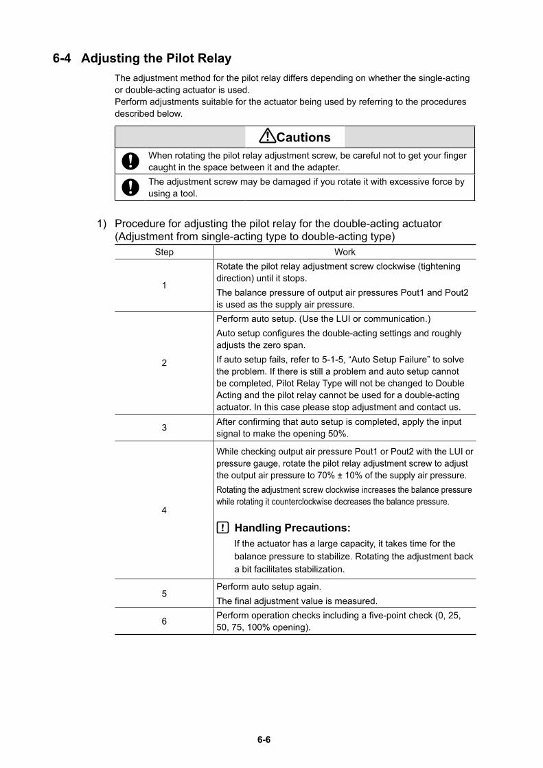
6-6
6-4 Adjusting the Pilot RelayThe adjustment method for the pilot relay differs depending on whether the single-acting or double-acting actuator is used.Perform adjustments suitable for the actuator being used by referring to the procedures described below.
CautionsWhen rotating the pilot relay adjustment screw, be careful not to get your finger caught in the space between it and the adapter.The adjustment screw may be damaged if you rotate it with excessive force by using a tool.
1) Procedure for adjusting the pilot relay for the double-acting actuator (Adjustment from single-acting type to double-acting type)
Step Work
1
Rotate the pilot relay adjustment screw clockwise (tightening direction) until it stops.The balance pressure of output air pressures Pout1 and Pout2 is used as the supply air pressure.
2
Perform auto setup. (Use the LUI or communication.)Auto setup configures the double-acting settings and roughly adjusts the zero span.If auto setup fails, refer to 5-1-5, “Auto Setup Failure” to solve the problem. If there is still a problem and auto setup cannot be completed, Pilot Relay Type will not be changed to Double Acting and the pilot relay cannot be used for a double-acting actuator. In this case please stop adjustment and contact us.
3 After confirming that auto setup is completed, apply the input signal to make the opening 50%.
4
While checking output air pressure Pout1 or Pout2 with the LUI or pressure gauge, rotate the pilot relay adjustment screw to adjust the output air pressure to 70% ± 10% of the supply air pressure.Rotating the adjustment screw clockwise increases the balance pressure while rotating it counterclockwise decreases the balance pressure.
Handling Precautions:If the actuator has a large capacity, it takes time for the balance pressure to stabilize. Rotating the adjustment back a bit facilitates stabilization.
5Perform auto setup again.The final adjustment value is measured.
6 Perform operation checks including a five-point check (0, 25, 50, 75, 100% opening).
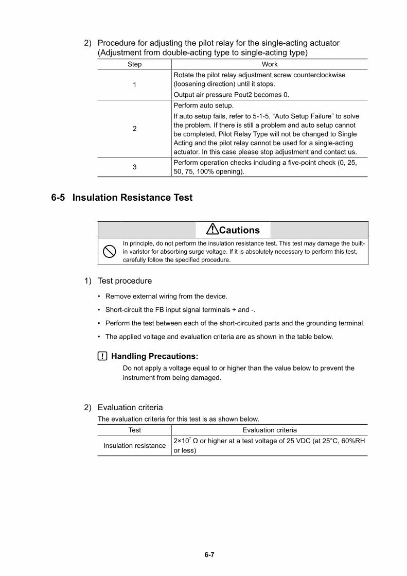
6-7
2) Procedure for adjusting the pilot relay for the single-acting actuator (Adjustment from double-acting type to single-acting type)
Step Work
1Rotate the pilot relay adjustment screw counterclockwise (loosening direction) until it stops.Output air pressure Pout2 becomes 0.
2
Perform auto setup.If auto setup fails, refer to 5-1-5, “Auto Setup Failure” to solve the problem. If there is still a problem and auto setup cannot be completed, Pilot Relay Type will not be changed to Single Acting and the pilot relay cannot be used for a single-acting actuator. In this case please stop adjustment and contact us.
3 Perform operation checks including a five-point check (0, 25, 50, 75, 100% opening).
6-5 Insulation Resistance Test
CautionsIn principle, do not perform the insulation resistance test. This test may damage the built-in varistor for absorbing surge voltage. If it is absolutely necessary to perform this test, carefully follow the specified procedure.
1) Test procedure
• Remove external wiring from the device.
• Short-circuit the FB input signal terminals + and -.
• Perform the test between each of the short-circuited parts and the grounding terminal.
• The applied voltage and evaluation criteria are as shown in the table below.
Handling Precautions:Do not apply a voltage equal to or higher than the value below to prevent the instrument from being damaged.
2) Evaluation criteriaThe evaluation criteria for this test is as shown below.
Test Evaluation criteria
Insulation resistance2×107 Ω or higher at a test voltage of 25 VDC (at 25°C, 60%RH or less)
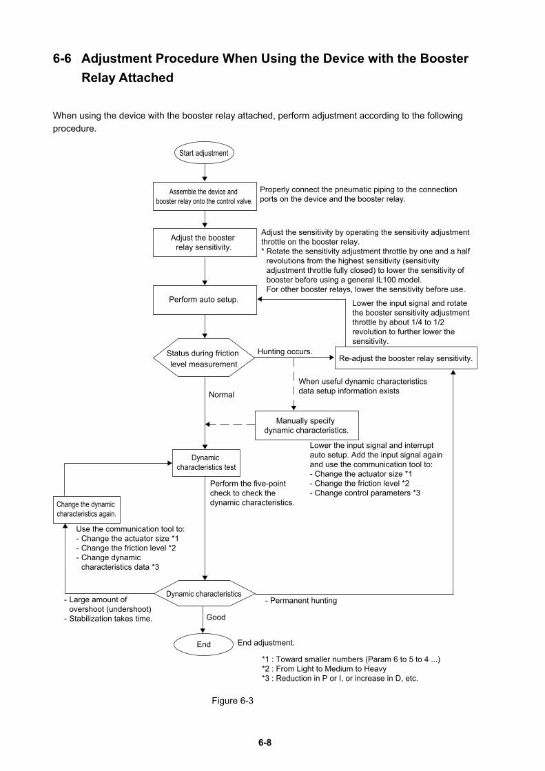
6-8
6-6 Adjustment Procedure When Using the Device with the Booster Relay Attached
When using the device with the booster relay attached, perform adjustment according to the following procedure.
Assemble the device and booster relay onto the control valve.
Adjust the booster relay sensitivity.
Perform auto setup.
Manually specify dynamic characteristics.
Re-adjust the booster relay sensitivity.Status during friction level measurement
Dynamic characteristics test
Change the dynamic characteristics again.
Dynamic characteristics
End
Properly connect the pneumatic piping to the connection ports on the device and the booster relay.
Start adjustment
When useful dynamic characteristics data setup information exists
- Permanent hunting
End adjustment.
Good
Normal
Hunting occurs.
Adjust the sensitivity by operating the sensitivity adjustment throttle on the booster relay.* Rotate the sensitivity adjustment throttle by one and a half
revolutions from the highest sensitivity (sensitivity adjustment throttle fully closed) to lower the sensitivity of booster before using a general IL100 model.For other booster relays, lower the sensitivity before use.
Lower the input signal and rotate the booster sensitivity adjustment throttle by about 1/4 to 1/2 revolution to further lower the sensitivity.
Lower the input signal and interrupt auto setup. Add the input signal again and use the communication tool to:- Change the actuator size *1- Change the friction level *2- Change control parameters *3
Perform the five-point check to check the dynamic characteristics.
Use the communication tool to:- Change the actuator size *1- Change the friction level *2- Change dynamic
characteristics data *3
- Large amount of overshoot (undershoot)
- Stabilization takes time.
*1 : Toward smaller numbers (Param 6 to 5 to 4 ...)*2 : From Light to Medium to Heavy*3 : Reduction in P or I, or increase in D, etc.
Figure 6-3
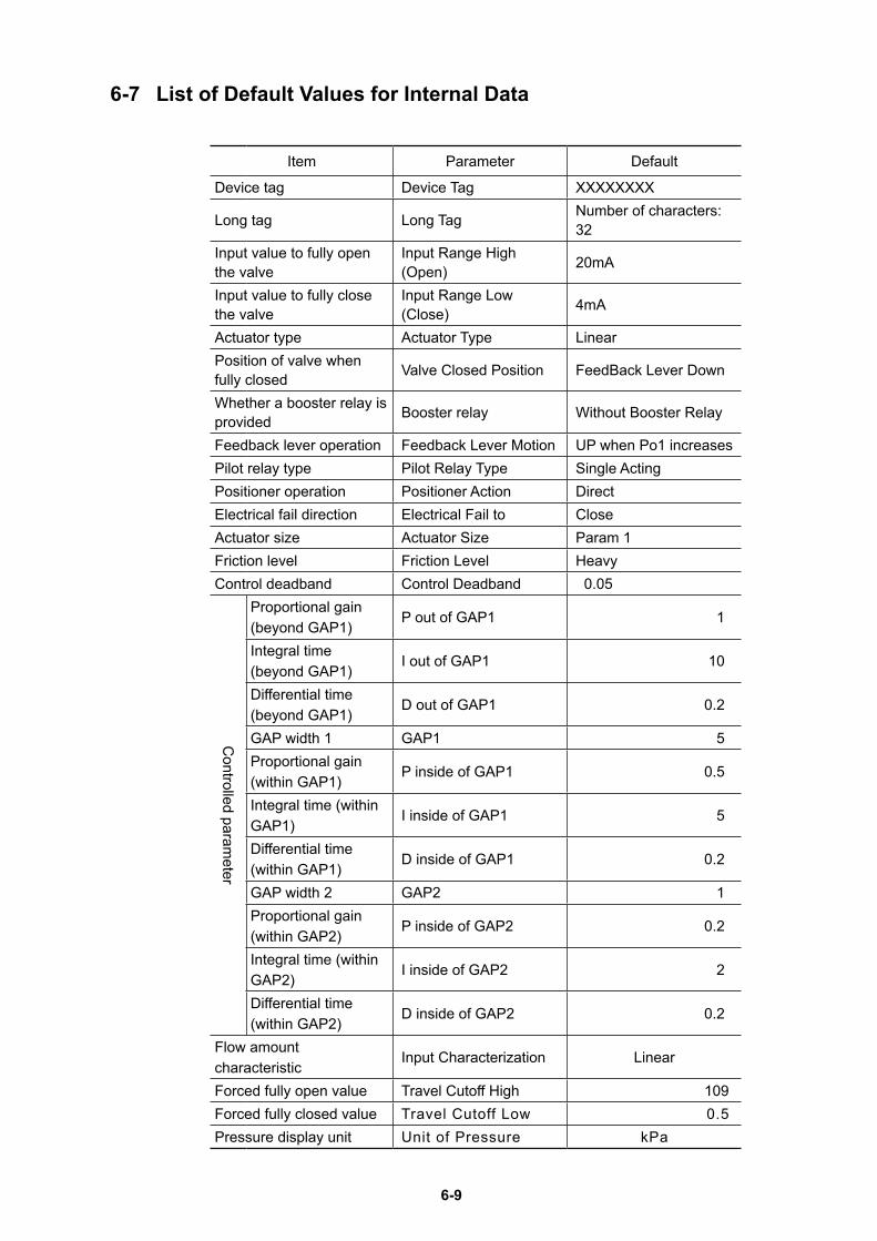
6-9
6-7 List of Default Values for Internal Data
Item Parameter Default
Device tag Device Tag XXXXXXXX
Long tag Long Tag Number of characters: 32
Input value to fully open the valve
Input Range High (Open) 20mA
Input value to fully close the valve
Input Range Low (Close) 4mA
Actuator type Actuator Type LinearPosition of valve when fully closed Valve Closed Position FeedBack Lever Down
Whether a booster relay is provided Booster relay Without Booster Relay
Feedback lever operation Feedback Lever Motion UP when Po1 increasesPilot relay type Pilot Relay Type Single ActingPositioner operation Positioner Action DirectElectrical fail direction Electrical Fail to CloseActuator size Actuator Size Param 1Friction level Friction Level HeavyControl deadband Control Deadband 0.05
Controlled param
eter
Proportional gain (beyond GAP1)
P out of GAP1 1
Integral time (beyond GAP1)
I out of GAP1 10
Differential time (beyond GAP1)
D out of GAP1 0.2
GAP width 1 GAP1 5Proportional gain (within GAP1)
P inside of GAP1 0.5
Integral time (within GAP1)
I inside of GAP1 5
Differential time (within GAP1)
D inside of GAP1 0.2
GAP width 2 GAP2 1Proportional gain (within GAP2)
P inside of GAP2 0.2
Integral time (within GAP2)
I inside of GAP2 2
Differential time (within GAP2)
D inside of GAP2 0.2
Flow amount characteristic
Input Characterization Linear
Forced fully open value Travel Cutoff High 109Forced fully closed value Travel Cutoff Low 0.5Pressure display unit Unit of Pressure kPa
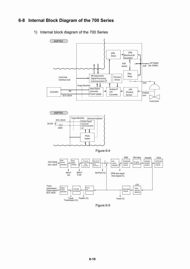
6-10
6-8 Internal Block Diagram of the 700 Series
1) Internal block diagram of the 700 Series
Output SignalConverterCommunication I/F
PhotoIsolater
Surge Absorber
250Ω
DC24V
Electrical Isolation
MicroprocessorDigital ProcessingCommunication I/F
Analog I/FA/D Converter
Input SignalConverterPower Supply
VTD(Position Sensor)
PilotRelayPressure
Sensor
Controller FeedbackLever
Control Valve
Surge Absorber
DC4–20mA
IIN
Local UserInterface (LUI)
EPMDriver
EPM(Electrical-AirConverter)
A/MSwitch
OUT
Air Supply140–700kPaSUP
AVP702
AVP701
DC4–20mA
Figure 6-4
Figure 6-5
EPM
Drive Signal (%)EPM drive signal
PIDcontroloperation
Flow amountcharacteristicsignalconversion
INPUT% IIN
Inputsignalranging
Inputcurrentcaribration
INPUTmA
Input signalDC4–20mA
DC4–20mAOutput signal
Travel transmission
Travel (%)
VTD
Focibly fllyopening/closing
signalconversion
Set Point (%)
−
Positionerforward/reverse
Air signalamplification
Actuatorforward/reverse
Valve plugforward/reverse
Zero spanranging
Reverse input characterization
Fail safe processing
Output current calibration
Pilot relay Actuator Valve
Valveopeningdetection
Travel Transmission (%)
Position (%)
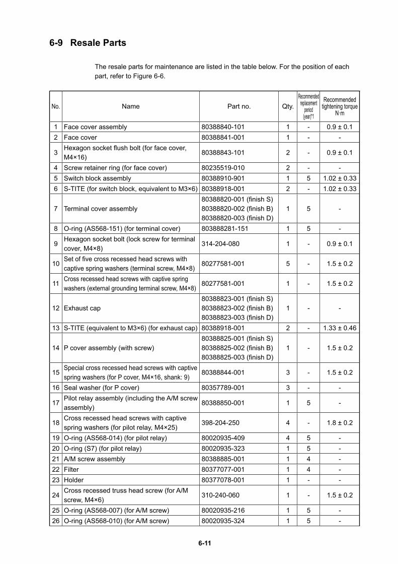
6-11
6-9 Resale Parts
The resale parts for maintenance are listed in the table below. For the position of each part, refer to Figure 6-6.
No. Name Part no. Qty.Recommended
replacementperiod
(year)*1
Recommendedtightening torque
N·m
1 Face cover assembly 80388840-101 1 - 0.9 ± 0.12 Face cover 80388841-001 1 - -
3Hexagon socket flush bolt (for face cover, M4×16)
80388843-101 2 - 0.9 ± 0.1
4 Screw retainer ring (for face cover) 80235519-010 2 - -5 Switch block assembly 80388910-901 1 5 1.02 ± 0.336 S-TITE (for switch block, equivalent to M3×6) 80388918-001 2 - 1.02 ± 0.33
7 Terminal cover assembly80388820-001 (finish S)80388820-002 (finish B)80388820-003 (finish D)
1 5 -
8 O-ring (AS568-151) (for terminal cover) 803888281-151 1 5 -
9Hexagon socket bolt (lock screw for terminal cover, M4×8)
314-204-080 1 - 0.9 ± 0.1
10Set of five cross recessed head screws with captive spring washers (terminal screw, M4×8)
80277581-001 5 - 1.5 ± 0.2
11Cross recessed head screws with captive spring washers (external grounding terminal screw, M4×8)
80277581-001 1 - 1.5 ± 0.2
12 Exhaust cap80388823-001 (finish S)80388823-002 (finish B)80388823-003 (finish D)
1 - -
13 S-TITE (equivalent to M3×6) (for exhaust cap) 80388918-001 2 - 1.33 ± 0.46
14 P cover assembly (with screw)80388825-001 (finish S)80388825-002 (finish B)80388825-003 (finish D)
1 - 1.5 ± 0.2
15Special cross recessed head screws with captive spring washers (for P cover, M4×16, shank: 9)
80388844-001 3 - 1.5 ± 0.2
16 Seal washer (for P cover) 80357789-001 3 - -
17Pilot relay assembly (including the A/M screw assembly)
80388850-001 1 5 -
18Cross recessed head screws with captive spring washers (for pilot relay, M4×25)
398-204-250 4 - 1.8 ± 0.2
19 O-ring (AS568-014) (for pilot relay) 80020935-409 4 5 -20 O-ring (S7) (for pilot relay) 80020935-323 1 5 -21 A/M screw assembly 80388885-001 1 4 -22 Filter 80377077-001 1 4 -23 Holder 80377078-001 1 - -
24Cross recessed truss head screw (for A/M screw, M4×6)
310-240-060 1 - 1.5 ± 0.2
25 O-ring (AS568-007) (for A/M screw) 80020935-216 1 5 -26 O-ring (AS568-010) (for A/M screw) 80020935-324 1 5 -
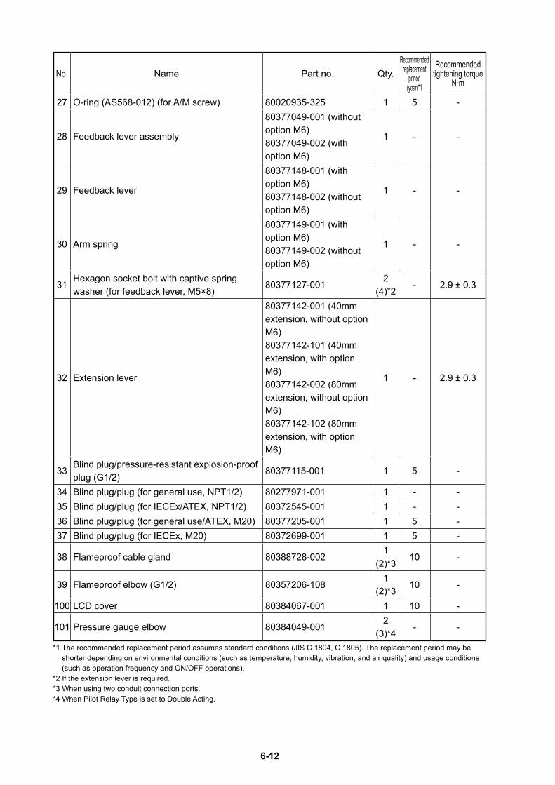
6-12
No. Name Part no. Qty.Recommended
replacementperiod
(year)*1
Recommendedtightening torque
N·m
27 O-ring (AS568-012) (for A/M screw) 80020935-325 1 5 -
28 Feedback lever assembly
80377049-001 (without option M6)80377049-002 (with option M6)
1 - -
29 Feedback lever
80377148-001 (with option M6)80377148-002 (without option M6)
1 - -
30 Arm spring
80377149-001 (with option M6)80377149-002 (without option M6)
1 - -
31Hexagon socket bolt with captive spring washer (for feedback lever, M5×8)
80377127-0012
(4)*2- 2.9 ± 0.3
32 Extension lever
80377142-001 (40mm extension, without option M6)80377142-101 (40mm extension, with option M6)80377142-002 (80mm extension, without option M6)80377142-102 (80mm extension, with option M6)
1 - 2.9 ± 0.3
33Blind plug/pressure-resistant explosion-proof plug (G1/2)
80377115-001 1 5 -
34 Blind plug/plug (for general use, NPT1/2) 80277971-001 1 - -35 Blind plug/plug (for IECEx/ATEX, NPT1/2) 80372545-001 1 - -36 Blind plug/plug (for general use/ATEX, M20) 80377205-001 1 5 -37 Blind plug/plug (for IECEx, M20) 80372699-001 1 5 -
38 Flameproof cable gland 80388728-0021
(2)*310 -
39 Flameproof elbow (G1/2) 80357206-1081
(2)*310 -
100 LCD cover 80384067-001 1 10 -
101 Pressure gauge elbow 80384049-0012
(3)*4- -
*1 The recommended replacement period assumes standard conditions (JIS C 1804, C 1805). The replacement period may be shorter depending on environmental conditions (such as temperature, humidity, vibration, and air quality) and usage conditions (such as operation frequency and ON/OFF operations).
*2 If the extension lever is required.*3 When using two conduit connection ports.*4 When Pilot Relay Type is set to Double Acting.
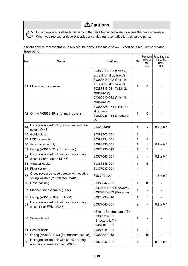
6-13
CautionsDo not replace or desorb the parts in the table below, because it causes the device damage.When you replace or desorb it, ask our service representative to replace the parts.
Ask our service representative to replace the parts in the table below. Expertise is required to replace these parts.
No. Name Part no. Qty.Recommended
replacementperiod
(year)*1
Recommendedtightening
torqueN·m
41 Main cover assembly
80388816-001 (finish S, except for structure V)80388816-002 (finish B, except for structure V)80388816-011 (finish S, structure V)80388816-012 (finish B, structure V)
1 5 -
42 O-ring (AS568-154) (for main cover)
80388828-154 (except for structure V)80020935-164 (structure V)
1 5 -
44Hexagon socket bolt (lock screw for main cover, M4×8)
314-204-080 1 - 0.9 ± 0.1
45 Guide plate 80388905-001 1 - -47 LCD assembly 80388931-001 1 5 -50 Adapter assembly 80388836-001 1 - 0.9 ± 0.151 O-ring (AS568-021) (for adapter) 80020935-612 1 5 -
52Hexagon socket bolt with captive spring washer (for adapter, M3×6)
80377046-001 3 - 0.9 ± 0.1
53 Adapter gasket 80388846-001 1 5 -54 Filter screen 80377087-001 4 - -
55Cross recessed head screws with captive spring washer (for adapter, M4×12)
398-204-120 4 - 1.8 ± 0.2
56 Case packing 80388847-001 1 10 -
57 Magnet unit assembly (EPM)80377010-001 (Forward)80377010-002 (Reverse)
1 - -
58 O-ring (AS568-007) (for EPM) 80020935-216 1 5 -
59Hexagon socket bolt with captive spring washer (for EPM, M3×6)
80377046-001 2 - 0.9 ± 0.1
60 Sensor board
<Except for structure L,T>80388935-001<Structure L,T>80384101-001
1 - -
61 Sensor cable 80388944-001 1 - -62 O-ring (AS568A-013) (for pressure sensor) 80388829-013 4 10 -
63Hexagon socket bolt with captive spring washer (for sensor cover, M3×8)
80377047-001 4 - 0.9 ± 0.1

6-14
No. Name Part no. Qty.Recommended
replacementperiod
(year)*1
Recommendedtightening
torqueN·m
64Hexagon socket bolt with captive spring washer (for coil, M3×8)
80377047-001 2 - 0.9 ± 0.1
65Hexagon socket bolt with captive spring washer (M6×16)
80388845-001 4 - 4.4 ± 0.5
66VTD assembly (with hexagon socket bolt M4×14)
80388909-001, 002 1 - 1.5 ± 0.2
*1 The recommended replacement period assumes standard conditions (JIS C 1804, C 1805). The replacement period may be shorter depending on environmental conditions (such as temperature, humidity, vibration, and air quality) and usage conditions (such as operation frequency and ON/OFF operations).
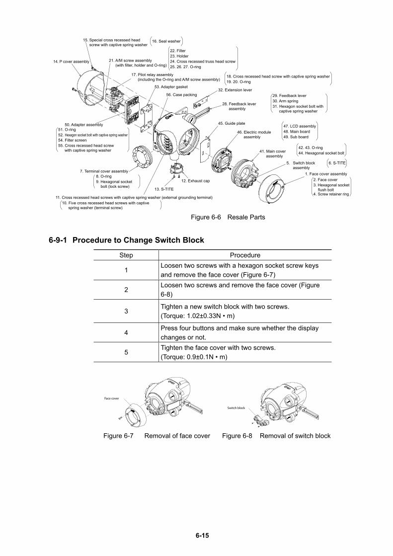
6-15
16. Seal washer
18. Cross recessed head screw with captive spring washer19. 20. O-ring
52. Hexagon socket bolt with captive spring washer51. O-ring
54. Filter screen55. Cross recessed head screw
with captive spring washer
23. Holder22. Filter
24. Cross recessed truss head screw
3. Hexagonal socket flush bolt
2. Face cover
4. Screw retainer ring
44. Hexagonal socket bolt42. 43. O-ring
48. Main board47. LCD assembly
49. Sub board
30. Arm spring29. Feedback lever
31. Hexagon socket bolt with captive spring washer
7. Terminal cover assembly
9. Hexagonal socket bolt (lock screw)
8. O-ring
10. Five cross recessed head screws with captive spring washer (terminal screw)
25. 26. 27. O-ring
15. Special cross recessed head screw with captive spring washer
14. P cover assembly
17. Pilot relay assembly (including the O-ring and A/M screw assembly)
50. Adapter assembly
1. Face cover assembly
5. Switch block assembly
6. S-TITE
41. Main cover assembly
46. Electric module assembly
28. Feedback lever assembly
32. Extension lever
45. Guide plate
12. Exhaust cap
11. Cross recessed head screws with captive spring washer (external grounding terminal)
13. S-TITE
56. Case packing
21. A/M screw assembly (with filter, holder and O-ring)
53. Adapter gasket
Figure 6-6 Resale Parts
6-9-1 Procedure to Change Switch Block
Step Procedure
1Loosen two screws with a hexagon socket screw keys and remove the face cover (Figure 6-7)
2Loosen two screws and remove the face cover (Figure 6-8)
3Tighten a new switch block with two screws.(Torque: 1.02±0.33N • m)
4Press four buttons and make sure whether the display changes or not.
5Tighten the face cover with two screws.(Torque: 0.9±0.1N • m)
Face cover
Figure 6-7 Removal of face cover
Switch block
Figure 6-8 Removal of switch block
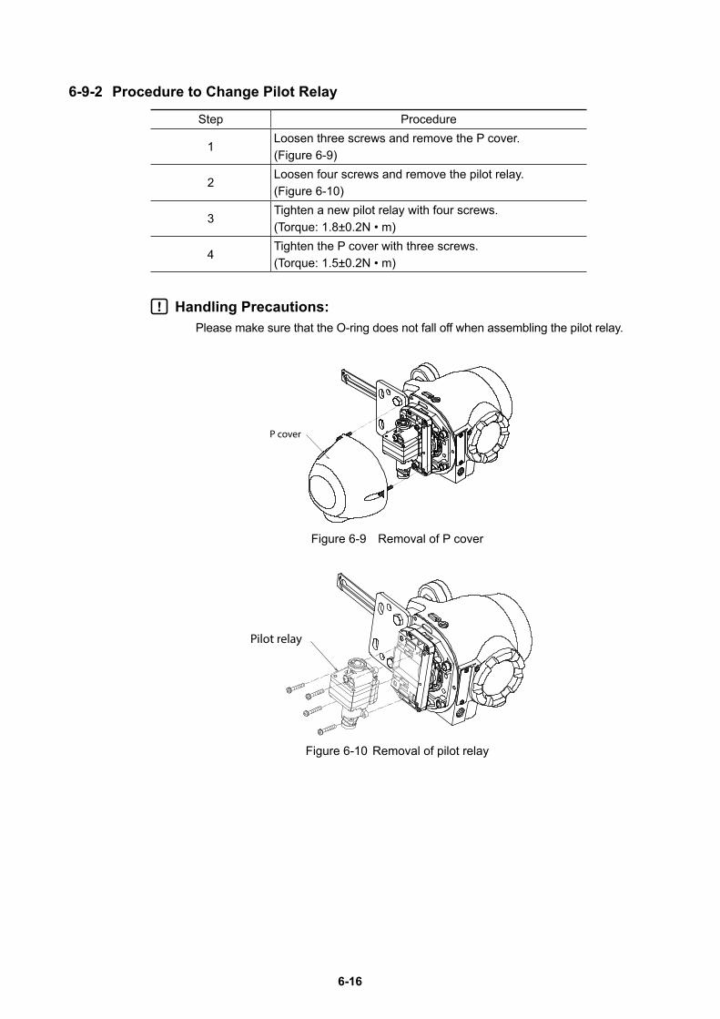
6-16
6-9-2 Procedure to Change Pilot Relay
Step Procedure
1Loosen three screws and remove the P cover. (Figure 6-9)
2Loosen four screws and remove the pilot relay. (Figure 6-10)
3Tighten a new pilot relay with four screws.(Torque: 1.8±0.2N • m)
4Tighten the P cover with three screws.(Torque: 1.5±0.2N • m)
Handling Precautions:Please make sure that the O-ring does not fall off when assembling the pilot relay.
P cover
Figure 6-9 Removal of P cover
Pilot relay
Figure 6-10 Removal of pilot relay

7-1
Chapter 7 Notes on the Explosion-Proof 700 Series
This chapter describes the notes on the explosion-proof 700 Series.
When using the explosion-proof 700 Series, sufficiently understand the notes in this section and use it correctly.
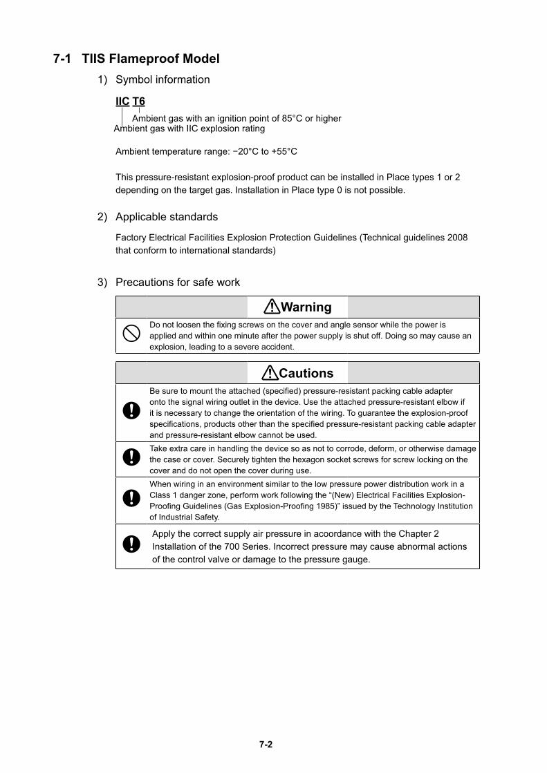
7-2
7-1 TIIS Flameproof Model1) Symbol information
IIC T6 Ambient gas with an ignition point of 85°C or higher
Ambient gas with IIC explosion rating
Ambient temperature range: −20°C to +55°C
This pressure-resistant explosion-proof product can be installed in Place types 1 or 2 depending on the target gas. Installation in Place type 0 is not possible.
2) Applicable standards
Factory Electrical Facilities Explosion Protection Guidelines (Technical guidelines 2008 that conform to international standards)
3) Precautions for safe work
WarningDo not loosen the fixing screws on the cover and angle sensor while the power is applied and within one minute after the power supply is shut off. Doing so may cause an explosion, leading to a severe accident.
CautionsBe sure to mount the attached (specified) pressure-resistant packing cable adapter onto the signal wiring outlet in the device. Use the attached pressure-resistant elbow if it is necessary to change the orientation of the wiring. To guarantee the explosion-proof specifications, products other than the specified pressure-resistant packing cable adapter and pressure-resistant elbow cannot be used.Take extra care in handling the device so as not to corrode, deform, or otherwise damage the case or cover. Securely tighten the hexagon socket screws for screw locking on the cover and do not open the cover during use.When wiring in an environment similar to the low pressure power distribution work in a Class 1 danger zone, perform work following the “(New) Electrical Facilities Explosion-Proofing Guidelines (Gas Explosion-Proofing 1985)” issued by the Technology Institution of Industrial Safety.
Apply the correct supply air pressure in acoordance with the Chapter 2 Installation of the 700 Series. Incorrect pressure may cause abnormal actions of the control valve or damage to the pressure gauge.
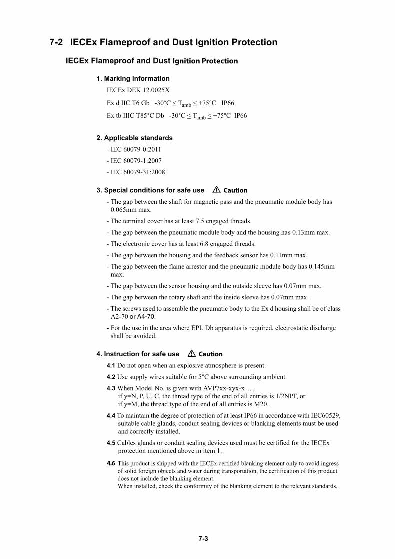
7-3
7-2 IECEx Flameproof and Dust Ignition Protection
or A4-70.
Caution
Caution
Ignition Protection
This product is shipped with the IECEx certified blanking element only to avoid ingressof solid foreign objects and water during transportation, the certification of this product does not include the blanking element.When installed, check the conformity of the blanking element to the relevant standards.
4.6

7-4
This product is shipped with the IECEx certified blanking element only to avoid ingressof solid foreign objects and water during transportation, the certification of this product does not include the blanking element.When installed, check the conformity of the blanking element to the relevant standards.
4.10
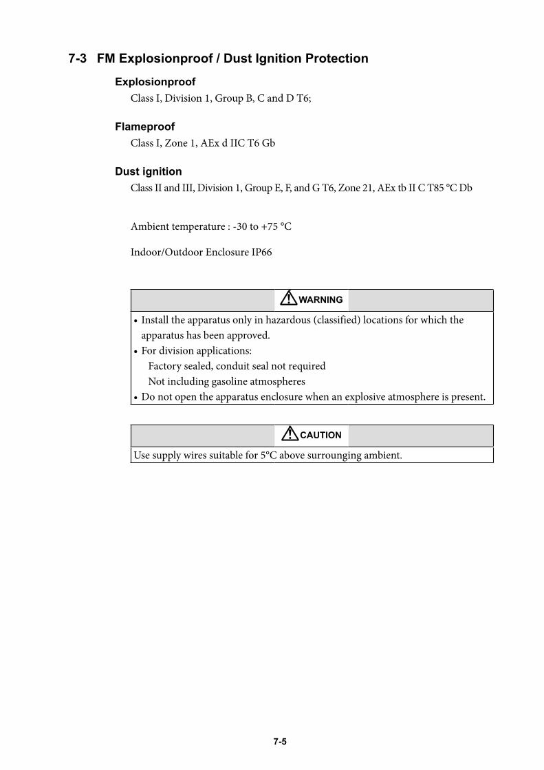
7-5
7-3 FM Explosionproof / Dust Ignition ProtectionExplosionproof
Class I, Division 1, Group B, C and D T6;
FlameproofClass I, Zone 1, AEx d IIC T6 Gb
Dust ignitionClass II and III, Division 1, Group E, F, and G T6, Zone 21, AEx tb II C T85 °C Db
Ambient temperature : -30 to +75 °C
Indoor/Outdoor Enclosure IP66
WARNING
• Install the apparatus only in hazardous (classified) locations for which the apparatus has been approved.
• For division applications:Factory sealed, conduit seal not requiredNot including gasoline atmospheres
• Do not open the apparatus enclosure when an explosive atmosphere is present.
CAUTION
Use supply wires suitable for 5°C above surrounging ambient.
7-6
7-4 FM Intrinsically safe (ic) and Nonincendive Intrinsically safe(ic)
Class I, Zone 2, AEx ic IIC T4
Entity Parameters:
Positioner Circuit: Ui=30V, Ii=100mA, Pi=1W, Ci=24nF, Li=0.22mH
Transmitter Circuit (AVP701): Ui=30V, Ii=100mA, Pi=1W, Ci=20nF, Li=0.22mH
NonincendiveClass I, Division 2, Group A, B, C and D, T4
Nonincendive Field Wiring Parameters:
Positioner Circuit: Vmax=30V, Imax=100mA, Ci=24nF, Li=0.22mH
Transmitter Circuit (AVP701): Vmax=30V, Imax=100mA, Ci=20nF, Li=0.22mH
SuitableClass II and Class III, Division 2, Group E, F and G, T4
Indoor/Outdoor EnclosureNEMA Type 4X, IP66
Ambient Temperature:-24 to 75
Instruction for safe use- Models AVP701/ AVP702 shall be installed in accordance with control drawings
80396167 and 80396168.
- Installations in the US shall comply with the relevant requirements of the National Electrical CodeR (ANSI/NFPA-70 (NECR).
- Tampering and replacement with non-factory components may adversely affect the safe use of the system.
- For guidance on installation in the US, see ANSI/ISA-RP12.06.01, Installation of Intrinsically Safe Systems for Hazardous (Classified) Locations.
- Electrical equipment connected to the Associated Apparatus shall not use or generate more than 250 Volts rms.
- The products discussed in this report were certified by FM Approvals under a Type3 Certification System as identified in ISO Guide 67.
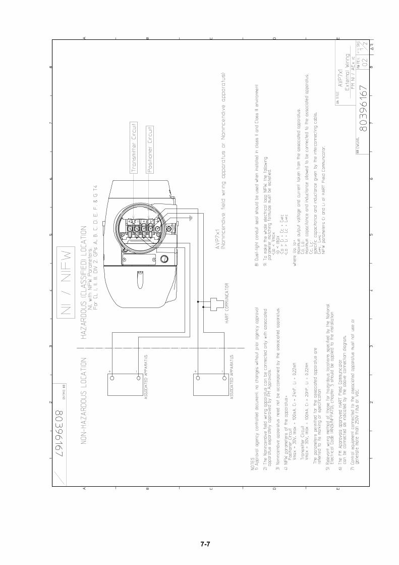
7-7
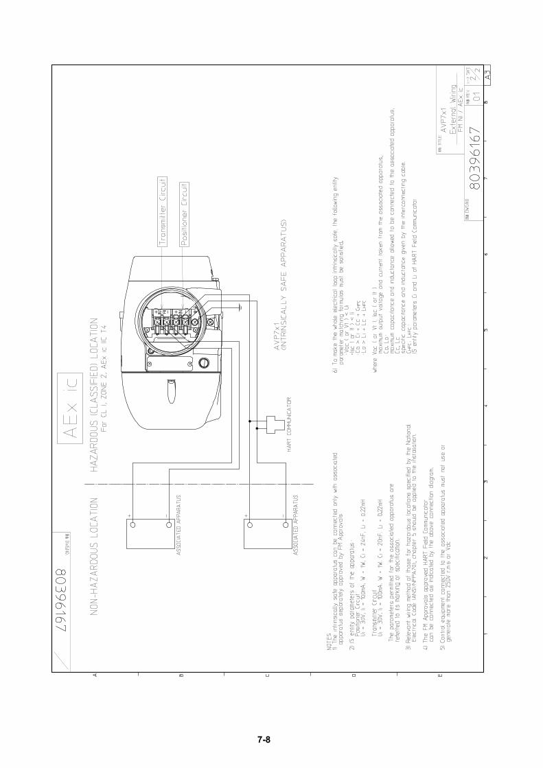
7-8
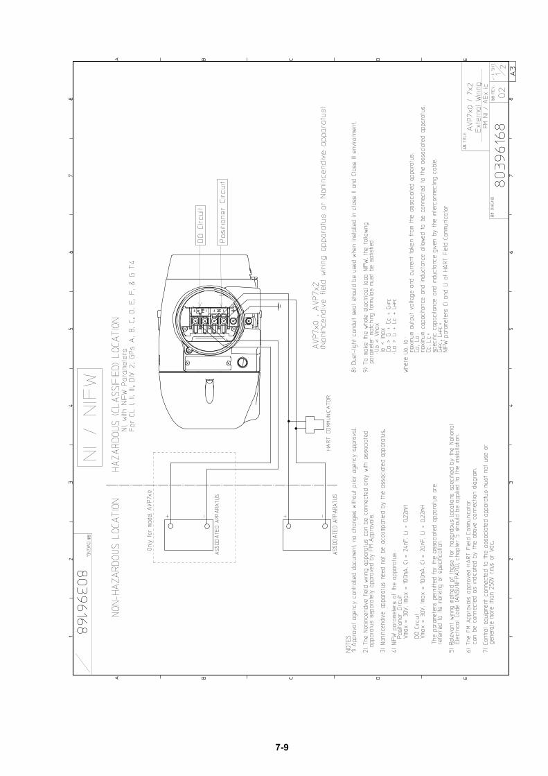
7-9
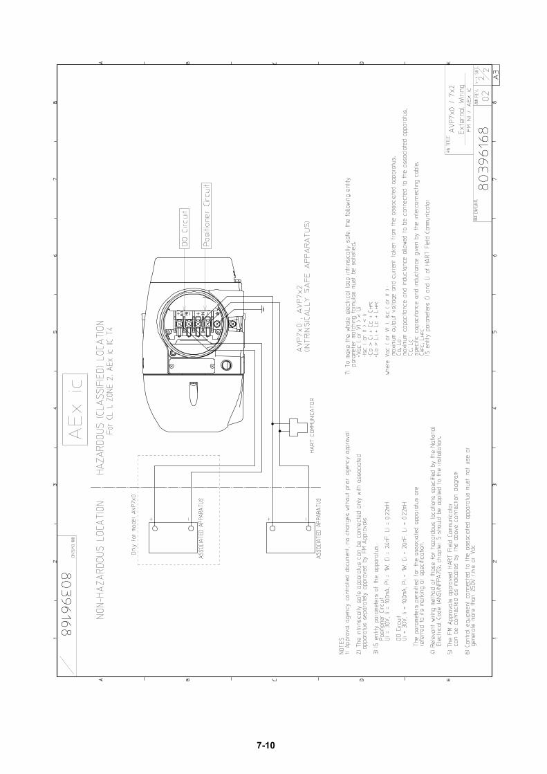
7-10
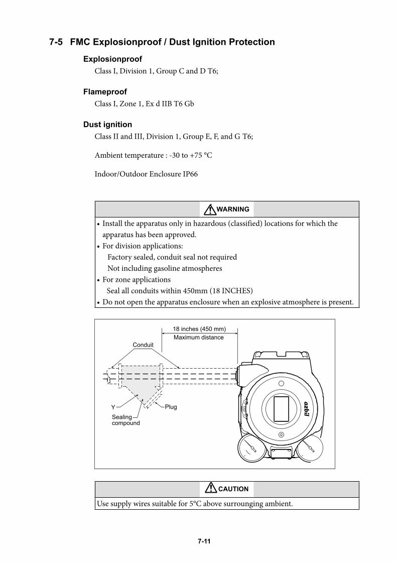
7-11
7-5 FMC Explosionproof / Dust Ignition ProtectionExplosionproof
Class I, Division 1, Group C and D T6;
FlameproofClass I, Zone 1, Ex d IIB T6 Gb
Dust ignitionClass II and III, Division 1, Group E, F, and G T6;
Ambient temperature : -30 to +75 °C
Indoor/Outdoor Enclosure IP66
WARNING
• Install the apparatus only in hazardous (classified) locations for which the apparatus has been approved.
• For division applications:Factory sealed, conduit seal not requiredNot including gasoline atmospheres
• For zone applicationsSeal all conduits within 450mm (18 INCHES)
• Do not open the apparatus enclosure when an explosive atmosphere is present.
CAUTION
Use supply wires suitable for 5°C above surrounging ambient.
Sealingcompound
Y Plug
Conduit
18 inches (450 mm)Maximum distance
7-12
7-6 CCC Flameproof / Dust Ignition ProtectionCCC 隔爆
1.防爆标志Ex d ⅡC T6 Gb
Ex tD A21 IP66 T85 ℃
2.国家防爆标准GB 3836.1–2010 爆炸性环境 第1部分:设备 通用要求
GB 3836.2–2010 爆炸性环境 第2部分:由隔爆外壳“d”保护的设备
GB 12476.1–2013 可燃性粉尘环境用电气设备 第1部分:通用要求
GB 12476.5–2013 可燃性粉尘环境用电气设备 第5部分:外壳保护型“tD”
3.产品安全使用特殊条件防爆合格证号后缀“X”表明产品具有安全使用特殊条件,具体内容如下:
3-1. 涉及安装、维护、维修时需咨询制造厂,索取并参考带有隔爆面参数的文件。
3-2. 紧固螺钉的性能等级为A2-70或A4-70。
4.产品使用注意事项4-1. 产品设有外接地端子,用户在安装使用时应可靠接地。
4-2. 产品电缆引入口须配用经国家指定的检验机构认可的、符合国家标准
GB3836.1–2010、GB3836.2–2010和GB12476.1–2010规定的、螺纹规格为
M20×1.5或1/2-14NPT、具有防爆等级为Ex d ⅡC的电缆引入装置或封堵件,方
可用于爆炸性危险场所。该电缆引入装置或封堵件的使用必须符合使用说明书的要
求。冗余电缆引入口应有效封堵。电缆引入装置或封堵件安装后,须确保设备整体
外壳防护等级不低于IP66。使用密封堵封,请使用CCC认证的产品。
4-3. 现场使用和维护时,必须遵循“严禁带电开盖”的原则。
4-4. 用户不得自行更换该产品的零部件,应会同产品制造商共同解决运行中出现的故
障,以杜绝损坏现象的发生。
4-5. 用户应当保持产品外壳表面清洁,以防粉尘堆积,但严禁用压缩空气吹扫。
4-6. 产品的安装、使用和维护应同时遵守产品说明书及下列相关标准、规范的要求:
GB 3836.13–2013 爆炸性环境 第13部分:设备的修理、检修、修复和改造
GB/T 3836.15–2017 爆炸性环境 第15部分:电气装置的设计、选型和安装
GB/T 3836.16–2017 爆炸性环境 第16部分:电气装置的检查与维护
GB 50257–2014 电气装置安装工程爆炸和火灾危险环境 电气装置施工及验收规范
GB 15577–2007 粉尘防爆安全规程
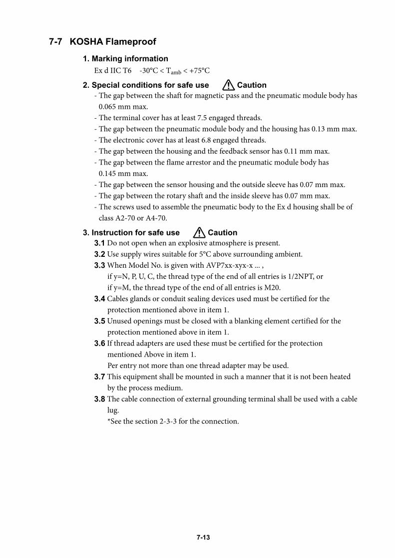
7-13
7-7 KOSHA Flameproof1 . Marking information
Ex d IIC T6 -30°C < Tamb < +75°C
2 . Special conditions for safe use Caution- The gap between the shaft for magnetic pass and the pneumatic module body has
0.065 mm max.- The terminal cover has at least 7.5 engaged threads.- The gap between the pneumatic module body and the housing has 0.13 mm max.- The electronic cover has at least 6.8 engaged threads.- The gap between the housing and the feedback sensor has 0.11 mm max.- The gap between the flame arrestor and the pneumatic module body has
0.145 mm max.- The gap between the sensor housing and the outside sleeve has 0.07 mm max.- The gap between the rotary shaft and the inside sleeve has 0.07 mm max.- The screws used to assemble the pneumatic body to the Ex d housing shall be of
class A2-70 or A4-70.
3 . Instruction for safe use Caution3 .1 Do not open when an explosive atmosphere is present.3 .2 Use supply wires suitable for 5°C above surrounding ambient.3 .3 When Model No. is given with AVP7xx-xyx-x ... ,
if y=N, P, U, C, the thread type of the end of all entries is 1/2NPT, or if y=M, the thread type of the end of all entries is M20.
3 .4 Cables glands or conduit sealing devices used must be certified for the protection mentioned above in item 1.
3 .5 Unused openings must be closed with a blanking element certified for the protection mentioned above in item 1.
3 .6 If thread adapters are used these must be certified for the protection mentioned Above in item 1. Per entry not more than one thread adapter may be used.
3 .7 This equipment shall be mounted in such a manner that it is not been heated by the process medium.
3 .8 The cable connection of external grounding terminal shall be used with a cable lug. *See the section 2-3-3 for the connection.
7-14
7-8 INMETRO Flameproof / Dust Ignition ProtectionEquipamento à prova de explosão do INMETRO
SegurançaSobre este manual
Este manual contém informações e advertências que devem ser observadas para manter posicionador de válvula smart o AVP7XX que opera seguramente.Instalação correta, operação correta e manutenção regular são essenciais para assegurar segurança enquanto usando este dispositivo.
Para o uso correto e seguro deste dispositivo é essencial que ambos que operam e pessoal de serviço segue procedimentos de segurança geralmente aceitos além das precauções de segurança especificadas neste manual.Os símbolos seguintes são usados neste manual para alertar a possíveis perigos:
AdvertênciaDenota um potencialmente situação perigosa que, se não evitou, poderia resultar em morte ou dano sério.
PrecauçãoDenota uma situação potencialmente situação perigosa que, se não evitar, poderá resultar em um dano secundário ao operador ou poderá danificar o dispositivo.
~ Informação de nota que pode ser útil ao usuário.
Precauções de segurançaADVERTINDO- PERIGO DE CHOQUE ELÉTRICO! Desligue antes de executar qualquer
instalação elétrica.- NUNCA abra a tampa do invólucro do terminal enquanto o AVP7XX está
energizado em um ambiente de atmosfera explosiva.- Não toque o AVP7XX desnecessariamente enquanto estiver em operação.A
superfície pode estar muito quente ou muito fria, enquanto dependendo do ambiente operacional.
PRECAUÇÃONão pisar, apoiar-se ou subir noAVP7XX. Você pode danificar o aparelho.
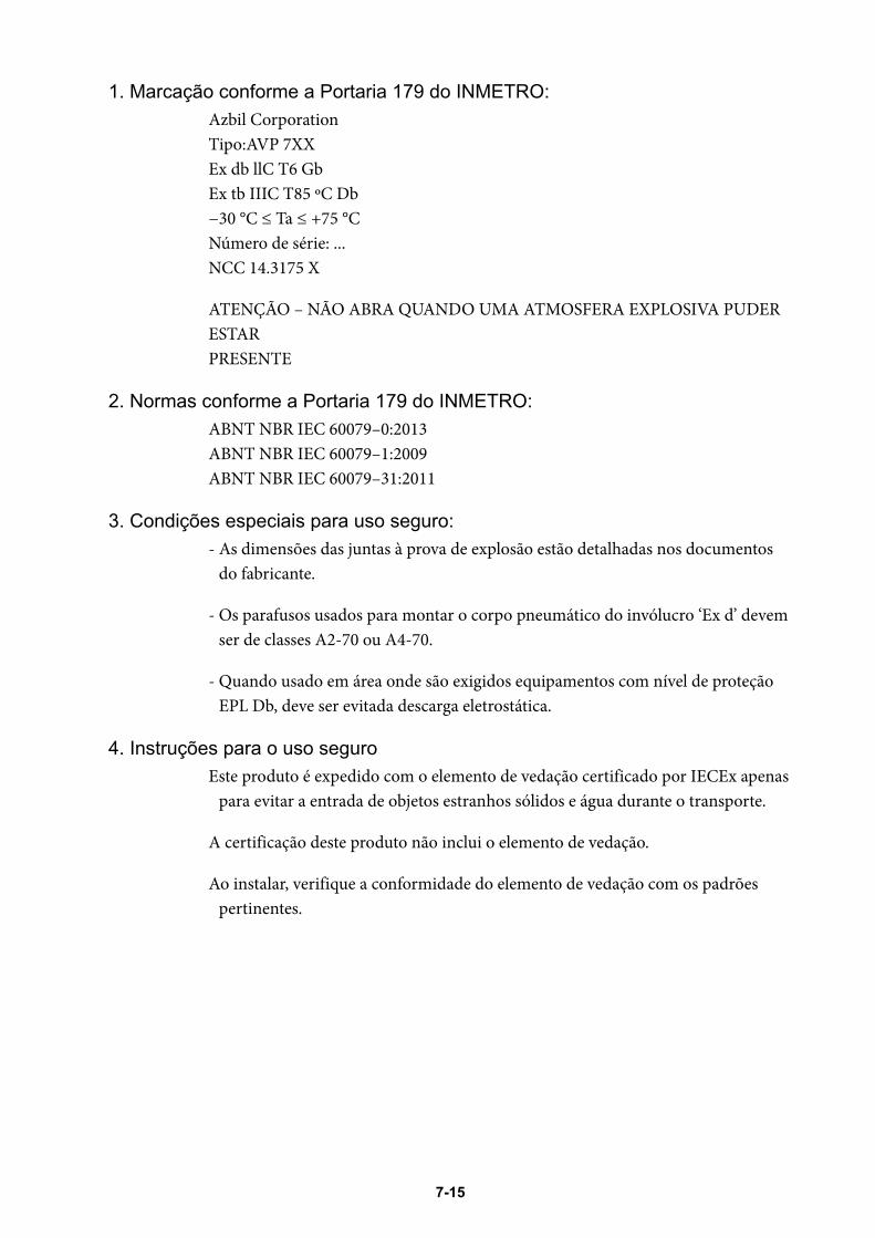
7-15
1. Marcação conforme a Portaria 179 do INMETRO:Azbil CorporationTipo:AVP 7XXEx db llC T6 GbEx tb IIIC T85 ºC Db−30 °C ≤ Ta ≤ +75 °CNúmero de série: ...NCC 14.3175 X
ATENÇÃO – NÃO ABRA QUANDO UMA ATMOSFERA EXPLOSIVA PUDER ESTARPRESENTE
2. Normas conforme a Portaria 179 do INMETRO:ABNT NBR IEC 60079–0:2013ABNT NBR IEC 60079–1:2009ABNT NBR IEC 60079–31:2011
3. Condições especiais para uso seguro:- As dimensões das juntas à prova de explosão estão detalhadas nos documentos
do fabricante.
- Os parafusos usados para montar o corpo pneumático do invólucro ‘Ex d’ devem ser de classes A2-70 ou A4-70.
- Quando usado em área onde são exigidos equipamentos com nível de proteção EPL Db, deve ser evitada descarga eletrostática.
4. Instruções para o uso seguroEste produto é expedido com o elemento de vedação certificado por IECEx apenas
para evitar a entrada de objetos estranhos sólidos e água durante o transporte.
A certificação deste produto não inclui o elemento de vedação.
Ao instalar, verifique a conformidade do elemento de vedação com os padrões pertinentes.
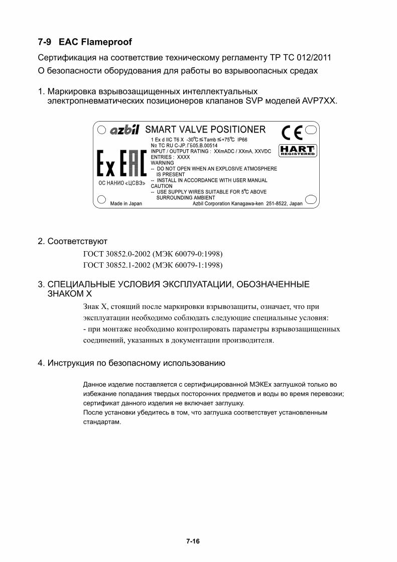
7-16
7-9 EAC FlameproofСертификация на соответствие техническому регламенту ТР ТС 012/2011О безопасности оборудования для работы во взрывоопасных средах
1. Маркировка взрывозащищенных интеллектуальных электропневматических позиционеров клапанов SVP моделей AVP7XX.
2. СоответствуютГОСТ 30852.0-2002 (МЭК 60079-0:1998)ГОСТ 30852.1-2002 (МЭК 60079-1:1998)
3. СПЕЦИАЛЬНЫЕ УСЛОВИЯ ЭКСПЛУАТАЦИИ, ОБОЗНАЧЕННЫЕ ЗНАКОМ Х
Знак Х, стоящий после маркировки взрывозащиты, означает, что приэксплуатации необходимо соблюдать следующие специальные условия:- при монтаже необходимо контролировать параметры взрывозащищенныхсоединений, указанных в документации производителя.
4. Инструкция по безопасному использованию
Данное изделие поставляется с сертифицированной МЭКЕх заглушкой только во избежание попадания твердых посторонних предметов и воды во время перевозки; сертификат данного изделия не включает заглушку.После установки убедитесь в том, что заглушка соответствует установленным стандартам.
7-17
7-10 ATEX Intrinsic Safety and Dust Ignition Protection
1 . Marking information
II 1G Ex ia IIC T4 Ga -40°C ≤ Ta ≤ +60°CII 1D Ex ia IIIC T135°C Da -40°C ≤ Ta ≤ +60°C IP66
+/-IN Ui = 30V, Ii = 93mA, Pi = 0.9W, Ci = 4nF, Li = 220μH+/-OUT(AVP7x0/AVP7x1) Ui = 30V, Ii = 93mA, Pi = 0.9W, Ci = 22nF, Li = 220μH
2 . Applicable standards- EN 60079-0: 2012+A11:2013 - EN 60079-11: 2012
3 . Special conditions for safe use Caution3 .1 For Group III, the enclosure must be mounted in a location where the risk of
electrostatic discharge is minimised.3 .2 The enclosure of the product is made of aluminium, if it is mounted in an
area where the use of EPL Ga apparatus is required, it must be installed such that, even in the event of rare incidents, ignition sources due to impact or friction sparks are excluded.
3 .3 The equipment is not capable of passing a 500V dielectric strength test between the power and signal connections and the housing. This shall be taken into account during installation.
4 . Instruction for safe use Caution4 .1 To maintain the degree of protection of IP66 in accordance with IEC 60529,
suitable cable glands, conduit sealing devices or blanking elements must be used and correctly installed.
4 .2 The equipment is to be connected with power supplies through a safety barrier suitable for the terminal parameters of the equipment.
Baseefa16ATEX0088X
7-18
7-11 IECEx Intrinsic Safety and Dust Ignition Protection
1 . Marking information
IECEx BAS 16.0069XEx ia IIC T4 Ga -40°C ≤ Ta ≤ +60°CEx ia IIIC T135°C Da -40°C ≤ Ta ≤ +60°C IP66+/-IN Ui = 30V, Ii = 93mA, Pi = 0.9W, Ci = 4nF, Li = 220μH+/-OUT(AVP7x0/AVP7x1) Ui = 30V, Ii = 93mA, Pi = 0.9W, Ci = 22nF, Li = 220μH
2 . Applicable standards- IEC 60079-0 : 2011- IEC 60079-11 : 2011
3 . Special conditions for safe use Caution3 .1 For Group III, the enclosure must be mounted in a location where the risk of
electrostatic discharge is minimised.3 .2 The enclosure of the product is made of aluminium, if it is mounted in an
area where the use of EPL Ga apparatus is required, it must be installed such that, even in the event of rare incidents, ignition sources due to impact or friction sparks are excluded.
3 .3 The equipment is not capable of passing a 500V dielectric strength test between the power and signal connections and the housing. This shall be taken into account during installation.
4 . Instruction for safe use Caution4 .1 To maintain the degree of protection of IP66 in accordance with IEC 60529,
suitable cable glands, conduit sealing devices or blanking elements must be used and correctly installed.
7-19
7-12 CCC Intrinsic Safety and Dust Ignition ProtectionCCC 本安防爆
1. 防爆标志Ex ia ⅡC T4 Ga
Ex iaD 20 T135
2. 国家防爆标准GB 3836.1–2010 爆炸性环境 第1部分:设备 通用要求
GB 3836.4–2010 爆炸性环境 第4部分:由本质安全型“i”保护的设备
GB 3836.19–2010 爆炸性环境 第19部分:现场总线本质安全概念(FISCO)
GB 3836.20–2010 爆炸性环境 第20部分:设备保护级别(EPL)为Ga级的设备
GB 12476.1–2013 可燃性粉尘环境用电气设备 第1部分:通用要求
GB 12476.4–2010 可燃性粉尘环境用电气设备 第4部分:本质安全型“iD”
3. 产品安全使用特殊条件防爆合格证号后缀“X”表明产品具有安全使用特殊条件,具体内容如下:
3-1. 当产品安装于要求EPL Ga级的场所时,用户须采取有效措施防止产品外壳由于冲击
或摩擦引起的点燃危险。
3-2. 关联设备应优先选用隔离式安全栅;如选用齐纳式安全栅,应符合
GB3836.15-2000标准关于本安电路接地的要求。
3-3. 在可燃性粉尘环境中应用时,应避免将产品安装于存在静电释放危险的场所。
4. 产品使用注意事项4-1. 产品使用环境温度范围:-40 ℃~+60 ℃。
4-2. 产品必须与经防爆检验认可的关联设备配套共同组成本安防爆系统方可使用于现场
存在爆炸性气体混合物的危险场所。其系统接线必须同时遵守该产品和所配关联设
备的使用说明书要求,接线端子不得接错。产品本安电气参数见下表:
4-2.1 AVP7a0、AVP7a1、AVP7a2
输入信号端子:最高输入电压
Ui (V)最大输入电流
Ii (mA)最大输入功率
Pi (W)最大内部等效参数
Ci (nF) Li (μH )30 93 0.9 4 220
输出信号端子:最高输入电压
Ui (V)最大输入电流
Ii (mA)最大输入功率
Pi (W)最大内部等效参数
Ci (nF) Li (μH )30 93 0.9 22 220
4-2.2 AVP703型用户端子最高输入电压
Ui (V)最大输入电流
Ii (mA)最大输入功率
Pi (W)最大内部等效参数
Ci (nF) Li (μH )17.5 380 5.32 2 近似为0
7-20
4-3. 用户不得自行更换该产品的零部件,应会同产品制造商共同解决运行中出现的故
障,以杜绝损坏现象的发生。
4-4. 用户应当保持产品外壳表面清洁,以防粉尘堆积,但严禁用压缩空气吹扫。
4-5. 产品的安装、使用和维护应同时遵守产品说明书及下列相关标准、规范的要求:
GB 3836.13–2013 爆炸性环境 第13部分:设备的修理、检修、修复和改造
GB 3836.15–2000 爆炸性气体环境用电气设备 第15部分:危险场所电气安装
(煤矿除外)
GB 3836.16–2006 爆炸性气体环境用电气设备 第16部分:电气装置的检查和维护
(煤矿除外)
GB 3836.18–2010 爆炸性环境 第18部分:本质安全系统
GB 50257–2014 电气装置安装工程爆炸和火灾危险环境 电气装置施工及验收规范
GB 12476.2–2010 可燃性粉尘环境用电气设备 第2部分:选型和安装
GB 15577–2007 粉尘防爆安全规程
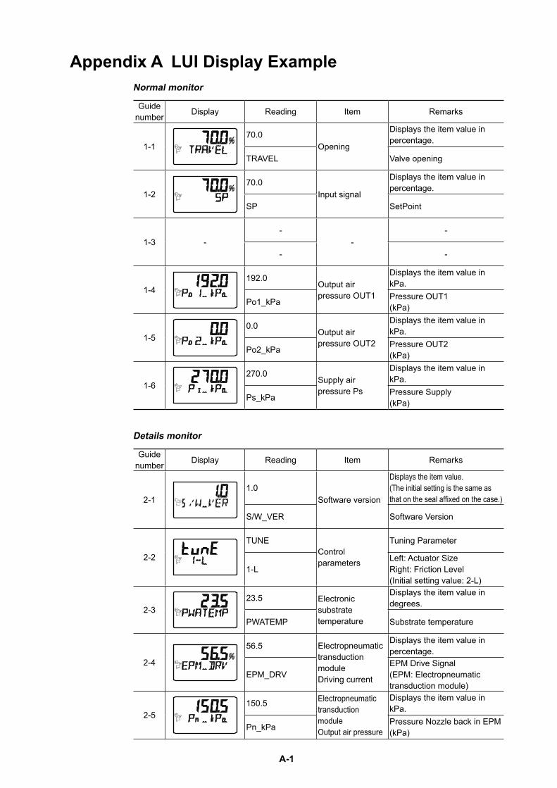
A-1
Appendix A LUI Display ExampleNormal monitor
Guide number Display Reading Item Remarks
1-170.0
Opening
Displays the item value in percentage.
TRAVEL Valve opening
1-270.0
Input signal
Displays the item value in percentage.
SP SetPoint
1-3 --
--
- -
1-4192.0
Output air pressure OUT1
Displays the item value in kPa.
Po1_kPa Pressure OUT1 (kPa)
1-50.0
Output air pressure OUT2
Displays the item value in kPa.
Po2_kPa Pressure OUT2 (kPa)
1-6270.0
Supply air pressure Ps
Displays the item value in kPa.
Ps_kPa Pressure Supply (kPa)
Details monitor
Guide number Display Reading Item Remarks
2-11.0
Software version
Displays the item value. (The initial setting is the same as that on the seal affixed on the case.)
S/W_VER Software Version
2-2
TUNEControl parameters
Tuning Parameter
1-LLeft: Actuator Size Right: Friction Level (Initial setting value: 2-L)
2-323.5 Electronic
substrate temperature
Displays the item value in degrees.
PWATEMP Substrate temperature
2-4
56.5 Electropneumatic transduction module Driving current
Displays the item value in percentage.
EPM_DRVEPM Drive Signal (EPM: Electropneumatic transduction module)
2-5150.5 Electropneumatic
transduction module Output air pressure
Displays the item value in kPa.
Pn_kPa Pressure Nozzle back in EPM (kPa)
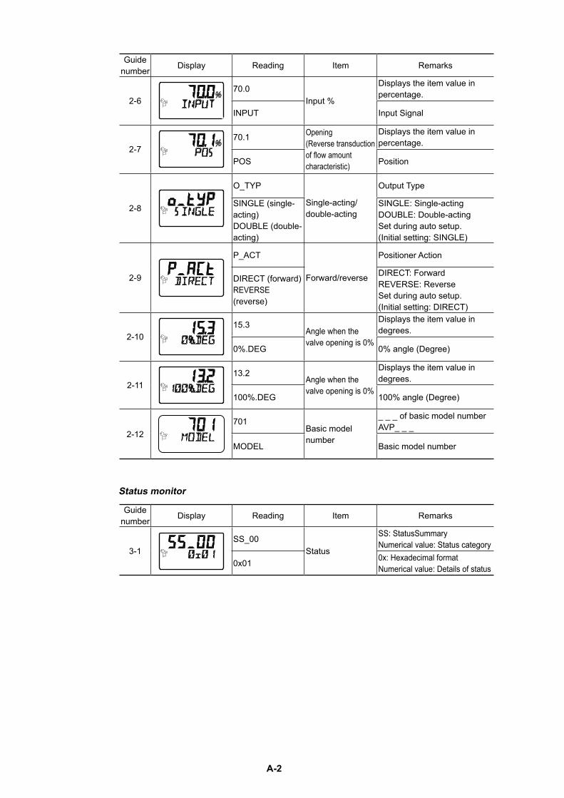
A-2
Guide number Display Reading Item Remarks
2-670.0
Input %
Displays the item value in percentage.
INPUT Input Signal
2-770.1 Opening
(Reverse transduction of flow amount characteristic)
Displays the item value in percentage.
POS Position
2-8
O_TYP
Single-acting/double-acting
Output Type
SINGLE (single-acting) DOUBLE (double-acting)
SINGLE: Single-acting DOUBLE: Double-acting Set during auto setup. (Initial setting: SINGLE)
2-9
P_ACT
Forward/reverse
Positioner Action
DIRECT (forward) REVERSE (reverse)
DIRECT: Forward REVERSE: Reverse Set during auto setup. (Initial setting: DIRECT)
2-1015.3
Angle when the valve opening is 0%
Displays the item value in degrees.
0%.DEG 0% angle (Degree)
2-1113.2
Angle when the valve opening is 0%
Displays the item value in degrees.
100%.DEG 100% angle (Degree)
2-12701
Basic model number
_ _ _ of basic model number AVP_ _ _
MODEL Basic model number
Status monitor
Guide number Display Reading Item Remarks
3-1SS_00
Status
SS: StatusSummary Numerical value: Status category
0x01 0x: Hexadecimal format Numerical value: Details of status
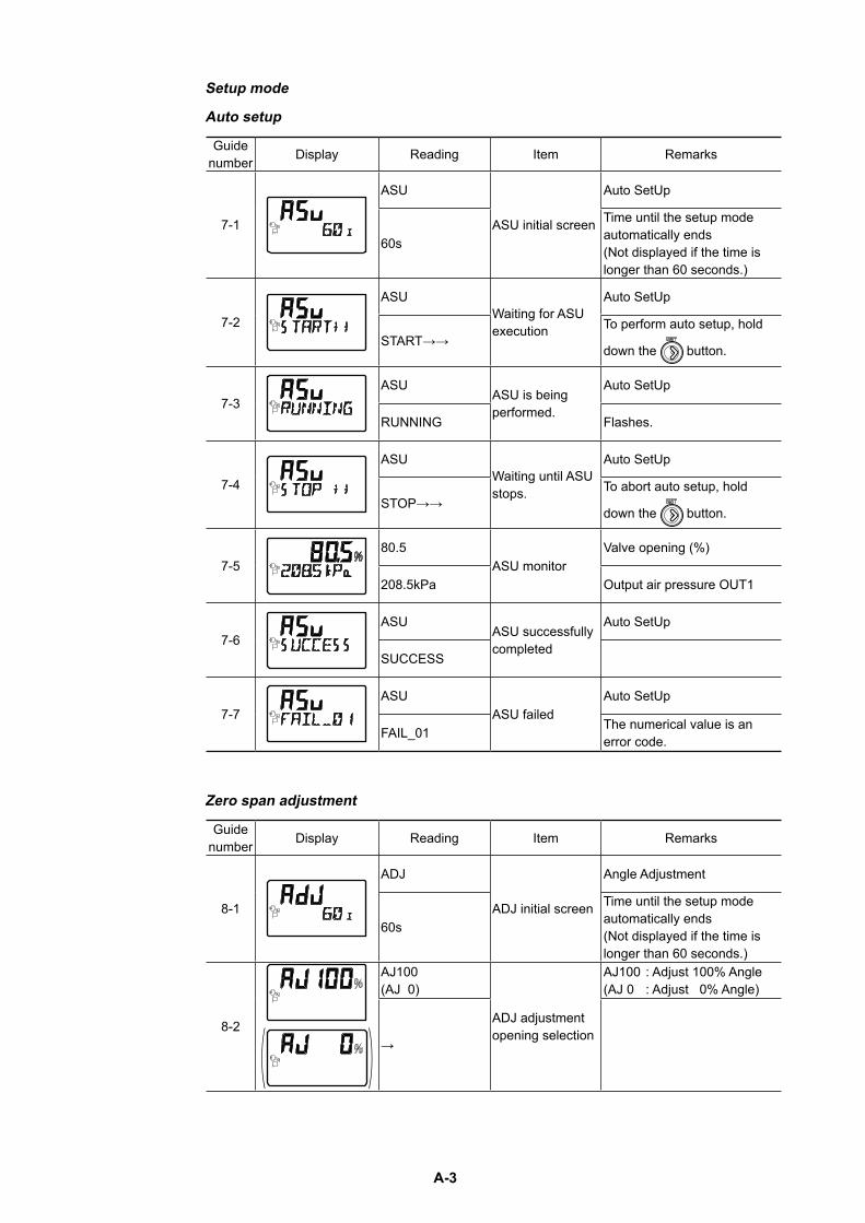
A-3
Setup mode
Auto setup
Guide number Display Reading Item Remarks
7-1
ASU
ASU initial screen
Auto SetUp
60s
Time until the setup mode automatically ends (Not displayed if the time is longer than 60 seconds.)
7-2
ASUWaiting for ASU execution
Auto SetUp
START→→To perform auto setup, hold
down the button.
7-3ASU
ASU is being performed.
Auto SetUp
RUNNING Flashes.
7-4
ASUWaiting until ASU stops.
Auto SetUp
STOP→→To abort auto setup, hold
down the button.
7-580.5
ASU monitorValve opening (%)
208.5kPa Output air pressure OUT1
7-6ASU
ASU successfully completed
Auto SetUp
SUCCESS
7-7ASU
ASU failedAuto SetUp
FAIL_01 The numerical value is an error code.
Zero span adjustment
Guide number Display Reading Item Remarks
8-1
ADJ
ADJ initial screen
Angle Adjustment
60s
Time until the setup mode automatically ends (Not displayed if the time is longer than 60 seconds.)
8-2
AJ100 (AJ 0)
ADJ adjustment opening selection
AJ100 : Adjust 100% Angle (AJ 0 : Adjust 0% Angle)
→
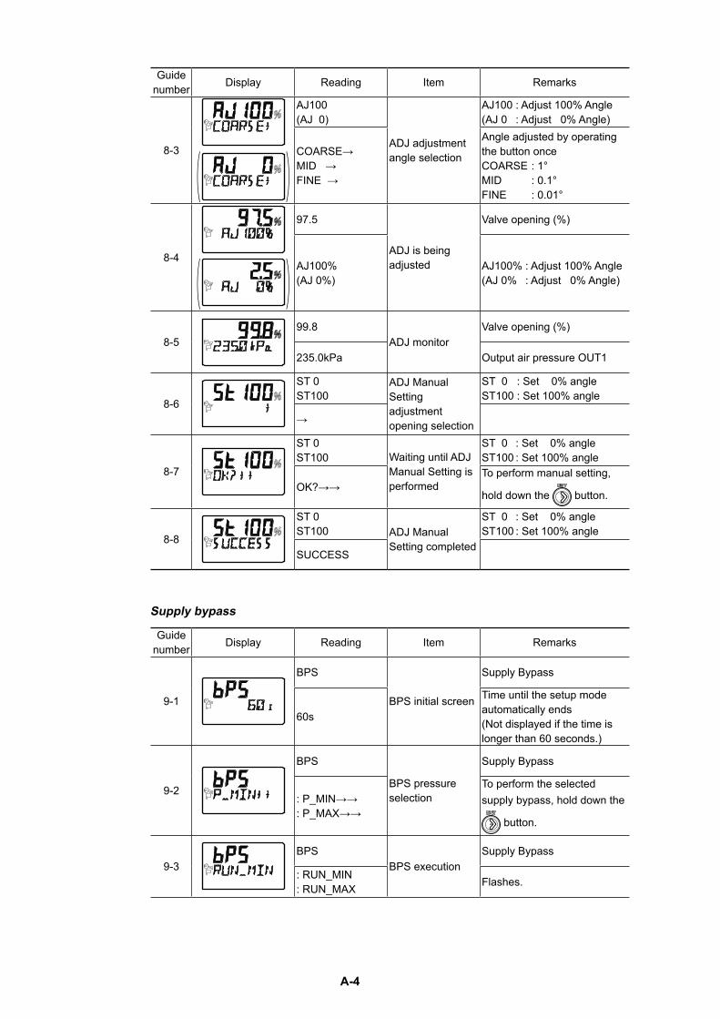
A-4
Guide number Display Reading Item Remarks
8-3
AJ100 (AJ 0)
ADJ adjustment angle selection
AJ100 : Adjust 100% Angle (AJ 0 : Adjust 0% Angle)
COARSE→ MID → FINE →
Angle adjusted by operating the button once COARSE : 1° MID : 0.1° FINE : 0.01°
8-4
97.5
ADJ is being adjusted
Valve opening (%)
AJ100% (AJ 0%)
AJ100% : Adjust 100% Angle (AJ 0% : Adjust 0% Angle)
8-599.8
ADJ monitorValve opening (%)
235.0kPa Output air pressure OUT1
8-6
ST 0 ST100
ADJ Manual Setting adjustment opening selection
ST 0 : Set 0% angle ST100 : Set 100% angle
→
8-7
ST 0 ST100 Waiting until ADJ
Manual Setting is performed
ST 0 : Set 0% angle ST100 : Set 100% angle
OK?→→To perform manual setting,
hold down the button.
8-8
ST 0 ST100 ADJ Manual
Setting completed
ST 0 : Set 0% angle ST100 : Set 100% angle
SUCCESS
Supply bypass
Guide number Display Reading Item Remarks
9-1
BPS
BPS initial screen
Supply Bypass
60s
Time until the setup mode automatically ends (Not displayed if the time is longer than 60 seconds.)
9-2
BPS
BPS pressure selection
Supply Bypass
: P_MIN→→ : P_MAX→→
To perform the selected supply bypass, hold down the
button.
9-3BPS
BPS executionSupply Bypass
: RUN_MIN : RUN_MAX Flashes.
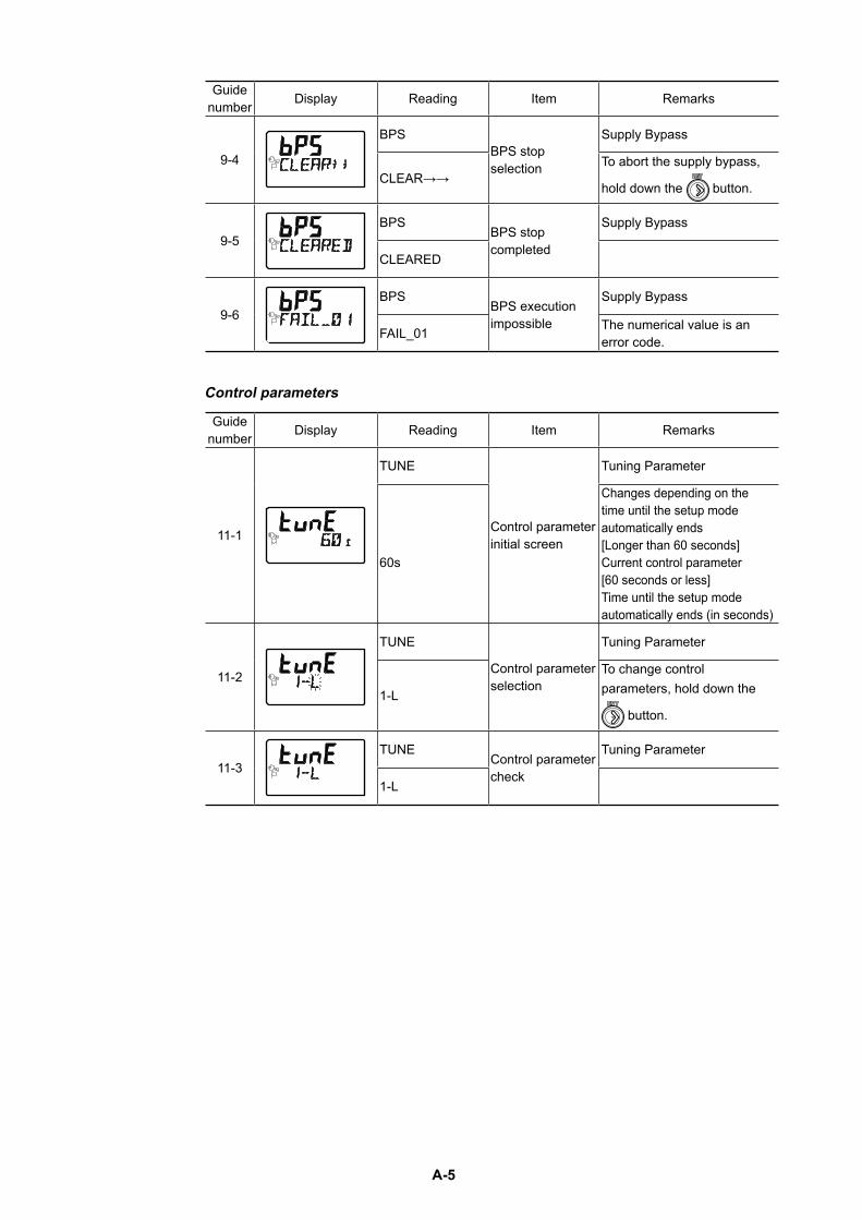
A-5
Guide number Display Reading Item Remarks
9-4
BPSBPS stop selection
Supply Bypass
CLEAR→→To abort the supply bypass,
hold down the button.
9-5BPS
BPS stop completed
Supply Bypass
CLEARED
9-6BPS
BPS execution impossible
Supply Bypass
FAIL_01 The numerical value is an error code.
Control parameters
Guide number Display Reading Item Remarks
11-1
TUNE
Control parameter initial screen
Tuning Parameter
60s
Changes depending on the time until the setup mode automatically ends [Longer than 60 seconds] Current control parameter [60 seconds or less] Time until the setup mode automatically ends (in seconds)
11-2
TUNE
Control parameter selection
Tuning Parameter
1-L
To change control parameters, hold down the
button.
11-3TUNE
Control parameter check
Tuning Parameter
1-L
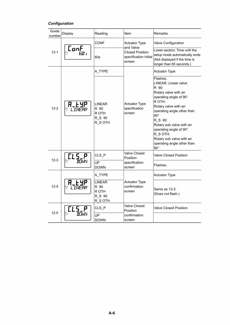
A-6
Configuration
Guide number Display Reading Item Remarks
12-1
CONF Actuator Type and Valve Closed Position specification initial screen
Valve Configuration
60s
Lower section: Time until the setup mode automatically ends (Not displayed if the time is longer than 60 seconds.)
12-2
A_TYPE
Actuator Type specification screen
Actuator Type
LINEAR R 90 R OTH R_S 90 R_S OTH
Flashes. LINEAR: Linear valve R 90: Rotary valve with an operating angle of 90° R OTH: Rotary valve with an operating angle other than 90° R_S 90: Rotary sub valve with an operating angle of 90° R_S OTH: Rotary sub valve with an operating angle other than 90°
12-3CLS_P Valve Closed
Position specification screen
Valve Closed Position
UP DOWN Flashes.
12-4
A_TYPE
Actuator Type confirmation screen
Actuator Type
LINEAR R 90 R OTH R_S 90 R_S OTH
Same as 12-2. (Does not flash.)
12-5CLS_P Valve Closed
Position confirmation screen
Valve Closed Position
UP DOWN
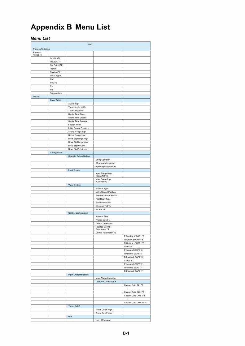
B-1
Appendix B Menu ListMenu List
Menu
Process VariablesProcess Variables
Input (mA) Input (%) *1Set Point (SP)TravelPosition *1Drive SignalPo 1Po 2 *2PsPnTemperature
DeviceBasic Setup
Auto SetupTravel Angle 100%Travel Angle 0%Stroke Time OpenStroke Time ClosedStroke Time AverageFriction IndexInitial Supply PressureSpring Range HighSpring Range LowDrive Sig Range HighDrive Sig Range LowDrive Sig-Pn GainDrive Sig-Pn Intercept
ConfigurationOperator Action Setting
Using OperatorAllow operator actionForbid operator action
Input RangeInput Range High (Open/100%)Input Range Low (Closed/0%)
Valve SystemActuator TypeValve Closed PositionFeedback Lever MotionPilot Relay TypePositioner ActionElectrical Fail ToAir Fail To
Control ConfigurationActuator SizeFriction Level *4Control DeadbandReplace Control Parameters *5Control Parameters *5
P Outside of GAP1 *5I Outside of GAP1 *5D Outside of GAP1 *5GAP1 *5P Inside of GAP1 *6I Inside of GAP1 *6D Inside of GAP1 *6GAP2 *6P Inside of GAP2 *7I Inside of GAP2 *7D Inside of GAP2 *7
Input CharacterizationInput CharacterizationCustom Curve Data *8
Custom Data IN 1 *8 |Custom Data IN 21 *8Custom Data OUT 1 *8 |Custom Data OUT 21 *8
Travel CutoffTravel Cutoff HighTravel Cutoff Low
UnitUnit of Pressure
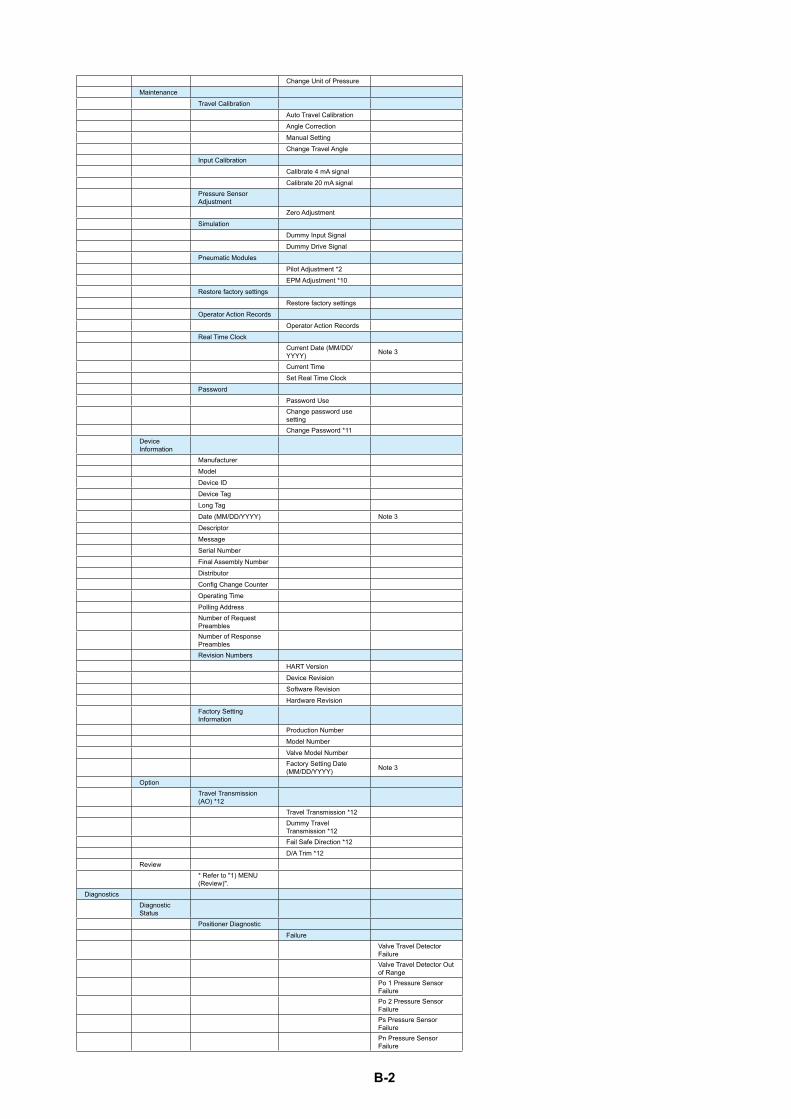
B-2
Change Unit of PressureMaintenance
Travel CalibrationAuto Travel CalibrationAngle CorrectionManual SettingChange Travel Angle
Input CalibrationCalibrate 4 mA signalCalibrate 20 mA signal
Pressure Sensor Adjustment
Zero AdjustmentSimulation
Dummy Input SignalDummy Drive Signal
Pneumatic ModulesPilot Adjustment *2EPM Adjustment *10
Restore factory settingsRestore factory settings
Operator Action RecordsOperator Action Records
Real Time ClockCurrent Date (MM/DD/YYYY) Note 3
Current TimeSet Real Time Clock
PasswordPassword UseChange password use settingChange Password *11
Device Information
ManufacturerModelDevice IDDevice TagLong TagDate (MM/DD/YYYY) Note 3DescriptorMessageSerial NumberFinal Assembly NumberDistributorConfig Change CounterOperating TimePolling AddressNumber of Request PreamblesNumber of Response PreamblesRevision Numbers
HART VersionDevice RevisionSoftware RevisionHardware Revision
Factory Setting Information
Production NumberModel NumberValve Model NumberFactory Setting Date (MM/DD/YYYY) Note 3
OptionTravel Transmission (AO) *12
Travel Transmission *12Dummy Travel Transmission *12Fail Safe Direction *12D/A Trim *12
Review* Refer to "1) MENU (Review)".
DiagnosticsDiagnostic Status
Positioner DiagnosticFailure
Valve Travel Detector FailureValve Travel Detector Out of RangePo 1 Pressure Sensor FailurePo 2 Pressure Sensor FailurePs Pressure Sensor FailurePn Pressure Sensor Failure
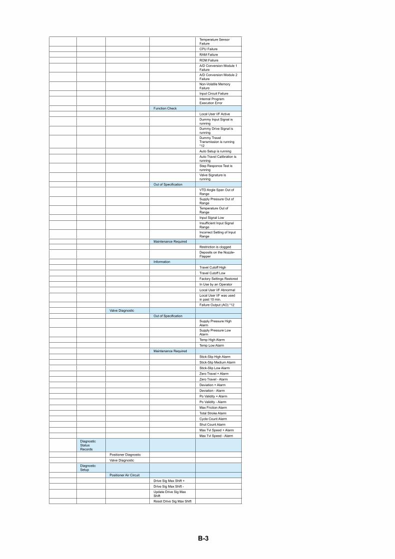
B-3
Temperature Sensor FailureCPU FailureRAM FailureROM FailureA/D Conversion Module 1 FailureA/D Conversion Module 2 FailureNon-Volatile Memory FailureInput Circuit FailureInternal Program Execution Error
Function CheckLocal User I/F ActiveDummy Input Signal is runningDummy Drive Signal is runningDummy Travel Transmission is running *12Auto Setup is runningAuto Travel Calibration is runningStep Responce Test is runningValve Signature is running
Out of SpecificationVTD Angle Span Out of RangeSupply Pressure Out of RangeTemperature Out of RangeInput Signal LowInsufficient Input Signal RangeIncorrect Setting of Input Range
Maintenance RequiredRestriction is cloggedDeposits on the Nozzle-Flapper
InformationTravel Cutoff HighTravel Cutoff LowFactory Settings RestoredIn Use by an OperatorLocal User I/F AbnormalLocal User I/F was used in past 10 min.Failure Output (AO) *12
Valve DiagnosticOut of Specification
Supply Pressure High AlarmSupply Pressure Low AlarmTemp High AlarmTemp Low Alarm
Maintenance RequiredStick-Slip High AlarmStick-Slip Medium AlarmStick-Slip Low AlarmZero Travel + AlarmZero Travel - AlarmDeviation + AlarmDeviation - AlarmPo Validity + AlarmPo Validity - AlarmMax Friction AlarmTotal Stroke AlarmCycle Count AlarmShut Count AlarmMax Tvl Speed + AlarmMax Tvl Speed - Alarm
Diagnostic Status Records
Positioner DiagnosticValve Diagnostic
Diagnostic Setup
Positioner Air CircuitDrive Sig Max Shift +Drive Sig Max Shift -Update Drive Sig Max ShiftReset Drive Sig Max Shift
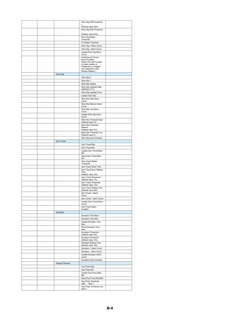
B-4
Drive Sig Shift Threshold + (Default value 25%)Drive Sig Shift Threshold -(Default value 25%)Drive Sig Stable ThresholdPn Stable ThresholdDrive Sig + Alarm CountDrive Sig - Alarm CountUpdate Drive Sig Alarm CountPositioner Air Circuit Alarm Enabled(Select the alarm enable or alarm disable of "Restriction is clogged" and "Deposits on the Nozzle-Flapper.)
Stick-SlipStick-Slip XStick-Slip YStick-Slip ValidityStick-Slip Updated Date (MM/DD/YYYY)Stick-Slip Updated TimeUpdate Stick-SlipStick-Slip High Alarm CountStick-Slip Medium Alarm CountStick-Slip Low Alarm CountUpdate Stick-Slip Alarm CountStick-Slip Threshold High(Default value 10)Stick-Slip Threshold Medium(Default value 5.5)Stick-Slip Threshold Low(Default value 3)Stick-Slip Alarm Enabled
Zero TravelZero Travel MaxZero Travel MinUpdate Zero Travel Max/MinReset Zero Travel Max/MinZero Travel Stable ThresholdZero Travel Static TimeZero Travel Error Waiting Time(Default value 10s)Zero Travel Threshold +(Default value 1%)Zero Travel Threshold -(Default value -3%)Zero Travel Waiting Time(Default value 40s)Zero Travel + Alarm CountZero Travel - Alarm CountUpdate Zero Travel Alarm CountZero Travel Alarm Enabled
DeviationDeviation Time Max +Deviation Time Max -Update Deviation Time MaxReset Deviation Time MaxDeviation Threshold +(Default value 5%)Deviation Threshold -(Default value -5%)Deviation Waiting Time(Default value 10s)Deviation + Alarm CountDeviation - Alarm CountUpdate Deviation Alarm CountDeviation Alarm Enabled
Supply PressureSup Press MaxSup Press MinUpdate Sup Press Max/MinReset Sup Press Max/MinSup Press Threshold High Note 1Sup Press Threshold Low Note 1
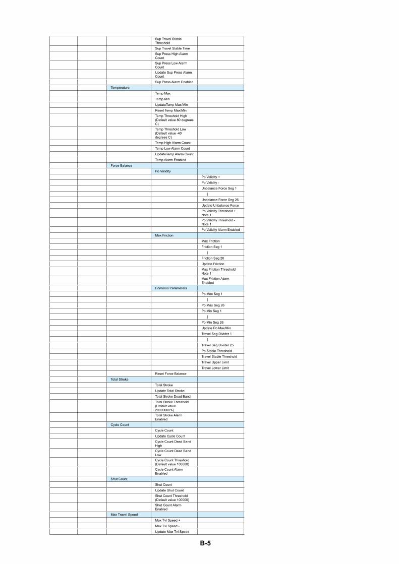
B-5
Sup Travel Stable ThresholdSup Travel Stable TimeSup Press High Alarm CountSup Press Low Alarm Count Update Sup Press Alarm CountSup Press Alarm Enabled
TemperatureTemp MaxTemp MinUpdateTemp Max/MinReset Temp Max/MinTemp Threshold High(Default value 80 degrees C)Temp Threshold Low(Default value -40 degrees C)Temp High Alarm CountTemp Low Alarm CountUpdateTemp Alarm CountTemp Alarm Enabled
Force BalancePo Validity
Po Validity +Po Validity -Unbalance Force Seg 1 |Unbalance Force Seg 26Update Unbalance ForcePo Validity Threshold + Note 1Po Validity Threshold - Note 1Po Validity Alarm Enabled
Max FrictionMax FrictionFriction Seg 1 |Friction Seg 26Update FrictionMax Friction Threshold Note 1Max Friction Alarm Enabled
Common ParametersPo Max Seg 1 |Po Max Seg 26Po Min Seg 1 |Po Min Seg 26Update Po Max/MinTravel Seg Divider 1 |Travel Seg Divider 25Po Stable ThresholdTravel Stable ThresholdTravel Upper LimitTravel Lower Limit
Reset Force BalanceTotal Stroke
Total StrokeUpdate Total StrokeTotal Stroke Dead BandTotal Stroke Threshold(Default value 20000000%)Total Stroke Alarm Enabled
Cycle CountCycle CountUpdate Cycle CountCycle Count Dead Band HighCycle Count Dead Band LowCycle Count Threshold(Default value 100000)Cycle Count Alarm Enabled
Shut CountShut CountUpdate Shut CountShut Count Threshold(Default value 100000)Shut Count Alarm Enabled
Max Travel SpeedMax Tvl Speed +Max Tvl Speed -Update Max Tvl Speed
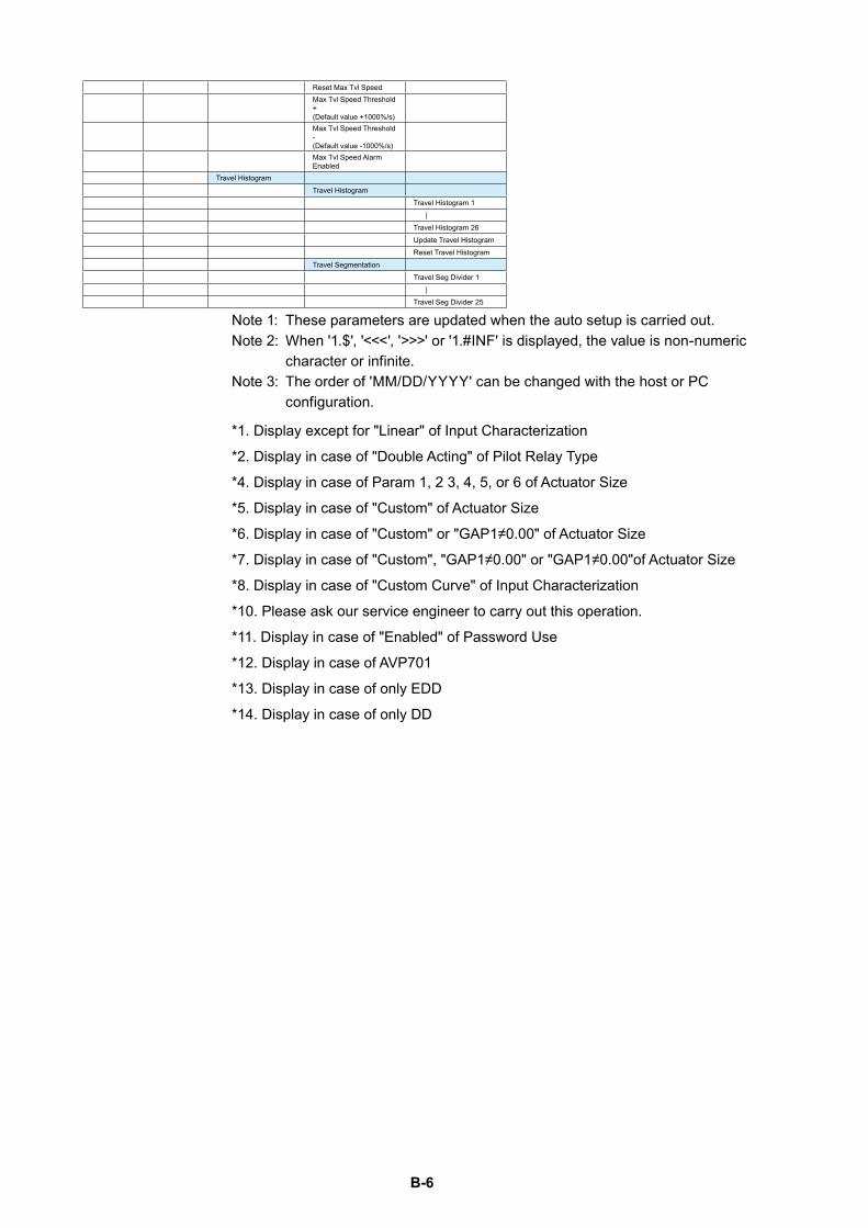
B-6
Reset Max Tvl SpeedMax Tvl Speed Threshold +(Default value +1000%/s)Max Tvl Speed Threshold -(Default value -1000%/s)Max Tvl Speed Alarm Enabled
Travel HistogramTravel Histogram
Travel Histogram 1 |Travel Histogram 26Update Travel HistogramReset Travel Histogram
Travel SegmentationTravel Seg Divider 1 |Travel Seg Divider 25
Note 1: These parameters are updated when the auto setup is carried out.Note 2: When '1.$', '<<<', '>>>' or '1.#INF' is displayed, the value is non-numeric
character or infinite.Note 3: The order of 'MM/DD/YYYY' can be changed with the host or PC
configuration.
*1. Display except for "Linear" of Input Characterization
*2. Display in case of "Double Acting" of Pilot Relay Type
*4. Display in case of Param 1, 2 3, 4, 5, or 6 of Actuator Size
*5. Display in case of "Custom" of Actuator Size
*6. Display in case of "Custom" or "GAP1≠0.00" of Actuator Size
*7. Display in case of "Custom", "GAP1≠0.00" or "GAP1≠0.00"of Actuator Size
*8. Display in case of "Custom Curve" of Input Characterization
*10. Please ask our service engineer to carry out this operation.
*11. Display in case of "Enabled" of Password Use
*12. Display in case of AVP701
*13. Display in case of only EDD
*14. Display in case of only DD

B-7
1) MENU (Review)Displayed parameters and their order are as shown below.
ManufacturerModelDevice IDDevice TagLong TagDateDescriptorMessageSerial NumberFinal Assembly NumberDistributorConfig Change CounterOperating TimePolling AddressNumber of Request PreamblesNumber of Response PreamblesHART VersionDevice RevisionSoftware RevisionHardware RevisionProduction NumberModel NumberValve Model NumberFactory Setting DateInput (mA) Input (%) *1Set Point (SP)TravelPosition *1Drive SignalPo 1Po 2 *2PsPnTemperatureVTD AngleTravel Angle 100%Travel Angle 0%Stroke Time OpenStroke Time ClosedStroke Time AverageFriction IndexInitial Supply PressureSpring Range HighSpring Range LowDrive Sig Range HighDrive Sig Range LowDrive Sig-Pn GainDrive Sig-Pn InterceptInput Range High (Open/100%)Input Range Low (Closed/0%)Actuator TypeValve Closed PositionFeedback Lever MotionPilot Relay TypePositioner ActionElectrical Fail ToAir Fail ToActuator SizeFriction Level *4Control DeadbandP Outside of GAP1 *5I Outside of GAP1 *5D Outside of GAP1 *5GAP1 *5P Inside of GAP1 *6I Inside of GAP1 *6
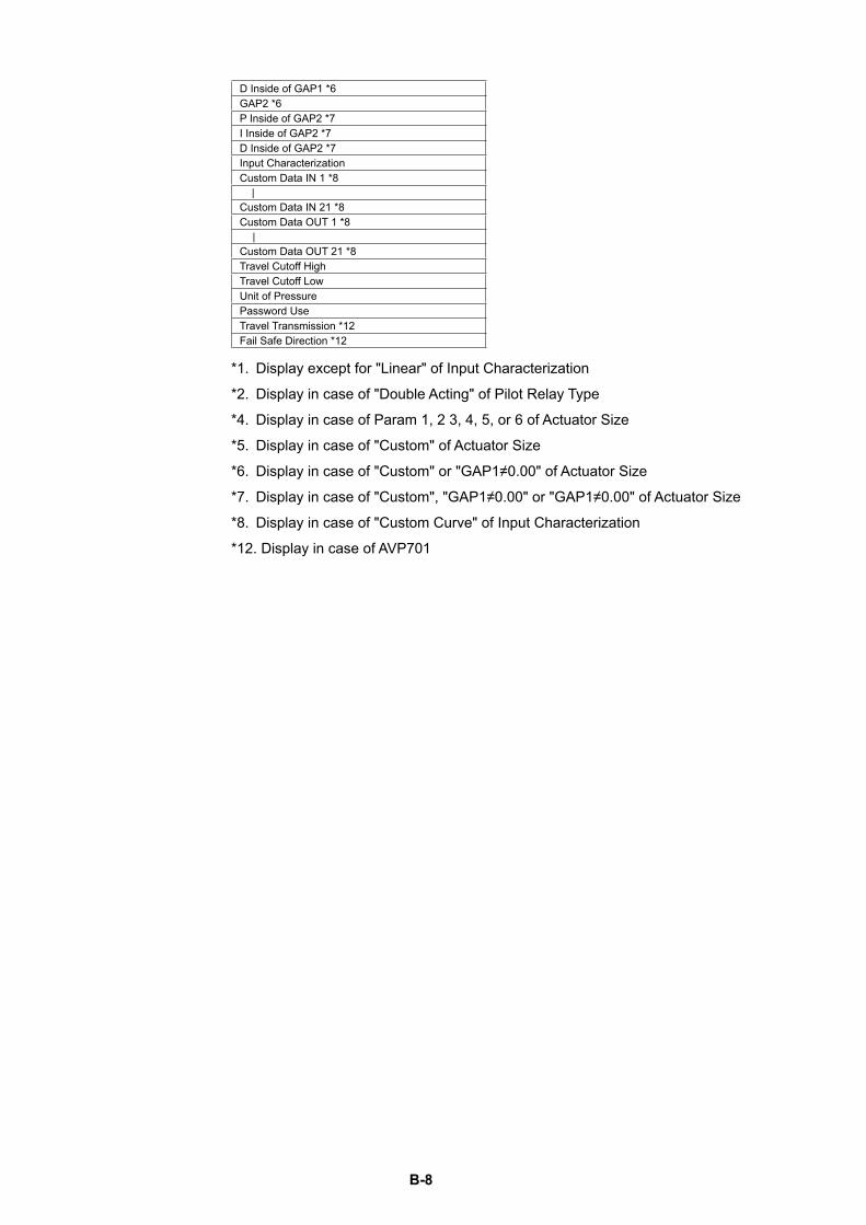
B-8
D Inside of GAP1 *6GAP2 *6P Inside of GAP2 *7I Inside of GAP2 *7D Inside of GAP2 *7Input CharacterizationCustom Data IN 1 *8 |Custom Data IN 21 *8Custom Data OUT 1 *8 |Custom Data OUT 21 *8Travel Cutoff HighTravel Cutoff LowUnit of PressurePassword UseTravel Transmission *12Fail Safe Direction *12
*1. Display except for "Linear" of Input Characterization
*2. Display in case of "Double Acting" of Pilot Relay Type
*4. Display in case of Param 1, 2 3, 4, 5, or 6 of Actuator Size
*5. Display in case of "Custom" of Actuator Size
*6. Display in case of "Custom" or "GAP1≠0.00" of Actuator Size
*7. Display in case of "Custom", "GAP1≠0.00" or "GAP1≠0.00" of Actuator Size
*8. Display in case of "Custom Curve" of Input Characterization
*12. Display in case of AVP701
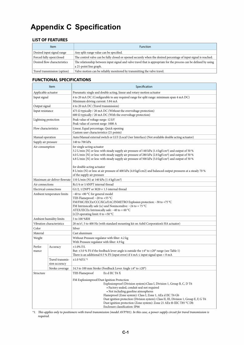
C-1
Appendix C SpecificationLIST OF FEATURES
Item Function
a 21-point line graph.Travel transmission (option) Valve motion can be reliably monitored by transmitting the valve travel.
FUNCTIONAL SPECIFICATIONSItem
Applicable actuator Pneumatic single and double acting, linear and rotary motion actuatorInput signal
Minimum driving current: 3.84 mAOutput signal 4 to 20 mA DC (Travel transmission)Input resistance 475 Ω typically / 20 mA DC (Without the overvoltage protection)
600 Ω typically / 20 mA DC (With the overvoltage protection)Lightning protection Peak value of voltage surge: 12 kV
Peak value of current surge: 1000 AFlow characteristics Linear, Equal percentage, Quick opening
Custom user characteristics (21 points)Manual operation Auto/Manual external switch or LUI (Local User Interface) (Not available double acting actuator)Supply air pressureAir consumption for single acting actuator
3.2 L/min [N] or less: with steady supply air pressure of 140 kPa {1.4 kgf/cm2} and output of 50 %4.0 L/min [N] or less: with steady supply air pressure of 280 kPa {2.8 kgf/cm2} and output of 50 %4.8 L/min [N] or less: with steady supply air pressure of 500 kPa {5.0 kgf/cm2} and output of 50 %
for double acting actuator8 L/min (N) or less: at air pressure of 400 kPa {4.0 kgf/cm2} and balanced output pressures at a steady 70 %of the supply air pressure
2}Air connections Rc1/4 or 1/4NPT internal threadElectrical connections G1/2, 1/2NPT or M20 × 1.5 internal thread
2
Color SilverMaterial Cast aluminumWeight
Perfor-mance
Accuracy ±1.0% F.S.But: ±3.0 % FS if the feedback lever angle is outside the ±4° to ±20° range (see Table 1)
Travel transmis-sion accuracy
.S.*1
Structure TIIS Flameproof Ex d IIC T6 X
FM Explosionproof/Dust Ignition Protection Explosionproof (Division system):Class I, Division 1, Group B, C, D T6
• Factory sealed, conduit seal not required • Not including gasoline atmospheres
Flameproof (Zone system): Class I, Zone 1, AEx d IIC T6 Gb
En
*1. is applies only to positioners with travel transmission (model AVP701). In this case, a power supply circuit for travel transmission isrequired.
FM/FMC/IECEx/CCC/KCs/EAC/INMETRO Explosion protection: −30 to +75 °C
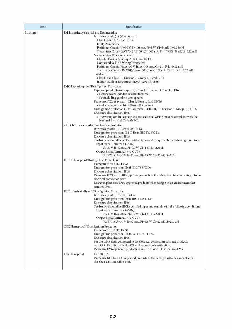
C-2
Item
Structure FM Intrinsically safe (ic) and Nonincendive Intrinsically safe (ic) (Zone system)
Class I, Zone 2, AEx ic IIC T4 Entity Parameters: PT
Nonincendive (Division system) Class I, Division 2, Group A, B, C and D, T4 Nonincendive Field Wiring Parameters: PT
Suitable Class II and Class III, Division 2, Group E, F and G, T4 Indoor/Outdoor Enclosure: NEMA Type 4X, IP66
FMC Explosionproof/Dust Ignition Protection Explosionproof (Division system): Class I, Division 1, Group C, D T6
• Factory sealed, conduit seal not required • Not including gasoline atmospheres
Flameproof (Zone system): Class I, Zone 1, Ex d IIB T6 • S
Dust ignition protection (Division system): Class II, III, Division 1, Group E, F, G T6En
ATEX Intrinsically safe/Dust Ignition ProtectionIntrinsically safe: II 1 G Ex ia IIC T4 GaDust ignition protection: II 1 D Ex ia IIIC T135°C Da
Input Signal Terminals (+/-IN): Ui=30 V, Ii=93 mA, Pi=0.9 W, Ci=4 nF, Li=220 μHOutput Signal Terminals (+/-OUT):
(AVP701) Ui=30 V, Ii=93 mA, Pi=0.9 W, Ci=22 nF, Li=220IECEx Flameproof/Dust Ignition Protection
Flameproof: Ex d IIC T6 Gb
En Please use IECEx Ex d IIC-approved products as the cable gland for connecting it to the electrical connection port. However, please use IP66-approved products when using it in an environment that requires IP66.
IECEx Intrinsically safe/Dust Ignition ProtectionIntrinsically safe: Ex ia IIC T4 GaDust ignition protection: Ex ia IIIC T135°C Da
Input Signal Terminals (+/-IN): Ui=30 V, Ii=93 mA, Pi=0.9 W, Ci=4 nF, Li=220 μHOutput Signal Terminals (+/-OUT):
(AVP701) Ui=30 V, Ii=93 mA, Pi=0.9 W, Ci=22 nF, Li=220 μHCCC Flameproof / Dust Ignition Protection
Flameproof: Ex d IIC T6 Gb
En For the cable gland connected to the electrical connection port, use productswith CCC Ex d IIC or Ex tD A21 explosion-proof certi�cation.Please use IP66-approved products in an environment that requires IP66.
KCs Flameproof Ex d IIC T6Please use KCs Ex d IIC-approved products as the cable gland to be connected tothe electrical connection port.
• �e wiring conduit cable gland and electrical wiring must be compliant with the National Electrical Code (NEC).
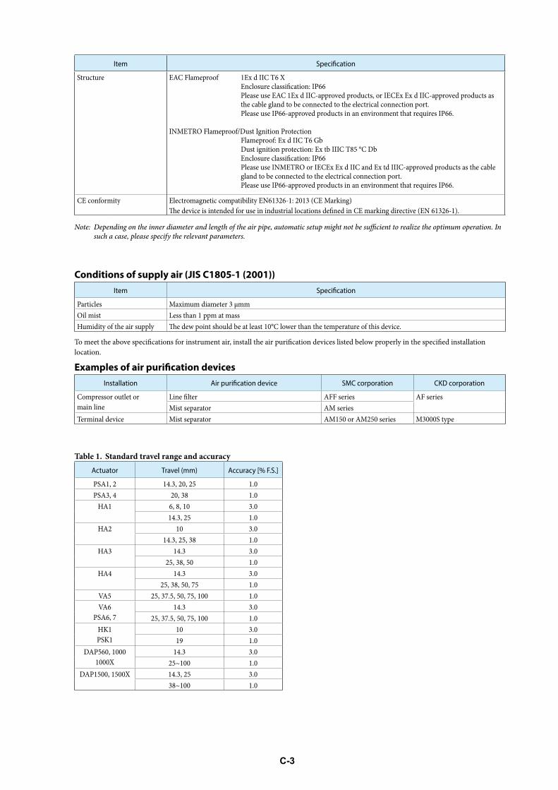
C-3
Item
Structure EAC Flameproof 1Ex d IIC T6 X En Please use EAC 1Ex d IIC-approved products, or IECEx Ex d IIC-approved products as the cable gland to be connected to the electrical connection port.Please use IP66-approved products in an environment that requires IP66.
INMETRO Flameproof/Dust Ignition Protection Flameproof: Ex d IIC T6 Gb D En Please use INMETRO or IECEx Ex d IIC and Ex td IIIC-approved products as the cable gland to be connected to the electrical connection port.Please use IP66-approved products in an environment that requires IP66.
CE conformity Electromagnetic compatibility EN61326-1: 2013 (CE Marking)
Note: Dsuch a case, please specify the relevant parameters.
Conditions of supply air (JIS C1805-1 (2001))Item
Particles Maximum diameter 3 μmmOil mist Less than 1 ppm at mass
location.
Installation SMC corporation CKD corporation
Compressor outlet or main line
L AFF series AF seriesMist separator AM series
Terminal device Mist separator AM150 or AM250 series M3000S type
Table 1. Standard travel range and accuracy
Actuator Travel (mm) Accuracy [% F.S.]
PSA1, 2 14.3, 20, 25 1.0PSA3, 4 20, 38 1.0
HA1 6, 8, 10 3.014.3, 25 1.0
HA2 10 3.014.3, 25, 38 1.0
HA3 14.3 3.025, 38, 50 1.0
HA4 14.3 3.025, 38, 50, 75 1.0
VA5 25, 37.5, 50, 75, 100 1.0VA6
PSA6, 714.3 3.0
25, 37.5, 50, 75, 100 1.0HK1PSK1
10 3.019 1.0
DAP560, 10001000X
14.3 3.025~100 1.0
DAP1500, 1500X 14.3, 25 3.038~100 1.0

C-4
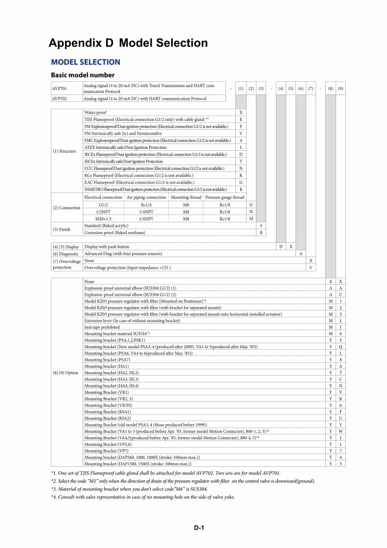
D-1
Appendix D Model SelectionMODEL SELECTIONBasic model number
AVP701 Analog signal (4 to 20 mA DC) with Travel Transmission and HART com-munication Protocol - (1) (2) (3) - (4) (5) (6) (7) - (8) (9)
AVP702 Analog signal (4 to 20 mA DC) with HART communication Protocol
(1) Structure
Water-proof XE
FM Explosionproof/Dust ignition protection (Electrical connection G1/2 is not available.) FFM Intrinsically safe (ic) and Nonincendive VFMC Explosionproof/Dust ignition protection (Electrical connection G1/2 is not available.) AATEX Intrinsically safe/Dust Ignition Protection LIECEx Flameproof/Dust ignition protection (Electrical connection G1/2 is not available.) DIECEx Intrinsically safe/Dust Ignition Protection TCCC Flameproof/Dust ignition protection (Electrical connection G1/2 is not available.) NKCs Flameproof (Electrical connection G1/2 is not available.) KEAC Flameproof (Electrical connection G1/2 is not available.) GINMETRO Flameproof/Dust ignition protection (Electrical connection G1/2 is not available.) B
(2) Connection
Electrical connection Air piping connection Mounting thread Pressure gauge thread
G1/2 Rc1/4 M8 Rc1/8 G1/2NPT 1/4NPT M8 Rc1/8 NM20×1.5 1/4NPT M8 Rc1/8 M
(3) FinishStandard (Baked acrylic) SCorrosion proof (Baked urethane) B
(4) (5) Display Display with push button D X(6) Diagnostic Advanced Diag (with four pressure sensors) A
(7) Overvoltage protection
None XOvervoltage protection (Input impedance +125 ) V
(8) (9) Option
None X XExplosion-proof universal elbow (SUS304 G1/2) (1) A AExplosion-proof universal elbow (SUS304 G1/2) (2) A C
*2 M 1M 2M 3
Extension lever (In case of without mounting bracket) M LSeal tape prohibited M JMounting bracket material SUS316*3 M 6Mounting bracket (PSA,1,2,PSK1) Y S
Y QY L
Mounting bracket (PSA7) Y 8Mounting bracket (HA1) Y AMounting bracket (HA2, HL2) Y TMounting bracket (HA3, HL3) Y CMounting bracket (HA4, HL4) Y NMounting Bracket (VR1) Y VMounting Bracket (VR2, 3) Y RMounting Bracket (VR3H) Y 6Mounting Bracket (RSA1) Y FMounting Bracket (RSA2) Y UMounting Bracket (old model PSA3, 4 (those produced before 1999)) Y YMounting Bracket (VA1 to 3 (produced before Apr. ‘83, former model Motion Connector), 800-1, 2, 3)*4 Y WMounting Bracket (VA4,5(produced before Apr. ‘83, former model Motion Connector), 800-4, 5)*4 Y JMounting Bracket (VP5,6) Y 1Mounting Bracket (VP7) Y 7Mounting bracket (DAP560, 1000, 1000X (stroke: 100mm max.)) Y 4Mounting bracket (DAP1500, 1500X (stroke: 100mm max.)) Y 5
*1. One set of TIIS Flameproof cable gland shall be attached for model AVP702. Two sets are for model AVP701.
*3. Material of mounting bracket when you don’t select code”M6” is SUS304.*4. Consult with sales representative in case of no mounting hole on the side of valve yoke.
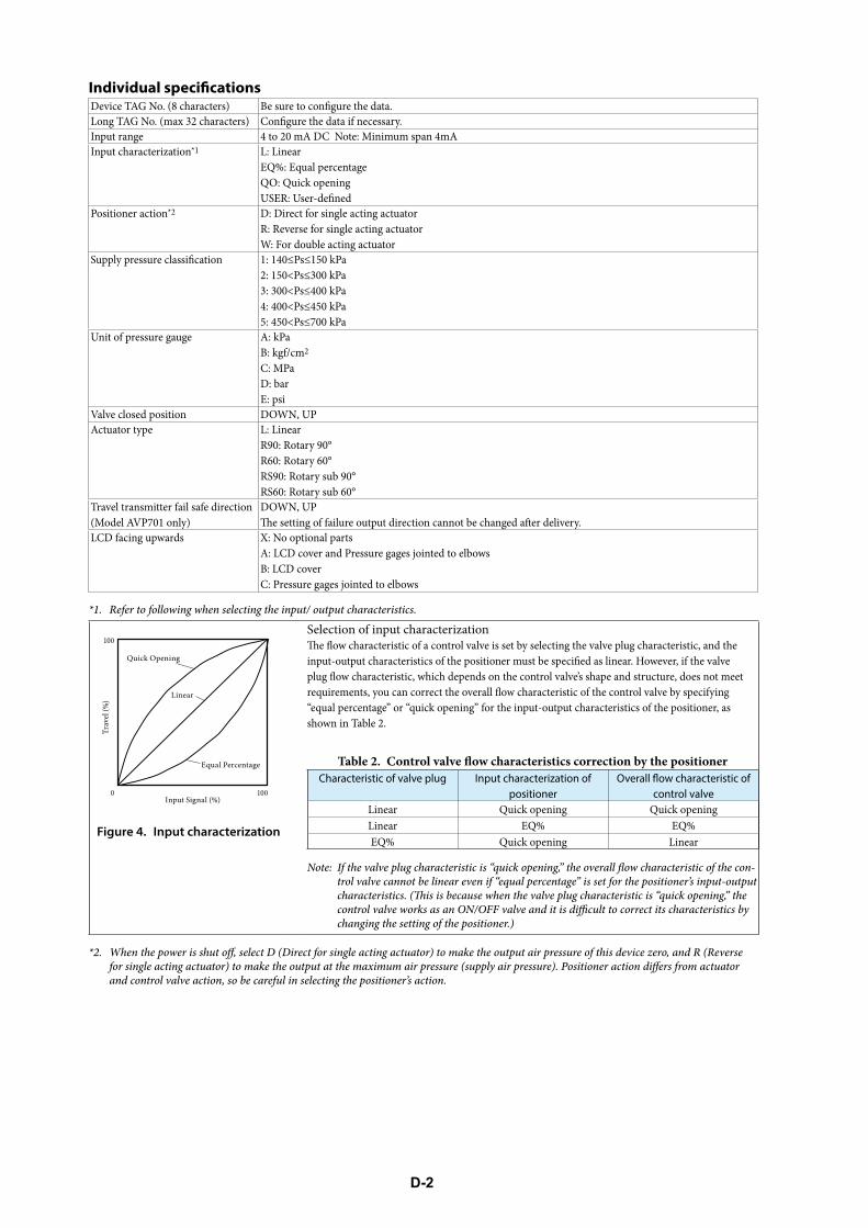
D-2
Input rangeInput characterization*1 L: Linear
EQ%: Equal percentageQO: Quick opening
Positioner action*2 D: Direct for single acting actuatorR: Reverse for single acting actuatorW: For double acting actuator
Unit of pressure gauge A: kPaB: kgf/cm2
C: MPaD: barE: psi
Valve closed position DOWN, UPActuator type L: Linear
R90: Rotary 90°R60: Rotary 60°RS90: Rotary sub 90°RS60: Rotary sub 60°
Travel transmitter fail safe direction (Model AVP701 only)
DOWN, UP
LCD facing upwards X: No optional partsA: LCD cover and Pressure gages jointed to elbowsB: LCD coverC: Pressure gages jointed to elbows
*1. Refer to following when selecting the input/ output characteristics.
Figure 4. Input characterization
Selection of input characterization
“equal percentage” or “quick opening” for the input-output characteristics of the positioner, as shown in Table 2.
Table 2. CCharacteristic of valve plug Input characterization of
positioner control valveLinear Quick opening Quick openingLinear EQ% EQ%EQ% Quick opening Linear
Note: Itrol valve cannot be linear even if “equal percentage” is set for the positioner’s input-output
changing the setting of the positioner.)
*2. W
and control valve action, so be careful in selecting the positioner’s action.
Quick Opening
Trav
el (%
)
Equal Percentage
Linear
100
1000Input Signal (%)
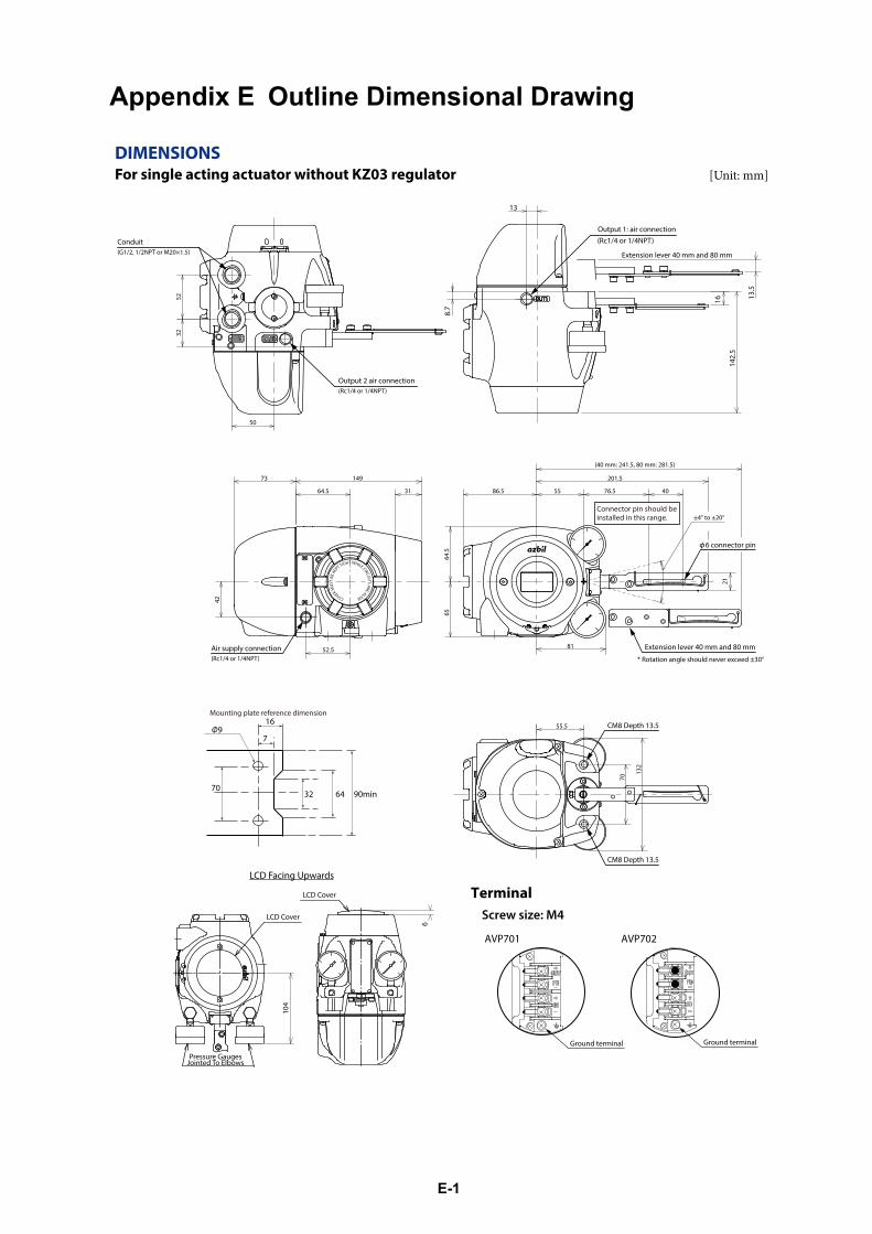
E-1
Appendix E Outline Dimensional Drawing
DIMENSIONSFor single acting actuator without KZ03 regulator [Unit: mm]
32
50
52
Conduit(G1/2, 1/2NPT or M20×1.5)
Output 2 air connection(Rc1/4 or 1/4NPT)
Extension lever 40 mm and 80 mm
16
13
13.5
8.7
(Rc1/4 or 1/4NPT)
142.
5
Output 1: air connection
Connector pin should be installed in this range.
31
52.5
55
81
76.5
42
21
(40 mm: 241.5, 80 mm: 281.5)
±4° to ±20°
Extension lever 40 mm and 80 mm
40
(Rc1/4 or 1/4NPT)
201.5
Air supply connection
86.5
6564
.5
73 149
64.5
6 connector pin
CM8 Depth 13.5
132
CM8 Depth 13.5
70
55.5
104
6
LCD Cover
LCD Cover
LCD Facing Upwards
Pressure GaugesJointed To Elbows
Ground terminalGround terminal
Terminal Screw size: M4
AVP701 AVP702
Mounting plate reference dimension
* Rotation angle should never exceed ±30°
169Φ
7032 64 90min
7
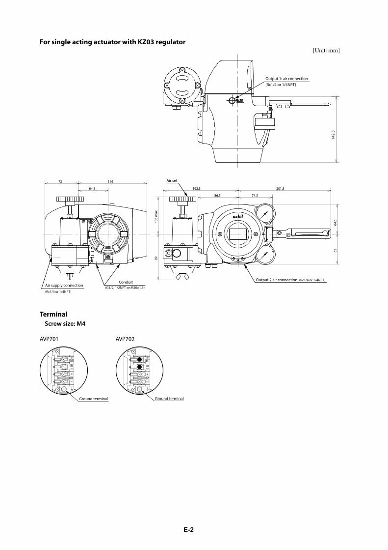
E-2
For single acting actuator with KZ03 regulator[Unit: mm]
142.
5
(Rc1/4 or 1/4NPT)Output 1: air connection
86.5
201.5162.5
9910
5 m
ax.
Air set73 149
64.5
74.5
64.5
65
Conduit(G1/2, 1/2NPT or M20×1.5)
Output 2 air connection (Rc1/4 or 1/4NPT)
Air supply connection(Rc1/4 or 1/4NPT)
TerminalScrew size: M4
AVP701
Ground terminal
AVP702
Ground terminal
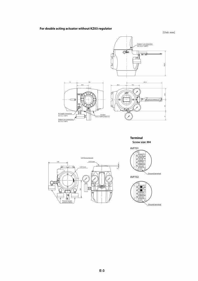
E-3
For double acting actuator without KZ03 regulator[Unit: mm]
142.
5
(Rc1/4 or 1/4NPT)Output 1: air connection
64.5
6551
74.5
Conduit(G1/2, 1/2NPT or M20×1.5)
Output 2 air connection(Rc1/4 or 1/4NPT)
201.5
Air supply connection
86.5
73 149
64.5
(Rc1/4 or 1/4NPT)
TerminalScrew size: M4
AVP701
Ground terminal
AVP702
Ground terminal
LCD Facing Upwards
6
LCD Cover
LCD Cover120
104
Pressure GaugesJointed to Elbows
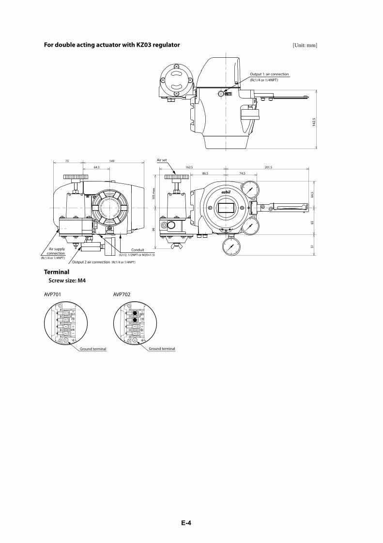
E-4
For double acting actuator with KZ03 regulator [Unit: mm]
142.
5
(Rc1/4 or 1/4NPT)
Output 1: air connection
162.5 201.5
65
74.5
51
73 149
64.5
86.5
Air set
9910
5 m
ax.
64.5
Conduit(G1/2, 1/2NPT or M20×1.5)
Output 2 air connection (Rc1/4 or 1/4NPT)
Air supplyconnection
(Rc1/4 or 1/4NPT)
TerminalScrew size: M4
AVP701
Ground terminal
AVP702
Ground terminal
We would like to express our appreciation for your purchase and use of Azbil Corporation’s products.
You are required to acknowledge and agree upon the following terms and conditions for your purchase of Azbil Corporation’s products (system products, field instruments, control valves, and control products), unless otherwise stated in any separate document, including, without limitation, estimation sheets, written agreements, catalogs, specifications and instruction manuals.
1. Warranty period and warranty scope
1.1 Warranty period
Azbil Corporation’s products shall be warranted for one (1) year from the date of your purchase of the said products or the delivery of the said products to a place designated by you.
1.2 Warranty scope
In the event that Azbil Corporation’s product has any failure attributable to azbil during the aforementioned warranty period, Azbil Corporation shall, without charge, deliver a replacement for the said product to the place where you purchased, or repair the said product and deliver it to the aforementioned place. Notwithstanding the foregoing, any failure falling under one of the following shall not be covered under this warranty:
(1) Failure caused by your improper use of azbil product (noncompliance with conditions, environment of use, precautions, etc. set forth in catalogs, specifications, instruction manuals, etc.);
(2) Failure caused for other reasons than Azbil Corporation’s product;(3) Failure caused by any modification or repair made by any person other than Azbil Corporation or Azbil Corporation’s
subcontractors; (4) Failure caused by your use of Azbil Corporation’s product in a manner not conforming to the intended usage of that product; (5) Failure that the state-of-the-art at the time of Azbil Corporation’s shipment did not allow Azbil Corporation to predict; or (6) Failure that arose from any reason not attributable to Azbil Corporation, including, without limitation, acts of God, disasters, and
actions taken by a third party.
Please note that the term “warranty” as used herein refers to equipment-only-warranty, and Azbil Corporation shall not be liable for any damages, including direct, indirect, special, incidental or consequential damages in connection with or arising out of Azbil Corporation’s products.
2. Ascertainment of suitability
You are required to ascertain the suitability of Azbil Corporation’s product in case of your use of the same with your machinery, equipment, etc. (hereinafter referred to as “Equipment”) on your own responsibility, taking the following matters into consideration:
(1) Regulations and standards or laws that your Equipment is to comply with.(2) Examples of application described in any documents provided by Azbil Corporation are for your reference purpose only, and
you are required to check the functions and safety of your Equipment prior to your use. (3) Measures to be taken to secure the required level of the reliability and safety of your Equipment in your use
Although azbil is constantly making efforts to improve the quality and reliability of Azbil Corporation’s products, there exists a possibility that parts and machinery may break down. You are required to provide your Equipment with safety design such as fool-proof design,*1 and fail-safe design*2 (anti-flame propagation design, etc.), whereby preventing any occurrence of physical injuries, fires, significant damage, and so forth. Furthermore, fault avoidance,*3 fault tolerance,*4 or the like should be incorporated so that the said Equipment can satisfy the level of reliability and safety required for your use.
*1. A design that is safe even if the user makes an error. *2. A design that is safe even if the device fails. *3. Avoidance of device failure by using highly reliable components, etc. *4. The use of redundancy.
3. Precautions and restrictions on application
3.1 Restrictions on application
Please follow the table below for use in nuclear power or radiation-related equipment.
Nuclear power quality*5 required Nuclear power quality*5 not required
Within a radiation controlled area*6
Cannot be used (except for limit switches for nuclear power*7)
Cannot be used (except for limit switches for nuclear power*7)
Outside a radiation controlled area*6
Cannot be used (except for limit switches for nuclear power*7)
Can be used
*5. Nuclear power quality: compliance with JEAG 4121 required*6. Radiation controlled area: an area governed by the requirements of article 3 of “Rules on the Prevention of Harm from
Ionizing Radiation,” article 2 2 4 of “Regulations on Installation and Operation of Nuclear Reactors for Practical Power Generation,” article 4 of “Determining the Quantity, etc., of Radiation-Emitting Isotopes,”etc.
*7. Limit switch for nuclear power: a limit switch designed, manufactured and sold according to IEEE 382 and JEAG 4121.
Any Azbil Corporation’s products shall not be used for/with medical equipment.
The products are for industrial use. Do not allow general consumers to install or use any Azbil Corporation’s product. However, azbil products can be incorporated into products used by general consumers. If you intend to use a product for that purpose, please contact one of our sales representatives.
3.2 Precautions on application
you are required to conduct a consultation with our sales representative and understand detail specifications, cautions for operation, and so forth by reference to catalogs, specifications, instruction manual, etc. in case that you intend to use azbil product for any purposes specified in (1) through (6) below. Moreover, you are required to provide your Equipment with fool-proof design, fail-safe design, anti-flame propagation design, fault avoidance, fault tolerance, and other kinds of protection/safety circuit design on your own responsibility to ensure reliability and safety, whereby preventing problems caused by failure or nonconformity.
Terms and Conditions
(1) For use under such conditions or in such environments as not stated in technical documents, including catalogs, specification, and instruction manuals
(2) For use of specific purposes, such as: * Nuclear energy/radiation related facilities
[When used outside a radiation controlled area and where nuclear power quality is not required] [When the limit switch for nuclear power is used]
* Machinery or equipment for space/sea bottom * Transportation equipment [Railway, aircraft, vessels, vehicle equipment, etc.] * Antidisaster/crime-prevention equipment * Burning appliances * Electrothermal equipment * Amusement facilities * Facilities/applications associated directly with billing
(3) Supply systems such as electricity/gas/water supply systems, large-scale communication systems, and traffic/air traffic control systems requiring high reliability
(4) Facilities that are to comply with regulations of governmental/public agencies or specific industries (5) Machinery or equipment that may affect human lives, human bodies or properties (6) Other machinery or equipment equivalent to those set forth in items (1) to (5) above which require high reliability and safety
4. Precautions against long-term use
Use of Azbil Corporation’s products, including switches, which contain electronic components, over a prolonged period may degrade insulation or increase contact-resistance and may result in heat generation or any other similar problem causing such product or switch to develop safety hazards such as smoking, ignition, and electrification. Although acceleration of the above situation varies depending on the conditions or environment of use of the products, you are required not to use any Azbil Corporation’s products for a period exceeding ten (10) years unless otherwise stated in specifications or instruction manuals.
5. Recommendation for renewal
Mechanical components, such as relays and switches, used for Azbil Corporation’s products will reach the end of their life due to wear by repetitious open/close operations.
In addition, electronic components such as electrolytic capacitors will reach the end of their life due to aged deterioration based on the conditions or environment in which such electronic components are used. Although acceleration of the above situation varies depending on the conditions or environment of use, the number of open/close operations of relays, etc. as prescribed in specifications or instruction manuals, or depending on the design margin of your machine or equipment, you are required to renew any Azbil Corporation’s products every 5 to 10 years unless otherwise specified in specifications or instruction manuals. System products, field instruments (sensors such as pressure/flow/level sensors, regulating valves, etc.) will reach the end of their life due to aged deterioration of parts. For those parts that will reach the end of their life due to aged deterioration, recommended replacement cycles are prescribed. You are required to replace parts based on such recommended replacement cycles.
6. Other precautions
Prior to your use of Azbil Corporation’s products, you are required to understand and comply with specifications (e.g., conditions and environment of use), precautions, warnings/cautions/notices as set forth in the technical documents prepared for individual Azbil Corporation’s products, such as catalogs, specifications, and instruction manuals to ensure the quality, reliability, and safety of those products.
7. Changes to specifications
Please note that the descriptions contained in any documents provided by azbil are subject to change without notice for improvement or for any other reason. For inquires or information on specifications as you may need to check, please contact our branch offices or sales offices, or your local sales agents.
8. Discontinuance of the supply of products/parts
Please note that the production of any Azbil Corporation’s product may be discontinued without notice. After manufacturing is discontinued, we may not be able to provide replacement products even within the warranty period.
For repairable products, we will, in principle, undertake repairs for five (5) years after the discontinuance of those products. In some cases, however, we cannot undertake such repairs for reasons, such as the absence of repair parts. For system products, field instruments, we may not be able to undertake parts replacement for similar reasons.
9. Scope of services
Prices of Azbil Corporation’s products do not include any charges for services such as engineer dispatch service. Accordingly, a separate fee will be charged in any of the following cases:
(1) Installation, adjustment, guidance, and attendance at a test run (2) Maintenance, inspection, adjustment, and repair(3) Technical guidance and technical education (4) Special test or special inspection of a product under the conditions specified by you
Please note that we cannot provide any services as set forth above in a nuclear energy controlled area (radiation controlled area) or at a place where the level of exposure to radiation is equivalent to that in a nuclear energy controlled area.
AAS-511A-014-10

Document Number:Document Name:
CM2-AVP702-2001 Smart Valve Positioner700 Series with HART Communication ProtocolModel AVP701/702User's Manual
Date:
Issued/Edited by:
1st edition: July 201410th edition: Apr. 2021Azbil Corporation