Embed Size (px)
Citation preview

Woodbridge Energy Center 700 MW Electric Generating Facility
PSD Air Permit Application
Prepared for:
CPV Shore, LLC
Prepared by:
TRC Environmental Corporation 1200 Wall Street West, 2nd Floor
Lyndhurst, NJ 07071
June 2011
June 2011 i Woodbridge Energy Center
TABLE OF CONTENTS Section Page
1.0 Introduction .......................................................................................................................... 1-1
1.1 Project Overview ............................................................................................................... 1-1 1.2 Summary of Federal and State-Level Emission Control Requirements ....................... 1-2
1.2.1 Lowest Achievable Emission Rate ........................................................................... 1-2 1.2.2 Best Available Control Technology .......................................................................... 1-2 1.2.3 State Of The Art Technology .................................................................................... 1-3
1.3 Assessment of Air Quality Impact ................................................................................... 1-3 1.3.1 Impact on Ambient Air Quality Standards and PSD Increments ......................... 1-3 1.3.2 Class I Area Impacts ................................................................................................. 1-3 1.3.3 Impacts to Soils, Vegetation, Visibility, and Industrial, Commercial, and Residential Growth ................................................................................................................... 1-4
1.4 Conclusions ....................................................................................................................... 1-4 1.5 Summary of Proposed Emission Limits .......................................................................... 1-4 1.6 Contents of Application Support Document and Appendices ....................................... 1-4 1.7 Project Schedule ................................................................................................................ 1-5
2.0 Project Description ............................................................................................................... 2-1
2.1 Facility Conceptual Design ............................................................................................... 2-1 2.2 Natural Gas-Fired Combined Cycle Units ....................................................................... 2-1
2.2.1 Control Equipment for the Combined Cycle Units ............................................... 2-4 2.3 Auxiliary Boiler ................................................................................................................ 2-5 2.4 Dew Point Heater ............................................................................................................. 2-5 2.5 Emergency Diesel Engines .............................................................................................. 2-6 2.6 Cooling Tower .................................................................................................................. 2-6 2.7 Ammonia Storage Tank ................................................................................................... 2-6 2.8 Other Exempt and Trivial Auxiliary Equipment ............................................................ 2-6 2.9 Fuels .................................................................................................................................. 2-6 2.10 Facility Operating Modes ................................................................................................ 2-7 2.11 Source Emission Parameters .......................................................................................... 2-7
2.11.1 Emissions from the Combined Cycle Units ........................................................... 2-7 2.11.2 Auxiliary Boiler Emissions ...................................................................................... 2-8 2.11.3 Dew Point Heater Emissions .................................................................................. 2-9 2.11.4 Emergency Diesel Engines Emissions.................................................................... 2-9 2.11.5 Cooling Tower Emissions ........................................................................................ 2-9 2.11.6 Facility Total Potential Annual Emissions ............................................................. 2-9
3.0 Applicable Requirements and Required Analyses .............................................................. 3-1
3.1 Federal New Source Performance Standards ................................................................. 3-1 3.1.1 Subpart A: General Provisions................................................................................. 3-1 3.1.2 Subpart KKKK: Stationary Combustion Turbines ................................................. 3-1 3.1.3 Subpart Dc: Standards of Performance for Small Industrial-Commercial-Institutional Steam Generating Units .................................................................................... 3-2 3.1.4 Subpart IIII: Standards of Performance for Stationary Compression Ignition Internal Combustion Engines ................................................................................................. 3-2
3.2 National Emission Standards for Hazardous Air Pollutants ........................................ 3-3 3.2.1 40 CFR Part 63, Subpart A – General Provisions ................................................. 3-3

TABLE OF CONTENTS
(Continued)
Section Page
June 2011 ii Woodbridge Energy Center
3.2.2 40 CFR Part 63, Subpart ZZZZ – Reciprocating Internal Combustion Engines 3-3 3.3 New Jersey Department of Environmental Protection Regulations ............................ 3-3 3.4 Attainment Status and Compliance with Air Quality Standards .................................. 3-5 3.5 Prevention of Significant Deterioration ......................................................................... 3-6
3.5.1 Applicability ............................................................................................................. 3-6 3.5.2 Requirements ........................................................................................................... 3-6
3.6 Non-Attainment New Source Review Requirements .................................................... 3-8 3.6.1 Applicability ............................................................................................................. 3-8 3.6.2 Requirements ........................................................................................................... 3-9
3.7 Clean Air Interstate Rule (CAIR) Requirements ..........................................................3-16 3.8 Transport Rule ................................................................................................................ 3-17 3.9 Greenhouse Gas Monitoring ......................................................................................... 3-18 3.10 CO2 Budget Trading Program ........................................................................................3-19 3.11 Section 112(r) Applicability ............................................................................................3-19
4.0 Control Technology Analysis ................................................................................................ 4-1
4.1 Overview ............................................................................................................................ 4-1 4.2 Applicability of Control Technology Requirements ....................................................... 4-1
4.2.1 PSD Pollutants Subject To BACT............................................................................ 4-2 4.2.2 Non-Attainment Pollutants Subject To LAER ....................................................... 4-2 4.2.3 Pollutants Subject to SOTA ..................................................................................... 4-2
4.3 Approach Used in BACT Analysis ................................................................................... 4-3 4.3.1 Inherently lower-emitting processes/practices/designs ...................................... 4-3 4.3.2 Technically Feasible Add-on Control Options ....................................................... 4-4 4.3.3 BACT Proposal ......................................................................................................... 4-5
4.4 LAER/BACT Analysis for Nitrogen Oxides .................................................................... 4-5 4.4.1 Review of NOx RBLC Database ............................................................................... 4-6 4.4.2 Identification of NOx Control Options and Technical Feasibility ........................ 4-7 4.4.3 Determination of LAER for NOx ............................................................................ 4-15
4.5 LAER Analysis for Volatile Organic Compounds ......................................................... 4-15 4.5.1 Review of VOC RBLC Database ............................................................................ 4-16 4.5.2 Identification of VOC Control Options and Technical Feasibility...................... 4-16 4.5.3 Determination of LAER for VOC .......................................................................... 4-18
4.6 BACT Analysis for Carbon Monoxide ........................................................................... 4-19 4.6.1 Review of CO BACT Database ............................................................................... 4-19 4.6.2 Identification of CO Control Options and Technical Feasibility ........................ 4-20 4.6.3 Determination of BACT for CO ..............................................................................4-21
4.7 BACT Analysis for PM/PM-10 .......................................................................................4-21 4.7.1 Review of PM/PM-10 BACT Databases ............................................................... 4-22 4.7.2 Identification of PM/PM-10 Control Options and Technical Feasibility........... 4-23 4.7.3 Determination of BACT for PM/PM-10 ............................................................... 4-24
4.8 BACT Analysis for Sulfuric Acid Mist ........................................................................... 4-25 4.8.1 Review of H2SO4 BACT Database ......................................................................... 4-26 4.8.2 Identification of H2SO4 Control Options and Technical Feasibility................... 4-26 4.8.3 Determination of BACT for H2SO4 ....................................................................... 4-27
4.9 BACT Analysis for Greenhouse Gas (GHG) Emissions ............................................... 4-28 4.9.1 Review of GHG BACT Database ........................................................................... 4-28 4.9.2 Identification of GHG Control Options and Technical Feasibility ..................... 4-28

TABLE OF CONTENTS
(Continued)
Section Page
June 2011 iii Woodbridge Energy Center
4.9.3 Determination of BACT for GHG ......................................................................... 4-29 4.10 SOTA Analysis for Ammonia......................................................................................... 4-30 4.11 SOTA Analysis for Opacity ............................................................................................ 4-30 4.12 Summary of Control Technology Proposals ................................................................. 4-30
5.0 Air Quality Impact Analysis.................................................................................................. 5-1
5.1 Regional Description ........................................................................................................ 5-1 5.2 Background Ambient Air Quality .................................................................................... 5-1 5.3 Modeling Methodology .................................................................................................... 5-2
5.3.1 Urban/Rural Area Analysis ..................................................................................... 5-3 5.3.2 Good Engineering Practice Stack Height ............................................................... 5-4 5.3.3 Model Selection ....................................................................................................... 5-5 5.3.4 Meteorological Data ................................................................................................ 5-5
5.4 Receptor Grid ................................................................................................................... 5-6 5.4.1 Basic Grid ................................................................................................................. 5-6 5.4.2 Property Line Receptors.......................................................................................... 5-6 5.4.3 Special Receptors ..................................................................................................... 5-6
5.5 Source Parameters, Worst Case Load and Operating Scenario Determination .......... 5-6 5.5.1 Modeling Emission Parameters ...............................................................................5-7 5.5.2 Combustion Turbine Load Screening Modeling Analysis .................................... 5-9 5.5.3 Start-up/Shutdown Modeling Analysis ............................................................... 5-10 5.5.4 Maximum Modeled Facility Concentrations ....................................................... 5-10 5.5.5 Area of Impact Determination ............................................................................... 5-11
5.6 Class I Impacts ................................................................................................................ 5-11 5.7 NJDEP Air Toxics Risk Analysis .................................................................................... 5-11 5.8 PSD Additional Impacts Analyses ................................................................................. 5-12
5.8.1 Impacts to Soil and Vegetation .............................................................................. 5-12 5.8.2 Impact on Visibility ................................................................................................ 5-13 5.8.3 Impact on Industrial, Commercial, and Residential Growth .............................. 5-13
5.9 Modeling Data Files ........................................................................................................ 5-14 5.10 References ....................................................................................................................... 5-14

TABLE OF CONTENTS
(Continued)
Section Page
June 2011 iv Woodbridge Energy Center
LIST OF TABLES Table 1-1: Summary of Proposed Permit Limits Combustion Turbine and Duct Burner (Steady
State Operations) Table 1-2: Summary of Proposed Permit Limits- Auxiliary Equipment Table 2-1: Summary of Project Criteria Pollutant and Total HAPs Annual Emissions Table 3-1: National Ambient Air Quality Standards, PSD Increments, Significant Monitoring
Concentrations, and Significant Impact Levels Table 3-2: New Jersey Ambient Air Quality Standards Table 3-3: Comparison of Facility Potential Emissions to PSD Significant Emission Rates and
Non-attainment NSR Thresholds Table 3-4: Emission Reduction Credits Required for CPV Shore, LLC‘s Woodbridge Energy Center Table 4-1: Summary of Proposed Emissions – Combustion Turbine/Duct Burner Table 4-2: Summary of Proposed Emissions – Auxiliary Boiler Table 4-3: Summary of Proposed Emissions – Dew Point Heater Table 4-4: Summary of Proposed Emissions – Emergency Diesel Engines Table 4-5: Summary of Proposed Emissions – Cooling Tower Table 5-1: Maximum Measured Ambient Air Quality Concentrations Table 5-2: GEP Stack Height Analysis Table 5-3: Combustion Turbine Modeled Source Parameters Table 5-4: Combustion Turbine Modeled Emission Rates Table 5-5: Cooling Tower Exhaust Characteristics and PM-10/PM-2.5 Emission Rate Table 5-6: Auxiliary Boiler Exhaust Characteristics and Emissions Table 5-7: Emergency Diesel Fire Pump Exhaust Characteristics and Emissions Table 5-8: Emergency Diesel Generator Exhaust Characteristics and Emissions Table 5-9: Dewpoint Heater Exhaust Characteristics and Emissions Table 5-10:Combustion Turbine Start-up and Shutdown Emission Rates and Stack Parameters Table 5-11:Maximum Modeled Concentrations During Start-Up/Shutdown Table 5-12:Facility Maximum Modeled Concentrations Table 5-13:Comparison of Maximum Modeled Concentrations of Pollutants to Vegetation
Screening Concentrations Table 5-14:VISCREEN Maximum Surrounding Area Visual Impacts
LIST OF FIGURES
Figure 1-1: Site Location Aerial Photograph Figure 1-2: Site Location Map Figure 2-1: General Arrangement Plan Figure 2-2: Conceptual Flow Diagram for Combined Cycle Units Figure 5-1: Landuse within 3-kilometers of Woodbridge Energy Center Facility Figure 5-2: Facility Buildings and Stacks for BPIP Figure 5-3: Modeled Receptor Grid (Near Grid) Figure 5-4: Modeled Receptor Grid (Full Grid) Figure 5-5: 24-hour PM-2.5 Significant Impact Area Figure 5-6: 1-Hour NO2 Significant Impact Area
June 2011 v Woodbridge Energy Center
LIST OF APPENDICES Appendix A: NJDEP Air Permit Application Forms (RADIUS) Appendix B: Emission Calculations Appendix C: RACT/BACT/LAER Clearinghouse Search Results Appendix D: Agency Correspondence Appendix E: Air Quality Modeling Protocol Appendix F: Summary of Maximum Modeled Concentrations for Combustion Turbines Appendix G: Modeling Input and Output Files Appendix H: NJDEP Risk Screening Worksheet

June 2011 vi Woodbridge Energy Center
LIST OF ACRONYMS
Acronym Definition
AAR Authorized Account Representative
ACC air-cooled condenser
AGL above grade level
AP-42 Compilation of Air Pollutant Emission Factors, Fifth Edition
AQRV Air Quality Related Values
BACT Best Available Control Technology
BHP Brake Horsepower
BPIPPRM Building Profile Input Program for PRIME (version 24274)
Btu British thermal unit
CAAA Clean Air Act Amendments
CAIR Clean Air Interstate Rule
CARB California Air Resources Board
CEMS continuous emissions monitoring system
CFR Code of Federal Regulations
CHP combined heat and power, or cogeneration
CO carbon monoxide
CO2 carbon dioxide
CTG combustion turbine generator
DB duct burner
DEM Digital Elevation Model
DLN dry low-NOx
EJ Environmental Justice
ERCs emission reduction credits
F fluoride
FGD Flue Gas Desulfurization
FGR flue gas recirculation
FLM Federal Land Manager
Ft feet
GE General Electric
GEP good engineering practice
GPM gallons per minute
GHG greenhouse gas
June 2011 vii Woodbridge Energy Center
Acronym Definition
H2O water
H2SO4 sulfuric acid
HAP Hazardous Air Pollutant
HF Hydrogen Fluoride
HHV higher heating value
HRSG heat recovery steam generator
K degrees on the Kelvin scale
Km kilometer
LAER Lowest Achievable Emission Rate
lb/hr pounds per hour
lb/MMBtu pounds per million British thermal units
LNB low-NOx burner
g/m3 microgram per cubic meter
m/s meters per second
MACT Maximum Achievable Control Technology
MMBtu/hr million British thermal units per hour
MSL mean sea level
MW megawatt
N2 nitrogen
NAAQS National Ambient Air Quality Standards
NAD83 North American Datum 1983
NCDC National Climatic Data Center
NESHAP National Emission Standards for Hazardous Air Pollutants
NH3 ammonia
(NH4)2SO4 ammonium sulfate
NH4HSO4 ammonium bisulfate
NJDEP New Jersey Department of Environmental Protection
NO nitric oxide
NO2 nitrogen dioxide
NOx nitrogen oxides
NSPS New Source Performance Standards
NNSR Non-Attainment New Source Review
NSR New Source Review
NWA National Wilderness Area

June 2011 viii Woodbridge Energy Center
Acronym Definition
NWR National Wildlife Refuge
NWS National Weather Service
O2 oxygen
O3 ozone
OTC Ozone Transport Commission
OTR Ozone Transport Region
Pb lead
PM particulate matter
PM-2.5 Particulate matter with an aerodynamic diameter of 2.5 microns or less
PM-10 particulate matter with an aerodynamic diameter of 10 microns or less
Ppm parts per million
Ppmvd parts per million dry volume
PSD Prevention of Significant Deterioration
PTE potential to emit
RACT Reasonably Available Control Technology
RBLC RACT/BACT/LAER Clearinghouse
RGGI Regional Greenhouse Gas Initiative
Scf standard cubic feet
SCR Selective Catalytic Reduction
SER Significant Emission Rate
SICs Significant Impact Concentrations
SILs Significant Impact Levels
SIP State Implementation Plan
SMC Significant Monitoring Concentration
SNCR selective noncatalytic reduction
SO2 sulfur dioxide
SO3 sulfur trioxide
SOTA State of the Art
STG steam turbine generator
TDS Total Dissolved Solids
Tpy tons per year
TRI Toxic Release Inventory
TSP total suspended particulate
TSS Total Suspended Solids

June 2011 ix Woodbridge Energy Center
Acronym Definition
ULSD Ultra low sulfur distillate
USEPA United States Environmental Protection Agency
USGS United States Geological Survey
UTM Universal Transverse Mercator
VOC volatile organic compounds

June 2011 1-1 Woodbridge Energy Center
1.0 INTRODUCTION
1.1 Project Overview
CPV Shore, LLC (CPV or CPV Shore) is proposing to construct and operate a 700 megawatt
(nominal), combined cycle electric power generating facility in Woodbridge Township,
Middlesex County, New Jersey known as the Woodbridge Energy Center (the Project or the
Facility). The proposed Facility will be located on an approximately 27.5-acre industrial parcel
of land, which will be sub-divided from a larger 180+acre parcel of land owned by El Paso and
presently being remediated under an New Jersey Department of Environmental Protection
(NJDEP) approved Remedial Action Work Plan. The approximate Universal Transverse
Mercator (UTM) coordinates of the proposed Facility are 557,672 meters Easting, 4,485,142
meters Northing, in Zone 18, NAD83. Figures 1-1 and 1-2 show the proposed Facility location
and the surrounding area. Access to the site will be from an existing entrance from Industrial
Avenue that will cross the existing Conrail railroad tracks and will be improved as necessary to
accommodate facility construction and operation.
The proposed Woodbridge Energy Center facility will consist of two General Electric (GE) 207
FA.05 combustion turbine generators (CTGs) that will utilize pipeline natural gas only. Heat
recovery steam generators (HRSGs) downstream of the combustion turbines will recover heat
from the exhaust gases to generate steam. The HRSGs will be equipped with natural gas-fired
duct burners for supplementary firing and will share a single steam turbine generator (STG).
Electricity generated in the CTGs and STG will be sold to the electric power grid. Supporting
ancillary equipment includes a natural gas fired auxiliary boiler, one small dew point fuel gas
heater (fuel gas heater), a mechanical draft cooling tower, an emergency diesel generator and an
emergency diesel fire pump.
Each combustion turbine will utilize a dry low-NOx (DLN) combustor and selective catalytic
reduction (SCR) system to control NOx emissions. An oxidation catalyst will be located in each
HRSG upstream of the SCR and used to control emissions of carbon monoxide (CO) as well as
volatile organic compounds (VOC). Exhaust gases from the combined cycle units (after
emission controls) will be directed to individual stacks at 135 feet above grade with an inner exit
flue diameter of 20 feet. In addition, CTG inlet air will be cooled using an evaporative cooler
when ambient temperatures are high to cool the compressor inlet air, which will improve CTG
efficiency and increase CTG generation output.
The Project will operate up to the equivalent of 8,760 full-load hours per year, but may operate
at partial loads. Partial loads can be achieved by operating the turbine at less than its full
capacity. However, part-load turbine operation will be limited to the range between 45 to 100%
of turbine load.

June 2011 1-2 Woodbridge Energy Center
1.2 Summary of Federal and State-Level Emission Control Requirements
The following provides a general description of the proposed facility‘s regulatory and emission
control requirements set forth by applicable Federal and State-Level air programs. Please see
Section 3 of this Air Permit Application for a detailed regulatory analysis and Table 3-2 for a
comparison of the proposed facility‘s potential emissions to the regulatory applicability
thresholds.
1.2.1 Lowest Achievable Emission Rate
Because the proposed facility is located in a moderate ozone non-attainment area (8-hour
standard) and potential emissions of NOx and VOC exceed 25 tons per year, Non-attainment
New Source Review (NNSR) is required for emissions of NOx and VOC (ozone precursors). A
component of NSR is a requirement to meet Lowest Achievable Emission Rate (LAER) limits.
To meet the LAER requirement for NOx emissions, the facility will employ dry low-NOx burner
combustion technology and SCR control technology to control flue gas NOx emissions from the
combustion turbines and natural gas-fired duct burners. For VOC emissions, the facility will
employ good combustion practices and an oxidation catalyst as LAER technology for the
combined cycle units. Proposed NOx and VOC LAER emission limits and control technologies
for all combustion units are described in Section 4.
Middlesex County is also designated as non-attainment for fine particulate matter less than 2.5
microns in diameter (PM-2.5). For new facilities located in a non-attainment area for PM-2.5,
NNSR is applicable to major sources of direct PM-2.5 emissions (potential emissions of 100
tons/year or greater). Additionally, the U.S. EPA has concluded that emissions of SO2, NOx,
VOC, and NH3 are responsible for the secondary formation of PM-2.5 in the atmosphere.
Currently, only SO2 is regulated as a pre-cursor of PM-2.5 as recorded in the Federal Register
notice issued on May 16, 2008 (effective date of July 15, 2008). Therefore, a new major source
of SO2 emissions (potential emissions of 100 tons/year or greater) in a PM-2.5 non-attainment
area would also trigger non-attainment NSR for PM-2.5. For the proposed project, PM-2.5
NNSR will not apply because the potential emissions of both PM-2.5 and SO2 will each be below
100 tons/year.
1.2.2 Best Available Control Technology
Best Available Control Technology (BACT) must be applied to control emissions of pollutants
that are subject to Prevention of Significant Deterioration (PSD) review based on potential
emissions of each pollutant for which the project site area is in attainment. For the proposed
combined cycle power facility, BACT is required for CO, sulfuric acid mist (H2SO4), PM/PM-10,

June 2011 1-3 Woodbridge Energy Center
and greenhouse gases (GHG). BACT is also triggered for NOx, which is subject to the more
stringent LAER requirements discussed above. It is assumed that meeting LAER requirements
will satisfy BACT requirements for NOx. The facility is proposing to meet BACT requirements by
using an oxidation catalyst for control of CO emissions and low sulfur fuels for control of H2SO4
and PM/PM-10 emissions. The facility will comply with BACT for GHGs by firing natural gas
and through energy efficiency measures. Section 4 presents detailed BACT proposals for the
combined cycle units, in addition to BACT proposals for applicable pollutants from the auxiliary
boiler, cooling tower, emergency diesel generator, diesel fire pump and dew point heater.
1.2.3 State Of The Art Technology
Based upon the requirements of N.J.A.C. 7:27-8.12, emissions from new or modified emission
units with uncontrolled emissions greater than 5 tons/year are required to incorporate State of
the Art (SOTA) performance levels. Based on the SOTA emission thresholds, only the
combustion turbines and the auxiliary boiler are subject to SOTA requirements. Compliance
with LAER or BACT, or NSPS requirements promulgated on or after August 2, 1995 or
performance levels present in a NJDEP SOTA manual(s) constitute compliance with SOTA
requirements. Based upon this methodology, the only pollutants not subject to LAER, BACT or
NSPS for which SOTA performance levels are presented are ammonia slip (NH3) and opacity
from the combustion turbine. Woodbridge Energy Center is proposing to meet the SOTA
guideline performance level of 5 ppmvd@15%O2 for ammonia slip and an opacity standard of
10% for normal steady-state operation.
1.3 Assessment of Air Quality Impact
1.3.1 Impact on Ambient Air Quality Standards and PSD Increments
Atmospheric dispersion modeling was performed in accordance with United States
Environmental Protection Agency (U.S. EPA) and New Jersey Department of Environmental
Protection (NJDEP) modeling guidelines to estimate maximum expected air quality impacts
from the proposed facility. The results of this modeling show that predicted facility impacts are
below U.S. EPA defined significant impact levels (SILs), PSD increments, and National Ambient
Air Quality Standards (NAAQS), as well as applicable New Jersey Ambient Air Quality
Standards (NJAAQS).
1.3.2 Class I Area Impacts
Proposed major sources within 300 km of a Class I area may be required to perform an
assessment of potential impacts in that Class I area. The only Class I area within 300 km of the
proposed facility is the Brigantine Wilderness area located in the Edwin B. Forsythe National

June 2011 1-4 Woodbridge Energy Center
Wildlife Refuge in New Jersey. This area is located approximately 108 km south of the proposed
facility.
On April 12, 2011, TRC submitted a request to the Federal Land Manager (FLM) of this Class I
area for a determination as to the need for Class I area air quality and AQRV analyses for the
Brigantine Wilderness Area as part of this PSD Air Permit application. On May 5, 2011, the FLM
notified TRC that an impact assessment at this Class I area will not be required for this Project
(See Appendix D for copies of the relevant correspondence).
1.3.3 Impacts to Soils, Vegetation, Visibility, and Industrial, Commercial, and Residential Growth
An analysis was performed to assess the proposed facility‘s impact on soils, vegetation, visibility,
and industrial, commercial, and residential growth. This analysis demonstrated that the
proposed facility would have negligible effects on these special concerns.
1.4 Conclusions
The conclusions reached from the results of the engineering and air quality modeling analyses
are that the proposed combined cycle facility will: 1) meet all control technology requirements
resulting from LAER, BACT, and SOTA; 2) not cause or contribute to a violation of the NAAQS
for any pollutant; 3) not exceed the PSD Class II increment for any pollutant; 4) not cause
adverse impacts to soils, vegetation, growth and visibility; and 5) comply with all other
applicable Federal and New Jersey air quality requirements.
1.5 Summary of Proposed Emission Limits
Table 1-1 presents a summary of the permit limits proposed for CPV Shore, LLC ‗s Woodbridge
Energy Center in the Township of Woodbridge, Middlesex County, New Jersey. These limits
reflect the application of LAER, BACT or SOTA control technology, as appropriate. In addition,
Section 5.0 of this application provides atmospheric dispersion modeling documentation that
confirms that the facility operating at the proposed limits will not contravene the
NAAQS/NJAAQS or PSD Class II increment air quality levels.
1.6 Contents of Application Support Document and Appendices
The application forms for the project have been prepared using NJDEP‘s RADIUS software.
Hard copies of the preconstruction permit application forms are included as Appendix A of this
document. Emission calculation spreadsheets providing supporting calculations for the
application forms are included as Appendix B. Air quality modeling data files are included in
Appendix G.

June 2011 1-5 Woodbridge Energy Center
1.7 Project Schedule
Preliminary schedule milestones for the planned CPV Shore, LLC combined cycle project are as
follows:
Air permit application submitted to NJDEP June 2011
Review Period June 2011 – February 2012
Public Comment Period February 2012 – March 2012
Final Permit Issuance April 2012
Commercial Operation June 2015

June 2011 1-6 Woodbridge Energy Center
Table 1-1: Summary of Proposed Permit Limits Combustion Turbine and Duct Burner (Steady-State Operation)
Pollutant
Stack Emissions1,2,3
Gas Firing
(lb/MMBtu) (ppm)
Nitrogen Oxides
CT Only 0.0073 2.0
CT w/ DB 0.0073 2.0
Volatile Organic Compounds
CT Only 0.0013 1.0
CT w/ DB 0.0025 2.0
Carbon Monoxide
CT Only 0.0045 2.0
CT w/ DB 0.0045 2.0
PM/PM-10/PM-2.54
CT Only 0.0084 N/A
CT w/ DB 0.0084 N/A
Sulfur Dioxide
CT Only 0.0018 N/A
CT w/ DB 0.0018 N/A
Sulfuric Acid Mist
CT Only 0.0010 N/A
CT w/ DB 0.0010 N/A
Ammonia
CT Only N/A 5.0
CT w/ DB N/A 5.0 1 ―ppm‖ refers to ppmvd @ 15% O2; lb/MMBtu limits are HHV basis. All ppm values are one-hour averages, with the exception of NOx (3-hour average). 2 Facility may exceed short-term limits during defined startup and shutdown periods. 3 All proposed emission limits (in units of ppm, lb/hr, and lb/MMBtu) do not serve as the basis for determining annual emission limits. Refer to Appendix B for potential annual emissions calculations. 4 Includes filterables, condensables, and sulfates.

June 2011 1-7 Woodbridge Energy Center
Table 1-2: Summary of Proposed Permit Limits - Auxiliary Equipment
Pollutant
Emissions
Auxiliary Boiler
Fuel Gas Heater
Emergency Diesel
Generator
Emergency Diesel Fire
Pump
Cooling Tower
(lb/MMBtu) (lb/MMBtu) (lb/MMBtu) (lb/MMBtu) (lb/hr)
NOx 0.0110 0.0350 1.6334 0.9120 N/A
VOC 0.0015 0.0050 0.0362 0.0740 N/A
CO 0.0375 0.0500 0.1479 0.9958 N/A
PM/PM-10 0.0050 0.00745 0.0099 0.0493 2.78/1.81
SO2-max 0.0018 0.0018 0.0015 0.0015 N/A
SO2-annual 0.0006 0.0006 0.0015 0.0015 N/A
H2SO4 0.00014 0.00014 N/A N/A N/A
PM-2.5 0.0050 0.00745 0.0099 0.0493 0.67

$
March 2011
1200 Wall Street WestLyndhurst, NJ 07071 Figure
1-1
Project Site Boundary
Site Location Aerial Photograph
CPV Shore, LLCWoodbridge Energy Center
Basemap: 7.5' USGS Quadrangles: South Amboy and Perth Amboy
0 0.2 0.4Miles
S:\Ma
ggie\
GIS\
CPV
Woo
dbrid
ge\M
XD\A
erial_
Site L
ocait
on M
ap.m
xd

$
March 2011
1200 Wall Street WestLyndhurst, NJ 07071 Figure
1-2
Project Site Boundary
Site Location Map
CPV Shore, LLCWoodbridge Energy Center
Basemap: 7.5' USGS Quadrangles: South Amboy and Perth Amboy
0 0.25 0.5Miles
S:\Ma
ggie\
GIS\
CPV
Woo
dbrid
ge\M
XD\A
erial_
Site L
ocait
on M
ap.m
xd

June 2011 2-1 Woodbridge Energy Center
2.0 PROJECT DESCRIPTION
2.1 Facility Conceptual Design
CPV Shore, LLC is proposing to construct and operate a 700 megawatt (nominal), combined
cycle electric power generating facility in Woodbridge Township, Middlesex County, New
Jersey. The facility is identified as the Woodbridge Energy Center (WEC). The project will
include two General Electric (GE) 207 FA.05 combustion turbines that will exclusively utilize
pipeline natural gas only. Heat recovery steam generators (HRSGs) downstream of the
combustion turbines will recover heat from the exhaust gases to generate steam. The HRSGs
will be equipped with natural gas-fired duct burners for supplementary firing and will share a
single steam turbine generator (STG). Electricity generated in the CTGs and STG will be sold to
the electric power grid. By using the waste heat from the combustion turbine to produce steam
and generate additional electricity, the Facility will operate with a higher thermal efficiency than
many other electricity generating facilities. The CTG will be equipped with an inlet air cooling
system to further boost power and efficiency on hot days. Supporting ancillary equipment will
include a natural gas fired auxiliary boiler, one small dew point fuel gas heater (fuel gas heater),
a mechanical draft cooling tower, an emergency diesel generator and an emergency diesel fire
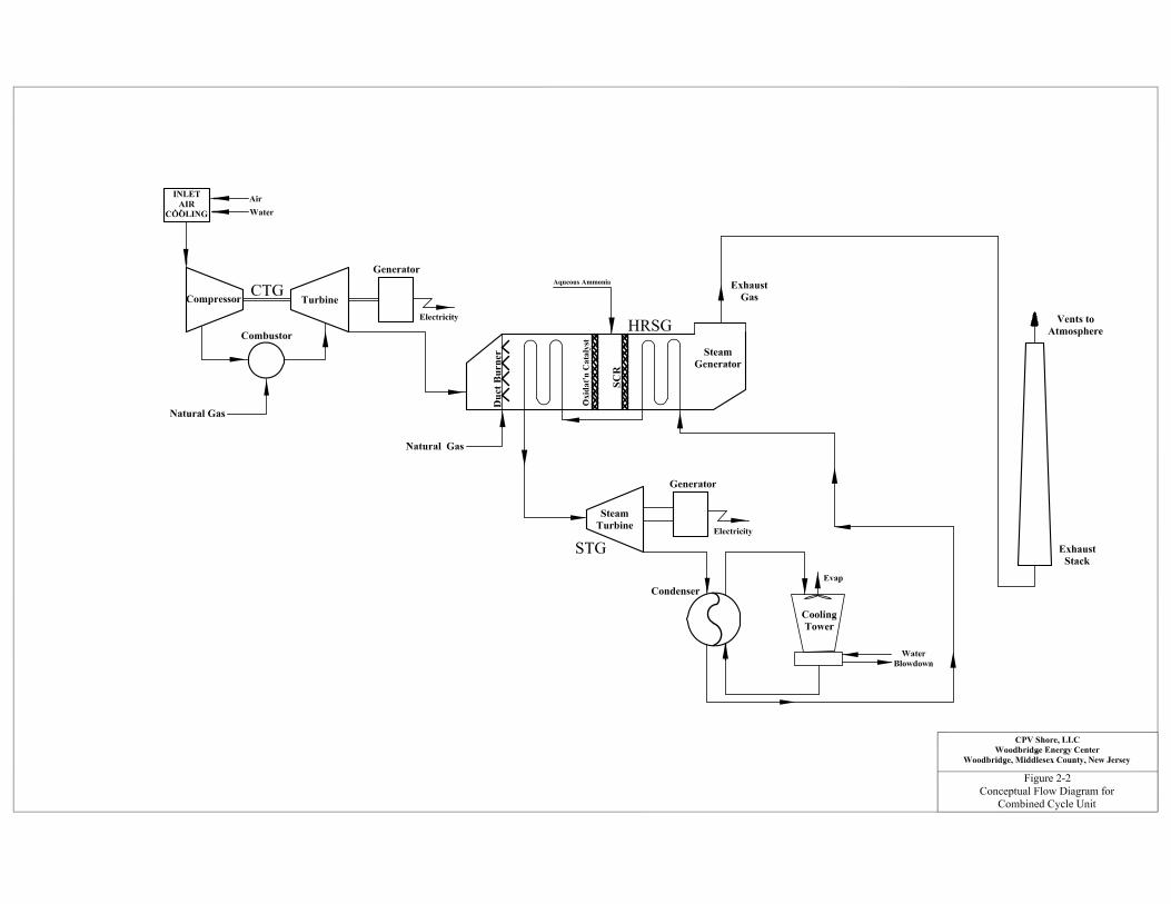
pump. Figure 2-1 presents the CPV Shore, LLC site plan and Figure 2-2 presents a simplified
process flow diagram for the combined cycle unit.
Emissions from the combined cycle units will be controlled by the use of dry low-NOx burner
technology and SCR for NOx, oxidation catalysts for CO and VOC, and the use of clean low-
sulfur fuels to minimize emissions of SO2, PM/PM-10/PM-2.5, and H2SO4. Exhaust gases from
the combined cycle unit after emission controls will be dispersed to the atmosphere via a 135-
foot (above grade) stack. Steam from the steam turbine will be sent to a condenser where it will
be cooled to a liquid state and returned to the HRSG. Waste heat from the condenser will be
dissipated through the mechanical draft cooling tower.
2.2 Natural Gas-Fired Combined Cycle Units
CPV is proposing to install two combined cycle General Electric (GE) 207 FA.05 combustion
turbines that will exclusively utilize pipeline natural gas as a fuel. The maximum combustion
turbine heat input capacity at -8 degrees Fahrenheit (°F) ambient temperature is 2,307 million
British thermal units per hour (MMBtu/hr) based on the Higher Heating Value (HHV) of the
fuel (without duct firing). The exhaust gases leaving the HRSG will be directed to a 135-foot
above grade stack.

CPV Shore, LLC
Woodbridge Energy Center
Figure 2-1: General Arrangement Plan Not to Scale
Source: Shaw Power Group, DWG No. 138396-00000-P-PP-003-1-C, June 2011.

June 2011 2-4 Woodbridge Energy Center
2.2.1 Control Equipment for the Combined Cycle Units
The emission control technologies proposed for the combustion turbine and duct burner
exhaust gases include dry low-NOx (DLN) combustors located within the combustion turbines
and an SCR system located with the heat recovery steam generators to control NOx emissions.
An oxidation catalyst and efficient combustion controls will be used to control emissions of CO
and VOC. Emissions of SO2, PM/PM-10/PM-2.5 will be minimized through the use of low sulfur
fuel, as well as efficient combustion controls.
2.2.1.1 DLN Combustor Dry low-NOx combustion will control NOx emissions from the turbines. DLN combustion limits
NOx formation by controlling the combustion process through air/fuel optimization.
2.2.1.2 Selective Catalytic Reduction
The formation of NOx is determined by the interaction of chemical and physical processes
occurring during combustion. There are two principal forms of NOx - "thermal" NOx and "fuel"
NOx. Thermal NOx formation is the result of oxidation of atmospheric nitrogen in the
combustion zone. The major factors influencing thermal NOx formation are temperature,
concentrations of nitrogen and oxygen in the inlet air and residence time within the combustion
zone. Fuel NOx is formed by the oxidation of fuel-bound nitrogen. NOx formation can be
controlled by adjusting the combustion process and/or installing post-combustion controls.
Selective Catalytic Reduction (SCR) is a supplemental NOx control technology that is placed in
the flue gas stream within the HRSG and downstream of the natural gas-fired duct burner. SCR
involves the injection of ammonia (NH3) into the exhaust gas stream upstream of a catalyst bed.
On the catalyst surface, NH3 reacts with NOx contained within the flue gas stream to form
nitrogen gas (N2) and water (H2O) in accordance with the following chemical equations:
4NH3 + 4NO + O2 → 4N2 + 6H2O
8NH3 + 6NO2 → 7N2 + 12H2O
The catalyst‘s active surface includes a metal (e.g., titanium, vanadium, or equivalent) to
promote the NOx reduction process. The geometric configuration of the catalyst body is
designed for maximum surface area and minimum obstruction of the flue gas flow path in order
to achieve maximum conversion efficiency of NOx to N2.
Aqueous ammonia (19% by weight) is drawn from a storage tank, vaporized, and injected into
the flue gas stream ahead of the catalyst bed. Excess ammonia which is not reacted in the SCR
and which is emitted from the stack is referred to as ammonia slip.

June 2011 2-5 Woodbridge Energy Center
2.2.1.3 Oxidation Catalyst
After combustion control, the only practical method to reduce CO emissions from the combined
cycle unit is an oxidation catalyst. Exhaust gases from the combustion turbine and duct burner
are passed over a catalyst bed where excess air oxidizes the CO to carbon dioxide. The oxidation
catalyst system will reduce inlet CO concentrations by 80% during all steady-state operating
modes. The oxidation catalyst will also reduce VOC emissions to 1.0 ppm without duct firing
and 2.0 ppm with duct firing. The oxidation catalyst will be located in an optimum temperature
region within the HRSG immediately upstream of the SCR ammonia injection grid and
downstream of the gas-fired duct burner.
2.2.1.4 Process Controls The Project will incorporate modern data acquisition and control systems, which will optimize
combustion performance. These same systems will minimize pollutant emissions through a
combination of operator and software-driven process adjustments and notifications.
2.3 Auxiliary Boiler
The Facility is proposing to install and operate one (1) auxiliary boiler to support start-up and
shutdown activities for the combined cycle unit. The auxiliary boiler will have a maximum heat
input of 91.4 MMBtu/hr (HHV) and will combust pipeline quality natural gas only. The total
estimated maximum operation is estimated to be 2,000 hours per year. The proposed package
boiler will be equipped with low-NOx burners to control NOx emissions. Natural gas combustion
will minimize the formation of PM/PM-10/PM-2.5 and SO2. Good combustion practices and
design will minimize CO and VOC emissions.
2.4 Dew Point Heater
CPV is proposing to install and operate one (1) 9.5 MMBtu/hr natural gas-fired dew point heater
which will heat the incoming natural gas before it is fired in the combustion turbine and duct
burner. Heating of the gas above its dew point temperature reduces the possibility of the gas
―slushing‖ or condensing into a liquid due to a reduction in pressure and temperature. As such,
the gas supplied to the combustion turbine and duct burner is required to be maintained at a
temperature of 50°F or more above the dew point of the gas. The exclusive use of natural gas
will limit emissions of PM and SO2 and good combustion practices will limit emissions of NOx,
CO, and VOC.

June 2011 2-6 Woodbridge Energy Center
2.5 Emergency Diesel Engines
The proposed facility will include two auxiliary diesel internal combustion (IC) engines: the
emergency generator and fire pump. Both of these emergency diesel engines will undergo
periodic testing and the total combined operation will not exceed 100 hours per year per engine.
2.6 Cooling Tower
Steam leaving the steam turbine will be returned to a condenser, which will be cooled by an
evaporative cooling tower. The proposed tower is a mechanical-draft design with fourteen (14)
cells (2x7 configuration). Each cell has its own fan. The cooling tower will be equipped with a
high efficiency drift eliminator (0.0005% efficiency) to minimize water drift losses and
associated PM/PM-10/PM-2.5 emissions.
2.7 Ammonia Storage Tank
Ammonia used in the SCR system of the combined cycle unit will be supplied from an aqueous
ammonia storage tank. The aqueous ammonia concentration will be limited to no greater than
19% by weight. The percentage concentration is below the 40 CFR Part 68, Section 112(r) (Table
1) risk management planning applicability threshold. The 15,000-gallon ammonia storage tank
will be a closed loop system. As a result, the tank will have no air emissions.
2.8 Other Exempt and Trivial Auxiliary Equipment
In addition to the significant emission sources (combined cycle combustion turbine, auxiliary
boiler, cooling tower, etc.), the proposed combined cycle power facility will also contain various
exempt and trivial auxiliary equipment and activities, which will not require an air permit.
Exempt and trivial auxiliary equipment either have zero emissions or are specifically listed as
exempt or trivial in accordance with NJDEP air quality regulations.
2.9 Fuels
CPV is proposing to utilize pipeline quality natural gas as the exclusive fuel for the combustion
turbines. The natural gas is assumed to have a HHV of 1,020 Btu/standard cubic foot (scf) and
a sulfur content of 0.225 grains per 100 scf on an annual average basis (maximum of 0.63
gr/100scf). The emergency diesel engines will burn ULSD. The ULSD is assumed to have a
HHV of approximately 19,485 Btu/lb with a sulfur content of 15 ppm by weight. ULSD firing in
each emergency engine will be limited to 100 hours per year.

June 2011 2-7 Woodbridge Energy Center
2.10 Facility Operating Modes
The combined cycle units will be operated to follow electrical demand (i.e., dispatch mode). The
combined cycle unit will not operate at steady-state below 45% load and the duct burner will
only operate at full load conditions for the combustion turbines. Therefore, the HRSG steam
production will follow the combustion turbine loads and higher HRSG steam output will only
occur when duct firing is employed during combustion turbine full load operation.
2.11 Source Emission Parameters
Emissions of air contaminants from the proposed combined cycle power facility have been
estimated based upon expected vendor emission guarantees, control analysis results, emission
factors presented in the U.S. EPA publication AP-42, mass balance calculations, and engineering
estimates. Emission calculations used to develop the emission estimates for the proposed
equipment are included in this application as Appendix B.
2.11.1 Emissions from the Combined Cycle Units
Emissions from the combined cycle units will include criteria pollutants, non-criteria pollutants,
and hazardous air pollutants (HAPs). Short-term and annual emission rates of these pollutants
from the combined cycle units are described below.
2.11.1.1 Criteria Pollutants
Combustion turbine performance and emissions are affected by ambient temperature, fuel
consumption, power output and fuel type. Proposed emission rates and exhaust characteristics
for the combined cycle units are provided in Appendix B. Exhaust and emission parameters are
presented for the combustion turbine natural gas firing at different ambient temperatures (-8°F
for worst-case winter conditions, 56°F for average annual conditions, and 105°F for worst-case
summer conditions), four combustion turbine steady-state loads (45%, 75%, 100% and PEAK)
and operating conditions for HRSG duct firing. A total of 14 total combustion turbine steady-
state operating scenarios are presented.
Potential emission rates for NOx, CO, VOC, and PM/PM-10/PM-2.5 from the combined cycle
unit are based on vendor emissions data. PM/PM-10/PM-2.5 emissions are based on EPA Test
Methods 201A or Method 5/5B and 202 in effect prior to January 2, 2011. SO2 potential
emission rates are determined from the fuel sulfur content and mass balance calculations
assuming 100% of fuel sulfur is converted to SO2.

June 2011 2-8 Woodbridge Energy Center
2.11.1.2 Greenhouse Gases
For PSD purposes, greenhouse gases (GHGs) are a single air pollutant defined as the aggregate
group of the following six gases: carbon dioxide (CO2), nitrous oxide (N2O), methane (CH4),
hydrofluorocarbons (HFCs), perfluorocarbons (PFCs) and sulfur hexafluoride (SF6). CO2, N2O
and CH4 are the only pollutants of concern for the combustion turbine units. Potential
emissions of GHGs from the proposed facility are based on U.S. EPA‘s AP-42 Emission Factors.
2.11.1.3 HAPs
Appendix B presents a summary table of potential emissions of HAPs from the proposed facility
based on U.S. EPA‘s AP-42 Emission Factor Guidance Document. U.S. EPA‘s AP-42 emission
factor for formaldehyde is expected to be much greater than actual formaldehyde emissions
from the use of the GE 7FA.05 combustion turbine. Since the AP-42 formaldehyde emission
factor is based on old testing data with limited data points, formadehyde emissions from the
combustion turbines while firing natural gas are based upon GE stack testing conducted on GE
7FA combined cycle turbines (August 1, 2001 letter from Brahim Richani, GE). Potential facility
formaldehyde emissions are less than 10 tons/yr. Total potential emissions of HAPs from all
sources are less than 25 tons/yr. Therefore, the proposed combined cycle power facility will be a
minor source for HAP emissions.
2.11.1.4 Other Pollutants
Sulfuric acid mist (H2SO4) emissions are based on the mass balance emission calculations for
SO2 and conversion rates of SO2 to SO3. The SCR and oxidation catalysts are expected to convert
a significant portion of SO2 to SO3 and CPV has assumed a total conversion rate of 45%. All SO3
is assumed to convert to H2SO4. Note that calculated potential emissions of SO2 have not been
reduced to reflect SO2 to SO3 conversion. CPV is proposing the worst-case potential emissions
for each pollutant and actual SO2 to SO3 conversion rates may be less than 45%.
Potential emissions of ammonia (NH3) are calculated from the proposed maximum NH3 slip
emission rate of 5 ppmvd @ 15% O2 during all operating scenarios.
2.11.2 Auxiliary Boiler Emissions
The Facility is proposing to use one natural gas-fired auxiliary boiler to support start-up and
shutdown activities for the combined cycle units. Short-term potential emission rates are
provided based on a combination of equipment vendor design data and fuel sulfur content. HAP
and GHG emissions from the auxiliary boiler are based on U.S. EPA‘s AP-42 Emission Factor
Guidance Document. Potential annual emissions are estimated from the operating hours at
maximum capacity (2,000 hrs/yr). Please see Appendix B for potential emission calculation
details.

June 2011 2-9 Woodbridge Energy Center
2.11.3 Dew Point Heater Emissions
The Facility is proposing to use one 9.5 MMBtu/hr natural gas-fired dew point heater to
maintain inlet fuel gas temperatures above dew point temperatures. Short-term potential
emission rates are provided based on a combination of equipment vendor design data and fuel
sulfur content. HAP and GHG emissions from the gas heater are based on U.S. EPA‘s AP-42
Emission Factor Guidance Document. Potential annual emissions are calculated using the
maximum hourly emission rate and 8,760 hours per year operation. Please see Appendix B for
potential emission calculation details.
2.11.4 Emergency Diesel Engines Emissions
CPV is proposing to use two (2) diesel internal combustion engines for the emergency generator
and back-up fire pump. Short-term potential emission rates for each engine are provided based
on a combination of equipment vendor design data and fuel sulfur content. HAP and GHG
emissions from the diesel engines are based on U.S. EPA‘s AP-42 Emission Factor Guidance
Document. Due to the limited operation of these sources, annual PTE emissions are calculated
using the maximum hourly emission rate and 100 hours per year operation per engine. Please
see Appendix B for potential emission calculation details.
2.11.5 Cooling Tower Emissions
The proposed cooling tower can potentially emit particulate matter (filterable PM/PM-10/PM-
2.5) emissions. Potential emissions of filterable PM/PM-10/PM-2.5 are determined by
performing a mass balance calculation using the maximum water flow rate (178,000 gpm),
maximum drift rate (0.0005% for high efficiency drift eliminator design), and the maximum
circulating water total dissolved solids (TDS)/total suspended solids (TSS) concentration (6,240
ppm). Annual potential emissions are calculated using the maximum hourly emission rate and
8,760 hours per year cooling tower operation. PM-10 and PM-2.5 emissions are calculated
using the particulate size distribution provided by the vendor. Please see Appendix B for
potential emission calculation details.
2.11.6 Facility Total Potential Annual Emissions
Total potential annual emissions for the proposed combined cycle power facility are presented
in Table 2-1. Annual emission values in Table 2-1 represent total PTE from all proposed sources
and were based on the following worst-case operating scenarios:
Year-round (8,760 hours), full load operation of the combustion turbines (at 56oF annual average ambient temperature);

June 2011 2-10 Woodbridge Energy Center
The equivalent of 1,250 hours of duct firing at maximum design firing rate for each combustion turbine;
A total of 262 annual combined cycle shutdown/startup events per turbine (10 cold starts, 52 warm starts and 200 hot starts);
The equivalent of 2,000 full load hours of operation of the auxiliary boiler;
Year-round (8,760 hours) operation of the fuel gas heater;
100 hours per year of operation of the emergency diesel generator and 100 hours per year of operation of the diesel fire pump engine; and
A maximum circulating water total dissolved solids (TDS)/total suspended solids (TSS) concentration of 6,240 ppm and 8,760 hours per year cooling tower operation.
To allow for maximum operational flexibility, the Woodbridge Energy Center is requesting that
the permit not contain limits on operating hours for the combustion turbine/duct burner units.
Instead, the facility will demonstrate compliance with annual tons/yr limits based on
continuous emission monitoring system (CEMS) data for NOx and CO, and combustion turbine
and duct burner fuel heat input values and emission factors for other pollutants. A sample
monthly calculation based on monthly total heat input and lb/MMBtu emission factors is
included below:
PM-2.5 (tons/month) = (0.0051 lb/MMBtu * HCT + 0.0068 lb/MMBtu * HCT+DB + 0.0077 lb/MMBtu *
HCT75)/2000 lb/ton
Where: HCT = heat input to the combustion turbines (with no duct firing), MMBtu, HHV
HCT+DB = heat input to the combustion turbines with duct firing, MMBtu, HHV
HCT75 = heat input to the combustion turbines during loads less than or equal to
75%, MMBtu, HHV
The facility‘s Data Acquisition and Handling System (DAHS) will track the heat input to the
turbines and duct burners continuously. Monthly emissions will be calculated for each pollutant
using pollutant specific emission factors, as above. The pollutant emission factors will be based
on permit limits for each operating condition, but stack test based factors may be used if stack
testing indicates a lower lb/MMBtu than the permit limits. In this case, the DAHS system will
be updated to include these new stack test results.
Monthly emissions for each unit are added to calculate facility-wide monthly emissions. Each
month, the monthly total for each pollutant is added to the total emissions for the previous
eleven months to determine a 12-month rolling total.

June 2011 2-11 Woodbridge Energy Center
Table 2-1: Summary of Project Criteria Pollutant and Total HAPs Annual
Emissions
Source
Potential Annual Emissions (tons/year)
NOX CO SO2 VOC PM/PM-10/
PM-2.5 GHG HAPS(a)
Combined Cycle Units(b) 136.9 83.7 11.9 27.4 95.0 2,036,598 --
Start-Up/Shutdown Emissions(c)
0.0 40.3 -- 0.0 0.0 -- --
Auxiliary Boiler 1.0 3.4 0.1 0.1 0.5 10,818 --
Diesel Fire pump 0.1 0.1 0.00016 0.01 0.01 820 --
Emergency Diesel Generator 1.1 0.1 0.001 0.01 0.0066 110.6 --
Cooling Tower -- -- -- -- 12.2/7.9/2.9 -- --
Dew Point Heater 1.5 2.1 0.026 0.21 0.31 4,925 --
Facility-Wide Total 140.6 129.7 12.0 27.8 107.9/103.7
/98.7 2,053,272 2.7/10.4
Notes: (a) The potential HAP emission calculations presented in Appendix B result in total HAP emissions less than 25 tons/yr. Additionally, potential annual emissions of the maximum individual HAP (formaldehyde) are less than 10 tons/yr.
(b) Potential annual emissions from the combined cycle units assume the equivalent of 8,760 hr/yr of combustion turbine operation and 1,250 hr/yr of duct firing. To allow for maximum operating flexibility, WEC does not wish to include hourly operating restrictions into the permit, but rather comply through the use of calculations based on annual heat input. See section 2.11.6. (c) Combined cycle unit start-up/shutdown emissions are added to the baseline steady-state PTE values if the total start-up/shutdown emissions are more than the steady-state full-load equivalent during the period of unit off-line downtime and duration of the start-up (and previous shutdown). For start-up/shutdown emissions noted above as ―—― for certain pollutants, the start-up/shutdown emissions addition to the baseline steady-state PTE is not applicable since mass emissions of these pollutants are fuel input based (lb/MMBtu) and the full-load, steady-state basis represents the worst-case scenario for PTE emission

June 2011 3-1 Woodbridge Energy Center
3.0 APPLICABLE REQUIREMENTS AND REQUIRED ANALYSES
This section contains an analysis of the applicability of federal and state air quality regulations
to the proposed 700 MW combined cycle combustion turbine power facility in the Township of
Woodbridge, Middlesex County, New Jersey. The specific regulations included in this
applicability review are the Federal New Source Performance Standards (NSPS), Prevention of
Significant Deterioration (PSD) and Non-Attainment New Source Review (NNSR) requirements,
Maximum Achievable Control Technology (MACT) applicability for HAPs, Federal Acid Rain
Program and NOx Budget Program requirements, and NJDEP Regulations.
3.1 Federal New Source Performance Standards
The NSPS are technology-based standards applicable to new, modified, and reconstructed
stationary sources. The NSPS requirements are established for approximately 70 source
categories. Four subparts of these standards apply to the proposed facility: General Provisions
(40 CFR 60, Subpart A), Standards of Performance for Stationary Combustion Turbines (40
CFR 60, Subpart KKKK), Standards of Performance for Small Industrial-Commercial-
Institutional Steam Generating Units (40 CFR 60, Subpart Dc), and Standards of Performance
for Stationary Compression Ignition Internal Combustion Engines (40 CFR 60, Subpart IIII).
3.1.1 Subpart A: General Provisions
Each source type that is subject to a NSPS of 40 CFR 60 is also subject to the general provisions
of Subpart A. The applicable general provisions of Subpart A are detailed in 40 CFR Parts 60.7
(Notification and Recordkeeping) and 60.8 (Performance Tests).
3.1.2 Subpart KKKK: Stationary Combustion Turbines
On July 6, 2006, the U.S. EPA promulgated Subpart KKKK to establish emission standards and
compliance schedules for the control of emissions from new stationary combustion turbines that
commence construction, modification, or reconstruction after February 18, 2005. Note that
stationary combustion turbines regulated under Subpart KKKK are exempt from Subpart GG
requirements, which are applicable to units constructed, modified, or reconstructed prior to
February 18, 2005. Additionally, heat recovery steam generators (HRSGs) and duct burners
regulated under Subpart KKKK are exempt from the requirements set forth in Subparts Da, Db,
and Dc for fossil fuel combustion units.

June 2011 3-2 Woodbridge Energy Center
Subpart KKKK establishes emission limits for NOx for combustion turbines with a heat input
capacity (exclusive of duct burners) greater than 850 MMBtu/hr. During natural gas firing, NOx
emissions are limited to 15 ppm (dry basis by volume, corrected to 15% O2) or 0.43 lb/MW-hr of
useful output. Emissions of SO2 from combustion turbines regardless of fuel type are limited to
0.90 lb/MW-hr gross output or low-sulfur fuel to achieve no greater than 0.060 lb/MMBtu.
Subpart KKKK also limits NOx emissions from associated duct burners (exclusive of emissions
from the stationary combustion turbine) to 54 ppmvd @ 15% O2 or 0.86 lb/MW-hr of useful
output. Note that useful output is defined as the thermal energy made available for use in any
industrial or commercial process, or used in any heating or cooling application (i.e., total
thermal energy made available for processes and applications other than electrical or
mechanical generation).
The Facility‘s proposed emission rates from the combustion turbines and duct burners are well
below the applicable Subpart KKKK emission standards.
3.1.3 Subpart Dc: Standards of Performance for Small Industrial-Commercial-Institutional Steam Generating Units
The auxiliary boiler is subject to the provisions of 40 CFR Part 60; Subpart Dc because the
maximum heat input capacity is between 10 and 100 MMBtu/hr. Subpart Dc requires an initial
notification and one-time opacity test for boilers that operate only on natural gas such as the
unit proposed. In addition, records must be maintained regarding the amount of fuel burned on
a monthly basis. However, since natural gas is the only fuel burned in the auxiliary boiler, there
is no reporting requirement to EPA.
3.1.4 Subpart IIII: Standards of Performance for Stationary Compression Ignition Internal Combustion Engines
Subpart IIII establishes emission standards, fuel sulfur limitations, maintenance requirements,
operating limitations, monitoring requirements, and recordkeeping requirements for affected
units. An affected unit must be a compression ignition designed internal combustion engine
that is new (dates vary between April 1, 2006 and 2007 model year) or reconstructed after July
11, 2006. CPV will purchase and install two (2) internal combustion diesel engines for the
emergency generator and back-up fire pump that will meet the applicability requirements of
Subpart IIII. Therefore, the proposed potential emission rates of NOx, CO, PM-10, and VOC
from the emergency diesel engines do not exceed the applicable emission standards set forth in
Subpart IIII.

June 2011 3-3 Woodbridge Energy Center
3.2 National Emission Standards for Hazardous Air Pollutants
The National Emissions Standards for Hazardous Air Pollutants (NESHAPs) are emissions
standards set by the U.S. EPA for an air pollutant not covered by the National Ambient Air
Quality Standards (NAAQS) and that may cause an increase in fatalities or in serious,
irreversible, or incapacitating illness. The standards for a particular source category require the
maximum degree of emission reduction that the U.S. EPA determines to be achievable, which is
known as the Maximum Achievable Control Technology (MACT). These standards are
authorized by Section 112 of the Clean Air Act and the regulations are published in 40 CFR Parts
61 and 63. The proposed facility is subject to the following two subparts: General Provisions (40
CFR Part 63, Subpart A) and the emission standards for Reciprocating Internal Combustion
Engines (RICE) (40 CFR Part 63, Subpart ZZZZ).
3.2.1 40 CFR Part 63, Subpart A – General Provisions The emergency diesel generator and fire pump are subject to the general provisions for
NESHAPs units in 40 CFR Part 63 Subpart A. These include the requirements for notification,
record keeping, and performance testing.
3.2.2 40 CFR Part 63, Subpart ZZZZ – Reciprocating Internal Combustion
Engines
Subpart ZZZZ establishes national emission limitations and operating limitations for hazardous
air pollutants (HAPs) emitted from stationary reciprocating internal combustion engines (RICE)
located at major and area sources of HAP emissions. An area source is defined as a source
which is not a major source of HAP emissions. The proposed emergency diesel generator and
fire pump are subject to these rules. By complying with the NSPS Subpart IIII, the units will
comply with Subpart ZZZZ.
3.3 New Jersey Department of Environmental Protection Regulations
Applicable regulations from Chapter 7:27 of the New Jersey Administrative Code are identified below:
Subchapter 3 ―Control and Prohibition of Smoke from Combustion of Fuel‖ - N.J.A.C.
7:27 - 3.5 limits the opacity from internal combustion engines and stationary combustion
turbines to less than 20% opacity, exclusive of condensed water vapor for a period of
more than 10 consecutive seconds. The combustion turbine will normally have opacity
near zero and it is not expected to exceed even 10% for 10 consecutive seconds.
Subchapter 4 ―Control and Prohibition of Particles Combustion of Fuel‖ - N.J.A.C. 7:27 -
4.2(a) limits the mass emission of particulates from the proposed combined cycle unit,

June 2011 3-4 Woodbridge Energy Center
the auxiliary boiler, the fuel gas heater, the emergency diesel generator and the diesel fire
pump. For the combined cycle units, maximum particulate emissions are proposed at
19.1 lb/hour. Maximum particulate emissions from the auxiliary boiler and fuel gas
heater are 0.46 lb/hour and 0.07 lb/hour, respectively. For the emergency diesel
generator and the diesel fire pump, particulate emissions are limited to 0.13 lb/hour and
0.10 lb/hour, respectively. The proposed particulate limits from all combustion sources
are all well below their respective standards.
Subchapter 8 ―Permits and Certificates‖ - requires a pre-construction permit to be
obtained for the proposed Woodbridge facility since the total heat input is greater than
1,000,000 Btu/hr and imposes SOTA requirements for new and/or modified sources.
This application seeks a permit pursuant to Subchapter 8 for the combustion turbines
(with and without duct firing), auxiliary boiler, fuel gas heater, emergency diesel
generator, the diesel fire pump, and cooling tower.
Subchapter 9 ―Sulfur in Fuels‖ - This subchapter does not limit the sulfur content of
gaseous fuels; only liquid and solid fuel sulfur content limits are prescribed. Subchapter
9 limits the sulfur content of diesel fuel used in the emergency diesel generator and fire
pump to 0.2% by weight. Per NSPS Subpart IIII, the Facility is required to use 0.0015%
sulfur diesel oil in the emergency generator and fire pump which is well below the
Subchapter 9 limit.
Subchapter 13 ―Ambient Air Quality Standards‖ - The air quality impacts from the
proposed Woodbridge facility are predicted not to exceed the standards presented in this
subchapter as demonstrated in Section 5.
Subchapter 16 ―Control and Prohibition of Air Pollution by Volatile Organic Compounds‖
- N.J.A.C. 7:27-16.9 establishes VOC and CO limits of 50 ppm and 250 ppm respectively
for stationary gas turbines. The proposed limits are well below these values for all load
and fuel cases. The auxiliary boiler is subject to N.J.A.C. 7:27-16.8 which limits VOC and
CO emissions to 50 ppm and 100 ppm at 7% oxygen, respectively. The proposed
emissions from the boiler are below these limits. Subchapter 16 does not apply to the
fuel gas heater, the emergency generator or the fire pump.
Subchapter 18 ―Control and Prohibition of Air Pollution from New or Altered Sources
Affecting Ambient Air Quality (Emission Offset Rules)‖ - Establishes emission offsets
and LAER requirements for defined major stationary sources. See Sections 3 and 4 of
this application.

June 2011 3-5 Woodbridge Energy Center
Subchapter 19 ―Control and Prohibition of Air Pollution from Oxides of Nitrogen‖ -
Limits turbine NOx emissions to 0.15 lb/MMBtu while firing natural gas per the
provisions of N.J.A.C. 7:27-19.5 Table 5. The maximum proposed NOx limit when firing
natural gas is 0.0073 lb/MMBtu. In addition, Subchapter 19 contains an efficiency limit
for natural gas fired combined cycle combustion turbines of 0.75 lb/MW-hr. The
proposed turbines will comply with this limit. N.J.A.C. 7:27-19.7 limits NOx emissions
from the auxiliary boiler to 0.10 lb/MMBtu. The auxiliary boiler‘s proposed NOx limit of
0.011 lb/MMBtu is well below the Subchapter 19 standard. In addition the boiler and the
fuel gas heater are required to be adjusted annually. The emergency generator is only
subject to the recordkeeping requirements under N.J.A.C. 7:27-19.11. The fire pump is
exempt from these regulations since the maximum power output is less than 500 hp.
Subchapter 21 ―Emission Statements‖ – The facility will submit an emissions statement
for each reporting year to the NJDEP in accordance with Subchapter 21.
Subchapter 22 ―Operating Permits‖ – The facility will file for an operating permit within
twelve months after commencing operation.
Subchapter 30 ―Clean Air Interstate Rule (CAIR) NOx Trading Program‖ – Detailed
information regarding the current status of the CAIR program is included in Section 3.8.
Subchapter 31 ―Ozone Transport Commission NOx Budget Program‖ – Detailed
requirements and proposed facility applicability and compliance with this program are
addressed in Section 3.7.
3.4 Attainment Status and Compliance with Air Quality Standards
The location of the proposed combined cycle power facility in Middlesex County, New Jersey is
in an area currently designated as attainment for SO2, NO2, CO, and PM-10. Therefore, for these
pollutants, the proposed project is required to demonstrate compliance with the NAAQS and
NJAAQS shown in Tables 3-1 and 3-2. Middlesex County is designated as moderate non-
attainment for the 8-hour ozone standard. Although the proposed project is located in an area
classified as moderate non-attainment for O3, N.J.A.C. 7:27-18.2 states that an emissions
increase of more than 25 tons per year of NOx or VOC would subject the proposed project to
Non-Attainment NSR for these pollutants. Because the Facility has potential emissions of NOx
and VOC above 25 tons per year, NNSR requirements will apply. Middlesex County is also
designated as non-attainment for PM-2.5. On May 16, 2008, the U.S. EPA published the final
rule for implementation of the NSR program for PM-2.5 emissions (effective as of July 15,
2008). For a new source located in a non-attainment area for PM-2.5, NNSR is applicable if
direct PM-2.5 emissions are greater than or equal to 100 tons/yr. Additionally, the U.S. EPA has

June 2011 3-6 Woodbridge Energy Center
concluded that emissions of SO2, NOx, VOC, and NH3 are responsible for the secondary
formation of PM-2.5 in the atmosphere. As such, the final rule for PM-2.5 NSR implementation
establishes surrogate significant emission rate thresholds for major sources of PM-2.5 and/or
PM-2.5 precursors. Prior to final SIP approval, only SO2 is being regulated as a PM-2.5
precursor. Therefore, if the Facility‘s potential annual emissions of SO2 are greater than 100
tons/yr, it would also be subject to NNSR requirements for PM-2.5. As shown in Table 2-1,
potential emissions from the proposed Project do not exceed 100 tons per year for either PM-2.5
or SO2. Hence, NNSR does not apply for PM-2.5.
3.5 Prevention of Significant Deterioration
3.5.1 Applicability
Fossil fuel steam/electric generating facilities with a heat input capacity of more than 250
MMBtu/hr and criteria pollutant emissions greater than 100 tons per year of any regulated
pollutant are subject to PSD review.
On June 3, 2010, EPA issued a final rule that ―tailors‖ the applicability provisions of PSD for
greenhouse gas (GHG) emissions. Under the tailoring rule, application of PSD to GHGs will be
implemented in multiple steps. The first step began on January 2, 2011 and ends on June 30,
2011. Under step 1, PSD applies to GHG emissions from a new source only if the source is
already subject to PSD due to emissions of criteria pollutants and the potential GHG emissions
from the project would be equal to or greater than 100,000 tons/year on a CO2e basis. Projects
which are not subject to PSD review for criteria pollutants and that receive permits and
commence construction prior to July 1, 2011 will not be subject to PSD for GHGs. The second
step starts on July 1, 2011 and will require sources subject solely considered ―major‖ sources due
to GHG emissions to obtain a PSD permit.
Based on potential to emit, the proposed facility is subject to PSD permitting requirements for
CO, PM/PM-10, NOx, H2SO4 and GHG emissions.
3.5.2 Requirements
The PSD regulations state that facilities subject to PSD review must perform an air quality
analysis (which can include atmospheric dispersion modeling and preconstruction ambient air
quality monitoring), and a Best Available Control Technology (BACT) demonstration for those
pollutants that exceed the pollutant-specific significant emission rates (SERs) identified in the
regulations as well as an additional impacts analysis that examines the impacts of air emissions
from the project on visibility, soils and vegetation.

June 2011 3-7 Woodbridge Energy Center
3.5.2.1 Best Available Control Technology
Woodbridge Energy Center must utilize BACT controls for emissions of CO, PM/PM-10 and
H2SO4, from each piece of new equipment. As previously stated, BACT is defined as the
optimum level of control applied to pollutant emissions based upon consideration of energy,
economic and environmental factors. In a BACT analysis, the energy, environmental, and
economic factors associated with each alternate control technology are evaluated, in addition to
the benefit of reduced emissions that the technology would bring. The BACT analysis for the
proposed facility is detailed in Section 4.
3.5.2.2 Air Quality Analysis
The PSD air quality impact analysis (described in detail in Section 5) requires dispersion
modeling that uses emission rates and stack parameters (stack height and flue gas exit
temperature and velocity, etc.) coupled with historical meteorology representative of the site to
predict the location and magnitude of maximum impacts for various pollutants and averaging
periods. If dispersion modeling indicates that the predicted air quality impact concentration of
a given pollutant emitted from the proposed facility is lower than its respective Significant
Impact Level (SIL) shown in Table 3-1, it is considered to have an insignificant impact and no
further air quality analysis is required. If modeled concentrations of one or more pollutants
exceed their respective SILs, the proposed facility is considered to have an area of impact and
requires additional air quality analysis.
3.5.2.2.1 Ambient Air Quality Monitoring
Proposed facilities subject to PSD review may have to perform up to one year of preconstruction
ambient air quality monitoring for those pollutants emitted in amounts exceeding the PSD SERs
shown in Table 3-3, unless granted an exemption by the reviewing agency, NJDEP. Pre-
application air quality monitoring guidance can be found in Chapter C, Section III.A of the ―New
Source Review Workshop Manual‖. It states that ―the permitting agency has discretionary
authority to exempt an applicant from the ambient air quality monitoring requirement if either
(1) the predicted ambient impact, i.e., the highest modeled concentration for the applicable
averaging time, caused by the proposed significant emissions increase (or significant net
emissions increase), or (2) the existing ambient pollutant concentrations are less than the
prescribed significant monitoring values‖ listed in 40 CFR 52.21 (i)(8)(i), listed in Table 3-1, or if
there is available high quality ambient air quality monitoring data which is representative of the
site area.
TRC, on behalf of the Project, submitted a request to the NJDEP for an exemption from the
requirement to perform one year of pre-construction ambient air quality monitoring at the

June 2011 3-8 Woodbridge Energy Center
proposed facility site on April 12, 2011. The request for waiver from pre-construction ambient
air quality monitoring is still under review and can be found in Appendix D.
3.5.2.2.2 Impact Area Determination
A proposed facility subject to the PSD regulations must determine its impact on air quality for
any pollutant for which it does not have an insignificant impact. The area of impact is defined as
the greatest distance from the proposed facility site within which the emissions result in
concentrations greater than the significant impact concentrations.
3.5.2.2.3 Additional Impact Analyses
The fact that the proposed facility‘s potential emissions are greater than the applicable PSD
significant emission rate thresholds means that certain additional analyses are required as part
of the PSD review. These include modeling to assess potential for impacts to soils and
vegetation, visibility, and include emissions from associated industrial, commercial, and
residential growth as well as the emissions from the proposed facility. A more detailed
explanation of this analysis is presented in Section 5 of this application.
3.5.2.2.4 Impacts on Class I Areas
Applicants proposing major projects within 300 km of Class I areas may be required to perform
an assessment of potential impacts in the Class I areas. The only Class I area within 300 km of
the proposed facility is the Brigantine Wilderness area located in the Edwin B. Forsythe National
Wildlife Refuge in New Jersey. This area is located approximately 108 km south of the proposed
facility. The Federal Land Manager (FLM) for this Class I area was notified by letter on April 12,
2011 and requested to determine if assessments of impacts in the Class I area would be required.
In an email dated May 5, 2011, the FLM indicated that no Class I modeling analyses would be
necessary. Copies of both the letter and the FLM‘s response can be found in Appendix D.
3.6 Non-Attainment New Source Review Requirements
3.6.1 Applicability
As stated above, since the proposed facility site is located within a moderate ozone non-
attainment area and within a designated PM-2.5 non-attainment area with potential annual
emissions above applicability thresholds for NOx and VOC, the source is subject to non-
attainment new source review. Facility potential to emit for SO2 (PM-2.5 pre-cursor) and PM-
2.5 emissions are below the major source thresholds.

June 2011 3-9 Woodbridge Energy Center
3.6.2 Requirements
The preconstruction review requirements for major new sources or major modifications located
in areas designated non-attainment pursuant to Section 107 of the Clean Air Act Amendments of
1990 (CAAA) differ from the PSD requirements. First, the emissions control requirement for
non-attainment areas, LAER, is defined differently and is more stringent than the BACT
emissions control requirement. Second, the source must obtain any required emissions
reductions (offsets) of the non-attainment pollutant precursors from other sources which impact
the same area as the proposed source. Third, the applicant must certify that all other sources
owned by the applicant in the State are complying with all applicable requirements of the CAAA,
including all applicable requirements in the State Implementation Plan (SIP). Additionally, per
the provisions of N.J.A.C. 7:27-18.3(c) (2), the applicant must perform an analysis of alternate
sites, equipment sizes, production processes and environmental control technologies.
3.6.2.1 Lowest Achievable Emission Rate
Pollutants subject to non-attainment NSR must be limited to LAER levels. LAER is defined as
either the most stringent emission limitation contained in a SIP (unless it is demonstrated to not
be achievable) or the most stringent emission limitation which is achieved in practice by the
class or category of source, whichever is the most stringent. Pollutants are subject to LAER if
potential emissions of individual pollutants exceed significance levels as defined in N.J.A.C.
7:27-18.2. Based upon these criteria, emissions of NOx and VOC are subject to LAER
requirements. LAER analyses for each piece of new equipment with emissions of NOx and VOC
are presented in Section 4 of this application support document.
3.6.2.2 Emission Reduction Credit Requirements
Emissions reductions must be obtained as a condition for approval to operate a major source or
major modification planned in a non-attainment area. The emissions reductions, generally
obtained from existing sources located in the vicinity of a proposed source must (1) offset the
emissions increase from the new source or modification and (2) provide a net air quality benefit.
These offsets, obtained from existing sources that have implemented a permanent, enforceable,
quantifiable and surplus emissions reduction, must equal the emission increase from the new
source or modification multiplied by an offset ratio, and must provide a net air quality benefit.
The New Jersey offset requirements are detailed in N.J.A.C. 7:27-18.5.
The amount of offsets required by the unit is determined by multiplying the proposed potential
emissions by the offset ratio. Minimum offsets ratios are presented in N.J.A.C. 7:27-18.5, Table
2, and are based upon the distance of the facility from the source of the emission credits. Based
upon these requirements, the minimum offset ratio required is 1.3:1.0. The calculation of

June 2011 3-10 Woodbridge Energy Center
required offsets for the facility based upon this minimum offset ratio is presented in Table 3-4.
The offsets must be obtained and certified for use prior to commencing operation of the facility.
Upon approval of the offset ratio for the proposed project, Woodbridge Energy Center will
acquire the required offsets. Per the provisions of N.J.A.C. 7:27-18.5, the minimum offset ratio
may be modified based upon the location of the source(s) of the emission offset credits.
3.6.2.3 Compliance Status of Other Competitive Power Ventures New Jersey Facilities
Competitive Power Ventures, Inc. (CPV) of which CPV Shore, LLC is a subsidiary does not own
or operate any facilities within the State of New Jersey.
3.6.2.4 Analysis of Alternatives
In accordance with N.J.A.C. 7:27-18.3(c)(2), applicants that are subject to non-attainment
review must submit an analysis of alternative sites, sizes, production processes, and
environmental control technologies for the proposed facility in order to demonstrate that the
benefits of the proposed facility significantly outweigh the environmental and social costs
imposed as a result of the proposed construction. Alternate sites, production processes,
equipment sizes, fuel supplies, and environmental control technologies were analyzed to address
this requirement. These analyses, which are presented in the Sections 3.6.2.4.1-3.6.2.4-5, show
that the benefits of the proposed facility significantly outweigh the environmental and social
costs imposed as a result of the proposed facility‘s construction and operation in the Township
of Woodbridge, Middlesex County, New Jersey.
3.6.2.4.1 Alternative Sites Evaluated Woodbridge Energy Center‘s initial screening evaluation process for the development of a new
power generation facility in the PJM regional electric transmission geographic area started with
the identification of several properties in New Jersey and Pennsylvania where the sites had
access to sufficient industrially zoned land in close proximity to electric transmission lines,
water and/or fuel. Screening efforts focused on evaluating potential sites from numerous
perspectives as well as undertaking preliminary evaluations (e.g., PJM interconnection study,
fuels supply, etc.) to identify a Project site that would minimize impacts to the environment, be
market-driven, create jobs, and facilitate economic development within the State of New Jersey.
This evaluation also reflected an assessment relative to an extensive list of criteria that included,
but was not limited to, the following:
Proximity of the project to existing major electric transmission lines and/or substations
Availability of more than 15 acres of land, preferably zoned industrial, and with a buffer
from sensitive receptor locations such as schools, hospitals and residences;

June 2011 3-11 Woodbridge Energy Center
Availability of adequate water supply and waste water discharge capacity;
Proximity to and/or ability to cost effectively obtain and/or develop required fuel supply
interconnections;
Proximity to major roadways and/or rail access (to facilitate equipment delivery/
construction needs);
Availability of a site with minimal or no impacts to wetlands;
Availability of a site with no impacts to threatened or endangered species; and,
Ability to access an adequate supply of labor for construction and operation phases of the
project.
Based on the search/evaluation criteria described above, project representatives determined
that the property in the Township of Woodbridge, Middlesex County, New Jersey was the
optimal site to develop an approximately 700 megawatt (nominal), combined cycle electric
generating facility. Project representatives recognized that the Township of Woodbridge site
satisfied many, if not all, the criteria. Detailed field and economic studies to further support
project permitting and development activities have been and/or are continuing to be performed.
A brief summary of the environmental, engineering, and economic considerations, which
supported CPV‘s decision to proceed with project development and permitting activities at the
Township of Woodbridge site location, is provided below.
Land Use and Zoning Compatibility – Development of a new power generation facility at
the Township of Woodbridge site is compatible with existing and planned land uses for the site,
as well as applicable local ordinances. The proposed project site is part of a Redevelopment Plan
presently being developed by the Township of Woodbridge and would comply with the
performance standards reflected in the Plan. The 27.5 acre WEC site is surrounded by
properties utilized for a variety of industrial and commercial uses. Current active land uses in
the area immediately surrounding the site include warehousing and distribution, chemical
manufacturing, bulk storage for transport of aggregates and petroleum products, asphalt batch
plant operations, and light industry. The closest residential area is located approximately 3,000
feet to the north-northeast and is buffered heavily by roads and highways.
In October of 2009, the NJDEP designated the Keasbey Redevelopment Area a Brownfield
Development Area (BDA). As part of a BDA, the NJDEP, the Township, the current property
owners (and their consultants), and other stakeholders have been designing and implementing
remediation and reuse plans for the area. The planned 27.5 acre WEC site is part of a larger
180+ acre tract of land owned by El Paso which is presently being remediated under an NJDEP
approved Remedial Action Work Plan. Developing a new power generation facility at the site

June 2011 3-12 Woodbridge Energy Center
will satisfy the Township‘s and State‘s desires to redevelop the site to create jobs and be
consistent with the surrounding industrial uses.
Water Supply and Wastewater Disposal – CPV Shore, LLC is proposing to use ―gray
water‖ or reusable wastewater supplied by the Middlesex County Utilities Authority (MCUA) to
meet the proposed facility‘s process water requirements. The MCUA is located south of the
proposed site location, across the Raritan River in Sayreville, Middlesex County, New Jersey.
CPV Shore will enter into a long-term contract with the MCUA to procure gray water to supply
the project‘s process water needs and to allow CPV Shore to construct a pipeline to convey the
gray water from the MCUA treatment plant within an existing MCUA tunnel under the Raritan
River. The existing MCUA tunnel runs below the Raritan River and upon reaching the
Woodbridge Township side of the river the new gray water line will be constructed in easements
(some of which are owned by MCUA) to an existing chamber pit proximate to the CPV Shore
site. No dredging activities are anticipated to be required for this aspect of the Project
The ability to use gray water at the Township of Woodbridge site location is advantageous from
an environmental perspective. The lack of adequate flow in the river, as a result of diversion for
industrial purposes, can cause deterioration of water quality and ecosystem health. The use of
gray water will also minimize wastewater discharges to the Raritan River from the MCUA. By
decreasing wastewater discharges to the Raritan River, the use of gray water at the proposed
facility will ultimately contribute to the preservation and enhancement of the River‘s natural,
marine habitat. In addition to these environmental benefits, according to the agreement to be
executed between CPV and MCUA, CPV will provide monetary compensation to MCUA for the
gray water to be utilized at the CPV Shore facility.
CPV Shore will secure its potable water supply via an interconnection with the local water
purveyor‘s (Middlesex Water Company) line on Industrial Avenue. Backflow preventers will be
constructed at appropriate locations within the CPV facility to prevent cross-contamination of
potable water and gray water supplies. Process water and sanitary discharges from the CPV
Shore plant will be discharged to the MCUA via an interconnection with an MCUA line
proximate to the CPV Shore site. The MCUA facilities comprise one of the largest sewage plants
in the State of New Jersey and are equipped with state-of-the-art technology to treat industrial
wastewater. Therefore, the MCUA will have sufficient capacity to treat effluent from the
proposed facility.
Fuel Use - The proposed facility would exclusively utilize clean burning natural gas. Several
natural gas pipelines are located in proximity to the Township of Woodbridge site and could be
used to deliver natural gas to the site by constructing a new natural gas pipeline lateral.
Potential suppliers of natural gas under evaluation include Transco, Spectra, and Elizabethtown
Gas.

June 2011 3-13 Woodbridge Energy Center
Transmission – The planned WEC site is located within 2.5 miles of an existing substation
(e.g., Raritan Substation) which is the preferred tie-in point for the electricity that would be
generated by the new combined cycle facility. An electric interconnection feasibility study is
currently being performed by PJM to verify the ability to interconnect to the electric
transmission system at this location and what upgrades, improvements, etc. would be required.
Proximity to Environmental and/or Sensitive Resources - Development at the
Township of Woodbridge site is not anticipated to significantly impact any threatened and
endangered species or scenic, recreational or culturally sensitive resources. The Project will be
designed to avoid and/or minimize impacts to wetlands and potential habitat for rare,
threatened, and endangered species. The larger approximately 180+ acre site presently being
remediated by El Paso is comprised of former developed upland areas, undeveloped upland
areas, wetlands, open waters, and tidal marsh adjacent to the Raritan River. As reflected in the
Remedial Action Work Plan, El Paso will be required to mitigate all wetland areas that will be
impacted (including all wetlands within the CPV Shore site). As such, the only potential wetland
impacts associated with the construction of the Woodbridge Energy Center facility will be
associated with required off-site infrastructure (i.e., electric transmission; water; wastewater;
and road).
Transportation - At the Township of Woodbridge site, sufficient options (i.e., roadways and
railroad) are available to an Engineering, Procurement, Construction (EPC) Contractor for the
delivery of construction materials and plant components to or proximate to the site and for
employee access once operations commence. Major highways surrounding the Township of
Woodbridge site include Routes 287, 95, and 9. Railroad tracks owned by Consolidated Rail
Corporation (Conrail) are located immediately to the north of the site along Industrial Avenue.
Preliminary access to the site will be from the existing entrance from Industrial Avenue. The
existing entrance will be improved as necessary for traffic associated with facility construction
and operation.
Labor – There is a more than adequate labor pool in the area surrounding the Township of
Woodbridge site from which to draw on during facility construction and operation. It is
anticipated that the required construction labor force for the project would be readily met with
the available trades and union workforce in Middlesex County without the need for in-migration
of construction workers from outside the New Jersey/ New York metropolitan area. At peak
construction, there will be approximately 500 to 600 workers onsite. Once operational, the
plant is expected to create an estimated 25 full time, permanent jobs with a payroll of
approximately $3.5 million annually.

June 2011 3-14 Woodbridge Energy Center
Availability – CPV Shore, LLC has entered into formal discussions with the current property
owners (―EPEC Polymers, Inc‖ or El Paso) to purchase approximately 27.5 acres of the larger
approximately 180+ acre property. The planned WEC site is sufficient for the development of
an approximately 700 MW combined cycle electric generating facility including the necessary
construction laydown, parking, and buffer areas.
Necessity – Construction and operation of the CPV Woodbridge Energy Center will help meet
high power demands in the state. The Woodbridge Energy Center was selected by the New
Jersey Board of Public Utilities (NJBPU) under the Long- Term Capacity Agreement Pilot
Program (LCAPP) as one of the three generating projects that will produce in-state power to
help lower electric costs for New Jersey customers who currently pay some of the highest rates
in the country. The NJBPU selection was undertaken as result of legislation (P.L. 2011) that was
signed into law to address the high cost of electric rates caused by the need to import electric
capacity to ensure that the needs of New Jersey customers and businesses could be met in all
circumstances.
In addition to these economic benefits, the citizens of Woodbridge Township will benefit directly
from construction and operation of the proposed facility. Local purchases of materials, supplies,
and contracted services used for construction would comprise a direct and positive
socioeconomic effect. Once operational, the plant is expected to create an estimated 25, full
time permanent jobs.
3.6.2.4.2 Alternative Sizes
Based upon a variety of studies performed as part of its electric generation development
evaluations (e.g., PJM feasibility study; electric generation pricing analyses based upon PJM
interconnection location; site availability; combustion turbine availability; delivery schedule;
cost; and operational performance; etc.), Woodbridge Energy Center has determined that the
optimal development for the Project site is a 714 megawatt combined cycle facility involving a 2
x 1 (i.e., 2 combustion turbines on 1 steam turbine) configuration with a natural gas fired duct
burner. The initial project concept studies performed by WEC also included the evaluation of
utilizing General Electric (GE) 207 FA.04 combustion turbines. Based upon the current PJM
pricing model, as well as desired operating efficiency/performance of the combustion turbine
machine, availability and cost, the Project selected the GE 7FA.05 machine for the proposed
Project. The project is not a baseload facility that would operate continuously. However, it is
being permitted to operate on an 8,760 hours/year basis as well as to start up and shut down as
required to meet the PJM electric grid demands.

June 2011 3-15 Woodbridge Energy Center
3.6.2.4.3 Production Process and Fuel Supply
The Project was initially designed to be a natural gas fired combined cycle facility with the ability
to combust low sulfur distillate oil in the event of natural gas curtailment. However, based upon
the New Jersey Board of Public Utilities evaluation and determination that a natural gas fired
only facility represented the most cost-effective option, the CPV Shore Project‘s engineering
design/ general arrangement was revised to reflect a natural gas fired only plant. The
combustion of oil generally produces high emissions of carbon dioxide, nitrogen oxides, sulfur
dioxide, and greenhouse gases than the combustion of natural gas. Particulate matter emissions
associated with the combustion of oil are also significantly greater than those associated with the
combustion of natural gas. In fact, under the current design (i.e., a natural gas fired only
facility), a shorter facility stack can be built than could have been built under the natural gas
with oil backup design scenario, while still meeting NAAQS. A shorter stack will limit WEC‘s
potential visibility i.e., a shorter stack will be visible from less places than a taller stack. Burning
natural gas also has lower impacts on water quality and generates less solid waste than using
other fossil fuels.
Furthermore, the use of modern combined cycle technology as reflected in the CPV Shore plans
promotes the efficient utilization of fuel for electric generation. Modern combined cycle
technology is approximately 30% more efficient than conventional electric generator
technologies. Increasing fuel efficiency favorably affects the cost of generating electricity.
3.6.2.4.4 Environmental Control Technologies
Based upon the Project‘s site location and non-attainment status, the premise for development
of the Woodbridge Energy Center is that it would be designed to meet federal Best Available
Control Technology (BACT) and Lowest Achievable Emission Rate (LAER) standards to comply
with Prevention of Significant Deterioration (PSD) requirements, Non-Attainment New Source
Review requirements and New Jersey State of the Art (SOTA) requirements, the facility‘s design
reflects the following:
Dry low NOx combustion technology for the combustion turbine and selective catalytic
reduction system (SCR) for NOx control.
An oxidation catalyst for CO & VOC control.
Pipeline quality natural gas and ULSD to minimize emissions of SO2 and PM/PM-
10/PM-2.5.
A cooling tower design that will include high efficiency drift eliminators that are
designed to meet .00005% control efficiency.

June 2011 3-16 Woodbridge Energy Center
Utilization of aqueous ammonia (at 19%) as opposed to anhydrous ammonia for the SCR
system.
The Project‘s engineering design reflects the utilization of treated wastewater effluent
from the Middlesex County Utilities Authority regional wastewater treatment plant
which is consistent with the New Jersey Department of Environmental Protection‘s
policy encouraging the use of reclaimed water for beneficial reuse.
3.6.2.4.5 Environmental/Social Costs and Benefits of the Proposed Facility
The proposed Woodbridge Energy Center has been designed to meet the objective of providing
reliable, efficient, economical and environmentally safe electricity to meet the current and future
demands for electric generation capacity in the State of New Jersey. As such, the proposed
Woodbridge Energy Center in the Township of Woodbridge, Middlesex County, New Jersey
meets and/or exceeds key development objectives articulated by New Jersey State officials for
projects that are market driven, create jobs and produce economic development within the
State. The proposed Project also satisfactorily addresses/meets most of the evaluation criteria
detailed above. These include:
Construction of the proposed Project will involve more than 500 people, on average,
during the 30+ month construction schedule.
The estimated construction-related cost of the facility is in excess of $500 million,
including labor benefits, overhead and taxes and the purchase of local supplies, services
and consumables. The facility will also have minimal impact on the Woodbridge
Township‘s municipal services (e.g., schools, police, fire, etc.).
The facility, once operational, will employ up to 25 employees to staff and operate the
facility with a payroll of approximately $3.5 million annually.
There will be minimal, if any, impacts to and/or on local roadways after construction.
The Project will beneficially reuse treated effluent to satisfy its process water
requirements, as opposed to procuring water from the Township‘s public water supply
system.
The facility‘s engineering design will ensure compliance with BACT, LAER and New
Jersey SOTA regulatory requirements.
The Project will redevelop a Brownfield Site into a new clean burning, natural gas fueled
power generation facility that will create jobs and generate in-state electricity for New
Jersey citizens.
The Project will have minimal or no impacts on wetlands. It also is not anticipated to
impact scenic, recreational or cultural resources.
3.7 Clean Air Interstate Rule (CAIR) Requirements

June 2011 3-17 Woodbridge Energy Center
The federal Clean Air Interstate Rule (CAIR) is a multi-state cap and trade program intended to
significantly reduce NOx and particulate matter emissions from large fossil-fuel combustion
sources and mitigate interstate transport of NOx, ground-level ozone and particulate matter.
CAIR builds upon the successful NOx SIP Call and Acid Rain programs, extending NOx
reductions from an ozone season basis to an annual basis, and requiring SO2 reductions
exceeding those of the Acid Rain Program.
The market-based cap-and-trade CAIR Program was developed by EPA to facilitate significant,
yet cost-effective NOx and SO2 emission reductions from large stationary sources in a multi-state
region. The CAIR programs provide affected sources with provisions for NOx allowance
allocations, monitoring, banking, penalties, trading protocols and program administration by
EPA.
The CAIR Program includes three multi-state cap and trade model rules. The first CAIR
program addresses interstate transfer of particulate matter emissions by reducing annual NOx
emissions from power plants. The second program addresses interstate transfer of NOx and
ozone by reducing seasonal NOx emissions from power plants and large industrial boilers. The
third program addresses interstate transfer of particulate matter emissions by reducing annual
SO2 emissions from power plants.
On July 11, 2008, the U.S. Court of Appeals vacated the Clean Air Interstate Rule (CAIR) as
proposed by U.S. EPA. However, in its latest ruling on December 23, 2008, the Court concluded
that the regulations, although having significant flaws, should be kept in place on a temporary
basis to preserve the environmental benefits gained from the program. Therefore, the CAIR
requirements remain in effect while EPA works to complete its proposed Transport Rule (see
Section 3.6).
3.8 Transport Rule On July 6, 2010 the US Environmental Protection Agency (EPA) proposed the Transport Rule
which will require 31 states and the District of Columbia to significantly improve air quality by
reducing power plant emissions that contribute to ozone and fine particle pollution in other
states. The Transport Rule proposes enforceable Federal Implementation Plans (FIPs) to
achieve emission reductions in each state by requiring emission reductions from the power
sector. Specifically, the rule would apply to fossil fuel fired electric generating units (EGUs) with
a nameplate capacity of greater than 25 MWe producing electricity for sale in the covered states,
with certain exemptions for cogeneration units and solid waste incineration units. The proposed
rule sets forth EPA‘s preferred approach and seeks comment on two alternative approaches.
Each of the approaches would set a pollution limit (or budget) for each state and would obtain
the reductions from power plants.

June 2011 3-18 Woodbridge Energy Center
EPA‘s preferred approach would allow intrastate trading and some interstate trading among
power plants but would, through an ―assurance provision‖ assure that each state would meet its
emissions budget. The preferred approach would establish four interstate trading programs:
two separate trading programs for annual SO2 (one for sources in states EPA has determined
must make aggressive reductions (―Group 1‖) and another for sources in states requiring less
stringent reductions (―Group 2‖)); one for annual NOx; and, one for ozone season NOx. EPA
would distribute to covered sources in each state a number of emissions allowances equal to the
state emissions budgets for SO2, NOx and ozone season NOx, with a three percent set-aside for
new units. Allocations for retired units would eventually be allocated to the new unit set-aside.
Each source would be required to hold an allowance for each ton of SO2 or NOx emitted by EGUs
at the source during the compliance period. Sources would be allowed to bank and trade
allowances, and allowances issued for one state for a trading program could be used in any of
the states included in the respective trading program. However, interstate trading would be
limited by the ―assurance provision‖, under which total emissions from each state would be
limited to an amount equal to the state‘s budget plus that state‘s ―variability limit‖ (calculated on
both a one-year and three-year rolling average). An exceedance of the state limit plus the
variability limit would trigger an allowance surrender requirement by owners whose units‘
emissions exceeded the owner‘s share of the state budget with the variability limit.
The two alternatives on which EPA is seeking comment would allow only intrastate trading or
would specify the allowable emission limit for each power plant and allow some averaging of
emission rates.
A final rule is expected in late Spring 2011. Once final, the proposed rule would take effect
quickly. An initial phase of emissions reductions would be required by early 2012 and a second
phase of reductions would be required by early 2014.
3.9 Greenhouse Gas Monitoring
On September 22, 2009, EPA promulgated the final 40 CFR Part 98 greenhouse gas monitoring
and reporting regulations that require approximately 10,000 facilities to report their greenhouse
gas (GHG) emissions annually. The reporting rule generally applies to facilities that emit more
than 25,000 tons of GHG a year and identifies 29 specific categories of covered sources, such as
oil refineries, pulp and paper manufacturing, landfills, manure management, and producers of
aluminum, cement, iron and steel, glass, and various chemicals, as well as a residual category for
facilities with large stationary fuel burning sources. Covered facilities started monitoring on
January 1, 2010. The proposed facility is subject to the federal GHG Monitoring requirements
and will meet them through use of CEMS and reporting to CAMD.

June 2011 3-19 Woodbridge Energy Center
3.10 CO2 Budget Trading Program
The CO2 Budget Trading Program is a mandatory cap-and-trade program to reduce greenhouse
gas emissions as part of the Regional Greenhouse Gas Initiative (RGGI). RGGI is a cooperative
effort by ten Northeast and Mid-Atlantic states to limit greenhouse gas emissions. RGGI is the
first mandatory, market-based CO2 emissions reduction program in the United States. RGGI is
composed of individual CO2 Budget Trading Programs in each of the ten participating states.
These ten programs are implemented through state regulations, based on a RGGI Model Rule,
and are linked through CO2 allowance reciprocity. Regulated power plants will be able to use a
CO2 allowance issued by any of the ten participating states to demonstrate compliance with the
state program governing their facility. Taken together, the ten individual state programs will
function as a single regional compliance market for carbon emissions. Under this program, New
Jersey (and other participating states) will stabilize power sector CO2 emissions at the capped
level through 2014. The cap will then be reduced by 2.5 percent in each of the four years 2015
through 2018, for a total reduction of 10 percent. Sources will need to acquire, from auctions or
directly from the NJDEP, one allowance (permit to emit CO2) for every ton of CO2 that they emit.
3.11 Section 112(r) Applicability Aqueous ammonia will be used as the reducing agent in the project‘s SCR system for controlling
NOx emissions from the combustion turbine. The NOx reduction achieved by the SCR system is
affected by the ratio of ammonia (NH3) to NOx. Section 112(r) of the Clean Air Act and the U.S.
EPA‘s Risk Management Program regulations (40 CFR Part 68) require modeling a catastrophic
release of any stored ammonia at 20% concentration or above in order to ensure the protection
of the off-site public. Furthermore, based on the ―general duty‖ clause of Section 112(r), such
analyses can be required even if the aqueous ammonia solution is diluted below 20%.
Woodbridge Energy Center proposes to store aqueous ammonia at a maximum ammonia
concentration of 19% or less as the means of complying with Section 112(r).

June 2011 3-20 Woodbridge Energy Center
Table 3-1
National Ambient Air Quality Standards, PSD Increments, Significant Monitoring Concentrations, and Significant Impact Levels
Pollutant Averaging
Period NAAQSa
( g/m3)
Class II PSD
Increment
( g/m3)
Significant Monitoring
Concentrations
( g/m3)
Significant Impact Level
( g/m3)
Carbon Monoxide 1-Hour 8-Hour
40,000 10,000
-- --
-- 575
2,000 500
Nitrogen Dioxide 1-Hour
Annual
188
100
--
25
--
14
10b
1
Ozone (VOC) 8-Hour 160 -- -- --
Coarse Particulate Matter (PM-10)
24-Hour Annual
150 --
30 17
10 --
5 1
Fine Particulate Matter (PM-2.5)
24-Hour Annual
35 15
9 4
4 --
1.2 0.3
Sulfur Dioxide
1-Hour 24-Hour Annual 3-Hour
197 365 80
1,300
-- 91 20 512
-- 13 -- --
7.9c 5 1
25
Lead 3-Month 0.15 -- 0.1 --
Notes: (--) indicates there are no standards for this pollutant. aAll short-term (1-hr, 3-hr, 8-hr, and 24-hr) standards except ozone, PM-2.5,PM-10, and 1-hour SO2 and NO2 are not to be exceeded more than once per year. For 8-hr ozone, EPA uses the average of the annual 4th highest 8-hour daily maximum concentrations from each of the last three years of air quality monitoring data to determine a violation of the standard. For 24-hour PM-10, EPA uses the 6th highest 24-hour maximum concentration from the last three years of air quality monitoring data to determine a violation of the standards. For 24-hour PM-2.5, EPA uses the 98% percentile 24-hour maximum concentration from the last three years of air quality monitoring data to determine a violation of the standard. For the 1-hour NO2 NAAQS, compliance would be determined by the 3-year average of the 98th percentile of the daily maximum 1-hour average at each monitor within an area and for the 1-hour SO2 NAAQS, compliance would be determined with the 3-year average of the 99th percentile of the daily maximum 1-hour average at each monitor within an area. bInterim SIL per Guidance from NJDEP staff. cInterim SIL per August 12, 2010 memorandum ―Guidance Concerning the Implementation of the 1-hour SO2 NAAQS for the Prevention of Significant Deterioration Program" from Steven Page (Director of U.S. EPA OAQPS).

June 2011 3-21 Woodbridge Energy Center
Table 3-2
New Jersey Ambient Air Quality Standards
Pollutant Standard Averaging Period NJAAQSa (ug/m3)
Sulfur Dioxide
Primary Primary
Secondary Secondary Secondary
12-month arith. mean 24-hour average
12-month arith. mean 24-hour average 3-hour average
80 365 60
260 1,300
Total Suspended Particulates
Primary Primary
Secondary Secondary
12-month geom. mean 24-hour average
12-month geom. meanb 24-hour average
75 260 60 150
Carbon Monoxide Primary & Secondary Primary & Secondary
8-hour average 1-hour average
10,000 40,000
Ozonec Primary
Secondary Max. daily 1-hour average
1-hour average 235 160
Nitrogen Dioxide Primary & Secondary
NJDEP Guideline 12-month arith. mean
1-hour average 100 470
Lead Primary & Secondary Rolling 3-month average 1.5
Notes: aNew Jersey short-term standards are not to be exceeded more than once in any 12 month period. Long-term standards are never to be exceeded. bIntended as a guideline for achieving short-term standard. cMaximum daily 1-hour average: averaged over a three year period, the expected number of days above the
standard must be less than or equal to 1.

June 2011 3-22 Woodbridge Energy Center
Table 3-3
Comparison of Facility Potential Emissions to PSD Significant Emission Rates and Non-attainment NSR Thresholds(a)
Pollutant
Proposed Facility
Potential Emissions (tons/yr)
PSD Significant Emissions
Increase Level (tons per year)
NNSR Major Source/Modification
Threshold (tons per year)
Carbon Monoxide 129.7 100 NA
Sulfur Dioxide 12.0 40 100/40(b)
Particulate Matter (PM) 107.9 25 NA
Particulate Matter less than 10 microns (PM-10)
103.7 15 NA
Particulate Matter less than 2.5 microns (PM-2.5)
98.7 10 100/10(b)
Nitrogen Oxides 140.6 40 25(c)
Ozone (VOC) 27.8 40 25(c)
Greenhouse Gases (GHG) 2,053,272 100,000 NA
Lead 0.01 0.6 NA
Fluorides NA 3 NA
Sulfuric Acid Mist 8.2 7 NA
Hydrogen Sulfide NA 10 NA
Total Reduced Sulfur (including H2S)
NA 10 NA
Reduced Sulfur Compounds (including H2S)
NA 10 NA
Notes: (a) Pursuant to 40 CFR 52.21 (b)(23)(i). (b) Under 40 CFR 51, Appendix S, new sources with potential emissions greater than or equal to 100 tons
per year and modifications to existing major sources with emissions greater than or equal to 40 tons per year of SO2 or 10 tons per year of PM-2.5 are subject to non-attainment NSR for PM-2.5.
(c) Per N.J.A.C 7:27-18.

June 2011 3-23 Woodbridge Energy Center
Table 3-4
Emission Reduction Credits Required
for CPV Shore, LLC’s Woodbridge Energy Center
Pollutant Proposed Facility
Potential Emissions (tons/yr)
Minimum Offset Ratio
Minimum Required ERC’s
(tons)
NOx 140.6 1.3 to 1 183
VOC 27.8 1.3 to 1 37

June 2011 4-1 Woodbridge Energy Center
4.0 CONTROL TECHNOLOGY ANALYSIS
4.1 Overview
Pre-construction review for new major stationary sources located in the State of New Jersey
involves an evaluation of Best Available Control Technology (BACT), lowest achievable emission
rate (LAER) and/or State-of-the-Art (SOTA). If an area is designated by USEPA as attainment
or unclassifiable for a particular pollutant, then new major sources would require permitting
under the PSD program, including a BACT demonstration for pollutants emitted in quantities
greater than the regulatory thresholds. However, if an area is designated by USEPA as non-
attainment for a given pollutant and the major source has the potential to emit the non-
attainment pollutant at levels greater than the pollutant-specific regulatory thresholds, then
non-attainment new source review (NNSR) applies. Non-attainment NSR requires the
application of LAER technology and the requirement to obtain emission offsets. If the proposed
project‘s emissions increase exceeds NJDEP‘s SOTA threshold for regulated pollutants, SOTA
requirements will also apply.
A control technology analysis has been performed for the proposed Facility based upon guidance
presented in the draft USEPA Guidance Document New Source Review Workshop Manual,
(October, 1990) and the NJDEP‘s State of the Art (SOTA) Manual for Combustion Turbines‖
(December, 2004).
Note that throughout this section, ―ppm‖ concentration levels for gaseous pollutants are parts
per million by volume, dry basis, corrected to 15% O2 content (ppmvd @ 15% O2), unless
otherwise noted. Likewise, all emission factors expressed as pounds of pollutant per million Btu
of fuel (lb/MMBtu) are based upon the higher heating value (HHV) of the fuel.
4.2 Applicability of Control Technology Requirements
An applicability determination, as discussed in this section, is the process of determining the
level of emission control required for each applicable air pollutant. Control technology
requirements are generally based upon the potential emissions from the new or modified source
and the attainment status of the area in which the source is to be located. A detailed
determination of applicable regulations, including control technology requirements under the
PSD and non-attainment rules, is provided in Section 3. The following sections discuss the
applicability of BACT, LAER and additional NJDEP requirements for emissions from equipment
included in this permit application.

June 2011 4-2 Woodbridge Energy Center
4.2.1 PSD Pollutants Subject To BACT
Pollutants subject to PSD review are subject to a BACT analysis. BACT is defined as an emission
limitation based on the maximum degree of reduction, on a case-by-case basis, taking into
account energy, environmental and economic considerations. The proposed Facility is
considered a ―major‖ source for PSD purposes since potential emissions exceed major source
thresholds. Therefore, individual regulated pollutants are subject to BACT requirements if
potential emissions exceed the significant emission rates presented in 40 CFR 52.21(b)(23) in a
PSD (attainment) area, as presented in Table 3-3. Based upon these criteria, NOx, CO, PM/PM-
10, H2SO4 and GHG are all subject to BACT requirements. Since the area is designated
attainment for NO2, NOx emissions are subject to BACT, as well as the more stringent LAER
requirements under the ozone non-attainment provisions. Since the LAER requirements are
generally at least as stringent as BACT, the LAER analysis will satisfy the technology
requirements for NOx.
4.2.2 Non-Attainment Pollutants Subject To LAER
Pollutants subject to non-attainment NSR must be limited to LAER levels. LAER is defined as
the more stringent of (1) the most stringent emission limitation which is achieved in practice by
the class or category of source or (2) the most stringent emission limitation contained in the
applicable State Implementation Plan (unless such emission rate is demonstrated not to be
achievable), whichever is the more stringent. LAER will be based upon the lowest permitted
emission rates that are verified as being achieved in practice, as discussed in the appropriate
section. Pollutants are subject to LAER if potential emissions of individual pollutants exceed
area-specific emission thresholds. Although the proposed project is located in an area classified
as moderate non-attainment for O3, N.J.A.C. 7:27-18.2 states that an emissions increase of more
than 25 tons per year of NOx or VOC (listed in Table 3-1) would subject the proposed project to
non-attainment NSR and LAER for these pollutants. Based upon these criteria, emissions of
NOx and VOC are subject to LAER requirements.
4.2.3 Pollutants Subject to SOTA
SOTA is a New Jersey State requirement that is defined as equipment, devices, methods or
techniques as determined by the NJDEP which will prevent, reduce or control emissions of an
air contaminant to the maximum degree possible and which are available or may be made
available. SOTA for most sources is well defined based upon previous permitting efforts or
emission levels presented in NJDEP SOTA Manuals. As defined in Section 1.4 of the SOTA
Manual (July 1997), compliance with SOTA requirements can be shown through documentation
of compliance with emission levels or technology requirements defined in an applicable SOTA
Manual. Pollutants for which potential emissions are below 5 TPY are not subject to NJDEP

June 2011 4-3 Woodbridge Energy Center
SOTA requirements. Pollutants subject to LAER, BACT or NSPS (promulgated on or after
August 2, 1995) meet or exceed New Jersey SOTA requirements. Those emissions of pollutants
not subject to BACT, LAER or NSPS are subject to SOTA requirements. For the proposed
facility, pollutants subject to SOTA only include NH3 and opacity from turbine operations.
Please note, since emissions of NH3 from the ammonia storage tank is less than 5 TPY, the
storage tank is not subject to the SOTA provisions. Additionally, SOTA requirements for opacity
emissions have been addressed in Section 4.10.
4.3 Approach Used in BACT Analysis
As previously stated, BACT is defined as the optimum level of control applied to pollutant
emissions based upon consideration of energy, economic and environmental factors. The BACT
analyses may include reductions achieved through the application of processes, systems, and
techniques for the control of each air pollutant. EPA has placed potentially applicable control
alternatives identified and evaluated in the BACT analysis into the following three categories:
(1) Inherently lower-emitting processes/practices/designs,
(2) Add-on controls, and;
(3) Combinations of (1) and (2).
4.3.1 Inherently lower-emitting processes/practices/designs Lower-polluting processes (including design considerations) should be considered based on
demonstrations made on the basis of manufacturing identical or similar products from identical
or similar raw materials or fuels.
4.3.1.1 Change in raw materials
This emissions limiting technique typically applies to industrial processes that use chemicals,
such as solvents, where substitution with a lower emitting chemical may be technically feasible.
In the case of the proposed Project, the ―raw material‖ is the fuel combusted for the generation
of electricity. The Project proposes to exclusively use natural gas, which is the fuel with the
lowest pollutant emissions.
4.3.1.2 Process Modifications
Process modifications may be implemented if a change in the process methods or conditions can
result in lower emissions. In the case of the Project, the ―process‖ is the combustion turbines
firing natural gas. The GE 7FA.05 combined cycle technology is among the most efficient fossil
fuel power plant designs currently available. Therefore, process modifications beyond what is
already proposed are not technologically feasible.

June 2011 4-4 Woodbridge Energy Center
4.3.2 Technically Feasible Add-on Control Options
The first step is identification of available technically feasible control technology options,
including consideration of transferable and innovative control measures that may not have
previously been applied to the source type under analysis. The minimum requirement for a
BACT proposal is an option that meets federal NSPS limits or other minimum state or local
requirements that would prevail in the absence of BACT decision-making, such as RACT or
NJDEP emission standards. After elimination of technically infeasible control technologies, the
remaining options are ranked by control effectiveness.
If there is only a single feasible option, or if the applicant is proposing the most stringent
alternative, then no further analysis is required. If two or more technically feasible options are
identified, the next three steps are applied to identify and compare the economic, energy, and
environmental impacts of the options. Technical considerations and site-specific sensitive
issues will often play a role in BACT determinations. Generally, if the most stringent technology
is rejected as BACT, the next most stringent technology is evaluated, and so on.
In order to identify options for each class of equipment, a search of the USEPA‘s
RACT/BACT/LAER Clearinghouse (RBLC) has been performed. Individual searches have been
performed for each pollutant (subject to BACT/LAER) emitted from each emissions unit. The
most recently issued permits for combustion turbines in New Jersey and others not yet on the
RBLC were also analyzed. Results of the RBLC and other recent permits search are summarized
in Appendix C.
4.3.2.1 Economic (Cost-Effectiveness) Analysis
This analysis consists of estimation of costs and calculation of the cost-effectiveness of each
control technology, on a dollar per ton of pollution removed basis. Annual emissions of an
option are subtracted from base case emissions to calculate tons of pollutant controlled per year.
The base case may be uncontrolled emissions or the maximum emission rate allowable without
BACT considerations that would generally correspond to an NSPS or RACT level. Annual costs,
in dollars per year, are calculated by adding annual operation and maintenance costs to the
annualized capital cost of an option. Cost-effectiveness ($/ton) of an option is simply the
equivalent annual cost ($/yr) divided by the annual reduction in emissions (ton/yr).
Note that no economic analysis is required if either the most effective option is proposed or if
there are no technically feasible control options.

June 2011 4-5 Woodbridge Energy Center
4.3.2.2 Energy Impact Analysis
Two forms of energy impacts that may be associated with a control option can normally be
quantified. Increases in energy consumption resulting from increased heat rate may be shown
as incremental Btu's or fuel consumed per year. Also, the installation of a control option may
reduce the output and/or reliability of the proposed equipment. This reduction would also
result in loss of revenue from power sales.
4.3.2.3 Environmental Impact Analysis
The primary focus of the environmental impact analysis is the reduction in ambient
concentrations of the pollutant being emitted. Increases or decreases in emissions of other
criteria or non-criteria pollutants may occur with some technologies, and should also be
identified. Non-air related impacts, such as solid waste disposal and increased water
consumption/ treatment, may be an issue for some projects and control options.
4.3.3 BACT Proposal
The determination of BACT for each pollutant from a given emission unit is based on a review of
the above-listed impact categories and the technical factors that affect feasibility of the control
alternatives under consideration. The methodology described above is applied to the proposed
Project for the pollutants specified above.
4.4 LAER/BACT Analysis for Nitrogen Oxides
This section presents LAER and BACT determinations for control of NOx emissions from the
combined cycle combustion turbines and duct burners, the auxiliary boiler, the fuel gas dew
point heater and the emergency diesel engines. For each type of equipment, alternative control
technologies are evaluated and existing permit limits for units in the same source categories are
identified.
As previously discussed, a LAER determination for a source category is based upon the more
stringent of either 1) the most stringent emission limitation contained in the SIP for such class
or category of source or 2) the most stringent emission limitation achieved in practice by such
class or category of source unless demonstrated to not be achievable. To determine the most
stringent permit limit, a search of the RBLC and recently issued applicable air permits was
performed. The results of the search are presented in Section 4.4.1 and Appendix C.

June 2011 4-6 Woodbridge Energy Center
The formation of NOx in combustion units is determined by the interaction of chemical and
physical processes occurring within the combustion chamber. There are two principal forms of
NOx, designated as ―thermal‖ NOx and ―fuel‖ NOx. Thermal NOx formation is the result of
oxidation of atmospheric nitrogen contained in the inlet gas in the high temperature, post flame
region of the combustion zone. The major factors influencing thermal NOx formation are
temperature, concentrations of nitrogen and oxygen in the inlet air and residence time within
the combustion zone. Fuel NOx is formed by the oxidation of fuel bound nitrogen. NOx
formation can be controlled by adjusting the combustion process and/or by installing post
combustion controls. Section 4.4.2 provides a technical description of NOx control techniques
for all the applicable equipment and the relative availability and suitability for the proposed
Project.
4.4.1 Review of NOx RBLC Database 4.4.1.1 Combined Cycle Combustion Turbines and Duct Burners The search of the RBLC and available permits identified over 350 natural gas-fired combined
cycle combustion turbine projects with NOx emission limits ranging from 2 to 102 ppm with the
majority of the NOx emission limits at or below 9 ppm. Fifty-seven (57) of these projects are
permitted for a NOx emission limit of 2 ppm and all use selective catalytic reduction in addition
to dry low-NOx (DLN) or low-NOx burner (LNB) technology. Many of these projects have
additional permitted NOx emission limits above 2 ppm for alternative operating modes when
employing either duct firing or for oil-fired operation.
4.4.1.2 Auxiliary Boiler The RBLC search of recent air permits for natural gas-fired boilers between 10 and 100
MMBtu/hr identified NOx emissions limits ranging from 0.0035 lb/MMBtu to 0.9365
lb/MMBtu. Only 5 out of over 250 permits have NOx limits less than 0.01 lb/MMBtu and of
these only 1 facility has a unit that is similar in size to the proposed boiler. That facility is not yet
operational.
4.4.1.3 Fuel Gas Heater The NOx emission permit limits found in the RBLC and available permits for natural gas-fired
dew point/fuel/efficiency/recuperator heaters ranges from 0.011 lb/MMBtu to 0.37 lb/MMBtu.
None of the facilities with NOx limits less than 0.035 lb/MMBtu appear to be in operation. CPV
understands that the basis for the NOx emission limits in the RBLC for fuel heaters are vendor
guarantees. CPV is currently estimating potential NOx emissions with an emission factor of
0.035 lb/MMBtu.

June 2011 4-7 Woodbridge Energy Center
4.4.1.4 Emergency Diesel Engines The RBLC indicates that the range of permitted NOx limits for diesel engines similar to the fire
water pump diesel engine are 0.414 to 29.8 lb/MMBtu, with only 4 permits less than 1.0
lb/MMBtu, as summarized in Appendix C. The range of permitted NOx limits for diesel engines
similar in size to the emergency generator diesel engine are 0.288 to 10.641 lb/MMBtu, as
summarized in Appendix C.
4.4.2 Identification of NOx Control Options and Technical Feasibility
The following sections detail the options that were identified for controlling NOx emissions from
the combined cycle combustion turbine and duct burner, auxiliary boiler, fuel gas heater and
emergency diesel engines. Their technical feasibility and respective level of commercially
demonstrated NOx reduction of each option is also discussed.
4.4.2.1 Combined Cycle Combustion Turbines and Duct Burners
The following control technologies for NOx were evaluated: Lean Burn Combustion, Selective
Catalytic Reduction, Selective Non-Catalytic Reduction, XONON™ and SCONOx™.
Lean Burn Combustion – Typical gas turbines are designed to operate at a nearly
stoichiometric ratio of fuel and in the combustion zone, with additional air introduced
downstream. This is the point where the highest combustion temperature and quickest
combustion reactions (including NOx formation) occur. Fuel-to-air ratios below stoichiometric
are referred to as fuel-lean mixtures (i.e., excess air in the combustion chamber); fuel-to-air
ratios above stoichiometric are referred to as fuel-rich (i.e., excess fuel in the combustion
chamber). The rate of NOx production falls off dramatically as the flame temperature decreases.
Thus, very lean, dry combustors can be used to control emissions.
Based upon this concept, lean combustors are designed to operate below the stoichiometric
ratio, thereby reducing thermal NOx formation within the combustion chamber. The lean
combustors typically are two-staged premixed combustors designed for use with natural gas
fuel. The first stage serves to thoroughly mix the fuel and air and to deliver a uniform, lean,
unburned fuel-air mixture to the second stage.
Selective Catalytic Reduction (SCR) – SCR is an add-on NOx control technique that is
placed in the exhaust stream following the gas turbine/duct burner. SCR involves the injection
of ammonia (NH3) into the exhaust gas stream upstream of a catalyst bed. On the catalyst
surface, NH3 reacts with NOx contained within the flue gas to form nitrogen gas (N2) and water
(H2O) in accordance with the following chemical equations:

June 2011 4-8 Woodbridge Energy Center
4NH3 + 4NO + O2 4N2 + 6H2O
8NH3 + 6NO2 7N2 + 12H2O
The catalyst's active surface is usually a noble metal (platinum), base metal (titanium or
vanadium) or a zeolite-based material. Metal-based catalysts are usually applied as a coating
over a metal or ceramic substrate. Zeolite catalysts are typically a homogenous material that
forms both the active surface and the substrate. The geometric configuration of the catalyst
body is designed for maximum surface area and minimum obstruction of the flue gas flow path
in order to achieve maximum conversion efficiency and minimum back pressure on the gas
turbine/duct burner. The most common configuration is a "honeycomb" design. Ammonia is
then fed and mixed into the combustion gas stream upstream of the catalyst bed. Excess NH3
which is not reacted in the catalyst bed and which is emitted from the stack is referred to as NH3
slip.
An important factor that affects the performance of an SCR is operating temperature. The
temperature range for standard base metal catalysts is between 400 and 800oF. Since SCR‘s
effective temperatures are below the turbine exit temperature and above the stack temperature,
the catalyst must be located within the HRSG.
An undesirable side-effect of SCR is the potential formation of ammonium bisulfate (NH4HSO4)
and ammonium sulfate ((NH4)2SO4), referred to as ammonium salts, which are corrosive and
can stick to the heat recovery surfaces, duct work, or stack at low temperatures and results in
additional PM/PM-10 formation if emitted. NH4HSO4 and (NH4)2SO4 are reaction products of
SO3 and NH3. Use of low sulfur fuels minimizes the formation of SO3 and the subsequent
formation of these ammonium salts.
Selective Non-Catalytic Reduction (SNCR) – SNCR is another method of post-combustion
control of NOx emissions. SNCR selectively reduces NOx into nitrogen and water vapor by
reacting the flue gas with a reagent. The SNCR system is dependent upon the reagent injection
location and temperature to achieve proper reagent/flue gas mixing for optimum NOx reduction.
SNCR systems require a fairly narrow temperature range for reagent injection in order to
achieve a specific NOx removal efficiency. The optimum temperature range for ammonia
injection is 1,500° to 1,900°F. The NOx removal efficiency of an SNCR system decreases rapidly
at temperatures outside the optimum temperature window. Operation below this temperature
window results in excessive ammonia emissions, also referred to as ―slip‖. Operation above the
temperature window results in increased NOx emissions.
Because the exhaust temperature at the exit of the Project‘s combined cycle combustion turbine
unit is between 200 – 300°F, which is significantly less than the optimum temperature range for

June 2011 4-9 Woodbridge Energy Center
the application of this technology, it is not technically feasible to apply this technology to this
Project and it will be eliminated from further evaluation in this LAER analysis.
XONON™ – A newer NOx control technology has been developed by Catalytica Energy
Systems, with the trade name of XONON™. This combustion technology includes a pre-burner,
a fuel injection and mixing system, a flameless catalyst module and a flameless burnout zone.
The pre-burner starts the turbine and a fuel injection system provides a uniform fuel and air
mixture to the catalyst, where a portion of the fuel is combusted at reduced temperature to
reduce thermal NOx emissions. Catalytica has reported NOx emissions at less than 3 ppm at 15
percent O2 from test units under 2 MW. The first commercial version of the XONON™
combustion system is operating in a 1.55 MW gas turbine in Santa Clara, CA. This system has
demonstrated NOx emission levels of less than 2.5 ppm.
The XONON™ system is not yet commercially available from Catalytica Energy Systems for
turbines of the size proposed for the Project. However, in December 2000, the California
Energy Commission approved the construction of a 750-MW facility in Bakersfield, California.
The Pastoria Energy Facility (Pastoria) proposed to use the XONON™ system as BACT to
control NOx emissions from three large combined cycle combustion turbines. The approval was
based on the anticipation that the XONON™ technology would be available by the time
installation of the Project components was scheduled. If XONON™ was not available in time,
Pastoria would install SCR to control emissions of NOx. Calpine completed construction of the
Pastoria facility in 2005 and ultimately installed SCR technology as opposed to XONONTM. To
date, XONON™ technology is not commercially available for large combustion turbines.
Based on the fact that the XONON™ technology is not currently commercially available and has
not been proven on combustion turbines of the size proposed by the Project, it is not further
considered in this analysis.
SCONOX™ – SCONOx
™ or Emx™ is a proprietary catalytic oxidation and adsorption technology
that uses a single catalyst for the control of NOx, CO and VOC emissions. The catalyst is a
monolithic design, made from a ceramic substrate with both a proprietary platinum-based
oxidation catalyst and a potassium carbonate adsorption coating. The catalyst simultaneously
oxidizes NO to NO2, CO to CO2, and VOC to CO2 and water, while NO2 is adsorbed onto the
catalyst surface and chemically converted to and stored as potassium nitrates and nitrites. The
SCONOx™ potassium carbonate layer has a limited adsorption capability and requires
regeneration approximately every 12-15 minutes in normal service. Each regeneration cycle
requires approximately 3-5 minutes. At any point in time, approximately 20% of the 40 to 60
compartments in a SCONOx™ system would be in regeneration mode, and the remaining 80% of
the compartments would be in oxidation/adsorption mode (Stone & Webster, Independent
Technical Review – SCONOx™ Technology and Design Review, February 2000).

June 2011 4-10 Woodbridge Energy Center
Regeneration of the adsorption layer requires exposure of the catalyst to hydrogen gas. In
practice, this is accomplished by reforming natural gas with high-pressure steam to produce a
gas mixture consisting of methane, carbon dioxide, and hydrogen that is passed over the catalyst
beds (Stone & Webster, February 2000). Initial attempts by the developer of the process to
create regeneration gases from natural gas and steam within the SCONOx™ catalyst bed (internal
autothermal regeneration) failed to produce consistent results; this approach was abandoned in
favor of the current offering, which uses an external steam-heated reformer that partially
reforms the natural gas to produce the gas mixture that is introduced into the catalyst bed (ABB
Environmental, op cit.). The reformation reaction continues to some extent within the catalyst
bed due to the presence of steam and the temperature of the catalyst surface, but some methane
and VOC from the natural gas remain.
Because the active regenerant gas is hydrogen, the regeneration process must be performed in
an atmosphere of low oxygen to prevent dilution of the hydrogen. In practice, the oxygen
present in the exhaust gas of combustion turbines is excluded from the catalyst bed by dividing
the catalyst bed into a number of individual cells or compartments that are equipped with front
and rear dampers that are closed at the beginning of each regeneration cycle. Proper
regeneration of the SCONOx™ catalyst system depends upon the proper functioning and sealing
of these sets of dampers approximately 4 times per hour so that an adequate concentration of
hydrogen can be maintained in each module to accomplish complete regeneration of the catalyst
before the dampers are opened and the compartment is placed back in service.
Because the SCONOx™ catalyst can be ―poisoned‖ or rendered inactive by even the very small
amounts of sulfur compounds present in natural gas, a SCOSOx catalyst bed, intended to remove
trace quantities of sulfur-bearing compounds from the exhaust gas stream, is installed upstream
of the SCONOx™ catalyst bed. Like the SCONOx
™ catalyst, the SCOSOx catalyst must be
regenerated. Regeneration of the two catalyst types occurs at the same time, with the same
regeneration gas supply provided to both; however, the sulfur-bearing regeneration gas for the
SCOSOx catalyst exits the SCONOx™ modules separately from the SCONOx
™ regeneration gas to
avoid contaminating the SCONOx™ catalyst beds. Both the regeneration gas streams are
returned to the gas turbine exhaust stream downstream of the SCONOx™ module (ABB
Environmental).
The external reformer used to create the regeneration gases is supplied with steam and natural
gas. To avoid poisoning the reformer catalyst, the natural gas supplied to the reformer passes
through an activated carbon filter to remove some of the sulfur-bearing compounds that are
added to natural gas to facilitate leak detection (Stone & Webster).

June 2011 4-11 Woodbridge Energy Center
The regeneration cycle time is expected to be controlled using a feedback system based on NOx
emission rates. That is, the higher the NOx emissions are relative to the design level, the shorter
the absorption cycle, and regeneration cycles will occur more frequently. This is analogous to
the use of feedback systems for controlling reagent (ammonia or urea) flow rates in an SCR
system.
Maintenance requirements for SCONOx™ systems are expected to include periodic replacement
of the reformer fuel sulfur carbon unit, periodic replacement of the reformer catalyst, periodic
washings of the SCOSOx and SCONOx™ catalyst beds, and periodic replacement of the catalyst
beds. The replacement frequency for the reformer sulfur carbon unit and reformer catalyst is
unknown at present. The SCOSOx catalyst is expected to require washing once per year. The
lead (upstream) SCONOx™ catalyst bed is expected to require washing once per year, while the
trailing (downstream) SCONOx™ catalyst bed(s) are expected to require washing once every
three years. The annual catalyst washing process is expected to take several days for large
combustion turbines and produce hundreds of thousands of gallons of wastewater. The
estimated catalyst life is reported to be 7 washings (Stone & Webster); the guaranteed catalyst
life is three years (letter from ABB ALSTOM Power to Bibb & Associates dated May 5, 2000 or
―ABB TMP‖).
Estimates of the control system efficiency vary. ABB Environmental (now ALSTOM Power) has
indicated that the SCONOx™ system is capable of achieving a 90% reduction in NOX; a 90%
reduction in CO, to a level of 2 ppm; and an 80%-85% reduction in VOC emissions (ABB
Environmental). The VOC reduction is not likely to be achieved with low VOC inlet
concentrations, in the 1-2 ppm range (ABB Environmental). Commercially quoted NOx
emission rates for the SCONOx™ system range from 2.0 ppm on a 3-hour average basis,
representing a 78% reduction (ABB TMP), to a 1.0 ppm with no averaging period specified
(letter from ABB ALSTOM Power to Sunlaw Energy Corporation dated February 11, 2000). The
SCONOx™ system does not control or reduce emissions of sulfur oxides or particulate matter
from the combustion device (ABB Environmental).
To date, SCONOx™ technology has been commercially demonstrated on natural gas and dual-
fuel turbine installations presented in the following table.

June 2011 4-12 Woodbridge Energy Center
Turbine & Fuel Facility Location Startup Date
NOx Permit Limit
5 MW Solar Taurus 60 dual-fuel1 turbine
Wyeth BioPharma cogeneration facility Unit #2
Andover, MA
September 2003
2.5 ppm (gas) 15.0 ppm (oil)
5 MW Solar Taurus 60 dual-fuel1 turbine
Montefiore Medical Center cogeneration Facility
Bronx, NY June 2002
2.5 ppm (gas) 15.0 ppm (oil)
45 MW ALSTOM GTX100 gas turbine
Redding Electric municipal plant
Redding, CA
June 2002 2.0 ppm (gas)
Two 15 MW Solar Titan 130 gas turbines
University of California cogeneration facility
San Diego, CA
July 2001 2.5 ppm (gas)
5 MW Solar Taurus 60 dual-fuel turbine
Wyeth BioPharma cogeneration facility Unit #1
Andover, MA
1999
2.5 ppm (gas) 15.0 ppm (oil)
32 MW GE LM2500 gas turbine
Sunlaw Federal cogeneration facility
Vernon, CA 1996 Actual2
1 Dual-fuel: pipeline natural gas and low-sulfur diesel fuel oil. 2 Below 2.0 ppm for nearly all of the plant‘s operating hours in 2000 and 2001, below 1.5 ppm performance for 97% of those operating hours, and below 1.0 ppm for over 90% of the hours.
The performance of SCR and SCONOx™, insofar as NOx emission levels are concerned, is
essentially equivalent. Both technologies have demonstrated the ability to reduce NOx
emissions by at least 90%. The principal differences between the two technologies are
associated with whether the low emission levels proposed have been ―achieved in practice,‖ cost-
effectiveness, and secondary environmental impacts.
SCONOx™ technology has been found to be capable of achieving compliance with permitted NOx
levels of 2.0 and 15.0 ppm for natural gas and fuel oil operation, respectively. The presently
available technical information does not support a conclusion that this technology can be proven
on large combustion turbines.
LAER for NOx is considered to be the use of either SCR or SCONOx™ systems to achieve NOx
levels of 2.0 ppm for natural gas firing. SCR has a proven record of consistently achieving low
NOx emission levels in large combustion turbines while SCONOx™ does not. The Project
proposes to use SCR technology to meet a NOx level of 2.0 ppm on a 3-hour average basis, which
is consistent with LAER requirements for NOx.
June 2011 4-13 Woodbridge Energy Center
4.4.2.2 Auxiliary Boiler The following control technologies for NOx were evaluated: Low-NOx Burners, Flue Gas
Recirculation (FGR), SCR and SNCR.
Low-NOx Burners – Dry low NOx burners reduce NOx through staged combustion. Staging
partially delays the combustion process, resulting in a cooler flame, which suppresses thermal
NOx formation. NOx emission reductions of 40 to 85 percent (relative to uncontrolled emission
levels) have been observed with low-NOx burners.
Flue Gas Recirculation (FGR) – In an FGR system, a portion of the flue gas is recirculated
from the stack to the burner. The recirculated gas is mixed with combustion air prior to being
fed to the burner. The FGR system reduces NOx emissions because the recirculated gas reduces
combustion temperatures, thus suppressing the thermal NOx mechanism. FGR also reduces
NOx formation by lowering the oxygen concentration in the primary flame zone. An FGR system
is normally used in combination with specially designed low-NOx burners capable of sustaining
a stable flame despite the increased recirculated gas flow resulting from the use of FGR.
Together, low-NOx burners and FGR are capable of reducing NOx emissions by 60 to 90 percent.
SCR – Selective Catalytic Reduction (SCR) technology uses ammonia as a reducing agent in the
presence of oxygen over a catalyst. The general chemical reaction is:
4NO + 4NH3 + O2 4N2 + 6H2O
The process includes an ammonia delivery system and a selective catalytic reaction section.
Vaporized ammonia (or urea) is introduced into the flue gas stream via an injection grid located
upstream of the catalyst. NOx emission reductions of 75 to 85 percent have been achieved
through the use of SCR.
The proposed auxiliary boiler for the combined cycle project will be limited to natural gas firing
only and will be operated for the purposes of supplying steam during the start-up process of the
combined cycle unit. The RBLC summary table includes many boilers which are permitted
and/or operated on a baseload basis (i.e., 8,760 hrs/yr) and several units employ SCR for NOx
emission control in the flue gas stream. SCR emission control technology is not considered
technically feasible for the proposed auxiliary boiler because the design effectiveness of an SCR
is not achieved until the flue gas temperature reaches between 400 and 800°F. The proposed
auxiliary boiler will be required to supply steam in an expedited manner to minimize the
duration of the combined cycle unit start-up, which produces elevated pollutant emission
concentrations from the turbine during each start-up procedure.

June 2011 4-14 Woodbridge Energy Center
4.4.2.3 Fuel Gas Heater Based on the results of the RBLC and available permits searches, the only control technology
evaluated is Low-NOx Burners. Add-on controls such as Selective Catalytic Reduction and
Selective Non-Catalytic Reduction (SNCR) are considered not considered feasible for the fuel
gas heater due to design limitations on geometry as well as the required temperature window
not being available without reheating the heater exhaust gas.
Low-NOx Burners – Low-NOx burners reduce NOx through staged combustion. Staging
partially delays the combustion process, resulting in a cooler flame, which suppresses thermal
NOx formation. NOx emission reductions of 40 to 85 percent (relative to uncontrolled emission
levels) have been observed with low-NOx burners.
4.4.2.4 Emergency Diesel Engines USEPA‘s Alternative Control Techniques (ACT) Document for reciprocating engines lists add-on
techniques such as SCR, as well as combustion control techniques such as ignition timing retard,
for NOx control from diesel engines. The ACT concludes that add-on controls are not cost
effective for small emergency diesel engines that operate less than 500 hours/year. While cost is
not a factor that may be considered in LAER determinations, add-on techniques would be
ineffective. Since the emergency diesel fire pump and emergency diesel generator will run for
limited duration, the SCR would never reach the operating temperature required to remove any
substantial NOx emissions, and thus would provide no benefit. Therefore, add-on controls do
not represent NOx LAER for the emergency diesel engines.
Ignition retard is accomplished in a reciprocating engine by delaying the injection of the fuel
into the compressed air in the cylinder. The result is that combustion occurs at lower peak
pressures and temperatures. In addition, the duration of the peak pressure and temperatures is
shorter than for standard timing of the fuel injection. The lower peak flame temperature and the
shorter exposure reduce the formation of NOx. However, as a result of the reduction in peak
pressures and temperatures, ignition retard reduces maximum power output and engine
efficiency while increasing emissions (particulates, VOC and CO) and fuel consumption.
Vendors no longer recommend this technology for emergency diesel engines, due to the various
limitations of ignition retard outweighing its limited effectiveness. Fuel consumption can
increase up to 5 percent, while emissions of hydrocarbons and particulates can double. With
these factors and each engines proposed limited operation during emergencies and testing only,
ignition retard does not represent NOx LAER for the emergency diesel fire pump or the
emergency diesel generator.
June 2011 4-15 Woodbridge Energy Center
4.4.3 Determination of LAER for NOx 4.4.3.1 Combined Cycle Combustion Turbines and Duct Burners Woodbridge Energy Center proposes DLN in combination with SCR, in order to achieve LAER
for NOx emissions from the Project‘s combined-cycle units. The proposed NOx emission limit
for the turbine is 2.0 ppm while firing natural gas with and without duct firing.
4.4.3.2 Auxiliary Boiler
Based on the analysis presented above, the Project is proposing to limit the total hours of
operation of the auxiliary boiler to 2,000 hrs/year and utilize low-NOx burners and good
combustion practices to achieve a NOx emission rate of 0.011 lb/MMBtu as LAER for the gas-
fired auxiliary boiler.
4.4.3.3 Fuel Gas Heater
Based upon the analysis presented above, the Project is proposing to use forced draft LNB for
the natural gas-fired fuel gas heater. This will result in a NOx emission limit of
0.035 lb/MMBtu. By controlling the fuel gas heater‘s NOx emissions using the forced draft LNB
design, CPV is implementing LAER control technology.
4.4.3.4 Emergency Diesel Engines
Although add-on controls, such as SCR, have been employed to reduce emissions from diesel
engines with greater annual operating capacity factors, the limited annual operation rules out
such controls. Combustion controls such as ignition retard are also not proposed for reasons
cited in Section 4.4.2.4 above. Thus, CPV proposes limited hours of operation (100 hours per
year each) and good combustion practices as LAER to achieve a NOx emission rate of 1.633
lb/MMBtu for the emergency diesel generator and 0.912 lb/MMBtu for the emergency diesel
fire pump. These limits correspond to only 1.1 tons of NOx per year from the generator and 0.1
tons per year from the fire pump due to limited operation.
4.5 LAER Analysis for Volatile Organic Compounds
Since potential emissions from the Facility exceed the 25 ton/year New Source Review
threshold, VOC emissions must meet LAER requirements. The combined cycle combustion
turbines and duct burners, auxiliary boiler, fuel gas heater and emergency diesel engines are all
sources of VOC emissions at the proposed Project.

June 2011 4-16 Woodbridge Energy Center
4.5.1 Review of VOC RBLC Database 4.5.1.1 Combined Cycle Combustion Turbines and Duct Burners The search of the RBLC and available permits identified approximately 295 natural gas-fired
combined cycle combustion turbine projects with VOC emission limits ranging from 0.3 to 34.2
ppm with the majority of the VOC emission limits at or below 1.4 ppm. The majority of these
units employ an oxidation catalyst to control VOC emissions.
4.5.1.2 Auxiliary Boiler The RBLC and recent air permit search for natural gas-fired boilers between 10 and 100
MMBtu/hr in size identified VOC emission limits between 0.002 to 0.079 lb/MMBtu. Most of
the boilers that operate in a similar manner to the proposed boiler (i.e., auxiliary, backup, etc.)
have an operational restriction on hours.
4.5.1.3 Fuel Gas Heater A review of the RBLC and permit search indicates that out of 22 projects with natural gas-fired
fuel gas/fuel/efficiency/recuperator heaters, the lowest VOC emission limits fall between 0.005
and 0.007 lb/MMBtu. These limits are based on units employing either good combustion
techniques or clean fuels.
4.5.1.4 Emergency Diesel Engines
The most stringent VOC emission permit limit for an emergency diesel generator is
0.007 lb/MMBtu for an 11.4 MMBtu/hr emergency engine at the PSEG Waterford Energy
Station in Ohio. It is unknown whether the facility is operating in compliance. The most
recently permitted emergency generator similar in size to the one proposed for the Project is for
the Ace Ethanol Plant in Wisconsin with a VOC limit of 0.033 lb/MMBtu, but it is unknown
whether this facility is operating.
The most stringent VOC emission permit limit shown in the RBLC database and permit search
for a diesel fire pump of similar size and use as the proposed emergency diesel fire pump is
0.022 lb/MMBtu. The entire range of VOC emission limits for diesel fire pumps is 0.0133 –
0.9739 lb/MMBtu.
4.5.2 Identification of VOC Control Options and Technical Feasibility 4.5.2.1 Combined Cycle Combustion Turbines and Duct Burners
Combustion turbines have inherently low VOC emissions. The emissions of VOC in a
combustion process are a result of the incomplete combustion of organic compounds within the

June 2011 4-17 Woodbridge Energy Center
fuel. In an ideal combustion process, all carbon and hydrogen contained within the fuel are
oxidized to form CO2 and H2O.
The only post-combustion control method practical to reduce VOC emissions from combustion
turbines is an oxidation catalyst. The optimum location for VOC control, in the 900 to 1,100oF
range, would be upstream of the HRSG or in the front-end section of the HRSG. However, at
the high temperatures necessary to make the oxidation catalyst optimized for VOC reduction
there is the undesirable result of causing substantially more conversion of SO2 to SO3 which
may, in turn, react with water and/or ammonia to form sulfuric acid mist and/or ammonia salt
PM-10 emissions. Therefore, the placement of the oxidation catalyst in the ―cooler‖ section of
the HRSG necessary for CO control is optimal, and has the additional side benefit of reducing
VOC emissions from the combustion turbine.
4.5.2.2 Auxiliary Boiler
The rate of VOC emissions from boilers depends on combustion efficiency. Fuel hydrocarbons
not converted to CO2 can result in VOC emissions due to incomplete combustion. VOC
emissions are minimized by combustion practices that promote high combustion temperatures,
long residence times at those temperatures, and turbulent mixing of fuel and combustion air.
Although the primary hydrocarbon constituents of natural gas – methane and ethane – are not
considered to be VOC, trace amounts of VOC species in the natural gas fuel may also contribute
to VOC emissions if they are not completely combusted in the boiler.
No technically feasible post-combustion control methods have been identified to assure the
reduction of VOC emissions from auxiliary boilers. However, it is feasible to utilize an oxidation
catalyst to control CO emissions from a boiler, which may also reduce VOC emissions. As
described in the CO BACT analysis below, a few recently issued air permits specify oxidation
catalysts for boilers.
4.5.2.3 Fuel Gas Heater
Since a fuel gas heater combusts fuel in the same manner as an auxiliary boiler, externally, the
technical feasibility analysis listed above is applicable. However, since no emission controls
other than good combustion practices and clean fuels are listed in the RBLC and recent air
permit search, these shall be the only controls considered technically feasible for this unit.
4.5.2.4 Emergency Diesel Engines
VOC from diesel engines are composed of a variety of organic compounds emitted into the
atmosphere because of incomplete combustion. Most unburned hydrocarbon emissions result
from fuel droplets that were transported or injected into the quench layer during combustion.

June 2011 4-18 Woodbridge Energy Center
The quench layer is the region immediately adjacent to the combustion chamber surfaces, where
heat transfer outward through the cylinder walls causes the mixture temperature to be too low
to support combustion. Partially burned hydrocarbons can occur because of poor air and fuel
homogeneity due to incomplete mixing, before or during combustion; incorrect air/fuel ratios in
the cylinder during combustion due to maladjustment of the engine fuel system; excessively
large fuel droplets (diesel engines); and low cylinder temperature due to excessive cooling
(quenching) through the walls or early cooling of the gases by expansion of the combustion
volume caused by piston motion before combustion is completed. Add-on controls are not
technically feasible.
4.5.3 Determination of LAER for VOC 4.5.3.1 Combined Cycle Combustion Turbines and Duct Burners
The Project is proposing to install an oxidation catalyst designed to reduce VOC emissions when
firing natural gas to 1.0 ppm and 2.0 ppm without and with duct firing, respectively.
4.5.3.2 Auxiliary Boiler
The auxiliary boiler is proposed to employ good combustion practices and have a restriction on
annual operation of 2,000 hours per year. It is proposed that these control methods represent
LAER for VOC emissions by limiting VOC emissions to 0.0015 lb/MMBtu.
4.5.3.3 Fuel Gas Heater
The fuel gas heater selected for the proposed Project will use modern design and combustion
controls to optimize fuel combustion. It is proposed that the use of good combustion control
represents VOC LAER for the fuel gas heater, resulting in a maximum VOC emission rate of
0.005 lb/MMBtu. The proposed limit holds potential VOC emissions for this equipment to no
more than 0.28 tons/year.
4.5.3.4 Emergency Diesel Engines
The application of good combustion practices and limited operating hours is proposed in order
to achieve LAER for the emergency diesel fire pump and emergency diesel generator. The
maximum VOC emissions from the emergency diesel generator and emergency fire pump are
0.036 lb/MMBtu and 0.074 lb/MMBtu, respectively. Potential VOC emissions from these units
are less than 0.03 tons/year total.

June 2011 4-19 Woodbridge Energy Center
4.6 BACT Analysis for Carbon Monoxide
The combined cycle combustion turbines and duct burners, auxiliary boiler, fuel gas heater and
emergency engines are all sources of CO emissions at the proposed Project. Since potential
emissions from the Project exceed the PSD ―significance‖ threshold, CO emissions from all the
units must incorporate BACT.
4.6.1 Review of CO BACT Database 4.6.1.1 Combined Cycle Combustion Turbine and Duct Burner
A review of approximately 300 natural gas-fired combined cycle facilities listed in the U.S. EPA‘s
RBLC as well as recently issued air permits (see Appendix C) lists CO emission limits ranging
from 0.9 to 188.7 ppm. The Kleen Energy Systems, LLC, Competitive Power Venture (CPV)
Warren, LLC, Southern Company/Georgia Power, and the Astoria Energy, LLC projects are
permitted with CO emissions less than 2 ppm, yet three of these projects are not yet operational
and CPV has been unable to verify if Astoria Energy is operating in compliance with their permit
limit. There are 29 permitted natural gas-fired combined cycle projects with CO emission limits
of 2 ppm employing an oxidation catalyst and/or good combustion practices. It is believed that
at least six of these facilities are operating in compliance with their 2 ppm CO emission limits.
4.6.1.2 Auxiliary Boiler
The CO limits for boilers of similar type listed in the RBLC range from 0.0068 to 0.848
lb/MMBtu. Only one boiler utilizes an oxidation catalyst, but this boiler is permitted to operate
up to 8,760 hours/year unlike the boiler proposed for the project.
4.6.1.3 Fuel Gas Heater
The RBLC and results of a recent air permit search for similar units indicates a range of
permitted CO emission limits between 0.007 and 0.848 lb/MMBtu.
4.6.1.4 Emergency Diesel Engines
The RBLC indicates that the CO permit limits for diesel engines similar in size to the proposed
emergency diesel generator range from 0.023 to 7.134 lb/MMBtu, as summarized in Appendix
C. The permit limits for diesel engines similar in size to the proposed diesel fire pump range
from 0.069 to 3.719 lb/MMBtu, as summarized in Appendix C.

June 2011 4-20 Woodbridge Energy Center
4.6.2 Identification of CO Control Options and Technical Feasibility
The following sections detail the options that were identified for controlling CO emissions from
the combustion turbines/duct burners, auxiliary boiler, fuel gas heater and emergency engines
pump. The technical feasibility of each option is also discussed.
4.6.2.1 Combined Cycle Combustion Turbines and Duct Burners
The formation of CO in the exhaust of a combustion turbine is the result of incomplete
combustion of fuel. Several conditions can lead to incomplete combustion, including
insufficient O2 availability, poor air/fuel mixing, cold wall flame quenching, reduced combustion
temperature, decreased combustion residence time and load reduction. By controlling the
combustion process carefully, CO emissions can be minimized.
After combustion control, the only practical control method to reduce CO emissions from
combustion turbines is an oxidation catalyst. Exhaust gases from the turbine are passed over a
catalyst bed where excess air oxidizes the CO to carbon dioxide (CO2). CO reduction efficiencies
in the range of 80 to 90 percent can be guaranteed, although CO reduction may at times be
somewhat less than the design value at the low inlet concentrations that are expected for the GE
7FA.05. No other technically feasible options are identified for combustion turbine CO control.
Drawbacks of the oxidation catalyst include added cost, reduced turbine output and efficiency
due to increased back pressure, and the potential for increased PM/PM-10/PM-2.5 and/or
sulfuric acid mist emissions.
4.6.2.2 Auxiliary Boiler
An oxidation catalyst for the auxiliary boiler is not considered technically feasible since the
auxiliary boiler is required to quickly supply steam to the combined cycle units during the start-
up procedure and the oxidation catalyst requires a high flue gas temperature to achieve effective
control. A more effective method of reducing emissions, including CO, is by restricting
operation on an annual basis.
4.6.2.3 Fuel Gas Heaters
As described in Section 4.5.2.2 it is feasible to utilize an oxidation catalyst to control CO
emissions from a boiler or heater, however, the small size of the fuel gas heater suggests that
add-on control technology is not feasible for the proposed fuel gas heaters. Good combustion
control practice represents CO BACT for the Project's fuel gas heaters.

June 2011 4-21 Woodbridge Energy Center
4.6.2.4 Emergency Diesel Engines
As reflected by existing permits, add-on control technology is not practicable for control of CO
emissions from an emergency diesel engine operating less than 100 hours per year. Good
combustion control practices and limited operating hours represent CO BACT for the Project's
emergency diesel fire pump and emergency diesel engine.
4.6.3 Determination of BACT for CO 4.6.3.1 Combined Cycle Combustion Turbines and Duct Burners
The Project is proposing to install an oxidation catalyst designed to reduce CO emissions to
2.0 ppm during natural gas (with and without duct firing).
4.6.3.2 Auxiliary Boiler
CPV is proposing to limit the auxiliary boiler CO emissions to a limit of 0.0375 lb/MMBtu,
corresponding to the anticipated guarantee level, and to restrict full load operation to 2,000
hours per year to satisfy BACT requirements.
4.6.3.3 Fuel Gas Heater
CPV is proposing to use good combustion practices and clean fuels to achieve CO emissions of
0.050 lb/MMBtu.
4.6.3.4 Emergency Diesel Engines
Existing permits show that add-on control technology is not practical for control of CO
emissions from emergency equipment. Therefore, the Project is proposing BACT for CO
emissions through good combustion practices and limiting operating hours. The proposed
emission rate from the emergency diesel generator is 0.148 lb/MMBtu and the proposed CO
emission rate from the emergency diesel fire pump is 0.996 lb/MMBtu.
4.7 BACT Analysis for PM/PM-10
The combined cycle combustion turbines and duct burners, auxiliary boiler, fuel gas heater,
emergency diesel engines and cooling tower are all sources of PM, PM-10 and PM-2.5 emissions.
Because potential emissions from the Project exceed the PSD ―significance‖ threshold for both
PM and PM-10 emissions, PM and PM-10 emissions from the all the units must meet BACT
emission rates.

June 2011 4-22 Woodbridge Energy Center
4.7.1 Review of PM/PM-10 BACT Databases
4.7.1.1 Combined Cycle Combustion Turbines and Duct Burners
A review of approximately 295 natural gas-fired combined cycle facilities from the USEPA‘s
RBLC and recently issued air permit searches (see Appendix C) lists PM/PM-10 emission limits
ranging from 0.0013 to 0.1400 lb/MMBtu.
In many instances, the pollutant listed in the RBLC database is TSP or PM. TSP and PM
typically only includes the filterable portion of particulate matter; therefore, many of these
limits cannot be compared to the proposed project. In fact, many pre-2001 permits were issued
PM/PM-10 limits for only the front-half, filterable portion of particulate matter, therefore
comparisons are difficult to make. Control technologies, good combustion practice and
low-sulfur, should be considered the driving factor for proposing BACT.
4.7.1.2 Auxiliary Boiler
A review of the RBLC shows that typically good combustion practices and low-sulfur fuel have
been used as BACT for gas-fired boilers. PM and PM-10 emission limits for gas-fired boilers of
similar size that are believed to be operating in compliance with their permit limits are as low as
0.007 lb/MMBtu.
4.7.1.3 Fuel Gas Heater
The RBLC and results of a recent air permit search for similar units at approximately 25
facilities indicates a range of permitted PM/PM-10 emission limits between 0.001 and 0.400
lb/MMBtu with the majority of facilities permitted with PM/PM-10 emission limits between
0.005 and 0.011 lb/MMBtu. This entire range of emission rates is achieved without add-on
controls, but rather with good combustion practices and clean fuels.
4.7.1.4 Emergency Diesel Engines
A review of the RBLC shows that only good combustion, limitations on operating hours and low-
sulfur fuels have been used as BACT for emergency diesel engines. The RBLC PM/PM-10
emission levels for diesel generators range from 0.004 to 0.491 lb/MMBtu, as summarized in
Appendix C. The RBLC PM/PM-10 emission levels for emergency diesel fire pumps range from
0.016 to 2.11 lb/MMBtu, as summarized in Appendix C.

June 2011 4-23 Woodbridge Energy Center
4.7.1.5 Cooling Tower A review of PM/PM-10 emission limits for cooling towers presented in the RBLC establishes
drift/mist eliminators as the most commonly used control technique for PM/PM-10 emissions.
The lowest drift/mist eliminator rate identified in the RBLC for cooling towers is 0.0005% (see
Appendix C).
4.7.2 Identification of PM/PM-10 Control Options and Technical Feasibility 4.7.2.1 Combustion Turbines and Duct Burners
PM, PM-10 and PM-2.5 emissions from the combustion turbines may be formed from non-
combustible constituents in fuel or combustion air, from products of incomplete combustion, or
from the formation of ammonium sulfates due to the conversion of SO2 to SO3, which is then
available to react with NH3 and form ammonium sulfate or ammonium bisulfate post
combustion. It is conservatively expected that all PM from the turbines will be equal to PM-10
and PM-2.5. PM, PM-10 and PM-2.5 emissions from combustion turbine are inherently low.
The combustion of clean burning fuels is the most effective means for controlling PM emissions
from combustion equipment. CPV is not aware of any combustion turbine project that has been
required to add on PM, PM-10 or PM-2.5 controls. Post-combustion controls, such as
baghouses, scrubbers and electrostatic precipitators (ESP) are impractical due to the high
pressure drops associated with these units, the large flue gas volumes and the low
concentrations of PM/PM-10/PM-2.5 present in the exhaust gas.
4.7.2.2 Auxiliary Boiler
PM/PM-10 emissions from natural gas-fired boilers may be due to products of incomplete
combustion as well as non-combustible constituents in the flue gas stream. Proper burner
design and operation as well as the primary use of natural gas will control PM/PM-10 emissions
to low levels. PM/PM-10 control technologies, such as ESP or fabric filters are common practice
on solid fuel boilers, and ESPs are also applied on boilers firing residual oil, where the filterable
component of PM is greater than that for the proposed Project.
4.7.2.3 Fuel Gas Heater
PM/PM-10 emissions from gas-fired fuel gas heaters also may be due to products of incomplete
combustion. Proper burner design and operation as well as the use of pipeline quality natural
gas will control PM/PM-10 emissions. PM/PM-10 control technologies, such as ESP or fabric
filters are common practice on solid fuel boilers, and ESPs are also applied on boilers firing

June 2011 4-24 Woodbridge Energy Center
residual oil, where the filterable component of PM is greater than that for the proposed Project.
These controls are not practical due to design, size and benefit for this type of unit.
4.7.2.4 Emergency Diesel Engines
Particulate matter emissions from oil-fired internal combustion engines may result from trace
metals present in the fuel, unburned carbon-containing materials and sulfate formation. Good
combustion practices and use of clean fuels are the methods currently utilized to minimize PM
and PM-10 emissions from diesel engines. Post-combustion controls, such as baghouses,
scrubbers and ESPs are impractical due to the high-pressure drops associated with these
technologies and the low concentrations of PM, PM-10 and PM-2.5 present in the exhaust gas.
In addition, any add-on controls applied would have extremely high cost, on a dollar per ton
PM/PM-10 removed basis, since this emergency equipment is expected to operate infrequently.
No other PM or PM-10 control devices are identified for diesel engines in USEPA‘s AP-42,
Compilation of Air Pollutant Emission Factors, Section 3.
4.7.2.5 Cooling Tower PM/PM-10 emissions from cooling towers occur because wet cooling towers provide direct
contact between the cooling water and the air passing through the tower. Some of the liquid
water may be entrained within the air stream and be carried out of the tower as ―drift‖ droplets.
Therefore, the PM/PM-10 constituent (suspended and dissolved solids) of the drift droplets may
be classified as an emission. Because drift droplets contain the same chemical impurities as
does the water circulating through the tower, these impurities can be converted into airborne
emissions. To reduce drift from cooling towers, drift eliminators are usually incorporated into
the tower design to prevent water droplets from leaving the tower and to therefore reduce
particulate emissions. The only alternative would be to reduce the solids content of the water,
either by water treatment or by reducing the cycles of concentration, which would increase the
blow down discharge and make-up water requirements of the tower.
4.7.3 Determination of BACT for PM/PM-10 4.7.3.1 Combined Cycle Combustion Turbines and Duct Burners
Good combustion techniques and low-sulfur fuels have been proposed to limit PM/PM-10
emissions. Proposed emission limits for PM/PM-10 when firing natural gas in the combustion
turbine are 0.0084 lb/MMBtu for the combustion turbine with and without duct firing. This
value is within the range of recent BACT determinations for combustion turbines.

June 2011 4-25 Woodbridge Energy Center
4.7.3.2 Auxiliary Boiler
The Project proposes the exclusive use of clean-burning fuels in conjunction with good
combustion practices as BACT. The proposed PM/PM-10 limit for the auxiliary boiler is 0.005
lb/MMBtu.
4.7.3.3 Fuel Gas Heater
The Project proposes the exclusive use of clean-burning pipeline quality natural gas in
conjunction with good combustion practices as BACT. The proposed BACT PM/PM-10 limit for
the fuel gas heaters is 0.00745 lb/MMBtu.
4.7.3.4 Emergency Diesel Engines
The Project proposes to use low sulfur fuel, employ good combustion practices, and limit
operating hours as BACT for PM/PM-10. The PM/PM-10 emission rates from the emergency
diesel generator and the emergency diesel fire pump are proposed as 0.01 lb/MMBtu and 0.049
lb/MMBtu, respectively.
4.7.3.5 Cooling Tower The cooling tower for the proposed project will be equipped with high-efficiency drift
eliminators for emission control of PM/PM-10/PM-2.5 occurring as dissolved and suspended
solids in the drift droplets. The proposed BACT limits for the cooling tower for PM and PM-10
emissions are 2.78 lb/hr and 1.81 lb/hr, respectively, which correspond to a drift eliminator rate
of 0.0005% which is the lowest drift rate which will be guaranteed by cooling tower vendors.
Because the proposed BACT proposal for PM/PM-10 emissions from the cooling tower is
consistent with the most stringent limit found in the RBLC database, no further analysis is
required.
4.8 BACT Analysis for Sulfuric Acid Mist
H2SO4 emissions, in addition to being a function of fuel sulfur content, are also related to the
amount of oxidation of fuel sulfur to SO3. Sulfuric acid is produced when SO2 is converted to
SO3 in the presence of a catalyst and is then further combined with water to form H2SO4
(sulfuric acid). Note that to be available to react with water to form sulfuric acid; the SO3 would
have to avoid first reacting with ammonia slip (and forming ammonia salts). During the
combustion process, most of the sulfur is converted to SO2. For the combustion turbines, forty-
five percent of the SO2 is assumed to be converted to SO3 as a result of the combined effects of
the combustion process and oxidation of the SCR and oxidation catalysts, and eventually to
H2SO4 and/or ammonium sulfate salts.

June 2011 4-26 Woodbridge Energy Center
4.8.1 Review of H2SO4 BACT Database
A review of the RBLC and search of recently issued air permits indicated only one option for
H2SO4 control. For all units where H2SO4 control was identified, the only option considered was
the combustion of low-sulfur fuels. No other controls have been implemented on a combustion
turbine, boiler/heater or diesel engine.
4.8.1.1 Combined Cycle Combustion Turbine and Duct Burner
A search of approximately 100 permits for natural gas-fired combined cycle combustion
turbines yielded a range of H2SO4 emission limits between 0.00008 and 0.0441 lb/MMBtu.
4.8.1.2 Auxiliary Boiler
A search of the RBLC for H2SO4 emissions from natural gas fired boilers similar in size to the
auxiliary boiler proposed at the Project yielded two results. The WPS Weston Plant in
Wisconsin has a BACT limit of 0.0001 lb/MMBtu for H2SO4 emissions from a 230 MMBtu/hr
auxiliary boiler and the Calpine Wawayanda facility in New York has a BACT limit of 0.0002
lb/MMBtu for H2SO4 emissions from an 80 MMBtu/hr.
4.8.1.3 Fuel Gas Heater A search of the RBLC yielded no results for H2SO4. Because H2SO4 is dependent upon the sulfur
content of the fuel, CPV performed a search for SO2. The only SO2 emission controls identified
in the RBLC are good combustion practices with restrictions on fuel oil sulfur content.
4.8.1.4 Emergency Diesel Engines A search of the RBLC for H2SO4 emissions from emergency diesel engines did not yield any
results. Because H2SO4 is dependent upon the sulfur content of the fuel, CPV performed a
search for SO2. The only SO2 emission controls identified in the RBLC are limitations on hours
of operation and good combustion practices with restrictions on fuel oil sulfur content.
4.8.2 Identification of H2SO4 Control Options and Technical Feasibility 4.8.2.1 Combined Cycle Combustion Turbines and Duct Burners
Strategies for the control of H2SO4 emissions can be divided into pre- and post-combustion
categories. Pre-combustion controls entail the use of low-sulfur fuels. Post-combustion
controls comprise various wet and dry flue gas desulfurization (FGD) processes. However, FGD
alternatives are undesirable for use on combustion turbine power facilities due to high-pressure
drops across the device, and would be particularly impractical for the large flue gas volumes and

June 2011 4-27 Woodbridge Energy Center
low sulfur concentrations in this situation. The use of natural gas results in low emission levels
of H2SO4.
4.8.2.2 Auxiliary Boiler
FGD is a technology used to control sulfur emissions from various combustion sources.
Installation of such systems is an established technology principally on coal-fired and high-
sulfur oil-fired steam electric generating stations, but is not feasible for boilers fired with natural
gas, such as the one proposed for this Project.
4.8.2.3 Fuel Gas Heater
Installation of post-combustion sulfur control systems is an established technology principally
on coal-fired and high-sulfur oil-fired steam electric generating stations, but is not feasible for a
small fuel gas heater fired with natural gas only.
4.8.2.4 Emergency Diesel Engines
The only practical control technique available for emergency diesel engines that will operate no
more than 100 hours per year is the use of low-sulfur fuel.
4.8.3 Determination of BACT for H2SO4 4.8.3.1 Combined Cycle Combustion Turbines and Duct Burners
CPV proposes to use natural gas as the exclusive fuel to meet BACT for H2SO4. H2SO4 emissions
will be limited to 0.001 lb/MMBtu (with and without duct firing).
4.8.3.2 Auxiliary Boiler
The Project proposes to fire natural gas in the auxiliary boiler to meet BACT for sulfuric acid.
The maximum proposed H2SO4 BACT emission limit is 0.00014 lb/MMBtu. The proposed
H2SO4 BACT emission limit on an annual average basis is 0.00005 lb/MMBtu.
4.8.3.3 Fuel Gas Heater
The Project proposes to fire pipeline quality natural gas in the fuel gas heater to meet BACT for
H2SO4. The maximum proposed H2SO4 BACT emission limit is 0.00014 lb/MMBtu. The
proposed H2SO4 BACT emission limit on an annual average basis is 0.00005 lb/MMBtu.

June 2011 4-28 Woodbridge Energy Center
4.9 BACT Analysis for Greenhouse Gas (GHG) Emissions The main sources of GHG emissions for the Woodbridge Energy Center project are the
combined cycle combustion turbines/duct burners, the auxiliary boiler and the fuel gas heater.
GHG emissions are also generated from the operation of the diesel fired engines, however since
operation of these sources are limited to 100 hours per year for testing and maintenance,
emissions from these units are considered insignificant for the purpose of this analysis. The
cooling tower is not a source of GHG emissions.
4.9.1 Review of GHG BACT Database
4.9.1.1 Combined Cycle Combustion Turbines and Duct Burners
A search of the RBLC for ―carbon dioxide‖ did not yield any results for combined cycle
combustion turbines with or without duct firing. CPV is aware of one project, the Calpine
Russell City Energy Center in Hayward, California, which contains a voluntary federally-
enforceable CO2 e limit for the facility‘s natural gas fired combined cycle power plant. This
permit has a CO2e BACT limit of 7,730 Btu/kW-hr for the natural gas fired combustion turbines.
4.9.1.2 Auxiliary Boiler
A search of the RBLC for ―carbon dioxide‖ did not yield any results for auxiliary boilers similar
in size to that proposed for the project.
4.9.1.3 Fuel Gas Heater A search of the RBLC for ―carbon dioxide‖ did not yield any results for natural gas fired heaters
similar to that proposed for the project.
4.9.2 Identification of GHG Control Options and Technical Feasibility 4.9.2.1 Combined Cycle Combustion Turbines and Duct Burners
The following control technologies for GHG were evaluated: Carbon Capture and Sequestration
(CCS) and Good Operation and Maintenance for Thermal Efficiency.
Carbon Capture and Sequestration (CCS) – EPA has classified CCS as an add-on pollution
control technology that is ―available‖ for large CO2-emitting facilities including fossil fuel fired
power plants. Carbon sequestration is a geo-engineering technique used to remove the CO2
from an exhaust gas stream and store it permanently in underground reservoirs (typically
depleted oil or gas reservoirs) or other geological features. The technology captures CO2 before
it enters the atmosphere, compresses the CO2 to a near liquid state, and transports it via pipeline
to a site where it is injected deep underground. The deep geological formations that receive and

June 2011 4-29 Woodbridge Energy Center
hold CO2 must be far below fresh water aquifers and below an impermeable cap rock or seal so
they cannot contaminate groundwater or escape into the atmosphere. Ideal geological
formations for sequestration include depleted oil and gas fields and deep ocean masses. While
current technologies could be used to capture CO2 from new fossil fuel fired power plants, they
are not ready for widespread implementation primarily because they have not been
demonstrated at the scale necessary to establish confidence for power plant application.1
Therefore, CCS is not considered to be technically feasible for the project.
Thermal Efficiency – Contrary to other pollutants, CO2 is not the byproduct of incomplete
combustion and contaminants in the fuel supply. It is the essential product of the chemical
reaction between fuel and oxygen and inherent in any fossil-fuel combustion technology.
Therefore, the only way to reduce the amount of CO2 generated is to minimize the amount of
fuel combustion required to produce the desired amount of electricity. This is achieved by
operating the units efficiently and conducting periodic maintenance to regain any recoverable
efficiency degradation. Natural gas generates a lower amount of CO2 when combusted in
comparison to other fossil fuels.
4.9.2.2 Auxiliary Boiler
The only feasible option for reducing GHG emissions from the auxiliary boiler is to use natural
gas, which is the fuel with the lowest pollutant emissions.
4.9.2.3 Fuel Gas Heater
The only feasible option for reducing GHG emissions from the fuel gas heater is to use natural
gas, which is the fuel with the lowest pollutant emissions.
4.9.3 Determination of BACT for GHG 4.9.3.1 Combined Cycle Combustion Turbines and Duct Burners
The only feasible control technology for reducing GHG emissions is good operation and
maintenance to retain the thermal efficiency of the equipment and using natural gas fuel.
4.9.3.2 Auxiliary Boiler
The Project proposes to exclusively use natural gas as the fuel and limit operating hours to
2,000 hours per year.
1 See Report of the Interagency Task Force on Carbon Capture and Storage, p.50
(http://www.epa.gov/climatechange/policy/ccs_task_force.html).

June 2011 4-30 Woodbridge Energy Center
4.9.3.3 Fuel Gas Heater
The Project proposes to exclusively use natural gas as the fuel.
4.10 SOTA Analysis for Ammonia
Ammonia (NH3) emissions from the proposed combined cycle unit result from the use of SCR
for NOx control. CPV has assumed a maximum NH3 slip from the SCR system of 5 ppm. This
proposed emission limit is equal to the value identified in NJDEP‘s most recent SOTA Technical
Manual for combustion turbines. Therefore, the SOTA proposal for NH3 emissions is a 5 ppm
emission limit.
4.11 SOTA Analysis for Opacity
Opacity is defined as the property of a substance which renders it partially or wholly obstructive
to the transmission of visible light expressed as the percentage to which the light is obstructed.
Particulates in large concentrations can decrease visibility by scattering and absorbing light.
The opacity resulting from the operation of natural gas fired combustion turbine is inherently
low due to the low particulate emission rate.
CPV has assumed a maximum stack opacity of 10% during normal operations of the combustion
turbine. The opacity may rise to as high as 20% during start-up and shutdown. Therefore, CPV
is proposing to meet the NJDEP SOTA limits for opacity of 10% during normal operations and
20% during start-up and shutdown (exclusive of visible condensed water vapor, for a period of
no more than 10 seconds) as presented in the SOTA manual.
4.12 Summary of Control Technology Proposals
Tables 4–1 through 4-5 provide a summary of the control technology proposals presented for
regulated pollutants.

June 2011 4-31 Woodbridge Energy Center
Table 4-1: Summary of Proposed Emissions – Combustion Turbine/Duct Burner
Pollutant Section LAER/BACT/SOTA Method Basis
NOx 4.4 2.0 ppm (with and without
duct firing) SCR and Dry LNB LAER
VOC 4.5 1.0 ppm (without duct firing)
2.0 ppm (with duct firing) Oxidation catalyst & good
Combustion practices LAER
CO 4.6 2.0 ppm (with and without
duct firing) Oxidation catalyst & good
combustion practices BACT
PM/PM-10/PM-2.5
4.7 0.0084 lb/MMBtu (with and
without duct firing) Low-sulfur fuels BACT
SO2 3.1.2 0.0018 lb/MMBtu (with and
without duct firing) Low-sulfur fuels
NSPS (KKKK)
H2SO4 4.8 0.0010 lb/MMBtu (with and
without duct firing) Low-sulfur fuels BACT
GHG 4.9 N/A Clean fuel and thermal
efficiency BACT
NH3 4.10 5 ppm N/A SOTA

June 2011 4-32 Woodbridge Energy Center
Table 4-2: Summary of Proposed Emissions – Auxiliary Boiler
Table 4-3: Summary of Proposed Emissions – Dew Point Heater
Pollutant Section LAER/BACT Method Basis
NOx 4.4 0.011 lb/MMBtu Low NOx Burners LAER
VOC 4.5 0.0015 lb/MMBtu Good combustion
Controls LAER
CO 4.6 0.0375 lb/MMBtu Good combustion
controls BACT
PM/
PM-10/
PM-2.5
4.7 0.005 lb/MMBtu Low sulfur fuel BACT
H2SO4 4.8
0.00014 lb/MMBtu (max)
0.00005 lb/MMBtu (annual avg)
Low sulfur fuel BACT
Pollutant Section LAER/BACT Method Basis
NOx 4.4 0.035 lb/MMBtu Good combustion controls LAER
VOC 4.5 0.005 lb/MMBtu Good combustion controls LAER
CO 4.6 0.050 lb/MMBtu Good combustion controls BACT
PM/
PM-10/
PM-2.5
4.7 0.00745 lb/MMBtu Low sulfur fuel BACT
H2SO4 4.8 0.00014 lb/MMBtu (max)
0.00005 lb/MMBtu (annual avg)
Low sulfur fuel BACT

June 2011 4-33 Woodbridge Energy Center
Table 4-4: Summary of Proposed Emissions – Emergency Diesel Engines
Table 4-5: Summary of Proposed Emissions – Cooling Tower
Pollutant Section Fire Water
Pump
Emergency
Generator Method Basis
NOx 4.4 0.912 lb/MMBtu 1.6334 lb/MMBtu
Good
Combustion
controls
LAER
VOC 4.5 0.074 lb/MMBtu 0.0362 lb/MMBtu
Good
Combustion
controls
LAER
CO 4.6 0.9958 lb/MMBtu 0.1479 lb/MMBtu
Good
Combustion
controls
BACT
PM/
PM-10/
PM-2.5
4.7 0.0493 lb/MMBtu 0.01 lb/MMBtu Low
sulfur fuels BACT
Pollutant Section BACT Method Basis
PM/PM-10/
PM-2.5 4.7
0.0005% drift
Ultra high efficiency drift
Eliminators BACT

June 2011 Woodbridge Energy Center 5-1
5.0 AIR QUALITY IMPACT ANALYSIS
5.1 Regional Description CPV Shore, LLC (CPV Shore) is proposing to construct a nominal 700-megawatt (MW) natural
gas fired 2-on-1 combined cycle power facility (to be known as the Woodbridge Energy Center
facility (i.e., the Project or Facility)) in the Township of Woodbridge, Middlesex County, New
Jersey. The proposed Facility will be located on an approximately 27.5-acre industrial parcel of
land, which will be sub-divided from a larger 180-acre parcel of land owned by El Paso (see
Figures 1-1 and 1-2).
Topography in the immediate area is generally flat, with elevations at sea level on the Raritan
River and elevation rising upwards of and exceeding 200 feet in Fords, New Jersey. Typical
terrain elevations on the Project site are approximately 20 feet above mean sea level (MSL).
Existing land uses in the vicinity of the proposed site include industrial development,
commercial development, neighborhood businesses, and residential neighborhoods (See Figure
1-2). The nearest residential locations are approximately one kilometer to the north, along
Sunnyview Oval just north of Route 440 and along Georges Post Road just south of Route 440.
The proposed facility will be located at approximately 40º 30‘ 54‖ North Latitude, 74º 19‘ 09‖
West Longitude, North American Datum 1983 (NAD83). The approximate Universal
Transverse Mercator (UTM) coordinates of the proposed facility are 557,672 meters Easting,
4,485,142 meters Northing, in Zone 18, NAD83.
5.2 Background Ambient Air Quality Consistent with the air quality modeling protocol (see Appendix E) submitted to and approved
by NJDEP, background ambient air quality data was obtained from various approved existing
monitoring locations. Based on review of the locations of NJDEP ambient air quality
monitoring sites, the closest NJDEP monitoring site was used to represent the current
background air quality in the site area. Background data for CO and SO2 was obtained from a
New Jersey monitoring station located in Middlesex County, New Jersey (EPA AIRData # 34-
023-2003), approximately 4 km east of the proposed Facility. The monitor is located at 130
Smith Street in Perth Amboy, a commercial/urban area. Background data for PM-10 was
obtained from a Jersey City monitoring station located in Hudson County, New Jersey (EPA
AIRData # 34-017-1003), approximately 32 km northeast of the proposed Facility. The monitor
is located at 355 Newark Avenue in a commercial/urban area. Background data for NO2 was
obtained from an East Brunswick monitoring station located in Middlesex County, New Jersey
(EPA AIRData # 34-023-0011), approximately 11 km southwest of the proposed Facility. The
monitor is located at Rutgers University (Veg. Research Farm #3 on Ryders Lane) in an

June 2011 Woodbridge Energy Center 5-2
agricultural/rural area with proximate commercial uses (i.e., Route 1 and Interstate 95).
Background data for PM-2.5 was obtained from a North Brunswick Township monitoring
station located in Middlesex County, New Jersey (EPA AIRData # 34-023-0006), approximately
10 km west of the proposed Facility. The monitor is located at Cook College (Log Cabin Road) in
an agricultural/rural area with proximate commercial uses.
The monitoring data for the most recent three years (2007-2009) are presented and compared
to the NAAQS in Table 5-1. The maximum measured concentrations for each of these pollutants
during the last three years are all below applicable standards and would be used in a NAAQS
analysis should one be required.
5.3 Modeling Methodology Air quality dispersion modeling was performed consistent with the procedures found in the
following documents: Guideline on Air Quality Models (Revised) (U.S. EPA, 2005), New Source
Review Workshop Manual (U.S. EPA, 1990), Screening Procedures for Estimating the Air
Quality Impact of Stationary Sources (U.S. EPA, 1992), and Guidance on Preparing an Air
Quality Modeling Protocol - Technical Manual 1002 (NJDEP, 2009).
The following methodology was incorporated into the assessment:
Use of five (5) years (2005-2009) of concurrent meteorological data collected from a
meteorological tower at Newark Liberty International Airport, approximately 22 km
north-northeast of the proposed Facility and from radiosondes launched from
Brookhaven National Labs, approximately 127 km to the east of the proposed Facility
site. It should be noted that AERMOD model-ready surface and profile files were
provided by NJDEP for use in the air quality modeling analyses;
Load screening of the combustion turbine operating scenarios (including supplementary
duct firing on natural gas and with and without evaporative cooling) to account for
varying loads (50%, 75%, and 100%); and
Modeling of several plant start-up/shutdown scenarios as well as modeling of facility
auxiliary equipment (i.e., emergency equipment, auxiliary boiler, and fuel gas heater).
Results of the combustion turbine load screening with sequential modeling to identify the worst
case operating conditions were compared to the significant impact concentrations (SICs)
established in the PSD regulations. These modeled concentrations were less than the SICs for
all pollutants except 24-hour PM-2.5 and 1-hour NO2 (during combustion turbine start-
up/shutdown). Additionally, modeling results for the auxiliary boiler were less than the SICs for
all pollutants except 24-hour PM-2.5 and 1-hour NO2.

June 2011 Woodbridge Energy Center 5-3
The modeling methodology used for assessing the proposed facility‘s air quality impact, was
detailed in the Air Quality Modeling Protocol submitted to the NJDEP on April 12, 2011. A copy
of the air quality modeling protocol can be found in Appendix E.
5.3.1 Urban/Rural Area Analysis A land cover classification analysis was performed to determine whether the urban source
modeling option in AERMOD should be used in quantifying ground-level concentrations. The
urban option in AERMOD accounts for the effects of increased surface heating on pollutant
dispersion under stable atmospheric conditions. Essentially, the urban convective boundary
layer forms during the night when stable rural air flows onto a warmer urban surface. The
urban surface is warmer than the rural surface because the urban surface cools at a slower rate
than the rural surface when the sun sets. The methodology utilized to determine whether the
project is located in an urban or rural area is described below.
The following classifications relate the colors on a United States Geological Survey (USGS)
topographic quadrangle map to the land use type that they represent:
Blue – water (rural);
Green – wooded areas (rural);
White – parks, unwooded, non-densely packed structures (rural);
Purple – industrial; identified by the large buildings, tanks, sewage disposal or filtration
plants, rail yards, roadways, and, intersections (urban);
Pink – residential or commercial (urban or rural determination based upon aerial
photography); and,
Red – roadways and intersections (urban)
The USGS map covering the area within a 3-kilometer radius of the site was reviewed (see
Figure 5-1) along with aerial photography and indicated that approximately half of the
surrounding area is denoted as blue, green, pink (common residential) or white, which
represents water, wooded areas, parks, common residential and non-densely packed structures.
Note that the ―AERMOD Implementation Guide‖ published on October 19, 2007 cautions users
against applying the Land Use Procedure on a source-by-source basis and instead consider the
potential for urban heat island influences across the full modeling domain (i.e., 20 kilometers x
20 kilometers). This approach is consistent with the fact that the urban heat island is not a
localized effect but is more regional in character.
The population density within 3 kilometers of the proposed site was assessed utilizing the
LandView 6 program from the U.S. Census Bureau. The population density within 3 kilometers

June 2011 Woodbridge Energy Center 5-4
of the site is approximately 748 persons per square kilometer. Note that the site is located
approximately 25 kilometers southwest from the southwestern edge of the New York City
metropolitan area.
In summary, the area within 3 kilometers of the proposed site is characterized by both rural and
urban land uses and the population density is just below the 750 persons per square kilometer
threshold for utilizing the Urban Source option in AERMOD. Because the urban heat island is
more of a regional effect, the Urban Source option in AERMOD was not utilized since the area is
more rural in nature given that the modeling domain is not located in the New York City
metropolitan area and thus, would not be subject to the New York City metropolitan area heat
island.
5.3.2 Good Engineering Practice Stack Height Section 123 of the Clean Air Act (CAA) Amendments required the United States Environmental
Protection Agency (U.S. EPA) to promulgate regulations to assure that the degree of emission
limitation for the control of any air pollutant under an applicable State Implementation Plan
(SIP) was not affected by (1) stack heights that exceed GEP or (2) any other dispersion
technique. The U.S. EPA provides specific guidance for determining GEP stack height and for
determining whether building downwash will occur in the Guidance for Determination of Good
Engineering Practice Stack Height (Technical Support Document for the Stack Height
Regulations), (EPA-450/4-80-023R, June, 1985). GEP is defined as ―…the height necessary to
ensure that emissions from the stack do not result in excessive concentrations of any air
pollutant in the immediate vicinity of the source as a result of atmospheric downwash, eddies,
and wakes that may be created by the source itself, nearby structures, or nearby terrain
―obstacles‖.‖
The GEP definition is based on the observed phenomenon of atmospheric flow in the immediate
vicinity of a structure. It identifies the minimum stack height at which significant adverse
aerodynamics (downwash) are avoided. The U.S. EPA GEP stack height regulations specify that
the GEP stack height be calculated in the following manner:
HGEP = HB + 1.5L
Where: HB = the height of adjacent or nearby structures, and L = the lesser dimension (height or projected width of the adjacent or nearby structures).
A site plan for the proposed Woodbridge Energy Center is shown in Figure 2-1. A GEP stack
height analysis has been conducted using the U.S. EPA approved Building Profile Input Program
with PRIME (BPIPPRM, version 04274). The results of the analysis are presented in Table 5-2.

June 2011 Woodbridge Energy Center 5-5
The largest controlling structure will be the heat recovery steam generator (HRSG), at a height
of 92 feet above grade, resulting in a formula GEP height of 230 feet above grade. Since non-
GEP stacks are proposed, direction-specific downwash parameters for the combustion turbine
exhaust stacks were determined using BPIPPRM, version 04274. Direction-specific downwash
parameters for the additional auxiliary equipment exhaust stacks to be modeled (i.e., auxiliary
boiler, dewpoint heater, emergency equipment and cooling tower) were also determined using
BPIPPRM, version 04274. All relevant direction-specific building downwash parameters were
input to the PSD modeling analysis.
Figure 5-2 provides an isometric view of the Facility structures that were included in the BPIP
analysis.
5.3.3 Model Selection The U.S. EPA has compiled a set of preferred and alternative computer models for the
calculation of pollutant impacts. The selection of a model depends on the characteristics of the
source, as well as the nature of the surrounding study area. Of the four classes of models
available, the Gaussian type model is the most widely used technique for estimating the impacts
of nonreactive pollutants.
The AERMOD model was designed for assessing pollutant concentrations from a wide variety of
sources (point, area, and volume). AERMOD is currently recommended for modeling studies in
rural or urban areas, flat or complex terrain, and transport distances less than 50 kilometers,
with one hour to annual averaging times. In November 2005, AERMOD became a U.S. EPA
guideline model replacing the Industrial Source Complex (ISCST3) model which had been the
preferred model for many years for most modeling applications.
AERMOD (version 11103 with PRIME) was used for the PSD modeling of the proposed Facility‘s
potential emissions to determine the maximum ambient air concentrations. The regulatory
default option was used in the dispersion modeling analysis.
5.3.4 Meteorological Data Five (5) years (2005-2009) of concurrent meteorological data collected from a meteorological
tower at Newark Liberty International Airport, approximately 22 km north-northeast of the
proposed Facility and from radiosondes launched from Brookhaven National Labratory,
approximately 127 kilometers to the east of the proposed Facility were used to create the
meteorological dataset (using AERMOD‘s meteorological processor, AERMET (version
B10300)) required for the modeling analyses.

June 2011 Woodbridge Energy Center 5-6
5.4 Receptor Grid 5.4.1 Basic Grid The AERMOD model requires receptor data consisting of location coordinates and ground-level
elevations. The receptor generating program, AERMAP (Version 11103), was used to develop a
complete receptor grid to a distance of 10 kilometers from the proposed facility. AERMAP uses
digital elevation model (DEM) or the National Elevation Dataset (NED) data obtained from the
USGS. The preferred elevation dataset based on NED data was used in AERMAP to process the
receptor grid. This is currently the preferred data to be used with AERMAP as indicated in the
U.S. EPA AERMOD Implementation Guide (U.S. EPA, 2009). AERMAP was run to determine
the representative elevation for each receptor using 1/3 arc second NED files that were obtained
for an area covering at least 20 kilometers in all directions from the Facility. The NED data were
obtained through the USGS Seamless Data Server (http://seamless.usgs.gov/index.php).
The following rectangular (i.e. Cartesian) receptors were used to assess the air quality impact of
the proposed facility:
• Fine grid receptors ≤ 100 meters for a 20 km (east-west) x 20 km (north-south) grid
centered on the proposed Facility site.
Plots of the Facility receptor grid are presented in Figures 5-3 and 5-4.
5.4.2 Property Line Receptors The proposed Facility will have a fenced property line that precludes public access to the site.
Ambient air is therefore defined as the area at and beyond the fence. The modeling receptor
grid includes receptors spaced at 25-meter intervals along the entire fence line. Any Cartesian
receptors located within the fence line were removed.
5.4.3 Special Receptors
There are no special receptors (i.e., schools, hospitals, day care, or senior care facilities) within
one (1) kilometer of the proposed Facility. Any sensitive population areas beyond one (1)
kilometer are adequately represented by the 100-meter spaced modeling receptor grid.
5.5 Source Parameters, Worst Case Load and Operating Scenario Determination The Project will include two General Electric (GE) 7 FA.05 combustion turbines that will utilize
pipeline natural gas (sulfur in fuel is 0.23 grains/100 SCF @ 1,020 btu/SCF), which will be
equipped with a natural gas-fired duct burners for supplementary firing, two Heat Recovery
Steam Generators (HRSGs), and a single steam turbine generator (STG). By using the waste

June 2011 Woodbridge Energy Center 5-7
heat from the combustion turbine to produce steam and generate additional electricity, the
Facility will operate with a higher thermal efficiency than many other electricity generating
facilities. Each CTG will be equipped with an inlet air cooling system to further boost power and
efficiency on hot days. The HRSGs will be equipped with a natural gas-fired duct burner.
Supporting ancillary equipment will include a natural gas fired auxiliary boiler, one small
dewpoint fuel gas heater (fuel gas heater), a mechanical draft cooling tower, an emergency diesel
generator and an emergency diesel fire pump to provide on-site fire-fighting capability. Figure
2-1 presents a general arrangement plan of the proposed Facility.
Emissions from the combined cycle units will be controlled by the use of dry low-NOx burner
technology and SCR for NOx control, an oxidation catalyst for CO and VOC control, and the use
of clean low-sulfur fuels (i.e., natural gas) to minimize emissions of SO2, PM/PM-10/PM-2.5,
and H2SO4. Exhaust gases from the combined cycle units after emission controls will be
dispersed to the atmosphere via individual stacks. Steam from the steam turbine will be sent to
a condenser where it will be cooled to a liquid state and returned to the HRSGs. Waste heat
from the condenser will be dissipated through the mechanical draft cooling tower.
The combined cycle units will be operated to follow electrical demand (i.e., dispatch mode), but
will be designed and permitted to operate on a continuous basis. The combined cycle units
typically will not operate at steady-state below 45% load and the duct burners will only operate
at full load conditions for the combustion turbine. Therefore, the HRSG steam production will
follow the combustion turbine loads. Higher HRSG steam output will only occur when duct
firing is employed during full load operation of the combustion turbines.
5.5.1 Modeling Emission Parameters Exhaust characteristics for each of the turbine/heat recovery steam generator stacks during
different operating scenarios are provided in Table 5-3. Exhaust parameters are presented for
gas firing at three ambient temperatures (-8 degrees Fahrenheit, 56 degrees Fahrenheit, and 105
degrees Fahrenheit) and three loads (50%, 75%, and 100%). Table 5-4 presents the potential
emission rates for each of the operating scenarios. In addition, emission rates and stack
parameters are presented for evaporative cooling and duct firing during natural gas operation at
100% load. Thus, emission rates and stack parameters for fourteen (14) ambient temperatures
and load combinations were used to determine the ―worst-case‖ operating scenario for the
turbines.
The emission rates and stack parameters for the cooling tower are presented in Table 5-5. Per
the NJDEP TM1002 Modeling Guidance, the mechanical draft cooling tower was included in the
modeling analysis for PM-10 standards compliance because the total PM-10 emission rate from
the tower is greater than 1.0 pounds per hour. On the other hand, the total PM-2.5 emission

June 2011 Woodbridge Energy Center 5-8
rate from the tower is less than the 1.0 pounds per hour modeling threshold, and thus, the
cooling tower was not included in the modeling analysis for PM-2.5 standards compliance.
Finally, Tables 5-6 to 5-9 present the stack parameters and emission rates for the auxiliary
boiler, emergency diesel firepump, emergency diesel generator, and dewpoint heater,
respectively. As discussed in Section 3.3 of the Air Quality Modeling Protocol (Appendix E), the
emergency diesel firepump and emergency diesel generator will be included in the modeling
analysis for appropriate pollutants and averaging periods when used for readiness testing (i.e.,
less than 1-hour per day).
5.5.1.1 Start-Up Scenarios
Startup is a short-term, transitional mode of operation for the combined cycle units. In
combined cycle operation, where the exhaust gases are directed through a HRSG to produce
steam for a steam turbine generator, additional startup time is necessary in order to reduce
thermal shock and excessive wear in both the HRSG and the steam turbine. Emission rates of
some pollutants may be higher during startup operations because emission controls may not
become fully effective until a minimum threshold operating load and/or control device
temperature is attained. The need for additional modeling to account for predicted short-term
Project impacts during startup of the combined cycle units was assessed for those criteria
pollutants whose short-term emission rates during startup may exceed those during normal
operation and for which a short-term NAAQS or PSD increment has been defined (i.e., for CO
and NO2). In addition, the need for startup modeling was assessed for SO2 and PM-10/PM-2.5.
Startup and shutdown conditions refer to all times when the CTG operates below the minimum
operating load (~45% load). Startups are defined as cold, warm, and hot and are defined for two
different types of start-up. The GE 7FA.05 combustion turbines can start-up in either a
conventional mode or in rapid-response mode, which takes less time. The basic approach for
rapid response mode is to thermodynamically decouple the gas turbine from the bottoming
cycle, thereby allowing the gas turbine to start without the hold times needed to allow the HRSG
and steam turbine to heat up. In other words, the rapid response start allows the plant to start
up significantly faster than conventional combined-cycle plants by decoupling the steam turbine
as the gas turbine ramps up and comes on-line. Both start-up types are being considered and
thus, the assessment of air quality impacts is based upon both start-up types. The cold startup
refers to startups after 72 hours of shutdown time and requires approximately 3.08 hours for
conventional starts and 0.40 hours for rapid response starts. The warm startup refers to
startups after typically 8.1 – 72 hours of shutdown time and requires approximately 1.25 hours
for conventional starts and 0.20 hours for rapid response starts. The hot startup refers to a
typical shutdown time of about 8 hours or less and can be achieved in 0.58 hours for a
conventional start and 0.20 hours for a rapid response start. Shutdowns can occur at any time

June 2011 Woodbridge Energy Center 5-9
and take approximately 0.30 hours for a conventional shutdown and 0.57 hours for a rapid-
response shutdown.
The short-term duration of startup and the relatively limited cumulative time of startup relative
to normal operation means that startup impacts will not have an appreciable effect on annual
impacts when taking into account the downtime necessary for each start-up type. For these
reasons, no start-up/shutdown modeling for the annual impacts was conducted since the
calculated potential to emit does not increase when considering the start-up/shutdown events
for NOx, PM-10/PM-2.5, and SO2. Since SO2 emissions are strictly dependent upon fuel flow
(and hence are smaller during start-up than continuous operation), SO2 start-ups/shutdowns
were not modeled for short-term averaging periods.
Startup emissions and associated stack parameters have been estimated for three varieties of
startup (cold, warm, and hot) based on vendor data for both rapid response and conventional
startup/shutdown types and are shown in Table 5-10. Startup emissions (lb/start) and emission
rates (lb/hour) were determined for both the lead turbine (i.e., the first unit to start) and the lag
turbine (i.e., the second unit to start).
Because the startup/shutdown durations from some types will be shorter than some of the
averaging periods modeled, the modeled concentrations for these averaging periods that extend
beyond the start-up duration were determined based on the combination of the startup
conditions for the appropriate amount of time and the worst-case full-load pollutant- and
averaging period-specific operating scenario determined in the combustion turbine load analysis
(i.e., Case 7 (Table 5-3) for CO and NO2).
In summary, the worst-case startup/shutdown emissions for CO and NOx were modeled since
these pollutants have significantly higher emissions during startup and shutdown conditions
when compared to normal operation for short-term averaging periods.
5.5.2 Combustion Turbine Load Screening Modeling Analysis To determine the worst case operating scenario for the proposed combustion turbines, a
detailed load screening analysis was performed. As previously discussed, fourteen (14)
combinations of load conditions and ambient operating temperatures were calculated. The
turbine load screening analysis results can be found in Appendix F. Appendix F shows
maximum modeled concentrations of all pollutants for all averaging periods to be less than their
respective SICs, except 24-hour PM-2.5. Note that the highlighted cells in this Appendix
represent the maximum modeled pollutant specific impact over the range of 14 modeled
operating scenarios.

June 2011 Woodbridge Energy Center 5-10
Of the 14 operating scenarios described in Section 5.5.1, the worst case turbine operating
scenarios (i.e., operating scenarios which yielded the maximum modeled concentrations) were:
Case 7 (combustion turbine at peak load with duct firing at 59 F ambient temperature) for all
averaging periods with the exception of 24-hour and annual PM-10/PM-2.5. The maximum
modeled PM-10/PM-2.5 impacts occur during operation of the combustion turbine at 50% load
without duct firing at 59 F ambient temperature (Case 9).
5.5.3 Start-up/Shutdown Modeling Analysis
The results of the start-up/shutdown modeling analysis are summarized in Table 5-11. The
maximum modeled impacts are compared to the SICs, Class II PSD increments, and NAAQS. As
shown in Table 5-11, the maximum modeled start-ups/shutdowns do not exceed any applicable
SIC, except for 1-hour NO2. Additionally, none of the pollutants exceed any applicable PSD
Class II increment, nor when combined with a representative background concentration, exceed
any applicable NAAQS/NJAAQS. Note that the start-up/shutdown modeling included
simultaneous operation of Facility auxiliary equipment.
5.5.4 Maximum Modeled Facility Concentrations
In summary, Table 5-12 presents the maximum modeled Facility air quality concentrations
(including maximum modeled concentrations due to startups and auxiliary equipment)
calculated by AERMOD during operation of the proposed Facility. As shown in this table, the
maximum concentrations are below the applicable SICs, except for 24-hour PM-2.5 and 1-hour
NO2. Additionally, none of the pollutants exceed any applicable PSD Class II increment, nor
when combined with a representative background concentration, exceed any applicable
NAAQS/NJAAQS.
Under longstanding U.S. EPA guidance and interpretations, the SICs are used to determine if a
source makes or could make a significant contribution to a predicted violation of a NAAQS or
PSD increment. If a source is predicted to have maximum impacts that are below the SICs, then
a cumulative (or ―full‖) impact analysis that includes other facilities is not required, and the
impacts of the project are considered to be de minimis or insignificant. By showing that
maximum predicted Project impacts will be below the corresponding SICs for SO2, CO, and PM-
10, the Project is exempt from the requirement to conduct any additional analyses to
demonstrate compliance with the NAAQS for these pollutants. Additionally, the modeled
impacts for annual NO2 and PM-2.5 are below the corresponding SICs and thus, the Project is
also exempt from the requirement to conduct additional analysis for the annual NO2 and PM-2.5
averaging periods.

June 2011 Woodbridge Energy Center 5-11
5.5.5 Area of Impact Determination 24-hour PM-2.5 and 1-hour NO2 concentrations have been determined to be significant;
therefore, they are the only pollutants/averaging periods determined to have an area of impact,
thus requiring additional impact assessments. The largest area of impact for 24-hour PM-2.5 is
1.7 kilometers and for 1-hour NO2 is 10.3 km. The additional impact assessment required for
24-hour PM-2.5 and 1-hour NO2 is a multiple source NAAQS modeling assessment. The
modeling assessment for PM-2.5 will follow the NJDEP‘s guidance outlined in the December 14,
2010 memorandum titled, ―Revised Interim Permitting and Modeling Procedures for Sources
Emitting between 10-100 Tons per Year of PM-2.5 (Fine Particulate)‖.
The air quality NAAQS modeling analysis for the 1-hour NO2 NAAQS will be performed
consistent with the guidance and procedures established in the March 1, 2011 guidance
memorandum from Tyler Fox (EPA OAQPS) titled ―Additional Clarification Regarding
Application of Appendix W Modeling Guidance for the 1-Hour NO2 NAAQS‖ (Memorandum).
A multi-source air quality modeling protocol will be submitted under separate cover for
approval by the department after a list of offsite sources to be included in the NAAQS analyses is
provided by the department. The multisource protocol will discuss the applicable modeling
methodology to be used in the NAAQS analysis along with appropriate offsite source emissions.
Figures 5-5 and 5-6 show the modeled significant impact areas for the 24-hour PM-2.5 and 1-
hour NO2 standards, respectively.
5.6 Class I Impacts The only Class I area within 300 km of the proposed Facility is the Brigantine Wilderness area in
New Jersey. This area is located approximately 108 km south of the proposed Facility. The
Federal Land Manager (FLM) for this Class I area was notified on April 12, 2011 to determine if
assessments of impacts in the Class I area would be required. The FLM has reviewed the
proposed Facility‘s details and related correspondence and has confirmed in a May 5, 2011 email
that a Class I analysis for the proposed Facility is not required (see Appendix D).
5.7 NJDEP Air Toxics Risk Analysis The receptor-point concentrations of any toxic substance identified by NJDEP as a Hazardous
Air Pollutant (HAP) that could potentially be emitted from the proposed Facility were assessed
in order to evaluate the potential health risk to the public beyond the property line of the
proposed Facility. This was done by considering each individual HAP emission that contributes
to the evaluation as well as by considering the cumulative effects of the HAPs that contribute to
the evaluation.

June 2011 Woodbridge Energy Center 5-12
To assess the potential for offsite public health threats, the NJDEP Technical Manual 1003:
Guidance on Preparing a Risk Assessment for Air Contaminant Emissions (Revised) (NJDEP,
2009) was used. The NJDEP has prescribed and provided an Air Toxics Risk Screening
Worksheet to ascertain the potential health effects from facilities seeking permits to emit air
toxics.
As proposed, TRC used the 24-hour and annual unit concentrations (XOQ) from the proposed
combustion turbine/duct burner (associated with the highest heat input value for Case 2) and
evaluated the air toxic impact using the Risk Screening Worksheet. Annual emissions in tons
per year and hourly emissions in pounds per hour (for the combustion turbine/duct burner,
auxiliary boiler, emergency diesel generator, firepump, and dewpoint heater) can be found in
Table B-12 in Appendix B.
As can be seen in NJDEP‘s Risk Screening Worksheet for Long-Term Carcinogenic and Non-
carcinogenic Effects and Short-Term Effects (found in Appendix H), the long-term Cancer Risk
for each individual HAP as well as the cumulative effects of all HAPs is less than one in a
million. The same is true for the long-term and short-term hazard indices, with each individual
HAP as well as the cumulative effects of all HAPs being less than one.
In the case of lead, it is also worth noting that the rolling 3-month period maximum was
conservatively estimated (from the calculated 24-hour unit concentration (XOQ) from the
proposed combustion turbine/duct burner (associated with the highest heat input value for Case
2) multiplied by the total facility lead emissions) to be 1.78 E-4 ug/m3, approximately 3 orders of
magnitude lower than the 0.15 ug/m3 lead NAAQS.
5.8 PSD Additional Impacts Analyses 5.8.1 Impacts to Soil and Vegetation A component of the PSD review includes an analysis to determine the potential air quality
impacts on sensitive vegetation types that may be present in the vicinity of the proposed facility.
The evaluation of potential impacts on vegetation was conducted in accordance with A
Screening Procedure for the Impacts of Air Pollution Sources on Plants, Soils, and Animals,
(U.S. EPA, 1980). Calculated concentrations of various constituents from the proposed Facility
were added to ambient background concentrations and compared to screening concentrations
(levels at which change has been reported) to provide an assessment regarding the potential for
adversely impacting vegetation with significant commercial and/or recreational value.
Screening concentrations used in this assessment represent the minimum ambient
concentrations reported in the scientific literature for which adverse effects (e.g., visible damage

June 2011 Woodbridge Energy Center 5-13
or growth retardation) to plants have been reported. Of the pollutants emitted by the proposed
Facility that triggered PSD review, vegetative screening concentrations are available for CO, SO2,
and NO2. Screening concentrations for particulate matter are not currently available.
Table 5-13 presents a comparison of maximum modeled concentrations from the proposed
Facility (including ambient background levels) for the three constituents of concern (i.e., SO2,
NO2, and CO) with their respective vegetation screening concentrations. This table
demonstrates that modeled ground-level concentrations from the proposed Facility are well
below levels at which even sensitive vegetation would be affected; thus, the proposed Facility
will not adversely impact vegetation in the site area.
5.8.2 Impact on Visibility In order to assess the potential impact on regional visibility, the conservative Level–1 screening
analysis using the VISCREEN model was conducted using a visual background range of 40
kilometers. This is the visual distance indicated on Figure 9 – Regional Background Values, in
the visibility assessment procedure described in the Workbook for Plume Visual Impact
Screening and Analysis (U.S. EPA, 1988). The screening procedure involves calculation of three
plume contrast coefficients using emissions of NO2, PM/PM-10, and sulfates (H2SO4). The
Level-1 screening procedure determines the light scattering impacts of particulates, including
sulfates and nitrates, with a mean diameter of two micrometers with a standard deviation of two
micrometers. These coefficients consider plume/sky contrast, plume/terrain contrast, and
sky/terrain contrast.
A Level-1 screening analysis using the U.S. EPA VISCREEN (Version 1.01) model was performed
for the calculated potential to emit (PTE) emissions. The visibility assessment was performed
for an observer at the visual range of 40 kilometers from the proposed Facility site. The results
of the analysis are presented in Table 5-14 and indicate that the proposed Facility will not
impact visibility in the area surrounding the proposed Facility site.
Electronic output files from the VISCREEN model have been provided on the DVD-ROM
contained in Appendix H.
5.8.3 Impact on Industrial, Commercial, and Residential Growth The operation of the proposed Facility will generate tax revenue for the local, county, and state
economies. Additionally, the proposed Facility will produce electricity that will be transmitted
for delivery to the Pennsylvania-Jersey-Maryland (PJM) Regional Transmission Grid. It is
anticipated that up to 500+ construction workers will be employed during the 30+ month
construction phase of the proposed Facility.

June 2011 Woodbridge Energy Center 5-14
Finally, since the air emissions from the proposed Facility will not result in excessive PSD
increment consumption, increment is available for new industry desiring to locate in the area.
Therefore, the proposed Facility should have no effect on future industrial, commercial, or
residential growth in the region.
5.9 Modeling Data Files All modeling data files for the PSD modeling analyses to determine the maximum ambient
ground-level concentrations from the proposed Facility are included on DVD-ROM in Appendix
G.
5.10 References
NJDEP, 2009. Technical Manual 1003: Guidance on Preparing a Risk Assessment for Air
Contaminant Emissions (Revised). Bureau of Air Quality Evaluation. Trenton, New Jersey.
NJDEP, 2009. Technical Manual 1002: Guidance on Preparing an Air Quality Modeling
Protocol. Bureau of Air Quality Evaluation. Trenton, New Jersey.
U.S. EPA, 1980. A Screening Procedure for the Impacts of Air Pollution Sources on Plants,
Soils, and Animals. EPA 450/2-81-078. Office of Air Quality Planning and Standards, U.S.
Environmental Protection Agency. Research Triangle Park, North Carolina. December 1980.
U.S. EPA, 1985. Guidelines for Determination of Good Engineering Practice Stack Height
(Technical Support Document for the Stack Height Regulations-Revised). EPA-450/4-80-
023R. U.S. Environmental Protection Agency.
U.S. EPA, 1988. Workbook for Plume Visual Impact Screening and Analysis. EPA-450/4-88-
015. Office of Air Quality Planning and Standards, U.S. Environmental Protection Agency.
Research Triangle Park, North Carolina. September 1988.
U.S. EPA, 1990. "New Source Review Workshop Manual, Draft". Office of Air Quality Planning
and Standards, U.S. Environmental Protection Agency. Research Triangle Park, North Carolina.
U.S. EPA, 1992. "Screening Procedures for Estimating the Air Quality Impact of Stationary
Sources, Revised". EPA Document 454/R-92-019, Office of Air Quality Planning and Standards,
Research Triangle Park, North Carolina.
U.S. EPA, 2005. "Guideline on Air Quality Models (Revised). Appendix W to Title 40 US Code
of Federal Regulations (CFR) Parts 51 and 52, Office of Air Quality Planning and Standards, U.S.
Environmental Protection Agency. Research Triangle Park, North Carolina.
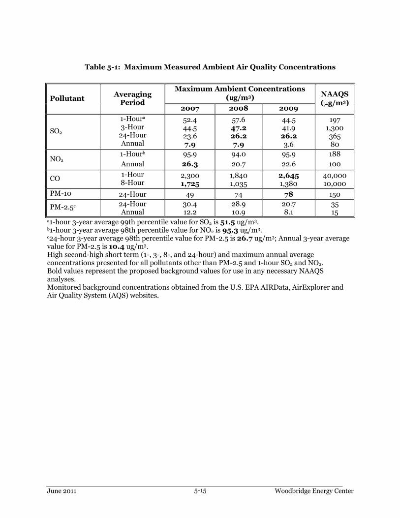
June 2011 Woodbridge Energy Center 5-15
Table 5-1: Maximum Measured Ambient Air Quality Concentrations
Pollutant Averaging
Period
Maximum Ambient Concentrations
( g/m3) NAAQS
( g/m3) 2007 2008 2009
SO2
1-Houra 3-Hour
24-Hour Annual
52.4 44.5 23.6 7.9
57.6 47.2 26.2 7.9
44.5 41.9 26.2 3.6
197 1,300 365 80
NO2 1-Hourb
Annual
95.9
26.3
94.0
20.7
95.9
22.6
188
100
CO 1-Hour 8-Hour
2,300 1,725
1,840 1,035
2,645 1,380
40,000 10,000
PM-10 24-Hour 49 74 78 150
PM-2.5c 24-Hour Annual
30.4 12.2
28.9 10.9
20.7 8.1
35 15
a1-hour 3-year average 99th percentile value for SO2 is 51.5 ug/m3. b1-hour 3-year average 98th percentile value for NO2 is 95.3 ug/m3. c24-hour 3-year average 98th percentile value for PM-2.5 is 26.7 ug/m3; Annual 3-year average value for PM-2.5 is 10.4 ug/m3. High second-high short term (1-, 3-, 8-, and 24-hour) and maximum annual average concentrations presented for all pollutants other than PM-2.5 and 1-hour SO2 and NO2. Bold values represent the proposed background values for use in any necessary NAAQS analyses. Monitored background concentrations obtained from the U.S. EPA AIRData, AirExplorer and Air Quality System (AQS) websites.

June 2011 Woodbridge Energy Center 5-16
Table 5-2: GEP Stack Height Analysis
Structure Height
(ft)
Maximum Projected Width
(ft)
5L Region of Influence
(ft)
HGEP=H+1.5L (ft)
HRSG Tier 92.0 93.2 460.0 230.0
HRSG Tier 49.0 52.6 245.0 122.5
Combustion Turbines 25.0 59.0 125.0 62.5
Combustion Turbine Generators
50.0 38.9 194.7 108.4
Combustion Turbine Air Inlets
68.0 47.6 238.2 139.5
Cooling Tower Fan Deck
41.4 398.5 207.0 103.5
Warehouse 22.0 178.0 110.0 55.0
Steam Turbine Generator
42.3 99.3 211.5 105.8
Demin Tank 32.0 46.0 160.0 80.0

June 2011 Woodbridge Energy Center 5-17
Table 5-3: Combustion Turbine Modeled Source Parameters
Operating
Case
Fuel
Ambient
Temperature
( F)
Operating
Load (%)
Duct Burner
Operation (On/Off)
Modeling Stack
Parameters Evaporative
Cooler Operation (On/Off)
Exhaust Temperature
(K)
Exhaust Velocity (m/s)a
Case1 Gas -8 100 Off Off 360.2 20.00
Case2 Gas -8 100 On Off 353.0 19.74
Case3 Gas -8 75 Off Off 353.9 15.93
Case4 Gas -8 50 Off Off 346.5 12.47
Case5 Gas 56 100 Off Off 357.6 18.30
Case6 Gas 56 100 On Off 351.4 18.12
Case7 Gas 59 PEAK On Off 351.4 18.03
Case8 Gas 56 75 Off Off 349.4 14.17
Case9 Gas 59 50 Off Off 345.5 11.85
Case10 Gas 105 100 Off On 362.4 17.94
Case11 Gas 105 100 On On 357.6 17.77
Case12 Gas 105 PEAK On On 356.0 17.77
Case13 Gas 105 75 Off Off 352.8 13.50
Case14 Gas 105 50 Off Off 351.0 12.19 aBased on a stack diameter of 20.0 feet.
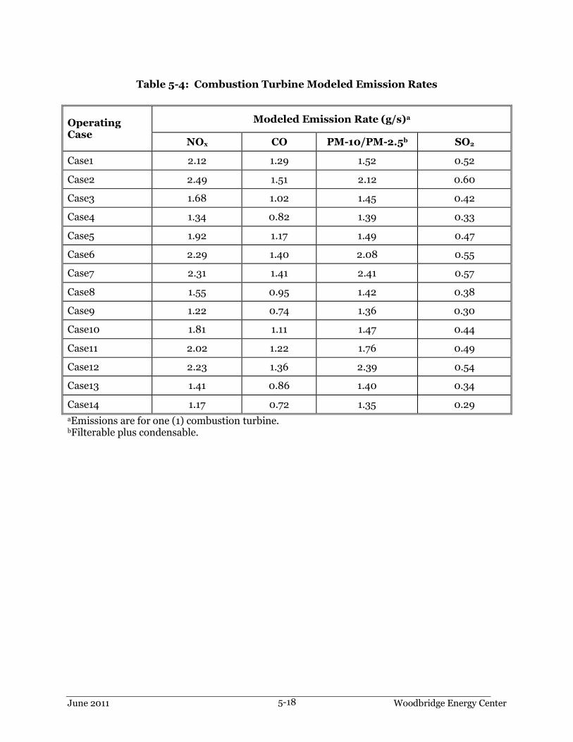
June 2011 Woodbridge Energy Center 5-18
Table 5-4: Combustion Turbine Modeled Emission Rates
Operating Case
Modeled Emission Rate (g/s)a
NOx CO PM-10/PM-2.5b SO2
Case1 2.12 1.29 1.52 0.52
Case2 2.49 1.51 2.12 0.60
Case3 1.68 1.02 1.45 0.42
Case4 1.34 0.82 1.39 0.33
Case5 1.92 1.17 1.49 0.47
Case6 2.29 1.40 2.08 0.55
Case7 2.31 1.41 2.41 0.57
Case8 1.55 0.95 1.42 0.38
Case9 1.22 0.74 1.36 0.30
Case10 1.81 1.11 1.47 0.44
Case11 2.02 1.22 1.76 0.49
Case12 2.23 1.36 2.39 0.54
Case13 1.41 0.86 1.40 0.34
Case14 1.17 0.72 1.35 0.29
aEmissions are for one (1) combustion turbine. bFilterable plus condensable.

June 2011 Woodbridge Energy Center 5-19
Table 5-5: Cooling Tower Exhaust Characteristics and
PM-10/PM-2.5 Emission Rate
Emissions Parameter
Number of Cells 14
Maximum Total Air Flow Rate (acfm) (Each Cell) 1,341,000
Maximum Water Flow Rate (gpm) (Total Tower) 178,000
Maximum Drift Rate 0.0005%
Total Solids in Circulating Water (ppm) 6,240b
14-cell Total TSP Emission Rate (lb/hr) (Total Tower) 2.78
1-cell TSP Emission Rate (g/s) 0.025
14-cell Total PM-10 Emission Rate (lb/hr) (Total Tower) 1.806
1-cell PM-10 Emission Rate (g/s) 0.016
14-cell Total PM-2.5 Emission Rate (lb/hr) (Total Tower) 0.667
1-cell PM-2.5 Emission Rate (g/s) 0.006
14-cell Total TSP Annual Emission Rate (ton/yr) (Total Tower) 12.17
14-cell Total PM-10 Annual Emission Rate (ton/yr) (Total Tower) 7.91
14-cell Total PM-2.5 Annual Emission Rate (ton/yr) (Total Tower) 2.92
Exhaust Parameter
Exhaust Height (ft above gradea) 55.18
Exhaust Height (m above grade) 16.82
Collar Height (ft above grade) 41.43
Collar Height (m above grade) 12.63
Exhaust Temperature (deg F) 85
Exhaust Velocity (ft/sec) 31.62
Exhaust Velocity (m/sec) 9.64
Inner Diameter (ft) 30
Inner Diameter (m) 9.14
aMeasurements on cooling tower specification sheet are referenced to ―top of curb‖ which is 2 feet above grade. bBased upon a makeup water TDS of 780 ppm and eight cycles of concentration.
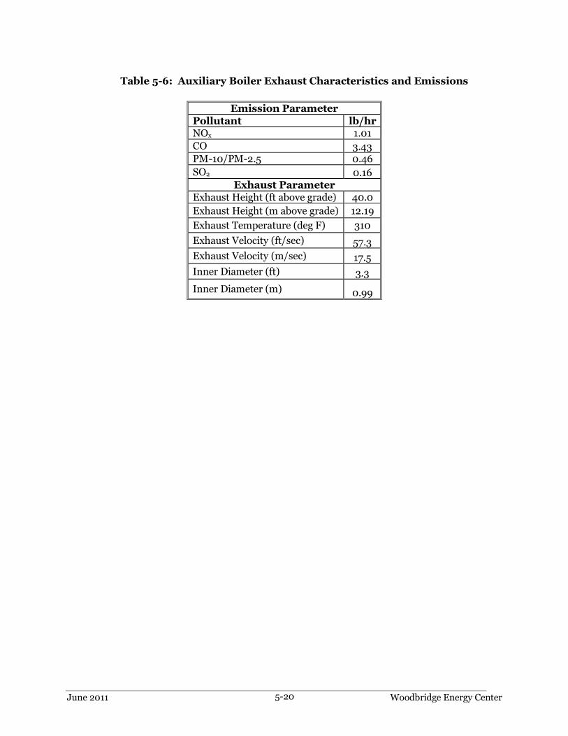
June 2011 Woodbridge Energy Center 5-20
Table 5-6: Auxiliary Boiler Exhaust Characteristics and Emissions
Emission Parameter
Pollutant lb/hr NOx 1.01
CO 3.43 PM-10/PM-2.5 0.46
SO2 0.16 Exhaust Parameter
Exhaust Height (ft above grade) 40.0
Exhaust Height (m above grade) 12.19
Exhaust Temperature (deg F) 310
Exhaust Velocity (ft/sec) 57.3
Exhaust Velocity (m/sec) 17.5
Inner Diameter (ft) 3.3
Inner Diameter (m) 0.99

June 2011 Woodbridge Energy Center 5-21
Table 5-7: Emergency Diesel Fire Pump Exhaust Characteristics and Emissions
Emission Parameter
Pollutant lb/hr
NOx 1.93 CO 2.10 PM-10/PM-2.5 0.10
SO2 0.003 Exhaust Parameter
Exhaust Height (ft above grade) 20.0
Exhaust Height (m above grade) 6.10
Exhaust Temperature (deg F) 961
Exhaust Velocity (ft/sec) 171.1
Exhaust Velocity (m/sec) 52.2
Inner Diameter (ft) 0.4
Inner Diameter (m) 0.13

June 2011 Woodbridge Energy Center 5-22
Table 5-8: Emergency Diesel Generator Exhaust Characteristics and Emissions
Emission Parameter Pollutant lb/hr
NOx 22.02
CO 1.99
PM-10/PM-2.5 0.13
SO2 0.0208 Exhaust Parameter
Exhaust Height (ft above grade) 20.0
Exhaust Height (m above grade) 6.10
Exhaust Temperature (deg F) 763.5
Exhaust Velocity (ft/sec) 528.1
Exhaust Velocity (m/sec) 161.0
Inner Diameter (ft) 0.7
Inner Diameter (m) 0.20

June 2011 Woodbridge Energy Center 5-23
Table 5-9: Dewpoint Heater Exhaust Characteristics and Emissions
Emission Parameter
Pollutant lb/hr
NOx 0.33 CO 0.48
PM-10/PM-2.5 0.07
SO2 0.017
Exhaust Parameter
Exhaust Height (ft above grade) 26.0
Exhaust Height (m above grade) 7.92
Exhaust Temperature (deg F) 690
Exhaust Velocity (ft/sec) 50.1
Exhaust Velocity (m/sec) 15.3
Inner Diameter (ft) 1.33
Inner Diameter (m) 0.41

June 2011 Woodbridge Energy Center 5-24
Table 5-10: Combustion Turbine Start-up and Shutdown Emission Rates and Stack Parameters
Estimated GE 7FA.05 Combustion Turbine Start-up/Shutdown Parameters - Conventional Start Mode
Event Elapsed Time(hr)
Stack NOx (lb/event)
Stack NOx (lb/hour -Max)
Stack CO (lb/event)
Stack CO
(lb/hr - Max)
Stack Particulates
(lb/event)
Stack Particulates
(lb/hr - Max)
Average Stack
Exhaust Flow
(acfm)
Average Stack
Exhaust Velocity
(m/s)
Average Stack
Exhaust Temperature (Degrees F)
Cold Start - Lead CTG
3.08 187 112 1292 565 37 12 580,000 9.38 178
Cold Start - Lag CTG
1.15 113 109 974 941 14 12 580,000 9.38 178
Warm Start - Lead CTG
1.25 84 77 419 354 15 12 580,000 9.38 178
Warm Start - Lag CTG
0.72 76 NA 413 NA 9 NA 580,000 9.38 178
Hot Start - Lead CTG
0.58 36 NA 268 NA 7 NA 550,000 8.89 160
Hot Start - Lag CTG
0.42 30 NA 205 NA 5 NA 550,000 8.89 160
Shutdown - Lead CTG
0.30 22 NA 445 NA 4 NA 600,000 9.70 160
Shutdown - Lag CTG
0.30 22 NA 445 NA 4 NA 600,000 9.70 160
Type of Start-up or Shutdown Event
Cold Warm Hot
Startup Startup Startup Shutdown
Duration of Turbine at 0% load prior to Start-up (hours)
>72 8.1 to 72 0 to 8 --
Maximum Duration of Start-up or Shutdown Event (hours)
3.08 1.25 0.58 0.30
Maximum Number per Yeara 10 52 200 262
a. Combined total number of conventional and rapid-response start-ups and shutdowns

June 2011 Woodbridge Energy Center 5-25
Table 5-10: Combustion Turbine Start-up and Shutdown Emission Rates and Stack Parameters (continued)
Estimated GE 7FA.05 Combustion Turbine Start-up/Shutdown Parameters - Rapid Response Start Mode Event Elapsed
Time(hr) Stack NOx (lb/event)
Stack NOx (lb/hour -Max)
Stack CO (lb/event)
Stack CO
(lb/hr - Max)
Stack Particulates
(lb/event)
Stack Particulates
(lb/hr - Max)
Average Stack
Exhaust Flow
(acfm)
Average Stack
Exhaust Velocity
(m/s)
Average Stack
Exhaust Temperature (Degrees F)
Cold Start - Lead CTG
0.40 44 NA 323 NA 5 NA 600,000 9.70 160
Cold Start - Lag CTG
0.40 44 NA 323 NA 5 NA 600,000 9.70 160
Warm Start - Lead CTG
0.20 12 NA 181 NA 2 NA 730,000 11.80 163
Warm Start - Lag CTG
0.20 12 NA 181 NA 2 NA 730,000 11.80 163
Hot Start - Lead CTG
0.20 12 NA 181 NA 2 NA 730,000 11.80 163
Hot Start - Lag CTG
0.20 12 NA 181 NA 2 NA 730,000 11.80 163
Shutdown - Lead CTG
0.57 60 NA 614 NA 7 NA 600,000 9.70 160
Shutdown - Lag CTG
0.57 60 NA 614 NA 7 NA 600,000 9.70 160
Notes: NA identifies those scenarios where the pound per hour emission rate equals the pound per event rate due to the event duration of less than 1-hour.

June 2011 Woodbridge Energy Center 5-26
Table 5-11: Maximum Modeled Concentrations During Start-Up/Shutdown
Pollutant Averaging
Period
Significant Impact
Concentration
( g/m3)
Class II PSD
Increment (ug/m3)
NAAQS/NJAAQS (ug/m3)
Maximum Modeled
Concentration
( g/m3)
Background Concentration
(ug/m3)
CO 1-Hour 2,000 - 40,000 548c 2,645
8-Hour 500 - 10,000 88c 1,725
NO2 1-Hour 7.5 - 188 36a,b,d 95
aAssumed 80% of NOx is NO2. bBased upon maximum of 5-year average 1st highest maximum modeled concentrations per EPA guidance. cDetermined from operation of combustion turbines during a conventional cold start-up sequence with the addition of facility auxiliary equipment. dDetermined from operation of combustion turbines during a rapid response mode shutdown sequence with the addition of facility auxiliary equipment.

June 2011 Woodbridge Energy Center 5-27
Table 5-12: Facility Maximum Modeled Concentrations
Pollutant Averaging
Period
Significant Impact
Concentration
( g/m3)
Class II PSD
Increment (ug/m3)
NAAQS/NJAAQS (ug/m3)
Maximum Modeled
Concentration
( g/m3)
Background Concentration
(ug/m3)
CO 1-Hour 2,000 - 40,000 548 2,645
8-Hour 500 - 10,000 88 1,725
SO2
1-Houra 7.9 - 197 3.1 52 3-Hour 25 512 1,300 2.6 47
24-Hour 5 91 365/260 1.4 26 Annual 1 20 80/60 0.1 7.9
PM-2.5 24-Houra 1.2 9 35 3.6 26.7
Annual 0.3 4 15 0.2 8.1
PM-10 24-Hour 5 30 150 4.1 78
NO2 1-Houra 7.5 - 188 36b 95
Annual 1 25 100 0.85c 26.3 aBased upon maximum of 5-year average 1st highest maximum modeled concentrations per EPA guidance. bAssumed 80% of NOx is NO2 per EPA guidance. cAssumed 75% of NOx is NO2 per EPA guidance.

June 2011 Woodbridge Energy Center 5-28
Table 5-13: Comparison of Maximum Modeled Concentrations of Pollutants to Vegetation Screening Concentrations
Pollutant
Averaging
Period
Maximum Modeled
Concentration (μg/m3)
Background
Concentrationg (μg/m3)
Total
Concentrationa (μg/m3)
Vegetation Screening Concentrationsf (μg/m3)
Sensitive Intermediate Resistant
SO2 1-Hour 3-Hour
3.1 2.6
51.5 47.2
55 50
917 786
- 2,096
- 13,100
NO2 4-Hour 8-Hour Annual
36b
36b
0.85
96c 96c 26
132 132 27
3,760 3,760
-
9,400 7,520
94
16,920 15,404
-
CO 1-Week 88e 1,725d 1,776 1,800,000 - 1,800,000
aTotal concentration = maximum modeled facility concentration + background concentration. bMaximum modeled concentration conservatively based on 1-hour averaging period. cMaximum background concentration conservatively based on 1-hour averaging period. dMaximum background concentration conservatively based on 8-hour averaging period. eMaximum modeled concentration conservatively based on 8-hour averaging period. fScreening concentrations found in Table 3.1 of ―A Screening Procedure for the Impacts of Air Pollution Sources on Plants, Soils, and Animals‖ (EPA, 1980). gHigh second-high short term and maximum annual average concentrations presented for all pollutants. (-) No screening concentration available.

June 2011 Woodbridge Energy Center 5-29
Table 5-14: VISCREEN Maximum Surrounding Area Visual Impacts
Background Theta
(degrees) Azimuth (degrees)
Distance (km)
Alpha (degrees)
Delta Ea Contrastb
Criteria Plume Criteria Plume
Inside Class I Area (Brigantine NWR)
Sky 10 162 108 6 2 0.006 0.05 0
Sky 140 162 108 6 2 0.001 0.05 0
Terrain 10 162 108 6 2 0.011 0.05 0
Terrain 140 162 108 6 2 0.003 0.05 0
Inside Surrounding Area
Sky 10 0 1 168 2 0.697 0.05 0.007
Sky 140 0 1 168 2 0.126 0.05 -0.005
Terrain 10 0 1 168 2 1.026 0.05 0.01
Terrain 140 0 1 168 2 0.305 0.05 0.01
aColor difference parameter (dimensionless). bVisual contrast against background parameter (dimensionless).


Appendix A
NJDEP Air Permit Application Forms (RADIUS)

Woodbridge Energy Center (18940)
New Jersey Department of Environmental ProtectionReason for Application
Date:6/3/2011
Permit Being Modified
Permit Class: Number:0
Descriptionof Modifications:
CPV Shore, LLC is proposing to construct and operate a nominal 700 megawatt (MW)combined cycle electric generating facility located in the Township of Woodbridge, NewJersey.
The facility will consist of two GE 207FA.05 combustion turbine generators (CTG), twoheat recovery steam generators (HRSG) equipped with natural gas-fired duct burners forsupplemental firing and a single steam turbine generator (STG). Supporting ancillaryequipment includes a natural gas fired auxiliary boiler, one small dew point fuel gas heater(fuel gas heater), a mechanical draft cooling tower, an emergency diesel generator, and anemergency diesel fire pump.
The proposed CTGs will be fueled exclusively by natural gas. The duct burners will alsofire natural gas exclusively and will only operate when the CTGs are at full load. The CTGswill utilize dry low-NOx (DLN) combustors and selective catalytic reduction (SCR)systems to control NOx emissions. An oxidation catalyst will be located in each HRSG,upstream of the SCR, and used to control emissions of carbon monoxide (CO) as well asvolatile organic compounds (VOC). Upon leaving the SCR, each turbine will exhaust to aseparate stack at 135 feet above grade with an inner exit flue diameter of 20 feet.
The project will be designed to operate on a continuous basis, but may operate at partialloads. Partial loads can be achieved by operating the turbine at less than its full capacity.However, part-load turbine operation will be limited to between 45 and 100% of turbineload.
The facility will be licensed as a new major facility in accordance with N.J.DEP Subchapter22 regulations.
Page 1 of 1

Woodbridge Energy Center (18940) Date: 6/2/2011
New Jersey Department of Environmental ProtectionFacility Profile (General)
557,672
4,485,142
Other
NAD83
Submittal Document
Digital Image
27.5 acre industrial parcel of land, which willbe subdivided from a larger 180 acre parcel ofland owned by El Paso and presently beingremediated.
State Plane Coordinates:
X-Coordinate:
Y-Coordinate:
Units:
Datum:
Source Org.:
Source Type:
County: Industry:LocationDescription:
Primary SIC:
Secondary SIC:
Middlesex
MailingAddress:
StreetAddress:
INDUSTRIAL HWYWOODBRIDGE, NJ 07095
CPV SHORE INC50 BRAINTREE HILL OFC PARKSTE 300BRAINTREE, MA 02184
Facility Name (AIMS): Woodbridge Energy Center Facility ID (AIMS): 18940
221112NAICS:
Page 1 of 2

Woodbridge Energy Center (18940) Date: 6/2/2011
New Jersey Department of Environmental ProtectionFacility Profile (General)
(201) 933-5601 x
( ) - x
TRC Environmental Corporation
Carla AdduciPrincipal Air Quality Engineer
(201) 508-6945 x 1200 Wall Street West2nd FloorLyndhurst, NJ 07071
Organization: Org. Type:Name:Title:
Phone:
Fax:
MailingAddress:
Other:
Type:
Email:
Corporation
NJ EIN: 06086161800
Contact Type: Consultant
Mobile
(781) 848-5804 x
(508) 579-6317 x
Competitive Power Ventures, Inc
Steven RemillardVice President
(781) 817-8970 x 50 Braintree Hill Office ParkSuite 300Braintree, MA 02184
Organization: Org. Type:Name:Title:
Phone:
Fax:
MailingAddress:
Other:
Type:
Email:
Corporation
NJ EIN:
Contact Type: General Contact
Mobile
(781) 848-5804 x
(508) 579-6317 x
Competitive Power Ventures, Inc
Steven RemillardVice President
(781) 817-8970 x 50 Braintree Hill Office ParkSuite 300Braintree, MA 02184
Organization: Org. Type:Name:Title:
Phone:
Fax:
MailingAddress:
Other:
Type:
Email:
Corporation
NJ EIN:
Contact Type: Responsible Official
Page 2 of 2

6/2/2011
New Jersey Department of Environmental ProtectionFacility Profile (Permitting)
Date: Woodbridge Energy Center (18940)
12. Have you provided, or are you planning to provide air contaminant modeling?
1. Is this facility classified as a small business by the USEPA?2. Is this facility subject to N.J.A.C. 7:27-22?3. Are you voluntarily subjecting this facility to the requirements of Subchapter 22?4. Has a copy of this application been sent to the USEPA?5. If not, has the EPA waived the requirement?6. Are you claiming any portion of this application to be confidential?7. Is the facility an existing major facility?8. Have you submitted a netting analysis?9. Are emissions of any pollutant above the SOTA threshold?10. Have you submitted a SOTA analysis?
11. If you answered "Yes" to Question 9 and "No" to Question 10, explain whya SOTA analysis was not required
NoYesNoNoNoNoYesNo
YesYes
Yes
Air Contaminant(s)CAS NumberName
Carbon monoxideNOx (Total)Particulate matter, <=10umPM-2.5 (Total)SO2
Page 1 of 1

Woodbridge Energy Center (18940)
New Jersey Department of Environmental ProtectionNon-Source Fugitive Emissions
Date: 06/02/2011
Page 1 of 1
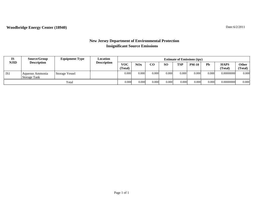
Woodbridge Energy Center (18940)
New Jersey Department of Environmental ProtectionInsignificant Source Emissions
6/2/2011Date:
IS NJID
Source/GroupDescription
Equipment Type Location Description
Estimate of Emissions (tpy)VOC
(Total)NOx CO SO TSP PM-10 Pb HAPS
(Total)Other(Total)
IS1 Aqueous AmmoniaStorage Tank
Storage Vessel 0.000 0.000 0.000 0.000 0.000 0.000 0.000 0.00000000 0.000
Total 0.000 0.000 0.000 0.000 0.000 0.0000.000 0.00000000 0.000
Page 1 of 1
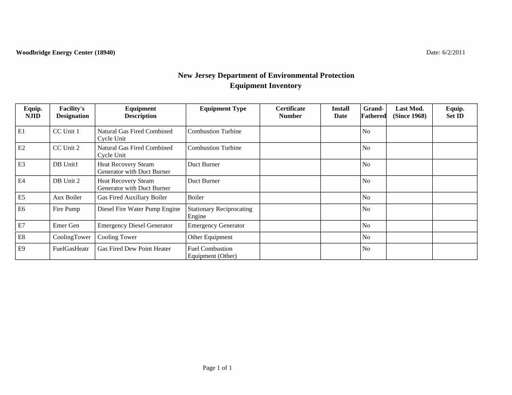
Equip.NJID
Facility's Designation
EquipmentDescription
Equipment Type CertificateNumber
InstallDate
Grand-Fathered
Last Mod.(Since 1968)
Equip.Set ID
New Jersey Department of Environmental ProtectionEquipment Inventory
Woodbridge Energy Center (18940) 6/2/2011Date:
E1 CC Unit 1 CNoNatural Gas Fired CombinedCycle Unit
Combustion Turbine
E2 CC Unit 2 CNoNatural Gas Fired CombinedCycle Unit
Combustion Turbine
E3 DB Unit1 DNoHeat Recovery SteamGenerator with Duct Burner
Duct Burner
E4 DB Unit 2 DNoHeat Recovery SteamGenerator with Duct Burner
Duct Burner
E5 Aux Boiler BNoGas Fired Auxiliary Boiler Boiler
E6 Fire Pump SNoDiesel Fire Water Pump Engine Stationary ReciprocatingEngine
E7 Emer Gen ENoEmergency Diesel Generator Emergency Generator
E8 CoolingTower ONoCooling Tower Other Equipment
E9 FuelGasHeatr FNoGas Fired Dew Point Heater Fuel CombustionEquipment (Other)
Page 1 of 1

Woodbridge Energy Center (18940) Date: 6/2/2011
New Jersey Department of Environmental ProtectionControl Device Inventory
CD NJID
Facility's Designation
Description CD Type InstallDate
Grand-Fathered
Last Mod.(Since 1968)
CDSet ID
CD1 Selective Catalyic Reduction forCombustion Turbine Unit 1
NoSCR Unit1 Selective CatalyticReduction
CD2 Oxidation Catalyst forCombustion Turbine Unit 1
NoOxyCat Unit1 Oxidizer (Catalytic)
CD3 Selective Catalytic Reduction forCombustion Turbine Unit 2
NoSCR Unit2 Selective CatalyticReduction
CD4 Oxidation Catalyst forCombustion Turbine Unit 2
NoOxyCat Unit2 Oxidizer (Catalytic)
CD5 Drift Eliminator for CoolingTower
NoDrift Elim Other
Page 1 of 1

Woodbridge Energy Center (18940) Date: 6/2/2011
New Jersey Department of Environmental ProtectionEmission Points Inventory
PT NJID
Facility's Designation
Description Config. Equiv.Diam.(in.)
Height(ft.)
Dist. toProp.
Line (ft)
Exhaust Temp. (deg. F) Exhaust Vol. (acfm)
Avg. Min. Max. Avg. Min. Max.
DischargeDirection
PTSet ID
PT1 HRSG Stack 1 Combined Cycle CombustionUnit 1 Turbine Stack
Round 240 135 230 177.5 162.3 192.6 Up R1,237,051.0753,867.0
PT2 HRSG Stack 2 Combined Cycle CombustionUnit 2 Turbine Stack
Round 240 135 100 177.5 162.3 192.6 Up R1,237,051.0753,867.0
PT3 AuxBoilerStk Auxiliary Boiler Exhaust Stack Round 39 40 315 310.0 310.0 310.0 Up R28,500.028,500.0 28,500.0
PT4 FirePumpStk Diesel Fire Water Pump Stack Round 5 20 135 961.0 961.0 961.0 Up R1,400.01,400.0 1,400.0
PT5 DieselGenStk Emergency Diesel GeneratorStack
Round 8 20 190 763.5 763.5 763.5 Up R11,060.611,060.6 11,060.6
PT6 CoolTowrCell Cooling Tower Exhausts (14Cells)
Round 360 55 60 85.0 85.0 85.0 Up R1,341,000.01,341,000.0 1,341,000.0
PT7 GasHeatrStk Fuel Gas Dew Point HeaterStack
Round 16 26 120 690.0 690.0 690.0 Up R4,200.04,200.0 4,200.0
Page 1 of 1

New Jersey Department of Environmental ProtectionEmission Unit/Batch Process Inventory
Woodbridge Energy Center (18940) Date: 6/2/2011
U 1 CC Unit 1 Combined Cycle Combustion Unit 1
UOSNJID
Facility'sDesignation
UOSDescription
OperationType
Signif.Equip.
ControlDevice(s)
EmissionPoint(s) SCC(s)
Flow (acfm)
Temp. (deg F)
Min. Max. Min. Max.
AnnualOper.
Min. Max.VOC
RangeOS1 CT1-W/DB Turbine firing natural gas
at full load with naturalgas fired duct burner inHRSG for supplementalfiring
Normal - SteadyState
E1 CD1 (P)CD2 (P)
PT1 2-01-002-01 0.0 1,250.0 753,867.0 1,237,051.0 162.3 192.6
OS2 CT1-WO/DB Turbine firing natural gasat full load withoutsupplemental duct burnerfiring in HRSG
Normal - SteadyState
E1 CD1 (P)CD2 (P)
PT1 2-01-002-01 0.0 8,760.0 753,867.0 1,237,051.0 162.3 192.6
OS3 CT1-CSU Conventional TurbineStart-up Operation
Startup E1 PT1 2-01-002-01 0.0 283.0 550,000.0 600,000.0 160.0 178.0
OS4 CT1-CSD Conventional TurbineShut-down Operation
Shutdown E1 PT1 2-01-002-01 0.0 79.0 550,000.0 600,000.0 160.0 178.0
OS5 CT1-RSU Rapid Turbine Start-upOperation
Startup E1 PT1 2-01-002-01 0.0 55.0 600,000.0 730,000.0 160.0 163.0
OS6 CT1-RSD Rapid Turbine Shut-downOperation
Shutdown E1 PT1 2-01-002-01 0.0 140.0 600,000.0 730,000.0 160.0 163.0

New Jersey Department of Environmental ProtectionEmission Unit/Batch Process Inventory
Woodbridge Energy Center (18940) Date: 6/2/2011
U 2 CC Unit 2 Combined Cycle Combustion Unit 2
UOSNJID
Facility'sDesignation
UOSDescription
OperationType
Signif.Equip.
ControlDevice(s)
EmissionPoint(s) SCC(s)
Flow (acfm)
Temp. (deg F)
Min. Max. Min. Max.
AnnualOper.
Min. Max.VOC
RangeOS1 CT2-W/DB Turbine firing natural gas
at full load with naturalgas fired duct burner inHRSG for supplementalfiring
Normal - SteadyState
E2 CD3 (P)CD4 (P)
PT2 2-01-002-01 0.0 1,250.0 753,867.0 1,237,051.0 162.3 192.6
OS2 CT2-WO/DB Turbine firing natural gasat full load withoutsupplemental duct burnerfiring in HRSG
Normal - SteadyState
E2 CD3 (P)CD4 (P)
PT2 2-01-002-01 0.0 8,760.0 753,867.0 1,237,051.0 162.3 192.6
OS3 CT2-CSU Conventional TurbineStart-up Operation
Startup E2 PT2 2-01-002-01 0.0 283.0 550,000.0 600,000.0 160.0 178.0
OS4 CT2-CSD Conventional TurbineShut-down Operation
Shutdown E2 PT2 2-01-002-01 0.0 79.0 550,000.0 600,000.0 160.0 178.0
OS5 CT2-RSU Rapid Turbine Start-upOperation
Startup E2 PT2 2-01-002-01 0.0 55.0 600,000.0 730,000.0 160.0 163.0
OS6 CT2-RSD Rapid Turbine Shut-downOperation
Shutdown E2 PT2 2-01-002-01 0.0 140.0 600,000.0 730,000.0 160.0 163.0

New Jersey Department of Environmental ProtectionEmission Unit/Batch Process Inventory
Woodbridge Energy Center (18940) Date: 6/2/2011
U 3 AuxBoiler Gas Fired Auxiliary Boiler
UOSNJID
Facility'sDesignation
UOSDescription
OperationType
Signif.Equip.
ControlDevice(s)
EmissionPoint(s) SCC(s)
Flow (acfm)
Temp. (deg F)
Min. Max. Min. Max.
AnnualOper.
Min. Max.VOC
RangeOS1 AuxBoiler Gas Fired Auxiliary Boiler Normal - Steady
StateE5 PT3 1-02-006-01 0.0 2,000.0 28,500.0 28,500.0 310.0 310.0
U 4 Fire Pump Diesel Fire Water Pump Engine
UOSNJID
Facility'sDesignation
UOSDescription
OperationType
Signif.Equip.
ControlDevice(s)
EmissionPoint(s) SCC(s)
Flow (acfm)
Temp. (deg F)
Min. Max. Min. Max.
AnnualOper.
Min. Max.VOC
RangeOS1 Fire Pump Diesel Fire Water Pump
EngineNormal - SteadyState
E6 PT4 2-02-001-02 0.0 100.0 1,400.0 1,400.0 961.0 961.0

New Jersey Department of Environmental ProtectionEmission Unit/Batch Process Inventory
Woodbridge Energy Center (18940) Date: 6/2/2011
U 5 Emer Gen Emergency Diesel Generator
UOSNJID
Facility'sDesignation
UOSDescription
OperationType
Signif.Equip.
ControlDevice(s)
EmissionPoint(s) SCC(s)
Flow (acfm)
Temp. (deg F)
Min. Max. Min. Max.
AnnualOper.
Min. Max.VOC
RangeOS1 Emer Gen Emergency Diesel
GeneratorNormal - SteadyState
E7 PT5 2-01-001-02 0.0 100.0 11,060.6 11,060.6 763.5 763.5
U 6 Cool Tower Cooling Tower
UOSNJID
Facility'sDesignation
UOSDescription
OperationType
Signif.Equip.
ControlDevice(s)
EmissionPoint(s) SCC(s)
Flow (acfm)
Temp. (deg F)
Min. Max. Min. Max.
AnnualOper.
Min. Max.VOC
RangeOS1 Cool Tower Cooling Tower - 14 Cells Normal - Steady
StateE8 PT6 A28-20-000-000 0.0 8,760.0 1,341,000.0 1,341,000.0 85.0 85.0

New Jersey Department of Environmental ProtectionEmission Unit/Batch Process Inventory
Woodbridge Energy Center (18940) Date: 6/2/2011
U 7 Fuel Heater Gas Fired Dew Point Heater
UOSNJID
Facility'sDesignation
UOSDescription
OperationType
Signif.Equip.
ControlDevice(s)
EmissionPoint(s) SCC(s)
Flow (acfm)
Temp. (deg F)
Min. Max. Min. Max.
AnnualOper.
Min. Max.VOC
RangeOS1 Fuel Heater Gas Fired Dew Point
HeaterNormal - SteadyState
E9 PT7 1-02-006-03 0.0 8,760.0 4,200.0 4,200.0 690.0 690.0

Date: 6/2/2011
New Jersey Department of Environmental ProtectionSubject Item Group Inventory
GR1 Conv SU OpsGroup NJID:Members:
Type ID OS Step U U 1 OS3 CT1-CSU U U 2 OS3 CT2-CSU
Formal Reason(s) for Group/Cap:Other
Other (explain): Total startup emissions from both CTs combined will be capped at a single lb/eventemission limit
Condition/Requirements that will be complied with or are no longerapplicable as a result of this Group: Operating Circumstances:
Conventional Start-up Operations
Page 1 of 4

Date: 6/2/2011
New Jersey Department of Environmental ProtectionSubject Item Group Inventory
GR2 Conv SD OpsGroup NJID:Members:
Type ID OS Step U U 1 OS4 CT1-CSD U U 2 OS4 CT2-CSD
Formal Reason(s) for Group/Cap:Other
Other (explain): Total shutdown emissions from both CTs combined will be capped at a single lb/eventemission limit
Condition/Requirements that will be complied with or are no longerapplicable as a result of this Group: Operating Circumstances:
Conventional Shut-down Operations
Page 2 of 4

Date: 6/2/2011
New Jersey Department of Environmental ProtectionSubject Item Group Inventory
GR3 Rapid SU OpsGroup NJID:Members:
Type ID OS Step U U 1 OS5 CT1-RSU U U 2 OS5 CT2-RSU
Formal Reason(s) for Group/Cap:Other
Other (explain): Total startup emissions from both CTs combined will be capped at a single lb/eventemission limit
Condition/Requirements that will be complied with or are no longerapplicable as a result of this Group: Operating Circumstances:
Rapid Start-up Operations
Page 3 of 4

Date: 6/2/2011
New Jersey Department of Environmental ProtectionSubject Item Group Inventory
GR4 Rapid SD OpsGroup NJID:Members:
Type ID OS Step U U 1 OS6 CT1-RSD U U 2 OS6 CT2-RSD
Formal Reason(s) for Group/Cap:Other
Other (explain): Total shutdown emissions from both CTs combined will be capped at a single lb/eventemission limit
Condition/Requirements that will be complied with or are no longerapplicable as a result of this Group: Operating Circumstances:
Rapid Shut-down Operations
Page 4 of 4

Woodbridge Energy Center (18940) Date: 6/3/2011
New Jersey Department of Environmental ProtectionPotential to Emit
Subject Item: FC
Operating Scenario:
Step:
Air Contaminant Category (HAPS)
Fugitive Emissions
Emissions Before Controls
Emissions After Controls
TotalEmissions
Alt. Em. Limit
Units
123.50000000 NoAmmonia 123.50000000 tons/yrNoCarbon Dioxide tons/yr
129.70000000 NoCO 129.70000000 tons/yr 10.40000000 NoHAPs (Total) 10.40000000 tons/yr
140.60000000 NoNOx (Total) 140.60000000 tons/yr 0.01000000 NoPb 0.01000000 tons/yr
103.70000000 NoPM-10 (Total) 103.70000000 tons/yr 98.70000000 NoPM-2.5 (Total) 98.70000000 tons/yr 12.00000000 NoSO2 12.00000000 tons/yr 8.20000000 NoSulfuric Acid Mist Emissions 8.20000000 tons/yr
107.90000000 NoTSP 107.90000000 tons/yr 27.80000000 NoVOC (Total) 27.80000000 tons/yr
Subject Item: GR1 Conv SU Ops
Operating Scenario:
Step:
Air Contaminant Category (HAPS)
Fugitive Emissions
Emissions Before Controls
Emissions After Controls
TotalEmissions
Alt. Em. Limit
Units
2,266.00000000 NoCO 2,266.00000000 lb/step 300.00000000 NoNOx (Total) 300.00000000 lb/step 51.00000000 NoPM-10 (Total) 51.00000000 lb/step 51.00000000 NoPM-2.5 (Total) 51.00000000 lb/step 51.00000000 NoTSP 51.00000000 lb/step
193.00000000 NoVOC (Total) 193.00000000 lb/step
Page 1 of 17

Woodbridge Energy Center (18940) Date: 6/3/2011
New Jersey Department of Environmental ProtectionPotential to Emit
Subject Item: GR2 Conv SD Ops
Operating Scenario:
Step:
Air Contaminant Category (HAPS)
Fugitive Emissions
Emissions Before Controls
Emissions After Controls
TotalEmissions
Alt. Em. Limit
Units
890.00000000 NoCO 890.00000000 lb/step 44.00000000 NoNOx (Total) 44.00000000 lb/step 8.00000000 NoPM-10 (Total) 8.00000000 lb/step 8.00000000 NoPM-2.5 (Total) 8.00000000 lb/step 8.00000000 NoTSP 8.00000000 lb/step
24.00000000 NoVOC (Total) 24.00000000 lb/step
Subject Item: GR3 Rapid SU Ops
Operating Scenario:
Step:
Air Contaminant Category (HAPS)
Fugitive Emissions
Emissions Before Controls
Emissions After Controls
TotalEmissions
Alt. Em. Limit
Units
646.00000000 NoCO 646.00000000 lb/step 88.00000000 NoNOx (Total) 88.00000000 lb/step 10.00000000 NoPM-10 (Total) 10.00000000 lb/step 10.00000000 NoPM-2.5 (Total) 10.00000000 lb/step 10.00000000 NoTSP 10.00000000 lb/step 26.00000000 NoVOC (Total) 26.00000000 lb/step
Page 2 of 17

Woodbridge Energy Center (18940) Date: 6/3/2011
New Jersey Department of Environmental ProtectionPotential to Emit
Subject Item: GR4 Rapid SD Ops
Operating Scenario:
Step:
Air Contaminant Category (HAPS)
Fugitive Emissions
Emissions Before Controls
Emissions After Controls
TotalEmissions
Alt. Em. Limit
Units
1,228.00000000 NoCO 1,228.00000000 lb/step 120.00000000 NoNOx (Total) 120.00000000 lb/step 14.00000000 NoPM-10 (Total) 14.00000000 lb/step 14.00000000 NoPM-2.5 (Total) 14.00000000 lb/step 14.00000000 NoTSP 14.00000000 lb/step 48.00000000 NoVOC (Total) 48.00000000 lb/step
Subject Item: U1 CC Unit 1
Operating Scenario: OS0 Summary
Step:
Air Contaminant Category (HAPS)
Fugitive Emissions
Emissions Before Controls
Emissions After Controls
TotalEmissions
Alt. Em. Limit
Units
61.75000000 NoAmmonia 61.75000000 tons/yrNoCarbon Dioxide tons/yr
62.00000000 NoCO 62.00000000 tons/yr 68.45000000 NoNOx (Total) 68.45000000 tons/yr 0.00500000 NoPb 0.00500000 tons/yr
47.50000000 NoPM-10 (Total) 47.50000000 tons/yr 47.50000000 NoPM-2.5 (Total) 47.50000000 tons/yr 5.95000000 NoSO2 5.95000000 tons/yr 4.10000000 NoSulfuric Acid Mist Emissions 4.10000000 tons/yr
47.50000000 NoTSP 47.50000000 tons/yr 13.70000000 NoVOC (Total) 13.70000000 tons/yr
Page 3 of 17

Woodbridge Energy Center (18940) Date: 6/3/2011
New Jersey Department of Environmental ProtectionPotential to Emit
Subject Item: U1 CC Unit 1
Operating Scenario: OS1
Step:
Air Contaminant Category (HAPS)
Fugitive Emissions
Emissions Before Controls
Emissions After Controls
TotalEmissions
Alt. Em. Limit
Units
15.40000000 NoAmmonia 15.40000000 lb/hr 12.00000000 NoCO 12.00000000 lb/hr 19.80000000 NoNOx (Total) 19.80000000 lb/hr 0.00133000 NoPb 0.00133000 lb/hr
19.10000000 NoPM-10 (Total) 19.10000000 lb/hr 19.10000000 NoPM-2.5 (Total) 19.10000000 lb/hr 4.80000000 NoSO2 4.80000000 lb/hr 3.30000000 NoSulfuric Acid Mist Emissions 3.30000000 lb/hr
19.10000000 NoTSP 19.10000000 lb/hr 6.90000000 NoVOC (Total) 6.90000000 lb/hr
Subject Item: U1 CC Unit 1
Operating Scenario: OS2
Step:
Air Contaminant Category (HAPS)
Fugitive Emissions
Emissions Before Controls
Emissions After Controls
TotalEmissions
Alt. Em. Limit
Units
15.50000000 NoAmmonia 15.50000000 lb/hr 10.20000000 NoCO 10.20000000 lb/hr 16.80000000 NoNOx (Total) 16.80000000 lb/hr 0.00113000 NoPb 0.00113000 lb/hr
12.10000000 NoPM-10 (Total) 12.10000000 lb/hr 12.10000000 NoPM-2.5 (Total) 12.10000000 lb/hr 4.10000000 NoSO2 4.10000000 lb/hr 2.80000000 NoSulfuric Acid Mist Emissions 2.80000000 lb/hr
Page 4 of 17

Woodbridge Energy Center (18940) Date: 6/3/2011
New Jersey Department of Environmental ProtectionPotential to Emit
Subject Item: U1 CC Unit 1
Operating Scenario: OS2
Step:
Air Contaminant Category (HAPS)
Fugitive Emissions
Emissions Before Controls
Emissions After Controls
TotalEmissions
Alt. Em. Limit
Units
12.10000000 NoTSP 12.10000000 lb/hr 2.90000000 NoVOC (Total) 2.90000000 lb/hr
Subject Item: U1 CC Unit 1
Operating Scenario: OS3
Step:
Air Contaminant Category (HAPS)
Fugitive Emissions
Emissions Before Controls
Emissions After Controls
TotalEmissions
Alt. Em. Limit
Units
941.00000000 NoCO 941.00000000 lb/hr 112.00000000 NoNOx (Total) 112.00000000 lb/hr 12.00000000 NoPM-10 (Total) 12.00000000 lb/hr 12.00000000 NoPM-2.5 (Total) 12.00000000 lb/hr 12.00000000 NoTSP 12.00000000 lb/hr 57.00000000 NoVOC (Total) 57.00000000 lb/hr
Subject Item: U1 CC Unit 1
Operating Scenario: OS4
Step:
Air Contaminant Category (HAPS)
Fugitive Emissions
Emissions Before Controls
Emissions After Controls
TotalEmissions
Alt. Em. Limit
Units
452.10000000 NoCO 452.10000000 lb/hr 33.80000000 NoNOx (Total) 33.80000000 lb/hr 12.00000000 NoPM-10 (Total) 12.00000000 lb/hr 12.00000000 NoPM-2.5 (Total) 12.00000000 lb/hr
Page 5 of 17

Woodbridge Energy Center (18940) Date: 6/3/2011
New Jersey Department of Environmental ProtectionPotential to Emit
Subject Item: U1 CC Unit 1
Operating Scenario: OS4
Step:
Air Contaminant Category (HAPS)
Fugitive Emissions
Emissions Before Controls
Emissions After Controls
TotalEmissions
Alt. Em. Limit
Units
12.00000000 NoTSP 12.00000000 lb/hr 14.03000000 NoVOC (Total) 14.03000000 lb/hr
Subject Item: U1 CC Unit 1
Operating Scenario: OS5
Step:
Air Contaminant Category (HAPS)
Fugitive Emissions
Emissions Before Controls
Emissions After Controls
TotalEmissions
Alt. Em. Limit
Units
329.12000000 NoCO 329.12000000 lb/hr 54.10000000 NoNOx (Total) 54.10000000 lb/hr 12.00000000 NoPM-10 (Total) 12.00000000 lb/hr 12.00000000 NoPM-2.5 (Total) 12.00000000 lb/hr 12.00000000 NoTSP 12.00000000 lb/hr 14.74000000 NoVOC (Total) 14.74000000 lb/hr
Subject Item: U1 CC Unit 1
Operating Scenario: OS6
Step:
Air Contaminant Category (HAPS)
Fugitive Emissions
Emissions Before Controls
Emissions After Controls
TotalEmissions
Alt. Em. Limit
Units
618.40000000 NoCO 618.40000000 lb/hr 67.20000000 NoNOx (Total) 67.20000000 lb/hr 12.00000000 NoPM-10 (Total) 12.00000000 lb/hr 12.00000000 NoPM-2.5 (Total) 12.00000000 lb/hr
Page 6 of 17

Woodbridge Energy Center (18940) Date: 6/3/2011
New Jersey Department of Environmental ProtectionPotential to Emit
Subject Item: U1 CC Unit 1
Operating Scenario: OS6
Step:
Air Contaminant Category (HAPS)
Fugitive Emissions
Emissions Before Controls
Emissions After Controls
TotalEmissions
Alt. Em. Limit
Units
12.00000000 NoTSP 12.00000000 lb/hr 25.25000000 NoVOC (Total) 25.25000000 lb/hr
Subject Item: U2 CC Unit 2
Operating Scenario: OS0 Summary
Step:
Air Contaminant Category (HAPS)
Fugitive Emissions
Emissions Before Controls
Emissions After Controls
TotalEmissions
Alt. Em. Limit
Units
61.75000000 NoAmmonia 61.75000000 tons/yrNoCarbon Dioxide tons/yr
62.00000000 NoCO 62.00000000 tons/yrNoHAPs (Total) tons/yr
68.45000000 NoNOx (Total) 68.45000000 tons/yr 0.00500000 NoPb 0.00500000 tons/yr
47.50000000 NoPM-10 (Total) 47.50000000 tons/yr 47.50000000 NoPM-2.5 (Total) 47.50000000 tons/yr 5.95000000 NoSO2 5.95000000 tons/yr 4.10000000 NoSulfuric Acid Mist Emissions 4.10000000 tons/yr
47.50000000 NoTSP 47.50000000 tons/yr 13.70000000 NoVOC (Total) 13.70000000 tons/yr
Page 7 of 17

Woodbridge Energy Center (18940) Date: 6/3/2011
New Jersey Department of Environmental ProtectionPotential to Emit
Subject Item: U2 CC Unit 2
Operating Scenario: OS1
Step:
Air Contaminant Category (HAPS)
Fugitive Emissions
Emissions Before Controls
Emissions After Controls
TotalEmissions
Alt. Em. Limit
Units
15.40000000 NoAmmonia 15.40000000 lb/hr 12.00000000 NoCO 12.00000000 lb/hr
NoHAPs (Total) lb/hr 19.80000000 NoNOx (Total) 19.80000000 lb/hr 0.00133000 NoPb 0.00133000 lb/hr
19.10000000 NoPM-10 (Total) 19.10000000 lb/hr 19.10000000 NoPM-2.5 (Total) 19.10000000 lb/hr 4.80000000 NoSO2 4.80000000 lb/hr 3.30000000 NoSulfuric Acid Mist Emissions 3.30000000 lb/hr
19.10000000 NoTSP 19.10000000 lb/hr 6.90000000 NoVOC (Total) 6.90000000 lb/hr
Subject Item: U2 CC Unit 2
Operating Scenario: OS2
Step:
Air Contaminant Category (HAPS)
Fugitive Emissions
Emissions Before Controls
Emissions After Controls
TotalEmissions
Alt. Em. Limit
Units
15.50000000 NoAmmonia 15.50000000 lb/hr 10.20000000 NoCO 10.20000000 lb/hr
NoHAPs (Total) lb/hr 16.80000000 NoNOx (Total) 16.80000000 lb/hr 0.00113000 NoPb 0.00113000 lb/hr
12.10000000 NoPM-10 (Total) 12.10000000 lb/hr 12.10000000 NoPM-2.5 (Total) 12.10000000 lb/hr
Page 8 of 17

Woodbridge Energy Center (18940) Date: 6/3/2011
New Jersey Department of Environmental ProtectionPotential to Emit
Subject Item: U2 CC Unit 2
Operating Scenario: OS2
Step:
Air Contaminant Category (HAPS)
Fugitive Emissions
Emissions Before Controls
Emissions After Controls
TotalEmissions
Alt. Em. Limit
Units
4.10000000 NoSO2 4.10000000 lb/hr 2.80000000 NoSulfuric Acid Mist Emissions 2.80000000 lb/hr
12.10000000 NoTSP 12.10000000 lb/hr 2.90000000 NoVOC (Total) 2.90000000 lb/hr
Subject Item: U2 CC Unit 2
Operating Scenario: OS3
Step:
Air Contaminant Category (HAPS)
Fugitive Emissions
Emissions Before Controls
Emissions After Controls
TotalEmissions
Alt. Em. Limit
Units
941.00000000 NoCO 941.00000000 lb/hrNoHAPs (Total) lb/hr
112.00000000 NoNOx (Total) 112.00000000 lb/hrNoPb lb/hr
12.00000000 NoPM-10 (Total) 12.00000000 lb/hr 12.00000000 NoPM-2.5 (Total) 12.00000000 lb/hr
NoSO2 lb/hr 12.00000000 NoTSP 12.00000000 lb/hr 57.00000000 NoVOC (Total) 57.00000000 lb/hr
Page 9 of 17

Woodbridge Energy Center (18940) Date: 6/3/2011
New Jersey Department of Environmental ProtectionPotential to Emit
Subject Item: U2 CC Unit 2
Operating Scenario: OS4
Step:
Air Contaminant Category (HAPS)
Fugitive Emissions
Emissions Before Controls
Emissions After Controls
TotalEmissions
Alt. Em. Limit
Units
452.10000000 NoCO 452.10000000 lb/hr 33.80000000 NoNOx (Total) 33.80000000 lb/hr 12.00000000 NoPM-10 (Total) 12.00000000 lb/hr 12.00000000 NoPM-2.5 (Total) 12.00000000 lb/hr 12.00000000 NoTSP 12.00000000 lb/hr 14.03000000 NoVOC (Total) 14.03000000 lb/hr
Subject Item: U2 CC Unit 2
Operating Scenario: OS5
Step:
Air Contaminant Category (HAPS)
Fugitive Emissions
Emissions Before Controls
Emissions After Controls
TotalEmissions
Alt. Em. Limit
Units
329.12000000 NoCO 329.12000000 lb/hr 54.10000000 NoNOx (Total) 54.10000000 lb/hr 14.74000000 NoVOC (Total) 14.74000000 lb/hr
Subject Item: U2 CC Unit 2
Operating Scenario: OS6
Step:
Air Contaminant Category (HAPS)
Fugitive Emissions
Emissions Before Controls
Emissions After Controls
TotalEmissions
Alt. Em. Limit
Units
618.40000000 NoCO 618.40000000 lb/hr 67.20000000 NoNOx (Total) 67.20000000 lb/hr 25.25000000 NoVOC (Total) 25.25000000 lb/hr
Page 10 of 17

Woodbridge Energy Center (18940) Date: 6/3/2011
New Jersey Department of Environmental ProtectionPotential to Emit
Subject Item: U3 AuxBoiler
Operating Scenario: OS0 Summary
Step:
Air Contaminant Category (HAPS)
Fugitive Emissions
Emissions Before Controls
Emissions After Controls
TotalEmissions
Alt. Em. Limit
Units
NoCarbon Dioxide 10,818.00000000 tons/yr 3.40000000 NoCO 3.40000000 tons/yr 0.20700000 NoMethane 0.20700000 tons/yr 0.19800000 NoNitrous oxide 0.19800000 tons/yr 1.00000000 NoNOx (Total) 1.00000000 tons/yr 0.00004500 NoPb 0.00004500 tons/yr 0.50000000 NoPM-10 (Total) 0.50000000 tons/yr 0.50000000 NoPM-2.5 (Total) 0.50000000 tons/yr 0.10000000 NoSO2 0.10000000 tons/yr 0.00400000 NoSulfuric Acid Mist Emissions 0.00400000 tons/yr 0.50000000 NoTSP 0.50000000 tons/yr 0.10000000 NoVOC (Total) 0.10000000 tons/yr
Subject Item: U3 AuxBoiler
Operating Scenario: OS1
Step:
Air Contaminant Category (HAPS)
Fugitive Emissions
Emissions Before Controls
Emissions After Controls
TotalEmissions
Alt. Em. Limit
Units
NoCarbon Dioxide 10,776.00000000 lb/hr 3.44000000 NoCO 3.44000000 lb/hr 0.20700000 NoMethane 0.20700000 lb/hr 0.19800000 NoNitrous oxide 0.19800000 lb/hr 1.01000000 NoNOx (Total) 1.01000000 lb/hr 0.00004480 NoPb 0.00004480 lb/hr
Page 11 of 17

Woodbridge Energy Center (18940) Date: 6/3/2011
New Jersey Department of Environmental ProtectionPotential to Emit
Subject Item: U3 AuxBoiler
Operating Scenario: OS1
Step:
Air Contaminant Category (HAPS)
Fugitive Emissions
Emissions Before Controls
Emissions After Controls
TotalEmissions
Alt. Em. Limit
Units
0.46000000 NoPM-10 (Total) 0.46000000 lb/hr 0.46000000 NoPM-2.5 (Total) 0.46000000 lb/hr 0.16000000 NoSO2 0.16000000 lb/hr 0.01200000 NoSulfuric Acid Mist Emissions 0.01200000 lb/hr 0.46000000 NoTSP 0.46000000 lb/hr 0.14000000 NoVOC (Total) 0.14000000 lb/hr
Subject Item: U4 Fire Pump
Operating Scenario: OS0 Summary
Step:
Air Contaminant Category (HAPS)
Fugitive Emissions
Emissions Before Controls
Emissions After Controls
TotalEmissions
Alt. Em. Limit
Units
820.00000000 NoCarbon Dioxide 820.00000000 tons/yr 0.10500000 NoCO 0.10500000 tons/yr 0.09640000 NoNOx (Total) 0.09640000 tons/yr 0.00000150 NoPb 0.00000150 tons/yr 0.00521000 NoPM-10 (Total) 0.00521000 tons/yr 0.00521000 NoPM-2.5 (Total) 0.00521000 tons/yr 0.00016300 NoSO2 0.00016300 tons/yr 0.00521000 NoTSP 0.00521000 tons/yr 0.00781000 NoVOC (Total) 0.00781000 tons/yr
Page 12 of 17

Woodbridge Energy Center (18940) Date: 6/3/2011
New Jersey Department of Environmental ProtectionPotential to Emit
Subject Item: U4 Fire Pump
Operating Scenario: OS1
Step:
Air Contaminant Category (HAPS)
Fugitive Emissions
Emissions Before Controls
Emissions After Controls
TotalEmissions
Alt. Em. Limit
Units
NoCarbon Dioxide 16,400.00000000 lb/hr 2.10000000 NoCO 2.10000000 lb/hr 1.93000000 NoNOx (Total) 1.93000000 lb/hr 0.00002960 NoPb 0.00002960 lb/hr 0.10000000 NoPM-10 (Total) 0.10000000 lb/hr 0.10000000 NoPM-2.5 (Total) 0.10000000 lb/hr 0.00300000 NoSO2 0.00300000 lb/hr 0.10000000 NoTSP 0.10000000 lb/hr 0.16000000 NoVOC (Total) 0.16000000 lb/hr
Subject Item: U5 Emer Gen
Operating Scenario: OS0 Summary
Step:
Air Contaminant Category (HAPS)
Fugitive Emissions
Emissions Before Controls
Emissions After Controls
TotalEmissions
Alt. Em. Limit
Units
110.56000000 NoCarbon Dioxide 110.56000000 tons/yr 0.09970000 NoCO 0.09970000 tons/yr 1.10000000 NoNOx (Total) 1.10000000 tons/yr 0.00000940 NoPb 0.00000940 tons/yr 0.00665000 NoPM-10 (Total) 0.00665000 tons/yr 0.00665000 NoPM-2.5 (Total) 0.00665000 tons/yr 0.00104000 NoSO2 0.00104000 tons/yr 0.00665000 NoTSP 0.00665000 tons/yr 0.02440000 NoVOC (Total) 0.02440000 tons/yr
Page 13 of 17

Woodbridge Energy Center (18940) Date: 6/3/2011
New Jersey Department of Environmental ProtectionPotential to Emit
Subject Item: U5 Emer Gen
Operating Scenario: OS1
Step:
Air Contaminant Category (HAPS)
Fugitive Emissions
Emissions Before Controls
Emissions After Controls
TotalEmissions
Alt. Em. Limit
Units
2,211.19000000 NoCarbon Dioxide 2,211.19000000 lb/hr 1.99000000 NoCO 1.99000000 lb/hr
22.02000000 NoNOx (Total) 22.02000000 lb/hr 0.00018900 NoPb 0.00018900 lb/hr 0.13000000 NoPM-10 (Total) 0.13000000 lb/hr 0.13000000 NoPM-2.5 (Total) 0.13000000 lb/hr 0.02080000 NoSO2 0.02080000 lb/hr 0.13000000 NoTSP 0.13000000 lb/hr 0.49000000 NoVOC (Total) 0.49000000 lb/hr
Subject Item: U6 Cool Tower
Operating Scenario: OS0 Summary
Step:
Air Contaminant Category (HAPS)
Fugitive Emissions
Emissions Before Controls
Emissions After Controls
TotalEmissions
Alt. Em. Limit
Units
7.91000000 NoPM-10 (Total) 7.91000000 tons/yr 2.92000000 NoPM-2.5 (Total) 2.92000000 tons/yr
12.17000000 NoTSP 12.17000000 tons/yr
Page 14 of 17

Woodbridge Energy Center (18940) Date: 6/3/2011
New Jersey Department of Environmental ProtectionPotential to Emit
Subject Item: U6 Cool Tower
Operating Scenario: OS1
Step:
Air Contaminant Category (HAPS)
Fugitive Emissions
Emissions Before Controls
Emissions After Controls
TotalEmissions
Alt. Em. Limit
Units
1.80600000 NoPM-10 (Total) 1.80600000 lb/hr 0.66700000 NoPM-2.5 (Total) 0.66700000 lb/hr 2.78000000 NoTSP 2.78000000 lb/hr
Subject Item: U7 Fuel Heater
Operating Scenario: OS0 Summary
Step:
Air Contaminant Category (HAPS)
Fugitive Emissions
Emissions Before Controls
Emissions After Controls
TotalEmissions
Alt. Em. Limit
Units
4,895.00000000 NoCarbon Dioxide 4,895.00000000 tons/yr 2.08000000 NoCO 2.08000000 tons/yr 0.09380000 NoMethane 0.09380000 tons/yr 0.08970000 NoNitrous oxide 0.08970000 tons/yr 1.46000000 NoNOx (Total) 1.46000000 tons/yr
D NoPb D tons/yr 0.31000000 NoPM-10 (Total) 0.31000000 tons/yr 0.31000000 NoPM-2.5 (Total) 0.31000000 tons/yr 0.02600000 NoSO2 0.02600000 tons/yr 0.00200000 NoSulfuric Acid Mist Emissions 0.00200000 tons/yr 0.31000000 NoTSP 0.31000000 tons/yr 0.21000000 NoVOC (Total) 0.21000000 tons/yr
Page 15 of 17

Woodbridge Energy Center (18940) Date: 6/3/2011
New Jersey Department of Environmental ProtectionPotential to Emit
Subject Item: U7 Fuel Heater
Operating Scenario: OS1
Step:
Air Contaminant Category (HAPS)
Fugitive Emissions
Emissions Before Controls
Emissions After Controls
TotalEmissions
Alt. Em. Limit
Units
1,118.00000000 NoCarbon Dioxide 1,118.00000000 lb/hr 0.48000000 NoCO 0.48000000 lb/hr 0.02140000 NoMethane 0.02140000 lb/hr 0.02050000 NoNitrous oxide 0.02050000 lb/hr 0.33000000 NoNOx (Total) 0.33000000 lb/hr 0.00000466 NoPb 0.00000466 lb/hr 0.07000000 NoPM-10 (Total) 0.07000000 lb/hr 0.07000000 NoPM-2.5 (Total) 0.07000000 lb/hr 0.02000000 NoSO2 0.02000000 lb/hr 0.00100000 NoSulfuric Acid Mist Emissions 0.00100000 lb/hr 0.07000000 NoTSP 0.07000000 lb/hr 0.05000000 NoVOC (Total) 0.05000000 lb/hr
Subject Item: U8
Operating Scenario: OS0 Summary
Step:
Air Contaminant Category (HAPS)
Fugitive Emissions
Emissions Before Controls
Emissions After Controls
TotalEmissions
Alt. Em. Limit
Units
0.00000000 NoCO 0.00000000 tons/yr 0.00000000 NoHAPs (Total) 0.00000000 tons/yr 0.00000000 NoNOx (Total) 0.00000000 tons/yr 0.00000000 NoPb 0.00000000 tons/yr 0.00000000 NoPM-10 (Total) 0.00000000 tons/yr 0.00000000 NoSO2 0.00000000 tons/yr
Page 16 of 17

Compliance Schedule
6/2/2011Date:Woodbridge Energy Center (18940)
Page G-1

000000 U1 OS1 (Fuel Information Table) Print Date: 6/2/2011Yes No
BTU/lb22,888.00
Natural gasNatural gasCommercial
Is this fuel a blend?Fuel Category:Fuel Type:Description (if other):Amount of Sulfur in Fuel (%):Amount of Ash in Fuel (%):Fuel Heating Value:Units:Estimated Maximum Amount of Fuel Burned Annually:Units:Estimated Actual Amount of Fuel Burned Annually:Units:
Comments:
Amount of Oxygen in Flue Gas (%):Amount of Moisture in Flue Gas (%):

000000 U1 OS2 (Fuel Information Table) Print Date: 6/2/2011Yes No
BTU/lb22,888.00
Natural gasNatural gasCommercial
Is this fuel a blend?Fuel Category:Fuel Type:Description (if other):Amount of Sulfur in Fuel (%):Amount of Ash in Fuel (%):Fuel Heating Value:Units:Estimated Maximum Amount of Fuel Burned Annually:Units:Estimated Actual Amount of Fuel Burned Annually:Units:
Comments:
Amount of Oxygen in Flue Gas (%):Amount of Moisture in Flue Gas (%):

000000 U1 OS3 (Fuel Information Table) Print Date: 6/2/2011Yes No
BTU/lb22,888.00
Natural gasNatural gasCommercial
Is this fuel a blend?Fuel Category:Fuel Type:Description (if other):Amount of Sulfur in Fuel (%):Amount of Ash in Fuel (%):Fuel Heating Value:Units:Estimated Maximum Amount of Fuel Burned Annually:Units:Estimated Actual Amount of Fuel Burned Annually:Units:
Comments:
Amount of Oxygen in Flue Gas (%):Amount of Moisture in Flue Gas (%):

000000 U1 OS4 (Fuel Information Table) Print Date: 6/2/2011Yes No
BTU/lb22,888.00
Natural gasNatural gasCommercial
Is this fuel a blend?Fuel Category:Fuel Type:Description (if other):Amount of Sulfur in Fuel (%):Amount of Ash in Fuel (%):Fuel Heating Value:Units:Estimated Maximum Amount of Fuel Burned Annually:Units:Estimated Actual Amount of Fuel Burned Annually:Units:
Comments:
Amount of Oxygen in Flue Gas (%):Amount of Moisture in Flue Gas (%):

000000 U1 OS5 (Fuel Information Table) Print Date: 6/2/2011Yes No
BTU/lb22,888.00
Natural gasNatural gasCommercial
Is this fuel a blend?Fuel Category:Fuel Type:Description (if other):Amount of Sulfur in Fuel (%):Amount of Ash in Fuel (%):Fuel Heating Value:Units:Estimated Maximum Amount of Fuel Burned Annually:Units:Estimated Actual Amount of Fuel Burned Annually:Units:
Comments:
Amount of Oxygen in Flue Gas (%):Amount of Moisture in Flue Gas (%):

000000 U1 OS6 (Fuel Information Table) Print Date: 6/2/2011Yes No
BTU/lb22,888.00
Natural gasNatural gasCommercial
Is this fuel a blend?Fuel Category:Fuel Type:Description (if other):Amount of Sulfur in Fuel (%):Amount of Ash in Fuel (%):Fuel Heating Value:Units:Estimated Maximum Amount of Fuel Burned Annually:Units:Estimated Actual Amount of Fuel Burned Annually:Units:
Comments:
Amount of Oxygen in Flue Gas (%):Amount of Moisture in Flue Gas (%):

000000 U2 OS1 (Fuel Information Table) Print Date: 6/2/2011Yes No
BTU/lb22,888.00
Natural gasNatural gasCommercial
Is this fuel a blend?Fuel Category:Fuel Type:Description (if other):Amount of Sulfur in Fuel (%):Amount of Ash in Fuel (%):Fuel Heating Value:Units:Estimated Maximum Amount of Fuel Burned Annually:Units:Estimated Actual Amount of Fuel Burned Annually:Units:
Comments:
Amount of Oxygen in Flue Gas (%):Amount of Moisture in Flue Gas (%):

000000 U2 OS2 (Fuel Information Table) Print Date: 6/2/2011Yes No
BTU/lb22,888.00
Natural gasNatural gasCommercial
Is this fuel a blend?Fuel Category:Fuel Type:Description (if other):Amount of Sulfur in Fuel (%):Amount of Ash in Fuel (%):Fuel Heating Value:Units:Estimated Maximum Amount of Fuel Burned Annually:Units:Estimated Actual Amount of Fuel Burned Annually:Units:
Comments:
Amount of Oxygen in Flue Gas (%):Amount of Moisture in Flue Gas (%):

000000 U2 OS3 (Fuel Information Table) Print Date: 6/2/2011Yes No
BTU/lb22,888.00
Natural gasNatural gasCommercial
Is this fuel a blend?Fuel Category:Fuel Type:Description (if other):Amount of Sulfur in Fuel (%):Amount of Ash in Fuel (%):Fuel Heating Value:Units:Estimated Maximum Amount of Fuel Burned Annually:Units:Estimated Actual Amount of Fuel Burned Annually:Units:
Comments:
Amount of Oxygen in Flue Gas (%):Amount of Moisture in Flue Gas (%):

000000 U2 OS4 (Fuel Information Table) Print Date: 6/2/2011Yes No
BTU/lb22,888.00
Natural gasNatural gasCommercial
Is this fuel a blend?Fuel Category:Fuel Type:Description (if other):Amount of Sulfur in Fuel (%):Amount of Ash in Fuel (%):Fuel Heating Value:Units:Estimated Maximum Amount of Fuel Burned Annually:Units:Estimated Actual Amount of Fuel Burned Annually:Units:
Comments:
Amount of Oxygen in Flue Gas (%):Amount of Moisture in Flue Gas (%):

000000 U2 OS5 (Fuel Information Table) Print Date: 6/2/2011Yes No
BTU/lb22,888.00
Natural gasNatural gasCommercial
Is this fuel a blend?Fuel Category:Fuel Type:Description (if other):Amount of Sulfur in Fuel (%):Amount of Ash in Fuel (%):Fuel Heating Value:Units:Estimated Maximum Amount of Fuel Burned Annually:Units:Estimated Actual Amount of Fuel Burned Annually:Units:
Comments:
Amount of Oxygen in Flue Gas (%):Amount of Moisture in Flue Gas (%):

000000 U2 OS6 (Fuel Information Table) Print Date: 6/2/2011Yes No
BTU/lb22,888.00
Natural gasNatural gasCommercial
Is this fuel a blend?Fuel Category:Fuel Type:Description (if other):Amount of Sulfur in Fuel (%):Amount of Ash in Fuel (%):Fuel Heating Value:Units:Estimated Maximum Amount of Fuel Burned Annually:Units:Estimated Actual Amount of Fuel Burned Annually:Units:
Comments:
Amount of Oxygen in Flue Gas (%):Amount of Moisture in Flue Gas (%):

000000 U3 OS1 (Primary Fuel) Print Date: 6/2/2011
179.00
179.00
NoCommercialNatural gas
22,888.00
MMft^3/yr
MMft^3/yr
BTU/lb
Fuel Category:
Description (if other):Amount of Sulfur in Fuel (%):Amount of Ash in Fuel (%):Fuel Heating Value:Units:Estimated Maximum Amount ofFuel Burned Annually:Units:Estimated Actual Amount of Fuel Burned Annually:Units:Amount of Oxygen in Flue Gas (%):
Fuel Type:
Is this fuel a blend?
Amount of Moisture in Flue Gas (%):Comments:

000000 U4 OS1 (Fuel Information Table) Print Date: 6/2/2011Yes No
gal/yr
gal/yr
1,527.00
1527.00
BTU/lb19,485.00
Diesel fuelDiesel fuelCommercial
Is this fuel a blend?Fuel Category:Fuel Type:Description (if other):Amount of Sulfur in Fuel (%):Amount of Ash in Fuel (%):Fuel Heating Value:Units:Estimated Maximum Amount of Fuel Burned Annually:Units:Estimated Actual Amount of Fuel Burned Annually:Units:
Comments:
Amount of Oxygen in Flue Gas (%):Amount of Moisture in Flue Gas (%):

000000 U5 OS1 (Fuel Information Table) Print Date: 6/2/2011
Diesel fuel
BTU/lb
gal/yr
19,485.00
gal/yr9,746.00
9,746.00
Fuel Type:Description (if other):Amount of Sulfur in Fuel (%):Amount of Ash in Fuel (%):Fuel Heating Value:Units:
Units:
Estimated Maximum Amount ofFuel Burned Annually:
Units:Comments:
Estimated Actual Amount of Fuel Burned Annually:

000000 U7 OS1 (Fuel Information Table) Print Date: 6/2/2011Yes No
MMft^3/yr
MMft^3/yr
82.00
82.00
BTU/lb22,888.00
Natural gasNatural gasCommercial
Is this fuel a blend?Fuel Category:Fuel Type:Description (if other):Amount of Sulfur in Fuel (%):Amount of Ash in Fuel (%):Fuel Heating Value:Units:Estimated Maximum Amount of Fuel Burned Annually:Units:Estimated Actual Amount of Fuel Burned Annually:Units:
Comments:
Amount of Oxygen in Flue Gas (%):Amount of Moisture in Flue Gas (%):

000000 E1 (Combustion Turbine) Print Date: 6/2/2011
General Electric
207FA.05GE
2,307.00
Combined-CycleElectrical Generator
Megawatts
Make:Manufacturer:Model:Maximum rated Gross Heat Input (MMBtu/hr-HHV):Type of Turbine:Type of Cycle:
Power Output:Industrial Application:
Is the combustion turbine using (check all that apply):A Dry Low NOx Combustor:Steam Injection:Water Injection:Other:Is the turbine Equipped with a Duct Burner?Have you attached adiagram showing thelocation and/or theconfiguration of thisequipment?
Comments:
Have you attached any manuf.'s data or specifications to aid the Dept. in its review of this application?
YesNo
YesNo
YesNo
Steam to Fuel Ratio:Water to Fuel Ratio:Description:
Description:Description:Units:

000000 E2 (Combustion Turbine) Print Date: 6/2/2011
General Electric
207FA.05GE
2,307.00
Combined-CycleElectrical Generator
Megawatts
Make:Manufacturer:Model:Maximum rated Gross Heat Input (MMBtu/hr-HHV):Type of Turbine:Type of Cycle:
Power Output:Industrial Application:
Is the combustion turbine using (check all that apply):A Dry Low NOx Combustor:Steam Injection:Water Injection:Other:Is the turbine Equipped with a Duct Burner?Have you attached adiagram showing thelocation and/or theconfiguration of thisequipment?
Comments:
Have you attached any manuf.'s data or specifications to aid the Dept. in its review of this application?
YesNo
YesNo
YesNo
Steam to Fuel Ratio:Water to Fuel Ratio:Description:
Description:Description:Units:

000000 E3 (Duct Burner) Print Date: 6/2/2011
TBDTBDTBD
500.00Natural Gas Fired Duct Burner for Supplemental Firing
Make:Manufacturer:Model:Maximum rated Gross Heat Input (MMBtu/hr-HHV):Equipment Type Description:
Have you attached adiagram showing thelocation and/or theconfiguration of thisequipment?
Comments:
Include Emission Rates on the Potential to Emit Screen for each contaminant in ppmvd @ 7%O2 in addition to lbs/hr and tons/yr.
Have you attached any manuf.'s data or specifications to aid the Dept. in its review of this application?
YesNo
YesNo

000000 E4 (Duct Burner) Print Date: 6/2/2011
TBDTBDTBD
500.00Natural Gas Fired Duct Burner for Supplemental Firing
Make:Manufacturer:Model:Maximum rated Gross Heat Input (MMBtu/hr-HHV):Equipment Type Description:
Have you attached adiagram showing thelocation and/or theconfiguration of thisequipment?
Comments:
Include Emission Rates on the Potential to Emit Screen for each contaminant in ppmvd @ 7%O2 in addition to lbs/hr and tons/yr.
Have you attached any manuf.'s data or specifications to aid the Dept. in its review of this application?
YesNo
YesNo

000000 E5 (Boiler) Print Date: 6/3/2011
TBDTBDTBD
91.60
Yes
No
Manufacturer:Model:Maximum Rated Gross Heat Input (MMBtu/hr - HHV):Boiler Type:Utility Type:Output Type:Steam Output (lb/hr):Fuel Firing Method:Description (if other):Draft Type:Heat Exchange Type:
Make:
Type:
Amount (%):
Is the boiler using? (check all that apply):
Have you attached a diagram showing the location and/or the configuration of this equipment?
Have you attached any manuf.'s data or specifications to aid the Dept. in its review of this application?
Comments:
Flue Gas Recirculation (FGR):
Low NOx Burner:Staged Air Combustion:

000000 E6 (Stationary Reciprocating Engine) Print Date: 6/2/2011
Clarke or equivalent
JU6H-UFAD98 or equivalentFire Protection Products, Inc. or equivalent
Compression
2.10
315.00
1800.0
Model:
Make:Manufacturer:
Maximum Rated Gross HeatInput (MMBtu/hr):Class:Description:Duty:Description:Minimum Load Range (%):Maximum Load Range (%):Stroke:Power Output (BHP):Electric Output(KW):Compression Ratio:Ignition Type:Description:
Air to Fuel Ratio at Peak Load:Ratio Basis:Lambda Factor (scfm/scfm):
Output Type:
Brake Specific Fuel Consumption at Peak Load (Btu/BHP-hr):
Heat to Power Ratio:Is the Engine Using a Turbocharger?Is the Engine Using an Aftercooler?Is the Engine Using (check all that apply):
Description:Have you attached adiagram showing thelocation and/or theconfiguration of thisequipment?
Comments:
Include Emission Rates on the Potential to Emit Screen for each contaminant in ppmvd @ 7%O2 in addition to lbs/hr and tons/yr.
A Prestratified Charge (PSC)Air to Fuel Adjustment (AF)Low Emission CombustionOther
Have you attached any manuf.'s data or specifications to aid the Dept. in its review of this application?
YesNo
YesNo
A NOx Converter
Non-Selective Catalytic Retard (NSCR)Ignition Timing Retard
Yes No
Yes No
Engine Speed (RPM):Engine Exhaust Temperature (°F):

000000 E7 (Emergency Generator) Print Date: 6/2/2011
Caterpillar or equivalentCAT or equivalentStandby 1500 ekW 1875 kVA or equivalent
13.50
Make:Manufacturer:Model:Maximum rated Gross Heat Input (MMBtu/hr-HHV):Will the equipment be used in excess of 500 hours per year?Have you attached a diagram showing the location and/or the configuration of this equipment?
Comments:
Have you attached any manuf.'s data or specifications to aid the Dept. in its review of this application?
YesNo
YesNo
YesNo

000000 E8 (Other Equipment) Print Date: 6/2/2011
TBDSPX Cooling Technologies or equivalentID33 or equivalentMechanical Draft Cooling Tower
Make:Manufacturer:Model:Equipment Type:
Units:2,967.00Capacity:
Description:Have you attached adiagram showing thelocation and/or theconfiguration of thisequipment?
Comments:
Have you attached any manuf.'s data or specifications to aid the Dept. in its review of this application?
YesNo
YesNo
gallons per secondother units

000000 E9 (Fuel Combustion Equipment (Other)) Print Date: 6/2/2011
TBDTBDTBD
Make:Manufacturer:Model:
9.50
Natural Gas Fired Dew Point Heater
Maximum rated Gross Heat Input (MMBtu/hr-HHV):Type of Heat Exchange:Equipment Type Description:
Include Emission Rates on the Potential to Emit Screen for each contaminant in ppmvd @ 7%O2 in addition to lbs/hr and tons/yr.
Comments:
Have you attached adiagram showing thelocation and/or theconfiguration of thisequipment?
Have you attached any manuf.'s data or specifications to aid the Dept. in its review of this application?
YesNo
YesNo

000000 CD1 (Selective Catalytic Reduction) Print Date: 6/2/2011
TBD
Ammonia
Make:Manufacturer:Model:Minimum Temperature at Catalyst Bed (°F):Maximum Temperature at Catalyst Bed (°F):Minimum Temperature at Reagent Injection Point (°F):
Description:Type of Reagent:
Maximum Temperature at Reagent Injection Point (°F):
Minimum Concentration of Reagent in Solution (% Volume):
Maximum Reagent Charge Rate (gpm):Minimum Reagent Charge Rate (gpm):Chemical Formula of Reagent:
Maximum Anticipated Ammonia Slip (ppm):
Minimum NOx to Reagent Mole Ratio:Maximum NOx to Reagent Mole Ratio:
Have you attached a catalyst replacement schedule?
Units:Anticipated Life of Catalyst:Form of Catalyst:Volume of Catalyst (ft³):Type of Catalyst:
Method of Determining Breakthrough:Yes No
Maximum Number of Sources Using this Apparatus as a Control Device (Include Permitted and Non-Permitted Sources):Alternative Method to Demonstrate Control Apparatus is Operating Properly:
Have you attached any manufacturer's data or specifications in support of the feasibility and/or effectiveness of this control apparatus?
Have you attached a diagram showing the location and/or configuration of this control apparatus? Yes No
Yes No

000000 CD1 (Selective Catalytic Reduction) Print Date: 6/2/2011
Comments:

000000 CD2 (Oxidizer (Catalytic)) Print Date: 6/2/2011
TBDMake:Manufacturer:Model:
Maximum Inlet Temperature (°F)Minimum Inlet Temperature (°F):
Minimum Outlet Temperature (°F)Maximum Outlet Temperature (°F):Minimum Residence Time (sec)Fuel Type:Description:
Maximum Pressure Drop Across Catalyst (psi):
Minimum Pressure Drop Across Catalyst (psi):
Maximum Rated Gross Heat Input (MMBtu/hr):
Catalyst Material:
Comments:
Have you attached data from recent performance testing?Have you attached any manufacturer's data or specifications in support of the feasibility and/or effectiveness of this control apparatus?
Have you attached a diagram showing the location and/or configuration of this control apparatus? Yes No
Yes No
Yes No
Maximum Number of Sources Using this Apparatus as a Control Device (Include Permitted and Non-Permitted Sources):Alternative Method to DemonstrateControl Apparatus is Operating Properly:
Volume of Catalyst (ft³):
Form of Catalyst:
Minimum Expected Life of Catalyst:Description:
Units:

000000 CD3 (Selective Catalytic Reduction) Print Date: 6/2/2011
TBD
Ammonia
Make:Manufacturer:Model:Minimum Temperature at Catalyst Bed (°F):Maximum Temperature at Catalyst Bed (°F):Minimum Temperature at Reagent Injection Point (°F):
Description:Type of Reagent:
Maximum Temperature at Reagent Injection Point (°F):
Minimum Concentration of Reagent in Solution (% Volume):
Maximum Reagent Charge Rate (gpm):Minimum Reagent Charge Rate (gpm):Chemical Formula of Reagent:
Maximum Anticipated Ammonia Slip (ppm):
Minimum NOx to Reagent Mole Ratio:Maximum NOx to Reagent Mole Ratio:
Have you attached a catalyst replacement schedule?
Units:Anticipated Life of Catalyst:Form of Catalyst:Volume of Catalyst (ft³):Type of Catalyst:
Method of Determining Breakthrough:Yes No
Maximum Number of Sources Using this Apparatus as a Control Device (Include Permitted and Non-Permitted Sources):Alternative Method to Demonstrate Control Apparatus is Operating Properly:
Have you attached any manufacturer's data or specifications in support of the feasibility and/or effectiveness of this control apparatus?
Have you attached a diagram showing the location and/or configuration of this control apparatus? Yes No
Yes No

000000 CD3 (Selective Catalytic Reduction) Print Date: 6/2/2011
Comments:

000000 CD4 (Oxidizer (Catalytic)) Print Date: 6/2/2011
TBDMake:Manufacturer:Model:
Maximum Inlet Temperature (°F)Minimum Inlet Temperature (°F):
Minimum Outlet Temperature (°F)Maximum Outlet Temperature (°F):Minimum Residence Time (sec)Fuel Type:Description:
Maximum Pressure Drop Across Catalyst (psi):
Minimum Pressure Drop Across Catalyst (psi):
Maximum Rated Gross Heat Input (MMBtu/hr):
Catalyst Material:
Comments:
Have you attached data from recent performance testing?Have you attached any manufacturer's data or specifications in support of the feasibility and/or effectiveness of this control apparatus?
Have you attached a diagram showing the location and/or configuration of this control apparatus? Yes No
Yes No
Yes No
Maximum Number of Sources Using this Apparatus as a Control Device (Include Permitted and Non-Permitted Sources):Alternative Method to DemonstrateControl Apparatus is Operating Properly:
Volume of Catalyst (ft³):
Form of Catalyst:
Minimum Expected Life of Catalyst:Description:
Units:

000000 CD5 (Other) Print Date: 6/2/2011
TBDMake:Manufacturer:Model:Maximum Air Flow Rate toControl Device (acfm):
Minimum Moisture Content of Vapor Stream to Control Device (%):
Maximum Temperature of Vapor Stream to Control Device (°F):Minimum Temperature of Vapor Streamto Control Device (°F):
Minimum Pressure Drop Across ControlDevice (in. H20):Maximum Pressure Drop Across Control Device (in. H20):
Alternative Method to Demonstrate Control Apparatus is Operating Properly:Have you attached data from recent performance testing?Have you attached any manufacturer's data or specifications in support of the feasibility and/or effectiveness of this control apparatus?
Maximum Number of Sources Using this Apparatus as a Control Device (Include Permitted and Non-Permitted Sources):
Have you attached a diagram showing the location and/or configuration of this control apparatus?Comments:
Yes No
Yes No
Yes No

Appendix B
Emission Calculations

Woodbridge Energy Center
Table B-1. Total Proposed Equipment Potential-to-Emit (PTE) Summary
Potential Annual Emissions (tons/yr)
NOx CO VOC SO2 TSP PM-10 PM-2.5 H2SO4 CO2e NH3 PbMaximum
Individual HAP Total HAPs
Combined Cycle Units Steady-State Basis 136.9 83.7 27.4 11.9 95.0 95.0 95.0 8.2 2,036,773 123.5 1.0E-02
Combined Cycle Units Start-Up/Shutdown(1)
0.0 40.3 0.0 N/A 0.0 0.0 0.0 N/A N/A N/A N/A
Auxiliary Boiler 1.0 3.4 0.1 0.1 0.5 0.5 0.5 0.004 10,842 4.5E-05
Fire Water Pump Diesel Engine 0.1 0.1 0.01 1.6E-04 0.01 0.01 0.01 820.0 1.5E-06
Emergency Diesel Generator 1.10 0.10 2.4E-02 1.0E-03 6.6E-03 6.6E-03 6.6E-03 110.6 9.4E-06
Cooling Tower 12.2 7.9 2.9Dew Point Heater 1.5 2.1 0.21 2.6E-02 0.31 0.31 0.31 0.0020 4,925.1
Total Project PTE 140.6 129.7 27.8 12.0 108.0 103.7 98.7 8.2 2,053,470 123.5 1.0E-02 2.7 10.6
Notes:
(1) Combined cycle unit start-up/shutdown emissions are added to the baseline steady-state PTE values if the total start-up/shutdown emissions are more than the steady-state full load equivalent during
the period of unit off-line downtime and duration of the start-up (and previous shutdown). For start-up/shutdown emissions noted above as "N/A" for certain pollutants, the start-up/shutdown emissions
addition to the baseline steady-state PTE is not applicable since mass emissions of these pollutants are fuel input based (lb/MMBtu) and the full load, steady-state basis represents the worst-case scenario
for PTE emissions.
Source

Woodbridge Energy Center
Table B-2. Natural Gas Firing Design Scenarios
Design Scenario
1 2 3 4 5 6 7 8 9 10 11 12 13 14
Combustion Turbine Parameters
CT Fuel Type -- Gas Gas Gas Gas Gas Gas Gas Gas Gas Gas Gas Gas Gas Gas
Ambient TemperatureoF -8 -8 -8 -8 56 56 59 56 59 105 105 105 105 105
CT Percent Load Rate % 100% 100% 75% 50% 100% 100% PEAK 75% 48% 100% 100% PEAK 75% 51%
Evaporative Cooling (Y/N) -- N N N N N N N N N Y Y Y N N
CT Heat Input Capacity, LHV MMBtu/hr 2,080 2,080 1,654 1,315 1,886 1,886 1,915 1,521 1,200 1,791 1,791 1,832 1,389 1,148
CT Heat Input Capacity, HHV MMBtu/hr 2,307 2,307 1,834 1,458 2,092 2,092 2,124 1,687 1,331 1,986 1,986 2,032 1,540 1,273
CT Uncontrolled EmissionsNOx ppmvd @ 15% O2 9.0 9.0 9.0 9.0 9.0 9.0 9.0 9.0 9.0 9.0 9.0 9.0 9.0 9.0
CO ppmvd @ 15% O2 9.0 9.0 9.0 9.0 9.0 9.0 9.0 9.0 9.0 9.0 9.0 9.0 9.0 9.0
VOC ppmvd @ 15% O2 1.4 1.4 1.4 1.4 1.4 1.4 1.4 1.4 1.4 1.4 1.4 1.4 1.4 1.4
Gas-Fired Duct Burner Parameters
DB Operation (Y/N) -- N Y N N N Y Y N N N Y Y N N
DB Heat Input Capacity, HHV MMBtu/hr 0.0 500.0 0.0 0.0 0.0 500.0 500.0 0.0 0.0 0.0 500.0 500.0 0.0 0.0
CT/DB Exhaust Composition
Ar % by vol 0.89% 0.89% 0.89% 0.89% 0.89% 0.88% 0.88% 0.89% 0.89% 0.86% 0.86% 0.85% 0.89% 0.87%N2 % by vol 75.04% 74.53% 75.10% 75.11% 74.46% 73.92% 73.80% 74.41% 74.61% 72.19% 71.91% 71.59% 72.65% 72.90%
O2 % by vol 12.45% 11.01% 12.62% 12.66% 12.42% 10.86% 10.72% 12.28% 12.84% 11.95% 11.13% 10.19% 12.05% 12.79%
CO2 % by vol 3.94% 4.60% 3.86% 3.84% 3.87% 4.59% 4.65% 3.94% 3.68% 3.80% 4.18% 4.62% 3.81% 3.47%
H2O % by vol 7.68% 8.97% 7.53% 7.49% 8.35% 9.75% 9.96% 8.49% 7.98% 11.19% 11.92% 12.75% 10.62% 9.97%
Molecular Weight lb/lbmol 28.48 28.40 28.49 28.49 28.40 28.31 28.29 28.39 28.42 28.08 28.04 27.99 28.15 28.19
Exhaust TemperatureoF 188.70 175.80 177.30 164.10 184.00 172.90 172.80 169.30 162.30 192.60 184.00 181.10 175.30 172.10
Exhaust Flow Rate lb/hr 4,462,700 4,480,500 3,618,900 2,892,400 4,101,400 4,119,200 4,097,000 3,248,500 2,749,000 3,922,400 3,931,400 3,942,700 3,038,900 2,762,600
Total Stack Emission Rates (Controlled)NOx ppmvd @ 15% O2 2.0 2.0 2.0 2.0 2.0 2.0 2.0 2.0 2.0 2.0 2.0 2.0 2.0 2.0
CO ppmvd @ 15% O2 2.0 2.0 2.0 2.0 2.0 2.0 2.0 2.0 2.0 2.0 2.0 2.0 2.0 2.0
VOC ppmvd @ 15% O2 1.0 2.0 1.0 1.0 1.0 2.0 2.0 1.0 1.0 1.0 2.0 2.0 1.0 1.0
NH3 (24-hr avg) ppmvd @ 15% O2 5.0 5.0 5.0 5.0 5.0 5.0 5.0 5.0 5.0 5.0 5.0 5.0 5.0 5.0
NOx lb/hr 16.8 19.8 13.3 10.6 15.2 18.2 18.3 12.3 9.7 14.4 16.0 17.7 11.2 9.3
CO lb/hr 10.2 12.0 8.1 6.5 9.3 11.1 11.2 7.5 5.9 8.8 9.7 10.8 6.8 5.7
VOC lb/hr 2.9 6.9 2.3 1.8 2.6 6.3 6.4 2.1 1.7 2.5 5.5 6.2 2.0 1.6SO2 - max lb/hr 4.1 4.8 3.3 2.6 3.7 4.4 4.5 3.0 2.4 3.5 3.9 4.3 2.7 2.3
SO2 - annual average lb/hr 1.5 1.8 1.2 0.9 1.3 1.6 1.7 1.1 0.8 1.3 1.6 1.6 1.0 0.8
PM/PM-10/PM-2.5 - without sulfates lb/hr 9.0 13.1 9.0 9.0 9.0 13.1 15.7 9.0 9.0 9.0 11.1 15.7 9.0 9.0
PM/PM-10/PM-2.5 - with sulfates - max lb/hr 12.1 16.8 11.5 11.0 11.8 16.5 19.1 11.3 10.8 11.7 14.0 19.0 11.1 10.7
PM/PM-10/PM-2.5 - with sulfates - annual average lb/hr 10.3 14.7 10.1 9.9 10.2 14.6 17.2 10.0 9.8 10.2 12.6 17.2 9.9 9.7SO3 - max lb/hr 2.3 2.7 1.9 1.5 2.1 2.5 2.5 1.7 1.4 2.0 2.2 2.4 1.5 1.3
SO3 - annual average lb/hr 0.8 1.0 0.7 0.5 0.7 0.9 0.9 0.6 0.5 0.7 0.9 0.9 0.5 0.5
H2SO4 - max lb/hr 2.8 3.3 2.3 1.8 2.5 3.0 3.1 2.1 1.7 2.4 2.7 3.0 1.9 1.6
H2SO4 - annual average lb/hr 1.0 1.2 0.8 0.6 0.9 1.1 1.1 0.7 0.6 0.9 1.1 1.1 0.7 0.6
NH3 (24-hr avg) lb/hr 15.5 15.4 12.3 9.8 14.1 14.1 14.3 11.3 9.0 13.3 13.3 13.7 10.4 8.6
CO2 lb/hr 253,739 254,168 201,771 160,417 230,073 230,502 234,039 185,547 146,388 218,484 218,913 223,914 169,444 140,045
N2O lb/hr 6.9 8.0 5.5 4.4 6.3 7.4 7.4 5.1 4.0 6.0 7.0 7.2 4.6 3.8
CH4 lb/hr 19.8 21.0 15.8 12.5 18.0 19.1 19.4 14.5 11.4 17.1 18.2 18.6 13.2 10.9
CO2e lb/hr 256,301 257,088 203,809 162,036 232,396 233,183 236,756 187,420 147,866 220,690 221,477 226,529 171,155 141,458
NOx lb/MMBtu 0.0073 0.0071 0.0073 0.0073 0.0073 0.0070 0.0070 0.0073 0.0073 0.0072 0.0064 0.0070 0.0073 0.0073
CO lb/MMBtu 0.0044 0.0043 0.0044 0.0045 0.0044 0.0043 0.0043 0.0044 0.0044 0.0044 0.0039 0.0043 0.0044 0.0045
VOC lb/MMBtu 0.0013 0.0025 0.0013 0.0012 0.0012 0.0024 0.0024 0.0012 0.0013 0.0013 0.0022 0.0024 0.0013 0.0013SO2 - max lb/MMBtu 0.0018 0.0017 0.0018 0.0018 0.0018 0.0017 0.0017 0.0018 0.0018 0.0018 0.0016 0.0017 0.0018 0.0018
SO2 - annual average lb/MMBtu 0.0006 0.0006 0.0006 0.0006 0.0006 0.0006 0.0006 0.0006 0.0006 0.0006 0.0006 0.0006 0.0006 0.0006
PM/PM-10/PM-2.5 - with sulfates - max lb/MMBtu 0.0052 0.0060 0.0063 0.0075 0.0056 0.0064 0.0073 0.0067 0.0081 0.0059 0.0056 0.0075 0.0072 0.0084
PM/PM-10/PM-2.5 - with sulfates - annual average lb/MMBtu 0.0045 0.0053 0.0055 0.0068 0.0049 0.0056 0.0066 0.0059 0.0073 0.0051 0.0050 0.0068 0.0064 0.0077H2SO4 - max lb/MMBtu 0.0010 0.0010 0.0010 0.0010 0.0010 0.0010 0.0010 0.0010 0.0010 0.0010 0.0009 0.0010 0.0010 0.0010
H2SO4 - annual average lb/MMBtu 0.0004 0.0004 0.0004 0.0004 0.0004 0.0004 0.0004 0.0004 0.0004 0.0004 0.0004 0.0004 0.0004 0.0004
NH3 (24-hr avg) lb/MMBtu 0.0012 0.0012 0.0012 0.0012 0.0012 0.0012 0.0012 0.0012 0.0012 0.0012 0.0011 0.0012 0.0012 0.0012
CO2 lb/MMBtu 110 91 110 110 110 89 89 110 110 110 88 88 110 110CO2e lb/MMBtu 111 92 111 111 111 90 90 111 111 111 89 89 111 111
Constants Units Value
Fuel Heating Values
Natural Gas HHV Btu/SCF 1,020
Natural Gas HHV Btu/lb 22,888
Fuel Sulfur Content
Natural Gas Sulfur Content - annual average grains/100 SCF 0.225
Natural Gas Sulfur Content - maximum hourly grains/100 SCF 0.630
No. 2 Fuel Oil Sulfur Content ppm by weight 15
Duct Burner Capacity Rating
Maximum Heat Input Rating MMBtu/hr (HHV) 500.00SO2 to SO3 Conversion Rates
CT % 5%
Duct Burner % 5%
SCR % 5%
Ox. Cat. % 30%
GHG AP-42 Emissions Factors (natural gas)CT - CO2 110 lb/MMBtu
CT - N2O 0.003 lb/MMBtu
CT - CH4 8.60E-03 lb/MMBtu
DB - CO2 120,000 lb/MMscf
DB - N2O 2.2 lb/MMscfDB - CH4 2.3 lb/MMscf
GHG Global Warming PotentialsCO2 1
N2O 310CH4 21
Molecular WeightsCO2 lb/lbmol 44
C lb/lbmol 12H2O lb/lbmol 18
NOx (as NO2) lb/lbmol 46
CO lb/lbmol 28VOC (as CH4) lb/lbmol 16
S lb/lbmol 32SO2 lb/lbmol 64
SO3 lb/lbmol 80
H2SO4 lb/lbmol 98
NH3 lb/lbmol 17
Ammonium Sulfate, (NH4)2SO4 lb/lbmol 132
Ammonium Bisulfate, NH4HSO4 lb/lbmol 115

Woodbridge Energy Center
Table B-3. Air Quality Modeling Data Input Parameters
Units 1 2 3 4 5 6 7 8 9 10 11 12 13 14
Combustion Turbine Parameters
CT Fuel Type -- Gas Gas Gas Gas Gas Gas Gas Gas Gas Gas Gas Gas Gas Gas
Ambient TemperatureoF -8 -8 -8 -8 56 56 59 56 59 105 105 105 105 105
CT Percent Load Rate % 100% 100% 75% 50% 100% 100% PEAK 75% 48% 100% 100% PEAK 75% 51%
Evaporative Cooling (Y/N) Y/N N N N N N N N N N Y Y Y N N
DB Operation (Y/N) Y/N N Y N N N Y Y N N N Y Y N N
Stack Mass Flow Rate lb/hr 4,462,700 4,480,500 3,618,900 2,892,400 4,101,400 4,119,200 4,097,000 3,248,500 2,749,000 3,922,400 3,931,400 3,942,700 3,038,900 2,762,600
Stack TemperatureoF 189 176 177 164 184 173 173 169 162 193 184 181 175 172
Stack Temperature K 360.2 353.0 353.9 346.5 357.6 351.4 351.4 349.4 345.5 362.4 357.6 356.0 352.8 351.0
Stack Volumetric Flow Rate ACFM 1,237,051 1,220,716 985,177 771,092 1,131,842 1,120,712 1,115,284 876,317 732,549 1,109,399 1,098,857 1,099,012 834,647 753,867
Stack Exit Velocity ft/s 65.6 64.8 52.3 40.9 60.0 59.5 59.2 46.5 38.9 58.9 58.3 58.3 44.3 40.0
Stack Exit Velocity m/s 20.0 19.7 15.9 12.5 18.3 18.1 18.0 14.2 11.8 17.9 17.8 17.8 13.5 12.2
NOx g/s 2.12 2.49 1.68 1.34 1.92 2.29 2.31 1.55 1.22 1.81 2.02 2.23 1.41 1.17
CO g/s 1.29 1.51 1.02 0.82 1.17 1.40 1.41 0.95 0.74 1.11 1.22 1.36 0.86 0.72
VOC g/s 0.37 0.87 0.29 0.23 0.33 0.79 0.81 0.26 0.21 0.32 0.69 0.78 0.25 0.20
SO2 g/s 0.52 0.60 0.42 0.33 0.47 0.55 0.57 0.38 0.30 0.44 0.49 0.54 0.34 0.29
Filt. PM/PM-10/PM-2.5 g/s 1.52 2.12 1.45 1.39 1.49 2.08 2.41 1.42 1.36 1.47 1.76 2.39 1.40 1.35
Stack Parameters
Height Above Grade = 135.0 ft
Height Above Grade = 41.1 m
Diameter = 20.0 ftDiameter = 6.1 m
Design Scenario

Woodbridge Energy Center
Table B-4. Net PTE Increase Analysis for Start-Up/Shutdown Periods - Conventional Starts
CC Units Off-Line Period Durations:
Cold 72 hrs (minimum)
Warm 8 hrs (minimum)
Hot 0.5 hrs (minimum)
Start-Up Event Durations:
Cold 3.4 hrs
Warm 1.6 hrs
Hot 0.8 hrs
Shutdown Event Duration: 0.3 hrs
No. of Start-Up/Shutdown Events:
Cold 10
Warm 52
Hot 200
Natural Gas
Sample Cold S/U Scenario Warm S/U Scenario
Units Calc NOx CO VOC PM-10/PM-2.5 NOx CO VOC PM-10/PM-2.5 NOx CO VOC PM-10/PM-2.5
PTE Baseline Emission Rate - 2 Units lbs/hr (1) 30.4 18.6 5.2 20.4 30.4 18.6 5.2 20.4 30.4 18.6 5.2 20.4
PTE 'Reduction' for Off-Line Period lbs/event (2) 2,300.8 1,407.7 393.6 1,547.5 2,300.8 1,407.7 393.6 1,547.5 2,300.8 1,407.7 393.6 1,547.5
Start-Up Emissions - 2 Units lbs/event (3) 300.0 2,266.0 193.0 51.0 160 832 61 24 66 473 32 12
Shutdown Emissions - 2 Units lbs/event (4) 44.0 890.0 24.0 8.0 44.0 890.0 24.0 8.0 44.0 890.0 24.0 8.0
SU/SD Event Total Emissions lbs/event (5) 344.0 3,156.0 217.0 59.0 204.0 1,722.0 85.0 32.0 110.0 1,363.0 56.0 20.0
PTE 'Increase' per SU/SD Event tons/event (6) 0.0 0.9 0.0 0.0 0.0 0.2 0.0 0.0 0.0 0.0 0.0 0.0
Total Annual PTE 'Increase' tons/yr (7) 0.0 8.7 0.0 0.0 0.0 8.2 0.0 0.0 0.0 0.0 0.0 0.0
Notes/Sample Calculations:
(1) - Steady-State PTE Emission Rate = PTE per Unit (tons/yr) * 2,000 lbs/ton * yr/Max Unit hrs * No. of Units
(2) - PTE 'Reduction' for Off-Line Period = (1) * (Shutdown Duration + Off-Line Duration + Start-Up Duration)
(3) - Start-Up Emissions per Unit provided by vendor
(4) - Shutdown Emissions per Unit provided by vendor
(5) - SU/SD Event Total Emissions = ((3)+(4)) * No. of Units
(6) - PTE 'Increase per SU/SD Event = zero if (5)-(2) <= 0; or ((5)-(2)) * ton/2,000 lbs if (5)-(2) > 0
(7) - Total Annual PTE 'Increase' = (6) * No. of Events per Year per Start-Up Type
Natural Gas
Hot S/U Scenario

Woodbridge Energy Center
Table B-5. Net PTE Increase Analysis for Start-Up/Shutdown Periods - Rapid Starts
CC Units Off-Line Period Durations:
Cold 72 hrs (minimum)
Warm 8 hrs (minimum)
Hot 0.5 hrs (minimum)
Start-Up Event Durations:
Cold 0.4 hrs
Warm 0.2 hrs
Hot 0.2 hrs
Shutdown Event Duration: 0.53 hrs
No. of Start-Up/Shutdown Events:
Cold 10
Warm 52
Hot 200
Natural Gas
Sample Cold S/U Scenario Warm S/U Scenario
Units Calc NOx CO VOC PM-10/PM-2.5 NOx CO VOC PM-10/PM-2.5 NOx CO VOC PM-10/PM-2.5
PTE Baseline Emission Rate - 2 Units lbs/hr (1) 30.4 18.6 5.2 20.4 30.4 18.6 5.2 20.4 30.4 18.6 5.2 20.4
PTE 'Reduction' for Off-Line Period lbs/event (2) 2,217.2 1,356.6 379.3 1,491.3 2,217.2 1,356.6 379.3 1,491.3 2,217.2 1,356.6 379.3 1,491.3
Start-Up Emissions - 2 Units lbs/event (3) 88.0 646.0 26.0 10.0 24 362 8 4 24 362 8 4
Shutdown Emissions - 2 Units lbs/event (4) 120.0 1,228.0 48.0 14.0 120.0 1,228.0 48.0 14.0 120.0 1,228.0 48.0 14.0
SU/SD Event Total Emissions lbs/event (5) 208.0 1,874.0 74.0 24.0 144.0 1,590.0 56.0 18.0 144.0 1,590.0 56.0 18.0
PTE 'Increase' per SU/SD Event tons/event (6) 0.0 0.3 0.0 0.0 0.0 0.1 0.0 0.0 0.0 0.1 0.0 0.0
Total Annual PTE 'Increase' tons/yr (7) 0.0 2.6 0.0 0.0 0.0 6.1 0.0 0.0 0.0 23.3 0.0 0.0
Notes/Sample Calculations:
(1) - Steady-State PTE Emission Rate = PTE per Unit (tons/yr) * 2,000 lbs/ton * yr/Max Unit hrs * No. of Units
(2) - PTE 'Reduction' for Off-Line Period = (1) * (Shutdown Duration + Off-Line Duration + Start-Up Duration)
(3) - Start-Up Emissions per Unit provided by vendor
(4) - Shutdown Emissions per Unit provided by vendor
(5) - SU/SD Event Total Emissions = ((3)+(4)) * No. of Units
(6) - PTE 'Increase per SU/SD Event = zero if (5)-(2) <= 0; or ((5)-(2)) * ton/2,000 lbs if (5)-(2) > 0
(7) - Total Annual PTE 'Increase' = (6) * No. of Events per Year per Start-Up Type
Natural Gas
Hot S/U Scenario

Woodbridge Energy Center
Table B-6. Combined Cycle Unit(s) Maximum Short-Term and Annual Emissions Summary
No. of Combined Cycle Units = 2
Total Annual Full Load CT Operation = 8,760
Total Annual Maximum DB Operation = 1,250
Maximum Emission Rates (per unit)(1)
Steady-State Start-Up & PTE
Natural Gas (w/ Duct Firing) Natural Gas (w/o Duct Firing) PTE(2)
Shutdown Total
ppmvd @ ppmvd @ PTE Increase CC Unit(s)
Pollutant 15% O2 lb/MMBtu(3)
lb/hr 15% O2 lb/MMBtu lb/hr tons/yr tons/yr tons/yr
NOx 2.0 0.0071 19.8 2.0 0.0073 16.8 136.9 0.0 136.9
CO 2.0 0.0043 12.0 2.0 0.0045 10.2 83.7 40.3 124.0
VOC 2.0 0.0025 6.9 1.0 0.0013 2.9 27.4 0.0 27.4
SO2 0.0017 4.8 0.0018 4.1 11.9 11.9
PM-10/PM-2.5 0.0075 19.1 0.0084 12.1 95.0 0.0 95.0
NH3 (24-hr avg) 5.0 0.0012 15.4 5.0 0.0012 15.5 123.5 123.5
H2SO4 0.0010 3.3 0.0010 2.8 8.2 8.2
CO2e 2,036,772.5 2,036,773
Notes:
(1) Maximum short-term emission rates per fuel type account for the maximum emission rates for any of the identified design scenarios.
(2) Potential annual emissions are based on the average annual design scenario (100% load, DB firing, 56 oF ambient temperature for gas firing; 100% load
and -8 oF ambient temperature for limited oil firing) and the specified annual hour limitations of plant/duct burner operation as noted above.
(3) In some instances, the lb/MMBtu value for duct fired cases is lower than the lb/MMBtu value for unfired cases. Because duct firing may not always
occur at the maximum heat input, the actual stack lb/MMBtu may more closely resemble unfired cases. Therefore, CPV requests that lb/MMBtu permit limits
reflect the worst-case lb/MMBtu between fired and unfired cases
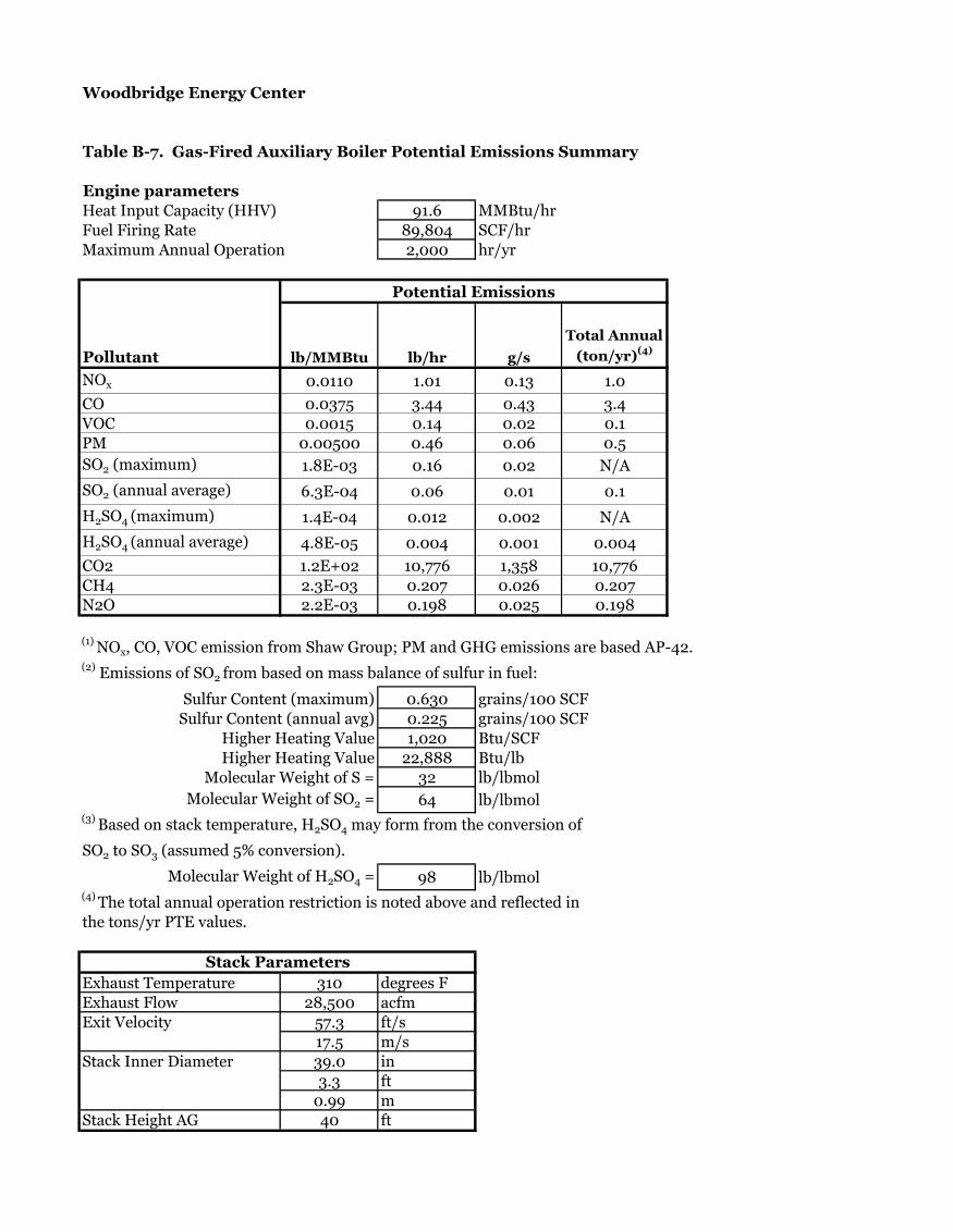
Woodbridge Energy Center
Table B-7. Gas-Fired Auxiliary Boiler Potential Emissions Summary
Engine parameters
Heat Input Capacity (HHV) 91.6 MMBtu/hr
Fuel Firing Rate 89,804 SCF/hr
Maximum Annual Operation 2,000 hr/yr
Pollutant lb/MMBtu lb/hr g/s
Total Annual
(ton/yr)(4)
NOx 0.0110 1.01 0.13 1.0
CO 0.0375 3.44 0.43 3.4
VOC 0.0015 0.14 0.02 0.1
PM 0.00500 0.46 0.06 0.5
SO2 (maximum) 1.8E-03 0.16 0.02 N/A
SO2 (annual average) 6.3E-04 0.06 0.01 0.1
H2SO4 (maximum) 1.4E-04 0.012 0.002 N/A
H2SO4 (annual average) 4.8E-05 0.004 0.001 0.004
CO2 1.2E+02 10,776 1,358 10,776
CH4 2.3E-03 0.207 0.026 0.207
N2O 2.2E-03 0.198 0.025 0.198
(1) NOx, CO, VOC emission from Shaw Group; PM and GHG emissions are based AP-42.
(2) Emissions of SO2 from based on mass balance of sulfur in fuel:
Sulfur Content (maximum) 0.630 grains/100 SCF
Sulfur Content (annual avg) 0.225 grains/100 SCF
Higher Heating Value 1,020 Btu/SCF
Higher Heating Value 22,888 Btu/lb
Molecular Weight of S = 32 lb/lbmol
Molecular Weight of SO2 = 64 lb/lbmol(3)
Based on stack temperature, H2SO4 may form from the conversion of
SO2 to SO3 (assumed 5% conversion).
Molecular Weight of H2SO4 = 98 lb/lbmol(4)
The total annual operation restriction is noted above and reflected in
the tons/yr PTE values.
Stack Parameters
Exhaust Temperature 310 degrees F
Exhaust Flow 28,500 acfm
Exit Velocity 57.3 ft/s
17.5 m/s
Stack Inner Diameter 39.0 in
3.3 ft
0.99 m
Stack Height AG 40 ft
Potential Emissions

Woodbridge Energy Center
Table B-8. Fire Water Pump Diesel Engine Potential Emissions Summary
Engine parameters
Power output base load 315 hp
Heat Input Capacity (HHV) 2.1 MMBtu/hr
Annual fuel usage 1527.3 gal/yr
Maximum Annual Operation 100 hr/yr
Pollutant g/bhp-hr(1)
lb/MMBtu lb/hr g/s
Total Annual
(ton/yr)(3)
NOx 2.77 0.9120 1.93 0.24 9.64E-02
CO (2)
3.03 0.9958 2.10 0.265 1.05E-01
VOC 0.23 0.0740 0.16 0.020 7.81E-03
PM 0.15 0.0493 0.10 0.013 5.21E-03
SO2(3)
0.005 0.0015 0.003 0.0004 1.63E-04
CO2 164 16400 9111 820
(1) NOx, VOC and PM emissions are based upon Tier 3 emission limits identified in NSPS Subpart IIII.
To determine individual limits for NOx and VOC, Tier 3 limit for NOX+HC was apportioned using
AP-42 emission factor ratios.(2)
CO and CO2 emissions based on AP-42 emission factors, Table 3.3-1.(3)
Emissions of SO2 from based on mass balance of sulfur in fuel:
Sulfur Content 15 ppm by weight
Higher Heating Value 19,485 Btu/lb
138,344 Btu/gal
Molecular Weight of S = 32 lb/lbmol
Molecular Weight of SO2 = 64 lb/lbmol(4)
Unit will operate only during emergency situations and for limited periods per week
for testing/maintenance purposes. Total annual operation due to testing/maintenance
is limited to 100 hours per year.(5)
Stack exhaust parameters based on vendor data.
Stack Parameters
Exhaust Temperature 961 degrees F
Exhaust Flow 1,400 acfm
Exit Velocity 171.1 ft/s
52.2 m/s
Stack Inner Diameter 5.0 in
0.4 ft
0.13 m
Stack Height AG 20 ft
Conversion Factors
g/lb 453.6
lb/ton 2,000
Potential Emissions

Woodbridge Energy Center
Table B-9. Emergency Diesel Generator Potential Emissions Summary
Engine parameters
Power output base load 1,500 kW
2010 hp
Heat Input Capacity (HHV) 13.5 MMBtu/hr
9745.9 gal/yr
Displacement per Cylinder <10 Liters
Maximum Annual Operation 100 hr/yr
Pollutant g/bhp-hr lb/MMBtu lb/hr g/s
Total Annual
(ton/yr)
NOx 4.97 1.6334 22.02 2.77 1.10
CO 0.45 0.1479 1.99 0.25 9.97E-02
VOC 0.11 0.0362 0.49 0.06 2.44E-02
PM 0.030 0.0099 0.13 0.02 6.65E-03SO2 0.0015 0.0208 0.0026 1.04E-03
CO2 164.0 2,211.19 278.61 110.56
(1) NOx, CO, VOC and PM emissions are based on vendor data.
CO2 emissions from AP-42 emission factor, Table 3.3-1(2)
Emissions of SO2 from based on mass balance of sulfur in fuel:
Sulfur Content 15 ppm by weight
Higher Heating Value 19,485 Btu/lb
138,344 Btu/gal
Molecular Weight of S = 32 lb/lbmol
Molecular Weight of SO2 = 64 lb/lbmol(3)
Unit will operate only during emergency situations and for limited periods per week
for testing purposes. The total annual operation restriction is noted above and reflected in
the tons/yr PTE values.
Stack Parameters
Exhaust Temperature 763.5 degrees F
Exhaust Flow 11,060.6 acfm
Exit Velocity 528.1 ft/s
161.0 m/s
Stack Inner Diameter 8.0 in
0.7 ft
0.20 m
Stack Height AG 20 ft
Conversion Factors
g/lb 453.6
lb/ton 2,000
Potential Emissions

Woodbridge Energy Center
Table B-10. Mechanical Draft Cooling Tower Potential Emissions Summary
Emissions Parameter
Number of Cells 14
Maximum Total Air Flow Rate (acfm) (Each Cell) 1,341,000
Maximum Water Flow Rate (gpm) (Total Tower) 178,000
Maximum Drift Rate 0.0005%
Total Solids in Circulating Water (ppm) 6,240
14-cell Total TSP Emission Rate (lb/hr) (Total Tower)
(1)2.78
1-Cell TSP Emission Rate (g/s) 0.025
14-cell Total PM-10 Emission Rate (lb/hr) (Total Tower)
(1)1.806
1-Cell PM-10 Emission Rate (g/s) 0.016
14-cell Total PM-2.5 Emission Rate (lb/hr) (Total Tower)
(1)0.667
1-Cell PM-2.5 Emission Rate (g/s) 0.006
14-cell Total TSP Annual Emission Rate (ton/yr) (Total Tower) (2)
12.17
14-cell Total PM-10 Annual Emission Rate (ton/yr) (Total Tower) (2)
7.91
14-cell Total PM-2.5 Annual Emission Rate (ton/yr) (Total Tower) (2)
2.92
Exhaust Parameter
Exhaust Height (ft above grade) 55
Exhaust Height (m above grade) 16.76
Collar Height (ft above grade) 39.43
Collar Height (m above grade) 12.02
Exhaust Temperature (oF) 85
Exhaust Velocity (ft/sec) 31.62
Exhaust Velocity (m/sec) 9.64
Inner Diameter (ft) 30
Inner Diameter (m) 9.14
(1) Hourly TSP emissions calculated as follows:
TSP (lb/hr) = Flow(gpm) * Drift Rate(%) * Solids Conc(ppm)/106
* 60(min/hr) * 8.34 (lb/gal)
PM-10 emissions based on PM-10/TSP ratio from vendor of 0.65
PM-2.5 emissions based on PM-2.5/TSP ratio from vendor of 0.24(2)
Annual emissions are based on 8,760 hours of operation.

Woodbridge Energy Center
Table B-11. Gas-Fired Dew Point Heater(s) Potential Emissions Summary
Engine parameters
Total Heat Input Capacity (HHV) 9.5 MMBtu/hr
Number of heaters 1.0
Fuel Firing Rate 9,314 SCF/hr
Maximum Annual Operation 8,760 hr/yr
Pollutant(1),(2),(3)
lb/MMBtu lb/hr g/s
Total Annual
(ton/yr)
NOx 0.0350 0.33 4.19E-02 1.46
CO 0.0500 0.48 5.99E-02 2.08
VOC 0.0050 0.05 5.99E-03 0.21
PM 0.00745 0.07 8.92E-03 0.31
SO2 (maximum) 1.8E-03 0.02 2.11E-03 N/A
SO2 (annual average) 6.3E-04 0.01 7.54E-04 0.03
H2SO4 (maximum) 1.4E-04 0.001 1.62E-04 N/A
H2SO4 (annual average) 4.8E-05 0.0005 5.78E-05 0.0020
CO2 1.2E+02 1,118 141 4,895
CH4 2.3E-03 0.0214 2.70E-03 0.0938N2O 2.2E-03 0.0205 2.58E-03 0.0897
(1) NOx, CO, and VOC emissions from Shaw Group. PM emissions are based upon U.S. EPA AP-42 Emission
Factor Guidance Document, Section 1.4(2)
Emissions of SO2 from based on mass balance of sulfur in fuel:
Sulfur Content (maximum) 0.630 grains/100 SCF
Sulfur Content (annual avg) 0.225 grains/100 SCF
Higher Heating Value 1,020 Btu/SCF
Higher Heating Value 22,888 Btu/lb
Molecular Weight of S = 32 lb/lbmol
Molecular Weight of SO2 = 64 lb/lbmol(3)
Based on stack temperature, H2SO4 may form from the conversion of
SO2 to SO3 (assumed 5% conversion).
Molecular Weight of H2SO4 = 98 lb/lbmol
Stack Parameters
Exhaust Temperature 690 degrees F
Exit Velocity 50.1 ft/s
15.3 m/s
Stack Inner Diameter 16.0 in
1.3 ft
0.41 mStack Height AG 26.0 ft
Conversion Factors
g/lb 453.6lb/ton 2,000
Potential Emissions

Woodbridge Energy Center
Table B-12. Potential HAP Emissions Summary
Heat Input Operation Number Fuel Properties:
Equipment Parameters: (mmBtu/hr) (hrs/year) of Units Natural Gas Heat Content 1,020 Btu/scf
Combustion Turbine - Gas (max) 2,307 8,760 2 Natural Gas Sulfur Content - Annual Avg 0.23 gr/100scf
Duct Burner 500 1,250 2 Distillate Oil Density 7.1 lb/gal
Auxiliary Boiler 91.6 2,000 1 Distillate Oil Sulfur Content 0.0015% weight %
Emergency Diesel Generator 13.5 100 1
Diesel Fire Pump 2.1 100 1
Gas Heater 9.5 8760 1
New Combustion Turbines Duct Burners Auxiliary Boiler Emer. Generator Fire Water Pump Dew Point Heater
Natural Gas Firing Natural Gas Firing Fuel Oil Firing Fuel Oil Firing Natural Gas Firing Total
EF Max Hourly EF Max Hourly EF Max EF Max EF Max EF Max Facility
Basis (1) Per CT Basis (2) Per DB Basis (2) Hourly Basis (3) Hourly Basis (3) Hourly Basis (2) Hourly PTE
Hazardous Air Pollutants (HAPs) lb/MMBtu lb/hr lb/MMCF lb/hr lb/MMCF lb/hr lb/MMBtu lb/hr lb/MMBtu lb/hr lb/MMCF lb/hr tons/yr
VOC-HAP
Acetaldehyde 4.00E-05 9.23E-02 7.67E-04 1.03E-02 7.67E-04 1.62E-03 8.1E-01
Acrolein 6.40E-06 1.48E-02 9.25E-05 1.25E-03 9.25E-05 1.95E-04 1.3E-01
Benzene 1.20E-05 2.77E-02 2.10E-03 1.03E-03 2.10E-03 1.89E-04 9.33E-04 1.26E-02 9.33E-04 1.97E-03 2.10E-03 1.96E-05 2.4E-01
1,3-Butadiene 4.30E-07 9.92E-04 8.7E-03
Dichlorobenzene 1.20E-03 5.88E-04 1.20E-03 1.08E-04 1.20E-03 1.12E-05 8.9E-04
Ethylbenzene 3.20E-05 7.38E-02 6.5E-01
Formaldehyde (see note #1) 1.30E-04 3.00E-01 7.50E-02 3.68E-02 7.50E-02 6.74E-03 1.18E-03 1.59E-02 1.18E-03 2.49E-03 7.50E-02 6.99E-04 2.7E+00
Hexane 1.80E+00 8.82E-01 1.80E+00 1.62E-01 1.80E+00 1.68E-02 1.3E+00
Naphthalene 1.30E-06 3.00E-03 6.10E-04 2.99E-04 6.10E-04 5.48E-05 8.48E-05 1.14E-03 8.48E-05 1.79E-04 6.10E-04 5.68E-06 2.7E-02
Propylene Oxide 2.90E-05 6.69E-02 5.9E-01
Toluene 1.30E-04 3.00E-01 3.40E-03 1.67E-03 3.40E-03 3.05E-04 4.09E-04 5.51E-03 4.09E-04 8.64E-04 3.40E-03 3.17E-05 2.6E+00
Xylenes 6.40E-05 1.48E-01 2.85E-04 3.84E-03 2.85E-04 6.02E-04 1.3E+00
Polycyclic Organic Compounds (POM)
Acenaphthene 8.50E-08 1.96E-04 1.80E-06 8.82E-07 1.80E-06 1.62E-07 1.42E-06 1.91E-05 1.42E-06 3.00E-06 1.80E-06 1.68E-08 1.7E-03
Acenaphthylene 8.53E-08 1.97E-04 1.80E-06 8.82E-07 1.80E-06 1.62E-07 5.06E-06 6.82E-05 5.06E-06 1.07E-05 1.80E-06 1.68E-08 1.7E-03
Anthracene 1.14E-07 2.63E-04 2.40E-06 1.18E-06 2.40E-06 2.16E-07 1.87E-06 2.52E-05 1.87E-06 3.95E-06 2.40E-06 2.24E-08 2.3E-03
Benz(a)anthracene 8.53E-08 1.97E-04 1.80E-06 8.82E-07 1.80E-06 1.62E-07 1.68E-06 2.27E-05 1.68E-06 3.55E-06 1.80E-06 1.68E-08 1.7E-03
Benzo(a)pyrene 5.69E-08 1.31E-04 1.20E-06 5.88E-07 1.20E-06 1.08E-07 1.88E-07 2.53E-06 1.88E-07 3.97E-07 1.20E-06 1.12E-08 1.2E-03
Benzo(b)fluoranthene 8.53E-08 1.97E-04 1.80E-06 8.82E-07 1.80E-06 1.62E-07 9.91E-08 1.34E-06 9.91E-08 2.09E-07 1.80E-06 1.68E-08 1.7E-03
Benzo(g,h,i)perylene 5.69E-08 1.31E-04 1.20E-06 5.88E-07 1.20E-06 1.08E-07 4.89E-07 6.59E-06 4.89E-07 1.03E-06 1.20E-06 1.12E-08 1.2E-03
Benzo(k)fluoranthene 8.53E-08 1.97E-04 1.80E-06 8.82E-07 1.80E-06 1.62E-07 1.55E-07 2.09E-06 1.55E-07 3.28E-07 1.80E-06 1.68E-08 1.7E-03
Chrysene 8.53E-08 1.97E-04 1.80E-06 8.82E-07 1.80E-06 1.62E-07 3.53E-07 4.76E-06 3.53E-07 7.46E-07 1.80E-06 1.68E-08 1.7E-03
Dibenzo(a,h)anthracene 5.69E-08 1.31E-04 1.20E-06 5.88E-07 1.20E-06 1.08E-07 5.83E-07 7.86E-06 5.83E-07 1.23E-06 1.20E-06 1.12E-08 1.2E-03
7,12-Dimethylbenz(a)anthracene 1.60E-05 7.84E-06 1.60E-05 1.44E-06 1.60E-05 1.49E-07 1.2E-05
Fluoranthene 1.42E-07 3.28E-04 3.00E-06 1.47E-06 3.00E-06 2.69E-07 7.61E-06 1.03E-04 7.61E-06 1.61E-05 3.00E-06 2.79E-08 2.9E-03
Fluorene 1.33E-07 3.07E-04 2.80E-06 1.37E-06 2.80E-06 2.51E-07 2.92E-05 3.94E-04 2.92E-05 6.17E-05 2.80E-06 2.61E-08 2.7E-03
3-Methylchloranthrene 1.80E-06 8.82E-07 1.80E-06 1.62E-07 1.80E-06 1.68E-08 1.3E-06
2-Methylnaphthalene 2.40E-05 1.18E-05 2.40E-05 2.16E-06 2.40E-05 2.24E-07 1.8E-05
Indeno(1,2,3-cd)pyrene 8.53E-08 1.97E-04 1.80E-06 8.82E-07 1.80E-06 1.62E-07 3.75E-07 5.06E-06 3.75E-07 7.92E-07 1.80E-06 1.68E-08 1.7E-03
Phenanthrene 8.06E-07 1.86E-03 1.70E-05 8.33E-06 1.70E-05 1.53E-06 2.94E-05 3.96E-04 2.94E-05 6.21E-05 1.70E-05 1.58E-07 1.6E-02
Pyrene 2.37E-07 5.47E-04 5.00E-06 2.45E-06 5.00E-06 4.49E-07 4.78E-06 6.44E-05 4.78E-06 1.01E-05 5.00E-06 4.66E-08 4.8E-03
Total POM 2.2E-06 5.1E-03 8.82E-05 4.32E-05 8.82E-05 7.92E-06 8.33E-05 1.12E-03 8.33E-05 1.76E-04 8.82E-05 8.21E-07 4.46E-02
Metal-HAPs
Arsenic 1.96E-07 4.52E-04 2.00E-04 9.80E-05 2.00E-04 1.80E-05 1.10E-05 1.48E-04 1.10E-05 2.32E-05 2.00E-04 1.86E-06 4.1E-03
Beryllium 1.18E-08 2.71E-05 1.20E-05 5.88E-06 1.20E-05 1.08E-06 3.10E-07 4.18E-06 3.10E-07 6.55E-07 1.20E-05 1.12E-07 2.5E-04
Cadmium 1.08E-06 2.49E-03 1.10E-03 5.39E-04 1.10E-03 9.88E-05 4.80E-06 6.47E-05 4.80E-06 1.01E-05 1.10E-03 1.02E-05 2.3E-02
Chromium 1.37E-06 3.17E-03 1.40E-03 6.86E-04 1.40E-03 1.26E-04 1.10E-05 1.48E-04 1.10E-05 2.32E-05 1.40E-03 1.30E-05 2.9E-02
Lead 4.90E-07 1.13E-03 5.00E-04 2.45E-04 5.00E-04 4.49E-05 1.40E-05 1.89E-04 1.40E-05 2.96E-05 5.00E-04 4.66E-06 1.0E-02
Manganese 3.73E-07 8.59E-04 3.80E-04 1.86E-04 3.80E-04 3.41E-05 7.90E-04 1.07E-02 7.90E-04 1.67E-03 3.80E-04 3.54E-06 8.4E-03
Mercury 2.55E-07 5.88E-04 2.60E-04 1.27E-04 2.60E-04 2.33E-05 1.20E-06 1.62E-05 1.20E-06 2.54E-06 2.60E-04 2.42E-06 5.3E-03
Nickel 2.06E-06 4.75E-03 2.10E-03 1.03E-03 2.10E-03 1.89E-04 4.60E-06 6.20E-05 4.60E-06 9.72E-06 2.10E-03 1.96E-05 4.3E-02
Selenium 2.35E-08 5.43E-05 2.40E-05 1.18E-05 2.40E-05 2.16E-06 2.50E-05 3.37E-04 2.50E-05 5.28E-05 2.40E-05 2.24E-07 5.1E-04
Total HAPs 1.05E+00 9.26E-01 1.70E-01 6.33E-02 9.92E-03 1.76E-02 1.06E+01
Maximum Individual HAP: 2.7
Total Project HAPs: 10.6
Notes:
Emission Factor References -
(1) U.S. EPA AP-42 Emission Factor Guidance Document, Section 3.1 (Stationary Gas Turbines), Table 3.1-3. Note metal HAPs assumed to be equivalent to natural gas firing of external combustion sources (see Ref #3).
Natural gas formaldehyde emission factor from GE formaldehyde emissions test results for GE 7FA dated August 1, 2001.
(2) U.S. EPA AP-42 Emission Factor Guidance Document, Section 1.4 (Natural Gas Combustion), Tables 1.4-2, 1.4-3, and 1.4-4.
(3) U.S. EPA AP-42 Emission Factor Guidance Document, Section 3.3 (Diesel Industrial Engines), Table 3.3-2. Note metal HAPs assumed to be equivalent to distillate fuel oil firing of combustion turbines (see Ref #2).
Natural Gas Firing

Appendix C
RACT/BACT/LAER Clearinghouse Search Results
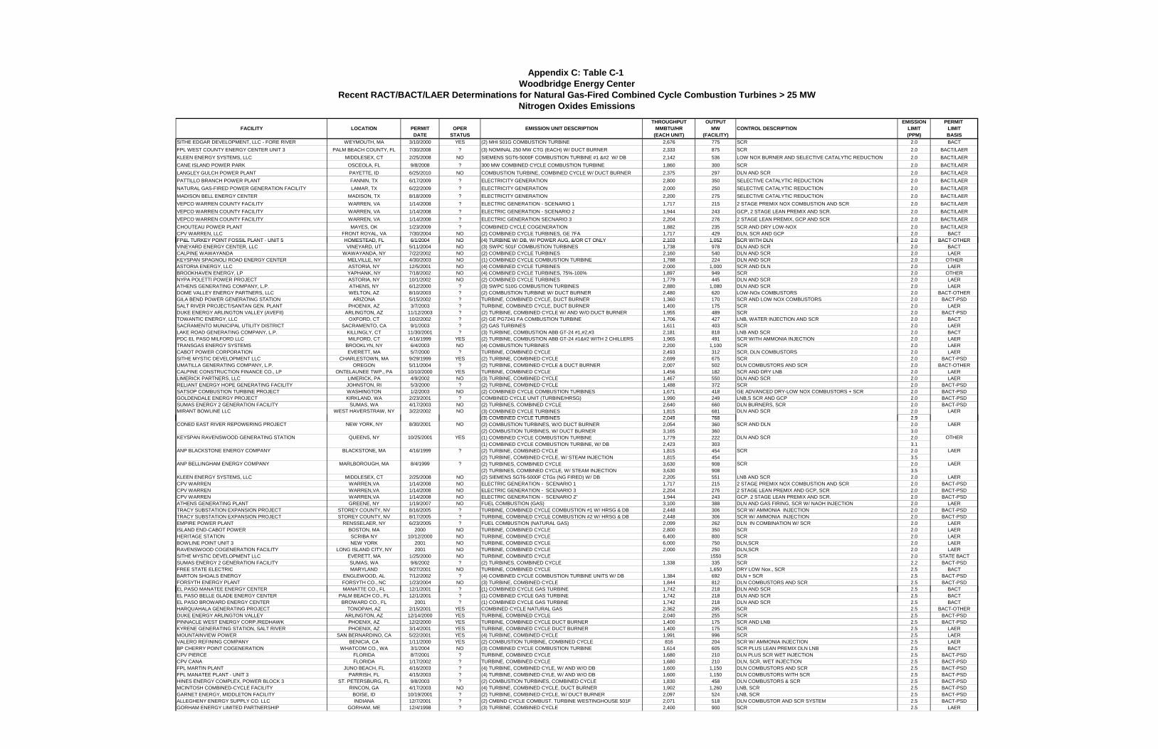
THROUGHPUT OUTPUT EMISSION PERMIT FACILITY LOCATION PERMIT OPER EMISSION UNIT DESCRIPTION MMBTU/HR MW CONTROL DESCRIPTION LIMIT LIMIT
DATE STATUS (EACH UNIT) (FACILITY) (PPM) BASISSITHE EDGAR DEVELOPMENT, LLC - FORE RIVER WEYMOUTH, MA 3/10/2000 YES (2) MHI 501G COMBUSTION TURBINE 2,676 775 SCR 2.0 BACTFPL WEST COUNTY ENERGY CENTER UNIT 3 PALM BEACH COUNTY, FL 7/30/2008 ? (3) NOMINAL 250 MW CTG (EACH) W/ DUCT BURNER 2,333 875 SCR 2.0 BACT/LAERKLEEN ENERGY SYSTEMS, LLC MIDDLESEX, CT 2/25/2008 NO SIEMENS SGT6-5000F COMBUSTION TURBINE #1  W/ DB 2,142 536 LOW NOX BURNER AND SELECTIVE CATALYTIC REDUCTION 2.0 BACT/LAERCANE ISLAND POWER PARK OSCEOLA, FL 9/8/2008 ? 300 MW COMBINED CYCLE COMBUSTION TURBINE 1,860 300 SCR 2.0 BACT/LAERLANGLEY GULCH POWER PLANT PAYETTE, ID 6/25/2010 NO COMBUSTION TURBINE, COMBINED CYCLE W/ DUCT BURNER 2,375 297 DLN AND SCR 2.0 BACT/LAERPATTILLO BRANCH POWER PLANT FANNIN, TX 6/17/2009 ? ELECTRICITY GENERATION 2,800 350 SELECTIVE CATALYTIC REDUCTION 2.0 BACT/LAERNATURAL GAS-FIRED POWER GENERATION FACILITY LAMAR, TX 6/22/2009 ? ELECTRICITY GENERATION 2,000 250 SELECTIVE CATALYTIC REDUCTION 2.0 BACT/LAERMADISON BELL ENERGY CENTER MADISON, TX 8/18/2009 ? ELECTRICITY GENERATION 2,200 275 SELECTIVE CATALYTIC REDUCTION 2.0 BACT/LAERVEPCO WARREN COUNTY FACILITY WARREN, VA 1/14/2008 ? ELECTRIC GENERATION - SCENARIO 1 1,717 215 2 STAGE PREMIX NOX COMBUSTION AND SCR 2.0 BACT/LAERVEPCO WARREN COUNTY FACILITY WARREN, VA 1/14/2008 ? ELECTRIC GENERATION - SCENARIO 2 1,944 243 GCP, 2 STAGE LEAN PREMIX AND SCR. 2.0 BACT/LAERVEPCO WARREN COUNTY FACILITY WARREN, VA 1/14/2008 ? ELECTRIC GENERATION SECNARIO 3 2,204 276 2 STAGE LEAN PREMIX, GCP AND SCR 2.0 BACT/LAERCHOUTEAU POWER PLANT MAYES, OK 1/23/2009 ? COMBINED CYCLE COGENERATION 1,882 235 SCR AND DRY LOW-NOX 2.0 BACT/LAERCPV WARREN, LLC FRONT ROYAL, VA 7/30/2004 NO (2) COMBINED CYCLE TURBINES, GE 7FA 1,717 429 DLN, SCR AND GCP 2.0 BACTFP&L TURKEY POINT FOSSIL PLANT - UNIT 5 HOMESTEAD, FL 6/1/2004 NO (4) TURBINE W/ DB, W/ POWER AUG, &/OR CT ONLY 2,103 1,052 SCR WITH DLN 2.0 BACT-OTHER
Appendix C: Table C-1 Woodbridge Energy Center
Recent RACT/BACT/LAER Determinations for Natural Gas-Fired Combined Cycle Combustion Turbines > 25 MWNitrogen Oxides Emissions
FP&L TURKEY POINT FOSSIL PLANT UNIT 5 HOMESTEAD, FL 6/1/2004 NO (4) TURBINE W/ DB, W/ POWER AUG, &/OR CT ONLY 2,103 1,052 SCR WITH DLN 2.0 BACT OTHERVINEYARD ENERGY CENTER, LLC VINEYARD, UT 5/11/2004 NO (3) SWPC 501F COMBUSTION TURBINES 1,738 978 DLN AND SCR 2.0 BACTCALPINE WAWAYANDA WAWAYANDA, NY 7/22/2002 NO (2) COMBINED CYCLE TURBINES 2,160 540 DLN AND SCR 2.0 LAERKEYSPAN SPAGNOLI ROAD ENERGY CENTER MELVILLE, NY 4/30/2003 NO (1) COMBINED CYCLE COMBUSTION TURBINE 1,788 224 DLN AND SCR 2.0 OTHERASTORIA ENERGY, LLC ASTORIA, NY 12/5/2001 NO (4) COMBINED CYCLE TURBINES 2,000 1,000 SCR AND DLN 2.0 LAERBROOKHAVEN ENERGY, LP YAPHANK, NY 7/18/2002 NO (4) COMBINED CYCLE TURBINES, 75%-100% 1,897 949 SCR 2.0 OTHERNYPA POLETTI POWER PROJECT ASTORIA, NY 10/1/2002 NO (2) COMBINED CYCLE TURBINES 1,779 445 DLN AND SCR 2.0 LAERATHENS GENERATING COMPANY, L.P. ATHENS, NY 6/12/2000 ? (3) SWPC 510G COMBUSTION TURBINES 2,880 1,080 DLN AND SCR 2.0 LAERDOME VALLEY ENERGY PARTNERS, LLC WELTON, AZ 8/10/2003 ? (2) COMBUSTION TURBINE W/ DUCT BURNER 2,480 620 LOW-NOx COMBUSTORS 2.0 BACT-OTHERGILA BEND POWER GENERATING STATION ARIZONA 5/15/2002 ? TURBINE, COMBINED CYCLE, DUCT BURNER 1,360 170 SCR AND LOW NOX COMBUSTORS 2.0 BACT-PSDSALT RIVER PROJECT/SANTAN GEN. PLANT PHOENIX, AZ 3/7/2003 ? TURBINE, COMBINED CYCLE, DUCT BURNER 1,400 175 SCR 2.0 LAERDUKE ENERGY ARLINGTON VALLEY (AVEFII) ARLINGTON, AZ 11/12/2003 ? (2) TURBINE, COMBINED CYCLE W/ AND W/O DUCT BURNER 1,955 489 SCR 2.0 BACT-PSDTOWANTIC ENERGY, LLC OXFORD, CT 10/2/2002 ? (2) GE PG7241 FA COMBUSTION TURBINE 1,706 427 LNB, WATER INJECTION AND SCR 2.0 BACTSACRAMENTO MUNICIPAL UTILITY DISTRICT SACRAMENTO, CA 9/1/2003 ? (2) GAS TURBINES 1,611 403 SCR 2.0 LAERLAKE ROAD GENERATING COMPANY, L.P. KILLINGLY, CT 11/30/2001 ? (3) TURBINE, COMBUSTION ABB GT-24 #1,#2,#3 2,181 818 LNB AND SCR 2.0 BACTPDC EL PASO MILFORD LLC MILFORD, CT 4/16/1999 YES (2) TURBINE, COMBUSTION ABB GT-24 #1 WITH 2 CHILLERS 1,965 491 SCR WITH AMMONIA INJECTION 2.0 LAERTRANSGAS ENERGY SYSTEMS BROOKLYN, NY 6/4/2003 NO (4) COMBUSTION TURBINES 2,200 1,100 SCR 2.0 LAERCABOT POWER CORPORATION EVERETT, MA 5/7/2000 ? TURBINE, COMBINED CYCLE 2,493 312 SCR, DLN COMBUSTORS 2.0 LAERSITHE MYSTIC DEVELOPMENT LLC CHARLESTOWN, MA 9/29/1999 YES (2) TURBINE, COMBINED CYCLE 2,699 675 SCR 2.0 BACT-PSDUMATILLA GENERATING COMPANY, L.P. OREGON 5/11/2004 ? (2) TURBINE, COMBINED CYCLE & DUCT BURNER 2,007 502 DLN COMBUSTORS AND SCR 2.0 BACT-OTHERCALPINE CONSTRUCTION FINANCE CO., LP ONTELAUNEE TWP., PA 10/10/2000 YES TURBINE, COMBINED CYCLE 1,456 182 SCR AND DRY LNB 2.0 LAERLIMERICK PARTNERS, LLC LIMERICK, PA 4/9/2002 NO (3) TURBINE, COMBINED CYCLE 1,467 550 DLN AND SCR 2.0 LAERRELIANT ENERGY HOPE GENERATING FACILITY JOHNSTON, RI 5/3/2000 ? (2) TURBINE, COMBINED CYCLE 1,488 372 SCR 2.0 BACT-PSDSATSOP COMBUSTION TURBINE PROJECT WASHINGTON 1/2/2003 NO (2) COMBINED CYCLE COMBUSTION TURBINES 1,671 418 GE ADVANCED DRY-LOW NOX COMBUSTORS + SCR 2.0 BACT-PSDGOLDENDALE ENERGY PROJECT KIRKLAND, WA 2/23/2001 ? COMBINED CYCLE UNIT (TURBINE/HRSG) 1,990 249 LNB,S SCR AND GCP 2.0 BACT-PSDSUMAS ENERGY 2 GENERATION FACILITY SUMAS, WA 4/17/2003 NO (2) TURBINES, COMBINED CYCLE 2,640 660 DLN BURNERS, SCR 2.0 BACT-PSD
(3) COMBINED CYCLE TURBINES 1,815 681 2.0(3) COMBINED CYCLE TURBINES 2 049 768 2 9
LAERDLN AND SCRMIRANT BOWLINE LLC WEST HAVERSTRAW, NY 3/22/2002 NO(3) COMBINED CYCLE TURBINES 2,049 768 2.9(2) COMBUSTION TURBINES, W/O DUCT BURNER 2,054 360 2.0(2) COMBUSTION TURBINES, W/ DUCT BURNER 3,165 360 3.0(1) COMBINED CYCLE COMBUSTION TURBINE 1,779 222 2.0(1) COMBINED CYCLE COMBUSTION TURBINE, W/ DB 2,423 303 3.1(2) TURBINE, COMBINED CYCLE 1,815 454 2.0(2) TURBINE, COMBINED CYCLE, W/ STEAM INJECTION 1,815 454 3.5(2) TURBINES, COMBINED CYCLE 3,630 908 2.0(2) TURBINES, COMBINED CYCLE, W/ STEAM INJECTION 3,630 908 3.5
KLEEN ENERGY SYSTEMS, LLC MIDDLESEX, CT 2/25/2008 NO (2) SIEMENS SGT6-5000F CTGs (NG FIRED) W/ DB 2,205 551 LNB AND SCR 2.0 LAERCPV WARREN WARREN,VA 1/14/2008 NO ELECTRIC GENERATION - SCENARIO 1 1,717 215 2 STAGE PREMIX NOX COMBUSTION AND SCR 2.0 BACT-PSDCPV WARREN WARREN,VA 1/14/2008 NO ELECTRIC GENERATION - SCENARIO 3 2,204 276 2 STAGE LEAN PREMIX AND GCP, SCR 2.0 BACT-PSDCPV WARREN WARREN,VA 1/14/2008 NO ELECTRIC GENERATION - SCENARIO 2" 1,944 243 GCP. 2 STAGE LEAN PREMIX AND SCR. 2.0 BACT-PSDATHENS GENERATING PLANT GREENE, NY 1/19/2007 NO FUEL COMBUSTION (GAS) 3,100 388 DLN AND GAS FIRING, SCR W/ NAOH INJECTION 2.0 LAERTRACY SUBSTATION EXPANSION PROJECT STOREY COUNTY, NV 8/16/2005 ? TURBINE, COMBINED CYCLE COMBUSTION #1 W/ HRSG & DB 2,448 306 SCR W/ AMMONIA INJECTION 2.0 BACT-PSDTRACY SUBSTATION EXPANSION PROJECT STOREY COUNTY, NV 8/17/2005 ? TURBINE, COMBINED CYCLE COMBUSTION #2 W/ HRSG & DB 2,448 306 SCR W/ AMMONIA INJECTION 2.0 BACT-PSDEMPIRE POWER PLANT RENSSELAER, NY 6/23/2005 ? FUEL COMBUSTION (NATURAL GAS) 2,099 262 DLN IN COMBINATION W/ SCR 2.0 LAERISLAND END-CABOT POWER BOSTON, MA 2000 NO TURBINE, COMBINED CYCLE 2,800 350 SCR 2.0 LAERHERITAGE STATION SCRIBA NY 10/12/2000 NO TURBINE, COMBINED CYCLE 6,400 800 SCR 2.0 LAERBOWLINE POINT UNIT 3 NEW YORK 2001 NO TURBINE, COMBINED CYCLE 6,000 750 DLN,SCR 2.0 LAERRAVENSWOOD COGENERATION FACILITY LONG ISLAND CITY, NY 2001 NO TURBINE, COMBINED CYCLE 2,000 250 DLN,SCR 2.0 LAERSITHE MYSTIC DEVELOPMENT LLC EVERETT, MA 1/25/2000 NO TURBINE, COMBINED CYCLE 1550 SCR 2.0 STATE BACTSUMAS ENERGY 2 GENERATION FACILITY SUMAS, WA 9/6/2002 ? (2) TURBINES, COMBINED CYCLE 1,338 335 SCR 2.2 BACT-PSDFREE STATE ELECTRIC MARYLAND 9/27/2001 NO TURBINE, COMBINED CYCLE 1,650 DRY LOW Nox., SCR 2.5 BACTBARTON SHOALS ENERGY ENGLEWOOD, AL 7/12/2002 ? (4) COMBINED CYCLE COMBUSTION TURBINE UNITS W/ DB 1,384 692 DLN + SCR 2.5 BACT-PSDFORSYTH ENERGY PLANT FORSYTH CO., NC 1/23/2004 NO (3) TURBINE, COMBINED CYCLE 1,844 812 DLN COMBUSTORS AND SCR 2.5 BACT-PSDEL PASO MANATEE ENERGY CENTER MANATTE CO., FL 12/1/2001 ? (1) COMBINED CYCLE GAS TURBINE 1,742 218 DLN AND SCR 2.5 BACT
SCR?
LAER
OTHER
LAER
LAER
8/30/2001 NO SCR AND DLN
DLN AND SCR
SCRMARLBOROUGH, MA ?
ANP BLACKSTONE ENERGY COMPANY
8/4/1999
CONED EAST RIVER REPOWERING PROJECT NEW YORK, NY
4/16/1999
ANP BELLINGHAM ENERGY COMPANY
KEYSPAN RAVENSWOOD GENERATING STATION
BLACKSTONE, MA
QUEENS, NY YES10/25/2001
, ( ) ,EL PASO BELLE GLADE ENERGY CENTER PALM BEACH CO., FL 12/1/2001 ? (1) COMBINED CYCLE GAS TURBINE 1,742 218 DLN AND SCR 2.5 BACTEL PASO BROWARD ENERGY CENTER BROWARD CO., FL 2001 ? (1) COMBINED CYCLE GAS TURBINE 1,742 218 DLN AND SCR 2.5 BACTHARQUAHALA GENERATING PROJECT TONOPAH, AZ 2/15/2001 YES COMBINED CYCLE NATURAL GAS 2,362 295 SCR 2.5 BACT-OTHERDUKE ENERGY ARLINGTON VALLEY ARLINGTON, AZ 12/14/2000 YES TURBINE, COMBINED CYCLE 2,040 255 SCR 2.5 BACT-PSDPINNACLE WEST ENERGY CORP./REDHAWK PHOENIX, AZ 12/2/2000 YES TURBINE, COMBINED CYCLE DUCT BURNER 1,400 175 SCR AND LNB 2.5 BACT-PSDKYRENE GENERATING STATION, SALT RIVER PHOENIX, AZ 3/14/2001 YES TURBINE, COMBINED CYCLE DUCT BURNER 1,400 175 SCR 2.5 LAERMOUNTAINVIEW POWER SAN BERNARDINO, CA 5/22/2001 YES (4) TURBINE, COMBINED CYCLE 1,991 996 SCR 2.5 LAERVALERO REFINING COMPANY BENICIA, CA 1/11/2000 YES (2) COMBUSTION TURBINE, COMBINED CYCLE 816 204 SCR W/ AMMONIA INJECTION 2.5 LAERBP CHERRY POINT COGENERATION WHATCOM CO., WA 3/1/2004 NO (3) COMBINED CYCLE COMBUSTION TURBINE 1,614 605 SCR PLUS LEAN PREMIX DLN LNB 2.5 BACTCPV PIERCE FLORIDA 8/7/2001 ? TURBINE, COMBINED CYCLE 1,680 210 DLN PLUS SCR WET INJECTION 2.5 BACT-PSDCPV CANA FLORIDA 1/17/2002 ? TURBINE, COMBINED CYCLE 1,680 210 DLN, SCR, WET INJECTION 2.5 BACT-PSDFPL MARTIN PLANT JUNO BEACH, FL 4/16/2003 ? (4) TURBINE, COMBINED CYLE, W/ AND W/O DB 1,600 1,150 DLN COMBUSTORS AND SCR 2.5 BACT-PSDFPL MANATEE PLANT - UNIT 3 PARRISH, FL 4/15/2003 ? (4) TURBINE, COMBINED CYLE, W/ AND W/O DB 1,600 1,150 DLN COMBUSTORS WITH SCR 2.5 BACT-PSDHINES ENERGY COMPLEX, POWER BLOCK 3 ST. PETERSBURG, FL 9/8/2003 ? (2) COMBUSTION TURBINES, COMBINED CYCLE 1,830 458 DLN COMBUSTORS & SCR 2.5 BACT-PSDMCINTOSH COMBINED-CYCLE FACILITY RINCON, GA 4/17/2003 NO (4) TURBINE, COMBINED CYCLE, DUCT BURNER 1,902 1,260 LNB, SCR 2.5 BACT-PSDGARNET ENERGY, MIDDLETON FACILITY BOISE, ID 10/19/2001 ? (2) TURBINE, COMBINED CYCLE, W/ DUCT BURNER 2,097 524 LNB, SCR 2.5 BACT-PSDALLEGHENY ENERGY SUPPLY CO. LLC INDIANA 12/7/2001 ? (2) CMBND CYCLE COMBUST. TURBINE WESTINGHOUSE 501F 2,071 518 DLN COMBUSTOR AND SCR SYSTEM 2.5 BACT-PSDGORHAM ENERGY LIMITED PARTNERSHIP GORHAM, ME 12/4/1998 ? (3) TURBINE, COMBINED CYCLE 2,400 900 SCR 2.5 LAER

THROUGHPUT OUTPUT EMISSION PERMIT FACILITY LOCATION PERMIT OPER EMISSION UNIT DESCRIPTION MMBTU/HR MW CONTROL DESCRIPTION LIMIT LIMIT
DATE STATUS (EACH UNIT) (FACILITY) (PPM) BASIS
Appendix C: Table C-1 Woodbridge Energy Center
Recent RACT/BACT/LAER Determinations for Natural Gas-Fired Combined Cycle Combustion Turbines > 25 MWNitrogen Oxides Emissions
WESTBROOK POWER LLC WESTBROOK, ME 12/4/1998 ? (2) TURBINE, COMBINED CYCLE 2,112 528 SCR AND DLN BURNERS 2.5 LAERCAROLINA POWER & LIGHT - RICHMOND CO. RALEIGH, NC 12/21/2000 ? (2) TURBINES, COMBINED CYCLE 1,628 407 DLN COMBUSTORS AND SCR 2.5 BACT-PSDCP&L ROWAN CO TURBINE FACILITY RALEIGH, NC 3/14/2001 ? (2) TURBINE, COMBINED CYCLE 1,628 407 DLN COMBUSTORS AND SCR 2.5 BACT-PSDFAYETTEVILLE GENERATION, LLC SANFORD, NC 1/10/2002 ? (2) TURBINE, COMBINED CYCLE 1,384 346 DLN AND SCR 2.5 BACT-PSDGENPOWER EARLEYS, LLC NORTH CAROLINA 1/9/2002 ? (2) TURBINES, COMBINED CYCLE 1,715 429 DLN AND SCR 2.5 BACT-PSDMIRANT GASTONIA POWER FACILITY NORTH CAROLINA 5/28/2002 ? (4) TURBINES, COMBINED CYCLE W/ AND W/O DB (GE, MHI, SW) 1,400 700 DLN AND SCR 2.5 BACT-PSDAES LONDONDERRY, LLC LONDONDERRY, NH 4/26/1999 ? (2) SWPC 501G TURBINE, COMBINED CYCLE #1 & #2 2,849 712 LNB WITH SCR 2.5 BACT-PSDNEWINGTON ENERGY LLC NEWINGTON, NH 4/26/1999 NO (2) TURBINES, COMBINED CYCLE 1,280 525 LNB WITH SCR 2.5 BACT-PSDLIBERTY GENERATING STATION LINDEN CITY, NJ 3/28/2002 ? (3) COMBINED CYCLE TURBINE, W/ AND W/O DB 2,964 1,112 SCR - AMMONIA FLOW RATE AT 11.46 GAL/H 2.5 OTHERMANTUA CREEK GENERATING FACILITY NEW JERSEY 6/26/2001 ? (3) COMBUSTION TURBINE (60%-100% LOAD) W/ AND W/O DB 2,181 818 SCR - 29% AQUEOUS AMMONIA, DLN 2.5 OTHERPORT WESTWARD PLANT PORTLAND, OR 1/16/2002 ? (2) COMBUSTION TURBINES WITH DUCT BURNER 2,600 650 SCR, DLN COMBUSTION AND GCP 2.5 BACT-PSDCOB ENERGY FACILITY, LLC OREGON 12/30/2003 ? (4) TURBINE, COMBINED CYCLE DUCT BURNER 2,300 1,150 DLN COMBUSTORS, AND SCR 2.5 BACT-PSDKLAMATH GENERATION, LLC PORTLAND, OR 3/12/2003 NO (2) TURBINE, COMBINED CYCLE DUCT BURNER 1,920 480 DLN COMBUSTION, SCR 2.5 BACT-PSDCALPINE BERKS ONTELAUNEE POWER PLANT READING, PA 10/10/2000 ? (2) TURBINES, COMBINED CYCLE 2,176 544 SCR 2.5 LAERFAIRLESS ENERGY LLC GLEN ALLEN, PA 3/28/2002 ? (4) TURBINES, COMBINED CYCLE 2,380 1,190 SCR, DLN COMBUSTION 2.5 LAERCONECTIV BETHLEHEM INC PENNSYLVANIA 1/16/2002 ? (6) TURBINE COMBINED CYCLE 976 732 SCR DLN COMB CLEAN FUEL WI NG DIFFUSION MODE 2 5 LAERCONECTIV BETHLEHEM, INC. PENNSYLVANIA 1/16/2002 ? (6) TURBINE, COMBINED CYCLE 976 732 SCR, DLN COMB, CLEAN FUEL WI NG DIFFUSION MODE 2.5 LAERDUKE ENERGY FAYETTE, LLC MASONTOWN, PA 1/30/2002 ? (2) TURBINE, COMBINED CYCLE 2,240 560 LNB, SCR 2.5 LAERSPRINGDALE TOWNSHIP STATION GREENSBURG, PA 7/12/2001 YES TURBINE, COMBINED CYCLE 2,094 262 DLN BURNERS WITH SCR 2.5 BACT-PSDDEER PARK ENERGY CENTER HOUSTON, TX 8/22/2001 ? (4) CTG1-4 & HRSG1-4, ST-1 THRU -4 1,440 720 DLN & SCR 2.5 LAERMIRANT AIRSIDE INDUSTRIAL PARK VIRGINIA 12/6/2002 ? (2) TURBINE, COMBINED CYCLE 1,962 491 LEAN PRE-MIX DLN AND GCP. SCR SYSTEM AND CEM 2.5 BACT-PSDJAMES CITY ENERGY PARK VIRGINIA 12/1/2003 ? TURBINE, COMBINED CYCLE W/ AND W/O DUCT FIRING 2,325 291 DLN BURNERS SCR W/ CEM DEVICES 2.5 BACT-PSDDUKE ENERGY WYTHE, LLC VIRGINIA 2/5/2004 NO (2) TURBINE, COMBINED CYCLE, W/ AND W/O DUCT BURNER 2,470 618 SCR AND LNB. GCP 2.5 BACT-PSDLONGVIEW ENERGY DEVELOPMENT LONGVIEW, WA 9/4/2001 ? COMBUSTION TURBINE COMBINED CYCLE 2,320 290 SCR 2.5 BACT-OTHERWALLULA POWER PLANT WASHINGTON 1/3/2003 NO (4) TURBINE, COMBINED CYCLE NATURAL GAS 2,600 1,300 SCR 2.5 BACT-OTHERBLACK HILLS CORP./NEIL SIMPSON TWO GILLETTE, WY 4/4/2003 ? TURBINE, COMBINED CYCLE & DUCT BURNER 320 40 DLN BURNERS AND SCR 2.5 BACT-OTHER
TURBINE, COMBINED CYCLE 1,923 240 2.5TURBINE, COMBINED CYCLE, W/ DUCT BURNER 1,923 240 3.1(4) TURBINE, COMBINED CYCLE 100%LOAD, W/ DUCT FIRING 2,200 1,100 2.5(4) TURBINE, COMBINED CYCLE 70%LOAD, W/ DUCT FIRING 958 479 3.3(4) COMBUSTION TURBINE COMBINED CYCLE 2,010 1,005 2.5(4) COMBUSTION TURBINE COMBINED CYCLE, W/ STEAM INJ 2,010 1,005 3.5(2) TURBINE, COMBINED CYCLE 2,132 533 2.5(2) TURBINE, COMBINED CYCLE, 70% LOAD 1,492 373 4.5
HINES POWER BLOCK 4 POLK, FL 6/8/2005 ? COMBINED CYCLE TURBINE 4,240 530 SCR 2.5 BACT-PSDSEPCO RIO LINDA, CA 10/5/1994 ? TURBINE, GAS COMBINED CYCLE GE MODEL 7 920 115 SCR AND DLN COMBUSTION 2.6 BACTEMPIRE POWER PLANT RENSSELAER, NY 6/23/2005 ? FUEL COMBUSTION (NATURAL GAS) DUCT BURNING 646 263 DLN IN COMBINATION W/ SCR 3.0 LAERS.W.E.C, LLC FALLS TWP, PA 2001 NO COMBUSTION TURBINE 3.0 LAERSACRAMENTO POWER AUTHORITY CAMPBELL SOUP SACRAMENTO, CA 8/19/1994 YES TURBINE GAS, COMBINE CYCLE SIEMENS V84.2 1,257 157 SCR AND DRY LOW NOX COMBUSTION 3.0 BACTFAIRBAULT ENERGY PARK RICE CO., MN 7/15/2004 NO TURBINE, COMBINED CYCLE 1,876 469 SCR AND DLN 3.0 BACT-PSDPANDA GILA RIVER GILA BEND, AZ 2/23/2001 YES TURBINE, COMBINED CYCLE, DUCT BURNER 1,360 170 SCR 3.0 BACT-PSDSALT RIVER/DESERT BASIN GENERATING PROJECT PHOENIX, AZ 9/10/1999 YES TURBINE, COMBINED CYCLE 2,320 290 SCR 3.0 BACT-PSDSACRAMENTO COGENERATION AUTHORITY P&G SACRAMENTO, CA 8/19/1994 ? TURBINE, GAS COMBINED CYCLE LM6000 421 53 SCR AND WATER INJECTION 3.0 BACTSACRAMENTO POWER AUTHORITY CAMPBELL SOUP SACRAMENTO CA 8/19/1994 ? TURBINE GAS COMBINE CYCLE SIEMENS V84 2 1 257 157 SCR AND DLN COMBUSTION 3 0 BACT
BACT-PSD
BACT-PSD
BACT-PSD
SCR
THE USE OF DLN COMBUSTOR AND SCR
LNB AND GCP. SCR USING AMMONIA INJECTION. CEM
DLN COMBUSTION AND SCR W/CEM
BACT-PSD
VIRGINIA 11/21/2002
3/22/2001
9/20/2000
NO
?
SILVER SPRING, VA
ARLINGTON, AZ
HENRY COUNTY POWER
MESQUITE GENERATING STATION
CPV CUNNINGHAM CREEK
BADGER GENERATING CO LLC PLEASANT PRAIRIE, WI
?
9/6/2002
?
SACRAMENTO POWER AUTHORITY CAMPBELL SOUP SACRAMENTO, CA 8/19/1994 ? TURBINE GAS COMBINE CYCLE SIEMENS V84.2 1,257 157 SCR AND DLN COMBUSTION 3.0 BACTROCKY MOUNTAIN ENERGY CENTER, LLC. LITTLETON, CO 8/11/2002 YES (2) COMBINED-CYCLE TURBINE 2,311 578 LN COMB (POLLUTION PREVENTION) AND SCR (CONTROL) 3.0 BACT-PSDAUGUSTA ENERGY CENTER GEORGIA 10/28/2001 YES (3) TURBINE, COMBINED CYCLE 2,000 750 SCR 3.0 BACT-PSDEFFINGHAM COUNTY POWER, LLC GEORGIA 12/27/2001 ? (2) TURBINE, COMBINED CYCLE 1,480 370 LNB AND SCR 3.0 BACT-PSDMURRAY ENERGY FACILITY DALTON, GA 10/23/2002 ? (4) TURBINE, COMBINED CYCLE W/ DUCT BURNER 2,480 1,240 DLN BURNERS AND SCR 3.0 BACT-PSDWANSLEY COMBINED CYCLE ENERGY FACILITY ROOPVILLE, GA 1/15/2002 ? (2) TURBINE, COMBINED CYCLE 1,336 334 DLN COMBUSTORS SCR 3.0GREATER DES MOINES ENERGY CENTER PLEASANT HILL, IA 4/10/2002 YES (2) COMBUSTION TURBINES - COMBINED CYCLE 1,400 350 SCR WITH DLN COMBUSTION 3.0 BACT-PSDROQUETTE AMERICA KEOKUK, IA 1/31/2003 ? TURBINE, COMBINED CYCLE 587 73 SCR 3.0 BACT-PSDPSEG LAWRENCEBURG ENERGY FACILITY LAWRENCEBURG, IN 6/7/2001 YES (4) TURBINE, COMBINED CYCLE 477 238 SCR 3.0 BACT-PSDMIRANT SUGAR CREEK, LLC WEST TERRE HAUTE, IN 5/9/2001 YES TURBINE, COMBINED CYCLE 1,360 170 SCR 3.0 BACT-PSDWHITING CLEAN ENERGY, INC. WHITING, IN 7/20/2000 YES (2) TURBINES, COMBUSTION, W/ AND W/O DB 1,735 434 SCR (80-90%), DLN BURNERS AND GCP 3.0 BACT-PSDCOGENTRIX LAWRENCE CO., LLC INDIANA 10/5/2001 ? (3) TURBINES, COMBINED CYCLE, W/ AND W/O DB 1,944 729 DLN BURNERS AND GOOD COMBUSTION: SCR 3.0 BACT-PSDMIRANT SUGAR CREEK LLC WEST TERRE HAUTE, IN 7/24/2002 ? (4) TURBINE, COMBINED CYCLE, W/ AND W/O DB 1,491 745 DLN BURNERS AND SCR. NATURAL GAS IS ONLY FUEL 3.0 BACT-PSDKALKASKA GENERATING, INC RAPID RIVER TWP, MI 2/4/2003 YES (2) TURBINE, COMBINED CYCLE, WITH DUCT BURNER 2,420 605 SCR AND LNB 3.0 BACT-PSDSOUTH SHORE POWER LLC BRIDGEMAN, MI 1/30/2003 YES (2) TURBINE, COMBINED CYCLE WITH DUCT BURNER 1,883 471 DLN BURNERS AND SCR 3.0 BACT-PSDCONTINENTAL ENERGY SVC, SILVER BOW GEN BUTTE, MT 6/7/2002 NO (4) COMBINED CYCLE CT 1,400 700 SCR 3.0 BACT-PSDLAWRENCE ENERGY OHIO 9/24/2002 YES (3) TURBINES, COMBINED CYCLE DUCT BURNERS ON/OFF 1,440 540 DLN & LNB & SCR 3.0 BACT-PSDDUKE ENERGY HANGING ROCK ENERGY FACILITY OHIO 12/13/2001 YES (4) TURBINES COMBINED CYCLE DUCT BURNERS ON/OFF 1,376 688 DLN BURNERS AND SCR 3.0 BACT-PSDFAIRLESS WORKS ENERGY CTR (FMR. SWEC-FALLS TWP) GLEN ALLEN, PA 8/7/2001 YES TURBINE, COMBINED CYCLE 1,344 544 DLN BURNERS, SCR 3.0 LAERRELIANT ENERGY- CHANNELVIEW COGEN HOUSTON, TX 10/29/2001 NO (4) TURBINE/HRSG #1-#4 2,350 1,175 NONE INDICATED 3.0 BACTCEDAR BLUFF POWER PROJECT CEDAR BLUFF, TX 12/21/2000 NO (2) COMBUSTION TURBINES W/HRSG STACK1&2 2,640 660 SCR 3.0 LAERMONTGOMERY COUNTY POWER PROJECT TEXAS 6/27/2001 NO (2) CTG-HRSG STACKS STACK1 & 2 1,440 360 SCR SYSTEM UNIT 3.0 BACT-PSDTENASKA FLUVANNA VIRGINIA 1/11/2002 YES (3) TURBINES, COMBINED CYCLE 2,375 891 SCR, CEM 3.0 BACT-PSDTRANSALTA CENTRALIA GENERATION LLC CENTRALIA, WA 2/22/2002 ? (4)TURBINE/HRSG 1,504 752 WATER INJECTION AND SCR 3.0 BACT-PSDCHEHALIS GENERATION FACILITY WASHINGTON 6/18/1997 YES (2) COMBUSTION TURBINES 1,840 460 ADVANCED DLN TECHNOLOGY AND SCR 3.0 BACT-PSDMIRANT WYANDOTTE LLC WYANDOTTE, MI 7/25/2001 YES (2) GAS TURBINES COMBINED CYCLE 2,205 551 DLN STAGED COMB SCR MODE: W/ STEAM INJECTION 3.0 BACT-PSD
(2) TURBINE, COMBINED CYCLE 2,200 550 3.0 BACT-PSDDLN BURNERS AND SCR1/28/2003 YESWYANDOTTE, MIMIRANT WYANDOTTE LLC (2) TURBINE, COMBINED CYCLE 2,200 550 3.0(2) TURBINE, COMBINED CYCLE W/ DB, POWER AUG. 2,200 550 3.5TURBINES (3) COMBINED CYCLE PREMIXED MODE, BASELOAD 1,333 500 3.0TURBINES (3) COMBINED CYCLE PREMIXED MODE, PEAKLOAD 1,333 500 9.0TURBINES (3) COMBINED CYCLE NG DIFFUSION MODE 1,333 500 14.0
BERKSHIRE POWER DEVELOPMENT, INC. AGAWAM, MA 9/22/1997 ? TURBINE, COMBUSTION ABB GT24 1,792 224 DLN COMB WITH SCR ADD-ON NOX CONTROL 3.1 BACT-PSDEMERY GENERATING STATION MASON CITY, IA 12/20/2002 YES (2) TURBINE, COMBINED CYCLE 2,046 512 SCR & DLN 3.1 BACT-OTHERSOUTHERN ENERGY, INC. ZEELAND, MI 3/16/2000 NO COMBINED CYCLE TURBINE ELECTRICAL GENERATING UNITS 1000 SELECTIVE CATALYTIC REDUCTION (SCR) 3.5 BACT-PSDPIKE GENERATION FACILITY MCCOMB, MS 11/14/2000 NO COMBUSTION TURBINE DLN, SCR 3.5 BACT-PSDCPV GULFCOAST LTD MANATEE CO, FL 2/6/2001 NO COMBUSTION TURBINE SCR 3.5 BACT-PSDDIGHTON POWER ASSOCIATE, LP DIGHTON, MA 10/6/1997 ? TURBINE, COMBUSTION ABB GT11N2 1,327 166 DLN COMB WITH SCR ADD-ON NOX CONTROL 3.5 BACT-PSDBEATRICE POWER STATION GAGE CO., NE 6/22/2004 NO (2) COMBUSTION TURBINES W/ DUCT BURNER 1,000 250 NONE INDICATED 3.5 BACT-PSDGPC - GOAT ROCK COMBINED CYCLE PLANT SMITHS, AL 4/10/2000 YES (6) COMBINED CYCLE ELECTRIC GENERATING UNITS 1,384 1,038 DLN W/SCR 3.5 BACT-PSDTENASKA TALLADEGA GENERATING STATION ALABAMA 10/3/2001 ? (6) COMBINED CYCLE COMB. TURB. UNITS W/ DUCT FIRING 1,360 1,020 DLN COMBUSTION & SCR 3.5 BACT-PSDDUKE ENERGY DALE, LLC ALABAMA 12/11/2001 ? (2) GE 7FA COMB. CYCLE W/DB 1,928 482 DLN AND SCR 3.5 BACT-PSDDUKE ENERGY AUTAUGA, LLC ALABAMA 10/23/2001 ? (2) GE COM. CYCLE UNITS W/HRSG & 550 MMBTU/HR DB 2,407 602 SCR 3.5 BACT-PSDTENASKA ALABAMA II GENERATING STATION ALABAMA 2/16/2001 ? (3) COMBINED CYCLE COMBUSTION TURBINE UNITS 1,360 510 DLN COMBUSTORS + SCR 3.5 BACT-PSDTPS - DELL, LLC DELL, AR 8/8/2000 YES (2) TURBINE 2,560 640 SCR/DLN 3.5 BACT-PSD
BACT PSD
LAER
DLN BURNERS AND SCR
DLN BURNERS WITH SCRHAY ROAD POWER COMPLEX UNITS 5-8 10/17/2000
1/28/2003
YES
YESWYANDOTTE, MIMIRANT WYANDOTTE LLC
WILMINGTON, DE

THROUGHPUT OUTPUT EMISSION PERMIT FACILITY LOCATION PERMIT OPER EMISSION UNIT DESCRIPTION MMBTU/HR MW CONTROL DESCRIPTION LIMIT LIMIT
DATE STATUS (EACH UNIT) (FACILITY) (PPM) BASIS
Appendix C: Table C-1 Woodbridge Energy Center
Recent RACT/BACT/LAER Determinations for Natural Gas-Fired Combined Cycle Combustion Turbines > 25 MWNitrogen Oxides Emissions
PINE BLUFF ENERGY LLC PINE BLUFF, AR 2/27/2001 YES TURBINE, COMBINED CYCLE 1,360 170 DLN BURNERS AND SCR 3.5 BACT-PSDHOT SPRINGS POWER PROJECT ARKANSAS 11/9/2001 ? (2) COMBUSTION TURBINE, HRSG, DUCT BURNER 2,800 700 DLN BURNERS W/ SCR 3.5 BACT-PSDDUKE ENERGY-JACKSON FACILITY ARKANSAS 4/1/2002 NO (2) TURBINES, COMBINED CYCLE 1,360 340 SCR AND DLN COMBUSTORS 3.5 BACT-PSDTENASKA ARKANSAS PARTNERS, LP OMAHA, AR 10/9/2001 NO TURBINE, COMBINED CYCLE 1,480 185 SCR 3.5 BACT-PSDGENOVA ARKANSAS I, LLC ARKANSAS 8/23/2002 NO (2) TURBINE, COMBINED CYCLE (GE, SWH OR MHI) 1,360 340 DLN COMBUSTOR/SCR 3.5 BACT-PSDCANE ISLAND POWER PARK /KUA - UNIT 3 INTERCESSION CITY, FL 11/24/1999 ? TURBINE, COMBINED CYCLE, W/ AND W/O DB 1,696 212 DLN BURNERS 3.5 BACT-PSDCPV GULFCOAST POWER GENERATING STATION PINEY POINT, FL 2/5/2001 YES TURBINE, COMBINED CYCLE 1,700 213 DLN WET INJECTION 3.5 BACT-PSDHINES ENERGY COMPLEX, POWER BLOCK 2 ST. PETERSBURG, FL 6/4/2001 YES (2) TURBINES, COMBINED CYCLE 1,915 479 DLN COMBUSTORS & SCR 3.5 BACT-PSDCPV ATLANTIC POWER GENERATING FACILITY PORT ST. LUCIE, FL 5/3/2001 ? COMBINED CYCLE COMBUSTION TURBINE 1,700 213 SCR (DLN 2.6). WET INJECTION 3.5 BACT-PSDOUC STANTON ENERGY CENTER PENSACOLA, FL 9/21/2001 YES (2) TURBINE, COMBINED CYCLE 2,402 601 SCR 3.5 BACT-PSDJEA/BRANDY BRANCH JACKSONVILLE, FL 3/27/2002 YES (2) TURBINES, COMBINED CYCLE 1,911 478 DLN BURNERS 3.5 BACT-PSDFORT PIERCE REPOWERING FORT PIERCE, FL 8/15/2001 ? TURBINE, COMBINED CYCLE 1,440 180 GOOD COMBUSTION AND SCR 3.5 BACT-PSDMIDDLETON FACILITY BOISE, ID 10/19/2001 ? (2) GAS TURBINES WITH DUCT BURNERS 2,097 524 DUCT BURNER, SCR 3.5 BACT-PSDRUMFORD POWER ASSOCIATES RUMFORD, ME 5/1/1998 YES TURBINE GENERATOR COMBUSTION 1,906 238 SCR 3.5 BACT-PSDCASCO BAY ENERGY CO VEAZIE, ME 7/13/1998 ? (2) TURBINE, COMBINED CYCLE 1,360 340 SCR 3.5 BACT-PSDRENAISSANCE POWER LLC MICHIGAN 6/7/2001 ? (3) TURBINES STATIONARY GAS COMBINED CYCLE 1 360 510 DLN BURNERS AND SCR 3 5 BACT-PSDRENAISSANCE POWER LLC MICHIGAN 6/7/2001 ? (3) TURBINES, STATIONARY GAS COMBINED CYCLE 1,360 510 DLN BURNERS AND SCR 3.5 BACT-PSDMIDLAND COGENERATION MIDLAND, MI 7/26/2001 ? (2) GAS TURBINE COMBINED CYCLE, W/ AND W/O DB 2,096 524 DLN BURNER AND SCR 3.5 BACT-PSDINDECK-NILES, LLC NILES, MI 12/2/2001 ? (4) GAS TURBINES COMBINED CYCLE, W/ AND W/O DB 2,152 1,076 LNB AND SCR 3.5 BACT-PSDBERRIEN ENERGY, LLC BENTON HARBOR, MI 10/10/2002 ? (3) TURBINE, COMBINED CYCLE AND DUCT BURNER 2,300 863 DLN BURNERS STAGED COMB OF NATURAL GAS + SCR 3.5 BACT-PSDCALEDONIA POWER LLC CALEDONIA, MS 3/27/2001 ? ELECTRIC POWER GENERATION TURBINE & DUCT BURNER 1,700 213 DLN COMBUSTORS + SCR 3.5 BACT-PSDLSP- BATESVILLE GENERATION FACILITY MISSISSIPPI 11/13/2001 ? COMBINED CYCLE COMBUSTION TURBINE GENERATION 2,100 263 SCR 3.5 BACT-PSDEL PASO MERCHANT ENERGY CO. MISSISSIPPI 6/24/2002 ? (2) TURBINE, COMBINED CYCLE DUCT BURNER 2,062 516 LNB AND SCR UNIT 3.5 BACT-PSDCHOCTAW GAS GENERATION, LLC MISSISSIPPI 12/13/2001 ? (2) TURBINE, COMBINED CYCLE 2,737 684 DLN BURNERS AND SCR 3.5 BACT-PSDPIKE GENERATION FACILITY MISSISSIPPI 9/24/2002 NO (4) TURBINES, COMBINED CYCLE, WITH DUCT BURNER 2,168 1,084 DLN COMBUSTORS, SCR 3.5 BACT-PSDBEATRICE POWER STATION BEATRICE, NE 5/29/2003 NO (2) TURBINE, COMBINED CYCLE 640 160 LNB AND SCR 3.5 BACT-PSDCLOVIS ENERGY FACILITY NEW MEXICO 6/27/2002 ? (4) TURBINES, COMBINED CYCLE 1,515 758 SCR AND COMBUST ONLY PIPELINE QUALITY NATURAL GAS 3.5 BACT-PSDDUKE ENERGY WASHINGTON COUNTY LLC OHIO 1/18/2001 YES (2) TURBINE COMBINED CYCLE W/ AND W/O DUCT FIRING 1,360 340 DLN COMBUSTION BURNERS AND SCR 3.5 BACT-PSDPSEG WATERFORD ENERGY LLC COLUMBUS, OH 3/29/2001 YES (3) TURBINES, COMBINED CYCLE W/ AND W/O DUCT FIRING 1,360 510 DLN COMBUSTION BURNERS AND SCR 3.5 BACT-PSDJACKSON COUNTY POWER, LLC OHIO 12/27/2001 YES (4) COMBUSTION TURBINES COMBINED CYCLE, W/ DB 2,440 1,220 SCR WITH DLN COMBUSTION 3.5 BACT-PSDFREMONT ENERGY CENTER, LLC OHIO 8/9/2001 YES (2) COMBUSTION TURBINES COMB CYCLE W/ AND W/O DB 1,440 360 SCR AND DLN BURNERS 3.5 BACT-PSDDRESDEN ENERGY LLC OHIO 10/16/2001 YES (2) COMBUSTION TURBINE COMB. CYCLE W/ AND W/O DB 1,374 343 SCR AND DLN BURNERS 3.5 BACT-PSDGENOVA OK I POWER PROJECT OKLAHOMA 6/13/2002 ? COMBUSTION TURBINE & DUCT BURNERS (GE OR MHI) 1,705 213 SCR WITH DLN COMBUSTORS 3.5 BACT-PSDDUKE ENERGY STEPHENS, LLC STEPHENS ENERGY OKLAHOMA 12/10/2001 ? (2) TURBINES, COMBINED CYCLE 1,701 425 SCR, DLN COMBUSTORS 3.5 BACT-PSDREDBUD POWER PLANT LUTHER, OK 3/18/2002 ? (4) COMBUSTION TURBINE AND DUCT BURNERS 1,832 916 SCR WITH DLN BURNERS 3.5 BACT-PSDFPL ENERGY MARCUS HOOK, L.P. MARCUS HOOK, PA 5/4/2003 ? (3) TURBINE, COMBINED CYCLE, W/ AND W/O DB 1,798 674 DLN COMBUSTION TECHNOLOGY AND SCR 3.5 BACT-PSDLIBERTY ELECTRIC POWER , LLC PENNSYLVANIA 5/3/2000 ? (2) TURBINE, COMBINED CYCLE 2,000 500 DLN COMBUSTORS, SCR 3.5 LAERLOWER MOUNT BETHEL ENERGY, LLC FAIRFAX 10/20/2001 ? (2) TURBINE, COMBINED CYCLE 1,480 370 SCR, DLN LEAN BURN COMBUSTORS 3.5 LAERRELIANT ENERGY HUNTERSTOWN, LLC JOHNSTOWN, PA 6/15/2001 ? (3) COMBUSTION TURBINE COMBINED CYCLE 2,400 900 DLN LEAN BURNERS & SCR 3.5 LAERCOLUMBIA ENERGY LLC COLUMBIA, SC 4/9/2001 ? (2) TURBINES, COMBINED CYCLE 1,360 340 DLN BURNERS, SCR 3.5 BACT-PSDHAYWOOD ENERGY CENTER, LLC TENNESSEE 2/1/2002 ? TURBINE, COMBINED CYCLE W/ AND W/O DUCT FIRING 1,990 249 DLN BURNERS, SCR 3.5 BACT-PSDMEMPHIS GENERATION, LLC MEMPHIS, TN 4/9/2001 NO TURBINE, COMBINED CYCLE DUCT BURNER 1,698 212 SCR AND LNB 3.5 BACT-PSDELECTRIC GENERATING STATION HOUSTON, TX 8/31/2000 ? (8) ELECTRIC GENERATION TURBINES 2,000 2,000 SCR 3.5 LAERCHANNEL ENERGY FACILITY HOUSTON TX 3/22/2000 ? (3) TURBINE 1 440 540 SCR 3 5 LAERCHANNEL ENERGY FACILITY HOUSTON, TX 3/22/2000 ? (3) TURBINE 1,440 540 SCR 3.5 LAERCHAMBERS ENERGY L.P./AMERICAN NATIONAL POWER SAN ANTONIO, TX 3/6/2000 NO (8) ABB GT-24 COMBUSTION TURBINES 1,440 2,200 DLN COMBUSTORS AND SCR SYSTEM H2O INJECTION 3.5 LAERCHANNELVIEW COGENERATION FACILITY HOUSTON, TX 12/9/1999 YES (4) TURBINE COGENERATION FACILITY 1,600 800 DLN COMBUSTION AND SCR 3.5 LAERBAYTOWN COGENERATION PLANT TEXAS 2/11/2000 ? (3) TURBINE/HRSGS CTG1-3 2,000 750 SCR, DLN BURNERS 3.5 LAERHARRIS ENERGY FACILITY HOUSTON, TX 8/31/2000 NO (8) COMBUSTION GS TURBINE GENERATORS STACK 1,400 1,400 SCR 3.5 BACT-PSDBRAZOS VALLEY ELECTRIC GENERATING FACILITY RICHMOND, TX 12/31/2002 ? (4) HRSG/TURBINES 001,002,003,004 1,400 700 SCR 3.5 BACT-PSDCHOCOLATE BAYOU PLANT ALVIN, TX 3/24/2003 NO (2) COMBUSTION TURBINE W/ DUCT BURNER 280 70 DLN COMBUSTORS & SCR 3.5 BACT-OTHERVA POWER - POSSUM POINT GLENN ALLEN, VA 11/18/2002 YES TURBINE, COMBINED CYCLE, W/ AND W/O DUCT BURNER 1,937 242 WATER INJECTION SCR AND CEM 3.5 LAERMILLENNIUM POWER PARTNER, LP CHARLTON, MA 2/2/1998 ? TURBINE, COMBUSTION WESTINGHOUSE MODEL 501G 2,534 317 DLN COMBUSTION + SCR ADD-ON NOX CONTROLS 3.5 BACT-PSD
(2) COMBUSTION TURBINE COMBINED CYCLE & COGEN 1,900 475 3.5(2) COMBUSTION TURBINE COMBINED CYCLE & COGEN, W/ DB 1,900 475 3.7COMBUSTION TURBINE, 300 MW, W/O DUCT BURNER 2,400 300 3.5COMBUSTION TURBINE, 300 MW, W/ DUCT BURNER 2,400 300 4.4
GPC - GOAT ROCK COMBINED CYCLE PLANT SMITHS, AL 4/10/2000 YES (2) COMBINED CYCLE COMB.TURB. 1,384 346 DLN COMBUSTOR & SCR NOX CONTROL 3.6 BACT-PSDAEC - MCWILLIAMS PLANT GANTT, AL 3/3/2000 YES (2) TURBINES, COMBINED CYCLE COMBUSTION 1,328 332 CLEAN BURNERS AND SCR 3.6 BACT-PSDAUTAUGAVILLE COMBINED CYCLE PLANT PRATTVILLE, AL 1/8/2001 ? (4) COMBUSTION TURBINES COMBINED CYCLE 1,384 692 DLN BURNERS AND SCR 3.6 BACT-PSDDECATUR ENERGY CENTER DECATUR, AL 6/6/2000 YES (3) TURBINES, COMBINED CYCLE 1,867 700 DLN BURNER AND SCR 3.6 BACT-PSDGENPOWER KELLEY LLC QUINTON, AL 1/12/2001 ? (4) TURBINE, COMBINED CYCLE ELECTRIC GEN UNITS 1,384 692 DLN AND SCR 3.6 BACT-PSDBEAR MOUNTAIN LIMITED BAKERSFIELD, CA 8/19/1994 ? TURBINE, GE COGENERATION 48 MW 384 48 STEAM INJECTION AND SCR 3.6 BACT-OTHERSWEPCO ARSENAL HILL POWER PLANT CADDO, LA 3/20/2008 ? TWO COMBINED CYCLE GAS TURBINES 2,110 528 LOW NOX TURBINES, DUCT BURNERS COMBINED WITH SCR 3.9 BACTTENASKA ALABAMA GENERATING STATION BILLINGSLY, AL 11/29/1999 YES (3) TURBINE & DUCT BURNER 1,360 510 DLN BURNER & SCR ON TURBINE. LNB ON DUCT BURNER 4.0 BACT-PSDNORTH AMERICAN POWER GP -KIOWA CREEK GREENWOOD VILLAGE, CO 1/17/2001 ? (4) COMBINED-CYCLE GAS TURBINES - GENERATORS 2,000 1,000 DLN COMBUSTION AND SCR USING AMMONIA INJECTION 4.0 BACT-PSDKANSAS CITY POWER & LIGHT CO. - HAWTHORN KANSAS CITY, MO 8/19/1999 YES (2) TURBINE, COMBINED 1,360 340 SCR OF NOX 4.0 BACT-OTHERBLUE MOUNTAIN POWER, LP RICHLAND, PA 7/31/1996 YES COMBUSTION TURBINE W/ HEAT RECOVERY BOILER 1,224 153 DRY LNB WITH SCR 4.0 LAERRIVER ROAD GENERATING PROJECT VANCOUVER, WA 10/25/1995 ? TURBINE 1,984 248 LNB, SCR 4.0 BACT-PSDPORTLAND GENERAL ELECTRIC CO. OR 5/31/1994 YES TURBINES, NATURAL GAS (2) 1,720 430 SCR 4.5 BACT-PSDSITHE/INDEPENDENCE POWER PARTNERS OSWEGO NY 11/24/1992 YES TURBINES COMBUSTION (4) (NATURAL GAS) (1012 MW) 2 133 267 SCR AND DRY LOW NOX 4 5 BACT-OTHER
BACT-PSD
BACT-PSD
DLN BURNERS AND SCRCULLODEN, WVPANDA CULLODEN GENERATING STATION ?
EL DORADO ENERGY, LLC CLARK CO., NV
12/18/2001
LNB + SCR8/19/2004 ?
SITHE/INDEPENDENCE POWER PARTNERS OSWEGO, NY 11/24/1992 YES TURBINES, COMBUSTION (4) (NATURAL GAS) (1012 MW) 2,133 267 SCR AND DRY LOW NOX 4.5 BACT-OTHERFAIRBAULT ENERGY PARK RICE, MN 6/5/2007 ? COMBINED CYCLE COMBUSTION TURBINE W/DUCT BURNER 1,758 220 DLN COMBUSTION FOR NG; WATER INJ FOR OIL; SCR 4.5 BACT-PSDPERRYVILLE ALEXANDRIA, LA 8/25/2000 ? (4) GAS TURBINES IN COMBINED CYCLE MODE 1,774 887 LNB, SCR 4.5 BACT-PSDWYANDOTTE ENERGY WYANDOTTE, MI 2/8/1999 YES (2) TURBINE, COMBINED CYCLE POWER PLANT 2,000 500 SCR 4.5 BACT-OTHERBLUEWATER ENERGY CENTER LLC MICHIGAN 1/7/2003 ? (3) TURBINE, COMBINED CYCLE WITH DUCT BURNER 1,440 540 DLN BURNERS AND SCR 4.5 BACT-PSDLSP - COTTAGE GROVE, L.P. COTTAGE GROVE, MN 11/10/1998 YES GENERATOR, COMBUS TURBINE & DUCT BURNER 2,258 282 SCR WITH A NOX CEM AND A NOX PEM 4.5 BACT-PSDXCEL ENERGY, BLACK DOG ELECTRIC GEN STATION BURNSVILLE, MN 11/17/2000 ? COMBUSTION TURBINE WITH HRSG 1,917 240 DLN COMBUSTORS PLUS SCR 4.5 95.9BLACK DOG GENERATING PLANT BURNSVILLE, MN 1/12/2001 ? TURBINE, COMBINED CYCLE 2,320 290 DLN BURNERS, SCR 4.5 BACT-PSDGREEN COUNTRY ENERGY PROJECT OKLAHOMA 10/1/1999 ? (3) TURBINES W/ DUCT BURNERS, COMBINED CYCLE 2,133 800 DLN COMBUSTOR 4.5 BACT-PSDKLAMATH FALLS COGENERATION FACILITY PORTLAND, OR 1/27/1998 ? COMBUSTION TURBINE (1 OR 2) 1,700 213 DRY COMBUSTION CONTROLS AND SCR 4.5 BACT-PSDCOYOTE SPRINGS PLANT BOARDMAN, OR 10/13/1998 ? (2) COMBUSTION TURBINES #1 & #2 1,836 459 SCR 4.5 BACT-PSD
(2) GAS TURBINES, EPNS 1-1, 1-2 1,360 340 4.5(2) GAS TURBINE/HRSG UNITS, EPNS 1-1, 1-2 1,360 340 12.5TURBINE, COMBINED CYCLE W DUCT BURNER 2,516 315 4.5TURBINE, COMBINED CYCLE W/O DUCT BURNERS 2,166 271 15.0
ALABAMA POWER COMPANY - THEODORE COGEN THEODORE, AL 3/16/1999 YES TURBINE, W/ DUCT BURNER 1,360 170 DLN COMBUSTOR IN CT LNB IN DUCT BURNER, SCR 4.9 BACT-PSDCROCKETT COGENERATION - C&H SUGAR CROCKETT, CA 10/5/1993 YES TURBINE, GAS, GENERAL ELECTRIC MODEL PG7221(FA)
1,920 240 DRY LOW-NOX COMBUSTERS AND A MITSUBISHI HEAVY INDUSTRIES AMERICAN SCR 5.0 BACT-OTHER
BACT-PSD
BACT-PSD
LNB, AND/OR SCR GOOD OPER & NATURAL GAS AS FUEL
SCR, LOW NOX COMBUSTORS
?
NO
3/8/2002ALEXANDRIA, LA
NELSON, IL
PERRYVILLE POWER STATION
LSP NELSON ENERGY, LLC 1/28/2000

THROUGHPUT OUTPUT EMISSION PERMIT FACILITY LOCATION PERMIT OPER EMISSION UNIT DESCRIPTION MMBTU/HR MW CONTROL DESCRIPTION LIMIT LIMIT
DATE STATUS (EACH UNIT) (FACILITY) (PPM) BASIS
Appendix C: Table C-1 Woodbridge Energy Center
Recent RACT/BACT/LAER Determinations for Natural Gas-Fired Combined Cycle Combustion Turbines > 25 MWNitrogen Oxides Emissions
GEISMAR PLANT GEISMAR, LA 2/26/2002 ? (2) COGENERATION UNITS W/ AND W/O DB 320 80 LNB AND A SCR SYSTEM 5.0 BACT-PSDPLAQUEMINE, IBERVILLE PARISH LOUISIANNA 12/26/2001 ? (4) GAS TURBINES/DUCT BURNERS 2,876 1,438 DLN BURNERS, SCR 5.0 BACT-PSDLOST PINES 1 POWER PLANT AUSTIN, TX 9/30/1999 ? (2) COMBINED CYCLE TURBINE 1,464 366 SCR & DLN BURNERS 5.0 BACT-PSDSAM RAYBURN GENERATION STATION NURSERY 1/17/2002 ? (3) COMBUSTION TURBINES 7,8,9 360 135 SCR AND GOOD COMBUSTION" 5.0 BACT-PSDMIDLOTHIAN ENERGY PROJECT VENUS, TX 5/9/2000 YES (6) GAS FUELED TURBINES, STACK 1-6 2,200 1,600 SCR, DLN BURNERS 5.0 BACT-PSDWEST TEXAS ENERGY FACILITY HOUSTON, TX 7/28/2000 NO (2) GAS TURBINE W/ AND W/O POWER AUGMENTATION 2,000 500 DLN COMBUSTORS & SCR 5.0 BACT-PSDENNIS TRACTEBEL POWER TEXAS 1/31/2003 NO (2) COMBUSTION TURBINE/HRSG STACKS 1,840 940 DLN BURNERS & SCR SYSTEM 5.0 BACT-PSD
(4) GAS TURBINES WITH HRSG (COMBINED FIRING) 1,384 692 5.0(4) GAS TURBINES TURBINE ONLY FIRING 1,360 680 9.0
MOBILE ENERGY LLC MOBILE, AL 1/5/1999 YES TURBINE, GAS COMBINED CYCLE 1,344 168 SCR & DLN COMBUSTORS 5.1 BACT-PSDBRIDGEPORT ENERGY, LLC BRIDGEPORT, CT 6/29/1998 YES TURBINES, COMBUSTION MODEL V84.3A, 2 SIEMES 2,080 260 DRY LOW NOX BURNER WITH SCR 6.0 BACT-PSDHERMISTON POWER PARTNERSHIP OREGON 4/13/1999 ? (2) TURBINE 1,853 463 SCR 6.0 OTHEREXXON-MOBIL BEAUMONT REFINERY BEAUMONT, TX 3/14/2000 ? (3) COMBUSTION TURBINES W/DUCT BURN 61STK001-003 1,464 549 SCR AND DLN BURNERS 6.0 BACT-OTHER
TURBINE/HRSG (CG-3) 1,280 160 6.0TURBINE/HRSG (CG-2) 1,280 160 9.0
ECOELECTRICA L P PENUELAS PR 10/1/1996 YES (2) SWPC 501F TURBINES COMBINED-CYCLE COGENERATION 1 844 461 STEAM/WATER INJECTION AND SCR 7 0 BACT-PSD
DLN BURNERS, FIRING WITH NATURAL GAS, USE OF SCR
SCR, DLN COMBUSTORS
BACT-PSD
LAER9/30/1998 ?TEXAS
FARMERS BRANCH, TX ?ARCHER GENERATING STATION
PASADENA 2 POWER FACILITY
1/3/2000
ECOELECTRICA, L.P. PENUELAS, PR 10/1/1996 YES (2) SWPC 501F TURBINES, COMBINED-CYCLE COGENERATION 1,844 461 STEAM/WATER INJECTION AND SCR 7.0 BACT-PSDLAKELAND C.D. MCINTOSH POWER PLANT LAKELAND, FL 1999 YES (1) COMBINED CYCLE GAS TURBINE 2,407 301 SCR 7.5 BACTBASF CORPORATION GEISMAR, LA 12/30/1997 ? (2) TURBINE, COGEN UNIT GE FRAME 6 339 85 STEAM INJECTION AND SCR 8.0 BACT-PSDLAKEWOOD COGENERATION, L.P. LAKEWOOD TWP, NJ 4/1/1991 YES TURBINES (NATURAL GAS) (2) 1190 149 SCR, DRY LOW NOX BURNER 8.9 BACT-OTHERDOSWELL LIMITED PARTNERSHIP VA 5/4/1990 YES TURBINE, COMBUSTION 1261 158 DRY COMBUSTOR TO 25 PPM SCR TO 9 PPM USING NAT GAS 9.0 OTHERDUKE ENERGY NEW SOMYRNA BEACH POWER CO. LP FL 10/15/1999 NO TURBINE-GAS, COMBINED CYCLE 4,000 500 DLN GE DLN2.6 BURNERS 9.0 BACT-PSDMID-GEORGIA COGEN. KATHLEEN, GA 4/3/1996 YES COMBUSTION TURBINE (2), NATURAL GAS 928 116 SCR 9.0 BACT-PSDNARRAGANSETT ELECTRIC/NEW ENGLAND POWER CO. PROVIDENCE, RI 4/13/1992 YES TURBINE, GAS AND DUCT BURNER 1,360 170 SCR 9.0 BACT-PSDPASNY/HOLTSVILLE COMBINED CYCLE PLANT HOLTSVILLE, NY 9/1/1992 YES TURBINE, COMBUSTION GAS (150 MW) 1,146 143 DRY LOW NOX 9.0 BACT-OTHERSARANAC ENERGY COMPANY PLATTSBURGH, NY 7/31/1992 YES TURBINES, COMBUSTION (2) (NATURAL GAS) 1,123 140 SCR 9.0 BACT-OTHERSELKIRK COGENERATION PARTNERS, L.P. SELKIRK, NY 6/18/1992 YES COMBUSTION TURBINES (2) (252 MW) 1,173 147 STEAM INJECTION AND SCR 9.0 BACT-OTHER GENERAL ELECTRIC PLASTICS BURKVILLE, AL 5/27/1998 ? TURBINE & DUCT BURNER COMBINED CYCLE 1,200 150 DLN BURNER ON TURBINE AND LNB ON DUCT BURNER 9.0 BACT-PSDDUKE ENERGY NEW SMYRNA BEACH POWER CO. LP NEW SMYRNA BEACH, FL 10/15/1999 ? (2) TURBINE, COMBINED CYCLE 2,000 500 DLN GE DLN2.6 BURNERS 9.0 BACT-PSDOLEANDER POWER PROJECT FLORIDA 11/22/1999 NO TURBINE-GAS, COMBINED CYCLE 1,520 190 DLN 2.6 GE ADVANCED DLN BURNERS 9.0 BACT-PSDCITY OF GAINESVILLE REGIONAL UTILITIES GAINESVILLE, FL 2/24/2000 YES ELECTRIC GENERATION TURBINE COMBINED CYCLE 1,083 135 DLN TECHNOLOGY AND WET INJECTION 9.0 BACT-PSDDUKE ENERGY, VIGO LLC WEST TERRE HAUTE, IN 6/6/2001 YES (2) TURBINE, COMBINED CYCLE, W/ DUCT BURNER 1,945 486 SCR 9.0 BACT-PSDFORMOSA PLASTICS CORPORATION, LOUISIANA BATON ROUGE, LA 3/2/1995 ? TURBINE/HRSG, GAS COGENERATION 450 56 DLN BURNER/COMBUSTION DESIGN AND CONTROL 9.0 LAERFORMOSA PLASTICS CORP, BATON ROUGE PLANT BATON ROUGE, LA 3/7/1997 YES TURBINE/HSRG, GAS COGENERATION 450 56 DLN BURNER/COMBUSTION DESIGN AND CONSTRUCTION 9.0 BACT-PSDCARVILLE ENERGY CENTER LOUISIANNA 12/9/1999 ? (2) GAS TURBINES 1,908 477 DLN COMBUSTORS AND BURNERS 9.0 BACT-PSDSHELL CHEMICAL COMPANY - GEISMAR PLANT GEISMAR, LA 5/10/2000 ? (2) COGENERATION UNITS COMBINED CYCLE 320 80 SCR 9.0 BACT-PSDCARVILLE ENERGY CENTER NORTHBROOK, IL 5/16/2001 ? (2) GAS TURBINES (1-98A, 2-98A) 1,908 477 DLN COMBUSTOR AND BURNERS 9.0 BACT-PSDPANDA-BRANDYWINE BRANDYWINE, MD 6/17/1994 YES (2) COMBUSTION TURBINES, COMBINED CYCLE 1,984 496 NONE INDICATED 9.0 OTHERCHAMPION INTL CORP. & CHAMP. CLEAN ENERGY BUCKSPORT, ME 9/14/1998 ? TURBINE, COMBINED CYCLE 1,400 175 DLN BURNER 9.0 BACT-OTHERBATESVILLE GENERATION FACILITY MISSISSIPPI 11/25/1997 ? (3) TURBINE, EMISSION POINTS AA-001, 002, 003 2,248 843 SCR 9.0 BACT-PSDNORTON ENERGY STORAGE, LLC OHIO 5/23/2002 YES (9) COMBUSTION TURBINES COMB CYCLE W/ & W/O DB 2,400 2,700 SCR AND DLN BURNERS 9.0 BACT-PSDMCCLAIN ENERGY FACILITY OKLAHOMA 1/19/2000 ? COMBUSTION TURBINES W/ NON-FIRED HEAT RECOVERY 1,360 170 DLN COMBUSTORS 9.0 BACT-PSDONETA GENERATING STA OKLAHOMA 1/21/2000 ? (4) COMBUSTION TURBINES, COMBINED CYCLE 1,360 680 DLN COMBUSTOR 9.0 BACT-PSDRAINEY GENERATING STATION STARR SC 4/3/2000 ? (2) TURBINES COMBINED CYCLE 1 360 340 DLN BURNERS 9 0 BACT PSDRAINEY GENERATING STATION STARR, SC 4/3/2000 ? (2) TURBINES, COMBINED CYCLE 1,360 340 DLN BURNERS 9.0 BACT-PSDSANTEE COOPER RAINEY GENERATION STATION MONKS CORNER, SC 4/3/2000 YES (2) TURBINES, COMBINED CYCLE 1,360 340 DLN BURNER WITH NATURAL GAS 9.0 BACT-PSDMAGIC VALLEY GENERATION STATION TEXAS 12/31/1998 NO (2) TURBINE/HRSG CTG-1 & CTG-2 1,920 480 SCR ON TURBINES & DBS AND DRY LNB'S ON TURBINES 9.0 BACT-PSDPALESTINE ENERGY FACILITY PALESTINE, TX 12/13/2000 NO (6) TURBINES, COMBINED CYCLE & HRSG 1,360 1,020 SCR 9.0 BACT-PSDBELL ENERGY FACILITY TEMPLE, TX 6/26/2001 NO (2) GAS TURBINES (HRSG-1 AND HRSG-2) 1,400 350 LOW NOX COMBUSTORS, SCR 9.0 BACT-PSDWISE COUNTY POWER HOUSTON, TX 7/14/2000 NO (2) COMBUSTION TURBINES STACK 1 & 2 1,840 460 SCR 9.0 BACT-PSDKAUFMAN COGEN LP TEXAS 1/31/2000 NO (2) GAS TURBINES HRSG-1 & -2 1,440 360 NONE INDICATED 9.0 BACT-PSDVH BRAUNIG A VON ROSENBERG PLANT SAN ANTONIO, TX 10/14/1998 NO (2) COMBUSTION TURBINES & HRSG W/ DUCT BURN E5&6 1,488 372 SCR 9.0 NSPSODESSA-ECTOR GENERATING STATION DALLAS, TX 11/18/1999 NO (4) TURBINES GT-HRSG 1-4 W/ AND W/O DB 2,000 1,000 DLN BURNERS 9.0 BACT-PSDAES WOLF HOLLOW LP AUSTIN, TX 7/20/2000 NO (2) GAS TURBINES GFRAME W/HRSG NORMAL OP EC-ST1&2 3,228 807 SCR 9.0 NSPSJACK COUNTY POWER PLANT HOUSTON, TX 3/14/2000 NO (2) GE-7241FA TURBINES, HRSG-1&-2 2,080 520 DLN COMBUSTORS 9.0 BACT-PSDENNIS TRACTEBEL POWER ENNIS, TX 1/31/2002 NO COMBUSTION TURBINE W/HRSG 2,800 350 NONE INDICATED 9.0 BACT-OTHERWEATHERFORD ELECTRIC GENERATION FACILITY TEXAS 3/11/2002 NO (2) GE7121EA GAS TURBINES 1,079 270 NONE INDICATED 9.0 NSPS
TURBINE, COMBINED CYCLE 1,488 186 9.0TURBINE, COMBINED CYCLE DUCT BURNER 1,488 186 9.4(3) COMBUSTION TURBINES WITHOUT DB CTG (1), (2), (3) 1,440 540 9.0(3) COMBUSTION TURBINES W/O DB, W/ STEAM INJECTION 1,440 540 12.0(3) COMBUSTION TURBINES & DUCTBURNERS CTG (1), (2), (3) 1,360 510 13.4(2) COMBUSTION TURBINE GENERATORS ONLY 1,288 322 9.0(2) TURBINES AND DUCT BURNERS COMBINED 1,288 322 12.6(4) GAS TURBINES GE7241FA GT-HRSG#1-#4 1,360 680 9.0(4) GAS TURBINES W/DUCT BURNERSGT-HRSG#1-#4 2,000 1,000 13.0(4) TURBINES - ONLY CTG-1 TO 4 1,360 680 9.0(4) TURBINES W/ DUCT BURNERS CTG-1 TO 4 2,000 1,000 13.0(6) TURBINES 1,358 1,019 9.0(6) COMBINED TURBINE & DUCT BURNER 1,358 1,019 13.4COGEN STACK TURBINE ONLY 310 39 9.0
DLN BURNERS
LNB, FIRING ONLY NAT GAS
DLN COMBUSTORS
DLN BURNERS
DLN COMBUSTORS
BACT-PSD
DLN BURNERS BACT-PSD
BACT-PSD
BACT-PSD
BACT-PSD
BACT-PSD
BACT-PSDDLN COMBUSTION DESIGN
10/28/1998
NO
3/21/2000
11/4/1999
3/20/2000 ?
NO
10/20/1999 ?
3/6/2000FORNEY PLANT HOUSTON, TX
DALLAS, TX
PORT LAVACA, TX
TEXAS
LAKE WORTH, FL
TEXAS
BASTROP CLEAN ENERGY CENTER
PARIS GENERATING STATION
LAKE WORTH GENERATION, LLC
GATEWAY POWER PROJECT
GUADALUPE GENERATING STATION
UCC SEADRIFT OPERATIONS
NO
2/15/1999
?
?
COGEN STACK TURBINE ONLY 310 39 9.0COGEN STACK COMBINED GT/HRSG&DB 1180 310 39 14.0(4) TURBINE, COMBINED CYCLE 1,698 849 9.0(4) TURBINE, COMBINED CYCLE, WITH DUCT BURNER 1,698 849 15.0(3) TURBINES, COMBINED CYCLE, W/O DUCT FIRING 1,698 637 9.0(3) TURBINES, COMBINED CYCLE, W/ DUCT FIRING 1,698 637 15.0TURBINE WITH DUCT BURNER 1,048 131 9.0COMBUSTION TURBINE, W/O DUCT BURNER 908 114 24.5TURBINE, GE 7EA FRAME COMBINED CYCLE 896 112 9.0(6) TURBINE GE LM 6000 COMBINED CYCLE 416 312 25.0(2) GAS TURBINES UNITS 1 & 2 W/O DUCT BURNER 602 75 11.2(2) GAS TURBINES UNITS 1 & 2 W/ DUCT BURNER 602 75 21.7
PERRYVILLE ALEXANDRIA, LA 8/25/2000 ? (4) COMBINED CYCLE GENERATION UNIT 1,464 183 LNB, SCR 11.6 BACT-PSDASSOCIATED ELECTRIC COOPERATIVE, INC. PRYOR, OK 3/24/1999 ELECTRIC GENERATION, TURBINE, NATURAL GAS 4,240 530 DRY LOW NOX COMBUSTOR 12.0 BACT-PSDPINE BLUFF ENERGY LLC - PINE BLUFF ENERGY CENTER PINE BLUFF, AR 5/5/1999 YES TURBINE, COMBINED CYCLE 1,360 170 DLN COMBUSTORS 12.0 BACT-PSDCITY OF TALLAHASSEE UTILITY SERVICES ST. MARKS, FL 5/29/1998 ? TURBINE, COMBINED CYCLE 1,468 184 DLN BURNERS VERSION 2.6 BY GE 12.0 BACT-OTHERCHOUTEAU POWER PLANT PRYOR, OK 3/24/1999 YES (2) COMBUSTION TURBINES COMBINED CYCLE 1,783 446 DLN BURNERS WITH SCR 12.0 BACT-PSDHIDALGO ENERGY FACILITY SAN ANTONIO, TX 12/22/1998 NO (2) GE-7241FA TURBINES HRSG-1 & -2 1,400 350 DLN BURNERS 12.0 BACT-PSDTENASKA GATEWAY GENERATING STATION TEXAS 5/7/1999 NO (3) TURBINE/HRSG NO.1, 2, 3 3,168 1,188 DLN BURNERS 12.2 BACT-PSD
BACT-PSD
BACT-OTHERINTERNAL COMBUSTION CONTROLS
DLN COMBUSTION (DLN MODE)
DLN COMBUSTORS
DLN COMBUSTION
DLN BURNERS BACT PSD
SCR, WATER INJECTION
BACT-PSD
BACT-PSD
BACT-PSD
10/20/1999 ?
?
NO
6/26/2000
8/15/2001
9/19/1995
FORT LUPTON, CO., MI
HOUSTON, TX
KM POWER COMPANY
TULSA, OK
MAYS LANDING, NJ
TULSA, OK
PORT LAVACA, TX
THUNDERBIRD POWER PLT
REDBUD POWER PLT
UCC SEADRIFT OPERATIONS
WEST CAMPUS COGENERATION COMPANY
(PCLP)
5/17/2001
?
?
5/2/1994
YES

THROUGHPUT OUTPUT EMISSION PERMIT FACILITY LOCATION PERMIT OPER EMISSION UNIT DESCRIPTION MMBTU/HR MW CONTROL DESCRIPTION LIMIT LIMIT
DATE STATUS (EACH UNIT) (FACILITY) (PPM) BASIS
Appendix C: Table C-1 Woodbridge Energy Center
Recent RACT/BACT/LAER Determinations for Natural Gas-Fired Combined Cycle Combustion Turbines > 25 MWNitrogen Oxides Emissions
HORSESHOE ENERGY PROJECT OKLAHOMA 2/12/2002 ? TURBINES AND DUCT BURNERS 2,480 310 SCR 12.5 BACT-PSDRIO NOGALES POWER PROJECT TEXAS 12/3/1999 ? (3) TURBINES/HRSG 1-3 CTG1-3 2,133 800 DLN BURNERS USE OF STEAM INJECTION AS NECESSARY 12.8 BACT-PSDAUBURNDALE POWER PARTNERS, LP FL 12/14/1992 TURBINE,GAS 1,214 152 DRY LOW NOX COMBUSTOR 15.0 BACT-PSDTIGER BAY LP FL 5/17/1993 TURBINE, GAS 1,615 202 DRY LOW NOX COMBUSTOR 15.0 BACT-PSDPANDA-KATHLEEN, L.P. LAKELAND, FL 6/1/1995 NO TURBINE, COMBINED CYCLE COMBUSTION (ABB OR GE) 600 75 DLN BURNER 15.0 BACT-PSDSEMINOLE HARDEE UNIT 3 FORT GREEN, FL 1/1/1996 ? TURBINE, COMBINED CYCLE COMBUSTION 1,120 140 DRY LNB STAGED COMBUSTION 15.0 BACT-PSDPSO NORTHEASTERN POWER STA OKLAHOMA 10/18/1999 ? (2) TURBINES, COMBINED CYCLE 1,280 320 DLN COMBUSTOR 15.0 BACT-PSDSMITH POCOLA ENERGY PROJECT OKLAHOMA CITY, OK 8/16/2001 ? (4) TURBINES, COMBINED CYCLE 1,372 686 LNB 15.0 BACT-PSDFLEETWOOD COGENERATION ASSOCIATES FLEETWOOD, PA 4/22/1994 ? NG TURBINE (GE LM6000) WITH WASTE HEAT BOILER 360 45 SCR WITH LOW NOX COMBUSTORS 15.0 BACT-OTHEREDINBURG ENERGY LIMITED PARTNERSHIP HOUSTON, TX 1/8/2002 NO (4) COMBINED CYCLE GAS TURBINE ABB MODEL GT24 1,440 815 NONE INDICATED 15.0 BACT-PSDFREEPORT COGENERATION FACILITY FREEPORT, TX 6/26/1998 ? TURBINE/HRSG W/ AND W/O DUCT BURNER FIRING 672 84 DLN BURNERS 15.0 BACT-OTHERPLANT NO. 2 LUBBOCK, TX 1/8/1999 ? (2) TURBINE/DUCT BURNER STGT1 & T2 336 84 LOW NOX COMBUSTORS, WATER INJECTION & SCR 15.0 BACT-PSD
UNIT NO. 9 CASE II SHORT-TERM, W/O DUCT BURNER 400 50 15.0UNIT NO. 9 CASE III SHORT-TERM, W/ DUCT BURNER 400 50 15.8(3) TURBINE/HRSG#1-#3 CASE 1, W/O DUCT BURNER 1,464 549 15.0(3) TURBINE/HRSG#1-#3 CASE 1 W/DUCT BURNER 1 464 549 16 7
BACT-PSD
BACT-PSD
LNB
DLN COMBUSTORS FOR TURBINE AND DUCT BURNER
7/30/1997
TENASKA FRONTIER GENERATION STATION
NO
NO8/7/1998
BROWNSVILLE, TX
OMAHA, TX
SILAS RAY POWER STATION UNIT 9
(3) TURBINE/HRSG#1-#3 CASE 1, W/DUCT BURNER 1,464 549 16.7(2) COMBUSTION TURBINES NO DUCT BURN EPN 101&102 1,480 370 15.0(2) COMBUSTION TURBINES W/DUCT BURN EPN101&102 1,480 370 16.8COMBUSTION TURBINE 457 57 15.0COMBUSTION TURBINE W/ DUCT BURNER 623 78 19.0(4) GAS TURBINE/HRSG 1-4, EPN1-4 970 485 15.0(4) GAS TURBINE/HRSG 1-4, EPN1-4, W/ DUCT BURNER 970 485 25.0TURBINE, COMBINED (70%-100% LOAD) 264 33 15.0TURBINE, COMBINED (<70% LOAD) 264 33 65.0CASE I: TURBINE E-1 W/O HRSG 720 90 15.0CASE I: TURBINE E-2 W/O HRSG 720 90 15.0CASE II: TURBINE E-1 W/ HRSG 720 90 85.4CASE II: TURBINE E-2 W/ HRSG 720 90 74.5
AES RED OAK LLC SAYREVILLE, NJ 10/24/2001 ? (3) 501F TURBINES WITH HRSG 1,967 738 SCR 15.3 BACT-PSDSTAR ENTERPRISE DELAWARE CITY, DE 3/30/1998 YES (2) TURBINES, COMBINED CYCLE 827 207 NITROGEN INJECTION WHILE FIRING GAS 16.0 LAERPUBLIC SERVICE OF COLO.-FORT ST VRAIN PLATTEVILLE, CO 5/1/1996 YES (2) COMBINED CYCLE TURBINES 1,884 471 DLN COMBUSTION FOR TURBINES AND DUCT BURNERS 17.0 BACT-PSDMANSFIELD MILL MANSFIELD, LA 8/14/2001 ? GAS TURBINE/HRSG 654 82 DLN BURNER 21.7 BACT-PSDPLAQUEMINE COGENERATION FACILITY IBERVILLE, LA 7/23/2008 (4) GAS TURBINES/DUCT BURNERS 2,876 1,438 DLN, SCR 22.6 BACT/LAERGRAYS FERRY COGEN PARTNERSHIP PHILADELPHIA, PA 3/21/2001 ? COMBUSTION TURBINE COMBINED CYCLE, W/ DUCT BURNER 1,515 189 SCR 23.0 BACT-PSDMEAD COATED BOARD, INC. PHENIX CITY, AL 3/12/1997 ? COMBINED CYCLE TURBINE (25 MW) 568 71 DLN COMBUSTOR DESIGN 25.0 BACT-PSDWRIGHTSVILLE POWER FACILITY WRIGHTSVILLE, AR 2/28/2000 ? (6)TURBINE, COMBUSTION GE LM6000 368 276 STEAM INJECTION 25.0 BACT-PSDKENTUCKY PIONEER ENERGY, LLC - TRAPP KENTUCKY 6/7/2001 ? (2) TURBINES, COMBINED CYCLE 1,765 441 STEAM INJECTION 25.0 BACT-PSDINTERNATIONAL PAPER MANSFIELD, LA 2/24/1994 ? TURBINE/HRSG, GAS COGEN 338 42 DLN COMBUSTOR/COMBUSTION CONTROL 25.0 BACT-OTHERPINE STATE POWER" JAY, ME 6/30/1994 ? (2) COMBINED CYCLE TURBINES #1 & #2 1,127 282 WI "QUIET COMBUSTOR" MULTI FUEL NOZZLE CAP ; LNB DB 25.0 BACT-PSDMIDLAND COGENERATION (MCV) MIDLAND, MI 4/21/2003 NO TURBINE, COMBINED CYCLE 984 123 LNB 25.0 BACT-PSDLIMA ENERGY COMPANY CINCINNATI 3/26/2002 ? (2) COMBUSTION TURBINE COMBINED CYCLE 1,360 340 DILUTION PRIOR TO COMB & DILUTION INJ. IN COMB ZONE 25.0 BACT-PSDMUSTANG ENERGY PROJECT OKLAHOMA 2/12/2002 ? COMBUSTION TURBINES W/ DUCT BURNERS 2,480 310 SCR 25.0 BACT-PSD
BACT-OTHER
BACT-PSD
NSPS
BACT-PSD
BACT-PSD
NONE INDICATED
DLN BURNERS
LNB
DLN BURNERS
DLN COMBUSTION, < 70% LOAD OPERATION IS MINIMIZED
CR WING COGENERATION PLANT 10/12/1999
4/19/1999
BIG SPRING, TX
DALLAS, TX NO
?
NO
YES
BELVIDERE, NJ
9/30/1998
10/8/1997
GREGORY POWER FACILITY
ROCHE VITAMINS
SWEENY COGENERATION FACILITY
6/16/1999 NOTEXAS
COLORADO SPRINGS UTILITIES FOUNTAIN, CO
PONCA CITY MUNICIPAL ELECTRICAL GEN PLANT OKLAHOMA 9/6/1996 ? COMBUSTION TURBINE 360 45 WATER/STEAM INJECTION, COMBUSTION MODIFICATION 25.0 BACT-PSDSWEENY COGENERATION LIMITED PARTNERS DALLAS, TX 9/9/1996 ? (3) COMBINED CYCLE TURBINES 970 364 DLN BURNERS 25.0 BACT-OTHERHIDALGO ENERGY FACILITY SAN ANTONIO, TX 12/22/1998 NO NEW GAS TURBINE PHASE 3 ONLYSTK-701 1,360 170 DLN BURNERS 25.0 RACTTEXAS CITY OPERATIONS TEXAS CITY, TX 1/23/2003 ? (4) GAS TURBINES & WHB - COMBINED 114 57 LOW NOX COMBUSTORS 25.0 BACT-OTHERSUNLAW COGEN. (FEDERAL COLD STORAGE COGEN) VERNON, CA 1/15/1994 ? TURBINE, COMBINED CYCLE AND COGEN 224 28 WI AND SCONOX (MOD 2) CATALYST SYSTEM AFTERHRSG 25.8 BACT-OTHERFULTON COGEN PLANT FULTON, NY 9/15/1994 ? STACK EMISSIONS (TURBINE & DUCT BURNER) 610 76 WATER INJECTION 36.0 BACT-OTHERMCWILLIAMS PLANT ANDALUSIA, AL 4/14/1995 YES TURBINE COMBINED CYCLE UNIT 848 106 LNB W/ STEAM INJECTION 42.0 BACT-PSDMIDLAND COGENERATION (MCV) MIDLAND, MI 4/21/2003 NO (11) TURBINE, COMBINED CYCLE 984 1,353 EXISTING STEAM INJECTION 42.0 BACT-PSDLEDERLE LABORATORIES PEARL RIVER, NY 9/15/1994 ? (2) GAS TURBINES (EP #S 00101&102) 110 14 STEAM INJECTION 42.0 BACT-PSDBORDEN CHEMICALS AND PLASTICS GEISMAR, LA 5/29/2001 ? COGEN II 471 59 STEAM INJECTION 51.0 BACT-PSDBORDEN CHEMICALS AND PLASTICS OPERATING, LP GEISMAR, LA 5/29/2001 ? COGEN III UNIT 473 59 STEAM INJECTION 62.0 RACTHOFFMAN-LA ROCHE, NUTLEY COGEN FACILITY NUTLEY, NJ 5/8/1995 YES TURBINE, GM LM500 87 11 NONE INDICATED 92.1 RACTGULF STATES UTILITIES COMPANY - LOUISIANA STA BATON ROUGE, LA 2/7/1996 ? NO.4 TURBINE/HRSG 1,573 197 NONE INDICATED 100.0 OTHERSC ELECTRIC AND GAS COMPANY - URQUHART STATION COLUMBIA, SC 9/22/2000 ? (2) TURBINES, COMBINED CYCLE 1,795 449 CEM, DLN COMBUSTORS AND GCP 102.0 BACT-PSD
SCR = SELECTIVE CATALYTIC REDUCTION, GCP = GOOD COMBUSTION PRACTICES, CEMS, CONTINUOUS EMISSION MONITOR, DLN = DRY LOW NOX, LNB = LOW NOX BURNERS

THROUGHPUT OUTPUT EMISSION PERMIT FACILITY PERMIT OPER EMISSION UNIT DESCRIPTION MMBTU/HR MW CONTROL DESCRIPTION LIMIT LIMIT
DATE STATUS (EACH UNIT) (FACILITY) (PPM) BASIS
KLEEN ENERGY SYSTEMS, LLC 2/25/2008 NOSIEMENS SGT6-5000F COMBUSTION TURBINE WITH 445 MMBTU/HR NATURAL GAS DUCT BURNER 2,142 536 CO CATALYST 0.9 BACT
1.5 w/out DB2.4 w/ DB
(2) COMBINED CYCLE TURBINES, GE 7FA 1,717 429 1.3(2) COMBINED CYCLE TURBINES W/ POWER AUGMENTATION, GE 7FA 1,717 429 1.8(2) COMBINED CYCLE TURBINES W/ DUCT BURNER, GE 7FA 2,217 554 2.5
ASTORIA ENERGY, LLC 12/5/2001 YES (4) COMBINED CYCLE TURBINES 2,000 1,000 OXIDATION CATALYST 1.5 LAERCOMBINED CYCLE COMBUSTION TURBINE, NG with Fuel oil backup 2032 254 OXIDATION CATALYST 9.0 BACTCOMBINED CYCLE COMBUSTION TURBINE, NG only 2032 254 OXIDATION CATALYST 1.8 BACT
PATTILLO BRANCH POWER COMPANY LLC 6/17/2009 NO ELECTRICITY GENERATION 2800 350 OXIDATION CATALYST 2.0 BACTBP CHERRY POINT COGENERATION PROJECT 1/11/2005 ? GE 7FA COMBUSTION TURBINE 1,392 174 LEAN PRE-MIX CT BURNER & OXIDATION CATALYST 2.0 BACT-PSDWANAPA ENERGY CENTER 8/8/2005 ? COMBUSTION TURBINE & HEAT RECOVERY STEAM GENERATOR 2384.1 596 OXIDATION CATALYST. 2.0 BACT-PSDSITHE EDGAR DEVELOPMENT, LLC - FORE RIVER 3/10/2000 YES (2) MHI 501G COMBUSTION TURBINE 2,676 775 OXIDATION CATALYST 2.0 BACTLAKELAND C.D. MCINTOSH POWER PLANT 1999 YES (1) COMBINED CYCLE GAS TURBINE 2,407 301 OXIDATION CATALYST 2.0 BACTCALPINE WAWAYANDA 7/22/2002 NO (2) COMBINED CYCLE TURBINES 2,160 540 OXIDATION CATALYST AND EFFICIENT COMBUSTION 2.0 BACTKEYSPAN SPAGNOLI ROAD ENERGY CENTER 4/30/2003 NO (1) COMBINED CYCLE COMBUSTION TURBINE 1,788 224 CATALYTIC REDUCTION 2.0 OTHERTRANSGAS ENERGY SYSTEMS 6/4/2003 NO (4) COMBUSTION TURBINES 2,200 1,100 OXIDATION CATALYST 2.0 BACTBP CHERRY POINT COGENERATION 3/1/2004 NO (3) COMBINED CYCLE COMBUSTION TURBINE 1,614 605 OXIDATION CATALYST 2.0 BACTAUGUSTA ENERGY CENTER 10/28/2001 ? (3) TURBINE, COMBINED CYCLE 2,000 750 CATALYTIC OXIDATION 2.0 BACT-PSDMCINTOSH COMBINED-CYCLE FACILITY 4/17/2003 NO (4) TURBINE, COMBINED CYCLE, DUCT BURNER 1,902 1,260 CATALYTIC OXIDATION 2.0 BACT-PSDWANSLEY COMBINED CYCLE ENERGY FACILITY 1/15/2002 ? (2) TURBINE, COMBINED CYCLE 1,336 334 GCP 2.0 BACT-PSDGARNET ENERGY, MIDDLETON FACILITY 10/19/2001 ? (2) TURBINE, COMBINED CYCLE, W/ DUCT BURNER 2,097 524 OXIDATION CATALYST AND GCP 2.0 BACT-PSDCABOT POWER CORPORATION 5/7/2000 ? TURBINE, COMBINED CYCLE 2,493 312 OXIDATION CATALYST 2.0 BACT-PSDSITHE MYSTIC DEVELOPMENT LLC 9/29/1999 YES (2) TURBINE, COMBINED CYCLE 2,699 675 OXIDATION CATALYST 2.0 BACT-PSDLIBERTY GENERATING STATION 3/28/2002 ? (3) COMBINED CYCLE TURBINE W/ AND W/O DB 2,964 1,112 CO CATALYST 2.0 OTHERCOB ENERGY FACILITY, LLC 12/30/2003 ? (4) TURBINE, COMBINED CYCLE DUCT BURNER 2,300 1,150 CATALYTIC OXIDATION 2.0 BACT-PSDUMATILLA GENERATING COMPANY, L.P. 5/11/2004 ? (2) TURBINE, COMBINED CYCLE & DUCT BURNER 2,007 502 CATALYTIC OXIDATION 2.0 BACT-OTHERLONGVIEW ENERGY DEVELOPMENT 9/4/2001 ? COMBUSTION TURBINE COMBINED CYCLE 2,320 290 OXIDATION CATALYST 2.0 BACT-OTHERWALLULA POWER PLANT 1/3/2003 NO (4) TURBINE, COMBINED CYCLE NATURAL GAS 2,600 1,300 OXIDATION CATALYST 2.0 BACT-OTHERGOLDENDALE ENERGY PROJECT 2/23/2001 ? COMBINED CYCLE UNIT (TURBINE/HRSG) 1,990 249 OXIDATION CATALYST 2.0 BACT-PSDLIVE OAKS COMPANY, LLC 4/8/2010 ? COMBINED CYCLE COMBUSTION TURBINE - ELECTRIC GENERATING PLANT 4800 600 GOOD COMBUSTION PRACTICES AND CATALYTIC OXIDATION 2.0 BACTIDAHO POWER COMPANY 6/25/2010 ? COMBUSTION TURBINE, COMBINED CYCLE W/ DUCT BURNER 2375.28 297 CATALYTIC OXIDATION (CATOX), DLN, GCP 2.0 BACTSUMAS ENERGY 2 GENERATION FACILITY 4/17/2003 NO (2) TURBINES, COMBINED CYCLE 2,640 660 OXIDATION CATALYST 2.0 BACT-PSD
(3) COMBINED CYCLE TURBINES 1,815 681 2.0(3) COMBINED CYCLE TURBINES 2,049 768 2.8(2) TURBINE, COMBINED CYCLE 1,360 340 2.0(2) TURBINE, COMBINED CYCLE & DUCT BURNER 1,955 489 3.0(1) COMBINED CYCLE COMBUSTION TURBINE 1,779 222 2.0(1) COMBINED CYCLE COMBUSTION TURBINE, W/ DUCT BURNER 2,423 303 3.9(2) COMBUSTION TURBINES, W/O DUCT BURNER 2,054 360 2.0(2) COMBUSTION TURBINES, W/ DUCT BURNER 3,165 360 4.0(3) TURBINES, COMBINED CYCLE DUCT BURNERS OFF 1,440 540 2.0(3) TURBINES COMBINED CYCLE DUCT BURNERS ON 1 440 540 10 0
BACT-PSD
OTHER
BACT
2996BACT
300
CO CATALYST AND EFFICIENT COMBUSTION TECHNIQUES
CATALYTIC OXIDIZER
OXIDATION CATALYST
BACT-PSDGOOD COMBUSTION PRACTICES AND OXIDATION CATALYST.
SOUTHERN COMPANY/GEORGIA POWER
VIRGINIA ELECTRIC AND POWER COMPANY
Mirant Bowline, LLC
CPV WARREN, LLC
NO
YES
(3) COMBINED CYCLE TURBINE GENERATORS W/ HRSG & DUCT BURNERSNO12/17/2010
NO
NO OXIDATION CATALYST AND GCP7/30/2004
Appendix C: Table C-2Woodbridge Energy Center
Recent RACT/BACT/LAER Determinations for Natural Gas-Fired Combined Cycle Combustion Turbines > 25 MWCarbon Monoxide Emissions
1/7/2008
BACT-PSD
DUKE ENERGY ARLINGTON VALLEY (AVEFII)
ConEd East River Repowering Project
LAWRENCE ENERGY
10/25/2001
3/22/2002
11/12/2003
NO
9/24/2002
8/30/2001 LAEROXIDATION CATALYST
YES GCP AND OXIDATION CATALYST
?
Keyspan Ravenswood Generating Station
(3) TURBINES, COMBINED CYCLE DUCT BURNERS ON 1,440 540 10.0DIGHTON POWER ASSOCIATE, LP 10/6/1997 ? TURBINE, COMBUSTION ABB GT11N2 1,327 166 DLN COMBUSTION TECHNOLOGY 2.0 BACT-PSD
(3) COMBUSTION TURBINE W/O DUCT BURNER 2,181 818 2.3(3) COMBUSTION TURBINE W/O DUCT BURNER 75%LOAD 1,636 613 2.4(3) COMBUSTION TURBINE W/O DUCT BURNER 60% LOAD 1,309 491 2.5(3) COMBUSTION TURBINE W/ DUCT BURNER 2,181 818 3.1
NYPA Poletti Power Project 10/1/2002 NO (2-2008) (2) COMBINED CYCLE TURBINES 1,779 445 OXIDATION CATALYST 2.5 LAERLSP- BATESVILLE GENERATION FACILITY 11/13/2001 ? COMBINED CYCLE COMBUSTION TURBINE GENERATION 2,100 263 NONE INDICATED 2.5 BACT-PSDCONECTIV BETHLEHEM, INC. 1/16/2002 ? (6) TURBINE, COMBINED CYCLE 976 732 GCP 2.5 BACT-OTHER
(1) COMBINED CYCLE GAS TURBINE 1,742 218 2.5(1) COMBINED CYCLE GAS TURBINE, W/ POWER AUGMENTATION 1,742 218 4.0(1) COMBINED CYCLE GAS TURBINE 1,742 218 2.5(1) COMBINED CYCLE GAS TURBINE, W/ POWER AUGMENTATION 1,742 218 4.0
PANDA GILA RIVER 2/23/2001 YES TURBINE, COMBINED CYCLE, DUCT BURNER 1,360 170 OXIDATION CATALYST 2.8 BACT-PSD(2) COMBUSTION TURBINE COMBINED CYCLE & COGEN 1,900 475 2.6(2) COMBUSTION TURBINE COMBINED CYCLE & COGEN, W/ DUCT BURNER 1,900 475 3.5(2) TURBINE, COMBUSTION ABB GT-24 #1  WITH 2 CHILLERS (100% LOAD) 1,965 491 3.0(2) TURBINE, COMBUSTION ABB GT-24 #1 WITH 2 CHILLERS (50-99% LOAD 1,965 491 11.8
CALPINE CORP. 5/2/2006 YES NATURAL-GAS FIRED, COMBINED-CYCLE TURBINE 2,400 Not Reported GOOD COMBUSTION CONTROL PRACTICES AND CATALISTIC OXIDATION 3.0 BACT-PSDVineyard Energy Center, LLC 5/11/2004 NO (3) SWPC 501F COMBUSTION TURBINES 1,738 978 OXIDATION CATALYST 3.0 BACTDome Valley Energy Partners, LLC 8/10/2003 ? (2) COMBUSTION TURBINE W/ DUCT BURNER 2,480 620 OXIDATION CATALYST 3.0 BACT-OTHERSALT RIVER PROJECT/SANTAN GEN. PLANT 3/7/2003 ? TURBINE, COMBINED CYCLE, DUCT BURNER 1,400 175 CATALYTIC OXIDIZER 3.0 LAERWYANDOTTE ENERGY 2/8/1999 YES (2) TURBINE, COMBINED CYCLE POWER PLANT 2,000 500 CATALYTIC OXIDIZER 3.0 LAERFAIRLESS ENERGY LLC 3/28/2002 ? (4) TURBINES, COMBINED CYCLE 2,380 1,190 OXIDATION CATALYST 3.0 BACT-PSDFAIRLESS WORKS ENERGY CTR (FORMER SWEC-FALLS TOWNSH 8/7/2001 YES TURBINE, COMBINED CYCLE 1,344 544 OXIDATION CATALYST 3.0 LAERSATSOP COMBUSTION TURBINE PROJECT 1/2/2003 NO (2) COMBINED CYCLE COMBUSTION TURBINES 1,671 418 OXIDATION CATALYST 3.0 BACT-PSDCHEHALIS GENERATION FACILITY 6/18/1997 YES (2) COMBUSTION TURBINES 1,840 460 CATALYTIC OXIDIZER 3.0 BACT-PSDBADGER GENERATING CO LLC 9/20/2000 ? (4) COMBUSTION TURBINE COMBINED CYCLE (50%-100% LOAD) 2,010 1,005 THE USE OF OXIDATION CATALYST SYSTEM 3.0 BACT-PSD
(3) TURBINE, COMBUSTION ABB GT-24 #1,#2,#3 (100% LOAD) 2,181 818 3.0(3) TURBINE, COMBUSTION ABB GT-24 #1,#2,#3 (75% LOAD) 2,181 818 4.0(3) TURBINE, COMBUSTION ABB GT-24 #1,#2,#3 (50% LOAD) 2,181 818 20.0(2) TURBINES, COMBINED CYCLE ABB GT-24 (75%-100%) W/ STEAM NJECTIO 1,815 580 3.0(2) TURBINES, COMBINED CYCLE ABB GT-24 (50%-75%) 1,361 580 4.0(2) TURBINES, COMBINED CYCLE ABB GT-24 (<50%) 908 580 20.0(2) TURBINES, COMBINED CYCLE ABB GT-24 (75%-100%) W/ STEAM NJECTIO 1,815 580 3.0(2) TURBINES, COMBINED CYCLE ABB GT-24 (50%-75%) 1,361 580 4.0(2) TURBINES, COMBINED CYCLE ABB GT-24 (<50%) 908 580 20.0(4) COMBINED CYCLE TURBINES, W/ STEAM INJECTION 1,897 949 3.0(4) COMBINED CYCLE TURBINES, 75%-100% 1,897 949 4.0(4) COMBINED CYCLE TURBINES, 50%-74% 1,404 702 20.0(3) TURBINES, STATIONARY GAS COMBINED CYCLE 1,360 510 3.0(3) TURBINES, STATIONARY GAS COMBINED CYCLE, W/ POWER AUG. 1,360 510 5.0COMBUSTION TURBINE W/ HEAT RECOVERY BOILER 1,224 153 3.1COMBUSTION TURBINE W/ HEAT RECOVERY BOILER (75% LOAD) 1,224 153 22.1
NO
OTHER
OXIDATION CATALYST
GCP AND OXIDATION CATALYST
OTHER
BACT-PSD
OXIDATION CATALYST
El Paso Belle Glade Energy Center
6/26/2001 NSPS
Lake Road Generating Company, L.P.
12/1/2001
PDC EL PASO MILFORD LLC
12/1/2001
El Paso Manatee Energy Center
MANTUA CREEK GENERATING FACILITY
EL DORADO ENERGY, LLC 8/19/2004
7/18/2002
11/30/2001
4/16/1999 BACT-PSD
LAEROXIDATION CATALYST
Brookhaven Energy, LP
6/7/2001
4/16/1999
7/31/1996
?
YES
ANP Bellingham Energy Company
ANP Blackstone Energy Company
8/4/1999
?
BLUE MOUNTAIN POWER, LP
RENAISSANCE POWER LLC
OXIDATION CATALYST
?
?
OXIDATION CATALYST
?
?
OXIDATION CATALYST
? BACT
BACT
OXIDATION CATALYST
OXIDATION CATALYST
BACT-PSD
BACT-PSD
OXIDATION CATALYST
OXIDATION CATALYST
BACT?
?

THROUGHPUT OUTPUT EMISSION PERMIT FACILITY PERMIT OPER EMISSION UNIT DESCRIPTION MMBTU/HR MW CONTROL DESCRIPTION LIMIT LIMIT
DATE STATUS (EACH UNIT) (FACILITY) (PPM) BASIS
Appendix C: Table C-2Woodbridge Energy Center
Recent RACT/BACT/LAER Determinations for Natural Gas-Fired Combined Cycle Combustion Turbines > 25 MWCarbon Monoxide Emissions
(2) TURBINE, COMBINED CYCLE (70%-100%) 2,132 533 3.1(2) TURBINE, COMBINED CYCLE (<70%) 1,492 373 16.0TURBINE, COMBINED CYCLE COMBUSTION #2 WITH HRSG AND DUCT BURNE 2,448 Not Reported OXIDATION CATALYST SYSTEM 3.5 BACT-PSDTURBINE, COMBINED CYCLE COMBUSTION #1 WITH HRSG AND DUCT BURNE 2,448 Not Reported OXIDATION CATALYST 3.5 BACT-PSDTURBINE, COMBINED CYCLE (75%-100%) 1,440 180 3.5TURBINE, COMBINED CYCLE (50%-75%) 1,440 180 10.0
BERKSHIRE POWER DEVELOPMENT, INC. 9/22/1997 ? TURBINE, COMBUSTION ABB GT24 1,792 224 DLN COMBUSTION TECHNOLOGY 3.6 BACT-PSD(2) TURBINE, COMBINED CYCLE 2,200 550 3.6(2) TURBINE, COMBINED CYCLE WITH DUCT BURNER, POWER AUG. 2,200 550 3.8
KYRENE GENERATING STATION, SALT RIVER PROJECT 3/14/2001 YES TURBINE, COMBINED CYCLE DUCT BURNER 1,400 175 OXIDATION CATALYST 3.9 LAERCRESENT CITY POWER, LLC 6/6/2005 YES NEW 600 MW NATURAL GAS-FIRED COMBINED CYCLE POWER PLANT 2,006 600 CO OXIDATION CATALYST AND GOOD COMBUSTION PRACTICES 4.0 BACT-PSDCAITHNESS BLYTHE II, LLC 4/25/2007 NO 520 MW NATURAL GAS-FIRED POWER PLANT 680 520 None 4.0 BACT-PSDGILA BEND POWER GENERATING STATION 5/15/2002 ? TURBINE, COMBINED CYCLE, DUCT BURNER 1,360 170 OXIDATION CATALYST 4.0 BACT-PSDSACRAMENTO MUNICIPAL UTILITY DISTRICT 9/1/2003 ? (2) GAS TURBINES 1,611 403 GOOD COMBUSTION CONTROL 4.0 LAERSOUTH SHORE POWER LLC 1/30/2003 ? (2) TURBINE, COMBINED CYCLE WITH DUCT BURNER 1,883 471 CATALYTIC OXIDATION AND USE OF GCP 4.0 BACT-PSD
TURBINE, COMBINED CYCLE 1,923 240 4.0TURBINE, COMBINED CYCLE W/ DUCT BURNER 1,923 240 5.0
FLORIDA POWER AND LIGHT 2/8/2005 NO THE PROPOSED A "4 ON 1" COMBINED CYCLE UNIT 5, WHICH WILL CONSIST 1,360 1,150 CO WILL BE MINIMIZED BY THE EFFICIENT COMBUSTION OF NATURAL GAS AND D 4.1 BACT-PSDPROGRESS ENERGY FLORIDA (PEF) 1/26/2007 NO COMBINED CYCLE COMBUSTION TURBINE SYSTEM (4-ON-1) 493 1,280 GOOD COMBUSTION 4.1 BACT-PSD
(4) COMBUSTION TURBINE 1,608 804 4.1(4) COMBUSTION TURBINE W/ DUCT BURNER 2,103 1,052 7.6(4) COMBUSTION TURBINE W/ DUCT BURNER, W/ POWER AUG. 2,103 1,052 14.0
PORT WESTWARD PLANT 1/16/2002 ? (2) COMBUSTION TURBINES WITH DUCT BURNER 2,600 650 CO CATALYST AND GCP 4.9 BACT-PSDSUMAS ENERGY 2 GENERATION FACILITY 9/6/2002 ? (2) TURBINES, COMBINED CYCLE 1,338 335 COMBUSTION CATALYST 4.9 BACT-PSDTowantic Energy, LLC 10/2/2002 ? (2) GE PG7241 FA COMBUSTION TURBINE 1,706 427 OXIDATION CATALYST 5.0 BACTMIDDLETON FACILITY 10/19/2001 ? (2) GAS TURBINES WITH DUCT BURNERS 2,097 524 NONE INDICATED 5.0 BACT-PSDGORHAM ENERGY LIMITED PARTNERSHIP 12/4/1998 ? (3) TURBINE, COMBINED CYCLE 2,400 900 NONE INDICATED 5.0 BACT-PSDKALKASKA GENERATING, INC 2/4/2003 ? (2) TURBINE, COMBINED CYCLE, WITH DUCT BURNER 2,420 605 OXIDATION CATALYST 5.0 BACT-PSDKLAMATH GENERATION, LLC 3/12/2003 NO (2) TURBINE, COMBINED CYCLE DUCT BURNER 1,920 480 CATALYTIC OXIDATION 5.0 BACT-PSDDUKE ENERGY FAYETTE, LLC 1/30/2002 ? (2) TURBINE, COMBINED CYCLE 2,240 560 OXIDATION CATALYST 5.0 BACT-PSDCHAMBERS ENERGY L.P./ANP 3/6/2000 NO (8) ABB GT-24 COMBUSTION TURBINES 1,440 2,200 GCP CO CATALYST OXIDATION CATALYST 5.0 BACT-PSDWEST TEXAS ENERGY FACILITY 7/28/2000 NO (2) GAS TURBINE W/ AND W/O POWER AUGMENTATION 2,000 500 GCP 5.0 BACT-PSD
(4) GAS TURBINES COMBINED CYCLE 2,152 1,076 5.0(4) GAS TURBINES COMBINED CYCLE W/ DUCT BURNER 2,152 1,076 7.5(3) TURBINE, COMBINED CYCLE W/O DUCT BURNER 1,650 619 5.0(3) TURBINE, COMBINED CYCLE AND DUCT BURNER 2,300 863 10.0(3) TURBINE, COMBINED CYCLE AND DUCT BURNER, POWER AUG. 2,300 863 20.0(6) GAS FUELED TURBINES, 1-6 2,133 1,600 5.0(6) GAS FUELED TURBINES, 1-6 W/STEAM INJECTION OR EVAP COOLING 2,133 1,600 25.0(2) COMBUSTION TURBINES COMB CYCLE W/O DUCT BURNER 1,440 360 5.0(2) COMBUSTION TURBINES COMB CYCLE W/ DUCT BURNER 1,440 360 25.0
EMERY GENERATING STATION 12/20/2002 YES (2) TURBINE, COMBINED CYCLE 2,046 512 CATALYTIC OXIDATION 5.2 BACT-OTHERCONTINENTAL ENERGY SVCS, SILVER BOW GEN 6/7/2002 NO (4) COMBINED CYCLE CT 1,400 700 NONE INDICATED 5.3 OTHER
CPV CUNNINGHAM CREEK 9/6/2002
8/16/2005
NO
GCP
OXIDATION CATALYST
BACT-PSD
BACT-PSD
CATALYTIC OXIDATION SYSTEM
BACT-PSD
BACT-PSDGOOD COMBUSTION AND OXIDATION CATALYST
GCP
3/22/2001
12/2/2001
8/9/2001 YES
10/10/2002
5/9/2000 YESMIDLOTHIAN ENERGY PROJECT
FREMONT ENERGY CENTER, LLC
MIRANT WYANDOTTE LLC
BERRIEN ENERGY, LLC
INDECK-NILES, LLC
FP&L Turkey Point Fossil Plant - Unit 5 6/1/2004
8/15/2001
?
?
?
?
NO
YES
NO
1/28/2003
SIERRA PACIFIC POWER COMPANY
FORT PIERCE REPOWERING
MESQUITE GENERATING STATION
BACT-OTHER
BACT-PSD
BACT-PSD
NONE INDICATED
OXIDATION CATALYST SYSTEM
CATALYTIC OXIDATION
GCP
BACT-PSD
BACT-PSD
GREATER DES MOINES ENERGY CENTER 4/10/2002 YES (2) COMBUSTION TURBINES - COMBINED CYCLE 1,400 350 CATALYTIC OXIDATION 5.4 BACT-OTHERPANDA-KATHLEEN, L.P. 6/1/1995 NO TURBINE, COMBINED CYCLE COMBUSTION, ABB 600 75 NONE INDICATED 5.6 BACT-OTHERAPS WEST PHOENIX 5/26/2000 YES (2) TURBINE, COMBINED CYCLE, DUCT BURNER CC4, CC5 2,640 660 OXIDATION CATALYST 6.0 LAERMOUNTAINVIEW POWER 5/22/2001 YES (4) TURBINE, COMBINED CYCLE 1,991 996 OXIDATION CATALYST 6.0 LAERVALERO REFINING COMPANY 1/11/2000 YES (2) COMBUSTION TURBINE, COMBINED CYCLE 816 204 OXIDATION CATALYST 6.0 LAERPSEG LAWRENCEBURG ENERGY FACILITY 6/7/2001 YES (4) TURBINE, COMBINED CYCLE 477 238 GOOD COMBUSTION 6.0 BACT-PSDALLEGHENY ENERGY SUPPLY CO. LLC 12/7/2001 ? (2) CMBND CYCLE COMBUST. TURBINE WESTINGHOUSE 501F 2,071 518 GCP 6.0 BACT-PSDLOWER MOUNT BETHEL ENERGY, LLC 10/20/2001 ? (2) TURBINE, COMBINED CYCLE 1,480 370 OXIDATION CATALYST 6.0 LAERRIVER ROAD GENERATING PROJECT 10/25/1995 ? TURBINE 1,984 248 OXIDATION CATALYST 6.0 BACT-PSD
(2) TURBINE, COMBINED CYCLE, W/O DUCT BURNER 1,360 340 6.0(2) TURBINE, COMBINED CYCLE, W/ DUCT BURNER 1,945 486 9.0(3) TURBINES, COMBINED CYCLE 1,944 729 6.0(3) TURBINES, COMBINED CYCLE & DUCT BURNERS 1,944 729 9.0(4) TURBINES COMBINED CYCLE DUCT BURNERS OFF 1,376 688 6.0(4) TURBINES COMBINED CYCLE DUCT BURNERS ON 1,376 688 9.0(2) COMBUSTION TURBINE COMB. CYCLE W/O DUCT BURNER 1,374 343 6.0(2) COMBUSTION TURBINE COMB. CYCLE W DUCT BURNER 1,374 343 13.5
TPS - DELL, LLC 8/8/2000 YES (2) TURBINE 2,560 640 DLN/GOOD COMBUSTION 7.0 BACT-PSDFPL MARTIN PLANT 4/16/2003 ? (4) TURBINE, COMBINED CYLE 1,600 1,150 GOOD COMBUSTION DESIGN AND PRACTICES 7.4 BACT-PSDFPL MANATEE PLANT - UNIT 3 4/15/2003 ? (4) TURBINE, COMBINED CYCLE 1,600 1,150 GOOD COMBUSTION DESIGN AND PRACTICES 7.4 BACT-PSD
TURBINE, NO DUCT BURNER FIRING 1,937 242 7.4TURBINE, COMBINED CYCLE, DUCT BURNER 1,937 242 14.5
TECO BAYSIDE POWER STATION 3/30/2001 YES (7) TURBINE, COMBINED CYCLE 1,360 1,190 GOOD COMBUSTION DESIGN AND OPERATING PRACTICES 7.8 BACT-PSDTECO BAYSIDE POWER STATION 1/8/2002 ? (11) TURBINE, COMBINED CYCLE 1,360 1,870 GOOD COMBUSTION DESIGN AND OPERATING PRACTICES 7.8 BACT-PSDONETA GENERATING STA 1/21/2000 ? (4) COMBUSTION TURBINES, COMBINED CYCLE 1,360 680 GOOD COMBUSTION 7.8 BACT-PSD
(3) TURBINE, COMBINED CYCLE 1,798 674 7.8(3) TURBINE, COMBINED CYCLE W/ DUCT BURNER 2,191 821 13.4
PROGRESS ENERGY 6/8/2005 YES COMBINED CYCLE POWER PLANT. THIS IS THE 4TH BLOCK OF POWER ADDE 4,240 2,090 GOOD COMBUSTION 8.0 BACT-PSDFLORIDA POWER AND LIGHT COMPANY 1/10/2007 NO COMBINED CYCLE COMBUSTION GAS TURBINES - 6 UNITS 389 2,500 None 8.0 BACT-PSDCPV PIERCE 8/7/2001 ? TURBINE, COMBINED CYCLE 1,680 210 COMBUSTION CONTROLS 8.0 BACT-PSDCPV CANA 1/17/2002 ? TURBINE, COMBINED CYCLE 1,680 210 COMBUSTION CONTROLS 8.0 BACT-PSDBLUEWATER ENERGY CENTER LLC 1/7/2003 ? (3) TURBINE, COMBINED CYCLE WITH DUCT BURNER 1,440 540 CATALYTIC AFTERBURNER 8.0 BACT-PSD
(1) COMBINED CYCLE GAS TURBINE 1,742 218 8.0(1) COMBINED CYCLE GAS TURBINE, W/ POWER AUGMENTATION 1,742 218 12.0(2) TURBINE, COMBINED CYCLE W/O DUCT BURNER 1,737 434 8.0(2) TURBINE, COMBINED CYCLE DUCT BURNER 2,062 516 13.8
LIMERICK PARTNERS, LLC 4/9/2002 NO (3) TURBINE, COMBINED CYCLE 1,467 550 OXIDATION CATALYST 8.1 BACT-PSDGENOVA ARKANSAS I, LLC 8/23/2002 ? (2) TURBINE, COMBINED CYCLE (GE) 1,360 340 GCP 8.2 BACT-PSD
GE COMBUSTION TURBINE & DUCT BURNERS 1,705 213 8.2GE COMBUSTION TURBINE W/O DUCT BURNERS 1,705 213 11.4COMBUSTION TURBINE, 300 MW, W/O DUCT BURNER 2,400 300 8.2COMBUSTION TURBINE, 300 MW, W/ DUCT BURNER 2,400 300 13.8
BEATRICE POWER STATION 6/22/2004 NO (2) COMBUSTION TURBINES W/ DUCT BURNER 1,000 250 NONE INDICATED 8.2 BACT-PSDHENRY COUNTY POWER 11/21/2002 ? (4) TURBINE, COMBINED CYCLE W/ DUCT FIRING (70%-100%) 2,200 1,100 CLEAN FUEL, GOOD COMBUSTION AND DESIGN 8.5 BACT-PSD
BACT-PSD
BACT-PSD
BACT-PSD
NONE INDICATED
GCP
BACT-PSD
BACT-PSD
NONE INDICATED
GCP
NONE INDICATED
BACT-PSDGOOD COMBUSTION
DRESDEN ENERGY LLC
FPL ENERGY MARCUS HOOK, L.P.
El Paso Broward Energy Center
EL PASO MERCHANT ENERGY CO.
6/13/2002
10/16/2001
6/24/2002
11/18/2002
10/5/2001
12/13/2001
?
12/18/2001
6/6/2001
?
YES
YES
?
?
?
?
5/4/2003
2001
?
YES
PANDA CULLODEN GENERATING STATION
VA POWER - POSSUM POINT
GENOVA OK I POWER PROJECT
COGENTRIX LAWRENCE CO., LLC
DUKE ENERGY HANGING ROCK ENERGY
DUKE ENERGY, VIGO LLC
BACT-PSDSTATE OF THE ART COMBUSTER DESIGN AND GOOD OPERATING PRACTICES
BACT
BACT-PSDCOMBUSTION CONTROL
OXIDATION CATALYST
BACT-PSDGCP

THROUGHPUT OUTPUT EMISSION PERMIT FACILITY PERMIT OPER EMISSION UNIT DESCRIPTION MMBTU/HR MW CONTROL DESCRIPTION LIMIT LIMIT
DATE STATUS (EACH UNIT) (FACILITY) (PPM) BASIS
Appendix C: Table C-2Woodbridge Energy Center
Recent RACT/BACT/LAER Determinations for Natural Gas-Fired Combined Cycle Combustion Turbines > 25 MWCarbon Monoxide Emissions
MINNESOTA MUNICIPAL POWER AGENCY 6/5/2007 NO COMBINED CYCLE COMBUSTION TURBINE GENERATOR WITH 249 MMBTU/H 1,758 GOOD COMBUSTION 9.0 BACT-PSDROCKY MOUNTAIN ENERGY CENTER, LLC. 8/11/2002 YES (2) COMBINED-CYCLE TURBINE 2,311 578 GOOD COMBUSTION CONTROL PRACTICES (PREVENTION) AND OXIDATION CATAL 9.0 BACT-PSDCPV GULFCOAST POWER GENERATING 2/5/2001 YES TURBINE, COMBINED CYCLE 1,700 213 COMBUSTION CONTROLS 9.0 BACT-PSDEFFINGHAM COUNTY POWER, LLC 12/27/2001 ? (2) TURBINE, COMBINED CYCLE 1,480 370 GCP 9.0 BACT-PSDMIRANT SUGAR CREEK, LLC 5/9/2001 YES TURBINE, COMBINED CYCLE 1,360 170 GOOD COMBUSTION 9.0 BACT-PSDCHAMPION INTERNATL CLEAN ENERGY 9/14/1998 ? TURBINE, COMBINED CYCLE 1,400 175 NONE INDICATED 9.0 BACT-OTHERCAROLINA POWER AND LIGHT - RICHMOND CO 12/21/2000 ? (2) TURBINES, COMBINED CYCLE 1,628 407 COMBUSTION CONTROL 9.0 BACT-PSDCP&L ROWAN CO TURBINE FACILITY 3/14/2001 ? (2) TURBINE, COMBINED CYCLE 1,628 407 COMBUSTION CONTROL 9.0 BACT-PSDFAYETTEVILLE GENERATION, LLC 1/10/2002 ? (2) TURBINE, COMBINED CYCLE 1,384 346 COMBUSTION CONTROL 9.0 BACT-PSDJACKSON COUNTY POWER, LLC 12/27/2001 YES (4) COMBUSTION TURBINES COMBINED CYCLE, W/ DUCT BURNER 2,440 1,220 GOOD COMBUSTION 9.0 BACT-PSDSANTEE COOPER RAINEY GEN STATION 4/3/2000 YES (2) TURBINES, COMBINED CYCLE 1,360 340 COMBUSTION TECHNOLOGY/CLEAN FUELS 9.0 BACT-PSDARCHER GENERATING STATION 1/3/2000 ? (4) GAS TURBINES TURBINE W/ AND W/O DUCT BURNER 1,384 692 LNB, GCP 9.0 BACT-PSDODESSA-ECTOR GENERATING STATION 11/18/1999 NO (4) TURBINE W/ AND W/O DUCT BURNERS GT-HRSG 1-4 2,000 1,000 GCP 9.0 BACT-PSDENNIS TRACTEBEL POWER 1/31/2003 NO (2) COMBUSTION TURBINE/HRSG STACKS 1,840 940 GCP & OXIDATION CATALYST SYSTEM 9.0 BACT-PSD
TURBINE, COMBINED CYCLE 1,973 247 9.0TURBINE, COMBINED CYCLE, DUCT BURNER 2,325 291 12.0(6) TURBINES 1,358 1,019 9.0(6) COMBINED TURBINE & DUCT BURNER 1,358 1,019 13.7(4) TURBINE, COMBINED CYCLE 1,491 745 9.0TURBINE, COMBINED CYCLE AND DUCT BURNER 1,791 224 14.0(2) TURBINES, COMBINED CYCLE 1,715 429 9.0(2) TURBINES, COMBINED CYCLE DUCT BURNERS 1,985 496 14.0(2) TURBINE, COMBINED CYCLE 1,827 457 9.0(2) TURBINE, COMBINED CYCLE DUCT BURNER 2,470 618 14.6TURBINE, COMBINED CYCLE 1,488 186 9.0TURBINE, COMBINED CYCLE DUCT BURNER 1,488 186 15.0(3) TURBINES, COMBINED CYCLE W/O DUCT FIRING 1,360 510 9.0(3) TURBINES, COMBINED CYCLE W/ DUCT FIRING 1,360 510 15.0(3) COMBUSTION TURBINES WITHOUT DB CTG (1), (2), (3) 1,440 540 9.0(3) COMBUSTION TURBINES WITHOUT DB CTG (1), (2), (3) W/ STEAM INJECTI 1,440 540 15.0(3) COMBUSTION TURBINES & DUCTBURNERS CTG (1), (2), (3) 1,360 510 16.3(4) TURBINE, COMBINED CYCLE W/O DUCT BURNER 1,698 849 9.0(4) TURBINE, COMBINED CYCLE, WITH DUCT BURNER 1,698 849 15.4(3) TURBINES, COMBINED CYCLE, W/O DUCT FIRING 1,698 637 9.0(3) TURBINES, COMBINED CYCLE, W/ DUCT FIRING 1,698 637 15.4(2) TURBINES, COMBUSTION 1,735 434 9.0(2) TURBINES, COMBUSTION W/DUCT BURNER 1,735 434 16.4COMBINED CYCLE COMBUSTION TURBINE 1,700 213 9.0COMBINED CYCLE COMBUSTION TURBINE, W/ POWER AUG. 1,700 213 20.0(4) TURBINES, COMBINED CYCLE GE 1,400 700 9.0(4) TURBINES, COMBINED CYCLE GE DUCT BURNERS 1,400 700 20.0(2) COMBUSTION TURBINE GENERATORS ONLY 1,288 322 9.0(2) TURBINES AND DUCT BURNERS COMBINED 1,288 322 25.0
NORTHERN STATES POWER CO DBA XCEL ENERGY 8/12/2005 YES 2 COMBINED CYCLE COMBUSTION TURBINES 2 640 N t R t d GOOD COMBUSTION PRACTICES 10 0 BACT PSD
BACT-PSD
BACT-PSD
BACT-PSD
BACT-PSD
BACT-PSD
BACT-PSD
BACT-PSD
COMB DESIGN & GOOD OPER PRACTICE. DLN COMBUSTION
NONE INDICATED
GCP
LNB
BACT-PSD
BACT-PSD
BACT-PSD
BACT-PSD
GCP, NATURAL GAS AS FUEL
GCP AND DESIGN
GCP
PSEG WATERFORD ENERGY LLC
GENPOWER EARLEYS, LLC
BASTROP CLEAN ENERGY CENTER
WHITING CLEAN ENERGY, INC.
REDBUD POWER PLT
THUNDERBIRD POWER PLT
GATEWAY POWER PROJECT
CPV ATLANTIC POWER GENERATING FACILITY
MIRANT GASTONIA POWER FACILITY
NO
NO
11/4/1999
3/29/2001
8/15/2001
5/17/2001
3/21/2000
2/5/2004
3/20/2000
5/3/2001
NO
?
?
5/28/2002
7/20/2000
?7/24/2002
YES
?
YES
?
?
?
3/6/2000
12/1/2003
1/9/2002
?
NOFORNEY PLANT
JAMES CITY ENERGY PARK
MIRANT SUGAR CREEK LLC
DUKE ENERGY WYTHE, LLC
LAKE WORTH GENERATION, LLC
BACT-PSDGCP
DLN COMBUSTORS, GCP
GCP
COMBUSTION CONTROLS
GCP
GCP BACT-PSD
BACT-PSDGCP
NORTHERN STATES POWER CO. DBA XCEL ENERGY 8/12/2005 YES 2 COMBINED-CYCLE COMBUSTION TURBINES 2,640 Not Reported GOOD COMBUSTION PRACTICES 10.0 BACT-PSDNORTHERN STATES POWER CO. DBA XCEL ENERGY 5/16/2006 YES TWO COMBUSTION TURBINES 1,885 Not Reported GOOD COMBUSTION PRACTICES 10.0 BACT-PSDSOUTHWEST ELECTRIC POWER COMPANY 3/20/2008 YES (2) COMBINED CYCLE GAS TURBINES 1,055 360 PROPER OPERATING PRACTICES 10.0 BACT-PSDFAIRBAULT ENERGY PARK 7/15/2004 NO TURBINE, COMBINED CYCLE 1,876 469 GCP 10.0 BACT-PSDTHOMAS B. FITZHUGH GENERATING STATION 2/15/2002 YES TURBINE, COMBINED CYCLE, SWPC 501D5A 1,365 171 GCP, DLN COMBUSTORS 10.0 BACT-PSDHARQUAHALA GENERATING PROJECT 2/15/2001 ? COMBINED CYCLE NATURAL GAS 2,362 295 OXIDATION CATALYST 10.0 BACT-OTHERBEAR MOUNTAIN LIMITED" 8/19/1994 ? TURBINE, GE COGENERATION 48 MW 384 48 OXIDATION CATALYST 10.0 BACT-OTHERHINES ENERGY COMPLEX, POWER BLOCK 3 9/8/2003 ? (2) COMBUSTION TURBINES, COMBINED CYCLE 1,830 458 COMBUSTION DESIGN GCP 10.0 BACT-PSDCLOVIS ENERGY FACILITY 6/27/2002 ? (4) TURBINES, COMBINED CYCLE 1,515 758 GOOD COMBUSTOR DESIGN, ONLY "SWEET" NATURAL GAS 10.0 BACT-PSDCHOUTEAU POWER PLANT 3/24/1999 YES (2) COMBUSTION TURBINES COMBINED CYCLE 1,783 446 COMBUSTION CONTROLS 10.0 BACT-PSDDUKE ENERGY STEPHENS, LLC STEPHENS 12/10/2001 ? (2) TURBINES, COMBINED CYCLE 1,701 425 COMBUSTION CONTROL 10.0 BACT-PSDCALPINE CONSTRUCTION FINANCE CO., LP 10/10/2000 ? TURBINE, COMBINED CYCLE 1,456 182 NONE INDICATED 10.0 BACT-OTHERCALPINE BERKS ONTELAUNEE POWER PLANT 10/10/2000 ? (2) TURBINES, COMBINED CYCLE 2,176 544 CATALYTIC CONTROL 10.0 LAEREDINBURG ENERGY LIMITED PARTNERSHIP 1/8/2002 NO (4) COMBINED CYCLE GAS TURBINE ABB MODEL GT24 1,440 815 NONE INDICATED 10.0 BACT-PSDSWEENY COGENERATION FACILITY 9/30/1998 NO (4) GAS TURBINE/HRSG 1-4, EPN1-4, W/ AND W/O DUCT BURNER 970 485 PROPER COMBUSTION CONTROL 10.0 BACT-PSDBAYTOWN COGENERATION PLANT 2/11/2000 ? (3) TURBINE/HRSGS CTG1-3 2,000 750 PROPER COMBUSTION 10.0 BACT-PSD
UNIT NO. 9 CASE II SHORT-TERM, W/O DUCT BURNER 400 50 10.0UNIT NO. 9 CASE III SHORT-TERM, W/ DUCT BURNER 400 50 13.9(2) TURBINE COMBINED CYCLE NO DUCT FIRING 1,360 340 10.0(2) TURBINE COMBINED CYCLE DUCT FIRING 1,360 340 14.0(4) TURBINES, COMBINED CYCLE MHI/SW 1,400 700 10.0(4) TURBINES, COMBINED CYCLE MHI/SW @ 75% LOAD 1,400 700 15.0(4) TURBINES, COMBINED CYCLE MHI/SW DUCT BURNERS 1,400 700 20.6(2) TURBINE, COMBINED (70%-100% LOAD) 1,360 340 10.0(2) TURBINE, COMBINED (>70% LOAD) 1,360 340 25.0
GENOVA ARKANSAS I, LLC 8/23/2002 NO (2) TURBINE, COMBINED CYCLE (MHI) 1,360 340 GCP/CO OXIDATION CATALYST 10.2 BACT-PSDGENOVA OK I POWER PROJECT 6/13/2002 ? MHI COMBUSTION TURBINE & DUCT BURNERS 1,767 221 CATALYTIC OXIDATION 10.2 BACT-PSDSWEENY COGENERATION LIMITED PARTNERS 9/9/1996 ? (3) COMBINED CYCLE TURBINES 970 364 LNB 10.3 BACT-PSDMIRANT AIRSIDE INDUSTRIAL PARK 12/6/2002 ? (2) TURBINE, COMBINED CYCLE 1,962 491 GCP 10.3 BACT-PSD
(9) COMBUSTION TURBINE COMB CYCLE W/O DUCT BURNER 2,400 2,700 11.0(9) COMBUSTION TURBINES COMB CYCLE W/ DUCT BURNER 2,400 2,700 17.0
SMITH POCOLA ENERGY PROJECT 8/16/2001 ? (4) TURBINES, COMBINED CYCLE 1,372 686 GOOD OPERATING PRACTICE 11.5 BACT-PSDTHREE COMBINED-CYCLE COMBUSTION TURBINE GENERATORS, EACH WIT 1,844 812 GOOD COMBUSTION PRACTICES AND EFFICIENT PROCESS DESIGN 11.6 BACT-PSDTURBINE & DUCT BURNER, COMBINED CYCLE, NAT GAS, 3 1,844 812 GOOD COMBUSTION PRACTICES AND EFFICIENT PROCESS DESIGN 25.9 BACT-PSD(3) TURBINE, COMBINED CYCLE 1,844 812 11.6(3) TURBINE, COMBINED CYCLE, W/ DUCT BURNER 1,844 812 25.9
HOT SPRINGS POWER PROJECT 11/9/2001 ? (2) COMBUSTION TURBINE, HRSG, DUCT BURNER 2,800 700 CATALYTIC OXIDIZER 12.0 BACT-PSDDUKE ENERGY NEW SMYRNA BEACH POWER 10/15/1999 ? (2) TURBINE, COMBINED CYCLE 2,000 500 GOOD COMBUSTION 12.0 BACT-PSDOLEANDER POWER PROJECT 11/22/1999 NO TURBINE-GAS, COMBINED CYCLE 1,520 190 GOOD COMBUSTION 12.0 BACT-PSDMURRAY ENERGY FACILITY 10/23/2002 ? (4) TURBINE, COMBINED CYCLE W/ DUCT BURNER 2,480 1,240 GCP 12.0 BACT-PSDMIDLAND COGENERATION (MCV) 4/21/2003 NO (12) TURBINE, COMBINED CYCLE 984 1,476 GOOD COMBUSTION TECHNIQUES 12.0 BACT-PSDPSO NORTHEASTERN POWER STA 10/18/1999 ? (2) TURBINES, COMBINED CYCLE 1,280 320 NONE INDICATED 12.0 BACT-PSDSC ELECTRIC AND GAS COMPANY - URQUHART 9/22/2000 ? (2) TURBINES, COMBINED CYCLE 1,795 449 COMBUSTION CONTROLS 12.0 BACT-PSD
TURBINE, COMBINED CYCLE 1,696 212 12.0
BACT-OTHER
BACT-PSD GCP AND EFFICIENT PROCESS DESIGN
KANSAS CITY POWER & LIGHT CO HAWTHORN
CANE ISLAND POWER PARK /KUA - UNIT 3
FORSYTH ENERGY PLANT
11/24/1999 ?
NO
MIRANT GASTONIA POWER FACILITY
SILAS RAY POWER STATION UNIT 9
NORTON ENERGY STORAGE, LLC
8/19/1999 YES
7/30/1997
5/28/2002
5/23/2002
1/18/2001
1/23/2004
?
NO
YES9/29/2005
YES
YES
DUKE ENERGY WASHINGTON COUNTY LLC
FORSYTH ENERGY PROJECTS, LLC
BACT-PSD
TURBINES OPERATE BASE LOAD AT LEAST 75% OF TIME
NONE INDICATED
GCP
BACT-PSD
BACT-PSD
OXIDATION CATALYST
NONE INDICATED BACT-PSD
GCP BACT-PSD

THROUGHPUT OUTPUT EMISSION PERMIT FACILITY PERMIT OPER EMISSION UNIT DESCRIPTION MMBTU/HR MW CONTROL DESCRIPTION LIMIT LIMIT
DATE STATUS (EACH UNIT) (FACILITY) (PPM) BASIS
Appendix C: Table C-2Woodbridge Energy Center
Recent RACT/BACT/LAER Determinations for Natural Gas-Fired Combined Cycle Combustion Turbines > 25 MWCarbon Monoxide Emissions
TURBINE, COMBINED CYCLE & DUCT BURNER 1,696 212 20.0AES RED OAK LLC 10/24/2001 ? (3) 501F TURBINES WITH HRSG 1,967 738 NONE INDICATED 12.2 BACT-PSDJEA/BRANDY BRANCH 3/27/2002 YES (2) TURBINES, COMBINED CYCLE 1,911 478 GOOD COMBUSTION 12.2 BACT-PSDLIBERTY ELECTRIC POWER , LLC 5/3/2000 ? (2) TURBINE, COMBINED CYCLE 2,000 500 GCP 12.9 OTHER
(4) GAS TURBINES GE7241FA GT-HRSG#1-#4 1,360 680 13.0(4) GAS TURBINES W/DUCT BURNERSGT-HRSG#1-#4 2,000 1,000 18.4(3) TURBINE/HRSG#1-#3 CASE 1, W/O DUCT BURNER 1,464 549 13.2(3) TURBINE/HRSG#1-#3 CASE 1, W/DUCT BURNER 1,464 549 20.2
PANDA-BRANDYWINE 6/17/1994 YES (2) COMBUSTION TURBINES, COMBINED CYCLE 1,984 496 NONE INDICATED 13.3 OTHERPINE BLUFF ENERGY LLC - PINE BLUFF ENERGY CENTER 5/5/1999 YES TURBINE, COMBINED CYCLE 1,360 170 DLN COMBUSTORS 13.3 BACT-PSDGENPOWER KELLEY LLC 1/12/2001 ? (4) TURBINE, COMBINED CYCLE ELECTRIC GENERATING UNITS 1,384 692 EFFICIENT COMBUSTION 13.4 BACT-PSDTENASKA TALLADEGA GENERATING STATION 10/3/2001 ? (6) COMBINED CYCLE COMB. TURB. UNITS W/ DUCT FIRING 1,360 1,020 EFFICIENT COMBUSTION 13.4 BACT-PSDPINE BLUFF ENERGY LLC 2/27/2001 YES TURBINE, COMBINED CYCLE 1,360 170 GCP 13.4 BACT-PSDPINNACLE WEST ENERGY CORP./REDHAWK GEN 12/2/2000 YES TURBINE, COMBINED CYCLE NO DUCT BURNER 1,400 175 GOOD COMBUSTION 14.0 BACT-PSDGRAYS FERRY COGEN PARTNERSHIP 3/21/2001 ? COMBUSTION TURBINE COMBINED CYCLE, W/ DUCT BURNER 1,515 189 OXIDATION CATALYST 14.0 BACT-PSDRELIANT ENERGY HUNTERSTOWN, LLC 6/15/2001 ? (3) COMBUSTION TURBINE COMBINED CYCLE 2,400 900 NONE INDICATED 14.0 LAERRIO NOGALES POWER PROJECT 12/3/1999 ? (3) TURBINES/HRSG 1-3 CTG1-3 2,133 800 GCP 14.4 BACT-PSDINEOS USA LLC 8/29/2006 YES COGENERATION TRAIN 2 AND 3 (TURBINE AND DUCT BURNER EMISSIONS) 140 Not Reported BP AMOCO PROPOSES PROPER COMBUSTION CONTROL 15.0 BACT-PSDDUKE ENERGY DALE, LLC 12/11/2001 ? (2) GE 7FA COMB. CYCLE W/DB 1,928 482 EFFICIENT COMBUSTION 15.0 BACT-PSDDUKE ENERGY AUTAUGA, LLC 10/23/2001 ? (2) GE COM. CYCLE UNITS W/HRSG & 550 MMBTU/HR DB 2,407 602 EFFICIENT COMBUSTION 15.0 BACT-PSDTENASKA ALABAMA II GENERATING STATION 2/16/2001 ? (3) COMBINED CYCLE COMBUSTION TURBINE UNITS 1,360 510 EFFICIENT COMBUSTION 15.0 BACT-PSDRUMFORD POWER ASSOCIATES 5/1/1998 YES TURBINE GENERATOR COMBUSTION 1,906 238 GE DLN COMBUSTOR DESIGN, GOOD COMBUSTION CONTROL 15.0 BACT-PSDWESTBROOK POWER LLC 12/4/1998 ? (2) TURBINE, COMBINED CYCLE 2,112 528 USING 15 % EXCESS AIR 15.0 BACT-PSDMIDLAND COGENERATION 7/26/2001 ? (2) GAS TURBINE COMBINED CYCLE 2,096 524 NONE INDICATED 15.0 BACT-PSDAES LONDONDERRY, LLC 4/26/1999 ? (2) SWPC 501G TURBINE, COMBINED CYCLE #1 & #2 2,849 712 LNB WITH GCP 15.0 BACT-PSDNEWINGTON ENERGY LLC 4/26/1999 NO (2) TURBINES, COMBINED CYCLE 1,280 525 LNB WITH GCP 15.0 BACT-PSDKLAMATH FALLS COGENERATION FACILITY 1/27/1998 ? COMBUSTION TURBINE (1 OR 2) 1,700 213 GOOD COMBUSTION 15.0 BACT-PSDCOYOTE SPRINGS PLANT 10/13/1998 ? (2) COMBUSTION TURBINES #1 & #2 1,836 459 NONE INDICATED 15.0 BACT-PSDHERMISTON POWER PARTNERSHIP 4/13/1999 ? (2) TURBINE 1,853 463 NONE INDICATED 15.0 NSPSCHANNELVIEW COGENERATION FACILITY 12/9/1999 YES (4) TURBINE COGENERATION FACILITY 1,600 800 PROPER COMBUSTION CONTROL 15.0 BACT-OTHERPALESTINE ENERGY FACILITY 12/13/2000 NO (6) TURBINES, COMBINED CYCLE & HRSG 1,360 1,020 GCP 15.0 OTHERSAM RAYBURN GENERATION STATION 1/17/2002 ? (3) COMBUSTION TURBINES 7,8,9 360 135 OXIDATION CATALYST 15.0 BACT-PSD
(4) TURBINES - ONLY CTG-1 TO 4 1,360 680 15.0(4) TURBINES W/ DUCT BURNERS CTG-1 TO 4 2,000 1,000 16.0COMBUSTION TURBINE 457 57 15.0COMBUSTION TURBINE W/ DUCT BURNER 623 78 20.0(2) COGENERATION UNITS POINT # 720-99 AND 721-99, W/O DUCT BURNER 320 80 15.0(2) COGENERATION UNITS POINT # 720-99 AND 721-99, W/ DUCT BURNER 320 80 24.8(3) SWPC 510G COMBUSTION TURBINES 2,880 1,080 15.0(3) SWPC 510G COMBUSTION TURBINES (75% LOAD) 2,880 1,080 30.0TURBINE, COMBINED CYCLE 2,320 290 15.3TURBINE, COMB'D CYCLE W/ DUCT BURNERS 2,320 290 24.0TURBINES E-1+E-2 W/O HRSG 720 90 15.2TURBINES E 1 E 2 W/ HRSG 720 90 31 7
10/8/1997
10/28/1998
2/15/1999
?
8/7/1998
ROCHE VITAMINS
CR WING COGENERATION PLANT
?
?
?
?2/26/2002
NO
6/12/2000
9/10/1999 YES
10/12/1999 NO
GUADALUPE GENERATING STATION
TENASKA FRONTIER GENERATION STATION
SALT RIVER PROJECT/ DESERT BASIN GEN
PARIS GENERATING STATION
GEISMAR PLANT
Athens Generating Company, L.P.
BACT-PSD
GCP
GCP
CLEAN BURNING FUELS AND EFFICIENT COMBUSTION TECHNIQUES
GCP WITH NATURAL GAS AS FUEL
LNB
BACT-PSD
BACT-PSD
BACT-PSD
BACT-PSD
BACT
GCP
BACT-PSD
OTHER
GCP
NONE INDICATEDTURBINES E-1+E-2 W/ HRSG 720 90 31.7
HINES ENERGY COMPLEX, POWER BLOCK 2 6/4/2001 YES (2) TURBINES, COMBINED CYCLE 1,915 479 COMBUSTION DESIGN, GCP 16.0 BACT-PSDENERGETIX 12/12/2006 YES COMBUSTION TURBINE AND DUCT BURNER Not Reported Not Reported GOOD COMBUSTION PRACTICES 16.4 BACT-PSDMEMPHIS GENERATION, LLC 4/9/2001 NO TURBINE, COMBINED CYCLE DUCT BURNER 1,698 212 NONE INDICATED 16.6 BACT-PSDOUC STANTON ENERGY CENTER 9/21/2001 YES (2) TURBINE, COMBINED CYCLE 2,402 601 GOOD COMBUSTION 17.0 BACT-PSDBRAZOS VALLEY ELECTRIC GENERATING 12/31/2002 ? (4) HRSG/TURBINES 001,002,003,004 1,400 700 GOOD COMBUSTION CONTROLS 17.0 BACT-PSDREDBUD POWER PLANT 3/18/2002 ? (4) COMBUSTION TURBINE AND DUCT BURNERS 1,832 916 GCP/DESIGN 17.2 BACT-PSDCALEDONIA POWER LLC 3/27/2001 ? ELECTRIC POWER GENERATION TURBINE & DUCT BURNER 1,700 213 NONE INDICATED 17.4 BACT-OTHERGREEN COUNTRY ENERGY PROJECT 10/1/1999 ? (3) TURBINES W/ DUCT BURNERS, COMBINED CYCLE 2,133 800 NONE INDICATED 17.4 BACT-PSDCOLUMBIA ENERGY LLC 4/9/2001 ? (2) TURBINES, COMBINED CYCLE 1,360 550 GCP AND CLEAN BURNING FUEL, DLN 17.4 BACT-PSDRELIANT ENERGY HOPE GENERATING FACILITY 5/3/2000 ? (2) TURBINE, COMBINED CYCLE 1,488 372 GCP 17.8 BACT-PSDMOBILE ENERGY LLC 1/5/1999 YES TURBINE, GAS COMBINED CYCLE 1,344 168 GCP 17.8 BACT-PSDAEC - MCWILLIAMS PLANT 3/3/2000 YES (2) TURBINES, COMBINED CYCLE COMBUSTION 1,328 332 EFFICIENT COMBUSTION 17.8 BACT-PSDBLACK DOG GENERATING PLANT 1/12/2001 ? TURBINE, COMBINED CYCLE 2,320 290 GOOD COMBUSTION CONTROL 18.0 BACT-PSD
COMBUSTION TURBINE WITH HRSG 1,917 240 18.0COMBUSTION TURBINE WITH HRSG W/ DUCT BURNER 2,427 303 25.0
BARTON SHOALS ENERGY 7/12/2002 ? (4) COMBINED CYCLE COMBUSTION TURBINE UNITS W/ DB 1,384 692 GCP 18.3 BACT-PSDBEATRICE POWER STATION 5/29/2003 NO (2) TURBINE, COMBINED CYCLE 640 160 GOOD COMBUSTION & CATALYTIC OXIDATION 18.4 BACT-OTHERPPG INDUSTRIES 12/2/1999 ? COGENERATION UNIT 5 AND 6 (EACH) 1,320 330 GOOD DESIGN,PROPER OPERATION AND MAINTENANCE PRACTICES 19.0 BACT-PSD
TURBINE, COMBINED CYCLE (75%-100% LOAD) 1,480 185 19.7TURBINE, COMBINED CYCLE (<75% LOAD) 1,480 185 68.2
DUKE ENERGY ARLINGTON VALLEY 12/14/2000 YES TURBINE, COMBINED CYCLE 2,040 255 NONE INDICATED 20.0 BACT-PSDSEMINOLE HARDEE UNIT 3 1/1/1996 ? TURBINE, COMBINED CYCLE COMBUSTION 1,120 140 DLNB, GCP 20.0 BACT-PSDCITY OF GAINESVILLE REGIONAL UTILITIES 2/24/2000 YES ELECTRIC GENERATION TURBINE COMBINED CYCLE 1,083 135 GCP 20.0 BACT-PSDCASCO BAY ENERGY CO 7/13/1998 ? (2) TURBINE, COMBINED CYCLE 1,360 340 15% EXCESS AIR 20.0 BACT-PSDMCCLAIN ENERGY FACILITY 1/19/2000 ? COMBUSTION TURBINES W/ NON-FIRED HEAT RECOVERY 1,360 170 GOOD COMBUSTION CONTROL 20.0 BACT-PSDBELL ENERGY FACILITY 6/26/2001 NO (2) GAS TURBINES (HRSG-1 AND HRSG-2) 1,400 350 LOW NOX COMBUSTOR, GCP 20.0 BACT-PSDWISE COUNTY POWER 7/14/2000 NO (2) COMBUSTION TURBINES STACK 1 & 2 1,840 460 OXIDATION CATALYST 20.0 BACT-PSDKAUFMAN COGEN LP 1/31/2000 NO (2) GAS TURBINES HRSG-1 & -2 1,440 360 NONE INDICATED 20.0 BACT-PSDHIDALGO ENERGY FACILITY 12/22/1998 NO (2) GE-7241FA TURBINES HRSG-1 & -2 1,400 350 GCP 20.0 BACT-PSDJACK COUNTY POWER PLANT 3/14/2000 NO (2) GE-7241FA TURBINES, HRSG-1&-2 2,080 520 GCP 20.0 BACT-PSDENNIS TRACTEBEL POWER 1/31/2002 NO COMBUSTION TURBINE W/HEAT RECOVERY STEAM GENERATOR 2,800 350 NONE INDICATED 20.0 BACT-OTHER
(2) COMBUSTION TURBINES NO DUCT BURN EPN 101&102 1,480 370 20.0(2) COMBUSTION TURBINES W/DUCT BURN EPN101&102 1,480 370 26.2
TENASKA ALABAMA GENERATING STATION 11/29/1999 YES (3) TURBINE & DUCT BURNER 1,360 510 EFFICIENT COMBUSTION 20.1 BACT-PSDTENASKA GATEWAY GENERATING STATION 5/7/1999 NO (3) TURBINE/HRSG NO.1, 2, 3 888 888 GOOD COMBUSTION 20.2 BACT-PSDTENASKA FLUVANNA 1/11/2002 YES (3) TURBINES, COMBINED CYCLE 2,375 891 BEST COMBUSTION CONTROL PRACTICES 21.0 BACT-PSDGULF STATES UTILITIES COMPANY - LOUISIANA 2/7/1996 ? NO.4 TURBINE/HRSG 1,573 197 NONE INDICATED 22.1 OTHERCHOCTAW GAS GENERATION, LLC 12/13/2001 ? (2) TURBINE, COMBINED CYCLE 2,737 684 GCP 22.3 BACT-PSDPINNACLE WEST ENERGY CORP./REDHAWK GEN 12/2/2000 YES TURBINE, COMBINED CYCLE DUCT BURNER 1,400 175 GOOD COMBUSTION 23.0 BACT-PSDRELIANT ENERGY- CHANNELVIEW COGENERATION 10/29/2001 NO (4) TURBINE/HRSG #1-#4 2,350 1,175 NONE INDICATED 23.0 OTHER
(2) GAS TURBINES UNITS 1 & 2 W/O DUCT BURNER 602 75 23.0(2) GAS TURBINES UNITS 1 & 2 W/ DUCT BURNER 602 75 35.7
GPC - GOAT ROCK COMBINED CYCLE PLANT 4/10/2000 YES (6) COMBINED CYCLE ELECTRIC GENERATING UNITS 1,384 1,038 GCP 23.2 BACT-PSD
INTERNAL COMBUSTION CONTROLSWEST CAMPUS COGENERATION COMPANY
GREGORY POWER FACILITY
XCEL ENERGY, BLACK DOG ELECTRIC GEN
TENASKA ARKANSAS PARTNERS, LP
NO5/2/1994
NO
11/17/2000 ?
NO6/16/1999
10/9/2001
COMBUSTOR DESIGN AND OPERATION
GCP
GOOD COMBUSTION
BACT-PSD
BACT-PSD
BACT-PSD
BACT-OTHER

THROUGHPUT OUTPUT EMISSION PERMIT FACILITY PERMIT OPER EMISSION UNIT DESCRIPTION MMBTU/HR MW CONTROL DESCRIPTION LIMIT LIMIT
DATE STATUS (EACH UNIT) (FACILITY) (PPM) BASIS
Appendix C: Table C-2Woodbridge Energy Center
Recent RACT/BACT/LAER Determinations for Natural Gas-Fired Combined Cycle Combustion Turbines > 25 MWCarbon Monoxide Emissions
AUTAUGAVILLE COMBINED CYCLE PLANT 1/8/2001 ? (4) COMBUSTION TURBINES COMBINED CYCLE 1,384 692 GCP 23.2 BACT-PSDDUKE ENERGY-JACKSON FACILITY 4/1/2002 NO (2) TURBINES, COMBINED CYCLE 1,360 340 GOOD OPERATING PRACTICE 23.6 BACT-PSDCEDAR BLUFF POWER PROJECT 12/21/2000 NO (2) COMBUSTION TURBINES W/HRSG STACK1&2 2,640 660 GOOD COMBUSTION AND OXIDATION CATALYST 23.6 BACT-PSDMONTGOMERY COUNTY POWER PROJECT 6/27/2001 NO (2) CTG-HRSG STACKS STACK1 & 2 1,440 360 GOOD COMBUSTION AND CO CATALYST 23.6 BACT-PSDRAINEY GENERATING STATION 4/3/2000 ? (2) TURBINES, COMBINED CYCLE 1,360 340 GOOD COMBUSTION TECHNOLOGY, CLEAN FUELS 23.7 BACT-PSDCHOCOLATE BAYOU PLANT 3/24/2003 NO (2) COMBUSTION TURBINE W/ DUCT BURNER 280 70 GCP 24.4 BACT-PSDPUBLIC SERVICE CO OF OKLAHOMA 2/9/2007 YES GAS-FIRED TURBINES Not Reported Not Reported COMBUSTION CONTROL 25.0 BACT-PSDFRONT RANGE POWER COMPANY, LLC 11/13/2000 ? TURBINES, COMBINED CYCLE 1,384 173 GOOD COMBUSTION CONTROL PRACTICES TO MINIMIZE EMISSIONS 25.0 BACT-PSDNORTH AMERICAN POWER GP -KIOWA CREEK 1/17/2001 ? (4) COMBINED-CYCLE GAS TURBINES - GENERATORS 2,000 1,000 GOOD COMBUSTION CONTROL PRACTICES 25.0 BACT-PSDPANDA-KATHLEEN, L.P. 6/1/1995 NO TURBINE, COMBINED CYCLE COMBUSTION, GE 600 75 COMBUSTION CONTROLS 25.0 BACT-PSDCITY OF TALLAHASSEE UTILITY SERVICES 5/29/1998 ? TURBINE, COMBINED CYCLE 1,468 184 GOOD COMBUSTION OF CLEAN FUELS 25.0 BACT-OTHERCIPS - GRAND TOWER POWER STATION 2/25/2000 YES (2) COMBINED CYCLE COMBUSTION TURBINE (UNITS 1&2) 2,365 591 GCP 25.0 BACT-PSDKENTUCKY PIONEER ENERGY, LLC - TRAPP 6/7/2001 ? (2) TURBINES, COMBINED CYCLE 1,765 441 GOOD COMBUSTION 25.0 BACT-PSDCARVILLE ENERGY CENTER 12/9/1999 ? (2) GAS TURBINES 1,908 477 GCP, GOOD DESIGN AND OPERATING PRACTICES, NATURAL GAS AS FUEL 25.0 BACT-PSDPLAQUEMINE, IBERVILLE PARISH 12/26/2001 ? (4) GAS TURBINES/DUCT BURNERS 2,876 1,438 GCP 25.0 BACT-PSDSHELL CHEMICAL COMPANY - GEISMAR PLANT 5/10/2000 ? (2) COGENERATION UNITS COMBINED CYCLE 320 80 GCP 25.0 BACT-PSDCARVILLE ENERGY CENTER 5/16/2001 ? (2) GAS TURBINES (1-98A, 2-98A) 1,908 477 GOOD DESIGN AND PRACTICES NATURAL GAS AS FUEL WITH DLN BURNERS 25.0 BACT-PSDPINE STATE POWER" 6/30/1994 ? (2) COMBINED CYCLE TURBINES #1 & #2 1,127 282 DILUENT WATER INJECTION SYTEM BY USING A "QUIET COMBUSTOR" MULTI FUE 25.0 BACT-PSDLIMA ENERGY COMPANY 3/26/2002 ? (2) COMBUSTION TURBINE COMBINED CYCLE 1,360 340 NONE INDICATED 25.0 BACT-PSDELECTRIC GENERATING STATION 8/31/2000 ? (8) ELECTRIC GENERATION TURBINES 2,000 2,000 OXIDATION CATALYST 25.0 LAERMAGIC VALLEY GENERATION STATION 12/31/1998 NO (2) TURBINE/HRSG CTG-1 & CTG-2 1,920 480 PROPER COMBUSTION 25.0 BACT-PSDPASADENA 2 POWER FACILITY 9/30/1998 ? (2) TURBINE/HRSG (CG-2, CG-3) 1,280 320 PROPER COMBUSTION CONTROL 25.0 BACT-PSDFREEPORT COGENERATION FACILITY 6/26/1998 ? TURBINE/HRSG W/ AND W/O DUCT BURNER FIRING 672 84 LNB 25.0 BACT-PSDLOST PINES 1 POWER PLANT 9/30/1999 ? (2) COMBINED CYCLE TURBINE 1,464 366 GCP 25.0 BACT-PSDEXXON-MOBIL BEAUMONT REFINERY 3/14/2000 ? (3) COMBUSTION TURBINES W/DUCT BURN 61STK001-003 1,464 549 DLN BURNERS 25.0 BACT-PSDHIDALGO ENERGY FACILITY 12/22/1998 NO NEW GAS TURBINE PHASE 3 ONLYSTK-701 1,360 170 NONE INDICATED 25.0 BACT-OTHERAES WOLF HOLLOW LP 7/20/2000 NO (2) GAS TURBINES GFRAME W/HRSG NORMAL OP EC-ST1&2 3,228 807 NONE INDICATED 25.0 OTHERHARRIS ENERGY FACILITY 8/31/2000 NO (8) COMBUSTION GS TURBINE GENERATORS STACKS 1-8 1,400 1,400 CO CATALYST 25.0 BACT-PSDDEER PARK ENERGY CENTER 8/22/2001 ? (4) CTG1-4 & HRSG1-4, ST-1 THRU -4 1,440 720 EFFICIENT & COMPLETE COMBUSTION 25.0 BACT-PSDWEATHERFORD ELECTRIC GENERATION FACILITY 3/11/2002 NO (2) GE7121EA GAS TURBINES 1,079 270 NONE INDICATED 25.0 OTHERPLANT NO. 2 1/8/1999 ? (2) TURBINE/DUCT BURNER STGT1 & T2 336 84 GCP 25.0 BACT-PSD
COGEN STACK TURBINE ONLY 310 39 25.0COGEN STACK COMBINED GT/HRSG&DB 1180 310 39 30.0(4) GAS TURBINES IN COMBINED CYCLE MODE 1,774 887 25.0(4) COMBINED CYCLE GENERATION UNIT 1,464 183 33.0(2) GAS TURBINES, EPNS 1-1, 1-2 1,360 340 25.0(2) GAS TURBINE/HRSG UNITS, EPNS 1-1, 1-2 1,360 340 35.5
FORMOSA PLASTICS CORPORATION, LOUISIANA 3/2/1995 ? TURBINE/HRSG, GAS COGENERATION 450 56 PROPER OPERATION 25.5 BACT-PSDVH BRAUNIG A VON ROSENBERG PLANT 10/14/1998 NO (2) COMBUSTION TURBINES & HRSG W/ DUCT BURN E5&6 1,488 372 NONE INDICATED 26.0 OTHERSOUTH MISSISSIPPI ELECTRIC POWER ASSOC. 4/9/1996 YES COMBUSTION TURBINE COMBINED CYCLE 1,299 162 GOOD COMBUSTION CONTROLS 26.3 BACT-PSD
COMBUSTION TURBINE, W/O DUCT BURNER 908 114 26.7TURBINE WITH DUCT BURNER 1,048 131 31.1TURBINE, COMBINED CYCLE W DUCT BURNER 2,516 315 27.0TURBINE COMBINED CYCLE W/O DUCT BURNERS 2 166 271 64 0
UCC SEADRIFT OPERATIONS
LSP NELSON ENERGY, LLC
PERRYVILLE
PERRYVILLE POWER STATION
Pedricktown Cogeneration Plant (PCLP)
1/28/2000
?3/8/2002
?9/19/1995
NO
?10/20/1999
8/25/2000 ?
BACT-PSD
PROPER OPERATION AND COMBUSTING NAT GAS &/OR BYPRODUCT FUEL GAS
LNB
BACT-PSD
GOOD OPERATING PRACTICES, USE OF CLEAN BURNING FUEL, LNB
BACT-PSD
BACT-PSD
BACT-PSD
NONE INDICATED
GCP AND COMBUSTION CONTROLTURBINE, COMBINED CYCLE W/O DUCT BURNERS 2,166 271 64.0
GPC - GOAT ROCK COMBINED CYCLE PLANT 4/10/2000 YES (2) COMBINED CYCLE COMB.TURB. 1,384 346 EFFICIENT COMBUSTION 27.2 BACT-PSDMEAD COATED BOARD, INC. 3/12/1997 ? COMBINED CYCLE TURBINE (25 MW) 568 71 PROPER DESIGN AND GCP 28.0 BACT-PSDHAYWOOD ENERGY CENTER, LLC 2/1/2002 ? TURBINE, COMBINED CYCLE W AND W/O DUCT FIRING 1,990 249 GCP 28.3 BACT-PSDGENOVA ARKANSAS I, LLC 8/23/2002 NO (2) TURBINE, COMBINED CYCLE (SWH) 1,360 340 GCP 30.0 BACT-PSD
(3) TURBINE, EMISSION POINTS AA-001, 002, 003 2,248 843 30.3(3) TURBINE, EMISSION POINTS AA-001, 002, 003 (<75% LOAD) 1,686 632 200.0
GENERAL ELECTRIC PLASTICS 5/27/1998 ? TURBINE & DUCT BURNER COMBINED CYCLE 1,200 150 PROPER COMBUSTION 31.2 BACT-PSDMILLENNIUM POWER PARTNER, LP 2/2/1998 ? TURBINE, COMBUSTION WESTINGHOUSE MODEL 501G 2,534 317 DLN COMBUSTION TECHNOLOGY 31.2 BACT-PSDECOELECTRICA, L.P. 10/1/1996 YES (2) SWPC 501F TURBINES, COMBINED-CYCLE COGENERATION 1,844 461 COMBUSTION CONTROLS 33.0 BACT-PSDSPRINGDALE TOWNSHIP STATION 7/12/2001 YES TURBINE, COMBINED CYCLE 2,094 262 GCP 36.0 BACT-PSDKM POWER COMPANY 6/26/2000 YES TURBINE, GE 7EA FRAME COMBINED CYCLE 896 112 NONE LISTED 37.0 BACT-PSDBLACK HILLS CORP./NEIL SIMPSON TWO 4/4/2003 ? TURBINE, COMBINED CYCLE & DUCT BURNER 320 40 GCP 37.2 BACT-PSDALABAMA POWER COMPANY - THEODORE COGEN 3/16/1999 YES TURBINE, W/ DUCT BURNER 1,360 170 EFFICIENT COMBUSTION 38.4 BACT-PSDPIKE GENERATION FACILITY 9/24/2002 NO (4) TURBINES, COMBINED CYCLE, WITH DUCT BURNER 2,168 1,084 EFFICIENT COMBUSTION PRACTICES 40.0 BACT-PSDMUSTANG ENERGY PROJECT 2/12/2002 ? COMBUSTION TURBINES W/ DUCT BURNERS 2,480 310 COMBUSTION CONTROLS 40.0 BACT-PSDHORSESHOE ENERGY PROJECT 2/12/2002 ? TURBINES AND DUCT BURNERS 2,480 310 GOOD COMBUSTION CONTROL 40.0 BACT-PSDDECATUR ENERGY CENTER 6/6/2000 YES (3) TURBINES, COMBINED CYCLE 1,867 700 EFFICIENT COMBUSTION 44.6 BACT-PSDPUBLIC SERVICE OF COLO.-FORT ST VRAIN 5/1/1996 YES (2) COMBINED CYCLE TURBINES 1,884 471 GOOD COMBUSTION CONTROL PRACTICES 48.0 BACT-PSDLEDERLE LABORATORIES 9/15/1994 ? (2) GAS TURBINES (EP #S 00101&102) 110 14 NONE LISTED 48.0 BACT-OTHERKM POWER COMPANY 6/26/2000 YES (6) TURBINE GE LM 6000 COMBINED CYCLE 416 312 NONE LISTED 60.0 BACT-PSDWRIGHTSVILLE POWER FACILITY 2/28/2000 ? (6)TURBINE, COMBUSTION GE LM6000 368 276 STEAM INJECTION/GOOD COMBUSTION 66.0 BACT-PSDFORMOSA PLASTICS CORPORATION, BATON ROUGE 3/7/1997 YES TURBINE/HSRG, GAS COGENERATION 450 56 COMBUSTION DESIGN AND CONSTRUCTION 69.0 BACT-PSDBASF CORPORATION 12/30/1997 ? (2) TURBINE, COGEN UNIT GE FRAME 6 339 85 GOOD DESIGN, PROPER COMBUSTION TECHNIQUES 2% EXCESS O2 88.3 BACT-PSDMCWILLIAMS PLANT 4/14/1995 YES TURBINE COMBINED CYCLE UNIT 848 106 EFFICIENT COMBUSTION 100.0 BACT-PSD
GAS TURBINE 500 63 107.0STACK EMISSIONS (TURBINE & DUCT BURNER) 610 76 156.0
TEXAS CITY OPERATIONS 1/23/2003 ? (4) GAS TURBINES & WHB - COMBINED 114 57 GCP 132.0 BACT-PSDINTERNATIONAL PAPER 2/24/1994 ? TURBINE/HRSG, GAS COGEN 338 42 COMBUSTION CONTROL 161.2 BACT-OTHERPONCA CITY MUNICIPAL ELECTRICAL GENERATING 9/6/1996 ? COMBUSTION TURBINE 360 45 DESIGN 188.7 BACT-PSD
BACT-OTHERNONE INDICATED?9/15/1994FULTON COGEN PLANT
BATESVILLE GENERATION FACILITY 11/25/1997 ? BACT-PSDNONE LISTED

THROUGHPUT OUTPUT EMISSION PERMIT FACILITY PERMIT OPER EMISSION UNIT DESCRIPTION MMBTU/HR MW CONTROL DESCRIPTION LIMIT LIMIT
DATE STATUS (EACH UNIT) (FACILITY) (PPM) BASISASSOCIATED ELECTRIC COOPERATIVE INC 1/23/2009 NO COMBINED CYCLE COGENERATION 1,882 235 GOOD COMBUSTION 0.3 BACTCHAMBERS ENERGY L.P./ANP 3/6/2000 NO (8) ABB GT-24 COMBUSTION TURBINES 1,440 2,200 GOOD COMBUSTION DESIGN/OPERATIONS CO CATALYST 0.4 LAER
(8) COMBUSTION GS TURBINE GENERATORS STACK (100% LOAD) 1,400 1,400 0.4(8) COMBUSTION GS TURBINE GENERATORS STACK (50%-100% LOAD) 1,400 1,400 0.7(2) GAS TURBINE NO POWER AUGMENTATION CASE I 2,000 500 0.4(2) GAS TURBINES W/POWER AUGMENTATION CASE II 2,000 500 3.0
0.7 w/out DB BACT1.6 w/DB BACT
ASSOCIATED ELECTRIC COOPERATIVE INC - CHOUTEAU POWERPLANT 3/24/1999 YES (2) COMBUSTION TURBINES COMBINED CYCLE 1,783 446 COMBUSTION CONTROLS 0.57 BACT-PSD
(2) COMBINED CYCLE TURBINES, GE 7FA 1,717 429 0.7(2) COMBINED CYCLE TURBINES W/ DUCT BURNER, GE 7FA 2,217 554 1.0(2) COMBINED CYCLE TURBINES W/ POWER AUG, W/ DB, GE 7FA 2,217 554 1.4(3) COMBUSTION TURBINE W/O DUCT BURNER 2,181 818 0.7(3) COMBUSTION TURBINE W/O DUCT BURNER 75%LOAD 1,636 613 0.8(3) COMBUSTION TURBINE W/O DUCT BURNER 60% LOAD 1,309 491 0.8(3) COMBUSTION TURBINE W/ DUCT BURNER 2,181 818 1.8
PANDA-BRANDYWINE 6/17/1994 YES (2) COMBUSTION TURBINES, COMBINED CYCLE 1,984 496 NONE INDICATED 0.8 OTHERBEAR MOUNTAIN LIMITED 8/19/1994 ? TURBINE, GE COGENERATION 48 MW 384 48 OXIDATION CATALYST 0.6 OTHERMEMPHIS GENERATION, LLC 4/9/2001 NO TURBINE, COMBINED CYCLE DUCT BURNER 1,698 212 NONE INDICATED 0.8 BACT-PSD
(2) TURBINES, ABB GT-24 #1&2 W/ 2 CHILLERS (75-99% LOAD, ALL TEMPS) 1,965 491 0.9(2) TURBINES, ABB GT-24 #1&2 W/ 2 CHILLERS (50-74% LOAD, ALL TEMPS) 1,965 491 1.2(2) TURBINES, ABB GT-24 #1&2 W/ 2 CHILLERS (100% LOAD, TEMP < 60oF) 1,965 491 1.2(2) TURBINES, ABB GT-24 #1&2 W/ 2 CHILLERS (100% LOAD, TEMP 61-70oF) 1,965 491 1.3(2) TURBINES, ABB GT-24 #1&2 W/ 2 CHILLERS (100% LOAD, TEMP 71-80oF) 1,965 491 1.5(2) TURBINES,ABB GT-24 #1&2 W/ 2 CHILLERS (100% LOAD, TEMP > 81oF) 1,965 491 3.0(2) GE FRAME 7FA COMB TURBINES, HRSGS & STG. 2,099 670 OXIDATION CATALYST 1.0 LAERFUEL COMBUSTION (NATURAL GAS) 646 670 OXIDATION CATALYST 7.0 LAER
FAIRBAULT ENERGY PARK 7/15/2004 NO (2) TURBINE, COMBINED CYCLE 1,876 469 GCP 1.0 BACT-PSD(2) MHI 501G COMBUSTION TURBINE 2,676 775 1.0(2) MHI 501G COMBUSTION TURBINE W/ DUCT FIRING 2,955 775 1.7(3) COMBINED CYCLE TURBINE 2,964 1,112 1.0(3) COMBINED CYCLE TURBINE W/ DUCT BURNER 3,202 1,201 1.7(2) TURBINE, COMBINED CYCLE 2,699 675 1.0(2) TURBINE, COMBINED CYCLE, DUCT FIRING 2,699 675 1.7(2) TURBINE, COMBINED CYCLE 1,360 340 1.0(2) TURBINE, COMBINED CYCLE & DUCT BURNER 1,955 489 4.0(4) TURBINES, COMBINED CYCLE MHI/SW 1,400 700 1.0(4) TURBINES, COMBINED CYCLE MHI/SW DUCT BURNERS 1,400 700 4.6
AES LONDONDERRY, LLC 4/26/1999 ? (2) SWPC 501G TURBINE, COMBINED CYCLE #1 & #2 2,849 712 GCP 1.0 SIPMILLENNIUM POWER PARTNER, LP 2/2/1998 ? TURBINE, COMBUSTION WESTINGHOUSE MODEL 501G 2,534 317 DLN COMBUSTION TECHNOLOGY 1.0 BACT-PSDMANSFIELD MILL 8/14/2001 ? GAS TURBINE/HRSG 654 82 OPERATION/MAINTENANCE, VENDOR GUARANTEE 1.0 BACT-PSDCRESENT CITY POWER, LLC 6/6/2005 NO NEW 600 MW NATURAL GAS-FIRED COMBINED CYCLE POWER PLANT 2,006 600 CO OXIDATION CATALYST AND GCP 1.1 BACT-PSDEL PASO MANATEE ENERGY CENTER 12/1/2001 ? (1) COMBINED CYCLE GAS TURBINE 1,742 218 OXIDATION CATALYST 1.1 BACTEL PASO BELLE GLADE ENERGY CENTER 12/1/2001 ? (1) COMBINED CYCLE GAS TURBINE 1,742 218 OXIDATION CATALYST 1.1 BACT
(4) COMBINED CYCLE TURBINES, 75%-100% 1,897 949 1.1(4) COMBINED CYCLE TURBINES, 50%-74% 1,404 702 1.9(2) TURBINE, COMBINED CYCLE 1,376 344 1.1(2) TURBINE, COMBINED CYCLE WITH DUCT BURNER 1,883 471 2.5
LAKE ROAD GENERATING COMPANY,L.P. 11/30/2001 ? (3) TURBINE, COMBUSTION ABB GT-24 #1,#2,#3 2,181 818 OXIDATION CATALYST FOR CO 1.1 BACTWESTBROOK POWER LLC 12/4/1998 ? (2) TURBINE, COMBINED CYCLE 2,112 528 NONE INDICATED 1.1 BACT-PSD
1.2 w/out DB1.5 w/DB
1.2 w/out DB1.5 w/DB
TRANSGAS ENERGY SYSTEMS 6/4/2003 NO (4) COMBUSTION TURBINES 2,200 1,100 OXIDATION CATALYST 1.2 LAERONETA GENERATING STA 1/21/2000 ? (4) COMBUSTION TURBINES, COMBINED CYCLE 1,360 680 NONE INDICATED 1.2 BACT-PSDCONECTIV BETHLEHEM, INC. 1/16/2002 ? (6) TURBINE, COMBINED CYCLE 976 732 NONE INDICATED 1.2 BACT-OTHERODESSA-ECTOR GENERATING STATION 11/18/1999 NO (4) TURBINE W/ AND W/O DUCT BURNERS GT-HRSG 1-4 1,360 680 GOOD COMBUSTION DESIGN & OPERATIONS 1.2 BACT-PSD
(6) GAS FUELED TURBINES, STACK 1-6 2,200 1,650 1.2(6) GAS FUELED TURBINES, STACK 1-6, W/ EVAP COOLER OR STEAM INJ. 2,200 1,650 3.0(4) COMBUSTION TURBINE COMBINED CYCLE (75% LOAD) 2,010 1,005 1.2(4) COMBUSTION TURBINE COMBINED CYCLE (50% LOAD) 2,010 1,005 3.0TURBINE, NO DUCT BURNER FIRING 1,937 242 1.2TURBINE, COMBINED CYCLE, DUCT BURNER 1,937 242 2.3(4) GAS TURBINES GE7241FA GT-HRSG#1-#4 1,360 680 1.2(4) GAS TURBINES W/DUCT BURNERSGT-HRSG#1-#4 2,000 1,000 2.3(3) COMBINED CYCLE TURBINES 1,815 681 1.2(3) COMBINED CYCLE TURBINES 2,049 768 2.4(2) TURBINE, COMBINED CYCLE, W/O DUCT BURNER 1,360 340 1.2(2) TURBINE, COMBINED CYCLE, W/ DUCT BURNER 1,945 486 6.2(1) COMBINED CYCLE COMBUSTION TURBINE 1,779 222 1.2(1) COMBINED CYCLE COMBUSTION TURBINE, W/ DUCT BURNER 2,423 303 7.6TURBINE, COMBINED CYCLE, NO DUCT BURNER CC4 1,040 130 1.9TURBINE, COMBINED CYCLE, DUCT BURNER CC4 1,040 130 2.1
TOWANTIC ENERGY, LLC 10/2/2002 ? (2) GE PG7241 FA COMBUSTION TURBINE 1,706 427 OXIDATION CATALYST FOR CO 1.2 BACTFLORIDA POWER AND LIGHT 2/8/2005 NO (4) GE MODEL FA TURBINES (170 MW EACH), (4) HRSGS, (1) STG 1,360 1,150 EFFICIENT COMBUSTION 1.3 None
(2) TURBINE, COMBINED CYCLE 1,827 457 1.3(2) TURBINE, COMBINED CYCLE DUCT BURNER 2,470 618 6.6
YES
?
BACT-PSD1,280
BACT-PSD
BADGER GENERATING CO LLC
875
12/23/2009 COMBINED CYCLE COMBUSTION TURBINE SYSTEM (4-ON-1) 493
PSD-BACT
PROGRESS ENERGY FLORIDA (PEF) - Bartow Plant SCR & DLN when firing natural gas
OTHER
FLORIDA POWER AND LIGHT COMPANY (FP&L) - West County Energy Center SCR & DLN when firing natural gas
BACT-PSDGCP2/5/2004 NO
10/25/2001 YES OXIDATION CATALYST OTHER
DUKE ENERGY WYTHE, LLC
KEYSPAN RAVENSWOOD GENERATING STATION
6/6/2001 NO GOOD COMBUSTION. NATURAL GAS ONLY BACT-PSD
3/22/2002 NO CO CATALYST & EFFICIENT COMBUSTION TECHNIQUES LAER
DUKE ENERGY, VIGO LLC
?10/28/1998
MIRANT BOWLINE, LLC
GOOD AIR POLLUTION CONTROL PRACTICES BACT-PSD
BACT-PSD
PARIS GENERATING STATION
GOOD AIR POLLUTION CONTROL PRACTICES
LAER
VA POWER - POSSUM POINT
9/20/2000 ?
11/18/2002 YES
?1/30/2003
5/9/2000
7/30/2008
THE USE OF OXIDATION CATALYST
GOOD COMBUSTION DESIGN AND OPERATIONSYES
YES THREE NOMINAL 250 MW CTG (EACH) WITH SUPPLEMENTARY-FIRED HRSG 2,333
MIDLOTHIAN ENERGY PROJECT
BROOKHAVEN ENERGY, LP
SOUTH SHORE POWER LLC
GCP BACT-PSD
BACT-OTHEROXIDATION CATALYST
OXIDATION CATALYST
NONE INDICATED BACT-PSD
7/18/2002 NO
5/28/2002MIRANT GASTONIA POWER FACILITY
DUKE ENERGY ARLINGTON VALLEY (AVEFII) 11/12/2003 NO
CLEAN FUEL LAER9/29/1999 YES
3/28/2002
SITHE MYSTIC DEVELOPMENT LLC
CO CATALYST OTHER
OXIDATION CATALYST BACT
NO
SITHE EDGAR DEV, LLC - FORE RIVER
LIBERTY GENERATING STATION
3/10/2000 YES
6/23/2005 NOEMPIRE GENERATING CO. LLC
6/26/2001 ?
OXIDATION CATALYST FOR CO
OXIDATION CATALYST NSPS
PDC EL PASO MILFORD LLC BACT4/16/1999 ?
7/30/2004 NO OXIDATION CATALYST BACT
MANTUA CREEK GENERATING FACILITY
CPV WARREN, LLC
7/28/2000WEST TEXAS ENERGY FACILITY
HARRIS ENERGY FACILITY
NO
GOOD COMBUSTION AND DESIGNNO
GOOD COMBUSTION PRACTICES AND OXIDATION CATALYST.
GOOD COMBUSTION DESIGN AND OPERATIONS BACT-PSD
BACT-PSD
Appendix C - Table C-3Woodbridge Energy Center
Recent RACT/BACT/LAER Determinations for Natural Gas-Fired Combined Cycle Combustion Turbines > 25 MWVolatile Organic Compound Emissions
8/31/2000
NOVIRGINIA ELECTRIC AND POWER COMPANY (3) COMBINED CYCLE TURBINE GENERATORS W/ HRSG & DUCT BURNERS
3002996
YES
12/17/2010
APS WEST PHOENIX OXIDATION CATALYST LAER5/26/2000

THROUGHPUT OUTPUT EMISSION PERMIT FACILITY PERMIT OPER EMISSION UNIT DESCRIPTION MMBTU/HR MW CONTROL DESCRIPTION LIMIT LIMIT
DATE STATUS (EACH UNIT) (FACILITY) (PPM) BASIS
Appendix C - Table C-3Woodbridge Energy Center
Recent RACT/BACT/LAER Determinations for Natural Gas-Fired Combined Cycle Combustion Turbines > 25 MWVolatile Organic Compound Emissions
EL PASO BROWARD ENERGY CENTER 2001 ? (1) COMBINED CYCLE GAS TURBINE 1,742 218 EFFICIENCT COMBUSTION 1.3 BACTNYPA POLETTI POWER PROJECT 10/1/2002 NO (2-2008) (2) COMBINED CYCLE TURBINES 1,779 445 OXIDATION CATALYST 1.3 LAERTECO BAYSIDE POWER STATION 3/30/2001 YES (7) TURBINE, COMBINED CYCLE 1,360 1,190 GOOD COMBUSTION DESIGN AND OPERATING PRACTICES 1.3 BACT-PSDCEDAR BLUFF POWER PROJECT 12/21/2000 NO (2) COMBUSTION TURBINES W/HRSG STACK1&2 2,640 660 GCP AND OXIDATION CATALYST 1.3 LAERMONTGOMERY COUNTY POWER PROJECT 6/27/2001 NO (2) CTG-HRSG STACKS STACK1 & 2 1,440 360 GOOD COMBUSTION AND VOC CATALYST 1.3 BACT-PSD
(9) COMBUSTION TURBINE COMB CYCLE W/O DUCT BURNER 2,400 2,700 1.3(9) COMBUSTION TURBINES COMB CYCLE W/ DUCT BURNER 2,400 2,700 2.3(4) TURBINE, COMBINED CYLE 1,600 1,150 1.3(4) TURBINE, COMBINED CYCLE W/ DUCT BURNER 2,095 1,150 4.0(4) TURBINE, COMBINED CYCLE 1,600 1,150 1.3(4) TURBINE, COMBINED CYCLE W/ DUCT BURNER OR POWER AUG. 1,360 1,150 4.0(4) TURBINES, COMBINED CYCLE GE 1,400 700 1.3(4) TURBINES, COMBINED CYCLE GE DUCT BURNERS 1,400 700 4.9(3) TURBINE/HRSG#1-#3 CASE 1, W/O DUCT BURNER 1,464 549 1.3(3) TURBINE/HRSG#1-#3 CASE 1, W/DUCT BURNER 1,464 549 5.6
PINE BLUFF ENERGY CENTER 5/5/1999 YES TURBINE, COMBINED CYCLE 1,360 170 GCP WITH DLN COMBUSTORS (NAT GAS) 1.3 BACT-PSDPINE BLUFF ENERGY LLC 2/27/2001 YES TURBINE, COMBINED CYCLE 1,360 170 GCP 1.3 BACT-PSDGORHAM ENERGY LIMITED PARTNERSHIP 12/4/1998 ? (3) TURBINE, COMBINED CYCLE 2,400 900 NONE INDICATED 1.3 BACT-PSDKEYSPAN SPAGNOLI ROAD ENERGY CENTER 4/30/2003 NO (1) COMBINED CYCLE COMBUSTION TURBINE 1,788 224 CATALYTIC REDUCTION 1.4 OTHERGENOVA ARKANSAS I, LLC 8/23/2002 NO (2) TURBINE, COMBINED CYCLE (GE) 1,360 340 GCP 1.4 BACT-PSDDUKE ENERGY ARLINGTON VALLEY 12/14/2000 YES TURBINE, COMBINED CYCLE 2,040 255 NONE INDICATED 1.4 BACT-PSDGILA BEND POWER GENERATING STATION 5/15/2002 ? TURBINE, COMBINED CYCLE, DUCT BURNER 1,360 170 OXIDATION CATALYST AND GCP 1.4 BACT-PSDMOUNTAINVIEW POWER 5/22/2001 YES (4) TURBINE, COMBINED CYCLE 1,991 996 OXIDATION CATALYST 1.4 LAERSACRAMENTO MUNICIPAL UTILITY DISTRICT 9/1/2003 ? (2) GAS TURBINES 1,611 403 NONE INDICATED 1.4FPL SANFORD PLANT 9/14/1999 YES (4) COMBUSTION TURBINES COMBINED CYCLE 1,776 888 GCP 1.4 BACT-PSDCPV GULFCOAST POWER GENERATING STATION 2/5/2001 YES TURBINE, COMBINED CYCLE 1,700 213 COMBUSTION CONTROLS 1.4 BACT-OTHERCPV ATLANTIC POWER GENERATING FACILITY 5/3/2001 ? COMBINED CYCLE COMBUSTION TURBINE 1,700 213 GCP 1.4 BACT-OTHERCP & L - RICHMOND CO. FACILITY 12/21/2000 ? (2) TURBINES, COMBINED CYCLE 1,628 407 COMBUSTION CONTROL 1.4 BACT-PSDCP&L ROWAN CO TURBINE FACILITY 3/14/2001 ? (2) TURBINE, COMBINED CYCLE 1,628 407 COMBUSTION CONTROL 1.4 BACT-PSDCLOVIS ENERGY FACILITY 6/27/2002 ? (4) TURBINES, COMBINED CYCLE 1,515 758 PIPELINE QUAL NAT GAS, GOOD ENGINEERING PRACTICE 1.4 BACT-PSDPALESTINE ENERGY FACILITY 12/13/2000 NO (6) TURBINES, COMBINED CYCLE & HRSG 1,360 1,020 GCP 1.4 BACT-PSDARCHER GENERATING STATION 1/3/2000 ? (4) GAS TURBINES TURBINE W/ AND W/O DUCT BURNER 1,360 680 GCP 1.4 BACT-PSD
(3) COMBUSTION TURBINES WITHOUT DB CTG (1), (2), (3) 1,440 540 1.4(3) COMBUSTION TURBINES & DUCTBURNERS CTG (1), (2), (3) 1,360 510 2.4(2) TURBINES, COMBINED CYCLE (50%-100%) 3,630 908 1.4(2) TURBINES, COMBINED CYCLE (<50%) 3,630 908 2.5(2) TURBINES, COMBINED CYCLE, W/ STEAM INJECTION 3,630 908 3.5(2) COMBUSTION TURBINE GENERATORS ONLY 1,288 322 1.4(2) TURBINES AND DUCT BURNERS COMBINED 1,288 322 3.0(3) TURBINE, COMBINED CYCLE 1,798 674 1.4(3) TURBINE, COMBINED CYCLE W/ DUCT BURNER 2,191 821 3.1(2) TURBINE, COMBINED CYCLE 1,815 454 1.4(2) TURBINE, COMBINED CYCLE, W/ STEAM INJECTION 1,815 454 3.5TURBINE, COMBINED CYCLE 1,973 247 1.4TURBINE, COMBINED CYCLE, DUCT BURNER 2,325 291 4.0TURBINE, COMBINED CYCLE 1,696 212 1.4TURBINE, COMBINED CYCLE & DUCT BURNER 1,696 212 4.0GE COMBUSTION TURBINE W/O DUCT BURNERS 1,705 213 1.4GE COMBUSTION TURBINE & DUCT BURNERS 1,705 213 4.1(4) GAS TURBINES IN COMBINED CYCLE MODE 1,774 887 1.4(4) COMBINED CYCLE GENERATION UNIT 1,464 183 4.8(2) COMBUSTION TURBINES, W/O DUCT BURNER 2,054 360 1.4(2) COMBUSTION TURBINES, W/ DUCT BURNER 3,165 360 5.0(2) GAS TURBINES, EPNS 1-1, 1-2 1,360 340 1.4(2) GAS TURBINE/HRSG UNITS, EPNS 1-1, 1-2 1,360 340 5.2(3) TURBINE, COMBINED CYCLE W/O DUCT BURNER 1,650 619 1.4(3) TURBINE, COMBINED CYCLE AND DUCT BURNER 2,300 863 5.4(3) TURBINE, COMBINED CYCLE AND DUCT BURNER, POWER AUG. 2,300 863 12.4COMBUSTION TURBINE, 300 MW, W/O DUCT BURNER 2,400 300 1.4COMBUSTION TURBINE, 300 MW, W/ DUCT BURNER 2,400 300 5.7(6) TURBINES 1,358 1,019 1.4(6) COMBINED TURBINE & DUCT BURNER 1,358 1,019 20.0
SPRINGDALE TOWNSHIP STATION 7/12/2001 YES TURBINE, COMBINED CYCLE 2,094 262 GCP 1.4 BACT-PSDWEATHERFORD ELECTRIC GENERATION FACILITY 3/11/2002 NO (2) GE7121EA GAS TURBINES 1,079 270 NONE INDICATED 1.4 OTHERBP CHERRY POINT COGENERATION 3/1/2004 NO (3) COMBINED CYCLE COMBUSTION TURBINE 1,614 605 OXIDATION CATALYST 1.4 BACTFLORIDA POWER AND LIGHT COMPANY 1/10/2007 NO COMBINED CYCLE COMBUSTION GAS TURBINES - 6 UNITS 389 2,500 None 1.5 BACT-PSDMINNESOTA MUNICIPAL POWER AGENCY 6/5/2007 NO COMBINED CYCLE COMB TURBINE GENERATOR W/ 249 MMBTU/H DB 1,758 Not Reported None 1.5 BACT-PSDBERRIEN ENERGY, LLC 4/13/2005 YES 3 COMBUSTION TURBINES AND DUCT BURNERS 1,584 1,100 CATALYTIC OXIDIZER 1.6 BACT-PSDNEWINGTON ENERGY LLC 4/26/1999 NO (2) TURBINES, COMBINED CYCLE 1,280 525 GCP 1.6 OTHERFAIRLESS ENERGY LLC 3/28/2002 ? (4) TURBINES, COMBINED CYCLE 2,380 1,190 OXIDATION CATALYST 1.6 LAERFAIRLESS WORKS ENERGY CTR (FMR. SWEC-FALLS TWP) 8/7/2001 YES TURBINE, COMBINED CYCLE 1,344 544 OXIDATION CATALYST 1.6 LAER
(3) TURBINES, COMBINED CYCLE 1,944 729 1.6(3) TURBINES, COMBINED CYCLE & DUCT BURNERS 1,944 729 2.9
TEXAS CITY OPERATIONS 1/23/2003 ? (4) GAS TURBINES & WHB - COMBINED 114 57 GCP 1.6 BACT-OTHER(4) TURBINES - ONLY CTG-1 TO 4 1,360 680 1.6(4) TURBINES W/ DUCT BURNERS CTG-1 TO 4 2,000 1,000 2.2
CHAMPION INTERNATL CORP. & CHAMP. CLEAN ENERGY 9/14/1998 ? TURBINE, COMBINED CYCLE 1,400 175 NONE INDICATED 1.7 BACT-OTHERBELL ENERGY FACILITY 6/26/2001 NO (2) GAS TURBINES (HRSG-1 AND HRSG-2) 1,400 350 GCP 1.7 BACT-OTHERPUBLIC SERVICE OF COLO.-FORT ST VRAIN 5/1/1996 YES (2) COMBINED CYCLE TURBINES 1,884 471 GOOD COMBUSTION CONTROL PRACTICES 1.7 BACT-PSDRAINEY GENERATING STATION 4/3/2000 ? (2) TURBINES, COMBINED CYCLE 1,360 340 GOOD COMBUSTION TECHNOLOGY, CLEAN FUEL 1.7 BACT-PSDSANTEE COOPER RAINEY GENERATION STATION 4/3/2000 YES (2) TURBINES, COMBINED CYCLE 1,360 340 COMBUSTION TECHNOLOGY/CLEAN FUELS 1.7 BACT-PSD
(2) TURBINE COMBINED CYCLE NO DUCT FIRING 1,360 340 1.7SCR HAS SOME CONTROL OF VOC BACT-PSD
BACT-PSD
YES1/18/2001
NO
DUKE ENERGY WASHINGTON COUNTY LLC
3/6/2000
GOOD COMBUSTION DESIGN AND OPERATIONS
BACT-PSD
GUADALUPE GENERATING STATION
?
2/15/1999 ?
10/5/2001
10/10/2002
GCPCOGENTRIX LAWRENCE CO., LLC
FORNEY PLANT
STATE OF THE ART COMBUSTER DESIGN, GCP
CATALYTIC OXIDIZER PROVIDES SOME CONTROL FOR VOC BACT-PSD
GCP BACT-PSD
BACT-PSDPANDA CULLODEN GENERATING STATION 12/18/2001 ?
BERRIEN ENERGY, LLC ?
GOOD OPER PRACTICES & USE OF NATURAL GAS AS FUEL BACT-PSD3/8/2002 ?
8/30/2001 NO
PERRYVILLE POWER STATION
CONED EAST RIVER REPOWERING PROJECT OXIDATION CATALYST LAER
?
LNB BACT-PSD
GCP AND DLN COMBUSTOR BACT-PSD
?8/25/2000PERRYVILLE
GOOD COMBUSTION/DESIGN AND CLEAN FUEL BACT-PSD
GOOD COMBUSTION BACT-PSD
6/13/2002
?
?
GENOVA OK I POWER PROJECT
CANE ISLAND POWER PARK /KUA - UNIT 3
12/1/2003
11/24/1999
CLEAN FUEL - NATURAL GAS BACT-PSD
JAMES CITY ENERGY PARK
LAER
ANP BLACKSTONE ENERGY COMPANY 4/16/1999 ?
? GCP5/4/2003
3/21/2000
GOOD COMBUSTION DESIGN AND OPERATIONS BACT-PSD
FPL ENERGY MARCUS HOOK, L.P.
NOBASTROP CLEAN ENERGY CENTER
ANP BELLINGHAM ENERGY COMPANY
3/20/2000 ?
GCP BACT-PSD
8/4/1999 CLEAN FUEL - NATURAL GAS LAER
GATEWAY POWER PROJECT
?
GOOD COMBUSTION DESIGN AND OPERATIONS BACT-PSD8/7/1998 NOTENASKA FRONTIER GENERATION STATION
MIRANT GASTONIA POWER FACILITY
GCP4/16/2003 ?
GCP?5/28/2002
4/15/2003 ?
FPL MARTIN PLANT
BACT-PSD
GCP BACT-OTHER
DLN & SCR BACT-PSD
BACT-PSD
FPL MANATEE PLANT - UNIT 3
NORTON ENERGY STORAGE, LLC 5/23/2002 YES

THROUGHPUT OUTPUT EMISSION PERMIT FACILITY PERMIT OPER EMISSION UNIT DESCRIPTION MMBTU/HR MW CONTROL DESCRIPTION LIMIT LIMIT
DATE STATUS (EACH UNIT) (FACILITY) (PPM) BASIS
Appendix C - Table C-3Woodbridge Energy Center
Recent RACT/BACT/LAER Determinations for Natural Gas-Fired Combined Cycle Combustion Turbines > 25 MWVolatile Organic Compound Emissions
(2) TURBINE COMBINED CYCLE DUCT FIRING 1,360 340 11.2SOUTHERN COMPANY/GEORGIA POWER 1/7/2008 NO 6 TURBINES, 254 MW EACH (NOT INCLUDING STEAM RECOVERY), 2,032 Not Reported OXIDATION CATALYST 1.8 LAERMUSTANG ENERGY PROJECT 2/12/2002 ? COMBUSTION TURBINES W/ DUCT BURNERS 2,480 310 GOOD COMBUSTION CONTROL 1.8 BACT-PSDCALPINE CONSTRUCTION FINANCE CO., LP 10/10/2000 ? TURBINE, COMBINED CYCLE 1,456 182 NONE INDICATED 1.8 LAERCALPINE BERKS ONTELAUNEE POWER PLANT 10/10/2000 ? (2) TURBINES, COMBINED CYCLE 2,176 544 2 CATALYTIC CONTROL DEVICES 1.8 BACT-OTHER
(2) TURBINE, COMBINED CYCLE, 70% LOAD 1,492 373 1.8(2) TURBINE, COMBINED CYCLE 2,132 533 2.0
CASCO BAY ENERGY CO 7/13/1998 ? (2) TURBINE, COMBINED CYCLE 1,937 484 GCP 1.8 BACT-PSD(2) COMBUSTION TURBINE COMB. CYCLE W/O DUCT BURNER 1,374 343 1.8(2) COMBUSTION TURBINE COMB. CYCLE W DUCT BURNER 1,374 343 3.7(2) TURBINE, COMBINED CYCLE, W/O DUCT BURNER 1,707 427 1.8(2) TURBINE, COMBINED CYCLE, W/ DUCT BURNER 2,097 524 3.8(3) TURBINES, COMBINED CYCLE W/O DUCT FIRING 1,360 510 1.8(3) TURBINES, COMBINED CYCLE W/ DUCT FIRING 1,360 510 3.9
LONGVIEW ENERGY DEVELOPMENT 9/4/2001 ? COMBUSTION TURBINE COMBINED CYCLE 2,320 290 GOOD COMBUSTION CLEAN FUELS 1.9 BACT-OTHERRIO NOGALES POWER PROJECT 12/3/1999 ? (3) TURBINES/HRSG 1-3 CTG1-3 2,133 800 GOOD COMBUSTION DESIGN & OPERATION 1.9 BACT-PSDIDAHO POWER COMPANY 6/25/2010 ? COMBUSTION TURBINE, COMBINED CYCLE W/ DUCT BURNER 2,375 297 CATALYTIC OXIDATION (CATOX),DLN, GCP 2 BACTLIVE OAKS COMPANY, LLC 4/8/2010 ? COMBINED CYCLE COMBUSTION TURBINE - ELECTRIC GENERATING PLANT 4,800 600 GOOD COMBUSTION PRACTICES, CATALYTIC OXIDATION 2.0 BACTPATTILLO BRANCH POWER COMPANY LLC 6/17/2009 NO ELECTRICITY GENERATION 2,800 350 OXIDATION CATALYST 2 BACTNORTHERN STATES POWER CO. DBA XCEL ENERGY 8/12/2005 YES 2 COMBINED-CYCLE COMBUSTION TURBINES 2,640 Not Reported GOOD COMBUSTION PRACTICES. 2.0 BACT-PSDAPS WEST PHOENIX 5/26/2000 YES TURBINE, COMBINED CYCLE, DUCT BURNER CC5 4,240 530 OXIDATION CATALYST 2.0 BACT-OTHERUMATILLA GENERATING COMPANY, L.P. 5/11/2004 ? (2) TURBINE, COMBINED CYCLE & DUCT BURNER 2,007 502 CATALYTIC OXIDATION AND GCP 2.0 BACT-OTHER
(4) TURBINE, COMBINED CYCLE 1,491 745 2.0TURBINE, COMBINED CYCLE AND DUCT BURNER 1,791 224 2.3
SACRAMENTO POWER AUTHORITY CAMPBELL SOUP 8/19/1994 ? TURBINE GAS COMBINE CYCLE SIEMENS V84.2 1,257 157 OXIDATION CATAYLST 2.0 BACTCABOT POWER CORPORATION 5/7/2000 ? TURBINE, COMBINED CYCLE 2,493 312 COMBUSTION CONTROLS AND OXIDATION CATALYST 2.0 BACT-PSDVALERO REFINING COMPANY 1/11/2000 YES (2) COMBUSTION TURBINE, COMBINED CYCLE 816 204 OXIDATION CATAYLST 2.0 LAERHINES ENERGY COMPLEX, POWER BLOCK 2 6/4/2001 YES (2) TURBINES, COMBINED CYCLE 1,915 479 COMBUSTION DESIGN, GCP 2.0 BACT-PSDHINES ENERGY COMPLEX, POWER BLOCK 3 9/8/2003 ? (2) COMBUSTION TURBINES, COMBINED CYCLE 1,830 458 COMBUSTION DESIGN, GCP 2.0 BACT-PSDAUGUSTA ENERGY CENTER 10/28/2001 ? (3) TURBINE, COMBINED CYCLE 2,000 750 CATALYTIC OXIDATION 2.0 BACT-PSDMCINTOSH COMBINED-CYCLE FACILITY 4/17/2003 NO (4) TURBINE, COMBINED CYCLE, DUCT BURNER 1,902 1,260 CATALYTIC OXIDATION 2.0 BACT-PSDWANSLEY COMBINED CYCLE ENERGY FACILITY 1/15/2002 ? (2) TURBINE, COMBINED CYCLE 1,336 334 GCP 2.0 BACT-PSDFLEETWOOD COGENERATION ASSOCIATES" 4/22/1994 ? NG TURBINE (GE LM6000) WITH WASTE HEAT BOILER 360 45 GCP 2.0 BACT-OTHERCHANNELVIEW COGENERATION FACILITY 12/9/1999 YES (4) TURBINE COGENERATION FACILITY 1,600 800 PROPER COMBUSTION CONTROL 2.0 LAERSAM RAYBURN GENERATION STATION 1/17/2002 ? (3) COMBUSTION TURBINES 7,8,9 360 135 GOOD COMBUSTION PRACTICES 2.0 BACT-OTHERWISE COUNTY POWER 7/14/2000 NO (2) COMBUSTION TURBINES STACK 1 & 2 1,840 460 FIRING PIPELINE NAT GAS AND OXIDATION CATALYST 2.0 BACT-OTHERKAUFMAN COGEN LP 1/31/2000 NO (2) GAS TURBINES HRSG-1 & -2 1,440 360 NONE INDICATED 2.0 OTHERHIDALGO ENERGY FACILITY 12/22/1998 NO (2) GE-7241FA TURBINES HRSG-1 & -2 1,400 350 GOOD COMBUSTION DESIGN AND OPERATIONS 2.0 BACT-PSDJACK COUNTY POWER PLANT 3/14/2000 NO (2) GE-7241FA TURBINES, HRSG-1&-2 2,080 520 GOOD COMBUSTION DESIGN AND OPERATIONS 2.0 BACT-OTHERENNIS TRACTEBEL POWER 1/31/2002 NO COMBUSTION TURBINE W/HEAT RECOVERY STEAM GENERATOR 2,800 350 NONE INDICATED 2.0 OTHER
(2) TURBINES, COMBINED CYCLE 1,715 429 2.0(2) TURBINES, COMBINED CYCLE DUCT BURNERS 1,985 496 3.7(2) COMBUSTION TURBINES NO DUCT BURN EPN 101&102 1,480 370 2.0(2) COMBUSTION TURBINES W/DUCT BURN EPN101&102 1,480 370 4.9COGEN STACK COMBINED GT/HRSG&DB 1180 310 39 2.0COGEN STACK TURBINE ONLY 310 39 7.0
ROCKY MOUNTAIN ENERGY CENTER, LLC. 8/11/2002 YES (2) COMBINED-CYCLE TURBINE 2,311 578 GOOD COMB CONTROL & OXIDATION CATALYST 2.0 BACT-PSDSACRAMENTO COGENERATION AUTHORITY P&G 8/19/1994 ? TURBINE, GAS COMBINED CYCLE LM6000 421 53 OXIDATION CATALYST 2.0 BACT
(2) COMBUSTION TURBINES COMB CYCLE W/O DUCT BURNER 1,440 360 2.1(2) COMBUSTION TURBINES COMB CYCLE W/ DUCT BURNER 1,440 360 16.3
MIRANT SUGAR CREEK, LLC 5/9/2001 YES TURBINE, COMBINED CYCLE 1,360 170 GOOD COMBUSTION. NATURAL GAS ONLY 2.1 BACT-PSDLOST PINES 1 POWER PLANT 9/30/1999 ? (2) COMBINED CYCLE TURBINE 1,464 366 GCP 2.1 BACT-PSD
(2) COMBUSTION TURBINE COMBINED CYCLE & COGEN 1,900 475 2.1(2) COMBUSTION TURBINE COMBINED CYCLE & COGEN, W/ DUCT BURNER 1,900 475 2.7
NORTH AMERICAN POWER GP -KIOWA CREEK 1/17/2001 ? (4) COMBINED-CYCLE GAS TURBINES - GENERATORS 2,000 1,000 GOOD COMBUSTION CONTROL PRACTICES 2.2 BACT-PSDEMERY GENERATING STATION 12/20/2002 YES (2) TURBINE, COMBINED CYCLE 2,046 512 CATALYTIC OXIDATION 2.2 BACT-OTHERFORT PIERCE REPOWERING 8/15/2001 ? TURBINE, COMBINED CYCLE 1,440 180 GOOD COMBUSTION AND OXIDATION CATALYST 2.2LIBERTY ELECTRIC POWER , LLC 5/3/2000 ? (2) TURBINE, COMBINED CYCLE 2,000 500 GCP 2.2 LAERCALPINE CORP. 5/2/2006 YES NATURAL-GAS FIRED, COMBINED-CYCLE TURBINE 2,400 Not Reported GCP AND OXIDATION CATALYST. 2.3 BACT-PSDASTORIA ENERGY, LLC 12/5/2001 NO (4) COMBINED CYCLE TURBINES 2,000 1,000 OXIDATION CATALYST 2.3 LAER
(3) TURBINES, COMBINED CYCLE DUCT BURNERS OFF 1,440 540 2.3(3) TURBINES, COMBINED CYCLE DUCT BURNERS ON 1,440 540 9.4TURBINE/HRSG W/O DUCT BURNER FIRING 672 84 2.4TURBINE/HRSG W/ DUCT BURNER FIRING 672 84 18.5(2) CASE I: TURBINES E-1+E-2 W/O HRSG 720 180 2.4(2) CASE II: TURBINES E-1+E-2 W/ HRSG 720 180 6.7
LIMERICK PARTNERS, LLC 4/9/2002 NO (3) TURBINE, COMBINED CYCLE 1,467 550 OXIDATION CATALYST 2.4 LAERELECTRIC GENERATING STATION 8/31/2000 ? (8) ELECTRIC GENERATION TURBINES 2,000 2,000 GCP 2.4 LAERCOB ENERGY FACILITY, LLC 12/30/2003 ? (4) TURBINE, COMBINED CYCLE DUCT BURNER 2,300 1,150 CATALYTIC OXIDATION AND GCP 2.4 BACT-PSDMADISON BELL PARTNERS LP 8/18/2009 NO ELECTRICITY GENERATION 2,200 275 GOOD COMBUSTION PRACTICES 2.5 BACTRIVER ROAD GENERATING PROJECT 10/25/1995 ? TURBINE 1,984 248 PIPELINE QUALITY NAT GAS 2.6 BACT-PSDALLEGHENY ENERGY SUPPLY CO. LLC 12/7/2001 ? (2) CMBND CYCLE COMBUST. TURBINE WESTINGHOUSE 501F 2,071 518 GCP 2.7 SIPMIRANT AIRSIDE INDUSTRIAL PARK 12/6/2002 ? (2) TURBINE, COMBINED CYCLE 1,962 491 GCP 2.7 BACT-PSDJACKSON COUNTY POWER, LLC 12/27/2001 YES (4) COMBUSTION TURBINES COMBINED CYCLE, W/ DUCT BURNER 2,440 1,220 NONE INDICATED 2.7 BACT-PSDBERKSHIRE POWER DEVELOPMENT, INC. 9/22/1997 ? TURBINE, COMBUSTION ABB GT24 1,792 224 DLN COMBUSTION TECHNOLOGY 2.7 BACT-PSD
TURBINE, COMBINED CYCLE 2,320 290 2.8TURBINE, COMB'D CYCLE W/ DUCT BURNERS 2,320 290 5.7
HARQUAHALA GENERATING PROJECT 2/15/2001 ? COMBINED CYCLE NATURAL GAS 2,362 295 COMBUSTION CONTROL AND USE OF NATURAL GAS 2.8 BACT-OTHERPANDA GILA RIVER 2/23/2001 YES TURBINE, COMBINED CYCLE, DUCT BURNER 1,360 170 NONE INDICATED 2.8 BACT-PSDAES WOLF HOLLOW LP 7/20/2000 NO (2) GAS TURBINES GFRAME W/HRSG NORMAL OP EC-ST1&2 3,228 807 NONE INDICATED 2.8 OTHERSATSOP COMBUSTION TURBINE PROJECT" 1/2/2003 NO (2) COMBINED CYCLE COMBUSTION TURBINES 1,671 418 OXIDATION CATALYST 2.8 BACT-PSDPINNACLE WEST ENERGY CORP/REDHAWK GEN. FACILITY 12/2/2000 YES TURBINE, COMBINED CYCLE DUCT BURNER 1,400 175 GOOD COMBUSTION 2.8 BACT-PSD
GCP BACT-PSD9/10/1999 YESSALT RIVER PROJ./ DESERT BASIN GENERATING PROJ.
BACT-OTHER
CR WING COGENERATION PLANT OTHER
FREEPORT COGENERATION FACILITY
COMBUSTION CONTROLS AND OXIDATION CATALYST BACT-PSD
10/12/1999 NO NONE INDICATED
GOOD COMBUSTION
YES
?6/26/1998
9/24/2002
BACT-PSD
LAWRENCE ENERGY
EL DORADO ENERGY, LLC 8/19/2004
GCP BACT-OTHER
? FIRING OF NATURAL GAS ONLY IN THE CTG/HRSGS AND THE USE OF GOOD COMBUSTION CONTROL
NONE INDICATED BACT-PSDFREMONT ENERGY CENTER, LLC
10/20/1999 ?
8/9/2001 YES
6/16/1999 GOOD COMBUSTION DESIGN AND PRACTICES BACT-PSD
UCC SEADRIFT OPERATIONS
GREGORY POWER FACILITY NO
GCP, NATURAL GAS FUEL
?1/9/2002
NONE INDICATEDYES
BACT-PSD
BACT-PSD
GENPOWER EARLEYS, LLC
BACT-PSD
GCP AND DESIGN
3/29/2001
7/24/2002 ?
?10/19/2001
MIRANT SUGAR CREEK LLC
PSEG WATERFORD ENERGY LLC
10/16/2001 YES
GARNET ENERGY, MIDDLETON FACILITY
BACT-PSD
GCP BACT-PSD
NONE INDICATEDDRESDEN ENERGY LLC
CPV CUNNINGHAM CREEK GCP BACT-PSDNO9/6/2002

THROUGHPUT OUTPUT EMISSION PERMIT FACILITY PERMIT OPER EMISSION UNIT DESCRIPTION MMBTU/HR MW CONTROL DESCRIPTION LIMIT LIMIT
DATE STATUS (EACH UNIT) (FACILITY) (PPM) BASIS
Appendix C - Table C-3Woodbridge Energy Center
Recent RACT/BACT/LAER Determinations for Natural Gas-Fired Combined Cycle Combustion Turbines > 25 MWVolatile Organic Compound Emissions
(4) TURBINE, COMBINED CYCLE 100%LOAD, W/ DUCT FIRING 2,200 1,100 2.9(4) TURBINE, COMBINED CYCLE 70%LOAD, W/ DUCT FIRING 958 479 6.1
RELIANT ENERGY HOPE GENERATING FACILITY 5/3/2000 ? (2) TURBINE, COMBINED CYCLE 1,488 372 VOC AS NMHC 2.9 BACT-PSDKLAMATH GENERATION, LLC 3/12/2003 NO (2) TURBINE, COMBINED CYCLE DUCT BURNER 1,920 480 CATALYTIC OXIDATION 2.9 BACT-PSDCHEHALIS GENERATION FACILITY 6/18/1997 YES (2) COMBUSTION TURBINES 1,840 460 CATALYTIC OXIDATION 3.0 BACT-PSDDIGHTON POWER ASSOCIATE, LP 10/6/1997 ? TURBINE, COMBUSTION ABB GT11N2 1,327 166 DLN COMBUSTION 3.0 BACT-PSDDOME VALLEY ENERGY PARTNERS, LLC 8/10/2003 ? (2) COMBUSTION TURBINE W/ DUCT BURNER 2,480 620 OXIDATION CATALYST 3.0 BACT-OTHERGENOVA ARKANSAS I, LLC 8/23/2002 ? (2) TURBINE, COMBINED CYCLE (SWH) 1,360 340 GCP 3.0 BACT-PSDOLEANDER POWER PROJECT 11/22/1999 NO TURBINE-GAS, COMBINED CYCLE 1,520 190 CLEAN FUELS AND GCP 3.0 BACT-PSDLOWER MOUNT BETHEL ENERGY, LLC 10/20/2001 ? (2) TURBINE, COMBINED CYCLE 1,480 370 OXIDATION CATALYST 3.0 LAERPINE STATE POWER 6/30/1994 ? (2) COMBINED CYCLE TURBINES #1 & #2 1,127 282 EFFECTIVE FUEL COMBUSTION 3.1 BACT-PSDAEC - MCWILLIAMS PLANT 3/3/2000 YES (2) TURBINES, COMBINED CYCLE COMBUSTION 1,328 332 EFFICIENT COMBUSTION 3.1 BACT-PSD
GAS TURBINE 500 63 3.1STACK EMISSIONS (TURBINE & DUCT BURNER) 610 76 31.2
SEPCO 10/5/1994 ? TURBINE, GAS COMBINED CYCLE GE MODEL 7 920 115 OXIDATION CATALYST 3.1 BACTAES RED OAK LLC 10/24/2001 ? (3) 501F TURBINES WITH HRSG 1,967 738 NONE INDICATED 3.2 BACT-PSDSWEENY COGENERATION FACILITY 9/30/1998 NO (4) GAS TURBINE/HRSG 1-4, EPN1-4 970 485 NONE INDICATED 3.2 OTHERLAKE WORTH GENERATION, LLC 11/4/1999 NO TURBINE, COMBINED CYCLE 1,488 186 COMBUSTION DESIGN AND GOOD OPERATING PRACTICE 3.3 BACT-OTHERKALKASKA GENERATING, INC 2/4/2003 ? (2) TURBINE, COMBINED CYCLE, WITH DUCT BURNER 2,420 605 OXIDATION CATALYST 3.5 BACT-PSDRELIANT ENERGY HUNTERSTOWN, LLC 6/15/2001 ? (3) COMBUSTION TURBINE COMBINED CYCLE 2,400 900 NONE INDICATED 3.5 LAERSC ELECTRIC AND GAS COMPANY - URQUHART STATION 9/22/2000 ? (2) TURBINES, COMBINED CYCLE 1,795 449 COMBUSTION CONTROLS 3.5 BACT-PSDHAYWOOD ENERGY CENTER, LLC 2/1/2002 ? TURBINE, COMBINED CYCLE W/ AND W/O DUCT FIRING 1,990 249 GCP 3.5 BACT-PSDKLEEN ENERGY SYSTEMS, LLC 2/25/2008 NO SIEMENS SGT6-5000F COMBUSTION TURBINE #1 AND #2 (NATURAL GAS FIRED) WITH 2,142 536 CO CATALYST 3.6 BACT
(2) TURBINES, COMBUSTION W/DUCT BURNER 1,735 434 3.6(2) TURBINES, COMBUSTION 1,735 434 12.5
KM POWER COMPANY 6/26/2000 YES TURBINE, GE 7EA FRAME COMBINED CYCLE 896 112 NONE INDICATED 3.7 BACT-PSDMIDDLETON FACILITY 10/19/2001 ? (2) GAS TURBINES WITH DUCT BURNERS 2,097 524 NONE INDICATED 3.8 BACT-PSDTPS - DELL, LLC 8/8/2000 YES (2) TURBINE 2,560 640 GCP 3.8 BACT-PSDKM POWER COMPANY 6/26/2000 YES (6) TURBINE GE LM 6000 COMBINED CYCLE 416 312 NONE INDICATED 3.9 BACT-PSDLAMAR POWER PARTNERS II LLC 6/22/2009 NO ELECTRICITY GENERATION 2,000 250 GOOD COMBUSTION PRACTICES 4 BACT
? COMBINED CYCLE COMBUSTION TURBINE 2,032 254 OXIDATION CATALYST 4.0 BACT? COMBINED CYCLE COMBUSTION TURBINE 2,032 254 OXIDATION CATALYST 1.8 BACT
NEW ATHENS GENERATING CO. LLC 1/19/2007 NO 3 WESTINGHOUSE MODEL 501G GAS COMBINED CYCLE TURBINES 3,100 360 GOOD COMBUSTION CONTROL 4.0 LAERTURBINE, COMBINED CYCLE COMBUSTION #2 WITH HRSG & DB 2,448 Not Reported OXIDATION CATALYST 4.0 BACT-PSDTURBINE, COMBINED CYCLE COMBUSTION #1 WITH HRSG & DB 2,448 Not Reported OXIDATION CATALYST 4.0 BACT-PSD
ATHENS GENERATING COMPANY, L.P. 6/12/2000 ? (3) SWPC 510G COMBUSTION TURBINES 2,880 1,080 EFFICIENT COMBUSTION TECHNIQUES 4.0 LAERHOT SPRINGS POWER PROJECT 11/9/2001 ? (2) COMBUSTION TURBINE, HRSG, DUCT BURNER 2,800 700 CATALYTIC OXIDIZER 4.0 BACT-PSDSALT RIVER PROJECT/SANTAN GEN. PLANT 3/7/2003 ? TURBINE, COMBINED CYCLE, DUCT BURNER 1,400 175 CATALYTIC OXIDIZER 4.0 LAERRENAISSANCE POWER LLC 6/7/2001 ? (3) TURBINES, STATIONARY GAS COMBINED CYCLE 1,360 510 GCP, OXIDATION CATALYST 4.0 BACT-PSDCHOCTAW GAS GENERATION, LLC 12/13/2001 ? (2) TURBINE, COMBINED CYCLE 2,737 684 GCP 4.0 BACT-PSDEXXON-MOBIL BEAUMONT REFINERY 3/14/2000 ? (3) COMBUSTION TURBINES W/DUCT BURN 61STK001-003 1,464 549 FIRING NAT GAS, AND DLN BURNERS 4.0 BACT-OTHERENNIS TRACTEBEL POWER 1/31/2003 NO (2) COMBUSTION TURBINE/HRSG STACKS 1,840 940 GCP 4.0 BACT-OTHER
(4) GAS TURBINES COMBINED CYCLE 2,152 1,076 4.0(4) GAS TURBINES COMBINED CYCLE W/ DUCT BURNER 2,152 1,076 5.2COMBUSTION TURBINE W/ HEAT RECOVERY BOILER 1,224 153 4.0COMBUSTION TURBINE W/ HEAT RECOVERY BOILER (75% LOAD) 1,224 153 7.6
MIDLAND COGENERATION 7/26/2001 ? (2) GAS TURBINE COMBINED CYCLE 2,096 524 NONE INDICATED 4.2 BACT-PSD? TWO COMBINED CYCLE GAS TURBINES 2,110 528 PROPER OPERATING PRACTICES 4.5 BACT
MURRAY ENERGY FACILITY 10/23/2002 ? (4) TURBINE, COMBINED CYCLE W/ DUCT BURNER 2,480 1,240 GCP 4.5 BACT-PSDNORTHERN STATES POWER CO. DBA XCEL ENERGY 5/16/2006 YES TWO COMBUSTION TURBINES 1,885 Not Reported GOOD COMBUSTION PRACTICES 4.6 BACT-PSDHIDALGO ENERGY FACILITY 12/22/1998 NO NEW GAS TURBINE PHASE 3 ONLYSTK-701 1,360 170 COMBUSTION CONTROL 4.6 BACT-OTHERMOBILE ENERGY LLC 1/5/1999 YES TURBINE, GAS COMBINED CYCLE 1,344 168 GCP 4.7 BACT-PSDGPC - GOAT ROCK COMBINED CYCLE PLANT 4/10/2000 YES (6) COMBINED CYCLE ELECTRIC GENERATING UNITS 1,384 1,038 GCP 4.7 BACT-PSDAUTAUGAVILLE COMBINED CYCLE PLANT 1/8/2001 ? (4) COMBUSTION TURBINES COMBINED CYCLE 1,384 692 GCP 4.7 BACT-PSDPEDRICKTOWN COGENERATION PLANT (PCLP) 9/19/1995 ? TURBINE WITH DUCT BURNER 1,048 131 NONE INDICATED 4.7 BACT-PSDCIPS - GRAND TOWER POWER STATION 2/25/2000 YES (2) COMBINED CYCLE COMBUSTION TURBINE (UNITS 1+2) 2,347 587 GCP 4.8 BACT-PSDSOUTHWEST ELECTRIC POWER COMPANY 3/20/2008 YES (2) COMBINED CYCLE GAS TURBINES 1,055 360 PROPER OPERATING PRACTICES 4.9 BACT-PSDPORT WESTWARD PLANT 1/16/2002 ? (2) COMBUSTION TURBINES WITH DUCT BURNER 2,600 650 CO CATALYST, GOOD COMBUSTION 4.9 BACT-PSDPSEG LAWRENCEBURG ENERGY FACILITY 6/7/2001 YES (4) TURBINE, COMBINED CYCLE 477 238 GOOD COMBUSTION. NATURAL GAS ONLY 4.9 BACT-PSDGENPOWER KELLEY LLC 1/12/2001 ? (4) TURBINE, COMBINED CYCLE ELECTRIC GENERATING UNITS 1,384 692 EFFICIENT COMBUSTION 4.9 BACT-PSDKLEEN ENERGY SYSTEMS, LLC 2/25/2008 NO (2) SIEMENS SGT6-5000F TURBINES (HRSG & NG DUCT BURNER) 1,071 580 EMISSION RATES NOT BASED ON RED. FROM CO CAT. 5.0 BACT-PSDECOELECTRICA, L.P. 10/1/1996 YES (2) SWPC 501F TURBINES, COMBINED-CYCLE COGENERATION 1,844 461 COMBUSTION CONTROLS 5.0 BACT-PSDWALLULA POWER PLANT 1/3/2003 NO (4) TURBINE, COMBINED CYCLE NATURAL GAS 2,600 1,300 GCP 5.0 BACT-OTHERSUMAS ENERGY 2 GENERATION FACILITY 4/17/2003 NO (2) TURBINES, COMBINED CYCLE 2,640 660 GCP 5.2 BACT-PSDMESQUITE GENERATING STATION 3/22/2001 ? TURBINE, COMBINED CYCLE 1,923 240 OXIDATION CATALYST 5.2 BACT-PSDPANDA-KATHLEEN, L.P. 6/1/1995 NO TURBINE, COMBINED CYCLE COMBUSTION, ABB 600 75 NONE INDICATED 5.2 BACT-OTHERSOUTH MISSISSIPPI ELECTRIC POWER ASSOC. 4/9/1996 YES COMBUSTION TURBINE COMBINED CYCLE 1,299 162 GOOD COMBUSTION CONTROLS 5.2 BACT-PSDBRAZOS VALLEY ELECTRIC GENERATING FACILITY 12/31/2002 ? (2) HRSG/TURBINES 001&002 1,400 350 GOOD COMBUSTION CONTROLS 5.3 LAERDUKE ENERGY FAYETTE, LLC 1/30/2002 ? (2) TURBINE, COMBINED CYCLE 2,240 560 OXIDATION CATALYST 5.3 LAERREDBUD POWER PLANT 3/18/2002 ? (4) COMBUSTION TURBINE AND DUCT BURNERS 1,832 916 GCP/DESIGN 5.3 BACT-PSDTENASKA ALABAMA GENERATING STATION 11/29/1999 YES (3) TURBINE & DUCT BURNER 1,360 510 EFFICIENT COMBUSTION 5.5 BACT-PSDCOLUMBIA ENERGY LLC 4/9/2001 ? (2) TURBINES, COMBINED CYCLE 1,360 550 GCP WITH DLN COMBUSTOR 5.6 BACT-PSDTENASKA GATEWAY GENERATING STATION 5/7/1999 NO (3) TURBINE/HRSG NO.1,2,3 3,168 1,188 GOOD COMBUSTION DESIGN AND OPERATIONS 5.6 OTHERBARTON SHOALS ENERGY 7/12/2002 ? (4) COMBINED CYCLE COMBUSTION TURBINE UNITS W/ DB 1,384 692 GCP 5.6 BACT-PSDFORSYTH ENERGY PROJECTS, LLC 9/29/2005 YES TURBINE & DUCT BURNER, COMBINED CYCLE, NAT GAS, 3 1,844 812 GCP AND EFFICIENT PROCESS DESIGN 5.7 BACT-PSDXCEL ENERGY, BLACK DOG ELECTRIC GEN STATION 11/17/2000 ? COMBUSTION TURBINE WITH HRSG 1,917 240 USE OF NATURAL GAS AS THE EXCLUSIVE FUEL 5.7 BACT-PSDBLACK DOG GENERATING PLANT 1/12/2001 ? TURBINE, COMBINED CYCLE 2,320 290 GOOD COMBUSTION CONTROL 5.7 BACT-PSDFORSYTH ENERGY PLANT 1/23/2004 NO (3) TURBINE, COMBINED CYCLE, W/ DUCT BURNER 1,844 812 GCP AND EFFICIENT PROCESS DESIGN 5.7 BACT-PSD BRAZOS VALLEY ELECTRIC GENERATING FACILITY 12/31/2002 ? (2) HRSG/TURBINES 003&004 1,400 350 GOOD COMBUSTION CONTROLS 5.7 LAERWYANDOTTE ENERGY 2/8/1999 YES (2) TURBINE, COMBINED CYCLE POWER PLANT 2,000 500 NONE INDICATED 6.0 BACT-PSDHORSESHOE ENERGY PROJECT 2/12/2002 ? TURBINES AND DUCT BURNERS 2,480 310 CATALYTIC OXIDATION 6.0 BACT-PSD
SOUTHERN COMPANY/GEORGIA POWER1/7/2008
OXIDATION CATALYST LAER
BACT-PSDNONE INDICATED
7/31/1996BLUE MOUNTAIN POWER, LP YES
?12/2/2001
NO
INDECK-NILES, LLC
GCP BACT-PSD
SIERRA PACIFIC POWER COMPANY 8/16/2005
YES
9/15/1994 ?
7/20/2000
NONE INDICATED BACT-OTHER
WHITING CLEAN ENERGY, INC.
FULTON COGEN PLANT
?HENRY COUNTY POWER 11/21/2002 CLEAN FUEL. GOOD COMBUSTION AND DESIGN BACT-PSD

THROUGHPUT OUTPUT EMISSION PERMIT FACILITY PERMIT OPER EMISSION UNIT DESCRIPTION MMBTU/HR MW CONTROL DESCRIPTION LIMIT LIMIT
DATE STATUS (EACH UNIT) (FACILITY) (PPM) BASIS
Appendix C - Table C-3Woodbridge Energy Center
Recent RACT/BACT/LAER Determinations for Natural Gas-Fired Combined Cycle Combustion Turbines > 25 MWVolatile Organic Compound Emissions
GOLDENDALE ENERGY PROJECT 2/23/2001 ? COMBINED CYCLE UNIT (TURBINE/HRSG) 1,990 249 OXIDATION CATALYST AND GCP 6.0 BACT-PSDTENASKA TALLADEGA GENERATING STATION 10/3/2001 ? (6) COMBINED CYCLE COMB. TURB. UNITS W/ DUCT FIRING 1,360 1,020 EFFICIENT COMBUSTION 6.1 BACT-PSDPASADENA 2 POWER FACILITY 9/30/1998 ? (2) TURBINE/HRSG (CG-2,CG-3) 1,280 320 PROPER COMBUSTION PRACTICES 6.2 LAERGPC - GOAT ROCK COMBINED CYCLE PLANT 4/10/2000 YES (2) COMBINED CYCLE COMB.TURB. 1,384 346 EFFICIENT COMBUSTION PRACTICES 6.2 BACT-PSDLSP - COTTAGE GROVE, L.P. 11/10/1998 YES GENERATOR, COMBUS TURBINE & DUCT BURNER 2,258 282 NATURAL GAS COMBUSTION 6.2 BACT-PSDDUKE ENERGY DALE, LLC 12/11/2001 ? (2) GE 7FA COMB. CYCLE W/DB 1,928 482 EFFICIENT COMBUSTION 6.4 BACT-PSDDUKE ENERGY AUTAUGA, LLC 10/23/2001 ? (2) GE COM. CYCLE UNITS W/HRSG & 550 MMBTU/HR DB 2,407 602 EFFICIENT COMBUSTION 6.4 BACT-PSDSUMAS ENERGY 2 GENERATION FACILITY 9/6/2002 ? (2) TURBINES, COMBINED CYCLE 1,338 335 CLEAN FUEL -- NATURAL GAS ONLY 6.6 BACT-PSDPANDA-KATHLEEN, L.P. 6/1/1995 NO TURBINE, COMBINED CYCLE COMBUSTION, GE 600 75 NONE INDICATED 7.0 BACT-OTHERINTERNATIONAL PAPER 2/24/1994 ? TURBINE/HRSG, GAS COGEN 338 42 COMBUSTION CONTROLS, FUEL SELECTION 7.0 BACT-OTHERFAYETTEVILLE GENERATION, LLC 1/10/2002 ? (2) TURBINE, COMBINED CYCLE 1,384 346 COMBUSTION CONTROL 7.0 BACT-PSDREDBUD POWER PLT 8/15/2001 ? (4) TURBINE, COMBINED CYCLE, WITH DUCT BURNER 1,698 849 OPERATIONAL CONTROLS 7.0 BACT-PSDTHUNDERBIRD POWER PLT 5/17/2001 ? (3) TURBINES, COMBINED CYCLE, W/ DUCT FIRING 1,698 637 DLN COMBUSTION 7.0 BACT-PSDGREEN COUNTRY ENERGY PROJECT 10/1/1999 ? (3) TURBINES W/ DUCT BURNERS, COMBINED CYCLE 2,133 800 GCP/DESIGN 7.0 BACT-PSDVH BRAUNIG A VON ROSENBERG PLANT 10/14/1998 NO (2) COMBUSTION TURBINES & HRSG W/ DUCT BURN E5&6 1,488 372 NONE INDICATED 7.0 OTHER
COMBUSTION TURBINE 457 57 7.2COMBUSTION TURBINE W/ DUCT BURNER 623 78 10.0TURBINE, COMBINED CYCLE (<75% LOAD) 1,480 185 7.3TURBINE, COMBINED CYCLE (75%-100% LOAD) 1,480 185 13.5
RELIANT ENERGY- CHANNELVIEW COGENERATION 10/29/2001 NO (4) TURBINE/HRSG #1-#4 2,350 1,175 NONE INDICATED 7.4 OTHERBASF CORPORATION 12/30/1997 ? (2) TURBINE, COGEN UNIT GE FRAME 6 339 85 NONE INDICATED 7.5 BACT-PSD
UNIT NO. 9 CASE II SHORT-TERM, W/O DUCT BURNER 400 50 8.4UNIT NO. 9 CASE III SHORT-TERM, W/ DUCT BURNER 400 50 10.1
DUKE ENERGY-JACKSON FACILITY 4/1/2002 NO (2) TURBINES, COMBINED CYCLE 1,360 340 GOOD COMBUSTION CONTROL 8.4 BACT-PSDGENOVA ARKANSAS I, LLC 8/23/2002 ? (2) TURBINE, COMBINED CYCLE (MHI) 1,360 340 GCP/CO OXIDATION CATALYST 8.4 BACT-PSDGENOVA OK I POWER PROJECT 6/13/2002 ? MHI COMBUSTION TURBINE & DUCT BURNERS 1,767 221 CATALYTIC OXIDATION 8.4 BACT-PSDLIMA ENERGY COMPANY 3/26/2002 ? (2) COMBUSTION TURBINE COMBINED CYCLE 1,360 340 NONE INDICATED 8.6 BACT-PSDCALEDONIA POWER LLC 3/27/2001 ? ELECTRIC POWER GENERATION TURBINE & DUCT BURNER 1,700 213 NONE INDICATED 8.9 BACT-OTHEREDINBURG ENERGY LIMITED PARTNERSHIP 1/8/2002 NO (4) COMBINED CYCLE GAS TURBINE ABB MODEL GT24 1,440 815 NONE INDICATED 9.0 BACT-PSD
(3) TURBINE, EMISSION POINT AA-001,002,003 (75%-100% LOAD) 2,248 843 9.3(3) TURBINE, EMISSION POINT AA-001,002,003 (<75% LOAD) 2,248 843 10.0
TENASKA ALABAMA II GENERATING STATION 2/16/2001 ? (3) COMBINED CYCLE COMBUSTION TURBINE UNITS 1,360 510 EFFICIENT COMBUSTION 9.4 BACT-PSDBLUEWATER ENERGY CENTER LLC 1/7/2003 ? (3) TURBINE, COMBINED CYCLE WITH DUCT BURNER 1,440 540 CATALYTIC AFTERBURNER 9.4 BACT-PSDCONTINENTAL ENERGY SERVICES, INC., SILVER BOW GEN 6/7/2002 NO (4) COMBINED CYCLE CT 1,400 700 NONE INDICATED 9.5 OTHER
TURBINE, COMBINED CYCLE W/O DUCT BURNERS 2,166 271 9.6TURBINE, COMBINED CYCLE W DUCT BURNER 2,516 315 12.6
LSP- BATESVILLE GENERATION FACILITY 11/13/2001 ? COMBINED CYCLE COMBUSTION TURBINE GENERATION 2,100 263 NONE INDICATED 9.6 OTHERBAYTOWN COGENERATION PLANT 2/11/2000 ? (3) TURBINE/HRSGS CTG1-3 2,000 750 PROPER COMBUSTION CONTROL 9.7 LAERSMITH POCOLA ENERGY PROJECT 8/16/2001 ? (4) TURBINES, COMBINED CYCLE 1,372 686 GOOD OPERATING PRACTICE 9.7 BACT-PSDMIRANT WYANDOTTE LLC 7/25/2001 YES (2) GAS TURBINES COMBINED CYCLE 2,205 551 CAT-OX SYSTEM 10.0 BACT-PSDMIRANT WYANDOTTE LLC 1/28/2003 YES (2) TURBINE, COMBINED CYCLE WITH DUCT BURNER, POWER AUG. 2,200 550 CATALYTIC OXIDIZER & GOOD COMBUSTION TECHNIQUES 10.0 BACT-OTHERDECATUR ENERGY CENTER 6/6/2000 YES (3) TURBINES, COMBINED CYCLE 1,867 700 EFFICIENT COMBUSTION 10.2 BACT-PSDDUKE ENERGY HANGING ROCK ENERGY FACILITY 12/13/2001 ? (4) TURBINES COMBINED CYCLE DUCT BURNERS ON 1,376 688 NONE INDICATED 11.6 BACT-PSDALABAMA POWER CO. - THEODORE COGENERATION 3/16/1999 YES TURBINE, W/ DUCT BURNER 1,360 170 EFFICIENT COMBUSTION 12.5 BACT-PSDGRAYS FERRY COGEN PARTNERSHIP 3/21/2001 ? COMBUSTION TURBINE COMBINED CYCLE, W/ DUCT BURNER 1,515 189 GCP 13.6 BACT-PSDKANSAS CITY POWER & LIGHT CO. - HAWTHORN STATION 8/19/1999 YES (2) TURBINE, COMBINED 1,360 340 GCP 13.7 BACT-OTHERMCWILLIAMS PLANT 4/14/1995 YES TURBINE COMBINED CYCLE UNIT 848 106 EFFICIENT COMBUSTION 15.0 BACT-PSDTENASKA FLUVANNA 1/11/2002 YES (3) TURBINES, COMBINED CYCLE 2,375 891 BEST COMBUSTION CONTROL PRACTICES 15.5 BACT-PSDCHOCOLATE BAYOU PLANT 3/24/2003 NO (2) COMBUSTION TURBINE W/ DUCT BURNER 280 70 GCP 17.1 BACT-OTHERDEER PARK ENERGY CENTER 8/22/2001 ? (4) CTG1-4 & HRSG1-4, ST-1 THRU -4 1,440 720 EFFICIENT & COMPLETE COMBUSTION 19.3 LAERPLANT NO. 2 1/8/1999 ? (2) TURBINE/DUCT BURNER STGT1 & T2 336 84 GOOD COMBUSTION DESIGN AND OPERATIONS 19.7 BACT-PSDDUKE ENERGY STEPHENS, LLC STEPHENS ENERGY 12/10/2001 ? (2) TURBINES, COMBINED CYCLE 1,701 425 GOOD COMBUSTION AND DLN TECHNOLOGY 20.9 BACT-PSDWEST CAMPUS COGENERATION COMPANY 5/2/1994 NO GAS TURBINES UNITS 1 & 2 W/ DUCT BURNER 602 75 INTERNAL COMBUSTION CONTROLS 22.6 BACT-OTHERPIKE GENERATION FACILITY 9/24/2002 NO (4) TURBINES, COMBINED CYCLE, WITH DUCT BURNER 2,168 1,084 EFFICIENT COMBUSTION PRACTICES 22.8 BACT-PSDPONCA CITY MUNICIPAL ELECTRICAL GENERATING PLANT 9/6/1996 ? COMBUSTION TURBINE 360 45 DESIGN 24.9 BACT-PSDMAGIC VALLEY GENERATION STATION 12/31/1998 NO (2) TURBINE/HRSG CTG-1 & CTG-2 1,920 480 PROPER COMBUSTION 28.4 BACT-PSDINEOS USA LLC 8/29/2006 YES COGENERATION TRAIN 2 AND 3 (TURBINE AND DUCT BURNER EMISSIONS) 140 Not Reported PROPER COMBUSTION CONTROL 34.2 BACT-PSD
SCR = SELECTIVE CATALYTIC REDUCTION, GCP = GOOD COMBUSTION PRACTICES, DLN = DRY LOW NOX, LNB = LOW NOX BURNERS
BACT-PSD
11/25/1997 ? BACT-PSD
LSP NELSON ENERGY, LLC
NONE INDICATED
1/28/2000 ? GCP AND COMBUSTION CONTROL
NO NONE INDICATED BACT-PSD
BATESVILLE GENERATION FACILITY
GCP BACT-PSD
SILAS RAY POWER STATION UNIT 9 7/30/1997
10/9/2001 NO
ROCHE VITAMINS
TENASKA ARKANSAS PARTNERS, LP
LNB BACT-PSD10/8/1997 ?

THROUGHPUT OUTPUT EMISSION PERMIT FACILITY PERMIT OPER EMISSION UNIT DESCRIPTION MMBTU/HR MW CONTROL DESCRIPTION LIMIT LIMIT
DATE STATUS (EACH UNIT) (FACILITY) (LB/MMBTU) BASISCALPINE WAWAYANDA 7/22/2002 NO (2) COMBINED CYCLE TURBINES, 75% LOAD 2,160 540 CLEAN BURNING FUEL AND EFFICIENT COMBUSTION 0.00130 BACT
(2) COMBINED CYCLE TURBINES 2,160 540 CLEAN BURNING FUEL AND EFFICIENT COMBUSTION 0.00930(2) COMBINED CYCLE TURBINES, 60% LOAD 2,160 540 CLEAN BURNING FUEL AND EFFICIENT COMBUSTION 0.01280
LAKEWOOD COGENERATION, L.P. 4/1/1991 ? TURBINES (NATURAL GAS) (2) 1190 1190 TURBINE DESIGN 0.0023 BACT-OTHERCOYOTE SPRINGS PLANT 10/13/1998 ? (2) COMBUSTION TURBINES #1 & #2 1,836 459 NONE INDICATED 0.00245 BACT-PSDTRANSALTA CENTRALIA GENERATION LLC 2/22/2002 ? (4)TURBINE/HRSG 1,504 752 GCP 0.00273 BACT-PSDASSOCIATED ELECTRIC COOPERATIVE, INC. - CHOUTEAU POW 3/24/1999 YES (2) COMBUSTION TURBINES COMBINED CYCLE 1,783 446 USE OF LOW ASH FUEL (NAT GAS) COMBUSTION CONTROLS 0.00300 BACT-PSDSUMAS ENERGY 2 GENERATION FACILITY 4/17/2003 NO (2) TURBINES, COMBINED CYCLE 2,640 660 GCP LOW SULFUR FUEL 0.00306 BACT-PSDTENASKA TALLADEGA GENERATING STATION 10/3/2001 ? (6) COMBINED CYCLE COMB. TURB. UNITS W/ DUCT FIRING 1,360 1,020 EFFICIENT COMBUSTION 0.00350 BACT-PSDASSOCIATED ELECTRIC COOPERATIVE, INC. - CHOUTEAU POW 1/23/2009 NO COMBINED CYCLE COGENERATION >25MW 1,882 235 NATURAL GAS FUEL 0.00350 BACTPANDA-BRANDYWINE 6/17/1994 YES (2) COMBUSTION TURBINES, COMBINED CYCLE 1,984 496 NONE INDICATED 0.00353 OTHERFORSYTH ENERGY PLANT 9/29/2005 ? TURBINE, COMBINED CYCLE NATURAL GAS (3) 1844.3 1844.3 0.0037 BACT-PSDHINES ENERGY COMPLEX, POWER BLOCK 2 6/4/2001 YES (2) TURBINES, COMBINED CYCLE 1,915 479 CLEAN BURNING FUELS, GCP 0.00381 BACT-PSDSUMAS ENERGY 2 GENERATION FACILITY 9/6/2002 ? (2) TURBINES, COMBINED CYCLE 1,338 335 CLEAN FUEL -- NATURAL GAS ONLY 0.00390 BACT-PSDINDECK-NILES, LLC 12/2/2001 ? (4) GAS TURBINES COMBINED CYCLE 2,152 1,076 NONE INDICATED 0.00395 BACT-PSDSELKIRK COGENERATION PARTNERS, L.P. 6/18/1992 ? COMBUSTION TURBINES (2) (252 MW) 1173 1173 COMBUSTION CONTROLS AND FUEL SPEC: LOW SULFUR OIL 0.0040 BACT-OTHERKLAMATH GENERATION, LLC 3/12/2003 NO (2) TURBINE, COMBINED CYCLE DUCT BURNER 1,920 480 NATURAL GAS < 1 GR S/100 SCF OF GAS 0.00420 BACT-PSDUMATILLA GENERATING COMPANY, L.P. 5/11/2004 ? (2) TURBINE, COMBINED CYCLE & DUCT BURNER 2,007 502 GOOD COMBUSTION AND FIRING NATURAL GAS 0.00420 BACT-OTHERLONGVIEW ENERGY DEVELOPMENT 9/4/2001 ? COMBUSTION TURBINE COMBINED CYCLE 2,320 290 GOOD COMBUSTION AND CLEAN FUELS 0.00431 BACT-OTHERTHOMAS B. FITZHUGH GENERATING STATION 2/15/2002 YES TURBINE, COMBINED CYCLE, SWPC 501D5A 1,365 171 LOW ASH FUELS, GCP 0.00432 BACT-PSDPINE STATE POWER 6/30/1994 ? (2) COMBINED CYCLE TURBINES #1 & #2 1,127 282 CLEAN FUEL 0.00444 BACT-PSDWHITING CLEAN ENERGY, INC. 7/20/2000 YES (2) TURBINES, COMBUSTION, W/ AND W/O DUCT BURNER 1,735 434 GCP AND NATURAL GAS FUEL 0.00450 BACT-PSDRIVER ROAD GENERATING PROJECT 10/25/1995 ? TURBINE 1,984 248 PIPELINE QUALITY NAT GAS 0.00454 BACT-PSDCITY OF GAINESVILLE REGIONAL UTILITIES 2/24/2000 YES ELECTRIC GENERATION TURBINE COMBINED CYCLE 1,083 135 CLEAN FUELS 0.00462 BACT-PSD
(2) COMBUSTION TURBINE COMBINED CYCLE & COGEN 1,900 475 0.00474(2) COMBUSTION TURBINE COMBINED CYCLE & COGEN, W/ DB 1,900 475 0.006105
PUBLIC SERVICE OF COLO.-FORT ST VRAIN 5/1/1996 YES (2) COMBINED CYCLE TURBINES 1,884 471 PIPELINE QUALITY GAS, CLOSE MONITORING/CONTROL/COMB 0.00478 BACT-PSDPINE BLUFF ENERGY LLC - PINE BLUFF ENERGY CENTER 5/5/1999 YES TURBINE, COMBINED CYCLE 1,360 170 CLEAN FUELS 0.00490 BACT-PSDMILLENNIUM POWER PARTNER, LP 2/2/1998 ? TURBINE, COMBUSTION, WESTINGHOUSE MODEL 501G 2,534 2534 DLN TECHNOLOGY IN CONJUNCTION WITH SCR 0.0050 BACT-PSD NARRAGANSETT ELECTRIC/NEW ENGLAND POWER CO. 4/13/1992 ? TURBINE, GAS AND DUCT BURNER 1,360 1360 USE OF NATURAL GAS 0.0050 BACT-PSDDECATUR ENERGY CENTER 6/6/2000 YES (3) TURBINES, COMBINED CYCLE 1,867 700 NATURAL GAS ONLY EFFICIENT COMBUSTION 0.00500 BACT-PSDMILLENNIUM POWER PARTNER, LP 2/2/1998 ? TURBINE, COMBUSTION WESTINGHOUSE MODEL 501G 2,534 317 DLN COMBUSTION TECHNOLOGY 0.00500 BACT-PSD
(9) COMBUSTION TURBINE COMB CYCLE W/O DUCT BURNER 2,400 2,700 0.00500(9) COMBUSTION TURBINES COMB CYCLE W/ DUCT BURNER 2,400 2,700 0.00542
APS WEST PHOENIX 5/26/2000 YES TURBINE, COMBINED CYCLE, DUCT BURNER CC5 4,240 530 USE OF NATURAL GAS AND GOOD COMBUSTION 0.00510 LAERNO ELECTRIC GENERATION - SCENARIO 2 1,717 1717 WITHOUT DUCT FIRING 0.0051 UNKNOWN
ELECTRIC GENERATION - SCENARIO 1 1944 0.0073 N/AKLEEN ENERGY SYSTEMS, LLC 2/25/2008 NO SIEMENS SGT6-5000F TURBINE #1 AND #2 W/ 445 MMBTU/HR DUCT BURNER 2,142 536 NONE INDICATED 0.00514 BACT
(3) SWPC 501F COMBUSTION TURBINES 1,738 978 0.00518(3) SWPC 501F COMBUSTION TURBINES, W/ DUCT BURNER 2,400 978 0.00631
KLAMATH FALLS COGENERATION FACILITY 1/27/1998 ? COMBUSTION TURBINE (1 OR 2) 1,700 213 GCP 0.00529 BACT-PSDECOELECTRICA, L.P. 10/1/1996 YES (2) SWPC 501F TURBINES, COMBINED-CYCLE COGENERATION 1,844 461 GCP. USE OF NG/LPG 0.00530 BACT-PSDAPS WEST PHOENIX 5/26/2000 YES TURBINE, COMBINED CYCLE, DUCT BURNER CC4 1,040 130 USE OF NATURAL GAS AND GCP 0.00550 LAERCAROLINA POWER AND LIGHT - RICHMOND CO. FACILITY 12/21/2000 ? (2) TURBINES, COMBINED CYCLE 1,628 407 COMBUSTION CONTROL 0.00550 BACT-PSDCP&L ROWAN CO TURBINE FACILITY 3/14/2001 ? (2) TURBINE, COMBINED CYCLE 1,628 407 COMBUSTION CONTROL 0.00550 BACT-PSD
(2) COMBUSTION TURBINES, W/O DUCT BURNER 2,054 360 0.00554(2) COMBUSTION TURBINES, W/ DUCT BURNER 3,165 360 0.00786
SACRAMENTO MUNICIPAL UTILITY DISTRICT 9/1/2003 ? (2) GAS TURBINES 1,611 403 GOOD COMBUSTION CONTROL 0.00559 LAERTIGER BAY LP 5/17/1993 ? TURBINE, GAS 1,615 1614.8 GOOD COMBUSTION PRACTICES 0.0056 BACT-PSDFLORIDA POWER AND LIGHT 6/5/1991 ? TURBINE, GAS, 4 EACH 400 400 COMBUSTION CONTROL 0.0056 BACT-PSDPANDA GILA RIVER 2/23/2001 YES TURBINE, COMBINED CYCLE, DUCT BURNER 1,360 170 NONE INDICATED 0.00560 BACT-PSDBARTON SHOALS ENERGY 7/12/2002 ? (4) COMBINED CYCLE COMBUSTION TURBINE UNITS W/ DB 1,384 692 GCP 0.00600 BACT-PSDCOB ENERGY FACILITY, LLC 12/30/2003 ? (4) TURBINE, COMBINED CYCLE DUCT BURNER 2,300 1,150 GOOD COMBUSTION AND FIRING NATURAL GAS 0.00609 BACT-PSDVALERO REFINING COMPANY 1/11/2000 YES (2) COMBUSTION TURBINE, COMBINED CYCLE 816 204 GCP 0.00610 LAERSARANAC ENERGY COMPANY 7/31/1992 ? TURBINES, COMBUSTION (2) (NATURAL GAS) 1,123 1123 COMBUSTION CONTROLS 0.0062 BACT-OTHERSOUTH MISSISSIPPI ELECTRIC POWER ASSOC. 4/9/1996 YES COMBUSTION TURBINE COMBINED CYCLE 1,299 162 GOOD COMBUSTION CONTROLS 0.00624 BACT-PSDSEMINOLE HARDEE UNIT 3 1/1/1996 ? TURBINE, COMBINED CYCLE COMBUSTION 1,120 140 DRY LNB, GOOD COMBUSTION 0.00625 BACT-PSD
TURBINE, COMBINED CYCLE W/O DUCT FIRING 1,990 249 0.00628TURBINE, COMBINED CYCLE W/ DUCT FIRING 1,990 249 0.00879
EL PASO MANATEE ENERGY CENTER 12/1/2001 ? (1) COMBINED CYCLE GAS TURBINE 1,742 218 CLEAN FUELS, GCP 0.00631 BACTEL PASO BELLE GLADE ENERGY CENTER 12/1/2001 ? (1) COMBINED CYCLE GAS TURBINE 1,742 218 PIPELINE NATURAL GAS, COMBUSTION CONTROLS 0.00631 BACTEL PASO BROWARD ENERGY CENTER 2001 ? (1) COMBINED CYCLE GAS TURBINE 1,742 218 PIPELINE NATURAL GAS, COMBUSTION CONTROLS 0.00631 BACTHIDALGO ENERGY FACILITY 12/22/1998 NO (2) GE-7241FA TURBINES HRSG-1 & -2 1,400 350 FIRING NAT GAS 0.00643 BACT-PSDCPV GULFCOAST POWER GENERATING STATION 2/5/2001 YES TURBINE, COMBINED CYCLE 1,700 213 COMBUSTION CONTROLS, LOW SULFUR FUELS 0.00647 BACT-PSDCPV ATLANTIC POWER GENERATING FACILITY 5/3/2001 ? COMBINED CYCLE COMBUSTION TURBINE 1,700 213 INHERENTLY CLEAN FUELS 0.00647 BACT-PSDASTORIA ENERGY, LLC 12/5/2001 NO (4) COMBINED CYCLE TURBINES 2,000 1,000 CLEAN FUELS 0.00650 BACTPINE BLUFF ENERGY LLC 2/27/2001 YES TURBINE, COMBINED CYCLE 1,360 170 GCP, CLEAN FUEL 0.00650 BACT-PSDROCKY MOUNTAIN ENERGY CENTER, LLC. 8/11/2002 YES (2) COMBINED-CYCLE TURBINE 2,311 578 USE OF PIPELINE QUALITY NATURAL GAS AND GCP 0.00650 BACT-PSDCPV PIERCE 8/7/2001 ? TURBINE, COMBINED CYCLE 1,680 210 CLEAN FUELS GOOD COMBUSTION 0.00655 BACT-PSDCPV CANA 1/17/2002 ? TURBINE, COMBINED CYCLE 1,680 210 CLEAN FUELS GOOD COMBUSTION 0.00655 BACT-PSD
TURBINE, COMBINED CYCLE 2,320 290 0.00659TURBINE, COMB'D CYCLE W/ DUCT BURNERS 2,320 290 0.00991GE LM6000PF-25 Turbines (4) 358 GOOD COMBUSTION PRACTICES. 0.00660 BACTGE LM6000PF-25 Turbines (4) 358 GOOD COMBUSTION PRACTICES. 0.00660 BACTGE LM6000PF-25 Turbines (4) 358 GOOD COMBUSTION PRACTICES. 0.00660 BACT(2) COMBUSTION TURBINES COMB CYCLE W/O DUCT BURNER 1,440 360 0.00660(2) COMBUSTION TURBINES COMB CYCLE W/ DUCT BURNER 1,440 360 0.00910
LORDSBURG L.P. 6/18/1997 TURBINE, NATURAL GAS-FIRED, ELEC. GEN. 800 (LESS THAN 0.05% BY WT.) 0.0066 BACT-PSDONETA GENERATING STA 1/21/2000 ? (4) COMBUSTION TURBINES, COMBINED CYCLE 1,360 680 USE OF LOW ASH FUELS 0.00662 BACT-PSDMEAD COATED BOARD, INC. 3/12/1997 ? COMBINED CYCLE TURBINE (25 MW) 568 71 EFFICIENT OPERATION OF THE COMBUSTION TURBINE 0.00680 BACT-PSDTENASKA FLUVANNA 1/11/2002 YES (3) TURBINES, COMBINED CYCLE 2,375 891 USE OF NATURAL GAS/CLEAN FUEL 0.00682 BACT-PSD
CASE I: TURBINE E-1 W/O HRSG 720 90 0.00694CASE II: TURBINE E-1 W/ HRSG 720 90 0.00750
MUSTANG ENERGY PROJECT 2/12/2002 ? COMBUSTION TURBINES W/ DUCT BURNERS 2,480 310 USE OF NO-ASH FUEL AND EFFICIENT COMBUSTION 0.00700 BACT-PSDDUKE ENERGY DALE, LLC 12/11/2001 ? (2) GE 7FA COMB. CYCLE W/DB 1,928 482 NATURAL GAS AS EXCLUSIVE FUEL 0.00720 BACT-PSDDUKE ENERGY AUTAUGA, LLC 10/23/2001 ? (2) GE COM. CYCLE UNITS W/HRSG & 550 MMBTU/HR DB 2,407 602 EFFICIENT COMBUSTION 0.00720 BACT-PSDKYRENE GENERATING STATION, SALT RIVER PROJECT 3/14/2001 YES TURBINE, COMBINED CYCLE DUCT BURNER 1,400 175 NONE INDICATED 0.00720 LAEREMERY GENERATING STATION 12/20/2002 YES (2) TURBINE, COMBINED CYCLE 2,046 512 LOW ASH FUEL, NG 0.00720 BACT-OTHERGULF STATES UTILITIES COMPANY - LOUISIANA STATION 2/7/1996 ? NO.4 TURBINE/HRSG 1,573 197 NONE INDICATED 0.00725 OTHERTRANSGAS ENERGY SYSTEMS 6/4/2003 NO (4) COMBUSTION TURBINES 2,200 1,100 CLEAN FUELS 0.00740 BACT
COMBUSTION TURBINE, 300 MW, W/O DUCT BURNER 2,400 300 0.00750
GCP
NONE INDICATED
NONE INDICATED
BACT-PSD
BACT-PSD
OTHER
USE OF LOW-ASH FUEL - NATURAL GAS BACT-OTHER
Appendix C: Table C-4Woodbridge Energy Center
Recent RACT/BACT/LAER Determinations for Natural Gas-Fired Combined Cycle Combustion Turbines > 25 MWParticulate Matter Emissions
NONE INDICATED
CLEAN FUELS, GCP
LAER
BACT-PSD
CHUGACH ELECTRIC ASSOCIATION, INC.
NONE INDICATED
BACT-PSD
BACT
1/14/2008
NONE INDICATEDYES
VINEYARD ENERGY CENTER, LLC
NO8/30/2001
5/11/2004 NO
NORTON ENERGY STORAGE, LLC
CPV WARREN
5/23/2002
CON ED EAST RIVER REPOWERING PROJECT
CR WING COGENERATION PLANT
SALT RIVER / DESERT BASIN GENERATING PROJECT
12/20/2010
9/10/1999 YES
2/1/2002
?
HAYWOOD ENERGY CENTER, LLC
FREMONT ENERGY CENTER, LLC
?
YES
NO
8/9/2001
10/12/1999
12/18/2001 ?PANDA CULLODEN GENERATING STATION
EL DORADO ENERGY, LLC NONE INDICATED LAER?8/19/2004

THROUGHPUT OUTPUT EMISSION PERMIT FACILITY PERMIT OPER EMISSION UNIT DESCRIPTION MMBTU/HR MW CONTROL DESCRIPTION LIMIT LIMIT
DATE STATUS (EACH UNIT) (FACILITY) (LB/MMBTU) BASIS
Appendix C: Table C-4Woodbridge Energy Center
Recent RACT/BACT/LAER Determinations for Natural Gas-Fired Combined Cycle Combustion Turbines > 25 MWParticulate Matter Emissions
COMBUSTION TURBINE, 300 MW, W/ DUCT BURNER 2,400 300 0.00929MIRANT WYANDOTTE LLC 7/25/2001 YES (2) GAS TURBINES COMBINED CYCLE 2,205 551 NONE INDICATED 0.00762 BACT-PSDMIRANT WYANDOTTE LLC 1/28/2003 YES (2) TURBINE, COMBINED CYCLE WITH DUCT BURNER, POWER AUG. 2,200 550 GCP AND USE OF PIPELINE QUALITY NATURAL GAS 0.00764 BACT-PSDTENASKA GATEWAY GENERATING STATION 5/7/1999 NO (3) TURBINE/HRSG NO.1,2,3 3,168 1,188 FIRING NAT GAS 0.00783 BACT-PSDRENAISSANCE POWER LLC 6/7/2001 ? (3) TURBINES, STATIONARY GAS COMBINED CYCLE 1,360 510 GOOD COMBUSTION 0.00787 BACT-PSD
(2) GAS TURBINE NO POWER AUGMENTATION CASE I 2,000 500 0.00795(2)GAS TURBINES W/POWER AUGMENTATION CASE II 2,000 500 0.00910
WALLULA POWER PLANT 1/3/2003 NO (4) TURBINE, COMBINED CYCLE NATURAL GAS 2,600 1,300 NONE INDICATED 0.00800 BACT-OTHERCEDAR BLUFF POWER PROJECT 12/21/2000 NO (2) COMBUSTION TURBINES W/HRSG STACK1&2 2,640 660 FIRING NAT GAS 0.00805 BACT-PSDHIDALGO ENERGY FACILITY 12/22/1998 NO NEW GAS TURBINE PHASE 3 ONLYSTK-701 1,360 170 COMBUSTION CONTROL & PIPELINE-QUALITY NAT GAS 0.00809 BACT-OTHERSAM RAYBURN GENERATION STATION 1/17/2002 ? (3) COMBUSTION TURBINES 7,8,9 360 135 GCP 0.00833 BACT-PSDMANSFIELD MILL 8/14/2001 ? GAS TURBINE/HRSG 654 82 NATURAL GAS FIRING 0.00840 BACT-PSDWYANDOTTE ENERGY 2/8/1999 YES (2) TURBINE, COMBINED CYCLE POWER PLANT 2,000 500 NONE INDICATED 0.00850 BACT-PSDCHEHALIS GENERATION FACILITY 6/18/1997 YES (2) COMBUSTION TURBINES 1,840 460 GOOD COMBUSTION 0.00858 BACT-PSDJACK COUNTY POWER PLANT 3/14/2000 NO (2) GE-7241FA TURBINES, HRSG-1&-2 2,080 520 FIRING NAT GAS 0.00865 BACT-PSD
(4) TURBINES, COMBINED CYCLE GE (50%-100%) 1,400 700 0.00876(4) TURBINES, COMBINED CYCLE GE (100%) 1,400 700 0.01007(4) TURBINES, COMBINED CYCLE GE DUCT BURNERS 1,400 700 0.01204
MOBILE ENERGY LLC 1/5/1999 YES TURBINE, GAS COMBINED CYCLE 1,344 168 COMBUSTION OF CLEAN FUELS 0.00890 BACT-PSDLSP - COTTAGE GROVE, L.P. 11/10/1998 YES GENERATOR, COMBUS TURBINE & DUCT BURNER 2,258 282 COMBUSTING NATURAL GAS 0.00890 BACT-PSDTIVERTON POWER ASSOCIATES 2/13/1998 COMBUSTION TURBINE, NATURAL GAS 2,120 2120 GOOD COMBUSTION 0.0089 BACT-PSDGPC - GOAT ROCK COMBINED CYCLE PLANT 4/10/2000 YES (8) COMBINED CYCLE ELECTRIC GENERATING UNITS 1,384 1,384 NATURAL GAS ONLY 0.00900 BACT-PSDAUTAUGAVILLE COMBINED CYCLE PLANT 1/8/2001 ? (4) COMBUSTION TURBINES COMBINED CYCLE 1,384 692 GCP 0.00900 BACT-PSDMCINTOSH COMBINED-CYCLE FACILITY 4/17/2003 NO (4) TURBINE, COMBINED CYCLE, DUCT BURNER 1,902 1,260 NATURAL GAS 0.00900 BACT-PSDRELIANT ENERGY HOPE GENERATING FACILITY 5/3/2000 ? (2) TURBINE, COMBINED CYCLE 1,488 372 NONE INDICATED 0.00900 BACT-PSDPANDA-KATHLEEN, L.P. 6/1/1995 NO TURBINE, COMBINED CYCLE COMBUSTION, ABB 600 75 NONE INDICATED 0.00900 BACT-OTHER
UNIT NO. 9 CASE II SHORT-TERM, W/O DUCT BURNER 400 50 0.00900UNIT NO. 9 CASE III SHORT-TERM, W/ DUCT BURNER 400 50 0.01025
SPRINGDALE TOWNSHIP STATION 7/12/2001 YES TURBINE, COMBINED CYCLE 2,094 262 GCP 0.00907 BACT-PSDTURBINE, COMBINED CYCLE, W/O DUCT BURNER 1,973 247 0.00912TURBINE, COMBINED CYCLE, DUCT BURNER 2,325 291 0.01062
ENNIS TRACTEBEL POWER 1/31/2002 NO COMBUSTION TURBINE W/HEAT RECOVERY STEAM GENERATOR 2,800 350 NONE INDICATED 0.00915 BACT-OTHERMIRANT AIRSIDE INDUSTRIAL PARK 12/6/2002 ? (2) TURBINE, COMBINED CYCLE 1,962 491 GCP. DRIFT ELIMINATORS 0.00917 BACT-PSD
(2) TURBINE, COMBINED CYCLE, W/O DUCT BURNER 1,707 427 0.00926(2) TURBINE, COMBINED CYCLE, W/ DUCT BURNER 2,097 524 0.00939
AES WOLF HOLLOW LP 7/20/2000 NO (2) GAS TURBINES GFRAME W/HRSG NORMAL OP EC-ST1&2 3,228 807 NONE INDICATED 0.00932 OTHERMIDDLETON FACILITY 10/19/2001 ? (2) GAS TURBINES WITH DUCT BURNERS 2,097 524 REASONABLE POLLUTION PREVENTION PRECAUTIONS 0.00939 BACT-PSDDIGHTON POWER ASSOCIATE, LP 10/6/1997 ? TURBINE, COMBUSTION ABB GT11N2 1,327 166 DLN COMBUSTION TECHNOLOGY 0.00942 BACT-PSD
TURBINE, NO DUCT BURNER FIRING 1,937 242 0.00945TURBINE, COMBINED CYCLE, DUCT BURNER 1,937 242 0.01146
GOLDENDALE ENERGY PROJECT 2/23/2001 ? COMBINED CYCLE UNIT (TURBINE/HRSG) 1,990 249 PIPELINE QUALITY NATURAL GAS AND GCP 0.00955 BACT-PSD(2) TURBINE, COMBINED CYCLE 1,827 457 0.00958(2) TURBINE, COMBINED CYCLE DUCT BURNER 2,470 618 0.00960(3) TURBINES, COMBINED CYCLE DUCT BURNERS OFF 1,440 540 0.00960(3) TURBINES, COMBINED CYCLE DUCT BURNERS ON 1,440 540 0.01010
BERKSHIRE POWER DEVELOPMENT, INC. 9/22/1997 ? TURBINE, COMBUSTION ABB GT24 1,792 224 DLN COMBUSTION TECHNOLOGY 0.00971 BACT-PSD(2) TURBINE, COMBINED CYCLE & DUCT BURNER 1,955 489 0.00972(2) TURBINE, COMBINED CYCLE 1,360 340 0.01103(3) COMBUSTION TURBINE COMBINED CYCLE 2,400 900 0.00980(3) COMBUSTION TURBINE COMBINED CYCLE, W/ DUCT BURNER 2,400 900 0.01060
EL PASO MERCHANT ENERGY CO. 6/24/2002 ? (2) TURBINE, COMBINED CYCLE DUCT BURNER 2,062 516 USE OF LOW ASH FUEL 0.00994 BACT-PSDLAKE ROAD GENERATING COMPANY, L.P. 11/30/2001 ? (3) TURBINE, COMBUSTION ABB GT-24 #1,#2,#3 2,181 818 NONE INDICATED 0.01000 BACTFAIRBAULT ENERGY PARK 7/15/2004 NO TURBINE, COMBINED CYCLE 1,876 469 CLEAN FUEL AND GCP 0.01000 BACT-PSDGENERAL ELECTRIC PLASTICS 5/27/1998 ? TURBINE & DUCT BURNER COMBINED CYCLE 1,200 150 CLEAN FUEL - NATURAL GAS/HYDROGEN 0.01000 BACT-PSDGENPOWER KELLEY LLC 1/12/2001 ? (4) TURBINE, COMBINED CYCLE ELECTRIC GENERATING UNITS 1,384 692 EFFICIENT COMBUSTION 0.01000 BACT-PSDSALT RIVER PROJECT/SANTAN GEN. PLANT 3/7/2003 ? TURBINE, COMBINED CYCLE, DUCT BURNER 1,400 175 NONE INDICATED 0.01000 LAERMCCLAIN ENERGY FACILITY 1/19/2000 ? COMBUSTION TURBINES W/ NON-FIRED HEAT RECOVERY 1,360 170 CLEAN FUEL/NATURAL GAS ONLY 0.01000 BACT-PSDREDBUD POWER PLT 8/15/2001 ? (4) TURBINE, COMBINED CYCLE, WITH DUCT BURNER 1,698 849 USE OF LOW ASH FUEL, EFFIECIENT COMBUSTION 0.01000 BACT-PSDTHUNDERBIRD POWER PLT 5/17/2001 ? (3) TURBINES, COMBINED CYCLE, W/ DUCT FIRING 1,698 637 USE OF LOW ASH FUEL 0.01000 BACT-PSDGREEN COUNTRY ENERGY PROJECT 10/1/1999 ? (3) TURBINES W/ DUCT BURNERS, COMBINED CYCLE 2,133 800 USE OF LOW ASH FUEL AND EFFICIENT COMBUSTION 0.01000 BACT-PSDGENOVA OK I POWER PROJECT 6/13/2002 ? MHI COMBUSTION TURBINE & DUCT BURNERS 1,767 221 LOW ASH FUEL AND EFFICIENT COMBUSTION 0.01000 BACT-PSDGRAYS FERRY COGEN PARTNERSHIP 3/21/2001 ? COMBUSTION TURBINE COMBINED CYCLE, W/ DUCT BURNER 1,515 189 GCP 0.01000 BACT-PSD
(2) NEW TURBINES, STACK 5 & 6 2,000 500 0.01000(4) GAS FUELED TURBINES, STACK 1-4 2,200 1,100 0.01091TURBINE, COMBINED CYCLE (<75% LOAD) 1,480 185 0.01000TURBINE, COMBINED CYCLE (75%-100% LOAD) 1,480 185 0.01100(4) TURBINES W/ DUCT BURNERS CTG-1 TO 4 2,000 1,000 0.01000(4) TURBINES - ONLY CTG-1 TO 4 1,360 680 0.01324
MURRAY ENERGY FACILITY 10/23/2002 ? (4) TURBINE, COMBINED CYCLE W/ DUCT BURNER 2,480 1,240 GCP, CLEAN FUEL 0.01008 BACT-PSDRELIANT ENERGY- CHANNELVIEW COGENERATION 10/29/2001 NO (4) TURBINE/HRSG #1-#4 2,350 1,175 NONE INDICATED 0.01009 BACT-PSDPINNACLE WEST ENERGY CORP./REDHAWK GEN. 12/2/2000 YES TURBINE, COMBINED CYCLE DUCT BURNER 1,400 175 NONE INDICATED 0.01010 BACT-PSD
(4) GAS TURBINES W/DUCT BURNERSGT-HRSG#1-#4 2,000 1,000 0.01015(4) GAS TURBINES GE7241FA GT-HRSG#1-#4 1,360 680 0.01346
HARQUAHALA GENERATING PROJECT 2/15/2001 ? COMBINED CYCLE NATURAL GAS 2,362 295 GOOD COMBUSTION CONTROL 0.01016 BACT-OTHERRIO NOGALES POWER PROJECT 12/3/1999 ? (3) TURBINES/HRSG 1-3 CTG1-3 2,133 800 FIRING NAT GAS 0.01017 BACT-PSD
(2) COMBUSTION TURBINE GENERATORS ONLY 1,288 322 0.01025(2) TURBINES AND DUCT BURNERS COMBINED 1,288 322 0.01258
KM POWER COMPANY 6/26/2000 YES TURBINE, GE 7EA FRAME COMBINED CYCLE 896 112 NONE INDICATED 0.01027 BACT-PSDCARVILLE ENERGY CENTER 12/9/1999 ? (2) GAS TURBINES 1,908 477 GCP GOOD DESIGN AND CLEAN BURNING NATURAL GAS 0.01034 BACT-PSDCARVILLE ENERGY CENTER 5/16/2001 ? (2) GAS TURBINES (1-98A, 2-98A) 1,908 477 GCP GOOD DESIGN AND CLEAN BURNING NATURAL GAS 0.01034 BACT-PSD
TURBINE/HRSG W/O DUCT BURNER FIRING 672 84 0.01042TURBINE/HRSG W/ DUCT BURNER FIRING 672 84 0.01871(4) TURBINES, COMBINED CYCLE MHI/SW @ 75% LOAD 1,400 700 0.01056(4) TURBINES, COMBINED CYCLE MHI/SW 1,400 700 0.01342(4) TURBINES, COMBINED CYCLE MHI/SW DUCT BURNERS 1,400 700 0.01523(4) TURBINE & DUCT BURNERS GT-HRSG 1-4 2,000 1,000 0.01050(4) TURBINES (ONLY) HR LIMITS ONLY GT-HRSG 1-4 1,360 680 0.01346(2) TURBINE, COMBINED CYCLE, W/O DUCT BURNER 1,360 340 0.01070(2) TURBINE, COMBINED CYCLE, W/ DUCT BURNER 1,945 486 0.01200
SMITH POCOLA ENERGY PROJECT 8/16/2001 ? (4) TURBINES, COMBINED CYCLE 1,372 686 USE OF LOW ASH FUEL AND EFFICIENT COMBUSTION 0.01071 BACT-PSDGREATER DES MOINES ENERGY CENTER 4/10/2002 YES (2) COMBUSTION TURBINES - COMBINED CYCLE 1,400 350 NONE INDICATED 0.01080 BACT-PSD
NATURAL GAS AS FUEL
GCP
FIRING NAT GAS
NATURAL GAS. GOOD COMBUSTION
BACT-OTHER
BACT-OTHER
BACT-PSD
BACT-PSD
FIRING NAT GAS
GCP
FIRING NAT GAS
BACT-PSD
BACT-PSD
BACT-PSD
FIRING NAT GAS
GCP
BACT-PSD
BACT-PSD
GCP
BURNING NATURAL GAS
NONE INDICATED
NONE INDICATED
BACT-PSD
BACT-PSD
BACT-PSD
BACT-OTHER
GCP
NONE INDICATED
GOOD COMBUSTION/DESIGN AND CLEAN FUEL
BACT-PSD
BACT-PSD
BACT-PSD
GCP
NONE INDICATED
BACT-PSD
BACT-PSD
FIRING NAT GAS BACT-PSD
MIRANT GASTONIA POWER FACILITY
YES6/6/2001
WEST TEXAS ENERGY FACILITY
LAWRENCE ENERGY
GARNET ENERGY, MIDDLETON FACILITY
JAMES CITY ENERGY PARK
DUKE ENERGY ARLINGTON VALLEY (AVEFII)
SILAS RAY POWER STATION UNIT 9
11/12/2003
YES
NO
7/28/2000
5/28/2002
7/30/1997
?
NO
6/26/1998
PARIS GENERATING STATION
11/18/1999
FREEPORT COGENERATION FACILITY
BASTROP CLEAN ENERGY CENTER
DUKE ENERGY, VIGO LLC
MIDLOTHIAN ENERGY PROJECT
TENASKA ARKANSAS PARTNERS, LP
RELIANT ENERGY HUNTERSTOWN, LLC
ODESSA-ECTOR GENERATING STATION
MIRANT GASTONIA POWER FACILITY
GUADALUPE GENERATING STATION
9/24/2002 YES
10/28/1998
2/15/1999
5/9/2000
?
?
YES
?
12/1/2003
NO
?10/19/2001
?
11/18/2002
2/5/2004
6/15/2001
3/21/2000
?
5/28/2002
NO
?
10/9/2001 NO
NO
?
DUKE ENERGY WYTHE, LLC
VA POWER - POSSUM POINT

THROUGHPUT OUTPUT EMISSION PERMIT FACILITY PERMIT OPER EMISSION UNIT DESCRIPTION MMBTU/HR MW CONTROL DESCRIPTION LIMIT LIMIT
DATE STATUS (EACH UNIT) (FACILITY) (LB/MMBTU) BASIS
Appendix C: Table C-4Woodbridge Energy Center
Recent RACT/BACT/LAER Determinations for Natural Gas-Fired Combined Cycle Combustion Turbines > 25 MWParticulate Matter Emissions
TOWANTIC ENERGY, LLC 10/2/2002 ? (2) GE PG7241 FA COMBUSTION TURBINE 1,706 427 NONE INDICATED 0.01080 BACTBEATRICE POWER STATION 6/22/2004 NO (2) COMBUSTION TURBINES W/ DUCT BURNER 1,000 250 NONE INDICATED 0.01080 BACT-OTHER
(4) TURBINES COMBINED CYCLE DUCT BURNERS OFF 1,376 688 0.01090(4) TURBINES COMBINED CYCLE DUCT BURNERS ON 1,376 688 0.01693
SITHE EDGAR DEVELOPMENT, LLC - FORE RIVER 3/10/2000 YES (2) MHI 501G COMBUSTION TURBINE 2,676 775 NONE INDICATED 0.01100 BACTATHENS GENERATING COMPANY, L.P. 6/12/2000 ? (3) SWPC 510G COMBUSTION TURBINES 2,880 1,080 CLEAN BURNING FUELS & EFFICIENT COMBUSTION 0.01100 BACTPDC EL PASO MILFORD LLC 4/16/1999 ? (2) TURBINE, COMBUSTION ABB GT-24 #1 WITH 2 CHILLERS 1,965 491 NAT GAS AS PRIMARY FUEL 0.01100 BACT-PSDWANSLEY COMBINED CYCLE ENERGY FACILITY 1/15/2002 ? (2) TURBINE, COMBINED CYCLE 1,336 334 GCP, LOW SULFUR FUEL 0.01100 BACT-PSDSITHE MYSTIC DEVELOPMENT LLC 9/29/1999 YES (2) TURBINE, COMBINED CYCLE 2,699 675 NATURAL GAS FUEL 0.01100 BACT-PSDCALEDONIA POWER LLC 3/27/2001 ? ELECTRIC POWER GENERATION TURBINE & DUCT BURNER 1,700 213 NONE INDICATED 0.01100 BACT-OTHERPSO NORTHEASTERN POWER STA 10/18/1999 ? (2) TURBINES, COMBINED CYCLE 1,280 320 COMBUSTION CONTROL 0.01100 BACT-PSD
TURBINE, COMBINED CYCLE AND DUCT BURNER 1,791 224 0.01128(4) TURBINE, COMBINED CYCLE 1,491 745 0.01200
CHOCTAW GAS GENERATION, LLC 12/13/2001 ? (2) TURBINE, COMBINED CYCLE 2,737 684 LOW ASH FUEL AND GCP 0.01136 BACT-PSDSOUTHWEST ELECTRIC POWER COMPANY (SWEPCO)
3/20/2008?
TWO COMBINED CYCLE GAS TURBINES 2,110 528GOOD COMBUSTION DESIGN/ PROPER OPERATING PRACTICES/ PIPELINE QUALITY NATURAL GAS AS FUEL 0.01148
BACT
(2) COMBUSTION TURBINES NO DUCT BURN EPN 101&102 1,480 370 0.01149(2) COMBUSTION TURBINES W/DUCT BURN EPN101&102 1,480 370 0.01486
THE DOW CHEMICAL COMPANY 7/23/2008 ? (4) GAS TURBINES/DUCT BURNERS 2,876 1,438 USE OF CLEAN BURNING FUELS 0.01165 BACTPLAQUEMINE, IBERVILLE PARISH 12/26/2001 ? (4) GAS TURBINES/DUCT BURNERS 2,876 1,438 USE OF CLEAN BURNING FUELS 0.01165 BACT-PSDHORSESHOE ENERGY PROJECT 2/12/2002 ? TURBINES AND DUCT BURNERS 2,480 310 LOW ASH FUEL (NATURAL GAS) 0.01170 BACT-PSDKM POWER COMPANY 6/26/2000 YES (6) TURBINE GE LM 6000 COMBINED CYCLE 416 312 NONE INDICATED 0.01178 BACT-PSDCPV CUNNINGHAM CREEK 9/6/2002 NO (2) TURBINE, COMBINED CYCLE 2,132 533 NONE INDICATED 0.01190 BACT-PSDMIRANT BOWLINE, LLC 3/22/2002 NO (3) COMBINED CYCLE TURBINES 2,049 768 CLEAN BURNING FUEL & EFFICIENT COMBUSTION 0.01200 BACTALABAMA POWER COMPANY - THEODORE COGEN 3/16/1999 YES TURBINE, W/ DUCT BURNER 1,360 170 COMBUSTION OF NATURAL GAS ONLY 0.01200 BACT-PSDAEC - MCWILLIAMS PLANT 3/3/2000 YES (2) TURBINES, COMBINED CYCLE COMBUSTION 1,328 332 GCP ALONG WITH USE OF NATURAL GAS 0.01200 BACT-PSDALLEGHENY ENERGY SUPPLY CO. LLC 12/7/2001 ? (2) CMBND CYCLE COMBUST. TURBINE WESTINGHOUSE 501F 2,071 518 GCP 0.01200 BACT-PSDANP BLACKSTONE ENERGY COMPANY 4/16/1999 ? (2) TURBINE, COMBINED CYCLE 1,815 454 CLEAN FUEL 0.01200 BACT-PSDANP BELLINGHAM ENERGY COMPANY 8/4/1999 ? (2) TURBINES, COMBINED CYCLE 3,630 908 NATURAL GAS FUEL 0.01200 BACT-PSDCABOT POWER CORPORATION 5/7/2000 ? TURBINE, COMBINED CYCLE 2,493 312 CLEAN FUEL - NATURAL GAS 0.01200 BACT-PSDREDBUD POWER PLANT 3/18/2002 ? (4) COMBUSTION TURBINE AND DUCT BURNERS 1,832 916 USE OF LOW ASH FUEL AND EFFICIENT COMBUSTION 0.01200 BACT-PSDMEMPHIS GENERATION, LLC 4/9/2001 NO TURBINE, COMBINED CYCLE DUCT BURNER 1,698 212 NONE INDICATED 0.01200 BACT-PSDDOME VALLEY ENERGY PARTNERS, LLC 8/10/2003 ? (2) COMBUSTION TURBINE W/ DUCT BURNER 2,480 620 NONE INDICATED 0.01202 BACT-OTHERPANDA-KATHLEEN, L.P. 6/1/1995 NO TURBINE, COMBINED CYCLE COMBUSTION, GE 600 75 NONE INDICATED 0.01233 BACT-OTHERJACKSON COUNTY POWER, LLC 12/27/2001 YES (4) COMBUSTION TURBINES COMBINED CYCLE, W/ DUCT BURNER 2,440 1,220 NONE INDICATED 0.01238 BACT-PSDLIBERTY ELECTRIC POWER , LLC 5/3/2000 ? (2) TURBINE, COMBINED CYCLE 2,000 500 NONE INDICATED 0.01244 LAERGENOVA ARKANSAS I, LLC 8/23/2002 NO (2) TURBINE, COMBINED CYCLE (SWH) 1,360 340 GCP/CLEAN FUEL 0.01250 BACT-PSDEDINBURG ENERGY LIMITED PARTNERSHIP 1/8/2002 NO (4) COMBINED CYCLE GAS TURBINE ABB MODEL GT24 1,440 815 NG < 0.8 GR/100SCF 0.01250 BACT-PSDKAUFMAN COGEN LP 1/31/2000 NO (2) GAS TURBINES HRSG-1 & -2 1,440 360 PIPELINE QUALITY NAT GAS 0.01250 BACT-PSDCLOVIS ENERGY FACILITY 6/27/2002 ? (4) TURBINES, COMBINED CYCLE 1,515 758 NONE INDICATED 0.01254 BACT-PSDBP CHERRY POINT COGENERATION 3/1/2004 NO (3) COMBINED CYCLE COMBUSTION TURBINE 1,614 605 NATURAL GAS FUEL 0.01276 BACTWEST CAMPUS COGENERATION COMPANY 5/2/1994 NO GAS TURBINES UNITS 1 & 2 W/ DUCT BURNER 602 75 INTERNAL COMBUSTION CONTROLS 0.01278 BACT-OTHERMESQUITE GENERATING STATION 3/22/2001 ? TURBINE, COMBINED CYCLE 1,923 240 NONE INDICATED 0.01280 BACT-PSDGENPOWER EARLEYS, LLC 1/9/2002 ? (2) TURBINES, COMBINED CYCLE 1,715 429 GCP AND DESIGN 0.01283 BACT-PSDBELL ENERGY FACILITY 6/26/2001 NO (2) GAS TURBINES (HRSG-1 AND HRSG-2) 1,400 350 GCP AND USE OF NATURAL GAS 0.01286 BACT-PSD
(4) GAS TURBINES IN COMBINED CYCLE MODE, W/ DUCT BURNER 1,774 887 0.01297(4) COMBINED CYCLE GENERATION UNIT, W/O DUCT BURNER 1,464 183 0.01783
WEATHERFORD ELECTRIC GENERATION FACILITY 3/11/2002 NO (2) GE7121EA GAS TURBINES 1,079 270 NONE INDICATED 0.01297 OTHERLOST PINES 1 POWER PLANT 9/30/1999 ? (2) COMBINED CYCLE TURBINE 1,464 366 NATURAL GAS WITH LOW ASH CONTENT 0.01298 BACT-PSD
ELECTRIC GENERATION - SCENARIO 1 1,717 215 GOOD COMBUSTION PRACTICES 0.01300 BACTELECTRIC GENERATION - SCENARIO 2 1,944 243 GOOD COMBUSTION PRACTICES 0.00643 BACTELECTRIC GENERATION SECNARIO 3 2,204 276 GOOD COMBUSTION PRACTICES. 0.00449 BACT
CPV Warren, LLC 7/30/2004 NO (2) COMBINED CYCLE TURBINES, GE 7FA 1,717 429 LOW SULFUR GAS < 0.002% 0.01300 BACTMCWILLIAMS PLANT 4/14/1995 YES TURBINE COMBINED CYCLE UNIT 848 106 EFFICIENT COMBUSTION 0.01300 BACT-PSDHOT SPRINGS POWER PROJECT 11/9/2001 ? (2) COMBUSTION TURBINE, HRSG, DUCT BURNER 2,800 700 CLEAN FUELS 0.01300 BACT-PSDPONCA CITY MUNICIPAL ELECTRICAL GEN PLANT 9/6/1996 ? COMBUSTION TURBINE 360 45 LOW ASH FUEL 0.01300 BACT-PSD
(4) TURBINE, COMBINED CYCLE 100%LOAD, W/ DUCT FIRING 2,200 1,100 0.01300(4) TURBINE, COMBINED CYCLE 70%LOAD, W/ DUCT FIRING 958 479 0.01400(3) COMBUSTION TURBINE W/ AND W/O DUCT BURNER 2,181 818 0.01300(3) COMBUSTION TURBINE W/O DUCT BURNER 75%LOAD 1,636 613 0.01540(3) COMBUSTION TURBINE W/O DUCT BURNER 60% LOAD 1,309 491 0.01730
MAGIC VALLEY GENERATION STATION 12/31/1998 NO (2) TURBINE/HRSG CTG-1 & CTG-2 1,920 480 PORPER COMBUSTION 0.01302 BACT-PSDPLANT NO. 2 1/8/1999 ? (2) TURBINE/DUCT BURNER STGT1 & T2 336 84 FIRING NAT GAS 0.01310 BACT-PSDDUKE ENERGY ARLINGTON VALLEY 12/14/2000 YES TURBINE, COMBINED CYCLE 2,040 255 NONE INDICATED 0.01324 BACT-PSDMIRANT SUGAR CREEK, LLC 5/9/2001 YES TURBINE, COMBINED CYCLE 1,360 170 GOOD COMBUSTION 0.01324 BACT-PSDLIMA ENERGY COMPANY 3/26/2002 ? (2) COMBUSTION TURBINE COMBINED CYCLE 1,360 340 USE OF CLEAN BURNING FUELS 0.01324 BACT-PSD
(2) COMBUSTION TURBINE COMB. CYCLE W/O DUCT BURNER 1,374 343 0.01332(2) COMBUSTION TURBINE COMB. CYCLE W DUCT BURNER 1,374 343 0.01587(6) TURBINES 1,358 1,019 0.01325(6) COMBINED TURBINE & DUCT BURNER 1,358 1,019 0.09526(3) COMBUSTION TURBINES WITHOUT DB CTG (1), (2), (3) 1,440 540 0.01340(3) COMBUSTION TURBINES & DUCTBURNERS CTG (1), (2), (3) 1,360 510 0.01735
SATSOP COMBUSTION TURBINE PROJECT 1/2/2003 NO (2) COMBINED CYCLE COMBUSTION TURBINES 1,671 418 NATURAL GAS FUEL USED 0.01352 BACT-PSDNORTH AMERICAN POWER GP -KIOWA CREEK 1/17/2001 ? (4) COMBINED-CYCLE GAS TURBINES - GENERATORS 2,000 1,000 PIPELINE QUALITY NATURAL GAS AND GCP 0.01360 BACT-PSDAUBURNDALE POWER PARTNERS, LP 12/14/1992 TURBINE,GAS 1,214 1214 GOOD COMBUSTION PRACTICES 0.0136 BACT-PSDGENOVA ARKANSAS I, LLC 8/23/2002 ? (2) TURBINE, COMBINED CYCLE (MHI) 1,360 340 GCP 0.01360 BACT-PSDBLUEWATER ENERGY CENTER LLC 1/7/2003 ? (3) TURBINE, COMBINED CYCLE WITH DUCT BURNER 1,440 540 EXCLUSIVE USE OF NATURAL GAS 0.01361 BACT-PSD
(2) TURBINE COMBINED CYCLE NO DUCT FIRING 1,360 340 0.01397(2) TURBINE COMBINED CYCLE DUCT FIRING 1,360 340 0.02059
GILA BEND POWER GENERATING STATION 5/15/2002 ? TURBINE, COMBINED CYCLE, DUCT BURNER 1,360 170 NONE INDICATED 0.01400 BACT-PSDFAIRLESS ENERGY LLC 3/28/2002 ? (4) TURBINES, COMBINED CYCLE 2,380 1,190 NONE INDICATED 0.01400 BACT-PSDFAIRLESS WORKS ENERGY CENTER 8/7/2001 YES TURBINE, COMBINED CYCLE 1,344 544 NONE INDICATED 0.01400 BACT-PSDLIMERICK PARTNERS, LLC 4/9/2002 NO (3) TURBINE, COMBINED CYCLE 1,467 550 NONE INDICATED 0.01400 BACT-OTHER
(3) TURBINES, COMBINED CYCLE & DUCT BURNERS 1,944 729 0.01400(3) TURBINES, COMBINED CYCLE 1,944 729 0.01700
BAYTOWN COGENERATION PLANT 2/11/2000 ? (3) TURBINE/HRSGS CTG1-3 2,000 750 GCP & FIRING NON-ASH CONTAINING GASEOUS FUELS 0.01415 BACT-PSDGENOVA ARKANSAS I, LLC 8/23/2002 ? (2) TURBINE, COMBINED CYCLE (GE) 1,360 340 GCP/CLEAN FUEL 0.01434 BACT-PSDEFFINGHAM COUNTY POWER, LLC 12/27/2001 ? (2) TURBINE, COMBINED CYCLE 1,480 370 GCP/CLEAN FUEL 0.01459 BACT-PSD
(4) GAS TURBINES WITH HRSG (COMBINED FIRING) 1,384 692 0.01467(4) GAS TURBINES TURBINE ONLY FIRING 1,360 680 0.01493
MONTGOMERY COUNTY POWER PROJECT 6/27/2001 NO (2) CTG-HRSG STACKS STACK1 & 2 1,440 360 FIRING PIPELINE-QUALITY NAT GAS 0.01476 BACT-PSD
FIRING NATURAL GAS
NONE INDICATED
NSPS
BACT-PSD
BACT-PSD
NONE INDICATED
GCP
BACT-PSD
BACT-PSD
BACT-PSD
NONE INDICATED
NONE INDICATED
BACT-PSD
BACT-PSD
BACT-PSD
BACT-PSD
GCP, USING CLEAN NATURAL GAS BACT-PSD
GCP
BACT-PSDGOOD COMBUSTION DESIGN AND CLEAN FUEL
NONE INDICATED
NONE INDICATED
FIRING NAT GAS
10/16/2001
1/14/2008
NO
7/24/2002
6/16/1999
10/5/2001
1/18/2001
?
6/26/2001
11/21/2002
?
DUKE ENERGY WASHINGTON COUNTY LLC
GATEWAY POWER PROJECT
?
?12/13/2001
1/3/2000
COGENTRIX LAWRENCE CO., LLC
3/6/2000
3/20/2000
MANTUA CREEK GENERATING FACILITY
MIRANT SUGAR CREEK LLC
8/25/2000
GREGORY POWER FACILITY
DUKE ENERGY HANGING ROCK ENERGY FACILITY
PERRYVILLE
HENRY COUNTY POWER
VIRGINIA ELECTRIC AND POWER COMPANY
DRESDEN ENERGY LLC
FORNEY PLANT
ARCHER GENERATING STATION
YES
?
?
?
YES
NO
?
?

THROUGHPUT OUTPUT EMISSION PERMIT FACILITY PERMIT OPER EMISSION UNIT DESCRIPTION MMBTU/HR MW CONTROL DESCRIPTION LIMIT LIMIT
DATE STATUS (EACH UNIT) (FACILITY) (LB/MMBTU) BASIS
Appendix C: Table C-4Woodbridge Energy Center
Recent RACT/BACT/LAER Determinations for Natural Gas-Fired Combined Cycle Combustion Turbines > 25 MWParticulate Matter Emissions
NYPA Poletti Power Project 10/1/2002 NO (2-2008) (2) COMBINED CYCLE TURBINES 1,779 445 NONE INDICATED 0.01500 BACTDUKE ENERGY STEPHENS, LLC STEPHENS ENERGY 12/10/2001 ? (2) TURBINES, COMBINED CYCLE 1,701 425 CLEAN FUEL AND EFFICIENT COMBUSTION 0.01500 BACT-OTHER
(3) TURBINE, COMBINED CYCLE W/ DUCT BURNER 2,191 821 0.01500(3) TURBINE, COMBINED CYCLE 1,798 674 0.01600(3) COMBINED CYCLE TURBINE W/O DUCT BURNER 2,964 1,112 0.01500(3) COMBINED CYCLE TURBINE W/ DUCT BURNER 3,202 1,201 0.01700
SWEENY COGENERATION FACILITY 9/30/1998 NO (4) GAS TURBINE/HRSG 1-4, EPN1-4 970 485 GCP & FIRING NON-ASH CONTAINING GASEOUS FUELS 0.01515 BACT-PSDBADGER GENERATING CO LLC 9/20/2000 ? (4) COMBUSTION TURBINE COMBINED CYCLE 2,010 1,005 GCP AND THE USE OF NATURAL GAS 0.01517 BACT-PSDTENASKA FRONTIER GENERATION STATION 8/7/1998 NO (3) TURBINE/HRSG#1-#3 CASE 1, W/DUCT BURNER 1,464 549 FIRING NATURAL GAS IN THE TURBINES AND DUCT BURNERS 0.01530 BACT-PSDXCEL ENERGY, BLACK DOG ELECTRIC GENERATING STA 11/17/2000 ? COMBUSTION TURBINE WITH HRSG 1,917 240 USE OF NATURAL GAS AS THE EXCLUSIVE FUEL 0.01534 BACT-PSD
(3) TURBINES, COMBINED CYCLE W/O DUCT FIRING 1,360 510 0.01544(3) TURBINES, COMBINED CYCLE W/ DUCT FIRING 1,360 510 0.01838
PASADENA 2 POWER FACILITY 9/30/1998 ? (2) TURBINE/HRSG (CG-2,CG-3) 1,280 320 GCP AND FIRING ONLY GASEOUS FUELS 0.01547 BACT-PSDDUKE ENERGY FAYETTE, LLC 1/30/2002 ? (2) TURBINE, COMBINED CYCLE 2,240 560 NONE INDICATED 0.01554 BACT-PSDKALKASKA GENERATING, INC 2/4/2003 ? (2) TURBINE, COMBINED CYCLE, WITH DUCT BURNER 2,420 605 CLEAN FUEL AND GCP 0.01570 BACT-PSDBASF CORPORATION 12/30/1997 ? (2) TURBINE, COGEN UNIT GE FRAME 6 339 85 GOOD DESIGN & OPERATING PRACTICES USE GASEOUS FUELS 0.01592 BACT-PSDBROOKHAVEN ENERGY, LP 7/18/2002 NO (4) COMBINED CYCLE TURBINES, 75%-100% 1,897 949 NONE INDICATED 0.01600 OTHER
COGEN STACK TURBINE ONLY 310 39 0.01615COGEN STACK COMBINED GT/HRSG&DB 1180 310 39 0.02590
PPG INDUSTRIES 12/2/1999 ? COGENERATION UNIT 5 AND 6 (EACH) 1,320 330 GCP, CLEAN BURNING FUEL 0.01621 BACT-PSDSHELL CHEMICAL COMPANY - GEISMAR PLANT 5/10/2000 ? (2) COGENERATION UNITS COMBINED CYCLE 320 80 GCP 0.01625 BACT-PSDTENASKA ALABAMA II GENERATING STATION 2/16/2001 ? (3) COMBINED CYCLE COMBUSTION TURBINE UNITS 1,360 510 CLEAN FUELS 0.01660 BACT-PSDKANSAS CITY POWER & LIGHT CO. - HAWTHORN STA 8/19/1999 YES (2) TURBINE, COMBINED 1,360 340 GCP 0.01662 BACT-OTHERBEATRICE POWER STATION 5/29/2003 NO (2) TURBINE, COMBINED CYCLE 640 160 NONE INDICATED 0.01688 BACT-OTHER
(2) GAS TURBINES, EPNS 1-1, 1-2 1,360 340 0.01691(2) GAS TURBINE/HRSG UNITS, EPNS 1-1, 1-2 1,360 340 0.01919
MIDLOTHIAN ENERGY PROJECT 10/2/1998 YES (4) COMBINED CYCLE GAS TURBINE STACK1-4 1,400 1,080 FIRING NAT GAS 0.01714 BACT-PSDSOUTH SHORE POWER LLC 1/30/2003 ? (2) TURBINE, COMBINED CYCLE 1,376 344 USE OF NATURAL GAS & STATE OF THE ART COMBUSTION 0.01744 BACT-PSDVH BRAUNIG A VON ROSENBERG PLANT 10/14/1998 NO (2) COMBUSTION TURBINES & HRSG W/ DUCT BURN E5&6 1,488 372 FIRING PIPELINE QUALITY NAT GAS 0.01781 NSPSKEYSPAN SPAGNOLI ROAD ENERGY CENTER 4/30/2003 NO (1) COMBINED CYCLE COMBUSTION TURBINE 1,788 224 LOW SULFUR FUELS 0.01820 OTHER
TURBINE, COMBINED CYCLE W DUCT BURNER 2,516 315 0.01832TURBINE, COMBINED CYCLE W/O DUCT BURNERS 2,166 271 0.01910
PALESTINE ENERGY FACILITY 12/13/2000 NO (6) TURBINES, COMBINED CYCLE & HRSG 1,360 1,020 GCP, USE OF GASEOUS FUELS CONTAINING NO ASH 0.01882 BACT-PSDSC ELECTRIC AND GAS COMPANY - URQUHART STATION 9/22/2000 ? (2) TURBINES, COMBINED CYCLE 1,795 449 NONE INDICATED 0.01894 BACT-PSDGENOVA OK I POWER PROJECT 6/13/2002 ? GE COMBUSTION TURBINE & DUCT BURNERS 1,705 213 LOW SULFUR FUEL AND EFFICIENT COMBUSTION 0.01900 BACT-PSD
(3) TURBINE, COMBINED CYCLE 1,844 812 0.01900(3) TURBINE, COMBINED CYCLE, W/ DUCT BURNER 1,844 812 0.02100
LSP- BATESVILLE GENERATION FACILITY 11/13/2001 ? COMBINED CYCLE COMBUSTION TURBINE GENERATION 2,100 263 USE OF NATURAL GAS AS FUEL 0.01905 BACT-PSDEXXON-MOBIL BEAUMONT REFINERY 3/14/2000 ? (3) COMBUSTION TURBINES W/DUCT BURN 61STK001-003 1,464 549 FIRING NAT GAS 0.01918 BACT-PSDMID-GEORGIA COGEN. 4/3/1996 COMBUSTION TURBINE (2), NATURAL GAS 928 928 CLEAN FUEL 0.0194 BACT-PSDTENASKA ALABAMA GENERATING STATION 11/29/1999 YES (3) TURBINE & DUCT BURNER 1,360 510 EFFICIENT COMBUSTION 0.02000 BACT-PSDROQUETTE AMERICA 1/31/2003 ? TURBINE, COMBINED CYCLE 587 73 GCP, NATURAL GAS ONLY 0.02000 BACT-PSDMIDLAND COGENERATION 7/26/2001 ? (2) GAS TURBINE COMBINED CYCLE 2,096 524 NONE INDICATED 0.02000 BACT-PSDTENASKA ALABAMA GENERATING STATION 11/29/1999 TURBINE, NG, 3 AT 170MW EA W/ DUCTBURNER 1,360 EFFICIENT COMBUSTION 0.0200 BACT-PSD PIKE GENERATION FACILITY 9/24/2002 NO (4) TURBINES, COMBINED CYCLE, WITH DUCT BURNER 2,168 1,084 LOW ASH FUEL AND GCP 0.02039 BACT-PSDENNIS TRACTEBEL POWER 1/31/2003 NO (2) COMBUSTION TURBINE/HRSG STACKS 1,840 940 FIRING PIPELINE NAT GAS 0.02043 BACT-PSDKEYSPAN RAVENSWOOD GENERATING STATION 10/25/2001 YES (1) COMBINED CYCLE COMBUSTION TURBINE, W/ AND W/O DB 1,779 222 CLEAN FUELS 0.02100 OTHERTPS - DELL, LLC 8/8/2000 YES (2) TURBINE 2,560 640 GCP 0.02100 BACT-PSDCOLUMBIA ENERGY LLC 4/9/2001 ? (2) TURBINES, COMBINED CYCLE 1,360 550 GCP, CLEAN FUEL 0.02154 BACT-PSDWISE COUNTY POWER 7/14/2000 NO (2) COMBUSTION TURBINES STACK 1 & 2 1,840 460 FIRING PIPELINE NAT GAS 0.02163 BACT-PSDFLEETWOOD COGENERATION ASSOCIATES 4/22/1994 ? NG TURBINE (GE LM6000) WITH WASTE HEAT BOILER 360 45 NONE INDICATED 0.02222 BACT-OTHERFAYETTEVILLE GENERATION, LLC 1/10/2002 ? (2) TURBINE, COMBINED CYCLE 1,384 346 COMBUSTION CONTROL 0.02262 BACT-PSDCONTINENTAL ENERGY SVCS, INC., SILVER BOW GEN 6/7/2002 NO (4) COMBINED CYCLE CT 1,400 700 NONE INDICATED 0.02314 OTHERDEER PARK ENERGY CENTER 8/22/2001 ? (4) CTG1-4 & HRSG1-4, ST-1 THRU -4 1,440 720 FIRING PIPELINE-QUALITY NAT GAS 0.02354 BACT-PSDDUKE ENERGY-JACKSON FACILITY 4/1/2002 NO (2) TURBINES, COMBINED CYCLE 1,360 340 GOOD COMBUSTION CONTROL CLEAN FUEL 0.02368 BACT-PSDFULTON COGEN PLANT 9/15/1994 ? STACK EMISSIONS (TURBINE & DUCT BURNER) 610 76 NONE INDICATED 0.02400 BACT-OTHERDOSWELL LIMITED PARTNERSHIP 5/4/1990 TURBINE, COMBUSTION 1,261 1261 FUEL SPEC: CLEAN BURNING FUEL, NAT GAS & DIST. #2 OIL 0.0262 OTHER
COMBUSTION TURBINE W/ DUCT BURNER 623 78 0.02700COMBUSTION TURBINE W/O DUCT BURNER 457 57 0.03300
HARRIS ENERGY FACILITY 8/31/2000 NO (2) COMBUSTION GS TURBINE GENERATORS STACK7&8 1,400 350 FIRING NAT GAS 0.02714 BACT-PSDBRAZOS VALLEY ELECTRIC GENERATING FACILITY 12/31/2002 ? (4) HRSG/TURBINES 001,002,003,004 1,400 700 GOOD COMBUSTION CONTROLS 0.02757 BACT-PSDHARRIS ENERGY FACILITY 8/31/2000 NO (6) COMBUSTION GS TURBINE GENERATORS STACK 1,400 1,050 FIRING NAT GAS 0.02907 BACT-PSDTEXAS CITY OPERATIONS 1/23/2003 ? (4) GAS TURBINES & WHB - COMBINED 114 57 FIRING NAT GAS 0.03345 BACT-OTHERGEISMAR PLANT 2/26/2002 ? (2) COGENERATION UNITS W/ AND W/O DB 320 80 USE OF CLEAN NATURAL GAS WITH GCP 0.03375 BACT-PSDCHOCOLATE BAYOU PLANT 3/24/2003 NO (2) COMBUSTION TURBINE W/ DUCT BURNER 280 70 GCP & FIRING ONLY GASEOUS FUELS CONTAINING NO ASH 0.03582 BACT-PSD
(3) TURBINE, COMBINED CYCLE AND DB, W/ AND W/O POWER AUG. 2,300 863 0.03616(3) TURBINE, COMBINED CYCLE W/O DUCT BURNER 1,650 619 0.05041
PSEG LAWRENCEBURG ENERGY FACILITY 6/7/2001 YES (4) TURBINE, COMBINED CYCLE 477 238 GOOD COMBUSTION 0.04406 BACT-PSDGORHAM ENERGY LIMITED PARTNERSHIP 12/4/1998 ? (3) TURBINE, COMBINED CYCLE 2,400 900 NONE INDICATED 0.06000 BACT-PSDWESTBROOK POWER LLC 12/4/1998 ? (2) TURBINE, COMBINED CYCLE 2,112 528 NONE INDICATED 0.06000 BACT-PSDCHAMPION INTERNATL CORP. & CHAMP. CLEAN ENERGY 9/14/1998 ? TURBINE, COMBINED CYCLE 1,400 175 NONE INDICATED 0.06000 BACT-OTHERCASCO BAY ENERGY CO 7/13/1998 ? (2) TURBINE, COMBINED CYCLE 1,360 340 NONE INDICATED 0.06000 BACT-PSDPORT WESTWARD PLANT 1/16/2002 ? (2) COMBUSTION TURBINES WITH DUCT BURNER 2,600 650 USE OF PIPELINE QUALITY NATURAL GAS 0.14000 BACT-OTHER
S = SULFUR, GCP = GOOD COMBUSTION PRACTICES, DLN = DRY LOW NOX, LNB = LOW NOX BURNERS
STATE OF THE ART COMBUSTION & NATURAL GAS
LOW SULFUR FUEL
NONE INDICATED
NONE INDICATED
FIRING NAT GAS
LNB, PROPER OPERATING INSTRUCTIONS & USE OF NATL GAS
GCP WITH USE OF NATURAL GAS BACT-PSD
BACT-PSD
BACT-PSD
BACT-PSD
BACT-PSD
BACT-PSD
USE OF ONLY CLEAN-BURNING LOW-SULFUR FUELS AND GCP
LNB
BACT-PSD
BACT-PSD
BACT-PSD
NO1/28/2000
?
3/28/2002
10/10/2002
?10/8/1997
?
5/4/2003
LSP NELSON ENERGY, LLC
UCC SEADRIFT OPERATIONS
PERRYVILLE POWER STATION 3/8/2002
PSEG WATERFORD ENERGY LLC
BERRIEN ENERGY, LLC
ROCHE VITAMINS
LIBERTY GENERATING STATION
FPL ENERGY MARCUS HOOK, L.P.
?
?
3/29/2001
10/20/1999
?
YES
FORSYTH ENERGY PLANT 1/23/2004 NO

THROUGHPUT OUTPUT EMISSION PERMIT FACILITY LOCATION PERMIT OPER EMISSION UNIT DESCRIPTION MMBTU/HR MW CONTROL DESCRIPTION LIMIT LIMIT
DATE STATUS (EACH UNIT) (FACILITY) (LB/MMBTU) BASIS(2) GE 207FA NG COMBINED-CYCLE TURBINES, W/ HRSG & DB 1,944 572 CEMS, GOOD COMB. PRAC. 2 STAGE LEAN PREMIX 0.0002 NA(2) GE MODEL 7FA NATURAL GAS COMBINED-CYCLE 1,717 0.0003(2) SIEMENS MODEL SGT6-5000 2,204 0.0003
NO ELECTRIC GENERATION - SCENARIO 1 1,717 215 GOOD COMBUSTION PRACTICES 0.0003 BACTELECTRIC GENERATION - SCENARIO 2 1,944 243 0.0002ELECTRIC GENERATION SECNARIO 3 2,204 276 0.0003
GOLDENDALE ENERGY PROJECT KIRKLAND, WA 2/23/2001 ? COMBINED CYCLE UNIT (TURBINE/HRSG) 1,990 249 PIPELINE QUALITY NAT GAS AND GCP 0.0005 BACT-PSDEL DORADO ENERGY, LLC CLARK CO., NV 8/19/2004 ? (2) COMBUSTION TURBINE COMBINED CYCLE & COGEN 1,900 475 NONE INDICATED 0.0005 BACT-OTHERASSOCIATED ELECTRIC COOPERATIVE INC MAYES, OK 1/23/2009 ? COMBINED CYCLE COGENERATION >25MW 1,882 235 NATURAL GAS FUEL 0.0006 BACT
3 COMBINED-CYCLE COMBUSTION TURBINES W/ DB 1,844 812 USE OF VERY LOW-SULFUR FUEL (NATURAL GAS) 0.0006 BACT-PSDTURBINE & DUCT BURNER, COMBINED CYCLE, NAT GAS, 3 1,844 812 LOW SULFUR FUEL (NATURAL GAS) 0.0006 BACT-PSD
CHOUTEAU POWER PLANT PRYOR, OK 3/24/1999 YES (2) COMBUSTION TURBINES COMBINED CYCLE 1,783 446 SULFUR CONTENT IN GAS 0.0006 OTHERFORSYTH ENERGY PLANT FORSYTH CO., NC 1/23/2004 NO (3) TURBINE, COMBINED CYCLE, W/ AND W/O DUCT BURNER 1,844 812 USE OF VERY LOW-SULFUR FUEL (NATURAL GAS) 0.0006 BACT-PSDNYPA POLETTI POWER PROJECT ASTORIA, NY 10/1/2002 NO (2) COMBINED CYCLE TURBINES 1,779 445 NONE INDICATED 0.0006 BACTGPC - GOAT ROCK COMBINED CYCLE PLANT SMITHS, AL 4/10/2000 YES (2) COMBINED CYCLE COMB.TURB. 1,384 346 USE OF NATURAL GAS ONLY 0.0006 OTHERPINE BLUFF ENERGY CENTER PINE BLUFF, AR 5/5/1999 YES TURBINE, COMBINED CYCLE 1,360 170 COMBUSTION OF LOW SULFUR FUELS, NO FUEL > 0.5% S 0.0006 BACT-PSDPINE BLUFF ENERGY LLC PINE BLUFF, AR 2/27/2001 YES TURBINE, COMBINED CYCLE 1,360 170 LOW SULFUR FUEL - < 0.05% S BY WT 0.0006 BACT-PSDCAROLINA POWER & LIGHT - RICHMOND CO. RALEIGH, NC 12/21/2000 ? (2) TURBINES, COMBINED CYCLE 1,628 407 NONE INDICATED 0.0006 BACT-PSDCP&L ROWAN CO TURBINE FACILITY RALEIGH, NC 3/14/2001 ? (2) TURBINE, COMBINED CYCLE 1,628 407 NONE INDICATED 0.0006 BACT-PSDFAYETTEVILLE GENERATION, LLC SANFORD, NC 1/10/2002 ? (2) TURBINE, COMBINED CYCLE 1,384 346 NONE INDICATED 0.0006 BACT-PSDLONGVIEW ENERGY DEVELOPMENT LONGVIEW, WA 9/4/2001 ? COMBUSTION TURBINE COMBINED CYCLE 2,320 290 LOW SULFUR FUELS 0.0006 BACT-OTHERTOWANTIC ENERGY, LLC OXFORD, CT 10/2/2002 ? (2) GE PG7241 FA COMBUSTION TURBINE 1,706 427 FUEL SULFUR LIMITED TO < 8 PPMV FOR NG 0.0007 BACTHIDALGO ENERGY FACILITY SAN ANTONIO, TX 12/22/1998 NO NEW GAS TURBINE PHASE 3 ONLYSTK-701 1,360 170 FIRING SWEET PIPELINE-QUALITY NAT GAS 0.0007 BACT-OTHERGRAYS FERRY COGEN PARTNERSHIP PHILADELPHIA, PA 3/21/2001 ? COMBUSTION TURBINE COMBINED CYCLE, W/ DUCT BURNER 1,515 189 GCP, LOW SULFUR FUEL 0.0008 BACT-PSD
(9) COMBUSTION TURBINE COMB CYCLE W/O DUCT BURNER 2,400 2,700 0.0008(9) COMBUSTION TURBINES COMB CYCLE W/ DUCT BURNER 2,400 2,700 0.0011TURBINE/HRSG W/O DUCT BURNER FIRING 672 84 0.0008TURBINE/HRSG W/ DUCT BURNER FIRING 672 84 0.0012(2) TURBINE, COMBINED CYCLE DUCT BURNER 2,470 618 0.0008(2) TURBINE, COMBINED CYCLE 1,827 457 0.0010TURBINE, NO DUCT BURNER FIRING 1,937 242 0.0009TURBINE, COMBINED CYCLE, DUCT BURNER 1,937 242 0.0011TURBINE WITH DUCT BURNER 1,048 131 0.0009COMBUSTION TURBINE, W/O DUCT BURNER 908 114 0.0400
EXXON-MOBIL BEAUMONT REFINERY BEAUMONT, TX 3/14/2000 ? (3) COMBUSTION TURBINES W/DUCT BURN 61STK001-003 1,464 549 FIRING NAT GAS 0.0010 BACT-OTHERCAITHNESS BELLPORT, LLC SUFFOLK, NY 5/10/2006 NO COMBINED CYCLE WITH DUCT FIRING UP TO 494 MMBTU/H 2,221 346 LOW SULFUR FUEL 0.0011 BACT-PSDMEMPHIS GENERATION, LLC MEMPHIS, TN 4/9/2001 NO TURBINE, COMBINED CYCLE DUCT BURNER 1,698 212 NONE INDICATED 0.0011 BACT-PSDMESQUITE GENERATING STATION ARLINGTON, AZ 3/22/2001 ? TURBINE, COMBINED CYCLE 1,923 240 PIPELINE QUALITY NATURAL GAS 0.0011 BACT-OTHERTransGas Energy Systems BROOKLYN, NY 6/4/2003 NO (4) COMBUSTION TURBINES 2,200 1,100 CLEAN FUELS 0.0011 BACT
(2) COMBUSTION TURBINE COMB. CYCLE W/O DUCT BURNER 1,374 343 0.0012(2) COMBUSTION TURBINE COMB. CYCLE W DUCT BURNER 1,374 343 0.0013(4) TURBINE & DUCT BURNERS GT-HRSG 1-4 2,000 1,000 0.0014(4) TURBINES (ONLY) HR LIMITS ONLY GT-HRSG 1-4 1,360 680 0.0018
KLAMATH FALLS COGENERATION FACILITY PORTLAND, OR 1/27/1998 ? COMBUSTION TURBINE (1 OR 2) 1,700 213 BURN ONLY PIPELINE QUALITY NATURAL GAS 0.0014 BACT-OTHERMIRANT BOWLINE, LLC WEST HAVERSTRAW, NY 3/22/2002 NO (3) COMBINED CYCLE TURBINES, ALL LOADS 2,049 768 LOW SULFUR FUEL < 0.5 GR/100SCF 0.0014 BACT
(4) GAS TURBINES W/DUCT BURNERSGT-HRSG#1-#4 2,000 1,000 0.0014(4) GAS TURBINES GE7241FA GT-HRSG#1-#4 1,360 680 0.0018(4) TURBINES W/ DUCT BURNERS CTG-1 TO 4 2,000 1,000 0.0014(4) TURBINES - ONLY CTG-1 TO 4 1,360 680 0.0018
MUSTANG ENERGY PROJECT OKLAHOMA 2/12/2002 ? COMBUSTION TURBINES W/ DUCT BURNERS 2,480 310 2 GRAINS S PER 100 SCF NATURAL GAS 0.0014 BACT-PSDPONCA CITY MUNICIPAL ELECTRICAL GEN PLANT OKLAHOMA 9/6/1996 ? COMBUSTION TURBINE 360 45 LOW-SULFUR NATURAL GAS </= 4 PPM S IN NATURAL GAS 0.0015 BACT-PSDRELIANT ENERGY HUNTERSTOWN, LLC JOHNSTOWN, PA 6/15/2001 ? (3) COMBUSTION TURBINE COMBINED CYCLE 2,400 900 NONE INDICATED 0.0015 BACT-OTHERRAINEY GENERATING STATION STARR, SC 4/3/2000 ? (2) TURBINES, COMBINED CYCLE 1,360 340 LOW SULFUR FUEL 0.0015 BACT-PSDSANTEE COOPER RAINEY GENERATION STATION MONKS CORNER, SC 4/3/2000 YES (2) TURBINES, COMBINED CYCLE 1,360 340 LOW SULFUR FUELS 0.0015 BACT-PSDSACRAMENTO MUNICIPAL UTILITY DISTRICT SACRAMENTO, CA 9/1/2003 ? (2) GAS TURBINES 1,611 403 LOW SULFUR NATURAL GAS 0.0016 LAERCPV Warren, LLC FRONT ROYAL, VA 7/30/2004 NO (2) COMBINED CYCLE TURBINES, GE 7FA 1,717 429 LOW SULFUR GAS < 0.002% 0.0016 BACTTENASKA FLUVANNA VIRGINIA 1/11/2002 YES (3) TURBINES, COMBINED CYCLE 2,375 891 USE OF CLEAN FUEL/NATURAL GAS 0.0017 BACT-PSDKEYSPAN SPAGNOLI ROAD ENERGY CENTER MELVILLE, NY 4/30/2003 NO (1) COMBINED CYCLE COMBUSTION TURBINE 1,788 224 LOW SULFUR FUELS 0.0017 OTHER
(2) GAS TURBINE NO POWER AUGMENTATION CASE I 2,000 500 0.0017(2)GAS TURBINES W/POWER AUGMENTATION CASE II 2,000 500 0.0020
WALLULA POWER PLANT WASHINGTON 1/3/2003 NO (4) TURBINE, COMBINED CYCLE NATURAL GAS 2,600 1,300 LOW - SULFUR FUEL: NATURAL GAS 0.0017 BACT-OTHERBASF CORPORATION GEISMAR, LA 12/30/1997 ? (2) TURBINE, COGEN UNIT GE FRAME 6 339 85 NONE INDICATED 0.0017 OTHERONETA GENERATING STA OKLAHOMA 1/21/2000 ? (4) COMBUSTION TURBINES, COMBINED CYCLE 1,360 680 USE OF LOW SULFUR NATURAL GAS 0.0018 BACT-PSDSATSOP COMBUSTION TURBINE PROJECT WASHINGTON 1/2/2003 NO (2) COMBINED CYCLE COMBUSTION TURBINES 1,671 418 NONE INDICATED 0.0020 BACT-PSDGENPOWER KELLEY LLC QUINTON, AL 1/12/2001 ? (4) TURBINE, COMBINED CYCLE ELECTRIC GENERATING UNITS 1,384 692 NONE INDICATED 0.0020 BACT-PSDTPS - DELL, LLC DELL, AR 8/8/2000 YES (2) TURBINE 2,560 640 LOW SULFUR FUEL 0.0020 BACT-PSDFAIRLESS ENERGY LLC GLEN ALLEN, PA 3/28/2002 ? (4) TURBINES, COMBINED CYCLE 2,380 1,190 LOW SULFUR FUEL 0.0020 OTHERFAIRLESS WORKS ENERGY CTR (FMR. SWEC-FALLS TWP) GLEN ALLEN, PA 8/7/2001 YES TURBINE, COMBINED CYCLE 1,344 544 NONE INDICATED 0.0020 BACT-OTHERMIDLOTHIAN ENERGY PROJECT VENUS, TX 5/9/2000 YES (2) NEW TURBINES, STACK 5 & 6 2,000 500 PIPELINE-QUALITY NAT GAS 0.8 GR S/100 DSCF 0.0020 BACT-PSD
(4) GAS TURBINES WITH HRSG (COMBINED FIRING) 1,384 692 0.0020(4) GAS TURBINES TURBINE ONLY FIRING 1,360 680 0.0021
GORHAM ENERGY LIMITED PARTNERSHIP GORHAM, ME 12/4/1998 ? (3) TURBINE, COMBINED CYCLE 2,400 900 NONE INDICATED 0.0020 BACT-PSDKALKASKA GENERATING, INC RAPID RIVER TWP, MI 2/4/2003 ? (2) TURBINE, COMBINED CYCLE, WITH DUCT BURNER 2,420 605 LOW SULFUR FUEL; S CONTENT OF FUEL IS 0.75 GR/100 SCF 0.0021 BACT-PSD
VIRGINIA ELECTRIC AND POWER COMPANY WARREN, VA
Appendix C: Table C-5Woodbridge Energy Center
Recent RACT/BACT/LAER Determinations for Natural Gas-Fired Combined Cycle Combustion Turbines > 25 MWSulfur Dioxide Emissions
1/14/2008
FORSYTH ENERGY PROJECTS, LLC FORSYTH, NC
NORTON ENERGY STORAGE, LLC OHIO NONE INDICATED
9/29/2005
BACT-PSD
YES
5/23/2002 YES
FREEPORT COGENERATION FACILITY FREEPORT, TX NSPS
DUKE ENERGY WYTHE, LLC VIRGINIA
6/26/1998 ? NATURAL GAS
2/5/2004 NO GCP & SULFUR IN NG LIMITED TO 0.3 GR/100 DSCF BACT-PSD
VA POWER - POSSUM POINT GLENN ALLEN, VA 11/18/2002 YES NONE INDICATED BACT-PSD
(PCLP) MAYS LANDING, NJ 9/19/1995 ? BACT-PSD
DRESDEN ENERGY LLC OHIO MAX SULFUR CONTENT OF NG </= 0.3 GRAINS/100 SCF
NONE INDICATED
10/16/2001 YES BACT-PSD
ODESSA-ECTOR GENERATING STATION DALLAS, TX 11/18/1999 BACT-PSD
PARIS GENERATING STATION DALLAS, TX FIRING NAT GAS W/ SULFUR CONTENT OF 5 GR S/100 DSCF
NO FIRING LOW S NAT GAS
10/28/1998 ? BACT-PSD
GUADALUPE GENERATING STATION TEXAS FIRING LOW S NAT GAS BACT-PSD
WEST TEXAS ENERGY FACILITY HOUSTON, TX NO
2/15/1999 ?
7/28/2000 LOW S FUEL BACT-OTHER
ARCHER GENERATING STATION FARMERS BRANCH, TX USE OF PIPELINE QUALITY LOW-SULFUR NATURAL GAS BACT-PSD1/3/2000 ?
CPV WARREN WARREN, VA 1/14/2008 NO

THROUGHPUT OUTPUT EMISSION PERMIT FACILITY LOCATION PERMIT OPER EMISSION UNIT DESCRIPTION MMBTU/HR MW CONTROL DESCRIPTION LIMIT LIMIT
DATE STATUS (EACH UNIT) (FACILITY) (LB/MMBTU) BASIS
Appendix C: Table C-5Woodbridge Energy Center
Recent RACT/BACT/LAER Determinations for Natural Gas-Fired Combined Cycle Combustion Turbines > 25 MWSulfur Dioxide Emissions
LAKE ROAD GENERATING CO., L.P. KILLINGLY, CT 11/30/2001 ? (3) TURBINE, COMBUSTION ABB GT-24 #1,#2,#3 2,181 818 LOW SULFUR FUEL < 0.05% S 0.0022 BACTPDC EL PASO MILFORD LLC MILFORD, CT 4/16/1999 ? (2) TURBINE, COMBUSTION ABB GT-24 #1 WITH 2 CHILLERS 1,965 491 NAT GAS AS PRIMARY FUEL 0.8 GR/100 SCF 0.0022 BACT-PSDEMERY GENERATING STATION MASON CITY, IA 12/20/2002 YES (2) TURBINE, COMBINED CYCLE 2,046 512 LOW SULFUR FUEL NG. NATURAL GAS < 0.8 GR/100SCF 0.0022 BACT-OTHERCABOT POWER CORPORATION EVERETT, MA 5/7/2000 ? TURBINE, COMBINED CYCLE 2,493 312 CLEAN FUEL - NG WITH .8 GRAINS SULFUR/100 SCF 0.0022 BACT-PSDBERKSHIRE POWER DEVELOPMENT, INC. AGAWAM, MA 9/22/1997 ? TURBINE, COMBUSTION ABB GT24 1,792 224 DLN COMBUSTION TECHNOLOGY 0.0022 BACT-PSDBADGER GENERATING CO LLC PLEASANT PRAIRIE, WI 9/20/2000 ? (4) COMBUSTION TURBINE COMBINED CYCLE 2,010 1,005 SULFUR CONTENT OF FUEL. 0.0022 BACT-PSDKLEEN ENERGY SYSTEMS, LLC MIDDLESEX, CT 2/25/2008 NO SIEMENS SGT6-5000F COMBUSTION TURBINE #1 AND #2 (NATURAL GAS F 2,142 536 NONE INDICATED 0.0023 BACT
COMBUSTION TURBINE, 300 MW, W/O DUCT BURNER 2,400 300 0.0023COMBUSTION TURBINE, 300 MW, W/ DUCT BURNER 2,400 300 0.0026
MIDLOTHIAN ENERGY PROJECT VENUS, TX 5/9/2000 YES (4) GAS FUELED TURBINES, STACK 1-4 2,200 1,100 LOW S FUEL 0.0023 BACT-PSDDIGHTON POWER ASSOCIATE, LP DIGHTON, MA 10/6/1997 ? TURBINE, COMBUSTION ABB GT11N2 1,327 166 DLN COMBUSTION TECHNOLOGY 0.0023 BACT-PSDSITHE - FORE RIVER STATION WEYMOUTH, MA 3/10/2000 YES (2) MHI 501G COMBUSTION TURBINE 2,676 775 NONE INDICATED 0.0023 BACTDOME VALLEY ENERGY PARTNERS, LLC WELTON, AZ 8/10/2003 ? (2) COMBUSTION TURBINE W/ DUCT BURNER 2,480 620 PIPELINE QUALITY NATURAL GAS < 0.75 grains/100 SCF 0.0023 BACT-OTHERMILLENNIUM POWER PARTNER, LP CHARLTON, MA 2/2/1998 ? TURBINE, COMBUSTION WESTINGHOUSE MODEL 501G 2,534 317 DLN COMBUSTION TECHNOLOGY 0.0023 BACT-PSDANP BLACKSTONE ENERGY COMPANY BLACKSTONE, MA 4/16/1999 ? (2) TURBINE, COMBINED CYCLE 1,815 454 CLEAN FUEL 0.0023 BACT-PSDANP BELLINGHAM ENERGY COMPANY MARLBOROUGH, MA 8/4/1999 ? (2) TURBINES, COMBINED CYCLE 3,630 908 NATURAL GAS FUEL 0.0023 BACT-PSDAES LONDONDERRY, LLC LONDONDERRY, NH 4/26/1999 ? (2) SWPC 501G TURBINE, COMBINED CYCLE #1 & #2 2,849 712 LOW SULFUR FUELS 0.0023 BACT-PSDHARQUAHALA GENERATING PROJECT TONOPAH, AZ 2/15/2001 ? COMBINED CYCLE NATURAL GAS 2,362 295 USE OF PIPELINE QUALITY NATURAL GAS ONLY 0.0025 BACT-OTHERMIRANT SUGAR CREEK LLC WEST TERRE HAUTE, IN 7/24/2002 ? TURBINE, COMBINED CYCLE AND DUCT BURNER 1,791 224 LOW S NAT GAS: < .007 %S BY WT (2 GR/100 SCF) GCP 0.0025 BACT-PSDMANTUA CREEK GENERATING FACILITY NEW JERSEY 6/26/2001 ? (3) COMBUSTION TURBINE W/ & W/O DB (ALL LOADS) 2,181 818 NATURAL GAS AS FUEL WITH <= 0.8% SULFUR BY WEIGHT 0.0025 NSPSWISE COUNTY POWER HOUSTON, TX 7/14/2000 NO (2) COMBUSTION TURBINES STACK 1 & 2 1,840 460 BURN NATURAL GAS 0.0026 BACT-OTHERENNIS TRACTEBEL POWER TEXAS 1/31/2003 NO (2) COMBUSTION TURBINE/HRSG STACKS 1,840 940 FIRING PIPELINE NAT GAS < 0.5 GRAINS/100 DSCF 0.0026 BACT-OTHERLOWER MOUNT BETHEL ENERGY, LLC PENNSYLVANIA 10/20/2001 ? (2) TURBINE, COMBINED CYCLE 1,480 370 LOW SULFUR FUEL 0.0027 LAERSPRINGDALE TOWNSHIP STATION GREENSBURG 7/12/2001 YES TURBINE, COMBINED CYCLE 2,094 262 GCP, LOW SULFUR FUEL 0.0027 BACT-PSD
UNIT NO. 9 CASE II SHORT-TERM, W/O DUCT BURNER 400 50 0.0028UNIT NO. 9 CASE III SHORT-TERM, W/ DUCT BURNER 400 50 0.0030
EDINBURG ENERGY LIMITED PARTNERSHIP HOUSTON, TX 1/8/2002 NO (4) COMBINED CYCLE GAS TURBINE ABB MODEL GT24 1,440 815 NONE INDICATED 0.0028 BACT-PSDMIRANT SUGAR CREEK LLC WEST TERRE HAUTE, IN 7/24/2002 ? (4) TURBINE, COMBINED CYCLE 1,491 745 LOW S NAT GAS: 0.007 % S BY WT (2 GR/100 SCF) GCP 0.0028 BACT-PSDCLOVIS ENERGY FACILITY NEW MEXICO 6/27/2002 ? (4) TURBINES, COMBINED CYCLE 1,515 758 PIPELINE QUALITY NAT GAS 0.0028 BACT-PSDELECTRIC GENERATING STATION HOUSTON, TX 8/31/2000 ? (8) ELECTRIC GENERATION TURBINES 2,000 2,000 GCP (LOW S FUEL - 0.8 GR/100 DSCF) 0.0029 LAERSITHE MYSTIC DEVELOPMENT LLC CHARLESTOWN, MA 9/29/1999 YES (2) TURBINE, COMBINED CYCLE 2,699 675 LOW S CONTENT IN FUEL -.8 GRAINS PER 100 CU FT 0.0029 BACT-PSD
SUMAS ENERGY 2 GENERATION FACILITY SUMAS, WA 4/17/2003 NO (2) TURBINES, COMBINED CYCLE 2,640 660 LOW S FUEL: < 2 GR/100 CF, 7 DAY AVG 1.1 GR/100 CF, 12 MO AVG 0.0030 BACT-PSDREDBUD POWER PLANT LUTHER, OK 3/18/2002 ? (4) COMBUSTION TURBINE AND DUCT BURNERS 1,832 916 VERY LOW SO2 EMISSION RATE-LOW SULFUR FUEL 0.0030 BACT-PSDMIRANT SUGAR CREEK, LLC WEST TERRE HAUTE, IN 5/9/2001 YES TURBINE, COMBINED CYCLE 1,360 170 LOW S NATURAL GAS ONLY (LESS THAN 0.8% BY WEIGHT) 0.0031 BACT-PSDMIDDLETON FACILITY BOISE, ID 10/19/2001 ? (2) GAS TURBINES WITH DUCT BURNERS 2,097 524 NAT GAS W/ MAX S CONTENT OF 1 GR/100 SCF 0.0031 BACT-PSD
(2) TURBINE, COMBINED CYCLE, W/ DUCT BURNER 2,097 524 0.0031(2) TURBINE, COMBINED CYCLE, W/O DUCT BURNER 1,707 427 0.0032
HARRIS ENERGY FACILITY HOUSTON, TX 8/31/2000 NO (2) COMBUSTION GS TURBINE GENERATORS STACK7&8 1,400 350 NAT GAS CONTAINING NOT MORE THAN 0.8 GR S/100 DSCF 0.0033 BACT-PSDLAKELAND C.D. - MCINTOSH POWER PLANT LAKELAND, FL 1999 YES (1) COMBINED CYCLE GAS TURBINE 2,407 301 CLEAN FUELS, GOOD COMBUSTION 0.0033 OTHERALLEGHENY ENERGY SUPPLY CO. LLC INDIANA 12/7/2001 ? (2) CMBND CYCLE COMBUST. TURBINE WESTINGHOUSE 501F 2,071 518 USE OF LOW SULFUR NATURAL GAS AS SOLE FUEL 0.0034 BACT-PSDMIDLOTHIAN ENERGY PROJECT HOUSTON, TX 10/2/1998 ? (4) COMBINED CYCLE GAS TURBINE STACK1-4 1,400 1,080 LOW S FUEL 0.0036 BACT-PSDNEWINGTON ENERGY LLC NEWINGTON, NH 4/26/1999 NO (2) TURBINES, COMBINED CYCLE 1,280 525 LOW SULFUR FUELS. 0.0036 BACT-PSDCOLUMBIA ENERGY LLC COLUMBIA, SC 4/9/2001 ? (2) TURBINES, COMBINED CYCLE 1,360 550 LOW SULFUR FUELS 0.0036 BACT-PSDOLEANDER POWER PROJECT FLORIDA 11/22/1999 NO TURBINE-GAS, COMBINED CYCLE 1,520 190 CLEAN FUELS AND GCP 0.0036 BACT-PSDSUMAS ENERGY 2 GENERATION FACILITY SUMAS, WA 9/6/2002 ? (2) TURBINES, COMBINED CYCLE 1,338 335 FUEL SULFUR CONTENT 0.0038 BACT-PSDPANDA-KATHLEEN, L.P. LAKELAND, FL 6/1/1995 NO TURBINE, COMBINED CYCLE COMBUSTION, ABB 600 75 NONE INDICATED 0.0040 BACT-OTHERLIBERTY GENERATING STATION LINDEN CITY, NJ 3/28/2002 ? (3) COMBINED CYCLE TURBINE W/ AND W/O DUCT BURNER 3,202 1,201 NONE INDICATED 0.0040 OTHERHARRIS ENERGY FACILITY HOUSTON, TX 8/31/2000 NO (6) COMBUSTION GS TURBINE GENERATORS STACK 1,400 1,050 NAT GAS CONTAINING NOT MORE THAN 0.8 GR S/100 DSCF 0.0041 BACT-PSDPANDA-KATHLEEN, L.P. LAKELAND, FL 6/1/1995 NO TURBINE, COMBINED CYCLE COMBUSTION, GE 600 75 NONE INDICATED 0.0042 BACT-OTHERKLEEN ENERGY SYSTEMS, LLC (DRAFT) MIDDLESEX, CT 2/25/2008 NO (2) SIEMENS SGT6-5000F TURBINES (HRSG & NG DUCT BURNER) 1,071 580 NONE INDICATED 0.0048 BACT-PSDJACK COUNTY POWER PLANT HOUSTON, TX 3/14/2000 NO (2) GE-7241FA TURBINES, HRSG-1&-2 2,080 520 FIRING PIPELINE NAT GAS 0.0048 BACT-PSD
TURBINE, COMBINED CYCLE, DUCT BURNER 2,325 291 0.0049TURBINE, COMBINED CYCLE 1,973 247 0.0058TURBINE, COMBINED CYCLE W/O DUCT FIRING 1,990 249 0.0049TURBINE, COMBINED CYCLE W/ DUCT FIRING 1,990 249 0.0059
CRESENT CITY POWER, LLC ORLEANS, LA 6/6/2005 YES 600 MW NATURAL GAS-FIRED COMBINED CYCLE POWER PLANT 2,006 600 USE OF LOW SULFUR NATURAL GAS, 1.8 GRAINS PER 100 SCF 0.0050 BACT-PSDREDBUD POWER PLT TULSA, OK 8/15/2001 ? (4) TURBINE, COMBINED CYCLE, WITH DUCT BURNER 1,698 849 LOW SULFUR FUEL - PIPELINE QUALITY NATURAL GAS 0.0050 BACT-PSDTHUNDERBIRD POWER PLT TULSA, OK 5/17/2001 ? (3) TURBINES, COMBINED CYCLE, W/ DUCT FIRING 1,698 637 PIPELINE QUALITY NATURAL GAS 0.0050 BACT-PSDBRAZOS VALLEY ELECTRIC GENERATING FACILITY RICHMOND, TX 12/31/2002 ? (4) HRSG/TURBINES 001,002,003,004 1,400 700 FIRING NAT GAS < 0.25 GR S/100 DSCF 12 MO ROLLING AV 0.0051 BACT-PSDRELIANT ENERGY HOPE GENERATING FACILITY JOHNSTON, RI 5/3/2000 ? (2) TURBINE, COMBINED CYCLE 1,488 372 CLEAN FUEL - NATURAL GAS 0.0054 BACT-PSDBP CHERRY POINT COGENERATION WHATCOM CO., WA 3/1/2004 NO (3) COMBINED CYCLE COMBUSTION TURBINE 1,614 605 NATURAL GAS FUEL 0.0055 BACTMIRANT WYANDOTTE LLC WYANDOTTE, MI 1/28/2003 YES (2) TURBINE, COMBINED CYCLE 2,200 550 SWEET NAT GAS W/ MAX S CONTENT 0.8 GR/100 SCF 0.0055 BACT-PSDFLORIDA POWER AND LIGHT COMPANY (FP&L) PALM BEACH CO., FL 7/30/2008 ? THREE NOMINAL 250 MW CTG (EACH) WITH SUPPLEMENTARY-FIRED HRSG 2,333 875 NONE INDICATED 0.0056 BACTFLORIDA MUNICIPAL POWER AGENCY (FMPA OSCEOLA, FL 9/8/2008 ? 300 MW COMBINED CYCLE COMBUSTION TURBINE 1,860 233 FUEL SPECIFICATIONS. 0.0056 BACTPROGRESS ENERGY FLORIDA (PEF) PINELLAS, FL 1/26/2007 NO COMBINED CYCLE COMBUSTION TURBINE SYSTEM (4-ON-1) 493 1,280 NONE INDICATED 0.0056 BACT-PSDFLORIDA POWER AND LIGHT COMPANY WEST PALM BEACH, FL 1/10/2007 NO COMBINED CYCLE COMBUSTION GAS TURBINES - 6 UNITS 389 2,500 LOW SULFUR FUELS 0.0056 BACT-PSD
PROGRESS ENERGY POLK, FL 6/8/2005 YESCOMBINED CYCLE POWER PLANT (4TH POWER BLOCK) TOTAL GEN CAPACITY OF FACILITY 2090 MW. 4,240 2,090 CLEAN FUELS 0.0056 BACT-PSD
FLORIDA POWER AND LIGHT DADE, FL 2/8/2005 YES4 GE MODEL FA GAS TURBINES (170 MW EACH), 4 HRSGS, 1 STEAM TURBINE-ELECTRICAL GENERATOR (470 MW) 1,360 1,150
GAS AND RESTRICTING THE AMOUNTS OF ULTRA LOW SULFUR DISTILLATE OIL. 0.0056 BACT-PSD
WEATHERFORD ELECTRIC GENERATION FACILITY TEXAS 3/11/2002 NO (2) GE7121EA GAS TURBINES 1,079 270 PIPELINE-QUALITY, SWEET NAT GAS 2.0 GR S/100 DSCF 0.0056 NSPSHORSESHOE ENERGY PROJECT OKLAHOMA 2/12/2002 ? TURBINES AND DUCT BURNERS 2,480 310 LOW SULFUR FUEL (NATURAL GAS) 0.0056 BACT-PSD
PANDA CULLODEN GENERATING STATION CULLODEN, WV ?12/18/2001 USE OF LOW-SULFUR FUEL - NATURAL GAS BACT-PSD
SILAS RAY POWER STATION UNIT 9 BROWNSVILLE, TX 7/30/1997 NO BACT-PSD
GARNET ENERGY, MIDDLETON FACILITY BOISE, ID LOW SULFUR FUEL, 1 GR/100 SCF
LOW SULFUR FUEL
10/19/2001 ? BACT-PSD
JAMES CITY ENERGY PARK VIRGINIA 12/1/2003 LOW SULFUR FUELS BACT-PSD
HAYWOOD ENERGY CENTER, LLC TAMPA ?
?
2/1/2002 LOW SULFUR FUEL (<2.0 GR SULFUR PER 100 SCF OF NATURAL GAS) BACT-PSD

THROUGHPUT OUTPUT EMISSION PERMIT FACILITY LOCATION PERMIT OPER EMISSION UNIT DESCRIPTION MMBTU/HR MW CONTROL DESCRIPTION LIMIT LIMIT
DATE STATUS (EACH UNIT) (FACILITY) (LB/MMBTU) BASIS
Appendix C: Table C-5Woodbridge Energy Center
Recent RACT/BACT/LAER Determinations for Natural Gas-Fired Combined Cycle Combustion Turbines > 25 MWSulfur Dioxide Emissions
CALPINE CONSTRUCTION FINANCE CO., LP ONTELAUNEE TWP., PA 10/10/2000 ? TURBINE, COMBINED CYCLE 1,456 182 GCP BASED ON SULFUR CONTENT (2 GR/DSCF) 0.0056 BACT-OTHERSOUTHWEST ELECTRIC POWER COMPANY (SWEPCO) CADDO, LA 3/20/2008 ? TWO COMBINED CYCLE GAS TURBINES 2,110 528 USE LOW-SULFUR PIPELINE-QUALITY NATURAL GAS AS FUEL 0.0057 BACTCHEHALIS GENERATION FACILITY WASHINGTON 6/18/1997 YES (2) COMBUSTION TURBINES 1,840 460 LOW SULFUR FUELS 0.0057 BACT-PSDDUKE ENERGY DALE, LLC HOUSTON, AL 12/11/2001 ? (2) GE 7FA COMB. CYCLE W/DB 1,928 482 NATURAL GAS AS EXCLUSIVE FUEL. 0.0057 BACT-PSDLAWRENCE ENERGY OHIO 9/24/2002 YES (3) TURBINES, COMBINED CYCLE DUCT BURNERS ON/OFF 1,440 540 BURNING NATURAL GAS 0.0057 BACT-PSDFREMONT ENERGY CENTER, LLC OHIO 8/9/2001 YES (2) COMBUSTION TURBINES COMB CYCLE W/ & W/O DB 1,440 360 NONE INDICATED 0.0057 BACT-PSD
(2) TURBINE, COMBINED CYCLE, W/ DUCT BURNER 1,945 486 0.0057(2) TURBINE, COMBINED CYCLE, W/O DUCT BURNER 1,360 340 0.0083
CPV GULFCOAST POWER GENERATING STATION PINEY POINT, FL 2/5/2001 YES TURBINE, COMBINED CYCLE 1,700 213 CLEAN FUELS. < 0.0065 % S GAS COMBUSTION CONTROLS 0.0059 BACT-PSDTENASKA ARKANSAS PARTNERS, LP OMAHA, AR 10/9/2001 NO TURBINE, COMBINED CYCLE 1,480 185 FUEL SPECIFICATION: LOW SULFUR FUELS 0.0060 BACT-PSDCOGENTRIX LAWRENCE CO., LLC INDIANA 10/5/2001 ? (3) TURBINES, COMBINED CYCLE, W/ AND W/O DUCT BURNER 1,944 729 GCP 0.0060 BACT-PSDWESTBROOK POWER LLC WESTBROOK, ME 12/4/1998 ? (2) TURBINE, COMBINED CYCLE 2,112 528 NONE INDICATED 0.0060 BACT-PSDCASCO BAY ENERGY CO VEAZIE, ME 7/13/1998 ? (2) TURBINE, COMBINED CYCLE 1,360 340 NONE INDICATED 0.0060 BACT-PSDGREEN COUNTRY ENERGY PROJECT OKLAHOMA 10/1/1999 ? (3) TURBINES W/ DUCT BURNERS, COMBINED CYCLE 2,133 800 USE OF NATURAL GAS 0.0060 BACT-PSD
DUKE ENERGY STEPHENS, LLC STEPHENS ENERGY OKLAHOMA 12/10/2001 ? (2) TURBINES, COMBINED CYCLE 1,701 425PIPELINE-QUALITY NATURAL GAS (VERY LOW SULFUR FUEL) MAXIMUM 0.8 % S BY WT. 0.0060 BACT-PSD
TURBINE, COMBINED CYCLE W/O DUCT BURNERS 2,166 271 0.0060TURBINE, COMBINED CYCLE W DUCT BURNER 2,516 315 0.0062(4) TURBINE, COMBINED CYCLE 100%LOAD, W/ DUCT FIRING 2,200 1,100 0.0060(4) TURBINE, COMBINED CYCLE 70%LOAD, W/ DUCT FIRING 958 479 0.0135
SAM RAYBURN GENERATION STATION NURSERY, TX 1/17/2002 ? (3) COMBUSTION TURBINES 7,8,9 360 135 FIRING NAT GAS, 1.25 GR/100SCF 0.0061 BACT-OTHERJACKSON COUNTY POWER, LLC OHIO 12/27/2001 YES (4) COMBUSTION TURBINES COMBINED CYCLE, W/ DUCT BURNER 2,440 1,220 LOW SULFUR FUEL (2) GR/100 SCF 0.0063 BACT-PSDMCCLAIN ENERGY FACILITY OKLAHOMA 1/19/2000 ? COMBUSTION TURBINES W/ NON-FIRED HEAT RECOVERY 1,360 170 NONE INDICATED 0.0067 BACT-PSDVALERO REFINING COMPANY BENICIA, CA 1/11/2000 YES (2) COMBUSTION TURBINE, COMBINED CYCLE 816 204 AMINE SCRUBBER 0.0069 LAER
ENNIS TRACTEBEL POWER ENNIS, TX 1/31/2002 NO COMBUSTION TURBINE W/HEAT RECOVERY STEAM GENERATOR 2,800 350PIPELINE QUALITY NAT GAS < 2.5 GR S/100 DSCF SHORT-TERM, AND 0.2 GR S/100 DSCF 12 MO ROLLING AV 0.0069 NSPS
KAUFMAN COGEN LP TEXAS 1/31/2000 NO (2) GAS TURBINES HRSG-1 & -2 1,440 360 PIPELINE QUALITY NAT GAS < 2.0 GR S/100 DSCF 0.0069 BACT-PSDATHENS GENERATING COMPANY, L.P. ATHENS, NY 6/12/2000 ? (3) SWPC 510G COMBUSTION TURBINES 2,880 1,080 LOW S FUELS AND EFFICIENT COMBUSTION TECHNIQUES BACTBARTON SHOALS ENERGY ENGLEWOOD, AL 7/12/2002 ? (4) COMBINED CYCLE COMBUSTION TURBINE UNITS W/ DB 1,384 692 NATURAL GAS ONLY 0.0070 BACT-PSDROCHE VITAMINS BELVIDERE, NJ 10/8/1997 ? COMBUSTION TURBINE W/ AND W/O DUCT BURNER 623 78 LNB 0.0070 BACT-PSD
(3) TURBINE, COMBINED CYCLE 1,798 674 0.0070(3) TURBINE, COMBINED CYCLE W/ DUCT BURNER 2,191 821 0.0080
CALEDONIA POWER LLC CALEDONIA, MS 3/27/2001 ? ELECTRIC POWER GENERATION TURBINE & DUCT BURNER 1,700 213 NONE INDICATED 0.0071 BACT-OTHERKEYSPAN RAVENSWOOD GENERATING STATION QUEENS, NY 10/25/2001 YES (1) COMBINED CYCLE COMBUSTION TURBINE, W/ & W/O DB 2,423 303 CLEAN FUELS 0.0071 OTHERLSP- BATESVILLE GENERATION FACILITY MISSISSIPPI 11/13/2001 ? COMBINED CYCLE COMBUSTION TURBINE GENERATION 2,100 263 NATURAL GAS A FUEL 0.0071 BACT-PSDBELL ENERGY FACILITY TEMPLE, TX 6/26/2001 NO (2) GAS TURBINES (HRSG-1 AND HRSG-2) 1,400 350 LOW SULFUR FUEL 0.0071 BACT-PSD
CEDAR BLUFF POWER PROJECT CEDAR BLUFF, TX 12/21/2000 NO (2) COMBUSTION TURBINES W/HRSG STACK1&2 2,640 660NAT GAS W/ S CONTENT OF 0.2 GR S/100 DSCF ANNUALLY AND 2.5 GR S/100 DSCF HOURLY 0.0072 BACT-OTHER
PIKE GENERATION FACILITY MISSISSIPPI 9/24/2002 NO (4) TURBINES, COMBINED CYCLE, WITH DUCT BURNER 2,168 1,084 LOW SULFUR FUEL 0.0072 BACT-PSDWEST CAMPUS COGENERATION COMPANY HOUSTON, TX 5/2/1994 NO GAS TURBINES UNITS 1 & 2 W/ DUCT BURNER 602 75 INTERNAL COMBUSTION CONTROLS 0.0073 BACT-OTHERHIDALGO ENERGY FACILITY SAN ANTONIO, TX 12/22/1998 NO (2) GE-7241FA TURBINES HRSG-1 & -2 1,400 350 FIRING NAT GAS 0.0076 BACT-PSDRENAISSANCE POWER LLC MICHIGAN 6/7/2001 ? (3) TURBINES, STATIONARY GAS COMBINED CYCLE 1,360 510 PIPELINE QUALITY NATURAL GAS OF NGT 0.5 GR/100 CF 0.0079 BACT-PSD
(4) TURBINES COMBINED CYCLE DUCT BURNERS OFF 1,376 688 0.0080(4) TURBINES COMBINED CYCLE DUCT BURNERS ON 1,376 688 0.0105(2) TURBINE COMBINED CYCLE NO DUCT FIRING 1,360 340 0.0082(2) TURBINE COMBINED CYCLE DUCT FIRING 1,360 340 0.0107
MIRANT AIRSIDE INDUSTRIAL PARK VIRGINIA 12/6/2002 ? (2) TURBINE, COMBINED CYCLE 1,962 491 LOW SULFUR FUELS AND GCP 0.0085 BACT-PSDCHAMPION INTL CORP. & CHAMP. CLEAN ENERGY BUCKSPORT, ME 9/14/1998 ? TURBINE, COMBINED CYCLE 1,400 175 NONE INDICATED 0.0086 BACT-OTHERSMITH POCOLA ENERGY PROJECT OKLAHOMA CITY, OK 8/16/2001 ? (4) TURBINES, COMBINED CYCLE 1,372 686 PIPELINE NAT GAS S CONTENT < 2 GR/100 SCF OR 65 PPMW 0.0101 BACT-PSDPSEG WATERFORD ENERGY LLC COLUMBUS, OH 3/29/2001 YES (3) TURBINES, COMBINED CYCLE W/ DUCT FIRING 1,360 510 NONE INDICATED 0.0103 BACT-PSDTENASKA GATEWAY GENERATING STATION TEXAS 5/7/1999 NO (2) TURBINE/HRSG NO.1,2 3,168 792 PIPELINE NG; SHORT-TERM MAX 5 GR S/100CF; < 2 GR S/100 CF 0.0106 BACT-PSD
(2) COMBUSTION TURBINES NO DUCT BURN EPN 101&102 1,480 370 0.0106(2) COMBUSTION TURBINES W/DUCT BURN EPN101&102 1,480 370 0.0133
SOUTHWEST ELECTRIC POWER COMPANY SHREVEPORT, LA 3/20/2008 YES (2) COMBINED CYCLE GAS TURBINES 1,055 360 USE LOW-SULFUR PIPELINE-QUALITY NATURAL GAS 0.0114 BACT-PSD
CPV CUNNINGHAM CREEK SILVER SPRING, VA 9/6/2002 NO (2) TURBINE, COMBINED CYCLE 2,132 533NAT GAS, < 3 GR S/100 DSCF (SHORT-TERM)& 0.25 GR S/100 DSCF 12 MO ROLLING AV 0.0119 BACT-PSD
CITY OF TALLAHASSEE UTILITY SERVICES ST. MARKS, FL 5/29/1998 ? TURBINE, COMBINED CYCLE 1,468 184 NONE INDICATED 0.0124 BACT-OTHERAES WOLF HOLLOW LP AUSTIN, TX 7/20/2000 NO (2) GAS TURBINES GFRAME W/HRSG NORMAL OP EC-ST1&2 3,228 807 NONE INDICATED 0.0129 NSPS
MONTGOMERY COUNTY POWER PROJECT TEXAS 6/27/2001 NO (2) CTG-HRSG STACKS STACK1 & 2 1,440 360PIPELINE-QUALITY NAT GAS CONTAINING < 0.2 GR S/100 DSCF ON AN ANNUAL AV AND 2.5 GR S/100 DSCF ON A MAX H BASIS 0.0131 BACT-OTHER
(2) TURBINES, COMBUSTION 1,735 434 0.0131(2) TURBINES, COMBUSTION W/DUCT BURNER 1,735 434 6.0000
PLANT NO. 2 LUBBOCK, TX 1/8/1999 ? (2) TURBINE/DUCT BURNER STGT1 & T2 336 84 LOW S FUEL 0.0134 BACT-OTHERTENASKA ALABAMA GENERATING STATION BILLINGSLY, AL 11/29/1999 YES (3) TURBINE & DUCT BURNER 1,360 510 PIPELINE QUALITY NATURAL GAS 0.0140 BACT-PSDBAYTOWN COGENERATION PLANT TEXAS 2/11/2000 ? (3) TURBINE/HRSGS CTG1-3 2,000 750 GCP & FIRING LOW S-CONTENT FUELS 0.0141 BACT-OTHERTHE DOW CHEMICAL COMPANY IBERVILLA, LA 7/23/2008 ? (4) GAS TURBINES/DUCT BURNERS 2,876 1,438 LOW SULFUR FUELS WITH MAXIMUM SULFUR CONTENT OF ��5 GR/100 S 0.0142 BACTPLAQUEMINE, IBERVILLE PARISH LOUISIANA 12/26/2001 ? (4) GAS TURBINES/DUCT BURNERS 2,876 1,438 LOW SULFUR FUELS MAX S CONTENT OF 5 GR/100 SCF 0.0142 BACT-PSDPANDA-BRANDYWINE BRANDYWINE, MD 6/17/1994 YES (2) COMBUSTION TURBINES, COMBINED CYCLE 1,984 496 LOW SULFUR FUEL 0.0146 OTHERRIO NOGALES POWER PROJECT TEXAS 12/3/1999 ? (3) TURBINES/HRSG 1-3 CTG1-3 2,133 800 FIRING NAT GAS 0.0152 BACT-PSDEL PASO MERCHANT ENERGY CO. MISSISSIPPI 6/24/2002 ? (2) TURBINE, COMBINED CYCLE DUCT BURNER 2,062 516 LOW SULFUR FUEL 0.0156 BACT-PSDRELIANT ENERGY- CHANNELVIEW COGEN HOUSTON, TX 10/29/2001 NO (4) TURBINE/HRSG #1-#4 2,350 1,175 NONE INDICATED 0.0165 BACT-PSDBERRIEN ENERGY, LLC BENTON HARBOR, MI 10/10/2002 ? (3) TURBINE, COMBINED CYCLE AND DUCT BURNER 2,300 863 USE OF PIPELINE QUALITY NATURAL GAS., S<0.5% 0.0173 BACT-PSDLOST PINES 1 POWER PLANT AUSTIN, TX 9/30/1999 ? (2) COMBINED CYCLE TURBINE 1,464 366 GCP, LOW SULFUR FUEL 0.0176 BACT-OTHER
DUKE ENERGY, VIGO LLC WEST TERRE HAUTE, IN 6/6/2001 YES GOOD COMBUSTION. NATURAL GAS ONLY BACT-PSD
LSP NELSON ENERGY, LLC NELSON, IL ?1/28/2000
BACT-PSD
CLEAN FUEL BACT-PSD
HENRY COUNTY POWER VIRGINIA 11/21/2002 ? LOW SULFUR FUELS AND GOOD COMBUSTION DESIGN
LOW SULFUR FUELFPL ENERGY MARCUS HOOK, L.P. MARCUS HOOK, PA 5/4/2003 ? BACT-OTHER
DUKE ENERGY HANGING ROCK ENERGY FACILITY OHIO
1/18/2001 YESDUKE ENERGY WASHINGTON COUNTY LLC OHIO
LOW SULFUR FUEL: MAXIMUM S CONTENT OF NATURAL GAS < 2 GRAINS/100 SCF
BACT-PSD12/13/2001 ?
BACT-PSD
GREGORY POWER FACILITY COSTA MESA, TX
YES
6/16/1999 NO PIPELINE QUALITY NAT GAS, CONTAINING < 3 GR S/100 DSCF (SHORT-TERM) AND 0.25 GR S/100 DSCF 12 MO ROLLING AV
LOW S NATURAL GAS 2 GR/100 SCF
NSPS
WHITING CLEAN ENERGY, INC. WHITING, IN 7/20/2000 GCP AND LOW SULFUR FUEL (0.8 % BY WT SULFUR) NSPS

THROUGHPUT OUTPUT EMISSION PERMIT FACILITY LOCATION PERMIT OPER EMISSION UNIT DESCRIPTION MMBTU/HR MW CONTROL DESCRIPTION LIMIT LIMIT
DATE STATUS (EACH UNIT) (FACILITY) (LB/MMBTU) BASIS
Appendix C: Table C-5Woodbridge Energy Center
Recent RACT/BACT/LAER Determinations for Natural Gas-Fired Combined Cycle Combustion Turbines > 25 MWSulfur Dioxide Emissions
MAGIC VALLEY GENERATION STATION TEXAS 12/31/1998 NO (2) TURBINE/HRSG CTG-1 & CTG-2 1,920 480 GC,P FIRE ONLY NAT GAS W/ S CONTENT < 5.0 GR/100 DSCF 0.0190 BACT-PSD(6) TURBINES 1,358 1,019 0.0194(6) COMBINED TURBINE & DUCT BURNER 1,358 1,019 0.0487(3) COMBUSTION TURBINES WITHOUT DB CTG (1), (2), (3) 1,440 540 0.0208(3) COMBUSTION TURBINES & DUCTBURNERS CTG (1), (2), (3) 1,360 510 0.0250(2) COMBUSTION TURBINE GENERATORS ONLY 1,288 322 0.0211(2) TURBINES AND DUCT BURNERS COMBINED 1,288 322 0.0244
DEER PARK ENERGY CENTER HOUSTON, TX 8/22/2001 ? (4) CTG1-4 & HRSG1-4, ST-1 THRU -4 1,440 720 FIRING LOW-S FUELS 0.0222 BACT-OTHER
PALESTINE ENERGY FACILITY PALESTINE, TX 12/13/2000 NO (6) TURBINES, COMBINED CYCLE & HRSG 1,360 1,020GCP, LOW SULFUR FUELS (NAT GAS W/< 5 GR S/100 DSCF ON H AVER & 0.25 GR S/100 DSCF FOR AN ANN. AVER) 0.0224 BACT-OTHER
TENASKA FRONTIER GENERATION STATION TEXAS 8/7/1998 NO (3) TURBINE/HRSG#1-#3 CASE 1, W/DUCT BURNER 1,464 549 FIRING NATURAL GAS IN THE TURBINES AND DUCT BURNERS 0.0229 BACT-PSDPSEG LAWRENCEBURG ENERGY FACILITY LAWRENCEBURG, IN 6/7/2001 YES (4) TURBINE, COMBINED CYCLE 477 238 LOW SULFUR NATURAL GAS (LESS THAN 2 G/DSCF) 0.0231 BACT-PSDPASADENA 2 POWER FACILITY TEXAS 9/30/1998 ? (2) TURBINE/HRSG (CG-2,CG-3) 1,280 320 LOW SULFUR FUEL (<5 GR/100 SCF) AND PROPER COMBUSTION 0.0232 BACT-PSDRIVER ROAD GENERATING PROJECT VANCOUVER, WA 10/25/1995 ? TURBINE 1,984 248 PIPELINE QUALITY NAT GAS 0.0258 BACT-PSD
LIMA ENERGY COMPANY CINCINNATI, OH 3/26/2002 ? (2) COMBUSTION TURBINE COMBINED CYCLE 1,360 340USE OF SOLVENT BASED ABSORPTION TECHNOLOGY WITH TAIL GAS RECIRCULATION PRIOR TO COMBUSTION 0.0284 BACT-PSD
FLEETWOOD COGENERATION ASSOCIATES FLEETWOOD, PA 4/22/1994 ? NG TURBINE (GE LM6000) WITH WASTE HEAT BOILER 360 45 FUEL SPEC: 0.1 % SULFUR IN FUEL 0.0314 BACT-OTHERVH BRAUNIG A VON ROSENBERG PLANT SAN ANTONIO, TX 10/14/1998 NO (2) COMBUSTION TURBINES & HRSG W/ DUCT BURN E5&6 1,488 372 PIPELINE QUALITY NAT GAS WITH NO > 1.0 GR S/100 DSCF 0.0392 NSPS
COGEN STACK TURBINE ONLY 310 39 0.0481COGEN STACK COMBINED GT/HRSG&DB 1180 310 39 0.0757(2) CASE I: TURBINES E-1+E-2 W/O HRSG 720 180 0.0411(2) CASE II: TURBINES E-1+E-2 W/ HRSG 720 180 0.0438
CHOCOLATE BAYOU PLANT ALVIN, TX 3/24/2003 NO (2) COMBUSTION TURBINE W/ DUCT BURNER 280 70 GCP & LOW S FUEL GASES < 0.5 GRAINS/DSCF 0.0452 BACT-OTHERCALPINE BERKS ONTELAUNEE POWER PLANT READING, PA 10/10/2000 ? (2) TURBINES, COMBINED CYCLE 2,176 544 NONE INDICATED 0.0460 SIP
TEXAS CITY OPERATIONS TEXAS CITY, TX 1/23/2003 ? (4) GAS TURBINES & WHB - COMBINED 114 57PRIMARY FUEL GAS OR PIPELINE QUALITY SWEET NATURAL GAS WITH NO > 5 GR/100 0.0528 NSPS
SWEENY COGENERATION FACILITY DALLAS, TX 9/30/1998 NO (4) GAS TURBINE/HRSG 1-4, EPN1-4 970 485 S & H2S LIMITATIONS IN FUEL SPECIFIED AT THE FACILITY LEVEL 0.0796 BACT-OTHERBLUEWATER ENERGY CENTER LLC MICHIGAN 1/7/2003 ? (3) TURBINE, COMBINED CYCLE WITH DUCT BURNER 1,440 540 USE OF PIPELINE QUALITY GAS AND GCP 0.0842 BACT-PSD
INEOS USA LLC BRAZORIA, TX 8/29/2006 YES COGENERATION TRAIN 2 AND 3 (TURBINE & DB) 140 Not ReportedTURBINES & DB WILL FIRE NATL GAS & COMPLEX GAS W/ S CONTENT < 5 GR/100 SCF ON AN HOURLY BASIS 0.0904 BACT-PSD
KANSAS CITY POWER & LIGHT CO. - HAWTHORN KANSAS CITY, MO 8/19/1999 YES (2) TURBINE, COMBINED 1,360 340 NONE INDICATED 0.2000 BACT-OTHERSC ELECTRIC AND GAS COMPANY - URQUHART COLUMBIA, SC 9/22/2000 ? (2) TURBINES, COMBINED CYCLE 1,795 449 S CONTENT OF FUEL LESS THAN OR EQUAL TO 0.2% BY WEIGHT 0.4028 BACT-PSDGULF STATES UTILITIES COMPANY - LOUISIANA BATON ROUGE, LA 2/7/1996 ? NO.4 TURBINE/HRSG 1,573 197 MAX H2S CONC OF 33.53 PPM @ 15% O2 IN FLUE GAS (DRY BASIS) 1.0212 OTHEREL PASO MANATEE ENERGY CENTER MANATTE CO., FL 12/1/2001 ? (1) COMBINED CYCLE GAS TURBINE 1,742 218 PIPELINE NATURAL GAS < 1.5 GR/100 SCF -- BACTEL PASO BELLE GLADE ENERGY CENTER PALM BEACH CO., FL 12/1/2001 ? (1) COMBINED CYCLE GAS TURBINE 1,742 218 PIPELINE NATURAL GAS < 1.5 GR/100 SCF -- BACTEL PASO BROWARD ENERGY CENTER BROWARD CO., FL 2001 ? (1) COMBINED CYCLE GAS TURBINE 1,742 218 PIPELINE NATURAL GAS < 1.5 GR/100 SCF -- BACTDUKE ENERGY-JACKSON FACILITY ARKANSAS 4/1/2002 NO (2) TURBINES, COMBINED CYCLE 1,360 340 CLEAN FUEL -- BACT-PSDSEMINOLE HARDEE UNIT 3 FORT GREEN, FL 1/1/1996 ? TURBINE, COMBINED CYCLE COMBUSTION 1,120 140 FUEL SPEC: NATURAL GAS FUEL; COMBUSTION OF CLEAN FUELS -- BACT-PSDCANE ISLAND POWER PARK /KUA - UNIT 3 INTERCESSION CITY, FL 11/24/1999 ? TURBINE, COMBINED CYCLE, W/ AND W/O DUCT BURNER 1,696 212 NATURAL GAS -- BACT-PSDDUKE ENERGY NEW SMYRNA BEACH POWER CO. LP NEW SMYRNA BEACH, FL 10/15/1999 ? (2) TURBINE, COMBINED CYCLE 2,000 500 NATURAL GAS ONLY -- BACT-PSDHINES ENERGY COMPLEX, POWER BLOCK 2 ST. PETERSBURG, FL 6/4/2001 YES (2) TURBINES, COMBINED CYCLE 1,915 479 PERMIT LIMIT IS LOW SULFUR FUELS --CPV ATLANTIC POWER GENERATING FACILITY PORT ST. LUCIE, FL 5/3/2001 ? COMBINED CYCLE COMBUSTION TURBINE 1,700 213 LOW SULFUR FUELS: GAS < .0065 % SULFUR;NO EMISSION LIMITS -- BACT-PSDLAKE WORTH GENERATION, LLC LAKE WORTH, FL 11/4/1999 NO TURBINE, COMBINED CYCLE 1,488 186 NATURAL GAS 1 GR/100 SCF OF GAS -- BACT-PSDOUC STANTON ENERGY CENTER PENSACOLA, FL 9/21/2001 YES (2) TURBINE, COMBINED CYCLE 2,402 601 CLEAN FUELS -- BACT-PSDJEA/BRANDY BRANCH JACKSONVILLE, FL 3/27/2002 YES (2) TURBINES, COMBINED CYCLE 1,911 478 CLEAN FUELS SULFUR FUEL LIMIT -- BACT-OTHERCPV PIERCE FLORIDA 8/7/2001 ? TURBINE, COMBINED CYCLE 1,680 210 CLEAN FUELS - < .0065 % S -- BACT-PSDCPV CANA FLORIDA 1/17/2002 ? TURBINE, COMBINED CYCLE 1,680 210 CLEAN FUELS, FUEL SULFUR LIMIT: .0065% S -- BACT-PSDFPL MARTIN PLANT JUNO BEACH, FL 4/16/2003 ? (4) TURBINE, COMBINED CYLE 1,600 1,150 LOW SULFUR FUELS -- BACT-PSDFPL MANATEE PLANT - UNIT 3 PARRISH, FL 4/15/2003 ? (4) TURBINE, COMBINED CYCLE 1,600 1,150 LOW SULFUR FUELS -- BACT-PSDFORT PIERCE REPOWERING FORT PIERCE, FL 8/15/2001 ? TURBINE, COMBINED CYCLE 1,440 180 NAT GAS W/ MAX OF 2.0 GRAINS OF SULFUR PER 100 SCF -- BACT-PSDHINES ENERGY COMPLEX, POWER BLOCK 3 ST. PETERSBURG, FL 9/8/2003 ? (2) COMBUSTION TURBINES, COMBINED CYCLE 1,830 458 PERMIT LIMIT IS LOW SULFUR FUELS -- BACT-PSDSOUTH SHORE POWER LLC BRIDGEMAN, MI 1/30/2003 ? (2) TURBINE, COMBINED CYCLE 1,376 344 PIPELINE QUALITY NAT GAS W/ 0.2 GR S/100 CF -- BACT-PSDMIDLAND COGENERATION (MCV) MIDLAND, MI 4/21/2003 NO (11) TURBINE, COMBINED CYCLE 984 1,353 NAT GAS W/S CONTENT OF 0.2 GRAINS/100 CF OF GAS -- BACT-PSDBLACK DOG GENERATING PLANT BURNSVILLE, MN 1/12/2001 ? TURBINE, COMBINED CYCLE 2,320 290 MAX S CONTENT 0.004 GR/DSCF USING 12-MONTH ROLLING AVG -- BACT-PSDCOB ENERGY FACILITY, LLC OREGON 12/30/2003 ? (4) TURBINE, COMBINED CYCLE DUCT BURNER 2,300 1,150 LOW SULFUR FUEL: < 0.8 % S BY WT -- NSPSKLAMATH GENERATION, LLC PORTLAND, OR 3/12/2003 NO (2) TURBINE, COMBINED CYCLE DUCT BURNER 1,920 480 FUEL NOT TO EXCEED 0.8 % S BY WT -- BACT-PSDECOELECTRICA, L.P. PENUELAS, PR 10/1/1996 YES (2) SWPC 501F TURBINES, COMBINED-CYCLE COGENERATION 1,844 461 FUEL SPEC: LNG/LPG AS PRIMARY FUEL -- BACT-PSDCHAMBERS ENERGY L.P./AMERICAN NATIONAL POWER SAN ANTONIO, TX 3/6/2000 NO (8) ABB GT-24 COMBUSTION TURBINES 1,440 2,200 LOW SULFUR FUEL -- BACT-PSD
CHANNELVIEW COGENERATION FACILITY HOUSTON, TX 12/9/1999 YES (4) TURBINE COGENERATION FACILITY 1,600 800NG W/ S CONT <5.0 GRAINS/100 DSCF (HRLY), <0.2 GRAINS/100 DSCF (ANNUAL), GCP -- BACT-OTHER
S = SULFUR, GCP = GOOD COMBUSTION PRACTICES, DLN = DRY LOW NOX, LNB = LOW NOX BURNERS
FORNEY PLANT HOUSTON, TX BACT-PSD3/6/2000 NO
BASTROP CLEAN ENERGY CENTER
?GATEWAY POWER PROJECT TEXAS
BASTROP, TX
FIRING LOW SULFUR PIPELINE NAT GAS
NO3/21/2000
FIRING NAT GAS
GCP. LOW S FUEL: < 5.0 GR S/100 DSCF (SHORT-TERM) + 1.0 GR TOTAL S/100 DSCF (ANNUAL AVG)
3/20/2000
BACT-PSD
UCC SEADRIFT OPERATIONS PORT LAVACA, TX FIRING PIPELINE QUALITY NAT GAS?
BACT-OTHER
BACT-OTHER
CR WING COGENERATION PLANT BIG SPRING, TX NSPSNONE INDICATEDNO10/12/1999
10/20/1999

THROUGHPUT EMISSIONFACILITY LOCATION PERMIT OPERATING EMISSION UNIT DESCRIPTION MMBTU/HR THROUGHPUT CONTROL DESCRIPTION LIMIT
DATE STATUS (EACH UNIT) MW (TOTAL) (LB/MMBTU)SOUTHWEST ELECTRIC POWER COMPANY (SWEPCO) CADDO,LA 3/20/2008 ? TWO COMBINED CYCLE GAS TURBINES 2,110 528 USE OF LOW-SULFUR PIPELINE QUALITY NATURAL GAS AS FUEL AND PR 0.00008
YES (9) COMBUSTION TURBINES COMB CYCLE W/O DB 2,400 2700 NONE LISTED 0.00008(9) COMBUSTION TURBINE COMB CYCLE W/ DB 2,400 2700 NONE LISTED 0.00011
NO ELECTRIC GENERATION - SCENARIO 1 1,717 215 GOOD COMBUSTION PRACTICES 0.00010ELECTRIC GENERATION - SCENARIO 2 1,944 243 GOOD COMBUSTION PRACTICES. 0.00020ELECTRIC GENERATION SECNARIO 3 2,204 276 GOOD COMBUSTION PRACTICES. 0.00010
NO ELECTRIC GENERATION - SCENARIO 1 1,717 215 GOOD COMBUSTION PRACTICES 0.00010ELECTRIC GENERATION - SCENARIO 2 1,944 243 GOOD COMBUSTION PRACTICES 0.00020ELECTRIC GENERATION SECNARIO 3 2,204 276 GOOD COMBUSTION PRACTICES 0.00010
GOLDENDALE ENERGY PROJECT KIRKLAND, WA 2/23/2001 ? COMBINED CYCLE UNIT (TURBINE/HRSG) 1,990 249 USE OF NATURAL GAS AND GOOD COMBUSTION PRACTICES 0.00010DRESDEN ENERGY LLC RICHMOND 10/16/2001 YES (2) COMBUSTION TURBINE W/ & W/O DB 1,374 343 NONE LISTED 0.00015RAINEY GENERATING STATION STARR, SC 4/3/2000 ? (2) TURBINES, COMBINED CYCLE 1,360 340 LOW SULFUR FUELS 0.00018SANTEE COOPER RAINEY GENERATION STATION MONKS CORNER, SC 4/3/2000 YES (2) TURBINES, COMBINED CYCLE 1,360 340 LOW SULFUR FUELS 0.00018NYPA POLETTI POWER PROJECT ASTORIA, NY 10/1/2002 ? (2) COMBINED CYCLE TURBINES 1,779 445 NONE INDICATED 0.00020LSP - COTTAGE GROVE, L.P. COTTAGE GROVE, MN 11/10/1998 YES GENERATOR, COMBUS TURBINE & DUCT BURNER 2,258 282 NATURAL GAS COMBUSTION 0.00020
(4) TURBINES (ONLY) HR LIMITS ONLY GT-HRSG 1-4 1,360 680 FIRING LOW-S NATURAL GAS 0.00020(4) TURBINE & DUCT BURNERS GT-HRSG 1-4 2,000 1000 NONE INDICATED 0.00015
ONETA GENERATING STA OKLAHOMA 1/21/2000 ? (4) COMBUSTION TURBINES, COMBINED CYCLE 1,360 680 USE OF LOW SULFUR NATURAL GAS FUEL 0.00021COMBUSTION TURBINE, 300 MW, W/O DUCT BURNER 2,400 300 USE OF LOW-SULFUR FUEL - NATURAL GAS 0.00026COMBUSTION TURBINE, 300 MW, W/ DUCT BURNER 2,400 300 USE OF LOW-SULFUR FUEL - NATURAL GAS 0.00030
CALPINE BERKS ONTELAUNEE POWER PLANT READING, PA 10/10/2000 ? (2) TURBINES, COMBINED CYCLE 2,176 544 NONE LISTED 0.00030SPRINGDALE TOWNSHIP STATION GREENSBURG 7/12/2001 YES TURBINE, COMBINED CYCLE 2,094 262 GOOD COMBUSTION PRACTICES, LOW SULFUR FUEL 0.00033MIRANT BOWLINE, LLC WEST HAVERSTRAW, NY 3/22/2002 NO (3) COMBINED CYCLE TURBINES 1,815 681 LOW SULFUR FUEL < 0.5 GR/100SCF 0.00033
(3) TURBINES, COMBINED CYCLE W/O DUCT FIRING 1,360 510 NONE LISTED 0.00035(3) TURBINES, COMBINED CYCLE W/ DUCT FIRING 1,360 510 NONE LISTED 0.00041
LIMA ENERGY COMPANY CINCINNATI 3/26/2002 ? (2) COMBUSTION TURBINE COMBINED CYCLE 1,360 340 NONE LISTED 0.00039CAITHNESS BELLPORT ENERGY CENTER SUFFOLK,NY 5/10/2006 ? COMBUSTION TURBINE 2,221 278 LOW SULFUR FUEL 0.00040TRACY SUBSTATION EXPANSION PROJECT STOREY COUNTY,NV 8/16/2005 ? TURBINE, CC COMBUSTION #1 WITH HRSG & DB 2,448 306 BEST COMBUSTION PRACTICES 0.00041WEATHERFORD ELECTRIC GENERATION FACILITY ATLANTA 3/11/2002 NO (2) GE7121EA GAS TURBINES 1,079 270 PIPELINE-QUALITY NAT GAS 0.00046JACKSON COUNTY POWER, LLC CHARLOTTE 12/27/2001 YES (4) COMBUSTION TURBINES W/ DUCT BURNER 2,440 1220 NONE LISTED 0.00048CPV WARREN LLC WARREN,VA 7/30/2004 ? TURBINE, COMBINED CYCLE (2) 1,717 429 MAX. 0.002% BY WT MAX S CONTENT 0.00050SUMAS ENERGY 2 GENERATION FACILITY SUMAS, WA 4/17/2003 NO (2) TURBINES, COMBINED CYCLE 2,640
660 LOW SULFUR FUEL: < 2 GR/100 CF 7 DAY AVG 1.1 GR/100 CF 12 MO AVG0.00062
COLUMBIA ENERGY LLC COLUMBIA, SC 4/9/2001 ? (2) TURBINES, COMBINED CYCLE 1,360340 GOOD COMBUSTION PRACTICES CLEAN BURNING LOW SULFUR FUELS
0.00066
DUKE ENERGY DALE, LLC HOUSTON 12/11/2001 ? (2) GE 7FA COMB. CYCLE W/DB 1,928 482 NATURAL GAS AS EXCLUSIVE FUEL 0.00070DUKE ENERGY AUTAUGA, LLC HOUSTON 10/23/2001 ? (2) GE COM. CYCLE UNITS W/HRSG & 550 MMBTU/HR DB 2,407 602 NATURAL GAS AS EXCLUSIVE FUEL 0.00070WALLULA POWER PLANT WASHINGTON 1/3/2003 NO (4) TURBINE, COMBINED CYCLE NATURAL GAS 2,600 1300 EXCLUSIVE USE OF NATURAL GAS 0.00073BROOKHAVEN ENERGY, LP YAPHANK, NY 7/18/2002 NO (4) COMBINED CYCLE TURBINES, 75%-100% 1,897 949 NONE LISTED 0.00078SUMAS ENERGY 2 GENERATION FACILITY SUMAS, WA 9/6/2002 ? (2) TURBINES, COMBINED CYCLE 1,338 335 LOW SULFUR FUEL -- NATURAL GAS ONLY 0.00080ENNIS TRACTEBEL POWER ENNIS 1/31/2002 NO COMBUSTION TURBINE W/HRSG 2,800 350 NONE INDICATED 0.00085ARSENAL HILL POWER PLANT CADDO,LA 3/20/2008 NO TWO COMBINED CYCLE GAS TURBINES 2,110 528 USE OF PIPELINE QUALITY NAT GAS AND PROPER SCR DESIGN 0.00088BRAZOS VALLEY ELECTRIC GENERATING FACILITY RICHMOND, TX 12/31/2002 ? (4) HRSG/TURBINES 001,002, 003 & 004 1,400 350 FIRING PIPELINE QUALITY NATURAL GAS 0.00093ASTORIA ENERGY, LLC ASTORIA, NY 12/5/2001 ? (4) COMBINED CYCLE TURBINES 2,000 1000 CLEAN FUELS 0.00100TENASKA GATEWAY GENERATING STATION TEXAS 5/7/1999 NO TURBINE/HRSG NO.1, 2 & 3 3,168 396 NAT GAS 0.00104PASADENA 2 POWER FACILITY TEXAS 9/30/1998 ? TURBINE/HRSG (CG-2) & (CG-3) 1,280 160 PROPER COMBUSTION CONTROL & LOW S FUELS 0.00106DICKERSON MONTGOMERY,MD 11/5/2004 ? UNIT 4 -GE FRAME 7F COMB. TURBINES W/HRSG - NG CC 1,568 196 NONE LISTED 0.00108CHEHALIS GENERATION FACILITY WASHINGTON 6/18/1997 YES (2) COMBUSTION TURBINES 1,840 460 LOW-SULFUR FUELS 0.00109TENASKA ALABAMA GENERATING STATION BILLINGSLY, AL 11/29/1999 YES (3) TURBINE & DUCT BURNER 1,360 510 INHERENTLY LIMITED BY LOW SULFUR IN FUEL 0.00110BARTON SHOALS ENERGY ENGLEWOOD 7/12/2002 ? (4) COMBINED CYCLE COMBUSTION TURBINE UNITS W/ DB 1,384 692 NATURAL GAS ONLY 0.00110EL PASO MERCHANT ENERGY CO. HOUSTON 6/24/2002 ? (2) TURBINE, COMBINED CYCLE DUCT BURNER 2,062 516 USE OF LOW SULFUR FUEL 0.00111CPV GULFCOAST POWER GENERATING STATION PINEY POINT, FL 2/5/2001 YES TURBINE, COMBINED CYCLE 1,700 213 NATURAL GAS < 0.0065 %S 0.00118ENNIS TRACTEBEL POWER TEXAS 1/31/2003 NO (2) COMBUSTION TURBINE/HRSG STACKS 1,840 940 NONE INDICATED 0.00118CPV CUNNINGHAM CREEK SILVER SPRING, VA 9/6/2002 NO (2) TURBINE, COMBINED CYCLE 2,132 533 GOOD COMBUSTION PRACTICES 0.00120
(4) TURBINES COMBINED CYCLE DUCT BURNERS ON 1,376 688 NONE LISTED 0.001221,376 688 NONE LISTED 0.00160
(2) TURBINE COMBINED CYCLE NO DUCT FIRING 1,360 340 NONE LISTED 0.00125(2) TURBINE COMBINED CYCLE DUCT FIRING 1,360 340 NONE LISTED 0.00162
MIRANT WYANDOTTE LLC WYANDOTTE, MI 1/28/2003 YES (2) TURBINE, COMBINED CYCLE W/ DB, POWER AUG. 2,200 550 USE OF NATURAL GAS. LOW SULFUR FUEL 0.00128SATSOP COMBUSTION TURBINE PROJECT" 1/2/2003 NO (2) COMBINED CYCLE COMBUSTION TURBINES 1,671 418 NONE LISTED 0.00130LAWRENCE ENERGY OHIO 9/24/2002 YES (3) TURBINES, COMBINED CYCLE W/ & W/O DB 1,440 540 NONE LISTED 0.00130
5/23/2002
CPV WARREN WARREN,VA 1/14/2008
1/14/2008WARREN,VA
?
VIRGINIA ELECTRIC AND POWER COMPANY
3/29/2001 YES
12/18/2001
OHIO 1/18/2001DUKE ENERGY WASHINGTON COUNTY LLC
PANDA CULLODEN GENERATING STATION CULLODEN
DUKE ENERGY HANGING ROCK ENERGY FACILITY CHARLOTTE
PSEG WATERFORD ENERGY LLC COLUMBUS, OH
YES
?12/13/2001
ODESSA-ECTOR GENERATING STATION DALLAS, TX 11/18/1999 NO
Appendix C: Table C-6Woodbridge Energy Center
Recent RACT/BACT/LAER Determinations for Natural Gas-Fired Combined Cycle Combustion Turbines > 25 MWSulfuric Acid Mist Emissions
NORTON ENERGY STORAGE, LLC HOUSTON

THROUGHPUT EMISSIONFACILITY LOCATION PERMIT OPERATING EMISSION UNIT DESCRIPTION MMBTU/HR THROUGHPUT CONTROL DESCRIPTION LIMIT
DATE STATUS (EACH UNIT) MW (TOTAL) (LB/MMBTU)
Appendix C: Table C-6Woodbridge Energy Center
Recent RACT/BACT/LAER Determinations for Natural Gas-Fired Combined Cycle Combustion Turbines > 25 MWSulfuric Acid Mist Emissions
(3) COMBUSTION TURBINE W/O DUCT BURNER 2,181 818 NONE 0.00138(3) COMBUSTION TURBINE W/ DUCT BURNER 2,181 818 NONE 0.00156(3) COMBUSTION TURBINE W/O DB 75%LOAD 1,636 613 NONE 0.00150(3) COMBUSTION TURBINE W/O DB 60% LOAD 1,309 491 NONE 0.00160
BADGER GENERATING CO LLC PLEASANT PRAIRIE, WI 9/20/2000 ? (4) COMBUSTION TURBINE COMBINED CYCLE 2,010 1005 THE USE OF NATURAL GAS ONLY 0.00139PANDA-BRANDYWINE MARYLAND 6/17/1994 ? (2) COMBUSTION TURBINES, COMBINED CYCLE 1,984 496 NONE LISTED 0.00151RIO NOGALES POWER PROJECT TEXAS 12/3/1999 ? (3) TURBINES/HRSG 1-3 CTG1-3 2,133 800 FIRING NAT GAS 0.00155AES WOLF HOLLOW LP AUSTIN, TX 7/20/2000 NO (2) GAS TURBINES GFRAME W/HRSG NORMAL OP EC-ST1&2 3,228 807 NONE INDICATED 0.00158TENASKA TALLADEGA GENERATING STATION OMAHA 10/3/2001 ? (6) COMBINED CYCLE COMB. TURB. UNITS W/ DUCT FIRING 1,360 1020 PIPELINE QUALITY NATURAL GAS 0.00170BP CHERRY POINT COGENERATION WHATCOM CO., WA 3/1/2004 NO (3) COMBINED CYCLE COMBUSTION TURBINE 1,614 605 NATURAL GAS FUEL 0.00173KALKASKA GENERATING, INC RAPID RIVER TWP, MI 2/4/2003 ? (2) TURBINE, COMBINED CYCLE, WITH DUCT BURNER 2,420 605 USE OF LOW SULFUR FUEL 0.00186BERRIEN ENERGY, LLC BENTON HARBOR, MI 10/10/2002 ? (3) TURBINE, COMBINED CYCLE AND DUCT BURNER 2,300 863 USE OF PIPELINE QUALITY GAS 0.00187
(2) COMBUSTION TURBINES W/O DUCT BURNER 1,440 360 NONE LISTED 0.00188(2) COMBUSTION TURBINES W/ DUCT BURNER 0.00257
KEYSPAN RAVENSWOOD GENERATING STATION QUEENS, NY 10/25/2001 ? (1) COMBINED CYCLE COMBUSTION TURBINE W & W/O DB 1,779 222 CLEAN FUELS 0.00220(4) GAS TURBINES TURBINE ONLY FIRING 1,360 680 USE OF PIPELINE QUALITY LOW-SULFUR NATURAL GAS 0.00206(4) GAS TURBINES WITH HRSG (COMBINED FIRING) 1,384 692 USE OF PIPELINE QUALITY LOW-SULFUR CONTENT NATURAL GAS 0.00023
HAYWOOD ENERGY CENTER, LLC TAMPA 2/1/2002 ? TURBINE, COMBINED CYCLE W/ & W/O DUCT FIRING 1,990 249 LOW SULFUR FUEL (<2.0 GR SULFUR PER 100 SCF OF NAT GAS) 0.00231BAYTOWN COGENERATION PLANT TEXAS 2/11/2000 ? (3) TURBINE/HRSGS CTG1-3 2,000 750 USE OF LOW SULFUR CONTENT FUELS 0.00240
(3) TURBINE, COMBINED CYCLE 1,798 674 LOW SULFUR FUEL 0.00240(3) TURBINE, COMBINED CYCLE W/ DUCT BURNER 2,191 821 LOW SULFUR FUEL 0.00300(3) COMBINED CYCLE TURBINE 2,964 1112 NONE LISTED 0.00243(3) COMBINED CYCLE TURBINE W/ DUCT BURNER 3,202 1201 NONE 0.00244
MAGIC VALLEY GENERATION STATION TEXAS 12/31/1998 NO (2) TURBINE/HRSG CTG-1 & CTG-2 1,920 480 NONE LISTED 0.00292(6) TURBINES 1,358 1019 FIRING LOW SULFUR PIPELINE NAT GAS 0.00297(6) COMBINED TURBINE & DUCT BURNER 1,358 1019 LOW SULFUR PIPELINE NAT GAS 0.03266
LOST PINES 1 POWER PLANT AUSTIN, TX 9/30/1999 ? (2) COMBINED CYCLE TURBINE 1,464 366 LOW SULFUR FUEL 0.00301DEER PARK ENERGY CENTER HOUSTON 8/22/2001 ? (4) CTG1-4 & HRSG1-4, ST-1 THRU -4 1,440 720 FIRING LOW-S FUELS 0.00340PALESTINE ENERGY FACILITY PALESTINE, TX 12/13/2000 NO (6) TURBINES, COMBINED CYCLE & HRSG 1,360 1020 NONE LISTED 0.00346SMITH POCOLA ENERGY PROJECT OKLAHOMA CITY" 8/16/2001 ? (4) TURBINES, COMBINED CYCLE 1,372 686 LOW SULFUR FUEL 0.00350GATEWAY POWER PROJECT TEXAS 3/20/2000 ? (3) COMBUSTION TURBINES & DB (1), (2), (3) 1,360 510 FIRING NAT GAS 0.00382CRESCENT CITY POWER ORLEANS,LA 6/6/2005 ? GAS TURBINES - 187 MW (2) 2,006 251 USE OF LOW SULFUR NATURAL GAS, 1.8 GRAINS PER 100 SCF 0.00424FLORIDA MUNICIPAL POWER AGENCY (FMPA OSCEOLA, FL 9/8/2008 ? 300 MW COMBINED CYCLE COMBUSTION TURBINE 1,860 233 FUEL SPECIFICATIONS 0.00429DUKE ENERGY HANGING ROCK ENERGY FACILITY LAWRENCE,OH 12/28/2004 ? TURBINES (4) (MODEL GE 7FA) DUCT BURNERS OFF 344 172 NONE LISTED 0.00488BLUEWATER ENERGY CENTER LLC MICHIGAN 1/7/2003 ? (3) TURBINE, COMBINED CYCLE WITH DUCT BURNER 1,440 540 EXCLUSIVE USE OF NATURAL GAS 0.00569SWEENY COGENERATION FACILITY DALLAS, TX 9/30/1998 NO (4) GAS TURBINE/HRSG 1-4, EPN1-4 970 485 FUEL SULFUR AND H2S CONTENT LIMITS 0.00608INEOS CHOCOLATE BAYOU FACILITY BRAZORIA,TX 8/29/2006 ? COGEN TRAIN 2 AND 3 (TURBINE & DB) 280 35 NATURAL GAS & COMPLEX GAS W/ MAX S CONTENT 5GR/100SCF 0.00693CHOCOLATE BAYOU PLANT ALVIN, TX 3/24/2003 NO (2) COMBUSTION TURBINE W/ DUCT BURNER 280 70 LOW SULFUR FUEL 0.00693GPC - GOAT ROCK COMBINED CYCLE PLANT SMITHS, AL 4/10/2000 YES (6) COMBINED CYCLE ELECTRIC GENERATING UNITS 1,384 1038 NATURAL GAS ONLY 0.00900(PCLP) MAYS LANDING, NJ 9/19/1995 ? COMBUSTION TURBINE, W/O DUCT BURNER 908 114 N/A 0.01000NEWINGTON ENERGY LLC NEWINGTON, NH 4/26/1999 NO TURBINES, COMBINED CYCLE 1,280 160 LOW SULFUR FUELS 0.01746GULF STATES UTILITIES COMPANY - LOUISIANA STA BATON ROUGE, LA 2/7/1996 ? NO.4 TURBINE/HRSG 1,573 197 NONE LISTED 0.04406
ARCHER GENERATING STATION FARMERS BRANCH, TX 1/3/2000
FPL ENERGY MARCUS HOOK, L.P. ?
?
YESFREMONT ENERGY CENTER, LLC BOSTON 8/9/2001
JUNO BEACH, FL 5/4/2003
NO
LIBERTY GENERATING STATION LINDEN CITY, NJ 3/28/2002 ?
FORNEY PLANT HOUSTON, TX 3/6/2000
?MANTUA CREEK GENERATING FACILITY 6/26/2001

NOx EMISSION PERMITFACILITY PERMIT OPERATING EMISSION UNIT DESCRIPTION HEAT INPUT CONTROL DESCRIPTION LIMIT LIMIT
DATE STATUS MMBTU/HR (LB/MMBTU) BASISMAPEE ALCOHOL FUEL, INC. 3/27/1981 ? AUXILIARY BOILER 35 LOW EXCESS AIR 0.0006 BACT-PSDMINNESOTA STEEL INDUSTRIES, LLC 9/7/2007 NO SMALL BOILERS & HEATERS(<100 MMBTU/H) 99 NONE INDICATED 0.0035 BACT-PSDCHILDREN'S HOSPITAL LOS ANGELES 12/2/1999 ? BOILER 34 SCR 0.0085 LAERCHILDREN'S HOSPITAL LOS ANGELES 12/2/1999 ? (2) BOILERS 24 SCR 0.0085 LAERCOCA COLA 11/23/1999 ? SCOTCH MARINE CUSTOM FIRE-TUBE BOILER 32 COEN - LNB, PEERLESS - SCR 0.0085 BACT-PSDLACORR PACKAGING 7/12/2000 ? CLEAVER BROOKS MODEL CB-LE 500 BOILER 21 SCR 0.0090 LAERHARRAH'S OPERATING COMPANY, INC. 8/20/2009 YES BOILER - UNIT CP26 24 LOW NOX BURNER 0.0108 BACT-PSDMGM MIRAGE 11/30/2009 YES BOILERS - UNITS CC026, CC027 AND CC028 AT CITY CENTER 44 LOW NOX BURNER AND GOOD COMBUSTION PRACTICES 0.0109 BACT-PSDWARREN COUNTY FACILITY 1/14/2008 ? AUXILIARY BOILER - SCENARIO 3 62 CEM SYSTEM 0.0110 BACT-PSDWARREN COUNTY FACILITY 1/14/2008 ? AUXILIARY BOILER - SCENARIO 2 97 CEM SYSTEM 0.0110 BACT-PSDMGM MIRAGE 11/30/2009 YES BOILERS - UNITS CC001, CC002, AND CC003 AT CITY CENTER 42 LOW NOX BURNER AND FLUE GAS RECIRCULATION 0.0110 BACT-PSDCPV ST CHARLES 11/12/2008 ? BOILER 93 LOW NOX WITH FGR 0.0110 BACT-PSDMEDIMMUNE FREDERICK CAMPUS 1/28/2008 NO 4 NATURAL GAS BOILERS EACH RATED AT 29.4 MMBTU/HR 29 ULTRA LOW NOX BURNERS 0.0110 LAERCPV WARREN 1/14/2008 NO AUXILIARY BOILER - SCENARIO 2 97 CEM SYSTEM 0.0110 N/ACPV WARREN 1/14/2008 NO AUXILIARY BOILER - SCENARIO 3 62 CEM SYSTEM 0.0110 N/ACAITHNESS BELLPORT ENERGY CENTER 5/10/2006 YES AUXILIARY BOILER 29 LOW NOX BURNERS & FLUE GAS RECIRCULATION 0.0110 BACT-PSDASTORIA ENERGY, LLC 12/5/2001 ? AUXILIARY BOILER 99 NATURAL GAS ONLY 0.0110 LAERNATION WIDE BOILER 3/15/2000 ? PORTABLE BOILER 29 NONE INDICATED 0.0110 LAERHI-COUNTRY 12/16/1999 YES FIRE TUBE BOILER 21 LNB 0.0110 LAERUNIVERSITY OF CALIFORNIA IRVINE MEDICAL CENTER 1/16/1992 ? ZURN/KEYSTONE WATERTUBE BOILER 49 SIX ALZETA CORPORATION CERAMIC FIBER RADIANT LNB 0.0110 BACT-PSDKAL KAN FOODS, INC. 7/24/1990 ? COEN DAF LOW NOX WATER-TUBE BOILER 79 SCR, LNB 0.0110 LAERMERCK - RAHWAY PLANT 1/14/1997 ? (3) BOILERS 100 ULTRA LNB 0.0111 OTHERKALKAN FOODS INC. 7/24/1990 ? BABCOCK AND WILCOX WATER-TUBE BOILER 79 SCR, FLUE GAS RECIRC COEN DAF BURNER 0.0111 LAERVALERO DELAWARE CITY REFINERY 2/26/2010 ? PACKAGE BOILERS (2009) 100 SCR AND LOW NOX BURNERS 0.0150 BACT-PSDLIBERTY CONTAINER CO 3/17/2000 ? CLEAVER BROOKS CB (LE) 700-400 16 ULTRA LNB 0.0150 LAERBUMBLE BEE SEAFOODS, INC. 3/10/2000 ? SUPERIOR MOHAWK MODEL 4X-2007-S150 FIRE TUBE BOILER 16 LNB AND FGR 0.0150 LAERLA PORTE POLYPROPYLENE PLANT 11/5/2001 NO PACKAGE BOILER BO-4 60 ULTRA LNB 0.0150 OTHERFLOPAM INC. 6/14/2010 ? Boilers 25 ULNB 0.0151 BACT-PSDSANTA MONICA - UCLA MEDICAL CENTER 1/28/2000 ? CLEAVER BROOKS MODEL CE (LE) 200-400 FIRE-TUBE BOILER 16 LNB AND FGR 0.0180 LAERSABINA PETROCHEMICALS LLC 8/20/2010 ? BOILER LOW NOX BURNERS AND SCR 0.0200 BACT-PSDADM CORN PROCESSING - CEDAR RAPIDS 6/29/2007 NO NATURAL GAS BOILER (292.5 MMBTU/H) 293 ADVANCED ULNB WITH FGR AND GCP 0.0200 BACT-PSDCALPINE WAWAYANDA 7/22/2002 NO AUXILIARY STEAM BOILER 80 LNB AND FGR 0.0200 BACT-PSDHARRAH'S OPERATING COMPANY, INC. 8/20/2009 YES BOILER - UNIT BA01 17 LOW-NOX BURNER AND BLUE GAS RECIRCULATION 0.0300 BACT-PSDECHO SPRINGS GAS PLANT 4/1/2009 ? HOT OIL HEATER S38 84 LOW NOX BURNERS WITH FLUE GAS RECIRCULATION 0.0300 BACT-PSDPONCA CITY REFINERY 2/9/2009 ? NH-5 NEW NO. 1 CTU TAR STRIPPER HEATER 98 ULTRA-LOW NOX BURNERS. 0.03 LB/MMBTU 0.0300 BACT-PSDPONCA CITY REFINERY 2/9/2009 ? NH-4 NEW NO. 4 CTU CRUDE HEATER 125 ULTRA-LOW NOX BURNERS. 0.03 LB/MMBTU 0.0300 BACT-PSDNELLIS AIR FORCE BASE 2/26/2008 ? BOILERS/HEATERS - NATURAL GAS-FIRED LOW-NOX BURNER AND FLUE GAS RECIRCULATION 0.0300 BACT-PSDANNISTON ARMY DEPOT 6/19/1997 ? (2) BOILER 13 LNB, CLEAN FUEL 0.0300 BACT-PSDANNISTON ARMY DEPOT 6/19/1997 ? (2) BOILER 12 CLEAN FUEL, LNB 0.0300 BACT-PSDHARRAH'S OPERATING COMPANY, INC. 8/20/2009 YES BOILER - UNIT BA03 31 LOW-NOX BURNER 0.0306 BACT-PSDPONCA CITY REFINERY 2/9/2009 ? NH-3 NEW NO. 4 CTU VACUUM HEATER 45 ULTRA-LOW NOX BURNERS. 0.03 LB/MMBTU 0.0309 BACT-PSDINTERNATIONAL STATION POWER PLANT 12/20/2010 ? Sigma Thermal Auxiliary Heater (1) 13 LNB AND FGR 0.0314 BACT-PSDVENTURA COASTAL CORP. 11/17/1988 ? CLEAVER-BROOKS MODEL CB-400 BOILER 27 NONE INDICATED 0.0327 OTHERPRO TEC COATING COMPANY 2/15/2001 ? (4) BOILERS 21 LNB 0.0330 SIPMEDIMMUNE FREDERICK CAMPUS 1/28/2008 ? (4) NATURAL GAS BOILERS EACH RATED AT 29.4 MMBTU/HR 29 ULTRA LOW NOX BURNERS 0.0332 BACT-PSDCOTTAGE HEALTH CARE - PUEBLO STREET 5/16/2006 NO BOILER: 5 TO < 33.5 MMBTU/H 25 ULTRA-LOW NOX BURNER 0.0332 BACT-PSDGENENTECH, INC. 9/27/2005 NO BOILER:>= 50 MMBTU/H 97 ULTRA LOW NOX BURNERS: NATCOM P-97-LOG-35-2127 0.0332 BACT-PSDTOMA-TEK INC. 3/1/1989 ? WATER TUBE BOILER W/ DYNASWIRL BURNER 90 LNB, GCP 0.0339 BACT-PSDHAWKEYE GENERATING, LLC 7/23/2002 ? AUXILIARY BOILER 49 GCP 0.0340 BACT-PSDFREMONT ENERGY CENTER, LLC 8/9/2001 ? AUXILIARY BOILER 80 LNB 0.0340 BACT-PSDDEMING ENERGY FACILITY 12/29/2000 ? AUXILIARY BOILER 44 DRY LNB, NATURAL GAS, AND GOOD ENGINEERING PRACTICE 0.0340 BACT-PSDVENTURA COASTAL CORP. 8/31/1987 ? CLEAVER-BROOKS MODEL CB-400 BOILER 31 FGR OXYGEN TRIM 0.0341 BACT-PSDDUKE ENERGY HANGING ROCK ENERGY FACILITY 12/28/2004 ? BOILERS (2) 31 NONE INDICATED 0.0350 BACT-PSDDUKE ENERGY HANGING ROCK ENERGY FACILITY 12/13/2001 ? (2) BOILER 37 NONE INDICATED 0.0350 BACT-PSDHONDA MANUFACTURING OF ALABAMA, LLC 2/29/2000 ? BOILERS 10 NATURAL GAS FUEL ONLY, LNB 0.0350 BACT-PSDHARRAH'S OPERATING COMPANY, INC. 8/20/2009 YES BOILER - UNIT CP01 35 LOW NOX BURNER 0.0350 BACT-PSDTHYSSENKRUPP STEEL AND STAINLESS USA, LLC 8/17/2007 NO 3 NATURAL GAS-FIRED BOILERS WITH ULNB & EGR (537-539) 65 ULNB & EGR – SAME FLUE GAS RECIRCULATION (FGR) 0.0350 BACT-PSDNUCOR DECATUR LLC 6/12/2007 NO VACUUM DEGASSER BOILER 95 ULTRA LOW NOX BURNERS 0.0350 BACT-PSDHARRAH'S OPERATING COMPANY, INC. 1/4/2007 NO COMMERCIAL/INSTITUTIONAL-SIZE BOILERS 35 LOW-NOX BURNER AND FLUE GAS RECIRCULATION 0.0350 BACT-PSDCOPPER MOUNTAIN POWER 5/14/2004 ? AUXILIARY BOILER 60 LOW NOX BURNER (WITH EITHER INTERNAL OR EXTERNAL FGR) 0.0350 UNKNOWNHYUNDAI MOTOR MANUFACTURING OF ALABAMA, LLC 3/23/2004 ? BOILERS, NATURAL GAS (3) 50 NATURAL GAS ONLY; LOW NOX BURNERS 0.0350 BACT-PSDHYUNDAI MOTOR MANUFACTURING OF ALABAMA, LLC 3/23/2004 ? (3) BOILERS 50 NATURAL GAS ONLY; LNB 0.0350 BACT-PSDQUAD GRAPHICS OKC FAC 2/3/2004 ? BOILERS 27 LNB, CLEAN FUEL AND FGR 0.0350 BACT-PSDCOB ENERGY FACILITY, LLC 12/30/2003 ? (2) AUXILIARY BOILERS 80 LNB AND FGR 0.0350 BACT-PSDNUCOR STEEL 11/21/2003 ? (2) BOILER 34 LNB, NATURAL GAS 0.0350 BACT-PSDDUKE ENERGY ARLINGTON VALLEY (AVEF I AND II) 11/6/2003 ? (2) AUXILIARY BOILERS 33 OPERATION LIMITED TO < 6,000 HR/YR 0.0350 BACT-PSDMURRAY ENERGY FACILITY 10/23/2002 NO AUXILIARY BOILER 36 DRY LNB, FGR (< 6,000 HR/YR) 0.0350 BACT-PSDHONDA MANUFACTURING OF ALABAMA, LLC 10/18/2002 ? (3) BOILERS 30 LNB, CLEAN FUEL, GOOD COMBUSTION 0.0350 BACT-PSDDUKE ENERGY-JACKSON FACILITY 4/1/2002 ? AUXILIARY BOILER 33 NONE INDICATED 0.0350 BACT-PSD
Appendix C: Table C-7Woodbridge Energy Center
Recent BACT/LAER Determinations for Natural Gas-Fired Auxiliary Boilers (10 - 100 mmBtu/hr)Nitrogen Oxide Emissions

NOx EMISSION PERMITFACILITY PERMIT OPERATING EMISSION UNIT DESCRIPTION HEAT INPUT CONTROL DESCRIPTION LIMIT LIMIT
DATE STATUS MMBTU/HR (LB/MMBTU) BASIS
Appendix C: Table C-7Woodbridge Energy Center
Recent BACT/LAER Determinations for Natural Gas-Fired Auxiliary Boilers (10 - 100 mmBtu/hr)Nitrogen Oxide Emissions
MARTINSBURG PLANT 8/30/2001 ? BOILER 54 LNB AND FGR 0.0350 BACT-PSDMARTINSBURG PLANT 8/30/2001 ? (3) BOILERS 66 LNB AND FGR 0.0350 BACT-PSDQUAD GRAPHICS OKC FACILITY 8/21/2001 ? BOILERS 63 LNB 0.0350 BACT-PSDSWEC-FALLS TOWNSHIP 8/7/2001 ? AUXILIARY BOILER 41 NATURAL GAS ONLY 0.0350 BACT-PSDSITHE EDGAR DEVELOPMENT, LLC - FORE RIVER STATION 3/10/2000 YES AUXILIARY BOILER 96 OPERATION LIMITED TO < 500 HR/YR 0.0350 BACT-PSDWESTBROOK POWER LLC 12/4/1998 ? AUXILIARY BOILER 25 LNB, FGR (< 1,000 HR/YR) 0.0350 LAERMORTON INTERNATIONAL 8/23/1995 ? STANDBY MID-SIZE BOILER 93 LIMIT OPERATION TO 500 HOURS PER YEAR 0.0350 RACTSTAFFORD RAILSTEEL CORPORATION 8/17/1993 ? VTD BOILER 47 FUEL SPEC: USE OF NATURAL GAS & LNB 0.0351 BACT-PSDCENTRAL SOYA COMPANY INC. 11/29/2001 ? BOILER 91 USE OF LNB 0.0352 SIPCASCO BAY ENERGY CO 7/13/1998 ? AUXILIARY BOILER 21 DLN COMBUSTORS 0.0352 BACT-PSDTOLEDO SUPPLIER PARK- PAINT SHOP 5/3/2007 NO BOILER -2 NATURAL GAS 20 LOW NOX BURNERS AND FLUE GAS RECIRCULATION 0.0353 BACT-PSDHARRAH'S OPERATING COMPANY, INC. 8/20/2009 YES BOILER - UNIT FL01 14 LOW NOX BURNER AND FLUE GAS RECIRCULATION 0.0353 BACT-PSDSITHE MYSTIC DEVELOPMENT LLC 9/29/1999 ? AUXILIARY BOILER 96 SCR 0.0354 BACT-PSDKAMINE/BESICORP SYRACUSE LP 12/10/1994 ? (3) UTILITY BOILERS 33 INDUCED FGR 0.0355 BACT-OTHERDUKE ENERGY WYTHE, LLC 2/5/2004 NO AUXILIARY BOILER 37 GCP 0.0355 BACT-PSDPONCA CITY REFINERY 2/9/2009 ? TB-1, TB-2, TB-3 95 ULTRA-LOW NOX BURNERS; 0.036 LB/MMBTU. 0.0360 BACT-PSDPONCA CITY REFINERY 2/9/2009 ? TB-1 Leased Boiler No. 1 95 ULNB 0.0360 BACT-PSDPONCA CITY REFINERY 2/9/2009 ? TB-2 Leased Boiler No.2 95 ULNB 0.0360 BACT-PSDVA POWER - POSSUM POINT 11/18/2002 ? AUXILIARY BOILER 99 LNB AND LOW NOX FUEL 0.0360 BACT-OTHERDART CONTAINER CORP OF PA 12/14/2001 YES (2) CLEAVER BROOKS BOILERS 34 LNB 0.0360 NSPSMCCLAIN ENERGY FACILITY 10/25/2001 ? AUXILIARY BOILER 22 NATURAL GAS FUEL AND GOOD COMBUSTION CONTROL 0.0360 BACT-PSDANNISTON ARMY DEPOT 1/5/2001 ? (2) BOILERS 12 LNB 0.0360 BACT-PSDANNISTON ARMY DEPOT 1/5/2001 ? (2) BOILERS 13 LNB 0.0360 BACT-PSDDARLING INTERNATIONAL 12/30/1996 ? NEBRASKA BOILER MODEL NS-B-40 31 LNB, FGR 0.0360 LAERSUNLAND REFINERY 9/24/1992 ? (2) BOILERS 13 FGR/LNB 0.0360 BACT-OTHERWPS - WESTON PLANT 8/27/2004 ? NATURAL GAS FIRED BOILER 46 BURNER DESIGN, NATURAL GAS FUELED 0.0361 N/AKLAMATH GENERATION, LLC 3/12/2003 ? AUXILIARY BOILER 59 NONE INDICATED 0.0363 BACT-PSDCLOVIS ENERGY FACILITY 6/27/2002 ? (2) AUXILIARY BOILERS 33 CLEAN FUEL, GCP 0.0364 BACT-PSDCON AGRA SOYBEAN PROCESSING CO. 8/14/1998 ? REFINERY & HYDROGEN PLANT REFORMER BOILERS 10 LNB AND FGR 0.0365 BACT-PSDHARRAH'S OPERATING COMPANY, INC. 8/20/2009 YES BOILER - UNIT PA15 21 LOW NOX BURNER 0.0366 BACT-PSDHARRAH'S OPERATING COMPANY, INC. 8/20/2009 YES BOILER - UNIT CP03 33 LOW NOX BURNER 0.0367 BACT-PSDSITIX OF PHOENIX, INC. 2/1/1996 ? BOILER 42 FGR 0.0369 BACT-PSDDUKE ENERGY WASHINGTON COUNTY LLC 1/18/2001 ? BOILER 47 NONE INDICATED 0.0369 BACT-PSDSOLVAY SODA ASH JOINT VENTURE TRONA MINE/SODA ASH 2/6/1998 ? BOILER 100 LNB SYSTEM 0.0380 LAERVALERO DELAWARE CITY REFINERY 2/26/2010 ? CRUDE UNIT ATMOSPHERIC HEATER 21-H-701 SCR 0.0400 BACT-PSDNORTHWEST PIPELINE CORP.-MT VERNON COMPRESSOR 6/14/2006 ? BOILER, NATURAL GAS 4 GOOD COMBUSTION PRACTICE 0.0400 BACT-PSDFAIRBAULT ENERGY PARK 7/15/2004 ? BOILER, NATURAL GAS (1) 40 LOW NOX BURNER; FGR. 0.0400 BACT-PSDFAIRBAULT ENERGY PARK 7/15/2004 NO BOILER 40 LNB; FGR 0.0400 BACT-PSDJ & L SPECIALTY STEEL, INC. 1/13/2003 ? DRAP LINE BOILER 34 ULTRA LNB 0.0400 BACT-OTHERGENOVA ARKANSAS I, LLC 8/23/2002 ? AUXILIARY BOILER 33 LNB AND/OR FGR 0.0400 BACT-PSDSHELL CHEMICAL COMPANY - GEISMAR PLANT 5/10/2000 ? C15/C16 COLUMN REBOILER FURNACE 21 LNB 0.0400 BACT-PSDCABOT POWER CORPORATION 5/7/2000 ? AUXILIARY BOILER 27 SCR, DLN COMBUSTOR 0.0400 LAERVICKSBURG CHEMICAL COMPANY 10/27/1998 ? BOILER 99 LNB AND FGR 0.0420 BACT-PSDU.S. ARMY, PINE BLUFF ARSENAL 2/17/2004 ? BOILER,PROCESS STEAM (2) SN-PBCDF-03 -04 32 LOW-NOX BURNERS WITHOUT FLUE GAS RECIRCULATION. 0.0476 BACT-PSDCPV CUNNINGHAM CREEK 9/6/2002 ? AUXILIARY BOILER 80 LNB AND GCP 0.0478 BACT-PSDMCCLELLAN AFB, U.S. GOVERNMENT 10/29/1986 ? BOILER 62 LNB, FGR 0.0484 BACT-PSDGILROY ENERGY CO. 8/1/1985 ? (2) AUXILIARY BOILER 90 LNB 0.0489 BACT-PSDFOLSOM PRISON 6/12/1986 ? (2) BOILER 48 FGR 0.0490 BACT-PSDHARRAH'S OPERATING COMPANY, INC. 8/20/2009 YES BOILER - UNIT IP04 17 LOW NOX BURNER 0.0490 BACT-PSDPRYOR PLANT CHEMICAL 2/23/2009 ? NITRIC ACID PREHEATERS #1, #3, AND #4 20 LOW-NOX BURNERS AND GOOD COMBUSTION PRACTICES. 0.0490 BACT-PSDCONCORD STEAM CORPORATION 2/27/2009 ? BOILER 3 (AUXILIARY) 77 LNB, FGR, AND LESS THAN 700 HOURS OF OPERATION/YEAR 0.0490 BACT-PSDCONCORD STEAM CORPORATION 2/27/2009 ? BOILER 2 (AUXILIARY) 77 LNB, FGR, AND LESS THAN 700 HOURS OF OPERATION/YEAR 0.0490 BACT-PSDEMERY GENERATING STATION 12/20/2002 ? AUXILIARY BOILER 68 DLN 0.0490 BACT-OTHERALLEGHENY ENERGY SUPPLY CO. LLC 12/7/2001 ? AUXILIARY BOILER 21 LNB 0.0490 BACT-PSDDUKE ENERGY, VIGO LLC 6/6/2001 ? (2) AUXILIARY BOILERS 46 GOOD COMBUSTION. LNB 0.0490 BACT-PSDTHUNDERBIRD POWER PLT 5/17/2001 ? AUXILIARY BOILER 20 LNB 0.0490 BACT-PSDMIRANT SUGAR CREEK, LLC 5/9/2001 ? (2) AUXILIARY BOILERS 35 LNB, GOOD COMBUSTION, NATURAL GAS 0.0490 BACT-PSDGREEN COUNTRY ENERGY PROJECT 10/1/1999 ? AUXILIARY BOILER 24 LNB 0.0490 BACT-PSDTITAN TIRE CORPORATION OF BRYAN 6/5/2008 ? BOILER 50 NONE INDICATED 0.0490 BACT-PSDGENPOWER EARLEYS, LLC 1/9/2002 ? AUXILIARY BOILER 83 LNB 0.0490 BACT-PSDDUKE ENERGY STEPHENS, LLC STEPHENS ENERGY 3/21/2003 ? AUXILIARY BOILER 33 LNB 0.0500 BACT-PSDMEDICINE BOW IGL PLANT 3/4/2009 ? HGT REACTOR CHARGE HEATER 2 LOW NOX BURNERS 0.0500 BACT-PSDMEDICINE BOW IGL PLANT 3/4/2009 ? REACTIVATION HEATER 12 LOW NOX BURNERS 0.0500 BACT-PSDMEDICINE BOW IGL PLANT 3/4/2009 ? GASIFICATION PREHEATER 2 21 LOW NOX BURNERS 0.0500 BACT-PSDMEDICINE BOW IGL PLANT 3/4/2009 ? GASIFICATION PREHEATER 3 21 LOW NOX BURNERS 0.0500 BACT-PSDMEDICINE BOW IGL PLANT 3/4/2009 ? GASIFICATION PREHEATER 4 21 LOW NOX BURNERS 0.0500 BACT-PSDMEDICINE BOW IGL PLANT 3/4/2009 ? GASIFICATION PREHEATER 5 21 LOW NOX BURNERS 0.0500 BACT-PSDMEDICINE BOW IGL PLANT 3/4/2009 ? GASIFICATION PREHEATER 1 21 LOW NOX BURNERS 0.0500 BACT-PSDMEDICINE BOW IGL PLANT 3/4/2009 ? CATALYST REGENERATOR 22 LOW NOX BURNERS 0.0500 BACT-PSD

NOx EMISSION PERMITFACILITY PERMIT OPERATING EMISSION UNIT DESCRIPTION HEAT INPUT CONTROL DESCRIPTION LIMIT LIMIT
DATE STATUS MMBTU/HR (LB/MMBTU) BASIS
Appendix C: Table C-7Woodbridge Energy Center
Recent BACT/LAER Determinations for Natural Gas-Fired Auxiliary Boilers (10 - 100 mmBtu/hr)Nitrogen Oxide Emissions
MEDICINE BOW IGL PLANT 3/4/2009 ? AUXILIARY BOILER 66 LOW NOX BURNERS 0.0500 BACT-PSDPRYOR PLANT CHEMICAL 2/23/2009 ? BOILERS #1 AND #2 80 LOW-NOX BURNERS AND GOOD COMBUSTION PRACTICES 0.0500 BACT-PSDFPL WEST COUNTY ENERGY CENTER 1/10/2007 NO TWO 99.8 MMBTU/HR GAS-FUELED AUXILIARY BOILERS 100 NONE INDICATED 0.0500 BACT-PSDOHIO RIVER PLANT 6/9/2004 NO BOILER 39 LNB/FGR 0.0500 BACT-PSDLAWRENCE ENERGY 9/24/2002 ? BOILER 99 LNB 0.0500 BACT-PSDBARTON SHOALS ENERGY 7/12/2002 ? (2) AUXILIARY BOILERS 40 LNB 0.0500 BACT-PSDGENOVA OK I POWER PROJECT 6/13/2002 ? AUXILIARY BOILER 33 LNB 0.0500 BACT-PSDGREATER DES MOINES ENERGY CENTER 4/10/2002 ? AUXILIARY BOILER 68 NONE INDICATED 0.0500 BACT-PSDWEBERS FALLS ENERGY FACILITY 10/22/2001 ? AUXILIARY BOILER 30 LNB (< 3,000 HR/YR) 0.0500 BACT-PSDGENPOWER KELLEY LLC 1/12/2001 ? BOILER 83 LNB 0.0500 BACT-PSDAMERICAN SODA, LLP, PARACHUTE FACILITY 5/6/1999 ? INDUSTRIAL BOILER 81 LOW NOX COMBUSTION SYSTEM 0.0500 BACT-PSDAMERICAN SODA, LLP, PINEANCE FACILITY 5/6/1999 ? TEST MINE HOT WATER BOILER NO.2 51 LOW NOX COMBUSTION SYSTEM 0.0500 BACT-PSDAIR LIQUIDE AMERICA CORPORATION 2/13/1998 ? BOILER NO. 1 95 LNB 0.0500 BACT-PSDI/N KOTE 11/20/1989 ? PACKAGE BOILER 71 FUEL SPEC: USE OF NATURAL GAS & FGR 0.0500 BACT-PSDI/N TEK 10/15/1987 ? (2) BOILER 73 FGR, NOX SUPPRESSION & BURNER DESIGN 0.0500 BACT-PSDNAVAL STATION TREASURE ISLAND 12/19/1986 ? STEAM BOILER 24 LNB, FGR 0.0500 OTHERSCHERING CORPORATION 3/7/1996 ? BOILERS 4&5 94 LNB 0.0506 BACT-PSDBMW MANUFACTURING CORP. 1/7/1994 ? (3) AUXILIARY BOILERS 60 LNB AND FGR 0.0508 BACT-PSDU.S. ARMY, PINE BLUFF ARSENAL 2/17/2004 NO (2) HOT WATER BOILER 12 LNB 0.0513 BACT-PSDU.S. ARMY, PINE BLUFF ARSENAL 2/17/2004 NO (2) PROCESS STEAM BOILER 28 LNB 0.0528 BACT-PSDOHIO RIVER PLANT 6/9/2004 ? BOILER, NATURAL GAS 39.00 MMBTU 39 LOW-NOX BURNERS/FLUE-GAS RECIRCULATION 0.0533 BACT-PSDRINCON POWER PLANT 3/24/2003 ? AUXILIARY BOILER 83 NONE INDICATED 0.0550 BACT-OTHERDEL MONTE FOODS, USA 9/26/1990 ? JOHNSTON BOILER 21 JOHNSTON BURNER 0.0586 BACT-PSDWILLIAMS REFINING & MARKETING, L.L.C. 4/3/2002 ? CCR STABILIZATION REBOILER 54 NONE INDICATED 0.0600 BACT-PSDINDELK ENERGY SERVICES OF OTSEGO 3/16/1993 ? BOILER 99 FGR 0.0600 BACT-OTHERINTEL CORPORATION 9/1/1996 ? (10) BOILERS 54 LNB 0.0611 BACT-PSDCONCORD STEAM CORPORATION 2/27/2009 ? BOILER #1 77 SELECTIVE CATALYTIC REDUCTION (SCR) SYSTEM 0.0650 BACT-PSDAMTRAK 10/12/1988 ? (2) BOILER 90 LNB 0.0652 BACT-PSDCHOUTEAU POWER PLANT 1/23/2009 ? AUXILIARY BOILER 34 LOW-NOX BURNERS 0.0700 BACT-PSDCHOUTEAU POWER PLANT 3/24/1999 YES AUXILIARY BOILER 27 LNB 0.0700 BACT-PSDDOW CHEMICAL CO. 2/21/1989 ? (2) BOILER 40 FGR, LOW EXCESS AIR STAGED COMBUSTION 0.0700 BACT-PSDWAUPACA FOUNDRY - PLANT 5 1/19/1996 ? BOILERS 94 LNB 0.0739 BACT-PSDREDBUD POWER PLT 5/6/2002 ? AUXILIARY BOILER 93 LNB 0.0750 BACT-PSDHULS AMERICA 8/31/1990 ? (2) BOILERS 39 LNB 0.0750 BACT-PSDQUALITECH STEEL CORP. 10/31/1996 ? BOILERS 68 NONE INDICATED 0.0794 BACT-PSDBLUEWATER PROJECT 7/22/2004 ? BOILERS 22 LOW NOX BURNERS 0.0800 BACT-PSDBLUEWATER PROJECT 7/22/2004 NO BOILERS 22 LNB 0.0800 BACT-PSDINDECK-ELWOOD, LLC 10/10/2003 ? BOILER 99 OPERATION LIMITED TO < 2,500 HR/YR 0.0800 BACT-PSDABBOTT LABORATORIES, STURGIS PLANT 9/16/2003 ? BOILER 99 LNB AND FGR 0.0800 BACT-PSDHENRY COUNTY POWER 11/21/2002 ? (2) AUXILIARY BOILER 40 LNB AND CLEAN FUEL 0.0800 BACT-PSDCOGENTRIX LAWRENCE CO., LLC 10/5/2001 ? AUXILIARY BOILER 35 CLEAN FUEL, LNB 0.0800 BACT-PSDBLOUNT MEGAWATT FACILITY 2/5/2001 ? AUXILIARY BOILER 40 LNB 0.0800 BACT-PSDROCKPORT WORKS 2/13/1997 ? (2) BOILERS BH NO. 2 76 LNB 0.0800 BACT-PSDWILLIAMS REFINING & MARKETING, L.L.C. 4/3/2002 ? BOILER, NO. 9 95 NONE INDICATED 0.0840 BACT-PSDDOUGLAS AIRCRAFT CO. 4/23/1987 ? (3) BOILER 34 FGR, OXYGEN TRIM 0.0846 BACT-PSDJACKSON COUNTY POWER, LLC 12/27/2001 ? AUXILIARY BOILER 76 LNB 0.0880 BACT-PSDQUINCY SOYBEAN COMPANY OF ARKANSAS 3/4/1997 ? COGENERATION/WASTE HEAT RECOVERY BOILER 68 LOW NOX COMBUSTORS 0.0926 BACT-PSDCRESCENT CITY POWER 6/6/2005 NO FUEL GAS HEATERS (3) 19 LOW NOX BURNERS AND GOOD COMBUSTION PRACTICES 0.0953 BACT-PSDCALIFORNIA DEPT. OF CORRECTIONS 12/18/1987 ? (2) BOILER 36 FGR 0.0954 BACT-PSDTENASKA TALLADEGA GENERATING STATION 10/3/2001 ? AUXILIARY BOILER 30 LOW NOX COMBUSTION 0.0960 BACT-PSDCHARTER STEEL 6/10/2004 ? BOILER FOR VACUUM OXYGEN DEGASSER VESSEL 29 LOW NOX BURNER 0.0979 BACT-PSDLAKE CHARLES GASIFICATION FACILITY 6/22/2009 ? SHIFT REACTOR STARTUP HEATER 34 GOOD DESIGN AND PROPER OPERATION 0.0980 BACT-PSDMUSTANG ENERGY PROJECT 2/12/2002 ? AUXILIARY BOILER 31 GCP AND DESIGN 0.0980 BACT-PSDHORSESHOE ENERGY PROJECT 2/12/2002 ? AUXILIARY BOILERS 31 GCP AND DESIGN 0.0980 BACT-PSDLAKE CHARLES GASIFICATION FACILITY 6/22/2009 ? METHANATION STARTUP HEATERS 57 GOOD DESIGN AND PROPER OPERATION 0.0981 BACT-PSDGENERAL ELECTRIC 10/14/1988 ? BOILER 99 LNB 0.0995 BACT-PSDSHELL OFFSHORE, INC. 10/25/1989 ? BOILER 48 LNB 0.0996 BACT-PSDPANDA-ROSEMARY CORP. 9/6/1989 ? (2) BOILER 81 LNB 0.0997 BACT-PSDSOLAR GAS TURBINE COGEN. 4/3/2000 ? AUXILIARY BOILER 54 NONE INDICATED 0.1000 BACT-PSDBP CHERRY POINT REFINERY 4/20/2005 ? PROCESS HEATER IHT 13 ULTRA LOW NOX BURNERS 0.1000 BACT-PSDDRESDEN ENERGY LLC 10/16/2001 ? BOILER 49 NONE INDICATED 0.1000 BACT-PSDSMITH POCOLA ENERGY PROJECT 8/16/2001 ? (2) AUXILIARY BOILERS 48 DRY LLNB, OPERATES IN PRE-MIX MODE 0.1000 BACT-PSDKIAMICHI ENERGY FACILITY 5/1/2001 ? AUXILIARY BOILER 28 LNB 0.1000 BACT-PSDPROCTER & GAMBLE PAPER PRODUCTS COMPANY 2/24/2000 ? (3) BOILERS 90 LNB 0.1000 BACT-PSDBUCKNELL UNIVERSITY 11/26/1997 ? HEAT RECOVERY BOILER 28 NONE INDICATED 0.1000 BACT-OTHERTOYOTA MOTOR MANUFACTURING, USA, INC 5/29/1997 ? BOILER 96 NONE INDICATED 0.1000 BACT-PSDTOYOTA MOTOR CORPORATION SVCS OF N.A. 8/9/1996 ? (6) BOILERS 58 LNB & FUEL SPEC: USE OF NATURAL GAS AS FUEL 0.1000 BACT-PSDMID-GEORGIA COGEN. 4/3/1996 ? BOILER 60 DRY LNB WITH FGR 0.1000 BACT-PSDOVERHALL LAUNDRY SERVICE, INC. 5/12/1992 ? BOILER 12 LNB 0.1000 BACT-OTHER

NOx EMISSION PERMITFACILITY PERMIT OPERATING EMISSION UNIT DESCRIPTION HEAT INPUT CONTROL DESCRIPTION LIMIT LIMIT
DATE STATUS MMBTU/HR (LB/MMBTU) BASIS
Appendix C: Table C-7Woodbridge Energy Center
Recent BACT/LAER Determinations for Natural Gas-Fired Auxiliary Boilers (10 - 100 mmBtu/hr)Nitrogen Oxide Emissions
TOYOTA MOTOR MANUFACTURING 6/21/1991 ? BOILER 96 NONE INDICATED 0.1000 BACT-PSDNORTHERN CONSOLIDATED POWER 5/3/1991 ? AUXILIARY BOILER 100 NONE INDICATED 0.1000 NSPSDOW CORNING CORP. 1/7/1991 ? POWER BOILERS 97 NONE INDICATED 0.1000 BACT-PSDKAISER ALUMINUM & CHEMICAL CORP. 9/24/1986 ? BOILER 17 NONE INDICATED 0.1000 OTHERINTERNATIONAL PAPER CO. 2/4/1984 ? PACKAGE BOILER 15 AUTOMATIC O2 CONTROL 0.1000 BACT-PSDBOEING COMMERCIAL AIRPLANE-FREDERKSN 4/2/1992 ? (2) BOILERS 26 LNB 0.1000 BACT-OTHERLOUISIANA LAND AND EXPLORATION COMPANY-LOST CABIN 4/3/1998 ? AUXILIARY BOILER 23 NONE INDICATED 0.1005 OTHERBAYTOWN CARBON BLACK PLANT 12/31/2002 ? BACK-UP BOILER 13 NONE INDICATED 0.1045 BACT-OTHERO.H. KRUSE GRAIN AND MILLING 9/19/1996 ? BOILER USED AS A BACKUP 10 NONE INDICATED 0.1060 LAERDUKE ENERGY DALE, LLC 12/11/2001 ? AUXILIARY BOILER 35 LNB 0.1080 BACT-PSDDUKE ENERGY AUTAUGA, LLC 10/23/2001 ? BOILER 31 LNB 0.1080 BACT-PSDGORDONSVILLE ENERGY L. P. 7/30/1993 ? AUXILIARY BOILER 22 LNB 0.1091 NSPSLAKE CHARLES GASIFICATION FACILITY 6/22/2009 ? GASIFIER STARTUP PREHEATER BURNERS (5) 35 GOOD DESIGN AND PROPER OPERATION 0.1100 BACT-PSDPSEG WATERFORD ENERGY LLC 3/29/2001 ? AUXILIARY BOILER 93 GAS AS SOLE FUEL, LNB 0.1100 BACT-PSDTEX-USS 4/16/1981 ? STEAM BOILER 99 LNB 0.1100 BACT-PSDTEX-USS 4/16/1981 ? STEAM BOILER 99 LNB 0.1100 BACT-PSDGORDONSVILLE ENERGY L.P. 9/25/1992 ? AUXILIARY BOILER 60 LNB 0.1117 BACT-PSDNISSAN NORTH AMERICA, INC. 4/2/2001 ? BOILER 35 LNB 0.1200 BACT-PSDDUKE ENERGY HOT SPRINGS 12/29/2000 ? (2) AUXILIARY BOILERS 44 LOW NOX COMBUSTER & PROPER OPERATION 0.1200 BACT-PSDNORTHSTAR DEVELOPMENT PROJECT 2/5/1999 NO WASTE HEAT RECOVERY UNIT 10 53 < 1,000 HR/YR 0.1200 BACT-OTHERROCKPORT WORKS 2/13/1997 ? (2) BOILERS BH NO. 2 76 LNB 0.1200 BACT-PSDSUN REFINING & MARKETING CO. 11/2/1987 ? BOILER 68 LNB 0.1200 OTHERSHINTECH, INC. 1/5/1981 ? STEAM BOILER 55 LNB 0.1200 BACT-PSDATOFINA CHEMICALS INCORPORATED 12/19/2002 NO (2) STEAM BOILERS 16 LNB 0.1297 OTHERGENERAL ELECTRIC CO. 9/17/1989 ? BOILER 93 STAGED COMBUSTION AIR & LOW EXCESS AIR 0.1330 BACT-PSDCNG TRANSMISSION CORPORATION 5/3/1993 ? WATER BOILER 10 NONE INDICATED 0.1373 BACT-PSDMACSTEEL DIVISION 10/28/1993 ? BOILER 45 LNB 0.1400 BACT-PSD
PORT WASHINGTON GENERATING STATION 10/13/2004 ? NATURAL GAS FIRED AUXILLIARY BOILER 97COMBUSTION OPTIMIZATION (BASED ON CF DURING OZONE SEASON > 20%) 0.1411 N/A
REYNOLDS METALS CO. 7/7/1989 ? MILL BOILER 29 LNB 0.1417 BACT-PSDHARRISONBURG RESOURCE RECOVER FACILITY 3/24/2003 ? BOILER NO. 1 43 FGR WITH LNB, CEM SYSTEM, GCP 0.1428 BACT-OTHERSTANLEY FURNITURE 12/1/2002 ? KEWANEE BOILER 27 NONE INDICATED 0.1434 BACT-OTHERCHOUTEAU POWER PLANT 1/23/2009 ? FUEL GAS HEATER (H2O BATH) 19 NONE INDICATED 0.1436 BACT-PSDR. R. DONNELLEY PRINTING COMPANY 5/2/1994 ? BOILER 47 NONE INDICATED 0.1461 BACT-PSDEXXON CO., USA 5/22/1984 ? (3) BOILER 26 DESIGN 0.1700 BACT-PSDARCHER DANIELS MIDLAND 5/28/1982 ? BOILER 90 EQUIPMENT DESIGN 0.1700 BACT-PSDARKANSAS EASTMAN CO. 7/14/1987 ? BOILER #4 78 NONE INDICATED 0.1705 OTHERCARGILL INC - SIOUX CITY 6/1/1998 ? BACKUP BOILER 77 NONE INDICATED 0.1766 OTHERINTERNATIONAL FLAVORS AND FRAGRANCES 6/9/1995 ? BOILER 96 NONE INDICATED 0.1800 RACTNUCOR STEEL 11/30/1993 ? VACUUM DEGASSER BOILER 34 LNB, STAGED COMBUSTION 0.1900 BACT-PSDINDECK-YERKES ENERGY SERVICES 6/24/1992 ? AUXILIARY BOILER 99 NONE INDICATED 0.2000 BACT-OTHERDOW CORNING CORP. 1/7/1991 ? POWER BOILERS 97 NONE INDICATED 0.2000 BACT-PSDCHEVRON USA, INC. 5/28/1980 ? (6) BOILER 94 DESIGN 0.2000 BACT-PSDAMOCO PRODUCTION CO. 12/20/1979 ? (2) BOILER 66 DESIGN 0.2000 BACT-PSDCIG 8/25/1976 ? (2) BOILER 48 DESIGN 0.2000 OTHERARCHER DANIELS MIDLAND CO. - NORTHERN SUN VEG. OIL 7/9/1998 ? NEBRASKA BOILER 28 NONE INDICATED 0.2071 BACT-PSDPPG INDUSTRIES, INC. 5/27/1981 ? (2) BOILER 21 COMBUSTION CONTROL 0.2294 BACT-PSDWALLULA POWER PLANT 1/3/2003 ? AUXILIARY BOILER 55 LNB PLUS FGR (<4,000 HR/YR) 0.2300 BACT-OTHERWYCON CHEMICALS 7/27/1984 ? UREA PLT BOILER 26 NONE INDICATED 0.2300 OTHERMICHELIN NORTH AMERICA, INC. 8/14/1996 ? (2) BOILERS 95 LNB AND FGR 0.2526 BACT-PSDQUAD/GRAPHICS, INC. 9/14/1995 ? (2) BOILERS 43 FUEL SPEC 0.3163 BACT-PSDKAMINE/BESICORP CORNING L.P. 11/5/1992 ? (3) AUXILIARY BOILERS 34 LNB, FGR 0.3200 BACT-OTHERHYUNDAI MOTOR MANUFACTURING ALABAMA, LLC 11/22/2004 ? BOILER, NATURAL GAS (2) 25 LOW NOX BURNERS 0.3500 BACT-PSDWELLTON MOHAWK GENERATINGSTATION 12/1/2004 ? AUXILIARY BOILER 38 LOW NOX BURNERS 0.3700 BACT-PSDDOME VALLEY ENERGY PARTNERS, LLC 8/10/2003 NO AUXILIARY BOILER 38 OPERATION LIMITED TO < 480 HR/YR 0.3700 BACT-OTHERROCHE VITAMINS 2/5/1999 ? BOILER 1 84 NONE INDICATED 0.4005 BACT-PSDPORT HUDSON OPERATIONS 1/25/2002 ? POWER BOILER NO. 2 66 LNB 0.9365 BACT-OTHER

CO EMISSION PERMITFACILITY PERMIT OPERATING EMISSION UNIT DESCRIPTION HEAT INPUT CONTROL DESCRIPTION LIMIT LIMIT
DATE STATUS MMBTU/HR (LB/MMBTU) BASISUNIVERSITY OF CALIFORNIA IRVINE MEDICAL CENTER 1/16/1992 ? ZURN/KEYSTONE WATERTUBE BOILER 49 SIX ALZETA CORPORATION CERAMIC FIBER RADIANT LNB 0.0068 BACT-PSDHARRAH'S OPERATING COMPANY, INC. 8/20/2009 YES BOILER - UNIT CP01 (for casino) 35 OPERATE IN ACCORDANCE W/ MFR'S SPECIFICATION 0.0073 BACT-PSDHARRAH'S OPERATING COMPANY, INC. 8/20/2009 YES BOILER - UNIT IP04 (for casino) 17 OPERATE IN ACCORDANCE W/ MFR'S SPECIFICATION 0.0074 BACT-PSDHARRAH'S OPERATING COMPANY, INC. 8/20/2009 YES BOILER - UNIT CP03 (for casino) 33 OPERATE IN ACCORDANCE W/ MFR'S SPECIFICATION 0.0075 BACT-PSDPRO TEC COATING COMPANY 2/15/2001 ? (4) BOILERS 21 NONE INDICATED 0.0110 SIP
MGM MIRAGE 11/30/2009 YES BOILERS - UNITS CC026, CC027 AND CC028 AT CITY CENTER 44 GCP INCLUDING THE USE OF PROPER AIR TO FUEL RATIO 0.0148 BACT-PSDSTAFFORD RAILSTEEL CORPORATION 8/17/1993 ? VTD BOILER 47 FUEL SPEC: USE OF NATURAL GAS & LNB 0.0151 BACT-PSDEMERY GENERATING STATION 12/20/2002 ? AUXILIARY BOILER 68 CATALYTIC OXIDATION 0.0164 BACT-OTHERHARRAH'S OPERATING COMPANY, INC. 8/20/2009 YES BOILER - UNIT BA03 31 OPERATE IN ACCORDANCE W/ MFR'S SPECIFICATION 0.0172 BACT-PSDHARRAH'S OPERATING COMPANY, INC. 8/20/2009 YES BOILER - UNIT BA01 17 FLUE GAS RECIRCULATION 0.0173 BACT-PSDMGM MIRAGE 11/30/2009 YES BOILERS - UNITS CC001, CC002, AND CC003 AT CITY CENTER 42 GCP AND LIMITING THE FUEL TO NATURAL GAS ONLY 0.0184 BACT-PSDCPV ST CHARLES 11/12/2008 ? BOILER 93 NONE INDICATED 0.0200 BACT-PSDASTORIA ENERGY, LLC 12/5/2001 YES AUXILIARY BOILER 99 NATURAL GAS ONLY 0.0200 LAERKAISER ALUMINUM & CHEMICAL CORP. 9/24/1986 ? BOILER 17 NONE INDICATED 0.0200 OTHERCHOUTEAU POWER PLANT 1/23/2009 NO AUXILIARY BOILER 34 GOOD COMBUSTION 0.1499 UNKNOWNINTERNATIONAL PAPER CO. 2/4/1984 ? PACKAGE BOILER 15 NONE INDICATED 0.0300 BACT-PSDNUCOR STEEL 11/30/1993 ? VACUUM DEGASSER BOILER 34 NONE INDICATED 0.0330 BACT-PSDPANDA-ROSEMARY CORP. 9/6/1989 ? (2) BOILER 81 COMBUSTION CONTROL 0.0332 BACT-PSDCNG TRANSMISSION CORPORATION 5/3/1993 ? WATER BOILER 10 NONE INDICATED 0.0343 BACT-PSDKLAMATH GENERATION, LLC 3/12/2003 ? AUXILIARY BOILER 59 NONE INDICATED 0.0350 BACT-PSDROCHE VITAMINS 2/5/1999 ? BOILER 1 84 NONE INDICATED 0.0355 BACT-PSDARCHER DANIELS MIDLAND CO. - NORTHERN SUN VEG. OIL 7/9/1998 ? NEBRASKA BOILER 28 NONE INDICATED 0.0357 BACT-PSDR. R. DONNELLEY PRINTING COMPANY 5/2/1994 ? BOILER 47 NONE INDICATED 0.0360 BACT-PSD
AUXILIARY BOILER - SCENARIO 3 62 CEM SYSTEM 0.0360 BACT-PSDAUXILIARY BOILER - SCENARIO 2 97 CEM SYSTEM 0.0360 BACT-PSD
HARRAH'S OPERATING COMPANY, INC. 1/4/2007 YES COMMERCIAL/INSTITUTIONAL-SIZE BOILERS 35 GOOD COMBUSTION DESIGN 0.0360 BACT-PSDCAITHNESS BELLPORT ENERGY CENTER 5/10/2006 YES AUXILIARY BOILER 29 GOOD COMBUSTION PRACTICES 0.0360 BACT-PSDWPS - WESTON PLANT 8/27/2004 ? NATURAL GAS FIRED BOILER 46 BOILER DESIGN 0.0361 N/AMERCK - RAHWAY PLANT 1/14/1997 ? (3) BOILERS 100 NONE INDICATED 0.0362 BACT-PSDCASCO BAY ENERGY CO 7/13/1998 ? AUXILIARY BOILER 21 ADEQUATE FUEL RESIDENCE TIME & PROPER COMB. TEMP 0.0362 BACT-PSDDUKE ENERGY HANGING ROCK ENERGY FACILITY 12/13/2001 ? (2) BOILER 37 NONE INDICATED 0.0369 BACT-PSDDUKE ENERGY HANGING ROCK ENERGY FACILITY 12/28/2004 ? BOILERS (2) 31 NONE INDICATED 0.0369 BACT-PSD
HARRAH'S OPERATING COMPANY, INC. 8/20/2009 ? BOILER - UNIT CP26 24 OPERATE IN ACCORDANCE W/ MFR'S SPECIFICATION 0.0370 BACT-PSD
NELLIS AIR FORCE BASE 2/26/2008 ? BOILERS/HEATERS - NATURAL GAS-FIRED FLUE GAS RECIRCULATION 0.0370 OTHERCOB ENERGY FACILITY, LLC 12/30/2003 ? (2) AUXILIARY BOILERS 80 GOOD COMBUSTION 0.0370 BACT-PSDMURRAY ENERGY FACILITY 10/23/2002 NO AUXILIARY BOILER 36 GCP (< 6,000 HR/YR) 0.0370 BACT-PSDSATSOP COMBUSTION TURBINE PROJECT 10/23/2001 ? AUXILIARY BOILER 29 NONE INDICATED 0.0370 BACT-PSDSWEC-FALLS TOWNSHIP 8/7/2001 ? AUXILIARY BOILER 41 NATURAL GAS ONLY 0.0370 BACT-PSDLACORR PACKAGING 7/12/2000 ? CLEAVER BROOKS MODEL CB-LE 500 BOILER 21 NONE INDICATED 0.0370 LAERLIBERTY CONTAINER CO 3/17/2000 ? CLEAVER BROOKS CB (LE) 700-400 16 NONE INDICATED 0.0370 LAERNATION WIDE BOILER 3/15/2000 ? PORTABLE BOILER 29 GCP 0.0370 LAERSANTA MONICA - UCLA MEDICAL CENTER 1/28/2000 ? CLEAVER BROOKS MODEL CE (LE) 200-400 FIRE-TUBE BOILER 16 FGR 0.0370 LAERCHILDREN'S HOSPITAL LOS ANGELES 12/2/1999 ? BOILER 34 GCP 0.0370 LAERCHILDREN'S HOSPITAL LOS ANGELES 12/2/1999 ? (2) BOILERS 24 GCP 0.0370 LAERCOCA COLA 11/23/1999 ? SCOTCH MARINE CUSTOM FIRE-TUBE BOILER 32 GCP 0.0370 BACT-PSDFLOPAM INC. 6/14/2010 NO Boilers 25 GOOD EQUIPMENT DESIGN AND GCP 0.0371 BACT-PSDARKANSAS EASTMAN CO. 7/14/1987 ? BOILER #4 78 NONE INDICATED 0.0372 OTHERINDECK-YERKES ENERGY SERVICES 6/24/1992 ? AUXILIARY BOILER 99 NONE INDICATED 0.0380 BACT-OTHERKAMINE/BESICORP SYRACUSE LP 12/10/1994 ? (3) UTILITY BOILERS 33 NONE INDICATED 0.0382 BACT-OTHERPONCA CITY REFINERY 2/9/2009 ? NH-3 NEW NO. 4 CTU VACUUM HEATER 45 ULTRA-LOW NOX BURNERS; GCP 0.0400 BACT-PSDPONCA CITY REFINERY 2/9/2009 ? TB-1, TB-2, TB-3 95 ULTRA-LOW NOX BURNERS AND GCP 0.0400 BACT-PSDPONCA CITY REFINERY 2/9/2009 ? TB-1 Leased Boiler No. 1 95 GCP 0.0400 BACT-PSDTHYSSENKRUPP STEEL AND STAINLESS USA, LLC 8/17/2007 NO 3 NATURAL GAS-FIRED BOILERS WITH ULNB & EGR (537-539) 65 NONE INDICATED 0.0400 BACT-PSDGENOVA ARKANSAS I, LLC 8/23/2002 ? AUXILIARY BOILER 33 GCP 0.0400 BACT-PSD
Appendix C: Table C-8Woodbridge Energy Center
Recent BACT/LAER Determinations for Natural Gas-Fired Auxiliary Boilers (10 - 100 mmBtu/hr)Carbon Monoxide Emissions
12/17/2010 NOVIRGINIA ELECTRIC AND POWER COMPANY

CO EMISSION PERMITFACILITY PERMIT OPERATING EMISSION UNIT DESCRIPTION HEAT INPUT CONTROL DESCRIPTION LIMIT LIMIT
DATE STATUS MMBTU/HR (LB/MMBTU) BASIS
Appendix C: Table C-8Woodbridge Energy Center
Recent BACT/LAER Determinations for Natural Gas-Fired Auxiliary Boilers (10 - 100 mmBtu/hr)Carbon Monoxide Emissions
PONCA CITY REFINERY 2/9/2009 ? NH-5 NEW NO. 1 CTU TAR STRIPPER HEATER 98 ULTRA-LOW NOX BURNERS; GCP 0.0400 BACT-PSDPONCA CITY REFINERY 2/9/2009 ? NH-4 NEW NO. 4 CTU CRUDE HEATER 125 ULTRA-LOW NOX BURNERS; GCP 0.0400 BACT-PSDSHINTECH PLAQUEMINE PLANT 2 7/10/2008 NO EQT122-EQT125 - FOUR VCM CRACKING FURNACES 90 GOOD COMBUSTION PRACTICES 0.0460 BACT-PSDMID-GEORGIA COGEN. 4/3/1996 ? BOILER 60 COMPLETE COMBUSTION 0.0500 BACT-PSDLAKE CHARLES GASIFICATION FACILITY 6/22/2009 ? GASIFIER STARTUP PREHEATER BURNERS (5) 35 GOOD DESIGN AND PROPER OPERATION 0.0560 BACT-PSDAIR LIQUIDE AMERICA CORPORATION 2/13/1998 ? BOILER NO. 1 95 GOOD DESIGN, PROPER OPER. PRACTICES & 2% EXCESS O2 0.0600 BACT-PSDNUCOR DECATUR LLC 6/12/2007 NO VACUUM DEGASSER BOILER 95 NONE INDICATED 0.0610 BACT-PSDNUCOR STEEL 11/21/2003 ? (2) BOILER 34 GCP, NATURAL GAS 0.0610 BACT-PSDQUAD GRAPHICS OKC FACILITY 8/21/2001 ? BOILERS 63 GOOD COMBUSTION/MAINTENANCE 0.0699 BACT-PSDREDBUD POWER PLT 5/6/2002 ? AUXILIARY BOILER 93 BOILER DESIGN AND GOOD OPERATING PRACTICES 0.0700 BACT-PSDHARRAH'S OPERATING COMPANY, INC. 8/20/2009 ? BOILER - UNIT FL01 14 FLUE GAS RECIRCULATION 0.0705 BACT-PSDADM CORN PROCESSING - CEDAR RAPIDS 6/29/2007 NO NATURAL GAS BOILER (292.5 MMBTU/H) 293 ULNB WITH FGR AND GOOD COMBUSTION PRACTICES 0.0720 BACT-PSDHENRY COUNTY POWER 11/21/2002 ? (2) AUXILIARY BOILER 40 GOOD COMBUSTION AND DESIGN, CLEAN FUEL 0.0725 BACT-PSDHAWKEYE GENERATING, LLC 7/23/2002 ? AUXILIARY BOILER 49 GCP 0.0730 BACT-PSDTENASKA TALLADEGA GENERATING STATION 10/3/2001 ? AUXILIARY BOILER 30 EFFICIENT COMBUSTION 0.0730 BACT-PSDBUMBLE BEE SEAFOODS, INC. 3/10/2000 ? SUPERIOR MOHAWK MODEL 4X-2007-S150 FIRE TUBE BOILER 16 NONE INDICATED 0.0740 LAERHI-COUNTRY 12/16/1999 YES FIRE TUBE BOILER 21 GCP 0.0740 LAERSCHERING CORPORATION 3/7/1996 ? BOILERS 4&5 94 NONE INDICATED 0.0774 BACT-PSDMEDICINE BOW IGL PLANT 3/4/2009 ? AUXILIARY BOILER 66 GOOD COMBUSTION PRACTICES 0.0800 BACT-PSDMINNESOTA STEEL INDUSTRIES, LLC 9/7/2007 NO SMALL BOILERS & HEATERS(<100 MMBTU/H) 99 NONE INDICATED 0.0800 BACT-PSDPROGRESS BARTOW POWER PLANT 1/26/2007 NO ONE GASEOUS-FUELED 99 MMTU/HR AUXILIARY BOILER 99 NONE INDICATED 0.0800 BACT-PSDFPL WEST COUNTY ENERGY CENTER 1/10/2007 NO TWO 99.8 MMBTU/HR GAS-FUELED AUXILIARY BOILERS 100 NONE INDICATED 0.0800 BACT-PSDCRESCENT CITY POWER 6/6/2005 ? FUEL GAS HEATERS (3) 19 GOOD COMBUSTION PRACTICES 0.0800 BACT-PSDWELLTON MOHAWK GENERATINGSTATION 12/1/2004 ? AUXILIARY BOILER 38 NONE INDICATED 0.0800 BACT-PSDOHIO RIVER PLANT 6/9/2004 ? BOILER, NATURAL GAS 39.00 MMBTU 44 NONE INDICATED 0.0800 BACT-PSDCOPPER MOUNTAIN POWER 5/14/2004 ? AUXILIARY BOILER 60 EFF. COMB. DESIGN, 10:1TURNDOWN CAPABILITY & LNB 0.0800 LAERDOME VALLEY ENERGY PARTNERS, LLC 8/10/2003 NO AUXILIARY BOILER 38 OPERATION LIMITED TO < 480 HR/YR 0.0800 BACT-OTHERBLOUNT MEGAWATT FACILITY 2/5/2001 ? AUXILIARY BOILER 40 GCP 0.0800 BACT-PSDSITHE EDGAR DEVELOPMENT, LLC - FORE RIVER STATION 3/10/2000 YES AUXILIARY BOILER 96 OPERATION LIMITED TO < 500 HR/YR 0.0800 BACT-PSDPORT WASHINGTON GENERATING STATION 10/13/2004 ? NATURAL GAS FIRED AUXILLIARY BOILER 97 NATURAL GAS FUEL, GOOD COMBUSTION PRACTICES 0.0800 BACT-PSDSITHE MYSTIC DEVELOPMENT LLC 9/29/1999 ? AUXILIARY BOILER 96 OXIDATION CATALYST 0.0802 BACT-PSDCPV CUNNINGHAM CREEK 9/6/2002 ? AUXILIARY BOILER 80 GCP 0.0803 BACT-PSDLA PORTE POLYPROPYLENE PLANT 11/5/2001 NO PACKAGE BOILER BO-4 60 NONE INDICATED 0.0807 OTHERGORDONSVILLE ENERGY L. P. 7/30/1993 ? AUXILIARY BOILER 22 GCP 0.0818 NSPSBARTON SHOALS ENERGY 7/12/2002 ? (2) AUXILIARY BOILERS 40 GCP 0.0820 BACT-PSDGENOVA OK I POWER PROJECT 6/13/2002 ? AUXILIARY BOILER 33 GCP 0.0820 BACT-PSDMUSTANG ENERGY PROJECT 2/12/2002 ? AUXILIARY BOILER 31 GCP AND DESIGN 0.0820 BACT-PSDHORSESHOE ENERGY PROJECT 2/12/2002 ? AUXILIARY BOILERS 31 GCP AND DESIGN 0.0820 BACT-PSDALLEGHENY ENERGY SUPPLY CO. LLC 12/7/2001 ? AUXILIARY BOILER 21 GCP 0.0820 BACT-PSDCOGENTRIX LAWRENCE CO., LLC 10/5/2001 ? AUXILIARY BOILER 35 CLEAN FUEL, GCP 0.0820 BACT-PSDDUKE ENERGY, VIGO LLC 6/6/2001 ? (2) AUXILIARY BOILERS 46 GOOD COMBUSTION 0.0820 BACT-PSDGREEN COUNTRY ENERGY PROJECT 10/1/1999 ? AUXILIARY BOILER 24 BOILER DESIGN & GOOD OPERATING PRACTICES 0.0820 BACT-PSDJ & L SPECIALTY STEEL, INC. 1/13/2003 ? DRAP LINE BOILER 34 NONE INDICATED 0.0821 BACT-OTHERTITAN TIRE CORPORATION OF BRYAN 6/5/2008 ? BOILER 50 NONE INDICATED 0.0823 BACT-PSDSOLAR GAS TURBINE COGEN. 4/3/2000 ? AUXILIARY BOILER 54 NONE INDICATED 0.0824 NSPSHARRISONBURG RESOURCE RECOVER FACILITY 3/24/2003 ? BOILER NO. 1 43 CEM SYSTEM AND GCP 0.0824 NSPSGENPOWER EARLEYS, LLC 1/9/2002 ? AUXILIARY BOILER 83 GCP AND DESIGN 0.0824 BACT-PSDPRYOR PLANT CHEMICAL 2/23/2009 ? BOILERS #1 AND #2 80 GOOD COMBUSTION PRACTICES 0.0825 BACT-PSDBAYTOWN CARBON BLACK PLANT 12/31/2002 ? BACK-UP BOILER 13 NONE INDICATED 0.0828 BACT-OTHERWALLULA POWER PLANT 1/3/2003 ? AUXILIARY BOILER 55 <4,000 HR/YR 0.0830 BACT-OTHERSTANLEY FURNITURE 12/1/2002 ? KEWANEE BOILER 27 NONE INDICATED 0.0830 BACT-OTHERGORDONSVILLE ENERGY L.P. 9/25/1992 ? AUXILIARY BOILER 60 GCP 0.0833 BACT-PSDTOLEDO SUPPLIER PARK- PAINT SHOP 5/3/2007 NO BOILER -2 NATURAL GAS 20 NONE INDICATED 0.0833 BACT-PSDFAIRBAULT ENERGY PARK 7/15/2004 ? BOILER, NATURAL GAS (1) 40 GOOD COMBUSTION. 0.0840 BACT-PSDFAIRBAULT ENERGY PARK 7/15/2004 NO BOILER 40 GOOD COMBUSTION 0.0840 BACT-PSDHONDA MANUFACTURING OF ALABAMA, LLC 10/18/2002 ? (3) BOILERS 30 CLEAN FUEL, GCP 0.0840 BACT-PSDGREATER DES MOINES ENERGY CENTER 4/10/2002 ? AUXILIARY BOILER 68 NONE INDICATED 0.0840 BACT-OTHERSMITH POCOLA ENERGY PROJECT 8/16/2001 ? (2) AUXILIARY BOILERS 48 COMBUSTION CONTROL 0.0840 BACT-PSDKIAMICHI ENERGY FACILITY 5/1/2001 ? AUXILIARY BOILER 28 GOOD OPERATING PRACTICES AND DESIGN 0.0840 BACT-PSDLAWRENCE ENERGY 9/24/2002 ? BOILER 99 NONE INDICATED 0.0840 BACT-PSD

CO EMISSION PERMITFACILITY PERMIT OPERATING EMISSION UNIT DESCRIPTION HEAT INPUT CONTROL DESCRIPTION LIMIT LIMIT
DATE STATUS MMBTU/HR (LB/MMBTU) BASIS
Appendix C: Table C-8Woodbridge Energy Center
Recent BACT/LAER Determinations for Natural Gas-Fired Auxiliary Boilers (10 - 100 mmBtu/hr)Carbon Monoxide Emissions
DRESDEN ENERGY LLC 10/16/2001 ? BOILER 49 NONE INDICATED 0.0841 BACT-PSDATOFINA CHEMICALS INCORPORATED 12/19/2002 NO (2) STEAM BOILERS 16 NONE INDICATED 0.0842 OTHERDUKE ENERGY STEPHENS, LLC STEPHENS ENERGY 3/21/2003 ? AUXILIARY BOILER 33 GCP 0.0848 BACT-PSDWEBERS FALLS ENERGY FACILITY 10/22/2001 ? AUXILIARY BOILER 30 BOILER DESIGN & GOOD OPER. PRACTICE (< 3,000 HR/YR) 0.0850 BACT-PSDGENPOWER KELLEY LLC 1/12/2001 ? BOILER 83 EFFICIENT COMBUSTION 0.0850 BACT-PSDDARLING INTERNATIONAL 12/30/1996 ? NEBRASKA BOILER MODEL NS-B-40 31 GOOD COMBUSTION 0.0890 LAERHYUNDAI MOTOR MANUFACTURING OF ALABAMA,LLC 3/23/2004 ? BOILERS, NATURAL GAS (3) 50 CLEAN FUEL 0.0900 BACT-PSDOHIO RIVER PLANT 6/9/2004 NO BOILER 39 NONE INDICATED 0.0900 BACT-PSDHYUNDAI MOTOR MANUFACTURING OF ALABAMA, LLC 3/23/2004 ? (3) BOILERS 50 CLEAN FUEL 0.0900 BACT-PSDWILLIAMS REFINING & MARKETING, L.L.C. 4/3/2002 ? BOILER, NO. 9 95 NONE INDICATED 0.0900 BACT-PSDAMERICAN SODA, LLP, PARACHUTE FACILITY 5/6/1999 ? INDUSTRIAL BOILER 81 GOOD COMBUSTION MANAGEMENT 0.0900 BACT-PSDAMERICAN SODA, LLP, PINEANCE FACILITY 5/6/1999 ? TEST MINE HOT WATER BOILER NO.2 51 GOOD COMBUSTION 0.0900 BACT-PSDJACKSON COUNTY POWER, LLC 12/27/2001 ? AUXILIARY BOILER 76 NONE INDICATED 0.0903 BACT-PSDRINCON POWER PLANT 3/24/2003 ? AUXILIARY BOILER 83 NONE INDICATED 0.0930 BACT-OTHERCALPINE WAWAYANDA 7/22/2002 NO AUXILIARY STEAM BOILER 80 CLEAN BURNING FUEL AND EFFICIENT COMBUSTION 0.0980 BACT-PSDFREMONT ENERGY CENTER, LLC 8/9/2001 ? AUXILIARY BOILER 80 NONE INDICATED 0.0980 BACT-PSDINDECK-ELWOOD, LLC 10/10/2003 BOILER 99 OPERATION LIMITED TO < 2,500 HR/YR 0.1000 BACT-PSDWILLIAMS REFINING & MARKETING, L.L.C. 4/3/2002 ? CCR STABILIZATION REBOILER 54 NONE INDICATED 0.1000 BACT-PSDBUCKNELL UNIVERSITY 11/26/1997 ? HEAT RECOVERY BOILER 28 NONE INDICATED 0.1000 BACT-OTHERCENTRAL SOYA COMPANY INC. 11/29/2001 ? BOILER 91 NONE INDICATED 0.1338 SIPDUKE ENERGY WYTHE, LLC 2/5/2004 NO AUXILIARY BOILER 37 NONE INDICATED 0.1339 BACT-PSDDUKE ENERGY DALE, LLC 12/11/2001 ? AUXILIARY BOILER 35 GOOD COMBUSTION 0.1350 BACT-PSDDUKE ENERGY AUTAUGA, LLC 10/23/2001 ? BOILER 31 EFFICIENT COMBUSTION 0.1350 BACT-PSDPSEG WATERFORD ENERGY LLC 3/29/2001 ? AUXILIARY BOILER 93 NONE INDICATED 0.1350 BACT-PSDDUKE ENERGY WASHINGTON COUNTY LLC 1/18/2001 ? BOILER 47 NONE INDICATED 0.1421 BACT-PSDVENTURA COASTAL CORP. 11/17/1988 ? CLEAVER-BROOKS MODEL CB-400 BOILER 27 NONE INDICATED 0.1482 OTHERCLOVIS ENERGY FACILITY 6/27/2002 ? (2) AUXILIARY BOILERS 33 DRY LOW NOX (DLN) TECHNOLOGY, GCP 0.1485 BACT-PSDCHOUTEAU POWER PLANT 3/24/1999 YES AUXILIARY BOILER 27 BOILER DESIGN AND GOOD OPERATING PRACTICES 0.1490 BACT-PSDDEMING ENERGY FACILITY 12/29/2000 ? AUXILIARY BOILER 44 GOOD COMBUSTION CONTROL, NATURAL GAS COMBUSTION 0.1497 BACT-PSDCHOUTEAU POWER PLANT 1/23/2009 ? AUXILIARY BOILER 34 GOOD COMBUSTION 0.1499 BACT-PSDDUKE ENERGY ARLINGTON VALLEY (AVEF I AND II) 11/6/2003 ? (2) AUXILIARY BOILERS 33 OPERATION LIMITED TO < 6,000 HR/YR 0.1500 BACT-PSDDUKE ENERGY-JACKSON FACILITY 4/1/2002 ? AUXILIARY BOILER 33 GOOD OPERATING PRACTICE 0.1500 BACT-PSDDUKE ENERGY HOT SPRINGS 12/29/2000 ? (2) AUXILIARY BOILERS 44 PROPER COMBUSTION PROCEDURES 0.1500 BACT-PSDCABOT POWER CORPORATION 5/7/2000 ? AUXILIARY BOILER 27 OXIDATION CATALYST 0.1500 BACT-PSDWESTBROOK POWER LLC 12/4/1998 ? AUXILIARY BOILER 25 OPERATION LIMITED TO < 1,000 HR/YR 0.1500 BACT-PSDINDELK ENERGY SERVICES OF OTSEGO 3/16/1993 ? BOILER 99 COMBUSTION CONTROL 0.1500 BACT-OTHERVA POWER - POSSUM POINT 11/18/2002 ? AUXILIARY BOILER 99 GCP 0.1505 BACT-OTHERQUINCY SOYBEAN COMPANY OF ARKANSAS 3/4/1997 ? COGENERATION/WASTE HEAT RECOVERY BOILER 68 GCP 0.1559 BACT-PSDPROCTER & GAMBLE PAPER PRODUCTS COMPANY 2/24/2000 ? (3) BOILERS 90 LNB 0.1730 BACT-PSDCOTTAGE HEALTH CARE - PUEBLO STREET 5/16/2006 ? BOILER: 5 TO < 33.5 MMBTU/H 25 ULTRA-LOW NOX BURNER 0.1845 BACT-PSDGENENTECH, INC. 9/27/2005 ? BOILER:>= 50 MMBTU/H 97 ULTRA LOW NOX BURNERS: NATCOM P-97-LOG-35-2127 0.1845 BACT-PSDWAUPACA FOUNDRY - PLANT 5 1/19/1996 ? BOILERS 94 LNB 0.2045 BACT-PSDDART CONTAINER CORP OF PA 12/14/2001 YES (2) CLEAVER BROOKS BOILERS 34 GCP 0.3000 BACT-OTHERKAL KAN FOODS, INC. 7/24/1990 ? COEN DAF LOW NOX WATER-TUBE BOILER 79 GCP 0.3000 LAERMCCLAIN ENERGY FACILITY 10/25/2001 ? AUXILIARY BOILER 22 USE OF NATURAL GAS FUEL 0.3700 BACT-PSDPORT HUDSON OPERATIONS 1/25/2002 ? POWER BOILER NO. 2 66 GOOD EQUIPMENT DESIGN AND PROPER COMBUSTION 0.5618 BACT-PSDMIRANT SUGAR CREEK, LLC 5/9/2001 ? (2) AUXILIARY BOILERS 35 GOOD COMBUSTION 0.8240 BACT-PSDBLUEWATER PROJECT 7/22/2004 ? BOILERS 22 GOOD COMBUSTION PRACTICE 0.8400 BACT-PSDBLUEWATER PROJECT 7/22/2004 NO BOILERS 22 GCP 0.8400 BACT-PSDHARRAH'S OPERATING COMPANY, INC. 8/20/2009 ? BOILER - UNIT PA15 21 OPERATE IN ACCORDANCE W/ MANUFACTURER'S SPECS 0.8480 BACT

EMISSION PERMITFACILITY PERMIT OPER LASTUPDATE EMISSION UNIT DESCRIPTION HEAT INPUT CONTROL DESCRIPTION LIMIT LIMIT
DATE STATUS MMBTU/HR (LB/MMBTU) BASISCPV ST CHARLES 11/12/2008 ? BOILER 93 NONE INDICATED 0.002 BACTASTORIA ENERGY, LLC 12/5/2001 NO AUXILIARY BOILER 99 NATURAL GAS ONLY (< 900 HR/YR) 0.002 LAERINTERNATIONAL PAPER CO. 2/4/1984 NO PACKAGE BOILER 15 NONE INDICATED 0.002 BACT-PSDROCHE VITAMINS 2/5/1999 YES EMERGENCY GENERATOR BOILER 84 EMERGENCY GENERATING UNIT < 500 HR/YR 0.002 BACT-PSD
MGM MIRAGE 11/30/2009 YES BOILERS - UNITS CC001, CC002, AND CC003 AT CI 42 LIMITING THE FUEL TO NATURAL GAS ONLY AND GCP 0.002 BACT
NUCOR STEEL 11/21/2003 YES (2) COLD MILL BOILERS 34 COMPLIANCE BY USING NATURAL GAS 0.003 BACT-PSD
PANDA-ROSEMARY CORP. 9/6/1989 YES 3/25/2011 (2) BOILER 81 COMBUSTION CONTROL 0.003 BACT-PSD
NUCOR STEEL 11/30/1993 NO VACUUM DEGASSER BOILER 34 NONE INDICATED 0.003 BACT-PSDCNG TRANSMISSION CORPORATION 5/3/1993 NO WATER BOILER 10 NONE INDICATED 0.003 BACT-PSDBMW MANUFACTURING CORP. 1/7/1994 ? (3) AUXILIARY BOILERS 60 NONE INDICATED 0.003 LAERFLOPAM INC. 6/14/2010 NO 3/25/2011 BOILERS 25 COOD EQUIPMENT DESIGN AND GCP 0.003 BACTFAIRLESS WORKS ENERGY CENTER (FMR. SWEC-FALLS TOWNSHIP) 8/7/2001 YES 9/4/2003 No boilers listed. Only combustion turbines 41 NATURAL GAS ONLY 0.003 BACT-PSDDOME VALLEY ENERGY PARTNERS, LLC 8/10/2003 NO AUXILIARY BOILER 38 OPERATION LIMITED TO < 480 HR/YR 0.003 BACT-OTHERMERCK - RAHWAY PLANT 1/14/1997 YES (3) BOILERS 100 NONE INDICATED 0.003 BACT-PSDKAMINE/BESICORP SYRACUSE LP 12/10/1994 ? (3) UTILITY BOILERS 33 NONE INDICATED 0.003 BACT-OTHERSTANLEY FURNITURE 12/1/2002 ? KEWANEE BOILER 27 NONE INDICATED 0.004 BACT-OTHERARKANSAS EASTMAN CO. 7/14/1987 ? BOILER #4 78 NONE INDICATED 0.004 OTHERRINCON POWER PLANT 3/24/2003 ? AUXILIARY BOILER 83 OPERATION LIMITED TO < 1,000 HR/YR 0.004 BACT-OTHERTENASKA TALLADEGA GENERATING STATION 10/3/2001 ? AUXILIARY BOILER 30 EFFICIENT COMBUSTION (< 1,000 HR/YR) 0.004 BACT-PSDVA POWER - POSSUM POINT 11/18/2002 ? (2) AUXILIARY BOILER 99 GCP 0.004 BACT-OTHERSTAFFORD RAILSTEEL CORPORATION 8/17/1993 NO VTD BOILER 47 FUEL SPEC: USE OF NATURAL GAS 0.004 OTHERHAWKEYE GENERATING, LLC 7/23/2002 ? AUXILIARY BOILER 49 GCP 0.005 BACT-PSDTHUNDERBIRD POWER PLT 5/17/2001 ? AUXILIARY BOILER 20 NONE INDICATED 0.005 BACT-PSDMID-GEORGIA COGEN. 4/3/1996 ? BOILER 60 COMPLETE COMBUSTION 0.005 BACT-PSDKAISER ALUMINUM & CHEMICAL CORP. 9/24/1986 NO BOILER 17 NONE INDICATED 0.005 OTHERCPV CUNNINGHAM CREEK 9/6/2002 ? AUXILIARY BOILER 80 GCP 0.005 BACT-PSDPRO TEC COATING COMPANY 6/20/2001 NO (4) HOT WATER BOILERS 21 NONE INDICATED 0.005 SIPHARRAH'S OPERATING COMPANY, INC. 8/20/2009 ? BOILER - UNIT IP04 17 OPERATE IN ACCORDANCE WITH MANUFACTURER'S SPECS 0.005 BACTCHOUTEAU POWER PLANT 1/23/2009 ? FUEL GAS HEATER (H2O BATH) 19 NONE INDICATED 0.005 BACTHARRISONBURG RESOURCE RECOVER FACILITY 3/24/2003 ? BOILER NO. 1 43 GCP 0.005 NSPSTITAN TIRE CORPORATION OF BRYAN 6/5/2008 ? BOILER 50 NONE INDICATED 0.005 BACTSOLAR GAS TURBINE COGEN. 4/3/2000 ? AUXILIARY BOILER 54 OPERATION LIMITED TO < 175 HR/YR 0.005 NSPSHARRAH'S OPERATING COMPANY, INC. 8/20/2009 YES BOILER - UNIT FL01 14 FLUE GAS RECIRCULATION 0.005 BACTHARRAH'S OPERATING COMPANY, INC. 8/20/2009 YES BOILER - UNIT BA01 17 FLUE GAS RECIRCULATION 0.005 BACTHARRAH'S OPERATING COMPANY, INC. 8/20/2009 YES BOILER - UNIT CP26 24 OPERATE IN ACCORDANCE WITH MANUFACTURER'S SPECS 0.005 BACTHARRAH'S OPERATING COMPANY, INC. 8/20/2009 YES BOILER - UNIT BA03 31 OPERATE IN ACCORDANCE WITH MANUFACTURER'S SPECS 0.005 BACTHARRAH'S OPERATING COMPANY, INC. 8/20/2009 YES BOILER - UNIT CP03 33 OPERATE IN ACCORDANCE WITH MANUFACTURER'S SPECS 0.005 BACTHARRAH'S OPERATING COMPANY, INC. 8/20/2009 YES BOILER - UNIT CP01 35 OPERATE IN ACCORDANCE WITH MANUFACTURER'S SPECS 0.005 BACT'EMERY GENERATING STATION 12/20/2002 ? AUXILIARY BOILER 68 CATALYTIC OXIDATION (OPER < 6,000 HR/YR) 0.005 BACT-OTHERBARTON SHOALS ENERGY 7/12/2002 ? (2) AUXILIARY BOILERS 40 GCP 0.005 BACT-PSDALLEGHENY ENERGY SUPPLY CO. LLC 12/7/2001 ? AUXILIARY BOILER 21 GCP 0.005 BACT-PSDDUKE ENERGY, VIGO LLC 6/6/2001 ? (2) AUXILIARY BOILERS 46 GOOD COMBUSTION (< 500 HR/YR) 0.005 BACT-PSDMIRANT SUGAR CREEK, LLC 5/9/2001 ? (2) AUXILIARY BOILERS 35 GOOD COMBUSTION (< 5,000 HR/YR) 0.005 BACT-PSDGREEN COUNTRY ENERGY PROJECT 10/1/1999 ? AUXILIARY BOILER 24 BOILER DESIGN / GOOD OPERATING PRACTICES 0.005 BACT-PSDGENPOWER EARLEYS, LLC 1/9/2002 ? AUXILIARY BOILER 83 GCP AND DESIGN (< 1,000 HR/YR) 0.005 BACT-PSDPRYOR PLANT CHEMICAL 2/23/2009 ? NITRIC ACID PREHEATERS #1, #3, AND #4 20 NONE INDICATED 0.006 BACTMGM MIRAGE 11/30/2009 ? BOILERS - UNITS CC026, CC027 AND CC028 AT CIT 44 LIMITING THE FUEL TO NATURAL GAS ONLY AND GCP 0.006 BACTBLUEWATER PROJECT 7/22/2004 NO PICKLE LINE BOILER 22 NATURAL GAS COMBUSTION ONLY 0.006 BACT-PSDBLUEWATER PROJECT 7/22/2004 NO VACUUM DEGASSER BOILER 51 NATURAL GAS COMBUSTION ONLY 0.006 BACT-PSDMUSTANG ENERGY PROJECT 2/12/2002 ? AUXILIARY BOILER 31 GCP AND DESIGN 0.006 BACT-PSDHORSESHOE ENERGY PROJECT 2/12/2002 ? AUXILIARY BOILERS 31 GCP AND DESIGN 0.006 BACT-PSDSMITH POCOLA ENERGY PROJECT 8/16/2001 ? (2) AUXILIARY BOILERS 48 COMBUSTION CONTROL 0.006 BACT-PSDFREMONT ENERGY CENTER, LLC 8/9/2001 YES AUXILIARY BOILER 80 NONE INDICATED 0.006 BACT-PSDKIAMICHI ENERGY FACILITY 5/1/2001 ? AUXILIARY BOILER 28 GCP AND DESIGN 0.006 BACT-PSDLAWRENCE ENERGY 9/24/2002 YES BOILER 99 NONE INDICATED 0.006 BACT-PSD
Appendix C: Table C-9Woodbridge Energy Center
Recent BACT/LAER Determinations for Natural Gas-Fired Auxiliary Boilers (10 - 100 MMBtu/hr)Volatile Organic Compound Emissions

EMISSION PERMITFACILITY PERMIT OPER LASTUPDATE EMISSION UNIT DESCRIPTION HEAT INPUT CONTROL DESCRIPTION LIMIT LIMIT
DATE STATUS MMBTU/HR (LB/MMBTU) BASIS
Appendix C: Table C-9Woodbridge Energy Center
Recent BACT/LAER Determinations for Natural Gas-Fired Auxiliary Boilers (10 - 100 MMBtu/hr)Volatile Organic Compound Emissions
ATOFINA CHEMICALS INCORPORATED 12/19/2002 NO (2) STEAM BOILERS 16 NONE INDICATED 0.006 OTHERLA PORTE POLYPROPYLENE PLANT 11/5/2001 NO PACKAGE BOILER BO-4 60 NONE INDICATED 0.006 OTHERWAUPACA FOUNDRY - PLANT 5 1/19/1996 ? BOILERS 94 NONE INDICATED 0.006 BACT-PSDDRESDEN ENERGY LLC 10/16/2001 YES BOILER 49 OPERATION LIMITED TO < 800 HR/YR 0.006 BACT-PSDWARREN COUNTY FACILITY 1/14/2008 ? AUXILIARY BOILER - SCENARIO 3 62 CEM SYSTEM 0.006 BACTBAYTOWN CARBON BLACK PLANT 12/31/2002 ? BACK-UP BOILER 13 NONE INDICATED 0.006 BACT-OTHERWARREN COUNTY FACILITY 1/14/2008 ? AUXILIARY BOILER - SCENARIO 2 97 CEM SYSTEM 0.006 BACTFAIRBAULT ENERGY PARK 7/15/2004 NO BOILER 40 GOOD COMBUSTION 0.006 BACT-PSDGENPOWER KELLEY LLC 1/12/2001 ? BOILER 83 EFFICIENT COMBUSTION (< 1,000 HR/YR) 0.006 BACT-PSDNELLIS AIR FORCE BASE 2/26/2008 ? BOILERS/HEATERS - NATURAL GAS-FIRED FLUE GAS RECIRCULATION 0.006 BACTPRYOR PLANT CHEMICAL 2/23/2009 ? BOILERS #1 AND #2 80 NONE INDICATED 0.006 BACTR. R. DONNELLEY PRINTING COMPANY 5/2/1994 YES BOILER 47 NONE INDICATED 0.006 BACT-PSDCOCA COLA 11/23/1999 YES SCOTCH MARINE CUSTOM FIRE-TUBE BOILER 32 NONE INDICATED 0.007 BACT-OTHERCENTRAL SOYA COMPANY INC. 11/29/2001 YES BOILER 91 NONE INDICATED 0.007 BACT-PSDREDBUD POWER PLT 5/6/2002 ? AUXILIARY BOILER 93 BOILER DESIGN AND GOOD OPERATING PRACTICES 0.008 BACT-PSDSITHE MYSTIC DEVELOPMENT LLC 9/29/1999 ? AUXILIARY BOILER 96 OPERATION LIMITED TO < 250 HR/YR 0.008 LAERSITHE EDGAR DEVELOPMENT, LLC - FORE RIVER STATION 3/10/2000 YES AUXILIARY BOILER 96 OPERATION LIMITED TO < 500 HR/YR 0.008 BACT-PSDSCHERING CORPORATION 3/7/1996 ? BOILERS 4&5 94 NONE INDICATED 0.008 BACT-PSDINDELK ENERGY SERVICES OF OTSEGO 3/16/1993 ? BOILER 99 STATE-OF-THE-ART COMBUSTION CONTROLS 0.010 BACT-OTHERDUKE ENERGY AUTAUGA, LLC 10/23/2001 ? BOILER 31 EFFICIENT COMBUSTION (< 2,500 HR/YR) 0.010 BACT-PSDCOGENTRIX LAWRENCE CO., LLC 10/5/2001 ? AUXILIARY BOILER 35 CLEAN FUEL, GCP 0.011 BACT-PSDJACKSON COUNTY POWER, LLC 12/27/2001 YES AUXILIARY BOILER 76 OPERATION LIMITED TO < 3,000 HR/YR 0.012 BACT-PSDDUKE ENERGY WYTHE, LLC 2/5/2004 NO 3/25/2004 AUXILIARY BOILER 37 NONE INDICATED 0.014 BACT-PSDDUKE ENERGY DALE, LLC 12/11/2001 ? AUXILIARY BOILER 35 GOOD COMBUSTION 0.014 BACT-PSDPSEG WATERFORD ENERGY LLC 3/29/2001 YES AUXILIARY BOILER 93 OPERATION LIMITED TO < 1,000 HR/YR 0.014 BACT-PSDDUKE ENERGY STEPHENS, LLC STEPHENS ENERGY 3/21/2003 ? AUXILIARY BOILER 33 BOILER DESIGN AND GOOD OPERATING PRACTICES 0.015 BACT-PSDCLOVIS ENERGY FACILITY 6/27/2002 ? (2) AUXILIARY BOILERS 33 CLEAN FUELS, GCP 0.015 BACT-PSDDUKE ENERGY WASHINGTON COUNTY LLC 1/18/2001 YES BOILER 47 NONE INDICATED 0.015 BACT-PSDDEMING ENERGY FACILITY 12/29/2000 ? AUXILIARY BOILER 44 GOOD COMBUSTION DESIGN 0.016 BACT-PSDMURRAY ENERGY FACILITY 10/23/2002 NO AUXILIARY BOILER 36 GCP (< 6,000 HR/YR) 0.016 BACT-PSDDUKE ENERGY-JACKSON FACILITY 4/1/2002 ? AUXILIARY BOILER 33 GOOD OPERATING PRACTICE 0.016 BACT-PSDWEBERS FALLS ENERGY FACILITY 10/22/2001 ? AUXILIARY BOILER 30 NONE INDICATED (< 3,000 HR/YR) 0.016 BACT-PSDDUKE ENERGY HOT SPRINGS 12/29/2000 ? (2) AUXILIARY BOILERS 44 CLEAN FUELS, PROPER COMBUSTION 0.016 BACT-PSDCABOT POWER CORPORATION 5/7/2000 ? AUXILIARY BOILER 27 COMB CONTROLS, OXIDATION CATALYST (< 500 HR/YR) 0.016 BACT-PSDCHOUTEAU POWER PLANT 3/24/1999 YES 9/16/2002 AUXILIARY BOILER 27 BOILER DESIGN AND GOOD OPERATING PRACTICES 0.016 BACT-PSDSATSOP COMBUSTION TURBINE PROJECT 10/23/2001 ? AUXILIARY BOILER 29 NONE INDICATED 0.016 BACT-PSDDUKE ENERGY ARLINGTON VALLEY (AVEF I AND II) 11/6/2003 ? 1/29/2004 (2) AUXILIARY BOILERS 33 OPERATION LIMITED TO < 6,000 HR/YR 0.016 BACT-PSDCHOUTEAU POWER PLANT 1/23/2009 ? AUXILIARY BOILER 34 GOOD COMBUSTION 0.016 BACTDUKE ENERGY HANGING ROCK ENERGY FACILITY 12/13/2001 YES (2) BOILER 37 NONE INDICATED 0.016 BACT-PSDCASCO BAY ENERGY CO 7/13/1998 ? 12/18/2001 AUXILIARY BOILER 21 ADEQUATE FUEL RESIDENCE TIME / PROPER COMB TEMP 0.016 BACT-PSDGENOVA ARKANSAS I, LLC 8/23/2002 YES AUXILIARY BOILER 33 GCP 0.018 BACT-PSDGENOVA OK I POWER PROJECT 6/13/2002 ? AUXILIARY BOILER 33 BOILER DESIGN AND GCP 0.018 BACT-PSDGORDONSVILLE ENERGY L. P. 7/30/1993 ? AUXILIARY BOILER 22 GCP 0.018 NSPSQUAD GRAPHICS OKC FAC 2/3/2004 ? BOILERS 27 MAINT/OPERATION PER MFGR'S SPECS (< 336 H/YR) 0.019 BACT-PSDECHO SPRINGS GAS PLANT 4/1/2009 ? HOT OIL HEATER S38 84 GOOD COMBUSTION PRACTICES 0.020 BACTINDECK-ELWOOD, LLC 10/10/2003 NO BOILER 99 OPERATION LIMITED TO < 2,500 HR/YR 0.020 BACT-PSDBLOUNT MEGAWATT FACILITY 2/5/2001 ? AUXILIARY BOILER 40 GCP 0.020 BACT-PSDWESTBROOK POWER LLC 12/4/1998 ? 12/18/2001 AUXILIARY BOILER 25 OPERATION LIMITED TO < 1,000 HR/YR 0.020 LAERGORDONSVILLE ENERGY L.P. 9/25/1992 ? AUXILIARY BOILER 60 GCP 0.023 BACT-PSDQUAD GRAPHICS OKC FACILITY 8/21/2001 ? BOILERS 63 GOOD COMBUSTION/MAINTENANCE 0.028 BACT-PSDPROCTOR AND GAMBLE PAPER PRODUCTS CO (CHARMIN) 5/31/1995 ? BOILERS #2 AND #4 70 REROUTING OF PULP PLANT EMISSIONS TO BOILERS 2 AND 4 0.028 RACTVENTURA COASTAL CORP. 11/17/1988 ? CLEAVER-BROOKS MODEL CB-400 BOILER 27 NONE INDICATED 0.076 OTHERBOISE CASCADE CORPORATION - YAKIMA COMPLEX 11/16/1996 ? BOILERS 27 FUEL SPEC: NATURAL GAS 0.079 BACT-PSD
GCP = GOOD COMBUSTION PRACTICES

PM/PM-10 EMISSION PERMITFACILITY PERMIT OPERATING LASTUPDATE EMISSION UNIT DESCRIPTION HEAT INPUT THRUPUT CONTROL DESCRIPTION LIMIT LIMIT
DATE STATUS MMBTU/HR (LB/MMBTU) BASISSUN REFINING & MARKETING CO. 11/2/1987 ? BOILER 68 68 NONE INDICATED 0.0005 OTHERSTAFFORD RAILSTEEL CORPORATION 8/17/1993 ? VTD BOILER 47 46.5 FUEL SPEC: NATURAL GAS USAGE 0.0011 BACT-PSDTITAN TIRE CORPORATION OF BRYAN 6/5/2008 ? BOILER 50 50.4 NONE INDICATED 0.0019 BACT
NUCOR STEEL 11/21/2003 ? (2) BOILER 34 34 COMPLIANCE BY USING NATURAL GAS 0.0019 BACT-PSDPRO TEC COATING COMPANY 2/15/2001 ? (4) BOILERS 21 20.9 NONE INDICATED 0.0019 SIPINDECK-ELWOOD, LLC 10/10/2003 ? BOILER 99 99 OPERATION LIMITED TO < 2,500 HR/YR 0.0029 BACT-PSDI/N TEK 10/15/1987 ? (2) BOILER 73 73.2 NONE INDICATED 0.0030 BACT-PSDNUCOR STEEL 11/30/1993 ? VACUUM DEGASSER BOILER 34 34 FUEL SPEC: NAT GAS FIRING 0.0030 BACT-PSDCAITHNESS BELLPORT ENERGY CENTER 5/10/2006 YES 5/8/2008 AUXILIARY BOILER 29 29.4 LOW SULFUR FUEL 0.0033 BACT-PSDWELLTON MOHAWK GENERATINGSTATION 12/1/2004 ? 1/31/2006 AUXILIARY BOILER 38 38 NONE INDICTAED 0.0033 BACT-PSDDOME VALLEY ENERGY PARTNERS, LLC 8/10/2003 NO AUXILIARY BOILER 38 38 NG (S < 0.75 GR/100 SCF) OPERATION < 480 HR/YR 0.0033 BACT-OTHERMERCK - RAHWAY PLANT 1/14/1997 ? (3) BOILERS 100 99.5 NONE INDICATED 0.0033 BACT-PSDGORDONSVILLE ENERGY L.P. 9/25/1992 ? AUXILIARY BOILER 60 60 FUEL SPEC: CLEAN BURNING FUEL 0.0033 BACT-PSDFLOPAM INC. 6/14/2010 NO 3/25/2011 Boilers 25 25.1 GOOD EQUIPMENT DESIGN, GCP, FUELED BY NAT GAS/ALCOHOL 0.0040 BACTKLAMATH GENERATION, LLC 3/12/2003 ? AUXILIARY BOILER 59 50000 NONE INDICATED 0.0042 BACT-PSDPANDA-ROSEMARY CORP. 9/6/1989 ? (2) BOILER 81 81.25 COMBUSTION CONTROL 0.0048 BACT-PSDCPV ST CHARLES 11/12/2008 ? BOILER 93 93 NONE INDICATED 0.0050 BACTCPV ST CHARLES 11/12/2008 ? BOILER 93 93 NONE INDICATED 0.0050 BACTCPV ST CHARLES 11/12/2008 ? BOILER 93 93 NONE INDICATED 0.0050 BACT
ADM CORN PROCESSING - CEDAR RAPIDS 6/29/2007 YES 3/25/2011 NATURAL GAS BOILER (292.5 MMBTU/H) 293 292.5 NATURAL GAS FUEL ONLY 0.0050 BACT-PSDASTORIA ENERGY, LLC 12/5/2001 ? AUXILIARY BOILER 99 99 NATURAL GAS ONLY 0.0050 BACT-PSDTENASKA TALLADEGA GENERATING STATION 10/3/2001 ? AUXILIARY BOILER 30 30 NATURAL GAS AS EXCLUSIVE FUEL 0.0050 BACT-PSDMID-GEORGIA COGEN. 4/3/1996 ? BOILER 60 60 COMPLETE COMBUSTION 0.0050 BACT-PSDWILLIAMS REFINING & MARKETING, L.L.C. 4/3/2002 ? CCR STABILIZATION REBOILER 54 54 NONE INDICATED 0.0050 BACT-PSDGORDONSVILLE ENERGY L. P. 7/30/1993 ? AUXILIARY BOILER 22 22 FUEL SPEC: CLEAN BURNING FUEL 0.0050 NSPSCENTRAL SOYA COMPANY INC. 11/29/2001 ? BOILER 91 91.2 NONE INDICATED 0.0050 BACT-PSDCALPINE WAWAYANDA 7/22/2002 NO AUXILIARY STEAM BOILER 80 80 CLEAN FUEL AND EFFICIENT COMBUSTION TECHNIQUES 0.0051 BACT-PSDKAMINE/BESICORP CORNING L.P. 11/5/1992 ? (3) AUXILIARY BOILERS 34 33.5 COMBUSTION CONTROL 0.0051 BACT-OTHERFREMONT ENERGY CENTER, LLC 8/9/2001 ? AUXILIARY BOILER 80 80 NONE INDICATED 0.0051 BACT-PSDARKANSAS EASTMAN CO. 7/14/1987 ? BOILER #4 78 78 NONE INDICATED 0.0051 OTHERFLOPAM INC. 6/14/2010 NO 3/25/2011 Boilers 25 25.1 GOOD EQUIPMENT DESIGN, GCP, FUELED BY NAT GAS/ALCOHOL 0.0052 BACTSCHERING CORPORATION 3/7/1996 ? BOILERS 4&5 94 94 NONE INDICATED 0.0052 BACT-PSDREDBUD POWER PLT 5/6/2002 ? AUXILIARY BOILER 93 93 NATURAL GAS/LOW ASH FUEL AND EFFICIENT COMBUSTION 0.0053 BACT-PSDCHOUTEAU POWER PLANT 1/23/2009 NO 3/25/2011 FUEL GAS HEATER (H2O BATH) 19 18.8 NONE INDICATED 0.0053 BACTSHINTECH, INC. 3/17/1980 ? (2) BOILER 55 55 NONE INDICATED 0.0055 BACT-PSD
PRYOR PLANT CHEMICAL 2/23/2009 ? BOILERS #1 AND #2 80 80 NONE INDICATED 0.0063 BACTR. R. DONNELLEY PRINTING COMPANY 5/2/1994 ? BOILER 47 47.24 NONE INDICATED 0.0064 BACT-PSD
SITHE EDGAR DEVELOPMENT, LLC - FORE RIVER STATION 3/10/2000 YES 3/25/2011 AUXILIARY BOILER 96 96 OPERATION < 500 HR/YR, SULFUR CONTENT < 0.8 GR/100 CF 0.0070 BACT-PSDHAWKEYE GENERATING, LLC 7/23/2002 ? AUXILIARY BOILER 49 48.5 GCP 0.0070 BACT-OTHERTOLEDO SUPPLIER PARK- PAINT SHOP 5/3/2007 NO 8/16/2007 BOILER -2 20 20.4 NONE INDICATED 0.0075 BACT-PSD
CARGILL, INC 12/3/2001 ? (2) BOILERS 1 & 2 75 75 NONE INDICATED 0.0075 OTHERVA POWER - POSSUM POINT 11/18/2002 ? AUXILIARY BOILER 99 99 CLEAN FUEL AND GCP 0.0071 BACT-OTHERCOCA COLA 11/23/1999 ? FIRE TUBE BOILER 32 31.5 NONE INDICATED 0.0071 BACT-OTHERNORTHSTAR DEVELOPMENT PROJECT 2/5/1999 NO WASTE HEAT RECOVERY UNIT 10 53 52.8 GOOD OPERATION PRACTICES (< 1,000 HR/YR) 0.0072 BACT-OTHERSHELL CHEMICAL COMPANY - GEISMAR PLANT 5/10/2000 ? C15/C16 COLUMN REBOILER FURNACE 21 20.75 GCP AND ENGINEERING DESIGN CLEAN BURNING FUEL 0.0072 BACT-PSDCPV CUNNINGHAM CREEK 9/6/2002 ? AUXILIARY BOILER 80 80 GCP 0.0073 BACT-PSDSITHE MYSTIC DEVELOPMENT LLC 9/29/1999 ? AUXILIARY BOILER 96 96 NATURAL GAS FUEL 0.0073 BACT-PSDOHIO RIVER PLANT 6/9/2004 ? 9/20/2004 BOILER, NATURAL GAS 39.00 MMBTU 44 365 NONE INDICATED 0.0073 BACT-PSDCHARTER STEEL 6/10/2004 ? 8/4/2008 BOILER FOR VACUUM OXYGEN DEGASSER VESSEL 29 28.6 NONE INDICATED 0.0073 BACT-PSDTOLEDO SUPPLIER PARK- PAINT SHOP 5/3/2007 NO 8/16/2007 BOILER -2 20 20.4 NONE INDICATED 0.0075 BACT-PSDCRESCENT CITY POWER 6/6/2005 ? 4/8/2008 FUEL GAS HEATERS (3) 19 19 LOW SULFUR PIPELINE NATURAL GAS AND GCP 0.0074 BACT-PSDTHUNDERBIRD POWER PLT 5/17/2001 ? AUXILIARY BOILER 20 20 USE OF LOW ASH FUEL 0.0074 BACT-PSDGREEN COUNTRY ENERGY PROJECT 10/1/1999 ? AUXILIARY BOILER 24 23.6 USE OF LOW ASH FUEL AND EFFICIENT COMBUSTION 0.0074 BACT-PSD
SOLAR GAS TURBINE COGEN. 4/3/2000 ? AUXILIARY BOILER 54 54.01S < 2.5 GRAINS TOTAL SULFUR PER 100 DSCF (SHORT-TERM) AND 0.5 GRAIN TOTAL SULFUR PER 100 DSCF (12-MONTH) 0.0074 NSPS
HARRISONBURG RESOURCE RECOVER FACILITY 3/24/2003 ? BOILER NO. 1 43 43.2 GCP 0.0074 NSPSINTERNATIONAL STATION POWER PLANT 12/20/2010 ? SIGMA THERMAL AUXILIARY HTR (1) 13 12.5 GCP 0.0075 BACTINTERNATIONAL STATION POWER PLANT 12/20/2010 ? SIGMA THERMAL AUXILIARY HTR (1) 13 12.5 GCP 0.0075 BACTINTERNATIONAL STATION POWER PLANT 12/20/2010 ? SIGMA THERMAL AUXILIARY HTR (1) 13 12.5 GCP 0.0075 BACTBAYTOWN CARBON BLACK PLANT 12/31/2002 ? BACK-UP BOILER 13 13.4 NONE INDICATED 0.0075 BACT-OTHERGENPOWER EARLEYS, LLC 1/9/2002 ? AUXILIARY BOILER 83 83 GOOD COMBUSTION AND DESIGN 0.0075 BACT-PSDHARRAH'S OPERATING COMPANY, INC. 8/20/2009 YES BOILER - UNIT FL01 14 14.34 FGR & OPERATE IN ACCORDANCE W/ MFR'S SPECS 0.0075 BACTHARRAH'S OPERATING COMPANY, INC. 8/20/2009 YES BOILER - UNIT CP26 24 24 OPERATE IN ACCORDANCE W/ MANUFACTURER'S SPECS 0.0075 BACTHARRAH'S OPERATING COMPANY, INC. 8/20/2009 YES BOILER - UNIT CP03 33 33.48 OPERATE IN ACCORDANCE W/ MANUFACTURER'S SPECS 0.0075 BACTMGM MIRAGE 11/30/2009 YES BOILERS - UNITS CC026 - CC028 AT CITY CENTER 44 44 NATURAL GAS ONLY AND GOOD COMBUSTION PRACTICES 0.0075 BACTPRYOR PLANT CHEMICAL 2/23/2009 ? NITRIC ACID PREHEATERS #1, #3, AND #4 20 20 NONE INDICATED 0.0075 BACTPRYOR PLANT CHEMICAL 2/23/2009 ? NITRIC ACID PREHEATERS #1, #3, AND #4 20 20 NONE INDICATED 0.0075 BACTPRYOR PLANT CHEMICAL 2/23/2009 ? BOILERS #1 AND #2 80 80 NONE INDICATED 0.0075 BACTHARRAH'S OPERATING COMPANY, INC. 1/4/2007 YES 4/26/2007 COMMERCIAL/INSTITUTIONAL-SIZE BOILERS 35 35.4 USE OF NATURAL GAS AS THE ONLY FUEL 0.0075 BACT-PSDBARTON SHOALS ENERGY 7/12/2002 ? (2) AUXILIARY BOILERS 40 40 NATURAL GAS ONLY 0.0075 BACT-PSDEMERY GENERATING STATION 12/20/2002 ? AUXILIARY BOILER 68 68 LOW ASH FUEL, NG 0.0075 BACT-OTHERDUKE ENERGY, VIGO LLC 6/6/2001 ? (2) AUXILIARY BOILERS 46 46 GOOD COMBUSTION 0.0075 BACT-PSDALLEGHENY ENERGY SUPPLY CO. LLC 12/7/2001 ? AUXILIARY BOILER 21 21 NATURAL GAS AS SOLE FUEL 0.0075 BACT-PSDWILLIAMS REFINING & MARKETING, L.L.C. 4/3/2002 ? BOILER, NO. 9 95 95 NONE INDICATED 0.0075 BACT-PSDSTANLEY FURNITURE 12/1/2002 ? KEWANEE BOILER 27 26.5 NONE INDICATED 0.0075 BACT-OTHERATOFINA CHEMICALS INCORPORATED 12/19/2002 NO (2) STEAM BOILERS 16 15.8 NONE INDICATED 0.0076 OTHERHARRAH'S OPERATING COMPANY, INC. 8/20/2009 YES BOILER - UNIT PA15 21 21 OPERATE IN ACCORDANCE W/ MANUFACTURER'S SPECS 0.0076 BACTHARRAH'S OPERATING COMPANY, INC. 8/20/2009 YES BOILER - UNIT BA03 31 31.38 OPERATE IN ACCORDANCE W/ MANUFACTURER'S SPECS 0.0076 BACTHARRAH'S OPERATING COMPANY, INC. 8/20/2009 YES BOILER - UNIT CP01 35 35.4 OPERATE IN ACCORDANCE W/ MANUFACTURER'S SPECS 0.0076 BACTTHYSSENKRUPP STEEL AND STAINLESS USA, LLC 8/17/2007 NO 4/3/2008 3 NAT GAS-FIRED BOILERS WITH ULNB & EGR (537-539) 65 64.9 NONE INDICATED 0.0076 BACT-PSDNUCOR DECATUR LLC 6/12/2007 NO 11/29/2007 VACUUM DEGASSER BOILER 95 95 NONE INDICATED 0.0076 BACT-PSDBLUEWATER PROJECT 7/22/2004 ? 10/25/2004 BOILERS 22 22 NATURAL GAS COMBUSTION ONLY 0.0076 BACT-PSDHYUNDAI MOTOR MANUFACTURING OF ALABAMA,LLC 3/23/2004 ? 4/30/2004 BOILERS, NATURAL GAS (3) 50 50 CLEAN FUEL 0.0076 BACT-PSDMUSTANG ENERGY PROJECT 2/12/2002 ? AUXILIARY BOILER 31 31 LOW ASH FUEL (NATURAL GAS) 0.0076 BACT-PSDHORSESHOE ENERGY PROJECT 2/12/2002 ? AUXILIARY BOILERS 31 31 LOW ASH FUEL (NATURAL GAS) 0.0076 BACT-PSDANNISTON ARMY DEPOT 6/19/1997 ? (2) BOILER 13 13.4 CLEAN FUEL 0.0076 BACT-PSD
Appendix C: Table C-10Woodbridge Energy Center
Recent BACT/LAER Determinations for Natural Gas-Fired Auxiliary Boilers (10 - 100 mmBtu/hr)Particulate Matter Emissions

PM/PM-10 EMISSION PERMITFACILITY PERMIT OPERATING LASTUPDATE EMISSION UNIT DESCRIPTION HEAT INPUT THRUPUT CONTROL DESCRIPTION LIMIT LIMIT
DATE STATUS MMBTU/HR (LB/MMBTU) BASIS
Appendix C: Table C-10Woodbridge Energy Center
Recent BACT/LAER Determinations for Natural Gas-Fired Auxiliary Boilers (10 - 100 mmBtu/hr)Particulate Matter Emissions
ANNISTON ARMY DEPOT 6/19/1997 ? (2) BOILER 12 11.7 CLEAN FUEL 0.0076 BACT-PSDHYUNDAI MOTOR MANUFACTURING OF ALABAMA, LLC 3/23/2004 ? (3) BOILERS 50 50 CLEAN FUEL 0.0076 BACT-PSDHONDA MANUFACTURING OF ALABAMA, LLC 10/18/2002 ? (3) BOILERS 30 30 CLEAN FUEL, GOOD COMBUSTION 0.0076 BACT-PSDBLUEWATER PROJECT 7/22/2004 NO BOILERS 22 22 NATURAL GAS COMBUSTION ONLY 0.0076 BACT-PSDGREATER DES MOINES ENERGY CENTER 4/10/2002 ? AUXILIARY BOILER 68 68 NONE INDICATED 0.0076 BACT-PSDSMITH POCOLA ENERGY PROJECT 8/16/2001 ? (2) AUXILIARY BOILERS 48 48 USE OF LOW ASH FUEL AND EFFICIENT COMBUSTION 0.0076 BACT-PSDKIAMICHI ENERGY FACILITY 5/1/2001 ? AUXILIARY BOILER 28 27.5 GCP AND DESIGN 0.0076 BACT-PSDPORT WASHINGTON GENERATING STATION 10/13/2004 ? 8/31/2006 NATURAL GAS FIRED AUXILLIARY BOILER 97 97.1 NATURAL GAS FUEL, GOOD COMBUSTION PRACTICES 0.0076 BACT-PSDLAWRENCE ENERGY 9/24/2002 ? BOILER 99 99 NONE INDICATED 0.0077 BACT-PSDHARRAH'S OPERATING COMPANY, INC. 8/20/2009 ? BOILER - UNIT BA01 17 16.8 OPERATE IN ACCORDANCE W/ MANUFACTURER'S SPECS 0.0077 BACTMGM MIRAGE 11/30/2009 ? BOILERS - UNITS CC001 - CC003 AT CITY CENTER 42 41.64 NATURAL GAS ONLY AND GOOD COMBUSTION PRACTICES 0.0077 BACTNELLIS AIR FORCE BASE 2/26/2008 ? BOILERS/HEATERS - NATURAL GAS-FIRED FLUE GAS RECIRCULATION 0.0077 BACTDRESDEN ENERGY LLC 10/16/2001 ? BOILER 49 49 NONE INDICATED 0.0078 BACT-PSDHARRAH'S OPERATING COMPANY, INC. 8/20/2009 ? BOILER - UNIT IP04 17 16.7 OPERATE IN ACCORDANCE W/ MANUFACTURER'S SPECS 0.0078 BACTFAIRBAULT ENERGY PARK 7/15/2004 ? 9/21/2004 BOILER, NATURAL GAS (1) 40 40 CLEAN FUEL AND GOOD COMBUSTION. 0.0080 BACT-PSDMIRANT SUGAR CREEK, LLC 5/9/2001 ? (2) AUXILIARY BOILERS 35 35 GOOD COMBUSTION 0.0080 BACT-PSDFAIRBAULT ENERGY PARK 7/15/2004 NO BOILER 40 40 CLEAN FUEL AND GOOD COMBUSTION 0.0080 BACT-PSDLA PORTE POLYPROPYLENE PLANT 11/5/2001 NO PACKAGE BOILER BO-4 60 60 NONE INDICATED 0.0080 NSPSOHIO RIVER PLANT 6/9/2004 NO BOILER 39 39 NONE INDICATED 0.0080 BACT-PSDDUKE ENERGY WYTHE, LLC 2/5/2004 NO 3/25/2004 AUXILIARY BOILER 37 37 PIPELINE NATURAL GAS 0.0082 BACT-PSDRINCON POWER PLANT 3/24/2003 ? AUXILIARY BOILER 83 83 NONE INDICATED 0.0084 BACT-OTHERU.S. ARMY, PINE BLUFF ARSENAL 2/17/2004 NO (2) HOT WATER BOILER 12 11.7 NATURAL GAS ONLY 0.0085 BACT-PSDDUKE ENERGY DALE, LLC 12/11/2001 ? AUXILIARY BOILER 35 35 NATURAL GAS AS EXCLUSIVE FUEL 0.0090 BACT-PSDDUKE ENERGY AUTAUGA, LLC 10/23/2001 ? BOILER 31 31.4 NATURAL GAS IS EXCLUSIVE FUEL 0.0090 BACT-PSDPSEG WATERFORD ENERGY LLC 3/29/2001 ? AUXILIARY BOILER 93 93.2 NONE INDICATED 0.0090 BACT-PSDMCCLAIN ENERGY FACILITY 10/25/2001 ? AUXILIARY BOILER 22 22 USE OF LOW ASH FUELS 0.0090 BACT-PSDDEMING ENERGY FACILITY 12/29/2000 ? AUXILIARY BOILER 44 44.1 NATURAL GAS ONLY, PRE-FILTERING 0.0091 BACT-PSDCARGILL INC - SIOUX CITY 6/1/1998 ? BACKUP BOILER 77 77 NONE INDICATED 0.0091 BACT-PSDCLOVIS ENERGY FACILITY 6/27/2002 ? (2) AUXILIARY BOILERS 33 33 NATURAL GAS ONLY, GCP 0.0091 BACT-PSDDUKE ENERGY WASHINGTON COUNTY LLC 1/18/2001 ? BOILER 47 46.6 NONE INDICATED 0.0094 BACT-PSDU.S. ARMY, PINE BLUFF ARSENAL 2/17/2004 ? 11/18/2004 BOILER,PROCESS STEAM (2) SN-PBCDF-03 -04 32 0.03 NATURAL GAS ONLY. 0.0095 BACT-PSDSATSOP COMBUSTION TURBINE PROJECT 10/23/2001 ? AUXILIARY BOILER 29 29.3 NONE INDICATED 0.0100 BACT-OTHERCHOUTEAU POWER PLANT 3/24/1999 YES 9/16/2002 AUXILIARY BOILER 27 26.8 BOILER DESIGN AND GOOD OPERATING PRACTICES 0.0100 BACT-PSDGENPOWER KELLEY LLC 1/12/2001 ? BOILER 83 83 EFFICIENT COMBUSTION 0.0100 BACT-PSDDUKE ENERGY HOT SPRINGS 12/29/2000 ? (2) AUXILIARY BOILERS 44 44.1 CLEAN FUELS, PROPER COMBUSTION 0.0100 BACT-PSDDUKE ENERGY-JACKSON FACILITY 4/1/2002 ? AUXILIARY BOILER 33 33 GOOD OPERATING PRACTICE 0.0100 BACT-PSDDUKE ENERGY ARLINGTON VALLEY (AVEF I AND II) 11/6/2003 ? 1/29/2004 (2) AUXILIARY BOILERS 33 33 OPERATION LIMITED TO < 6,000 HR/YR 0.0100 BACT-PSDMURRAY ENERGY FACILITY 10/23/2002 NO AUXILIARY BOILER 36 36 GCP, CLEAN FUEL (< 6,000 HR/YR) 0.0100 BACT-PSDAIR LIQUIDE AMERICA CORPORATION 2/13/1998 ? BOILER NO. 1 95 95 GOOD DESIGN, PROPER OPER PRACTICES &NAT GAS AS FUEL 0.0100 BACT-PSDCABOT POWER CORPORATION 5/7/2000 ? AUXILIARY BOILER 27 26.6 NATURAL GAS FUEL 0.0100 BACT-PSDWEBERS FALLS ENERGY FACILITY 10/22/2001 ? AUXILIARY BOILER 30 30 LOW ASH FUEL & EFFICIENT COMBUSTION (< 3,000 HR/YR) 0.0100 BACT-PSDGENOVA OK I POWER PROJECT 6/13/2002 ? AUXILIARY BOILER 33 33 GCP 0.0100 BACT-PSDDUKE ENERGY STEPHENS, LLC STEPHENS ENERGY 3/21/2003 ? AUXILIARY BOILER 33 33 GCP 0.0100 BACT-PSDSWEC-FALLS TOWNSHIP 8/7/2001 ? 9/4/2003 AUXILIARY BOILER 41 41 NATURAL GAS ONLY 0.0100 BACT-PSDMAPEE ALCOHOL FUEL, INC. 3/27/1981 ? AUXILIARY BOILER 35 35 FUEL SPEC: USE OF NAT. GAS FUEL 0.0100 BACT-PSDINTERNATIONAL PAPER CO. 2/4/1984 ? PACKAGE BOILER 15 14.6 NONE INDICATED 0.0100 BACT-PSDQUAD GRAPHICS OKC FACILITY 8/21/2001 ? BOILERS 63 62.77 NATURAL GAS FUEL, GCP 0.0100 BACT-PSDDUKE ENERGY HANGING ROCK ENERGY FACILITY 12/13/2001 ? (2) BOILER 37 36.6 NONE INDICATED 0.0101 BACT-PSDDUKE ENERGY HANGING ROCK ENERGY FACILITY 12/28/2004 ? 7/5/2005 BOILERS (2) 31 30.6 0.0101 BACT-PSDKAMINE/BESICORP SYRACUSE LP 12/10/1994 ? (3) UTILITY BOILERS 33 33 FUEL SPECIFICATION: SULFUR CONTENT < 0.15% BY WEIGHT 0.0103 BACT-OTHERU.S. ARMY, PINE BLUFF ARSENAL 2/17/2004 NO (2) PROCESS STEAM BOILER 28 28.4 NATURAL GAS ONLY 0.0106 BACT-PSDGENOVA ARKANSAS I, LLC 8/23/2002 ? AUXILIARY BOILER 33 33 GCP 0.0120 BACT-PSDO.H. KRUSE GRAIN AND MILLING 9/19/1996 ? BOILER USED AS A BACKUP 10 10 NONE INDICATED 0.0120 LAERARCHER DANIELS MIDLAND - VALDESTA, GA 10/12/1995 NO CLEAVER-BROOKS BOILER 75 75 NONE INDICATED 0.0133 BACT-OTHERBMW MANUFACTURING CORP. 1/7/1994 ? (3) AUXILIARY BOILERS 60 60 NONE INDICATED 0.0137 BACT-PSDDARLING INTERNATIONAL 12/30/1996 ? NEBRASKA BOILER MODEL NS-B-40 31 31.2 NONE INDICATED 0.0137 LAERWAUPACA FOUNDRY - PLANT 5 1/19/1996 ? BOILERS 94 93.9 NONE INDICATED 0.0137 BACT-PSDROCHE VITAMINS 2/5/1999 ? BOILER 1 84 84.4 NONE INDICATED 0.0142 BACT-PSDPPG INDUSTRIES, INC. 5/27/1981 ? (2) BOILER 21 20.92 NONE INDICATED 0.0143 BACT-PSDDOW CORNING CORP. 1/7/1991 ? POWER BOILERS 97 97 NONE INDICATED 0.0150 OTHERWPS - WESTON PLANT 8/27/2004 ? 5/15/2006 NATURAL GAS FIRED BOILER 46 46.2 NATURAL GAS 0.0173 N/AARCHER DANIELS MIDLAND - VALDESTA, GA 10/12/1995 NO NEBRASKA BOILER 28 28 NONE INDICATED 0.0179 NSPSARCHER DANIELS MIDLAND - VALDESTA, GA 10/12/1995 NO CLEAVER-BROOKS BOILER 75 75 NONE INDICATED 0.0179 BACT-OTHERTITAN TIRE CORPORATION OF BRYAN 6/5/2008 ? BOILER 50 50.4 NONE INDICATED 0.0200 BACTBLOUNT MEGAWATT FACILITY 2/5/2001 ? AUXILIARY BOILER 40 40 GCP 0.0200 BACT-PSDCOGENTRIX LAWRENCE CO., LLC 10/5/2001 ? AUXILIARY BOILER 35 35 CLEAN FUEL, GCP 0.0200 BACT-OTHERKAISER ALUMINUM & CHEMICAL CORP. 9/24/1986 ? BOILER 17 16.8 NONE INDICATED 0.0200 OTHERJACKSON COUNTY POWER, LLC 12/27/2001 ? AUXILIARY BOILER 76 76 NONE INDICATED 0.0200 BACT-PSDQUAD GRAPHICS OKC FAC 2/3/2004 ? BOILERS 27 27.39 CLEAN FUELS 0.0230 BACT-PSDCASCO BAY ENERGY CO 7/13/1998 ? 12/18/2001 AUXILIARY BOILER 21 21 PROPER COMBUSTION CONTROL,NATURAL GAS ONLY 0.0500 BACT-PSDPORT HUDSON OPERATIONS 1/25/2002 ? POWER BOILER NO. 2 66 65.5 FIRED BY NATURAL GAS 0.0508 BACT-PSDMINNESOTA MINING AND MANUFACTURING (3M) 7/10/1991 ? BOILER 40 39.6 LOW SULFUR FUEL 0.0850 OTHERARCHER DANIELS MIDLAND CO. - NORTHERN SUN VEG. OIL 7/9/1998 ? NEBRASKA BOILER 28 28 NONE INDICATED 0.0857 BACT-PSDTOYOTA MOTOR MANUFACTURING, USA, INC 5/29/1997 ? BOILER 96 96 FABRIC FILTER 0.1000 BACT-PSDTOYOTA MOTOR MANUFACTURING 6/21/1991 ? BOILER 96 96 LOW SULFUR FUEL 0.1000 BACT-PSDINDECK-YERKES ENERGY SERVICES 6/24/1992 ? AUXILIARY BOILER 99 99 NONE INDICATED 0.1000 BACT-OTHERAMTRAK 10/12/1988 ? (2) BOILER 90 90 NONE INDICATED 0.1000 OTHERWESTBROOK POWER LLC 12/4/1998 ? 12/18/2001 AUXILIARY BOILER 25 25 OPERATION LIMITED TO < 1,000 HR/YR 0.1200 BACT-PSDGENERAL ELECTRIC CO. 9/17/1989 ? BOILER 93 93 LNB 0.1570 OTHERTOYOTA MOTOR CORPORATION SVCS OF N.A. 8/9/1996 ? (6) BOILERS 58 58 LNB & FUEL SPEC: USE OF NATURAL GAS AS FUEL 0.2000 BACT-PSDQUEBECOR WORLD FRANKLIN 7/12/2002 NO BOILER #4 34 33.5 NONE INDICATED 0.3080 BACT-PSDDART CONTAINER CORP OF PA 12/14/2001 YES (2) CLEAVER BROOKS BOILERS 34 33.5 NONE INDICATED 0.4000 NSPSSOLVAY SODA ASH JOINT VENTURE TRONA MINE/SODA ASH 2/6/1998 ? BOILER 100 100 MINIMAL PARTICULATE EMISSIONS AND LOW EMITTING FUEL 5.0000 BACT-PSD

SO2 EMISSION PERMITFACILITY LOCATION PERMIT OPERATING EMISSION UNIT DESCRIPTION HEAT INPUT CONTROL DESCRIPTION LIMIT LIMIT
DATE STATUS MMBTU/HR (LB/MMBTU) BASISCRESCENT CITY POWER ORLEANS, LA 6/6/2005 ? FUEL GAS HEATERS (3) 19 NONE INDICATED 0.0004 BACT-PSDPPG INDUSTRIES, INC. TEXAS 5/27/1981 YES (2) BOILER 21 FUEL SPEC: NATURAL GAS FIRING 0.0005 BACT-PSDTOLEDO SUPPLIER PARK- PAINT SHOP LUCAS, OH 5/3/2007 ? BOILER -2 20 NONE INDICATED 0.0005 UNKNOWNCAITHNESS BELLPORT ENERGY CENTER SUFFOLK, NY 5/10/2006 YES AUXILIARY BOILER 29 NONE INDICATED 0.0005 BACT-PSDPSEG WATERFORD ENERGY LLC WASHINGTON CO., OH 3/29/2001 YES AUXILIARY BOILER 93 LOW S NATURAL GAS 2 GR/100 SCF 0.0005 BACT-PSDLAKE CHARLES GASIFICATION FACILITY CALCASIEU, LA 6/22/2009 ? SHIFT REACTOR STARTUP HEATER 34 FUELED BY NATURAL GAS OR SUBSTITUTE NATURAL GAS (SNG) 0.0006 BACTINDECK-ELWOOD, LLC BUFFALO GROVE, IL 10/10/2003 ? BOILER 99 OPERATION LIMITED TO < 2,500 HR/YR 0.0006 BACT-PSDPANDA-ROSEMARY CORP. NORTH CAROLINA 9/6/1989 YES (2) BOILER 81 FUEL SPEC: LOW S FUEL 0.0006 BACT-PSDWAUPACA FOUNDRY - PLANT 5 PERRY CO., IN 1/19/1996 YES BOILERS 94 NONE INDICATED 0.0006 BACT-PSDCHOUTEAU POWER PLANT MAYES, OK 1/23/2009 ? AUXILIARY BOILER 34 LOW SULFUR FUEL 0.0006 BACTBLUEWATER PROJECT MISSISSIPPI CO., AR 7/22/2004 NO BOILERS 22 NATURAL GAS COMBUSTION ONLY 0.0006 BACT-PSDNUCOR STEEL MONTGOMERY CO., IN 11/21/2003 YES (2) BOILER 34 COMPLIANCE BY USING NATURAL GAS 0.0006 BACT-PSDEMERY GENERATING STATION CERRO GORDO CO., IA 12/20/2002 YES AUXILIARY BOILER 68 LOW SULFUR FUEL, NG 0.0006 BACT-OTHERALLEGHENY ENERGY SUPPLY CO. LLC ST. JOSEPH CO., IN 12/7/2001 YES AUXILIARY BOILER 21 LOW SULFUR CONTENT NATURAL GAS 0.0006 BACT-PSDDUKE ENERGY, VIGO LLC VIGO CO., IN 6/6/2001 YES (2) AUXILIARY BOILERS 46 NATURAL GAS AS FUEL 0.0006 BACT-PSDMIRANT SUGAR CREEK, LLC VIGO CO., IN 5/9/2001 YES (2) AUXILIARY BOILERS 35 LOW SULFUR NATURAL GAS ONLY (LESS THAN 0.8% BY WEIGHT) 0.0006 BACT-PSDMAPEE ALCOHOL FUEL, INC. MOORE CO., TX 3/27/1981 YES AUXILIARY BOILER 35 FUEL SPEC: USE OF NAT. GAS FUEL 0.0006 BACT-PSDBLUEWATER PROJECT MISSISSIPPI, AR 7/22/2004 ? BOILERS 22 NONE INDICATED 0.0006 BACT-PSDNUCOR DECATUR LLC MORGAN, AL 6/12/2007 ? VACUUM DEGASSER BOILER 95 NONE INDICATED 0.0006 BACT-PSDCENTRAL SOYA COMPANY INC. HURON CO., OH 11/29/2001 YES BOILER 91 NONE INDICATED 0.0006 SIPPORT WASHINGTON GENERATING STATION WASHINGTON, WI 10/13/2004 ? NATURAL GAS FIRED AUXILLIARY BOILER 97 USE OF NAT GAS 0.0006 BACT-PSDATOFINA CHEMICALS INCORPORATED JEFFERSON CO., TX 12/19/2002 NO (2) STEAM BOILERS 16 SWEET NATURAL GAS CONTAINING < 5 GR S/100 DSCF 0.0006 OTHERSTAFFORD RAILSTEEL CORPORATION CRITTENDEN CO., AR 8/17/1993 YES VTD BOILER 47 FUEL SPEC: NATURAL GAS USAGE 0.0006 OTHERCOPPER MOUNTAIN POWER CLARK, NV 5/14/2004 ? AUXILIARY BOILER 60 NONE INDICATED 0.0007 UNKNOWNCHARTER STEEL CUYAHOGA, OH 6/10/2004 ? BOILER FOR VACUUM OXYGEN DEGASSER VESSEL 29 NONE INDICATED 0.0007 BACT-PSDLAKE CHARLES GASIFICATION FACILITY CALCASIEU, LA 6/22/2009 ? GASIFIER STARTUP PREHEATER BURNERS (5) 35 FUELED BY NATURAL GAS OR SUBSTITUTE NATURAL GAS (SNG) 0.0007 BACTMGM MIRAGE CLARK, NV 11/30/2009 ? BOILERS - UNITS CC001, CC002, AND CC003 AT CITY CENT 42 LIMITING THE FUEL TO NATURAL GAS ONLY. 0.0007 BACTBAYTOWN CARBON BLACK PLANT HARRIS CO., TX 12/31/2002 YES BACK-UP BOILER 13 NONE INDICATED 0.0007 BACT-OTHERCOCA COLA LOS ANGELES CO., CA 11/23/1999 YES FIRE TUBE BOILER 32 NONE INDICATED 0.0008 BACT-OTHERKAISER ALUMINUM & CHEMICAL CORP. OHIO 9/24/1986 YES BOILER 17 NONE INDICATED 0.0008 OTHERCASCO BAY ENERGY CO VEAZIE, ME 7/13/1998 ? AUXILIARY BOILER 21 PIPELINE QUALITY NATURAL GAS 0.0010 BACT-PSDMCCLAIN ENERGY FACILITY MCCLAIN CO., OK 10/25/2001 YES AUXILIARY BOILER 22 USE OF PIPELINE QUALITY NATURAL GAS 0.0010 BACT-PSDMERCK - RAHWAY PLANT UNION CO., NJ 1/14/1997 YES (3) BOILERS 100 NONE INDICATED 0.0010 BACT-PSDVA POWER - POSSUM POINT PRINCE WILLIAM CO., VA 11/18/2002 YES AUXILIARY BOILER 99 LOW SULFUR FUEL AND GCP 0.0010 BACT-OTHERDUKE ENERGY HANGING ROCK ENERGY FACILITY LAWRENCE CO., OH 12/13/2001 YES (2) BOILER 37 THE MAXIMUM S CONTENT < 2 GRAINS PER 100 CUBIC FEET 0.0010 BACT-PSDDRESDEN ENERGY LLC MUSKINGUM CO., OH 10/16/2001 YES BOILER 49 THE MAXIMUM SULFUR CONTENT < 0.3 GRAINS PER 100 SCF 0.0010 BACT-PSDSATSOP COMBUSTION TURBINE PROJECT GRAYS HARBOR CO., WA 10/23/2001 YES AUXILIARY BOILER 29 NONE INDICATED 0.0010 BACT-PSDWPS - WESTON PLANT MARATHON, WI 8/27/2004 ? NATURAL GAS FIRED BOILER 46 USE OF NAT GAS 0.0011 UNKNOWNROCHE VITAMINS WARREN CO., NJ 2/5/1999 YES BOILER 1 84 NONE INDICATED 0.0012 BACT-PSDANNISTON ARMY DEPOT CALHOUN CO., AL 6/19/1997 YES (2) BOILER 13 CLEAN FUEL 0.0012 BACT-PSDWESTBROOK POWER LLC WESTBROOK, ME 12/4/1998 ? AUXILIARY BOILER 25 OPERATION LIMITED TO < 1,000 HR/YR 0.0012 BACT-PSDPRYOR PLANT CHEMICAL MAYES, OK 2/23/2009 ? NITRIC ACID PREHEATERS #1, #3, AND #4 20 NONE INDICATED 0.0015 BACTWARREN COUNTY FACILITY WARREN, VA 1/14/2008 ? AUXILIARY BOILER - SCENARIO 2 97 CEM SYSTEM 0.0015 BACTCHOUTEAU POWER PLANT MAYES, OK 1/23/2009 ? FUEL GAS HEATER (H2O BATH) 19 LOW SULFUR FUEL 0.0016 BACTSWEC-FALLS TOWNSHIP GLEN ALLEN, PA 8/7/2001 ? AUXILIARY BOILER 41 NATURAL GAS ONLY 0.0020 BACT-PSDCABOT POWER CORPORATION SUFFOLK CO., MA 5/7/2000 YES AUXILIARY BOILER 27 NATURAL GAS FUEL OF < .8 GRAINS PER 100 SCF 0.0022 BACT-PSDDOME VALLEY ENERGY PARTNERS, LLC WELTON, AZ 8/10/2003 NO AUXILIARY BOILER 38 NG (S < 0.75 GR/100 SCF) OPERATION LIMITED TO < 480 HR/YR 0.0023 BACT-OTHERWELLTON MOHAWK GENERATINGSTATION YUMA, AZ 12/1/2004 ? AUXILIARY BOILER 38 NONE INDICATED 0.0023 BACT-PSDDUKE ENERGY ARLINGTON VALLEY (AVEF I AND II) ARLINGTON, AZ 11/6/2003 ? (2) AUXILIARY BOILERS 33 OPERATION LIMITED TO < 6,000 HR/YR 0.0024 BACT-PSDREDBUD POWER PLT OKLAHOMA CO., OK 5/6/2002 YES AUXILIARY BOILER 93 USE OF NATURAL GAS/LOW ASH FUEL AND EFFICIENT COMBUSTION 0.0029 BACT-PSDSITHE EDGAR DEVELOPMENT, LLC - FORE RIVER STATION WEYMOUTH, MA 3/10/2000 YES AUXILIARY BOILER 96 OPERATION < 500 HR/YR, SULFUR CONTENT < 0.8 GR/100 CF 0.0029 BACT-PSDCLOVIS ENERGY FACILITY CURRY CO., NM 6/27/2002 YES (2) AUXILIARY BOILERS 33 NATURAL GAS ONLY, GCP 0.0030 BACT-PSDSITHE MYSTIC DEVELOPMENT LLC SUFFOLK CO., MA 9/29/1999 YES AUXILIARY BOILER 96 NATURAL GAS FUEL < .8 GRAINS OF SULFUR PER 100 CU FT 0.0031 BACT-PSDWARREN COUNTY FACILITY WARREN, VA 1/14/2008 ? AUXILIARY BOILER - SCENARIO 3 62 CEM SYSTEM 0.0032 BACTLAKE CHARLES GASIFICATION FACILITY CALCASIEU, LA 6/22/2009 ? METHANATION STARTUP HEATERS 57 FUELED BY NATURAL GAS OR SUBSTITUTE NATURAL GAS (SNG) 0.0035 BACTU.S. ARMY, PINE BLUFF ARSENAL JEFFERSON CO., AR 2/17/2004 NO (2) PROCESS STEAM BOILER 28 LOW-SULFUR NATURAL GAS ONLY 0.0035 BACT-PSDPORT HUDSON OPERATIONS E. BATON ROUGE PARISH, LA 1/25/2002 YES POWER BOILER NO. 2 66 FIRING NATURAL GAS 0.0040 BACT-PSDPRYOR PLANT CHEMICAL MAYES, OK 2/23/2009 ? BOILERS #1 AND #2 80 NONE INDICATED 0.0040 BACTMUSTANG ENERGY PROJECT CANADIAN CO., OK 2/12/2002 YES AUXILIARY BOILER 31 < 2 GR/100 SCF SULFUR 0.0056 BACT-PSDHORSESHOE ENERGY PROJECT LINCOLN CO., OK 2/12/2002 YES AUXILIARY BOILERS 31 < 2 GR/100 SCF SULFUR 0.0056 BACT-PSDLAWRENCE ENERGY LAWRENCE CO., OH 9/24/2002 YES BOILER 99 NONE INDICATED 0.0057 BACT-PSDDUKE ENERGY DALE, LLC DALE CO., AL 12/11/2001 YES AUXILIARY BOILER 35 NATURAL GAS 0.0057 BACT-PSDDUKE ENERGY AUTAUGA, LLC AUTAUGA CO., AL 10/23/2001 YES BOILER 31 NATURAL GAS IS EXCLUSIVE FUEL 0.0057 BACT-PSDCOGENTRIX LAWRENCE CO., LLC LAWRENCE CO., IN 10/5/2001 YES AUXILIARY BOILER 35 GCP 0.0060 BACT-PSDFREMONT ENERGY CENTER, LLC SANDUSKY CO., OH 8/9/2001 YES AUXILIARY BOILER 80 NONE INDICATED 0.0060 BACT-PSD
Appendix C: Table C-11Woodbridge Energy Center
Recent BACT/LAER Determinations for Natural Gas-Fired Auxiliary Boilers (10 - 100 mmBtu/hr)Sulfur Dioxide Emissions

SO2 EMISSION PERMITFACILITY LOCATION PERMIT OPERATING EMISSION UNIT DESCRIPTION HEAT INPUT CONTROL DESCRIPTION LIMIT LIMIT
DATE STATUS MMBTU/HR (LB/MMBTU) BASIS
Appendix C: Table C-11Woodbridge Energy Center
Recent BACT/LAER Determinations for Natural Gas-Fired Auxiliary Boilers (10 - 100 mmBtu/hr)Sulfur Dioxide Emissions
BLOUNT MEGAWATT FACILITY BLOUNT CO., AL 2/5/2001 YES AUXILIARY BOILER 40 GCP 0.0060 BACT-PSDDUKE ENERGY HOT SPRINGS HOT SPRINGS CO., AR 12/29/2000 YES (2) AUXILIARY BOILERS 44 LOW SULFUR FUELS 0.0060 BACT-PSDGREEN COUNTRY ENERGY PROJECT TULSA CO., OK 10/1/1999 YES AUXILIARY BOILER 24 USE OF NATURAL GAS 0.0060 BACT-PSDKIAMICHI ENERGY FACILITY PITTSBURG CO., OK 5/1/2001 YES AUXILIARY BOILER 28 USE OF NATURAL GAS WITH LOW SULFUR CONTENT 0.0060 BACT-PSDDUKE ENERGY WASHINGTON COUNTY LLC WASHINGTON CO., OH 1/18/2001 YES BOILER 47 NONE INDICATED 0.0060 BACT-PSDDUKE ENERGY STEPHENS, LLC STEPHENS ENERGY STEPHENS CO., OK 3/21/2003 YES AUXILIARY BOILER 33 LOW SULFUR FUEL 0.0061 BACT-PSDJACKSON COUNTY POWER, LLC JACKSON CO., OH 12/27/2001 YES AUXILIARY BOILER 76 LOW SULFUR FUEL, NATURAL GAS SULFUR LIMIT - 2 GR/100 SCF 0.0066 BACT-PSDU.S. ARMY, PINE BLUFF ARSENAL JEFFERSON CO., AR 2/17/2004 YES (2) HOT WATER BOILER 12 LOW-SULFUR NATURAL GAS ONLY 0.0085 BACT-PSD
SOLAR GAS TURBINE COGEN. ECTOR CO., TX 4/3/2000 YES AUXILIARY BOILER 54 < 2.5 GRAINS TOTAL SULFUR PER 100 DSCF (SHORT-TERM) AND 0.5 GRAIN TOTAL SULFUR PER 100 DSCF (12-MONTH) 0.0143 NSPS
ARKANSAS EASTMAN CO. ARKANSAS 7/14/1987 YES BOILER #4 78 FUEL SPEC: MAX SULFUR LIMIT 0.0154 OTHERLA PORTE POLYPROPYLENE PLANT HARRIS CO., TX 11/5/2001 YES PACKAGE BOILER BO-4 60 NONE INDICATED 0.0158 NSPSHULS AMERICA MOBILE CO., AL 8/31/1990 YES (2) BOILERS 39 LOW SULFUR NATURAL GAS 0.0411 BACT-PSDHARRISONBURG RESOURCE RECOVER FACILITY HARRISONBURG, VA 3/24/2003 YES BOILER NO. 1 43 CEM SYSTEM AND GCP 0.0507 NSPSSUNLAND REFINERY CALIFORNIA 9/24/1992 YES (2) BOILERS 13 FUEL SPEC: LOW SULFUR FUEL 0.1690 BACT-PSDSMITH POCOLA ENERGY PROJECT OKLAHOMA CO., OK 8/16/2001 YES (2) AUXILIARY BOILERS 48 NATURAL GAS W/SULFUR CONTENT 2 GRAINS SULFUR/100 SCF 0.2000 BACT-PSDCPV WARREN WARREN, VA 1/14/2008 NO AUXILIARY BOILER - SCENARIO 3 62 NONE INDICATED 0.2000 UNKNOWNINTERNATIONAL PAPER CO. DALLAS CO., TX 2/4/1984 YES PACKAGE BOILER 15 FUEL SPEC: 0.2200 BACT-PSDMINNESOTA MINING AND MANUFACTURING (3M) KENTUCKY 7/10/1991 YES BOILER 40 LOW SULFUR FUEL 0.2240 OTHERCALIFORNIA DEPT. OF CORRECTIONS CALIFORNIA 12/18/1987 YES (2) BOILER 36 FUEL SPEC: LOW S FUEL, <0.12% S 0.2431 BACT-PSDWEBERS FALLS ENERGY FACILITY MUSKOGEE CO., OK 10/22/2001 YES AUXILIARY BOILER 30 USE OF NATURAL GAS (< 3,000 HR/YR) 0.2533 BACT-PSDTOYOTA MOTOR MANUFACTURING, USA, INC SCOTT CO., KY 5/29/1997 YES BOILER 96 THE SULFUR CONTENT OF NO.2 FUEL < 0.3% 0.3000 BACT-PSDTOYOTA MOTOR MANUFACTURING SCOTT CO., KY 6/21/1991 YES BOILER 96 SULFUR CONTENT LIMITED 0.3000 OTHERCPV WARREN WARREN, VA 1/14/2008 NO AUXILIARY BOILER - SCENARIO 2 97 NONE INDICATED 0.3200 UNKNOWNR. R. DONNELLEY PRINTING COMPANY CAMPBELL CO., VA 5/2/1994 YES BOILER 47 NONE INDICATED 0.4170 BACT-PSDMICHELIN NORTH AMERICA, INC. LEXINGTON CO., SC 8/14/1996 YES (2) BOILERS 95 USE OF NATURAL GAS AS PRIMARY FUEL 0.5000 BACT-PSDDOW CORNING CORP. CARROLL CO., KY 1/7/1991 YES POWER BOILERS 97 CLEAN BURNING FUEL 0.5000 BACT-PSDSTANLEY FURNITURE HENRY CO., VA 12/1/2002 YES KEWANEE BOILER 27 NONE INDICATED 0.5132 BACT-OTHERQUEBECOR WORLD FRANKLIN SIMPSON CO., KY 7/12/2002 YES BOILER #4 34 CLEAN FUEL 1.0570 BACT-PSDNORTHSTAR DEVELOPMENT PROJECT ALASKA 2/5/1999 YES WASTE HEAT RECOVERY UNIT 10 53 H2S CONTENT OF NATURAL GAS FUEL < 50 PPMV (< 1,000 HR/YR) 2.5500 BACT-OTHERDART CONTAINER CORP OF PA LANCASTER CO., PA 12/14/2001 YES (2) CLEAVER BROOKS BOILERS 34 LOW SULFUR FUEL 4.0000 NSPSFAIRBAULT ENERGY PARK RICE CO., MN 7/15/2004 YES BOILER 40 LOW SULFUR FUEL 0.8 GR/SCF CALENDAR YEAR AVERAGE -- BACT-PSDDUKE ENERGY-JACKSON FACILITY JACKSON CO., AR 4/1/2002 YES AUXILIARY BOILER 33 FUELS LIMIT: < 2 GR/100 DSCF -- BACT-PSDSCHERING CORPORATION UNION CO., NJ 3/7/1996 YES BOILERS 4&5 94 NONE INDICATED -- BACT-PSD

EMISSION PERMITFACILITY LOCATION PERMIT OPER EMISSION UNIT DESCRIPTION HEAT INPUT CONTROL DESCRIPTION LIMIT LIMIT
DATE STATUS (MMBTU/HR) (LB/MMBTU) BASIS
HARRAH'S OPERATING COMPANY, INC. LAS VEGAS, NV 8/20/2009 ? BOILER - UNIT CP26 24.0 LOW NOX BURNER 0.011 BACT-PSDMGM MIRAGE LAS VEGAS, NV 11/30/2009 ? BOILERS - UNITS BE102-BE105 AT BELLAGIO 2.0 LOW-NOX BURNER AND GCP 0.012 BACT-PSD
BOILER - UNIT MB090 AT MANDALAY BAY 4.3 ULTRA-LOW NOX BURNER AND FGR 0.014 BACT-PSDBOILERS - UNITS CC004, CC005, CC006 AT CITY CENTER 4.2 LOW-NOX BURNER AND FGR 0.014 BACT-PSD
HARRAH'S OPERATING COMPANY, INC. LAS VEGAS, NV 8/20/2009 ? BOILER - UNIT HA08 8.4 EQUIPPED WITH A LOW-NOX BURNER 0.015 BACT-PSDMGM MIRAGE LAS VEGAS, NV 11/30/2009 ? WATER HEATERS - UNITS NY037 ,NY038 AT NY - NY 2.0 LOW-NOX BURNERS AND GCP 0.025 BACT-PSD
BOILERS - UNITS NY42, NY43, AND NY44 AT NY - NY 2.0 LOW NOX BURNER AND GCP 0.025 BACT-PSDHARRAH'S OPERATING COMPANY, INC. LAS VEGAS, NV 8/20/2009 ? BOILER - UNIT BA01 16.8 LOW-NOX BURNER AND FGR 0.030 BACT-PSD
BOILER - UNIT FL01 14.3 LOW NOX BURNER AND FGR 0.035 BACT-PSDOCEAN PEAKING POWER LAKEWOOD, NJ 2002 YES (3) GAS HEATER 4.6 LOW NOX FORCED DRAFT BURNERS 0.036 LAERHARRAH'S OPERATING COMPANY, INC. LAS VEGAS, NV 8/20/2009 ? BOILER - UNIT PA15 21.0 LOW NOX BURNER 0.037 BACT-PSDGREATER DES MOINES ENERGY CENTER DES MOINES, IA 4/10/2002 ? (2) EFFICIENCY HEATERS #1,#2 18.5 NONE INDICATED 0.041 BACT-PSDHARRAH'S OPERATING COMPANY, INC. LAS VEGAS, NV 8/20/2009 ? BOILER - UNIT IP04 16.7 LOW NOX BURNER 0.049 BACT-PSDPRYOR PLANT CHEMICAL OKLAHOMA CITY, OK 2/23/2009 ? NITRIC ACID PREHEATERS #1, #3, AND #4 20.0 LOW-NOX BURNERS AND GCP 0.049 BACT-PSDPOWER IOWA ENERGY CENTER CEDAR RAPIDS, IA 12/20/2002 ? (2) GAS HEATERS (EU3&EU4) 20.0 DLN BURNER 0.049 BACT-PSDEMERY GENERATING STATION CERRO GORDO CO., IA 6/26/2003 ? GAS HEATER 9.0 DLN 0.049 BACT-PSD
GAS HEATER 16.4 NONE INDICATED 0.049 Other Case-by-CaseMEDICINE BOW IGL PLANT CARBON COUNTY 3/4/2009 ? GASIFICATION PREHEATER 2 21.0 LOW NOX BURNERS 0.050 BACT-PSD
GASIFICATION PREHEATER 3 21.0 LOW NOX BURNERS 0.050 BACT-PSDGASIFICATION PREHEATER 4 21.0 LOW NOX BURNERS 0.050 BACT-PSDGASIFICATION PREHEATER 5 21.0 LOW NOX BURNERS 0.050 BACT-PSDGASIFICATION PREHEATER 1 21.0 LOW NOX BURNERS 0.050 BACT-PSD
CALPINE WAWAYANDA WAWAYANDA, NY 7/22/2002 NO (2) GAS PREHEATERS 3.1 NATURAL GAS ONLY 0.050 LAERMEDICINE BOW FUEL & POWER CARBON CO, WY 3/4/2009 NO GASIFICATION HEATERS 1-5 21.0 LOW NOX BURNERS 0.050 BACT-PSDENTERGY HAWKEYE GENERATING, LLC ADAIR CO., IA 7/23/2002 ? (2) FUEL PREHEATER 6.5 NONE INDICATED 0.054 BACT-PSDNORTON ENERGY STORAGE, LLC SUMMIT CO., OH 5/23/2002 YES (9) FUEL SUPPLY HEATERS 11.5 NONE INDICATED 0.094 BACT-PSD
(9) RECUPERATOR PRE-HEATERS 12.8 NONE INDICATED 0.094 BACT-PSDCASCO BAY ENERGY COMPANY, LLC VEAZIE, ME 2000 ? NATURAL GAS HEATER 5.0 NONE INDICATED 0.096 BACTWESTON 4 - NORTH SITE WAUSAU, WI 10/18/2004 NO (2) NATURAL GAS HEATER STATIONS 0.8 FIRING NATURAL GAS 0.097 BACTLONGVIEW ENERGY DEVELOPMENT LONGVIEW, WA 9/4/2001 ? FUEL PREHEATER 7.0 NONE INDICATED 0.100 BACTCPV ST CHARLES CHARLES COUNTY 11/12/2008 ? HEATER 1.7 NONE INDICATED 0.100 BACT-PSDPORT WASHINGTON GENERATING STATION WASHINGTON CO., WI 10/13/2004 ? GAS HEATER 10.0 NONE INDICATED 0.100 N/ATALBOT ENERGY FACILITY TALBOT CO, GA 6/9/2003 ? (3) FUEL GAS PREHEATERS 5.0 DLN BURNERS 0.110 BACT-PSDSUMMIT VINEYARD, LLC VINEYARD, UT 10/25/2004 NO FUEL DEW POINT HEATER 3.7 LNB 0.110 LAERAES RED OAK LLC MIDDLESEX CO., NJ 10/24/2001 ? FUEL GAS HEATER 16.2 NONE INDICATED 0.120 LAERPSEG LAWRENCEBURG ENERGY FACILITY LAWRENCEBURG 12/23/2002 YES HEATER, STARTUP GAS 2.4 NONE INDICATED 0.140 BACT-PSDCHOUTEAU POWER PLANT PRYOR, OK 1/23/2009 ? FUEL GAS HEATER (H2O BATH) 18.8 NONE INDICATED 0.144 BACT-PSDROQUETTE AMERICA LEE CO., IA 1/31/2003 ? DEW POINT HEATER 1.6 GCP 0.150 BACT-PSDCHOUTEAU POWER PLANT PRYOR, OK 3/24/1999 YES FUEL GAS WATER BATH HEATER 13.4 HEATER DESIGN & GOOD OPER PRACTICES 0.179 BACT-PSDMCINTOSH COMBINED CYCLE FACILITY EFFINGHAM CO, GA 4/17/2003 ? FUEL GAS HEATER 5.0 NONE INDICATED 0.370 BACT-PSDINTERNATIONAL STATION POWER PLANT ANCHORAGE, AK 12/20/2010 NO SIGMA THERMAL AUXILIARY HTR (1) 12.5 LOW NOX BURNER AND FGR 0.031 BACT-PSDMGM MIRAGE LAS VEGAS, NV 11/30/2009 ? BOILER - UNIT BE111 AT BELLAGIO 2.1 LOW NOX BURNER 0.024 BACT-PSD
GCP = GOOD COMBUSTION PRACTICES, LNB = LOW NOX BURNERS, FGR = FLUE GAS RECIRCULATION
Appendix C: Table C-12
Recent BACT/LAER Determinations for Natural Gas Fuel Heaters < 25 MMBtu/hrNitrogen Oxides Emissions
Woodbridge Energy Center

EMISSION PERMITFACILITY PERMIT OPER LAST UPDATE EMISSION UNIT DESCRIPTION HEAT INPUT CONTROL DESCRIPTION LIMIT LIMIT
DATE STATUS (MMBTU/HR) (LB/MMBTU) BASISHARRAH'S OPERATING COMPANY, INC. 8/20/2009 ? BOILER - UNIT IP04 16.7 OPERATE IN ACCORDANCE W/ MFR'S SPECS 0.007 BACT-PSD
BOILER - UNIT BA01 16.8 FLUE GAS RECIRCULATION 0.017 BACT-PSDCHOUTEAU POWER PLANT 1/23/2009 NO 3/25/2011 FUEL GAS HEATER (H2O BATH) 18.8 NONE INDICATED 0.021 BACT-PSD
MGM MIRAGE 11/30/2009 ? BOILERS - UNITS CC004, CC005, AND CC006 AT CITY CENTER 4.2 NATURAL GAS AND GCP 0.021 BACT-PSDTALBOT ENERGY FACILITY 6/9/2003 ? (3) FUEL GAS PREHEATERS 5.0 GCP 0.022 BACT-PSDCHOUTEAU POWER PLANT 3/24/1999 YES 3/25/2011 FUEL GAS WATER BATH HEATER 13.4 HEATER DESIGN & GOOD OPER PRACTICES 0.025 BACT-PSDGREATER DES MOINES ENERGY CENTER 4/10/2002 ? (2) EFFICIENCY HEATERS #1,#2 18.5 NONE INDICATED 0.032 BACT-PSDENTERGY HAWKEYE GENERATING, LLC 7/23/2002 ? (2) FUEL PREHEATER 6.5 NONE INDICATED 0.033 BACT-PSDMGM MIRAGE 11/30/2009 ? WATER HEATERS - UNITS NY037 AND NY038 AT NEW YORK - NEW YORK 2.0 NATURAL GAS AND GCP 0.035 BACT-PSD
BOILERS - UNITS NY42, NY43, AND NY44 AT NEW YORK - NEW YORK 2.0 NATURAL GAS AND GCP 0.035 BACT-PSDGREATER DES MOINES ENERGY CENTER 3/1/2004 ? DEW POINT HEATER 8.4 NONE INDICATED 0.036 BACT-PSDMGM MIRAGE 11/30/2009 ? BOILER - UNIT MB090 AT MANDALAY BAY 4.3 FLUE GAS RECIRCULATION AND GCP 0.036 BACT-PSDHARRAH'S OPERATING COMPANY, INC. 8/20/2009 ? BOILER - UNIT HA08 8.4 OPERATE IN ACCORDANCE W/ MFR'S SPECS 0.037 BACT-PSD
BOILER - UNIT CP26 24.0 OPERATE IN ACCORDANCE W/ MFR'S SPECS 0.037 BACT-PSDMGM MIRAGE 11/30/2009 ? BOILERS - UNITS BE102 THRU BE105 AT BELLAGIO 2.0 GCP AND PROPER MAINTENANCE 0.037 BACT-PSD
BOILER - UNIT BE111 AT BELLAGIO 2.1 NATURAL GAS AND GCP 0.038 BACT-PSD
NORTON ENERGY STORAGE, LLC 5/23/2002 YES (9) RECUPERATOR PRE-HEATERS 12.8 NONE INDICATED 0.040 BACT-PSDPORT WASHINGTON GENERATING STATION 10/13/2004 ? GAS HEATER 10.0 NONE INDICATED 0.047 BACT-PSDAES RED OAK LLC 10/24/2001 ? FUEL GAS HEATER 16.2 GCP 0.054 BACT-PSDHARRAH'S OPERATING COMPANY, INC. 8/20/2009 ? BOILER - UNIT FL01 14.3 FLUE GAS RECIRCULATION 0.071 BACT-PSDCPV ST CHARLES 11/12/2008 ? HEATER 1.7 NONE INDICATED 0.080 BACT-PSDMEDICINE BOW IGL PLANT 3/4/2009 ? GASIFICATION PREHEATER 2 21.0 GOOD COMBUSTION PRACTICES 0.080 BACT-PSD
GASIFICATION PREHEATER 3 21.0 GOOD COMBUSTION PRACTICES 0.080 BACT-PSDGASIFICATION PREHEATER 4 21.0 GOOD COMBUSTION PRACTICES 0.080 BACT-PSDGASIFICATION PREHEATER 5 21.0 GOOD COMBUSTION PRACTICES 0.080 BACT-PSDGASIFICATION PREHEATER 1 21.0 GOOD COMBUSTION PRACTICES 0.080 BACT-PSD
WESTON 4 - NORTH SITE 10/18/2004 NO (2) NATURAL GAS HEATER STATIONS 0.8 FIRING NATURAL GAS 0.080 BACTMEDICINE BOW FUEL & POWER 3/4/2009 NO GASIFICATION HEATERS 1-5 21.0 GCP 0.080 BACT-PSDCASCO BAY ENERGY COMPANY, LLC 2000 ? NATURAL GAS HEATER 5.0 GCP 0.082 BACTPOWER IOWA ENERGY CENTER 12/20/2002 ? (2) GAS HEATERS (EU3&EU4) 20.0 NONE INDICATED 0.082 BACT-PSDEMERY GENERATING STATION 6/26/2003 ? GAS HEATER 9.0 GCP 0.082 BACT-PSD
GAS HEATER 16.4 NONE INDICATED 0.082 Other Case-by-CasePRYOR PLANT CHEMICAL 2/23/2009 ? NITRIC ACID PREHEATERS #1, #3, AND #4 20.0 GOOD COMBUSTION PRACTICES. 0.083 BACT-PSDMCINTOSH COMBINED CYCLE FACILITY 4/17/2003 ? FUEL GAS HEATER 5.0 NONE INDICATED 0.083 BACT-PSDCALPINE WAWAYANDA 7/22/2002 NO (2) GAS PREHEATERS 3.08 NATURAL GAS ONLY 0.084 BACTNORTON ENERGY STORAGE, LLC 5/23/2002 YES (9) FUEL SUPPLY HEATERS 11.5 NONE INDICATED 0.084 BACT-PSDLONGVIEW ENERGY DEVELOPMENT 9/4/2001 ? 4/24/2002 FUEL PREHEATER 7.0 NONE INDICATED 0.084 BACTSUMMIT VINEYARD, LLC 10/25/2004 NO FUEL DEW POINT HEATER 3.7 GCP 0.092 BACTOCEAN PEAKING POWER 2002 YES (3) GAS HEATER 4.6 NONE INDICATED 0.150 BACT-PSDHARRAH'S OPERATING COMPANY, INC. 8/20/2009 ? BOILER - UNIT PA15 21.0 OPERATE IN ACCORDANCE W/ MFR'S SPECS 0.848 BACT-PSD
GCP = GOOD COMBUSTION PRACTICES
Appendix C: Table C-13
Recent BACT/LAER Determinations for Natural Gas Fuel Heaters < 25 MMBtu/hrCarbon Monoxide Emissions
Woodbridge Energy Center

EMISSION PERMITFACILITY LOCATION PERMIT OPER EMISSION UNIT DESCRIPTION HEAT INPUT CONTROL DESCRIPTION LIMIT LIMIT
DATE STATUS (MMBTU/HR) (LB/MMBTU) BASISCASCO BAY ENERGY COMPANY, LLC VEAZIE, ME 2000 ? NATURAL GAS HEATER 5.0 GCP 0.005 BACTMGM MIRAGE LAS VEGAS, NV 11/30/2009 ? BOILERS - UNITS CC004-CC006 AT CITY CENTER 4.2 NATURAL GAS ONLY AND GCP 0.005 BACT
BOILER - UNIT BE111 AT BELLAGIO 2.1 NATURAL GAS ONLY AND GCP 0.005 BACTCPV ST CHARLES CHARLES COUNTY 11/12/2008 ? HEATER 1.7 NONE INDICATED 0.005 BACTMGM MIRAGE LAS VEGAS, NV 11/30/2009 ? BOILERS - UNITS NY42 - NY44 AT NY - NY 2.0 GOOD COMBUSTION PRACTICES 0.005 BACTHARRAH'S OPERATING COMPANY, INC. LAS VEGAS, NV 8/20/2009 ? BOILER - UNIT IP04 16.7 OPERATE IN ACCORDANCE W/ MFR'S SPECS 0.005 BACTCHOUTEAU POWER PLANT PRYOR, OK 1/23/2009 ? FUEL GAS HEATER (H2O BATH) 18.8 NONE INDICATED 0.005 BACTWESTON 4 - NORTH SITE WAUSAU, WI 10/18/2004 NO (2) NATURAL GAS HEATER STATIONS 0.8 FIRING NATURAL GAS 0.005 BACTHARRAH'S OPERATING COMPANY, INC. LAS VEGAS, NV 8/20/2009 ? BOILER - UNIT HA08 8.4 OPERATE IN ACCORDANCE W/ MFR'S SPECS 0.005 BACT
BOILER - UNIT FL01 14.3 FLUE GAS RECIRCULATION 0.005 BACTBOILER - UNIT BA01 16.8 FLUE GAS RECIRCULATION 0.005 BACTBOILER - UNIT CP26 24.0 OPERATE IN ACCORDANCE W/ MFR'S SPECS 0.005 BACT
MGM MIRAGE LAS VEGAS, NV 11/30/2009 ? WATER HTRS - UNITS NY037-NY038 AT NY - NY 2.0 NATURAL GAS ONLY AND GCP 0.005 BACTBOILER - UNIT MB090 AT MANDALAY BAY 4.3 FGR AND GOOD COMBUSTION PRACTICES 0.005 BACTBLRS - UNITS BE102 THRU BE105 AT BELLAGIO 2.0 NATURAL GAS ONLY AND GCP 0.005 BACT
POWER IOWA ENERGY CENTER CEDAR RAPIDS, IA 12/20/2002 ? (2) GAS HEATERS (EU3&EU4) 20.0 NONE INDICATED 0.005 BACT-PSDEMERY GENERATING STATION CERRO GORDO CO., IA 6/26/2003 ? GAS HEATER 9.0 GCP 0.005 BACT-PSD
GAS HEATER 16.4 NONE INDICATED 0.005 Other Case-by-Case PRYOR PLANT CHEMICAL OKLAHOMA CITY, OK 2/23/2009 ? NITRIC ACID PREHEATERS #1, #3, AND #4 20.0 NONE INDICATED 0.006 BACTLONGVIEW ENERGY DEVELOPMENT LONGVIEW, WA 9/4/2001 ? FUEL PREHEATER 7.0 NONE INDICATED 0.006 BACTSUMMIT VINEYARD, LLC VINEYARD, UT 10/25/2004 NO FUEL DEW POINT HEATER 3.7 GCP 0.006 LAERGREATER DES MOINES ENERGY CENTER DES MOINES, IA 3/1/2004 ? DEW POINT HEATER 8.4 NONE INDICATED 0.006 BACT-PSDNORTON ENERGY STORAGE, LLC SUMMIT CO., OH 5/23/2002 YES (9) FUEL SUPPLY HEATERS 11.5 NONE INDICATED 0.006 BACT-PSD
(9) RECUPERATOR PRE-HEATERS 12.8 NONE INDICATED 0.006 BACT-PSDPORT WASHINGTON GENERATING STATION WASHINGTON CO., WI 10/13/2004 ? GAS HEATER 10.0 NONE INDICATED 0.006 BACT-PSDCHOUTEAU POWER PLANT PRYOR, OK 3/24/1999 YES FUEL GAS WATER BATH HEATER 13.4 HEATER DESIGN / GOOD OPER PRACTICES 0.007 BACT-PSDAES RED OAK LLC MIDDLESEX CO., NJ 10/24/2001 ? FUEL GAS HEATER 16.2 GCP 0.007 LAERGREATER DES MOINES ENERGY CENTER DES MOINES, IA 4/10/2002 ? (2) EFFICIENCY HEATERS #1,#2 18.5 NONE INDICATED 0.022 BACT-PSDENTERGY HAWKEYE GENERATING, LLC ADAIR CO., IA 7/23/2002 ? (2) FUEL PREHEATER 6.5 GCP 0.033 Other Case-by-Case OCEAN PEAKING POWER LAKEWOOD, NJ 2002 YES (3) GAS HEATER 4.6 NONE INDICATED 0.050 LAER
GCP = GOOD COMBUSTION PRACTICES, FGR = FLUE GAS RECIRCULATION
Appendix C: Table C-14
Recent BACT/LAER Determinations for Natural Gas Fuel Heaters < 25 MMBtu/hrVolatile Organic Compounds Emissions
Woodbridge Energy Center

EMISSION PERMITFACILITY PERMIT OPER LASTUPDA EMISSION UNIT DESCRIPTION HEAT INPUT CONTROL DESCRIPTION LIMIT LIMIT
DATE STATUS (MMBTU/HR) (LB/MMBTU) BASISLONGVIEW ENERGY DEVELOPMENT 9/4/2001 ? 4/24/2002 FUEL PREHEATER 7.0 NONE INDICATED 0.001 BACTGREATER DES MOINES ENERGY CENTER 3/1/2004 ? DEW POINT HEATER 8.4 NONE INDICATED 0.005 BACT-PSDMGM MIRAGE 11/30/2009 ? BOILERS - UNITS NY42 -NY44 AT NY - NY 2.0 GOOD COMBUSTION PRACTICES 0.005 BACT
ASSOCIATED ELECTRIC COOPERATIVE INC 1/23/2009 NO 3/25/2011 FUEL GAS HEATER (H2O BATH) 18.8 NONE INDICATED 0.005 BACTCHOUTEAU POWER PLANT 3/24/1999 YES 3/25/2011 FUEL GAS WATER BATH HEATER 13.4 HEATER DESIGN / GOOD OPER PRACTICES 0.006 BACT-PSDGREATER DES MOINES ENERGY CENTER 4/10/2002 ? (2) EFFICIENCY HEATERS #1,#2 18.5 NONE INDICATED 0.006 BACT-PSDCPV MARYLAND, LLC 11/12/2008 ? HEATER 1.7 NONE INDICATED 0.00700 BACT
HEATER 1.7 NONE INDICATED 0.00700 BACTMGM MIRAGE 11/30/2009 ? BOILER - UNIT MB090 AT MANDALAY BAY 4.3 NATURAL GAS ONLY AND GCP 0.00700 BACTCPV MARYLAND, LLC 11/12/2008 ? HEATER 1.7 NONE INDICATED 0.00700 BACTMGM MIRAGE 11/30/2009 ? BOILERS - UNITS CC004 -CC006 AT CITY CENTER 4.2 NATURAL GAS ONLY AND GCP 0.00710 BACTCHUGACH ELECTRIC ASSOCIATION, INC. 12/20/2010 ? SIGMA THERMAL AUXILIARY HEATER 12.5 GCP 0.0075 BACTHARRAH'S OPERATING COMPANY, INC. 8/20/2009 ? BOILER - UNIT HA08 8.4 OPERATE IN ACCORDANCE W/ MFR'S SPECS 0.008 BACT
BOILER - UNIT FL01 14.3 FGR AND OPERATE IN ACCORDANCE W/ MFR'S SPECS 0.008 BACTBOILER - UNIT CP26 24.0 OPERATE IN ACCORDANCE W/ MFR'S SPECS 0.008 BACT
MGM MIRAGE 11/30/2009 ? WATER HTRS - UNITS NY037-NY038 AT NY - NY 2.0 NATURAL GAS ONLY AND GCP 0.008 BACTBOILERS - UNITS BE102-BE105 AT BELLAGIO 2.0 NATURAL GAS ONLY AND GCP 0.008 BACT
PRYOR PLANT CHEMICAL COMPANY 2/23/2009 ? NITRIC ACID PREHEATERS #1, #3, AND #4 20.0 NONE INDICATED 0.008 BACTNITRIC ACID PREHEATERS #1, #3, AND #4 20.0 NONE INDICATED 0.008 BACT
POWER IOWA ENERGY CENTER 12/20/2002 ? (2) GAS HEATERS (EU3&EU4) 20.0 NONE INDICATED 0.008 BACT-PSDEMERY GENERATING STATION 6/26/2003 ? GAS HEATER 9.0 LOW ASH FUEL 0.008 BACT-PSD
GAS HEATER 16.4 NONE INDICATED 0.008 Other Case-by-CaseHARRAH'S OPERATING COMPANY, INC. 8/20/2009 ? BOILER - UNIT PA15 21.0 OPERATE IN ACCORDANCE W/ MFR'S SPECS 0.008 BACTCALPINE WAWAYANDA 7/22/2002 NO (2) GAS PREHEATERS 3.08 NATURAL GAS ONLY 0.008 BACTHARRAH'S OPERATING COMPANY, INC. 8/20/2009 ? BOILER - UNIT BA01 16.8 OPERATE IN ACCORDANCE W/ MFR'S SPECS 0.008 BACT
BOILER - UNIT IP04 16.7 OPERATE IN ACCORDANCE W/ MFR'S SPECS 0.008 BACTWESTON 4 - NORTH SITE 10/18/2004 NO (2) NATURAL GAS HEATER STATIONS 0.8 FIRING NATURAL GAS 0.008 BACTROQUETTE AMERICA 1/31/2003 ? 8/15/2003 DEW POINT HEATER 1.6 GCP 0.008 BACT-PSDNORTON ENERGY STORAGE, LLC 5/23/2002 YES (9) FUEL SUPPLY HEATERS 11.5 NONE INDICATED 0.008 BACT-PSD
(9) RECUPERATOR PRE-HEATERS 12.8 NONE INDICATED 0.008 BACT-PSDSUMMIT VINEYARD, LLC 10/25/2004 NO FUEL DEW POINT HEATER 3.7 GCP 0.008 BACTPORT WASHINGTON GENERATING STATION 10/13/2004 ? GAS HEATER 10.0 NONE INDICATED 0.008 BACT-PSDCASCO BAY ENERGY COMPANY, LLC 2000 ? NATURAL GAS HEATER 5.0 PROPER COMBUSTION CONTROL 0.009 BACTMGM MIRAGE 11/30/2009 ? BOILER - UNIT BE111 AT BELLAGIO 2.1 NATURAL GAS ONLY AND GCP 0.010 BACTENTERGY HAWKEYE GENERATING, LLC 7/23/2002 ? (2) FUEL PREHEATER 6.5 GCP 0.010 BACT-PSDOCEAN PEAKING POWER 2002 YES (3) GAS HEATER 4.6 CLEAN FUELS, NATURAL GAS ONLY 0.011 BACT-PSDAES RED OAK LLC 10/24/2001 ? FUEL GAS HEATER 16.2 NONE INDICATED 0.027 BACT-PSDHANDSOME LAKE ENERGY 8/4/2003 YES FUEL HEATER 9.5 NONE INDICATED 0.400 BACT-PSD
GCP = GOOD COMBUSTION PRACTICES
Appendix C: Table C-15
Recent BACT/LAER Determinations for Natural Gas Fuel Heaters < 25 MMBtu/hrParticulate Matter Emissions
Woodbridge Energy Center

EMISSION PERMITFACILITY LOCATION PERMIT OPER EMISSION UNIT DESCRIPTION HEAT INPUT CONTROL DESCRIPTION LIMIT LIMIT
DATE STATUS (MMBTU/HR) (LB/MMBTU) BASISASSOCIATED ELECTRIC COOPERATIVE INC PRYOR, OK 1/23/2009 ? FUEL GAS HEATER (H2O BATH) 18.8 LOW SULFUR FUEL 0.001 BACTWESTON 4 - NORTH SITE WAUSAU, WI 10/18/2004 NO (2) NATURAL GAS HEATER STATIONS 0.8 FIRING NATURAL GAS 0.001 BACTLONGVIEW ENERGY DEVELOPMENT LONGVIEW, WA 9/4/2001 ? FUEL PREHEATER 7.0 NONE INDICATED 0.001 BACTHARRAH'S OPERATING COMPANY, INC. LAS VEGAS, NV 8/20/2009 ? BOILER - UNIT HA08 8.4 FUEL IS LIMITED TO NATURAL GAS. 0.001 BACTPOWER IOWA ENERGY CENTER CEDAR RAPIDS, IA 12/20/2002 ? (2) GAS HEATERS (EU3&EU4) 20.0 NONE INDICATED 0.001 BACT-PSDEMERY GENERATING STATION CERRO GORDO CO., IA 6/26/2003 ? GAS HEATER 9.0 LOW SULFUR FUEL, NATURAL GAS 0.001 BACT-PSD
GAS HEATER 16.4 NONE INDICATED 0.001 Other Case-by-CaseCHOUTEAU POWER PLANT PRYOR, OK 3/24/1999 YES FUEL GAS WATER BATH HEATER 13.4 NONE INDICATED 0.001 BACT-PSDGREATER DES MOINES ENERGY CENTER DES MOINES, IA 3/1/2004 ? DEW POINT HEATER 8.4 NONE INDICATED 0.001 BACT-PSDPRYOR PLANT CHEMICAL COMPANY OKLAHOMA CITY, OK 2/23/2009 ? NITRIC ACID PREHEATERS #1, #3, & #4 20.0 NONE INDICATED 0.002 BACTNORTON ENERGY STORAGE, LLC SUMMIT CO., OH 5/23/2002 YES (9) FUEL SUPPLY HEATERS 11.5 lOW SULFUR FUEL, NATURAL GAS 0.002 BACT-PSD
(9) RECUPERATOR PRE-HEATERS 12.8 MAXIMUM SULFUR < 0.6 GRAINS PER 100 SCF 0.002 BACT-PSDSUMMIT VINEYARD, LLC VINEYARD, UT 10/25/2004 NO FUEL DEW POINT HEATER 3.7 GCP 0.002 BACTPORT WASHINGTON GENERATING STATION WASHINGTON CO., WI 10/13/2004 ? GAS HEATER 10.0 NONE INDICATED 0.002 BACT-PSDGREATER DES MOINES ENERGY CENTER DES MOINES, IA 4/10/2002 ? (2) EFFICIENCY HEATERS #1,#2 18.5 NONE INDICATED 0.002 BACT-PSDOCEAN PEAKING POWER LAKEWOOD, NJ 2002 YES (3) GAS HEATER 4.6 NONE INDICATED 0.003 BACT-PSDAES RED OAK LLC MIDDLESEX CO., NJ 10/24/2001 ? FUEL GAS HEATER 16.2 NATURAL GAS FUEL 0.004 BACT-PSDCASCO BAY ENERGY COMPANY, LLC VEAZIE, ME 2000 ? NATURAL GAS HEATER 5.0 PIPELINE QUALITY NATURAL GAS 0.005 BACTHANDSOME LAKE ENERGY KENNERDELL, PA 8/4/2003 YES FUEL HEATER 9.5 USE OF NATURAL GAS 4.000 BACT-PSD
GCP = GOOD COMBUSTION PRACTICES
Appendix C: Table C-16
Recent BACT/LAER Determinations for Natural Gas Fuel Heaters < 25 MMBtu/hrSulfur Dioxide Emissions
Woodbridge Energy Center

THROUGHPUT NOx EMISSION PERMIT FACILITY LOCATION PERMIT EMISSION UNIT DESCRIPTION MMBTU/HR CONTROL DESCRIPTION LIMIT LIMIT
DATE (EACH UNIT) (LB/MMBTU) BASISPSEG WATERFORD ENERGY LLC COLUMBUS, OH 3/29/2001 EMERGENCY GENERATOR 11.4 NONE INDICATED 0.288 BACT-PSDUSAF EARECKSON AIR STATION ANCHORAGE, AK 9/29/2003 DIESEL FUEL IC ENGINE GENERATORS (2) 32.2 SCR 0.301 BACT-PSDDOME VALLEY ENERGY PARTNERS, LLC WELTON, AZ 8/10/2003 (2) BLACK START GENERATORS 58.5 OPERATION < 200 HR/YR 0.455 BACT-PSDUNION OIL CO. OF CALIFORNIA KENAI, AK 8/4/1989 GENERATOR, EMERGENCY DIESEL FIRED 449 NONE INDICATED 0.909 BACT-PSDOHIO RIVER CLEAN FUELS, LLC COLUMBIAN, OH 11/20/2008 EMERGENCY GENERATOR 23.38 GOOD COMBUSTION PRACTICES, GOOD ENGINE DESIGN, IGNITION 1.132 BACT-PSDADM CORN PROCESSING - CEDAR RAPIDS LINN, IA 6/29/2007 EMERGENCY GENERATOR 16.1 NONE INDICATED 1.240 BACT-PSDTATE & LYLE INDGREDIENTS AMERICAS, INC. WEBSTER, IA 9/19/2008 EMERGENCY GENERATOR 7.51 NONE INDICATED 1.274 BACT-PSDARIZONA CLEAN FUELS YUMA LLC YUMA, AZ 4/14/2005 EMERGENCY GENERATOR 10.9 NONE INDICATED 1.315 BACT-PSDASSOCIATED ELECTRIC COOPERATIVE INC MAYES, OK 1/23/2009 EMERGENCY DIESEL GENERATOR (2200 HP) 17.60 NONE INDICATED 1.315 BACT-PSDIDAHO POWER COMPANY PAYETTE, ID 6/25/2010 EMERGENCY GENERATOR ENGINE 8.05 TIER 2 ENGINE-BASED,��GOOD COMBUSTION PRACTICES (GCP) 1.315 BACT-PSDLONGVIEW POWER, LLC MAIDSVILLE, WV 3/2/2004 EMERGENCY GENERATOR 14.4 GOOD COMBUSTION PRACTICES 1.450 BACT-PSDMIDAMERICAN ENERGY COMPANY COUNCIL BLUFFS, IA 6/17/2003 EMERGENCY GENERATOR 13.7 GCP 1.710 BACT-PSDDUTCH HARBOR SEAFOOD PROCESSING FAC ALEUTIANS WEST, AK 10/10/2003 FUEL OIL IC ENGINE GENERATORS (3) 23.8 WATER INJECTION AND LOW NOX DESIGN 1.780 BACT-PSDDUKE ENERGY WASHINGTON COUNTY LLC OHIO 1/18/2001 EMERGENCY DIESEL-FIRED GENERATOR 6.8 LOW SULFUR FUEL COMBUSTION CONTROL 1.812 BACT-PSDLIBERTY GENERATING STATION LINDEN CITY, NJ 3/28/2002 EMERGENCY GENERATOR 14.1 NONE 1.858 OTHERRIVER HILL POWER COMPANY KARTHAUS TWP, PA 7/21/2005 EMERGENCY GENERATOR 8 NONE INDICATED 1.900 LAERDUKE ENERGY HANGING ROCK, LLC LAWRENCE, OH 12/28/2004 BACKUP GENERATORS (2) 5.4 NONE INDICATED 1.900 BACT-PSDHARTFORD INSURANCE CO. SIMSBURY, CT 8/30/1989 GENERATOR, EMERGENCY STANDBY DIESEL FIRED 10.2 LIMIT HRS OF OPERATION 1.961 BACT-PSDCARDINAL FG CO./ CARDINAL GLASS PLANT OKLAHOMA 3/18/2003 IC ENGINES, EMERGENCY GENERATORS (2) 22.8 ENGINE DESIGN & LIMIT OPER (<500 H/YR) 2.035 BACT-PSDODESSA-ECTOR GENERATING STATION DALLAS, TX 11/18/1999 EMERGENCY ELECTRICAL GENERATOR 22.8 NONE INDICATED 2.052 BACT-PSDARCHER GENERATING STATION FARMERS BRANCH, TX 1/3/2000 EMERGENCY ELECTRICAL GENERATOR 22.8 NONE INDICATED 2.052 BACT-PSDSITHE MYSTIC DEVELOPMENT LLC CHARLESTOWN, MA 9/29/1999 IC ENGINE EMERGENCY DIESEL GENERATOR 17.1 SCR 2.189 BACT-PSDSABINE PASS LNG - IMPORT TERMINAL CAMERON, LA 11/24/2004 1500 KW EMERGENCY GENERATOR 17.3 GOOD ENGINE DESIGN AND PROPER OPERATING PRACTICES 2.189 BACT-PSDNOME JOINT UTILITIES - SNAKE RIVER NOME, AK 11/5/2004 WARTSILA DIESEL ELECTRIC GENERATORS (3) 55.9 FUEL INJECTION RETARD/LOW TEMP COOLING WATER SYS 2.400 BACT-PSDBROOKLYN NAVY YARD COGENERATION NEW YORK CITY, NY 6/6/1995 GENERATOR, 3000 KW EMERGENCY 34.2 NONE INDICATED 2.600 LAERSCE&G - JASPER COUNTY GENERATING COLUMBIA, SC 5/23/2002 GENERATOR, EMERGENCY DIESEL FUEL 22.8 NONE INDICATED 2.609 BACT-PSDSOUTH CAROLINA ELECTRIC AND GAS COPE, SC 7/15/1992 GENERATOR, NO 2 OIL - EMERGENCY 4.6 NONE INDICATED 2.872 BACT-PSDREDBUD POWER PLT PEREZ OKLAHOMA 5/6/2002 DIESEL ENGINE, EMERGENCY GENERATOR 14.0 NONE INDICATED 3.113 BACT-PSDFORSYTH ENERGY PLANT FORSYTH CO., NC 9/29/2005 EMERGENCY GENERATOR 11.4 PROPER OPERATION AND MAINTENANCE OF EQUIPMENT 3.200 BACT-PSDPSI ENERGY - MADISON STATION MADISON, OH 8/24/2004 EMERGENCY DIESEL GENERATORS (2) 17.2 NONE INDICATED 3.200 BACT-PSDAES RED OAK LLC SAYREVILLE, NJ 10/24/2001 EMERGENCY GENERATOR 49 LIMITED USE 3.258 LAERMN MUNICIPAL POWER AGENCY - FAIRBAULT RICE, MN 7/15/2004 FUEL OIL IC ENGINE GENERATOR 4.9 GOOD COMBUSTION PRACTICES 3.280 BACT-PSDBRISTOL HOSPITAL, INC. BRISTOL, CT 10/24/1989 GENERATOR, EMERGENCY DIESEL FIRED 7.14 NONE INDICATED 3.350 BACT-PSDMANKATO ENERGY CENTER BLUE EARTH, MN 12/4/2003 EMERGENCY GENERATOR 14.8 GOOD COMBUSTION PRACTICES 3.500 BACT-PSDCR WING COGENERATION PLANT BIG SPRING, TX 10/12/1999 STARTUP & EMERGENCY ELEC GENERATOR 15.5 NONE INDICATED 3.517 OTHERKC PUBLIC UTILITIES - NEARMAN CREEK WYANDOTTE, KS 10/18/2005 EMERGENCY BLACK START GENERATOR 24.1 NONE INDICATED 3.519 BACT-PSDACE ETHANOL - STANLEY CHIPPEWA, WI 1/21/2004 DIESEL GENERATOR SET 14.8 NONE INDICATED 3.583 BACT-PSDWEPCO - PORT WASHINGTON STATION WASHINGTON, WI 10/13/2004 DIESEL ENGINE GENERATOR 7.6 ENGINE DESIGN 3.600 BACT-PSDROCKINGHAM POWER, LLC POWER GEN NORTH CAROLINA 6/30/1999 IC ENGINE, EMERGENCY GENERATOR 2.9 LIMITED TO 500 H/YR 3.648 BACT-PSDHARRIS ENERGY FACILITY HOUSTON, TX 8/31/2000 (8) EMERGENCY GENERATOR ENGINES EMGEN1-8 3.1 NONE INDICATED 4.021 BACT-PSDTENASKA INDIANA PARTNERS, L.P. OTWELL, IN 11/12/2002 EMERGENCY GENERATOR 10.1 GCP, 250 HR/YR 4.113 BACT-PSDTENASKA INDIANA PARTNERS, L.P. OTWELL, IN 11/12/2002 (6) BLACK START DIESEL GENERATORS 19.1 GCP, 500 HR/YR 4.350 BACT-PSDAES WOLF HOLLOW LP AUSTIN, TX 7/20/2000 EMERGENCY GENERATOR E-GEN 3.5 NONE INDICATED 4.849 OTHERNAVY PUBLIC WORKS CENTER NORFOLK, VA 5/16/1994 1 EMERGENCY GENERATOR 17.1 RETARD TIMING 6 DEGREES 10.641 NSPS
ASSUMPTION: HEAT INPUT RATE AND EMISSION LIMITS CALCULATED FROM KW, GAL/HR, G/KWH & LB/HP-HR BASED ON A FUEL USAGE RATE OF 8,000 BTU/HP-HR AND FUEL HHV OF 140,000 BTU/GAL, AS NEEDEDGCP = GOOD COMBUSTION PRACTICES, SCR = SELECTIVE CATALYTIC REDUCTION
Appendix C: Table C-17
Recent BACT/LAER Determinations for Emergency Diesel GeneratorsNitrogen Oxides Emissions
Woodbridge Energy Center
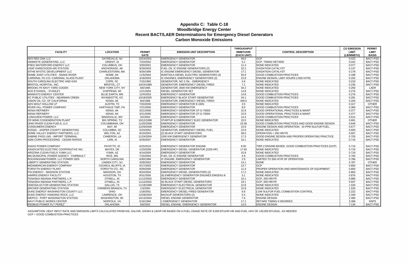
THROUGHPUT CO EMISSION PERMIT FACILITY LOCATION PERMIT EMISSION UNIT DESCRIPTION MMBTU/HR CONTROL DESCRIPTION LIMIT LIMIT
DATE (EACH UNIT) (LB/MMBTU) BASISAES RED OAK LLC SAYREVILLE, NJ 10/24/2001 EMERGENCY GENERATOR 49.0 GCP 0.023 BACT-PSDHAWKEYE GENERATING, LLC ORIENT, IA 7/23/2002 EMERGENCY GENERATOR 5.2 GCP, TIMING RETARD 0.042 BACT-PSDPSEG WATERFORD ENERGY LLC COLUMBUS, OH 3/29/2001 EMERGENCY GENERATOR 11.4 NONE INDICATED 0.077 BACT-PSDUSAF EARECKSON AIR STATION ANCHORAGE, AK 9/29/2003 FUEL OIL IC ENGINE GENERATORS (2) 32.2 OXIDATION CATALYST 0.137 BACT-PSDSITHE MYSTIC DEVELOPMENT LLC CHARLESTOWN, MA 9/29/1999 IC ENGINE EMERGENCY DIESEL GENERATOR 17.1 OXIDATION CATALYST 0.178 BACT-PSDNOME JOINT UTILITIES - SNAKE RIVER NOME, AK 11/5/2004 WARTSILA DIESEL ELECTRIC GENERATORS (3) 55.9 GOOD COMBUSTION PRACTICES 0.188 BACT-PSDCARDINAL FG CO./ CARDINAL GLASS PLANT OKLAHOMA 3/18/2003 IC ENGINES, EMERGENCY GENERATORS (2) 22.8 ENGINE DESIGN, LIMIT HOURS (<500 H/YR) 0.202 BACT-PSDSOUTH CAROLINA ELECTRIC AND GAS COPE, SC 7/15/1992 GENERATOR, NO 2 OIL - EMERGENCY 4.6 NONE INDICATED 0.219 BACT-PSDBRISTOL HOSPITAL, INC. BRISTOL, CT 10/24/1989 GENERATOR, EMERGENCY DIESEL FIRED 7.1 NONE INDICATED 0.230 BACT-PSDBROOKLYN NAVY YARD COGEN NEW YORK CITY, NY 6/6/1995 GENERATOR, 3000 KW EMERGENCY 34.2 NONE INDICATED 0.250 LAERACE ETHANOL - STANLEY CHIPPEWA, WI 1/21/2004 DIESEL GENERATOR SET 14.8 NONE INDICATED 0.276 BACT-PSDMANKATO ENERGY CENTER BLUE EARTH, MN 12/4/2003 EMERGENCY GENERATOR 14.8 GOOD COMBUSTION PRACTICES 0.276 BACT-PSDKC PUBLIC UTILITIES - NEARMAN CREEK WYANDOTTE, KS 10/18/2005 EMERGENCY BLACK START GENERATOR 24.1 GOOD COMBUSTION PRACTICES 0.291 BACT-PSDUNION OIL CO. OF CALIFORNIA KENAI, AK 8/4/1989 GENERATOR, EMERGENCY DIESEL FIRED 449.0 NONE INDICATED 0.294 BACT-PSDAES WOLF HOLLOW LP AUSTIN, TX 7/20/2000 EMERGENCY GENERATOR E-GEN 3.5 NONE INDICATED 0.317 OTHERRIVER HILL POWER COMPANY KARTHAUS TWP, PA 7/21/2005 EMERGENCY GENERATOR 8.0 GOOD COMBUSTION PRACTICES 0.369 BACT-PSDKENAI REFINERY KENAI, AK 3/21/2000 EMERGENCY GENERATOR CF-G-70003 22.8 GOOD OPERATIONAL PRACTICES & MAINT 0.377 BACT-PSDKENAI REFINERY KENAI, AK 3/21/2000 EMERGENCY GENERATOR CF-G-70004 22.8 GOOD OPERATIONAL PRACTICES & MAINT 0.377 BACT-PSDLONGVIEW POWER, LLC MAIDSVILLE, WV 3/2/2004 EMERGENCY GENERATOR 14.4 GOOD COMBUSTION PRACTICES 0.614 BACT-PSDCR WING COGENERATION PLANT BIG SPRING, TX 10/12/1999 STARTUP & EMERGENCY ELEC GENERATOR 15.5 NONE INDICATED 0.691 OTHEROHIO RIVER CLEAN FUELS, LLC COLUMBIANA, OH 11/20/2008 EMERGENCY GENERATOR 23.38 GOOD COMBUSTION PRACTICES AND GOOD ENGINE DESIGN 0.649 BACT-PSDCONSUMERS ENERGY BAY, MI 12/29/2009 EMERGENCY GENERATOR 22.8 ENGINE DESIGN AND OPERATION. 15 PPM SULFUR FUEL. 0.677 BACT-PSDSCE&G - JASPER COUNTY GENERATING COLUMBIA, SC 5/23/2002 GENERATOR, EMERGENCY DIESEL FUEL 22.8 NONE INDICATED 0.693 BACT-PSDDOME VALLEY ENERGY PARTNERS, LLC WELTON, AZ 8/10/2003 (2) BLACK START GENERATORS 58.5 OPERATION < 200 HR/YR 0.697 BACT-PSDSABINE PASS LNG - IMPORT TERMINAL CAMERON, LA 11/24/2004 1500 KW EMERGENCY GENERATOR 17.3 GOOD ENGINE DESIGN AND PROPER OPERATING PRACTICE 0.705 BACT-PSDADM CORN PROCESSING - CEDAR RAPIDS LINN, IA 6/29/2007 EMERGENCY GENERATOR 16.1 NONE INDICATED 0.716 BACT-PSD
IDAHO POWER COMPANY PAYETTE, ID 6/25/2010 EMERGENCY GENERATOR ENGINE 8.05 TIER 2 ENGINE-BASED, GOOD COMBUSTION PRACTICES (GCP) 0.719 BACT-PSDASSOCIATED ELECTRIC COOPERATIVE INC MAYES, OK 1/23/2009 EMERGENCY DIESEL GENERATOR (2200 HP) 17.60 NONE INDICATED 0.719 BACT-PSDARIZONA CLEAN FUELS YUMA LLC YUMA, AZ 4/14/2005 EMERGENCY GENERATOR 10.9 NONE INDICATED 0.719 BACT-PSDMN MUNICIPAL POWER AGENCY - FAIRBAULT RICE, MN 7/15/2004 FUEL OIL IC ENGINE GENERATOR 4.9 GOOD COMBUSTION PRACTICES 0.760 BACT-PSDROCKINGHAM POWER, LLC POWER GEN NORTH CAROLINA 6/30/1999 IC ENGINE, EMERGENCY GENERATOR 2.9 LIMITED TO 500 H/YR OF OPERATION 0.786 BACT-PSDLIBERTY GENERATING STATION LINDEN CITY, NJ 3/28/2002 EMERGENCY GENERATOR 14.1 NONE 0.787 OTHERMIDAMERICAN ENERGY COMPANY COUNCIL BLUFFS, IA 6/17/2003 EMERGENCY GENERATOR 13.7 GCP 0.850 BACT-PSDFORSYTH ENERGY PLANT FORSYTH CO., NC 9/29/2005 EMERGENCY GENERATOR 11.4 PROPER OPERATION AND MAINTENANCE OF EQUIPMENT 0.850 BACT-PSDPSI ENERGY - MADISON STATION MADISON, OH 8/24/2004 EMERGENCY DIESEL GENERATORS (2) 17.2 NONE INDICATED 0.850 BACT-PSDHARRIS ENERGY FACILITY HOUSTON, TX 8/31/2000 (8) EMERGENCY GENERATOR ENGINES EMGEN1-8 3.1 NONE INDICATED 0.876 BACT-PSDTENASKA INDIANA PARTNERS, L.P. OTWELL, IN 11/12/2002 EMERGENCY GENERATOR 10.1 GCP, 250 HR/YR 0.886 BACT-PSDTENASKA INDIANA PARTNERS, L.P. OTWELL, IN 11/12/2002 (6) BLACK START DIESEL GENERATORS 19.1 GCP, 500 HR/YR 0.937 BACT-PSDODESSA-ECTOR GENERATING STATION DALLAS, TX 11/18/1999 EMERGENCY ELECTRICAL GENERATOR 22.8 NONE INDICATED 1.530 BACT-PSDARCHER GENERATING STATION FARMERS BRANCH, TX 1/3/2000 EMERGENCY ELECTRICAL GENERATOR 22.8 NONE INDICATED 1.530 BACT-PSDDUKE ENERGY WASHINGTON COUNTY LLC OHIO 1/18/2001 EMERGENCY DIESEL-FIRED GENERATOR 6.8 LOW SULFUR FUEL COMBUSTION CONTROL 2.222 BACT-PSDDUKE ENERGY HANGING ROCK, LLC LAWRENCE, OH 12/28/2004 BACKUP GENERATORS (2) 5.4 NONE INDICATED 2.349 BACT-PSDWEPCO - PORT WASHINGTON STATION WASHINGTON, WI 10/13/2004 DIESEL ENGINE GENERATOR 7.6 ENGINE DESIGN 2.480 BACT-PSDNAVY PUBLIC WORKS CENTER NORFOLK, VA 5/16/1994 1 EMERGENCY GENERATOR 17.1 RETARD TIMING 6 DEGREES 3.368 NSPSREDBUD POWER PLT PEREZ" OKLAHOMA 5/6/2002 DIESEL ENGINE, EMERGENCY GENERATOR 14.0 ENGINE DESIGN 7.134 BACT-PSD
ASSUMPTION: HEAT INPUT RATE AND EMISSION LIMITS CALCULATED FROM KW, GAL/HR, G/KWH & LB/HP-HR BASED ON A FUEL USAGE RATE OF 8,000 BTU/HP-HR AND FUEL HHV OF 140,000 BTU/GAL, AS NEEDEDGCP = GOOD COMBUSTION PRACTICES
Appendix C: Table C-18
Recent BACT/LAER Determinations for Emergency Diesel GeneratorsCarbon Monoxide Emissions
Woodbridge Energy Center

THROUGHPUT VOC EMISSION PERMIT FACILITY LOCATION PERMIT EMISSION UNIT DESCRIPTION MMBTU/HR CONTROL DESCRIPTION LIMIT LIMIT
DATE (EACH UNIT) (LB/MMBTU) BASISPSEG WATERFORD ENERGY LLC COLUMBUS, OH 3/29/2001 EMERGENCY GENERATOR 11.4 NONE INDICATED 0.007 BACT-PSDHAWKEYE GENERATING, LLC ORIENT, IA 7/23/2002 EMERGENCY GENERATOR 5.2 GCP, TIMING RETARD 0.014 BACT-PSDACE ETHANOL - STANLEY CHIPPEWA, WI 1/21/2004 DIESEL GENERATOR SET 14.8 NONE INDICATED 0.033 BACT-PSDMANKATO ENERGY CENTER BLUE EARTH, MN 12/4/2003 EMERGENCY GENERATOR 14.8 GOOD COMBUSTION PRACTICES 0.033 BACT-PSDTATE & LYLE INDGREDIENTS AMERICAS, INC. WEBSTER, IA 9/19/2008 EMERGENCY GENERATOR 7.51 NONE INDICATED 0.041 BACT-PSDAES WOLF HOLLOW LP AUSTIN, TX 7/20/2000 EMERGENCY GENERATOR E-GEN 3.5 NONE INDICATED 0.057 OTHEROHIO RIVER CLEAN FUELS, LLC COLUMBIANA, OH 11/20/2008 EMERGENCY GENERATOR 23.38 GOOD COMBUSTION PRACTICES AND GOOD ENGINE DESIGN 0.059 BACTSITHE MYSTIC DEVELOPMENT LLC CHARLESTOWN, MA 9/29/1999 IC ENGINE EMERGENCY DIESEL GENERATOR 17.1 GOOD COMBUSTION CONTROL 0.068 LAERRIVER HILL POWER COMPANY KARTHAUS TWP, PA 7/21/2005 EMERGENCY GENERATOR 8.0 GOOD COMBUSTION PRACTICES 0.069 LAERSCE&G - JASPER COUNTY GENERATING FACILITY COLUMBIA, SC 5/23/2002 GENERATOR, EMERGENCY DIESEL FUEL 22.8 NONE INDICATED 0.075 LAERADM CORN PROCESSING - CEDAR RAPIDS LINN, IA 6/29/2007 EMERGENCY GENERATOR 16.1 NONE INDICATED 0.083 BACT-PSDCR WING COGENERATION PLANT BIG SPRING, TX 10/12/1999 STARTUP & EMERGENCY ELEC GENERATOR 15.5 NONE INDICATED 0.084 OTHERLONGVIEW POWER, LLC MAIDSVILLE, WV 3/2/2004 EMERGENCY GENERATOR 14.4 GOOD COMBUSTION PRACTICES 0.084 BACT-PSDASSOCIATED ELECTRIC COOPERATIVE INC MAYES, OK 1/23/2009 EMERGENCY DIESEL GENERATOR (2200 HP) 17.60 GOOD COMBUSTION 0.088 OTHERPSI ENERGY - MADISON STATION MADISON, OH 8/24/2004 EMERGENCY DIESEL GENERATORS (2) 17.2 NONE INDICATED 0.090 BACT-PSDMIDAMERICAN ENERGY COMPANY COUNCIL BLUFFS, IA 6/17/2003 EMERGENCY GENERATOR 13.7 GCP 0.090 BACT-PSDREDBUD POWER PLT PEREZ" OKLAHOMA 5/6/2002 DIESEL ENGINE, EMERGENCY GENERATOR 14.0 ENGINE DESIGN 0.091 BACT-PSDFORSYTH ENERGY PLANT FORSYTH CO., NC 9/29/2005 EMERGENCY GENERATOR 11.4 PROPER OPERATION AND MAINTENANCE OF EQUIPMENT 0.091 BACT-PSDCARDINAL FG CO./ CARDINAL GLASS PLANT OKLAHOMA 3/18/2003 IC ENGINES, EMERGENCY GENERATORS (2) 22.8 ENGINE DESIGN, LIMIT OPERATION (<500 H/YR) 0.095 BACT-PSDSABINE PASS LNG - IMPORT TERMINAL CAMERON, LA 11/24/2004 1500 KW EMERGENCY GENERATOR 17.3 GOOD COMBUSTION PRACTICES 0.096 BACT-PSDLIBERTY GENERATING STATION LINDEN CITY, NJ 3/28/2002 EMERGENCY GENERATOR 14.1 NONE 0.099 OTHERMN MUNICIPAL POWER AGENCY - FAIRBAULT RICE, MN 7/15/2004 FUEL OIL IC ENGINE GENERATOR 4.9 GOOD COMBUSTION PRACTICES 0.100 BACT-PSDODESSA-ECTOR GENERATING STATION DALLAS, TX 11/18/1999 EMERGENCY ELECTRICAL GENERATOR 22.8 NONE INDICATED 0.127 BACT-PSDARCHER GENERATING STATION FARMERS BRANCH, TX 1/3/2000 EMERGENCY ELECTRICAL GENERATOR 22.8 NONE INDICATED 0.127 BACT-PSDDUKE ENERGY HANGING ROCK, LLC LAWRENCE, OH 12/28/2004 BACKUP GENERATORS (2) 5.4 NONE INDICATED 0.205 BACT-PSDAES RED OAK LLC SAYREVILLE, NJ 10/24/2001 EMERGENCY GENERATOR 49.0 GOOD COMBUSTION 0.246 LAERDUKE ENERGY WASHINGTON COUNTY LLC OHIO 1/18/2001 EMERGENCY DIESEL-FIRED GENERATOR 6.8 LOW SULFUR FUEL COMBUSTION CONTROL 0.257 BACT-PSDWEPCO - PORT WASHINGTON STATION WASHINGTON, WI 10/13/2004 DIESEL ENGINE GENERATOR 7.6 ENGINE DESIGN 0.283 BACT-PSDROCKINGHAM POWER, LLC POWER GENERATING NORTH CAROLINA 6/30/1999 IC ENGINE, EMERGENCY GENERATOR 2.9 LIMITED TO 500 H/YR OF OPERATION 0.295 BACT-PSDHARRIS ENERGY FACILITY HOUSTON, TX 8/31/2000 (8) EMERGENCY GENERATOR ENGINES EMGEN1-8 3.1 NONE INDICATED 0.324 BACT-PSDTENASKA INDIANA PARTNERS, L.P. OTWELL, IN 11/12/2002 EMERGENCY GENERATOR 10.1 GCP, 250 HR/YR 0.334 BACT-PSDTENASKA INDIANA PARTNERS, L.P. OTWELL, IN 11/12/2002 (6) BLACK START DIESEL GENERATORS 19.1 GCP, 500 HR/YR 0.353 BACT-PSDUNION OIL CO. OF CALIFORNIA" KENAI, AK 8/4/1989 GENERATOR, EMERGENCY DIESEL FIRED 449.0 NONE INDICATED 0.641 BACT-PSDBRISTOL HOSPITAL, INC." BRISTOL 10/24/1989 GENERATOR, EMERGENCY DIESEL FIRED 7.1 NONE INDICATED 0.730 BACT-PSDNAVY PUBLIC WORKS CENTER NORFOLK, VA 5/16/1994 1 EMERGENCY GENERATOR 17.1 RETARD TIMING 6 DEGREES 0.959 NSPSCONSUMERS ENERGY BAY, MI 12/29/2009 EMERGENCY GENERATOR 22.8 ENGINE DESIGN AND OPERATION. 15 PPM SULFUR FUEL 1.237 OTHERIDAHO POWER COMPANY PAYETTE, ID 6/25/2010 EMERGENCY GENERATOR ENGINE 8.05 TIER 2 ENGINE-BASED,��GOOD COMBUSTION PRACTICES (GCP) 1.315 OTHER
ASSUMPTION: HEAT INPUT RATE AND EMISSION LIMITS CALCULATED FROM KW, GAL/HR, G/KWH & LB/HP-HR BASED ON A FUEL USAGE RATE OF 8,000 BTU/HP-HR AND FUEL HHV OF 140,000 BTU/GAL, AS NEEDEDGCP = GOOD COMBUSTION PRACTICES
Appendix C: Table C-19
Recent BACT/LAER Determinations for Emergency Diesel GeneratorsVolatile Organic Compound Emissions
Woodbridge Energy Center

THROUGHPUT PM/PM-10 EMISSION PERMIT FACILITY LOCATION PERMIT EMISSION UNIT DESCRIPTION MMBTU/HR CONTROL DESCRIPTION LIMIT LIMIT
DATE (EACH UNIT) (LB/MMBTU) BASISPSEG WATERFORD ENERGY LLC COLUMBUS, OH 3/29/2001 EMERGENCY GENERATOR 11.4 NONE INDICATED 0.004 BACT-PSDARIZONA CLEAN FUELS YUMA LLC YUMA, AZ 4/14/2005 EMERGENCY GENERATOR 10.9 NONE INDICATED 0.004 BACT-PSDACE ETHANOL - STANLEY CHIPPEWA, WI 1/21/2004 DIESEL GENERATOR SET 14.8 LOW SULFUR FUEL 0.019 BACT-PSDMANKATO ENERGY CENTER BLUE EARTH, MN 12/4/2003 EMERGENCY GENERATOR 14.8 GOOD COMBUSTION PRACTICES 0.019 BACT-PSDCR WING COGENERATION PLANT BIG SPRING, TX 10/12/1999 STARTUP & EMERGENCY ELEC GENERATOR 15.5 NONE INDICATED 0.032 OTHEROHIO RIVER CLEAN FUELS, LLC COLUMBIANA, OH 11/20/2008 EMERGENCY GENERATOR 23.38 GOOD COMBUSTION PRACTICES AND GOOD ENGINE DESIGN 0.037 BACT-PSDASSOCIATED ELECTRIC COOPERATIVE INC MAYES, IJ 1/23/2009 EMERGENCY DIESEL GENERATOR (2200 HP) 17.60 NONE INDICATED 0.041 BACT-PSDCONSUMERS ENERGY BAY, MI 12/29/2009 EMERGENCY GENERATOR 21.46 ENGINE DESIGN AND OPERATION. 15 PPM SULFUR FUEL. 0.041 BACT-PSDTATE & LYLE INDGREDIENTS AMERICAS, INC. WEBSTER, IA 9/19/2008 EMERGENCY GENERATOR 7.51 NONE INDICATED 0.041 BACT-PSDTATE & LYLE INDGREDIENTS AMERICAS, INC. WEBSTER, IA 9/19/2008 EMERGENCY GENERATOR 7.51 NONE INDICATED 0.041 BACT-PSDIDAHO POWER COMPANY PAYETTE, ID 6/25/2010 EMERGENCY GENERATOR ENGINE 8.05 TIER 2 ENGINE-BASED,��GOOD COMBUSTION PRACTICES (GCP) 0.041 BACT-PSDADM CORN PROCESSING - CEDAR RAPIDS LINN, IA 6/29/2007 EMERGENCY GENERATOR 16.1 NONE INDICATED 0.041 BACT-PSDCARDINAL FG CO./ CARDINAL GLASS PLANT OKLAHOMA 3/18/2003 IC ENGINES, EMERGENCY GENERATORS (2) 22.8 ENGINE DESIGN 0.044 BACT-PSDAES WOLF HOLLOW LP AUSTIN, TX 7/20/2000 EMERGENCY GENERATOR E-GEN 3.5 NONE INDICATED 0.045 OTHERSITHE MYSTIC DEVELOPMENT LLC CHARLESTOWN, MA 9/29/1999 IC ENGINE EMERGENCY DIESEL GENERATOR 17.1 GOOD COMBUSTION CONTROL 0.051 BACT-PSDSABINE PASS LNG - IMPORT TERMINAL CAMERON, LA 11/24/2004 1500 KW EMERGENCY GENERATOR 17.3 GOOD COMBUSTION PRACTICES 0.053 BACT-PSDAES RED OAK LLC SAYREVILLE, NJ 10/24/2001 EMERGENCY GENERATOR 49 LIMITED USE 0.054 BACT-PSDCONSUMERS ENERGY BAY, MI 12/29/2009 EMERGENCY GENERATOR 21.46 ENGINE DESIGN AND OPERATION. 15 PPM SULFUR FUEL. 0.057 BACT-PSDKENAI REFINERY KENAI, AK 3/21/2000 EMERGENCY GENERATOR CF-G-70003 22.8 GOOD OPERATIONAL PRACTICES & MAINT 0.057 BACT-PSDKENAI REFINERY KENAI, AK 3/21/2000 EMERGENCY GENERATOR CF-G-70004 22.8 GOOD OPERATIONAL PRACTICES & MAINT 0.057 BACT-PSDRIVER HILL POWER COMPANY KARTHAUS TWP, PA 7/21/2005 EMERGENCY GENERATOR 8.0 CLEAN FUELS 0.059 BACT-PSDPSI ENERGY - MADISON STATION MADISON, OH 8/24/2004 EMERGENCY DIESEL GENERATORS (2) 17.2 NONE INDICATED 0.063 BACT-PSDHAWKEYE GENERATING, LLC ORIENT, IA 7/23/2002 EMERGENCY GENERATOR 5.2 GCP, TIMING RETARD 0.066 BACT-PSDLONGVIEW POWER, LLC MAIDSVILLE, WV 3/2/2004 EMERGENCY GENERATOR 14.4 GOOD COMBUSTION PRACTICES 0.078 BACT-PSDSCE&G - JASPER COUNTY GENERATING FACILITY COLUMBIA, SC 5/23/2002 GENERATOR, EMERGENCY DIESEL FUEL 22.8 CLEAN FUEL(LOW SULFUR DIESEL) GCP 0.083 BACT-PSDODESSA-ECTOR GENERATING STATION DALLAS, TX 11/18/1999 EMERGENCY ELECTRICAL GENERATOR 22.8 NONE INDICATED 0.091 BACT-PSDARCHER GENERATING STATION FARMERS BRANCH, TX 1/3/2000 EMERGENCY ELECTRICAL GENERATOR 22.8 NONE INDICATED 0.091 BACT-PSDLIBERTY GENERATING STATION LINDEN CITY, NJ 3/28/2002 EMERGENCY GENERATOR 14.1 NONE 0.099 OTHERLIBERTY GENERATING STATION LINDEN CITY, NJ 3/28/2002 EMERGENCY GENERATOR 14.1 NONE 0.099 OTHERFORSYTH ENERGY PLANT FORSYTH CO., NC 9/29/2005 EMERGENCY GENERATOR 11.4 PROPER OPERATION AND MAINTENANCE OF EQUIPMENT 0.100 BACT-PSDMN MUNICIPAL POWER AGENCY - FAIRBAULT RICE, MN 7/15/2004 FUEL OIL IC ENGINE GENERATOR 4.9 CLEAN FUELS AND GOOD COMBUSTION PRACTICES 0.100 BACT-PSDBRISTOL HOSPITAL, INC. BRISTOL, CT 10/24/1989 GENERATOR, EMERGENCY DIESEL FIRED 7.14 NONE INDICATED 0.100 BACT-PSDDUKE ENERGY WASHINGTON COUNTY LLC OHIO 1/18/2001 EMERGENCY DIESEL-FIRED GENERATOR 6.8 LOW SULFUR FUEL COMBUSTION CONTROL 0.105 BACT-PSDDUKE ENERGY HANGING ROCK, LLC LAWRENCE, OH 12/28/2004 BACKUP GENERATORS (2) 5.4 NONE INDICATED 0.110 BACT-PSDHARTFORD INSURANCE CO. SIMSBURY, CT 8/30/1989 GENERATOR, EMERGENCY STANDBY DIESEL FIRED 10.2 NONE INDICATED 0.110 BACT-PSDWEPCO - PORT WASHINGTON STATION WASHINGTON, WI 10/13/2004 DIESEL ENGINE GENERATOR 7.6 CLEAN FUELS 0.117 BACT-PSDMIDAMERICAN ENERGY COMPANY COUNCIL BLUFFS, IA 6/17/2003 EMERGENCY GENERATOR 13.7 GCP 0.140 BACT-PSDROCKINGHAM POWER, LLC POWER GENERATING NORTH CAROLINA 6/30/1999 IC ENGINE, EMERGENCY GENERATOR 2.9 LIMITED TO 500 H/YR OF OPERATION 0.260 BACT-PSDHARRIS ENERGY FACILITY HOUSTON, TX 8/31/2000 (8) EMERGENCY GENERATOR ENGINES EMGEN1-8 3.1 NONE INDICATED 0.292 BACT-PSDTENASKA INDIANA PARTNERS, L.P. OTWELL, IN 11/12/2002 EMERGENCY GENERATOR 10.1 SULFUR LIMITED TO 0.05% BY WEIGHT, 250 HR/YR 0.292 BACT-PSDTENASKA INDIANA PARTNERS, L.P. OTWELL, IN 11/12/2002 (6) BLACK START DIESEL GENERATORS 19.1 SULFUR LIMITED TO 0.05% BY WEIGHT, 500 HR/YR 0.309 BACT-PSDNAVY PUBLIC WORKS CENTER NORFOLK, VA 5/16/1994 1 EMERGENCY GENERATOR 17.1 NO CONTROLS FEASIBLE 0.491 NSPS
ASSUMPTION: HEAT INPUT RATE AND EMISSION LIMITS CALCULATED FROM KW, GAL/HR, G/KWH & LB/HP-HR BASED ON A FUEL USAGE RATE OF 8,000 BTU/HP-HR AND FUEL HHV OF 140,000 BTU/GAL, AS NEEDEDGCP = GOOD COMBUSTION PRACTICES
Appendix C: Table C-20
Recent BACT/LAER Determinations for Emergency Diesel GeneratorsParticulate Matter Emissions
Woodbridge Energy Center

THROUGHPUT SO2 EMISSION PERMIT FACILITY LOCATION PERMIT EMISSION UNIT DESCRIPTION MMBTU/HR CONTROL DESCRIPTION LIMIT LIMIT
DATE (EACH UNIT) (LB/MMBTU) BASISAES WOLF HOLLOW LP AUSTIN, TX 7/20/2000 EMERGENCY GENERATOR E-GEN 3.5 NONE INDICATED 0.001 OTHERPSEG WATERFORD ENERGY LLC COLUMBUS, OH 3/29/2001 EMERGENCY GENERATOR 11.4 LOW SULFUR FUEL 0.004 BACT-PSDCR WING COGENERATION PLANT BIG SPRING, TX 10/12/1999 STARTUP & EMERGENCY ELEC GENERATOR 15.5 NONE INDICATED 0.032 OTHERSCE&G - JASPER COUNTY GENERATING FACILITY COLUMBIA, SC 5/23/2002 GENERATOR, EMERGENCY DIESEL FUEL 22.8 LOW SULFUR (0.05%) DIESEL 0.039 BACT-PSDTATE & LYLE INDGREDIENTS AMERICAS, INC. WEBSTER, IA 9/19/2008 EMERGENCY GENERATOR 7.51 NONE INDICATED 0.047 BACT-PSDADM CORN PROCESSING - CEDAR RAPIDS LINN, IA 6/29/2007 EMERGENCY GENERATOR 16.1 LOW SULFUR FUEL (0.05% BY WEIGHT) 0.050 BACT-PSDKC PUBLIC UTILITIES - NEARMAN CREEK WYANDOTTE, KS 10/18/2005 EMERGENCY BLACK START GENERATOR 24.1 LOW SULFUR FUEL (0.05% BY WEIGHT) 0.050 BACT-PSDDUKE ENERGY HANGING ROCK, LLC LAWRENCE, OH 12/28/2004 BACKUP GENERATORS (2) 5.4 LOW SULFUR FUEL 0.050 BACT-PSDWEPCO - PORT WASHINGTON STATION WASHINGTON, WI 10/13/2004 DIESEL ENGINE GENERATOR 7.6 LOW SULFUR FUEL (0.05% BY WEIGHT) 0.050 BACT-PSDAES RED OAK LLC SAYREVILLE, NJ 10/24/2001 EMERGENCY GENERATOR 49 LOW SULFUR FUEL 0.050 BACT-PSDCARDINAL FG CO./ CARDINAL GLASS PLANT OKLAHOMA 3/18/2003 IC ENGINES, EMERGENCY GENERATORS (2) 22.8 LOW SULFUR FUEL, < 0.05% S 0.050 BACT-PSDASSOCIATED ELECTRIC COOPERATIVE INC MAYES, OK 1/23/2009 EMERGENCY DIESEL GENERATOR (2200 HP) 17.60 NONE INDICATED 0.051 BACT-PSDFORSYTH ENERGY PLANT FORSYTH CO., NC 9/29/2005 EMERGENCY GENERATOR 11.4 PROPER OPERATION AND MAINTENANCE OF EQUIPMENT 0.051 BACT-PSDMN MUNICIPAL POWER AGENCY - FAIRBAULT RICE, MN 7/15/2004 FUEL OIL IC ENGINE GENERATOR 4.9 FUEL SULFUR LIMIT (0.05% BY WEIGHT) 0.051 BACT-PSDMIDAMERICAN ENERGY COMPANY COUNCIL BLUFFS, IA 6/17/2003 EMERGENCY GENERATOR 13.7 GCP AND LOW SULFUR FUEL 0.052 BACT-PSDSITHE MYSTIC DEVELOPMENT LLC CHARLESTOWN, MA 9/29/1999 IC ENGINE EMERGENCY DIESEL GENERATOR 17.1 FUEL SULFUR AND HOURS PER YEAR LIMITS 0.056 BACT-PSDLIBERTY GENERATING STATION LINDEN CITY, NJ 3/28/2002 EMERGENCY GENERATOR 14.1 SULFUR IN OIL LIMITED TO 0.05% BY WEIGHT. 0.057 OTHERDUKE ENERGY WASHINGTON COUNTY LLC OHIO 1/18/2001 EMERGENCY DIESEL-FIRED GENERATOR 6.8 LOW SULFUR FUEL COMBUSTION CONTROL 0.058 BACT-PSDODESSA-ECTOR GENERATING STATION DALLAS, TX 11/18/1999 EMERGENCY ELECTRICAL GENERATOR 22.8 NONE INDICATED 0.083 BACT-PSDARCHER GENERATING STATION FARMERS BRANCH, TX 1/3/2000 EMERGENCY ELECTRICAL GENERATOR 22.8 NONE INDICATED 0.083 BACT-PSDBP EXPLORATION ALASKA - BADAMI CENTER N SLOPE BRGH, AK 8/19/2005 CUMMINS IC ENGINE GENERATOR 14.8 NONE INDICATED 0.150 BACT-PSDMANKATO ENERGY CENTER BLUE EARTH, MN 12/4/2003 EMERGENCY GENERATOR 14.8 LOW SULFUR FUEL 0.163 BACT-PSDRIVER HILL POWER COMPANY KARTHAUS TWP, PA 7/21/2005 EMERGENCY GENERATOR 8.0 LOW SULFUR FUEL 0.203 BACT-PSDBRISTOL HOSPITAL, INC. BRISTOL, CT 10/24/1989 GENERATOR, EMERGENCY DIESEL FIRED 7.14 NONE INDICATED 0.220 BACT-PSDHARRIS ENERGY FACILITY HOUSTON, TX 8/31/2000 (8) EMERGENCY GENERATOR ENGINES EMGEN1-8 3.1 NONE INDICATED 0.259 BACT-PSDSOUTH CAROLINA ELECTRIC AND GAS COMPANY COPE, SC 7/15/1992 GENERATOR, NO 2 OIL - EMERGENCY 4.6 FUEL SPEC: 0.3% S FUEL; LIMIT OPER <500 HOURS/YEAR 0.263 BACT-PSDTENASKA INDIANA PARTNERS, L.P. OTWELL, IN 11/12/2002 EMERGENCY GENERATOR 10.1 SULFUR LIMITED TO 0.05% BY WEIGHT, 250 HR/YR 0.272 BACT-PSDTENASKA INDIANA PARTNERS, L.P. OTWELL, IN 11/12/2002 (6) BLACK START DIESEL GENERATORS 19.1 SULFUR LIMITED TO 0.05% BY WEIGHT, 500 HR/YR 0.288 BACT-PSDREDBUD POWER PLT PEREZ OKLAHOMA 5/6/2002 DIESEL ENGINE, EMERGENCY GENERATOR 14.0 NONE INDICATED 0.400 BACT-PSDLONGVIEW POWER, LLC MAIDSVILLE, WV 3/2/2004 EMERGENCY GENERATOR 14.4 SULFUR IN FUEL 0.451 BACT-PSDNOME JOINT UTILITIES - SNAKE RIVER NOME, AK 11/5/2004 WARTSILA DIESEL ELECTRIC GENERATORS (3) 55.9 FUEL SULFUR LIMIT (0.5% BY WEIGHT) 0.500 BACT-PSDPSI ENERGY - MADISON STATION MADISON, OH 8/24/2004 EMERGENCY DIESEL GENERATORS (2) 17.2 FUEL SULFUR LIMIT 0.500 BACT-PSDNAVY PUBLIC WORKS CENTER NORFOLK, VA 5/16/1994 1 EMERGENCY GENERATOR 17.1 NO CONTROLS FEASIBLE 0.982 NSPS
ASSUMPTION: HEAT INPUT RATE AND EMISSION LIMITS CALCULATED FROM KW, GAL/HR, G/KWH & LB/HP-HR BASED ON A FUEL USAGE RATE OF 8,000 BTU/HP-HR AND FUEL HHV OF 140,000 BTU/GAL, AS NEEDEDGCP = GOOD COMBUSTION PRACTICES
Appendix C: Table C-21
Recent BACT/LAER Determinations for Emergency Diesel GeneratorsSulfur Dioxide Emissions
Woodbridge Energy Center

THROUGHPUT NOx EMISSION PERMITFACILITY LOCATION PERMIT EMISSION UNIT DESCRIPTION MMBTU/HR CONTROL DESCRIPTION LIMIT LIMIT
DATE (EACH UNIT) (LB/MMBTU) BASISDOME VALLEY ENERGY PARTNERS, LLC WELTON, AZ 8/10/2003 EMERGENCY FIRE PUMP ENGINE 2.42 OPERATION < 200 HR/YR 0.414 BACT-PSDTATE & LYLE INDGREDIENTS AMERICAS, INC. WEBSTER, IA 9/19/2008 FIRE PUMP ENGINE 4.60 NONE INDICATED 0.802 BACTIDAHO POWER COMPANY PAYETTE, ID 6/25/2010 FIRE PUMP ENGINE 2.52 TIER 3 ENGINE-BASED��GOOD COMBUSTION PRACTICES (GCP) 0.822 BACTARIZONA CLEAN FUELS YUMA LLC YUMA, AZ 4/14/2005 FIRE WATER PUMPS (2) 5.46 NONE INDICATED 0.822 BACT-PSDLA COUNTY PROBATION/FAC PLANNING/ISD LOS ANGELES, CA 8/14/2003 IC ENGINE FIRE PUMP 1.92 FUEL INJECTION RETARD-AFTER COOLER BY RAW WATER 1.160 BACT-PSDAES WOLF HOLLOW LP HOOD CO., TX 7/20/2000 EMERGENCY FIREWATER PUMP 2.00 NONE INDICATED 1.200 Other Case-by-Case PASNY/HOLTSVILLE COMBINED CYCLE PLANT HOLTSVILLE, NY 9/1/1992 DIESEL FIRE PUMP 1.30 LEAN BURN ENGINE 1.300 BACT-OTHERHOLLAND ENERGY, LLC HOLLAND, IL 12/3/2001 BACKUP DIESEL FIRE PUMP 1.40 NONE INDICATED 1.429 BACT-PSDEL PASO MANATEE ENERGY CENTER MANATTE CO., FL 12/1/2001 DIESEL FIRE PUMP 2.00 OPERATION LIMITED TO < 500 HR/YR 1.480 BACT-OTHEREL PASO BELLE GLADE ENERGY CENTER PALM BEACH CO., FL 12/1/2001 DIESEL FIRE PUMP 2.00 OPERATION LIMITED TO < 500 HR/YR 1.480 BACT-OTHEREL PASO BROWARD ENERGY CENTER BROWARD CO., FL 2001 DIESEL FIRE PUMP 2.00 OPERATION LIMITED TO < 500 HR/YR 1.480 BACT-OTHERSUMMIT VINEYARD, LLC VINEYARD, UT 10/25/2004 DIESEL-FIRED FIRE PUMP 2.32 GCP, INLET AIR FILTER 1.571 LAERRIVER HILL POWER COMPANY KARTHAUS TWP, PA 7/21/2005 DIESEL ENGINE FIRE PUMP 1.70 NONE INDICATED 1.620 LAERTRANSGAS ENERGY SYSTEMS BROOKLYN, NY 6/4/2003 DIESEL FIRE PUMP 1.10 NONE INDICATED 1.850 LAERLSP - COTTAGE GROVE, L.P. COTTAGE GROVE, MN 11/10/1998 DIESEL EMERGENCY FIRE PUMP ENGINE 2.70 LIMITED TO BURN DIESEL 150 H/YR 1.850 BACT-PSDLSP-COTTAGE GROVE, L.P. COTTAGE GROVE, MN 3/1/1995 DIESEL ENGINE-DRIVEN FIRE PUMP 2.70 RETARD ENGINE TIMING; TURBOCHARGER AFTERCOOLING 1.852 BACT-PSDFAIRLESS WORKS ENERGY CTR (FMR. SWEC-FALLS TWP) GLEN ALLEN, PA 8/7/2001 DIESEL FIRED EMERGENCY PUMP 2.24 LIMITED OPERATION < 500 HR/YR 1.984 LAER
OHIO RIVER CLEAN FUELS, LLC COLUMBIANA, OH 11/20/2008 FIRE PUMP ENGINES (2) 2.40
GOOD COMBUSTION PRACTICES, GOOD ENGINE DESIGN, IGNITION TIMING RETARD, TURBOCHARGER, AND LOW-TEMPERATURE AFTERCOOLER 2.038 BACT
HAWKEYE GENERATING, LLC ORIENT, IA 7/23/2002 FIRE PUMP 1.82 GCP, TIMING RETARD 2.088 BACT-PSDASSOCIATED ELECTRIC COOPERATIVE INC MAYES, OK 1/23/2009 EMERGENCY FIRE PUMP (267-HP DIESEL) 2.14 NONE INDICATED 2.149 BACTMANTUA CREEK GENERATING FACILITY NEW JERSEY 6/26/2001 DIESEL FIRE PUMP 1.50 < 100 HR/YR OPERATION 2.200 N/ASABINE PASS LNG - IMPORT TERMINAL CAMERON, LA 11/24/2004 FIRE WATER PUMP 5.28 GOOD ENGINE DESIGN AND OPERATING PRACTICES 2.309 BACT-PSDVAUGHAN FURNITURE COMPANY STUART, VA 8/28/1996 DIESEL FIRE PUMP (IC ENGINE) 1.85 300 HOURS/YEAR LIMIT 2.381 BACTLONGVIEW ENERGY DEVELOPMENT LONGVIEW, WA 9/4/2001 FIRE PUMP ENGINE 2.94 OPERATION LIMITATION 2.514 BACTDUKE ENERGY - AUDRAIN GENERATING STATION VANDALIA, MO 5/9/2000 EMERGENCY DIESEL FIRE PUMP 1.50 WATER SPRAY INJECTION SYSTEM 2.563 BACT-PSDCRESCENT CITY POWER ORLEANS, LA 6/6/2005 DIESEL FIRED WATER PUMP 3.40 GOOD ENGINE DESIGN AND PROPER OPERATING PRACTICES 2.618 BACT-PSDCALPINE WAWAYANDA WAWAYANDA, NY 7/22/2002 FIRE WATER PUMP 2.40 OPERATIONAL RESTRICTIONS (< 52 HR/YR) 2.700 LAEROXY NGL, INC. JOHNSON BAYOU, LA 11/14/1989 (2) FIRE PUMP DIESEL ENGINE 3.20 LIMIT OPERATING HOURS 2.750 OTHERWEST CASCADE ENERGY FACILITY COBURG, OR 11/1/2003 FIRE WATER PUMP 2.03 NONE INDICATED 2.819 BACT-OTHERPSEG WATERFORD ENERGY LLC COLUMBUS, OH 3/29/2001 FIRE WATER PUMP 3.11 GOOD WORKING ORDER & OPER PER MFGR SPECS. 2.966 BACT-PSDFORSYTH ENERGY PLANT FORSYTH CO., NC 1/23/2004 EMERGENCY FIREWATER PUMP (IC ENGINE) 11.40 EMERGENCY ONLY, USAGE LIMITED TO < 200 H/YR 3.200 BACT-PSDPSI ENERGY - MADISON STATION MADISON, OH 8/24/2004 EMERGENCY DIESEL FIRE PUMP 1.60 NONE INDICATED 3.210 BACT-PSDASTORIA ENERGY, LLC ASTORIA, NY 12/5/2001 DIESEL FIREWATER PUMP 2.40 OPERATION LIMITED TO < 500 HR/YR 3.440 BACT-OTHERNEARMAN CREEK POWER STATION WYANDOTTE COUNTY, KS 10/18/2005 EMERGENCY BLACK START GENERATOR 24.10 NONE 3.519 BACT-PSDROCKINGHAM POWER, LLC POWER GENERATING ROCKINGHAM CO., NC 6/30/1999 FIRE WATER PUMP (IC ENGINE) 2.48 LIMITED TO 500 H/YR OF OPERATION 3.800 BACT-PSDDUKE ENERGY HANGING ROCK ENERGY FACILITY CHARLOTTE 12/13/2001 FIRE WATER PUMP 2.12 LIMITED TO 500 H/YR OPERATION 3.868 BACT-PSDWPS WESTON 4 - NORTH SITE WAUSAU, WI 10/18/2004 DIESEL BOOSTER PUMP 2.12 FIRING ULTRA LOW SULFUR FUEL OIL (< 0.003%S) 3.873 BACTWPS WESTON 4 - NORTH SITE WAUSAU, WI 10/18/2004 MAIN DIESEL FIRE PUMP 3.68 FIRING ULTRA LOW SULFUR FUEL OIL (< 0.003%S) 3.875 BACT
SOUTHWEST ELECTRIC POWER COMPANY (SWEPCO) CADDO, LA 3/20/2008 DFP DIESEL FIRE PUMP 2.48USE OF LOW-SULFUR FUELS, LIMITING OPERATING HOURS AND PROPER ENGINE MAINTENANCE 3.875 BACT
FIRST QUALITY TISSUE, LLC CLINTON, PA 10/20/2004 FIRE PUMP 4.60 NONE INDICATED 3.875 BACT-PSDBELL ENERGY FACILITY TEMPLE 6/26/2001 FIREWATER PUMP ENGINE 3.20 GOOD COMBUSTION CONTROL 3.875 BACT-PSDBASTROP CLEAN ENERGY CENTER BASTROP CO., TX 3/21/2000 FIREWATER PUMP ENGINE 2.40 ANNUAL OPERATION < 250 NON-EMERGENCY HOURS 3.875 BACT-PSD BRAZOS VALLEY ELECTRIC GENERATING FACILITY FORT BEND CO., TX 12/31/2002 (2) FIRE WATER PUMPS 2.40 NONE INDICATED 3.875 BACT-PSD CHOUTEAU POWER PLANT PRYOR, OK 3/24/1999 EMERGENCY DIESEL FIRE PUMP 2.14 GOOD ENGINE DESIGN, < 200 H/YR OPERATION 3.876 BACT-PSDHARRIS ENERGY FACILITY HOUSTON, TX 8/31/2000 FIRE WATER PUMP ENGINE 2.68 NONE INDICATED 3.881 BACT-PSD REDBUD POWER PLT OKLAHOMA 5/6/2002 FIRE WATER PUMP DIESEL ENGINE 2.40 NONE INDICATED 3.886 BACT-PSDARCHER POWER PARTNERS, L.P. ECTOR CO., TX 1/3/2000 EMERGENCY FIREWATER PUMP 2.08 NONE INDICATED 3.894 BACT-PSDODESSA-ECTOR GENERATING STATION ECTOR CO., TX 11/18/1999 EMERGENCY FIREWATER PUMP 2.08 NONE INDICATED 3.894 BACT-PSDDUKE ENERGY WASHINGTON COUNTY LLC OHIO 1/18/2001 EMERGENCY DIESEL FIRE PUMP ENGINE 3.20 LOW SULFUR FUEL COMBUSTION CONTROL 4.000 BACT-PSDDUKE ENERGY ARLINGTON VALLEY (AVEFII) ARLINGTON, AZ 11/12/2003 DIESEL FIREWATER PUMP ENGINE 1.60 GOOD COMB CONTROL / MODERN ENGINES (< 500 HR/YR) 4.000 BACT-OTHERKAMINE/BESICORP SYRACUSE LP SOLVAY, NY 12/10/1994 FIRE PUMP 1.50 NONE INDICATED 4.250 BACT-OTHERWESTBROOK POWER LLC WESTBROOK, ME 12/4/1998 DIESEL FIRE PUMP 1.80 LOWE SULFUR FUEL AND LIMITED OPERATION 4.339 LAEREMERY GENERATING STATION MASON CITY, IA 12/20/2002 EMERGENCY FIRE PUMP (IC ENGINE) 2.59 IGNITION TIMING RETARD 4.410 BACT-OTHERMIDAMERICAN ENERGY COMPANY COUNCIL BLUFFS, IA 6/17/2003 DIESEL FIRE PUMP 3.89 GCP 4.410 BACT-PSDDIGHTON POWER ASSOCIATE, LP DIGHTON, MA 10/6/1997 DIESEL FIRE PUMP ENGINE 1.50 NONE INDICATED 4.410 BACT-PSDHORSESHOE ENERGY PROJECT LINCOLN CO., OK 2/12/2002 FIRE WATER PUMP DIESEL ENGINE 2.00 ENGINE DESIGN AND LIMITATION OF HOURS 4.410 BACT-PSDGENOVA OK I POWER PROJECT GRADY CO., OK 6/13/2002 FIRE WATER PUMP DIESEL ENGINE 1.60 ENGINE DESIGN AND LIMITATION OF HOURS 4.410 BACT-PSDDUKE ENERGY STEPHENS, LLC STEPHENS ENERGY STEPHENS CO., OK 3/21/2003 FIRE WATER PUMP (IC ENGINE) 2.12 ENGINE DESIGN AND HOURS LIMIT (<100 H/YR) 4.410 BACT-PSDBADGER GENERATING CO LLC PLEASANT PRAIRIE, WI 9/20/2000 EMERGENCY DIESEL FIRE PUMP ENGINE 3.80 GCP EQUIPMENT USAGE LIMITS 4.411 BACT-PSDLAKEWOOD COGENERATION, LP LAKEWOOD, NJ 1993 DF FIRE PUMP 2.6 NONE INDICATED 4.423 BACT-OTHERLIBERTY GENERATING STATION LINDEN CITY, NJ 3/28/2002 DIESEL FIRE PUMP 3.50 NONE INDICATED 4.429 OTHERARSENAL HILL POWER PLANT CADDO CO, LA 3/20/2008 DIESEL FIRE PUMP 2.17 NONE 4.429 BACT-PSDCPV WARREN, LLC FRONT ROYAL, VA 7/30/2004 DIESEL EMERGENCY FIRE WATER PUMP 2.30 OPERATION LIMITED TO < 500 HR/YR 4.435 BACT-OTHERBLYTHE ENERGY PROJECT II RIVERSIDE CO, CA 4/25/2007 DIESEL FIRE PUMP 2.12 NONE 4.531 BACT-PSDOXY NGL, INC. JOHNSON BAYOU, LA 11/14/1989 (2) FIRE PUMP DIESEL ENGINE 2.20 LIMIT OPERATING HOURS 4.727 OTHERCASCO BAY ENERGY COMPANY, LLC VEAZIE, ME 2000 FIRE PUMP 3.40 LOW SULFUR FUEL AND LIMITED OPERATION 5.000 BACTLONGVIEW POWER MAIDSVILLE, WV 12/4/2003 FIRE PUMP ENGINE 2.07 NONE INDICATED 5.081 BACT-PSDGRAIN PROCESSING CORP. WASHINGTON, IN 6/10/1997 EMERGENCY FIRE PUMP 0.92 LIMITED TO 1,128 GAL/YR DIESEL FUEL 7.750 BACT-PSDTENASKA INDIANA PARTNERS, L.P. OTWELL, IN 11/12/2002 DIESEL FIRE PUMP 0.95 GCP, 500 HR/YR 12.008 BACT-PSDKIAMICHI ENERGY FACILITY PITTSBURG CO., OK 5/1/2001 FIRE WATER PUMP DIESEL ENGINE 2.16 GCP AND DESIGN 29.800 BACT-PSD
ASSUMPTION: HEAT INPUT RATE AND EMISSION LIMITS CALCULATED BASED ON A FUEL USAGE RATE OF 8,000 BTU/HP-HR AND FUEL HHV OF 140,000 BTU/GAL, AS NEEDED
Appendix C: Table C-22
Recent BACT/LAER Determinations for Diesel Fire PumpsNitrogen Oxides Emissions
Woodbridge Energy Center

THROUGHPUT CO EMISSION PERMITFACILITY LOCATION PERMIT EMISSION UNIT DESCRIPTION MMBTU/HR CONTROL DESCRIPTION LIMIT LIMIT
DATE (EACH UNIT) (LB/MMBTU) BASISSUMMIT VINEYARD, LLC VINEYARD, UT 10/25/2004 DIESEL-FIRED FIRE PUMP 2.3 GCP, INLET AIR FILTER 0.069 BACTSABINE PASS LNG - IMPORT TERMINAL CAMERON, LA 11/24/2004 FIRE WATER PUMP 5.3 GOOD ENGINE DESIGN AND OPERATING PRACTICES 0.104 BACT-PSDLA COUNTY PROBATION/FAC PLANNING/ISD LOS ANGELES, CA 8/14/2003 IC ENGINE FIRE PUMP 1.9 NONE INDICATED 0.121 BACT-PSDASTORIA ENERGY, LLC ASTORIA, NY 12/5/2001 DIESEL FIREWATER PUMP 2.4 OPERATION LIMITED TO < 500 HR/YR 0.180 BACT-OTHERRIVER HILL POWER COMPANY KARTHAUS TWP, PA 7/21/2005 DIESEL ENGINE FIRE PUMP 1.7 GOOD COMBUSTION PRACTICES 0.228 BACT-PSDHOLLAND ENERGY, LLC HOLLAND, IL 12/3/2001 BACKUP DIESEL FIRE PUMP 1.4 NONE INDICATED 0.286 BACT-PSDWEST CASCADE ENERGY FACILITY COBURG, OR 11/1/2003 FIRE WATER PUMP 2.0 NONE INDICATED 0.312 BACT-OTHERBLYTHE ENERGY PROJECT II RIVERSIDE CO, CA 4/25/2007 DIESEL FIRE PUMP 2.12 NONE 0.330 BACT-PSDFAIRLESS WORKS ENERGY CTR (FMR. SWEC-FALLS TWP) GLEN ALLEN, PA 8/7/2001 DIESEL FIRED EMERGENCY PUMP 2.2 LIMITED OPERATION < 500 HR/YR 0.331 BACT-PSDEL PASO MANATEE ENERGY CENTER MANATTE CO., FL 12/1/2001 DIESEL FIRE PUMP 2.0 OPERATION LIMITED TO < 500 HR/YR 0.360 BACT-OTHEREL PASO BELLE GLADE ENERGY CENTER PALM BEACH CO., FL 12/1/2001 DIESEL FIRE PUMP 2.0 OPERATION LIMITED TO < 500 HR/YR 0.360 BACT-OTHEREL PASO BROWARD ENERGY CENTER BROWARD CO., FL 2001 DIESEL FIRE PUMP 2.0 OPERATION LIMITED TO < 500 HR/YR 0.360 BACT-OTHERTRANSGAS ENERGY SYSTEMS BROOKLYN, NY 6/4/2003 DIESEL FIRE PUMP 1.1 NONE INDICATED 0.400 BACTAES WOLF HOLLOW LP HOOD CO., TX 7/20/2000 EMERGENCY FIREWATER PUMP 2.0 NONE INDICATED 0.527 Other Case-by-Case CONSUMERS ENERGY BAY, MI 12/29/2009 FIRE PUMP 4.2 ENGINE DESIGN AND OPERATION. 15 PPM SULFUR FUEL 0.535 BACTASSOCIATED ELECTRIC COOPERATIVE INC MAYES, OK 1/23/2009 EMERGENCY FIRE PUMP (267-HP DIESEL) 2.1 NONE INDICATED 0.535 BACTCRESCENT CITY POWER ORLEANS, LA 6/6/2005 DIESEL FIRED WATER PUMP 3.4 GOOD ENGINE DESIGN AND PROPER OPERATING PRACTICES 0.553 BACT-PSDLAMAR LIGHT & POWER POWER PLANT POWERS, CO 2/3/2006 DIESEL ENGINE FIRE PUMP 12.0 GOOD COMBUSTION PRACTICES 0.610 BACT-PSDLONGVIEW ENERGY DEVELOPMENT LONGVIEW, WA 9/4/2001 FIRE PUMP ENGINE 2.9 OPERATION LIMITATION 0.611 BACTPSEG WATERFORD ENERGY LLC COLUMBUS, OH 3/29/2001 FIRE WATER PUMP 3.1 GOOD WORKING ORDER / OPER PER MFGR SPECS. 0.618 BACT-PSDDOME VALLEY ENERGY PARTNERS, LLC WELTON, AZ 8/10/2003 EMERGENCY FIRE PUMP ENGINE 2.4 OPERATION < 200 HR/YR 0.634 BACT-PSDCALPINE WAWAYANDA WAWAYANDA, NY 7/22/2002 FIRE WATER PUMP 2.4 OPERATIONAL RESTRICTIONS (< 52 HR/YR) 0.635 BACTDUKE ENERGY - AUDRAIN GENERATING STATION VANDALIA, MO 5/9/2000 EMERGENCY DIESEL FIRE PUMP 1.5 GOOD COMBUSTION 0.689 BACT-PSDPASNY/HOLTSVILLE COMBINED CYCLE PLANT HOLTSVILLE, NY 9/1/1992 DIESEL FIRE PUMP 1.3 COMBUSTION CONTROL 0.710 BACT-OTHEROHIO RIVER CLEAN FUELS, LLC COLUMBIANA, OH 11/20/2008 FIRE PUMP ENGINES (2) 2.4 GOOD COMBUSTION PRACTICES AND GOOD ENGINE DESIGN 0.717 BACTARIZONA CLEAN FUELS YUMA LLC YUMA, AZ 4/14/2005 FIRE WATER PUMPS (2) 5.5 NONE INDICATED 0.719 BACT-PSDTATE & LYLE INDGREDIENTS AMERICAS, INC. WEBSTER, IA 9/19/2008 FIRE PUMP ENGINE 4.6 NONE INDICATED 0.720 BACTDUKE ENERGY ARLINGTON VALLEY (AVEFII) ARLINGTON, AZ 11/12/2003 DIESEL FIREWATER PUMP ENGINE 1.6 GOOD COMB CONTROL / MODERN ENGINES (< 500 HR/YR) 0.750 BACT-OTHEROXY NGL, INC. JOHNSON BAYOU, LA 11/14/1989 (2) FIRE PUMP DIESEL ENGINE 2.2 NONE INDICATED 0.773 BACT-PSDROCKINGHAM POWER, LLC POWER GENERATING ROCKINGHAM CO., NC 6/30/1999 FIRE WATER PUMP (IC ENGINE) 2.5 LIMITED TO 500 H/YR OF OPERATION 0.800 BACT-PSDMANTUA CREEK GENERATING FACILITY NEW JERSEY 6/26/2001 DIESEL FIRE PUMP 1.5 < 100 HR/YR OPERATION 0.800 N/AARCHER POWER PARTNERS, L.P. ECTOR CO., TX 1/3/2000 EMERGENCY FIREWATER PUMP 2.1 NONE INDICATED 0.817 BACT-PSDODESSA-ECTOR GENERATING STATION ECTOR CO., TX 11/18/1999 EMERGENCY FIREWATER PUMP 2.1 NONE INDICATED 0.817 BACT-PSDHARRIS ENERGY FACILITY HOUSTON, TX 8/31/2000 FIRE WATER PUMP ENGINE 2.7 NONE INDICATED 0.821 BACT-PSD CHOUTEAU POWER PLANT PRYOR, OK 3/24/1999 EMERGENCY DIESEL FIRE PUMP 2.1 GOOD ENGINE DESIGN, < 200 H/YR OPERATION 0.833 BACT-PSDBASTROP CLEAN ENERGY CENTER BASTROP CO., TX 3/21/2000 FIREWATER PUMP ENGINE 2.4 ANNUAL OPERATION < 250 NON-EMERGENCY HOURS 0.833 BACT-PSD BRAZOS VALLEY ELECTRIC GENERATING FACILITY FORT BEND CO., TX 12/31/2002 (2) FIRE WATER PUMPS 2.4 NONE INDICATED 0.833 Other Case-by-Case WPS WESTON 4 - NORTH SITE WAUSAU, WI 10/18/2004 MAIN DIESEL FIRE PUMP 3.7 FIRING ULTRA LOW SULFUR FUEL OIL (< 0.003%S) 0.834 BACTSOUTHWEST ELECTRIC POWER COMPANY (SWEPCO) CADDO, LA 3/20/2008 DFP DIESEL FIRE PUMP 2.5 USE OF LOW-SULFUR FUELS, LIMITING OPERATING HOURS AND PRO 0.835 BACTWPS WESTON 4 - NORTH SITE WAUSAU, WI 10/18/2004 DIESEL BOOSTER PUMP 2.1 FIRING ULTRA LOW SULFUR FUEL OIL (< 0.003%S) 0.835 BACTFIRST QUALITY TISSUE, LLC CLINTON, PA 10/20/2004 FIRE PUMP 4.6 NONE INDICATED 0.838 BACT-PSDBELL ENERGY FACILITY TEMPLE 6/26/2001 FIREWATER PUMP ENGINE 3.2 GOOD COMBUSTION CONTROL 0.844 BACT-PSDDUKE ENERGY HANGING ROCK ENERGY FACILITY CHARLOTTE 12/13/2001 FIRE WATER PUMP 2.1 LIMITED TO 500 H/YR OPERATION 0.849 BACT-PSDREDBUD POWER PLT OKLAHOMA 5/6/2002 FIRE WATER PUMP DIESEL ENGINE 2.4 ENGINE DESIGN 0.854 BACT-PSDPSI ENERGY - MADISON STATION MADISON, OH 8/24/2004 EMERGENCY DIESEL FIRE PUMP 1.6 NONE INDICATED 0.856 BACT-PSDDUKE ENERGY WASHINGTON COUNTY LLC OHIO 1/18/2001 EMERGENCY DIESEL FIRE PUMP ENGINE 3.2 LOW SULFUR FUEL COMBUSTION CONTROL 0.863 BACT-PSDWESTBROOK POWER LLC WESTBROOK, ME 12/4/1998 DIESEL FIRE PUMP 1.8 LOWE SULFUR FUEL AND LIMITED OPERATION 0.933 BACTLIBERTY GENERATING STATION LINDEN CITY, NJ 3/28/2002 DIESEL FIRE PUMP 3.5 NONE INDICATED 0.943 OTHERLAKEWOOD COGENERATION, LP LAKEWOOD, NJ 1993 DF FIRE PUMP 2.6 NONE INDICATED 0.946 BACT-OTHEREMERY GENERATING STATION MASON CITY, IA 12/20/2002 EMERGENCY FIRE PUMP (IC ENGINE) 2.6 GCP 0.950 BACT-OTHERMIDAMERICAN ENERGY COMPANY COUNCIL BLUFFS, IA 6/17/2003 DIESEL FIRE PUMP 3.9 GCP 0.950 BACT-PSDDIGHTON POWER ASSOCIATE, LP DIGHTON, MA 10/6/1997 DIESEL FIRE PUMP ENGINE 1.5 NONE INDICATED 0.950 BACT-PSDHORSESHOE ENERGY PROJECT LINCOLN CO., OK 2/12/2002 FIRE WATER PUMP DIESEL ENGINE 2.0 GCP AND DESIGN 0.950 BACT-PSDGENOVA OK I POWER PROJECT GRADY CO., OK 6/13/2002 FIRE WATER PUMP DIESEL ENGINE 1.6 GOOD ENGINE DESIGN 0.950 BACT-PSDKIAMICHI ENERGY FACILITY PITTSBURG CO., OK 5/1/2001 FIRE WATER PUMP DIESEL ENGINE 2.2 GCP AND DESIGN 0.950 BACT-PSDDUKE ENERGY STEPHENS, LLC STEPHENS ENERGY STEPHENS CO., OK 3/21/2003 FIRE WATER PUMP (IC ENGINE) 2.1 ENGINE DESIGN AND GCP 0.950 BACT-PSDBADGER GENERATING CO LLC PLEASANT PRAIRIE, WI 9/20/2000 EMERGENCY DIESEL FIRE PUMP ENGINE 3.8 GCP EQUIPMENT USAGE LIMITS 0.950 BACT-PSDARSENAL HILL POWER PLANT CADDO CO, LA 3/20/2008 DIESEL FIRE PUMP 2.17 NONE 0.954 BACT-PSDCPV WARREN, LLC FRONT ROYAL, VA 7/30/2004 DIESEL EMERGENCY FIRE WATER PUMP 2.3 OPERATION LIMITED TO < 500 HR/YR 0.957 BACT-OTHERCASCO BAY ENERGY COMPANY, LLC VEAZIE, ME 2000 FIRE PUMP 3.4 LOW SULFUR FUEL AND LIMITED OPERATION 1.059 BACTNORTHSTAR DEVELOPMENT PROJECT ALASKA 2/5/1999 FIRE WATER PUMP 6.0 NONE INDICATED 1.060 BACT-PSDGRAIN PROCESSING CORP. WASHINGTON, IN 6/10/1997 EMERGENCY FIRE PUMP 0.9 LIMITED TO 1,128 GAL/YR DIESEL FUEL 1.674 BACT-PSDLONGVIEW POWER MAIDSVILLE, WV 12/4/2003 FIRE PUMP ENGINE 2.1 NONE INDICATED 2.144 BACT-PSDHAWKEYE GENERATING, LLC ORIENT, IA 7/23/2002 FIRE PUMP 1.8 GCP, TIMING RETARD 2.582 BACT-PSDTENASKA INDIANA PARTNERS, L.P. OTWELL, IN 11/12/2002 DIESEL FIRE PUMP 1.0 GCP, 500 HR/YR 2.588 BACT-PSDKAMINE/BESICORP SYRACUSE LP SOLVAY, NY 12/10/1994 FIRE PUMP 1.5 NONE INDICATED 2.880 BACT-OTHEROXY NGL, INC. JOHNSON BAYOU, LA 11/14/1989 (2) FIRE PUMP DIESEL ENGINE 3.2 NONE INDICATED 3.719 BACT-PSD
Appendix C: Table C-23
Recent BACT/LAER Determinations for Diesel Fire PumpsCarbon Monoxide Emissions
Woodbridge Energy Center
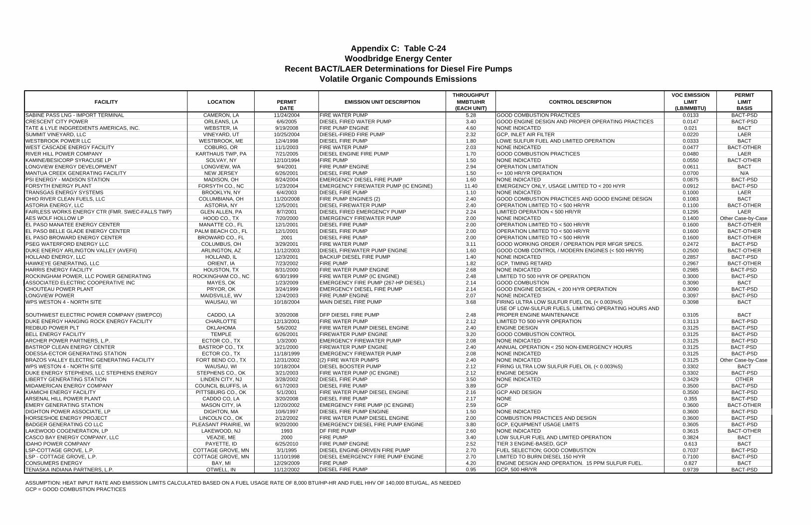
THROUGHPUT VOC EMISSION PERMITFACILITY LOCATION PERMIT EMISSION UNIT DESCRIPTION MMBTU/HR CONTROL DESCRIPTION LIMIT LIMIT
DATE (EACH UNIT) (LB/MMBTU) BASISSABINE PASS LNG - IMPORT TERMINAL CAMERON, LA 11/24/2004 FIRE WATER PUMP 5.28 GOOD COMBUSTION PRACTICES 0.0133 BACT-PSDCRESCENT CITY POWER ORLEANS, LA 6/6/2005 DIESEL FIRED WATER PUMP 3.40 GOOD ENGINE DESIGN AND PROPER OPERATING PRACTICES 0.0147 BACT-PSDTATE & LYLE INDGREDIENTS AMERICAS, INC. WEBSTER, IA 9/19/2008 FIRE PUMP ENGINE 4.60 NONE INDICATED 0.021 BACTSUMMIT VINEYARD, LLC VINEYARD, UT 10/25/2004 DIESEL-FIRED FIRE PUMP 2.32 GCP, INLET AIR FILTER 0.0220 LAERWESTBROOK POWER LLC WESTBROOK, ME 12/4/1998 DIESEL FIRE PUMP 1.80 LOWE SULFUR FUEL AND LIMITED OPERATION 0.0333 BACTWEST CASCADE ENERGY FACILITY COBURG, OR 11/1/2003 FIRE WATER PUMP 2.03 NONE INDICATED 0.0477 BACT-OTHERRIVER HILL POWER COMPANY KARTHAUS TWP, PA 7/21/2005 DIESEL ENGINE FIRE PUMP 1.70 GOOD COMBUSTION PRACTICES 0.0480 LAERKAMINE/BESICORP SYRACUSE LP SOLVAY, NY 12/10/1994 FIRE PUMP 1.50 NONE INDICATED 0.0550 BACT-OTHERLONGVIEW ENERGY DEVELOPMENT LONGVIEW, WA 9/4/2001 FIRE PUMP ENGINE 2.94 OPERATION LIMITATION 0.0611 BACTMANTUA CREEK GENERATING FACILITY NEW JERSEY 6/26/2001 DIESEL FIRE PUMP 1.50 <= 100 HR/YR OPERATION 0.0700 N/APSI ENERGY - MADISON STATION MADISON, OH 8/24/2004 EMERGENCY DIESEL FIRE PUMP 1.60 NONE INDICATED 0.0875 BACT-PSDFORSYTH ENERGY PLANT FORSYTH CO., NC 1/23/2004 EMERGENCY FIREWATER PUMP (IC ENGINE) 11.40 EMERGENCY ONLY, USAGE LIMITED TO < 200 H/YR 0.0912 BACT-PSDTRANSGAS ENERGY SYSTEMS BROOKLYN, NY 6/4/2003 DIESEL FIRE PUMP 1.10 NONE INDICATED 0.1000 LAEROHIO RIVER CLEAN FUELS, LLC COLUMBIANA, OH 11/20/2008 FIRE PUMP ENGINES (2) 2.40 GOOD COMBUSTION PRACTICES AND GOOD ENGINE DESIGN 0.1083 BACTASTORIA ENERGY, LLC ASTORIA, NY 12/5/2001 DIESEL FIREWATER PUMP 2.40 OPERATION LIMITED TO < 500 HR/YR 0.1100 BACT-OTHERFAIRLESS WORKS ENERGY CTR (FMR. SWEC-FALLS TWP) GLEN ALLEN, PA 8/7/2001 DIESEL FIRED EMERGENCY PUMP 2.24 LIMITED OPERATION < 500 HR/YR 0.1295 LAERAES WOLF HOLLOW LP HOOD CO., TX 7/20/2000 EMERGENCY FIREWATER PUMP 2.00 NONE INDICATED 0.1400 Other Case-by-Case EL PASO MANATEE ENERGY CENTER MANATTE CO., FL 12/1/2001 DIESEL FIRE PUMP 2.00 OPERATION LIMITED TO < 500 HR/YR 0.1600 BACT-OTHEREL PASO BELLE GLADE ENERGY CENTER PALM BEACH CO., FL 12/1/2001 DIESEL FIRE PUMP 2.00 OPERATION LIMITED TO < 500 HR/YR 0.1600 BACT-OTHEREL PASO BROWARD ENERGY CENTER BROWARD CO., FL 2001 DIESEL FIRE PUMP 2.00 OPERATION LIMITED TO < 500 HR/YR 0.1600 BACT-OTHERPSEG WATERFORD ENERGY LLC COLUMBUS, OH 3/29/2001 FIRE WATER PUMP 3.11 GOOD WORKING ORDER / OPERATION PER MFGR SPECS. 0.2472 BACT-PSDDUKE ENERGY ARLINGTON VALLEY (AVEFII) ARLINGTON, AZ 11/12/2003 DIESEL FIREWATER PUMP ENGINE 1.60 GOOD COMB CONTROL / MODERN ENGINES (< 500 HR/YR) 0.2500 BACT-OTHERHOLLAND ENERGY, LLC HOLLAND, IL 12/3/2001 BACKUP DIESEL FIRE PUMP 1.40 NONE INDICATED 0.2857 BACT-PSDHAWKEYE GENERATING, LLC ORIENT, IA 7/23/2002 FIRE PUMP 1.82 GCP, TIMING RETARD 0.2967 BACT-OTHERHARRIS ENERGY FACILITY HOUSTON, TX 8/31/2000 FIRE WATER PUMP ENGINE 2.68 NONE INDICATED 0.2985 BACT-PSD ROCKINGHAM POWER, LLC POWER GENERATING ROCKINGHAM CO., NC 6/30/1999 FIRE WATER PUMP (IC ENGINE) 2.48 LIMITED TO 500 H/YR OF OPERATION 0.3000 BACT-PSDASSOCIATED ELECTRIC COOPERATIVE INC MAYES, OK 1/23/2009 EMERGENCY FIRE PUMP (267-HP DIESEL) 2.14 GOOD COMBUSTION 0.3090 BACTCHOUTEAU POWER PLANT PRYOR, OK 3/24/1999 EMERGENCY DIESEL FIRE PUMP 2.14 GOOD ENGINE DESIGN, < 200 H/YR OPERATION 0.3090 BACT-PSDLONGVIEW POWER MAIDSVILLE, WV 12/4/2003 FIRE PUMP ENGINE 2.07 NONE INDICATED 0.3097 BACT-PSDWPS WESTON 4 - NORTH SITE WAUSAU, WI 10/18/2004 MAIN DIESEL FIRE PUMP 3.68 FIRING ULTRA LOW SULFUR FUEL OIL (< 0.003%S) 0.3098 BACT
SOUTHWEST ELECTRIC POWER COMPANY (SWEPCO) CADDO, LA 3/20/2008 DFP DIESEL FIRE PUMP 2.48USE OF LOW-SULFUR FUELS, LIMITING OPERATING HOURS AND PROPER ENGINE MAINTENANCE 0.3105 BACT
DUKE ENERGY HANGING ROCK ENERGY FACILITY CHARLOTTE 12/13/2001 FIRE WATER PUMP 2.12 LIMITED TO 500 H/YR OPERATION 0.3113 BACT-PSDREDBUD POWER PLT OKLAHOMA 5/6/2002 FIRE WATER PUMP DIESEL ENGINE 2.40 ENGINE DESIGN 0.3125 BACT-PSDBELL ENERGY FACILITY TEMPLE 6/26/2001 FIREWATER PUMP ENGINE 3.20 GOOD COMBUSTION CONTROL 0.3125 BACT-PSDARCHER POWER PARTNERS, L.P. ECTOR CO., TX 1/3/2000 EMERGENCY FIREWATER PUMP 2.08 NONE INDICATED 0.3125 BACT-PSDBASTROP CLEAN ENERGY CENTER BASTROP CO., TX 3/21/2000 FIREWATER PUMP ENGINE 2.40 ANNUAL OPERATION < 250 NON-EMERGENCY HOURS 0.3125 BACT-PSD ODESSA-ECTOR GENERATING STATION ECTOR CO., TX 11/18/1999 EMERGENCY FIREWATER PUMP 2.08 NONE INDICATED 0.3125 BACT-PSDBRAZOS VALLEY ELECTRIC GENERATING FACILITY FORT BEND CO., TX 12/31/2002 (2) FIRE WATER PUMPS 2.40 NONE INDICATED 0.3125 Other Case-by-Case WPS WESTON 4 - NORTH SITE WAUSAU, WI 10/18/2004 DIESEL BOOSTER PUMP 2.12 FIRING ULTRA LOW SULFUR FUEL OIL (< 0.003%S) 0.3302 BACTDUKE ENERGY STEPHENS, LLC STEPHENS ENERGY STEPHENS CO., OK 3/21/2003 FIRE WATER PUMP (IC ENGINE) 2.12 ENGINE DESIGN 0.3302 BACT-PSDLIBERTY GENERATING STATION LINDEN CITY, NJ 3/28/2002 DIESEL FIRE PUMP 3.50 NONE INDICATED 0.3429 OTHERMIDAMERICAN ENERGY COMPANY COUNCIL BLUFFS, IA 6/17/2003 DIESEL FIRE PUMP 3.89 GCP 0.3500 BACT-PSDKIAMICHI ENERGY FACILITY PITTSBURG CO., OK 5/1/2001 FIRE WATER PUMP DIESEL ENGINE 2.16 GCP AND DESIGN 0.3500 BACT-PSDARSENAL HILL POWER PLANT CADDO CO, LA 3/20/2008 DIESEL FIRE PUMP 2.17 NONE 0.355 BACT-PSDEMERY GENERATING STATION MASON CITY, IA 12/20/2002 EMERGENCY FIRE PUMP (IC ENGINE) 2.59 GCP 0.3600 BACT-OTHERDIGHTON POWER ASSOCIATE, LP DIGHTON, MA 10/6/1997 DIESEL FIRE PUMP ENGINE 1.50 NONE INDICATED 0.3600 BACT-PSDHORSESHOE ENERGY PROJECT LINCOLN CO., OK 2/12/2002 FIRE WATER PUMP DIESEL ENGINE 2.00 COMBUSTION PRACTICES AND DESIGN 0.3600 BACT-PSDBADGER GENERATING CO LLC PLEASANT PRAIRIE, WI 9/20/2000 EMERGENCY DIESEL FIRE PUMP ENGINE 3.80 GCP, EQUIPMENT USAGE LIMITS 0.3605 BACT-PSDLAKEWOOD COGENERATION, LP LAKEWOOD, NJ 1993 DF FIRE PUMP 2.60 NONE INDICATED 0.3615 BACT-OTHERCASCO BAY ENERGY COMPANY, LLC VEAZIE, ME 2000 FIRE PUMP 3.40 LOW SULFUR FUEL AND LIMITED OPERATION 0.3824 BACTIDAHO POWER COMPANY PAYETTE, ID 6/25/2010 FIRE PUMP ENGINE 2.52 TIER 3 ENGINE-BASED, GCP 0.613 BACTLSP-COTTAGE GROVE, L.P. COTTAGE GROVE, MN 3/1/1995 DIESEL ENGINE-DRIVEN FIRE PUMP 2.70 FUEL SELECTION; GOOD COMBUSTION 0.7037 BACT-PSDLSP - COTTAGE GROVE, L.P. COTTAGE GROVE, MN 11/10/1998 DIESEL EMERGENCY FIRE PUMP ENGINE 2.70 LIMITED TO BURN DIESEL 150 H/YR 0.7100 BACT-PSDCONSUMERS ENERGY BAY, MI 12/29/2009 FIRE PUMP 4.20 ENGINE DESIGN AND OPERATION. 15 PPM SULFUR FUEL. 0.827 BACTTENASKA INDIANA PARTNERS, L.P. OTWELL, IN 11/12/2002 DIESEL FIRE PUMP 0.95 GCP, 500 HR/YR 0.9739 BACT-PSD
ASSUMPTION: HEAT INPUT RATE AND EMISSION LIMITS CALCULATED BASED ON A FUEL USAGE RATE OF 8,000 BTU/HP-HR AND FUEL HHV OF 140,000 BTU/GAL, AS NEEDEDGCP = GOOD COMBUSTION PRACTICES
Appendix C: Table C-24
Recent BACT/LAER Determinations for Diesel Fire PumpsVolatile Organic Compounds Emissions
Woodbridge Energy Center

THROUGHPUT PM/PM-10 EMISSION PERMITFACILITY LOCATION PERMIT EMISSION UNIT DESCRIPTION MMBTU/HR CONTROL DESCRIPTION LIMIT LIMIT
DATE (EACH UNIT) (LB/MMBTU) BASISLAMAR LIGHT & POWER POWER PLANT POWERS, CO 2/3/2006 DIESEL ENGINE FIRE PUMP 12.0 LOW SULFUR FUEL (0.05% BY WEIGHT) 0.016 BACT-PSDSUMMIT VINEYARD, LLC VINEYARD, UT 10/25/2004 DIESEL-FIRED FIRE PUMP 2.32 GCP, INLET AIR FILTER 0.019 BACTEL PASO MANATEE ENERGY CENTER MANATTE CO., FL 12/1/2001 DIESEL FIRE PUMP 2.00 OPERATION LIMITED TO < 500 HR/YR 0.026 BACT-OTHEREL PASO BELLE GLADE ENERGY CENTER PALM BEACH CO., FL 12/1/2001 DIESEL FIRE PUMP 2.00 OPERATION LIMITED TO < 500 HR/YR 0.026 BACT-OTHEREL PASO BROWARD ENERGY CENTER BROWARD CO., FL 2001 DIESEL FIRE PUMP 2.00 OPERATION LIMITED TO < 500 HR/YR 0.026 BACT-OTHERRIVER HILL POWER COMPANY KARTHAUS TWP, PA 7/21/2005 DIESEL ENGINE FIRE PUMP 1.70 CLEAN FUELS 0.030 BACT-PSDIDAHO POWER COMPANY PAYETTE, ID 6/25/2010 FIRE PUMP ENGINE 2.52 TIER 3 ENGINE-BASED,��GOOD COMBUSTION PRACTICES (GCP) 0.031 BACTGENOVA OK I POWER PROJECT GRADY CO., OK 6/13/2002 FIRE WATER PUMP DIESEL ENGINE 1.60 ENGINE DESIGN AND GOOD COMBUSTION 0.031 BACT-PSDLA COUNTY PROBATION/PAC PLANNING/ISD LOS ANGELES, CA 8/14/2003 IC ENGINE FIRE PUMP 1.92 NONE INDICATED 0.039 BACT-PSDARIZONA CLEAN FUELS YUMA LLC YUMA, AZ 4/14/2005 FIRE WATER PUMPS (2) 5.46 NONE INDICATED 0.041 BACT-PSDTATE & LYLE INDGREDIENTS AMERICAS, INC. WEBSTER, IA 9/19/2008 FIRE PUMP ENGINE 4.60 NONE INDICATED 0.041 BACTTATE & LYLE INDGREDIENTS AMERICAS, INC. WEBSTER, IA 09/19/2008 & FIRE PUMP ENGINE 4.60 NONE INDICATED 0.041 BACTCRESCENT CITY POWER ORLEANS, LA 6/6/2005 DIESEL FIRED WATER PUMP 3.40 GOOD ENGINE DESIGN AND PROPER OPERATING PRACTICES 0.041 BACT-PSDCONSUMERS ENERGY BAY, MI 12/29/2009 FIRE PUMP 4.20 ENGINE DESIGN AND OPERATION. 15 PPM SULFUR FUEL. 0.041 BACTLONGVIEW ENERGY DEVELOPMENT LONGVIEW, WA 9/4/2001 FIRE PUMP ENGINE 2.94 OPERATION LIMITATION 0.044 BACTCALPINE WAWAYANDA WAWAYANDA, NY 7/22/2002 FIRE WATER PUMP 2.40 OPERATIONAL RESTRICTIONS (< 52 HR/YR) 0.047 BACTBLYTHE ENERGY PROJECT II RIVERSIDE CO, CA 4/25/2007 DIESEL FIRE PUMP 2.12 NONE 0.047 BACT-PSDASTORIA ENERGY, LLC ASTORIA, NY 12/5/2001 DIESEL FIREWATER PUMP 2.40 OPERATION LIMITED TO < 500 HR/YR 0.060 BACT-OTHERFAIRLESS WORKS ENERGY CENTER (FMR. SWEC-FA GLEN ALLEN, PA 8/7/2001 DIESEL FIRED EMERGENCY PUMP 2.24 LIMITED OPERATION < 500 HR/YR 0.061 BACT-PSDWEST CASCADE ENERGY FACILITY COBURG, OR 11/1/2003 FIRE WATER PUMP 2.03 NONE INDICATED 0.062 BACT-OTHERAES WOLF HOLLOW LP HOOD CO., TX 7/20/2000 EMERGENCY FIREWATER PUMP 2.00 NONE INDICATED 0.070 Other Case-by-Case HOLLAND ENERGY, LLC HOLLAND, IL 12/3/2001 BACKUP DIESEL FIRE PUMP 1.40 NONE INDICATED 0.086 BACT-PSDFORSYTH ENERGY PLANT FORSYTH CO., NC 1/23/2004 EMERGENCY FIREWATER PUMP (IC ENGINE) 11.40 EMERGENCY ONLY, USAGE LIMITED TO < 200 H/YR 0.100 BACT-PSDBADGER GENERATING CO LLC PLEASANT PRAIRIE, WI 9/20/2000 EMERGENCY DIESEL FIRE PUMP ENGINE 3.80 GCP USE OF FUEL < 0.05% S BY WT. EQUIPMENT USAGE LIMIT 0.100 BACT-PSDASSOCIATED ELECTRIC COOPERATIVE INC MAYES, OK 1/23/2009 EMERGENCY FIRE PUMP (267-HP DIESEL) 2.14 NONE INDICATED 0.112 BACTOHIO RIVER CLEAN FUELS, LLC COLUMBIANA, OH 11/20/2008 FIRE PUMP ENGINES (2) 2.40 GOOD COMBUSTION PRACTICES AND GOOD ENGINE DESIGN 0.113 BACTWESTBROOK POWER LLC WESTBROOK, ME 12/4/1998 DIESEL FIRE PUMP 1.80 LOWE SULFUR FUEL AND LIMITED OPERATION 0.120 BACTCASCO BAY ENERGY COMPANY, LLC VEAZIE, ME 2000 FIRE PUMP 3.40 LOW SULFUR FUEL AND LIMITED OPERATION 0.120 BACTHAWKEYE GENERATING, LLC ORIENT, IA 7/23/2002 FIRE PUMP 1.82 GCP, TIMING RETARD 0.121 BACT-PSDHAWKEYE GENERATING, LLC ORIENT, IA 7/23/2002 FIRE PUMP 1.82 GCP, TIMING RETARD 0.121 BACT-PSDMANTUA CREEK GENERATING FACILITY NEW JERSEY 6/26/2001 DIESEL FIRE PUMP 1.50 SULFUR <= 0.2% BY WEIGHT; <= 100 HR/YR OPERATION 0.170 N/APSI ENERGY - MADISON STATION MADISON, OH 8/24/2004 EMERGENCY DIESEL FIRE PUMP 1.60 NONE INDICATED 0.194 BACT-PSDKAMINE/BESICORP SYRACUSE LP SOLVAY, NY 12/10/1994 FIRE PUMP 1.50 FUEL SPECIFICATION: SULFUR CONTENT </= 0.15% BY WT 0.200 BACT-OTHERKAMINE/BESICORP SYRACUSE LP SOLVAY, NY 12/10/1994 FIRE PUMP 1.50 FUEL SPECIFICATION: SULFUR CONTENT </= 0.15% BY WT 0.200 BACT-OTHERPSEG WATERFORD ENERGY LLC COLUMBUS, OH 3/29/2001 FIRE WATER PUMP 3.11 GOOD WORKING ORDER AND OPERATION PER MFGR SPECS. 0.210 BACT-PSDSABINE PASS LNG - IMPORT TERMINAL CAMERON, LA 11/24/2004 FIRE WATER PUMP 5.28 GOOD COMBUSTION PRACTICE 0.235 BACT-PSDDUKE ENERGY ARLINGTON VALLEY (AVEFII) ARLINGTON, AZ 11/12/2003 DIESEL FIREWATER PUMP ENGINE 1.60 GOOD COMB CONTROL / MODERN ENGINES, S < 0.05% (< 500 HR/YR) 0.250 BACT-OTHERLSP-COTTAGE GROVE, L.P. COTTAGE GROVE, MN 3/1/1995 DIESEL ENGINE-DRIVEN FIRE PUMP 2.70 FUEL SELECTION; GOOD COMBUSTION 0.259 BACT-PSDLSP - COTTAGE GROVE, L.P. COTTAGE GROVE, MN 11/10/1998 DIESEL EMERGENCY FIRE PUMP ENGINE 2.70 LIMITED TO BURN DIESEL 150 H/YR 0.260 BACT-PSDLSP - COTTAGE GROVE, L.P. COTTAGE GROVE, MN 11/10/1998 DIESEL EMERGENCY FIRE PUMP ENGINE 2.70 LIMITED TO BURN DIESEL 150 H/YR 0.260 BACT-PSDHARRIS ENERGY FACILITY HOUSTON, TX 8/31/2000 FIRE WATER PUMP ENGINE 2.68 NONE INDICATED 0.261 BACT-PSD LONGVIEW POWER MAIDSVILLE, WV 12/4/2003 FIRE PUMP ENGINE 2.07 NONE INDICATED 0.271 BACT-PSDWPS WESTON 4 - NORTH SITE WAUSAU, WI 10/18/2004 DIESEL BOOSTER PUMP 2.12 FIRING ULTRA LOW SULFUR FUEL OIL (< 0.003%S) 0.274 BACTARCHER POWER PARTNERS, L.P. ECTOR CO., TX 1/3/2000 EMERGENCY FIREWATER PUMP 2.08 NONE INDICATED 0.274 BACT-PSDODESSA-ECTOR GENERATING STATION ECTOR CO., TX 11/18/1999 EMERGENCY FIREWATER PUMP 2.08 NONE INDICATED 0.274 BACT-PSDSOUTHWEST ELECTRIC POWER COMPANY (SWEPCO CADDO, LA 3/20/2008 DFP DIESEL FIRE PUMP 2.48 USE OF LOW-SULFUR FUELS, LIMITING OPERATING HOURS AND PROPER 0.274 BACTWPS WESTON 4 - NORTH SITE WAUSAU, WI 10/18/2004 MAIN DIESEL FIRE PUMP 3.68 FIRING ULTRA LOW SULFUR FUEL OIL (< 0.003%S) 0.274 BACTDUKE ENERGY WASHINGTON COUNTY LLC OHIO 1/18/2001 EMERGENCY DIESEL FIRE PUMP ENGINE 3.20 LOW SULFUR FUEL COMBUSTION CONTROL 0.275 BACT-PSDREDBUD POWER PLT OKLAHOMA 5/6/2002 FIRE WATER PUMP DIESEL ENGINE 2.4 NONE INDICATED 0.275 BACT-PSDBASTROP CLEAN ENERGY CENTER BASTROP CO., TX 3/21/2000 FIREWATER PUMP ENGINE 2.40 ANNUAL OPERATION < 250 NON-EMERGENCY HOURS 0.275 BACT-PSD BRAZOS VALLEY ELECTRIC GENERATING FACILITY FORT BEND CO., TX 12/31/2002 (2) FIRE WATER PUMPS 2.40 NONE INDICATED 0.275 Other Case-by-Case CHOUTEAU POWER PLANT PRYOR, OK 3/24/1999 EMERGENCY DIESEL FIRE PUMP 2.14 GOOD ENGINE DESIGN, < 200 H/YR OPERATION 0.276 BACT-PSDBELL ENERGY FACILITY TEMPLE 6/26/2001 FIREWATER PUMP ENGINE 3.20 GOOD COMBUSTION CONTROL AND USE OF LOW-SULFUR DIESEL 0.281 BACT-PSDLAIDLAW BERLIN BIOPOWER, LLC COOS, NH 7/26/2010 EU03 FIRE PUMP ENGINE 2.3 NONE INDICATED 0.300 BACTROCKINGHAM POWER, LLC POWER GENERATING ROCKINGHAM CO., NC 6/30/1999 FIRE WATER PUMP (IC ENGINE) 2.48 LIMITED TO 500 H/YR OF OPERATION 0.300 BACT-PSDLAKEWOOD COGENERATION, LP LAKEWOOD, NJ 1993 DF FIRE PUMP 2.60 NONE INDICATED 0.308 BACT-OTHERCONSUMERS ENERGY BAY, MI 12/29/2009 FIRE PUMP 4.20 ENGINE DESIGN AND OPERATION. 15 PPM SULFUR FUEL. 0.310 BACTTRANSGAS ENERGY SYSTEMS BROOKLYN, NY 6/4/2003 DIESEL FIRE PUMP 1.10 NONE INDICATED 0.310 BACTEMERY GENERATING STATION MASON CITY, IA 12/20/2002 EMERGENCY FIRE PUMP (IC ENGINE) 2.59 LOW ASH FUEL AND GOOD OPERATING PRACTICES 0.310 BACT-OTHERMIDAMERICAN ENERGY COMPANY COUNCIL BLUFFS, IA 6/17/2003 DIESEL FIRE PUMP 3.89 GCP 0.310 BACT-PSDDUKE ENERGY STEPHENS, LLC STEPHENS ENERGY STEPHENS CO., OK 3/21/2003 FIRE WATER PUMP (IC ENGINE) 2.12 COMBUSTION CONTROL AND GOOD ENGINE DESIGN 0.310 BACT-PSDEMERY GENERATING STATION MASON CITY, IA 12/20/2002 EMERGENCY FIRE PUMP (IC ENGINE) 2.59 LOW ASH FUEL AND GCP 0.310 BACT-OTHERMIDAMERICAN ENERGY COMPANY COUNCIL BLUFFS, IA 6/17/2003 DIESEL FIRE PUMP 3.89 GCP 0.310 BACT-PSDDIGHTON POWER ASSOCIATE, LP DIGHTON, MA 10/6/1997 DIESEL FIRE PUMP ENGINE 1.50 NONE INDICATED 0.310 BACT-PSDHORSESHOE ENERGY PROJECT LINCOLN CO., OK 2/12/2002 FIRE WATER PUMP DIESEL ENGINE 2.00 LOW ASH FUEL 0.310 BACT-PSDDUKE ENERGY HANGING ROCK ENERGY FACILITY CHARLOTTE 12/13/2001 FIRE WATER PUMP 2.12 LIMITED TO 500 H/YR OPERATION 0.311 BACT-PSDARSENAL HILL POWER PLANT CADDO CO, LA 3/20/2008 DIESEL FIRE PUMP 2.17 NONE 0.313 BACT-PSDLIBERTY GENERATING STATION LINDEN CITY, NJ 3/28/2002 DIESEL FIRE PUMP 3.50 NONE 0.314 OTHERLIBERTY GENERATING STATION LINDEN CITY, NJ 3/28/2002 DIESEL FIRE PUMP 3.50 NONE 0.314 OTHERGRAIN PROCESSING CORP. WASHINGTON, IN 6/10/1997 EMERGENCY FIRE PUMP 0.92 NONE INDICATED 0.543 BACT-PSDTENASKA INDIANA PARTNERS, L.P. OTWELL, IN 11/12/2002 DIESEL FIRE PUMP 0.95 SULFUR LIMITED TO 0.05% BY WEIGHT, 500 HR/YR 0.852 BACT-PSDKIAMICHI ENERGY FACILITY PITTSBURG CO., OK 5/1/2001 FIRE WATER PUMP DIESEL ENGINE 2.16 GCP AND DESIGN 2.110 BACT-PSD
ASSUMPTION: HEAT INPUT RATE AND EMISSION LIMITS CALCULATED BASED ON A FUEL USAGE RATE OF 8,000 BTU/HP-HR AND FUEL HHV OF 140,000 BTU/GAL, AS NEEDEDGCP = GOOD COMBUSTION PRACTICES
Appendix C: Table C-25
Recent BACT/LAER Determinations for Diesel Fire PumpsParticulate Matter Emissions
Woodbridge Energy Center

THROUGHPUT SO2 EMISSION PERMITFACILITY LOCATION PERMIT EMISSION UNIT DESCRIPTION MMBTU/HR CONTROL DESCRIPTION LIMIT LIMIT
DATE (EACH UNIT) (LB/MMBTU) BASISEL PASO MANATEE ENERGY CENTER MANATTE CO., FL 12/1/2001 DIESEL FIRE PUMP 2.0 OPERATION LIMITED TO < 500 HR/YR 0.003 BACT-OTHEREL PASO BELLE GLADE ENERGY CENTER PALM BEACH CO., FL 12/1/2001 DIESEL FIRE PUMP 2.0 OPERATION LIMITED TO < 500 HR/YR 0.003 BACT-OTHEREL PASO BROWARD ENERGY CENTER BROWARD CO., FL 2001 DIESEL FIRE PUMP 2.0 OPERATION LIMITED TO < 500 HR/YR 0.003 BACT-OTHERTRANSGAS ENERGY SYSTEMS BROOKLYN, NY 6/4/2003 DIESEL FIRE PUMP 1.1 NONE INDICATED 0.020 BACTFAIRLESS WORKS ENERGY CENTER (FMR. SWEC-FALLS TO GLEN ALLEN, PA 8/7/2001 DIESEL FIRED EMERGENCY PUMP 2.2 LIMITED OPERATION < 500 HR/YR 0.047 BACT-PSDDUKE ENERGY HANGING ROCK ENERGY FACILITY CHARLOTTE 12/13/2001 FIRE WATER PUMP 2.1 LOW SULFUR FUEL 0.047 BACT-PSDTATE & LYLE INDGREDIENTS AMERICAS, INC. WEBSTER, IA 9/19/2008 FIRE PUMP ENGINE 4.6 LIMIT ON SULFUR IN FUEL 0.047 BACTLONGVIEW ENERGY DEVELOPMENT LONGVIEW, WA 9/4/2001 FIRE PUMP ENGINE 2.9 LOW SULFUR FUEL OIL (< 0.05% S) 0.048 BACTLA COUNTY PROBATION/FAC PLANNING/ISD LOS ANGELES, CA 8/14/2003 IC ENGINE FIRE PUMP 1.9 LOW SULFUR FUEL OIL (TO BE CONVERTED TO ULTRA LOW SULFUR FUEL) 0.050 BACT-PSDROCKINGHAM POWER, LLC POWER GENERATING ROCKINGHAM CO., NC 6/30/1999 FIRE WATER PUMP (IC ENGINE) 2.5 LIMITED TO 500 H/YR OF OPERATION 0.050 BACT-PSDMANTUA CREEK GENERATING FACILITY NEW JERSEY 6/26/2001 DIESEL FIRE PUMP 1.5 SULFUR MUST BE <= 0.2% BY WEIGHT; <= 100 HR/YR OPERATION 0.050 N/AHORSESHOE ENERGY PROJECT LINCOLN CO., OK 2/12/2002 FIRE WATER PUMP DIESEL ENGINE 2.0 LOW SULFUR DIESEL FUEL 0.050 BACT-PSDFORSYTH ENERGY PLANT FORSYTH CO., NC 1/23/2004 EMERGENCY FIREWATER PUMP (IC ENGINE) 11.4 EMERGENCY ONLY, USAGE LIMITED TO < 200 H/YR 0.051 BACT-PSDASSOCIATED ELECTRIC COOPERATIVE INC MAYES, OK 1/23/2009 EMERGENCY FIRE PUMP (267-HP DIESEL) 2.1 LOW SULFUR DIESEL 0.051 BACTCHOUTEAU POWER PLANT PRYOR, OK 3/24/1999 EMERGENCY DIESEL FIRE PUMP 2.1 LIMITED TO 200 H/YR OPERATION 0.051 BACT-PSDMIDAMERICAN ENERGY COMPANY COUNCIL BLUFFS, IA 6/17/2003 DIESEL FIRE PUMP 3.9 GCP AND LOW SULFUR FUEL 0.052 BACT-PSDDIGHTON POWER ASSOCIATE, LP DIGHTON, MA 10/6/1997 DIESEL FIRE PUMP ENGINE 1.5 NONE INDICATED 0.053 BACT-PSDCASCO BAY ENERGY COMPANY, LLC VEAZIE, ME 2000 FIRE PUMP 3.4 LOW SULFUR FUEL AND LIMITED OPERATION 0.059 BACTLAMAR LIGHT & POWER POWER PLANT POWERS, CO 2/3/2006 DIESEL ENGINE FIRE PUMP 12.0 LOW SULFUR FUEL (0.05% BY WEIGHT) 0.060 BACT-PSDARCHER POWER PARTNERS, L.P. ECTOR CO., TX 1/3/2000 EMERGENCY FIREWATER PUMP 2.1 NONE INDICATED 0.101 BACT-PSDODESSA-ECTOR GENERATING STATION ECTOR CO., TX 11/18/1999 EMERGENCY FIREWATER PUMP 2.1 NONE INDICATED 0.101 BACT-PSDCRESCENT CITY POWER ORLEANS, LA 6/6/2005 DIESEL FIRED WATER PUMP 3.4 NONE INDICATED 0.180 BACT-PSDRIVER HILL POWER COMPANY KARTHAUS TWP, PA 7/21/2005 DIESEL ENGINE FIRE PUMP 1.7 LOW SULFUR FUEL 0.203 BACT-PSDDUKE ENERGY STEPHENS, LLC STEPHENS ENERGY STEPHENS CO., OK 3/21/2003 FIRE WATER PUMP (IC ENGINE) 2.1 USE OF VERY LOW SULFUR DIESEL FUEL (<0.05% S BY WT) 0.236 BACT-PSDBELL ENERGY FACILITY TEMPLE 6/26/2001 FIREWATER PUMP ENGINE 3.2 GOOD COMBUSTION CONTROLS, USE OF LOW SULFUR (0.05%) FUELS 0.250 BACT-PSDDUKE ENERGY ARLINGTON VALLEY (AVEFII) ARLINGTON, AZ 11/12/2003 DIESEL FIREWATER PUMP ENGINE 1.6 GOOD COMB CONTROL / MODERN ENGINES, S < 0.05% (< 500 HR/YR) 0.250 BACT-OTHERWPS WESTON 4 - NORTH SITE WAUSAU, WI 10/18/2004 DIESEL BOOSTER PUMP 2.1 FIRING ULTRA LOW SULFUR FUEL OIL (< 0.003%S) 0.255 BACTWPS WESTON 4 - NORTH SITE WAUSAU, WI 10/18/2004 MAIN DIESEL FIRE PUMP 3.7 FIRING ULTRA LOW SULFUR FUEL OIL (< 0.003%S) 0.255 BACT
SOUTHWEST ELECTRIC POWER COMPANY (SWEPCO) CADDO, LA 3/20/2008 DFP DIESEL FIRE PUMP 2.5USE OF LOW-SULFUR FUELS, LIMITING OPERATING HOURS AND PROPER ENGINE MAINTENANCE 0.258 BACT
BASTROP CLEAN ENERGY CENTER BASTROP CO., TX 3/21/2000 FIREWATER PUMP ENGINE 2.4 DISTILLATE FUEL OIL < 0.3 WEIGHT PERCENT SULFUR 0.258 BACT-PSD BRAZOS VALLEY ELECTRIC GENERATING FACILITY FORT BEND CO., TX 12/31/2002 (2) FIRE WATER PUMPS 2.4 DIESEL </+ 0.3% S, MAX OPER 100 H/YR, NON-EMERGENCY USE 0.258 Other Case-by-Case HARRIS ENERGY FACILITY HOUSTON, TX 8/31/2000 FIRE WATER PUMP ENGINE 2.7 NONE INDICATED 0.261 BACT-PSD DUKE ENERGY WASHINGTON COUNTY LLC OHIO 1/18/2001 EMERGENCY DIESEL FIRE PUMP ENGINE 3.2 LOW SULFUR FUEL COMBUSTION CONTROL 0.263 BACT-PSDWESTBROOK POWER LLC WESTBROOK, ME 12/4/1998 DIESEL FIRE PUMP 1.8 LOWE SULFUR FUEL AND LIMITED OPERATION 0.283 BACTLIBERTY GENERATING STATION LINDEN CITY, NJ 3/28/2002 DIESEL FIRE PUMP 3.5 NONE INDICATED 0.286 BACT-OTHERHOLLAND ENERGY, LLC HOLLAND, IL 12/3/2001 BACKUP DIESEL FIRE PUMP 1.4 NONE INDICATED 0.286 BACT-PSDLAKEWOOD COGENERATION, LP LAKEWOOD, NJ 1993 DF FIRE PUMP 2.6 NONE INDICATED 0.288 BACT-OTHERBADGER GENERATING CO LLC PLEASANT PRAIRIE, WI 9/20/2000 EMERGENCY DIESEL FIRE PUMP ENGINE 3.8 DIESEL FUEL SULFUR CONTENT OF 0.05% & EQUIPMENT USAGE LIMITS 0.289 BACT-PSDEMERY GENERATING STATION MASON CITY, IA 12/20/2002 EMERGENCY FIRE PUMP (IC ENGINE) 2.6 LOW SULFUR FUEL 0.290 BACT-OTHERNEARMAN CREEK POWER STATION WYANDOTTE COUNTY, KS 10/18/2005 EMERGENCY BLACK START GENERATOR 24.10 NONE 0.291 BACT-PSDARSENAL HILL POWER PLANT CADDO CO, LA 3/20/2008 DIESEL FIRE PUMP 2.17 NONE 0.295 BACT-PSDSUMMIT VINEYARD, LLC VINEYARD, UT 10/25/2004 DIESEL-FIRED FIRE PUMP 2.3 GCP, INLET AIR FILTER 0.322 BACTPSEG WATERFORD ENERGY LLC COLUMBUS, OH 3/29/2001 FIRE WATER PUMP 3.1 GOOD WORKING ORDER AND OPERATION PER MANUFACTURER SPECS. 0.371 BACT-PSDREDBUD POWER PLT OKLAHOMA 5/6/2002 FIRE WATER PUMP DIESEL ENGINE 2.4 NONE INDICATED 0.400 BACT-PSDAES WOLF HOLLOW LP HOOD CO., TX 7/20/2000 EMERGENCY FIREWATER PUMP 2.0 NONE INDICATED 0.420 Other Case-by-Case PSI ENERGY - MADISON STATION MADISON, OH 8/24/2004 EMERGENCY DIESEL FIRE PUMP 1.6 LOW SULFUR FUEL 0.500 BACT-PSDWEST CASCADE ENERGY FACILITY COBURG, OR 11/1/2003 FIRE WATER PUMP 2.0 NONE INDICATED 0.507 BACT-OTHERTENASKA INDIANA PARTNERS, L.P. OTWELL, IN 11/12/2002 DIESEL FIRE PUMP 1.0 SULFUR LIMITED TO 0.05% BY WEIGHT, 500 HR/YR 0.794 BACT-PSDLONGVIEW POWER MAIDSVILLE, WV 12/4/2003 FIRE PUMP ENGINE 2.1 NONE INDICATED 1.597 BACT-PSD
Appendix C: Table C-26
Recent BACT/LAER Determinations for Diesel Fire PumpsSulfur Dioxide Emissions
Woodbridge Energy Center

DRIFT PERMITFACILITY LOCATION PERMIT OPERATING EMISSION UNIT DESCRIPTION CONTROL DESCRIPTION PM LIMIT RATE LIMIT
DATE STATUS LB/HR % BASISOPPD - NEBRASKA CITY STATION OTOE, NE 3/9/2005 NO NONE INDICATED 0.001 ? BACT-PSDAES WOLF HOLLOW LP AUSTIN, TX 7/20/2000 NO COOLING TOWERS E-CTOWER-W&-E (2) NONE INDICATED 0.002 0.01% OTHERFORSYTH ENERGY PLANT FORSYTH, NC 9/29/2005 NO MIST ELIMINATOR 0.002 0.0005% BACT-PSDSAN JUAN REPOWERING PROJECT MONACILLOS, PR 3/2/2000 ? COOLING TOWER DRIFT ELIMINATORS 0.004 0.0005% OTHERGREGORY POWER FACILITY TEXAS 6/16/1999 NO CONDENSATE COOLING TOWER 108 NONE INDICATED 0.01 ? BACT-PSDBELL ENERGY FACILITY TEMPLE, TX 6/26/2001 NO 9 COOLING TOWER VENTS HIGH-EFFICIENCY DRIFT ELIMINATORS 0.04 ? BACT-PSDJACK COUNTY POWER PLANT HOUSTON, TX 3/14/2000 NO COOLING TOWER VENTS CTV1-9 NONE INDICATED 0.04 ? BACT-PSDKAUFMAN COGEN LP CHARLOTTE, NC 1/31/2000 NO COOLING TOWER VENTS CTV1 THRU 9 NONE INDICATED 0.04 ? BACT-PSDMICHOUD ELECTRIC GENERATING PLANT ORLEANS, LA 10/12/2004 ? DRIFT ELIMINATORS AND GOOD OPERATING PRACTICES 0.05 0.001% BACT-PSDATOFINA CHEMICALS INCORPORATED BEAUMONT, TX 12/19/2002 NO SULFOX COOLING TOWER SULFOX-CT NONE INDICATED 0.06 ? OTHERSHINTECH LOUISIANA LLC IBERVILLE CO, LA 2/27/2009 NO DRIFT ELIMINATOR 0.15 ? BACT-PSDPLAQUEMINE PVC PLANT IBERVILLE, LA 7/27/2005 NO GOOD DESIGN, MAINTENANCE & INTEGRATED DRIFT ELIM 0.19 ? BACT-PSDLIMESTONE ELECTRIC GENERATING STATION HOUSTON, TX 5/23/2001 NO AUXILIARY COOLING TOWERS NO 1 & 2 (2) MIST & DRIFT ELIMINATORS 0.29 ? BACT-PSDNSA-A DIVISION OF SOUTHWIRE COMPANY" HAWESVILLE, KY 5/29/1998 ? COOLING TOWER REASONABLE POLLUTION PRECAUTIONS 0.29 ? OTHERGENOVA OK I POWER PROJECT OKLAHOMA 6/13/2002 ? COOLING TOWER DRIFT ELIMINATORS 0.31 0.001% BACT-PSDCOGENERATION PLANT (AES-PRCP) PUERTO RICO 10/29/2001 YES COOLING TOWER DRIFT ELIMINATOR 0.33 ? BACT-PSDDUKE ENERGY HANGING ROCK ENERGY FACILITY CHARLOTTE, NC 12/13/2001 YES COOLING TOWERS (2) DRIFT ELIMINATORS 0.33 ? BACT-PSDCHOUTEAU POWER PLANT MAYES, OK 1/23/2009 ? COOLING TOWER DRIFT ELIMINATORS 0.4 ? BACT-PSDEL PASO BELLE GLADE ENERGY CENTER BELLE GLADE, FL 9/7/2001 NO COOLING TOWER USE OF FRESH WATER AND DRIFT ELIMINATORS 0.40 0.0005% BACT-PSDEL PASO BROWARD ENERGY CENTER DEERFIELD BEACH, FL 8/17/2001 NO COOLING TOWER USE OF FRESH WATER AND DRIFT ELIMINATORS 0.40 0.0005% BACT-PSDEL PASO MANATEE ENERGY CENTER PINEY POINT, FL 9/11/2001 NO COOLING TOWER USE OF FRESH WATER AND DRIFT ELIMINATORS 0.40 0.0005% BACT-PSDTHOMAS B. FITZHUGH GENERATING STATION OZARK, AR 2/15/2002 ? COOLING TOWER DRIFT ELIMINATORS 0.40 ? BACT-PSDBERGEN PLANT NEWARK, NJ 5/27/1993 ? MECHANICAL DRAFT COOLING TOWERS (2) HIGH EFFICIENCY DRIFT ELIMINATOR 0.50 ? NSPSENNIS TRACTEBEL POWER ENNIS, TX 1/31/2002 NO COOLING TOWER CT-1 NONE INDICATED 0.50 ? OTHERSHELL CHEMICAL COMPANY - GEISMAR PLANT GEISMAR, LA 5/10/2000 ? COOLING TOWERS DRIFT ELIMINATORS 0.51 ? BACT-PSDCHOCOLATE BAYOU PLANT ALVIN, TX 3/24/2003 NO COOLING WATER TOWER (2 CELLS) COGENCWT NONE INDICATED 0.54 ? OTHERACE ETHANOL - STANLEY CHIPPEWA, WI 1/21/2004 ? MIST ELIMINATORS 0.65 0.005% BACT-PSDCLOVIS ENERGY FACILITY HOUSTON, NM 6/27/2002 ? COOLING TOWERS (CT-1 AND CT-2) DRIFT ELIMINATORS 0.70 ? BACT-PSDDUKE ENERGY HOT SPRINGS MALVERN, AR 12/29/2000 NO 12 CELL COOLING TOWERS (2) DRIFT ELIMINATOR 0.70 ? BACT-PSDACADIA POWER STATION, ACADIA POWER LOUISIANA 1/31/2002 ? COOLING TOWERS NO. 1 & 2 INTEGRATED DRIFT ELIMINATORS 0.76 ? BACT-PSDBATON ROUGE REFINERY BATON ROUGE, LA 4/26/2002 NO COOLING TOWER DRIFT ELIMINATOR (MECHANICAL DRAFT DESIGN) 0.77 ? BACT-PSDWESTERN GREENBRIER COGENERATION, LLC GREENBRIER, WV 4/26/2006 NO DRIFT ELIMINATORS @ 0.0005% DRIFT RATE 0.79 0.0005% BACT-PSDPLUM POINT ENERGY ARKANSAS 8/20/2003 ? COOLING TOWER SN-03 MIST ELIMINATORS 0.80 ? OTHERSAM RAYBURN GENERATION STATION NURSERY, TX 1/17/2002 ? COOLING TOWER DRIFT ELIMINATORS 0.84 0.0005% BACT-PSDAES RED OAK LLC SAYREVILLE, NJ 10/24/2001 YES 10 CELL WET MECHANICAL DRAFT COOLING TOWER NONE INDICATED 0.90 ? BACT-PSDHOT SPRINGS POWER PROJECT ARKANSAS 11/9/2001 ? COOLING TOWER SN-03 - SN14 HIGH EFFICENCY DRIFT ELIMINATOR 0.90 ? BACT-PSDLIBERTY GENERATING STATION LINDEN CITY, NJ 3/28/2002 ? MECHANICAL DRAFT COOLING TOWERS (3) NONE INDICATED 0.90 ? OTHERLONGVIEW POWER, LLC MAIDSVILLE, WV 3/2/2004 NO REDUNDANT BAFFLE AND MESH DEMISTER SYSTEM 0.90 0.0002% BACT-PSDCARVILLE ENERGY CENTER NORTHBROOK, LA 12/9/1999 ? COOLING TOWERS (2) LIMIT EXCESS WATER & AIR FLOW & AVOID BYPASS OF DRIFT ELIM 0.92 ? BACT-PSDLAKE CHARLES REFINERY WESTLAKE, LA 12/22/1998 NO COOLING TOWER Y-6 NONE INDICATED 1.00 ? BACT-OTHERPPG INDUSTRIES LAKE CHARLES, LA 12/2/1999 ? COOLING TOWERS DRIFT ELIMINATOR 1.00 ? BACT-PSDWISE COUNTY POWER HOUSTON, TX 7/14/2000 NO COOLING TOWER CT-1 NONE INDICATED 1.05 ? BACT-OTHERGATEWAY POWER PROJECT TEXAS 3/20/2000 ? (3) COOLING TOWER 1,2,3; CLT-1,-2,-3 NONE INDICATED 1.07 ? BACT-PSDALCOA ALUMINUM SHEET, PLATE & FOIL ELMENDORF, TX 9/28/2001 NO COOLING TOWER NONE INDICATED 1.10 ? BACT-PSDEXXON-MOBIL BEAUMONT REFINERY BEAUMONT, TX 3/14/2000 ? JV COOLING TOWER 61CTL_031 NONE INDICATED 1.10 ? NSPSTENASKA INDIANA PARTNERS, L.P. OTWELL, IN 11/12/2002 ? NONE INDICATED 1.10 0.0005% BACT-PSD
UWGP - FUEL GRADE ETHANOL PLANT FRIESLAND, WI 8/14/2003 ? COOLING TOWERS, P80 0.005% MAX. DRIFT RATE; 2,000 PPM SOLIDS; MAX FLOW OF 22,000 GPM 1.10 0.0005% OTHERMONTGOMERY COUNTY POWER PROJECT TEXAS 6/27/2001 NO COOLING TOWER CT-1 NONE INDICATED 1.13 ? BACT-OTHERRODEMACHER BROWNFIELD UNIT 3 RAPIDES, LA 2/23/2006 NO DRIFT ELIMINATORS 1.13 0.0050% BACT-PSDCARVILLE ENERGY CENTER NORTHBROOK, LA 5/16/2001 ? COOLING TOWER DRIFT ELIMINATOR AND GOP 1.19 ? BACT-PSDDUKE ENERGY STEPHENS, LLC OKLAHOMA 3/21/2003 ? COOLING TOWER DRIFT ELIMINATORS 1.20 ? BACT-PSDWEBERS FALLS ENERGY FACILITY NORMAN, OK 10/22/2001 ? COOLING TOWER DRIFT ELIMINATORS 1.20 ? BACT-PSDCHARTER STEEL DIVISION SAUKVILLE, WI 2/26/1997 ? COOLING TOWER, P06 DRIFT ELIMINATOR & TDS IN COOLING WATER < 1.2% BY WEIGHT 1.30 ? BACT-PSDHARRIS ENERGY FACILITY HOUSTON, TX 8/31/2000 NO COOLING TOWER UNITS 1 - 8 (8) NONE INDICATED 1.30 ? BACT-PSDLAKE CHARLES REFINERY WESTLAKE, LA 8/12/1999 ? COOLING TOWERS Y-4 & Y-5 DRIFT ELIMINATOR 1.30 0.004% BACT-PSDGOLDEN GRAIN ENERGY CERRO GORDO, IA 4/19/2006 NO MIST ELIMINATOR 1.33 ? BACT-PSDCAROLINA POWER AND LIGHT - RICHMOND CO RALEIGH, NC 12/21/2000 ? COOLING TOWER DRIFT ELIMINATORS 1.38 ? BACT-PSDPLAQUEMINE COGENERATION FACILITY IBERVILLE, LA 7/23/2008 ? COOLING TOWER GOOD OPERATING PRACTICES 1.40 0.01 BACT-PSDARSENAL HILL POWER PLANT CADDO, LA 3/20/2008 ? COOLING TOWER USE OF MIST ELIMINATORS 1.40 ? BACT-PSDLIMA CHEMICALS COMPLEX LIMA, OH 7/10/2003 YES COOLING TOWER DRIFT ELIMINATORS + LDAR PROGRAM 1.40 ? BACT-PSDSWEPCO ARSENAL HILL POWER PLANT LOUISIANA 3/20/2008 ? MIST ELIMINATORS 1.4 ? BACT-PSDWEATHERFORD ELECTRIC GENERATION TEXAS 3/11/2002 NO COOLING TOWER C-1 NONE INDICATED 1.45 ? OTHERMANTUA CREEK GENERATING FACILITY MANTUA CREEK, NJ 6/26/2001 ? 5 CELL MECHANICAL DRAFT COOLING TOWERS (3) DRIFT ELIMINATOR 1.47 0.0005% NSPSFREMONT ENERGY CENTER, LLC OHIO 8/9/2001 YES MECHANICAL DRAFT COOLING TOWER HIGH EFFICIENCY DRIFT ELIMINATORS 1.50 ? BACT-PSDBRAZOS VALLEY ELECTRIC GENERATING RICHMOND, TX 12/31/2002 ? COOLING TOWERS CT-001& -002 (2) NONE INDICATED 1.58 ? BACT-PSDARIZONA CLEAN FUELS YUMA YUMA, AZ 4/14/2005 NO HIGH EFFICIENCY DRIFT ELIMINATORS 1.60 ? BACT-PSDDEMING ENERGY FACILITY NEW MEXICO 12/29/2000 NO COOLING TOWER HIGH EFFICIENCY DRIFT ELIMINATORS, GOOD ENG PRACTICES 1.60 0.0005% BACT-OTHERCEDAR BLUFF POWER PROJECT TEXAS 12/21/2000 NO COOLING TOWER CT-1 NONE INDICATED 1.69 ? OTHERLAWRENCE ENERGY OHIO 9/24/2002 YES 22 CELL MECHANICAL DRAFT COOLING TOWER HIGH EFFICIENCY DRIFT ELIMINATORS 1.69 ? SIPPLAQUEMINE, IBERVILLE PARISH COLUMBUS, LA 12/26/2001 ? COOLING TOWER GOP 1.70 0.0005% BACT-PSD
Appendix C: Table C-27
Recent BACT/LAER Determinations for Cooling TowersParticulate Emissions
Woodbridge Energy Center

DRIFT PERMITFACILITY LOCATION PERMIT OPERATING EMISSION UNIT DESCRIPTION CONTROL DESCRIPTION PM LIMIT RATE LIMIT
DATE STATUS LB/HR % BASIS
Appendix C: Table C-27
Recent BACT/LAER Determinations for Cooling TowersParticulate Emissions
Woodbridge Energy Center
GEISMAR PLANT GEISMAR, LA 2/26/2002 ? COOLING TOWER #343-99 DRIFT ELIMINATORS 1.72 ? BACT-PSDSANTEE COOPER CROSS GENERATING STATION PINESVILLE, SC 2/18/2004 NO NONE INDICATED 1.86 ? OTHERLIMA ENERGY COMPANY CINCINNATI, OH 3/26/2002 YES COOLING TOWER IMPLEMENTATION OF HIGH EFFICIENCY DRIFT ELIMINATORS 1.88 ? BACT-PSDHOLLAND ENERGY, LLC HOLLAND, IL 12/3/2001 ? DRIFT ELIMINATORS 1.90 0.0005% BACT-PSDBAYTOWN COGENERATION PLANT TEXAS 2/11/2000 ? COOLING TOWER CWT-1 NONE INDICATED 1.90 ? BACT-PSDFINA OIL AND CHEMICAL COMPANY PORT ARTHUR, TX 9/8/1998 NO COOLING TOWER NONE INDICATED 1.90 ? BACT-PSDENNIS TRACTEBEL POWER ENNIS, TX 1/31/2003 NO COOLING TOWER CT-1 NONE INDICATED 1.93 ? OTHERDUKE ENERGY WASHINGTON COUNTY LLC WASHINGTON, OH 8/14/2003 ? NONE INDICATED 2.08 ? BACT-PSDTENASKA ARKANSAS PARTNERS, LP OMAHA, AR 10/9/2001 ? COOLING TOWERS DRIFT ELIMINATORS 2.17 ? BACT-PSDNAFTA REGION OLEFINS COMPLEX PORT ARTHUR, TX 9/5/2001 NO COOLING TOWER CT NONE INDICATED 2.31 ? BACT-PSDPARIS GENERATING STATION DALLAS, TX 10/28/1998 ? COOLING TOWER CT NONE INDICATED 2.40 ? BACT-PSDBASTROP CLEAN ENERGY CENTER BASTROP, TX 3/21/2000 NO COOLING TOWER NONE INDICATED 2.45 ? BACT-PSDDUKE ENERGY HANGING ROCK ENERGY FACILITY LAWRENCE, OH 12/28/2004 ? DRIFT ELIMINATORS 2.60 ? BACT-PSDCRESCENT CITY POWER ORLEANS, LA 6/6/2005 NO NONE INDICATED 2.61 0.0050% BACT-PSDKEYSTONE COGENERATION SYSTEMS, INC. LOGAN TOWNSHIP, NJ 9/6/1991 YES COOLING TOWER NONE INDICATED 3.10 ? BACT-OTHERREDBUD POWER PLT OKLAHOMA 5/6/2002 ? COOLING TOWERS DRIFT ELIMINATORS 3.17 ? BACT-PSDRIO NOGALES POWER PROJECT TEXAS 12/3/1999 ? COOLING TOWER CLT NONE INDICATED 3.20 ? BACT-PSDPERRYVILLE ALEXANDRIA, LA 8/25/2000 ? COOLING TOWERS DRIFT ELIMINATORS 3.30 ? BACT-PSDPERRYVILLE POWER STATION ALEXANDRIA, LA 3/8/2002 ? COOLING TOWER DRIFT ELIMINATORS 3.30 ? BACT-PSDJACKSON COUNTY POWER, LLC OHIO 12/27/2001 YES COOLING TOWERS (4) NONE INDICATED 3.43 ? BACT-PSDHIDALGO ENERGY FACILITY SAN ANTONIO, TX 12/22/1998 NO COOLING TOWER VENTS CTVS 1-9 NONE INDICATED 3.52 ? BACT-PSDJ R SIMPLOT COMPANY - DON SIDING PLANT POWER, ID 4/5/2004 YES DRIFT ELIMINATORS 3.53 ? RACTWPS WESTON 4 - NORTH SITE WAUSAU, WI 10/19/2004 U.C. HIGH EFFICIENCY DRIFT ELIMINATORS (0.002%) 3.76 0.002% BACT-PSDMUSTANG ENERGY PROJECT OKLAHOMA 2/12/2002 ? COOLING TOWERS DRIFT ELIMINATORS 3.78 0.0040% BACT-PSDCORDOVA ENERGY CENTER CORDOVA, IL 9/28/1999 ? DRIFT ELIMINATORS 4.11 0.002% BACT-PSDFORNEY PLANT HOUSTON, TX 3/6/2000 NO COOLING TOWERS (2) NONE INDICATED 4.23 ? BACT-PSDPALESTINE ENERGY FACILITY PALESTINE, TX 12/13/2000 NO COOLING TOWERS (2) NONE INDICATED 4.32 ? BACT-PSDAGRIFIOS- OLIN FACILITY PASADENA, TX 4/27/2000 NO COOLING TOWER DESIGNED TO REDUCE DRIFT (OVERSPRAY) 4.50 ? BACT-OTHERDOW TEXAS OPERATIONS FREEPORT FREEPORT, TX 11/26/2002 ? COOLING TOWER PROJECT A A50CT1 NONE INDICATED 5.05 ? BACT-PSDDEER PARK ENERGY CENTER HOUSTON, TX 8/22/2001 ? COOLING TOWER CW-1 NONE INDICATED 5.26 ? BACT-PSDLA PAZ GENERATING FACILITY LA PAZ, AZ 9/4/2003 ? DRIFT ELIMINATORS 5.30 0.0005% BACT-PSDFORMOSA PLASTICS CORP EAST BATON ROUGE, LA 2/18/2009 NO DRIFT ELIMINATORS 5.5 ? BACT-PSDCROWN/VISTA ENERGY PROJECT (CVEP) WEST DEPFORD, NJ 10/1/1993 NO DRIFT ELIMINATOR 5.90 ? BACT-PSDLSP KENDALL ENERGY, LLC MINOOKA, IL 6/2/1999 YES DRIFT ELIMINATORS 6.90 0.001% BACT-PSDLSP NELSON ENERGY, LLC NELSON, IL 11/19/2001 NO DRIFT ELIMINATORS 6.90 0.001% BACT-PSDCORPUS CHRISTI ENERGY CENTER TEXAS 2/4/2000 NO COOLING TOWERS CT NONE INDICATED 11.15 ? OTHERKIAMICHI ENERGY FACILITY OKLAHOMA 5/1/2001 ? COOLING TOWERS DRIFT ELIMINATORS 14.10 ? BACT-PSDARCHER GENERATING STATION FARMERS BRANCH, TX 1/3/2000 ? COOLING TOWERS (2) NONE INDICATED 17.50 ? BACT-PSDANCLOTE POWER PLANT FLORIDA 12/22/2006 ? DRIFT ELIMINATORS 24.66 0.0005% UNKNOWNLANGLEY GULCH POWER PLANT PAYETTE, ID 6/25/2010 NO COOLING TOWER DRIFT ELIMINATORS -- 0.0005% BACT-PSDFPL WEST COUNTY ENERGY CENTER UNIT 3 PALM BEACH COUNTY, FL 7/30/2008 ? ONE 26-CELL MECHANICAL DRAFT COOLING TOWER DRIFT ELIMINATORS -- ? BACT-PSDCANE ISLAND POWER PARK OSCEOLA, FL 9/8/2008 ? AN EIGHT-CELL MECHANICAL COOLING TOWER -- ? BACT-PSDBATON ROUGE REFINERY EAST BATON ROUGE, LA 2/18/2004 YES DRIFT ELIMINATOR SYSTEM -- 0.003% BACT-PSDBP CHERRY POINT COGENERATION PROJECT WHATCOM, WA 1/11/2005 NO DRIFT ELIM W/ LOSS < 0.001% OF THE RECIRC WATER FLOW RATE -- 0.001% BACT-PSDCPV CANA POWER GENERATING FACILITY ST LUCIE, FL 5/3/2001 NO DRIFT ELIMINATOR -- 0.0005% BACT-PSDDARRINGTON ENERGY COGENERATION POWER PLANT SNOHOMISH, WA 2/11/2005 NO DRIFT ELIM W/ LOSS < 0.001% OF THE RECIRC WATER FLOW RATE -- 0.001% BACT-PSDFLORIDA POWER CORPORATION CRYSTAL RIVER CRYSTAL RIVER, FL 8/30/1990 YES DRIFT ELIMINATOR -- ? BACT-PSDGREAT RIVER ENERGY SPIRITWOOD STATION IOWA 9/14/2007 ? DRIFT ELIMINATOR -- 0.0005% BACT-PSDHOMELAND ENERGY SOLUTIONS IOWA 8/8/2007 ? DRIFT ELIMINATOR / DEMISTER -- 0.0005% BACT-PSDMIRANT - DICKERSON STATION MONTGOMERY, MD 11/5/2004 YES MIST ELIMINATORS -- 0.001% BACT-PSDNEWMONT NV ENERGY - TS POWER PLANT EUREKA, NV 5/5/2005 NO DRIFT ELIMINATORS -- 0.0005% BACT-PSDNUCOR STEEL HERTFORD, NC 11/23/2004 ? MIST ELIMINATORS WITH A 0.008 PERCENT DRIFT LOSS -- 0.008% BACT-PSDTRIGEN-NASSAU ENERGY CORPORATION NASSAU, NY 3/31/2005 NO NONE INDICATED -- 0.0005% BACT-PSD
WANAPA ENERGY CENTER UMATILLA, OR 8/8/2005 NOHIGH EFFICIENCY 0.0005% DRIFT ELIMINATORS. LIMIT TDS IN WATER < 3,532 PPMW. -- 0.0005% BACT-PSD
XCEL ENERGY (PSCO) - COMANCHE STATION PUEBLO, CO 7/5/2005 NO DRIFT ELIMINATORS TO ACHIEVE 0.0005 % DRIFT OR LESS. -- 0.0005% BACT-PSD
GOP = GOOD OPERATING PRACTICES, LDAR = LEAK DETECTION AND REPAIR, TDS = TOTAL DISSOLVED SOLIDS

Appendix D
Agency Correspondence


1
Ometz, Darin (Lyndhurst,NJ-US)
From: [email protected]: Thursday, May 05, 2011 3:52 PMTo: Ometz, Darin (Lyndhurst,NJ-US)Subject: CPV Shore Woodbridge Energy Center New Jersey
Mr. Ometz, Thank you for sending the information regarding the CPV Shore, LLC Woodbridge Energy Center proposed project in the Township of Woodbridge, New Jersey. Based on the emission rates and the distance from the Brigantine Class I area (as provided in your letter dated April 12, 2011), the Fish and Wildlife Service anticipates that modeling would not show any significant additional impacts to air quality related values (AQRV) at the Class I area. Therefore, we are not requesting that a Class I analysis be included in the PSD permit application. Our screening of this analysis does not indicate agreement with any AQRV analysis protocols or conclusions applicants may make independent of Federal Land Manager review. Please note that we are specifically addressing the need for an AQRV analysis for Class I areas managed by the Fish and Wildlife Service. The state and/or EPA may have a different opinion regarding the need for a Class I increment analysis. Should the emissions or the nature of the project change significantly, please contact me directly, so that we might re-evaluate the revised proposed project. Thank you for keeping us informed and involving the Fish and Wildlife Service in the project review. Jill Webster, Environmental Scientist US Fish and Wildlife Service National Wildlife Refuge System Branch of Air Quality 7333 W. Jefferson Ave., Suite 375 Lakewood, CO 80235-2017 (303) 914-3804 fax: (303) 969-5444

April 12, 2011 Ms. Jill Webster, Environmental Scientist U.S. Fish & Wildlife Refuge System Branch of Air Quality 7333 W. Jefferson Ave., Suite 375 Lakewood, Colorado 80235-2017 Subject: Proposed CPV Shore, LLC Woodbridge Energy Center Need for Class I Area Air Quality and Air Quality Related Values Analyses for the Brigantine Class I Area Dear Ms. Webster: TRC has been retained by CPV Shore, LLC to prepare an air permit application for a proposed nominal 700 megawatt (MW) combined cycle power facility to be known as the Woodbridge Energy Center. The Woodbridge Energy Center will be constructed in the Township of Woodbridge, Middlesex County, New Jersey. The proposed Facility will be located on an approximately 27.5-acre industrial parcel of land, which will be sub-divided from a larger 180-acre parcel of land owned by El Paso. The emissions from the project will be approximately centered at the following location: (557,672 meters Easting, 4,485,142 meters Northing, in Zone 18, NAD83). The project will include two General Electric (GE) 7 FA.05 Combustion Turbines that will utilize pipeline natural gas as its fuel. The combustion turbines will be equipped with a natural gas-fired duct burner for supplementary firing and a single steam turbine generator (STG). By using the waste heat from the combustion turbine to produce steam and generate additional electricity, the Facility will operate with a higher thermal efficiency than many other electricity generating facilities. Emissions from the combined cycle units will be controlled by the use of dry low-NOx burner technology and SCR for NOx control, an oxidation catalyst for CO and VOC control, and the use of clean low-sulfur fuels (i.e., natural gas and ULSD) to minimize emissions of SO2, PM/PM-10/PM-2.5, and H2SO4. Exhaust gases from the combined cycle units after emission controls will be dispersed to the atmosphere via single flue stacks. Steam from the steam turbine will be sent to a condenser where it will be cooled to a liquid state and returned to the HRSG. Waste heat from the condenser will be dissipated through the mechanical draft cooling tower.

Ms. Jill Webster April 12, 2011 Page 2 of 3
Estimated potential short-term (24-hour) maximum emissions and annual emissions from the combined cycle units are presented in Table 1. The PM-10 emission rates presented in Table 1 include filterable and condensable particulates. The facility-wide PM-10 (and PM-2.5) emissions will be limited on an annual basis to 95 tons per year (tpy) under a proposed emissions cap. Table 1: Estimated Potential Emissions
Pollutant Combustion Turbine/Duct Burner Maximum Short-Term Emissions1
(lb/hr)
Annual Emissions2 (tpy)
Natural Gas-Fired Nitrogen Oxides (NOx) 18.3 136.9 Sulfur Dioxide (SO2) 4.5 11.9
Particulate Matter with an aerodynamic diameter less than 10 microns (PM-10)
19.1 95.0
Sulfuric Acid Mist (H2SO4) 3.1 8.2 1 Maximum short-term emission rates based on single combustion turbine operating at the maximum combined emission rate conditions across (14) different load combinations. Emission rates for natural gas firing include maximum proposed level of duct firing. 2 Annual emissions based on two combustion turbines each operating up to 8,760 hours per year (hr/yr) on natural gas firing at average temperature conditions (56◦F) with duct firing occurring for 1,250 of those hours. The minimum distance from the Woodbridge Energy Center site to the Brigantine Wilderness Area Class I area is approximately 108 km. Following the Draft Revised Federal Land Managers’ Air Quality Related Values Workgroup (FLAG) guidance (October 2010), we believe that this project is eligible for an exemption from the requirement to perform a Class I area modeling analysis because of its inherent low emissions and distance to Class I areas. We understand that the maximum short-term emission rates are used in the exemption analysis even if annual emissions are limited. Assuming full year operation (8,760 hours) of the turbines firing natural gas, the resulting annual emissions of NOx, SO2, PM-10, and H2SO4 would be equal to (18.3 + 4.5 + 19.1+ 3.1) lb/hr x 8760 hr/yr x ton/2000 lb x 2 units= 394.2 tons. The resulting ratio of emissions in tpy to distance in km (“Q/D”) would be given by (394.2 tpy)/(108 km), or approximately 3.65. Our understanding of the draft revised FLAG guidance is that a project with a Q/D ratio of ≤ 10 is considered to have negligible impacts on AQRVs and is normally exempt from any additional Class I impact or AQRV analysis. The Q/D ratios calculated for the turbines are less than 10. Therefore, we believe that this project qualifies for an exemption from Class I modeling impact requirements.

Ms. Jill Webster April 12, 2011 Page 3 of 3
With this letter CPV Shore, LLC is formally requesting a decision on the need for Class I area air quality and AQRV analyses for the Brigantine Wilderness Area based on the potential emissions presented herein. If you should require additional information on the proposed project or have any questions, please do not hesitate to contact me at (201) 508-6964 or x x x x x x@xxxxxxx x x x x x.xxx . Sincerely,
TRC
Darin Ometz Senior Consulting Meteorologist cc: A. Coulter, U.S. EPA Region II Permitting Section
A. Dresser, NJDEP S. Remillard, CPV J. Donovan, CPV R. Golden, TRC TRC Project 173062

April 12, 2011 TM023-11 Mr. Joel Leon Mail Code 401-02 New Jersey Department of Environmental Protection Division of Air Quality PO Box 420 401 East State Street Trenton, New Jersey 08625-0420 Subject: CPV Shore, LLC Woodbridge Energy Center Proposed Combined Cycle Power Facility Woodbridge Township, Middlesex County, New Jersey Atmospheric Dispersion Modeling Protocol Dear Mr. Leon: Enclosed please find two (2) copies of the atmospheric dispersion modeling protocol for the proposed Woodbridge Energy Center combined cycle power facility to be constructed in Woodbridge Township, Middlesex County, New Jersey. The proposed combined cycle power facility will consist of a 2-on-1 (i.e., two gas turbine generators with steam being used in a single steam turbine generator) configuration, capable of generating a nominal 700 megawatts (MW), with two (2) individual exhaust stacks. The proposed facility will be natural gas fired only with supplementary firing (with natural gas only) in the heat recovery steam generators. Engineering design plans also reflect the use of a 14 cell mechanical draft cooling tower. The enclosed protocol contains a project and site description and a preliminary site plan. The protocol also contains a detailed description of the modeling methodology proposed for the air quality impact analysis to be included in the PSD permit application to be submitted for the proposed facility. A PSD permit application for the proposed CPV Shore LLC, Woodbridge Energy Center combined cycle power facility is expected to be submitted in May 2011.

Mr. Joel Leon, NJDEP April 12, 2011 Page 2 of 2
Please feel free to contact me at 201 508-6960 should you have any questions regarding the enclosed protocol. We look forward to working with you on this project. Sincerely, TRC Theodore Main Manager, Lyndhurst Air Quality Modeling Group Attachment cc: A. Dresser, NJDEP R. Huizer, NJDEP D. Ometz, TRC R. Golden, TRC S. Remillard, CPV J. Donovan, CPV A. Coulter, EPA Region II D. Ahern, Shaw C. Allgeier, Shaw TRC Project File 173062 CPV-Prococol-Cover-tm023-11.ltr.doc

1
April 12, 2011 Mr. Joel Leon New Jersey Department of Environmental Protection Division of Air Quality 401 East State Street Trenton, New Jersey 08625 Subject: CPV Shore, LLC
Proposed Woodbridge Energy Center Township of Woodbridge, Middlesex County, New Jersey Request for Waiver from Pre-Construction Ambient Air Quality Monitoring
Dear Mr. Leon: This letter serves as a formal request on behalf of CPV Shore, LLC (CPV) for an exemption from the requirement to perform one year of pre-construction ambient air quality monitoring for the proposed combined cycle power facility to be located in the Township of Woodbridge, Middlesex County, New Jersey in accordance with Prevention of Significant Deterioration (PSD) of Air Quality regulations promulgated under 40 CFR 52 by the United States Environmental Protection Agency (U.S. EPA). Those regulations state that major new or modified facilities having annual emissions of regulated air pollutants in excess of the significant emission rates (SERs) defined in the PSD regulations must perform an air quality analysis for these pollutants which can include collection of one year of on-site ambient air quality data. Pursuant to 40 CFR 52.21, a waiver from pre-construction ambient air quality monitoring may be granted if one of the following can be demonstrated:
The proposed facility ambient air quality impacts are less than the significant monitoring concentrations specified in 40 CFR 52.21, or
Existing quality assured ambient air quality data are available from alternate locations that are representative of, or conservative, as compared to conditions at the proposed facility location.
This requirement does not apply to emitted pollutants for which the area in which the source is locating is designated as non-attainment and for which it is subject to Non-Attainment New Source Review (NNSR). Supporting documentation for this waiver request is presented herein.

Mr. Joel Leon New Jersey Department of Environmental Protection
2
Project Description CPV Shore, LLC is proposing to construct a nominal 700-megawatt (MW) natural gas fired 2-on-1 combined cycle power facility (to be known as the Woodbridge Energy Center, LLC facility) in the Township of Woodbridge, Middlesex County, New Jersey. The proposed Facility will be located on an approximately 27.5-acre industrial parcel of land (See Attached Figure 1-1). The facility (combustion turbines) will be fueled by natural gas. Because the proposed facility is located in an attainment area for sulfur dioxide (SO2), nitrogen dioxide (NO2), carbon monoxide (CO), and particulate matter with an aerodynamic diameter less than 10 micrometers (m) (PM-10) and will potentially emit more than 100 tons per year of several air pollutants, it will be subject to Prevention of Significant Deterioration (PSD) permitting. The project will include two General Electric (GE) 7 FA.05 Combustion Turbines that will utilize pipeline natural gas, which will be equipped with a natural gas-fired duct burner for supplementary firing and a single steam turbine generator (STG). By using the waste heat from the combustion turbines to produce steam and generate additional electricity, the Facility will operate with a higher thermal efficiency than many other electricity generating facilities. The CTGs will be equipped with an inlet air cooling system to further boost power and efficiency on hot days. The HRSG will be equipped with a natural gas-fired duct burner. Supporting ancillary equipment will include a natural gas fired auxiliary boiler, one small dew point fuel gas heater (fuel gas heater), a mechanical draft cooling tower, an emergency diesel generator and an emergency diesel fire pump to provide on-site fire-fighting capability. Emissions from the combined cycle units will be controlled by the use of dry low-NOx burner technology and SCR for NOx control, an oxidation catalyst for CO and VOC control, and the use of clean low-sulfur fuels (i.e., natural gas) to minimize emissions of SO2, PM/PM-10/PM-2.5, and H2SO4. Exhaust gases from the combined cycle units after emission controls will be dispersed to the atmosphere via single flue stacks. Steam from the steam turbine will be sent to a condenser where it will be cooled to a liquid state and returned to the HRSG. Waste heat from the condenser will be dissipated through the mechanical draft cooling tower. Facility Emissions The proposed facility will be located in an area designated as attainment for sulfur dioxide (SO2), nitrogen dioxide (NO2), carbon monoxide (CO), and particulate matter with an aerodynamic diameter less than 10 micrometers (μm) (PM-10). However, Middlesex County is designated as moderate non-attainment for the 8-hour ozone standard and non-attainment for PM-2.5. Therefore, NNSR requirements apply to the proposed facility for NOx and VOC emissions since potential emissions of NOx and VOC may potentially exceed 25 tons per year as applicable in moderate ozone non-attainment areas. NNSR rules apply for PM-2.5 if emissions of PM-2.5 or SO2 equal or exceed 100 tons per year. The proposed facility does not expect to have PM-2.5 or SO2 emissions in excess of 100 tons per year. Therefore, PM-2.5 NNSR requirements would not be triggered. Under PSD regulations, an air quality dispersion modeling analysis will be required to ensure that CO, PM-10, SO2, and NO2 emissions from the proposed facility will be compliant with National Ambient Air Quality Standards (NAAQS) and applicable PSD increments. Table 1 presents projected facility emission rates and the pollutant specific significant emission rates (SERs) defined in the PSD regulations. A review of the table indicates that the proposed facility is projected to have annual emissions in excess of PSD SERs for CO, NOx, particulates

Mr. Joel Leon New Jersey Department of Environmental Protection
3
(PM/PM-10), the ozone precursor VOC, and sulfuric acid mist (H2SO4). Thus, the potential for ambient preconstruction monitoring must be addressed for these pollutants. Emissions of lead and SO2 are below the respective SERs. Further, since there are no approved ambient monitoring techniques for H2SO4, an exemption from monitoring is requested for that pollutant. Background Ambient Air Quality Data Pursuant to PSD regulations, the New Jersey Department of Environmental Protection (NJDEP) may exempt a proposed PSD source from the one-year preconstruction ambient monitoring program requirement if the source can demonstrate through dispersion modeling that air quality impacts from the proposed facility will be below the significant monitoring (or de minimis) concentrations (SMCs) established by U.S. EPA and included in the regulations under 40 CFR 52.21 (i)(8). In addition, a monitoring exemption can be requested based upon existing quality assured ambient air quality data that are available from alternate locations and are representative of, or conservative, as compared to conditions at the proposed facility location. CPV is requesting an exemption from preconstruction monitoring for CO, NO2, and PM-10 on this basis. Based on review of the locations of NJDEP ambient air quality monitoring sites, the closest “regional” NJDEP monitoring sites will be used to represent the current background air quality in the site area. Background data for CO was obtained from a New Jersey monitoring station located in Middlesex County, New Jersey (EPA AIRData # 34-023-2003), approximately 4 km east of the proposed facility. The monitor is located at 130 Smith Street in Perth Amboy, a commercial/urban area. Background data for PM-10 was obtained from a Jersey City monitoring station located in Hudson County, New Jersey (EPA AIRData # 34-017-1003), approximately 32 km northeast of the proposed facility. The monitor is located at 355 Newark Avenue in a commercial/urban area. Background data for NO2 was obtained from an East Brunswick monitoring station located in Middlesex County, New Jersey (EPA AIRData # 34-023-0011), approximately 11 km southwest of the proposed facility. The monitor is located at Rutgers University (Veg. Research Farm #3 on Ryders Lane) in an area consisting of agricultural/industrial uses with proximate mobile source uses (i.e., Route 1 and Interstate 95). The monitoring data for the most recent three years (2007-2009) are presented in Table 2. Annual potential emissions of the ozone precursor VOC exceed the SER. However, no de minimis air quality level is provided for ozone. Further, the preconstruction ambient air quality monitoring requirement does not apply to emitted pollutants when the area in which the source is locating is designated as non-attainment (i.e., ozone) and since it is subject to NNSR. Monitoring Waiver Request In summary, CPV is requesting an exemption from the need to perform preconstruction ambient monitoring for lead and SO2 because they will be emitted in amounts less than their SERs; for fluorides, hydrogen sulfide, total reduced sulfur, and reduced sulfur compounds because they are not anticipated as a product of natural gas combustion (i.e., from the combustion turbine/duct burner, auxiliary boiler, and dew point heater) and fuel oil combustion (i.e., from the emergency diesel generator and diesel fire pump); and for H2SO4 because there is no approved monitoring technique available.

Mr. Joel Leon New Jersey Department of Environmental Protection
4
Further, CPV is requesting an exemption from the need to perform preconstruction ambient air quality monitoring for CO, NO2, and PM-10 on the basis that existing quality assured ambient air quality data is available from alternate locations that are representative or conservative, as compared to conditions at the proposed facility location. Finally, the pre-construction ambient air quality monitoring requirement does not apply to ozone since it is not an emitted pollutant and monitoring for the ozone precursor VOC is not required in an ozone non-attainment area (i.e., subject to NNSR). Please feel free to contact me at (201) 508-6964 or Ted Main at (201) 508-6960 should you have any questions regarding this monitoring exemption request. Sincerely, TRC Darin Ometz Senior Consulting Meteorologist Attachments: Tables 1 and 2 and Figure 1-1 cc: Y. Doshi, NJDEP A. Dresser, NJDEP
T. Main, TRC R. Golden, TRC
S. Remillard, CPV J. Donovan, CPV
TRC Project 173062

Mr. Joel Leon New Jersey Department of Environmental Protection
5
TABLE 1: WOODBRIDGE ENERGY CENTER FACILITY COMPARISON OF PROJECTED FACILITY EMISSIONS TO PSD SIGNIFICANT EMISSION RATES
Pollutant
Preliminary Emission Rate
(tons per year)
PSD Significant
Emission Rate (tons per
year)
Carbon Monoxide 129.7 100
Sulfur Dioxide 12.0 40
Particulate Matter (PM) 107.9 25
Particulate Matter less than 10 microns (PM-10)
103.7 15
Particulate Matter less than 2.5 microns (PM-2.5)
98.7 10
Nitrogen Oxides 140.6 40
Ozone (VOC) 27.8 40
Lead 0.01 0.6
Fluorides a 3
Sulfuric Acid Mist 8.2 7
Hydrogen Sulfide a 10
Total Reduced Sulfur (including H2S)
a 10
Reduced Sulfur Compounds (including H2S)
a 10
a Not anticipated as a product of natural gas (i.e., from the combustion turbine/duct burner, auxiliary boiler, and dew point heater) or fuel oil combustion (i.e., emergency diesel generator and diesel fire pump).
b No acceptable monitoring techniques exist for this pollutant.

Mr. Joel Leon New Jersey Department of Environmental Protection
6
TABLE 2 WOODBRIDGE ENERGY CENTER FACILITY AMBIENT CONCENTRATIONS OF CRITERIA POLLUTANTS PROPOSED TO BE USED TO
REPRESENT SITE CONDITIONS
Pollutant Averaging
Period
Maximum Ambient Concentrations (g/m3)
NAAQS (g/m3)
2007 2008 2009
NO2 1-Houra
Annual
95.9
26.3
94.0
20.7
95.9
22.6
188
100
CO 1-Hour
8-Hour
2,300
1,725
1,840
1,035
2,645
1,380
40,000
10,000
PM-10 24-Hour 49 74 78 150
a1-hour 3-year average 98th percentile value for NO2 is 95.3 ug/m3. High second-high short term (1-, 8-, and 24-hour) and maximum annual average concentrations presented for all pollutants other than 1-hour NO2. Bold values represent the proposed background values for use in any necessary NAAQS analyses. Monitored background concentrations obtained from the U.S. EPA AIRData, AirExplorer and Air Quality System (AQS) website.
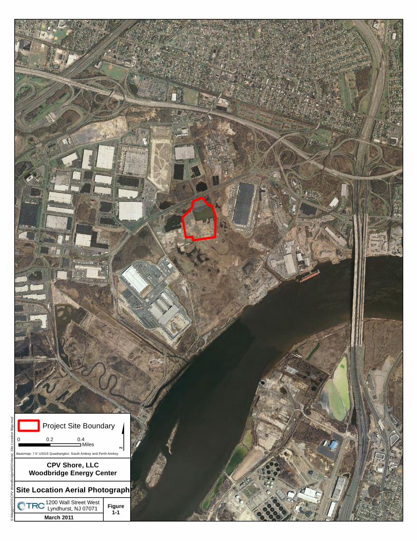
$
March 2011
1200 Wall Street WestLyndhurst, NJ 07071 Figure
1-1
Project Site Boundary
Site Location Aerial Photograph
CPV Shore, LLCWoodbridge Energy Center
Basemap: 7.5' USGS Quadrangles: South Amboy and Perth Amboy
0 0.2 0.4Miles
S:\Ma
ggie\
GIS\
CPV
Woo
dbrid
ge\M
XD\A
erial_
Site L
ocait
on M
ap.m
xd

Appendix E
Air Quality Modeling Protocol

April 12, 2011 TM023-11 Mr. Joel Leon Mail Code 401-02 New Jersey Department of Environmental Protection Division of Air Quality PO Box 420 401 East State Street Trenton, New Jersey 08625-0420 Subject: CPV Shore, LLC Woodbridge Energy Center Proposed Combined Cycle Power Facility Woodbridge Township, Middlesex County, New Jersey Atmospheric Dispersion Modeling Protocol Dear Mr. Leon: Enclosed please find two (2) copies of the atmospheric dispersion modeling protocol for the proposed Woodbridge Energy Center combined cycle power facility to be constructed in Woodbridge Township, Middlesex County, New Jersey. The proposed combined cycle power facility will consist of a 2-on-1 (i.e., two gas turbine generators with steam being used in a single steam turbine generator) configuration, capable of generating a nominal 700 megawatts (MW), with two (2) individual exhaust stacks. The proposed facility will be natural gas fired only with supplementary firing (with natural gas only) in the heat recovery steam generators. Engineering design plans also reflect the use of a 14 cell mechanical draft cooling tower. The enclosed protocol contains a project and site description and a preliminary site plan. The protocol also contains a detailed description of the modeling methodology proposed for the air quality impact analysis to be included in the PSD permit application to be submitted for the proposed facility. A PSD permit application for the proposed CPV Shore LLC, Woodbridge Energy Center combined cycle power facility is expected to be submitted in May 2011.

Mr. Joel Leon, NJDEP April 12, 2011 Page 2 of 2
Please feel free to contact me at 201 508-6960 should you have any questions regarding the enclosed protocol. We look forward to working with you on this project. Sincerely, TRC Theodore Main Manager, Lyndhurst Air Quality Modeling Group Attachment cc: A. Dresser, NJDEP R. Huizer, NJDEP D. Ometz, TRC R. Golden, TRC S. Remillard, CPV J. Donovan, CPV A. Coulter, EPA Region II D. Ahern, Shaw C. Allgeier, Shaw TRC Project File 173062 CPV-Prococol-Cover-tm023-11.ltr.doc

AIR QUALITY MODELING PROTOCOL
Prepared for
CPV Shore, LLC Woodbridge Energy Center
Township of Woodbridge, Middlesex County, New Jersey
Submitted to
New Jersey Department of Environmental Protection
Trenton, New Jersey
Prepared by
TRC 1200 Wall Street West, 2nd Floor
Lyndhurst, New Jersey 07071
April 2011

i
TABLE OF CONTENTS Section Page
1.0 INTRODUCTION ............................................................................................................... 1-1
2.0 AREA DESCRIPTION ........................................................................................................ 2-1
3.0 FACILITY DESCRIPTION ................................................................................................. 3-1
3.1 Equipment/Fuels ............................................................................................................ 3-1 3.2 Operation ....................................................................................................................... 3-2 3.3 Selection of Sources for Modeling ................................................................................ 3-2 3.4 Exhaust Stack Configuration and Emission Parameters ..............................................3-3 3.5 Good Engineering Practice Stack Height ......................................................................3-3
4.0 REGULATORY REQUIREMENTS .................................................................................... 4-1
4.1 New Source Review ........................................................................................................ 4-1 4.1.1 Attainment Status ......................................................................................................... 4-1 4.1.2 Prevention of Significant Deterioration ..................................................................... 4-2 4.1.3 Preconstruction Ambient Air Quality Monitoring Exemption .................................. 4-3
4.2 New Jersey Department of Environmental Protection Regulations ........................... 4-3
5.0 MODELING METHODOLOGY ......................................................................................... 5-1
5.1 Model Selection .............................................................................................................. 5-1 5.2 Surrounding Area and Land Use ................................................................................... 5-1 5.3 Meteorological Data ....................................................................................................... 5-2 5.4 Sources ............................................................................................................................ 5-4 5.5 Load Analysis .................................................................................................................. 5-4 5.6 Startups/Shutdowns....................................................................................................... 5-5 5.7 1-Hour NO2 Modeling .................................................................................................... 5-6 5.8 NJDEP Air Toxics Risk Analysis .................................................................................... 5-7 5.9 Receptor Grid ................................................................................................................. 5-7
5.9.1 Basic Grid ............................................................................................................... 5-7 5.9.2 Special Receptors .................................................................................................. 5-8
5.10 Background Ambient Air Quality .................................................................................. 5-8 5.11 NAAQS/NJAAQS Analysis ............................................................................................. 5-9 5.12 PSD Increment Analysis ................................................................................................. 5-9 5.13 Additional Impact Analyses ......................................................................................... 5-10
5.13.1 Assessment of Impacts due to Growth ................................................................ 5-10 5.13.2 Assessment of Impacts on Soils and Vegetation ................................................. 5-10 5.13.3 Impact on Visibility .............................................................................................. 5-10 5.13.4 Impacts on Class I Areas ...................................................................................... 5-10
5.14 Modeling Submittal ...................................................................................................... 5-11
LIST OF APPENDICIES
Appendix A: Agency Correspondence

ii
TABLE OF CONTENTS (Continued)
LIST OF TABLES Table No. Page Table 3-1: Combustion Turbine Preliminary Source Parameters ............................................................... 3-7 Table 3-2: Combustion Turbine Preliminary Emission Rates .................................................................... 3-8 Table 3-3: Cooling Tower Preliminary Exhaust Characteristics and PM-10/PM-2.5 Emission Rate ........ 3-9 Table 3-4: Auxiliary Boiler Preliminary Exhaust Characteristics and Emissions ..................................... 3-10 Table 3-5: Emergency Diesel Firepump Preliminary Exhaust Characteristics and Emissions ................. 3-11 Table 3-6: Emergency Diesel Generator Preliminary Exhaust Characteristics and Emissions................ 3-12 Table 3-7: Dewpoint Heater Preliminary Exhaust Characteristics and Emissions .................................. 3-13 Table 3-8: GEP Stack Height Analysis ....................................................................................................... 3-14 Table 4-1: Preliminary Emission Rates, PSD Significant Emission Rates, and Non-attainment NSR
Thresholds ................................................................................................................................. 4-5 Table 4-2: National Ambient Air Quality Standards, PSD Increments, Significant Monitoring
Concentrations, and Significant Impact Levels ........................................................................ 4-6 Table 4-3: New Jersey Ambient Air Quality Standards ............................................................................... 4-7 Table 5-1: Combustion Turbine Start-up and Shutdown Emission Rates and Stack Parameters ............ 5-12 Table 5-2: Maximum Measured Ambient Air Quality Concentrations ..................................................... 5-14
LIST OF FIGURES Figure No. Page Figure 1-1: Site Location Map (Aerial Photograph) ..................................................................................... 1-2 Figure 1-2: Site Location Map (Topographical) ........................................................................................... 1-3 Figure 3-1: Preliminary Site Plan ................................................................................................................. 3-5 Figure 3-2: Facility Buildings and Stacks for BPIP ...................................................................................... 3-6 Figure 5-1: 3-Kilometer Radius Around the Proposed Woodbridge Energy Center ................................. 5-15 Figure 5-2: Location of the Proposed Woodbridge Energy Center and Newark Liberty International
Airport ..................................................................................................................................... 5-16 Figure 5-3: Wind Rose for Newark Liberty International Airport (2005-2009) ....................................... 5-17 Figure 5-4: Modeled Receptor Grid (Near Grid) ....................................................................................... 5-18 Figure 5-5: Modeled Receptor Grid (Far Grid) .......................................................................................... 5-19

1-1
1.0 INTRODUCTION
CPV Shore, LLC (CPV Shore) is proposing to construct a nominal 700-megawatt (MW) natural
gas fired 2-on-1 combined cycle power facility (to be known as the Woodbridge Energy Center,
LLC facility (i.e., the Project)) in the Township of Woodbridge, Middlesex County, New Jersey.
The proposed Facility will be located on an approximately 27.5-acre industrial parcel of land,
which will be sub-divided from a larger 180-acre parcel of land owned by El Paso (see Figures 1-1
and 1-2). The facility (combustion turbines) will be fueled by natural gas. Because the proposed
facility is located in an attainment area for sulfur dioxide (SO2), nitrogen dioxide (NO2), carbon
monoxide (CO), and particulate matter with an aerodynamic diameter less than 10 micrometers
(m) (PM-10) and will potentially emit more than 100 tons per year of several air pollutants, it
will be subject to Prevention of Significant Deterioration (PSD) permitting. It is expected that
emissions of nitrogen oxides (NOx), ozone (as VOC), sulfuric acid (H2SO4), PM-10, PM-2.5, and
CO will exceed the pollutant specific PSD significant emission rates (SER) and, consequently, an
air dispersion modeling analysis will be required for these pollutants.
Middlesex County is designated as moderate non-attainment for the 8-hour ozone standard and
non-attainment for PM-2.5. The proposed project site is in an ozone non-attainment area and
within a designated PM-2.5 non-attainment area. If potential annual emissions of NOx and/or
VOC exceed the major source thresholds (i.e., 25 tons per year of NOx and/or 25 tons per year of
VOC), the proposed facility will be subject to non-attainment New Source Review (NSR) for
ozone precursors. Additionally, if potential annual emissions of PM-2.5 or SO2 exceed the major
source thresholds (i.e., 100 tons per year of PM-2.5 or SO2), the proposed facility will be subject
to non-attainment NSR for PM-2.5.
The air quality analysis will be required to demonstrate that the proposed facility will be
compliant with all applicable PSD increment levels, National Ambient Air Quality Standards
(NAAQS), and New Jersey Ambient Air Quality Standards (NJAAQS). Initially, the air quality
impact of the proposed facility will be modeled using potential emission rates to determine if the
facility will yield significant air quality impacts (i.e., maximum modeled concentrations greater
than the PSD significant impact concentrations). The significance modeling will be performed
for multiple operating loads. The pollutant-specific “worst-case” operating scenario determined
from the significance modeling analysis will be used in all subsequent modeling, including any
PSD increment and multiple source NAAQS/NJAAQS analyses, if necessary.

$
March 2011
1200 Wall Street WestLyndhurst, NJ 07071 Figure
1-1
Project Site Boundary
Site Location Aerial Photograph
CPV Shore, LLCWoodbridge Energy Center
Basemap: 7.5' USGS Quadrangles: South Amboy and Perth Amboy
0 0.2 0.4Miles
S:\Ma
ggie\
GIS\
CPV
Woo
dbrid
ge\M
XD\A
erial_
Site L
ocait
on M
ap.m
xd

$
March 2011
1200 Wall Street WestLyndhurst, NJ 07071 Figure
1-2
Project Site Boundary
Site Location Map
CPV Shore, LLCWoodbridge Energy Center
Basemap: 7.5' USGS Quadrangles: South Amboy and Perth Amboy
0 0.25 0.5Miles
S:\Ma
ggie\
GIS\
CPV
Woo
dbrid
ge\M
XD\A
erial_
Site L
ocait
on M
ap.m
xd

2-1
2.0 AREA DESCRIPTION
The proposed Woodbridge Energy Center facility will be located on an approximately 27.5-acre
industrial parcel of land located in the Township of Woodbridge, Middlesex County, New Jersey
(see Figure 1-1).
Topography in the immediate area is generally flat, with elevations at sea level on the Raritan
River and elevation risings upwards of and exceeding 200 feet in Fords, New Jersey. Typical
terrain elevations on the Project site are approximately 21 feet above mean sea level (MSL).
Existing land uses in the vicinity of the proposed site include industrial development,
commercial development, neighborhood businesses, and residential neighborhoods (See Figure
1-2). The nearest residential locations are approximately one kilometer to the north, along
Sunnyview Oval just north of Route 440 and along Georges Post Road just south of Route 440.
The proposed facility will be located at approximately 40º 30’ 54” North Latitude, 74º 19’ 09”
West Longitude, North American Datum 1983 (NAD83). The approximate Universal Transverse
Mercator (UTM) coordinates of the proposed facility are 557,672 meters Easting, 4,485,142
meters Northing, in Zone 18, NAD83.

3-1
3.0 FACILITY DESCRIPTION
The information contained in this section provides an overview of the equipment, operations,
stack parameters, and emission rates for the proposed Project. Equipment specific parameters
are presented based upon preliminary design since final equipment design has not been
completed for the Project. Information presented in this section will be included and revised if
appropriate in the PSD/Subchapter 8 preconstruction permit application, and any changes that
have been made will be reflected in the application. In addition, greater detail specific to
equipment description and manufacturer specifications will be provided in the PSD/Subchapter
8 preconstruction permit application. Therefore, the PSD/Subchapter 8 preconstruction permit
application will be the means by which the following parameters and facility design are verified
and presented as final.
3.1 Equipment/Fuels
The project will include two General Electric (GE) 7 FA.05 Combustion Turbines that will utilize
pipeline natural gas (sulfur in fuel is 0.23 grains/100 SCF @ 1020 btu/SCF), which will be
equipped with a natural gas-fired duct burner for supplementary firing and a single steam
turbine generator (STG). By using the waste heat from the combustion turbine to produce steam
and generate additional electricity, the Facility will operate with a higher thermal efficiency than
many other electricity generating facilities. The CTG will be equipped with an inlet air cooling
system to further boost power and efficiency on hot days. The HRSG will be equipped with a
natural gas-fired duct burner. Supporting ancillary equipment will include a natural gas fired
auxiliary boiler, one small dew point fuel gas heater (fuel gas heater), a mechanical draft cooling
tower, an emergency diesel generator and an emergency diesel fire pump to provide on-site fire-
fighting capability. Figure 3-1 presents a general arrangement drawing of the proposed facility.
Emissions from the combined cycle units will be controlled by the use of dry low-NOx burner
technology and SCR for NOx control, an oxidation catalyst for CO and VOC control, and the use
of clean low-sulfur fuels (i.e., natural gas) to minimize emissions of SO2, PM/PM-10/PM-2.5,
and H2SO4. Exhaust gases from the combined cycle units after emission controls will be
dispersed to the atmosphere via individual stacks. Steam from the steam turbine will be sent to
a condenser where it will be cooled to a liquid state and returned to the HRSG. Waste heat from
the condenser will be dissipated through the mechanical draft cooling tower.

3-2
3.2 Operation
The combined cycle units will be operated to follow electrical demand (i.e., dispatch mode), but
will be designed and permitted to operate on a continuous basis. The combined cycle units
typically will not operate at steady-state below 45% load and the duct burner will only operate at
full load conditions for the combustion turbine. Therefore, the HRSG steam production will
follow the combustion turbine loads and higher HRSG steam output will only occur when duct
firing is employed during combustion turbine full load operation.
3.3 Selection of Sources for Modeling
The emission sources responsible for most of the potential emissions from the Project are the
two combustion turbines. These units will be included in and are the main focus of the modeling
analyses. As discussed in Section 3.4, the modeling will include consideration of operation over
a range of turbine loads and operating scenarios. Initial modeling of the turbines by themselves
will be conducted to identify those operating conditions for each pollutant and averaging period
that yield the maximum modeled impacts. Any subsequent modeling incorporating other
emissions units at the plant or other facilities will include the turbines operating conditions that
yield the maximum modeled impacts. Modeling conducted for PM-10 and PM-2.5 will include
filterable and condensable PM.
Ancillary sources (the emergency generator, fire pump, auxiliary boiler and dew point heater)
will also be included in the modeling for appropriate pollutants and averaging periods. The
emergency equipment may operate for up to one-half hour in any day for readiness testing and
maintenance purposes. Operation of the emergency equipment for longer periods of time in an
emergency mode would not be expected to occur when the turbines are operating.
Although only limited operation is expected from the emergency equipment, initial modeling to
assess short-term Project impacts will assume concurrent operation of the emergency equipment
for readiness testing (i.e., less than 1-hour per day) with the combustion turbines.
Per the NJDEP TM1002 Modeling Guidance, the mechanical draft cooling tower will be included
in the modeling analysis for PM-10 standards compliance if the total PM-10 emission rate from
the tower is greater than 1.0 pounds per hour. Similarly, if the total PM-2.5 emission rate from
the tower is greater than 1.0 pounds per hour, the cooling tower will be included in the modeling
analysis for PM-2.5 standards compliance. Otherwise, the cooling tower will not be included in
the modeling analysis.

3-3
3.4 Exhaust Stack Configuration and Emission Parameters
The preliminary general arrangement for the proposed facility is presented in Figure 3-1.
Preliminary exhaust characteristics of the turbine/heat recovery steam generator stack during
different operating scenarios are provided in Table 3-1. Exhaust parameters are presented for
gas firing at three ambient temperatures (-8 degrees Fahrenheit, 56 degrees Fahrenheit, and 105
degrees Fahrenheit) and three loads (50%, 75%, and 100%). Table 3-2 presents the preliminary
potential emission rates for each of the operating scenarios. In addition, emission rates and
stack parameters are presented for evaporative cooling and duct firing during natural gas
operation at 100% load. Thus, emission rates and stack parameters for fourteen (14) ambient
temperatures and load combinations will be used to determine the “worst-case” operating
scenario for the turbines.
Finally, Tables 3-4 to 3-7 present the preliminary stack parameters and emission rates for the
auxiliary boiler, emergency diesel firepump, emergency diesel generator, and dewpoint heater,
respectively. As discussed in Section 3.3, the emergency diesel firepump and emergency diesel
generator will be included in the modeling analysis for appropriate pollutants and averaging
periods when used for readiness testing (i.e., less than 1-hour per day).
3.5 Good Engineering Practice Stack Height
Section 123 of the Clean Air Act (CAA) Amendments required the United States Environmental
Protection Agency (U.S. EPA) to promulgate regulations to assure that the degree of emission
limitation for the control of any air pollutant under an applicable State Implementation Plan
(SIP) was not affected by (1) stack heights that exceed GEP or (2) any other dispersion
technique. The U.S. EPA provides specific guidance for determining GEP stack height and for
determining whether building downwash will occur in the Guidance for Determination of Good
Engineering Practice Stack Height (Technical Support Document for the Stack Height
Regulations), (EPA-450/4-80-023R, June, 1985). GEP is defined as “…the height necessary to
ensure that emissions from the stack do not result in excessive concentrations of any air
pollutant in the immediate vicinity of the source as a result of atmospheric downwash, eddies,
and wakes that may be created by the source itself, nearby structures, or nearby terrain
“obstacles”.”
The GEP definition is based on the observed phenomenon of atmospheric flow in the immediate
vicinity of a structure. It identifies the minimum stack height at which significant adverse
aerodynamics (downwash) are avoided. The U.S. EPA GEP stack height regulations specify that
the GEP stack height be calculated in the following manner:
HGEP = HB + 1.5L

3-4
Where: HB = the height of adjacent or nearby structures, and L = the lesser dimension (height or projected width of the adjacent or nearby structures).
A preliminary site plan for the proposed Woodbridge Energy Center is shown in Figure 3-1. A
final site plan will be included in the PSD/Subchapter 8 air permit application that will be
submitted to the NJDEP. A preliminary GEP stack height analysis has been conducted using the
U.S. EPA approved Building Profile Input Program with PRIME (BPIPPRM, version 04274).
The results of the preliminary analysis are presented in Table 3-8. The largest controlling
structure will be the heat recovery steam generator (HRSG), at a height of 92 feet above grade,
resulting in a formula GEP height of 230 feet above grade. A final GEP stack height analysis will
be conducted and included in the permit application for the NJDEP’s review. Since a non-GEP
stack may be proposed, direction-specific downwash parameters for the combustion turbine
exhaust stack would be determined using BPIPPRM, version 04274. Direction-specific
downwash parameters for the additional auxiliary equipment exhaust stacks to be modeled (i.e.,
auxiliary boiler, dewpoint heater, emergency equipment and cooling tower, if necessary) will
also be determined using BPIPPRM, version 04274. Any direction-specific building downwash
parameters will be input to the PSD modeling analysis.
Figure 3-2 provides an isometric view of the Facility structures proposed to be included in the
BPIP analysis.


CPV Shore LLC Woodbridge Energy Center Township of Woodbridge, Middlesex County, New Jersey
Figure 3-2: Facility Buildings for BPIP
Source: Google Earth, 2011

3-7
Table 3-1: Combustion Turbine Preliminary Source Parameters
Operating
Case
Fuel
Ambient
Temperature (F)
Operating
Load (%)
Duct Burner Operation (On/Off)
Modeling Stack
Parameters Evaporative
Cooler Operation (On/Off)
Exhaust Temperature
(K)
Exhaust Velocity (m/s)a
Case1 Gas -8F 100 Off Off 360.2 20.00 Case2 Gas -8F 100 On Off 353.0 19.74 Case3 Gas -8F 75 Off Off 353.9 15.93 Case4 Gas -8F 50 Off Off 346.5 12.47 Case5 Gas 56F 100 Off Off 357.6 18.30 Case6 Gas 56F 100 On Off 351.4 18.12 Case7 Gas 59F PEAK On Off 351.4 18.03 Case8 Gas 56F 75 Off Off 349.4 14.17 Case9 Gas 59F 50 Off Off 345.5 11.85 Case10 Gas 105F 100 Off On 362.4 17.94 Case11 Gas 105F 100 On On 357.6 17.77 Case12 Gas 105F PEAK On On 356.0 17.77 Case13 Gas 105F 75 Off Off 352.8 13.50 Case14 Gas 105F 50 Off Off 351.0 12.19
aBased on a stack diameter of 20.0 feet.

3-8
Table 3-2: Combustion Turbine Preliminary Emission Rates
Operating Case
Modeled Emission Rate (g/s)a
NOx CO PM-10/PM-2.5b SO2
Case1 2.12 1.29 1.52 0.52
Case2 2.49 1.51 2.12 0.60
Case3 1.68 1.02 1.45 0.42
Case4 1.34 0.82 1.39 0.33
Case5 1.92 1.17 1.49 0.47
Case6 2.29 1.40 2.08 0.55
Case7 2.31 1.41 2.41 0.57
Case8 1.55 0.95 1.42 0.38
Case9 1.22 0.74 1.36 0.30
Case10 1.81 1.11 1.47 0.44
Case11 2.02 1.22 1.76 0.49
Case12 2.23 1.36 2.39 0.54
Case13 1.41 0.86 1.40 0.34
Case14 1.17 0.72 1.35 0.29 aEmissions are for one (1) combustion turbine. bFilterable plus condensable.

3-9
Table 3-3: Cooling Tower Preliminary Exhaust Characteristics and PM-10/PM-2.5 Emission Rate
Emissions Parameter
Number of Cells 14
Maximum Total Air Flow Rate (acfm) (Each Cell) 1,341,000
Maximum Water Flow Rate (gpm) (Total Tower) 178,000
Maximum Drift Rate 0.0005%
Total Solids in Circulating Water (ppm) 6,240
14-cell Total TSP Emission Rate (lb/hr) (Total Tower) 2.78
1-cell TSP Emission Rate (g/s) 0.025
14-cell Total PM-10 Emission Rate (lb/hr) (Total Tower) 1.806
1-cell PM-10 Emission Rate (g/s) 0.016
14-cell Total PM-2.5 Emission Rate (lb/hr) (Total Tower) 0.667
1-cell PM-2.5 Emission Rate (g/s) 0.006
14-cell Total TSP Annual Emission Rate (ton/yr) (Total Tower) 12.17
14-cell Total PM-10 Annual Emission Rate (ton/yr) (Total Tower) 7.91
14-cell Total PM-2.5 Annual Emission Rate (ton/yr) (Total Tower) 2.92
Exhaust Parameter
Exhaust Height (ft above gradea) 55.18
Exhaust Height (m above grade) 16.82
Collar Height (ft above grade) 41.43
Collar Height (m above grade) 12.63
Exhaust Temperature (deg F) 85
Exhaust Velocity (ft/sec) 31.62
Exhaust Velocity (m/sec) 9.64
Inner Diameter (ft) 30
Inner Diameter (m) 9.14 aMeasurements on cooling tower specification sheet are referenced to “top of curb” which is
2 feet above grade.

3-10
Table 3-4: Auxiliary Boiler Preliminary Exhaust Characteristics and Emissions
Emission Parameter Pollutant lb/hr
NOx 1.01 CO 3.43
PM-10/PM-2.5 0.46 SO2 0.16
Exhaust Parameter Exhaust Height (ft above grade) TBD Exhaust Height (m above grade) TBD
Exhaust Temperature (deg F) 310
Exhaust Velocity (ft/sec) 57.3 Exhaust Velocity (m/sec) 17.5
Inner Diameter (ft) 3.3
Inner Diameter (m) 0.99

3-11
Table 3-5: Emergency Diesel Fire Pump Preliminary Exhaust Characteristics and Emissions
Emission Parameter
Pollutant lb/hr
NOx 1.93 CO 2.10
PM-10/PM-2.5 0.10 SO2 0.003
Exhaust Parameter Exhaust Height (ft above grade) TBD Exhaust Height (m above grade) TBD
Exhaust Temperature (deg F) 961 Exhaust Velocity (ft/sec) 171.1 Exhaust Velocity (m/sec) 52.2
Inner Diameter (ft) 0.4 Inner Diameter (m) 0.13

3-12
Table 3-6: Emergency Diesel Generator Preliminary Exhaust Characteristics and Emissions
Emission Parameter
Pollutant lb/hr
NOx 22.02
CO 1.99 PM-10/PM-2.5 0.13
SO2 0.0208 Exhaust Parameter
Exhaust Height (ft above grade) TBD Exhaust Height (m above grade) TBD
Exhaust Temperature (deg F) 763.5 Exhaust Velocity (ft/sec) 528.1 Exhaust Velocity (m/sec) 161.0
Inner Diameter (ft) 0.7 Inner Diameter (m) 0.20

3-13
Table 3-7: Dew point Heater Preliminary Exhaust Characteristics and Emissions
Emission Parameter Pollutant lb/hr
NOx 0.33 CO 0.48
PM-10/PM-2.5 0.07 SO2 0.017
Exhaust Parameter Exhaust Height (ft above grade) TBD Exhaust Height (m above grade) TBD
Exhaust Temperature (deg F) 690 Exhaust Velocity (ft/sec) 50.1 Exhaust Velocity (m/sec) 15.3
Inner Diameter (ft) 1.33 Inner Diameter (m) 0.41

3-14
Table 3-8: GEP Stack Height Analysis
Structure Height
(ft)
Maximum Projected Width
(ft)
5L Region of Influence
(ft)
HGEP=H+1.5L (ft)
HRSG Tier 92.0 93.2 460.0 230.0
HRSG Tier 49.0 52.6 245.0 122.5
Combustion Turbines 25.0 59.0 125.0 62.5
Combustion Turbine Generators
50.0 38.9 194.7 108.4
Combustion Turbine Air Inlets
68.0 47.6 238.2 139.5
Cooling Tower Fan Deck
41.4 398.5 207.0 103.5
Warehouse 22.0 178.0 110.0 55.0
Steam Turbine Generator
42.3 99.3 211.5 105.8
Demin Tank 32.0 46.0 160.0 80.0

4-1
4.0 REGULATORY REQUIREMENTS
Air quality modeling requirements are specified under Federal U.S. EPA and NJDEP regulatory
programs including PSD and non-attainment NSR programs, and the State of New Jersey
Administrative Code, Title 7, Chapter 27, Subchapter 8 (N.J.A.C. 7:27-8) for preconstruction
permits and minor source operating permits, and N.J.A.C. 7:27-22 for major source operating
permits. All applicable requirements that include air quality impact assessments are outlined in
this section.
4.1 New Source Review
The Federal NSR program consists of the non-attainment NSR and PSD programs. Applicability
of these programs to the proposed facility is determined based upon the attainment status and
the potential emissions of the proposed facility. New Jersey’s non-attainment NSR for NOx and
VOC requires the use of lowest achievable emission rate (LAER) controls and compliance with
emission offset requirements should facility emissions exceed applicable thresholds.
4.1.1 Attainment Status
The U.S. EPA has established National Ambient Air Quality Standards (NAAQS) for each of the
following criteria air pollutants: PM-10, PM-2.5, sulfur dioxide (SO2), ozone (O3), nitrogen
dioxide (NO2), carbon monoxide (CO), and lead (Pb). Areas in which the NAAQS are being met
are referred to as attainment areas. Areas in which the NAAQS are not being met are referred to
as nonattainment areas. Areas that were formerly nonattainment areas but are now in
attainment and covered by a maintenance plan are referred to as maintenance areas. Areas for
which sufficient data are not available to determine a classification are referred to as
unclassifiable. The federal attainment status designations of areas in New Jersey with respect to
NAAQS are listed at 40 CFR 81.331. The Project is located in Middlesex County in the New
Jersey-New York-Connecticut Air Quality Control Region (AQCR).
The location of the Woodbridge Energy Center facility is in an area currently designated as
attainment for SO2, NO2, CO, and PM-10. Middlesex County, however, is designated as
moderate non-attainment for the 8-hour ozone standard and non-attainment for PM-2.5. Under
the moderate non-attainment designation for 8-hour ozone, new sources with emissions of NOx
exceeding 25 tons per year and/or emissions of VOC exceeding 25 tons per year are subject to
non-attainment new source review (NSR) and require the application of LAER control
technology and NOx and/or VOC offsets. The applicability of LAER and emission offsets in New
Jersey is set forth in N.J.A.C. 7:27-18. Potential net emission increases of 25 tons per year or
greater of NOx and or VOC emissions trigger Subchapter 18 applicability.

4-2
On May 16, 2008, the U.S. EPA published the final rule for implementation of the NSR program
for PM-2.5 emissions (effective as of July 15, 2008). For a new source located in a non-
attainment area for PM-2.5, NNSR is applicable if direct PM-2.5 emissions are greater than or
equal to 100 tons/yr. Additionally, the U.S. EPA has concluded that emissions of SO2, NOx,
VOC, and NH3 are responsible for the secondary formation of PM-2.5 in the atmosphere. As
such, the final rule for PM-2.5 NSR implementation establishes surrogate significant emission
rate thresholds for major sources of PM-2.5 and/or PM-2.5 precursors. Prior to final SIP
approval, only SO2 is being regulated as a PM-2.5 precursor. Therefore, if the Facility’s potential
annual emissions of SO2 are greater than 100 tons/yr, it will also be subject to NNSR
requirements for PM-2.5. As shown in Table 4-1, the Woodbridge Energy Center’s potential
emissions will not exceed 100 tons per year for either PM-2.5 or SO2. Hence, NNSR will not
apply for PM-2.5.
4.1.2 Prevention of Significant Deterioration
The New Jersey Administrative Code adopted the Prevention of Significant Deterioration
program pursuant to 40 CFR 51.166, which is administered through the NJDEP permitting
process, and applies to a new or modified major facility located in an attainment area. The
Department accepted delegation of the administration of the PSD program from the U.S. EPA on
February 22, 1983. As such, any fossil fuel fired steam electric plant with a heat input capacity
greater than 250 mmBTU/hr and potential emissions greater than 100 tons per year of any
regulated pollutant is considered a “major” source and is subject to the PSD regulations. Based
on potential emissions from the fossil fuel fired combustion turbines, the proposed facility will
have potential emissions greater than 100 tons per year of multiple regulated pollutants. Thus,
the proposed facility will be subject to the PSD permitting requirements.
Facilities subject to PSD must perform an air quality analysis (which includes atmospheric
dispersion modeling) and a best available control technology (BACT) demonstration for those
pollutants that exceed the pollutant specific Significant Emission Rates (SERs) identified in the
regulations. These emission rates, as well as the non-attainment NSR thresholds, are provided
in Table 4-1. The final annual facility emissions have not been determined and will be presented
in the final air permit application. (Note that since NOx and VOC are precursors to ozone
formation, NOx and VOC emissions will be controlled to the more stringent LAER emission
levels if they exceed the non-attainment NSR thresholds).
Dispersion modeling for the PSD requirements consists of three analyses: a significance analysis,
a NAAQS/NJAAQS analysis, and a PSD increment analysis. The significance analysis compares
the maximum-modeled ambient concentrations from the proposed facility to the significant

4-3
impact levels (SILs) listed in Table 4-2 for each pollutant. If the modeled concentrations for the
proposed facility are less than the SILs, then more detailed NAAQS/NJAAQS and PSD
increment analyses are not required under PSD regulations. However, if the modeled
concentrations are greater than the SILs, then NAAQS/NJAAQS and PSD increment analyses
are required for that pollutant. The NAAQS and PSD increments are listed in Table 4-2 while
the NJAAQS are listed in Table 4-3.
4.1.3 Preconstruction Ambient Air Quality Monitoring Exemption
As discussed previously, PSD regulations require an applicant to perform an air quality analysis
for those pollutants emitted in quantities exceeding the SERs shown in Table 4-1. This analysis
can include the collection of up to one year of ambient air quality monitoring data. Preliminary
facility emissions indicate that air quality monitoring could be required for some of the
pollutants listed in Table 4-1.
Pursuant to the PSD regulations codified in 40 CFR 51.166 and 40 CFR 52.21, U.S. EPA may
exempt a proposed PSD source, otherwise subject to the one-year pre-construction ambient
monitoring requirement, if either 1) the predicted ambient impact, i.e., the highest modeled
concentration for the applicable averaging time, caused by the proposed significant emissions
increase (or significant net emissions increase) are less than the prescribed significant
monitoring values, or 2) existing quality assured ambient air quality data are available from
alternate locations that are representative of, or conservative, as compared to conditions at the
proposed facility location. TRC, on behalf of CPV Shore, LLC, is submitting a preconstruction
monitoring exemption request to the NJDEP under separate cover, a copy of which is attached
as Appendix A.
4.2 New Jersey Department of Environmental Protection Regulations
Applicable regulations from Chapter 7:27 of the New Jersey Administrative Code are identified
below:
Subchapter 3 “Control and Prohibition of Smoke from Combustion of Fuel” - N.J.A.C.
7:27 - 3.5 limits the opacity from internal combustion engines and stationary combustion
turbines to less than 20% opacity, exclusive of condensed water vapor for a period of
more than 10 consecutive seconds. The natural gas fired combustion turbines will
normally have opacity near zero and are not expected to exceed even 10% for 10
consecutive seconds.

4-4
Subchapter 4 “Control and Prohibition of Particles Combustion of Fuel” - N.J.A.C. 7:27 -
4.2(a) limits the mass emission of particulates from the proposed combined cycle units,
the auxiliary boilers, the fuel gas heater, the emergency diesel generator and the diesel
fire pump.
Subchapter 8 “Permits and Certificates” - requires a pre-construction permit to be
obtained for the proposed CPV Shore facility since the total heat input is greater than
1,000,000 Btu/hr and imposes State of the Art (SOTA) requirements for new and/or
modified sources.
Subchapter 9 “Sulfur in Fuels” - This subchapter does not limit the sulfur content of
gaseous fuels; only liquid and solid fuel sulfur content limits are prescribed. Subchapter
9 limits the sulfur content of diesel fuel to 15 ppmw from July 1, 2016 and onward. Thus,
the facility will use 15 ppm ultra low sulfur distillate for any fuel oil fired combustion
equipment (specifically the emergency diesel generator and diesel fire pump).
Subchapter 13 “Ambient Air Quality Standards” - The air quality impacts from the
proposed Woodbridge Energy Center facility should not exceed the standards presented
in this subchapter.
Subchapter 16 “Control and Prohibition of Air Pollution by Volatile Organic Compounds”
- N.J.A.C. 7:27-16.9 establishes VOC and CO limits of 50 ppm and 250 ppm respectively
for stationary gas turbines. The proposed limits will be well below these values for all
load and fuel cases.
Subchapter 18 “Control and Prohibition of Air Pollution from New or Altered Sources
Affecting Ambient Air Quality (Emission Offset Rules)” - Establishes emission offsets
and LAER requirements for defined major stationary sources.
Subchapter 19 “Control and Prohibition of Air Pollution from Oxides of Nitrogen” -
Limits NOx emissions based upon equipment sizes and types.
Subchapter 22 “Operating Permits” – The facility will file for or obtain an operating
permit within twelve months after commencing operation.

4-5
Table 4-1: Preliminary Emission Rates, PSD Significant Emission Rates, and Non-attainment NSR Thresholds
Pollutant Preliminary
Emission Rate (tons per year)
PSD Significant
Emission Rate (tons per year)
NNSR Major Source/Modification
Threshold
(tons per year)
Carbon Monoxide 129.7 100 100/100
Sulfur Dioxide 12.0 40 100/40
Particulate Matter (PM) 107.9 25 100/25
Particulate Matter less than 10 microns (PM-10)
103.7 15 100/15
Particulate Matter less than 2.5 microns (PM-2.5)
98.7 10 100/10a
Nitrogen Oxides 140.6 40 25/25b
Ozone (VOC) 27.8 40 25/25b
Lead 0.01 0.6 10/0.6
Fluorides NA 3 NA
Sulfuric Acid Mist 8.2 7 NA
Hydrogen Sulfide NA 10 NA
Total Reduced Sulfur (including H2S)
NA 10 NA
Reduced Sulfur Compounds (including H2S)
NA 10 NA
Note: Pursuant to 40 CFR 52.21 (b) (23) (i). aUnder 40 CFR 51, Appendix S, new sources with potential emissions greater than or equal to 100 tons per year and modifications to existing major sources with emissions greater than or equal to 40 tons per year of SO2 or 10 tons per year of PM-2.5 are subject to non-attainment NSR for PM-2.5. bPer N.J.A.C 7:27-18.

4-6
Table 4-2: National Ambient Air Quality Standards, PSD Increments, Significant Monitoring Concentrations, and Significant Impact Levels
Pollutant Averaging
Period NAAQSa (g/m3)
Class II PSD Increment
(g/m3)
Significant Monitoring
Concentrations (g/m3)
Significant Impact Level
(g/m3)
Carbon Monoxide
1-Hour 8-Hour
40,000 10,000
-- --
-- 575
2,000 500
Nitrogen Dioxide
1-Hour Annual
188 100
-- 25
-- 14
7.5b 1
Ozone (VOC) 8-Hour 160 -- -- --
Coarse Particulate
Matter (PM-10)
24-Hour Annual
150 --
30 17
10 --
5 1
Fine Particulate
Matter (PM-2.5)
24-Hour Annual
35 15
9 4
4 --
1.2 0.3
Sulfur Dioxide
1-Hour 24-Hour Annual 3-Hour
197 365 80
1,300
-- 91 20 512
-- 13 -- --
7.9c 5 1
25 Lead 3-Month 0.15 -- 0.1 --
Note: (--) indicates there are no standards for this pollutant. aAll short-term (1-hr, 3-hr, 8-hr, and 24-hr) standards except ozone, PM-2.5,PM-10, and 1-hour SO2 and NO2 are not to be exceeded more than once per year. For 8-hr ozone, EPA uses the average of the annual 4th highest 8-hour daily maximum concentrations from each of the last three years of air quality monitoring data to determine a violation of the standard. For 24-hour PM-10, EPA uses the 6th highest 24-hour maximum concentration from the last three years of air quality monitoring data to determine a violation of the standards. For 24-hour PM-2.5, EPA uses the 98% percentile 24-hour maximum concentration from the last three years of air quality monitoring data to determine a violation of the standard. For the 1-hour NO2 NAAQS, compliance would be determined by the 3-year average of the 98th percentile of the daily maximum 1-hour average at each monitor within an area and for the 1-hour SO2 NAAQS, compliance would be determined with the 3-year average of the 99th percentile of the daily maximum 1-hour average at each monitor within an area. bInterim SIL per Guidance from NJDEP staff. cInterim SIL per August 12, 2010 memorandum “Guidance Concerning the Implementation of the 1-hour SO2 NAAQS for the Prevention of Significant Deterioration Program" from Steven Page (Director of U.S. EPA OAQPS).

4-7
Table 4-3: New Jersey Ambient Air Quality Standards
Pollutant Standard Averaging Period NJAAQSa (ug/m3)
Sulfur Dioxide
Primary Primary
Secondary Secondary Secondary
12-month arith. mean 24-hour average
12-month arith. mean 24-hour average 3-hour average
80 365 60
260 1,300
Total Suspended Particulates
Primary Primary
Secondary Secondary
12-month geom. mean 24-hour average
12-month geom. meanb 24-hour average
75 260 60 150
Carbon Monoxide Primary & Secondary Primary & Secondary
8-hour average 1-hour average
10,000 40,000
Ozonec Primary
Secondary Max. daily 1-hour average
1-hour average 235 160
Nitrogen Dioxide Primary & Secondary
NJDEP Guideline 12-month arith. mean
1-hour average 100 470
Lead Primary & Secondary Rolling 3-month average 1.5
aNew Jersey short-term standards are not to be exceeded more than once in any 12 month period. Long-term standards are never to be exceeded.
bIntended as a guideline for achieving short-term standard. cMaximum daily 1-hour average: averaged over a three year period, the expected number of days
above the standard must be less than or equal to 1.

5-1
5.0 MODELING METHODOLOGY
Air quality dispersion modeling will be performed consistent with the procedures found in the
following documents: Guideline on Air Quality Models (Revised) (U.S. EPA, 2005), New Source
Review Workshop Manual (U.S. EPA, 1990), Screening Procedures for Estimating the Air
Quality Impact of Stationary Sources (U.S. EPA, 1992), and Guidance on Preparing an Air
Quality Modeling Protocol - Technical Manual 1002 (NJDEP, 2009).
5.1 Model Selection
The U.S. EPA has compiled a set of preferred and alternative computer models for the
calculation of pollutant impacts. The selection of a model depends on the characteristics of the
source, as well as the nature of the surrounding study area. Of the four classes of models
available, the Gaussian type model is the most widely used technique for estimating the impacts
of nonreactive pollutants.
The U.S. EPA AERMOD model is proposed to be used. The AERMOD model was designed for
assessing pollutant concentrations from a wide variety of sources (point, area, and volume).
AERMOD is currently recommended for modeling studies in rural or urban areas, flat or
complex terrain, and transport distances less than 50 kilometers, with one hour to annual
averaging times. In November 2005, AERMOD became a U.S. EPA guideline model replacing
the Industrial Source Complex (ISCST3) model which had been the preferred model for many
years for most modeling applications.
AERMOD (version 11059 with PRIME) will be used for the preliminary modeling of the
proposed facility’s potential emissions to determine the maximum ambient air concentrations.
The regulatory default option will be used in the dispersion modeling analysis.
5.2 Surrounding Area and Land Use A land cover classification analysis was performed to determine whether the urban source
modeling option in AERMOD should be used in quantifying ground-level concentrations. The
urban option in AERMOD accounts for the effects of increased surface heating on pollutant
dispersion under stable atmospheric conditions. Essentially, the urban convective boundary
layer forms in the night when stable rural air flows onto a warmer urban surface. The urban
surface is warmer than the rural surface because the urban surface cools at a slower rate than the
rural surface when the sun sets. The methodology utilized to determine whether the project is
located in an urban or rural area is described below.

5-2
The following classifications relate the colors on a United States Geological Survey (USGS)
topographic quadrangle map to the land use type that they represent:
Blue – water (rural);
Green – wooded areas (rural);
White – parks, unwooded, non-densely packed structures (rural);
Purple – industrial; identified by the large buildings, tanks, sewage disposal or filtration
plants, rail yards, roadways, and, intersections (urban);
Pink – residential or commercial (urban or rural determination based upon aerial
photography); and,
Red – roadways and intersections (urban)
The USGS map covering the area within a 3-kilometer radius of the site was reviewed (see Figure
5-1) along with aerial photography and indicated that approximately half of the surrounding
area is denoted as blue, green, pink (common residential) or white, which represents water,
wooded areas, parks, common residential and non-densely packed structures. Note that the
“AERMOD Implementation Guide” published on October 19, 2007 cautions users against
applying the Land Use Procedure on a source-by-source basis and instead consider the potential
for urban heat island influences across the full modeling domain (i.e., 20 kilometers x 20
kilometers). This approach is consistent with the fact that the urban heat island is not a
localized effect, but is more regional in character.
The population density within 3 kilometers of the proposed site was assessed utilizing the
LandView 6 program from the U.S. Census Bureau. The population density within 3 kilometers
of the site is approximately 748 persons per square kilometer. Note that the site is located
approximately 25 kilometers southwest from the southwestern edge of the New York City
metropolitan area.
In summary, the area within 3 kilometers of the proposed site is characterized by both rural and
urban land uses and the population density is just below the 750 persons per square kilometer
threshold for utilizing the Urban Source option in AERMOD. Because the urban heat island is
more of a regional effect, the Urban Source option in AERMOD will not be utilized since the area
is more rural in nature given that the modeling domain is not located in the New York City
metropolitan area and thus, would not be subject to the New York City metropolitan area heat
island.
5.3 Meteorological Data
For any PSD modeling analysis conducted using the AERMOD model, two meteorological
datasets are required: 1) hourly surface data and 2) upper air sounding data. According to the

5-3
Guideline on Air Quality Models (Revised) (2005), the meteorological data used in a PSD
modeling analysis should be selected based on its spatial and climatological representativeness
of a proposed facility site and its ability to accurately characterize the transport and dispersion
conditions in the area of concern. The spatial and climatological representativeness of the
meteorological data are dependent on four factors:
1. The proximity of the meteorological monitoring site to the area under consideration; 2. The complexity of the terrain; 3. The exposure of the meteorological monitoring site; and, 4. The period of time during which data were collected.
This protocol presents one hourly surface dataset and one upper air sounding dataset for use in
modeling the proposed facility to be located in the Township of Woodbridge, Middlesex County.
Each of these meteorological datasets was reviewed using the U.S. EPA criteria.
The nearest National Weather Service (NWS) operated meteorological monitoring station to the
proposed facility site is at the Newark Liberty International Airport (WBAN 14734) in Essex
County. The airport is located approximately 22 km north-northeast of the proposed facility site
at an elevation of approximately 7 feet above MSL. Figure 5-2 shows the location of the Newark
Liberty International Airport in relation to the proposed facility site. The meteorological
monitoring station at the Airport continues to operate.
Both the proposed facility site and Newark Liberty International Airport are located within the
same metropolitan, industrial area along the New Jersey/New York urban corridor. Further,
there are no high ridges (i.e., intervening terrain) between the proposed facility site and the
airport.
An Automated Surface Observing System (ASOS) station was installed at Newark Liberty
International Airport on July 1, 1996 and data collected after this date was measured at a height
of 32.8 feet. NJDEP has provided an AERMOD-ready Newark Liberty International Airport
meteorological dataset (2005-2009) that will be used in the air quality modeling analysis.
A wind rose displaying the composite wind rose for all five years (2005-2009) of wind speed and
direction for the Newark Liberty International Airport is shown in Figure 5-3. Over the five (5)
year period, predominant winds varied from the southwest to the northwest. The average wind
speed over the five years is 4.60 meters per second. Calm winds during the five years had an
average frequency of calms of 0.57 percent. Additionally, the wind data recorded at the airport
is reasonably consistent from year to year.
Thus, based on the information provided above, the applicant believes that the meteorological
data recorded at the Newark Liberty International Airport are representative of the air regime at

5-4
the proposed facility site and suitable to be used in an atmospheric dispersion modeling study
because:
Due to the proximity of the airport to the proposed facility site and the lack of significant
intervening terrain features, overall climatological conditions would be expected to be
quite similar at both the airport and the proposed facility site;
The elevation of the airport (approximately 7 feet above MSL) and the proposed facility
site elevation (approximately 21 feet above MSL) are comparable;
The meteorological tower is well sited and in an area free of obstructions to wind flow;
and,
The quality of the available data is good, exceeding U.S. EPA data recovery guidelines
and displaying consistency from year to year of the available data record.
Concurrent upper air sounding data from Brookhaven National Labs, New York (WBAN 94703)
was used with the hourly surface data from Newark Liberty International Airport by NJDEP to
create the meteorological dataset required for the modeling analysis. Brookhaven National Labs
is approximately 127 km to the east of the proposed facility site. Based on Holzworth’s Mixing
Heights, Wind Speeds, and Potential for Urban Air Pollution Throughout the Contiguous
United States, it is believed that upper air meteorological conditions in the Brookhaven, NY area
are more representative than those from the next most proximate upper air station. Both the
surface and upper air sounding data were processed by NJDEP using AERMOD’s meteorological
processor, AERMET (version B10300). The output from AERMET will be used as the
meteorological database for the air quality modeling analysis and will consist of a surface data
file and a vertical profile data file.
5.4 Sources The proposed facility will consist of various types of emission sources. The AERMOD technical
manual will be used to set up the various sources to develop a logical and comprehensive
modeling assessment. The following identifies the types of sources and how they will be
assessed.
Combustion Turbine Exhaust Stacks – Single point sources Ancillary Equipment Exhaust Stacks – Single point sources
5.5 Load Analysis The proposed facility’s combustion turbines will be operated over a range of loads. The air
permit application will provide a detailed discussion of all the sources at the proposed facility
and how they are assessed in the air quality analysis. All fourteen (14) combustion turbine
operating cases as listed in Table 3-2 will be modeled to determine which case is the “worst-case”

5-5
operating scenario for each pollutant and averaging period. These “worst-case” loads will then
be used for any subsequent NAAQS or PSD Increment modeling, including additional facility
sources and potentially offsite sources.
5.6 Startups/Shutdowns Startup is a short-term, transitional mode of operation for the combined cycle units. In combined
cycle operation, where the exhaust gases are directed through a HRSG to produce steam for a steam
turbine generator, additional startup time is necessary in order to reduce thermal shock and
excessive wear in both the HRSG and the steam turbine. Emission rates of some pollutants may be
higher during startup operations because emissions controls may not become fully effective until a
minimum threshold operating load and or control device temperature is attained. The need for
additional modeling to account for predicted short-term Project impacts during startup of the
combined cycle units will be assessed for those criteria pollutants whose short-term emission rates
during startup may exceed those during normal operation and for which a short-term NAAQS or
PSD increment has been defined (i.e., for CO and NO2). In addition, the need for startup modeling
will be assessed for SO2 and PM-10/PM-2.5.
Startup and shutdown conditions refer to all times when the CTG operates below the minimum
operating load (~45% load). Startups are defined as cold, warm, and hot and are defined for two
different types of start-up. The GE 7FA.05 combustion turbines can start-up in either a
conventional mode or in rapid-response mode, which takes less time. The basic approach for rapid
response mode is to thermodynamically decouple the gas turbine from the bottoming cycle, thereby
allowing the gas turbine to start without the hold times needed to allow the HRSG and steam turbine
to heat up. In other words, the rapid response start allows the plant to start up significantly faster
than conventional combined-cycle plants by decoupling the steam turbine as the gas turbine ramps
up and comes on-line. Both start-up types are being considered and thus, the assessment of air
quality impacts will assess both start-up types. The cold startup refers to startups after 72 hours of
shutdown time and requires approximately 3.08 hours for conventional starts and 0.40 hours for
rapid response starts. The warm startup refers to startups after typically 8.1 – 72 hours of shutdown
time and requires approximately 1.25 hours for conventional starts and 0.20 hours for rapid
response starts. The hot startup refers to a typical shutdown time of about 8 hours or less and can
be achieved in 0.58 hours for a conventional start and 0.20 hours for a rapid response start.
Shutdowns can occur at any time and take approximately 0.30 hours for a conventional shutdown
and 0.57 hours for a rapid-response shutdown.
The short-term duration of startup and the relatively limited cumulative time of startup relative to
normal operation mean that startup impacts will not have an appreciable effect on annual impacts
when taking into account the downtime necessary for each start-up type. For these reasons, no
start-up/shutdown modeling for the annual impacts is proposed unless for an annual averaging

5-6
period pollutant (i.e., NOx, PM-2.5, and SO2) the calculated potential to emit significantly increases
when considering the start-up/shutdown events.
Startup emissions and associated stack parameters have been estimated for three varieties of startup
(cold, warm, and hot) based on vendor data for both rapid response and conventional
startup/shutdown types and are shown in Table 5-1. Startup emissions and emission rates were
determined for both the lead turbine (i.e., the first unit to start) and the lag turbine (i.e., the second
unit to start).
Because the startup/shutdown durations from some types will be shorter than some of the averaging
periods modeled, the modeled concentrations for these averaging periods that extend beyond the
start-up duration will be determined based on the combination of the startup conditions for the
appropriate amount of time and the worst-case full-load pollutant- and averaging period-specific
operating scenario determined in the combustion turbine load analysis.
In summary, the worst-case startup/shutdown emissions for CO, SO2, NOx, and PM-10/PM-2.5
will be modeled if the pollutant(s) have higher emissions during startup and shutdown
conditions when compared to normal operation for short-term averaging periods. For annual
averaging periods, start-ups will only be included in the modeling analysis if the potential to
emit for the Facility increases due to the inclusion of start-ups into the annual potential to emit
calculation.
5.7 1-Hour NO2 Modeling
The air quality modeling analysis for the 1-hour NO2 NAAQS will be performed consistent with
the guidance and procedures established in the March 1, 2011 guidance memorandum from
Tyler Fox (EPA OAQPS) titled “Additional Clarification Regarding Application of Appendix W
Modeling Guidance for the 1-Hour NO2 NAAQS” (Memorandum). Based upon the discussion in
the memorandum regarding the treatment of intermittent sources it is proposed that only
equipment or operating scenarios that “are continuous or frequent enough to contribute
significantly to the annual distribution of daily maximum 1-hour concentrations” will be
included in the 1-Hour NO2 modeling analysis.
This methodology per the examples provided in the Memorandum would exempt any Facility
equipment or operating scenarios from 1-hour NO2 compliance modeling that does not operate
on a normal daily or routine schedule. For example, the emergency generator and firewater
pump are not expected to be tested more than once per week for more than 1-hour and thus,
would not be expected to contribute significantly to the annual distribution of maximum 1-hour
concentrations. For these reasons consistent with the Memorandum it is proposed that the 1-
hour NO2 modeling will not include the emergency equipment at the site.

5-7
Related to the discussion above on emergency equipment operation it is not expected that
combustion turbine start-up after a shutdown period of more than 72 hours (i.e., a cold start-up)
will occur more than a few times per year. Also, it is not expected that a start-up after more than
8.1 to 72 hours of shutdown (i.e., a warm start) would occur on average more than once per
week. Thus, it is also proposed that cold startup and warm startup conditions will not be
included in the air quality modeling analysis for the 1-hour NO2 standard as these conditions
would not be expected to contribute significantly to the annual distribution of daily maximum
concentrations due to their infrequency on a yearly basis.
5.8 NJDEP Air Toxics Risk Analysis
The receptor-point concentrations of any toxic substance identified by NJDEP as a Hazardous
Air Pollutant (HAP) that could potentially be emitted from the proposed facility will be assessed
in order to evaluate the potential health risk to the public beyond the property line of the
proposed facility. This will be done by considering each individual HAP emission that
contributes to the evaluation as well as by considering the cumulative effects of the HAPs that
contribute to the evaluation.
To assess the potential for offsite public health threats, the NJDEP Technical Manual 1003:
Guidance on Preparing a Risk Assessment Protocol for Air Contaminant Emissions will be used.
The NJDEP has prescribed and provided an Air Toxics Risk Screening Worksheet to ascertain
the potential health effects from facilities seeking permits to emit air toxics. TRC proposes to
use the 24-hour and annual unit concentrations (XOQ) from the proposed combustion
turbine/duct burner (associated with the highest heat input value for Case 2) and evaluate the
air toxic impact using the Risk Screening Worksheet.
The HAPs and emission rates that will be evaluated in the risk assessment will be included in the
PSD permit application that will be submitted to the NJDEP. It should be noted that sulfuric
acid mist is not listed as a HAP under the Clean Air Act but is included in NJDEP’s Risk
Screening Worksheet.
5.9 Receptor Grid
5.9.1 Basic Grid
The AERMOD model requires receptor data consisting of location coordinates and ground-level
elevations. The receptor generating program, AERMAP (Version 09040), will be used to develop a
complete receptor grid to a distance of 10 kilometers from the proposed facility. AERMAP uses
digital elevation model (DEM) or the National Elevation Dataset (NED) data obtained from the

5-8
USGS. The preferred elevation dataset based on NED data will be used in AERMAP to process the
receptor grid. This is currently the preferred data to be used with AERMAP as indicated in the U.S.
EPA AERMOD Implementation Guide (U.S. EPA, 2009). AERMAP will be run to determine the
representative elevation for each receptor using 1/3 arc second NED files that will be obtained for an
area covering at least 20 kilometers in all directions from the Facility. The NED data will be
obtained through the USGS Seamless Data Server (http://seamless.usgs.gov/index.php).
The following rectangular (i.e. Cartesian) receptors will be used to assess the air quality impact of
the proposed facility:
• Fine grid receptors ≤ 100 meters for a 20 km (east-west) x 20 km (north-south) grid
centered on the proposed facility site.
Receptors will be placed along the facility fence line or property boundary every 25 meters. Grid
receptors within the fenced plant property will be excluded from the grid as public access will be
precluded in this area. Plots of the facility receptor grid are presented in Figures 5-4 and 5-5.
5.9.2 Special Receptors
An additional analysis will be performed using selected sensitive receptors, if necessary, for the
health risk assessment modeling. These locations will include schools, hospitals, day care, and
senior care facilities within one (1) kilometer of the proposed facility. A summary table of air
quality concentrations at sensitive receptors will be provided in the air permit application, if
necessary.
5.10 Background Ambient Air Quality
Based on review of the locations of NJDEP ambient air quality monitoring sites, the closest
NJDEP monitoring site will be used to represent the current background air quality in the site
area, if necessary. Background data for CO and SO2 was obtained from a New Jersey monitoring
station located in Middlesex County, New Jersey (EPA AIRData # 34-023-2003), approximately
4 km east of the proposed facility. The monitor is located at 130 Smith Street in Perth Amboy, a
commercial/urban area. Background data for PM-10 was obtained from a Jersey City
monitoring station located in Hudson County, New Jersey (EPA AIRData # 34-017-1003),
approximately 32 km northeast of the proposed facility. The monitor is located at 355 Newark
Avenue in a commercial/urban area. Background data for NO2 was obtained from an East
Brunswick monitoring station located in Middlesex County, New Jersey (EPA AIRData # 34-
023-0011), approximately 11 km southwest of the proposed facility. The monitor is located at
Rutgers University (Veg. Research Farm #3 on Ryders Lane) in an agricultural/rural area with
proximate commercial uses (i.e., Route 1 and Interstate 95). Background data for PM-2.5 was

5-9
obtained from a North Brunswick Township monitoring station located in Middlesex County,
New Jersey (EPA AIRData # 34-023-0006), approximately 10 km west of the proposed facility.
The monitor is located at Cook College (Log Cabin Road) in an agricultural/rural area with
proximate commercial uses.
The monitoring data for the most recent three years (2007-2009) are presented and compared
to the NAAQS in Table 5-2. The maximum measured concentrations for each of these pollutants
during the last three years are all below applicable standards and are proposed to be used in a
NAAQS analysis should one be required.
5.11 NAAQS/NJAAQS Analysis
Should modeled concentrations be greater than the SILs for one or more pollutants,
NAAQS/NJAAQS analyses for those pollutants will be performed. The first step of conducting
the NAAQS/NJAAQS analysis will be to determine the pollutant specific area(s) of impact of the
proposed facility. The area of impact corresponds to the distance at which the model calculated
pollutant concentrations fall below the SILs. The second step is obtaining off-site major source
inventories within the area of impact plus a distance to be determined based upon discussions
with NJDEP. Discussions with NJDEP will be centered on the development of an off-site source
inventory and the procedures recommended for preparing a multiple source inventory. These
off-site major sources would be included in the NAAQS/NJAAQS modeling analysis along with
all sources at the proposed facility. The resultant concentrations will then be added to the
representative background concentration for comparison to the NAAQS/NJAAQS. If the
modeled concentration plus the background concentration is less than the NAAQS/NJAAQS, the
proposed facility is considered acceptable relative to the NAAQS/NJAAQS. CPV Shore will
demonstrate that its modeled impact plus representative background concentrations will be in
compliance with the NAAQS/NJAAQS presented in Table 4-2 and 4-3, respectively.
5.12 PSD Increment Analysis
Should modeled concentrations be greater than the SILs, the source must also demonstrate
compliance with the PSD increments established for SO2, NO2, and PM-10/PM-2.5. The
proposed facility is located in a PSD Class II area. CPV Shore will demonstrate that its modeled
impact will be in compliance with the Class II PSD increments presented in Table 4-2.

5-10
5.13 Additional Impact Analyses
In addition to assessing impacts on the NAAQS and PSD increments, facilities subject to PSD
review must assess the potential impact for the area as a result of growth, and the potential
impacts to soils, vegetation, and visibility in the area surrounding the proposed facility.
5.13.1 Assessment of Impacts due to Growth The proposed facility will be reviewed to assess the potential for affecting local and regional
industrial, commercial, and residential growth. Factors that will be examined include the effects
the transient working force will have during construction, which is anticipated to occur for up to
30 months, with a currently planned 2015 commercial operation date. If an increase in the
permanent working force is required, the effects on the local growth will also be examined.
Other effects to growth that will be examined include the air quality constraints the emissions
from the proposed facility will have on precluding new growth, and the potential for drawing
new industrial growth due to the electricity generated.
5.13.2 Assessment of Impacts on Soils and Vegetation
Pursuant to PSD regulations, an assessment of the potential impacts of the proposed facility on
soils and vegetation will be prepared. The methodology outlined in A Screening Procedure for
the Impacts of Air Pollution Sources on Plants, Soils, and Animals, EPA 450/2-81-078 will be
used. This assessment will compare the maximum-modeled facility impacts plus background to
pollutant-specific concentration levels. These pollutant-specific concentration levels are
minimum pollutant concentration levels at which damage to the natural vegetation and
predominant crops could occur. Therefore, if the maximum-modeled concentrations are less
than the pollutant-specific concentration levels, then no damage to vegetation will be
anticipated. The specific impact criteria levels to be used for the comparison will be identified for
predominant soil and vegetation types based upon a review of the current literature.
5.13.3 Impact on Visibility
An assessment of the proposed facility’s potential impact on visibility within the surrounding
area will be performed using the U.S. EPA VISCREEN model (version 88341).
5.13.4 Impacts on Class I Areas
The only Class I area within 300 km of the proposed facility is the Brigantine Wilderness area
located in the Edwin B. Forsythe National Wildlife Refuge in New Jersey. This area is located
approximately 108 km south of the proposed facility. The Federal Land Manager (FLM) for this

5-11
Class I area will be notified by correspondence and requested to determine if assessments of
impacts in the Class I area would be required. Copies of both the request letter and the FLM’s
response will be included in the PSD permit application.
5.14 Modeling Submittal
The permit application for the proposed facility will include a section detailing the modeling
methodology and results from the modeling analysis. All final stack parameters and emission
rates will be presented in the report. All modeling input and output files used in the analysis will
be submitted in electronic format (DVD-ROM) with the permit application.

5-12
Table 5-1: Combustion Turbine Start-up and Shutdown Emission Rates and Stack Parameters
Estimated GE 7FA.05 Combustion Turbine Start-up/Shutdown Parameters - Conventional Start ModeEvent Elapsed
Time(hr) Stack NOx (lb/event)
Stack NOx (lb/hour -Max)
Stack CO (lb/event)
Stack CO (lb/hr - Max)
Stack Particulates (lb/event)
Stack Particulates (lb/hr - Max)
Average Stack Exhaust Flow (acfm)
Average Stack Exhaust Velocity (m/s)
Average Stack Exhaust Temperature (Degrees F)
Cold Start - Lead CTG
3.08 187 112 1292 565 37 12 580,000 9.38 178
Cold Start - Lag CTG
1.15 113 109 974 941 14 12 580,000 9.38 178
Warm Start - Lead CTG
1.25 84 77 419 354 15 12 580,000 9.38 178
Warm Start - Lag CTG
0.72 76 NA 413 NA 9 NA 580,000 9.38 178
Hot Start - Lead CTG
0.58 36 NA 268 NA 7 NA 550,000 8.89 160
Hot Start - Lag CTG
0.42 30 NA 205 NA 5 NA 550,000 8.89 160
Shutdown - Lead CTG
0.30 22 NA 445 NA 4 NA 600,000 9.70 160
Shutdown - Lag CTG
0.30 22 NA 445 NA 4 NA 600,000 9.70 160
Type of Start-up or Shut-down Event
Cold Warm Hot
Startup Startup Startup Shutdown Duration of Turbine at 0% load
prior to Start-up (hours) >72 8.1 to 72 0 to 8 --
Maximum Duration of Start-up or Shut-down Event (hours)
3.08 1.25 0.58 0.30
Maximum Number per Yeara 5 52 208 265
a. Combined total number of conventional and rapid-response start-ups and shutdowns

5-13
Estimated GE 7FA.05 Combustion Turbine Start-up/Shutdown Parameters - Rapid Response Start ModeEvent Elapsed
Time(hr) Stack NOx (lb/event)
Stack NOx (lb/hour -Max)
Stack CO (lb/event)
Stack CO (lb/hr - Max)
Stack Particulates (lb/event)
Stack Particulates (lb/hr - Max)
Average Stack Exhaust Flow (acfm)
Average Stack Exhaust Velocity (m/s)
Average Stack Exhaust Temperature (Degrees F)
Cold Start - Lead CTG
0.40 44 NA 323 NA 5 NA 600,000 9.70 160
Cold Start - Lag CTG
0.40 44 NA 323 NA 5 NA 600,000 9.70 160
Warm Start - Lead CTG
0.20 12 NA 181 NA 2 NA 730,000 11.80 163
Warm Start - Lag CTG
0.20 12 NA 181 NA 2 NA 730,000 11.80 163
Hot Start - Lead CTG
0.20 12 NA 181 NA 2 NA 730,000 11.80 163
Hot Start - Lag CTG
0.20 12 NA 181 NA 2 NA 730,000 11.80 163
Shutdown - Lead CTG
0.57 60 NA 614 NA 7 NA 600,000 9.70 160
Shutdown - Lag CTG
0.57 60 NA 614 NA 7 NA 600,000 9.70 160
Notes: NA identifies those scenarios where the pound per hour emission rate equals the pound per event rate due to the event duration of less than 1-hour.
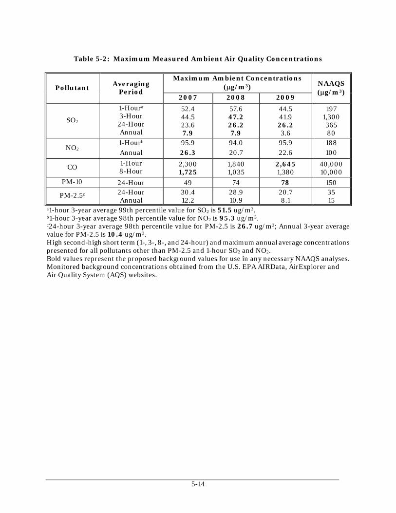
5-14
Table 5-2: Maximum Measured Ambient Air Quality Concentrations
Pollutant Averaging Period
Maximum Ambient Concentrations (g/m3) NAAQS
(g/m3) 2007 2008 2009
SO2
1-Houra 3-Hour
24-Hour Annual
52.4 44.5 23.6 7.9
57.6 47.2 26.2 7.9
44.5 41.9 26.2 3.6
197 1,300 365 80
NO2 1-Hourb Annual
95.9 26.3
94.0 20.7
95.9 22.6
188 100
CO 1-Hour 8-Hour
2,300 1,725
1,840 1,035
2,645 1,380
40,000 10,000
PM-10 24-Hour 49 74 78 150
PM-2.5c 24-Hour Annual
30.4 12.2
28.9 10.9
20.7 8.1
35 15
a1-hour 3-year average 99th percentile value for SO2 is 51.5 ug/m3. b1-hour 3-year average 98th percentile value for NO2 is 95.3 ug/m3. c24-hour 3-year average 98th percentile value for PM-2.5 is 26.7 ug/m3; Annual 3-year average value for PM-2.5 is 10.4 ug/m3. High second-high short term (1-, 3-, 8-, and 24-hour) and maximum annual average concentrations presented for all pollutants other than PM-2.5 and 1-hour SO2 and NO2. Bold values represent the proposed background values for use in any necessary NAAQS analyses. Monitored background concentrations obtained from the U.S. EPA AIRData, AirExplorer and Air Quality System (AQS) websites.

CPV Shore LLC Woodbridge Energy Center Township of Woodbridge, Middlesex County, New Jersey
Figure 5-1: Landuse within 3-kilomters of Woodbridge Energy Center
Source: USGS Topographical Maps

CPV Shore LLC Woodbridge Energy Center Township of Woodbridge, Middlesex County, New Jersey
Figure 5-2: Locations of Woodbridge Energy Center and Newark Liberty Airport Source: Google Earth, 2011

CPV Shore LLC Woodbridge Energy Center Township of Woodbridge, Middlesex County, New Jersey
Figure 5-3: Wind Rose for Newark Liberty International Airport (2005-2009)
Source: WRPLOT – Lakes Environmental

CPV Shore LLC Woodbridge Energy Center Township of Woodbridge, Middlesex County, New Jersey
Figure 5-4: Modeled Receptor Grid (Near Grid)
Source: Aerial Imagery

CPV Shore LLC Woodbridge Energy Center Township of Woodbridge, Middlesex County, New Jersey
Figure 5-5: Modeled Receptor Grid (Full Grid)
Source: USGS Topographical Maps

REFERENCES NJDEP, 2009. Guidance on Preparing an Air Quality Modeling Protocol. Bureau of Air Quality
Evaluation Technical Manual 1002, Trenton, New Jersey. U.S. EPA, 2005. Guideline on Air Quality Models (Revised). Appendix W to Title 40 U.S. Code
of Federal Regulations (CFR) Parts 51 and 52, Office of Air Quality Planning and Standards, U.S. Environmental Protection Agency. Research Triangle Park, North Carolina. November 6, 2005.
U.S. EPA, 1992. "Screening Procedures for Estimating the Air Quality Impact of Stationary
Sources, Revised". EPA Document 454/R-92-019, Office of Air Quality Planning and Standards, Research Triangle Park, North Carolina.
U.S. EPA, 1990. "New Source Review Workshop Manual, Draft". Office of Air Quality Planning
and Standards, U.S. Environmental Protection Agency. Research Triangle Park, North Carolina.
U.S. EPA, 1985. Guidelines for Determination of Good Engineering Practice Stack Height
(Technical Support Document for the Stack Height Regulations-Revised). EPA-450/4-80-023R. U.S. Environmental Protection Agency.
U.S. EPA, 1980. A Screening Procedure for the Impacts of Air Pollution Sources on Plants, Soils,
and Animals. EPA 450/2-81-078. Office of Air Quality Planning and Standards, U.S. Environmental Protection Agency. Research Triangle Park, North Carolina. December 1980.
U.S. EPA, 2011. Additional Clarification Regarding Application of Appendix W Modeling
Guidance for the 1-Hour NO2 NAAQS. U.S. EPA. March 1, 2011.

APPENDIX A
Agency Correspondence

1
April 12, 2011 Mr. Joel Leon New Jersey Department of Environmental Protection Division of Air Quality 401 East State Street Trenton, New Jersey 08625 Subject: CPV Shore, LLC
Proposed Woodbridge Energy Center Township of Woodbridge, Middlesex County, New Jersey Request for Waiver from Pre-Construction Ambient Air Quality Monitoring
Dear Mr. Leon: This letter serves as a formal request on behalf of CPV Shore, LLC (CPV) for an exemption from the requirement to perform one year of pre-construction ambient air quality monitoring for the proposed combined cycle power facility to be located in the Township of Woodbridge, Middlesex County, New Jersey in accordance with Prevention of Significant Deterioration (PSD) of Air Quality regulations promulgated under 40 CFR 52 by the United States Environmental Protection Agency (U.S. EPA). Those regulations state that major new or modified facilities having annual emissions of regulated air pollutants in excess of the significant emission rates (SERs) defined in the PSD regulations must perform an air quality analysis for these pollutants which can include collection of one year of on-site ambient air quality data. Pursuant to 40 CFR 52.21, a waiver from pre-construction ambient air quality monitoring may be granted if one of the following can be demonstrated:
The proposed facility ambient air quality impacts are less than the significant monitoring concentrations specified in 40 CFR 52.21, or
Existing quality assured ambient air quality data are available from alternate locations that are representative of, or conservative, as compared to conditions at the proposed facility location.
This requirement does not apply to emitted pollutants for which the area in which the source is locating is designated as non-attainment and for which it is subject to Non-Attainment New Source Review (NNSR). Supporting documentation for this waiver request is presented herein.

Mr. Joel Leon New Jersey Department of Environmental Protection
2
Project Description CPV Shore, LLC is proposing to construct a nominal 700-megawatt (MW) natural gas fired 2-on-1 combined cycle power facility (to be known as the Woodbridge Energy Center, LLC facility) in the Township of Woodbridge, Middlesex County, New Jersey. The proposed Facility will be located on an approximately 27.5-acre industrial parcel of land (See Attached Figure 1-1). The facility (combustion turbines) will be fueled by natural gas. Because the proposed facility is located in an attainment area for sulfur dioxide (SO2), nitrogen dioxide (NO2), carbon monoxide (CO), and particulate matter with an aerodynamic diameter less than 10 micrometers (m) (PM-10) and will potentially emit more than 100 tons per year of several air pollutants, it will be subject to Prevention of Significant Deterioration (PSD) permitting. The project will include two General Electric (GE) 7 FA.05 Combustion Turbines that will utilize pipeline natural gas, which will be equipped with a natural gas-fired duct burner for supplementary firing and a single steam turbine generator (STG). By using the waste heat from the combustion turbines to produce steam and generate additional electricity, the Facility will operate with a higher thermal efficiency than many other electricity generating facilities. The CTGs will be equipped with an inlet air cooling system to further boost power and efficiency on hot days. The HRSG will be equipped with a natural gas-fired duct burner. Supporting ancillary equipment will include a natural gas fired auxiliary boiler, one small dew point fuel gas heater (fuel gas heater), a mechanical draft cooling tower, an emergency diesel generator and an emergency diesel fire pump to provide on-site fire-fighting capability. Emissions from the combined cycle units will be controlled by the use of dry low-NOx burner technology and SCR for NOx control, an oxidation catalyst for CO and VOC control, and the use of clean low-sulfur fuels (i.e., natural gas) to minimize emissions of SO2, PM/PM-10/PM-2.5, and H2SO4. Exhaust gases from the combined cycle units after emission controls will be dispersed to the atmosphere via single flue stacks. Steam from the steam turbine will be sent to a condenser where it will be cooled to a liquid state and returned to the HRSG. Waste heat from the condenser will be dissipated through the mechanical draft cooling tower. Facility Emissions The proposed facility will be located in an area designated as attainment for sulfur dioxide (SO2), nitrogen dioxide (NO2), carbon monoxide (CO), and particulate matter with an aerodynamic diameter less than 10 micrometers (μm) (PM-10). However, Middlesex County is designated as moderate non-attainment for the 8-hour ozone standard and non-attainment for PM-2.5. Therefore, NNSR requirements apply to the proposed facility for NOx and VOC emissions since potential emissions of NOx and VOC may potentially exceed 25 tons per year as applicable in moderate ozone non-attainment areas. NNSR rules apply for PM-2.5 if emissions of PM-2.5 or SO2 equal or exceed 100 tons per year. The proposed facility does not expect to have PM-2.5 or SO2 emissions in excess of 100 tons per year. Therefore, PM-2.5 NNSR requirements would not be triggered. Under PSD regulations, an air quality dispersion modeling analysis will be required to ensure that CO, PM-10, SO2, and NO2 emissions from the proposed facility will be compliant with National Ambient Air Quality Standards (NAAQS) and applicable PSD increments. Table 1 presents projected facility emission rates and the pollutant specific significant emission rates (SERs) defined in the PSD regulations. A review of the table indicates that the proposed facility is projected to have annual emissions in excess of PSD SERs for CO, NOx, particulates

Mr. Joel Leon New Jersey Department of Environmental Protection
3
(PM/PM-10), the ozone precursor VOC, and sulfuric acid mist (H2SO4). Thus, the potential for ambient preconstruction monitoring must be addressed for these pollutants. Emissions of lead and SO2 are below the respective SERs. Further, since there are no approved ambient monitoring techniques for H2SO4, an exemption from monitoring is requested for that pollutant. Background Ambient Air Quality Data Pursuant to PSD regulations, the New Jersey Department of Environmental Protection (NJDEP) may exempt a proposed PSD source from the one-year preconstruction ambient monitoring program requirement if the source can demonstrate through dispersion modeling that air quality impacts from the proposed facility will be below the significant monitoring (or de minimis) concentrations (SMCs) established by U.S. EPA and included in the regulations under 40 CFR 52.21 (i)(8). In addition, a monitoring exemption can be requested based upon existing quality assured ambient air quality data that are available from alternate locations and are representative of, or conservative, as compared to conditions at the proposed facility location. CPV is requesting an exemption from preconstruction monitoring for CO, NO2, and PM-10 on this basis. Based on review of the locations of NJDEP ambient air quality monitoring sites, the closest “regional” NJDEP monitoring sites will be used to represent the current background air quality in the site area. Background data for CO was obtained from a New Jersey monitoring station located in Middlesex County, New Jersey (EPA AIRData # 34-023-2003), approximately 4 km east of the proposed facility. The monitor is located at 130 Smith Street in Perth Amboy, a commercial/urban area. Background data for PM-10 was obtained from a Jersey City monitoring station located in Hudson County, New Jersey (EPA AIRData # 34-017-1003), approximately 32 km northeast of the proposed facility. The monitor is located at 355 Newark Avenue in a commercial/urban area. Background data for NO2 was obtained from an East Brunswick monitoring station located in Middlesex County, New Jersey (EPA AIRData # 34-023-0011), approximately 11 km southwest of the proposed facility. The monitor is located at Rutgers University (Veg. Research Farm #3 on Ryders Lane) in an area consisting of agricultural/industrial uses with proximate mobile source uses (i.e., Route 1 and Interstate 95). The monitoring data for the most recent three years (2007-2009) are presented in Table 2. Annual potential emissions of the ozone precursor VOC exceed the SER. However, no de minimis air quality level is provided for ozone. Further, the preconstruction ambient air quality monitoring requirement does not apply to emitted pollutants when the area in which the source is locating is designated as non-attainment (i.e., ozone) and since it is subject to NNSR. Monitoring Waiver Request In summary, CPV is requesting an exemption from the need to perform preconstruction ambient monitoring for lead and SO2 because they will be emitted in amounts less than their SERs; for fluorides, hydrogen sulfide, total reduced sulfur, and reduced sulfur compounds because they are not anticipated as a product of natural gas combustion (i.e., from the combustion turbine/duct burner, auxiliary boiler, and dew point heater) and fuel oil combustion (i.e., from the emergency diesel generator and diesel fire pump); and for H2SO4 because there is no approved monitoring technique available.

Mr. Joel Leon New Jersey Department of Environmental Protection
4
Further, CPV is requesting an exemption from the need to perform preconstruction ambient air quality monitoring for CO, NO2, and PM-10 on the basis that existing quality assured ambient air quality data is available from alternate locations that are representative or conservative, as compared to conditions at the proposed facility location. Finally, the pre-construction ambient air quality monitoring requirement does not apply to ozone since it is not an emitted pollutant and monitoring for the ozone precursor VOC is not required in an ozone non-attainment area (i.e., subject to NNSR). Please feel free to contact me at (201) 508-6964 or Ted Main at (201) 508-6960 should you have any questions regarding this monitoring exemption request. Sincerely, TRC Darin Ometz Senior Consulting Meteorologist Attachments: Tables 1 and 2 and Figure 1-1 cc: Y. Doshi, NJDEP A. Dresser, NJDEP
T. Main, TRC R. Golden, TRC
S. Remillard, CPV J. Donovan, CPV
TRC Project 173062

Mr. Joel Leon New Jersey Department of Environmental Protection
5
TABLE 1: WOODBRIDGE ENERGY CENTER FACILITY COMPARISON OF PROJECTED FACILITY EMISSIONS TO PSD SIGNIFICANT EMISSION RATES
Pollutant
Preliminary Emission Rate
(tons per year)
PSD Significant
Emission Rate (tons per
year)
Carbon Monoxide 129.7 100
Sulfur Dioxide 12.0 40
Particulate Matter (PM) 107.9 25
Particulate Matter less than 10 microns (PM-10)
103.7 15
Particulate Matter less than 2.5 microns (PM-2.5)
98.7 10
Nitrogen Oxides 140.6 40
Ozone (VOC) 27.8 40
Lead 0.01 0.6
Fluorides a 3
Sulfuric Acid Mist 8.2 7
Hydrogen Sulfide a 10
Total Reduced Sulfur (including H2S)
a 10
Reduced Sulfur Compounds (including H2S)
a 10
a Not anticipated as a product of natural gas (i.e., from the combustion turbine/duct burner, auxiliary boiler, and dew point heater) or fuel oil combustion (i.e., emergency diesel generator and diesel fire pump).
b No acceptable monitoring techniques exist for this pollutant.
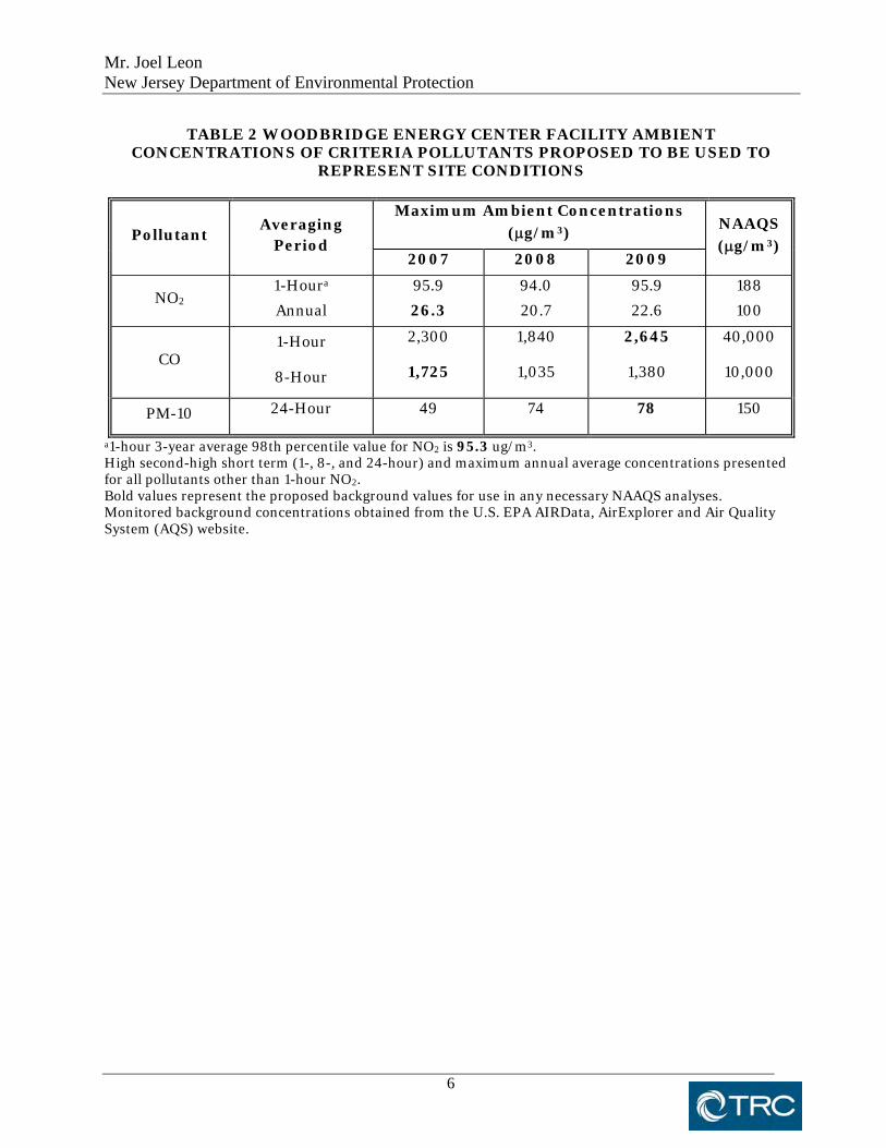
Mr. Joel Leon New Jersey Department of Environmental Protection
6
TABLE 2 WOODBRIDGE ENERGY CENTER FACILITY AMBIENT CONCENTRATIONS OF CRITERIA POLLUTANTS PROPOSED TO BE USED TO
REPRESENT SITE CONDITIONS
Pollutant Averaging
Period
Maximum Ambient Concentrations (g/m3)
NAAQS (g/m3)
2007 2008 2009
NO2 1-Houra
Annual
95.9
26.3
94.0
20.7
95.9
22.6
188
100
CO 1-Hour
8-Hour
2,300
1,725
1,840
1,035
2,645
1,380
40,000
10,000
PM-10 24-Hour 49 74 78 150
a1-hour 3-year average 98th percentile value for NO2 is 95.3 ug/m3. High second-high short term (1-, 8-, and 24-hour) and maximum annual average concentrations presented for all pollutants other than 1-hour NO2. Bold values represent the proposed background values for use in any necessary NAAQS analyses. Monitored background concentrations obtained from the U.S. EPA AIRData, AirExplorer and Air Quality System (AQS) website.

$
March 2011
1200 Wall Street WestLyndhurst, NJ 07071 Figure
1-1
Project Site Boundary
Site Location Aerial Photograph
CPV Shore, LLCWoodbridge Energy Center
Basemap: 7.5' USGS Quadrangles: South Amboy and Perth Amboy
0 0.2 0.4Miles
S:\Ma
ggie\
GIS\
CPV
Woo
dbrid
ge\M
XD\A
erial_
Site L
ocait
on M
ap.m
xd

Appendix F
Summary of Maximum Modeled Concentrations for Combustion Turbines

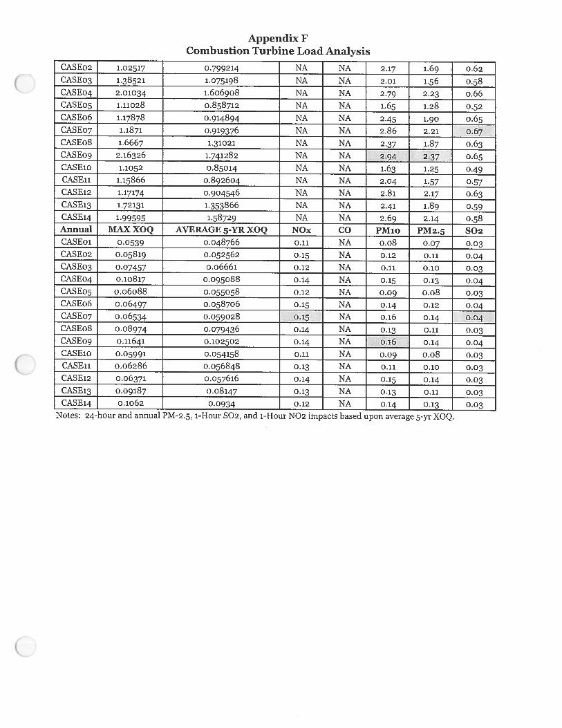

Appendix G
Modeling Input and Output Files

dir.datThis DVD contains the modeling input and output files for the proposed CPV Shore LLC Woodbridge Energy Centerlocated in Middlesex County, New Jersey. The following are brief descriptionsfor each of the modeling files used in the air quality modeling analysis. (June 2011)
** Note that all files with the .aer extension are AERMOD input files.** All files with the .out extension are output files.
Directory of \CPV Woodbridge\PSD Modeling Files Appendix
06/03/2011 02:17 PM <DIR> AERMAP06/03/2011 01:43 PM <DIR> AERMOD_LoadAnalysis06/03/2011 01:46 PM <DIR> AERMOD_Normal CT Operation06/03/2011 01:46 PM <DIR> AERMOD_Startup_Shutdown06/03/2011 02:15 PM <DIR> BPIP06/06/2011 09:14 AM <DIR> MeteorologicalData
*********************************************************************************************************************
Directory of \CPV Woodbridge\PSD Modeling Files Appendix\AERMAP
** This Directory contains the AERMAP input and output files used to process the modeling receptor grid.
02/01/2011 11:18 AM 124,138,703 73804948.tif04/14/2011 10:41 AM 887,089 aermap.exe04/27/2011 09:45 AM 1,618,864 aermap.inp04/29/2011 03:48 AM 3,749 aermap.out06/21/2004 02:12 PM 530,000 alaska.las06/21/2004 02:12 PM 530,000 alaska.los04/29/2011 03:48 AM 35,449,288 CALCHCDET.OUT06/21/2004 02:12 PM 133,712 conus.las06/21/2004 02:12 PM 133,712 conus.los04/29/2011 03:48 AM 2,508,794 CPVREC.out06/21/2004 02:12 PM 227,856 hawaii.las06/21/2004 02:12 PM 227,856 hawaii.los04/27/2011 09:47 AM 2,083 MAPDETAIL.OUT04/27/2011 09:49 AM 2,583 MAPPARAMS.OUT06/21/2004 02:12 PM 13,776 prvi.las06/21/2004 02:12 PM 13,776 prvi.los04/29/2011 03:48 AM 473 RECDETAIL.OUT04/29/2011 03:48 AM 99,565,200 RECELV.OUT04/27/2011 09:47 AM 33,255,818 RECNDEM.OUT06/21/2004 02:12 PM 30,256 stgeorge.las06/21/2004 02:12 PM 30,256 stgeorge.los06/21/2004 02:12 PM 13,776 stlrnc.las06/21/2004 02:12 PM 13,776 stlrnc.los06/21/2004 02:12 PM 3,696 stpaul.las06/21/2004 02:12 PM 3,696 stpaul.los
*********************************************************************************************************************
Directory of \CPV Woodbridge\PSD Modeling Files Appendix\AERMOD_LoadAnalysis
** This Directory contains the AERMOD input and output files used for the modeling the short term and annual load analysis.
04/29/2011 08:29 AM 2,518,719 load05.aer04/29/2011 07:37 PM 238,280,514 load05.out04/29/2011 08:29 AM 2,518,719 load06.aer04/29/2011 07:35 PM 238,280,514 load06.out04/29/2011 08:29 AM 2,518,719 load07.aer04/29/2011 07:29 PM 238,280,514 load07.out04/29/2011 08:29 AM 2,518,719 load08.aer04/29/2011 06:59 PM 238,280,514 load08.out04/29/2011 08:29 AM 2,518,719 load09.aer04/29/2011 07:33 PM 238,280,514 load09.out
*********************************************************************************************************************
Directory of \CPV Woodbridge\PSD Modeling Files Appendix\AERMOD_Normal CT Operation
** This Directory contains the AERMOD input and output files used for modeling facility impacts during normal ** operation of the combustion turbines. Plotfiles are provided for all pollutants and averaging periods for ** comparison to the PSD Significant Impact Levels.
06/03/2011 01:37 PM <DIR> 1HourCO06/03/2011 01:09 PM <DIR> 1HourNO206/03/2011 01:10 PM <DIR> 1HourSO206/03/2011 01:40 PM <DIR> 24HourPM1006/03/2011 01:39 PM <DIR> 24HourPM2.506/03/2011 01:41 PM <DIR> 24HourSO206/03/2011 01:11 PM <DIR> 3HourSO206/03/2011 01:34 PM <DIR> 8HourCO
Page 1

dir.dat06/03/2011 01:41 PM <DIR> AnnualNO206/03/2011 01:42 PM <DIR> AnnualPM1006/03/2011 01:42 PM <DIR> AnnualPM2.506/03/2011 01:43 PM <DIR> AnnualSO2
Directory of \CPV Woodbridge\PSD Modeling Files Appendix\AERMOD_Normal CT Operation\1HourCO
05/02/2011 04:29 PM 4,815,374 1hrCO05.out05/02/2011 04:29 PM 4,815,374 1hrCO06.out05/02/2011 04:28 PM 4,815,374 1hrCO07.out05/02/2011 04:30 PM 4,815,374 1hrCO08.out05/02/2011 04:29 PM 4,815,374 1hrCO09.out05/02/2011 01:56 PM 2,524,300 CPVShore05.aer05/02/2011 04:29 PM 23,294,954 CPVShore05.out05/02/2011 02:15 PM 2,524,300 CPVShore06.aer05/02/2011 04:29 PM 23,294,954 CPVShore06.out05/02/2011 02:15 PM 2,524,300 CPVShore07.aer05/02/2011 04:28 PM 23,294,954 CPVShore07.out05/02/2011 02:16 PM 2,524,300 CPVShore08.aer05/02/2011 04:30 PM 23,294,954 CPVShore08.out05/02/2011 02:16 PM 2,524,300 CPVShore09.aer05/02/2011 04:29 PM 23,294,954 CPVShore09.out
Directory of \CPV Woodbridge\PSD Modeling Files Appendix\AERMOD_Normal CT Operation\1HourNO2
05/03/2011 01:25 PM 4,815,374 1hrNO205.out05/03/2011 01:31 PM 4,815,374 1hrNO206.out05/03/2011 01:26 PM 4,815,374 1hrNO207.out05/03/2011 01:31 PM 4,815,374 1hrNO208.out05/03/2011 01:26 PM 4,815,374 1hrNO209.out05/03/2011 11:22 AM 2,519,806 CPVShore05.aer05/03/2011 01:25 PM 16,559,244 CPVShore05.out05/03/2011 11:22 AM 2,519,806 CPVShore06.aer05/03/2011 01:31 PM 16,559,244 CPVShore06.out05/03/2011 11:22 AM 2,519,806 CPVShore07.aer05/03/2011 01:26 PM 16,559,244 CPVShore07.out05/03/2011 11:22 AM 2,519,806 CPVShore08.aer05/03/2011 01:31 PM 16,559,244 CPVShore08.out05/03/2011 11:23 AM 2,519,806 CPVShore09.aer05/03/2011 01:26 PM 16,559,244 CPVShore09.out
Directory of \CPV Woodbridge\PSD Modeling Files Appendix\AERMOD_Normal CT Operation\1HourSO2
05/03/2011 01:24 PM 4,815,374 1hrSO205.out05/03/2011 01:21 PM 4,815,374 1hrSO206.out05/03/2011 01:23 PM 4,815,374 1hrSO207.out05/03/2011 01:25 PM 4,815,374 1hrSO208.out05/03/2011 01:04 PM 4,815,374 1hrSO209.out05/03/2011 11:36 AM 2,519,806 CPVShore05.aer05/03/2011 01:24 PM 16,559,244 CPVShore05.out05/03/2011 11:36 AM 2,519,806 CPVShore06.aer05/03/2011 01:21 PM 16,559,244 CPVShore06.out05/03/2011 11:37 AM 2,519,806 CPVShore07.aer05/03/2011 01:23 PM 16,559,244 CPVShore07.out05/03/2011 11:37 AM 2,519,806 CPVShore08.aer05/03/2011 01:25 PM 16,559,244 CPVShore08.out05/03/2011 11:37 AM 2,519,806 CPVShore09.aer05/03/2011 01:05 PM 16,559,244 CPVShore09.out
Directory of \CPV Woodbridge\PSD Modeling Files Appendix\AERMOD_Normal CT Operation\24HourPM10
04/30/2011 12:54 AM 4,815,374 24hrpm05.out04/30/2011 12:52 AM 4,815,374 24hrpm06.out04/30/2011 12:52 AM 4,815,374 24hrpm07.out04/30/2011 01:01 AM 4,815,374 24hrpm08.out04/30/2011 12:56 AM 4,815,374 24hrpm09.out04/29/2011 03:05 PM 2,555,527 CPVShore05.aer04/30/2011 12:54 AM 26,898,278 CPVShore05.out04/29/2011 03:06 PM 2,555,527 CPVShore06.aer04/30/2011 12:52 AM 26,898,278 CPVShore06.out04/29/2011 03:07 PM 2,555,527 CPVShore07.aer04/30/2011 12:52 AM 26,898,278 CPVShore07.out04/29/2011 03:07 PM 2,555,527 CPVShore08.aer04/30/2011 01:01 AM 26,898,278 CPVShore08.out04/29/2011 03:07 PM 2,555,527 CPVShore09.aer04/30/2011 12:56 AM 26,898,278 CPVShore09.out
Directory of \CPV Woodbridge\PSD Modeling Files Appendix\AERMOD_Normal CT Operation\24HourPM2.5
04/29/2011 06:44 PM 4,815,374 24hrpm05.out04/29/2011 06:49 PM 4,815,374 24hrpm06.out04/29/2011 06:47 PM 4,815,374 24hrpm07.out04/29/2011 06:50 PM 4,815,374 24hrpm08.out04/29/2011 06:48 PM 4,815,374 24hrpm09.out04/29/2011 02:06 PM 2,524,306 CPVShore05.aer04/29/2011 06:44 PM 23,294,954 CPVShore05.out04/29/2011 02:07 PM 2,524,306 CPVShore06.aer04/29/2011 06:49 PM 23,294,954 CPVShore06.out
Page 2
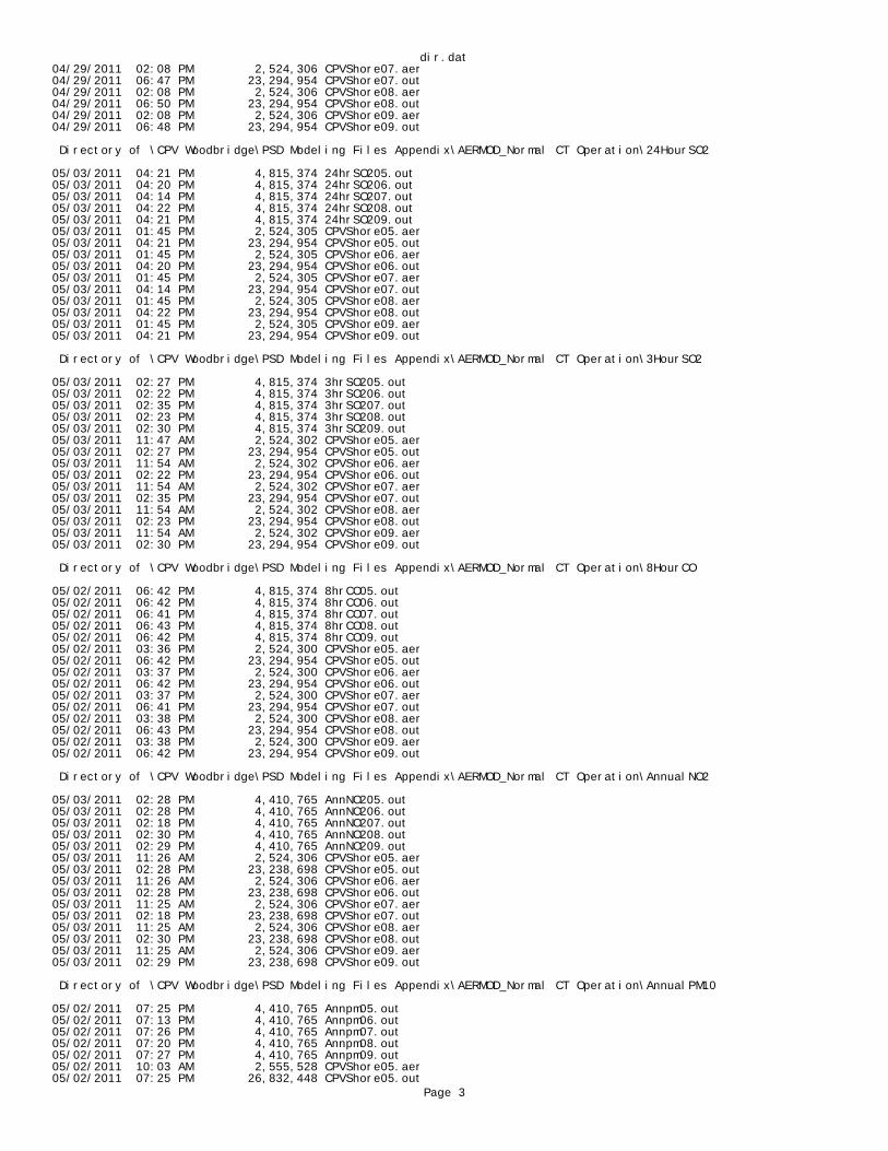
dir.dat04/29/2011 02:08 PM 2,524,306 CPVShore07.aer04/29/2011 06:47 PM 23,294,954 CPVShore07.out04/29/2011 02:08 PM 2,524,306 CPVShore08.aer04/29/2011 06:50 PM 23,294,954 CPVShore08.out04/29/2011 02:08 PM 2,524,306 CPVShore09.aer04/29/2011 06:48 PM 23,294,954 CPVShore09.out
Directory of \CPV Woodbridge\PSD Modeling Files Appendix\AERMOD_Normal CT Operation\24HourSO2
05/03/2011 04:21 PM 4,815,374 24hrSO205.out05/03/2011 04:20 PM 4,815,374 24hrSO206.out05/03/2011 04:14 PM 4,815,374 24hrSO207.out05/03/2011 04:22 PM 4,815,374 24hrSO208.out05/03/2011 04:21 PM 4,815,374 24hrSO209.out05/03/2011 01:45 PM 2,524,305 CPVShore05.aer05/03/2011 04:21 PM 23,294,954 CPVShore05.out05/03/2011 01:45 PM 2,524,305 CPVShore06.aer05/03/2011 04:20 PM 23,294,954 CPVShore06.out05/03/2011 01:45 PM 2,524,305 CPVShore07.aer05/03/2011 04:14 PM 23,294,954 CPVShore07.out05/03/2011 01:45 PM 2,524,305 CPVShore08.aer05/03/2011 04:22 PM 23,294,954 CPVShore08.out05/03/2011 01:45 PM 2,524,305 CPVShore09.aer05/03/2011 04:21 PM 23,294,954 CPVShore09.out
Directory of \CPV Woodbridge\PSD Modeling Files Appendix\AERMOD_Normal CT Operation\3HourSO2
05/03/2011 02:27 PM 4,815,374 3hrSO205.out05/03/2011 02:22 PM 4,815,374 3hrSO206.out05/03/2011 02:35 PM 4,815,374 3hrSO207.out05/03/2011 02:23 PM 4,815,374 3hrSO208.out05/03/2011 02:30 PM 4,815,374 3hrSO209.out05/03/2011 11:47 AM 2,524,302 CPVShore05.aer05/03/2011 02:27 PM 23,294,954 CPVShore05.out05/03/2011 11:54 AM 2,524,302 CPVShore06.aer05/03/2011 02:22 PM 23,294,954 CPVShore06.out05/03/2011 11:54 AM 2,524,302 CPVShore07.aer05/03/2011 02:35 PM 23,294,954 CPVShore07.out05/03/2011 11:54 AM 2,524,302 CPVShore08.aer05/03/2011 02:23 PM 23,294,954 CPVShore08.out05/03/2011 11:54 AM 2,524,302 CPVShore09.aer05/03/2011 02:30 PM 23,294,954 CPVShore09.out
Directory of \CPV Woodbridge\PSD Modeling Files Appendix\AERMOD_Normal CT Operation\8HourCO
05/02/2011 06:42 PM 4,815,374 8hrCO05.out05/02/2011 06:42 PM 4,815,374 8hrCO06.out05/02/2011 06:41 PM 4,815,374 8hrCO07.out05/02/2011 06:43 PM 4,815,374 8hrCO08.out05/02/2011 06:42 PM 4,815,374 8hrCO09.out05/02/2011 03:36 PM 2,524,300 CPVShore05.aer05/02/2011 06:42 PM 23,294,954 CPVShore05.out05/02/2011 03:37 PM 2,524,300 CPVShore06.aer05/02/2011 06:42 PM 23,294,954 CPVShore06.out05/02/2011 03:37 PM 2,524,300 CPVShore07.aer05/02/2011 06:41 PM 23,294,954 CPVShore07.out05/02/2011 03:38 PM 2,524,300 CPVShore08.aer05/02/2011 06:43 PM 23,294,954 CPVShore08.out05/02/2011 03:38 PM 2,524,300 CPVShore09.aer05/02/2011 06:42 PM 23,294,954 CPVShore09.out
Directory of \CPV Woodbridge\PSD Modeling Files Appendix\AERMOD_Normal CT Operation\AnnualNO2
05/03/2011 02:28 PM 4,410,765 AnnNO205.out05/03/2011 02:28 PM 4,410,765 AnnNO206.out05/03/2011 02:18 PM 4,410,765 AnnNO207.out05/03/2011 02:30 PM 4,410,765 AnnNO208.out05/03/2011 02:29 PM 4,410,765 AnnNO209.out05/03/2011 11:26 AM 2,524,306 CPVShore05.aer05/03/2011 02:28 PM 23,238,698 CPVShore05.out05/03/2011 11:26 AM 2,524,306 CPVShore06.aer05/03/2011 02:28 PM 23,238,698 CPVShore06.out05/03/2011 11:25 AM 2,524,306 CPVShore07.aer05/03/2011 02:18 PM 23,238,698 CPVShore07.out05/03/2011 11:25 AM 2,524,306 CPVShore08.aer05/03/2011 02:30 PM 23,238,698 CPVShore08.out05/03/2011 11:25 AM 2,524,306 CPVShore09.aer05/03/2011 02:29 PM 23,238,698 CPVShore09.out
Directory of \CPV Woodbridge\PSD Modeling Files Appendix\AERMOD_Normal CT Operation\AnnualPM10
05/02/2011 07:25 PM 4,410,765 Annpm05.out05/02/2011 07:13 PM 4,410,765 Annpm06.out05/02/2011 07:26 PM 4,410,765 Annpm07.out05/02/2011 07:20 PM 4,410,765 Annpm08.out05/02/2011 07:27 PM 4,410,765 Annpm09.out05/02/2011 10:03 AM 2,555,528 CPVShore05.aer05/02/2011 07:25 PM 26,832,448 CPVShore05.out
Page 3
dir.dat05/02/2011 10:03 AM 2,555,528 CPVShore06.aer05/02/2011 07:13 PM 26,832,448 CPVShore06.out05/02/2011 10:04 AM 2,555,528 CPVShore07.aer05/02/2011 07:26 PM 26,832,448 CPVShore07.out05/02/2011 10:04 AM 2,555,528 CPVShore08.aer05/02/2011 07:20 PM 26,832,448 CPVShore08.out05/02/2011 10:04 AM 2,555,528 CPVShore09.aer05/02/2011 07:27 PM 26,832,448 CPVShore09.out
Directory of \CPV Woodbridge\PSD Modeling Files Appendix\AERMOD_Normal CT Operation\AnnualPM2.5
05/02/2011 01:12 PM 4,410,765 Annpm05.out05/02/2011 01:13 PM 4,410,765 Annpm06.out05/02/2011 01:06 PM 4,410,765 Annpm07.out05/02/2011 01:13 PM 4,410,765 Annpm08.out05/02/2011 01:06 PM 4,410,765 Annpm09.out05/02/2011 10:02 AM 2,524,307 CPVShore05.aer05/02/2011 01:12 PM 23,238,698 CPVShore05.out05/02/2011 10:02 AM 2,524,307 CPVShore06.aer05/02/2011 01:13 PM 23,238,698 CPVShore06.out05/02/2011 10:02 AM 2,524,307 CPVShore07.aer05/02/2011 01:06 PM 23,238,698 CPVShore07.out05/02/2011 10:02 AM 2,524,307 CPVShore08.aer05/02/2011 01:13 PM 23,238,698 CPVShore08.out05/02/2011 10:03 AM 2,524,307 CPVShore09.aer05/02/2011 01:06 PM 23,238,698 CPVShore09.out
Directory of \CPV Woodbridge\PSD Modeling Files Appendix\AERMOD_Normal CT Operation\AnnualSO2
05/03/2011 04:19 PM 4,410,765 AnnSO205.out05/03/2011 04:13 PM 4,410,765 AnnSO206.out05/03/2011 04:18 PM 4,410,765 AnnSO207.out05/03/2011 04:15 PM 4,410,765 AnnSO208.out05/03/2011 04:19 PM 4,410,765 AnnSO209.out05/03/2011 01:59 PM 2,524,307 CPVShore05.aer05/03/2011 04:19 PM 23,238,698 CPVShore05.out05/03/2011 01:59 PM 2,524,307 CPVShore06.aer05/03/2011 04:13 PM 23,238,698 CPVShore06.out05/03/2011 02:00 PM 2,524,307 CPVShore07.aer05/03/2011 04:18 PM 23,238,698 CPVShore07.out05/03/2011 02:00 PM 2,524,307 CPVShore08.aer05/03/2011 04:15 PM 23,238,698 CPVShore08.out05/03/2011 02:00 PM 2,524,307 CPVShore09.aer05/03/2011 04:19 PM 23,238,698 CPVShore09.out
*********************************************************************************************************************
Directory of \CPV Woodbridge\PSD Modeling Files Appendix\AERMOD_Startup_Shutdown
** This Directory contains the AERMOD input and output files used for modeling facility impacts during startup/shutdown** of the combustion turbines. Plotfiles are provided for all pollutants and averaging periods for ** comparison to the PSD Significant Impact Levels.
06/03/2011 01:44 PM <DIR> StartupsCO1HR06/03/2011 01:44 PM <DIR> StartupsCO8HR06/03/2011 01:45 PM <DIR> StartupsNO2
Directory of \CPV Woodbridge\PSD Modeling Files Appendix\AERMOD_Startup_Shutdown\StartupsCO1HR
05/20/2011 03:24 AM 4,815,374 ColCon5.out05/20/2011 05:15 AM 4,815,374 ColCon6.out05/20/2011 03:21 AM 4,815,374 ColCon7.out05/20/2011 04:06 AM 4,815,374 ColCon8.out05/20/2011 03:59 AM 4,815,374 ColCon9.out05/19/2011 02:52 PM 2,574,695 CPVShore05.aer05/20/2011 03:24 AM 23,645,352 CPVShore05.out05/19/2011 02:52 PM 2,574,695 CPVShore06.aer05/20/2011 05:15 AM 23,645,352 CPVShore06.out05/19/2011 02:52 PM 2,574,695 CPVShore07.aer05/20/2011 03:21 AM 23,645,352 CPVShore07.out05/19/2011 02:53 PM 2,574,695 CPVShore08.aer05/20/2011 04:08 AM 23,645,352 CPVShore08.out05/19/2011 02:53 PM 2,574,695 CPVShore09.aer05/20/2011 03:59 AM 23,645,352 CPVShore09.out05/20/2011 03:24 AM 4,815,374 HotCon5.out05/20/2011 05:15 AM 4,815,374 HotCon6.out05/20/2011 03:21 AM 4,815,374 HotCon7.out05/20/2011 04:05 AM 4,815,374 HotCon8.out05/20/2011 03:59 AM 4,815,374 HotCon9.out05/20/2011 03:24 AM 4,815,374 ShutCon5.out05/20/2011 05:15 AM 4,815,374 ShutCon6.out05/20/2011 03:21 AM 4,815,374 ShutCon7.out05/20/2011 04:06 AM 4,815,374 ShutCon8.out05/20/2011 03:59 AM 4,815,374 ShutCon9.out05/20/2011 03:24 AM 4,815,374 ShutRap5.out05/20/2011 05:15 AM 4,815,374 ShutRap6.out
Page 4

dir.dat05/20/2011 03:21 AM 4,815,374 ShutRap7.out05/20/2011 04:06 AM 4,815,374 ShutRap8.out05/20/2011 03:59 AM 4,815,374 ShutRap9.out05/20/2011 03:24 AM 4,815,374 WarmCon5.out05/20/2011 05:15 AM 4,815,374 WarmCon6.out05/20/2011 03:21 AM 4,815,374 WarmCon7.out05/20/2011 04:06 AM 4,815,374 WarmCon8.out05/20/2011 03:59 AM 4,815,374 WarmCon9.out05/20/2011 03:24 AM 4,815,374 WarmRap5.out05/20/2011 05:15 AM 4,815,374 WarmRap6.out05/20/2011 03:21 AM 4,815,374 WarmRap7.out05/20/2011 04:08 AM 4,815,374 WarmRap8.out05/20/2011 03:59 AM 4,815,374 WarmRap9.out
Directory of \CPV Woodbridge\PSD Modeling Files Appendix\AERMOD_Startup_Shutdown\StartupsCO8HR
05/20/2011 08:37 PM 4,815,374 ColCon5.out05/20/2011 08:35 PM 4,815,374 ColCon6.out05/20/2011 08:31 PM 4,815,374 ColCon7.out05/20/2011 08:43 PM 4,815,374 ColCon8.out05/20/2011 08:32 PM 4,815,374 ColCon9.out05/20/2011 10:32 AM 2,574,699 CPVShore05.aer05/20/2011 08:37 PM 23,644,818 CPVShore05.out05/20/2011 10:30 AM 2,574,699 CPVShore06.aer05/20/2011 08:35 PM 23,644,818 CPVShore06.out05/20/2011 10:31 AM 2,574,699 CPVShore07.aer05/20/2011 08:31 PM 23,644,818 CPVShore07.out05/20/2011 10:31 AM 2,574,699 CPVShore08.aer05/20/2011 08:43 PM 23,644,818 CPVShore08.out05/20/2011 10:31 AM 2,574,699 CPVShore09.aer05/20/2011 08:32 PM 23,644,818 CPVShore09.out05/20/2011 08:37 PM 4,815,374 HotCon5.out05/20/2011 08:35 PM 4,815,374 HotCon6.out05/20/2011 08:31 PM 4,815,374 HotCon7.out05/20/2011 08:43 PM 4,815,374 HotCon8.out05/20/2011 08:32 PM 4,815,374 HotCon9.out05/20/2011 08:37 PM 4,815,374 ShutCon5.out05/20/2011 08:35 PM 4,815,374 ShutCon6.out05/20/2011 08:31 PM 4,815,374 ShutCon7.out05/20/2011 08:43 PM 4,815,374 ShutCon8.out05/20/2011 08:32 PM 4,815,374 ShutCon9.out05/20/2011 08:37 PM 4,815,374 ShutRap5.out05/20/2011 08:35 PM 4,815,374 ShutRap6.out05/20/2011 08:31 PM 4,815,374 ShutRap7.out05/20/2011 08:43 PM 4,815,374 ShutRap8.out05/20/2011 08:32 PM 4,815,374 ShutRap9.out05/20/2011 08:37 PM 4,815,374 WarmCon5.out05/20/2011 08:35 PM 4,815,374 WarmCon6.out05/20/2011 08:31 PM 4,815,374 WarmCon7.out05/20/2011 08:43 PM 4,815,374 WarmCon8.out05/20/2011 08:32 PM 4,815,374 WarmCon9.out05/20/2011 08:37 PM 4,815,374 WarmRap5.out05/20/2011 08:35 PM 4,815,374 WarmRap6.out05/20/2011 08:31 PM 4,815,374 WarmRap7.out05/20/2011 08:43 PM 4,815,374 WarmRap8.out05/20/2011 08:32 PM 4,815,374 WarmRap9.out
Directory of \CPV Woodbridge\PSD Modeling Files Appendix\AERMOD_Startup_Shutdown\StartupsNO2
05/04/2011 09:01 AM 2,551,724 CPVShore05.aer05/04/2011 03:38 PM 16,741,286 CPVShore05.out05/04/2011 09:03 AM 2,551,724 CPVShore06.aer05/04/2011 03:37 PM 16,741,286 CPVShore06.out05/04/2011 09:04 AM 2,551,724 CPVShore07.aer05/04/2011 03:34 PM 16,741,286 CPVShore07.out05/04/2011 09:04 AM 2,551,724 CPVShore08.aer05/04/2011 03:41 PM 16,741,286 CPVShore08.out05/04/2011 09:04 AM 2,551,724 CPVShore09.aer05/04/2011 03:36 PM 16,741,286 CPVShore09.out05/04/2011 03:38 PM 4,815,374 HotCon5.out05/04/2011 03:37 PM 4,815,374 HotCon6.out05/04/2011 03:34 PM 4,815,374 HotCon7.out05/04/2011 03:41 PM 4,815,374 HotCon8.out05/04/2011 03:36 PM 4,815,374 HotCon9.out05/04/2011 03:38 PM 4,815,374 ShutCon5.out05/04/2011 03:37 PM 4,815,374 ShutCon6.out05/04/2011 03:34 PM 4,815,374 ShutCon7.out05/04/2011 03:41 PM 4,815,374 ShutCon8.out05/04/2011 03:36 PM 4,815,374 ShutCon9.out05/04/2011 03:38 PM 4,815,374 ShutRap5.out05/04/2011 03:37 PM 4,815,374 ShutRap6.out05/04/2011 03:34 PM 4,815,374 ShutRap7.out05/04/2011 03:41 PM 4,815,374 ShutRap8.out05/04/2011 03:36 PM 4,815,374 ShutRap9.out05/04/2011 03:38 PM 4,815,374 WarmRap5.out05/04/2011 03:37 PM 4,815,374 WarmRap6.out05/04/2011 03:34 PM 4,815,374 WarmRap7.out05/04/2011 03:41 PM 4,815,374 WarmRap8.out
Page 5

dir.dat05/04/2011 03:36 PM 4,815,374 WarmRap9.out
*********************************************************************************************************************
Directory of \CPV Woodbridge\PSD Modeling Files Appendix\BPIP
** This Directory contains the BPIP input and output used for the building downwash analysis
04/27/2011 11:51 AM 48,638 cpvgep.out04/27/2011 11:41 AM 16,257 CPVGEP.PIP04/27/2011 11:51 AM 757,116 cpvgep.sum
*********************************************************************************************************************
Directory of \CPV Woodbridge\PSD Modeling Files Appendix\MeteorologicalData
** This Directory contains the processed surface and upper air data used in the AERMOD modeling analyses (obtained from NJDEP)
03/01/2011 02:29 PM 2,936,208 EWR0509.pfl03/01/2011 02:31 PM 7,231,050 EWR0509.sfc
*********************************************************************************************************************
Directory of V:\CPV Woodbridge\PSD Modeling Files Appendix\VISCREEN
** This Directory contains the modeling input and output files for the visibility screening assessment.
05/04/2011 03:18 PM 2,209 CPVSHORE.OUT05/04/2011 03:18 PM 7,709 CPVSHORE.SUM
Page 6

Appendix H
NJDEP Risk Screening Worksheet


