Embed Size (px)
Citation preview
DCP-252A Dual-Axis Precision Positioner
Installation and Configuration Guide


Congratulations on your purchase!
Diamond Engineering’s Desktop Antenna Measurement System has been designed to aid in the testing and development of small to medium sized antennas. Using our state of the art software, this system enables you to make many different types of measurements with complete user-definable configuration settings.
This manual will fully assist you with the assembling and configuring as well as teach you how to utilize the many features of your Desktop Antenna Measurement System. To achieve the full functionality of the measurement system, it’s expected the user have some working knowledge about the concepts and theories involved in microwaves and antenna design development.
We cannot emphasize the importance of fully reading and understanding this manual before using the equipment to avoid damaging the unit and/or voiding your warranty.
Best regards,
The Diamond Engineering Team

Table of Contents
Introduction ...................................................................................................................................................................... 7
Mounting the DCP-252A ............................................................................................................................................. 8
Optional Rotary Joint Adapter Plates ...................................................................................................................... 10
Connecting Cables .......................................................................................................................................................... 11
Cable Routing Options ................................................................................................................................................. 12
mmW Extender Mounting - VDI Extenders .......................................................................................................... 13
DAMS Software Installation ........................................................................................................................................ 14
DAMS Software Configuration .................................................................................................................................. 15
DAMS Software Configuration - 2nd Auxiliary Positioner .............................................................................. 16
Single / Primary Positioner Control ......................................................................................................................... 17
AUX / Secondary Positioner Control ....................................................................................................................... 18
Multi-Positioner Automation...................................................................................................................................... 19
Automation Module - File Information .................................................................................................................. 20
Automation Module - Exported File Format ........................................................................................................ 21
Detailed Motor and Axis Specifications ................................................................................................................. 22
Mounting Plate Drawing .............................................................................................................................................. 23
Adapter Plates .................................................................................................................................................................. 25
Controller Pinout ............................................................................................................................................................. 27
Adjusting COM Port ....................................................................................................................................................... 28
Troubleshooting and Support .................................................................................................................................... 29
http://www.DiamondEng.net · [email protected]
P.O. Box 2037 Diamond Springs, CA 95619 · 530-626-3857

7Installation & Configuration DCP-252A Dual-Axis Positioner
Overview
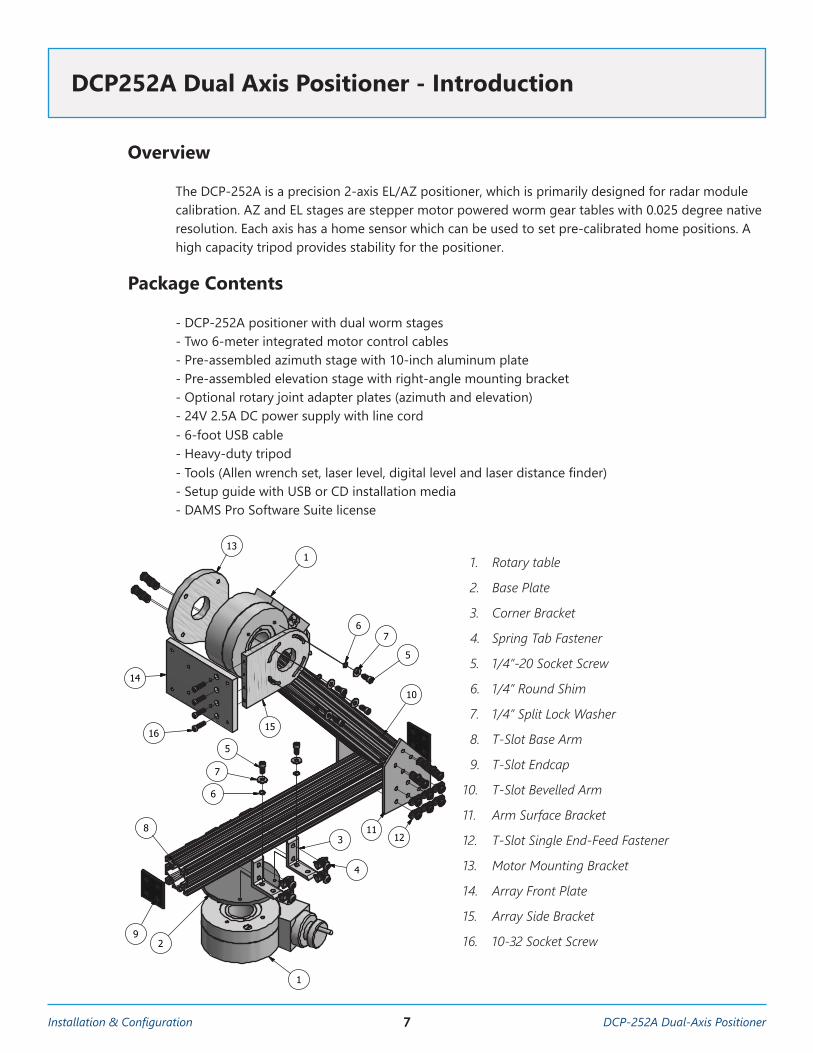
The DCP-252A is a precision 2-axis EL/AZ positioner, which is primarily designed for radar module calibration. AZ and EL stages are stepper motor powered worm gear tables with 0.025 degree native resolution. Each axis has a home sensor which can be used to set pre-calibrated home positions. A high capacity tripod provides stability for the positioner.
Package Contents
- DCP-252A positioner with dual worm stages- Two 6-meter integrated motor control cables- Pre-assembled azimuth stage with 10-inch aluminum plate - Pre-assembled elevation stage with right-angle mounting bracket - Optional rotary joint adapter plates (azimuth and elevation) - 24V 2.5A DC power supply with line cord - 6-foot USB cable- Heavy-duty tripod - Tools (Allen wrench set, laser level, digital level and laser distance finder)- Setup guide with USB or CD installation media - DAMS Pro Software Suite license
DCP252A Dual Axis Positioner - Introduction
PARTS LISTPART NUMBERPART NAMEQTYITEMDE00001Velmex B4800TS21
DE00002Base Plate12
DE00003Corner Bracket43
DE00004Spring Tab Fastener84
DE000051/4"-20 Socket Screw85
DE000061/4" Round Shim86
DE000071/4" Split Lock Washer87
DE00008T-Slot Base Arm18
DE00009T-Slot Endcap29
DE00010T-Slot Bevelled Arm110
DE00011Arm Surface Bracket211
DE00012T-Slot Single End-Feed Fastener2612
DE00013Motor Mounting Bracket113
DE00014Array Front Plate114
DE00015Array Side Bracket115
DE0001610-32 Socket Screw416
1
1
2
2
A A
B B
DRAWNJoshua MartzCHECKED
QA
MFG
APPROVED
5/23/2018Diamond Engineering
TITLE
Radar Calibration Arm Full Assembly Diagram
SIZEA
SCALE
DWG NO
REV1
SHEET 1 OF 1
1
9
83
4
6
7
5
1211
10
1
15
13
14
16
2
1:4
67
5
1. Rotary table
2. Base Plate
3. Corner Bracket
4. Spring Tab Fastener
5. 1/4”-20 Socket Screw
6. 1/4” Round Shim
7. 1/4” Split Lock Washer
8. T-Slot Base Arm
9. T-Slot Endcap
10. T-Slot Bevelled Arm
11. Arm Surface Bracket
12. T-Slot Single End-Feed Fastener
13. Motor Mounting Bracket
14. Array Front Plate
15. Array Side Bracket
16. 10-32 Socket Screw
8DCP-252A Dual-Axis Positioner Installation & Configuration
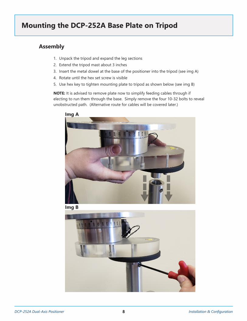
Assembly
1. Unpack the tripod and expand the leg sections 2. Extend the tripod mast about 3 inches 3. Insert the metal dowel at the base of the positioner into the tripod (see img A)4. Rotate until the hex set screw is visible5. Use hex key to tighten mounting plate to tripod as shown below (see img B) NOTE: It is advised to remove plate now to simplify feeding cables through if electing to run them through the base. Simply remove the four 10-32 bolts to reveal unobstructed path. (Alternative route for cables will be covered later.)
Mounting the DCP-252A Base Plate on Tripod
Img A
Img B
9Installation & Configuration DCP-252A Dual-Axis Positioner
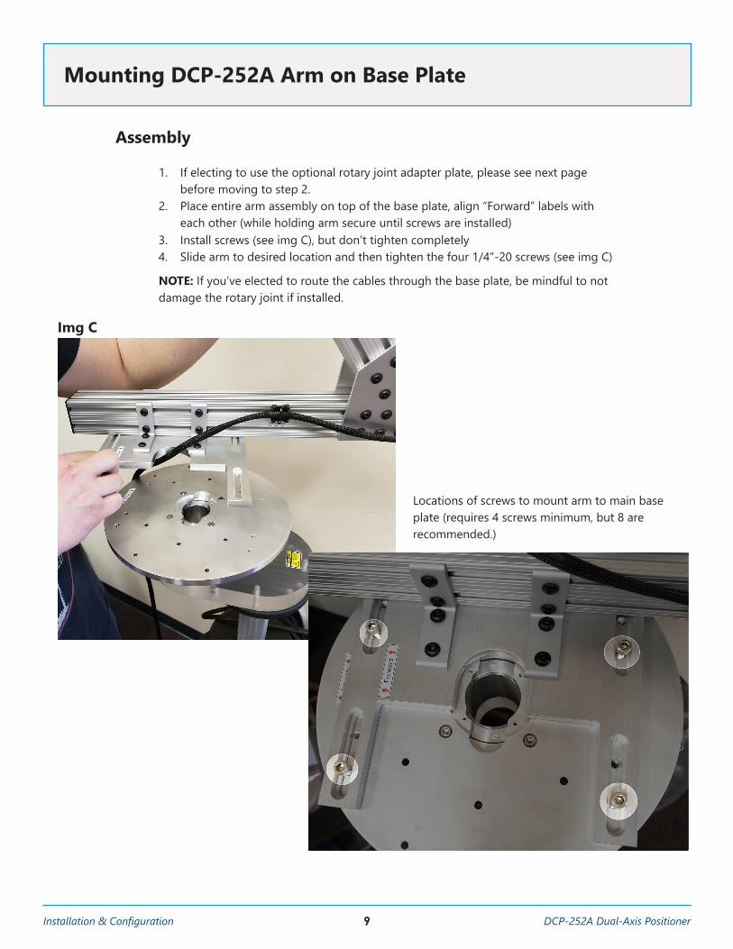
Assembly
1. If electing to use the optional rotary joint adapter plate, please see next page before moving to step 2.
2. Place entire arm assembly on top of the base plate, align “Forward” labels with each other (while holding arm secure until screws are installed)
3. Install screws (see img C), but don’t tighten completely4. Slide arm to desired location and then tighten the four 1/4”-20 screws (see img C) NOTE: If you’ve elected to route the cables through the base plate, be mindful to not damage the rotary joint if installed.
Mounting DCP-252A Arm on Base Plate
Img C
Locations of screws to mount arm to main base plate (requires 4 screws minimum, but 8 are recommended.)
10DCP-252A Dual-Axis Positioner Installation & Configuration
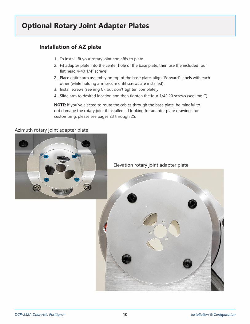
Installation of AZ plate
1. To install, fit your rotary joint and affix to plate. 2. Fit adapter plate into the center hole of the base plate, then use the included four flat head 4-40 1/4” screws.2. Place entire arm assembly on top of the base plate, align “Forward” labels with each other (while holding arm secure until screws are installed) 3. Install screws (see img C), but don’t tighten completely4. Slide arm to desired location and then tighten the four 1/4”-20 screws (see img C) NOTE: If you’ve elected to route the cables through the base plate, be mindful to not damage the rotary joint if installed. If looking for adapter plate drawings for customizing, please see pages 23 through 25.
Optional Rotary Joint Adapter Plates
Azimuth rotary joint adapter plate
Elevation rotary joint adapter plate
11Installation & Configuration DCP-252A Dual-Axis Positioner
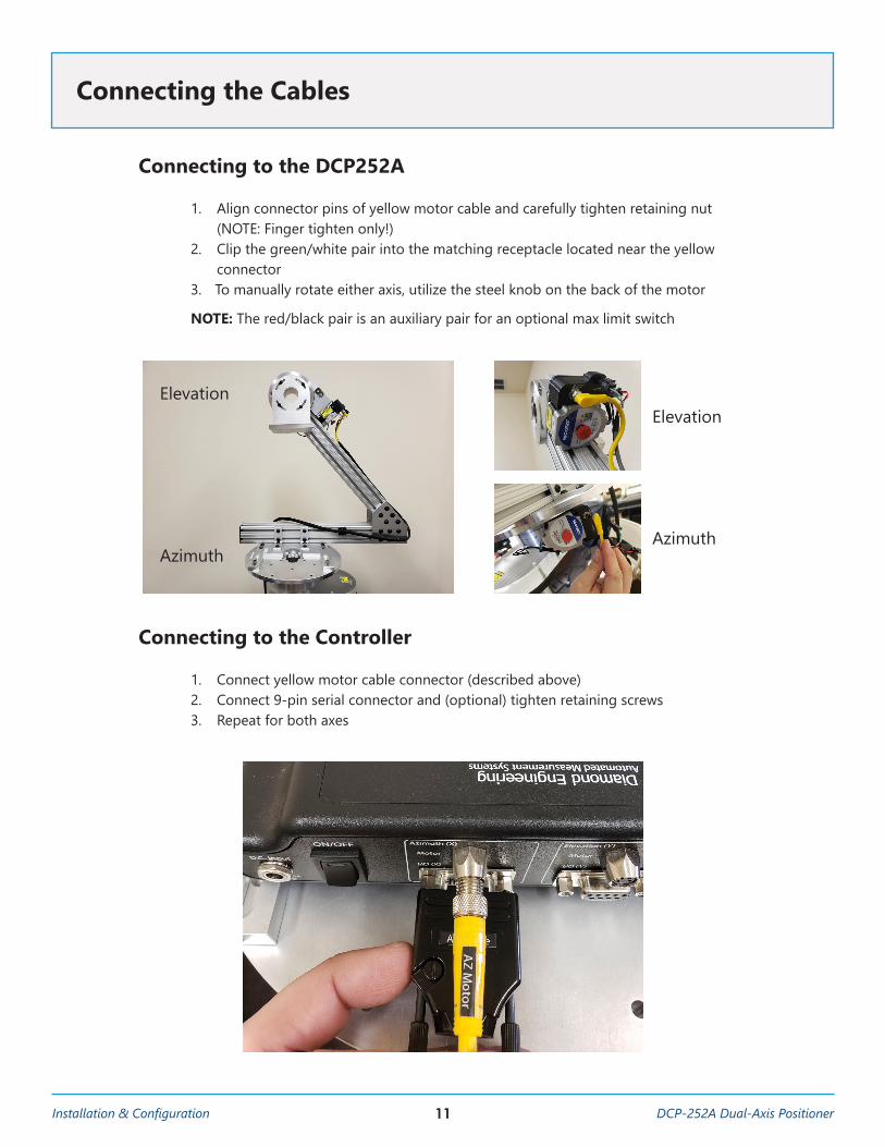
Connecting to the DCP252A
1. Align connector pins of yellow motor cable and carefully tighten retaining nut (NOTE: Finger tighten only!)
2. Clip the green/white pair into the matching receptacle located near the yellow connector
3. To manually rotate either axis, utilize the steel knob on the back of the motor NOTE: The red/black pair is an auxiliary pair for an optional max limit switch
Connecting to the Controller
1. Connect yellow motor cable connector (described above)2. Connect 9-pin serial connector and (optional) tighten retaining screws3. Repeat for both axes
Connecting the Cables
Elevation
Azimuth
Elevation
Azimuth
12DCP-252A Dual-Axis Positioner Installation & Configuration
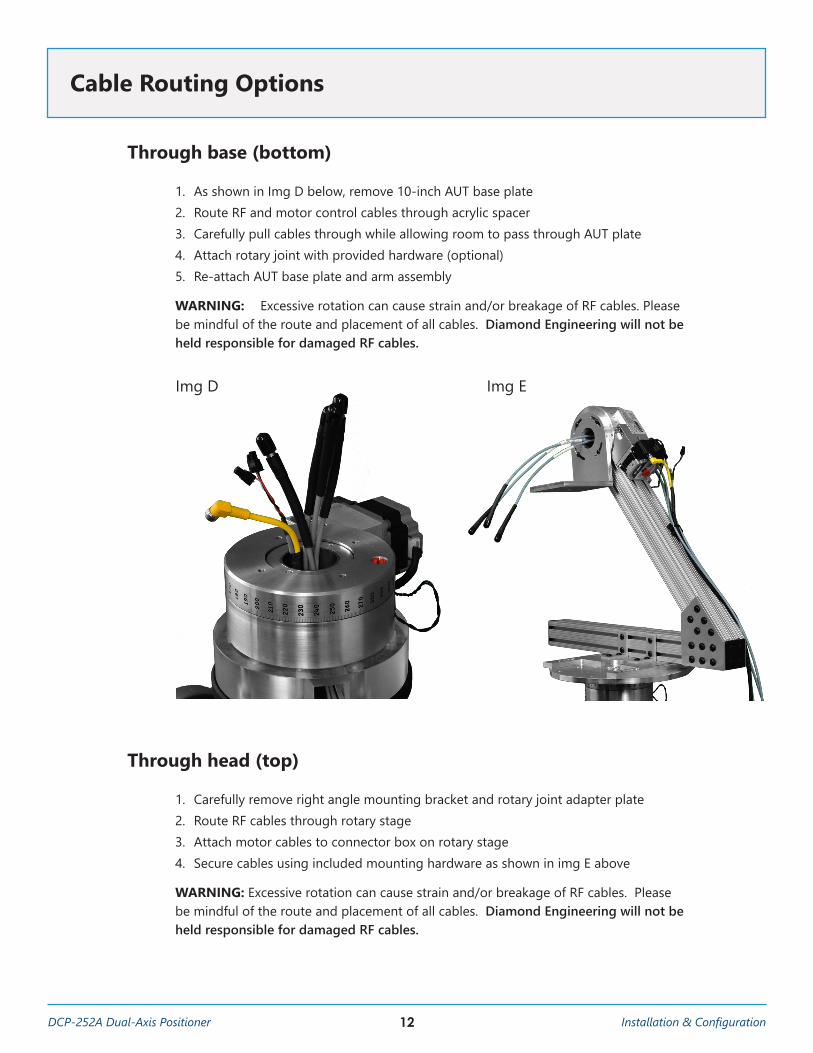
Through base (bottom)
1. As shown in Img D below, remove 10-inch AUT base plate2. Route RF and motor control cables through acrylic spacer3. Carefully pull cables through while allowing room to pass through AUT plate4. Attach rotary joint with provided hardware (optional)5. Re-attach AUT base plate and arm assembly WARNING: Excessive rotation can cause strain and/or breakage of RF cables. Please be mindful of the route and placement of all cables. Diamond Engineering will not be held responsible for damaged RF cables.
Through head (top)
1. Carefully remove right angle mounting bracket and rotary joint adapter plate2. Route RF cables through rotary stage3. Attach motor cables to connector box on rotary stage4. Secure cables using included mounting hardware as shown in img E above WARNING: Excessive rotation can cause strain and/or breakage of RF cables. Please be mindful of the route and placement of all cables. Diamond Engineering will not be held responsible for damaged RF cables.
Cable Routing Options
Img D Img E
13Installation & Configuration DCP-252A Dual-Axis Positioner
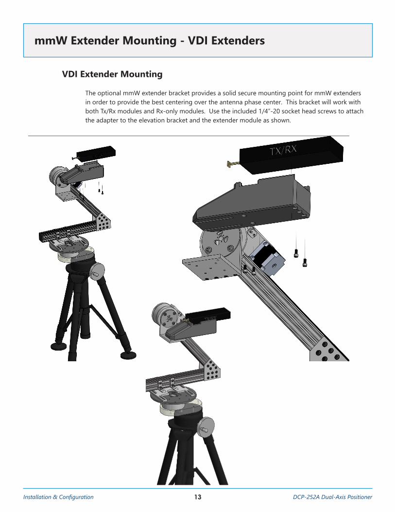
VDI Extender Mounting
The optional mmW extender bracket provides a solid secure mounting point for mmW extenders in order to provide the best centering over the antenna phase center. This bracket will work with both Tx/Rx modules and Rx-only modules. Use the included 1/4”-20 socket head screws to attach the adapter to the elevation bracket and the extender module as shown.
mmW Extender Mounting - VDI Extenders
1
1
2
2
3
3
4
4
5
5
6
6
7
7
8
8
A A
B B
C C
D D
SHEET 1 OF 1
DRAWN
CHECKED
QA
MFG
APPROVED
Jordan Foster 3/7/2019
DWG NO
TITLE
SIZE
DSCALE
REV
0.35 : 1
14DCP-252A Dual-Axis Positioner Installation & Configuration
Basic Instructions
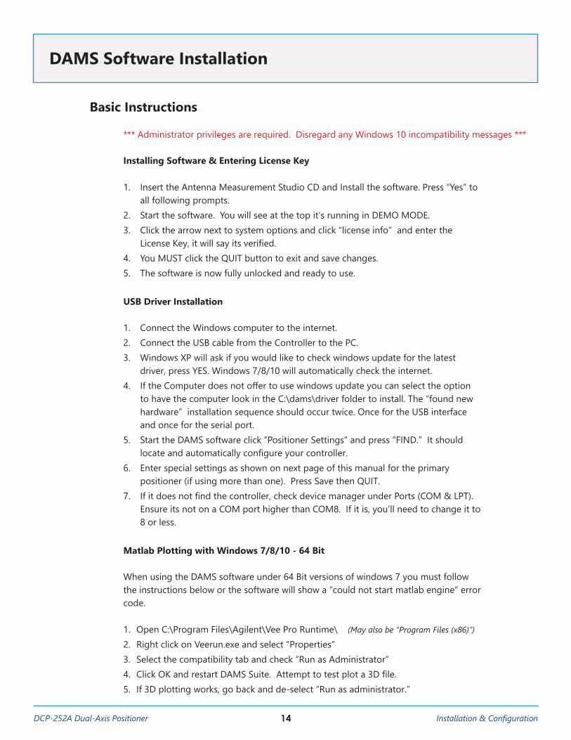
*** Administrator privileges are required. Disregard any Windows 10 incompatibility messages ***
Installing Software & Entering License Key
1. Insert the Antenna Measurement Studio CD and Install the software. Press “Yes” to all following prompts.
2. Start the software. You will see at the top it’s running in DEMO MODE.3. Click the arrow next to system options and click “license info” and enter the
License Key, it will say its verified. 4. You MUST click the QUIT button to exit and save changes. 5. The software is now fully unlocked and ready to use.
USB Driver Installation
1. Connect the Windows computer to the internet.2. Connect the USB cable from the Controller to the PC.3. Windows XP will ask if you would like to check windows update for the latest
driver, press YES. Windows 7/8/10 will automatically check the internet. 4. If the Computer does not offer to use windows update you can select the option
to have the computer look in the C:\dams\driver folder to install. The “found new hardware” installation sequence should occur twice. Once for the USB interface and once for the serial port.
5. Start the DAMS software click “Positioner Settings” and press “FIND.” It should locate and automatically configure your controller.
6. Enter special settings as shown on next page of this manual for the primary positioner (if using more than one). Press Save then QUIT.
7. If it does not find the controller, check device manager under Ports (COM & LPT). Ensure its not on a COM port higher than COM8. If it is, you’ll need to change it to 8 or less.
Matlab Plotting with Windows 7/8/10 - 64 Bit
When using the DAMS software under 64 Bit versions of windows 7 you must follow the instructions below or the software will show a “could not start matlab engine” error code.
1. Open C:\Program Files\Agilent\Vee Pro Runtime\ (May also be “Program Files (x86)”)
2. Right click on Veerun.exe and select “Properties”3. Select the compatibility tab and check “Run as Administrator”4. Click OK and restart DAMS Suite. Attempt to test plot a 3D file.5. If 3D plotting works, go back and de-select “Run as administrator.”
DAMS Software Installation
15Installation & Configuration DCP-252A Dual-Axis Positioner
Primary Positioner Configuration
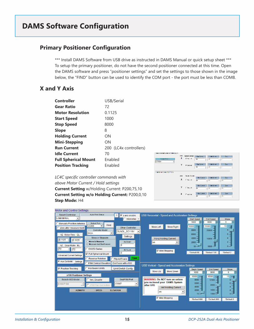
*** Install DAMS Software from USB drive as instructed in DAMS Manual or quick setup sheet ***To setup the primary positioner, do not have the second positioner connected at this time. Open the DAMS software and press “positioner settings” and set the settings to those shown in the image below, the “FIND” button can be used to identify the COM port - the port must be less than COM8.
X and Y Axis
Controller USB/SerialGear Ratio 72 Motor Resolution 0.1125Start Speed 1000Stop Speed 8000Slope 8 Holding Current ON Mini-Stepping ONRun Current 200 (LC4x controllers)Idle Current 70 Full Spherical Mount EnabledPosition Tracking Enabled
LC4C specific controller commands with above Motor Current / Hold settings Current Setting w/Holding Current: P200,75,10 Current Setting w/o Holding Current: P200,0,10 Step Mode: H4
DAMS Software Configuration
16DCP-252A Dual-Axis Positioner Installation & Configuration
Secondary Positioner Configuration
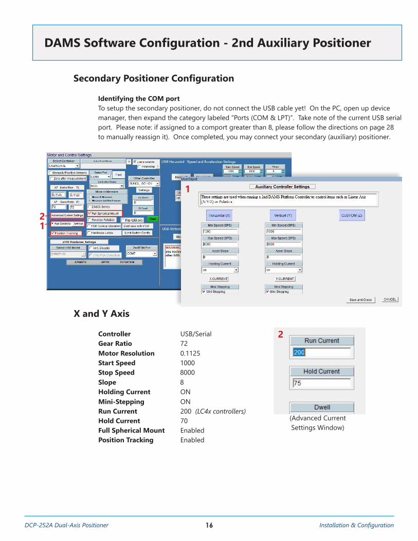
Identifying the COM portTo setup the secondary positioner, do not connect the USB cable yet! On the PC, open up device manager, then expand the category labeled “Ports (COM & LPT)”. Take note of the current USB serial port. Please note: if assigned to a comport greater than 8, please follow the directions on page 28 to manually reassign it). Once completed, you may connect your secondary (auxiliary) positioner.
DAMS Software Configuration - 2nd Auxiliary Positioner
X and Y Axis
Controller USB/SerialGear Ratio 72 Motor Resolution 0.1125Start Speed 1000Stop Speed 8000Slope 8 Holding Current ON Mini-Stepping ONRun Current 200 (LC4x controllers)Hold Current 70 Full Spherical Mount EnabledPosition Tracking Enabled
21
1
2
(Advanced Current Settings Window)
ü
ü
17Installation & Configuration DCP-252A Dual-Axis Positioner
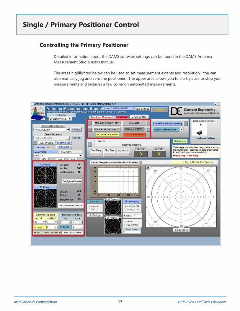
Controlling the Primary Positioner
Detailed information about the DAMS software settings can be found in the DAMS Antenna Measurement Studio users manual.
The areas highlighted below can be used to set measurement extents and resolution. You can also manually jog and zero the positioner. The upper area allows you to start, pause or stop your measurements and includes a few common automated measurements.
Single / Primary Positioner Control
18DCP-252A Dual-Axis Positioner Installation & Configuration
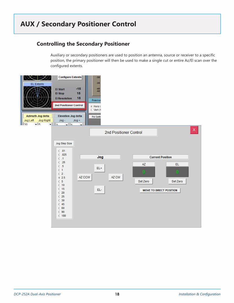
Controlling the Secondary Positioner
Auxiliary or secondary positioners are used to position an antenna, source or receiver to a specific position, the primary positioner will then be used to make a single cut or entire Az/El scan over the configured extents.
AUX / Secondary Positioner Control
19Installation & Configuration DCP-252A Dual-Axis Positioner
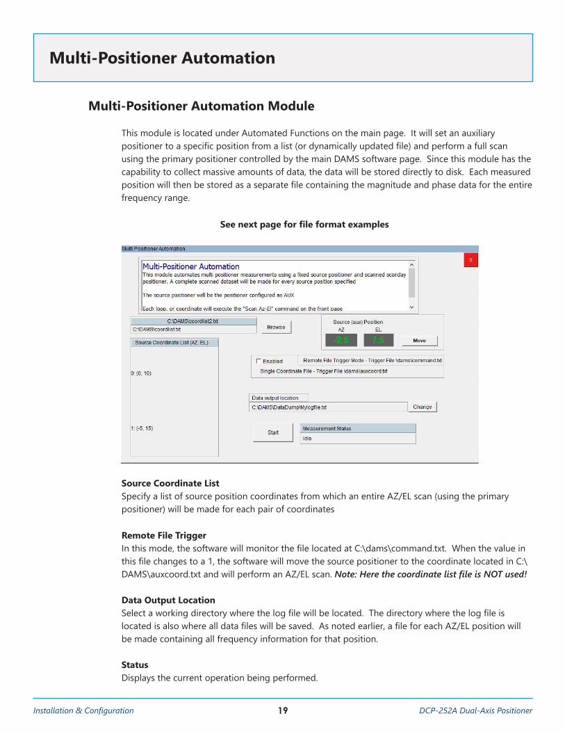
Multi-Positioner Automation Module
This module is located under Automated Functions on the main page. It will set an auxiliary positioner to a specific position from a list (or dynamically updated file) and perform a full scan using the primary positioner controlled by the main DAMS software page. Since this module has the capability to collect massive amounts of data, the data will be stored directly to disk. Each measured position will then be stored as a separate file containing the magnitude and phase data for the entire frequency range.
See next page for file format examples
Source Coordinate ListSpecify a list of source position coordinates from which an entire AZ/EL scan (using the primary positioner) will be made for each pair of coordinates
Remote File TriggerIn this mode, the software will monitor the file located at C:\dams\command.txt. When the value in this file changes to a 1, the software will move the source positioner to the coordinate located in C:\DAMS\auxcoord.txt and will perform an AZ/EL scan. Note: Here the coordinate list file is NOT used!
Data Output LocationSelect a working directory where the log file will be located. The directory where the log file is located is also where all data files will be saved. As noted earlier, a file for each AZ/EL position will be made containing all frequency information for that position.
StatusDisplays the current operation being performed.
Multi-Positioner Automation
20DCP-252A Dual-Axis Positioner Installation & Configuration
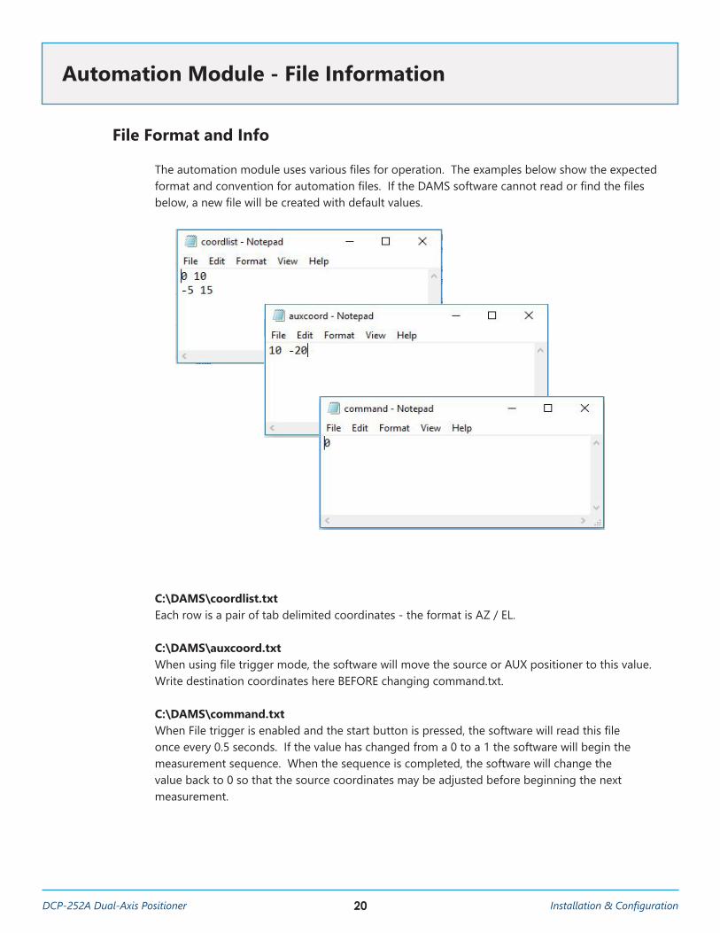
File Format and Info
The automation module uses various files for operation. The examples below show the expected format and convention for automation files. If the DAMS software cannot read or find the files below, a new file will be created with default values.
C:\DAMS\coordlist.txtEach row is a pair of tab delimited coordinates - the format is AZ / EL.
C:\DAMS\auxcoord.txtWhen using file trigger mode, the software will move the source or AUX positioner to this value. Write destination coordinates here BEFORE changing command.txt.
C:\DAMS\command.txtWhen File trigger is enabled and the start button is pressed, the software will read this file once every 0.5 seconds. If the value has changed from a 0 to a 1 the software will begin the measurement sequence. When the sequence is completed, the software will change the value back to 0 so that the source coordinates may be adjusted before beginning the next measurement.
Automation Module - File Information
21Installation & Configuration DCP-252A Dual-Axis Positioner
Individual Coordinate Files
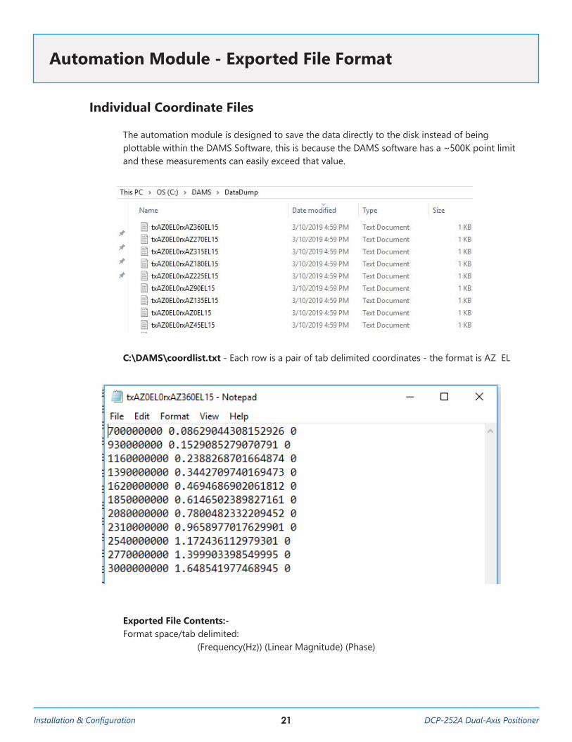
The automation module is designed to save the data directly to the disk instead of being plottable within the DAMS Software, this is because the DAMS software has a ~500K point limit and these measurements can easily exceed that value.
C:\DAMS\coordlist.txt - Each row is a pair of tab delimited coordinates - the format is AZ EL
Exported File Contents:- Format space/tab delimited: (Frequency(Hz)) (Linear Magnitude) (Phase)
Automation Module - Exported File Format
22DCP-252A Dual-Axis Positioner Installation & Configuration
Default Settings
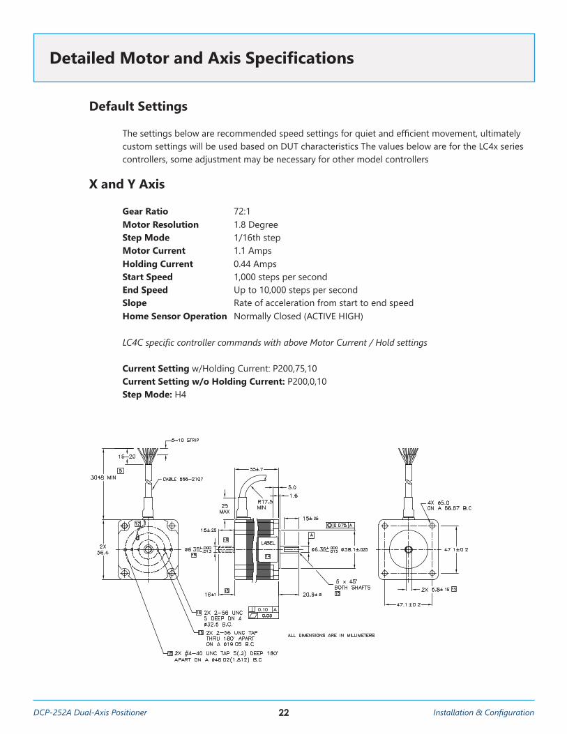
The settings below are recommended speed settings for quiet and efficient movement, ultimately custom settings will be used based on DUT characteristics The values below are for the LC4x series controllers, some adjustment may be necessary for other model controllers
X and Y Axis
Gear Ratio 72:1 Motor Resolution 1.8 DegreeStep Mode 1/16th step Motor Current 1.1 AmpsHolding Current 0.44 AmpsStart Speed 1,000 steps per secondEnd Speed Up to 10,000 steps per second Slope Rate of acceleration from start to end speedHome Sensor Operation Normally Closed (ACTIVE HIGH)
LC4C specific controller commands with above Motor Current / Hold settings
Current Setting w/Holding Current: P200,75,10 Current Setting w/o Holding Current: P200,0,10 Step Mode: H4
Detailed Motor and Axis Specifications
23Installation & Configuration DCP-252A Dual-Axis Positioner
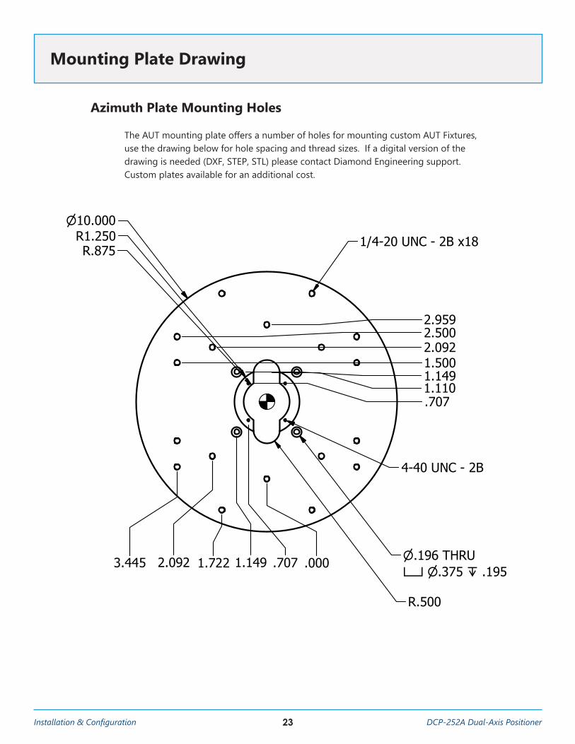
Azimuth Plate Mounting Holes
The AUT mounting plate offers a number of holes for mounting custom AUT Fixtures, use the drawing below for hole spacing and thread sizes. If a digital version of the drawing is needed (DXF, STEP, STL) please contact Diamond Engineering support. Custom plates available for an additional cost.
Mounting Plate Drawing
1
1
2
2
A A
B B
.707
1.1491.110
1.5002.0922.5002.959
.707 .0001.1491.7222.0923.445
10.000R1.250R.875
R.500
1/4-20 UNC - 2B x18
.196 THRU .375 .195
4-40 UNC - 2B
Part Name: DCP-252A Turntable Material: .375" 6061 Aluminum Sheet Tolerance: 5 mil std. Finishing: General De-burring Drawing Units: Inches DATE: 7/5/2018 Contact: Diamond Engineering Inc. (530)626-3857
.375
.130
24DCP-252A Dual-Axis Positioner Installation & Configuration
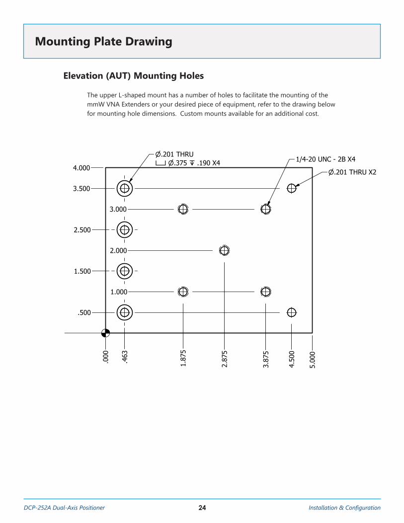
Elevation (AUT) Mounting Holes
The upper L-shaped mount has a number of holes to facilitate the mounting of the mmW VNA Extenders or your desired piece of equipment, refer to the drawing below for mounting hole dimensions. Custom mounts available for an additional cost.
Mounting Plate Drawing
1
1
2
2
A A
B B
DRAWNJoshCHECKED
QA
MFG
APPROVED
12/18/2018Diamond Engineering
TITLE
Front Array Mount for USC
SIZEA
SCALE
DWG NO
Array Mount Front_USCREV2
SHEET 1 OF 1 1 : 1
.000
.463
1.87
5
2.87
5
3.87
5
4.50
0
5.00
0
.000
.500
1.000
1.500
2.000
2.500
3.000
3.500
4.000
.375
1/4-20 UNC - 2B X4
.201 THRU X2
.201 THRU .375 .190 X4
25Installation & Configuration DCP-252A Dual-Axis Positioner
Adapter Plates
1.00
1.00
.375
4-40 UNC - 2B
.12 .35 .23 X 82°
.750
.313
.636
R.125
R.1875 .500
2.495
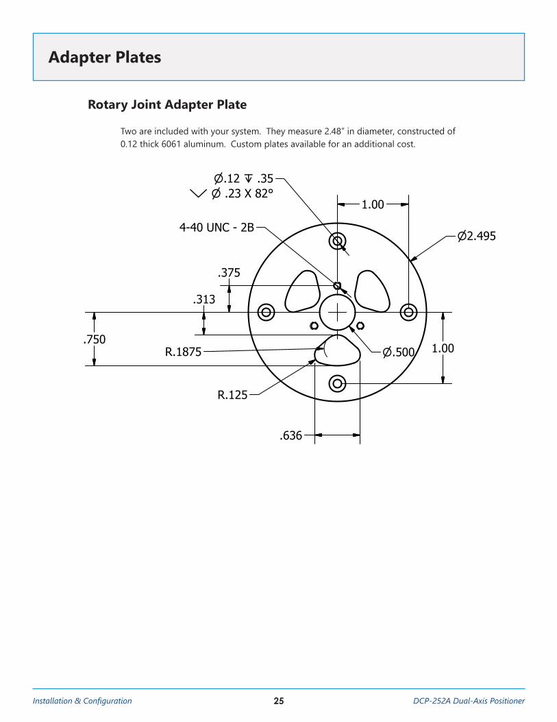
Rotary Joint Adapter Plate
Two are included with your system. They measure 2.48” in diameter, constructed of 0.12 thick 6061 aluminum. Custom plates available for an additional cost.
26DCP-252A Dual-Axis Positioner Installation & Configuration
1
1
2
2
A A
B B
R3.946
6.750
10.696
7.891
5.891
1.000
3.164
1.8212.250.500
2.500
2.000
2.000
R.250R.129
1.000
3.000 3.000
1.000
1.500
.250
.375
Part Name: DCP-252A Slider PlateMaterial: .375" 6061 Aluminum SheetTolerance: 5 mil std.Finishing: General De-burring Drawing Units: Inches DATE: 7/5/2018 Contact: Diamond Engineering Inc. (530)626-3857
1/4-20 UNC - 2B x8
2.000
R1.125
3.946
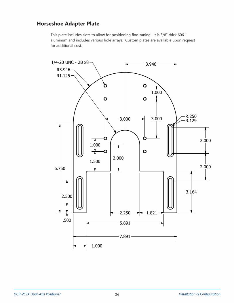
Horseshoe Adapter Plate
This plate includes slots to allow for positioning fine-tuning. It is 3/8” thick 6061 aluminum and includes various hole arrays. Custom plates are available upon request for additional cost.
27Installation & Configuration DCP-252A Dual-Axis Positioner
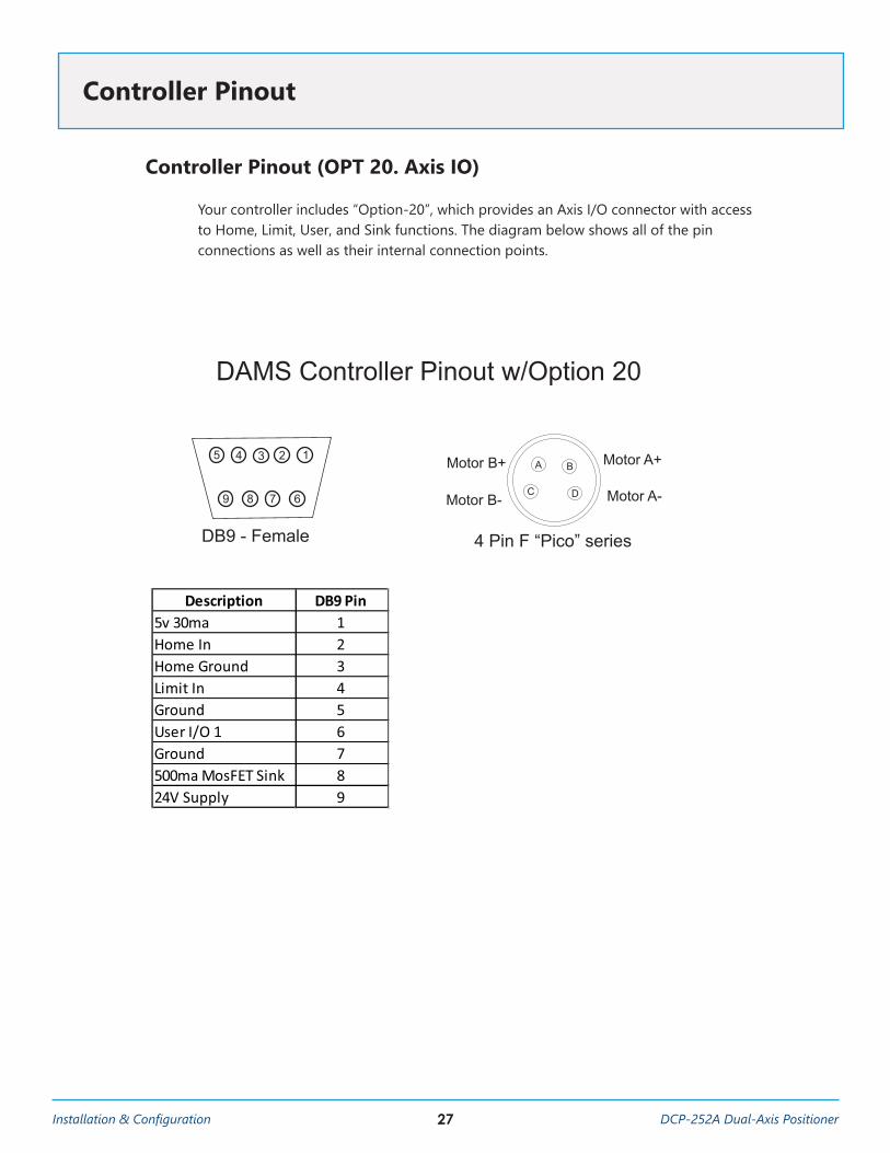
Controller Pinout (OPT 20. Axis IO)
Your controller includes “Option-20”, which provides an Axis I/O connector with access to Home, Limit, User, and Sink functions. The diagram below shows all of the pin connections as well as their internal connection points.
Controller Pinout
A B
C
12345
DB9 - Female
6789 D
4 Pin F “Pico” series
Motor A+
Motor A-
Motor B+
Motor B-
DAMS Controller Pinout w/Option 20
Description DB9 Pin
5v 30ma 1
Home In 2
Home Ground 3
Limit In 4
Ground 5
User I/O 1 6
Ground 7
500ma MosFET Sink 8
24V Supply 9
28DCP-252A Dual-Axis Positioner Installation & Configuration
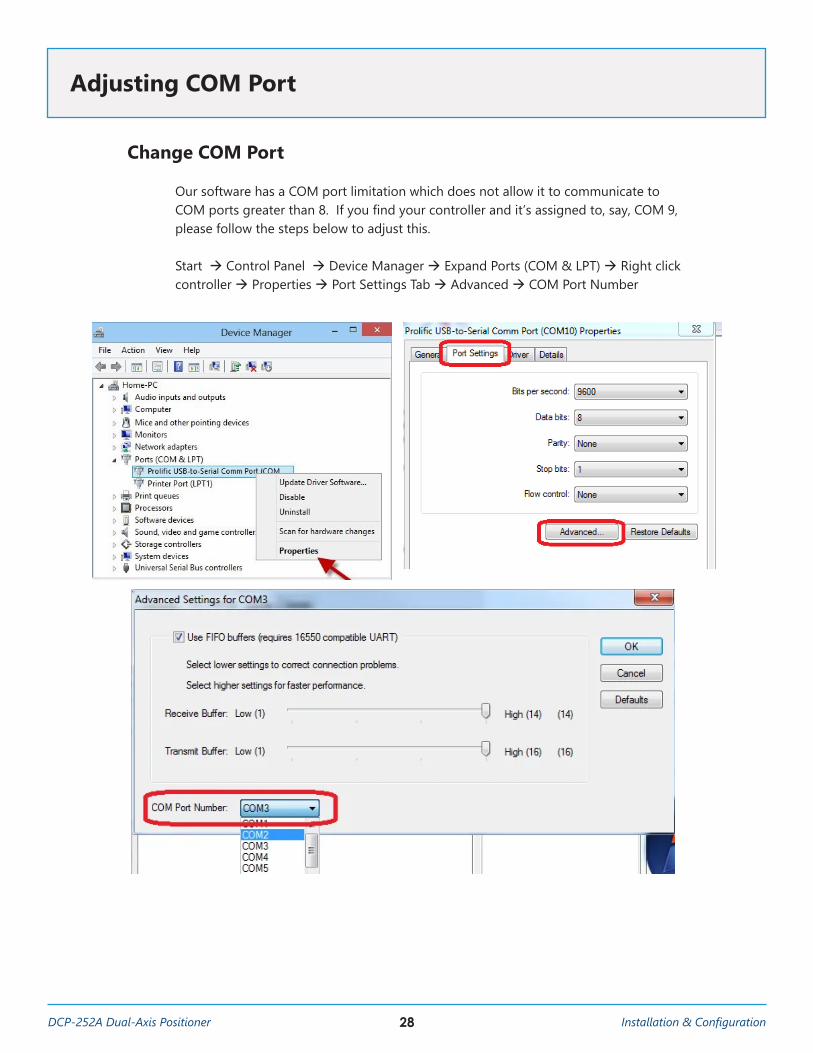
Change COM Port
Our software has a COM port limitation which does not allow it to communicate to COM ports greater than 8. If you find your controller and it’s assigned to, say, COM 9, please follow the steps below to adjust this.
Start à Control Panel à Device Manager à Expand Ports (COM & LPT) à Right click controller à Properties à Port Settings Tab à Advanced à COM Port Number
Adjusting COM Port

29Installation & Configuration DCP-252A Dual-Axis Positioner
Troubleshooting and Support
http://www.DiamondEng.net · [email protected]
P.O. Box 2037 Diamond Springs, CA 95619 · 530-626-3857
Analyzer Connectivity
The Network Analyzer is connected to the PC using a USB-GPIB Adapter or Ethernet Cable. When there are connectivity issues please check the following.
Checking Connectivity in Agilent Connection Expert (FOR TCP/IP and GPIB)
1. Check all cables between equipment and PC, ensure all equipment is turned on 2. Look on the USB to GPIB adapter, is the green “READY” light illuminated? 3. On the PC, open the “Agilent Connection Expert” this can be accessed by right
clicking the IO Icon located near the system clock. 4. Is the GPIB Adapter and Agilent PNA shown? Do they all have green check marks
next to them? 5. If one of the devices is not showing a green check mark, try restarting the
instrument, additionally the USB GPIB adapter can be directly connected to the instrument GPIB connection to verify there are no issues with the GPIB cable. Any time the connection is changed you must press the “REFRESH” button in the Agilent connection expert to re-find the instruments.
If connection expert shows as OK but you are still having connection problems.
1. In the connection expert, note the GPIB Addresses of all instruments 2. Open Start à Programs à Agilent à Vee Pro Runtime à IO Configuration3. Ensure the GPIB addresses match those shown in the Connection Expert
Contacting Diamond Engineering
We’re happy to assist you! If possible, take screenshots of any errors and provide any details that may be helpful in resolving your issue. You can contact us at one of the methods below:
E-mail: [email protected] Phone: +1 530.626.3857 Fax: +1 530-626-0495


