Embed Size (px)
Citation preview
1/16
Information on available spare parts:
www.boschrexroth.com/spc
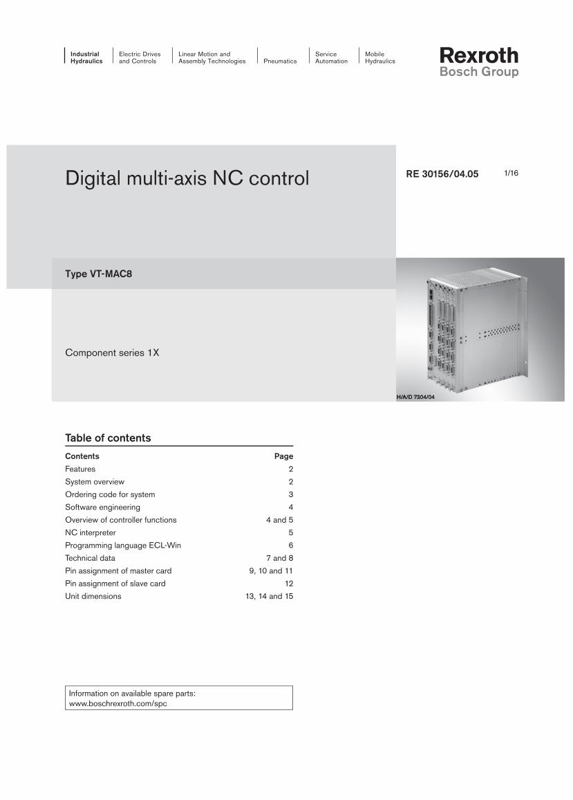
Digital multi-axis NC control
Type VT-MAC8
Component series 1X
RE 30156/04.05
Table of contents
Contents Page
Features 2
System overview 2
Ordering code for system 3
Software engineering 4
Overview of controller functions 4 and 5
NC interpreter 5
Programming language ECL-Win 6
Technical data 7 and 8
Pin assignment of master card 9, 10 and 11
Pin assignment of slave card 12
Unit dimensions 13, 14 and 15

2/16 Bosch Rexroth AG Industrial Hydraulics VT-MAC8 RE 30156/04.05
Features
The MAC8 is a digital Rexroth multi-axis NC control of modular
design. It consists of a master card with no, 2 or 4 axis control-
lers and can be extended as required with up to seven slave
cards for four axes each. It is therefore the ideal solution for
complex control tasks with up to 32 interpolatable axes. Fur-
ther MAC8s can be connected via local Ethernet. The MAC8
communicates via field bus (Profibus DP® or CAN) or via Eth-
ernet with the higher-level PLC machine control. It is provided
with special hydraulic closed-loop control characteristics and
can control movements of the machine or machine parts on its
own and therefore assumes PLC functions. Sensors and actua-
tors can also be evaluated and controlled via CAN bus.
Fields of application:
– Presses (tube forming, metal / ceramic, powder, plastic,
deep drawing, glass presses, press brakes, die cushion
controls, IHF (internal high pressure forming, etc.)
– Materials handling (container cranes, balance cranes,
train/truck lifts, belt drive, etc.)
– Steelworks and rolling mill technology (continuous casters,
curved casting machines, mould oscillation, roll stands, 3-roll
bending machines, turning cooling beds, flying shears, ladle
cars, moulding plant, etc.)
– Testing technology (weld testing machine, shock absorber
test bench, tube testing press, etc.)
– Special machinery (coal distributors, thick sheet turning
equipment, engine turning system, etc.)
Process interfacing
32 digital inputs, 24 digital outputs, Profibus DP®,
CAN open, TCP-IP
Interfacing / visualisation
– By means of “OPC server”
– By means of “Active X” elements
– Interfaces: RS 485 or Ethernet
Programming
– Use programming by means of a PC
– Comprehensive diagnosis and debugging tools
– Comfortable data management on a PC
– High-level language-oriented
– 32 NC programs that can be executed in parallel
– High processing speed due to compiled programs
– Fast integer and real arithmetic
– Exponential and angle functions
Hydraulic axes
– Measuring system Incremental or absolute (SSI)
Analogue ±10 V and 4 to 20 mA
±10 mA and ± 20 mA
– Control output Analogue ±10 V and 4 to 20 mA
±10 mA and ± 20 mA
Closed-loop control
– Following controller
– State controller
– Position-dependent braking
– Synchronisation controller for up to 32 axes (various vari-
ants)
– Pressure/force controller
System overview
Visualisation /
diagnosis
Profibus DP / CAN / Ethernet
Local Ethernet
Ethernet / RS422
PLC / proc-
ess control
level
CAN bus
Sensors
Actuators
Up to 32
drives
Up to 32
drives

Industrial Hydraulics Bosch Rexroth AGRE 30156/04.05 VT-MAC8 3/16
Ordering code for system
Part of
ordering code
Analogue In RS 232
RS 485
CAN Open Profibus DP Analogue I/O Encoder plug
AM 1 X X X
AM 2 X X X X 2X
AM 4 X X X 4X
PM 1 X X X X
PM 2 X X X X X 2X
PM 4 X X X X 4X
Selection aid
VT-MAC 8 1X S M AX4 *
System with
1 slot = 1
5 slots = 5
8 slots = 8
Bus variant
No field bus = A
Profibus DP slave interface module = P
Further details in clear text
4 axis slaves
0 to 7 = Number
Master
1 = Without axis module, with RS485
2 = 2-axis version, with RS 485
4 = 4-axis version
Components
Material no. Type Designation
R901075726 VT-MAC8-1X/K-AM1 Master card without axis controller
R901075728 VT-MAC8-1X/K-AM2 Master card with 2 axis controllers
R901075730 VT-MAC8-1X/K-AM4 Master card with 4 axis controllers
R901075732 VT-MAC8-1X/K-PM1 Master card with Profibus DP, without axis controller
R901075734 VT-MAC8-1X/K-PM2 Master card with Profibus DP, with 2 axis controllers
R901075738 VT-MAC8-1X/K-PM4 Master card with Profibus DP, with 4 axis controllers
R901075752 VT-MAC8-1X/K-AX4 Salvekarte with 4 axis controllers
R901075757 VT-MAC8-1X/K-DUMMY Blank location cover for one slot
R901075714 VT-MAC8-1X/K-RACK1 Blank rack with one slot (master card)
R901075722 VT-MAC8-1X/K-RACK5 Blank rack with 5 slots (1 master, 4 slaves)
R901075725 VT-MAC8-1X/K-RACK8 Blank rack with 8 slots (1 master, 7 slaves)
R901052075 Cable set MAC8/ABS/SF/3M Cable for absolute value encoder SSI (X2), 3 metres, open end
R901052153 Cable set MAC8/INC/24V/SF3M Cable for incremental encoder 24V (X2), 3 metres, open end
R901052152 Cable set MAC8/INC/5V/SF/3M Cable for incremental encoder 5V (X2), 3 metres, open end
R901052141 Cable set MAC8/AE/SF/3M Cable for analogue inputs (X4), 3 metres, open end
R901052069 Cable set MAC8/AEA/SF/3M Cable for analogue inputs/outputs (X1), 3 metres, open end
R901052150 Cable set MAC8/DEA/SF/3M Cable for digital inputs/outputs (X5), 3 metres, open end
R901074828 Cable set MAC8/PC/RS232/5M Cable for PC-MAC8 RS232 interface (X3.4), 5 metres
R901074832 Cable set MAC8/PC/RS422/RS232/ADAPT/5M Cable for PC-MAC8 RS422 with RS232 adapter (X3.4), 5 m
R901074837 Cable set MAC8/PC/RS422/RS232/ADAPT/30M Cable for PC-MAC8 RS422 with RS232 adapter (X3.4), 30 m
R901074840 Cable set MAC8/PC/RS422/RS232/ADAPT/50M Cable for PC-MAC8 RS422 with RS232 adapter (X3.4), 50 m
R901058546 SYS-MAC8- D/E Installation CD for MAC8 Tools

4/16 Bosch Rexroth AG Industrial Hydraulics VT-MAC8 RE 30156/04.05
Software engineering
Creation of program with MACpro
– Windows version with integrated editor with
command highlighting
– Creation of project groups for the management of individual
programs on the slots, with automatic change-over
– Global header files for common definitions
– Programs can be organised in modules (files)
– Nesting depth for up to 50 subroutines
– Change-oriented compiling and transfer to the MAC8
– Reference list of variables and subroutines used
– Automatic comparison of version PC <-> MAC8
– Saving of different desktop settings
– Program saved in the flash
Debugging
– On-line help for “Syntax”, “Tools” and “Keys”
– Tracing of program execution (trace)
– Process variable tracing by means of Trend
– Program view (View) with search functions
– Function level display (call hierarchy)
– 5 break points are managed
– Stop / Start / Continue and Single Steps (Single, Step,
Stepover) of individual or all programs
– Saving of memory image (program with data)
View of variables
– All variable windows can be selected by means of hot keys
or from the menu; flexible window size
– Configurable variable window (mix-variables) with hexadeci-
mal, decimal, binary and floating point representation: Simple
inclusion of optional variables from the program view into the
tracing window and structuring by means of comments
– Setup window with all axis-specific process variables
– System parameter assistant
Acquisition of measured data
– 12 recording channels with start and stop trigger
– Recording option for all process variables
– Graphic and numeric representation (DBF format) of re-
corded channels
– Continuous data recording (Trend)
Commissioning functions
– Inputs can be simulated
– Outputs can be set
– Analogue output variables can be set
– Inching mode for optimising the controller
– Activation / deactivation of individual controller components
Project-related administration of:
– programs
– configurable programming user interface
– system parameters
– measured data
System requirements of MACpro:
– IBM-PC or compatible system
– Windows NT®, Windows 2000®, Win XP®
– Processor 300 MHz or faster
– Min. 64 MB RAM (recommended: 128 MB)
– Min. 100 MB free hard disk space
The program is installed from a CD
(SYS-MAC-8-D/E, material no. R901058546)
Overview of controller functions
Position controller:
– Following controller
– Alternating control (position / pressure)
– Force limitation in positive and negative direction
Direction-dependent gain adjustment
– “Inflected” gain characteristic curve
– Fine positioning
– Residual voltage principle
– Compensation of zero point offsets
– State feedback
– Command value feedforward
– Control output limitation by means of NC program
– “Position-dependent braking”
– External controller function via NC program
– Following operation
– Velocity override
– Gain can be changed via NC program
– Interpolation of up to 32 axes
– Pre-acceleration
– Force / distance; force / time curves
– Position/input value curves
– Transformation of coordinates of spatial axes
10 2 3 4 5 6 7 8 9 10 11 12 ... ... 26 27 28 29 30 31
Industrial Hydraulics Bosch Rexroth AGRE 30156/04.05 VT-MAC8 5/16
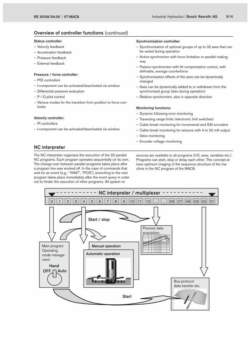
NC interpreter
The NC interpreter organises the execution of the 32 parallel
NC programs. Each program operates sequentially on its own.
The change-over between parallel programs takes place after
a program line was worked off. In the case of commands that
wait for an event (e.g.: “WAIT”, “POS”), branching to the next
program takes place immediately after the event query in order
not to hinder the execution of other programs. All system re-
sources are available to all programs (I/O, axes, variables etc.).
Programs can start, stop or delay each other. This concept al-
lows optimum imaging of the sequence structure of the ma-
chine in the NC program of the MAC8.
Status controller:
– Velocity feedback
– Acceleration feedback
– Pressure feedback
– External feedback
Pressure / force controller:
– PID controllers
– I-component can be activated/deactivated via window
– Differential pressure evaluation
– P / Q pilot control
– Various modes for the transition from position to force con-
troller
Velocity controller:
– PI controllers
– I-component can be activated/deactivated via window
Overview of controller functions (continued)
Synchronisation controller:
– Synchronisation of optional groups of up to 32 axes that can
be varied during operation
– Active synchronism with force limitation or parallel making
way
– Passive synchronism with tilt compensation control, with
definable, average counterforce
– Synchronisation offsets of the axes can be dynamically
changed
– Axes can be dynamically added to or withdrawn from the
synchronised group (also during operation)
– Relative synchronism, also in opposite direction
Monitoring functions:
– Dynamic following error monitoring
– Traversing range limits (electronic limit switches)
– Cable break monitoring for incremental and SSI encoders
– Cable break monitoring for sensors with 4 to 20 mA output
– Valve monitoring
– Encoder voltage monitoring
Manual operation
Automatic operation
NC interpreter / multiplexer
Start / stop
Start
Hand
AutoOFF
Main program
Operating
mode manage-
ment
Process data
acquisition
Bus protocol
data transfer etc.

6/16 Bosch Rexroth AG Industrial Hydraulics VT-MAC8 RE 30156/04.05
Programming language ECL-Win
The data organisation of the MAC8:
Numeric variables (integers):
V: Standard variables
P: Local variables
N: Process variables
Fields (integers):
A: Custom fields
S: System parameters
Real variables:
R: Floating point figures
Logic variables:
I: Inputs
O: Outputs
F: Process flags
Signs and operators:
<num. sign> “-“ | “!“ | “#“
<num. operator> “*“ | “/“ | “+“ | “-“ | “&“ |
“|“ |”^“ | “<<“ | “>>“
<num. real operator> “sin“ | “cos“ |
“tan“ | “asin“ | “acos“ | “atan“
| “sqrt“
<log. operator> “&“ | “|“ | ”^“
<num. comp. operator> “<=“ | “>=“ | “<>“ |”<“ |”>“
| “=“
Compiler instructions:
„;“ <comment>
„#include“ <file name>
„#modul“ <file name>
„#define“ <name> <text>
„#global“ <file name>
Acquisition of measured values:
TIMER Timer
TRACE Oscilloscope function
Dialogue commands (hand-held control box or terminal):
DIALOG Start dialogue
WINDOW Define window
DISPLAY Output variable or text
INPUT Input definition
LEVEL User level
READ_KEY Softkey query
SSET String assignment
Special commands:
CALL <address> Call C-function
START/STOP TASK Start C-task
Program sequence control:
IF ELSE Instruction
WHILE Loop
.. Command block
[..] Bundling of commands
BEGIN END Program definition
Label
JUMP <label> or <soubroutine>
START/STOP/BREAK/CONT<program>
WAIT <time> or <condition>
Data manipulation:
DIM Field declaration
COPY Field copying function
SET Assign variable
MSET Preset fields
PSET Assign local variable
Axis/process funcitons:
AXINIT Initialise axes
AXSET Take over axis data
STOP Interrupt axis movement
HALT Immediate halt of axis movement
POS HALT Immediate halt of axis movement
BREAK Interrupt axis movement
CONT Resume axis movement
EQUIT Acknowledge axis esrror
LOCK Lock axis control
UNLOCK Unlock control
OVER Determine axis override
ACC Acceleration (±) of axis
VEL Axis velocity
POS Position axis
SYNCH Define axes to be synchronised
LIN Linear interpolation
FORCE Force control
DAC Voltage output
FUNC Axis functions
SIMU Simulation of axis
HOME Referencing
TABLE Create process curve
VIRTUAL Define virtual axes
REAL Inverse calculation formula to
VIRTUAL
FREEZE Freeze axis velocity
For operating parameters that are not listed here, it is usually
possible to enter a constant, a variable or a term!

Industrial Hydraulics Bosch Rexroth AGRE 30156/04.05 VT-MAC8 7/16
Technical data
Operating voltage UO
18 to 36 VDC / max 3.6 A
Current consumption Master without axis 500 mA
Master with axis 800 mA
Slave 400 mA
Processor MPC860 and MPC555
Memory 16 MB SDRAM, 16 MB flash, 8 KBytes DPR
4 MB Flash (MPC555)
2 MB SRAM (MPC555)
Analogue inputs:
– Voltage inputs (differential inputs) ±10 V 12 bits with 4-fold oversampling
• Input voltage UI
max. +10 V to –10 V
• Input resistance RI
160 kΩ
• Resolution 5 mV
– Current inputs
• Input current II 4 – 20 mA, ±20 mA
• Input resistance R 100 Ω
• Power loss IL
12 µA
• Resolution 4 µA
Analogue outputs:
– Voltage outputs
• Output voltage Unom
±10 V PWM (pulse-width modulation)
• Output current Imax
10 mA
• Load Rmin
2 kΩ
– Current outputs
• Output current, normalised Inom
±20 mA
• Load Rmax
500 Ω
• Resolution 1 mV
Serial interfaces Standard RS232 (19.2 KBaud)
RS485 (115 KBaud)
Optional Profibus DP (max. 12 MBaud)
CAN open (max. 1 MBaud)
Switching inputs Number 32
Logic level log 0 (low) 0 V to +5 V
log 1 (high) +10 V to 36 V
RI
3 kΩ ±10 %
Switching outputs Number 24
Logic level log 0 (low) 0 V to +5 V;
log 1 (high) +10 V to 36 V;
Current carrying capacity up to 50 mA

8/16 Bosch Rexroth AG Industrial Hydraulics VT-MAC8 RE 30156/04.05
Technical data (continued)
Digital position transducers
– Incremental transducer
• Transducer with TTL output
Input voltage log 0 0 to 1 V
log 1 2.8 to 5.5 V
Input current log 0 –0.8 mA (at 0 V)
log 1 0.8 mA (at 5 V)
Max. frequency referred to Ua 1 fmax
250 kHz, 24 bits
SSI position transducer
– Coding Gray code
– Data width Adjustable up to max. 28 bits
– Line receiver (TTL) fmax
250 kHz
– Input voltage log 0 0 to 1 V
log 1 2.5 to 5.5 V
– Input current log 0 –0.5 mA (at 0 V)
log 1 0.5 mA (at 5 V)
– Line driver
– Output voltage log 0 0 to 0.5 V
log 1 2.5 to 5.5 V
Permissible operating temperature range 0 to 50 °C
Storage temperature range –20 to 70 °C
Weight:
– Rack 1 m 1000 g
– Rack 5 m 1800 g
– Rack 8 m 2500 g
– Master card m 400 g
– Slave card m 350 g
– Blank cover m 100 g

24V X6
24V RUNOK BUS
CAN
field
bus
X3.1
X3.3
RS48
5 / V
24
X3.4
anal
og in
X5
X4
10Ba
seT
100B
aseT
Rexroth
X1b
X1a
digi
tal I
/O
MAC-8
Industrial Hydraulics Bosch Rexroth AGRE 30156/04.05 VT-MAC8 9/16
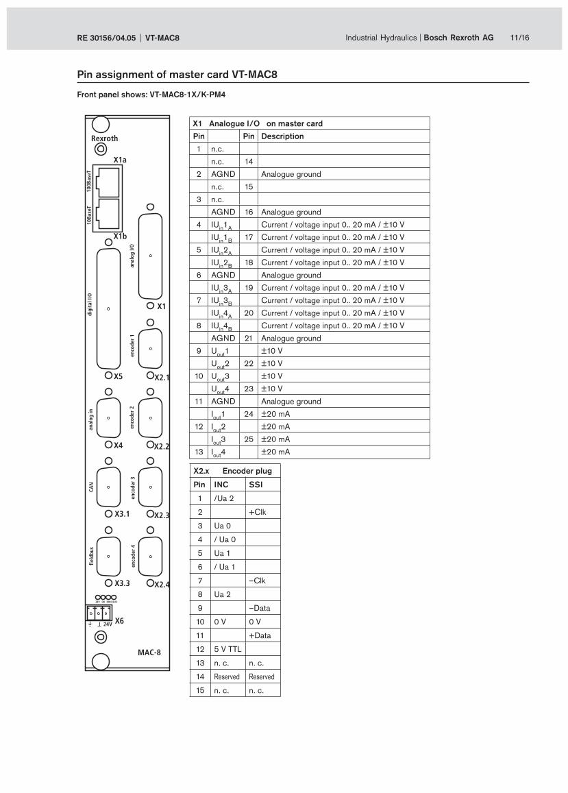
Pin assignment of master card VT-MAC8
X1a RJ-45; 100BaseT Ethernet
1 TPO+
2 TPO–
3 TPI+
4 75K-GND
5 75K-GND
6 TPI–
7 75K-GND
8 75K-GND
X1b RJ-45; 10BaseT Ethernet
1 TPO+
2 TPO–
3 TPI+
4 n.c.
5 n.c.
6 TPI–
7 n.c.
8 n.c.
X3.1 CAN open
1 n.c.
n.c. 6
2 CAN_Lx
CAN_Hx 7
3 GNDCANx
n.c. 8
4 n.c.
n.c. 9
5 n.c.
X3.3 Profibus DP
1 n.c.
VP 6
2 n.c.
n.c. 7
3 RxD/TxD -P
RxD/TxD -N 8
4 CNTR -P
n.c. 9
5 DGND
X3.4 V 24
1 GND
RxD 6
2 TxD
RS485
GND 7
3 5 V
RxD+ 8
4 RxD–
TxD+ 9
5 TxD–X6 Voltage supply
1 Shield
2 GND
3 +24 V
X4 Analogue in
1 Uin1
C
Uin2
C6
2 Uin3
C
Uin4
C7
3 AGND
Uin1
D8
4 Uin2
D
Uin3
D9
5 Uin4
D
Front panel shows: VT-MAC8-1X/K-PM1

24V X6
24V RUNOK BUS
CAN
field
bus
X3.1
X3.3
RS48
5 / V
24
X3.4
anal
og in
X5
X4
enco
der
1
X2.1
enco
der
2
X2.2
X1
10Ba
seT
100B
aseT
Rexroth
X1b
X1a
anal
og I/
O
digi
tal I
/O
MAC-8
10/16 Bosch Rexroth AG Industrial Hydraulics VT-MAC8 RE 30156/04.05
X5 Digital I/O
Pin Description Pin Description Pin Description
22 Reserved
43 Reserved 1 Reserved
23 In0
44 In2 2 In1
24 In3
45 In5 3 In4
25 In6
46 In8 4 In7
26 In9
47 In11 5 In10
27 In12
48 In14 6 In13
28 In15
49 In17 7 In16
29 In18
50 In20 8 In19
30 In21
51 In23 9 In22
31 In24
52 In26 10 In25
32 In27
53 In29 11 In28
33 In30
54 Out0 12 In31
34 Out1
55 Out3 13 Out2
35 Out4
56 Out6 14 Out5
36 Out7
57 Out9 15 Out8
37 Out10
58 Out12 16 Out11
38 Out13
59 Out15 17 Out14
39 Out16
60 Out18 18 Out17
40 Out19
61 Out21 19 Out20
41 Out22
62 0 V 20 Out23
42 0 V
21 0 V
Pin assignment of master card VT-MAC8
Front panel shows: VT-MAC8-1X/K-PM2
24V X6
24V RUNOK BUS
CAN
field
bus
X3.1
X3.3
enco
der
3
X2.3
enco
der
4
X2.4
anal
og in
X5
X4
enco
der
1
X2.1
enco
der
2
X2.2
X1
10Ba
seT
100B
aseT
Rexroth
X1b
X1a
anal
og I/
O
digi
tal I
/O
MAC-8
Industrial Hydraulics Bosch Rexroth AGRE 30156/04.05 VT-MAC8 11/16
Pin assignment of master card VT-MAC8
X1 Analogue I/O on master card
Pin Pin Description
1 n.c.
n.c. 14
2 AGND Analogue ground
n.c. 15
3 n.c.
AGND 16 Analogue ground
4 IUin1
ACurrent / voltage input 0.. 20 mA / ±10 V
IUin1
B17 Current / voltage input 0.. 20 mA / ±10 V
5 IUin2
ACurrent / voltage input 0.. 20 mA / ±10 V
IUin2
B18 Current / voltage input 0.. 20 mA / ±10 V
6 AGND Analogue ground
IUin3
A19 Current / voltage input 0.. 20 mA / ±10 V
7 IUin3
BCurrent / voltage input 0.. 20 mA / ±10 V
IUin4
A20 Current / voltage input 0.. 20 mA / ±10 V
8 IUin4
BCurrent / voltage input 0.. 20 mA / ±10 V
AGND 21 Analogue ground
9 Uout
1 ±10 V
Uout
2 22 ±10 V
10 Uout
3 ±10 V
Uout
4 23 ±10 V
11 AGND Analogue ground
Iout
1 24 ±20 mA
12 Iout
2 ±20 mA
Iout
3 25 ±20 mA
13 Iout
4 ±20 mA
X2.x Encoder plug
Pin INC SSI
1 /Ua 2
2 +Clk
3 Ua 0
4 / Ua 0
5 Ua 1
6 / Ua 1
7 –Clk
8 Ua 2
9 –Data
10 0 V 0 V
11 +Data
12 5 V TTL
13 n. c. n. c.
14 Reserved Reserved
15 n. c. n. c.
Front panel shows: VT-MAC8-1X/K-PM4

AX-4
Rexroth
24V OK RUN BUS
enco
der
4en
code
r 3
enco
der
2en
code
r 1
anal
og I/
O
X2.4
X2.3
X2.2
X2.1
X1
S1
address
12/16 Bosch Rexroth AG Industrial Hydraulics VT-MAC8 RE 30156/04.05
Pin assignment of slave card VT-MAC8-1X/K-AX4
S1 Address
Slot
2 Slot 2
3 Slot 3
4 Slot 4
5 Slot 5
6 Slot 6
7 Slot 7
8 Slot 8
0 - 1 Not permitted
9 - F Not permitted
X1 Analogue I/O on slave card
Pin Pin Description
1 Iin1
CCurrent input ±20 mA
Iin2
C14 Current input ±20 mA
2 AGND Analogue ground
Iin3C 15 Current input ±20 mA
3 Iin4C Current input ±20 mA
AGND 16 Analogue ground
4 IUin1
ACurrent / voltage input 0.. 20 mA / ±10 V
IUin1
B17 Current / voltage input 0.. 20 mA / ±10 V
5 IUin2
ACurrent / voltage input 0.. 20 mA / ±10 V
IUin2
B18 Current / voltage input 0.. 20 mA / ±10 V
6 AGND Analogue ground
IUin3
A19 Current / voltage input 0.. 20 mA / ±10 V
7 IUin3
BCurrent / voltage input 0.. 20 mA / ±10 V
IUin4
A20 Current / voltage input 0.. 20 mA / ±10 V
8 IUin4
BCurrent / voltage input 0.. 20 mA / ±10 V
AGND 21 Analogue ground
9 Uout
1 ±10 V
Uout
2 22 ±10 V
10 Uout
3 ±10 V
Uout
4 23 ±10 V
11 AGND Analogue ground
Iout
1 24 ±20 mA
12 Iout
2 ±20 mA
Iout
3 25 ±20 mA
13 Iout
4 ±20 mA
X2.x Encoder plug
Pin INC SSI
1 /Ua 2
2 +Clk
3 Ua 0
4 / Ua 0
5 Ua 1
6 / Ua 1
7 –Clk
8 Ua 2
9 –Data
10 0 V 0 V
11 +Data
12 5 V TTL
13 n. c. n. c.
14 Reserved Reserved
15 n. c. n. c.
Address the card ac-
cording to the slot!
Caution!

AX-4
Rexroth
AX-4
Rexroth
AX-4
Rexroth
AX-4
RexrothRexroth
MAC-8
X1
24V OK RUN BUS
X2.4
X2.3
X2.2
X2.1
S1
address
X1
24V OK RUN BUS
X2.4
X2.3
X2.2
X2.1
address
S1
X1
24V OK RUN BUS
X2.4
X2.3
X2.2
X2.1
address
S1
X1
24V OK RUN BUS
X2.4
X2.3
X2.2
X2.1
address
S1
175,4
134,6
3
X1a
X1b
X5
X4
X3.1
24V
X3.3
RUNOK BUS
X624V
X3.4
160
190,
5(3
7,7)
37,7
7
Rexroth
MAC-8
X1a
X1b
X5
X1
X2.1
X4
X3.1
X2.2
X2.3
24V
X3.3
RUNOK BUS
X624V
X2.4
3
190,
5(3
7,7)
37,7
7
79
Industrial Hydraulics Bosch Rexroth AGRE 30156/04.05 VT-MAC8 13/16
Unit dimensions (nominal dimensions in mm)
VT-MAC8-1X/K-RACK5
System with 5 slots
VT-MAC8-1X/K-RACK1
System with 1 slot

AX-4
Rexroth
AX-4
Rexroth
AX-4
RexrothRexroth
MAC-8
X1
24V OK RUN BUS
X2.4
X2.3
X2.2
X2.1
S1
address
X1
24V OK RUN BUS
X2.4
X2.3
X2.2
X2.1
address
S1
X1
24V OK RUN BUS
X2.4
X2.3
X2.2
X2.1
address
S1
238,8
198
3
X1a
X1b
X5
X4
X3.1
24V
X3.3
RUNOK BUS
X624V
X2.4
221,3
190,
5(3
7,7)
37,7
7X2.2
X2.3
X2.1
X1
AX-4
Rexroth
X1
24V OK RUN BUS
X2.4
X2.3
X2.2
X2.1
address
S1
AX-4
Rexroth
X1
24V OK RUN BUS
X2.4
X2.3
X2.2
X2.1
address
S1
AX-4
Rexroth
X1
24V OK RUN BUS
X2.4
X2.3
X2.2
X2.1
address
S1
AX-4
Rexroth
X1
24V OK RUN BUS
X2.4
X2.3
X2.2
X2.1
address
S1
14/16 Bosch Rexroth AG Industrial Hydraulics VT-MAC8 RE 30156/04.05
Unit dimensions (nominal dimensions in mm)
VT-MAC8-1X/K-RACK8
System with 8 slots
219,526
5,9
91
(min. 310,5)
Industrial Hydraulics Bosch Rexroth AGRE 30156/04.05 VT-MAC8 15/16
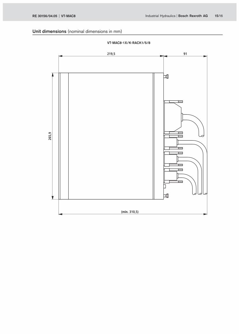
Unit dimensions (nominal dimensions in mm)
VT-MAC8-1X/K-RACK1/5/8

Bosch Rexroth AG
Industrial Hydraulics
Zum Eisengießer 1
97816 Lohr am Main, Germany
Phone +49 (0) 93 52 / 18-0
Fax +49 (0) 93 52 / 18-23 58
www.boschrexroth.de
© This document, as well as the data, specifi cations and other
information set forth in it, are the exclusive property of Bosch Rexroth
AG. Without their consent it may not be reproduced or given to third
parties.
The data specifi ed above only serve to describe the product. No
statements concerning a certain condition or suitability for a certain
application can be derived from our information. The information given
does not release the user from the obligation of own judgment and
verifi cation. It must be remembered that our products are subject to a
natural process of wear and aging.
16/16 Bosch Rexroth AG Industrial Hydraulics VT-MAC8 RE 30156/04.05
Notes


