Embed Size (px)
Citation preview
Electric Drivesand Controls Pneumatics Service
Linear Motion and Assembly TechnologiesHydraulics
Rexroth MTA 200Rexroth BTV 20.4A
Project Planning Manual
DOK-MTA200-BTV20.4A***-PR02-EN-P
RS-b47a5fc1b95d3a090a6846a00185914e-1-en-US-11
This documentation describes the hardware components of the Rexroth MTAcontrol system that are included in the operating PC Rexroth BTV 20.4A.
Edition Release Date Notes
120-1720-B371-01/EN 04.2004 First edition120-1720-B371-02/EN 05.2009 Revised edition
© Bosch Rexroth AG, 2004Copying this document, giving it to others and the use or communication of thecontents thereof without express authority, are forbidden. Offenders are liablefor the payment of damages. All rights are reserved in the event of the grant ofa patent or the registration of a utility model or design (DIN 34-1).The specified data is for product description purposes only and may not bedeemed to be guaranteed unless expressly confirmed in the contract. All rightsare reserved with respect to the content of this documentation and the availa‐bility of the product.Bosch Rexroth AGBgm.-Dr.-Nebel-Str. 2 ■ 97816 Lohr am Main, GermanyPhone +49 (0)93 52/ 40-0 ■ Fax +49 (0)93 52/ 40-48 85http://www.boschrexroth.com/Dept. DCC/EAX5 (OI) (SyMu/CaSp)This document has been printed on chlorine-free bleached paper.
Title
Type of Documentation
Document Typecode
Internal File Reference
Purpose of Documentation
Record of Revision
Bosch Rexroth AG | Electric Drivesand Controls
Rexroth MTA 200 | Project Planning Manual
Copyright
Validity
Published by
Note

Table of ContentsPage
1 Overview........................................................................................................................ 71.1 System Concept..................................................................................................................................... 71.2 About this Documentation....................................................................................................................... 71.3 Further Documentation........................................................................................................................... 8
2 Important Instructions on Use...................................................................................... 112.1 Appropriate Use.................................................................................................................................... 112.1.1 Introduction........................................................................................................................................ 112.1.2 Areas of Use and Application............................................................................................................ 112.2 Inappropriate Use................................................................................................................................. 122.3 ESD notes............................................................................................................................................. 12
3 Safety Instructions for Electric Drives and Controls .................................................... 133.1 Definitions of Terms.............................................................................................................................. 133.2 General Information.............................................................................................................................. 143.2.1 Using the Safety Instructions and Passing Them on to Others......................................................... 143.2.2 Requirements for Safe Use............................................................................................................... 143.2.3 Hazards by Improper Use.................................................................................................................. 153.2.4 Explanation of Safety Symbols and Hazard Classification................................................................ 163.3 Instructions with Regard to Specific Dangers....................................................................................... 163.3.1 Protection Against Contact with Electrical Parts and Housings......................................................... 163.3.2 Protective Extra-Low Voltage as Protection Against Electric Shock ................................................ 173.3.3 Protection Against Dangerous Movements....................................................................................... 183.3.4 Protection Against Magnetic and Electromagnetic Fields During Operation and Mounting.............. 203.3.5 Protection Against Contact with Hot Parts......................................................................................... 203.3.6 Protection During Handling and Mounting......................................................................................... 213.3.7 Battery Safety.................................................................................................................................... 213.3.8 Protection Against Pressurized Systems........................................................................................... 21
4 Machine Operator Terminal BTV 20.4A....................................................................... 234.1 Brief Description................................................................................................................................... 234.1.1 General Information........................................................................................................................... 234.1.2 Default Configuration BTV 20.4......................................................................................................... 244.1.3 Additional Modules BTV 20.4A.......................................................................................................... 244.1.4 Firmware and Software Configurations............................................................................................. 24
Operating system........................................................................................................................... 244.2 Front Panel, Keyboard.......................................................................................................................... 254.2.1 Floppy-Disk Flap, Reset Button......................................................................................................... 254.2.2 Operating Display.............................................................................................................................. 254.2.3 Keys General Information.................................................................................................................. 27
General Information........................................................................................................................ 27Explanation and Replication of Keys.............................................................................................. 27
4.2.4 Machine and PLC Function Keys...................................................................................................... 29
Project Planning Manual | Rexroth MTA 200 Electric Drivesand Controls
| Bosch Rexroth AG I/VI
Table of Contents
Page
General Information........................................................................................................................ 29Machine Function Keys.................................................................................................................. 29PLC Function Keys......................................................................................................................... 29
4.2.5 Addressing via PLC........................................................................................................................... 30Machine Function Keys.................................................................................................................. 30PLC Function Keys......................................................................................................................... 30
4.2.6 Replacing the Slide-in Strips............................................................................................................. 31General Information........................................................................................................................ 31How to Replace Slide-in Strips....................................................................................................... 32
4.3 Keyboard Layout................................................................................................................................... 334.3.1 General Information........................................................................................................................... 334.3.2 Changing the Keyboard Language.................................................................................................... 334.4 Technical Data...................................................................................................................................... 374.4.1 General Technical Data..................................................................................................................... 374.4.2 Ambient Conditions........................................................................................................................... 374.4.3 Wear Parts......................................................................................................................................... 374.5 Dimensions........................................................................................................................................... 384.5.1 Housing Dimensions.......................................................................................................................... 384.6 Mounting Dimensions........................................................................................................................... 424.7 Connections.......................................................................................................................................... 434.7.1 General Connections......................................................................................................................... 434.7.2 Interfaces of the NC CPU board - processor configuration 45.......................................................... 45
General Information........................................................................................................................ 45Serial Interface COM1.................................................................................................................... 45VGA Screen Connection................................................................................................................ 45Ethernet Interface (10 Base-T / 100 Base-Tx)................................................................................ 46USB Interface................................................................................................................................. 46
4.7.3 LPT1 Printer Interface and SIS.......................................................................................................... 47General Information........................................................................................................................ 47LPT1 interface................................................................................................................................ 47COM2 SIS interface........................................................................................................................ 48Configuration.................................................................................................................................. 48
4.7.4 Internal Wiring................................................................................................................................... 484.7.5 Application Examples........................................................................................................................ 50
Application Example for BTV 20.4A with INTERBUS Switch......................................................... 50Application Example with BTA 10/20 and BTC 06 Hand-held Terminal......................................... 51Connection to MTS-P0x.2 (BTV 20)............................................................................................... 52Application Example BTV 20.4A and SERCOS Interface.............................................................. 53Assembled Interface Connectors................................................................................................... 54
4.8 Ordering Information............................................................................................................................. 554.8.1 Type Designation Code..................................................................................................................... 554.8.2 Configuration Type Designation Code............................................................................................... 57
BTV 20.4A...................................................................................................................................... 574.8.3 Accessories....................................................................................................................................... 58
List of connectors and assembled cables....................................................................................... 58Lockable floppy-disk flap................................................................................................................ 62
II/VI Bosch Rexroth AG | Electric Drivesand Controls
Rexroth MTA 200 | Project Planning Manual
Table of Contents
Page
4.9 Accessories (Included in the Scope of Delivery).................................................................................. 63
5 PC CPU Configuration -45........................................................................................... 655.1 Brief Description................................................................................................................................... 655.2 Technical Data...................................................................................................................................... 655.2.1 Electrical Specifications..................................................................................................................... 655.2.2 CPU and Memory Specification......................................................................................................... 655.3 PhoenixBIOS Setup.............................................................................................................................. 665.3.1 General Information........................................................................................................................... 665.3.2 Help Screen (Online Help)................................................................................................................. 665.3.3 Navigation in the PhoenixBIOS Setup............................................................................................... 665.3.4 PhoenixBIOS Setup - Main Menu...................................................................................................... 66
General Information........................................................................................................................ 66Default Settings.............................................................................................................................. 67Special MTA Settings..................................................................................................................... 67
5.3.5 PhoenixBIOS Settings for the BTV 20.4............................................................................................ 675.4 Installation of SO DIMM Memory Modules........................................................................................... 725.5 Temporary Connection of Further IDE Devices.................................................................................... 735.5.1 General Information........................................................................................................................... 735.5.2 Connection for the Power Supply Cable............................................................................................ 735.5.3 IDE Port............................................................................................................................................. 74
6 PC CPU Configuration -55........................................................................................... 756.1 Brief Description................................................................................................................................... 756.2 Technical Data Slot CPU Card, Processor Specification -55 .............................................................. 756.2.1 Electrical Specifications..................................................................................................................... 756.2.2 CPU and Memory Specification......................................................................................................... 756.3 PhoenixBIOS Setup (Processor Specification -55)............................................................................... 766.3.1 General Information........................................................................................................................... 766.3.2 Help Screen (Online Help)................................................................................................................. 766.3.3 Navigation in the PhoenixBIOS Setup............................................................................................... 766.3.4 PhoenixBIOS Setup – Main Menu..................................................................................................... 76
General Information........................................................................................................................ 76Default Settings.............................................................................................................................. 77Special MTA Settings..................................................................................................................... 77
6.3.5 PhoenixBIOS Settings BTV20.3, Processor Specification -55.......................................................... 77
7 PC CPU Configuration -44........................................................................................... 837.1 Brief Description................................................................................................................................... 837.2 Technical Data...................................................................................................................................... 837.2.1 Electrical Specifications..................................................................................................................... 837.2.2 CPU and Memory Specification......................................................................................................... 837.3 PhoenixBIOS Setup.............................................................................................................................. 847.3.1 General Information........................................................................................................................... 847.3.2 PhoenixBIOS settings of the NC CPU............................................................................................... 84
Project Planning Manual | Rexroth MTA 200 Electric Drivesand Controls
| Bosch Rexroth AG III/VI
Table of Contents

Page
8 NC Multifunction Card NCM02..................................................................................... 898.1 Brief Description................................................................................................................................... 898.2 Features................................................................................................................................................ 898.3 Available Versions................................................................................................................................ 898.4 Interfaces.............................................................................................................................................. 918.5 Coding and Component Diagrams....................................................................................................... 938.5.1 +NCM0201........................................................................................................................................ 938.5.2 +NCM0202........................................................................................................................................ 948.5.3 +NCM0204........................................................................................................................................ 958.6 Slot Brackets......................................................................................................................................... 968.6.1 General Information........................................................................................................................... 968.6.2 CNC Fault (X21)................................................................................................................................ 968.6.3 Fast I/Os (X23).................................................................................................................................. 968.6.4 Status Indicators................................................................................................................................ 97
SERCOS Ring H4.......................................................................................................................... 97Fast I/Os H5................................................................................................................................... 97Fast I/Os H6................................................................................................................................... 97
8.7 Additional SERCOS Rings.................................................................................................................... 978.7.1 General Information........................................................................................................................... 978.7.2 +NCMZ003........................................................................................................................................ 988.7.3 +NCMZ004........................................................................................................................................ 988.7.4 X24.* Transmitter............................................................................................................................... 988.7.5 X25.* Receiver................................................................................................................................... 998.7.6 Status Indicators................................................................................................................................ 99
SERCOS Ring H4.......................................................................................................................... 998.7.7 Connections....................................................................................................................................... 998.7.8 NCM in the BTV20.4A..................................................................................................................... 1008.8 Connecting Cables............................................................................................................................. 1008.8.1 General Information......................................................................................................................... 1008.8.2 Cable Specifications........................................................................................................................ 1008.9 NCIO Card.......................................................................................................................................... 1018.9.1 General Information......................................................................................................................... 1018.9.2 Slot Brackets................................................................................................................................... 1028.9.3 I/O Interface X22............................................................................................................................. 1028.9.4 Installation....................................................................................................................................... 1038.10 Phoenix Block I/O Module ILB IB 24 DI16 DO16................................................................................ 1048.10.1 General Information......................................................................................................................... 1048.10.2 Connection...................................................................................................................................... 1048.10.3 Signal Assignment........................................................................................................................... 105
9 PLC Modules MTS-P01.2 and MTS-P02.2................................................................ 1079.1 Brief Description................................................................................................................................. 1079.2 Technical Data.................................................................................................................................... 1099.2.1 General Information......................................................................................................................... 1099.2.2 Supply Voltage................................................................................................................................ 1099.2.3 EMC................................................................................................................................................. 110
IV/VI Bosch Rexroth AG | Electric Drivesand Controls
Rexroth MTA 200 | Project Planning Manual
Table of Contents
Page
9.2.4 Interfaces......................................................................................................................................... 1109.3 Communication................................................................................................................................... 1109.3.1 Communication with the Computer................................................................................................. 1109.3.2 Communication with the NC Control............................................................................................... 1109.3.3 PLC Inputs for Machine Function Keys (X8)................................................................................... 1109.3.4 Connection of BTV 20 PLC Function Keys (X12)............................................................................ 110
General Information...................................................................................................................... 110Addressing.................................................................................................................................... 110
9.3.5 PLC Ready (X5).............................................................................................................................. 1119.3.6 COM Interface (X16)....................................................................................................................... 1119.3.7 BT BUS (X15).................................................................................................................................. 111
General Information...................................................................................................................... 111Addressing.................................................................................................................................... 112
9.4 Commissioning................................................................................................................................... 1139.4.1 Installation....................................................................................................................................... 1139.4.2 Address Setting............................................................................................................................... 114
General Information...................................................................................................................... 1149.4.3 Battery............................................................................................................................................. 1149.4.4 Status Displays and Error Diagnostics............................................................................................ 115
Operating Status Display.............................................................................................................. 115Error Display................................................................................................................................. 115Interface Assignment.................................................................................................................... 116
9.5 INTERBUS Master Connection.......................................................................................................... 1189.5.1 Brief Description.............................................................................................................................. 1189.5.2 Setting of the I/O Address............................................................................................................... 1199.5.3 Technical Data................................................................................................................................. 1199.5.4 Interface Assignment....................................................................................................................... 1199.6 PROFIBUS DP Connection................................................................................................................ 1219.6.1 Brief Description Master and Slave Connection.............................................................................. 1219.6.2 Setting I/O addresses...................................................................................................................... 1229.6.3 Status and Diagnosis Information.................................................................................................... 1229.6.4 Technical Data................................................................................................................................. 1239.6.5 Interface Assignment....................................................................................................................... 1239.7 Connecting the Hand-held terminal BTC 06....................................................................................... 1249.8 Configurations..................................................................................................................................... 1279.8.1 MTS-P0*.2-D2-B1-NN-NN-NN-FW.................................................................................................. 1279.8.2 MTS-P0*.2-D2-P1-NN-NN-NN-FW.................................................................................................. 128
10 Tips and Tricks........................................................................................................... 12910.1 BTV Replacement............................................................................................................................... 12910.1.1 General Information......................................................................................................................... 12910.1.2 Hard Disk Image ............................................................................................................................. 129
General Information...................................................................................................................... 129Backup of all Hard Disk Data........................................................................................................ 129Restoring the Hard Disk Data....................................................................................................... 129
10.1.3 Control Parameters (NCM Replacement)........................................................................................ 129
Project Planning Manual | Rexroth MTA 200 Electric Drivesand Controls
| Bosch Rexroth AG V/VI
Table of Contents

Page
10.1.4 CMOS Variables.............................................................................................................................. 12910.1.5 PLC Retain Data (PLC Replacement)............................................................................................. 130
11 Service and Support.................................................................................................. 131
Index.......................................................................................................................... 133
VI/VI Bosch Rexroth AG | Electric Drivesand Controls
Rexroth MTA 200 | Project Planning Manual
Table of Contents

1 Overview1.1 System Concept
The consistent implementation of PC technology and the use of internationalindustrial standards has made it possible to fully integrate the control hardwarein the operating PC while still ensuring simple and clear connections to drivesand I/O peripherals.This integral solution guarantees that only defined and tested device onfigura‐tions are offered and supplied.
1.2 About this DocumentationThe defined combination of different hardware components is the basis of theMTA 200 control system. The operating PC itself as well as the componentsthat are already installed in the operator PC on delivery are described in detailin this documentation.
Fig.1-1: Control architectureThe following components are included:
Type Description Chapter
BTV 20.4A Operating PC with integrated control hardware chapter 4 "Machine Operator Terminal BTV 20.4A" onpage 23
ETXP3-700 PC-CPU chapter 5 "PC CPU Configuration -45" on page 65and chapter 6 "PC CPU Configuration -55" on page75
ETXP3-400 NC CPU chapter 7 "PC CPU Configuration -44" on page 83
Project Planning Manual | Rexroth MTA 200 Electric Drivesand Controls
| Bosch Rexroth AG 7/135
Overview
Type Description Chapter
NCM02 NC module with SERCOS interface chapter 8 "NC Multifunction Card NCM02" on page89
NCIO I/O module for fast I/Os chapter 9 "PLC Modules MTS-P01.2 and MTS-P02.2"on page 107
MTS-P Integrated PLC chapter 10 "Tips and Tricks" on page 129
The openness of the control system allows the machine manufacturer to inde‐pendently carry out application-specific hardware settings in the PC part, suchas measured values acquisitions , network connections etc. In this case, themachine manufacturer must provide supplements to the hardware documen‐tation.
1.3 Further Documentation
Fig.1-2: System architectureThe MTA 200 control system includes additional hardware components that aredescribed in separate documents :
Type Description Documentation
BTA 20.4 Machine operator controlpanel
DOK-SUPPL*-BTA20.4****-PR0x-EN-P
BTM 15 Machine operator panel DOK-MTC200-BTM15******-PR0x-EN-P
BTM 16 Machine operator panel DOK-MTC200-BTM16.1****-FKBx-EN-P
PCK03 Drawer keyboard DOK-SUPPL*-PCK03.3****-PR0x-EN-P
BTC 06 Hand-held terminal DOK-SUPPL*-BTC06******-PR0x-EN-P
BTV 06 Mini control panel DOK-SUPPL*-BTV06.1****-PR0x-EN-P
8/135 Bosch Rexroth AG | Electric Drivesand Controls
Rexroth MTA 200 | Project Planning Manual
Overview
Type Description Documentation
RECO12 Control cabinet I/Os forInterbus
DOK-CONTRL-RECO12.2***-PRJx-EN-P
RMG12 Gateway module for I/Ocoupling
DOK-CONTRL-RMG12.2****-PR0x-EN-P
RMC RECO analog module DOK-CONTRL-RMC12.2****-ANWx-EN-P
SMx Protection type modulesfor Interbus
DOK-CONTRL-SM*12.1****-PRJx-EN-P
RECO In‐line
Brief overviewInterbus S systemProfibus DP systemBus terminal InterbusBus terminal ProfibusDigital I/O modulesAnalog I/O modulesCounter module
DOK-CONTRL-R-IL*INLINE-KB0x-EN-PDOK-CONTRL-R-IL*IBSSYS-AW0x-EN-PDOK-CONTRL-R-IL*PBSSYS-AW0x-EN-PDOK-CONTRL-R-IL*IBS-BK-FK0x-EN-PDOK-CONTRL-R-IL*PB*-BK-FK0x-EN-PDOK-CONTRL-R-IL*DIO***-FK0x-EN-PDOK-CONTRL-R-IL*AIO***-FK0x-EN-PDOK-CONTRL-R-IL*CNT***-AW0x-EN-P
RECOFieldline
Interbus devicesProfibus devices
DOK-CONTRL-RF-FLS-IB**-PR0x-EN-PDOK-CONTRL-RF-FLS-PB**-PR0x-EN-P
The MTA 200 control system is supplemented by the intelligent digital drives ofthe Diax 04 and IndraDrive series.
Project Planning Manual | Rexroth MTA 200 Electric Drivesand Controls
| Bosch Rexroth AG 9/135
Overview

10/135 Bosch Rexroth AG | Electric Drivesand Controls
Rexroth MTA 200 | Project Planning Manual
2 Important Instructions on Use2.1 Appropriate Use2.1.1 Introduction
Bosch Rexroth products represent state-of-the-art developments and manu‐facturing. They are tested prior to delivery to ensure operational safety andreliability.Therefore the products may only be used for the intended purpose. If they arenot used as intended, situations causing personal injury as well as materialdamage can occur.
Rexroth disclaims as manufacturer any warranty, liability or dam‐ages occurring due to inappropriate use of the products. Further‐more, Rexroth is not paying any compensation; the user isresponsible for any risks resulting from inappropriate use of theproducts.
Before using Bosch Rexroth products, the following requirements must be metto ensure appropriate use of the products:● Anyone handling one of the Rexroth products in any way has to read and
understand the respective safety-related guidelines as well as the instruc‐tions on appropriate use.
● Hardware products have to remain in their original state, i. e. no modifi‐cation regarding the design is allowed. Software products must not bedecompiled and their source codes must not be modified.
● Damaged or faulty products must not be implemented or put into opera‐tion.
● It must be ensured that the products are installed as specified in the doc‐umentation.
2.1.2 Areas of Use and ApplicationFor BTV 20.4A Bosch Rexroth defines appropriate use for installation into acontrol panel, into the wall or door of a control cabinet or directly into the en‐closure of a machine tool. It may only be operated under the assembly andinstallation conditions, in the position of application and under the ambient con‐ditions (temperature, degree of protection, humidity, EMC, etc.) specified in thisdocumentation.The BTV 20.4A may only be used in the configurations described in this doc‐umentation. For appropriate use the application of software and firmwareoffered by Bosch Rexroth for the MTA 200 control system and the applicationof digital Bosch Rexroth servo drives and main spindle drives of the Diax 04family with corresponding servo or main spindle firmware is required.Every MTA 200 control system is to be parameterized and programmed cor‐respondingly before its commissioning by skilled staff.Typical applications of MTA 200 control system are machine tools for the fol‐lowing processing technologies:● Milling and grinding crankshafts● Grinding camshafts● Gear wheel processing
Project Planning Manual | Rexroth MTA 200 Electric Drivesand Controls
| Bosch Rexroth AG 11/135
Important Instructions on Use
2.2 Inappropriate UseThe application of the BTV 20.4A that are not within the specified areas of ap‐plication or under operating conditions deviating from the operating conditionsand technical data specified in the documentation is considered as "inappro‐priate".The BTV 20.4A may not be used if...● it is exposed to operating conditions that do not fulfill the ambient condi‐
tions specified For instance, operation under water, in case of extremevariations of temperature or in extreme maximum temperatures is not al‐lowed.
● Bosch Rexroth has not explicitly released the intended applications. It isimperative that you also note the information given in the general noteson safety!
2.3 ESD notesElectrostatically charged persons/tools that are discharged via the controller orprinted circuit boards can damage these components. Therefore do observethe following notes:
CAUTION
Risk of damage to the electronic components and deterioration of theiroperating safety by electrostatic charges!⇒ Bodies coming into contact with components and printed circuit boards mustbe discharged by grounding. Otherwise, errors in the control can occur.
Examples for such bodies:● when soldering, the soldering iron● your own body (grounding by contact with a conductive, grounded object)● parts and tools (when deposited on a conductive surface)Components exposed to this risk may only be stored and dispatched in a con‐ductive packaging.
12/135 Bosch Rexroth AG | Electric Drivesand Controls
Rexroth MTA 200 | Project Planning Manual
Important Instructions on Use
3 Safety Instructions for Electric Drives and Controls 3.1 Definitions of Terms
The entire documentation used to inform the user of the product about the useand safety-relevant features for configuring, integrating, installing, mounting,commissioning, operating, maintaining, repairing and decommissioning theproduct. The following terms are also used for this kind of documentation: UserGuide, Operation Manual, Commissioning Manual, Instruction Manual, ProjectPlanning Manual, Application Manual, etc.Combination of elements with a specified function, which are part of a piece ofequipment, device or system. Components of a drive and control system are,for example, supply units, drive controllers, mains choke, mains filter, motors,cables, etc.Several interconnected control components placed on the market as a singlefunctional unit.Finished product with a defined function, intended for users and placed on themarket as an individual piece of merchandise.A group of components consisting of electric motor(s), motor encoder(s) andcable(s), supply units and drive controllers, as well as possible auxiliary andadditional components, such as mains filter, mains choke, etc.Objects used to generate, convert, transmit, distribute or apply electrical ener‐gy, such as machines, transformers, switching devices, cables, lines, power-consuming devices, circuit board assemblies, plug-in units, control cabinets,etc.Several devices or systems interconnected for a defined purpose and on a de‐fined site which, however, are not intended to be placed on the market as asingle functional unit.Entirety of interconnected parts or units at least one of which is movable. Thus,a machine consists of the appropriate machine drive elements, as well as con‐trol and power circuits, which have been assembled for a specific application.A machine is, for example, intended for processing, treatment, movement orpackaging of a material. The term "machine" also covers a combination of ma‐chines which are arranged and controlled in such a way that they function as aunified whole.Individual or legal entity bearing responsibility for the design and manufactureof a product which is placed on the market in the individual's or legal entity'sname. The manufacturer can use finished products, finished parts or finishedelements, or contract out work to subcontractors. However, he must alwayshave overall control and possess the required authority to take responsibilityfor the product.Produced device, component, part, system, software, firmware, among otherthings.Part of the application documentation used to support the dimensioning andplanning of systems, machines or installations.In terms of this application documentation, qualified persons are those personswho are familiar with the installation, mounting, commissioning and operationof the components of the drive and control system, as well as with the hazardsthis implies, and who possess the qualifications their work requires. To complywith these qualifications, it is necessary, among other things,● to be trained, instructed or authorized to switch electric circuits and devi‐
ces safely on and off, to ground them and to mark them,
Project Planning Manual | Rexroth MTA 200 Electric Drivesand Controls
| Bosch Rexroth AG 13/135
Safety Instructions for Electric Drives and Controls
Application Documentation
Component
Control System
Device
Drive System
Electrical Equipment
Installation
Machine
Manufacturer
Product
Project Planning Manual
Qualified Persons
● to be trained or instructed to maintain and use adequate safety equipment,● to attend a course of instruction in first aid.A person installing, commissioning or using a product which has been placedon the market.
3.2 General Information3.2.1 Using the Safety Instructions and Passing Them on to Others
Do not attempt to install and operate the electric components of the drive andcontrol system without first reading all documentation provided with the product.Read and understand these safety instructions and all user documentation priorto working with these components. If you do not have the user documentationfor the components, contact your responsible Bosch Rexroth sales partner. Askfor these documents to be sent immediately to the person or persons respon‐sible for the safe operation of the components.If the component is resold, rented and/or passed on to others in any other form,these safety instructions must be delivered with the component in the officiallanguage of the user's country.
WARNING
Improper use of these components, failure to follow the safety instruc‐tions in this document or tampering with the product, including disablingof safety devices, could result in property damage, injury, electric shockor even death.Observe the safety instructions!
3.2.2 Requirements for Safe UseRead the following instructions before initial commissioning of the electric com‐ponents of the drive and control system in order to eliminate the risk of injuryand/or property damage. You must follow these safety instructions.● Bosch Rexroth is not liable for damages resulting from failure to observe
the safety instructions.● Read the operating, maintenance and safety instructions in your language
before commissioning. If you find that you cannot completely understandthe application documentation in the available language, please ask yoursupplier to clarify.
● Proper and correct transport, storage, mounting and installation, as wellas care in operation and maintenance, are prerequisites for optimal andsafe operation of the component.
● Only qualified persons may work with components of the drive and controlsystem or within its proximity.
● Only use accessories and spare parts approved by Bosch Rexroth.● Follow the safety regulations and requirements of the country in which the
electric components of the drive and control system are operated.● Only use the components of the drive and control system in the manner
that is defined as appropriate. See chapter "Appropriate Use".● The ambient and operating conditions given in the application documen‐
tation at hand must be observed.● Safety-relevant applications are only allowed if clearly and explicitly speci‐
fied in the application documentation "Integrated Safety Technology". Ifthis is not the case, they are excluded. Safety-relevant are all such appli‐cations which can cause danger to persons and property damage.
14/135 Bosch Rexroth AG | Electric Drivesand Controls
Rexroth MTA 200 | Project Planning Manual
Safety Instructions for Electric Drives and Controls
User

● The information given in the application documentation with regard to theuse of the delivered components contains only examples of applicationsand suggestions.The machine and installation manufacturer must– make sure that the delivered components are suited for his individual
application and check the information given in this application docu‐mentation with regard to the use of the components,
– make sure that his individual application complies with the applicablesafety regulations and standards and carry out the required meas‐ures, modifications and complements.
● Commissioning of the delivered components is only allowed once it is surethat the machine or installation in which the components are installedcomplies with the national regulations, safety specifications and standardsof the application.
● Operation is only allowed if the national EMC regulations for the applica‐tion are met.
● The instructions for installation in accordance with EMC requirements canbe found in the section on EMC in the respective application documenta‐tion.The machine or installation manufacturer is responsible for compliancewith the limit values as prescribed in the national regulations.
● The technical data, connection and installation conditions of the compo‐nents are specified in the respective application documentations and mustbe followed at all times.
National regulations which the user must take into account● European countries: According to European EN standards● United States of America (USA):
– National Electrical Code (NEC)– National Electrical Manufacturers Association (NEMA), as well as
local engineering regulations– Regulations of the National Fire Protection Association (NFPA)
● Canada: Canadian Standards Association (CSA)● Other countries:
– International Organization for Standardization (ISO)– International Electrotechnical Commission (IEC)
3.2.3 Hazards by Improper Use● High electrical voltage and high working current! Danger to life or serious
injury by electric shock!● High electrical voltage by incorrect connection! Danger to life or injury by
electric shock!● Dangerous movements! Danger to life, serious injury or property damage
by unintended motor movements!● Health hazard for persons with heart pacemakers, metal implants and
hearing aids in proximity to electric drive systems!● Risk of burns by hot housing surfaces!● Risk of injury by improper handling! Injury by crushing, shearing, cutting,
hitting!
Project Planning Manual | Rexroth MTA 200 Electric Drivesand Controls
| Bosch Rexroth AG 15/135
Safety Instructions for Electric Drives and Controls
● Risk of injury by improper handling of batteries!● Risk of injury by improper handling of pressurized lines!
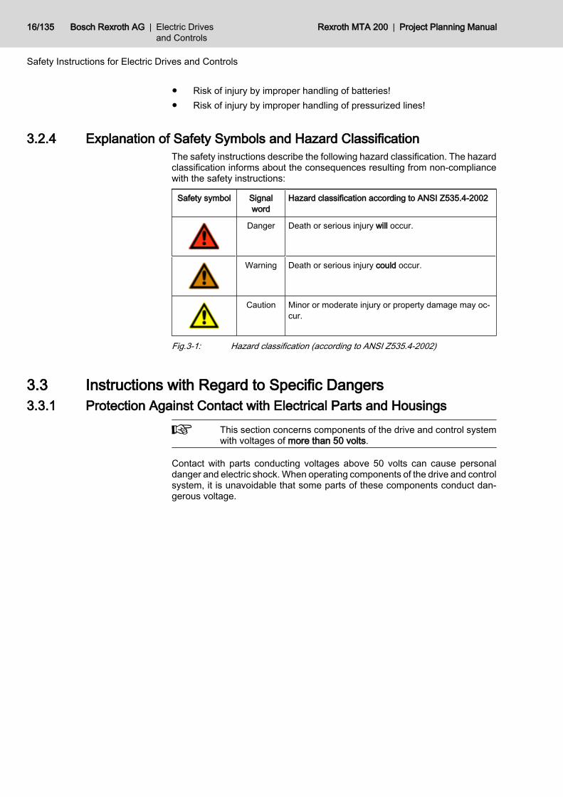
3.2.4 Explanation of Safety Symbols and Hazard ClassificationThe safety instructions describe the following hazard classification. The hazardclassification informs about the consequences resulting from non-compliancewith the safety instructions:
Safety symbol Signalword
Hazard classification according to ANSI Z535.4-2002
Danger Death or serious injury will occur.
Warning Death or serious injury could occur.
Caution Minor or moderate injury or property damage may oc‐cur.
Fig.3-1: Hazard classification (according to ANSI Z535.4-2002)
3.3 Instructions with Regard to Specific Dangers3.3.1 Protection Against Contact with Electrical Parts and Housings
This section concerns components of the drive and control systemwith voltages of more than 50 volts.
Contact with parts conducting voltages above 50 volts can cause personaldanger and electric shock. When operating components of the drive and controlsystem, it is unavoidable that some parts of these components conduct dan‐gerous voltage.
16/135 Bosch Rexroth AG | Electric Drivesand Controls
Rexroth MTA 200 | Project Planning Manual
Safety Instructions for Electric Drives and Controls
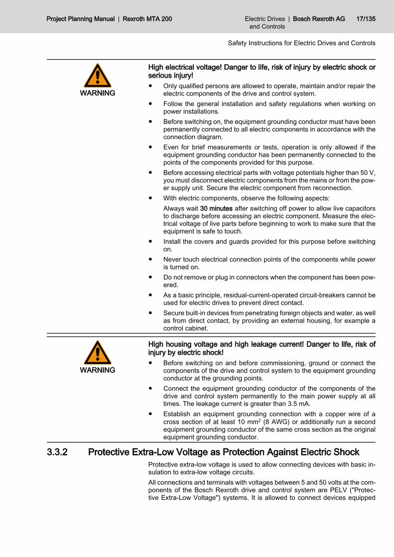
WARNING
High electrical voltage! Danger to life, risk of injury by electric shock orserious injury!● Only qualified persons are allowed to operate, maintain and/or repair the
electric components of the drive and control system.● Follow the general installation and safety regulations when working on
power installations.● Before switching on, the equipment grounding conductor must have been
permanently connected to all electric components in accordance with theconnection diagram.
● Even for brief measurements or tests, operation is only allowed if theequipment grounding conductor has been permanently connected to thepoints of the components provided for this purpose.
● Before accessing electrical parts with voltage potentials higher than 50 V,you must disconnect electric components from the mains or from the pow‐er supply unit. Secure the electric component from reconnection.
● With electric components, observe the following aspects:Always wait 30 minutes after switching off power to allow live capacitorsto discharge before accessing an electric component. Measure the elec‐trical voltage of live parts before beginning to work to make sure that theequipment is safe to touch.
● Install the covers and guards provided for this purpose before switchingon.
● Never touch electrical connection points of the components while poweris turned on.
● Do not remove or plug in connectors when the component has been pow‐ered.
● As a basic principle, residual-current-operated circuit-breakers cannot beused for electric drives to prevent direct contact.
● Secure built-in devices from penetrating foreign objects and water, as wellas from direct contact, by providing an external housing, for example acontrol cabinet.
WARNING
High housing voltage and high leakage current! Danger to life, risk ofinjury by electric shock!● Before switching on and before commissioning, ground or connect the
components of the drive and control system to the equipment groundingconductor at the grounding points.
● Connect the equipment grounding conductor of the components of thedrive and control system permanently to the main power supply at alltimes. The leakage current is greater than 3.5 mA.
● Establish an equipment grounding connection with a copper wire of across section of at least 10 mm2 (8 AWG) or additionally run a secondequipment grounding conductor of the same cross section as the originalequipment grounding conductor.
3.3.2 Protective Extra-Low Voltage as Protection Against Electric Shock Protective extra-low voltage is used to allow connecting devices with basic in‐sulation to extra-low voltage circuits.All connections and terminals with voltages between 5 and 50 volts at the com‐ponents of the Bosch Rexroth drive and control system are PELV ("Protec‐tive Extra-Low Voltage") systems. It is allowed to connect devices equipped
Project Planning Manual | Rexroth MTA 200 Electric Drivesand Controls
| Bosch Rexroth AG 17/135
Safety Instructions for Electric Drives and Controls

with basic insulation (such as programming devices, PCs, notebooks, displayunits) to these connections.
WARNING
Danger to life, risk of injury by electric shock! High electrical voltage byincorrect connection!If extra-low voltage circuits of devices containing voltages and circuits of morethan 50 volts (e.g., the mains connection) are connected to Bosch Rexrothproducts, the connected extra-low voltage circuits must comply with the re‐quirements for PELV ("Protective Extra-Low Voltage").
3.3.3 Protection Against Dangerous MovementsDangerous movements can be caused by faulty control of connected motors.Some common examples are:● Improper or wrong wiring or cable connection● Operator errors● Wrong input of parameters before commissioning● Malfunction of sensors and encoders● Defective components● Software or firmware errorsThese errors can occur immediately after equipment is switched on or evenafter an unspecified time of trouble-free operation.The monitoring functions in the components of the drive and control system willnormally be sufficient to avoid malfunction in the connected drives. Regardingpersonal safety, especially the danger of injury and/or property damage, thisalone cannot be relied upon to ensure complete safety. Until the integratedmonitoring functions become effective, it must be assumed in any case thatfaulty drive movements will occur. The extent of faulty drive movements de‐pends upon the type of control and the state of operation.
18/135 Bosch Rexroth AG | Electric Drivesand Controls
Rexroth MTA 200 | Project Planning Manual
Safety Instructions for Electric Drives and Controls

WARNING
Dangerous movements! Danger to life, risk of injury, serious injury orproperty damage!● A risk assessment must be prepared for the installation or machine, with
its specific conditions, in which the components of the drive and controlsystem are installed. As a result of the risk assessment, the user mustprovide for monitoring functions and higher-level measures on the instal‐lation side for personal safety. The safety regulations applicable to theinstallation or machine must be taken into consideration. Unintended ma‐chine movements or other malfunctions are possible if safety devices aredisabled, bypassed or not activated.
To avoid accidents, injury and/or property damage:● Keep free and clear of the machine’s range of motion and moving machine
parts. Prevent personnel from accidentally entering the machine’s rangeof motion by using, for example:– Safety fences– Safety guards– Protective coverings– Light barriers
● Make sure the safety fences and protective coverings are strong enoughto resist maximum possible kinetic energy.
● Mount emergency stop switches in the immediate reach of the operator.Before commissioning, verify that the emergency stop equipment works.Do not operate the machine if the emergency stop switch is not working.
● Prevent unintended start-up. Isolate the drive power connection by meansof an emergency stop circuit or use a safe starting lockout.
● Make sure that the drives are brought to a safe standstill before accessingor entering the danger zone.
● Additionally secure vertical axes against falling or dropping after switchingoff the motor power by, for example,– mechanically securing the vertical axes,– adding an external braking/arrester/clamping mechanism or– ensuring sufficient equilibration of the vertical axes.
● The standard equipment motor holding brake or an external holding brakecontrolled by the drive controller is not sufficient to guarantee personalsafety!
● Disconnect electrical power to the components of the drive and controlsystem using the master switch and secure them from reconnection for:– Maintenance and repair work– Cleaning of equipment– Long periods of discontinued equipment use
● Prevent the operation of high-frequency, remote control and radio equip‐ment near electric/electronic components of the drive and control systemand their supply leads. If the use of these devices cannot be avoided,check the machine or installation, before initial commissioning of the driveand control system, for possible malfunctions when operating such high-frequency, remote control and radio equipment in its possible positions ofnormal use. It might possibly be necessary to perform a special electro‐magnetic compatibility (EMC) test.
Project Planning Manual | Rexroth MTA 200 Electric Drivesand Controls
| Bosch Rexroth AG 19/135
Safety Instructions for Electric Drives and Controls
3.3.4 Protection Against Magnetic and Electromagnetic Fields During Oper‐ation and Mounting
Magnetic and electromagnetic fields generated by current-carrying conductorsor permanent magnets of electric motors represent a serious danger to personswith heart pacemakers, metal implants and hearing aids.
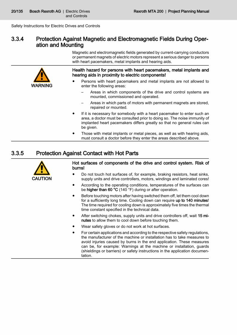
WARNING
Health hazard for persons with heart pacemakers, metal implants andhearing aids in proximity to electric components!● Persons with heart pacemakers and metal implants are not allowed to
enter the following areas:– Areas in which components of the drive and control systems are
mounted, commissioned and operated.– Areas in which parts of motors with permanent magnets are stored,
repaired or mounted.● If it is necessary for somebody with a heart pacemaker to enter such an
area, a doctor must be consulted prior to doing so. The noise immunity ofimplanted heart pacemakers differs greatly so that no general rules canbe given.
● Those with metal implants or metal pieces, as well as with hearing aids,must consult a doctor before they enter the areas described above.
3.3.5 Protection Against Contact with Hot Parts
CAUTION
Hot surfaces of components of the drive and control system. Risk ofburns!● Do not touch hot surfaces of, for example, braking resistors, heat sinks,
supply units and drive controllers, motors, windings and laminated cores!● According to the operating conditions, temperatures of the surfaces can
be higher than 60 °C (140 °F) during or after operation.● Before touching motors after having switched them off, let them cool down
for a sufficiently long time. Cooling down can require up to 140 minutes!The time required for cooling down is approximately five times the thermaltime constant specified in the technical data.
● After switching chokes, supply units and drive controllers off, wait 15 mi‐nutes to allow them to cool down before touching them.
● Wear safety gloves or do not work at hot surfaces.● For certain applications and according to the respective safety regulations,
the manufacturer of the machine or installation has to take measures toavoid injuries caused by burns in the end application. These measurescan be, for example: Warnings at the machine or installation, guards(shieldings or barriers) or safety instructions in the application documen‐tation.
20/135 Bosch Rexroth AG | Electric Drivesand Controls
Rexroth MTA 200 | Project Planning Manual
Safety Instructions for Electric Drives and Controls
3.3.6 Protection During Handling and Mounting
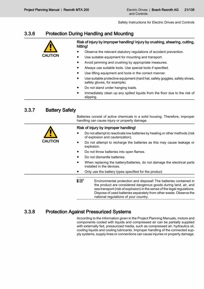
CAUTION
Risk of injury by improper handling! Injury by crushing, shearing, cutting,hitting!● Observe the relevant statutory regulations of accident prevention.● Use suitable equipment for mounting and transport.● Avoid jamming and crushing by appropriate measures.● Always use suitable tools. Use special tools if specified.● Use lifting equipment and tools in the correct manner.● Use suitable protective equipment (hard hat, safety goggles, safety shoes,
safety gloves, for example).● Do not stand under hanging loads.● Immediately clean up any spilled liquids from the floor due to the risk of
slipping.
3.3.7 Battery SafetyBatteries consist of active chemicals in a solid housing. Therefore, improperhandling can cause injury or property damage.
CAUTION
Risk of injury by improper handling!● Do not attempt to reactivate low batteries by heating or other methods (risk
of explosion and cauterization).● Do not attempt to recharge the batteries as this may cause leakage or
explosion.● Do not throw batteries into open flames.● Do not dismantle batteries.● When replacing the battery/batteries, do not damage the electrical parts
installed in the devices.● Only use the battery types specified for the product.
Environmental protection and disposal! The batteries contained inthe product are considered dangerous goods during land, air, andsea transport (risk of explosion) in the sense of the legal regulations.Dispose of used batteries separately from other waste. Observe thenational regulations of your country.
3.3.8 Protection Against Pressurized SystemsAccording to the information given in the Project Planning Manuals, motors andcomponents cooled with liquids and compressed air can be partially suppliedwith externally fed, pressurized media, such as compressed air, hydraulics oil,cooling liquids and cooling lubricants. Improper handling of the connected sup‐ply systems, supply lines or connections can cause injuries or property damage.
Project Planning Manual | Rexroth MTA 200 Electric Drivesand Controls
| Bosch Rexroth AG 21/135
Safety Instructions for Electric Drives and Controls
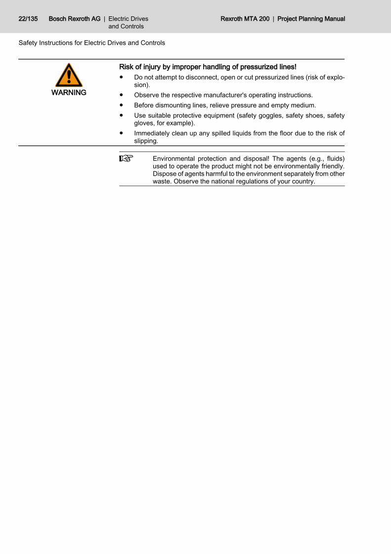
WARNING
Risk of injury by improper handling of pressurized lines!● Do not attempt to disconnect, open or cut pressurized lines (risk of explo‐
sion).● Observe the respective manufacturer's operating instructions.● Before dismounting lines, relieve pressure and empty medium.● Use suitable protective equipment (safety goggles, safety shoes, safety
gloves, for example).● Immediately clean up any spilled liquids from the floor due to the risk of
slipping.
Environmental protection and disposal! The agents (e.g., fluids)used to operate the product might not be environmentally friendly.Dispose of agents harmful to the environment separately from otherwaste. Observe the national regulations of your country.
22/135 Bosch Rexroth AG | Electric Drivesand Controls
Rexroth MTA 200 | Project Planning Manual
Safety Instructions for Electric Drives and Controls

4 Machine Operator Terminal BTV 20.4A4.1 Brief Description4.1.1 General Information
The BTV 20.4A is a PC-based machine operator terminal that also contains allthe hardware of the MTA 200 control system. Depending on the configuration,slots are available for customer-specific extensions in the PC bus.
This chapter describes the BTV 20.4A in its version for the MTA 200control system. The BTV 20 can also be delivered as a pure indus‐trial PC, as a PC with integrated PLC, or as a PC with integratedMTC200 control system. These versions are described in the gen‐eral BTV 20 documentation DOK-MTC200-BTV20.3****-PR0x-EN-P.
The figure below shows the structure of the BTV 20.4 front panel:
Fig.4-1: BTV 20.4 front panelThe front panel consists of a 4 mm thick aluminum panel with beveled edges.It is coated with a chemical resistant polyester foil with embossed keys thatcovers the whole front panel. The integrated 10.4" TFT color display providesexcellent visualization of the data. A 3.5" floppy disk drive, a reset button anda connection for an external keyboard or a mouse are located under the floppy-disk flap. Three LEDs indicate the operating state of the BTV 20.4. A key-operated switch locks the safety functions.
Project Planning Manual | Rexroth MTA 200 Electric Drivesand Controls
| Bosch Rexroth AG 23/135
Machine Operator Terminal BTV 20.4A
Furthermore, the BTV 20.4 is equipped with an extensive application-orientedfunction keyboard with the following keys:● Machine function keys● Function and operating Keys● PLC function keys and with separators● KeypadFor further information regarding the functioning and the assignment of the in‐dividual keys as well as the elements of the front panel elements mentionedabove, refer to the description of the front panel in chapter 4.
4.1.2 Default Configuration BTV 20.4● Pentium SLOT CPU, min. 700 MHz, with integrated graphics controller, 4
MB screen memory and Ethernet connection● 128 or 256 MB working memory selectable● At least 3 GB hard disk● 3.5" floppy-disk drive● 10.4" TFT color display● Power supply unit 115 - 230 VAC
4.1.3 Additional Modules BTV 20.4AIn the model functioning as an MTA 200 control system, the BTV 20.4A isequipped with the following additional modules:● NC CPU Pentium Slot CPU with 400 MHz● NCM NC module with one SERCOS interface● NCZ module with one or two additional SERCOS interfaces● PLC module with INTERBUS-S or Profibus master connection● NIO module for parallel connection of fast I/OsAll currently existing configurations can be found in the configuration type de‐sigantion code (see chapter 4.8.2 "Configuration Type Designation Code" onpage 57).All listed modules are described in detail in the following chapters.
4.1.4 Firmware and Software ConfigurationsOperating system
For license reasons the BTV 20.4 is only delivered with already installed oper‐ating system .The following firmware configurations are available for the BTV 20.4A:
Firmware type Description
FWA-BTV*44-WNT-04VRS-DE-OEM WindowsNT 4.0 German
FWA-BTV*44-WNT-04VRS-EN-OEM WindowsNT 4.0 English
FWA-BTV*44-WNT-05VRS-DE-OEM Windows2000 German
FWA-BTV*44-WNT-05VRS-EN-OEM Windows2000 English
Fig.4-2: Firmware configurations for MTA 200The SWA, SWL, SWS and/or SWP ordered together with the BTV 20.4A areinstalled on the BTV prior to delivery.
24/135 Bosch Rexroth AG | Electric Drivesand Controls
Rexroth MTA 200 | Project Planning Manual
Machine Operator Terminal BTV 20.4A

Bosch Rexroth does not pre-install any software requiring export authorization;the end user has to install this type of software subsequently commissioningthe BTV 20.
4.2 Front Panel, Keyboard4.2.1 Floppy-Disk Flap, Reset Button
Under the floppy-disk flap , there is a reset button , which can be reached byusing a thin object (pen, etc.), as well as the connection for an external key‐board. This connection can be used as service interface if no PCK03 drawerkeyboard is available.
If the reset button is pressed, all open applications are finishedwithout prior saving and the computer is rebooted.
CAUTION
In the MTA 200 the reset button influences only the PC part of the control. Atfirst the NC part goes on running. However, when booting the PC part the com‐munication task to the NC will get stuck - the BTV must be switched on and offagain.⇒ Therefore we recommend you not to use the reset button for the MTA!
Fig.4-3: Position of the reset button
When using the floppy-disk drive, keep the floppy-disk flap open.During closing the flap, the disk may be ejected, causing write andread errors.
4.2.2 Operating Display3 LEDs are under the floppy-disk drive with the following meaning:
Project Planning Manual | Rexroth MTA 200 Electric Drivesand Controls
| Bosch Rexroth AG 25/135
Machine Operator Terminal BTV 20.4A
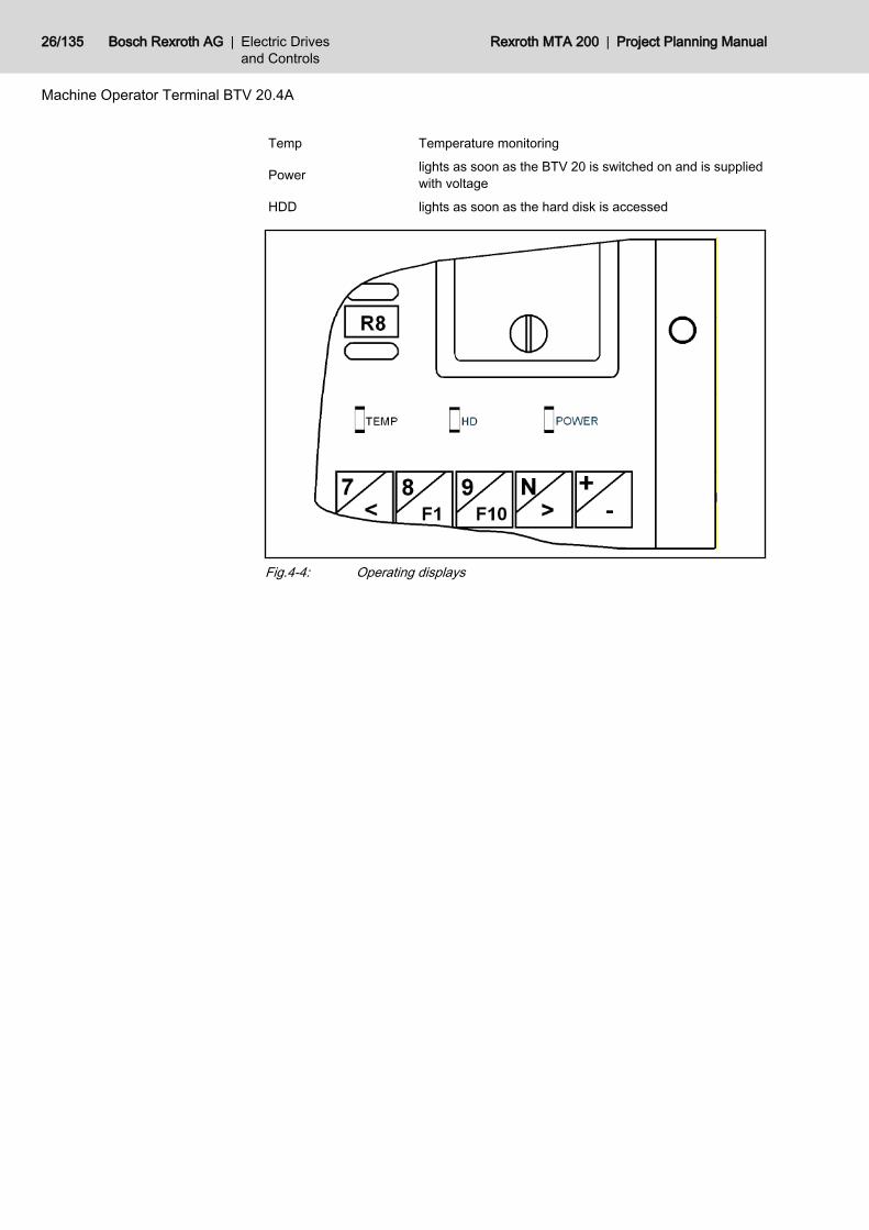
Temp Temperature monitoring
Power lights as soon as the BTV 20 is switched on and is suppliedwith voltage
HDD lights as soon as the hard disk is accessed
Fig.4-4: Operating displays
26/135 Bosch Rexroth AG | Electric Drivesand Controls
Rexroth MTA 200 | Project Planning Manual
Machine Operator Terminal BTV 20.4A
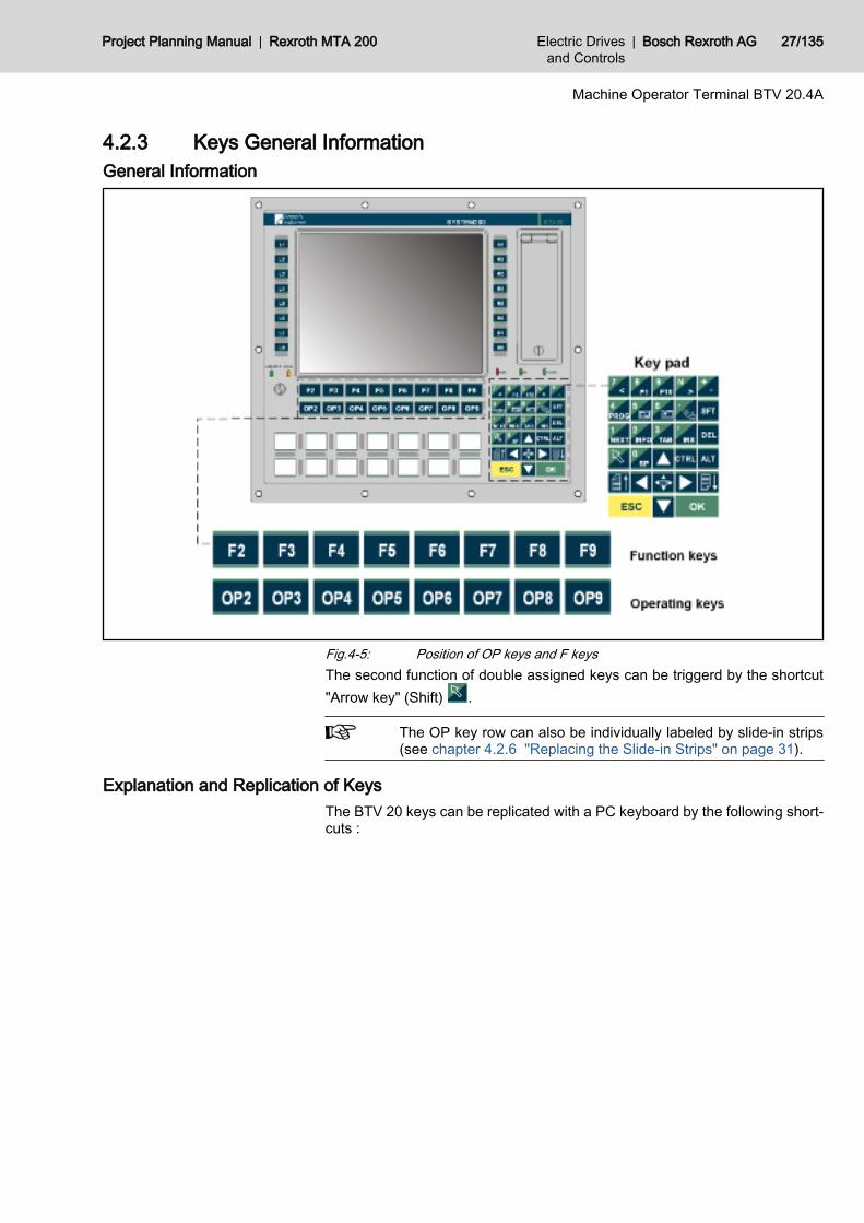
4.2.3 Keys General InformationGeneral Information
Fig.4-5: Position of OP keys and F keysThe second function of double assigned keys can be triggerd by the shortcut"Arrow key" (Shift) .
The OP key row can also be individually labeled by slide-in strips(see chapter 4.2.6 "Replacing the Slide-in Strips" on page 31).
Explanation and Replication of KeysThe BTV 20 keys can be replicated with a PC keyboard by the following short‐cuts :
Project Planning Manual | Rexroth MTA 200 Electric Drivesand Controls
| Bosch Rexroth AG 27/135
Machine Operator Terminal BTV 20.4A
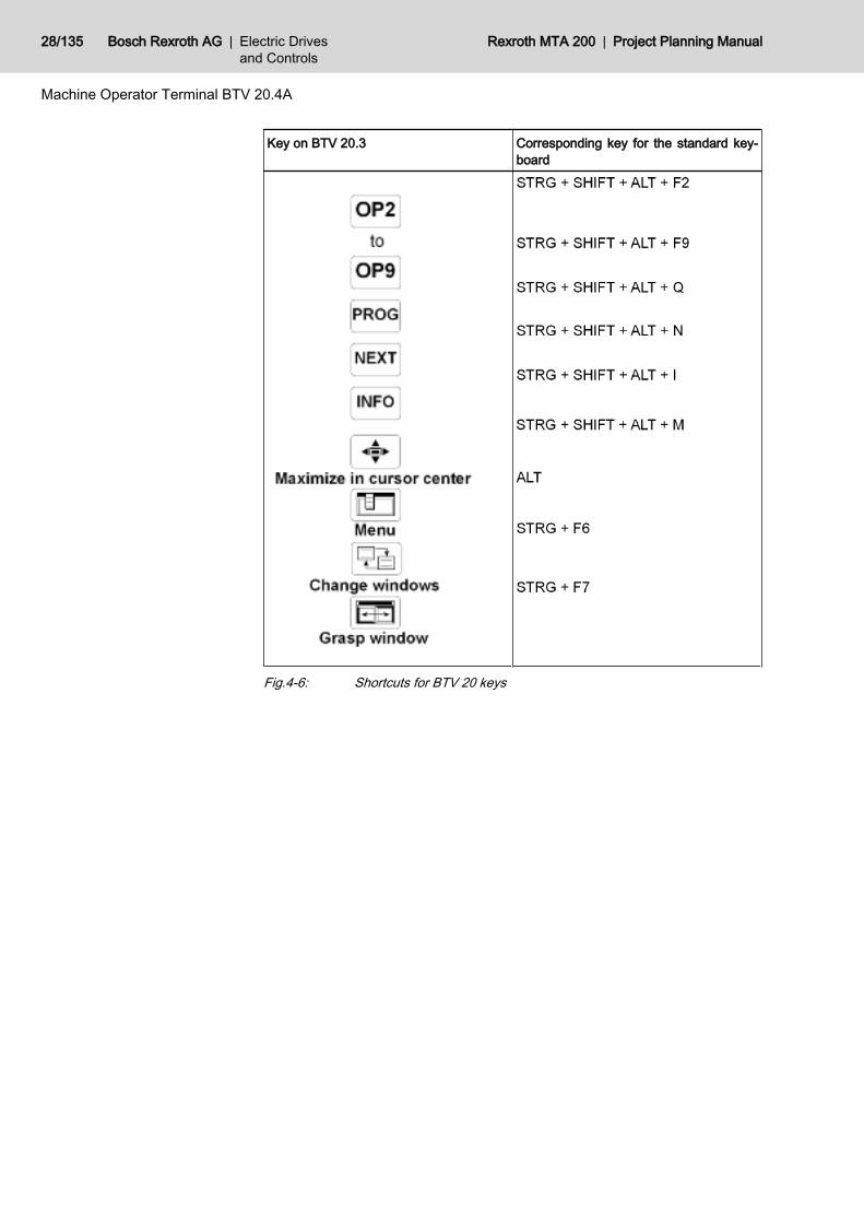
Key on BTV 20.3 Corresponding key for the standard key‐board
Fig.4-6: Shortcuts for BTV 20 keys
28/135 Bosch Rexroth AG | Electric Drivesand Controls
Rexroth MTA 200 | Project Planning Manual
Machine Operator Terminal BTV 20.4A
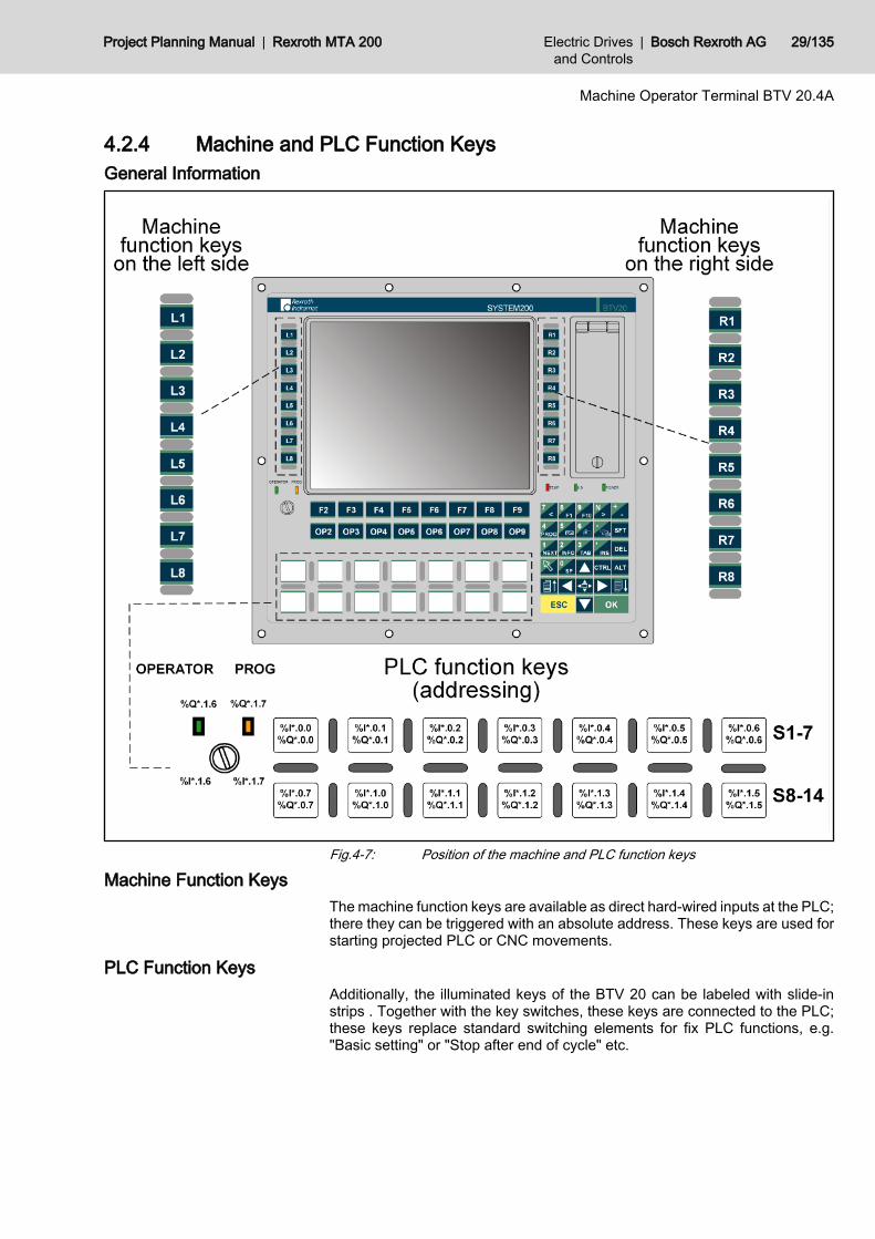
4.2.4 Machine and PLC Function KeysGeneral Information
Fig.4-7: Position of the machine and PLC function keys
Machine Function KeysThe machine function keys are available as direct hard-wired inputs at the PLC;there they can be triggered with an absolute address. These keys are used forstarting projected PLC or CNC movements.
PLC Function KeysAdditionally, the illuminated keys of the BTV 20 can be labeled with slide-instrips . Together with the key switches, these keys are connected to the PLC;these keys replace standard switching elements for fix PLC functions, e.g."Basic setting" or "Stop after end of cycle" etc.
Project Planning Manual | Rexroth MTA 200 Electric Drivesand Controls
| Bosch Rexroth AG 29/135
Machine Operator Terminal BTV 20.4A
4.2.5 Addressing via PLCMachine Function Keys
In BTVs with integrated PLC, the machine function keys are directly connectedto the PLC and therefore they can be directly addressed by the PLC program.
Machine function keys Address
L1 %I0.1480.0
L2 %I0.1480.1
L3 %I0.1480.2
L4 %I0.1480.3
L5 %I0.1480.4
L6 %I0.1480.5
L7 %I0.1480.6
L8 %I0.1480.7
R1 %I0.1481.0
R2 %I0.1481.1
R3 %I0.1481.2
R4 %I0.1481.3
R5 %I0.1481.4
R6 %I0.1481.5
R7 %I0.1481.6
R8 %I0.1481.7
Fig.4-8: Addressing of machine function keysInstead of the direct address entry also address constants for Bosch Rexrothfirmware data types can be used.Machine function keys left/right
PLC program identifier Address constants Data type
MFT_L A#iMFK_L MFK_L
MFT_R A#iMFK_R MFK_R
Fig.4-9: Addressing with address constantsThe MFK_L data type contains the L1, L2,..., L8 elements of the BOOL type.The MFK_R data type contains the R1, R2,..., R8 elements of the BOOL type.Example in the PLC program: MFT_L.L1
PLC Function KeysPLC function key Address key Address LEDs
S1 (see figure) %I*.0.0 %Q*.0.0
S2 %I*.0.1 %Q*.0.1
S3 %I*.0.2 %Q*.0.2
S4 %I*.0.3 %Q*.0.3
S5 %I*.0.4 %Q*.0.4
30/135 Bosch Rexroth AG | Electric Drivesand Controls
Rexroth MTA 200 | Project Planning Manual
Machine Operator Terminal BTV 20.4A
Alternatives with address constants
PLC function key Address key Address LEDs
S6 %I*.0.5 %Q*.0.5
S7 %I*.0.6 %Q*.0.6
S8 %I*.0.7 %Q*.0.7
S9 %I*.1.0 %Q*.1.0
S10 %I*.1.1 %Q*.1.1
S11 %I*.1.2 %Q*.1.2
S12 %I*.1.3 %Q*.1.3
S13 %I*.1.4 %Q*.1.4
S14 %I*.1.5 %Q*.1.5
Key switch left side (op‐erator)
%I*.1.6 %Q*.1.6
Key switch right side(Prog)
%I*.1.7 %Q*.1.7
Fig.4-10: Addressing of the PLC function keysTwo vacant logical addresses are to be assigned for inputs and outputs withinthe PLC configuration.
4.2.6 Replacing the Slide-in StripsGeneral Information
The 14 PLC function keys on the front of the BTV 20 can be labeled by usinga slide-in strip . The key row above the PLC function keys (OP2...OP9) is alsofreely configurable using slide-in strips.These strips, which are already inserted when the device is delivered, can befreely replaced. Preprinted strips as well as a floppy-disk with templates arealso included in the scope of delivery so that you can create your own keylabels. How to replace the slide-in strips is decribed below.
Project Planning Manual | Rexroth MTA 200 Electric Drivesand Controls
| Bosch Rexroth AG 31/135
Machine Operator Terminal BTV 20.4A
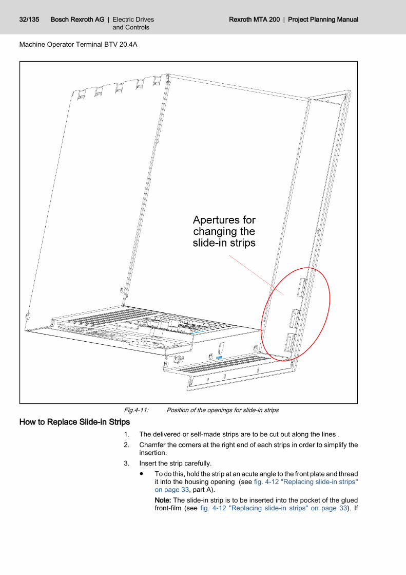
Fig.4-11: Position of the openings for slide-in strips
How to Replace Slide-in Strips1. The delivered or self-made strips are to be cut out along the lines .2. Chamfer the corners at the right end of each strips in order to simplify the
insertion.3. Insert the strip carefully.
● To do this, hold the strip at an acute angle to the front plate and threadit into the housing opening (see fig. 4-12 "Replacing slide-in strips"on page 33, part A).Note: The slide-in strip is to be inserted into the pocket of the gluedfront-film (see fig. 4-12 "Replacing slide-in strips" on page 33). If
32/135 Bosch Rexroth AG | Electric Drivesand Controls
Rexroth MTA 200 | Project Planning Manual
Machine Operator Terminal BTV 20.4A
the strip should be not in the film pocket, the strip can be insertedonly up to the first partition of the front panel.
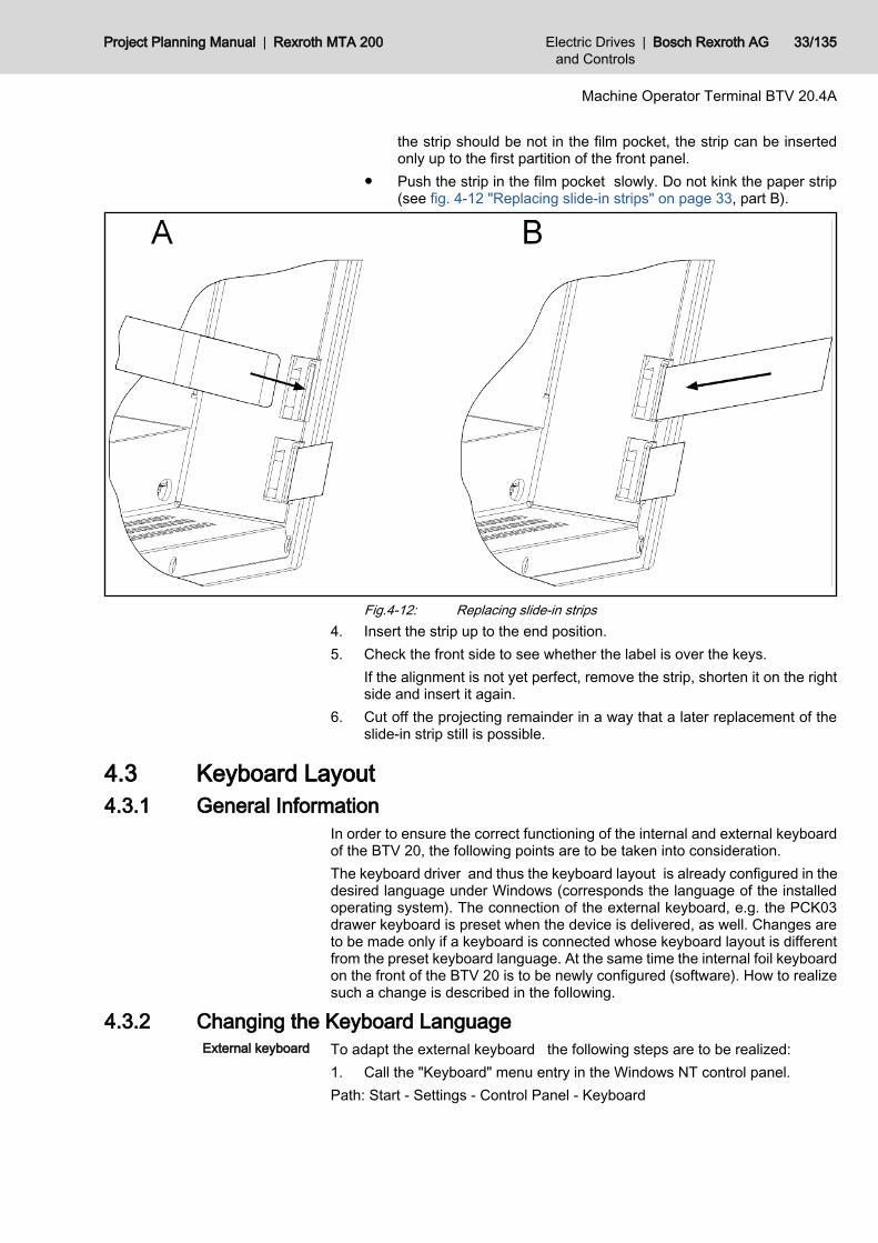
● Push the strip in the film pocket slowly. Do not kink the paper strip(see fig. 4-12 "Replacing slide-in strips" on page 33, part B).
Fig.4-12: Replacing slide-in strips4. Insert the strip up to the end position.5. Check the front side to see whether the label is over the keys.
If the alignment is not yet perfect, remove the strip, shorten it on the rightside and insert it again.
6. Cut off the projecting remainder in a way that a later replacement of theslide-in strip still is possible.
4.3 Keyboard Layout4.3.1 General Information
In order to ensure the correct functioning of the internal and external keyboardof the BTV 20, the following points are to be taken into consideration.The keyboard driver and thus the keyboard layout is already configured in thedesired language under Windows (corresponds the language of the installedoperating system). The connection of the external keyboard, e.g. the PCK03drawer keyboard is preset when the device is delivered, as well. Changes areto be made only if a keyboard is connected whose keyboard layout is differentfrom the preset keyboard language. At the same time the internal foil keyboardon the front of the BTV 20 is to be newly configured (software). How to realizesuch a change is described in the following.
4.3.2 Changing the Keyboard LanguageTo adapt the external keyboard the following steps are to be realized:1. Call the "Keyboard" menu entry in the Windows NT control panel.Path: Start - Settings - Control Panel - Keyboard
Project Planning Manual | Rexroth MTA 200 Electric Drivesand Controls
| Bosch Rexroth AG 33/135
Machine Operator Terminal BTV 20.4A
External keyboard
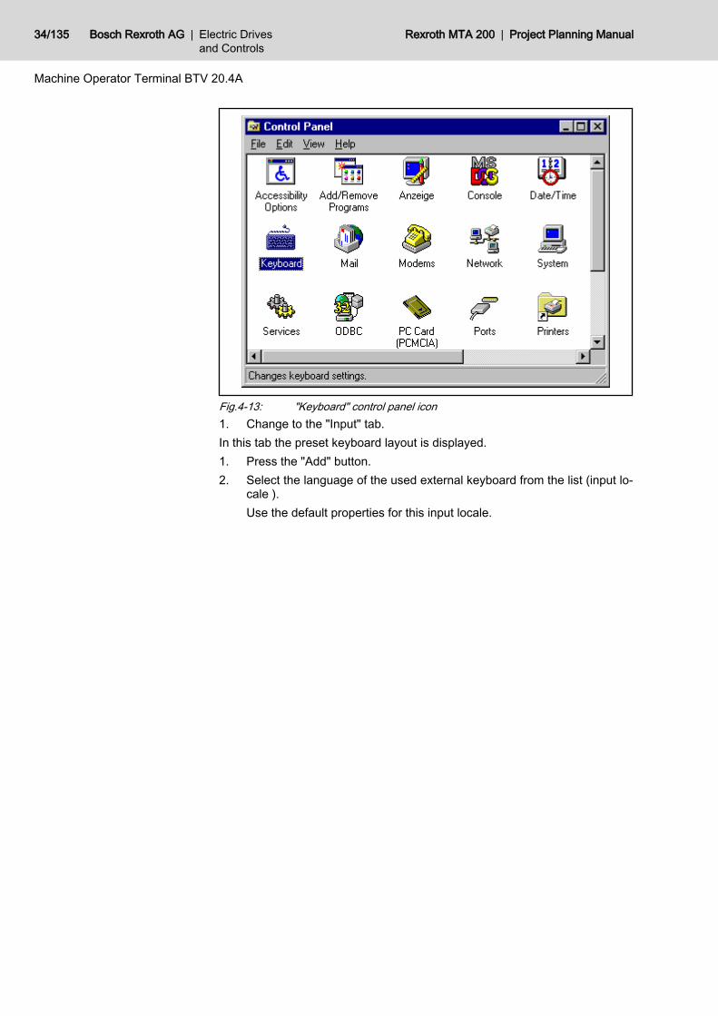
Fig.4-13: "Keyboard" control panel icon1. Change to the "Input" tab.In this tab the preset keyboard layout is displayed.1. Press the "Add" button.2. Select the language of the used external keyboard from the list (input lo‐
cale ).Use the default properties for this input locale.
34/135 Bosch Rexroth AG | Electric Drivesand Controls
Rexroth MTA 200 | Project Planning Manual
Machine Operator Terminal BTV 20.4A

Fig.4-14: "Input" tabThis method is used for adding a keyboard layout, i.e. several keyboard lan‐guages are displayed in the window and the desired language is to be selected.Use the "Properties" button in the input tab of the control panel to set the key‐board layout directly to the desired language.
However, after the change only the changed keyboard is displayedin the window. You cannot choose between the old and new key‐board layout, as it is the case when the "Add" button is used.
For adapting the internal foil keyboard the additional "BTV 20" icon is availablein the Windows NT control panel. Do the following steps:1. Call the "BTV 20" entry in the Windows NT control panel.
Path: Start - Settings - Control Panel - BTV 20
Project Planning Manual | Rexroth MTA 200 Electric Drivesand Controls
| Bosch Rexroth AG 35/135
Machine Operator Terminal BTV 20.4A
Internal keyboard
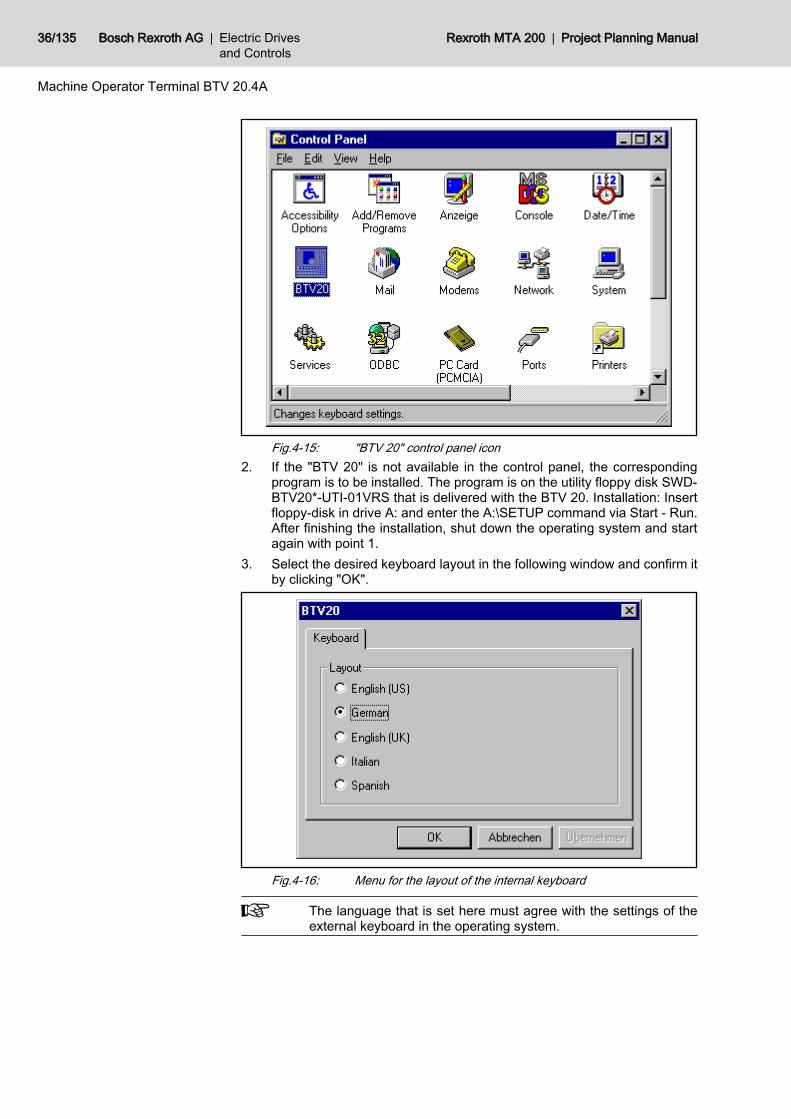
Fig.4-15: "BTV 20" control panel icon2. If the "BTV 20" is not available in the control panel, the corresponding
program is to be installed. The program is on the utility floppy disk SWD-BTV20*-UTI-01VRS that is delivered with the BTV 20. Installation: Insertfloppy-disk in drive A: and enter the A:\SETUP command via Start - Run.After finishing the installation, shut down the operating system and startagain with point 1.
3. Select the desired keyboard layout in the following window and confirm itby clicking "OK".
Fig.4-16: Menu for the layout of the internal keyboard
The language that is set here must agree with the settings of theexternal keyboard in the operating system.
36/135 Bosch Rexroth AG | Electric Drivesand Controls
Rexroth MTA 200 | Project Planning Manual
Machine Operator Terminal BTV 20.4A
4.4 Technical Data4.4.1 General Technical Data
Pentium - Slot CPU (min. 700 MHz) with integrated graphics controller128 MB (default), 256 MB (as option)At least 3 GB1 serial (RS232), 1 parallel (Centronics), 1 x Rexroth RS232, RS422 andRS485, 1 Ethernet 10Base-T/100Base-Tx, 2 USB (is not supported by Win‐dowsNT 4.0)10.4" TFT color display2 vacant PCI slots on the PC CPU sideMachine operating keyboard, 16 machine function keysFront panel IP 65 housing IP 20 DIN 40 050, IEC 529Color RAL 7035 light gray372 x 335 x 209 mm (WxHxD)407 x 370 x 220 mm (WxHxD)115/230 VAC ± 15%; 47-63 Hz250 VA100 W200 Wapprox. 10.5 kg (without control cards)
4.4.2 Ambient Conditions In operation Storage / Transport
Max. surrounding air temperature +5 °C up to +45 °C -20 °C up to +60 °C
Max. temperature gradient 10 K/h 15 K/h
Relative humidity 75 % on average, 80 % occasionally 75 % on average, 80 % occasion‐ally, non-condensing
Air pressure 860 to 1060 hPa, 1500 m 12,000 m
Max. external magnetic field 6 x 10⁻⁴ Tesla 6 x 10⁻⁴ Tesla
Max. vibration 10-57 Hz: Continuously: 0.0375 mm amplitude, occasionally: 0.075 mmaplitude, 57-150 Hz, continuously: 0.5 g constant acceleration, occasion‐ally: 1.0 g constant acceleration. To be applied to each of the threevertically positioned axes. (according to standard IEC 60068-2-6)
Max. shock Occasionally peaks up to 15 g above 11 ms, half sine wave in each of thethree vertically positioned axes. (according to standard IEC 60068-2-27)
Fig.4-17: Ambient conditions BTV 20.4
4.4.3 Wear Parts● Fan● Backlight tubes● Floppy-disk drive (FDD)● Hard-disk drives (HDD)● Battery (slot CPU)
Project Planning Manual | Rexroth MTA 200 Electric Drivesand Controls
| Bosch Rexroth AG 37/135
Machine Operator Terminal BTV 20.4A
PC processorRAM
Hard diskInterfaces (PC configuration)
Display unitSlots
KeyboardDegree of protectionFront panel surface
Plug-in unit dimensionsDimensions with front panel
Voltage supplyMax. power consumption
Typ. heat lossMax. heat loss
Weight
Wear parts without warranty

The average service life to be expected of the wear parts is 20,000 operatinghours. After this time we recommend you to exchange these components asprevention.
4.5 Dimensions4.5.1 Housing Dimensions
Fig.4-18: Dimensions - front panel
38/135 Bosch Rexroth AG | Electric Drivesand Controls
Rexroth MTA 200 | Project Planning Manual
Machine Operator Terminal BTV 20.4A

Fig.4-19: Rear view
Project Planning Manual | Rexroth MTA 200 Electric Drivesand Controls
| Bosch Rexroth AG 39/135
Machine Operator Terminal BTV 20.4A
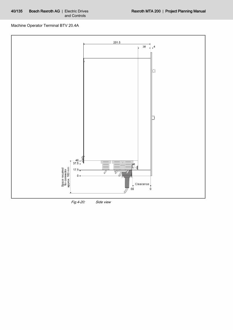
Fig.4-20: Side view
40/135 Bosch Rexroth AG | Electric Drivesand Controls
Rexroth MTA 200 | Project Planning Manual
Machine Operator Terminal BTV 20.4A
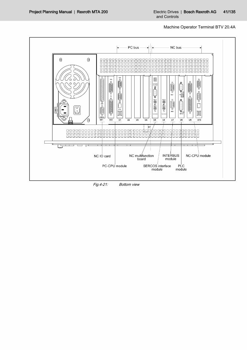
Fig.4-21: Bottom view
Project Planning Manual | Rexroth MTA 200 Electric Drivesand Controls
| Bosch Rexroth AG 41/135
Machine Operator Terminal BTV 20.4A
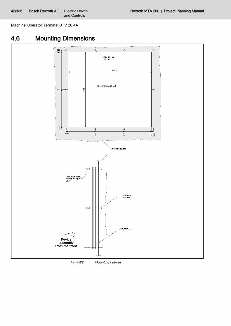
4.6 Mounting Dimensions
Fig.4-22: Mounting cut-out
42/135 Bosch Rexroth AG | Electric Drivesand Controls
Rexroth MTA 200 | Project Planning Manual
Machine Operator Terminal BTV 20.4A
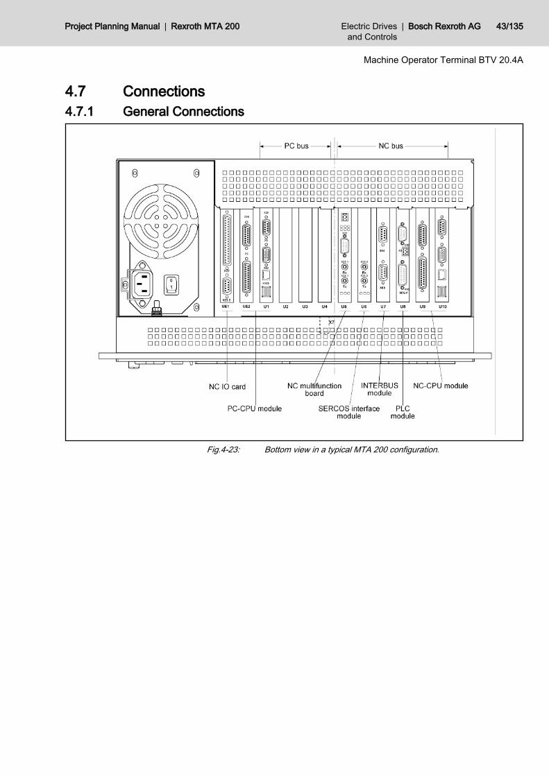
4.7 Connections4.7.1 General Connections
Fig.4-23: Bottom view in a typical MTA 200 configuration.
Project Planning Manual | Rexroth MTA 200 Electric Drivesand Controls
| Bosch Rexroth AG 43/135
Machine Operator Terminal BTV 20.4A
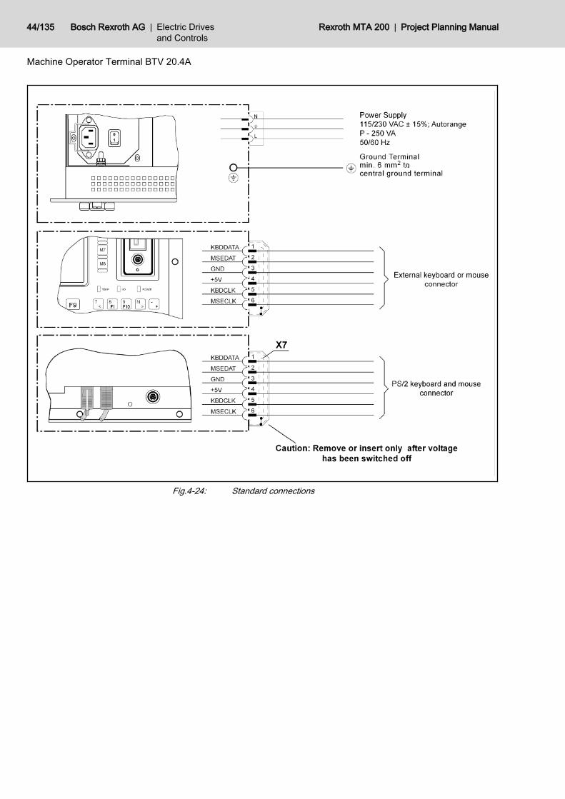
Fig.4-24: Standard connections
44/135 Bosch Rexroth AG | Electric Drivesand Controls
Rexroth MTA 200 | Project Planning Manual
Machine Operator Terminal BTV 20.4A
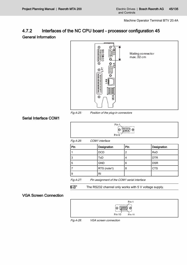
4.7.2 Interfaces of the NC CPU board - processor configuration 45General Information
Fig.4-25: Position of the plug-in connectors
Serial Interface COM1
Fig.4-26: COM1 interface
Pin Designation Pin Designation
1 DCD 2 RxD
3 TxD 4 DTR
5 GND 6 DSR
7 RTS (note1) 8 CTS
9 RI
Fig.4-27: Pin assignment of the COM1 serial interface
The RS232 channel only works with 5 V voltage supply.
VGA Screen Connection
Fig.4-28: VGA screen connection
Project Planning Manual | Rexroth MTA 200 Electric Drivesand Controls
| Bosch Rexroth AG 45/135
Machine Operator Terminal BTV 20.4A
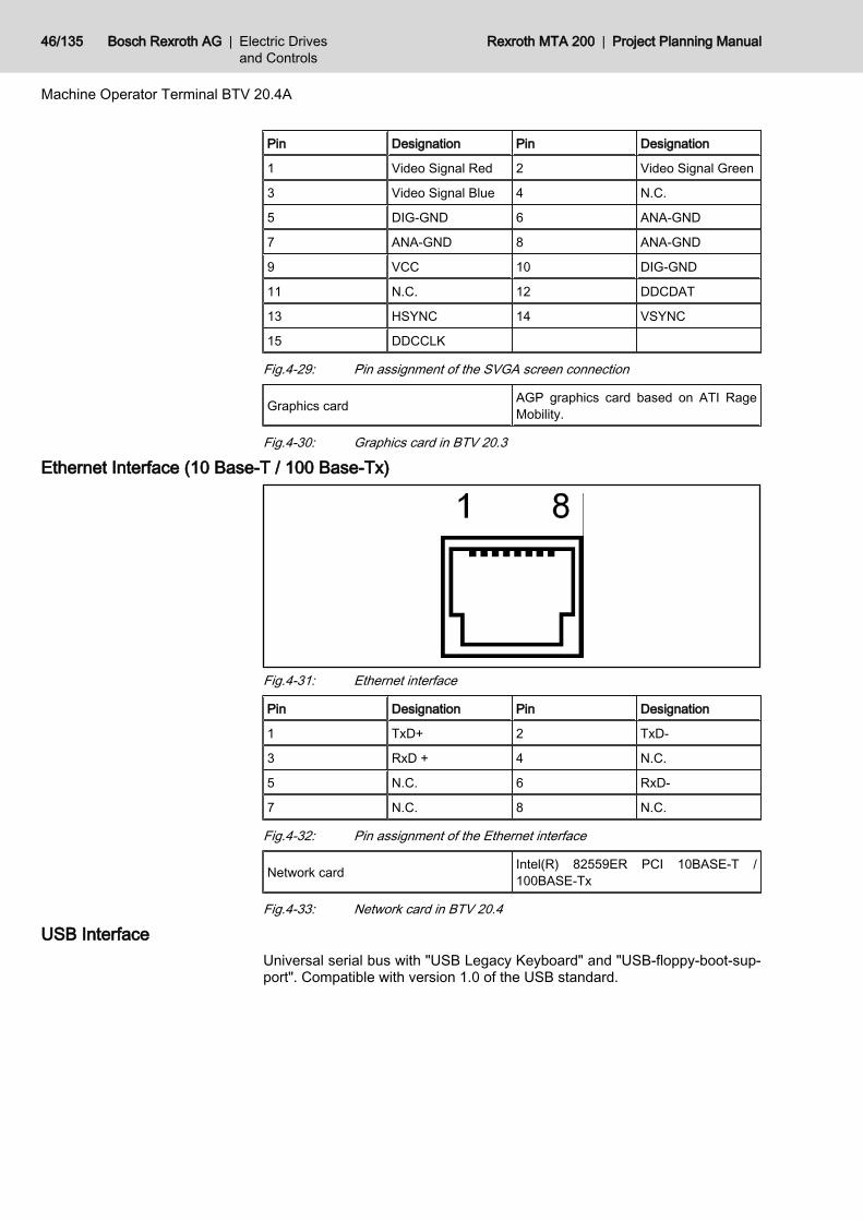
Pin Designation Pin Designation
1 Video Signal Red 2 Video Signal Green
3 Video Signal Blue 4 N.C.
5 DIG-GND 6 ANA-GND
7 ANA-GND 8 ANA-GND
9 VCC 10 DIG-GND
11 N.C. 12 DDCDAT
13 HSYNC 14 VSYNC
15 DDCCLK
Fig.4-29: Pin assignment of the SVGA screen connection
Graphics card AGP graphics card based on ATI RageMobility.
Fig.4-30: Graphics card in BTV 20.3
Ethernet Interface (10 Base-T / 100 Base-Tx)
Fig.4-31: Ethernet interface
Pin Designation Pin Designation
1 TxD+ 2 TxD-
3 RxD + 4 N.C.
5 N.C. 6 RxD-
7 N.C. 8 N.C.
Fig.4-32: Pin assignment of the Ethernet interface
Network card Intel(R) 82559ER PCI 10BASE-T /100BASE-Tx
Fig.4-33: Network card in BTV 20.4
USB InterfaceUniversal serial bus with "USB Legacy Keyboard" and "USB-floppy-boot-sup‐port". Compatible with version 1.0 of the USB standard.
46/135 Bosch Rexroth AG | Electric Drivesand Controls
Rexroth MTA 200 | Project Planning Manual
Machine Operator Terminal BTV 20.4A
Fig.4-34: USB interface
PIN Designation
1 USB power supply (max. 500 mA)
2 Data -
3 Data +
4 USB ground
Fig.4-35: Pin assignment of the USB interface
4.7.3 LPT1 Printer Interface and SISGeneral Information
The serial interface COM2 (X16) is switched according to the Rexroth standard(SIS). The LPT1 printer interface features the default Centronics assignment.Both interfaces are explained more detailed in the following.
LPT1 interface
Fig.4-36: LPT1 interface
PIN Signal designation PIN Signal designation
1 /STB - Strobe 2 PD0
3 PD1 4 PD2
5 PD3 6 PD4
7 PD5 8 PD6
9 PD7 10 /ACK - Acknowledge
11 Busy 12 PE - Paper End
13 SLCT - Select 14 /AFD - Auto Feed
15 /ERR - Error 16 /INIT
17 /SLCTIN - Select In 18 GND
19 GND 20 GND
21 GND 22 GND
23 GND 24 GND
25 GND
Fig.4-37: Pin assignment of the LPT1 interface
Project Planning Manual | Rexroth MTA 200 Electric Drivesand Controls
| Bosch Rexroth AG 47/135
Machine Operator Terminal BTV 20.4A
COM2 SIS interface
Fig.4-38: COM2 SIS interface
PIN Signal designation PIN Signal designation
1 Protected Ground 2 TxD (RS232)
3 RxD (RS232) 4 RS485+ / RxD+ (RS422)
5 RS485- /RxD- (RS422) 6 Data Set Ready (RS232)
7 Signal Ground 8 Data Carrier Detected (RS232)
9 TxD+ (RS422) 10 GND
11 TxD- (RS422) 12 +5V
13 Request To Send (RS232) 14 Clear To Send (RS232)
15 Data Terminal Ready
Fig.4-39: Pin assignment of the COM2 SIS interface
ConfigurationThe configuration of the COM2 SIS interface is performed by the "SISCon‐trol" Windows tool. A link to this tool is filed on the Windows desktop.
Fig.4-40: COM2 SIS interface configuration tool "SISControl"The COM2 SIS interface is internally performed via the COM4 port. Thereforeselect under COM port always COM4 port that is shown as default here. Thenselect the desired SIS mode 0 to 7 from the table, corresponding to the usedRS485 or RS422 interface.
The RS232 mode of the COM2 SIS interface is always active, in‐dependent from the selected settings for RS485 and RS422!
4.7.4 Internal WiringThe inner part of the BTV 20.4A is illustrated in fig. 4-41 "Inside of the BTV20.4A" on page 49. The figure shows how the plug-in cards are allocated and
48/135 Bosch Rexroth AG | Electric Drivesand Controls
Rexroth MTA 200 | Project Planning Manual
Machine Operator Terminal BTV 20.4A
how they are to be interconnected and as well how to be connected to harddrive and floppy-disk drive.
Fig.4-41: Inside of the BTV 20.4A
Project Planning Manual | Rexroth MTA 200 Electric Drivesand Controls
| Bosch Rexroth AG 49/135
Machine Operator Terminal BTV 20.4A
4.7.5 Application ExamplesApplication Example for BTV 20.4A with INTERBUS Switch
Fig.4-42: INTERBUS-S connection example
50/135 Bosch Rexroth AG | Electric Drivesand Controls
Rexroth MTA 200 | Project Planning Manual
Machine Operator Terminal BTV 20.4A
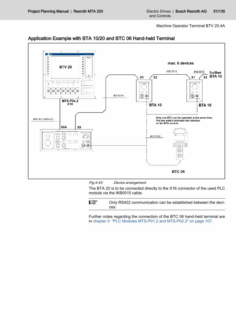
Application Example with BTA 10/20 and BTC 06 Hand-held Terminal
Fig.4-43: Device arrangementThe BTA 20 is to be connected directly to the X16 connector of the used PLCmodule via the IKB0015 cable.
Only RS422 communication can be established between the devi‐ces.
Further notes regarding the connection of the BTC 06 hand-held terminal arein chapter 9 "PLC Modules MTS-P01.2 and MTS-P02.2" on page 107.
Project Planning Manual | Rexroth MTA 200 Electric Drivesand Controls
| Bosch Rexroth AG 51/135
Machine Operator Terminal BTV 20.4A
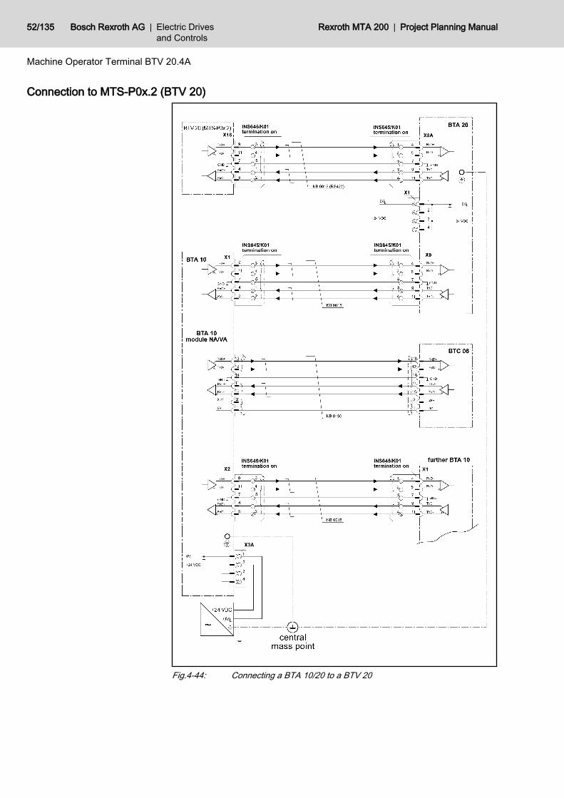
Connection to MTS-P0x.2 (BTV 20)
Fig.4-44: Connecting a BTA 10/20 to a BTV 20
52/135 Bosch Rexroth AG | Electric Drivesand Controls
Rexroth MTA 200 | Project Planning Manual
Machine Operator Terminal BTV 20.4A
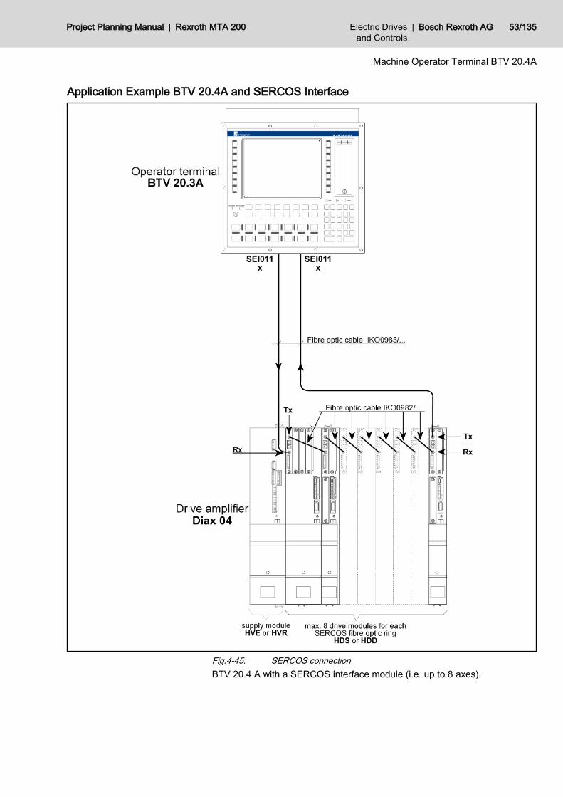
Application Example BTV 20.4A and SERCOS Interface
Fig.4-45: SERCOS connectionBTV 20.4 A with a SERCOS interface module (i.e. up to 8 axes).
Project Planning Manual | Rexroth MTA 200 Electric Drivesand Controls
| Bosch Rexroth AG 53/135
Machine Operator Terminal BTV 20.4A

Assembled Interface ConnectorsFor RS422 and RS485 communication connectors are available that include atermination in the housing. The cable can be mounted with screw terminals.The figure shows the pin assignment of the both connectors.The table in chapter 4.8.3 "Accessories" on page 58 shows when which con‐nector housing for interface cables is used .
Fig.4-46: Pin assignment of the assembled connector housingThe termination can be activated by a switch.
54/135 Bosch Rexroth AG | Electric Drivesand Controls
Rexroth MTA 200 | Project Planning Manual
Machine Operator Terminal BTV 20.4A
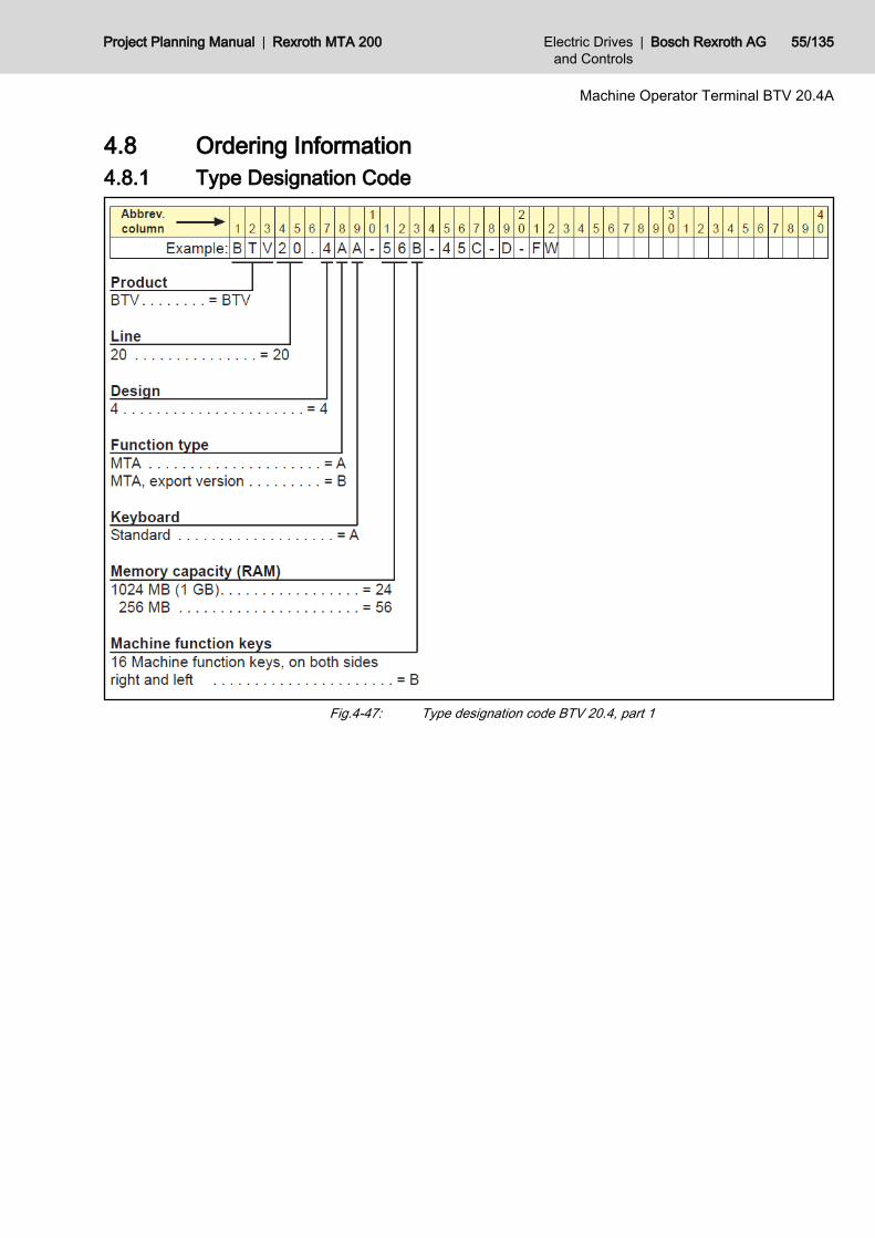
4.8 Ordering Information4.8.1 Type Designation Code
Fig.4-47: Type designation code BTV 20.4, part 1
Project Planning Manual | Rexroth MTA 200 Electric Drivesand Controls
| Bosch Rexroth AG 55/135
Machine Operator Terminal BTV 20.4A
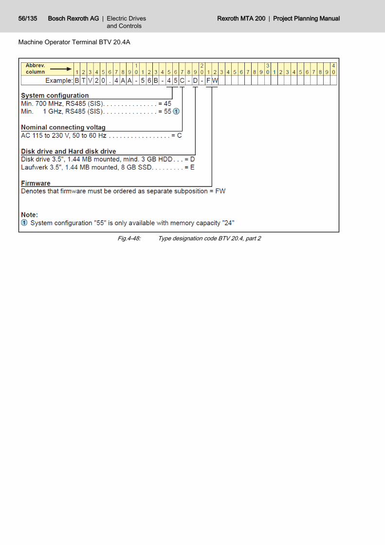
Fig.4-48: Type designation code BTV 20.4, part 2
56/135 Bosch Rexroth AG | Electric Drivesand Controls
Rexroth MTA 200 | Project Planning Manual
Machine Operator Terminal BTV 20.4A
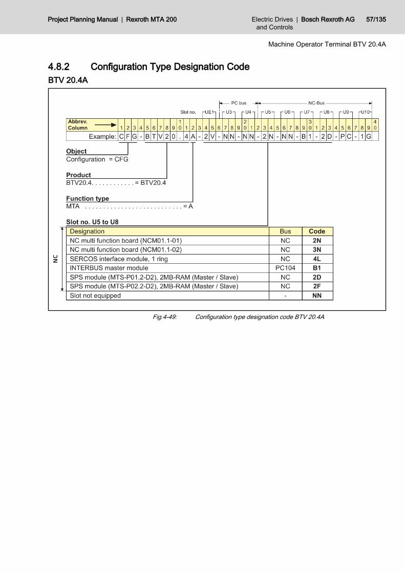
4.8.2 Configuration Type Designation CodeBTV 20.4A
Fig.4-49: Configuration type designation code BTV 20.4A
Project Planning Manual | Rexroth MTA 200 Electric Drivesand Controls
| Bosch Rexroth AG 57/135
Machine Operator Terminal BTV 20.4A
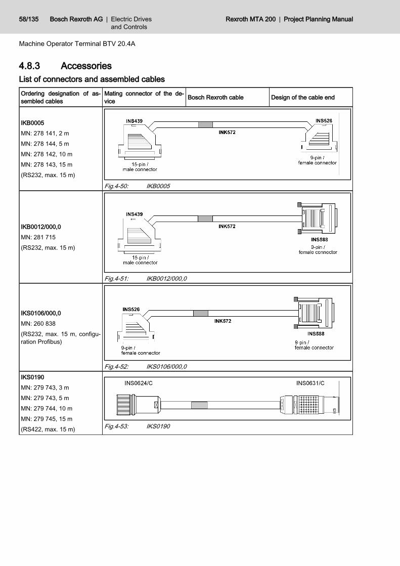
4.8.3 AccessoriesList of connectors and assembled cablesOrdering designation of as‐sembled cables
Mating connector of the de‐vice Bosch Rexroth cable Design of the cable end
IKB0005MN: 278 141, 2 mMN: 278 144, 5 mMN: 278 142, 10 mMN: 278 143, 15 m(RS232, max. 15 m)
Fig.4-50: IKB0005
IKB0012/000,0MN: 281 715(RS232, max. 15 m)
Fig.4-51: IKB0012/000,0
IKS0106/000,0MN: 260 838(RS232, max. 15 m, configu‐ration Profibus)
Fig.4-52: IKS0106/000,0IKS0190MN: 279 743, 3 mMN: 279 743, 5 mMN: 279 744, 10 mMN: 279 745, 15 m(RS422, max. 15 m) Fig.4-53: IKS0190
58/135 Bosch Rexroth AG | Electric Drivesand Controls
Rexroth MTA 200 | Project Planning Manual
Machine Operator Terminal BTV 20.4A
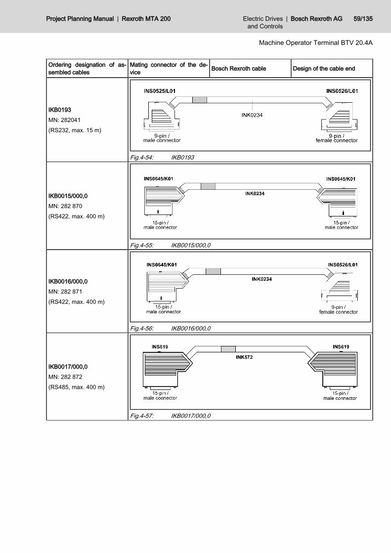
Ordering designation of as‐sembled cables
Mating connector of the de‐vice Bosch Rexroth cable Design of the cable end
IKB0193MN: 282041(RS232, max. 15 m)
Fig.4-54: IKB0193
IKB0015/000,0MN: 282 870(RS422, max. 400 m)
Fig.4-55: IKB0015/000,0
IKB0016/000,0MN: 282 871(RS422, max. 400 m)
Fig.4-56: IKB0016/000,0
IKB0017/000,0MN: 282 872(RS485, max. 400 m)
Fig.4-57: IKB0017/000,0
Project Planning Manual | Rexroth MTA 200 Electric Drivesand Controls
| Bosch Rexroth AG 59/135
Machine Operator Terminal BTV 20.4A

Ordering designation of as‐sembled cables
Mating connector of the de‐vice Bosch Rexroth cable Design of the cable end
IKB0018/000,0MN: 282 874(RS485, max. 400 m)
Fig.4-58: IKB0018/000,0
IKB0019/000,0MN: 282 875(RS485, max. 400 m)
Fig.4-59: IKB0019/000,0
IKB0030/000,0MN: 291 736(configuration Interbus, max.15 m)
Fig.4-60: IKB0030/000,0
IKB0031/000,0MN: 291 805(INTERBUS, max. 400 m)IKB0031/000,5MN: 291 806(INTERBUS, 0.5 m)
Fig.4-61: IKB0031/000,0; IKB0031/000,5
IKB0032/000,0MN: 291 807(INTERBUS, max. 400 m)
Fig.4-62: IKB0032/000,0
60/135 Bosch Rexroth AG | Electric Drivesand Controls
Rexroth MTA 200 | Project Planning Manual
Machine Operator Terminal BTV 20.4A
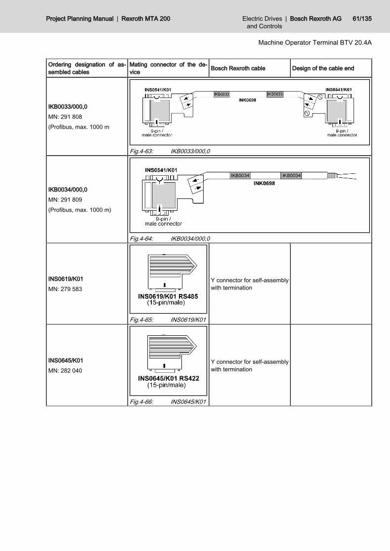
Ordering designation of as‐sembled cables
Mating connector of the de‐vice Bosch Rexroth cable Design of the cable end
IKB0033/000,0MN: 291 808(Profibus, max. 1000 m
Fig.4-63: IKB0033/000,0
IKB0034/000,0MN: 291 809(Profibus, max. 1000 m)
Fig.4-64: IKB0034/000,0
INS0619/K01MN: 279 583
Fig.4-65: INS0619/K01
Y connector for self-assemblywith termination
INS0645/K01MN: 282 040
Fig.4-66: INS0645/K01
Y connector for self-assemblywith termination
Project Planning Manual | Rexroth MTA 200 Electric Drivesand Controls
| Bosch Rexroth AG 61/135
Machine Operator Terminal BTV 20.4A
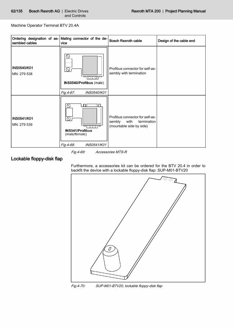
Ordering designation of as‐sembled cables
Mating connector of the de‐vice Bosch Rexroth cable Design of the cable end
INS0540/K01MN: 279 538
Fig.4-67: INS0540/K01
Profibus connector for self-as‐sembly with termination
INS0541/K01MN: 279 539
Fig.4-68: INS0541/K01
Profibus connector for self-as‐sembly with termination(mountable side by side)
Fig.4-69: Accessories MTS-R
Lockable floppy-disk flapFurthermore, a accessories kit can be ordered for the BTV 20.4 in order tobackfit the device with a lockable floppy-disk flap: SUP-M01-BTV20
Fig.4-70: SUP-M01-BTV20, lockable floppy-disk flap
62/135 Bosch Rexroth AG | Electric Drivesand Controls
Rexroth MTA 200 | Project Planning Manual
Machine Operator Terminal BTV 20.4A

4.9 Accessories (Included in the Scope of Delivery)Assembly kit● 10 x fillister-head screws M5 x 12● 10 x seal M5 Nyltite● 1 x AC connector, 3-pin, female (only variant with 230 V power supply unit)● Seal front panel 404 x 4 x 0.8 mm● Seal front panel 365 x 4 x 0.8 mmSet of inscription plates● Pre-printed sample slide-in strips● Floppy disk with templates for independent creation of labelsSWD-BTV20*-UTI-01VRS-MS-C1,44● Floppy disk with software for setting the keyboard languageSlip case with software package● Compilation of the ordered firmware and software
Project Planning Manual | Rexroth MTA 200 Electric Drivesand Controls
| Bosch Rexroth AG 63/135
Machine Operator Terminal BTV 20.4A

64/135 Bosch Rexroth AG | Electric Drivesand Controls
Rexroth MTA 200 | Project Planning Manual
5 PC CPU Configuration -455.1 Brief Description
Fig.5-1: Slot CPU card
5.2 Technical Data5.2.1 Electrical SpecificationsVoltage supply +5, +12 V (+/- 3%)
Power consumption 10-20 W typically (depending on the processor type)
Battery +3.6 volt lithium battery, size ½ AA)
Fig.5-2: Electrical specifications
5.2.2 CPU and Memory SpecificationProcessor INTEL, Mobile Pentium III min. 700 MHz
CPU Clock Rate Min. 700 MHz
System Clock Rate 100 MHz frontside bus
Program memory 1 144 Pin SO-DIMM 3,3 V PC100, max. 256 MB. Use 256 MB "stacked" SODIMM modules only. Do not use 256 MegaBit modules.
System Core INTEL 440BX AGP Set
Fig.5-3: CPU and memory specification
Project Planning Manual | Rexroth MTA 200 Electric Drivesand Controls
| Bosch Rexroth AG 65/135
PC CPU Configuration -45
5.3 PhoenixBIOS Setup5.3.1 General Information
The BIOS of the BTV 20.4 is a "Phoenix BIOS 4.0 Release 6.1, 256 KByteFLASH-BIOS, NV-EEPROM". It contains a battery-buffered CMOS memory forstoring date, time and system configuration.
Wrong settings can cause damage to the system or prevent it frombooting.
Call the main menu of the BIOS system by pressing the <F2> key during boot‐ing when the following message is displayed:"Press <F2> to Enter Setup"
5.3.2 Help Screen (Online Help)Press <F1> to call the "General Help", i.e. the basic help. Here the informationabout operating the PhoenixBIOS Setup is displayed. The menus in the rightpart display always a "Item Specific Help", i.e. the help for the currently selectedmenu entry.
5.3.3 Navigation in the PhoenixBIOS SetupThe following keys in the PhoenixBIOS Setup are of importance:
Keys Function
<F1> or <Alt-H> Call "General Help"
<Esc> Exit the menu
← or → arrow keys Select different menus
↑ or ↓ arrow keys Select the desired menu item
<Tab> or <Shift-Tab> Jump to the next or to the previous menu item
<Home> or <End> Move the cursor to the beginning or to the end of the cur‐rent menu
<PgUp> or <PgDn> Move the cursor to the next or to the previous menu
<F5> or <-> Select the previous entry from the list of the menu item
<F6> or <+> Select the next entry from the list of the menu item
<F9> Load the "Default" values for this menu
<F10> Save and exit
<Enter> Execute the command or select the submenu
<Alt-R> Update the display
Fig.5-4: PhoenixBIOS key functions
5.3.4 PhoenixBIOS Setup - Main MenuGeneral Information
The PhoenixBIOS Setup screen is divided into four sections.
66/135 Bosch Rexroth AG | Electric Drivesand Controls
Rexroth MTA 200 | Project Planning Manual
PC CPU Configuration -45
Part of the Setupscreen
Position on the screen Function
Menu bar Top Display and selection of all "Top-Lev‐el" menus
Navigation bar Bottom Display of the Setup navigation keyfunctions
Specific help Right Help for the currently selected menuitem
Menu contents Left Display of the current menu
"General Help" Front and center Display of the Help
Fig.5-5: Division of the PhoenixBIOS Setup menu
Default SettingsPressing the <F9> key loads the "Default Setup Configuration". However, theseare not the "Default" values for the BTV 20.4!
The default values for the BTV 20.4 are listed in the following tables.
Special MTA SettingsIt is not necessary to make any changes to the BIOS settings in the BTV 20.4Afor the MTA 200 control system.As the NC CPU is equal to the PC CPU only in its appearance, it must beensured that the PC CPU is not used as NC CPU and vice versa.Otherwise, the different BIOS settings of NC CPU and PCU CPU would preventthe BTV 20.4A from booting!
The BTV 20.4A with processor configuration 45 mandatorily re‐quires a MTA software version 23VRS or higher. The BTV 20.4Acannot be operated with older versions!
5.3.5 PhoenixBIOS Settings for the BTV 20.4Main
System Time Current time
System Date Current date
Legacy Diskette A 1.44/1.25 MB 3½"
Legacy Diskette B disabled
Primary Master Autodetected drive / submenu
Primary Slave Autodetected drive / submenu
Secondary Master Autodetected drive / submenu
Secondary Slave Autodetected drive / submenu
Memory Shadow Submenu
Memory Cache Submenu
System Memory Display of the system memory
Extended Memory Display of the Extended Memory
Fig.5-6: Main menu
Project Planning Manual | Rexroth MTA 200 Electric Drivesand Controls
| Bosch Rexroth AG 67/135
PC CPU Configuration -45
Primary / Secondary Master / Slave
Type Primary Master: AutoPrimary Slave: NoneSecondary Master: AutoSecondary Slave: None
CHS Format
Cylinders Display depends on the IDE device
Heads Display depends on the IDE device
Sectors Display depends on the IDE device
Maximum Capacity Display depends on the IDE device
LBA Format
Total Sectors Display depends on the IDE device
Maximum Capacity Display depends on the IDE device
Multi-Sector Transfer Display depends on the IDE device
LBA Mode Control Display depends on the IDE device
32-bit I/O Enabled
Transfer Mode Display depends on the IDE device
Ultra DMA Mode Display depends on the IDE device
Fig.5-7: "IDE Device" submenu
Memory Shadow
CC00 - CFFF Disabled
D000 - D3FF Disabled
D400 - D7FF Disabled
D800 - DBFF Disabled
DC00 - DFFF Disabled
Fig.5-8: "Memory Shadow" submenu
Memory Cache
Memory Cache Enabled
Cache System BIOS area Write Protect
Cache Video BIOS area Write Protect
Cache Extended memory area Write Back
CC00 - CFFF Disabled
D000 - D3FF Disabled
D400 - D7FF Disabled
D800 - DBFF Disabled
DC00 - DFFF Disabled
Fig.5-9: "Memory Cache" submenu
68/135 Bosch Rexroth AG | Electric Drivesand Controls
Rexroth MTA 200 | Project Planning Manual
PC CPU Configuration -45
Advanced Menu
Advanced Chipset Control Submenu
PNP OS installed No
Reset Configuration Data No
Secured Setup Configuration Yes
PCI Configuration Submenu
PS/2 mouse Autodetect
Keyboard Features Submenu
I/O Device Configuration Submenu
Large Disk Access Mode DOS
SMART Device Monitoring Enabled
Halt On Errors Yes
Fig.5-10: Advanced menu
Advanced Chipset Control
Graphics Aperture 64
Enabled memory gap Disabled
ECC Config Disabled
SERR signal condition None
8 bit I/O Recovery 4.5
16 bit I/O Recovery 4.5
Fig.5-11: "Advanced Chipset Control" submenu
PCI Configuration
PCI IRQ line 1 Auto Select
PCI IRQ line 2 Auto Select
PCI IRQ line 3 Auto Select
PCI IRQ line 4 Auto Select
PCI/PNP ISA UMB Region Exclusion Submenu
PCI/PNP ISA IRQ Resource Exclusion Submenu
Default Primary Video Adapter AGP
ISA graphics device installed No
Assign IRQ to PCI VGA No
Fig.5-12: "PCI Configuration" submenu
PNP/UMB Region Exclusion
CC00 - CFFF Available
D000 - D3FF Reserved
D400 - D7FF Available
D800 - DBFF Available
DC00 - DFFF Available
Fig.5-13: "PCI/PNP UMB Region Exclusion" submenu
Project Planning Manual | Rexroth MTA 200 Electric Drivesand Controls
| Bosch Rexroth AG 69/135
PC CPU Configuration -45

PCI/PNP ISA IRQ Resource Exclusion
IRQ3 Available
IRQ4 Available
IRQ5 Available
IRQ7 Available
IRQ9 Available
IRQ10 Available
IRQ11 Available
IRQ12 Available
Fig.5-14: "PCI/PNP ISA IRQ Resource Exclusion" submenu
Keyboard Features
NumLock Auto
Key Click Disabled
Keyboard auto-repeat rate 30/sec
Keyboard auto-repeat delay ½ sec
Fig.5-15: "Keyboard Features" submenu
I/O Device Configuration
Local Bus IDE adapter Both
Onboard FDC Enabled
Base I/O address Primary
External FDC Disabled
Serial port A Enabled
Base I/O address 3F8
Interrupt IRQ4
Serial port B Enabled
Mode Normal
Base I/O address 2F8
Interrupt IRQ3
Serial port C Enabled
Base I/O address 3E8
Interrupt IRQ11
Serial port D Enabled
Base I/O address 2E8
Interrupt IRQ11
Mode Normal
External LPT Enabled
Mode Bi-directional
Base I/O address 278
Interrupt IRQ5
70/135 Bosch Rexroth AG | Electric Drivesand Controls
Rexroth MTA 200 | Project Planning Manual
PC CPU Configuration -45

I/O Device Configuration
Legacy USB Support Enabled
Watchdog Settings Submenu
Fig.5-16: "I/O Device Configuration" submenu
Watchdog Settings
Mode Disabled
Fig.5-17: "Watchdog Settings" submenu
Security
Supervisor Password Is Clear
User Password Is Clear
Set Supervisor Password
Set User Password
Password on boot Disabled
Fixed disk boot sector Normal
Diskette access Supervisor
Virus check reminder Disabled
System backup reminder Disabled
Fig.5-18: Security menu
Power
Power Savings Disabled
Idle Mode Off
Standby Timeout Off
Auto Suspend Timeout Off
Hard Disk Timeout Disabled
Video Timeout Disabled
Resume On Time Off
Resume Time 00:00:00
Power Supply ATX
Fig.5-19: Power menu
Boot
Floppy Check Disabled
Summary Screen Disabled
QuickBoot Mode Enabled
Dark Boot Disabled
Boot Device Priority Submenu
Onboard LAN RPL ROM Disabled
Fig.5-20: Boot menu
Project Planning Manual | Rexroth MTA 200 Electric Drivesand Controls
| Bosch Rexroth AG 71/135
PC CPU Configuration -45
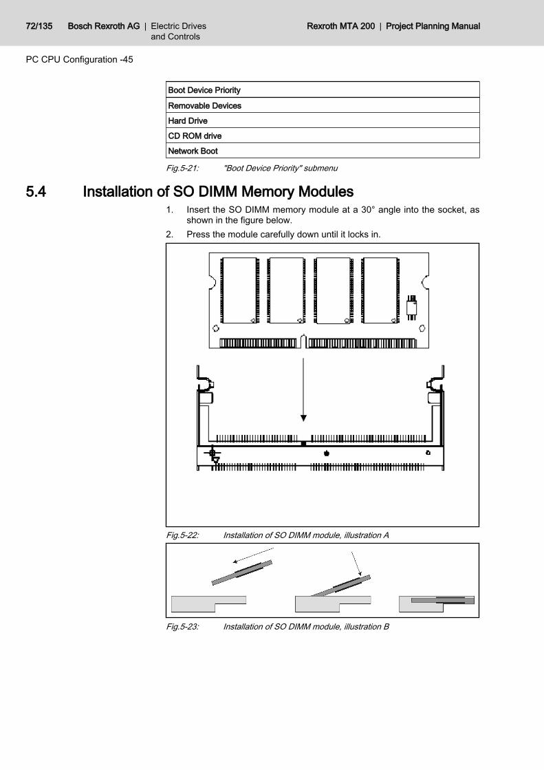
Boot Device Priority
Removable Devices
Hard Drive
CD ROM drive
Network Boot
Fig.5-21: "Boot Device Priority" submenu
5.4 Installation of SO DIMM Memory Modules1. Insert the SO DIMM memory module at a 30° angle into the socket, as
shown in the figure below.2. Press the module carefully down until it locks in.
Fig.5-22: Installation of SO DIMM module, illustration A
Fig.5-23: Installation of SO DIMM module, illustration B
72/135 Bosch Rexroth AG | Electric Drivesand Controls
Rexroth MTA 200 | Project Planning Manual
PC CPU Configuration -45
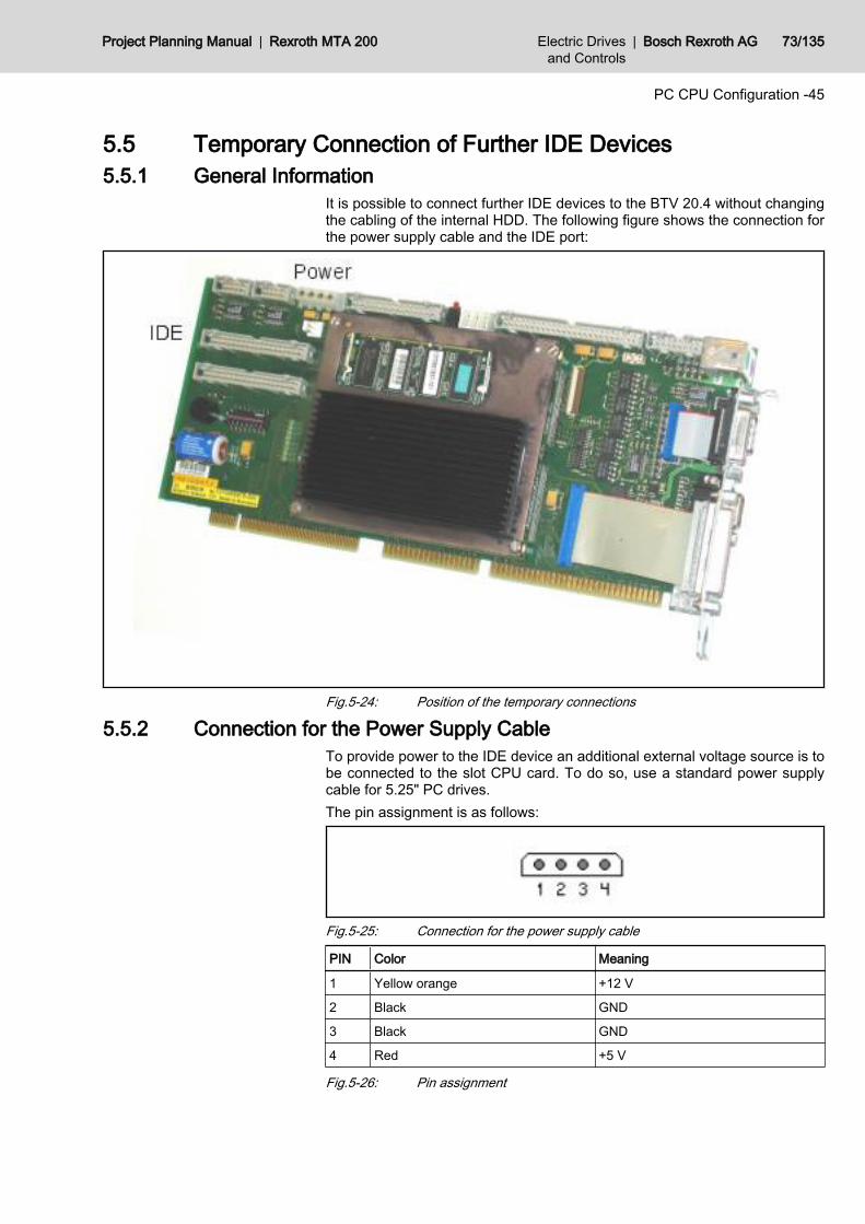
5.5 Temporary Connection of Further IDE Devices5.5.1 General Information
It is possible to connect further IDE devices to the BTV 20.4 without changingthe cabling of the internal HDD. The following figure shows the connection forthe power supply cable and the IDE port:
Fig.5-24: Position of the temporary connections
5.5.2 Connection for the Power Supply CableTo provide power to the IDE device an additional external voltage source is tobe connected to the slot CPU card. To do so, use a standard power supplycable for 5.25" PC drives.The pin assignment is as follows:
Fig.5-25: Connection for the power supply cable
PIN Color Meaning
1 Yellow orange +12 V
2 Black GND
3 Black GND
4 Red +5 V
Fig.5-26: Pin assignment
Project Planning Manual | Rexroth MTA 200 Electric Drivesand Controls
| Bosch Rexroth AG 73/135
PC CPU Configuration -45
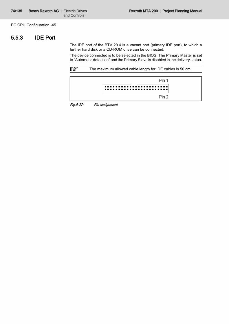
5.5.3 IDE PortThe IDE port of the BTV 20.4 is a vacant port (primary IDE port), to which afurther hard disk or a CD-ROM drive can be connected.The device connected is to be selected in the BIOS. The Primary Master is setto "Automatic detection" and the Primary Slave is disabled in the delivery status.
The maximum allowed cable length for IDE cables is 50 cm!
Fig.5-27: Pin assignment
74/135 Bosch Rexroth AG | Electric Drivesand Controls
Rexroth MTA 200 | Project Planning Manual
PC CPU Configuration -45
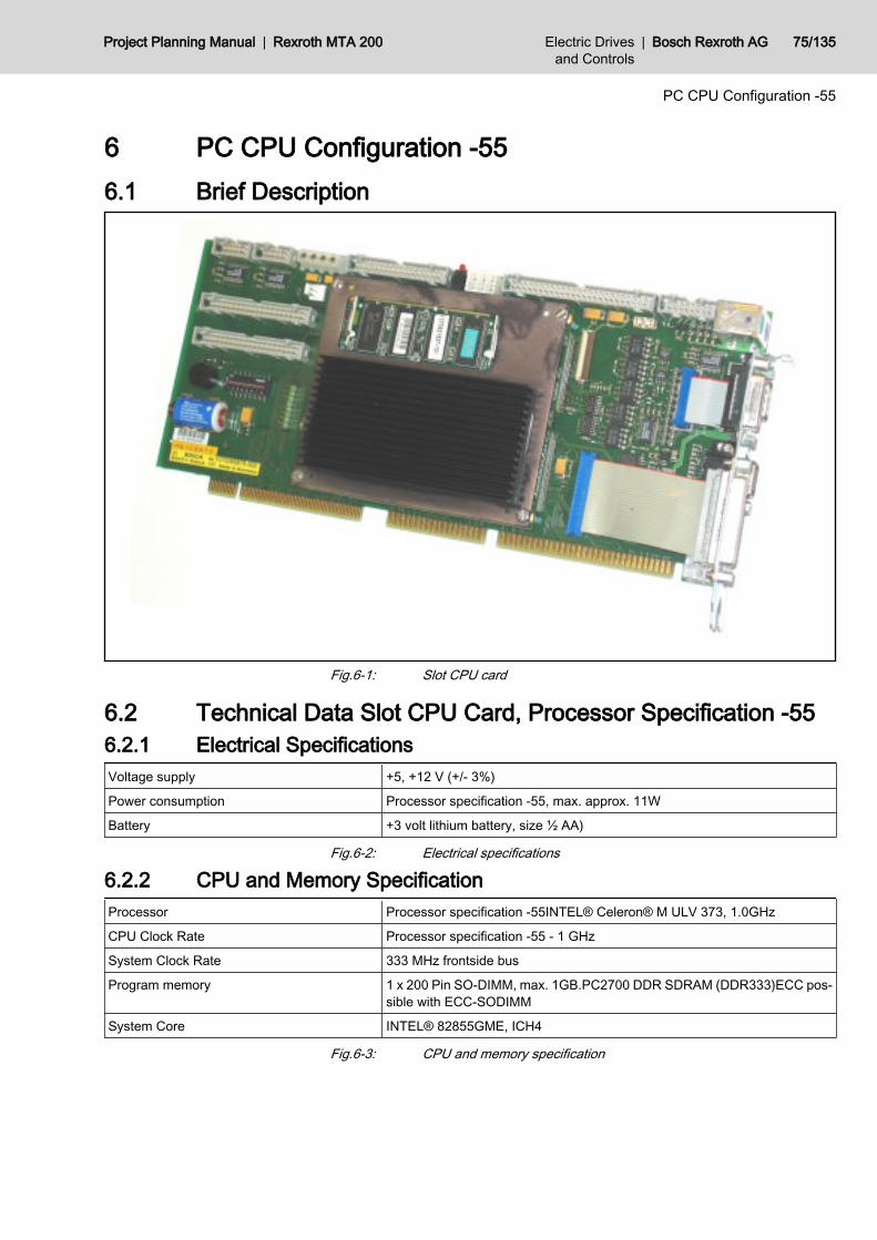
6 PC CPU Configuration -556.1 Brief Description
Fig.6-1: Slot CPU card
6.2 Technical Data Slot CPU Card, Processor Specification -55 6.2.1 Electrical SpecificationsVoltage supply +5, +12 V (+/- 3%)
Power consumption Processor specification -55, max. approx. 11W
Battery +3 volt lithium battery, size ½ AA)
Fig.6-2: Electrical specifications
6.2.2 CPU and Memory SpecificationProcessor Processor specification -55INTEL® Celeron® M ULV 373, 1.0GHz
CPU Clock Rate Processor specification -55 - 1 GHz
System Clock Rate 333 MHz frontside bus
Program memory 1 x 200 Pin SO-DIMM, max. 1GB.PC2700 DDR SDRAM (DDR333)ECC pos‐sible with ECC-SODIMM
System Core INTEL® 82855GME, ICH4
Fig.6-3: CPU and memory specification
Project Planning Manual | Rexroth MTA 200 Electric Drivesand Controls
| Bosch Rexroth AG 75/135
PC CPU Configuration -55
6.3 PhoenixBIOS Setup (Processor Specification -55)6.3.1 General Information
"Phoenix BIOS" is the BIOS of the BTV20.3 processor specification -55. It con‐tains a battery-buffered CMOS memory for storing date, time and systemconfiguration.
Wrong settings can cause damage to the system or prevent it frombooting.
Call the main menu of the BIOS system by pressing the <F2> key during boot‐ing when the following message is displayed:"Press <F2> to Enter Setup"
6.3.2 Help Screen (Online Help)Press <F1> to call the "General Help", i.e. the basic help. Here the informationabout operating the PhoenixBIOS Setup is displayed. The menus in the rightpart display always a "Item Specific Help", i.e. the help for the currently selectedmenu entry.
6.3.3 Navigation in the PhoenixBIOS SetupThe following keys in the PhoenixBIOS Setup are of importance:
Keys Function
<F1> or <Alt-H> Call "General Help"
<Esc> Exit the menu
← or → arrrow keys Select different menus
↑ or ↓ arrow keys Select the desired menu item
<Tab> or <Shift-Tab> Jump to the next or previous menu item
<Home> or <End> Move the cursor to the beginning or to the end of the currentmenu
<PgUp> or <PgDn> Move the cursor to the next or previous menu
<F5> or <-> Select the previous entry from the list of the menu item
<F6> or <+> Select the next entry from the list of the menu item
<F9> Load the "Default" values for this menu
<F10> Save and exit
<Enter> Execute the command or select the submenu
<Alt-R> Update the display
Fig.6-4: PhoenixBIOS key functions
6.3.4 PhoenixBIOS Setup – Main MenuGeneral Information
The PhoenixBIOS Setup screen is divided into four sections.
76/135 Bosch Rexroth AG | Electric Drivesand Controls
Rexroth MTA 200 | Project Planning Manual
PC CPU Configuration -55
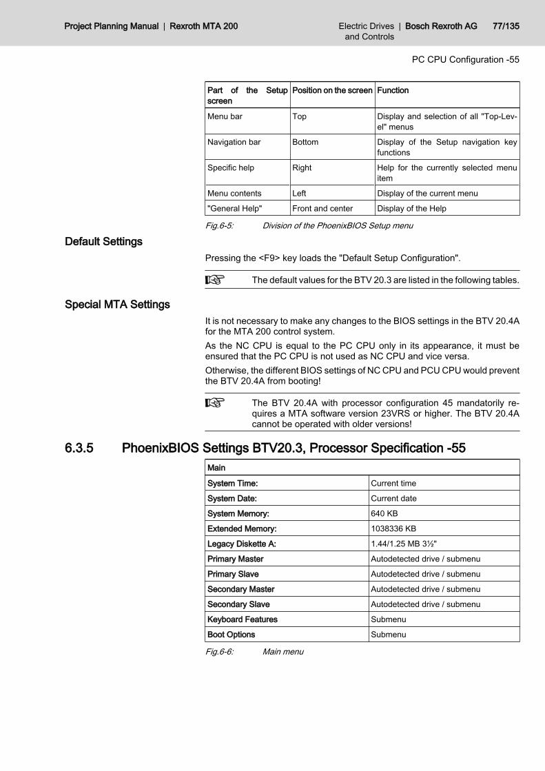
Part of the Setupscreen
Position on the screen Function
Menu bar Top Display and selection of all "Top-Lev‐el" menus
Navigation bar Bottom Display of the Setup navigation keyfunctions
Specific help Right Help for the currently selected menuitem
Menu contents Left Display of the current menu
"General Help" Front and center Display of the Help
Fig.6-5: Division of the PhoenixBIOS Setup menu
Default SettingsPressing the <F9> key loads the "Default Setup Configuration".
The default values for the BTV 20.3 are listed in the following tables.
Special MTA SettingsIt is not necessary to make any changes to the BIOS settings in the BTV 20.4Afor the MTA 200 control system.As the NC CPU is equal to the PC CPU only in its appearance, it must beensured that the PC CPU is not used as NC CPU and vice versa.Otherwise, the different BIOS settings of NC CPU and PCU CPU would preventthe BTV 20.4A from booting!
The BTV 20.4A with processor configuration 45 mandatorily re‐quires a MTA software version 23VRS or higher. The BTV 20.4Acannot be operated with older versions!
6.3.5 PhoenixBIOS Settings BTV20.3, Processor Specification -55Main
System Time: Current time
System Date: Current date
System Memory: 640 KB
Extended Memory: 1038336 KB
Legacy Diskette A: 1.44/1.25 MB 3½"
Primary Master Autodetected drive / submenu
Primary Slave Autodetected drive / submenu
Secondary Master Autodetected drive / submenu
Secondary Slave Autodetected drive / submenu
Keyboard Features Submenu
Boot Options Submenu
Fig.6-6: Main menu
Project Planning Manual | Rexroth MTA 200 Electric Drivesand Controls
| Bosch Rexroth AG 77/135
PC CPU Configuration -55
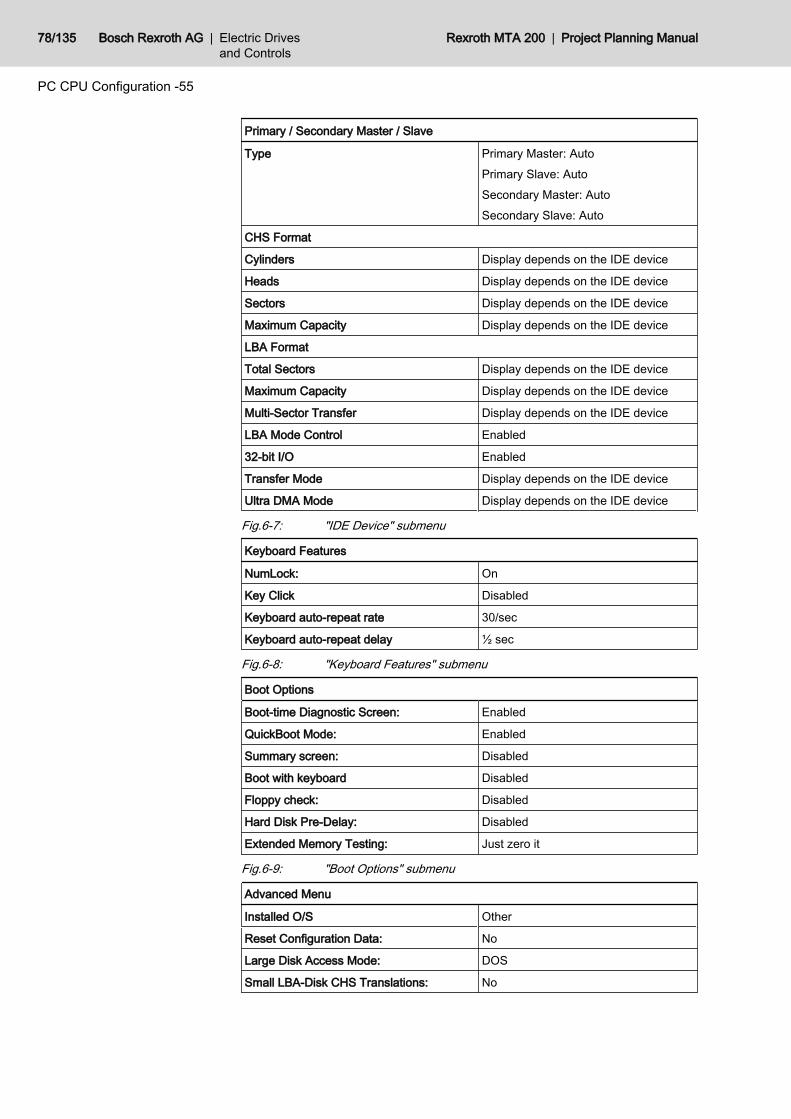
Primary / Secondary Master / Slave
Type Primary Master: AutoPrimary Slave: AutoSecondary Master: AutoSecondary Slave: Auto
CHS Format
Cylinders Display depends on the IDE device
Heads Display depends on the IDE device
Sectors Display depends on the IDE device
Maximum Capacity Display depends on the IDE device
LBA Format
Total Sectors Display depends on the IDE device
Maximum Capacity Display depends on the IDE device
Multi-Sector Transfer Display depends on the IDE device
LBA Mode Control Enabled
32-bit I/O Enabled
Transfer Mode Display depends on the IDE device
Ultra DMA Mode Display depends on the IDE device
Fig.6-7: "IDE Device" submenu
Keyboard Features
NumLock: On
Key Click Disabled
Keyboard auto-repeat rate 30/sec
Keyboard auto-repeat delay ½ sec
Fig.6-8: "Keyboard Features" submenu
Boot Options
Boot-time Diagnostic Screen: Enabled
QuickBoot Mode: Enabled
Summary screen: Disabled
Boot with keyboard Disabled
Floppy check: Disabled
Hard Disk Pre-Delay: Disabled
Extended Memory Testing: Just zero it
Fig.6-9: "Boot Options" submenu
Advanced Menu
Installed O/S Other
Reset Configuration Data: No
Large Disk Access Mode: DOS
Small LBA-Disk CHS Translations: No
78/135 Bosch Rexroth AG | Electric Drivesand Controls
Rexroth MTA 200 | Project Planning Manual
PC CPU Configuration -55
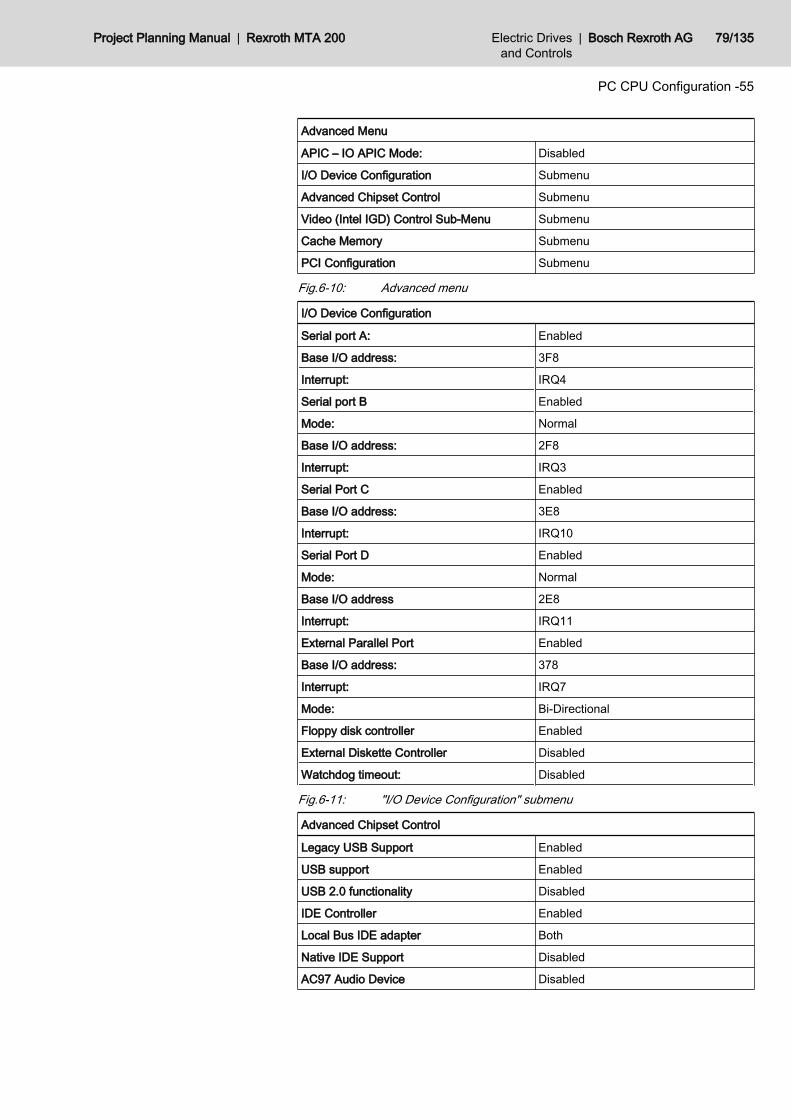
Advanced Menu
APIC – IO APIC Mode: Disabled
I/O Device Configuration Submenu
Advanced Chipset Control Submenu
Video (Intel IGD) Control Sub-Menu Submenu
Cache Memory Submenu
PCI Configuration Submenu
Fig.6-10: Advanced menu
I/O Device Configuration
Serial port A: Enabled
Base I/O address: 3F8
Interrupt: IRQ4
Serial port B Enabled
Mode: Normal
Base I/O address: 2F8
Interrupt: IRQ3
Serial Port C Enabled
Base I/O address: 3E8
Interrupt: IRQ10
Serial Port D Enabled
Mode: Normal
Base I/O address 2E8
Interrupt: IRQ11
External Parallel Port Enabled
Base I/O address: 378
Interrupt: IRQ7
Mode: Bi-Directional
Floppy disk controller Enabled
External Diskette Controller Disabled
Watchdog timeout: Disabled
Fig.6-11: "I/O Device Configuration" submenu
Advanced Chipset Control
Legacy USB Support Enabled
USB support Enabled
USB 2.0 functionality Disabled
IDE Controller Enabled
Local Bus IDE adapter Both
Native IDE Support Disabled
AC97 Audio Device Disabled
Project Planning Manual | Rexroth MTA 200 Electric Drivesand Controls
| Bosch Rexroth AG 79/135
PC CPU Configuration -55
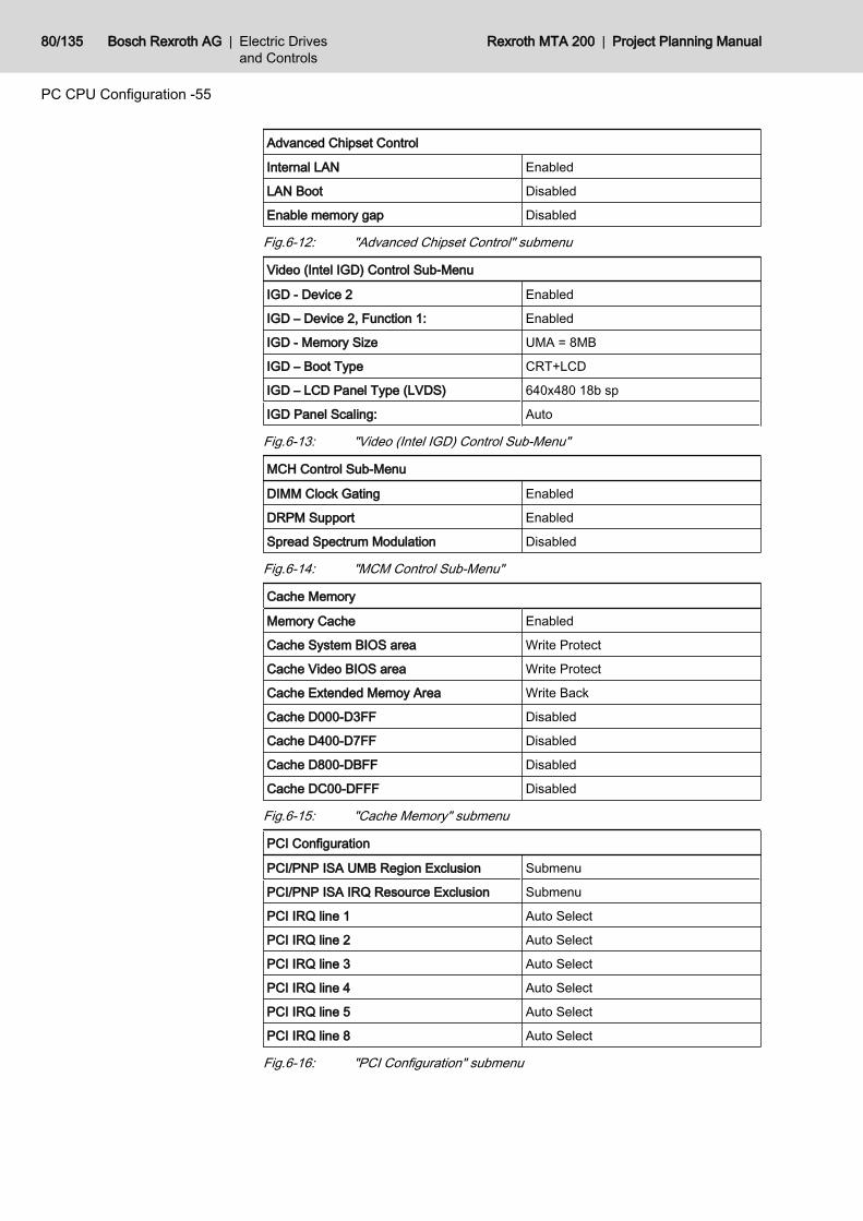
Advanced Chipset Control
Internal LAN Enabled
LAN Boot Disabled
Enable memory gap Disabled
Fig.6-12: "Advanced Chipset Control" submenu
Video (Intel IGD) Control Sub-Menu
IGD - Device 2 Enabled
IGD – Device 2, Function 1: Enabled
IGD - Memory Size UMA = 8MB
IGD – Boot Type CRT+LCD
IGD – LCD Panel Type (LVDS) 640x480 18b sp
IGD Panel Scaling: Auto
Fig.6-13: "Video (Intel IGD) Control Sub-Menu"
MCH Control Sub-Menu
DIMM Clock Gating Enabled
DRPM Support Enabled
Spread Spectrum Modulation Disabled
Fig.6-14: "MCM Control Sub-Menu"
Cache Memory
Memory Cache Enabled
Cache System BIOS area Write Protect
Cache Video BIOS area Write Protect
Cache Extended Memoy Area Write Back
Cache D000-D3FF Disabled
Cache D400-D7FF Disabled
Cache D800-DBFF Disabled
Cache DC00-DFFF Disabled
Fig.6-15: "Cache Memory" submenu
PCI Configuration
PCI/PNP ISA UMB Region Exclusion Submenu
PCI/PNP ISA IRQ Resource Exclusion Submenu
PCI IRQ line 1 Auto Select
PCI IRQ line 2 Auto Select
PCI IRQ line 3 Auto Select
PCI IRQ line 4 Auto Select
PCI IRQ line 5 Auto Select
PCI IRQ line 8 Auto Select
Fig.6-16: "PCI Configuration" submenu
80/135 Bosch Rexroth AG | Electric Drivesand Controls
Rexroth MTA 200 | Project Planning Manual
PC CPU Configuration -55
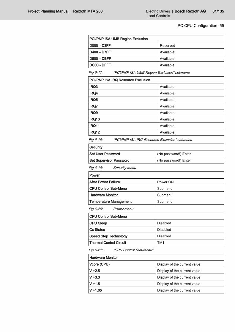
PCI/PNP ISA UMB Region Exclusion
D000 – D3FF Reserved
D400 – D7FF Available
D800 – DBFF Available
DC00 - DFFF Available
Fig.6-17: "PCI/PNP ISA UMB Region Exclusion" submenu
PCI/PNP ISA IRQ Resource Exclusion
IRQ3 Available
IRQ4 Available
IRQ5 Available
IRQ7 Available
IRQ9 Available
IRQ10 Available
IRQ11 Available
IRQ12 Available
Fig.6-18: "PCI/PNP ISA IRQ Resource Exclusion" submenu
Security
Set User Password (No password!) Enter
Set Supervisor Password (No password!) Enter
Fig.6-19: Security menu
Power
After Power Failure Power ON
CPU Control Sub-Menu Submenu
Hardware Monitor Submenu
Temperature Management Submenu
Fig.6-20: Power menu
CPU Control Sub-Menu
CPU Sleep Disabled
Cx States Disabled
Speed Step Technology Disabled
Thermal Control Circuit TM1
Fig.6-21: "CPU Control Sub-Menu"
Hardware Monitor
Vcore (CPU) Display of the current value
V +2.5 Display of the current value
V +3.3 Display of the current value
V +1.5 Display of the current value
V +1.05 Display of the current value
Project Planning Manual | Rexroth MTA 200 Electric Drivesand Controls
| Bosch Rexroth AG 81/135
PC CPU Configuration -55
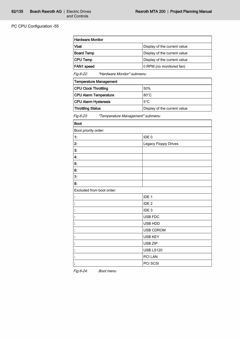
Hardware Monitor
Vbat Display of the current value
Board Temp Display of the current value
CPU Temp Display of the current value
FAN1 speed 0 RPM (no monitored fan)
Fig.6-22: "Hardware Monitor" submenu
Temperature Management
CPU Clock Throttling 50%
CPU Alarm Temperature 80°C
CPU Alarm Hysteresis 5°C
Throttling Status Display of the current value
Fig.6-23: "Temperature Management" submenu
Boot
Boot priority order:
1: IDE 0
2: Legacy Floppy Drives
3:
4:
5:
6:
7:
8:
Excluded from boot order:
: IDE 1
: IDE 2
: IDE 3
: USB FDC
: USB HDD
: USB CDROM
: USB KEY
: USB ZIP
: USB LS120
: PCI LAN
: PCI SCSI
Fig.6-24: Boot menu
82/135 Bosch Rexroth AG | Electric Drivesand Controls
Rexroth MTA 200 | Project Planning Manual
PC CPU Configuration -55
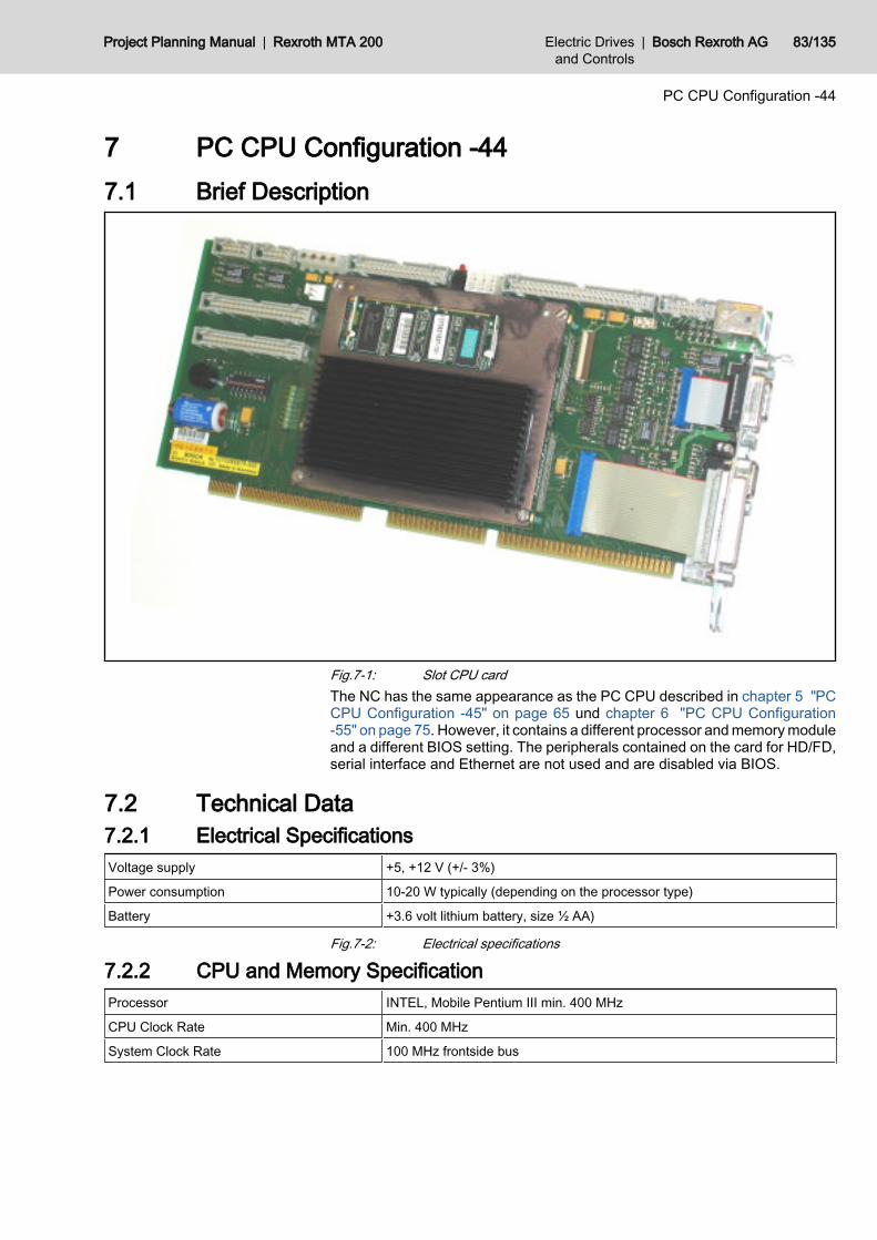
7 PC CPU Configuration -447.1 Brief Description
Fig.7-1: Slot CPU cardThe NC has the same appearance as the PC CPU described in chapter 5 "PCCPU Configuration -45" on page 65 und chapter 6 "PC CPU Configuration-55" on page 75. However, it contains a different processor and memory moduleand a different BIOS setting. The peripherals contained on the card for HD/FD,serial interface and Ethernet are not used and are disabled via BIOS.
7.2 Technical Data7.2.1 Electrical SpecificationsVoltage supply +5, +12 V (+/- 3%)
Power consumption 10-20 W typically (depending on the processor type)
Battery +3.6 volt lithium battery, size ½ AA)
Fig.7-2: Electrical specifications
7.2.2 CPU and Memory SpecificationProcessor INTEL, Mobile Pentium III min. 400 MHz
CPU Clock Rate Min. 400 MHz
System Clock Rate 100 MHz frontside bus
Project Planning Manual | Rexroth MTA 200 Electric Drivesand Controls
| Bosch Rexroth AG 83/135
PC CPU Configuration -44
Program memory 1 144 Pin SO DIMM 3.3 V PC100, 128 MB
System Core INTEL 440BX AGP Set
Fig.7-3: CPU and memory specification
7.3 PhoenixBIOS Setup7.3.1 General Information
The BIOS of the NC CPU is a "Phoenix BIOS 4.0 Release 6.8, 256 KByteFLASH-BIOS, NV-EEPROM". It contains a battery-buffered CMOS memory forstoring date, time and system configuration.
Wrong settings can cause damage to the system or prevent it frombooting.
The BIOS settings of the NC CPU cannot be checked directly at the BTV 20.4A.If a check of these settings should be necessary, a monitor and a keyboardhave to be directly connected to the NC CPU.The start and the condition of the BIOS editor are described in chapter 3
7.3.2 PhoenixBIOS settings of the NC CPUMain
System Time Current time
System Date Current date
Legacy Diskette A 1.44/1.25 MB 3½"
Legacy Diskette B disabled
Primary Master none
Primary Slave none
Secondary Master none
Secondary Slave none
Memory Shadow Submenu
Memory Cache Submenu
System Memory Display of the system memory
Extended Memory Display of the Extended Memory
Fig.7-4: Main menu
Memory Shadow
CC00 - CFFF Disabled
D000 - D3FF Disabled
D400 - D7FF Disabled
D800 - DBFF Disabled
DC00 - DFFF Disabled
Fig.7-5: "Memory Shadow" submenu
84/135 Bosch Rexroth AG | Electric Drivesand Controls
Rexroth MTA 200 | Project Planning Manual
PC CPU Configuration -44
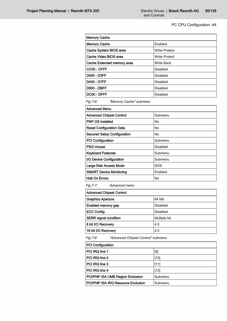
Memory Cache
Memory Cache Enabled
Cache System BIOS area Write Protect
Cache Video BIOS area Write Protect
Cache Extended memory area Write Back
CC00 - CFFF Disabled
D000 - D3FF Disabled
D400 - D7FF Disabled
D800 - DBFF Disabled
DC00 - DFFF Disabled
Fig.7-6: "Memory Cache" submenu
Advanced Menu
Advanced Chipset Control Submenu
PNP OS installed No
Reset Configuration Data No
Secured Setup Configuration No
PCI Configuration Submenu
PS/2 mouse Disabled
Keyboard Features Submenu
I/O Device Configuration Submenu
Large Disk Access Mode DOS
SMART Device Monitoring Enabled
Halt On Errors No
Fig.7-7: Advanced menu
Advanced Chipset Control
Graphics Aperture 64 Mb
Enabled memory gap Disabled
ECC Config Disabled
SERR signal condition Multiple bit
8 bit I/O Recovery 4.5
16 bit I/O Recovery 4.5
Fig.7-8: "Advanced Chipset Control" submenu
PCI Configuration
PCI IRQ line 1 [9]
PCI IRQ line 2 [10]
PCI IRQ line 3 [11]
PCI IRQ line 4 [12]
PCI/PNP ISA UMB Region Exclusion Submenu
PCI/PNP ISA IRQ Resource Exclusion Submenu
Project Planning Manual | Rexroth MTA 200 Electric Drivesand Controls
| Bosch Rexroth AG 85/135
PC CPU Configuration -44
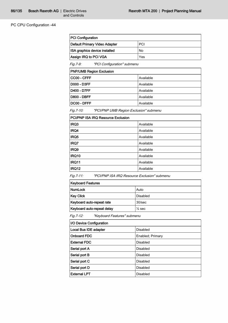
PCI Configuration
Default Primary Video Adapter PCI
ISA graphics device installed No
Assign IRQ to PCI VGA Yes
Fig.7-9: "PCI Configuration" submenu
PNP/UMB Region Exclusion
CC00 - CFFF Available
D000 - D3FF Available
D400 - D7FF Available
D800 - DBFF Available
DC00 - DFFF Available
Fig.7-10: "PCI/PNP UMB Region Exclusion" submenu
PCI/PNP ISA IRQ Resource Exclusion
IRQ3 Available
IRQ4 Available
IRQ5 Available
IRQ7 Available
IRQ9 Available
IRQ10 Available
IRQ11 Available
IRQ12 Available
Fig.7-11: "PCI/PNP ISA IRQ Resource Exclusion" submenu
Keyboard Features
NumLock Auto
Key Click Disabled
Keyboard auto-repeat rate 30/sec
Keyboard auto-repeat delay ½ sec
Fig.7-12: "Keyboard Features" submenu
I/O Device Configuration
Local Bus IDE adapter Disabled
Onboard FDC Enabled; Primary
External FDC Disabled
Serial port A Disabled
Serial port B Disabled
Serial port C Disabled
Serial port D Disabled
External LPT Disabled
86/135 Bosch Rexroth AG | Electric Drivesand Controls
Rexroth MTA 200 | Project Planning Manual
PC CPU Configuration -44
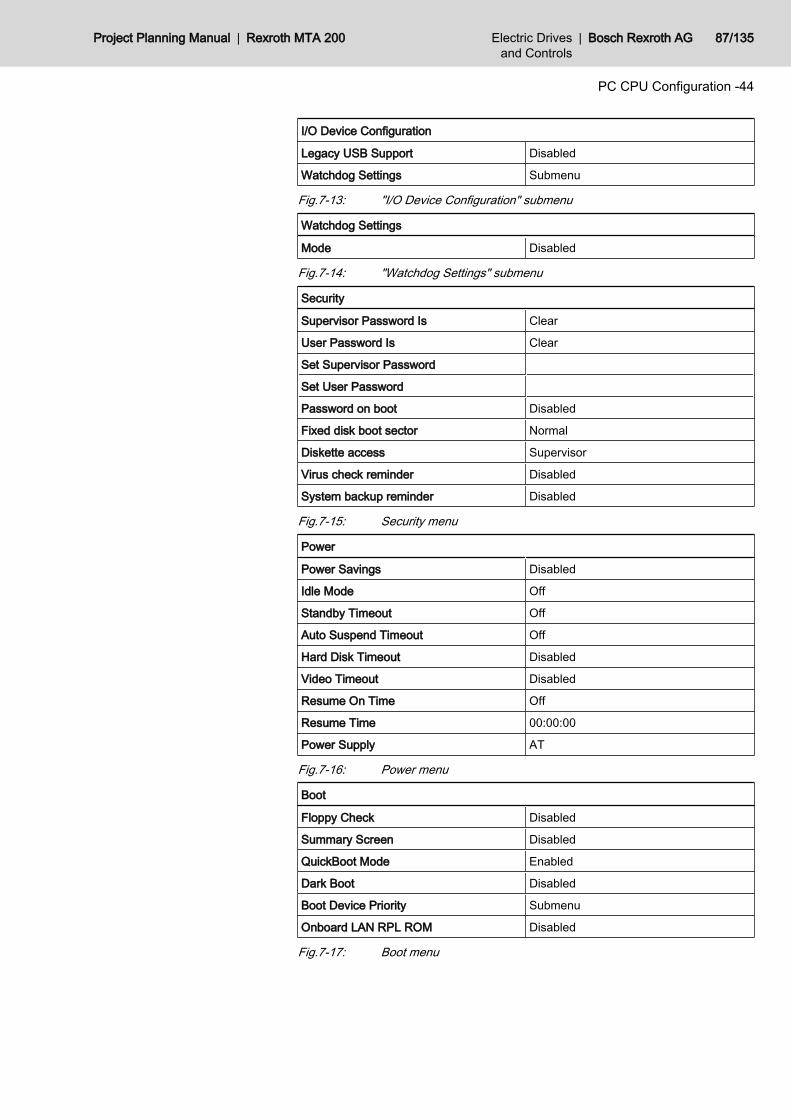
I/O Device Configuration
Legacy USB Support Disabled
Watchdog Settings Submenu
Fig.7-13: "I/O Device Configuration" submenu
Watchdog Settings
Mode Disabled
Fig.7-14: "Watchdog Settings" submenu
Security
Supervisor Password Is Clear
User Password Is Clear
Set Supervisor Password
Set User Password
Password on boot Disabled
Fixed disk boot sector Normal
Diskette access Supervisor
Virus check reminder Disabled
System backup reminder Disabled
Fig.7-15: Security menu
Power
Power Savings Disabled
Idle Mode Off
Standby Timeout Off
Auto Suspend Timeout Off
Hard Disk Timeout Disabled
Video Timeout Disabled
Resume On Time Off
Resume Time 00:00:00
Power Supply AT
Fig.7-16: Power menu
Boot
Floppy Check Disabled
Summary Screen Disabled
QuickBoot Mode Enabled
Dark Boot Disabled
Boot Device Priority Submenu
Onboard LAN RPL ROM Disabled
Fig.7-17: Boot menu
Project Planning Manual | Rexroth MTA 200 Electric Drivesand Controls
| Bosch Rexroth AG 87/135
PC CPU Configuration -44

Boot Device Priority
Removable Devices
Hard Drive
CD ROM drive
Network Boot
Fig.7-18: "Boot Device Priority" submenu
88/135 Bosch Rexroth AG | Electric Drivesand Controls
Rexroth MTA 200 | Project Planning Manual
PC CPU Configuration -44

8 NC Multifunction Card NCM028.1 Brief Description
The NC multifunction card is the core of the NC CPU. It is responsible for thedrive communication with up to 4 SERCOS interfaces. A flash memory is pro‐vided for storing machine-specific data, the axis resolution, the ramp-curvesetc. The direct I/Os to the CNC are available via an Interbus master.
Fig.8-1: NC multifunction card
8.2 Features● PCI Interface● Flash memory with up to 1024 kB.● 4 SERCOS interfaces with 2/4/8/16 MBaud. Bus master ability for cyclic
data transmission between SERCON components and the RAM.● 32-bit RISC communication processor, clocked with 40 MHz, 128 kB flash
EPROM, 10 kB RAM and 2 kB dual port RAM to the PCI bus.● 3 processor-internal serial interfaces.
8.3 Available VersionsThe NC multifunction card is available in various component versions.
Project Planning Manual | Rexroth MTA 200 Electric Drivesand Controls
| Bosch Rexroth AG 89/135
NC Multifunction Card NCM02
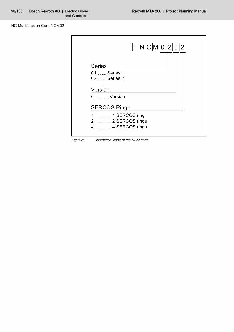
Fig.8-2: Numerical code of the NCM card
90/135 Bosch Rexroth AG | Electric Drivesand Controls
Rexroth MTA 200 | Project Planning Manual
NC Multifunction Card NCM02
8.4 Interfaces
Fig.8-3: Interfaces of the NC multifunction card
Project Planning Manual | Rexroth MTA 200 Electric Drivesand Controls
| Bosch Rexroth AG 91/135
NC Multifunction Card NCM02

The MTA 200 does not provide the handwheel interfaces and the4. SERCOS ring.
92/135 Bosch Rexroth AG | Electric Drivesand Controls
Rexroth MTA 200 | Project Planning Manual
NC Multifunction Card NCM02
8.5 Coding and Component Diagrams8.5.1 +NCM0201
Fig.8-4: NC multifunction card, with 1 SERCOS ring
Project Planning Manual | Rexroth MTA 200 Electric Drivesand Controls
| Bosch Rexroth AG 93/135
NC Multifunction Card NCM02
8.5.2 +NCM0202
Fig.8-5: NC multifunction card, with 2 SERCOS rings
94/135 Bosch Rexroth AG | Electric Drivesand Controls
Rexroth MTA 200 | Project Planning Manual
NC Multifunction Card NCM02
8.5.3 +NCM0204
Fig.8-6: NC multifunction card, with 4 SERCOS rings
Project Planning Manual | Rexroth MTA 200 Electric Drivesand Controls
| Bosch Rexroth AG 95/135
NC Multifunction Card NCM02
8.6 Slot Brackets8.6.1 General Information
Fig.8-7: Slot brackets of the NC multifunction card
8.6.2 CNC Fault (X21)The CNC fault contact is a relay contact that is connected via a hardwarewatchdog. It is permanently triggered by the NC operating system. In case ofan error (hardware error, firmware error, system error etc.) the contact is force-opened. The CNC fault contact can be wired, e.g. in the emergency stop chainof the machine.Contact load:● Umax = 24V● Imax = 150 mA
8.6.3 Fast I/Os (X23)At the X23 connector fast I/O signals can be directly connected to the CNC,bypassing the PLC. A total of 16 inputs and 16 outputs is provided. The interfaceis designed as a standard Interbus-S interface. The signals are to be connectedvia an Interbus-S I/O module. This can be done in 2 ways:● Internal implementation via NCIO card: This option provides a solution
with a 37-pin Sub-D connector, that is compatible with the earlier BTVs(see chapter 8.9 "NCIO Card" on page 101).
● External implementation via Phoenix Block I/O module: The I/O modulecan also be mounted in the control cabinet, away from the BTV (seechapter 8.10 "Phoenix Block I/O Module ILB IB 24 DI16 DO16" on page104).
96/135 Bosch Rexroth AG | Electric Drivesand Controls
Rexroth MTA 200 | Project Planning Manual
NC Multifunction Card NCM02
8.6.4 Status IndicatorsSERCOS Ring H4
LED Description
green Data is received
yellow Data is transmitted
red Distortion or line-break
Fig.8-8: Status indicators for SERCOS ring H4
Fast I/Os H5LED Description
yellow 1 Peripherals error
yellow 2 Not used
yellow 3 Host error
Fig.8-9: Status indicators for fast I/Os H5
Fast I/Os H6LED Description
green Ready for operation
yellow ???
red Error
Fig.8-10: Status indicators for fast I/Os H6
8.7 Additional SERCOS Rings8.7.1 General Information
On the NC multifunction card one pair of fibre optics cable is available for thefirst SERCOS ring. The interface adapters +NCMZ003 (for one additionalSERCOS ring) and +NCMZ004 (for two additional SERCOS rings) are availablefor connecting further SERCOS rings.
Project Planning Manual | Rexroth MTA 200 Electric Drivesand Controls
| Bosch Rexroth AG 97/135
NC Multifunction Card NCM02
8.7.2 +NCMZ003
Fig.8-11: Slot bracket for one additional SERCOS ring
8.7.3 +NCMZ004
Fig.8-12: Slot bracket for two additional SERCOS rings
8.7.4 X24.* TransmitterX24.2 transmitter (TX) 2. SERCOS ring
98/135 Bosch Rexroth AG | Electric Drivesand Controls
Rexroth MTA 200 | Project Planning Manual
NC Multifunction Card NCM02
X24.3 transmitter (TX) 3. SERCOS ring
8.7.5 X25.* ReceiverX25.2 receiver (RX) 2. SERCOS ringX25.3 receiver (RX) 3. SERCOS ring
8.7.6 Status IndicatorsSERCOS Ring H4
LED Description
green Data is received
yellow Data is transmitted
red Distortion or line-break
Fig.8-13: Status indicator for SERCOS ring H4
8.7.7 Connections
Fig.8-14: Connection of additional SERCOS rings to NCM
Project Planning Manual | Rexroth MTA 200 Electric Drivesand Controls
| Bosch Rexroth AG 99/135
NC Multifunction Card NCM02
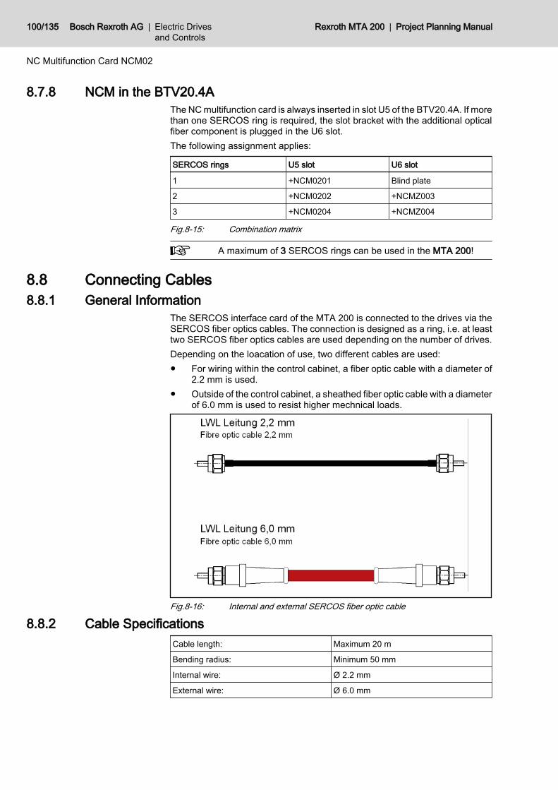
8.7.8 NCM in the BTV20.4AThe NC multifunction card is always inserted in slot U5 of the BTV20.4A. If morethan one SERCOS ring is required, the slot bracket with the additional opticalfiber component is plugged in the U6 slot.The following assignment applies:
SERCOS rings U5 slot U6 slot
1 +NCM0201 Blind plate
2 +NCM0202 +NCMZ003
3 +NCM0204 +NCMZ004
Fig.8-15: Combination matrix
A maximum of 3 SERCOS rings can be used in the MTA 200!
8.8 Connecting Cables8.8.1 General Information
The SERCOS interface card of the MTA 200 is connected to the drives via theSERCOS fiber optics cables. The connection is designed as a ring, i.e. at leasttwo SERCOS fiber optics cables are used depending on the number of drives.Depending on the loacation of use, two different cables are used:● For wiring within the control cabinet, a fiber optic cable with a diameter of
2.2 mm is used.● Outside of the control cabinet, a sheathed fiber optic cable with a diameter
of 6.0 mm is used to resist higher mechnical loads.
Fig.8-16: Internal and external SERCOS fiber optic cable
8.8.2 Cable SpecificationsCable length: Maximum 20 m
Bending radius: Minimum 50 mm
Internal wire: Ø 2.2 mm
External wire: Ø 6.0 mm
100/135 Bosch Rexroth AG | Electric Drivesand Controls
Rexroth MTA 200 | Project Planning Manual
NC Multifunction Card NCM02

CAUTION
The SERCOS fiber optics cable may not be kinked; and the bending radiusmust be at least 50 mm!
Further information regarding the handling of fiber optics cable can be found inthe DOK-CONNEC-CABLE*LWL**-AW0x-EN-P documentation.
8.9 NCIO Card8.9.1 General Information
The NCIO card serves for converting the bus signals of the 9-pin Sub-D con‐nector on the NC multifunction card to a 37-pin Sub-D female connector strip.Here, 16 digital inputs and 16 digital outputs are applied. The assignment anddesignation of the signals corresponds exactly to the assignment of the MIOcard of the previous controls.The connection between NCIO card and NCM is established via the IKS0031connecting cable, which is included in the BTV20.4A standard delivery, if theNCIO option (...-2V-... in the type designation code) is contained.
Fig.8-17: NCIO Card
CAUTION
Danger of short-circuits!Plug and unplug the IKS0031 connecting cable between NCIO and NCM onlyif there is no voltage at the BTV 20.4!
Project Planning Manual | Rexroth MTA 200 Electric Drivesand Controls
| Bosch Rexroth AG 101/135
NC Multifunction Card NCM02

8.9.2 Slot Brackets
Fig.8-18: NCIO slot bracket
8.9.3 I/O Interface X22The I/O interface of the NCIO card has 16 electrically isolated inputs and out‐pus. Design: 37-pin SUB-D female connector.
Pin Signal designation Type Signal
1 GND only for port 23, bit 0 Uexternal
2 Port 23, bit 0, encoder+ (24V) Input * 1
3 Port 23, bit 1 Input *
4 Port 23, bit 2 Input *
5 Port 23, bit 3 Input *
6 Port 23, bit 4 Input *
7 Port 23, bit 5 Input *
8 Port 23, bit 6 Input *
9 Port 23, bit 7 Input *
10 Input +24V (for output signals) Uexternal
11 GND (for output signals) Uexternal
12 not assigned Output
102/135 Bosch Rexroth AG | Electric Drivesand Controls
Rexroth MTA 200 | Project Planning Manual
NC Multifunction Card NCM02

Pin Signal designation Type Signal
13 not assigned Output
14 not assigned Output
15 not assigned Output
16 not assigned Output
17 not assigned Output
18 not assigned Output
19 not assigned Output
20 Read enable Input 1
21 Processing enable Input 1
22 not assigned Input
23 not assigned Input
24 not assigned Input
25 not assigned Input
26 Feed enable all axes Input 1
27 E-STOP Input 0
28 GND (for input signals) Uexternal
29 GND (for input signals) Uexternal
30 not assigned Output
31 not assigned Output
32 not assigned Output
33 not assigned Output
34 not assigned Output
35 not assigned Output
36 not assigned Output
37 not assigned Output
* Input (addressable via analog C commands, see LINPOS)1 Active signal level = High (1)0 Active signal level = Low (0)
CAUTION
⇒ The EMERGENCY STOP contacts must always be laid out as NC contactsso that they immediately stop all movements if a break occurs in the connectingcables.
Signal level: 24 V DC, +/- 10% Max.Load per output: 80 mAInput current: approx. 5 mA
8.9.4 InstallationThe NCIO card is always inserted in the UE1 slot. The interbus connection fromconnector X23 of the NCM module to the connector X23.2 of the NCIO card isto be plugged externally; the IKB0031 cable is included in the scope of deliveryof the BTV20.4A if the NCIO option is contained.
Project Planning Manual | Rexroth MTA 200 Electric Drivesand Controls
| Bosch Rexroth AG 103/135
NC Multifunction Card NCM02
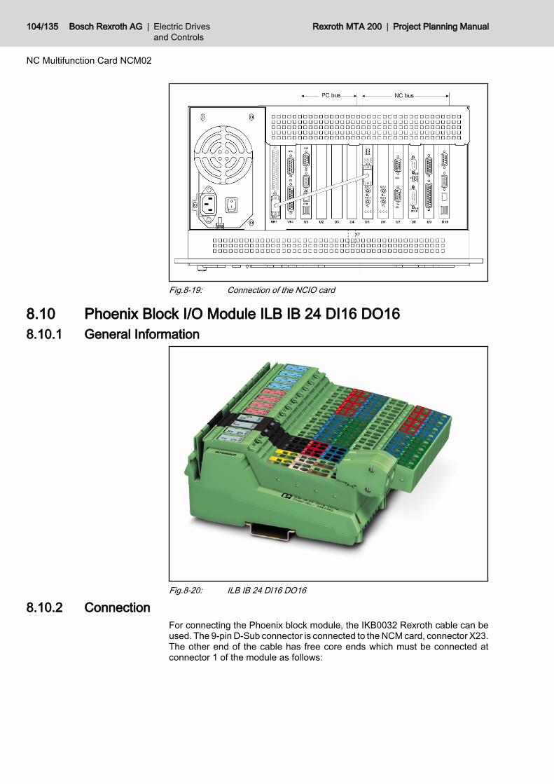
Fig.8-19: Connection of the NCIO card
8.10 Phoenix Block I/O Module ILB IB 24 DI16 DO168.10.1 General Information
Fig.8-20: ILB IB 24 DI16 DO16
8.10.2 ConnectionFor connecting the Phoenix block module, the IKB0032 Rexroth cable can beused. The 9-pin D-Sub connector is connected to the NCM card, connector X23.The other end of the cable has free core ends which must be connected atconnector 1 of the module as follows:
104/135 Bosch Rexroth AG | Electric Drivesand Controls
Rexroth MTA 200 | Project Planning Manual
NC Multifunction Card NCM02
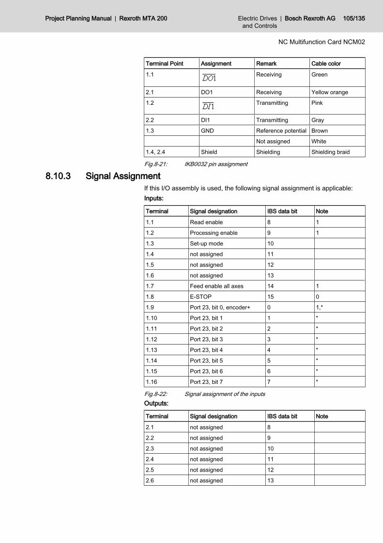
Terminal Point Assignment Remark Cable color
1.1 Receiving Green
2.1 DO1 Receiving Yellow orange
1.2 Transmitting Pink
2.2 DI1 Transmitting Gray
1.3 GND Reference potential Brown
Not assigned White
1.4, 2.4 Shield Shielding Shielding braid
Fig.8-21: IKB0032 pin assignment
8.10.3 Signal AssignmentIf this I/O assembly is used, the following signal assignment is applicable:Inputs:
Terminal Signal designation IBS data bit Note
1.1 Read enable 8 1
1.2 Processing enable 9 1
1.3 Set-up mode 10
1.4 not assigned 11
1.5 not assigned 12
1.6 not assigned 13
1.7 Feed enable all axes 14 1
1.8 E-STOP 15 0
1.9 Port 23, bit 0, encoder+ 0 1,*
1.10 Port 23, bit 1 1 *
1.11 Port 23, bit 2 2 *
1.12 Port 23, bit 3 3 *
1.13 Port 23, bit 4 4 *
1.14 Port 23, bit 5 5 *
1.15 Port 23, bit 6 6 *
1.16 Port 23, bit 7 7 *
Fig.8-22: Signal assignment of the inputsOutputs:
Terminal Signal designation IBS data bit Note
2.1 not assigned 8
2.2 not assigned 9
2.3 not assigned 10
2.4 not assigned 11
2.5 not assigned 12
2.6 not assigned 13
Project Planning Manual | Rexroth MTA 200 Electric Drivesand Controls
| Bosch Rexroth AG 105/135
NC Multifunction Card NCM02

Terminal Signal designation IBS data bit Note
2.7 not assigned 14
2.8 not assigned 15
2.9 Spindle speed = 0 0 1
2.10 Spindle ramp 1 1
2.11 not assigned 2
2.12 not assigned 3
2.13 not assigned 4
2.14 not assigned 5
2.15 not assigned 6
2.16 not assigned 7
* Input addressable via analog C commands (see LINPOS)1 Active signal level = High (1)0 Active signal level = Low (0)Fig.8-23: Output signal assignment
106/135 Bosch Rexroth AG | Electric Drivesand Controls
Rexroth MTA 200 | Project Planning Manual
NC Multifunction Card NCM02
9 PLC Modules MTS-P01.2 and MTS-P02.29.1 Brief Description
The MTS-P01.2 and MTS-P02.2 PLC modules are efficient PLC controls in ISAbus plug-in card format, intended for being fitted in a BTV 20/30 or in a com‐mercially available industrial PC. The MTS-P02.2 is equipped with a hardwarewhich, in contrast to the MTS-P01.2, shows a performance increased by a fac‐tor of 2 to 2.5 (depending on the program structure).A MTS-P consists of a basic unit with ISA bus (the actual PLC) and of an activePC/104 interface and various PC/104 plug-in modules These plug-in modulesare, for example, fieldbus connections, serial interfaces and I/O modules. Forconnecting a printer, a read/write memory or an operation and visualizationdevice such as the BTV 04/05 from Bosch Rexroth, a serial COM user interface(RS232) that is operated via the PLC user program is available. The multimodeoperation of the interface(RS232/RS422/RS485) is configured using a PLCfunction module.In addition, the MTS-P01.2 and MTS-P02.2 provide a BT bus (operating ter‐minal bus) which can be used to operate up to 4 operator terminals (BTM 15/16, BTA 20 etc.) Cable lengths up to 50 m are possible (between theconnection and the last user).The MTS-P0*.2 is provided with 16 TTL inputs and 16 TTL outputs. They canbe used to, for instance, directly connect the machine function keys and keyswitches of the BTV20.The MTS-P module can be operated either as a stand-alone PLC or, in con‐nection with an MTC-P, as a slave PLC. The firmware of the PLC,which is storedin a flash EPROM, serves to distinguish between master and slave operation.Communication with decentralized I/O units or operating units is established bymeans of field bus connections (which can be optionally plugged on) and/orserial interfaces. These optional connections and interfaces are designed asPC/104 modules. The following ones are currently available:● INTERBUS master connection● PROFIBUS master connection● PROFIBUS slave connectionUp to 4 PC/104 modules can be operated on a MTS-P01.2 or MTS-P02.2.
Project Planning Manual | Rexroth MTA 200 Electric Drivesand Controls
| Bosch Rexroth AG 107/135
PLC Modules MTS-P01.2 and MTS-P02.2
Fig.9-1: MTS-P01.2
Fig.9-2: MTS-P02.2
108/135 Bosch Rexroth AG | Electric Drivesand Controls
Rexroth MTA 200 | Project Planning Manual
PLC Modules MTS-P01.2 and MTS-P02.2
Fig.9-3: Front view MTS-P01.2 and MTS-P02.2
9.2 Technical Data9.2.1 General InformationHumidity: 75 %, non-condensing (operation)
95 %, non-condensing (transport)DIN 40 040 class F
Air pressure: 860 to 1080 hPa, 1500 m (operation)660 to 1080 hPa, 3500 m (transport)
Surrounding air temperature in operation: 0 to 50°C, DIN 40 040 class KV
Storage temperature: -20°C to +70°C
Dimensions (WxHxD): 22 mm x 145 mmm x 295 mm
Weight: approx. 0.3 kg
9.2.2 Supply VoltageNominal value: +5 V +12 V -12 V
Permissible ripple: 50 mV 120 mV 120 mV
Permissible voltage range: +4,875 +11.4 V .....+12.6 V -12.6 V .....-11.4 V
Max. current consumption (+5V): (MTS-P01.2)(MTS-P02.2)
0.6 A (+ supply voltage for PC/104 modules up to max. 2.5A)1.8 A (+ supply voltage for PC/104 modules up to max. 2.5A)
Project Planning Manual | Rexroth MTA 200 Electric Drivesand Controls
| Bosch Rexroth AG 109/135
PLC Modules MTS-P01.2 and MTS-P02.2

9.2.3 EMCEmitted interferences acc. to EN55022 Class A (industrial environment) Data only in connection with BTV
20/30Noise immunity acc. to IEC 1000-4-2- (ESD) Evaluation criterion B
Noise immunity acc. to IEC 1000-4-4- (burst) Evaluation criterion B
9.2.4 InterfacesGeneral serial interface (COM) RS232/RS422/RS485 (D-SUB, 15-pin, female connector)
BT bus Bosch Rexroth BT bus (D-SUB, 9-pin, female connector)
Optional interfaces: INTERBUS (D-SUB, 9-pin, female connector)PROFIBUS-DP (D-SUB, 9-pin, female connector)2 x RS232 and 2 x RS422/485 (D-SUB, 9-pin, male connector)
9.3 Communication9.3.1 Communication with the Computer
With the PC CPU as well as the operating and programming interface, data isexchanged via the NC CPU and the PCI/PCI bridge of the backplane.
9.3.2 Communication with the NC ControlThe MTS-P0*.2 exchanges data with the NC CPU of the MTA200 control sys‐tem via the NC bus in the BTV20.2A .
9.3.3 PLC Inputs for Machine Function Keys (X8)If the MTS-P0*.2 is used in Bosch Rexroth industrial PCs of type BTV 20/30,the machine function keys are directly wired onto the PLC module (X8).To use the machine function keys, select the "M keys" activation via the I/Oconfigurator of WinPCL (see DOK-CONTRL-WINPCL*6VRS-AW01-EN-P).The left key row is assigned to the less significant input byte, and the right keyrow is assigned to the more significant input byte.
9.3.4 Connection of BTV 20 PLC Function Keys (X12)General Information
The MTS-P0*.2 is provided with 16 TTL inputs and 16 TTL outputs. This allowsdirect connection of the machine operating keys of the BTV20 (including thekey switch).
AddressingThe PLC function keys, the lamps, the key switch, and the displays of the BTV20 are addressed by assigning a logical user number to the inputs and outputsin the PLC I/O configurator.This results, e.g. in the following addresses:● 10 = logical user number of the inputs● 11 = logical user number of the outputs
110/135 Bosch Rexroth AG | Electric Drivesand Controls
Rexroth MTA 200 | Project Planning Manual
PLC Modules MTS-P01.2 and MTS-P02.2
Fig.9-4: Input and output addresses of PLC function keys in BTV 20
9.3.5 PLC Ready (X5)The PLC Ready contact is a relay contact which is closed via a hardwarewatchdog. It is permanently triggered by the running PLC program. In case ofan error (hardware error, firmware error, system error, etc.), the contact is force-opened. The PLC Ready contact can, for instance, be wired in the emergencystop chain of the machine.
9.3.6 COM Interface (X16)The multimode COM user interface is delivered as RS232 interface as default.The parameters for RS422/RS485 operation are set by programming theOPEN_COM standard PLC function block and assigning the COM functionblock input correspondingly. For more detailed information, please refer to thePLC programming instructions (DOK-CONTRL-WINPCL*6VRS-AW01-EN-P).
9.3.7 BT BUS (X15)General Information
The BT bus can be used for connecting up to four operator panels of type BTM15/16 or BTA 20. The maximum length of the BT bus may be up to 50m (fromthe connection point to the last user). This applies to the connection of only onedevice and the permissible maximum number of 4 devices. It is not possible todirectly access the I/O data of the operator panels from the PLC (e.g. %IBP*.*).Data is exchanged exclusively via the image memory.The address assignments required for programming can be found in the cor‐responding documents of the devices to be connected.
Project Planning Manual | Rexroth MTA 200 Electric Drivesand Controls
| Bosch Rexroth AG 111/135
PLC Modules MTS-P01.2 and MTS-P02.2
Fig.9-5: BT bus overview
AddressingThe BT bus is addressed by assigning a logical user number in the I/O editorof the PLC programming interface. Each input image memory, as well as eachoutput image memory, is assigned its own address.Each of the two image memories has a size of 128 bytes, which are availablefor the connected operating devices. The number of bytes assigned in thememory depends on the operator panel (see fig. 9-6 "Memory requirements ofthe operating devices" on page 113).
112/135 Bosch Rexroth AG | Electric Drivesand Controls
Rexroth MTA 200 | Project Planning Manual
PLC Modules MTS-P01.2 and MTS-P02.2
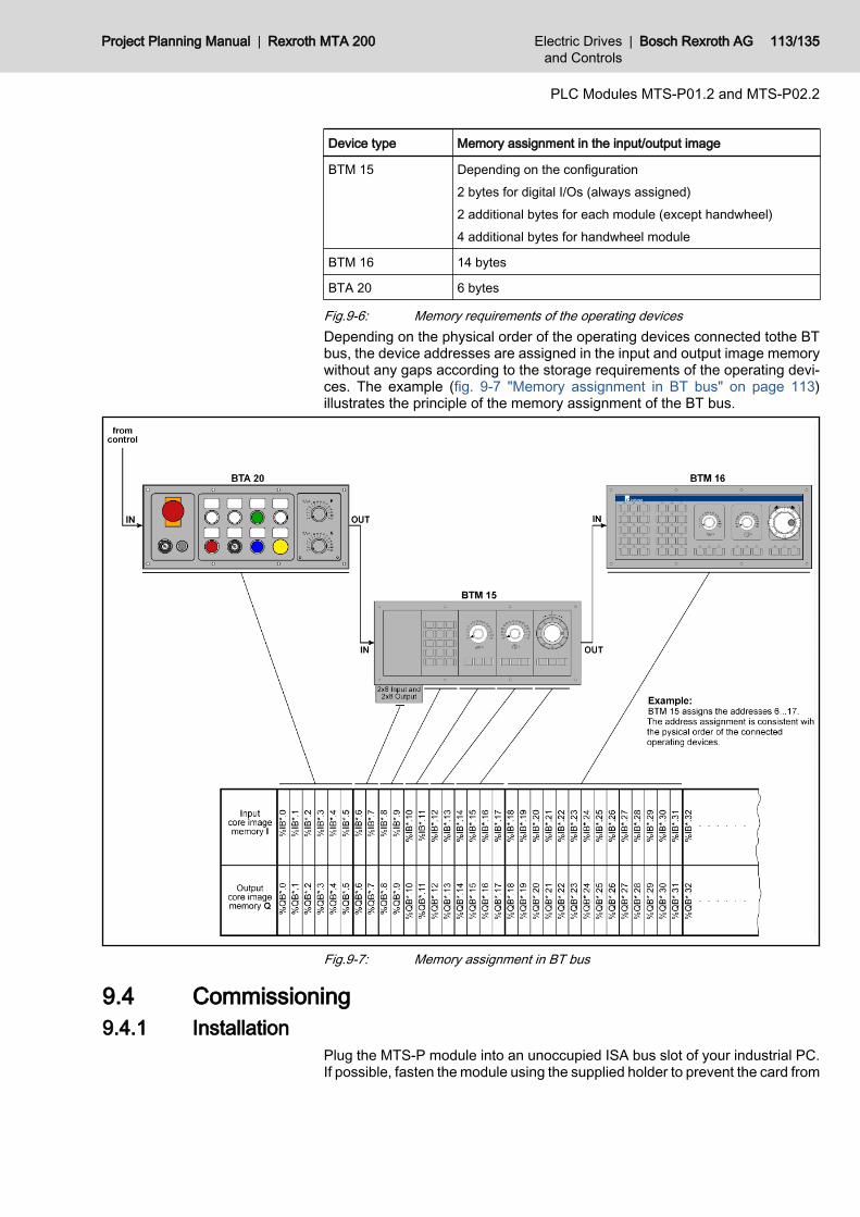
Device type Memory assignment in the input/output image
BTM 15 Depending on the configuration2 bytes for digital I/Os (always assigned)2 additional bytes for each module (except handwheel)4 additional bytes for handwheel module
BTM 16 14 bytes
BTA 20 6 bytes
Fig.9-6: Memory requirements of the operating devicesDepending on the physical order of the operating devices connected tothe BTbus, the device addresses are assigned in the input and output image memorywithout any gaps according to the storage requirements of the operating devi‐ces. The example (fig. 9-7 "Memory assignment in BT bus" on page 113)illustrates the principle of the memory assignment of the BT bus.
Fig.9-7: Memory assignment in BT bus
9.4 Commissioning9.4.1 Installation
Plug the MTS-P module into an unoccupied ISA bus slot of your industrial PC.If possible, fasten the module using the supplied holder to prevent the card from
Project Planning Manual | Rexroth MTA 200 Electric Drivesand Controls
| Bosch Rexroth AG 113/135
PLC Modules MTS-P01.2 and MTS-P02.2
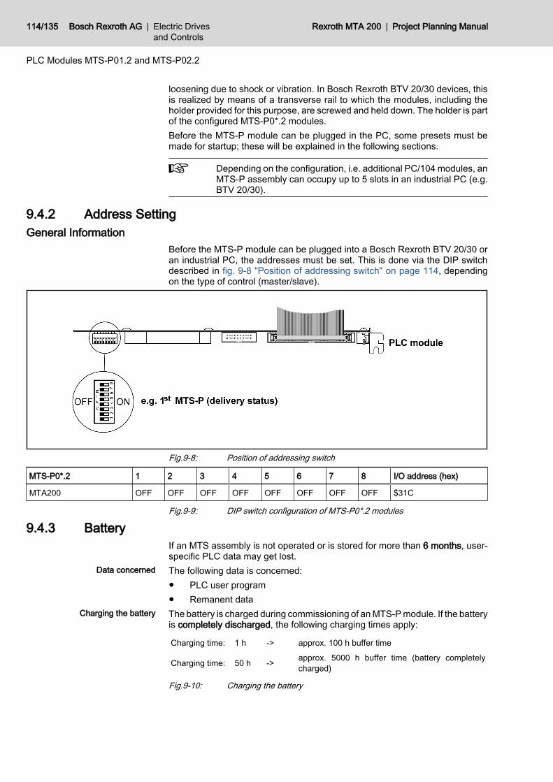
loosening due to shock or vibration. In Bosch Rexroth BTV 20/30 devices, thisis realized by means of a transverse rail to which the modules, including theholder provided for this purpose, are screwed and held down. The holder is partof the configured MTS-P0*.2 modules.Before the MTS-P module can be plugged in the PC, some presets must bemade for startup; these will be explained in the following sections.
Depending on the configuration, i.e. additional PC/104 modules, anMTS-P assembly can occupy up to 5 slots in an industrial PC (e.g.BTV 20/30).
9.4.2 Address SettingGeneral Information
Before the MTS-P module can be plugged into a Bosch Rexroth BTV 20/30 oran industrial PC, the addresses must be set. This is done via the DIP switchdescribed in fig. 9-8 "Position of addressing switch" on page 114, dependingon the type of control (master/slave).
Fig.9-8: Position of addressing switch
MTS-P0*.2 1 2 3 4 5 6 7 8 I/O address (hex)
MTA200 OFF OFF OFF OFF OFF OFF OFF OFF $31C
Fig.9-9: DIP switch configuration of MTS-P0*.2 modules
9.4.3 BatteryIf an MTS assembly is not operated or is stored for more than 6 months, user-specific PLC data may get lost.The following data is concerned:● PLC user program● Remanent dataThe battery is charged during commissioning of an MTS-P module. If the batteryis completely discharged, the following charging times apply:
Charging time: 1 h -> approx. 100 h buffer time
Charging time: 50 h -> approx. 5000 h buffer time (battery completelycharged)
Fig.9-10: Charging the battery
114/135 Bosch Rexroth AG | Electric Drivesand Controls
Rexroth MTA 200 | Project Planning Manual
PLC Modules MTS-P01.2 and MTS-P02.2
Data concerned
Charging the battery
Under normal operating conditions, the service life of the battery is 7 to 10 years.Continuous charging of the battery does not affect its service life (continuousoperation of the control).
9.4.4 Status Displays and Error DiagnosticsOperating Status Display
A diagnostic of the MTS-P0*.2 module can be performed using the 7-segmentdisplay H1. The various states are displayed via the one-digit error codes shownbelow.
Code Meaning
- Power-Fail triggered (control must be reset)
b Ready for operating (PLC is running)
0. Startup state (reset test)
F. Firmware in the flash EPROM is not valid
J. Boot lockout for firmware activated
S System stack overflow
P Local bus not connected
Fig.9-11: Operating states of MTS-P0*.2
If any other one-digit code (followed by a period) is displayed, cus‐tomer service must be immediately notified.
Error DisplayError states are indicated by three-digit error codes on the successively flashing7-segment display. The error codes represented correspond to the system errormessages of the user interface BOF/GBO.
Code Meaning
007 Software version error
008 Self-test was not successful
052 PLC program is not valid
055 Max. cycle time of PLC exceeded
071 Operating voltage of PLC too low
081 2-ms implementation time exceeded
082 INTERBUS error
083 INTERBUS storage overflow
084 INTERBUS configuration error
085 INTERBUS bus error
086 INTERBUS hardware firmware error
087 INTERBUS module error peripheral bus
088 INTERBUS not ready
089 INTERBUS - general error generation 4
Project Planning Manual | Rexroth MTA 200 Electric Drivesand Controls
| Bosch Rexroth AG 115/135
PLC Modules MTS-P01.2 and MTS-P02.2
Code Meaning
090 Profibus initialization error
093 BT bus error
Fig.9-12: Error codes of MTS-P0*.2
Interface AssignmentThe following tables list the interface assignments of the MTS-P modules.
PIN Signal designation PIN Signal designation
1 NC 2 Transmit Data (RS232)
3 Receive Data (RS232) 4 RS485+ or RxD+ (RS422)
5 RS485- or RxD- (RS422) 6 NC
7 GND 8 NC
9 TxD+ (RS422) 10 GND
11 TxD- (RS422) 12 +5V
13 Request To Send (modem) 14 Clear To Send (modem)
15 NC
Fig.9-13: Pin assignment COM interface X16
PIN Signal designation PIN Signal designation
1 Data Out + 2 Data In +
2 GND 4 NC
5 +5V 6 Data Out -
7 Data In - 8 NC
9 Detection of the assignment
Fig.9-14: Pin assignment BT bus X15
PIN Function
X1.1 - X1.4 Supply voltage VCC
X1.5 - X1.20 Input (0....15)
X1.21 - X1.36 Output (0....15)
X1.37 - X1.40 GND
Fig.9-15: Pin assignment I/O connector, 40-pin, X12
PIN Signal designation PIN Signal designation
1 +5VDC 2 +5VDC
3 S0 4 S1
5 S2 6 S3
7 S4 8 S5
9 S6 10 S7
11 S8 12 S9
116/135 Bosch Rexroth AG | Electric Drivesand Controls
Rexroth MTA 200 | Project Planning Manual
PLC Modules MTS-P01.2 and MTS-P02.2
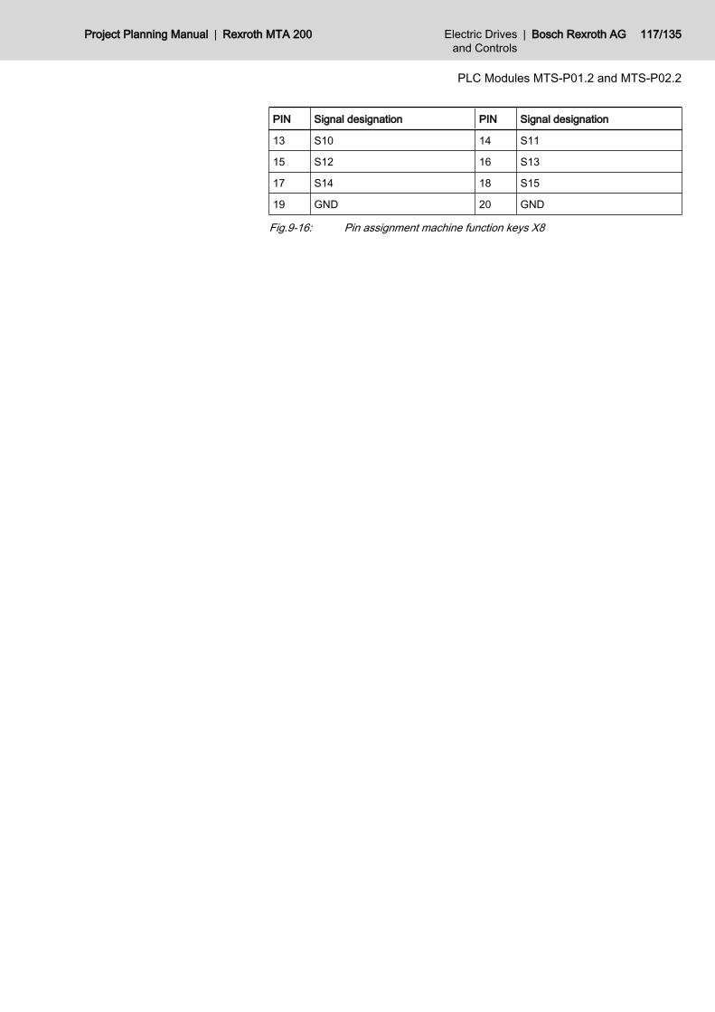
PIN Signal designation PIN Signal designation
13 S10 14 S11
15 S12 16 S13
17 S14 18 S15
19 GND 20 GND
Fig.9-16: Pin assignment machine function keys X8
Project Planning Manual | Rexroth MTA 200 Electric Drivesand Controls
| Bosch Rexroth AG 117/135
PLC Modules MTS-P01.2 and MTS-P02.2
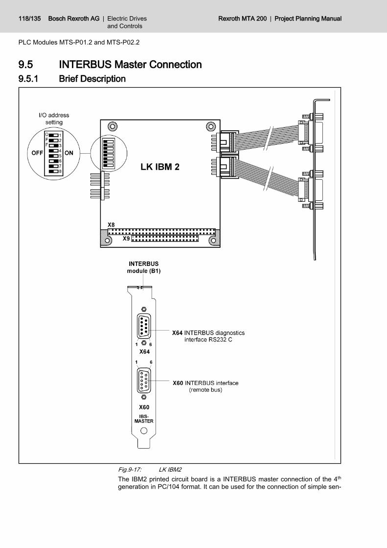
9.5 INTERBUS Master Connection9.5.1 Brief Description
Fig.9-17: LK IBM2The IBM2 printed circuit board is a INTERBUS master connection of the 4th
generation in PC/104 format. It can be used for the connection of simple sen‐
118/135 Bosch Rexroth AG | Electric Drivesand Controls
Rexroth MTA 200 | Project Planning Manual
PLC Modules MTS-P01.2 and MTS-P02.2
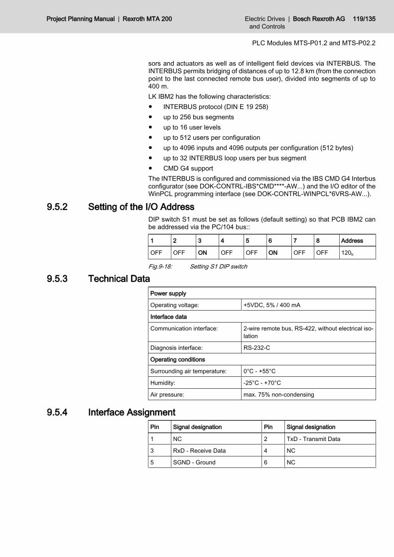
sors and actuators as well as of intelligent field devices via INTERBUS. TheINTERBUS permits bridging of distances of up to 12.8 km (from the connectionpoint to the last connected remote bus user), divided into segments of up to400 m.LK IBM2 has the following characteristics:● INTERBUS protocol (DIN E 19 258)● up to 256 bus segments● up to 16 user levels● up to 512 users per configuration● up to 4096 inputs and 4096 outputs per configuration (512 bytes)● up to 32 INTERBUS loop users per bus segment● CMD G4 supportThe INTERBUS is configured and commissioned via the IBS CMD G4 Interbusconfigurator (see DOK-CONTRL-IBS*CMD****-AW...) and the I/O editor of theWinPCL programming interface (see DOK-CONTRL-WINPCL*6VRS-AW...).
9.5.2 Setting of the I/O AddressDIP switch S1 must be set as follows (default setting) so that PCB IBM2 canbe addressed via the PC/104 bus::
1 2 3 4 5 6 7 8 Address
OFF OFF ON OFF OFF ON OFF OFF 120h
Fig.9-18: Setting S1 DIP switch
9.5.3 Technical DataPower supply
Operating voltage: +5VDC, 5% / 400 mA
Interface data
Communication interface: 2-wire remote bus, RS-422, without electrical iso‐lation
Diagnosis interface: RS-232-C
Operating conditions
Surrounding air temperature: 0°C - +55°C
Humidity: -25°C - +70°C
Air pressure: max. 75% non-condensing
9.5.4 Interface AssignmentPin Signal designation Pin Signal designation
1 NC 2 TxD - Transmit Data
3 RxD - Receive Data 4 NC
5 SGND - Ground 6 NC
Project Planning Manual | Rexroth MTA 200 Electric Drivesand Controls
| Bosch Rexroth AG 119/135
PLC Modules MTS-P01.2 and MTS-P02.2
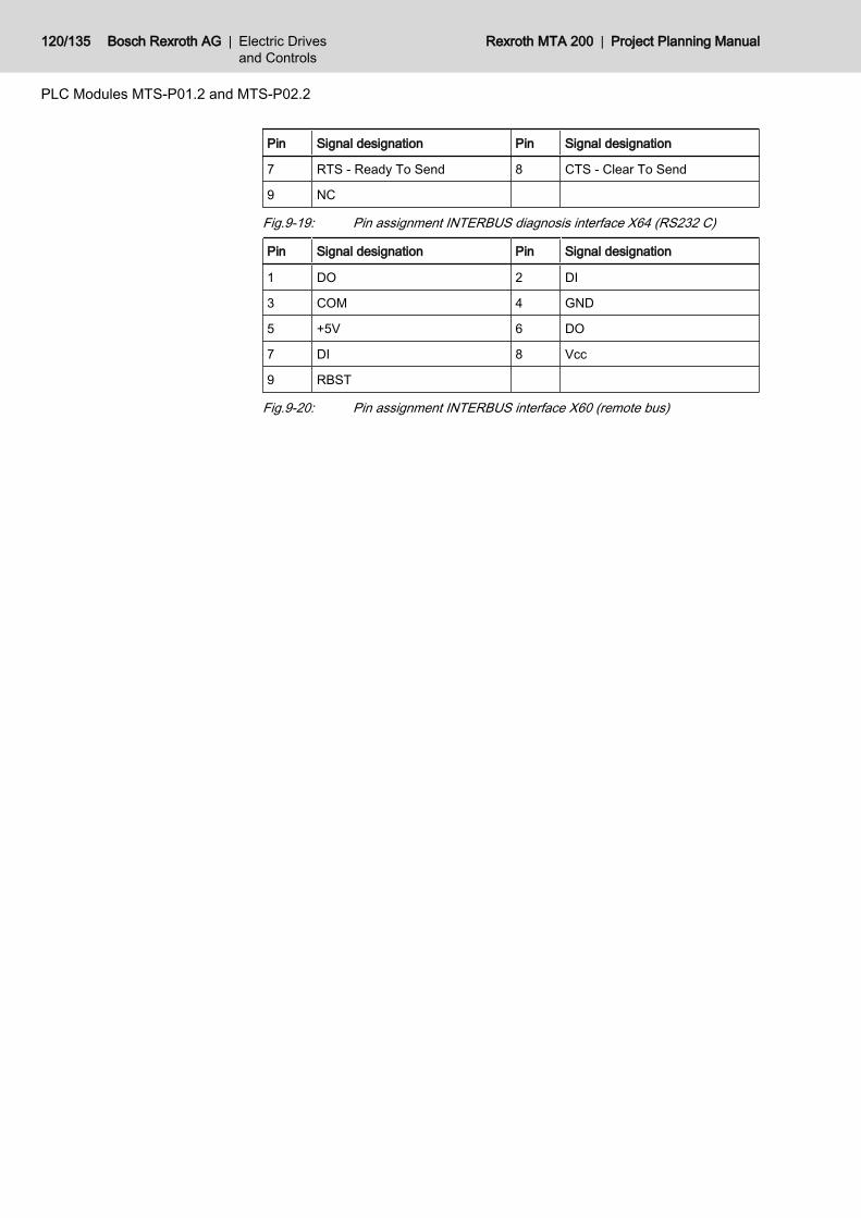
Pin Signal designation Pin Signal designation
7 RTS - Ready To Send 8 CTS - Clear To Send
9 NC
Fig.9-19: Pin assignment INTERBUS diagnosis interface X64 (RS232 C)
Pin Signal designation Pin Signal designation
1 DO 2 DI
3 COM 4 GND
5 +5V 6 DO
7 DI 8 Vcc
9 RBST
Fig.9-20: Pin assignment INTERBUS interface X60 (remote bus)
120/135 Bosch Rexroth AG | Electric Drivesand Controls
Rexroth MTA 200 | Project Planning Manual
PLC Modules MTS-P01.2 and MTS-P02.2
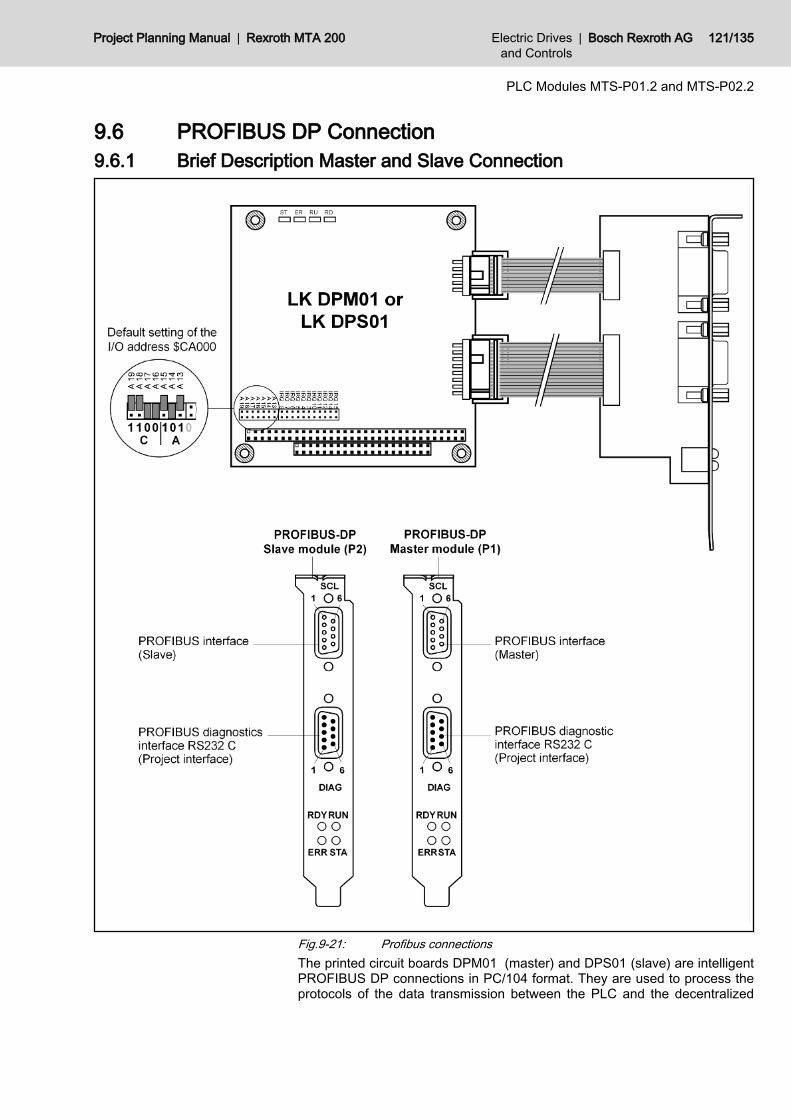
9.6 PROFIBUS DP Connection9.6.1 Brief Description Master and Slave Connection
Fig.9-21: Profibus connectionsThe printed circuit boards DPM01 (master) and DPS01 (slave) are intelligentPROFIBUS DP connections in PC/104 format. They are used to process theprotocols of the data transmission between the PLC and the decentralized
Project Planning Manual | Rexroth MTA 200 Electric Drivesand Controls
| Bosch Rexroth AG 121/135
PLC Modules MTS-P01.2 and MTS-P02.2

Profibus inputand output units. The built-in microprocessor allows automaticexecutionof the entire data transmission, thus relieving the PLC of real-timetasks.Data is exchanged between the PLC and the DPM01/ DPS01 printed circuitboards via an 8-kbyte dual-port memory (DPM). The DPM is a memory whichcan be simultaneously accessed by the PLC and the microprocessor of theDPM01/DPS01 printed circuit boards.The LK DPM/DPS01 are configured and commissioned via the SyCon systemconfigurator (see DOK-CONTRL-SYCON****DP-AW...). For configuration theIKS0106 interface cable is required. The LK DPM01 PROFIBUS DP masterconnection allows the connection of up to 32 PROFIBUS DP usesrs within onebus segment. If several bus segments are connected to each other via a re‐peater, a maximum of 125 slaves can be operated in the maximum configura‐tion.The LK DPM01 PROFIBUS DP master connection allows the connection of upto 32 PROFIBUS DP users within a bus segment. If several bus segments areconnected to each other via a repeater, a maximum of 125 slaves can be op‐erated in the maximum configuration. However, each repeater in use reducesthe maximum number of slaves within one segment, whereas no user addressis assigned to the repeater, as a passive user.Depending on the transmission rate set in each case, line lengths of up to 1200m can be realized between the Profibus DP users. The line length is reducedto max. 200 m if the transmission rate is 1.5 MBaud and to 100 m if the trans‐mission rate is 12 MBaud.Slaves with inputs of a maximum of 244 bytes and outputs of a maximum of244 bytes can be connected to the LK DPM01 master. The total of inputs andoutputs of all slaves must not exceed 512 bytes each.The LK DPS01 slave must be configured in such a way that the total of theinputs and/or outputs of the individual modules is a maximum of 244 bytes each.Do ensure that the total of the inputs and outputs of all modules does not exceed368 bytes.
In order to ensure proper functioning of the PROFIBUS interface,only cables IKB0033 / IKB0034 or cables according to PROFIBUSspecification RS485 (cable type A) are to be used.
9.6.2 Setting I/O addressesThe bus address is set using the jumpers of plug board J2. The address line isspecified next to each jumper.Depending on the additional slot, the addresses must be set as follows (X =jumper plugged):
Connection Address A19 A18 A17 A16 A15 A14 A13
Master $CA000 X X X
Slave $CC000 X X X
Fig.9-22: Setting the module type
9.6.3 Status and Diagnosis InformationWhile switching on the DPM01/DPS01 printed circuit boards, they perform aself-test. After the initialization phase of this test (2 to 3 seconds), the two L EDsERR and STA turn dark, and the yellow RDY LED lights if the test is successfullycompleted . If not, the RDY LED starts flashing, and the processing of the pro‐
122/135 Bosch Rexroth AG | Electric Drivesand Controls
Rexroth MTA 200 | Project Planning Manual
PLC Modules MTS-P01.2 and MTS-P02.2
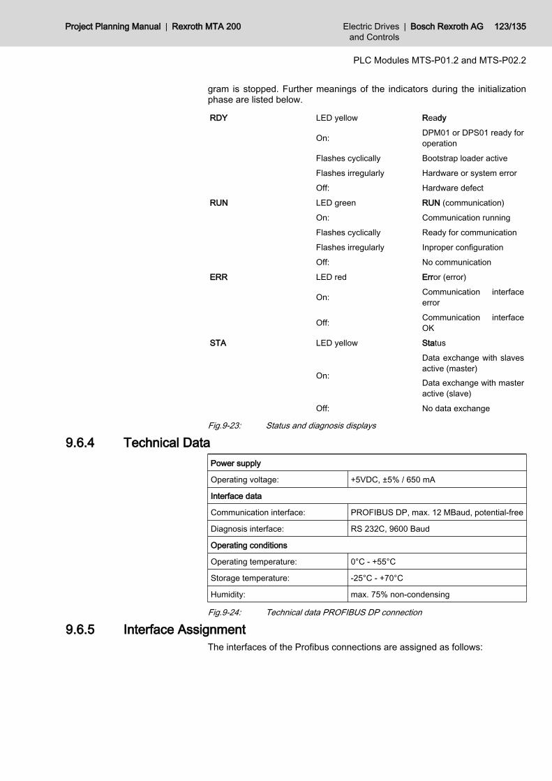
gram is stopped. Further meanings of the indicators during the initializationphase are listed below.
RDY LED yellow Ready
On: DPM01 or DPS01 ready foroperation
Flashes cyclically Bootstrap loader active
Flashes irregularly Hardware or system error
Off: Hardware defect
RUN LED green RUN (communication)
On: Communication running
Flashes cyclically Ready for communication
Flashes irregularly Inproper configuration
Off: No communication
ERR LED red Error (error)
On: Communication interfaceerror
Off: Communication interfaceOK
STA LED yellow Status
On:
Data exchange with slavesactive (master)Data exchange with masteractive (slave)
Off: No data exchange
Fig.9-23: Status and diagnosis displays
9.6.4 Technical DataPower supply
Operating voltage: +5VDC, ±5% / 650 mA
Interface data
Communication interface: PROFIBUS DP, max. 12 MBaud, potential-free
Diagnosis interface: RS 232C, 9600 Baud
Operating conditions
Operating temperature: 0°C - +55°C
Storage temperature: -25°C - +70°C
Humidity: max. 75% non-condensing
Fig.9-24: Technical data PROFIBUS DP connection
9.6.5 Interface AssignmentThe interfaces of the Profibus connections are assigned as follows:
Project Planning Manual | Rexroth MTA 200 Electric Drivesand Controls
| Bosch Rexroth AG 123/135
PLC Modules MTS-P01.2 and MTS-P02.2
PIN Signal designation PIN Signal designation
1 NC 2 RxD - Receive Data
3 TxD - Transmit Data 4 DTR - Data Terminal Ready
5 GND - Signal ground 6 NC
7 RTS - Ready To Send 8 CTS - Clear To Send
9 NC
Fig.9-25: Pin assignment diagnosis interface RS232C (X74, X79)
PIN Signal designation PIN Signal designation
1 RGND - Reference potential 2 NC
3 RxD/TxD-P - Send/Receive 4 NC
5 DGND - Reference potential 6 VP - Supply voltage - Plus
7 NC 8 RxD/TxD-N - Send/Receive
9 NC
Fig.9-26: Pin assignment PROFIBUS interface (X70, X75)
9.7 Connecting the Hand-held terminal BTC 06The hand-held terminal BTC 06 may only and exclusively be connected via themachine operator panels BTA 10 or BTA 20. RS232 operation is converted intoRS422 operation by the interface converter integrated in the BTA 10/20 (seefig. 9-27 "MTS-P with BTC 06 via RS232 interface" on page 125). RS422 op‐eration with BTC 06 also is only possible via BTA 10/20. However, no interfaceconversion takes place in this case. The interface connector is merely adaptedto the BTC 06 connector (see fig. 9-28 "MTS-P with BTC 06 via RS422 inter‐face" on page 126).
124/135 Bosch Rexroth AG | Electric Drivesand Controls
Rexroth MTA 200 | Project Planning Manual
PLC Modules MTS-P01.2 and MTS-P02.2
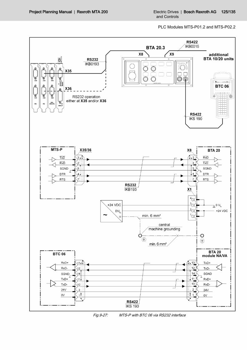
Fig.9-27: MTS-P with BTC 06 via RS232 interface
Project Planning Manual | Rexroth MTA 200 Electric Drivesand Controls
| Bosch Rexroth AG 125/135
PLC Modules MTS-P01.2 and MTS-P02.2
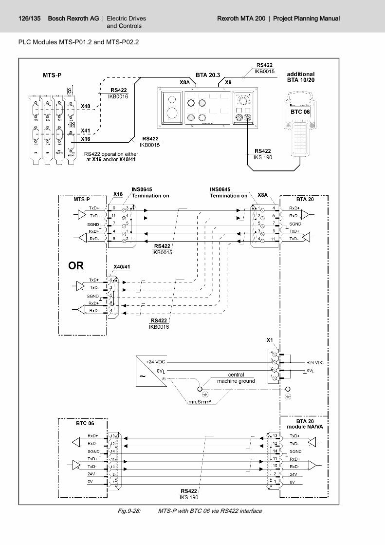
Fig.9-28: MTS-P with BTC 06 via RS422 interface
126/135 Bosch Rexroth AG | Electric Drivesand Controls
Rexroth MTA 200 | Project Planning Manual
PLC Modules MTS-P01.2 and MTS-P02.2

9.8 Configurations9.8.1 MTS-P0*.2-D2-B1-NN-NN-NN-FW
Fig.9-29: Structure of MTS-P0*.2-D2-B1-NN-NN-NN-FW configuration
Project Planning Manual | Rexroth MTA 200 Electric Drivesand Controls
| Bosch Rexroth AG 127/135
PLC Modules MTS-P01.2 and MTS-P02.2
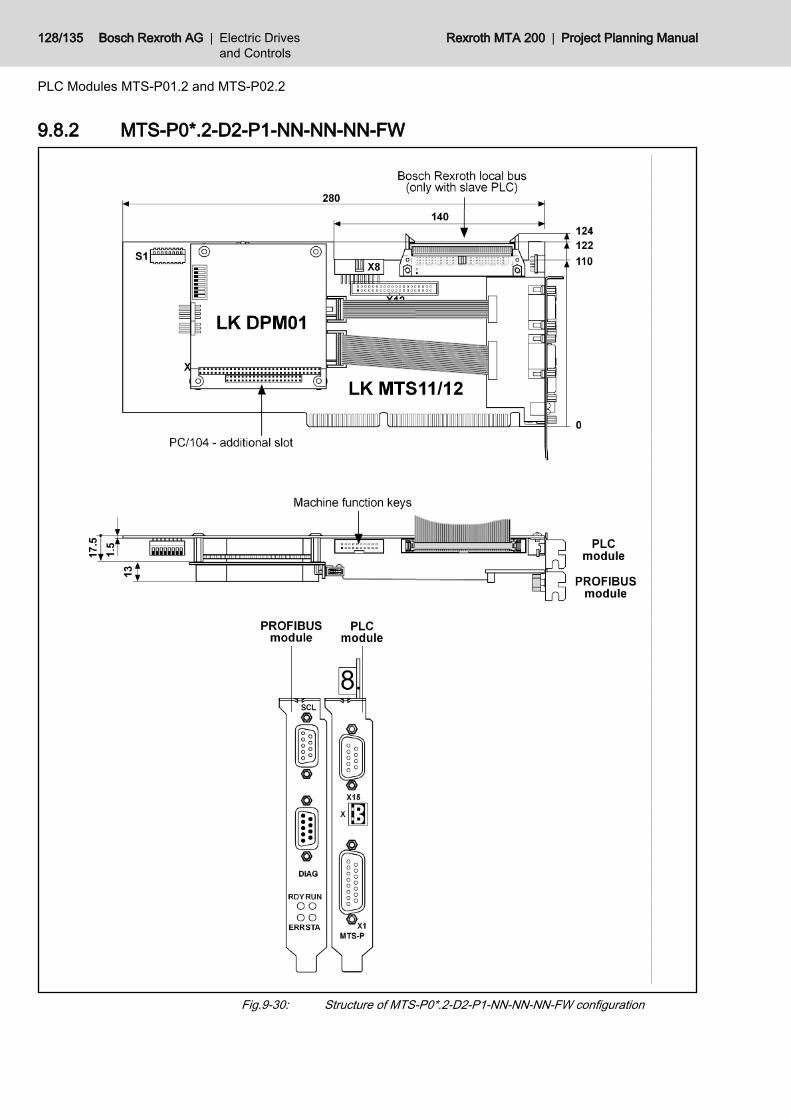
9.8.2 MTS-P0*.2-D2-P1-NN-NN-NN-FW
Fig.9-30: Structure of MTS-P0*.2-D2-P1-NN-NN-NN-FW configuration
128/135 Bosch Rexroth AG | Electric Drivesand Controls
Rexroth MTA 200 | Project Planning Manual
PLC Modules MTS-P01.2 and MTS-P02.2
10 Tips and Tricks10.1 BTV Replacement10.1.1 General Information
If the entire BTV, or parts thereof, must be replaced during servicing, data mustbe backed up and transferred to the new hardware.
10.1.2 Hard Disk ImageGeneral Information
If the entire BTV or hard disk is to be replaced, the hard disk data must bebacked up first. This is best done by creating a hard disk image (DriveImage orGhost programs) that then can be transferred to the new hard disk.The documentation DOK-MTA200-MTGUI***V23-AW0x-EN-P chapter 9 de‐scribes different data backup methods, including the full backup using a harddisk image.
Backup of all Hard Disk DataUsing a network connection (one-to-one) from the BTV to a laptop, an imageof the BTV hard disk can be created:● Boot the BTV under DOS with the network● Enable the drive and connect it to the notebook● Create the image
Restoring the Hard Disk DataRestore the image on the new hard disk.
10.1.3 Control Parameters (NCM Replacement)Parameters are handled by the Project Navigator of the MTA user interface.This ensures that a copy of the current parameters of the NCM card is alwaysstored on the hard disk.After the BTV or NCM has been replaced, the last valid parameter set is to benewly loaded into the the NCM using the "Download" function.
Before use, the NCM card must be initialized in the BTV 20.4A. Theinitialization is carried out by the Bosch Rexroth Testing Division.Therefore replacement cards may be only requested from and de‐livered by the Testing Division.
10.1.4 CMOS VariablesIn the BTV 20.4A, CMOS data is saved on the hard disk and is automaticallyloaded to the main memory during booting.As soon as the hard disk data is completely restored, also the CMOS data is inits current state.CMOS data also can be transferred from one control to another one. To do so,the NVRAM.DAT and NVRAM.DAT.BAK files from theD:\ProgramFiles\Indramt\MTGUI\ExternalApp\Andron\System directoryare to be transferred.
Project Planning Manual | Rexroth MTA 200 Electric Drivesand Controls
| Bosch Rexroth AG 129/135
Tips and Tricks

If the NRAM.DAT and NRAM.DATBAK files are not found during booting in thedefined directory, an error message is displayed. If the error message is con‐firmed, all CMOS data is re-initialized.
10.1.5 PLC Retain Data (PLC Replacement)Remanent variables are stored on the PLC card if they are used in the PLCproject. These variables are deleted if the PLC card is replaced, firmware isdownloaded or a new project is loaded. The retain data can be stored directlyin the PLC programming.Under WinPCL, the retain data is saved underStart -> Variable Values
130/135 Bosch Rexroth AG | Electric Drivesand Controls
Rexroth MTA 200 | Project Planning Manual
Tips and Tricks

11 Service and SupportOur service helpdesk at out headquarters in Lohr, Germany, will assist you withall kinds of enquiries. Out of helpdesk hours please contact our German servicedepartment directly.
Helpdesk Service HotlineGermany
Service HotlineWorldwide
Time 1) Mo-Fr 7:00 am - 6:00 pm CET Mo-Fr 6:00 pm - 7:00 am CETSa-Su 0:00 am - 12:00 pm CET
Outwith Germany please con‐tact our sales/service office inyour area first.For hotline numbers refer to thesales office addresses on theInternet.
Phone +49 (0) 9352 40 50 60 +49 (0) 171 333 88 26or+49 (0) 172 660 04 06
Fax +49 (0) 9352 40 49 41 –
e-mail [email protected] –
Internet http://www.boschrexroth.comYou will also find additional notes regarding service, maintenance (e.g. delivery addresses) andtraining.
1) Central European Time (CET) For quick and efficient help please have the following information ready:● detailed description of the fault and the circumstances● information on the type plate of the affected products, especially type co‐
des and serial numbers● your phone, fax numbers and e-mail address so we can contact you in
case of questions.
Project Planning Manual | Rexroth MTA 200 Electric Drivesand Controls
| Bosch Rexroth AG 131/135
Service and Support
Preparing Information

132/135 Bosch Rexroth AG | Electric Drivesand Controls
Rexroth MTA 200 | Project Planning Manual
IndexAAir pressure......................................................... 37Analog module...................................................... 9Appropriate use
Introduction .................................................. 11
BBacklight tubes.................................................... 37Battery............................................................... 114BIOS settings
Special settings for MTA 200 ................. 67, 77BTA 20.............................................................. 107BT bus....................................................... 107, 111
Addressing ................................................. 112BTM 15/16........................................................ 107
CCharging times.................................................. 114COM2.................................................................. 47Component versions........................................... 89COM user interface........................................... 111Connector housing.............................................. 54
DDegree of protection........................................... 37Dimensions......................................................... 37DIP switch................................................. 114, 119Display unit......................................................... 37DPM01.............................................................. 121DPS01............................................................... 121Drawer keyboard................................................... 8
EError display...................................................... 115External keyboard............................................... 33
FFan...................................................................... 37Fieldbus connections........................................ 107Film pocket.......................................................... 33Flash EPROM................................................... 107Floppy-disk flap................................................... 25
Lockable ....................................................... 62Front panel.......................................................... 37
GGateway module................................................... 9
HHand-held terminal................................................ 8
HHardware components
Additional components ................................... 8Hardware watchdog.......................................... 111Heat loss............................................................. 37Housing opening................................................. 32
II/O interface X22............................................... 102Image memory.................................................. 112Inappropriate use................................................ 12
Consequences, exclusion of liability ............ 11Input locale.......................................................... 34INTERBUS loop................................................ 119INTERBUS master connection................. 107, 118Interface assignment................................. 116, 123Internal foil keyboard........................................... 35
KKeyboard............................................................. 37Keyboard driver................................................... 33Keyboard language............................................. 33Keyboard layout.................................................. 33Key labeling........................................................ 31Key switch......................................................... 110Key switches..................................................... 107
LLPT1................................................................... 47
MMachine function keys........................ 30, 107, 110Machine operating keys.................................... 110Max. external magnetic field............................... 37Max. shock.......................................................... 37Max. surrounding air temperature....................... 37Max. temperature gradient.................................. 37Max. vibration...................................................... 37Measured value acquisitions................................. 8Memory module.................................................. 72Mini control panel.................................................. 8MTS-P01.2........................................................ 107MTS-P02.2........................................................ 107
NNC bus.............................................................. 110Network connections............................................. 8
OOPEN_COM...................................................... 111Operating status display................................... 115Operating system................................................ 24
Project Planning Manual | Rexroth MTA 200 Electric Drivesand Controls
| Bosch Rexroth AG 133/135
Index
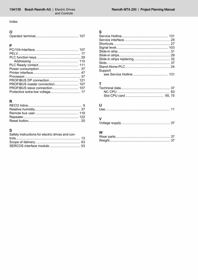
OOperator terminal.............................................. 107
PPC/104-Interface............................................... 107PELV................................................................... 17PLC function keys............................................... 29
Addressing ................................................. 110PLC Ready contact........................................... 111Power consumption............................................ 37Printer interface................................................... 47Processor............................................................ 37PROFIBUS DP connection............................... 121PROFIBUS master connection......................... 107PROFIBUS slave connection............................ 107Protective extra-low voltage................................ 17
RRECO Inline.......................................................... 9Relative humidity................................................. 37Remote bus user............................................... 119Repeater........................................................... 122Reset button........................................................ 25
SSafety instructions for electric drives and con‐trols..................................................................... 13Scope of delivery................................................ 63SERCOS interface module................................. 53
SService Hotline.................................................. 131Service interface................................................. 25Shortcuts............................................................. 27Signal level........................................................ 103Slide-in strip........................................................ 31Slide-in strips...................................................... 29Slide-in strips replacing....................................... 32Slots.................................................................... 37Stand-Alone-PLC................................................ 24Support
see Service Hotline .................................... 131
TTechnical data..................................................... 37
NC CPU ....................................................... 83Slot CPU card ........................................ 65, 75
UUse...................................................................... 11
VVoltage supply.................................................... 37
WWear parts.......................................................... 37Weight................................................................. 37
134/135 Bosch Rexroth AG | Electric Drivesand Controls
Rexroth MTA 200 | Project Planning Manual
Index
O

Notes
Project Planning Manual | Rexroth MTA 200 Electric Drivesand Controls
| Bosch Rexroth AG 135/135
Printed in GermanyDOK-MTA200-BTV20.4A***-PR02-EN-PR911307076
Bosch Rexroth AGElectric Drives and ControlsP.O. Box 13 5797803 Lohr, GermanyBgm.-Dr.-Nebel-Str. 297816 Lohr, GermanyTel. +49 (0)93 52-40-0Fax +49 (0)93 52-48 85www.boschrexroth.com