Embed Size (px)
Citation preview

Rexroth IndraDrive ML
Drive Systems with HMU05
Project Planning ManualR911344279
Edition 02

Rexroth IndraDrive MLDrive Systems with HMU05
Project Planning Manual
DOK-INDRV*-HXX05******-PR02-EN-P
RS-bdff4382be37d8ef0a6846a5002ff107-2-en-US-3
● Overview of the Rexroth IndraDrive Hxx05 system● Description of the allowed system component combinations● Selection of the drive system components● Specification applying to all components (ambient and operating condi‐
tions)● Application description of system characteristics
Edition Release Date Notes
02 2016-09 Revised edition01 2014-10 First edition
Copyright © Bosch Rexroth AG 2016This document, as well as the data, specifications and other information setforth in it, are the exclusive property of Bosch Rexroth AG. It may not be re‐produced or given to third parties without its consent.
Liability The specified data is intended for product description purposes only and shallnot be deemed to be a guaranteed characteristic unless expressly stipulatedin the contract. All rights are reserved with respect to the content of this docu‐mentation and the availability of the product.
Title
Type of Documentation
Document Typecode
Internal File Reference
Purpose of Documentation
Record of Revision
Bosch Rexroth AG DOK-INDRV*-HXX05******-PR02-EN-PRexroth IndraDrive ML Drive Systems with HMU05

Table of ContentsPage
1 System presentation.................................................................................................... 111.1 Rexroth IndraDrive ML range............................................................................................................... 111.1.1 Overview – Rexroth IndraDrive ML.................................................................................................... 111.1.2 Target applications............................................................................................................................ 131.1.3 Features............................................................................................................................................ 14
Functional features......................................................................................................................... 14Performance features..................................................................................................................... 15Interfaces........................................................................................................................................ 15Supported encoder systems........................................................................................................... 16
1.2 System configuration............................................................................................................................ 171.2.1 System structure................................................................................................................................ 171.2.2 System components.......................................................................................................................... 18
HMU05 universal inverter............................................................................................................... 18HMU05 type code........................................................................................................................ 18
Control sections.............................................................................................................................. 20Optional cards................................................................................................................................ 24Installing and removing control sections and optional cards.......................................................... 25
Training........................................................................................................................................ 25ESD protection............................................................................................................................ 25Limited number of insertions and removals................................................................................. 25Instructions.................................................................................................................................. 26
Firmware......................................................................................................................................... 271.2.3 About this documentation.................................................................................................................. 28
Purpose.......................................................................................................................................... 28Documentations.............................................................................................................................. 28
Drive systems, system components............................................................................................ 28Firmware...................................................................................................................................... 28
Your feedback................................................................................................................................ 29
2 Important directions for use ........................................................................................ 312.1 Appropriate use ................................................................................................................................... 312.1.1 Introduction........................................................................................................................................ 312.1.2 Areas of use and application............................................................................................................. 312.2 Inappropriate use.................................................................................................................................. 32
3 Safety instructions for electric drives and controls....................................................... 333.1 Definitions of terms............................................................................................................................... 333.2 General information.............................................................................................................................. 343.2.1 Using the Safety instructions and passing them on to others............................................................ 343.2.2 Requirements for safe use................................................................................................................ 343.2.3 Hazards by improper use.................................................................................................................. 353.3 Instructions with regard to specific dangers.......................................................................................... 373.3.1 Protection against contact with electrical parts and housings........................................................... 37
DOK-INDRV*-HXX05******-PR02-EN-P Bosch Rexroth AG I/407Rexroth IndraDrive ML Drive Systems with HMU05
Table of Contents

Page
3.3.2 Protective extra-low voltage as protection against electric shock .................................................... 383.3.3 Protection against dangerous movements........................................................................................ 393.3.4 Protection against electromagnetic and magnetic fields during operation and mounting.................. 403.3.5 Protection against contact with hot parts........................................................................................... 403.3.6 Protection during handling and mounting.......................................................................................... 413.3.7 Battery safety..................................................................................................................................... 413.3.8 Protection against pressurized systems............................................................................................ 423.4 Explanation of signal words and the Safety alert symbol..................................................................... 42
4 Combining the individual components......................................................................... 454.1 Documentations.................................................................................................................................... 454.2 Brief description of individual components........................................................................................... 454.2.1 HMU05 - brief description and design............................................................................................... 454.3 Configuring the drive system................................................................................................................ 474.3.1 Firmware............................................................................................................................................ 47
Firmware and device types............................................................................................................. 474.3.2 Motors................................................................................................................................................ 47
Third-party motors.......................................................................................................................... 47General information on third-party motors................................................................................... 47Requirements on third-party motors............................................................................................ 48Third-party motor encoder requirements..................................................................................... 50Notes on selection and commissioning....................................................................................... 51
4.3.3 Cables............................................................................................................................................... 52Motor power cable.......................................................................................................................... 52Encoder cables............................................................................................................................... 52
4.3.4 Leakage capacitances....................................................................................................................... 53Allowed leakage capacitances....................................................................................................... 53HMU05 systems for medium leakage capacitances....................................................................... 53
HMU05 systems with a single supply unit................................................................................... 53HMU05 systems with supply units connected in parallel............................................................. 53
HMU05 systems for high leakage capacitances............................................................................. 54DC bus choke, Y capacitor pairs................................................................................................. 54HMU05 systems with a single supply unit................................................................................... 54HMU05 systems with supply units connected in parallel............................................................. 55
Operating HMU05 together with HMS01/HMD01........................................................................... 56Topologies................................................................................................................................... 56HMU05 systems without a central DC bus choke....................................................................... 57HMU05 systems with a central DC bus choke............................................................................ 59
4.4 Installation conditions........................................................................................................................... 604.4.1 Ambient and operating conditions..................................................................................................... 604.4.2 Control cabinet.................................................................................................................................. 62
Air cooling....................................................................................................................................... 62Control cabinet design and cooling............................................................................................. 62
Liquid cooling.................................................................................................................................. 63General information..................................................................................................................... 63Cooling devices........................................................................................................................... 63
Bosch Rexroth AG DOK-INDRV*-HXX05******-PR02-EN-PII/407Rexroth IndraDrive ML Drive Systems with HMU05
Table of Contents

Page
Cooling device components........................................................................................................ 65Cooling of the drive components................................................................................................. 73Coolant........................................................................................................................................ 77Sizing liquid cooling..................................................................................................................... 78
4.4.3 UL ratings.......................................................................................................................................... 79Introduction..................................................................................................................................... 79Inverter........................................................................................................................................... 79Supply units.................................................................................................................................... 80
4.4.4 Compatibility with foreign matters...................................................................................................... 814.5 Mechanical project planning................................................................................................................. 824.5.1 Dimensions........................................................................................................................................ 82
HMU05.1N-F0140-0350................................................................................................................. 82HMU05.1N-F0170-0430................................................................................................................. 83HMU05.1N-F0220-0510................................................................................................................. 84HMU05.1N-F0270-0660................................................................................................................. 85HMU05.1N-F0340-0820................................................................................................................. 86HMU05.1N-F0430-1040................................................................................................................. 87HMU05.1N-F0540-1300................................................................................................................. 88
4.5.2 Dimensions, mass, insulation, sound pressure level ........................................................................ 894.5.3 Temperatures, cooling, power dissipation, distances........................................................................ 904.5.4 Mounting positions of components.................................................................................................... 934.6 Electrical project planning..................................................................................................................... 944.6.1 Overall connection diagram (HMU05 as drive controller).................................................................. 944.6.2 Overall connection diagram (HMU05 as supply unit)........................................................................ 95
Overall connection diagram with load contactor............................................................................. 95Overall connection diagram with a controllable main switch.......................................................... 96
4.6.3 Project planning of control voltage.................................................................................................... 98Control voltage for drive systems................................................................................................... 98Sizing the control voltage supply.................................................................................................... 98
Determining the power requirements.......................................................................................... 98Requirements on the 24V power supply unit............................................................................. 100Installing the 24V supply............................................................................................................ 101
4.6.4 Mains connection............................................................................................................................. 102Residual-current-operated circuit breakers (RCD, RCCB) as additional fusing........................... 102
General information................................................................................................................... 102Cause of leakage currents......................................................................................................... 103Possibilities of use..................................................................................................................... 103
Mains types.................................................................................................................................. 104TN-S mains type........................................................................................................................ 104TN-C mains type........................................................................................................................ 105IT mains type............................................................................................................................. 106TT system.................................................................................................................................. 107Mains with grounded outer conductor (Corner-grounded delta mains)..................................... 107
Mains connection type.................................................................................................................. 108Mains connected load and mains current .................................................................................... 110
Technical data of the components............................................................................................. 110
DOK-INDRV*-HXX05******-PR02-EN-P Bosch Rexroth AG III/407Rexroth IndraDrive ML Drive Systems with HMU05
Table of Contents

Page
Calculating the mains-side phase current ................................................................................ 110Dimensioning the line cross sections and fuses........................................................................... 111Dimensioning and selecting the mains transformer...................................................................... 111Combining mains filter, mains choke, preconnected choke and capacitance pack...................... 112
4.6.5 Running multiple HMU05s in parallel.............................................................................................. 1144.7 Acceptance tests and approvals......................................................................................................... 117
5 Condition as supplied, identification, transport and storage...................................... 1195.1 Condition as supplied......................................................................................................................... 1195.1.1 Factory testing................................................................................................................................. 119
Voltage testing and insulation resistance testing.......................................................................... 1195.1.2 Customer testing............................................................................................................................. 1195.2 Identification........................................................................................................................................ 1205.2.1 Type plates...................................................................................................................................... 120
Design.......................................................................................................................................... 1205.2.2 Contents of delivery......................................................................................................................... 1205.3 Transporting components................................................................................................................... 1205.4 Storing components............................................................................................................................ 121
6 Mounting and installation........................................................................................... 1236.1 Mounting HMU05 devices in control cabinet...................................................................................... 1236.2 Electrical connection........................................................................................................................... 1236.2.1 Overall connection diagram (HMU05 as drive controller)................................................................ 1236.2.2 Overall connection diagram (HMU05 as supply unit)...................................................................... 123
Overall connection diagram with load contactor........................................................................... 123Overall connection diagram with controllable main switch........................................................... 123
6.2.3 Connection points............................................................................................................................ 124Arrangement of HMU05 connection points................................................................................... 124Connection point of equipment grounding conductor................................................................... 125L1, L2, L3, mains/motor connection............................................................................................. 126
Important notes.......................................................................................................................... 126XG3, motor temperature monitoring, motor holding brake, motor fan control ............................. 127XG32, HNA bus............................................................................................................................ 129XG1, IndraBus.............................................................................................................................. 129XD10, 24 V supply (control voltage)............................................................................................. 129L+ L-, DC bus connection............................................................................................................. 130Shield connection......................................................................................................................... 131Ground connection....................................................................................................................... 133
6.2.4 Optional cards................................................................................................................................. 134HPC01.1-MN0x-NN...................................................................................................................... 134HPC01.1-P001-NN....................................................................................................................... 134
6.3 WATER IN/OUT, cooling liquid connection........................................................................................ 135
7 Technical data of the components............................................................................. 1377.1 Ambient and operating conditions...................................................................................................... 137
Bosch Rexroth AG DOK-INDRV*-HXX05******-PR02-EN-PIV/407Rexroth IndraDrive ML Drive Systems with HMU05
Table of Contents

Page
7.2 Power section..................................................................................................................................... 1377.2.1 Control voltage................................................................................................................................ 1377.2.2 Mains voltage.................................................................................................................................. 1397.2.3 DC bus............................................................................................................................................. 1417.2.4 Inverter............................................................................................................................................ 143
8 Cables, accessories, additional components............................................................. 1478.1 Overview............................................................................................................................................. 1478.1.1 Cables............................................................................................................................................. 1478.1.2 Accessories..................................................................................................................................... 1478.1.3 Additional components.................................................................................................................... 1478.2 Accessories........................................................................................................................................ 1488.2.1 Mounting and connection accessories (HAS03).............................................................................. 1488.2.2 Cabinet installation kit (HAS08.1-008)............................................................................................. 149
Type code..................................................................................................................................... 149Parts............................................................................................................................................. 150Mounting....................................................................................................................................... 151
On top of control cabinet........................................................................................................... 151In front of control cabinet........................................................................................................... 152Mounting the device.................................................................................................................. 154Dismounting the device............................................................................................................. 156
8.2.3 Blank covers, motor monitor grounding, mounting plates (HAS10)................................................. 157HAS10 type code.......................................................................................................................... 157Blank covers (HAS10.1-002-003)................................................................................................. 157Motor monitor grounding (HAS10.1-002-004).............................................................................. 160Mounting plate for device width 200 mm (HAS10.1-002-005)...................................................... 162Mounting plate for device width 220 mm (HAS10.1-002-006)...................................................... 164
8.3 Additional components....................................................................................................................... 1668.3.1 HNA05 mains connection module................................................................................................... 166
HNA05 type code......................................................................................................................... 166Dimensions................................................................................................................................... 167Data.............................................................................................................................................. 169Connection points......................................................................................................................... 171
Overview.................................................................................................................................... 171Equipment grounding conductor connection point.................................................................... 172XD1, mains voltage, equipment grounding conductor............................................................... 173XD2, DC bus.............................................................................................................................. 174XD10, 24 V supply (control voltage).......................................................................................... 175XG1, IndraBus........................................................................................................................... 176XG31, messages....................................................................................................................... 177XG32, HNA bus......................................................................................................................... 179XG33, on, off, ZKS (DC bus short circuit) status....................................................................... 180XG34, mains contactor (contact)............................................................................................... 182XG40, mains contactor (acknowledgment messages).............................................................. 183
Display elements.......................................................................................................................... 1848.3.2 HNC05 mains capacitor................................................................................................................... 185
DOK-INDRV*-HXX05******-PR02-EN-P Bosch Rexroth AG V/407Rexroth IndraDrive ML Drive Systems with HMU05
Table of Contents

Page
HNC05 type code......................................................................................................................... 185Dimensions................................................................................................................................... 186
HNC05.1N-0050........................................................................................................................ 186HNC05.1N-0075........................................................................................................................ 187HNC05.1N-0100........................................................................................................................ 188
Data.............................................................................................................................................. 189Assignment to HMU05.................................................................................................................. 189
8.3.3 HNF05 mains filter........................................................................................................................... 190HNF05 type code.......................................................................................................................... 190Dimensions................................................................................................................................... 192
HNF05.1A-500N-R0250............................................................................................................ 192HNF05.1A-500N-R0320, -R0400.............................................................................................. 193HNF05.1A-500N-R0600............................................................................................................ 194HNF05.1A-500N-R1000............................................................................................................ 195HNF05.1A-500N-R1600............................................................................................................ 196
Mounting....................................................................................................................................... 196Data.............................................................................................................................................. 197Assignment to HMU05.................................................................................................................. 197
8.3.4 HNL05 mains choke........................................................................................................................ 198HNL05 type code.......................................................................................................................... 198Type plate..................................................................................................................................... 202Dimensions................................................................................................................................... 203
HNL05.1R-0219-N0218............................................................................................................. 203HNL05.1R-0182-N0262............................................................................................................. 204HNL05.1R-0045-N0327............................................................................................................. 205HNL05.1R-0135-N0327............................................................................................................. 206HNL05.1R-0054-N0409............................................................................................................. 207HNL05.1R-0117-N0409............................................................................................................. 208HNL05.1R-0043-N0514............................................................................................................. 209HNL05.1R-0130-N0514............................................................................................................. 210HNL05.1R-0050-N0652............................................................................................................. 211HNL05.1R-0113-N0652............................................................................................................. 212HNL05.1R-0040-N0811............................................................................................................. 213HNL05.1R-0100-N0811............................................................................................................. 214HNL05.1R-0040-N1019............................................................................................................. 215HNL05.1R-0094-N1019............................................................................................................. 216
Data.............................................................................................................................................. 217Water cooling................................................................................................................................ 218Connection................................................................................................................................... 218Assignment to HMU05.................................................................................................................. 218
8.3.5 HML05 motor choke/balancing choke............................................................................................. 219HML05 type code......................................................................................................................... 219HML05 to HMU05 assignment..................................................................................................... 220Dimensions................................................................................................................................... 221Data.............................................................................................................................................. 229
8.3.6 HLL05 DC bus choke...................................................................................................................... 231
Bosch Rexroth AG DOK-INDRV*-HXX05******-PR02-EN-PVI/407Rexroth IndraDrive ML Drive Systems with HMU05
Table of Contents

Page
HLL05 type code.......................................................................................................................... 231Sizing............................................................................................................................................ 232Dimensions................................................................................................................................... 233
HLL05.1W-04M0-S0202............................................................................................................ 233HLL05.1F-04M0-S0202............................................................................................................. 234HLL05.1F-04M0-S0243............................................................................................................. 235HLL05.1W-04M0-S0303............................................................................................................ 236HLL05.1F-04M0-S0303............................................................................................................. 237HLL05.1F-04M0-S0380............................................................................................................. 238HLL05.1F-04M0-S0475............................................................................................................. 239HLL05.1F-04M0-S0603............................................................................................................. 240HLL05.1F-04M0-S0720............................................................................................................. 241HLL05.1F-04M0-S0942............................................................................................................. 242
Data.............................................................................................................................................. 243Water cooling................................................................................................................................ 244Assignment................................................................................................................................... 245Circuit diagram............................................................................................................................. 246Connection................................................................................................................................... 246
8.3.7 Y capacitor pair (HAS04.1-003)....................................................................................................... 247Type code..................................................................................................................................... 247Data.............................................................................................................................................. 247
8.3.8 HLR05 external braking resistor...................................................................................................... 249HLR05 type code.......................................................................................................................... 249Dimensions................................................................................................................................... 250
HLR05.1W-54K0-N05R4, …-70K0-N04R0............................................................................... 250Data.............................................................................................................................................. 251Installation.................................................................................................................................... 252
8.3.9 HLT05 braking unit.......................................................................................................................... 255HLT05 type code.......................................................................................................................... 255Dimensions................................................................................................................................... 256Data.............................................................................................................................................. 259Connection diagram..................................................................................................................... 260Connection points......................................................................................................................... 263
Overview.................................................................................................................................... 263XE01, equipment grounding conductor connection point.......................................................... 265XD02, DC bus............................................................................................................................ 267XD4, braking resistor................................................................................................................. 271XD10, 24 V supply (control voltage).......................................................................................... 272XG1, IndraBus........................................................................................................................... 273XG3, braking resistor overtemperature signal contact.............................................................. 274XG31, signal contact (Bb, warning) and reset input.................................................................. 275XG33, DC bus short-circuit (ZKS)............................................................................................. 277
SF1 switch.................................................................................................................................... 278Display elements.......................................................................................................................... 279
8.3.10 24V power supply unit..................................................................................................................... 280Features....................................................................................................................................... 280
DOK-INDRV*-HXX05******-PR02-EN-P Bosch Rexroth AG VII/407Rexroth IndraDrive ML Drive Systems with HMU05
Table of Contents

Page
Data.............................................................................................................................................. 28124V/20A connection diagram....................................................................................................... 28224V/40A connection diagram....................................................................................................... 283
8.3.11 Heat Exchanger HAH01.................................................................................................................. 284Type Code HAH01....................................................................................................................... 284General Information...................................................................................................................... 285
Manufacturer’s details and machine identification details......................................................... 285Declaration of conformity........................................................................................................... 286Disclaimer notice....................................................................................................................... 287
Safety Information........................................................................................................................ 288General safety warnings............................................................................................................ 288
Liquid-Liquid Heat Exchanger...................................................................................................... 289Technical Information................................................................................................................ 289Information concerning handling and installation...................................................................... 301Information for Use.................................................................................................................... 307Maintenance Information........................................................................................................... 315Breakdown Information.............................................................................................................. 317Information Concerning Replacements..................................................................................... 318Hydraulic diagrams.................................................................................................................... 322
Air-Liquid Heat Exchanger............................................................................................................ 326Technical Information................................................................................................................ 326Information Concerning Handling and Installation..................................................................... 339Information for Use.................................................................................................................... 346Maintenance Information........................................................................................................... 353Breakdown Information.............................................................................................................. 355Information Concerning Replacements..................................................................................... 356Hydraulic diagrams.................................................................................................................... 362
9 Environmental protection and disposal ..................................................................... 3659.1 Environmental protection.................................................................................................................... 3659.2 Disposal.............................................................................................................................................. 365
10 Service and support................................................................................................... 367
11 Appendix.................................................................................................................... 36911.1 Switching supply units on and off....................................................................................................... 36911.1.1 Switching on.................................................................................................................................... 36911.1.2 Switching off.................................................................................................................................... 37011.2 Dimensioning the line cross sections and fuses ................................................................................ 37111.3 DC bus fuses...................................................................................................................................... 38011.4 Aluminum contact points and cupal disks........................................................................................... 38111.4.1 Introduction...................................................................................................................................... 38111.4.2 Preparation...................................................................................................................................... 38111.4.3 Cupal disk........................................................................................................................................ 38111.5 Determining the leakage capacitance................................................................................................. 383
Bosch Rexroth AG DOK-INDRV*-HXX05******-PR02-EN-PVIII/407Rexroth IndraDrive ML Drive Systems with HMU05
Table of Contents

Page
11.6 Leakage capacitances........................................................................................................................ 38411.6.1 Leakage capacitance of power cables ........................................................................................... 38411.7 Total Harmonic Distortion (THD)........................................................................................................ 38511.8 Liquid cooling...................................................................................................................................... 38711.8.1 Sizing liquid cooling......................................................................................................................... 387
Calculation criteria........................................................................................................................ 387Physical data............................................................................................................................. 387Flow rate.................................................................................................................................... 387Pressure decrease.................................................................................................................... 388
Sizing aids.................................................................................................................................... 38911.8.2 Sizing example................................................................................................................................ 394
Index.......................................................................................................................... 399
DOK-INDRV*-HXX05******-PR02-EN-P Bosch Rexroth AG IX/407Rexroth IndraDrive ML Drive Systems with HMU05
Table of Contents

Bosch Rexroth AG DOK-INDRV*-HXX05******-PR02-EN-PX/407Rexroth IndraDrive ML Drive Systems with HMU05

1 System presentation1.1 Rexroth IndraDrive ML range1.1.1 Overview – Rexroth IndraDrive ML
Rexroth IndraDrive ML
HMU05
Tab. 1-1: HMU05 universal inverter of the Rexroth IndraDrive ML productrange
DOK-INDRV*-HXX05******-PR02-EN-P Bosch Rexroth AG 11/407Rexroth IndraDrive ML Drive Systems with HMU05
System presentation

Supply unit Drive controller
* Only relevant to high-performance HMU05HNA05 Mains connection moduleHMU05 Universal inverterCSB02.5 Control section with firmware for supply units
(FWA‑INDRV*‑PSB‑…)HPC01 Motor/mains moduleHNC05 Mains capacitorHNL05 ChokeHNF05 Mains filterFig. 1-1: Supply unit components
HMU05 Universal inverterCSx02.5 Control section with firmware for drive con‐
trollers (FWA‑INDRV*‑MPx‑…)HPC01 Motor/mains moduleHML05 Motor choke (optional)HMF05 Motor filter (optional)Fig. 1-2: Drive controller components
Tab. 1-2: Supply unit, drive controller
HMV05 HMV05 is the designation for a supply unit consisting of an HNA05 mainsconnecting module, HMU05 universal inverter and CSB02.5 control sectionwith firmware for supply units (FWA-INDRV*-PSB-...).HMV05 is not an official product designation and is used solely for documen‐tation purposes.
HMS05 HMS05 is the designation for a drive controller consisting of an HMU05universal inverter and CSx02.5 control section with firmware for drive control‐lers (FWA-INDRV*-MPx-...).HMS05 is not an official product designation and is used solely for documen‐tation purposes.
Bosch Rexroth AG DOK-INDRV*-HXX05******-PR02-EN-P12/407Rexroth IndraDrive ML Drive Systems with HMU05
System presentation

1.1.2 Target applications
Metal forming● Servo press main drive● Winders● Straightener drives● Profiler drives
Plastics● Extruders● Kneaders● Pumps● Injector and profiling axis drives
Marine/offshore technology● Fishing winches● Anchor handling winches● Nautical winches● Shiplifts
Metallurgy● Roller conveyors● Transfer lifters
Others● Paper manufacturing (pumps, rollers)● Printing machines (winding computation, cross cutters, rollers)● General automation (pumps, cranes, testing stations)
Tab. 1-3: Target applications
DOK-INDRV*-HXX05******-PR02-EN-P Bosch Rexroth AG 13/407Rexroth IndraDrive ML Drive Systems with HMU05
System presentation

1.1.3 FeaturesFunctional features
● Universal power sections for inverters and regenerative supply units● Power sections with the same output can be connected in parallel● Compact type of construction● Degree of protection of device: IP20; degree of protection of connec‐
tions: IP00● CSx02.5 control section● Control panel with programming module function● Scalable signal processing and firmware● Multi-encoder interface for all standard encoders● DC bus connection● Analog input (14 bit, ±10 V)● Cooling type: Liquid cooling
Bosch Rexroth AG DOK-INDRV*-HXX05******-PR02-EN-P14/407Rexroth IndraDrive ML Drive Systems with HMU05
System presentation

Performance featuresInverter
HMU05.1N-… → 0140-0350 0170-0430 0220-0510 0270-0660 0340-0820 0430-1040 0540-1300 0680-1690
Continuous cur‐rent
A 254 306 392 490 616 771 1002 1185
Maximum current A 357 427 515 660 825 1037 1297 1686
Typical motorpower 1)
kW 132 | 110 160 | 132 200 | 160 250 | 200 315 | 250 400 | 315 500 | 400 630 | 500
1) x | y; x = basic load for 540 s, 10% overload for 60 s; y = basicload for 540 s, 50% overload for 60 s
Tab. 1-4: HMU05.1N, inverter performance features Supply unit
HMU05.1N-… → 0140-0350 0170-0430 0220-0510 0270-0660 0340-0820 0430-1040 0540-1300 0680-1690
Mains connectionvoltageULN
V 3 AC 380 … 500; -15%, +10%
Mains input cur‐rent (basic pow‐er) 1)
A 216 | 180 260 | 216 324 | 260 405 | 324 509 | 405 645 | 509 803 | 645 1009 | 803
Basic DC buspower 1)
kW 144 | 120 173 | 144 216 | 173 270 | 216 339 | 270 430 | 339 535 | 430 672 | 535
DC bus overloadcapacity 1)
PDC_max
kW 158 | 180 190 | 216 238 | 260 297 | 324 373 | 405 473 | 509 589 | 645 739 | 803
Continuous DCbus powerPDC_cont
kW 145 174 219 273 342 435 540 679
1) x | y; x = basic load for 540 s, 10% overload for 60 s; y = basicload for 540 s, 50% overload for 60 s
Tab. 1-5: HMU05.1N, supply unit performance features
InterfacesOverview ● Compatible with IndraDrive platform
● Ethernet-based communication with the following supported protocols:– sercos III– PROFINET IO– EtherNet/IP– EtherNet POWERLINK– EtherCAT
● Alternative communication:– PROFIBUS– CANopen
DOK-INDRV*-HXX05******-PR02-EN-P Bosch Rexroth AG 15/407Rexroth IndraDrive ML Drive Systems with HMU05
System presentation

● Optional safety technology● Optional multi-encoder interface● Optional encoder emulation● Analog input● Freely configurable digital inputs/outputs● Optional I/O extension digital/analog
Supported encoder systemsSupported encoder systems Encoder systems with a supply voltage of 5 and 12 V:
● IndraDyn encoder● 1Vpp sin-cos encoder; HIPERFACE®● 1Vpp sin-cos encoder; EnDat 2.1; EnDat 2.2● 1Vpp sin-cos encoder; with reference track● 5V TTL square-wave encoder; with reference track● SSI● Combined encoder for SSI (combination of SSI and 1Vpp sin-cos encod‐
er)● Resolver
Bosch Rexroth AG DOK-INDRV*-HXX05******-PR02-EN-P16/407Rexroth IndraDrive ML Drive Systems with HMU05
System presentation

1.2 System configuration1.2.1 System structure
* Optional** Only relevant to high-performance HMU0524V 24V power supply unit (AC/DC power supply unit; optional
DC/DC power supply unit for redundancy in the case of mainsfailure)
HLL DC bus chokeHLR Braking resistorHLT Braking unitHMF Motor filterHML Motor chokeHMU Universal inverterHNA Mains connection moduleHNC Mains capacitorHNF Mains filterHNL ChokeM MotorFig. 1-3: Rexroth IndraDrive ML drive system
DOK-INDRV*-HXX05******-PR02-EN-P Bosch Rexroth AG 17/407Rexroth IndraDrive ML Drive Systems with HMU05
System presentation

1.2.2 System componentsHMU05 universal inverter
HMU05 type code
Short type designation 1 2 3 4 5 6 7 8 910 1 2 3 4 5 6 7 8 9
20 1 2 3 4 5 6 7 8 9
30 1 2 3 4 5 6 7 8 9
40
Example: H M U 0 5 . 1 N - F 0 2 7 0 - 0 6 6 0 - N - A 4 - D 7 - N 1 N - N N N N
① ② ③④ ⑤ ⑥ ⑦ ⑧ ⑨⑩⑪ ⑫
① Product:HMU = Universal inverter
② Series:05 = 05
③ Design:1 = 1
④ Application:N = Standard
⑤ Cooling type:F = Liquid coolingW = Air, internal
⑥ DC bus continuous power / maximum current 4):0140-0210 = 140 kW / 210 A0140-0350 = 140 kW / 350 A0170-0250 = 170 kW / 250 A0170-0430 = 170 kW / 430 A0220-0300 = 220 kW / 300 A0220-0510 = 220 kW / 510 A0270-0370 = 270 kW / 370 A0270-0660 = 270 kW / 660 A0340-0820 = 340 kW / 820 A0400-0600 = 400 kW / 600 A0430-1040 = 430 kW / 1040 A0540-0750 = 540 kW / 750 A0540-1300 = 540 kW / 1300 A0680-0980 = 680 kW / 980 A0680-1690 = 680 kW / 1690 A
⑦ Degree of protection:N = IP00
⑧ Mains connection voltage / Nominal DC bus voltage:A4-D7 = supply unit: 3 x AC 380 V -15% ... 500V +10%; inverter: DC 750 VA5-11 = supply unit: 3 x AC 525 V -15% ... 690V +10%; inverter: DC 1100 V
Bosch Rexroth AG DOK-INDRV*-HXX05******-PR02-EN-P18/407Rexroth IndraDrive ML Drive Systems with HMU05
System presentation

Short type designation 1 2 3 4 5 6 7 8 910 1 2 3 4 5 6 7 8 9
20 1 2 3 4 5 6 7 8 9
30 1 2 3 4 5 6 7 8 9
40
Example: H M U 0 5 . 1 N - F 0 2 7 0 - 0 6 6 0 - N - A 4 - D 7 - N 1 N - N N N N
① ② ③④ ⑤ ⑥ ⑦ ⑧ ⑨⑩⑪ ⑫
⑨ Parallel operation 1):N = Parallel operation is not possibleP = Parallel operation is possible
⑩ Motor/mains module connection 2):B = Not equipped (with blank cover at motor/mains module connection and control section con‐nection)1 = Equipped
⑪ Parallel module connection 3):B = Not equipped, with blank cover1 = EquippedN = Without
⑫ Other design:NNNN = None
1) Parallel operation = N only possible with DC bus continuouspower / maximum current = 0140-0350, 0170-0430, 0220-0510and 0270-0660
2) Motor/mains module connection = B only possible if parallel op‐eration = P
3) Parallel module connection = B or 1 only possible if parallel op‐eration = P
4) DC bus continuous power / maximum current = 0140-0210 or =0170-0250 or = 0220-0300 or = 0270-0370 or = 0400-0600 or= 0540-0750 or = 0680-0980 only with cooling type = F andmains connection voltage / nominal DC bus voltage = A5-11;DC bus continuous power / maximum current = 0140-0350 or =0170-0430 or = 0220-0510 or = 0270-0660 or = 0340-0820 or= 0430-1040 or = 0540-1300 or = 0680-1690 only with coolingtype = F and mains connection voltage / nominal DC bus volt‐age = A4-D7
Tab. 1-6: HMU05, type code
The figure illustrates the basic structure of the type code. Oursales representative will assist you with the versions available.
DOK-INDRV*-HXX05******-PR02-EN-P Bosch Rexroth AG 19/407Rexroth IndraDrive ML Drive Systems with HMU05
System presentation

Control sections
Short type designation 1 2 3 4 5 6 7 8 910 1 2 3 4 5 6 7 8 9
20 1 2 3 4 5 6 7 8 9
30 1 2 3 4 5 6 7 8 9
40
Example: C S B 0 2 . 5 B - E T - E C - P B - L 3 - E C - N N - F W
① ② ③④ ⑤ ⑥ ⑦ ⑧ ⑨ ⑩ ⑪
① Product:CSB = Single-axis control section BASIC
② Series:02 = 02
③ Design:5 = For Hxx05
④ Interface equipment:B = Extended scope
⑤ Communication:ET = Multi-Ethernet
⑥ Interface 1:EC = Multi-encoder interface
⑦ Interface 2:NN = Not equippedPB = PROFIBUSCN = CANopenEC = Multi-encoder interfaceEM = Encoder emulationEP = Engineering port
⑧ Interface 3 (safety technology) 1):NN = Not equippedL3 = STO (Safe Torque Off)S4 = Safe MotionS5 = Safe MotionSB = Safe Motion Bus
⑨ Interface 4:NN = Not equipped
EC = Multi-encoder interface 2)
EM = Encoder emulation 3)
DA = Digital/analog I/O extension
Bosch Rexroth AG DOK-INDRV*-HXX05******-PR02-EN-P20/407Rexroth IndraDrive ML Drive Systems with HMU05
System presentation

Short type designation 1 2 3 4 5 6 7 8 910 1 2 3 4 5 6 7 8 9
20 1 2 3 4 5 6 7 8 9
30 1 2 3 4 5 6 7 8 9
40
Example: C S B 0 2 . 5 B - E T - E C - P B - L 3 - E C - N N - F W
① ② ③④ ⑤ ⑥ ⑦ ⑧ ⑨ ⑩ ⑪
⑩ Other design:NN = None
⑪ Firmware:FW = Firmware has to be ordered as a separate subpositionNW = Without control panel, without firmware
1) The L3, S4, S5 and SB interfaces guarantee both the functionand the certification
2) Only if interface 2 = PB or CN3) Only if interface 2 = PB, CN or ECTab. 1-7: CSB02.5 type code
Short type designation 1 2 3 4 5 6 7 8 910 1 2 3 4 5 6 7 8 9
20 1 2 3 4 5 6 7 8 9
30 1 2 3 4 5 6 7 8 9
40
Example: C S H 0 2 . 5 B - C C - E C - E T - N N - D A - N N - F W
① ② ③④ ⑤ ⑥ ⑦ ⑧ ⑨ ⑩ ⑪
① Product:CSH = Single-axis control section ADVANCED
② Series:02 = 02
③ Design:5 = For Hxx05
④ Interface equipment:B = Extended scope
⑤ Communication:CC = sercos III masterET = Multi-Ethernet
⑥ Interface 1:EC = Multi-encoder interface
⑦ Interface 2:NN = Not equipped
ET = Multi-Ethernet 1)
PB = PROFIBUS 1)
CN = CANopen 1)
EC = Multi-encoder interfaceEM = Encoder emulation
DOK-INDRV*-HXX05******-PR02-EN-P Bosch Rexroth AG 21/407Rexroth IndraDrive ML Drive Systems with HMU05
System presentation

Short type designation 1 2 3 4 5 6 7 8 910 1 2 3 4 5 6 7 8 9
20 1 2 3 4 5 6 7 8 9
30 1 2 3 4 5 6 7 8 9
40
Example: C S H 0 2 . 5 B - C C - E C - E T - N N - D A - N N - F W
① ② ③④ ⑤ ⑥ ⑦ ⑧ ⑨ ⑩ ⑪
⑧ Interface 3 (safety technology) 2):NN = Not equippedL3 = STO (Safe Torque Off)S4 = Safe MotionS5 = Safe MotionSB = Safe Motion Bus
⑨ Interface 4:NN = Not equipped
EC = Multi-encoder interface 3)
EM = Encoder emulation 3)
DA = Digital/analog I/O extension
⑩ Other design:NN = None
⑪ Firmware:FW = Firmware must be ordered as a separate subpositionNW = Without control panel, without firmware
1) Only if communication = CC2) The L3, S4, S5 and SB interfaces guarantee both the function
and the certification3) Only if interface 2 = ET, PB, CN or ECTab. 1-8: CSH02.5 type code
Bosch Rexroth AG DOK-INDRV*-HXX05******-PR02-EN-P22/407Rexroth IndraDrive ML Drive Systems with HMU05
System presentation

CSB02.5 control section vs. CSH02.5 control section
Functional equipmentCSB02.5B-ET
(BASIC)CSH02.5B-CC/ET
(ADVANCED)
Communication Multi-Ethernet(incl. sercos III)
CC: sercos III masterET: Multi-Ethernet
Alternative interface1)
(PROFIBUS, CANopen)2)
Alternative interface1)
(Multi-Ethernet, PROFIBUS, CANopen)
Encoder evaluation Multi-encoder interface Multi-encoder interface
Optional multi-encoder interface1) Optional multi-encoder interface1)
Encoder emulation ✓ ✓
Integrated safety technology L3 (Safe Torque Off)S4 (Safe Motion)S5 (Safe Motion)
SB (Safe Motion Bus)
L3 (Safe Torque Off)S4 (Safe Motion)S5 (Safe Motion)
SB (Safe Motion Bus)
IndraMotion MLD-S3) MLD-S3)
MLD-M3)
Freely configurable digital in‐puts/outputs (incl. probe)
✓ ✓
Analog input ✓ ✓
Control panel● With programming
module function● With slot for microSD
memory card
✓ –
✓ ✓
Optional I/O extension digital/analog
✓ ✓
1) One additional interface per converter for communication orencoder evaluation
2) If you use "PROFIBUS" or "CANopen" communication, theMulti-Ethernet function is no longer available. However, youcan still use the connection points X24 and X25 as Engineeringinterfaces.
3) Firmware version MPx-19 or higherTab. 1-9: BASIC vs. ADVANCED
DOK-INDRV*-HXX05******-PR02-EN-P Bosch Rexroth AG 23/407Rexroth IndraDrive ML Drive Systems with HMU05
System presentation

Optional cards
Short type designation 1 2 3 4 5 6 7 8 910 1 2 3 4 5 6 7 8 9
20 1 2 3 4 5 6 7 8 9
30 1 2 3 4 5 6 7 8 9
40
Example: H P C 0 1 . 1 - P 0 0 1 - N N
① ② ③ ④ ⑤
① Product:HPC = HPC
② Series:01 = 01
③ Design:1 = 1
④ Function:P001 = StandardMN01 = Motor/mains module (for devices that cannot be connected in parallel)MN02 = Motor/mains module (for devices that can be connected in parallel)
⑤ Other design:NN = None
Tab. 1-10: HPC01, type code
Optional card Function
HPC01.1-MN01 Motor/mains module (built-in) for devices that cannot be con‐nected in parallel. Devices can only be operated individually.● Motor: temperature sensor, brake control● HNA05 mains connection module: Communication
HPC01.1-MN02 Motor/mains module for devices that can be connected in par‐allel; individual and parallel operation possible; when runningmultiple HMU05s in parallel, HMU05 with this optional card ismaster.● Motor: temperature sensor, brake control● HNA05 mains connection module: Communication
HPC01.1-P001 Parallel connection module; when running multiple HMU05s inparallel, the HMU05s with only this optional card are slaves.● Controlling/synchronizing HMU05s● Transmitting safety signals
Tab. 1-11: Optional cards
Bosch Rexroth AG DOK-INDRV*-HXX05******-PR02-EN-P24/407Rexroth IndraDrive ML Drive Systems with HMU05
System presentation

Installing and removing control sections and optional cardsTraining
Risk of damage from improper handling.NOTICE
Only those trained by Rexroth for installing and removing control sectionsand optional cards are allowed to perform these actions.
ESD protection
Risk of damage and impairment to reliabilityfrom electrostatic discharge.
NOTICE
Exposed conductive parts coming into contact with control sections and op‐tional cards must be discharged beforehand through grounding.
Such exposed conductive parts include:● The human body (grounding by touching a conductive, grounded object)● Parts and tools (place them on a conductive surface)Control sections and optional cards may only be stored or shipped in conduc‐tive packaging.
Limited number of insertions and removals
Risk of damage from frequent installation andremoval.
NOTICE
A control section/optional card may only be installed and removed a maxi‐mum of 20 times.
DOK-INDRV*-HXX05******-PR02-EN-P Bosch Rexroth AG 25/407Rexroth IndraDrive ML Drive Systems with HMU05
System presentation

Instructions1. Loosen the mounting screws for the control section, optional card or
blank cover.
①②③ Mounting screws: ① CSx02.5 control section, ②HPC01.1-MN02, ③ HPC01.1-P001
Fig. 1-4: HMU05 with control section (CSx02.5) and optional card(HPC01)
2. Carefully remove the control section or optional card from the slot.3. Installation is the reverse of removal.
Bosch Rexroth AG DOK-INDRV*-HXX05******-PR02-EN-P26/407Rexroth IndraDrive ML Drive Systems with HMU05
System presentation

Firmware
Firmware for drive controllers Assigned device type
FWA-INDRV*-MPB-20VRS-D5-x-NNN-NN or higher CSB02.5 control section (BASIC)
FWA-INDRV*-MPC-20VRS-D5-x-xxx-xx or higher CSH02.5 control section (ADVANCED)
Tab. 1-12: Drive firmware
Firmware for supply units Assigned device type
FWA-INDRV*-PSB-20VRS-D5-x-NNN-NN or higher CSB02.5 control section (BASIC)
Tab. 1-13: Supply unit firmware
For detailed information, see the Functional Description of the firmwareused (index entry "Overview of functions/functional packages").
DOK-INDRV*-HXX05******-PR02-EN-P Bosch Rexroth AG 27/407Rexroth IndraDrive ML Drive Systems with HMU05
System presentation

1.2.3 About this documentationPurpose
Personal injury and property damage causedby improper project planning for applications,machines and installations!
WARNING
Observe the contents of the documentation relevant to your drive system(see chapter "Documentations" on page 28).
This documentation contains the following:● Overview of the Rexroth IndraDrive ML system● Description of the allowed combinations of Rexroth IndraDrive ML sys‐
tem components● Selection of the system components of the Rexroth IndraDrive ML sys‐
tem● Specification applying to all components (ambient and operating condi‐
tions)● Application description of system characteristics
DocumentationsDrive systems, system components
TitleRexroth IndraDrive …
Type of documentation Document typecode1)
DOK-INDRV*-…
Material numberde (en)
ML, Drive Systems with HMU05 Project Planning Manual HXX05******-PRxx-EN-P R911344278(R911344279)
Control Sections CBS02, CSE02,CSH02, CDB02
Project Planning Manual CXX02******-PRxx-EN-P R911338961(R911338962)
1) In the document typecodes, "xx" is a placeholder for the currentedition of the documentation (e.g.: PR01 is the first edition of aProject Planning Manual)
Tab. 1-14: Documentations – drive systems, system components
Firmware
TitleRexroth IndraDrive ...
Type of documentation Document typecode1)
DOK-INDRV*-…
Material numberde (en)
Power Supply Basic PSB‑20Version Notes
Release Notes PSB-20VRS**-RNxx-EN-P R911345611(R911345612)
Power Supply Basic PSB‑20Functions
Application Manual PSB-20VRS**-APxx-EN-P R911345609(R911345610)
MPx-20Version Notes
Release Notes MP*-20VRS**-RNxx-EN-P R911345605(R911345606)
MPx-20Functions
Application Manual MP*-20VRS**-APxx-EN-P R911345607(R911345608)
Bosch Rexroth AG DOK-INDRV*-HXX05******-PR02-EN-P28/407Rexroth IndraDrive ML Drive Systems with HMU05
System presentation

TitleRexroth IndraDrive ...
Type of documentation Document typecode1)
DOK-INDRV*-…
Material numberde (en)
MPx-16 to MPx-20 and PSBParameters
Reference Book GEN1-PARA**-RExx-EN-P R911328650(R911328651)
MPx-16 to MPx-20 and PSBDiagnostic Messages
Reference Book GEN1-DIAG**-RExx-EN-P R911326539(R911326738)
Integrated Safety Technology"Safe Torque Off" (as of MPx-16)
Application Manual SI3-**VRS**-APxx-EN-P R911332633(R911332634)
Integrated Safety Technology"Safe Motion" (as of MPx-18)
Application Manual SI3*SMO-VRS-APxx-EN-P R911338919(R911338920)
Rexroth IndraMotion MLDLibraries as of MPx-18
Reference Book MLD-SYSLIB3-RExx-EN-P R911338915(R911338916)
Rexroth IndraMotion MLDas of MPx-18
Application Manual MLD3-**VRS*-APxx-EN-P R911338913(R911338914)
1) In the document typecodes, "xx" is a placeholder for the currentedition of the documentation (e.g.: RE02 is the second editionof a Reference Book)
Tab. 1-15: Documentations – firmware
Your feedback
Your experience is important for our improvement processes ofproducts and documentations.
Inform us about mistakes you discovered in this documentation and changesyou suggest; we would be grateful for your feedback.Please send your remarks to:
Address for your feedback Bosch Rexroth AGDept. DC-IA/EDY1Buergermeister-Dr.-Nebel-Str. 297816 Lohr, GermanyE-mail: [email protected]
DOK-INDRV*-HXX05******-PR02-EN-P Bosch Rexroth AG 29/407Rexroth IndraDrive ML Drive Systems with HMU05
System presentation

Bosch Rexroth AG DOK-INDRV*-HXX05******-PR02-EN-P30/407Rexroth IndraDrive ML Drive Systems with HMU05

2 Important directions for use2.1 Appropriate use2.1.1 Introduction
Rexroth products are developed and manufactured to the state-of-the-art.They are tested before delivery to ensure operational safety and reliability.
Personal injury and property damage by us‐ing products incorrectly!
WARNING
The products have been designed for use in an industrial environment andmay only be used in the appropriate way. Failure to use them in the appropri‐ate way may cause situations resulting in property damage and personal in‐jury.
Rexroth as the manufacturer cannot honor any warranty, liabilityor compensatory claims for damages resulting from inappropriateuse. The user alone bears the risks of inappropriate use of theproducts.
Before using Rexroth products, make sure that all the pre-requisites for anappropriate use of the products are satisfied:● Personnel that in any way, shape or form uses our products must first
read and understand the relevant safety instructions and be familiar withtheir appropriate use.
● Leave hardware products in their original state, i.e., do not make anystructural modifications. Do not decompile software products or altertheir source codes.
● Do not install damaged or faulty products or put them into operation.● Make sure that the products have been installed in the manner descri‐
bed in the relevant documentation.
2.1.2 Areas of use and applicationDrive controllers made by Rexroth are designed to control electric motors andmonitor their operation.Controlling and monitoring the drive controllers may require additional sen‐sors and actuators.
The drive controllers may only be used with the accessories andattachments specified in this documentation. If a component hasnot been specifically named, then it may neither be mounted norconnected. The same applies to cables and lines.Operation is only permitted in the specified configurations andcombinations of components using the software and firmware asspecified in the relevant Functional Descriptions.
Drive controllers have to be programmed before commissioning to ensurethat the motor executes the specific functions of an application.Drive controllers of the Rexroth IndraDrive ML series have been developedfor use in single- and multi-axis drive and control tasks.
DOK-INDRV*-HXX05******-PR02-EN-P Bosch Rexroth AG 31/407Rexroth IndraDrive ML Drive Systems with HMU05
Important directions for use

Drive controllers may only be operated under the assembly and installationconditions described in this documentation, in the specified mounting positionand under the ambient conditions as described (temperature, degree of pro‐tection, humidity, EMC, etc.).
2.2 Inappropriate useUsing the drive controllers outside of the operating conditions described inthis documentation and outside of the indicated technical data and specifica‐tions is defined as "inappropriate use".Drive controllers may not be used, if …● they are exposed to operating conditions that do not meet the prescri‐
bed ambient conditions. This includes, for example, operation under wa‐ter, under extreme temperature fluctuations or extreme maximum tem‐peratures.
● Furthermore, drive controllers may not be used in applications whichhave not been explicitly authorized by Rexroth. Please carefully followthe specifications outlined in the general Safety Instructions!
Components of the Rexroth IndraDrive ML system with a mainsinput current < 400 A are products of Category C3 (with restricteddistribution) in accordance with IEC 61800‑3. The Category C3comprises EMC limit values for line-based and radiated noiseemission.Components of the Rexroth IndraDrive ML system with a mainsinput current > 400 A are products of Category C4 (with restricteddistribution) in accordance with IEC 61800‑3. The Category C4comprises an EMC plan developed by manufacturers and users.Compliance with these Categories requires the appropriate meas‐ures of interference suppression (e.g., mains filters, shieldingmeasures) to be used in the drive system.These components are not provided for use in a public low-volt‐age mains supplying residential areas. If these components areused in such a mains, high-frequency interference is to be expec‐ted. This can require additional measures of interference suppres‐sion.The components are not provided for use in a mains with groun‐ded outer conductor (corner-grounded delta mains).The component source shall be derived from a non-corner groun‐ded type TN AC source not exceeding 289 V phase to earth.
Bosch Rexroth AG DOK-INDRV*-HXX05******-PR02-EN-P32/407Rexroth IndraDrive ML Drive Systems with HMU05
Important directions for use

3 Safety instructions for electric drives and controls3.1 Definitions of terms
Installation An installation consists of several devices or systems interconnected for adefined purpose and on a defined site which, however, are not intended to beplaced on the market as a single functional unit.
Electric drive system An electric drive system comprises all components from mains supply to mo‐tor shaft; this includes, for example, electric motor(s), motor encoder(s), sup‐ply units and drive controllers, as well as auxiliary and additional compo‐nents, such as mains filter, mains choke and the corresponding lines and ca‐bles.
User A user is a person installing, commissioning or using a product which hasbeen placed on the market.
Application documentation Application documentation comprises the entire documentation used to in‐form the user of the product about the use and safety-relevant features forconfiguring, integrating, installing, mounting, commissioning, operating, main‐taining, repairing and decommissioning the product. The following terms arealso used for this kind of documentation: Operating Instructions, Commis‐sioning Manual, Instruction Manual, Project Planning Manual, Application De‐scription, etc.
Electrical equipment Electrical equipment encompasses all devices used to generate, convert,transmit, distribute or apply electrical energy, such as electric motors, trans‐formers, switching devices, cables, lines, power-consuming devices, circuitboard assemblies, plug-in units, control cabinets, etc.
Device A device is a finished product with a defined function, intended for users andplaced on the market as an individual piece of merchandise.
Vendor The manufacturer is an individual or legal entity bearing responsibility for thedesign and manufacture of a product which is placed on the market in the in‐dividual's or legal entity's name. The manufacturer can use finished products,finished parts or finished elements, or contract out work to subcontractors.However, the manufacturer must always have overall control and possessthe required authority to take responsibility for the product.
Component A component is a combination of elements with a specified function, whichare part of a piece of equipment, device or system. Components of the elec‐tric drive and control system are, for example, supply units, drive controllers,mains choke, mains filter, motors, cables, etc.
Machine A machine is the entirety of interconnected parts or units at least one ofwhich is movable. Thus, a machine consists of the appropriate machine driveelements, as well as control and power circuits, which have been assembledfor a specific application. A machine is, for example, intended for processing,treatment, movement or packaging of a material. The term "machine" alsocovers a combination of machines which are arranged and controlled in sucha way that they function as a unified whole.
Product Examples of a product: Device, component, part, system, software, firmware,among other things.
Project Planning Manual A Project Planning Manual is part of the application documentation used tosupport the sizing and planning of systems, machines or installations.
Qualified persons In terms of this application documentation, qualified persons are those per‐sons who are familiar with the installation, mounting, commissioning and op‐eration of the components of the electric drive and control system, as well aswith the hazards this implies, and who possess the qualifications their work
DOK-INDRV*-HXX05******-PR02-EN-P Bosch Rexroth AG 33/407Rexroth IndraDrive ML Drive Systems with HMU05
Safety instructions for electric drives and controls

requires. To comply with these qualifications, it is necessary, among otherthings,1) to be trained, instructed or authorized to switch electric circuits and devi‐ces safely on and off, to ground them and to mark them2) to be trained or instructed to maintain and use adequate safety equipment3) to attend a course of instruction in first aid
Control system A control system comprises several interconnected control componentsplaced on the market as a single functional unit.
3.2 General information3.2.1 Using the Safety instructions and passing them on to others
Do not attempt to install and operate the components of the electric drive andcontrol system without first reading all documentation provided with the prod‐uct. Read and understand these safety instructions and all user documenta‐tion prior to working with these components. If you do not have the user doc‐umentation for the components, contact your responsible Rexroth sales part‐ner. Ask for these documents to be sent immediately to the person or per‐sons responsible for the safe operation of the components.If the component is resold, rented and/or passed on to others in any otherform, these safety instructions must be delivered with the component in theofficial language of the user's country.Improper use of these components, failure to follow the safety instructions inthis document or tampering with the product, including disabling of safety de‐vices, could result in property damage, injury, electric shock or even death.
3.2.2 Requirements for safe useRead the following instructions before initial commissioning of the compo‐nents of the electric drive and control system in order to eliminate the risk ofinjury and/or property damage. You must follow these safety instructions.● Rexroth is not liable for damages resulting from failure to observe the
safety instructions.● Read the operating, maintenance and safety instructions in your lan‐
guage before commissioning. If you find that you cannot completely un‐derstand the application documentation in the available language,please ask your supplier to clarify.
● Proper and correct transport, storage, mounting and installation, as wellas care in operation and maintenance, are prerequisites for optimal andsafe operation of the component.
● Only qualified persons may work with components of the electric driveand control system or within its proximity.
● Only use accessories and spare parts approved by Rexroth.● Follow the safety regulations and requirements of the country in which
the components of the electric drive and control system are operated.● Only use the components of the electric drive and control system in the
manner that is defined as appropriate. See chapter "Appropriate Use".● The ambient and operating conditions given in the available application
documentation must be observed.● Applications for functional safety are only allowed if clearly and explicitly
specified in the application documentation "Integrated Safety Technolo‐
Bosch Rexroth AG DOK-INDRV*-HXX05******-PR02-EN-P34/407Rexroth IndraDrive ML Drive Systems with HMU05
Safety instructions for electric drives and controls

gy". If this is not the case, they are excluded. Functional safety is a safe‐ty concept in which measures of risk reduction for personal safety de‐pend on electrical, electronic or programmable control systems.
● The information given in the application documentation with regard tothe use of the delivered components contains only examples of applica‐tions and suggestions.The machine and installation manufacturers must– make sure that the delivered components are suited for their indi‐
vidual application and check the information given in this applica‐tion documentation with regard to the use of the components,
– make sure that their individual application complies with the appli‐cable safety regulations and standards and carry out the requiredmeasures, modifications and complements.
● Commissioning of the delivered components is only allowed once it issure that the machine or installation in which the components are instal‐led complies with the national regulations, safety specifications andstandards of the application.
● Operation is only allowed if the national EMC regulations for the applica‐tion are met.
● The instructions for installation in accordance with EMC requirementscan be found in the section on EMC in the respective application docu‐mentation.The machine or installation manufacturer is responsible for compliancewith the limit values as prescribed in the national regulations.
● The technical data, connection and installation conditions of the compo‐nents are specified in the respective application documentations andmust be followed at all times.
National regulations which the user has to comply with● European countries: In accordance with European EN standards● United States of America (USA):
– National Electrical Code (NEC)– National Electrical Manufacturers Association (NEMA), as well as
local engineering regulations– Regulations of the National Fire Protection Association (NFPA)
● Canada: Canadian Standards Association (CSA)● Other countries:
– International Organization for Standardization (ISO)– International Electrotechnical Commission (IEC)
3.2.3 Hazards by improper use● High electrical voltage and high working current! Danger to life or seri‐
ous injury by electric shock!● High electrical voltage by incorrect connection! Danger to life or injury by
electric shock!● Dangerous movements! Danger to life, serious injury or property dam‐
age by unintended motor movements!● Health hazard for persons with heart pacemakers, metal implants and
hearing aids in proximity to electric drive systems!
DOK-INDRV*-HXX05******-PR02-EN-P Bosch Rexroth AG 35/407Rexroth IndraDrive ML Drive Systems with HMU05
Safety instructions for electric drives and controls

● Risk of burns by hot housing surfaces!● Risk of injury by improper handling! Injury by crushing, shearing, cutting,
hitting!● Risk of injury by improper handling of batteries!● Risk of injury by improper handling of pressurized lines!
Bosch Rexroth AG DOK-INDRV*-HXX05******-PR02-EN-P36/407Rexroth IndraDrive ML Drive Systems with HMU05
Safety instructions for electric drives and controls

3.3 Instructions with regard to specific dangers3.3.1 Protection against contact with electrical parts and housings
This section concerns components of the electric drive and con‐trol system with voltages of more than 50 volts.
Contact with parts conducting voltages above 50 volts can cause personaldanger and electric shock. When operating components of the electric driveand control system, it is unavoidable that some parts of these componentsconduct dangerous voltage. High electrical voltage! Danger to life, risk of injury by electric shock or seri‐ous injury!● Only qualified persons are allowed to operate, maintain and/or repair the
components of the electric drive and control system.● Follow the general installation and safety regulations when working on
power installations.● Before switching on, the equipment grounding conductor must have
been permanently connected to all electric components in accordancewith the connection diagram.
● Even for brief measurements or tests, operation is only allowed if theequipment grounding conductor has been permanently connected to thepoints of the components provided for this purpose.
● Before accessing electrical parts with voltage potentials higher than50 V, you must disconnect electric components from the mains or fromthe power supply unit. Secure the electric component from reconnec‐tion.
● With electric components, observe the following aspects:Always wait 30 minutes after switching off power to allow live capacitorsto discharge before accessing an electric component. Measure the elec‐trical voltage of live parts before beginning to work to make sure that theequipment is safe to touch.
● Install the covers and guards provided for this purpose before switchingon.
● Never touch electrical connection points of the components while poweris turned on.
● Do not remove or plug in connectors when the component has beenpowered.
● Under specific conditions, electric drive systems can be operated atmains protected by residual-current-operated circuit-breakers sensitiveto universal current (RCDs/RCMs).
● Secure built-in devices from penetrating foreign objects and water, aswell as from direct contact, by providing an external housing, for exam‐ple a control cabinet.
High housing voltage and high leakage current! Danger to life, risk of injuryby electric shock!● Before switching on and before commissioning, ground or connect the
components of the electric drive and control system to the equipmentgrounding conductor at the grounding points.
DOK-INDRV*-HXX05******-PR02-EN-P Bosch Rexroth AG 37/407Rexroth IndraDrive ML Drive Systems with HMU05
Safety instructions for electric drives and controls

● Connect the equipment grounding conductor of the components of theelectric drive and control system permanently to the main power supplyat all times. The leakage current is greater than 3.5 mA.
● Establish an equipment grounding connection with a minimum crosssection according to the table below. With an outer conductor cross sec‐tion smaller than 10 mm2 (8 AWG), the alternative connection of twoequipment grounding conductors is allowed, each having the samecross section as the outer conductors.
Cross section outer con‐ductor
Minimum cross section equipment grounding conductorLeakage current ≥ 3.5 mA
1 equipment groundingconductor
2 equipment groundingconductors
1.5 mm2 (16 AWG)
10 mm2 (8 AWG)
2 × 1.5 mm2 (16 AWG)
2.5 mm2 (14 AWG) 2 × 2.5 mm2 (14 AWG)
4 mm2 (12 AWG) 2 × 4 mm2 (12 AWG)
6 mm2 (10 AWG) 2 × 6 mm2 (10 AWG)
10 mm2 (8 AWG) -
16 mm2 (6 AWG)
16 mm2 (6 AWG)
-
25 mm2 (4 AWG) -
35 mm2 (2 AWG) -
50 mm2 (1/0 AWG) 25 mm2 (4 AWG) -
70 mm2 (2/0 AWG) 35 mm2 (2 AWG) -
X mm2(X × 0.5) mm2
(applies to X ≥ 50)-
Tab. 3-1: Minimum cross section of the equipment grounding connection
3.3.2 Protective extra-low voltage as protection against electric shock Protective extra-low voltage is used to allow connecting devices with basic in‐sulation to extra-low voltage circuits.On components of an electric drive and control system provided by Rexroth,all connections and terminals with voltages up to 50 volts are PELV ("Protec‐tive Extra-Low Voltage") systems. It is allowed to connect devices equippedwith basic insulation (such as programming devices, PCs, notebooks, displayunits) to these connections. Danger to life, risk of injury by electric shock! High electrical voltage by incor‐rect connection!If extra-low voltage circuits of devices containing voltages and circuits ofmore than 50 volts (e.g., the mains connection) are connected to Rexrothproducts, the connected extra-low voltage circuits must comply with the re‐quirements for PELV ("Protective Extra-Low Voltage").
Bosch Rexroth AG DOK-INDRV*-HXX05******-PR02-EN-P38/407Rexroth IndraDrive ML Drive Systems with HMU05
Safety instructions for electric drives and controls

3.3.3 Protection against dangerous movementsDangerous movements can be caused by faulty control of connected motors.Some common examples are:● Improper or wrong wiring or cable connection● Operator errors● Wrong input of parameters before commissioning● Malfunction of sensors and encoders● Defective components● Software or firmware errorsThese errors can occur immediately after equipment is switched on or evenafter an unspecified time of trouble-free operation.The monitoring functions in the components of the electric drive and controlsystem will normally be sufficient to avoid malfunction in the connecteddrives. Regarding personal safety, especially the danger of injury and/orproperty damage, this alone cannot be relied upon to ensure complete safety.Until the integrated monitoring functions become effective, it must be as‐sumed in any case that faulty drive movements will occur. The extent of faultydrive movements depends upon the type of control and the state of opera‐tion. Dangerous movements! Danger to life, risk of injury, serious injury or propertydamage!A risk assessment must be prepared for the installation or machine, with itsspecific conditions, in which the components of the electric drive and controlsystem are installed.As a result of the risk assessment, the user must provide for monitoring func‐tions and higher-level measures on the installation side for personal safety.The safety regulations applicable to the installation or machine must be takeninto consideration. Unintended machine movements or other malfunctionsare possible if safety devices are disabled, bypassed or not activated.To avoid accidents, injury and/or property damage:● Keep free and clear of the machine’s range of motion and moving ma‐
chine parts. Prevent personnel from accidentally entering the machine’srange of motion by using, for example:– Safety fences– Safety guards– Protective coverings– Light barriers
● Make sure the safety fences and protective coverings are strong enoughto resist maximum possible kinetic energy.
● Mount emergency stopping switches in the immediate reach of the oper‐ator. Before commissioning, verify that the emergency stopping equip‐ment works. Do not operate the machine if the emergency stoppingswitch is not working.
● Prevent unintended start-up. Isolate the drive power connection bymeans of OFF switches/OFF buttons or use a safe starting lockout.
● Make sure that the drives are brought to safe standstill before accessingor entering the danger zone.
DOK-INDRV*-HXX05******-PR02-EN-P Bosch Rexroth AG 39/407Rexroth IndraDrive ML Drive Systems with HMU05
Safety instructions for electric drives and controls

● Additionally secure vertical axes against falling or dropping after switch‐ing off the motor power by, for example,– mechanically securing the vertical axes,– adding an external braking/arrester/clamping mechanism or– ensuring sufficient counterbalancing of the vertical axes.
● The standard equipment motor holding brake or an external holdingbrake controlled by the drive controller is not sufficient to guarantee per‐sonal safety!
● Disconnect electrical power to the components of the electric drive andcontrol system using the master switch and secure them from reconnec‐tion ("lock out") for:– Maintenance and repair work– Cleaning of equipment– Long periods of discontinued equipment use
● Prevent the operation of high-frequency, remote control and radio equip‐ment near components of the electric drive and control system and theirsupply leads. If the use of these devices cannot be avoided, check themachine or installation, at initial commissioning of the electric drive andcontrol system, for possible malfunctions when operating such high-fre‐quency, remote control and radio equipment in its possible positions ofnormal use. It might possibly be necessary to perform a special electro‐magnetic compatibility (EMC) test.
3.3.4 Protection against electromagnetic and magnetic fields during opera‐tion and mounting
Electromagnetic and magnetic fields!Health hazard for persons with active implantable medical devices (AIMD)such as pacemakers or passive metallic implants.● Hazards for the above-mentioned groups of persons by electromagnetic
and magnetic fields in the immediate vicinity of drive controllers and theassociated current-carrying conductors.
● Entering these areas can pose an increased risk to the above-men‐tioned groups of persons. They should seek advice from their physician.
● If overcome by possible effects on above-mentioned persons during op‐eration of drive controllers and accessories, remove the exposed per‐sons from the vicinity of conductors and devices.
3.3.5 Protection against contact with hot partsHot surfaces of components of the electric drive and control system. Risk ofburns!● Do not touch hot surfaces of, for example, braking resistors, heat sinks,
supply units and drive controllers, motors, windings and laminatedcores!
● According to the operating conditions, temperatures of the surfaces canbe higher than 60 °C (140 °F) during or after operation.
● Before touching motors after having switched them off, let them cooldown for a sufficient period of time. Cooling down can require up to 140
Bosch Rexroth AG DOK-INDRV*-HXX05******-PR02-EN-P40/407Rexroth IndraDrive ML Drive Systems with HMU05
Safety instructions for electric drives and controls

minutes! The time required for cooling down is approximately five timesthe thermal time constant specified in the technical data.
● Before touching chokes after having switched them off, let them cooldown for a sufficient period of time. Cooling down can require up to 140minutes!
● After switching off supply units and drive controllers, wait 15 minutes toallow them to cool down before touching them.
● Wear safety gloves or do not work at hot surfaces.● For certain applications, and in accordance with the respective safety
regulations, the manufacturer of the machine or installation must takemeasures to avoid injuries caused by burns in the final application.These measures can be, for example: Warnings at the machine or in‐stallation, guards (shieldings or barriers) or safety instructions in the ap‐plication documentation.
3.3.6 Protection during handling and mountingRisk of injury by improper handling! Injury by crushing, shearing, cutting, hit‐ting!● Observe the relevant statutory regulations of accident prevention.● Use suitable equipment for mounting and transport.● Avoid jamming and crushing by appropriate measures.● Always use suitable tools. Use special tools if specified.● Use lifting equipment and tools in the correct manner.● Use suitable protective equipment (hard hat, safety goggles, safety
shoes, safety gloves, for example).● Do not stand under hanging loads.● Immediately clean up any spilled liquids from the floor due to the risk of
falling!
3.3.7 Battery safetyBatteries consist of active chemicals in a solid housing. Therefore, improperhandling can cause injury or property damage.Risk of injury by improper handling!● Do not attempt to reactivate low batteries by heating or other methods
(risk of explosion and cauterization).● Do not attempt to recharge the batteries as this may cause leakage or
explosion.● Do not throw batteries into open flames.● Do not dismantle batteries.● When replacing the battery/batteries, do not damage the electrical parts
installed in the devices.● Only use the battery types specified for the product.
DOK-INDRV*-HXX05******-PR02-EN-P Bosch Rexroth AG 41/407Rexroth IndraDrive ML Drive Systems with HMU05
Safety instructions for electric drives and controls

Environmental protection and disposal! The batteries contained inthe product are considered dangerous goods during land, air, andsea transport (risk of explosion) in the sense of the legal regula‐tions. Dispose of used batteries separately from other waste. Ob‐serve the national regulations of your country.
3.3.8 Protection against pressurized systemsAccording to the information given in the Project Planning Manuals, motorsand components cooled with liquids and compressed air can be partially sup‐plied with externally fed, pressurized media, such as compressed air, hy‐draulics oil, cooling liquids and cooling lubricants. Improper handling of theconnected supply systems, supply lines or connections can cause injuries orproperty damage.Risk of injury by improper handling of pressurized lines!● Do not attempt to disconnect, open or cut pressurized lines (risk of ex‐
plosion).● Observe the respective manufacturer's operating instructions.● Before dismounting lines, relieve pressure and empty medium.● Use suitable protective equipment (safety goggles, safety shoes, safety
gloves, for example).● Immediately clean up any spilled liquids from the floor due to the risk of
falling!
Environmental protection and disposal! The agents (e.g., fluids)used to operate the product might not be environmentally friendly.Dispose of agents harmful to the environment separately fromother waste. Observe the national regulations of your country.
3.4 Explanation of signal words and the Safety alert symbolThe Safety Instructions in the available application documentation containspecific signal words (DANGER, WARNING, CAUTION or NOTICE) and,where required, a safety alert symbol (in accordance withANSI Z535.6-2011).The signal word is meant to draw the reader's attention to the safety instruc‐tion and identifies the hazard severity.The safety alert symbol (a triangle with an exclamation point), which pre‐cedes the signal words DANGER, WARNING and CAUTION, is used to alertthe reader to personal injury hazards.
DANGER
In case of non-compliance with this safety instruction, death or serious injurywill occur.
Bosch Rexroth AG DOK-INDRV*-HXX05******-PR02-EN-P42/407Rexroth IndraDrive ML Drive Systems with HMU05
Safety instructions for electric drives and controls

WARNING
In case of non-compliance with this safety instruction, death or serious injurycould occur.
CAUTION
In case of non-compliance with this safety instruction, minor or moderate in‐jury could occur.
NOTICE
In case of non-compliance with this safety instruction, property damage couldoccur.
DOK-INDRV*-HXX05******-PR02-EN-P Bosch Rexroth AG 43/407Rexroth IndraDrive ML Drive Systems with HMU05
Safety instructions for electric drives and controls

Bosch Rexroth AG DOK-INDRV*-HXX05******-PR02-EN-P44/407Rexroth IndraDrive ML Drive Systems with HMU05

4 Combining the individual components4.1 Documentations
See chapter "Documentations" on page 28
4.2 Brief description of individual components4.2.1 HMU05 - brief description and design
Brief description HMU05 components belong to the Rexroth IndraDrive ML product range andare used as:● Drive controller (HMU05 + firmware for drive controllers):
DC bus voltage: 450 … 800 V DC; nominal: 750 V DC● Supply unit (HMU05 + HNA05 + firmware for supply units):
Mains connection voltage: 3 AC 380 … 500 V
DOK-INDRV*-HXX05******-PR02-EN-P Bosch Rexroth AG 45/407Rexroth IndraDrive ML Drive Systems with HMU05
Combining the individual components

CSx Control sectionF FuseHAS Y capacitor pair (HAS04.1-003)HLL DC bus chokeHML Motor chokeHMU Universal inverterHNA Mains connection moduleHNC Mains capacitorHNF Mains filterHNL Mains chokeHPC Plug-in module for power sectionK1 External mains contactorM MotorFig. 4-1: Design of a drive system
Bosch Rexroth AG DOK-INDRV*-HXX05******-PR02-EN-P46/407Rexroth IndraDrive ML Drive Systems with HMU05
Combining the individual components

4.3 Configuring the drive system4.3.1 FirmwareFirmware and device types
See chapter "Firmware" on page 27.
4.3.2 MotorsThird-party motors
General information on third-party motorsWhy use third-party motors on Rexroth IndraDrive ML drive control‐lers?Today, machine axes are mainly moved with electric drives. Standard motorsare used in most cases, as this is the most cost-efficient solution.
Special requirements Due to special requirements on machine axes, design or safety-related as‐pects, it may be necessary for the machine manufacturer to use a motor de‐sign diverging from the standard.
Motor designs not included inproduct range
In these cases, the drive suppliers are required to also create drives with mo‐tors not in their own inventory due to their special design.
Checking before use Third-party motors can be used on drive controllers from theRexroth IndraDrive ML device range. Check whether or not the third-partymotor meets the requirements for use.The functional description of the firmware contains motor data forms. Obtainthe completed form for testing the suitability of a third-party motor.
Which directives are important?In accordance with the legal regulations (EU Directive EMC 89/336/EEC andthe German EMC laws), installations and machines must be designed andbuilt in accordance with the present state-of-the-art of standardization.In order to comply with the machine directives regarding "electromagneticcompatibility (EMC)", a conformity test must be carried out on the drive sys‐tem (motor with controller and connection design). The machine manufactur‐er has to guarantee the test of the drive system and compliance with the di‐rectives.
Controllable third-party motorsMotor types The following motor types can be controlled:
● Asynchronous motors, rotary● Asynchronous motors, linear● Synchronous motors, rotary● Synchronous motors, linearThese motors can be operated within the scope of the technical data of theselected Rexroth IndraDrive ML drive controller. If motors come with a hold‐ing brake, it should be controlled by the drive controller. Make sure that therelevant technical data for the motor holding brake complies with that of theholding brake output.
For third-party motors, Rexroth usually does not guarantee theperformance data of the motor shaft.
DOK-INDRV*-HXX05******-PR02-EN-P Bosch Rexroth AG 47/407Rexroth IndraDrive ML Drive Systems with HMU05
Combining the individual components

Synchronous motors For synchronous motors with motor encoder, the commutation offset must beset during commissioning. The drive firmware provides several methods fordetermining this offset so that it is possible to determine the value for differentmotor characteristics.
Observe the restrictions when using synchronous motors in con‐junction with determining commutation offset. See firmware docu‐mentation, chapter "Drive control", "Commutation setting".Any reluctance property cannot be used for synchronous third-party motors! For third-party motors, it is impossible to determinefail-safe motor parameter values for using the reluctance proper‐ty. For this reason, the corresponding bit for "P‑0‑4014, Motortype" cannot be set.
Requirements on third-party motorsGeneral informationCheck the following for successfully and reliably using a third-party motor:● Third-party motor being controlled can handle the voltage loads● Which drive controller is suitable based on the motor torques being de‐
livered● Third-party motor has the required minimum inductance● Motor can be protected against inadmissible temperature rise in the
case of overload (temperature evaluation)● Mounted position measuring system can be evaluated by the drive con‐
troller or which position measuring system can be selected for kit motors
Third-party motor voltage loadThe voltage load of the insulation system of a motor that occurs in practice ismainly influenced by the following characteristics:● The output variables of the drive controller used (feed the transmission
distance)● Cable parameters depending on cable design and length (determine the
properties of the transmission distance, such as attenuation)● The motor design regarding capacitive and inductive properties (form
the end of the transmission distance)As a result of these variables, the insulation system of the third-party motor isloaded by the following voltage values:● Periodic peak voltage Upp and● Voltage change dv/dtThe periodic peak voltages occurring on the motor terminals are caused byreflections at the motor cable end. This loads the motor insulation with a high‐er peak voltage than the one occurring at the output of the power section.
Determine the load occurring at the terminals of the third-partymotor in the application with all involved components.
Using the HMF motor filter Use voltage-reducing components (e.g., HMF motor filter) if one of the follow‐ing criteria applies:● Allowed voltage change (dv/dt) of third-party motor: < 5 kV/s● With mains voltage 3 AC 380 V … 500 V:
Bosch Rexroth AG DOK-INDRV*-HXX05******-PR02-EN-P48/407Rexroth IndraDrive ML Drive Systems with HMU05
Combining the individual components

Allowed periodic peak voltage (peak value) of third-party motor betweenphase-phase and phase-housing: < 1500 V
● The voltage change (dv/dt) and periodic peak voltage (Vpp) at the motorterminals are influenced by the length and electrical properties of themotor cable:– The longer the motor cable, the higher the degree of voltage over‐
shoot (periodic peak voltage) at the motor-side end of the cable.For cables 25 m and longer, the maximum periodic peak voltageoccurs. Further voltage increase is not expected even with longercables.
– With cable lengths of less than 15 m, the periodic peak voltage isreduced to the DC bus voltage value depending on the length andcompared to the specified maximum value.
Apart from the nominal current IN, observe in particular the maxi‐mum allowed switching frequency of the power output stage (fs)with which the HMF motor filter may be operated.Verify the success of the voltage-reducing measures by measur‐ing the voltage at the motor terminals. Use an isolated measuringdevice.
Minimum inductance of third-party motorDepending on the drive controller used, the motor has to have a minimumvalue for inductance. The actual inductance of a motor can be measured di‐rectly between two motor terminals with an inductance measuring bridge. Themeasurement has to be made for a complete motor wired for normal opera‐tion but not yet connected. One motor terminal remains open. For asynchro‐nous motors, the measured value can only be used if the rotor does not haveany closed slots!
Drive controller Minimum required motor inductance [mH]
HMU05 with 3 × 400 V AC LU-V = 80 × 4 ÷ (√2 × IType × fs)
HMU05 with 3 × 480 V AC LU-V = 116 × 4 / (√2 × IType × fs)
HMU05 with 3x 500 V AC LU-V = 160 × 4 / (√2 × IType × fs)
IType Maximum current of drive controller according to type code(rms value)
fs Desired switching frequency in kHzTab. 4-1: Minimum inductances depending on drive controller data, supply
units and supply voltageInstall a three-phase choke in the motor feed wire if the inductance of thethird-party motor is smaller than indicated in the table above. This choke hasto increase the inductance that can be measured between two motor termi‐nals to the minimum value.
When the inductance is measured, different inductance valuescan be determined at different rotor positions within one pole pairdistance of the motor. The average value is relevant for checkingthe minimum value.Correct values can only be determined when the motor is at astandstill.
DOK-INDRV*-HXX05******-PR02-EN-P Bosch Rexroth AG 49/407Rexroth IndraDrive ML Drive Systems with HMU05
Combining the individual components

Available third-party motor Planned third-party motor
LDr =0.5 × (LU-Vmin - LU-V) (inductance measurementwith 1 kHz)
Fig. 4-2: Mounting 3x LDr (three-phase choke)
Calculate the leakage inductance (asynchronous mo‐tor) or inductance (synchronous motor) of the third-par‐ty motor using the single-phase equivalent circuit dia‐gram (manufacturer's specification).Calculate the choke, if necessary.It is recommended to contact Rexroth.
Choke requirements:● In_Dr ≥ In_Mot
The rated current of the choke has to be greater than or equal to the rated motor current.● Depending on the maximum speed, the choke is loaded with the appropriate output frequency and the PWM frequen‐
cy of the drive controller.● The insulation class has to correspond at least to that of the motor or has to be sized for higher temperatures.● The voltage load of the choke depends on the drive controller used.
Tab. 4-2: Data for any required choke
Third-party motor temperature evaluationOnly operate motors with a built-in temperature sensor on Rexroth IndraDriveML drive controllers so that the motor can be thermally monitored by the drivecontroller and protected from being damaged from excess temperature in‐crease (see "P‑0‑0512, Temperature sensor").If you want to operate third-party motors without a temperature sensor onRexroth IndraDrive ML drive controllers in exceptional instances, you have todetermine the thermal time constants of the motor housing (P‑0‑4035) andmotor winding (P‑0‑4034, P‑0‑4037). The firmware can correctly reflect thecooling situation of the motor using its temperature model.
A dirty motor housing or fan impairs the cooling situation of themotor and the motor is not sufficiently protected against thermaloverload.
Third-party motor encoder requirementsThird-party asynchronous motor encoderAsynchronous motors can also be controlled by Rexroth IndraDrive ML drivecontrollers in "open-loop" operation (without motor encoder). In "closed-loop"operation (with motor encoder), a relative measuring system is sufficient forasynchronous motors.
Third-party synchronous motor encoderFor fail-safe drives with synchronous third-party motors onRexroth IndraDrive ML drive controllers, the following potential combinationsor restrictions have to be considered when selecting the measuring system:
Bosch Rexroth AG DOK-INDRV*-HXX05******-PR02-EN-P50/407Rexroth IndraDrive ML Drive Systems with HMU05
Combining the individual components

Drive range Motor measuring system Third-party synchronousmotor
Rexroth IndraDriveML
Absolute ■
Relative □
■ Advantageous combination□ Combination is possible (restrictions specific to application),
commissioning may be more complicated.Tab. 4-3: Potential combinations of third-party synchronous motor and motor
measuring system
The drive controller can evaluate measuring systems as motorencoders when they are listed in "P‑0‑0074, Encoder type 1 (mo‐tor encoder)".For information on absolute and relative measuring systems, seesection "Measuring systems" in the firmware documentation.
Motor encoder resolver – notes on selectionResolvers first have to be checked to see if they are suited for motor encod‐ers. The following resolver data are required to check if they can be evalu‐ated by the drive controllers:● Data of resolver system being compared have to be available at 8 kHz● Gear ratio● Current consumption● DC resistance of stator● Number of poles● Phase shiftUsing the resolver data, check if the supply voltage of the encoder interfaceand the signal levels of the encoder tracks are sufficient.
Notes on selection and commissioningSelecting the drive controller in regard to continuous currentThe drive controller required for the each motor is determined by comparingthe motor data to the device data.
The continuous current of the drive controller should be greaterthan the continuous current of the motor.The continuous power of the drive controller has to be greaterthan the required average power.
Selecting the connection techniqueFor the available power cables and encoder cables, see the "RexrothIndraDrive and IndraDyn connection cables" documentation.
Notes on commissioning
For further information, notes on commissioning and supportingdocuments (e.g., forms for entering the required data) see firm‐ware documentation.
DOK-INDRV*-HXX05******-PR02-EN-P Bosch Rexroth AG 51/407Rexroth IndraDrive ML Drive Systems with HMU05
Combining the individual components

4.3.3 CablesMotor power cable
When selecting the motor power cable, observe the following:● Cross section: The minimum size depends on the type current and rout‐
ing method of the motor power cable.● Leakage capacitance: Without HLL DC bus choke, maximum 500 nF
per phase is permitted (phase: HMU + HNL + HNC + HNL + HNF).When connecting multiple HMUs in parallel, the allowed leakage capaci‐tance drops to 450 nF per phase. Reason: balancing HNF mains filter.The overall leakage capacitance for n parallel HMUs is therefore n x 450nF.
Encoder cables
Encoder Allowed cable length
Encoder evaluation in CSx02 control sec‐tion 75 m
Tab. 4-4: Cable length
Bosch Rexroth AG DOK-INDRV*-HXX05******-PR02-EN-P52/407Rexroth IndraDrive ML Drive Systems with HMU05
Combining the individual components

4.3.4 Leakage capacitancesAllowed leakage capacitances
Capacitive leakage currents arise due to the clocked operation of an inverterin conjunction with the leakage capacitances of the motor power cables andthe leakage capacitances of the motors.In order for the drive system to run in accordance with its intended use, thevalues of the capacitive leakage currents have to be limited.When sizing drive systems with HMU05 take the maximum allowed leakagecapacitances into account.Comply with the allowed cable capacitance for motor chokes or balancingchokes.See also chapter 11.5 "Determining the leakage capacitance" on page 383.
HMU05 systems for medium leakage capacitancesHMU05 systems with a single supply unitAt a single HMU05 supply unit, it is possible to connect cables and motorswith a total leakage capacitance of 500 nF.The number and operation mode (individual or parallel operation) of theHMU05 inverters are irrelevant.
HMU05 systems with supply units connected in parallelFor supply units connected in parallel, the maximum allowed leakage capaci‐tance increases by 500 nF with each additional supply unit.A derating factor of 0.95 applies to the allowed total leakage capacitance.The number and operation mode (individual or parallel operation) of theHMU05 inverters are irrelevant.
Cab_Kx Leakage capacitance of motor power cableCab_Mx Leakage capacitance of motorFig. 4-3: HMU05 systems with supply units connected in parallel
DOK-INDRV*-HXX05******-PR02-EN-P Bosch Rexroth AG 53/407Rexroth IndraDrive ML Drive Systems with HMU05
Combining the individual components

HMU05 systems for high leakage capacitancesDC bus choke, Y capacitor pairsIn drive systems with many axes, big motors and/or long motor power cables,a DC bus choke (HLL05) can be used to increase the maximum allowed totalleakage capacitance of the drive system.4 Y capacitor pairs (HAS04.1‑003) are assigned to each DC bus choke. TheY capacitor pairs have to be distributed evenly in accordance with the leak‐age capacitances connected to the inverters.
Damage to the Y capacitor pairs!NOTICE
If the leakage current is distributed unevenly, Y capacitor pairs risk gettingoverloaded and damaged!Evenly distribute Y capacitor pairs in accordance with the leakage capacitan‐ces connected to the inverters.
Example: 2 inverters at the DC bus with the same connected leakage capaci‐tance. Consequently: 2 Y capacitor pairs are connected at the DC bus ofeach inverter.Mounting the Y capacitor pairs:● Mount them as near as possible to the DC bus bars of the inverters.● Mount the housing directly to the grounded back panel of the control
cabinet. Make sure the connection is highly conductive.● Use the shortest possible cables (cross section: 25 mm2) to connect Y
capacitor pairs to L+ and L- of the DC bus bar.● Always mount 4 Y capacitor pairs per DC bus choke.
Fig. 4-4: HLL DC bus choke (left) and 4 Y capacitor pairs (right)
HMU05 systems with a single supply unitFor HMU05 systems with a single HMU05 supply unit, the maximum allowedleakage capacitance increases to 1200 nF if the DC bus choke and the Y ca‐pacitor pairs are used.The number and operation mode (individual or parallel operation) of theHMU05 inverters are irrelevant.
Bosch Rexroth AG DOK-INDRV*-HXX05******-PR02-EN-P54/407Rexroth IndraDrive ML Drive Systems with HMU05
Combining the individual components

HMU05 systems with supply units connected in parallelFor supply units connected in parallel, the maximum allowed leakage capaci‐tance increases by 1200 nF with each additional supply unit with a DC buschoke and 4 Y capacitor pairs.A derating factor of 0.95 applies to the allowed total leakage capacitance.The number and operation mode (individual or parallel operation) of theHMU05 inverters are irrelevant.
Fig. 4-5: HMU05 systems with supply units connected in parallel
DOK-INDRV*-HXX05******-PR02-EN-P Bosch Rexroth AG 55/407Rexroth IndraDrive ML Drive Systems with HMU05
Combining the individual components

Operating HMU05 together with HMS01/HMD01TopologiesHMS01 or HMD01 drive controllers of the IndraDrive M product range mayonly be operated at HMU05 supply units, if at least one HLL DC bus chokewith the corresponding Y capacitor pairs is used (regarding Y capacitor pairs,see also chapter "HMU05 systems for high leakage capacitances" on page54).There are two different topologies:● HMU05 systems without a central DC bus choke● HMU05 systems with a central DC bus choke Concerning the tapered cross sections of the DC bus bars, please observethe information on DC bus fuses: See chapter 11.3 "DC bus fuses" on page380. With the drive firmware you can configure an inverter as a module bus mas‐ter. Integrate the relay contact of the module bus master configured as a Bbcontact in the power supply control circuit in such a way that opening the re‐lay contact causes the power to be disconnected.
Bosch Rexroth AG DOK-INDRV*-HXX05******-PR02-EN-P56/407Rexroth IndraDrive ML Drive Systems with HMU05
Combining the individual components

HMU05 systems without a central DC bus chokeHMU05 systems without a central DC bus choke require an HLL DC buschoke before the HMS/HMD drive lines, as well as HLC DC bus capacitorunits in the HMS/HMD drive lines.DC bus choke:Size the DC bus choke in accordance with the continuous current and peakcurrent. (The DC bus current is calculated from the DC bus power and DCbus voltage).DC bus capacitor unit:Dimension the minimum size of the DC bus capacitor unit in accordance withthe planned continuous power of the respective drive system:47 μF per kilowatt [kW] of continuous powerMount Y capacitor pairs close to the HMS/HMD drive controllers.In the case of multiple drive lines, the Y capacitor pairs are distributed propor‐tionately in accordance with the sum of leakage capacitances.
Fig. 4-6: HMU05 systems without a central DC bus choke
DOK-INDRV*-HXX05******-PR02-EN-P Bosch Rexroth AG 57/407Rexroth IndraDrive ML Drive Systems with HMU05
Combining the individual components

Fig. 4-7: HMU05 systems without a central DC bus choke and without anHMU05 inverter
Bosch Rexroth AG DOK-INDRV*-HXX05******-PR02-EN-P58/407Rexroth IndraDrive ML Drive Systems with HMU05
Combining the individual components

HMU05 systems with a central DC bus chokeHMS drive lines may be connected directly to the DC bus, if a DC bus chokehas been assigned to each HMU05 supply unit.The Y capacitor pairs are distributed proportionately in accordance with thesum of leakage capacitances.HLC DC bus capacitor units have to be installed in the HMS/HMD drive lines.Dimension the minimum size of the HLC DC bus capacitor unit in accordancewith the planned continuous power of the respective drive system:47 μF per kilowatt [kW] of continuous power
Fig. 4-8: HMU05 systems with a central DC bus choke
DOK-INDRV*-HXX05******-PR02-EN-P Bosch Rexroth AG 59/407Rexroth IndraDrive ML Drive Systems with HMU05
Combining the individual components

4.4 Installation conditions4.4.1 Ambient and operating conditions
Lethal electric shock by live parts with morethan 50 V!
WARNING
Exclusively operate the device● with plugged on connectors (even if there haven't been any lines con‐
nected to the connectors) and● with connected equipment grounding conductor!
Control cabinet The devices in the Rexroth IndraDrive ML product range, as well as their ad‐ditional components (except for some braking resistors), have to be mountedin control cabinets.Check that the ambient and operating conditions, in particular the controlcabinet temperature, are observed by calculating the heat levels in the con‐trol cabinet. Afterwards, make the corresponding measurements to confirmthat ambient and operating conditions have actually been observed. Thepower dissipation is indicated in the technical data of the individual compo‐nents as an important input value for calculating the heat levels.Ambient and operating conditions
Description Symbol Unit Value
Conductive dirt contamination Not allowed(You can protect the devices against conductive dirt
contamination, e.g., by mounting them in control cab‐inets with a degree of protection of IP54 in accord‐
ance with IEC529.)
Degree of protection (IEC529) IP00
Use within scope of CSA / UL For use in NFPA 79 Applications only!
Temperature during storage see chapter 5.4 "Storing components" on page 121
Temperature during transport see chapter 5.3 "Transporting components" on page120
Allowed mounting position G1
Installation altitude hnenn m 1000
Ambient temperature range Ta_work °C 0 … 40
Bosch Rexroth AG DOK-INDRV*-HXX05******-PR02-EN-P60/407Rexroth IndraDrive ML Drive Systems with HMU05
Combining the individual components

Description Symbol Unit Value
Derating vs. ambient temperature:The performance data are reduced by the fac‐tor FTa in the ambient temperature rangeTa_work_red:
FTA = 1 - [(Ta - 40) x fTa]
Example: With an ambient temperatureTa = 50 °C and a capacity utilization factorfTa = 2%, the rated power is reduced to
PDC_cont_red = PDC_cont x FTa =
PDC_cont x (1 - [(50 - 40) x 0.02]) = PDC_cont x 0.8
Operation at ambient temperatures outside ofTa_work and Ta_work_red is not allowed!
Ta_work_red °C 40 … 55
fTa %/K Load factor: see technical data for each component(data for cooling and power dissipation → derating of
PDC_cont, PBD, Iout_cont at Ta_work < Ta < Ta_work_red)
Derating vs. installation altitude:At an installation altitude h > hnenn, the per‐formance data reduced by factor f2) are availa‐ble.At an installation altitude in the rangehmax_ohne to hmax, an isolating transformer hasto be installed at the drive system mains con‐nection.Use above hmax is not allowed! hmax_ohne m 2000
hmax m 4000
Simultaneous derating for ambient tempera‐ture and installation altitude
Allowed;reduce with factors f and fTa
Relative humidity % 5 … 95
Absolute humidity g/m3 1 … 29
Moisture condensation Not allowed
Climatic category (IEC 60731‑3‑3) 3K3
Allowed pollution degree (IEC 60664‑1) 2
Resistance to chemically active substances IEC 60721‑3‑3, class 3C1
Vibration sine: Amplitude (peak-peak) at10 … 57 Hz 1)
mm 0.15
Vibration sine: Acceleration at 57 … 150 Hz 1) g 1
Overvoltage category III (according to IEC 60664-1)
1) According to EN 60068-2-62) Reduced performance data for drive controllers: allowed DC
bus continuous power, allowed mains voltage, braking resistorcontinuous power, continuous current
Tab. 4-5: Ambient and operating conditions
DOK-INDRV*-HXX05******-PR02-EN-P Bosch Rexroth AG 61/407Rexroth IndraDrive ML Drive Systems with HMU05
Combining the individual components

4.4.2 Control cabinetAir cooling
Control cabinet design and cooling
The only mounting position allowed for supply units and drivecontrollers to be installed in control cabinets is G1.
Possibilities of heat dissipation
Closed control cabinet withair circulation
Closed control cabinet withheat exchanger
Control cabinet with fan Closed control cabinet withair conditioning unit
PQ ~ 400 W PQ ~ 1700 W PQ ~ 2700 W PQ ~ 4000 W
PQ Dissipated heat outputTab. 4-6: Possibilities of heat dissipationThe section below describes the "control cabinet with fan".
Requirements for control cabinetswith fan Risk of damage by unclean air in the control
cabinet!NOTICE
Operating a control cabinet with a fan, but without the corresponding filters,can damage the devices or cause malfunction.
● Install filters at the air intake opening of the control cabinet so that un‐clean air cannot get into the control cabinet.
● Service the filters at regular intervals according to the dust loading in theenvironment.
● Only replace the filters when the fan has been switched off, becauseotherwise the fan sucks in the dirt coming off the filter and the dirt getsinto the control cabinet.
Bosch Rexroth AG DOK-INDRV*-HXX05******-PR02-EN-P62/407Rexroth IndraDrive ML Drive Systems with HMU05
Combining the individual components

Control cabinet ventilation (sche‐matic diagram)
1 Control cabinet2 Air outlet opening3 Heat discharge4 Device in control cabinet5 Control cabinet fan6 Filter at air intake openingFig. 4-9: Control cabinet ventilation (schematic diagram) Only clean air gets into the control cabinet through the filter at the air intakeopening. The control cabinet fan behind the air intake opening conveys theair into the control cabinet and generates overpressure in the control cabinet.The overpressure prevents unclean air from getting into the control cabinetthrough possibly existing leaky points (leaky cable ducts, damaged seals,etc.).
Liquid coolingGeneral information
Cooling devices There are three types of cooling devices for liquid cooling:● Air-liquid cooling unit● Liquid-liquid cooling unit● Refrigerating unit
Power dissipation in control cabi‐net
Liquid-cooled drive components dissipate power in the control cabinet in theform of heat. It may be necessary to include the control cabinet in the liquid-cooled circuit.
Cooling devicesThe cooling device dissipates the sum of all heat output discharged in thecooling liquid to a higher-level cooling medium. The cooling device provides acooling medium with a required temperature and thereby maintains a re‐quired temperature level in the components being cooled.There are three different types of cooling devices. The names of the coolingdevices correspond to the kind of heat exchange from one medium to theother.
DOK-INDRV*-HXX05******-PR02-EN-P Bosch Rexroth AG 63/407Rexroth IndraDrive ML Drive Systems with HMU05
Combining the individual components

Air-liquid cooling unit Liquid-liquid cooling unit Refrigerating unit
1. Coolant pump2. Coolant container3. Air-liquid heat exchanger
1. Coolant pump2. Coolant container3. Liquid-liquid heat exchanger
1. Coolant pump2. Coolant container3. Air-cooled liquefier4. Condenser5. Evaporator
Tab. 4-7: Types of cooling devices
Features Air-liquid
cooling unit
Liquid-liquid
cooling unit
Refrigerating unit
Temperature control precision of coolant Low (±5 K) Low (±5 K) Good (±1 K)
Higher-level coolant circuit required? No Yes No
Ambient air of machine heated up? Yes No Yes
Recovery of power dissipation possible? No Yes No
Spatial volume of cooing unit Minor Small Big
Depending on ambient temperature? Yes No No
Tab. 4-8: Comparison of cooling devices
Bosch Rexroth AG DOK-INDRV*-HXX05******-PR02-EN-P64/407Rexroth IndraDrive ML Drive Systems with HMU05
Combining the individual components

Application Air-liquid
cooling unit
Particularly suited for individual workshop machines.Is used● Where there is no higher-level cooling circuit available● Where there are no high demands on the stability of the cool‐
ant temperature
liquidliquid
cooling unit
Particularly suited for systems with central recooling.Is used where there are no high demands on the stability of thecoolant temperature.
Refrigeratingunit
Particularly suited where a high degree of thermal stability in a sys‐tem is required.A certain temperature is kept constant, the temperature increasefrom electrical components therefore does not have any effect onthe precision of the system.
Tab. 4-9: Uses of cooling devicesCost comparison
1 Air-liquid cooling unit2 Liquid-liquid cooling unit3 Refrigerating unitFig. 4-10: Approximate cost comparison of the cooling devices
Cooling device componentsOverviewA liquid cooling system consists of:● A cooling device and● The drive components being cooled, including
– Lines– Fittings– Shut-off devices, etc.
Heat is dissipated by a heat exchanger to a higher-level cooling medium.
DOK-INDRV*-HXX05******-PR02-EN-P Bosch Rexroth AG 65/407Rexroth IndraDrive ML Drive Systems with HMU05
Combining the individual components

A Cooling deviceA1 Coolant containerA2 Coolant pumpA3 Heat exchangerB Coolant linesC FittingsD to cooling, electrical drive componentsE Heat transferF Higher-level cooling mediumΔp Pressure decreaseΣQ Required flow rateFig. 4-11: Basic arrangement of a liquid cooling system
Coolant reservoirRecommendation for sizing the coolant reservoir:
VT Required volume of coolant reservoirVCs Coolant circulating in cooling systemVT_min Minimum required coolant volumeFig. 4-12: Required volume of coolant reservoir
VCs Coolant volume of cooling system (circulating coolant)VHe Coolant volume in heat exchangerVFtg Coolant volume in fittings of cooling systemVDc Coolant volume in drive componentsVL Coolant volume in coolant linesFig. 4-13: Coolant circulating in cooling system
Coolant pumpGeneral informationThe coolant pump of a cooling device must generate the required flow rate ofthe cooling system. For this purpose, the coolant pump must generate a
Bosch Rexroth AG DOK-INDRV*-HXX05******-PR02-EN-P66/407Rexroth IndraDrive ML Drive Systems with HMU05
Combining the individual components

pressure corresponding to the total pressure decrease of the cooling systemat the required flow rate.A coolant pump is characterized by:● Delivery rate● Corresponding delivery heightThe delivery height results from the total pressure decrease of the coolingsystem.The intersection of the flow diagrams of cooling system and coolant pump isthe working point of the coolant pump. The delivery rate in the working pointmust be greater than or equal to the flow rate required for the cooling system.
A Characteristic of coolant pumpB Characteristic of cooling systemΔH Delivery heightP Working point of coolant pumpQ Delivery rateFig. 4-14: Working point of a coolant pump
Delivery rateParallel connection
Fig. 4-15: Parallel connection of componentsThe delivery rate of the coolant pump (QP) must correspond to the total flowrate of all connected components (ΣQ):
DOK-INDRV*-HXX05******-PR02-EN-P Bosch Rexroth AG 67/407Rexroth IndraDrive ML Drive Systems with HMU05
Combining the individual components

QP Delivery rate of coolant pumpQ1 to n Required flow rates of drive componentsFig. 4-16: Delivery rate of the coolant pump with parallel connection
Series connection
Fig. 4-17: Series connection of componentsThe delivery rate of the coolant pump must correspond to the flow rate of thecomponent which requires the highest flow. This flow rate flows through allother connected components.
QP Delivery rate of coolant pumpQ1 to n Required flow rates of drive componentsFig. 4-18: Delivery rate of series coolant pumpThe required flow rates of the liquid-cooled drive components are indicated inthe technical data for each component (referring to a fixed temperature in‐crease of the coolant water). When using different coolants or a different tem‐perature increase, calculate the flow rate accordingly.
Delivery pressureRequired delivery pressure of
coolant pumpThe coolant pump must overcome all pressure decreases on the flow path ofthe coolant.The flow path passes through:● Heat exchanger● Valves and fittings● Main distribution● Parallel and/or series drive components● Coolant line
Δpxxx Pressure decreases in individual cooling system componentson flow path (He: heat exchanger; Ftg: fittings; Dc: drive com‐ponents; L: lines)
Δpp Delivery pressure of coolant pumpFig. 4-19: Required delivery pressure of coolant pump
Bosch Rexroth AG DOK-INDRV*-HXX05******-PR02-EN-P68/407Rexroth IndraDrive ML Drive Systems with HMU05
Combining the individual components

Coolant line pressure decrease
ΔpL/Δl Length-based pressure decrease in hPa/ml Line length in mFig. 4-20: Coolant line pressure decreaseUse the data of the coolant line manufacturer for calculation.
Fittings pressure decrease See manufacturer's specification for pressure drop. If no data is available, thefollowing rough formula can be used:
ΔpL/Δl Pressure decrease for tube with same inner diameter in hPa/mFig. 4-21: Fittings pressure decrease
Heat exchanger pressure de‐crease
See manufacturer's specification for pressure decrease ΔpHe.
Drive components pressure de‐crease
The resulting pressure decrease ΔpDc generally differs from the indicatedΔpn, because the flow rate is mostly greater than Qmin.Calculating pressure decrease: See chapter "Appendix" → "Liquid cooling" →"Calculation criteria".The diagram below shows the relation of pressure decrease and flow rate.
Δp Pressure decreaseQ Flow rateFig. 4-22: Flow diagram
Components that are too small can consider‐ably increase the pressure decrease.
NOTICE
Size the components according to our specifications.
When selecting the coolant pump, its required delivery height ΔH must beknown:
DOK-INDRV*-HXX05******-PR02-EN-P Bosch Rexroth AG 69/407Rexroth IndraDrive ML Drive Systems with HMU05
Combining the individual components

Coolant pump delivery height
ΔH Delivery height in mΔpp Pressure of coolant pump in hPaρ Specific weight of coolant in kg/lFig. 4-23: Coolant pump delivery heightA correctly sized coolant pump can be operated at or near the point of bestefficiency. This requires the installation characteristic to be determined asprecisely as possible. Excess safety margins often result in an unnecessarilylarge coolant pump that then has to be operated at partial load.If the required pressure of the coolant pump is above the maximum permittedsystem pressure, it is necessary to size the tube diameter or the temperatureincrease ΔT in the cooling system again.
Cooling unit or refrigerating unitAir-liquid cooling unit and control cabinet air cooler
Data for selection Determining specific cooling capacity
PV Power dissipation being discharged in kWP01 Specific cooling capacity in kW/KTamb Ambient temperature in °CTin Inlet temperature of coolant in heat exchanger in °CFig. 4-24: Determining specific cooling capacityFor economic reasons, 50°C should be selected as the maximum outlet tem‐perature of the drive components (= Tin) for air-liquid cooling units. An air-liq‐uid cooling unit is only useful up to an ambient temperature of approx. 35°Cand up to 3 kW.Coolant temperature change
PV Power dissipation being discharged in kWρ Density of coolant in kg/lcCl Specific thermal capacity of coolant in kJ/kgKQ Flow rate of coolant in l/minFig. 4-25: Coolant temperature change
Bosch Rexroth AG DOK-INDRV*-HXX05******-PR02-EN-P70/407Rexroth IndraDrive ML Drive Systems with HMU05
Combining the individual components
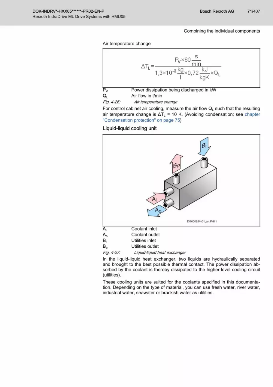
Air temperature change
PV Power dissipation being discharged in kWQL Air flow in l/minFig. 4-26: Air temperature changeFor control cabinet air cooling, measure the air flow QL such that the resultingair temperature change is ΔTL = 10 K. (Avoiding condensation: see chapter"Condensation protection" on page 75)
Liquid-liquid cooling unit
Ai Coolant inletAo Coolant outletBi Utilities inletBo Utilities outletFig. 4-27: Liquid-liquid heat exchangerIn the liquid-liquid heat exchanger, two liquids are hydraulically separatedand brought to the best possible thermal contact. The power dissipation ab‐sorbed by the coolant is thereby dissipated to the higher-level cooling circuit(utilities).These cooling units are suited for the coolants specified in this documenta‐tion. Depending on the type of material, you can use fresh water, river water,industrial water, seawater or brackish water as utilities.
DOK-INDRV*-HXX05******-PR02-EN-P Bosch Rexroth AG 71/407Rexroth IndraDrive ML Drive Systems with HMU05
Combining the individual components

Data for selection Determining specific cooling capacity
PV Power dissipation being discharged in kWP01 Specific cooling capacity in kW/KT1 Inlet temperature of coolant in °CT2 Inlet temperature of utilities in °CFig. 4-28: Determining specific cooling capacityCooling warmer medium (coolant)
ΔT1 Temperature reduction of coolant in Kρ1 Density of coolant in kg/lPV Power dissipation in kWc1 Specific thermal capacity of coolant in kJ/kgKQ1 Flow rate of coolant in l/minFig. 4-29: Cooling warmer medium (coolant)Temperature increase of colder medium (utilities)
ΔT2 Temperature increase of utilities in Kρ2 Density of utilities in kg/lPV Power dissipation in kWc2 Specific thermal capacity of utilities in kJ/kgKQ2 Flow rate of utilities in l/minFig. 4-30: Temperature increase of colder medium (utilities)
Bosch Rexroth AG DOK-INDRV*-HXX05******-PR02-EN-P72/407Rexroth IndraDrive ML Drive Systems with HMU05
Combining the individual components

Refrigerating unit
Ai Coolant inletAo Coolant outletBi Air intakeBo Air outletFig. 4-31: Refrigerating unitA refrigerating unit consists of a refrigerant circuit and a coolant circuit. Thewater heated up by the drive components being cooled is conveyed by thecoolant pump through the evaporator and cooled down there. The heat takenfrom the coolant is brought to a higher temperature level in the refrigerant cir‐cuit and dissipated to a higher-level cooling medium in the liquefier. The re‐frigerant circuit is automatically controlled using thermostats. The desiredcoolant temperature can be exactly set.Refrigerating units are characterized by their refrigerating capacity.For units with an air-cooled liquefier, the refrigerating capacity depends onthe ambient temperature. The refrigerating capacity (in kW) of a refrigeratingunit must always be greater than or equal to the total power dissipation to bedischarged.Determining refrigerating capacity
Data for selection
PC Refrigerating capacity of refrigerating unit∑PV Sum of power dissipations being dischargedFig. 4-32: Determining refrigerating capacity
Cooling of the drive componentsTechnical data
The technical data needed to size the cooling system can befound in the project planning manuals of the drive componentsused (see "Other applicable documentation").
DOK-INDRV*-HXX05******-PR02-EN-P Bosch Rexroth AG 73/407Rexroth IndraDrive ML Drive Systems with HMU05
Combining the individual components

InterconnectionThe two possible kinds of hydraulic component interconnection (series con‐nection/parallel connection) show considerable differences with regard to:● Pressure decrease of entire cooling system● Delivery rate of coolant pump● Temperature level and temperature controllability of the individual com‐
ponents being cooled
Parallel connection Series connection
Tab. 4-10: Parallel and series connection of drive components being cooledParallel connection Parallel connection is characterized by nodal points in the hydraulic system.
The following applies:● The sum of the coolant flows which flow towards a nodal point equals
the sum of the coolant flows which flow away from this nodal point.● For all cooling system branches between two nodal points there is the
same pressure difference (pressure decrease).Aspects of applicationThe individual components being cooled● Can be cooled with the individually required flow rate ⇒ high degree of
thermal operational safety● Have the same temperature level at the coolant inlet ⇒ steady machine
temperature increase● All have the same pressure difference between coolant inlet and outlet
⇒ high degree of hydraulic operational safety of the cooling system dueto low total pressure.
Series connection With series connection, one single coolant flow is flowing through all compo‐nents to be cooled.The following applies:● The flow rates of all components are the same.● Each component has a pressure decrease between inlet and outlet of
the coolant. The individual pressure decreases add up to form the totalpressure decrease of the drive components.
Aspects of application
Bosch Rexroth AG DOK-INDRV*-HXX05******-PR02-EN-P74/407Rexroth IndraDrive ML Drive Systems with HMU05
Combining the individual components

The following properties of series connection generally have to be observed:● Series connection does not allow setting the required flow rate individu‐
ally for each of the connected components.● The required system pressure corresponds to the sum of all pressure
decreases of the connected individual components. This means a lowerdegree of hydraulic operational safety of due to high system pressure.
● The temperature level of the coolant increases from component to com‐ponent because each power dissipation discharged to the coolant in‐creases its temperature. This means uneven machine temperature in‐crease by the components being cooled.
Combined interconnection
Fig. 4-33: Combined interconnection of drive components being cooledThe combined interconnection of the drive components being cooled allowsusing the advantages of parallel and series connection.
Condensation protection
Risk of damage. Drive components cannotbuild condensation.
NOTICE
In temperate zones (up to 40°C and 70% humidity), the inlet temperature ofthe coolant may be at a maximum 5 K below the temperature in the controlcabinet.Safest protection against condensation:Coolant inlet temperature = ambient temperature
The temperature of the coolant flowing through liquid-cooled drive compo‐nents generally differs from the temperature of the ambient air.Depending on the humidity, the ambient air contains water vapor. Theamount of water vapor which can be absorbed by the air depends on the airtemperature and air pressure. The warmer the air, the more water vapor itcan absorb at the same air pressure.When warm air gets in contact with a less warm object, a moist film (conden‐sation) forms on the surface of the object if the temperature of the object isbelow the condensation temperature.Drive components with protection classes IPx4, IPx5, IPx6 are not at riskfrom condensation because their design provides sufficient protection againstwater.
DOK-INDRV*-HXX05******-PR02-EN-P Bosch Rexroth AG 75/407Rexroth IndraDrive ML Drive Systems with HMU05
Combining the individual components

Drive components with the protection class IPx0, such as drive controllersand supply units, do not have sufficient protection against water. This is whycondensation cannot be allowed to form on them.
Condensation temperature In temperate zones (e.g., Central Europe), the condensation temperature is34°C at● Air temperatures up to 40°C and● Relative humidity up to 70%For climatic zones with higher air temperatures and/or higher relative humidi‐ties, the condensation temperature must be graphically determined accordingto the figure below. The maximum temperature difference between internalair of the control cabinet and coolant inlet temperature derives from the fig‐ure.
A Characteristic of water vapor saturationB Maximum temperature of ambient airC Condensation temperatureG1, G2 Artificial linesrH Relative humidityT Ambient temperaturea Maximum ambient temperature (e.g., 40°C)b, b1 Intersection point of ambient air temperature and characteristic
of water vapor saturation. This intersection point characterizesthe 100% humidity value (b1)
c Convert 100% humidity value graphically by parallel translationof artificial line G1 to expected humidity value (e.g., 70%) (⇒ ar‐tificial line G2)
d Intersection point of expected humidity value and characteristicof water vapor saturation leads to expected condensation tem‐perature of drive component (34°C)
Fig. 4-34: Determining condensation temperature
Bosch Rexroth AG DOK-INDRV*-HXX05******-PR02-EN-P76/407Rexroth IndraDrive ML Drive Systems with HMU05
Combining the individual components

The temperature difference between the actual ambient air tem‐perature and the coolant inlet temperature must not be greaterthan between maximum ambient air temperature and moisturecondensation temperature to be expected!
CoolantWater-based coolant
Risk of damage to components.NOTICE
● Observe the required properties and the appropriate composition of thecoolant.
● For transport and storage of the components, make sure sufficient anti‐freeze is provided (see chapter "Transport and storage").
Required properties Most cooling systems use water as coolant. The values given in the technicaldata of the components thus refer to the coolant water with a maximum volu‐metric content of 3% coolant additives.The water-based coolant must have the following properties:● pH value: 7-8.5● Hardness: max. 10 °dH (England: 12.5 °e; France: 17.8 °f; USA: 178
ppm CaCO3)● Chloride: max. 20 mg/l● Nitrate: max. 10 mg/l● Sulfate: max. 100 mg/l● Insoluble substances: max. 250 mg/lDrinking water in Germany complies with these requirements.
Antifreeze Coolant with antifreeze may only be used for transport and storage of thecomponents (see chapter "Transport and storage").
Protection against corrosion ● For protection against corrosion and chemical stabilization, an appropri‐ate additive must be mixed with the cooling water.
● The required mixing ratio (according to manufacturer's data sheet) mustbe complied with and checked. Deviations can cause:– Reduction of cooling capacity– Changes in emulsion stability– Unexpected behavior with gasket materials– Reduction of protection against corrosion
● The coolant should be chemically neutral (pH-value approx. 7).● Use closed circuit. An open circuit should not be used for cooling, be‐
cause deposits and corrosion (e.g., from hard water) worsen the heattransfer or completely clog up cooling channels.
If the required mixing ratio exceeds the maximum permitted addi‐tion, the cooling system must be calculated with the resultingcoolant.
Anti-corrosion additive Aqueous solutions ensure reliable protection against corrosion without nota‐ble changes in the physical properties of the water.
DOK-INDRV*-HXX05******-PR02-EN-P Bosch Rexroth AG 77/407Rexroth IndraDrive ML Drive Systems with HMU05
Combining the individual components

Observe the safety instructions of the anti-corrosive manufacturer(e.g., DIN safety sheet).
Coolant additivesRecommended manufacturer of
coolant additivesThe proper chemical treatment of closed water systems is required to preventcorrosion, maintain heat transmission and minimize growth of bacteria in allparts of the system.
Rexroth cannot make any general statements or inquiries into thesuitability of system-specific cooling media, additives or operatingconditions.Testing the performance of the coolants used and sizing the liquidcoolant system are generally the responsibility of the machinemanufacturer.
Water-based coolantWater + Antifrogen in a 4:1 ratio (e.g., "Rifrost" from Rittal).
Non-water-based coolantNon-water-based coolants (e.g., oil) are not permitted.
Sizing liquid coolingThe corresponding information for sizing a cooling system with liquid coolingplus a sizing example can be found in the appendix.
Bosch Rexroth AG DOK-INDRV*-HXX05******-PR02-EN-P78/407Rexroth IndraDrive ML Drive Systems with HMU05
Combining the individual components

4.4.3 UL ratingsIntroduction
This chapter contains:● Limit values for use within the scope of CSA / UL● Applied standards (CE conformity, UL listing)
InverterAmbient and operating conditions - UL ratings
Description Symbol UnitHMU05.1N-F0140-0350-N-A4-D7-P
HMU05.1N-F0170-0430-N-A4-D7-P
HMU05.1N-F0220-0510-N-A4-D7-P
HMU05.1N-F0270-0660-N-A4-D7-P
Short circuit current rating SCCR A rms 85000
Rated input voltage, power1) ULN_nenn V DC 450...750
Rated input current ILN A 242.0 291.0 373.0 467.0
Output voltage Uout V 3 x AC 0...500
Output current Iout A 254.0 306.0 392.0 490.0
Last modification: 2015-12-03
1) Mains input L1, L2, L3 (for HMV and HCS only); For use on asolidly grounded wye source only.
Tab. 4-11: HMU – ambient and operating conditions – UL ratingsAmbient and operating conditions - UL ratings
Description Symbol UnitHMU05.1N-F0340-0820-N-A4-D7-P
HMU05.1N-F0430-1040-N-A4-D7-P
HMU05.1N-F0540-1300-N-A4-D7-P
HMU05.1N-F0680-1690-N-A4-D7-P
Planned
Short circuit current rating SCCR A rms 85000
Rated input voltage, power1) ULN_nenn V DC 450...750
Rated input current ILN A 587.0 734.0 954.0 tbd
Output voltage Uout V 3 x AC 0...500
Output current Iout A 616.0 771.0 1002.0 tbd
Last modification: 2015-12-03
1) Mains input L1, L2, L3 (for HMV and HCS only); For use on asolidly grounded wye source only.
Tab. 4-12: HMU – ambient and operating conditions – UL ratings
DOK-INDRV*-HXX05******-PR02-EN-P Bosch Rexroth AG 79/407Rexroth IndraDrive ML Drive Systems with HMU05
Combining the individual components

Supply unitsAmbient and operating conditions - UL ratings
Description Symbol UnitHMU05.1N-F0140-0350-N-A4-D7-P
HMU05.1N-F0170-0430-N-A4-D7-P
HMU05.1N-F0220-0510-N-A4-D7-P
HMU05.1N-F0270-0660-N-A4-D7-P
Short circuit current rating SCCR A rms 85000
Rated input voltage, power1) ULN_nenn V 3 x AC 380...500
Mains frequency fLN Hz 50...60
Nominal current ILN A 218.00 262.00 327.00 409.00
Output voltage Uout V DC 750
Output power Pout kW 144.00 173.00 216.00 270.00
Last modification: 2015-12-03*
1) Mains input L1, L2, L3; For use on a solidly grounded wyesource only.
Tab. 4-13: HMU – ambient and operating conditions – UL ratingsAmbient and operating conditions - UL ratings
Description Symbol UnitHMU05.1N-F0340-0820-N-A4-D7-P
HMU05.1N-F0430-1040-N-A4-D7-P
HMU05.1N-F0540-1300-N-A4-D7-P
HMU05.1N-F0680-1690-N-A4-D7-P
Planned
Short circuit current rating SCCR A rms 85000
Rated input voltage, power1) ULN_nenn V 3 x AC 380...500
Mains frequency fLN Hz 50...60
Nominal current ILN A 514.00 652.00 811.00 1019.00
Output voltage Uout V DC 750
Output power Pout kW 339.00 430.00 535.00 672.00
Last modification: 2015-12-03*
1) Mains input L1, L2, L3; For use on a solidly grounded wyesource only.
Tab. 4-14: HMU – ambient and operating conditions – UL ratings
Bosch Rexroth AG DOK-INDRV*-HXX05******-PR02-EN-P80/407Rexroth IndraDrive ML Drive Systems with HMU05
Combining the individual components

4.4.4 Compatibility with foreign mattersAll Rexroth controls and drives are developed and tested according to thestate-of-the-art technology.As it is impossible to follow the continuing development of all materials (e.g.lubricants in machine tools) which may interact with the controls and drives, itcannot be completely ruled out that any reactions with the materials we usemight occur.For this reason, before using the respective material a compatibility test hasto be carried out for new lubricants, cleaning agents etc. and our housings/materials.
DOK-INDRV*-HXX05******-PR02-EN-P Bosch Rexroth AG 81/407Rexroth IndraDrive ML Drive Systems with HMU05
Combining the individual components

4.5 Mechanical project planning4.5.1 DimensionsHMU05.1N-F0140-0350
A Minimum mounting clearanceB Boring dimensionsFig. 4-35: HMU05.1N-F0140-0350
Bosch Rexroth AG DOK-INDRV*-HXX05******-PR02-EN-P82/407Rexroth IndraDrive ML Drive Systems with HMU05
Combining the individual components

HMU05.1N-F0170-0430
A Minimum mounting clearanceB Boring dimensionsFig. 4-36: HMU05.1N-F0170-0430
DOK-INDRV*-HXX05******-PR02-EN-P Bosch Rexroth AG 83/407Rexroth IndraDrive ML Drive Systems with HMU05
Combining the individual components

HMU05.1N-F0220-0510
A Minimum mounting clearanceB Boring dimensionsFig. 4-37: HMU05.1N-F0220-0510
Bosch Rexroth AG DOK-INDRV*-HXX05******-PR02-EN-P84/407Rexroth IndraDrive ML Drive Systems with HMU05
Combining the individual components

HMU05.1N-F0270-0660
A Minimum mounting clearanceB Boring dimensionsFig. 4-38: HMU05.1N-F0270-0660
DOK-INDRV*-HXX05******-PR02-EN-P Bosch Rexroth AG 85/407Rexroth IndraDrive ML Drive Systems with HMU05
Combining the individual components

HMU05.1N-F0340-0820
A Minimum mounting clearanceB Boring dimensionsFig. 4-39: HMU05.1N-F0340-0820
Bosch Rexroth AG DOK-INDRV*-HXX05******-PR02-EN-P86/407Rexroth IndraDrive ML Drive Systems with HMU05
Combining the individual components

HMU05.1N-F0430-1040
A Minimum mounting clearanceB Boring dimensionsFig. 4-40: HMU05.1N-F0430-1040
DOK-INDRV*-HXX05******-PR02-EN-P Bosch Rexroth AG 87/407Rexroth IndraDrive ML Drive Systems with HMU05
Combining the individual components

HMU05.1N-F0540-1300
A Minimum mounting clearanceB Boring dimensionsFig. 4-41: HMU05.1N-F0540-1300
Bosch Rexroth AG DOK-INDRV*-HXX05******-PR02-EN-P88/407Rexroth IndraDrive ML Drive Systems with HMU05
Combining the individual components

4.5.2 Dimensions, mass, insulation, sound pressure level Data for mass, dimensions, sound pressure level, insulation
Description Symbol UnitHMU05.1N-F0140-0350-N-A4-D7-N
HMU05.1N-F0170-0430-N-A4-D7-N
HMU05.1N-F0220-0510-N-A4-D7-N
HMU05.1N-F0270-0660-N-A4-D7-N
Mass m kg 51.00 58.00 65.00
Device height1) H mm 817 921 1025
Device depth2) T mm 440
Device width3) B mm 200
Insulation resistance at 500 V DC Ris Mohm > 50
Capacitance against housing CY nF -
Average sound pressure level (ac‐curacy class 2) at PDC_cont
4) LP dB (A) -
Last modification: 2016-06-16
1) 2) 3) Housing dimension; see also related dimensional drawing4) According to DIN EN ISO 11205; comparative value at dis‐
tance 1 m, out of cabinet; HCS types with order code -L***:load-dependent
Tab. 4-15: HMU – data for mass, dimensions, sound pressure level, insulationData for mass, dimensions, sound pressure level, insulation
Description Symbol UnitHMU05.1N-F0340-0820-N-A4-D7-P
HMU05.1N-F0430-1040-N-A4-D7-P
HMU05.1N-F0540-1300-N-A4-D7-P
HMU05.1N-F0680-1690-N-A4-D7-P
Planned
Mass m kg 70.00 83.00 103.00 tbd
Device height1) H mm 1103 1311 1522 tbd
Device depth2) T mm 440 tbd
Device width3) B mm 200 220 tbd
Insulation resistance at 500 V DC Ris Mohm > 50
Capacitance against housing CY nF -
Average sound pressure level (ac‐curacy class 2) at PDC_cont
4) LP dB (A) -
Last modification: 2016-06-16
1) 2) 3) Housing dimension; see also related dimensional drawing4) According to DIN EN ISO 11205; comparative value at dis‐
tance 1 m, out of cabinet; HCS types with order code -L***:load-dependent
Tab. 4-16: HMU – data for mass, dimensions, sound pressure level, insulation
DOK-INDRV*-HXX05******-PR02-EN-P Bosch Rexroth AG 89/407Rexroth IndraDrive ML Drive Systems with HMU05
Combining the individual components

4.5.3 Temperatures, cooling, power dissipation, distancesCooling and power dissipation data
Description Symbol UnitHMU05.1N-F0140-0350-N-A4-D7-P
HMU05.1N-F0170-0430-N-A4-D7-P
HMU05.1N-F0220-0510-N-A4-D7-P
HMU05.1N-F0270-0660-N-A4-D7-P
Allowed mounting position G1
Allowed switching frequencies1) fs kHz 2,4,8
Power dissipation at Iout_cont = 0 A;fs = fs (min.)2)
PDiss_0A_fs
minW 230 250 270 320
Power dissipation at Iout_cont = 0 A;fs = fs (max.)3)
PDiss_0A_fs
maxW 300 325 350 400
Power dissipation at continuouscurrent and continuous DC buspower respectively4)
PDiss_cont W 2500.00 3000.00 4250.00 5500.00
Liquid cooling data
Power dissipation ratio (liquid)with continuous current/continu‐ous power
PDiss_cont_
FW 2100.0 2500.0 3500.0 4500.0
Coolant inlet temperature Tin °C Less than 60
Required minimum coolant flowfor PDiss_cont_F
Qmin l/min 4 5 7 9
Temperature increase for Qmin
and PDiss_cont_FΔT K Less than 10
Pressure drop for Q min Δp bar 0.4 0.5
Maximum allowed operating pres‐sure pmax bar 2.00
Coolant channel volume Vch ml 609 667 724
Coolant channel material Aluminum
Constant for determining pressuredrop KΔp tbd
Air cooling data
Power dissipation ratio (air) withcontinuous current/continuouspower
PDiss_cont_
AW 400.0 500.0 750.0 1000.0
Ambient temperature range foroperation with nominal data Ta_work °C 0...40
Ambient temperature range foroperation with reduced nominaldata
Ta_work_red °C 0...55
Derating of PDC_cont; PBD; Iout_cont
when Ta_work < Ta < Ta_work_redfTa %/K 2.0
Last modification: 2016-06-17
Bosch Rexroth AG DOK-INDRV*-HXX05******-PR02-EN-P90/407Rexroth IndraDrive ML Drive Systems with HMU05
Combining the individual components

Description Symbol UnitHMU05.1N-F0140-0350-N-A4-D7-P
HMU05.1N-F0170-0430-N-A4-D7-P
HMU05.1N-F0220-0510-N-A4-D7-P
HMU05.1N-F0270-0660-N-A4-D7-P
Volumetric capacity of forced cool‐ing V m3/h -
Minimum distance on the top ofthe device5) dtop mm 100
Minimum distance on the bottomof the device6) dbot mm 100
Temperature increase with mini‐mum distances dbot; dtop; PBD
ΔT K 10
Last modification: 2016-06-17
1) Also depending on firmware and control section; see parame‐ter description "P‑0‑0001, Switching frequency of the poweroutput stage"; see "P-0-4058, Amplifier type data"; for supplyunits the switching frequency is 4.2 kHz
2) 3) Plus dissipation of braking resistor and control section; find in‐terim values by interpolation to P_Diss_cont
4) Plus dissipation of braking resistor and control section5) 6) See fig. "Air intake and air outlet at device"Tab. 4-17: HMU – cooling and power dissipation dataCooling and power dissipation data
Description Symbol UnitHMU05.1N-F0340-0820-N-A4-D7-P
HMU05.1N-F0430-1040-N-A4-D7-P
HMU05.1N-F0540-1300-N-A4-D7-P
HMU05.1N-F0680-1690-N-A4-D7-P
Planned
Allowed mounting position G1
Allowed switching frequencies1) fs kHz 2,4,8
Power dissipation at Iout_cont = 0 A;fs = fs (min.)2)
PDiss_0A_fs
minW 350 400 450 500
Power dissipation at Iout_cont = 0 A;fs = fs (max.)3)
PDiss_0A_fs
maxW 450 500 550 600
Power dissipation at continuouscurrent and continuous DC buspower respectively4)
PDiss_cont W 5500.00 6500.00 8700.00 10000.00
Liquid cooling data
Power dissipation ratio (liquid)with continuous current/continu‐ous power
PDiss_cont_
FW 4500.0 5500.0 7500.0 8500.0
Coolant inlet temperature Tin °C Less than 60
Required minimum coolant flowfor PDiss_cont_F
Qmin l/min 9 11 16 18
Last modification: 2016-06-17
DOK-INDRV*-HXX05******-PR02-EN-P Bosch Rexroth AG 91/407Rexroth IndraDrive ML Drive Systems with HMU05
Combining the individual components

Description Symbol UnitHMU05.1N-F0340-0820-N-A4-D7-P
HMU05.1N-F0430-1040-N-A4-D7-P
HMU05.1N-F0540-1300-N-A4-D7-P
HMU05.1N-F0680-1690-N-A4-D7-P
Planned
Temperature increase for Qmin
and PDiss_cont_FΔT K Less than 10
Pressure drop for Q min Δp bar 0.6 1 1.3
Maximum allowed operating pres‐sure pmax bar 2.00
Coolant channel volume Vch ml 851 966 1024 tbd
Coolant channel material Aluminum
Constant for determining pressuredrop KΔp tbd
Air cooling data
Power dissipation ratio (air) withcontinuous current/continuouspower
PDiss_cont_
AW 1000.0 1200.0 1500.0
Ambient temperature range foroperation with nominal data Ta_work °C 0...40
Ambient temperature range foroperation with reduced nominaldata
Ta_work_red °C 0...55
fTa %/K 2.0
Volumetric capacity of forced cool‐ing V m3/h -
Minimum distance on the top ofthe device5) dtop mm 100
Minimum distance on the bottomof the device6) dbot mm 100
Temperature increase with mini‐mum distances dbot; dtop; PBD
ΔT K 10
Last modification: 2016-06-17
1) Also depending on firmware and control section; see parame‐ter description "P‑0‑0001, Switching frequency of the poweroutput stage"; see "P-0-4058, Amplifier type data"; for supplyunits the switching frequency is 4.2 kHz
2) 3) Plus dissipation of braking resistor and control section; find in‐terim values by interpolation to P_Diss_cont
4) Plus dissipation of braking resistor and control section5) 6) See fig. "Air intake and air outlet at device"Tab. 4-18: HMU – cooling and power dissipation data
Bosch Rexroth AG DOK-INDRV*-HXX05******-PR02-EN-P92/407Rexroth IndraDrive ML Drive Systems with HMU05
Combining the individual components

Property damage due to temperatures higherthan 105 ℃!
NOTICE
Observe the indicated minimum distances!Above the devices there may only be such materials which● are not combustible● are insensitive to the occurring high temperatures
A Air intakeB Air outletC Mounting surface in control cabinetdtop Distance topdbot Distance bottomdhor Distance horizontalFig. 4-42: Air intake and air outlet at device
4.5.4 Mounting positions of components
Risk of damage to the components by incor‐rect mounting position!
NOTICE
Only operate the components in their allowed mounting positions.For supply units and drive controllers installed in control cabinets, only themounting position G1 is allowed.
Mounting position G1
The air that is heated inside the component can flow out of thecomponent in a vertical upward direction. The natural convectionsupports the forced cooling air current. This avoids the generationof pockets of heat in the component.
1. Mounting surface in control cabinet2. Outgoing, heated air3. Component4. Fan within the component (forces the cooling air current)5. Cooling air
Tab. 4-19: Mounting position G1
DOK-INDRV*-HXX05******-PR02-EN-P Bosch Rexroth AG 93/407Rexroth IndraDrive ML Drive Systems with HMU05
Combining the individual components

4.6 Electrical project planning4.6.1 Overall connection diagram (HMU05 as drive controller)
Fig. 4-43: Connection diagram (HMU05 as drive controller)
Bosch Rexroth AG DOK-INDRV*-HXX05******-PR02-EN-P94/407Rexroth IndraDrive ML Drive Systems with HMU05
Combining the individual components

4.6.2 Overall connection diagram (HMU05 as supply unit)Overall connection diagram with load contactor
For your drive system, preferably use the connection with a loadcontactor pictured here (instead of the connection with a control‐lable main switch).
1) With multiple contactors connected in parallel, connect the N/Ocontacts and N/C contacts in series.
Fig. 4-44: Connection diagram with load contactor (HMU05 as supply unit)
DOK-INDRV*-HXX05******-PR02-EN-P Bosch Rexroth AG 95/407Rexroth IndraDrive ML Drive Systems with HMU05
Combining the individual components

Overall connection diagram with a controllable main switch
For your drive system, preferably use the connection with a loadcontactor (instead of the connection with a controllable mainswitch).
Transient oscillation processes between HNC and mains induc‐tance can occur when the main switch is turned on. Therefore,select an appropriate main switch.
Observe the local regulations regarding EMC and standards.
Bosch Rexroth AG DOK-INDRV*-HXX05******-PR02-EN-P96/407Rexroth IndraDrive ML Drive Systems with HMU05
Combining the individual components

1) With multiple main switches connected in parallel, connect theN/O contacts and N/C contacts in series.
Fig. 4-45: Connection diagram with controllable main switch (HMU05 as supplyunit)
DOK-INDRV*-HXX05******-PR02-EN-P Bosch Rexroth AG 97/407Rexroth IndraDrive ML Drive Systems with HMU05
Combining the individual components

4.6.3 Project planning of control voltageControl voltage for drive systems
Some components of a drive system have to be supplied with control voltage.When doing the project planning for control voltage supply, include the drivesystem component requirements:● Depending on the motor cable length and whether or not motor holding
brakes are used, the permitted tolerances of the supply voltage● Power consumption of the drive controllers● Power consumption of other loads (e.g., motor holding brakes, digital
outputs)● Current carrying capacity of the connection point for control voltage sup‐
ply on the component for the purpose of looping through the control volt‐age to other components
Sizing the control voltage supplyDetermining the power requirements
Drive controller power require‐ments
The total power requirements of the control voltage supply of a drive control‐ler result from the sum of the following power values:● Basic device (drive controller without connected encoders)● Optional connection interfaces (e.g., communication, additional encoder
evaluation)● Connected encoder systems● External loads See the type plate and type code for configuring your drive controller. The tables below contain the individual power values required by the drivecontroller. The power requirement of the supplying 24 V power supply unit re‐sults from the sum of these individual power values.
Basic device power requirements The power requirements of the basic device result from● Maximum current of drive controller● Inrush current of drive controller● Control section design (data: see Project Planning Manual for control
section)
Bosch Rexroth AG DOK-INDRV*-HXX05******-PR02-EN-P98/407Rexroth IndraDrive ML Drive Systems with HMU05
Combining the individual components

HMU05.1N-… performance[kW]
Current consumption of control voltage supply[Arms]
F0140-0350 110/132 1.7
F0170-0430 132/160 2.0
F0220-0510 160/200 2.2
F0270-0660 200/250 1.9
F0340-0820 250/315 2.0
F0430-1040 315/400 2.3
F0540-1300 400/500 2.4
F0680-1690 500/630 2.7
Tab. 4-20: Current consumption of control voltage supplyPower requirements of the option‐
al connection pointsIf the drive controller has optional connection points, the power requirementsof the basic device are increased. (Data: see Project Planning Manual forcontrol section)
Power requirements of the exter‐nal loads
External loads include, for example,● Encoder system of the motor● Motor holding brake● Load at a digital output The drive controller has to supply the external loads with power.Table 3: Power requirements of the external loads
External load Power requirement
5 V encoder system P = IEncoder × 5 V × 1.75 1), 5)
12 V encoder system P = IEncoder x 12 V x 1.25 1), 5)
Load at digital output P = ILoad x UN3 2), 4)
Motor holding brake P = IBrake x UN3 3), 4)
1) Iencoder : Current consumption of encoder system2) Iload : Current consumption of external load3) Ibrake : Current consumption of motor holding brake4) UN3 : Control voltage supply of drive controller5) The sum of the power consumption of all connected encoder
systems incl. encoder emulation cannot exceed 6 W.Tab. 4-21: Power requirements of the external loads
Calculation formula The total power consumption (PN3) from the 24 V control voltage of a drivecontroller is calculated with:PN3 = Pbasic device + ΣPoptional connection points + ΣPexternal loads
DOK-INDRV*-HXX05******-PR02-EN-P Bosch Rexroth AG 99/407Rexroth IndraDrive ML Drive Systems with HMU05
Combining the individual components

Requirements on the 24V power supply unit
PELV1) for 24V power supply unitFor the 24V supply of the devices of the Rexroth IndraDrive MLrange, use a power supply unit or a control-power transformerwith protection by PELV according to IEC 60204-1 (section 6.4).In the scope of CSA/UL, the data of the control-power transformerare limited to:● Max. output voltage: 42.4 Vpeak or 30 Vac
● Max. output power: 10000 VA
The following parameters contain the essential electrical requirements on the24 V power supply unit:● Output voltage or output voltage range● Continuous power which the 24 V power supply unit has to supply dur‐
ing operation● Peak current which the 24 V power supply unit has to supply when
switching on● Inrush current which the 24 V power supply unit has to supply when
switching onRequired continuous power The continuous power of the 24 V power supply unit has to be greater than
the sum of the power consumptions PN3 of the components being supplied.To select the 24 V power supply unit, determine the continuous current IN3 ofall components:IN3 = PN3 / UN3
(PN3 : power consumption of all components) The calculated current IN3 corresponds to the continuous current of the 24 Vpower supply unit.The power consumption is indicated as the maximum value of each compo‐nent and can occur in individual components.In drive systems with several components, the occurring power consumptionunder statistical assumptions will be lower than the calculated one.
Required peak current When the 24 V control voltage unit is switched on, the 24 V power supply unitis loaded with the charging current of the capacitors from the connected com‐ponents. This charging current is electronically limited in the components.The required peak current of the power supply unit is calculated with:IPeakCurrent_PowerSupplyUnit = 1.2 × PN3 / UN3
(PN3 : power consumption of all components)The power supply unit has to provide the calculated peak current IPeakCur‐
rent_PowerSupplyUnit for at least one second.Required inrush current See chapter 7.2.1 "Control voltage" on page 137
1) Protective Extra Low Voltage
Bosch Rexroth AG DOK-INDRV*-HXX05******-PR02-EN-P100/407Rexroth IndraDrive ML Drive Systems with HMU05
Combining the individual components

Installing the 24V supplyNotes on installation ● The 24 V supply of the Rexroth IndraDrive ML drive system components
should in principle be installed in a star layout. This means it is necessa‐ry to run separate supply lines for each group of drive controllers orthird-party components. This also applies to multiple-line arrangement incase of supply from, e.g., a supply unit.
● Route lines of sufficient size to reduce load-dependent voltage drops.● For looping through the control voltage, observe the maximum current
carrying capacity of the connection points. The maximum current carry‐ing capacity limits the number of devices to which the control voltagecan be looped through.
A Number of devices is limited to x components with a total cur‐rent consumption of < 40 A (in accordance with UL: 31 A).
B Number of devices is limited to y components with a total cur‐rent consumption of < 40 A (in accordance with UL: 31 A).
C Third-party component (e.g., PLC, valve, etc.)1) Connection to central ground point (e.g., PE earth-circuit con‐
nector)Fig. 4-46: Installing the 24 V supply
If you use several 24 V power supply units:● Output voltages of the 24 V power supply units have to be
within the allowed voltage range● Interconnect reference conductors 0 V of the individual 24 V
power supply units with low impedance● Always switch 24 V power supply units on and off synchro‐
nously
Chronological order of 24 V supply
and mains voltageBefore mains voltage or DC bus voltage is applied to the components, theyhave to be supplied by the 24 V supply.
DOK-INDRV*-HXX05******-PR02-EN-P Bosch Rexroth AG 101/407Rexroth IndraDrive ML Drive Systems with HMU05
Combining the individual components

Looping through the control volt‐
age Property damage in case of error from linecross section being too small!
NOTICE
Observe the current carrying capacity of the connection points for controlvoltage supply at the components used.
You can only loop through the control voltage between the components, if thesum of current consumptions ΣIN3 of the individual components is smallerthan 40 A (in accordance with UL: 31 A) (current carrying capacity of the con‐nection point XD10).
Fig. 4-47: Looping through the control voltage Sample calculation for 3 drive controllers:
Fig. 4-48: Continuous currentThe result ID has to be smaller than the specified current carrying capacity ofthe connection point.
4.6.4 Mains connectionResidual-current-operated circuit breakers (RCD, RCCB) as additional fusing
General informationThe following designations are used for residual-current-operated circuitbreakers:● RCCB (Residual-Current-Operated Circuit Breaker)● RCD (Residual-Current-Operated Device)● RCM (Residual-Current Monitoring Device)● Earth-leakage circuit breaker (voltage-independent)● Residual-current circuit breaker (voltage-dependent)
It is only to a limited extent that residual-current-operated circuitbreakers can be used with Rexroth IndraDrive ML systems.
If these circuit breakers are to be used, the company erecting the installationhas to check the mutual compatibility of the residual-current-operated circuitbreakers and installation or machine with the drive system, in order to avoid
Bosch Rexroth AG DOK-INDRV*-HXX05******-PR02-EN-P102/407Rexroth IndraDrive ML Drive Systems with HMU05
Combining the individual components

accidental triggering of the residual-current-operated circuit breaker. This hasto be taken into account● for switch-on processes, due to high asymmetric inrush currents and● during operation of the installation, due to leakage currents produced in
normal operation.
Cause of leakage currentsFor the purpose of stepless speed variation with a high degree of positioningaccuracy and dynamic response, certain modulation procedures are neces‐sary for drive systems. For physical reasons, these modulation proceduresgive rise to inevitable leakage current produced during normal operation. Es‐pecially with unbalanced loads of the mains phases or a large number ofdrives it can easily reach some amperes (rms value).The leakage current is not sinusoidal but pulse-shaped. For this reason,measuring instruments normally sized for alternating currents in the range of50 Hz are not suited. Use measuring instruments with rms value measuringranges up to at least 150 kHz.The degree of leakage current depends on the following features of the in‐stallation:● Type of inrush current limitation● Number, type and size of drives used● Length and cross section of connected motor power cables● Grounding conditions of the mains at the site of installation● Unbalance of the three-phase system● Types of filters and chokes connected in the incoming circuit● EMC measures that are takenIf measures are taken to improve the electromagnetic compatibility (EMC) ofthe installation (mains filters, shielded lines), the leakage current in theground wire is inevitably increased, especially when switching on or in thecase of mains unbalance. Given these operating conditions, residual-current-operated circuit breakers can trigger without an error having occurred.The EMC measures are mainly based on capacitive short-circuiting of the in‐terference currents within the drive system. Inductive filter measures can re‐duce the leakage currents, but affect the dynamic response of the drive andbring about● higher construction volume● higher weight● expensive core material
Possibilities of useMotor cable lengths Keep the motor cables as short as possible. Only short motor cables do allow
low leakage currents and thereby enable residual-current-operated circuitbreakers to work.
Types of residual-current-operatedcircuit breakers
There are two types of residual-current-operated circuit breakers:1. Residual-current-operated circuit breakers sensitive to power pulse cur‐
rent (type A acc. to IEC 60755)These are normally used. However, it is only pulsating direct fault cur‐rents of a maximum of 5 mA and sinusoidal alternating fault currentsthat they switch off safely. This is why they are not allowed for devicesthat can generate smoothed direct fault currents. In the case of smooth‐
DOK-INDRV*-HXX05******-PR02-EN-P Bosch Rexroth AG 103/407Rexroth IndraDrive ML Drive Systems with HMU05
Combining the individual components

ed direct fault currents that can be produced in power supply units,mains rectifiers and drive controllers with power converters in B6 circuit,the residual-current-operated circuit breaker is not triggered. This blocksthe triggering of a residual-current-operated circuit breaker sensitive topower pulse current in the case of ground contact, i.e. in the case oferror.Residual-current-operated circuit breakers sensitive to power pulse cur‐rent do not provide any protection against inadmissible contact voltage.
2. Residual-current-operated circuit breakers sensitive to universal current(type B acc. to IEC 60755)These circuit breakers are suited for smoothed direct fault currents, too,and safely switch off devices with B6 input rectifiers.If a current with 30 mA triggers the residual-current-operated circuitbreaker, it is possible to use a residual-current-operated circuit breakerwith a higher tripping current for machine protection.If this residual-current-operated circuit breaker triggers accidentally, too,check in how far the above conditions and dependencies can be im‐proved (for example, by connecting current-compensated mains chokesin the incoming circuit, increasing the inrush current limitation).
Using isolating transformer to re‐duce leakage current in mains
If there is no improvement achieved and the residual-current-operated circuitbreaker, due to specific mains conditions on site, has to be used neverthe‐less on the mains input side, connect an isolating transformer between mainsconnection and power connection of the drive system. This reduces the leak‐age current in the ground wire of the mains that is produced during normaloperation which allows the residual-current-operated circuit breaker to beused. Connect the neutral point of the secondary winding of the isolatingtransformer to the equipment grounding conductor of the drive system.Adjust the ground-fault loop impedance to the overcurrent protective deviceso that the unit can be switched off in the case of failure.Before operating enable, check the correct function of the overcurrent protec‐tion device including activation in the case of failure.Exclusive fusing by residual-current-operated circuit breakerFor drive systems with electronic drive controllers, exclusive protection bymeans of a residual-current-operated circuit breaker normally is not possibleand not allowed.Electronic equipment that has a nominal power higher than 4 kVA or is des‐tined for permanent connection does not need residual-current-operated cir‐cuit breakers.According to IEC 60204‑1 and IEC 61800‑5‑1, the mains-side protectionagainst indirect contact, i.e. in the case of insulation failure, has to be provi‐ded in a different way, for example by means of an overcurrent protection de‐vice, protective grounding, protective-conductor system, protective separationor total insulation.
Mains typesTN-S mains typeThe TN-S mains type is the usual mains type in Europe.
Bosch Rexroth AG DOK-INDRV*-HXX05******-PR02-EN-P104/407Rexroth IndraDrive ML Drive Systems with HMU05
Combining the individual components

T = Direct grounding of a point (station ground)N = Exposed conductive parts directly connected to station groundS = Separate neutral conductor and equipment grounding conduc‐
tor in entire mainsFig. 4-49: TN-S mains type
TN-C mains type
T = Direct grounding of a point (station ground)N = Exposed conductive parts directly connected to station groundC = Neutral conductor and equipment grounding conductor func‐
tions in entire mains combined in a single conductor, the PENconductor.
Fig. 4-50: TN-C mains type
DOK-INDRV*-HXX05******-PR02-EN-P Bosch Rexroth AG 105/407Rexroth IndraDrive ML Drive Systems with HMU05
Combining the individual components

IT mains type
I Insulation of all active parts from ground or connection of onepoint to ground via an impedance RE
T Exposed conductive parts directly grounded, independent ofgrounding of current source (station ground)
Fig. 4-51: IT mains typeNotes on project planning Risk to damage to devices from voltage arc‐
ing.NOTICE
For applications with static charging (e.g., printing, packaging) and operationon IT mains type, use an isolating transformer with UK ≤ 2.5%.
Voltage increase in the case of ground fault!In case of a "ground fault" in the IT mains type, higher voltagesagainst ground (device housing) affect the device as opposed toerror-free operation.The "ground fault" in the IT mains type is only possible temporari‐ly with the IndraDrive components.For operation on the IT mains type, the drive system includingmains filter and mains choke should be electrically separatedfrom the mains by an isolating transformer.In this way, the ground fault detection or monitoring can remaineffective in the system.
Bosch Rexroth AG DOK-INDRV*-HXX05******-PR02-EN-P106/407Rexroth IndraDrive ML Drive Systems with HMU05
Combining the individual components

TT system
T = Direct grounding of a point (station ground)T = Exposed conductive parts directly grounded, independent of
grounding of current source (station ground)Fig. 4-52: TT mains systemThe EMC requirements are only observed through specific measures (incl.special mains filters).
Mains with grounded outer conductor (Corner-grounded delta mains)
I = Isolation of all active parts from ground, connection of onephase ‑ generally phase V - to ground or via an impedance RE
T = Exposed conductive parts directly grounded, independent ofgrounding of current source (station ground)
Fig. 4-53: Mains with grounded outer conductorNotes on project planning The EMC requirements are only observed through specific measures (incl.
special mains filters).
DOK-INDRV*-HXX05******-PR02-EN-P Bosch Rexroth AG 107/407Rexroth IndraDrive ML Drive Systems with HMU05
Combining the individual components

HNF05 mains filter and HNC05 mains capacitors on mains groun‐ded with outer conductorHNF05 mains filter and HNC05 mains capacitors are not suitedfor operation on mains grounded with outer conductor. Use isolat‐ing transformers.Allowed mains connection voltage: see technical data for eachdevice
Mains connection typeSee also chapter 4.6.4 "Mains connection" on page 102.Wire the ready relay contacts of the drive controllers supplied with mains volt‐age in the control circuit of the mains contactor.
Parallel connection Multiple HMU05 components (same size) are connected to the mains and inparallel to a larger HMV05. Each HMU05 has its own mains choke and mainsfilter.
Grayed out components: optional, depending on the applica‐tion
A HMU05 component (all components A identical); connected tosupply mains with mains chokes; connected to other compo‐nents through DC bus
B HMU05 component (as HMS05 inverter); connected to othercomponents through DC bus
K1 on/off Mains contactor wiring; connect the auxiliary contacts of themains contactors in series (see picture below)
M IndraBusN HNA05 mains connection moduleFig. 4-54: Parallel connection; multiple HMU05 components connected to sup‐
ply mains
Bosch Rexroth AG DOK-INDRV*-HXX05******-PR02-EN-P108/407Rexroth IndraDrive ML Drive Systems with HMU05
Combining the individual components

Mains contactor wiring in the case of parallel connection
Fig. 4-55: Mains contactor wiring in the case of parallel connection
Mains contactor wiring: Connect the auxiliary contacts of themains contactors in series. The auxiliary contacts are evaluatedby HNA05.Switch-on process: N/O contacts are monitoredSwitch-off process: N/C contacts are monitored
DOK-INDRV*-HXX05******-PR02-EN-P Bosch Rexroth AG 109/407Rexroth IndraDrive ML Drive Systems with HMU05
Combining the individual components

Risk of fire caused by missing fuses!NOTICE
Install fuses. In case a short circuit occurs in the drive controller, a fuse pro‐vides optimum safety against overheating or fire (see also IEC 61800‑5‑1 andUL 508C).For distribution in North America, single fuses are required for this type ofmains connection (see UL 508A).In the scope of international and European standards (IEC/EN, not NorthAmerica), it is allowed to use a group fuse instead of the single fuses. Whenselecting the nominal current of the group fuse, observe the loop impedance,the line length and the line cross section of the mains supply feeder (see IEC60204-1, chapter Appendix A).Observe the data for dimensioning line cross sections and fuses (see alsoIEC 60204‑1, UL 508A and NFPA 79).
Mains connected load and mains current Technical data of the components● See chapter 7.2.2 "Mains voltage" on page 139● See chapter 7.2.3 "DC bus" on page 141
Calculating the mains-side phase current The mains-side phase current is required for the following cases:● Selecting mains contactor● Determining fuses in the mains connection● Determining line cross section● Selecting other components in the mains connection (mains filter, mains
choke)Operation under rated conditions For data on mains contactor, fuses and cross section in operation under rat‐
ed conditions, see technical data of the respective component.Operation at partial load Operation at partial load can lead to smaller mains contactors, fuses and line
cross sections.If defined data for operation at partial load are available, the mains-sidephase current can be determined as follows:1. Determine motor power
Take power of drive controller-motor combination from Rexroth Indra‐Size or calculate it.
PmHa Mechanical nominal power for main drives (shaftoutput) [kW]
Mn Nominal motor torque [Nm]nn Nominal motor speed [min-1]
2. Determine DC bus power from motor power and efficiency
Bosch Rexroth AG DOK-INDRV*-HXX05******-PR02-EN-P110/407Rexroth IndraDrive ML Drive Systems with HMU05
Combining the individual components

PDC Required DC bus continuous power [W]Meff Effective torque in Nmnm Average speed in min-1
k Factor for motor and controller efficiency = 1.253. Add powers of all axes at common DC bus and put them into relation to
rated power of supply unit⇒ Partial load of PDC_cont is available
4. Determine power factor TPF for partial load (TPF = Total Power Factor)For the value TPF at rated power and TPF10 (at 10% of rated power),see technical data (mains voltage) of the component.
5. Calculate mains connected load
SLN Mains connected load [VA]PDC DC bus continuous power [W]TPF Total Power Factor λ
6. Calculate mains-side phase current
3-phase: ILN Mains-side phase current in [A]SLN Mains connected load [VA]ULN Voltage between phases of mains [V]
7. Select mains contactor8. Determine mains circuit breaker and line cross section
See chapter 11.2 "Dimensioning the line cross sections and fuses " onpage 371
Dimensioning the line cross sections and fusesSee chapter 11.2 "Dimensioning the line cross sections and fuses " on page371.
Dimensioning and selecting the mains transformerMains transformers are always needed when the mains voltage is outside ofthe allowed nominal voltage of the component.
Grounded mains The mains voltage for grounded mains is generally adjusted with autotrans‐formers.
Ungrounded mains The mains voltage for ungrounded mains is generally adjusted with isolatingtransformers to prevent overvoltages between outer conductor and ground.Short-circuit voltage of the isolating transformer: ≤ 6%
DOK-INDRV*-HXX05******-PR02-EN-P Bosch Rexroth AG 111/407Rexroth IndraDrive ML Drive Systems with HMU05
Combining the individual components

Combining mains filter, mains choke, preconnected choke and capacitance pack
HNF05.1A-500N Mains filterHNL05.1R Preconnected chokeHNC05.1N Mains capacitorHNL05.1R Mains chokeHMU05.1N Universal inverterFig. 4-56: Mains connection components
Bosch Rexroth AG DOK-INDRV*-HXX05******-PR02-EN-P112/407Rexroth IndraDrive ML Drive Systems with HMU05
Combining the individual components

Components
Supply unit HMU05.1N-…
F014
0-03
50(1
10 k
W s
ize)
F017
0-04
30(1
32 k
W s
ize)
F022
0-05
10(1
60 k
W s
ize)
F027
0-06
60(2
00 k
W s
ize)
F034
0-08
20(2
50 k
W s
ize)
F043
0-10
40(3
15 k
W s
ize)
F054
0-13
00(4
00 k
W s
ize)
F068
0-16
90(5
00 k
W s
ize)
Mai
ns c
hoke
HN
L05.
1R-
0219-N0218 ✓
0182-N0262 ✓
0135-N0327 ✓
0117-N0409 ✓
0130-N0514 ✓
0113-N0652 ✓
0100-N0811 ✓
0094-N1019 ✓
Prec
onne
cted
cho
keH
NL0
5.1R
-
0045-N0327 ✓
0054-N0409 ✓
0043-N0514 ✓
0050-N0652 ✓
0040-N0811 ✓
0040-N1019 ✓
Mai
ns c
apac
itor
HN
C05
.1N
- 0050 ✓ ✓
0075 ✓
0100 ✓ ✓ ✓ ✓ ✓
Mai
ns fi
lter
HN
F05.
1A-
500N-R0250 ✓
500N-R0320 ✓
500N-R0400 ✓
500N-R0600 ✓ ✓
500N-R1000 ✓ ✓
500N-R1600 ✓
Tab. 4-22: Mains connection components
DOK-INDRV*-HXX05******-PR02-EN-P Bosch Rexroth AG 113/407Rexroth IndraDrive ML Drive Systems with HMU05
Combining the individual components

4.6.5 Running multiple HMU05s in parallelUp to eight HMU05 with the same performance can be operated in parallel toextend the power range.Parallel HMU05s can be operated both as supply units and drive controllers.Operation as supply unit uses HNL05 mains chokes to balance parallel oper‐ation.
Fig. 4-57: Parallel operation of HMU05 to run as supply unit
Operation as drive controller uses additional HML05 motor chokes.
Bosch Rexroth AG DOK-INDRV*-HXX05******-PR02-EN-P114/407Rexroth IndraDrive ML Drive Systems with HMU05
Combining the individual components

Clock frequency Parallel HMU05s can only be operated at clock frequenciesbelow 8 kHz.
Motor A motor can be operated with electrically isolated windings.A motor cannot be operated with phase-shifted windings.
Fig. 4-58: Parallel operation of HMU05 to run as drive controllerWhen running in parallel, one HMU05 is the "master" and the other HMU05sare the "slaves".The master has a CSx02.5 control section and an HPC01.1-MN02 optionalcard. The master communicates with the slaves through the HPC01.1-P001optional cards (ring topology). Connection cables to the HPC01.1-P001 op‐tional cards always have to be run inside the control cabinet. Comply withmaximum allowed line lengths.The power outputs have to be wired symmetrically to ensure the output cur‐rent of the HMU05s are symmetrically distributed and no HMU05s are over‐loaded. To do this, the power outputs are connected to a common busbar.The motor is then connected directly to the busbar.
Maximum line lengths Between HMU05 and motor:
● Shielded: 100 m● Unshielded: 150 m
DOK-INDRV*-HXX05******-PR02-EN-P Bosch Rexroth AG 115/407Rexroth IndraDrive ML Drive Systems with HMU05
Combining the individual components

Comply with the allowed cable capacitance for motor chokes or balancingchokes.
Connection to HPC01.1-P001 optional cards● 1 m: Between two neighboring devices● 8 m: Between the last and first device(Lines may not be routed outside the control cabinet.)
Derating 5%Since the output current is not exactly distributed equally even with a sym‐metrical design, the output current is derated. Therefore, it is impossible touse 100% of the calculated total power.
Bosch Rexroth AG DOK-INDRV*-HXX05******-PR02-EN-P116/407Rexroth IndraDrive ML Drive Systems with HMU05
Combining the individual components

4.7 Acceptance tests and approvalsDeclaration of conformity Declarations of conformity confirm that the components comply with the valid
EN standards and EC directives. If required, our sales representative canprovide you with the declarations of conformity for components.
Drive controllers,Supply units Motors
CE conformity regardingLow-Voltage Directive
EN 61800-5-1:2007 EN 60034-1:2010+Cor.:2010EN 60034-5:2001+A1:2007
CE conformity regardingEMC product standard EN 61800-3:2004 + A1:2012
Tab. 4-23: CE - applied standards
C-UL-US listing The components are listed by UL (Underwriters Laboratories Inc.®).Proof of certification can be found online:www.ul.com/databaseUnder "UL File Number" enter the file number or under "Company Name" en‐ter the company name "Bosch Rexroth AG".
● UL standard: 61800-5-1● CSA standard: Canadian Standard
CSA C22.2 No. 274-13
Company NameBOSCH REXROTH ELECTRIC DRIVES & CON‐TROLS GMBHCategory Name:Power Conversion Equipment
File numbersRexroth IndraDrive ML components (HMU05, HNA05,HNC05, HNF05, HNL05, HML05, HLL05, HPC01):● E134201
Tab. 4-24: C-UL listing
UL ratingsWhen using the component in the scope of CSA / UL, observe theUL ratings for each component.Make sure that the indicated SCCR short-circuit rating is not ex‐ceeded, e.g., by using appropriate fuses in the mains connectionof the supply unit.
UL wiring materialIn the scope of CSA / UL, use copper 60/75 °C only; class 1 orequivalent only.
DOK-INDRV*-HXX05******-PR02-EN-P Bosch Rexroth AG 117/407Rexroth IndraDrive ML Drive Systems with HMU05
Combining the individual components

Allowed pollution degreeComply with the allowed pollution degree of the components (see"Ambient and operating conditions").
CCC (China Compulsory Certifica‐
tion)The CCC mark is a compulsory certification of safety and quality for certainproducts mentioned in the product catalog "First Catalogue of Products Sub‐ject to Compulsory Certification" and in the CNCA document "ApplicationScope for Compulsory Certification of Products acc. first Catalogue" and putin circulation in China. This compulsory certification has existed since 2003.CNCA is the Chinese authority responsible for certification guidelines. Whena product is imported in China, the certification will be checked at customsusing the entries in a database. Three criteria are typically critical for certifica‐tion being required:1. Customs tariff number (HS code) according to CNCA document "Appli‐
cation Scope for Compulsory Certification of Products acc. first Cata‐logue".
2. Area of application according to CNCA document "Application Scope forCompulsory Certification of Products acc. first Catalogue".
3. For the IEC product standard used, a corresponding Chinese GB stand‐ard must exist.
For the drive components by Rexroth described in this documentation, certifi‐cation is currently not required, so they are not CCC certified. Negative certifi‐cations will not be issued.
Bosch Rexroth AG DOK-INDRV*-HXX05******-PR02-EN-P118/407Rexroth IndraDrive ML Drive Systems with HMU05
Combining the individual components

5 Condition as supplied, identification, transport andstorage
5.1 Condition as supplied5.1.1 Factory testingVoltage testing and insulation resistance testing
According to standard, the components of the Rexroth IndraDrive ML rangeare tested with voltage.
Testing Test rate
Voltage testing 100% (EN 61800-5-1)
Insulation resistance testing 100% (EN 60204-1)
Tab. 5-1: Applied standards
5.1.2 Customer testing
Risk of damage to the installed Rexroth com‐ponents by customer-side testing of the ma‐chine or installation!
NOTICE
Before conducting voltage testing or insulation resistance testing for an instal‐lation or machine in which these components are used:Disconnect all connections to the Rexroth components or disconnect theplug-in connections to protect the electronic components.
DOK-INDRV*-HXX05******-PR02-EN-P Bosch Rexroth AG 119/407Rexroth IndraDrive ML Drive Systems with HMU05
Condition as supplied, identification, transport and storage

5.2 Identification5.2.1 Type platesDesign
Type plate (device)
1 Device type2 Part number3 Production week; 11W36, for example, means year 2011,
week 364 Factory identifier5 Bar code6 Serial number7 Hardware index8 Country of manufacture9 IdentificationFig. 5-1: Type plate (device)
5.2.2 Contents of delivery
Standard
HAS10.1-002-006-NN
Documentation
Tab. 5-2: Contents of delivery HMU05
5.3 Transporting componentsAmbient and operating conditions for transport
Description Symbol Unit Value
Temperature range Ta_tran °C -25 to 70
Relative humidity % 5 to 95
Absolute humidity g/m3 1 to 60
Climatic category (IEC721) 2K3
Condensation Not permitted
Icing Not permitted
Tab. 5-3: Ambient and operating conditions for transport
Bosch Rexroth AG DOK-INDRV*-HXX05******-PR02-EN-P120/407Rexroth IndraDrive ML Drive Systems with HMU05
Condition as supplied, identification, transport and storage

5.4 Storing components
Risk of damage to components from long-term storage.
NOTICE
Some components contain electrolytic capacitors which may deteriorate dur‐ing storage.When storing the following components for a longer period of time, run themonce per year for at least one hour:● Converters and supply units: operated with line voltage VLN
● Inverters and DC bus capacitor units: operated with DC bus voltage VDC
Risk of damage to liquid-cooled componentsfrom frost.
NOTICE
Before storing, fully drain coolant channels or use antifreeze.
Ambient and operating conditions for storage
Description Symbol Unit Value
Temperature range Ta_store °C -25 to 55
Relative humidity % 5 to 95
Absolute humidity g/m3 1 to 29
Climatic category (IEC721) 1K3
Condensation Not permitted
Icing Not permitted
Tab. 5-4: Ambient and operating conditions for storage
DOK-INDRV*-HXX05******-PR02-EN-P Bosch Rexroth AG 121/407Rexroth IndraDrive ML Drive Systems with HMU05
Condition as supplied, identification, transport and storage

Bosch Rexroth AG DOK-INDRV*-HXX05******-PR02-EN-P122/407Rexroth IndraDrive ML Drive Systems with HMU05

6 Mounting and installation6.1 Mounting HMU05 devices in control cabinet
HMU05 drive controllers were designed to be mounted in control cabinets.Notes on mounting ● When mounting, observe the mandatory minimum distances between
components (see chapter 4.5.1 "Dimensions" on page 82).● Tightening torque of the M10 mounting screws: 48 Nm● Mounting tools: HAS08.1-008-NNN-MH
Description of the individual mounting steps: See chapter 8.2.2 "Cabi‐net installation kit (HAS08.1-008)" on page 149.
● Mounting accessories:– Mounting plate for device width 200 mm: HAS10.1-002-005
See chapter "Mounting plate for device width 200 mm(HAS10.1-002-005)" on page 162.
– Mounting plate for device width 220 mm: HAS10.1-002-006See chapter "Mounting plate for device width 220 mm(HAS10.1-002-006)" on page 164.
6.2 Electrical connection6.2.1 Overall connection diagram (HMU05 as drive controller)
See chapter 4.6.1 "Overall connection diagram (HMU05 as drive controller)"on page 94.
6.2.2 Overall connection diagram (HMU05 as supply unit)Overall connection diagram with load contactor
See chapter "Overall connection diagram with load contactor" on page 95.
Overall connection diagram with controllable main switchSee chapter "Overall connection diagram with a controllable main switch" onpage 96.
DOK-INDRV*-HXX05******-PR02-EN-P Bosch Rexroth AG 123/407Rexroth IndraDrive ML Drive Systems with HMU05
Mounting and installation

6.2.3 Connection pointsArrangement of HMU05 connection pointsHMU05 connection points
CSx02.5 Control sectionHPC01 Optional cardL1, L2, L3 Mains/motor connectionL+, L- DC BusPE Equipment grounding conductorXG1 IndraBusXD10 Control voltageWATER IN/OUT Cooling liquidFig. 6-1: HMU05 connection points
Bosch Rexroth AG DOK-INDRV*-HXX05******-PR02-EN-P124/407Rexroth IndraDrive ML Drive Systems with HMU05
Mounting and installation

Connection point of equipment grounding conductor
High housing voltage and high leakage cur‐rent! Danger to life, risk of injury from electricshock!
WARNING
● Ground or connect the electrical drive and control system componentswith the equipment grounding conductor to the grounding points beforepower-on and commissioning.
● Connect the equipment grounding conductor of the electric drive andcontrol system components permanently to the main power supply at alltimes. The leakage current is greater than 3.5 mA.
● Make sure the copper equipment grounding connection wire is largeenough (see table "Minimum equipment grounding connection crosssection").
Lethal electric shock by live parts with morethan 50 V!
WARNING
Exclusively operate the device● with plugged on connectors (even if there haven't been any lines con‐
nected to the connectors) and● with connected equipment grounding conductor!
Equipment grounding conductor: material and cross sectionUse the same metal (e.g., copper) for the equipment groundingconductor as for the outer conductors.Make sure the lines for the connections from the device's equip‐ment grounding conductor to the equipment grounding conductorsystem in the control cabinet are large enough.Equipment grounding connection cross sections:see table "Minimum equipment grounding connection cross sec‐tion".Also mount the housing on a bare metal mounting plate. Be sureto connect the mounting plate to the equipment grounding systemin the control cabinet with at least the same cross section of wire.
DOK-INDRV*-HXX05******-PR02-EN-P Bosch Rexroth AG 125/407Rexroth IndraDrive ML Drive Systems with HMU05
Mounting and installation

View Identifica‐tion
Function
PE Connection to equipment grounding system
Connecting bolt Unit Min. Max.
Hole diameter mm 13
Tightening torque M10 Nm 25
Tightening torque M12 Nm 48
Occurring current load and minimum requiredconnection cross section
See technical data of device used (ILN and ALN)
Occurring voltage load See technical data of device used (ULN or ULN_nenn)
Tab. 6-1: Function, pin assignment, propertiesMinimum cross section of equipment grounding connection
Outer conductor cross section Min. cross section of equipment ground‐ing conductor
Leakage current ≥ 3.5 mA
16 mm2 (6 AWG)
16 mm2 (6 AWG)25 mm2 (4 AWG)
35 mm2 (2 AWG)
50 mm2 (1/0 AWG) 25 mm2 (4 AWG)
70 mm2 (2/0 AWG) 35 mm2 (2 AWG)
X mm2(X × 0.5) mm2
(valid for X ≥ 50)
Tab. 6-2: Minimum cross section of equipment grounding connection
L1, L2, L3, mains/motor connectionImportant notes
Lethal electric shock by live parts with morethan 50 V!
WARNING
Exclusively operate the device● with plugged on connectors (even if there haven't been any lines con‐
nected to the connectors) and● with connected equipment grounding conductor!
Notes on installation ● The cable is connected to the connection point using ring cable lugs.● Measure the necessary cross section of the connection cables accord‐
ing to the determined phase current ILN and the mains fuse.
Bosch Rexroth AG DOK-INDRV*-HXX05******-PR02-EN-P126/407Rexroth IndraDrive ML Drive Systems with HMU05
Mounting and installation

Risk of damage to the device!NOTICE
Provide strain relief for the terminal connectors of the device in the controlcabinet.
View Identifica‐tion
Function
L1 Connection to mains power supply (L1) or motor (A1)
L2 Connection to mains power supply (L2) or motor (A2)
L3 Connection to mains power supply (L3) or motor (A3)
Connecting bolt Unit Min. Max.
Hole diameter mm 13
Tightening torque M10 Nm 25
Tightening torque M12 Nm 48
Occurring current load and minimum requiredconnection cross section
See technical data of device used (ILN and ALN)
Occurring voltage load See technical data of device used (ULN or ULN_nenn)
Tab. 6-3: Function, pin assignment, properties
XG3, motor temperature monitoring, motor holding brake, motor fan control
Dangerous movements! Danger to personsfrom falling or dropping axes!
WARNING
The standard motor holding brake provided or an external motor holdingbrake controlled directly by the drive controller are not sufficient on their ownto guarantee personal safety!Personal safety must be achieved using higher-level, fail-safe measures:● Block off danger zones with safety fences or safety guards● Additionally secure vertical axes against falling or dropping after switch‐
ing off the motor power by, for example,– mechanically securing the vertical axes– adding external braking/arrester/clamping mechanisms– ensuring sufficient equilibration of the vertical axes
Lethal electric shock from live parts with morethan 50 V!
WARNING
The motor temperature evaluation input is not electrically isolated from thehousing. If excessive voltage is applied to the input (e.g., from motor windingvoltage flashover), this voltage can travel to the housing. Make sure the tem‐perature sensor of the connected motor is double insulated from the motorwinding.
DOK-INDRV*-HXX05******-PR02-EN-P Bosch Rexroth AG 127/407Rexroth IndraDrive ML Drive Systems with HMU05
Mounting and installation

Risk of damage to device from excess volt‐age at motor temperature evaluation input!
NOTICE
Only the allowed control voltage for the device is allowed at the motor tem‐perature evaluation input. Excess voltage at the input can damage the de‐vice.
Function ● Monitoring motor temperature
● Controlling motor holding brake● Analog output for connecting a motor fan frequency converter
Via an integrated contact element (BR), the power sectionswitches the voltage of the external 24 V supply to the output forcontrolling the motor holding brake.
View Connec‐tion
Signal name Function
1 24VEA 24 V supply voltage
2 24VBr Output for controlling motor hold‐ing brake3 0VBr
4 MotTemp+ Motor temperature evaluation in‐put5 MotTemp-
6 MotLue+ Motor fan output (0 … 10 V)
7 MotLue0V Reference to motor fan output(0 V)
8 0VEA 0 V supply voltage
Spring terminal (connector) Unit Min. Max.
Connection cableStranded wire
mm2 0.25 1.5
AWG 24 16
Stripped length mm 10
Current carrying capacity XG3 output(motor holding brake)
A - 2
Number of switching actions at max.time constant of load
Wear-free electronic contact
Short circuit protection XG3.2 against XG3.3 (output for controlling motor holding brake)
Overload protection XG3.2 against XG3.3 (output for controlling motor holding brake)
Tab. 6-4: Function, pin assignment
Bosch Rexroth AG DOK-INDRV*-HXX05******-PR02-EN-P128/407Rexroth IndraDrive ML Drive Systems with HMU05
Mounting and installation

XG32, HNA busView Identifica‐
tionFunction
XG32 HNA bus
D-Sub, 9-pin, male Unit Min. Max.
Connection cross section mm2 0.25 0.5
Cable: RKB0037 m 0.5 or 0.66 1
Tab. 6-5: Function, pin assignment, properties
XG1, IndraBusView Connec‐
tionFunction
XG1aXG1b
Connects parallel components through a ribbon cable.● Output for quickly reporting critical errors to other devi‐
ces● Input for detecting critical errors from other devices● Blocking and releasing DC bus short circuit by a brak‐
ing resistor unit● Reporting DC bus availabilityCable● Unshielded length: < 3 m
Cable designation: RKB0036● Shielded length: < 100 m
Cable designation: RKB0035In individual operation (that is to say not in combination withother devices of the Hxx05.1 series), both IndraBusRBS0025 terminating plugs must have been plugged in.
Tab. 6-6: XG1, IndraBus
XD10, 24 V supply (control voltage)Function, pin assignment The 24 V supply is applied externally via connection point X10.
View Connec‐tion
Signal name Function
24V +24V Power supply
+24V
0V 0V Reference potential for pow‐er supply0V
Tab. 6-7: XD10, 24 V supply
DOK-INDRV*-HXX05******-PR02-EN-P Bosch Rexroth AG 129/407Rexroth IndraDrive ML Drive Systems with HMU05
Mounting and installation

Mechanical data
Spring terminal (connector) Unit Min. Max.
Connection cableSolid wire
mm2 1 10
Connection cableStranded wire without ferrule
mm2 1 6
AWG 16 10
Connection cableStranded wire with ferrule
mm2 1 4
Stripped length mm 10
Tab. 6-8: Mechanical dataElectrical data
Unit Min. Max.
Voltage load capacity V - UN3
Power consumption W - PN3
Current carrying capacity (looping through) A - 40 (UL: 31)
Allowed inductance µH - 100(2 twisted single strands, 75
m long)
Tab. 6-9: Electrical data
Notes on installation Depending on the power consumption of the devices and the current carryingcapacity of the connector XD10, check the number of devices through whichone line for 24 V supply can be looped through. You may have to connect an‐other device directly to the 24 V supply and then loop through the control volt‐age from this device to other devices.
L+ L-, DC bus connection
Lethal electric shock from live parts with morethan 50 V!
WARNING
Before working on live parts: De-energize system and secure power switchagainst unintentional or unauthorized reconnection.Make sure voltage has fallen below 50 V before touching live parts!Wait at least 30 minutes after switching off the supply voltages to allow dis‐charging before accessing the device.The discharge time can be more than 30 minutes if Y capacitor pairs areused.Secure the DC bus connections against being touched.
Function, pin assignment The DC bus connection connects the DC buses of multiple components.
Bosch Rexroth AG DOK-INDRV*-HXX05******-PR02-EN-P130/407Rexroth IndraDrive ML Drive Systems with HMU05
Mounting and installation

View Identifica‐tion
Function
L+L-
Connections for screwing on DC bus barsThreads on connecting bolt: 2 x M10Tightening torque: 48 Nm
Unit
Dimensions See component dimensional drawing
Short circuit protection Upstream fuse elements in mains connection
Overload protection Upstream fuse elements in mains connection
Tab. 6-10: Function, pin assignment, properties
Notes on installation Select the connection cross section according to the maximum current loadoccurring on the DC bus and the installation method for the connections.
Risk of damage by reversing the polarity ofthe DC bus connections L- and L+
NOTICE
Make sure the polarity is correct.
Shield connectionControl line shield connection Shield connection for control lines of the control section, motor, etc. whose
connectors do not have a shield connection.
Always connect the shields with the largest possible metal-to-met‐al contact surface.
Fig. 6-2: Shield connection of shielded control lines
DOK-INDRV*-HXX05******-PR02-EN-P Bosch Rexroth AG 131/407Rexroth IndraDrive ML Drive Systems with HMU05
Mounting and installation

Motor power cable shield connec‐tion
The motor power cable shield is connected at a separate location in the con‐trol cabinet and not directly at HMU05.
Bosch Rexroth AG DOK-INDRV*-HXX05******-PR02-EN-P132/407Rexroth IndraDrive ML Drive Systems with HMU05
Mounting and installation

Ground connectionThe ground connection of the housing is used to provide functional safety ofthe drive controllers and protection against contact in conjunction with theequipment grounding conductor.Ground the housings of the drive controllers:
1. Connect the bare metal back panel of the drive controller in conductiveform to the mounting surface in the control cabinet. To do this, use thesupplied mounting screws.
2. Connect the mounting surface of the control cabinet in conductive formto the equipment grounding system.
3. For the ground connection, observe the maximum allowed ground re‐sistance.
DOK-INDRV*-HXX05******-PR02-EN-P Bosch Rexroth AG 133/407Rexroth IndraDrive ML Drive Systems with HMU05
Mounting and installation

6.2.4 Optional cardsHPC01.1-MN0x-NN
Fig. 6-3: HPC01.1-MN0x-NNXG3 See chapter "XG3, motor temperature monitoring, motor holding brake, motor
fan control " on page 127XG32 See chapter "XG32, HNA bus" on page 129
HPC01.1-P001-NN
Fig. 6-4: HPC01.1-P001-NN
Cable RKB0038; cable for connecting multiple HPC01.1-P001-NN
It is not allowed to run the lines outside the control cabinet!
Maximum allowed length● 1 m: between two neighboring devices● 8 m: between the last and first device
Bosch Rexroth AG DOK-INDRV*-HXX05******-PR02-EN-P134/407Rexroth IndraDrive ML Drive Systems with HMU05
Mounting and installation

6.3 WATER IN/OUT, cooling liquid connectionView ID Function
WATER IN Supply
WATER OUT Return
Symbol Unit Min. Max.
Connecting thread G1/2"
Coolant inlet temperature Tin °C Ambient temperature - 5 K 60
Permitted operating pressure pmax bar - 2
Tab. 6-11: Function, properties
Risk of damage. Drive components cannotbuild condensation.
NOTICE
In temperate zones (up to 40°C and 70% humidity), the inlet temperature ofthe coolant may be at a maximum 5 K below the temperature in the controlcabinet.Safest protection against condensation:Coolant inlet temperature = ambient temperature
Condensation protection Refer to the information on condensation protection.
DOK-INDRV*-HXX05******-PR02-EN-P Bosch Rexroth AG 135/407Rexroth IndraDrive ML Drive Systems with HMU05
Mounting and installation

Bosch Rexroth AG DOK-INDRV*-HXX05******-PR02-EN-P136/407Rexroth IndraDrive ML Drive Systems with HMU05

7 Technical data of the components7.1 Ambient and operating conditions
7.2 Power section7.2.1 Control voltage
Control voltage supply data
Description Symbol UnitHMU05.1N-F0140-0350-N-A4-D7-P
HMU05.1N-F0170-0430-N-A4-D7-P
HMU05.1N-F0220-0510-N-A4-D7-P
HMU05.1N-F0270-0660-N-A4-D7-P
Control voltage input1) UN3 V 24 ±20%
Control voltage when using motorholding brake with motor cablelength less than 50 m (HCS01less than 40 m)2)
UN3 V 24 ±5%
Control voltage when using motorholding brake with motor cablelength more than 50 m (HCS01more than 40 m)3)
UN3 V 26 ±5%
Max. inrush current at 24 V supply IIN3_max A less than 8
Pulse width of IEIN3 tEIN3Lade ms less than 20
Input capacitance CN3 mF less than 0.01
Rated power consumption controlvoltage input at UN3
4) PN3 W 65 48 53 46
Last modification: 2015-12-03
1) 2) 3) Observe supply voltage for motor holding brakes4) See information on "Rated power consumption control voltage
input at UN3"Tab. 7-1: HMU – control voltage supply data
Rated power consumption control voltage input at UN3
Plus motor holding brake and control section, plus safety option
Control voltage supply data
Description Symbol UnitHMU05.1N-F0340-0820-N-A4-D7-P
HMU05.1N-F0430-1040-N-A4-D7-P
HMU05.1N-F0540-1300-N-A4-D7-P
HMU05.1N-F0680-1690-N-A4-D7-P
Planned
Control voltage input1) UN3 V 24 ±20%
Control voltage when using motorholding brake with motor cablelength less than 50 m (HCS01less than 40 m)2)
UN3 V 24 ±5%
Last modification: 2015-12-03
DOK-INDRV*-HXX05******-PR02-EN-P Bosch Rexroth AG 137/407Rexroth IndraDrive ML Drive Systems with HMU05
Technical data of the components

Description Symbol UnitHMU05.1N-F0340-0820-N-A4-D7-P
HMU05.1N-F0430-1040-N-A4-D7-P
HMU05.1N-F0540-1300-N-A4-D7-P
HMU05.1N-F0680-1690-N-A4-D7-P
Planned
Control voltage when using motorholding brake with motor cablelength more than 50 m (HCS01more than 40 m)3)
UN3 V 26 ±5%
Max. inrush current at 24 V supply IIN3_max A less than 8
Pulse width of IEIN3 tEIN3Lade ms less than 20
Input capacitance CN3 mF less than 0.01
Rated power consumption controlvoltage input at UN3
4) PN3 W 48 56 58 65
Last modification: 2015-12-03
1) 2) 3) Observe supply voltage for motor holding brakes4) See information on "Rated power consumption control voltage
input at UN3"Tab. 7-2: HMU – control voltage supply data
Rated power consumption control voltage input at UN3
Plus motor holding brake and control section, plus safety option
OvervoltageOvervoltage greater than 33 V has to be discharged by means ofthe appropriate electrical equipment of the machine or installation.This includes:● 24V power supply units that reduce incoming overvoltage to
the allowed value.● Overvoltage limiters at the control cabinet input that limit ex‐
isting overvoltage to the allowed value. This, too, applies tolong 24V lines that have been run in parallel to power cablesand mains cables and can absorb overvoltage by inductiveor capacitive coupling.
Bosch Rexroth AG DOK-INDRV*-HXX05******-PR02-EN-P138/407Rexroth IndraDrive ML Drive Systems with HMU05
Technical data of the components

7.2.2 Mains voltageElectrical data – currents, voltages, power
Description Symbol UnitHMU05.1N-F0140-0350-N-A4-D7-P
HMU05.1N-F0170-0430-N-A4-D7-P
HMU05.1N-F0220-0510-N-A4-D7-P
HMU05.1N-F0270-0660-N-A4-D7-P
Mains frequency fLN Hz 50...60
Mains frequency tolerance Hz ± 2
Rotary field condition None
Single-phase mains voltage ULN V -
Three-phase mains voltage at TN-S, TN-C, TT mains ULN V 380..500
Nominal mains voltage ULN_nenn V 4 AC 400
Three-phase mains voltage at ITmains1) ULN V 380..500
Three-phase mains voltage atCorner-grounded-Delta mains2) ULN V 200..230
Tolerance rated input voltage ULN % +10 / -15
Minimum inductance of mainssupply (mains phase inductance) Lmin µH 40
Assigned type of mains choke HNL05.1R-0219-N0218
HNL05.1R-0182-N0262
HNL05.1R-0135-N0327
HNL05.1R-0117-N0409
Assigned type of mains filter HNF05.1A-500N-R0250
HNF05.1A-500N-R0320
HNF05.1A-500N-R0400
HNF05.1A-500N-R0600
Nominal current ILN A 218.00 262.00 327.00 409.00
Required wire size in accordancewith NFPA 79 and UL 508 A (in‐ternal wiring);4)
ALN AWG Project Planning Manual appendix
Power factor TPF (λL) at PDC_cont
with mains choke; ULN_nennTPF 0.99
Last modification: 2015-12-03*
1) 2) Mains voltage > ULN: Use a transformer with grounded neutralpoint, do not use autotransformers!
4) Copper wire; PVC-insulation (conductor temperature 90 °C;Ta ≤ 40 °C) in accordance with NFPA 79 chapter 12 andUL 508A chapter 28
Tab. 7-3: HMU – electrical data – currents, voltages, power
DOK-INDRV*-HXX05******-PR02-EN-P Bosch Rexroth AG 139/407Rexroth IndraDrive ML Drive Systems with HMU05
Technical data of the components

Electrical data – currents, voltages, power
Description Symbol UnitHMU05.1N-F0340-0820-N-A4-D7-P
HMU05.1N-F0430-1040-N-A4-D7-P
HMU05.1N-F0540-1300-N-A4-D7-P
HMU05.1N-F0680-1690-N-A4-D7-P
Planned
Mains frequency fLN Hz 50...60
Mains frequency tolerance Hz ± 2
Rotary field condition None
Single-phase mains voltage ULN V -
Three-phase mains voltage at TN-S, TN-C, TT mains ULN V 380..500
Nominal mains voltage ULN_nenn V 4 AC 400
Three-phase mains voltage at ITmains1) ULN V 380..500
Three-phase mains voltage atCorner-grounded-Delta mains2) ULN V 200..230
Tolerance rated input voltage ULN % +10 / -15
Minimum inductance of mainssupply (mains phase inductance) Lmin µH 40
Assigned type of mains choke HNL05.1R-0130N0514
HNL05.1R-0113-N0652
HNL05.1R-0100N0811
HNL05.1R-0094-N1019
Assigned type of mains filter HNF05.1A-500N-R0600 HNF05.1A-500N-R1000 HNF05.1A-50
0N-R1600
Nominal current ILN A 514.00 652.00 811.00 1019.00
Required wire size in accordancewith NFPA 79 and UL 508 A (in‐ternal wiring);4)
ALN AWG Project Planning Manual appendix
Power factor TPF (λL) at PDC_cont
with mains choke; ULN_nennTPF 0.99
Last modification: 2015-12-03*
1) 2) Mains voltage > ULN: Use a transformer with grounded neutralpoint, do not use autotransformers!
4) Copper wire; PVC-insulation (conductor temperature 90 °C;Ta ≤ 40 °C) in accordance with NFPA 79 chapter 12 andUL 508A chapter 28
Tab. 7-4: HMU – electrical data – currents, voltages, power
Bosch Rexroth AG DOK-INDRV*-HXX05******-PR02-EN-P140/407Rexroth IndraDrive ML Drive Systems with HMU05
Technical data of the components

7.2.3 DC bus
Mains input voltage (ULN) and DC bus power (PDC), deratingWith ULN < ULNnenn (rated mains input voltage), a derating ofULN / ULNnenn has to be taken into account for the DC bus power.With ULN > ULNnenn, the DC bus power remains limited to the nomi‐nal value.
Power section data - DC bus
Description Symbol UnitHMU05.1N-F0140-0350-N-A4-D7-P
HMU05.1N-F0170-0430-N-A4-D7-P
HMU05.1N-F0220-0510-N-A4-D7-P
HMU05.1N-F0270-0660-N-A4-D7-P
DC bus voltage UDC V DC 450...750
Capacitance in DC bus CDC mF 5.00 6.60 8.25
DC resistance in DC bus (L+ toL-) RDC kOhm 30.00 24.00
Monitoring value maximum DCbus voltage, switch-off threshold
UDC_lim‐
it_maxV 900
Monitoring value minimum DC busvoltage, undervoltage threshold
UDC_lim‐
it_minV -
Allowed external DC bus capaci‐tance (nom.) at ULN_nenn
1) CDCext mF 2500.00
Rated power (t > 10 min) atfs = 4 kHz; ULN_nenn; control factora0 > 0.8; with mains choke
PDC_cont kW 140.00 170.00 220.00 270.00
Maximum allowed DC bus powerat ULN_nenn; with mains choke PDC_max kW 180.00 216.00 260.00 324.00
Last modification: 2016-06-16
1) Use assigned mains chokeTab. 7-5: HMU – power section data – DC busPower section data - DC bus
Description Symbol UnitHMU05.1N-F0340-0820-N-A4-D7-P
HMU05.1N-F0430-1040-N-A4-D7-P
HMU05.1N-F0540-1300-N-A4-D7-P
HMU05.1N-F0680-1690-N-A4-D7-P
Planned
DC bus voltage UDC V DC 450...750
Capacitance in DC bus CDC mF 9.90 13.20 16.50 19.80
DC resistance in DC bus (L+ toL-) RDC kOhm 24.00 15.00 12.00
Monitoring value maximum DCbus voltage, switch-off threshold
UDC_lim‐
it_maxV 900
Last modification: 2015-12-03
DOK-INDRV*-HXX05******-PR02-EN-P Bosch Rexroth AG 141/407Rexroth IndraDrive ML Drive Systems with HMU05
Technical data of the components

Description Symbol UnitHMU05.1N-F0340-0820-N-A4-D7-P
HMU05.1N-F0430-1040-N-A4-D7-P
HMU05.1N-F0540-1300-N-A4-D7-P
HMU05.1N-F0680-1690-N-A4-D7-P
Planned
Monitoring value minimum DC busvoltage, undervoltage threshold
UDC_lim‐
it_minV -
Allowed external DC bus capaci‐tance (nom.) at ULN_nenn
1) CDCext mF 2500.00
Rated power (t > 10 min) atfs = 4 kHz; ULN_nenn; control factora0 > 0.8; with mains choke
PDC_cont kW 340.00 430.00 540.00 tbd
Maximum allowed DC bus powerat ULN_nenn; with mains choke PDC_max kW 405.00 509.00 645.00 tbd
Last modification: 2015-12-03
1) Use assigned mains chokeTab. 7-6: HMU – power section data – DC bus
Bosch Rexroth AG DOK-INDRV*-HXX05******-PR02-EN-P142/407Rexroth IndraDrive ML Drive Systems with HMU05
Technical data of the components

7.2.4 InverterPower section data - inverter
Description Symbol Unit HMU05.1N-F0140-0350-N-A4-D7-N
HMU05.1N-F0170-0430-N-A4-D7-N
HMU05.1N-F0220-0510-N-A4-D7-N
HMU05.1N-F0270-0660-N-A4-D7-N
Allowed switching frequencies1) fs kHz 2,4,8
Output voltage, fundamentalwave for V/Hz (U/f) control
Vout_eff V ~ UDC x 0.71
Output voltage, fundamentalwave for closed-loop operation
Vout_eff V ~ UDC x 0.71
Rise of voltage at output withULN_nenn and 15 m motor cablelength phase-phase (10‑90%)2)
dv/dt kV/µs 5.00 3.00
Rise of voltage at output withULN_nenn and 15 m motor cablelength phase-ground (10‑90%)3)
dv/dt kV/µs 2.00
Output frequency range whenfs = 2 kHz
fout_2k Hz 0..200
Output frequency range whenfs = 4 kHz
fout_4k Hz 0..400
Output frequency range whenfs = 8 kHz
fout_8k Hz 0..800
Output frequency threshold fordetecting motor standstill4)
fout_still Hz 6
Maximum output current whenfs = 2 kHz
Iout_max2 A 357.0 427.0 515.0 660.0
Maximum output current whenfs = 4 kHz
Iout_max4 A 357.0 427.0 515.0 660.0
Maximum output current whenfs = 8 kHz
Iout_max8 A 242.0 362.0 430.0 476.0
Continuous output current whenfs = 2 kHz
Iout_cont2 A 254.0 306.0 392.0 490.0
Continuous output current whenfs = 4 kHz
Iout_cont4 A 254.0 306.0 392.0 490.0
Continuous output current whenfs = 8 kHz
Iout_cont8 A 182.0 260.0 315.0 350.0
Continuous output current whenfs = 1 kHz; output frequencyfout less than fout_still
5)
Iout_cont0Hz_1 210.0 251.0 302.0 388.0
Continuous output current whenfs = 2 kHz; output frequencyfout less than fout_still
Iout_cont0Hz_2 A 210.0 251.0 302.0 388.0
Last modification: 2015-12-03*
DOK-INDRV*-HXX05******-PR02-EN-P Bosch Rexroth AG 143/407Rexroth IndraDrive ML Drive Systems with HMU05
Technical data of the components

Description Symbol Unit HMU05.1N-F0140-0350-N-A4-D7-N
HMU05.1N-F0170-0430-N-A4-D7-N
HMU05.1N-F0220-0510-N-A4-D7-N
HMU05.1N-F0270-0660-N-A4-D7-N
Continuous output current whenfs = 4 kHz; output frequencyfout less than fout_still
Iout_cont0Hz_4 A 210.0 230.0 302.0 320.0
Continuous output current whenfs = 8 kHz; output frequencyfout less than fout_still
Iout_cont0Hz_8 A 150.0 185.0 213.0
Last modification: 2015-12-03*
1) Also depending on firmware and control section; see parame‐ter description "P‑0‑0001, Switching frequency of power outputstage"; see "P-0-4058, Amplifier type data"; for supply units,the switching frequency is 4.2 kHz; operating HMU05s connec‐ted in parallel is only possible at clock frequencies below 8 kHz
2) 3) Guide value, see following note4) See following note regarding output current reduction5) The switching frequency fs = 1 kHz is not allowed; this setting is
only relevant if the "halving the PWM frequency in the standstillrange" function is used; see "P‑0‑0045, Control word of currentcontroller"
Tab. 7-7: HMU – power section data – inverterPower section data - inverter
Description Symbol Unit HMU05.1N-F0340-0820-N-A4-D7-P
HMU05.1N-F0430-1040-N-A4-D7-P
HMU05.1N-F0540-1300-N-A4-D7-P
HMU05.1N-F0680-1690-N-A4-D7-P
Planned
Allowed switching frequencies1) fs kHz 2,4,8
Output voltage, fundamentalwave for V/Hz (U/f) control
Vout_eff V ~ UDC x 0.71
Output voltage, fundamentalwave for closed-loop operation
Vout_eff V ~ UDC x 0.71
Rise of voltage at output withULN_nenn and 15 m motor cablelength phase-phase (10‑90%)2)
dv/dt kV/µs 3.00
Rise of voltage at output withULN_nenn and 15 m motor cablelength phase-ground (10‑90%)3)
dv/dt kV/µs 2.00
Output frequency range whenfs = 2 kHz
fout_2k Hz 0..200
Output frequency range whenfs = 4 kHz
fout_4k Hz 0..400
Output frequency range whenfs = 8 kHz
fout_8k Hz 0..800
Last modification: 2015-12-03*
Bosch Rexroth AG DOK-INDRV*-HXX05******-PR02-EN-P144/407Rexroth IndraDrive ML Drive Systems with HMU05
Technical data of the components

Description Symbol Unit HMU05.1N-F0340-0820-N-A4-D7-P
HMU05.1N-F0430-1040-N-A4-D7-P
HMU05.1N-F0540-1300-N-A4-D7-P
HMU05.1N-F0680-1690-N-A4-D7-P
Planned
Output frequency threshold fordetecting motor standstill4)
fout_still Hz 6
Maximum output current whenfs = 2 kHz
Iout_max2 A 825.0 1037.0 1297.0 1686.0
Maximum output current whenfs = 4 kHz
Iout_max4 A 765.0 838.0 1000.0 1303.0
Maximum output current whenfs = 8 kHz
Iout_max8 A 510.0 650.0 736.0 843.0
Continuous output current whenfs = 2 kHz
Iout_cont2 A 616.0 771.0 1002.0 1185.0
Continuous output current whenfs = 4 kHz
Iout_cont4 A 546.0 624.0 775.0 1185.0
Continuous output current whenfs = 8 kHz
Iout_cont8 A 364.0 465.0 526.0 592.0
Continuous output current whenfs = 1 kHz; output frequencyfout less than fout_still
5)
Iout_cont0Hz_1 485.0 610.0 705.0 992.0
Continuous output current whenfs = 2 kHz; output frequencyfout less than fout_still
Iout_cont0Hz_2 A 485.0 610.0 650.0 992.0
Continuous output current whenfs = 4 kHz; output frequencyfout less than fout_still
Iout_cont0Hz_4 A 450.0 493.0 500.0 766.0
Continuous output current whenfs = 8 kHz; output frequencyfout less than fout_still
Iout_cont0Hz_8 A 298.0 496.0
Last modification: 2015-12-03*
1) Also depending on firmware and control section; see parame‐ter description "P‑0‑0001, Switching frequency of power outputstage"; see "P-0-4058, Amplifier type data"; for supply units,the switching frequency is 4.2 kHz; operating HMU05s connec‐ted in parallel is only possible at clock frequencies below 8 kHz
2) 3) Guide value, see following note4) See following note regarding output current reduction5) The switching frequency fs = 1 kHz is not allowed; this setting is
only relevant if the "halving the PWM frequency in the standstillrange" function is used; see "P‑0‑0045, Control word of currentcontroller"
Tab. 7-8: HMU – power section data – inverter
DOK-INDRV*-HXX05******-PR02-EN-P Bosch Rexroth AG 145/407Rexroth IndraDrive ML Drive Systems with HMU05
Technical data of the components

Guide value "Rise of voltage at output"Note that the load on the motor is virtually independent of thepower section used.When using standard motors in particular, make sure they canhandle the voltage load.
Reduced output current at motor standstillDepending on the electric output frequency, the output current isreduced for thermal protection of the power section.The output current is reduced, when the electric output frequencyhas fallen below the threshold to detect motor standstill.
For the highest possible acceleration, the maximum current Imax may not flowfor more than 400 mss every 10 minutes.
Fig. 7-1: Current profile during acceleration
Bosch Rexroth AG DOK-INDRV*-HXX05******-PR02-EN-P146/407Rexroth IndraDrive ML Drive Systems with HMU05
Technical data of the components

8 Cables, accessories, additional components8.1 Overview8.1.1 Cables
Function Cables, connectors
IndraBus RKB0035 (shielded, < 100 m)RKB0036 (shielded, < 3 m)RBS0025 (terminating plug)
HNA bus RKB0037
Connection between HPC01.1-P001-NN parallelconnecting modules
RKB0038
Tab. 8-1: Cables - overview
8.1.2 Accessories
Accessories Note
HAS03: Mounting and connection accessories For mounting an HNA05/HLT05
HAS08: Cabinet installation kit (mounting kit) For mounting an HMU05
HAS10: Blank covers, motor monitor grounding,mounting plates
Tab. 8-2: Accessories - overview
8.1.3 Additional components
Type Additional component
HAH01 Heat exchanger
HAS04 Y capacitor pair
HLL05 DC bus choke
HMF05 Motor filter
HML05 Motor choke
HNA05 Mains connection module
HNC05 Mains capacitor
HNF05 Mains filter
HNL05 Mains choke
HLR05 Braking resistor
HLT05 Braking unit
DOK-INDRV*-HXX05******-PR02-EN-P Bosch Rexroth AG 147/407Rexroth IndraDrive ML Drive Systems with HMU05
Cables, accessories, additional components

Type Additional component
QT20.241QTD20.241QT40.241
24V power supply unit
YR40.241YR80.241
Redundancy module
Tab. 8-3: Additional components - overview
8.2 Accessories8.2.1 Mounting and connection accessories (HAS03)
Short type designation 1 2 3 4 5 6 7 8 910 1 2 3 4 5 6 7 8 9
20 1 2 3 4 5 6 7 8 9
30 1 2 3 4 5 6 7 8 9
40
Example: H A S 0 3 . 1 - 0 0 2 - N N N - N N
① ② ③ ④ ⑤ ⑥
① Product:HAS = IndraDrive accessories
② Series:03 = Control cabinet adapter
③ Design:1 = 1
④ Device assignment:002 = HCS02.1E-W0012002 = HCS02.1E-W0028002 = HLB01.1C-01K0-N06R0-A-007-NNNN002 = HLC01.1C-01M0-A-007-NNNN002 = HLC01.1C-02M4-A-007-NNNN004 = HCS02.1E-W0054004 = HCS02.1E-W0070006 = HNA05.1, HLT05.1W-105K (height leveling + depth leveling 200 mm)007 = HNA05.1, HLT05.1W-105K (height leveling + depth leveling 240 mm)
⑤ Other properties:NNN = None
⑥ Other design:NN = None
Tab. 8-4: HAS03, type code
Use Accessories are used to mount HNA05 mains connection modules or HLT05braking units in the control cabinet and even out the height (defined offsetparallel to the mounting surface) or depth (defined offset vertical to themounting surface).
Bosch Rexroth AG DOK-INDRV*-HXX05******-PR02-EN-P148/407Rexroth IndraDrive ML Drive Systems with HMU05
Cables, accessories, additional components

8.2.2 Cabinet installation kit (HAS08.1-008)Type code
Short type designation 1 2 3 4 5 6 7 8 910 1 2 3 4 5 6 7 8 9
20 1 2 3 4 5 6 7 8 9
30 1 2 3 4 5 6 7 8 9
40
Example: H A S 0 8 . 1 - 0 0 1 - P 5 4 - F L
① ② ③ ④ ⑤ ⑥
① Product:HAS = IndraDrive accessories
② Series:08 = Cabinet installation kit
③ Design:1 = 1
④ Device assignment:001 = HCS04.2E-W0290002 = HCS04.2E-W0350003 = HCS04.2E-W0420004 = HCS04.2E-W0520005 = HCS04.2E-W0640005 = HCS04.2E-W0790006 = HCS04.2E-W1010006 = HCS04.2E-W1240007 = HCS04.2E-W1540008 = HMU05
⑤ Degree of protection:P00 = IP00P23 = IP23P54 = IP54NNN = Not relevant
⑥ Other design:NN = NoneFL = Filter fanGL = Separate air flowMH = Mounting kit, dismounting kit
Tab. 8-5: HAS08, type code
DOK-INDRV*-HXX05******-PR02-EN-P Bosch Rexroth AG 149/407Rexroth IndraDrive ML Drive Systems with HMU05
Cables, accessories, additional components

PartsThe HAS08.1-008-NNN-MH accessory contains parts for assembling amounting kit.
1 Stabilizer bar2 Supporting bar3 Stand4 Stop plate5 Block and tackle6 Plate with eyeboltFig. 8-1: HAS08.1-008-NNN_MH mounting kit
Bosch Rexroth AG DOK-INDRV*-HXX05******-PR02-EN-P150/407Rexroth IndraDrive ML Drive Systems with HMU05
Cables, accessories, additional components

MountingOn top of control cabinet
A Stabilizer barB Supporting barC Plate with eyeboltD Support plateFig. 8-2: Stabilizer bars, plate with eyebolt, supporting bar, support plateSteps to follow
1. Mount stabilizer bars on top of control cabinet using 4 × M12.2. Fit plate with eyebolt to supporting bar.3. Mount supporting bar to stabilizer bars using 8 × M8.4. Align plate with eyebolt and screw it on using 4 × M8.5. For heavy devices, additionally mount support plates to stabilizer bars
using 4 × M8.
DOK-INDRV*-HXX05******-PR02-EN-P Bosch Rexroth AG 151/407Rexroth IndraDrive ML Drive Systems with HMU05
Cables, accessories, additional components

In front of control cabinet
A Stop platesB StandHAS10.1-002 Mounting plate2 x M8 Screws to adjust the hight of the standFig. 8-3: Stand, stop plates
Bosch Rexroth AG DOK-INDRV*-HXX05******-PR02-EN-P152/407Rexroth IndraDrive ML Drive Systems with HMU05
Cables, accessories, additional components

Steps to follow1. Drill all holes for mounting the device in control cabinet, incl. holes for
HAS10.1-002 mounting plates.2. Mount stop plates to top plate using 8 × M8.3. Pre-assemble stand using M8 and adjust it to device size (1, 2 or 3
plates)4. Fit stand to screws of HAS10.1-002 mounting plate and screw it on.5. To adjust, screw 2 × M8 to bottom plate of stand.
DOK-INDRV*-HXX05******-PR02-EN-P Bosch Rexroth AG 153/407Rexroth IndraDrive ML Drive Systems with HMU05
Cables, accessories, additional components

Mounting the deviceSteps to follow
1. Attach block and tackle to eyebolt of supporting bar.2. Attach device to block and tackle using rear eyebolt and lift device.
Fig. 8-4: Rear eyebolt
Fig. 8-5: Device at block and tackle3. Put edge of device on front stop plate.4. Align equipment grounding conductor connection point with rear stop
plate.
Bosch Rexroth AG DOK-INDRV*-HXX05******-PR02-EN-P154/407Rexroth IndraDrive ML Drive Systems with HMU05
Cables, accessories, additional components

Fig. 8-6: HMU05 on front stop plate5. Push device into control cabinet putting your hand at front of device, and
lower device using block and tackle.6. Screw on device.7. Disassemble mounting kit.
DOK-INDRV*-HXX05******-PR02-EN-P Bosch Rexroth AG 155/407Rexroth IndraDrive ML Drive Systems with HMU05
Cables, accessories, additional components

Dismounting the deviceSteps to follow
1. Assemble mounting kit: See chapters chapter "On top of control cabinet"on page 151 and chapter "In front of control cabinet" on page 152.
2. Attach device to block and tackle.3. Unscrew device screws.4. Slightly push device into control cabinet putting your hand at front of de‐
vice, and lift device using block and tackle.Device will tilt outwards over first stop plate.
5. Put device down.6. Disassemble mounting kit.
Bosch Rexroth AG DOK-INDRV*-HXX05******-PR02-EN-P156/407Rexroth IndraDrive ML Drive Systems with HMU05
Cables, accessories, additional components

8.2.3 Blank covers, motor monitor grounding, mounting plates (HAS10)HAS10 type code
Short type designation 1 2 3 4 5 6 7 8 910 1 2 3 4 5 6 7 8 9
20 1 2 3 4 5 6 7 8 9
30 1 2 3 4 5 6 7 8 9
40
Example: H A S 1 0 . 1 - 0 0 1 - 0 0 2 - N N
① ② ③ ④ ⑤ ⑥
① Product:HAS = IndraDrive accessories
② Series:10 = Mechanical mounting parts
③ Design:1 = 1
④ Device assignment 1):001 = KSM01.2, KSM02.1 KMS01.2 and KMS02.1002 = HMU05.1 and HCS05.1
⑤ Other properties 2):001 = Fixing clip of connectors for increased vibration resistance002 = Fixing clip of connectors and master communication for increased vibration resistance003 = Dummy cover for slide-in ducts: 1 × parallel module / 1 × motor mains module / 1 × controlsection004 = Motor monitor grounding005 = Mounting plate for device width 200 mm006 = Mounting plate for device width 220 mm
⑥ Other design:NN = None
Tab. 8-6: HAS10, type code
Blank covers (HAS10.1-002-003)This accessory contains blank covers for covering unused mounting bays.
DOK-INDRV*-HXX05******-PR02-EN-P Bosch Rexroth AG 157/407Rexroth IndraDrive ML Drive Systems with HMU05
Cables, accessories, additional components

Fig. 8-7: Product insert (HAS10.1-002-003)
Bosch Rexroth AG DOK-INDRV*-HXX05******-PR02-EN-P158/407Rexroth IndraDrive ML Drive Systems with HMU05
Cables, accessories, additional components

Fig. 8-8: Blank covers (HAS10.1-002-003)
DOK-INDRV*-HXX05******-PR02-EN-P Bosch Rexroth AG 159/407Rexroth IndraDrive ML Drive Systems with HMU05
Cables, accessories, additional components

Motor monitor grounding (HAS10.1-002-004)
Fig. 8-9: Product insert (HAS10.1-002-004)
Bosch Rexroth AG DOK-INDRV*-HXX05******-PR02-EN-P160/407Rexroth IndraDrive ML Drive Systems with HMU05
Cables, accessories, additional components

A Tightening torque of screws: 1 NmFig. 8-10: Use (HAS10.1-002-004)
DOK-INDRV*-HXX05******-PR02-EN-P Bosch Rexroth AG 161/407Rexroth IndraDrive ML Drive Systems with HMU05
Cables, accessories, additional components

Mounting plate for device width 200 mm (HAS10.1-002-005)
Fig. 8-11: Product insert (HAS10.1-002-005)
Bosch Rexroth AG DOK-INDRV*-HXX05******-PR02-EN-P162/407Rexroth IndraDrive ML Drive Systems with HMU05
Cables, accessories, additional components

M10 Tightening torque: 48 NmFig. 8-12: Use (HAS10.1-002-005)
DOK-INDRV*-HXX05******-PR02-EN-P Bosch Rexroth AG 163/407Rexroth IndraDrive ML Drive Systems with HMU05
Cables, accessories, additional components

Mounting plate for device width 220 mm (HAS10.1-002-006)
Fig. 8-13: Product insert (HAS10.1-002-006)
Bosch Rexroth AG DOK-INDRV*-HXX05******-PR02-EN-P164/407Rexroth IndraDrive ML Drive Systems with HMU05
Cables, accessories, additional components

M10 Tightening torque: 48 NmFig. 8-14: Use (HAS10.1-002-006)
DOK-INDRV*-HXX05******-PR02-EN-P Bosch Rexroth AG 165/407Rexroth IndraDrive ML Drive Systems with HMU05
Cables, accessories, additional components

8.3 Additional components8.3.1 HNA05 mains connection moduleHNA05 type code
Short type designation 1 2 3 4 5 6 7 8 910 1 2 3 4 5 6 7 8 9
20 1 2 3 4 5 6 7 8 9
30 1 2 3 4 5 6 7 8 9
40
Example: H N A 0 5 . 1 N - W R 0 2 F 5 - A 4 - A - N N N N
① ② ③④ ⑤⑥ ⑦ ⑧ ⑨ ⑩
① Product:HNA = Mains connection module
② Series:05 = 05
③ Design:1 = 1
④ Application:N = Standard
⑤ Cooling type:W = Air, internal
⑥ Supply system:R = For regenerative devices only
⑦ Charging power:02F5 = 2.5 F (example)
⑧ Mains connection voltage:A4 = 3 × AC 380 V -15% ... 3 × AC 500 V +10%A5 = 3 × AC 380 V -15% ... 3 × AC 690 V +10%
⑨ Degree of protection:A = IP20
⑩ Other design:NNNN = None
Tab. 8-7: HNA05, type code
Bosch Rexroth AG DOK-INDRV*-HXX05******-PR02-EN-P166/407Rexroth IndraDrive ML Drive Systems with HMU05
Cables, accessories, additional components

DimensionsHNA05, dimensional drawing
M10 Tightening torque: 40 NmFig. 8-15: HNA05, dimensional drawing
DOK-INDRV*-HXX05******-PR02-EN-P Bosch Rexroth AG 167/407Rexroth IndraDrive ML Drive Systems with HMU05
Cables, accessories, additional components

HNA05 with mounting plate (440 mm), dimensional drawing
M10 Tightening torque: 40 NmFig. 8-16: HNA05 with HAS03.1-007 mounting plate for height leveling and
depth leveling to 440 mm depth, dimensional drawing
Bosch Rexroth AG DOK-INDRV*-HXX05******-PR02-EN-P168/407Rexroth IndraDrive ML Drive Systems with HMU05
Cables, accessories, additional components

Data
Description Unit HNA05.1N-WR02F5-…
A4 A5
Degree of protection IP20
Allowed mounting position G1
Ambient temperature range °C 0 … 55
Mass kg 6,70
Insulation resistance MΩ 50
Y-capacitance -
Installation height mm 390
Installation width mm 124.5
Cooling type Air cooling
Distance top mm 80
Distance bottom mm 80
Distance side mm 0
Charging power dissipation W 150
Basic power dissipation in operation W 50
Rated power consumption control voltage input at UN3 W < 15
Control voltage inrush current A < 3
Inrush current duration ms < 2
Control voltage UN3 V 24
Tolerance of control voltage UN3 % ±20
Input capacitance of control voltage UN3 mF 0.05
Control voltage input current mA 500
Rated mains input voltage Unenn V AC 400 AC 690
Three-phase mains input voltage (TN-S, TN-C, TT mains) V AC 380 … 500 AC 380 … 690
Mains input voltage tolerance % +10 / -15
Mains frequency Hz 50 … 60
Maximum allowed mains frequency change Hz/s 1
Mains frequency tolerance Hz ±2
Rotary field condition None
Minimum inductance of mains supply µH 40
Charging mains input current A < 10
Mains fuse A ≤ 16
Power mains input connection cross section mm2 2.5
DC bus connection cross section mm2 2.5
DOK-INDRV*-HXX05******-PR02-EN-P Bosch Rexroth AG 169/407Rexroth IndraDrive ML Drive Systems with HMU05
Cables, accessories, additional components

Description Unit HNA05.1N-WR02F5-…
A4 A5
DC bus connection cable length m < 2; twisted
Upper DC bus voltage limit V 900 1300
Output voltage V Unenn × √2 + 30
Nominal output current A 10
Max. chargeable energy kWs 680 1265
Max. chargeable output voltage V 808 1100
Max. charging time s 240
Maximum capacitance at 500 V F 2.5
Minimum capacitance at output mF 1
Short circuit current rating (SCCR) kA rms 85
Tab. 8-8: HNA05 ratings
Connection diagram See chapter 4.6.2 "Overall connection diagram (HMU05 as supply unit)" onpage 95
Maximum allowed operating cy‐cles for charging circuit
The exact value depends on the existing DC bus capacitance (number andsize of HMUs, additional capacitance connected).
Bosch Rexroth AG DOK-INDRV*-HXX05******-PR02-EN-P170/407Rexroth IndraDrive ML Drive Systems with HMU05
Cables, accessories, additional components

Connection pointsOverview
PE Equipment grounding conductorXD1 Mains voltage, equipment grounding conductor (L1, L2, L3,
PE)XD2 DC bus (L+, L-)XD10 Control voltage (0 V, 24 V)XG1 IndraBusXG31 Connection for messagesXG32 HNA busXG33 On, off, ZKS (DC bus short circuit) statusXG34 Contact for external mains contactorXG40 Acknowledgment messages of mains contactorFig. 8-17: HNA05 connection points
DOK-INDRV*-HXX05******-PR02-EN-P Bosch Rexroth AG 171/407Rexroth IndraDrive ML Drive Systems with HMU05
Cables, accessories, additional components

Equipment grounding conductor connection point
Lethal electric shock from live parts with morethan 50 V!
WARNING
Connect the equipment grounding conductor to the equipment groundingsystem of the control cabinet.Check the continuity of the equipment grounding conductors from the mainsconnection to the connected motors.
Equipment grounding conductor: material and cross sectionUse the same metal (e.g., copper) for the equipment groundingconductor as for the outer conductors.Make sure the lines for the connections from the device's equip‐ment grounding conductor to the equipment grounding conductorsystem in the control cabinet are large enough.For outer conductors with a cross section greater than 16 mm²,you can reduce the cross section of the equipment groundingconnection according to the table "Equipment grounding conduc‐tor cross section".
Cross-sectional area A of outer conduc‐tors
Minimum cross-sectional area APE ofequipment grounding connection
A ≤ 16 mm² A
16 mm² < A ≤ 35 mm² 16
35 mm² < A A / 2
Tab. 8-9: Equipment grounding conductor cross section
View Identifica‐tion
Function
Connection to equipment grounding system
Screw connection Unit Min. Max.
Screw M6x25
Tightening torque Nm 9.5 10.5
Tab. 8-10: Equipment grounding conductor connection point
Bosch Rexroth AG DOK-INDRV*-HXX05******-PR02-EN-P172/407Rexroth IndraDrive ML Drive Systems with HMU05
Cables, accessories, additional components

XD1, mains voltage, equipment grounding conductor
View Connec‐tion
Function
Equipment grounding conductor
L3 Connection to mains power supply (L3)
L2 Connection to mains power supply (L2)
L1 Connection to mains power supply (L1)
Tab. 8-11: XD1, mains voltage, groundMechanical data
Screw connection at connector Unit Min. Max.
Tightening torque Nm 0.8
Connection cableSolid wire
mm2 0.2 10
Connection cableStranded wire without ferrule
mm2 0.2 6
AWG 24 10
Connection cableStranded wire with ferrule
mm2 0.25 4
Stripped length mm 10
Tab. 8-12: Mechanical dataElectrical data
Unit Min. Max.
Voltage V 630
Current A 41
Tab. 8-13: Electrical data
DOK-INDRV*-HXX05******-PR02-EN-P Bosch Rexroth AG 173/407Rexroth IndraDrive ML Drive Systems with HMU05
Cables, accessories, additional components

XD2, DC bus
Lethal electric shock from live parts with morethan 50 V!
WARNING
Before working on live parts: De-energize system and secure power switchagainst unintentional or unauthorized reconnection.Make sure voltage has fallen below 50 V before touching live parts!Wait at least 30 minutes after switching off the supply voltages to allow dis‐charging before accessing the device.The discharge time can be more than 30 minutes if Y capacitor pairs areused.Secure the DC bus connections against being touched.
View Identifica‐tion
Function
L- DC bus connection (-)
n. c.
n. c.
L+ DC bus connection (+)
Tab. 8-14: XD2, DC busMechanical data
Screw connection at connector Unit Min. Max.
Tightening torque Nm 0.8
Connection cableSolid wire
mm2 0.2 10
Connection cableStranded wire without ferrule
mm2 0.2 6
AWG 24 10
Connection cableStranded wire with ferrule
mm2 0.25 4
Stripped length mm 10
Tab. 8-15: Mechanical dataElectrical data
Unit Min. Max.
Voltage V 1000
Current A 41
Tab. 8-16: Electrical data
Bosch Rexroth AG DOK-INDRV*-HXX05******-PR02-EN-P174/407Rexroth IndraDrive ML Drive Systems with HMU05
Cables, accessories, additional components

XD10, 24 V supply (control voltage)Function, pin assignment The 24 V supply is applied externally via connection point X10.
View Connec‐tion
Signal name Function
24V +24V Power supply
+24V
0V 0V Reference potential for pow‐er supply0V
Tab. 8-17: XD10, 24 V supplyMechanical data
Spring terminal (connector) Unit Min. Max.
Connection cableSolid wire
mm2 1 10
Connection cableStranded wire without ferrule
mm2 1 6
AWG 16 10
Connection cableStranded wire with ferrule
mm2 1 4
Stripped length mm 10
Tab. 8-18: Mechanical dataElectrical data
Unit Min. Max.
Voltage load capacity V - UN3
Power consumption W - PN3
Current carrying capacity (looping through) A - 40 (UL: 31)
Allowed inductance µH - 100(2 twisted single strands, 75
m long)
Tab. 8-19: Electrical data
Notes on installation Depending on the power consumption of the devices and the current carryingcapacity of the connector XD10, check the number of devices through whichone line for 24 V supply can be looped through. You may have to connect an‐other device directly to the 24 V supply and then loop through the control volt‐age from this device to other devices.
DOK-INDRV*-HXX05******-PR02-EN-P Bosch Rexroth AG 175/407Rexroth IndraDrive ML Drive Systems with HMU05
Cables, accessories, additional components

XG1, IndraBus
View Connec‐tion
Function
XG1aXG1b
Connects parallel components through a ribbon cable.● Output for quickly reporting critical errors to other devi‐
ces● Input for detecting critical errors from other devices● Blocking and releasing DC bus short circuit by a brak‐
ing resistor unit● Reporting DC bus availabilityCable● Unshielded length: < 3 m
Cable designation: RKB0036● Shielded length: < 100 m
Cable designation: RKB0035In individual operation (that is to say not in combination withother devices of the Hxx05.1 series), both IndraBusRBS0025 terminating plugs must have been plugged in.
Tab. 8-20: XG1, IndraBus
Bosch Rexroth AG DOK-INDRV*-HXX05******-PR02-EN-P176/407Rexroth IndraDrive ML Drive Systems with HMU05
Cables, accessories, additional components

XG31, messagesPin assignment
View Connec‐tion
I/O Function
1 I Supply voltage of inputs/outputs (24VEA)
2 I Reset input for resetting error messages:1: Reset active0: Reset not active
3 I Input for selecting between stand-alone modeand slave mode:1: Stand-alone mode0: Slave mode
4 O Isolated Bb contact (N/O)N/O contact signals readiness for operation.Closed with:Readiness for operation of supply unitOpen with:● Error messages: F2800 … F2899● Error messages: F8069, F8070
5
6 O Isolated warning contact (N/C)N/C contact signals warning states.Open with:Overtemperature at supply unit
7
8 I Reference potential of supply voltage (0VEA)
Tab. 8-21: XG31, messages
Operating HNA05 with HMU05 (slave mode) does not requireXG31 to be connected.If the master communication has been deactivated, it is necessa‐ry to connect Bb contact, warning contact and reset input.
Mechanical data
Spring terminal (connector) Unit Min. Max.
Connection cableStranded wire without ferrule
mm2 0.2 1.5
AWG 24 16
Connection cableStranded wire with ferrule
mm2 0.25 0.75
Stripped length mm 10
Tab. 8-22: Mechanical data
DOK-INDRV*-HXX05******-PR02-EN-P Bosch Rexroth AG 177/407Rexroth IndraDrive ML Drive Systems with HMU05
Cables, accessories, additional components

Electrical data
Unit Min. Max.
Digital inputs - Digital inputs correspond to IEC 61131-2 Type 1
Switching voltage V 24 -6%
Output current mA 500
Energy absorption capacity mJ 700
Overload protection - Short circuit protection
Bb and warning contact - Digital outputs correspond to IEC 61131-2 Type 1
Switching voltage VDC 30
Continuous current A 1
Switching current A 5
Load current mA 10
Switching cycles - 3 × 10⁵
Tab. 8-23: Electrical data
Bosch Rexroth AG DOK-INDRV*-HXX05******-PR02-EN-P178/407Rexroth IndraDrive ML Drive Systems with HMU05
Cables, accessories, additional components

XG32, HNA bus
View Identifica‐tion
Function
XG32 HNA bus
D-Sub, 9-pin, male Unit Min. Max.
Connection cross section mm2 0.25 0.5
Cable: RKB0037 m 0.5 or 0.66 1
Tab. 8-24: Function, pin assignment, properties
DOK-INDRV*-HXX05******-PR02-EN-P Bosch Rexroth AG 179/407Rexroth IndraDrive ML Drive Systems with HMU05
Cables, accessories, additional components
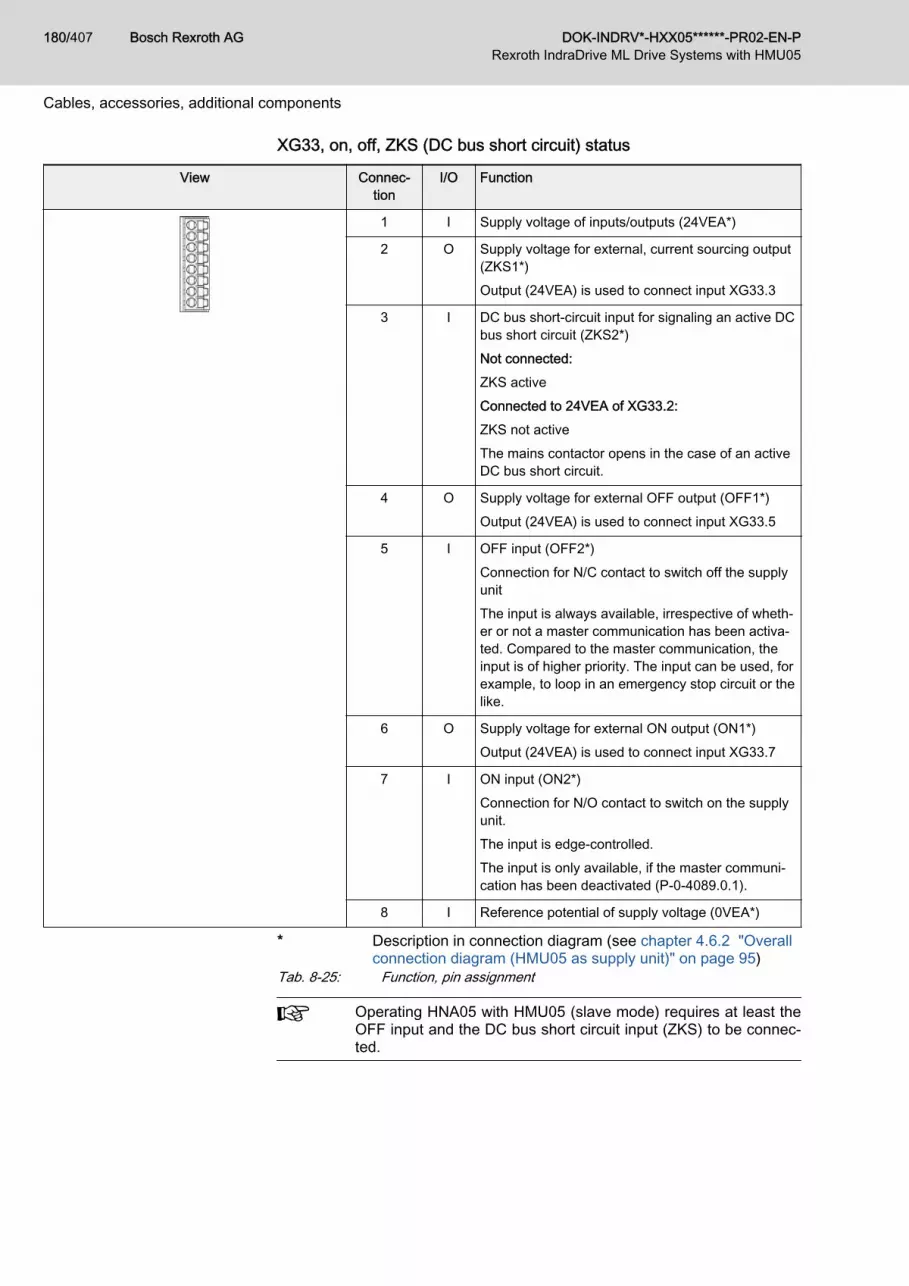
XG33, on, off, ZKS (DC bus short circuit) status
View Connec‐tion
I/O Function
1 I Supply voltage of inputs/outputs (24VEA*)
2 O Supply voltage for external, current sourcing output(ZKS1*)Output (24VEA) is used to connect input XG33.3
3 I DC bus short-circuit input for signaling an active DCbus short circuit (ZKS2*)Not connected:ZKS activeConnected to 24VEA of XG33.2:ZKS not activeThe mains contactor opens in the case of an activeDC bus short circuit.
4 O Supply voltage for external OFF output (OFF1*)Output (24VEA) is used to connect input XG33.5
5 I OFF input (OFF2*)Connection for N/C contact to switch off the supplyunitThe input is always available, irrespective of wheth‐er or not a master communication has been activa‐ted. Compared to the master communication, theinput is of higher priority. The input can be used, forexample, to loop in an emergency stop circuit or thelike.
6 O Supply voltage for external ON output (ON1*)Output (24VEA) is used to connect input XG33.7
7 I ON input (ON2*)Connection for N/O contact to switch on the supplyunit.The input is edge-controlled.The input is only available, if the master communi‐cation has been deactivated (P-0-4089.0.1).
8 I Reference potential of supply voltage (0VEA*)
* Description in connection diagram (see chapter 4.6.2 "Overallconnection diagram (HMU05 as supply unit)" on page 95)
Tab. 8-25: Function, pin assignment
Operating HNA05 with HMU05 (slave mode) requires at least theOFF input and the DC bus short circuit input (ZKS) to be connec‐ted.
Bosch Rexroth AG DOK-INDRV*-HXX05******-PR02-EN-P180/407Rexroth IndraDrive ML Drive Systems with HMU05
Cables, accessories, additional components

Mechanical data
Spring terminal (connector) Unit Min. Max.
Connection cableStranded wire without ferrule
mm2 0.2 1.5
AWG 24 16
Connection cableStranded wire with ferrule
mm2 0.25 0.75
Stripped length mm 10
Tab. 8-26: Mechanical dataElectrical data
Unit Min. Max.
Digital Inputs - Digital inputs correspond to IEC 61131-2 Type 1
Supply outputs -
Total output current mA 300
Tab. 8-27: Electrical data
DOK-INDRV*-HXX05******-PR02-EN-P Bosch Rexroth AG 181/407Rexroth IndraDrive ML Drive Systems with HMU05
Cables, accessories, additional components

XG34, mains contactor (contact)
View Connec‐tion
Function
1 Connection to outer conductor L
2 Mains contactor connection
Tab. 8-28: Function, pin assignment, propertiesMechanical data
Screw connection at connector Unit Min. Max.
Tightening torque Nm 0.6 0.8
Connection cableStranded wire without ferrule
mm2 0.2 2.5
AWG 24 12
Connection cableStranded wire with ferrule
mm2 0.25 2.5
Stripped length mm 10
Tab. 8-29: Mechanical dataElectrical data
Unit Min. Max.
Switching voltage V 5Vac / 5Vdc ~250Vac / 50Vdc
Continuous current A 1
Switching current A 5
Load current mA 10
Switching cycles 3 × 10⁵
Tab. 8-30: Electrical data
Bosch Rexroth AG DOK-INDRV*-HXX05******-PR02-EN-P182/407Rexroth IndraDrive ML Drive Systems with HMU05
Cables, accessories, additional components

XG40, mains contactor (acknowledgment messages)
View Connec‐tion
I/O Function
1 I Acknowledgment message:N/O contact of external mains contactor
2 O Output (24VEA) is used to connect XG40.1
3 I Acknowledgment message:N/C contact of external mains contactor
4 O Output (24VEA) is used to connect XG40.3
Tab. 8-31: Function, pin assignmentMechanical data
Spring terminal (connector) Unit Min. Max.
Connection cableStranded wire without ferrule
mm2 0.2 1.5
AWG 24 16
Connection cableStranded wire with ferrule
mm2 0.25 0.75
Stripped length mm 10
Tab. 8-32: Mechanical dataElectrical data
Unit Min. Max.
Digital inputs - Digital inputs correspond to IEC 61131-2 Type 1
Supply outputs -
Total output current mA 300
Tab. 8-33: Electrical data
DOK-INDRV*-HXX05******-PR02-EN-P Bosch Rexroth AG 183/407Rexroth IndraDrive ML Drive Systems with HMU05
Cables, accessories, additional components

Display elements
Fig. 8-18: LEDs at HNA05
LED Color/status Meaning
PF55 Green 24 V power supply applied
Off 24 V power supply < 19.2 V
PF56 Green HNA ready
Flashing green HNA ready; no mains voltage
Off HNA not ready
PF57 Yellow Charging complete (DC bus capacitance charged)
Flashing yellow Charging
Off Charging interrupted
PF58 Red Error
Flashing red Warning
Off No error, no warning
Tab. 8-34: LED displays
Bosch Rexroth AG DOK-INDRV*-HXX05******-PR02-EN-P184/407Rexroth IndraDrive ML Drive Systems with HMU05
Cables, accessories, additional components

8.3.2 HNC05 mains capacitorHNC05 type code
Short type designation 1 2 3 4 5 6 7 8 910 1 2 3 4 5 6 7 8 9
20 1 2 3 4 5 6 7 8 9
30 1 2 3 4 5 6 7 8 9
40
Example: H N C 0 5 . 1 N - 0 2 0 0 - A 4 - N N N N
① ② ③④ ⑤ ⑥ ⑦
① Product:HNC = Mains capacitor
② Series:05 = 05
③ Design:1 = 1
④ Degree of protection:N = IP00
⑤ Capacitance value:0040 = 40 μF0050 = 50 μF0070 = 70 μF0075 = 75 μF0100 = 100 μF0125 = 125 μF0150 = 150 μF0200 = 200 μF
⑥ Mains voltage:A4 = 3 x AC 380 V -15% ... 500 V +10%A5 = 3 x AC 525 V -15% ... 690 V +10%
⑦ Other design:NNNN = None
Tab. 8-35: HNC05, type codePossible combinations:
Mains volt‐age
Capacitance
0040 0050 0070 0075 0100 0125 0150 0200
A4 – ✓ – ✓ ✓ – ✓ ✓
A5 ✓ ✓ ✓ – ✓ ✓ ✓ –
Tab. 8-36: Possible combinations
DOK-INDRV*-HXX05******-PR02-EN-P Bosch Rexroth AG 185/407Rexroth IndraDrive ML Drive Systems with HMU05
Cables, accessories, additional components

DimensionsHNC05.1N-0050
Fig. 8-19: HNC05.1N-0050
Bosch Rexroth AG DOK-INDRV*-HXX05******-PR02-EN-P186/407Rexroth IndraDrive ML Drive Systems with HMU05
Cables, accessories, additional components

HNC05.1N-0075
Fig. 8-20: HNC05.1N-0075
DOK-INDRV*-HXX05******-PR02-EN-P Bosch Rexroth AG 187/407Rexroth IndraDrive ML Drive Systems with HMU05
Cables, accessories, additional components

HNC05.1N-0100
Fig. 8-21: HNC05.1N-0100
Bosch Rexroth AG DOK-INDRV*-HXX05******-PR02-EN-P188/407Rexroth IndraDrive ML Drive Systems with HMU05
Cables, accessories, additional components

Data
● Equipment grounding conductor cross section = outer con‐ductor cross section!
● Keep supply lines as short as possible.● Mount mains capacitors to the back panel of the control cab‐
inet over the largest possible surface area to establish agood electrical connection. Reason: EMC, heat dissipation
Mains capacitorHNC05.1N-…
Capacitance[µF]
Nominal cur‐rent [A]
Power dissi‐pation [W]
Connection Degree ofprotection
Weight[kg]
0050 50 60 100 Phases:
Screw terminal, 25 mm2
Tightening torque:4 … 4.5 NmGround: Bolt, M8x20
IP20 11.6
0075 75 80 100 Phases:
Screw terminal, 25 mm2
Tightening torque: 5 NmGround: Bolt, M8x20
IP20 11.6
0100 100 80 150 Phases:
Screw terminal, 25 mm2
Tightening torque: 5 NmGround: Bolt, M8x20
IP20 11.6
Tab. 8-37: HNC05.1N, data
Discharge time 20 minutes
Assignment to HMU05See chapter "Combining mains filter, mains choke, preconnected choke andcapacitance pack" on page 112.
DOK-INDRV*-HXX05******-PR02-EN-P Bosch Rexroth AG 189/407Rexroth IndraDrive ML Drive Systems with HMU05
Cables, accessories, additional components

8.3.3 HNF05 mains filterHNF05 type code
Short type designation 1 2 3 4 5 6 7 8 910 1 2 3 4 5 6 7 8 9
20 1 2 3 4 5 6 7 8 9
30 1 2 3 4 5 6 7 8 9
40
Example: H N F 0 5 . 1 A - 5 0 0 N - R 0 8 1 1 - N - A 4 - N N N N
① ② ③④ ⑤ ⑥ ⑦ ⑧ ⑨ ⑩
① Product:HNF = Mains filter
② Series:05 = 05
③ Design:1 = 1
④ EMC area:A = Category C3 in accordance with DIN EN 61800-3B = Category C1 in accordance with DIN EN 61800-3C = Category C2 in accordance with DIN EN 61800-3D = Extended frequency range in accordance with EMC integration guidelines of the automotiveindustry for production environment
⑤ Leakage capacitance:500N = 500 nF (example)
⑥ Supply system:R = For regenerative devices only
⑦ Nominal current:0150 = 150 A0180 = 180 A0250 = 250 A0320 = 320 A0400 = 400 A0600 = 600 A1000 = 1000 A1600 = 1600 A
⑧ Degree of protection:N = IP00
⑨ Mains connection voltage:A4 = 3 x AC 380 V -15% ... 500 V +10%A5 = 3 x AC 380 V -15% ... 690 V +10%
⑩ Other design:NNNN = None
Tab. 8-38: HNF05, type code
Bosch Rexroth AG DOK-INDRV*-HXX05******-PR02-EN-P190/407Rexroth IndraDrive ML Drive Systems with HMU05
Cables, accessories, additional components

Possible combinations:
Mains connection voltage
A4, A5
Nominal current
0150 0180 0250 0320 0400 0600 1000 1600
EMC area A ✓ ✓ ✓ ✓ ✓ ✓ ✓ ✓
Tab. 8-39: Possible combinations
DOK-INDRV*-HXX05******-PR02-EN-P Bosch Rexroth AG 191/407Rexroth IndraDrive ML Drive Systems with HMU05
Cables, accessories, additional components

DimensionsHNF05.1A-500N-R0250
Fig. 8-22: HNF05.1A-500N-R0250
Bosch Rexroth AG DOK-INDRV*-HXX05******-PR02-EN-P192/407Rexroth IndraDrive ML Drive Systems with HMU05
Cables, accessories, additional components

HNF05.1A-500N-R0320, -R0400
Fig. 8-23: HNF05.1A-500N-R0320, -R0400
DOK-INDRV*-HXX05******-PR02-EN-P Bosch Rexroth AG 193/407Rexroth IndraDrive ML Drive Systems with HMU05
Cables, accessories, additional components

HNF05.1A-500N-R0600
Fig. 8-24: HNF05.1A-500N-R0600
Bosch Rexroth AG DOK-INDRV*-HXX05******-PR02-EN-P194/407Rexroth IndraDrive ML Drive Systems with HMU05
Cables, accessories, additional components

HNF05.1A-500N-R1000
Fig. 8-25: HNF05.1A-500N-R1000
DOK-INDRV*-HXX05******-PR02-EN-P Bosch Rexroth AG 195/407Rexroth IndraDrive ML Drive Systems with HMU05
Cables, accessories, additional components

HNF05.1A-500N-R1600
Fig. 8-26: HNF05.1A-500N-R1600
MountingMounting position Observe the mounting position of the filters! Generally, mount the device in
such a way that the natural convection is not impaired.Mounting points As a matter of principle, the mechanical fixing, for example, can be carried
out using 4 mounting points, and the other 2 mounting points are used as aPE connection to the mounting plate with metallic conduction properties. Inthis case, mark the 2 PE connections with the symbol for the equipmentgrounding conductor connection point. The metallic connection to the mount‐ing plate has to comply with the valid standards.
Threaded bolt PENominal size Tightening torque [Nm] Tolerance [Nm]
M10 10.0 9.0 … 11.0
M12 15.5 14.0 … 17.0
M16 30 27.0 … 33.0
Tab. 8-40: Threaded bolt PE
Bosch Rexroth AG DOK-INDRV*-HXX05******-PR02-EN-P196/407Rexroth IndraDrive ML Drive Systems with HMU05
Cables, accessories, additional components

DataHNF05.1A-500N-R… Nominal volt‐
age[V]
Nominal cur‐rent[A]
Power dissipa‐tion[W]
Leakage cur‐rent[mA]
Resistance[µΩ]
Weight[kg]
0250 690/400,50/60 Hz
250 34 < 905 1) 63 15
0320 320 36 67 21
0400 400 53
0600 600 86 52 22
1000 1000 166 33 28
1600 1600 283 22 34
1) With nominal voltage, 50 HzTab. 8-41: HNF05.1A, data
Assignment to HMU05See chapter "Combining mains filter, mains choke, preconnected choke andcapacitance pack" on page 112.
DOK-INDRV*-HXX05******-PR02-EN-P Bosch Rexroth AG 197/407Rexroth IndraDrive ML Drive Systems with HMU05
Cables, accessories, additional components

8.3.4 HNL05 mains chokeHNL05 type code
Short type designation 1 2 3 4 5 6 7 8 910 1 2 3 4 5 6 7 8 9
20 1 2 3 4 5 6 7 8 9
30 1 2 3 4 5 6 7 8 9
40
Example: H N L 0 5 . 1 R - 0 1 8 2 - C 0 8 1 1 - N - A 4 - N N N F
① ② ③④ ⑤ ⑥ ⑦ ⑧ ⑨ ⑩
① Product:HNL = Mains choke
② Series:05 = 05
③ Design:1 = 1
④ Supply system:R = For regenerative devices only
⑤ Nominal inductance:0040 = 40 μH0043 = 43 μH0045 = 45 μH0050 = 50 μH0054 = 54 μH0080 = 80 μH0094 = 94 μH0100 = 100 μH0113 = 113 μH0117 = 117 μH0125 = 125 μH0130 = 130 μH0135 = 135 μH0139 = 139 μH0175 = 175 μH0182 = 182 μH0219 = 219 μH0234 = 234 μH0346 = 346 μH0434 = 434 μH0542 = 542 μH0649 = 649 μH1019 = 1019 μH
⑥ Additional option:N = None
Bosch Rexroth AG DOK-INDRV*-HXX05******-PR02-EN-P198/407Rexroth IndraDrive ML Drive Systems with HMU05
Cables, accessories, additional components

Short type designation 1 2 3 4 5 6 7 8 910 1 2 3 4 5 6 7 8 9
20 1 2 3 4 5 6 7 8 9
30 1 2 3 4 5 6 7 8 9
40
Example: H N L 0 5 . 1 R - 0 1 8 2 - C 0 8 1 1 - N - A 4 - N N N F
① ② ③④ ⑤ ⑥ ⑦ ⑧ ⑨ ⑩
⑦ Nominal current:0127 = 127 A0152 = 152 A0190 = 190 A0218 = 218 A0238 = 238 A0262 = 262 A0327 = 327 A0352 = 352 A0409 = 409 A0471 = 471 A0514 = 514 A0592 = 592 A0652 = 652 A0811 = 811 A1019 = 1019 A
⑧ Degree of protection:N = IP00
⑨ Mains connection voltage:A4 = 3 x AC 380 V – 15% … 500 V + 10%A5 = 3 x AC 525 V – 15% … 690 V + 10%
⑩ Other design:NNNF = Liquid coolingNNNN = None
Tab. 8-42: HNL05, type code
DOK-INDRV*-HXX05******-PR02-EN-P Bosch Rexroth AG 199/407Rexroth IndraDrive ML Drive Systems with HMU05
Cables, accessories, additional components

Possible combinations (mains connection voltage A4):
Mains connection voltage
A4
Other design
NNNF NNNN
Nominal current
0218 0262 0327 0409 0514 0652 0811 1019 0327 0409 0514 0652 0811 1019
Nom
inal
indu
ctan
ce
0040 – – – – – – – – – – – – ✓ ✓
0043 – – – – – – – – – – ✓ – – –
0045 – – – – – – – – ✓ – – – – –
0050 – – – – – – – – – – – ✓ – –
0054 – – – – – – – – – ✓ – – – –
0094 – – – – – – – ✓ – – – – – –
0100 – – – – – – ✓ – – – – – – –
0113 – – – – – ✓ – – – – – – – –
0117 – – – ✓ – – – – – – – – – –
0130 – – – – ✓ – – – – – – – – –
0135 – – ✓ – – – – – – – – – – –
0182 – ✓ – – – – – – – – – – – –
0219 ✓ – – – – – – – – – – – – –
Tab. 8-43: Possible combinations (mains connection voltage A4)
Bosch Rexroth AG DOK-INDRV*-HXX05******-PR02-EN-P200/407Rexroth IndraDrive ML Drive Systems with HMU05
Cables, accessories, additional components

Possible combinations (mains connection voltage A5):
Mains connection voltage
A5
Other design
NNNF NNNN
Nominal current
0592 0471 0352 0238 0190 0152 0127 0592 0471 0352 0238 0190 0152
Nom
inal
indu
ctan
ce
0032 – – – – – – – ✓ – – – – –
0040 – – – – – – – – ✓ – – – –
0054 – – – – – – – – – ✓ – – –
0080 – – – – – – – – – – ✓ – –
0100 – – – – – – – – – – – ✓ –
0125 – – – – – – – – – – – – ✓
0139 ✓ – – – – – – – – – – – –
0175 – ✓ – – – – – – – – – – –
0234 – – ✓ – – – – – – – – – –
0346 – – – ✓ – – – – – – – – –
0434 – – – – ✓ – – – – – – – –
0542 – – – – – ✓ – – – – – – –
0649 – – – – – – ✓ – – – – – –
Tab. 8-44: Possible combinations (mains connection voltage A5)
DOK-INDRV*-HXX05******-PR02-EN-P Bosch Rexroth AG 201/407Rexroth IndraDrive ML Drive Systems with HMU05
Cables, accessories, additional components

Type plate
1 Word mark2 Business facility number3 CE label4 Type designation (two lines, 20 characters each)5 Part number6 Change release7 Production date (YYWww)8 Certification label9 Nominal voltage / frequency10 Nominal current11 Number of design specification12 Nominal inductance13 Temperature14 Number and value of additional capacitors15 Designation of origin16 Approval number17 Bar code (39 or 93)18 Serial number19 Company addressFig. 8-27: Type plate
Bosch Rexroth AG DOK-INDRV*-HXX05******-PR02-EN-P202/407Rexroth IndraDrive ML Drive Systems with HMU05
Cables, accessories, additional components

DimensionsHNL05.1R-0219-N0218
Fig. 8-28: HNL05.1R-0219-N0218
DOK-INDRV*-HXX05******-PR02-EN-P Bosch Rexroth AG 203/407Rexroth IndraDrive ML Drive Systems with HMU05
Cables, accessories, additional components

HNL05.1R-0182-N0262
Fig. 8-29: HNL05.1R-0182-N0262
Bosch Rexroth AG DOK-INDRV*-HXX05******-PR02-EN-P204/407Rexroth IndraDrive ML Drive Systems with HMU05
Cables, accessories, additional components

HNL05.1R-0045-N0327
Fig. 8-30: HNL05.1R-0045-N0327
DOK-INDRV*-HXX05******-PR02-EN-P Bosch Rexroth AG 205/407Rexroth IndraDrive ML Drive Systems with HMU05
Cables, accessories, additional components

HNL05.1R-0135-N0327
Fig. 8-31: HNL05.1R-0135-N0327
Bosch Rexroth AG DOK-INDRV*-HXX05******-PR02-EN-P206/407Rexroth IndraDrive ML Drive Systems with HMU05
Cables, accessories, additional components

HNL05.1R-0054-N0409
Fig. 8-32: HNL05.1R-0054-N0409
DOK-INDRV*-HXX05******-PR02-EN-P Bosch Rexroth AG 207/407Rexroth IndraDrive ML Drive Systems with HMU05
Cables, accessories, additional components

HNL05.1R-0117-N0409
Fig. 8-33: HNL05.1R-0117-N0409
Bosch Rexroth AG DOK-INDRV*-HXX05******-PR02-EN-P208/407Rexroth IndraDrive ML Drive Systems with HMU05
Cables, accessories, additional components

HNL05.1R-0043-N0514
Fig. 8-34: HNL05.1R-0043-N0514
DOK-INDRV*-HXX05******-PR02-EN-P Bosch Rexroth AG 209/407Rexroth IndraDrive ML Drive Systems with HMU05
Cables, accessories, additional components

HNL05.1R-0130-N0514
Fig. 8-35: HNL05.1R-0130-N0514
Bosch Rexroth AG DOK-INDRV*-HXX05******-PR02-EN-P210/407Rexroth IndraDrive ML Drive Systems with HMU05
Cables, accessories, additional components

HNL05.1R-0050-N0652
Fig. 8-36: HNL05.1R-0050-N0652
DOK-INDRV*-HXX05******-PR02-EN-P Bosch Rexroth AG 211/407Rexroth IndraDrive ML Drive Systems with HMU05
Cables, accessories, additional components

HNL05.1R-0113-N0652
Fig. 8-37: HNL05.1R-0113-N0652
Bosch Rexroth AG DOK-INDRV*-HXX05******-PR02-EN-P212/407Rexroth IndraDrive ML Drive Systems with HMU05
Cables, accessories, additional components

HNL05.1R-0040-N0811
Fig. 8-38: HNL05.1R-0040-N0811
DOK-INDRV*-HXX05******-PR02-EN-P Bosch Rexroth AG 213/407Rexroth IndraDrive ML Drive Systems with HMU05
Cables, accessories, additional components

HNL05.1R-0100-N0811
Fig. 8-39: HNL05.1R-0100-N0811
Bosch Rexroth AG DOK-INDRV*-HXX05******-PR02-EN-P214/407Rexroth IndraDrive ML Drive Systems with HMU05
Cables, accessories, additional components

HNL05.1R-0040-N1019
Fig. 8-40: HNL05.1R-0040-N1019
DOK-INDRV*-HXX05******-PR02-EN-P Bosch Rexroth AG 215/407Rexroth IndraDrive ML Drive Systems with HMU05
Cables, accessories, additional components

HNL05.1R-0094-N1019
Fig. 8-41: HNL05.1R-0094-N1019
Bosch Rexroth AG DOK-INDRV*-HXX05******-PR02-EN-P216/407Rexroth IndraDrive ML Drive Systems with HMU05
Cables, accessories, additional components

Data
HNL05.1R-… Inductance[µH]
Nominal cur‐rent[A]
Power dissipation 1)
[W]
Degree ofprotection
Max. ambi‐ent tempera‐
ture 2)
[°C]
Weight[kg]
Air Water
0219-N0218 219 218 1300 1400 IP00 40 37
0182-N0262 182 262 1350 1500 IP00 40 53
0045-N0327 45 327 230 - IP00 40 21
0135-N0327 135 327 900 1700 IP00 40 58
0054-N0409 54 409 350 - IP00 40 40
0117-N0409 117 409 1200 2000 IP00 40 82
0043-N0514 43 514 400 - IP00 40 50
0130-N0514 130 514 1350 2400 IP00 40 116
0050-N0652 50 652 560 - IP00 40 70
0113-N0652 113 652 1500 2700 IP00 40 150
0040-N0811 40 811 620 - IP00 40 85
0100-N0811 100 811 1650 3000 IP00 40 180
0040-N1019 40 1019 850 - IP00 40 121
0094-N1019 94 1019 1950 3500 IP00 40 225
1) The air/water distribution was determined at an ambient tem‐perature of 30 °C and a water inlet temperature of 50 °C
2) Up to 55°C with current deratingTab. 8-45: HNL05.1R, data
Temperature monitoring contact ● Trigger temperatureAuslösetemperatur: 160 °C● N/C in one of the windings● Electric switching capacity:
– 1 A– AC 250 V– DC 24 V
DOK-INDRV*-HXX05******-PR02-EN-P Bosch Rexroth AG 217/407Rexroth IndraDrive ML Drive Systems with HMU05
Cables, accessories, additional components

Water cooling
HNL05.1R-… Flow [l/min] Filling capacity[l]
Pressure decrease [bar]
5 l / min 7 l / min 9 l / min
0219-N0218 > 6 1.3 0.14 0.27 0.42
0182-N0262 > 6 1.5 0.15 0.29 0.46
0135-N0327 > 6 1.6 0.17 0.32 0.51
0117-N0409 > 6 2.0 0.21 0.39 0.62
0130-N0514 > 6 2.5 0.24 0.44 0.75
0113-N0652 > 8 3.4 0.03 0.06 0.10
0100-N0811 > 8 3.6 0.04 0.07 0.10
0094-N1019 > 8 4.1 0.04 0.07 0.12
Tab. 8-46: Water cooling
ConnectionSee chapter 11.4 "Aluminum contact points and cupal disks" on page 381.
Assignment to HMU05See chapter "Combining mains filter, mains choke, preconnected choke andcapacitance pack" on page 112.
Bosch Rexroth AG DOK-INDRV*-HXX05******-PR02-EN-P218/407Rexroth IndraDrive ML Drive Systems with HMU05
Cables, accessories, additional components

8.3.5 HML05 motor choke/balancing chokeHML05 type code
Short type designation 1 2 3 4 5 6 7 8 910 1 2 3 4 5 6 7 8 9
20 1 2 3 4 5 6 7 8 9
30 1 2 3 4 5 6 7 8 9
40
Example: H M L 0 5 . 1 W - D 9 8 0 U - N 1 0 0 2 - N - 5 0 0 - N N N N
① ② ③④ ⑤ ⑥ ⑦ ⑧ ⑨ ⑩ ⑪
① Product:HML = Motor choke/balancing choke
② Series:05 = 05
③ Design:1 = 1
④ Cooling type, type of construction:W = Air cooling
⑤ Choke type:D = dv/dt choke
⑥ Nominal inductance:980U = 980 μH (example)
⑦ Additional option:N = None
⑧ Nominal current:1002 = 1002 A (example)
⑨ Degree of protection:N = IP00
⑩ Rated voltage:500 = 3 × AC 500 V690 = 3 × AC 690 V
⑪ Other design:NNNN = None
Tab. 8-47: HML05, type code
DOK-INDRV*-HXX05******-PR02-EN-P Bosch Rexroth AG 219/407Rexroth IndraDrive ML Drive Systems with HMU05
Cables, accessories, additional components

HML05 to HMU05 assignmentBalancing chokes are necessary if a higher output drive controller is formedusing multiple HMUs that can be connected in parallel. One balancing chokeper HMU motor output.
HMU05.1N-… HML05.1W-…
F0140-0350 D021U-N0254-N-500-NNNN
F0170-0430 D018U-N0306-N-500-NNNN
F0220-0510 D014U-N0392-N-500-NNNN
F0270-0660 D009U-N0490-N-500-NNNN
F0340-0820 D009U-N0616-N-500-NNNN
F0430-1040 D007U-N0771-N-500-NNNN
F0540-1300 D006U-N1002-N-500-NNNN
F0680-1690 D004U-N1185-N-500-NNNN
Tab. 8-48: HML05 ↔ HMU05 assignment
Bosch Rexroth AG DOK-INDRV*-HXX05******-PR02-EN-P220/407Rexroth IndraDrive ML Drive Systems with HMU05
Cables, accessories, additional components

Dimensions
Fig. 8-42: HML05.1W-D021U-N0254-N-500-NNNN, dimensions
DOK-INDRV*-HXX05******-PR02-EN-P Bosch Rexroth AG 221/407Rexroth IndraDrive ML Drive Systems with HMU05
Cables, accessories, additional components

Fig. 8-43: HML05.1W-D018U-N0306-N-500-NNNN, dimensions
Bosch Rexroth AG DOK-INDRV*-HXX05******-PR02-EN-P222/407Rexroth IndraDrive ML Drive Systems with HMU05
Cables, accessories, additional components

Fig. 8-44: HML05.1W-D014U-N0392-N-500-NNNN, dimensions
DOK-INDRV*-HXX05******-PR02-EN-P Bosch Rexroth AG 223/407Rexroth IndraDrive ML Drive Systems with HMU05
Cables, accessories, additional components

Fig. 8-45: HML05.1W-D009U-N0490-N-500-NNNN, dimensions
Bosch Rexroth AG DOK-INDRV*-HXX05******-PR02-EN-P224/407Rexroth IndraDrive ML Drive Systems with HMU05
Cables, accessories, additional components

Fig. 8-46: HML05.1W-D009U-N0616-N-500-NNNN, dimensions
DOK-INDRV*-HXX05******-PR02-EN-P Bosch Rexroth AG 225/407Rexroth IndraDrive ML Drive Systems with HMU05
Cables, accessories, additional components

Fig. 8-47: HML05.1W-D007U-N0771-N-500-NNNN, dimensions
Bosch Rexroth AG DOK-INDRV*-HXX05******-PR02-EN-P226/407Rexroth IndraDrive ML Drive Systems with HMU05
Cables, accessories, additional components

Fig. 8-48: HML05.1W-D006U-N1002-N-500-NNNN, dimensions
DOK-INDRV*-HXX05******-PR02-EN-P Bosch Rexroth AG 227/407Rexroth IndraDrive ML Drive Systems with HMU05
Cables, accessories, additional components

Fig. 8-49: HML05.1W-D004U-N1185-N-500-NNNN, dimensions
Bosch Rexroth AG DOK-INDRV*-HXX05******-PR02-EN-P228/407Rexroth IndraDrive ML Drive Systems with HMU05
Cables, accessories, additional components

Data
Description HML05.1W-D … -N-500-NNNN
Unit 021U-N0254
018U-N0306
014U-N0392
009U-N0490
009U-N0616
007U-N0771
006U-N1002
004U-N1185
Relative uk % 0.8 0.8 0.8 0.8 0.8 0.8 0.8 0.8
Inductance µH 3 × 21 3 × 18 3 × 14 3 × 9.1 3 × 8.9 3 × 7.0 3 × 5.6 3 × 4.5
Motor inductance in working point, typ. µH 533 448 352 228 224 176 141 112
Working point 1: 2 kHzclock frequency;≤ 200 Hz rotary fieldfrequency
Nominal current Arms 254 306 392 490 616 771 1002 1185
Maximum phase-phase capacitance(motor cable)
nF 30 30 30 30 50 50 50 tbd
Maximum leakagecapacitance
nF 180 180 180 180 300 300 300 tbd
Working point 2: 4 kHzclock frequency;≤ 200 Hz rotary fieldfrequency
Nominal current Arms 254 306 392 490 546 632 775 1008
Maximum phase-phase capacitance(motor cable)
nF 20 20 20 20 30 30 30 tbd
Maximum leakagecapacitance
nF 120 120 120 120 180 180 180 tbd
Working point 3: 4 kHzclock frequency;≤ 400 Hz rotary fieldfrequency
Nominal current Arms 254 306 392 490 546 632 775 1008
Maximum phase-phase capacitance(motor cable)
nF 10 10 10 10 30 30 30 tbd
Maximum leakagecapacitance
nF 60 60 60 60 180 180 180 tbd
Stable inductance up to … Arms 314 377 454 582 727 915 1144 1488
Power dissipation W 200 250 300 300 350 330 425 tbd
Voltage V 3 × 500
Protection class - Class I
Degree of protection - IP00
Weight kg 15 20 25 25 34 38 40 42
Tab. 8-49: HML05, data
DOK-INDRV*-HXX05******-PR02-EN-P Bosch Rexroth AG 229/407Rexroth IndraDrive ML Drive Systems with HMU05
Cables, accessories, additional components

Thermal overload of the chokes!NOTICE
Observe the specified maximum values of cable and leakage capacitances.Otherwise, the motor/balancing chokes are thermally overloaded.The motor inductance should not fall considerably below the minimum valuein the working point. For axes connected in parallel using balancing chokes,the motor inductance may be lower by the corresponding factor.For applications with a high continuous load, thermally gauge the motor/balancing chokes during commissioning. In particular, this applies if all pa‐rameters are not reliably known (e.g., motor inductance in the working point).In case of doubt, install a forced ventilation or use the next bigger size, if therise of voltage at the motor allows this (bigger size has lower inductance).Installing a DC bus choke does not relieve the motor/balancing chokes.
Bosch Rexroth AG DOK-INDRV*-HXX05******-PR02-EN-P230/407Rexroth IndraDrive ML Drive Systems with HMU05
Cables, accessories, additional components

8.3.6 HLL05 DC bus chokeHLL05 type code
Short type designation 1 2 3 4 5 6 7 8 910 1 2 3 4 5 6 7 8 9
20 1 2 3 4 5 6 7 8 9
30 1 2 3 4 5 6 7 8 9
40
Example: H L L 0 5 . 1 F - 0 4 M 0 - S 0 7 2 0 - N - D 7 - 0 1 U 2 - N N N N
① ② ③④ ⑤ ⑥ ⑦ ⑧ ⑨ ⑩ ⑪
① Product:HLL = DC bus choke
② Series:05 = 05
③ Design:1 = 1
④ Cooling type, type of construction:F = Liquid coolingW = Air cooling
⑤ Nominal inductance:04M0 = 4 mH
⑥ Additional option:S = Current-compensated
⑦ Nominal current:0202 = 202 A0243 = 243 A0303 = 303 A0380 = 380 A0475 = 475 A0603 = 603 A0720 = 720 A0942 = 942 A
⑧ Degree of protection:N = IP00
⑨ Nominal DC bus voltage:D7 = DC 750 V11 = DC 1100 V
⑩ Leakage capacitance:01U2 = 1.2 μF
⑪ Other design:NNNN = None
Tab. 8-50: HLL05, type code
DOK-INDRV*-HXX05******-PR02-EN-P Bosch Rexroth AG 231/407Rexroth IndraDrive ML Drive Systems with HMU05
Cables, accessories, additional components

SizingAn HLL DC bus choke is always necessary if the leakage capacitance of theoverall system incl. cable and motor capacitance is greater than 500 nF.
See also chapter 4.3.4 "Leakage capacitances" on page 53.
The DC bus choke is sized according to the DC bus current in each driveline.The lowest DC bus voltage UDCmin that occurs is always used to determinethe DC bus current IDC:IDC = PDC / UDCmin
An HLL DC bus choke is always necessary if IndraDrive M(HMS01, HMD01) components are connected to the DC bus.See chapter "Operating HMU05 together with HMS01/HMD01" onpage 56.
Bosch Rexroth AG DOK-INDRV*-HXX05******-PR02-EN-P232/407Rexroth IndraDrive ML Drive Systems with HMU05
Cables, accessories, additional components

DimensionsHLL05.1W-04M0-S0202
Fig. 8-50: HLL05.1W-04M0-S0202
DOK-INDRV*-HXX05******-PR02-EN-P Bosch Rexroth AG 233/407Rexroth IndraDrive ML Drive Systems with HMU05
Cables, accessories, additional components

HLL05.1F-04M0-S0202
Fig. 8-51: HLL05.1F-04M0-S0202
Bosch Rexroth AG DOK-INDRV*-HXX05******-PR02-EN-P234/407Rexroth IndraDrive ML Drive Systems with HMU05
Cables, accessories, additional components

HLL05.1F-04M0-S0243
Fig. 8-52: HLL05.1F-04M0-S0243
DOK-INDRV*-HXX05******-PR02-EN-P Bosch Rexroth AG 235/407Rexroth IndraDrive ML Drive Systems with HMU05
Cables, accessories, additional components

HLL05.1W-04M0-S0303
Fig. 8-53: HLL05.1W-04M0-S0303
Bosch Rexroth AG DOK-INDRV*-HXX05******-PR02-EN-P236/407Rexroth IndraDrive ML Drive Systems with HMU05
Cables, accessories, additional components

HLL05.1F-04M0-S0303
Fig. 8-54: HLL05.1F-04M0-S0303
DOK-INDRV*-HXX05******-PR02-EN-P Bosch Rexroth AG 237/407Rexroth IndraDrive ML Drive Systems with HMU05
Cables, accessories, additional components

HLL05.1F-04M0-S0380
Fig. 8-55: HLL05.1F-04M0-S0380
Bosch Rexroth AG DOK-INDRV*-HXX05******-PR02-EN-P238/407Rexroth IndraDrive ML Drive Systems with HMU05
Cables, accessories, additional components

HLL05.1F-04M0-S0475
Fig. 8-56: HLL05.1F-04M0-S0475
DOK-INDRV*-HXX05******-PR02-EN-P Bosch Rexroth AG 239/407Rexroth IndraDrive ML Drive Systems with HMU05
Cables, accessories, additional components

HLL05.1F-04M0-S0603
Fig. 8-57: HLL05.1F-04M0-S0603
Bosch Rexroth AG DOK-INDRV*-HXX05******-PR02-EN-P240/407Rexroth IndraDrive ML Drive Systems with HMU05
Cables, accessories, additional components

HLL05.1F-04M0-S0720
Fig. 8-58: HLL05.1F-04M0-S0720
DOK-INDRV*-HXX05******-PR02-EN-P Bosch Rexroth AG 241/407Rexroth IndraDrive ML Drive Systems with HMU05
Cables, accessories, additional components

HLL05.1F-04M0-S0942
Fig. 8-59: HLL05.1F-04M0-S0942
Bosch Rexroth AG DOK-INDRV*-HXX05******-PR02-EN-P242/407Rexroth IndraDrive ML Drive Systems with HMU05
Cables, accessories, additional components

Data
Choke HLL05.1x-04M0-…
Inductance[mH]
Continuouscurrent
[A]
Power dissipation[W]
Allowedleakage ca‐pacitance
[µF]
Degree ofprotection
Ambient tem‐perature 1)
[°C]
Weight[kg]
Air Water 2)
S0202 (air-cooled) 4 202 380 - 1.2 IP00 40 27
S0202 (water-cooled) 4 202 230 400 1.2 IP00 40 23
S0243 4 243 240 430 1.2 IP00 40 25
S0303 (air-cooled) 4 303 400 - 1.2 IP00 40 38
S0303 (water-cooled) 4 303 270 480 1.2 IP00 40 33
S0380 4 380 330 580 1.2 IP00 40 36
S0475 4 475 420 760 1.2 IP00 40 86
S0603 4 603 530 940 1.2 IP00 40 98
S0720 4 720 540 960 1.2 IP00 40 110
S0942 4 942 680 1220 1.2 IP00 40 152
1) Maximum ambient temperature: 55 °C (with derating)2) Maximum water inlet temperature: 60 °CTab. 8-51: HLL05.1F, data
Temperature monitoring contact ● Trigger temperatureAuslösetemperatur: 160 °C● N/C in one of the windings● Electric switching capacity:
– 1 A– AC 250 V– DC 24 V
DOK-INDRV*-HXX05******-PR02-EN-P Bosch Rexroth AG 243/407Rexroth IndraDrive ML Drive Systems with HMU05
Cables, accessories, additional components

Water cooling
HLL05.1F-04M0-… Flow [l/min] Filling capacity[l]
Pressure decrease [bar]
5 l/min 7 l/min 9 l/min
S0202 > 6 0.7 0.09 0.17 0.27
S0243 > 6 0.8 0.10 0.18 0.28
S0303 > 6 1.0 0.12 0.22 0.35
S0380 > 6 1.1 0.14 0.25 0.40
S0475 > 6 1.2 0.01 0.03 0.04
S0603 > 8 1.7 0.02 0.04 0.06
S0720 > 8 1.9 0.02 0.04 0.06
S0942 > 8 2.3 0.03 0.05 0.08
Tab. 8-52: Water cooling
Bosch Rexroth AG DOK-INDRV*-HXX05******-PR02-EN-P244/407Rexroth IndraDrive ML Drive Systems with HMU05
Cables, accessories, additional components

Assignment
Components
Supply unit HMU05.1N-…
F014
0-03
50(1
10 k
W s
ize)
F017
0-04
30(1
32 k
W s
ize)
F022
0-05
10(1
60 k
W s
ize)
F027
0-06
60(2
00 k
W s
ize)
F034
0-08
20(2
50 k
W s
ize)
F043
0-10
40(3
15 k
W s
ize)
F054
0-13
00(4
00 k
W s
ize)
F068
0-16
90(5
00 k
W s
ize)
DC
bus
cho
keH
LL05
.1F-
04M
0-
S0202 ✓
S0243 ✓
S0303 ✓
S0380 ✓
S0475 ✓
S0603 ✓
S0720 ✓
S0942 ✓
Tab. 8-53: HLL05 ↔ HMU05 assignment
DOK-INDRV*-HXX05******-PR02-EN-P Bosch Rexroth AG 245/407Rexroth IndraDrive ML Drive Systems with HMU05
Cables, accessories, additional components

Circuit diagram
T Temperature switch (N/C)+1 +2, -1 -2 DC bus connectionFig. 8-60: Circuit diagram
The DC bus connections of the choke may be switched on bothsides.
Connection
DC bus chokes should not be simultaneously connected in paral‐lel at the input and at the output.
Use cupal disks for the aluminum contact point connection: See chapter 11.4 "Aluminum contact points and cupal disks" on page 381.
Bosch Rexroth AG DOK-INDRV*-HXX05******-PR02-EN-P246/407Rexroth IndraDrive ML Drive Systems with HMU05
Cables, accessories, additional components

8.3.7 Y capacitor pair (HAS04.1-003)Type code
Short type designation 1 2 3 4 5 6 7 8 910 1 2 3 4 5 6 7 8 9
20 1 2 3 4 5 6 7 8 9
30 1 2 3 4 5 6 7 8 9
40
Example: H A S 0 4 . 1 - 0 0 1 - N N N - N N
① ② ③ ④ ⑤ ⑥
① Product:HAS = IndraDrive accessories
② Series:04 = Capacitor
③ Design:1 = 1
④ Capacitor:001 = 2 × 470 nF (HCS02.x)002 = 2 × 470 nF (HCS03.x)003 = 2 × 2.5 μF (HLL05)
⑤ Other contents:NNN = None
⑥ Other design:NN = None
Tab. 8-54: HAS04, type code
Data
Description Unit Value
Voltage V AC 500
DC 1200
Capacitance µF 2.5 ±20%
Tab. 8-55: Data
DOK-INDRV*-HXX05******-PR02-EN-P Bosch Rexroth AG 247/407Rexroth IndraDrive ML Drive Systems with HMU05
Cables, accessories, additional components

Fig. 8-61: Dimensions
Bosch Rexroth AG DOK-INDRV*-HXX05******-PR02-EN-P248/407Rexroth IndraDrive ML Drive Systems with HMU05
Cables, accessories, additional components

8.3.8 HLR05 external braking resistorHLR05 type code
Short type designation 1 2 3 4 5 6 7 8 910 1 2 3 4 5 6 7 8 9
20 1 2 3 4 5 6 7 8 9
30 1 2 3 4 5 6 7 8 9
40
Example: H L R 0 5 . 1 W - 5 4 K 0 - N 0 5 R 4 - A - D 7 - N N N N
① ② ③④ ⑤ ⑥ ⑦ ⑧ ⑨ ⑩
① Product:HLR = Braking resistor
② Series:05 = 05
③ Design:1 = 1
④ Cooling type, type of construction:W = Air cooling
⑤ Continuous power:
54K0 = 54 kW 1)
70K0 = 70 kW 2)
⑥ Additional option:N = None
⑦ Resistance value:
04R0 = 4.0 ohm 2)
05R4 = 5.4 ohm 1)
⑧ Degree of protection:A = IP20
⑨ Nominal DC bus voltage:
D7 = DC 750 V 1) 2)
11 = DC 1100 V
⑩ Other design:NNNN = None
1) "54K0" continuous power only with "05R4" resistance valueand "D7" nominal DC bus voltage
2) "70K0" continuous power only with "04R0" resistance valueand "D7" nominal DC bus voltage
Tab. 8-56: HLR05, type code
DOK-INDRV*-HXX05******-PR02-EN-P Bosch Rexroth AG 249/407Rexroth IndraDrive ML Drive Systems with HMU05
Cables, accessories, additional components

DimensionsHLR05.1W-54K0-N05R4, …-70K0-N04R0
Fig. 8-62: HLR05.1W-54K0-N05R4, …-70K0-N04R0; dimensions in mm
Bosch Rexroth AG DOK-INDRV*-HXX05******-PR02-EN-P250/407Rexroth IndraDrive ML Drive Systems with HMU05
Cables, accessories, additional components

Data
Description Unit HLR05.1W-…
54K0-N05R4 70K0-N04R0
Resistance Ω 5.4 ±10% 4 ±10%
Continuous power kW 54 70
650 VDC peak power kW 78 106
820 VDC peak power kW 124 168
650 VDC duty cycle peak power (120 s max. cycle) % 70 66
820 VDC duty cycle peak power (120 s max. cycle) % 38 41
Maximum energy absorption kWs 6500 8400
Weight kg 145 145
Power connections cross section mm2 25 35
Tab. 8-57: HLR05.1W, data
DOK-INDRV*-HXX05******-PR02-EN-P Bosch Rexroth AG 251/407Rexroth IndraDrive ML Drive Systems with HMU05
Cables, accessories, additional components

Installation
Property damage due to temperatures higherthan 105 ℃!
NOTICE
Observe the indicated minimum distances!Above the devices there may only be such materials which● are not combustible● are insensitive to the occurring high temperatures
Mounting ● Mounting position: Upright on horizontal surfacesDo not mount on walls!
● Keep min. 200 mm distance from adjacent parts and wallsSurface temperatures can reach 150 °C.
● Ensure unhindered entry of cooling air● Ensure unhindered exit of heated air● Do not mount below fire alarm sensors● Do not mount near flammable materials
Cables ● Length: ≤ 100 m● Keep feeder and return cables in parallel and as close together as pos‐
sible or twist them● Place cables away from signal and data lines● Place so they are protected against short-circuiting and ground faults You can use Rexroth cables:
HLR05.1W-… Cables
54K0-N05R4 INK0607, mat. no.: R911245289
70K0-N04R0 INK0667, mat. no.: R911245292
Tab. 8-58: Cables
Bosch Rexroth AG DOK-INDRV*-HXX05******-PR02-EN-P252/407Rexroth IndraDrive ML Drive Systems with HMU05
Cables, accessories, additional components

Connection point
PE Equipment grounding conductor; connection cross section ofterminal: 6…35 mm2
1 Stranded wire for HLT terminal connector XD4a; connectioncross section of HLR terminal: 6…35 mm2
2 Stranded wire for HLT terminal connector XD4b; connectioncross section of HLR terminal: 6…35 mm2
3 Stranded wires for HLT terminal connector XG3; connectioncross section of HLR terminal: 0.25…2.5 mm2
4 Wire not used
DOK-INDRV*-HXX05******-PR02-EN-P Bosch Rexroth AG 253/407Rexroth IndraDrive ML Drive Systems with HMU05
Cables, accessories, additional components

5 Filler strand not usedFig. 8-63: Connection point
Bosch Rexroth AG DOK-INDRV*-HXX05******-PR02-EN-P254/407Rexroth IndraDrive ML Drive Systems with HMU05
Cables, accessories, additional components

8.3.9 HLT05 braking unitHLT05 type code
Short type designation 1 2 3 4 5 6 7 8 910 1 2 3 4 5 6 7 8 9
20 1 2 3 4 5 6 7 8 9
30 1 2 3 4 5 6 7 8 9
40
Example: H L T 0 5 . 1 W - 1 0 5 K - N - D 7 - N N N N
① ② ③④ ⑤ ⑥ ⑦ ⑧
① Product:HLT = Braking unit
② Series:05 = 05
③ Design:1 = 1
④ Cooling type, type of construction:W = Air cooling
⑤ Nominal power:
045K = 45 kW 1)
105K = 105 kW
245K = 245 kW 1)
⑥ Degree of protection:N = IP00
⑦ Nominal DC bus voltage:
D7 = DC 750 V 1)
11 = DC 1100 V
⑧ Other design:NNNN = None
1) "045K" and "245K" nominal power only with "D7" nominal DCbus voltage
Tab. 8-59: HLT05, type code
DOK-INDRV*-HXX05******-PR02-EN-P Bosch Rexroth AG 255/407Rexroth IndraDrive ML Drive Systems with HMU05
Cables, accessories, additional components

Dimensions
5 mm of horizontal spacing required, if 2 HLTs arranged side byside.
HLT05.1W-045K, -105K, dimensional drawing
A Minimum mounting clearanceB Boring dimensionsFig. 8-64: HLT05.1W-045K, -105K, dimensional drawing
Bosch Rexroth AG DOK-INDRV*-HXX05******-PR02-EN-P256/407Rexroth IndraDrive ML Drive Systems with HMU05
Cables, accessories, additional components

HLT05.1W-045K, -105K with mounting plate (440 mm), dimensional drawing
A Minimum mounting clearanceB Boring dimensionsM10x25 Tightening torque = 40 NmFig. 8-65: HLT05.1W-045K, -105K with mounting plate HAS03.1-007 for height
leveling and depth leveling to 440 mm depth, dimensional drawing
DOK-INDRV*-HXX05******-PR02-EN-P Bosch Rexroth AG 257/407Rexroth IndraDrive ML Drive Systems with HMU05
Cables, accessories, additional components

HLT05.1W-245K, dimensional drawing
A Minimum mounting clearanceB Boring dimensionsFig. 8-66: HLT05.1W-245K, dimensional drawing
Bosch Rexroth AG DOK-INDRV*-HXX05******-PR02-EN-P258/407Rexroth IndraDrive ML Drive Systems with HMU05
Cables, accessories, additional components

Data
Description Symbol Unit HLT05.1W- ... -0-N-D7-NNNN
45K 105K 245K
Continuous power PBD kW 45 105 245
Short time power (60 s) PBK kW 60 145 350
Peak power (2 s) PBS kW 85 205 495
Minimum braking resistance Rmin Ω 5.4 2.7 1.0
Balancing factor for PBD (for parallel operationat common DC bus)
f 0.95
Min. braking transistor switch-on threshold UHLT_On_min V 820
Max. braking transistor switch-on threshold UHLT_On_max V 850
Workload-based delay of braking transistorswitch-on threshold
UHLT_On_d V 30
Emergency comparator switch-on voltage UNot V 943 ±2.5%
Max. input voltage Umax V 980
Continuous current for DC connection points Inom A 100 200 500
Power dissipation (full load) PDiss_max W 250 400 1000
Power dissipation (standby) PDiss_min W 20
Rated control voltage input UN3 V 24 ±20%
Control voltage input current IN3 mA 470 630
Short circuit current rating SCCR kA rms 85
Weight m kg 7.5 23
Tab. 8-60: HLT05, ratings
DOK-INDRV*-HXX05******-PR02-EN-P Bosch Rexroth AG 259/407Rexroth IndraDrive ML Drive Systems with HMU05
Cables, accessories, additional components

Connection diagram
Fig. 8-67: HLT05.1W-045K, -105K connection diagram
Bosch Rexroth AG DOK-INDRV*-HXX05******-PR02-EN-P260/407Rexroth IndraDrive ML Drive Systems with HMU05
Cables, accessories, additional components

Fig. 8-68: HLT05.1W-245K connection diagram
DOK-INDRV*-HXX05******-PR02-EN-P Bosch Rexroth AG 261/407Rexroth IndraDrive ML Drive Systems with HMU05
Cables, accessories, additional components

Internal wiring of connection points XD02 and XD4:
Fig. 8-69: Internal wiring of connection points XD02 and XD4
Bosch Rexroth AG DOK-INDRV*-HXX05******-PR02-EN-P262/407Rexroth IndraDrive ML Drive Systems with HMU05
Cables, accessories, additional components

Connection pointsOverview
XD02a, XD02b DC bus (L+: XD02a, L-: XD02b)XD4a, XD4b Braking resistorXD10 Control voltage (0 V, 24 V)XE01 Equipment grounding conductorXG1 IndraBus; (In individual operation (i.e. not in combination with
Hxx05 devices) plug in both RBS0025 terminating plugs atXG1.)
XG3 Braking resistor overtemperature signal contact (N/C con‐tact)
XG31 Signal contact (Bb, warning) and reset input for resettingerror messages
XG33 DC bus short-circuit (ZKS) functionFig. 8-70: HLT05.1W-045K, -105K connection points
DOK-INDRV*-HXX05******-PR02-EN-P Bosch Rexroth AG 263/407Rexroth IndraDrive ML Drive Systems with HMU05
Cables, accessories, additional components

L+, L- DC bus; M10 2xSF1 "Auto-ZKS" (auto DC bus short-circuit) switchXD4a, XD4b Braking resistorXD10 Control voltage (0 V, 24 V)XE01 Equipment grounding conductor; M6 5xXG1 IndraBus; (In individual operation (i.e. not in combination with
Hxx05 devices) plug in both RBS0025 terminating plugs atXG1.)
XG3 Braking resistor overtemperature signal contact (N/C contact)XG31 Signal contact (ready, warning) and reset input for resetting
error messagesXG33 DC bus short-circuit (ZKS) functionShield Shield connection on the bottom with HAS02.1-003 accesso‐
riesFig. 8-71: HLT05.1W-245K connection points
Bosch Rexroth AG DOK-INDRV*-HXX05******-PR02-EN-P264/407Rexroth IndraDrive ML Drive Systems with HMU05
Cables, accessories, additional components

XE01, equipment grounding conductor connection point
Lethal electric shock from live parts with morethan 50 V!
WARNING
Connect the equipment grounding conductor to the equipment groundingsystem of the control cabinet.Check the continuity of the equipment grounding conductors from the mainsconnection to the connected motors.
Equipment grounding conductor: material and cross sectionUse the same metal (e.g., copper) for the equipment groundingconductor as for the outer conductors.Make sure the lines for the connections from the device's equip‐ment grounding conductor to the equipment grounding conductorsystem in the control cabinet are large enough.For outer conductors with a cross section greater than 16 mm²,you can reduce the cross section of the equipment groundingconnection according to the table "Equipment grounding conduc‐tor cross section".
Cross-sectional area A of outer conduc‐tors
Minimum cross-sectional area APE ofequipment grounding connection
A ≤ 16 mm² A
16 mm² < A ≤ 35 mm² 16
35 mm² < A A / 2
Tab. 8-61: Equipment grounding conductor cross section
DOK-INDRV*-HXX05******-PR02-EN-P Bosch Rexroth AG 265/407Rexroth IndraDrive ML Drive Systems with HMU05
Cables, accessories, additional components

View Identifica‐tion
Function
HLT05.1W-045K, -105K:
HLT05.1W-245K:
Connection to equipment grounding system
Screw connection Unit Min. Max.
Screw M6x25
Tightening torque Nm 9.5 10.5
Tab. 8-62: Equipment grounding conductor connection point
Bosch Rexroth AG DOK-INDRV*-HXX05******-PR02-EN-P266/407Rexroth IndraDrive ML Drive Systems with HMU05
Cables, accessories, additional components

XD02, DC busHLT05.1W-045K, -105K
Lethal electric shock from live parts with morethan 50 V!
WARNING
Before working on live parts: De-energize system and secure power switchagainst unintentional or unauthorized reconnection.Make sure voltage has fallen below 50 V before touching live parts!Wait at least 30 minutes after switching off the supply voltages to allow dis‐charging before accessing the device.The discharge time can be more than 30 minutes if Y capacitor pairs areused.Secure the DC bus connections against being touched.
HLT05.1W-045K, -105K
View Connec‐tion
Signal name Function
XD02a L+ Positive pole DC bus voltage
XD02b L- Negative pole DC bus volt‐age
Tab. 8-63: XD02, DC busMechanical data
Screw connection Unit Min. Max.
Connection cable mm2 85 95
AWG 3/0 4/0
Cable length 1) m 1
Stripped length mm 27
Tightening torque (M8) Nm 15
1) Place the HLT05 braking unit close to the DC bus capacitors. Ifthis is impossible, connect an external capacitor (e.g., HLC) tothe braking unit.
Tab. 8-64: Mechanical data
DOK-INDRV*-HXX05******-PR02-EN-P Bosch Rexroth AG 267/407Rexroth IndraDrive ML Drive Systems with HMU05
Cables, accessories, additional components

Electrical data
Unit Min. Max.
Nominal voltage as per UL 1059 V - 600
Nominal current as per UL 1059 A - 230
Tab. 8-65: Electrical data
Bosch Rexroth AG DOK-INDRV*-HXX05******-PR02-EN-P268/407Rexroth IndraDrive ML Drive Systems with HMU05
Cables, accessories, additional components

HLT05.1W-245K
Lethal electric shock from live parts with morethan 50 V!
WARNING
Before working on live parts: De-energize system and secure power switchagainst unintentional or unauthorized reconnection.Make sure voltage has fallen below 50 V before touching live parts!Wait at least 30 minutes after switching off the supply voltages to allow dis‐charging before accessing the device.The discharge time can be more than 30 minutes if Y capacitor pairs areused.Secure the DC bus connections against being touched.
HLT05.1W-245K
View Connec‐tion
Signal name Function
L+ L+ Positive pole DC bus voltage
L- L- Negative pole DC bus volt‐age
Tab. 8-66: XD02, DC busMechanical data
Screw connection Unit Min. Max.
Contact bar mm2 288 -
Connection cable mm2 2 × 120 -
kcmil 2 × 250 -
Cable length 1) m - 1
Tightening torque (M10) Nm 48
1) Place the HLT05 braking unit close to the DC bus capacitors. Ifthis is impossible, connect an external capacitor (e.g., HLC) tothe braking unit.
Tab. 8-67: Mechanical data
DOK-INDRV*-HXX05******-PR02-EN-P Bosch Rexroth AG 269/407Rexroth IndraDrive ML Drive Systems with HMU05
Cables, accessories, additional components

Electrical data
Unit Min. Max.
Nominal voltage as per UL 1059 V - 600
Nominal current as per UL 1059 A - 500
Tab. 8-68: Electrical data
Bosch Rexroth AG DOK-INDRV*-HXX05******-PR02-EN-P270/407Rexroth IndraDrive ML Drive Systems with HMU05
Cables, accessories, additional components

XD4, braking resistorFunction, pin assignment Braking resistors are connected to the XD4 connection point.
View Connec‐tion
Signal name Function
HLT05.1W-045K, -105K:
HLT05.1W-245K:
XD4a E Braking resistor
XD4b E Braking resistor
Tab. 8-69: XD04, braking resistorMechanical data
Screw connection Unit Min. Max.
HLT05.1W-045K, -105K connection cable mm2 25 50
AWG 4 1/0
HLT05.1W-245K connection cable mm2 50
AWG 1/0
Stripped length mm 24
Tightening torque (M6) Nm 6
Tab. 8-70: Mechanical dataElectrical data
Unit Min. Max.
Nominal voltage as per UL 1059 V - 600
Nominal current as per UL 1059 (per terminal) 1) A - 145
1) The rms current Irms should not exceed the nominal current ofthe terminal connector (Irms = √(Pcont / Rload); Pcont: continuousbraking power, Rload: load resistance).
Tab. 8-71: Electrical data
DOK-INDRV*-HXX05******-PR02-EN-P Bosch Rexroth AG 271/407Rexroth IndraDrive ML Drive Systems with HMU05
Cables, accessories, additional components

XD10, 24 V supply (control voltage)Function, pin assignment The 24 V supply is applied externally via connection point XD10.
View Connec‐tion
Signal name Function
24V +24V Power supply
+24V
0 V 0 V Reference potential for pow‐er supply0 V
Tab. 8-72: XD10, 24 V supplyMechanical data
Screw connection at connector Unit Min. Max.
Connection cableSolid wire
mm2 1 10
Connection cableStranded wire without ferrule
mm2 1 6
AWG 16 10
Connection cableStranded wire with ferrule
mm2 1 4
Stripped length mm 10
Tab. 8-73: Mechanical dataElectrical data
Unit Min. Max.
Voltage V - 60
Current A - 1
Tab. 8-74: Electrical data
Bosch Rexroth AG DOK-INDRV*-HXX05******-PR02-EN-P272/407Rexroth IndraDrive ML Drive Systems with HMU05
Cables, accessories, additional components

XG1, IndraBus
View Connec‐tion
Function
XG1aXG1b
Connects parallel components through a ribbon cable.● Output for quickly reporting critical errors to other devi‐
ces● Input for detecting critical errors from other devices● Blocking and releasing DC bus short circuit by a brak‐
ing resistor unit● Reporting DC bus availabilityCable● Unshielded length: < 3 m
Cable designation: RKB0036● Shielded length: < 100 m
Cable designation: RKB0035In individual operation (that is to say not in combination withother devices of the Hxx05.1 series), both IndraBusRBS0025 terminating plugs must have been plugged in.
Tab. 8-75: XG1, IndraBus
DOK-INDRV*-HXX05******-PR02-EN-P Bosch Rexroth AG 273/407Rexroth IndraDrive ML Drive Systems with HMU05
Cables, accessories, additional components

XG3, braking resistor overtemperature signal contactPin assignment
View Connec‐tion
I/O Function(N/C contact)
1 O Relay contact supply voltage
2 I Digital input of relay contact
Tab. 8-76: XG3, braking resistor signal contactMechanical data
Spring terminal (connector) Unit Min. Max.
Connection cableStranded wire without ferrule
mm2 0.2 1.5
AWG 24 16
Connection cableStranded wire with ferrule
mm2 0.25 0.75
Stripped length mm 10
Tab. 8-77: Mechanical data
Bosch Rexroth AG DOK-INDRV*-HXX05******-PR02-EN-P274/407Rexroth IndraDrive ML Drive Systems with HMU05
Cables, accessories, additional components

XG31, signal contact (Bb, warning) and reset inputPin assignment
View Connec‐tion
I/O Function
1 I Supply voltage of inputs/outputs (24VEA_Sup‐ply)
2 I Reset input to reset error messages1: Reset active
0: Reset not active
3 - n. c.
4 O N/O contact signals readiness for operationClosed with: Readiness for operation of device
Open with: Error messages: F****5
6 O N/C contact signals warning statesOpen with: Overtemperature at device/braking
resistor7
8 I Reference potential of supply voltage(0VEA_Supply)
Tab. 8-78: XG31, messagesMechanical data
Spring terminal (connector) Unit Min. Max.
Connection cableStranded wire without ferrule
mm2 0.2 1.5
AWG 24 16
Connection cableStranded wire with ferrule
mm2 0.25 0.75
Stripped length mm 10
Tab. 8-79: Mechanical dataElectrical data
Unit Min. Max.
Digital inputs - Digital inputs correspond to IEC 61131-2 Type 1
Switching voltage V 24 -6%
Output current mA 500
Energy absorption capacity mJ 700
Overload protection - Short circuit protection
Bb and warning contact - Digital outputs correspond to IEC 61131-2 Type 1
Switching voltage VDC 30
Continuous current A 1
Switching current A 5
DOK-INDRV*-HXX05******-PR02-EN-P Bosch Rexroth AG 275/407Rexroth IndraDrive ML Drive Systems with HMU05
Cables, accessories, additional components

Unit Min. Max.
Load current mA 10
Switching cycles - 3 × 10⁵
Tab. 8-80: Electrical data
Bosch Rexroth AG DOK-INDRV*-HXX05******-PR02-EN-P276/407Rexroth IndraDrive ML Drive Systems with HMU05
Cables, accessories, additional components

XG33, DC bus short-circuit (ZKS)
View Connec‐tion
I/O Function
1 O DC bus short-circuit input supply voltage(24VEA_Out)
2 I DC bus short-circuit 1 – positive connection forcontrolling DC bus short-circuit function
Typical wiring: Connect XG33.1 to XG33.2 us‐ing an N/C contact
3 I DC bus short-circuit 2 – negative connection forcontrolling DC bus short-circuit function
Typical wiring: Connect XG33.4 to XG33.3
4 O Reference potential of supply voltage (0VEA)
Tab. 8-81: Function, pin assignment
The DC bus short-circuit function requires a 24 V control voltage.In the event of a control voltage failure, the DC bus will not dis‐charge automatically.
Mechanical data
Spring terminal (connector) Unit Min. Max.
Connection cableStranded wire without ferrule
mm2 0.2 1.5
AWG 24 16
Connection cableStranded wire with ferrule
mm2 0.25 0.75
Stripped length mm 10
Tab. 8-82: Mechanical dataElectrical data
Unit Min. Max.
Digital Inputs - Digital inputs correspond to IEC 61131-2 Type 1
Supply outputs -
Total output current mA 300
Tab. 8-83: Electrical data
DOK-INDRV*-HXX05******-PR02-EN-P Bosch Rexroth AG 277/407Rexroth IndraDrive ML Drive Systems with HMU05
Cables, accessories, additional components

SF1 switchUse Activate or deactivate "Auto-ZKS" (auto DC bus short-circuit) function.
With the "Auto-ZKS" (auto DC bus short-circuit) function, the device automati‐cally executes a DC bus short circuit (ZKS) if the external 24 V control volt‐age supply fails.The "Auto-ZKS" (auto DC bus short-circuit) function is deactivated by default.
Type DIP; 2-pin
Fig. 8-72: SF1 switchThe switch sits underneath a cover. The cover can be removed using ascrewdriver.
FunctionSwitch 1 Switch 2 Auto-ZKS (auto DC bus short-circuit) activated?
ON ON –
ON OFF ✓
OFF ON ✓
OFF OFF ✓
ON Move switch down to the lowermost positionOFF Move switch up to the topmost positionSliding force 8 NTab. 8-84: Function
Bosch Rexroth AG DOK-INDRV*-HXX05******-PR02-EN-P278/407Rexroth IndraDrive ML Drive Systems with HMU05
Cables, accessories, additional components

Display elements
Fig. 8-73: LEDs on HLT05
LED Color / status Significance
PF55 Green 24 V power supply applied
Off 24 V power supply < 19.2 V
PF56 Green Ready for operation
Off Not ready for operation
PF57 Yellow Active
Off Inactive
PF58 Red Error
Flashingred
Warning
Off No error, no warning
Tab. 8-85: HLT05 LED displays
DOK-INDRV*-HXX05******-PR02-EN-P Bosch Rexroth AG 279/407Rexroth IndraDrive ML Drive Systems with HMU05
Cables, accessories, additional components

8.3.10 24V power supply unitFeatures
The following PULS products are suitable for IndraDrive ML systems:
Product Use
QT20.241 24V power supply unit; supply via mainsOutput current: 20 A
QTD20.241 24V power supply unit; supply via DC busOutput current: 20 A
QT40.241 24V power supply unit; supply via mainsOutput current: 40 A
YR40.241 Redundancy module for establishing a redundant power supply.2 × 20 A input, 1 × 40 A output
YR80.241 Redundancy module for establishing a redundant power supply.2 × 40 A input, 1 × 80 A output
Tab. 8-86: Power supply units, redundancy modules Important properties:● SELV/PELV power supply unit1)
● Overvoltage protection available● Overtemperature protection available● Exclusively 3-phase operation allowed● UL approval (E198865)
Documentation Product documentations can be found online:http://www.pulspower.com/index.php?reqNav=download
1) SELV: Safety Extra Low Voltage; PELV: Protected Extra Low Voltage
Bosch Rexroth AG DOK-INDRV*-HXX05******-PR02-EN-P280/407Rexroth IndraDrive ML Drive Systems with HMU05
Cables, accessories, additional components

Data
Description Unit QT20.241 QTD20.241 QT40.241
Mains input voltage V 3 AC 380 … 480-15%/+20%
- 3 AC 380 … 480-15%/+20%
DC bus input voltage VDC - 480 … 840 (continuously)360 … 480 (< 60 s)840 … 900 (< 60 s)
-
Input current A 0.79 (400 V) 0.85 (600 VDC) 1.65 (400 V)
Output voltage VDC DC 24
Output current (24 V) ADC 20 (continuously)30 (< 4 s)
20 (continuously)25 (< 4 s)
40 (continuously)60 (< 4 s)
Output power (24 V) W 480600 (< 4 s)
480720 (< 4 s)
9601440 (< 4 s)
Input line fuses - - Present (2 ×) Present (3 ×)
Degree of protection - IP20
Weight kg 0.87 0.89 1.5
Dimensions mm(W×H×D)
65×124×127 110×124×127
Mounting - Top-hat railWall-mounted (with optional accessories)
Tab. 8-87: Data
DOK-INDRV*-HXX05******-PR02-EN-P Bosch Rexroth AG 281/407Rexroth IndraDrive ML Drive Systems with HMU05
Cables, accessories, additional components

24V/20A connection diagram
DC bus DC busQT20.241 Power supply unitQTD20.241 DC bus power supply unitYR40.241 Redundancy moduleFig. 8-74: 24V/20A connection diagram
Setting the output voltage:● QT20.241: 25.5 V● QTD20.241: 24 V
Bosch Rexroth AG DOK-INDRV*-HXX05******-PR02-EN-P282/407Rexroth IndraDrive ML Drive Systems with HMU05
Cables, accessories, additional components

24V/40A connection diagram
DC bus DC busQT20.241 Power supply unitQT40.241 Power supply unitQTD20.241 DC bus power supply unitYR40.241 Redundancy moduleYR80.241 Redundancy moduleFig. 8-75: 24V/40A connection diagram
Setting the output voltage:● QT40.241: 25.5 V● QTD20.241: 24 V
DOK-INDRV*-HXX05******-PR02-EN-P Bosch Rexroth AG 283/407Rexroth IndraDrive ML Drive Systems with HMU05
Cables, accessories, additional components

8.3.11 Heat Exchanger HAH01Type Code HAH01
Type short description 1 2 3 4 5 6 7 8 910 1 2 3 4 5 6 7 8 9
20 1 2 3 4 5 6 7 8 9
30 1 2 3 4 5 6 7 8 9
40
Example: H A H 0 1 . 2 - W A 0 3 5 K - 0 0 9 0 - 0 1 5 - 0 0 0 1
① ② ③ ④⑤ ⑥ ⑦ ⑧ ⑨
① Product:HAH = Heat exchanger
② Line:01 = 1
③ Design:2 = 2
④ Cooling circuit drive side:W = Water
⑤ Cooling circuit customer side 1):A = AirW = Water
⑥ Cooling power 1):008K = 8 kW035K = 35 kW060K = 60 kW
⑦ Flow rate circuit drive side 1):0020 = 20 liter/minute0090 = 90 liter/minute0180 = 180 liter/minute
⑧ Pressure circuit drive side:015 = 1,5 bar
⑨ Other design:0001 = Configuration 1
1) Locking cooling power with flow rate circuit drive side and cool‐ing circuit customer side done:Cooling power "008K" only available with flow rate circuit driveside "0020"Cooling power "035K" only available with flow rate circuit driveside "0090"Cooling power "060K" only available with flow rate circuit driveside "0180" and cooling circuit customer side "W"
Tab. 8-88: HAH01, Type Code
Bosch Rexroth AG DOK-INDRV*-HXX05******-PR02-EN-P284/407Rexroth IndraDrive ML Drive Systems with HMU05
Cables, accessories, additional components

General InformationManufacturer’s details and machine identification details
A Manufacturer’s details
B Customer product description
C Machine type
D Installed power
E Power supply
F Power supply frequency
G Weight
H Maximum output pressure
L Customer product code
M Week and year of manufacture
N Article number
P "EEEW" (RAEE) marking concerning the obliga‐tion to dispose of electrical and electronic equip‐ment separately from household waste
Q "CE" marking of conformity
Tab. 8-89: Manufacturer’s details and machine identification details
DOK-INDRV*-HXX05******-PR02-EN-P Bosch Rexroth AG 285/407Rexroth IndraDrive ML Drive Systems with HMU05
Cables, accessories, additional components

Declaration of conformity
Fig. 8-76: Declaration of conformity
Bosch Rexroth AG DOK-INDRV*-HXX05******-PR02-EN-P286/407Rexroth IndraDrive ML Drive Systems with HMU05
Cables, accessories, additional components

Disclaimer noticeThe manufacturer cannot be held responsible for the following:● machine misuse● unauthorised modifications and/or repairs● missing or inadequate maintenance● use of non-original spare parts or parts not designed specifically for the
model concerned
DOK-INDRV*-HXX05******-PR02-EN-P Bosch Rexroth AG 287/407Rexroth IndraDrive ML Drive Systems with HMU05
Cables, accessories, additional components

Safety InformationGeneral safety warningsThe majority of accidents at work are due to lack of attention, non-compliancewith the most basic safety rules and improper use of tools and equipment.Being prudent and attentive when operating the machine is the best way toprevent accidents and injuries.Read the instruction manual provided carefully and strictly follow the instruc‐tions, particularly those related to safety.All specialised technicians that perform work on the machine must have tech‐nical skills, ability and experience to perceive the risks and dangers that mayresult from the specific activity to be performed.Familiarise yourself with the meanings of the symbols on the stickers: theirshape and colour are important for safety purposes; make sure they are al‐ways legible and always observe the information given.Do not tamper with, circumvent, eliminate or bypass the locking and safetydevices; failure to comply with this requirement may cause serious risks tothe health and safety of persons.Waste (coolant, etc.) must be disposed of correctly to prevent ecological andenvironmental damage.Dispose of all packing materials according to their composition in compliancewith the laws in force.
Bosch Rexroth AG DOK-INDRV*-HXX05******-PR02-EN-P288/407Rexroth IndraDrive ML Drive Systems with HMU05
Cables, accessories, additional components

Liquid-Liquid Heat ExchangerTechnical InformationGeneral description of the machineThe machine is designed and manufactured for the purpose of cooling devi‐ces or equipment by means of a liquid solution made of glycol and demineral‐ised water.The cooling system is mainly based on the exchange of heat between twofluids that circulate in two independent circuits (customer side circuit anddrive circuit) and a heat exchanger.The cold liquid, provided by the owner, flows in the customer side circuit andthrough the heat exchanger it cools the liquid in the drive circuit.The equipment or machine to be cooled is connected to the drive circuit.
Main parts
A Electrical panelB Main pumpC Filling pumpD Heat exchangerE Expansion tankF Coolant distribution manifoldFig. 8-77: Main parts
DOK-INDRV*-HXX05******-PR02-EN-P Bosch Rexroth AG 289/407Rexroth IndraDrive ML Drive Systems with HMU05
Cables, accessories, additional components

Operational cycle and component descriptionIn the customer side circuit, the cold liquid coming from the owner’s externalsystem, via the heat exchanger, cools the fluid in the drive circuit and conse‐quently the machine to be cooled.The temperature of the fluid in the drive circuit is controlled by the mixingvalve of the primary circuit that adjusts the flow of the cold liquid into the heatexchanger.
Bosch Rexroth AG DOK-INDRV*-HXX05******-PR02-EN-P290/407Rexroth IndraDrive ML Drive Systems with HMU05
Cables, accessories, additional components

A Ball valve: it opens and closes the return fluid from the equip‐ment to be cooled
B Ball valve: it opens and closes the delivery fluid to the equip‐ment to be cooled
C Ball valve: it opens and closes the flow of the coolant from theowner’s system
D Ball valve: it opens and closes the flow of the coolant towardsthe owner’s system
E Filter: it filters the incoming liquidF Mixing valve: it automatically varies the flow rate of the coolant
in the heat exchanger in order to increase or decrease the tem‐perature of the fluid in the drive circuit
G Actuator: it controls the mixing valve in order to shut the coldliquid in the heat exchanger
DOK-INDRV*-HXX05******-PR02-EN-P Bosch Rexroth AG 291/407Rexroth IndraDrive ML Drive Systems with HMU05
Cables, accessories, additional components

H Heat exchanger: it lowers the temperature of the coolant in thedrive circuit
L Expansion tank: it maintains the pressure in the drive circuitconstant
M Coolant distribution manifoldN Valve: this is used to open and close the flow from the filling
pumpP Valve: this is used to open and close the flow of the main pumpQ Main pump: it makes the coolant circulate in the drive circuitR Filling pump: it fills the cooling circuit of the owner’s equipmentS By-pass valve: it limits the pressure of the output liquidT Pressure sensor: this measures the differential pressure be‐
tween the intake and the outlet of the machine to be cooledU Check valve: this is used to stop the filling pump intake pipe
drainingFig. 8-78: Operational cycle and component description
GuardsThe owner must fit the machine with suitable guards in conformity with theregulations in force, in order to prevent the risk of injury.
Overpressure devicesThe owner is obliged to install a safety device in the drive circuit, on the re‐turn pipe to the machine, which limits the pressure in the system to a maxi‐mum of 2 bar.
Bosch Rexroth AG DOK-INDRV*-HXX05******-PR02-EN-P292/407Rexroth IndraDrive ML Drive Systems with HMU05
Cables, accessories, additional components

Overall dimensions
Fig. 8-79: Overall dimensions
DOK-INDRV*-HXX05******-PR02-EN-P Bosch Rexroth AG 293/407Rexroth IndraDrive ML Drive Systems with HMU05
Cables, accessories, additional components

SpecificationsMachine Specification
Item Unit WW0008K-0020 WW0035K-0090
Power voltage Vac 380 (-15%) … 500 (+10%)
Frequency Hz 50/60
Input current A 2,3 3,5
Maximum power that can be dissipated kW 8 35
Maximum customer side circuit input flow rate l/min 120 120
Maximum drive circuit output flow rate l/min 20 90
Maximum customer side circuit input liquid pressure bar 7
Maximum drive circuit input liquid pressure bar 2
Maximum drive circuit output liquid pressure bar 4,5
Maximum coolant temperature (customer side circuit) °C 50
Minimum coolant temperature (customer side circuit) °C 10
Maximum coolant temperature (drive circuit) °C 70
Minimum coolant temperature (drive circuit) °C 30
Drive circuit coolant (monoethyl glycol and demineralised water solution) - 25% glycol
Customer side circuit coolant See tab. 8-91 "Water quality speci‐fication (TIU_14_0003)" on page
295
Weight kg 115 120
Tab. 8-90: Machine specification
Bosch Rexroth AG DOK-INDRV*-HXX05******-PR02-EN-P294/407Rexroth IndraDrive ML Drive Systems with HMU05
Cables, accessories, additional components

Water quality specification
Pos. Chemical element Unit Requirement
1 PH value Range 7 … 8,5
2 Temporary hardness °F < 5,0
3 Total hardness °F < 10,0
4 Conductivity range μS/cm 150 … 1000
5 Particle dimension mm 0,02
6 Suspended particles mg/l < 0,2
7 Residue at 105° mg/l < 450
8 KMnO4 consumption mg/l < 0,1
9 Ammonia mg/l < 0,1
10 Mineral oil mg/l < 0,1
11 Iron (Fe) mg/l < 0,5
12 Zinc (Zn) mg/l < 0,5
13 Manganese (Mn) mg/l < 0,2
14 Phosphor (P) mg/l < 1,0
15 Copper (Cu) mg/l < 0,2
16 Fluorides (F-) mg/l < 1,0
17 Nitrates (NO3-) mg/l < 10,0
18 Free carbonic acid mg/l 8 … 15
19 Oxygen (O) mg/l < 0,2
20 Alkalinity (CaCO3) mg/l < 200
21 Solphate ions (SO42-) mg/l < 100
22 Cloride ions (Cl-) mg/l < 50
Tab. 8-91: Water quality specification (TIU_14_0003)
DOK-INDRV*-HXX05******-PR02-EN-P Bosch Rexroth AG 295/407Rexroth IndraDrive ML Drive Systems with HMU05
Cables, accessories, additional components

ENABLE, UNIT ERROR and UNIT WARNING connectionsThe signals to enable the relative machine status using the owner’s operatingterminal are transmitted via the terminal board shown.Connect up the cables using the terminals shown in the table titled "Connect‐ing the terminals".
Pos. Meaning Terminals
24V - 15 Terminals to enable machine viaowner’s operating terminal(ENABLE)
6 - 78 - 9
Machine error signal terminals.Closed contact: no error.
10 - 1112 - 13
Warning signal terminals. Closedcontact: no Warning.
Tab. 8-92: Connecting the terminals
Bosch Rexroth AG DOK-INDRV*-HXX05******-PR02-EN-P296/407Rexroth IndraDrive ML Drive Systems with HMU05
Cables, accessories, additional components

Fuses description
Name Current (A) Type Ratedvoltage(Vac)
Inter‐rupting
capacity(kW)
Fuse Position
35-90 08-20
FU1 1 1 CC 600 200 Delayed
FU2 4 4
FU3 6 3
Tab. 8-93: Fuses
DOK-INDRV*-HXX05******-PR02-EN-P Bosch Rexroth AG 297/407Rexroth IndraDrive ML Drive Systems with HMU05
Cables, accessories, additional components

Processing and protection devices
Serious health and safety risksWARNING
Do not tamper with, circumvent, remove or bypass processing and protectiondevices; failure to comply with this requirement may cause serious health andsafety risks.
A Pressure switch (0,5 bar): this detects the pres‐sure level in the intake manifold.The pressure switch allows a warning to be sig‐nalled when the pressure falls below 0,5 bar.
B Pressure switch (0,2 bar): this detects the pres‐sure level in the intake manifold.The pressure switch allows an "error" to be sig‐nalled when the pressure falls below 0,2 barand stops machine operation.
C Bypass valve: this is used to keep the fluid pres‐sure in the drive circuit outlet pipe within themaximum limit allowed.
D Temperature sensor: this detects the coolanttemperature in the drive circuit outlet pipe.Depending on the temperature detected, thesystem will signal either a "Warning"(tempera‐ture too high) or an "Error" (temperature contin‐ues to rise, resulting in machine shutdown).
E Pressure sensor: this detects, in real time, thedifferential pressure between the intake pipeand the drive circuit output pipe.Through the sensor, the drive circuit outlet pipepressure is kept constant.
F Check valve: this is used to stop the filling pumpintake pipe draining.
Tab. 8-94: Processing and protection devices
Environmental conditions for operationThe machine works correctly with an ambient temperature of between 5 and55 °C and a maximum humidity level of 95% (without condensation).The machine is able to function properly at altitudes up to 2000 m above sealevel.
Permitted useThe machine is designed and manufactured to cool electric or electronicequipment or machines.Any other use than that specified, or not included or inferable from this man‐ual, should be considered mishandling and therefore not permitted.
Improper and unauthorised usesIt is forbidden to use coolants with characteristics different from those speci‐fied by the manufacturer.
Bosch Rexroth AG DOK-INDRV*-HXX05******-PR02-EN-P298/407Rexroth IndraDrive ML Drive Systems with HMU05
Cables, accessories, additional components

It is forbidden to use the machine in a potentially flammable or explosive at‐mosphere.It is forbidden to start the machine until the system or machine in which it isincorporated has been declared compliant with the national and local regula‐tions in force.
Residual risksRisk of crushing: when moving the machine, incorrect manoeuvres or improp‐er handling of the load may pose a risk of injury to the operators involved.Risk of electric shock: maintenance operations or replacement of compo‐nents may involve a risk of electric shock due to accidental contact with liveelectrical components.Thermal risk: contact with hot surfaces can cause burns; allow the machineto cool down before any operation.
DOK-INDRV*-HXX05******-PR02-EN-P Bosch Rexroth AG 299/407Rexroth IndraDrive ML Drive Systems with HMU05
Cables, accessories, additional components

Information and safety signs
WARNING
Check that all the plates are legible; if they are not, clean them or - if they aredamaged - replace them, applying the new ones in the same place as the oldones.
A This indicates the obligation for op‐erators to read the instruction man‐ual before operating the machine
B Indicates risk of electric shock andthat no works must be carried out inlive electrical parts.
C This indicates that there is the riskof burns due to contact with hotsurfaces; allow the machine to cooldown before any operation.
D This indicates that there is the riskof electric shock.
E This shows the fuses technicalcharacteristics.
F This shows the electrical connec‐tions of the terminals in the electri‐cal panel.
Tab. 8-95: Information and safety signs
Bosch Rexroth AG DOK-INDRV*-HXX05******-PR02-EN-P300/407Rexroth IndraDrive ML Drive Systems with HMU05
Cables, accessories, additional components

Information concerning handling and installationHandling and installation safety recommendationsThe staff assigned to handling the load must have the required ability and ex‐perience and must be skilled in the use of the lifting means adopted.Use lifting equipment of a capacity suitable to lift and move the load.The person authorised to handle the appliance will have to take the appropri‐ate measures to guarantee his/her own safety and the safety of those directlyinvolved.Place the package on a steady surface.When stacking packages, the specified limits should be observed to avoidsudden movements.Upon reception, each package must be inspected to verify the integrity andthe exact quantity of its contents; in case of damaged or missing items, con‐tact the importer or the manufacturer directly to discuss the procedure to beadopted.
Package descriptionThe type of packing is chosen according to the selected means of transportand the destination.The parcels can be loaded onto a means of transport directly or in suitablecontainers if shipped by sea or air or to far-off destinations.To make transport easier some components are removed and duly protected. The figure describes the most common package types, their maximum di‐mensions, warning symbols and information affixed to the packages.
A This symbol means the packed ma‐chine must be stored in a dry place:its contents may be damaged bydampness.
B This symbol means the packed ma‐chine must be kept upright.
C This symbol means the packed ma‐chine must be handled with care:its contents are fragile.
D This symbol indicates that thepackage must be kept away fromdirect sunlight and heat sources toavoid exposing its content to exces‐sively high temperatures.
E This symbol indicates the maximumnumber of packages that can bestacked.
F This symbol indicates the overallweight of the package.
Tab. 8-96: Package description
DOK-INDRV*-HXX05******-PR02-EN-P Bosch Rexroth AG 301/407Rexroth IndraDrive ML Drive Systems with HMU05
Cables, accessories, additional components

Handling and lifting the packed unitThe figure describes the package lifting mode.
Fig. 8-80: Handling and lifting the packed unit
StorageIf the machine is not going to be used for an extended period, it should bestored (possibly without unpacking it, or at least adequately protected) in asheltered place protected from atmospheric agents at a temperature between-20 and +60 °C.Avoid storing the machine in places where weather conditions could preju‐dice its good working order.
Bosch Rexroth AG DOK-INDRV*-HXX05******-PR02-EN-P302/407Rexroth IndraDrive ML Drive Systems with HMU05
Cables, accessories, additional components

UnpackingIt is advisable to unpack the machine near the installation area to facilitateassembly.The figure shows how to unpack the machine properly.Proceed as outlined below.
1 Unscrew the screws.
2 Remove the cover.
3 Lift the side walls of thepackage.
4 Remove the lockingitems and the straps.
5 Screw in the eyebolts (A).
6 Position the bracket (B).
7 Tighten the screws (C).
8 Fit the bracket (D) withthe relevant screws.
DOK-INDRV*-HXX05******-PR02-EN-P Bosch Rexroth AG 303/407Rexroth IndraDrive ML Drive Systems with HMU05
Cables, accessories, additional components

9 Hook the ropes onto theeyebolts (A).
10 WARNING! When liftingpay attention to the ma‐chine swinging move‐ment as the lifting point isnever perfectly barycen‐tric; sudden movementsmay injure the people in‐volved in the operations. Remove the machine. The packaging material(wood, propylene, etc,.)can be kept for future useor properly disposed ofaccording to the regula‐tions in force.
Tab. 8-97: Unpacking
Bosch Rexroth AG DOK-INDRV*-HXX05******-PR02-EN-P304/407Rexroth IndraDrive ML Drive Systems with HMU05
Cables, accessories, additional components

Assembling the machineThe installation area must be provided with electrical connections and con‐nections for transmission of machine enabling/status signals.Carry out the operations described.
1 Strap up the machine as shown inthe figure.
2 Lift the machine and place it in theinstallation area.
3 Screw in the self-tapping screws(A) to lock the machine onto thesupport.
4 Lock the machine in the same wayon the opposite side.
5 Unscrew the eyebolts.
6 Position the bracket (B).
7 Tighten the screws (C).
8 Screw in the self-tappingscrews (D).
9 Fit the bracket (E) in the same way.
Tab. 8-98: Assembling the machine
DOK-INDRV*-HXX05******-PR02-EN-P Bosch Rexroth AG 305/407Rexroth IndraDrive ML Drive Systems with HMU05
Cables, accessories, additional components

Electrical connectionThe electrical connections must be performed at professional standards incompliance with all legislative requirements and regulations.Use a 4 G-AWG 12 cable (three-phase conductors + earth conductor).Connect the three phases (L1, L2, and L3) and the earth wire to the relevantterminals inside the electrical panel.
Hose connections
The owner must install devices to adjust the pressureand discharge in the input pipe of the customer sidecircuit and in the return pipe of the drive circuit.Adjust the pressure in the input and return pipes to thevalue shown in chapter "Specifications" on page 294.Use flexible tubes with an internal diameter of not lessthan 25 mm.Use connectors with an internal diameter of not lessthan 20 mm.
Tab. 8-99: Hose connections
Bosch Rexroth AG DOK-INDRV*-HXX05******-PR02-EN-P306/407Rexroth IndraDrive ML Drive Systems with HMU05
Cables, accessories, additional components

Information for UseSafety advice concerning useBefore starting the machine, make sure that the system or machine in whichit has been fitted is in compliance with local regulations and directives inforce.
Description of the controls and signal lights
A Main disconnect switch: it is used for connectingand disconnecting the power supply to machine.The indicator lamp (B) lights up.
B Indicator lamp (white light): indicates that thepower supply to the machine is enabled.
C Key-operated two-position stay-put selectorswitch: this is used to enable “service” and “au‐tomatic” operation modes.The key must be kept by the designated staffmember and available to the staff responsiblefor technical servicing.
D Two-position stay-put back-lit switch (red light):this is used to switch the filling pump on and off.
Tab. 8-100: Information and safety signs
DOK-INDRV*-HXX05******-PR02-EN-P Bosch Rexroth AG 307/407Rexroth IndraDrive ML Drive Systems with HMU05
Cables, accessories, additional components

Starting procedureWhen starting the machine for the first time fill the drive circuit (see chapter"Procedure to fill the drive circuit" on page 310).To start the machine, proceed as described.
1 Open the ball valves (A - B - C - D).
2 Make sure that there is fluid flowing through thecustomer side circuit.
3 Turn the main disconnect switch (F) to the "ON"position. The indicator lamp (G) lights up.
4 Turn the key selector (E) to "automatic" posi‐tion.Machine start-up must be performed using theoperating terminal of the machine to be cooled,via the "ENABLE" connection (see chapter"ENABLE, UNIT ERROR and UNIT WARNINGconnections" on page 296).
Tab. 8-101: Starting procedure
Bosch Rexroth AG DOK-INDRV*-HXX05******-PR02-EN-P308/407Rexroth IndraDrive ML Drive Systems with HMU05
Cables, accessories, additional components

Stopping procedure
Stopping with the main switch1. Turn the main cut-off switch (A) to the "OFF" po‐
sition.● The signal light (B) will switch off.● Machine operation stops and the electricity sup‐
ply to the electrical panel is interrupted.● The terminals for the connection to the mains re‐
main live.
Stopping with the key-operated switchThis stop mode is reserved for authorised personnel.
1. Insert the key into the selector switch (C).2. Turn the selector switch to the "Service" posi‐
tion.● Operation of the main pump stops.● The electrical panel on the machine remains
live.
Remote-controlled stoppingRemote-controlled stopping must be performed usingthe owner’s operating terminal, via the "ENABLE" con‐nection.● Operation of the main pump stops.● The electrical panel on the machine remains
live.
Tab. 8-102: Stopping procedure
Stopping in emergency conditionsTo stop the appliance in the event of imminent danger (emergency stop), turnthe main cut-off switch (A) to the "OFF" position.Eliminate the cause of the emergency stop before re-starting the machine.
DOK-INDRV*-HXX05******-PR02-EN-P Bosch Rexroth AG 309/407Rexroth IndraDrive ML Drive Systems with HMU05
Cables, accessories, additional components

Procedure to fill the drive circuitCheck that the installation, electrical connections and hydraulic connectionsare made to a professional standard in accordance with the manufacturer’sinstructions.
1 Fill a tank with an appropriateamount of fluid solution (seechapter "Specifications" onpage 294).
2 Fit the pipes (L - M) into thetank.
3 Open the ball valve (A).
4 Open the ball valve (B).
5 Open the valve (C).
6 Open the valve (D).
7 Open the valve (E).
8 Turn the key-operated selec‐tor switch (F) to "service" toprevent unexpected activa‐tion of the main pump.
9 Make sure that the remote-controlled "ENABLE" functionis activated.
10 NOTICE! Do not turn the se‐lector switch (F) to "automat‐ic" as this could cause dam‐age to the main pump. Open any of the valves in‐stalled outside the machineon the circuit for the machineto be cooled.
11 Turn the main cut-off switch (G) to the "ON" position.The indicator lamp (P) lights up.
12 Turn the selector switch (H) to activate the filling pump.Always keep the fluid in the tank at a sufficient level.
13 Close the valve (D) when the fluid is running out of the clear tube (L) in a steady stream (no bubbles) and the pres‐sure has reached 1,5 bar.The pressure is shown by the pressure gauge (N).
14 Open the valve (D).
15 Turn the key-operated selector switch (F) to "automatic" to activate the main pump.
Bosch Rexroth AG DOK-INDRV*-HXX05******-PR02-EN-P310/407Rexroth IndraDrive ML Drive Systems with HMU05
Cables, accessories, additional components

16 NOTICE! The main pump is activated only when the circuit pressure reaches over 0,2 bar.During this stage, a sudden drop in pressure may occur, caused by the air pumped into the circuit as a result ofactivation of the main pump.Turn the main pump on and off, from time to time, using the selector switch (F) to facilitate circuit bleeding and pres‐surisation.Make sure that the key-operated switch is set to "automatic".If it is hard for the system to get up to pressure, close the valve (D).If the pressure exceeds 1,5 bar, turn off the filling pump and temporarily open the spigot (D) until the correct pres‐sure is reached. Turn the selector switch (H) to deactivate the filling pump.
17 Close the valve (C).
18 Remove the pipes from the tank.
19 Remove the key from the selector switch (F) and store in a safe place.After one hour of operation, check that the pressure is correct, and if it is not carry out the restore procedure (seechapter "Pressure restore procedure" on page 312).
Tab. 8-103: Procedure to fill the drive circuit
DOK-INDRV*-HXX05******-PR02-EN-P Bosch Rexroth AG 311/407Rexroth IndraDrive ML Drive Systems with HMU05
Cables, accessories, additional components

Pressure restore procedure
This procedure can be carried out only if the pressure is above0,8 bar and the main pump is activated.If the pressure is below this level, carry out the circuit filling proce‐dure (see chapter "Procedure to fill the drive circuit" on page310).
1 Fill a tank with an appropriateamount of fluid solution (seechapter "Specifications" onpage 294).
2 Fit the pipes (L - M) into thetank.
3 Open the valve (C).
4 Turn the selector switch (H)to activate the filling pump.
5 Open the spigot (D) andkeep open until the fluid isrunning out of the clear tube(L) in a steady stream (nobubbles) and the pressurehas reached 1,5 bar.
6 NOTICE! If the pressure ex‐ceeds 1,5 bar, turn off the fill‐ing pump and temporarilyopen the valve (D) until thecorrect pressure is reached. Turn the selector switch (H)to deactivate the filling pump.
7 Close the valve (C).
8 Remove the pipes from thetank.
9 Remove the key from the se‐lector switch (F) and store ina safe place.
Tab. 8-104: Pressure restore procedure
Bosch Rexroth AG DOK-INDRV*-HXX05******-PR02-EN-P312/407Rexroth IndraDrive ML Drive Systems with HMU05
Cables, accessories, additional components

Customer side circuit drainage procedure
1 Position a suitable container in which tocollect the coolant.
2 Stop the machine (see chapter "Stoppingprocedure" on page 309).
3 Turn the key selector (C) to "Service" po‐sition.
4 Close the ball valves (A - B).
5 Unscrew cap (D).
6 Drain out all the coolant.
7 Screw on the cap (D). NOTICE! Do not dump the coolant; dis‐pose of it in accordance with the laws inforce.
Tab. 8-105: Customer side circuit drainage procedure
DOK-INDRV*-HXX05******-PR02-EN-P Bosch Rexroth AG 313/407Rexroth IndraDrive ML Drive Systems with HMU05
Cables, accessories, additional components

Drive circuit drainage procedure
1 Position a suitable container in which tocollect the coolant.
2 Stop the machine (see chapter "Stoppingprocedure" on page 309).
3 Turn the key selector (C) to "Service" po‐sition.
4 Turn the main cut-off switch (A) to the"OFF" position.
5 The signal light (B) will switch off.
6 Close the ball valves (D - E).
7 Open the valve (F).
8 Unscrew caps (G).
9 Drain out all the coolant.
10 Close the valve (F).
11 Screw on the caps (G).
12 Unscrew the screws (H).
13 Remove the fixed guard (L).
14 Unscrew the cap (M) and allow the liquidto flow out from the main pump.
15 Screw on the cap (M).
16 Put the fixed guard (L) back in place.
17 Tighten the screws (H). NOTICE! Do not dump the coolant; dis‐pose of it in accordance with the laws inforce.
Tab. 8-106: Drive circuit drainage procedure
Bosch Rexroth AG DOK-INDRV*-HXX05******-PR02-EN-P314/407Rexroth IndraDrive ML Drive Systems with HMU05
Cables, accessories, additional components

Maintenance InformationSafety advice for maintenanceFor personal safety reasons, before conducting maintenance interventions,check that all safety devices are activated and warn the people present in theworkplace that such intervention is underway.In particular, disconnect the power supply to the machine.Make sure that the electricity cannot be accidentally restored.The operator must allow the machine to cool down before carrying out anyintervention to prevent scalds or burns.
Scheduled maintenance chart
Interval Component Type of work Reference
Every 1600 hours ofwork
Every 30000 hours ofwork
– – –
✓ – Filter Cleaning See chapter "Cleaningthe customer side cir‐cuit filter" on page 315
– ✓ Main pump Replacement See chapter "Replac‐ing the main pump" on
page 319
– ✓ Coolant Replacement
Tab. 8-107: Scheduled maintenance chart
Cleaning the customer side circuit filter
1 Drain the liquid from the customerside circuit.
2 Close the inlet and outlet ballvalves (A - B).
3 Unscrew cap (C).
4 Remove and wash the filter.Do not use aggressive, flammableor toxic detergents.
5 Position the filter.
6 Screw on the cap. (C).
7 Open the ball valves (A - B).
Tab. 8-108: Cleaning the customer side circuit filter
DOK-INDRV*-HXX05******-PR02-EN-P Bosch Rexroth AG 315/407Rexroth IndraDrive ML Drive Systems with HMU05
Cables, accessories, additional components

Machine cleaningClean the machine with detergents allowed by the legislation in force.
Bosch Rexroth AG DOK-INDRV*-HXX05******-PR02-EN-P316/407Rexroth IndraDrive ML Drive Systems with HMU05
Cables, accessories, additional components

Breakdown InformationThe following list contains a number of common problems that may arise dur‐ing work, together with the ways to solve them.
Code Type Fault Likely cause Solution
E2011 Warning 1 Low pressure The circuit pressure is below 0,5 bar (in Drive side) Pressurise the circuitto 1,5 bar
E2012 Warning 2 The machine doesnot start
Pump CP‑1 does not start in the speed check mode Make sure the systemis in a "AF" status be‐fore enabling
E2013 Warning 3 The machine doesnot maintain the setpoint temperature
The 3MV‑1 3‑way mixing valve may have a me‐chanical fault or the electrical connection cable maybe brokenThe level of thermal output to be dissipated is high‐er than the machine’s rated thermal input
Check the 3MV‑1 mix‐ing valve Reduce thethermal output
E2014 Warning 4 Outlet fluid tempera‐ture too high
The fluid temperature at the outlet is higher than theset point temperature (T_set) plus a ΔT defined byparameter P‑0‑1380 for a given time, defined by pa‐rameter P‑0‑1381 (see IndraDrive programming)
If necessary, changethe P‑0‑1380 and/orP‑0‑1381 parameters
F2011 Error 1 Low pressure alarm The circuit pressure is below 0,2 bar (in Drive side) Pressurise the circuitto 1,5 bar
F2012 Error 2 High temperaturealarm
The fluid temperature (in the Drive side) is abovethe maximum allowed temperature limit (see pa‐rameter P‑0‑1382)
If necessary, changethe P‑0‑1382 parame‐ter
Tab. 8-109: Errors and Warnings
DOK-INDRV*-HXX05******-PR02-EN-P Bosch Rexroth AG 317/407Rexroth IndraDrive ML Drive Systems with HMU05
Cables, accessories, additional components

Information Concerning ReplacementsSafety advice in case of replacementsFor personal safety reasons, before conducting maintenance interventions,check that all safety devices are activated and warn the people present in theworkplace that such intervention is underway.In particular, disconnect the power supply to the machine.Make sure that the electricity cannot be accidentally restored.The operator must allow the machine to cool down before carrying out anyintervention to prevent scalds or burns.Replace worn or damaged parts with original spare parts.
Replacing the filling pump
1 Close the valve (A).
2 Cut the power supply cables.
Bosch Rexroth AG DOK-INDRV*-HXX05******-PR02-EN-P318/407Rexroth IndraDrive ML Drive Systems with HMU05
Cables, accessories, additional components

3 Undo the screw and remove thestrap (B).
4 Extract the hose (C).
5 Repeat the same operations to re‐move the other flexible tube.
6 Unscrew the screws (E).
7 Remove the pump.
8 Install the new pump.To fit the new pump carry out theremoval operations described in re‐verse order.
9 Fill the drive circuit (see chapter"Procedure to fill the drive circuit"on page 310).
Tab. 8-110: Replacing the filling pump
Replacing the main pump
1 Close the valve (D).
2 Unscrew the screws (A).
3 Remove the fixed guard (B).
4 Unscrew cap (C).
DOK-INDRV*-HXX05******-PR02-EN-P Bosch Rexroth AG 319/407Rexroth IndraDrive ML Drive Systems with HMU05
Cables, accessories, additional components

5 Disconnect the hosing (E).
6 Disconnect the hosing (F).
7 Remove the cover (G).
8 Disconnect the cables from the ter‐minals.
9 Unscrew the screws (H).
10 Remove the pump.
11 Install the new pump.To fit the new pump carry out theremoval operations described in re‐verse order.
12 Fill the drive circuit (see see chap‐ter "Procedure to fill the drive cir‐cuit" on page 310).
Tab. 8-111: Replacing the main pump
Replacing the mixing valve
1 Unscrew the collars (A).
2 Remove the valve (B) and the ac‐tuator (C).
3 Remove the gaskets (D).
4 Unscrew the screws (E).
5 Separate the valve from the actua‐tor.
6 Join the new valve to the actuator.
7 Position the gaskets (D).Replace the gaskets if damaged orworn.
8 Place the valve and actuator intheir position.
9 Screw in the collars (A).To fit the new valve carry out theremoval operations described in re‐verse order.
Tab. 8-112: Replacing the mixing valve
Bosch Rexroth AG DOK-INDRV*-HXX05******-PR02-EN-P320/407Rexroth IndraDrive ML Drive Systems with HMU05
Cables, accessories, additional components

Replacing the actuator
1 Disconnect the electricity supplycables from the actuator (see wiringdiagram enclosed).
2 Unscrew the screws (A).
3 Remove the actuator (B).To fit the new actuator carry out theremoval operations described in re‐verse order.
Tab. 8-113: Replacing the actuator
Replacing the fuses
Before replacing the fuse, remove the cause of the problem.Replace the interrupted fuse only with a fuse with the same char‐acteristics.For the characteristics of the fuses see chapter "Fuses descrip‐tion" on page 297.
Scrapping and disposalScrapping operations must be handled by specialised personnel with suitableskills for the job.When dismantling the machine, all components must be collected separatelyfor disposal according to their chemical properties, in accordance with the rel‐evant regulations in force.With reference to European Directive (RAEE), electric and electronic compo‐nents must be either disposed of in authorized landfill sites, or, in case of anew purchase, the machine, complete of the said parts, must be returned tothe dealer.The owner is responsible for delivering the machine, at the end of its workinglife, to the appropriate collection structures; failure to comply shall lead topenalties foreseen by the regulations in force.
DOK-INDRV*-HXX05******-PR02-EN-P Bosch Rexroth AG 321/407Rexroth IndraDrive ML Drive Systems with HMU05
Cables, accessories, additional components

Hydraulic diagramsWW0035K-0090 Hydraulic diagram
Fig. 8-81: WW0035K-0090 Hydraulic diagram
Bosch Rexroth AG DOK-INDRV*-HXX05******-PR02-EN-P322/407Rexroth IndraDrive ML Drive Systems with HMU05
Cables, accessories, additional components

Designation Description
PW-1 Pressure Switch 0,5 bar
VS-1 Safety Valve 2 bar
PW-2 Pressure Switch 0,2 bar
PI-1 Pressure Indicator 0 … 4 bar
PTK-1 18L Expansion Vessel
PS-1 Diff. Pressure Sensor 0 … 6 bar; Out: 0 … 10 V
CP-1 Main Pump 400 Vac 50/60 Hz CM5-5
LLHE-1 Water-Water Heatexchanger
TS-1 Temperature Sensor Pt100
- Pt100 Converter - Out: 0 … 10 V (M12)
DP-1 24Vdc Pressurization Pump
3MV-1 3 Way Valve Actuator
NR-1 One-Way Valve
Tab. 8-114: Designations
DOK-INDRV*-HXX05******-PR02-EN-P Bosch Rexroth AG 323/407Rexroth IndraDrive ML Drive Systems with HMU05
Cables, accessories, additional components

WW0008K-0020 Hydraulic diagram
Fig. 8-82: WW0008K-0020 Hydraulic diagram
Bosch Rexroth AG DOK-INDRV*-HXX05******-PR02-EN-P324/407Rexroth IndraDrive ML Drive Systems with HMU05
Cables, accessories, additional components

Designation Description
PW-1 Pressure Switch 0,5 bar
VS-1 Safety Valve 2 bar
PW-2 Pressure Switch 0,2 bar
PI-1 Pressure Indicator 0 … 4 bar
PTK-1 18L Expansion Vessel
PS-1 Diff. Pressure Sensor 0 … 6 bar; Out: 0 … 10 V
CP-1 Main Pump 400 Vac 50/60 Hz CM1-4
LLHE-1 Water-Water Heatexchanger
TS-1 Temperature Sensor Pt100
- Pt100 Converter - Out: 0 … 10 V (M12)
DP-1 24 Vdc Pressurization Pump
3MV-1 3 Way Valve Actuator
NR-1 One-Way Valve
Tab. 8-115: Designations
DOK-INDRV*-HXX05******-PR02-EN-P Bosch Rexroth AG 325/407Rexroth IndraDrive ML Drive Systems with HMU05
Cables, accessories, additional components

Air-Liquid Heat ExchangerTechnical InformationGeneral description of the machineThe machine is designed and manufactured for the purpose of cooling devi‐ces or equipment by means of a liquid solution made of glycol and demineral‐ised water.The underlying principle of the cooling method is the exchange of heat be‐tween air and liquid through a heat exchanger.The fluid is circulated by a pump inside the radiator and cooled by the air flowgenerated by an electric fan.The machine can be equipped with a heater to increase the temperature ofthe ingoing liquid.
Bosch Rexroth AG DOK-INDRV*-HXX05******-PR02-EN-P326/407Rexroth IndraDrive ML Drive Systems with HMU05
Cables, accessories, additional components

Main parts
A Electrical panelB Electric fanC Heat exchangerD Expansion tankE HeaterF Main pumpG Filling pumpFig. 8-83: Main parts
DOK-INDRV*-HXX05******-PR02-EN-P Bosch Rexroth AG 327/407Rexroth IndraDrive ML Drive Systems with HMU05
Cables, accessories, additional components

Operational cycle and component descriptionThe illustration shows the operating principle.
Bosch Rexroth AG DOK-INDRV*-HXX05******-PR02-EN-P328/407Rexroth IndraDrive ML Drive Systems with HMU05
Cables, accessories, additional components

A Main pump: this is used to circulate the coolant around the hy‐draulic circuit.
B Temperature sensor: this detects the coolant temperature inthe outlet pipe.
C By-pass valve: it limits the pressure of the output liquid.D Heat exchanger: this is used to lower the temperature of the
coolant.E Ball valve: it opens and closes the flow of the coolant from the
owner’s system.F Ball valve: it opens and closes the flow of the coolant towards
the owner’s system.
DOK-INDRV*-HXX05******-PR02-EN-P Bosch Rexroth AG 329/407Rexroth IndraDrive ML Drive Systems with HMU05
Cables, accessories, additional components

G Pressure sensor: this detects, in real time, the differential pres‐sure between the intake pipe and the output pipe.
H Expansion tank: this is used to ensure constant circuit pres‐sure.
L Pressure switch (0,2 bar): this detects the pressure level in theintake manifold.
M Pressure switch (0,5 bar): this detects the pressure level in theintake manifold.
N Pressure gauge: this is used to detect the liquid pressure in theintake manifold.
P Valve: this is used to open and close the flow to the pressuregauge (N).
Q Valve: this is used to open and close the flow from the fillingpump.
R Filling pump: it fills the cooling circuit of the owner’s equipment.S Check valve: this is used to stop the filling pump intake pipe
draining.Fig. 8-84: Operational cycle and component description
Bosch Rexroth AG DOK-INDRV*-HXX05******-PR02-EN-P330/407Rexroth IndraDrive ML Drive Systems with HMU05
Cables, accessories, additional components

Guards
Risk of injury.WARNING
Never use the machine without the fixed guards.
A Fixed guards: they prevent unwanted access to machine parts.B Fixed guard: this prevents inadvertent contact with the fan.Fig. 8-85: Guards
Overpressure devicesThe owner is required to install a safety device, on the return pipe to the ma‐chine, that keeps the system pressure within the maximum limit of 2 bar.
DOK-INDRV*-HXX05******-PR02-EN-P Bosch Rexroth AG 331/407Rexroth IndraDrive ML Drive Systems with HMU05
Cables, accessories, additional components

Overall dimensions
Fig. 8-86: Overall dimensions
Bosch Rexroth AG DOK-INDRV*-HXX05******-PR02-EN-P332/407Rexroth IndraDrive ML Drive Systems with HMU05
Cables, accessories, additional components

SpecificationsMachine Specification
Item Unit WA0035K-0090
Power voltage Vac 380 (-15%) ÷ 500 (+10%)
Frequency Hz 50/60
Input current A 11
Maximum power that can be dissipated kW 35
Maximum output flow rate l/min 90
Maximum ingoing coolant pressure bar 2
Maximum outgoing coolant pressure bar 4,5
Maximum coolant temperature °C 70
Minimum coolant temperature °C 5
Drive circuit coolant (monoethyl glycol and demineralised water solution) - 25% glycol
Degree of protection IP 54
Weight kg 250
Tab. 8-116: Machine specification
DOK-INDRV*-HXX05******-PR02-EN-P Bosch Rexroth AG 333/407Rexroth IndraDrive ML Drive Systems with HMU05
Cables, accessories, additional components

ENABLE, UNIT ERROR and UNIT WARNING connectionsThe signals to enable the relative machine status using the owner’s operatingterminal are transmitted via the terminal board shown.Connect up the cables using the terminals shown in the table titled "Connect‐ing the terminals".
Pos. Meaning Terminals
24V - 15 Terminals to enable machine viaowner’s operating terminal(ENABLE)
6 - 78 - 9
Machine error signal terminals.Closed contact: no error.
10 - 1112 - 13
Warning signal terminals.Closed contact: no Warning.
Tab. 8-117: Connecting the terminals
Bosch Rexroth AG DOK-INDRV*-HXX05******-PR02-EN-P334/407Rexroth IndraDrive ML Drive Systems with HMU05
Cables, accessories, additional components

Fuses description
Name Current (A) Type Ratedvoltage(Vac)
Inter‐rupting
capacity(kW)
Fuse Position
FU1 1 CC 600 200 Delayed
FU2 4
FU3 6
FU4 4
FU5 4
FU6 6
Tab. 8-118: Fuses
DOK-INDRV*-HXX05******-PR02-EN-P Bosch Rexroth AG 335/407Rexroth IndraDrive ML Drive Systems with HMU05
Cables, accessories, additional components

Processing and protection devices
Serious health and safety risks!WARNING
Do not tamper with, circumvent, remove or bypass processing and protectiondevices; failure to comply with this requirement may cause serious health andsafety risks.
A Pressure switch (0,5 bar): this detects thepressure level in the intake manifold.The pressure switch allows a "Warning"to be signalled when the pressure fallsbelow 0,5 bar.
B Pressure switch (0,2 bar): this detects thepressure level in the intake manifold.The pressure switch allows an "Error" tobe signalled when the pressure falls be‐low 0,2 bar and stops machine operation.
C Bypass valve: this is used to keep the flu‐id pressure in the outlet pipe within themaximum limit allowed.
D Temperature sensor: this detects thecoolant temperature in the outlet pipe.Depending on the temperature detected,the system will signal either a "Warn‐ing"(temperature too high) or an "Error"(temperature continues to rise, resultingin machine shutdown).
E Pressure sensor: this detects, in realtime, the differential pressure betweenthe intake pipe and the output pipe.Through the sensor, the outlet pipe pres‐sure is kept constant.
F Check valve: this is used to stop the fillingpump intake pipe draining.
Tab. 8-119: Processing and protection devices
Environmental conditions for operationThe machine works correctly with an ambient temperature of between -20and 40 °C and a maximum humidity level of 95% (without condensation).The machine is able to function properly at altitudes up to 2000 m above sealevel.
Permitted useThe machine is designed and manufactured to cool electric or electronicequipment or machines.The machine must be used in conformity with its technical characteristics; it isforbidden to make modifications or use the machine for improper uses.The machine can be used either indoors or outdoors, in areas exposed to theweather.
Bosch Rexroth AG DOK-INDRV*-HXX05******-PR02-EN-P336/407Rexroth IndraDrive ML Drive Systems with HMU05
Cables, accessories, additional components

Any other use than that specified, or not included or inferable from this man‐ual, should be considered mishandling and therefore not permitted.
Improper and unauthorised usesIt is forbidden to use coolants with characteristics different from those speci‐fied by the manufacturer.It is forbidden to use the machine in a potentially flammable or explosive at‐mosphere.It is forbidden to start the machine until the system or machine in which it isincorporated has been declared compliant with the national and local regula‐tions in force.
Residual risksRisk of crushing: when moving the machine, incorrect manoeuvres or improp‐er handling of the load may pose a risk of injury to the operators involved.Risk of electric shock: maintenance operations or replacement of compo‐nents may involve a risk of electric shock due to accidental contact with liveelectrical components.Thermal risk: contact with hot surfaces can cause burns; allow the machineto cool down before any operation.
DOK-INDRV*-HXX05******-PR02-EN-P Bosch Rexroth AG 337/407Rexroth IndraDrive ML Drive Systems with HMU05
Cables, accessories, additional components

Information and safety signs
WARNING
Check that all the plates are legible; if they are not, clean them or - if they aredamaged - replace them, applying the new ones in the same place as the oldones.
A This indicates the obligation for op‐erators to read the instruction man‐ual before operating the machine.
B This shows that the voltage insidethe electrical panel is hazardous.
C This shows the risk of arc discharg‐es and electric shocks.Wear appropriate personal protec‐tive equipment.
D This indicates that there is the riskof burns due to contact with hotsurfaces; allow the machine to cooldown before any operation.
E This indicates that there is the riskof electric shock.
F Indicates risk of electric shock andthat no works must be carried out inlive electrical parts.
G This shows the fuses technicalcharacteristics.
Tab. 8-120: Information and safety signs
Bosch Rexroth AG DOK-INDRV*-HXX05******-PR02-EN-P338/407Rexroth IndraDrive ML Drive Systems with HMU05
Cables, accessories, additional components

Information Concerning Handling and InstallationHandling and installation safety recommendationsThe staff assigned to handling the load must have the required ability and ex‐perience and must be skilled in the use of the lifting means adopted.Use lifting equipment of a capacity suitable to lift and move the load.The person authorised to handle the appliance will have to take the appropri‐ate measures to guarantee his/her own safety and the safety of those directlyinvolved.Place the package on a steady surface.Do not place the packed machines on top of each other as they are not de‐signed to be stacked.Upon reception, each package must be inspected to verify the integrity andthe exact quantity of its contents; in case of damaged or missing items, con‐tact the importer or the manufacturer directly to discuss the procedure to beadopted.
Package descriptionThe type of packing is chosen according to the selected means of transportand the destination.The parcels can be loaded onto a means of transport directly or in suitablecontainers if shipped by sea or air or to far-off destinations.To make transport easier some components are removed and duly protected. The figure describes the most common package types, their maximum di‐mensions, warning symbols and information affixed to the packages.
DOK-INDRV*-HXX05******-PR02-EN-P Bosch Rexroth AG 339/407Rexroth IndraDrive ML Drive Systems with HMU05
Cables, accessories, additional components

A This symbol means the packed ma‐chine must be stored in a dry place:its contents may be damaged bydampness.
B This symbol means the packed ma‐chine must be kept upright.
C This symbol means the packed ma‐chine must be handled with care:its contents are fragile.
D This symbol indicates that thepackage must be kept away fromdirect sunlight and heat sources toavoid exposing its content to exces‐sively high temperatures.
E This symbol indicates the overallweight of the package.
F The plate shows the procedure forlifting the package.
Tab. 8-121: Package description
Bosch Rexroth AG DOK-INDRV*-HXX05******-PR02-EN-P340/407Rexroth IndraDrive ML Drive Systems with HMU05
Cables, accessories, additional components
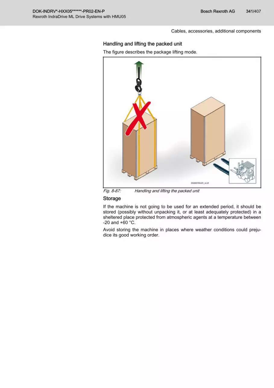
Handling and lifting the packed unitThe figure describes the package lifting mode.
Fig. 8-87: Handling and lifting the packed unit
StorageIf the machine is not going to be used for an extended period, it should bestored (possibly without unpacking it, or at least adequately protected) in asheltered place protected from atmospheric agents at a temperature between-20 and +60 °C.Avoid storing the machine in places where weather conditions could preju‐dice its good working order.
DOK-INDRV*-HXX05******-PR02-EN-P Bosch Rexroth AG 341/407Rexroth IndraDrive ML Drive Systems with HMU05
Cables, accessories, additional components

UnpackingIt is advisable to unpack the machine near the installation area to facilitateassembly.The figure shows how to unpack the machine properly.Proceed as outlined below.
1 Unscrew the screws.
2 Remove the cover.
3 Lift the side walls of the package.
Bosch Rexroth AG DOK-INDRV*-HXX05******-PR02-EN-P342/407Rexroth IndraDrive ML Drive Systems with HMU05
Cables, accessories, additional components

4 Tighten the eyebolts (A) provided.
5 Hook the ropes onto the eyebolts (A).
6 Lift the machine. WARNING! When lifting pay attention tothe machine swinging movement as thelifting point is never perfectly barycentric;sudden movements may injure the peopleinvolved in the operations. The packaging material (wood, propy‐lene, etc,.) can be kept for future use orproperly disposed of according to the reg‐ulations in force.
Tab. 8-122: Unpacking
DOK-INDRV*-HXX05******-PR02-EN-P Bosch Rexroth AG 343/407Rexroth IndraDrive ML Drive Systems with HMU05
Cables, accessories, additional components

Installation
Installation area The installation area must be flat and lev‐el, and meet the designed load factor andbe wired up for electrical connections andfor the transmission of the "UNITERROR" - "UNIT WARNING" signals aswell as having all the hydraulic connec‐tions required by regulations and laws inforce.The area must be adequately ventilatedand illuminated, in accordance with therelevant workplace health and safety reg‐ulations.Make sure to leave enough space aroundthe installation area so that interventionscan be carried out under safe conditions.
Tab. 8-123: Installation area
Bosch Rexroth AG DOK-INDRV*-HXX05******-PR02-EN-P344/407Rexroth IndraDrive ML Drive Systems with HMU05
Cables, accessories, additional components

Electrical connectionThe electrical connections must be carried out according to the instructionssupplied by the manufacturer in the wiring diagram enclosed.The electrical connections must be performed at professional standards incompliance with all legislative requirements and regulations.Use a 4 G-AWG 12 cable (three-phase conductors + earth conductor).Connect the three phases (L1, L2, L3) and the earth wire to the relevant ter‐minals inside the electrical panel.
Hose connections
The owner must install a pressure regulating deviceon the return pipe.Adjust the pressure in the input and return pipes to thevalue shown in chapter "Specifications" on page 333.Use flexible tubes with an internal diameter of not lessthan 25 mm.Use connectors with an internal diameter of not lessthan 20 mm.
Tab. 8-124: Hose connections
DOK-INDRV*-HXX05******-PR02-EN-P Bosch Rexroth AG 345/407Rexroth IndraDrive ML Drive Systems with HMU05
Cables, accessories, additional components

Information for UseSafety advice concerning useBefore starting the machine, make sure that the system or machine in whichit has been fitted is in compliance with local regulations and directives inforce.
Description of the controls and signal lights
A Main disconnect switch: it is used for connectingand disconnecting the power supply to machine.The indicator lamp (B) lights up.
B Indicator lamp (white light): indicates that thepower supply to the machine is enabled.
C Key-operated two-position stay-put selectorswitch: this is used to enable and disable mainpump operation.The key must be kept by the designated staffmember and available to the staff responsiblefor technical servicing.
D Two-position stay-put back-lit switch (red light):this is used to switch the filling pump on and off.
E Signal light (yellow): this shows automatic shut‐down of the heater (optional) triggered by over‐temperature of the liquid solution.
Tab. 8-125: Description of the controls and signal lights
Bosch Rexroth AG DOK-INDRV*-HXX05******-PR02-EN-P346/407Rexroth IndraDrive ML Drive Systems with HMU05
Cables, accessories, additional components

Starting procedureAt first start-up, carry out the circuit filling procedure (see chapter "Procedureto fill the hydraulic circuit" on page 349).To start the machine, proceed as described.
1 Open the ball valves (F - G).
2 Turn the main cut-off switch (A) to the "ON" po‐sition.The indicator lamp (B) lights up.
3 Turn the key selector (C) to "automatic" posi‐tion.Machine start-up must be performed using theoperating terminal of the machine to be cooled,via the "ENABLE" connection (see chapter"ENABLE, UNIT ERROR and UNIT WARNINGconnections" on page 334).
Tab. 8-126: Starting procedure
DOK-INDRV*-HXX05******-PR02-EN-P Bosch Rexroth AG 347/407Rexroth IndraDrive ML Drive Systems with HMU05
Cables, accessories, additional components

Stopping procedure
Stopping with the main switch1. Turn the main cut-off switch (A) to the "OFF" po‐
sition.● The signal light (B) will switch off.● Machine operation stops and the electricity sup‐
ply to the electrical panel is interrupted.● The terminals for the connection to the mains re‐
main live.
Stopping with the key-operated switchThis stop mode is reserved for authorised personnel.
1. Insert the key into the selector switch (C).2. Turn the selector switch to the "OFF" position.
● Operation of the main pump stops.● The electrical panel on the machine remains
live.
Remote-controlled stopping● Remote-controlled stopping must be performed using the owner’s operating terminal, via the "ENABLE" connection.● Operation of the main pump stops.● The electrical panel on the machine remains live.
Automatic stop● The machine stops automatically if the circuit pressure drops below 0,2 bar and the fluid temperature goes above the
preset upper limit (see parameter P-0-1382).
Tab. 8-127: Stopping procedure
Stopping in emergency conditionsTo stop the appliance in the event of imminent danger (emergency stop), turnthe main cut-off switch (A) to the "OFF" position.Eliminate the cause of the emergency stop before re-starting the machine.
Bosch Rexroth AG DOK-INDRV*-HXX05******-PR02-EN-P348/407Rexroth IndraDrive ML Drive Systems with HMU05
Cables, accessories, additional components

Procedure to fill the hydraulic circuitCheck that the installation, electrical connections and hydraulic connectionsare made to a professional standard in accordance with the manufacturer’sinstructions.
Fig. 8-88: Procedure to fill the hydraulic circuit1. Fill a tank with an appropriate amount of fluid solution (see chapter
"Specifications" on page 333).2. Fit the pipes (P - N) into the tank.3. Open the ball valve (G).4. Open the ball valve (F).5. Open the valve (M).6. Open the valve (L).7. Open the valve (H).8. Turn the key-operated selector switch (C) to "OFF" to prevent unexpec‐
ted activation of the main pump.9. Make sure that the remote-controlled "ENABLE" function is activated.
10. NOTICE! Do not turn the selector switch (C) to "ON" as this could causedamage to the main pump. Open any of the valves installed outside the machine on the circuit forthe machine to be cooled.
11. Turn the main cut-off switch (A) to the "ON" position.The indicator lamp (B) lights up.
DOK-INDRV*-HXX05******-PR02-EN-P Bosch Rexroth AG 349/407Rexroth IndraDrive ML Drive Systems with HMU05
Cables, accessories, additional components

12. Turn the selector switch (D) to activate the filling pump.Always keep the fluid in the tank at a sufficient level.
13. When the fluid is running out of the clear tube (N) in a steady stream (nobubbles) and the pressure has reached 1,5 bar close the valve (M).The pressure is shown by the pressure gauge (Q).
14. Open the valve (M).15. Turn the selector switch (C) to "ON" to activate the main pump.16. NOTICE! The main pump is activated only when the circuit pressure
reaches over 0,2 bar.During this stage, a sudden drop in pressure may occur, caused by theair pumped into the circuit as a result of activation of the main pump.Turn the main pump on and off, from time to time, using the selectorswitch (C) to facilitate circuit bleeding and pressurisation.Make sure that the key-operated switch is set to "ON".If it is hard for the system to get up to pressure, close the valve (M).If the pressure exceeds 1,5 bar, turn off the filling pump and temporarilyopen the valve (M) until the correct pressure is reached. Turn the selector switch (D) to deactivate the filling pump.
17. Close the spigot (M) when the pressure in the circuit reaches 1,5 bar18. Close the valve (L).19. Remove the pipes from the tank.20. Remove the key from the selector switch (C) and store in a safe place.
After one hour of operation, check that the pressure is correct, and if it isnot carry out the restore procedure (see chapter "Pressure restore pro‐cedure" on page 351).
Bosch Rexroth AG DOK-INDRV*-HXX05******-PR02-EN-P350/407Rexroth IndraDrive ML Drive Systems with HMU05
Cables, accessories, additional components

Pressure restore procedure
This procedure can be carried out only if the pressure is above0,8 bar and the main pump is activated.If the pressure is below this level, carry out the circuit filling proce‐dure (see chapter "Procedure to fill the hydraulic circuit" on page349).
Fig. 8-89: Pressure restore procedure1. Fill a tank with an appropriate amount of fluid solution (see chapter
"Specifications" on page 333).2. Fit the pipes (N - P) into the tank.3. Open the valve (L).4. Turn the selector switch (D) to activate the filling pump.5. Open the spigot (M) and keep open until the fluid is running out of the
clear tube (N) in a steady stream (no bubbles) and the pressure hasreached 1,5 bar.
6. NOTICE! If the pressure exceeds 1,5 bar, turn off the filling pump andtemporarily open the valve (M) until the correct pressure is reached. Close the valve (M).
7. Turn the selector switch (D) to deactivate the filling pump.8. Close the valve (L).9. Remove the pipes from the tank.
10. Remove the key from the selector switch (C) and store in a safe place.
DOK-INDRV*-HXX05******-PR02-EN-P Bosch Rexroth AG 351/407Rexroth IndraDrive ML Drive Systems with HMU05
Cables, accessories, additional components

Procedure to empty the hydraulic circuit
Fig. 8-90: Procedure to empty the hydraulic circuit1. Position a suitable container in which to collect the coolant.2. Stop the machine (see chapter "Stopping procedure" on page 348).3. Turn the key selector (C) to "OFF" position.4. Turn the main cut-off switch (A) to the "OFF" position.5. The signal light (B) will switch off.6. Close the ball valves (F - G).7. Open the valve (H).8. Unscrew caps (L).9. Drain out all the coolant.
10. Close the valve (H).11. Screw on the caps (L).
NOTICE! Do not dump the coolant; dispose of it in accordance with thelaws in force.
Bosch Rexroth AG DOK-INDRV*-HXX05******-PR02-EN-P352/407Rexroth IndraDrive ML Drive Systems with HMU05
Cables, accessories, additional components

Maintenance InformationSafety advice for maintenanceFor personal safety reasons, before conducting maintenance interventions,check that all safety devices are activated and warn the people present in theworkplace that such intervention is underway.In particular, disconnect the power supply to the machine.Make sure that the electricity cannot be accidentally restored.The operator must allow the machine to cool down before carrying out anyintervention to prevent scalds or burns.
Scheduled maintenance chart
Interval Component Type of work Reference
Every 5000 hoursof work
Every 30000hours of work
Every 10 years ofwork
– – –
✓ – – Radiator - channel Cleaning See chapter "Cleaningthe radiator and the
channel" on page 354
– ✓ – Main pump Replacement See chapter "Replac‐ing the main pump" on
page 358
– ✓ – Cooling fan Replacement See chapter "Replac‐ing the electric fan" on
page 360
– ✓ – Coolant Replacement See chapter "Replac‐ing the coolant" on
page 360
– – ✓ EPDM rubber hoses Replacement –
Tab. 8-128: Scheduled maintenance chart
DOK-INDRV*-HXX05******-PR02-EN-P Bosch Rexroth AG 353/407Rexroth IndraDrive ML Drive Systems with HMU05
Cables, accessories, additional components

Cleaning the radiator and the channel
1 Disconnect the machine fromthe power supply source.
2 Unscrew the screws (A).
3 Remove and prop up theelectric fan unit (B).
4 Vacuum away the dust anddirt inside the channel (C).
5 Clean the core of the radiator(D) using compressed air.
6 Vacuum away the dirt in thechannel again.
7 Place the electric fan unit inposition.
8 Tighten the screws (A).
Tab. 8-129: Cleaning the radiator and the channel
Machine cleaningClean the machine with detergents allowed by the legislation in force.
Bosch Rexroth AG DOK-INDRV*-HXX05******-PR02-EN-P354/407Rexroth IndraDrive ML Drive Systems with HMU05
Cables, accessories, additional components

Breakdown InformationThe following list contains a number of common problems that may arise dur‐ing work, together with the ways to solve them.
Code Type Fault Likely cause Solution
E2011 Warning 1 Low pressure The circuit pressure is below 0,5 bar (in Drive side) Pressurise the circuitto 1,5 bar
E2012 Warning 2 The machine doesnot start
Pump CP‑1 does not start in the speed check mode Make sure the systemis in a "AF" status be‐fore enabling
E2014 Warning 4 Outlet fluid tempera‐ture too high
The fluid temperature at the outlet is higher than theset point temperature (T_set) plus a ΔT defined byparameter P‑0‑1380 for a given time, defined by pa‐rameter P‑0‑1381 (see IndraDrive programming)
If necessary, changethe P‑0‑1380 and/orP‑0‑1381 parameters
F2011 Error 1 Low pressure alarm The circuit pressure is below 0,2 bar Pressurise the circuitto 1,5 bar
F2012 Error 2 High temperaturealarm
The fluid temperature is above the maximum al‐lowed temperature limit (see parameter P‑0‑1382)
If necessary, changethe P‑0‑1382 parame‐terClean the radiatorReduce the level ofthermal output to bedissipated
F2013 Error 3 Electric fan alarm Electric fan failureBlown fuses
Replace the electricfanReplace the interrup‐ted fuse
Liquid temperaturetoo high (yellow sig‐nal light on)
Heater temperature safety thermostat triggered Check the circuit pres‐sure and, if necessary,restore correct levelBleed the circuitReset the heater ther‐mostat
Tab. 8-130: Errors and Warnings
DOK-INDRV*-HXX05******-PR02-EN-P Bosch Rexroth AG 355/407Rexroth IndraDrive ML Drive Systems with HMU05
Cables, accessories, additional components

Information Concerning ReplacementsSafety advice in case of replacementsFor personal safety reasons, before conducting maintenance interventions,check that all safety devices are activated and warn the people present in theworkplace that such intervention is underway.In particular, disconnect the power supply to the machine.Make sure that the electricity cannot be accidentally restored.The operator must allow the machine to cool down before carrying out anyintervention to prevent scalds or burns.Replace worn or damaged parts with original spare parts.
Bosch Rexroth AG DOK-INDRV*-HXX05******-PR02-EN-P356/407Rexroth IndraDrive ML Drive Systems with HMU05
Cables, accessories, additional components

Replacing the filling pump
1 Disconnect the machine from thepower supply source.
2 Unscrew the screws (A).
3 Remove the fixed guard (B).
4 Cut the power supply cables.
5 Make sure that the valve (B) isclosed.
6 Undo the screw and remove thestrap (C).
7 Extract the hose (D).
8 Repeat the same operations to re‐move the other flexible tube.
9 Unscrew the screws (E).
10 Remove the pump.
11 Install the new pump.To fit the new pump carry out theremoval operations described in re‐verse order.
Tab. 8-131: Replacing the filling pump
DOK-INDRV*-HXX05******-PR02-EN-P Bosch Rexroth AG 357/407Rexroth IndraDrive ML Drive Systems with HMU05
Cables, accessories, additional components

Replacing the main pump
1 Disconnect the machine from thepower supply source.
2 Unscrew the screws (A).
3 Remove the fixed guard (B).
4 Close the valve (C).
Bosch Rexroth AG DOK-INDRV*-HXX05******-PR02-EN-P358/407Rexroth IndraDrive ML Drive Systems with HMU05
Cables, accessories, additional components

5 Undo the screw and remove thestrap (D).
6 Disconnect the hosing (E).
7 Repeat the same operations to re‐move the other flexible tube.
8 Remove the cover (F).
9 Disconnect the cables from the ter‐minals.
10 Unscrew the screws (G).
11 Remove the pump.
12 Install the new pump.To fit the new pump carry out theremoval operations described in re‐verse order.NOTICE! The spare pump is sup‐plied with the fittings mounted.Do not unscrew the fittings as thiscould cause liquid leakage.
Tab. 8-132: Replacing the main pump
DOK-INDRV*-HXX05******-PR02-EN-P Bosch Rexroth AG 359/407Rexroth IndraDrive ML Drive Systems with HMU05
Cables, accessories, additional components

Replacing the electric fan
1 Disconnect the machine fromthe power supply source.
2 Remove the cover (A).
3 Disconnect the cables fromthe terminals.
4 Unscrew the screws (B).
5 Remove the electric fan unit(C).
6 Unscrew the screws (D).
7 Remove the electric fan (E).
8 Place the replacement elec‐tric fan in position.
9 Tighten the screws (D).
10 Place the electric fan unit inposition.
11 Tighten the screws (B).
12 Connect up the wires (usingthe wiring diagram for refer‐ence).
13 Fit the cover (A).
Tab. 8-133: Replacing the electric fan
Replacing the fuses
Before replacing the fuse, remove the cause of the problem.Replace the interrupted fuse only with a fuse with the same char‐acteristics.For the characteristics of the fuses see chapter "Fuses descrip‐tion" on page 335.
Replacing the coolantDrain out the machine’s hydraulic circuit (see chapter "Procedure to emptythe hydraulic circuit" on page 352).Fill the hydraulic circuit (see chapter "Procedure to fill the hydraulic circuit" onpage 349).
Scrapping and disposalScrapping operations must be handled by specialised personnel with suitableskills for the job.When dismantling the machine, all components must be collected separatelyfor disposal according to their chemical properties, in accordance with the rel‐evant regulations in force.With reference to European Directive (RAEE), electric and electronic compo‐nents must be either disposed of in authorized landfill sites, or, in case of anew purchase, the machine, complete of the said parts, must be returned tothe dealer.
Bosch Rexroth AG DOK-INDRV*-HXX05******-PR02-EN-P360/407Rexroth IndraDrive ML Drive Systems with HMU05
Cables, accessories, additional components

The owner is responsible for delivering the machine, at the end of its workinglife, to the appropriate collection structures; failure to comply shall lead topenalties foreseen by the regulations in force.
DOK-INDRV*-HXX05******-PR02-EN-P Bosch Rexroth AG 361/407Rexroth IndraDrive ML Drive Systems with HMU05
Cables, accessories, additional components

Hydraulic diagramsWA0035K-0090 Hydraulic diagram
Fig. 8-91: WA0035K-0090 Hydraulic diagram
Bosch Rexroth AG DOK-INDRV*-HXX05******-PR02-EN-P362/407Rexroth IndraDrive ML Drive Systems with HMU05
Cables, accessories, additional components

Designation Description
VS-1 Safety Valve 2 bar
PW-1 Pressure Switch 0,5 bar
HT-1 2 kW 380-500 Vac Heater SS
PTK-1 8L Expansion Vessel
PW-2 Pressure Switch 0,2 bar
CP-1 Main Pump 400 Vac 50/60 Hz CM5-5
FAN-2 Fan 200-480 Vac 50/60 Hz 3P - IP55
TS-1 Temperature Sensor Pt100
- Pt100 Converter - Out: 0 … 10 V (M12)
DP-1 24Vdc Pressurization Pump
PS-1 Diff. Pressure Sensor 0 … 6 bar; Out: 0 … 10 V
ALHE-1 Air-Water Heatexchanger
DT-1 Drain Tank 2L
PI-1 Pressure Indicator 0 … 4 bar
NR-1 One-Way valve
Tab. 8-134: Designations
DOK-INDRV*-HXX05******-PR02-EN-P Bosch Rexroth AG 363/407Rexroth IndraDrive ML Drive Systems with HMU05
Cables, accessories, additional components

Bosch Rexroth AG DOK-INDRV*-HXX05******-PR02-EN-P364/407Rexroth IndraDrive ML Drive Systems with HMU05

9 Environmental protection and disposal9.1 Environmental protection
Production processes The products are made with energy- and resource-optimized production pro‐cesses which allow re-using and recycling the resulting waste. We regularlytry to replace pollutant-loaded raw materials and supplies by more environ‐ment-friendly alternatives.
No release of hazardous substan‐ces
Our products do not contain any hazardous substances which may be re‐leased in the case of appropriate use. Normally, our products will not haveany negativ influences on the environment.
Significant components Basically, our products contain the following components:Electronic devices Motors∙ steel ∙ steel∙ aluminum ∙ aluminum∙ copper ∙ copper∙ synthetic materials ∙ brass∙ electronic components and modules ∙ magnetic materials ∙ electronic components and modules
9.2 DisposalReturn of products Our products can be returned to our premises free of charge for disposal. It is
a precondition, however, that the products are free of oil, grease or other dirt.Furthermore, the products returned for disposal must not contain any undueforeign material or foreign components.Send the products ”free domicile” to the following address: Bosch Rexroth AG Electric Drives and Controls Buergermeister-Dr.-Nebel-Strasse 2 97816 Lohr am Main, Germany
Packaging The packaging materials consist of cardboard, wood and polystyrene. Thesematerials can be recycled anywhere without any problem.For ecological reasons, please refrain from returning the empty packages tous.
Batteries and accumulators Batteries and accumulators can be labeled with this symbol.
The symbol indicating "separate collection" for all batteries and accu‐mulators is the crossed-out wheeled bin.The end user within the EU is legally obligated to return used batteries. Out‐side the validity of the EU Directive 2006/66/EC keep the stipulated direc‐tives.Used batteries can contain hazardous substances, which can harm the envi‐ronment or the people´s health when they are improper stored or disposed of.After use, the batteries or accumulators contained in Rexroth products haveto be properly disposed of according to the country-specific collection.
Recycling Most of the products can be recycled due to their high content of metal. Inorder to recycle the metal in the best possible way, the products must be dis‐assembled into individual modules.
DOK-INDRV*-HXX05******-PR02-EN-P Bosch Rexroth AG 365/407Rexroth IndraDrive ML Drive Systems with HMU05
Environmental protection and disposal

Metals contained in electric and electronic modules can also be recycled bymeans of special separation processes.Products made of plastics can contain flame retardants. These plastic partsare labeled according to EN ISO 1043. They have to be recycled separatelyor disposed of according to the valid legal requirements.
Bosch Rexroth AG DOK-INDRV*-HXX05******-PR02-EN-P366/407Rexroth IndraDrive ML Drive Systems with HMU05
Environmental protection and disposal

10 Service and supportOur worldwide service network provides an optimized and efficient support.Our experts offer you advice and assistance should you have any queries.You can contact us 24/7.
Service Germany Our technology-oriented Competence Center in Lohr, Germany, is responsi‐ble for all your service-related queries for electric drive and controls.Contact the Service Hotline and Service Helpdesk under:
Phone: +49 9352 40 5060Fax: +49 9352 18 4941E-mail: [email protected]: http://www.boschrexroth.com/
Additional information on service, repair (e.g. delivery addresses) and trainingcan be found on our internet sites.
Service worldwide Outside Germany, please contact your local service office first. For hotlinenumbers, refer to the sales office addresses on the internet.
Preparing information To be able to help you more quickly and efficiently, please have the followinginformation ready:● Detailed description of malfunction and circumstances● Type plate specifications of the affected products, in particular type co‐
des and serial numbers● Your contact data (phone and fax number as well as your e-mail ad‐
dress)
DOK-INDRV*-HXX05******-PR02-EN-P Bosch Rexroth AG 367/407Rexroth IndraDrive ML Drive Systems with HMU05
Service and support

Bosch Rexroth AG DOK-INDRV*-HXX05******-PR02-EN-P368/407Rexroth IndraDrive ML Drive Systems with HMU05

11 Appendix11.1 Switching supply units on and off11.1.1 Switching on
Risk of damage to the supply units when theyare switched on simultaneously!
NOTICE
With 3 or more supply units at common mains power supply:Switch on supply units one after the other with a time interval of at least 0.5seconds so that the inrush currents are not added.In the switch-on sequence of the supply unit, the supplying mains is loadedwith the current IL_trans_max_on for the purpose of analysis. During the unloadingprocess, voltage overshoot can occur at the mains components connected inthe incoming circuit (e.g. mains filters) due to inductances connected in theincoming circuit, e.g. the leakage inductance of the mains transformer.
t1 Time depends on whether the supply unit is connected to acontrol unit via the communication, and on how fast this controlunit is booting up.
t2 Time can be set by the user. Take the time into account whichis required for run-up of all devices connected to IndraBus.This time depends on the control unit or the machine.
t3 Switch-on pulset4 HNA charges the DC bus and switches the mt5 Time depends on DC bus capacitance (internal, external) and
mains voltage Mains contactor is switched on by HNA.t6 Time for internal test routinest7 Time depends on the supply unit and the connected DC bus
capacitances. Supply unit goes to "LB" (ready for power output)status
Fig. 11-1: Signal sequences when switching on with digital inputs/outputs
DOK-INDRV*-HXX05******-PR02-EN-P Bosch Rexroth AG 369/407Rexroth IndraDrive ML Drive Systems with HMU05
Appendix

11.1.2 Switching off
Damage to the supply unit!NOTICE
At regenerative supply units, at least 10 ms have to elapse between themains OFF request and the disconnection of the mains voltage, so that theenergy flow has been interrupted when the disconnection process starts.You can make sure this order is observed by appropriate switch elements(e.g., by a control cabinet main switch with leading auxiliary contact). For thispurpose, connect the auxiliary contact in series with mains OFF.
t1 Time depends on device (mains contactor off delay); OFF re‐lates to the hardware input
Fig. 11-2: Signal sequences when switching off
Bosch Rexroth AG DOK-INDRV*-HXX05******-PR02-EN-P370/407Rexroth IndraDrive ML Drive Systems with HMU05
Appendix

11.2 Dimensioning the line cross sections and fuses Dimensioning the line cross sections and fuses in the supply feederand branches to the drive system:
1. Determine current in supply feeder of drive system and correct it withcorrection factors for ambient temperature and bundling.(In the technical data of the components in section "Data for mains volt‐age supply", you can find standardized data for connection cross sec‐tion and mains circuit breaker at operation under rated conditions.)
2. Determine country of use ("international except for USA/Canada" or"USA/Canada")
3. Determine installation type (e.g., B1 or B2)4. In "Current carrying capacity" table row, select the value that is immedi‐
ately above the value determined in the first step5. In "Fuse" table row, read corresponding fuse6. In "Cross section A …" table row, read corresponding required cross
sectionInternational except for USA/Canada; installation type B1 Country of use: international except for USA/Canada
Fuse IN [A] Current carrying ca‐pacity (× 0.87) IZ(40)
[A]
Cross section A [mm2]Installation type B11 × 2 × 3 ×
2 1.6 1.5
4 3.3 1.5
6 5.0 1.5
10 8.6 1.5
16 10.3 1.5
16 13.5 1.5
20 18.27 2.5
35 24.36 4
35 31.32 6
50 43.50 10
80 59.16 16
100 77.43 25
125 95.70 35
160 116.58 50
200 148.77 70
200 180.09 95
250 207.93 120
250 227.94 150
315 257.52 185
355 301.02 240
DOK-INDRV*-HXX05******-PR02-EN-P Bosch Rexroth AG 371/407Rexroth IndraDrive ML Drive Systems with HMU05
Appendix

Country of use: international except for USA/Canada
Fuse IN [A] Current carrying ca‐pacity (× 0.87) IZ(40)
[A]
Cross section A [mm2]Installation type B11 × 2 × 3 ×
400 342.78 300
160 238.03 2 × 70
160 288.14 2 × 95
200 332.69 2 × 120
200 364.70 2 × 150
250 412.03 2 × 185
315 481.63 2 × 240
315 548.45 2 × 300
125 312.42 3 × 70
160 378.19 3 × 95
160 436.65 3 × 120
200 478.67 3 × 150
200 540.79 3 × 185
250 632.14 3 × 240
315 719.84 3 × 300
Tab. 11-1: Line cross sections and fuses, B1 according to EN 60204-1:2006,Table 6, for 150mm² and more DIN IEC 60364-5-52:2004, Table B.52-4
International except for USA/Canada; installation type B2 Country of use: international except for USA/Canada
Fuse IN [A] Current carrying ca‐pacity (× 0.87) IZ(40)
[A]
Cross section A [mm2]Installation type B21 × 2 × 3 ×
2 1.6 0.75
4 3.3 0.75
6 5.0 0.75
10 8.5 0.75
16 10.1 1.0
16 13.05 1.5
20 17.40 2.5
25 23.49 4
35 29.58 6
50 40.02 10
63 53.94 16
80 69.60 25
Bosch Rexroth AG DOK-INDRV*-HXX05******-PR02-EN-P372/407Rexroth IndraDrive ML Drive Systems with HMU05
Appendix

Country of use: international except for USA/Canada
Fuse IN [A] Current carrying ca‐pacity (× 0.87) IZ(40)
[A]
Cross section A [mm2]Installation type B21 × 2 × 3 ×
100 86.13 35
125 102.66 50
160 129.63 70
200 155.73 95
200 179.22 120
224 195.75 150
250 221.85 185
315 258.39 240
355 294.93 300
125 207.41 2 × 70
160 249.17 2 × 95
160 286.75 2 × 120
200 313.20 2 × 150
200 354.96 2 × 185
250 413.42 2 × 240
315 471.89 2 × 300
100 272.22 3 × 70
125 327.03 3 × 95
160 376.36 3 × 120
160 411.08 3 × 150
200 465.89 3 × 185
200 542.62 3 × 240
250 619.35 3 × 300
Tab. 11-2: Line cross sections and fuses, B2 according to EN 60204-1:2006,Table 6, for 150mm² and more DIN IEC 60364-5-52:2004, Table B.52-4
International except for USA/
Canada; installation type E Country of use: international except for USA/Canada
Fuse IN [A] Current carrying ca‐pacity (× 0.87) IZ(40)
[A]
Cross section A [mm2]Installation type E1 × 2 × 3 ×
2 1.6 2
4 3.3 4
6 5.0 6
10 8.3 10
DOK-INDRV*-HXX05******-PR02-EN-P Bosch Rexroth AG 373/407Rexroth IndraDrive ML Drive Systems with HMU05
Appendix

Country of use: international except for USA/Canada
Fuse IN [A] Current carrying ca‐pacity (× 0.87) IZ(40)
[A]
Cross section A [mm2]Installation type E1 × 2 × 3 ×
16 10.4 16
16 12.4 16
20 16.10 1.5
25 21.75 2.5
35 29.58 4
50 37.41 6
63 52.20 10
80 69.60 16
100 87.87 25
125 109.62 35
160 133.11 50
200 170.52 70
250 207.06 95
315 240.12 120
355 277.53 150
400 316.68 185
425 374.10 240
500 432.39 300
160 272.83 2 x 70
200 331.30 2 x 95
250 384.19 2 x 120
250 444.05 2 x 150
315 506.69 2 x 185
400 598.56 2 x 240
400 691.82 2 x 300
160 358.09 3 x 70
200 434.83 3 x 95
200 504.25 3 x 120
250 582.81 3 x 150
250 665.03 3 x 185
315 785.61 3 x 240
400 908.02 3 x 300
Tab. 11-3: Line cross sections and fuses, E according to EN 60204-1:2006, Ta‐ble 6, for 150mm² and more DIN IEC 60364-5-52:2004, Table B.52-10
Bosch Rexroth AG DOK-INDRV*-HXX05******-PR02-EN-P374/407Rexroth IndraDrive ML Drive Systems with HMU05
Appendix

USA/Canada; installation type E
Country of use: USA/Canada
Fuse IN Current carry‐ing capacity IZ
[A]
Cross section AInstallation type E1 × 2 × 3 × 4 ×
2 1.6 14 AWG
4 3.3 14 AWG
6 5 14 AWG
10 8.3 14 AWG
16 13 14 AWG
20 15 14 AWG
25 20 12 AWG
40 30 10 AWG
70 50 8 AWG
80 65 6 AWG
100 85 4 AWG
110 100 3 AWG
125 115 2 AWG
150 130 1 AWG
175 150 1/0 AWG
200 175 2/0 AWG
225 200 3/0 AWG
250 230 4/0 AWG
300 255 250 kcmil
300 285 300 kcmil
350 310 350 kcmil
350 335 400 kcmil
400 380 500 kcmil
450 420 600 kcmil
600 460 700 kcmil
600 475 750 kcmil
600 490 800 kcmil
600 520 900 kcmil
800 545 1000 kcmil
800 590 1250 kcmil
800 625 1500 kcmil
800 650 1750 kcmil
DOK-INDRV*-HXX05******-PR02-EN-P Bosch Rexroth AG 375/407Rexroth IndraDrive ML Drive Systems with HMU05
Appendix

Country of use: USA/Canada
Fuse IN Current carry‐ing capacity IZ
[A]
Cross section AInstallation type E1 × 2 × 3 × 4 ×
800 665 2000 kcmil
200 300 2 × 1/0 AWG
225 350 2 × 2/0 AWG
250 400 2 × 3/0 AWG
300 460 2 × 4/0 AWG
300 510 2 × 250 kcmil
350 570 2 × 300 kcmil
350 620 2 × 350 kcmil
400 670 2 × 400 kcmil
450 760 2 × 500 kcmil
600 840 2 × 600 kcmil
600 920 2 × 700 kcmil
600 950 2 × 750 kcmil
600 980 2 × 800 kcmil
800 1040 2 × 900 kcmil
800 1090 2 × 1000 kcmil
200 450 3 × 1/0 AWG
225 525 3 × 2/0 AWG
250 600 3 × 3/0 AWG
300 690 3 × 4/0 AWG
300 765 3 × 250 kcmil
350 855 3 × 300 kcmil
350 930 3 × 350 kcmil
400 1005 3 × 400 kcmil
450 1140 3 × 500 kcmil
200 600 4 × 1/0 AWG
225 700 4 × 2/0 AWG
250 800 4 × 3/0 AWG
300 920 4 × 4/0 AWG
300 1020 4 × 250 kcmil
350 1140 4 × 300 kcmil
350 1240 4 × 350 kcmil
Bosch Rexroth AG DOK-INDRV*-HXX05******-PR02-EN-P376/407Rexroth IndraDrive ML Drive Systems with HMU05
Appendix

Country of use: USA/Canada
Fuse IN Current carry‐ing capacity IZ
[A]
Cross section AInstallation type E1 × 2 × 3 × 4 ×
400 1340 4 × 400 kcmil
450 1520 4 × 500 kcmil
Tab. 11-4: Line cross sections and fuses according to UL508A:2007, Table 28.1Dimensioning variables of the table values
1. Ambient temperature TA of routed lines ≤ 40 °C2. Temperature TL at conductor at nominal current: 90 °C for UL-listed
lines (USA/Canada) or 70 °C for PVC lines3. The nominal current of the fuse is approx. 10-20% above the nominal
current ILN of the converter/supply unit or the determined current of thedrive system.
4. Installation types:● B1 in accordance with IEC 60364-5-52, e.g. stranded wires routed
in cable duct● B2 in accordance with IEC 60364-5-52, e.g. multi-core line routed
in cable duct● E in accordance with EN 60204-1, e.g. multi-core line routed on
open cable tray● In accordance with NFPA 79 (external wiring), UL508A (internal
wiring), NEC, NFPA 70:– 1 cable with 3 conductors, 1 neutral conductor and 1 equip‐
ment grounding conductor– Routed in pipe on the wallInternal wiring: Routing inside of control cabinet or inside of devi‐cesExternal wiring: Routing outside of control cabinetField wiring: Data of cross sections of terminal connectors wired bythe user (in the field)
5. Recommendation for design of the fuses: ● International except for USA/Canada:
– Fuse-link in accordance with IEC 60269-1, characteristic gG(fuses)
– Circuit breakers in accordance with IEC 60898-1/2, type B orC
– Circuit breakers in accordance with IEC 60947-2/6-2● USA/Canada:
– Class J; 600 V
DOK-INDRV*-HXX05******-PR02-EN-P Bosch Rexroth AG 377/407Rexroth IndraDrive ML Drive Systems with HMU05
Appendix

Correction factorsFor deviating dimensioning variables, the corresponding stand‐ards specify correction factors.Below you can find the correction factors for ambient temperatureand numbers of routed lines and circuits. If necessary, multiplythe determined current in the supply feeder with these factors.
Ambient temperature correction factor
Ambient temperature TA / °C 30 35 40 45 50 55 60
Correction factor according toEN 60204‑1:2006, table D.1
0.87 0.93 1.00 1.1 1.22 1.41 1.73
Correction factor according toNFPA 79:2007, table 12.5.5(a)
0.88 0.94 1.00 1.1 1.18 1.32 1.52
Tab. 11-5: Ambient temperature correction factor in accordance with EN60204-1:2006 and NFPA 79:2007
Correction factor for bundling lines (installation methods B2 and E) and cir‐cuits (installation method B11))
Number of lines 1 2 3 4 5
Correction factor according toEN 60204‑1:2006, table D.2
1 1.25 1.43 1.54 1.67
Correction factor according toNFPA 79:2007, table 12.5.5(b)
1 1.25
1) Three single cores (L1, L2, L3) for mains supply of a device areto be considered as one circuit.
Tab. 11-6: Correction factor for bundling lines and circuits in accordance withEN 60204-1:2006 and NFPA 79:2007
Bosch Rexroth AG DOK-INDRV*-HXX05******-PR02-EN-P378/407Rexroth IndraDrive ML Drive Systems with HMU05
Appendix

B1 Conductor in installation pipes and in installation channels tobe opened
B2 Cables or lines in installation pipes and in installation channelsto be opened
C Cables or lines on wallsE Cables or lines on open cable trays.Fig. 11-3: Installation methods (compare IEC 60364-5-52; VDE0298-7; EN
60204-1)
DOK-INDRV*-HXX05******-PR02-EN-P Bosch Rexroth AG 379/407Rexroth IndraDrive ML Drive Systems with HMU05
Appendix

11.3 DC bus fusesIf lower output drive components (e.g., IndraDrive M or IndraDrive C) are alsoconnected to the DC bus, the cross section has to be tapered.For IndraDrive C/M series drive components, sizes between 110 and 350 Acan be connected with a maximum DC bus cable length of 2 m without DCbus fuses.For drive components lower than 110 A or a DC bus cable length over 2 m,DC bus fuses should be installed.
Bosch Rexroth AG DOK-INDRV*-HXX05******-PR02-EN-P380/407Rexroth IndraDrive ML Drive Systems with HMU05
Appendix

11.4 Aluminum contact points and cupal disks11.4.1 Introduction
The following components have aluminum contact points:● Preconnected choke● Chopper choke● DC bus choke Aluminum contact points require a specific screw connection for establishingcontact.
11.4.2 PreparationThe aluminum contact points come prepared for instant connection and donot need to be adapted when installed for the first time. The contact pointsare clean and have an anticorrosive coating.The components with aluminum contact points come with bimetallic cupaldisks. Cupal is a composite made of copper (Cu) and aluminum (Al).Use cupal disks whenever contact is established between the aluminum con‐tact point and any material other than aluminium.Clean both sides of the cupal disks with abrasive fleece before connectingthem, and then grease the cupal disks with a thin layer of contact grease.If the connection is opened after operation, abrade and grease the connec‐tions and the cupal disks again.
11.4.3 Cupal diskThe aluminum side of the cupal disk always has to have direct contact to thealuminum contact point!If contact is established on both sides of the aluminum contact point, also usea cupal disk on the opposite side.
DOK-INDRV*-HXX05******-PR02-EN-P Bosch Rexroth AG 381/407Rexroth IndraDrive ML Drive Systems with HMU05
Appendix

1 Screw2 Spring washer3 Washer4 Ring terminals5 Cupal disk (copper side)6 Cupal disk (aluminum side)7 Aluminum contact point8 Washer9 NutFig. 11-4: Connecting an aluminum contact point using a cupal disk
Tightening torque Risk of damage from mechanical stress!NOTICE
Keep the aluminum contact point from inadmissible mechanical stress:Always hold the aluminum contact point and ring terminal in place when tight‐ening the screw connection.
Screw Tightening torque [Nm]
M4 1.9
M5 3.7
M6 6.3
M8 15
M10 30
M12 52
Tab. 11-7: Tightening torque
Protection against corrosion To protect the connection against corrosion, apply a thin layer of anticorro‐sive paste (contact grease) to the connection.Suitable anticorrosive paste: acid- and alkali-free petrolatum
Bosch Rexroth AG DOK-INDRV*-HXX05******-PR02-EN-P382/407Rexroth IndraDrive ML Drive Systems with HMU05
Appendix

11.5 Determining the leakage capacitanceThe capacitances that generate so-called leakage currents against ground atthe inverter outputs are referred to as leakage capacitance Cab. The relevantvalues for the total value of leakage capacitance Cab_g are:● Capacitances of output filters● Capacitances of power cables (capacitance per unit length against
shield and ground wire)● Capacitances of motors (winding capacitance against housing)Leakage capacitance consists of the power cable and motor values for all in‐dividual drives operated on the mains filter.Calculation:
Cab_g Total value of leakage capacitanceCab_Mg Total value of motor leakage capacitanceCab_Kg Total value of cable leakage capacitanceFig. 11-5: Total leakage capacitanceThe total capacitance Cab_Mg is the sum of the capacitances of the individualmotors. See motor documentation for these capacitances.
Cab(motor) Leakage capacitance of a motorFig. 11-6: Total leakage capacitance of motor
CY_K typ Capacitance per unit length of cablesCab_Kg Total leakage capacitance of cablesFig. 11-7: Total leakage capacitance of cablesThe total capacitance Cab_Kg is the sum of capacitances of the individual pow‐er cables. See the technical data of the power cables for these capacitancesper unit length.
DOK-INDRV*-HXX05******-PR02-EN-P Bosch Rexroth AG 383/407Rexroth IndraDrive ML Drive Systems with HMU05
Appendix

11.6 Leakage capacitances11.6.1 Leakage capacitance of power cables
The "RKL" series power cables (bulk cables) from Rexroth have the followingcapacitances per unit length. The values refer to the sum of the individual ca‐pacitances of power cores 1, 2 and 3 against the overall shield.See also Rexroth connection cables - bulk cables data sheet. Leakage capacitance is specified in C per cable. In the case of parallel con‐nection, the total value is the sum of individual cables.Excerpt of data sheet on bulk cables
Type Power core cross section Leakage capacitance
mm2CY_K_typ
nF/m
INK0653 1.0 0.6
INK0650 1.5 0.8
INK0602 2.5 0.7
INK0603 4.0 0.8
INK0604 6.0 0.8
INK0605 10.0 1.0
INK0606 16.0 1.2
INK0607 25.0 1.1
INK0667 35.0 1.2
INK0668 50.0 1.3
Last modification: 2007-11-08
Tab. 11-8: INK - technical data (excerpt)Excerpt of data sheet on bulk cables
Type Power core cross section Leakage capacitanceCY_K_typ
mm2 nF/m
REH0800 2.5 0.2
Tab. 11-9: REH - technical data (excerpt)
The rough calculation with the following values is allowed:● Cross section 1 … 6 mm2: 1 nF/m● Cross section 10 … 50 mm2: 1.2 nF/m● Cross section 50 … 300 mm2: 1.3 nF/m
Bosch Rexroth AG DOK-INDRV*-HXX05******-PR02-EN-P384/407Rexroth IndraDrive ML Drive Systems with HMU05
Appendix

11.7 Total Harmonic Distortion (THD)The parameters individually set for drive control have a strong influence onthe THDi (mains current) and THDu (mains voltage) values. Therefore, thetable shows typical values for the parameters set by default.
Size Mains voltage[VAC]
Chopper frequen‐cy
[KHz]
THDi mains cur‐rent[%]
THDu mains voltage[%]
Load
HMU05.1-F0140 400 4.2 3,993 4,940 Partial load 50%
HMU05.1-F0140 400 4.2 4,332 4,843 Nominal load
HMU05.1-F0140 400 4.2 2,529 4,851 Peak load
HMU05.1-F0140 500 4.2 3,622 4,272 Partial load 50%
HMU05.1-F0140 500 4.2 2,217 3,882 Nominal load
HMU05.1-F0140 500 4.2 1,585 3,904 Peak load
HMU05.1-F0170 400 4.2 2,489 4,014 Partial load 50%
HMU05.1-F0170 400 4.2 0,785 4,867 Nominal load
HMU05.1-F0170 400 4.2 1,262 5,157 Peak load
HMU05.1-F0170 500 4.2 3,786 3,455 Partial load 50%
HMU05.1-F0170 500 4.2 0,453 4,150 Nominal load
HMU05.1-F0170 500 4.2 2,135 4,564 Peak load
HMU05.1-F0220 400 4.2 3,189 4,224 Partial load 50%
HMU05.1-F0220 400 4.2 2,247 1,646 Nominal load
HMU05.1-F0220 400 4.2 2,244 2,482 Peak load
HMU05.1-F0220 500 4.2 4,871 3,620 Partial load 50%
HMU05.1-F0220 500 4.2 1,427 4,687 Nominal load
HMU05.1-F0220 500 4.2 1,797 5,155 Peak load
HMU05.1-F0270 400 4.2 2,780 1,577 Partial load 50%
HMU05.1-F0270 400 4.2 2,012 3,197 Nominal load
HMU05.1-F0270 400 4.2 3,335 2,009 Peak load
HMU05.1-F0270 500 4.2 3,205 3,406 Partial load 50%
HMU05.1-F0270 500 4.2 1,245 3,805 Nominal load
HMU05.1-F0270 500 4.2 1,820 0,954 Peak load
DOK-INDRV*-HXX05******-PR02-EN-P Bosch Rexroth AG 385/407Rexroth IndraDrive ML Drive Systems with HMU05
Appendix

Size Mains voltage[VAC]
Chopper frequen‐cy
[KHz]
THDi mains cur‐rent[%]
THDu mains voltage[%]
Load
HMU05.1-F0340 400 4.2 3,087 3,152 Partial load 50%
HMU05.1-F0340 400 4.2 2,201 3,617 Nominal load
HMU05.1-F0340 400 4.2 1,983 3,824 Peak load
HMU05.1-F0340 500 4.2 3,265 2,870 Partial load 50%
HMU05.1-F0340 500 4.2 2,447 3,391 Nominal load
HMU05.1-F0340 500 4.2 2,112 3,554 Peak load
HMU05.1-F0430 400 4.2 5,076 3,511 Partial load 50%
HMU05.1-F0430 400 4.2 3,781 3,925 Nominal load
HMU05.1-F0430 400 4.2 3,440 3,948 Peak load
HMU05.1-F0430 500 4.2 4,911 3,338 Partial load 50%
HMU05.1-F0430 500 4.2 3,887 3,789 Nominal load
HMU05.1-F0430 500 4.2 3,772 3,892 Peak load
HMU05.1-F0540 400 4.2 3,175 3,334 Partial load 50%
HMU05.1-F0540 400 4.2 2,344 3,784 Nominal load
HMU05.1-F0540 400 4.2 2,080 3,869 Peak load
HMU05.1-F0540 500 4.2 3,352 3,121 Partial load 50%
HMU05.1-F0540 500 4.2 2,467 3,600 Nominal load
HMU05.1-F0540 500 4.2 2,378 3,729 Peak load
Tab. 11-10: Total Harmonic Distortion (THD)
Bosch Rexroth AG DOK-INDRV*-HXX05******-PR02-EN-P386/407Rexroth IndraDrive ML Drive Systems with HMU05
Appendix

11.8 Liquid cooling11.8.1 Sizing liquid coolingCalculation criteria
Physical dataThe figure below shows the fundamental physical data of a liquid-cooleddrive component.
Q Flow rateΔT = T2 - T1 Temperature increaseΔp = p2 - p1 Pressure decreasePv Power dissipation to be dischargedFig. 11-8: Physical data
Flow rateFlow rate Coolant flows through liquid-cooled components. The flow rate Q indicates
how much coolant volume ΔV per time interval Δt flows through the compo‐nent.
Q Flow rate in l/minΔV Coolant volume in lΔt Time interval in minutes in which ΔV flowsFig. 11-9: Flow rate
Calculating the required flow rate If the power dissipation PV and the coolant are known, the required flowrate Q can be calculated with a selected coolant temperature increase ΔT.The required flow rate Q can be calculated from the physical data of the com‐ponent being cooled.
DOK-INDRV*-HXX05******-PR02-EN-P Bosch Rexroth AG 387/407Rexroth IndraDrive ML Drive Systems with HMU05
Appendix

PV Power dissipation to be discharged in kWΔT Temperature rise of coolant in Kρ Density of coolant in kg/lc Specific thermal capacity of coolant in kJ/kgKFig. 11-10: Calculating the flow rateThe flow rates are indicated in the technical data of the liquid-cooled compo‐nents (referring to a fixed temperature increase of the coolant water). For anyother temperature increase, calculate the flow rate using the above formula.
Pressure decreaseThe coolant flow in a drive component is subject to changes in volume anddirection. This results in losses in the drive components due to friction andchange of direction. These losses cause the pressure decrease Δp.The flow diagram shows how the pressure decrease Δp depends on the flowrate Q of a specific component.Flow diagram
Δp Pressure decreaseΔpQmin Pressure decrease for QminQ Flow rateQmin Min. required flow rate (see technical data for each component)Fig. 11-11: Flow diagramAll other parts of the cooling system through which the coolant flows (tubes,valves, etc.) also cause pressure decreases.
Calculating pressure decrease The pressure decrease Δp in liquid-cooled drive components is indicated inthe technical data of each drive component. It refers to the indicated flow rateof the coolant water. These pressure decrease values only refer to drive com‐ponents from Rexroth. The pressure decrease caused by equipment connec‐ted by the customer, such as screw connections, connecting bends, hosenozzles, etc., must be added to the pressure decrease of the drive compo‐nent.The flow rate-based pressure decrease can be calculated with the followingformula:
Bosch Rexroth AG DOK-INDRV*-HXX05******-PR02-EN-P388/407Rexroth IndraDrive ML Drive Systems with HMU05
Appendix

Δp Pressure decreaseKΔp Constant (see technical data for each component)Q Flow rate in l/minFig. 11-12: Pressure decrease vs. flow rate
Sizing aidsThe following sizing aids are based on a cooling system with four motors con‐nected in parallel.
1 Liquid-cooled motor2 Main distributor of cooling liquid3 Cooling device (cooling or refrigerating unit)4 Heat dissipation5 Higher-level cooling mediumFig. 11-13: Arrangement with liquid-cooled motors
DOK-INDRV*-HXX05******-PR02-EN-P Bosch Rexroth AG 389/407Rexroth IndraDrive ML Drive Systems with HMU05
Appendix

Liquid cooling circuit diagram
A Cooling deviceA1 Coolant containerA2 Coolant pumpA3 Heat exchangerB Coolant linesC FittingsD Drive components being cooledE Heat transferF Higher-level cooling mediumQ Flow rateΔp Pressure decrease (Ftg: fittings; Dc: drive components; Chk:
choke; L: line; P: coolant pump; He: heat exchanger)ΔPv Power dissipation of a drive component being dischargedFig. 11-14: Liquid cooling circuit diagram for four liquid-cooled drive components
Bosch Rexroth AG DOK-INDRV*-HXX05******-PR02-EN-P390/407Rexroth IndraDrive ML Drive Systems with HMU05
Appendix

Sizing a cooling system
Liquid-cooled drive components have been selected
Gather technical data (for ΔT = 10 K)
(see below "Form: Collecting technical data")
Convert technical
dataNo
Temperature increase = 10 K?
Yes
Go to "Convert tech‐nical data"
Check requirements and ambient conditions:● Temperature control precision?● Which higher-level cooling medium can be used?
Yes
No Increase tempera‐
ture difference?
Select cooling device:● Cooling capacity P ≥ ΣPv
● Type of cooling device?– Air-liquid cooling unit (P01 = kW/K)
– Liquid-liquid cooling unit (P01 = kW/K)
– Refrigerating unit (PRefrig = kW)
Make installation plan:● Components: determine interconnection (series/parallel)● Lines: determine lengths and diameters
Size coolant pump:● Fluidic data of cooling system branches● Parallel connection of branches● Series connection of branches● Pressure decrease in overall system● Working point of pump:
– ΔH = ……… m– Qp = ……… l/min
(see below "Form: Sizing a coolant pump")
Tank volume of cool‐ing device:VTank = ………… l
NoΣΔp > 3000 hPa ?
Yes
Sizing complete
Tab. 11-11: Sizing a cooling system
DOK-INDRV*-HXX05******-PR02-EN-P Bosch Rexroth AG 391/407Rexroth IndraDrive ML Drive Systems with HMU05
Appendix

Form: Gathering technical data
Drive com‐ponent
Pv [kW]
Coolant
Pv [kW]
Air
Q [l/min] Δp [hPa] ΔT [°C] V [l]
ΣPvCl
ΣPvAir
Tab. 11-12: Gathering technical dataForm: Sizing a coolant pump
Fluidic data of cooling system branches
Cooling system branch 1 2 3 4 5 …
Drive component Type designation
Flow rate Qchn l/min
Pressure decreases Coolant line Length ln m
Added length ladd m
Ø d mm
ΔpL/Δl for Qch hPa/m
ΔpLn hPa + + + + + +
Drive component Δpchn hPa + + + + + +
Additional component ΔpAdd hPa + + + + + +
Total pressure de‐crease:
Without choker valve ΔpBn hPa = = = = = =
(Only with parallel con‐nection)
With choker valve 1) ΔpBn hPa = = = = = =
Parallel connection of branches no. ……………
Total pressure de‐crease
Δpb hPa
Bosch Rexroth AG DOK-INDRV*-HXX05******-PR02-EN-P392/407Rexroth IndraDrive ML Drive Systems with HMU05
Appendix

Total flow rate With choker valve 1) ΣQch l/min
Without choker valve 2) ApproximationQchn
l/min
ΣQch l/min
Series connection of branches no. ……………
Total pressure de‐crease
ΣΔpBn hPa
Total flow rate ΣQchnmax l/min
Pressure decrease in overall system
Cooling systembranches
ΔpB or
ΣpBn
hPa +
Coolant line Length l0 m
Added lengthladd0
m
Diameter d0 mm
ΣQch l/min
ΔpL/Δl for Qch hPa/m
ΔpL hPa +
Heat exchanger ΔpHe hPa +
Fittings ΔpFtg hPa +
Additional component ΔpAdd hPa +
Overall cooling system ΔpCs hPa +
Working point of coolant pump
Required deliveryheight
ΔH m
Required delivery rate QP l/min
1) The required coolant flow Qchn is set with the choker valve inthe cooling system branch.
2) The coolant flow Qchn is set according to the pressure decreaseover the cooling system branches Δpb.
Tab. 11-13: Form for sizing coolant pump
DOK-INDRV*-HXX05******-PR02-EN-P Bosch Rexroth AG 393/407Rexroth IndraDrive ML Drive Systems with HMU05
Appendix

11.8.2 Sizing exampleThe calculation for the cooling device is shown using a drive system to clarifythe sizing calculation.Components● 1x supply unit with P = 400 kW● 1x drive controller with P = 250 kW● 1x drive controller with P = 132 kW
Fig. 11-15: ComponentsForm: Gathering technical data (for temperature increase = 10 K)
Drive com‐ponent
Pv [kW]
Coolant
Pv [kW]
Air
Q [l/min] Δp [hPa] ΔT [°C] V [l]
HMU05.1N-F0540
7.5 1.2 15.8 1.3 10 xxx
HMU05.1N-F0340
4.5 1 9 0.6 xxx
HMU05.1N-F0140
2.5 0.5 4.5 0.4 xxx
HNL05.1R 4 1.8 10 1.5 xxx
HNA05.1 - 0.15
ΣPvCl
= 18.5 kW
ΣPvAir
= 4.65 kW
ΣVch
xxx
Tab. 11-14: Gathering technical data
Bosch Rexroth AG DOK-INDRV*-HXX05******-PR02-EN-P394/407Rexroth IndraDrive ML Drive Systems with HMU05
Appendix

Coolant The coolant should be a 4:1 mixture of water and Antifrogen N or L (e.g., Ri‐Frost 1:4 from Rittal).Do not mix Antifrogen N with Antifrogen L. When switching the coolant (N forL or vice-versa), thoroughly rinse out all components and lines before addingthe new coolant.
Maximum coolant temperature At nominal power dissipation, the temperature increase in the coolant is 10 Kat the indicated minimum flow rates. If the maximum coolant inlet tempera‐ture is 60°C, the maximum coolant temperature is 70°C.
Requirements for ambient condi‐tions
No higher-level liquid cooling system is available at the installation site. Therequirements on the temperature accuracy of the coolant are low (±5 K).
Selecting the cooling device The absorbed thermal energy should be dissipated into the ambient air withan air-liquid cooling unit.The cooling liquid must dissipate 18.5 kW of heat output into the ambient air.The maximum expected air temperature is 35°C.Specific cooling capacity:
∑PV = 18.5 kW (sum of power dissipations from technical data of drive com‐ponents)Tin = 60°C, max. coolant inlet temperature into cooling unitTamb = 35°C according to ambient conditionsP01 = 18.5 ÷ (60 - 35) = 0.74 kW/°C In addition, a cooling device should be installed on the control cabinet thatcan absorb the power of 4.65 kW dissipated into the air.
Fluidic interconnection Due to the very different coolant flow rates of the drive components, the fluid‐ic connection of the cooling system branches for the drive components is inparallel.
DOK-INDRV*-HXX05******-PR02-EN-P Bosch Rexroth AG 395/407Rexroth IndraDrive ML Drive Systems with HMU05
Appendix

Creating an installation plan
A Cooling deviceA1 Coolant containerA2 Coolant pumpA3 Heat exchangerB Coolant linesC FittingsD Drive components being cooledE Heat transferF Higher-level cooling mediumQ Flow rateΔp Pressure decrease (Ftg: fittings; Dc: drive components; Chk:
choke; L: line; P: coolant pump; He: heat exchanger)ΔPv Power dissipation of a drive component being dischargedFig. 11-16: Liquid cooling circuit diagramSizing the coolant pump
Fluidic data of cooling system branches
Cooling system branch 1 2 3 4 …
Drive component Type designation
Flow rate Qchn l/min
Pressure decreases Coolant line Length ln m
Added length ladd m
Diameter d mm
ΔpL/Δl for Qch hPa/m
ΔpLn hPa
Drive component Δpchn hPa
Additional component ΔpAdd hPa + / + / + / + /
Total pressure decrease: Without choker valve ΔpBn hPa
(Only with parallel con‐nection)
With choker valve 1) ΔpBn hPa
Bosch Rexroth AG DOK-INDRV*-HXX05******-PR02-EN-P396/407Rexroth IndraDrive ML Drive Systems with HMU05
Appendix

Parallel connection of branches no.1, 2, 3, 4
Total pressure decrease Δpb hPa
Total flow rate With choker valve 1) ΣQch l/min
Without choker valve 2) ApproximationQchn
l/min / / / /
ΣQch l/min /
Series connection of branches no. ………………
Total pressure decrease ΣΔpBn hPa
Total flow rate ΣQchnmax l/min
Pressure decrease in overall system
Cooling system branches ΔpB or
ΣpBn
hPa
Coolant line Length l0 m
Added lengthladd0
m
Diameter d0 mm
ΣQch l/min
ΔpL/Δl at ΣQch hPa/m
ΔpL hPa
Heat exchanger ΔpHe hPa
Fittings ΔpFtg hPa
Additional component ΔpAdd hPa + /
Overall cooling system ΔpCs hPa
Working point of coolant pump
Required delivery height ΔH m
Required delivery rate QP l/min
1) The required coolant flow Qchn is set with the choker valve inthe cooling system branch.
2) The coolant flow Qchn is set according to the pressure decreaseover the cooling system branches Δpb.
Tab. 11-15: Sizing the coolant pumpSince the pressure decrease of the overall cooling system falls below the per‐mitted input pressure, the coolant pump has been sized.
Tank
DOK-INDRV*-HXX05******-PR02-EN-P Bosch Rexroth AG 397/407Rexroth IndraDrive ML Drive Systems with HMU05
Appendix

wherebyVHe = ……… from the heat exchanger manufacturer's specificationsVFtg = ……… from the specifications of the fittings manufacturerVDc = ……… gathered from the technical data of the drive componentsVL= line lengths x flow cross-sectionVDist = as indicated by the distributor manufacturer
Conclusion The data determined for the cooling device can be retained in the procedurediagram. This data can be used to contact the supplier of the cooling device.
Bosch Rexroth AG DOK-INDRV*-HXX05******-PR02-EN-P398/407Rexroth IndraDrive ML Drive Systems with HMU05
Appendix

Index0 … 924 V supply
Connection point.......................... 129, 175, 27224V power supply unit....................................... 28024V supply
Continuous power........................................ 100Installation.................................................... 101Peak current................................................. 100Project planning............................................. 98
AAcceptance tests............................................... 117Accessories
Blank cover (HAS10)................................... 157Cabinet installation kit (HAS08.1-008-NNN-MH)..................................................... 149HAS03.......................................................... 148HAS08.......................................................... 149HAS10.......................................................... 157Mounting and connection accessories(HAS03)....................................................... 148Overview...................................................... 147
Accumulators.................................................... 365Additional components...................................... 166
Overview...................................................... 147Additional documentations.................................. 28ADVANCED
CSH02.5........................................................ 23Air-liquid cooling unit
Cooling capacity............................................. 70Properties....................................................... 64
Air-Liquid Heat ExchangerHAH01.2-WA............................................... 326
Aluminum contact pointsCupal disks.................................................. 381
Ambient conditions.............................................. 60Applications
IndraDrive ML................................................ 13Appropriate use................................................... 31
Applications.................................................... 31Approvals.......................................................... 117Assignment
HMU05 and additional components............. 112Axis coupling..................................................... 114
BBASIC
CSB02.5......................................................... 23Batteries............................................................ 365Braking resistor
external, HLR05........................................... 249HLR05, data................................................. 251
Braking unitHLT05.......................................................... 255
Brief description
HMU05........................................................... 45
CC-UL-US listing................................................. 117Cables
Capacitance................................................. 384Encoder cables, selection table..................... 52Leakage capacitance................................... 384Overview...................................................... 147Shield connection......................................... 131
CalculationsLeakage capacitance................................... 383Liquid cooling............................................... 387Mains-side phase current............................. 110Phase current............................................... 110
CapacitancePower cables............................................... 384
CCC, China Compulsory Certification............... 118CE label............................................................ 117Certifications..................................................... 117Characteristic
Fuses........................................................... 377China Compulsory Certification (CCC)............. 118Compatibility
With foreign matters....................................... 81Components
Combining...................................................... 45Mounting positions......................................... 93
Condensation protectionFor liquid cooling............................................ 75
Condition as supplied........................................ 119Conditions
Ambient and operating conditions.................. 60Configuration
Drive system.................................................. 47Connection
24 V supply (XD10)...................... 129, 175, 272Aluminum contact points.............................. 381Connection diagram (HMU05 as drivecontroller)............................................... 94, 123Connection diagram (HMU05 as supplyunit)........................................................ 95, 123Connection points, overview........................ 124Control voltage (XD10)................ 129, 175, 272Cooling liquid............................................... 135Cupal disks.................................................. 381DC bus......................................................... 130Electrical...................................................... 123Equipment grounding conductor.................. 125Ground......................................................... 133Hydraulics.................................................... 135Mains........................................................... 102Mains/motor (L1, L2, L3).............................. 126Motor fan control (XG3)............................... 127Motor holding brake(XG3)............................ 127
DOK-INDRV*-HXX05******-PR02-EN-P Bosch Rexroth AG 399/407Rexroth IndraDrive ML Drive Systems with HMU05
Index

Motor temperature monitoring (XG3)........... 127Shield........................................................... 131
Connection pointsHMU05, overview......................................... 124
Contained substancessee "Significant components"...................... 365
Contents of deliveryHMU05......................................................... 120
Control cabinetCooling........................................................... 62Design............................................................ 62
Control linesCables, shield connection............................ 131
Control sectionInstallation and removal................................. 25
Control voltageConnection point XD10................ 129, 175, 272Continuous power........................................ 100Data............................................................. 137Determining the power requirements............. 98For drive systems........................................... 98HMU05......................................................... 137Installation.................................................... 101Loop-through contacts (XD10)..... 129, 175, 272Looping through........................................... 102Peak current................................................. 100Project planning............................................. 98Requirements on the power supply unit....... 100Supply with control voltage 24 V.................... 98
CoolantNon-water-based........................................... 78Water-based............................................ 77, 78
Coolant pump...................................................... 66Coolant reservoir................................................. 66Cooling
HMU05........................................................... 90Cooling device
Components................................................... 65Cooling devices................................................... 63Cooling liquid
Connection points........................................ 135Cooling system
Sizing........................................................... 391Corner-grounded delta mains........................... 107Coupling............................................................ 135
Axis coupling................................................ 114DC bus coupling........................................... 114
CSB02.5BASIC............................................................ 23Type code...................................................... 20
CSH02.5ADVANCED................................................... 23Type code...................................................... 20
CSx02.5Functional equipment..................................... 23
Cupal disksAluminum contact points.............................. 381
DData
Ambient conditions......................................... 60HLL05.......................................................... 243HLR05.......................................................... 251HLT05.......................................................... 259HML05......................................................... 229HMU05, control voltage............................... 137HMU05, cooling............................................. 90HMU05, DC bus........................................... 141HMU05, dimensional drawing........................ 82HMU05, dimensions....................................... 82HMU05, distances.......................................... 90HMU05, housing dimensions......................... 89HMU05, insulation.......................................... 89HMU05, inverter........................................... 143HMU05, Mains voltage................................. 139HMU05, mass................................................ 89HMU05, power dissipation............................. 90HMU05, temperatures.................................... 90HMU05, THD............................................... 385HMU05, UL ratings........................................ 79HNA05......................................................... 169HNC05......................................................... 189HNF05.......................................................... 197HNL05.......................................................... 217Operating conditions...................................... 60
DC busConnection point.......................................... 130Data, HMU05............................................... 141Fuses........................................................... 380Fusing.......................................................... 380
DC bus chokeHLL05.......................................................... 231
DC bus coupling................................................ 114Declaration of conformity.................................. 117Design
HMU05........................................................... 45Devices
Mounting positions......................................... 93Dimensional drawing
HLL05.......................................................... 233HLR05.......................................................... 250HLT05.......................................................... 256HML05......................................................... 221HMU05........................................................... 82HNA05................................................. 167, 203HNC05......................................................... 186HNF05.......................................................... 192
DimensioningLine cross sections and fuses...................... 371
Disposal............................................................ 365Distances
HMU05........................................................... 90Documentation
Additional documentations............................. 28Drive systems................................................ 28
Bosch Rexroth AG DOK-INDRV*-HXX05******-PR02-EN-P400/407Rexroth IndraDrive ML Drive Systems with HMU05
Index

Firmware........................................................ 28Overview........................................................ 28Purpose.......................................................... 28Reference documentations............................ 28System components...................................... 28
Drive rangeRexroth IndraDrive ML................................... 11
Drive system....................................................... 33Configuring..................................................... 47HMU05 with HMS01/HMD01......................... 56System structure............................................ 17
EElectric drive system........................................... 33Electrical connection......................................... 123Electrical project planning................................... 94Encoder
Supported encoder systems.......................... 16Environmental protection.................................. 365Equipment grounding conductor
Connection................................................... 125External braking resistor
HLR05.......................................................... 249External wiring.................................................. 377
FField wiring........................................................ 377File numbers
UL................................................................ 117Firmware............................................................. 27
Assigned HMU05 device types...................... 47Documentation............................................... 28
Flow rateCalculation................................................... 387
Foreign mattersCompatibility.................................................. 81
Functional equipmentCSx02.5......................................................... 23
Functional featuresHMU05........................................................... 14
FusesCharacteristic............................................... 377Circuit breaker.............................................. 377DC bus......................................................... 380Design.......................................................... 377Dimensioning............................................... 371
GG1
Mounting position........................................... 93Ground
Connection................................................... 133Ground connection............................................ 133
HHAH01
Declaration of conformity............................. 286
Disclaimer notice.......................................... 287General Information..................................... 285Heat Exchanger........................................... 284Manufacturer’s details and machine iden‐tification details............................................ 285Safety Information........................................ 288Type Code................................................... 284Water quality specification........................... 295
HAH01.2-WABreakdown information................................ 355Cleaning....................................................... 354Description of the controls and signallights............................................................. 346Electrical connection.................................... 345ENABLE, UNIT ERROR and UNITWARNING connections............................... 334Fuses description......................................... 335General description of the machine............. 326Handling and installation safety recom‐mendations.................................................. 339Handling and lifting the packed unit............. 341Hose connections........................................ 345Hydraulic diagram........................................ 362Hydraulic diagram WA0035K-0090.............. 362Information and safety signs........................ 338Information for Use...................................... 346Machine specification................................... 333Main parts.................................................... 327Maintenance information.............................. 353Operational cycle and component de‐scription........................................................ 328Overall dimensions...................................... 332Package description..................................... 339Pressure restore procedure......................... 351Procedure to empty the hydraulic circuit...... 352Procedure to fill the hydraulic circuit............ 349Processing and protection devices.............. 336Replacing the electric fan............................. 360Replacing the filling pump............................ 357Replacing the main pump............................ 358Starting procedure....................................... 347Stopping procedure...................................... 348Storage........................................................ 341Unpacking.................................................... 342
HAH01.2-WWAssembling the machine.............................. 305Breakdown information................................ 317Customer side circuit drainage procedure... 313Description of the controls and signallights............................................................. 307Drive circuit drainage procedure.................. 314Electrical connection.................................... 306ENABLE, UNIT ERROR and UNITWARNING connections............................... 296Fuses description......................................... 297General description of the machine............. 289Handling and installation safety recom‐mendations.................................................. 301
DOK-INDRV*-HXX05******-PR02-EN-P Bosch Rexroth AG 401/407Rexroth IndraDrive ML Drive Systems with HMU05
Index

Handling and lifting the packed unit............. 302Hose connections........................................ 306Hydraulic diagram WW0008K-0020............. 324Hydraulic diagram WW0035K-0090............. 322Information and safety signs........................ 300Information for Use...................................... 307Machine specification................................... 294Main parts.................................................... 289Maintenance information.............................. 315Operational cycle and component de‐scription........................................................ 290Overall dimensions...................................... 293Package description..................................... 301Pressure restore procedure......................... 312Procedure to fill the drive circuit................... 310Processing and protection devices.............. 298Replacing the actuator................................. 321Replacing the filling pump............................ 318Replacing the main pump............................ 319Replacing the mixing valve.......................... 320Starting procedure....................................... 308Stopping procedure...................................... 309Storage........................................................ 302Unpacking.................................................... 303
HAS03Accessories (for mounting and installa‐tion).............................................................. 148
HAS04.1-003Y capacitor pair............................................ 247
HAS08Cabinet installation kit.................................. 149
HAS10Blank cover.................................................. 157Type code.................................................... 157
Hazardous substances..................................... 365Heat Exchanger
HAH01......................................................... 284Helpdesk........................................................... 367HLL05
Data............................................................. 243DC bus choke.............................................. 231Dimensional drawing.................................... 233Dimensions.................................................. 233Sizing........................................................... 232Type code.................................................... 231
HLR05Braking resistor (external)............................ 249Data............................................................. 251Dimensional drawing.................................... 250Dimensions.................................................. 250Installation.................................................... 252Type code.................................................... 249
HLT05Braking unit.................................................. 255Connection diagram..................................... 260Connection points........................................ 263Data............................................................. 259Dimensional drawing.................................... 256
Dimensions.................................................. 256Display elements.......................................... 279LEDs............................................................ 279Type code.................................................... 255
HML05Assignment.................................................. 220Data............................................................. 229Dimensional drawing.................................... 221Dimensions.................................................. 221Type code.................................................... 219
HMS05Drive controller............................................... 12
HMU05Assigning additional components................ 112Brief description............................................. 45Connection points, overview........................ 124Contents of delivery..................................... 120Control voltage, data.................................... 137DC bus, data................................................ 141Design (block diagram).................................. 45Dimensional drawing...................................... 82Dimensions.................................................... 82Distances....................................................... 90Drive system with HMS01/HMD01................. 56Firmware........................................................ 47Functional features........................................ 14Housing dimensions....................................... 89Insulation........................................................ 89Inverter, data................................................ 143Mains voltage, data...................................... 139Mass.............................................................. 89Mounting in control cabinet.......................... 123Performance features.................................... 15Power dissipation........................................... 90Sound pressure level..................................... 89Supported motors.......................................... 47Temperatures................................................. 90THD.............................................................. 385Type code...................................................... 18UL ratings....................................................... 79
HMV05Supply unit..................................................... 12
HNA busXG32.................................................... 129, 179
HNA05Connection points........................................ 171Data............................................................. 169Dimensional drawing.................................... 167Dimensions.................................................. 167Display elements.......................................... 184Equipment grounding conductor connec‐tion point...................................................... 172LEDs............................................................ 184Mains connection module............................ 166Type code.................................................... 166
HNC05Data............................................................. 189Dimensional drawing.................................... 186
Bosch Rexroth AG DOK-INDRV*-HXX05******-PR02-EN-P402/407Rexroth IndraDrive ML Drive Systems with HMU05
Index

Dimensions.................................................. 186Mains capacitor............................................ 185Type code.................................................... 185
HNF05Data............................................................. 197Dimensional drawing.................................... 192Dimensions.................................................. 192Mains filter.................................................... 190Type code.................................................... 190
HNLType plate.................................................... 202
HNL05............................................................... 198Data............................................................. 217Dimensional drawing.................................... 203Dimensions.................................................. 203Type code.................................................... 198Type plate.................................................... 202
Hotline............................................................... 367Housing dimensions
HMU05........................................................... 89HPC01
Connection points........................................ 134Optional cards................................................ 24Type code...................................................... 24
IIdentification
Of components............................................. 120Inappropriate use................................................ 32
Consequences, disclaimer............................. 31Individual components
Combining...................................................... 45IndraDrive ML
Applications.................................................... 13Overview........................................................ 11Target applications......................................... 13
Installation24V supply................................................... 101Connection points........................................ 123Control section............................................... 25Control voltage supply................................. 101Electrical connection.................................... 123Optional card.................................................. 25
Installation conditions.......................................... 60Installation methods.......................................... 379Installation type
B1......................................................... 371, 377B2......................................................... 372, 377E................................................... 373, 375, 377NFPA........................................................... 377UL508A........................................................ 377
InsulationHMU05........................................................... 89
Insulation resistance testing.............................. 119Internal wiring.................................................... 377Inverter, data
HMU05......................................................... 143
IT mains type.................................................... 106
LL+, L-
DC bus......................................................... 130L1, L2, L3
Mains/motor connection............................... 126Leakage capacitance
Calculating................................................... 383Determining.................................................. 383HMU05 systems for high leakage capaci‐tances............................................................ 54HMU05 systems for medium leakage ca‐pacitances...................................................... 53Power cables............................................... 384
Leakage currentsCause........................................................... 103
LineCorrection factor.......................................... 378Cross sections, dimensioning...................... 371Fuses, dimensioning.................................... 371
Liquid coolingCalculation criteria....................................... 387Condensation protection................................ 75Coolant........................................................... 77Cooling device components........................... 65Flow rate...................................................... 387Interconnection.............................................. 74Liquid cooling circuit diagram....................... 390Parallel connection......................................... 74Physical data................................................ 387Pressure decrease....................................... 388Project planning manual................................ 63Series connection.......................................... 74Sizing aids.................................................... 389Sizing example............................................. 394
Liquid cooling circuit diagramLiquid cooling............................................... 390
Liquid-liquid cooling unitCooling capacity............................................. 71Properties....................................................... 64
Liquid-Liquid Heat ExchangerHAH01.2-WW.............................................. 289
ListingC-UL-US...................................................... 117
Lock nipple........................................................ 135
MMains
With grounded outer conductor.................... 107Mains capacitor
HNC05......................................................... 185Mains choke...................................................... 198
Combining with mains filter.......................... 112HNL05.......................................................... 198
Mains connectionL1, L2, L3..................................................... 126
DOK-INDRV*-HXX05******-PR02-EN-P Bosch Rexroth AG 403/407Rexroth IndraDrive ML Drive Systems with HMU05
Index

Mains current............................................... 110Mains filter, mains choke............................. 112Parallel connection....................................... 108Power........................................................... 110Project planning........................................... 102Types........................................................... 108
Mains current.................................................... 110Mains filter
Combining with mains choke....................... 112HNF05.......................................................... 190
Mains transformerDimensioning............................................... 111Selecting...................................................... 111
Mains types....................................................... 104Mains voltage
HMU05......................................................... 139Mains-side phase current
Calculating................................................... 110Mass
HMU05........................................................... 89Mechanical project planning............................... 82Motor
Cables, shield connection............................ 132Motor fan control.......................................... 127Motor fan control connection (XG3)............. 127Motor holding brake..................................... 127Motor holding brake connection (XG3)........ 127Motor temperature monitoring...................... 127Motor temperature monitoring connection(XG3)........................................................... 127Supported motors.......................................... 47Third-party motors.......................................... 47
Motor connectionL1, L2, L3..................................................... 126
MountingHMU05 in control cabinet............................. 123
Mounting positionG1.................................................................. 93
OOperating conditions........................................... 60Operation at partial load.................................... 110Optional card
Installation and removal................................. 25Optional cards
HPC01........................................................... 24Overview
Accessories.................................................. 147Additional components................................. 147Cables.......................................................... 147
PPackaging......................................................... 365Parallel connection............................................ 108Parallel operation
Power extension.......................................... 114PELV................................................................... 38
Performance featuresHMU05........................................................... 15
PF55, PF56, PF57, PF58LEDs, HLT05............................................... 279LEDs, HNA05............................................... 184
Phase currentCalculating................................................... 110
Power extensionParallel operation......................................... 114
Power supply unit24 V.............................................................. 28024V/20A connection diagram....................... 28224V/40A connection diagram....................... 283Data............................................................. 281
Pressure decreaseCalculation................................................... 388
Production processes....................................... 365Project planning
Electrical project planning.............................. 94Mechanical project planning.......................... 82
Protective extra-low voltage................................ 38
RRCCB................................................................ 102RCD.................................................................. 102Recycling.......................................................... 365Reference documentations................................. 28Refrigerating unit
Properties....................................................... 64Refrigerating capacity.................................... 73
RemovalControl section............................................... 25Optional card.................................................. 25
Residual-current-operated circuit breakers....... 102Return of products............................................ 365Rexroth IndraDrive ML
Applications.................................................... 13Drive range.................................................... 11Overview........................................................ 11System presentation...................................... 11Target applications......................................... 13
SSafety instructions for electric drives andcontrols............................................................... 33Service hotline.................................................. 367SF1
Switch.......................................................... 278Shield
Connection................................................... 131Control lines................................................. 131Motor power cables...................................... 132
Significant components..................................... 365Sound pressure level
HMU05........................................................... 89Standard motors
Voltage load................................................. 146
Bosch Rexroth AG DOK-INDRV*-HXX05******-PR02-EN-P404/407Rexroth IndraDrive ML Drive Systems with HMU05
Index

State-of-the-art.................................................... 31Storing
Components................................................. 121Supply
With control voltage 24 V............................... 98with mains voltage....................................... 102
Support............................................................. 367Switch
SF1.............................................................. 278Switching off
Supply unit................................................... 369Switching on
Supply unit................................................... 369System structure
Drive system.................................................. 17
TTarget applications
IndraDrive ML................................................ 13Technical data
HMU05, power section................................. 137See also index entry Data............................ 137
TestingCustomer..................................................... 119Factory-side................................................. 119Insulation resistance.................................... 119Voltage testing............................................. 119
THDHMU05......................................................... 385
Third-party motorsAt drive controllers......................................... 47
TN-C mains type............................................... 105TN-S mains type............................................... 104Transporting
Components................................................. 120TT system......................................................... 107Type code
CSB02.5......................................................... 20CSH02.5........................................................ 20HAS10.......................................................... 157HLL05.......................................................... 231HLR05.......................................................... 249HLT05.......................................................... 255HML05......................................................... 219HMU05........................................................... 18HNA05......................................................... 166HNC05......................................................... 185HNF05.......................................................... 190HNL05.......................................................... 198HPC01........................................................... 24
Type CodeHAH01......................................................... 284
Type plateDevice.......................................................... 120HNL.............................................................. 202
UUL
File numbers................................................ 117Listing........................................................... 117Ratings, HMU05............................................. 79
Ungrounded mains............................................ 106Use
Appropriate use.............................................. 31Inappropriate use........................................... 32
VVoltage testing.................................................. 119
WWA0035K-0090
Hydraulic diagram........................................ 362WATER IN/OUT
Cooling liquid connection............................. 135WW0008K-0020
Hydraulic diagram........................................ 324WW0035K-0090
Hydraulic diagram........................................ 322
XXD1
Mains voltage, equipment grounding con‐ductor........................................................... 173
XD02DC bus......................................................... 267
XD2DC bus......................................................... 174
XD4Braking resistor............................................ 271
XD10Control voltage (24 V).................. 129, 175, 272
XE01Equipment grounding conductor connec‐tion point...................................................... 265
XF1................................................................... 135XF2................................................................... 135XG1
IndraBus....................................... 129, 176, 273XG3
Braking resistor signal contact..................... 274Motor temperature monitoring, motorholding brake, motor fan control.................. 127
XG31Messages............................................. 177, 275
XG32HNA bus............................................... 129, 179
XG33DC bus short-circuit (ZKS)........................... 277On, off, ZKS (DC bus short circuit) status.... 180
XG34Mains contactor (contact)............................. 182
XG40
DOK-INDRV*-HXX05******-PR02-EN-P Bosch Rexroth AG 405/407Rexroth IndraDrive ML Drive Systems with HMU05
Index

Mains contactor (acknowledgment mes‐sages).......................................................... 183
YY capacitor pair
HAS04.1-003............................................... 247
Bosch Rexroth AG DOK-INDRV*-HXX05******-PR02-EN-P406/407Rexroth IndraDrive ML Drive Systems with HMU05
Index

Notes
DOK-INDRV*-HXX05******-PR02-EN-P Bosch Rexroth AG 407/407Rexroth IndraDrive ML Drive Systems with HMU05

Bosch Rexroth AGElectric Drives and ControlsP.O. Box 13 5797803 Lohr, GermanyBgm.-Dr.-Nebel-Str. 297816 Lohr, GermanyPhone +49 9352 18 0Fax +49 9352 18 8400www.boschrexroth.com/electrics
*R911344279*R911344279
DOK-INDRV*-HXX05******-PR02-EN-P


