Embed Size (px)
Citation preview

NOTE : Read safety instructions carefully and understand them before using. Retain this Instruction Manual for future reference.
INSTRUCTION MANUAL
ML-111
No.02
40095701
Please do not hesitate to contact our distributors or agents in your area for further information when necessary.* The description covered in this instruction manual is subject to change for improvement of the
commodity without notice.
13 · 09 Printed in Japan
Copyright C 2011-2013 JUKI CORPORATION
• All rights reserved throughout the world.
SEWING MACHINERY BUSINESS UNIT2-11-1, TSURUMAKI, TAMA-SHI, TOKYO, 206-8551, JAPANPHONE : (81)42-357-2371FAX : (81)42-357-2380http://www.juki.com

i
For the sewing machine, automatic machine and ancillary devices (hereinafter collectively referred to as "machine"), it is inevitable to conduct sewing work near moving parts of the machine. This means that there is always a possibility of unintentionally coming in contact with the moving parts. Operators who actually operate the machine and maintenance personnel who are involved in maintenance and repair of the machine are strongly recommended to carefully read to fully understand the following SAFETY PRECAUTIONSbefore using/maintaining the machine. The content of the SAFETY PRECAUTIONS includes items which are not contained in the speci cations of your product.The risk indications are classi ed into the following three different categories to help understand the meaning of the labels. Be sure to fully understand the following description and strictly observe the instructions.
War
ning
labe
l
❶
❷❸
❶ T ere i e ibili a lig eri in r r ea a be a e T ere i e ibili a in r a be a e b ing ing ar❷ T er r e ing r i a e g ar T er r e ing r i a e er T er r e ing r i a e r e i n e i e❸ e re rn e er OFF be re arr ing a ine ea rea ing
nee le anging b bbin anging r iling an leaning
❸
❷
❶
Ele
rial
an
ger l
abel
DANGER :T i in i a i n i gi en ere ere i an i e ia e anger ea r er in r i e er n in arge r an ir
ar i an le e a ine r e n a i e anger i a i n en era ing r ain aining e a ine WARNING :
T i in i a i n i gi en ere ere i a en iali r ea r eri in r i e er n in arge r an ir ar i an le e a ine r e n a i e anger i a i n en era ing r ain aining e a ine
CAUTION :T i in i a i n i gi en ere ere i a anger e i in r in r i e er n in arge r an ir ar
i an le e a ine r e n a i e anger i a i n en era ing r ain aining e a ine
I e re iring e ial a en i n
Piri
al
arni
ng in
ia
in
T ere i a ri in r i n aing a ing e i n
Piri
al
arni
ng
ini
ai
n
e a are a l ing e e ing a ine ring era i n an r r an
T ere i a ri ele ri al i n a ing a ig l age e i n
T ere i a ri en angle en in e bel re l ing in in r
T ere i a ri a b rn i n aing a ig e era re e i n
T ere i a ri in r i e b n arrier
e a are a e e e ien an be a e b l ing ire l a e la er bea
Ini
ai
n la
bel
T e rre ire i n i in i a e
T ere i a ri n a be een r ea an e e ing a
ine
C nne i n a ear able i in i a e
TO ENSURE SAFE USE OF YOUR SEWING MACHINE
I E lana i n ri le el
(II) E lana i n i rial arning in i a i n an arning label
– 10 –
14. HEIGHT OF THE PRESSER BAR
1
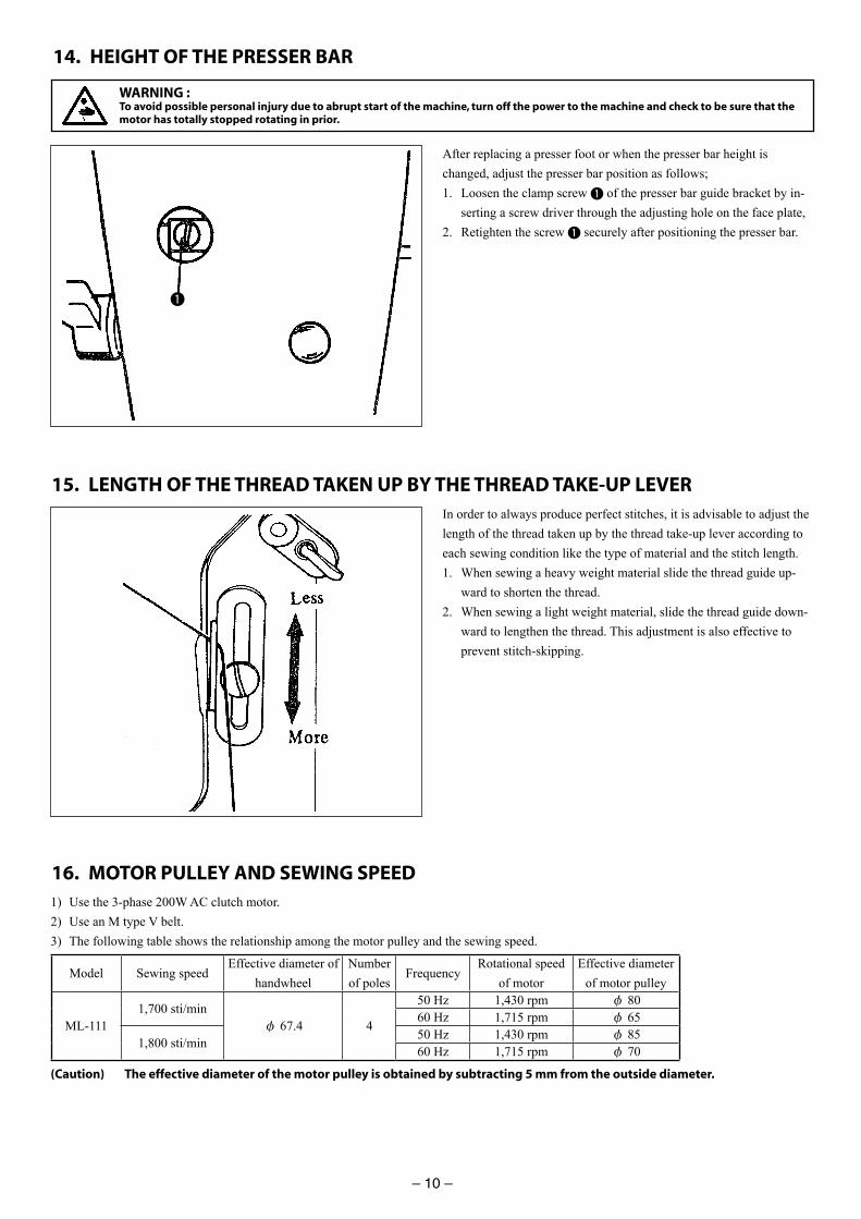
After replacing a presser foot or when the presser bar height is changed, adjust the presser bar position as follows;1. Loosen the clamp screw 1 of the presser bar guide bracket by in-
serting a screw driver through the adjusting hole on the face plate,2. Retighten the screw 1 securely after positioning the presser bar.
15. LENGTH OF THE THREAD TAKEN UP BY THE THREAD TAKE-UP LEVERIn order to always produce perfect stitches, it is advisable to adjust the length of the thread taken up by the thread take-up lever according to each sewing condition like the type of material and the stitch length.1. When sewing a heavy weight material slide the thread guide up-
ward to shorten the thread.2. When sewing a light weight material, slide the thread guide down-
ward to lengthen the thread. This adjustment is also effective to prevent stitch-skipping.
WARNING :To avoid possible personal injury due to abrupt start of the machine, turn off the power to the machine and check to be sure that the motor has totally stopped rotating in prior.
1) Use the 3-phase 200W AC clutch motor.2) Use an M type V belt.3) The following table shows the relationship among the motor pulley and the sewing speed.
Model Sewing speedEffective diameter of
handwheelNumber of poles
FrequencyRotational speed
of motorEffective diameter
of motor pulley
ML-1111,700 sti/min
φ 67.4 4
50 Hz 1,430 rpm φ 8060 Hz 1,715 rpm φ 65
1,800 sti/min50 Hz 1,430 rpm φ 8560 Hz 1,715 rpm φ 70
(Caution) The effective diameter of the motor pulley is obtained by subtracting 5 mm from the outside diameter.
16. MOTOR PULLEY AND SEWING SPEED
– 9 –
13. RELATION BETWEEN THE NEEDLE AND THE LOOPER
2 mm
1
2
3
5
7
6
8
4
8
0.05 mm
13
13
9
WARNING :To avoid possible personal injury due to abrupt start of the machine, turn off the power to the machine and check to be sure that the motor has totally stopped rotating in prior.
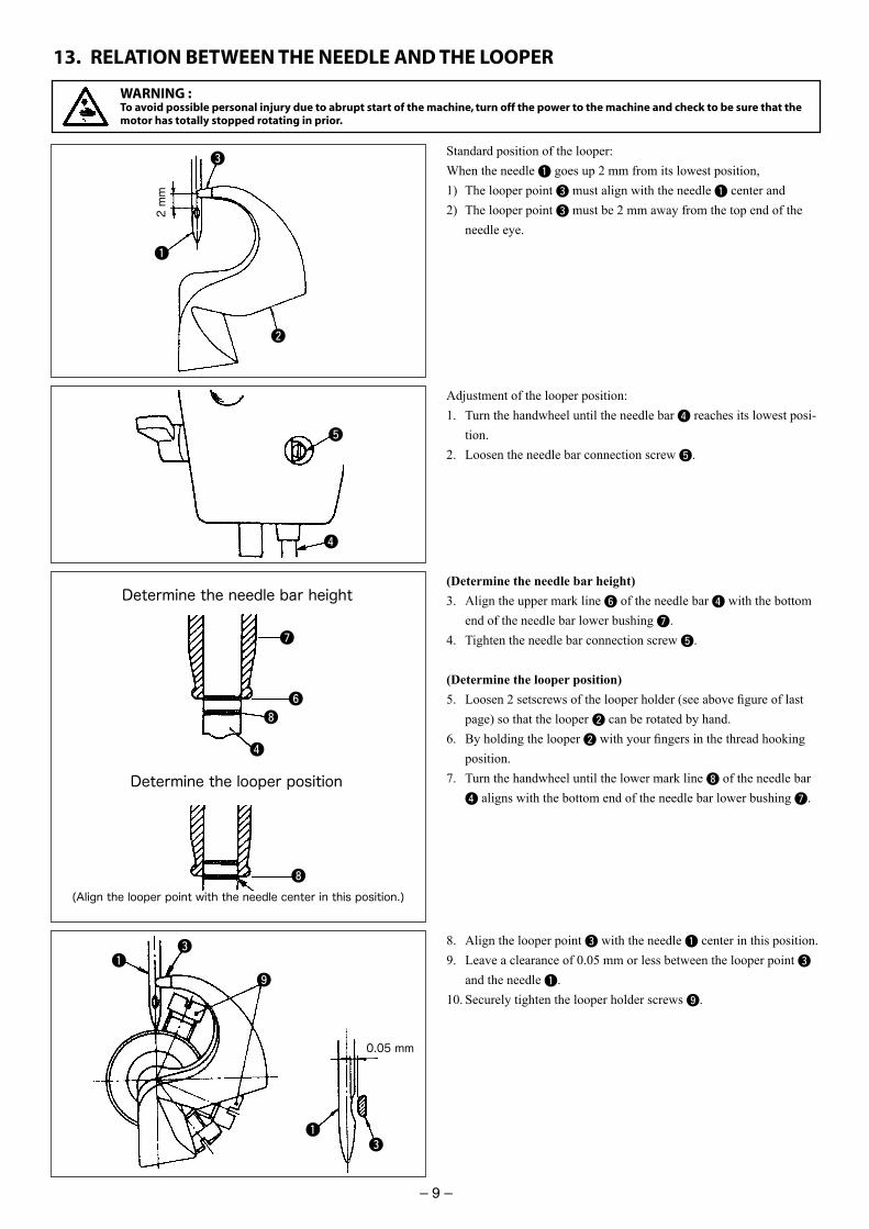
Standard position of the looper:When the needle 1 goes up 2 mm from its lowest position, 1) The looper point 3 must align with the needle 1 center and2) The looper point 3 must be 2 mm away from the top end of the
needle eye.
8. Align the looper point 3 with the needle 1 center in this position.9. Leave a clearance of 0.05 mm or less between the looper point 3
and the needle 1.10. Securely tighten the looper holder screws 9.
Adjustment of the looper position:1. Turn the handwheel until the needle bar 4 reaches its lowest posi-
tion.2. Loosen the needle bar connection screw 5.
(Determine the needle bar height)3. Align the upper mark line 6 of the needle bar 4 with the bottom
end of the needle bar lower bushing 7.4. Tighten the needle bar connection screw 5.
(Determine the looper position)5. Loosen 2 setscrews of the looper holder (see above fi gure of last
page) so that the looper 2 can be rotated by hand. 6. By holding the looper 2 with your fi ngers in the thread hooking
position.7. Turn the handwheel until the lower mark line 8 of the needle bar
4 aligns with the bottom end of the needle bar lower bushing 7.
4
Determine the needle bar height
Determine the looper position
(Align the looper point with the needle center in this position.)
ii
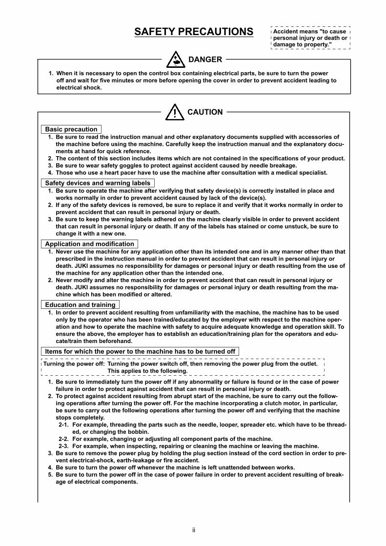
SAFETY PRECAUTIONS
W en i i ne e ar en e n r l b n aining ele ri al ar be re rn e er an ai r e in e r re be re ening e er in r er re en a i en lea ing
ele ri al
A i en ean a e er nal in r r ea r a age r er
DANGER
CAUTION
a i re a i n e re rea e in r i n an al an er e lana r en lie i a e rie
e a ine be re ing e a ine Care ll ee e in r i n an al an e e lana r en a an r i re eren e
T e n en i e i n in l e i e i are n n aine in e e i a i n r r e re ear a e g ggle r e again a i en a e b nee le brea age T e e a ear a er a e e e a ine a er n l a i n i a e i al e iali
Sa e e i e an arning label e re era e e a ine a er eri ing a a e e i e( ) i rre l in alle in la e an
r n r all in r er re en a i en a e b la e e i e( ) I an e a e e i e i re e be re re la e i an eri a i r n r all in r er
re en a i en a an re l in er nal in r r ea e re ee e arning label a ere n e a ine learl i ible in r er re en a i en
a an re l in er nal in r r ea I an e label a aine r e n be re ange i i a ne ne
A li a i n an i a i n Ne er e e a ine r an a li a i n er an i in en e ne an in an anner er an a
re ribe in e in r i n an al in r er re en a i en a an re l in er nal in r r ea U I a e n re n ibili r a age r er nal in r r ea re l ing r e e e a ine r an a li a i n er an e in en e ne
Ne er i an al er e a ine in r er re en a i en a an re l in er nal in r r ea U I a e n re n ibili r a age r er nal in r r ea re l ing r e aine i a been i e r al ere
E a i n an raining In r er re en a i en re l ing r n a iliari i e a ine e a ine a be e
nl b e era r a been raine e a e b e e l er i re e e a ine era i n an era e e a ine i a e a ire a e a e n le ge an era i n ill T en re e ab e e e l er a e abli an e a i n raining lan r e era r an e
a e rain e be re an
I e r i e er e a ine a be rne
T rning e er : T rning e er i en re ing e er l g r e le T i a lie e ll ing
e re i e ia el rn e er i an abn r ali r ail re i n r in e a e er ail re in r er r e again a i en a an re l in er nal in r r ea
T r e again a i en re l ing r abr ar e a ine be re arr e lling era i n a er rning e er F r e a ine in r ra ing a l r in ar i lar be re arr e ll ing era i n a er rning e er an eri ing a e a ine
le el F r e a le rea ing e ar a e nee le l er rea er e i a e be rea
e r anging e b bbin F r e a le anging r a ing all nen ar e a ine F r e a le en in e ing re airing r leaning e a ine r lea ing e a ine e re re e e er l g b l ing e l g e i n in ea e r e i n in r er re
en ele ri al ear lea age r re a i en e re rn e er ene er e a ine i le na en e be een r e re rn e er in e a e er ail re in r er re en a i en re l ing brea
age ele ri al nen
iii
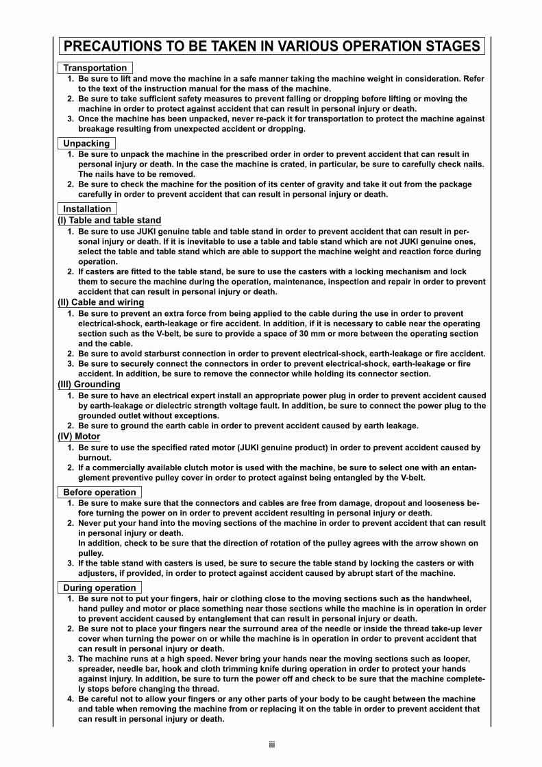
PRECAUTIONS TO E TA EN IN ARIOUS OPERATION STAGESTran r a i n
e re li an e e a ine in a a e anner a ing e a ine eig in n i era i n Re er e e e in r i n an al r e a e a ine
e re a e ien a e ea re re en alling r r ing be re li ing r ing e a ine in r er r e again a i en a an re l in er nal in r r ea
On e e a ine a been n a e ne er re a i r ran r a i n r e e a ine again brea age re l ing r ne e e a i en r r ing
Un a ing e re n a e a ine in e re ribe r er in r er re en a i en a an re l in
er nal in r r ea In e a e e a ine i ra e in ar i lar be re are ll e nail T e nail a e be re e
e re e e a ine r e i i n i en er gra i an a e i r e a age are ll in r er re en a i en a an re l in er nal in r r ea
In alla i n(I) Table an able an
e re e U I gen ine able an able an in r er re en a i en a an re l in ernal in r r ea I i i ine i able e a able an able an i are n U I gen ine ne
ele e able an able an i are able r e a ine eig an rea i n r e ring era i n
I a er are e e able an be re e e a er i a l ing e ani an l e e re e a ine ring e era i n ain enan e in e i n an re air in r er re en
a i en a an re l in er nal in r r ea(II) Cable an iring
e re re en an e ra r e r being a lie e able ring e e in r er re en ele ri al ear lea age r re a i en In a i i n i i i ne e ar able near e era ing e i n a e bel be re r i e a a e r re be een e era ing e i n
an e able e re a i arb r nne i n in r er re en ele ri al ear lea age r re a i en e re e rel nne e nne r in r er re en ele ri al ear lea age r re
a i en In a i i n be re re e e nne r ile l ing i nne r e i n(III) Gr n ing
e re a e an ele ri al e er in all an a r ria e er l g in r er re en a i en a e b ear lea age r iele ri reng l age a l In a i i n be re nne e er l g e gr n e le i e e i n
e re gr n e ear able in r er re en a i en a e b ear lea age(I ) M r
e re e e e i e ra e r ( U I gen ine r ) in r er re en a i en a e b b rn
I a er iall a ailable l r i e i e a ine be re ele ne i an en angle en re en i e lle er in r er r e again being en angle b e bel
e re era i n e re a e re a e nne r an able are ree r a age r an l ene be
re rning e er n in r er re en a i en re l ing in er nal in r r ea Ne er r an in e ing e i n e a ine in r er re en a i en a an re l
in er nal in r r ea In a i i n e be re a e ire i n r a i n e lle agree i e arr n n
lle I e able an i a er i e be re e re e able an b l ing e a er r i
a er i r i e in r er r e again a i en a e b abr ar e a ine
D ring era i n e re n r nger air r l ing l e e ing e i n a e an eel
an lle an r r la e e ing near e e i n ile e a ine i in era i n in r er re en a i en a e b en angle en a an re l in er nal in r r ea
e re n la e r nger near e rr n area e nee le r in i e e rea a e le er er en rning e er n r ile e a ine i in era i n in r er re en a i en a
an re l in er nal in r r ea T e a ine r n a a ig ee Ne er bring r an near e ing e i n a l er
rea er nee le bar an l ri ing ni e ring era i n in r er r e r an again in r In a i i n be re rn e er an e be re a e a ine le el be re anging e rea
e are l n all r nger r an er ar r b be a g be een e a ine an able en re ing e a ine r r re la ing i n e able in r er re en a i en a
an re l in er nal in r r ea
– 8 –
12. HOW TO REMOVE THE LOOPER
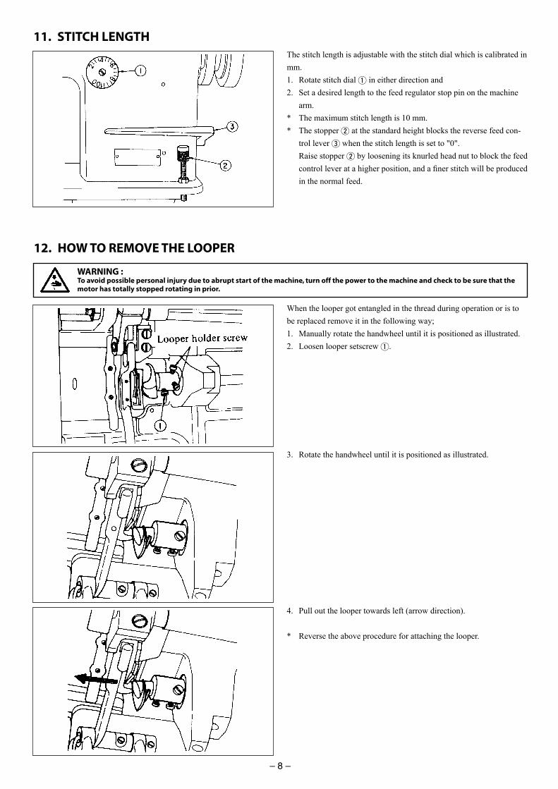
11. STITCH LENGTHThe stitch length is adjustable with the stitch dial which is calibrated in mm.1. Rotate stitch dial 1 in either direction and2. Set a desired length to the feed regulator stop pin on the machine
arm.* The maximum stitch length is 10 mm.* The stopper 2 at the standard height blocks the reverse feed con-
trol lever 3 when the stitch length is set to "0". Raise stopper 2 by loosening its knurled head nut to block the feed
control lever at a higher position, and a fi ner stitch will be produced in the normal feed.
When the looper got entangled in the thread during operation or is to be replaced remove it in the following way;1. Manually rotate the handwheel until it is positioned as illustrated.2. Loosen looper setscrew 1.
3. Rotate the handwheel until it is positioned as illustrated.
4. Pull out the looper towards left (arrow direction).
* Reverse the above procedure for attaching the looper.
WARNING :To avoid possible personal injury due to abrupt start of the machine, turn off the power to the machine and check to be sure that the motor has totally stopped rotating in prior.
– 7 –
10. PRESSER FOOT AND FEED DOG
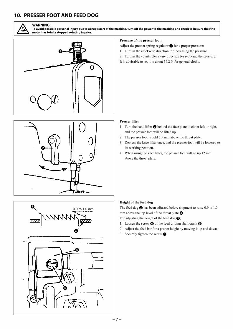
Pressure of the presser foot:Adjust the presser spring regulator 1 for a proper pressure:1. Turn in the clockwise direction for increasing the pressure.2. Turn in the counterclockwise direction for reducing the pressure. It is advisable to set it to about 39.2 N for general cloths.
Presser lifter1. Turn the hand lifter 2 behind the face plate to either left or right,
and the presser foot will be lifted up.2. The presser foot is held 5.5 mm above the throat plate.3. Depress the knee lifter once, and the presser foot will be lowered to
its working position.4. When using the knee lifter, the presser foot will go up 12 mm
above the throat plate.
Height of the feed dogThe feed dog 3 has been adjusted before shipment to raise 0.9 to 1.0 mm above the top level of the throat plate 4.For adjusting the height of the feed dog 3;1. Loosen the screw 6 of the feed driving shaft crank 5.2. Adjust the feed bar for a proper height by moving it up and down.3. Securely tighten the screw 6.
1
2
3
4
5
6
WARNING :To avoid possible personal injury due to abrupt start of the machine, turn off the power to the machine and check to be sure that the motor has totally stopped rotating in prior.
0.9 to 1.0 mm
iv
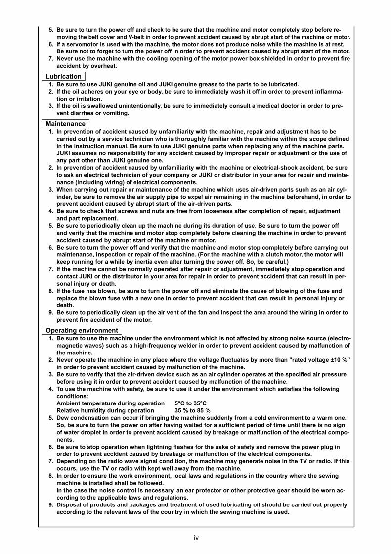
e re rn e er an e be re a e a ine an r le el be re reing e bel er an bel in r er re en a i en a e b abr ar e a ine r r
I a er r i e i e a ine e r e n r e n i e ile e a ine i a re e re n rge rn e er in r er re en a i en a e b abr ar e r
Ne er e e a ine i e ling ening e r er b iel e in r er re en re a i en b er ea
bri a i n e re e U I gen ine il an U I gen ine grea e e ar be l bri a e I e il a ere n r e e r b be re i e ia el a i in r er re en in a a
i n r irri a i n I e il i all e nin en i nall be re i e ia el n l a e i al r in r er re
en iarr ea r i ing
Main enan e In re en i n a i en a e b n a iliari i e a ine re air an a en a be
arrie b a er i e e ni ian i r g l a iliar i e a ine i in e e e ne in e in r i n an al e re e U I gen ine ar en re la ing an e a ine ar
U I a e n re n ibili r an a i en a e b i r er re air r a en r e e an ar er an U I gen ine ne
In re en i n a i en a e b n a iliari i e a ine r ele ri al a i en be re a an ele ri al e ni ian r an r U I r i rib r in r area r re air an ain e
nan e (in l ing iring) ele ri al nen W en arr ing re air r ain enan e e a ine i e air ri en ar a an air l
in er be re re e e air l i e e el air re aining in e a ine be re an in r er re en a i en a e b abr ar e air ri en ar
e re e a re an n are ree r l ene a er le i n re air a en an ar re la e en
e re eri i all lean e a ine ring i ra i n e e re rn e er an eri a e a ine an r le el be re leaning e a ine in r er re en a i en a e b abr ar e a ine r r
e re rn e er an eri a e a ine an r le el be re arr ing ain enan e in e i n r re air e a ine (F r e a ine i a l r e r ill
ee r nning r a ile b iner ia e en a er rning e er S be are l ) I e a ine ann be n r all era e a er re air r a en i e ia el era i n an
n a U I r e i rib r in r area r re air in r er re en a i en a an re l in ernal in r r ea
I e e a bl n be re rn e er an eli ina e e a e bl ing e e an re la e e bl n e i a ne ne in r er re en a i en a an re l in er nal in r r
ea e re eri i all lean e air en e an an in e e area ar n e iring in r er
re en re a i en e r
O era ing en ir n en e re e e a ine n er e en ir n en i i n a e e b r ng n i e r e (ele r
agne i a e ) a a ig re en el er in r er re en a i en a e b al n i n e a ine
Ne er era e e a ine in an la e ere e l age a e b re an ra e l age in r er re en a i en a e b al n i n e a ine
e re eri a e air ri en e i e a an air lin er era e a e e i e air re re be re ing i in r er re en a i en a e b al n i n e a ine
T e e a ine i a e be re e i n er e en ir n en i a i e e ll ing n i i n :
A bien e era re ring era i n C C Rela i e i i ring era i n De n en a i n an r i bringing e a ine enl r a l en ir n en a ar ne
S be re rn e er n a er a ing ai e r a ien eri i e n il ere i n ign a er r le in r er re en a i en a e b brea age r al n i n e ele ri al
nen e re era i n en lig ning a e r e a e a e an re e e er l g in
r er re en a i en a e b brea age r al n i n e ele ri al nen De en ing n e ra i a e ignal n i i n e a ine a genera e n i e in e T r ra i I i
r e e T r ra i i e ell a a r e a ine In r er en re e r en ir n en l al la an reg la i n in e n r ere e e ing
a ine i in alle all be ll eIn e a e e n i e n r l i ne e ar an ear r e r r er r e i e gear l be rn a
r ing e a li able la an reg la i n Di al r an a age an rea en e l bri a ing il l be arrie r erl
a r ing e rele an la e n r in i e e ing a ine i e

v
Precautions to be taken so as to use the ML-111 more safely 1. Keep your hands away from needle when you turn ON the power switch or while the
machine is in operation.
2. Do not put your fi ngers into the thread take-up cover while the machine is operat-
ing.
3. Turn OFF the power switch when tilting the machine head, or removing the belt
cover or the V belts.
4. During operation, be careful not to allow your or any other person’s head, hands or
clothes to come close to the handwheel and thread take-up lever. Also, do not place
anything close to them.
5. Do not operate your machine with the belt cover and fi nger guard removed.
6. When tilting the machine head, be sure to confi rm that the head support bar is
properly attached to your machine head, and be careful not to allow your fi ngers or
the like to be pinched in the machine head.
1. To ensure safety, never operate the machine with the ground wire for the power
supply removed.
2. When inserting/removing the power plug, the power switch has to be turned OFF in
advance.
3. In time of thunder and lightening, stop your work and disconnect the power plug
from the receptacle so as to ensure safety.
4. If the machine is suddenly moved from a cold place to a warm place, dew conden-
sation may be observed. In this case, turn ON the power to the machine after you
have confi rmed that there is no danger of water drops in the machine.
5. To prevent fi res, periodically draw out the power plug from the plug socket and
clean the root of the pins and the space between pins.
6. The loopers oscillate at a high speed during operation.
Be sure to keep your hands away from the vicinity of the loopers to protect hands
from possible injury during operation. Turn the power OFF before threading the
machine head.
7. To avoid possible accidents due to abrupt start of the machine, be sure to turn OFF
the power to the machine.
8. Be careful of handling this product so as not to pour water or oil, shock by drop-
ping, and the like since this product is a precision instrument.
9. When tilting or returning the sewing machine to the home position, hold the upper
side of the machine head with both hands and perform the work quietly so that fi n-
gers or the like are not caught in the machine.
– 6 –
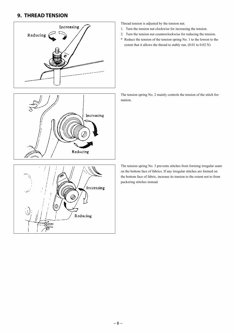
9. THREAD TENSIONThread tension is adjusted by the tension nut.1. Turn the tension nut clockwise for increasing the tension.2. Turn the tension nut counterclockwise for reducing the tension. * Reduce the tension of the tension spring No. 1 to the lowest to the
extent that it allows the thread to stably run. (0.01 to 0.02 N)
The tension spring No. 2 mainly controls the tension of the stitch for-mation.
The tension spring No. 3 prevents stitches from forming irregular seam on the bottom face of fabrics. If any irregular stitches are formed on the bottom face of fabric, increase its tension to the extent not to from puckering stitches instead.
– 5 –
7. ATTACHING THE NEEDLE
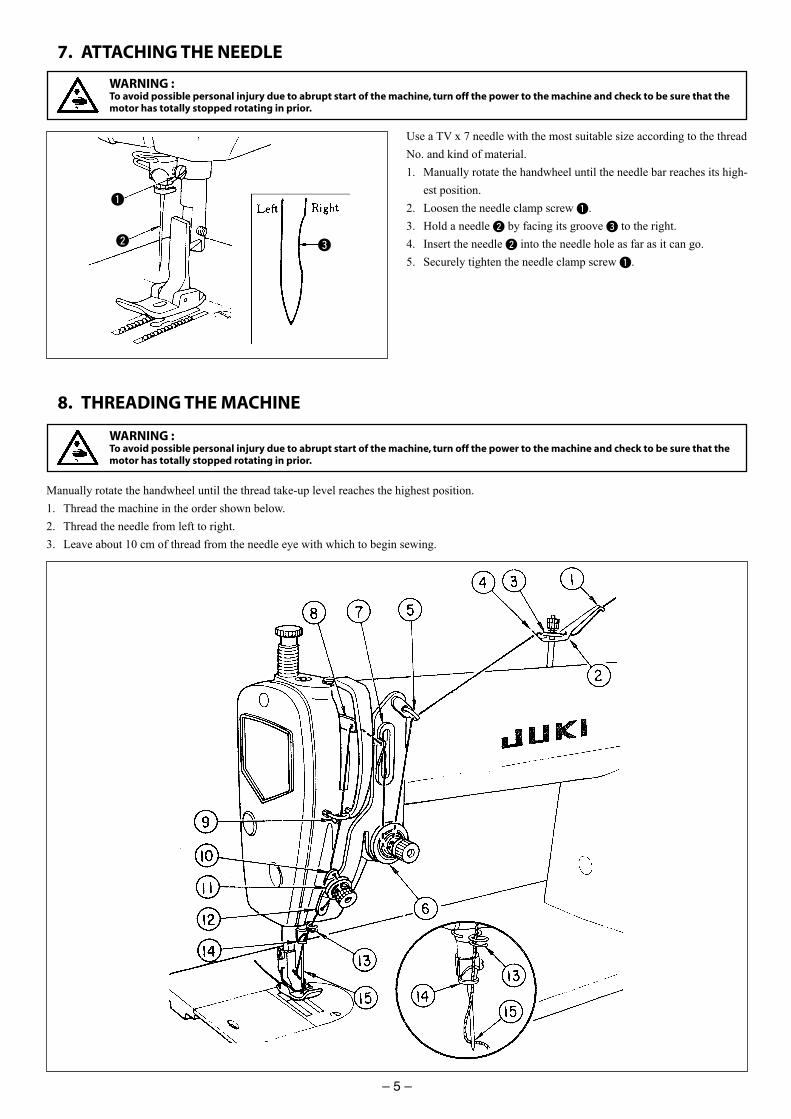
Use a TV x 7 needle with the most suitable size according to the thread No. and kind of material.1. Manually rotate the handwheel until the needle bar reaches its high-
est position.2. Loosen the needle clamp screw 1.3. Hold a needle 2 by facing its groove 3 to the right.4. Insert the needle 2 into the needle hole as far as it can go.5. Securely tighten the needle clamp screw 1.
1
2 3
8. THREADING THE MACHINE
Manually rotate the handwheel until the thread take-up level reaches the highest position.1. Thread the machine in the order shown below.2. Thread the needle from left to right.3. Leave about 10 cm of thread from the needle eye with which to begin sewing.
WARNING :To avoid possible personal injury due to abrupt start of the machine, turn off the power to the machine and check to be sure that the motor has totally stopped rotating in prior.
WARNING :To avoid possible personal injury due to abrupt start of the machine, turn off the power to the machine and check to be sure that the motor has totally stopped rotating in prior.
vi
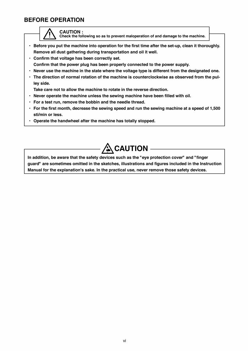
BEFORE OPERATION
CAUTION :Check the following so as to prevent maloperation of and damage to the machine.
• Before you put the machine into operation for the fi rst time after the set-up, clean it thoroughly.
Remove all dust gathering during transportation and oil it well.
• Confi rm that voltage has been correctly set.
Confi rm that the power plug has been properly connected to the power supply.
• Never use the machine in the state where the voltage type is different from the designated one.
• The direction of normal rotation of the machine is counterclockwise as observed from the pul-
ley side.
Take care not to allow the machine to rotate in the reverse direction.
• Never operate the machine unless the sewing machine have been fi lled with oil.
• For a test run, remove the bobbin and the needle thread.
• For the fi rst month, decrease the sewing speed and run the sewing machine at a speed of 1,500
sti/min or less.
• Operate the handwheel after the machine has totally stopped.
In addition, be aware that the safety devices such as the "eye protection cover" and "fi nger
guard" are sometimes omitted in the sketches, illustrations and fi gures included in the Instruction
Manual for the explanation's sake. In the practical use, never remove those safety devices.
CAUTION

– 4 –
6. LUBRICATION
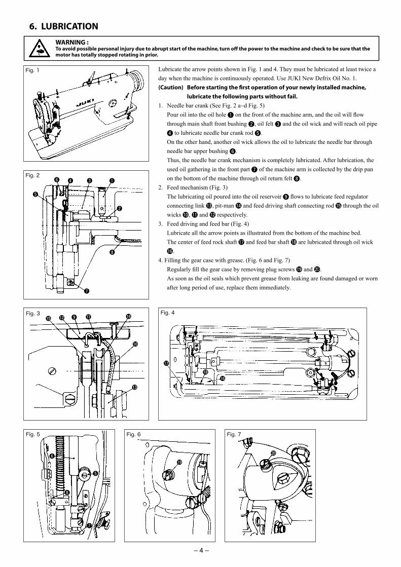
Lubricate the arrow points shown in Fig. 1 and 4. They must be lubricated at least twice a day when the machine is continuously operated. Use JUKI New Defrix Oil No. 1.(Caution) Before starting the fi rst operation of your newly installed machine,
lubricate the following parts without fail.
1. Needle bar crank (See Fig. 2 a~d Fig. 5) Pour oil into the oil hole 1 on the front of the machine arm, and the oil will fl ow
through main shaft front bushing 2, oil felt 3 and the oil wick and will reach oil pipe 4 to lubricate needle bar crank rod 5.
On the other hand, another oil wick allows the oil to lubricate the needle bar through needle bar upper bushing 6.
Thus, the needle bar crank mechanism is completely lubricated. After lubrication, the used oil gathering in the front part 7 of the machine arm is collected by the drip pan on the bottom of the machine through oil return felt 8.
2. Feed mechanism (Fig. 3) The lubricating oil poured into the oil reservoir 9 fl ows to lubricate feed regulator
connecting link !3, pit-man !4 and feed driving shaft connecting rod !5 through the oil wicks !0, !1 and !2 respectively.
3. Feed driving and feed bar (Fig. 4) Lubricate all the arrow points as illustrated from the bottom of the machine bed. The center of feed rock shaft !7 and feed bar shaft !8 are lubricated through oil wick
!6.4. Filling the gear case with grease. (Fig. 6 and Fig. 7) Regularly fi ll the gear case by removing plug screws !9 and @00. As soon as the oil seals which prevent grease from leaking are found damaged or worn
after long period of use, replace them immediately.
Fig. 1
Fig. 2
Fig. 3 Fig. 4
Fig. 5 Fig. 6 Fig. 7
WARNING :To avoid possible personal injury due to abrupt start of the machine, turn off the power to the machine and check to be sure that the motor has totally stopped rotating in prior.
1346
5
2
8
7
6
5
8
7
!0
9 !1!2
!3
!4!5
!6
!7
!8
!9
@0
vii
DECLARATION OF INCORPORATION OF PARTLY COMPLETED MACHINERY
We hereby declare that the sewing machine (sewing head) described below ;
1. Must not be put into service until the machinery to which it is incorporated has been declared in conformity with the provisions of the Directive 2006/42/EC, and
2. Conforms to the essential requirements of the Directive 2006/42/EC, described in the technical documentation, and
3. To be prepared with the above technical documentation compiled in accordance with part B of Annex VII, and
4. Also to conform to the RoHS Directive 2011/65/EU5. Relevant information on which should be transmitted in response to a reasoned request by the
national authorities, by the electronic method or other according to the request.
Applied harmonized standards, in particular :EN ISO12100, EN ISO10821, EN 50581
Manufacturer :JUKI CORPORATION2-11-1, Tsurumaki, Tama-shi, Tokyo, Japan
ModelDescription Industrial Sewing MachineFunction make stitches and sew
ML-111
– 3 –
4. INSTALLING THE BELT COVER
5. ADJUSTING THE BELT TENSION
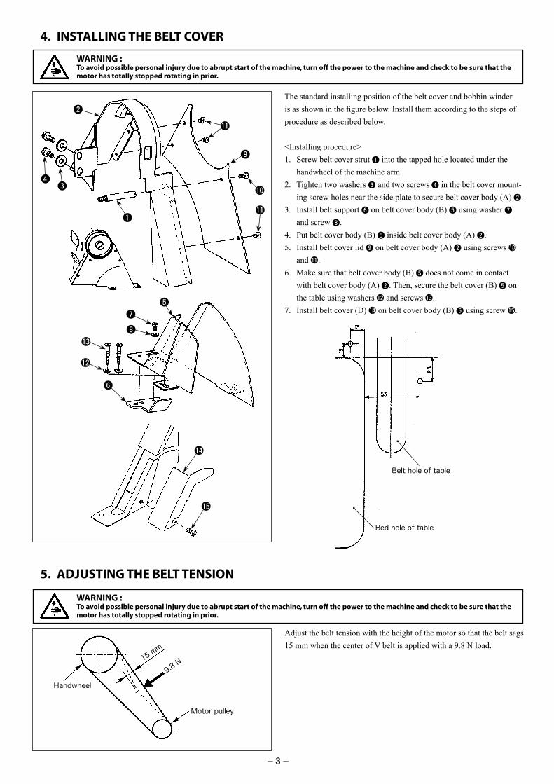
The standard installing position of the belt cover and bobbin winder is as shown in the fi gure below. Install them according to the steps of procedure as described below.
<Installing procedure>1. Screw belt cover strut 1 into the tapped hole located under the
handwheel of the machine arm. 2. Tighten two washers 3 and two screws 4 in the belt cover mount-
ing screw holes near the side plate to secure belt cover body (A) 2.3. Install belt support 6 on belt cover body (B) 5 using washer 7
and screw 8. 4. Put belt cover body (B) 5 inside belt cover body (A) 2.5. Install belt cover lid 9 on belt cover body (A) 2 using screws !0
and !1. 6. Make sure that belt cover body (B) 5 does not come in contact
with belt cover body (A) 2. Then, secure the belt cover (B) 5 on the table using washers !2 and screws !3.
7. Install belt cover (D) !4 on belt cover body (B) 5 using screw !5.
1
2
34
5
6
8
7
9
!0
!1
!1
!2
!3
Adjust the belt tension with the height of the motor so that the belt sags 15 mm when the center of V belt is applied with a 9.8 N load.
15 mm
9.8 N
Handwheel
Motor pulley
WARNING :To avoid possible personal injury due to abrupt start of the machine, turn off the power to the machine and check to be sure that the motor has totally stopped rotating in prior.
WARNING :To avoid possible personal injury due to abrupt start of the machine, turn off the power to the machine and check to be sure that the motor has totally stopped rotating in prior.
!4
!5
Belt hole of table
Bed hole of table
viii
CONTENTSSPECIFICATIONS ...........................................................................................................................1
1. INSTALLING THE MACHINE ....................................................................................................1
2. INSTALLING THE KNEE LIFTER COMPONENTS ......................................................................2
3. INSTALLING THE THREAD STAND ..........................................................................................2
4. INSTALLING THE BELT COVER ................................................................................................3
5. ADJUSTING THE BELT TENSION .............................................................................................3
6. LUBRICATION ..........................................................................................................................4
7. ATTACHING THE NEEDLE ........................................................................................................5
8. THREADING THE MACHINE ....................................................................................................5
9. THREAD TENSION ...................................................................................................................6
10. PRESSER FOOT AND FEED DOG .............................................................................................7
11. STITCH LENGTH ......................................................................................................................8
12. HOW TO REMOVE THE LOOPER .............................................................................................8
13. RELATION BETWEEN THE NEEDLE AND THE LOOPER ..........................................................9
14. HEIGHT OF THE PRESSER BAR .............................................................................................10
15. LENGTH OF THE THREAD TAKEN UP BY THE THREAD TAKE-UP LEVER .............................10
16. MOTOR PULLEY AND SEWING SPEED .................................................................................10
– 1 –
1. INSTALLING THE MACHINE
SPECIFICATIONS
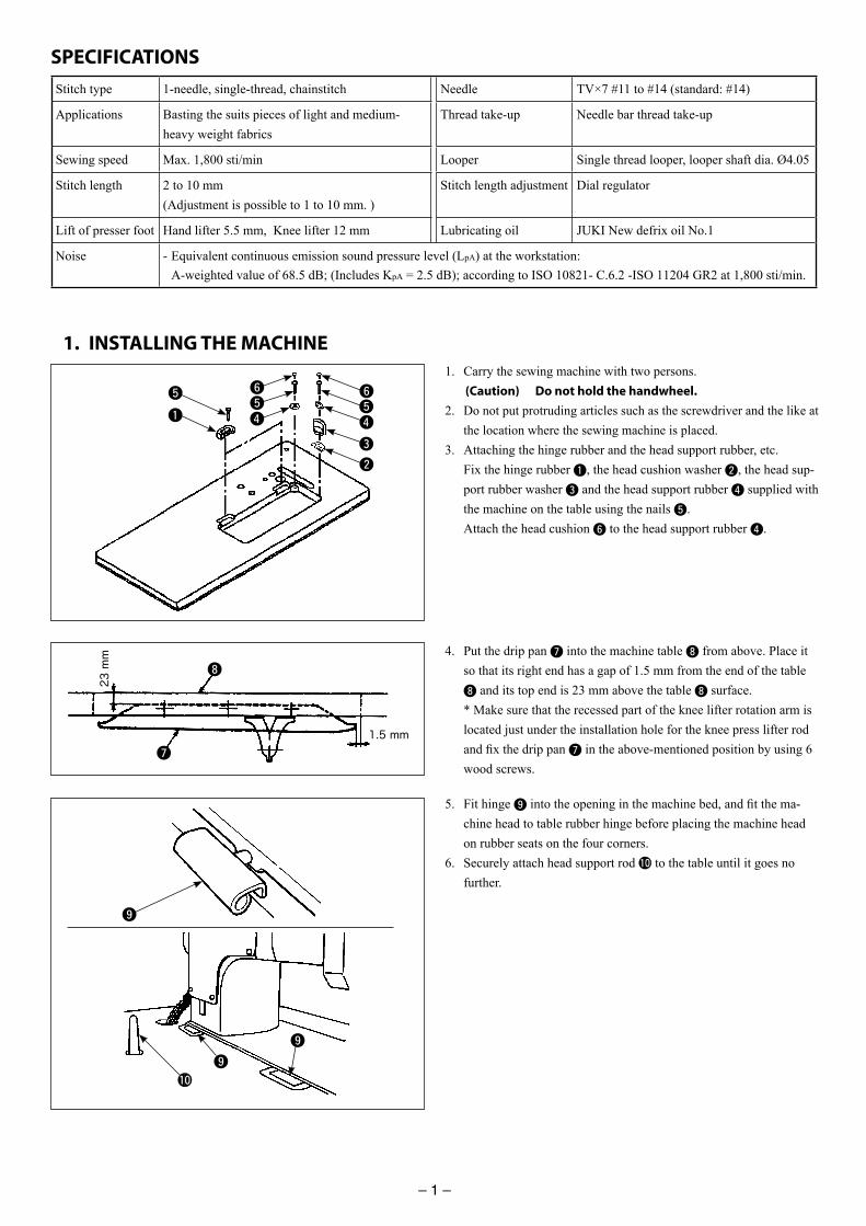
1. Carry the sewing machine with two persons. (Caution) Do not hold the handwheel.
2. Do not put protruding articles such as the screwdriver and the like at the location where the sewing machine is placed.
3. Attaching the hinge rubber and the head support rubber, etc. Fix the hinge rubber 1, the head cushion washer 2, the head sup-
port rubber washer 3 and the head support rubber 4 supplied with the machine on the table using the nails 5.
Attach the head cushion 6 to the head support rubber 4.
Stitch type 1-needle, single-thread, chainstitch Needle TV×7 #11 to #14 (standard: #14)
Applications Basting the suits pieces of light and medium-heavy weight fabrics
Thread take-up Needle bar thread take-up
Sewing speed Max. 1,800 sti/min Looper Single thread looper, looper shaft dia. Ø4.05
Stitch length 2 to 10 mm (Adjustment is possible to 1 to 10 mm. )
Stitch length adjustment Dial regulator
Lift of presser foot Hand lifter 5.5 mm, Knee lifter 12 mm Lubricating oil JUKI New defrix oil No.1
Noise - Equivalent continuous emission sound pressure level (LpA) at the workstation: A-weighted value of 68.5 dB; (Includes KpA = 2.5 dB); according to ISO 10821- C.6.2 -ISO 11204 GR2 at 1,800 sti/min.
5. Fit hinge 9 into the opening in the machine bed, and fi t the ma-chine head to table rubber hinge before placing the machine head on rubber seats on the four corners.
6. Securely attach head support rod !0 to the table until it goes no further.
9
9
9
!0
1
3
55
2
4
654
6
8
7
23 mm
1.5 mm
4. Put the drip pan 7 into the machine table 8 from above. Place it so that its right end has a gap of 1.5 mm from the end of the table 8 and its top end is 23 mm above the table 8 surface.
* Make sure that the recessed part of the knee lifter rotation arm is located just under the installation hole for the knee press lifter rod and fi x the drip pan 7 in the above-mentioned position by using 6 wood screws.
– 2 –
3. INSTALLING THE THREAD STAND
2. INSTALLING THE KNEE LIFTER COMPONENTS
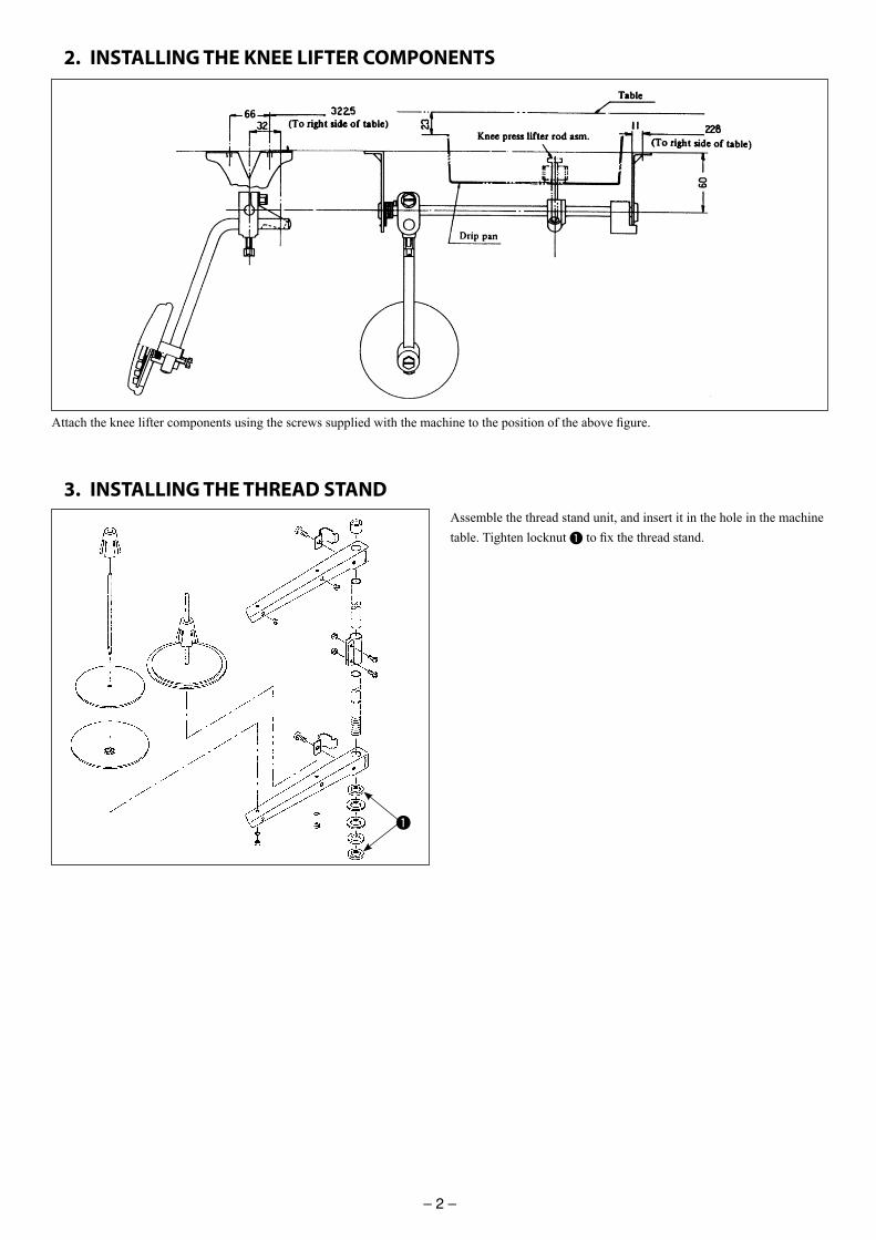
Attach the knee lifter components using the screws supplied with the machine to the position of the above fi gure.
1
Assemble the thread stand unit, and insert it in the hole in the machine table. Tighten locknut 1 to fi x the thread stand.
– 1 –
1. INSTALLING THE MACHINE
SPECIFICATIONS
1. Carry the sewing machine with two persons. (Caution) Do not hold the handwheel.
2. Do not put protruding articles such as the screwdriver and the like at the location where the sewing machine is placed.
3. Attaching the hinge rubber and the head support rubber, etc. Fix the hinge rubber 1, the head cushion washer 2, the head sup-
port rubber washer 3 and the head support rubber 4 supplied with the machine on the table using the nails 5.
Attach the head cushion 6 to the head support rubber 4.
Stitch type 1-needle, single-thread, chainstitch Needle TV×7 #11 to #14 (standard: #14)
Applications Basting the suits pieces of light and medium-heavy weight fabrics
Thread take-up Needle bar thread take-up
Sewing speed Max. 1,800 sti/min Looper Single thread looper, looper shaft dia. Ø4.05
Stitch length 2 to 10 mm (Adjustment is possible to 1 to 10 mm. )
Stitch length adjustment Dial regulator
Lift of presser foot Hand lifter 5.5 mm, Knee lifter 12 mm Lubricating oil JUKI New defrix oil No.1
Noise - Equivalent continuous emission sound pressure level (LpA) at the workstation: A-weighted value of 68.5 dB; (Includes KpA = 2.5 dB); according to ISO 10821- C.6.2 -ISO 11204 GR2 at 1,800 sti/min.
5. Fit hinge 9 into the opening in the machine bed, and fi t the ma-chine head to table rubber hinge before placing the machine head on rubber seats on the four corners.
6. Securely attach head support rod !0 to the table until it goes no further.
9
9
9
!0
1
3
55
2
4
654
6
8
7
23 mm
1.5 mm
4. Put the drip pan 7 into the machine table 8 from above. Place it so that its right end has a gap of 1.5 mm from the end of the table 8 and its top end is 23 mm above the table 8 surface.
* Make sure that the recessed part of the knee lifter rotation arm is located just under the installation hole for the knee press lifter rod and fi x the drip pan 7 in the above-mentioned position by using 6 wood screws.
– 2 –
3. INSTALLING THE THREAD STAND
2. INSTALLING THE KNEE LIFTER COMPONENTS
Attach the knee lifter components using the screws supplied with the machine to the position of the above fi gure.
1
Assemble the thread stand unit, and insert it in the hole in the machine table. Tighten locknut 1 to fi x the thread stand.
– 3 –
4. INSTALLING THE BELT COVER
5. ADJUSTING THE BELT TENSION
The standard installing position of the belt cover and bobbin winder is as shown in the fi gure below. Install them according to the steps of procedure as described below.
<Installing procedure>1. Screw belt cover strut 1 into the tapped hole located under the
handwheel of the machine arm. 2. Tighten two washers 3 and two screws 4 in the belt cover mount-
ing screw holes near the side plate to secure belt cover body (A) 2.3. Install belt support 6 on belt cover body (B) 5 using washer 7
and screw 8. 4. Put belt cover body (B) 5 inside belt cover body (A) 2.5. Install belt cover lid 9 on belt cover body (A) 2 using screws !0
and !1. 6. Make sure that belt cover body (B) 5 does not come in contact
with belt cover body (A) 2. Then, secure the belt cover (B) 5 on the table using washers !2 and screws !3.
7. Install belt cover (D) !4 on belt cover body (B) 5 using screw !5.
1
2
34
5
6
8
7
9
!0
!1
!1
!2
!3
Adjust the belt tension with the height of the motor so that the belt sags 15 mm when the center of V belt is applied with a 9.8 N load.
15 mm
9.8 N
Handwheel
Motor pulley
WARNING :To avoid possible personal injury due to abrupt start of the machine, turn off the power to the machine and check to be sure that the motor has totally stopped rotating in prior.
WARNING :To avoid possible personal injury due to abrupt start of the machine, turn off the power to the machine and check to be sure that the motor has totally stopped rotating in prior.
!4
!5
Belt hole of table
Bed hole of table
viii
CONTENTSSPECIFICATIONS ...........................................................................................................................1
1. INSTALLING THE MACHINE ....................................................................................................1
2. INSTALLING THE KNEE LIFTER COMPONENTS ......................................................................2
3. INSTALLING THE THREAD STAND ..........................................................................................2
4. INSTALLING THE BELT COVER ................................................................................................3
5. ADJUSTING THE BELT TENSION .............................................................................................3
6. LUBRICATION ..........................................................................................................................4
7. ATTACHING THE NEEDLE ........................................................................................................5
8. THREADING THE MACHINE ....................................................................................................5
9. THREAD TENSION ...................................................................................................................6
10. PRESSER FOOT AND FEED DOG .............................................................................................7
11. STITCH LENGTH ......................................................................................................................8
12. HOW TO REMOVE THE LOOPER .............................................................................................8
13. RELATION BETWEEN THE NEEDLE AND THE LOOPER ..........................................................9
14. HEIGHT OF THE PRESSER BAR .............................................................................................10
15. LENGTH OF THE THREAD TAKEN UP BY THE THREAD TAKE-UP LEVER .............................10
16. MOTOR PULLEY AND SEWING SPEED .................................................................................10
– 4 –
6. LUBRICATION
Lubricate the arrow points shown in Fig. 1 and 4. They must be lubricated at least twice a day when the machine is continuously operated. Use JUKI New Defrix Oil No. 1.(Caution) Before starting the fi rst operation of your newly installed machine,
lubricate the following parts without fail.
1. Needle bar crank (See Fig. 2 a~d Fig. 5) Pour oil into the oil hole 1 on the front of the machine arm, and the oil will fl ow
through main shaft front bushing 2, oil felt 3 and the oil wick and will reach oil pipe 4 to lubricate needle bar crank rod 5.
On the other hand, another oil wick allows the oil to lubricate the needle bar through needle bar upper bushing 6.
Thus, the needle bar crank mechanism is completely lubricated. After lubrication, the used oil gathering in the front part 7 of the machine arm is collected by the drip pan on the bottom of the machine through oil return felt 8.
2. Feed mechanism (Fig. 3) The lubricating oil poured into the oil reservoir 9 fl ows to lubricate feed regulator
connecting link !3, pit-man !4 and feed driving shaft connecting rod !5 through the oil wicks !0, !1 and !2 respectively.
3. Feed driving and feed bar (Fig. 4) Lubricate all the arrow points as illustrated from the bottom of the machine bed. The center of feed rock shaft !7 and feed bar shaft !8 are lubricated through oil wick
!6.4. Filling the gear case with grease. (Fig. 6 and Fig. 7) Regularly fi ll the gear case by removing plug screws !9 and @00. As soon as the oil seals which prevent grease from leaking are found damaged or worn
after long period of use, replace them immediately.
Fig. 1
Fig. 2
Fig. 3 Fig. 4
Fig. 5 Fig. 6 Fig. 7
WARNING :To avoid possible personal injury due to abrupt start of the machine, turn off the power to the machine and check to be sure that the motor has totally stopped rotating in prior.
1346
5
2
8
7
6
5
8
7
!0
9 !1!2
!3
!4!5
!6
!7
!8
!9
@0
vii
DECLARATION OF INCORPORATION OF PARTLY COMPLETED MACHINERY
We hereby declare that the sewing machine (sewing head) described below ;
1. Must not be put into service until the machinery to which it is incorporated has been declared in conformity with the provisions of the Directive 2006/42/EC, and
2. Conforms to the essential requirements of the Directive 2006/42/EC, described in the technical documentation, and
3. To be prepared with the above technical documentation compiled in accordance with part B of Annex VII, and
4. Also to conform to the RoHS Directive 2011/65/EU5. Relevant information on which should be transmitted in response to a reasoned request by the
national authorities, by the electronic method or other according to the request.
Applied harmonized standards, in particular :EN ISO12100, EN ISO10821, EN 50581
Manufacturer :JUKI CORPORATION2-11-1, Tsurumaki, Tama-shi, Tokyo, Japan
ModelDescription Industrial Sewing MachineFunction make stitches and sew
ML-111
– 5 –
7. ATTACHING THE NEEDLE
Use a TV x 7 needle with the most suitable size according to the thread No. and kind of material.1. Manually rotate the handwheel until the needle bar reaches its high-
est position.2. Loosen the needle clamp screw 1.3. Hold a needle 2 by facing its groove 3 to the right.4. Insert the needle 2 into the needle hole as far as it can go.5. Securely tighten the needle clamp screw 1.
1
2 3
8. THREADING THE MACHINE
Manually rotate the handwheel until the thread take-up level reaches the highest position.1. Thread the machine in the order shown below.2. Thread the needle from left to right.3. Leave about 10 cm of thread from the needle eye with which to begin sewing.
WARNING :To avoid possible personal injury due to abrupt start of the machine, turn off the power to the machine and check to be sure that the motor has totally stopped rotating in prior.
WARNING :To avoid possible personal injury due to abrupt start of the machine, turn off the power to the machine and check to be sure that the motor has totally stopped rotating in prior.
vi
BEFORE OPERATION
CAUTION :Check the following so as to prevent maloperation of and damage to the machine.
• Before you put the machine into operation for the fi rst time after the set-up, clean it thoroughly.
Remove all dust gathering during transportation and oil it well.
• Confi rm that voltage has been correctly set.
Confi rm that the power plug has been properly connected to the power supply.
• Never use the machine in the state where the voltage type is different from the designated one.
• The direction of normal rotation of the machine is counterclockwise as observed from the pul-
ley side.
Take care not to allow the machine to rotate in the reverse direction.
• Never operate the machine unless the sewing machine have been fi lled with oil.
• For a test run, remove the bobbin and the needle thread.
• For the fi rst month, decrease the sewing speed and run the sewing machine at a speed of 1,500
sti/min or less.
• Operate the handwheel after the machine has totally stopped.
In addition, be aware that the safety devices such as the "eye protection cover" and "fi nger
guard" are sometimes omitted in the sketches, illustrations and fi gures included in the Instruction
Manual for the explanation's sake. In the practical use, never remove those safety devices.
CAUTION
v
Precautions to be taken so as to use the ML-111 more safely 1. Keep your hands away from needle when you turn ON the power switch or while the
machine is in operation.
2. Do not put your fi ngers into the thread take-up cover while the machine is operat-
ing.
3. Turn OFF the power switch when tilting the machine head, or removing the belt
cover or the V belts.
4. During operation, be careful not to allow your or any other person’s head, hands or
clothes to come close to the handwheel and thread take-up lever. Also, do not place
anything close to them.
5. Do not operate your machine with the belt cover and fi nger guard removed.
6. When tilting the machine head, be sure to confi rm that the head support bar is
properly attached to your machine head, and be careful not to allow your fi ngers or
the like to be pinched in the machine head.
1. To ensure safety, never operate the machine with the ground wire for the power
supply removed.
2. When inserting/removing the power plug, the power switch has to be turned OFF in
advance.
3. In time of thunder and lightening, stop your work and disconnect the power plug
from the receptacle so as to ensure safety.
4. If the machine is suddenly moved from a cold place to a warm place, dew conden-
sation may be observed. In this case, turn ON the power to the machine after you
have confi rmed that there is no danger of water drops in the machine.
5. To prevent fi res, periodically draw out the power plug from the plug socket and
clean the root of the pins and the space between pins.
6. The loopers oscillate at a high speed during operation.
Be sure to keep your hands away from the vicinity of the loopers to protect hands
from possible injury during operation. Turn the power OFF before threading the
machine head.
7. To avoid possible accidents due to abrupt start of the machine, be sure to turn OFF
the power to the machine.
8. Be careful of handling this product so as not to pour water or oil, shock by drop-
ping, and the like since this product is a precision instrument.
9. When tilting or returning the sewing machine to the home position, hold the upper
side of the machine head with both hands and perform the work quietly so that fi n-
gers or the like are not caught in the machine.
– 6 –
9. THREAD TENSIONThread tension is adjusted by the tension nut.1. Turn the tension nut clockwise for increasing the tension.2. Turn the tension nut counterclockwise for reducing the tension. * Reduce the tension of the tension spring No. 1 to the lowest to the
extent that it allows the thread to stably run. (0.01 to 0.02 N)
The tension spring No. 2 mainly controls the tension of the stitch for-mation.
The tension spring No. 3 prevents stitches from forming irregular seam on the bottom face of fabrics. If any irregular stitches are formed on the bottom face of fabric, increase its tension to the extent not to from puckering stitches instead.
– 7 –
10. PRESSER FOOT AND FEED DOG
Pressure of the presser foot:Adjust the presser spring regulator 1 for a proper pressure:1. Turn in the clockwise direction for increasing the pressure.2. Turn in the counterclockwise direction for reducing the pressure. It is advisable to set it to about 39.2 N for general cloths.
Presser lifter1. Turn the hand lifter 2 behind the face plate to either left or right,
and the presser foot will be lifted up.2. The presser foot is held 5.5 mm above the throat plate.3. Depress the knee lifter once, and the presser foot will be lowered to
its working position.4. When using the knee lifter, the presser foot will go up 12 mm
above the throat plate.
Height of the feed dogThe feed dog 3 has been adjusted before shipment to raise 0.9 to 1.0 mm above the top level of the throat plate 4.For adjusting the height of the feed dog 3;1. Loosen the screw 6 of the feed driving shaft crank 5.2. Adjust the feed bar for a proper height by moving it up and down.3. Securely tighten the screw 6.
1
2
3
4
5
6
WARNING :To avoid possible personal injury due to abrupt start of the machine, turn off the power to the machine and check to be sure that the motor has totally stopped rotating in prior.
0.9 to 1.0 mm
iv
e re rn e er an e be re a e a ine an r le el be re reing e bel er an bel in r er re en a i en a e b abr ar e a ine r r
I a er r i e i e a ine e r e n r e n i e ile e a ine i a re e re n rge rn e er in r er re en a i en a e b abr ar e r
Ne er e e a ine i e ling ening e r er b iel e in r er re en re a i en b er ea
bri a i n e re e U I gen ine il an U I gen ine grea e e ar be l bri a e I e il a ere n r e e r b be re i e ia el a i in r er re en in a a
i n r irri a i n I e il i all e nin en i nall be re i e ia el n l a e i al r in r er re
en iarr ea r i ing
Main enan e In re en i n a i en a e b n a iliari i e a ine re air an a en a be
arrie b a er i e e ni ian i r g l a iliar i e a ine i in e e e ne in e in r i n an al e re e U I gen ine ar en re la ing an e a ine ar U I a e n re n ibili r an a i en a e b i r er re air r a en r e e
an ar er an U I gen ine ne In re en i n a i en a e b n a iliari i e a ine r ele ri al a i en be re
a an ele ri al e ni ian r an r U I r i rib r in r area r re air an ain enan e (in l ing iring) ele ri al nen
W en arr ing re air r ain enan e e a ine i e air ri en ar a an air lin er be re re e e air l i e e el air re aining in e a ine be re an in r er
re en a i en a e b abr ar e air ri en ar e re e a re an n are ree r l ene a er le i n re air a en
an ar re la e en e re eri i all lean e a ine ring i ra i n e e re rn e er
an eri a e a ine an r le el be re leaning e a ine in r er re en a i en a e b abr ar e a ine r r
e re rn e er an eri a e a ine an r le el be re arr ing ain enan e in e i n r re air e a ine (F r e a ine i a l r e r ill
ee r nning r a ile b iner ia e en a er rning e er S be are l ) I e a ine ann be n r all era e a er re air r a en i e ia el era i n an
n a U I r e i rib r in r area r re air in r er re en a i en a an re l in ernal in r r ea
I e e a bl n be re rn e er an eli ina e e a e bl ing e e an re la e e bl n e i a ne ne in r er re en a i en a an re l in er nal in r r
ea e re eri i all lean e air en e an an in e e area ar n e iring in r er
re en re a i en e r
O era ing en ir n en e re e e a ine n er e en ir n en i i n a e e b r ng n i e r e (ele r
agne i a e ) a a ig re en el er in r er re en a i en a e b al n i n e a ine
Ne er era e e a ine in an la e ere e l age a e b re an ra e l age in r er re en a i en a e b al n i n e a ine
e re eri a e air ri en e i e a an air lin er era e a e e i e air re re be re ing i in r er re en a i en a e b al n i n e a ine
T e e a ine i a e be re e i n er e en ir n en i a i e e ll ing n i i n :
A bien e era re ring era i n C C Rela i e i i ring era i n De n en a i n an r i bringing e a ine enl r a l en ir n en a ar ne
S be re rn e er n a er a ing ai e r a ien eri i e n il ere i n ign a er r le in r er re en a i en a e b brea age r al n i n e ele ri al
nen e re era i n en lig ning a e r e a e a e an re e e er l g in
r er re en a i en a e b brea age r al n i n e ele ri al nen De en ing n e ra i a e ignal n i i n e a ine a genera e n i e in e T r ra i I i
r e e T r ra i i e ell a a r e a ine In r er en re e r en ir n en l al la an reg la i n in e n r ere e e ing
a ine i in alle all be ll eIn e a e e n i e n r l i ne e ar an ear r e r r er r e i e gear l be rn a
r ing e a li able la an reg la i n Di al r an a age an rea en e l bri a ing il l be arrie r erl
a r ing e rele an la e n r in i e e ing a ine i e
iii
PRECAUTIONS TO E TA EN IN ARIOUS OPERATION STAGESTran r a i n
e re li an e e a ine in a a e anner a ing e a ine eig in n i era i n Re er e e e in r i n an al r e a e a ine
e re a e ien a e ea re re en alling r r ing be re li ing r ing e a ine in r er r e again a i en a an re l in er nal in r r ea
On e e a ine a been n a e ne er re a i r ran r a i n r e e a ine again brea age re l ing r ne e e a i en r r ing
Un a ing e re n a e a ine in e re ribe r er in r er re en a i en a an re l in
er nal in r r ea In e a e e a ine i ra e in ar i lar be re are ll e nail T e nail a e be re e
e re e e a ine r e i i n i en er gra i an a e i r e a age are ll in r er re en a i en a an re l in er nal in r r ea
In alla i n(I) Table an able an
e re e U I gen ine able an able an in r er re en a i en a an re l in ernal in r r ea I i i ine i able e a able an able an i are n U I gen ine ne
ele e able an able an i are able r e a ine eig an rea i n r e ring era i n
I a er are e e able an be re e e a er i a l ing e ani an l e e re e a ine ring e era i n ain enan e in e i n an re air in r er re en
a i en a an re l in er nal in r r ea(II) Cable an iring
e re re en an e ra r e r being a lie e able ring e e in r er re en ele ri al ear lea age r re a i en In a i i n i i i ne e ar able near e era ing e i n a e bel be re r i e a a e r re be een e era ing e i n
an e able e re a i arb r nne i n in r er re en ele ri al ear lea age r re a i en e re e rel nne e nne r in r er re en ele ri al ear lea age r re
a i en In a i i n be re re e e nne r ile l ing i nne r e i n(III) Gr n ing
e re a e an ele ri al e er in all an a r ria e er l g in r er re en a i en a e b ear lea age r iele ri reng l age a l In a i i n be re nne e er l g e gr n e le i e e i n
e re gr n e ear able in r er re en a i en a e b ear lea age(I ) M r
e re e e e i e ra e r ( U I gen ine r ) in r er re en a i en a e b b rn
I a er iall a ailable l r i e i e a ine be re ele ne i an en angle en re en i e lle er in r er r e again being en angle b e bel
e re era i n e re a e re a e nne r an able are ree r a age r an l ene be
re rning e er n in r er re en a i en re l ing in er nal in r r ea Ne er r an in e ing e i n e a ine in r er re en a i en a an re l
in er nal in r r ea In a i i n e be re a e ire i n r a i n e lle agree i e arr n n
lle I e able an i a er i e be re e re e able an b l ing e a er r i
a er i r i e in r er r e again a i en a e b abr ar e a ine
D ring era i n e re n r nger air r l ing l e e ing e i n a e an eel
an lle an r r la e e ing near e e i n ile e a ine i in era i n in r er re en a i en a e b en angle en a an re l in er nal in r r ea
e re n la e r nger near e rr n area e nee le r in i e e rea a e le er er en rning e er n r ile e a ine i in era i n in r er re en a i en a
an re l in er nal in r r ea T e a ine r n a a ig ee Ne er bring r an near e ing e i n a l er
rea er nee le bar an l ri ing ni e ring era i n in r er r e r an again in r In a i i n be re rn e er an e be re a e a ine le el be re anging e rea
e are l n all r nger r an er ar r b be a g be een e a ine an able en re ing e a ine r r re la ing i n e able in r er re en a i en a
an re l in er nal in r r ea
– 8 –
12. HOW TO REMOVE THE LOOPER
11. STITCH LENGTHThe stitch length is adjustable with the stitch dial which is calibrated in mm.1. Rotate stitch dial 1 in either direction and2. Set a desired length to the feed regulator stop pin on the machine
arm.* The maximum stitch length is 10 mm.* The stopper 2 at the standard height blocks the reverse feed con-
trol lever 3 when the stitch length is set to "0". Raise stopper 2 by loosening its knurled head nut to block the feed
control lever at a higher position, and a fi ner stitch will be produced in the normal feed.
When the looper got entangled in the thread during operation or is to be replaced remove it in the following way;1. Manually rotate the handwheel until it is positioned as illustrated.2. Loosen looper setscrew 1.
3. Rotate the handwheel until it is positioned as illustrated.
4. Pull out the looper towards left (arrow direction).
* Reverse the above procedure for attaching the looper.
WARNING :To avoid possible personal injury due to abrupt start of the machine, turn off the power to the machine and check to be sure that the motor has totally stopped rotating in prior.
– 9 –
13. RELATION BETWEEN THE NEEDLE AND THE LOOPER
2 mm
1
2
3
5
7
6
8
4
8
0.05 mm
13
13
9
WARNING :To avoid possible personal injury due to abrupt start of the machine, turn off the power to the machine and check to be sure that the motor has totally stopped rotating in prior.
Standard position of the looper:When the needle 1 goes up 2 mm from its lowest position, 1) The looper point 3 must align with the needle 1 center and2) The looper point 3 must be 2 mm away from the top end of the
needle eye.
8. Align the looper point 3 with the needle 1 center in this position.9. Leave a clearance of 0.05 mm or less between the looper point 3
and the needle 1.10. Securely tighten the looper holder screws 9.
Adjustment of the looper position:1. Turn the handwheel until the needle bar 4 reaches its lowest posi-
tion.2. Loosen the needle bar connection screw 5.
(Determine the needle bar height)3. Align the upper mark line 6 of the needle bar 4 with the bottom
end of the needle bar lower bushing 7.4. Tighten the needle bar connection screw 5.
(Determine the looper position)5. Loosen 2 setscrews of the looper holder (see above fi gure of last
page) so that the looper 2 can be rotated by hand. 6. By holding the looper 2 with your fi ngers in the thread hooking
position.7. Turn the handwheel until the lower mark line 8 of the needle bar
4 aligns with the bottom end of the needle bar lower bushing 7.
4
Determine the needle bar height
Determine the looper position
(Align the looper point with the needle center in this position.)
ii
SAFETY PRECAUTIONS
W en i i ne e ar en e n r l b n aining ele ri al ar be re rn e er an ai r e in e r re be re ening e er in r er re en a i en lea ing
ele ri al
A i en ean a e er nal in r r ea r a age r er
DANGER
CAUTION
a i re a i n e re rea e in r i n an al an er e lana r en lie i a e rie
e a ine be re ing e a ine Care ll ee e in r i n an al an e e lana r en a an r i re eren e
T e n en i e i n in l e i e i are n n aine in e e i a i n r r e re ear a e g ggle r e again a i en a e b nee le brea age T e e a ear a er a e e e a ine a er n l a i n i a e i al e iali
Sa e e i e an arning label e re era e e a ine a er eri ing a a e e i e( ) i rre l in alle in la e an
r n r all in r er re en a i en a e b la e e i e( ) I an e a e e i e i re e be re re la e i an eri a i r n r all in r er
re en a i en a an re l in er nal in r r ea e re ee e arning label a ere n e a ine learl i ible in r er re en a i en
a an re l in er nal in r r ea I an e label a aine r e n be re ange i i a ne ne
A li a i n an i a i n Ne er e e a ine r an a li a i n er an i in en e ne an in an anner er an a
re ribe in e in r i n an al in r er re en a i en a an re l in er nal in r r ea U I a e n re n ibili r a age r er nal in r r ea re l ing r e e e a ine r an a li a i n er an e in en e ne
Ne er i an al er e a ine in r er re en a i en a an re l in er nal in r r ea U I a e n re n ibili r a age r er nal in r r ea re l ing r e aine i a been i e r al ere
E a i n an raining In r er re en a i en re l ing r n a iliari i e a ine e a ine a be e
nl b e era r a been raine e a e b e e l er i re e e a ine era i n an era e e a ine i a e a ire a e a e n le ge an era i n ill T en re e ab e e e l er a e abli an e a i n raining lan r e era r an e
a e rain e be re an
I e r i e er e a ine a be rne
T rning e er : T rning e er i en re ing e er l g r e le T i a lie e ll ing
e re i e ia el rn e er i an abn r ali r ail re i n r in e a e er ail re in r er r e again a i en a an re l in er nal in r r ea
T r e again a i en re l ing r abr ar e a ine be re arr e lling era i n a er rning e er F r e a ine in r ra ing a l r in ar i lar be re arr e ll ing era i n a er rning e er an eri ing a e a ine
le el F r e a le rea ing e ar a e nee le l er rea er e i a e be rea
e r anging e b bbin F r e a le anging r a ing all nen ar e a ine F r e a le en in e ing re airing r leaning e a ine r lea ing e a ine e re re e e er l g b l ing e l g e i n in ea e r e i n in r er re
en ele ri al ear lea age r re a i en e re rn e er ene er e a ine i le na en e be een r e re rn e er in e a e er ail re in r er re en a i en re l ing brea
age ele ri al nen
i
For the sewing machine, automatic machine and ancillary devices (hereinafter collectively referred to as "machine"), it is inevitable to conduct sewing work near moving parts of the machine. This means that there is always a possibility of unintentionally coming in contact with the moving parts. Operators who actually operate the machine and maintenance personnel who are involved in maintenance and repair of the machine are strongly recommended to carefully read to fully understand the following SAFETY PRECAUTIONSbefore using/maintaining the machine. The content of the SAFETY PRECAUTIONS includes items which are not contained in the speci cations of your product.The risk indications are classi ed into the following three different categories to help understand the meaning of the labels. Be sure to fully understand the following description and strictly observe the instructions.
War
ning
labe
l
❶
❷❸
❶ T ere i e ibili a lig eri in r r ea a be a e T ere i e ibili a in r a be a e b ing ing ar❷ T er r e ing r i a e g ar T er r e ing r i a e er T er r e ing r i a e r e i n e i e❸ e re rn e er OFF be re arr ing a ine ea rea ing
nee le anging b bbin anging r iling an leaning
❸
❷
❶
Ele
rial
an
ger l
abel
DANGER :T i in i a i n i gi en ere ere i an i e ia e anger ea r er in r i e er n in arge r an ir
ar i an le e a ine r e n a i e anger i a i n en era ing r ain aining e a ine WARNING :
T i in i a i n i gi en ere ere i a en iali r ea r eri in r i e er n in arge r an ir ar i an le e a ine r e n a i e anger i a i n en era ing r ain aining e a ine
CAUTION :T i in i a i n i gi en ere ere i a anger e i in r in r i e er n in arge r an ir ar
i an le e a ine r e n a i e anger i a i n en era ing r ain aining e a ine
I e re iring e ial a en i n
Piri
al
arni
ng in
ia
in
T ere i a ri in r i n aing a ing e i n
Piri
al
arni
ng
ini
ai
n
e a are a l ing e e ing a ine ring era i n an r r an
T ere i a ri ele ri al i n a ing a ig l age e i n
T ere i a ri en angle en in e bel re l ing in in r
T ere i a ri a b rn i n aing a ig e era re e i n
T ere i a ri in r i e b n arrier
e a are a e e e ien an be a e b l ing ire l a e la er bea
Ini
ai
n la
bel
T e rre ire i n i in i a e
T ere i a ri n a be een r ea an e e ing a
ine
C nne i n a ear able i in i a e
TO ENSURE SAFE USE OF YOUR SEWING MACHINE
I E lana i n ri le el
(II) E lana i n i rial arning in i a i n an arning label
– 10 –
14. HEIGHT OF THE PRESSER BAR
1
After replacing a presser foot or when the presser bar height is changed, adjust the presser bar position as follows;1. Loosen the clamp screw 1 of the presser bar guide bracket by in-
serting a screw driver through the adjusting hole on the face plate,2. Retighten the screw 1 securely after positioning the presser bar.
15. LENGTH OF THE THREAD TAKEN UP BY THE THREAD TAKE-UP LEVERIn order to always produce perfect stitches, it is advisable to adjust the length of the thread taken up by the thread take-up lever according to each sewing condition like the type of material and the stitch length.1. When sewing a heavy weight material slide the thread guide up-
ward to shorten the thread.2. When sewing a light weight material, slide the thread guide down-
ward to lengthen the thread. This adjustment is also effective to prevent stitch-skipping.
WARNING :To avoid possible personal injury due to abrupt start of the machine, turn off the power to the machine and check to be sure that the motor has totally stopped rotating in prior.
1) Use the 3-phase 200W AC clutch motor.2) Use an M type V belt.3) The following table shows the relationship among the motor pulley and the sewing speed.
Model Sewing speedEffective diameter of
handwheelNumber of poles
FrequencyRotational speed
of motorEffective diameter
of motor pulley
ML-1111,700 sti/min
φ 67.4 4
50 Hz 1,430 rpm φ 8060 Hz 1,715 rpm φ 65
1,800 sti/min50 Hz 1,430 rpm φ 8560 Hz 1,715 rpm φ 70
(Caution) The effective diameter of the motor pulley is obtained by subtracting 5 mm from the outside diameter.
16. MOTOR PULLEY AND SEWING SPEED

NOTE : Read safety instructions carefully and understand them before using. Retain this Instruction Manual for future reference.
INSTRUCTION MANUAL
ML-111
No.02
40095701
Please do not hesitate to contact our distributors or agents in your area for further information when necessary.* The description covered in this instruction manual is subject to change for improvement of the
commodity without notice.
13 · 09 Printed in Japan
Copyright C 2011-2013 JUKI CORPORATION
• All rights reserved throughout the world.
SEWING MACHINERY BUSINESS UNIT2-11-1, TSURUMAKI, TAMA-SHI, TOKYO, 206-8551, JAPANPHONE : (81)42-357-2371FAX : (81)42-357-2380http://www.juki.com


