Embed Size (px)
Citation preview
Marine pipeline construction
Andrew Palmer
KIVI 17 april 2003
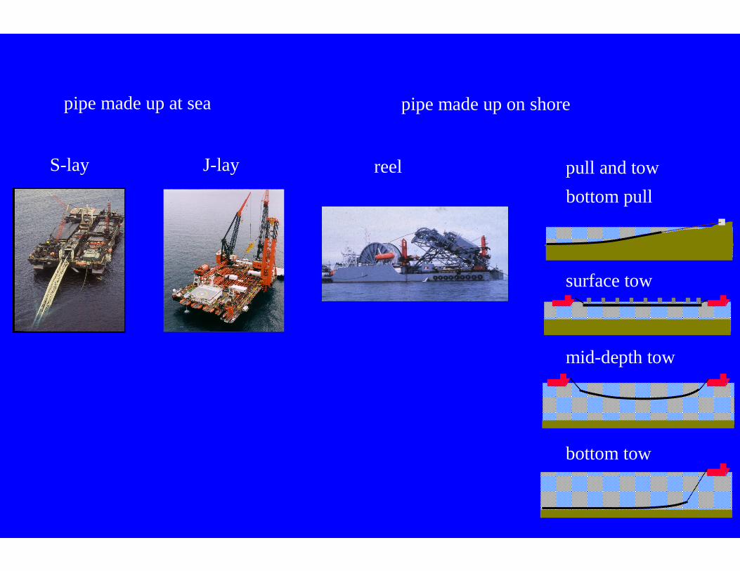
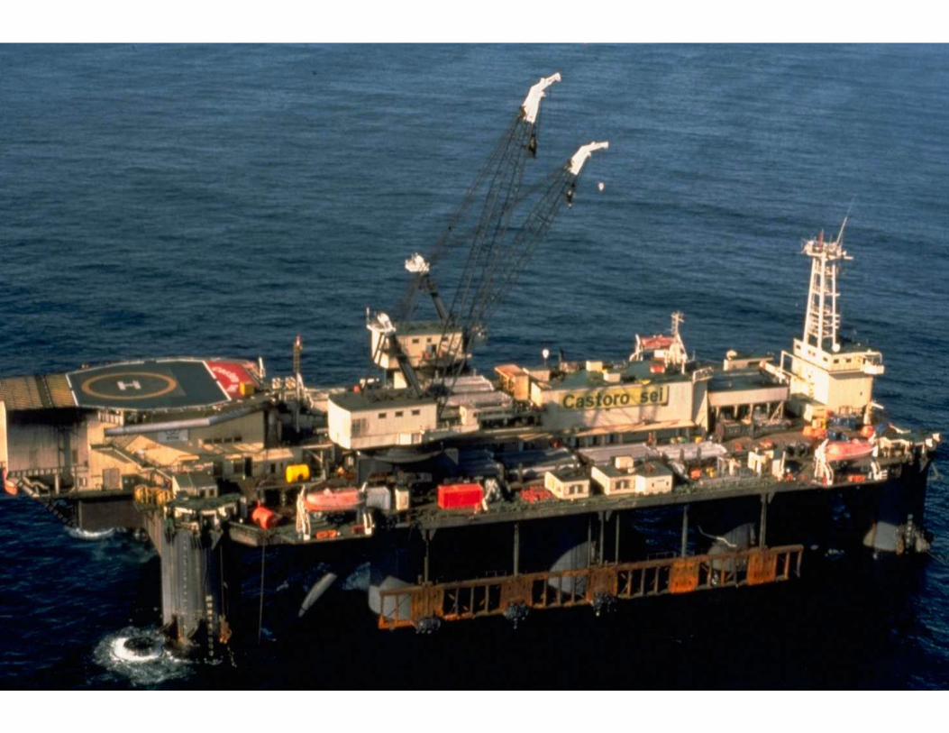
S-lay J-lay
pipe made up at sea pipe made up on shore
reel pull and tow
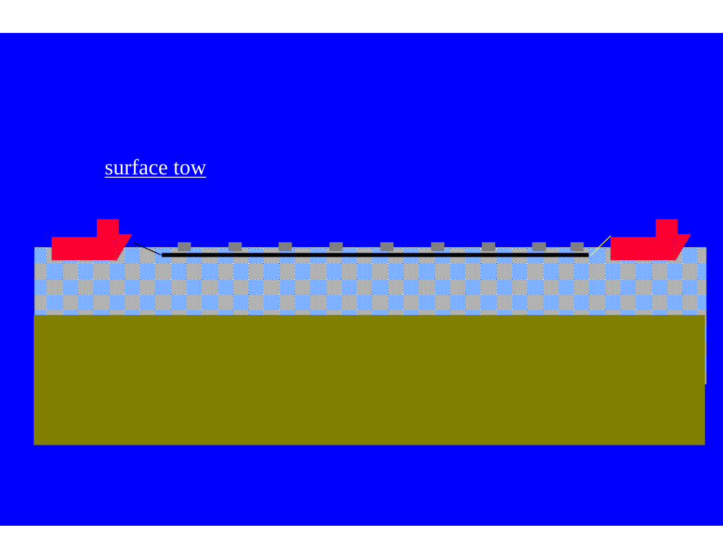
surface tow
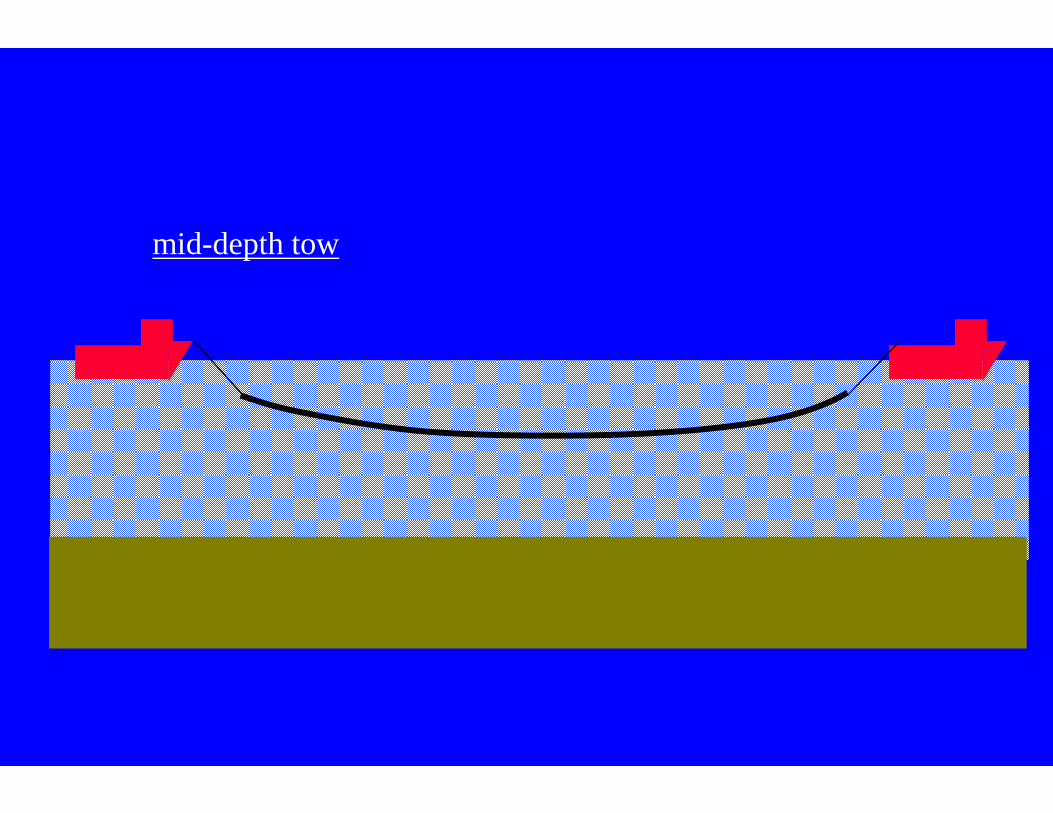
mid-depth tow
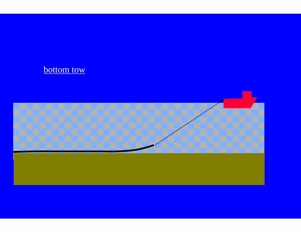
bottom tow
bottom pull
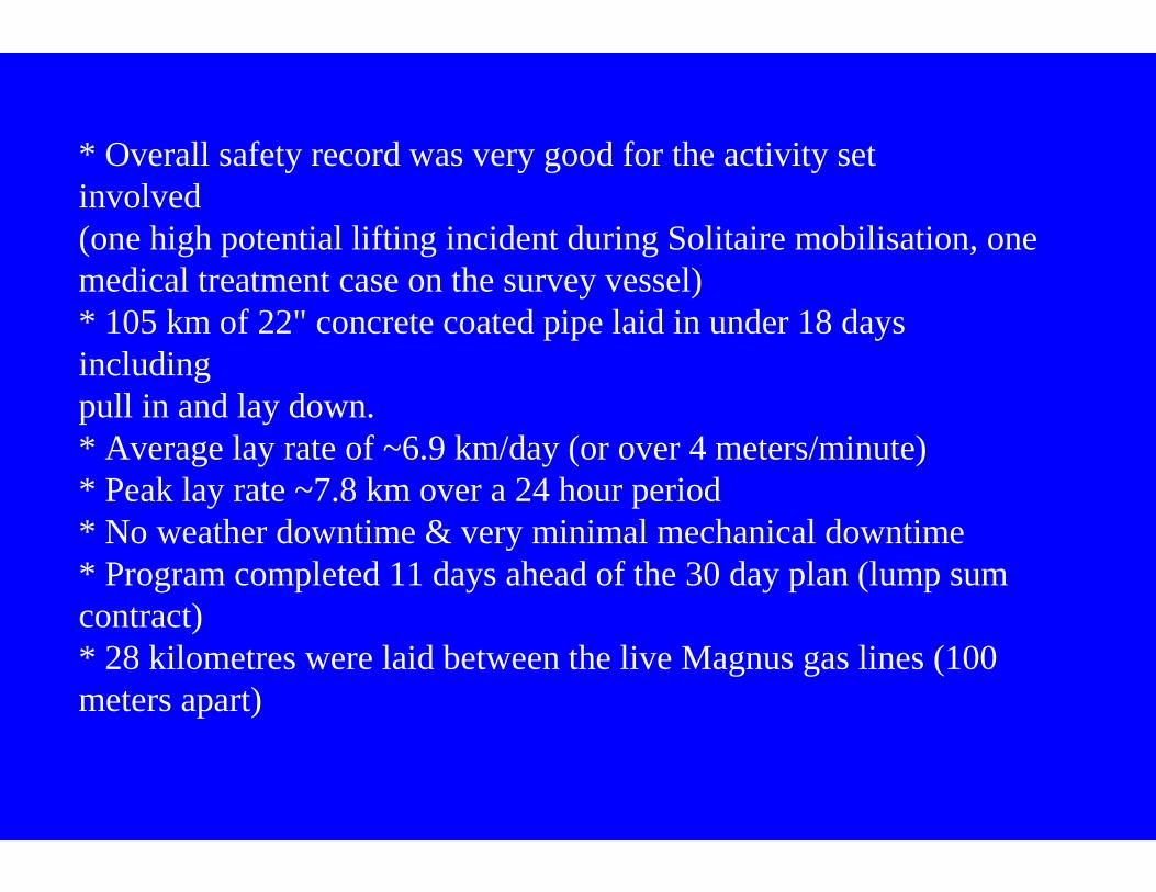
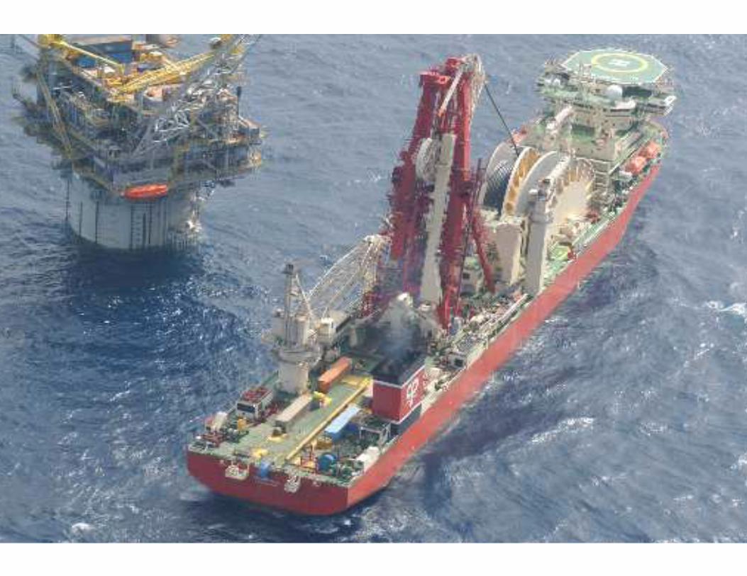
* Overall safety record was very good for the activity setinvolved(one high potential lifting incident during Solitaire mobilisation, onemedical treatment case on the survey vessel)* 105 km of 22" concrete coated pipe laid in under 18 daysincludingpull in and lay down. * Average lay rate of ~6.9 km/day (or over 4 meters/minute)* Peak lay rate ~7.8 km over a 24 hour period * No weather downtime & very minimal mechanical downtime* Program completed 11 days ahead of the 30 day plan (lump sumcontract)* 28 kilometres were laid between the live Magnus gas lines (100meters apart)
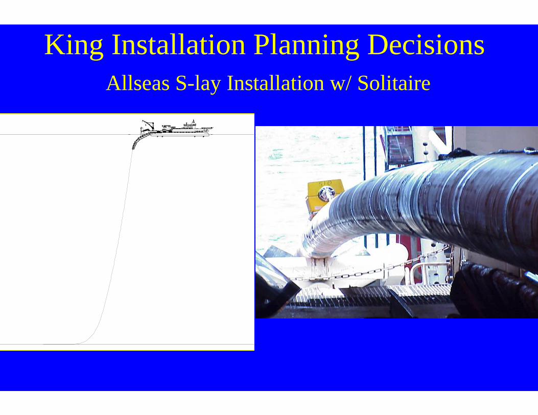
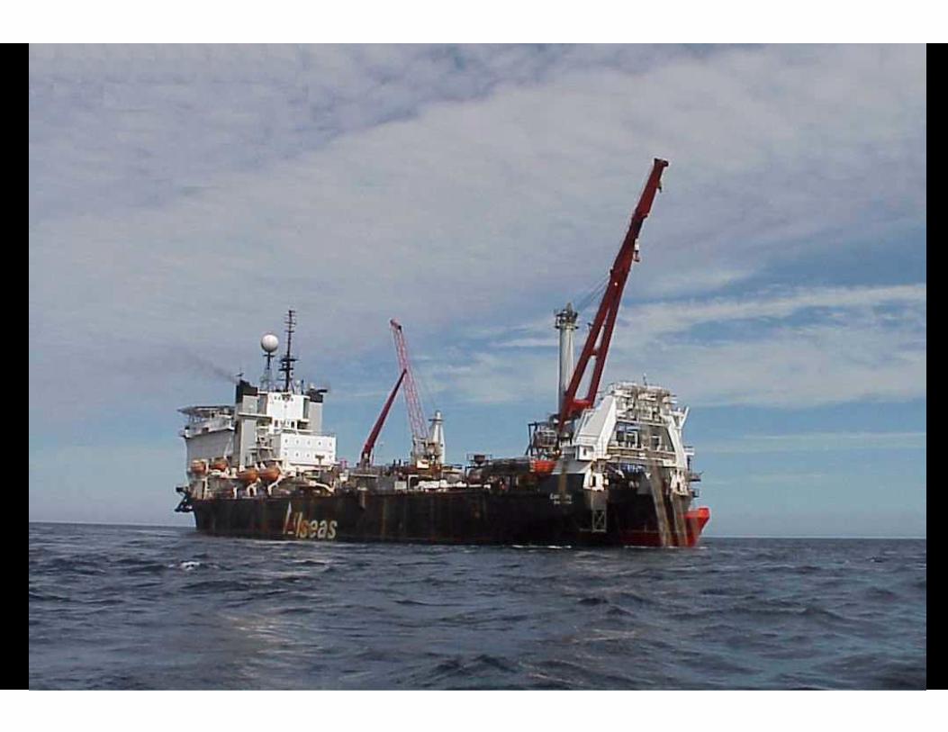
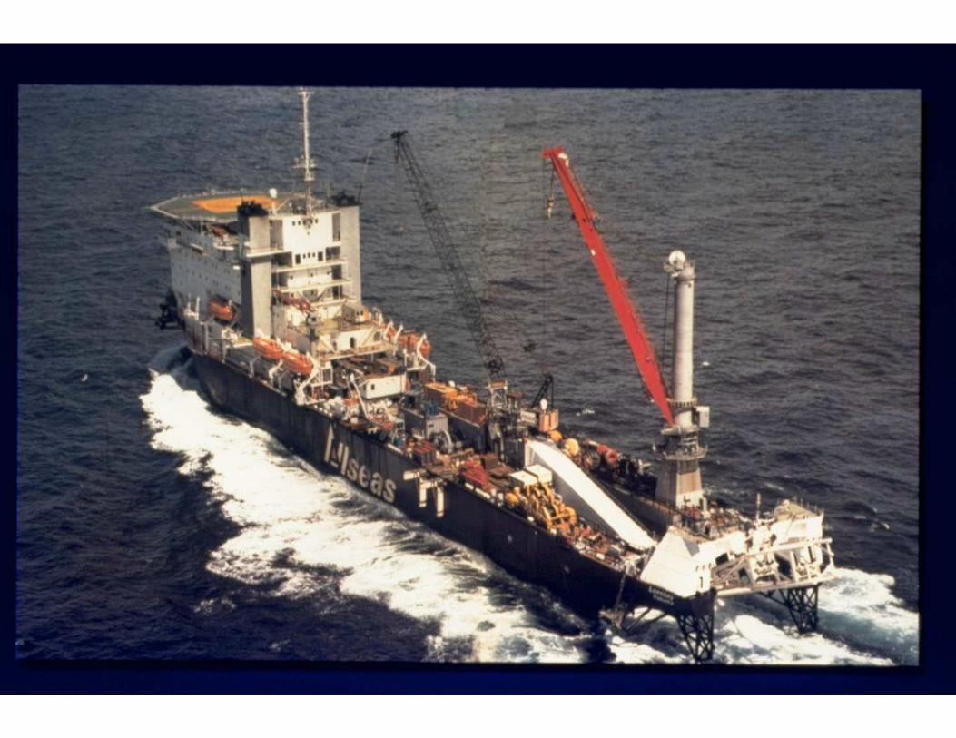
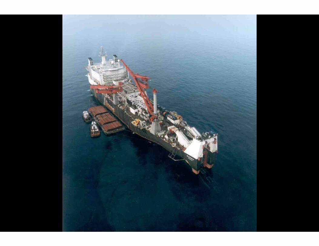
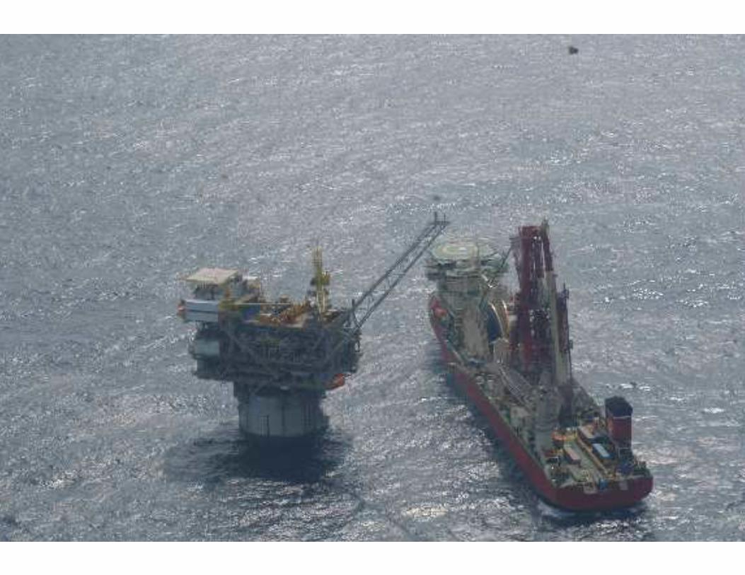
King Installation Planning Decisions Allseas S-lay Installation w/ Solitaire
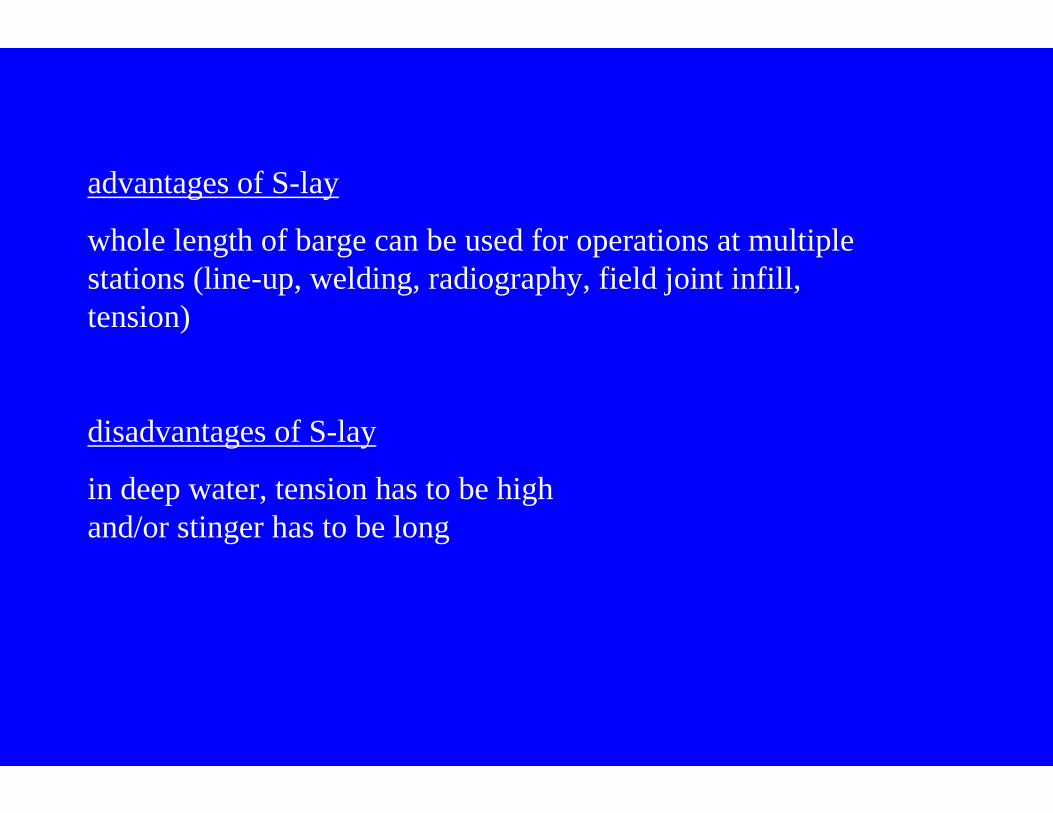
advantages of S-lay
whole length of barge can be used for operations at multiple stations (line-up, welding, radiography, field joint infill, tension)
disadvantages of S-lay
in deep water, tension has to be highand/or stinger has to be long
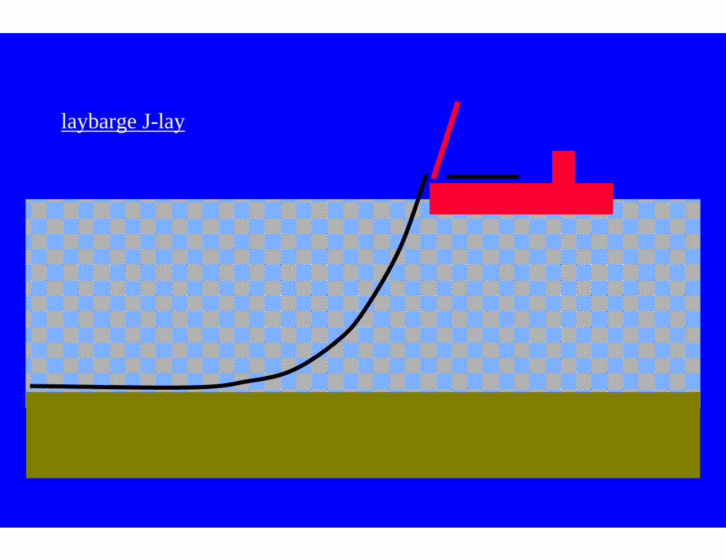
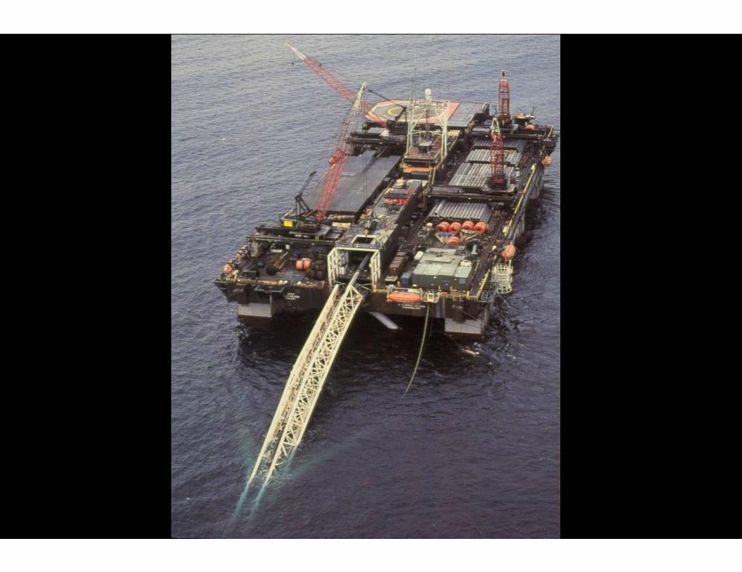
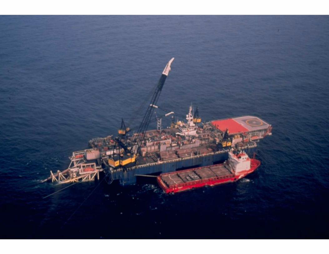
laybarge J-lay
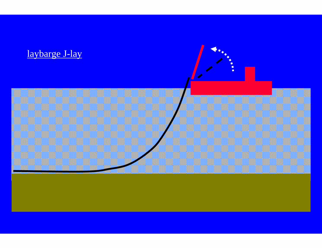
laybarge J-lay
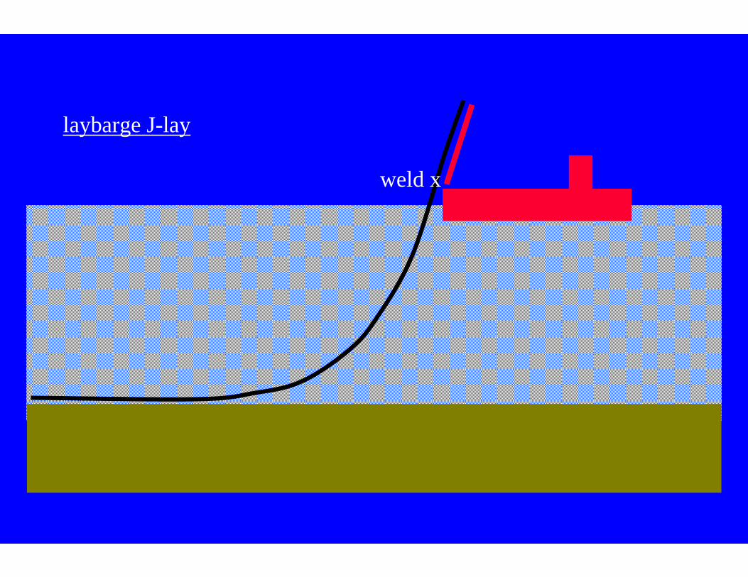
laybarge J-lay
weld x
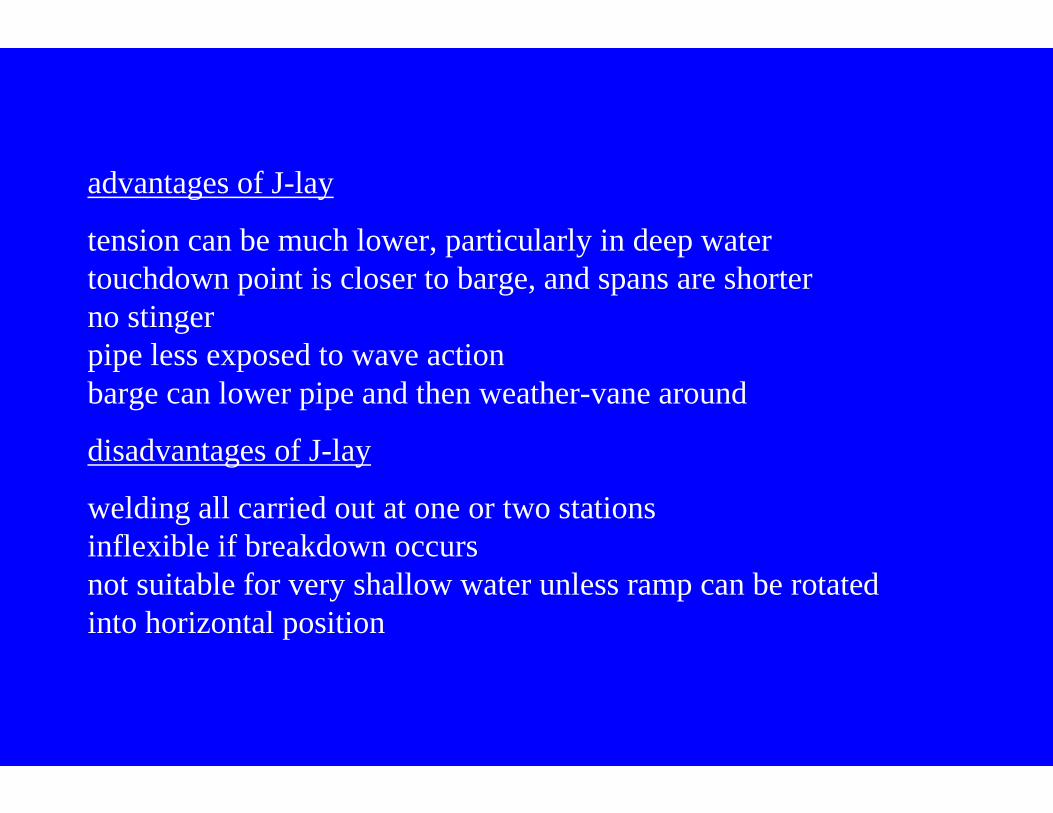
advantages of J-lay
tension can be much lower, particularly in deep watertouchdown point is closer to barge, and spans are shorterno stingerpipe less exposed to wave actionbarge can lower pipe and then weather-vane around
disadvantages of J-lay
welding all carried out at one or two stationsinflexible if breakdown occursnot suitable for very shallow water unless ramp can be rotated into horizontal position
KIVI 17 april 2003
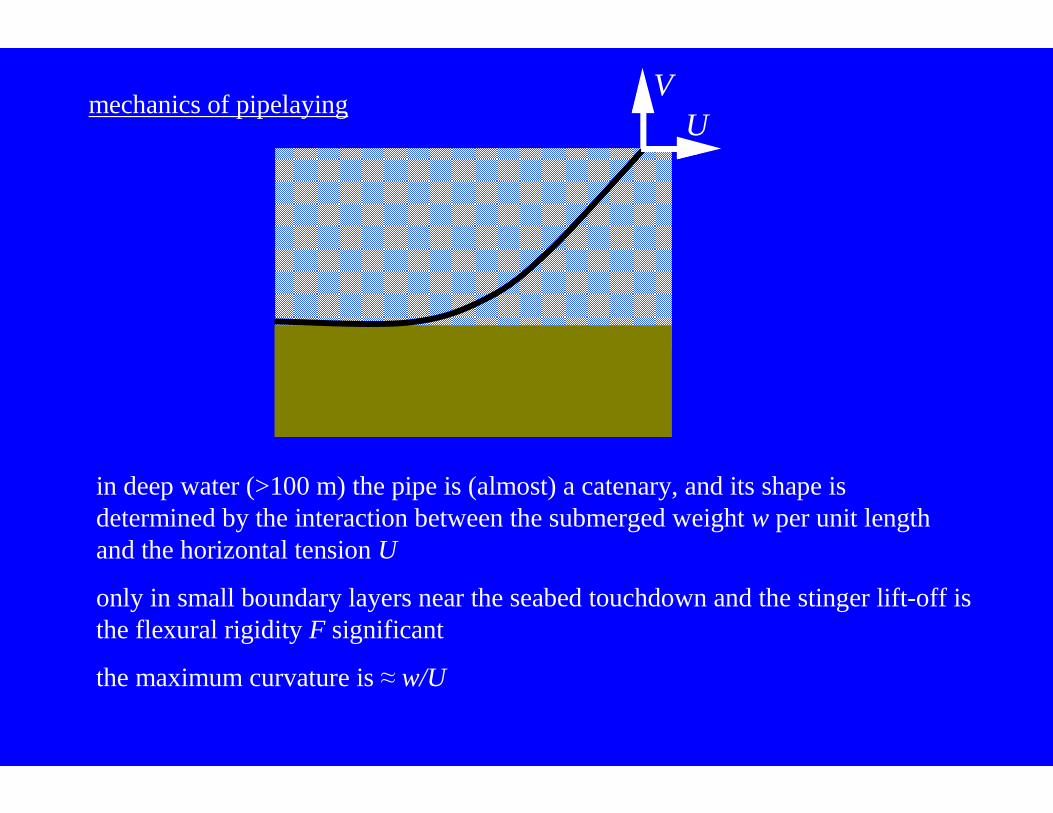
mechanics of pipelayingV
U
in deep water (>100 m) the pipe is (almost) a catenary, and its shape is determined by the interaction between the submerged weight w per unit length and the horizontal tension U
only in small boundary layers near the seabed touchdown and the stinger lift-off is the flexural rigidity F significant
the maximum curvature is ≈ w/U
surface tow
bottom tow
mid-depth tow
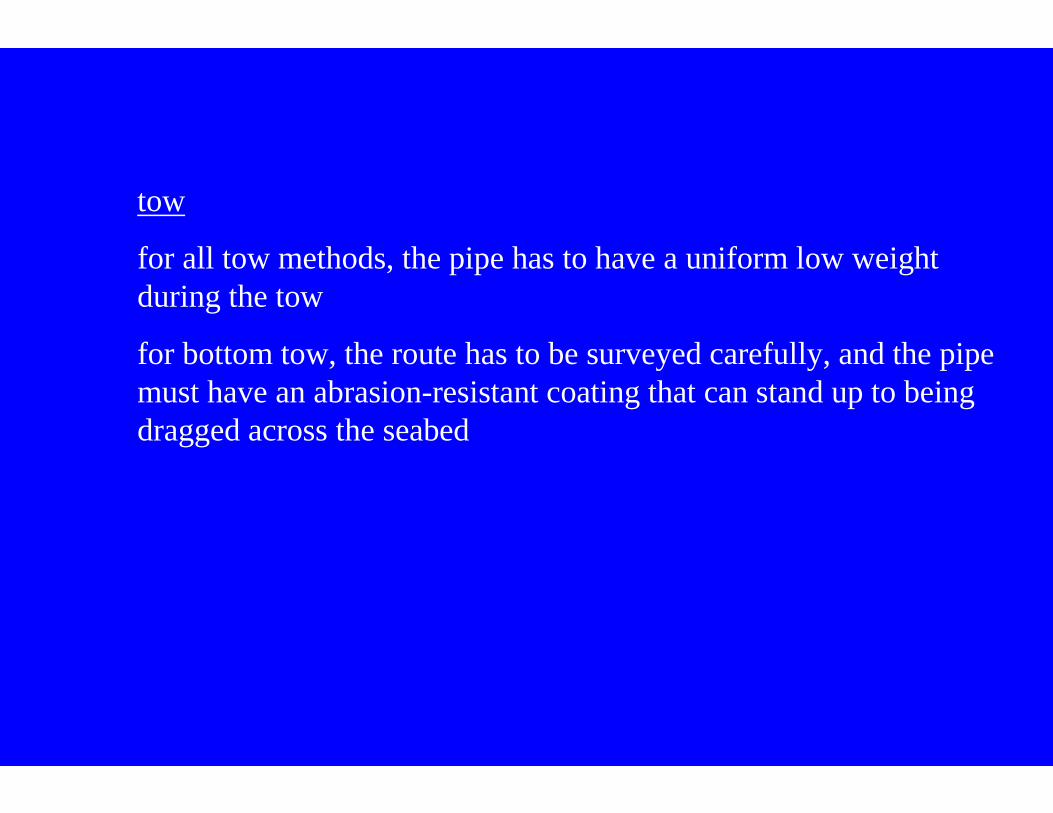
tow
for all tow methods, the pipe has to have a uniform low weight during the tow
for bottom tow, the route has to be surveyed carefully, and the pipe must have an abrasion-resistant coating that can stand up to being dragged across the seabed
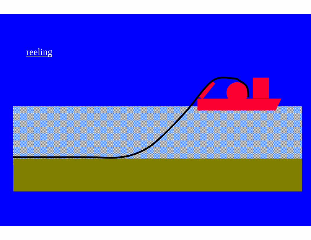
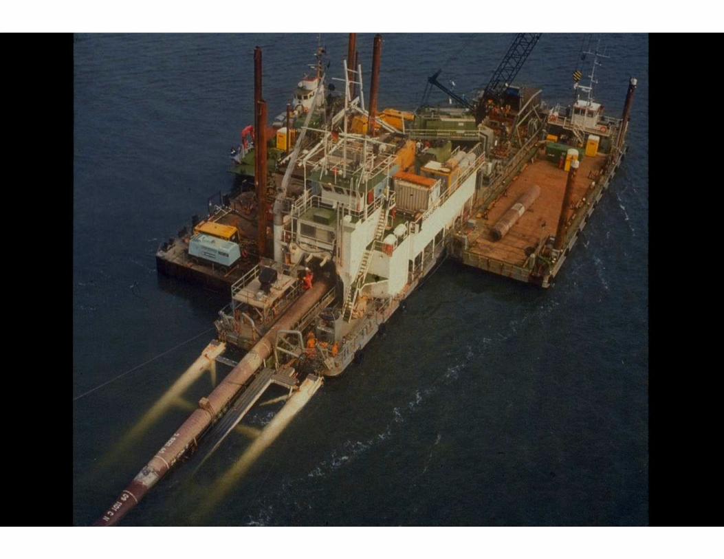
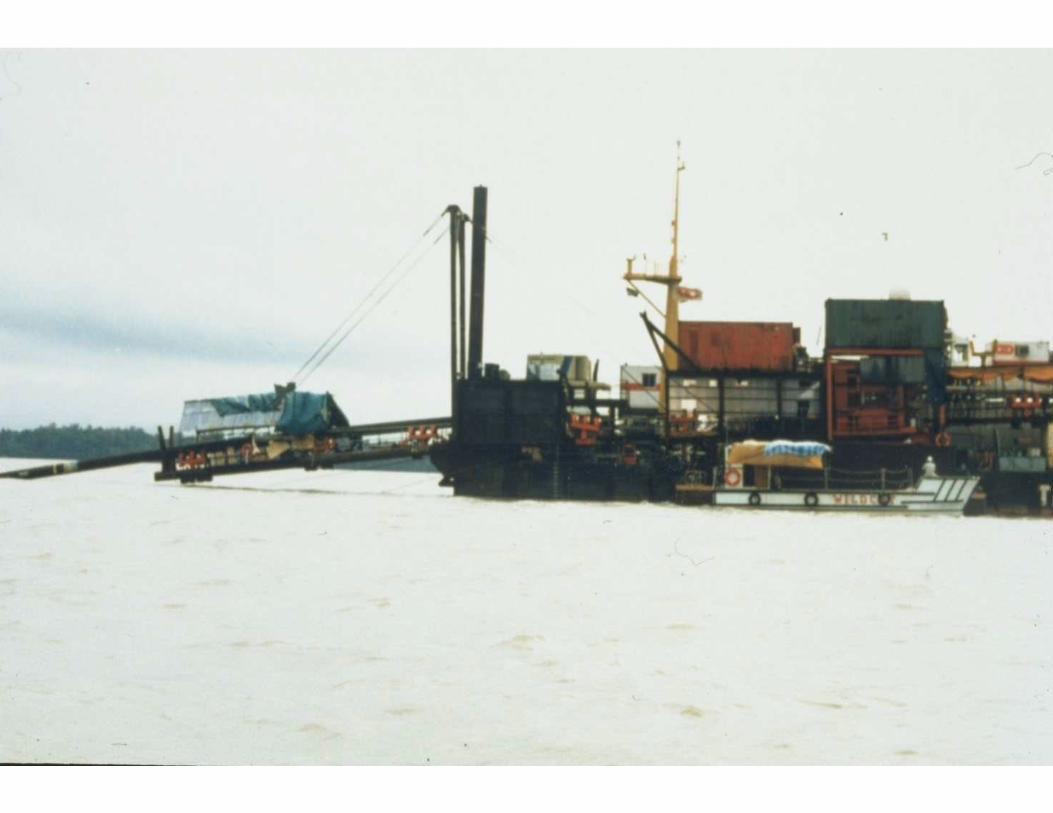
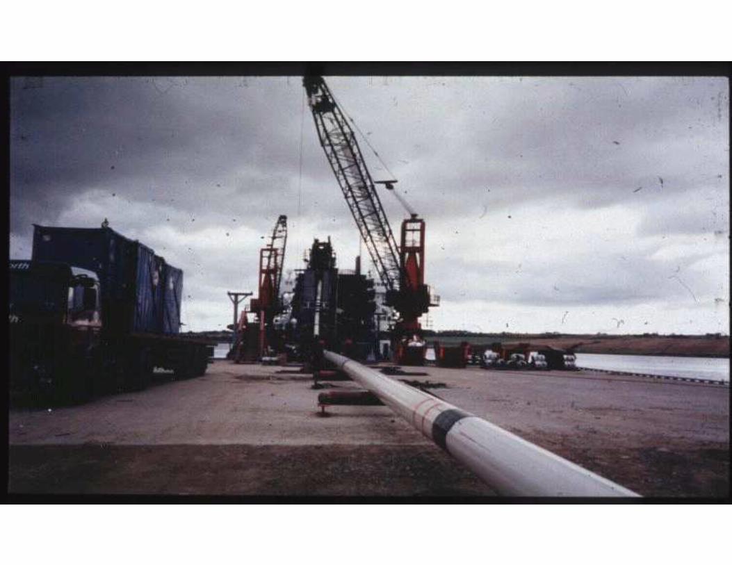
reeling
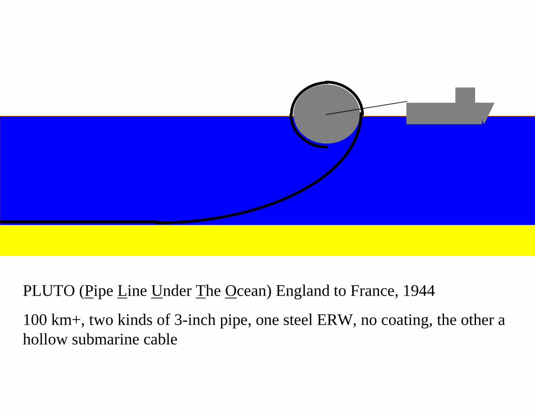
PLUTO (Pipe Line Under The Ocean) England to France, 1944
100 km+, two kinds of 3-inch pipe, one steel ERW, no coating, the other a hollow submarine cable
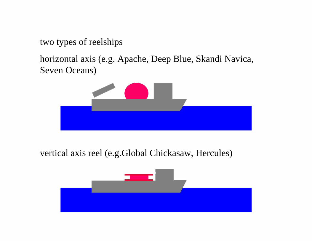
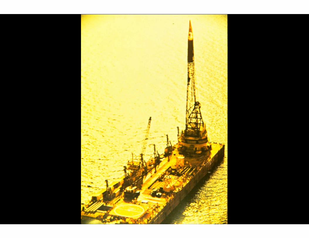
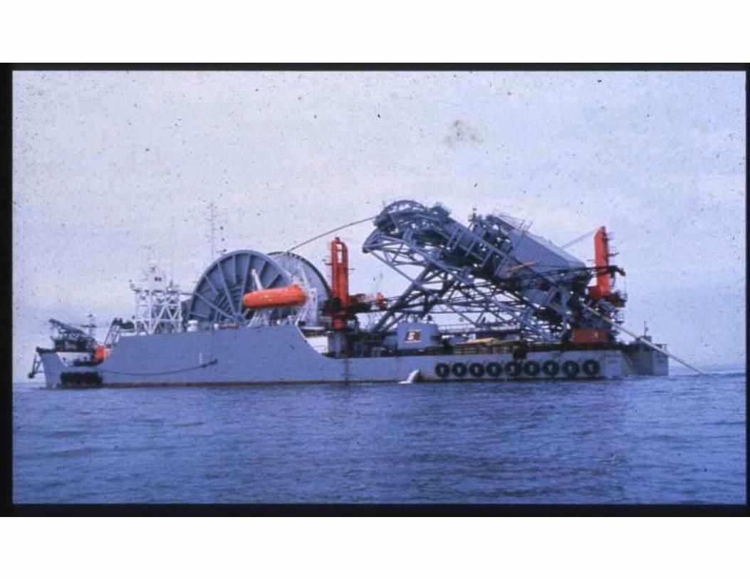
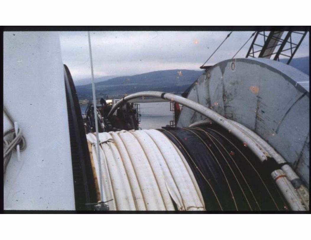
vertical axis reel (e.g.Global Chickasaw, Hercules)
two types of reelships
horizontal axis (e.g. Apache, Deep Blue, Skandi Navica, Seven Oceans)
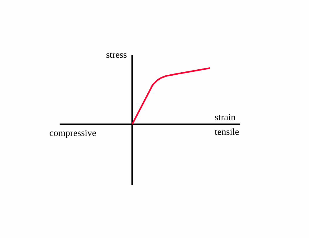
strain
stress
compressive tensile

strain
stress
compressive tensile
Bauschingereffect
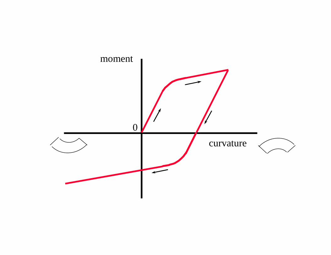
curvature
moment
0
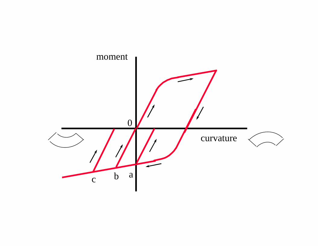
curvature
moment
abc
0
curvature
moment
0
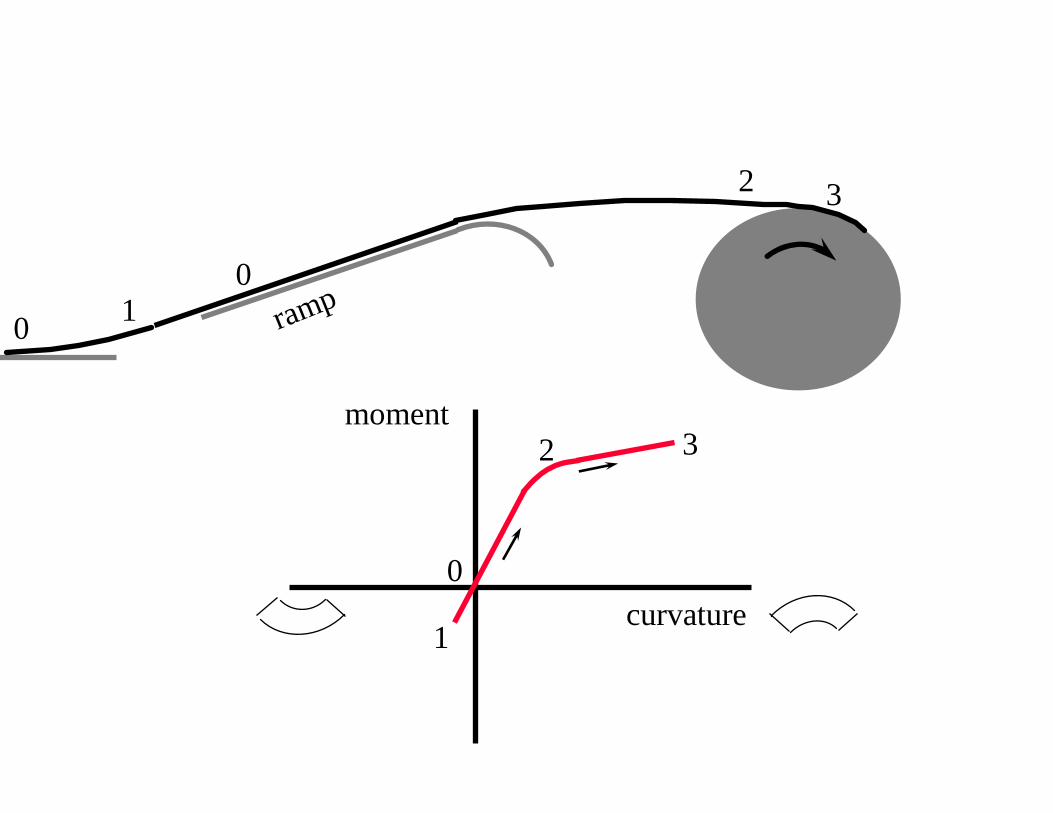
ramp0
01
2 3
32
1
curvature
moment
0
ram
p
3
32
1
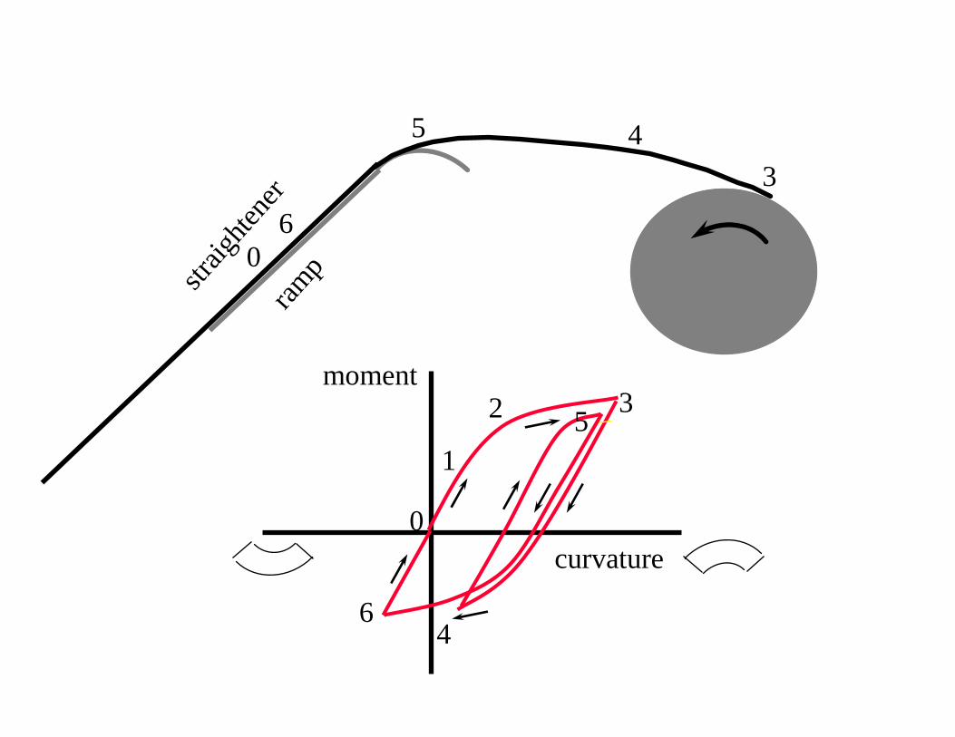
4
4
5
straig
hten
er
6
6
0
5
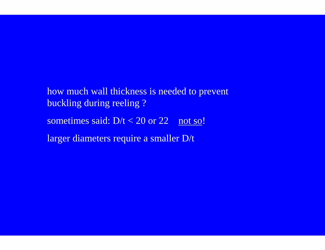
how much wall thickness is needed to prevent buckling during reeling ?
sometimes said: D/t < 20 or 22 not so!
larger diameters require a smaller D/t
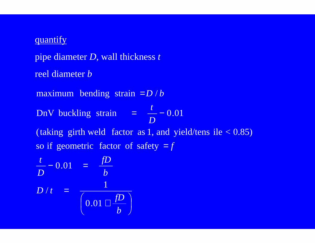
quantify
pipe diameter D, wall thickness t
reel diameter b
+=
=−
=
−=
=
b
fDtD
b
fD
D
t
f
D
t
bD
01.0
1/
01.0
safety offactor geometric if so
0.85) < ileyield/tens and 1, asfactor girth weld taking(
01.0strain buckling DnV
/strain bending maximum
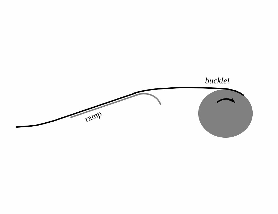
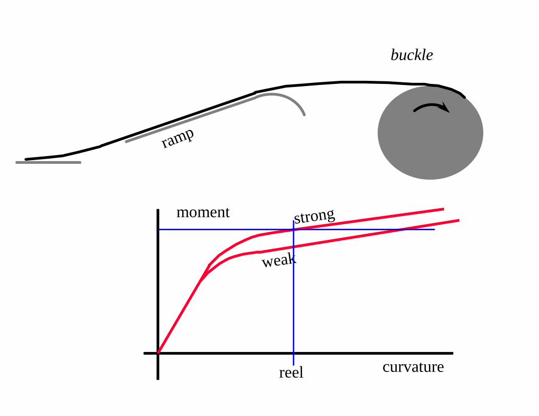
ramp
buckle!
curvature
moment
ramp
buckle
weak
strong
reel
pipe with concrete weight coating cannot be reeled
links choice of construction method to design of pipeline
if stability is a governing factor, requires the steel thickness to be increased to give the pipeline enough weight
expensive (particularly for CRA pipe)
leads to other difficulties (such as upheaval buckling)
means that anti-corrosion coating has to resist potential mechanical damage
alternative flexible concrete weight coating
polymer-modified rubber-like concrete
more expensive than conventional concrete, but much cheaper than steel (per kg of submerged weight)
can be applied
gives mechanical protection to anti-corrosion coating
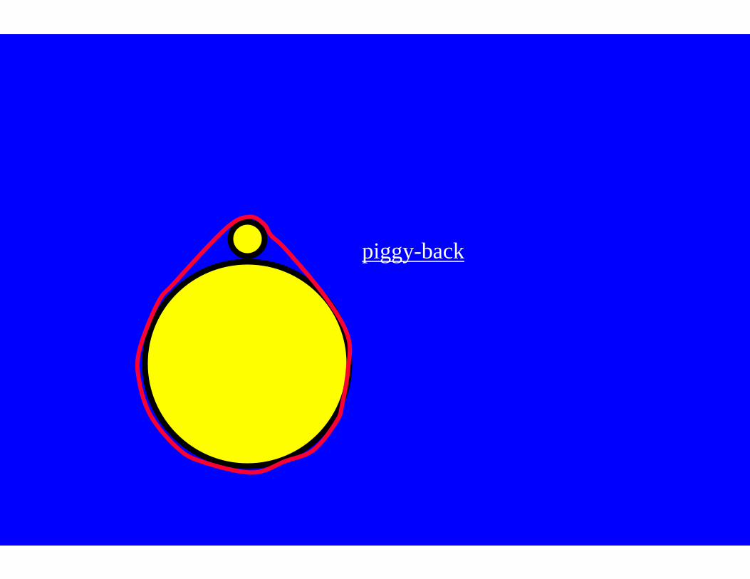
piggy-back
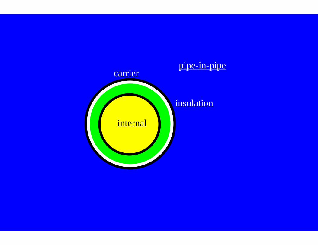
carrier
internal
insulation
pipe-in-pipe
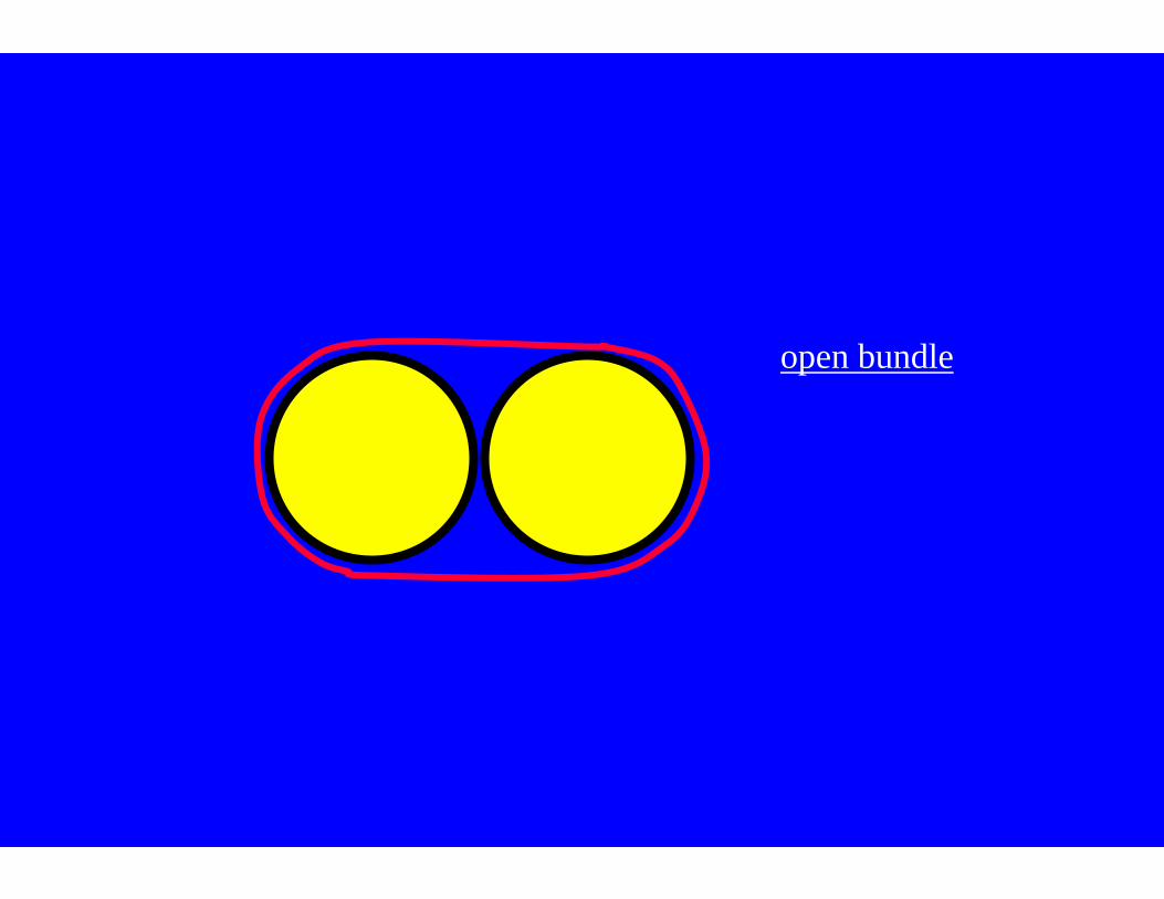
open bundle
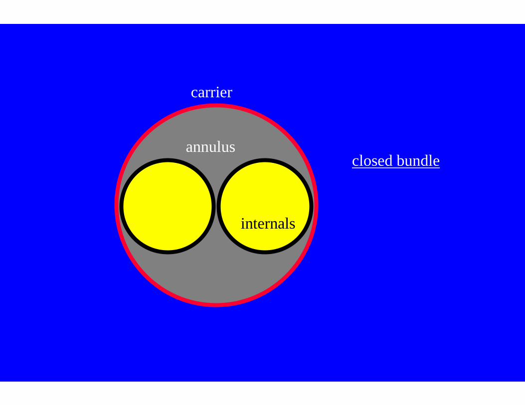
closed bundle
carrier
annulus
internals
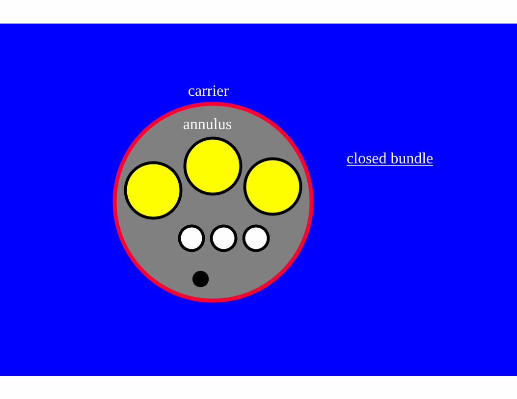
closed bundle
carrier
annulus
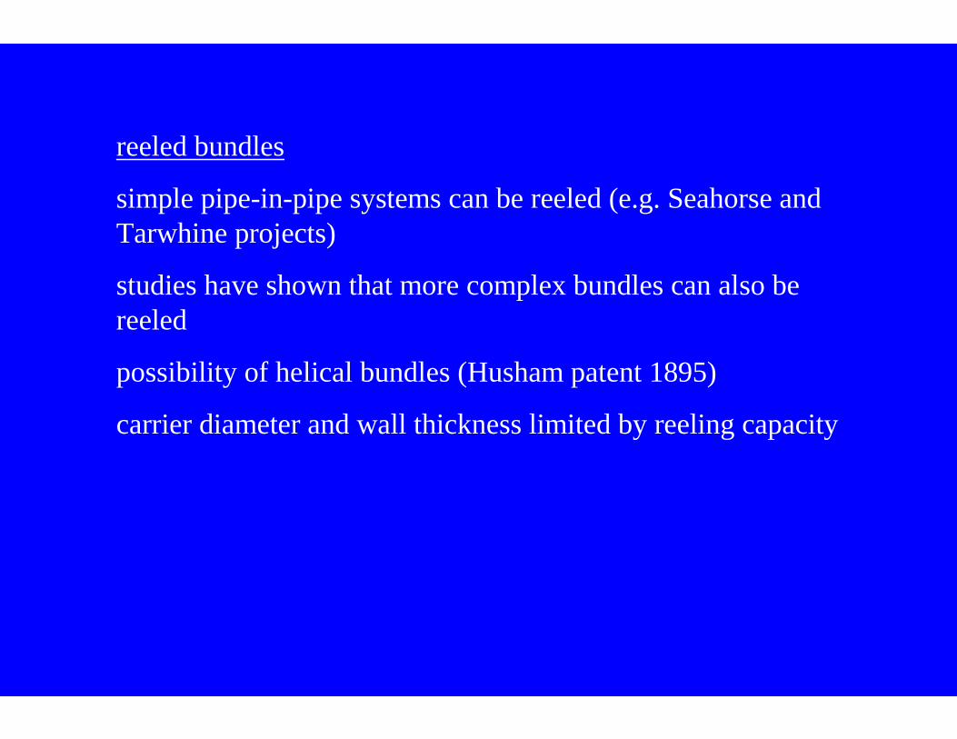
reeled bundles
simple pipe-in-pipe systems can be reeled (e.g. Seahorse and Tarwhine projects)
studies have shown that more complex bundles can also be reeled
possibility of helical bundles (Husham patent 1895)
carrier diameter and wall thickness limited by reeling capacity
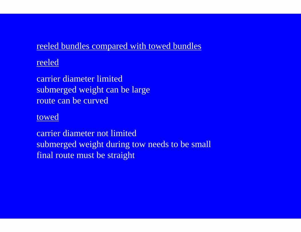
reeled bundles compared with towed bundles
reeled
carrier diameter limited submerged weight can be largeroute can be curved
towed
carrier diameter not limitedsubmerged weight during tow needs to be smallfinal route must be straight