Embed Size (px)
Citation preview
AL-TR-89-044 AD:
Final Report Investigation of Applicationsfor the periodAugust1988 to of Diamond FilmMay 1989
November 1989 Authors: Aerojet TechsystemsD.M. Jassowski RO. Box 13222
Sacramento, CA 95813-6000
" ' ... , ,.F04611-88-C-0074
S EC I "199
Approved for Public Release
Distribution is unlimited. The AFAL Technical Services Office has reviewed this report and it is releasableto the National Technical InforrnatlonService. where it will be available to the general public, includingforeign nationals.
Prepared for the: Air ForceAstronauticsLaboratoryAir Force Space Technology CenterSpace Division, Air Force Systems CommandEdwards Air Force Base,California 93523-5000
89 12 26 072
NOTICE
When U.S. Government drawings, specifications, or other data are used for
any purpose other than a definitely related Government procurement operation,
the fact that the Government may have formulated, furnished, or in any way
supplied the said drawings, specifications, or other data, is not to be
regarded by implication or otherwise, or in any way licensing the holder or
any other person or corporation, or conveying any rights or permission to
manufacture, use, or sell any patented invention that may be related thereto.
FOREWORD
This final report was submitted by Aerojet TechSystems Company on
completion of Contract F04611-88-C-0074 with the Astronautics Laboratory
(AFSC), Edwards Air Force Base CA. AL Project Manager was Curt Selph.
This report has been reviewed and is approved for release and
distribution in accordance with the distribution statement on the cover and on
the DD Form 1473.
CURT[S C. SELPH - -OBERT L. WISWELLProject Manager Chief, Liquid Propulsion Branch
FO\THE DIRECTOR
DAVIDirecto, LTNOL, USAFDeputy Director, R pulsion Division
UnclassifiedSECURITY CLASSIFICATION OF THIS PAGE
REPORT DOCUMENTATION PAGE
is. REPORT SECURITY CLASSIFICATION lb. RESTRICTIVE MARKINGS
UNCLASSIFIED21L SECURITY CLASSIFICATION AUTHORITY 3. DISTRIBUTIONIAVAILABILITY OF REPORT
APPROVED FOR PUBLIC RELEASE; DISTRIBUTION2b. DECLASSIFICATION/OOWNGRAOING SCHEDULE IS UNLIMITED.
4. PERFORMING ORGANIZATION REPORT NUMBER(S) S. MONITORING ORGANIZATION REPORT NUMBER(S)
AL-TR-89-044
G& NAME OF PERFORMING ORGANIZATION W OFFICE SYMBOL 7a. NAME OF MONITORING ORGANIZATION(If appuicabda)
AEROJET TECHSYSTEMS ( ASTRONAUTICS LABORATORY (AFSC)
6c. ADDRESS (City. State and ZIP Code) 7b. ADDRESS (City, State and ZIP Code)
P.O. BOX 13222 AL/RKLCSACRAMENTO, CA 95813-6000 EDWARDS AFB, CA 93523-5000
Ba. NAME OF FUNOING/SPONSORING ab. OFFICE SYMBOL 9. PROCUREMENT INSTRUMENT IDENTIFICATION NUMBER
ORGANIZATION r(If appilucbi)
F04611-88-C-0074
Sc. ADDRESS (City. State and ZIP Coade 10. SOURCE OF FUNDING NOS.
PROGRAM PROJECT TASK WORK UNITELEMENT NO. NO. NO. NO.
________________________ 61101F 58 00 2V11. TITLE (Inc u.de Security Chlauftcation)
INVESTIGATION OF APPLICATIONS OF DIAf.iOND FILM12. PERSONAL AUTHORIS)
IQM, jAeSQWSKT13a. TYPE OF REPORT 13b. TIME COVERED 14. DATE OF REPORT (. . Mo.. Do) IS. PAGE COUNT
FINALI FROM. _aL.L_ TO..5L._ 89/11 19216. SUPPLEMENTARY NOTATION
17. COSATI CODES 18. SUBJECT TERMS (Continue on ',wre i / neceswI and identify by block numberl
FIELD GROUP I SUB. GR. Diamond film, rocket propulsion, application study21 08
19. ABSTRACT (Continue on revere it necemary and identify by block number)
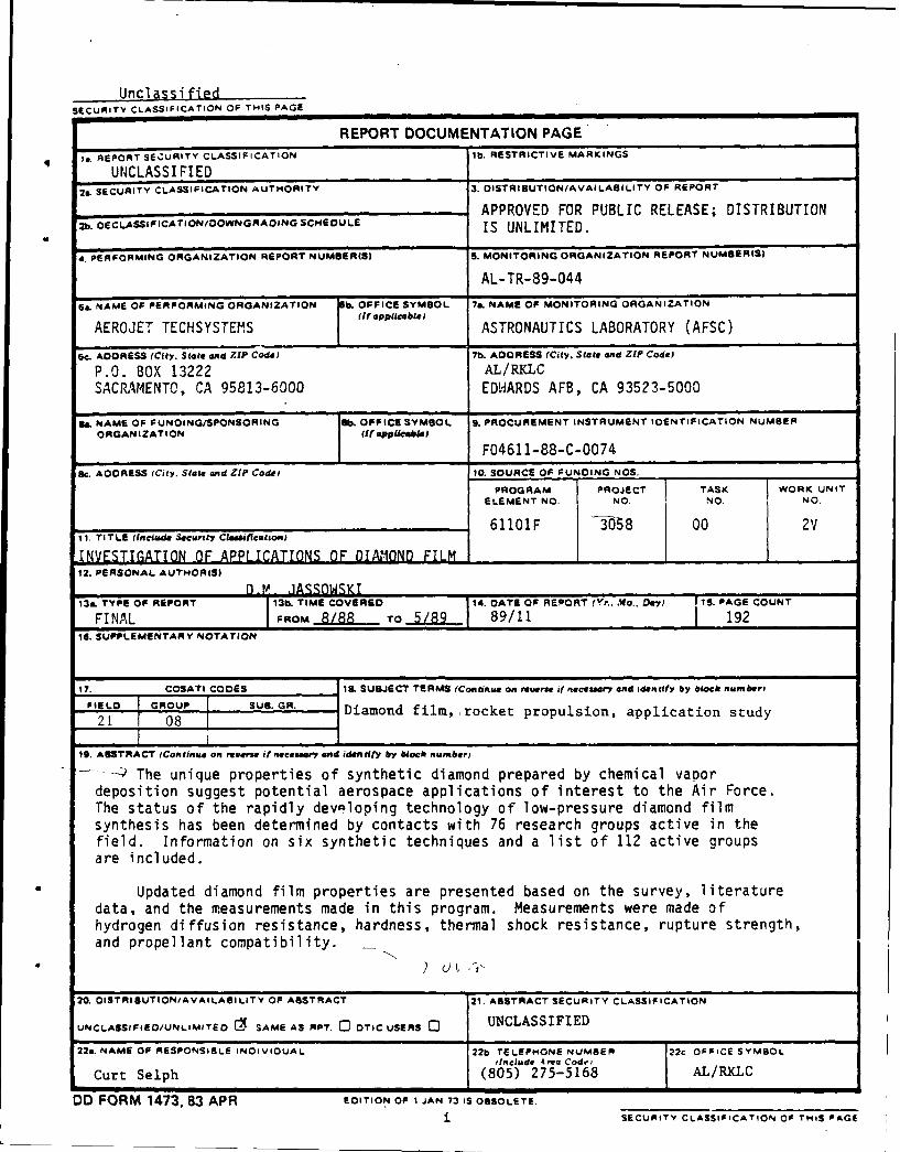
S-' The unique properties of synthetic diamond prepared by chemical vapordeposition suggest potential aerospace applications of interest to the Air Force.The status of the rapidly developing technology of low-pressure diamond filmsynthesis has been determined by contacts with 76 research groups active in thefield. Information on six synthetic techniques and a list of 112 active groupsare included.
Updated diamond film properties are presented based on the survey, literaturedata, and the measurements made in this program. Measurements were made ofhydrogen diffusion resistance, hardness, thermal shock resistance, rupture strength,and propellant compatibility. ..
20. OISTRISUTION/AVAILABILITY OF ABSTRACT 21. ABSTRACT SECURITY CLASSIFICATION
UNCLASSIFIEO/UNLIMITED C SAME AS RPT. [ OTIC USERS c UNCLASSIFIED
22&. NAME OF RESPONSIBLE INOIVIOUAL 22b TELEPHONE NUMBER 22c OFFICE SYMBOL(Include 4ea Cod."
Curt Selph (805) 275-5168 AL/RKLC
OD FORM 1473, 83 APR EDITION OF I JAN 73 IS OBSOLETE.
i SECURITY CLASSIFICATION OF THIS PAGE
Unclassified
SE0JRITY CLASSIFICATION OF THIS PAGE
19. Abstract (cont.)
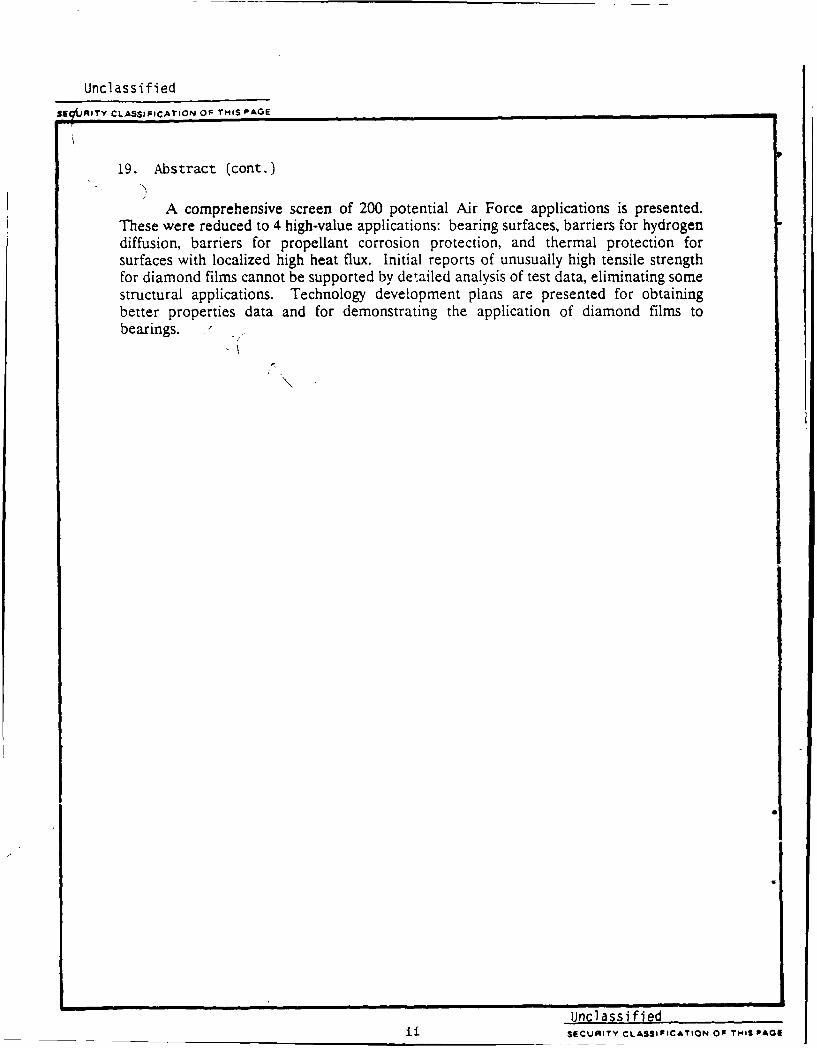
A comprehensive screen of 200 potential Air Force applications is presented.These were reduced to 4 high-value applications: bearing surfaces, barriers for hydrogendiffusion, barriers for propellant corrosion protection, and thermal protection forsurfaces with localized high heat flux. Initial reports of unusually high tensile strengthfor diamond films cannot be supported by detailed analysis of test data, eliminating somestructural applications. Technology development plans are presented for obtainingbetter properties data and for demonstrating the application of diamond films tobearings.
i6
Unclassified____________SECURITY CLASSIFICATION OF THIS PAGE
ACKNOWLEDGEMENTS
We use this opportunity to thank the individuals who took time fromtheir research to respond to our survey; they are listed in Section 3.1.In particular, we thank Y. Jmai and Mitsui & Company, Ltd., who madepossible our contacts with Japanese researchers. In addition, we thankDr. Lise Schioler who, while at Aerojet, initiated Aerojet work indiamond film, and Mr. Curt Selph who recognized the potential value ofdiamond film to the Air Force.
Acce.ion For
NTIS CR;,,
D );*. , ,t.
J ,, h. .... ... .. .
,/
iii ',V
I /"
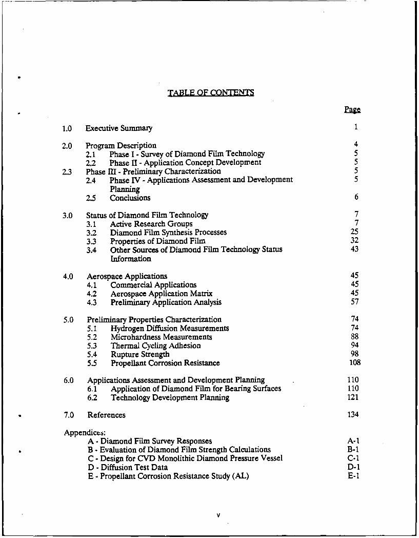
TABLE OF CONTENTS
1.0 Executive Summary 1
2.0 Program Description 42.1 Phase I - Survey of Diamond Film Technology 52.2 Phase II - Application Concept Development 5
2.3 Phase III - Preliminary Characterization 52.4 Phase IV - Applications Assessment and Development 5
Planning2.5 Conclusions 6
3.0 Status of Diamond Film Technology 73.1 Active Research Groups 73.2 Diamond Film Synthesis Processes 253.3 Properties of Diamond Film 323.4 Other Sources of Diamond Film Technology Status 43
Information
4.0 Aerospace Applications 454.1 Commercial Applications 454.2 Aerospace Application Matrix 454.3 Preliminary Application Analysis 57
5.0 Preliminary Properties Characterization 745.1 Hydrogen Diffusion Measurements 745.2 Microhardness Measurements 885.3 Thermal Cycling Adhesion 945.4 Rupture Strength 985.5 Propellant Corrosion Resistance 108
6.0 Applications Assessment and Development Planning 1106.1 Application of Diamond Film for Bearing Surfaces 1106.2 Technology Development Planning 121
7.0 References 134
Appendices:A - Diamond Film Survey Responses A-1B - Evaluation of Diamond Film Strength Calculations B-1C - Design for CVD Monolithic Diamond Pressure Vessel C-1D - Diffusion Test Data D-1E - Propellant Corrosion Resistance Study (AL) E-1
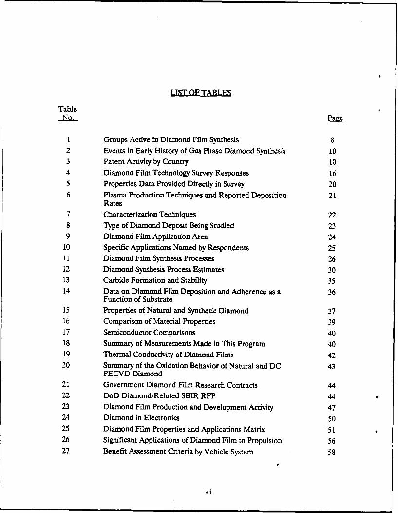
LJST OF TABLES
Table
1 Groups Active in Diamond Film Synthesis 82 Events in Early History of Gas Phase Diamond Synthesis 103 Patent Activity by Country 104 Diamond Film Technology Survey Responses 165 Properties Data Provided Directly in Survey 206 Plasma Production Techniques and Reported Deposition 21
Rates7 Characterization Techniques 228 Type of Diamond Deposit Being Studied 239 Diamond Film Application Area 24
10 Specific Applications Named by Respondents 2511 Diamond Film Synthesis Processes 2612 Diamond Synthesis Process Estimates 3013 Carbide Formation and Stability 3514 Data on Diamond Film Deposition and Adherence as a 36
Function of Substrate15 Properties of Natural and Synthetic Diamond 3716 Comparison of Material Properties 3917 Semiconductor Comparisons 4018 Summary of Measurements Made in This Program 4019 Thermal Conductivity of Diamond Films 4220 Summary of the Oxidation Behavior of Natural and DC 43
PECVD Diamond21 Government Diamond Film Research Contracts 4422 DoD Diamond-Related SBIR RFP 4423 Diamond Film Production and Development Activity 4724 Diamond in Electronics 5025 Diamond Film Properties and Applications Matrix 5126 Significant Applications of Diamond Film to Propulsion 5627 Benefit Assessment Criteria by Vehicle System 58
vi
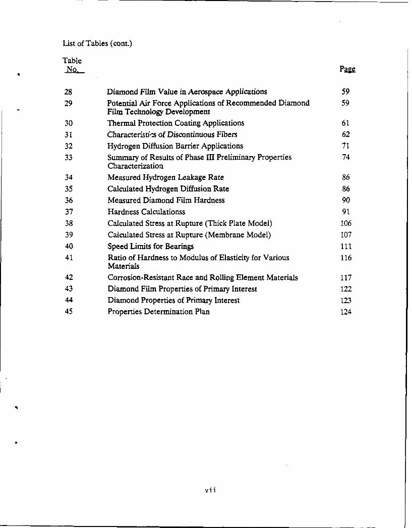
List of Tables (cont.)
TableNo P
28 Diamond Film Value in Aerospace Applications 5929 Potential Air Force Applications of Recommended Diamond 59
Film Technology Development
30 Thermal Protection Coating Applications 61
31 Characteristis of Discontinuous Fibers 62
32 Hydrogen Diffusion Barrier Applications 7133 Summary of Results of Phase III Preliminary Properties 74
Characterization34 Measured Hydrogen Leakage Rate 86
35 Calculated Hydrogen Diffusion Rate 8636 Measured Diamond Film Hardness 9037 Hardness Calculationss 91
38 Calculated Stress at Rupture (Thick Plate Model) 106
39 Calculated Stress at Rupture (Membrane Model) 10740 Speed Limits for Bearings 1141 Ratio of Hardness to Modulus of Elasticity for Various 116
Materials42 Corrosion-Resistant Race and Rolling Element Materials 117
43 Diamond Film Properties of Primary Interest 12244 Diamond Properties of Primary Interest 123
45 Properties Determination Plan 124
vii
LIST OF FIGURES
FigureNo.
1 CVD Diamond R&T Investment 11
2 Diamond Film Technology Survey Questionnaire 12
3 Diamond Film Survey Cover Letter 154 Research Group Size 17
5 Group Life 17
6 Types of Group Identified in Survey 187 Number of Property is Measured 19
8 Number of Characterization Methods Used 229 Minimum Deposition Temperature Range 24
10 Schematic of DC Discharge CVD Diamond Apparatus 2611 Approaches for Diamond Film Synthesis 2712 Two Recently Developed Synthesis Processes 2813 Suggested Model for the Nucleation of Crystalline 28
Diamond Films on Single Crystal Substrates
14 Scanning Electron Photomicrographs of Diamond Film 29Surfaces
15 Common Spectra Show Coating Uniformity 3316 Thickness Uniformity 3417 Raman Spectra of CVD and Natural Diamond 34
18 Thermal Conductivity vs. Temperature for Natural 41Diamond and Diamond Films
19 Arrhenius Plot of Diamond Oxidation Rates 4220 CVD Diamond Application Areas 4621 Diamond Film Deposited on a Drill Bit 4822 Diamond Deposition on Titanium Surgical Needle 4923 Peak Surface Temperature Reduction by Diamond Film 6024 Tensile Data on Reinforced Aluminum Alloys 6325 Elastic Moduli for Reinforced Aluminum Alloys 6326 Projected Properties for Diamond Film Coated Silicon 64
Carbide Reinforced Aluminum Composite27 Continuous Reinforced Aluminum Composites Maximize 65
Properties in Diamond Film Fiber Direction
viii
List of Figures (cont.)
FigureNo. Pg
28 Diamond Films Laminated Together Offer High Strength 66in Planar Direction
29 Impact Armor Concept 6630 Single Layer for Laminate Buildup 67
31 Electronics Cooling Through Diamond Film Insulation 69Compared to Other Electrical Insulators
32 Semiconductor Microwave Generator Dependence of Power 70Capability on Heat Sink Thermal Conductivity
33 Fundamental Device Operation Limits 70
34 Effect of Hydrogen Absorption on Signal Transmission 72in Fiber Optic Cable
35 Application of Diamond Film to Fiber Optic Trairmission 73Cables
36 Raman Spectrum, Test Specimen Parent Wafer at R /8 7637 Raman Spectrum, Test Specimen Parent Wafer at R/2 77
38 Silicon Support for Diamond X-Ray Window 7839 Diamond X-Ray Window 7940 X-Ray Window Schematic, Diamond Film on Silicon Grid, 80
End View41 Detail of Mounted Window for Diffusion Measurements 8142 Mass Spectrometer with Mounted Window Under Test 8243 Mass Spectrometer Stability Ov,,r 24 Hours 83
44 Stability Test, T = 0 8545 H2 Leakage Spectra at 24 Hours 85
46 Hydrogen Leakage Through 0.5A CVD Diamond Films on 87Silicon Support Grids
47 Surface Appearance of Hardness Specimen 89
48 Asymietric Indent on CVD Diamond on Silicon Samples 9249 Vickers Hardness, CVD Diamond on Silicon Substrate 93
50 SEM Photos of Unsatisfactory Deposition on Ti6A14V 95Specimens
51 Thermal Cycling Die #11, Center 96
52 Then:,,' Cycling Components 9753 Appearance of Diamond Film Interface at Edge of 99
Specimen 10-N-96-11
ix
List of Figures (cont.)
FigureNo. P=g
54 Appearance of Diamond Film Interface at Edge of 100Specimen 10-N-96-12
55 Pretest Appearance of Diamond Film Interface at 101Edge of Specimen 10-N-96-14
56 Appearance of Diamond Film Interface at Edge of 102Specimen 10-N-96-15
57 Burst Test Specimen Coafiguration 10358 SEM of Rupture Specimen Diamond Film 10459 Burst Test Setup (ScLematic) 104
60 Rupture Test Specimens (10X Magnification) 10561 Calculated Stress at Failure 10862 Failure Stress Versus Film Thickness Calculation 109
Using Thick Failure Analysis63 Normalizer Resistance to Wear Chromium = 1.0, 112
Extrapolated to Diamond
64 Effect of Surface Hardness of Bearing Life 11265 Wear Rates for Rolling Contact Bearings on the Film 113
Lubricated Bearings66 Hardness vs. Function of Temperature for Different 114
Classes of Bearing Materials67 Wear Versus Elastic Modulus 11568 Effect of Ambient Pressure on Coefficient Friction 11769 NASA-MSFC Bearing Life Tester 12070 Properties Determination for CVD Diamond 124
71 Tensile Specimen Configuration 125
72 Schematic of Clip-On Extensometer Set-Ups for 126Measuring Tensile Strain
73 Predicted Tensile Stress-Strain Responses for 127Uncoated Titanium and Diamond Coated (0.005" Coating)0.05" Thick Titanium
74 Compressive Specimen Configuration 12875 Contact Stress Test Schematic 128
76 In-Plane Thermal Expansion Specimen 13077 Diamond Film Bearing Sur-ace Study Schedule 131
x
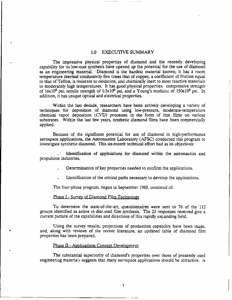
1.0 EXECUTIVE SUMMARY
The impressive physical properties of diamond and the recently developingcapability for its low-cost synthesis have opened up the potential for the use of diamondas an engineering material. "Diamond is the hardest material known; it has a roomtemperature thermal conductivity five times that of copper, a coefficient of friction equalto that of Teflon, is resistant to oxidation, and chemically inert to most reactive materialsto moderately high temperatures. It has good physical properties: compressive strengthof 16x10 6 psi, tensile strength of 0.5x10 6 psi, and a Young's modulu of 150x10 6 psi. Inaddition, it has unique optical and electrical properties.
Within the last decade, researchers have been actively developing a variety oftechniques for deposition of diamond using low-pressure, moderate-temperaturechemical vapor deposition (CVD) processes in the form of thin films on varioussubstrates. Within the last few years, synthetic diamond films have been commerciallyapplied.
Because of the significant potential for use of diamond in high-performanceaerospace applications, the Astronautics Laboratory (AFSC) conducted this program toinvestigate synthetic diamond. This six-month technical effort had as its objectives:
Identification of applications for diamond within the astronautics and
propulsion industries.
Determination of key properties needed to confirm the applications.
Identification of the critical paths necessary to develop the applications.
The four-phase program, begun in September 1988, consisted of:
Phase I - Survey of Diamond Film Technology
To determine the state-of-the-art, questionnaires were sent to 76 of the 112groups identified as active in dianiond film synthesis. The 23 responses received give acurrent picture of tne capabilities and directions of this rapidly expanding field.
Using the survey results, projections of production capability have been made,and, along with reviews of the recent literature, an updated table of diamond filmproperties has been prepared.
Phase II - Applications Concept Development
The substantial superiority of diamond's properties over those of presently usedengineeriag materials suggests that many aerospace applications should be attractive. A
matrix of 26 of the properties by the 200 applications they enhance was prepared and
screened to isolate applications of high value to the Air Force.
The high-value applications identified initially were:
* Bearing surface coating* Composite structural material* Hydrogen diffusion barrier* Monolithic structural material* Thermal protective coating
Phase IIl- Preliminary Characterization
Properties critical to the high-value applications were identified andmeasurements of four were made by the contractor. One other was measured by ALusing diamond film specimens supplied by the contractor.
The properties measured were:
Hydrogen Diffusion--Determined to be less than the limits of detection for a 0.5micron (0.02 mil) thick film (limit of detection = 6x 10- I std cm 3 sec'), indicating thatdiffusion barrier applications should be considered.
Microhardness-For films on a strong substrate (molybdenum) the hardness is atthe limits of measurement = 10,000 Kg mm-2, which equals natural diamond, indicatingbearing applications should be considered.
Thermal Shock Resistance--Diamond deposited on molybdenum withstands atleast 100 cycles from ambient to liquid nitrogen temperature without degradation,indicating it may be practical for coatings in cryogenic applications.
Rupture (Tensile Strength) Tests-Results of these tests are ambiguous. Detailedanalysis indicates a tensile strength of about 500,000 psi, similar to that of naturaldiamond. Although this is an impressive value, especially considering the relative lackof process maturity, and is adequate for many applications, it does rule out for presentconsideration some structural applications, such as monolithic pressure vessels, andmakes other applications, such as composite structures, less attractive.
Propellant Compatibility-(Astronautics Laboratory (AFSC) measurement)Exposure tests of free-standing 40-micron diamond film to CIF 3 and N20 4 vapor, andN2H 4 liquid showed no reaction.
2
Phase IV - Applications assessment and Development Planning
Diamond film bearing applications were examined and a program to demonstratethis technology was outlined. It is recommended that this program be preceded by aone-year effort to quantify more diamond film properties in conjunction with processdevelopment to assure optimization and control of properties.
Conclusions and Recommendations
Synthetic CVD diamond is a high-value material with significant engineeringapplications and a potential for relatively low cost. Its properties should be furtherdocumented and optimized and the technology for its application to turbopump bearingsshould be demonstrated.
/
3
2.0 PROGRAM DESCRIPTION
This program was conducted by the Astronautics Laboratory (AFSC) to identifypotential high-value applications of diamond film to its aerospace missions. To do thisrequired determination of the state-of-the-art of diamond film technology, both toidentify realistic synthesis capability and its properties. Natural diamond has someattractive engineering properties which have not been exploited because of the limitedavailability and form of the material. The evolution of CVD diamond synthesis providesthe capability to produce synthetic diamond economically in geometries useful forengineering applications.
Along with the state-of-the-art data, a wide range of Air Force applications wereidentified which would be benefitted by the known or potential superiority of theproperties of CVD diamond over conventional materials. Since some properties wereuncertain, their experimental determination was undertaken to provide preliminaryvalues on which to base further study of selected applications. Measurements weremade of hardness, hydrogen diffusion resistance, thermal cycle adherence, rupturestrength, and propellant corrosion compatibility.
The 200 potential applications identified were screened to five high-valueapplications: bearings, composite structures, hydrogen diffusion barriers, pressurevessels, and thermal protection coating. After further study of these applications andassessment of the new properties data, the bearing application was chosen as the bestsuited for near-term technology demonstration. A recommended program is outlined forproving the technological feasibility of diamond film for bearing applications.
Since many engineering properties of diamond film have not been measured, it isrecommended that the initial study be concentrated on basic properties measurement ofCVD diamond.
The Investigation of Applications of Diamond Film program consisted of fourphases, which included:
Phase I - Survey of Diamond Film TechnologyPhase II - Applications Concept DevelopmentPhase III - Preliminary CharacterizationPhase IV - Applications Assessment and Developmental Planning
These phases are outlined below and described in the following sections.
2.1 PHASE I- SURVEY OF DIAMOND FILM TECHNOLOGY
The purpose of this phase was to determine the capability for diamond filmsynthesis and the extent of developmental activity in the field. Many research groups
4
were identified and asked to provide data on their synthesis techniques and diamonddeposition capability. The data from this survey are discussed in Section 3.1.
An updated listing of diamond properties was prepared based on these contactsand the literature. Information on eight different synthesis processes was obtained in thesurvey. Projections of process capability and production cost estimates were preparedfor these processes.
Five sources of extensive data on diamond film synthesis were identified and arediscussed in Section 3.4.
2.2 PHASE II - APPLIC XTION CONCEPT DEVELOPMENT
A matrix of possible applications of diamond film in the aerospace field and thesignificant properties of diamond film which promote the applications was prepared andis presented in Section 4.
By considering various measures of value to the Air Force of these applications,they were screened to a small number of potentially high-value uses for furtherconsideration.
2.3 PHASE II - PREIMINARY CHARACTERIZATION
In the process of application development, critical properties of diamond filmwere identified, which are needed to assess the potential value of the application. Fiveof these properties, hydrogen diffusion rate, hardness, thermal cycling adhesion, rupturestrength, and propellant corrosion resistance were measured on this program. Thistesting and its results are described in Section 5.
2.4 PHASE IV - APPLICATIONS ASSESSMENT AND DEVELOPMENTALPLANNING
In this phase, a high-value propulsion application of diamond films, surfaces forbearing elements in turbopump systems, was assessed. A plan for a program todemonstrate the technology for diamond-film bearings was prepared. Because of thelarge amount of basic properties data which still must be defined for CVD diamond film,a recommendation has been made to precede the technology development withextensive laboratory characterization studies. These planned activities are described inSection 6.
5
2.5 CONCLUSIONS
The conclusions of the present study are:
(1) A broad base of academic and industrial researchers is active indevelopment of diamond film synthesis.
(2) A number of synthetic approaches is under development, with no clearleader at the present time.
(3) The properties of CVD diamond film generally appear to match those ofnatural diamond.
(4) Initial applications being developed utilize small quantities of diamondfilm in very high-value uses in terms of $/Kg. However, there is no fundamental barrierto high-volume applications of diamond film as an engineering material, since it usesreadily available, inexpensive, nonstrategic synthesis materials with little or noenvironmental problems.
(5) Lack of well-characterized properties and of demonstrated pilotapplications limit the use of diamond film in engineering applications.
6
3.0 STATUS OF DIAMOND FILM TECHNOLOGY
The state-of-the-art of diamond film technology status is defined by:
(1) Those groups active in the field.
(2) The current development status of synthesis capabilities.
(3) The engineering properties which can be obtained with CVD diamond, ascontrasted with those of the natural material.
As might be expected for what appears to be an exploding technology area,several groups are active in defining the CVD diamond field from a range of viewpoints.
3.1 ACTIVE RESEARCH GROUPS
During initial consideration of the subject, it was assumed that contact withperhaps two dozen research groups would cover the field. In fact, over 150 individuals in112 groups were identified. These are listed in Table 1, which is by no means all-inclusive of those working on CVD diamond synthesis.
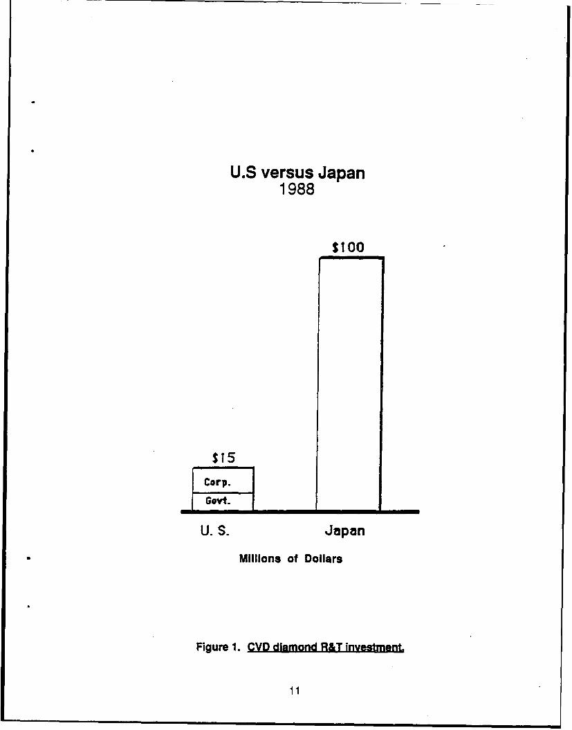
Although the history of CVD diamond synthesis will not be covered here, it canbe generalized as beginning with early Soviet and American work in the mid-50s,followed by Japanese and American studies in the late 70s (Table 2, based on Ref. 1).Most extensive work has been concentrated in Japan, as indicated by the patent historyshown in Table 3 from Ref. 2 and the relative R&D investment shown in Figure 1.
To obtain data on technology status, a standardized survey was prepared and sentto 82 of the groups believed to be active in some aspect of CVD diamond synthesis.Because of the importance of the Japanese work, a cross-section of 10 groups wascontacted through the efforts of Mitsui & Company, Ltd., which volunteered its servicesand allowed us to overcome the language barrier.
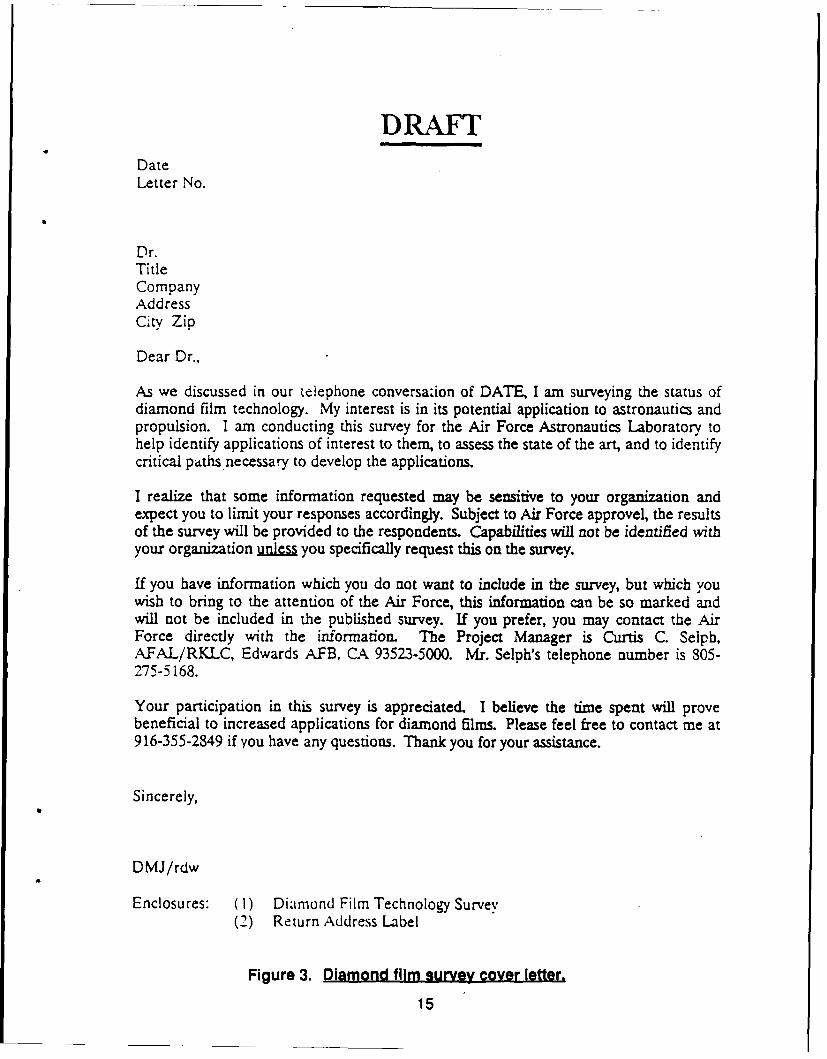
The survey process consisted of an initial telephone contact, followed bytransmittal of a copy of the survey with a descriptive cover letter (Figures 2 and 3).Responses were received from the 23 groups listed in Table 4. It is likely that somegroups believed that it was not in their best interest to respond to the survey although, infollow-up calls, this attitude was expressed by only one individual.
Respondents were cautioned not to include proprietary data in their responses,which further limited the data provided. Because of this factor and the selectiveresponses, the survey cannot be considered to be a statistically exact definition of thefield. It does provide a snapshot of the status of a significant number of research groupsand their approaches to diamond synthesis.
7
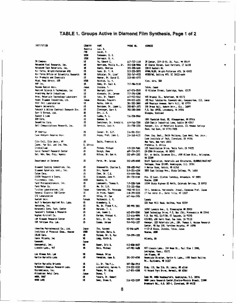
TABLE 1. Groups Active in Diamond Film Synthesis, Page 1 of 2
INSTITUTION COUNTRY NAME9 PHON NO. ADDRESSAustria Lu. B.F"I XodI. P.USS Fedessov. 0. N.USSR Dervain. a. V.
39 CoeanY US Yo. Edard C. 641-7T3-lll0 IN Canter, 21?-SS-QU. St. Paul. OH 5522Advanced Fuel esearcb. Inc. Us Horriso, Philip I.. Jr. 203-521-9"04 17 Chorch Strut. Est Hartford. CT 06109Advanced Tech Materljs, INC. US Bltz, Charles 203-3"5-2hl1 520-I Dabory Rd.Air Force, riqt-Pattersoe AF1 US Vans, Dr. T. V. 513-255-5192 A /NAL .N. Wriqht-Pitterson AFl. 014 45433Air Force Office of Sclntific Research US Schioler, Dr. Lise' 202-767-4933 Al ME. Balling AFl. CC 20332-6600Air Products and Chesicals US Hoover. Or. David S. 213-491-4772Akad. Mihk Ukrain. SEa USSR Nidich. Is. V. Kiev. Ukra. SRAMP Inc. US Dou, or. el ii 1. 717-96-5116Aaysoa Sakiun Univ. 4ea nuozuka, T. Tokyo, JapanAeliod Science i Technology, Inc US Bourget. Larry 17-976-5345 40 Allstn Street, Cambridge, Mass. 02139Arestrong World Industries uS ViseaOky, Dr. Jere 717-396-5238Arty, Materials Technology Laboratory US aCat, Dr. Robert 617-923-5262 405 Arsenal St., Wterto, MA 02172Aen11i Diamod Industries, Ltd. Juan Ouze. Fuesovrt 044-133-6221 18S ioji Takatso-ke, KanUaki-si, Kana-ken, 213, JuanATIT ?ell Laboratories US Mucha. John A. 201-52-00 600 Mountain AN~. wurry Hill, Q 07974Auburn University uS Davidson, Dr. Jam L. 205-87-l173 200 Drou Hall, Ashore Ulv.. All. . 36849hahcock & Wilcox Contract Research Div. uS Cl vinqar, Sary S. 70-3-2000 P.D. Do 10935, Lynchburg, VA 24504Barr I Stroud, Ltd. UK Orr, J. S. Slanpe, Scotlandhasch t Lost uS Cuobo. A. J. 716-338-5960lOw Carl. US nudo, B. 0t R adolph Road. SE, Albuaierme. 1117016BeasAlloy Coro. US Detchan. Dr. Arnold H. 614-764-3300 6340 Dublin Industrial Lane, mublin ON 43017Bell Coeunications Research, Inc. us Vernick. Jack H. 201-758-3350 Manager, Div. of Materials Science, 331 4man Sorings
load. Red Bank, 4J 07701-70203P aaerica us :eater. Dr. 6.P. 216-591-5311-ase eastern Reserve Univ. US Aruts, Prof. John C. 216-36-4133 Chet. Enq. Oact., Saith Buildinq, Case Next. Res. Ufiy.,
Case Institute of Tech. Cleveland, ON 44106City Col. City Univ., NY us Sith, Fredrick H. Men York, ke York 10031CounC. for Sci. and Ind. Re.. S. Africa Pretoria. S. AfricaCrvstallun US Plnanea. Mchael 415-324-901 125 Constitution Drive. Ionio Park. CA 94025lavid Sarnoff Research Center uS Sezaqb, Bat b0-734-2471 CN-5W3 Princeton, NJ 08543Cel. Adv. Res. Pros. Agency US Wilcox, Or. Ben A. 202-694-1303 Dir. of Htls. Sciences Div,. 1400 ilson Blvd., Arlington.
VA 22209Uisartment of Defense uS Persh. Mr. Jeroel 202-695-0 Staff Specialist. Materials and Structures, U5S" I£/RIAT/NST
Penta"ee, om 301019, labisqton, D.C. 20301Diamond Coating Industries. Inc. US NImo rth, Charles E. 5*455-9463 4 Mercer Road, Natick, NA 01760hiamond Materials Inst., Inc. US Orr, Reiner 814-231-6200 2120 Eat Colleqp Ave.. State College, PA, 16101Eaton Coro. uS Che, Dr. C.S. 414-441-7806.XION Research * Enqrg. uS Dlseukes, John P. 201-730-0100 die. 22 East. Clinton Touniip, Annandale, NJ OfOlFizicheskii lenst. USSR Susaa, A. Moscow, USSRFord Microelectronics, Inc. Us Lokoerski, Tbos R. 719-521-7600 10340 State Highway 83 North, Colorado Serinqs, C0 80921Ford Notor Co. uS He. Or. C.M. 313-322-046*-ifitso Laboratories. Ltd. lapn Kavarada. Or. Aotonobs 0462-41-3111 !0-1, akahiya. lortnoseto. Atsuqi, Ka4n4aea Pref. JapnSeneral Electric I&O Center iS Of Vril, obrt .1i-391-5223 17 Van Vart Or.. 3urnt qills, MY 12027iTE Laboratories US blas. Dr. s h17-466-2456Suelph Univ. Canada ,acdoaold, J. A. Canadaui4 I Western Applied Sci. Lobs. US Aionborg, 5. 3 leer HIIl Road, ealthan, Oets 02154Hercules, Inc. US Ho, Or. Floyd F.-L. 302-99 3521Hoimevell Corp. Tech. Center us Moravec. I. J. 10701 Lyedale A"e,. S. floeeinqton 0 534204O"Idoeell Syutam I Research uS Lue. Jaen C. Wt2-970-5200 3W Technoloqy Drive. P.O. Dox 1341. Minneapolis HN 534404ughe Aircraft Co. US irdles, MiChael A. 213-6Wi-919 P.D. Ion 902, EIFI50. El Segundo, CA 90245tel Alsaden Research Center uS Schi, Dr. Raj 400-927-1000 c33/802. 450 Marry Road. San lose. CA 95120IN Vrkton Mts. Lab. US Cale, Jeron 914-945-13 7 el gaaer. CC$ Materials Lab., IBN. Thoes J. Watson Research
Center, PO Bor 216, Porkte. Heights. MY 10598Idneitu Petrothulcal Co., Ltd. Japan Ito, Kazueui 03-54-640 4-12-l0 linae, Chuouku. Tokyo. JapanInstitute of Physical Chl., Muoe USSR Belitne, loris . %Kati, US IRIBLAI Core. US Sayeno, Dr. R. Ray 714-319-13MIonic tlsata, Inc US Legg, Kleth 0. Atlanta, BACaussaki JuanKeena-etsl, Iec. us lao . Eric 6. 412-638-2037Lincoln Laob., MIT US his, Michael 417-911-44 NIT ULcole Labs.. 244 Wood St.. Rail Stoe 1 300,
Lmniqto, Nass., 02173Los ilao Mat, Lab US Nees, Brian Las Alme. 0Martin Marietta Labs US onable, Ja . 0. 301-247-0700 beseciate hlretter, Martin N. Lobs., 1450 South lolling
Id., Baltmore, O 21227Nartl Marietta Orlando US Li, Dr. To PL. 407-31-914kNownl-loolns Rerch Lobs. us Lielefield, Hrvey V. 314-232-0212 lldq. 110, I 516, St. Lasis, NO 6314NIcrescitnce, Inc. US Popov, Dr. Clog 617-171-030 41 Accord Part Drlve, lorsell, M W201itedisbi ill Care. Jam N, Y.
"uIA, amI US FoNro, Dr. Rort Code IN. M Iadartors, W blnqiton, D.C. 20144NAMA LefC US Senc, Dian, N. 21k-433-2309 WS Lmls Reswch C0eter,1lctro-hyslcs Brach, 21006
rubtrt ft., 0.6. 301"I, Clovelaef, ON 44133
8
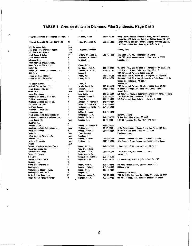
TABLE 1. Groups Active in Diamond Film Synthesis, Page 2 of 2
National Institute of Standards and Tech. US Fldman, Albert 301-975-5740 Brad Loader, Optical Materials krm, National birmas ofStandards, A257 Materials kildiq, Saitersburg, NO 20609
National Materials Advisory Board, NRC Us Lane, Or. Jose R. 202-334-3503 Senior Proan Officer, (1I01), atinal Ressarch CmciL,210t Constitation Ave., Washsigton, D.C. 20411
Mat. Aerospace Lab. JapanMat. Inst. Res. Inorganic Marts. Japan lobayashi, Tayobiko Sakara, Japanhat. space Dav. Aency Jaw"Naval Research Labs. US ltler, Dr. James E. 202-767-111 ail Code 6174, O., Washington, VC 20375Mval N o Cee US Scharti, Dr. Robert Cod T73, M Raval #spoons Canter, China Like, CA 91355Nebraka Univ. US k-Abud, G. Lincoln, noNorth Amricon Phillips Corn, USNorth Carolina State Univ. US glass, loffryMorton Co. US Dr. loll, Peter M. 00-795-5000 VP, Corp Tech., Une Men lad ST., orceter, MA 01606-2698Noton Co., Morton Christasen, Inc. US Biqelow, Dr. L. K. 0Ol-972-3140 2532 South 2270 vest, Salt Lake City, UT 84119OCL! Coro US ur,. H. 2789 Northaoint Parkway, Santa Ross, CAOffice of Mava Research uS Yoder, "as 703-696-4213 Code 1114Y, 900 M. GOincy St., Arlington, VA 22217-.000Office of Naval Technology US inna. Marlin 202-696-4791 Chairman, Joint Directors of Laboratory Tech. Panel, 000 N.
Quincy St., Arlington, VA 22217Old Doanion Univ. uS Albin. S. MOrfolk,VAOptical Coating Lab, Inc. US Afl, Joseph H. 707-545-6440 2789 Northpoint Parkway, 5S 121-1, Seanta Rosa, CA 15407Osasa Diamond Ind. Co. Japan Toiesnrt, H. 0722-62-1061 00 htorikita-acnizoho, Sakai-shi, Osaka. JaanOsaka Univ. Japan Suzuki, Juo-ichi suita, JapanPenn. State niv. uS Roy, Rultnu 14-963-1704 25 Materials Reearch Laboratory, University Part, ?A 10602Pewkin-Eleer Co., Mtco Div. us Reardon, Joseph 0. 516-334-1300 1101 Prospect Ave.. Westbury, MY 115Ohilips Laoratoitn US Ble, Strald 1-945-6000 345 Scarborough Road, Briarcliff lanor, MY 10510Phillips I Dupont otical Co. US Johnson, Or. George H. 302-999-4114PP9 Induatries. Inc. us f.Ich. Dr. Cletus A. 216-646-41fIRaytheon Copansy US Tustison, Dr. landail d. 617-660-3030Rssearch Triangle Inlst. uS Rudder, R. A.Rocktdyno. Inc. US Holly, Dr. Sander 81-700-4839Royal Sigals and Nadir Establish. aI LEttingtom, I. H. Halvers, EnglandScientific Research Aociates, Inc. US Bruin. Harold L. 203-659-0333 50 Nve Road, 61astonbory, CT 06033Shows Osnko K.K. Jason Kosaki, KuOio 03-733-0151 2-24-25 Taagaema, Ohta-kv, Tokyo, 146 JonanSoectrn Corn usStratabit, Inc. US 0seeis. Or. Mahlon 0. 713-999-4530Suitoao Electric Industries. Ltd. Jason Nishiera. A 03-423-5207 3-12. Notoakanaks. -COes. 4inato-ku, Tokyo, 107 JaanTenas Instruments US Purdes Andrew J. 214-"5-5559 0S 147 P.O. Bon 655?36. Dalls. '1 75265TOak, Univ. Japan lida. Rasaeori Wiratsuka. JananTokyo Univ. of 9r. i Tech. Japan Komatsu. K.Toshiba Coro. Jaon Saeab1 , Atsuito 044-549-2116 1 Kosukai Toshiba-tho Saina. iaNasali 210 Jaoan
Tottor Intvtrsitv ason Iiihiaort. X. 0657-28-0321 101, Rinaot 4-Choe., Kovaea-cho, 7ottori City, JapanT
Oyota Japas
Jeited technology Research Center iS Rosan, Ward C. 203-729-7000 Silver Line. 4S ?0. Eant 4artford, CT 16|08
Universal Energy Co. US Woo. Dr. Richard"yny sity yf Teas JS Collivo. CarJ 3. 21-290-211l 2601 Floyd Road, Richardson. ?1 75093
Jnt. :f Colorado iS Can, Aehoter C. 3oulder, CO'IT! Cor. 'iS nArooln. r. 4icholas 215-537-0700
'arian Renearcn Canter US Reynolds, Slyn 415-493-4000 ril Ratno Nay, ./S K-1O, Palo Alto. :A 9 303daveast, Inc. uSival State University US Pryor, ROger 1. 313-577-0146 6U Nest Hancock Street, Detroit, Rich 43202Westinghouse US Comstock, Robert 412-256-1277 Pittsburg, PAVostinghose Electric Corp. US leoco. Dr. S. 301-765-4617Westinghouse R&D Center US Choyke .UJ. Pittsburgh, PM 15235
5. J. Schafer Associates US Flaeing, Deenni P. 703-559-7100 (901 North Ft. Ayer r., unite 000, Arlinqton, VA 22209lerox Vebster Research Center US Machonkia, N.A. 716-422-9411 600 Philips Road. Ildo. [14-41D. Mebster, MY 14560
9
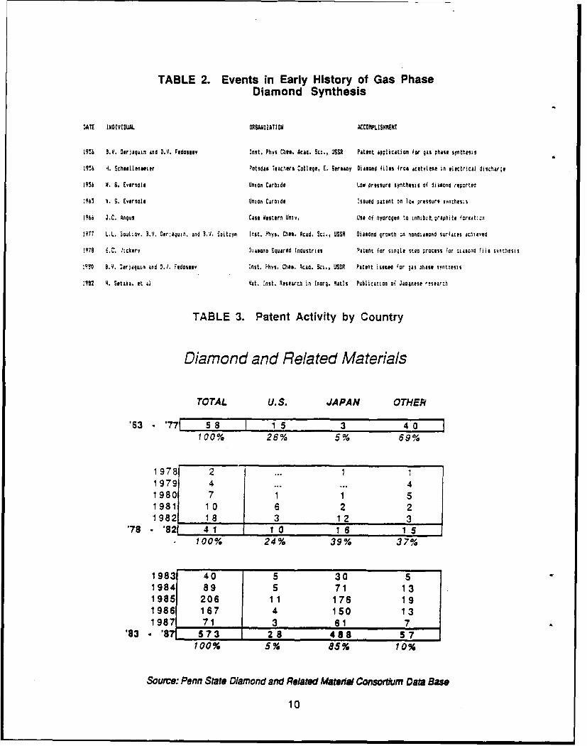
TABLE 2. Events in Early History of Gas PhaseDiamond Synthesis
DATE INOIVIDUAL ORSAHIZATION ACCOIPLISHMENT
19% 3.V. Derlquin find D.V. FIdoseIy lnst. Phts Chi,. Acid. Sci., USSR Patent application for gas phase synthesis
19%li H. Scftlilenseler Potsdas Teachers College, E. Streany Dia1ond files frca acetylene in electrical discharge
1956 9. S. Eversole Union Carbide Lov pressure synthesis of fijaond repcrted
.963 0. S. Eversole Union Carbide Issued patent on low pressure svnthesis
1196 J.C. Angus Case ofstern Untv, Use of hydrogen t onftbzt,,;rohte fcreat::n
1977 L.L. 3oulioy, 3.1. Ooragun. and S.. Spitzyn Itst. Phys. Chlt. Acid. Sc., USSR Diasond qr:wthl - nandiaond surfaces acleved
!979 -.. lickery Diamono Squired Industries Patent for single sto ;rocess For :iaaonc fiil OnwesIS
1930 a.v. .erjaquin and D,1. -idoslv inst. ,hlys. ChlMe Acid. Sci., USSR Patent issed 'or gas ;tast synthesis
1982 4. Setaka, at &I 4at. inst. Researcl in [norg. latis Publication of Jaoinese esearch
TABLE 3. Patent Activity by Country
Diamond and Related Materials
TOTAL U.S. JAPAN OTHER
'63 - '771 5 8 1 1 5 3 4100% 26% 5% 69%
1978 2 ... 1 11979 4 ...... 41980 7 1 1 51981 10 6 2 21982 1 8 3 1 2 3
'78 - '82 4 1 1 0 1 6 1 5100% 24% 39% 37%
1983 40 5 30 51984 89 5 71 13
1985 206 1 1 176 191986 167 4 150 131987 71 3 61 7
'83 - '87 573 2 8 488 57100% 5% 85% 10%
Source: Penn State Diamond and Related Materidal Consortium Data Base
10
U.S versus Japan1988
$I00
$15
Govt.
U. S. Japan
Millions of Dollars
Figure 1. CVD diamond R&T investment.
11
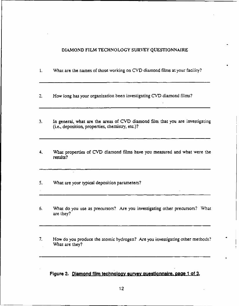
DIAMOND FILM TECHNOLOGY SURVEY QUESTIONNAIRE
1. What are the names of those working on CVD diamond films at your facility?
2. How long has your organization been investigating CVD diamond films?
3. In general, what are the areas of CVD diamond film that you are investigating(i.e., deposition, properties, chemistry, etc.)?
4. What properties of CVD diamond films have you measured and what were the
results?
5. What are your typical deposition parameters?
6. What do you use as precursors? Are you investigating other precursors? Whatare they?
7. How do you produce the atomic hydrogen? Are you investigating other methods?What are they?
Figure 2, Diamond film technology survey auestionnaire. page 1 of 3.
12
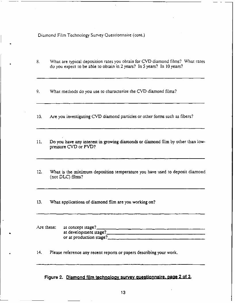
Diamond Film Technology Survey Questionnaire (cont.)
8. What are typical deposition rates you obtain for CVD diamond films? What ratesdo you expect to be able to obtain in 2 years? In 5 years? In 10 years?
9. What methods do you use to characterize the CVD diamond films?
10. Are you investigating CVD diamond particles or other forms such as fibers?
11. Do you have any interest in growing diamonds or diamond film by other than low-pressure CVD or PYD?
12. What is the minimum deposition temperature you have used to deposit diamond(not DLC) films?
13. What applications of diamond film are you working on?
Are these: at concept stage?at development stage?or at production stage?
14. Please reference any recent reports or papers describing your work.
Figure 2. Diamond film technology survey questionnaire. aage 2 of 3.
13
Diamond Film Technology Survey Questionnaire (cont.)
15. Please provide your comments on the status of diamond film technology, areasrequiring work, and assessment of applications.
16. Please provide any descriptive or promotional literature on your organization'scapabilities.
17. From your knowledge of the field, please provide names of other researchers whoshould be contacted for this survey.
-0-
You may may not include my organization's name in the list of survey respondents.(Circle One)
Survey Completed By:
Organization:
Please return to:
Bldg 2019-A2/Dept 9990Aerojet TechSystems CompanyP.O. Box 13222Sacramento, CA 95813-6000
Figure 2. Diamond film technology survey questionnaire, page 3 of 3.
14
DRAFTDateLetter No.
Dr.TitleCompanyAddressCity Zip
Dear Dr.,
As we discussed in our telephone conversazion of DATE, I am surveying the status ofdiamond film technology. My interest is in its potential application to astronautics andpropulsion. I am conducting this survey for the Air Force Astronautics Laboratory tohelp identify applications of interest to them, to assess the state of the art, and to identifycritical paths necessary to develop the applications.
I realize that some information requested may be sensitive to your organization andexpect you to limit your responses accordingly. Subject to Air Force approvel, the resultsof the survey will be provided to the respondents. Capabilities will not be identified withyour organization unl= you specifically request this on the survey.
If you have information which you do not want to include in the survey, but which youwish to bring to the attention of the Air Force, this information can be so marked andwill not be included in the published survey. If you prefer, you may contact the AirForce directly with the information. The Project Manager is Curtis C. Selph,AFAL/RKLC, Edwards AFB, CA 93523-5000. Mr. Selph's telephone number is 805-275-5168.
Your participation in this survey is appreciated. I believe the time spent will provebeneficial to increased applications for diamond films. Please feel free to contact me at916-355-2849 if you have any questions. Thank you for your assistance.
Sincerely,
DMJ/rdw
Enclosures: (1) Diamond Film Technology Survey(2) Return Address Label
Figure 3. Diamond film survey cover letter.
15
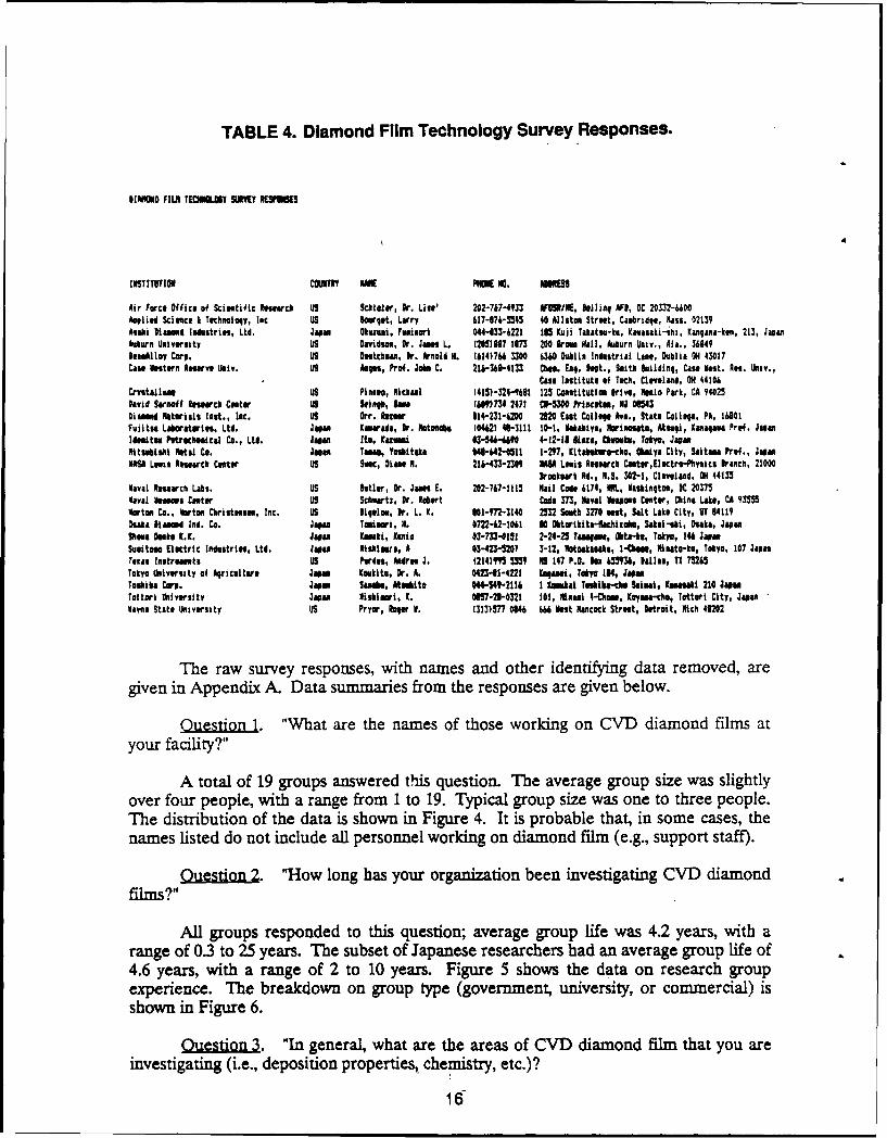
TABLE 4. Diamond Film Technology Survey Responses.
DIAMOND FIL TECNUNLI S1 YR P
INSTITUTION COUNM UK PHO0. ADRSS
Air Force Office of Scieutific Reearch us Skhioler, Dr. List' 202-767-4933 FDOSR/E, So1linq AFI, DC 20332-6600Applied Scimce & Techlology, Inc US iourqet, Larry 617-374-5M45 40 Allston Street, Csnbridge, mass. 02139kal Diaed Industries, Ltd. Japan Okezui, Feniori 044-33-6221 I0 Koji Takstst-ka, Kaasaki-mhi, Kanlaa-ton, 213, JapanAuburn University US Davidsn, Or. Jat L. (20)iW 1173 200 Iroin all, Auburn Univ., Ala., 36849leaAlloy Corp. US Dutchumn, Dr. Anold H. (614)7A 1300 6360 Dblia Industrial Lane, Dublin OH 43017Cae Intern Reserve Univ. US Aspt, Prof. Joke C. 216-366-4133 Chet. Eqi. Diet., Saith huildinq, Case Iet. Rv. Univ.,
Can Institute of Tech, Cleveland, OH 44106Cyetallei us Pinola, Michael 1415)-324-9631 125 Contitution Drive, Mtio Park, CA 94025David Sarnof Reearch Cantor US Shu , IeM (669)734 2471 C*-50 Priacetos, NJ 06143Diand Raterials last., loc. US Orr. Inur 114-231-6200 2320 East Coll@e Ave., State Collge, PA, 16801Fujit. Laboratories, Ltd. Joan Kasrads, Dr. otmhbs (042) 46-3111 10-1, lakahiyn, orisuto, Atuqi, lasaqaga Prof. Japan
ldesitsU Potrocheeical Co., Ltd. Jaa Ito, Cauwi 43-546-690 4-12-11 lia, Cemoki, Tokyo, JapaMiltitbisi Metal Co. Joa Yaw, Ytskitaka 04-642-0511 1-27, KLtshevo-che, 1 ay City, Sitna Prof., JapanMASA Lots Rnearcb Cantr US Sec, Diane M. 216-433-2309 MS5 Letis Research Coetor,ElKtr-Physics Branch, 21000
Brootpark Rd., H.S. 302-1, Cleveland, O 44135Naval Research Labs. uS Doller, Dr. Jane E. 202-767-1ll! ail Code 6174, W, iauingtoa, KC 20375Naval lestses Center US Schoartz, Dr. Robert Code 37, Nval Vnsels Cnter, China Lakte, CA 935M5Norton Co., Norton Christfese, Inc. US I19oloe, Dr. L. K. 001-M2-3140 2532 South 3270 est, Salt Lake City, UT D4119Osaka isetd Ind. Co. jaw Tannari, H. 0722-42-1041 30 Obtorikita-nchioko, Sakal-ski, Bska, JapsaShea Detk K.I. Japan0 Kiki, uin 03-7n-01 1 2-24-25 Taanae, Chta-k, Tokyo, 246 JapanSuiteo Electric Industries, Ltd. Jpe Nlhlmru, A 03-423-5207 3-12, otoakannk8, I-Co, Niueto-ku, Tokyo, 107 JapaTeias Ilstremstle US Pardun, Andre J. (214)095 5559 16 147 P.O. 05536, Dallas, TI 75245Tokyo University of Airiculture Japan Kowkits, Dr. A. 0423.41-4221 Koa, Tokyo IN, JapunToshiba Cor, Japan Sue, Atubito 044-549-2116 1 oemti TeMia-clie Saien, Knnki 210 JapseTottori University Japan liabisri, K. 0057-21-0321 101, Manl 4-Clom, Coyas-cho, Totturt City, JapanVas. State University US Pryor, Roqer V. (323)577 0846 666 eet Hancock Street, Detroit, ilch 40202
The raw survey responses, with names and other identifying data removed, aregiven in Appendix A. Data summaries from the responses are given below.
Ouestion 1. "What are the names of those working on CVD diamond films atyour facility?"
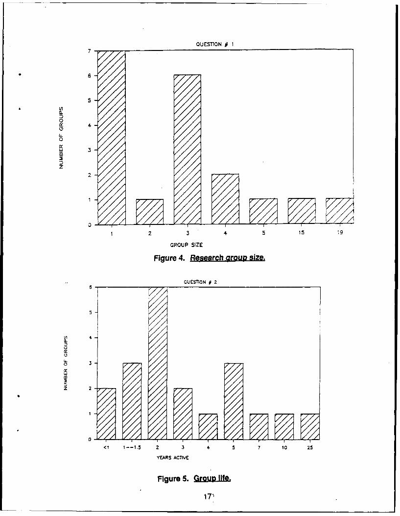
A total of 19 groups answered this question. The average group size was slightlyover four people, with a range from 1 to 19. Typical group size was one to three people.The distribution of the data is shown in Figure 4. It is probable that, in some cases, thenames listed do not include all personnel working on diamond film (e.g., support staff).
Ouestion 2. "How long has your organization been investigating CVD diamondfilms?"
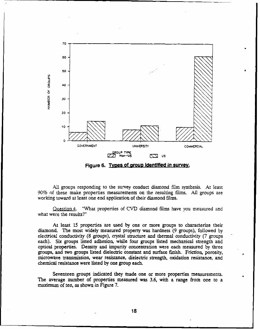
All groups responded to this question; average group life was 4.2 years, with arange of 0.3 to 25 years. The subset of Japanese researchers had an average group life of4.6 years, with a range of 2 to 10 years. Figure 5 shows the data on research groupexperience. The breakdown on group type (government, university, or commercial) isshown in Figure 6.
Queion3. "In general, what are the areas of CVD diamond film that you are
investigating (i.e., deposition properties, chemistry, etc.)?
16
QUESON # 17
56 -
0
z
,;71
1 2 3 4 5 15
GROUP SIZE
Figure 4. Researchgousi.
OUES'fON 412
54A) 4a-D0
U-
o
U
Z 2
<1 1-.5 2 3 4 5 7 10 25
YEARS ACTIVE
Figure 5. Qrw&IIIL%
17'
70 -
50
a.
00L0 .
ot
30
Z201
10
0
GOVERNMENT UNIVERSITY COMMERCIAL
ROUP TYPECM Non-US us
Figure 6. Tpes of group identified in survey.
All groups responding to the survey conduct diamond film synthesis. At least90% of these make properties measurements on the resulting films. All groups areworldng toward at least one end application of their diamond films.
Question 4. "What properties of CVD diamond films have you measured andwhat were the results?"
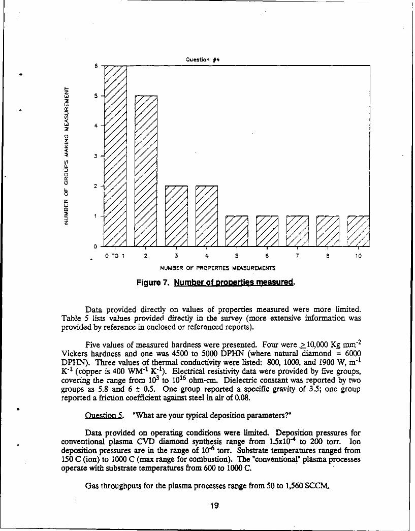
At least 15 properties are used by one or more groups to characterize theirdiamond. The most widely measured property was hardness (9 groups), followed byelectrical conductivity (8 groups), crystal structure and thermal conductivity (7 groupseach). Six groups listed adhesion, while four groups listed mechanical strength andoptical properties. Density and impurity concentration were each measured by. threegroups, and two groups listed dielectric constant and surface finish. Friction, porosity,microwave transmission, wear resistance, dielectric strength, oxidation resistance, andchemical resistance were listed by one group each.
Seventeen groups indicated they made one or more properties measurements.The average number of properties measured was 3.6, with a range from one to amaximum of ten, as shown in Figure 7.
18
Question #46
95
4.-
z
3
0 22
(r
Co /
D2 1 ////
z
0 2 i!I
0
OTO 1 2 3 5 6 7 a 10
NUMBER OF PROPERTIES MEASUREMENTS
Figure 7. Number of orooertles measured.
Data provided directly on values of properties measured were more limited.Table 5 lists values provided directly in the survey (more extensive information wasprovided by reference in enclosed or referenced reports).
Five values of measured hardness were presented. Four were >10,000 Kg mm 2
Vickers hardness and one was 4500 to 5000 DPHN (where natural diamond = 6000DPHN). Three values of thermal conductivity were listed: 800, 1000, and 1900 W, m-1
K-1 (copper is 400 WM "I K71). Electrical resistivity data were provided by five groups,covering the range from 103 to 1016 ohm-cm. Dielectric constant was reported by twogroups as 5.8 and 6 ± 0.5. One group reported a specific gravity of 3.5; one groupreported a friction coefficient against steel in air of 0.08.
uetion. "What are your typical deposition parameters?"
Data provided on operating conditions were limited. Deposition pressures forconventional plasma CVD diamond synthesis range from 1.5x10 "4 to 200 torr. Iondeposition pressures are in the range of 10-6 tor'. Substrate temperatures ranged from150 C (ion) to 1000 C (max range for combustion). The "conventional" plasma processesoperate with substrate temperatures from 600 to 1000 C.
Gas throughputs for the plasma processes range from 50 to 1,560 SCCM.
19'
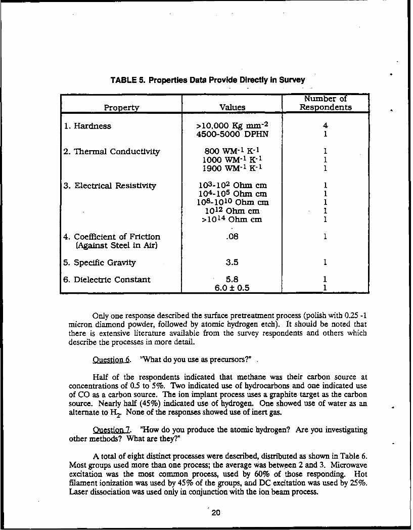
TABLE 5. Properties Data Provide Directly In Survey
Number ofProperty Values Respondents
1. Hardness >10,000 Kg mm- 2 44500-5000 DPHN 1
2. Thermal Conductivity 800 WM- 1 K-1 11000 WM- 1 K- 11900 WM K-1 1
3. Electrical Resistivity 10 3 -10 2 Ohm cm 1104-105 Ohm cm 1108 -10 10 Ohm cm 11012 Ohm cm 1>10 14 Ohm cm 1
4. Coefficient of Friction .08 1(Against Steel in Air)
5. Specific Gravity 3.5 1
6. Dielectric Constant 5.8 16.0 ± 0.5 1
Only one response described the surface pretreatment process (polish with 0.25 -1micron diamond powder, followed by atomic hydrogen etch). It should be noted thatthere is extensive literature available from the survey respondents and others whichdescribe the processes in more detail.
Q. "What do you use as precursors?"
Half of the respondents indicated that methane was their carbon source atconcentrations of 0.5 to 5%. Two indicated use of hydrocarbons and one indicated useof CO as a carbon source. The ion implant process uses a graphite target as the carbonsource. Nearly half (45%) indicated use of hydrogen. One showed use of water as analternate to H2. None of the responses showed use of inert gas.
Qui . "How do you produce the atomic hydrogen? Are you investigatingother methods? What are they?"
A total of eight distinct processes were described, distributed as shown in Table 6.Most groups used more than one process; the average was between 2 and 3. Microwaveexcitation was the most common process, used by 60% of those responding. Hotfilament ionization was used by 45% of the groups, and DC excitation was used by 25%.Laser dissociation was used only in conjunction with the ion beam process.
20
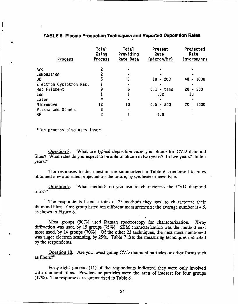
TABLE 6. Plasma Production Techniques and Reported Deposition Rates
Total Total Present ProjectedUsing Providing Rate Rate
Process Process Rate Data (micron/hr) (micron/hr)
Arc 2 -Combustion 2 -
DC 5 3 10 -200 40 1000Electron Cyclotron Res. 1 -
Hot Filament 9 6 0.1 tens 20 - 500Ion 1 1 .02 30Laser * -
Microwave 12 10 0.5 500 20 - 1000Plasma and Others 3 -
RF 2 1 1.0
*Ion process also uses laser.
Question 8. "What are typical deposition rates you obtain for CVD diamondfilms? What rates do you expect to be able to obtain in two years? In five years? In tenyears?"
The responses to this question are summarized in Table 6, condensed to ratesobtained now and rates projected for the future, by synthesis process type.
Ouestion 9. "What methods do you use to characterize the CVD diamondfilms?"
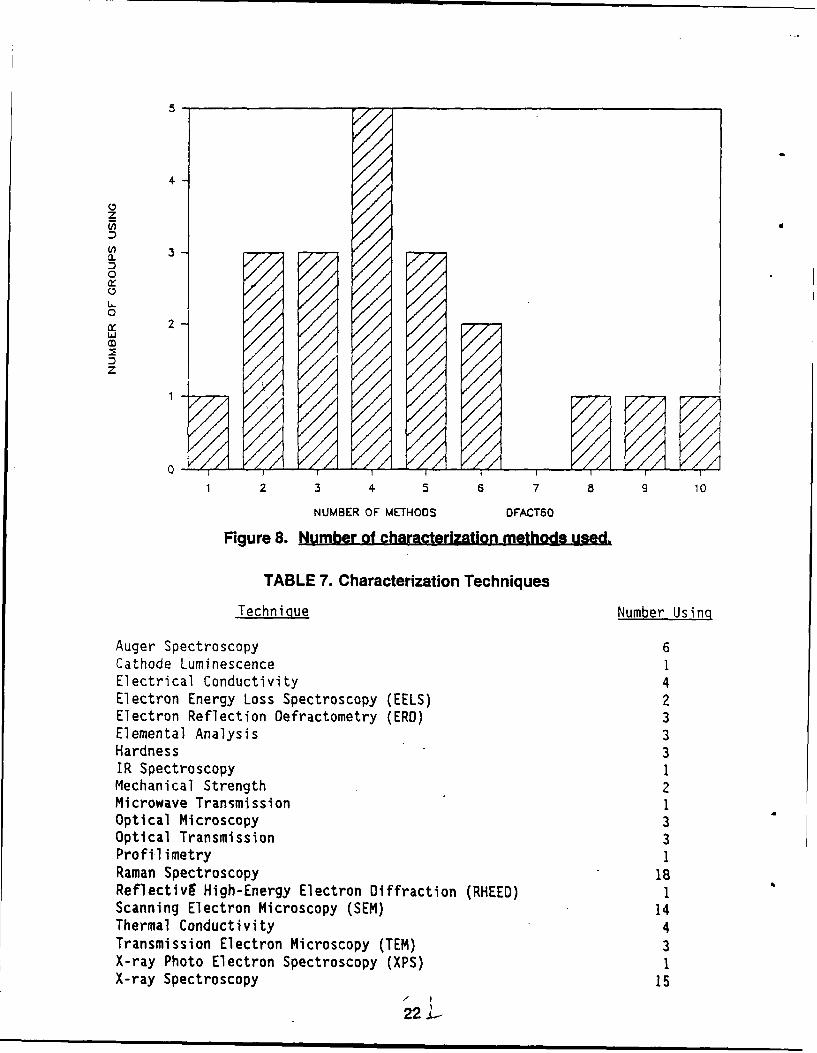
The respondents listed a total of 25 methods they used to characterize theirdiamond films. One group listed ten different measurements; the average number is 4.5,as shown in Figure 8.
Most groups (90%) used Raman spectroscopy for characterization. X-raydiffraction was used by 15 groups (75%). SEM characterization was the method nextmost used, by 14 groups (70%). Of the other 23 techniques, the next most mentionedwas auger electron scanning, by 25%. Table 7 lists the measuring techniques indicatedby the respondents.
Quion 10. "Are you investigating CVD diamond particles or other forms- suchas fibers?"
Forty-eight percent (11) of the respondents indicated they were only involvedwith diamond films. Powders or particles were the area of interest for four groups(17%). The responses are summarized in Table 8.
21
4
W, 3
2
cx
0
L../
01
I/j/
NUMBER OF METHODS DFACTS0
Figure 8. Number of characterization methods used.
TABLE 7. Characterization Techniques
Techni oue Number Using
Auger Spectroscopy 6Cathode Luminescence 1Electrical Conductivity 4Electron Energy Loss Spectroscopy (EELS) 2Electron Reflection Defractometry (ERD) 3Elemental Analysis 3Hardness 3IR Spectroscopy 1Mechanical Strength 2Microwave Transmi ssi on 1Optical Microscopy 3Optical Transmission 3Profil imetry IRaman Spectroscopy 18ReflectivE High-Energy Electron Diffraction (RHEED) 1Scanning Electron Microscopy (SEM) 14Thermal Conductivity 4Transmission Electron Microscopy (TEM) 3X-ray Photo Electron Spectroscopy (XPS) 1X-ray Spectroscopy 15
22 L
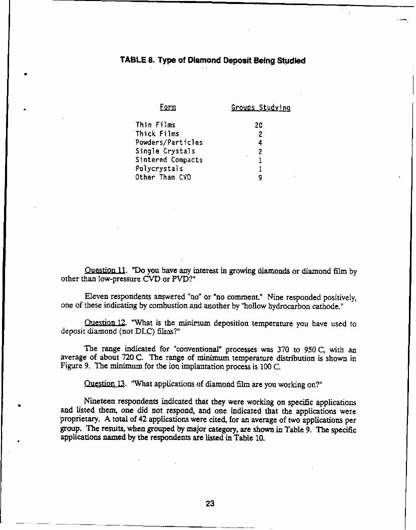
TABLE 8. Type of Diamond Deposit Being Studied
Form Groups Studying
Thin Films 20Thick Films 2Powders/Particles 4Single Crystals 2Sintered Compacts 1Polycrystals 1Other Than CVD 9
OutionJ..1. "Do you have any interest in growing diamonds or diamond film byother than low-pressure CVD or PVD?"
Eleven respondents answered "no" or "no comment." Nine responded positively,one of these indicating by combustion and another by "hollow hydrocarbon cathode."
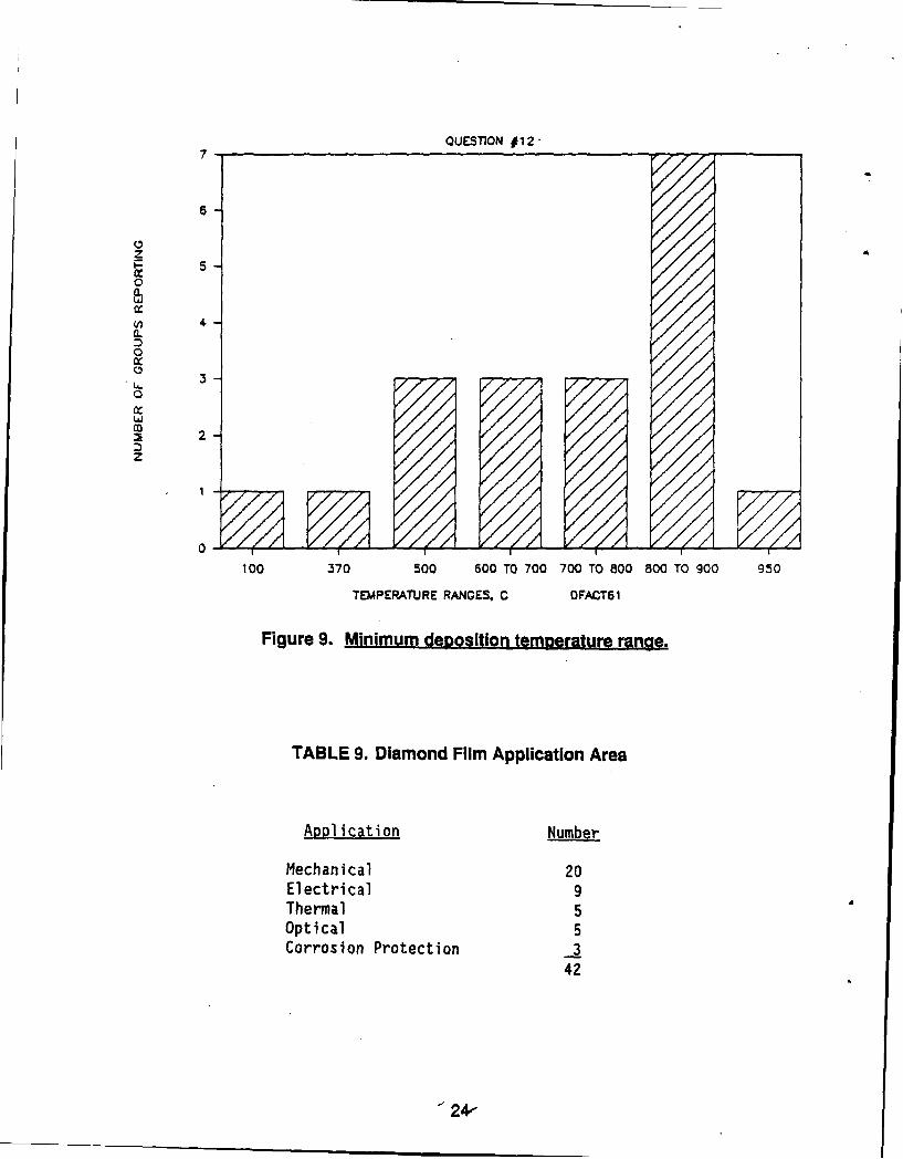
tion 12. "What is the minimum deposition temperature you have used todeposit diamond (not DLC) films?"
The range indicated for "conventional" processes was 370 to 950 C, with anaverage of about 720 C. The range of minimum temperature distribution is shown inFigure 9. The minimum for the ion implantation process is 100 C.
Q. "What applications of diamond film are you working on?"
Nineteen respondents indicated that they were working on specific applicationsand listed them, one did not respond, and one indicated that the applications wereproprietary. A total of 42 applications were cited, for an average of two applications pergroup. The results, when grouped by major category, are shown in Table 9. The specificapplications named by the respondents are listed in Table 10.
23
QUESTION #12
6
0
0
LA
2n 4
00
10 7 0 0 O7070,O8080T 0 5
TEPRTR0AGS FC6
Fiue9 iiu t stintmaauerne
Figre . inimu eiin tepeuer ne
Mechanical 20Electrical 9Thermal 5Optical 5Corrosion Protection 3
42
24,
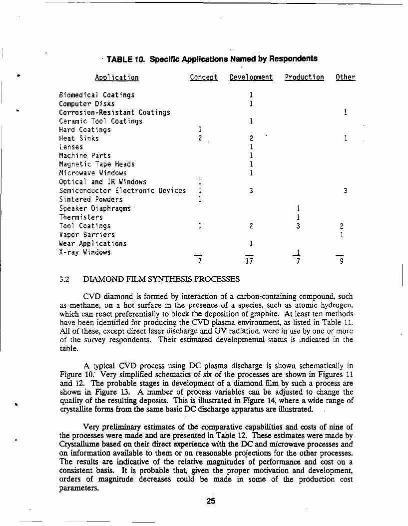
TABLE 10. Specific Applications Named by Respondents
Application Concept Development Production Other
Biomedical Coatings IComputer Disks ICorrosion-Resistant Coatings 1Ceramic Tool Coatings 1Hard Coatings 1Heat Sinks 2 2 1Lenses 1Machine Parts 1Magnetic Tape Heads 1Microwave Windows IOptical and IR Windows ISemiconductor Electronic Devices 1 3 3Sintered Powders 1Speaker Diaphragms 1Thermisters 1Tool Coatings 1 2 3 2Vapor Barriers 1Wear Applications 1X-ray Windows I
7 17 7 9
3.2 DIAMOND FILM SYNTHESIS PROCESSES
CVD diamond is formed by interaction of a carbon-containing compound, suchas methane, on a hot surface in the presence of a species, such as atomic hydrogen.which can react preferentially to block the deposition of graphite. At least ten methodshave been identified for producing the CVD plasma environment, as listed in Table 11.All of these, except direct laser discharge and UV radiation, were in use by one or moreof the survey respondents. Their estimated developmental status is indicated in thetable.
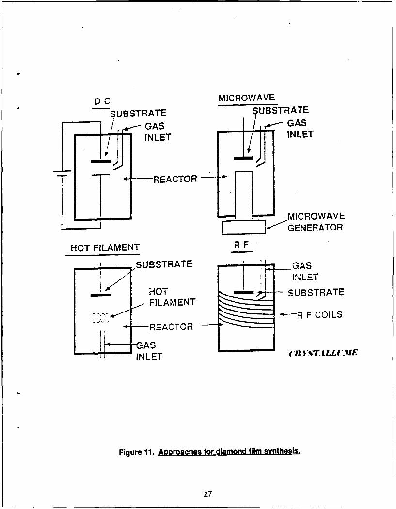
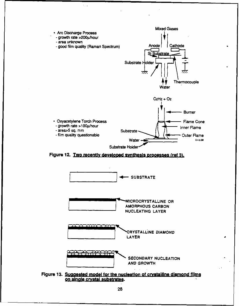
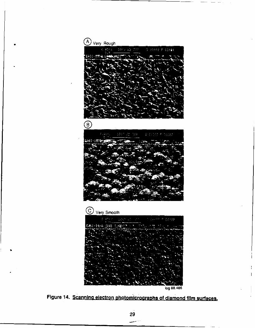
A typical CVD process using DC plasma discharge is shown schematically inFigure 10: Very simplified schematics of six of the processes are shown in Figures 11and 12. The probable stages in development of a diamond film by such a process areshown in Figure 13. A number of process variables can be adjusted to change thequality of the resulting deposits. This is illustrated in Figure 14, where a wide range ofcrystallite forms from the same basic DC discharge apparatus are illustrated.
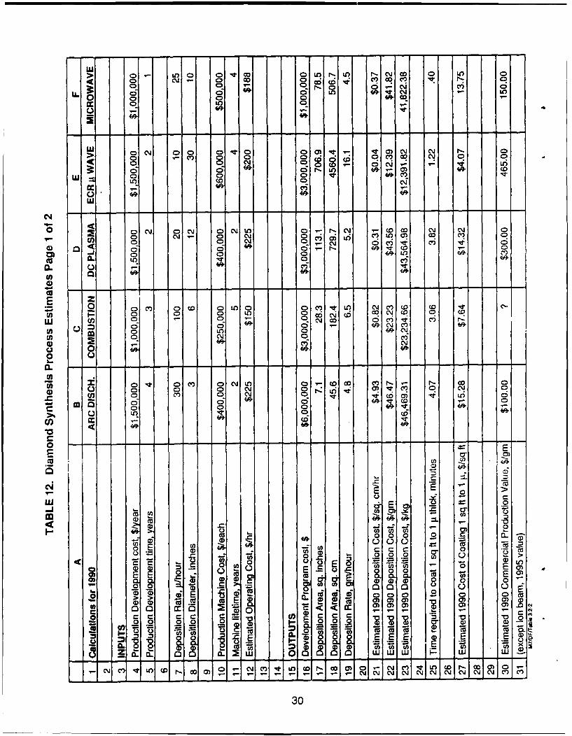
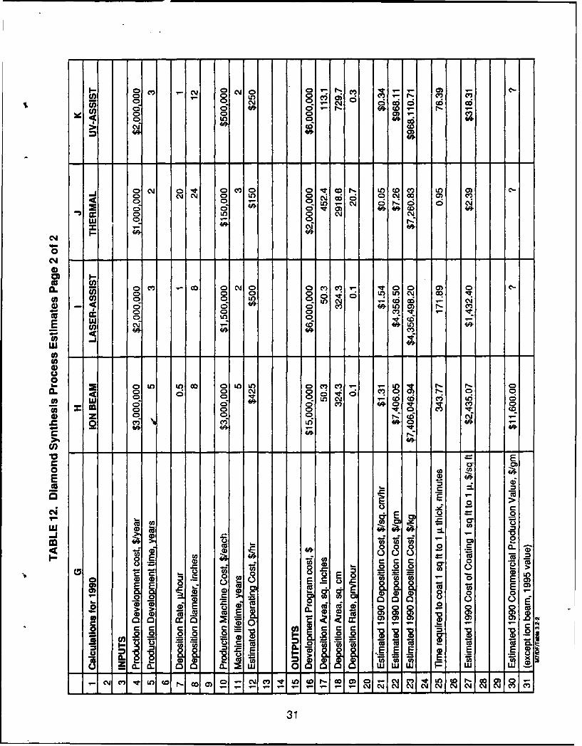
Very preliminary estimates of the comparative capabilities and costs of nine ofthe processes were made and are presented in Table 12. These estimates were made byCrystallume based on their direct experience with the DC and microwave processes andon information available to them or on reasonable projections for the other processes.The results are indicative of the relative magnitudes of performance and cost on aconsistent basis. It is probable that, given the proper motivation and development,orders of magnitude decreases could be made in some of the production costparameters.
25
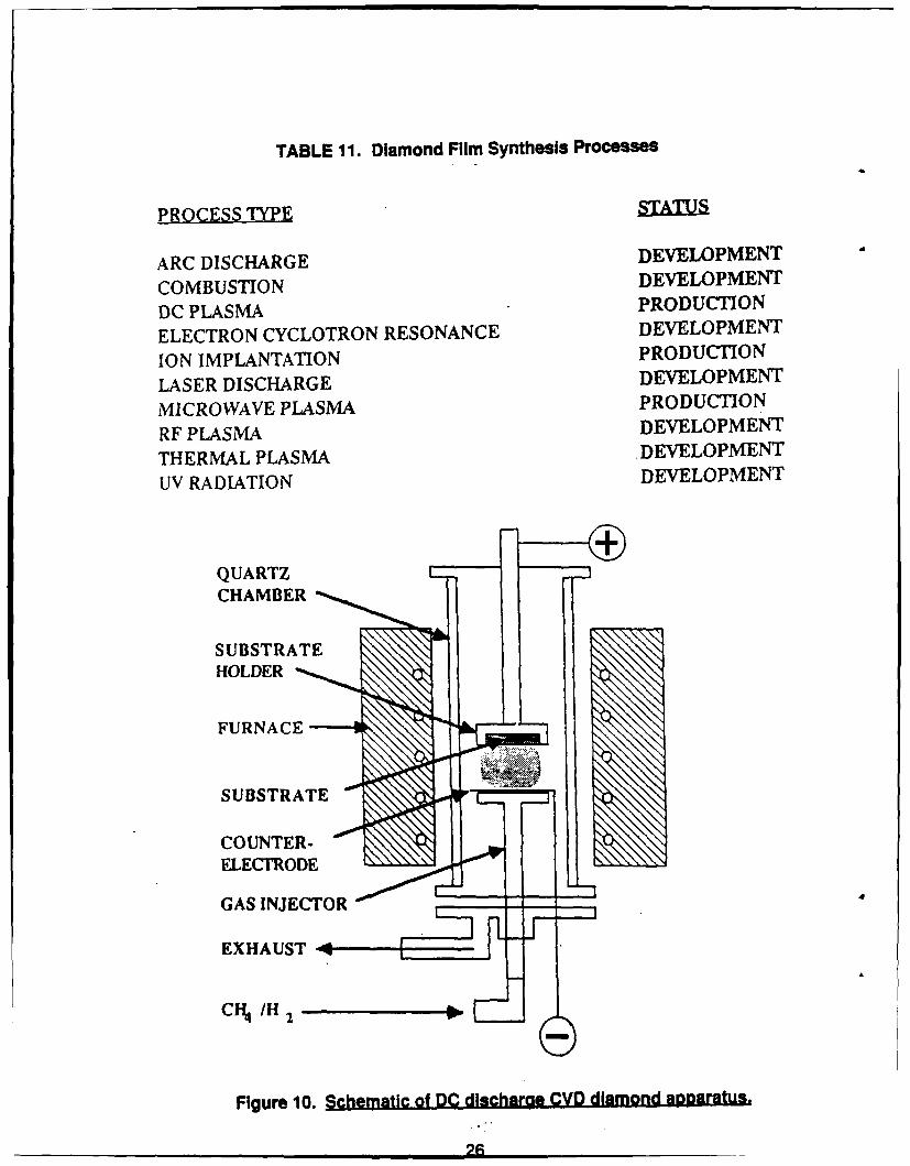
TABLE 11. Diamond Film Synthesis Processes
PROCESS TYPE STATUS
ARC DISCHARGE DEVELOPMENT
COMBUSTION DEVELOPMENT
DC PLASMA PRODUCTION
ELECTRON CYCLOTRON RESONANCE DEVELOPMENT
ION IMPLANTATION PRODUCTION
LASER DISCHARGE DEVELOPMENT
MICROWAVE PLASMA PRODUCTION
RF PLASMA DEVELOPMENT
THERMAL PLASMA DEVELOPMENT
UV RADIATION DEVELOPMENT
QUARTZCHAMBER
SUBSTRATEHOLDER
FURNACE --- l" --
SUBSTRATE
COUNTER-ELECTRODE
L-
GAS INJECTOR
EXHAUST S i o D disc" d
CN /H2
Figure 10. Schematic-of DQ dlscharge CVD diamond aRoaratu.
D C MICROWAVE
SUBSTRATE 7UBSTRATE
/ GAS GAS
INLET INLET
REACTOR
MICROWAVE
EI1A~G EN ERATOR
HOT FILAMENT R F
HOT SUBSTRATEFILAMENT
JjREACO ,FCOL
INLET (lIL f
Figure 11. Approaches for diamond film ynthesis.
27
Mixed GasesArc Discharge Process
- growth rate >200pdhour *- area unknown- good film quality (Raman Spectrum) Anode Cathode
Substrate 1older
S ThermocoupleWater
C2H2 + 02
- -- Burner
* Oxyacetylene Torch Process No- Flame Cone- growth rate >1 OOphour Inner Flame- area>5 sq. mm Substrate- film quality questionable Outer Flame
Water -- 2-4.0.68
Substrate Holder,''
Figure 12. Two recently develooed synthesis processes (ref 31.
-4 -- SUBSTRATE
-MICROCRYSTALLINE ORAMORPHOUS CARBONNUCLEATING LAYER
]".RYSTALLINE DIAMOND
~ ~SECONDARY NUCLEATIONAND GROWTH
Figure 13. Suggested model for the nucleation of crystalline diamond films
on single crystal substrates.
28
* Very Rough
OVery Smooth
log 88.486
Figure 14. Scanning electron Uhotofilcroaraghs of diamond film surfaces,
29
o LO aCO C) 14 co0f- ic
o. 0 -f NL0 0 0 C
C.69.
ON0 0 0 0 O 'IT 00~ qt CD 0l
>0 0 a ( 6 C RWi 0 0 0 0 - 0C* tL
I n 0 - L 4 C
040 ON ON 0C 0 C~l ) a -r- N~ T- CDOD N N 0D
-00 0cl~i i 6 C U0 q O Cl 00 0\ N
0 N) -c' cr) 'I 6
C5 6p, 6c dtV- C)
(5 al. 64 0n
C6 -
Cu0 0 0 to 0Lc 0 COm CO CONC 0r CD
w I 0D 0) C) 0 0 0'' c',It r-Cu & gc &~ - 0'
0 0 06
_-C'I C'
U)
zCu 3 0 IT 0 c) 0 Nm to~ 0 DC fr.r- DCO
4) 0) C) C0 m 0 1-4 Lr 6 I l cl 0 cr 0 N0 ~ ItT C to0 1 OC
0 0 09t 9
0Q In (d'
VA -- C D" I
E >-
(a- (M C
IaIds 0 0 0 _C
conf E .C
(D000'&0 .X- En- -c 2 I
I-- )-0. - (D In-0 0 (n
4) 0) (DC L 0
OCI) 0 C WIV 0 ~ o0. >0 a .cl
> E0i0 tw -) ' C9 ODO8 -
*6 0 <O 0<
00 .0C cuE E @7 ' r 7
=~ E S E E E E E CLt
(D 0 (a
30
CD) 0M 0 'y0 M 7)O0 Lc) 0 CV C
0 0M Ci o-UI, 0)o C C 6
N; G4 C) GO), (D Qr C
4 Mq 0 0 Lfli- ONO 0r NO (
-0 0 N )CLu 0 -~ 0CM
CJ~
0
CM
Otl i-CD ON OCr), 00O (DC300 M 4 0 CIL 0 0 4 ULL) N CR
(I,0 IL) 0 ION0 -CDD . N~C; 0e 0 0 cr) 69.LAO0) Nr cr)
-D 00 0V I
'U0 H. 0 o 0 Di 0C O n1
CD Nm C; 4 U ~69 D1q
Cut00i
* Z 0 06. NN-
0c C' ' C O
C-4 Y. -
E 0cc c_ c-
UU0)C 040).
0 - 0
I- _ LoC C ~ C
0 h.
>3 >u ccE I 0
c, 0 cur 0 z u.E
02 0 0 0002 9 s'5s t5 ~ B3 ii cG 1Cu S. CU
CL~NN ' CL')MAC') u
31
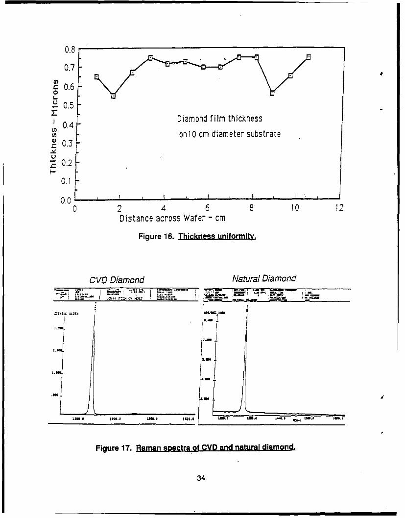
Present processes, such as DC and microwave discharge deposition, are operatedmuch eke microelect-ronic chip production. Figures 15 and 16 illustrate a typicalsynthesis form, a 4-in. wafer, and show the uniformity of composition and depositionthickness achieved.
As noted in Section 3.1, Raman spectra are universally used to characterizediamond films since they can distinguish between diamond and graphite. Ramanspectra for CVD diamond and natural diamond are compared in Figure 17.
If a need arose for continuous production of diamond film in large quantities,there are techniques which should be adaptable. Vacuum plasma sputtering processesare in routine production of coatings on continuous films, both nonmetallic and metallic,which are meters wide and kilometers long. Such a process could provide inexpensivediamond film for layered composite structures for engineering applications, for example.
Recent European processes for production of CVD diamond particles producecrystal deposits on filaments like beads on a string, which are then stripped off for use incutting tools and abrasives.
A barrier to use of diamond film is process incompatibility with the substrate.This can be due to excessive process temperature, adverse chemical attack such ashydride formation, inadequate nucleation, or inadequate bonding. Some of thesedeficiencies may be cured by flash-coating the surface with a compatible material beforediamond deposition. Nucleation and bonding sites are typically provided by scratchingthe surface microscopically with fine diamond powder.
Diamond film adherence on metal surfaces is thought to be enhanced byformation of an initial carbide layer. Carbide formation characteristics of a range ofelements are shown in Table 13. It should be noted, however, that this is not a sufficientcriterium. Iron, for example, forms a stable carbide but is not a good substrate forreasons that are not well understood.
Actual coating experience on a limited set of metals, oxides (A120 3 and SiO 2),carbides (SiC, TiC, and WC), and nitrides (BN, SiN), is shown in Table 14.
3.3 PROPERTIES OF DIAMOND FILM
An extensive properties literature exists for natural diamond. Only a few of theseproperties have been unambiguously measured for diamond film. Properties listedbelow have been gathered from the literature, from the diamond film technology survey,from measurements in this program, and from other programs which are in progress.
3.3.1 Published Literature Data-A summary of properties for naturaldiamond and CVD diamond is given in Table 15. The data presentation is based onproperties summary given in Ref. 4, which has been extensively updated.
Some of the more interesting properties of diamond are compared tothose of other engineering materials in Tables 16 and 17 (from Ref. 5). This highlightsthe unusual friction, hardness, thermal conductivity, modulus, and semiconductorcapabilities of diamond.
- m •32
- - I C
C
0
0E20
U
1'~ Lr- A - S -
7 :. /'C
. t'S Is
iji t
'A ~ S
- . ~.- .. Ji .~ _______________
.33
0.8
0.7
0.6: 0.5
0. Diamond film thickness0.4
on 1 0 cm diameter substrate0.3
- 0.2
0.1
0.0 ,0 2 4 6 8 10 12
Distance across Wafer - cm
Figure 16. Thickness uniformity.
CVD Diamond Natural Diamond- ce. ,,,"...• :fl ;o, .*-'- . .. ...._- - i n ",= ." . .....,,,-". ".-,. i . _,., = ., - .,- ... _ wr_. - .. --.
i~,& ..@O =, I -. ... . .
-' : - S"' ., . i z .-- i
' icUii4 'Mz I A M~a
I I
Figure 17. Raman spectra of CVD and natural diamond.
34
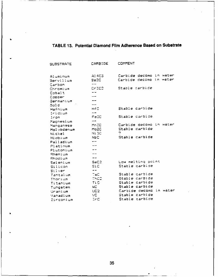
TABLE 13. Potential Diamond Film Adherence Based on Substrate
SUBSTRATE CARBIDE COMMENT
Aluminum A14C3 Carbide decomo in water
Beryllium Be2C Carbide decOmo in water
Carbon --
Chromium Cr3C2 Stable =arbide
Cobalt --
Coooer --
Germanium --
Sold --
Hafnium HfC Stable carbide
Ir idium --
iron Fe7C Stable carbide
Maonesium --
Manganese MnZC Carbide decomo in water
Molybdenum Mo2C Stable carbide
Nickel Ni 3CNicbium NbC Stable carbide
Palladium --
Platinum --
Plutonium --
Rhenium --
Rhodium --
Selenium SeC2 Low melting moint
Silicon SiC Stable carbide
Si lver --
Tantalum TaC Stable carbide
Thorium -hC2 Stable carbide
Titanium TiC Stable carbide
Tungsten WC Stable carbide
Uranium UC2 Carbide decomo in water
Vanadium VC Stable carbide
Zirconium ZrC Stable carbide
35
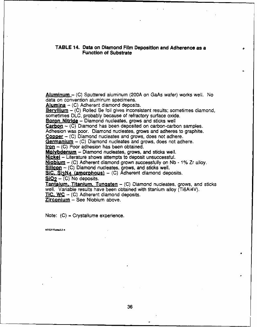
TABLE 14. Data on Diamond Film Deposition and Adherence as aFunction of Substrate
Aluminum - (C) Sputtered aluminum (200A on GaAs wafer) works well. Nodata on convention aluminum specimens.Alumina - (C) Adherent diamond deposits.Beryllium - (C) Rolled Be foil gives inconsistent results; sometimes diamond,sometimes DLC, probably because of refractory surface oxide.BoronaNi1 ide - Diamond nucleates, grows and sticks wellCarbon - (C) Diamond has been deposited on carbon-carbon samples.Adhesion was poor. Diamond nucleates, grows and adheres to graphite.Copper - (C) Diamond nucleates and grows, does not adhere.Germanium - (C) Diamond nucleates and grows, does not adhere.Iron - (C) Poor adhesion has been obtained.MolydeI.m - Diamond nucleates, grows, and sticks well.Nickel - Literature shows attempts to deposit unsuccessful.Niobium - (C) Adherent diamond grown successfully on Nb - 1% Zr alloy.Silicon - (C) Diamond nucleates, grows, and sticks well.SiC. Sin& (amorphous) - (C) Adherent diamond deposits.f - (C) No deposits.Tantalum, Titanium, Tungsten - (C) Diamond nucleates, grows, and stickswell. Variable results have been obtained with titanium alloy (Ti6AI4V).TiC, WC - (C) Adherent diamond deposits.Zirconium - See Niobium above.
Note: (C) = Crystallume experience.
M7/DF/Table3.2-4
36
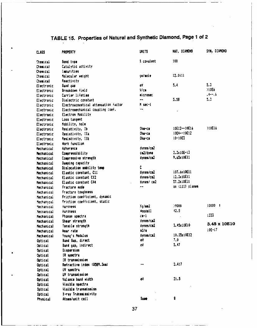
TABLE 15. Properties of Natural and Synthetic Diamond, Page 1 of 2
CLASS PROPERTY UNITS NAT. DIMOND SYN. DIMOND
chemical Bond type % covalent !00
Chemical Catalytic activityChemical ImuritiesChemical Molecular oeight go/mol 12.0111
Chemical ReactivityElectronic Band gap eV 5.4 5.3
Electronic Breakdown field V/ca )IOEb
Electronic Carrier lifetime microsec
Electronic Dielectric constant -- 5.55Electronic Electroacoustical attenuation factor M sec-I
Electronic Electromechanical coupling cof. --
Electronic Electron MobilityElectronic Loss tangentElectronic Mobility, holeElectronic Resistivity, lb Ohm-cA IOE12--10E16 >10EI6
Electronic Resistivity, Ila Ohs-cA 1OE4--IOE!2
Electronic Resistivity, lIb Ohm-cA l0-10E3
Electronic Work functionMechanical Adherence dynes/ca2
Mechanical Compressibility cW2/dynm 2.3xiOE-13
Mechanical Compressive strength dyneucm2 9.65xlOEtl
Mechanical Damping capacityMechanical Dislocation mobility tap CMechanical Elastic constant, C11 dynes/c&2 107.xlOEIt
Mechanical Elastic constant C12 dynes/ca2 12.SxlOEII
Mechanical Elastic constant C44 dynes/ cm2 57.2xlOEll
Mechanical Fracture mode -- on (111) planes
Mechanical Fracture toughnessMechanical Friction coefficient, dynamicMechanical Friction coefficient. staticlecnanical 'araness Ko/mm2 )9000 10000 1
Mecnanical Hardness Woodell 42.5
Mechanical Phonon spectra ca-I 133
Mechanical Shear strength dynet/cm2
Mechanical Tensile strength dyns/Wc2 3.45xlOElO 3.45 z lOE10
Mechanical Wear rate e3I 1OE-17
Mechanical Young's Modulus dynesic&2 10.33xlOE12
Optical Band Gap, direct eV 7.0
Optical Band gap, indirect eV 5.47
Optical DispersionOptical IR spectraOptical IR transmissionOptical Refractive index (358Y.3nm) -- 2.417
Optical UV spectraOptical UV transmissionOptical Valance band width eV 21.5Optical Visible spectraOptical Visible transmissionOptical X-ray TrineaissivityPhysical Atoms/unit cell Same 9
37
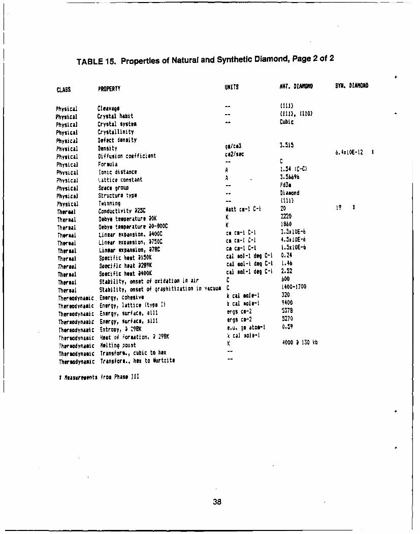
TABLE 15. Properties of Natural and Synthetic Diamond, Page 2 of 2
CLASS PROPERTY UNITS NAT. DIAMOND SYN. DIANOND
Physical Cleavage -- {1)
Physical Crystal habit -- 11), (110)
Physical Crystal system -- Cubic
Physical Crystallinity
Physical Defect densityPhysical Density W/sca3 3.515
Physical Diffusion coefficient cC2/si 6.4xt0E-12
Physical Formula -- C
Physical Ionic distance A .54 (C-C)
Physical Lattice constant A e.5M96
Physical Sace group -- FdimPhysical Structure type -- (111)Physical Twinning - - 1 10!}Thermal Conductivity 25C att ce-I C-I 20 19
Thermal Debyg temperature 0K K 2220
Thermal Debye temperature @0-00C K 8I60
Thermal Linear expansion, 3400C ce ca-I C-I 3.5xIOE-
Thermal Linear expansion, 2750C ce c2-I C-I 4.SxIOE-6
Thermal Linear expansion, 78C cA cu-I C-I 1.3xlOE-6
Thermal Specific heat 2150K cal aol-I dog C-I 0.24
Thermal Soecjfic beat 2299K cal ol-I deg C-I 1.46
Thermal Specific heat 4400K cal mol-I dog C-I 2.52
Thermal Stability, onset of oxidation in air C 600
Thermal Stability, onset of graphitization in vacuum C 1400-1700
Thermodynamic Energy, cohesive k cal mole-I 320
Thermodynamic Energy, lattice (type I) k cal 1oe-1 9400
Thermodynamic Energy, surface, elil ergs ca-2 5378
Thermodynamic Energy, surface, sill ergs ca-2 5270
Thermodynamic Entropy, ; 29K 1.u. Im atom-I 0.59
Thermodynamic Heat of formation, ; 298K k cal sole-I
Thermodynamic Melting point K 4000 1 130 kb
Thermodynamic Transform., cubic to hex ""
Thermodynamic Transform., hex to Vurtzite --
I Measurements from Phase III
38
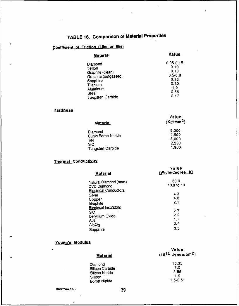
TABLE 16. Comparison of Material Properties
Coefficient of Friction (Like or like)
MaeilValue
Diamond 0.05-0.15Teflon 010Graphite (clean) 0.10Graphite (outgassed) 0.5-0.8Sapphire 0.15Titanium 0.60Aluminum 1.9Steel 0.58Tungsten Carbide 0.17
Value
Material (Kg/mm 2 )
Diamond 9,000Cubic Boron Nitride 4,500TiN 3,000SiC 2,500Tungsten Carbide 1,900
Thermal Conductivity
ValueMaeil(W/cm/dearee K _
Natural Diamond (max.) 20.0CVD Diamond 10.0 to 19Electrical ConductorsSilver 4.3Copper 4.0Graphite 2.1F1etrfH-l fisulators
sic 2.7SiC2.
Beryllium Oxide 2.2AIN 1.7A120 3
0.4
Sapphire 0.3
Young's Modulus
Value
Material (1012 dynes/cm2 )
Diamond 10.35Silicon Carbide 7.0Silicon Nitride 3.85Silicon 1.9Boron Nitride 1,5-2.51
W ,FrrO, 3.3.-1 39
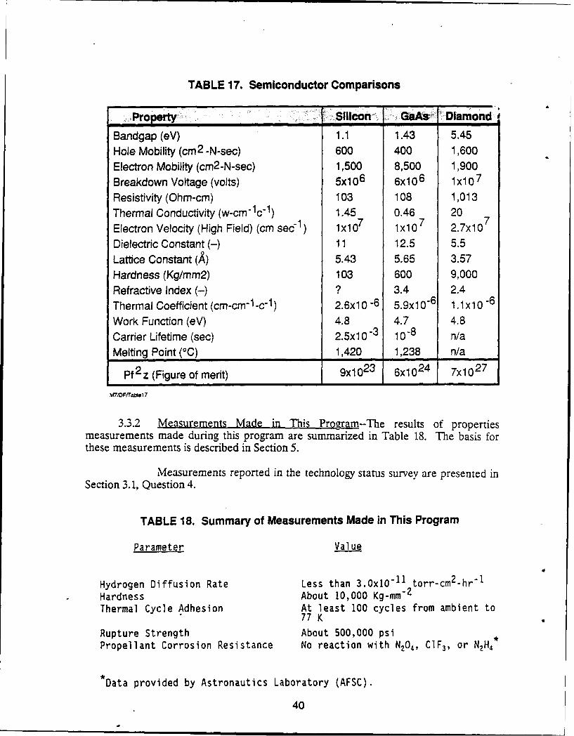
TABLE 17. Semiconductor Comparisons
Property. S1lon, t G Diamond'
Bandgap (eV) 1.1 1.43 5.45Hole Mobility (cm2 -N-sec) 600 400 1,600Electron Mobility (cm2 -N-sec) 1,500 8,500 1,900Breakdown Voltage (volts) 5x,0 6 6x10 6 1x10 7
Resistivity (Ohm-cm) 103 108 1,013Thermal Conductivity (w-cm-lc-1 ) 1.45 0.46 20
Electron Velocity (High Field) (cm sec 1 ) lx107 lx10 7 2.7x10 7
Dielectric Constant (-) 11 12.5 5.5Lattice Constant (A) 5.43 5.65 3.57Hardness (Kg/mm2) 103 600 9,000Refractive Index (-) ? 3.4 2.4Thermal Coefficient (cm-cm-i-c-1) 2.6x1 0 -6 5.9x10⁶ 1.1x10 -6
Work Function (eV) 4.8 4.7 4.8
Carrier Lifetime (sec) 2.5xl 0 -3 10"8 n/aMelting Point (°C) 1,420 1,238 n/a
Pf 2 z (Figure of merit) 9x10 23 6x10 24 7x10 2 7
M'DFf/rase17
3.3.2 Measurements Made in This Program--The results of propertiesmeasurements made during this program are summarized in Table 18. The basis forthese measurements is described in Section 5.
Measurements reported in the technology status survey are presented inSection 3.1, Question 4.
TABLE 18. Summary of Measurements Made in This Program
Parameter Value
Hydrogen Diffusion Rate Less than 3.0xO -1' torr-cm2-hr-1
Hardness About 10,000 Kg-mm 2
Thermal Cycle Adhesion At least 100 cycles from ambient to77 K
Rupture Strength About 500,000 psiPropellant Corrosion Resistance No reaction with N204, C1F 3, or NH4*
*Data provided by Astronautics Laboratory (AFSC).
40
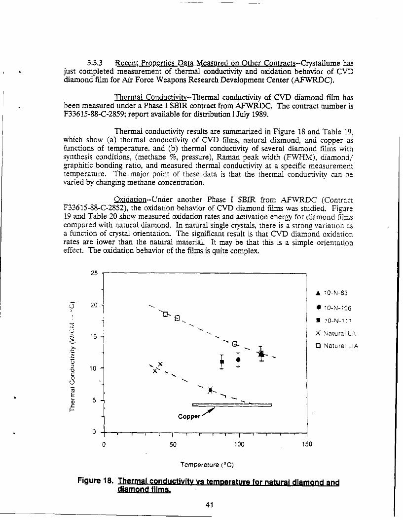
3.3.3 Recent Properties Data Measured on Other Contracts--Crystallume hasjust completed measurement of thermal conductivity and oxidation behavio of CVDdiamond film for Air Force Weapons Research Development Center (AFWRDC).
Thermal Conductivity--Thermal conductivity of CVD diamond film hasbeen measured under a Phase I SBIR contract from AFWRDC. The contract number isF33615-88-C-2859; report available for distribution I July 1989.
Thermal conductivity results are summarized in Figure 18 and Table 19,which show (a) thermal conductivity of CVD films, natural diamond, and copper asfunctions of temperature, and (b) thermal conductivity of several diamond films withsynthesis conditions, (methane %, pressure), Raman peak width (FWHM), diamond/graphitic bonding ratio, and measured thermal conductivity at a specific measurementtemperature. The-major point of these data is that the thermal conductivity can bevaried by changing methane concentration.
Oxidation--Under another Phase I SBIR from AFWRDC (ContractF33615-88-C-2852), the oxidation behavior of CVD diamond films was studied. Figure19 and Table 20 show measured oxidation rates and activation energy for diamond filmscompared with natural diamond. In natural single crystals, there is a strong variation asa function of crystal orientation. The significant result is that CVD diamond oxidationrates are lower than the natural material. It may be that this is a simple orientationeffect. The oxidation behavior of the films is quite complex.
25
A 10-N-83
j 2 0 -- 1 10-N-I06
- 3O-N- I
15 " -X Natural LA
0 Natural LIA
- -10
Copper "
050 100 150
Temperature (°C)
Figure 18. Thermal conductivity v9 temperature for natural diamond anddiamond films.
41
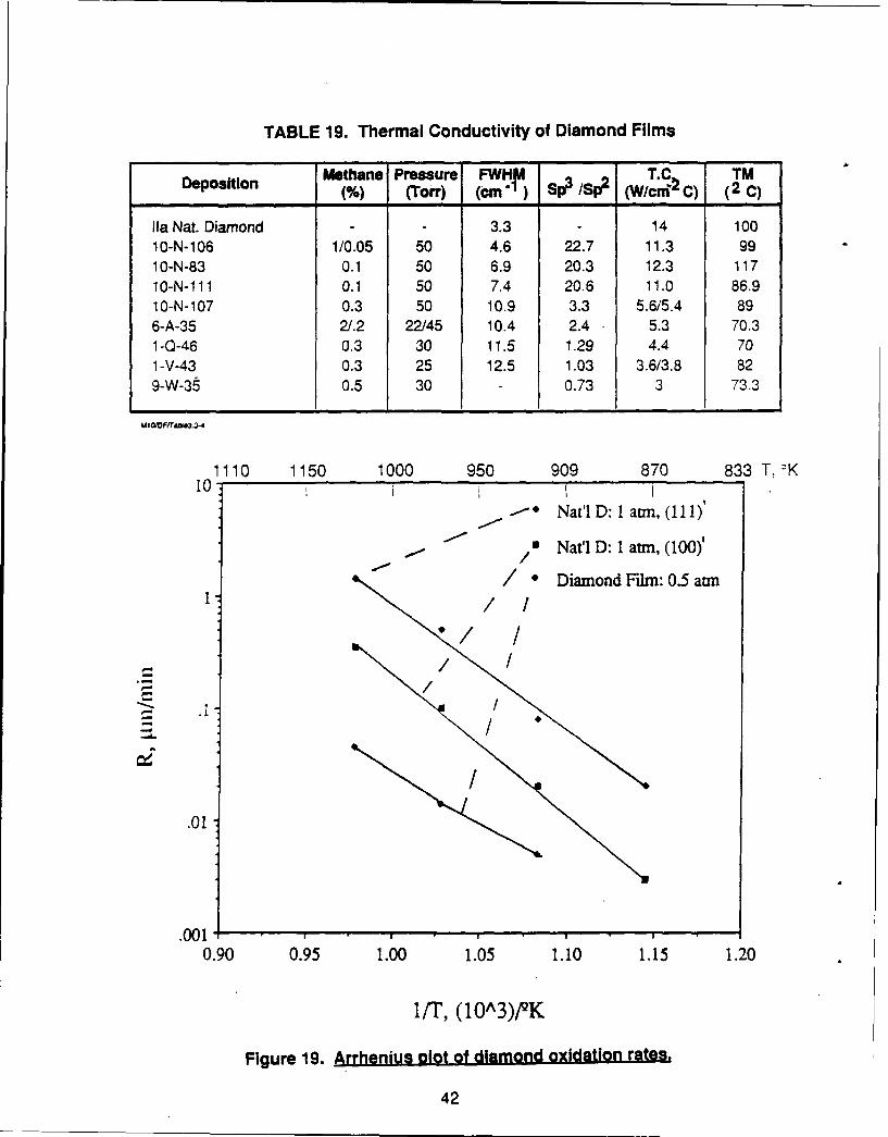
TABLE 19. Thermal Conductivity of Diamond Films
Deposition Methane Pressure FWHIW T.C TM____________ N% (Torr) (cm ,I) SpP ISp2 (W/cni2 C) (2 C)
Ila Nat. Diamond - - 3.3 - 14 10010-N-106 1/0.05 50 4.6 22.7 11.3 991 0-N-83 0.1 50 6.9 20.3 12.3 11710-N-Ill1 0.1 50 7.4 206 11.0 86.910-N-107 0.3 50 10.9 3.3 5.6/5.4 896-A-35 21.2 22145 10.4 2.4 5.3 70.31-0-46 0.3 30 11.5 1.29 4.4 701 -V-43 0.3 25 12.5 1.03 3.6/3.8 829-W-38 0.5 30 - 0.73 3 73.3
1110 1150 1000 950 909 870 833 T. OK10 -
-*Nat'l D: I amin, (I111)'
Na t l D: 1 atm, (100)'
/ *Diamond Film: 0.5 atm
.01/
.001
0.90 0.95 1.00 1.05 1.10 1.15 1.20
liT, (10A3)PQK
Figure 19. Arrhenius plot of diamond oxidation rates.
42
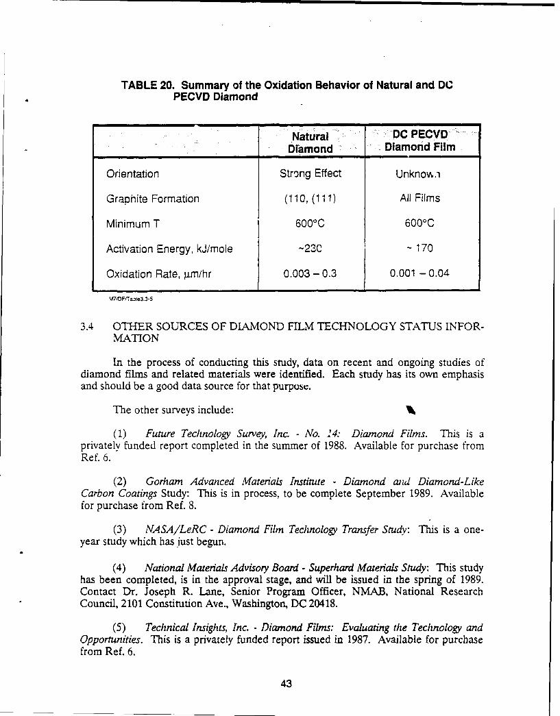
TABLE 20. Summary of the Oxidation Behavior of Natural and DCPECVD Diamond
Natural DC PECVD_____ "________ Diamond Diamond Film
Orientation Strong Effect Unknow.,
Graphite Formation (110, (111) All Films
Minimum T 6000C 6000C
Activation Energy, kJ/mole -23C - 170
Oxidation Rate, 4m/hr 0.003 - 0.3 0.001 - 0.04
V7tOFTaze3.3-5
3.4 OTHER SOURCES OF DIAMOND FILM TECHNOLOGY STATUS INFOR-MATION
In the process of conducting this study, data on recent and ongoing studies ofdiamond films and related materials were identified. Each study has its own emphasisand should be a good data source for that purpose.
The other surveys include:
(1) Future Technology Survey, Inc. - No. 24: Diamond Films. This is aprivately funded report completed in the summer of 1988. Available for purchase fromRef. 6.
(2) Gorham Advanced Materials Institute - Diamond aid Diamond-LikeCarbon Coatings Study: This is in process, to be complete September 1989. Availablefor purchase from Ref. 8.
(3) NASA/LeRC - Diamond Film Technology Transfer Study: This is a one-year study which has just begun.
(4) National Materials Advisory Board - Superhard Materials Study: This studyhas been completed, is in the approval stage, and will be issued in the spring of 1989.Contact Dr. Joseph R. Lane, Senior Program Officer, NMAB, National ResearchCouncil, 2101 Constitution Ave., Washington, DC 20418.
(5) Technical Insights, Inc. - Diamond Films: Evaluating the Technology andOpportunities. This is a privately funded report issued in 1987. Available for purchasefrom Ref. 6.
43
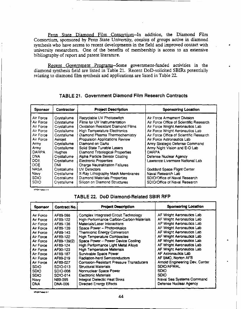
Penn State Diamond Film Consortium--In addition, the Diamond FilmConsortium, sponsored by Penn State University, consists of groups active in diamondsynthesis who have access to recent developments in the field and improved contact withuniversity researchers. One of the benefits of membership is access to an extensivebibliography of report and patent literature.
Recent Government Programs-Some government-funded activities in thediamond synthesis field are listed in Table 21. Recent DoD-solicited SBIRs potentiallyrelating to diamond film synthesis and applications are listed in Table 22.
TABLE 21. Government Diamond Film Research Contracts
Sponsor Contractor Project Description Sponsoring Location
Air Force Crystallume Recyclable UV Photoswitch Air Force Armament DivisionAir Force Crystallume Films for UV Instrumentation Air Force Office of Scientific ResearchAir Force Crystallume Oxidation Resistant Diamond Films Air Force Wright Aeronautics LabAir Force Crystallume High Temperature Electronics Air Force Wright Aeronautics LabAir Force Crystallume Diamond Plasma Thermochemistry Air Force Office of Scientific ResearchAir Force Aerojet Propulsion Applications Review Air Force Astronautics LabArmy Crystailume Diamond on GaAs Army Strategic Defense CommandArmy Crystallume Solid State Tunable Lasers Army Night Vision and E-O LabDARPA Hughes Diamond Tribological Properties DARPADNA Crystallume Alpha Particle Sensor Coating Defense Nuclear AgencyDOE Crystallume Electronic Properties Lawrence Livermore National LabDOE DMI Charge Neutralization FailuresNASA Crystallume UV Detectors Goddard Space Flight CenterNavy Crystallume X-Ray Lithography Mask Membranes Naval Research LabSDbo Crystallume Diamond Materials Properties SDIO/Office of Naval ResearchSDIO Crystallume Silicon on Diamond Structures SDIO/Office of Naval Research
V7'MFMT&r,3 1-4
TABLE 22. DoD Diamond-Related SBIR RFP
Sponsor Contract No. Project Description Sponsoring Location
Air Force AF89-086 Complex Integrated Circuit Technology AF Wright Aeronautics LabAir Force AF89-122 High-Performance Carbon-Carbon Materials AF Wright Aeronautics LabAir Force AF89-136 Materials/Laser Interactions AF Wright Aeronautics LabAir Force AF89-139 Space Power - Photovoltaics AF Wright Aeronautics LabAir Force AF89-143 Thermionic Energy Conversion AF Wright Aeronautics LabAir Force AF89-122 High Temperature Composites AF Wright Aeronautics LabAir Force AF89-139(2) Space Power - Power Device Cooling AF Wright Aeronautics LabAir Force AF89-124 High Performance Light Metal Alloys AF Wright Aeronautics LabAir Force AF90- 123 High Temperature Materials AF Wright Aeronautics LabAir Force AF89-187 Survivable Space Power AF Astronautics LabAir Force AF89-219 Radiation-hard Semiconductors AF BMO, Norton AFBAir Force AF89-027 Corrosion-Resistant Pressure Transducers Arnold Engineering Dev. CenterSDIO SDIO-013 Structural Materials SDIO/AFWALSolo SDIO-006 Nonnuclear Space Power SDIOSolO SDIO-014 Electronic Materials SDIONavy N89-095 Integral Dielectic Heat Sinks Naval Sea Systems CommandDNA DNA-006 Directed Energy Effects Defense Nuclear Agency
IE7,VffT~u3.7
44
4.0 AEROSPACE APPLICATIONS
Aerospace applications include subsets of commercial applications and uniqueuses which occur almost exclusively in space or noncommercial propulsion. After reviewof the diamond film literature, tabulation of the wide range of applications which havebeen suggested for diamond film, and brainstorming for advanced requirements, amatrix of aerospace applications was developed.
4.1 COMMERCIAL APPLICATIONS
Figure 20 is a chart which relates a dozen of diamond's properties to specificproducts in five classes of products: (1) tooling, (2) electronic substrates and heat sinks,(3) semiconductor devices, (4) optical and electro-optic material, and (5) high-performance structural materials.
A few applications are in production and development. Some of these, with thegroup conducting the activity and its status, are summarized in Table 23.
Cutting tools are being pursued by a number of groups. Figure 21 shows adiamond-coated drill bit for use in gang-drilling of electronic circuit boards. A surgicalneedle before and after coating with diamond film is shown in Figure 22.
Diamond has potential application in electronics in both passive and active
elements. Seven classes of applications are shown in Table 24.
4.2 AEROSPACE APPLICATION .MATRIX
A matrix was prepared to relate diamond properties to potential aerospaceapplications. Twenty-six of the properties of diamond film were chosen as beingdiscriminators in one or more of the applications. To aid in classification, theapplications were categorized into space vehicles, aircraft, missiles, and, as a separateclassification, propulsion. The latter was further subdivided into chemical, electrical.and nuclear.
Each classification was further subdivided into major subsystem, subsystem. andcomponent. At the final level, the list was limited to the more significant applications ofdiamond as opposed to "making everything with diamond."
The resulting matrix is shown in Table 25. It contains about 200 specificaerospace applications of diamond film which are potentially of major significance. Therelative importance of each of the 26 properties to the application is rated, "high,""medium," "low," or "not applicable."
A summary of aerospace applications, which is a subset of the matrix, is shown inTable 26. This table was prepared to assist in screening applications. It shows probableapplication time frame and uncertainties which must be resolved to make the technologypractical. Applications with long time frames and extensive uncertainties are lessattractive for near-term technology demonstration.
45
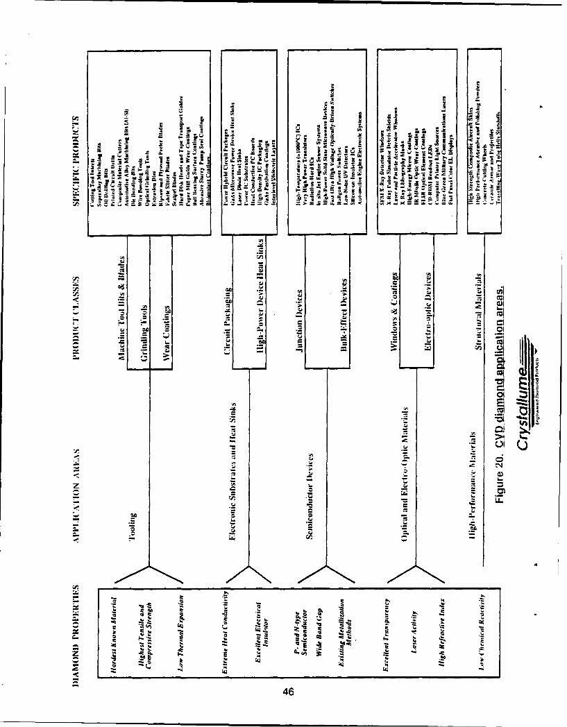
12 I I
l cj IPi- Soya
z 14 -1H W
to If AM S t -- - , 1
~~ax
2 - .2..will
1411I ~ ~S *ul
to.'~
in 1
.~ .2Z
CC a.~ 46
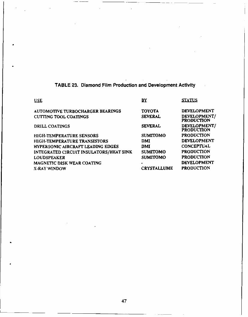
TABLE 23. Diamond Film Production and Development Activity
Uu BYf STATUS
AUTOMOTIVE TURBOCHARGER BEARINGS TOYOTA DEVELOPMENTCUTTING TOOL COATINGS SEVERAL DEVELOPMENT/
PRODUCTIONDRILL COATINGS SEVERAL DEVELOPMENT/
PRODUCTIONHIGH-TEMPERATURE SENSORS SUMITOMO PRODUCTIONHIGH-TEMPERATURE TRANSISTORS DMI DEVELOPMENTHYPERSONIC AIRCRAFT LEADING EDGES DMI CONCEPTUALINTEGRATED CIRCUIT INSULATORS/HEAT SINK SUMITOMO PRODUCTIONLOUDSPEAKER SUMITOMO PRODUCTIONMAGNETIC DISK WEAR COATING DEVELOPMENTX-RAY WINDOW CRYSTALLUME PRODUCTION
47
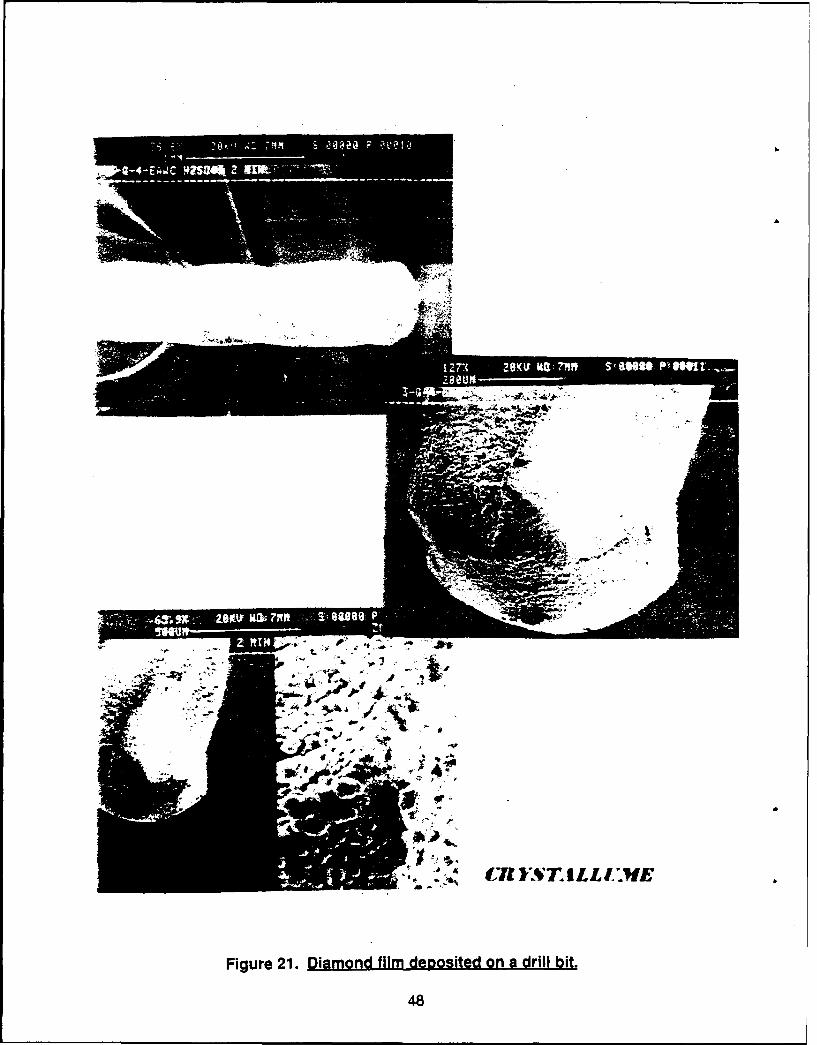
AZA
CRY4(7 STILLI E
Figure 21. Diamond film deposited on a drill bit.
48
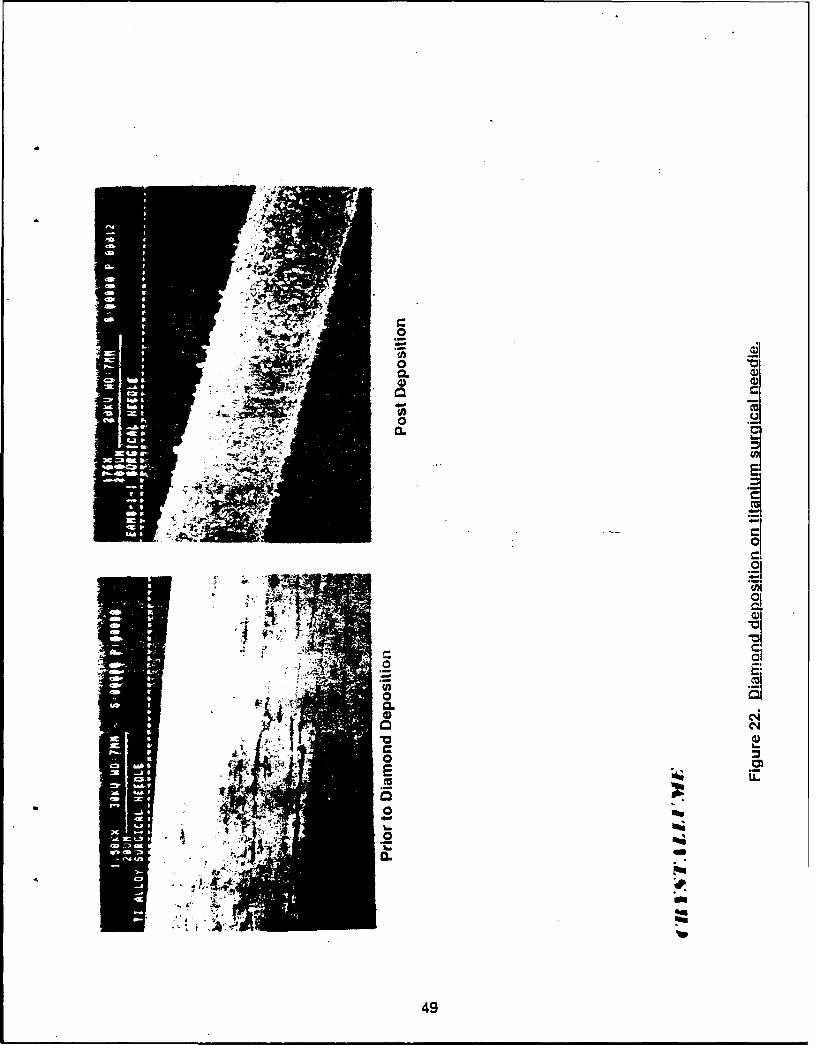
0-Cfl
~JIo. a,-0) C.,0
0. 1~
C,,
:10
0I
Ici
0U'
0.a)o c~Ja,
C0E ;im~Cu
0I-
0& _
urn
49
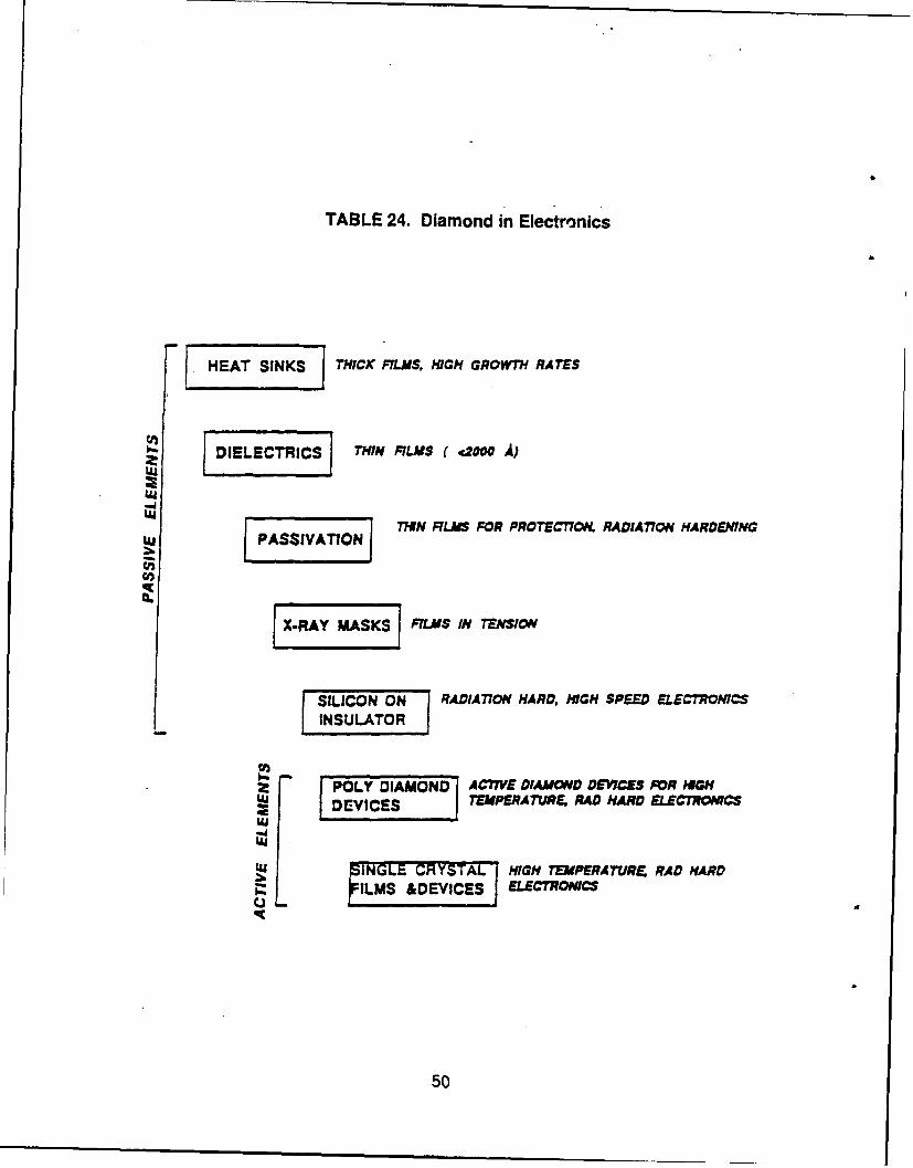
TABLE 24. Diamond in Electronics
HEAT SINKS THICK FILMS, HIGH GROWTH RATES
DIELECTRICS' THiN RLMS ( 2OoO A)
THIN RLMS FOR PROTECTION. RADIATION HARDEiNGwPASSIVATION
X-RAY SKS FILMS IN TENSION
SILICN ON RADIATION HARD, HIGH SPEED ELECTIONICSINSLLTORJ
POLY DIAMOND AC77VE DIAMOND DEVCES FOR GHDEVICES TEMPERATURE, RAD HARD ELECTROWCS
Uj INGLE CRYSTAL HIGH TEMPERATURE, RAD HARDILMS &DEVICES ELECTRONICS
50
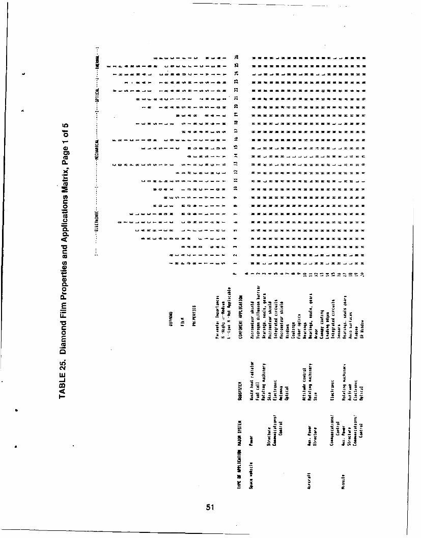
- -- - - - -
= Q - - - - - -
~ .
-. T., m n 0 r. Zsst m1 Z S Z ..
9:& -z -c= --
Cu bU
noc~~~ 2.ot-c -1 Sz~~s
U) - a- = 5= ~ ==5s ==5Z2a;
0 o..u4 0 S =51
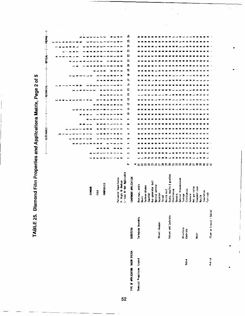
.......... .. a... C s nt t S ~ m t m
cc t&
CL -a
ca -~0 -a -..- -J-M - - tmn t m SS t n S
7 - - - - -
0)
Ja.'
- a mJu-i4 ,l-J ~X m
*0~ SSL W -m52
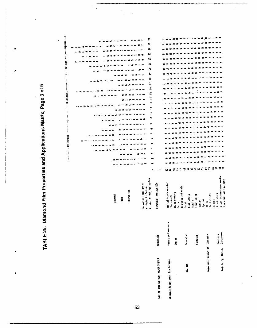
* j ~ ZMJC 04
~ca..a4n-Oa LaO .~ 04
* ~
a~4 ~aaflCn0~O 04
-I ~
04
-
~OSJ 04
* -~ as~ns~ta~O= 04
SLJfl S~ -
* ,~
~======~J ==--==
COWbJUflt'
cv, U, -
La =U,~ -
, 0 4.- JUflnaw
)
oa~ ~.LJ -
(I)CO
.2 ~ CO------
JLa~O-ca 0CC fl
Laaa-b.J 4'
- s===a
aao O~
C W~a ~ 04
'U - CCC
a a flret~vnflnafl
a)
'U0. - =
0 - - CC a -
0= - C a C
- - a La -
Ca -
C - aCe 0-
- - a a * *
C =2 -
LL -t -J 0
-
- - C -c - - = a -
.. .4--4--
0 a- a. C C .4
S'U
'4C~Jw-j
S
I-
C
A
S - a
a
a
53
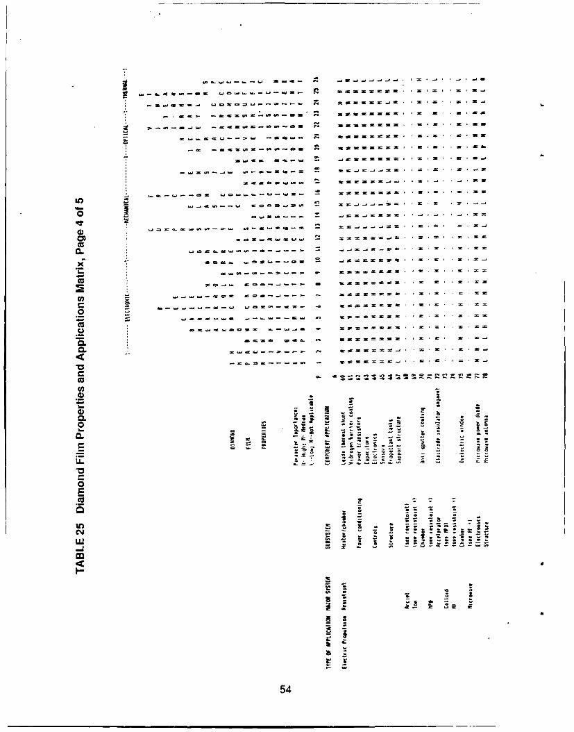
(OS.----Lb S .0 j5.j..j.~..J..JI~ ~~@~CS~-CS LbCI.D.~.~Lb~UJS~ *4 nfi SJ
* ~.JSCC-. LbCtS-----S. (4 5 * = =
- raS. ~ ~ inaS~ 2 5.55.5
* z.~-e~w aasn=~-.,-== ~ SSS=S=S= *.===
aLb~SCLb~~= 5ct*d eQ 55S5255
S * S = US
-= 55 05 IS'C5 555522555 Us
seajaS 5e ~ JSSSSS .5.5' *2 5 0
-b.DSQ'-J' S(&4S(W~ - tS.J~Afl - - 5'
SCCSISAU, - Sf2S~~
.5Lb Lb C &Lb .45 - 55SSSSSS S = = SC
U,- dC~~ Lb CC..JU' - ==~I**d== = = =
0Sled5 **j=S-~SSS=
q~.
4) LbC'~~ ~ - 52 * * = * = =
COr.dSLb - S~j * * = * = * =
(U0. j.JS..J..SC * = = *
X so sa SLJ CS - ~JS====== * = = * S
3-- - - ======s= * *2.5 * = .55
'Uso-a... 20~ a sS=S===S =2 S =5
(fl SOS 5 ~ 52=22S * * = .5 =
.0 ZS~2~
0
C.) * aa..CS.CCS .- ~e-JC W=2S
aCtS Ca. - S * * 2 2 2
iI( -- S~C f-c 2S====s-~ * * = 'S * * 2 *
-20.0~ 5r2~J * .2 = * =
(U a. a a'
U,4) S S
3- -. S
a)0.. - S
(0 0~C Lb03- = .
0. =
C ~J C -- - - 00 0
2 o I- S. -c -- let - ~ 0
- - C 0 sO - 00
- , 0 *~0 I 0.t CO
0E(U S
0
U,
CJ 0=
* * *SSS* S 500
w-J
2
gLbS. 2 a
II
I
54
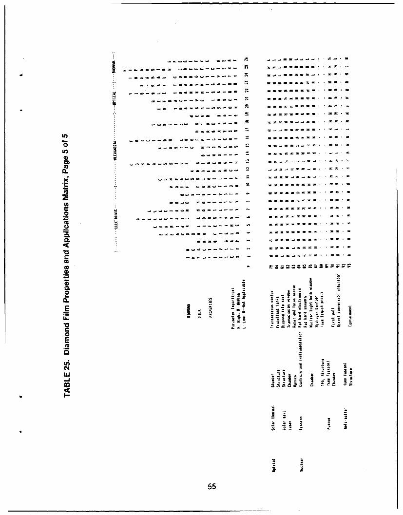
- ~ ~ 21t -itS C o. -' -S - -
* = car ~ 2 asm= . htO ea fm
.4 r ,. S S act a.1 ~ s tt-go=
LO a.r zc- SS552 5
A ~ ~ ~ ~ ~ ~ ~ C m-rt .SS ~ S W S *S
CL. xa- W Wt t t S . 5
* ~ l~d~t-JS tL~mw mt_==w -* 55
CL~lJ' ~ ttt ~ .5-
CL
0.
cjO~t&.J14U5
- itt-t-5-
a 5, 52S 5 S
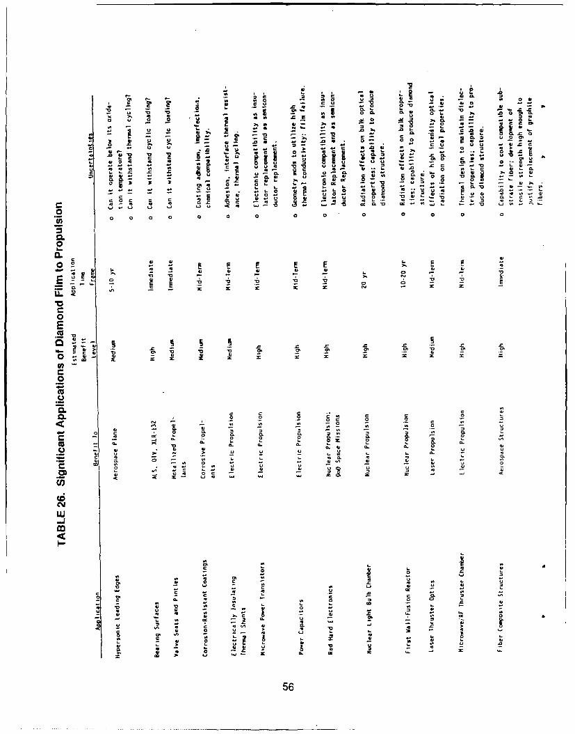
0 r8. v - v8
C0 "a CL CL 0 0 "a -0 5. C0
-o a 2 5 - o . -
0~~~- r 06 E804- 68 08 - .L31 a~ I8 .8 -. .,
0)- .. 0 o.
o U 0 m z0 48 ... 6 08 w880a 0
4 * C 0 4 CP 0
-0 - C 1 c8. M ~ -u - '0 CL. *C4
Q 8 0 ,8 c a04 0' c .0006
CL. a.c a 41 wV C
.0 16 * 8Ch~~~ .0 . . -
L. o 60 004 00u
.8 - -- - - - 0t -0 5 0 . .4
u u u r0 =v-0
Z0.0 - 0 0.6 C 08. C 0 . 0 C 0 0 . 0~
08 E' 05-
-. ~ ~ .2 0 . 8. . 4. C - - .8w.'4
C 4)6 0..8~ 4.
0b 0 0 0 "0 e a00
0
4,..0-C
48~I CL
0 8
0 0
0 0
Pa0
E20. -
00
0c .
O . - 0 0 .0 . , 0
-0 u. . .0 . '
0 .. 4,.8.40. 8 8. . O 0 0 C56
To reduce the number of applications to a manageable list, benefit assessmentswere made, first by generic application. Table 27 is an assessment of the potentialbenefit of an application by system and vehicle type. As might be expected, theapplications with high benefit potential are those for high-value vehicles.
The applications which show the highest quantifiable potential benefit are thosein which use of diamond can prevent catastrophic failure. Table 28 assesses theseprotective applications for specific aerospace systems. The value of the diamond in theapplication is computed in terms of the failure avoidance savings.
Five applications of diamond film were assessed to be of high potential for AirForce aerospace uses, and which warranted further consideration for near-termtechnology development. These applications were: (1) bearing surfaces, (2) hydrogenbarriers, (3) monolithic structures. (4) composite structures, and (5) thermal protection.Table 29 Lists specific Air Force uses and potential benefits.
Further consideration of these potenti,"l applications included propertiescharacterization measurements. These measurements, discussed in Section 5, served todetermine if the characteristic necessary for the advanced applications could probablybe achieved with CVD diamond.
In addition, brief analyses were made to attempt to quantify the applications'technical potential in more detail. These analyses are discussed below, along withdiscussion of several other applications which are more generic in nature. These latterapplications have suficient commercial utility that they will be developed without theneed for Air Force funding.
4.3 PRELIMINARY APPLICATION ANALYSIS
Scoping evaluation was made of several suggested applications which have utilityfor soecialized uses. This work is summarized here.
4.3.1 Thermal Protection--Diamond film is suitable for protecting surfacesfrom high, nonuniform heat flux by reducing peak surface temperature. Figure 23illustrates its ability to reduce surface temperature for a specific example: a nickelsurface exposed to 10 Btu in. -2 sec-1. Note that a 0.1 mm (0.004 in.) thick laver with 20%of the surface heated can reduce the peak temperature by 260 C (500 F). This is asignificant reduction for materials which are being pushed to their design limits.
Table 30 lists some potential applications for thermal protection. Key tothe ability of diamond film to reduce the temperature is (I) diamond's very high thermalconductivity and (2) a surface which is heated only locally.
4.3.2 Composites Using Diamond Films and Fiber s--Study of structuralapplications of diamond was triggered by reports of tensile strength in the 3 million psirange, since this is well above the tensile strengths available in existing engineeringmaterials. T-1000 carbon fiber, for example, used in filament-wound structures, has atensile strength of 1.3 million psi. Since the most likely tensile strength of diamond is500,000 psi, it is not competitive with graphite fibers. Because of its availability as afilm, diamond still could be practical for laminated structure applications.
57
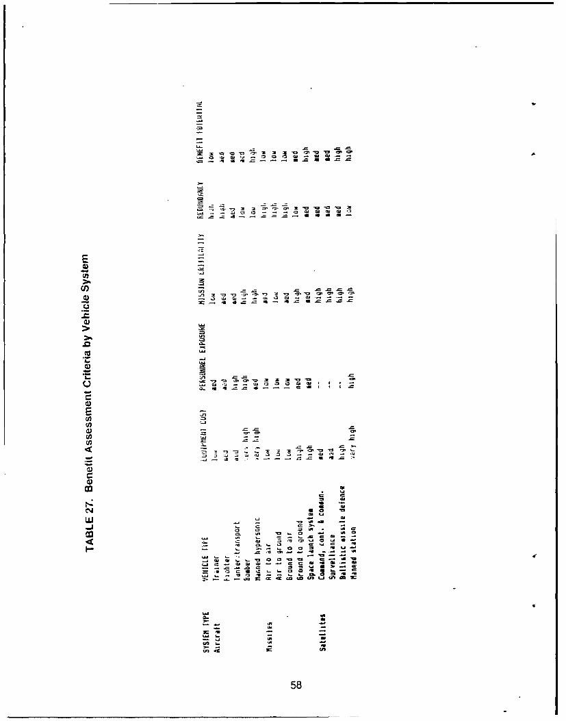
LU ~ ~ ~ C 0 IM 0*C 0 a G G 1-
C'44
LU ~ ~ ~ C 0, 1" 410 '0 ' a-LU e- * C C0- - cn 0W 00 0
tn .C -c- ~ n"U U
E 58
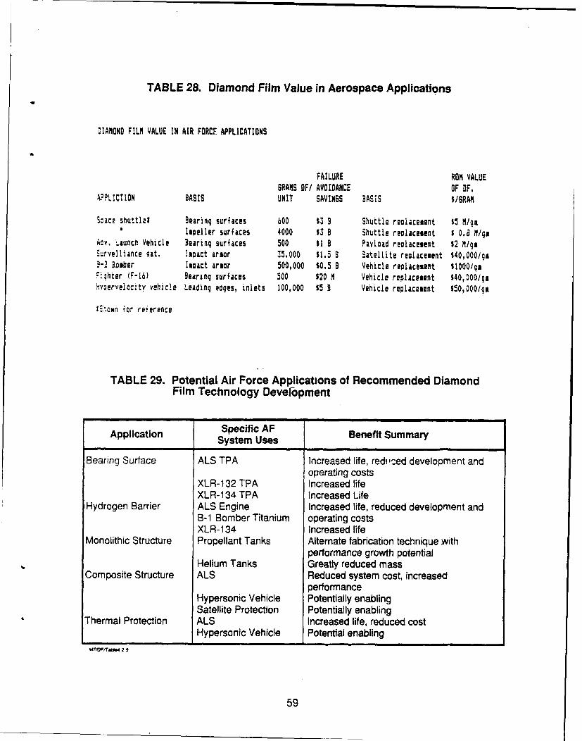
TABLE 28. Diamond Film Value in Aerospace Applications
DIAMOND F!LM VALUE IN AIR FORCE APPLICATIONS
FAILURE RON VALUEBRANS OF/ AVOIDANCE OF OF,
APPLICTION BASIS UNIT SAVINSS BASIS $/BRAN
.:ace shuttle? Bearing surfaces 00 $3 B Shuttle reolacesent $5 M/gaIpeller surfaces 4000 $53 B Shuttle realacesent $ 0.8 Iga
Ady. Launch Vehicle Bearing surfaces 500 $1 B Payload reolacetent 52 M/geS-rvelliance sat. Ispact arsor 35.000 $1.5 B Satellite reolacesent $40,000/0a.:2- Bomber Impact armor 500,000 $0.5 B Vehicle replacement 11000/gaF.hter (F-16) Bearing surfaces 500 $20 N Vehicle replacement $40,0001gs!y3ervelocity vehicle Leading edges, inlets 100,000 $5 B Vehicle rePlacement $50,000/gm
tinown -or reference
TABLE 29. Potential Air Force Applications of Recommended DiamondFilm Technology Development
Application Specific AFSystem Uses Benefit Summal
Bearing Surface ALS TPA Increased life, redi'ced development andoperating costs
XLR- 132 TPA Increased lifeXLR-1 34 TPA Increased Life
Hydrogen Barrier ALS Engine Increased life, reduced development andB-1 Bomber Titanium operating costsXLR-134 Increased life
Monolithic Structure Propellant Tanks Alternate fabrication technique withperformance growth potential
Helium Tanks Greatly reduced massComposite Structure ALS Reduced system cost, increased
performanceHypersonic Vehicle Potentially enablingSatellite Protection Potentially enabling
Thermal Protection ALS Increased life, reduced costHypersonic Vehicle Potential enabling
&MF/raW5 25
59
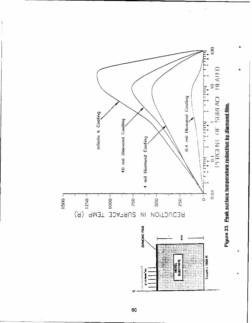
EC
LL0
6 0
TABLE 30. Thermal Protection Coating Applications
PRI MARY APPLICATION
o REDUCTION OF PEAK TEMPERATURES IN NONUNIFORM, HIGH HEAT FLUXAPPLICATIONS
POTENTIAL AIR FORCE USES
o LEADING EDGES, INLETS, AND FUEL STRUTS OF HYPERSONIC AIRCRAFT
o TURBINE AND STATOR BLADE COATINGS IN FUEL-RICH GAS GENERATORROCKET PROPULSION CYCLES
o NOZZLE ENTRANCE AND INJECTOR FACE THERMAL PROTECTION COATINGS
All composites are comprised of at least two constituents, the matrix andthe reinforcement(s). Before composites reinforced with diamond can be discussed, aclassification scheme is needed. One simple composite classification scheme is toseparate them according to their reinforcement form; particulate, laminar, and fiber.Particulate-reinforced composites are defined as those that have reinforcements withroughly equal dimensions, e.g., spheres, cylinders, rods, etc. Laminar-reinforcedcomposites are those composed of two or more layers with two of their dimensions muchgreater than the third. Fiber-reinforced composites are separated into two categories,discontinuous and continuous. Discontinuous reinforcements are those that. whenincreased in length, will change the properties of the composite, whereas continuousreinforcements are those that do not affect the properties if the fiber length is increased.The composites' properties, mechanical, physical, electrical, optical, etc., are to a largeextent dictated by the properties of the reinforcement.
If otie were to consider the reinforcement constituent to be fabricatedfrom diamond, either film or fiber, then, because of the widely different properties ofthis material, the possibility to produce composites with differen-. characteristics exists.This report briefly compares and contrasts the properties of diamond to existingreinforcements, discusses potential benefits, assesses candidate matrix materials, andpredicts properties. Since diamonds are produced by deposition techniques, it seemsreasonable to assume the primary forms will be as either a thin film over a fiber or as aflat thin film which could be used to produce a laminar-type composite. Therefore, thediscussion below is focused on fiber-reinforced composites and laminar composites.
Fiber Reinforcement Composites--In this section, the properties of sometypical fiber reinforcements are presented and compared to the properties of diamond.For convenience, this section is separated into two subsections, discontinuous andcontinuous reinforcements.
Discontinuous: Discontinuous reinforcements can be chopped fibers,whiskers, or particulates, and are generally ceramic or carbon, Table 31 has beenprepared to show some typical properties of discontinuous fibers.
61
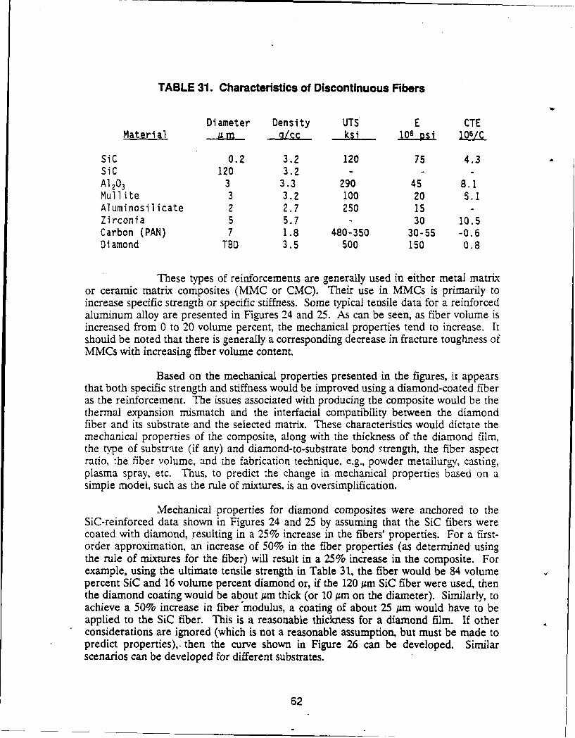
TABLE 31. Characteristics of Discontinuous Fibers
Diameter Density UTS E CTEMaterial U n m *! ksi 106 psi 106/C
SiC 0.2 3.2 120 75 4.3SiC 120 3.2 - - -
A1203 3 3.3 290 45 8.1Mullite 3 3.2 100 20 5.1Aluminosilicate 2 2.7 250 15 -Zirconia 5 5.7 - 30 10.5Carbon (PAN) 7 1.8 480-350 30-55 -0.6Diamond TBD 3.5 500 150 0.8
These types of reinforcements are generally used in either metal matrixor ceramic matrix composites (MMC or CMC). Their use in MMCs is primarily toincrease specific strength or specific stiffness. Some typical tensile data for a reinforcedaluminum alloy are presented in Figures 24 and 25. As can be seen, as fiber volume isincreased from 0 to 20 volume percent, the mechanical properties tend to increase. Itshould be noted that there is generally a corresponding decrease in fracture toughness ofMMCs with increasing fiber volume content.
Based on the mechanical properties presented in the figures, it appearsthat both specific strength and stiffness would be improved using a diamond-coated fiberas the reinforcement. The issues associated with producing the composite would be thethermal expansion mismatch and the interfacial compatibility between the diamondfiber and its substrate and the selected matrix. These characteristics would dictate themechanical properties of the composite, along with the thickness of the diamond film,the type of substrite (if any) and diamond-to-substrate bond strength, the fiber aspectratio, :he fiber volume, and the fabrication technique, e.g., powder metallurgy, casting,plasma spray, etc. Thus, to predict the change in mechanical properties based on asimple model, such as the rule of mixtures, is an oversimplification.
Mechanical properties for diamond composites were anchored to theSiC-reinforced data shown in Figures 24 and 25 by assuming that the SiC fibers werecoated with diamond, resulting in a 25% increase in the fibers' properties. For a first-order approximation, an increase of 50% in the fiber properties (as determined usingthe rule of mixtures for the fiber) will result in a 25% increase in the composite. Forexample, using the ultimate tensile strength in Table 31, the fiber would be 84 volumepercent SiC and 16 volume percent diamond or, if the 120 um SiC fiber were used, thenthe diamond coating would be about jm thick (or 10 gm on the diameter). Similarly, toachieve a 50% increase in fiber'modulus, a coating of about 25 A~m would have to beapplied to the SiC fiber. This is a reasonable thickness for a diamond film. If otherconsiderations are ignored (which is not a reasonable assumption, but must be made topredict properties),, then the curve shown in Figure 26 can be developed. Similarscenarios can be developed for different substrates.
62
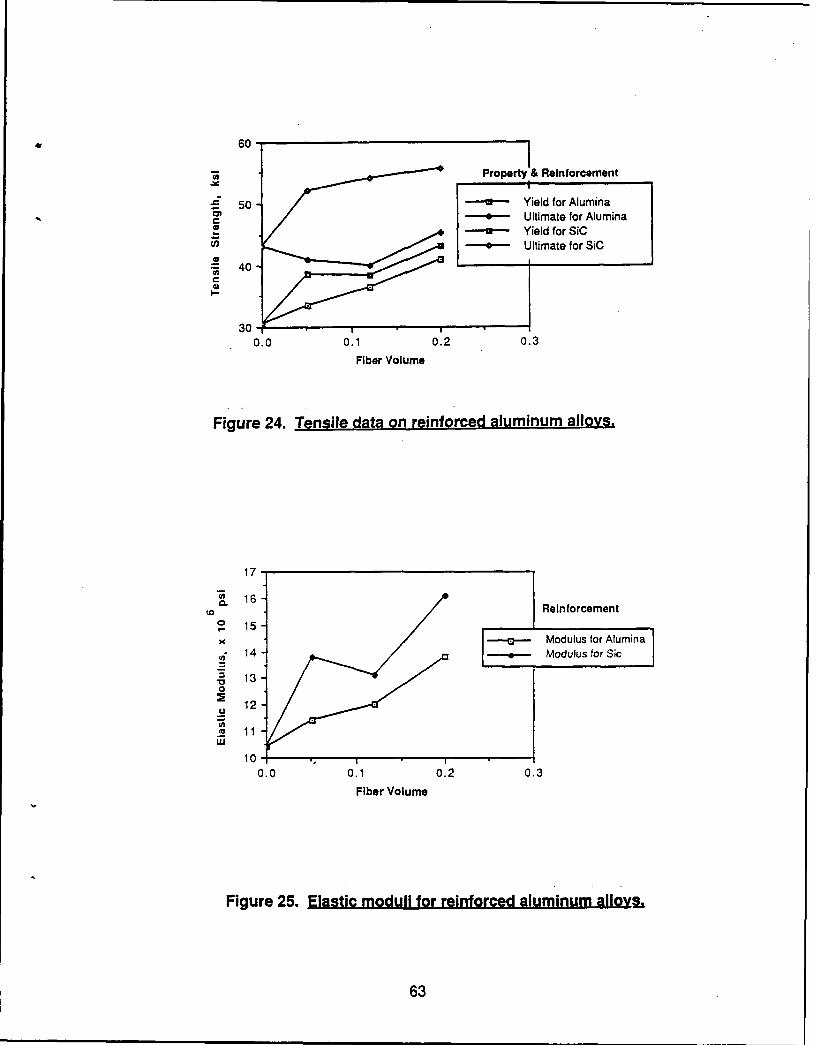
60P
o et enoc m n
40
30
0.0 0.1 0.2o.
Fiber Volume
Figure 24. Tensile data on reinforced aluminum alloys.
17-
~16-Reinforcement
S15--a- Mouls or Alumna
14- [odulu fuor Si
a'3 13-0
12-
4 11
0.0 0.1 0.2 0.3
Fiber Volume
Figure 25. Elastic moduli for reinforced aluminum alloy
63
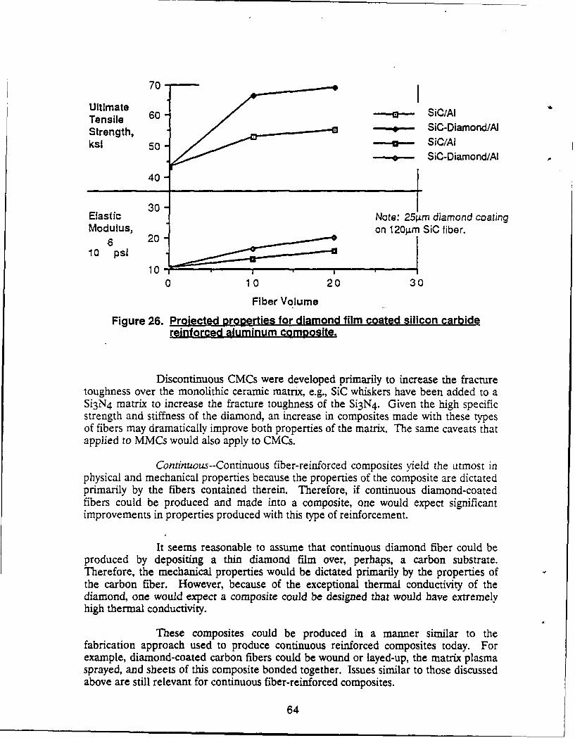
70-
Ultimate , SiC/AlTensile 60-Strength, . -- SiC-Diamond/Aksl 50 - SiC/A1
-- e-- SiC-Diamond/A
40-
30Elastic Note: 25 .m diamond coatingModulus, on 120gm SiC fiber.
10 psi
100 10 20 30
Fiber Volume
Figure 26. Projected properties for diamond film coated silicon carbidereinforced aluminum composite.
Discontinuous CMCs were developed primarily to increase the fracturetoughness over the monolithic ceramic matrx, e.g., SiC whiskers have been added to aSi3 N4 matrix to increase the fracture toughness of the Si3 N4 . Given the high specificstrength and stiffness of the diamond, an increase in composites made with these typesof fibers may dramatically improve both properties of the matrix. The same caveats thatapplied to MMCs would also apply to CMCs.
Continuous--Continuous fiber-reinforced composites yield the utmost inphysical and mechanical properties because the properties of the composite are dictatedprimarily by the fibers contained therein. Therefore, if continuous diamond-coatedfibers could be produced and made into a composite, one would expect significantimprovements in properties produced with this type of reinforcement.
It seems reasonable to assume that continuous diamond fiber could beproduced by depositing a thin diamond film over, perhaps, a carbon substrate.Therefore, the mechanical properties would be dictated primarily by the properties ofthe carbon fiber. However, because of the exceptional thermal conductivity of thediamond, one would expect a composite could be designed that would have extremelyhigh thermal conductivity.
These composites could be produced in a manner similar to thefabrication approach used to produce continuous reinforced composites today. Forexample, diamond-coated carbon fibers could be wound or layed-up, the matrix plasmasprayed, and sheets of this composite bonded together. Issues similar to those discussedabove are still relevant for continuous fiber-reinforced composites.
64
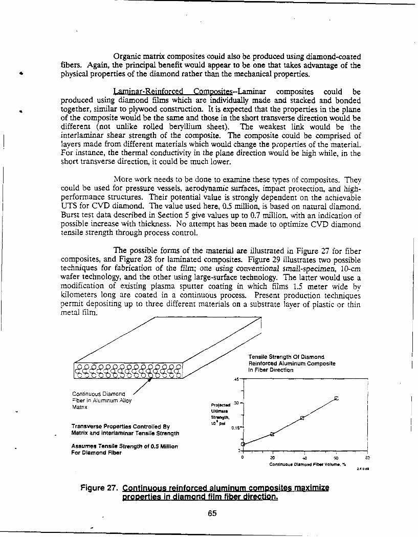
Organic matrix composites could also be produced using diamond-coatedfibers. Again, the principal benefit would appear to be one that takes advantage of thephysical properties of the diamond rather than the mechanical properties.
Laminar-Reinforced Comnosites-Laminar composites could beproduced using diamond films which are individually made and stacked and bondedtogether, similar to plywood construction. It is expected that the properties in the planeof the composite would be the same and those in the short transverse direction would bedifferent (not unlike rolled beryllium sheet). The weakest link would be theinterlaminar shear strength of the composite. The composite could be comprised oflayers made from different materials which would change the properties of the material.For instance, the thermal conductivity in the plane direction would be high while, in theshort transverse direction, it could be much lower.
More work needs to be done to examine these types of composites. Theycould be used for pressure vessels, aerodynamic surfaces, impact protection, and high-performance structures. Their potential value is strongly dependent on the achievableUTS for CVD diamond. The value used here, 0.5 million, is based on natural diamond.Burst test data described in Section 5 give values up to 0.7 million, with an indication ofpossible increase with thickness. No attempt has been made to optimize CVD diamondtensile strength through process control.
The possible forms of the material are illustrated in Figure 27 for fibercomposites, and Figure 28 for laminated composites. Figure 29 illustrates two possibletechniques for fabrication of the film; one using conventional small-specimen, 10-cmwafer technology, and the other using large-surface technology. The latter would use amodification of existing plasma sputter coating in which films 1.5 meter wide bykilometers long are coated in a continuous process. Present production techniquespermit depositing up to three different materials on a substrate layer of plastic or thinmetal film.
Tensile Strength Of DiamondReinforced Aluminum CompositeIn Fiber Direction
Continuous DiamondFiber in Aluminum Alloy 10Matrix Projected
Ultimate
Strength,
Transverse Properties Controlled By 10 psi
Matrix and Interlaminar Tensile Strength
Assumes Tensile Strength of 0.5 MillionFor Diamond Fiber 0 ,
o 20 4o .30 20
Continuous Diamond Fiber Volume. %2.4069
Figure 27. Continuous reinforced aluminum composites maximize
properties in diamond film fiber direction.
65
Tensile Strength =0.5 Million PSI
"Plywood Construction"
Properties In Short Transverse DirectionControlled By "Glue"
Figure 28. Diamond films laminated together offer high strength inpalanar direction.
0 K4 INCH DIA WAFER FREE COMPOSITE FILM _________
(SILICON OR COPPER BY ETCHING ORSUBSTRATE. 10) THERMAL 0.1 - I em THICK STACK.
DIAMOND FILM*v.BOND CYCLE THERMAL OR ADIFESlVEKAPTON OR MYLAR) BOND
DIRECT PLASMA DEPOSITION ONKAPTON OR KEYLAR FILM IMPACT TESTING 36.0.10
Figure 29. Impact armrc cpt
66
Some of the impact armor applications include:
o Micrometeoroid protectiono Satellite battle protectiono Aircraft armoro Body armoro Rain and dust impact protection in hypervelocity atmospheric flight
A typical laminate for this application is illustrated in Figure 30. Itwould use a Kevlar or Kapton substrate with a molybdenum interlayer to provide goodadhesion for the CVD diamond layer. A thermal bonding layer would be applied to thesubstrate so that a thick laminate could be built up by stacking and vacuum thermalbonding, such as is done for Kapton flexible circuit bonds.
CVD Diamond 10-100,lu
300APlasma
DepositedMolybdenium
XXXXXXXX XXXX,--Og KEVLAR
\- Thermal Bonding Aid
Figure 30. Single layer for laminate buildup.
67
Some of the design features which must be considered are:
o Deposition process parameterso Diamond film thickness relative to substrateo Diamond film crystal structureo Diamond film purityo Composite optimizationo Substrate material propertieso Carbide-forming interlayero Laminate adhesion layer
Laminates of such a material could be used against a range of impactthreats:
o Low velocity (e.g., typical aircraft intercept)o Medium velocity (e.g., hypervelocity intercept)o High velocity (e.g., orbital intercept)
4.3.3 Electronic Applications--Although the Air Force is a significant user ofadvanced electronics, activity directed toward development of such applications wasconsidered to be generic in nature and off the main interest of this study of aerospaceapplications. However, information developed on some electronic applications isdiscussed here.
4.3.3.1 Electronics .Cooling-A passive electronic application fordiamond film is in heat removal from electronic devices. Aerospace control, sensor dataacquisition, storage, and transmission systems currently employ integrated circuits; theiruse is rapidly expanding for control, safety, and health monitoring applications. The lifeand reliability of integrated circuits are limiting factors in their application.
The life of integrated circuit devices is an Arrhenius function ofthe junction temperature. Reduction of the thermal resistance of the heat conductionpath for cooling can reduce junction temperature at a given power level, therebyincreasing life or permitting operation at higher power levels at a given life. Diamondhas nine times the thermal conductivity and about ten times the dielectric strength of thenext best thermally conductive electrical insulator, beryllium oxide. Figure 31 shows theeffect of diamond on the temperature drop across a film at fixed flux compared to othermaterials in use. However, when diamond film is used as an external isolator to replaceBeO, little reduction in junction temperature will be achieved since most of the thermalresistance is in the junction-to-case path. Therefore, realizing the benefits of diamondfilm requires integrating it into the fabrication of the semiconductor device to replaceinsulating layers such as sapphire (A120 3 ) or SiO 2 . Design studies have shown theoperating power of microwave transistors can be increased by more than a factor of two(Figure 32), providing smaller, lighter-weight space power conditioning.
4.3.3.2 High-Temperature Power Capacitors--Because of its highdielectric strength and high thermal conductivity, coupled with its capability to befabricated into thin films, diamond can be used as an insulator for high-temperaturecapacitors. In addition to applications to integrated circuit devices, diamond films
68
appear to have application to power conditioning units (PCU) as well. PCUs are amajor component of aerospace systems, in general, and electrical propulsion systems, inparticular. To stay within reasonable mass limitations, PCUs must operate at highpower densities. This reduces their conversion efficiency and makes them system lifelimiters.
Nearly all electrical propulsion applications require a PCU thatinterfaces the vehicle power source to the propulsion device. The major portion of astate-of-the-art PCU is a switching power supply, DC-DC for arc, ion, microwave, andMPD, and DC-AC for RF thrusters. The power, filter, and RF1 isolation circuits requirepower capacitors that account for a significant fraction of the PCU mass. The life ofthese units is increased by a factor of two for every 10 C drop in operating temperature.Dielectric heating in high-frequency switching power supply capacitors generatesinternal heat that must be conducted to a heat sink. Poor thermal conductivity of plasticfilm insulators and their low operating temperatures limit capacitor power density andlife. Use of tantalum metal film on diamond film construction would provide anincrease in maximum internal operating temperature by a factor of three, insulatordielectric strength by a factor of six, and a decrease in overall thermal resistance by afactor of more than two. When configured to take advantage of the properties ofdiamond, tantalum-diamond capacitors, capacitors, Figure 33, should have nearly anorder of magnitude size decrease relative to plastic film capacitors. Use of diamond-likecarbon films in capacitor fabrication is described in Ref. 10.
4.3.3.3 Active Devices--If reliable techniques are developed for p- andn-doping of CVD diamond film, as well as for its epitaxial growth, it will be asemiconductor material superior to silicon and germanium arsenide and capable of
Electrical Insolator/ Qualz with Thermal Conductor
~Electronics with100.-..--.-Sapphire q Heat Generation q
0E
X 50 0 --*-Beryllium OxideTV WXIfr _XXXI
so.-
10 0- aT, TemeaueHa
M Ref- Diamond Diff erence Sink0 -~ t -Constant
5 - q Constant
E
0 5 10 15 20Thermal Conductivity, kc,w/cm-degK bg 88.478
Figure 31. Electronics cooling-through diamond film insulation comparedto other electrical insulators.
69
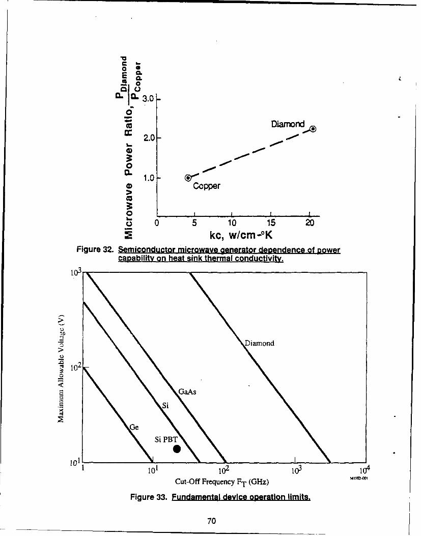
06
60.
0Dmamnond,
2.0-
IL 1.0-W Copper
O'
o 0 5 10 15 20kc, w/cm-°K
Figure 32. Semiconductor microwave generator dependence of gowercapability on heat sink thermal conductivity.
103
Diamond
i20
GaAs
.Si
Ge
Si PBT
10 10212<0
iol io2 o o
Cut-Off Frequency FT (GHz)
Figure 33. Fundamental device operation limits.
70
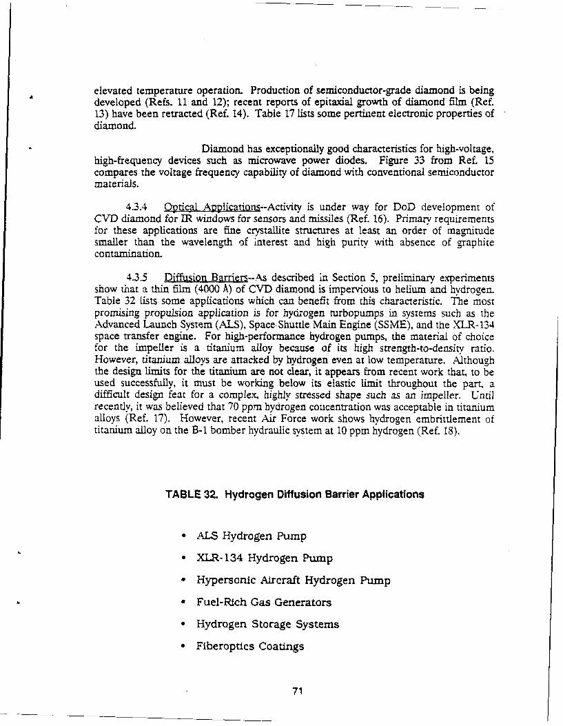
elevated temperature operation. Production of semiconductor-grade diamond is beingdeveloped (Refs. 11 and 12); recent reports of epitaxial growth of diamond film (Ref.13) have been retracted (Ref. 14). Table 17 lists some pertinent electronic properties ofdiamond.
Diamond has exceptionally good characteristics for high-voltage,high-frequency devices such as microwave power diodes. Figure 33 from Ref. 15compares the voltage frequency capability of diamond with conventional semiconductormaterials.
4.3.4 Optical Applicatdon-Activity is under way for DoD development ofCVD diamond for IR windows for sensors and missiles (Ref. 16). Primary requirementsfor these applications are fine crystallite structures at least an order of magnitudesmaller than the wavelength of interest and high purity with absence of graphitecontamination.
4.3.5 Diffusion Barriers--As described in Section 5, preliminary experimentsshow that a thin film (4000 A) of CVD diamond is impervious to helium and hydrogen.Table 32 lists some applications which can benefit from this characteristic. The mostpromising propulsion application is for hydrogen turbopumps in systems such as theAdvanced Launch System (ALS), Space Shuttle Main Engine (SSME), and the XLR-134space transfer engine. For high-performance hydrogen pumps, the material of choicefor the impeller is a titanium alloy because of its high strength-to-density ratio.However, titanium alloys are attacked by hydrogen even at low temperature. Althoughthe design limits for the titanium are not clear, it appears from recent work that, to beused successfully, it must be working below its elastic limit throughout the part, adifficult design feat for a complex, highly stressed shape such as an impeller. Untilrecently, it was believed that 70 ppm hydrogen concentration was acceptable in titaniumalloys (Ref. 17). However, recent Air Force work shows hydrogen embrittlement oftitanium alloy on the B-i bomber hydraulic system at 10 ppm hydrogen (Ref. 18).
TABLE 32. Hydrogen Diffusion Barrier Applications
* ALS Hydrogen Pump
* XLR- 134 Hydrogen Pump
* Hypersonic Aircraft Hydrogen Pump
" Fuel-Rich Gas Generators
* Hydrogen Storage Systems
* Fiberoptics Coatings
71
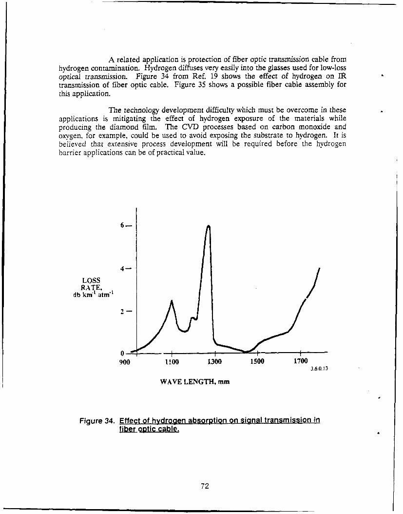
A related application is protection of fiber optic transmission cable fromhydrogen contamination. Hydrogen diffuses very easily into the glasses used for low-lossoptical transmission. Figure 34 from Ref. 19 shows the effect of hydrogen on IRtransmission of fiber optic cable. Figure 35 shows a possible fiber cable assembly forthis application.
The technology development difficulty which must be overcome in theseapplications is mitigating the effect of hydrogen exposure of the materials whileproducing the diamond film. The CVD processes based on carbon monoxide andoxygen, for example, could be used to avoid exposing the substrate to hydrogen. It isbelieved that extensive process development will be required before the hydrogenbarrier applications can be of practical value.
6-
4-
LOSSRATE, /
db km t atm't
2-
0900 100 1300 1500 1700
3.6.0.13
WAVE LENGTH, mm
Figure 34. Effect of hydrogen absorption on signal transmission infijtftoatic cable.
72
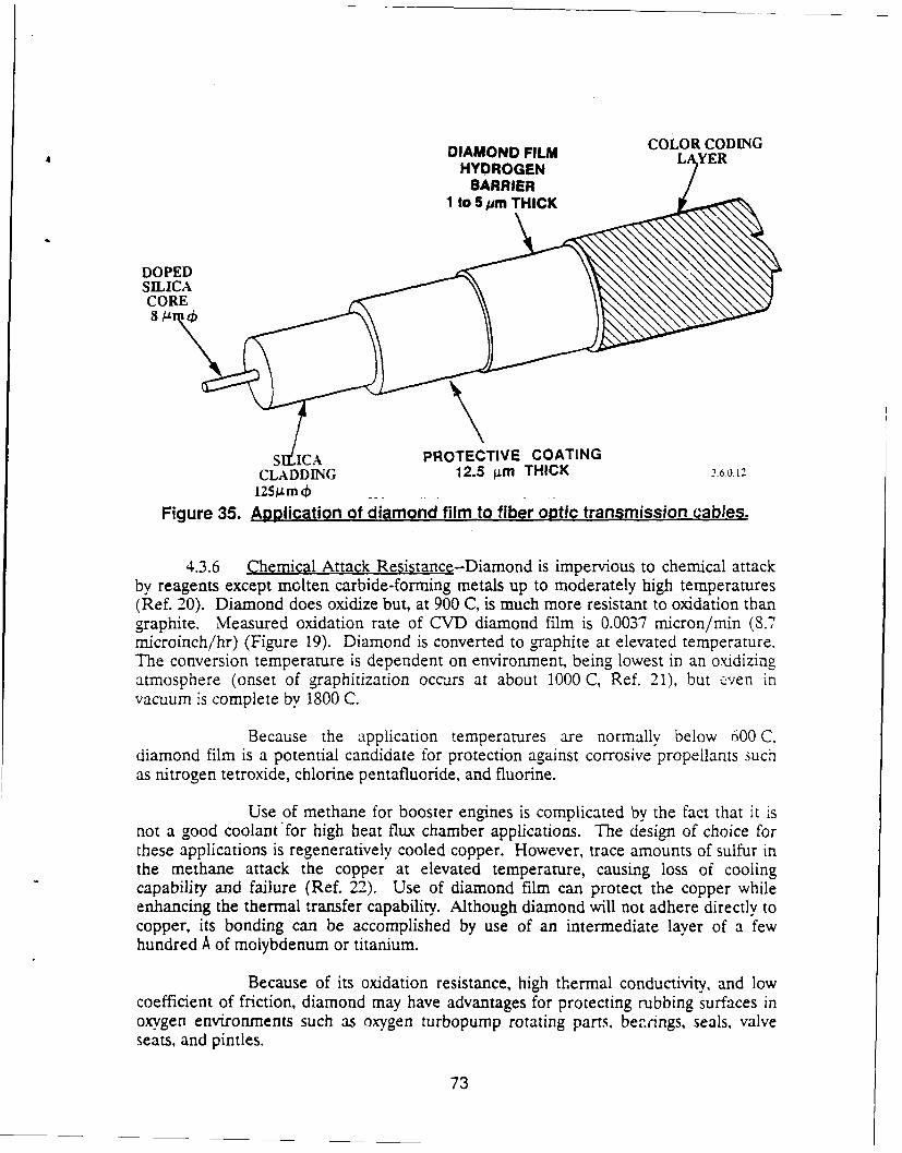
DIAMOND FILM COLOR CODINGHYDROGEN
BARRIER1 to 5 jim THICK
DOPED
S ICA PROTECTIVE COATINGCLADDING 12.5 gim THICK 3.6.012
125gm..Figure 35. Application of diamond film to fiber optic transmission cables.
4.3.6 Chemical Attack Resistance--Diamond is impervious to chemical attackby reagents except molten carbide-forming metals up to moderately high temperatures(Ref. 20). Diamond does oxidize but, at 900 C, is much more resistant to oxidation thangraphite. Measured oxidation rate of CVD diamond film is 0.0037 micron/min (8.7microinch/hr) (Figure 19). Diamond is converted to graphite at elevated temperature.The conversion temperature is dependent on environment, being lowest in an oXidizingatmosphere (onset of graphitization occurs at about 1000 C, Ref. 21), but even invacuum is complete by 1800 C.
Because the application temperatures are normally below 600 C.diamond film is a potential candidate for protection against corrosive propellants suchas nitrogen tetroxide, chlorine pentafluoride, and fluorine.
Use of methane for booster engines is complicated by the fact that it isnot a good coolant for high heat flux chamber applications. The design of choice forthese applications is regeneratively cooled copper. However, trace amounts of sulfur inthe methane attack the copper at elevated temperature, causing loss of coolingcapability and failure (Ref. 22). Use of diamond film can protect the copper whileenhancing the thermal transfer capability. Although diamond will not adhere directly tocopper, its bonding can be accomplished by use of an intermediate layer of a fewhundred A of molybdenum or titanium.
Because of its oxidation resistance, high thermal conductivity, and lowcoefficient of friction, diamond may have advantages for protecting rubbing surfaces inoxygen environments such as oxygen turbopump rotating parts, bezings, seals, valveseats, and pintles.
73
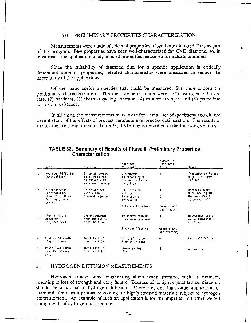
5.0 PRELIMINARY PROPERTIES CHARACTERIZATION
Measurements were made of selected properties of synthetic diamond films as partof this program. Few properties have been well-characterized for CV-D diamond, so, inmost cases, the application analyses used properties measured for natural diamond.
Since the suitability of diamond film for a specific application is criticallydependent upon its properties, selected characteristics were measured to reduce theuncertainty of the applications.
Of the many useful properties that could be measured, five were chosen forpreliminary characterization. The measurements made were: (1) hydrogen diffusionrate, (2) hardness, (3) thermal cycling adhesion, (4) rupture strength, and (5) propellantcorrosion resistance.
In all cases, the measurements made were for a small set of specimens and did notpermit study of the effects of process parameters or process optimization. The results ofthe testing are summarized in Table 33; the testing is described in the following sections.
TABLE 33. Summary of Results of Phase III Preliminary PropertiesCharacterization
Number ofSpecimen Specimens
Test Procedure Description Tested Results
1. Hydrogen Diffusion I atm 4P across 0.5 micron Transmission Range:(Crystallume) film, measured thickness by DC 0 to D0"-1 torr-
diffusion with plasma discharge cm3 sec "
mass spectrometer on silicon
2. 4icrohardness Leitz Durimet 10 micron on Hardness Range:(Crystallume/ with Vickers silicon 3820-8950 Kg ,ii2
Stanford 1 .tlas diamond indenter 15 micron on I Hardness Rangl:estinq Laoora- molybdenum 10,000 Kg im
Titanium (Ti6AI4V) Deposit notsatisfactory
Thermal Cycle Cycle specimen 10 micron film on 4 Withstands test:Adhesion from ambient to 0.76 mm molybdenum no delamination or(Crystallume) 77 K 100 times cracking
Titanium (TiSA14V) Deposit notsatisfactory
1. Ruoture Strength Rurst test of 11 to 17 micron 4 About 500,000 psi(Crystallume) circular film film on silicon
5. Propellaot Corro- Burst test of Free-standing 4 4o reactionsion Resistance circular film filmIAL)
5.1 HYDROGEN DIFFUSION MEASUREMENTS
Hydrogen attacks some engineering alloys when stressed, such as titanium.resulting in loss of strength and early failure. Because of its tight crystal lattice, diamondshould be a barrier to hydrogen diffusion. Therefore, one high-value application ofdiamond film is as a protective coating for highly stressed materials subject to hydrogenembrittlement. An example of such an application is for the impeller and other wettedcomponents of hydrogen turbopumps.
74
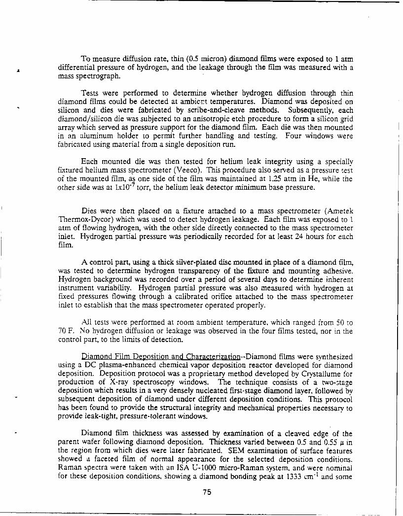
To measure diffusion rate, thin (0.5 micron) diamond films were exposed to 1 atmdifferential pressure of hydrogen, and the leakage through the film was measured with amass spectrograph.
Tests were performed to determine whether hydrogen diffusion through thindiamond films could be detected at ambiert temperatures. Diamond was deposited onsilicon and dies were fabricated by scribe-and-cleave methods. Subsequently, eachdiamond/silicon die was subjected to an anisotropic etch procedure to form a silicon gridarray which served as pressure support for the diamond film. Each die was then mountedin an aluminum holder to permit further handling and testing. Four windows werefabricated using material from a single deposition run.
Each mounted die was then tested for helium leak integrity using a speciallyfixtured helium mass spectrometer (Veeco). This procedure also served as a pressure testof the mounted film, as one side of the film was maintained at 1.25 arm in He, while theother side was at lxl0 7 torr, the helium leak detector minimum base pressure.
Dies were then placed on a fixture attached to a mass spectrometer (AmetekThermox-Dycor) which was used to detect hydrogen leakage. Each film was exposed to 1atm of flowing hydrogen, with the other side directly connected to the mass spectrometerinlet. Hydrogen partial pressure was periodically recorded for at least 24 hours for eachfilm.
A control part, using a thick silver-plated disc mounted in place of a diamond film,was tested to determine hydrogen transparency of the fixture and mounting adhesive.Hydrogen background was recorded over a period of several days to determine inherentinstrument variability. Hydrogen partial pressure was also measured with hydrogen atfixed pressures flowing through a calibrated orifice attached to the mass spectrometerinlet to establish that the mass spectrometer operated properly.
All tests were performed at room ambient temperature, which ranged from 50 to70 F. No hydrogen diffusion or leakage was observed in the four films tested, nor in thecontrol part, to the limits of detection.
Diamond Film Deposition and Characterization--Diamond films were synthesizedusing a DC plasma-enhanced chemical vapor deposition reactor developed for diamonddeposition. Deposition protocol was a proprietary method developed by Crystallume forproduction of X-ray spectroscopy windows. The technique consists of a two-stagedeposition which results in a very densely nucleated first-stage diamond layer, followed bysubsequent deposition of diamond under different deposition conditions. This protocolhas been found to provide the structural integrity and mechanical properties necessary toprovide leak-tight, pressure-tolerant windows.
Diamond film thickness was assessed by examination of a cleaved edge of theparent wafer following diamond deposition. Thickness varied between 0.5 and 0.55 /1 inthe region from which dies were later fabricated. SEM examination of surface featuresshowed a faceted film of normal appearance for the selected deposition conditions.Raman spectra were taken with an ISA U-1000 micro-Raman system, and were nominalfor these deposition conditions, showing a diamond bonding peak at 1333 cm 1 and some
75
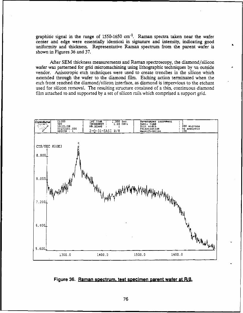
graphitic signal in the range of 1550-1650 cm "1. Raman spectra taken near the wafercenter and edge were essentially identical in signature and intensity, indicating gooduniformity and thickness. Representative Raman spectrum from the parent wafer isshown in Figures 36 and 37.
After SEM thickness measurements and Raman spectroscopy, the diamond/siliconwafer was patterned for grid micromachining using lithographic techniques by -n outsidevendor. Anisotropic etch techniques were used to create trenches in the silicon whichextended through the wafer to the diamond film. Etching action terminated when theetch front reached the diamond/silicon interface, as diamond is impervious to the etchantused for silicon removal. The resulting structure consisted of a thin, continuous diamondfilm attached to and supported by a set of silicon rails which comprised a support grid.
C~ysail1e U1000 INT.TIME : 1.000 Sec Wavenumber increment 1SHY INCREMENT 1.00 CM-I Dwell time 1
. 10/21/88 NB.SCANS 1 i Slit width 300 microns,- 01031EZ1.S00 Polarization no analysis
REGION 1 2-Q-31-EASI R/8 Maqnification 100
CTS/S C X1QE3
8.8001
8.000.
7.2001
6.4001
5.600
i200.0 1400.0 1500.0 1600.0
Figure 36. Raman spectrum. test specimen parent wafer at R18.
76
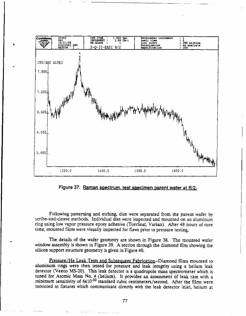
Crysia~m 1 Uf000 INT.TIME : 1.000 Sec Wavenumber increment 1SHY INCREMENT 1.00 CM-i Dwell time 110/21/88 MB.SCANS 1 Slit width: 300 microns01031EZ2.S00 Polarization no analysisREGION I 2-O-31-EASI R/2 Magnification 100
CTS/S C X1OE3 -
7.800
7.200
6.600
6.0001
5.400
200.0 1400.0 1500.0 1600.0
Figure 37. Raman spectrum, test specimen parent wafer at R/2.
Following patterning and etching, dice were separated from the parent wafer byscribe-and-cleave methods. Individual dies were inspected and mounted on an aluminumring using low vapor pressure epoxy adhesive (TorrSeal, Varian). After 48 hours of curetime, mounted films were visually inspected for flaws prior to pressure testing.
The details of the wafer geometry are shown in Figure 38. The mounted waferwindow assembly is shown in Figure 39. A section through the diamond film showing thesilicon support structure geometry is given in Figure 40.
Pressure/He Leak Tests and Subsequent Fabrication-Diamond films mounted toaluminum rings were then tested for pressure and leak integrity using a helium leakdetector (Veeco MS-20). This leak detector is a quadrupole mass spectrometer which istuned for Atomic Mass No. 4 (helium). It provides an assessment of leak rate with aminimum sensitivity of 6x10 "10 standard cubic centimeters/second. After the films weremounted to fixtures which communicate directly with the leak detector inlet, helium at
77
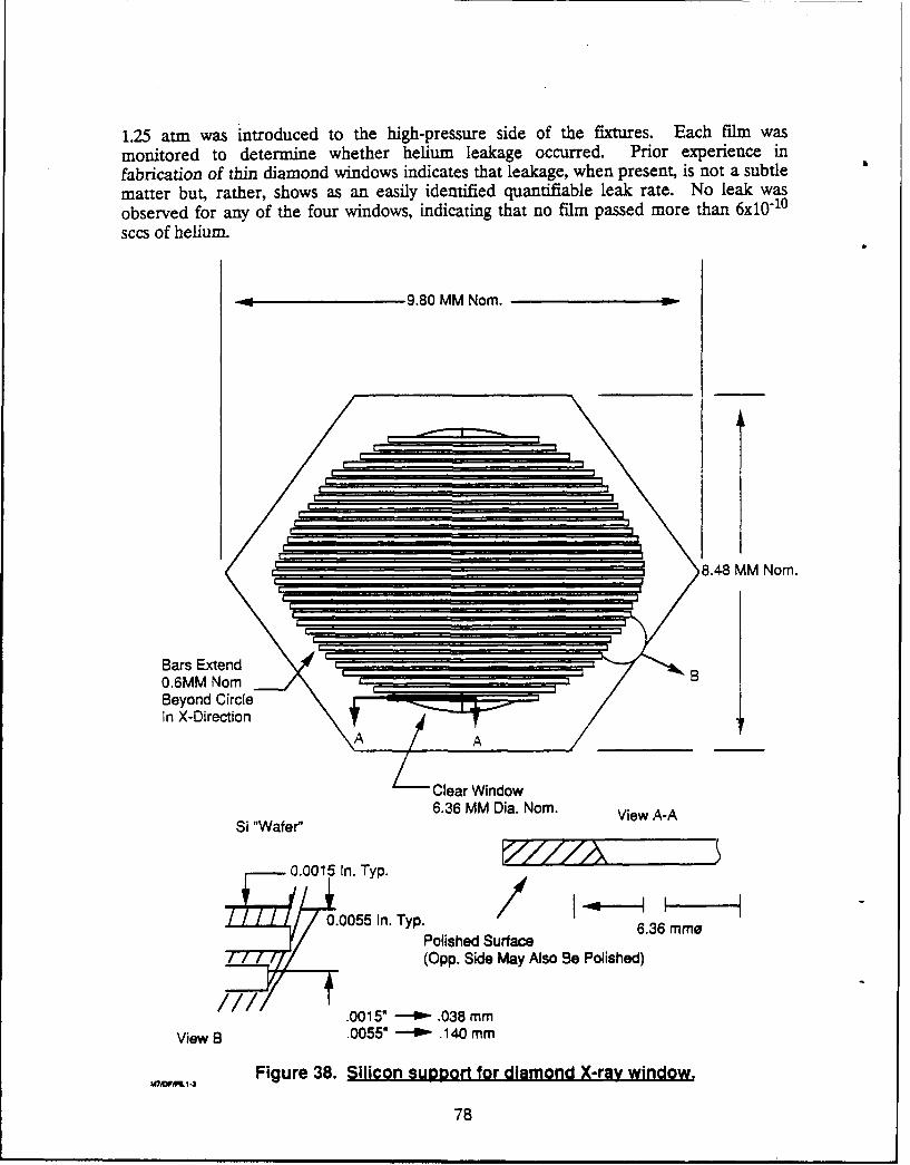
1.25 atm was introduced to the high-pressure side of the fixtures. Each film wasmonitored to determine whether helium leakage occurred. Prior experience infabrication of thin diamond windows indicates that leakage, when present, is not a subtlematter but, rather, shows as an easily identified quantifiable leak rate. No leak wasobserved for any of the four windows, indicating that no film passed more than 6x10 "10
sccs of helium.
9.80 MM Nom.
8.48 MM Nom.
Bars Extend0.6MM NorBeyond CircleIn X-Direction
A A
Clear Window6.36 MM Dia. Nom. View A-A
Si "Wafer
0.0015 In. Typ.
0.0055 In. Typ. /Polished Surface
(Opp. Side May Also Be Polished)
.0015" - .038 mm
View B .0055" - .140 mm
%VW-& 1.. Figure 38. Silicon support for diamond X-ray window.
78
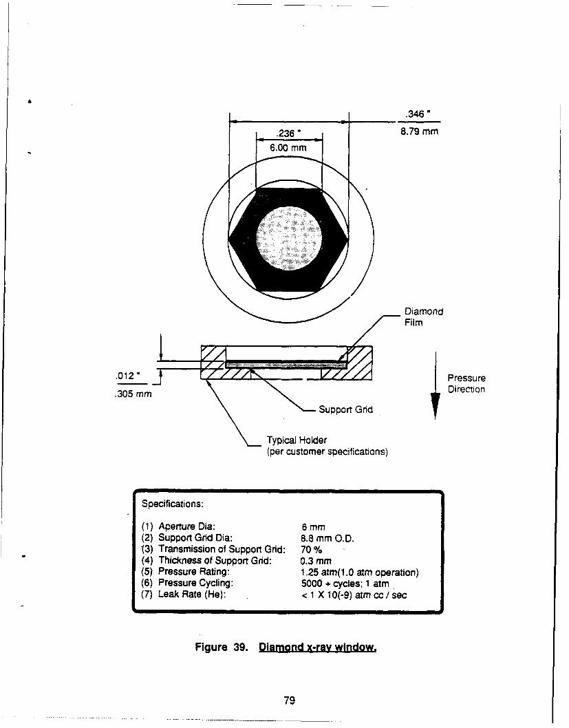
.346"
•.236 8.79 mm6.00 mm
DiamondFilm
.012" r Pressure
.305 mm S Gri Direction
• Suppor Grid
Typical Holder(per customer specifications)
Specifications:
(1) Aperture Dia: 6 mm(2) Support Grid Dia: 8.8 mm O.D.3) Transmission of Support Grid: 70 %
(4) Thickness of Support Grid: 0.3 mm(5) Pressure Rating: 1.25 atm(1.0 atm operation)(6) Pressure Cycling: 5000 + cycles; 1 atm.(7) Leak Rate (He): <1 X 10(-9) atm cc / sec
Figure 39. Diamond x-ray window.
79
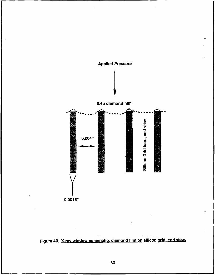
Applied Pressure
0.411 diamond film
0.004".
Y(0
0.0015"
Figure 40. X-ray window schematic. diamond film on silicon grid. end view,
80
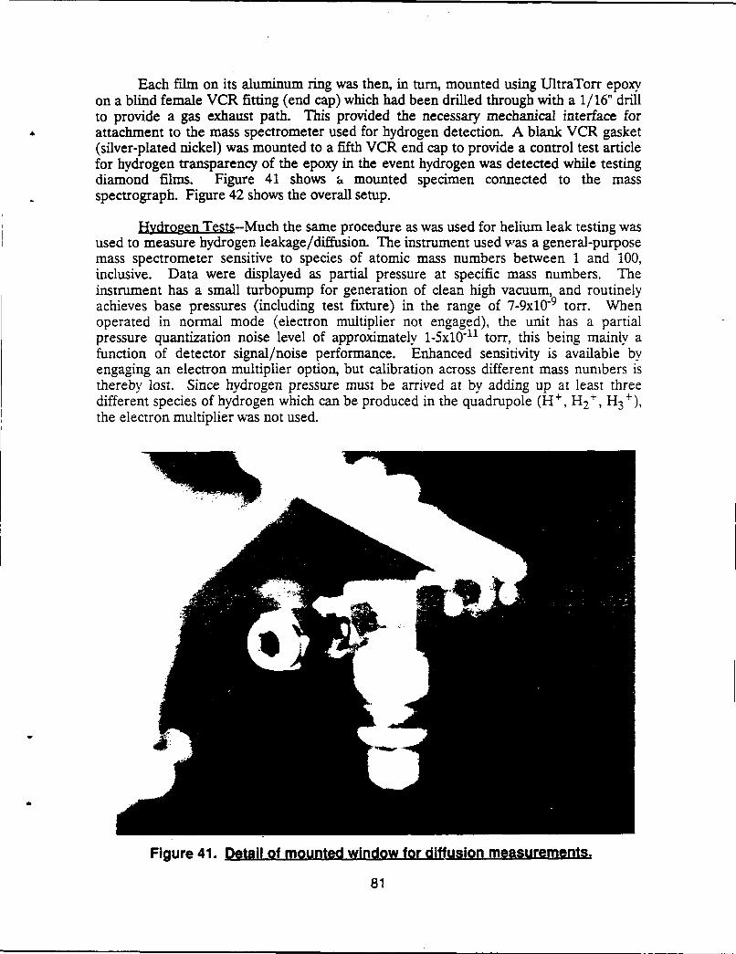
Each film on its aluminum ring was then, in turn, mounted using UltraTorr epoxyon a blind female VCR fitting (end cap) which had been drilled through with a 1/16" drillto provide a gas exhaust path. This provided the necessary mechanical interface forattachment to the mass spectrometer used for hydrogen detection. A blank VCR gasket(silver-plated nickel) was mounted to a fifth VCR end cap to provide a control test articlefor hydrogen transparency of the epoxy in the event hydrogen was detected while testingdiamond films. Figure 41 shows a mounted specimen connected to the massspectrograph. Figure 42 shows the overall setup.
Hydrogen Tests--Much the same procedure as was used for helium leak testing wasused to measure hydrogen leakage/diffusion. The instrument used was a general-purposemass spectrometer sensitive to species of atomic mass numbers between 1 and 100,inclusive. Data were displayed as partial pressure at specific mass numbers. Theinstrument has a small turbopump for generation of clean high vacuum, and routinelyachieves base pressures (including test fixture) in the range of 7-9x10 "9 torr. Whenoperated in normal mode (electron multiplier not engaged), the unit has a partialpressure quantization noise level of approximately 1-5x10- 11 torn, this being mainly afunction of detector signal/noise performance. Enhanced sensitivity is available byengaging an electron multiplier option, but calibration across different mass numbers isthereby lost. Since hydrogen pressure must be arrived at by adding up at least threedifferent species of hydrogen which can be produced in the quadrupole (H + , H2 ', H3
+)the electron multiplier was not used.
Figure 41. Detail of mounted window for diffusion measurements.
81
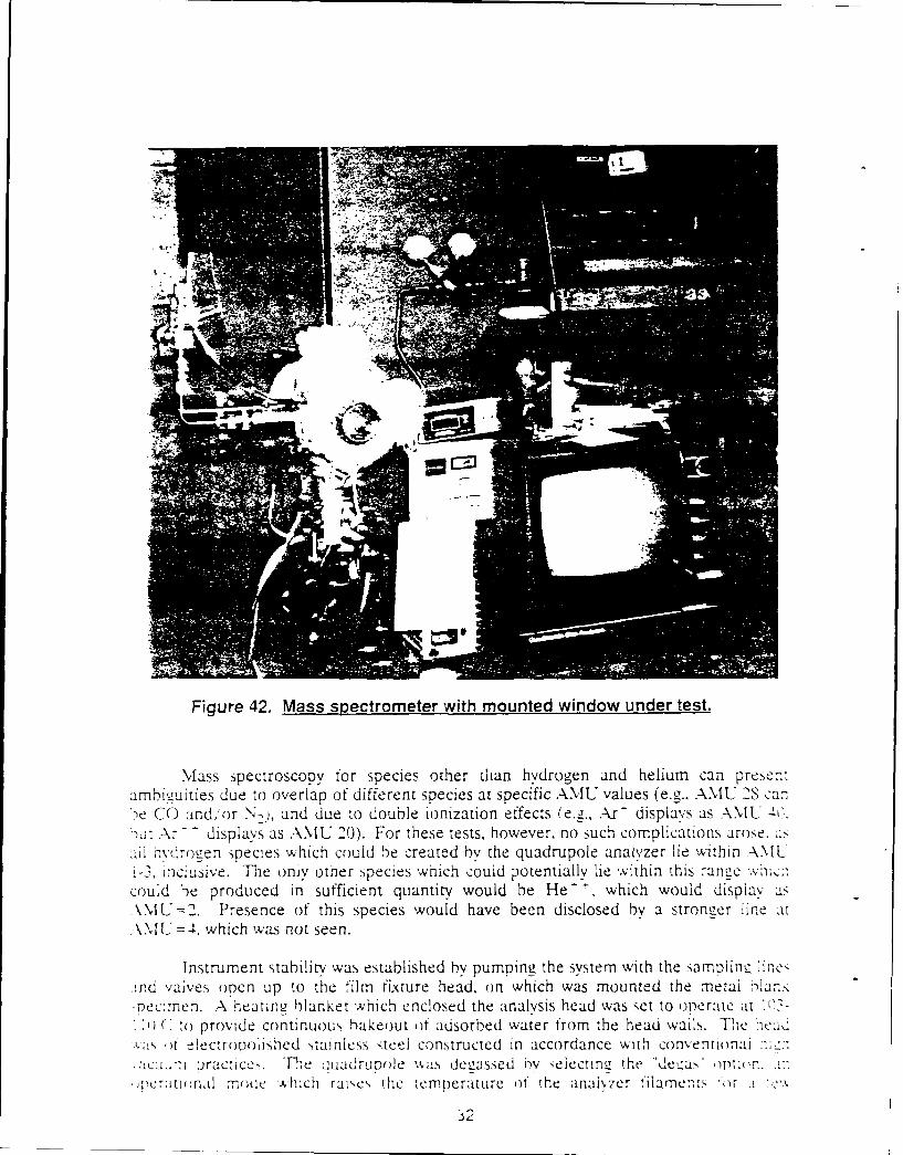
Figure 42. Mass spectrometer with mounted window under test.
Mass spectroscopy for species other than hydrogen and helium can presert:amhi~mities due to overlap of different -species at specific AMU values (e.gz.. AMVU 2S ca,-,'e CO and/lor N>%, and due to double ionization effects (eg.Al- displays as AMU 'c
MiLt Ar -displays as ANIU 20). For these tests, however, no such complications arose. asdil hvdro ,e n species which could be created by the quadrupole analyzer lie within AMUt-, Inc;isive. TPhe oniy other species 'which couid potentially lie within this range nc.could be produced in sufficient quantity would be He which would display asAM1U =2. Presence of this species would have been disclosed by a stroneer lie at:\NU =4. which was not seen.
Instrument stability was established by pumping the system with the sampling, irtes1cMd vaives open uip to the film fixture head, on which was mounted the metal ln-pec:.nen. A heatin2 blanket which enclosed the analysis head was set to onerate 'Lt '-
* )C to provide continuous hakeout of adsorbed water from the head wails. The, >1elc()t )t lectropoii]shed ,talniess steel constructed In accordance with converitionai
*cu.-i practice'). Tie quadrupole wsdegassed 'Oy selectin,_ the da ontinn.* Q)CratU )n.Ll modeC which raisc', the temperatuire of the anal','7r tilaMer,,s '(r .1
32
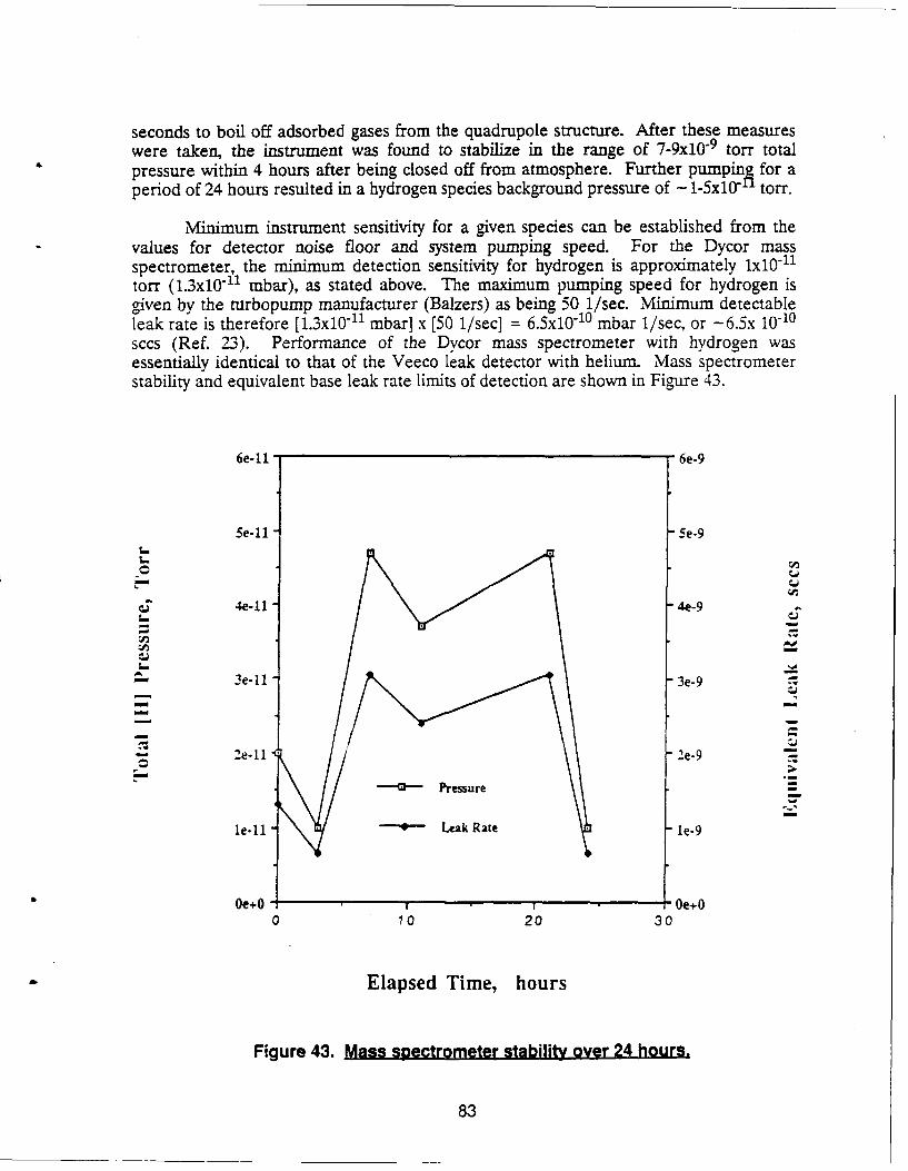
seconds to boil off adsorbed gases from the quadrupole structure. After these measureswere taken, the instrument was found to stabilize in the range of 7-9x10 "9 torr totalpressure within 4 hours after being closed off from atmosphere. Further pumpinA for aperiod of 24 hours resulted in a hydrogen species background pressure of - 1-5xI0 torr.
Minimum instrument sensitivity for a given species can be established from thevalues for detector noise floor and system pumping speed. For the Dycor massspectrometer, the minimum detection sensitivity for hydrogen is approximately x10 "11
torr (1.3xi0 11 mbar), as stated above. The maximum pumping speed for hydrogen isgiven by the nirbopump manufacturer (Balzers) as being 50 1/sec. Minimum detectableleak rate is therefore [.3x10"1 mbar] x [50 1/sec] = 6.5x10 "1 0 mbar I/sec, or -6.5x 10⁻¹⁰sccs (Ref. 23). Performance of the Dycor mass spectrometer with hydrogen wasessentially identical to that of the Veeco leak detector with helium. Mass spectrometerstability and equivalent base leak rate limits of detection are shown in Figure 43.
6e-11 6e-9
5e-1l 5e-9
4e-11 4e-9
-3e-11 3e-9
,e-1 2e-9-
Pressure
le-1l"-"* - Leak Rate le-9
Oe+O, Oe+0 10 20 30
Elapsed Time, hours
Figure 43. Mass spectrometer stability over 24 hours.
83
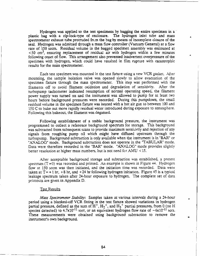
Hydrogen was applied to the test specimens by bagging the entire specimen in aplastic bag with a zip-lock-type of enclosure. The hydrogen inlet tube and massspectrometer exhaust tube protruded frcm the bag by means of incomplete closure of theseal. Hydrogen was admitted through a mass flow controller (Vacuum General) at a flowrate of 150 sccm. Residual volume in the bagged specimen assembly was estimated at<50 cm 3, ensuring replacement of residual air with hydrogen within a few minutesfollowing onset of flow. This arrangement also prevented inadvertent overpressure of thespecimen with hydrogen, which could have resulted in film rupture with catastrophicresults for the mass spectrometer.
Each test specimen was mounted in the test fixture using a new VCR gasket. Aftermounting, the sample isolation valve was opened slowly to allow evacuation of thespecimen fixture through the mass spectrometer. This step was performed with thefilaments off to avoid filament oxidation and degradation of sensitivity. After theturbopump tachometer indicated resumption of normal operating speed, the filamentpower supply was turned on and the instrument was allowed to pump for at least twohours before background pressures were recorded. During this pumpdown, the smallresidual volume in the specimen fixture was heated with a hot air gun to between 100 and150 C to bake out more rapidly residual water introduced during exposure to atmosphere.Following this bakeout, the filament was degassed.
Following establishment of a stable background pressure, the instrument wasprogrammed to collect a reference background spectrum for storage. This backgroundwas subtracted from subsequent scans to provide maximum sensitivity and rejection of anysignals from roughing pump oil which might have diffused upstream through theturbopump. Background subtraction is only available when the instrument is in "BAR" or"ANALOG" mode. Background subtraction does not operate in the "TABULAR" mode.Data were therefore recorded in the "BAR" mode. "ANALOG" mode provides slightlybetter resolution at higher mass numbers, but is not need fcr AMU < 15.
After acceptable background storage and subtraction was established, a pretestspectrum (T=0) was recorded and printed. An example is shown in Figure 44. Hydrogenflow at 150 sccm was then initiated, and the initiation time was recorded. Data weretaken at T = + 1 hr, + 8 hr, and + 24 hr following hydrogen initiation. Figure 45 is a typicalleakage spectrum taken after 24-hour exposure to hydrogen. The complete set of dataprintouts are given in Appendix D.
Test Results
Mass Spectrometer Stability: Samples taken at various intervals during a 24-hourperiod using a blanked-off VCR fitting in the test fixture showed variations in hydrogenpartial pressure, defined as the sum of H , H2
+ , and H3+ partial pressures, from 0 (no H
species detected) to 4.7x10 "11 torr, or an equivalent hydrogen flow rate of -6x10 1 1 sccs.These measurements were obtained using background subtraction to remove theinstrument's own background.
84
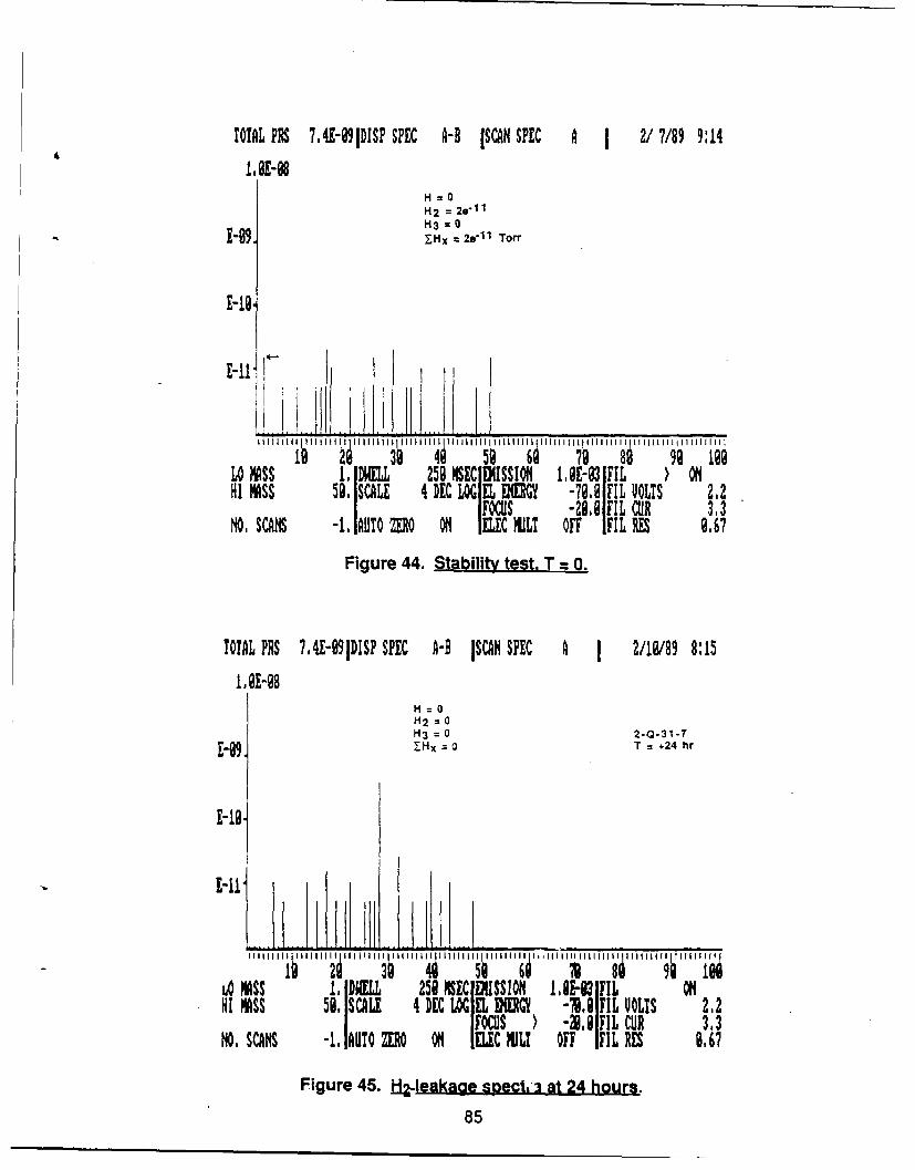
TOTAL PR 7,4H91DISP SPEC A-B ISCAN SPEC A I 2/7/89 9:14
M.E-08H=O
H2 = 20-11H3 =
-1-9 .Hx 28 "11 Toff
E-19,
..... ..I i ..I
3 4s 5Q 61 99 logLo MASS 1. DWELL 259 MSEC EMISSIONi 1,9-93 IFIL ONHI MASS 59. SCALE 4 EC LOGEL EM -7,0FIL ULTS 212
A FOCUS -2109IFIL CUR 3.3NO. SCAN -1. AUTO M O IEC MIL! OFF IFIL RES 9,67
Figure 44. Stability test, T = 0.
!OTAL PRS ?,4E-99lDISP SPEC A-B lSCAH SPEC A J 2/10/89 8:15
1. 91-98H=OH2 = 0H3 = 0 2-0-31-7
-. =Hx 0 T = +24 hr
10 NASS 1. DWELL 258 MSIC EDiSSlON 1.E-83 FIL OHI MASS 5I SCALE 4 DE A EL BOEGY -78,8 FIL UOLTS 212
FOCUS ' -30.9 FIL CUR 3.3NO. SCANS -1. 1AUTO ZRO ONI ELC MiLI OFF FIL RES 6.67
Figure 45. H2-teakage spectbi at 24 hours.
85
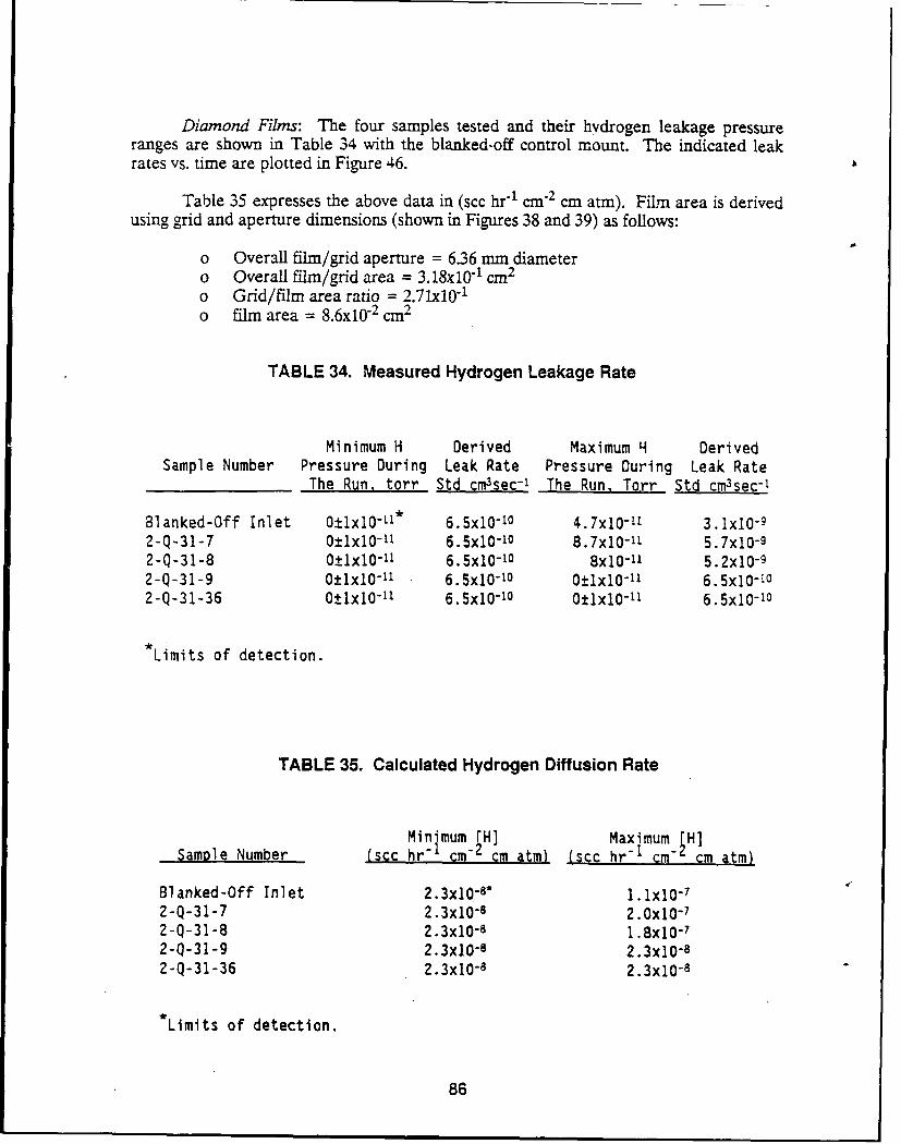
Diamond Films: The four samples tested and their hydrogen leakage pressureranges are shown in Table 34 with the blanked-off control mount. The indicated leakrates vs. time are plotted in Figure 46.
Table 35 expresses the above data in (scc hr-1 c rn 2 cm atm). Film area is derivedusing grid and aperture dimensions (shown in Figures 38 and 39) as follows:
o Overall film/grid aperture = 6.36 mm diametero Overall film/grid area = 3.18x101 cm 2
o Grid/film area ratio = 2.71x10 "1
o film area = 8.6x10 2 cm2
TABLE 34. Measured Hydrogen Leakage Rate
Minimum H Derived Maximum H DerivedSample Number Pressure During Leak Rate Pressure During Leak Rate
The Run, torr Std cm3sec-' The Run, Torr Std cm3sec-1
Blanked-Off Inlet 0±1x10 -11* 6.5x10-10 4.7x10"- 3. lx10-92-Q-31-7 0±lxl0-"1 6.5x10⁻¹⁰ 8.7x10-"1 5.7x10- 9
2-Q-31-8 O±1x10 -1 6.5x10⁻¹⁰ 8x10-11 5.2xi0-92-Q-31-9 O±Ix10-1 6.5x10 - 10 O+_x10- 1 6.5xi0-I02-Q-31-36 O+1x10 1- 6.5x10- 0 Olx10- 6.5xi0-10
Limits of detection.
TABLE 35. Calculated Hydrogen Diffusion Rate
Minimum H] Maximum H]-Samole Number (scc hr" lcm" cm atm) (scc hr"I cm- cm atm)
Blanked-Off Inlet 2.3x10 - * 1. Jx10- 7
2-Q-31-7 2.3x0-8 2.0x10-72-Q-31-8 2.3x0 -8 1.8x0 - 7
2-Q-31-9 2.3x10⁻⁸ 2.3x10-82-Q-31-36 2.3xi0 - 2.3x0 -8
*Limits of detection.
86
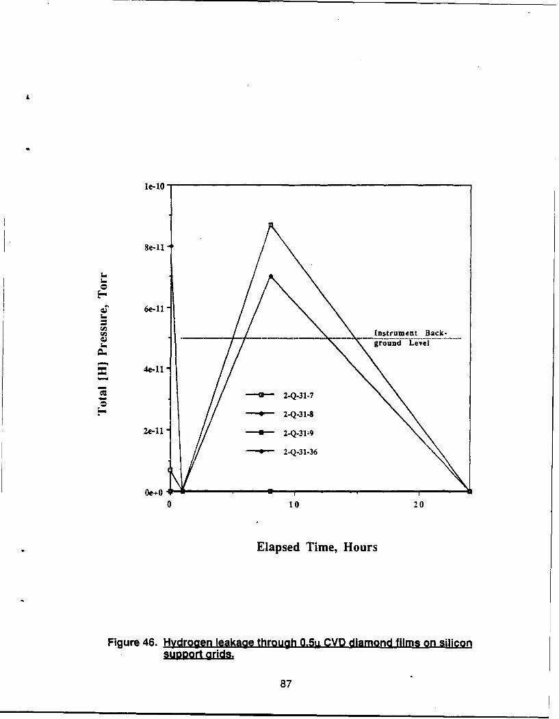
le-lO
Se-ll
Q6e-ll
Instrument Back-6
4e-11
2.Q-31-7
- 2-Q-31.8
2e-W 2.Q319
2-Q.31-36
Oe O
0 10 20
Elapsed Time, Hours
Figure 46. Hydrogen leakage through 0.5u CVD diamond films on silicon
87
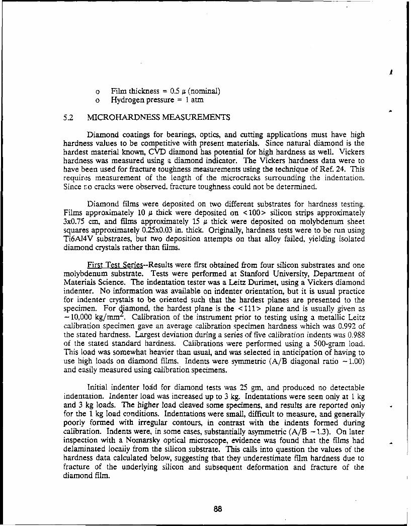
o Film thickness = 0.5,u (nominal)o Hydrogen pressure = 1 atm
5.2 MICROHARDNESS MEASUREMENTS
Diamond coatings for bearings, optics, and cutting applications must have highhardness values to be competitive with present materials. Since natural diamond is thehardest material known, CVD diamond has potential for high hardness as well. Vickershardness was measured using a diamond indicator. The Vickers hardness data were tohave been used for fracture toughness measurements using the technique of Ref. 24. Thisrequires measurement of the length of the microcracks surrounding the indentation.Since ro cracks were observed, fracture toughness could not be determined.
Diamond films were deposited on two different substrates for hardness testing.Films approximately 10 j thick were deposited on < 100> silicon strips approximately3x0.75 cm, and films approximately 15 g thick were deposited on molybdenum sheetsquares approximately 0.25x0.03 in. thick. Originally, hardness tests were to be run usingTi6AI4V substrates, but two deposition attempts on that alloy failed, yielding isolateddiamond crystals rather than films.
First Test Series--Results were first obtained from four silicon substrates and onemolybdenum substrate. Tests were performed at Stanford University, Department ofMaterials Science. The indentation tester was a Leitz Durimet, using a Vickers diamondindenter. No information was available on indenter orientation, but it is usual practicefor indenter crystals to be oriented such that the hardest planes are presented to thespecimen. For diamond, the hardest plane is the < 111> plane and is usually given as- 10,000 kg/mm2 . Calibration of the instrument prior to testing using a metallic Leitzcalibration specimen gave an average calibration specimen hardness which was 0.992 ofthe stated hardness. Largest deviation during a series of five calibration indents was 0.988of the stated standard hardness. Calibrations were performed using a 500-gram load.This load was somewhat heavier than usual, and was selected in anticipation of having touse high loads on diamond films. Indents were symmetric (A/B diagonal ratio - 1.00)and easily measured using calibration specimens.
Initial indenter lodd for diamond tests was 25 gm, and produced no detectableindentation. Indenter load was increased up to 3 kg. Indentations were seen only at 1 kgand 3 kg loads. The higher load cleaved some specimens, and results are reported onlyfor the 1 kg load conditions. Indentations were small, difficult to measure, and generallypoorly formed with irregular contours, in contrast with the indents formed duringcalibration. Indents were, in some cases, substantially asymmetric (A/B -1.3). On laterinspection with a Nomarsky optical microscope, evidence was found that the films haddelaminated locaily from the silicon substrate. This calls into question the values of thehardness data calculated below, suggesting that they underestimate film hardness due tofracture of the underlying silicon and subsequent deformation and fracture of thediamond film.
88
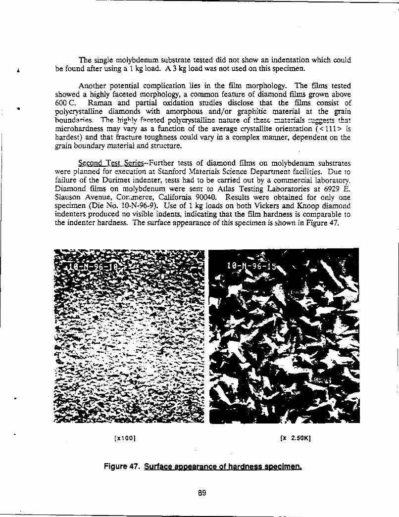
The single molybdenum substrate tested did not show an indentation which couldbe found after using a 1 kg load. A 3 kg load was not used on this specimen.
Another potential complication lies in the film morphology. The films testedshowed a highly faceted morphology, a common feature of diamond films grown above600 C. Raman and partial oxidation studies disclose that the films consist ofpolycrystalline diamonds with amorphous and/or graphitic material at the grainboundaries. The highly fpceted polycrystalline nature of these- aterials suogests thatmicrohardness may vary as a function of the average crystallite orientation (<111> ishardest) and that fracture toughness could vary in a complex manner, dependent on thegrain boundary material and structure.
Second Test Series--Further tests of diamond films on molybdenum substrateswere planned for execution at Stanford Materials Science Department facilities. Due tofailure of the Durimet indenter, tests had to be carried out by a commercial laboratory.Diamond films on molybdenum were sent to Atlas Testing Laboratories at 6929 E.Slauson Avenue, Cormerce, California 90040. Results were obtained for only onespecimen (Die No. 10-N-96-9). Use of 1 kg loads on both Vickers and Knoop diamondindenters produced no visible indents, indicating that the film hardness is comparable tothe indenter hardness. The surface appearance of this specimen is shown in Figure 47.
!JP
E_,,. :t -
(X1OO1 [x 2.50K]
Figure 47. Surface appRearance of hardness specimen.
89
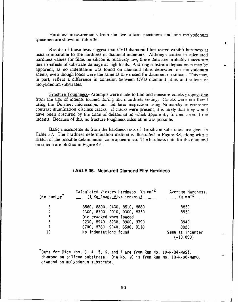
Hardness measurements from the five silicon specimens and one molybdenumspecimen are shown in Table 36.
Results of these tests suggest that CVD diamond films tested exhibit hardness atleast comparable to the hardness of diamond indenters. Although scatter in calculatedhardness values for films on silicon is relatively low, these data are probably inaccuratedue to effects of substrate damage at high loads. A strong substrate dependence may beapparent, as no indentation was found on diamond films deposited on molybdenumsheets, even though loads were the same as those used for diamond on silicon. This may,in part, reflect a difference in adhesion between CVD diamond films and silicon ormolybdenum substrates.
Fracture Toughness--Attempts were made to find and measure cracks propagatingfrom the tips of indents formed during microhardness testing. Cracks were not foundusing the Durimet microscope, nor did later inspection using Nomarsky interferencecontrast illumination disclose cracks. If cracks were present, it is likely that they wouldhave been obscured by the zone of delamination which apparently formed around theindents. Because of this, no fracture toughness calculation was possible.
Basic measurements from the hardness tests of the silicon substrates are given inTable 37. The hardness determination method is illustrated in Figure 48, along with asketch of the possible delamination zone appearance. The hardness data for the diamondon silicon are plotted in Figure 49.
TABLE 36. Measured Diamond Film Hardness
Calculated Vickers Hardness, Kg mm-2 Average Hardness,Die Number* (1 Kq load, five indents) Kq mm-2
3 8560, 8890, 9430, 8510, 8880 88504 9300, 8790, 9010, 9300, 8350 89505 Die cracked when loaded -6 9230, 8940, 8230, 8900, 9390 89407 8700, 8760, 9040, 8500, 9110 8820
10 No indentations found Same as indenter(-10,000)
*Data for Dice Nos. 3, 4, 5, 6, and 7 are from Run No. l0-N-84-MWSI,
diamond on silicon substrate. Die No. 10 is from Run No. 10-N-96-MWMO,diamond on molybdenum substrate.
90
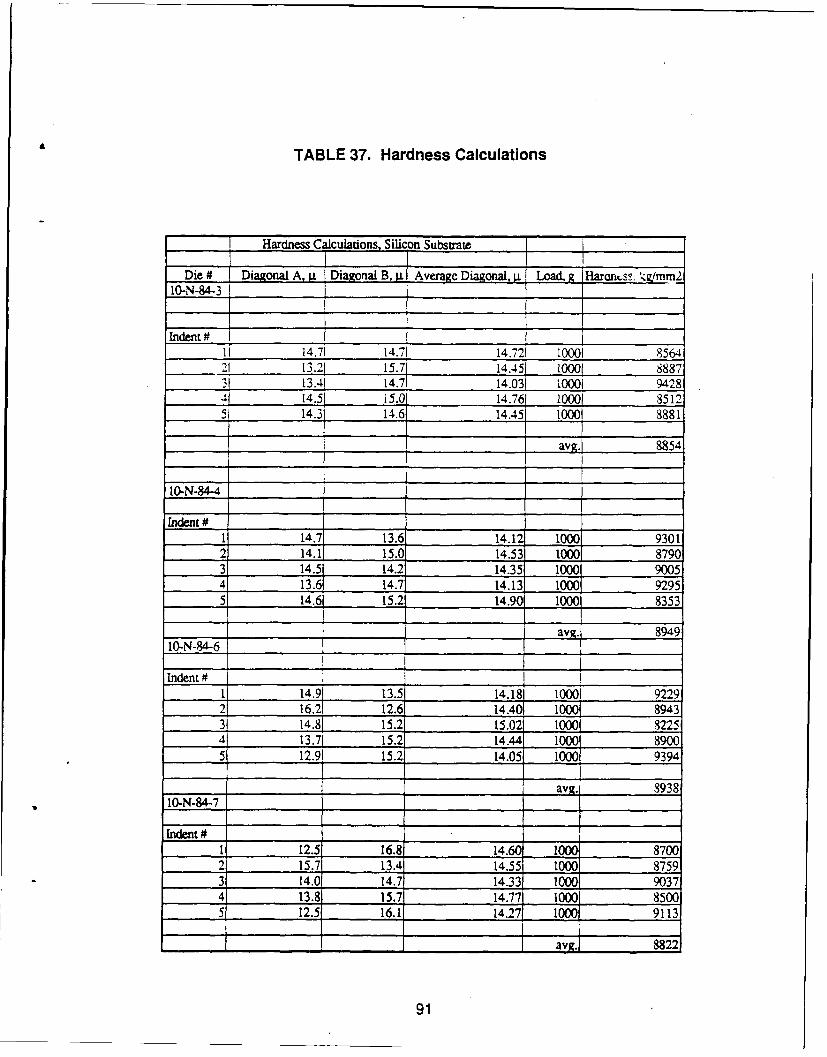
TABLE 37. Hardness Calculations
Hardness Ca culations, Silicon SubstrateDie # [Diagonal A, Diagonal B,i verage Diagonl, L g Haran~s /mm2
10-N-84-3
Indent #I i 14.71 14.71 14.721 10001 85642! 13.21 15.71 14.451 10001 88873 13.41 14.71 14.031 10001 94284 14.51 15.0 14.761 10001 85125 14.3 14.6 14.45 10001 8881
avg.1 8854
10.N-84-4
Indent #1 14.7 13.6 14.12 1000 93012 14.1 15.0 14.53 1000 87903 14.5 14.2 14.35 1000 90054 13.6 14.7 14.13 1000 929551 14.6 15.2 14.90 1000 8353
avg. 8949:10-N-84-6
Indent #
1 14.91 13.5 14.181 1000 92292 16.21 12.6 14.401 1000 i 89433 14.8 15.2 15.02 1000 8225
_ 13.71 15.2 14.44 1000 89005 12.91 15.2 14.05 1000 9394
avg. 893810-N-84-7
Indent#I 12.5 16.81 14.60 1000 87002 15.7 13.4 14.55 1000 87593 14.0 14.7 14.33: 1000 90374 13.8 15.7 14.77 1000 85005 12.5 16.1 14.27 1000 9113
1 av. 8822
91
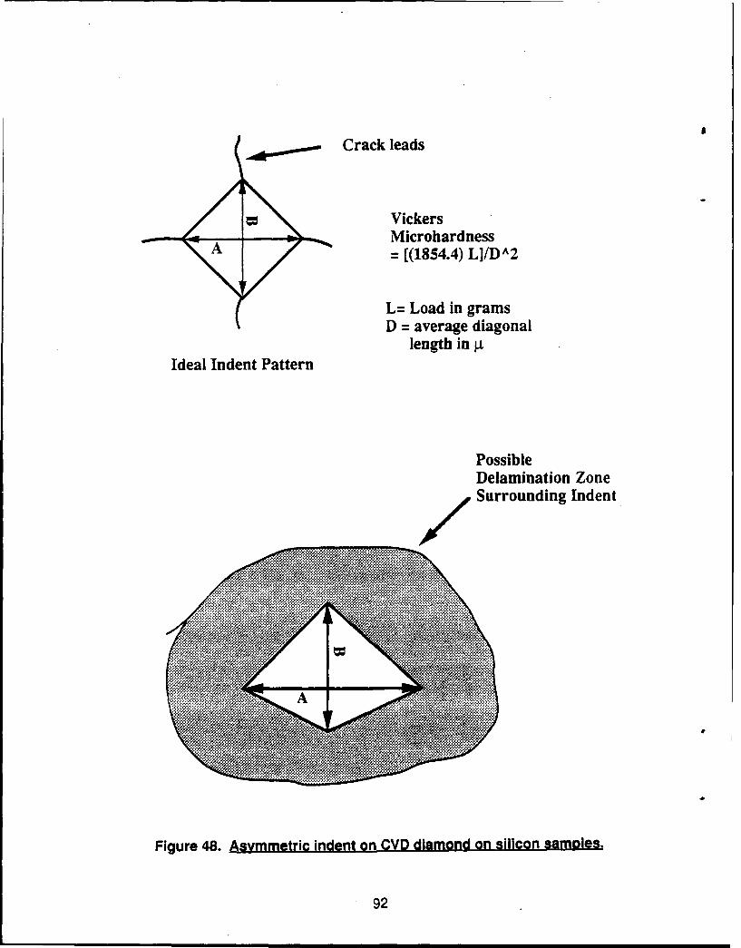
Crack leads
VickersMicrohardness
A = [(1854.4) L]/DA2
L= Load in gramsD = average diagonal
length in p.Ideal Indent Pattern
PossibleDelamination ZoneSurrounding Indent
g v '" '~ .......... .... *
.... . . ........ ~ ~ *
*--V.
*. .. x.:. ... ~ ~ >A~ s ~ 4 tX * *
4~: ~ 0*OtM
*1 *K
Fiue4. smeri net nCDdimn n iioAsmls
920
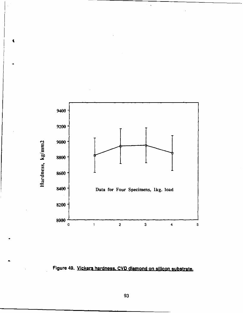
9400-
9200-
9000-
8800
= 8600-
8400- Data for Four Specimens, 1kg. load
8200-
8000 1 2 3 45
Figure 49. Vickers hardness. CVD diamond on silicon substrate.
93
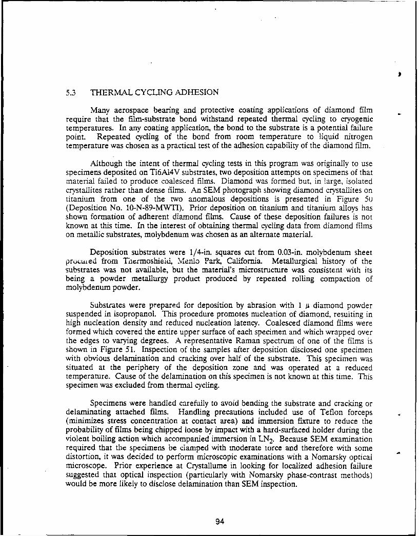
5.3 THERMAL CYCLING ADHESION
Many aerospace bearing and protective coating applications of diamond filmrequire that the film-substrate bond withstand repeated thermal cycling to cryogenictemperatures. In any coating application, the bond to the substrate is a potential failurepoint. Repeated cycling of the bond from room temperature to liquid nitrogentemperature was chosen as a practical test of the adhesion capability of the diamond film.
Although the intent of thermal cycling tests in this program was originally to usespecimens deposited on Ti6AI4V substrates, two deposition attempts on specimens of thatmaterial failed to produce coalesced films. Diamond was formed but, in large, isolatedcrystallites rather than dense films. An SEM photograph showing diamond crystallites ontitanium from one of the two anomalous depositions is presented in Figure 50(Deposition No. 10-N-89-MWTI). Prior deposition on titanium and titanium alloys hasshown formation of adherent diamond films. Cause of these deposition failures is notknown at this time. In the interest of obtaining thermal cycling data from diamond filmson metallic substrates, molybdenum was chosen as an alternate material.
Deposition substrates were 1/4-in. squares cut from 0.03-in. molybdenum sheetprotruied from Tiiermoshieid, Menlo Park, California. Metallurgical history of thesubstrates was not available, but the material's microstructure was consistent with itsbeing a powder metallurgy product produced by repeated rolling compaction ofmolybdenum powder.
Substrates were prepared for deposition by abrasion with 1 /i diamond powdersuspended in isopropanol. This procedure promotes nucleation of diamond, resulting inhigh nucleation density and reduced nucleation latency. Coalesced diamond films wereformed which covered the entire upper surface of each specimen and which wrapped overthe edges to varying degrees. A representative Raman spectrum of one of the films isshown in Figure 51. Inspection of the samples after deposition disclosed one specimenwith obvious delamination and cracking over half of the substrate. This specimen wassituated at the periphery of the deposition zone and was operated at a reducedtemperature. Cause of the delamination on this specimen is not known at this time. Thisspecimen was excluded from thermal cycling.
Specimens were handled carefully to avoid bending the substrate and cracking ordelaminating attached films. Handling precautions included use of Teflon forceps(minimizes stress concentration at contact area) and immersion fixture to reduce theprobability of films being chipped loose by impact with a hard-surfaced holder during theviolent boiling action which accompanied immersion in LN 2. Because SEM examinationrequired that the specimens be clamped with moderate torce and therefore with somedistortion, it was decided to perform microscopic examinations with a Nomarsky opticalmicroscope. Prior experience at Crystallume in looking for localized adhesion failuresuggested that optical inspection (particularly with Nomarsky phase-contrast methods)would be more likely to disclose delamination than SEM inspection.
94
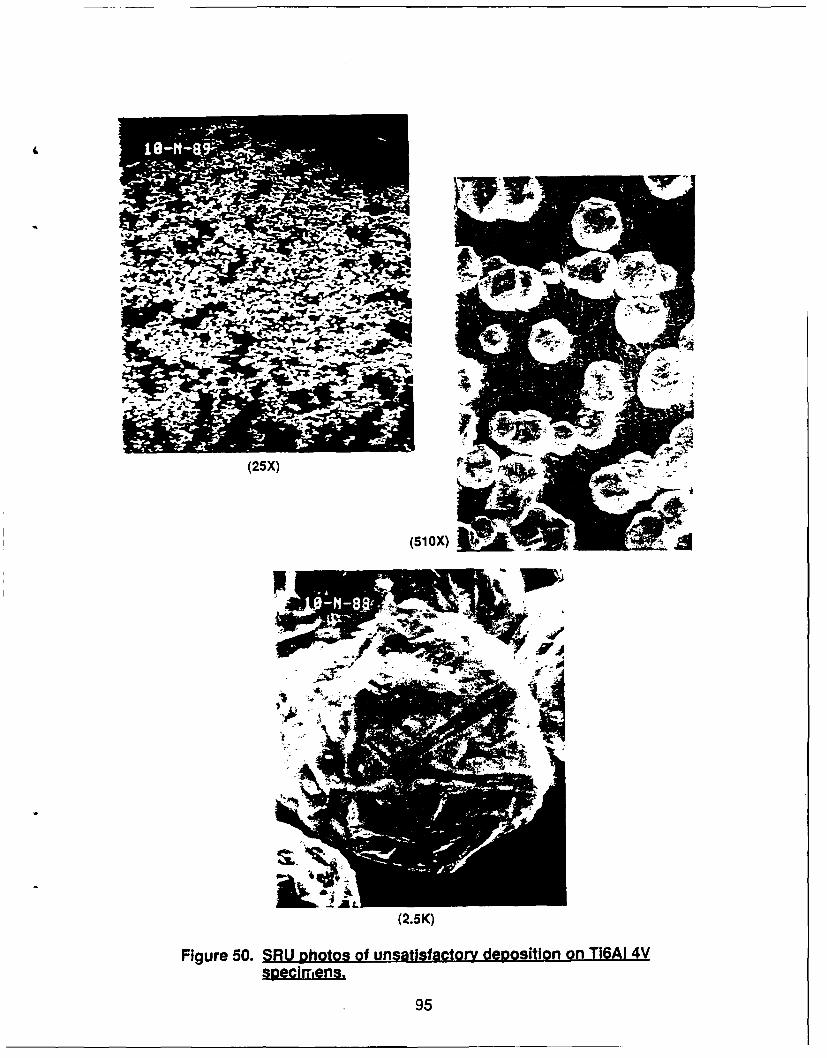
(25X)
(510X)
(2.5K)
Figure 50. aft p2hotos of unsatisfactory deposition on T16AI 4Vspecimens.
95
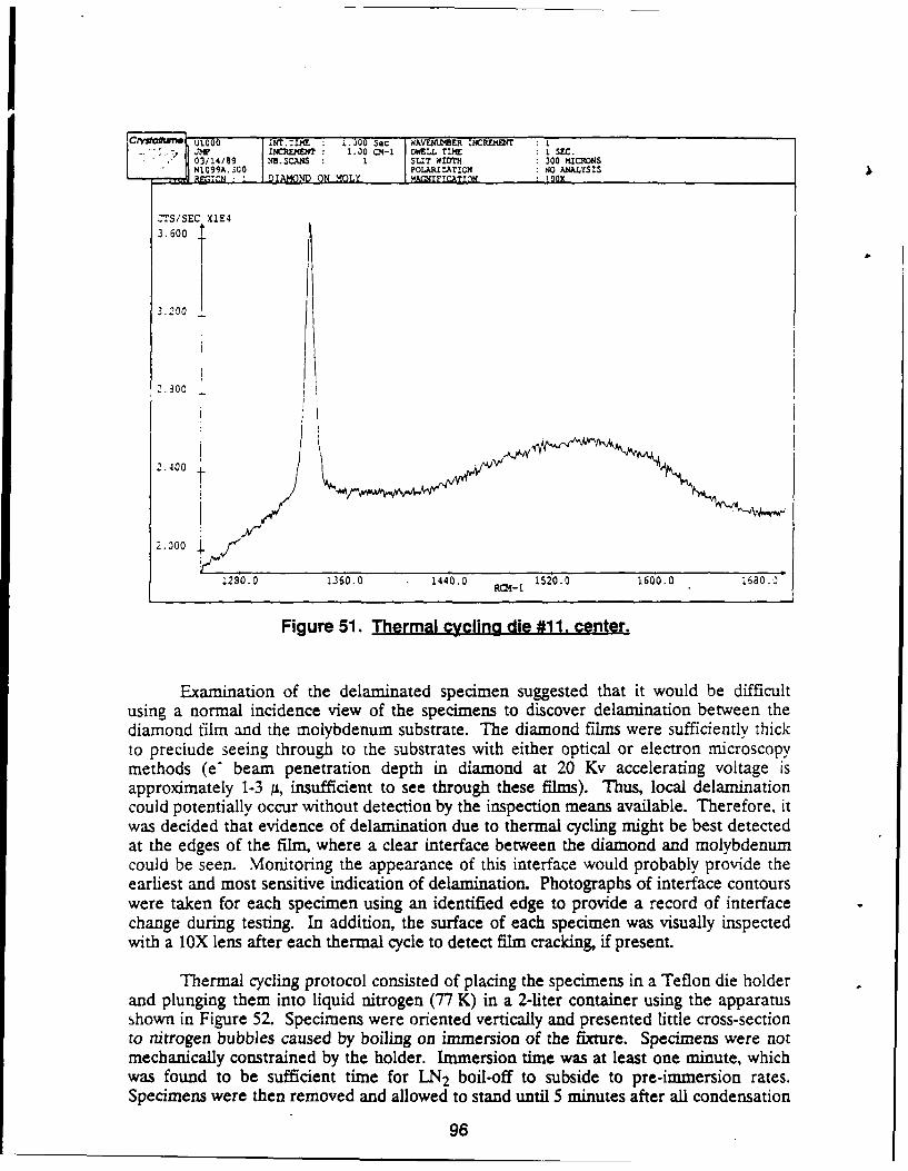
CryvIa T UO00 :NT .I :E 1.)00 Sec wA1J U NER ICIDJT L
.)- 'M INCX4ENT 1.0 0092 DIEL INE I SEC.03/14/89 N .SCANS : SL.? W TH 300 ?ICRONSN1099A. 00 POLAMIZATION NO ANALYSIS_Q':C QT DAMOND ON MOLY 11MINFYCTO : Z"00
CTS/SEC X1E4
3.600
3.200
2.300
2.4001K
2.300
1280.0 1360,0 1440.0 1520.0 1600.0 16ao.10
Figure 51. Thermal cycling die #11. center.
Examination of the delaminated specimen suggested that it would be difficultusing a normal incidence view of the specimens to discover delamination between thediamond film and the molybdenum substrate. The diamond films were sufficiently thickto preclude seeing through to the substrates with either optical or electron microscopymethods (e- beam penetration depth in diamond at 20 Kv accelerating voltage isapproximately 1-3 JL, insufficient to see through these films). Thus, local delaminationcould potentially occur without detection by the inspection means available. Therefore, itwas decided that evidence of delamination due to thermal cycling might be best detectedat the edges of the film, where a clear interface between the diamond and molybdenumcould be seen. Monitoring the appearance of this interface would probably provide theearliest and most sensitive indication of delamination. Photographs of interface contourswere taken for each specimen using an identified edge to provide a record of interfacechange during testing. In addition, the surface of each specimen was visually inspectedwith a 1oX lens after each thermal cycle to detect film cracking, if present.
Thermal cycling protocol consisted of placing the specimens in a Teflon die holderand plunging them into liquid nitrogen (77 K) in a 2-liter container using the apparatusshown in Figure 52. Specimens were oriented vertically and presented little cross-sectionto nitrogen bubbles caused by boiling on immersion of the fixture. Specimens were notmechanically constrained by the holder. Immersion time was at least one minute, whichwas found to be sufficient time for LN 2 boil-off to subside to pre-immersion rates.Specimens were then removed and allowed to stand until 5 minutes after all condensation
96
Awl*
9' 17O0m
970
ice had melted. This time varied with local humidity, but was never less than 11 minutes.The immersion cycle was then repeated. Specimens were inspected at intervals of 5immersions and photographed at intervals of 25 immersions, to 100 total immersions.Tests were performed over four days, with 25 immersions per day.
Results--No thermally induced delamination of diamond films from molybdenumwas noted during the course of these tests. Sample photographs are presented in Figures53 through 56. Although photographs were taken every 25 cycles, only the pretest and100-cycle photos are shown because of the lack of change in visual appearance. Labels inthe lower left comers are sample numbers, lower right comers are magnifications, andupper right comers are thermal cycling numbers, where 0 = precycling.
Examination of the specimens and of micrographs taken of each specimen showedthat the reference film edges remained unchanged from their precycling contours. Noremoval of crvstallites was noted, indicating that thermal cycling was insufficient toovercome adhesion between the molybdenum and deposited diamond even in those areasin which the film had not fully coalesced.
A final test of film adhesion was performed which consisted of mounting eachspecimen to double-sided tape (deposition side up) and performing a pull test with single-sided tape attached to the exposed diamond film. The single-sided tape has a weakerbond with the diamond film than did the tape in contact with the reverse of eachspecimen. This test was carried out after all thermal cycling was done because of itspotential for complication of the results by production of deformation-induced filmfracture and delamination. Tapes were examined after pulling to locate film fragments.None was found.
5.4 RLPTURE STRENGTH
Natural diamond has a measured tensile strength of 0.5x10 6 psi and a theoreticaltensile strength of 16x106 psi. Burst tests of thin diamond films during previousproduction testing of X-ray windows 'gave loads at failure initially interpreted by platetheory as being in the range of 3x10⁶ psi. Such a strength value would open up manystructural applications for diamond film. Since the window tests were made with very thin(0.5 micron) films, the test procedure was modified to use thicker films which woul bepractical for structural application. Further detailed analysis of the early window .causing membrane theory prior to testing the thick films indicated that the rupturt -datashould be interpreted as representing tensile strengths in the 0.25x10⁶ psi range.
To obtain data on tensile strength for this program, a burst test procedure wasdesigned for using the thicker films under conditions which would allow morestraightforward interpretation of the data. Free-standing diamond films were subjected toincreasing differential pressure until film rupture occurred in order to determine tensilestrength at rupture. One object of these tests was to determine how tensile strengthscaled with film thickness.
98
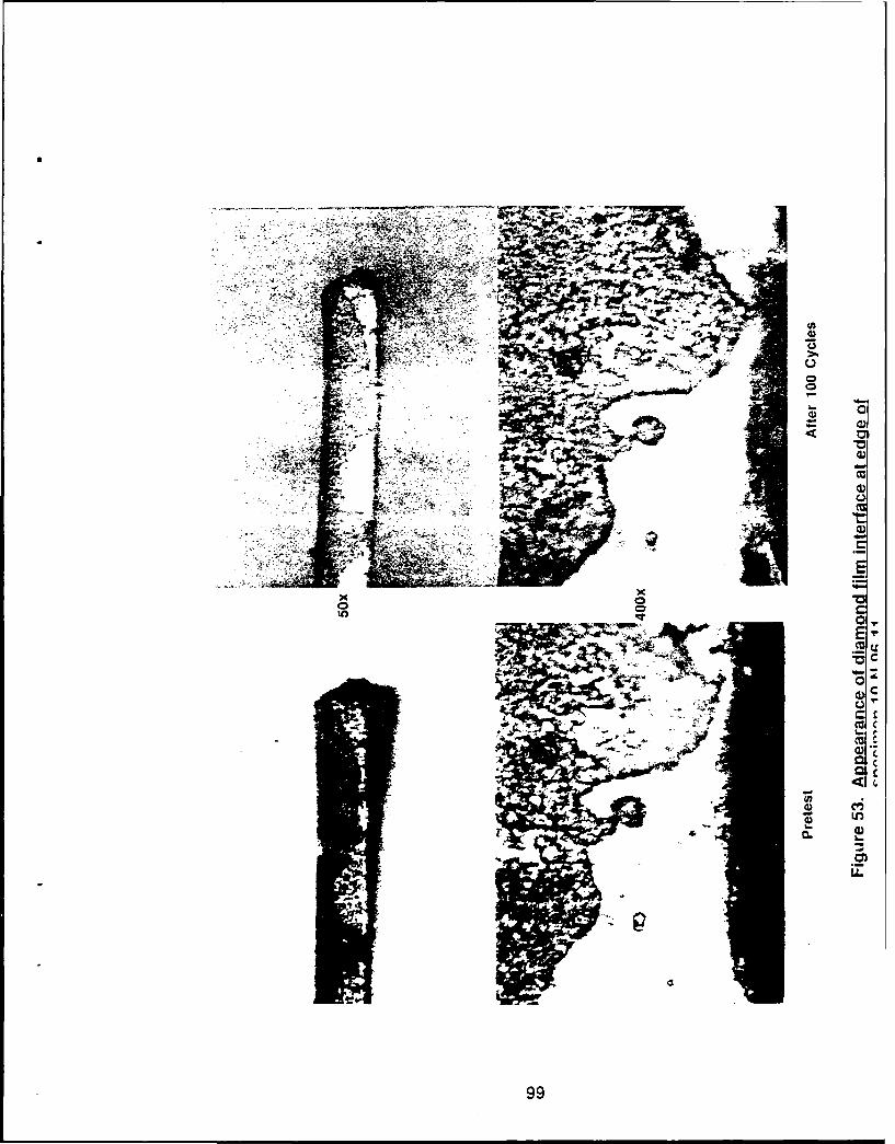
, 4
--- .. . . .. .0
E
C
AE*
991
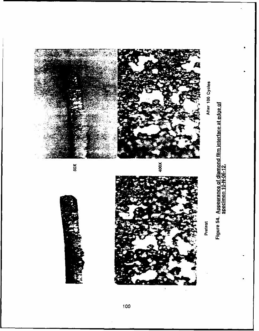
Cc,
0 0
cc0
100
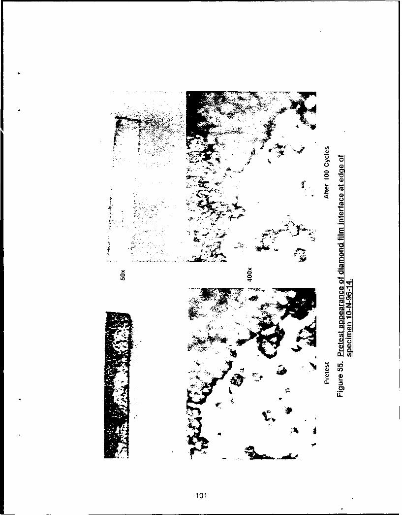
2O i~ 0
6. 0
-..
400
101
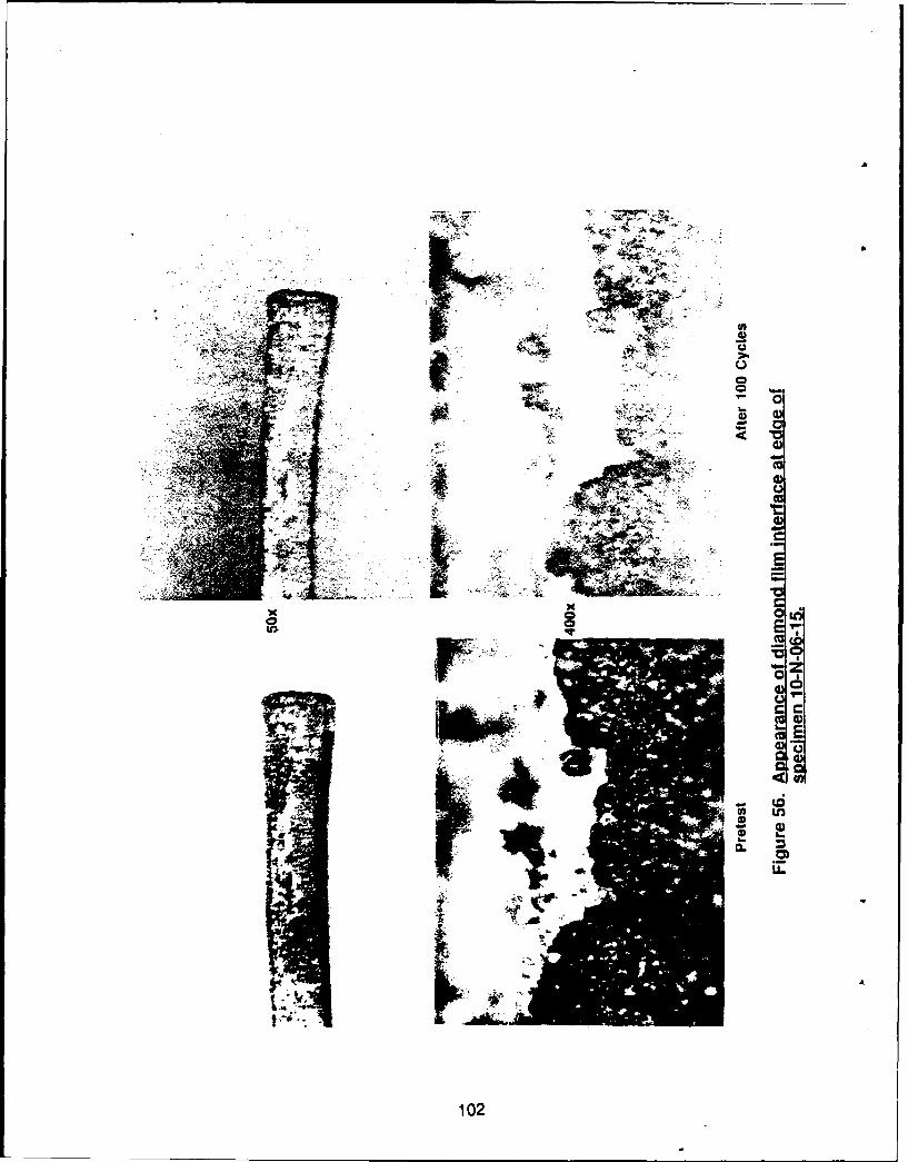
X 4.,
0 e
0102
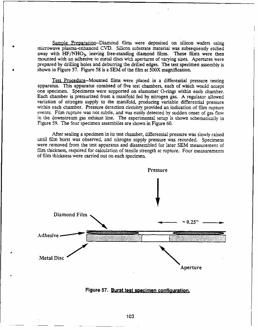
Sample Preparation-Diamond films were deposited on silicon wafers usingmicrowave plasma-enhanced CVD. Silicon substrate material was subsequently etchedaway with HF/NHO3, leaving free-standing diamond films. These films were thenmounted with an adhesive to metal discs with apertures of varying sizes. Apertures wereprepared by drilling holes and deburring the drilled edges. The test specimen assembly isshown in Figure 57. Figure 58 is a SEM of the film at 50OX magnification.
Test Procedure-Mounted films were placed in a differential pressure testingapparatus. This apparatus consisted of five test chambers, each of which would acceptone specimen. Specimens were supported on elastomer O-rings within each chamber.Each chamber is pressurized from a manifold fed by nitrogen gas. A regulator allowedvariation of nitrogen supply to the manifold, producing variable differential pressurewithin each chamber. Pressure detection circuitry provided an indication of film ruptureevents. Film rupture was not subtle, and was easily detected by sudden onset of gas flowin the downstream gas exhaust line. The experimental setup is shown schematically inFigure 59. The four specimen assemblies are shown in Figure 60.
After sealing a specimen in its test chamber, differential pressure was slowly raiseduntil film burst was observed, and nitrogen supply pressure was recorded. Specimenswere removed from the test apparatus and disassembled for later SEM measurement offilm thickness, required for calculation of tensile strength at rupture. Four measurementsof film thickness were carried out on each specimen.
PressureIDiamond Film
A dhesive .. ..........-
Metal Disc
Aperture
Figure 57. Burst test secimen configuration.
103
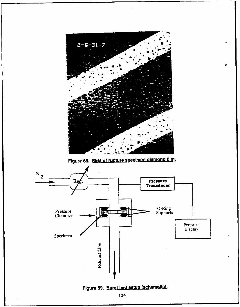
Vb
Figure 58. SEM of ruptr pemndamnd film.
N 2
Fressre 59 us ts eup (c Raicn.
410
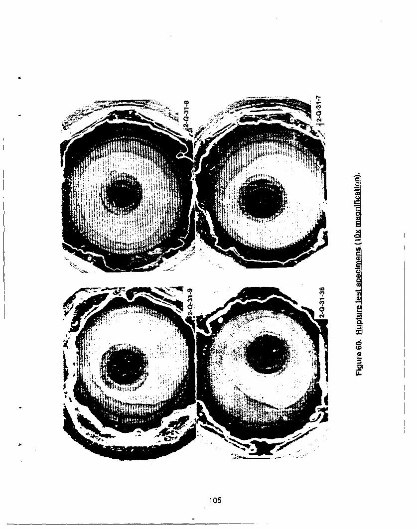
CfCu
wo))
CCO
C*4 CV
105
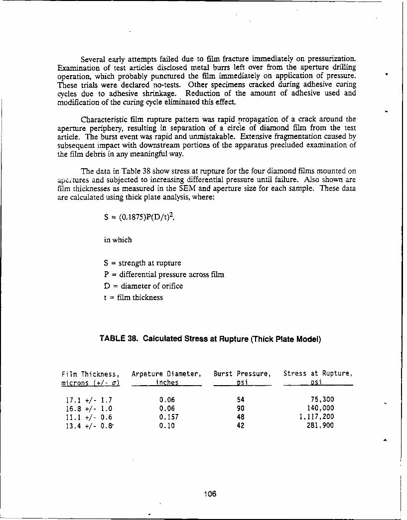
Several early attempts failed due to film fracture immediately on pressurization.Examination of test articles disclosed metal burrs left over from the aperture drillingoperation, which probably punctured the film immediately on application of pressure.These trials were declared no-tests. Other specimens cracked during adhesive curingcycles due to adhesive shrinkage. Reduction of the amount of adhesive used andmodification of the curing cycle eliminated this effect.
Characteristic film rupture pattern was rapid propagation of a crack around theaperture periphery, resulting in separation of a circle of diamond film from the testarticle. The burst event was rapid and unmistakable. Extensive fragmentation caused bysubsequent impact with downstream portions of the apparatus precluded examination ofthe film debris in any meaningful way.
The data in Table 38 show stress at rupture for the four diamond films mounted onap,;rures and subjected to increasing differential pressure until failure. Also shown arefilm thicknesses as measured in the SEM and aperture size for each sample. These dataare calculated using thick plate analysis, where:
S = (0.1875)P(D/t) 2,
in which
S = strength at rupture
P = differential pressure across film
D = diameter of orifice
t = film thickness
TABLE 38. Calculated Stress at Rupture (Thick Plate Model)
Film Thickness, Arpeture Diameter, Burst Pressure, Stress at Rupture,microns (+/- a) inches psi psi
17.1 +1- 1.7 0.06 54 75,30016.8 +/- 1.0 0.06 90 140,00011.1 +/- 0.6 0.157 48 1,117,20013.4 +/- 0.8- 0.10 42 281,900
106
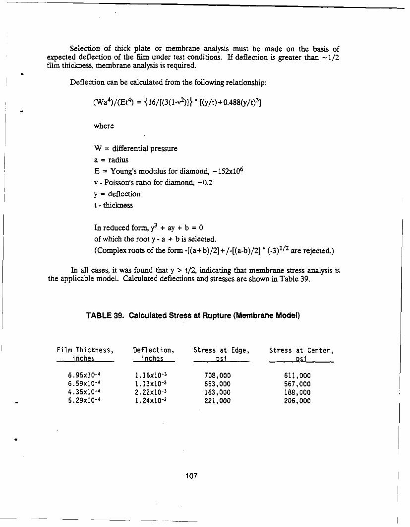
Selection of thick plate or membrane analysis must be made on the basis ofexpected deflection of the film under test conditions. If deflection is greater than -1/2film thickness, membrane analysis is required.
Deflection can be calculated from the following relationship:
(Wa4)/(Et4) = 16/[(3(1-v2)] * [(y/t) + 0.488(y/t) 3]
where
W = differential pressurea = radius
E = Young's modulus for diamond, - 152x10 6
v - Poisson's ratio for diamond, -0.2
y = deflection
t - thickness
In reduced form, y3 + ay + b = 0
of which the root y - a + b is selected.
(Complex roots of the form -[(a+ b)/2] + /-[(a-b)/2] (-3)1/2 are rejected.)
In all cases, it was found that y > t/2, indicating that membrane stress analysis isthe applicable model. Calculated deflections and stresses are shown in Table 39.
TABLE 39. Calculated Stress at Rupture (Membrane Model)
Film Thickness, Deflection, Stress at Edge, Stress at Center,inches inches psi psi
6.95x10⁻⁴ I. 16x10-3 708,000 611,0006.59x10-4 1. 13x10-3 653,000 567,0004.35x10-4 2.22x10⁻³ 163,000 188,0005.29xl0-4 1.24x10⁻³ 221,000 206,000
107
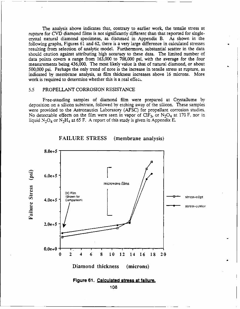
The analysis above indicates that, contrary to earlier work, the tensile stress atrupture for CVD diamond films is not significantly different than that reported for single-crystal natural diamond specimens, as discussed in Appendix B. As shown in thefollowing graphs, Figures 61 and 62, there is a very large difference in calculated stressesresulting from selection of analytic model. Furthermore, substantial scatter in the datashould caution against attributing high accuracy to these data. The limited number ofdata points covers a range from 163,000 to 708,000 psi, with the average for the fourmeasurements being 436,000. The most likely value is that of natural diamond, or about500,000 psi. Perhaps the only trend of note is the increase in tensile stress at rupture, asindicated by membrane analysis, as film thickness increases above 16 microns. Morework is required to determine whether this is a real effec,.
5.5 PROPELLANT CORROSION RESISTANCE
Free-standing samples of diamond film were prepared at Crystallume bydeposition on a silicon substrate, followed by etching away of the silicon. These sampleswere provided to the Astronautics Laboratory (AFSC) for propellant corrosion studies.No detectable effects on the film were seen in vapor of ClF 3, or N20 4 at 170 F, nor inliquid N20 4 or N2H 4 at 65 F. A report of this study is given in Appendix E.
FAILURE STRESS (membrane analysis)
8.0e+5
6.0e+5 Fmicrowave films
L_ DC RilmS(Shown for - stress-edige
4.0e+5 ComparsonLt_. --- 4--- stress-cenlter
2.0e+5
00Oe+O0. e4 I I I I I | I I I
0 2 4 6 8 10 12 14 16 18 20
Diamond thickness (microns)
Figure 61. Calculated stress at failure.108
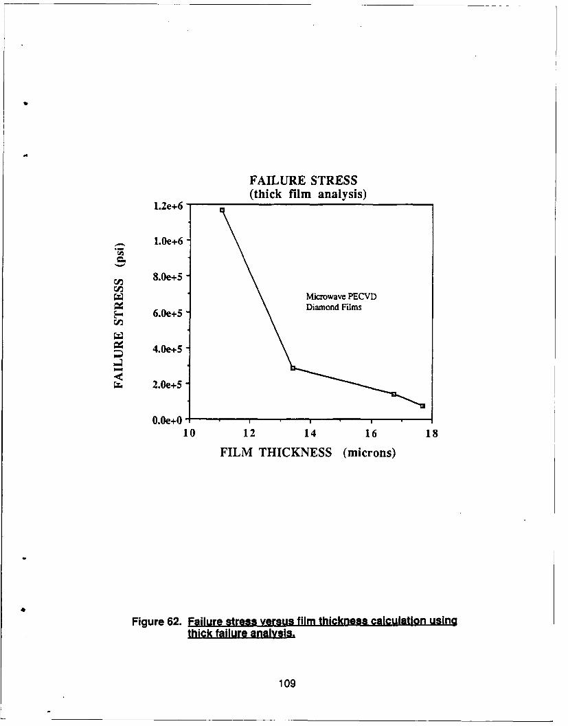
FAILURE STRESS(thick film analysis)
1.2e+6
1.0e+6
Cn 8.0e+5
Microwave PECVD6.0e+5 Diamond Films
4.0e+5
2.0e+5
0.Oe+0 ,10 12 14 16 18
FILM THICKNESS (microns)
Figure 62. Failure stress versus film thickness calculation usinothick failure analysis.
109
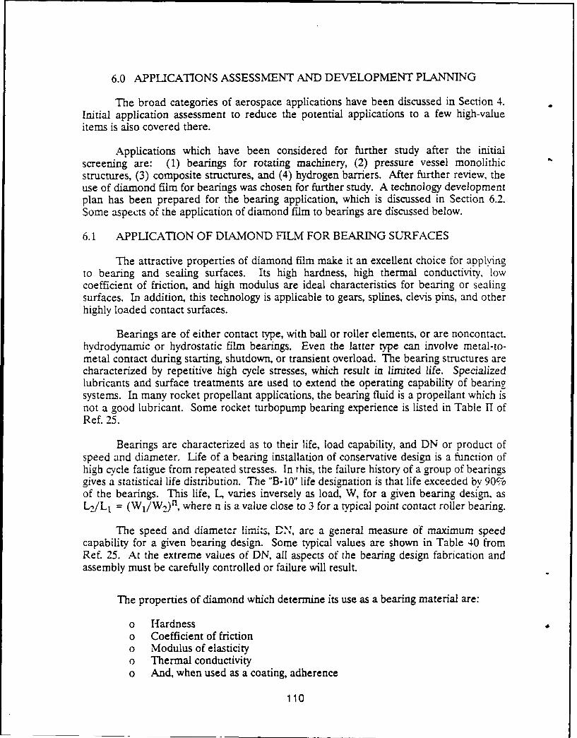
6.0 APPLICATIONS ASSESSMENT AND DEVELOPMENT PLANNING
The broad categories of aerospace applications have been discussed in Section 4.Initial application assessment to reduce the potential applications to a few high-valueitems is also covered there.
Applications which have been considered for further study after the initialscreening are: (1) bearings for rotating machinery, (2) pressure vessel monolithicstructures, (3) composite structures, and (4) hydrogen barriers. After further review, theuse of diamond film for bearings was chosen for further study. A technology developmentplan has been prepared for the bearing application, which is discussed in Section 6.2.Some aspects of the application of diamond film to bearings are discussed below.
6.1 APPLICATION OF DIAMOND FILM FOR BEARING SURFACES
The attractive properties of diamond film make it an excellent choice for applyingto bearing and sealing surfaces. Its high hardness, high thermal conductivity, lowcoefficient of friction, and high modulus are ideal characteristics for bearing or sealingsurfaces. In addition, this technology is applicable to gears, splines, clevis pins, and otherhighly loaded contact surfaces.
Bearings are of either contact type, with ball or roller elements, or are noncontact,hydrodynamic or hydrostatic film bearings. Even the latter type can involve metal-to-metal contact during starting, shutdown, or transient overload. The bearing structures arecharacterized by repetitive high cycle stresses, which result in limited life. Specializedlubricants and surface treatments are used to extend the operating capability of bearingsystems. In many rocket propellant applications, the bearing fluid is a propellant which isnot a good lubricant. Some rocket turbopump bearing experience is listed in Table H ofRef. 25.
Bearings are characterized as to their life, load capability, and DN or product ofspeed and diameter. Life of a bearing installation of conservative design is a function ofhigh cycle fatigue from repeated stresses. In this, the failure history of a group of bearingsgives a statistical life distribution. The "B-10" life designation is that life exceeded by 90%of the bearings. This life, L, varies inversely as load, W, for a given bearing design, asL1JL1 = (W1/W 2 )n, where n is a value close to 3 for a typical point contact roller bearing.
The speed and diametcr limits, DN, arc a general measure of maximum speedcapability for a given bearing design. Some typical values are shown in Table 40 fromRef. 25. At the extreme values of DN, all aspects of the bearing design fabrication andassembly must be carefully controlled or failure will result.
The properties of diamond which determine its use as a bearing material are:
o Hardnesso Coefficient of frictiono Modulus of elasticityo Thermal conductivityo And, when used as a coating, adherence
110
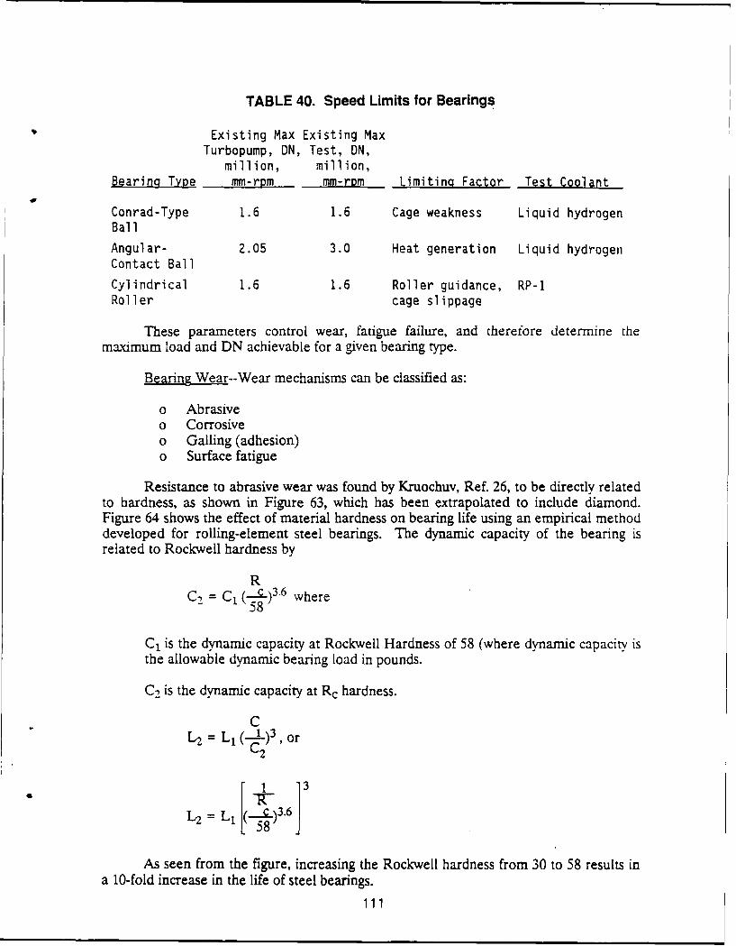
TABLE 40. Speed Limits for Bearings
Existing Max Existing MaxTurbopump, DN, Test, DN,
million, million,Bearing Type mm-rpm mm-rpm Limiting Factor Test Coolant
Conrad-Type 1.6 1.6 Cage weakness Liquid hydrogenBall
Angular- 2.05 3.0 Heat generation Liquid hydrogenContact Ball
Cylindrical 1.6 1.6 Roller guidance, RP-1Roller cage slippage
These parameters control wear, fatigue failure, and therefore determine themaximum load and DN achievable for a given bearing type.
Bearing Wear--Wear mechanisms can be classified as:
o Abrasiveo Corrosiveo Galling (adhesion)o Surface fatigue
Resistance to abrasive wear was found by Kruochuv, Ref. 26, to be directly relatedto hardness, as shown in Figure 63, which has been extrapolated to include diamond.Figure 64 shows the effect of material hardness on bearing life using an empirical methoddeveloped for rolling-element steel bearings. The dynamic capacity of the bearing isrelated to Rockwell hardness by
RC, = C1 ( C )3.6 where
- 58
C1 is the dynamic capacity at Rockwell Hardness of 58 (where dynamic capacity isthe allowable dynamic bearing load in pounds.
C, is the dynamic capacity at Rc hardness.
CL2 L, 1 )3, or
C2
i L1 ,(...)3.6
2 58
As seen from the figure, increasing the Rockwell hardness from 30 to 58 results ina 10-fold increase in the life of steel bearings.
111
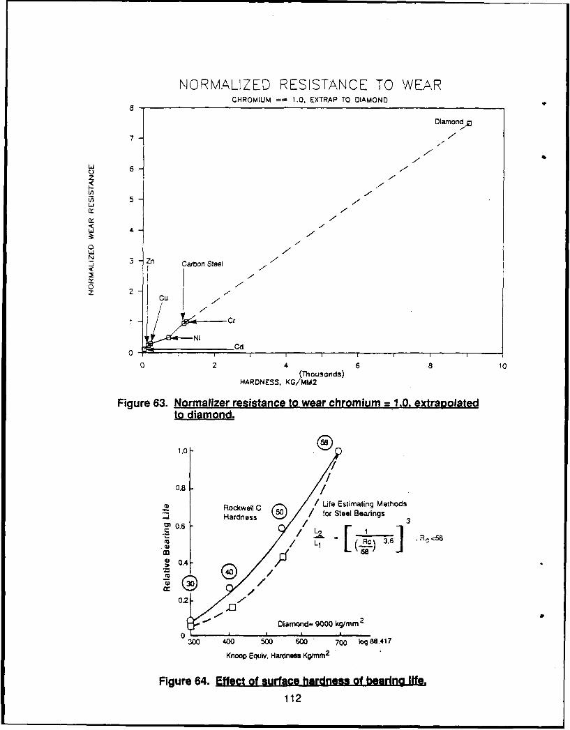
NORMALIZED RESISTANCE TO WEARCHROMIUM == 1.0, EXTRAP TO DIAMOND
Diamond
7-
6 7F
z(1) 7U
N 3 Zn Carbon Steel
z C
-r e Cr
NICd
02 6 10(Thousands)
HARDNESS. KG/MM2
Figure 63. Normalizer resistance to wear chromium = 1.0. extrapolatedto diamond.
1.0 .
0.8 /~Rockwell C / Life Estimating Methods
5 Hadnssfor Steel Bearings-j Hardness30.6 -
' , Rc<58/ (.I , .\
0.43
-"-o1 40
S
Diamond- 9000 ko/mm2
0300 400 500 60 700 log 88.417
Knoop Equiv. Hardness KgWmm2
Figure 64. Effect of surface hardness of bearing life.
112
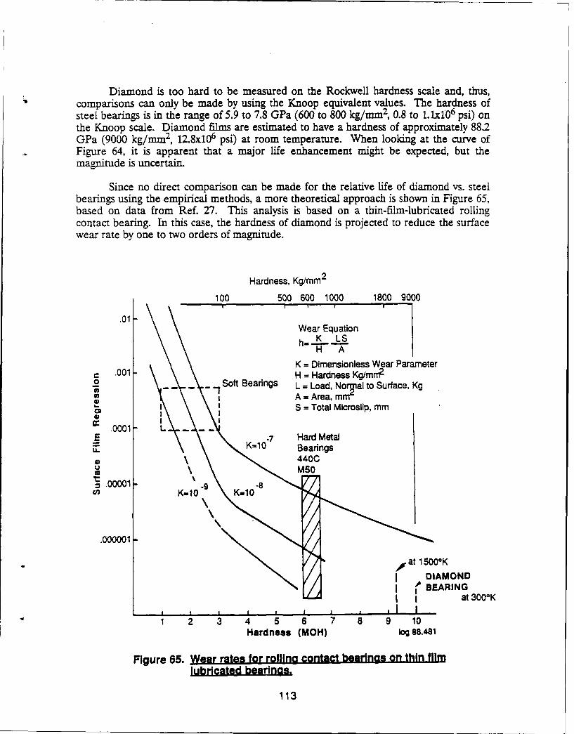
Diamond is too hard to be measured on the Rockwell hardness scale and, thus,comparisons can only be made by using the Knoop equivalent values. The hardness ofsteel bearings is in the range of 5.9 to 7.8 GPa (600 to 800 kg/mm 2, 0.8 to I.1x10 6 psi) onthe Knoop scale. Diamond films are estimated to have a hardness of approximately 88.2GPa (9000 kg/mm2 , 12.8x10 6 psi) at room temperature. When looking at the curve ofFigure 64, it is apparent that a major life enhancement might be expected, but themagnitude is uncertain.
Since no direct comparison can be made for the relative life of diamond vs. steelbearings using the empirical methods, a more theoretical approach is shown in Figure 65,based on data from Ref. 27. This analysis is based on a thin-film-lubricated rollingcontact bearing. In this case, the hardness of diamond is projected to reduce the surfacewear rate by one to two orders of magnitude.
Hardness, Kg/mm 2
100 500 600 1000 1800 9000
.01Wear Equationh. K LS
H A
K = Dimensionless Wear ParameterC .001 H = Hardness Kg/mrT?
o Soft Bearings L = Load, Nor al to Surface, KgA = Area, mm-
LP -S = Total Microslip, mm
.0001 L
E K10 Hard Metal,. K=10" Bearings
440C
-. 00001 -80n K=- K-10
.000001-
,00 at 15000KI DIAMOND
I BEARINGI I at 3000K
I I I I I I i I ,
1 2 3 4 5 6 7 8 9 10
Hardness (MOH) log 88.481
Figure 65. Wear rates for rolilna contact bearings on thin film
lubricated bearings.
113
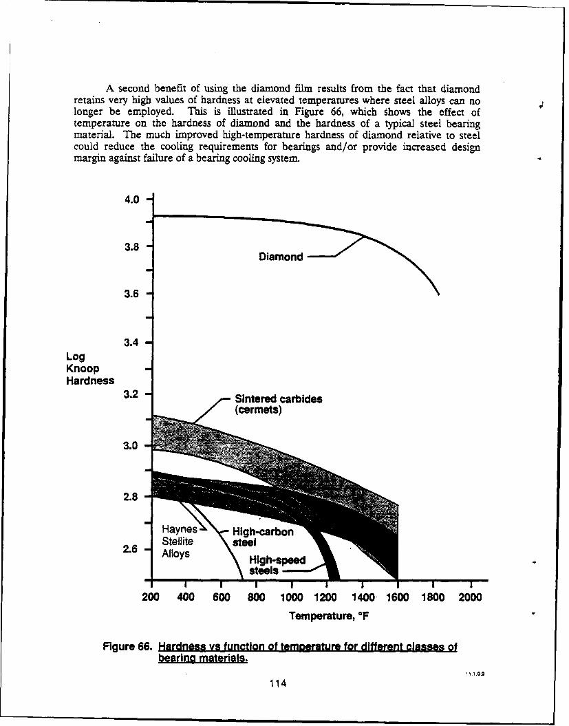
A second benefit of using the diamond film results from the fact that diamondretains very high values of hardness at elevated temperatures where steel alloys can nolonger be employed. This is illustrated in Figure 66, which shows the effect oftemperature on the hardness of diamond and the hardness of a typical steel bearingmaterial. The much improved high-temperature hardness of diamond relative to steelcould reduce the cooling requirements for bearings and/or provide increased designmargin against failure of a bearing cooling system.
4.0
3.8
3.6
3.4LogKnoopHardness 3.2
Sintered carbidesI f (cerrnets)
3.0 .
2.8
ayes High-caro.Sllite steel
200 400 600 800 1000 1200 1400. 1600 1800 2000Temperature, °F
Figure 66. Hardness vs function of temperature for different classes ofbearing materials.
11 1.0.9
114
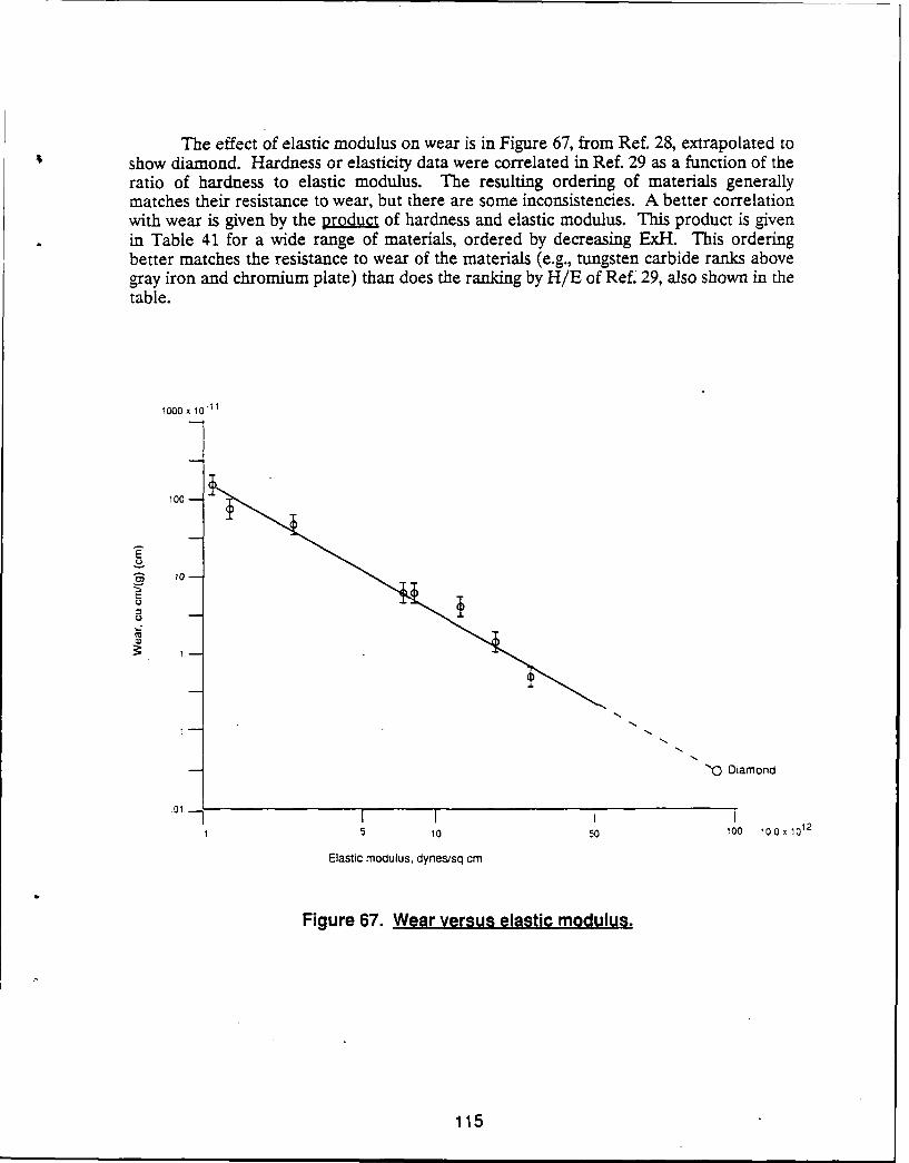
The effect of elastic modulus on wear is in Figure 67, from Ref. 28, extrapolated toshow diamond. Hardness or elasticity data were correlated in Ref. 29 as a function of theratio of hardness to elastic modulus. The resulting ordering of materials generallymatches their resistance to wear, but there are some inconsistencies. A better correlationwith wear is given by the product of hardness and elastic modulus. This product is givenin Table 41 for a wide range of materials, ordered by decreasing ExH. This orderingbetter matches the resistance to wear of the materials (e.g., tungsten carbide ranks abovegray iron and chromium plate) than does the ranking by H/E of Ref. 29, also shown in thetable.
1000 x 10.11
100 -
o, 10 -
E
'0Diamond
15 10 50 100 10 0x1012
Elastic modulus, clynesisq cm
Figure 67. Wear versug elastic modulus.
115
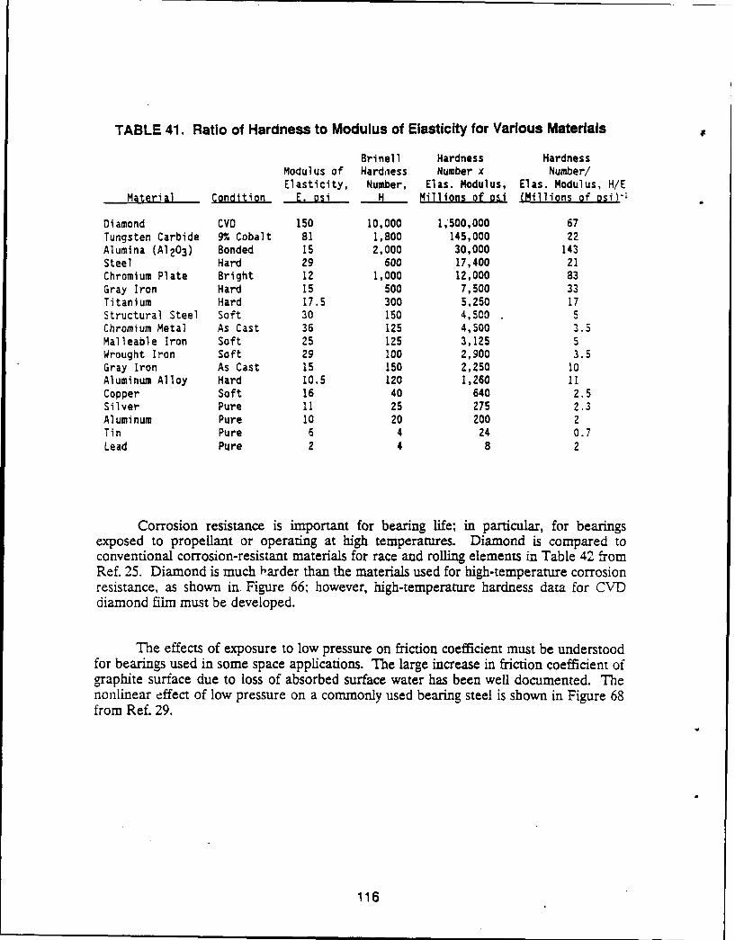
TABLE 41. Ratio of Hardness to Modulus of Elasticity for Various Materials
Brinell Hardness HardnessModulus of Hardness Number x Number!Elasticity, Number, Elas. Modulus, Elas. Modulus, H/E
Material Condition E. osi H Millions of osi (Millions of osi)-!
Diamond CVD 150 10,000 1,*500,000 67Tungsten Carbide 9% Cobalt 81 1,800 145,000 22Alumina (A1203) Bonded 15 2,000 30,000 143Steel Hard 29 600 17,400 21Chromium Plate Bright 12 1,000 12,000 83Gray Iron Hard 15 500 7,500 33Titanium Hard 17.5 300 5,250 17Structural Steel Soft 30 150 4,500 5Chromium Metal As Cast 36 125 4,500 3.5Malleable Iron Soft 25 125 3,125 5Wrought Iron Soft 29 100 2,900 3.5Gray Iron As Cast 15 150 2,250 10Aluminum Alloy Hard 10.5 120 1,260 11Copper Soft 16 40 640 2.5Silver Pure 11 25 275 2.3Aluminum Pure 10 20 200 2Tin Pure 6 4 24 0.7Lead Pure 2 4 8 2
Corrosion resistance is important for bearing life; in particular, for bearingsexposed to propellant or operating at high temperatures. Diamond is compared toconventional corrosion-resistant materials for race and rolling elements in Table 42 fromRef. 25. Diamond is much harder than the materials used for high-temperature corrosionresistance, as shown in. Figure 66; however, high-temperature hardness data for CVDdiamond film must be developed.
The effects of exposure to low pressure on friction coefficient must be understoodfor bearings used in some space applications. The large increase in friction coefficient ofgraphite surface due to loss of absorbed surface water has been well documented. Thenonlinear effect of low pressure on a commonly used bearing steel is shown in Figure 68from Ref. 29.
116
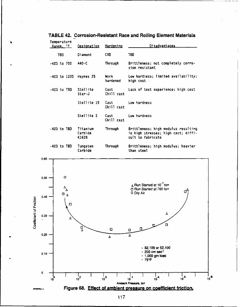
TABLE 42. Corrosion-Resistant Race and Rolling Element MaterialsTemperatureRange. "F Desianation Hardening Disadvantages
TBD Diamond CVD TBD
-423 to 700 440-C Through Brittleness; not completely corro-sion resistant
-423 to 1200 Haynes 25 Work Low hardness; limited availability;hardened high cost
-423 to TBD Stellite Cast Lack of test experience; high costStar-J Chill cast
Stellite 19 Cast Low hardnessChill cast
Stellite 3 Cast Low hardnessChill cast
-423 to TBD Titanium Through Brittleness; high modulus resultingCarbide in high stresses; high cost; diffi-K162B cult to fabricate
-423 to TBD Tungsten Through Brittleness; high modulus; heavierCarbide than steel
0.60
0.50- 0
A A Run Started at 10" torrA Run Started at 760 torr
ADA
0 0
0 3
0.20 -
•52, 100 of 52, 1000.10 A sec
•1,000 gmn load•75OF
00
0.2 A A . 1 14 11
102 100 101 10166 10Ambient Pressure, torr
Figure 68. Effect of ambient pressure on coefficient friction.
117
As can be seen from these preliminary analyses, using diamond films as coatings
on bearings can result in large payoffs in life and extension in operating conditions.
Benefits
(1) Advanced Launch System
The Advanced Launch System, ALS, will have high-pressure hydrogenturbopumps. Initial design studies show that titanium alloy is the material of choice forthe impeller because of its high strength-to-weight ratio. Any other material requires amore complex pump design, with more stages. Titanium 5A12.5V is the alloy of choicebecause of its high ductility at liquid hydrogen temperature (approximately 10%).
Labyrinth seals on the impeller are problem areas with the titanium alloy becauscthey operate at elevated temperature and fal rapidly from hydriding. These surfaces inALS can be diamond coated. This would reduce frictional heating and provide a barrierto hydrogen attack.
Other bearing and seal surfaces in ALS can benefit from diamond coating toreduce friction and increase life. Although the ALS will be a single-use vehicle, it mustoperate for several test cycles leading up to flight. Therefore, its turbopump componentswill have been exposed to hydrogen and will be subject to hydrogen embrittlement.
(2) Titan
The Titan engine system is being improved to provide greater lift capability. Thisinvolves increased pressure and thrust, larger propellant tanks, and longer burns.Although the present system is capable of providing the required upgrade, it isaccompanied by a reduced design margin. Life endurance testing has indicated gearboxoverheating and tooth wear and fretting of a spline in an aluminum pump impeller andcould benefit from a hard, low-friction surface coating such as would be provided bydiamond film. A similar situation probably exists for an uprated RL-10 engine which usesa gear drive system.
(3) XLR-132
The XLR-132 engine incorporates a high-modulus TZM (molybdenum) alloy shaftwhich includes labyrinth seals which are one of the life-limiting parameters. Attempts toimprove design life margin by hard Cr plating have been unsuccessful because Cr will notadhere to the shaft material. In contrast, diamond-molybdenum bonds have beenreported to be outstandingly good. The life of the (WTiC), K5H alloy balls and BG42race material employed in the XLR-132 may also be enhanced by the addition of adiamond film.
118
(4) SSME
The SSME turbopump bearings represent the greatest single propulsion systembearing life improvement effort, as measured by total funds being expended and thenumber of independent investigations. A number of these design fixes involve theapplication of thin, hard surfaces over the existing bearing material substrate (AIMS5618). This material was originally selected for its high strength, high hardness, RC 58-62(735 Knoop), and corrosion resistance. These metallic materials, however, do not comeclose to meeting the 55-mission life requirement.
Ng and Naerheim, Ref. 30, of Rocketdyne and the Rockwell Science Centerreported significant life improvement when RF sputtered TiN (Knoop hardness, 1800Kg/mm2 ) is applied to the wear surfaces.
Thorn and Dolan, Ref. 31, of the NASA/Marshall Space Flight Center reported a300% bearing life improvement in simulation testing when 1/2 micron of zirconiumnitride (Knoop hardness 1500) is applied to the bearing surface. Their test method andresulting data are displayed in Figure 69. Wedeven and Miller, Ref. 32, working for SKFAerospace, reported similar benefits for TiN and hard chrome plating and even better lifeimprovement (500 to 1000%) for Si3 N4 (Knoop hardness 2200) in similar tests.
The hardness of diamond (Knoop 9000 Kg/mm2 ) offers substantial reward ifhardness is the primary measure of life improvement. Other desirable factors which comeinto play are high thermal conductivity, low friction coefficient, and high elastic modulus.In this respect, the properties of diamond film are all superior to the nitride compounds.
(5) Other Liquid Rocket Applications
XLR-134 and OTV turbopump assemblies operate with H- and 02 cooledbearings for which life testing is presently in progress. These designs are also prototype tothe NASP TPAs. Each requires demonstration of a 20-hr life. The XLR-134 uses rollingcontact bearings, while the OTV uses hydrostatic thrust and journal bearings. Numeroushighly stressed wear surfaces in each application could be considered for use of diamondfilm coating to increase design margin.
Limiting Use Factors-In all of the identified applications, a low coefficient offriction, combined with hardness to resist wear, high thermal conductance to remove localhot spots, and a high modulus to resist deformation are required. The friction coefficient,however, is not an entirely invarient property of the material, but is dependent on theoperazing environment and exposure history as adsorbed surface films contribute to thesliding action.
The influence of propellants on the friction and propellant compatibility must beestablished before diamond films can be considered as suitable for applications where lowfriction is essential. The propellants of interest are as follows:
119
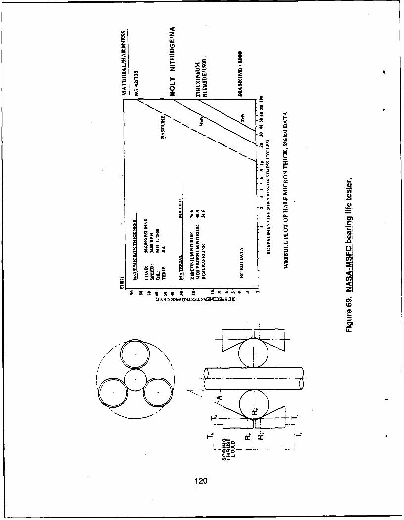
U, z
LLIz
Iwo
Lt.
4r..
zz
a)ag)
29 a aL
z ,a-
so CD.) -
CCf
col
120w~- I
o Fuels Liquid and gaseous hydrogenLiquid and gaseous methaneMMH, N2H4, A-50 (storable propellants)
o Oxidizers Liquid and gaseous oxygenN20 4 (storable oxidizer)CIF 3 and CIF5
A second factor is that the deposition temperature for the diamond film is 600 to800"C, while the strength and hardness properties of the substrate metal are reducedabove about 2600C for 440C alloys, and 550°C for BG42 alloys.
6.2 TECHNOLOGY DEVELOPMENT PLANNING
Technology demonstration of practical use of diamond films in aerospaceapplications will assist in rapid utilization of this new material. A program fordemonstration of diamond films for turbopump bearings is described in Section 6.3.2.However, before such a program is undertaken, a better understanding is required of theproperties of diamond film and their correlation with process variables. For this reason,the technology demonstration should be preceded by a more basic activity which would bean extension of the preliminary characterization measurements made during Phase Im ofthis program. The estimated resources for this activity are the equivalent of 1.5 person-year.
6.2.1 Properties Determination for CVD Diamond-Most engineering proper-ties of CVD diamond should be experimentally confirmed, rather than relying on naturaldiamond data or isolated measurements of films prepared under a variety of incompletelydefined conditions.
To have confidence in properties whose values are critical to anengineering application, sufficient measurements must be made to assure statisticalconfidence and process repeatability. In addition, the effects of major process variablesshould be isolated both to allow intelligent process control and to permit optimization offilm characteristics.
The properties of primary interest are shown in Table 43, which is a subsetof the properties data table, showing those 14 parameters of primary interest. The list isstill extensive and includes some measurements (chemical reactivity, mechanicaladherence, diffusion coefficient, thermal stability) which would require extensivemultiparameter programs for proper study.
If the list is held to those parameters necessary for bearing design, and ifthe bearing environment is defined, the number of measurements becomes moremanageable. The parameters of primary interest are shown in Table 44.
121
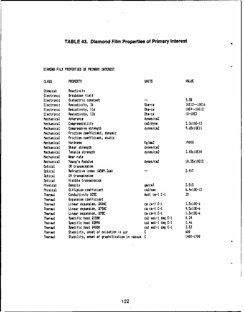
TABLE 43. Diamond Film Properties of Primary Interest
DIAMOND FILM PROPERTIES OF PRIMARY INTEREST
CLASS PROPERTY UNITS VALUE
Chemical ReactivityElectronic Breakdown fieldElectronic Dielectric constant -- 5.59Electronic Resistivity, lb Ohm-ca IOE12--IOE16Electronic Resistivity, Ila Ohm-ca 10E4--10E12Electronic Resistivity, lIb Ohm-cm 10-10E3Mechanical Adherence dynes/ca2Mechanical Compressibility ca2/dyne 2.3xlOE-13Mechanical Compressive strength dynes/c&2 9.65xlOElMechanical Friction coefficient, dynamicMechanical Friction coefficient, staticMechanical Hardness Kg/mm2 >9000Mechanical Shear strength dynes/cn2Mechanical Tensile strength dynes/ca2 3.45xlOE1OMechanical Near rateMechanical Young's Modulus dynes/ca2 10.35xl0E12Optical IR transmissionOptical Refractive index (59q.3nm) -- 2.417Optical UV transmissionOptical Visible transmissionPhysical Density gOIcm3 3.515Physical Diffusion coefficient cm2/sec 6.4xlOE-12Thermal Conductivity ;25C Watt cm-i C-1 20Thermal Expansion coefficientThermal Linear expansion, 4400C cm cm-I C-1 3.3xIOE-6Thermal Linear expansion, 2750C cm cm-i C-i 4.5xlOE-6Thermal Linear expansion, 278C ca cm-i C-I 1.5xI0E-6Thermal Specific heat 415OK cal eol-i deg C-i 0.24Thermal Specific heat ;299K cal mol-I deg C-I 1.46Thermal Specific heat ;400K cal sol-I deg C-i 2.52Thermal Stability, onset of oxidation in air C 600Thermal Stability, onset of graphitization in vacuum C 1400-1700
122
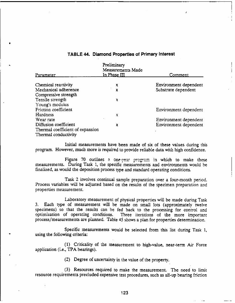
TABLE 44. Diamond Properties of Primary Interest
PreliminaryMeasurements Made
Parameter In Phase II Comment
Chemical reactivity x Environment dependentMechanical adherence x Substrate dependentCompressive strengthTensile strength xYoung's modulusFriction coefficient Environment dependentHardness xWear rate Environment dependentDiffusion coefficient x Environment dependentThermal coefficient of expansionThermal conductivity
Initial measurements have been made of six of these values during thisprogram. However, much more is required to provide reliable data with high confidence.
Figure 70 outlines a one-year prigram in which to make thesemeasurements. During Task 1, the specific measurements and environments would befinalized, as would the deposition process type and standard operating conditions.
Task 2 involves continual sample preparation over a four-month period.Process variables will be adjusted based on the results of the specimen preparation andproperties measurement.
Laboratory measurement of physical properties will be made during Task3. Each type of measurement will be made on small lots (approximately twelvespecimens) so that the results can be fed back to the processing for control andoptimization of operating conditions. Three iterations of the more importantprocess/measurements are planned. Table 45 shows a plan for properties determination.
Specific measurements would be selected from this list during Task 1,using the following criteria:
(1) Criticality of the measurement to high-value, near-term Air Force
application (i.e., TPA bearings).
(2) Degree of uncertainty in the value of the property.
(3) Resources required to make the measurement. The need to limitresource requirements precluded expensive test procedures, such as all-up bearing friction
123
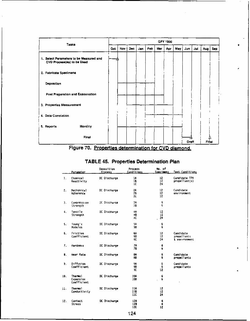
GFY 1990Tasks
Oct Nov Dec Jan Feb Mar Apr May Jun Jul Aug Sep
1. Select Parameters to be Measured andCVD Process(es) to be Used
2. Fabricate Specimens
Deposition
Post Preparation and Examination
3. Properties Measurement - -
4. Data Correlation
5. Reports Monthly
Final
____ ___ ____ ___Dr~ft F1.1Figure 70. Properties determination for CVD diamond.
TABLE 45. Properties Determination Plan
Deposition Process No. ofParameter Process Conditions Specimens Test Conditions
1. Chemical DC Discharge IA 12 Candidate TPAReactivity 18 12 propellant(s)
IC 24
2. Mechanical DC Discharge 2A 12 CandidateAdherence 28 12 environment
2C 12
3. Comoression DC Discharge 3A 6Strength 38 6
4. Tensile DC Discharge 4A 12Strength 48 12
4C 24
5. Young's DC Discharge SA 6Modulus 55 6
6. Friction OC Discharge 6A 12 CandidateCoefficient 58 12 propellants
6C 24 & environment
7. Hardness DC Discharge 7A 678 6
8. Wear Rate DC Discharge 8A 6 CandidateaB 6 propellants
9. Diffusion DC Discnarge 9A 6 CandidateCoefficient 98 6 propellants
9C 12
I0. Thermal OC Discharge IDA 6Expansion 108 6Coefficient
11. Thermal OC Discharge IIA 12Conductivity 18 12
liC 24
12. Contact DC Discharge 12A 6Stress 128 6
12C 12
124
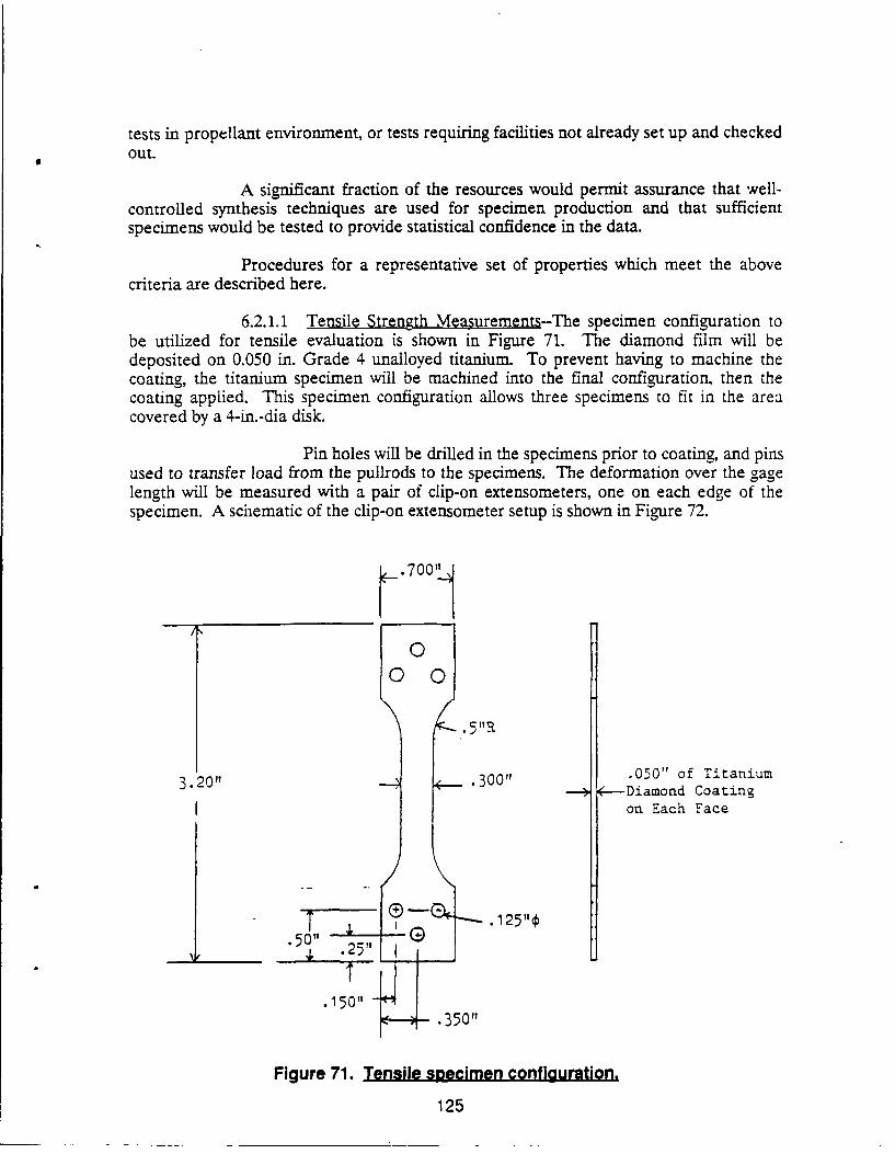
tests in propellant environment, or tests requiring facilities not already set up and checkedout.
A significant fraction of the resources would permit assurance that well-controlled synthesis techniques are used for specimen production and that sufficientspecimens would be tested to provide statistical confidence in the data.
Procedures for a representative set of properties which meet the abovecriteria are described here.
6.2.1.1 Tensile Strength Measurements--The specimen configuration tobe utilized for tensile evaluation is shown in Figure 71. The diamond film will bedeposited on 0.050 in. Grade 4 unalloyed titanium. To prevent having to machine thecoating, the titanium specimen will be machined into the final configuration, then thecoating applied. This specimen configuration allows three specimens to fit in the areacovered by a 4-in.-dia disk.
Pin holes will be drilled in the specimens prior to coating, and pinsused to transfer load from the pullrods to the specimens. The deformation over the gagelength will be measured with a pair of clip-on extensometers, one on each edge of thespecimen. A schematic of the clip-on extensometer setup is shown in Figure 72.
.700
00 0
3.201t .300" .050" of Titanium3 Diamond Coating
on Each Face
.50" .2".2511
.150".350"1
Figure 71. Tensile specimen configuration.
125
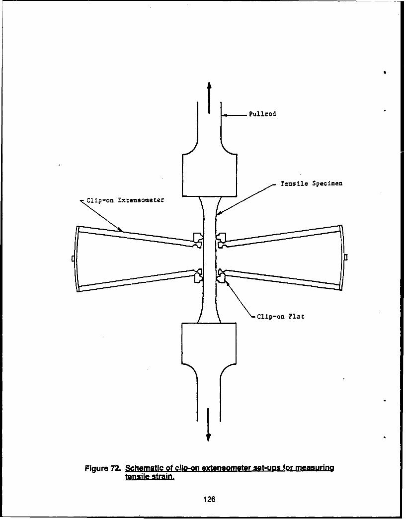
tulo
Tensile Specimen
Clip-on Extensouieter
Clip-oni Flat
r4
Figure 72. Schematic Of clip2-on extensometer set-uRs for measuring
126
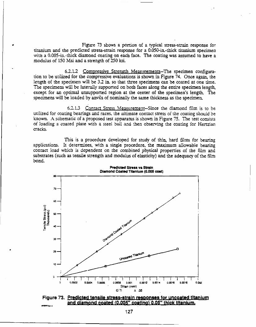
Figure 73 shows a portion of a typical stress-strain response fortitanium and the predicted stress-strain response for a 0.050-in.-thick titanium specimenwith a 0.005-in.-thick diamond coating on each face. The coating was assumed to have amodulus of 150 Msi and a strength of 250 ksi.
6.2.1.2 Compressive Strength Measurements-The specimen configura-tion to be utilized for the compressive evaluations is shown in Figure 74. Once again, thelength of the specimen will be 3.2 in. so that three specimens can be coated at one time.The specimens will be laterally supported on both faces along the entire specimen length,except for an optimal unsupported region at the center of the specimen's length. Thespecimens will be loaded by anvils of nominally the same thickness as the specimen.
6.2.1.3 Contact Stress Measurement--Since the diamond film is to beutilized for coating bearings and races, the ultimate contact stress of the coating should beknown. A schematic of a proposed test apparatus is shown in Figure 75. The test consistsof loading a coated plate with a steel ball and then observing the coating for Hertziancracks.
This is a procedure developed for study of thin, hard ilms for bearingapplications. It determines, with a single procedure, the maximum allowable bearingcontact load which is dependent on the combined physical properties of the film andsubstrates (such as tensile strength and modulus of elasticity) and the adequacy of the filmbond.
Predicted Stress vs StrainDiamond Coated Titanium (0.005 coat)
80-,
70-
60-
SGO
30-
20-1
10-
0 I i I I I I I I I I I0 9.0002 o.oo04 0.0006 0.0008 0.001 0.0012 0.0014 0.0016 0.0018 0.002
Strain (irvin)0 'r a .05
Figure 73. Predicted tensile stress-strain responses for uncoated titaniumand diamond coated (0.005" coatlnal 0.05" thick titanium.
127
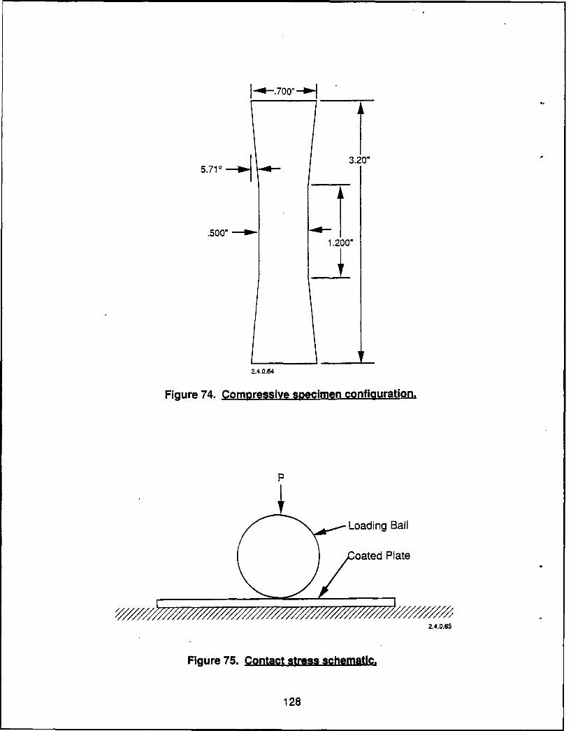
3. 0"5.710
.5001-,1.200"
2.4.0.64
Figure 74. Compressive specimen configuration.
Loading Ball
oated Plate
2.4.0.65
Figure 75. Contact stress schematic.
128
The plate will be machined from the same material as the bearing racewill be manufactured from so as to provide support similar to that in actual application.Five load levels will be chosen. The load level at which cracking is first observed with theunaided eye or at low magnification will be recorded. Also, the specimen from the loadlevel immediately prior to this will be observed using SEM techniques in an attempt todetect microcracking. In addition to this, knowing the maximum applied load and thematerial properties of the loading ball and the coating, the maximum obtained normaland shear stresses can be calculated for the coating using elastic contact stress equations.
6.2.1.4 Thermal Expansion Measurement--The thermal expansionspecimen configuration to be utilized for these evaluations is shown in Figure 76. Forthese specimens, a coating 0.020 to 0.030 in. will be applied to silicon. The silicon willthen be etched away, leaving a specimen consisting of the diamond coating only. Thefree-standing diamond specimen is then mounted between reference surfaces in acontrolled-temperature oven. The temperature is set over the range of ambient to 800 Cand the expansion of the diamond measured relative to NBS calibrated quartzdilatometer tubes.
6.2.2 Program Plan for BearingTechnology Demonstration
A program plan has been developed to assess the application of diamondfilms for bearings, seals, and other tribological uses. There are three main tasks to thisevaluation. The first task consists of a fabrication demonstration to establish feasibilityfor depositing diamond films on specific substrates and certain configurations. Thesecond task consists of properties evaluation which are key for rocket engine applications.The third and final task of this effort will select a component, e.g., a bearing or a face seal,and then design, fabricate, and test it in a rocket engine environment to demonstrate lifeand performance improvement.
A schedule for this activity has been prepared and is shown in Figure 77.A task-by-task description is presented. The resources required are estimated to be eightperson-years over the three-year program.
Task 1.0 - Fabrication Demonstration--This task will address two keyissues for diamond film fabrication. The first consists of substrate material. Diamond canbe deposited on molybdenum and molybdenum alloys such as TZM; however, othercandidate substrate materials must be evaluated. The first part of this task will select aminimum of three alloys, such as those listed above in the technical discussion, which aretypically used in wear or rubbing applications. These materials will be procured and usedfor deposition studies. Parametric deposition studies will be conducted to develop anoptimum coating for each material. Thicknesses ranging from 12.7 to 254 micron (0.0005to 0.0100 in.) will be deposited for evaluation. The evaluation will include visual andSEM examination for surface defects, Raman spectroscopy, and X-ray diffraction forcrystallographic phase identification. Metallographic sections will be prepared to checkfor microstructure and any other anomalous features such as porosity. Special emphasis
129
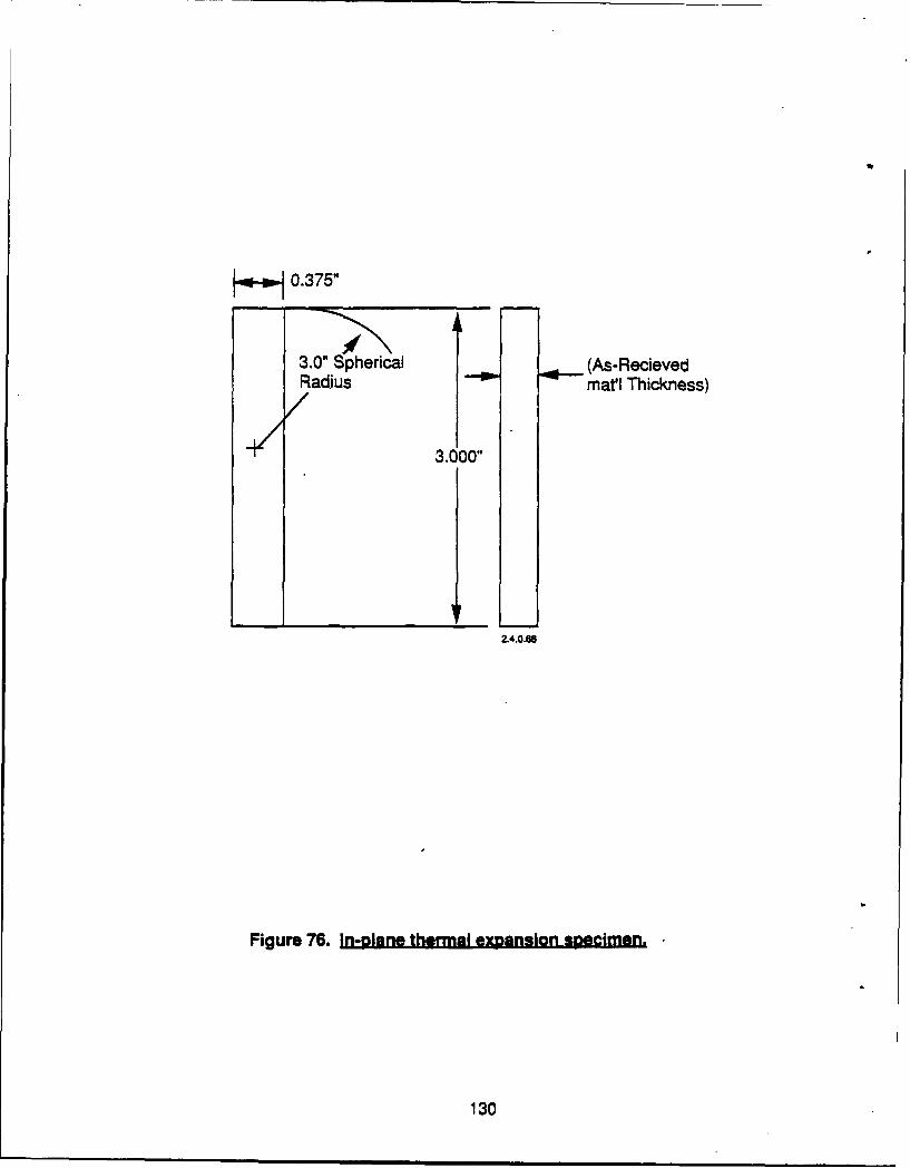
3.0" Spherical (As-RecievedRadius matl Thickness)
3.00'
Z.4.0.6
Figure 76. In-plane thermal expansion speimen.
130
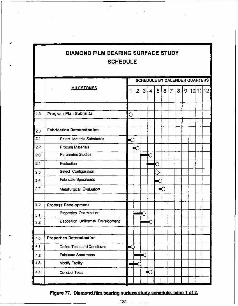
DIAMOND FILM BEARING SURFACE STUDY
SCHEDULE
SCHEDULE BY CALENDER QUARTERS
1 2 3 4 5 6 7 8 9 10 11 12
1.0 Program Plan Submittal 0
2.0 Fabrication Demonstration
2.1 Select Material Substrates
2.2 Procure Materials O
2.3 Parametric Studies I
2.4 Evaluation 1111 go
2.5 Select Configuration
2.6I Fabricate Specimens
2.7 Metallurgical Evaluation --- )
3.0 Process Development
3.1 Properties Optimization (
3.2 Deposition Uniformity Development - - .
4.0 Properties Determination
4.1 Define Tests and Conditions
4.2 Fabricate Specimens m IN
4.3 Modify Facility ----
4.4 Conduct Tests moo
Figure 77. Diamond film bearfng surface study schedule. page 1 of 2.
131
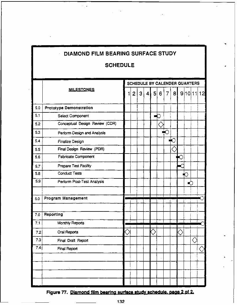
DIAMOND FILM BEARING SURFACE STUDY
SCHEDULE
SCHEDULE BY CALENDER QUARTERS
MILESTONES1 12 3 4 56 7 8 9101112
5.0 Prototype Demonstration
5.1 Select Component
5.2 Conceptual Design Review (CDR)
5.3 Perform Design and Analysis
5.4 Finalize Design
5.5 Final Design Review (PDR)
5.6 Fabricate Component 1
5.7 Prepare Test Facility
5.8 Conduct Tests
5.9 Perform Post-Test Analysis
6.0 Program Management mi
7.0 Reporting
7.1 Monthly Reports wii
7.2 Oral Reports
7.3 Final Draft Report
7.4 Final Report
Figure 77. Diamond film bearing surface study schedule. page 2 of 2.
132
will be devoted to examining the bond interface. Other specimens will be thermallycycled up to 1000 C and examined to check for bond adherence.
The second part of this task will demonstrate coating configuration. Threecandidate applications, such as bearing rolling elements, races, and seals, will be selected.Specimens will be produced from materials which were demonstrated to be viablesubstrates in the first part of this task. These specimens will have diamond films of theappropriate thickness deposited on them and then evaluated. The evaluation will besimilar to that done above, except special emphasis will be placed on thickness uniformity.
Task 2.0 - Properties Determination-A series of tests will be conducted todetermine key, properties of diamond. These tests deal primarily with measuring thecoefficient of friction of diamond films in appropriate propellant operating environments.These tests will include environments such as oxygen or hydrogen. The tests will bedefined on the program, but they will probably be either pin-on-plate or traction-rig tests.Appropriate substrates will also be selected, i.e., for tests conducted in hydrogen, titaniumalloys would be a proper substrate.
These data will be assembled and used to generate designs for Task 3.0.
Task 3.0 - Prototype Demonstration-This final task wil demonstrateperformance and life improvement attainable with diamond films on a selected specimen.Based on the work conducted in Task 1.0, a candidate subcomponent, such as a face seal,will be selected for design, fabrication, and test. The component selection and the AFALapproval will be influenced by available test facilities. The tests will be performed tosimulate operating loads and environments. Once the component has been selected, amechanical design will be prepared using the data developed in Task 2.0. Analyticalmodels will be prepared and evaluated to determine life and performance improvements.These data will be used to finalize the design.
The component will then be fabricated and tested to verify the model'spredictions.
Task 4.0 - Management and Reporting-A separate task will be establishedto handle monthly and final reports and to insure proper direction and guidance on theprogram.
133
7.0 REFERENCES
1. Chem. Eng. News, 15 May 1989.2. Penn State Diamond and Related Material Consortium data base.3. First International Conference on The New Diamond Technology, October 1988,
Tokyo, Japan.4. DeVries, R. C., "Cubic Boron Nitride: Handbook of Properties," June 1972
General Electric Technical Information Series, Report No. 72CRD 178.5. Yoder, M., Office of Naval Research.6. Technical Insights, Inc., Department J02888, P.O. Box 1304, Fort Lee, New Jersey
07024, U.S.A.7. Evans, T., and Phaa, C., "Proceedings of The Fifth Biennial Conference on Carbon
(Penn State University) 1962, pp 247-153.8. Gorham Advanced Materials Institute, P.O. Box 250, Gorham, Maine 04038-0250.9. Crystallume data.
10. Davidson, J. L, Ellis, C., and Baginski, T., "Multilevel DLC (Diamondlike Carbon)Capacitor Structure," 5.ME Vol. 871, Space Structures. Power. and Power.ondi.tioning (1988), pp 308-312.
11. Peters, M. G., Pinneo, J. M., Ravi, K. V., and Piano, L S., "PECVD Diamond ThinFilms for Research Instrumentation," AFOSR-TR-88-0647, Contract F49620-87-C-0102, 4-88.
12. Yoder, M., "Semiconducting Diamond Technology," Naval Research Reviews,Two/87, pp 27-31.
13. Robertson, J. L, Lifshitz, Y., et al., "Eidtaxial Growth of Diamond Films on Si(111) at Room Temperature by Mass-Selected Low-Energy C+ Beams," Science,Vol. 243, 24 February 1989.
14. Moss, S. C., S Vol. 244,2 June 1989, pp 1029-1030.15. Johnson, A., RCA Rev. a., 163 (1965).16. Naval Weapons Center, Solicitation No. N60530-89-R-0100.17. Raymond, L. (Ed.), "Hydrogen Embrittlement: Prevention and Control," ASTM
STP962.18. Aviation Week, 6 June 1989.19. Tumenaro, R. L., "Materials Aspects of the SL Lightguide Undersea Cable
Design," MRS Bull., July 1988, pp 14-22.20. Laurie, P. G., and Wilson, J. M., "The Diamond Surface I - The Structure of the
Clean Surface and the Interaction With Gases and Metals," Surface Science, 65,453-75, 1977.
21. Fedoseev, D. B., "Surface Graphitization of Diamond at High Temperatures,"erkhnoaL (1), 92-99, 1986.
22. Hydrocarbon-Fuel/Combustion-Chamber-Liner Materials Compatibility Program,Contract NAS 3-25070.
23. Vacuum Technology Reference Book, pp 70 and 82, Leybold-Heraeus.24. Evans, A. G., and Charles, E. A. "Fracture Toughness Determination by
Indentation," J. Am. Ceram. Soc. U (7-8), 371-372 (1976).25. "Liquid Rocket Engine Turbopump Bearings," NASA SP-8048, March 1971.
134
26. Kruschov, M. M., "Resistance of Metals to Wear By Abrasion, as Related toHardness," Inst. Mech. Eng. Proc. Conference on Lubrication and Wear (London),1957, p 655.
27. Peterson, M. B., et al., Contract N00014-82-C-0247, ONR, Wear SciencesCorporation.
28. Spurr, R. T., and Newcomb, T. P., 'The Friction and Wear of Various Materials,"Inst. Mech. Eng. Proc. Conference on Lubrication and Wear (London), 1957, p269.
29. Bissom, E. B., and Anderson, W. J., Advanced Bearing Technology, NASA SP-38,1964.
30. Ng., L., and Naerhe=m, Y., "Surface Modification for Wear Resistant LiquidOxygen Turbopump Environment," MSFC Adv. Earth-to-Orbit Symposium, May1986, NASA CP2436.
31. Thorn, R. L., and Dolan, F. J., "Rolling Contact Fatigue Life of Zirconium andMolybdenum Nitride Sputter Plated AMS 5749 Bearing Steel," MSFC Adv. Earth-to-Orbit Symposium, May 1988, NASA CP3012.
32. Wedeven, L. D., and Miller, N. C., "Material and Tribological Considerations forHPOTP (High Pressure Ox Turbopump) Bearings," MSFC Adv. Earth-to-OrbitSymposium, NASA CP3012.
135
APPENDIXA
DIAMOND FILM SURVEY RESPONSES
WTpinXii-#gp A A-i
APPENDIX A
INTRODUCTION
The following pages contain data transcribed from the surveyresponses with information which would identify the group removed. Tomaximize the extent of information transfer, a separate set of data is pro-
vided which identifies the personnel and papers as provided in the survey
questionnaires.
FRT.OOI7S.7A A A-2
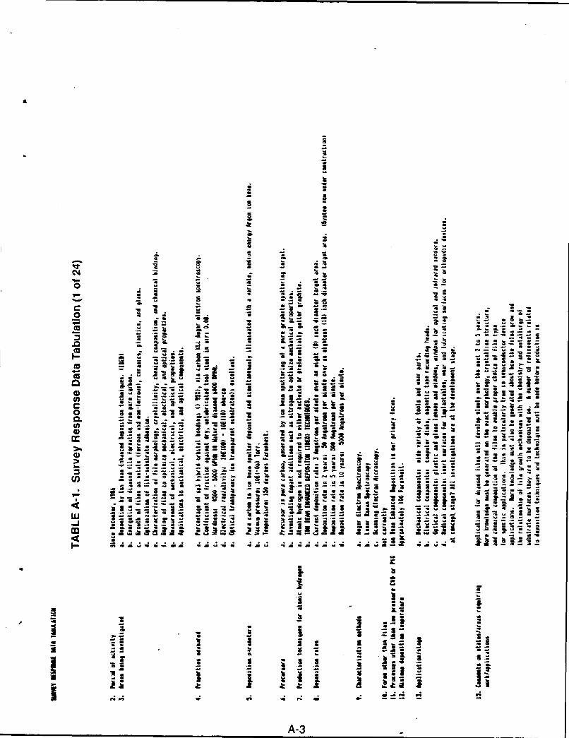
UZ
idiC33
0 a
. . al
Z5 M
- alj .3. .- x ..
O a ra mi all 3. 1- GZ 2
0-. C - 9.8= -. 0~ .44b
'a4a Iz a 0
* a! ..- az z-g..A-3 0
caa
CL
ozo
CO x
A-
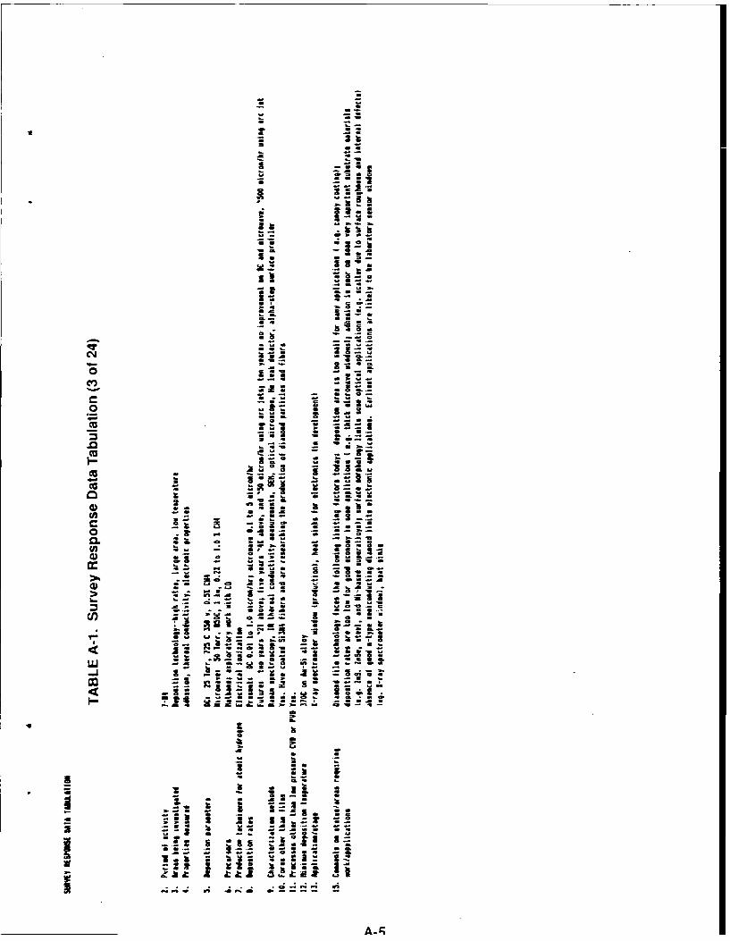
i S.
a Z
4-0- = .
* - 3
Cf20V
M 0, 0, G
cc.
0a*5CL .3
Ua.
0 a a-, -a
- a as al~~a I VC
Cf J- - a12 ~~ a a.X4
nt -- A i It -2
A P4 W; A
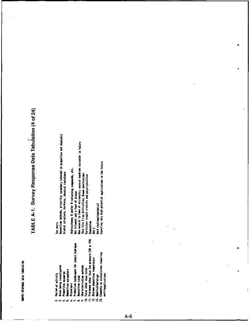
0
0
(a
ca.
CLC
a= tU) - 2
Lft...
lal- bl- :
0 A-6
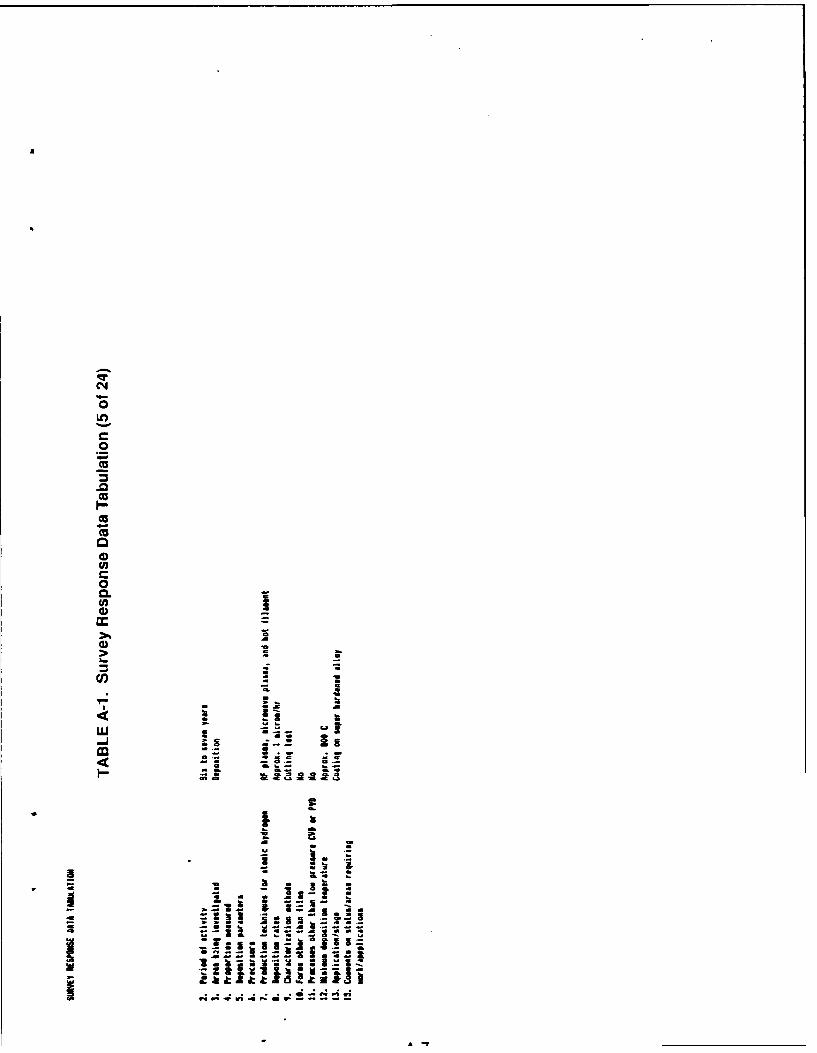
a0
0
U)
0CL
4)
-
fil
.E4k i I
44P ;j z0 0
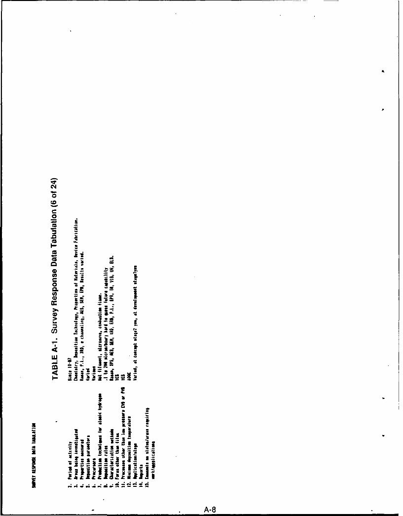
04J
0
.0
a .cu
2 r a
0 . m~
I.-
Cu
2 21
-
a--
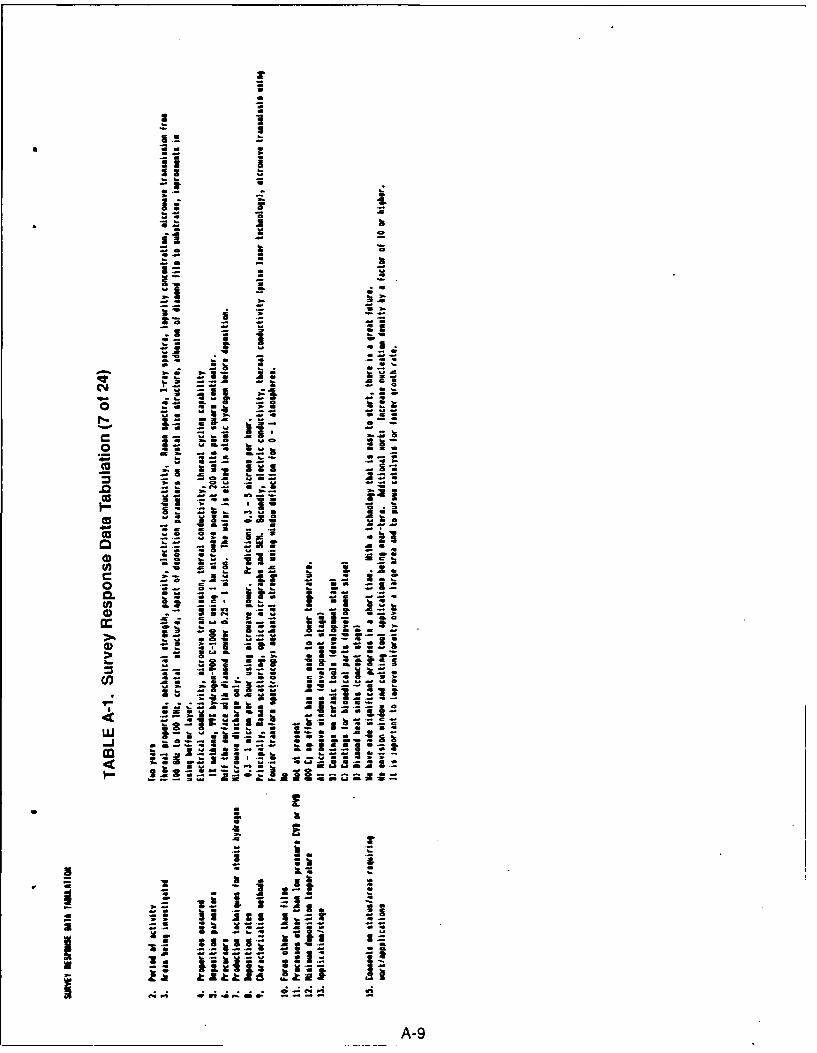
0Z
U.
Z-
Ni-. a
75 t
be 0
""~ I
raa
I~~~~ ri, , I.h
a a a
3 - , a ..
to - -& -,I a
i m . . 2
-I .=• o 3 0im i
I
I l .: i,, i
, ... - I
X. _2 ."• " Q ; re a aa
- a I ! a
_ h. -- ,U
A-9
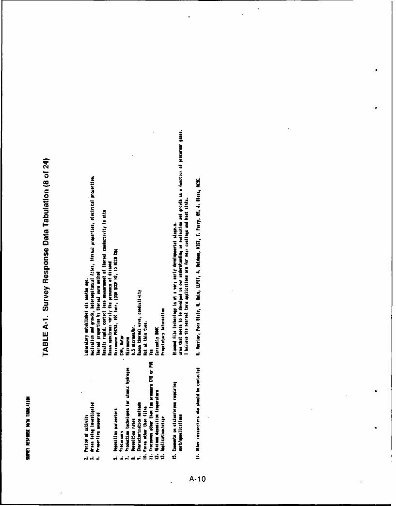
Na
Aa
4r
0 .co=
- !- -.
.0 - -- = 1
.. ai IlIIiI l a aa I
* a. .- - .i
... ..
I
a 2 = a X
0. r~. . . - aaww
z.~
.; it AasJ N a
-- ~~A- 0 --
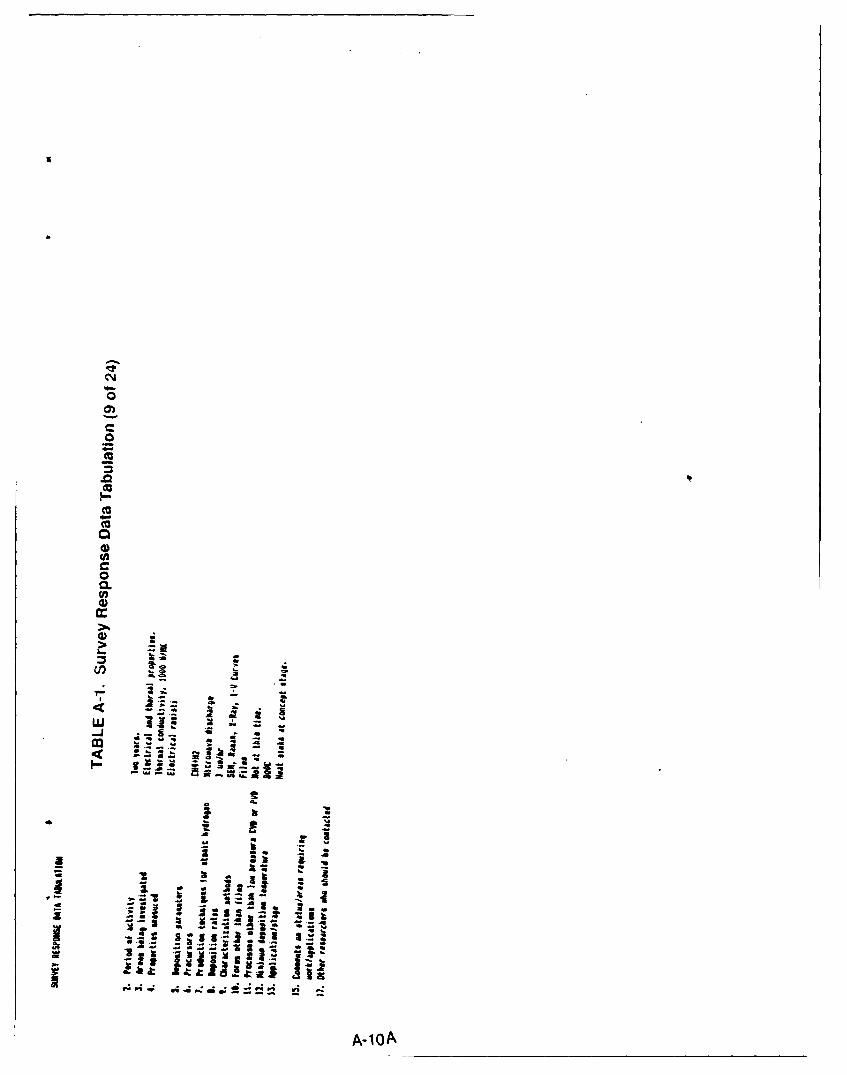
U
C~4
0
C0
0
'UI-CUCU00U'C00.U'0
0 -a
Ca -'S -~
a -- a
a 2w ~ -'a -S'SC- 'S - a~ - 'S a
a -
3 'a2' a*
a 5.1a .~
2 ~-
- --- I* a - a
- 3 -- a - jggt~I~ A--.z~I~3 '
- 4 .'U'~ ~a.. ~j~jEJ 1 Z~
. .~, ~ ~
A-1OA
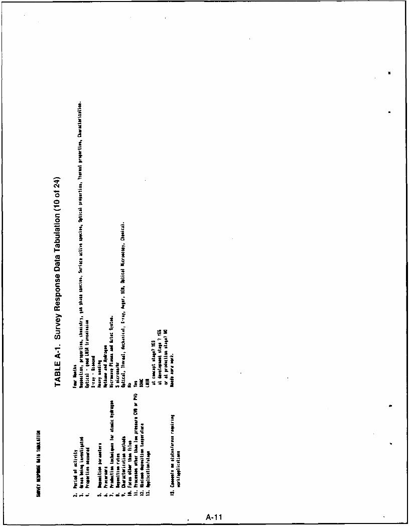
rU
-i ".... _ -
o , = :~o
C o -
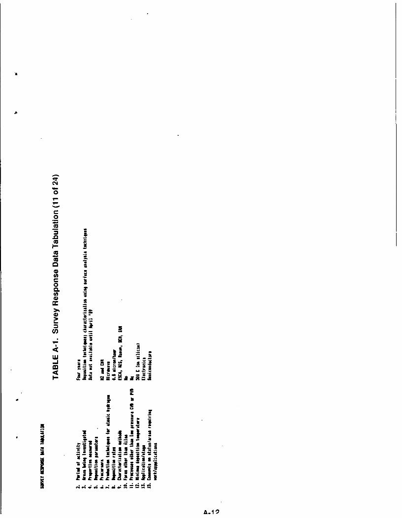
C4J
0
00
I"
.0
9 t
- !-1* •
0. ! ill
I j _..a I ll _.i88." -(5 C. .-
,, U ¥ , |
0 - il l ll t
* a.~ lt-.l. ll ;Il
-,t"
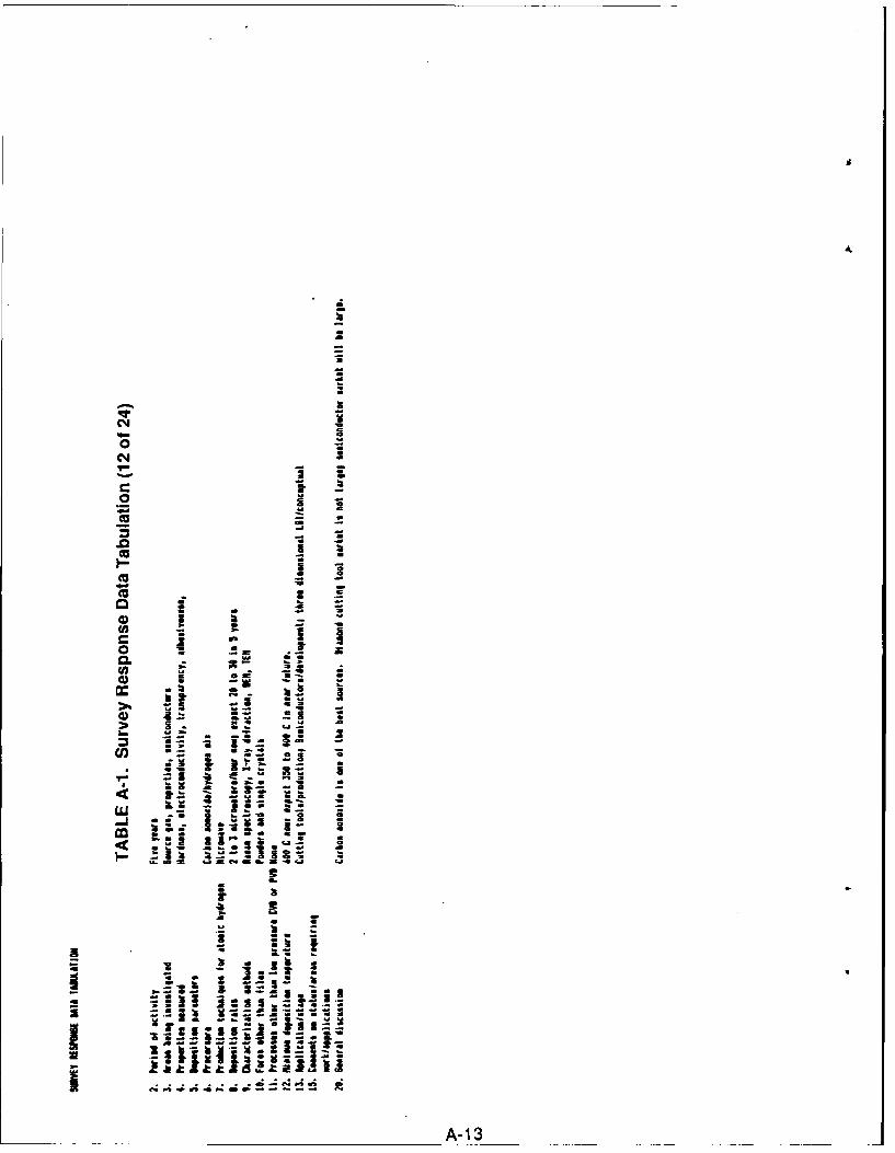
__ "
.- i .. -
en am eo a1a) a
.. 0
- - -*0 , -
a.. a - . |S.
-A-U
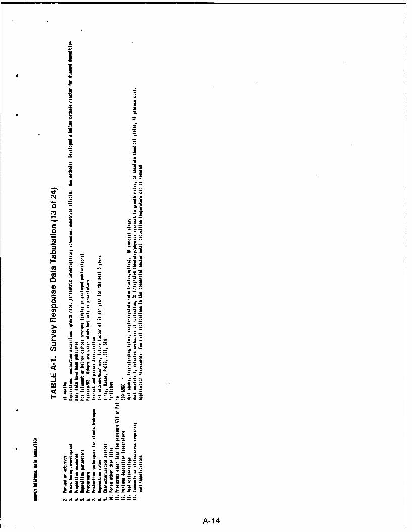
U
I.I
4 -
I Ua 6.
A -
k -
a S
* S
a S* S
* 64
*1 - -a a..* S
* S
= 5=
__ -o~. - - -
- *0
- a6.S* ae~ ~
V a-
C0- U..
'U.a *'U'U -
- .~
(U - - C..
C~ *~ I -U
0 - C. U~.~1
C ~ -C--o -a.6. - 3
0 =
0 -
~(J) C.. =5.5. - -
550 = *S - St
-Se 55 *S -
ILl o S.s - - C
.2. U~ 32.flt a-- *~ ~.S CJ * -
.. 5--- 0- S S
< Maa~... Ia . - - aI"~ - - - C as 500*00
- a === C- -, - a = - a
ICa -
i U.C--.
p 5 5 - I..!~ ~Clii I i~ ~-
I 333:ZI~ ~~ ~
.. . a-
JIIIIJIAStiIII*C* ~C - fl - -. -
A-14
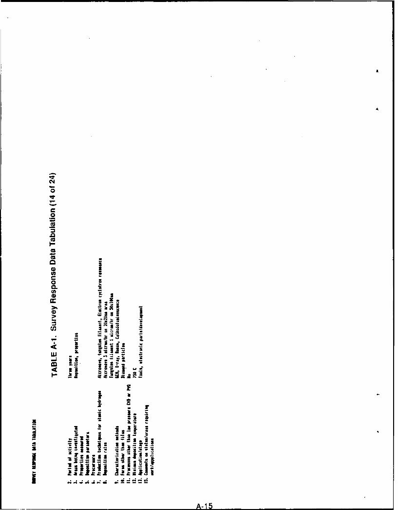
N£
0
0CL
'uco
4-i
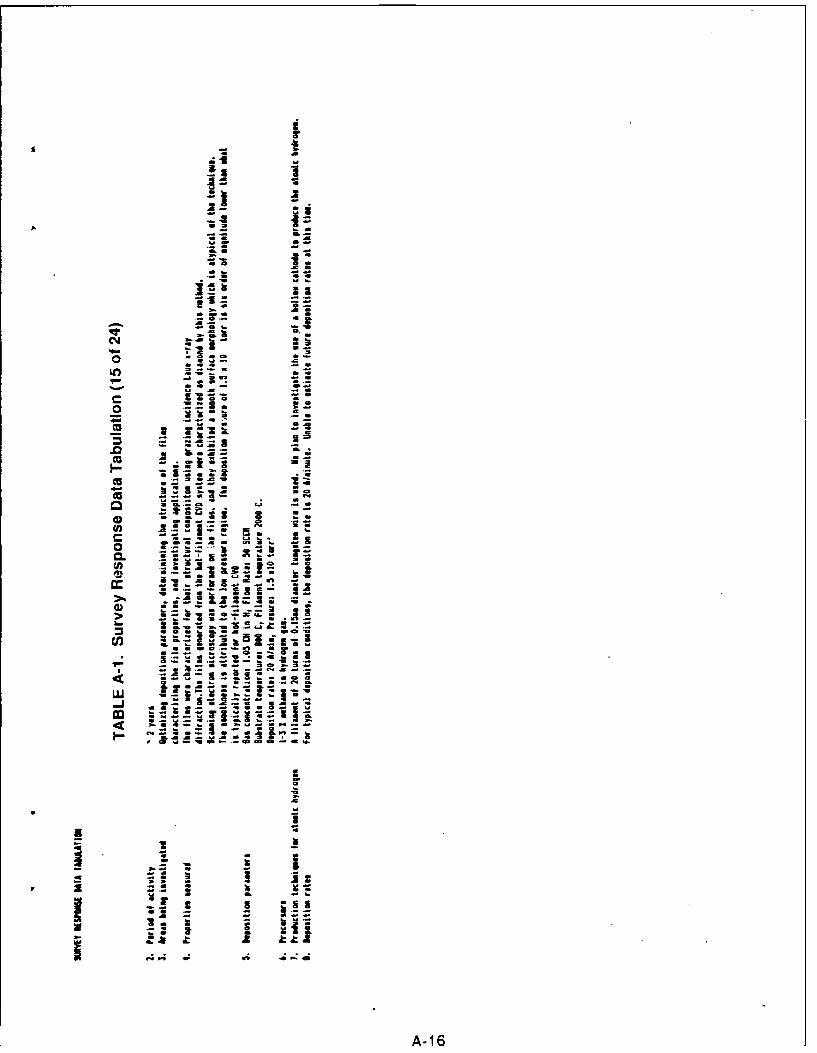
.2.
AA
M z
a Z
Cr A
CL.I 13
Z.2.xL ~ f
*I IC*~d C -
C A-16
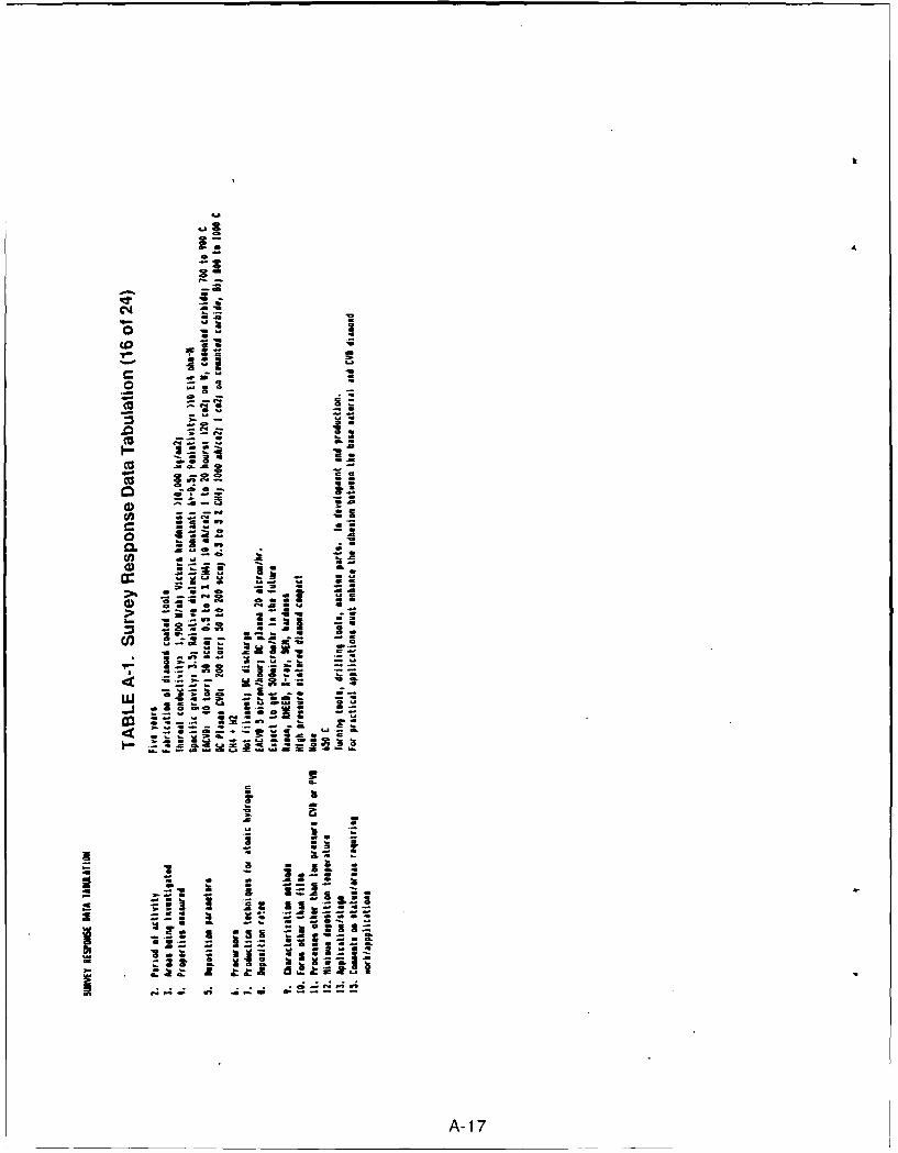
C14
00
ccI75
;aU
-- S
CL 9
agas
-2
(U
-a....-as-~9 CLA A
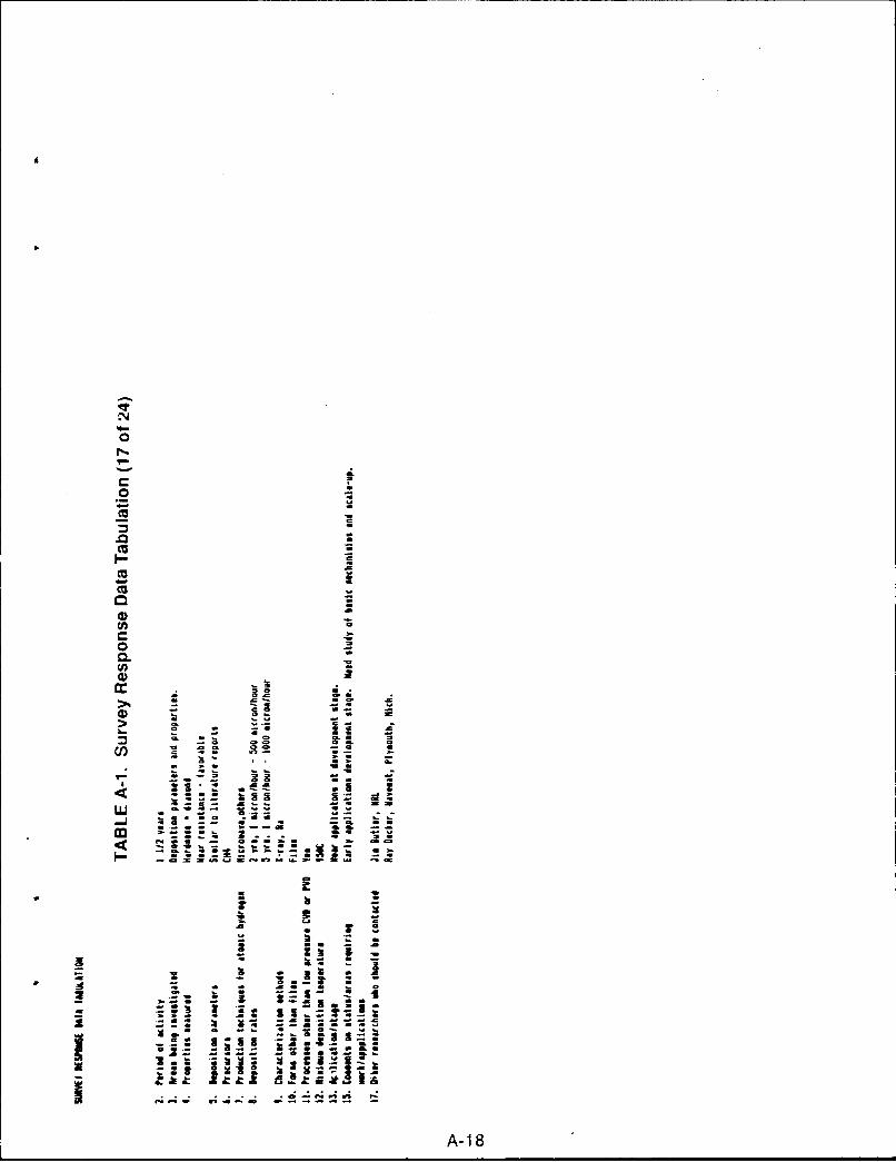
N
0
1~
0 -
(U -
.0 a(U U
I- =
(U aa
(5 -o -
a)(n C
C a.o -0. -(I,a)
a Ca OS
a) 0
a.-0 00 Ha
Cl, a
II- ~33 U ~= =
~- - a U. -~0b. --
I.- U. a.- fl==.flI~D=e4fl0~a.~=~ --
3* a a- ha -
.5 18
- - a- as & -
.5 - I ~ *- - *2 -= a a - a a
*~~- .~ I~j ~ I: I C~3iu~a - - -a- - aS - a
CU a -a.~a I~I3 ~asa.- -s--- ~
1a~ ~:2H ~
.............. e-nrn .-
A-18
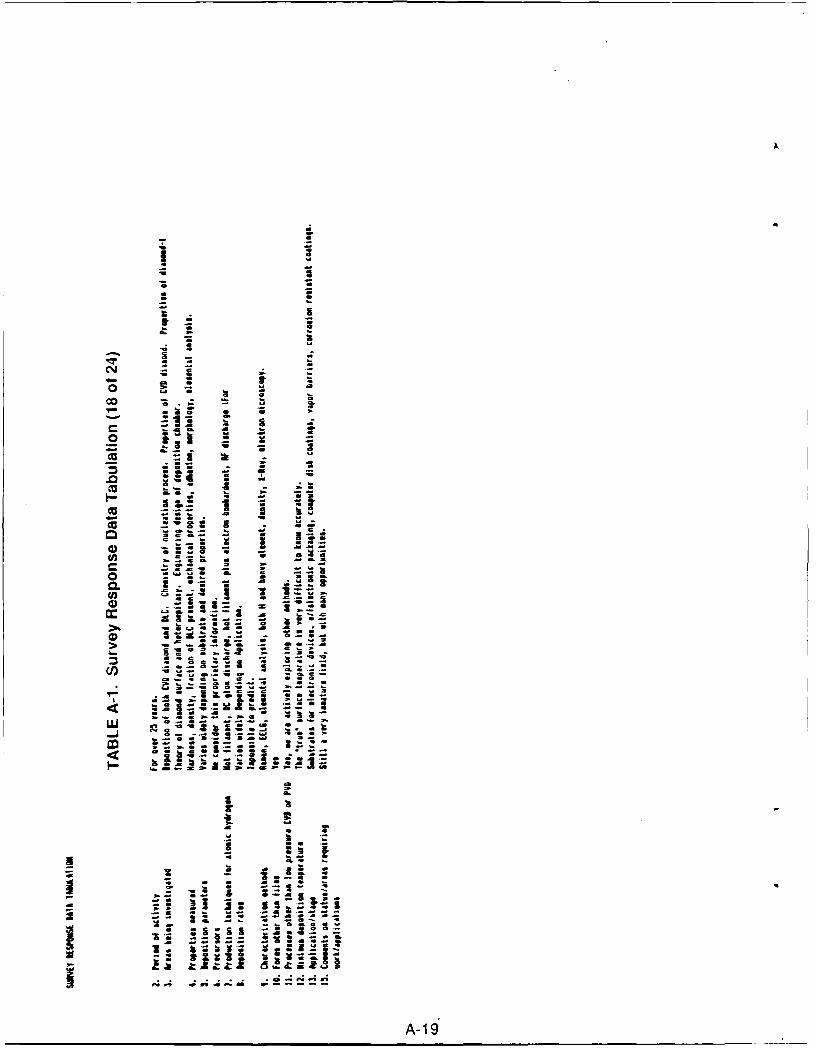
7553L
.2
00
o9 -01
CU I z
U2 Z
CAU19
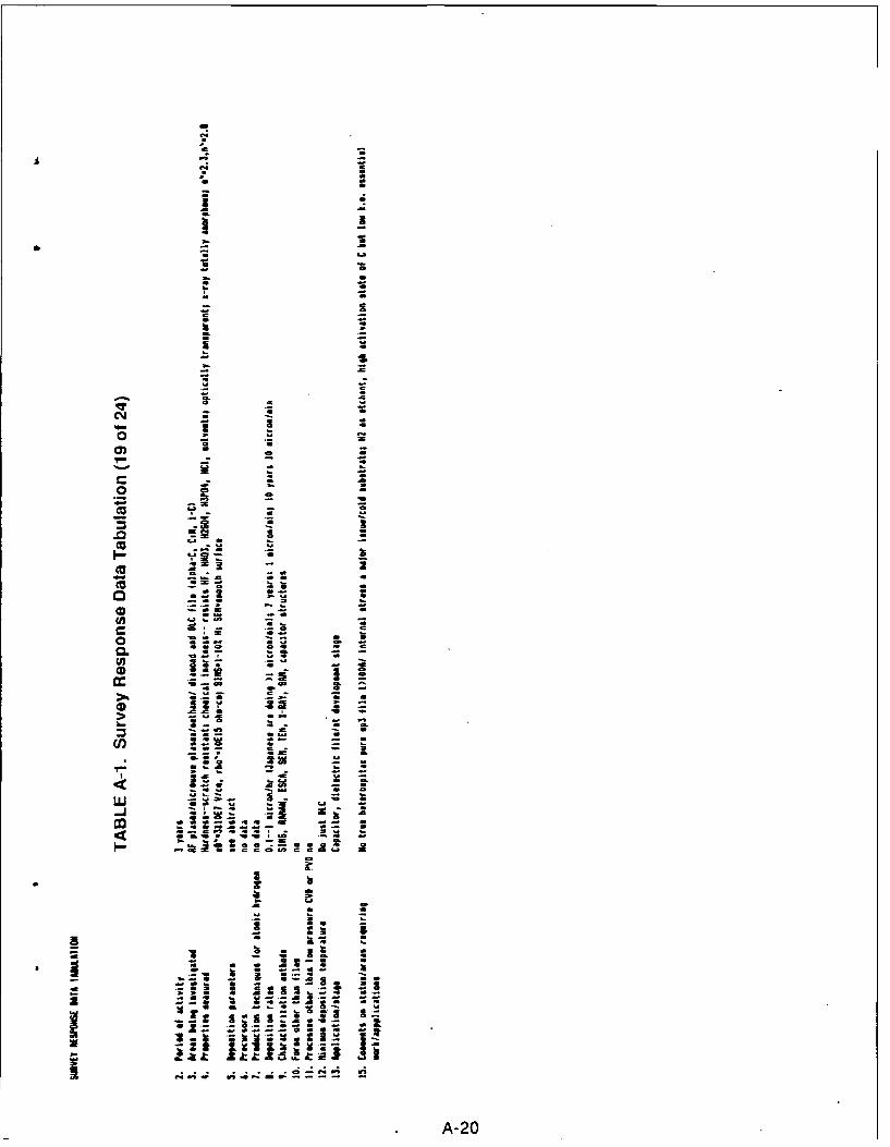
ca
A A
I -.
SS
a. -030
- .S S.. . .
., ,- C.'.t& .° " . ! . I
o o '• • =i pa
A-20
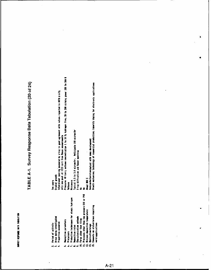
C*4
o *1
00
4) z a
-1 Z
o * it0.2 2.
'T . 1 g I S 3 & 91X a&a~~g _: a
(AI2
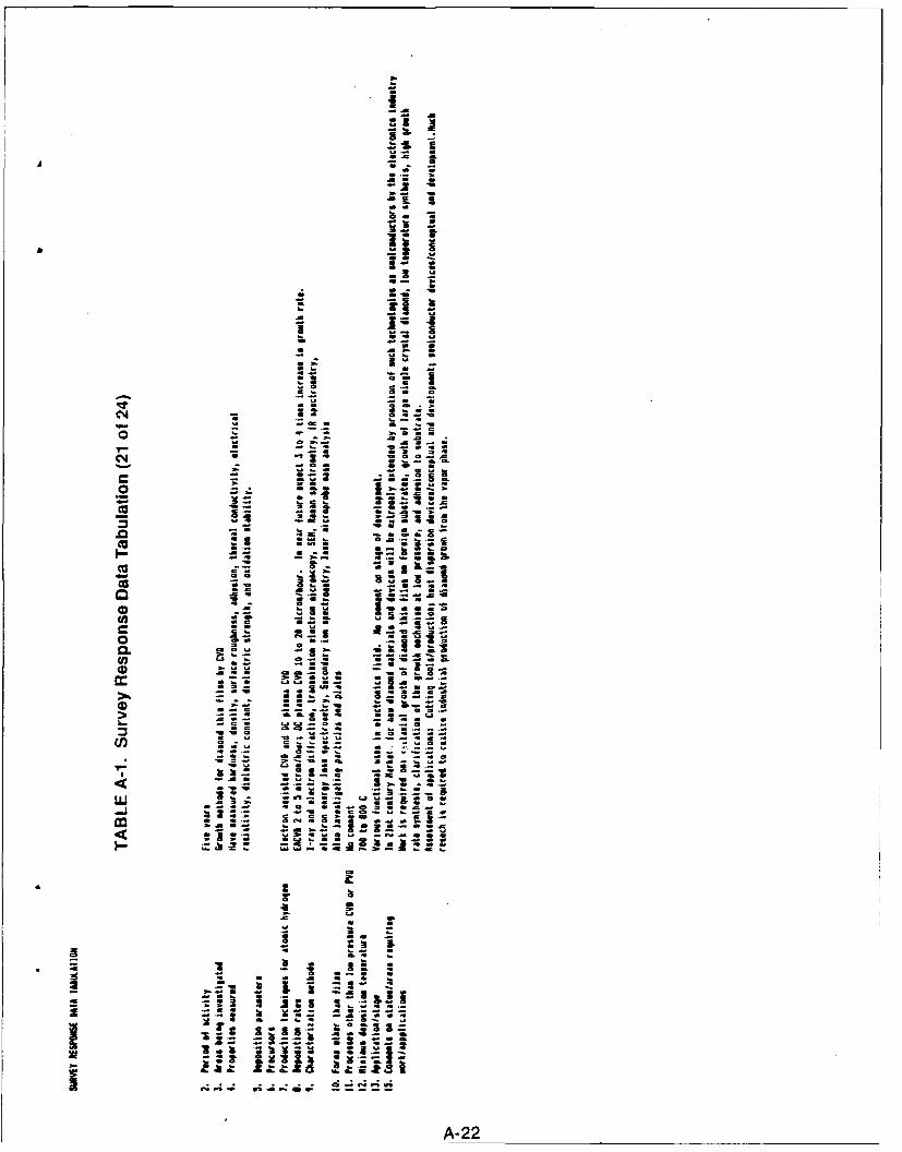
i'
04- .
cc ~ IiiX a . _g . X 4,=
i II I~ a
- 4;
7 I -Z
2 a.
a 9 9.
z Z
a sam a.
.- -" a
M- M ~ i ,. %& z
!7 .= 2.-.S l . i
o 3.
- .- ° . . .a
t4J P4 1.: * 0;4;
A-22
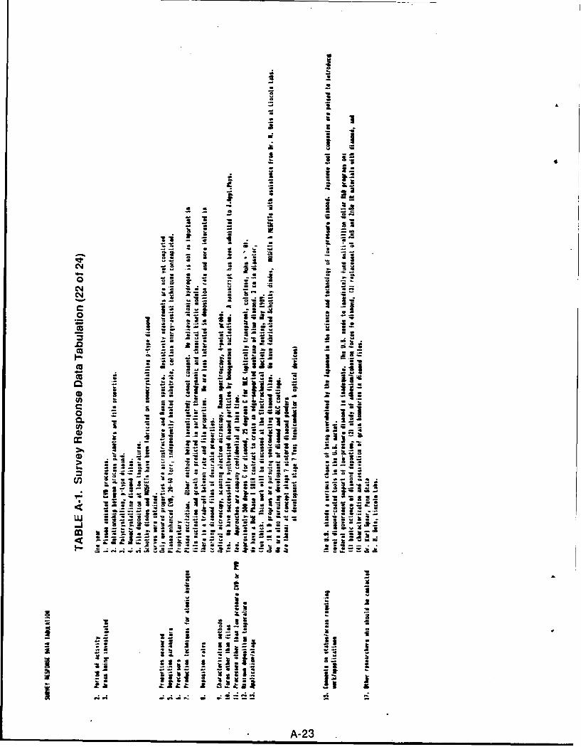
NV
i :a
o ii-
SS
, I I
--4- ag, .- ,.2.: --
a a I • . ,3. :' .
- t I I
1. M
. . . . ..z I"V
iIS
',3 I I
o 1,1 , I*=mI~
-3 z
A32
: . . a. 33I .. a:
L-C,: . i . , I a I S. Ii 1
a. a~, J a io .,a= ai . -. L i -. , cI *i
C , , -- - -- -- ,, .-- .i .- a 3 3 a - -I I
=1 - I . m
_-& -&.. ,- ,. - aa.a
a stI~ IS
A-23a
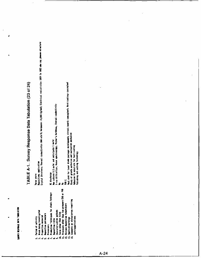
0
CYJ
0
ca a !
- SUS
_ 0
CZ. di
IA-24
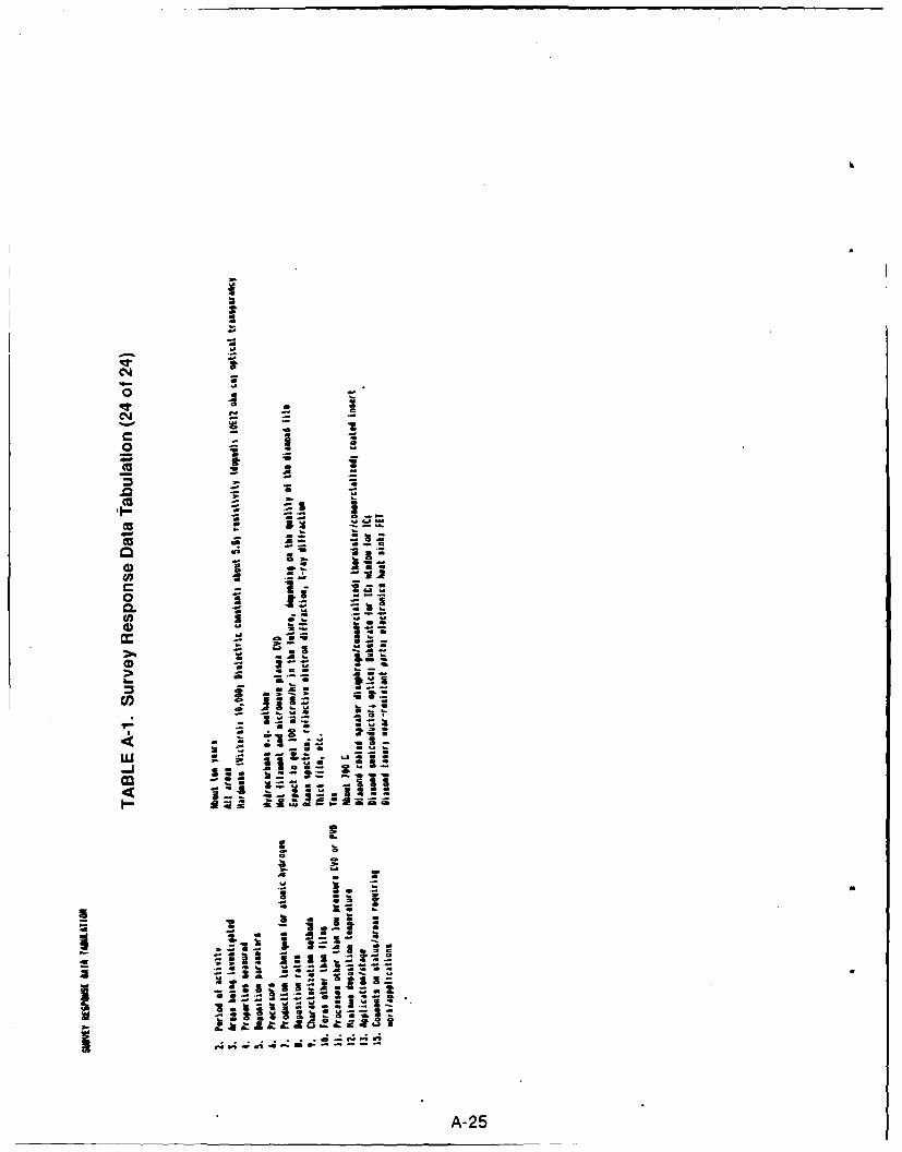
•I I
~i
%o 9 -
-- aC
.0~ t
4,.
u
-- .2
.,-- 2-.. - .
. ' - ,.
A-25
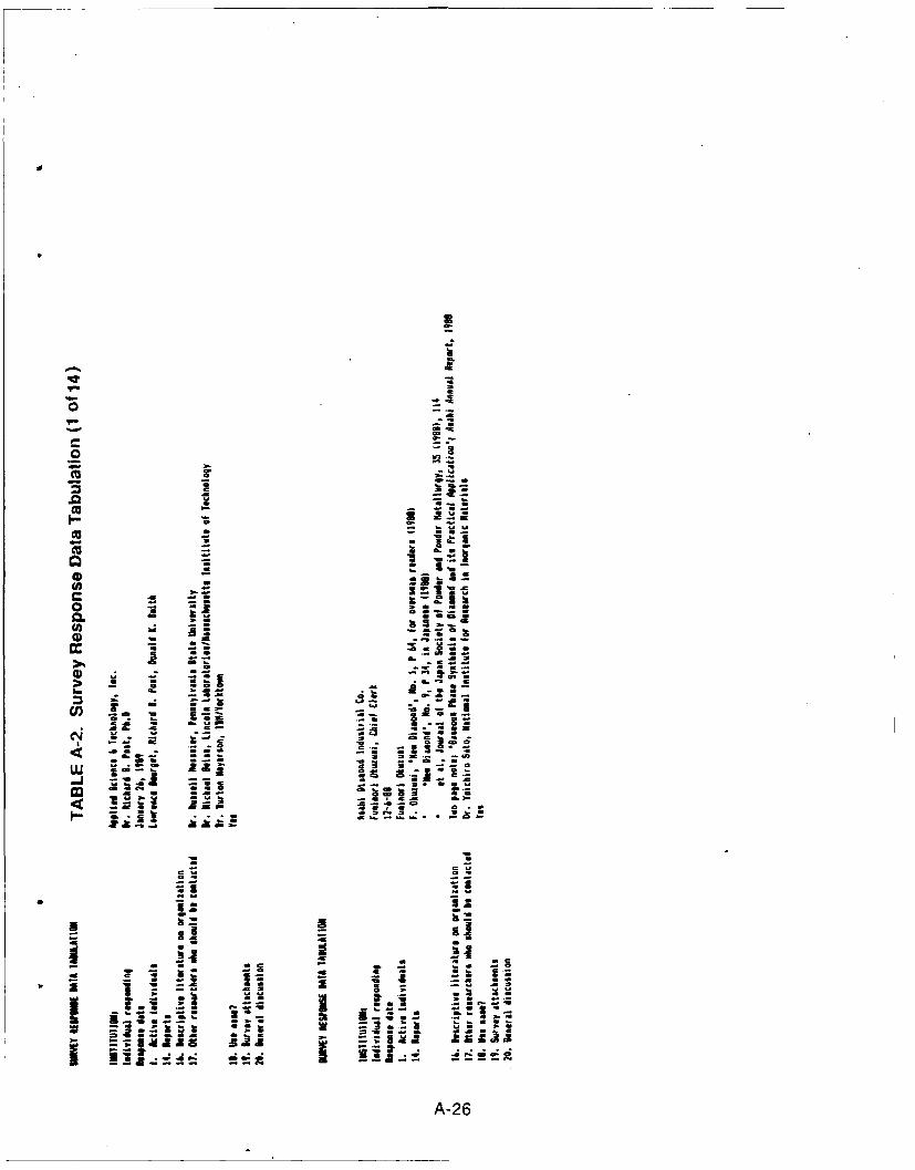
aaa
S
- .~
a ~
0
0
0- - 5.3
- .5a a
- l.a= -0 -
GO a . -a -. -
-m k .U~a aS ~a aea. - as a
0 -~ - a- a- a. u~* - - .. acee= a.
-- a. 'as- inb. - a --
0 ~Cs0 * - --ti - Cola~ - a - - .5.- CS COO a o a-- a. sa- . h. S .aCa.
- a .Ci~ ~. = S~ -o 3am--. 5 -= .~ a -Ca 5.Ua -.- a.-5.sa. C -a a. C aSU - *4J -Wa -
- -~ - a a =~s-~. a *~ -~ a alas
-. aa a as... .. 0~LU ~ ~ ;. 0~ 555 a~ a..- as-~.. -- C. . .. aea -
~ . -a. aa~
-M ~ S - . C I C'a S.)
I- ~ -~
a a.2: - .-
'1 1- a a as
3.; - .~ .1A - - a - - - aSa - .5 -S SC S - - - - - =a *; :~ aS - 5 C -~ ~
uJi 1IZE 3~ -- a
A-26
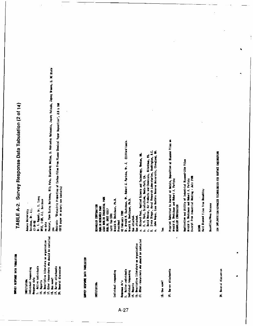
a04
0=
'-, . . .... pcisJ__3
a
o - a --
U Z
.0 b
-- - a,, ,a. L ".. ,
S- -
Z z at
U - - -I a
do- a A a
. * - as •-
f l I m@~ 0
4 4 Z a .1- 0
, .-. A -7
A-27-
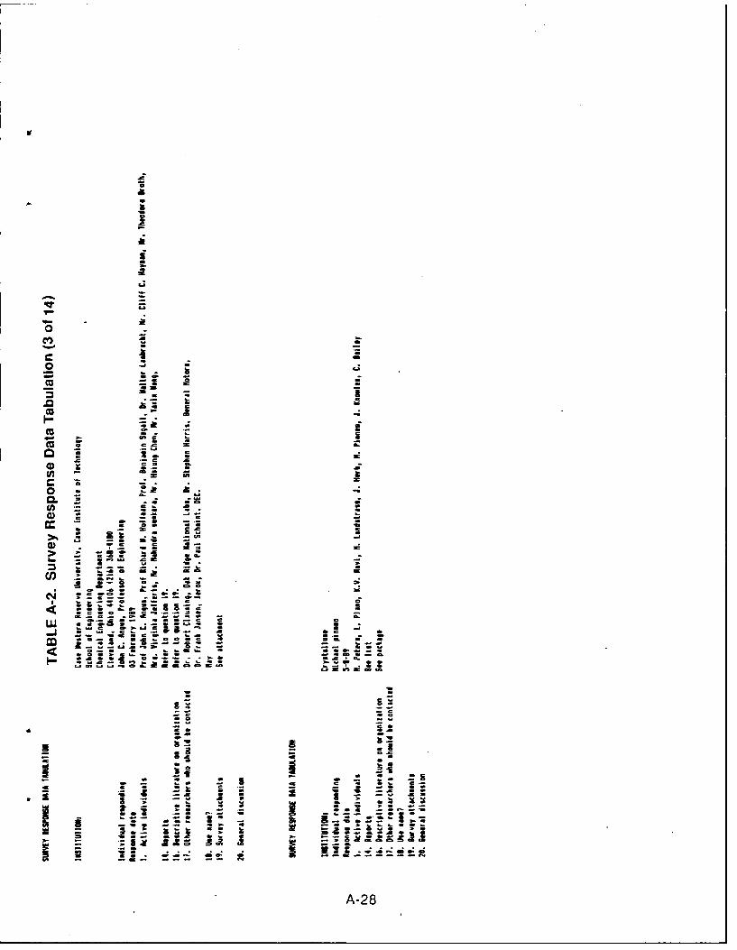
CO)a
0a
zA4-0
0*1
CL4-
72 2-
Cu C-
w c
o0 .1r
- 2
0 S
(fl - X
WS J" ZZ
a.A-2
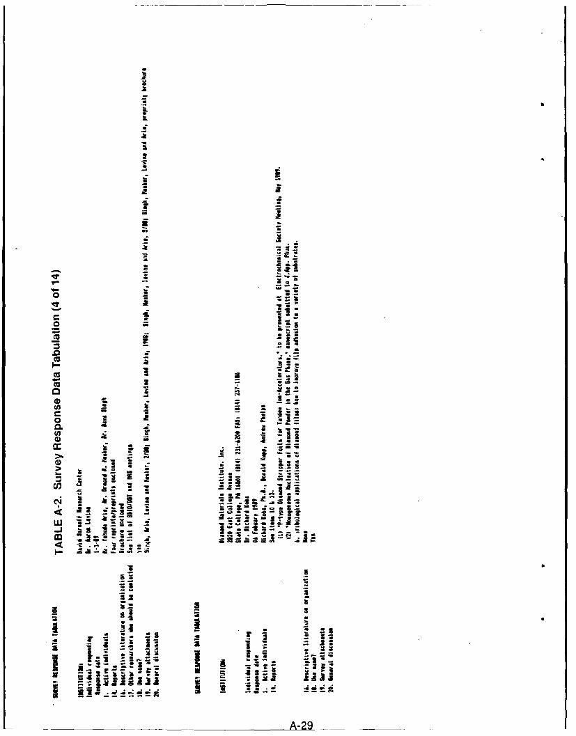
0
Ia
a
21= 00 aa -- a.0
i.0
~00* a -
C a -* 0 .0
-~ C
- aa-
- - -- 'a.a - -a-
_ a a~ ~11--2. saGa 0~o - - -
4- --Cu - a..
- assa. a El
.0Cu - a
1-~ - - a ~a 00.0* 2. h.
- . - @0...
Cu a -o aCa I -
0 0 - - a(fl U - ae .~ a. aC * - a ao * a ~
a - ~0.a.a. - a ha S~fl - S
Cu -U - - --- a
- hi ~ =- a C. =
- - aCu . -
2. 2. a -a - - -
- a - = - S
- a U -: S ~1 ICD ~ 'a a5
a a . a-a a -
2 ~a.3 - 0.0.4 N
* :. .2 ~w i.5 a:;:
a a~a@ - - *..a2.' --
..J 23 l~a~ .~ ass.... =- I~E.2=~e -.-.- a
a- a ... :~ .u:I - Ca hi 50in~ S S a.
4
- a
- - *1as
2-l -
* Nj a a a
.3 - - - ~ .23
.23 - ~ Ii- ~ - a 'a -
Na 2 .- -z a a *
~.2.! .z ~ - -a
-- 2aa2 C- - g * ... 4.. Ia-; a:z ~ his
a. - j ~
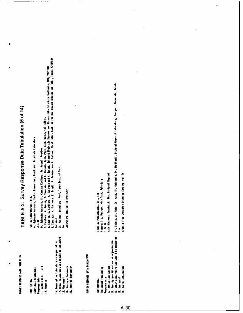
72
i
75 5;U)U
0o a
• . i C,
a- -
m I ,o w
-CU-
A-3
-a-
- a -! ai,-- • "C "a,.,,
" -@. i
CU !.. , !i - " l
aA-30
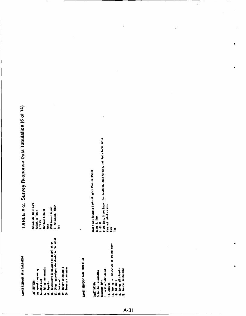
m 1.
(U a
9 I
oA
.302
UB. j
Ao3
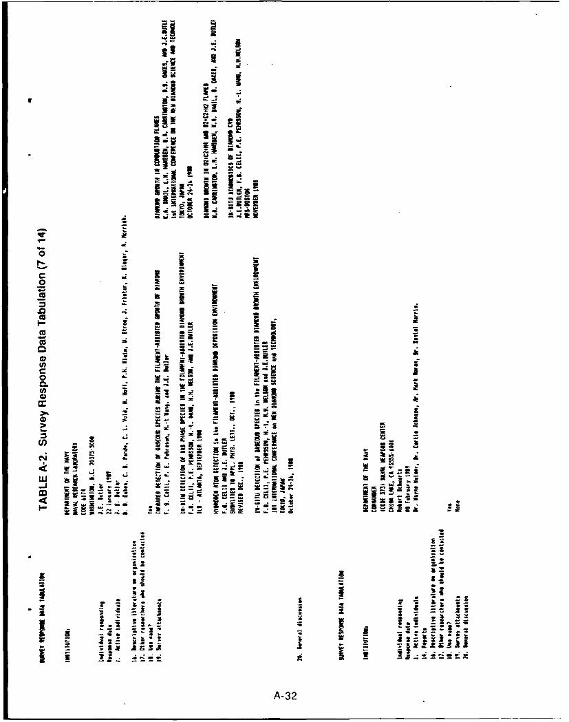
75I z
co- V
422
cr..
~ ~3-IS.'w v3
W r- .
e0 m Is 1 .d
0 - K o
I- U ~ 3 72
a~ * ~ k -3A-32
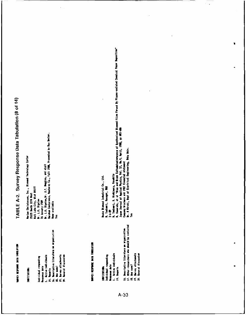
0.3
0a
.0
- LW-
-j
A;-33!
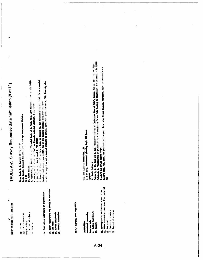
3z
cis
- -!_
0
4 v
S-- -
ii o vii
a -s l
fA-
aso .. . -"-5-.
. . . . ..
0A--
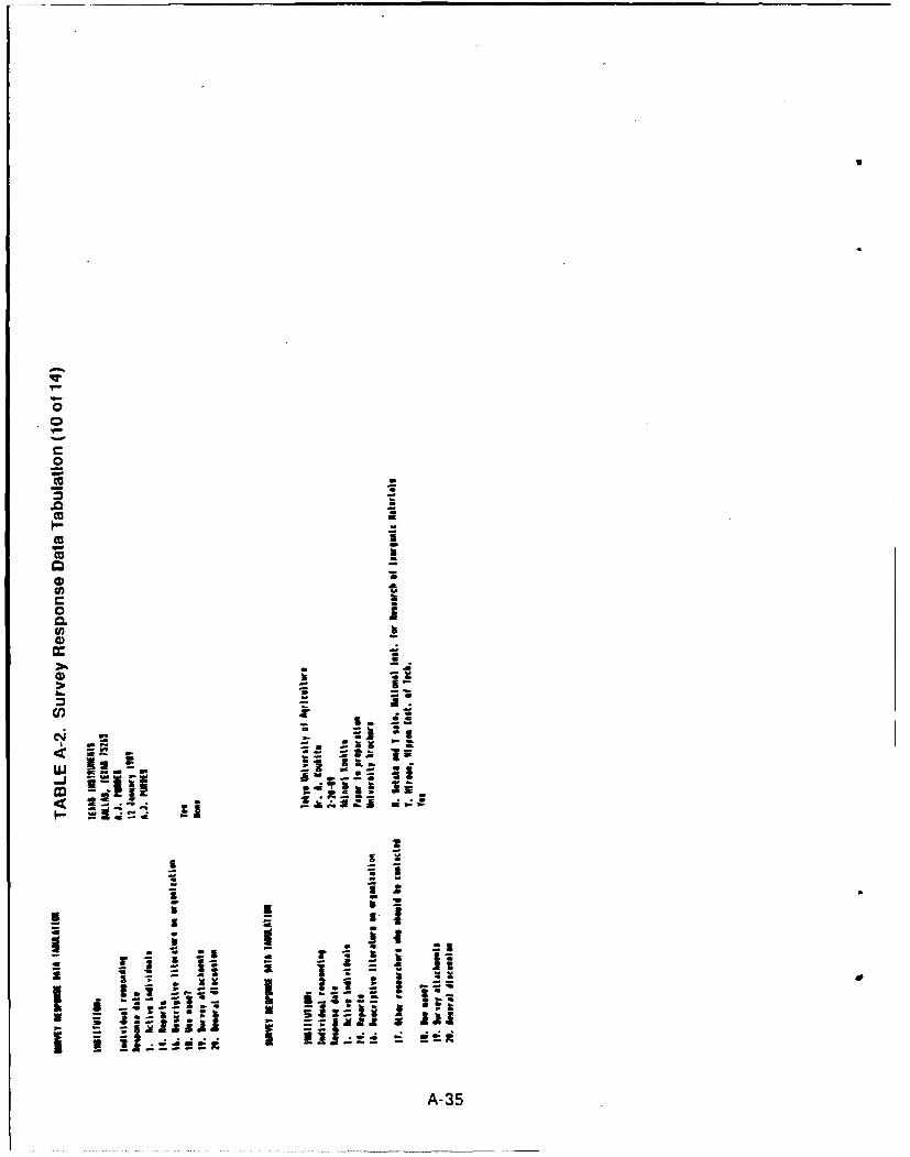
It
II
C"
C. -4)
o Z
A3
0)0
-1 0
-3
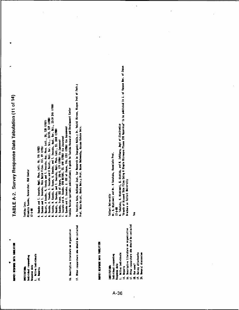
va
XI
- .- . - -o1 s3 1 a.
dw "a - a
) a X
"'"c .. .
So .2
.,.--U, IZ z" -., -f - -p , -.
U) : .i i a mi. .i i i
S .. . ... -. ._X=
- ' - I- .
LU i xi i - 0.
WI o~n
I- U I. eeI -I
" . -
-i ..
I- -. - -ha-
-36
0 an . w w*7Z
rip a
* wn
all 50a
0 ~ aA-
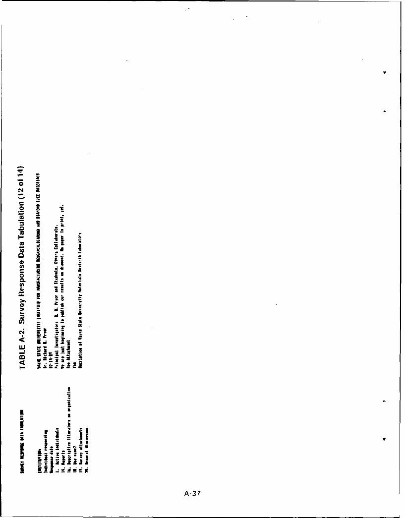
C.,'
'- -
_- =
C_
In.0 .
a ' a -
- SC& .
A-37
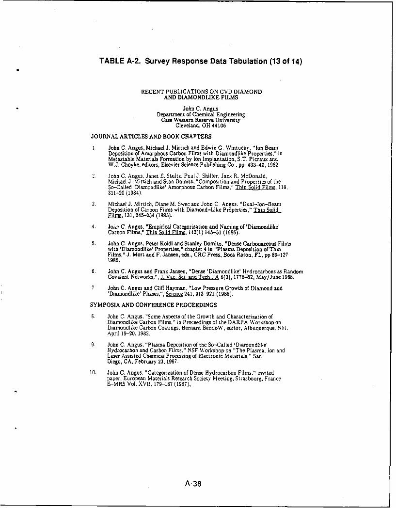
TABLE A-2. Survey Response Data Tabulation (13 of 14)
RECENT PUBLICATIONS ON CVD DIAMONDAND DIAMONDLIKE FILMS
John C. AngusDepartment of Chemical Engineering
Case Western Reserve UniversityCleveland, OH 44106
JOURNAL ARTICLES AND BOOK CHAPTERS
1 John C. Angus, Michael J. Mirtich and Edwin G. Wintucky, "Ion BeamDeposition of Amorphous Carbon Films with Diamondlike Properties," inMetastable Materials Formation by Ion Implantation, S.T. Picraux andW.J. Choyke, editors, Elsevier Science Publishing Co., pp. 433-40, 1982.
2. John C. Angus, Janet E. Stultz, Paul J. Shiller, Jack R. McDonald.Michael J. Mirtich and Stan Domitz, "Composition and Properties of theSo-Called 'Diamondlike' Amorphous Carbon Films," Thin Solid Films, 118,311-20 (1984).
3. Michael J. Mirtich, Diane M. Swec and John C. Angus, "Dual-lon-BeamDeposition of Carbon Films with Diamond-Like Properties," Thin SolidEilms, 131, 245-254 (1985).
4. JoL, C. Angus, "Empirical Categorization and Naming of 'Diamondlike'Carbon Films," Thin Solid Films, 142(1) 145-51 (1986).
5. John C. Angus, Peter Koidl and Stanley Domitz, "Dense Carbonaceous Filmswith 'Diamondlike' Properties," chapter 4 in "Plasma Deposition of ThinFilms," J. Mort and F. Jansen, eds., CRC Press, Boca Raton, FL, pp 89-1271986.
6. John C. Angus and Frank Jansen, "Dense 'Diamondlike' Hydrocarbons as RandomCovalent Networks,", J. Vac. Sci. and Tech.. A 6(3), 1778-82, May/June 1988.
7 John C. Angus and Cliff Hayman, "Low Pressure Growth of Diamond and'Diamondlike' Phases,", Science 241, 913421 (1988).
SYMPOSIA AND CONFERENCE PROCEEDINGS
S. John C. Angus, "Some Aspects of the Growth and Characterization ofDiamondlike Carbon Films,' in Proceedings of the DARPA Workshop onDiamondlike Carbon Coatings, Bernard BendoW, editor, Albuquerque. NM.April 19-20,1982.
9. John C. Angus, "Plasma Deposition of the So-Called 'Diamondlike'Hydrocarbon and Carbon Films." NSF Workshop on "The Plasma, Ion andLaser Assisted Chemical Processing of Electronic Materials," SanDiego, CA, February 23, 1987.
10. John C. Angus, "Categorization of Dense Hydrocarbon Films," invitedpaper, European Materials Research Society Meeting, Strasbourg, FranceE-MRS Vol. XVII, 179-187 (1987),
A-38
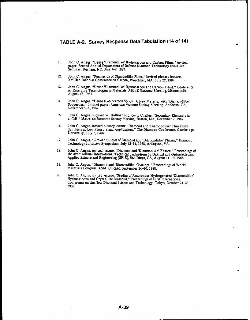
TABLE A-2. Survey Response Data Tabulation (14 of 14)
11. John C. Angus, "Dense 'Dianondlike' Hydrocarbon and Carbon Films," nvitedpaper, Second Annual Department of Defense Diamond Technology InitiativeSeminar, Durham, NC, July 7-8, 1987.
12. John C. Angus, "Formation of Diamondlike Films," invited plenary lecture,XVIIIth Biennial Conference on Carbon, Worcester, MA, July 22, 1987. -.
13. John C. Angus, "Dense 'Diamondlike' Hydrocarbon and Carbon Films," Conferenceon Emerging Technologies in Materials, AIChE National Meeting, Minneapolis,August 18, 1987.
14. John C. Angus, "Dense Hydrocarbon Solids: A New Material with 'Diamondlike'Properties,' Invited paper, American Vacuum Society Meeting, Anaheim. CA,November 2-6, 1987.
15. John C. Angus, Richard W. Hoffman and Kevin Chaffee. "Secondary Elements ina-C:H," Materials Research Society Meeting, Boston, MA, December 2, 1987.
16. John C. Angus, invited plenary lecture,"Dianond and 'Diamondlike' Thin Films:Synthesis at Low Pressure and Applications," The Diamond Conference, CambridgeUniversity, July 7, 1988.
17. John C. Angus, "Growth Studies of Diamond and 'Diamondlike' Phases," DiamondTechnology initiative Symposium, July 12-14, 1988, Arlington, VA.
18. John C. Angus, invited lecture, "Diamond and 'Diamondlike' Phases," Proceedings ofthe 32nd Annual International Technical Symposium on Optical and OptoelectronicApplied Science and Engineering (SPIE), San Diego, CA, August 14-19, 1988.
19. John C. Angus, "Diamond and 'Diamondlike' Coatings." Proceedings of WorldMaterials Congress, ASM, Chicago, September 24-30,1988.
20. John C. Anglis, invited lecture, "Studies of Amorphous Hydrogenated 'Diamondlike'Hydroca-bons and Crystalline Diamend," Proceedings of First InternationalConference on the New Diamond Science and Technology, Tokyo, October 24-26,1988.
A-39
APPENDIX 5
EVALUATION OF DIAMOND FILM
STRENGTH CALCULATIONS
RPT-O ?.37-Amp B
B-i
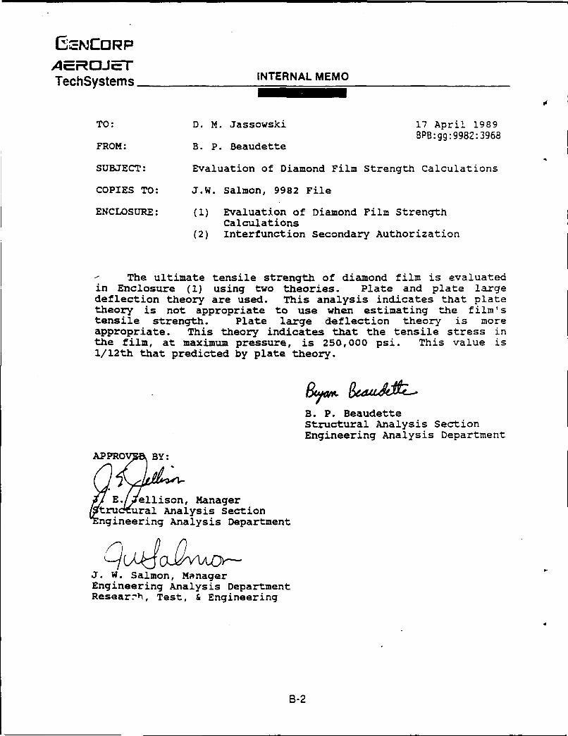
EZNCORPAEROJE--7
TechSystems INTERNAL MEMO
TO: D. M. Jassowski 17 April 1989BPB:gg:9982:3968
FROM: B. P. Beaudette
SUBJECT: Evaluation of Diamond Film Strength Calculations
COPIES TO: J.W. Salmon, 9982 File
ENCLOSURE: (1) Evaluation of Diamond Film StrengthCalculations
(2) Interfunction Secondary Authorization
- The ultimate tensile strength of diamond film is evaluatedin Enclosure (1) using two theories. Plate and plate largedeflection theory are used. This analysis indicates that platetheory is not appropriate to use when estimating the film'stensile strength. Plate large deflection theory is moreappropriate. This theory indicates that the tensile stress inthe film, at maximum pressure, is 250,000 psi. This value is1/12th that predicted by plate theory.
B. P. BeaudetteStructural Analysis SectionEngineering Analysis Department
APPROV BY:
E./$ellson, Managertrud ural Analysis Section
Engineering Analysis Department
J. W. Salmon, ManagerEngineering Analysis DepartmentResearrh, Test, & Engineering
B-2
ENCLOSURE (7)
EVALUATION OF DIAMOND FILMSTRENGTH CALCULATIONS
PREPARED BY:
B. P. BeaudetteStructural Analysis SectionEngineering Analysis Department
AP RROV 7 Y: REVIEWED BY:
E. a llison, Manager J.D. Melot ral Analysis Section Structural Analysis Section
Engineering Analysis Department Engineering Analysis Department
J. W. Salmon, ManagerEngineering Analysis DepartmentResearch, Test & Engineering
B-3
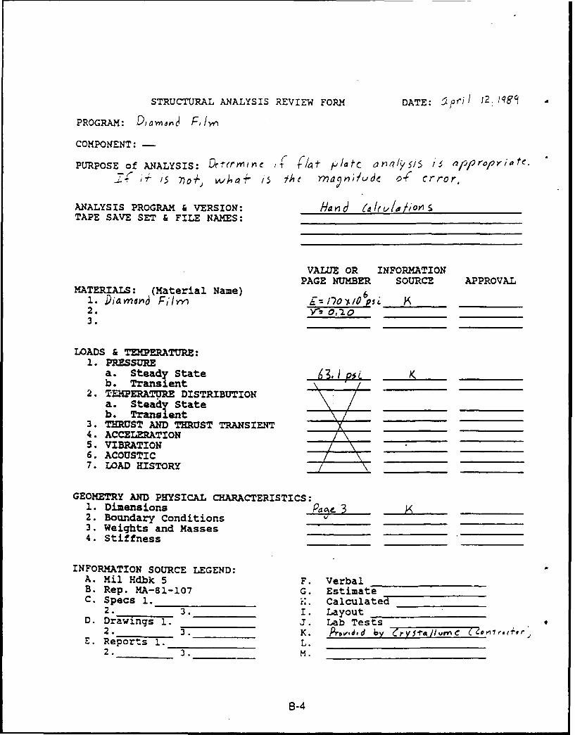
STRUCTURAL ANALYSIS REVIEW FORM DATE: r4' 2 qg ,
PROGRAM: ),ao1j FIw
COMPONENT: -
PURPOSE of ANALYSIS: 4ftp//c r2/ 5/e//r/Yst15' 7o+ . w'ha+ /'5 Je Yn'a~,-;A.'Se 0( Crror,
ANALYSIS PROGRAM & VERSION: Ha P7 d(/(I u/ioTAPE SAVE SET & FILE NAMES:
VALUE OR INFORMATIONPAGE NUMBER SOURCE APPROVAL
MATERIALS: (Material Name) 61. Diaayr~ d , ,~f/rn __ __ __ I_ _ _ _ ____ __s
2. V- 012 03.
LOADS & TEMPERATURE:1. PRESSURE
a. Steady State 5 J.4I K _____b. Transient \_'_ _2. TF21ERATURE DISTRIBUTION
a. Steady Stateb. Transient /
3. THRUST AND THRUST TRANSIENT __'4. ACCELERATION /\\5. VIBRATION
_ __\6. ACOUSTIC7. LOAD HISTORY
GEOMETRY AND PHYSICAL CHARACTERISTICS:1. Dimensions Pa%- 32. Boundary Conditions3. Weights and Masses4. Stiffness
INFORMATION SOURCE LEGEND:A. Mil Hdbk 5 F. VerbalB. Rep. MA-81-107 G. EstimateC. Specs 1. K. Calculated
2. 3. I. LayoutD. Drawings 1. J. Lab Tests
2. 3. K. Provd ,d - y rypra//I,'C ce ,,,+,rE. Reports 1. L.
2. 3. M.
B-4
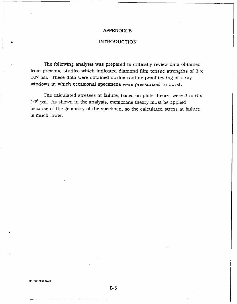
APPENDIX B
INTRODUCTION
The following analysis was prepared to critically review data obtainedfrom previous studies which indicated diamond film tensile strengths of 3 x10⁶ psi. These data were obtained during routine proof testing of x-raywindows in which occasional specimens were pressurized to burst.
The calculated stresses at failure, based on plate theory, were 3 to 6 x10⁶ psi. As shown in the analysis, membrane theory must be appliedbecause of the geometry of the specimen, so the calculated stress at failure
is much lower.
RPT.00 78.37-AM B
B-5
TABLE OF CONTENTS
PageI. Introduction B- 7II. Summary of Results B-7III. Conclusions and Recommendations B-9
IV. -est Specimen Test Data B-10. Analysis B-10
LIST OF ILLUSTRATIONS
Figure Title Page
B-I Schematic Test Specimen Cross-Section B-8Cross-Section (End View)
B-2 View of the Specimen, Looking Down from Above B-1i
B-3 Normalized Stress vs. Pressure B-16B-4 Normalized Deflection vs. Pressure B-17
REFERENCES
1. Raymond J. Roark, and Warren C. Young, "Formulas for Stress andStrain", 5th Edition
2. Murray R. Spiegel, "Schaum's Outline Series, MathematicalHandbook of Formulas and Tables", Copyright 1968
PT-DO017.37-Aw 8-ToC
B-6
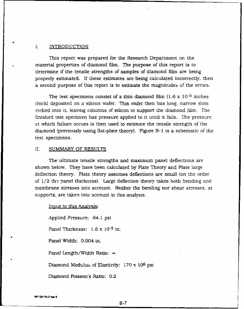
I. INTRODUCTION
This report was prepared for the Research Department on the
material properties of diamond film. The purpose of this report is to
determine if the tensile strengths of samples of diamond film are beingproperly estimated. If these estimates are being calculated incorrectly, then
a second purpose of this report is to estimate the magnitudes of the errors.
The test specimens consist of a thin diamond film (1.6 x 10⁻⁵ inches
thick) deposited on a silicon wafer. This wafer then has long, narrow slotsetched into it. leaving columns of silicon to support the diamond film. The
finished test specimen has pressure applied to it until it fails. The pressure
at which failure occurs is then used to estimate the tensile strength of the
dim-nond (previously using flat-plate theory). Figure B-I is a schematic of the
test specimens.
II. SUMMARY OF RESULTS
The ultimate tensile strengths and maximum panel deflections are
shown below. They have been calculated by Plate Theory and Plate large
deflection theory. Plate theory assumes deflections are small (on the order
of 1/2 the panel thickness). Large deflection theory takes both bending and
membrane stresses into account. Neither the bending nor shear stresses, at
supports, are taken into account in this analysis.
Input to this Analysis:
Applied- Pressure: 64.1 psi
Panel Thickness: 1.6 x 10⁻⁵ in.
Panel Width: 0.004 in.
Panel Length/Width Ratio:
Diamond Modulus of Elasticity: 170 x 106 psi
Diamond Poisson's Ratio: 0.2
APT-OOl78.37.Ap 8
B-7
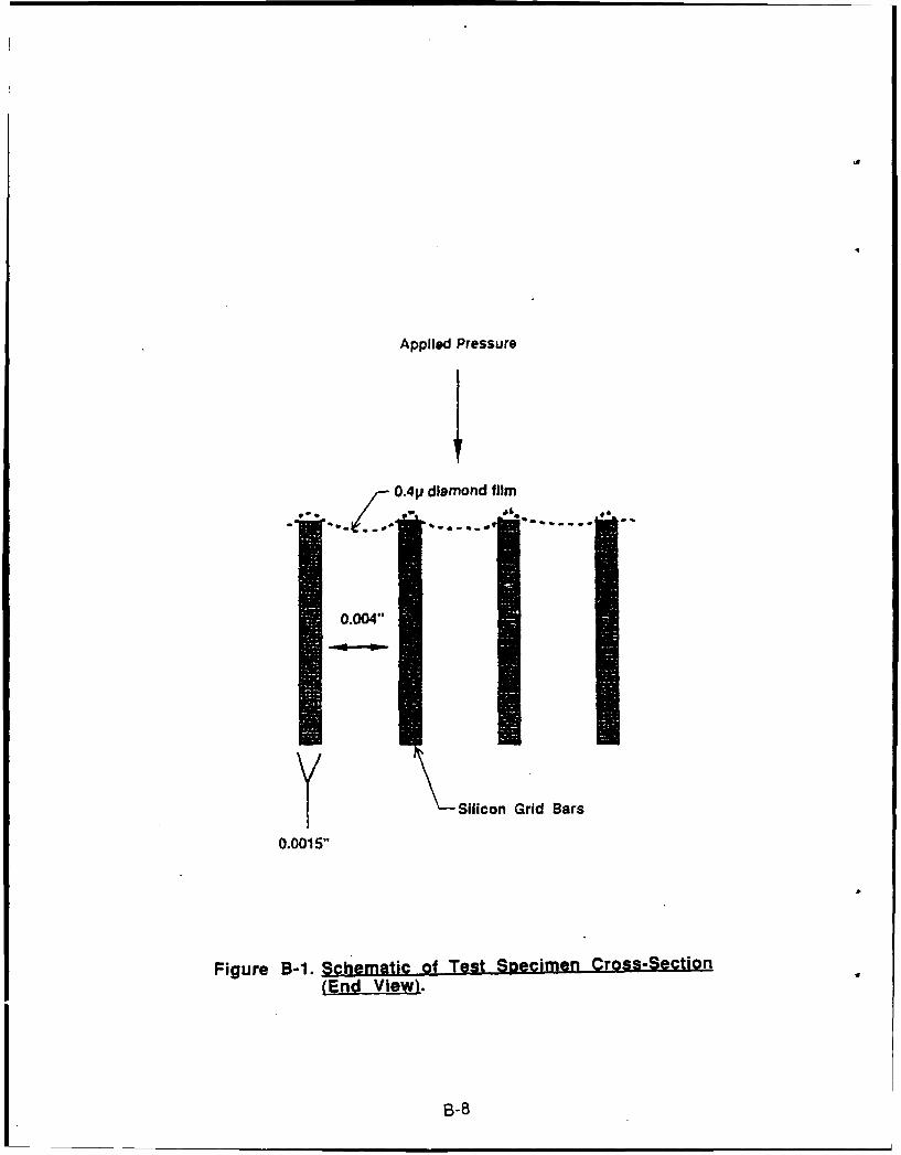
Applied Pressure
0.4p diamond film
Silicon Grid Bars
0.0015"
Figure B-1. Schematic of Test Specimen Cross-Section(End View).
B-8
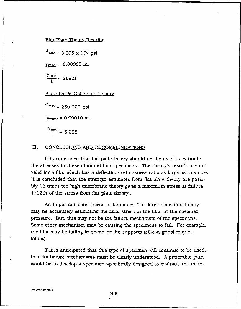
Flat Plate Theory Results:
max = 3.005 x 10⁶ psi
Ymax = 0.00335 in.
YmnaxY- 209.3t
Plate Large Drflection Theory
amax= 250,000 psi
Ymax = 0.00010 in.
Yrnax= 6.358t
III. CONCLUSIONS AND RECOMMENDATIONS
It is concluded that flat plate theory should not be used to estimatethe stresses in these diamond film specimens. The theory's results are not
valid for a film which has a deflection-to-thickness ratio as large as this does.
It is concluded that the strength estimates from flat plate theory are possi-bly 12 times too high (membrane theory gives a maximum stress at failure
1/12th of the stress from flat plate theory).
An important point needs to be made: The large deflection theorymay be accurately estimating the axial stress in the film, at the specified
pressure. But, this may not be the failure mechanism of the specimens.
Some other mechanism may be causing the specimens to fail. For example.
the film may be failing in shear, or the supports (silicon grids) may be
failing.
If it is anticipated that this type of specimen will continue to be used,then its failure mechanisms must be cearly understood. A preferable pathwould be to develop a specimen specifically designed to evaluate the mate-
APT-D0178.37-App B
B-9
rial properties of interest. For example, if tensile strength is of interest,create a tensile pull specimen.
IV. TEST SPECIMEN TEST DATA
A LOADS
The specimen being analyzed failed at a pressure of 64.1 psi.*This specimen had the film floated onto the silicon gridwork. This meansthat the diamond is not permanently bonded onto the grids.
B. MATERIAL PROPERTIES OF DIAMOND FILIVI*
E= 170 x 106 psi
V =0.2
The tables in Reference (1) use a Poisson's Ratio of 0.3. Thesetables are used directly, in this analysis. It is assumed that the error is small(see page 385 of Reference 1). Linear behavior to failure is assumed in thisanalysis-no plasticity.
V. ANALYSIS
A. GEOMETRY AND PHYSICAL CHARACTERISTICS
Figure B-i shows a cross-section of the test specimen. Below is asketch of the diamond film to be analyzed. Figure B-2..
Figure B-2, is a view of the Specimen, Looking Down From Above
* Provided by Crystallurne
RPT.DO178.37.Am B
B-10
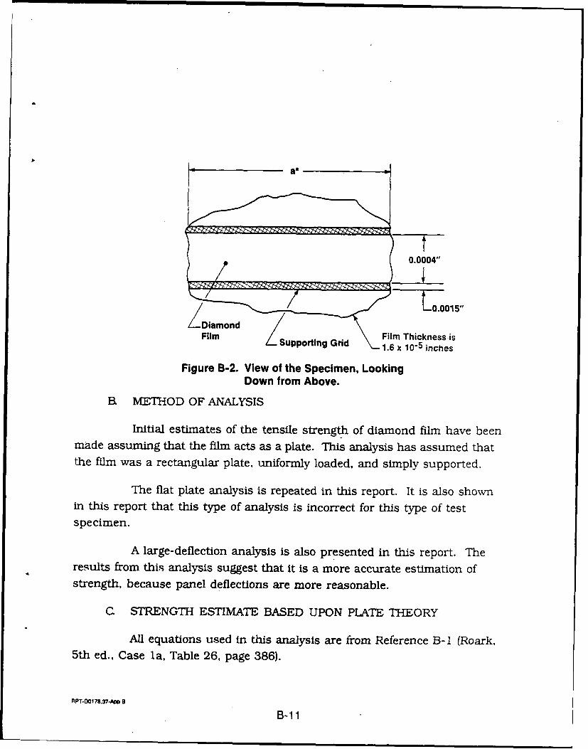
a*
0.0004"
LiDiamond0.15Filmo Film Thickness isFilm Supporting Grid 1.6 i nches
Figure B-2. View of the Specimen, LookingDown from Above.
B. METHOD OF ANALYSIS
Initial estimates of the tensile strength of diamond film have beenmade assuming that the film acts as a plate. This analysis has assumed thatthe film was a rectangular plate. uniformly loaded, and simply supported.
The flat plate analysis is repeated in this report. It is also shownin this report that this type of analysis is incorrect for this type of testspecimen.
A large-deflection analysis is also presented in this report. Theresults from this analysis suggest that it is a more accurate estimation ofstrength, because panel deflections are more reasonable.
C. STRENGTH ESTIMATE BASED UPON PLATE THEORY
All equations used in this analysis are from Reference B-I (Roark,5th ed., Case la, Table 26, page 386).
RPT-00178.37-A1p 8
B-1 1
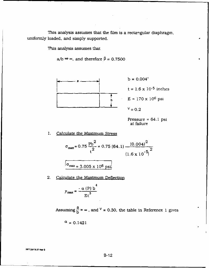
This analysis assumes that the film is a rectangular diaphragm,uniformly loaded, and simply supported.
This analysis assumes that
a/b = -, and therefore f3 = 0.7500
a b = 0.004"
t = 1.6 x 10⁻⁵ inches
b E= 170x 106 psi
V =0.2
Pressure = 64.1 psi
at failure
1. Calculate the Maximum Stress
Pb 2 0.0)2am = 0.75 = -0.75 (64.1) (0.004)
t2 (1.6x 10- 2
[max = 3.005 x 10⁶ psi
2. Calculate the Maximum Deflection
4-a(P) bYmax= Et3
Assuming - oand v -0.30, the table in Reference 1 gives
a = 0.1421
RPT-DO178.37-A B
B-1.2
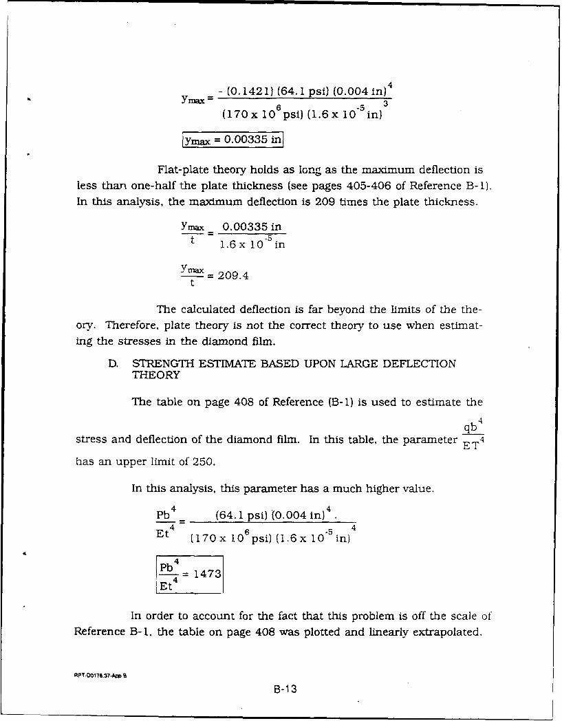
= - (0.1421) (64.1 psi) (0.004 in) 4
(170x 106psi) (1.6x in)
Ymax = 0.00335 in
Flat-plate theory holds as long as the maximum deflection is
less than one-half the plate thickness (see pages 405-406 of Reference B-i).
In this analysis. the maximum deflection is 209 times the plate thickness.
Ymax 0.00335 int 1.6x 10⁻⁵ in
=- 209.4t
The calculated deflection is far beyond the limits of the the-
ory. Therefore, plate theory is not the correct theory to use when estimat-
ing the stresses in the diamond film.
D. STRENGTH ESTIMATE BASED UPON LARGE DEFLECTIONTHEORY
The table on page 408 of Reference (B-i) is used to estimate the
qb4
stress and deflection of the diamond film. In this table, the parameter E T 4
has an upper limit of 250.
In this analysis, this parameter has a much higher value.
Pb (64.1 psi) (0.004 in)4 .6 -5
Et4 (170x 106psi)(1.6x 10⁵ in)
pb4 1473
Et4
In order to account for the fact that this problem is off the scale ofReference B-1, the table on page 408 was plotted and linearly extrapolated.
RPT-Oa176.37.A4
B-1 3
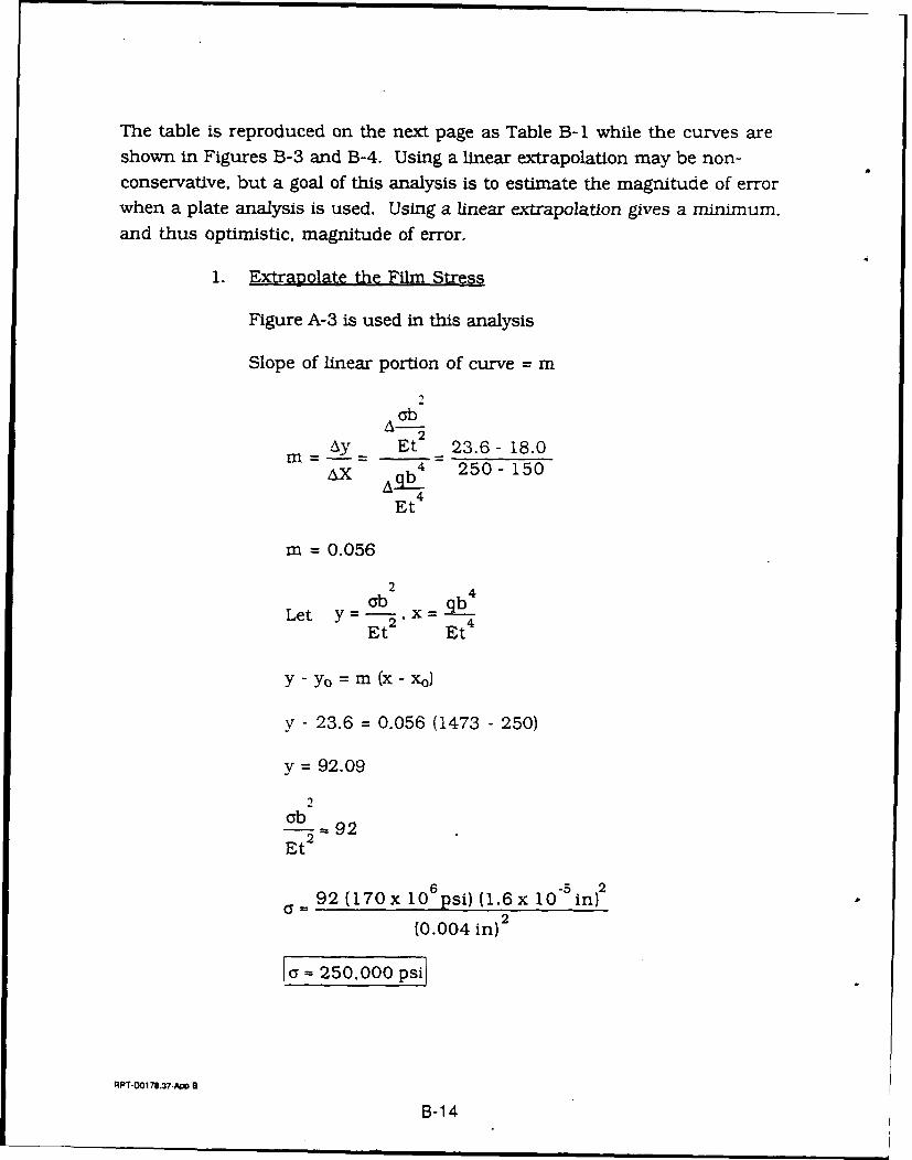
The table is reproduced on the next page as Table B-i while the curves areshown in Figures B-3 and B-4. Using a linear extrapolation may be non-conservative, but a goal of this analysis is to estimate the magnitude of errorwhen a plate analysis is used. Using a linear extrapolation gives a minimum.
and thus optimistic, magnitude of error.
1. Extrapolate the Film Stress
Figure A-3 is used in this analysis
Slope of linear portion of curve = m
ab
M Ay Et' 2 36 18.0___AX Aqb 4 250- 150
Et4
m - 0.056
2
Let Y = _ x =Et 2 Et4
y - yo = m (X - Xo)
y - 23.6 = 0.056 (1473 - 250)
y = 92.09
2oba- 92Et 2
9 2 (170x 106psi) (1.6x10 -in) 2
(0.004 in) 2
250.000 psi
;PT.O0178.37-AMp 8
B-14
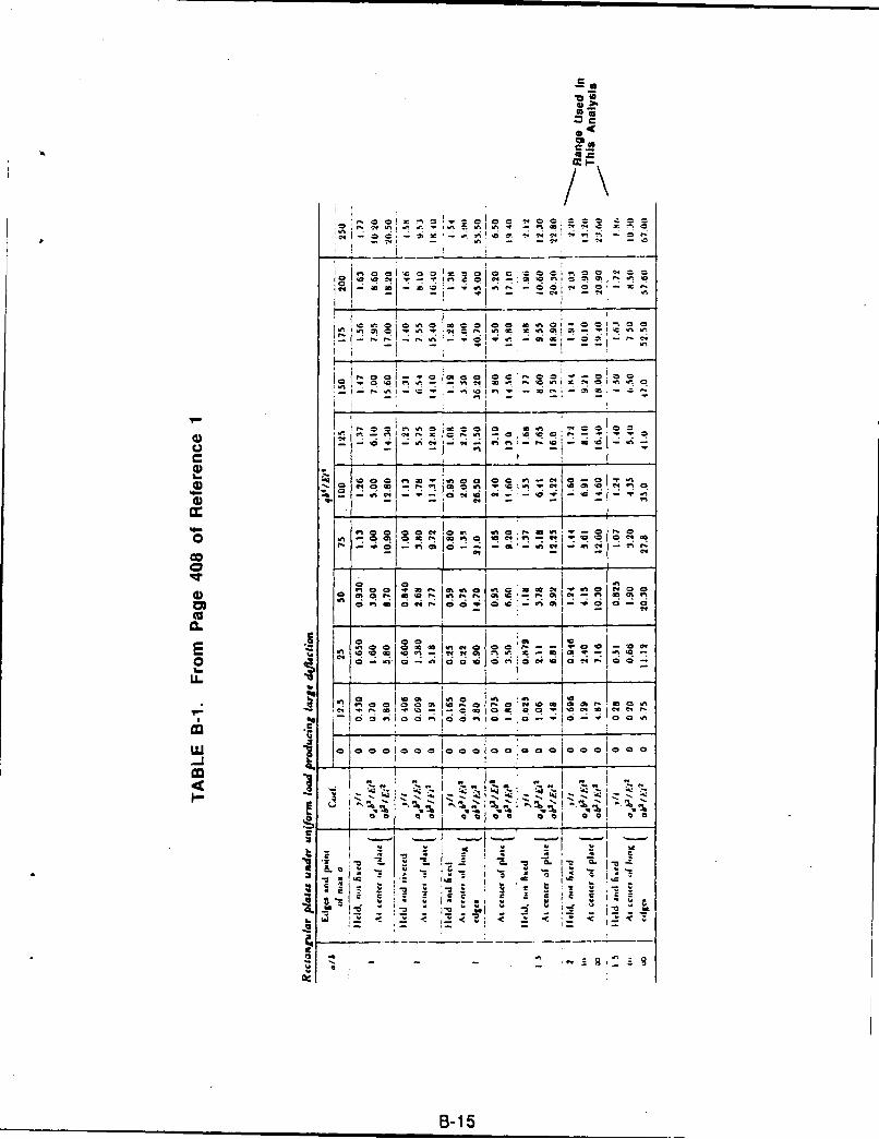
I-e
CIO
.'3
'~I-oc--,ra. -
C _o x C 1 _'
I 0 00C C CC C0 1_ = 1- -< .9 C 1 0 e -a. = " .9
'~~0 C~0 2 0 00 * CI0 I
lob 0 -n.
IV, 2 .I : .: -.I2 I +'
I I I I __ _ _ _ _ _
"C0 0 eq i 0;
0 1
5 hi 200 ., 92t 00 00m .9e = C-C I o+ + I
- :1 - i m -I-
26 CL -- I ..
lC1 C C" C . ,, "B-1'-
o + . , +. . . . + ,, ,.
0." I < - - .< - -E ,- a. ..
1 2 ~e0 00~' 0 ~e
B-15C.~a
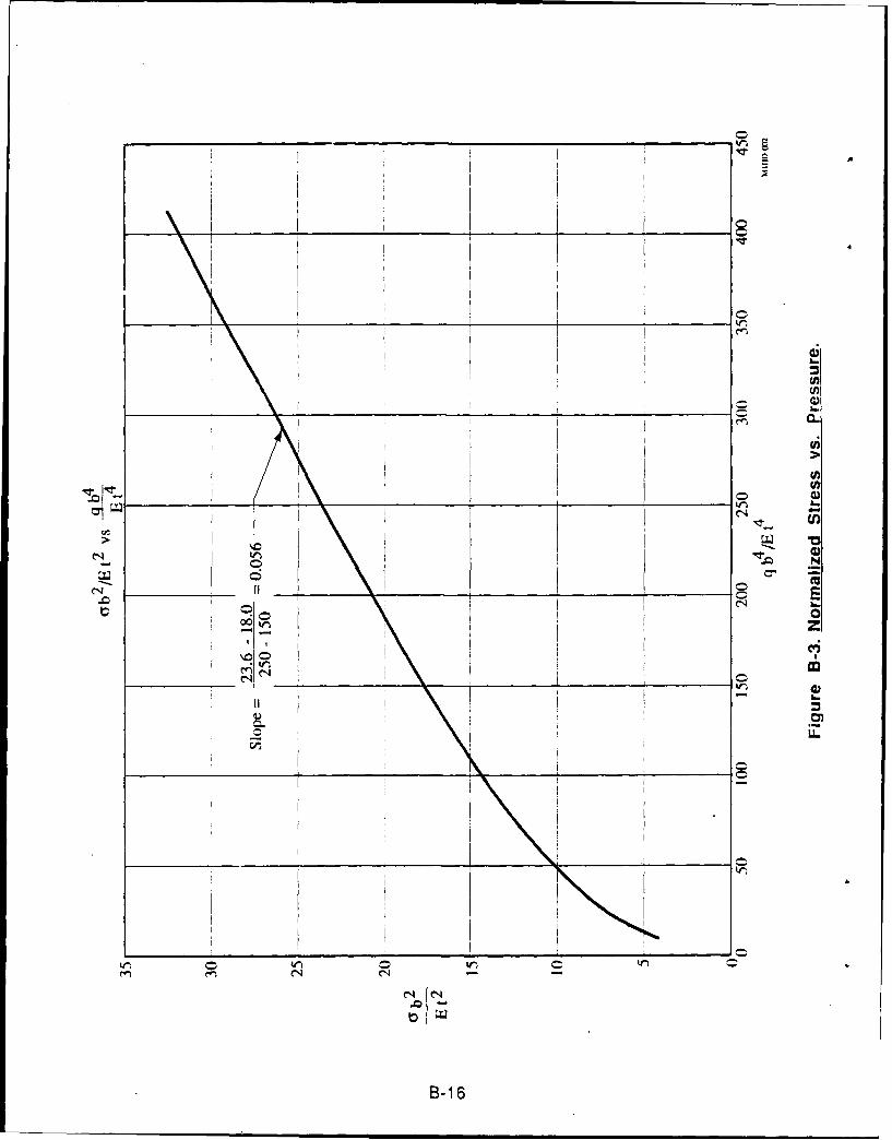
w 1N
LL
cq r!
B-1 6
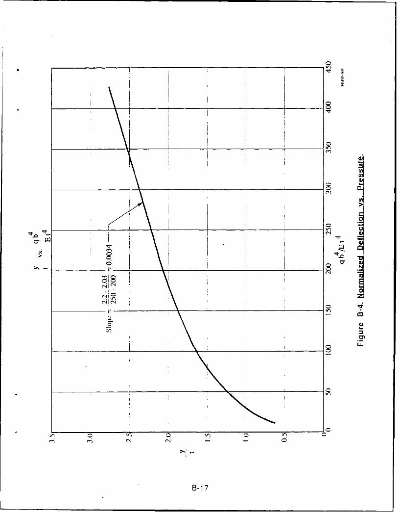
0_______ Ij~
(j~U,a)
C,,
C0
___ tr~a)U)
0 N
EI..0z
0
a)
0,
00
0tr~ -, Lr~
C - - 0
8-17
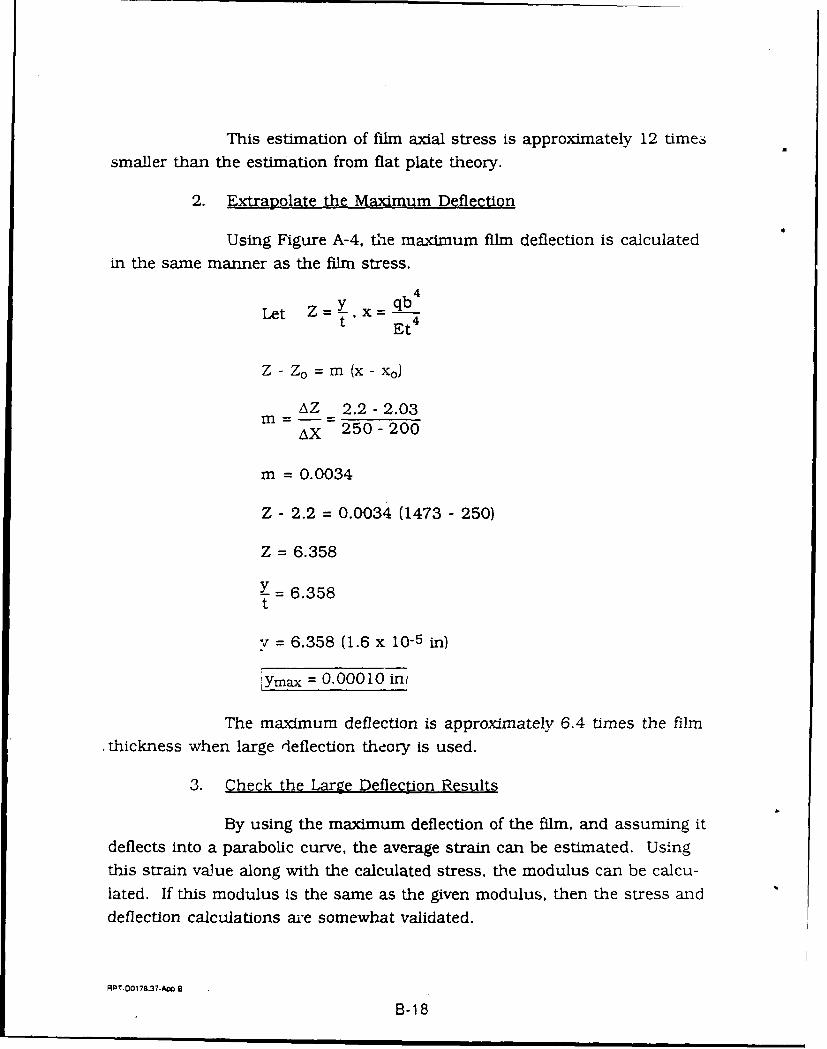
This estimation of film axial stress is approximately 12 timessmaller than the estimation from flat plate theory.
2. Extrapolate the Maximum Deflection
Using Figure A-4, the maximum film deflection is calculated
in the same manner as the film stress.
Let Z=Y,x= qb 4
Et4
Z- Zo = m (x-xo)
AZ 2.2 - 2.03M = - =
AX 250 - 200
m = 0.0034
Z - 2.2 = 0.0034 (1473 - 250)
Z = 6.358
Y = 6.358t
v = 6.358 (1.6 x 10⁻⁵ in)
Ymax = 0.00010 in
The maximum deflection is approximately 6.4 times the film-thickness when large deflection theory is used.
3. Check the Large Deflection Results
By using the maximum deflection of the film, and assuming itdeflects into a parabolic curve, the average strain can be estimated. Usingthis strain value along with the calculated stress, the modulus can be calcu-
lated. If this modulus is the same as the given modulus, then the stress and
deflection calculations are somewhat validated.
RPT-DO178.37-Ap 8
B-18
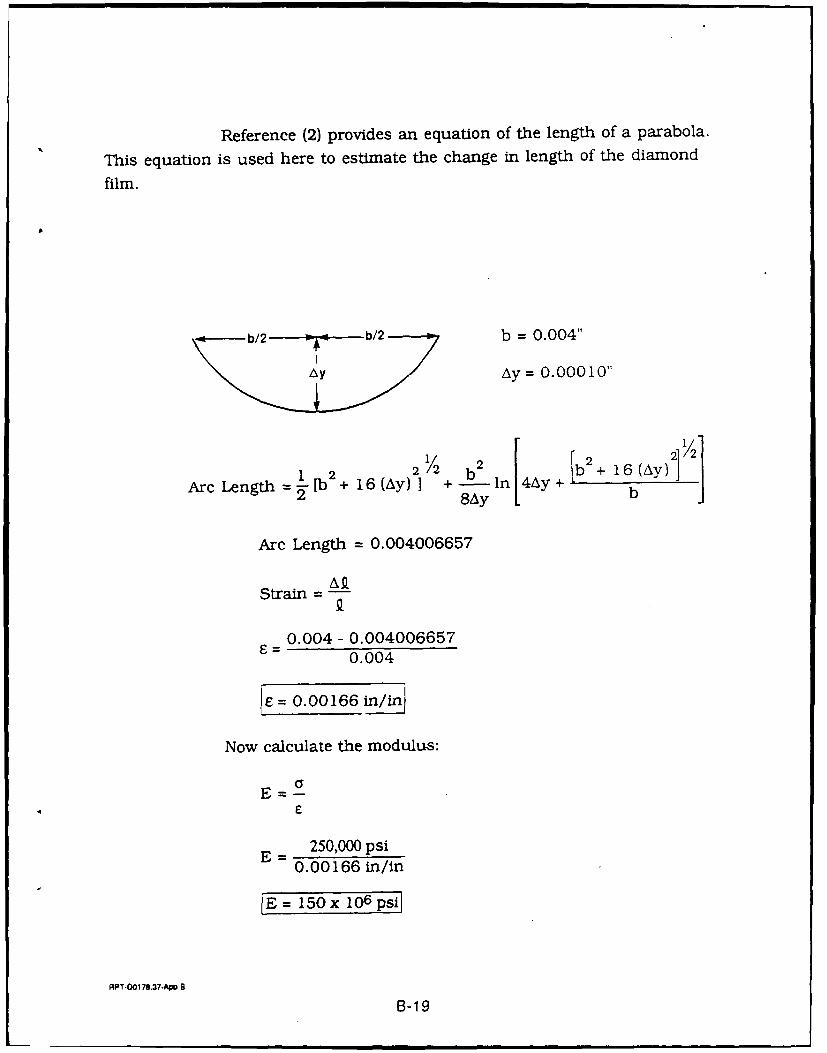
Reference (2) provides an equation of the length of a parabola.
This equation is used here to estimate the change in length of the diamond
film.
b/2 = b/2 b = 0.004"
Ay Ay = 0.00010"
I 2 2/2 b 2 b2+ 16(A)
Arc Length =-[b + 16(Ay) I +-ln 4Ay+ b "
Arc Length = 0.004006657
Strain
0.004 - 0.0040066570.004
I= O 1 6 6i/
Now calculate the modulus:
E
E =250,000 psi
0.00166 in/in
IE= 150x 106 psi
APT-O0178.37-AMp B
B-19
This estimated value of elastic modulus is approximately 13%
less than the given value of 170 x 106 psi. This relatively small differencesuggests that the extrapolation of the tables in Reference (1) were appropri-
ate. And that the stress estimate is a reasonable estimate of the maximum
stress in the film.
RPT-O0178.37-A 8
B-20
APPENDIX C
DESIGN FOR CVD MONOLITHICDIAMOND PRESSURE VESSEL
RPT-00 i78.37-Ap C
c-i
APPENDIX C
DESIGN FOR CVD MONOLITHIC
DIAMOND PRESSURE VESSEL
The following analysis was prepared to determine the feasibility ofusing a continuous CVD diamond film structure as a high-pressure vessel.Critical to the application is an acceptable transition from the CVD materialto an attachment boss which makes the assembly into a practical pressurevessel. By an iterative process, the design was modified to nearly eliminatestress concentration at the attachment. However, detailed analysis of rup-ture test data indicated that the computed tensile strengths of 3 x 10⁶ psiwere actually perhaps a tenth of this. Subsequent rupture tests of moreappropriated design specimens give tensile strengths of up to perhaps 0.7 x10⁶ psi. Many more measurements are required to give confidence in any of
the values.
The CVD tank design is presented here as a potential future applica-tion for ultra-high strength CVD materials. The design is presented for amaterial with a tensile strength of 3 x 10⁶ psi operating at a pressure of25,000 psi; it is also appropriate for a material with a tensile strength of700,000 psi operating at a pressure of 5,800 psi.
RPT-DO178.37-A C
C-2
SENCORP
AEROJ--TechSystems INTERNAL MEMO
TO: D. K. Morgan 20 March 1989LWB:gJ0:9982:3916
FROM: L. W. Bush
SUBJECT: Diamond Tank Stress Results
COPIES TO: D.M. Jassowski, P.T. Lansaw, L. Schoenman,J.R. Wooten, 9982 File
ENCLOSURE: (1) Subject Analysis
Recently, it has become possible to deposit thin films ofdiamond. Assuming it becomes possible to deposit relativelythick films and assuming this multi-crystalline film has atensile strength similar to single crystal diamond, this thenopens up a wide range of structural applications.
This analysis examined using diamond for a very lightweight, ery high pressure tank. The tensile strength used was3.0 x 10 psi as per Deena Morgan.
Traditionally, pressure tanks are very over designed. Thefiller neck often causes a factor of 3.0 stress concentration.This analysis tried to optimize the filler neck shape andthickness variations to make the stress concentration as smallas possible. The final model has a neck stress concentration ofonly 1.25.
Considering that only 3 days of effort went into this, thisis a major accomplishment.
The design method for determining the weight of any chosentank size and pressure are detailed in the conclusions.
L. W. BushStructural Analysis SectionEngineering Analysis Department
APPROV D BY:
Eellison, ManagerStru ural Analysis SectionEngineering Analysis Department
J. W. Salmon, ManagerEngineering Ana].ysis DepartmentResearch, Test, & Engineerina
C-3
ENCLOSURE (1)
DIAMOND TANKSTRESS ANALYSIS
6 MARCH 1989
PREPARED BY:
L. W. BushStructural Analysis SectionEngineering Analysis Department
AP ROV plBY: REVIEWED BY:
/ E. /ellison, Manager R. K. Ishikawatruc ural Analysis Section Structur~al Analysis Section
Engineering Analysis Department Engineering Analysis Departmenz
J. W' ManagerEngineering Analysis DepartmentResearch, Test & Engineerinq
0-4
STRUCTURAL ANALYSIS REVIEW FORM DATE: SI- /4
1k PROGRAM: OL C 4 TC-Ct C-K,
COMPONENT: Z jCAv- V17/~-
PURPOSE of ANALYSIS: -E 5 '- c-- a2, kk y fS 'k ,
ANALYSIS PROGRAM & VERSION: 0 6 by C4.v, L Li (II'TAPE SAVE SET & FILE NAMES:
zq I/ , f ,Q- , i-
VALUE OR INFORMATIONPAGE NUMBER SOURCE APPROVALMATER~LS : (Material Name)
l . 7 e e -"--q
LOADS & TEMPERATURE:1. PRESSURE
a. Steady State __________
b. Transient _
2. TEMPERATURE DISTRIBUTIONa. Steady Stateb. Transient
3. THRUST AND THRUST TRANSIENT4. ACCELERATION5. VIBRATION6. ACOUSTIC7. LOAD HISTORY
GEOMETRY AND PHYSICAL CHARACTERISTICS: "r1. Dimensions2. Boundary Conditions __
3. Weights and Masses4. Stiffness
TIFOPJA.TION1 SOUP.CE LEGEND:A. Mil Hdbk 5 F. VerbalB. Rep. MA-81-107 G. EstimateC. Specs . H. Calculated
2. 3. i LayoutD. Drawinas .. _ Lab Tests
2. _ _ _ _
E. Reports _.
2.- _ _ _ _ _ _ _
C-5
I. INTRODUCTION
Recently it has become possible to make thin films of diamond.Assuming it becomes possible to make films of reasonable thickness theobvious question is can the tremendous strength of diamond be used in
structural applications. This analysis examines using diamond to make pres-sure vessels. The goal of such a tank would be a very high pressure tank andvery light weight.
A spherical tank design was chosen since this is the most efficientshape for a pressure vessel made from a uniform strength shell material.
The real challenge of such a design is to minimize the stress concentrationeffect of the filler neck. This analysis hence focused on that region.
Four Finite Element models were made to investigate various shapes of
the transition from the spherical tank to the filler neck. The first modelhad the liner material cover the entire inner surface of the tank. This
showed that, if that is the case, the liner would yield.
The second model removed the liner from all areas except the neck.
The neck/tank transition was a 1.0 in radius fillet. The third model used a
parabola to make the transition. The fourth model locally thickened areas ofhigh stress.
The actual size and pressure of the tank analyzed is not important.What is significant is the stress concentration factor achieved. With it anysize and pressure tank can be designed and its weight predicted.
Summary of Results:
Stress Concentration Factors
ConcentrationFactor
Model #2 2.32
Model #3 1.51
Model #4 1.25
RPT.0178.37.-AIp C
C-6
Discussion:
Model #2 is a 1.0" radius fillet
Model #3 is a parabola fillet
Model #4 is model #3 with local thickening
Conclusions:
The best stress concentration factor achieved for a uniform thicknesstank is 1.51; for any tank the best configuration analyzed it is 1.25. Similarresults are expected for any tank size and pressure using the following
formula.a3 +23 pesr
Stress = (Concentration Factor) a + 3 pressure3 b3 2a-b
Where a = Outside Radius
b = Inside Radius
Recommendation
Use the following for designPD4t. (Concentration Factor) = a stress
Check final design using thick sphere formula of the conclusions.
ANALYSIS
Design Criteria
1.5 on ultimate
1.0 on yield
Load and Environment
As a design point use 25000 psi internal pressure, 701F. Notemodel # 1 was run with 20,000 psi.
RPT-0O178.37.DA C
C-7
Material Properties
The following few pages detail the material properties received
and the manipulation of them to a form acceptable for the finite element
model.
Material property conversions use equation of Mechanics of
Composite Materials: 1975 Jones.
dyne 1.450x 10 . = psi
cm
dyne 2.248x10⁻⁶ 2b cm2
cm 21.(2.54) in 2
Cl 11 Assume ClI = C 2 2 CM
C 12 12
C44 44
C = 3.66034 E-24 19
$12 = 6.56337 E-9 21
El = 1.5236 E-8 20
S12 = -6.733 E-10 22
S44 = 1.20569 E-8 23
= .102585 24
G 12 = 8.294 E-7 25
Data:
Compressibility: cm2 = 2.3 x 10⁻¹³dyne
Compressive Strength = 9.65 x 10¹¹ dynescm 2
Cli = 107.6 x 10¹¹ dynescm 2
C12 = 12.3 x 0 i l dynescm 2
C44 = 57.2 x 10"l dynescm 2
Shear Strength = ?
RPT-00178.37-Ap C
0-8
Natural SyntheticTensile Strength =dye
3.45 x 101' 2.07 x 10,, dynescm
2
E: Youngs Modulus = 10.35 x 10¹² dynes/cm2
Convert to english dyne 1.450 x 10 5 = psicm 2
C11 = 1.5602 E8 psi
C12 = 1.7835 E7 psi
C44 = 8.294 E7 psi
E = 1.50 E8 psi
Tensile Strength = 3.00 x 10⁶ psi (Synthetic)
GEOMETRY AND PHYSICAL CHARACTERISTICS
Model #1
10" Dia
.023" Shell
.05" Liner
1.0" Radius Fillet to
1/4" OD Line .05" hole
.I" Wall (Line)
q = 20.000 psi internal pressure
o -a3 + 2b3 = 2.17 MSI2 a3-b 3
Model #2
Same as model # 1 except liner is only in the neck regions.
Model #3
Same as Model #2 except 1/2 of the 1.0" fillet radius replaced by aparabola which matches slope at 450 point of fillet.
RPT.DO178.37-Am C
C-9
Model #4
Same as Model #3 except some local thickening of sphere wheremax stress occurs near the neck. 37% max thickness increase.
METHOD OF ANALYSIS
A finite element analysis of the tank and neck are used together withhand calculations to determine the stress concentration factor for that par-
ticular geometry.
The ANSYS finite element code is the program used. Only elasticanalyses were performed.
Hand analysis used the following:
Thick Sphere Equation
a= P. a 3 + 2b 3 Where a = Outer Radiu2 a3 -b 3 b = Inner Radiu
DETAILED ANALYSIS
Model # 1
10.0 in dia
0.023 diamond wall
0.050 Beryllium liner
Model #1 Results
The Beryllium of the shell carried an excessive amount of
stress. If a plastic analysis had been run" it would have yielded substantially.Because of the incorrect load sharing the stress results are not usable.
Model #2
Similar to Model #1 except the beryllium is only in the neck.
Pressure is 25,000 psi.
RPT-O0178.37-Dp C
C-10
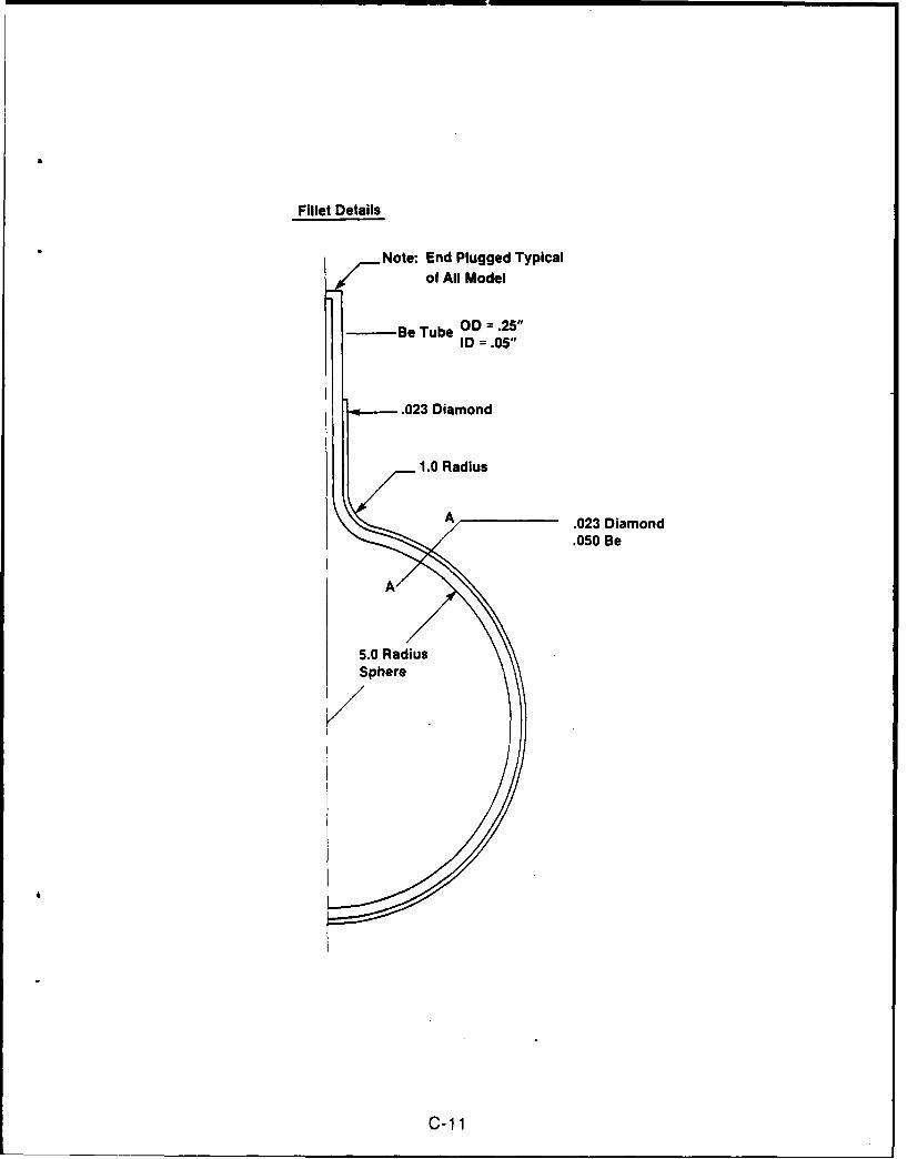
Fillet Details
Note: End Plugged Typicalof All Model
I -Be Tube OD =.25"ID = .05"
.023 Diamond
/ 1.0 Radius
.023 Diamond.050 Be
5.0 Radius-Sphre l
C-1 1
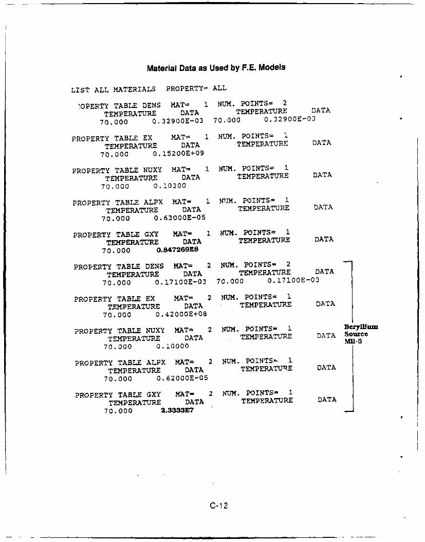
Material Data as Used by F.E. Models
LIST ALL MATERIALS PROPERTY= ALL
'.OPERTY TABLE DENS MAT= 1 NUM. POINTS= 2
TEMPERATURE DATA TEMPERATURE DATA
70.000 0.32900E-03 70.000 0.32900E-03
PROPERTY TABLE EX MAT= 1 NUM. POINTS= I
TEMPERATURE DATA TEMPERATURE DATA
70.000 0.15200E+09
PROPERTY TABLE NUXY MAT= 1 NUM. POINTS= 1
TEMPERATURE DATA TEMPERATURE DATA
70.000 0.10300
PROPERTY TABLE ALPX MAT- 1 NM. POINTS= I
TEMPERATURE DATA TEMPERATURE DATA
70.000 0.63000E-05
PROPERTY TABLE GXY MAT= I NUM. POINTS- 1
TEMPERATURE DATA TEMPERATURE DATA
70.000 0.847269E8
PROPERTY TABLE DENS MAT= 2 NUM. POINTS= 2
TEMPERATURE DATA TEMPERATURE DATA
70.000 0.17100E-03 70.000 0.17100E-03
PROPERTY TABLE EX MAT= 2 NUM. POINTS= 1
TEMPERATURE DATA TEMPERATURE DATA
70.000 0.42000E+08
PROPERTY TABLE NUXY MAT= 2 NUM. POINTS= 1 BerylimTEMPERATURE DATA TEMPERATURE DATA Source
70.000 0.20000 M1U-5
PROPERTY TABLE ALPX MAT= 2 NUM. POINTS- 1
TEMPERATURE DATA TEMPERATURE DATA
70.000 0.62000E-05
PROPERTY TABLE GXY MAT- 2 NUM. POINTS= 1
TEMPERATURE DATA TEMPERATURE DATA
70.000 2.3333E7
C-12
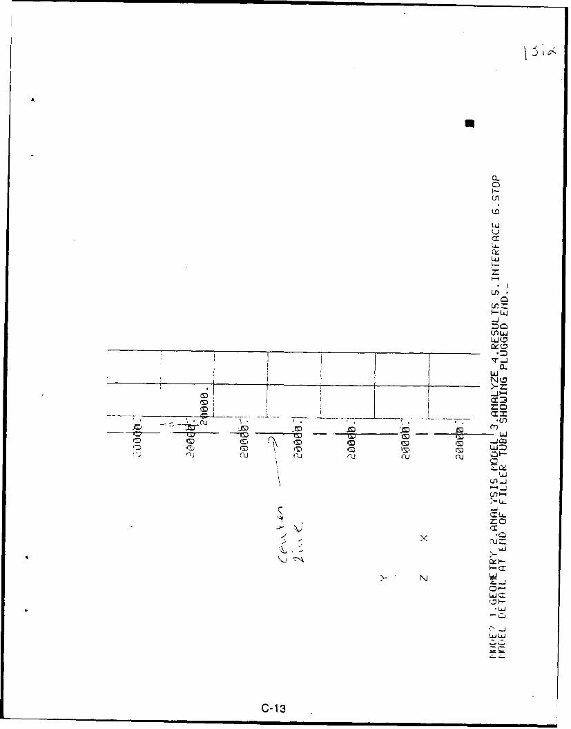
Ir
3J
U'
LA-
CL
uj.
c0
0i LO
LI
tm Im (M
Cuu (U
LJ
7- -j
-U-
20
AN wI W'
C-13
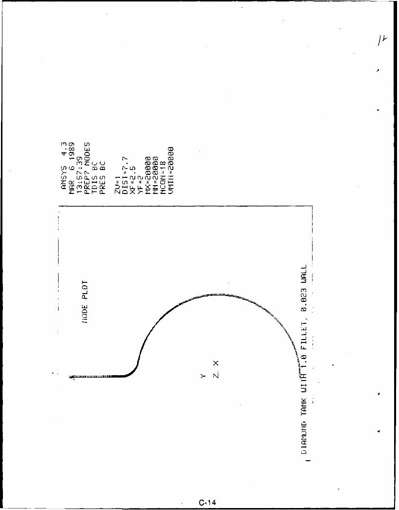
1-I) 0 (
>- -N f . MC 110 )CL U) U) fl U J lOJ O :
= C- .- LJ W (- 1 1 1 11 11 RI C:)
3'
a--
Lai
__ C-1 4
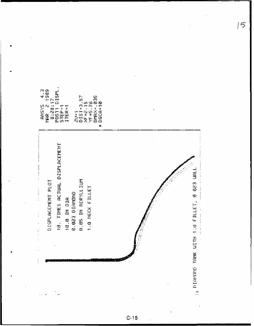
U-5
Mo C ....i
0
C r 0 O..W' D -4 NOX)-00: (
LLJu
C -
a.u
a-. p -j ILi
F- Q
zJ* .- 0 a
1-4
C-15
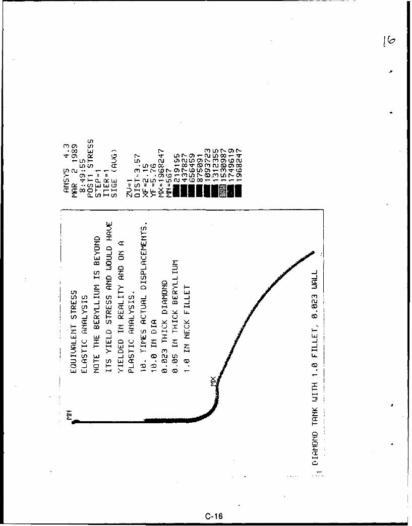
Qr-p
-ur H CU vU QW OC- (w
Z: 0 f U) Umwr'-o0 it -o)
C 7-
)-j LiiW -j U _j ( X C o -jC
co Z:z:li U
D >- 0 r)-i -c r Ln w 0 -mmJ
C3 HjC - im m .. 0LA W
CLJJ C M MHr~ r'~-4QI
Hr
Lii W LiC
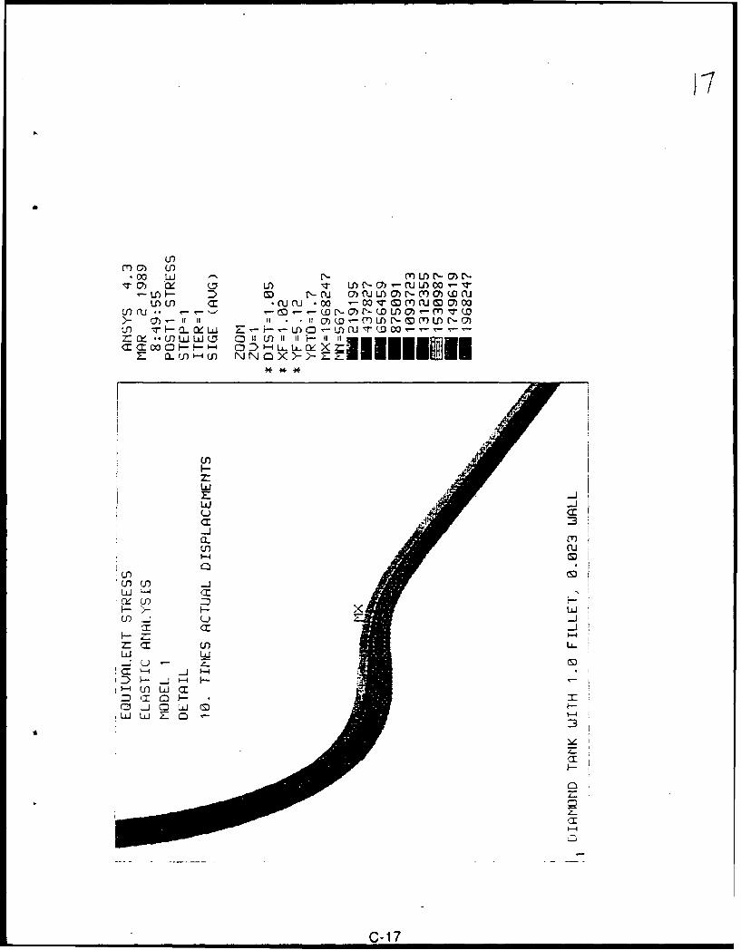
LrK
>- Crr u i M cuLMmr-mm(w
y- ~ - I ii U)L I D ) )i
Z CL - 4- ( NNXcXZ~l mlll
LU
C
a-
Uo c
LO U-A- >- z- CS
-j-.rC In Li
~ J 4-4
C-17
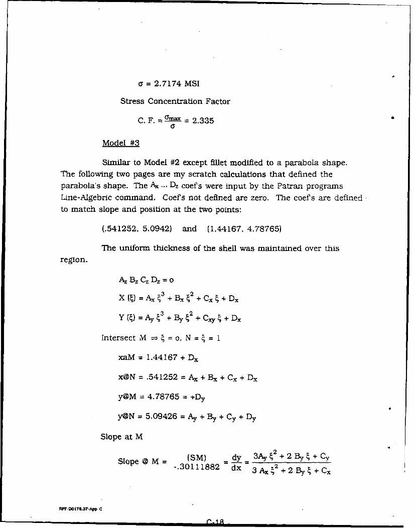
= 2.7174 MSI
Stress Concentration Factor
C. F. =2.335
Model #3
Similar to Model #2 except fillet modified to a parabola shape.
The following two pages are my scratch calculations that defined theparabola's shape. The Ax ... Dz coefs were input by the Patran programsLine-Algebric command. Coefs not defined are zero. The coefs are defined
to match slope and position at the two points:
(.541252, 5.0942) and (1.44167, 4.78765)
The uniform thickness of the shell was maintained over this
region.
Az Bz Cz Dz = o
X (4) = A2 4' + B-, + C. 4 + DxY( )=A. 3+By% +Cxy%+Dx
Y (4) = A-'+ B, ~2+ C,+ Dx
Intersect M = =o, N= = 1
xaM = 1.44167 + Dx
x@N = .541252 = Ax + Bx + Cx + Dx
y@M = 4.78765 =+Dy
y@N = 5.09426 = Ay + By + Cy + Dy
Slope at M
S (SM) = dy2 + 2 By _ _+ C-. 30111882 x 3 Ax 2 + 2 By + C,
R'T- 0178.37-App C
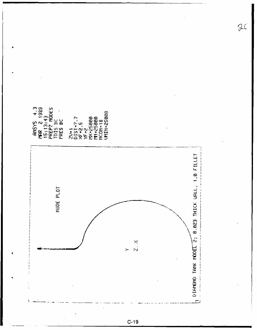
.c00 LUI m
?: Z: (M 00U)cu coco r )( N M ~- (CVmr- 4 . U) WLA~ILU C QU)M '- N CUNu
-JI
a-i
LLLJ
C-19)
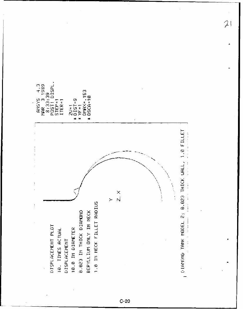
M LA
m (S)
a- cr -I IID - -
CL Wc' NO)-00
-JI
(n (M)
o : LJI 1UJ
C -i Q 0 '-1 'M-1 (Z: LUJ C
LLJ LLJ )-
Z nZ n ZLAJ_LJU1 LL. = r - 0
4. - m_ = P-
a_ a_, (S 0
-0- . L
C-20
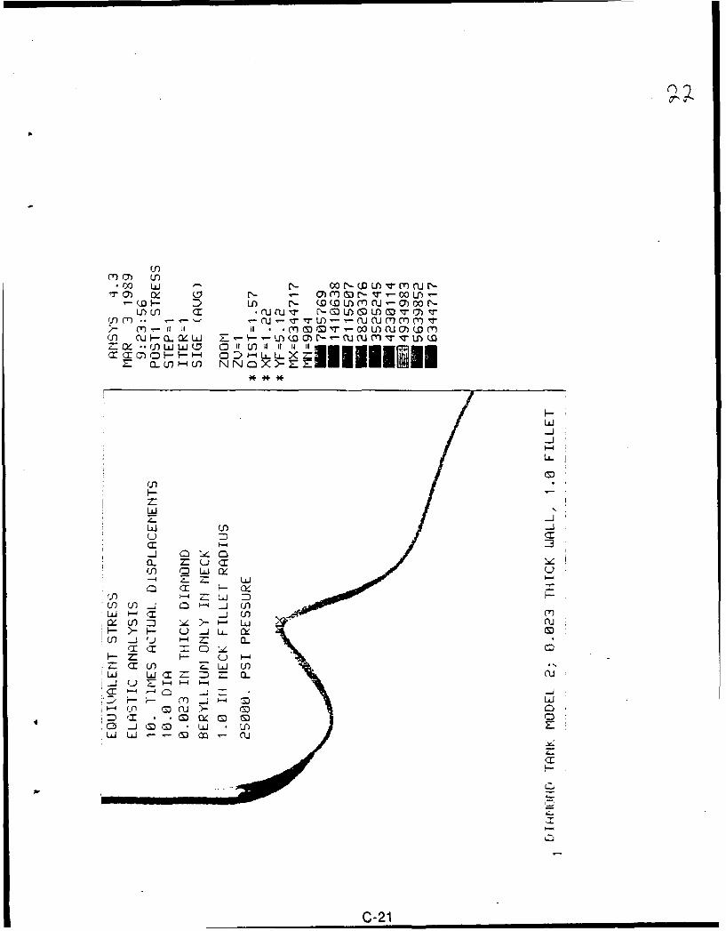
mJU)
*Cx2 .i W -(LA V m N -
>-) M~- *m c Vo W(M
D oUnu rNX - WUDU)U U (7 0 r
U) in 1 (J C VN M U M I) M V 17 VN M
(n ( M~r00 ) CUC7) -Y(P N(L c- W U' (m N Mv v n-(Z: i- - (o ij L (D 'I ') i if f-1
M CD D " - U-i
LiJ
z~LLJ U3
(0 Q~
W , -L O m
LAJ X L <1 CL CU,
w0- c
m. 000
__ C-21
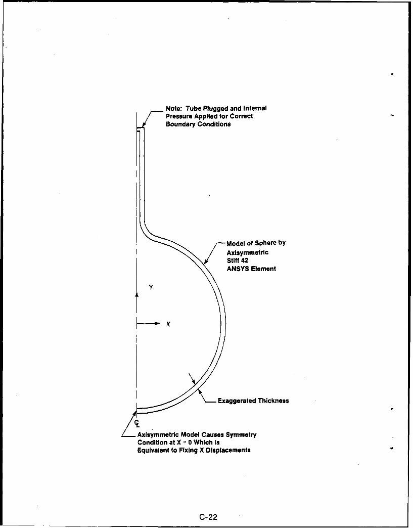
Note: Tube Plugged and InternalPressure Applied for CorrectBoundary Conditions
Model of Sphere byAxisymmetricStiff 42ANSYS Element
SX
Exaggerated Thickness
Axisymmetric Model Causes SymmetryCondition at X = 0 Which isEquivalent to Fixing X Displacements
C-22
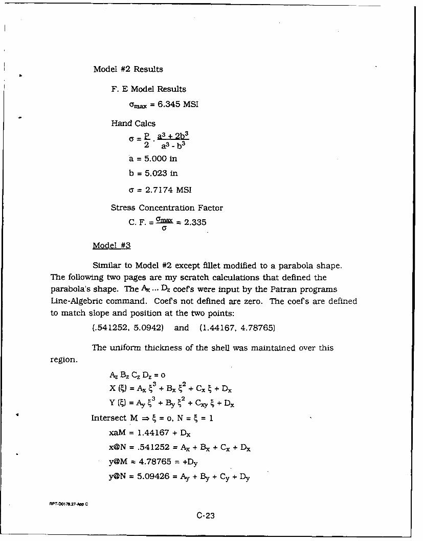
Model #2 Results
F. E Model Results
amax = 6.345 MSI
Hand Cacs
P a3+2b3
2 a3 -b 3
a = 5.000 in
b = 5.023 in
a = 2.7174 MSI
Stress Concentration Factor
C. F. = max = 2.335a
Model #3
Similar to Model #2 except fillet modified to a parabola shape.The following two pages are my scratch calculations that defined theparabola's shape. The Ax ... Dz coefs were input by the Patran programsLine-Algebric command. Coef s not defined are zero. The coefs are definedto match slope and position at the two points:
(.541252, 5.0942) and (1.44167, 4.78765)
The uniform thickness of the shell was maintained over this
region.
Az Bz Cz Dz = o
*x4) = Ax 43 + Bx 42 + Cx 4 + Dx
Y (4) = Ay 3 + By 42 + Cxy 4 + Dx
Intersect M - 4 =o, N = = 1
xaM = 1.44167 + Dx
x@N = .541252 = Ax + Bx + Cx + Dx
y@M 4.78765 =+Dy
y@N = 5.09426 =Ay + By + Cy + Dy
RPT-D1OI737-A C
C-23
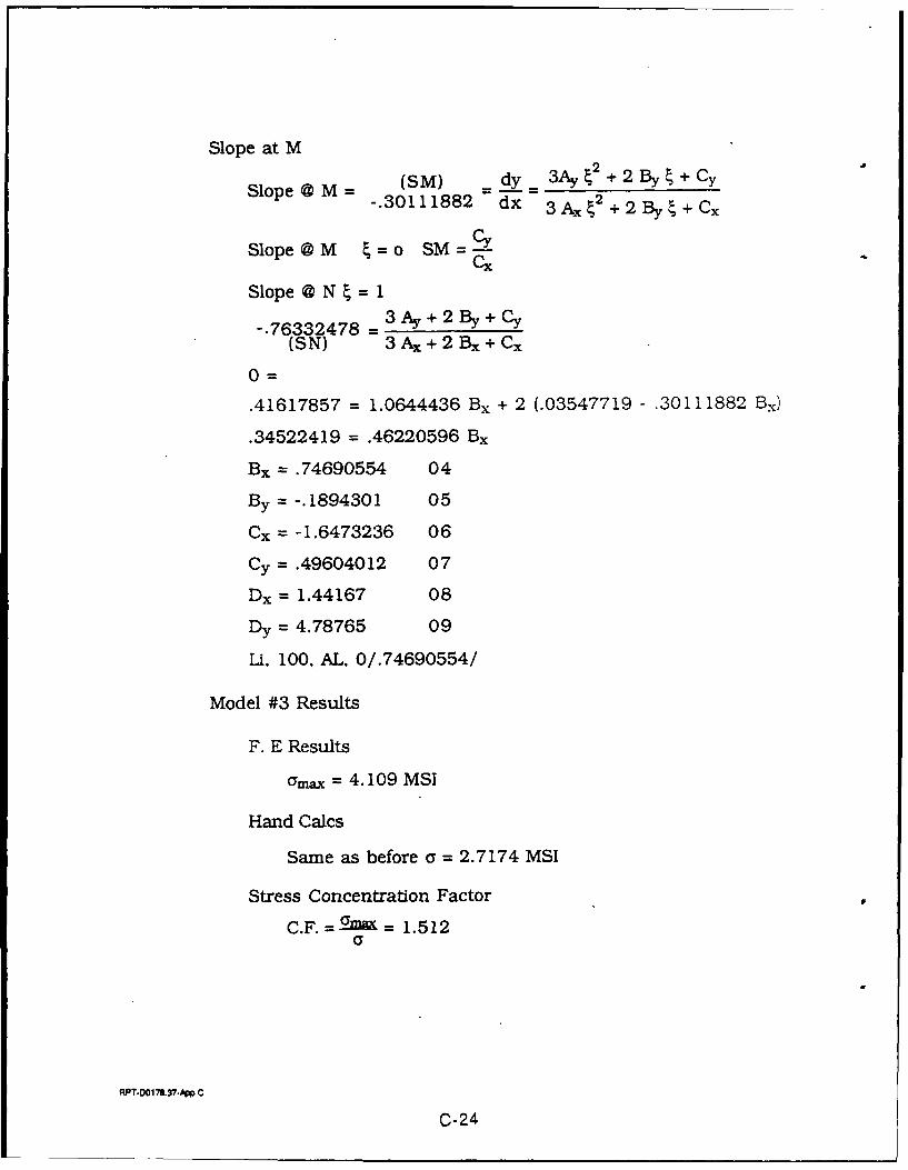
Slope at MSM) dy3Ay 2 + 2 By + Cy
Slope@ M (SM) 2-. 30111882 dx 3A. 2+2 By+Cx
Slope@M S=o sK
Slope @ N= 1
-. 76332478 = 3Ay+2By+Cy
(SN) 3 Ax + 2 Bx + Cx
0=
.41617857 = 1.0644436 Bx + 2 (.03547719 - .30111882 Bx)
.34522419 = .46220596 Bx
Bx= .74690554 04
By = -. 1894301 05
Cx = -1.6473236 06
Cy =.49604012 07
Dx = 1.44167 08
Dy = 4.78765 09
Li, 100, AL, 0/.74690554/
Model #3 Results
F. E Results
amax = 4.109 MSI
Hand Calcs
Same as before a = 2.7174 MSI
Stress Concentration Factor
RPT-DO17.37-DP C
C-24
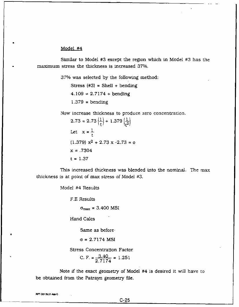
Model #4
Similar to Model #3 except the region which in Model #3 has themaximum stress the thickness is increased 37%.
37% was selected by the following method:
Stress (#3) = Shell + bending
4.109 = 2.7174 + bending
1.379 = bending
Now increase thickness to produce zero concentration.
2.73 = 2.73 () + 1.379
t
(1.379) x2 + 2.73 x -2.73 = o
x = .7304
t= 1.37
This increased thickness was blended into the nominal. The maxthickness is at point of max stress of Model #3.
Model #4 Results
F.E Results
amax = 3.400 MSI
Hand Calcs
Same as before-
a = 2.7174 MSI
Stress Concentration Factor
C.F. = 3.40 = 1.2512.7174
Note if the exact geometry of Model #4 is desired it will have tobe obtained from the Patrayn geometry file.
WT-001"79.X-10 C
C-25
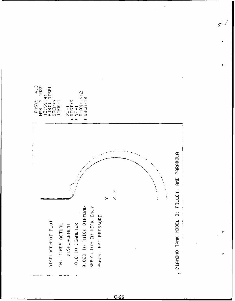
m-. wn nJ
=fm. a -() -- J r 1 7
a, Z*~- Lo N a i >- I
~~-4LLLLf
a CXt 1, ::D _
j Q')
CL (m r u~
T' ) w E m :
CD) M EL ') I
LU LU 0 C-26
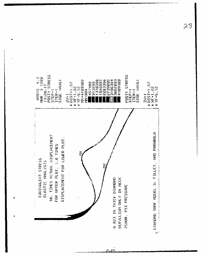
(r) Qr U-) -. 00 L&U cri w r U) 7 mr~ U -
D U m m 'cn 03 m 00M0 - '(n N urua) Tc7I wm o m m w mn U CU CIA
m NJ-~ - T I-M - WM M U M -~ r~u
0-Uhf N O F-UUui i CL WU) NO MMV C WU
CL (. 1-4f-0 Q L- N
E C Cc
LJU-i -j x1
(n m CC.,-o - -S I
CC_j = =
Z a CL U
CL
(n~i
C
m w~ co -
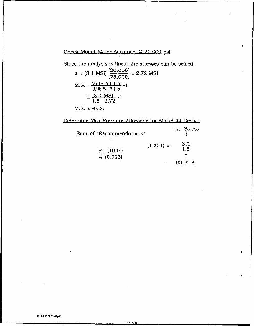
Check Model #4 for Adequagy @ 20.000 psi
Since the analysis is linear the stresses can be scaled.120~oo 00C = (3.4 MSI) 20,000) = 2.72 MSI
M.S. Material Ult -1
(Ult S. F.) a= 3.0 MSI -1
1.5 2.72
M.S. = -0.26
Determine Max Pressure Allowable for Model #4 DesignUlt. Stress
Eqm of "Recommendations" $
(1.251) = 3.0P. (10.0") 1.54 (0.023) T
Ult. F. S.
RPT-0018.37- C
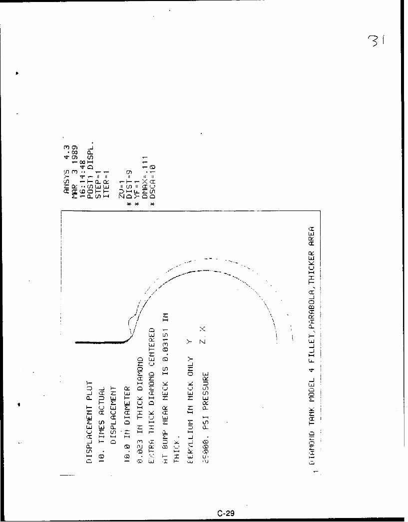
r3(
17)C7
V - II GI I
M (7I
LUJ
c-
0r
iiy
1-4 (1~
LUJ U)
InLlU 0 UCD LO
Z cJ H 0 0 LJtf
10L Hz ill LU
H- LUj Y- -4 w
H wL E '- LL.(m~ u T C (I
LUJ <1 '- w~ U -E w j 0 Li F H
(M --4 :;-Z
0i a
0 A -Z LU Li
C-29
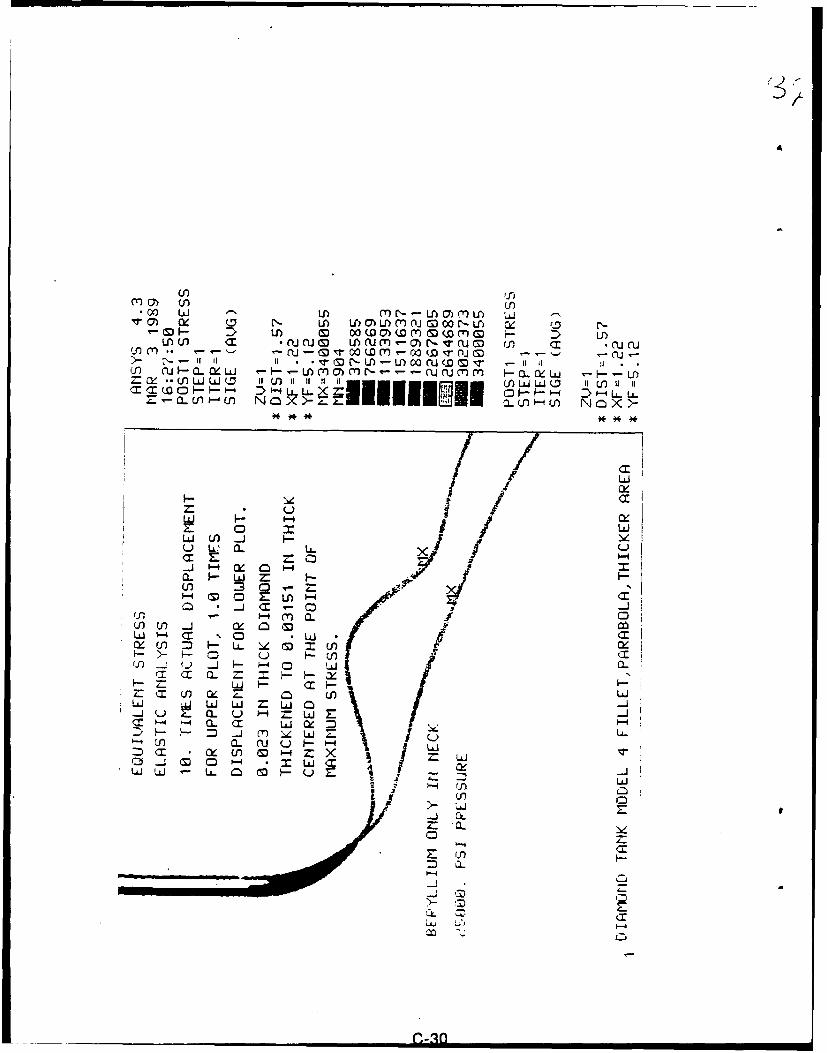
Lf-r*c2w LA U) M M M )u LAU
N (: - U L r) 7)Lrm ~ N f Cn NM00NU i I'U) (n <1 N~nm 1-( -M<JCn )U *Wmt N ~ w N-rii rJr M*curQuo
UV-mMNL-'-- 0-UCuM-
)- r - Ii 'I"U-L. a LL.-- ru~ LA.ICL *IUlU( flu) (n NO aZ-11 a. U-1 m~- N) aiJ X U
~~iiiiiucJ~a4u) ~ '- )U) ~ X)
L1/ Lo -Z: 0
4- (M 0 I
C) - j <X C
w " C -C I
IL CL,
Z: L LL CUO
'-J w w -4w
Ln I
= LAJJE x
-j C
Z: CL
APPENDIX D
DIFFUSION TEST DATA
RWr-D0178.37App D
Q-1
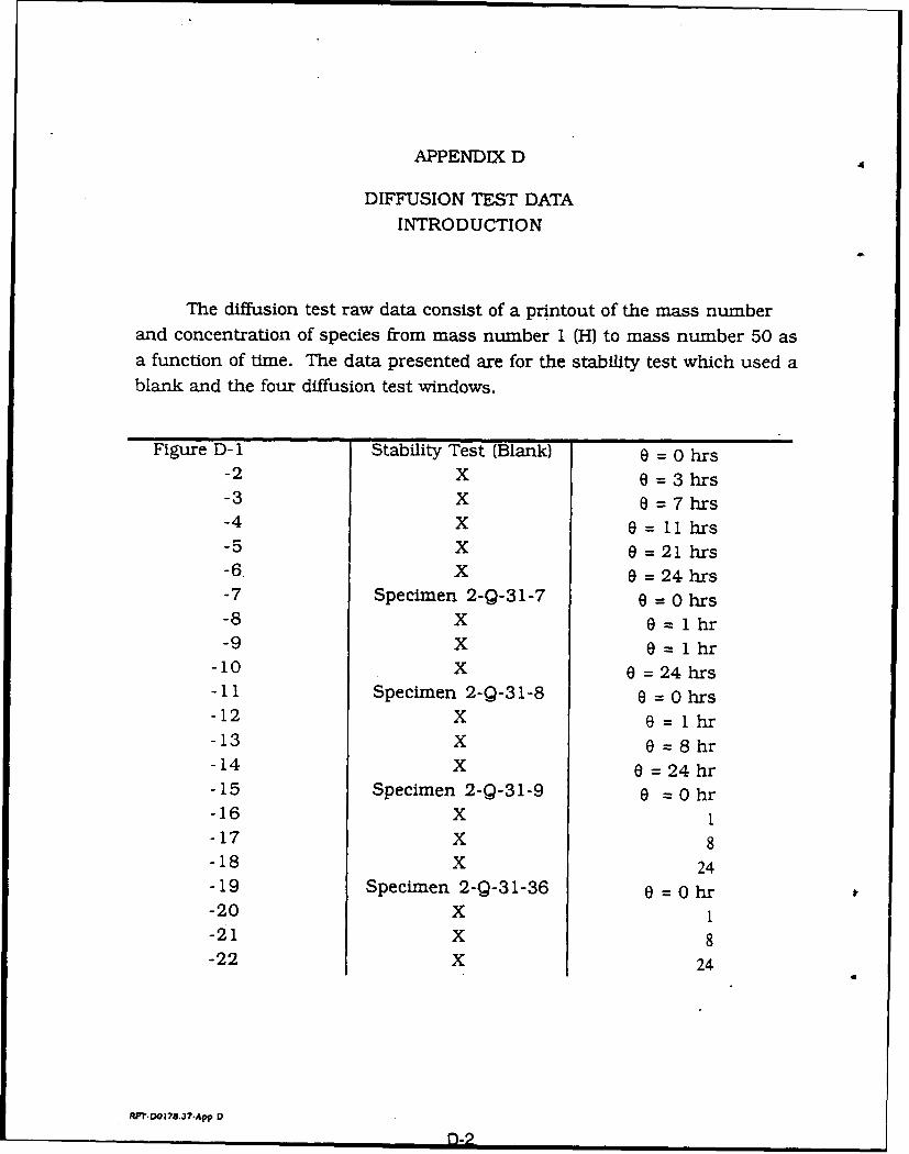
APPENDIX D A
DIFFUSION TEST DATAINTRODUCTION
The diffusion test raw data consist of a printout of the mass numberand concentration of species from mass number I (H) to mass number 50 asa function of time. The data presented are for the stability test which used ablank and the four diffusion test windows.
Figure D-1 Stability Test (Blank) e = 0 hrs-2 X 0 =3hrs-3 X 6 =7hrs-4 X 6 = 11 hrs-5 X 0 = 21 hrs-6. X 0 = 24 hrs-7 Specimen 2-Q-31-7 8 = 0 hrs-8 X 8=lhr-9 X 0 = lhr
-10 X O = 24 hrs-11 Specimen 2-Q-31-8 0 = 0 hrs-12 X 8= lhr
-13 X 6 =8hr-14 X 0 = 24hr-15 Specimen 2-Q-31-9 0 =0hr-16 X 1-17 X 8-18 X 24-19 Specimen 2-Q-31-36 0 = 0 hr-20 X 1-21 X 8-22 X 24
A
RP.-DO178.37-App D
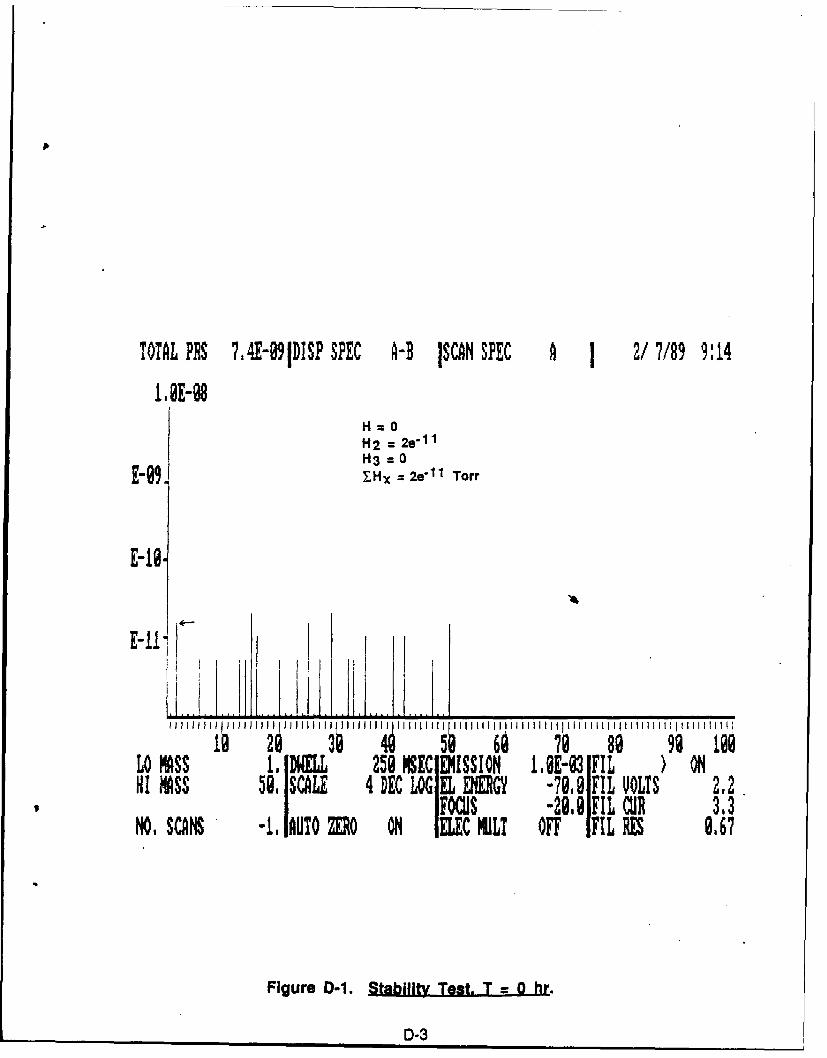
TOTAL PRS 7.4E-991DISP SPEC -D ISCAN SPEC A 1 2/7/89 9:14
1,@E-1H=OH2 = 2e- 1 1
H3= 0
E-99 Hx = 2e 1 1 Torr
E-16.
J~ l ll II l ll J ll l l I i l I llll111 III I I III11 1 11 I I II l lIII III I!11i Il : 1111 1111
LO 's MLL 258EMISSION IBE-3 IFIL ON
HI ASS 50SCALE 4 DEC LOGE ENERGY -70,? FIL VOLTS 2,2FOCUS -28. FIL CU 3.3
NO. SCANS -1, AUTO MO ON IELEC HULT OFF IFIL RES 9.67
Figure D-1. Stability Test. T = 0 hr.
D-3
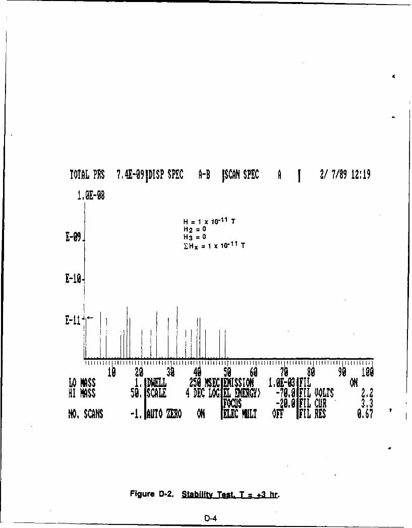
TOTAL PRS 7,4.-91DISP SPEC A- ISN SPEC A 1 2/7/89 12:19
,12E-98
H 1 x 10-11 TH2 =OE'99. H3=0JH2 =EI~:H 1 x 10-11 T
jgllI Illll~lllI lll IIII )II I lllll IIIIIll IIItIll II IIlltl
LO MSS 1. DWELL 25 MSEC IEISSION4 I,E-93 FIL ONIFOCS -21., FL CUR, 3.3
NO, SCANS -1 IAUQO MO ON 1ILEC HILT OFF IFIL RES 0,67
Figure D-2. Stability Test. T = +3 hr.
D-4
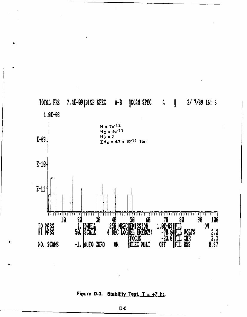
TOTAL PRS 7,4E-89IDISP SPEC A-B ISCAN SPEC A 2/7189 16: 6
IBE-0H = 7e
1 2
H2 = 4e"11g9 H3 = 0
E9XHx 4.7 x 10"11 Torr
E-11
J r a" "e"' ''''''' '" " i '"! 108'
o 258 EC EMISSIO , IE-83FILOHI MASS 51,SCL 4 DRC LOG EL ENERGY) [email protected] UOL7S 2.2NO ISS - IA'Ns -2.8,IFIL C R 3,3NO, SCANS -I,1AUlO O O IELEC MLI OFF IFIL RES 8,67
Figure D-3. Stability Test. T = 7 hr.
D-5
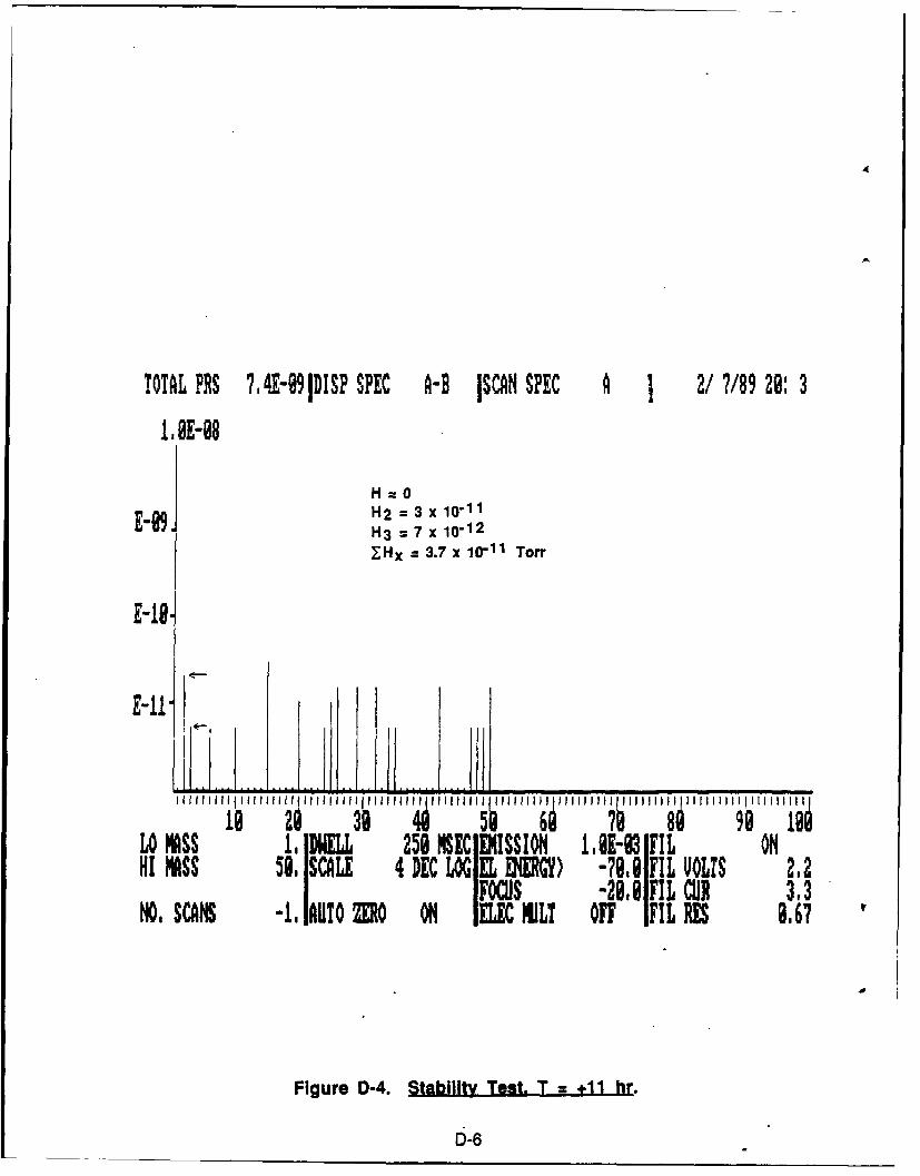
TOTAL PRS 7,4E-9IDISP SPEC A-B ISCAN SPEC A 2/7/89 20: 3
1.@E-08
H=O
E89. H2 = 3 x 10-11H3 = 7 x 10-12
ZHx = 3.7 x 10"1 1 Torr
E-18.
LO IASS I 258 MSEC ]MISSION IOA-0 FILOHI Iss 5e, SCALE 4 DEC LOG EL OW ) -79.8 FIL VOLTS 2.2
FOCUS -28.8 FIL CUR 3,3NO, SCANS -. lAUTOZO ON 01I C CILT OFF IFIL ES 8,67
Figure D-4. Stability Test. T = +11 hr.
D-6
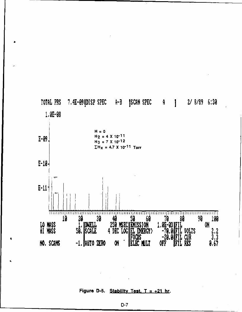
TOTAL PRIS 7,4E-991DISP SPEC A-B ISCAN SPEC A I 2/8/89 6:39
H = 0H2 = 4 X 10-11H3 = 7 X 10-12
XHx = 4.7 X 10⁻¹¹ Torr
E-IS.
I I ll llIIIIHIiII III I ll~ l J J lJl~ ~ ll l II liii II1111 I1111111 li 111
58 6 89 1@@LO MASS I1 DWELL 250 MEC EMISSION 1.@E-93 FIL OHHI MIASS 59. SCALE 4 DEC LOG EL ENERGY) -79.9 FIL VOLTS 2.2
-FOCUS " -28,8FIL CUR 3.3NO, SCANS -, IABTO R ON " IE M LT OFF IFIL RE 9.67
Figure D-5. Stability Test. T = +21 hr.
D-7
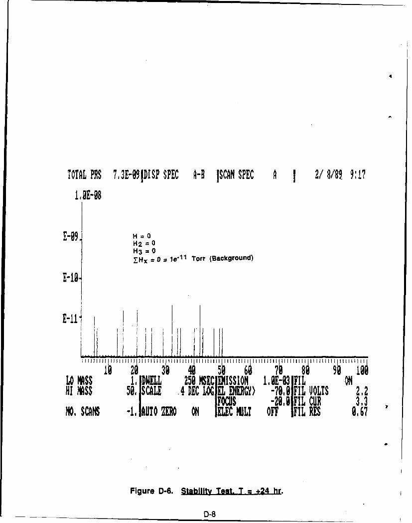
4
TOTAL PRS 73E-09IDISP SPEC A-B ISCAN SPEC A 2/8/8 9:17
1,0E-98
E-09. H = oH2 = 0H3 0_Hx -0 = le' 1 1 Torr (Background)
E-18.
E-111 I
i lll II 1 1 II III llli II ll IIII I IIII I 1Il'1'l111l l IUlI I 1111 III
LO MSS 1, DWILL 258 SI ISSION ,M-031FIL ON
HI MASS 50, SCALE .4 DEC LOG IEL ENEGY) -78,8 FIL UOLTS 2,21IFOCUS -29.@gFIL CUR M,3NO, SCANS -1 iUTO ZERO ON ELEC ULT OFF IFIL RES 8,67
Figure D-6. Stabilit Test. T = +24 hr.
D-8
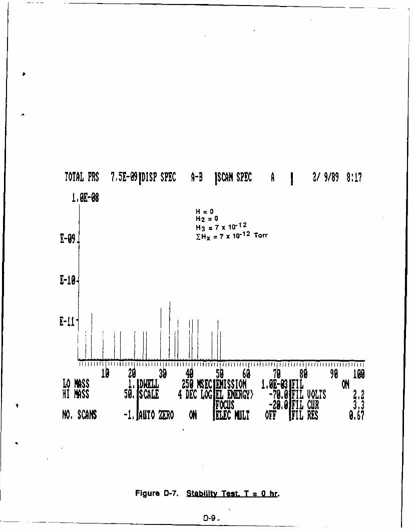
TOTAL PRS 7,5E-991DISP SPEC A-B ISCAN SPEC A 2/9/89 8:17
L0E-08H=OH2 0
H3 = 0-1H3 = 7 x 10-12E-Y, Hx = 7 x 10- 1 2 Torr
E-tI,
E-1"
I I 1 I III I ~I I I I Ii~ I I I H 1 1 4 H l f l1 1 6 1, 1 i i III II i III1I11111 11111Ii III IsfoI I III29 98 ILO MSI.DWELL 259 ME MISSION M.E-83 IFIL OHI MASS 59. SCALE 4 DEC LOG EL ENEGY) -70.9 IFIL VOLTS 212
Focus -29,8,FIL CO 3,3NO, SCANS -, IAUTO MO O IEC liLT OFF IFIL RES 9,67
Figure D-7. Stability Test. T = 0 hr.
D-9.
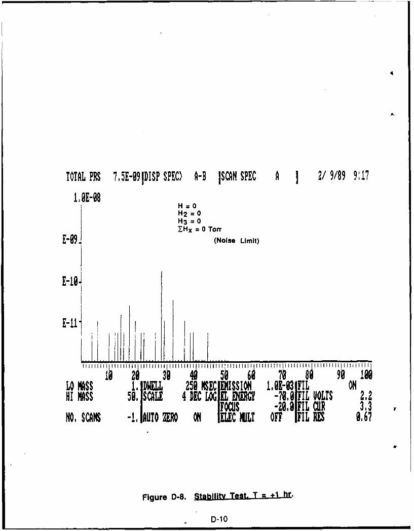
TOTAL PRS 7,SE-991DISP SPEC) A-B ISCAN SPEC A 1 2/9/89 9:17
1,0E-98H=OH2 = 0H3 = 0ZHx = 0 Torr
E-09. (Noise Limit)
E-le.
LO MASS 1. DWELL 258 MSEC IENISSION 1E-3 FIL ONHI MASS 58. SCALE 4,DEC LOGIELR790IL YoLI S 2,2
Focus -28,81FILCUR 3,3NO, SCANS -,,IAUTO ZERO ON IELEC NIL? OFF IFIL RES 9.6?
Figure D-8. Stability Test. T = 1 hr.
D-10
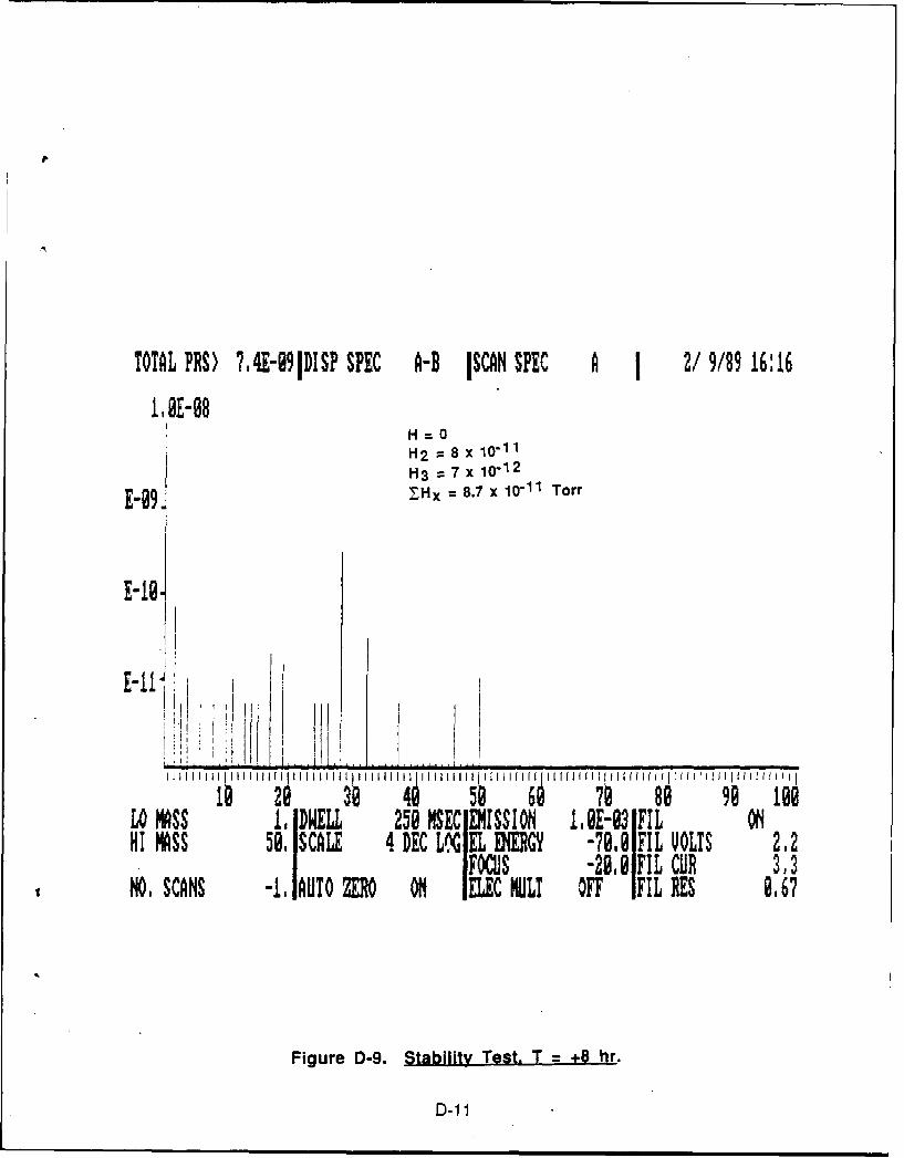
TOTAL PRS) 7,4-99IDISP SPEC A-B ISCN SPEC A 1 2/9/89 16:16
I.OE-08H-O
H2 = 8 x 10-11H3 = 7 x 10- 1 2
I XHx = 8.7 x 1l1 Torr
E -G I , . .. .....l l
18 2 4 50 79 89 99 199Lo ASS 1. DWELL 250 SECL EISSION 1.,E-03 FIL ONHI MASS 50. SCALE 4 DEC LAGIEL ENERGY -79.81FIL VOLTS 2,2
IIFOCUS -29,9 IFIL CUR 313NO. SCANS -I IAUTO ZERO ON IELEC MULl OFF IFIL RES 0,67
Figure D-9. Stability Test. T +8 hr.
D-11
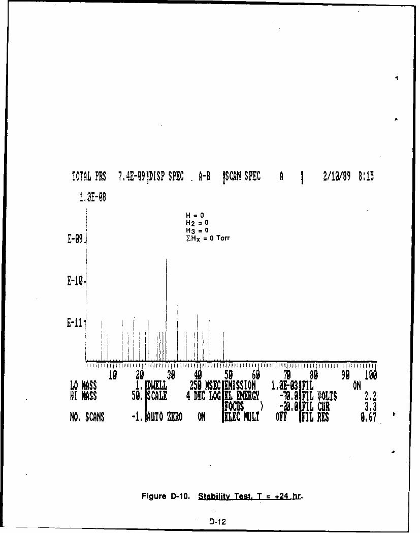
TOTAL PRS ?,4E-O9DISP SPEC A-B ISCAN SPEC A 1 2/18/89 8:15
I13E-08H=OH2=0H3= 0E9H= 0 Torr
E-181
E-11 i lL Ii
8 48 5 6 79 39 49 958Lo MASS 1. DWELL 258 MSSN AVI ONHI MASS 59, SCALE 4 DEC LX EL B-7.1 FIL VOLTS 2,2
FOCUS -N. 8 FIL CUR 313NO, SCANS -1, AUTO ZERO ONl ELEC NIL! OFF IFILRES 8. 67
Figure D-10. Stability Test. T = +24 hr.
D-12
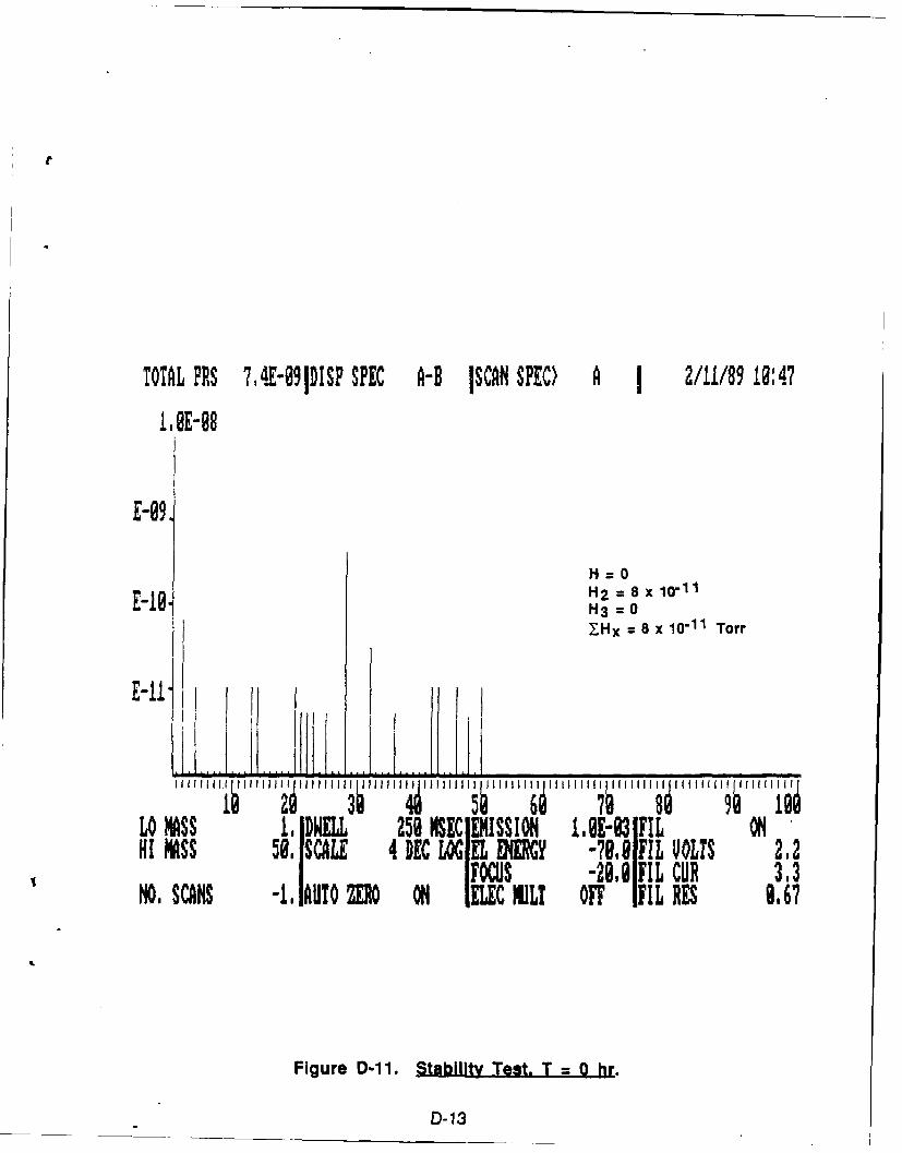
TOTAL PRS 7,4E-091DISP SPEC A-B ISCAN SPEC) A 1 2/11/89 10:47
E-098
H2 = 8 x 10¹¹H3 = 0lHx = 8 x 10-11 Torr
E-11j r I
I "I iHfII i i" 11"11 I 111 11 "I IIII f11 I 11111 H t" 11111 il 'I ff1 11ff ili
Lo MASS 1, DWELL 251 MSEC EMISSION , E-3 IFIL ONHI MASS 50. SCALE 4 DEC LOG EL ENX -79.9lFIL UOLIS 2.2
FOCUS -29,0IFIL CUR 3,3NO, SCANS -I. IAUTO ZERO ON ILC NILT OFF IFIL RES 8,67
Figure D-11. Stability Test. T = 0 hr.
D-13
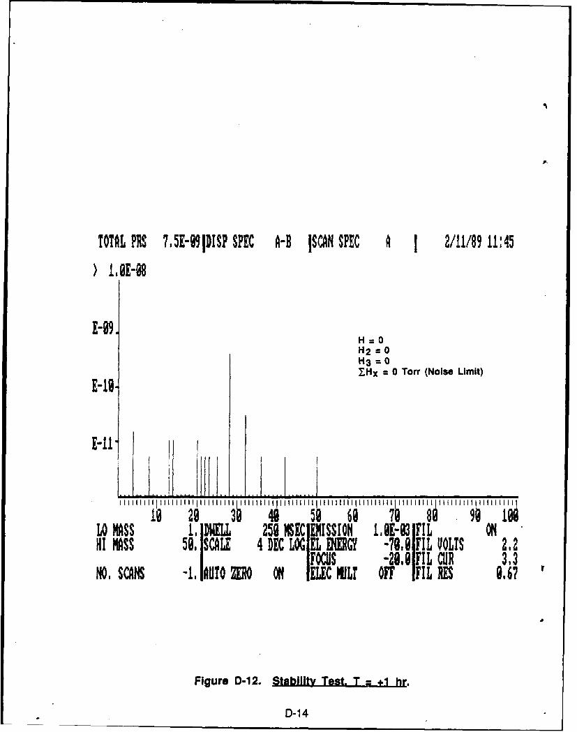
TOTAL PRS 7,5E-991DISP SPEC A-B ISCAN SPEC A 1 2/11/89 11:45
) lIE-e8
E-09.H=0H2 = 0H3=07-Hx = 0 Torr (Noise Limit)E-I.
9 29 3 49 59 688lLO MASS 1, DWELL 259 IEC UISSION 11E-93 FIL ONHI MASS 50. SCALE 4 DEC LO EL MRGY -789 FIL VOLTS 2.2
Focus -28.8FIL CUR 33NO, SCANS -1. AUTO ZRO ON IELEC MiL! OFF IFIL RES 8,6?
Figure D-12. Stability Test. T +1 hr.
D-14
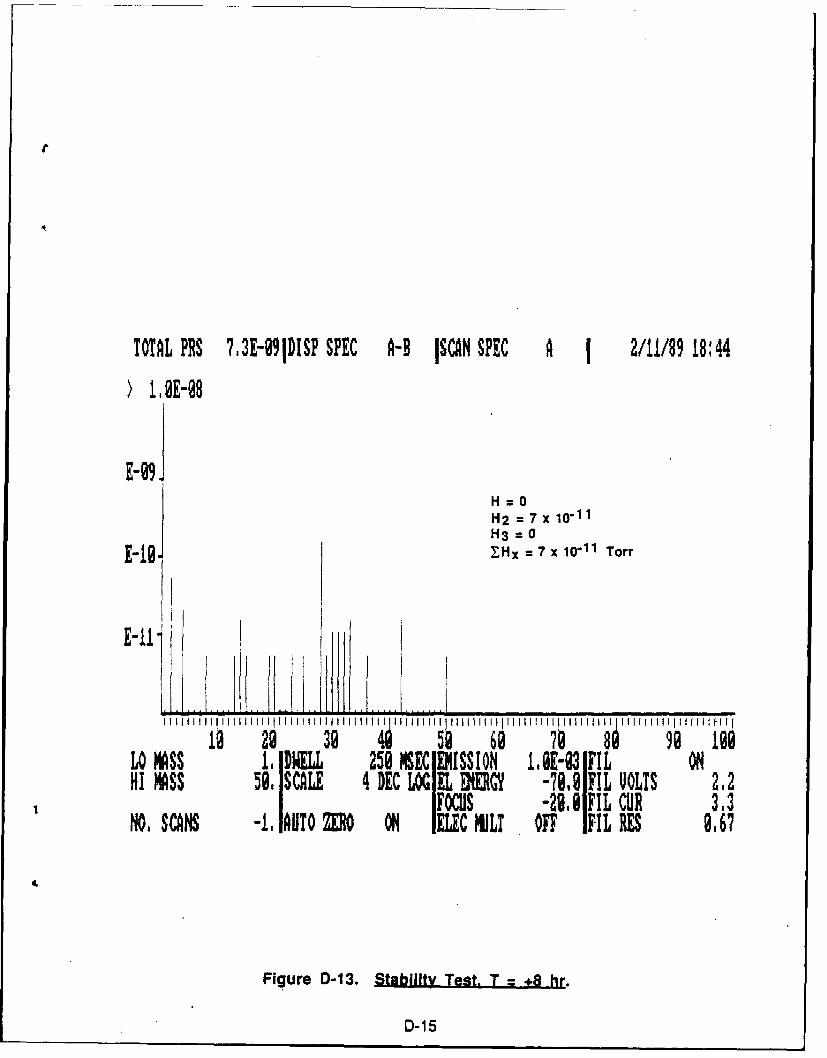
TOTAL PRS 73E-09DISP SPEC A-R ISCAN SPEC A 1 2/11/89 18:44
Y 1,E-98
E-N,H=O
H2 = 7 X 10-11H3= 0,Hx = 7 x 10-11 Torr
I _ _ _ _ _ _ _ _ _ _
I I Im I I 1 1111 1 111 1 11 1 1 1 1 1 11 1 1 1 1 11 111111 1 li 111111 liI IIIIII I II H H ( lLID MASS 1, DWEL 251 NSECl MISSION I,-931FIL OHI MASS 59, SCALE 4 DEC LOG E ENERG -78,81FIL VOLTS 2.2
IFOCS -298 FIL CUR 3.3NO, SCANS -1, AUTO MO ON I1LC NLT OFF IFIL RES 8,67
Figure D-13. Stability Test. T = +8 hr.
D-15
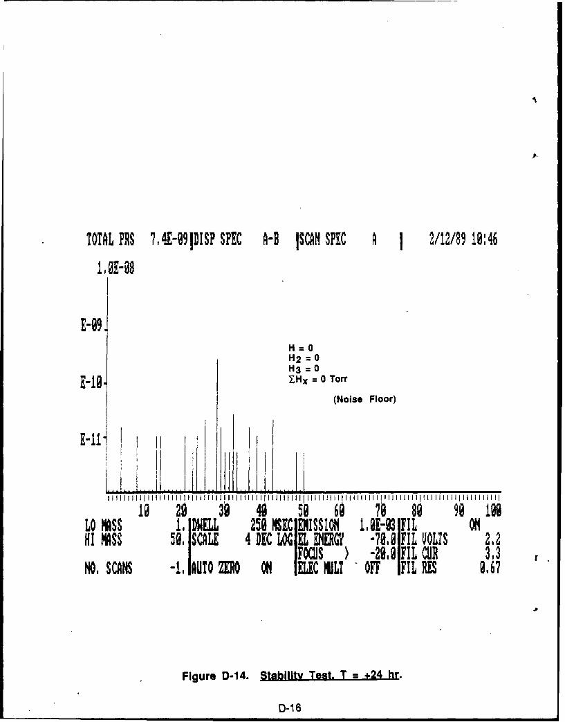
TOTAL PRS 74E-9IDISP SPEC A-B ISCAN SPEC A 1 2/12/89 19:46
1.2-98
E-99H=OH=H2= 0H3 = 0E'I7S, =. 0 Torr
(Noise Floor)
ED-16
LO MASS 1, DWELL 259 SE EMISSIONM1.E-03 FIL OH1 MASS 59. SCALE 4 DEC LOG EL ENEGY -79.8 FIL VOLTS 2.2
FOCUS ) -28.89FIL CUR 3.3NO. SCANS -1, AUTO ZRO ON IELEC NILT OFF IFIL RES 9,67
Figure D-14. Stability Test + 24 hr.
D-16
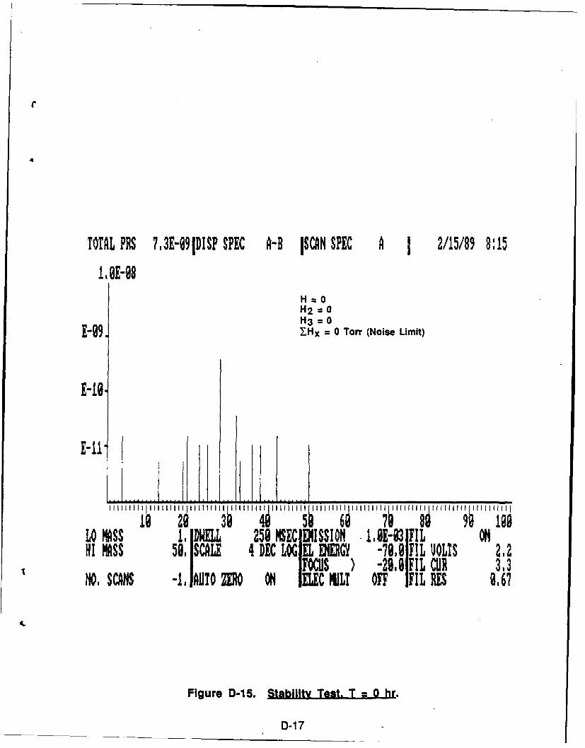
TOTAL PRS ?3E-9lDISP SPEC A-B ISCAN SPEC A 1 2/15/89 8:15ME-98
H2-OH2 = 0H3 = 0
E-99 1Hx = 0 Torr (Noise Limit)
E-. ..
1. 9 41lLO MSS I INELL 258 MEC EMISSION . E-83 FIL ONHI MASS 59. SCALE 4 DEC LOG EL ENERGY -?I.@ FIL VOLTS 2.2
FOCUS -29.8 FIL CUR 3.3NO, SCANS -1,I UT0 MO ON IEUC MUL! OFF IFIL RS9,67
Figure D-15. Stability Test. T = 0 hr.
D-17
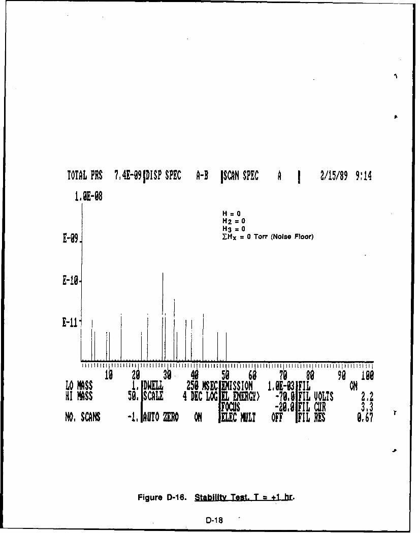
TOTAL PRS ?,4E-91DISP SPEC A-B ISCN SPEC A 1 2/15/89 9:14
1,IE-98H--OH2 =0H3 = 0
E-99. YHx = 0 Torr (Noise Floor)
E-11 ............ ...~ i i II IIIIII IIIIIII I il iliii I I 1111I 111 11111
29 4• 708 1 go IleLO MASS 1, DWILL 258 NECI EISSION 1,E-3 1FIL ONHI MASS 50, SCALE 4 DEC LOGIEL ENERGY) -?@.@IFIL VOLTS 2.2
IFous -28.8 IFIL CUR 313HO, SC6 -I, AtUTO f11O ON IIEC MJLT OFF IFIL RES 8,67
Figure D-16. Stability Test. T = +1 hr.
D-18
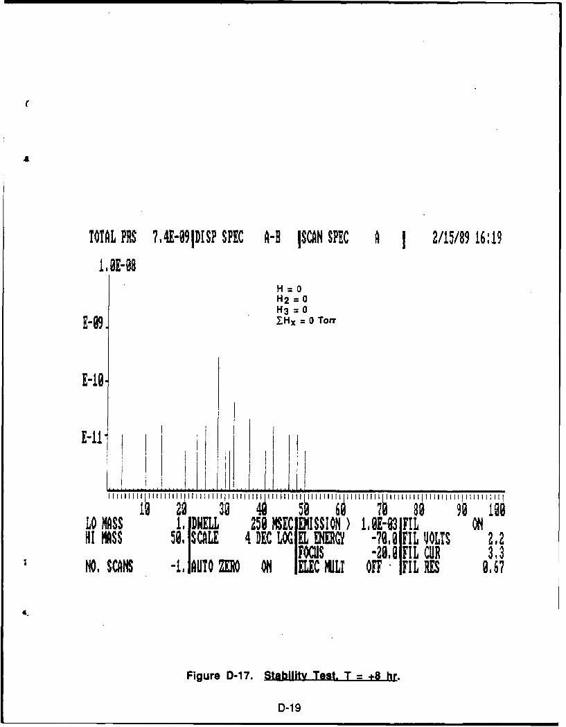
TOTAL PRS ?,4E-091DISP SPEC A-B ISCAN SPEC A 1 2/15/89 16:191, 0E- 8
H OH2= 0H3 = 0
E-09. ZH - 0 Torr
E-10,
LO MASS 1, DWELL 250 NSEC IEISSION ) 1,E-3 FIL ONHI MASS 58, SCALE 4 DE LOG EL ENERGY -70.1 FIL VOLTS 212
I FOCUS -28.1 FIL CUR 3,3O, SCAS -1, AUTO O O IELEC MILI OFF - FIL RES 9,67
Figure D-17. Stability Test, T = +8 hr.
D-19
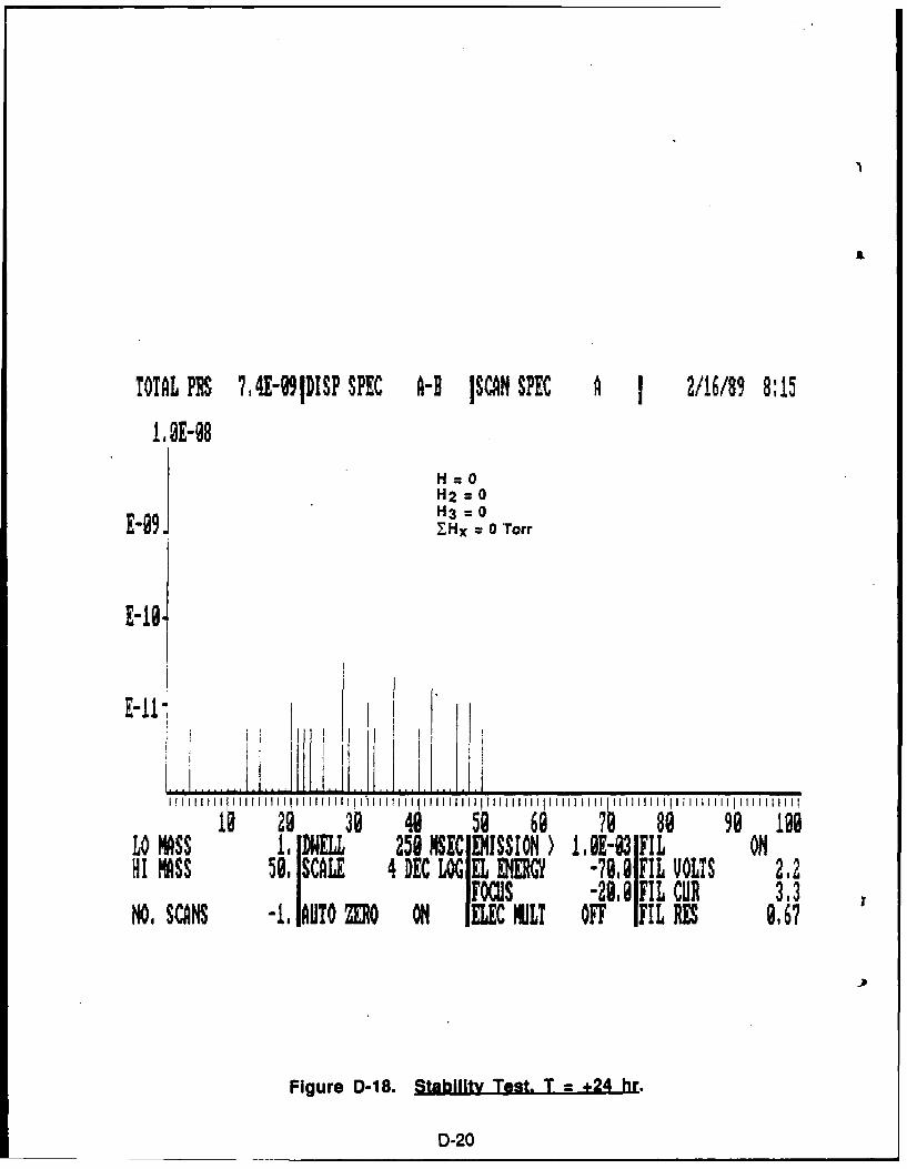
TOTAL PRS 74E-9IDSP SPEC A-B ISCAN SPEC A 1 2/16/89 8:15
H=OH2 = 0H3 = 0-. Hx = 0 Torr
E-19.
E-114
19 29 39 45 6 7 0 9LO M'ASS 1,IDWELL 250 NSEC EMISSION ) ME-93 FIL ONHL MASS 5. ISCALE 4 DEC LOG EL M -78, 7 FIL VOLTS 212
FOCUS -29.0 FILCUR 3.3NO. SCANS -1.IAUTO MO ON IELEC ML OFF FIL RES 9,67
Figure D-18. Stability Test. T = +24 hr.
D-20
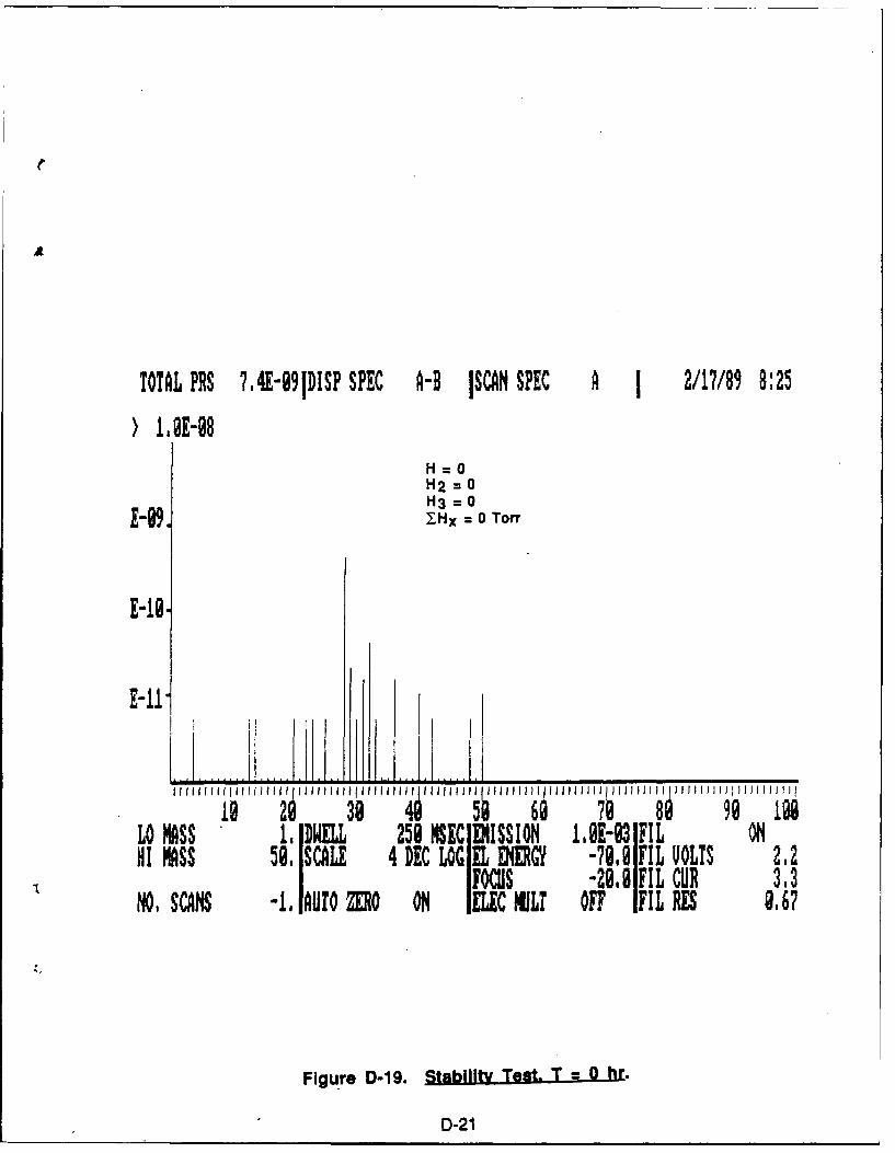
'
TOTAL PRS ?,4E-991DISP SPEC A-B ISCAN SPEC A 1 2/17/89 8:25) 1,8E-g8
H =0H2 = 0H3 = 0
E09. 7Hx = 0 Toff
E-19,
E-1LL ..I.
1o 21 95 9 7 89 99 l8@LO MASS 1 DWELL 258 NEC ]MISSION I,-93 FIL ONHI MASS 59. SCALE 4 DEC LOG EL ENERGY -79 FIL VOLTS 2.2
FOcus -20, 11FILCUR 3,3NO. SCANS -I. AUTO Zo ON lELIC MULT OFF IFIL RES 9.67
Figure D-19. Stability Test. T = 0 hr.
D-21
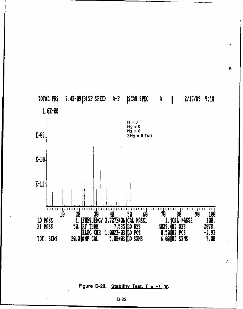
TOTAL PRS ?4E-09DISP SPEC) A-B ISCAN SPEC A 1 2/17/89 9:18
1.@E-08H =0H2 = 0H3= 0
E-09 _Hx = 0 Torr
E-18.
E-11
Lo MASS 1, F UHQW 2,?27+ 1 CAL MASSI 1, CAL MASS2 M.HI MASS 59, IF TUE 7,585 Lo RES 4929, HI RES 278,
ELEC CUR I.2 E-3 LO P0S 858 HI P0S -.,93TOTE SENS 29,81AM CAL 5.B+3 LO SENS 6,8HI SENS ,8
Figure D-20. Stability Test. T - +1 hr.
D-22
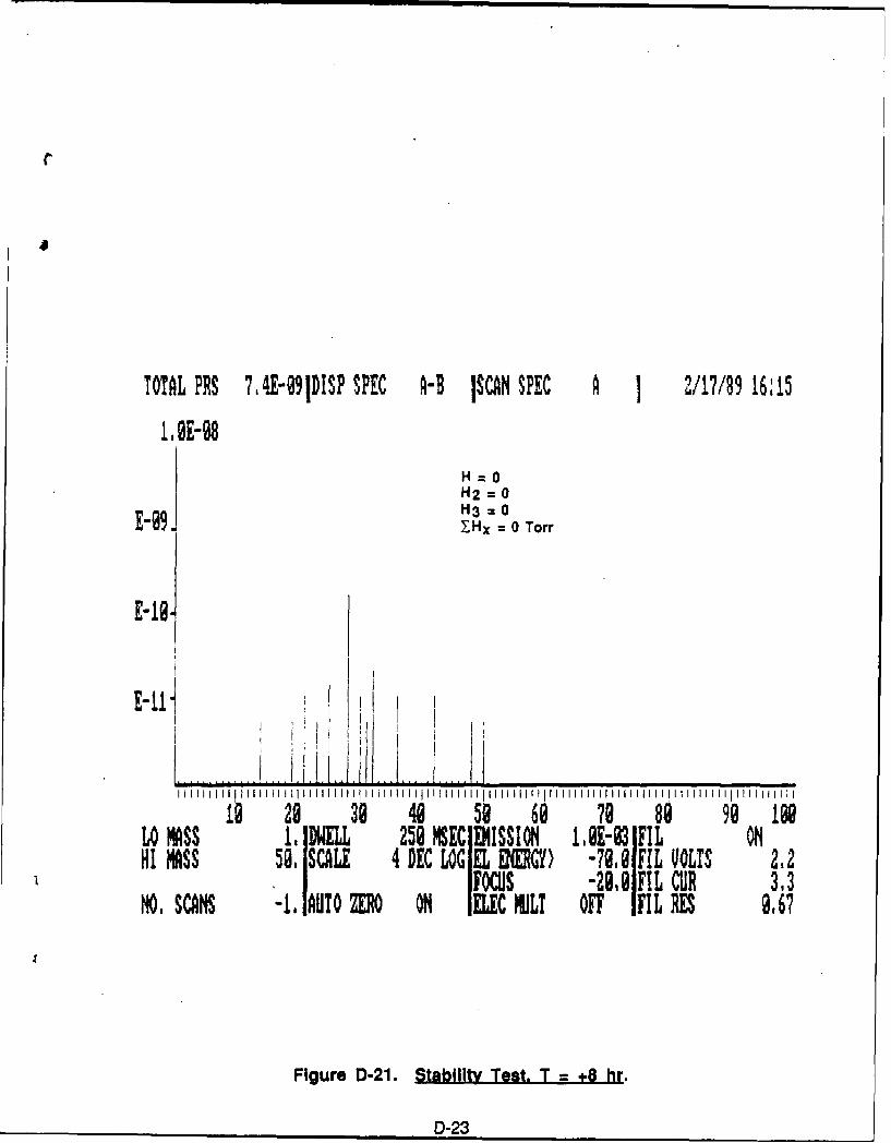
C
TOTAL PRS 7,4E-9jDISP SPEC H ISCAN SPEC A 1 2/17/89 16:15
1.,OE-9
H2=0H12 = 0H3 = 0
E-099 Y.Hx 0 Torr
E- 18.
1 29 30 40 50 68 79 88 98 180Lo MASS 1,IDNELL 258 MSEClEMISSION 18E-03 IFIL ONHI MASS 58, SCALE 4 DEC LOGIEL DEGY) -70.0 FIL VOLTS 2.2
SFOCS -28.8 FIL CuR 3.3NO, SCANS -I IAUTO ZERO ON IELEC MJLI OFF IFIL RES 9.67
Figure D-21. Stability Test, T = +8 hr.
D-23
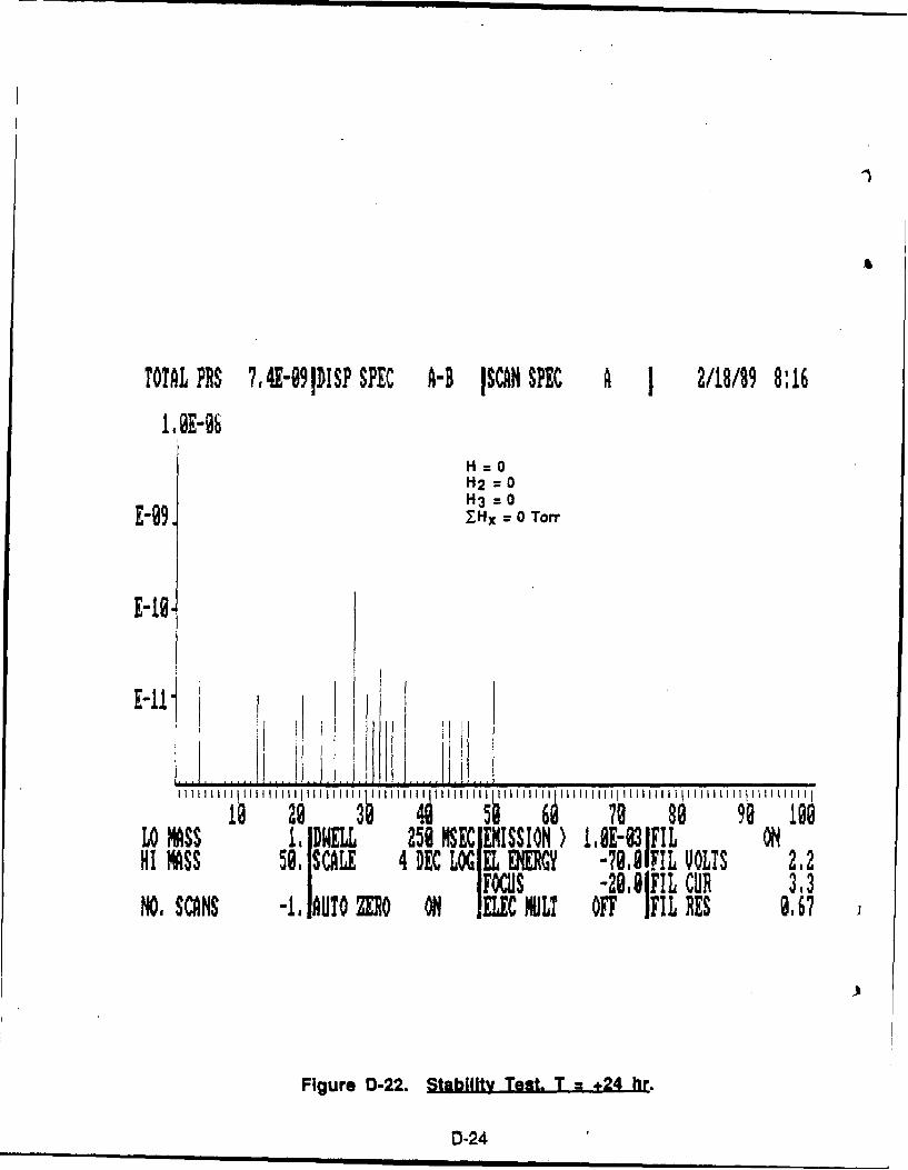
TOTAL PRS 7 4E-991DSP SPEC A-B ISCAN SPEC A 1 2/18/89 8:16
1tE-06
H =0H2 = 0H3 = 0
E-99. YHx 0 0 Torr
E-1S-
E-11 Il t l
LO MSS , DELL 250MSE EMISSION la8E-031LOHI MASS 59, SCALE 4DECLOGELENERGY -70. IL VOLTS 2.2
SIFOCUS -29. ,FIL CUR 3.3NO, SCANS -1. AUTO ZER0 ON MC MI OFF IFIL RES 9.67
Figure D-22. Stability Test. T +24 hr.
D-24
APEDIr
PROPELLANT CORROSION RESISTANCE STUDY (AL)
NPT-00176.37-App r E-1.
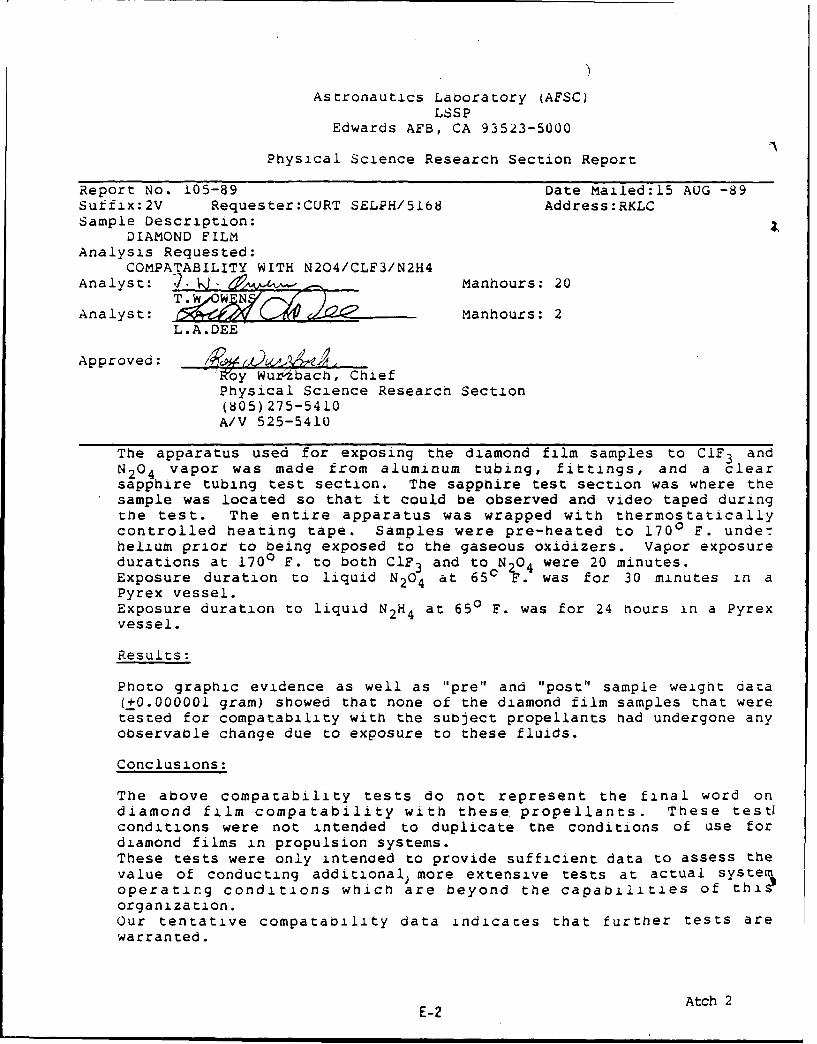
Astronautics Laboratory (AFSC)LSSP
Edwards AFB, CA 93523-5000
Physical Science Research Section Report
Report No. 105-89 Date Mailed:15 AUG -89
Suffix:2V Requester:CURT SELPH/5168 Address:RKLCSample Description:
DIAMOND FILM
Analysis Requested:COMPATABILITY WITH N204/CLF3/N2H4
Analyst: 2. - Manhours: 20
Analyst: Manhours: 2L.A.DEE
Approved: __ __ _ __ _
It'oy Wukzibach, ChiefPhysical Science Research Section
(805) 275-5410A/V 525-5410
The apparatus used for exposing the diamond film samples to CIF3 andN204 vapor was made from aluminum tubing, fittings, and a clearsapphire tubing test section. The sapphire test section was where thesample was located so that it could be observed and video taped duringthe test. The entire apparatus was wrapped with thermostaticallycontrolled heating tape. Samples were pre-heated to 1700 F. underhelium prior to being exposed to the gaseous oxidizers. Vapor exposuredurations at 1700 F. to both CIF3 and to N204 were 20 minutes.Exposure duration to liquid N204 at 650 F. was for 30 minutes in aPyrex vessel.Exposure duration to liquid N2H4 at 650 F. was for 24 hours in a Pyrexvessel.
Results:
Photo graphic evidence as well as "pre" and "post" sample weight data(±0.000001 gram) showed that none of the diamond film samples that weretested for compatability with the subject propellants had undergone anyobservable change due to exposure to these fluids.
Conclusions:
The above compatability tests do not represent the final word ondiamond film compatability with these propellants. These testlconditions were not intended to duplicate the conditions of use fordiamond films in propulsion systems.These tests were only intenaed to provide sufficient data to assess thevalue of conducting additional, more extensive tests at actual systeoperating conditions which are beyond the capabilities of thi)organization.Our tentative compatability data indicates that further tests arewarranted.
E-2 Atch 2


