Embed Size (px)
Citation preview
This article appeared in a journal published by Elsevier. The attachedcopy is furnished to the author for internal non-commercial researchand education use, including for instruction at the authors institution
and sharing with colleagues.
Other uses, including reproduction and distribution, or selling orlicensing copies, or posting to personal, institutional or third party
websites are prohibited.
In most cases authors are permitted to post their version of thearticle (e.g. in Word or Tex form) to their personal website orinstitutional repository. Authors requiring further information
regarding Elsevier’s archiving and manuscript policies areencouraged to visit:
http://www.elsevier.com/copyright
Author's personal copy
Intrados strengthening of brick masonry arches with composite materials
Antonio Borri, Giulio Castori ⇑, Marco CorradiDepartment of Civil and Environmental Engineering, University of Perugia, via Duranti 93, 06125 Perugia, Italy
a r t i c l e i n f o
Article history:Received 1 August 2010Received in revised form 14 January 2011Accepted 18 March 2011Available online 25 March 2011
Keywords:A. Glass fibersA. PlatesB. DebondingMasonry arches
a b s t r a c t
The objective of this study is to investigate the effectiveness of an innovative technique for strengtheningmasonry arches at their intrados, based on the use of carbon plates. Although FRP sheets or strips are suc-cessfully used as strengthening elements for this kind of application, they present several critical issuesthat can compromise these upgrading works, leading to the local collapse mechanism, which correspondsto the debonding of reinforcement from the masonry substrate. As an alternative to FRP sheets, the use ofFRP plates presents instead several interesting aspects which make them very attractive for intradosstrengthening. More precisely, FRP plates have an inherent bending and axial stiffness that may overcomeproblems concerning premature peeling. Fifteen prototypes of brickwork arches strengthened at theirintrados with GFRP sheets or CFRP plates were tested under a monotonic vertical load applied at the key-stone. The influence of the types of reinforcement (glass fibers and carbon plates), properties of the bond-ing system and masonry substrate and the presence of anchor spikes has been investigated.
� 2011 Elsevier Ltd. All rights reserved.
1. Introduction
Due to movements in the abutments, structural alterations in-duced by architectural changes, or increased service loads, ma-sonry arches and vaults often need repair and/or strengthening.Because structural remedial measures might be needed after astructural evaluation, a significant concern in actual research isthe need for efficient strengthening techniques to re-establishthe performance of these structures, ensuring that under severeseismic conditions they will not collapse upon their occupants orpassers-by. In the development of these methodologies, on theone hand, structural safety, including seismic hazard, must be ac-counted for, while on the other, the original construction mustbe preserved from both an aesthetic and a structural perspective.With regard to the many issues associated with the maintenanceand restoration of historic buildings [1], the interest of workersin this field has become increasingly devoted to the developmentof innovative materials and advanced technologies. Specifically,there is an increasing interest in fiber-reinforced polymer (FRP)composites, whose use in the structural reinforcement of RC (rein-forced concrete) structures has been widespread now for morethan a decade [2–4]. FRP reinforcement provides designers withoutstanding combination of properties, including low self-weight,and high strength. Moreover, the use of these materials does notalter the natural behavior of the structure since they do not addmass. In addition, they are removable, and they can be made either
invisible or visible, in order to comply with modern restorationrequirements. For these reasons, FRP reinforcement in the formof externally bonded at either the intrados or the extrados of thearch or vault with the wet lay-up technique is an effective solution,as demonstrated by the available experimental and theoreticalstudies [5–8].
As found in literature [8–10], the use of composite materials en-ables in fact masonry structures to carry substantial tensile stres-ses, eliminating their greatest mechanical shortcoming at anacceptable cost. More specifically, reinforcement is incapable ofpreventing masonry from cracking (to do so, it would either haveto have a stiffness several times greater than the masonry, or itwould have to be pre-stressed), but it does transmit the tensionforce between the two faces of the crack, i.e., it stitches the crack.Hence cracks may form at a reinforced boundary, but cannot open,since the tension force is transmitted by the reinforcement in lieuof the cracked masonry, i.e., the tension force bypasses the cracksand passes into the reinforcement. This means that reinforcingthe extrados or the intrados allows to prevent all mechanisms(hinged mode failures) from occurring, forcing such structures tofail by other failure modes (i.e., crushing, sliding, debonding orFRP rupture).
Parametric analyses [9,10] have been developed for predictingthe ultimate load associated with each failure modes, the lowestof which constitutes the strength of the reinforced masonry arch.According to such analysis and to the abovementioned experimen-tal studies, when FRP strips are bonded at the intrados, the effec-tiveness of the strengthening scheme was found to be highlydependent on the bond between composite strip and existing
1359-8368/$ - see front matter � 2011 Elsevier Ltd. All rights reserved.doi:10.1016/j.compositesb.2011.03.005
⇑ Corresponding author. Tel.: +39 0755853906; fax: +39 0755853897.E-mail address: [email protected] (G. Castori).
Composites: Part B 42 (2011) 1164–1172
Contents lists available at ScienceDirect
Composites: Part B
journal homepage: www.elsevier .com/locate /composi tesb
Author's personal copy
structure. In the presence of concavely-curved soffits, the FRP lam-inates tends to get straightened under tension, leading to a multi-axial stress state, which combines the shear stresses (s), parallel tothe bonding masonry boundary, with transverse tensile stresses(r), which accelerate debonding failure [11,12]. Under such condi-tions, peeling and debonding became critical considerations in thedesign of masonry arches strengthening since the load-carryingcapacity for this failure mode is commonly much lower than thatof the other failure modes [6].
Nevertheless, quite surprisingly, few studies are available onmasonry arches strengthened at their intrados [13], despite thefact that such strengthening arrangements are often found in prac-tice. The main objective of the present research is finding out aneffective way of applying FRP reinforcement at the intrados of ma-sonry arches to improve their performance, overcoming problemsconcerning premature peeling. Fifteen prototypes of brickwork ar-ches were built, reinforced and tested to compare their behavior upto collapse by testing several types reinforcement (glass fibers andcarbon plates), looking after the properties of both the adhesivesystem and the masonry substrate, possibly influenced by the pres-ence of anchor spikes.
2. Behavior of masonry arches strengthened at their intrados
Traditional design and analysis of masonry arches and vaults[14] is based on a number of simplifying assumptions: (i) masonryhas no tensile strength and infinite compressive strength, and (ii)sliding failure of an arch with rigid abutments is unrealistic. Theconsequence of these assumptions is that failure of a masonry archtheoretically occurs by formation of a sufficient number of hingestransforming the arch into a mechanism, and stability under givenloads depends essentially on the geometry of the structure.
As abovementioned, the presence of a bonded FRP strengthen-ing modifies completely the structural behavior of a masonry arch.Since reinforcement enables masonry structures to carry substan-tial tensile stresses, it may stitches the crack, preventing theboundary opposite an FRP strip from hinging. Depending on theposition and amount of the reinforcement and on the loading pat-tern, the formation of hinges may be either altered (hinges form atdifferent locations than in the unstrengthened arch) or completelyprevented. Therefore, the capacity of the arch may be controlled byother failure mechanisms, which depend on the strength limits ofthe constituent materials (masonry and reinforcement) and ontheir structural interactions at the local level (bond and localizedshear).
Specifically, if the FRP strip is bonded at the intrados, the effec-tiveness of the strengthening scheme is highly dependent on thebond between composite strip and existing structure. In this case,the interfacial shear stresses (s) between FRP and masonry shouldbe in equilibrium with the normal ones (r) resulting from theshape of the concave substrate.
Basic theoretical evaluation proves that the relationship thatlinks the tension force in the reinforcement (T) with the normalstresses (r) is given by [13]:
r ¼ Tbreinf � R
; ðnormal stressÞ ð1Þ
where breinf = width of the reinforcement; and R = radius ofcurvature.
According to Eq. (1), r stresses are proportional to the tension inthe fibers (T); as a consequence the use of reinforcements withhigh strength induces very high r stresses that are far above sstresses, which are consequently negligible.
Consequently, in order to obtain an analysis model, able to de-scribe the debonding failure mode, it is assumed to assess the
resultant state of stress (rd = f(r, s)), acting in a generic crackedsection, by considering only the contribution of normal stresses(rd = r). The crucial point is to establish the limit (rRd) of the rd.rRd can be measured by in situ tests (pull-off tests) or obtainedfrom the technical literature. Failure occurs once rd reaches rRd
in a generic cross section.
3. Experimental program
3.1. Characterization of masonry mortar
The arches were constructed using a hydraulic lime mortar (ra-tio sand/binder = 5/2 in volume). To obtain the mechanical proper-ties of the, flexural and compressive strength tests were performedin accordance with the following specifications: ASTM C 348 [15]and ASTM C 349 [16]. As for the flexural strength tests, six pris-matic specimens (160 � 40 � 40 mm) were used. Accordingly, themean value of the flexural strength was 0.36 MPa, while the coef-ficient of variation was equal to 0.09. Compression tests were per-formed on 12 specimens, obtained from the flexural test specimensby breaking each prism into two halves. The compression strengthis equal to 6.95 MPa, while the coefficient of variation was equal to0.02 MPa.
3.2. Characterization of the bricks
Solid clay bricks (250 � 125 � 55 mm3) were used for the con-struction of the masonry arches. The mechanical characteristicsof the bricks were obtained by means of compression and bendingtests carried out on six samples each. Uniaxial compression testsgave a mean strength and a coefficient of variation of 20.99 MPaand 0.11 MPa, respectively, whereas the mean value of the bendingtensile strength and its coefficient of variation were 0.81 MPa and0.27 MPa, respectively.
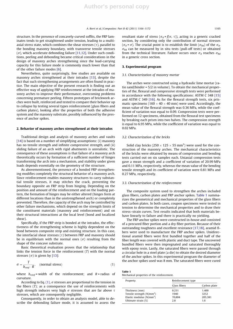
3.3. Characterization of the reinforcement
The composite system used to strengthen the arches includedglass fibers, carbon plates and FRP anchor spikes. Table 1 summa-rizes the geometrical and mechanical properties of the glass fibersand carbon plates. In both cases, coupon specimens were tested intension to determine the mechanical properties and to draw theirstress–strain curves. Test results indicated that both materials be-have linearly to failure and there is practically no yielding.
The FRP anchor spikes were constructed in-house and consistedof a precured fiber portion and a dry fiber portion. Because of theiroutstanding toughness and excellent resistance [17,18], aramid fi-bers were used to manufacture the FRP anchor spikes. Unidirec-tional aramid fibers were first bundled together and half of thefiber length was covered with plastic and duct tape. The uncoveredbundled fibers were then impregnated and saturated thoroughlywith epoxy resin. Lastly, the saturated fibers were passed througha circular hole in a steel plate (a die) to obtain the desired diameterof the anchor spikes. In this experimental program the diameter ofthe anchor spikes used was 8 mm. The saturated fibers were cured
Table 1Mechanical properties of the reinforcement.
Property Reinforcement type
Glass fibers Carbon plate
Thickness (mm) 0.231 1.400Tensile strength (N/mm2) 1940 3252Elastic modulus (N/mm2) 70,804 205,381Ultimate strain (%) 2.8 1.6
A. Borri et al. / Composites: Part B 42 (2011) 1164–1172 1165
Author's personal copy
in ambient temperature for 24–48 h and the plastic sheet was re-moved from the anchor spike to free the unsaturated dry fibers.These dry fibers were to be used for bonding purposes, suitablytrimmed to different lengths according to specific requirements.Standard pull-out tests were conducted for these anchor spikes.In this particular situation, the aramid fibers were fully impreg-nated with saturant along their length to make AFRP bars for thesetests. These anchors were embedded in 150 mm hydraulic limemortar cubes over different lengths of 25 mm, 51 mm, 76 mmand 102 mm to perform the pull-out tests. A 530 kN Tinus-Olesenmachine was used for these pull-out tests. The recorded averagepull-out loads at failure were 22 kN, 29 kN, 36 kN and 31 kN,respectively. Based on these results, it was decided that in the mainexperimental program on masonry arches tests, the anchor spikeswould be embedded 80 mm.
3.4. Interaction between masonry and reinforcement
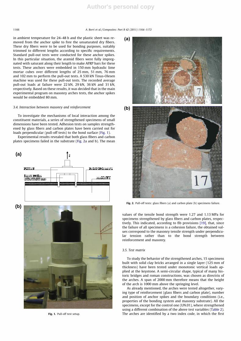
To investigate the mechanisms of local interaction among theconstituent materials, a series of strengthened specimens of smalldimensions have been tested. Adhesion tests on samples strength-ened by glass fibers and carbon plates have been carried out forloads perpendicular (pull-off tests) to the bond surface (Fig. 1).
Experimental results revealed that both glass fibers and carbonplates specimens failed in the substrate (Fig. 2a and b). The mean
values of the tensile bond strength were 1.27 and 1.13 MPa forspecimens strengthened by glass fibers and carbon plates, respec-tively. This indicated, according to fib provisions [19], that, sincethe failure of all specimens is a cohesion failure, the obtained val-ues correspond to the masonry tensile strength under perpendicu-lar tension rather than to the bond strength betweenreinforcement and masonry.
3.5. Test matrix
To study the behavior of the strengthened arches, 15 specimensbuilt with solid clay bricks arranged in a single layer (125 mm ofthickness) have been tested under monotonic vertical loads ap-plied at the keystone. A semi-circular shape, typical of many his-toric bridges and roman constructions, was chosen as directrix ofthe arches. A span of 2000 mm therefore means that the heightof the arch is 1000 mm above the springing level.
As already mentioned, the arches were tested altogether, vary-ing type of reinforcement (glass fibers and carbon plate), numberand position of anchor spikes and the boundary conditions (i.e.,properties of the bonding system and masonry substrate). All thespecimens, except for the control one (UN.01), where strengthenedusing a different combination of the above test variables (Table 2).The arches are identified by a two index code, in which the first
(a)
(b)
Fig. 1. Pull-off test setup.
Fig. 2. Pull-off tests: glass fibers (a) and carbon plate (b) specimens failure.
1166 A. Borri et al. / Composites: Part B 42 (2011) 1164–1172
Author's personal copy
indicates the type of reinforcement (UN = unreinforced; GF = glassfibers; CP = carbon plate), while the second indicates the identifica-tion number of the specimen.
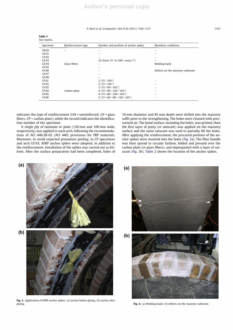
A single ply of laminate or plate (150 mm and 100 mm wide,respectively) was applied to each arch, following the recommenda-tions of ACI 440.2R-02 (ACI 440) provisions for FRP materials.Moreover, to avoid expected premature peeling, in CP specimensand arch GF.03, AFRP anchor spikes were adopted, in addition tothe reinforcement. Installation of the spikes was carried out as fol-lows. After the surface preparation had been completed, holes of
10 mm diameter and 85 mm depth were drilled into the masonrysoffit prior to the strengthening. The holes were cleaned with pres-surized air. The bond surface, including the holes, was primed, thenthe first layer of putty (or saturant) was applied on the masonrysurface and the same saturant was used to partially fill the holes.After applying the reinforcement, the precured portions of the an-chor spikes were inserted into the holes (Fig. 3a). The fiber bundlewas then spread in circular fashion, folded and pressed over thecarbon plate (or glass fibers), and impregnated with a layer of sat-urant (Fig. 3b). Table 2 shows the location of the anchor spikes.
Table 2Test matrix.
Specimen Reinforcement type Number and position of anchor spikes Boundary conditions
UN.01 – – –GF.01 – –GF.02 – –GF.03 22 (from 15� to 160�, every 7�) –GF.04 Glass fibers – Bedding bandGF.05 –GF.06 – Defects on the masonry substrateGF.07 –GF.08 –CP.01 2 (15�–165�) –CP.02 2 (15�–165�) –CP.03 3 (15�–90�–165�) –CP.04 Carbon plate 4 (15�–60�–120�–165�) –CP.05 4 (15�–60�–120�–165�) –CP.06 5 (15�–60�–90�–120�–165�) –
Fig. 3. Application of AFRP anchor spikes: (a) anchor before gluing; (b) anchor aftergluing. Fig. 4. (a) Bedding band; (b) defects on the masonry substrate.
A. Borri et al. / Composites: Part B 42 (2011) 1164–1172 1167
Author's personal copy
Finally, it is known that with masonry arches is very usual tohave a soffit characterized by the presence of a layer of cementi-tious grout (bedding band), used to eliminate the irregularities ofmasonry substrate, or a different kind of substrate, with lowermechanical properties, that become in this way the elements ofweakness of the whole strengthening system. Therefore, in twospecimens (GF.04 and GF.05 tests), in order to investigate the influ-ence of bonding system properties, the reinforcement was appliedinterposing a layer of cementitious grout (bedding band, Fig. 4a),whereas three specimens (GF.06, GF.07 and GF.08 tests), with asurface of application characterized by the presence of a substratewith lower mechanical properties (Fig. 4b), were used to simulatethe presence of defects on the masonry substrate.
3.6. Test setup
As shown in Fig. 5, all tests were conducted using a close-loopload configuration, where no external reaction is required. The loadalways applied at keystone was generated by means of a 100 kNmanual hydraulic jack reacting against a steel frame and a100 kN load cell, placed on bottom of the jack, was used to recordload levels. Horizontal reaction was supplied by a reaction frame,built with equal leg angles and flat bars. In addition, a total of threeLinear Variable Displacement Transducers (LVDTs) were used to
Fig. 5. Test setup.
Table 3Comparison among the experimental results.
Specimen Ultimateloadcapacity(kN)
Load pointdeflection(mm)
Reinforcementstrain (le)
Mode of failure
UN.01 0.70 1.50 – MechanismGF.01 7.07 16.04 5184 Laminate
debondingGF.02 6.41 11.68 3394 Laminate
debondingGF.03 6.90 18.61 4783 Masonry
crushingGF.04 4.71 14.01 2958 Laminate
debondingGF.05 4.48 5.74 2930 Laminate
debondingGF.06 4.85 8.44 4075 Shear
sliding + laminatedebonding
GF.07 5.93 10.95 4909 Shearsliding + laminatedebonding
GF.08 4.88 14.28 4122 Shearsliding + laminatedebonding
CP.01 13.44 1.69 779a Shear slidingCP.02 14.20 2.33 925a Shear slidingCP.03 15.81 5.83 2066 Masonry
crushingCP.04 18.55 7.78 2377 Masonry
crushingCP.05 11.50 4.17 1113a Masonry
crushingCP.06 11.18 2.44 2046 Masonry
crushing
a Gauge produced unreliable data from this point. Fig. 6. Laminate debonding: (a) arch GF.01; (b) arch GF.05.
1168 A. Borri et al. / Composites: Part B 42 (2011) 1164–1172
Author's personal copy
register deflections, while four strain gauges were placed near thepredicted hinge position to ensure the maximum strain wasrecorded.
4. Test results
In the following, the results of the experimental tests carriedout on the arches are grouped for type of the reinforcement(Table 3).
4.1. Unstrengthened arch
The unreinforced arch showed a brittle failure, due to the for-mation of four hinges (arch displacement mechanism). Failure oc-curred suddenly (without any warning), for small displacementsand just after the maximum load (equal to 0.7 kN) has beenreached.
4.2. Arches strengthened with glass fibers
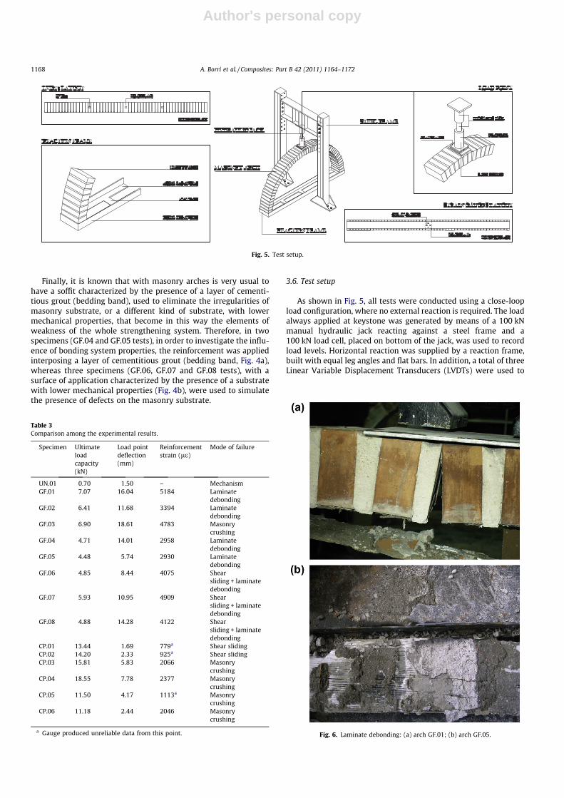
The arches strengthened with glass fibers exhibited three differ-ent patterns of collapse: laminate debonding, masonry crushingand shear sliding. More precisely, in specimens GF.01 and GF.02failure was dictated by the detachment of the reinforcement underthe loaded section (the mean value of the failure load was 6.73 kN),with part of the masonry substrate attached to the laminate(Fig. 6a), denoting a good interface bond between masonry andreinforcement. Arches GF.04 and GF.05, reinforced by interposinga layer of cementitious grout (bedding band), exhibited the same
failure mode (laminate debonding), the difference being failure oc-curred at the interface between masonry and bedding band(Fig. 6b), but a lower ultimate load capacity (4.60 kN). Conversely,in arch GF.03, employing AFRP anchor spikes able to delay ex-pected premature peeling, collapse occurred for an ultimate loadof 6.90 kN (Fig. 7a) due to a crushing of the keystone masonryblocks, while the GFRP strip remained fixed. In this latter case, aswell as in the previous ones, the structure did not reach a stateof collapse, since the reinforcement contributed in holding thebricks together during the last phase.
Finally, arches GF.06, GF.07 and GF.08, characterized by thepresence of a substrate with lower mechanical properties, faileddue to the sliding along the mortar joint close to the point of appli-cation of the load, resulting in the consequent detachment of thereinforcement from the masonry (Fig. 7b). Under such conditions,debonding progressed as long as the reinforcement contributedto holding the bricks together, then the arch load-carrying capacity(5.22 kN) decreased suddenly and the specimens collapsed undertheir own weight.
4.3. Arches strengthened with carbon plates
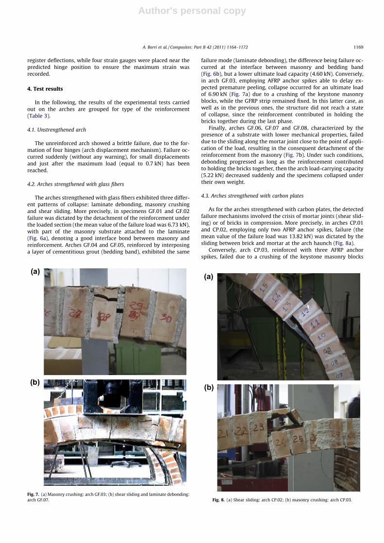
As for the arches strengthened with carbon plates, the detectedfailure mechanisms involved the crisis of mortar joints (shear slid-ing) or of bricks in compression. More precisely, in arches CP.01and CP.02, employing only two AFRP anchor spikes, failure (themean value of the failure load was 13.82 kN) was dictated by thesliding between brick and mortar at the arch haunch (Fig. 8a).
Conversely, arch CP.03, reinforced with three AFRP anchorspikes, failed due to a crushing of the keystone masonry blocks
Fig. 7. (a) Masonry crushing: arch GF.03; (b) shear sliding and laminate debonding:arch GF.07. Fig. 8. (a) Shear sliding: arch CP.02; (b) masonry crushing: arch CP.03.
A. Borri et al. / Composites: Part B 42 (2011) 1164–1172 1169
Author's personal copy
(Fig. 8b) after a significant increment of the load-carrying capacity(15.81 kN). It is worth noticing that such a failure mode is causedand governed by the pin localization, which is due to the bricks’rotation and governed by the stitching action of the plate. Morespecifically, as expected (see Section 2), the reinforcement is inca-pable of preventing masonry from cracking, but it stitches thecrack, preventing the boundary opposite an FRP strip from hinging.In such a context, the blocks close to the point of application of theload are cracked, but stitched by the reinforcement. The tensionforce in the CFRP plate is thus the result of a substantial relativerotation of the bricks around the boundary opposite the plate.The opposite boundary thus behaves like a pin. The pin localizesthe contact between the units that rotate around it. Consequently,the stress profile lies at a limited depth and when the compressivestrength was overcome, said stresses lead the keystone masonryblocks to crack along a horizontal plane, following the top side ofthe arch.
Finally, arches CP.04 and CP.05, reinforced with four AFRP an-chor spikes, and arch CP.06, reinforced with five AFRP anchor
spikes, presented a different ultimate load capacity despite havingshown the same failure mode (masonry crushing). Specifically,while arch CP.04 exhibited a substantial increase of the failure load(18.55 kN), the ultimate loads of arches CP.05 and CP.06 were con-siderably lower (11.50 and 11.18 kN, respectively). Due to thenotable variations in results typical of tests on masonry and con-sidering the presence of undesirable variables (such as handwork)that may have arisen from the construction of the specimens, thisfact may be attributed to a lower value of the masonry compressivestrength.
It is worth noticing that all specimens did not reach a state ofcollapse because the reinforcement contributed in holding thebrick together during the last phase.
5. Analysis of the results
The experimental investigation carried out on the strengthenedarches is aimed at assessing the potential of carbon plates to
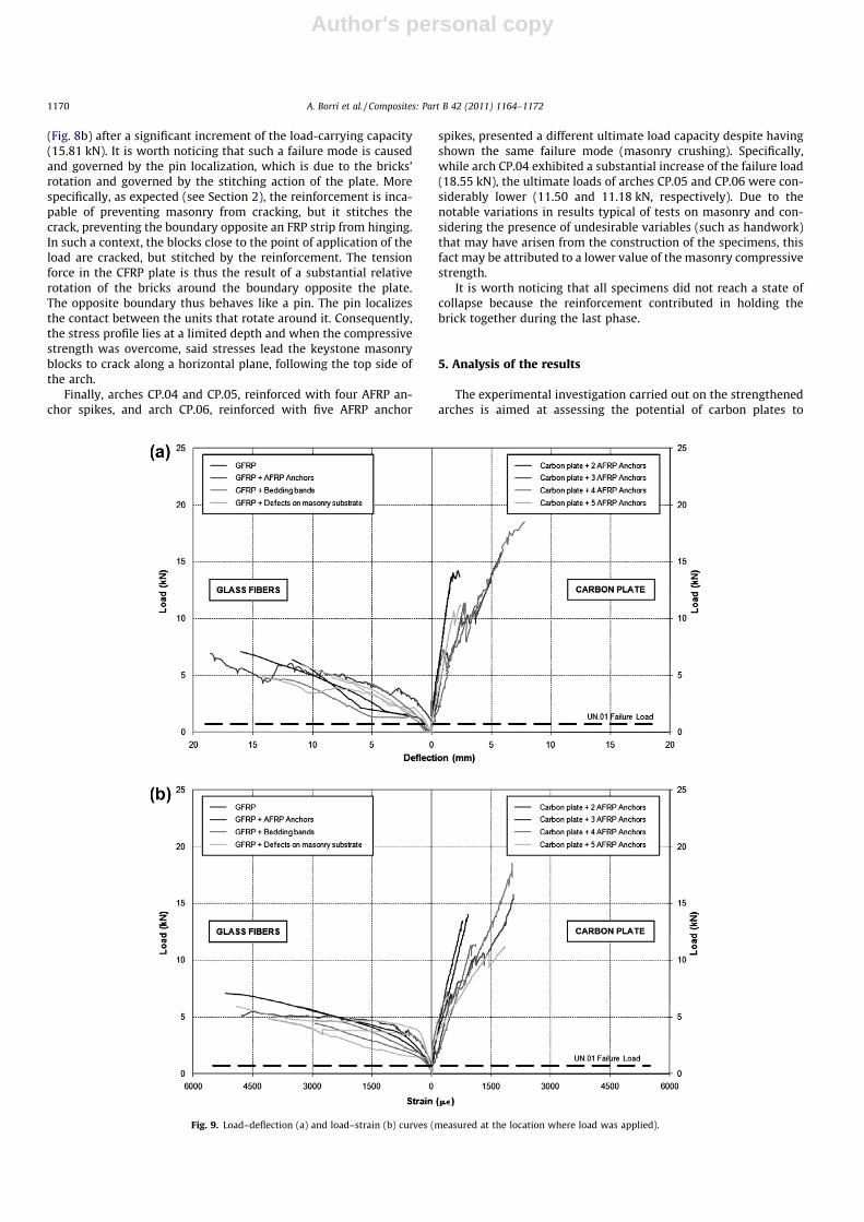
Fig. 9. Load–deflection (a) and load–strain (b) curves (measured at the location where load was applied).
1170 A. Borri et al. / Composites: Part B 42 (2011) 1164–1172
Author's personal copy
provide a reinforcing system alternative to FRP laminates for intra-dos strengthening of masonry arches. According to this goal, anal-ysis of the test results is conducted first with respect to archesstrengthened with glass fibers, investigating the influence of theproperties of the bonding system and masonry substrate; and then,arches using the same strengthening arrangement with differentmaterials (glass fibers and carbon plates) are compared (Fig. 9). Re-marks on the influence of the presence and number of anchorspikes are also presented.
According to such an analysis the following can be highlighted:
1. As for the arches strengthened with glass fibers, it was observedthat much of the success of masonry arches reinforced at theirintrados lies with the integrity of the bond between GFRP stripand masonry substrate. Laboratory outcomes highlighted thatthe load-carrying capacity of the GF arches is significantlyaffected by the surface preparation (e.g., use of bedding bands)and masonry substrate properties. More specifically, comparedwith arches GF.01 and GF.02, the arches reinforced by interpos-ing a layer of cementitious grout (arches GF.04 and GF.05) pro-vided an ultimate strength approximately 30% smaller, whereasthe presence of a substrate with lower mechanical properties(arches GF.06, GF.07 and GF.08) evidenced an average decreasein strength equal to 23%. Furthermore, it is worth noticing thateven if AFRP anchor spikes allowed to eradicate the problem ofpremature peeling, they were incapable of increasing the archload-carrying capacity. In spite of a different failure mechanism(masonry crushing), the ultimate load capacity of arch GF.03was in fact similar (+2%) than that of the arches without anchorspikes (arches GF.01 and GF.02).
2. The use of carbon plates and AFRP anchor spikes eradicates theproblem of premature peeling by resisting the transverse ten-sile stress that would otherwise limit the capacity of the struc-ture leading to premature collapse. Strength increases providedby carbon plates were greater than those obtained using glassfibers. Regardless of the number of anchor spikes, carbon platespermitted the attainment of strength increases rangingbetween 16 and 26 times the original, while the maximumincrease obtained with glass fibers was no more than 10 timesthe original.
3. As for the CP arches, it was observed that the number and theposition of the anchor spikes have a limited influence on thereinforcing action of the carbon plates. Compared with archesreinforced with two anchor spikes (arches CP.01 and CP.02),arches CP.03 and CP.04, reinforced with three and four anchorspikes respectively, permitted the attainment of strengthincreases ranging between 11% and 38%, while the ultimatestrength of arches CP.05 and CP.06, reinforced with four and fiveanchor spikes respectively, was approximately 20% smaller.
4. Important information is also provided by the analysis of LVDTand strain gauges readings at the keystone of the arch. Theload–deflection and stress–strain curves (Fig. 9a and b) for ser-ies GF and series CP reveal a different behavior pattern. While inCP arches the failure was brittle, GF arches tends to attain abilinear shape, characterized by a long pre-peak branch, whichprovides the structure with important ductility behavior. Infact, the peak load was achieved for a displacement even 11times greater than the ones corresponding to the CP specimens.
Conclusions
The following conclusions are deduced from the experimentalresults:
� The use of AFRP anchor spikes to secure the GFRP strip to thearch soffit, albeit able to eradicate the problem of premature
peeling, was shown to be labor intensive (the spacing of theanchors is small) and, above all, incapable of increasing theload-carrying capacity of GF arches. In spite of a different failuremechanism (masonry crushing), the ultimate load capacity ofarch GF.03 was in fact close to of the arches without anchorspikes. A key factor that may explain such a discrepancy is thedamage on the masonry region adjacent the pre-drilled holesused for the insertion of AFRP anchor spikes. The presence oftoo many anchors, inserted to a depth of 2/3 of the arch thick-ness, are likely, in fact, to justify a serious weakening ofmasonry blocks.� Carbon plates and AFRP anchor spikes were effective in helping
to prevent debonding and premature peeling and provided anoverall better performance, in terms of ultimate load capacity,than glass fibers. This is because the FRP sheet is generally sothin and its bending stiffness so small that when it detachedfrom the masonry it acts like a membrane, which cannot adheremore to the masonry substrate. As a consequence, since it can-not carry the stresses occurring at the tensed edges, it becomesincapable of preventing masonry from hinging. As an alterna-tive to FRP sheets, the use of FRP plates presents instead severalinteresting aspects which make them very attractive for intra-dos strengthening. These can be summarized as follows: FRPplates have an inherent bending and axial stiffness that mayovercome problems concerning premature peeling. More pre-cisely, if the ends of the FRP system are sufficiently anchoredto the soffit of the arch (experimental analysis pointed out that,since the number AFRP anchor spikes have a limited influenceon the reinforcing action of the carbon plates, even two anchorsare enough) and no slip is allowed at the interface betweenmasonry and reinforcement, even when the transverse stressesreach the tensile resistance of the adhesive or masonry support,the FRP plate, due to its greater bending and axial stiffness,tends to maintain its shape and hence it can continue to adhereto the masonry substrate, carrying the tensile stresses and pre-venting masonry from hinging.� Reinforced arches exhibited a different postcapacity behavior
with respect the unreinforced ones. While the unreinforcedarch failed due to the complete loss of capacity, both the GFand CP arches (with the exception of arches GF.06, GF.07 andGF.08, characterized by the presence of a substrate with lowermechanical properties) did not reach a state of collapse becausethe reinforcement contributed in holding the brick togetherduring the last phase. This means that either classical GFRPsheets and CFRP plates are effective in preventing the collapseof masonry arches when subjected to ultimate stress limits.The difference being that GF specimens, exhibiting a largerdeformation capacity prior to failure, also provide the archeswith important ductility behavior.
Acknowledgements
The authors would like to acknowledge the support of FIDIA forproviding the strengthening materials, and TECINN Laboratorytechnicians for their assistance during the construction of the AFRPanchor spikes.
References
[1] ICOMOS. International scientific committee for analysis and restoration ofstructures of architectural heritage. Recommendations for the analysis,conservation and structural restoration of architectural heritage. In:Guidelines of ICOMOS 14th General Assembly. Victoria Falls; October, 2003.
[2] Fanning P, Kelly O. Shear strengthening of reinforced concrete beams: anexperimental study using CFRP plates. In: Proceedings of structural faults +repair 99 conference. London; July 1999.
A. Borri et al. / Composites: Part B 42 (2011) 1164–1172 1171
Author's personal copy
[3] Nanni A. Fiber reinforced plastic reinforcement for concrete structures:properties and applications. Amsterdam: Elsevier; 1993.
[4] Smith ST, Teng JG. FRP-strengthened RC beams. I. Review of debondingstrength models. Eng Struct 2002;24(4):385–95.
[5] Basilio I, Oliveira D, Lourenço P. Optimal FRP strengthening of masonry arches.In: Proceedings of 13th international brick and block masonry conference.Amsterdam; July 2004. p. 361–70.
[6] Borri A, Casadei P, Casadei G, Hammond J. Strengthening of brick masonryarches with externally bonded steel reinforced composites. J Compos Constr2009;13(6):468–75.
[7] De Lorenzis L, Dimitri R, La Tegola A. Reduction of the lateral thrust of masonryarches and vaults with FRP composites. Constr Build Mater 2007;21(7):1415–30.
[8] Valluzzi MR, Valdemarca M, Modena C. Behaviour of brick masonry vaultsstrengthened by FRP laminates. J Compos Constr 2001;5(3):163–9.
[9] Briccoli Bati S, Rovero L. Towards a methodology for estimating strength andcollapse mechanism in masonry arches strengthened with fibre reinforcedpolymer applied on external surfaces. Mater Struct 2008;41:1291–306.
[10] Foraboschi P. Strengthening of masonry arches with fiber-reinforced polymerstrips. J Compos Constr 2004;8(3):96–104.
[11] De Lorenzis L, Zavarise G. Interfacial stress analysis and prediction ofdebonding for a thin plate bonded to a curved substrate. Int J Non LinearMech 2009;44(4):358–70.
[12] Eshwar N, Ibell T, Nanni A, Porter AD. Effectiveness of CFRP strengthening oncurved soffit RC beams. Adv Struct Eng 2005;8(1):55–68.
[13] Borri A, Castori G. Influence of bonding defects in masonry vaults and archesstrengthened at their intrados with FRP. In: Proceedings of mechanics ofmasonry structures strengthened with FRP. Venice; December 2004.p. 7–16.
[14] Heyman J. The masonry arch. West Sussex: Ellis Horwood; 1982.[15] ASTM C 348. Standard test method for flexural strength of hydraulic-cement
mortars. ASTM International, West Conshohocken, Pennsylvania, UnitedStates; 2008.
[16] ASTM C 349. Standard test method for compressive strength of hydraulic-cement mortars (using portions of prisms broken in flexure). ASTMInternational, West Conshohocken, Pennsylvania, United States; 2008.
[17] Clements LL. Organic fibers. In: Handbook of Composites. London: Chapman &Hall; 1998.
[18] Uomoto T, Nishimura T, Ohga H. Static and fatigue strength of FRP rods forconcrete reinforcement. In: Proceedings of 2nd international RILEMsymposium (FRPRCS-2) and block masonry conference; August, 1995. p.100–7.
[19] Fédération International du Béton (FIB). Externally bonded FRP reinforcementfor RC structures, Technical Bulletin No. 14. CEB-FIB, Lausanne, Switzerland;2001.
1172 A. Borri et al. / Composites: Part B 42 (2011) 1164–1172